Embed Size (px)
Citation preview

Governance for Railway Investment Projects
Page 2 of 61
Ref: 350164/WTD/BTL/01
Version: 03
Date: September 2015
This page left deliberately blank
Governance for Railway Investment Projects
Page 3 of 61
Ref: 350164/WTD/BTL/01
Version: 03
Date: September 2015
Network Rail
139886 Gipsy Patch Lane
Option Selection Report
Issue and Revision Record:
Rev
01
Date
05 June 2015
Originator
G Skehel
Checked
A Georgiev
Approved
C Bishop
Description
Draft report for preliminary
review of Options 1 to 4
02
10 July 2015
G Skehel
A Georgie
C Bishop
Revised to include review of
Options 1 to 6
03
21 September
2015
J Harrison-King
G Skehel
C Bishop
Revised to address
comments
04
Group Disclaimer
“This document is issued for the party which commissioned it and for specific purposes connected with the above- captioned project only. It should not be relied upon by any other party or used for any other purpose.
We accept no responsibility for the consequences of this document being relied upon by any other party, or being used for any other purpose, or containing any error or omission which is due to an error or omission in data supplied to us by other parties”
“This document contains confidential information and proprietary intellectual property. It should not be shown to other parties without consent from us and from the party which commissioned it.”
Mott MacDonald
10 Temple Back
Bristol BS1 6FL
United Kingdom
350164/WTD/BTL/01/02 PiMS Ref. No. 1593483307

Governance for Railway Investment Projects
Page 4 of 61
Ref: 350164/WTD/BTL/01
Version: 03
Date: September 2015
This page left deliberately blank
Governance for Railway Investment Projects
Page 5 of 61
Ref: 350164/WTD/BTL/01
Version: 03
Date: September 2015
Contents
1 EXECUTIVE SUMMARY 9
2 OPTIONS REPORT & CONCEPT DESIGNS 11
2.1 Considerations for Option Selection 11
2.2 Discarded Options 11
2.2.1 Prestressed, Precast Concrete Frame 11
2.2.2 Network Rail Standard Designs and Details 12
2.2.3 Bespoke Steel Deck 14
2.2.4 Jacked Concrete Box 15
2.2.5 Re-use of Existing Structure 16
2.2.6 Raised Cycle/Footway 17
2.2.7 Intermediate Supports 18
2.3 Bridge Structure Options Considered 22
2.3.1 Option 1 – No Bus Lane (skewed to the track) 22
2.3.2 Option 2 – Single Bus Lane (skewed to the track) 23
2.3.3 Option 3 – No Bus Lane (square to the track) 23
2.3.4 Option 4 – Single Bus Lane (square to the track) 24
2.3.5 Option 5 – Dual Bus Lane (skewed to track) 25
2.3.6 Option 6 – Dual Bus Lane (square to track) 25
2.4 Wing Wall Options 26
2.5 Foundation Options 26
2.6 Works Not Requiring Option Selection 29
2.6.1 Track Alignment 29
2.6.2 Headroom 29
2.6.3 Parapets 29
2.6.4 Drainage and Waterproofing 29
2.6.5 Width of Bridge 30
2.6.6 Finishing Works 30
2.6.7 Foundation Connection 30
2.7 Constructability Assessment 31
2.7.1 Construction Sequence 31
2.7.2 SPMTs 32
2.7.3 Construction Risks 34
2.7.4 Site Compound 34
Governance for Railway Investment Projects
Page 6 of 61
Ref: 350164/WTD/BTL/01
Version: 03
Date: September 2015
2.7.5 Fence and Boundary Review 34
2.8 Access and Possession Strategy 35
2.9 Project Schedule 35
2.10 Whole Life Cost Assessment of Options 35
2.11 Estimates (excluding whole life costings) 36
2.12 Sustainability Consideration 36
2.13 Diversity Impact Assessment 37
2.14 QRA 37
2.15 Risk Register 38
2.16 Assumptions 38
2.17 Signed Design Compliance Certificate 38
2.18 Asset Condition Surveys / GI / Topographical 38
2.19 Options Evaluation 39
2.20 Selected Option 45
3 INTERFACES WITH OTHER PROJECTS 45
4 CDM INFORMATION 46
5 SAFETY VERIFICATION RECOMMENDATIONS 46
6 CONSENTS STRATEGY 46
7 ENVIRONMENTAL IMPACT ASSESSMENT 47
7.1 General Risks 47
7.2 Water 47
7.3 Historical 47
7.4 Ecology 47
7.5 Contaminated land 48
7.6 Waste 48
8 MAINTENANCE AND OPERATIONS STRATEGY 48
9 ENGINEERING OUTPUTS 49
10 CONCLUSION AND RECOMMENDATIONS 49
11 FORMAL ACCEPTANCE OF SELECTED OPTION BY CLIENT, FUNDERS AND STAKEHOLDERS 50

Governance for Railway Investment Projects
Page 7 of 61
Ref: 350164/WTD/BTL/01
Version: 03
Date: September 2015
APPENDICES
A. Drawings
B. Project Hazard Log
C. Not Used
D. Cost Estimating (redacted for commercial reasons)
E. Photographs
F. Environmental Appraisal
G. Geotechnical Design Report
H. Carbon Footprint Calculation
I. Project Risk Register (redacted for commercial reasons)
Governance for Railway Investment Projects
Page 8 of 61
Ref: 350164/WTD/BTL/01
Version: 03
Date: September 2015
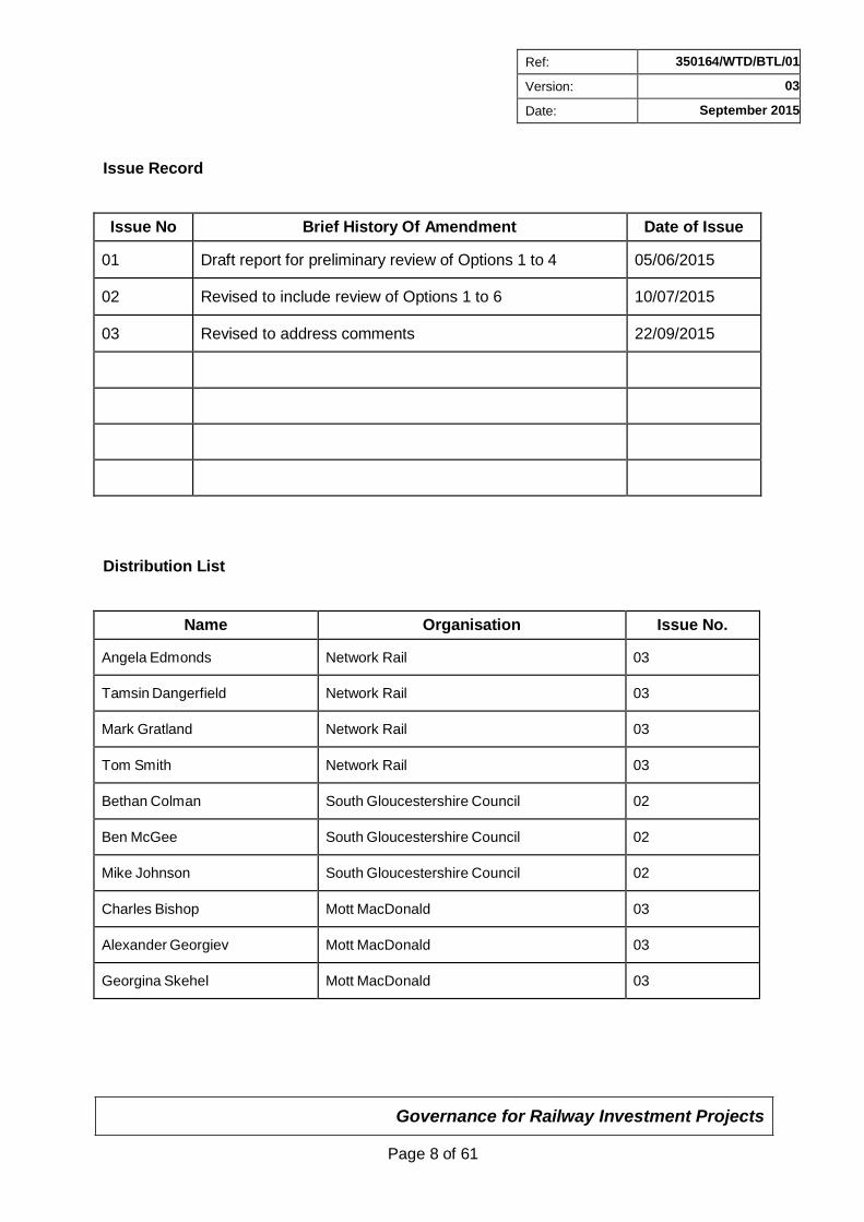
Issue Record
Issue No Brief History Of Amendment Date of Issue
01
Draft report for preliminary review of Options 1 to 4
05/06/2015
02
Revised to include review of Options 1 to 6
10/07/2015
03
Revised to address comments
22/09/2015
Distribution List
Name Organisation Issue No.
Angela Edmonds
Network Rail
03
Tamsin Dangerfield
Network Rail
03
Mark Gratland
Network Rail
03
Tom Smith
Network Rail
03
Bethan Colman
South Gloucestershire Council
02
Ben McGee
South Gloucestershire Council
02
Mike Johnson
South Gloucestershire Council
02
Charles Bishop
Mott MacDonald
03
Alexander Georgiev
Mott MacDonald
03
Georgina Skehel
Mott MacDonald
03
Governance for Railway Investment Projects
Page 9 of 61
Ref: 350164/WTD/BTL/01
Version: 03
Date: September 2015
1 Executive Summary
Gipsy Patch Lane is a single span underline structure located south of Bristol Patchway Station at BSW 5miles and 60chains. The existing superstructure comprises a masonry arch bridge constructed square to the track. It carries four lines that converge to three via switches located on the bridge over Gipsy Patch Lane, which consists of a single carriageway and narrow footpath.
The bridge has limited clearance with a 4m height restriction which forms a pinch point on South Gloucestershire Council’s (SGC) travel network. Further disruption to travel occurs during incidents of bridge strikes which Network Rail reports are a regular occurrence.
SGC previously commissioned a feasibility study which looked at options to address the issues at Gipsy Patch Lane which recommended providing a jacked box subway for pedestrians and cyclists adjacent to the existing structure. Since this feasibility study, additional requirements to consider the provision for enabling the passage of double decker buses and potential for designated bus lanes along the route have arisen as part of the Cribbs Patchway MetroBus Extension project.
The Cribbs Patchway MetroBus Extension Project aims to provide an express bus service which includes improved cycling and pedestrian facilities. It will form an extension to part of an already planned MetroBus route to provide a faster and more direct route between Parkway Station and Cribbs Causeway via the Cribbs Causeway new neighbourhood on the former Filton Airfield. The proposed route will use Gipsy Patch Lane, hence further optioneering is required to consider a new bridge structure in order to increase the headroom and width of the carriageway to facilitate the increase in buses and non-motorised users traffic.
The new structure will be designed for a 120 year design life and will be owned and maintained by Network Rail with a one-off maintenance contribution made by SGC on completion of the works.
An option selection process has been undertaken to consider different carriageway layouts, constructability and structural arrangement. Options that were immediately identified as unsuitable, and hence discarded, have been included for completeness and to illustrate the design process. Six main options for the bridge structure have been considered and for each of these a detailed description has been provided. SGC have commissioned CH2M to undertake the highway design for the different carriageway layouts and design of the bridge structure has been co-ordinated with these.
Sheet piled and reinforced concrete wing walls, either straight with the bridge abutments or splayed have been considered. Discussions regarding the wing wall options have considered their construction and aesthetics in order to identify which would be best suited for the bridge proposal.
In order to provide the bearing resistance required for the main options for the bridge structure considered in this report, six foundation options have been reviewed and a comparison of these options are detailed in Section 2.5 of this report. It is considered that the preferred option would be ground beams spanning between piles at either end however targeted ground investigation in later design stages may present value engineering options to further develop the foundation design by reducing or eliminating the piles at either ends of the ground beam.
Governance for Railway Investment Projects
Page 10 of 61
Ref: 350164/WTD/BTL/01
Version: 03
Date: September 2015
The recommended solution is to provide a pre-cast concrete portal frame with an 18.7m clear span and abutments aligned with the carriageway (option 2). This is sufficient to include a single designated bus lane whilst keeping the overall structure size to a minimum. The wing walls should be pre-cast, integral with the main bridge structure for more efficient construction. Ground beams supporting the wing walls and the abutments, spanning between large diameter piles are considered to be appropriate, however targeted ground investigations in later design stages may present opportunity to refine the foundation design.
The proposed construction sequence involves pre-casting the portal frame in a compound located in the Rolls Royce East Works site adjacent to the existing bridge. During an abnormal possession the embankment can be excavated and the existing bridge demolished prior to the pre-cast structure being driven into place using self- propelled modular transporter units (SPMT).
To provide the required improved headroom below the proposed bridge, the carriageway will need to be lowered. This will impact on the existing buried services below the carriageway and the extent of the regrading required to tie in with the existing highway. The construction of the new bridge will need to be co-ordinated with the associated highway realignment and further works being undertaken as part of the wider Cribbs Patchway MetroBus Extension Project.
Governance for Railway Investment Projects
Page 11 of 61
Ref: 350164/WTD/BTL/01
Version: 03
Date: September 2015
2 Options Report & Concept Designs An option selection process has been carried out to evaluate and compare options to determine the most effective solution for the replacement bridge structure. A brief description of the discarded options has been included to illustrate the design process. Six options have been considered in greater detail for option selection and a preferred solution identified.
2.1 Considerations for Option Selection
The areas requiring consideration during the option selection process include:
Type of structure – the materials used and structural arrangement need to be suitable for the required spans, constructability, durability, appearance and maintenance.
Alignment of structure – the alignment will need to consider track sensitivity, road users’ sightlines, appearance, maintenance access and most efficient structural arrangement to provide sufficient clear span for the proposed carriageway.
Foundations – the foundation solution will need to consider the construction method, particularly with the limited possession time available, whilst suiting the existing ground conditions and the applied loading.
Carriageway layout - three main options are proposed for the carriageway to facilitate the increase in buses and non-motorised users: 14.5m clear width, the required minimum span allowing for a two lane single carriageway with shared cycle/footway on each side; 18.7m clear width, allowing for a two lane single carriageway with designated bus lane and with cycle/footways on each side; or a 24.4m clear width, allowing for a two lane single carriageway with a designated bus lane on each side and with cycle/footways on each side.
Wing walls – construction and alignment of the wing walls will need to consider the construction method and the aesthetics of the structure.
Feasibility of construction – the impact on route operation, for both the railway and highway and the method of construction will impact on the suitability of the options considered. The construction method will also need to consider any interaction with the existing structure and services.
Impact on existing services – a large number of services are located at this site as shown by MMD-350164-C-DR-GP-XX-0001 in Appendix A. In order to maintain the existing track alignment the road below will require some lowering so provision for relocating services and their interaction with the construction phase will need to be considered when costing and planning all options.
2.2 Discarded Options
The following options were considered during the option selection process and discarded:
2.2.1 Prestressed, Precast Concrete Frame
In order to reduce the construction depth of the structure, a prestressed concrete frame including pre-tensioning and post-tensioning was considered, particularly for the wider
Governance for Railway Investment Projects
Page 12 of 61
Ref: 350164/WTD/BTL/01
Version: 03
Date: September 2015
carriageway options. Prestressed concrete results in a greater stiffness and improved elastic behaviours which could reduce the thickness of the slab required. Prestressing reduces cracking in the concrete, providing a more durable and aesthetically pleasing solution. The overall steel weight required for reinforcement can be reduced and is generally less congested than traditional reinforced concrete sections.
These benefits are particularly relevant to the largest option that will require a large construction depth to span the wider carriageway option and hence has a greater impact on the extent the carriageway will need to be lowered.
The prestressed concrete frame would need to be designed for the temporary load case of lifting and transporting the structure to its permanent position. This would result in requirement for a significantly more complex and expensive temporary support and bracing system for lifting and transportation.
However prestressing would present a maintenance issue as it would introduce hidden elements at anchorage points that could not be easily inspected as part of the Network Rail structures maintenance regime. Furthermore, due to the high loading from the track supported above, deflection will generally govern the thickness of the slab and hence the benefits of a prestressed system reduce.
2.2.2 Network Rail Standard Designs and Details
Network Rails Standard Design and Details (SDDs) as per NR/L3/CIV/151/F010 have been reviewed to determine whether any were suitable for the replacement bridge structure. The SDDs have been developed and approved with an aim of reducing the volume of maintenance and management, limiting hidden details and facilitating precast/preassembled construction methods. A series of concrete and steel arrangements are available to suit various spans and alignments.
The concrete underbridge standard details are generally suited to 2.5m to 20m spans which is not sufficient for the larger span options being considered. Whilst longer spans can be achieved, the increased weight and construction depth makes these options less favourable. The span/depth ratios are also greater than could be achieved from a bespoke design. The concrete elements can be precast offsite and the structure can be erected adjacent to the final position and manoeuvred into place, however this is not a common construction method when using the concrete SDDs or a cost effective solution.
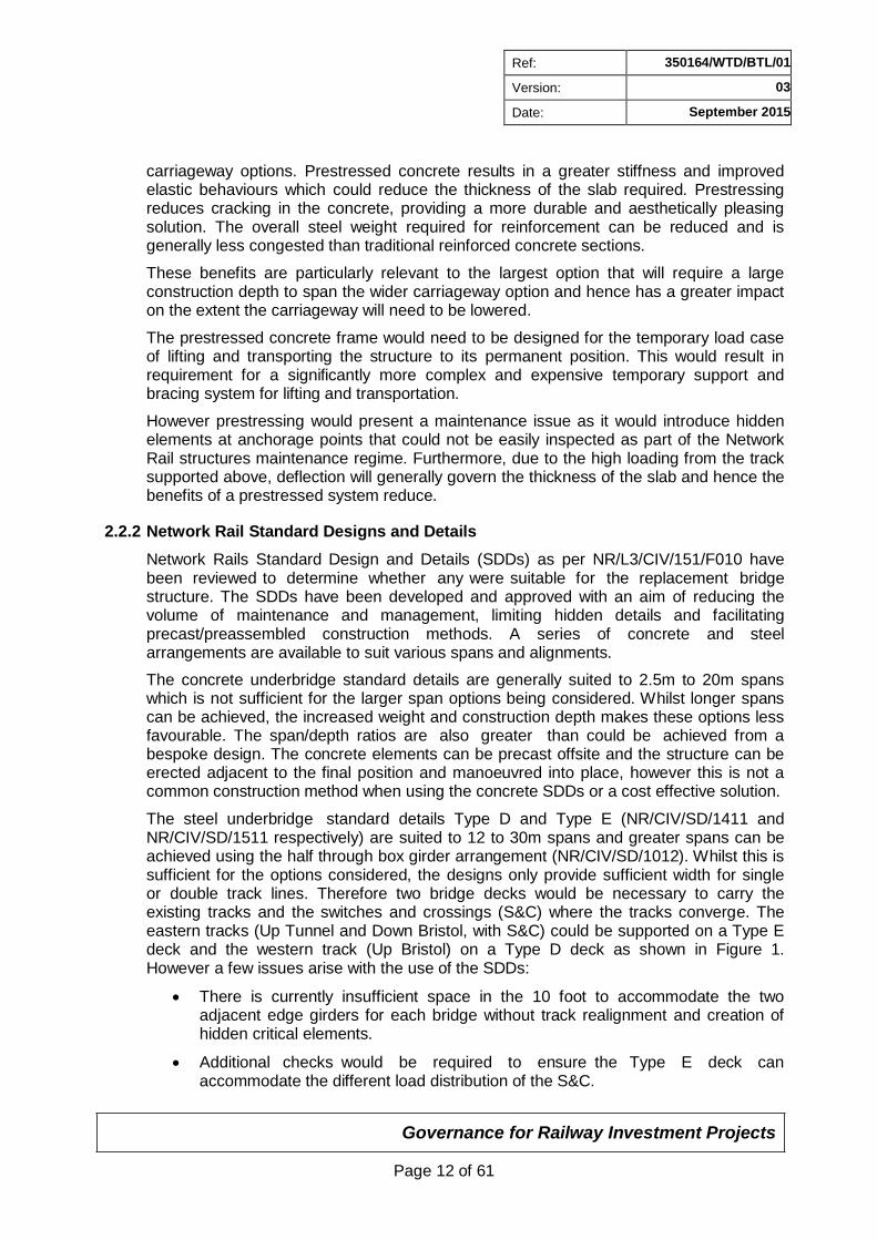
The steel underbridge standard details Type D and Type E (NR/CIV/SD/1411 and NR/CIV/SD/1511 respectively) are suited to 12 to 30m spans and greater spans can be achieved using the half through box girder arrangement (NR/CIV/SD/1012). Whilst this is sufficient for the options considered, the designs only provide sufficient width for single or double track lines. Therefore two bridge decks would be necessary to carry the existing tracks and the switches and crossings (S&C) where the tracks converge. The eastern tracks (Up Tunnel and Down Bristol, with S&C) could be supported on a Type E deck and the western track (Up Bristol) on a Type D deck as shown in Figure 1. However a few issues arise with the use of the SDDs:
There is currently insufficient space in the 10 foot to accommodate the two adjacent edge girders for each bridge without track realignment and creation of hidden critical elements.
Additional checks would be required to ensure the Type E deck can accommodate the different load distribution of the S&C.
Governance for Railway Investment Projects
Page 13 of 61
Ref: 350164/WTD/BTL/01
Version: 03
Date: September 2015
The Type E deck is at its limit for width when providing a cess walkway.
A cess could only be provided along the western edge of the bridge.
Figure 1 - Cross section illustrating a SDD deck arrangement without track alignment
The design does provide a relatively thin deck profile and therefore a reduced overall construction depth which results in less highway regrading. The deck can be manoeuvred into place by either lifting, sliding or self-propelled modular transporters (SPMT) and as a result a steel underbridge deck is suitable for installation during a possession.
The steel underbridge arrangement outlined above would have a reduced width compared to the existing bridge. To allow for the addition of another track in the future, the abutments can be extended and designed to allow for the installation of a further Type D deck to the west of the lines when required, or two Type E decks can be installed with only one track initially run on western span.
The design of the substructure and foundations is not part of the SDD. These structural elements have a key role in the considered construction phasing to minimise railway disruptions. The construction of separate abutments and foundations would have significant impact on the length of main possession required and hence is considered as one of the main disadvantages of using SDDs for this bridge replacement.
To limit the possession time required abutments could be created by boring/jacking through the embankment and filling with concrete. However overall construction time would increase as installation of bored/jacked elements is a slow procedure. Another limit to this method of abutment construction is access. Works to the southern abutment could be completed from the Rolls Royce east works site. However due to the close proximity of buildings to the north western embankment works could not be carried out from this side. There is space to the east however this would require additional site space and access restrictions.
Lifting the abutments together with the deck was considered, however due to the nature of the spans and bearing arrangement this is not preferred.
Due to the form of the bridges, the vertical loading on the abutment will be particularly high at midpoint where the main girders for each deck are located. To accommodate this, piles are likely to be required locally. As this falls between the tracks, this work would be carried out during shorter possessions prior to the main works. To limit overall track disruption, the piling rig could be positioned on the western side of the tracks, utilising the Down Bristol line for the work and allowing for shorter closures to the remaining lines. The width of the 10 foot and the available working space will restrict the number and position of the piles.
Governance for Railway Investment Projects
Page 14 of 61
abutment and foundation construction as outlined for the steel SDDs above.
Ref: 350164/WTD/BTL/01
Version: 03
Date: September 2015
Although the use of steel SDDs may provide cost savings, the need for two bridges could remove much of the financial incentive for a standard design, requiring the construction of two bridges and the associated abutments which are not provided in the SDDs.
The requirements for joints and bearings in each of the concrete and steel standard designs present an additional maintenance issue and may pose difficulties in controlling differential movement of the supported track. Due to the track arrangement and presence of the S&C above the bridge, a fully integral structure would be better suited to reduce differential movement. The presence of multiple joints could also pose a corrosion problem, particularly to the underbridges utilising steel girders and beams. A filler beam deck, where the steel beams are encased in concrete, could be employed to reduce the risk.
Additional vehicle collision restraining devices may be required as the soffit of the new bridge will be lower than 5.7m and the bridge self-weight and rigidity alone is not likely to be sufficient to resist deck uplift in the event of a bridge strike.
Overall, the SDDs are less favourable options. The concrete underbridge provides issues with installation during a possession that would require design changes, thereby reducing the attractiveness of a ‘standard’ design and the deck depth would be greater than could be achieved with a bespoke design. The steel underbridge designs also have shortcomings; the necessity for two bridge deck installations, required track realignment, construction of abutments, the risk of corrosion and differential settlement are critical. Both steel and concrete underbridge SDDs will also limit any future changes that can be made to the track arrangement.
2.2.3 Bespoke Steel Deck
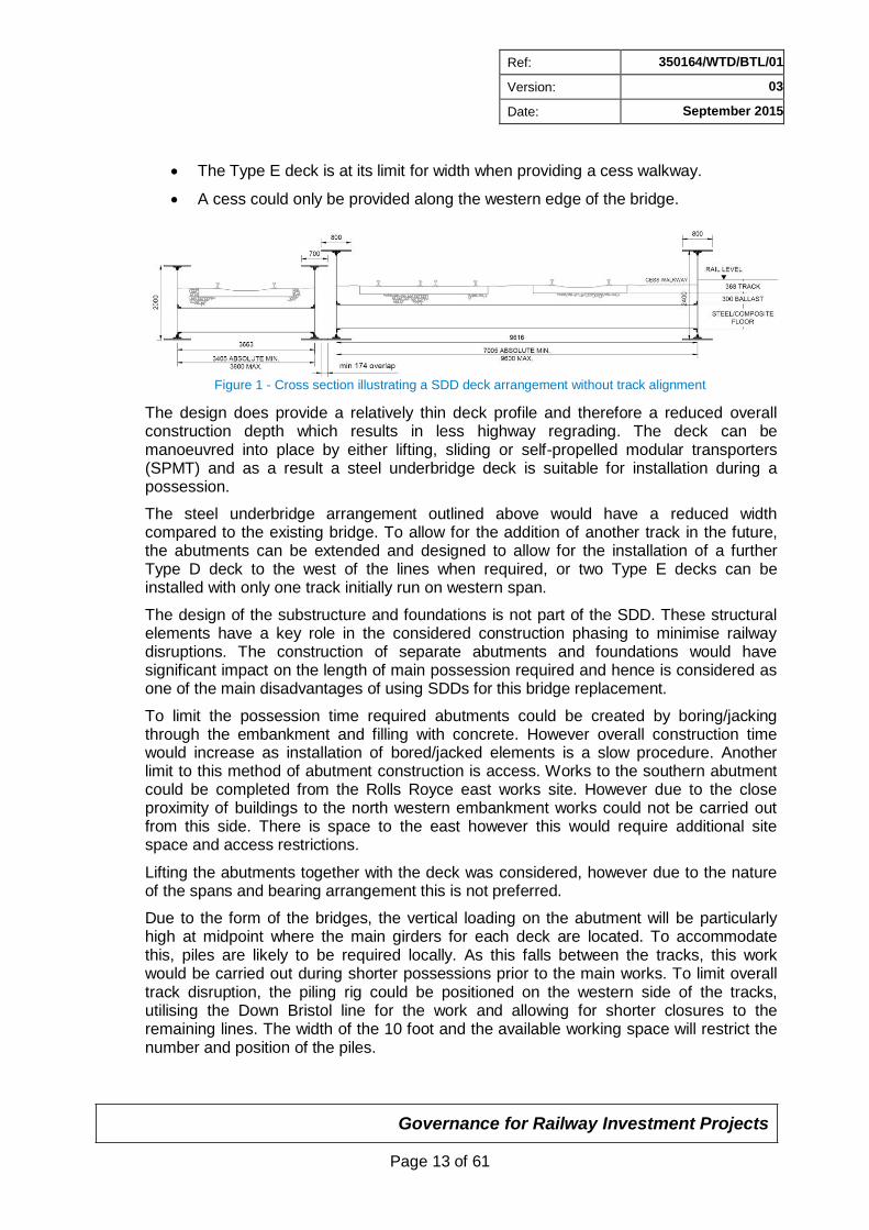
To avoid the need for track realignment and to suit the larger span options, a nonstandard steel deck could be utilised. However due to the width of the structure being approximately equal to the span, the transverse elements will need to be large to span between the main longitudinal girders, resulting in a greater construction depth. This could be reduced by using multiple box/plate girders. Having two unequally loaded spans creates torsion issues and may rely on large central girder with significant rotational stiffness. Box girders could be used for the main longitudinal members to overcome this.
As illustrated in Figure 2, if the span widths are matched, sufficient space for a cess and future additional track to the west can be provided. However this bespoke design is likely to require an increase in construction depth and will face the same issues regarding
Figure 2 - Cross section illustrating a box girder deck arrangement
As identified for the steel underbridge SDDs, it is likely that additional vehicle collision restraining devices will be required to resist deck uplift in the event of a bridge strike. It will also be difficult to accommodate the additional overhead line equipment (OLE)
Governance for Railway Investment Projects
Page 15 of 61
Ref: 350164/WTD/BTL/01
Version: 03
Date: September 2015
gantry identified as being located on the bridge by the Great Western Electrification Programme (GWEP) and will limit any further changes to track alignment that may be required in the future.
Steel underbridges also present further maintenance requirements. Additional painting for corrosion protection is required and access to hidden/confined elements will also need be considered, particularly the confined space access required to inspect the inside of the box girders.
Overall it is concluded that due to the width of the bridge requiring deeper transverse elements and additional vehicle collision restraining devices, a more efficient design may be achieved through a reinforced concrete deck.
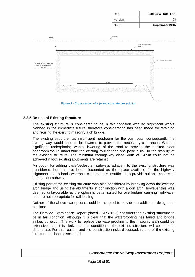
2.2.4 Jacked Concrete Box
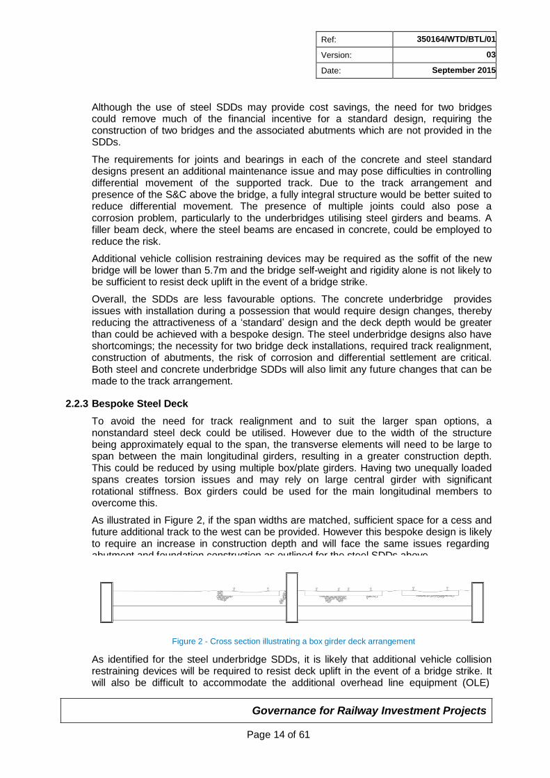
Box jacking would involve thrusting a precast concrete box unit through the embankment, with materials from the face removed through the box. This construction method would allow for the tracks to remain operational, albeit with a speed restriction, whilst the precast box is jacked through the embankment. No track replacement would be required.
Although a thinner roof slab could be achieved with this option compared to a portal frame structure, the concrete box would require sufficient cover to prevent interaction with the track above in order to jack through the embankment below the operational railway. It will also be difficult to work around the existing masonry arch bridge when jacking the box through the embankment. The arch could be demolished ahead of the box as it is driven through the embankment but it will be difficult to maintain sufficient stability of the arch to keep the railway above operational. High resistance forces are required to jack the box through the embankment meaning extensive temporary works would be required. Therefore this would not be a cost-effective solution, particularly when compared to a cut and fill construction.
The base of the box would need to be below the carriageway build up. Additional space is also necessary for the relocated services which would further increase the box height. The existing services will require diverting prior to the box-jacking operations being undertaken, which will not be possible without top-down excavation. Realistically, the large and deep buried services cannot be relocated inside the box and therefore they will be inaccessible for maintenance for the length of the jacked box. The variability of embankment fill would pose another risk to box-jacking operations; any weak ground encountered would need additional treatment to stabilise the surrounding soil which will also impact on the time taken to carry out the works.
Governance for Railway Investment Projects
Page 16 of 61
Ref: 350164/WTD/BTL/01
Version: 03
Date: September 2015
Figure 3 - Cross section of a jacked concrete box solution
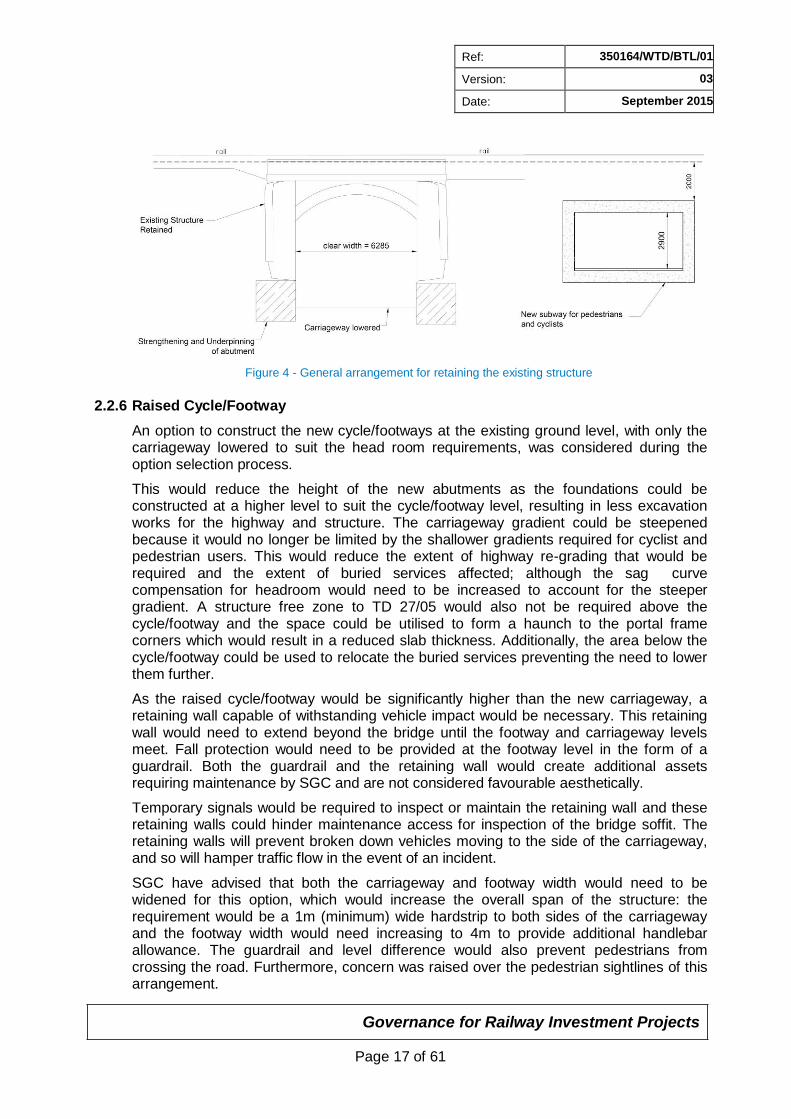
2.2.5 Re-use of Existing Structure
The existing structure is considered to be in fair condition with no significant works planned in the immediate future, therefore consideration has been made for retaining and reusing the existing masonry arch bridge.
The existing structure has insufficient headroom for the bus route, consequently the carriageway would need to be lowered to provide the necessary clearances. Without significant underpinning works, lowering of the road to provide the desired clear headroom would undermine the existing foundations and pose a risk to the stability of the existing structure. The minimum carriageway clear width of 14.5m could not be achieved if both existing abutments are retained.
An option for adding cycle/pedestrian subways adjacent to the existing structure was considered, but this has been discounted as the space available for the highway alignment due to land ownership constraints is insufficient to provide suitable access to an adjacent subway.
Utilising part of the existing structure was also considered by breaking down the existing arch bridge and using the abutments in conjunction with a con arch; however this was deemed unfavourable as the option is better suited for overbridges carrying highways, and are not appropriate for rail loading.
Neither of the above two options could be adapted to provide an additional designated bus lane.
The Detailed Examination Report (dated 22/05/2013) considers the existing structure to be in fair condition, although it is clear that the waterproofing has failed and bridge strikes do occur. The work to replace the waterproofing to the masonry arch could be extensive, and it is likely that the condition of the existing structure will continue to deteriorate. For this reason, and the construction risks discussed, re-use of the existing structure has been discounted.
Governance for Railway Investment Projects
Page 17 of 61
Ref: 350164/WTD/BTL/01
Version: 03
Date: September 2015
Figure 4 - General arrangement for retaining the existing structure
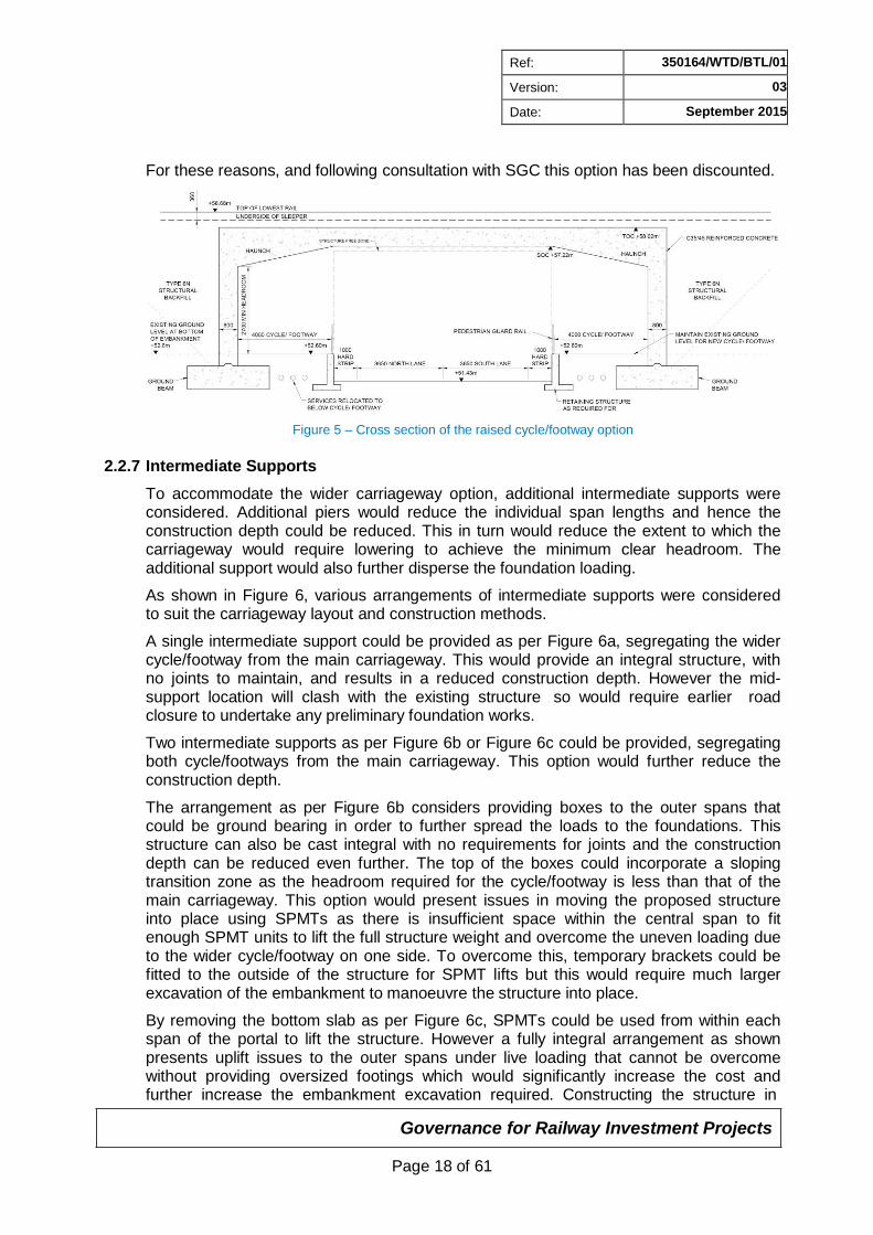
2.2.6 Raised Cycle/Footway
An option to construct the new cycle/footways at the existing ground level, with only the carriageway lowered to suit the head room requirements, was considered during the option selection process.
This would reduce the height of the new abutments as the foundations could be constructed at a higher level to suit the cycle/footway level, resulting in less excavation works for the highway and structure. The carriageway gradient could be steepened because it would no longer be limited by the shallower gradients required for cyclist and pedestrian users. This would reduce the extent of highway re-grading that would be required and the extent of buried services affected; although the sag curve compensation for headroom would need to be increased to account for the steeper gradient. A structure free zone to TD 27/05 would also not be required above the cycle/footway and the space could be utilised to form a haunch to the portal frame corners which would result in a reduced slab thickness. Additionally, the area below the cycle/footway could be used to relocate the buried services preventing the need to lower them further.
As the raised cycle/footway would be significantly higher than the new carriageway, a retaining wall capable of withstanding vehicle impact would be necessary. This retaining wall would need to extend beyond the bridge until the footway and carriageway levels meet. Fall protection would need to be provided at the footway level in the form of a guardrail. Both the guardrail and the retaining wall would create additional assets requiring maintenance by SGC and are not considered favourable aesthetically.
Temporary signals would be required to inspect or maintain the retaining wall and these retaining walls could hinder maintenance access for inspection of the bridge soffit. The retaining walls will prevent broken down vehicles moving to the side of the carriageway, and so will hamper traffic flow in the event of an incident.
SGC have advised that both the carriageway and footway width would need to be widened for this option, which would increase the overall span of the structure: the requirement would be a 1m (minimum) wide hardstrip to both sides of the carriageway and the footway width would need increasing to 4m to provide additional handlebar allowance. The guardrail and level difference would also prevent pedestrians from crossing the road. Furthermore, concern was raised over the pedestrian sightlines of this arrangement.
Governance for Railway Investment Projects
Page 18 of 61
Ref: 350164/WTD/BTL/01
Version: 03
Date: September 2015
For these reasons, and following consultation with SGC this option has been discounted.
Figure 5 – Cross section of the raised cycle/footway option
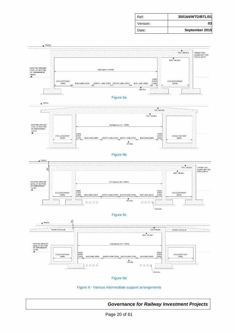
2.2.7 Intermediate Supports
To accommodate the wider carriageway option, additional intermediate supports were considered. Additional piers would reduce the individual span lengths and hence the construction depth could be reduced. This in turn would reduce the extent to which the carriageway would require lowering to achieve the minimum clear headroom. The additional support would also further disperse the foundation loading.
As shown in Figure 6, various arrangements of intermediate supports were considered to suit the carriageway layout and construction methods.
A single intermediate support could be provided as per Figure 6a, segregating the wider cycle/footway from the main carriageway. This would provide an integral structure, with no joints to maintain, and results in a reduced construction depth. However the mid- support location will clash with the existing structure so would require earlier road closure to undertake any preliminary foundation works.
Two intermediate supports as per Figure 6b or Figure 6c could be provided, segregating both cycle/footways from the main carriageway. This option would further reduce the construction depth.
The arrangement as per Figure 6b considers providing boxes to the outer spans that could be ground bearing in order to further spread the loads to the foundations. This structure can also be cast integral with no requirements for joints and the construction depth can be reduced even further. The top of the boxes could incorporate a sloping transition zone as the headroom required for the cycle/footway is less than that of the main carriageway. This option would present issues in moving the proposed structure into place using SPMTs as there is insufficient space within the central span to fit enough SPMT units to lift the full structure weight and overcome the uneven loading due to the wider cycle/footway on one side. To overcome this, temporary brackets could be fitted to the outside of the structure for SPMT lifts but this would require much larger excavation of the embankment to manoeuvre the structure into place.
By removing the bottom slab as per Figure 6c, SPMTs could be used from within each span of the portal to lift the structure. However a fully integral arrangement as shown presents uplift issues to the outer spans under live loading that cannot be overcome without providing oversized footings which would significantly increase the cost and further increase the embankment excavation required. Constructing the structure in
Governance for Railway Investment Projects
Page 19 of 61
Ref: 350164/WTD/BTL/01
Version: 03
Date: September 2015
separate spans would present further difficulties. Additional cranes would be required to lift the smaller outer spans into position or significant temporary works would be required to use SPMTs for the full lift.
The option to construct a central portal frame for the main carriageway and further box subways for the cycle/footways was also considered (Figure 6d). The main portal would be manoeuvred into position and the outer box subways lifted in sections using cranes. This arrangement would also allow the transition zone to be incorporated within the main structure envelope. The box subways could be ground bearing and the reduced portal size would also result in smaller foundations being required for the main span. However multiple lifts would be required to manoeuvre the box subways into position extending the construction time and the joints introduced could pose a maintenance issue. Consideration would need to be made to accommodate any differential settlement between the main portal frame and the outer box culverts.
Governance for Railway Investment Projects
Page 20 of 61
Ref: 350164/WTD/BTL/01
Version: 03
Date: September 2015
Figure 6a
Figure 6b
Figure 6c
Figure 6d
Figure 6 - Various intermediate support arrangements
Governance for Railway Investment Projects
Page 21 of 61
Ref: 350164/WTD/BTL/01
Version: 03
Date: September 2015
As per the raised cycle/footway option previously discussed, the introduction of intermediate supports would mean the carriageway and cycle/footway width would need to be increased to accommodate additional hardstrips and handlebar allowance. This, along with the width of the additional piers, will increase the overall size of the structure required. The constructability issues related to each option outlined above will also outweigh the benefits gained from the reduced construction depth.
Maintenance, inspection and repair works to the whole structure could not be undertaken from the cycle/footway if they are segregated from the main carriageway so road closure would be required. The intermediate piers will also restrict the opportunity for any future carriageway layout options and create additional buffer zones on the highway approach to the structure.
For these reasons and following further consultation with SGC and Network Rail, these options for providing intermediate supports have been discounted and a preference for a clear single span structure indicated.
Governance for Railway Investment Projects
Page 22 of 61
Ref: 350164/WTD/BTL/01
Version: 03
Date: September 2015
2.3 Bridge Structure Options Considered
A concrete portal frame structure was determined to be better suited for the bridge replacement. A portal frame can be precast and manoeuvred into position in order to significantly reduce the possession time required to replace the existing bridge structure. The potential availability of a pre-casting yard adjacent to the existing structure has made this option particularly viable.
A portal frame will provide an open base to suit the existing buried services and will not impede on future maintenance access. A cut and cover construction will permit shallow ballast depths which overall reduces the amount of road lowering needed to provide the required headroom below. A structure-free zone must be provided above the full carriageway, including the cycle/footway, so a haunch cannot be used to further reduce the construction depth.
Concrete structures are more durable and therefore require less maintenance. A plain, smooth concrete finish is considered desirable to SGC.
This arrangement has been further developed into six main options for consideration. These incorporate different carriageway arrangements and different alignments of the structure relative to the track. These options have been summarised in the matrix found in Table 1 in Section 2.19. The matrix table has been used to evaluate each option and aid selection of the preferred option.
2.3.1 Option 1 – No Bus Lane (skewed to the track)
Option 1 is to provide a precast reinforced concrete portal frame structure with a 14.5m clear span and an 11° skew to the track alignment. The proposed abutments are parallel to the carriageway and provide clear width for a 7.5m single carriageway with 3.5m wide cycle/footways either side. For analysis purposes, the effective span of the portal frame 15.5m.
Due to the skew to the track, transition slabs will be required for each track to limit track movement due to any differential settlement. Separate transition slabs will be provided for each track with a 1:30 crossfall towards the cess to facilitate drainage.
Refer to drawing number MMD-350164-C-DR-GP-XX-0011 in Appendix A for further details.
This proposal is the smallest option and therefore has the least materials required, less cut and fill and the least spoil to remove. The smaller span allows for a thinner slab which reduces the overall construction depth and the extent to which the road will require lowering. Therefore this option will have the least impact on the existing buried services.
The proposed alignment of the abutments allows for the wing walls to also be aligned parallel to the carriageway and they could be integral with the main structure. However, the reduced span will pose construction issues as the envelope of the new structure will clash with that of the existing masonry arch bridge making it difficult to commence any construction, such as preliminary foundation works, prior to demolition or without temporary works.
This option does not provide sufficient clear width to achieve a carriageway layout with a designated bus lane(s).
Governance for Railway Investment Projects
Page 23 of 61
Ref: 350164/WTD/BTL/01
Version: 03
Date: September 2015
2.3.2 Option 2 – Single Bus Lane (skewed to the track)
With this option it is proposed to provide a precast reinforced concrete portal frame structure with a clear 18.7m span and an 11° skew to the track alignment. The proposed abutments are parallel to the carriageway and provide clear width, sufficient to provide a 7.5m single carriageway plus a 4.2m designated bus lane with 3.5m wide cycle/footways either side. For analysis purposes, the effective span of the portal frame is 20.5m.
As per option 1, transition slabs will be required for each track to limit track movement due to any differential settlement. Due to the wider span of the structure, the new bridge abutment will be located closer to the crossing point of the central track S&C. As this is more sensitive, the transition slab will need to be extended past the crossing in order to reduce movement of the track at the crossing point.
Refer to drawing number MMD-350164-C-DR-GP-XX-0012 in Appendix A for further details.
This option provides sufficient width for a designated bus lane whilst keeping the overall structural envelope to a minimum. By aligning the abutments with the carriageway, no redundant areas are created and, as with option 1, the wing walls can be aligned parallel to the carriageway and constructed as part of the main structure.
The increased span will require a thicker slab so the overall construction depth will be increased. The road level will need to be lowered accordingly to provide the necessary headroom which will result in a greater length of the existing road needing reconstruction in order to tie into the existing highway alignment. This will result in a greater impact on the existing services.
The alignment of the proposed carriageway should be carefully considered for this option. Currently two alignments have been proposed by CH2M with the additional bus lane located on either the north or the south side of the main carriageway. Providing the bus lane on the north side of the main carriageway results in the proposed south abutment and wing wall clashing with the existing bridge. This will limit any work that can be undertaken prior to demolition. If the bus lane is located on the south side, then the proposed structure should be sufficiently clear of the existing bridge to undertake preliminary foundation works.
2.3.3 Option 3 – No Bus Lane (square to the track)
Option 3 is to provide a precast reinforced concrete portal frame structure with a 19.5m clear span, square to the track alignment. To provide a structure square to the track alignment, the abutments will be skewed to the carriageway alignment by 11°. This option provides a clear carriageway width of 14.5m which is sufficient for a 7.5m single carriageway and 3.5m wide cycle/footways either side.
Providing a structure that is square in relation to the track alignment is the preferred option with regard to track sensitivity. It ensures that the support to the track is uniform across the width of the sleepers and the risk of issues arising from differential settlement is reduced. However, a larger structure is required to ensure sufficient clearance is provided for the carriageway whilst maintaining the straight alignment to the track. This will move the proposed abutments closer to the crossing of the S&C. Due to the sensitivity of the S&C to track movement, it is likely that a transition slab will still be required despite the abutment being square to the track. The transition slab will need to extend past the crossing point to accommodate the tighter tolerances on this track.
Governance for Railway Investment Projects
Page 24 of 61
Ref: 350164/WTD/BTL/01
Version: 03
Date: September 2015
Refer to drawing number MMD-350164-C-DR-GP-XX-0013 in Appendix A for further details.
This proposal has a greater span but does not gain any additional clear width available for the carriageway. However, this greater span does result in the proposed structure being sufficiently clear of the existing masonry arch bridge to allow for preliminary foundation works to be undertaken prior to demolition of the existing structure.
The larger span and angle of the structure creates redundant areas which can become a maintenance issue. A thicker slab is needed to achieve the larger span therefore a lower road level will be required, having a greater impact on the existing services.
With this proposed arrangement it will not be possible to align the wing walls with the abutments as they would impede on the carriageway alignment. Greater excavation of the embankment will be required to drive a portal frame with skewed wing walls into place. Skewed abutments in relation to the highway alignment are not desired as they are aesthetically unpleasant to the travelling public at road level.
2.3.4 Option 4 – Single Bus Lane (square to the track)
This option is to provide a precast reinforced concrete portal frame structure with a 23.44m clear span, square to the track alignment. As with option 3, in order for the structure to be square to the track alignment, the abutments will be skewed to the carriageway alignment by 11°. This option provides a clear width for a carriageway of 18.7m which is sufficient for a 7.5m single carriageway, 4.2m designated bus lane and 3.5m wide cycle/footways either side.
As with option 3, the alignment of the structure is most suitable to reduce the risk of differential settlement, however the much larger span will result in the abutments being located below the sensitive track crossing and therefore a transition slab will still be required below this track. The transition slab will need to extend past the crossing point in order to accommodate the tighter tolerances of the S&C track.
Refer to drawing number MMD-350164-C-DR-GP-XX-0014 in Appendix A for further details.
As with option 3, the angle of the structure also creates redundant areas which can become a maintenance issue. The additional span length ensures sufficient clearance to the existing structure to facilitate undertaking early foundation works.
This option presents a larger structure than option 2 and therefore it will require more materials, greater excavation and larger volume of spoil to be removed but does not benefit from any additional carriageway space. The longer span will require a thicker slab and therefore further lowering of the existing road level below to maintain the existing track level. The extent of the road lowering and the additional span will have a much greater impact on the existing services.
The envelope of the structure comes close to the Network Rail and SGC land ownership boundaries and it is likely that excavations to construct the new structure will extend outside of the land ownership boundaries.
As with option 3, the wing walls cannot be aligned with the abutments as there is not sufficient clearance to the carriageway so greater excavation of the embankment will be required to drive a portal frame with skewed wing walls into place. Skewed abutments in relation to the highway alignment are not desired as they are aesthetically unpleasant to the travelling public at road level.
Governance for Railway Investment Projects
Page 25 of 61
Ref: 350164/WTD/BTL/01
Version: 03
Date: September 2015
2.3.5 Option 5 – Dual Bus Lane (skewed to track)
This option is to provide a precast reinforced concrete portal frame structure with a 24.4m clear span and an 11° skew to the track alignment. The proposed abutments are parallel to the carriageway and provide clear width for a 7.5m single carriageway plus a 4.2m designated bus lane with a 3.5m cycle/footway to the north and a 4.2m designated bus lane with a 5.0m cycle/footway to the south. For analysis purposes, the effective span of the portal frame is 24.8m.
As per options 1 and 2, transition slabs will be required for each track to limit track movement due to any differential settlement as a result of the skewed alignment. Due to the wider span, the abutments will be located below the S&C and as such the transition slabs will need to extend past the crossing to reduce movement in the sensitive mechanisms.
Refer to drawing number MMD-350164-C-DR-GP-XX-0015 in Appendix A for further details.
This option provides sufficient width for two designated bus lanes and wider shared cycle/footway to the south, whilst minimising the overall structural envelope required. As with option 1 and 2, the wing walls can be aligned parallel to the carriageway and constructed as part of the main structure.
The envelope of the structure comes close to the Network Rail and SGC land ownership boundaries and it is likely that the carriageway will exceed the SGC ownership boundaries on the approach to the bridge. It is anticipated that excavations to construct the new structure will need to extend outside of the land ownership boundaries.
2.3.6 Option 6 – Dual Bus Lane (square to track)
This option is to provide a precast reinforced concrete portal frame structure with a 29.3m clear span, square to the track alignment. As with options 3 and 4, to accommodate a structure square to the track alignment, the abutments will be skewed to the carriageway alignment by 11°. This option provides a clear width for a carriageway of 24.4m which is sufficient for a 7.5m single carriageway plus a 4.2m designated bus lane with a 3.5m cycle/footway to the north and a 4.2m designated bus lane with a 5.0m cycle/footway to the south.
As with options 3 and 4, the alignment of the structure is most suitable to reduce the risk of differential settlement, however the much larger span results in the abutments being located directly below the sensitive track crossing. Therefore a transition slab will still be required to extend past the S&C in order to accommodate the tighter settlement tolerances for this track.
Refer to drawing number MMD-350164-C-DR-GP-XX-0016 for further details.
This option presents the largest structure therefore it will require the greatest space, most materials, greater excavation and larger volume of spoil to be removed. The longer span will require the thickest slab and therefore the most lowering of the existing road level below to maintain the existing track level. The extent of the road lowering and wider span will have the greatest impact on the existing services.
As with options 3 and 4 the wing walls cannot be aligned with the abutments as there is not sufficient clearance to the carriageway so greater excavation of the embankment will be required to drive the portal frame into place. As previously discussed, this wing wall arrangement is not preferable aesthetically to the travelling public at road level.
Governance for Railway Investment Projects
Page 26 of 61
Ref: 350164/WTD/BTL/01
Version: 03
Date: September 2015
2.4 Wing Wall Options
Two types of wing wall construction have been considered during the option selection process: sheet piles or reinforced concrete wing walls. These could either be straight and aligned with the bridge abutments, or splayed. Refer to drawing number MMD- 350164-C-DR-GP-XX-0021 in Appendix A for further details. Gabion wing walls were also considered however they would require more excavation, slower construction and present a maintenance issue so this option was discarded.
Sheet pile wing walls could be utilised to create a clear worksite and reduce the amount of excavation required and the extent of backfilling. They could be installed in smaller possessions if necessary, ahead of the main construction works. Some pre-auguring may be required due to the mudstone bearing strata. The sheet piles would require some form of facing or cladding to improve their appearance and suit SGC’s preference for concrete finish. This would hide the structural element, which is not preferable for Network Rail as it presents access issues for their inspection and maintenance regime.
Reinforced concrete wing walls can be pre-cast either as part of the main portal bridge structure or separately. They will require further excavation and backfilling to construct but will suit SGC’s preferences for a plain smooth concrete finish whilst remaining easily accessible for Network Rail’s inspection and maintenance regime.
Splayed wing walls will take up a larger area and hence will require more excavation (and backfilling if constructed from concrete), however they are generally preferred aesthetically by public users as they differentiate between the main bridge abutment and the ground retaining wing wall. Splayed wing walls will need to be much longer in order to accommodate the existing ground topography which will result in greater cost and construction time. This will also result in the wing walls clashing with the existing pill box and they may begin to impede on the nearby buildings such as the local business to the north west and residential garden to the south east. For the larger bridge spans, this arrangement may extend past the current Network Rail and SGCs land ownership boundaries.
Straight wing walls, in line with the bridge abutments, will take up much less space and a shorter length is required to retain the existing embankment.
Any reduction in the main possession time from constructing sheet piled wing walls is expected to be relatively small and hence it is recommended that the wing walls are constructed from precast concrete and cast integral with the main bridge structure. This will allow for the entire structure to be lifted and moved into position together. Straight wing walls, in-line with the abutments will be most suitable for lifting with the main bridge structure. If splayed wing walls are preferred or necessary due to the bridge alignment, greater excavation of the embankment will be required to drive a portal frame with skewed wing walls into place. Alternatively the wing walls can be precast separately or cast in-situ and connected to the main bridge structure after it has been positioned, however this will increase the construction timing and may impact on the re-opening of the line.
2.5 Foundation Options
Given that the demolition of the existing structure and installation of the precast portal frame will be required to be completed under an abnormal 100 hour possession, construction of piled foundations along the length of the abutments during the possession is not considered to be feasible due to the construction time.
Governance for Railway Investment Projects
Page 27 of 61
Ref: 350164/WTD/BTL/01
Version: 03
Date: September 2015
As the foundation will need to be incorporated with the other construction activities to be undertaken within the limited possession time available, it is considered that precast strip footings would be the preferred foundation option for the portal frame structure due to the speed and ease of construction, and the fact that the portal frame can also be slid into place and form an integral unit with the strip footings.
However, it is uncertain whether the foundation is to be founded on the firm to stiff clay layer or the underlying Blue Lias mudstone/limestone formation due to the variation in the historical borehole logs, with the mudstone/limestone stratum encountered at between 47.54 and 49.52m AOD.
In the absence of more accurate soil information, the foundation has been designed to be founded on firm to stiff clay at this stage of the scheme and therefore some form of ground improvement or piled supports to be constructed offline will be required in order to provide the bearing resistance required for the new structure.
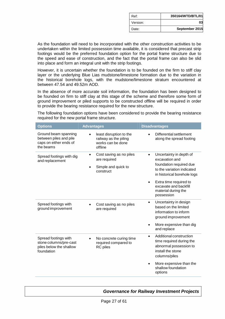
The following foundation options have been considered to provide the bearing resistance required for the new portal frame structure.
Options Advantages Disadvantages
Ground beam spanning between piles and pile caps on either ends of the beams
Spread footings with dig and replacement
Spread footings with ground improvement
Spread footings with stone columns/pre-cast piles below the shallow foundation
least disruption to the
railway as the piling works can be done offline
Cost saving as no piles
are required
Simple and quick to construct
Cost saving as no piles are required
No concrete curing time required compared to RC piles
Differential settlement
along the spread footing
Uncertainty in depth of
excavation and
foundation required due
to the variation indicated
in historical borehole logs
Extra time required to excavate and backfill material during the possession
Uncertainty in design
based on the limited
information to inform
ground improvement
More expensive than dig and replace
Additional construction
time required during the
abnormal possession to
install the stone
columns/piles
More expensive than the shallow foundation options
Governance for Railway Investment Projects
Page 28 of 61
Ref: 350164/WTD/BTL/01
Version: 03
Date: September 2015
Options Advantages Disadvantages
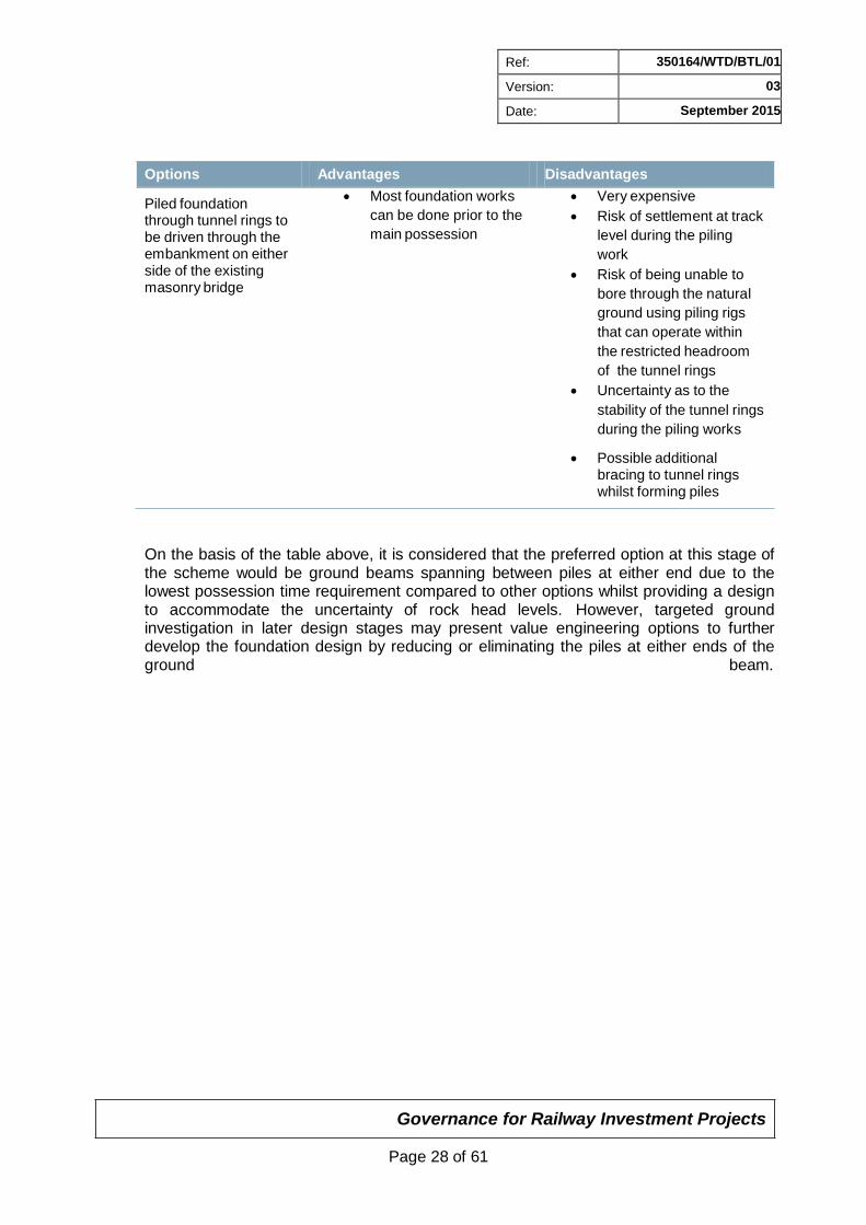
Piled foundation through tunnel rings to be driven through the embankment on either side of the existing masonry bridge
Most foundation works
can be done prior to the
main possession
Very expensive
Risk of settlement at track
level during the piling
work
Risk of being unable to
bore through the natural
ground using piling rigs
that can operate within
the restricted headroom
of the tunnel rings
Uncertainty as to the
stability of the tunnel rings
during the piling works
Possible additional bracing to tunnel rings whilst forming piles
On the basis of the table above, it is considered that the preferred option at this stage of the scheme would be ground beams spanning between piles at either end due to the lowest possession time requirement compared to other options whilst providing a design to accommodate the uncertainty of rock head levels. However, targeted ground investigation in later design stages may present value engineering options to further develop the foundation design by reducing or eliminating the piles at either ends of the ground beam.
Governance for Railway Investment Projects
Page 29 of 61
Ref: 350164/WTD/BTL/01
Version: 03
Date: September 2015
2.6 Works Not Requiring Option Selection
Areas which do not require option selection are outlined below:
2.6.1 Track Alignment
Network Rail have advised that the track construction in the areas around Gipsy Patch Lane Bridge has recently been replaced and some of the S&C track is modular. As such, the existing track is to be reinstated to the same line and level as existing following the construction of the new bridge. There are no further known track works proposed in the vicinity of the bridge.
2.6.2 Headroom
In accordance with NR/L3/CIV/020, in the design of new spans over highways the headroom from the soffit should be not less than 5.3m and at least 5.7m “where this can be achieved with reasonable economy”. Providing 5.7m headroom below the replacement structure will require extensive lowering of the existing carriageway which will have a significant impact on the existing buried services under the bridge and the length of the carriageway that will need regrading. Major diversion of the multiple services and the extensive works required to tie the lowered carriageway in with the existing highway is not considered achievable without unreasonable cost.
Therefore the minimum highways requirement of 5.3m + allowance for sag will be adopted. This is an improvement on the existing structure and in line with the requirements of TD27/05. As this is less than 5.7m the superstructure will need to be designed for vehicle collision loads as per NR/L3/CIV/020 cl 9.11.2.
Following consultation with the Structures Route Asset Manager (RAM) at Network Rail, as a result of the design having 5.3m + sag headroom, it was identified that additional mitigation is required to prevent projectiles landing within the railway kinematic envelope in the event of a bridge strike. It is proposed that this is addressed by providing parapets to act as a sufficient barrier as outlined below.
2.6.3 Parapets
The parapets will be constructed from precast reinforced concrete and installed after the main bridge structure has been constructed and driven into place. The parapets could be precast with the main portal frame but this would increase the overall height of the structure so it may impede on the temporary cable bridge supporting services at track level.
The parapets will need to be capable of preventing any debris from a bridge strike at highway level being thrown forward into the train envelope. To further allow for this the parapets will be 1.25m above rail level, this is also higher than the parapet level of the current structure so is an overall improvement in terms of protection of the railway.
2.6.4 Drainage and Waterproofing
A trackbed investigation was undertaken by URS prior to track renewals in 2013/2014. The investigation found that the trackbed drainage was poor and recommended that a full lineside drainage system be installed and tied in with the proposed track bed design. It is not clear if this was provided as part of the track bed renewal works, but it is
Governance for Railway Investment Projects
Page 30 of 61
Ref: 350164/WTD/BTL/01
Version: 03
Date: September 2015
recommended that cess drainage be provided as part of the track replacement works for the construction of the new bridge.
In order to prevent build-up of pore water pressure behind the new abutments, drainage should be provided at the bottom of the abutments, running the full width of the portal frame and wing walls. Design should consider discharge of this drainage into the existing highways surface water system however it should be noted that this will need to be allowed for in the carriageway pump capacity and drainage being installed as part of the highways design.
Waterproofing of the proposed bridge structure should be provided to suit requirements of NR/L3/CIV/041. It is proposed to provide two layers of bituminous paint to all buried faces. It is anticipated that the entire structure can be cast integral without any joints so special waterproofing around joints will not be required for the main structure. If transition slabs are required, the waterproofing should extend over the transition slab and waterproof buried joints should be provided between the transition slab and bridge abutments.
2.6.5 Width of Bridge
It is proposed to replace the existing bridge with a structure of the same width in order to suit the existing track and embankment alignment. The proposed bridge will follow the same alignment as the existing parapets and track is to be reinstated to the same alignment.
The existing arrangement provides sufficient room for a place of safety to the east side of the tracks and a larger, mostly redundant area to the west, sufficient to provide a safe cess walkway.
It is anticipated that an overhead line equipment (OLE) gantry will be located on the bridge as part of the GWEP which could impede on the place of safety to the east of the track. There is the opportunity as part of the GRIP 3 process to consider the bridge alignment to ensure sufficient room is provided for a cess walkway to the east of the track after the OLE gantry is installed without significant impact on the design or cost.
The mostly redundant area to the west of the tracks will be retained to avoid major realignment of the embankment and retain the available width at track level. Whilst no further track works have been identified for this area, this will also maintain potential growth opportunities for the route. As such, the proposed replacement structure will be designed to accommodate loading from an additional track.
2.6.6 Finishing Works
There is no requirement for additional lighting to be provided to the finished structure. All exposed concrete surfaces are to receive a plain, smooth finish with an anti-graffiti coating.
The carriageway will be reinstated in accordance with the highways design following the bridge construction.
2.6.7 Foundation Connection
The ground beams will be constructed integral with the portal frame and lifted onto the pile caps. A shear key can be provided if the friction between the ground beam and the pile cap or ground is not sufficient to resist the lateral loading.
Governance for Railway Investment Projects
Page 31 of 61
Ref: 350164/WTD/BTL/01
Version: 03
Date: September 2015
2.7 Constructability Assessment
2.7.1 Construction Sequence
The design options for the replacement bridge structure have been developed alongside a proposed construction sequence in order to limit the impact on the operational route and highway traffic as far as reasonably practicable during the works.
The highway works are being designed by CH2M and are not included in the below construction procedure unless pertinent to the bridge design.
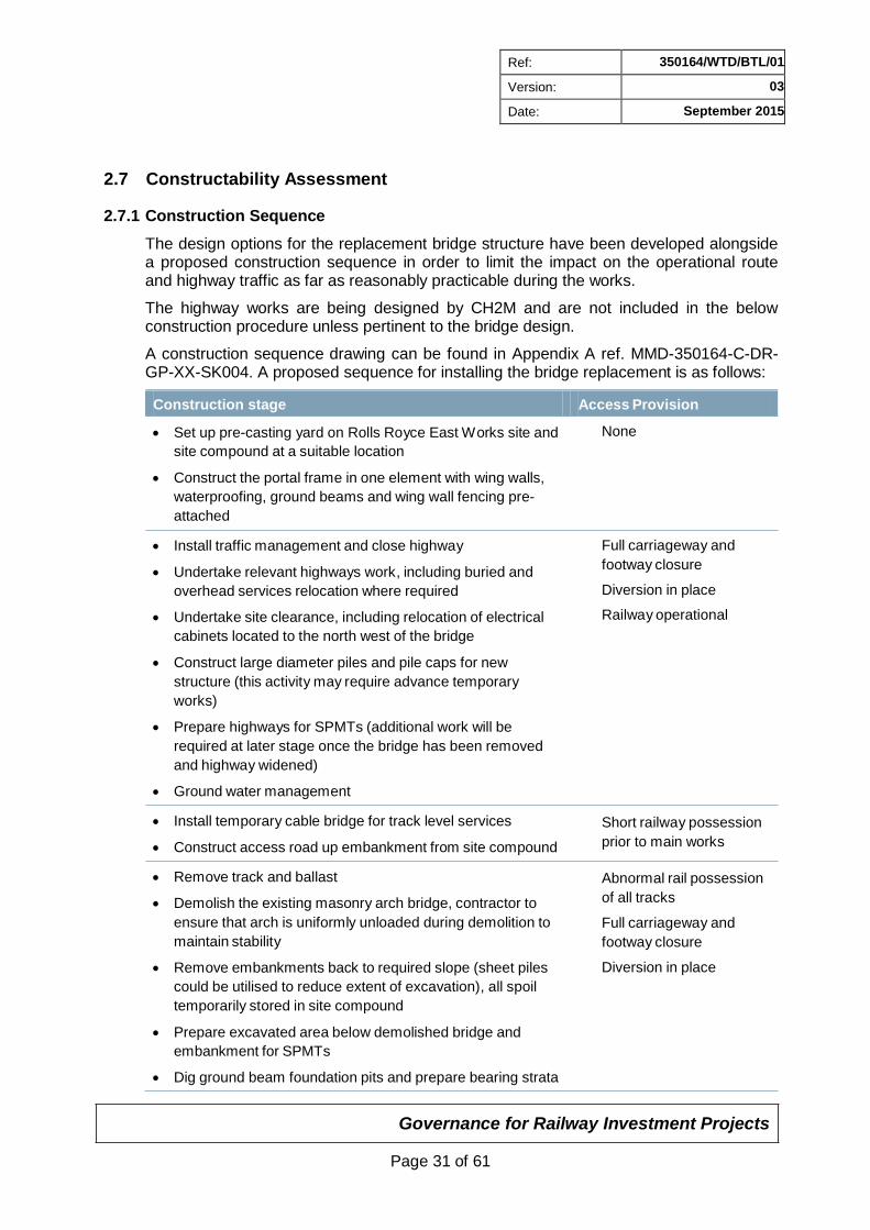
A construction sequence drawing can be found in Appendix A ref. MMD-350164-C-DR- GP-XX-SK004. A proposed sequence for installing the bridge replacement is as follows:
Construction stage Access Provision
Set up pre-casting yard on Rolls Royce East Works site and
site compound at a suitable location
Construct the portal frame in one element with wing walls,
waterproofing, ground beams and wing wall fencing pre-
attached
Install traffic management and close highway
Undertake relevant highways work, including buried and
overhead services relocation where required
Undertake site clearance, including relocation of electrical
cabinets located to the north west of the bridge
Construct large diameter piles and pile caps for new
structure (this activity may require advance temporary
works)
Prepare highways for SPMTs (additional work will be
required at later stage once the bridge has been removed
and highway widened)
Ground water management
Install temporary cable bridge for track level services
Construct access road up embankment from site compound
Remove track and ballast
Demolish the existing masonry arch bridge, contractor to
ensure that arch is uniformly unloaded during demolition to
maintain stability
Remove embankments back to required slope (sheet piles
could be utilised to reduce extent of excavation), all spoil
temporarily stored in site compound
Prepare excavated area below demolished bridge and
embankment for SPMTs
Dig ground beam foundation pits and prepare bearing strata
None
Full carriageway and
footway closure
Diversion in place
Railway operational
Short railway possession
prior to main works
Abnormal rail possession
of all tracks
Full carriageway and
footway closure
Diversion in place
Governance for Railway Investment Projects
Page 32 of 61
Ref: 350164/WTD/BTL/01
Version: 03
Date: September 2015
Construction stage Access Provision
Move portal frame into location using SPMTs, legs of portal
frame to be propped during transport
Backfill bridge and regrade embankment slopes using type
6N structural fill, compacted as required
Lift and install pre-cast transition slabs
Install embankment and track drainage
Lift in precast parapets and guardrails (if not constructed
integral with the main bridge structure)
Reinstate bridge deck services and remove temporary
cable bridge
Re-lay ballast and tracks
Finish embankments profile, apply top soil and seeding
Reinstate services
Undertake carriageway works, including re-profiling the
road and new cycle/footway
Demobilise site and return highway to local authority
Full carriageway and
footway closure
Diversion in place
Railway operational
2.7.2 SPMTs
A number of self-propelled modular transporter units (SPMTs) will be utilised to support and lift the pre-cast portal frame into place. The SPMTs as a whole are capable of turning around its centre and moving sideways.
They can move over a variety of surfaces provided the bearing capacity is great enough;
loading is likely to be in the order of 10 tonnes/m2 or less. For fill material a trackway is required to prevent the wheels from digging into the fill. If required, the trackway, timber mats or a geocell system can be utilised to further spread the loading and protect buried services below.
One of the major advantages of using SPMTs is the ability to lift a whole structure into place without the needs for joints; as a result many potential maintenance problems can be avoided such as hidden details and waterproofing issues.
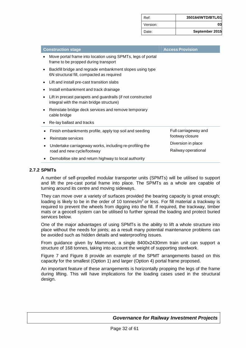
From guidance given by Mammoet, a single 8400x2430mm train unit can support a structure of 168 tonnes, taking into account the weight of supporting steelwork.
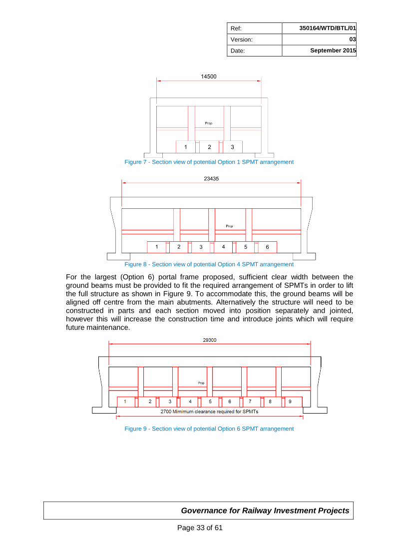
Figure 7 and Figure 8 provide an example of the SPMT arrangements based on this capacity for the smallest (Option 1) and larger (Option 4) portal frame proposed.
An important feature of these arrangements is horizontally propping the legs of the frame during lifting. This will have implications for the loading cases used in the structural design.
Governance for Railway Investment Projects
Page 33 of 61
Ref: 350164/WTD/BTL/01
Version: 03
Date: September 2015
Figure 7 - Section view of potential Option 1 SPMT arrangement
Figure 8 - Section view of potential Option 4 SPMT arrangement
For the largest (Option 6) portal frame proposed, sufficient clear width between the ground beams must be provided to fit the required arrangement of SPMTs in order to lift the full structure as shown in Figure 9. To accommodate this, the ground beams will be aligned off centre from the main abutments. Alternatively the structure will need to be constructed in parts and each section moved into position separately and jointed, however this will increase the construction time and introduce joints which will require future maintenance.
Figure 9 - Section view of potential Option 6 SPMT arrangement
Governance for Railway Investment Projects
Page 34 of 61
Ref: 350164/WTD/BTL/01
Version: 03
Date: September 2015
2.7.3 Construction Risks
The key construction risks that have been identified are:
• The existing water table (+50.87m) is within the construction zone, and must be considered for foundation design and construction
• Completion of the necessary works within the possession time
• The use of SPMTs is an innovative construction method
• The instability of the existing structure. Although the visible bridge structure appears in fair condition, the soffit could not be inspected due to steel sheeting. Later design stages must ensure the demolition sequence is fully considered.
For the full project hazard log see Appendix B.
2.7.4 Site Compound
During the works it is anticipated that the site compound will require:
• Area for casting of the portal frame and associated works (75m x 75m = 5625m2)
• Site offices, welfare and parking – 5625m2
• Spoil storage – 5625m2
Considerations for the selection of the site compound(s) should include:
• Casting of the portal frame should be carried out close to the site to limit the route of the SPMTs
• Mains water provision will be required
• Site access and impact on residents
• Haulage availability to remove spoil during proposed works
• Walking distance from site to the welfare facilities
The contractor is to confirm exact site requirements at a later GRIP Stage.
For option 6 it should be noted that a relatively larger area will be required for the pre- casting area and spoil storage.
2.7.5 Fence and Boundary Review
As part of the works the Network Rail boundary fences will require temporary removal local to the works. This includes all fencing along the wing walls and to a distance along the embankment sufficient to allow for the bridge widening and access for the works.
The widening of the highway will also require the removal of an access gate for electrical cabinets on the north west of the bridge. This is to be reinstated to suit the relocated electrical cabinets.
New wing wall fencing is to be installed as part of the proposed works.
Private fencing will also be affected by the works, with the extent also dictated by the highway works.
Governance for Railway Investment Projects
Page 35 of 61
Ref: 350164/WTD/BTL/01
Version: 03
Date: September 2015
Private fencing will also be affected by the works, with the extent also dictated by the highway works.
The private boundary to the north west of the bridge should be maintained during the works, due to the proximity of the property to the fence line. The fence line should be protected as necessary throughout the works.
The Rolls Royce East Works site, road side and rail side boundary fence will be removed as part of the works with the length of the removal to allow for provision of an access route up the embankment to the track level and for the SPMT route.
Trees along the road and in proximity to the slope will also require removal and this is detailed further in the Environmental Impact Assessment in Section 7.
For details for the existing fence and boundary refer to Existing General Arrangement drawing re MMD-350164-C-DR-GP-XX-0002 in Appendix A.
2.8 Access and Possession Strategy
It is anticipated that an abnormal, up to 100 hour possession will be required to undertake the bridge replacement works and reinstate the track.
The large diameter piles and pile caps will be constructed ahead of the main works. These may need to be carried out in smaller possessions prior to the main possession works.
Monitoring and re-tamping of the track will be required following the works and therefore a temporary speed restriction may be required in the period immediately after the construction works.
Gipsy Patch Lane will require closure to undertake the associated highway works, bridge construction and lowering of the carriageway to suit the new bridge. It is anticipated that the highway works will take significantly longer than the construction time required for the bridge replacement. Ideally all the works should be undertaken with one closure as the closure of Gipsy Patch Lane will require long diversion routes and will impact on local businesses, traffic on other highways and local commuting times.
2.9 Project Schedule
GRIP 3 Form F001 AIP is programmed to follow on directly from the option selection stage.
GRIP 4-5 are programmed to be undertaken in 2016/2017/2018 with GRIP 6 following in 2018/2019 and GRIP 7-8 is planned for 2019/2020 in line with the overall Cribbs MetroBus Extension Programme (dated February 2015).
2.10 Whole Life Cost Assessment of Options
The Whole Life Cost Assessment of this Grip level 3 quantified estimate, for each of the 6 options, provides a bespoke analysis of which option has the better combined future renewal cost, operation cost and maintenance cost over a 60 year period.
Renewal costs comprise the predicted cost of renewing the structure.
Operation cost in this case are considered to be any costs associated with the planning of the repairs, inspections and maintenance.
Governance for Railway Investment Projects
Page 36 of 61
Ref: 350164/WTD/BTL/01
Version: 03
Date: September 2015
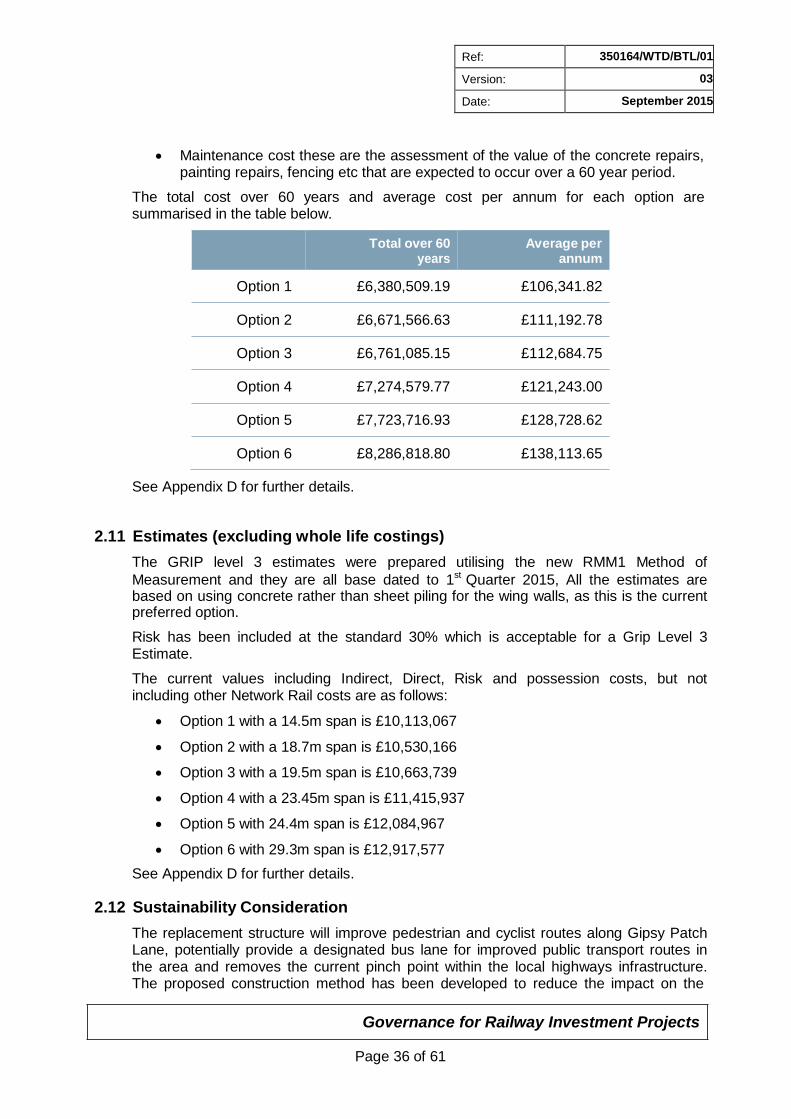
Maintenance cost these are the assessment of the value of the concrete repairs, painting repairs, fencing etc that are expected to occur over a 60 year period.
The total cost over 60 years and average cost per annum for each option are summarised in the table below.
Total over 60 years
Average per annum
Option 1 £6,380,509.19 £106,341.82
Option 2 £6,671,566.63 £111,192.78
Option 3 £6,761,085.15 £112,684.75
Option 4 £7,274,579.77 £121,243.00
Option 5 £7,723,716.93 £128,728.62
Option 6 £8,286,818.80 £138,113.65
See Appendix D for further details.
2.11 Estimates (excluding whole life costings)
The GRIP level 3 estimates were prepared utilising the new RMM1 Method of
Measurement and they are all base dated to 1st Quarter 2015, All the estimates are based on using concrete rather than sheet piling for the wing walls, as this is the current preferred option.
Risk has been included at the standard 30% which is acceptable for a Grip Level 3 Estimate.
The current values including Indirect, Direct, Risk and possession costs, but not including other Network Rail costs are as follows:
Option 1 with a 14.5m span is £10,113,067
Option 2 with a 18.7m span is £10,530,166
Option 3 with a 19.5m span is £10,663,739
Option 4 with a 23.45m span is £11,415,937
Option 5 with 24.4m span is £12,084,967
Option 6 with 29.3m span is £12,917,577
See Appendix D for further details.
2.12 Sustainability Consideration
The replacement structure will improve pedestrian and cyclist routes along Gipsy Patch Lane, potentially provide a designated bus lane for improved public transport routes in the area and removes the current pinch point within the local highways infrastructure. The proposed construction method has been developed to reduce the impact on the
Governance for Railway Investment Projects
Page 37 of 61
Ref: 350164/WTD/BTL/01
Version: 03
Date: September 2015
operational railway whilst also creating opportunities to incorporate sustainable targets into the design and construction.
The largest options, whilst providing sufficient width for two designated bus lanes and a wider cycle/footway, will require demolition of the existing pill box located to the north west of the existing structure.
Pre-casting the portal frame adjacent to the final location reduces the transporting distance once assembled and an efficient work site can reduce the amount of waste created. The contractor should look to use BES 6001 accredited and locally sourced materials where reasonably practicable.
Concrete is a durable material with a long design life resulting in low maintenance costs and disruptions. At the end of life, all cured concrete and reinforcing steel waste can be recycled to create new construction materials.
To assist in evaluating each of the options a carbon footprint calculation was undertaken to estimate and compare the amount of embodied carbon in each of the six options. Embodied carbon is the amount of carbon released during the production and processing of materials. This has been calculated by taking the quantities of each material used and multiplying it by its embodied carbon coefficient. The embodied carbon coefficients have been taken from the Inventory of Carbon & Energy database. Full results can be found in Appendix H. The carbon footprint calculation has only included the embodied carbon for the materials used in the construction of the bridge replacements; it does not capture the temporary works, highway works or construction activities. The amount of embodied carbon from the Carbon Crunch calculations for each option is as follows and is measured in tonnes of carbon dioxide equivalents:
Option 1 with no lane = 914.6 tCO2e
Option 2 with single bus lane = 1039.4 tCO2e
Option 3 with no bus lane = 1110.7 tCO2e
Option 4 with single bus lane = 1412.9 tCO2e
Option 5 with dual bus lane = 1595.0 tCO2e
Option 6 with dual bus lane = 1980.5 tCO2e
2.13 Diversity Impact Assessment
The diversity impact assessment has highlighted the positive impact this project will have through the provision of inclusive travel routes. This is one of the fundamental drivers of the project which will include a cycleway and footway wide enough to allow many different users to feel safe and comfortable using the cycle/footway. A full Diversity Impact Assessment for the proposed options can be found in 350164/WTD/BTL/06, which is submitted as a standalone document to Network Rail.
2.14 QRA
A risk workshop has been undertaken and a quantitative risk assessment conducted by Network Rail. The critical risks that may lead to significant additional costs and/or programme delays are summarised below:
Interface between the highway and rail designs giving rise to the risk of design errors/delays and costs
Governance for Railway Investment Projects
Page 38 of 61
Ref: 350164/WTD/BTL/01
Version: 03
Date: September 2015
Protracted negotiation of implementation agreement due to lack of understanding between parties
The unavailability of land owned by third parties for the site compound
Unsuitable ground conditions preventing the bridge from being constructed on the compound site or requiring improvements to be made
Damage to buried/overhead utilities
The presence of invasive species such as Japanese knotweed which require removal
Delays caused by elongated internal procedures between NR and SGC
Discovery of unexploded ordnance on the site as a left over from historic WW2 bombing of the area
Refer to Appendix C for the complete risk register. 2.15 Risk Register
The key risks and their impacts are as follows:
Stability of the existing structure and embankment during demolition
Ground water level
Completion of works within possession time
The full project hazard log can be found in Appendix B.
2.16 Assumptions
The following has been assumed:
The findings of the Detailed Examination Report are valid and the existing structure is in fair condition
There is sufficient slack in the signal and telecommunication (S&T) cables and that they will not be cut as part of works and temporary cable bridge will be provided
2.17 Signed Design Compliance Certificate
A Design Compliance Certificate is not relevant to this option selection stage. 2.18 Asset Condition Surveys / GI / Topographical
A review of the Detailed Examination Report (dated 22/05/2013) and the Visual Examination Report (dated 26/02/2014) for the existing structure at Gipsy Patch Lane has noted that the condition of the existing bridge is generally fair.
A number of defects have been identified (see Appendix E for photographs from site visit):
There is significant water leakage, which is evidence of failed waterproofing
Evidence of bridge strikes including bent steel sheeting and chipped and spalled brickwork to the arch rings
Governance for Railway Investment Projects
Page 39 of 61
Ref: 350164/WTD/BTL/01
Version: 03
Date: September 2015
Surface corrosion to all soffit plates
Spandrels; drummy with hairline separation fractures and open joints in places
Abutments; drummy and spalling in places with individual jumper stones showing shatter fractures, along with some slight bulging to 40mm
Wing walls; some open joints to 20mm deep, and fractures, drummy in places and shatter fractured jumper stones
Stone parapet; approximately 45mm bow and leans away from the road. Weak mortar and open joints and spalled / weathered stoned in places
Brick parapet; vertical fractures in places.
Extension walls to the parapet have suffered foundation failure and have displaced and separated from main wall
The arch soffit is clad with steel plates, and therefore inspection of the underlying masonry arch was not possible
The reports recommended that sections of the steel lining were removed for future examination to further investigate the water leakage, joints and areas of loose stonework are repointed, the cause of the parapet displacement is investigated, vegetation to the top of the walls is removed and bulged area of arch soffit is monitored annually.
A topographical survey of the existing structure, embankments and surrounding area has previously been carried out. A detailed track survey of the existing track has been undertaken in order to inform GRIP 3 Form 001 and Form A.
2.19 Options Evaluation
An Options Matrix has been developed to compare and evaluate each of the proposed options for the main bridge structure. Each scorable Key Determining Factor has been given a rating from 1 to 5, with 1 being least desirable and 5 being most. These ratings have been multiplied by a weighting factor that each key determining factor has been given to reflect the project drivers in the scoring.
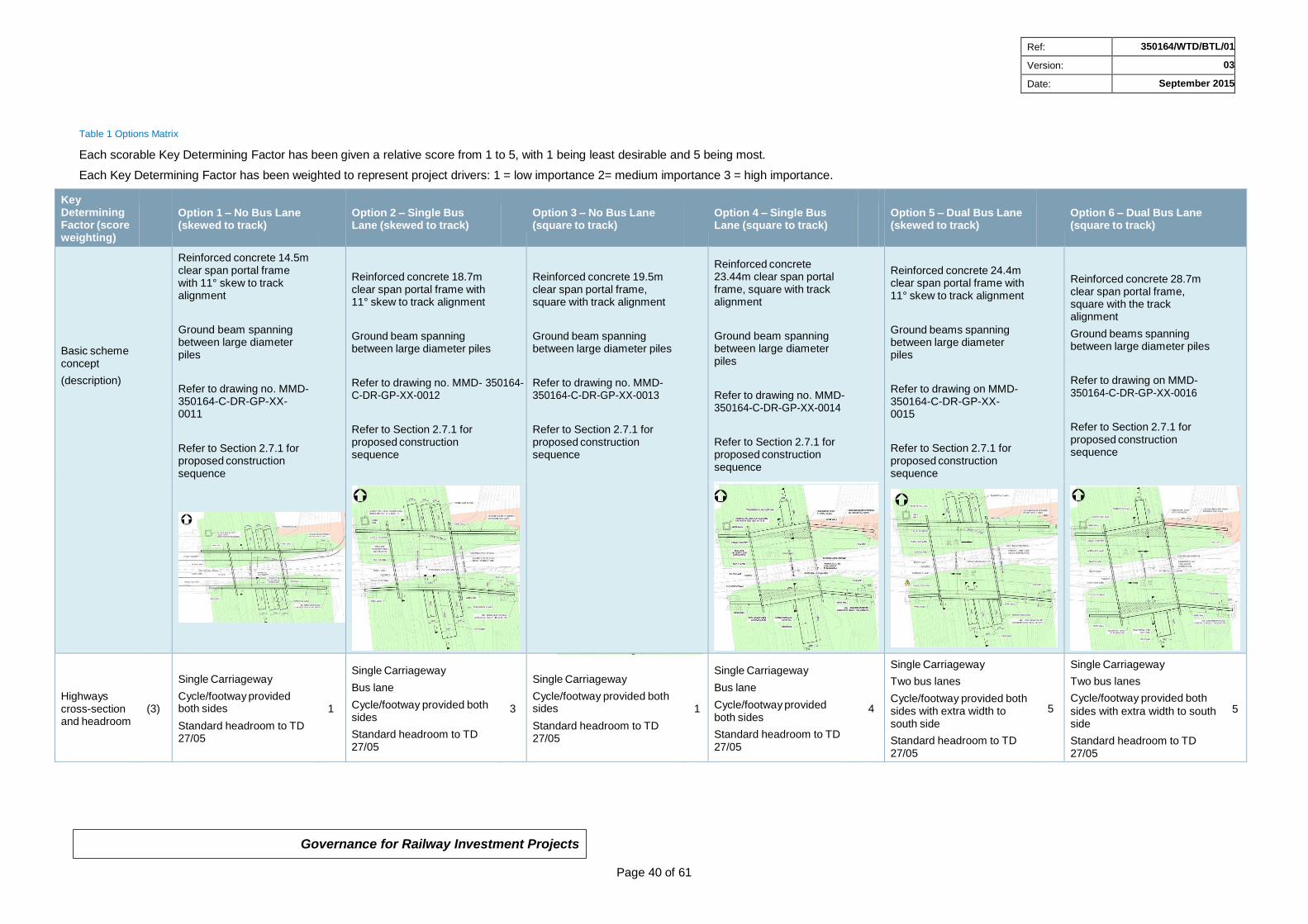
Governance for Railway Investment Projects
Page 40 of 61
Ref: 350164/WTD/BTL/01
Version: 03
Date: September 2015
Table 1 Options Matrix
Each scorable Key Determining Factor has been given a relative score from 1 to 5, with 1 being least desirable and 5 being most.
Each Key Determining Factor has been weighted to represent project drivers: 1 = low importance 2= medium importance 3 = high importance.
Key Determining Factor (score weighting)
Option 1 – No Bus Lane (skewed to track)
Option 2 – Single Bus Lane (skewed to track)
Option 3 – No Bus Lane (square to track)
Option 4 – Single Bus Lane (square to track)
Option 5 – Dual Bus Lane (skewed to track)
Option 6 – Dual Bus Lane (square to track)
Basic scheme concept
(description)
Reinforced concrete 14.5m clear span portal frame with 11° skew to track alignment
Ground beam spanning between large diameter piles
Refer to drawing no. MMD- 350164-C-DR-GP-XX- 0011
Refer to Section 2.7.1 for proposed construction sequence
Reinforced concrete 18.7m clear span portal frame with 11° skew to track alignment
Ground beam spanning between large diameter piles
Refer to drawing no. MMD- 350164-C-DR-GP-XX-0012
Refer to Section 2.7.1 for proposed construction sequence
Reinforced concrete 19.5m clear span portal frame, square with track alignment
Ground beam spanning between large diameter piles
Refer to drawing no. MMD- 350164-C-DR-GP-XX-0013
Refer to Section 2.7.1 for proposed construction sequence
Reinforced concrete 23.44m clear span portal frame, square with track alignment
Ground beam spanning between large diameter piles
Refer to drawing no. MMD- 350164-C-DR-GP-XX-0014
Refer to Section 2.7.1 for proposed construction sequence
Reinforced concrete 24.4m clear span portal frame with 11° skew to track alignment
Ground beams spanning between large diameter piles
Refer to drawing on MMD- 350164-C-DR-GP-XX-0015
Refer to Section 2.7.1 for proposed construction sequence
Reinforced concrete 28.7m clear span portal frame, square with the track alignment
Ground beams spanning between large diameter piles
Refer to drawing on MMD- 350164-C-DR-GP-XX-0016
Refer to Section 2.7.1 for proposed construction sequence
Highways cross-section and headroom
(3)
Single Carriageway
Cycle/footway provided both sides
Standard headroom to TD 27/05
1
Single Carriageway
Bus lane
Cycle/footway provided both sides
Standard headroom to TD 27/05
3
Single Carriageway
Cycle/footway provided both sides
Standard headroom to TD 27/05
1
Single Carriageway
Bus lane
Cycle/footway provided both sides
Standard headroom to TD 27/05
4
Single Carriageway
Two bus lanes
Cycle/footway provided both sides with extra width to south side
Standard headroom to TD 27/05
5
Single Carriageway
Two bus lanes
Cycle/footway provided both
sides with extra width to south 5
side
Standard headroom to TD 27/05
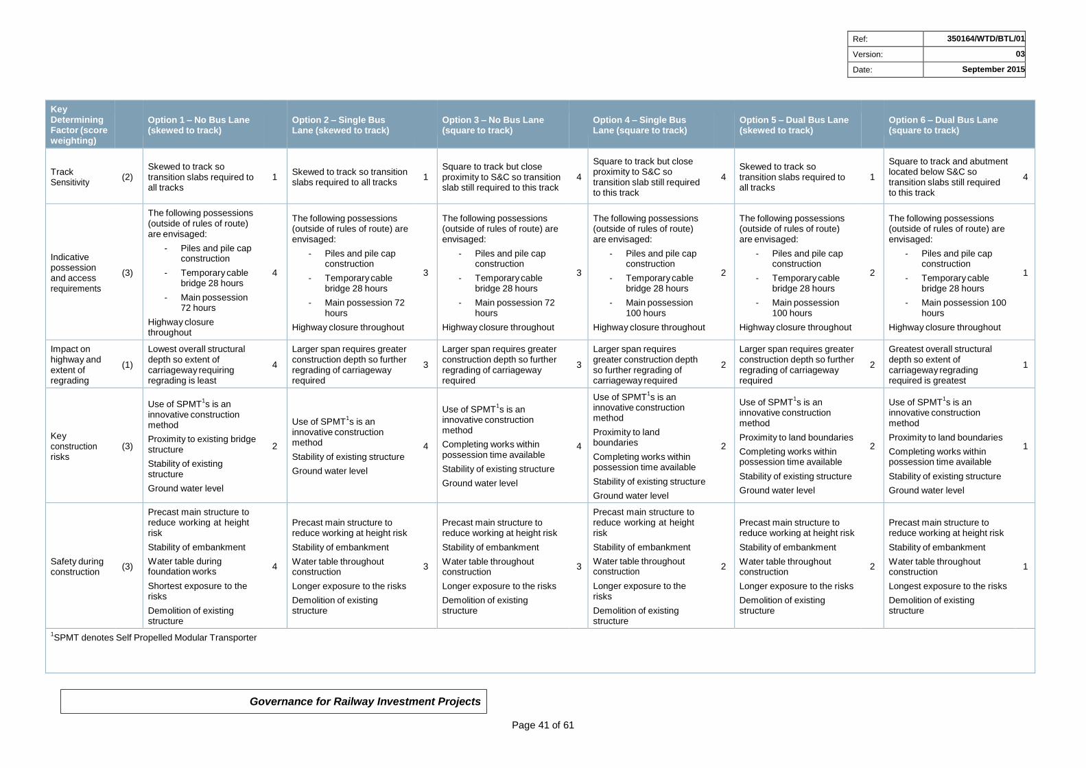
Governance for Railway Investment Projects
Page 41 of 61
Ref: 350164/WTD/BTL/01
Version: 03
Date: September 2015
Key Determining Factor (score weighting)
Option 1 – No Bus Lane (skewed to track)
Option 2 – Single Bus Lane (skewed to track)
Option 3 – No Bus Lane (square to track)
Option 4 – Single Bus Lane (square to track)
Option 5 – Dual Bus Lane (skewed to track)
Option 6 – Dual Bus Lane (square to track)
Track Sensitivity
(2)
Skewed to track so transition slabs required to all tracks
1
Skewed to track so transition slabs required to all tracks
1
Square to track but close proximity to S&C so transition slab still required to this track
4
Square to track but close proximity to S&C so transition slab still required to this track
4
Skewed to track so transition slabs required to all tracks
1
Square to track and abutment located below S&C so transition slabs still required to this track
4
Indicative possession and access requirements
(3)
The following possessions (outside of rules of route) are envisaged:
- Piles and pile cap construction
- Temporary cable bridge 28 hours
- Main possession 72 hours
Highway closure throughout
4
The following possessions (outside of rules of route) are envisaged:
- Piles and pile cap construction
- Temporary cable bridge 28 hours
- Main possession 72 hours
Highway closure throughout
3
The following possessions (outside of rules of route) are envisaged:
- Piles and pile cap construction
- Temporary cable bridge 28 hours
- Main possession 72 hours
Highway closure throughout
3
The following possessions (outside of rules of route) are envisaged:
- Piles and pile cap construction
- Temporary cable bridge 28 hours
- Main possession 100 hours
Highway closure throughout
2
The following possessions (outside of rules of route) are envisaged:
- Piles and pile cap construction
- Temporary cable bridge 28 hours
- Main possession 100 hours
Highway closure throughout
2
The following possessions (outside of rules of route) are envisaged:
- Piles and pile cap construction
- Temporary cable bridge 28 hours
- Main possession 100 hours
Highway closure throughout
1
Impact on highway and extent of regrading
(1)
Lowest overall structural depth so extent of carriageway requiring regrading is least
4
Larger span requires greater construction depth so further regrading of carriageway required
3
Larger span requires greater construction depth so further regrading of carriageway required
3
Larger span requires greater construction depth so further regrading of carriageway required
2
Larger span requires greater construction depth so further regrading of carriageway required
2
Greatest overall structural depth so extent of carriageway regrading required is greatest
1
Key construction risks
(3)
Use of SPMT1s is an
innovative construction method
Proximity to existing bridge structure
Stability of existing structure
Ground water level
2
Use of SPMT1s is an
innovative construction method
Stability of existing structure
Ground water level
4
Use of SPMT1s is an
innovative construction method
Completing works within possession time available
Stability of existing structure
Ground water level
4
Use of SPMT1s is an
innovative construction method
Proximity to land boundaries
Completing works within possession time available
Stability of existing structure
Ground water level
2
Use of SPMT1s is an
innovative construction method
Proximity to land boundaries
Completing works within possession time available
Stability of existing structure
Ground water level
2
Use of SPMT1s is an
innovative construction method
Proximity to land boundaries
Completing works within possession time available
Stability of existing structure
Ground water level
1
Safety during construction
(3)
Precast main structure to reduce working at height risk
Stability of embankment
Water table during foundation works
Shortest exposure to the risks
Demolition of existing structure
4
Precast main structure to reduce working at height risk
Stability of embankment
Water table throughout construction
Longer exposure to the risks
Demolition of existing structure
3
Precast main structure to reduce working at height risk
Stability of embankment
Water table throughout construction
Longer exposure to the risks
Demolition of existing structure
3
Precast main structure to reduce working at height risk
Stability of embankment
Water table throughout construction
Longer exposure to the risks
Demolition of existing structure
2
Precast main structure to reduce working at height risk
Stability of embankment
Water table throughout construction
Longer exposure to the risks
Demolition of existing structure
2
Precast main structure to reduce working at height risk
Stability of embankment
Water table throughout construction
Longest exposure to the risks
Demolition of existing structure
1
1SPMT denotes Self Propelled Modular Transporter
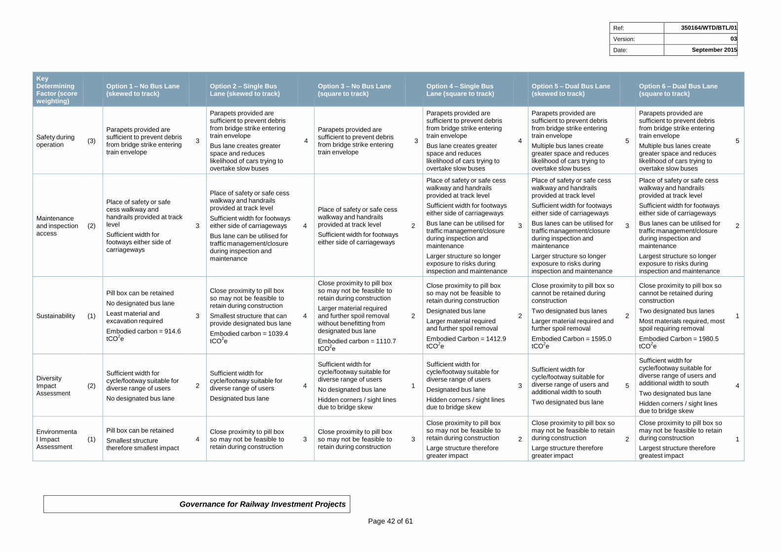
Governance for Railway Investment Projects
Page 42 of 61
Ref: 350164/WTD/BTL/01
Version: 03
Date: September 2015
Key Determining Factor (score weighting)
Option 1 – No Bus Lane (skewed to track)
Option 2 – Single Bus Lane (skewed to track)
Option 3 – No Bus Lane (square to track)
Option 4 – Single Bus Lane (square to track)
Option 5 – Dual Bus Lane (skewed to track)
Option 6 – Dual Bus Lane (square to track)
Safety during operation
(3)
Parapets provided are sufficient to prevent debris from bridge strike entering train envelope
3
Parapets provided are sufficient to prevent debris from bridge strike entering train envelope
Bus lane creates greater space and reduces likelihood of cars trying to overtake slow buses
4
Parapets provided are sufficient to prevent debris from bridge strike entering train envelope
3
Parapets provided are sufficient to prevent debris from bridge strike entering train envelope
Bus lane creates greater space and reduces likelihood of cars trying to overtake slow buses
4
Parapets provided are sufficient to prevent debris from bridge strike entering train envelope
Multiple bus lanes create greater space and reduces likelihood of cars trying to overtake slow buses
5
Parapets provided are sufficient to prevent debris from bridge strike entering train envelope
Multiple bus lanes create greater space and reduces likelihood of cars trying to overtake slow buses
5
Maintenance and inspection access
(2)
Place of safety or safe cess walkway and handrails provided at track level
Sufficient width for footways either side of carriageways
3
Place of safety or safe cess walkway and handrails provided at track level
Sufficient width for footways either side of carriageways
Bus lane can be utilised for traffic management/closure during inspection and maintenance
4
Place of safety or safe cess walkway and handrails provided at track level
Sufficient width for footways either side of carriageways
2
Place of safety or safe cess walkway and handrails provided at track level
Sufficient width for footways either side of carriageways
Bus lane can be utilised for traffic management/closure during inspection and maintenance
Larger structure so longer exposure to risks during inspection and maintenance
3
Place of safety or safe cess walkway and handrails provided at track level
Sufficient width for footways either side of carriageways
Bus lanes can be utilised for traffic management/closure during inspection and maintenance
Largest structure so longer exposure to risks during inspection and maintenance
2
Sustainability
(1)
Pill box can be retained
No designated bus lane
Least material and excavation required
Embodied carbon = 914.6 tCO
2e
3
Close proximity to pill box so may not be feasible to retain during construction
Smallest structure that can provide designated bus lane
Embodied carbon = 1039.4 tCO
2e
4
Close proximity to pill box so may not be feasible to retain during construction
Larger material required and further spoil removal without benefitting from designated bus lane
Embodied carbon = 1110.7 tCO
2e
2
Close proximity to pill box so may not be feasible to retain during construction
Designated bus lane
Larger material required and further spoil removal
Embodied Carbon = 1412.9 tCO
2e
2
Close proximity to pill box so cannot be retained during construction
Two designated bus lanes
Larger material required and further spoil removal
Embodied Carbon = 1595.0 tCO
2e
2
Close proximity to pill box so cannot be retained during construction
Two designated bus lanes
Most materials required, most spoil requiring removal
Embodied Carbon = 1980.5 tCO
2e
1
Diversity Impact Assessment
(2)
Sufficient width for cycle/footway suitable for diverse range of users
No designated bus lane
2
Sufficient width for cycle/footway suitable for diverse range of users
Designated bus lane
4
Sufficient width for cycle/footway suitable for diverse range of users
No designated bus lane
Hidden corners / sight lines due to bridge skew
1
Sufficient width for cycle/footway suitable for diverse range of users
Designated bus lane
Hidden corners / sight lines due to bridge skew
3
Sufficient width for cycle/footway suitable for diverse range of users and additional width to south
Two designated bus lane
5
Sufficient width for cycle/footway suitable for diverse range of users and additional width to south
Two designated bus lane
Hidden corners / sight lines due to bridge skew
4
Environmental Impact Assessment
(1)
Pill box can be retained
Smallest structure therefore smallest impact
4
Close proximity to pill box so may not be feasible to retain during construction
3
Close proximity to pill box so may not be feasible to retain during construction
3
Close proximity to pill box so may not be feasible to retain during construction
Large structure therefore greater impact
2
Close proximity to pill box so may not be feasible to retain during construction
Large structure therefore greater impact
2
Close proximity to pill box so may not be feasible to retain during construction
Largest structure therefore greatest impact
1
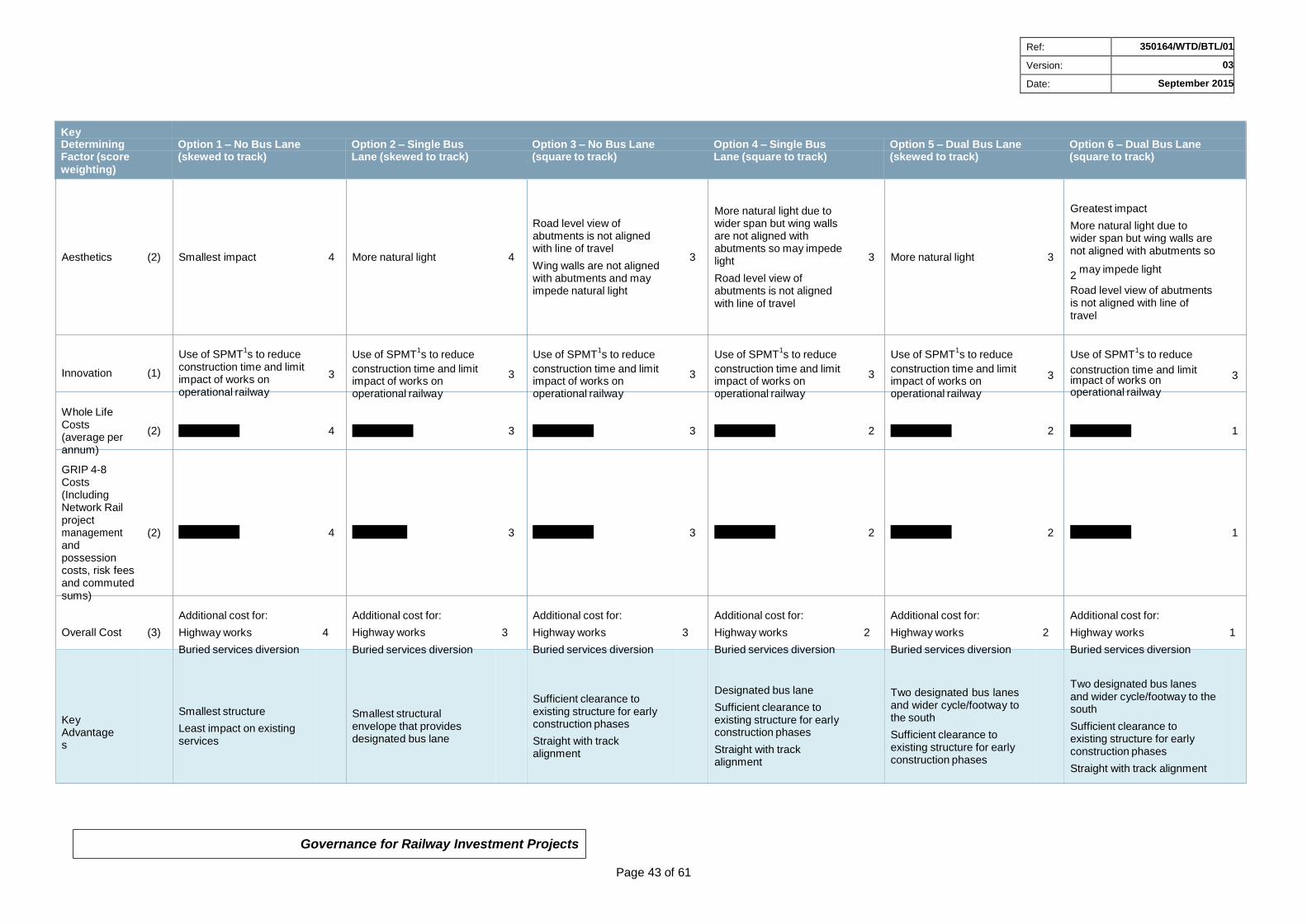
Governance for Railway Investment Projects
Page 43 of 61
Ref: 350164/WTD/BTL/01
Version: 03
Date: September 2015
Key Determining Option 1 – No Bus Lane Option 2 – Single Bus Option 3 – No Bus Lane Option 4 – Single Bus Option 5 – Dual Bus Lane Option 6 – Dual Bus Lane Factor (score (skewed to track) Lane (skewed to track) (square to track) Lane (square to track) (skewed to track) (square to track) weighting)
Aesthetics (2) Smallest impact 4 More natural light 4
Road level view of abutments is not aligned with line of travel
Wing walls are not aligned with abutments and may impede natural light
More natural light due to wider span but wing walls are not aligned with abutments so may impede
3 light
Road level view of abutments is not aligned with line of travel
3 More natural light 3
Greatest impact
More natural light due to wider span but wing walls are not aligned with abutments so
2 may impede light
Road level view of abutments is not aligned with line of travel
Innovation (1)
Whole Life
Use of SPMT1s to reduce
construction time and limit impact of works on operational railway
Use of SPMT1s to reduce
3 construction time and limit impact of works on operational railway
Use of SPMT1s to reduce
3 construction time and limit impact of works on operational railway
Use of SPMT1s to reduce
3 construction time and limit impact of works on operational railway
Use of SPMT1s to reduce
3 construction time and limit impact of works on operational railway
Use of SPMT1s to reduce
3 construction time and limit
3
impact of works on operational railway
Costs (average per annum)
GRIP 4-8 Costs (Including Network Rail project management and possession costs, risk fees and commuted sums)
(2) £106,341.82 4 £111,192.78 3 £112,684.75 3 £121,243.00 2 £128,728.62 2 £138,113.65 1
(2) £12,469,374 4 £12,928,183 3 £13,075,113 3 £13,902,531 2 £14,585,401 2 £15,554,335 1
Overall Cost (3)
Additional cost for:
Highway works 4
Buried services diversion
Additional cost for:
Highway works
Buried services diversion
Additional cost for:
3 Highway works
Buried services diversion
Additional cost for:
3 Highway works
Buried services diversion
Additional cost for:
2 Highway works
Buried services diversion
Additional cost for:
2 Highway works 1
Buried services diversion
Key Advantages
Smallest structure
Least impact on existing services
Smallest structural envelope that provides designated bus lane
Sufficient clearance to existing structure for early construction phases
Straight with track alignment
Designated bus lane
Sufficient clearance to existing structure for early construction phases
Straight with track alignment
Two designated bus lanes and wider cycle/footway to the south
Sufficient clearance to existing structure for early construction phases
Two designated bus lanes and wider cycle/footway to the south
Sufficient clearance to existing structure for early construction phases
Straight with track alignment
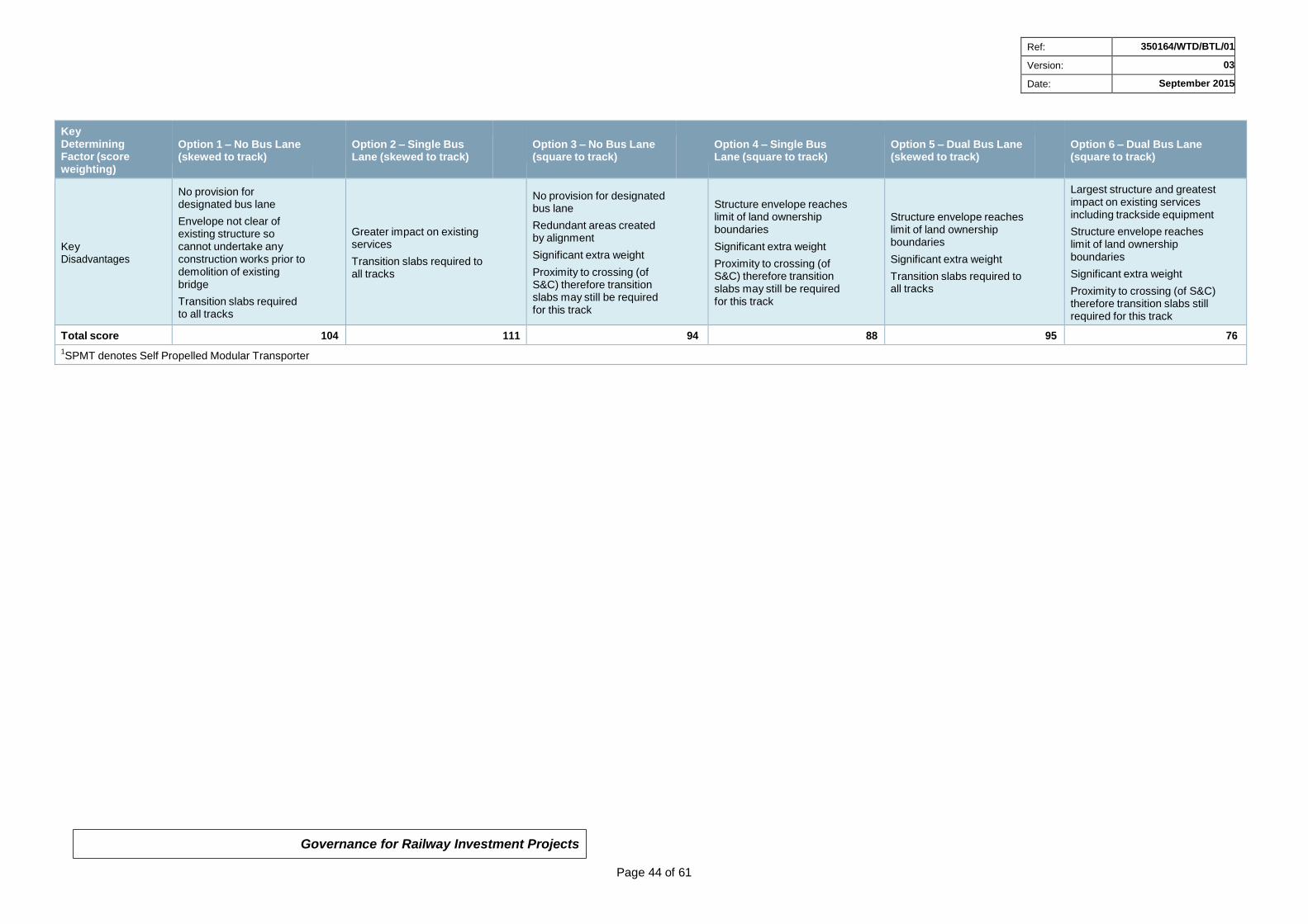
Governance for Railway Investment Projects
Page 44 of 61
Ref: 350164/WTD/BTL/01
Version: 03
Date: September 2015
Key Determining Factor (score weighting)
Option 1 – No Bus Lane (skewed to track)
Option 2 – Single Bus Lane (skewed to track)
Option 3 – No Bus Lane (square to track)
Option 4 – Single Bus Lane (square to track)
Option 5 – Dual Bus Lane (skewed to track)
Option 6 – Dual Bus Lane (square to track)
Key Disadvantages
No provision for designated bus lane
Envelope not clear of existing structure so cannot undertake any construction works prior to demolition of existing bridge
Transition slabs required to all tracks
Greater impact on existing services
Transition slabs required to all tracks
No provision for designated bus lane
Redundant areas created by alignment
Significant extra weight
Proximity to crossing (of S&C) therefore transition slabs may still be required for this track
Structure envelope reaches limit of land ownership boundaries
Significant extra weight
Proximity to crossing (of S&C) therefore transition slabs may still be required for this track
Structure envelope reaches limit of land ownership boundaries
Significant extra weight
Transition slabs required to all tracks
Largest structure and greatest impact on existing services including trackside equipment
Structure envelope reaches limit of land ownership boundaries
Significant extra weight
Proximity to crossing (of S&C) therefore transition slabs still required for this track
Total score 104 111 94 88 95 76
1SPMT denotes Self Propelled Modular Transporter
Governance for Railway Investment Projects
Page 45 of 61
Ref: 350164/WTD/BTL/01
Version: 03
Date: September 2015
2.20 Selected Option
It is recommended that a pre-cast portal frame with an 18.7m clear span and 11° skew to the track alignment as per Option 2 is progressed as the preferred option for the bridge replacement. The score from the options matrix in Table 1 identifies that this is the most suitable option when considering all evaluation points and project drivers.
Option 2 presents the minimum structure size required to achieve suitable carriageway width for one designated bus lane in addition to the single carriageway and shared cycle/footways. Whilst this option does not have the preferred alignment in relation to the track, it is a significantly smaller structure than that required to provide a bridge that is square to the track alignment. This reduces the overall construction time and costs, removes redundant areas that could become a maintenance issue and allows the wing walls and foundations to be aligned straight with the abutments. Transition slabs will be required to prevent any differential movement in the track due to the structure skew.
Whilst two designated bus lanes and a wider cycle/footway may be more desirable, the increased construction time and costs, the extensive carriageway works and significant impact on the buried services are considered to outweigh the benefits.
The wing walls should be constructed from reinforced concrete and aligned straight with the bridge abutments. This ensures it is feasible to precast them integral with the main portal frame.
The foundations will consist of ground beams spanning between pile caps. The ground beams will be cast integral with the main structure. The entire structure: portal frame, wing walls and ground beams, can then be manoeuvred into place using SPMTs and located on the precast pile caps.
3 Interfaces with Other Projects
The anticipated interfaces with other projects are as follows:
South Gloucestershire Council – Cribbs Patchway MetroBus Extension
Network Rail – Intercity Express Programme, Stoke Gifford Depot
Bristol Area Signalling Renewals
Great Western Electrification Programme (GWEP)
Rolls Royce Site Development
MetroWest Phase 2
In particular, it has been identified that an OLE gantry will be located on Gipsy Patch Lane Bridge as part of the Great Western Electrification Programme. Network Rail have expressed a preference for the gantry to be mechanically separate to the bridge structure and hence the design of the main structure will need to accommodate these loadings.
Governance for Railway Investment Projects
Page 46 of 61
Ref: 350164/WTD/BTL/01
Version: 03
Date: September 2015
4 CDM Information
The CDM arrangements for this project are as follows:
Client: Network Rail
Client’s Representative: Angela Edmunds, Commercial Scheme Sponsor, Western House, 1 Holbrook Way, Swindon, SN1 1BD, 07739 775382
Principal Designer: Network Rail
Principal Designer Representative: Jane Austin, Head of Engineering, SN1, Station Road, Swindon, SN1 1DG, 07887 896484
Designer: TBA
Person acting on behalf of the Designer: TBA
Principal Contractor: TBA
Client appointed Contractors: TBA
Refer to Appendix B for a Project Hazard Log.
5 Safety Verification Recommendations
The project has been classified by the Network Rail Acceptance Panel (NRAP) as a Category 1 in terms of ROGS (Railway and Other Guided Transport Systems (Safety) Regulations). This classification means that the project introduces no new transport system safety risks that are significant and has no potential to significantly increase safety risk.
6 Consents Strategy
The appropriate consents will be required to close Gipsy Patch Lane temporarily for the bridge replacement and the local highway construction. The road closure will form part of the highways design but will need to be co-ordinated with the bridge replacement works.
As discussed in Section 2.7.4, land will be required for the various site compound requirements. It is anticipated that part of the Rolls Royce East Works site will be obtained by South Gloucestershire Council for use as the pre-casting yard and further appropriate sites will be allocated/rented to provide remaining compound areas.
Appropriate possessions as per Section 2.8 will need to be obtained from Network Rail.
Governance for Railway Investment Projects
Page 47 of 61
Ref: 350164/WTD/BTL/01
Version: 03
Date: September 2015
7 Environmental Impact Assessment
An Environmental Appraisal for the proposed options at Gipsy Patch Lane and the identified site compound areas has been undertaken and the key risks are summarised below. The full Environmental Appraisal can be found in Appendix F.
7.1 General Risks
Option 4, 5, 6 and any site compounds are likely to require land lease/purchase. Discussions with internal/external stakeholders will be required. Residents of Little Stoke are likely to be adversely affected during the construction works due to vehicular movements, noise disturbance and air quality. Early consultation with external stakeholders is recommended. Work programme should consider residents immediately adjacent to the trackway and access areas and should obtain Section 61 consent on nuisance (noise) during construction (under the Control of Pollution Act 1974). All work should adhere to CIRIA guidelines (e.g. C692 and C715).
Construction traffic and works will need road management and likely to require a Temporary Traffic Regulation Order (TTRO). Works will also close off and re-divert a public footpath and cycle pass during the works. Consultation with the Local Council in regards to a temporary closure or diversion of a public right of way (PROW) is required.
7.2 Water
The site is situated on a minor aquifer (high vulnerability) and a secondary bedrock aquifer. Proposed site compounds 1, 2, 4 and 5 as per Section 2.7.4 are at medium risk of flooding from surface water. A Surface Water Drainage Assessment may be required. Pollution prevention measures should be implemented for all works and adhere to Network Rails contract requirements for the Environment NR/L2/ENV/015.
7.3 Historical
An undesignated World War 2 pill box is adjacent to the site works. Every reasonable effort should be made to avoid damaging the structure.
7.4 Ecology
There are no statutory designated sites within the area of works however vegetation is present and likely to be impacted by works. Vegetation comprises scrub as well as a strip on Biodiversity Action Plan (BAP) priority broadleaved woodland habitat and grassland. This vegetation is connected to habitats within the disused Filton Airfield via the railway embankment. Japanese knotweed is known to be present in the stream located approximately 40m from the railway bridge.
There is potential for great crested newts (GCN), nesting birds, common reptiles and bats (roosting, commuting and foraging) within the working area. GCN have been recorded within the pods and surrounding area of Filton Airfield. These species could be impacted during construction and operation. Biological records within 1km of the site are required to find out what protected species are within the immediate locality.
Bat transect surveys may be required along the embankment and bridge due to potential for severance of a linear habitat feature used by commuting bats. Inspections for bat roost potential will be required on mature trees that are to be removed as part of works.
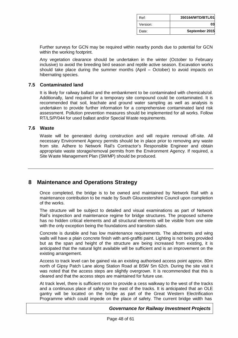
Governance for Railway Investment Projects
Page 48 of 61
Ref: 350164/WTD/BTL/01
Version: 03
Date: September 2015
Further surveys for GCN may be required within nearby ponds due to potential for GCN within the working footprint.
Any vegetation clearance should be undertaken in the winter (October to February inclusive) to avoid the breeding bird season and reptile active season. Excavation works should take place during the summer months (April – October) to avoid impacts on hibernating species.
7.5 Contaminated land
It is likely for railway ballast and the embankment to be contaminated with chemicals/oil. Additionally, land required for a temporary site compound could be contaminated. It is recommended that soil, leachate and ground water sampling as well as analysis is undertaken to provide further information for a comprehensive contaminated land risk assessment. Pollution prevention measures should be implemented for all works. Follow RT/LS/P/044 for used ballast and/or Special Waste requirements.
7.6 Waste
Waste will be generated during construction and will require removal off-site. All necessary Environment Agency permits should be in place prior to removing any waste from site. Adhere to Network Rail’s Contractor’s Responsible Engineer and obtain appropriate waste storage/removal permits from the Environment Agency. If required, a Site Waste Management Plan (SWMP) should be produced.
8 Maintenance and Operations Strategy
Once completed, the bridge is to be owned and maintained by Network Rail with a maintenance contribution to be made by South Gloucestershire Council upon completion of the works.
The structure will be subject to detailed and visual examinations as part of Network Rail’s inspection and maintenance regime for bridge structures. The proposed scheme has no hidden critical elements and all structural elements will be visible from one side with the only exception being the foundations and transition slabs.
Concrete is durable and has low maintenance requirements. The abutments and wing walls will have a plain concrete finish with anti-graffiti paint. Lighting is not being provided but as the span and height of the structure are being increased from existing, it is anticipated that the natural light available will be sufficient and is an improvement on the existing arrangement.
Access to track level can be gained via an existing authorised access point approx. 80m north of Gipsy Patch Lane along Station Road at BSW 5m 62ch. During the site visit it was noted that the access steps are slightly overgrown. It is recommended that this is cleared and that the access steps are maintained for future use.
At track level, there is sufficient room to provide a cess walkway to the west of the tracks and a continuous place of safety to the east of the tracks. It is anticipated that an OLE gantry will be located on the bridge as part of the Great Western Electrification Programme which could impede on the place of safety. The current bridge width has
Governance for Railway Investment Projects
Page 49 of 61
Ref: 350164/WTD/BTL/01
Version: 03
Date: September 2015
been proposed to match the existing structure but there is the opportunity as part of the GRIP 3 process, to consider shifting the bridge envelope to the east in order to provide sufficient space for the OLE gantry and a cess walkway to the east of the tracks. It is anticipated that this could be achieved without significant impact on the design or costs and without compromising the cess walkway to the west of the tracks. The bridge design and gantry foundation design should be co-ordinated to ensure as a minimum a safe cess is provided through the structure to both sides of the track.
9 Engineering Outputs
To develop this scheme in the future, the design should be progressed in accordance with the Network Rail GRIP processes. The next stage should be the development of the GRIP 3 outline design, presented under cover of a Form F001.
10 Conclusion and Recommendations
The recommended solution is to provide a pre-cast concrete portal frame with an 18.7m clear span in order to provide sufficient clear width for a single carriageway, a shared cycle/footway on each side and one designated bus lane. The wing walls will be aligned with the abutments and precast integral with the main portal frame. The foundation ground beams will also be cast integral with the main structure and the entire structure manoeuvred into position so the ground beams span between pile caps constructed ahead of the main works.
It is recommended that the following should be investigated further in the later GRIP stages:
Consider targeted ground investigation to inform value engineering for the foundation design
Consider shifting the structure east to accommodate GWEP gantry and cess walkway
Continued liaison with all stakeholders and coordination with the other projects identified in Section 3
Survey the size and extent of the existing structure to inform the demolition process and integration into the construction phasing
Obtain more accurate level, location and type of existing buried and overhead services
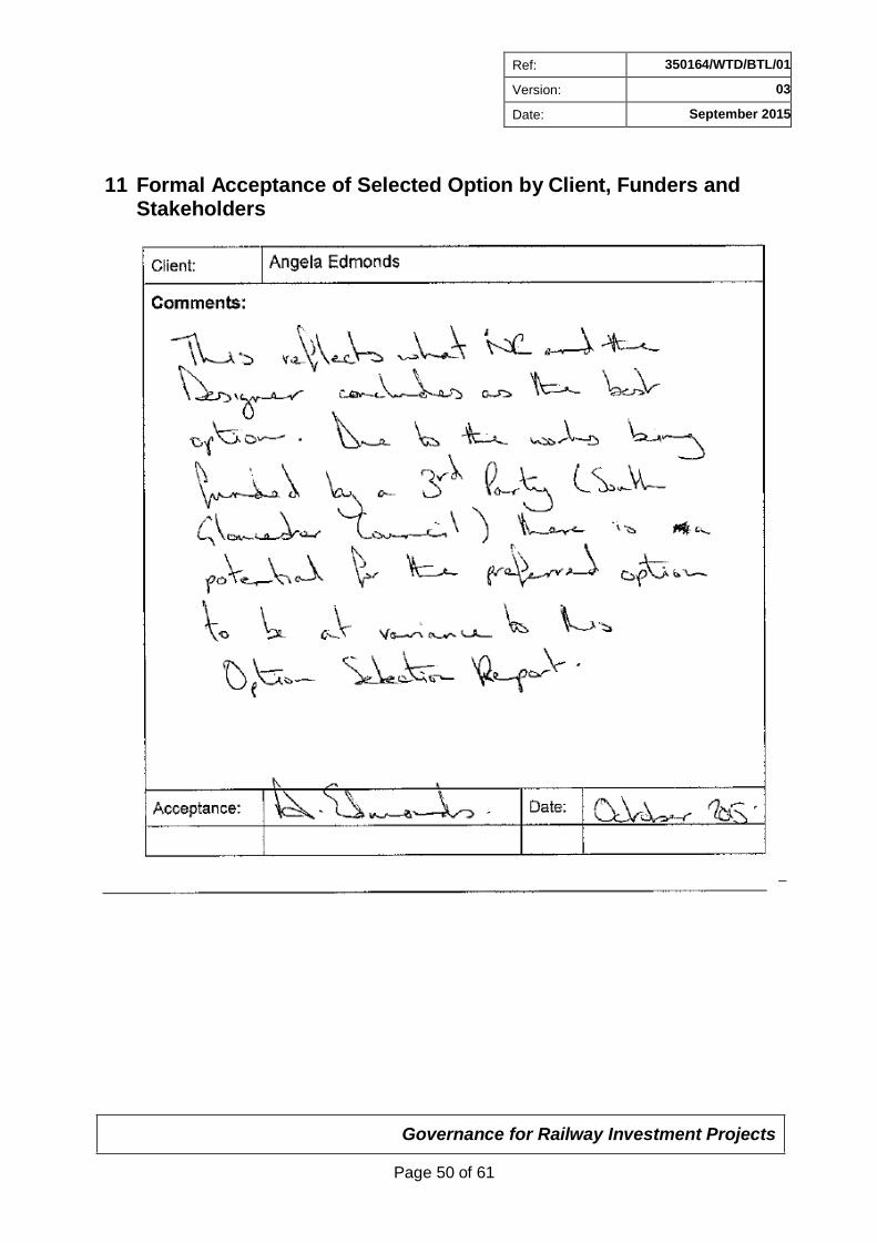
Governance for Railway Investment Projects
Page 50 of 61
Ref: 350164/WTD/BTL/01
Version: 03
Date: September 2015
11 Formal Acceptance of Selected Option by Client, Funders and Stakeholders

Ref: 350164/WTD/BTL/01
Version: 03
Date: September 2015
Appendix A
Drawings
Governance for Railway Investment Projects
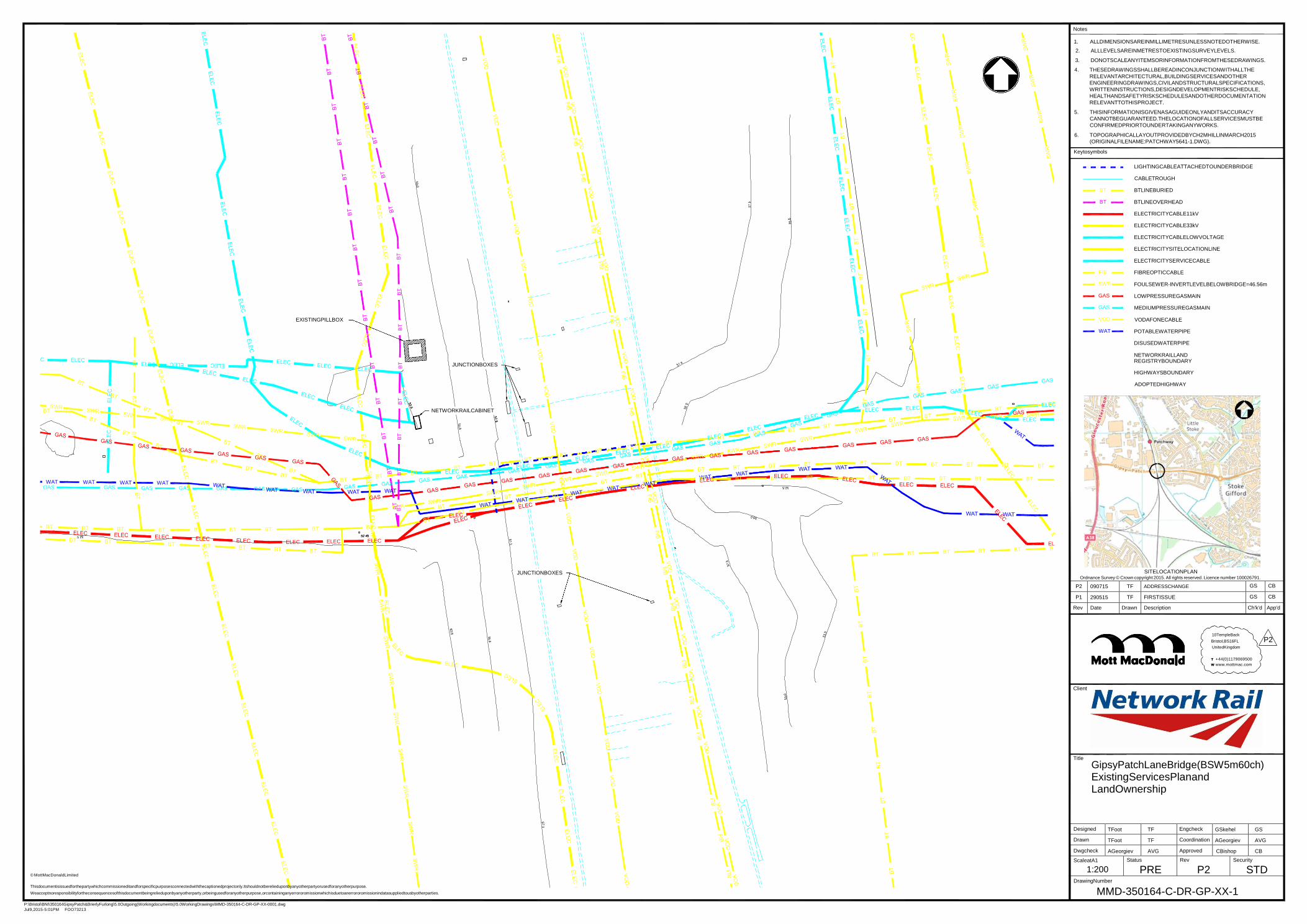
Notes
1. ALLDIMENSIONSAREINMILLIMETRESUNLESSNOTEDOTHERWISE.
MMD-350164-C-DR-GP-XX-1 Weacceptnoresponsibilityfortheconsequencesofthisdocumentbeingrelieduponbyanyotherparty,orbeingusedforanyotherpurpose,orcontaininganyerrororomissionwhichisduetoanerrororomissionindatasuppliedtousbyotherparties.
P:\Bristol\BNI\350164GipsyPatch&BrierlyFurlong\5.0Outgoing(Workingdocuments)\5.0WorkingDrawings\MMD-350164-C-DR-GP-XX-0001.dwg
Jul9,2015-5:01PM FOO73213
Designed TFoot TF Engcheck GSkehel GS
Drawn TFoot TF Coordination AGeorgiev AVG
Dwgcheck AGeorgiev AVG Approved CBishop CB
ScaleatA1
1:200
Status
PRE Rev
P2 Security
STD
WAT WAT WAT GAS GAS GAS GAS GAS GAS
ELEC ELEC ELEC
SW
R
BT
B
T
BT
BT
B
T
BT
B
T
BT
B
T
BT
B
T
BT
2. ALLLEVELSAREINMETRESTOEXISTINGSURVEYLEVELS.
3. DONOTSCALEANYITEMSORINFORMATIONFROMTHESEDRAWINGS.
4. THESEDRAWINGSSHALLBEREADINCONJUNCTIONWITHALLTHE
RELEVANTARCHITECTURAL,BUILDINGSERVICESANDOTHER
ENGINEERINGDRAWINGS,CIVILANDSTRUCTURALSPECIFICATIONS,
WRITTENINSTRUCTIONS,DESIGNDEVELOPMENTRISKSCHEDULE,
HEALTHANDSAFETYRISKSCHEDULESANDOTHERDOCUMENTATION
RELEVANTTOTHISPROJECT.
5. THISINFORMATIONISGIVENASAGUIDEONLYANDITSACCURACY
CANNOTBEGUARANTEED.THELOCATIONOFALLSERVICESMUSTBE
CONFIRMEDPRIORTOUNDERTAKINGANYWORKS.
6. TOPOGRAPHICALLAYOUTPROVIDEDBYCH2MHILLINMARCH2015
(ORIGINALFILENAME:PATCHWAY5641-1.DWG).
Keytosymbols
LIGHTINGCABLEATTACHEDTOUNDERBRIDGE
CABLETROUGH
BT
BT
FIB
SWR
GAS
GAS
BTLINEBURIED
BTLINEOVERHEAD
ELECTRICITYCABLE11kV
ELECTRICITYCABLE33kV
ELECTRICITYCABLELOWVOLTAGE
ELECTRICITYSITELOCATIONLINE
ELECTRICITYSERVICECABLE
FIBREOPTICCABLE
FOULSEWER-INVERTLEVELBELOWBRIDGE=46.56m
LOWPRESSUREGASMAIN
MEDIUMPRESSUREGASMAIN
EXISTINGPILLBOX
JUNCTIONBOXES
VOD
WAT
VODAFONECABLE
POTABLEWATERPIPE
DISUSEDWATERPIPE
NETWORKRAILLAND REGISTRYBOUNDARY
HIGHWAYSBOUNDARY
ADOPTEDHIGHWAY
NETWORKRAILCABINET
ELEC
GAS
WAT
BT BT
BT BT BT BT BT BT BT BT BT
BT BT BT BT BT
EL
JUNCTIONBOXES SITELOCATIONPLAN Ordnance Survey © Crown copyright 2015. All rights reserved. Licence number 100026791.
P2 090715 TF ADDRESSCHANGE GS CB
P1 290515 TF FIRSTISSUE GS CB
Rev Date Drawn Description Ch'k'd App'd
10TempleBack
Bristol,BS16FL P2 UnitedKingdom
T +44(0)1179069500
W www.mottmac.com
Client
Title
GipsyPatchLaneBridge(BSW5m60ch)
ExistingServicesPlanand LandOwnership
© MottMacDonaldLimited
Thisdocumentisissuedforthepartywhichcommissioneditandforspecificpurposesconnectedwiththecaptionedprojectonly.Itshouldnotberelieduponbyanyotherpartyorusedforanyotherpurpose.
DrawingNumber
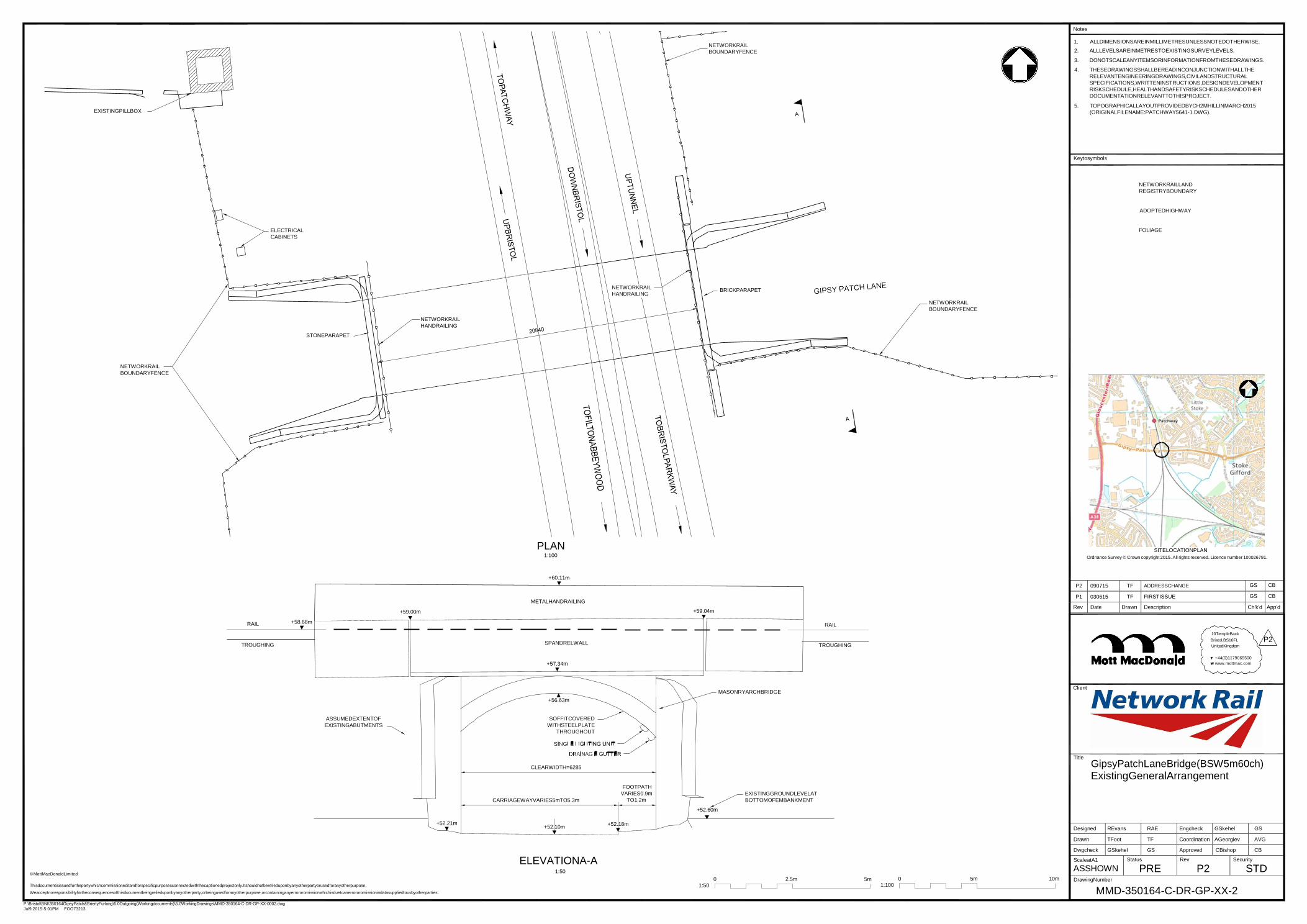
Notes
1. ALLDIMENSIONSAREINMILLIMETRESUNLESSNOTEDOTHERWISE.
MMD-350164-C-DR-GP-XX-2 Weacceptnoresponsibilityfortheconsequencesofthisdocumentbeingrelieduponbyanyotherparty,orbeingusedforanyotherpurpose,orcontaininganyerrororomissionwhichisduetoanerrororomissionindatasuppliedtousbyotherparties.
P:\Bristol\BNI\350164GipsyPatch&BrierlyFurlong\5.0Outgoing(Workingdocuments)\5.0WorkingDrawings\MMD-350164-C-DR-GP-XX-0002.dwg
Jul9,2015-5:01PM FOO73213
P2 090715 TF ADDRESSCHANGE GS CB
P1 030615 TF FIRSTISSUE GS CB
Rev Date Drawn Description Ch'k'd App'd
Designed REvans RAE Engcheck GSkehel GS
Drawn TFoot TF Coordination AGeorgiev AVG
Dwgcheck GSkehel GS Approved CBishop CB
ScaleatA1
ASSHOWN Status
PRE Rev
P2 Security
STD
EXISTINGPILLBOX
NETWORKRAIL
BOUNDARYFENCE
2. ALLLEVELSAREINMETRESTOEXISTINGSURVEYLEVELS.
3. DONOTSCALEANYITEMSORINFORMATIONFROMTHESEDRAWINGS.
4. THESEDRAWINGSSHALLBEREADINCONJUNCTIONWITHALLTHE
RELEVANTENGINEERINGDRAWINGS,CIVILANDSTRUCTURAL
SPECIFICATIONS,WRITTENINSTRUCTIONS,DESIGNDEVELOPMENT
RISKSCHEDULE,HEALTHANDSAFETYRISKSCHEDULESANDOTHER
DOCUMENTATIONRELEVANTTOTHISPROJECT.
5. TOPOGRAPHICALLAYOUTPROVIDEDBYCH2MHILLINMARCH2015
(ORIGINALFILENAME:PATCHWAY5641-1.DWG).
Keytosymbols
NETWORKRAILLAND
REGISTRYBOUNDARY
ADOPTEDHIGHWAY
ELECTRICAL
CABINETS
FOLIAGE
STONEPARAPET
NETWORKRAIL
HANDRAILING
NETWORKRAIL
HANDRAILING
BRICKPARAPET
NETWORKRAIL
BOUNDARYFENCE
NETWORKRAIL
BOUNDARYFENCE
PLAN 1:100
SITELOCATIONPLAN
Ordnance Survey © Crown copyright 2015. All rights reserved. Licence number 100026791.
+60.11m
RAIL
+58.68m
METALHANDRAILING
+59.00m +59.04m
RAIL
TROUGHING
SPANDRELWALL
TROUGHING
10TempleBack
Bristol,BS16FL P2 UnitedKingdom
+57.34m
T +44(0)1179069500
W www.mottmac.com
+56.63m
MASONRYARCHBRIDGE
Client
ASSUMEDEXTENTOF
EXISTINGABUTMENTS
SOFFITCOVERED
WITHSTEELPLATE
THROUGHOUT
+52.21m
CLEARWIDTH=6285
CARRIAGEWAYVARIES5mTO5.3m
+52.10m
FOOTPATH
VARIES0.9m
TO1.2m
+52.18m
+52.60m
EXISTINGGROUNDLEVELAT
BOTTOMOFEMBANKMENT
Title
GipsyPatchLaneBridge(BSW5m60ch)
ExistingGeneralArrangement
© MottMacDonaldLimited
ELEVATIONA-A 1:50
0 2.5m 5m 0 5m
10m
DrawingNumber Thisdocumentisissuedforthepartywhichcommissioneditandforspecificpurposesconnectedwiththecaptionedprojectonly.Itshouldnotberelieduponbyanyotherpartyorusedforanyotherpurpose. 1:50 1:100

Notes
1.
2.
ALLDIMENSIONSAREINMILLIMETRESUNLESSNOTEDOTHERWISE.
ALLLEVELSAREINMETRESTOEXISTINGSURVEYLEVELS.
P:\Bristol\BNI\350164GipsyPatch&BrierlyFurlong\5.0Outgoing(Workingdocuments)\5.0WorkingDrawings\MMD-350164-C-DR-GP-XX-0011.dwg
Jul9,2015-5:01PM FOO73213
P2 090715 TF ADDRESSCHANGE&ADDITIONALNOTE AVG CB
P1 050615 TF FIRSTDRAFT AVG CB
Rev Date Drawn Description Ch'k'd App'd
Designed GSkehel GS Engcheck AGeorgiev AVG
Drawn TFoot TF Coordination AGeorgiev AVG
Dwgcheck AGeorgiev AVG Approved CBishop CB
ScaleatA1
ASSHOWN Status
PRE Rev
P2 Security
STD
360
14500C
LE
AR
SP
AN
2000
5820
1000
PILLBOXMAYBEKEPT
CLEARFROM
CONSTRUCTIONBOUNDARY
WINGWALL
TRANSITIONSLABS
WINGWALL
GROUNDBEAMSPANNING
BETWEENPILECAPS
BURIEDJOINTIN
WATERPROOFING
TOPOFRUNNINGRAIL
BRIDGEDECKWATERPROOFING
9000
2500 6500
INCREASEDDEPTH
OFBALLAST
3. DONOTSCALEANYITEMSORINFORMATIONFROMTHESEDRAWINGS.
4. THESEDRAWINGSSHALLBEREADINCONJUNCTIONWITHALLTHE
RELEVANTENGINEERINGDRAWINGS,CIVILANDSTRUCTURAL
SPECIFICATIONS,WRITTENINSTRUCTIONS,DESIGNDEVELOPMENT
RISKSCHEDULE,HEALTHANDSAFETYRISKSCHEDULESANDOTHER
DOCUMENTATIONRELEVANTTOTHISPROJECT.
5. FORPROPOSEDCARRIAGEWAYSAGCURVEOF290m,S=270mm
6. DRAWINGSHOULDBEREADINCONJUNCTIONWITH350164-WTD-BTL
-001OPTIONSELECTIONREPORT.
7. TOPOGRAPHICALLAYOUTPROVIDEDBYCH2MHILLINMARCH2015
(ORIGINALNAME:PATCHWAY5641-1.DWG).
8. TOTALNOMINALWEIGHTOFSTRUCTUREFORLIFTINGINCLUDING
PORTALFRAME,GROUNDBEAMSANDALLWINGWALLS=2715 P2 TONNES.
UNDERSIDEOFSLEEPER
CYCLEFOOTWAY
Keytosymbols
NORTHLANE
SOUTHLANE
PARAPET
POTENTIAL
OLEGANTRY
PARAPETSTO
PILECAP
COMPACTEDFORMATION
WATERPROOFJOINTWITH
STAINLESSSTEELDOWELAND
1:30CROSSFALLTOWARDS
CESSDRAINAGE
REINFORCEDCONCRETE
TRANSITIONSLABTOBE
SQUAREWITHTRACK
TOC - TOPOFCONCRETE
SOC - SOFFITOFCONCRETE
NETWORKRAILLAND
REGISTRYBOUNDARY
CYCLEFOOTWAY
22000
BE1.25mABOVE
RUNNINGRAIL
WINGWALL
BRIDGE
ABUTMENT
ELASTOMERICSTRIP
TYPE6N
STRUCTURAL
BACKFILL
SECTIONB-B 1:50
ADOPTEDHIGHWAY
SIGNIFICANTCDMHEALTHANDSAFETYRISKS
WINGWALL TRANSITIONSLABS
4No. 12000 REINFORCED
CONCRETE PILES =13m LENGTH
03,04
18
EXISTINGSTRUCTUREEXTENTSUNKNOWN
WATERLEVELAT50.87m
REFERTOPROJECTHAZARDLOG:350164-WTD-BTL-003
PLANOFSTRUCTURE 1:200
300MINBALLASTBELOWSLEEPERS
TOPOFLOWESTRAIL
UNDERSIDEOFSLEEPER
+58.68m
PROPRIETARYWATERPROOFING
SYSTEMTOBRIDGEDECK
TRANSITIONSLAB
OMITTEDFORCLARITY
WATERPROOFING-2No.
COATSOFBITUMINOUSPAINT
STRUCTUREFREEZONE=5.3m+SSEENOTE5
TOC+58.02m
SOC+57.02m
TRANSITIONSLABOMITTEDFORCLARITY
C3545REINFORCEDCONCRETE
SITELOCATIONPLAN
Ordnance Survey © Crown copyright 2015. All rights reserved. Licence number 100026791.
VARIES3380TO6690 VARIES1780TO5300
FILTERDRAIN
TYPE6N
STRUCTURAL
BACKFILL
ASSUMEDEXTENTOF
EXISTINGABUTMENTS
03,04
14500CLEARSPAN
TYPE6N
STRUCTURAL
BACKFILL
10TempleBack
Bristol,BS16FL P2 UnitedKingdom
T +44(0)1179069500
W www.mottmac.com
EXISTINGGROUND
LEVELATBOTTOM
OFEMBANKMENT
+52.6m
NEWDRAINAGEPIPE
DISCHARINGTOSURFACE
WATERSYSTEM
GROUNDBEAM
800
3500CYCLEFOOTWAY
+51.35m
3750NORTHLANE
EXPOSEDFACESTOHAVE
PLAINCONCRETEFINISH
WITHANTI-GRAFFITICOATING
3750SOUTHLANE
+51.20m
3500CYCLEFOOTWAY
+51.35m
800
NEWDRAINAGEPIPE
DISCHARINGTOSURFACE
WATERSYSTEM 18
WATERTABLE +50.87
GROUNDBEAM
Client
Title
GipsyPatchLaneBridge(BSW5m60ch)
Option1-NoBusLane SkewedtoTrack
COMPACTEDFORMATION SECTIONA-A
1:50
COMPACTEDFORMATION
© MottMacDonaldLimited
Thisdocumentisissuedforthepartywhichcommissioneditandforspecificpurposesconnectedwiththecaptionedprojectonly.Itshouldnotberel ieduponbyanyotherpartyorusedforanyotherpurpose.
Weacceptnoresponsibilityfortheconsequencesofthisdocumentbeingrelieduponbyanyotherparty,orbeingusedforanyotherpurpose,orcontaininganyerrororomissionwhichisduetoanerrororomissionindatasuppliedtousbyotherparties.
0
1:50
2.5m 5m
0
1:200
10m 20m
DrawingNumber
MMD-350164-C-DR-GP-XX-0011

Notes
1.
2.
ALLDIMENSIONSAREINMILLIMETRESUNLESSNOTEDOTHERWISE.
ALLLEVELSAREINMETRESTOEXISTINGSURVEYLEVELS.
P:\Bristol\BNI\350164GipsyPatch&BrierlyFurlong\5.0Outgoing(Workingdocuments)\5.0WorkingDrawings\MMD-350164-C-DR-GP-XX-12 Jul9,2015-
5:01PM FOO73213
P2 090715 TF WALLTHICKNESSUPDATED, ADDRESSCHANGE&ADDITIONALNOTE
AVG CB
P1 050615 TF FIRSTDRAFT AVG CB
Rev Date Drawn Description Ch'k'd App'd
Designed GSkehel GS Engcheck AGeorgiev AVG
Drawn TFoot TF Coordination AGeorgiev AVG
Dwgcheck AGeorgiev AVG Approved CBishop CB
ScaleatA1
ASSHOWN
Status
PRE Rev
P2 Security
STD
22000
360
18700C
LE
AR
SP
AN
5820
1000
REMOVEPILLBOXFORBUSLANE
ONNORTHSIDE(SEENOTE8)
WING
WALL A
CYCLEFOOTWAY
TRANSITIONSLABS
WINGWALL
GROUNDBEAMSPANNING
BETWEENPILECAPS
BURIEDJOINTIN
WATERPROOFING
TOPOFRUNNINGRAIL
UNDERSIDEOFSLEEPER
BRIDGEDECKWATERPROOFING
9000
2500 6500
COMPACTEDFORMATION 1:30CROSSFALLTOWARDS
INCREASEDDEPTH
OFBALLAST
REINFORCEDCONCRETE
3. DONOTSCALEANYITEMSORINFORMATIONFROMTHESEDRAWINGS.
4. THESEDRAWINGSSHALLBEREADINCONJUNCTIONWITHALLTHE
RELEVANTENGINEERINGDRAWINGS,CIVILANDSTRUCTURAL
SPECIFICATIONS,WRITTENINSTRUCTIONS,DESIGNDEVELOPMENTRISK
SCHEDULE,HEALTHANDSAFETYRISKSCHEDULESANDOTHER
DOCUMENTATIONRELEVANTTOTHISPROJECT.
5. FORPROPOSEDCARRIAGEWAYSAGCURVEOF290m,S=270mm
6. DRAWINGSHOULDBEREADINCONJUNCTIONWITH350164-WTD-BTL-
001OPTIONSELECTIONREPORT
7. TOPOGRAPHICALLAYOUTPROVIDEDBYCH2MHILLINMARCH2015
(ORIGINALNAME:PATCHWAY5641-1.DWG).
8. TWOBUSLANEALIGNMENTSHAVEBEENPROPOSEDBYTHEHIGHWAY
DESIGNERS;ONEOPTIONWITHDESIGNATEDBUSLANELOCATEDON
THENORTHSIDEANDONEOPTIONONTHESOUTHSIDEOFTHE
CARRIAGEWAY.THISDRAWINGPRESENTSTHEOPTIONWITHTHEBUS
LANEONTHENORTHSIDE,WHICHBEARSGREATERRISKTOTHE
BRIDGECONSTRUCTION.
9. TOTALNOMINALWEIGHTOFSTRUCTUREFORLIFTINGINCLUDING
PORTALFRAME,GROUNDBEAMSANDALLWINGWALLS=3350TONNES.
BUSLANE
ONNORTHSIDE
(SEENOTE8)
NORTHLANE
EXISTINGARCHBRIDGE
PARAPETTOBE1.25m
ABOVERUNNINGRAIL
BRIDGE
ABUTMENT
WATERPROOFJOINTWITH
STAINLESSSTEELDOWELAND
ELASTOMERICSTRIP
TYPE6N
STRUCTURAL
CESSDRAINAGE TRANSITIONSLABTOBE
SQUAREWITHTRACK
P2
Keytosymbols
SOUTHLANE
PARAPET
CYCLEFOOTWAY
A
WINGWALL
POTENTIALOLEGANTRY
WINGWALL
TRANSITIONSLABS
PILECAP
BURIEDJOINTIN
WATERPROOFING
TOPOFRUNNINGRAIL
UNDERSIDEOFSLEEPER
BACKFILL
6900
SECTIONB-B 1:50
BRIDGEDECKWATERPROOFING
16000
INCREASEDDEPTH
OFBALLAST
9100
TOC - TOPOFCONCRETE
SOC - SOFFITOFCONCRETE
NETWORKRAILLAND
REGISTRYBOUNDARY
ADOPTEDHIGHWAY
SIGNIFICANTCDMHEALTHANDSAFETYRISKS
EXISTINGSTRUCTUREEXTENTSUNKNOWN
03,04
WATERLEVELAT50.87m
18 REFERTOPROJECTHAZARDLOG:350164-WTD-BTL-003
4No. 12000 REINFORCED
CONCRETE PILES ::14m LENGTH
CROSSING WATERPROOFJOINTWITH
STAINLESSSTEELDOWELAND
ELASTOMERICSTRIP
COMPACTEDFORMATION
1:30CROSSFALLTOWARDS
CESSDRAINAGE
REINFORCEDCONCRETE
TRANSITIONSLABTOBE
SQUAREWITHTRACK
PLANOFSTRUCTURE 1:200
TYPE6N
STRUCTURAL
BACKFILL
SECTIONC-C
1:50
300MINBALLASTBELOWSLEEPERS
TOPOFLOWESTRAIL
+58.68m
PROPRIETARYWATERPROOFING
SYSTEMTOBRIDGEDECK
UNDERSIDEOFSLEEPER
TRANSITIONSLABSOMITTEDFORCLARITY
800
STRUCTUREFREEZONE=5.3m+SSEENOTE5
18700CLEARSPAN
TOC+58.02m
800
TRANSITIONSLABSOMITTEDFORCLARITY
C3545REINFORCEDCONCRETE
SITELOCATIONPLAN Ordnance Survey © Crown copyright 2015. All rights reserved. Licence number 100026791.
WATERPROOFING-2No.
COATSOFBITUMINOUSPAINT
P2
TYPE6N
STRUCTURAL
BACKFILL
SOC+56.82m
VARIES7250TO10900 VARIES1870TO5470
ASSUMEDEXTENT
OFEXISTING
ABUTMENTS)
03,04
P2
FILTERDRAIN
TYPE6N
STRUCTURAL
BACKFILL
Client
10TempleBack
Bristol,BS16FL P2 UnitedKingdom
T +44(0)1179069500
W www.mottmac.com
EXISTINGGROUND
LEVELATBOTTOM
OFEMBANKMENT
+52.6m
EXPOSEDFACESTOHAVE
PLAINCONCRETEFINISH
WITHANTI-GRAFFITICOATING
NEWDRAINAGEPIPE
DISCHARGINGTO
SURFACEWATERSYSTEM
3500CYCLEFOOTWAY
+51.15m
4200BUSLANE
3750NORTHLANE
+51.00m
3750SOUTHLANE
3500CYCLEFOOTWAY
+51.15m
NEWDRAINAGEPIPE
DISCHARGINGTO
SURFACEWATERSYSTEM
WATERTABLE +50.87
Title
GipsyPatchLaneBridge(BSW5m60ch)
Option2-SingleBusLane SkewedtoTrack
18
GROUNDBEAM GROUNDBEAM
SECTIONA-A COMPACTEDFORMATION 1:50 COMPACTEDFORMATION
© MottMacDonaldLimited
Thisdocumentisissuedforthepartywhichcommissioneditandforspecificpurposesconnectedwiththecaptionedprojectonly. Itshouldnotberelieduponbyanyotherpartyorusedforanyotherpurpose.
Weacceptnoresponsibilityfortheconsequencesofthisdocumentbeingrelieduponbyanyotherparty,orbeingusedforanyotherpurpose,orcontaininganyerrororomissionwhichisduetoanerrororomissionindatasuppliedtousbyotherparties.
0
1:50
2.5 m 5m
0
1:200
10m 20m
DrawingNumber
MMD-350164-C-DR-GP-XX-0012

Notes
P:\Bristol\BNI\350164GipsyPatch&BrierlyFurlong\5.0Outgoing(Workingdocuments)\5.0WorkingDrawings\MMD-350164-C-DR-GP-XX-13 Jul9,2015-
5:02PM FOO73213
P2 090715 TF CHANGEOFADDRESS&ADDITIONALNOTE AVG CB
P1 050615 TF FIRSTDRAFT AVG CB
Rev Date Drawn Description Ch'k'd App'd
Designed GSkehel GS Engcheck AGeorgiev AVG
Drawn TFoot TF Coordination AGeorgiev AVG
Dwgcheck AGeorgiev AVG Approved CBishop CB
ScaleatA1
ASSHOWN Status
PRE Rev
P2 Security
STD
360
3000
5820
1000
PILLBOXMAYBEKEPT
CLEARFROM
CONSTRUCTIONBOUNDARY
TRANSITIONSLAB
OVERS&C
REDUNDANTAREA
ATROADLEVEL
WINGWALL
GROUNDBEAMSPANNING
BETWEENPILECAPS
BURIEDJOINTIN
WATERPROOFING
TOPOFRUNNINGRAIL
UNDERSIDEOFSLEEPER
BRIDGEDECKWATERPROOFING
9000
2500 6500
INCREASEDDEPTH
OFBALLAST
1. ALLDIMENSIONSAREINMILLIMETRESUNLESSNOTEDOTHERWISE.
2. ALLLEVELSAREINMETRESTOEXISTINGSURVEYLEVELS.
3. DONOTSCALEANYITEMSORINFORMATIONFROMTHESEDRAWINGS.
4. THESEDRAWINGSSHALLBEREADINCONJUNCTIONWITHALLTHE
RELEVANTENGINEERINGDRAWINGS,CIVILANDSTRUCTURAL
SPECIFICATIONS,WRITTENINSTRUCTIONS,DESIGNDEVELOPMENT
RISKSCHEDULE,HEALTHANDSAFETYRISKSCHEDULESANDOTHER
DOCUMENTATIONRELEVANTTOTHISPROJECT.
5. FORPROPOSEDCARRIAGEWAYSAGCURVEOF290m,S=270mm.
6. DRAWINGSHOULDBEREADIONCONJUNCTIONWITH
350164-WTD-BTL-001OPTIONSELECTIONREPORT.
7. TOPOGRAPHICALLAYOUTPROVIDEDBYCH2MHILLINMARCH2015
(ORIGINALNAME:PATCHWAY5641-1.DWG).
8. TOTALNOMINALWEIGHTOFSTRUCTUREFORLIFTINGINCLUDING PORTALFRAME,GROUNDBEAMSANDALLWINGWALLS=3605
WINGWALL
CYCLEFOOTWAY
BRIDGE
ABUTMENT
COMPACTEDFORMATION
WATERPROOFJOINTWITH
STAINLESSSTEELDOWELAND
ELASTOMERICSTRIP
TYPE6N
STRUCTURAL
1:30CROSSFALLTOWARDS
CESSDRAINAGE
REINFORCEDCONCRETE
TRANSITIONSLABTOBE
SQUAREWITHTRACK
TONNES.
Keytosymbols
P2
(XXXX) - SKEWEDDIMENSION
NORTHLANE
SOUTHLANE
PARAPET
POTENTIAL
OLEGANTRY
PARAPETSTOBE
1.25mABOVE
RUNNINGRAIL
EXISTINGARCHBRIDGE
PILECAP
BACKFILL SECTIONB-B
1:50
TOC - TOPOFCONCRETE
SOC - SOFFITOFCONCRETE
NETWORKRAILLAND
REGISTRYBOUNDARY
ADOPTEDHIGHWAY
CYCLEFOOTWAY
WINGWALL
WINGWALL BURIEDJOINTIN
WATERPROOFING
BRIDGEDECKWATERPROOFING
16000
INCREASEDDEPTH
OFBALLAST
SIGNIFICANTCDMHEALTHANDSAFETYRISKS
EXISTINGSTRUCTUREEXTENTSUNKNOWN
4No. 12000 REINFORCED
CONCRETE PILES ::14.5m LENGTH
TOPOFRUNNINGRAIL
6900
9100 03,04
18
WATERLEVELAT50.87m
REFERTOPROJECTHAZARDLOG:350164-WTD-BTL-003
REDUNDANTAREA
ATROADLEVEL
TRANSITIONSLAB
OVERS&C
CROSSING
UNDERSIDEOFSLEEPER
WATERPROOFJOINTWITH
STAINLESSSTEELDOWELAND
ELASTOMERICSTRIP
COMPACTEDFORMATION
1:30CROSSFALLTOWARDS
CESSDRAINAGE
REINFORCEDCONCRETE
TRANSITIONSLABTOBE
SQUAREWITHTRACK
PLANOFSTRUCTURE 1:200
TYPE6N
STRUCTURAL
BACKFILL
SECTIONC-C
1:50
TOPOFLOWESTRAIL
UNDERSIDEOFSLEEPER
TRANSITIONSLABSOMITTEDFORCLARITY
WATERPROOFING2No.COATS
OFBITUMINOUSPAINT
+58.68m
STRUCTUREFREEZONE=5.3m+SSEENOTE5
300MINBALLASTBELOWSLEEPERS PROPRIETARYWATERPROOFING
SYSTEMTOBRIDGEDECK
TOC+58.02m
TRANSITIONSLABSOMITTEDFORCLARITY
C3545REINFORCEDCONCRETE
SITELOCATIONPLAN
Ordnance Survey © Crown copyright 2015. All rights reserved. Licence number 100026791.
VARIES6760TO7340
VARIES5550TO6220
SOC+56.82m
FILTERDRAIN
10TempleBack
Bristol,BS16FL P2 UnitedKingdom
T +44(0)1179069500
W www.mottmac.com
TYPE6N
STRUCTURAL
BACKFILL
REDUNDANT
SPACE
ASSUMEDEXTENTOF
EXISTINGABUTMENTS
03,04
19500CLEARSPAN
EXPOSEDFACESTOHAVE
PLAINCONCRETEFINISH
WITHANTI-GRAFITTICOATING
REDUNDANT
SPACE
TYPE6N
STRUCTURAL
BACKFILL
Client
EXISTINGGROUND
LEVELATBOTTOM
OFEMBANKMENT
+52.6m
NEWDRAINAGEPIPE
DISCHARGINGINTO
SURFACEWATERSYSTEM
VARIES0TO4400
CYCLEFOOTWAY(3500)
+51.15m
NORTHLANE(3750)
SOUTHLANE(3750)
+51.00m
CYCLEFOOTWAY(3500)
+51.15m
VARIES0TO4400
NEWDRAINAGEPIPEDISCHARGING
INTOSURFACEWATERSYSTEM
WATERTABLE +50.87
Title
GipsyPatchLaneBridge(BSW5m60ch)
Option3-NoBusLane SquaretoTrack
18
GROUNDBEAM GROUNDBEAM
SECTIONA-A
© MottMacDonaldLimited
COMPACTEDFORMATION 1:50
COMPACTEDFORMATION
DrawingNumber Thisdocumentisissuedforthepartywhichcommissioneditandforspecificpurposesconnectedwiththecaptionedprojectonly.Itshouldnotberelieduponbyanyotherp artyorusedforanyotherpurpose.
Weacceptnoresponsibilityfortheconsequencesofthisdocumentbeingrelieduponbyanyotherparty,orbeingusedforanyotherpurpose,orcontaininganyerrororomissionwhichisduetoanerrororomissionindatasuppliedtousbyotherparties.
0 1:50
2.5m 5m 0 1:200
10m 20m
MMD-350164-C-DR-GP-XX-0013

P:\Bristol\BNI\350164GipsyPatch&BrierlyFurlong\5.0Outgoing(Workingdocuments)\5.0WorkingDrawings\MMD-350164-C-DR-GP-XX-14 Jul9,2015-
5:02PM FOO73213
Notes
1. ALLDIMENSIONSAREINMILLIMETRESUNLESSNOTEDOTHERWISE.
P2 090715 TF CHANGEOFADDRESS&ADDITIONALNOTE AVG CB
P1 050615 TF FIRSTDRAFT AVG CB
Rev Date Drawn Description Ch'k'd App'd
Designed GSkehel GS Engcheck AGeorgiev AVG
Drawn TFoot TF Coordination AGeorgiev AVG
Dwgcheck AGeorgiev AVG Approved CBishop CB
ScaleatA1
ASSHOWN Status
PRE Rev
P2 Security
STD
360
5820
1000
TRANSITIONSLABOVERS&C
REMOVEPILLBOXFORBUSLANE
ONNORTHSIDE(SEENOTE8)
WINGWALL
REDUNDANTAREA
ATROADLEVEL
WINGWALL
GROUNDBEAMSPANNING
BETWEENPILECAPS
BURIEDJOINTIN
WATERPROOFING
TOPOFRUNNINGRAIL
UNDERSIDEOFSLEEPER
BRIDGEDECKWATERPROOFING
9000
2500 6500
COMPACTEDFORMATION 1:30CROSSFALLTOWARDS
INCREASEDDEPTH
OFBALLAST
REINFORCEDCONCRETE
2. ALLLEVELSAREINMETRESTOEXISTINGSURVEYLEVELS.
3. DONOTSCALEANYITEMSORINFORMATIONFROMTHESEDRAWINGS.
4. THESEDRAWINGSSHALLBEREADINCONJUNCTIONWITHALLTHE
RELEVANTENGINEERINGDRAWINGS,CIVILANDSTRUCTURAL
SPECIFICATIONS,WRITTENINSTRUCTIONS,DESIGNDEVELOPMENT
RISKSCHEDULE,HEALTHANDSAFETYRISKSCHEDULESANDOTHER
DOCUMENTATIONRELEVANTTOTHISPROJECT.
5. FORPROPOSEDCARRIAGEWAYSAGCURVEOF290m,S=270mm.
6. DRAWINGSHOULDBEREADINCONJUNCTIONWITH
350164-WTD-BTL-001OPTIONSELECTIONREPORT.
7. TOPOGRAPHICALLAYOUTPROVIDEDBYCH2MHILLINMARCH2015
(ORIGINALNAME:PATCHWAY5641-1.DWG).
8. TWOBUSLANEALIGNMENTSHAVEBEENPROPOSEDBYTHE
HIGHWAYDESIGNERS;ONEOPTIONWITHDESIGNATEDBUSLANE
LOCATEDONTHENORTHSIDEANDONEOPTIONONTHESOUTHSIDE
OFTHECARRIAGEWAY.THISDRAWINGPRESENTSTHEOPTIONWITH
THEBUSLANEONTHENORTHSIDE,WHICHBEARSGREATERRISKTO
THEBRIDGECONSTRUCTION.
9. TOTALNOMINALWEIGHTOFSTRUCTUREFORLIFTINGINCLUDING
CYCLEFOOTWAY
BUSLANE
ONNORTHSIDE
(SEENOTE8)
EXISTINGARCHBRIDGE
PILECAP
BRIDGE
ABUTMENT
WATERPROOFJOINTWITH
STAINLESSSTEELDOWELAND
ELASTOMERICSTRIP
TYPE6N
STRUCTURAL BACKFILL
CESSDRAINAGE TRANSITIONSLABTOBE
SQUAREWITHTRACK PORTALFRAME,GROUNDBEAMSANDALLWINGWALLS=4860 P2 TONNES.
Keytosymbols
(XXXX) - SKEWEDDIMENSION
NORTHLANE
PARAPETSTOBE
1.25mABOVE
RUNNINGRAIL
POTENTIALOLEGANTRY
SECTIONB-B 1:50
TOC - TOPOFCONCRETE
SOC - SOFFITOFCONCRETE
NETWORKRAILLAND
REGISTRYBOUNDARY SOUTHLANE
CYCLEFOOTWAY
PARAPET
PILECAP
BURIEDJOINTIN
WATERPROOFING
6900
BRIDGEDECKWATERPROOFING
16000
INCREASEDDEPTH
OFBALLAST
9100
ADOPTEDHIGHWAY
SIGNIFICANTCDMHEALTHANDSAFETYRISKS
EXISTINGSTRUCTUREEXTENTSUNKNOWN
03,04
WINGWALL
TOPOFRUNNINGRAIL
UNDERSIDEOFSLEEPER
WATERLEVELAT50.87m
18
WINGWALL
4No. 12000 REINFORCED
CONCRETE PILES :: 15m LENGTH REFERTOPROJECTHAZARDLOG:350164-WTD-BTL-003
REDUNDANTAREA
ATROADLEVEL
TRANSITIONSLAB
OVERS&C
CROSSING
WATERPROOFJOINTWITH
STAINLESSSTEELDOWELAND
ELASTOMERICSTRIP
COMPACTEDFORMATION
1:30CROSSFALLTOWARDS
CESSDRAINAGE
REINFORCEDCONCRETE
TRANSITIONSLABTOBE
SQUAREWITHTRACK
TOPOFLOWESTRAIL
PLANOFSTRUCTURE 1:200
+58.68m
TYPE6N
STRUCTURAL
BACKFILL
SECTIONC-C
1:50
PROPRIETARYWATERPROOFING
SYSTEMTOBRIDGEDECK
300MINBALLASTBELOWSLEEPERS
TRANSITIONSLABS
UNDERSIDEOFSLEEPER
1500
23435CLEARSPAN
TOC+58.02m
1500
TRANSITIONSLABS
OMITTEDFORCLARITY
SITELOCATIONPLAN
Ordnance Survey © Crown copyright 2015. All rights reserved. Licence number 100026791.
OMITTEDFORCLARITY STRUCTUREFREEZONE=5.3m+SSEENOTE5
C3545REINFORCEDCONCRETE
WATERPROOFING2No.COATS
OFBITUMINOUSPAINT
TYPE6N
STRUCTURAL
BACKFILL
SOC+56.52m
VARIES10930TO11500
VARIES5660TO6210
ASSUMEDEXTENTOF
EXISTINGABUTMENTS
EXPOSEDFACESTOHAVE
PLAINCONCRETEFINISHWITH
FILTERDRAIN
TYPE6N
Client
10TempleBack
Bristol,BS16FL P2 UnitedKingdom
T +44(0)1179069500
W www.mottmac.com
EXISTINGGROUND
LEVELATBOTTOM
OFEMBANKMENT
+52.6m
800
REDUNDANT
SPACE
VARIES0TO4400
CYCLEFOOTWAY(3500)
03,04 ANTI-GRAFFITICOATING
REDUNDANT
SPACE
800
STRUCTURAL
BACKFILL
NEWDRAINAGEPIPE
DISCHARGINGTO
SURFACEWATERSYSTEM
Title
GipsyPatchLaneBridge(BSW5m60ch) NEWDRAINAGEPIPE
DISCHARGINGTO
BUSLANE(4200)
NORTHLANE(3750)
SOUTHLANE(3750)
CYCLEFOOTWAY(3500) VARIES0TO4400 WATERTABLE Option4-SingleBusLane
SURFACEWATERSYSTEM +50.85m +50.85m +50.70m
+50.87m SquaretoTrack
GROUNDBEAM
COMPACTEDFORMATION
SECTIONA-A 1:50
18
GROUNDBEAM
COMPACTEDFORMATION
© MottMacDonaldLimited
Thisdocumentisissuedforthepartywhichcommissioneditandforspecificpurposesconnectedwiththecaptionedprojectonly.Itshouldnotberel ieduponbyanyotherpartyorusedforanyotherpurpose.
Weacceptnoresponsibilityfortheconsequencesofthisdocumentbeingrelieduponbyanyotherparty,orbeingusedforanyotherpurpose,orcontaininganyerrororomissionwhichisduetoanerrororomissionindatasuppliedtousbyotherparties.
0
1:50
2.5m 5m
0
1:200
10m 20m
DrawingNumber
MMD-350164-C-DR-GP-XX-0014
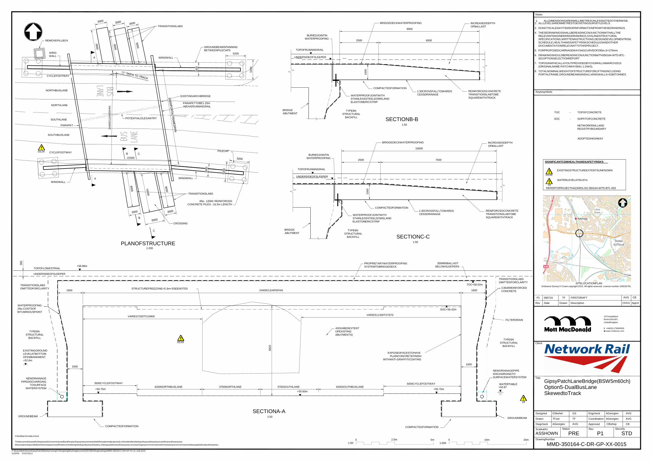
P:\Bristol\BNI\350164GipsyPatch&BrierlyFurlong\5.0Outgoing(Workingdocuments)\5.0WorkingDrawings\MMD-350164-C-DR-GP-XX-15 Jul9,2015-
5:02PM FOO73213
Notes
1. ALLDIMENSIONSAREINMILLIMETRESUNLESSNOTEDOTHERWISE.
P1 090715 TF FIRSTDRAFT AVG CB
Rev Date Drawn Description Ch'k'd App'd
22000
360
24400C
LE
AR
SP
AN
3500
5200
5820
1000
1000
REMOVEPILLBOX
WING
WALL A
CYCLEFOOTWAY
TRANSITIONSLABS
WINGWALL
GROUNDBEAMSPANNING
BETWEENPILECAPS
5200
BURIEDJOINTIN
WATERPROOFING
TOPOFRUNNINGRAIL
UNDERSIDEOFSLEEPER
BRIDGEDECKWATERPROOFING
9000
2500 6500
INCREASEDDEPTH
OFBALLAST
2. ALLLEVELSAREINMETRESTOEXISTINGSURVEYLEVELS.
3. DONOTSCALEANYITEMSORINFORMATIONFROMTHESEDRAWINGS.
4. THESEDRAWINGSSHALLBEREADINCONJUNCTIONWITHALLTHE
RELEVANTENGINEERINGDRAWINGS,CIVILANDSTRUCTURAL
SPECIFICATIONS,WRITTENINSTRUCTIONS,DESIGNDEVELOPMENTRISK
SCHEDULE,HEALTHANDSAFETYRISKSCHEDULESANDOTHER
DOCUMENTATIONRELEVANTTOTHISPROJECT.
5. FORPROPOSEDCARRIAGEWAYSAGCURVEOF290m,S=270mm
6. DRAWINGSHOULDBEREADINCONJUNCTIONWITH350164-WTD-BTL-
001OPTIONSELECTIONREPORT
7. TOPOGRAPHICALLAYOUTPROVIDEDBYCH2MHILLINMARCH2015
(ORIGINALNAME:PATCHWAY5641-1.DWG).
8. TOTALNOMINALWEIGHTOFSTRUCTUREFORLIFTINGINCLUDING
PORTALFRAME,GROUNDBEAMSANDALLWINGWALLS=5280TONNES.
NORTHBUSLANE
NORTHLANE
EXISTINGARCHBRIDGE
PARAPETTOBE1.25m
ABOVERUNNINGRAIL
BRIDGE
ABUTMENT
COMPACTEDFORMATION
WATERPROOFJOINTWITH
STAINLESSSTEELDOWELAND
ELASTOMERICSTRIP
TYPE6N
STRUCTURAL
1:30CROSSFALLTOWARDS
CESSDRAINAGE
REINFORCEDCONCRETE
TRANSITIONSLABTOBE
SQUAREWITHTRACK
Keytosymbols
TOC - TOPOFCONCRETE
SOUTHLANE
PARAPET
POTENTIALOLEGANTRY BACKFILL SECTIONB-B
1:50
SOC - SOFFITOFCONCRETE
NETWORKRAILLAND
REGISTRYBOUNDARY
03,04
SOUTHBUSLANE
CYCLEFOOTWAY
PILECAP
BURIEDJOINTIN
WATERPROOFING
BRIDGEDECKWATERPROOFING
10000
2500 7500
INCREASEDDEPTH
OFBALLAST
ADOPTEDHIGHWAY
SIGNIFICANTCDMHEALTHANDSAFETYRISKS
A
WINGWALL
WINGWALL
TOPOFRUNNINGRAIL
UNDERSIDEOFSLEEPER
03,04
18
EXISTINGSTRUCTUREEXTENTSUNKNOWN
WATERLEVELAT50.87m
REFERTOPROJECTHAZARDLOG:350164-WTD-BTL-003
TRANSITIONSLABS
4No. 12000 REINFORCED
CONCRETE PILES ::16.5m LENGTH
CROSSING
COMPACTEDFORMATION
WATERPROOFJOINTWITH
STAINLESSSTEELDOWELAND
ELASTOMERICSTRIP
1:30CROSSFALLTOWARDS
CESSDRAINAGE
REINFORCEDCONCRETE
TRANSITIONSLABTOBE
SQUAREWITHTRACK
PLANOFSTRUCTURE 1:200
BRIDGE
ABUTMENT
TYPE6N
STRUCTURAL
BACKFILL
SECTIONC-C 1:50
TOPOFLOWESTRAIL
+58.68m
PROPRIETARYWATERPROOFING
SYSTEMTOBRIDGEDECK
300MINBALLAST
BELOWSLEEPERS
UNDERSIDEOFSLEEPER
TRANSITIONSLABS
OMITTEDFORCLARITY
1600
STRUCTUREFREEZONE=5.3m+SSEENOTE5
24400CLEARSPAN
TOC+58.02m
1600
TRANSITIONSLABS
OMITTEDFORCLARITY
C3545REINFORCED
CONCRETE
SITELOCATIONPLAN Ordnance Survey © Crown copyright 2015. All rights reserved. Licence number 100026791.
WATERPROOFING-
2No.COATSOF
BITUMINOUSPAINT
VARIES7250TO10900 VARIES11330TO7670
SOC+56.42m
FILTERDRAIN
10TempleBack
Bristol,BS16FL
UnitedKingdom
TYPE6N
STRUCTURAL
BACKFILL
EXISTINGGROUND
LEVELATBOTTOM
OFEMBANKMENT
+52.6m
NEWDRAINAGE
PIPEDISCHARGING
TOSURFACE
WATERSYSTEM
1000
3500CYCLEFOOTWAY
+50.75m
03,04
4200NORTHBUSLANE
3750NORTHLANE
3750SOUTHLANE
+50.60m
ASSUMEDEXTENT
OFEXISTING
ABUTMENTS)
4200SOUTHBUSLANE
EXPOSEDFACESTOHAVE
PLAINCONCRETEFINISH
WITHANTI-GRAFFITICOATING
5000CYCLEFOOTWAY
+50.75m
1000
TYPE6N
STRUCTURAL
BACKFILL
NEWDRAINAGEPIPE
DISCHARGINGTO
SURFACEWATERSYSTEM
WATERTABLE +50.87
Client
Title
T +44(0)1179069500
W www.mottmac.com
GipsyPatchLaneBridge(BSW5m60ch)
Option5-DualBusLane SkewedtoTrack
GROUNDBEAM
SECTIONA-A
1:50
COMPACTEDFORMATION COMPACTEDFORMATION
18
GROUNDBEAM
Designed
Drawn
Dwgcheck
ScaleatA1
GSkehel GS
TFoot TF
AGeorgiev AVG
Status
Engcheck
Coordination
Approved
Rev
AGeorgiev AVG
AGeorgiev AVG
CBishop CB
Security
© MottMacDonaldLimited
Thisdocumentisissuedforthepartywhichcommissioneditandforspecificpurposesconnectedwiththecaptionedprojectonly.Itshouldnotberelieduponbyanyotherpartyorusedforanyotherpurpose.
0 2.5m 5m 0
10m 20m
ASSHOWN PRE DrawingNumber
P1 STD
Weacceptnoresponsibilityfortheconsequencesofthisdocumentbeingrelieduponbyanyotherparty,orbeingusedforanyotherpurpose,orcontaininganyerrororomissionwhichisduetoanerrororomissionindatasuppliedtousbyotherparties. 1:50 1:200 MMD-350164-C-DR-GP-XX-0015

P:\Bristol\BNI\350164GipsyPatch&BrierlyFurlong\5.0Outgoing(Workingdocuments)\5.0WorkingDrawings\MMD-350164-C-DR-GP-XX-16 Jul9,2015-
5:02PM FOO73213
P1 090715 TF FIRSTDRAFT AVG CB
Rev Date Drawn Description Ch'k'd App'd
Designed GSkehel GS Engcheck AGeorgiev AVG
Drawn TFoot TF Coordination AGeorgiev AVG
Dwgcheck AGeorgiev AVG Approved CBishop CB
ScaleatA1
ASSHOWN Status
PRE Rev
P1 Security
STD
360
5840
1000
TOPOFLOWESTRAIL
UNDERSIDEOFSLEEPER
+58.68m
PROPRIETARYWATERPROOFING
SYSTEMTOBRIDGEDECK
300MINBALLASTBELOWSLEEPERS
TRANSITIONSLABS
OMITTEDFORCLARITY
1750
STRUCTUREFREEZONE=5.3m+SSEENOTE5
29300CLEARSPAN
TOC+58.02m
1750
TRANSITIONSLABS
OMITTEDFORCLARITY
C3545
REINFORCED
CONCRETE
WATERPROOFING2No.COATS
OFBITUMINOUSPAINT
TYPE6N
STRUCTURAL
BACKFILL
EXISTINGGROUND
LEVELATBOTTOM
OFEMBANKMENT
+52.6m
REDUNDANT
SPACE
VARIES10930TO11500 VARIES12230TO11520
ASSUMEDEXTENTOF
EXISTINGABUTMENTS
03
SOC+56.27m
EXPOSEDFACESTOHAVE
PLAINCONCRETEFINISHWITH
ANTI-GRAFFITICOATING
REDUNDANT
SPACE
FILTERDRAIN
TYPE6N
STRUCTURAL
BACKFILL
NEWDRAINAGEPIPE
DISCHARGINGTO
1000
VARIES0TO4400
CYCLEFOOTWAY(3500)
BUSNORTHLANE(4200)
NORTHLANE(3750)
SOUTHLANE(3750)
BUSSOUTHLANE(4200)
CYCLEFOOTWAY(5000)
VARIES4400TO0
1000
NEWDRAINAGEPIPE
DISCHARGINGTO
SURFACEWATERSYSTEM
WATERTABLE
+50.87m
SURFACEWATERSYSTEM +50.85m +50.58m +50.43m
GROUNDBEAM
SECTIONA-A 1:50
18
GROUNDBEAM
COMPACTEDFORMATION COMPACTEDFORMATION
BURIEDJOINTIN
WATERPROOFING
9000
BRIDGEDECKWATERPROOFING
2500 6500
TOPOFRUNNINGRAIL
INCREASEDDEPTH
OFBALLAST
TRANSITIONSLAB
REDUNDANTAREA
ATROADLEVEL
GROUNDBEAMSPANNING
BETWEENPILECAPS
UNDERSIDEOFSLEEPER
REMOVEPILLBOX
WINGWALL
WINGWALL
CYCLEFOOTWAY
PILECAP
BRIDGE
ABUTMENT
COMPACTEDFORMATION
WATERPROOFJOINTWITH
STAINLESSSTEELDOWELAND
ELASTOMERICSTRIP
TYPE6N
1:30CROSSFALLTOWARDS
CESSDRAINAGE
REINFORCEDCONCRETE
TRANSITIONSLABTOBE
SQUAREWITHTRACK
SITELOCATIONPLAN
NORTHBUSLANE
STRUCTURAL
BACKFILL SECTIONB-B 1:50
Ordnance Survey © Crown copyright 2015. All rights reserved. Licence number 100026791.
EXISTINGARCHBRIDGE
NORTHLANE PARAPETSTOBE
1.25mABOVE
RUNNINGRAIL
SOUTHLANE
PARAPET
POTENTIALOLEGANTRY
1. ALLDIMENSIONSAREINMILLIMETRESUNLESSNOTED
(XXXX) - SKEWEDDIMENSION
10TempleBack
Bristol,BS16FL
UnitedKingdom
T +44(0)1179069500
SOUTHBUSLANE
CYCLEFOOTWAY
WINGWALL
PILECAP
OTHERWISE.
2. ALLLEVELSAREINMETRESTOEXISTINGSURVEY
LEVELS.
3. DONOTSCALEANYITEMSORINFORMATIONFROM
THESEDRAWINGS.
4. THESEDRAWINGSSHALLBEREADINCONJUNCTION
WITHALLTHERELEVANTENGINEERINGDRAWINGS,
CIVILANDSTRUCTURALSPECIFICATIONS,WRITTEN
INSTRUCTIONS,DESIGNDEVELOPMENTRISK
SCHEDULE,HEALTHANDSAFETYRISKSCHEDULESAND
OTHERDOCUMENTATIONRELEVANTTOTHISPROJECT.
5. FORPROPOSEDCARRIAGEWAYSAGCURVEOF290m,
S=270mm.
6. DRAWINGSHOULDBEREADINCONJUNCTIONWITH
TOC - TOPOFCONCRETE
SOC - SOFFITOFCONCRETE
NETWORKRAILLAND
REGISTRYBOUNDARY
ADOPTEDHIGHWAY
SIGNIFICANTCDMHEALTHANDSAFETYRISKS
EXISTINGSTRUCTUREEXTENTSUNKNOWN
Client
Title
W www.mottmac.com
GipsyPatchLaneBridge(BSW5m60ch)
WINGWALL
REDUNDANTAREA
ATROADLEVEL
TRANSITIONSLAB OVERS&C
4No. 12000 REINFORCED
CONCRETE PILES = 19m LENGTH 350164-WTD-BTL-001OPTIONSELECTIONREPORT.
7. TOPOGRAPHICALLAYOUTPROVIDEDBYCH2MHILLIN
MARCH2015(ORIGINALNAME:PATCHWAY5641-1.DWG).
8. TOTALNOMINALWEIGHTOFSTRUCTUREFORLIFTING
INCLUDINGPORTALFRAME,GROUNDBEAMSANDALL
03
WATERLEVELAT50.87m
18
Option6-DualBusLane SquaretoTrack
WINGWALLS=5970TONNES. REFERTOPROJECTHAZARDLOG:350164-WTD-BTL-003
CROSSING 0
1:50
2.5 m 5m
0
1:200
10m 20m
© MottMacDonaldLimited
PLANOFSTRUCTURE 1:200
DrawingNumber Thisdocumentisissuedforthepartywhichcommissioneditandforspecificpurposesconnectedwiththecaptionedprojectonly.Itshouldnotberel ieduponbyanyotherpartyorusedforanyotherpurpose.
Weacceptnoresponsibilityfortheconsequencesofthisdocumentbeingrelieduponbyanyotherparty,orbeingusedforanyotherpurpose,orcontaininganyerrororomissionwhichisduetoanerrororomissionindatasuppliedtousbyotherparties. MMD-350164-C-DR-GP-XX-0016
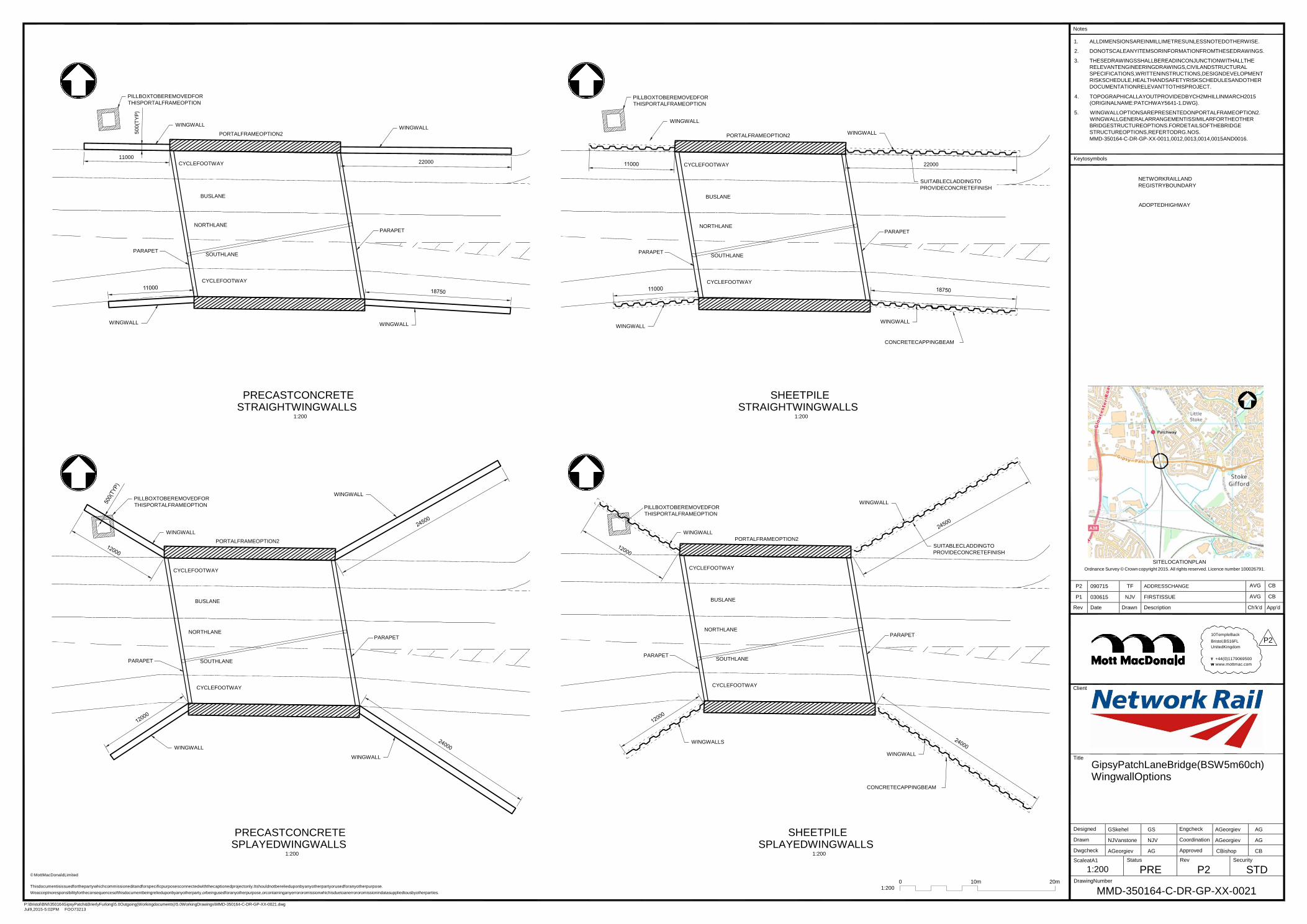
P:\Bristol\BNI\350164GipsyPatch&BrierlyFurlong\5.0Outgoing(Workingdocuments)\5.0WorkingDrawings\MMD-350164-C-DR-GP-XX-0021.dwg
Jul9,2015-5:02PM FOO73213
P2 090715 TF ADDRESSCHANGE AVG CB
P1 030615 NJV FIRSTISSUE AVG CB
Rev Date Drawn Description Ch'k'd App'd
Designed GSkehel GS Engcheck AGeorgiev AG
Drawn NJVanstone NJV Coordination AGeorgiev AG
Dwgcheck AGeorgiev AG Approved CBishop CB
ScaleatA1
1:200
Status
PRE Rev
P2 Security
STD
11000
22000
500(T
YP
)
Notes
PILLBOXTOBEREMOVEDFOR
THISPORTALFRAMEOPTION
WINGWALL WINGWALL
PORTALFRAMEOPTION2
PILLBOXTOBEREMOVEDFOR
THISPORTALFRAMEOPTION
WINGWALL
PORTALFRAMEOPTION2
WINGWALL
1. ALLDIMENSIONSAREINMILLIMETRESUNLESSNOTEDOTHERWISE.
2. DONOTSCALEANYITEMSORINFORMATIONFROMTHESEDRAWINGS.
3. THESEDRAWINGSSHALLBEREADINCONJUNCTIONWITHALLTHE
RELEVANTENGINEERINGDRAWINGS,CIVILANDSTRUCTURAL
SPECIFICATIONS,WRITTENINSTRUCTIONS,DESIGNDEVELOPMENT
RISKSCHEDULE,HEALTHANDSAFETYRISKSCHEDULESANDOTHER
DOCUMENTATIONRELEVANTTOTHISPROJECT.
4. TOPOGRAPHICALLAYOUTPROVIDEDBYCH2MHILLINMARCH2015
(ORIGINALNAME:PATCHWAY5641-1.DWG).
5. WINGWALLOPTIONSAREPRESENTEDONPORTALFRAMEOPTION2.
WINGWALLGENERALARRANGEMENTISSIMILARFORTHEOTHER
BRIDGESTRUCTUREOPTIONS.FORDETAILSOFTHEBRIDGE
STRUCTUREOPTIONS,REFERTODRG.NOS.
MMD-350164-C-DR-GP-XX-0011,0012,0013,0014,0015AND0016.
CYCLEFOOTWAY
22000
CYCLEFOOTWAY
Keytosymbols
BUSLANE
BUSLANE
SUITABLECLADDINGTO
PROVIDECONCRETEFINISH
NETWORKRAILLAND
REGISTRYBOUNDARY
ADOPTEDHIGHWAY
NORTHLANE
PARAPET
NORTHLANE PARAPET
PARAPET
SOUTHLANE
PARAPET
SOUTHLANE
CYCLEFOOTWAY
CYCLEFOOTWAY
WINGWALL WINGWALL
WINGWALL WINGWALL
CONCRETECAPPINGBEAM
PRECASTCONCRETE STRAIGHTWINGWALLS
1:200
SHEETPILE STRAIGHTWINGWALLS
1:200
PILLBOXTOBEREMOVEDFOR
THISPORTALFRAMEOPTION
WINGWALL
PILLBOXTOBEREMOVEDFOR
THISPORTALFRAMEOPTION
WINGWALL
WINGWALL
PORTALFRAMEOPTION2
WINGWALL PORTALFRAMEOPTION2
SUITABLECLADDINGTO
PROVIDECONCRETEFINISH
SITELOCATIONPLAN
CYCLEFOOTWAY CYCLEFOOTWAY Ordnance Survey © Crown copyright 2015. All rights reserved. Licence number 100026791.
BUSLANE BUSLANE
PARAPET
NORTHLANE
SOUTHLANE
PARAPET
PARAPET
NORTHLANE
SOUTHLANE
PARAPET
10TempleBack
Bristol,BS16FL P2 UnitedKingdom
T +44(0)1179069500
W www.mottmac.com
CYCLEFOOTWAY CYCLEFOOTWAY
Client
WINGWALL
WINGWALL
WINGWALLS
WINGWALL
CONCRETECAPPINGBEAM
Title
GipsyPatchLaneBridge(BSW5m60ch)
WingwallOptions
PRECASTCONCRETE SPLAYEDWINGWALLS
1:200
SHEETPILE SPLAYEDWINGWALLS
1:200
© MottMacDonaldLimited
Thisdocumentisissuedforthepartywhichcommissioneditandforspecificpurposesconnectedwiththecaptionedprojectonly.Itshouldnotberelieduponbyanyotherpartyorusedforanyotherpurpose.
Weacceptnoresponsibilityfortheconsequencesofthisdocumentbeingrelieduponbyanyotherparty,orbeingusedforanyotherpurpose,orcontaininganyerrororomissionwhichisduetoanerrororomissionindatasuppliedtousbyotherparties.
0
1:200
10m 20m
DrawingNumber
MMD-350164-C-DR-GP-XX-0021
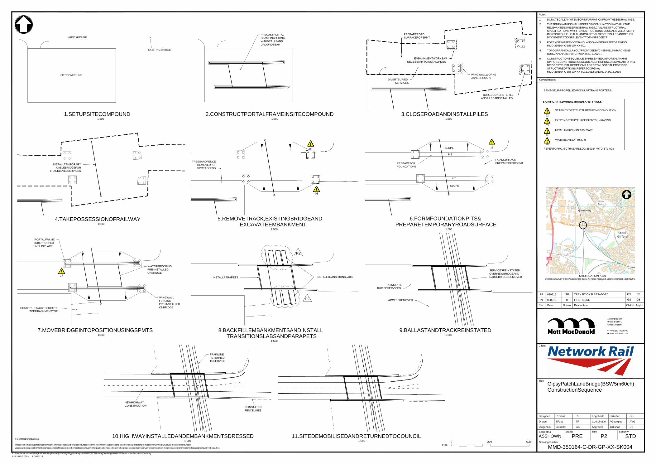
Jul9,2015-5:03PM FOO73213
P2 090715 TF TRANSITIONSLABSADDED GS CB
P1 050615 TF FIRSTISSUE GS CB
Rev Date Drawn Description Ch'k'd App'd
Designed REvans RE Engcheck Gskehel GS
Drawn TFoot TF Coordination AGeorgiev AVG
Dwgcheck GSkehel GS Approved CBishop CB
ScaleatA1
ASSHOWN Status
PRE Rev
P2 Security
STD
GipsyPatchLane
SITECOMPOUND
EXISTINGBRIDGE
PRECASTPORTAL
FRAMEINCLUDING
WINGWALLSAND
GROUNDBEAM
PREPAREROAD
SURFACEFORSPMT
EMBANKMENTWORKSAS
NECESSARYTOINSTALLPILES
DIVERTBURIED
SERVICES
WINGWALLWORKS
ASNECESSARY
Notes
1. DONOTSCALEANYITEMSORINFORMATIONFROMTHESEDRAWINGS.
2. THESEDRAWINGSSHALLBEREADINCONJUNCTIONWITHALLTHE
RELEVANTENGINEERINGDRAWINGS,CIVILANDSTRUCTURAL
SPECIFICATIONS,WRITTENINSTRUCTIONS,DESIGNDEVELOPMENT
RISKSCHEDULE,HEALTHANDSAFETYRISKSCHEDULESANDOTHER
DOCUMENTATIONRELEVANTTOTHISPROJECT.
3. FOREXISTINGSERVICESANDLANDOWNERSHIPSEEDRAWING
MMD-350164-C-DR-GP-XX-001
4. TOPOGRAPHICALLAYOUTPROVIDEDBYCH2MHILLINMARCH2015
(ORIGINALNAME:PATCHWAY5641-1.DWG).
5. CONSTRUCTIONSEQUENCEISPRESENTEDONPORTALFRAME
OPTION1.CONSTRUCTIONSEQUENCEPROPOSEDISSIMILARFORALL
BRIDGESTRUCTUREOPTIONS.FORDETAILSOFOTHERBRIDGE
STRUCTUREOPTIONS,REFERTODRGNos
MMD-350164-C-DR-GP-XX-0011,0012,0013,0014,0015,0016
Keytosymbols
BOREDCONCRETEPILE
ANDPILECAPINSTALLED
SPMT-SELF-PROPELLEDMODULARTRANSPORTERS
SIGNIFICANTCDMHEALTHANDSAFETYRISKS
1.SETUPSITECOMPOUND 1:500
2.CONSTRUCTPORTALFRAMEINSITECOMPOUND 1:500
3.CLOSEROADANDINSTALLPILES 1:500
STABILITYOFSTRUCTUREDURINGDEMOLITION
02
EXISTINGSTRUCTUREEXTENTSUNKNOWN
03
SPMTLOADINGONROADWAY
17
WATERLEVELAT50.87m
18
02 SLOPE 18 REFERTOPROJECTHAZARDLOG:350164-WTD-BTL-003
INSTALLTEMPORARY
CABLEBRIDGEFOR
TRACKLEVELSERVICES
TREESANDFENCE
REMOVEDFOR
SPMTACCESS
PREPAREFOR
FOUNDATIONS
PIT
PIT
ROADSURFACE
PREPAREDFORSPMT
SLOPE
03
4.TAKEPOSSESSIONOFRAILWAY 1:500
5.REMOVETRACK,EXISTINGBRIDGEAND EXCAVATEEMBANKMENT
1:500
6.FORMFOUNDATIONPITS& PREPARETEMPORARYROADSURFACE
1:500
PORTALFRAME
TOBEPROPPED
UNTILINPLACE
P2
WATERPROOFING
PRE-INSTALLED
ONBRIDGE 17
INSTALLPARAPETS INSTALLTRANSITIONSLABS
SERVICESREINSTATED
OVERNEWBRIDGEAND
CABLEBRIDGEREMOVED
SITELOCATIONPLAN Ordnance Survey © Crown copyright 2015. All rights reserved. Licence number 100026791.
REINSTATE
BURIEDSERVICES
CONSTRUCTACCESSROUTE
TOEMBANKMENTTOP
WINGWALL
FENCING
PRE-INSTALLED
ONBRIDGE
P2 ACCESSREMOVED
7.MOVEBRIDGEINTOPOSITIONUSINGSPMTS 1:500
8.BACKFILLEMBANKMENTSANDINSTALL TRANSITIONSLABSANDPARAPETS
1:500
9.BALLASTANDTRACKREINSTATED 1:500
Client
10TempleBack
Bristol,BS16FL
UnitedKingdom
T +44(0)1179069500
W www.mottmac.com
TRAINLINE
RETURNED
TOSERVICE
Title
GipsyPatchLaneBridge(BSW5m60ch)
ConstructionSequence
NEWHIGHWAY
CONSTRUCTION REINSTATED
FENCELINES
© MottMacDonaldLimited
10.HIGHWAYINSTALLEDANDEMBANKMENTSDRESSED 1:500
11.SITEDEMOBILISEDANDRETURNEDTOCOUNCIL 1:500 0
25m 50m
DrawingNumber Thisdocumentisissuedforthepartywhichcommissioneditandforspecificpurposesconnectedwiththecaptionedprojectonly.Itshouldnotberel ieduponbyanyotherpartyorusedforanyotherpurpose.
Weacceptnoresponsibilityfortheconsequencesofthisdocumentbeingrelieduponbyanyotherparty,orbeingusedforanyotherpurpose,orcontaininganyerrororomissionwhichisduetoanerrororomissionindatasuppliedtousbyotherparties.
1:500 MMD-350164-C-DR-GP-XX-SK004
P:\Bristol\BNI\350164GipsyPatch&BrierlyFurlong\5.0Outgoing(Workingdocuments)\5.0WorkingDrawings\MMD-350164-C-DR-GP-XX-SK004.dwg
Ref: 350164/WTD/BTL/01
Version: 03
Date: September 2015
Appendix B
Project Hazard Log
Governance for Railway Investment Projects
NetworkRail IP Western Wales
Notice
This report was produced by Mott MacDonald for Network Rail for the sole purpose of Gypsy Patch Lane (BSW Sm 60ch) .
It may not be used by any person for any other purpose other than that specified without the express written permission of Network Rail and Mott MacDonald.
Any liability arising out of use by Network Rail or a third party of this document for purposes not wholly connected with the above shall be the responsibility of that party who shall indemnify Mott MacDonald against all claims cosls damages
and losses arising out of such use.
Gipsy Patch Lane
Hazard Log
Document Historv
Document Reference: 350164-WTD-BTL-003 Revision: B
CEM Robert Sanderson
Date f//7/IJ- Signature /f r:.---r .J ......
Form Ref No WW IMS 1207 Version A02 13th Nov 2012 1 of1
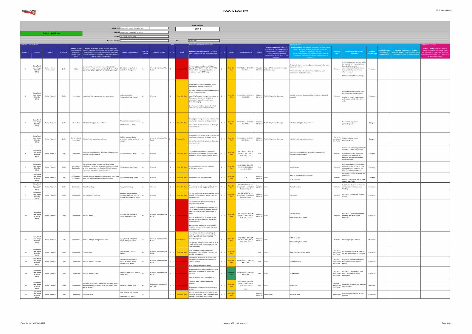
IP Western Wales HAZARD LOG Form
Form Ref No : WW IMS 1207 Version A02 13th Nov 2012 Page 1 of 2
DESIGN STAGE
Project Title Gipsy Patch Lane & Brierly Furlong
GRIP 3 Project Hazard Log Location Gipsy Patch Lane (BSW 5m 60ch)
Doc Ref 350164-WTD-BTL-003
Revision Number B Date 06 July 2015
HAZARD ASSESSMENT Risk DESIGNER CONTROL MEASURES RESIDUAL RISK HAZARD TRANSFER
Hazard ID
Location
Source
Discipline
Sub-discipline -
Topic within the
engineering
discipline (eg.
Cess).
Hazard Description - Description of the Hazard
relating to building construction, use (as a workplace),
operating in normal/abnormal/emergency/degraded
modes, cleaning and maintaining, altering, dismantling
and demolition of a structure.
Hazard Consequences
Red List
Hazard
Persons at Risk
F
C
Result
Measures Taken by Designer - Detail the
hazard elimination or risk reduction actions.
F
C
Result
Location of details
Status
Designer comments - Designer
comments on the designer control
measures section contents that
records decisions taken and
clarification of actions taken by the
designer.
Residual Hazard Description - Description of the Residual
Hazard relating to building construction, using (as a
workplace), operating in normal/
abnormal/emergency/degraded modes, cleaning and
maintaining, altering, dismantling and demolition of a
structure.
Persons at
Risk
Possible Residual Control
Measures
Residual
Hazard Owner
Residual Hazard
Information
Transmission
Designer Comments to Explain
Residual Hazard (To be completed where
necessary for clarity and convey intent)
Project Transfer Status - Details of
status of hazard when residual risk is
being transferred to identified owner. No
entry required until hazard formally offered
to residual risk owner.
1
Gipsy Patch
Lane Bridge
(BSW 5m
60ch)
Buried services
information
Civils
Utilities
Contact with buried services and overhead cables.
Buried services information, provided by Network Rail
may be out-of-date at the time of construction works.
Electrocution, gas leak or
water leak, during works
No
Workers, Members of the
Public
3
4
Intolerable Risk
Known services have been marked on
drawing MMD-350164-C-DR-GP-XX-0001.
This should be reviewed and updated as
necessary in future GRIP stages.
1
4
Tolerable
Risk
MMD-350164-C-DR-GP-
XX-0001.
Mitigation
Identified
Future GWEP works will introduce
OLE to the route
Contact with buried services: Electrocution, gas leak or water
leak, during works.
Potential for clash with unknown services during future
maintenance or alterations works.
Workers
An investigation into services within
the proximity of the structure is to
be undertaken prior to
commencement of works. Services
to be rerouted as part of works
where necessary.
Maintain and update hazard logs.
Contractor
2
Gipsy Patch
Lane Bridge
(BSW 5m
60ch)
Design Proposal
Civils
Demolition
Instability of existing structure during demolition
Collapse causing -
Injury/serious injury / death
No
Workers
2
4
Tolerable Risk
Bridge to be demolished as part of scope
therefore not possible to design out.
Demolition staging to be specified by designer
as part of detailed design.
Latest NWR Assessment and inspections for
the structure reviewed by designer to
understand the condition and inform
demolition staging.
Structure noted to be in fair condition but
soffit was not visible during inspections.
1
4
Tolerable
Risk
MMD-350164-C-DR-GP-
XX-SK004.
Mitigation
Identified
Risk highlighted on drawings
Collapse of existing structure during demolition / structural
instability
Workers
Detailed demolition staging to be
provided at later design stages.
Staging to ensure excavation to
arch is even to both sides of the
arch.
Contractor
3
Gipsy Patch
Lane Bridge
(BSW 5m
60ch)
Design Proposal
Civils
Demolition
Extent of existing structure unknown
Programme and cost increase
COMMERCIAL - NWR
No
3
3
Tolerable Risk
Ground penetrating radar to be undertaken to
establish dimensions of existing structure.
Extent of structure to be shown on drawings
once confirmed.
2
3
Tolerable
Risk
MMD-350164-C-DR-GP-
XX-0002.
Mitigation
Identified
Risk highlighted on drawings
Extent of existing structure unknown
Review following ground
penetrating radar
Designer
4
Gipsy Patch
Lane Bridge
(BSW 5m
60ch)
Design Proposal
Civils
Construction &
Demolition
Extent of existing structure unknown
Striking structure during
preliminary works, leading to
collapse
No
Workers, Members of the
Public
3
3
Tolerable Risk
Ground penetrating radar to be undertaken to
establish dimensions of existing structure.
Extent of structure to be shown on drawings
once confirmed.
2
3
Tolerable
Risk
MMD-350164-C-DR-GP-
XX-0002.
Mitigation
Identified
Risk highlighted on drawings
Extent of existing structure unknown
Workers,
Members of
the Public
Review following ground
penetrating radar
Designer
5
Gipsy Patch
Lane Bridge
(BSW 5m
60ch)
Design Proposal
Civils
Demolition
Potential contaminants e.g. Asbestos in embankments
exposed during demolition
Long term illness / death
No
Workers
2
4
Tolerable Risk
Not practicable within scope to conduct
asbestos / contaminants survey, should be
undertaken prior to commencement of works
2
4
Tolerable
Risk
MMD-350164-C-DR-GP-
XX-0011, 0012, 0013,
0014, 0015, 0016
Open
Potential contaminants e.g. Asbestos in embankments
exposed during demolition
Workers
Further Ground Investigations to be
carried out at later design stage.
Suitable method for disposal of
contaminated material to be
identified by contractor prior to
undertaking works.
Designer
6
Gipsy Patch
Lane Bridge
(BSW 5m
60ch)
Design Proposal
Civils
Demolition /
Construction
The National Hazard Directory has identified the
following – “This stretch of railway has been identified
as being at risk from the migration of landfill gasses.
Appropriate precautions should be taken.”
Injury/serious injury / death
No
Workers
2
4
Tolerable Risk
Not practicable within scope to monitor
landfill gases on site.
1
4
Tolerable
Risk
MMD-350164-C-DR-GP-
XX-0011, 0012, 0013,
0014, 0015, 0016
Open
Landfill gases
Workers
During excavation and foundation
construction, the contractor must
ensure adequate measures are
taken for hazard management.
Contractor
7
Gipsy Patch
Lane Bridge
(BSW 5m
60ch)
Design Proposal
Civils
Embankment
excavation
Detailed make up of embankment unknown, soft / hard
spots and slope instability may be encountered
Injury/serious injury / death
No
Workers
2
4
Tolerable Risk
Available GI used to inform design
1
4
Tolerable
Risk
GDR
Mitigation
Identified
None
Make up of embankment unknown
Slope instability
Workers
Undertake further GI to inform later
grip stages.
Geotechnical input to ensure slope
angle is maintained.
Designer
8
Gipsy Patch
Lane Bridge
(BSW 5m
60ch)
Design Proposal
Civils
Construction
Manual handling
Injury/serious injury
No
Workers
3
3
Tolerable Risk
Pre-cast elements to be used in design and
lifted in to place with SPMTs & cranes
2
3
Tolerable
Risk
350164-WTD-BTL-001
Gipsy Patch Lane Option
Selection Report
Mitigation
Identified
None
Manual handling
Workers
Suitable construction method to be
developed to minimise manual
handling.
Contractor
9
Gipsy Patch
Lane Bridge
(BSW 5m
60ch)
Design Proposal
Civils
Construction
Use of Mortars / Concrete
Chemical burns (mortars,
concrete) leading to injury or
impacting on long term health
No
Workers
3
3
Tolerable Risk
Pre-cast elements to be used in design where
possible to reduce use of wet concrete and
mortars on site.
2
3
Tolerable
Risk
350164-WTD-BTL-001
Gipsy Patch Lane Option
Selection Report
Mitigation
Identified
None
Injury, burn
Workers
Contractor to follow safe systems
of work
Contractor
10
Gipsy Patch
Lane Bridge
(BSW 5m
60ch)
Design Proposal
Civils
Construction
Working at height
Injury through falling from
height, falling equipment
No
Workers, Members of the
Public
4
4
Intolerable Risk
Not practicable to design out working at
height for bridge works.
Design to incorporate precast elements that
can be lifted into position and thus reducing
the construction time and time working at
height.
Number of elements to be limited where
possible to limit the assembly time whilst
working at height.
Main concrete structure to be pre-cast in
controlled environment to reduce the risk of
working at height.
2
4
Tolerable
Risk
MMD-350164-C-DR-GP-
XX-0011, 0012, 0013,
0014, 0015, 0016
Mitigation
Identified
None
Fall from height
Objects falling from height
Workers
Contractor to consider temporary
handrails and fall arresting
equipment.
Contractor
11
Gipsy Patch
Lane Bridge
(BSW 5m
60ch)
Design Proposal
Civils
Maintenance
Working at height during maintenance
Injury through falling from
height, falling equipment
No
Workers, Members of the
Public
2
4
Tolerable Risk
Not practicable to design out working at
height for bridge maintenance, due to the
nature of standard maintenance and
inspection regimes.
New parapet to be provided to a minimum of
1.25m and handrails to be provided (as per
NWR standards)
1
4
Tolerable
Risk
MMD-350164-C-DR-GP-
XX-0011, 0012, 0013,
0014, 0015, 0016
Mitigation
Identified
None
Fall from height
Objects falling from height
Workers
Maintain parapet handrails
Maintainer
12
Gipsy Patch
Lane Bridge
(BSW 5m
60ch)
Design Proposal
Civils
Construction
Public access
Harm to public, conflict,
liability
No
Workers, Members of the
Public
3
2
Tolerable Risk
Road / Footpath closure required for
demolition of existing bridge. Therefore not
possible to design out.
3
2
Tolerable
Risk
Open
None
Harm to public, conflict, liability
Workers,
Members of
the Public
Consideration should be given to
the alternative routes for the public
Contractor
13
Gipsy Patch
Lane Bridge
(BSW 5m
60ch)
Design Proposal
Civils
Construction
Working adjacent to a road
Disruption to traffic flows,
struck by vehicle, injury,
serious injury, death
No
Workers, Members of the
Public
3
5
Intolerable Risk
Portal frame structure to be constructed
within site compound to reduce roadside
construction time.
Road to be closed for main works.
1
5
Tolerable
Risk
MMD-350164-C-DR-GP-
XX-SK004
Open
None
Struck by vehicle
Workers,
Members of
the Public
Contractor to detail and maintain
traffic management and site
extents.
Contractor
14
Gipsy Patch
Lane Bridge
(BSW 5m
60ch)
Design Proposal
Civils
Construction
Working adjacent to rail
Struck by train, injury, serious
injury, death
No
Workers, Members of the
Public
2
5
Intolerable Risk
All trackside works to be completed during a
possession, as detailed in construction
sequence.
Form A completed for track replacement.
1
2
Negligible
Risk
MMD-350164-C-DR-GP-
XX-SK004
Open
None
Struck by train
Workers,
Members of
the Public
Contractor to ensure track side
works are completed under
possession.
Contractor
15
Gipsy Patch
Lane Bridge
(BSW 5m
60ch)
Design Proposal
Civils
Construction
Sensitivity of the track – the skewed option will present
differential settlement which could lead to track twist
and derailment
Derailment, injury, death
No
Passengers, Members of
the Public
3
5
Intolerable Risk
Transition slabs to be installed where
required.
Settlement predictions to be included as part
of GDR.
1
5
Tolerable
Risk
MMD-350164-C-DR-GP-
XX-0011, 0012, 0013,
0014, 0015, 0016
GDR
Open
None
Derailment
Passengers,
Members of
the Public
Monitoring & retamping of ballast to
be undertaken.
Maintainer
16
Gipsy Patch
Lane Bridge
(BSW 5m
60ch)
Design Proposal
Civils
Construction
Disruption to rail
Cost to NWR, risk to asset
COMMERCIAL NWR
No
2
4
Tolerable Risk
Pre-cast elements to be used in design and
lifted in to place with SPMTs & cranes where
possible to reduce possession time.
1
4
Tolerable
Risk
Mitigation
Identified
Risk to asset
Disruption to rail
Passengers
Construction activities to be well
planned.
Contractor
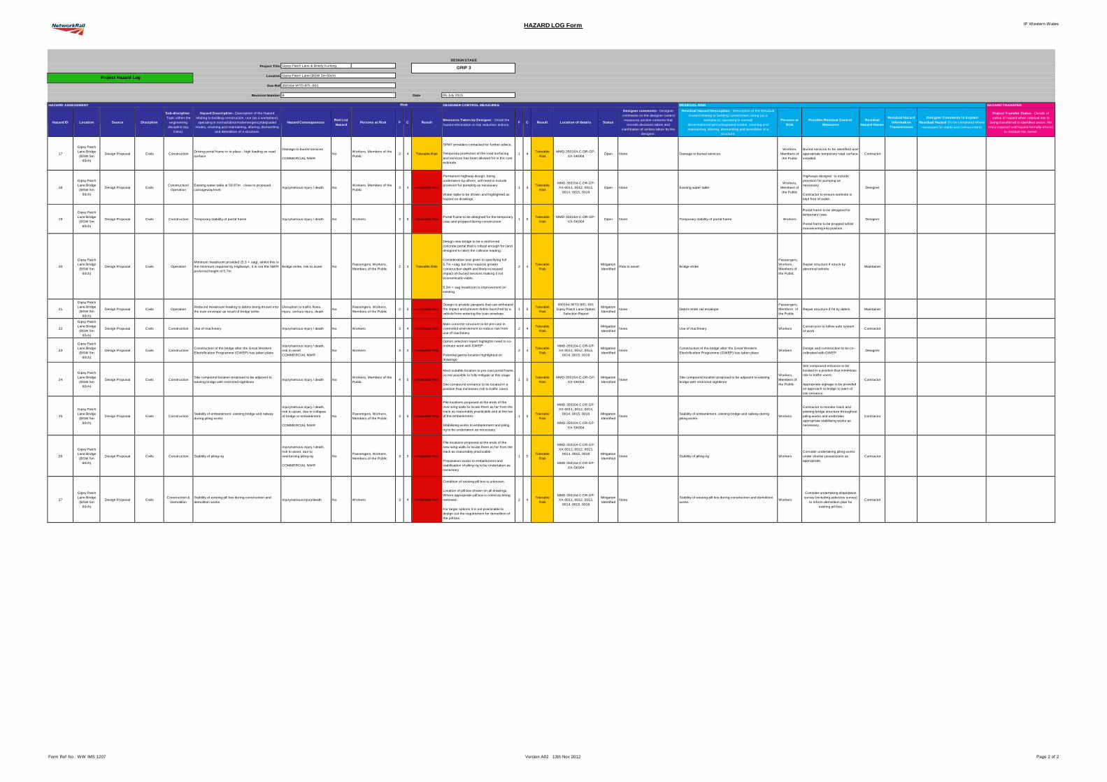
IP Western Wales HAZARD LOG Form
Form Ref No : WW IMS 1207 Version A02 13th Nov 2012 Page 2 of 2
DESIGN STAGE
Project Title Gipsy Patch Lane & Brierly Furlong
GRIP 3 Project Hazard Log Location Gipsy Patch Lane (BSW 5m 60ch)
Doc Ref 350164-WTD-BTL-003
Revision Number B Date 06 July 2015
HAZARD ASSESSMENT Risk DESIGNER CONTROL MEASURES RESIDUAL RISK HAZARD TRANSFER
Hazard ID
Location
Source
Discipline
Sub-discipline -
Topic within the
engineering
discipline (eg.
Cess).
Hazard Description - Description of the Hazard
relating to building construction, use (as a workplace),
operating in normal/abnormal/emergency/degraded
modes, cleaning and maintaining, altering, dismantling
and demolition of a structure.
Hazard Consequences
Red List
Hazard
Persons at Risk
F
C
Result
Measures Taken by Designer - Detail the
hazard elimination or risk reduction actions.
F
C
Result
Location of details
Status
Designer comments - Designer
comments on the designer control
measures section contents that
records decisions taken and
clarification of actions taken by the
designer.
Residual Hazard Description - Description of the Residual
Hazard relating to building construction, using (as a
workplace), operating in normal/
abnormal/emergency/degraded modes, cleaning and
maintaining, altering, dismantling and demolition of a
structure.
Persons at
Risk
Possible Residual Control
Measures
Residual
Hazard Owner
Residual Hazard
Information
Transmission
Designer Comments to Explain
Residual Hazard (To be completed where
necessary for clarity and convey intent)
Project Transfer Status - Details of
status of hazard when residual risk is
being transferred to identified owner. No
entry required until hazard formally offered
to residual risk owner.
17
Gipsy Patch
Lane Bridge
(BSW 5m
60ch)
Design Proposal
Civils
Construction
Driving portal frame in to place - high loading on road
surface
Damage to buried services
COMMERCIAL NWR
No
Workers, Members of the
Public
2
4
Tolerable Risk
SPMT providers contacted for further advice.
Temporary protection of the road surfacing
and services has been allowed for in the cost
estimate.
1
4
Tolerable
Risk
MMD-350164-C-DR-GP-
XX-SK004
Open
None
Damage to buried services
Workers,
Members of
the Public
Buried services to be identified and
appropriate temporary road surface
installed.
Contractor
18
Gipsy Patch
Lane Bridge
(BSW 5m
60ch)
Design Proposal
Civils
Construction/
Operation
Existing water table at 50.87m - close to proposed
carriageway level.
Injury/serious injury / death
No
Workers, Members of the
Public
3
4
Intolerable Risk
Permanent highway design, being
undertaken by others, will need to include
provision for pumping as necessary.
Water table to be shown and highlighted as
hazard on drawings.
1
4
Tolerable
Risk
MMD-350164-C-DR-GP-
XX-0011, 0012, 0013,
0014, 0015, 0016
Open
None
Existing water table
Workers,
Members of
the Public
Highways designer to include
provision for pumping as
necessary.
Contractor to ensure worksite is
kept free of water.
Designer
19
Gipsy Patch
Lane Bridge
(BSW 5m
60ch)
Design Proposal
Civils
Construction
Temporary stability of portal frame
Injury/serious injury / death
No
Workers
3
5
Intolerable Risk
Portal frame to be designed for the temporary
case and propped during construction
1
5
Tolerable
Risk
MMD-350164-C-DR-GP-
XX-SK004
Open
None
Temporary stability of portal frame
Workers
Portal frame to be designed for
temporary case.
Portal frame to be propped whilst
manoeuvring into position.
Designer
20
Gipsy Patch
Lane Bridge
(BSW 5m
60ch)
Design Proposal
Civils
Operation
Minimum headroom provided (5.3 + sag), whilst this is
the minimum required by Highways, it is not the NWR
preferred height of 5.7m
Bridge strike, risk to asset
No
Passengers, Workers,
Members of the Public
2
4
Tolerable Risk
Design new bridge to be a reinforced
concrete portal that is robust enough for (and
designed to take) the collision loading.
Consideration was given to specifying full
5.7m +sag, but this requires greater
construction depth and likely increased
impact on buried services making it not
economically viable.
5.3m + sag headroom is improvement on
existing.
2
4
Tolerable
Risk
Mitigation
Identified
Risk to asset
Bridge strike
Passengers,
Workers,
Members of
the Public
Repair structure if struck by
abnormal vehicle.
Maintainer
21
Gipsy Patch
Lane Bridge
(BSW 5m
60ch)
Design Proposal
Civils
Operation
Reduced Headroom leading to debris being thrown into
the train envelope as result of bridge strike
Disruption to traffic flows,
injury, serious injury, death
No
Passengers, Workers,
Members of the Public
2
5
Intolerable Risk
Design to provide parapets that can withstand
the impact and prevent debris launched by a
vehicle from entering the train envelope.
1
5
Tolerable
Risk
350164-WTD-BTL-001
Gipsy Patch Lane Option
Selection Report
Mitigation
Identified
None
Debris enter rail envelope
Passengers,
Members of
the Public
Repair structure if hit by debris.
Maintainer
22
Gipsy Patch
Lane Bridge
(BSW 5m
60ch)
Design Proposal
Civils
Construction
Use of machinery
Injury/serious injury / death
No
Workers
3
4
Intolerable Risk
Main concrete structure to be pre-cast in
controlled environment to reduce risk from
use of machinery
2
4
Tolerable
Risk
Mitigation
Identified
None
Use of machinery
Workers
Constructor to follow safe system
of work.
Contractor
23
Gipsy Patch
Lane Bridge
(BSW 5m
60ch)
Design Proposal
Civils
Construction
Construction of the bridge after the Great Western
Electrification Programme (GWEP) has taken place
Injury/serious injury / death,
risk to asset
COMMERCIAL NWR
No
Workers
3
4
Intolerable Risk
Option selection report highlights need to co-
ordinate work with GWEP.
Potential gantry location highlighted on
drawings.
2
4
Tolerable
Risk
MMD-350164-C-DR-GP-
XX-0011, 0012, 0013,
0014, 0015, 0016
Mitigation
Identified
None
Construction of the bridge after the Great Western
Electrification Programme (GWEP) has taken place
Workers
Design and construction to be co-
ordinated with GWEP
Designer
24
Gipsy Patch
Lane Bridge
(BSW 5m
60ch)
Design Proposal
Civils
Construction
Site compound location proposed to be adjacent to
existing bridge with restricted sightlines
Injury/serious injury / death
No
Workers, Members of the
Public
4
5
Intolerable Risk
Most suitable location to pre-cast portal frame
so not possible to fully mitigate at this stage.
Site compound entrance to be located in a
position that minimises risk to traffic users
1
5
Tolerable
Risk
MMD-350164-C-DR-GP-
XX-SK004
Mitigation
Identified
None
Site compound location proposed to be adjacent to existing
bridge with restricted sightlines
Workers,
Members of
the Public
Site compound entrance to be
located in a position that minimises
risk to traffic users.
Appropriate signage to be provided
on approach to bridge to warn of
site entrance.
Contractor
25
Gipsy Patch
Lane Bridge
(BSW 5m
60ch)
Design Proposal
Civils
Construction
Stability of embankment, existing bridge and railway
during piling works
Injury/serious injury / death,
risk to asset, due to collapse
of bridge or embankment
COMMERCIAL NWR
No
Passengers, Workers,
Members of the Public
3
5
Intolerable Risk
Pile locations proposed at the ends of the
new wing walls to locate them as far from the
track as reasonably practicable and at the toe
of the embankment.
Stabilising works to embankment and piling
rig to be undertaken as necessary.
1
5
Tolerable
Risk
MMD-350164-C-DR-GP-
XX-0011, 0012, 0013,
0014, 0015, 0016
MMD-350164-C-DR-GP-
XX-SK004
Mitigation
Identified
None
Stability of embankment, existing bridge and railway during
piling works
Workers
Contractor to monitor track and
existing bridge structure throughout
piling works and undertake
appropriate stabilising works as
necessary.
Contractor
26
Gipsy Patch
Lane Bridge
(BSW 5m
60ch)
Design Proposal
Civils
Construction
Stability of piling rig
Injury/serious injury / death,
risk to asset, due to
overturning piling rig
COMMERCIAL NWR
No
Passengers, Workers,
Members of the Public
3
5
Intolerable Risk
Pile locations proposed at the ends of the
new wing walls to locate them as far from the
track as reasonably practicable.
Preparation works to embankment and
stabilisation of piling rig to be undertaken as
necessary.
1
5
Tolerable
Risk
MMD-350164-C-DR-GP-
XX-0011, 0012, 0013,
0014, 0015, 0016
MMD-350164-C-DR-GP-
XX-SK004
Mitigation
Identified
None
Stability of piling rig
Workers
Consider undertaking piling works
under shorter possessions as
appropriate.
Contractor
27
Gipsy Patch
Lane Bridge
(BSW 5m
60ch)
Design Proposal
Civils
Construction &
Demolition
Stability of existing pill box during construction and
demolition works
Injury/serious injury/death
No
Workers
3
4
Intolerable Risk
Condition of existing pill box is unknown.
Location of pill box shown on all drawings.
Where appropriate pill box is noted as being
removed.
For larger options it is not practicable to
design out the requirement for demolition of
the pill box.
2
4
Tolerable
Risk
MMD-350164-C-DR-GP-
XX-0011, 0012, 0013,
0014, 0015, 0016
Mitigation
Identified
None
Stability of existing pill box during construction and demolition
works
Workers
Consider undertaking dilapidation
survey (including asbestos survey)
to inform demolition plan for
existing pill box.
Contractor
Governance for Railway Investment Projects
Ref: 350164/WTD/BTL/01
Version: 03
Date: September 2015
Appendix C
Not Used
Governance for Railway Investment Projects
Ref: 350164/WTD/BTL/01
Version: 03
Date: September 2015
Appendix D
Cost Estimating
Local Government (Access to Information) Act 1985: The cost estimates have been redacted from publication because it is commercially sensitive, such that it would dis-advantage the commercial position of the council in relation to the cost and delivery of the scheme.
Governance for Railway Investment Projects
Ref: 350164/WTD/BTL/01
Version: 03
Date: September 2015
Appendix E
Photographs
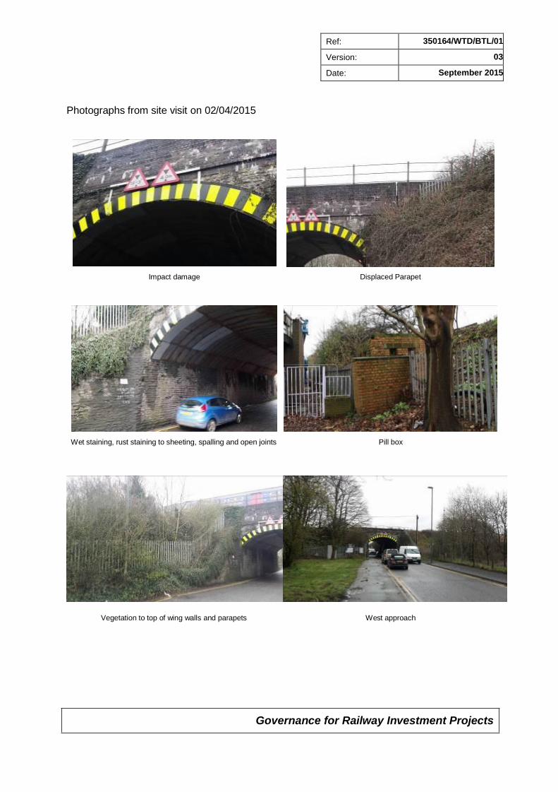
Governance for Railway Investment Projects
Ref: 350164/WTD/BTL/01
Version: 03
Date: September 2015
Photographs from site visit on 02/04/2015
Impact damage Displaced Parapet
Wet staining, rust staining to sheeting, spalling and open joints Pill box
Vegetation to top of wing walls and parapets West approach
Governance for Railway Investment Projects
Ref: 350164/WTD/BTL/01
Version: 03
Date: September 2015
Appendix F
Environmental Appraisal
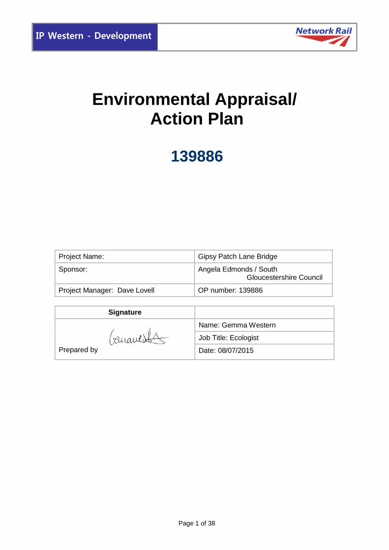
Page 1 of 38
IP Western - Development
Environmental Appraisal/ Action Plan
139886
Project Name: Gipsy Patch Lane Bridge
Sponsor: Angela Edmonds / South Gloucestershire Council
Project Manager: Dave Lovell OP number: 139886
Signature
Prepared by
Name: Gemma Western
Job Title: Ecologist
Date: 08/07/2015
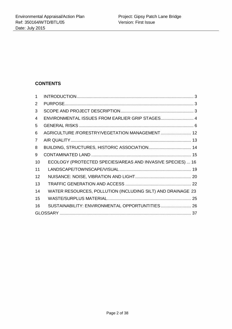
Page 2 of 38
Environmental Appraisal/Action Plan
Ref: 350164/WTD/BTL/05
Date: July 2015
Project: Gipsy Patch Lane Bridge
Version: First Issue
CONTENTS
1 INTRODUCTION ................................................................................................ 3
2 PURPOSE.......................................................................................................... 3
3 SCOPE AND PROJECT DESCRIPTION ............................................................ 3
4 ENVIRONMENTAL ISSUES FROM EARLIER GRIP STAGES ........................... 4
5 GENERAL RISKS .............................................................................................. 6
6 AGRICULTURE /FORESTRY/VEGETATION MANAGEMENT ......................... 12
7 AIR QUALITY ................................................................................................... 13
8 BUILDING, STRUCTURES, HISTORIC ASSOCIATION ................................... 14
9 CONTAMINATED LAND .................................................................................. 15
10 ECOLOGY (PROTECTED SPECIES/AREAS AND INVASIVE SPECIES) ... 16
11 LANDSCAPE/TOWNSCAPE/VISUAL ........................................................... 19
12 NUISANCE: NOISE, VIBRATION AND LIGHT .............................................. 20
13 TRAFFIC GENERATION AND ACCESS ...................................................... 22
14 WATER RESOURCES, POLLUTION (INCLUDING SILT) AND DRAINAGE 23
15 WASTE/SURPLUS MATERIAL ..................................................................... 25
16 SUSTAINABILITY: ENVIRONMENTAL OPPORTUNTITIES ......................... 26
GLOSSARY ............................................................................................................ 37
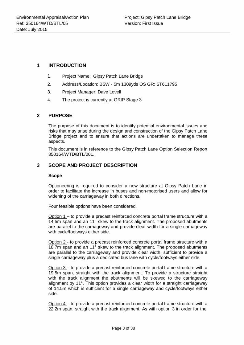
Page 3 of 38
Environmental Appraisal/Action Plan
Ref: 350164/WTD/BTL/05
Date: July 2015
Project: Gipsy Patch Lane Bridge
Version: First Issue
1 INTRODUCTION
1. Project Name: Gipsy Patch Lane Bridge
2. Address/Location: BSW - 5m 1309yds OS GR: ST611795
3. Project Manager: Dave Lovell
4. The project is currently at GRIP Stage 3
2 PURPOSE
The purpose of this document is to identify potential environmental issues and risks that may arise during the design and construction of the Gipsy Patch Lane Bridge project and to ensure that actions are undertaken to manage these aspects.
This document is in reference to the Gipsy Patch Lane Option Selection Report 350164/WTD/BTL/001.
3 SCOPE AND PROJECT DESCRIPTION
Scope
Optioneering is required to consider a new structure at Gipsy Patch Lane in order to facilitate the increase in buses and non-motorised users and allow for widening of the carriageway in both directions.
Four feasible options have been considered.
Option 1 – to provide a precast reinforced concrete portal frame structure with a 14.5m span and an 11° skew to the track alignment. The proposed abutments are parallel to the carriageway and provide clear width for a single carriageway with cycle/footways either side.
Option 2 - to provide a precast reinforced concrete portal frame structure with a 18.7m span and an 11° skew to the track alignment. The proposed abutments are parallel to the carriageway and provide clear width, sufficient to provide a single carriageway plus a dedicated bus lane with cycle/footways either side.
Option 3 – to provide a precast reinforced concrete portal frame structure with a 19.5m span, straight with the track alignment. To provide a structure straight with the track alignment the abutments will be skewed to the carriageway alignment by 11°. This option provides a clear width for a straight carriageway of 14.5m which is sufficient for a single carriageway and cycle/footways either side.
Option 4 – to provide a precast reinforced concrete portal frame structure with a 22.2m span, straight with the track alignment. As with option 3 in order for the
Page 4 of 38
Environmental Appraisal/Action Plan
Ref: 350164/WTD/BTL/05
Date: July 2015
Project: Gipsy Patch Lane Bridge
Version: First Issue
structure to be straight with the track alignment, the abutments will be skewed to the carriageway alignment by 11°. This option provides a clear width for a straight carriageway of 18.7m which is sufficient for a single carriageway, dedicated bus lane and cycle/footways either side.
Option 5 - to provide a precast reinforced concrete portal frame structure with a 24.4m clear span and an 11° skew to the track alignment. The proposed abutments are parallel to the carriageway and provide clear width for a 7.5m single carriageway plus a 4.2m designated bus lane with a 3.5m cycle/footway to the north and a 4.2m designated bus lane with a 5.0m cycle/footway to the south.
Option 6 - to provide a precast reinforced concrete portal frame structure with a 29.3m clear span, square to the track alignment. As with options 3 and 4, to accommodate a structure square to the track alignment, the abutments will be skewed to the carriageway alignment by 11°. This option provides a clear width for a carriageway of 24.4m which is sufficient for a 7.5m single carriageway plus a 4.2m designated bus lane with a 3.5m cycle/footway to the north and a 4.2m designated bus lane with a 5.0m cycle/footway to the south.
Multiple site compound locations have been proposed for the project, refer to appendix C of the option selection report (Gipsy Patch Lane – Site Compound memo 350164/WTD/BTL/04) for further detail.
Description
As part of the Cribbs Patchway Metro Bus Extension Project South Gloucestershire Council (SGC) commissioned an option selection report to address the issues at Gipsy Patch Lane, however following a review of the feasibility of the proposed options by Network Rail, South Gloucestershire Council have proposed an additional requirement to consider the provision for a double decker bus along the route.
Mott MacDonald Ltd. has been commissioned by Network Rail to undertake an option selection report to evaluate and compare options for a new structure at Gipsy Patch Lane to facilitate the increase in buses and non-motorised users and allow for widening of the carriageway in both directions.
The current structure in place is Gipsy Patch Lane Bridge is a single span underline structure located in Little Stoke, South Gloucestershire just south of Patchway Railway Station. The railway is orientated approximately north-south within a largely urban area. The disused Bristol Filton Airport is located to the west of the site.
4 ENVIRONMENTAL ISSUES FROM EARLIER GRIP STAGES
GRIP stage Status
1-2 Environmental Appraisal previously undertaken by Mouchel (2014)
Page 5 of 38
Environmental Appraisal/Action Plan
Ref: 350164/WTD/BTL/05
Date: July 2015
Project: Gipsy Patch Lane Bridge
Version: First Issue
3 This report
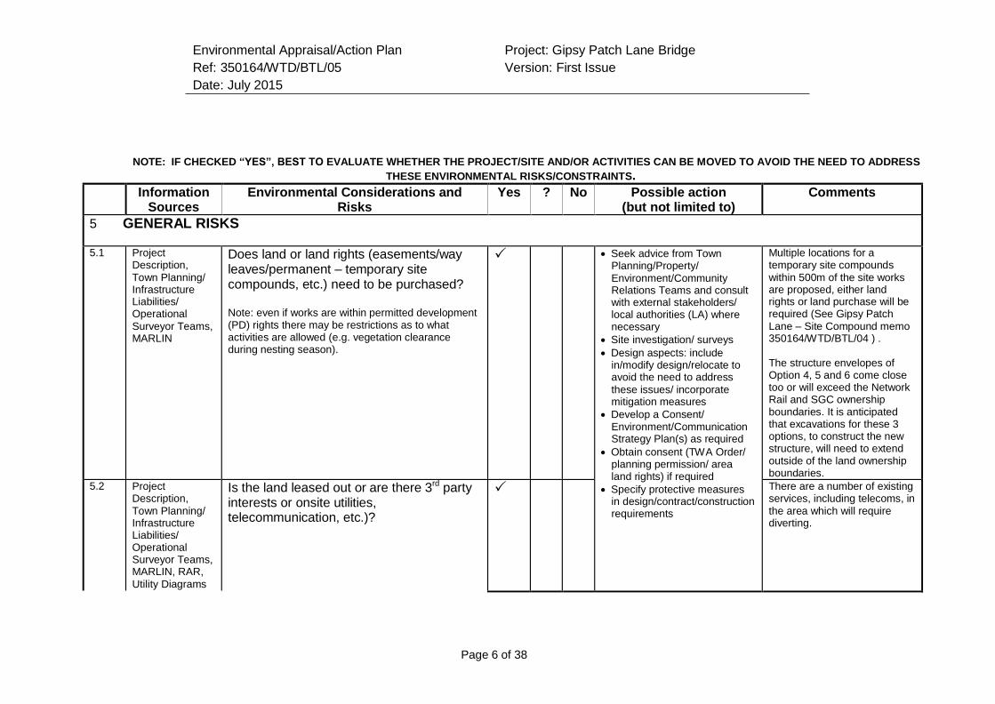
Environmental Appraisal/Action Plan
Ref: 350164/WTD/BTL/05
Date: July 2015
Project: Gipsy Patch Lane Bridge
Version: First Issue
Page 6 of 38
NOTE: IF CHECKED “YES”, BEST TO EVALUATE WHETHER THE PROJECT/SITE AND/OR ACTIVITIES CAN BE MOVED TO AVOID THE NEED TO ADDRESS
THESE ENVIRONMENTAL RISKS/CONSTRAINTS.
Information Sources
Environmental Considerations and Risks
Yes ? No Possible action (but not limited to)
Comments
5 GENERAL RISKS
5.1 Project Description,
Town Planning/ Infrastructure Liabilities/ Operational
Surveyor Teams, MARLIN
Does land or land rights (easements/way leaves/permanent – temporary site compounds, etc.) need to be purchased?
Note: even if works are within permitted development (PD) rights there may be restrictions as to what activities are allowed (e.g. vegetation clearance during nesting season).
Seek advice from Town Planning/Property/
Environment/Community Relations Teams and consult with external stakeholders/ local authorities (LA) where necessary
Site investigation/ surveys
Design aspects: include in/modify design/relocate to avoid the need to address
these issues/ incorporate mitigation measures
Develop a Consent/ Environment/Communication Strategy Plan(s) as required
Obtain consent (TWA Order/ planning permission/ area land rights) if required
Specify protective measures in design/contract/construction requirements
Multiple locations for a temporary site compounds
within 500m of the site works are proposed, either land rights or land purchase will be required (See Gipsy Patch
Lane – Site Compound memo 350164/WTD/BTL/04 ) .
The structure envelopes of Option 4, 5 and 6 come close too or will exceed the Network Rail and SGC ownership boundaries. It is anticipated that excavations for these 3 options, to construct the new structure, will need to extend outside of the land ownership boundaries.
5.2 Project Description,
Town Planning/ Infrastructure Liabilities/ Operational Surveyor Teams, MARLIN, RAR,
Utility Diagrams
Is the land leased out or are there 3rd party interests or onsite utilities, telecommunication, etc.)?
There are a number of existing services, including telecoms, in
the area which will require diverting.
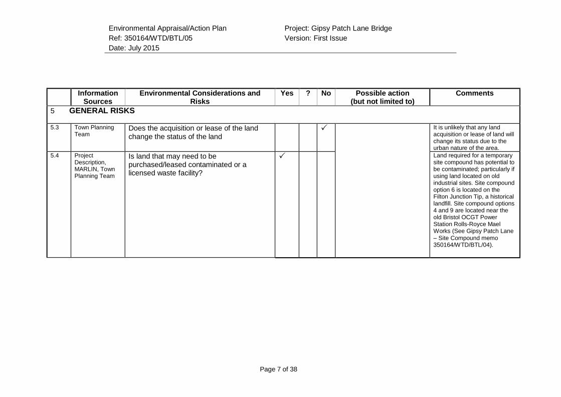
Environmental Appraisal/Action Plan
Ref: 350164/WTD/BTL/05
Date: July 2015
Project: Gipsy Patch Lane Bridge
Version: First Issue
Page 7 of 38
Information
Sources Environmental Considerations and
Risks Yes ? No Possible action
(but not limited to) Comments
5 GENERAL RISKS
5.3 Town Planning Team
Does the acquisition or lease of the land change the status of the land
It is unlikely that any land acquisition or lease of land will change its status due to the urban nature of the area.
5.4 Project Description, MARLIN, Town Planning Team
Is land that may need to be purchased/leased contaminated or a licensed waste facility?
Land required for a temporary site compound has potential to be contaminated; particularly if using land located on old industrial sites. Site compound option 6 is located on the Filton Junction Tip, a historical landfill. Site compound options 4 and 9 are located near the old Bristol OCGT Power Station Rolls-Royce Mael Works (See Gipsy Patch Lane
– Site Compound memo 350164/WTD/BTL/04).
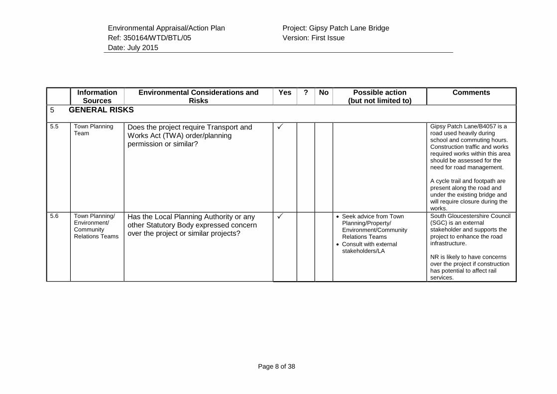
Environmental Appraisal/Action Plan
Ref: 350164/WTD/BTL/05
Date: July 2015
Project: Gipsy Patch Lane Bridge
Version: First Issue
Page 8 of 38
Information
Sources Environmental Considerations and
Risks Yes ? No Possible action
(but not limited to) Comments
5 GENERAL RISKS
5.5 Town Planning Team
Does the project require Transport and Works Act (TWA) order/planning permission or similar?
Gipsy Patch Lane/B4057 is a road used heavily during school and commuting hours. Construction traffic and works required works within this area should be assessed for the need for road management.
A cycle trail and footpath are present along the road and under the existing bridge and will require closure during the works.
5.6 Town Planning/ Environment/ Community Relations Teams
Has the Local Planning Authority or any other Statutory Body expressed concern over the project or similar projects?
Seek advice from Town Planning/Property/ Environment/Community Relations Teams
Consult with external stakeholders/LA
South Gloucestershire Council (SGC) is an external stakeholder and supports the
project to enhance the road infrastructure.
NR is likely to have concerns over the project if construction has potential to affect rail services.
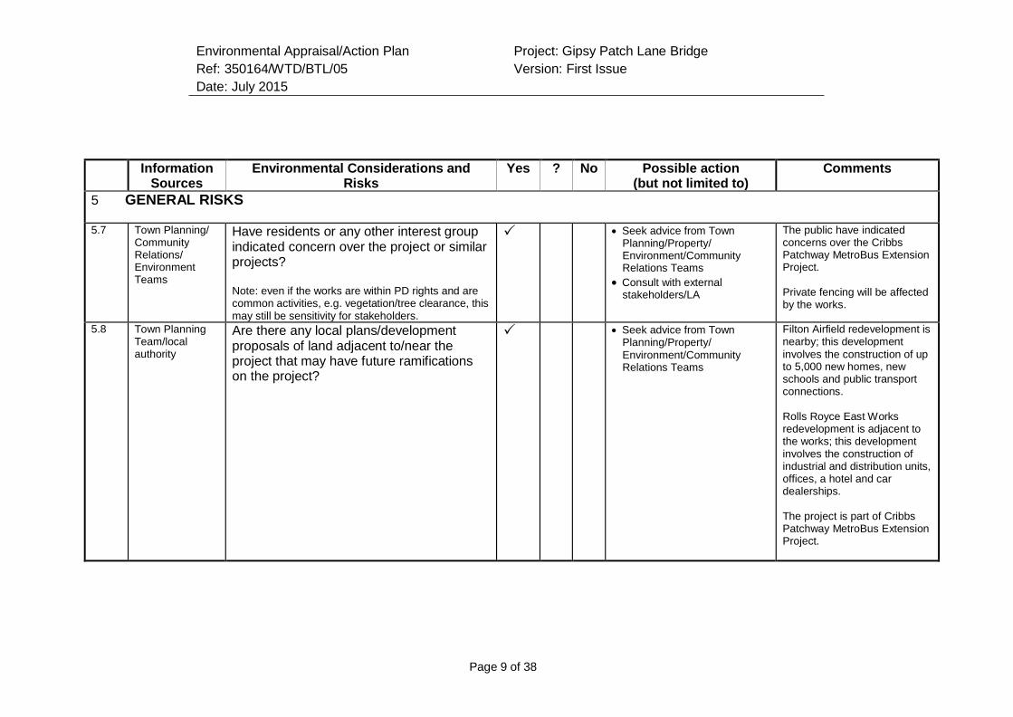
Environmental Appraisal/Action Plan
Ref: 350164/WTD/BTL/05
Date: July 2015
Project: Gipsy Patch Lane Bridge
Version: First Issue
Page 9 of 38
Information
Sources Environmental Considerations and
Risks Yes ? No Possible action
(but not limited to) Comments
5 GENERAL RISKS
5.7 Town Planning/ Community Relations/ Environment Teams
Have residents or any other interest group indicated concern over the project or similar projects?
Note: even if the works are within PD rights and are common activities, e.g. vegetation/tree clearance, this may still be sensitivity for stakeholders.
Seek advice from Town Planning/Property/ Environment/Community Relations Teams
Consult with external stakeholders/LA
The public have indicated concerns over the Cribbs Patchway MetroBus Extension Project.
Private fencing will be affected by the works.
5.8 Town Planning Team/local authority
Are there any local plans/development proposals of land adjacent to/near the project that may have future ramifications on the project?
Seek advice from Town Planning/Property/
Environment/Community Relations Teams
Filton Airfield redevelopment is nearby; this development
involves the construction of up to 5,000 new homes, new schools and public transport connections.
Rolls Royce East Works redevelopment is adjacent to the works; this development involves the construction of industrial and distribution units, offices, a hotel and car dealerships.
The project is part of Cribbs Patchway MetroBus Extension Project.
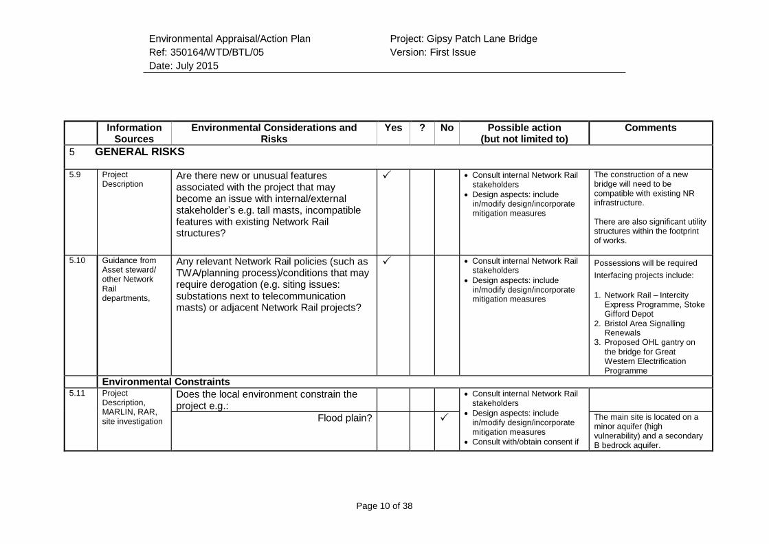
Environmental Appraisal/Action Plan
Ref: 350164/WTD/BTL/05
Date: July 2015
Project: Gipsy Patch Lane Bridge
Version: First Issue
Page 10 of 38
Information
Sources Environmental Considerations and
Risks Yes ? No Possible action
(but not limited to) Comments
5 GENERAL RISKS
5.9 Project Description
Are there new or unusual features associated with the project that may become an issue with internal/external stakeholder’s e.g. tall masts, incompatible features with existing Network Rail structures?
Consult internal Network Rail stakeholders
Design aspects: include in/modify design/incorporate mitigation measures
The construction of a new bridge will need to be compatible with existing NR infrastructure.
There are also significant utility structures within the footprint of works.
5.10 Guidance from Asset steward/ other Network
Rail departments,
Any relevant Network Rail policies (such as TWA/planning process)/conditions that may require derogation (e.g. siting issues: substations next to telecommunication masts) or adjacent Network Rail projects?
Consult internal Network Rail stakeholders
Design aspects: include in/modify design/incorporate mitigation measures
Possessions will be required
Interfacing projects include:
1. Network Rail – Intercity
Express Programme, Stoke Gifford Depot
2. Bristol Area Signalling Renewals
3. Proposed OHL gantry on
the bridge for Great Western Electrification Programme
Environmental Constraints 5.11 Project
Description, MARLIN, RAR, site investigation
Does the local environment constrain the project e.g.:
Consult internal Network Rail stakeholders
Design aspects: include in/modify design/incorporate mitigation measures
Consult with/obtain consent if
Flood plain? The main site is located on a minor aquifer (high vulnerability) and a secondary B bedrock aquifer.
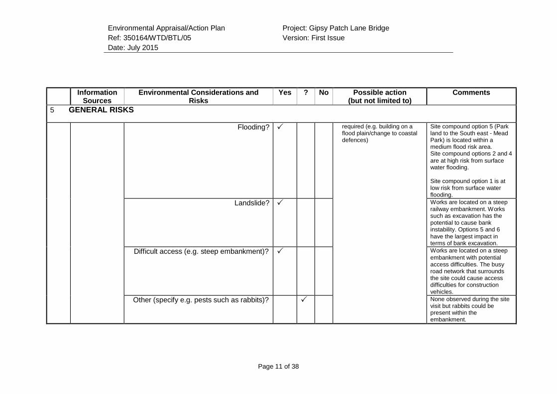
Environmental Appraisal/Action Plan
Ref: 350164/WTD/BTL/05
Date: July 2015
Project: Gipsy Patch Lane Bridge
Version: First Issue
Page 11 of 38
Information
Sources Environmental Considerations and
Risks Yes ? No Possible action
(but not limited to) Comments
5 GENERAL RISKS
Flooding? required (e.g. building on a flood plain/change to coastal defences)
Site compound option 5 (Park land to the South east - Mead Park) is located within a medium flood risk area. Site compound options 2 and 4
are at high risk from surface water flooding.
Site compound option 1 is at low risk from surface water flooding.
Landslide? Works are located on a steep railway embankment. Works such as excavation has the potential to cause bank instability. Options 5 and 6
have the largest impact in terms of bank excavation.
Difficult access (e.g. steep embankment)? Works are located on a steep
embankment with potential access difficulties. The busy road network that surrounds the site could cause access difficulties for construction vehicles.
Other (specify e.g. pests such as rabbits)? None observed during the site visit but rabbits could be present within the embankment.
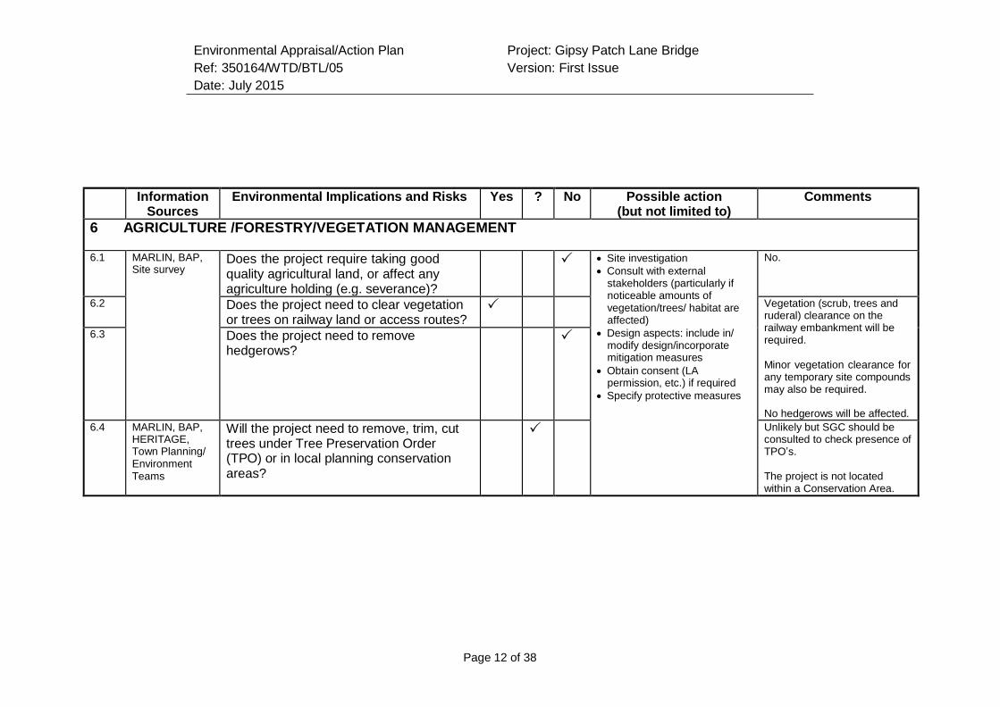
Environmental Appraisal/Action Plan
Ref: 350164/WTD/BTL/05
Date: July 2015
Project: Gipsy Patch Lane Bridge
Version: First Issue
Page 12 of 38
Information Sources
Environmental Implications and Risks Yes ? No Possible action (but not limited to)
Comments
6 AGRICULTURE /FORESTRY/VEGETATION MANAGEMENT
6.1 MARLIN, BAP, Site survey
Does the project require taking good quality agricultural land, or affect any agriculture holding (e.g. severance)?
Site investigation
Consult with external stakeholders (particularly if noticeable amounts of vegetation/trees/ habitat are affected)
Design aspects: include in/ modify design/incorporate mitigation measures
Obtain consent (LA permission, etc.) if required
Specify protective measures
No.
6.2 Does the project need to clear vegetation or trees on railway land or access routes?
Vegetation (scrub, trees and ruderal) clearance on the railway embankment will be required.
Minor vegetation clearance for any temporary site compounds may also be required.
No hedgerows will be affected.
6.3 Does the project need to remove hedgerows?
6.4 MARLIN, BAP, HERITAGE, Town Planning/ Environment Teams
Will the project need to remove, trim, cut trees under Tree Preservation Order (TPO) or in local planning conservation areas?
Unlikely but SGC should be consulted to check presence of TPO’s.
The project is not located within a Conservation Area.
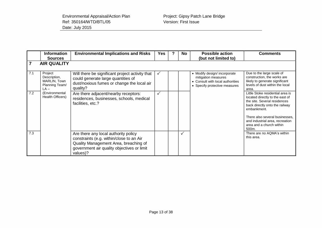
Environmental Appraisal/Action Plan
Ref: 350164/WTD/BTL/05
Date: July 2015
Project: Gipsy Patch Lane Bridge
Version: First Issue
Page 13 of 38
Information
Sources Environmental Implications and Risks Yes ? No Possible action
(but not limited to) Comments
7 AIR QUALITY
7.1 Project Description, MARLIN, Town Planning Team/ LA –
(Environmental Health Officers)
Will there be significant project activity that could generate large quantities of dust/noxious fumes or change the local air quality?
Modify design/ incorporate mitigation measures
Consult with local authorities
Specify protective measures
Due to the large scale of construction, the works are likely to generate significant levels of dust within the local area.
7.2 Are there adjacent/nearby receptors: residences, businesses, schools, medical facilities, etc.?
Little Stoke residential area is located directly to the east of the site. Several residences
back directly onto the railway embankment.
There also several businesses, and industrial area, recreation area and a church within 500m.
7.3 Are there any local authority policy constraints (e.g. within/close to an Air Quality Management Area, breaching of government air quality objectives or limit values)?
There are no AQMA’s within this area.
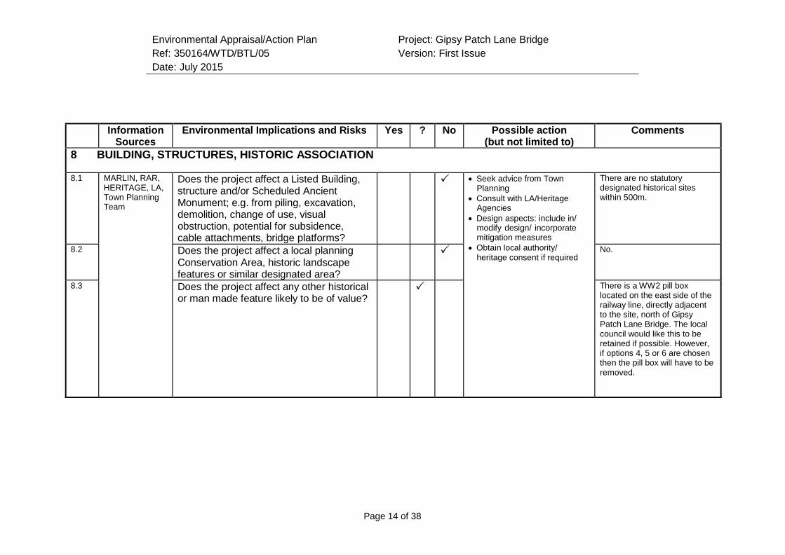
Environmental Appraisal/Action Plan
Ref: 350164/WTD/BTL/05
Date: July 2015
Project: Gipsy Patch Lane Bridge
Version: First Issue
Page 14 of 38
Information
Sources Environmental Implications and Risks Yes ? No Possible action
(but not limited to) Comments
8 BUILDING, STRUCTURES, HISTORIC ASSOCIATION
8.1 MARLIN, RAR, HERITAGE, LA, Town Planning Team
Does the project affect a Listed Building, structure and/or Scheduled Ancient Monument; e.g. from piling, excavation, demolition, change of use, visual obstruction, potential for subsidence, cable attachments, bridge platforms?
Seek advice from Town Planning
Consult with LA/Heritage Agencies
Design aspects: include in/ modify design/ incorporate mitigation measures
Obtain local authority/ heritage consent if required
There are no statutory designated historical sites within 500m.
8.2 Does the project affect a local planning Conservation Area, historic landscape features or similar designated area?
No.
8.3 Does the project affect any other historical or man made feature likely to be of value?
There is a WW2 pill box located on the east side of the railway line, directly adjacent to the site, north of Gipsy Patch Lane Bridge. The local council would like this to be retained if possible. However, if options 4, 5 or 6 are chosen then the pill box will have to be removed.
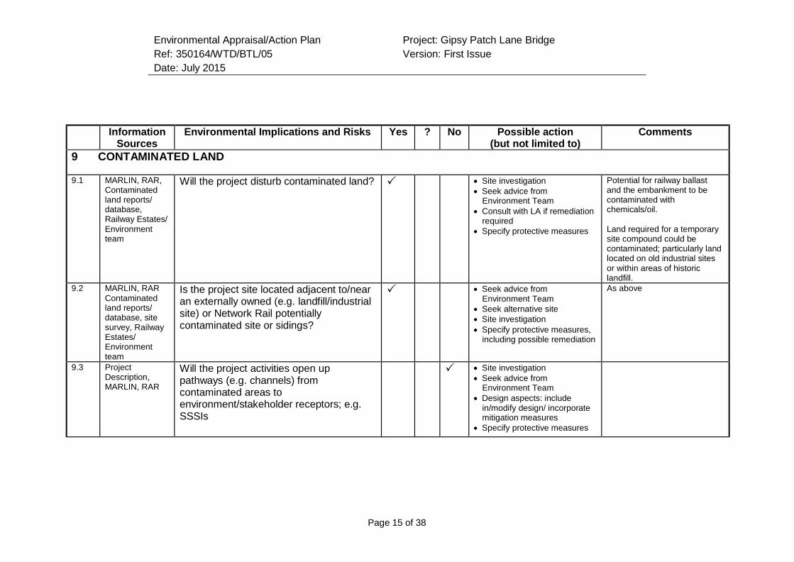
Environmental Appraisal/Action Plan
Ref: 350164/WTD/BTL/05
Date: July 2015
Project: Gipsy Patch Lane Bridge
Version: First Issue
Page 15 of 38
Information
Sources Environmental Implications and Risks Yes ? No Possible action
(but not limited to) Comments
9 CONTAMINATED LAND
9.1 MARLIN, RAR, Contaminated land reports/ database, Railway Estates/
Environment team
Will the project disturb contaminated land? Site investigation
Seek advice from Environment Team
Consult with LA if remediation required
Specify protective measures
Potential for railway ballast and the embankment to be contaminated with chemicals/oil.
Land required for a temporary site compound could be contaminated; particularly land located on old industrial sites or within areas of historic landfill.
9.2 MARLIN, RAR
Contaminated land reports/ database, site survey, Railway Estates/ Environment team
Is the project site located adjacent to/near an externally owned (e.g. landfill/industrial site) or Network Rail potentially contaminated site or sidings?
Seek advice from Environment Team
Seek alternative site
Site investigation
Specify protective measures, including possible remediation
As above
9.3 Project Description, MARLIN, RAR
Will the project activities open up pathways (e.g. channels) from contaminated areas to environment/stakeholder receptors; e.g. SSSIs
Site investigation
Seek advice from Environment Team
Design aspects: include in/modify design/ incorporate mitigation measures
Specify protective measures
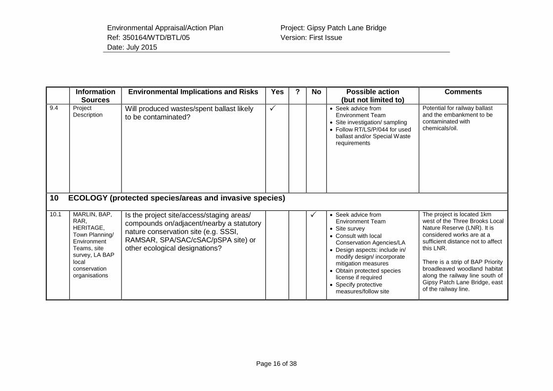
Environmental Appraisal/Action Plan
Ref: 350164/WTD/BTL/05
Date: July 2015
Project: Gipsy Patch Lane Bridge
Version: First Issue
Page 16 of 38
Information
Sources Environmental Implications and Risks Yes ? No Possible action
(but not limited to) Comments
9.4 Project Description
Will produced wastes/spent ballast likely to be contaminated?
Seek advice from Environment Team
Site investigation/ sampling
Follow RT/LS/P/044 for used ballast and/or Special Waste requirements
Potential for railway ballast and the embankment to be contaminated with chemicals/oil.
10 ECOLOGY (protected species/areas and invasive species)
10.1 MARLIN, BAP, RAR, HERITAGE,
Town Planning/ Environment Teams, site survey, LA BAP
local conservation organisations
Is the project site/access/staging areas/ compounds on/adjacent/nearby a statutory nature conservation site (e.g. SSSI, RAMSAR, SPA/SAC/cSAC/pSPA site) or other ecological designations?
Seek advice from Environment Team
Site survey
Consult with local Conservation Agencies/LA
Design aspects: include in/ modify design/ incorporate mitigation measures
Obtain protected species license if required
Specify protective measures/follow site
The project is located 1km west of the Three Brooks Local Nature Reserve (LNR). It is
considered works are at a sufficient distance not to affect this LNR.
There is a strip of BAP Priority broadleaved woodland habitat along the railway line south of Gipsy Patch Lane Bridge, east of the railway line.
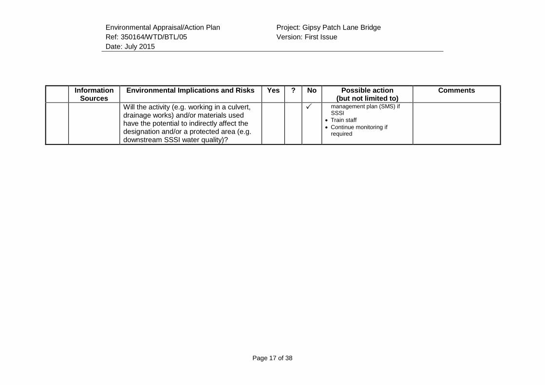
Environmental Appraisal/Action Plan
Ref: 350164/WTD/BTL/05
Date: July 2015
Project: Gipsy Patch Lane Bridge
Version: First Issue
Page 17 of 38
Information
Sources Environmental Implications and Risks Yes ? No Possible action
(but not limited to) Comments
Will the activity (e.g. working in a culvert, drainage works) and/or materials used have the potential to indirectly affect the designation and/or a protected area (e.g. downstream SSSI water quality)?
management plan (SMS) if SSSI
Train staff
Continue monitoring if required
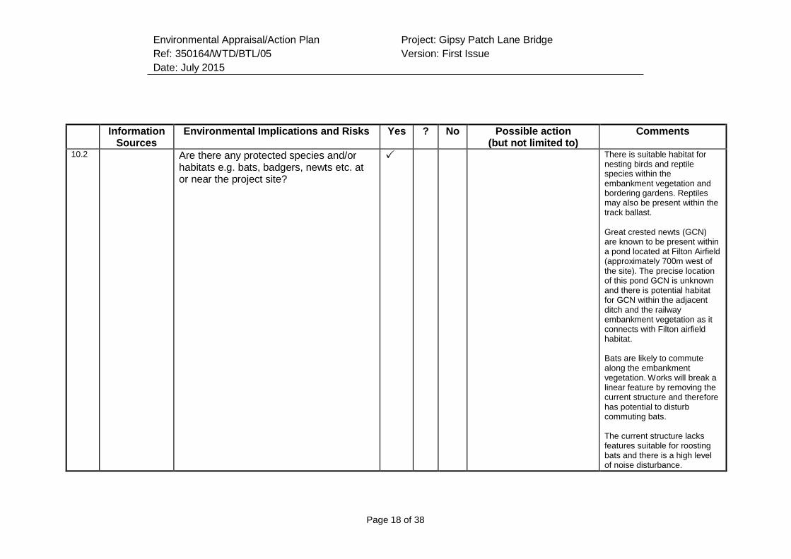
Environmental Appraisal/Action Plan
Ref: 350164/WTD/BTL/05
Date: July 2015
Project: Gipsy Patch Lane Bridge
Version: First Issue
Page 18 of 38
Information
Sources Environmental Implications and Risks Yes ? No Possible action
(but not limited to) Comments
10.2 Are there any protected species and/or habitats e.g. bats, badgers, newts etc. at or near the project site?
There is suitable habitat for nesting birds and reptile species within the embankment vegetation and bordering gardens. Reptiles may also be present within the track ballast.
Great crested newts (GCN) are known to be present within a pond located at Filton Airfield (approximately 700m west of the site). The precise location of this pond GCN is unknown and there is potential habitat for GCN within the adjacent ditch and the railway embankment vegetation as it connects with Filton airfield habitat.
Bats are likely to commute along the embankment vegetation. Works will break a linear feature by removing the current structure and therefore has potential to disturb commuting bats.
The current structure lacks features suitable for roosting bats and there is a high level of noise disturbance.
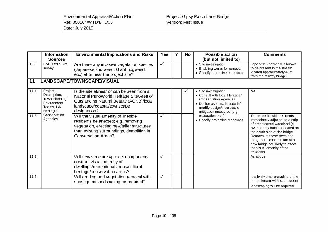
Environmental Appraisal/Action Plan
Ref: 350164/WTD/BTL/05
Date: July 2015
Project: Gipsy Patch Lane Bridge
Version: First Issue
Page 19 of 38
Information
Sources Environmental Implications and Risks Yes ? No Possible action
(but not limited to) Comments
10.3 BAP, RAR, Site
survey Are there any invasive vegetation species (Japanese knotweed, Giant hogweed, etc.) at or near the project site?
Site investigation
Enabling works for removal
Specify protective measures
Japanese knotweed is known to be present in the stream located approximately 40m from the railway bridge.
11 LANDSCAPE/TOWNSCAPE/VISUAL
11.1 Project Description, Town Planning/ Environment Teams, LA/ Heritage/ Conservation Agencies
Is the site at/near or can be seen from a National Park/World Heritage Site/Area of Outstanding Natural Beauty (AONB)/local landscape/coastal/townscape designation?
Site investigation
Consult with local Heritage/ Conservation Agencies
Design aspects: include in/ modify design/incorporate mitigation measures (e.g. restoration plan)
Specify protective measures
No
11.2 Will the visual amenity of lineside residents be affected; e.g. removing vegetation, erecting new/taller structures than existing surroundings, demolition in Conservation Areas?
There are lineside residents immediately adjacent to a strip
of broadleaved woodland (a BAP priority habitat) located on the south side of the bridge. Removal of these trees and the general construction of a
new bridge are likely to affect the visual amenity of the residents.
11.3 Will new structures/project components obstruct visual amenity of dwellings/recreational areas/cultural heritage/conservation areas?
As above
11.4 Will grading and vegetation removal with subsequent landscaping be required?
It is likely that re-grading of the
embankment with subsequent
landscaping will be required.
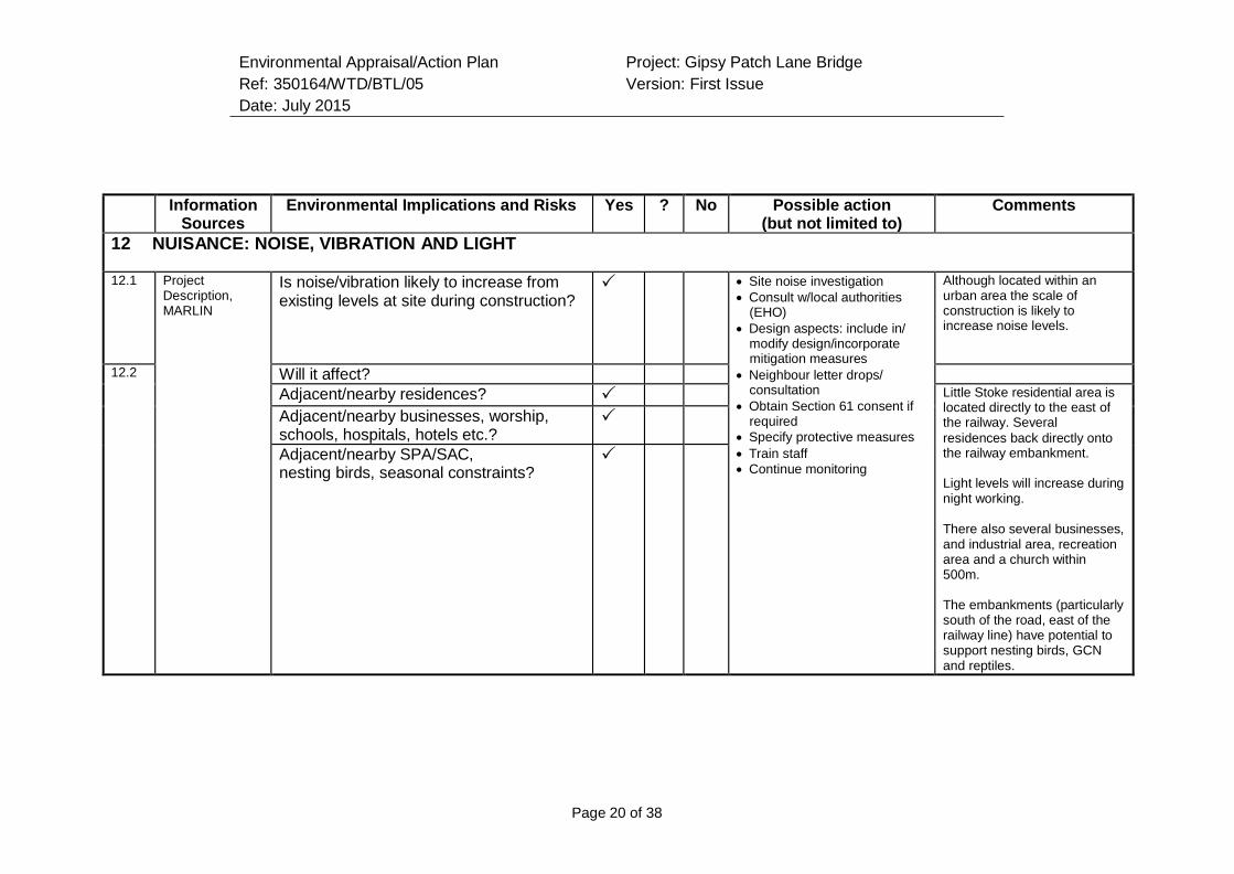
Environmental Appraisal/Action Plan
Ref: 350164/WTD/BTL/05
Date: July 2015
Project: Gipsy Patch Lane Bridge
Version: First Issue
Page 20 of 38
Information
Sources Environmental Implications and Risks Yes ? No Possible action
(but not limited to) Comments
12 NUISANCE: NOISE, VIBRATION AND LIGHT
12.1 Project Description, MARLIN
Is noise/vibration likely to increase from existing levels at site during construction?
Site noise investigation
Consult w/local authorities (EHO)
Design aspects: include in/ modify design/incorporate mitigation measures
Neighbour letter drops/ consultation
Obtain Section 61 consent if required
Specify protective measures
Train staff
Continue monitoring
Although located within an urban area the scale of construction is likely to increase noise levels.
12.2 Will it affect? Adjacent/nearby residences? Little Stoke residential area is
located directly to the east of the railway. Several
residences back directly onto the railway embankment.
Light levels will increase during night working.
There also several businesses, and industrial area, recreation area and a church within 500m.
The embankments (particularly south of the road, east of the railway line) have potential to support nesting birds, GCN and reptiles.
Adjacent/nearby businesses, worship, schools, hospitals, hotels etc.?
Adjacent/nearby SPA/SAC, nesting birds, seasonal constraints?
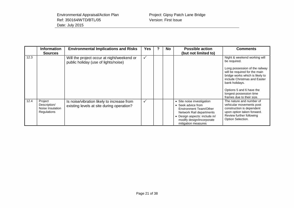
Environmental Appraisal/Action Plan
Ref: 350164/WTD/BTL/05
Date: July 2015
Project: Gipsy Patch Lane Bridge
Version: First Issue
Page 21 of 38
Information
Sources Environmental Implications and Risks Yes ? No Possible action
(but not limited to) Comments
12.3 Will the project occur at night/weekend or public holiday (use of lights/noise)
Night & weekend working will be required.
Long possession of the railway will be required for the main bridge works which is likely to include Christmas and Easter bank holidays.
Options 5 and 6 have the longest possession time frames due to their size.
12.4 Project Description/ Noise Insulation Regulations
Is noise/vibration likely to increase from existing levels at site during operation?
Site noise investigation
Seek advice from Environment Team/Other Network Rail departments
Design aspects: include in/ modify design/incorporate mitigation measures
The nature and number of vehicular movements post construction is dependent upon option taken forward. Review further following Option Selection.
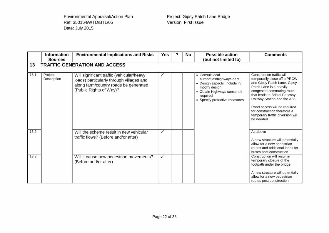
Environmental Appraisal/Action Plan
Ref: 350164/WTD/BTL/05
Date: July 2015
Project: Gipsy Patch Lane Bridge
Version: First Issue
Page 22 of 38
Information
Sources Environmental Implications and Risks Yes ? No Possible action
(but not limited to) Comments
13 TRAFFIC GENERATION AND ACCESS
13.1 Project Description
Will significant traffic (vehicular/heavy loads) particularly through villages and along farm/country roads be generated (Public Rights of Way)?
Consult local authorities/highways dept.
Design aspects: include in/ modify design
Obtain Highways consent if required
Specify protective measures
Construction traffic will temporarily close off a PROW and Gipsy Patch Lane. Gipsy Patch Lane is a heavily congested commuting route that leads to Bristol Parkway Railway Station and the A38.
Road access will be required for construction therefore a temporary traffic diversion will be needed.
13.2 Will the scheme result in new vehicular traffic flows? (Before and/or after)
As above
A new structure will potentially allow for a new pedestrian routes and additional lanes for buses post construction.
13.3 Will it cause new pedestrian movements? (Before and/or after)
Construction will result in temporary closure of the footpath under the bridge.
A new structure will potentially allow for a new pedestrian routes post construction.
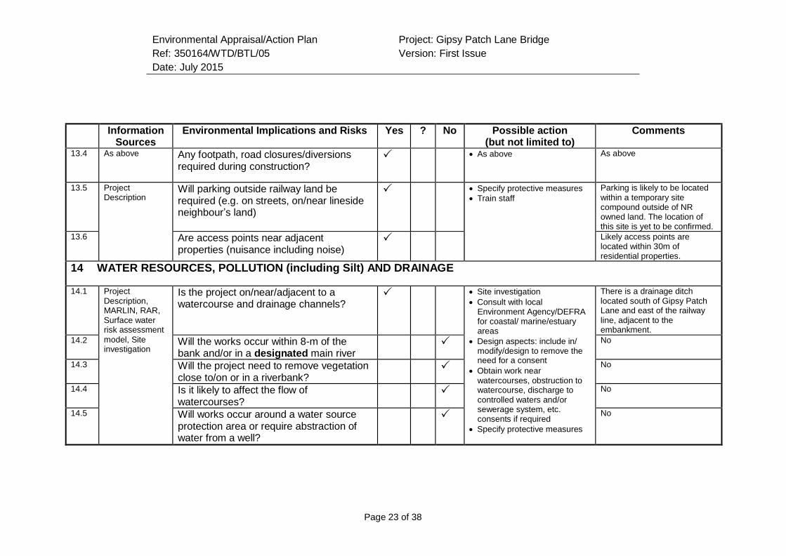
Environmental Appraisal/Action Plan
Ref: 350164/WTD/BTL/05
Date: July 2015
Project: Gipsy Patch Lane Bridge
Version: First Issue
Page 23 of 38
Information
Sources Environmental Implications and Risks Yes ? No Possible action
(but not limited to) Comments
13.4 As above Any footpath, road closures/diversions required during construction?
As above As above
13.5 Project Description
Will parking outside railway land be required (e.g. on streets, on/near lineside neighbour’s land)
Specify protective measures
Train staff
Parking is likely to be located within a temporary site compound outside of NR owned land. The location of this site is yet to be confirmed.
13.6 Are access points near adjacent properties (nuisance including noise)
Likely access points are located within 30m of residential properties.
14 WATER RESOURCES, POLLUTION (including Silt) AND DRAINAGE
14.1 Project Description, MARLIN, RAR, Surface water risk assessment
model, Site investigation
Is the project on/near/adjacent to a watercourse and drainage channels?
Site investigation
Consult with local Environment Agency/DEFRA for coastal/ marine/estuary areas
Design aspects: include in/ modify/design to remove the need for a consent
Obtain work near watercourses, obstruction to watercourse, discharge to controlled waters and/or sewerage system, etc. consents if required
Specify protective measures
There is a drainage ditch located south of Gipsy Patch Lane and east of the railway line, adjacent to the embankment.
14.2 Will the works occur within 8-m of the bank and/or in a designated main river
No
14.3 Will the project need to remove vegetation close to/on or in a riverbank?
No
14.4 Is it likely to affect the flow of watercourses?
No
14.5 Will works occur around a water source protection area or require abstraction of water from a well?
No
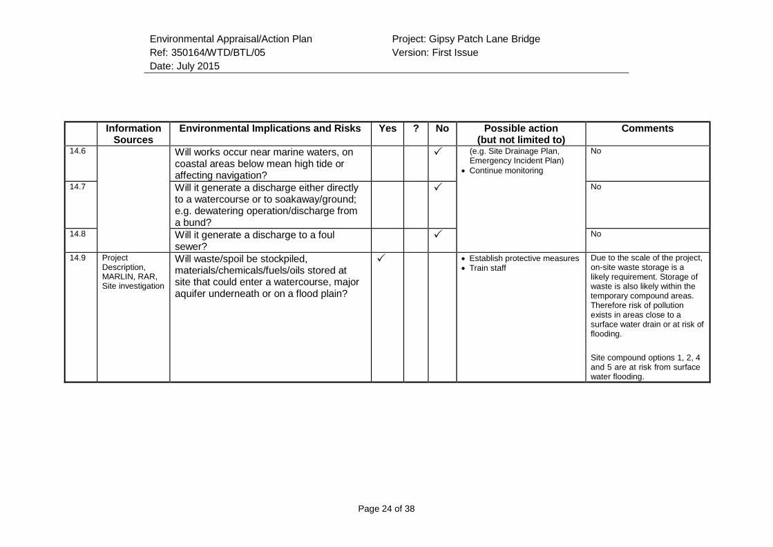
Environmental Appraisal/Action Plan
Ref: 350164/WTD/BTL/05
Date: July 2015
Project: Gipsy Patch Lane Bridge
Version: First Issue
Page 24 of 38
Information
Sources Environmental Implications and Risks Yes ? No Possible action
(but not limited to) Comments
14.6 Will works occur near marine waters, on coastal areas below mean high tide or affecting navigation?
(e.g. Site Drainage Plan, Emergency Incident Plan)
Continue monitoring
No
14.7 Will it generate a discharge either directly to a watercourse or to soakaway/ground; e.g. dewatering operation/discharge from a bund?
No
14.8 Will it generate a discharge to a foul sewer?
No
14.9 Project Description, MARLIN, RAR, Site investigation
Will waste/spoil be stockpiled, materials/chemicals/fuels/oils stored at site that could enter a watercourse, major aquifer underneath or on a flood plain?
Establish protective measures
Train staff
Due to the scale of the project, on-site waste storage is a likely requirement. Storage of waste is also likely within the temporary compound areas. Therefore risk of pollution exists in areas close to a surface water drain or at risk of flooding.
Site compound options 1, 2, 4 and 5 are at risk from surface water flooding.
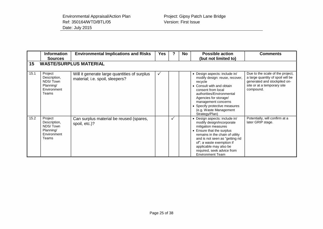
Environmental Appraisal/Action Plan
Ref: 350164/WTD/BTL/05
Date: July 2015
Project: Gipsy Patch Lane Bridge
Version: First Issue
Page 25 of 38
Information
Sources Environmental Implications and Risks Yes ? No Possible action
(but not limited to) Comments
15 WASTE/SURPLUS MATERIAL
15.1 Project Description, NDS/ Town Planning/ Environment Teams
Will it generate large quantities of surplus material; i.e. spoil, sleepers?
Design aspects: include in/ modify design: reuse, recover, recycle
Consult with and obtain consent from local authorities/Environmental
Agencies for storage/ management concerns
Specify protective measures
(e.g. Waste Management Strategy/Plan)
Due to the scale of the project, a large quantity of spoil will be generated and stockpiled on- site or at a temporary site compound.
15.2 Project Description, NDS/ Town Planning/ Environment Teams
Can surplus material be reused (spares, spoil, etc.)?
Design aspects: include in/ modify design/incorporate mitigation measures
Ensure that the surplus remains in the chain of utility and is not seen as “getting rid
of”; a waste exemption if applicable may also be required, seek advice from Environment Team
Potentially, will confirm at a later GRIP stage.
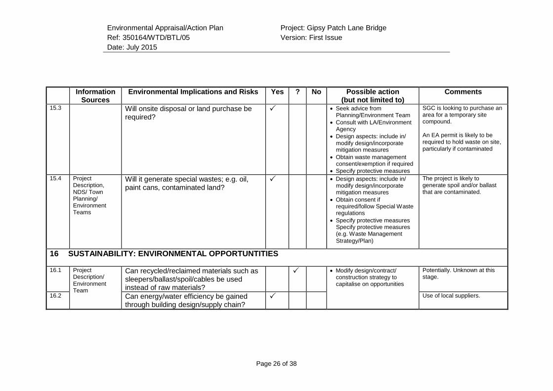
Environmental Appraisal/Action Plan
Ref: 350164/WTD/BTL/05
Date: July 2015
Project: Gipsy Patch Lane Bridge
Version: First Issue
Page 26 of 38
Information
Sources Environmental Implications and Risks Yes ? No Possible action
(but not limited to) Comments
15.3 Will onsite disposal or land purchase be required?
Seek advice from Planning/Environment Team
Consult with LA/Environment Agency
Design aspects: include in/ modify design/incorporate mitigation measures
Obtain waste management consent/exemption if required
Specify protective measures
SGC is looking to purchase an area for a temporary site compound.
An EA permit is likely to be required to hold waste on site, particularly if contaminated
15.4 Project Description, NDS/ Town Planning/ Environment Teams
Will it generate special wastes; e.g. oil, paint cans, contaminated land?
Design aspects: include in/ modify design/incorporate mitigation measures
Obtain consent if required/follow Special Waste regulations
Specify protective measures Specify protective measures (e.g. Waste Management
Strategy/Plan)
The project is likely to generate spoil and/or ballast that are contaminated.
16 SUSTAINABILITY: ENVIRONMENTAL OPPORTUNTITIES
16.1 Project Description/
Environment Team
Can recycled/reclaimed materials such as sleepers/ballast/spoil/cables be used instead of raw materials?
Modify design/contract/ construction strategy to capitalise on opportunities
Potentially. Unknown at this stage.
16.2 Can energy/water efficiency be gained through building design/supply chain?
Use of local suppliers.
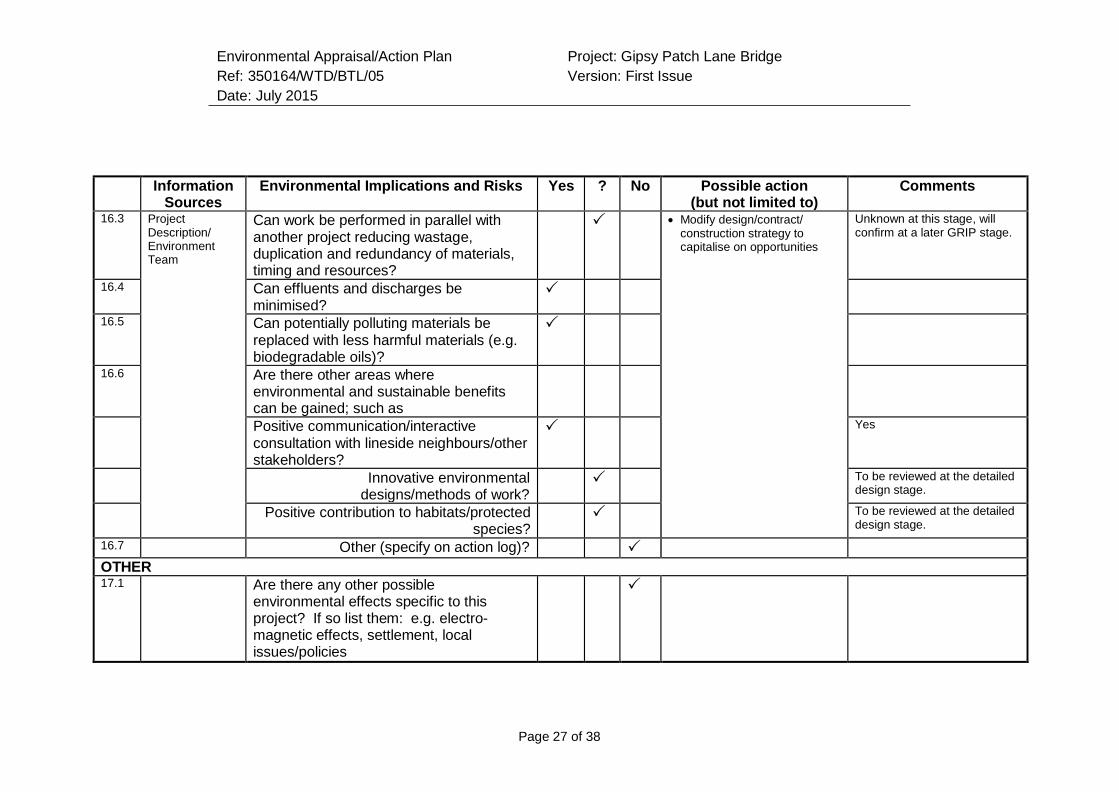
Environmental Appraisal/Action Plan
Ref: 350164/WTD/BTL/05
Date: July 2015
Project: Gipsy Patch Lane Bridge
Version: First Issue
Page 27 of 38
Information
Sources Environmental Implications and Risks Yes ? No Possible action
(but not limited to) Comments
16.3 Project Description/ Environment Team
Can work be performed in parallel with another project reducing wastage, duplication and redundancy of materials, timing and resources?
Modify design/contract/ construction strategy to capitalise on opportunities
Unknown at this stage, will confirm at a later GRIP stage.
16.4 Can effluents and discharges be minimised?
16.5 Can potentially polluting materials be replaced with less harmful materials (e.g. biodegradable oils)?
16.6 Are there other areas where environmental and sustainable benefits can be gained; such as
Positive communication/interactive consultation with lineside neighbours/other stakeholders?
Yes
Innovative environmental designs/methods of work?
To be reviewed at the detailed design stage.
Positive contribution to habitats/protected species?
To be reviewed at the detailed design stage.
16.7 Other (specify on action log)?
OTHER 17.1 Are there any other possible
environmental effects specific to this project? If so list them: e.g. electro- magnetic effects, settlement, local issues/policies
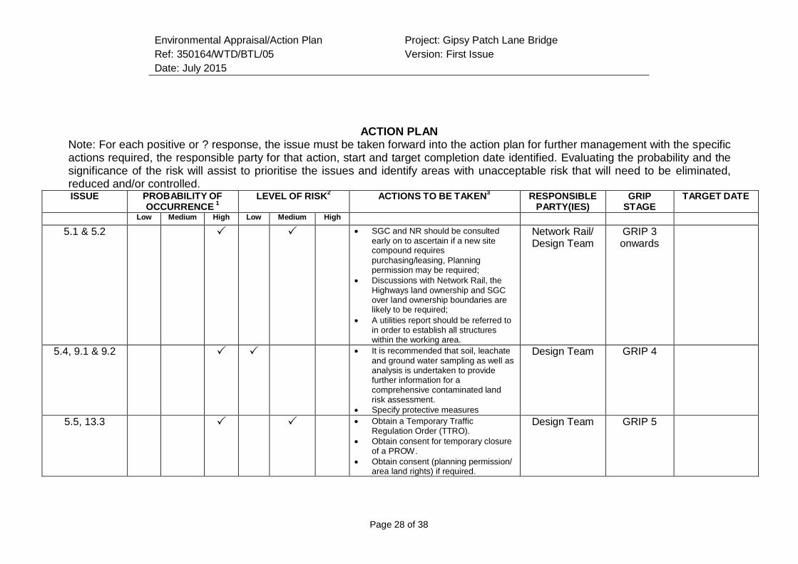
Environmental Appraisal/Action Plan
Ref: 350164/WTD/BTL/05
Date: July 2015
Project: Gipsy Patch Lane Bridge
Version: First Issue
Page 28 of 38
ACTION PLAN Note: For each positive or ? response, the issue must be taken forward into the action plan for further management with the specific actions required, the responsible party for that action, start and target completion date identified. Evaluating the probability and the significance of the risk will assist to prioritise the issues and identify areas with unacceptable risk that will need to be eliminated, reduced and/or controlled. ISSUE PROBABILITY OF
OCCURRENCE 1
LEVEL OF RISK2
ACTIONS TO BE TAKEN3
RESPONSIBLE PARTY(IES)
GRIP STAGE
TARGET DATE
Low Medium High Low Medium High 5.1 & 5.2 SGC and NR should be consulted
early on to ascertain if a new site compound requires
purchasing/leasing, Planning permission may be required;
Discussions with Network Rail, the Highways land ownership and SGC over land ownership boundaries are likely to be required;
A utilities report should be referred to in order to establish all structures within the working area.
Network Rail/ Design Team
GRIP 3 onwards
5.4, 9.1 & 9.2 It is recommended that soil, leachate and ground water sampling as well as analysis is undertaken to provide further information for a comprehensive contaminated land risk assessment.
Specify protective measures
Design Team GRIP 4
5.5, 13.3 Obtain a Temporary Traffic Regulation Order (TTRO).
Obtain consent for temporary closure of a PROW.
Obtain consent (planning permission/ area land rights) if required.
Design Team GRIP 5
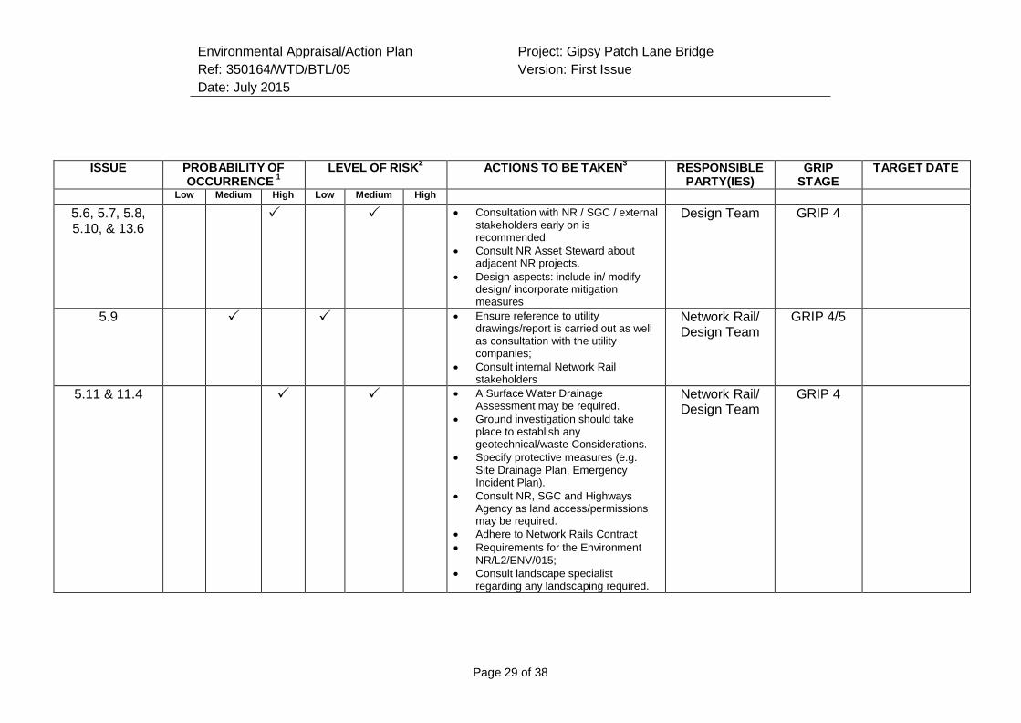
Environmental Appraisal/Action Plan
Ref: 350164/WTD/BTL/05
Date: July 2015
Project: Gipsy Patch Lane Bridge
Version: First Issue
Page 29 of 38
ISSUE PROBABILITY OF
OCCURRENCE 1
LEVEL OF RISK2
ACTIONS TO BE TAKEN3
RESPONSIBLE PARTY(IES)
GRIP STAGE
TARGET DATE
Low Medium High Low Medium High 5.6, 5.7, 5.8, 5.10, & 13.6
Consultation with NR / SGC / external stakeholders early on is recommended.
Consult NR Asset Steward about adjacent NR projects.
Design aspects: include in/ modify design/ incorporate mitigation measures
Design Team GRIP 4
5.9 Ensure reference to utility drawings/report is carried out as well as consultation with the utility companies;
Consult internal Network Rail stakeholders
Network Rail/ Design Team
GRIP 4/5
5.11 & 11.4 A Surface Water Drainage Assessment may be required.
Ground investigation should take place to establish any geotechnical/waste Considerations.
Specify protective measures (e.g.
Site Drainage Plan, Emergency Incident Plan).
Consult NR, SGC and Highways Agency as land access/permissions may be required.
Adhere to Network Rails Contract
Requirements for the Environment NR/L2/ENV/015;
Consult landscape specialist regarding any landscaping required.
Network Rail/ Design Team
GRIP 4
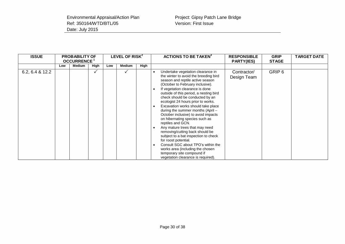
Environmental Appraisal/Action Plan
Ref: 350164/WTD/BTL/05
Date: July 2015
Project: Gipsy Patch Lane Bridge
Version: First Issue
Page 30 of 38
ISSUE PROBABILITY OF
OCCURRENCE 1
LEVEL OF RISK2
ACTIONS TO BE TAKEN3
RESPONSIBLE PARTY(IES)
GRIP STAGE
TARGET DATE
Low Medium High Low Medium High 6.2, 6.4 & 12.2 Undertake vegetation clearance in
the winter to avoid the breeding bird season and reptile active season (October to February inclusive).
If vegetation clearance is done outside of this period, a nesting bird check should be conducted by an ecologist 24 hours prior to works.
Excavation works should take place during the summer months (April – October inclusive) to avoid impacts on hibernating species such as reptiles and GCN.
Any mature trees that may need removing/cutting back should be subject to a bat inspection to check for roost potential.
Consult SGC about TPO’s within the works area (including the chosen temporary site compound if vegetation clearance is required).
Contractor/ Design Team
GRIP 6
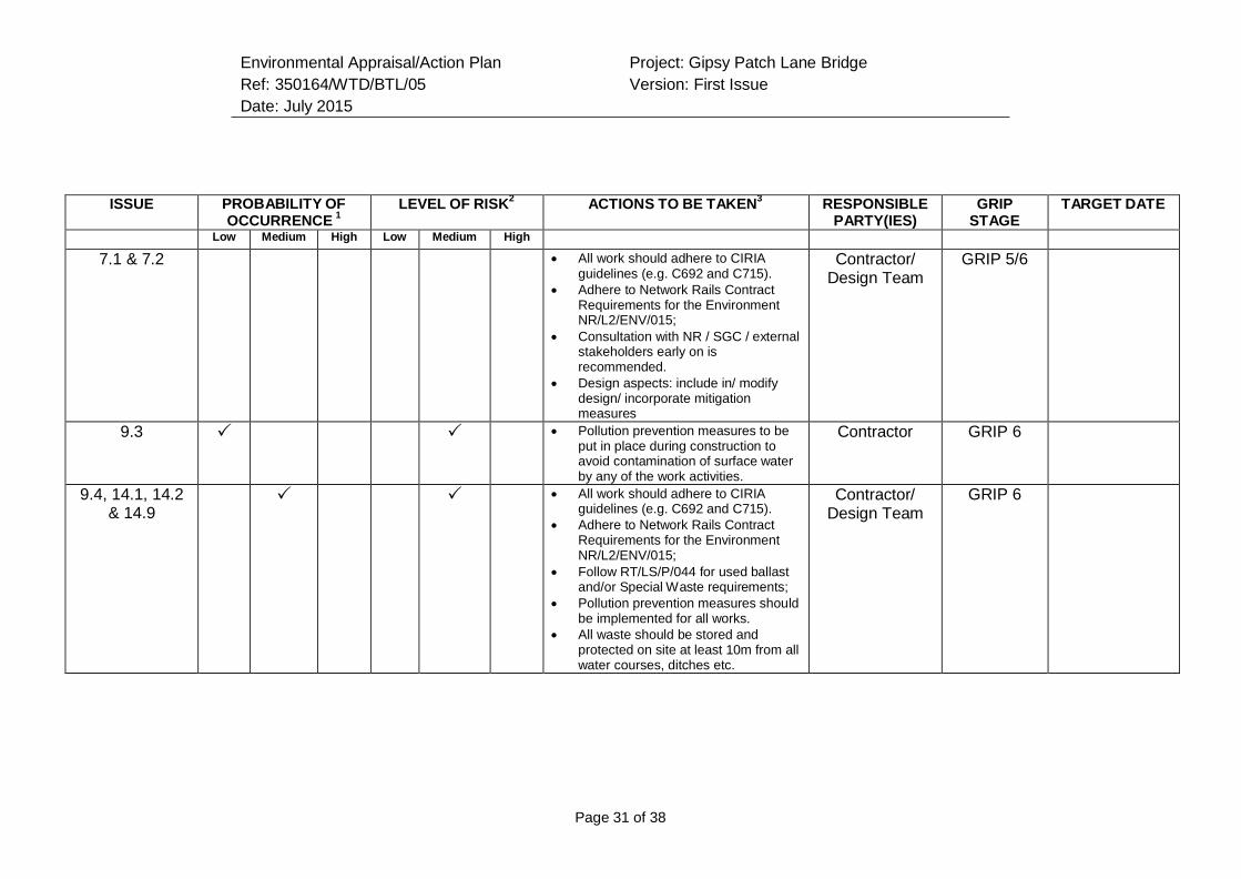
Environmental Appraisal/Action Plan
Ref: 350164/WTD/BTL/05
Date: July 2015
Project: Gipsy Patch Lane Bridge
Version: First Issue
Page 31 of 38
ISSUE PROBABILITY OF
OCCURRENCE 1
LEVEL OF RISK2
ACTIONS TO BE TAKEN3
RESPONSIBLE PARTY(IES)
GRIP STAGE
TARGET DATE
Low Medium High Low Medium High 7.1 & 7.2 All work should adhere to CIRIA
guidelines (e.g. C692 and C715).
Adhere to Network Rails Contract Requirements for the Environment NR/L2/ENV/015;
Consultation with NR / SGC / external stakeholders early on is recommended.
Design aspects: include in/ modify design/ incorporate mitigation measures
Contractor/ Design Team
GRIP 5/6
9.3 Pollution prevention measures to be put in place during construction to avoid contamination of surface water by any of the work activities.
Contractor GRIP 6
9.4, 14.1, 14.2 & 14.9
All work should adhere to CIRIA guidelines (e.g. C692 and C715).
Adhere to Network Rails Contract Requirements for the Environment NR/L2/ENV/015;
Follow RT/LS/P/044 for used ballast and/or Special Waste requirements;
Pollution prevention measures should be implemented for all works.
All waste should be stored and protected on site at least 10m from all water courses, ditches etc.
Contractor/ Design Team
GRIP 6
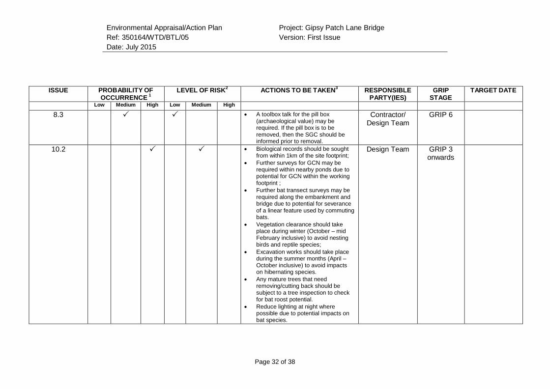
Environmental Appraisal/Action Plan
Ref: 350164/WTD/BTL/05
Date: July 2015
Project: Gipsy Patch Lane Bridge
Version: First Issue
Page 32 of 38
ISSUE PROBABILITY OF
OCCURRENCE 1
LEVEL OF RISK2
ACTIONS TO BE TAKEN3
RESPONSIBLE PARTY(IES)
GRIP STAGE
TARGET DATE
Low Medium High Low Medium High 8.3 A toolbox talk for the pill box
(archaeological value) may be required. If the pill box is to be removed, then the SGC should be informed prior to removal.
Contractor/ Design Team
GRIP 6
10.2 Biological records should be sought from within 1km of the site footprint;
Further surveys for GCN may be required within nearby ponds due to potential for GCN within the working footprint ;
Further bat transect surveys may be required along the embankment and bridge due to potential for severance of a linear feature used by commuting bats.
Vegetation clearance should take place during winter (October – mid February inclusive) to avoid nesting birds and reptile species;
Excavation works should take place during the summer months (April – October inclusive) to avoid impacts on hibernating species.
Any mature trees that need removing/cutting back should be subject to a tree inspection to check for bat roost potential.
Reduce lighting at night where possible due to potential impacts on bat species.
Design Team GRIP 3 onwards
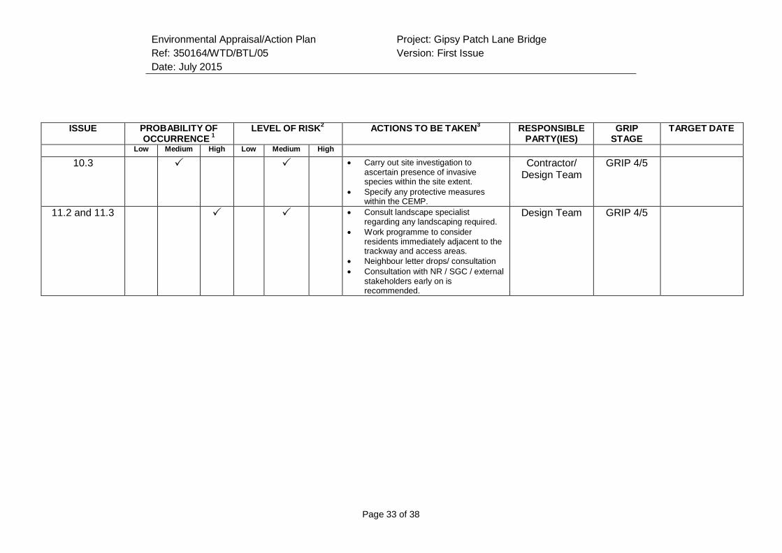
Environmental Appraisal/Action Plan
Ref: 350164/WTD/BTL/05
Date: July 2015
Project: Gipsy Patch Lane Bridge
Version: First Issue
Page 33 of 38
ISSUE PROBABILITY OF
OCCURRENCE 1
LEVEL OF RISK2
ACTIONS TO BE TAKEN3
RESPONSIBLE PARTY(IES)
GRIP STAGE
TARGET DATE
Low Medium High Low Medium High 10.3 Carry out site investigation to
ascertain presence of invasive species within the site extent.
Specify any protective measures within the CEMP.
Contractor/ Design Team
GRIP 4/5
11.2 and 11.3 Consult landscape specialist regarding any landscaping required.
Work programme to consider residents immediately adjacent to the trackway and access areas.
Neighbour letter drops/ consultation
Consultation with NR / SGC / external stakeholders early on is recommended.
Design Team GRIP 4/5
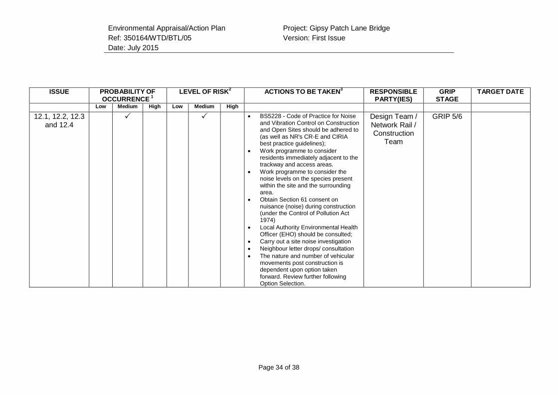
Environmental Appraisal/Action Plan
Ref: 350164/WTD/BTL/05
Date: July 2015
Project: Gipsy Patch Lane Bridge
Version: First Issue
Page 34 of 38
ISSUE PROBABILITY OF
OCCURRENCE 1
LEVEL OF RISK2
ACTIONS TO BE TAKEN3
RESPONSIBLE PARTY(IES)
GRIP STAGE
TARGET DATE
Low Medium High Low Medium High 12.1, 12.2, 12.3
and 12.4 BS5228 - Code of Practice for Noise
and Vibration Control on Construction and Open Sites should be adhered to (as well as NR's CR-E and CIRIA best practice guidelines);
Work programme to consider residents immediately adjacent to the trackway and access areas.
Work programme to consider the noise levels on the species present within the site and the surrounding area.
Obtain Section 61 consent on nuisance (noise) during construction (under the Control of Pollution Act 1974)
Local Authority Environmental Health Officer (EHO) should be consulted;
Carry out a site noise investigation
Neighbour letter drops/ consultation
The nature and number of vehicular movements post construction is dependent upon option taken
forward. Review further following Option Selection.
Design Team / Network Rail / Construction
Team
GRIP 5/6
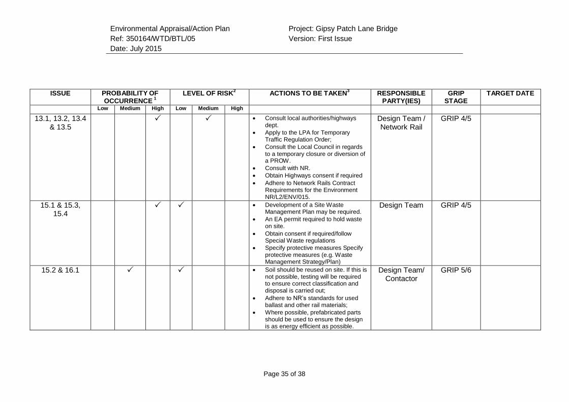
Environmental Appraisal/Action Plan
Ref: 350164/WTD/BTL/05
Date: July 2015
Project: Gipsy Patch Lane Bridge
Version: First Issue
Page 35 of 38
ISSUE PROBABILITY OF
OCCURRENCE 1
LEVEL OF RISK2
ACTIONS TO BE TAKEN3
RESPONSIBLE PARTY(IES)
GRIP STAGE
TARGET DATE
Low Medium High Low Medium High 13.1, 13.2, 13.4
& 13.5 Consult local authorities/highways
dept.
Apply to the LPA for Temporary Traffic Regulation Order;
Consult the Local Council in regards to a temporary closure or diversion of a PROW.
Consult with NR.
Obtain Highways consent if required
Adhere to Network Rails Contract Requirements for the Environment NR/L2/ENV/015.
Design Team / Network Rail
GRIP 4/5
15.1 & 15.3, 15.4
Development of a Site Waste Management Plan may be required.
An EA permit required to hold waste on site.
Obtain consent if required/follow Special Waste regulations
Specify protective measures Specify protective measures (e.g. Waste Management Strategy/Plan)
Design Team GRIP 4/5
15.2 & 16.1 Soil should be reused on site. If this is not possible, testing will be required to ensure correct classification and disposal is carried out;
Adhere to NR’s standards for used ballast and other rail materials;
Where possible, prefabricated parts should be used to ensure the design is as energy efficient as possible.
Design Team/ Contactor
GRIP 5/6
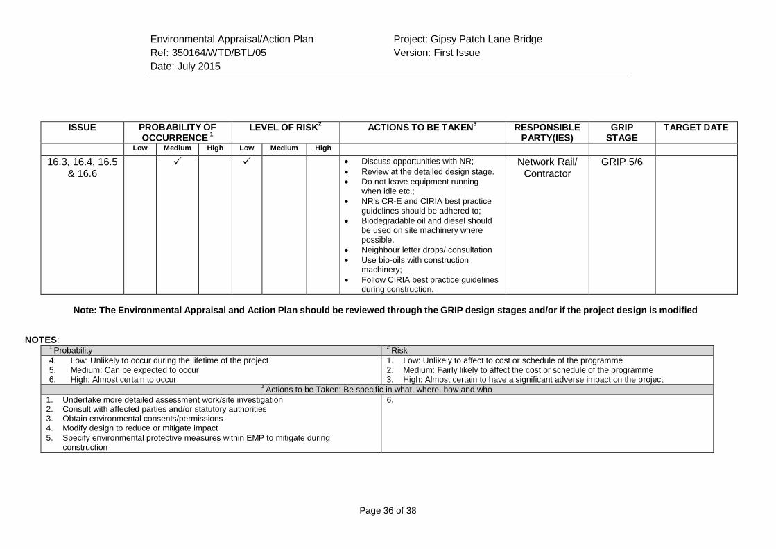
Environmental Appraisal/Action Plan
Ref: 350164/WTD/BTL/05
Date: July 2015
Project: Gipsy Patch Lane Bridge
Version: First Issue
Page 36 of 38
ISSUE PROBABILITY OF
OCCURRENCE 1
LEVEL OF RISK2
ACTIONS TO BE TAKEN3
RESPONSIBLE PARTY(IES)
GRIP STAGE
TARGET DATE
Low Medium High Low Medium High 16.3, 16.4, 16.5
& 16.6 Discuss opportunities with NR;
Review at the detailed design stage.
Do not leave equipment running when idle etc.;
NR's CR-E and CIRIA best practice guidelines should be adhered to;
Biodegradable oil and diesel should be used on site machinery where possible.
Neighbour letter drops/ consultation
Use bio-oils with construction machinery;
Follow CIRIA best practice guidelines during construction.
Network Rail/ Contractor
GRIP 5/6
Note: The Environmental Appraisal and Action Plan should be reviewed through the GRIP design stages and/or if the project design is modified
NOTES: 1
Probability 2
Risk
4. Low: Unlikely to occur during the lifetime of the project 5. Medium: Can be expected to occur 6. High: Almost certain to occur
1. Low: Unlikely to affect to cost or schedule of the programme 2. Medium: Fairly likely to affect the cost or schedule of the programme 3. High: Almost certain to have a significant adverse impact on the project
3 Actions to be Taken: Be specific in what, where, how and who
1. Undertake more detailed assessment work/site investigation 2. Consult with affected parties and/or statutory authorities 3. Obtain environmental consents/permissions 4. Modify design to reduce or mitigate impact
5. Specify environmental protective measures within EMP to mitigate during construction
6.
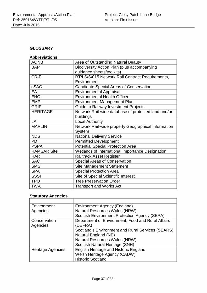
Environmental Appraisal/Action Plan
Ref: 350164/WTD/BTL/05
Date: July 2015
Project: Gipsy Patch Lane Bridge
Version: First Issue
Page 37 of 38
GLOSSARY
Abbreviations
AONB Area of Outstanding Natural Beauty
BAP Biodiversity Action Plan (plus accompanying guidance sheets/toolkits)
CR-E RT/LS/S/015 Network Rail Contract Requirements, Environment
cSAC Candidate Special Areas of Conservation
EA Environmental Appraisal
EHO Environmental Health Officer
EMP Environment Management Plan
GRIP Guide to Railway Investment Projects
HERITAGE Network Rail-wide database of protected land and/or buildings
LA Local Authority
MARLIN Network Rail-wide property Geographical Information System
NDS National Delivery Service
PD Permitted Development
PSPA Potential Special Protection Area
RAMSAR Site Wetlands of International Importance Designation
RAR Railtrack Asset Register
SAC Special Areas of Conservation
SMS Site Management Statement
SPA Special Protection Area
SSSI Site of Special Scientific Interest
TPO Tree Preservation Order
TWA Transport and Works Act
Statutory Agencies
Environment Agencies
Environment Agency (England) Natural Resources Wales (NRW) Scottish Environment Protection Agency (SEPA)
Conservation Agencies
Department of Environment, Food and Rural Affairs (DEFRA) Scotland’s Environment and Rural Services (SEARS) Natural England (NE) Natural Resources Wales (NRW) Scottish Natural Heritage (SNH)
Heritage Agencies English Heritage and Historic England Welsh Heritage Agency (CADW) Historic Scotland
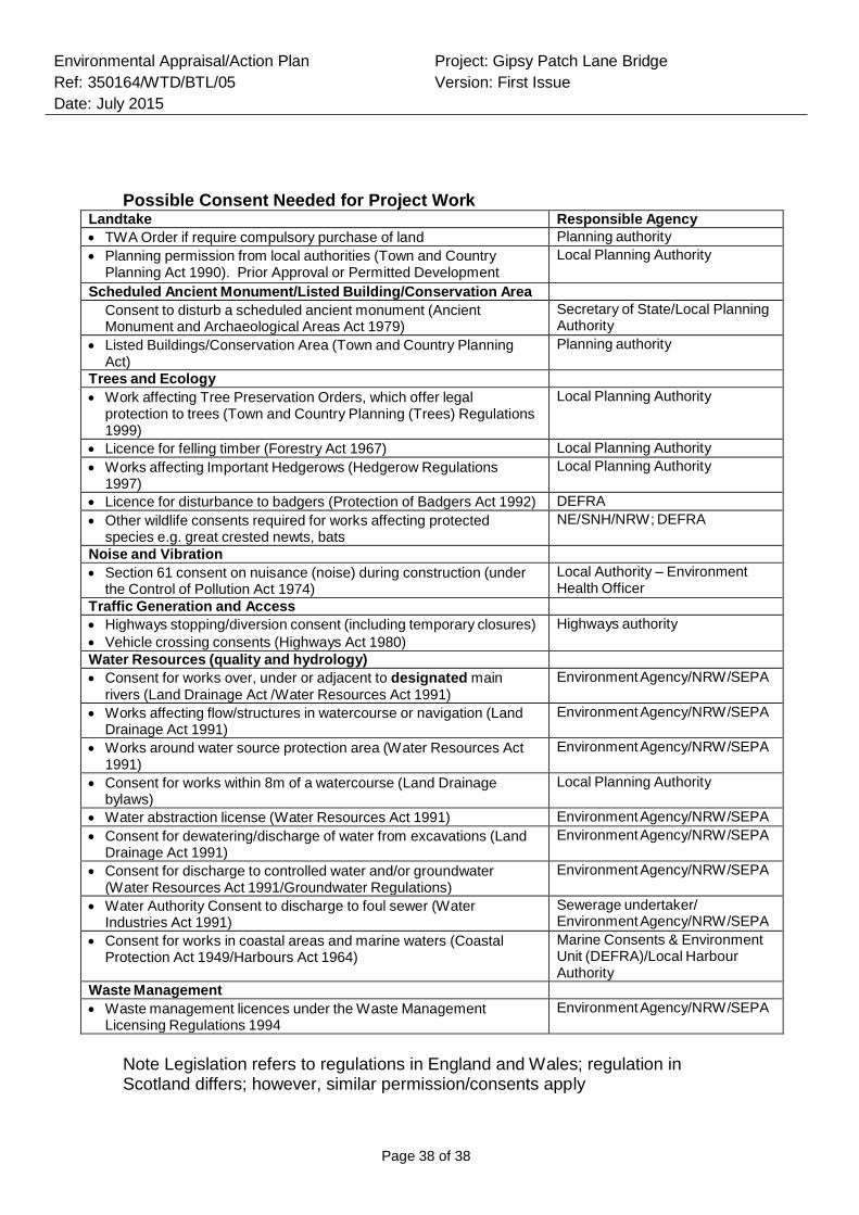
Environmental Appraisal/Action Plan
Ref: 350164/WTD/BTL/05
Date: July 2015
Project: Gipsy Patch Lane Bridge
Version: First Issue
Page 38 of 38
Possible Consent Needed for Project Work Landtake Responsible Agency
TWA Order if require compulsory purchase of land Planning authority
Planning permission from local authorities (Town and Country Planning Act 1990). Prior Approval or Permitted Development
Local Planning Authority
Scheduled Ancient Monument/Listed Building/Conservation Area Consent to disturb a scheduled ancient monument (Ancient Monument and Archaeological Areas Act 1979)
Secretary of State/Local Planning Authority
Listed Buildings/Conservation Area (Town and Country Planning Act)
Planning authority
Trees and Ecology Work affecting Tree Preservation Orders, which offer legal
protection to trees (Town and Country Planning (Trees) Regulations 1999)
Local Planning Authority
Licence for felling timber (Forestry Act 1967) Local Planning Authority
Works affecting Important Hedgerows (Hedgerow Regulations 1997)
Local Planning Authority
Licence for disturbance to badgers (Protection of Badgers Act 1992) DEFRA
Other wildlife consents required for works affecting protected species e.g. great crested newts, bats
NE/SNH/NRW; DEFRA
Noise and Vibration Section 61 consent on nuisance (noise) during construction (under
the Control of Pollution Act 1974)
Local Authority – Environment Health Officer
Traffic Generation and Access Highways stopping/diversion consent (including temporary closures)
Vehicle crossing consents (Highways Act 1980)
Highways authority
Water Resources (quality and hydrology) Consent for works over, under or adjacent to designated main
rivers (Land Drainage Act /Water Resources Act 1991)
Environment Agency/NRW/SEPA
Works affecting flow/structures in watercourse or navigation (Land Drainage Act 1991)
Environment Agency/NRW/SEPA
Works around water source protection area (Water Resources Act 1991)
Environment Agency/NRW/SEPA
Consent for works within 8m of a watercourse (Land Drainage bylaws)
Local Planning Authority
Water abstraction license (Water Resources Act 1991) Environment Agency/NRW/SEPA
Consent for dewatering/discharge of water from excavations (Land Drainage Act 1991)
Environment Agency/NRW/SEPA
Consent for discharge to controlled water and/or groundwater (Water Resources Act 1991/Groundwater Regulations)
Environment Agency/NRW/SEPA
Water Authority Consent to discharge to foul sewer (Water Industries Act 1991)
Sewerage undertaker/ Environment Agency/NRW/SEPA
Consent for works in coastal areas and marine waters (Coastal Protection Act 1949/Harbours Act 1964)
Marine Consents & Environment Unit (DEFRA)/Local Harbour Authority
Waste Management Waste management licences under the Waste Management
Licensing Regulations 1994
Environment Agency/NRW/SEPA
Note Legislation refers to regulations in England and Wales; regulation in Scotland differs; however, similar permission/consents apply

Ref: 350164/WTD/BTL/01
Version: 03
Date: September 2015
Appendix G
Geotechnical Design Report
Governance for Railway Investment Projects
Gipsy Patch Lane Bridge
Geotechnical Design Report
July 2015
Network Rail

350164 WTD BTL 07 A
http://pims01/pims/llisapi.dll/properties/1595448401
July 2015
Gipsy Patch Lane Bridge
Geotechnical Design Report
Gipsy Patch Lane Bridge
Geotechnical Design Report
July 2015
Network Rail
Western House 1 Holbrook Way Swindon SN2 1UY
Mott MacDonald, 10 Templeback, Bristol, BS1 6FL, United Kingdom
T +44 (0)117 906 9500 F +44(0) 117 376 3688 W www.mottmac.com

Gipsy Patch Lane Bridge Geotechn ical Design Report Mott MacDona ld
Issue and revision record
Revision Date Originator Checker Approver Description
P1 June 20 15 P Kwok T Bird IDuncan First Draft
A July 2015 First Issue
Information Class: Standard
This document is issued for the party which commissioned it
and for specific purposes connected with the above-cap tioned
project only. It should not be relied upon by any other party or
used for any other purpose.
We accept no responsibility for the consequences of this
document being relied upon by any other party, or being used
for any other purpose, or containing any error or omission
wh ich is due to an error or omission in data supplied to us by
other parties.
This document conta ins confident ial informat ion and
proprietary intellectual property. It should not be shown to
other parties without consent from us and from the party
wh ich commissioned it.
350164/WTD/BTL/07/A July 2015
http://pims01/pims/llisapi.d11/ properties/ 1595448401

Gipsy Patch Lane Bridge Geotechnical Design Report
Contents
Chapter Title Page
1 Earthworks 1
1.1 General 1
1.1.1 Generalised sequence of strata 1
1.1.2 Groundwater 2
1.1.3 Characteristic geotechnical parameters 3
1.3 Cutting stability 6
1.4 Embankment stability 6
1.5 Re-use of materials 7
2 Structure 8
2.1 Portal frame structure 8
2.2 Foundations options for portal frame 8
2.3 Further Ground Investigation 9
2.4 Ground beam 10
2.4.1 Bearing resistance 10
2.5 Piled foundation 12
2.5.1 Axial resistance 12
2.5.2 Lateral resistance 14
2.6 Serviceability limit state 15
2.6.1 Settlement prediction 15
2.7 Summary of results 16
2.7.1 Differential settlement 17
2.8 Chemical classification 17
3 Strengthened Earthworks (NOT USED) 19
4 Drainage 20
5 Pavement Design, Subgrade and Capping 21
6 Geotechnical Risk Register 22
7 REFERENCES 26
Appendix A. Drawings 28
Appendix B. Figures 29
350164/WTD/BTL/07/A July 2015 http://pims01/pims/llisapi.dll/properties/1595448401
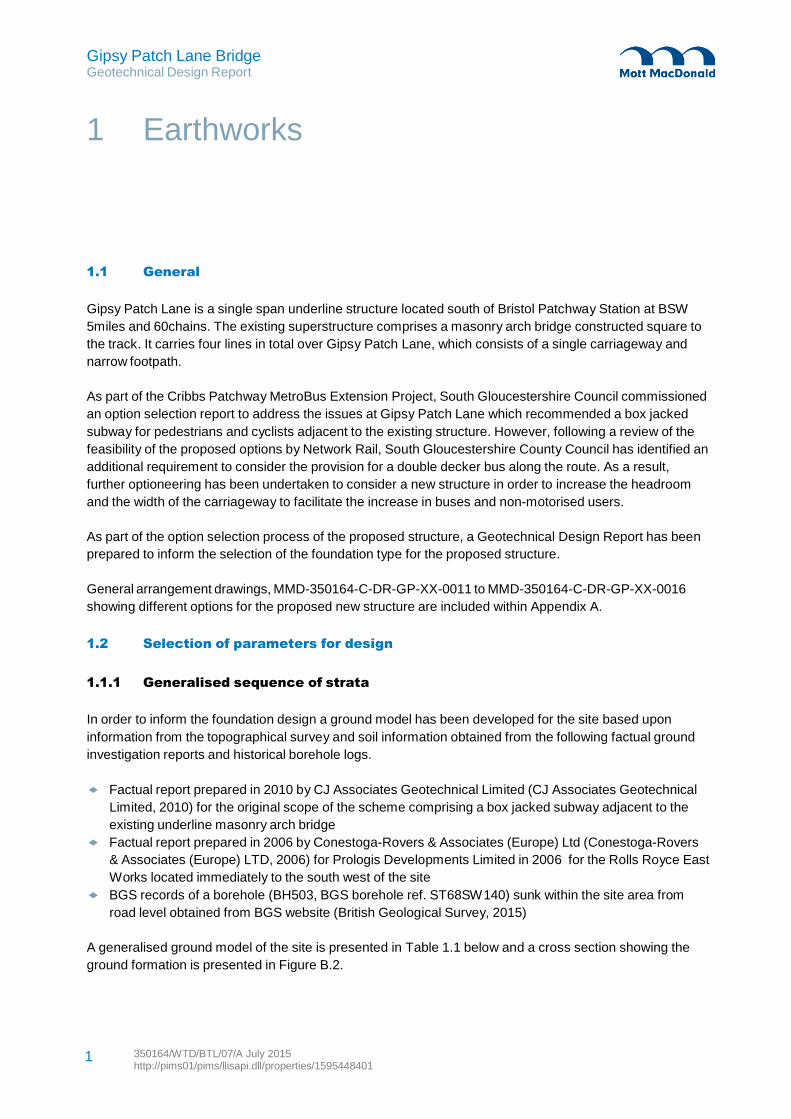
Gipsy Patch Lane Bridge Geotechnical Design Report
350164/WTD/BTL/07/A July 2015 http://pims01/pims/llisapi.dll/properties/1595448401
1
1 Earthworks
1.1 General
Gipsy Patch Lane is a single span underline structure located south of Bristol Patchway Station at BSW
5miles and 60chains. The existing superstructure comprises a masonry arch bridge constructed square to
the track. It carries four lines in total over Gipsy Patch Lane, which consists of a single carriageway and
narrow footpath.
As part of the Cribbs Patchway MetroBus Extension Project, South Gloucestershire Council commissioned
an option selection report to address the issues at Gipsy Patch Lane which recommended a box jacked
subway for pedestrians and cyclists adjacent to the existing structure. However, following a review of the
feasibility of the proposed options by Network Rail, South Gloucestershire County Council has identified an
additional requirement to consider the provision for a double decker bus along the route. As a result,
further optioneering has been undertaken to consider a new structure in order to increase the headroom
and the width of the carriageway to facilitate the increase in buses and non-motorised users.
As part of the option selection process of the proposed structure, a Geotechnical Design Report has been
prepared to inform the selection of the foundation type for the proposed structure.
General arrangement drawings, MMD-350164-C-DR-GP-XX-0011 to MMD-350164-C-DR-GP-XX-0016
showing different options for the proposed new structure are included within Appendix A.
1.2 Selection of parameters for design
1.1.1 Generalised sequence of strata
In order to inform the foundation design a ground model has been developed for the site based upon
information from the topographical survey and soil information obtained from the following factual ground
investigation reports and historical borehole logs.
Factual report prepared in 2010 by CJ Associates Geotechnical Limited (CJ Associates Geotechnical
Limited, 2010) for the original scope of the scheme comprising a box jacked subway adjacent to the
existing underline masonry arch bridge
Factual report prepared in 2006 by Conestoga-Rovers & Associates (Europe) Ltd (Conestoga-Rovers
& Associates (Europe) LTD, 2006) for Prologis Developments Limited in 2006 for the Rolls Royce East
Works located immediately to the south west of the site
BGS records of a borehole (BH503, BGS borehole ref. ST68SW140) sunk within the site area from
road level obtained from BGS website (British Geological Survey, 2015)
A generalised ground model of the site is presented in Table 1.1 below and a cross section showing the
ground formation is presented in Figure B.2.
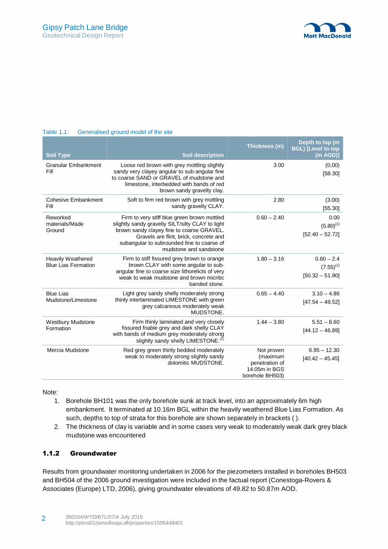
Gipsy Patch Lane Bridge Geotechnical Design Report
350164/WTD/BTL/07/A July 2015 http://pims01/pims/llisapi.dll/properties/1595448401
2
Table 1.1: Generalised ground model of the site
Soil Type Soil description
Thickness (m)
Depth to top (m BGL) [Level to top
(m AOD)]
Granular Embankment Fill
Cohesive Embankment Fill
Reworked materials/Made Ground
Heavily Weathered Blue Lias Formation
Blue Lias Mudstone/Limestone
Westbury Mudstone Formation
Loose red brown with grey mottling slightly sandy very clayey angular to sub-angular fine
to coarse SAND or GRAVEL of mudstone and limestone, interbedded with bands of red
brown sandy gravelly clay.
Soft to firm red brown with grey mottling sandy gravelly CLAY.
Firm to very stiff blue green brown mottled
slightly sandy gravelly SILT/silty CLAY to light brown sandy clayey fine to coarse GRAVEL.
Gravels are flint, brick, concrete and subangular to subrounded fine to coarse of
mudstone and sandstone
Firm to stiff fissured grey brown to orange brown CLAY with some angular to sub-
angular fine to coarse size lithorelicts of very weak to weak mudstone and brown micritic
banded stone.
Light grey sandy shelly moderately strong thinly interlaminated LIMESTONE with green
grey calcareous moderately weak MUDSTONE.
Firm thinly laminated and very closely fissured friable grey and dark shelly CLAY
with bands of medium grey moderately strong
slightly sandy shelly LIMESTONE.(2)
3.00 (0.00)
[58.30]
2.80 (3.00)
[55.30]
0.60 – 2.40 0.00
(5.80)(1)
[52.40 – 52.72]
1.80 – 3.16 0.60 – 2.4
(7.55)(1)
[50.32 – 51.90]
0.65 – 4.40 3.10 – 4.86
[47.54 – 49.52]
1.44 – 3.80 5.51 – 8.60
[44.12 – 46.89]
Mercia Mudstone Red grey green thinly bedded moderately weak to moderately strong slightly sandy
dolomitic MUDSTONE.
Not proven (maximum
penetration of 14.05m in BGS
borehole BH503)
6.95 – 12.30
[40.42 – 45.45]
Note:
1. Borehole BH101 was the only borehole sunk at track level, into an approximately 6m high
embankment. It terminated at 10.16m BGL within the heavily weathered Blue Lias Formation. As
such, depths to top of strata for this borehole are shown separately in brackets ( ).
2. The thickness of clay is variable and in some cases very weak to moderately weak dark grey black
mudstone was encountered
1.1.2 Groundwater
Results from groundwater monitoring undertaken in 2006 for the piezometers installed in boreholes BH503
and BH504 of the 2006 ground investigation were included in the factual report (Conestoga-Rovers &
Associates (Europe) LTD, 2006), giving groundwater elevations of 49.82 to 50.87m AOD.
Gipsy Patch Lane Bridge Geotechnical Design Report
350164/WTD/BTL/07/A July 2015 http://pims01/pims/llisapi.dll/properties/1595448401
3
The results of the groundwater monitoring undertaken for this ground investigation were plotted on a
location plan in Figure 5.11 and 5.12 of the 2006 factual report (Conestoga-Rovers & Associates (Europe)
LTD, 2006) , which show the shallow and deep groundwater elevation contours of the Rolls Royce East
Works located immediately to the south west of the site. Copies of the figures are included in Appendix B
for reference.
In addition to this, water strikes were also recorded in boreholes sunk for the 2010 GI (CJ Associates
Geotechnical Limited, 2010). These borehole logs indicated water strikes within the possible reworked
material/weathered bedrock layer at 7.5m BGL (~50.8m AOD) in BH 101 and 1.0m BGL in
BH 102(~51.5m AOD). These raised slightly to 7.2m BGL to 0.9m BGL respectively.
This indicates that the highest recorded groundwater level is within the construction zone, and careful
consideration shall be made for foundation design in later Governance for Railway Investment Projects
(GRIP) stages.
1.1.3 Characteristic geotechnical parameters
With reference to the general arrangement drawings, the base level of the proposed portal frame is
proposed to be constructed at approximately 0.35m below the proposed road level at between
50.08m AOD and 50.85m AOD, depending on the options. It is therefore expected that the embankment fill
and made ground within the footprint of the foundation will be removed prior to the construction works.
As such soil parameters for these strata are not considered relevant to the foundation assessment and
have not been considered further.
1.1.3.1 Derivation of soil parameters
Characteristic geotechnical parameters have been derived for strata relevant to the foundation design
based on soil descriptions, laboratory and in situ testing results from the ground investigations undertaken
at or near the site as detailed in Section 1.1.1, and with reference to appropriate standards and literature
references.
Laboratory testing in the C J Associates Limited investigation (CJ Associates Geotechnical Limited, 2010)
was confined to the Made Ground and embankment fill at this site. Testing undertaken as part of the
Rolls-Royce East works investigation (Conestoga-Rovers & Associates (Europe) LTD, 2006) was limited to
geo-environmental analyses.
Bulk unit weight (γ)
As no reliable test data for bulk density was available from the historical ground investigations, the
characteristic bulk unit weight for each of the relevant strata has been estimated using Table 1 from
BS 8002 (British Standards Institution, Amended 2001) based on the soil descriptions, and with reference
to the recommended values presented in Tables B7 and B8 of the Geological Society Special Publication
Gipsy Patch Lane Bridge Geotechnical Design Report
350164/WTD/BTL/07/A July 2015 http://pims01/pims/llisapi.dll/properties/1595448401
4
No. 21 edited by G M Reeves (Geological Society, 2006) for various Lower Jurassic and Triassic
formations.
Effective angle of shearing resistance (ϕ’)
In the absence of relevant laboratory testing results, the characteristic effective angle of shearing
resistance, ϕ’, for each of the relevant strata has been obtained based on descriptions on the borehole logs
and the recommended values in Tables B7 and B8 of the Geological Society Special Publication No.21
(Geological Society, 2006). Reference has also been made to the recommended values presented in
Table 4 of BS 8002 (British Standards Institution, Amended 2001) for rocks and CIRIA C570 (CIRIA, 2001)
for Mercia Mudstone, assuming a weathering grade of III.
Effective cohesion (c’)
In the absence of direct laboratory testing to determine the effective cohesion, c', characteristic values
have been assumed based on the recommended values presented in Tables B7 and B8 of the Engineering
Geology Special Publication No. 21 (Geological Society, 2006)
Undrained shear strength (cu)
Characteristic undrained shear strength of cohesive material, cu, has been correlated from SPT N values
obtained from the historical ground investigations using the equation below from Stroud published in CIRIA
143 (CIRIA, 1995).
cu = f1 x N60
Where
f1 is the factor relating to the plasticity index of the material and can be deduced from Figure 31 from
CIRIA report 143 (CIRIA, 1995)
N60 is the equivalent Standard Penetration Test resistance corrected to 60% of the theoretical free fall
hammer energy
For the weak rock strata that reported SPT refusals in the exploratory logs, a conventional relationship
between uniaxial compressive strength (UCS) and undrained shear strength of UCS = 2cu has been used
to derived the characteristic cu values.
Young’s Modulus (E’ & Eu)
The characteristic undrained Young’s Modulus, Eu for each of the cohesive or mudstone strata has been
estimated based on the following relationship with undrained shear strength, cu, after Burland presented in
WALLAP manual (Burland, 1979), assuming a strain level of 0.4%.
Eu = 400 ∙ cu
Gipsy Patch Lane Bridge Geotechnical Design Report
350164/WTD/BTL/07/A July 2015 http://pims01/pims/llisapi.dll/properties/1595448401
5
Where
cu is the undrained shear strength
The value of drained Young’s Modulus can be calculated using the following equation.
Where
ν' is the drained Poisson’s Ratio
Uniaxial compressive strength (UCS)
E = Eu ∙
2(1 + )
3
As no reliable in situ or laboratory test data were available to determine the uniaxial compressive strength,
characteristic values have been conservatively determined based on the rock descriptions in the historical
boreholes and the associated strength given in BS 5930 (British Standards Institution, 1999) or Table 5 of
BS EN ISO 14689-1 (British Standards Institution, 2003), depending on the standards that the rock
descriptions are based upon.
Coefficient of compressibility (mv)
As no consolidation testing was undertaken to determine the coefficient of compressibility of the soil
encountered on site, characteristic mv values have been adopted based on the recommended values
presented in Tomlinson (Tomlinson, Foundation Design and Construction, 2001) for different materials and
with reference to recommended soil parameters of various formations of Jurassic and Triassic age
presented in the Geological Society Special Publication No. 21 (Geological Society, 2006).
Poisson’s ratio (ν' and νu)
A characteristic drained Poisson’s Ratio of v’ =0.15 has been adopted based the recommended values
presented in Tomlinson (Tomlinson, Foundation Design and Construction, 2001).
The undrained Poisson’s Ratio, νu, is assumed to be 0.5 for cohesive soils.
1.1.3.2 Characteristic geotechnical parameters
The characteristic geotechnical parameters to be used for design purposes are summarised in Table 1.2
below.
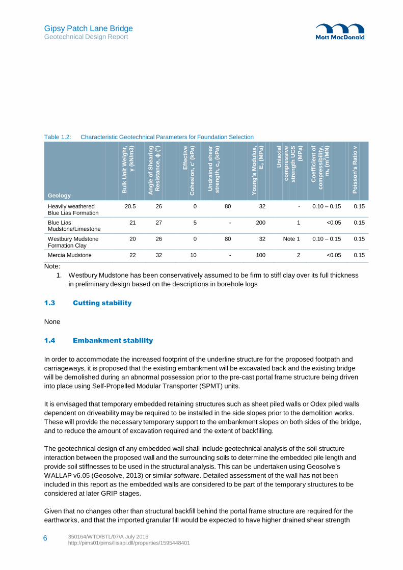
Gipsy Patch Lane Bridge Geotechnical Design Report
350164/WTD/BTL/07/A July 2015 http://pims01/pims/llisapi.dll/properties/1595448401
6
Bu
lk U
nit
We
igh
t,
γ (
kN
/m3
)
An
gle
of
Sh
eari
ng
Re
sis
tan
ce
, ϕ
(°)
Eff
ec
tive
Co
he
sio
n, c
’ (k
Pa
)
Un
dra
ine
d s
hear
str
en
gth
, c
u (
kP
a)
Yo
un
g’s
Mo
du
lus
,
Eu
(M
Pa
)
Un
iax
ial
co
mp
res
siv
e
str
en
gth
UC
S
(MP
a)
Co
eff
icie
nt
of
co
mp
res
sib
ilit
y,
mv
(m
2/M
N)
Po
iss
on
’s R
ati
o ν
Table 1.2: Characteristic Geotechnical Parameters for Foundation Selection
Geology
Heavily weathered Blue Lias Formation
20.5 26 0 80 32 - 0.10 – 0.15 0.15
Blue Lias 21 27 5 - 200 1 <0.05 0.15 Mudstone/Limestone Westbury Mudstone Formation Clay
20 26 0 80 32 Note 1 0.10 – 0.15 0.15
Mercia Mudstone 22 32 10 - 100 2 <0.05 0.15
Note:
1. Westbury Mudstone has been conservatively assumed to be firm to stiff clay over its full thickness
in preliminary design based on the descriptions in borehole logs
1.3 Cutting stability
None
1.4 Embankment stability
In order to accommodate the increased footprint of the underline structure for the proposed footpath and
carriageways, it is proposed that the existing embankment will be excavated back and the existing bridge
will be demolished during an abnormal possession prior to the pre-cast portal frame structure being driven
into place using Self-Propelled Modular Transporter (SPMT) units.
It is envisaged that temporary embedded retaining structures such as sheet piled walls or Odex piled walls
dependent on driveability may be required to be installed in the side slopes prior to the demolition works.
These will provide the necessary temporary support to the embankment slopes on both sides of the bridge,
and to reduce the amount of excavation required and the extent of backfilling.
The geotechnical design of any embedded wall shall include geotechnical analysis of the soil-structure
interaction between the proposed wall and the surrounding soils to determine the embedded pile length and
provide soil stiffnesses to be used in the structural analysis. This can be undertaken using Geosolve’s
WALLAP v6.05 (Geosolve, 2013) or similar software. Detailed assessment of the wall has not been
included in this report as the embedded walls are considered to be part of the temporary structures to be
considered at later GRIP stages.
Given that no changes other than structural backfill behind the portal frame structure are required for the
earthworks, and that the imported granular fill would be expected to have higher drained shear strength
Gipsy Patch Lane Bridge Geotechnical Design Report
350164/WTD/BTL/07/A July 2015 http://pims01/pims/llisapi.dll/properties/1595448401
7
parameters than the existing embankment fill, overall stability analyses for the embankment slopes on
either side of the new structure are not considered to be required at this stage.
The presence of a significant thickness of existing granular fill within the embankment will have an impact
on the temporary works design for the temporary excavations allowing construction of the portal frame.
Granular fill will be susceptible to ravelling and local instability if cut slopes are formed at oversteep angles.
Particular consideration will be required to this element of temporary works design.
With reference to the option selection report (Mott MacDonald, 2015), one of the wingwall options is to
utilise the temporary sheet piled retaining structures as the permanent wing walls for the new structure by
installing some form of facing or cladding to improve their appearance to suit South Gloucestershire
Council requirements.
However, sheet piled wingwalls are not the preferred option presented in the Option Selection Report due
to the additional short possessions may be required for the piling works, and the required cladding works
will impede on future maintenance or inspection access. As such no further development of this option has
been undertaken.
The preferred wingwall option comprises pre-cast reinforced concrete wingwalls integrated with the main
bridge structure. These will be designed to accommodate the relevant earth pressures and permanent and
variable actions associated with railway operation.
1.5 Re-use of materials
It is anticipated that the majority of the materials to be excavated will comprise a layer of ballast underlain
by embankment fill based on the general arrangement drawings and ground formation discussed in
Section 1.1.1. As such, the excavated material is likely to comprise slightly sandy very clayey angular to
sub-angular fine to coarse SAND or sandy gravelly CLAY. It is expected that any site won cohesive
material will be disposed of with consent of Scheme Engineer whilst reuse of the granular material may be
possible subject to testing.
Details of waste classification of the site won materials shall be investigated further during the single option
development to detailed design stages of the scheme (Guide to Railway Investment Projects (GRIP)
Stages 4 to 5).
Gipsy Patch Lane Bridge Geotechnical Design Report
350164/WTD/BTL/07/A July 2015 http://pims01/pims/llisapi.dll/properties/1595448401
8
2 Structure
2.1 Portal frame structure
With reference to the option section report a concrete portal frame structure has been proposed for the
bridge replacement as the portal frame can be precast at the adjacent site compound and driven into place
using Self-Propelled Modular Transporter (SPMT) units to significantly reduce the possession time
required to replace the existing bridge structure. A portal frame will also provide an open base to suit the
existing buried services and will not impede on future maintenance access.
In order to incorporate different carriageway arrangements and alignments relative to the track, six different
portal frame options has been considered. Details of these options can be found in the option selection
report.
The ground beams will be constructed integral with the portal frame and lifted onto the pile caps. A shear
key can be provided if the friction between the ground beam and the pile cap or ground is not sufficient to
resist the lateral loading.
2.2 Foundations options for portal frame
Given that the demolition of the existing structure and installation of the precast portal frame will be
required to be completed under an abnormal 100 hour possession, construction of piled foundations along
the length of the abutments during the possession is not considered to be feasible due to the construction
time.
As the foundation will need to be incorporated with the other construction activities to be constructed within
the limited possession time available, it is considered that precast strip footings would be the preferred
foundation option for the portal frame structure due to the speed and ease of construction, and the fact that
the portal frame can also be slid into place and form an integral unit with the strip footings.
However, it is uncertain whether the foundation is to be founded on the firm to stiff clay layer or the
underlying Blue Lias mudstone/limestone formation due to the variation in the historical borehole logs, with
the mudstone/limestone stratum encountered at between 47.54 and 49.52m AOD.
In the absence of more accurate soil information, the foundation has been designed to be founded on firm
to stiff clay at this stage of the scheme and therefore some form of ground improvement or piled supports
to be constructed offline will be required in order to provide the bearing resistance required for the new
structure.
The following foundation options have been considered to provide the bearing resistance required for the
new portal frame structure.
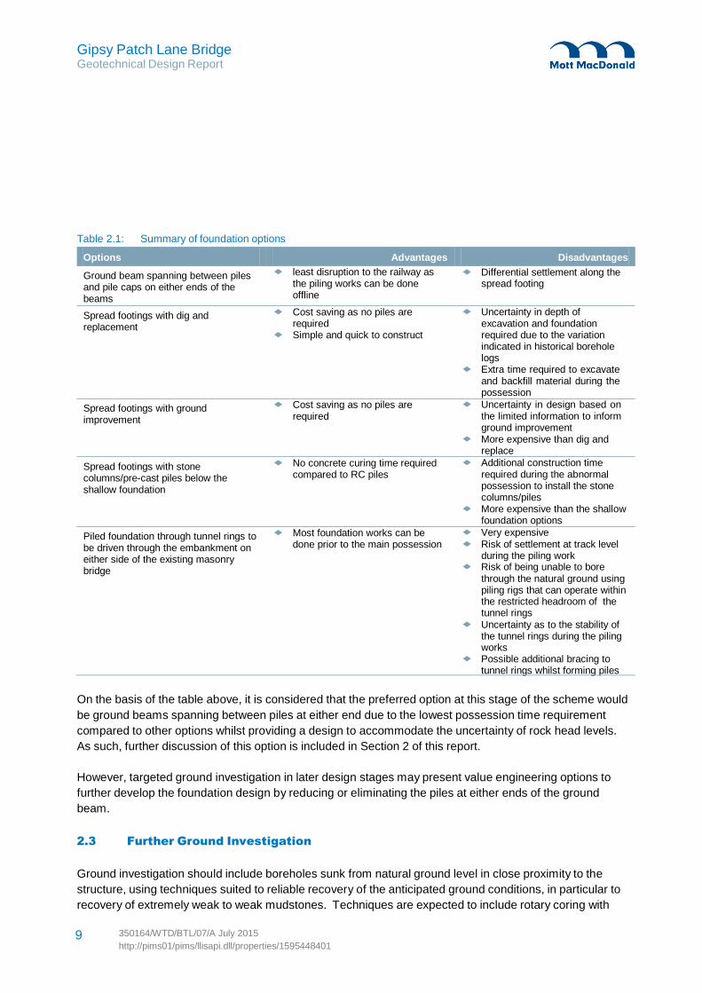
Gipsy Patch Lane Bridge Geotechnical Design Report
http://pims01/pims/llisapi.dll/properties/1595448401
Table 2.1: Summary of foundation options
Options Advantages Disadvantages
Ground beam spanning between piles and pile caps on either ends of the beams
Spread footings with dig and replacement
Spread footings with ground improvement
Spread footings with stone columns/pre-cast piles below the shallow foundation
Piled foundation through tunnel rings to be driven through the embankment on either side of the existing masonry bridge
least disruption to the railway as the piling works can be done offline
Cost saving as no piles are required
Simple and quick to construct Cost saving as no piles are
required
No concrete curing time required
compared to RC piles Most foundation works can be
done prior to the main possession
Differential settlement along the spread footing
Uncertainty in depth of
excavation and foundation required due to the variation indicated in historical borehole logs
Extra time required to excavate and backfill material during the possession
Uncertainty in design based on the limited information to inform ground improvement
More expensive than dig and replace
Additional construction time required during the abnormal possession to install the stone columns/piles
More expensive than the shallow foundation options
Very expensive Risk of settlement at track level
during the piling work Risk of being unable to bore
through the natural ground using piling rigs that can operate within the restricted headroom of the tunnel rings
Uncertainty as to the stability of the tunnel rings during the piling works
Possible additional bracing to tunnel rings whilst forming piles
On the basis of the table above, it is considered that the preferred option at this stage of the scheme would
be ground beams spanning between piles at either end due to the lowest possession time requirement
compared to other options whilst providing a design to accommodate the uncertainty of rock head levels.
As such, further discussion of this option is included in Section 2 of this report.
However, targeted ground investigation in later design stages may present value engineering options to
further develop the foundation design by reducing or eliminating the piles at either ends of the ground
beam.
2.3 Further Ground Investigation
Ground investigation should include boreholes sunk from natural ground level in close proximity to the
structure, using techniques suited to reliable recovery of the anticipated ground conditions, in particular to
recovery of extremely weak to weak mudstones. Techniques are expected to include rotary coring with
9 350164/WTD/BTL/07/A July 2015
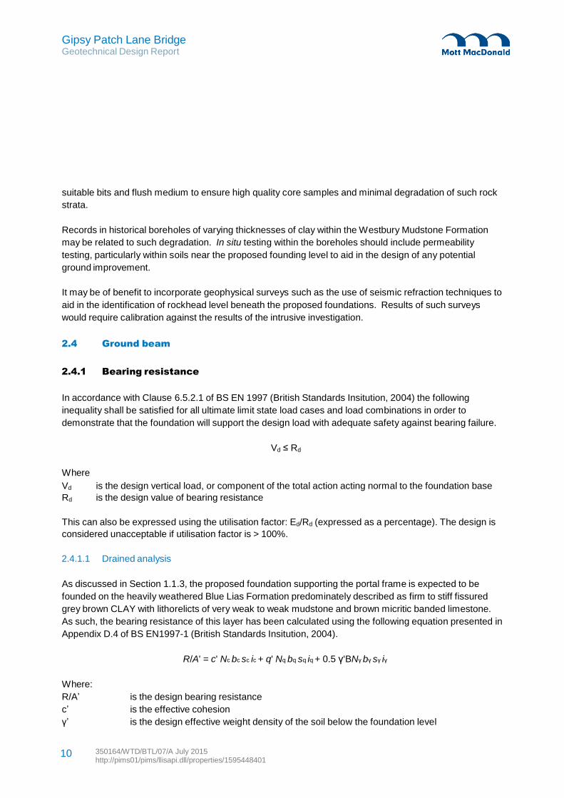
Gipsy Patch Lane Bridge Geotechnical Design Report
350164/WTD/BTL/07/A July 2015 http://pims01/pims/llisapi.dll/properties/1595448401
10
suitable bits and flush medium to ensure high quality core samples and minimal degradation of such rock
strata.
Records in historical boreholes of varying thicknesses of clay within the Westbury Mudstone Formation
may be related to such degradation. In situ testing within the boreholes should include permeability
testing, particularly within soils near the proposed founding level to aid in the design of any potential
ground improvement.
It may be of benefit to incorporate geophysical surveys such as the use of seismic refraction techniques to
aid in the identification of rockhead level beneath the proposed foundations. Results of such surveys
would require calibration against the results of the intrusive investigation.
2.4 Ground beam
2.4.1 Bearing resistance
In accordance with Clause 6.5.2.1 of BS EN 1997 (British Standards Insitution, 2004) the following
inequality shall be satisfied for all ultimate limit state load cases and load combinations in order to
demonstrate that the foundation will support the design load with adequate safety against bearing failure.
Vd ≤ Rd
Where
Vd is the design vertical load, or component of the total action acting normal to the foundation base
Rd is the design value of bearing resistance
This can also be expressed using the utilisation factor: Ed/Rd (expressed as a percentage). The design is
considered unacceptable if utilisation factor is > 100%.
2.4.1.1 Drained analysis
As discussed in Section 1.1.3, the proposed foundation supporting the portal frame is expected to be
founded on the heavily weathered Blue Lias Formation predominately described as firm to stiff fissured
grey brown CLAY with lithorelicts of very weak to weak mudstone and brown micritic banded limestone.
As such, the bearing resistance of this layer has been calculated using the following equation presented in
Appendix D.4 of BS EN1997-1 (British Standards Insitution, 2004).
R/A' = c' Nc bc sc ic + q' Nq bq sq iq + 0.5 γ'BNγ bγ sγ iγ
Where:
R/A’ is the design bearing resistance
c’ is the effective cohesion
γ’ is the design effective weight density of the soil below the foundation level
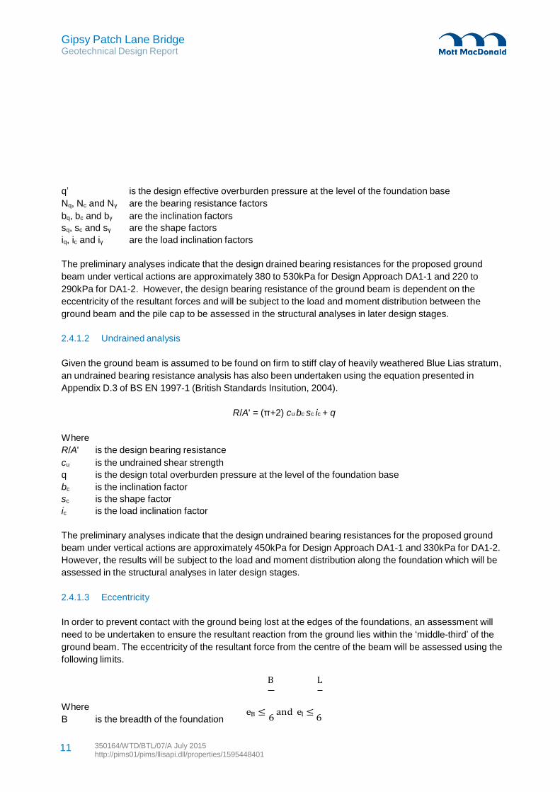
Gipsy Patch Lane Bridge Geotechnical Design Report
350164/WTD/BTL/07/A July 2015 http://pims01/pims/llisapi.dll/properties/1595448401
11
q’ is the design effective overburden pressure at the level of the foundation base
Nq, Nc and Nγ are the bearing resistance factors
bq, bc and bγ are the inclination factors
sq, sc and sγ are the shape factors
iq, ic and iγ are the load inclination factors
The preliminary analyses indicate that the design drained bearing resistances for the proposed ground
beam under vertical actions are approximately 380 to 530kPa for Design Approach DA1-1 and 220 to
290kPa for DA1-2. However, the design bearing resistance of the ground beam is dependent on the
eccentricity of the resultant forces and will be subject to the load and moment distribution between the
ground beam and the pile cap to be assessed in the structural analyses in later design stages.
2.4.1.2 Undrained analysis
Given the ground beam is assumed to be found on firm to stiff clay of heavily weathered Blue Lias stratum,
an undrained bearing resistance analysis has also been undertaken using the equation presented in
Appendix D.3 of BS EN 1997-1 (British Standards Insitution, 2004).
R/A' = (π+2) cu bc sc ic + q
Where
R/A' is the design bearing resistance
cu is the undrained shear strength
q is the design total overburden pressure at the level of the foundation base
bc is the inclination factor
sc is the shape factor
ic is the load inclination factor
The preliminary analyses indicate that the design undrained bearing resistances for the proposed ground
beam under vertical actions are approximately 450kPa for Design Approach DA1-1 and 330kPa for DA1-2.
However, the results will be subject to the load and moment distribution along the foundation which will be
assessed in the structural analyses in later design stages.
2.4.1.3 Eccentricity
In order to prevent contact with the ground being lost at the edges of the foundations, an assessment will
need to be undertaken to ensure the resultant reaction from the ground lies within the ‘middle-third’ of the
ground beam. The eccentricity of the resultant force from the centre of the beam will be assessed using the
following limits.
B L
Where
B is the breadth of the foundation eB ≤
6 and el ≤
6
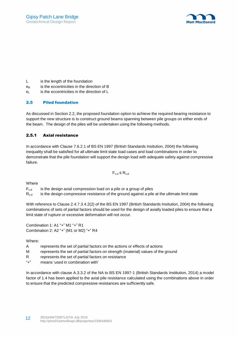
Gipsy Patch Lane Bridge Geotechnical Design Report
350164/WTD/BTL/07/A July 2015 http://pims01/pims/llisapi.dll/properties/1595448401
12
L is the length of the foundation
eB is the eccentricities in the direction of B
eL is the eccentricities in the direction of L
2.5 Piled foundation
As discussed in Section 2.2, the proposed foundation option to achieve the required bearing resistance to
support the new structure is to construct ground beams spanning between pile groups on either ends of
the beam. The design of the piles will be undertaken using the following methods.
2.5.1 Axial resistance
In accordance with Clause 7.6.2.1 of BS EN 1997 (British Standards Insitution, 2004) the following
inequality shall be satisfied for all ultimate limit state load cases and load combinations in order to
demonstrate that the pile foundation will support the design load with adequate safety against compressive
failure.
Fc;d ≤ Rc;d
Where
Fc;d is the design axial compression load on a pile or a group of piles
Rc;d is the design compressive resistance of the ground against a pile at the ultimate limit state
With reference to Clause 2.4.7.3.4.2(2) of the BS EN 1997 (British Standards Insitution, 2004) the following
combinations of sets of partial factors should be used for the design of axially loaded piles to ensure that a
limit state of rupture or excessive deformation will not occur.
Combination 1: A1 “+” M1 “+” R1
Combination 2: A2 “+” (M1 or M2) “+” R4
Where:
A represents the set of partial factors on the actions or effects of actions
M represents the set of partial factors on strength (material) values of the ground
R represents the set of partial factors on resistance
“+” means ‘used in combination with’
In accordance with clause A.3.3.2 of the NA to BS EN 1997-1 (British Standards Institution, 2014) a model
factor of 1.4 has been applied to the axial pile resistance calculated using the combinations above in order
to ensure that the predicted compressive resistances are sufficiently safe.
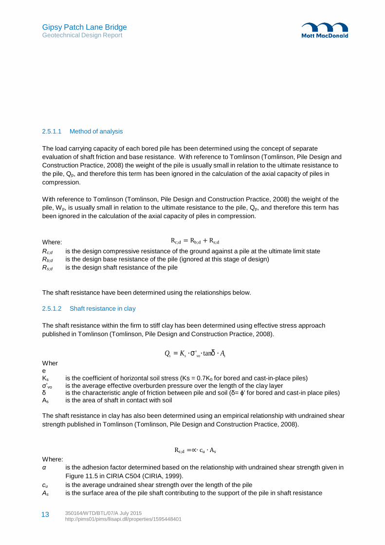
Gipsy Patch Lane Bridge Geotechnical Design Report
350164/WTD/BTL/07/A July 2015 http://pims01/pims/llisapi.dll/properties/1595448401
13
2.5.1.1 Method of analysis
The load carrying capacity of each bored pile has been determined using the concept of separate
evaluation of shaft friction and base resistance. With reference to Tomlinson (Tomlinson, Pile Design and
Construction Practice, 2008) the weight of the pile is usually small in relation to the ultimate resistance to
the pile, Qp, and therefore this term has been ignored in the calculation of the axial capacity of piles in
compression.
With reference to Tomlinson (Tomlinson, Pile Design and Construction Practice, 2008) the weight of the
pile, Wp, is usually small in relation to the ultimate resistance to the pile, Qp, and therefore this term has
been ignored in the calculation of the axial capacity of piles in compression.
Where: Rc;d = Rb;d + Rs;d
Rc;d is the design compressive resistance of the ground against a pile at the ultimate limit state
Rb;d is the design base resistance of the pile (ignored at this stage of design)
Rs;d is the design shaft resistance of the pile
The shaft resistance have been determined using the relationships below.
2.5.1.2 Shaft resistance in clay
The shaft resistance within the firm to stiff clay has been determined using effective stress approach
published in Tomlinson (Tomlinson, Pile Design and Construction Practice, 2008).
Where
Qs = Ks ⋅σ 'vo⋅tanδ ⋅ As
Ks is the coefficient of horizontal soil stress (Ks = 0.7K0 for bored and cast-in-place piles) σ’vo is the average effective overburden pressure over the length of the clay layer δ is the characteristic angle of friction between pile and soil (δ= ϕ' for bored and cast-in place piles) As is the area of shaft in contact with soil
The shaft resistance in clay has also been determined using an empirical relationship with undrained shear
strength published in Tomlinson (Tomlinson, Pile Design and Construction Practice, 2008).
Rs;d =∝∙ cu ∙ As
Where:
α is the adhesion factor determined based on the relationship with undrained shear strength given in
Figure 11.5 in CIRIA C504 (CIRIA, 1999).
cu is the average undrained shear strength over the length of the pile
As is the surface area of the pile shaft contributing to the support of the pile in shaft resistance
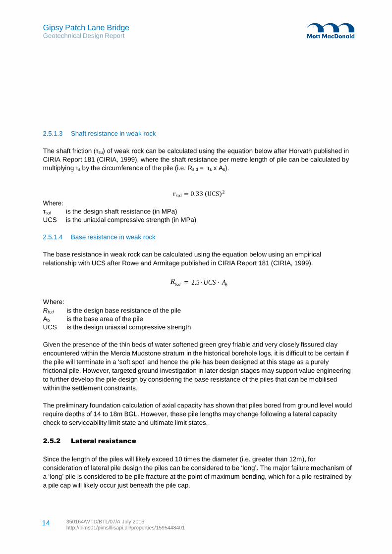
Gipsy Patch Lane Bridge Geotechnical Design Report
350164/WTD/BTL/07/A July 2015 http://pims01/pims/llisapi.dll/properties/1595448401
14
2.5.1.3 Shaft resistance in weak rock
The shaft friction (τsu) of weak rock can be calculated using the equation below after Horvath published in
CIRIA Report 181 (CIRIA, 1999), where the shaft resistance per metre length of pile can be calculated by
multiplying τs by the circumference of the pile (i.e. Rs;d = τs x As).
rs;d = 0.33 (UCS)2
Where:
τs;d is the design shaft resistance (in MPa)
UCS is the uniaxial compressive strength (in MPa)
2.5.1.4 Base resistance in weak rock
The base resistance in weak rock can be calculated using the equation below using an empirical
relationship with UCS after Rowe and Armitage published in CIRIA Report 181 (CIRIA, 1999).
Rb;d = 2.5 ⋅UCS ⋅ Ab
Where:
Rb;d is the design base resistance of the pile
Ab is the base area of the pile
UCS is the design uniaxial compressive strength
Given the presence of the thin beds of water softened green grey friable and very closely fissured clay
encountered within the Mercia Mudstone stratum in the historical borehole logs, it is difficult to be certain if
the pile will terminate in a ‘soft spot’ and hence the pile has been designed at this stage as a purely
frictional pile. However, targeted ground investigation in later design stages may support value engineering
to further develop the pile design by considering the base resistance of the piles that can be mobilised
within the settlement constraints.
The preliminary foundation calculation of axial capacity has shown that piles bored from ground level would
require depths of 14 to 18m BGL. However, these pile lengths may change following a lateral capacity
check to serviceability limit state and ultimate limit states.
2.5.2 Lateral resistance
Since the length of the piles will likely exceed 10 times the diameter (i.e. greater than 12m), for
consideration of lateral pile design the piles can be considered to be ‘long’. The major failure mechanism of
a ‘long’ pile is considered to be pile fracture at the point of maximum bending, which for a pile restrained by
a pile cap will likely occur just beneath the pile cap.
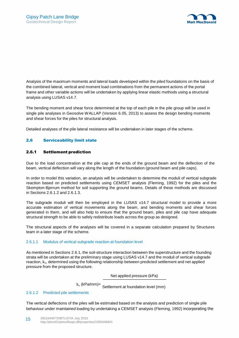
Gipsy Patch Lane Bridge Geotechnical Design Report
350164/WTD/BTL/07/A July 2015 http://pims01/pims/llisapi.dll/properties/1595448401
15
Analysis of the maximum moments and lateral loads developed within the piled foundations on the basis of
the combined lateral, vertical and moment load combinations from the permanent actions of the portal
frame and other variable actions will be undertaken by applying linear elastic methods using a structural
analysis using LUSAS v14.7.
The bending moment and shear force determined at the top of each pile in the pile group will be used in
single pile analyses in Geosolve WALLAP (Version 6.05, 2013) to assess the design bending moments
and shear forces for the piles for structural analysis.
Detailed analyses of the pile lateral resistance will be undertaken in later stages of the scheme.
2.6 Serviceability limit state
2.6.1 Settlement prediction
Due to the load concentration at the pile cap at the ends of the ground beam and the deflection of the
beam, vertical deflection will vary along the length of the foundation (ground beam and pile caps).
In order to model this variation, an analysis will be undertaken to determine the moduli of vertical subgrade
reaction based on predicted settlements using CEMSET analysis (Fleming, 1992) for the piles and the
Skempton-Bjerrum method for soil supporting the ground beams. Details of these methods are discussed
in Sections 2.6.1.2 and 2.6.1.3.
The subgrade moduli will then be employed in the LUSAS v14.7 structural model to provide a more
accurate estimation of vertical movements along the beam, and bending moments and shear forces
generated in them, and will also help to ensure that the ground beam, piles and pile cap have adequate
structural strength to be able to safely redistribute loads across the group as designed.
The structural aspects of the analyses will be covered in a separate calculation prepared by Structures
team in a later stage of the scheme.
2.6.1.1 Modulus of vertical subgrade reaction at foundation level
As mentioned in Sections 2.6.1, the soil-structure interaction between the superstructure and the founding
strata will be undertaken at the preliminary stage using LUSAS v14.7 and the moduli of vertical subgrade reaction, ks, determined using the following relationship between predicted settlement and net applied
pressure from the proposed structure.
Net applied pressure (kPa)
ks (kPa/mm)= Settlement at foundation level (mm)
2.6.1.2 Predicted pile settlements
The vertical deflections of the piles will be estimated based on the analysis and prediction of single pile
behaviour under maintained loading by undertaking a CEMSET analysis (Fleming, 1992) incorporating the
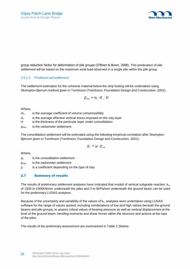
Gipsy Patch Lane Bridge Geotechnical Design Report
350164/WTD/BTL/07/A July 2015 http://pims01/pims/llisapi.dll/properties/1595448401
16
group reduction factor for deformation of pile groups (O'Brien & Bown, 2008). This predication of pile
settlement will be based on the maximum axial load observed in a single pile within the pile group.
2.6.1.3 Predicted soil settlement
The settlement estimation for the cohesive material below the strip footing will be undertaken using
Skempton-Bjerrum method given in Tomlinson (Tomlinson, Foundation Design and Construction, 2001):
ρoed = mv ⋅σ z ⋅ H
Where,
mv is the average coefficient of volume compressibility
σz is the average effective vertical stress imposed on the clay layer
H is the thickness of the particular layer under consolidation
ρoed is the oedometer settlement
The consolidation settlement will be estimated using the following empirical correlation after Skempton-
Bjerrum given in Tomlinson (Tomlinson, Foundation Design and Construction, 2001):
ρ c = µ ⋅ ρoed
Where,
ρc is the consolidation settlement
ρoed is the oedometer settlement
µ is a coefficient depending on the type of clay
2.7 Summary of results
The results of preliminary settlement analyses have indicated that moduli of vertical subgrade reaction, ks,
of 1500 to 2300kN/mm underneath the piles and 3 to 8kPa/mm underneath the ground beam can be used
for the preliminary LUSAS analyses.
Because of the uncertainty and variability of the values of ks, analyses were undertaken using LUSAS
software for the range of values quoted, including combinations of low and high values beneath the ground
beams and pile groups, to assess critical values of bearing pressure as well as vertical displacement at the
level of the ground beam, bending moments and shear forces within the structure and actions at the tops
of the piles.
The results of the preliminary assessment are summarised in Table 2.2below.
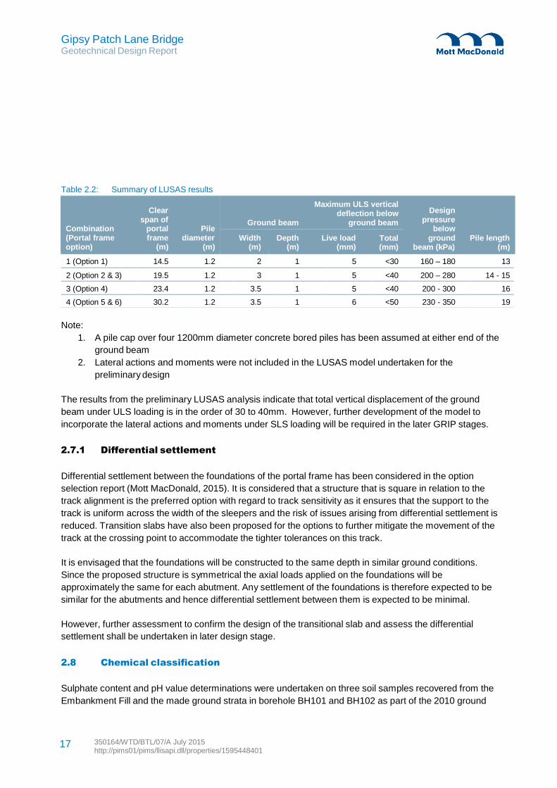
Gipsy Patch Lane Bridge Geotechnical Design Report
350164/WTD/BTL/07/A July 2015 http://pims01/pims/llisapi.dll/properties/1595448401
17
1 (Option 1) 14.5 1.2 2 1 5 <30 160 – 180 13
2 (Option 2 & 3) 19.5 1.2 3 1 5 <40 200 – 280 14 - 15
3 (Option 4) 23.4 1.2 3.5 1 5 <40 200 - 300 16
4 (Option 5 & 6) 30.2 1.2 3.5 1 6 <50 230 - 350 19
Table 2.2: Summary of LUSAS results
Clear
span of Combination portal Pile (Portal frame frame diameter option) (m) (m)
Ground beam
Maximum ULS vertical deflection below
ground beam
Design
pressure below
ground Pile length beam (kPa) (m)
Width (m)
Depth (m)
Live load (mm)
Total (mm)
Note:
1. A pile cap over four 1200mm diameter concrete bored piles has been assumed at either end of the
ground beam
2. Lateral actions and moments were not included in the LUSAS model undertaken for the
preliminary design
The results from the preliminary LUSAS analysis indicate that total vertical displacement of the ground
beam under ULS loading is in the order of 30 to 40mm. However, further development of the model to
incorporate the lateral actions and moments under SLS loading will be required in the later GRIP stages.
2.7.1 Differential settlement
Differential settlement between the foundations of the portal frame has been considered in the option
selection report (Mott MacDonald, 2015). It is considered that a structure that is square in relation to the
track alignment is the preferred option with regard to track sensitivity as it ensures that the support to the
track is uniform across the width of the sleepers and the risk of issues arising from differential settlement is
reduced. Transition slabs have also been proposed for the options to further mitigate the movement of the
track at the crossing point to accommodate the tighter tolerances on this track.
It is envisaged that the foundations will be constructed to the same depth in similar ground conditions.
Since the proposed structure is symmetrical the axial loads applied on the foundations will be
approximately the same for each abutment. Any settlement of the foundations is therefore expected to be
similar for the abutments and hence differential settlement between them is expected to be minimal.
However, further assessment to confirm the design of the transitional slab and assess the differential
settlement shall be undertaken in later design stage.
2.8 Chemical classification
Sulphate content and pH value determinations were undertaken on three soil samples recovered from the
Embankment Fill and the made ground strata in borehole BH101 and BH102 as part of the 2010 ground

Gipsy Patch Lane Bridge Geotechnical Design Report
350164/WTD/BTL/07/A July 2015 http://pims01/pims/llisapi.dll/properties/1595448401
18
investigation (CJ Associates Geotechnical Limited, 2010), giving water soluble sulphate contents of 51 to
329mg/l and associate pH values of 7.7 and 8.2.
With reference to Table C1 in BRE Special Digest 1 (BRE, 2001) and the chemical test results, both the
embankment fill and the made ground can be classified as Design sulphate (DS) DS-1 and Aggressive
Chemical Environment for Concrete (ACEC) Class AC-1d.
In the absence of chemical testing for the natural deposits within the site area, reference has been made to
the testing undertaken for the 2006 ground investigation for Rolls-Royce East Works located immediately
to the south west of the site. The results give in Table 15 of the factual report (Conestoga-Rovers &
Associates (Europe) LTD, 2006) shows the site has DS and ACEC classes of DS-1 to DS-2 and AC-1 to
AC-2 for samples recovered between 0.3 and 6m BGL within the made ground and Blue Lias Formation
strata based on the water-soluble sulphate and pH results. However, Box C6 in BRE Special Digest 1
(BRE, 2001) suggests that Blue Lias Formation of the Lias Group is known to contain pyrite and hence
total sulphur and acid soluble sulphate content testing should be undertaken in order to determine the DS
and ACEC class.
In the absence of testing on acid soluble sulphate and total sulphur content, a higher DC and ACEC class
of DS-3 and AC-3 has been assumed in preliminary design and will be subject to confirmation from
chemical testing to be undertaken in later stages of the design.
Gipsy Patch Lane Bridge Geotechnical Design Report
350164/WTD/BTL/07/A July 2015 http://pims01/pims/llisapi.dll/properties/1595448401
19
3 Strengthened Earthworks (NOT USED)
Gipsy Patch Lane Bridge Geotechnical Design Report
350164/WTD/BTL/07/A July 2015 http://pims01/pims/llisapi.dll/properties/1595448401
20
4 Drainage
Details of the proposed drainage were not available at the time of writing this report. However, due to the
high water table suggested from the historical groundwater monitoring data, it is considered that further
assessment will be required to confirm if any improvement works to the existing drainage system are
required.
Gipsy Patch Lane Bridge Geotechnical Design Report
350164/WTD/BTL/07/A July 2015 http://pims01/pims/llisapi.dll/properties/1595448401
21
5 Pavement Design, Subgrade and Capping
Details of the proposed pavement and layout of the road were not available at the time of writing this
report, however it is expected that the proposed subgrade is likely to comprise weathered Lower Lias
Formation based on the GA drawings.
Given that California Bearing Ratio (CBR) testing was not undertaken as part of the 2014 intrusive
investigation, CBR values for the subgrade design of the proposed footpath and carriageway have been
determined in accordance with Table 5.1 in IAN 73 (Highways England, 2009) based on the soil
description and plasticity index.
It is considered that a characteristic CBR for the heavily weathered Blue Lias Formation of 3% is
appropriate based on the recommended values for silty clay and a plasticity index of 24 to 34%
recommended in the Geological Society Special Publication No. 21 (Geological Society, 2006) for Blue
Lias Clay.
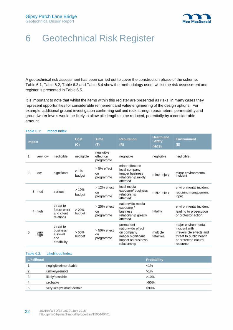
Gipsy Patch Lane Bridge Geotechnical Design Report
350164/WTD/BTL/07/A July 2015 http://pims01/pims/llisapi.dll/properties/1595448401
22
6 Geotechnical Risk Register
A geotechnical risk assessment has been carried out to cover the construction phase of the scheme.
Table 6.1, Table 6.2, Table 6.3 and Table 6.4 show the methodology used, whilst the risk assessment and
register is presented in Table 6.5.
It is important to note that whilst the items within this register are presented as risks, in many cases they
represent opportunities for considerable refinement and value engineering of the design options. For
example, additional ground investigation confirming soil and rock strength parameters, permeability and
groundwater levels would be likely to allow pile lengths to be reduced, potentially by a considerable
amount.
Table 6.1: Impact Index
Impact
Cost
(C)
Time
(T)
negligible
Reputation
(R)
Health and Safety
(H&S)
Environment
(E)
1 very low negligible negligible effect on programme
> 5% effect
negligible negligible negligible
minor effect on local company
2 low significant > 1%
budget
on programme
> 12% effect
image/ business relationship mildly affected
local media
minor injury minor environmental incident
environmental incident
3 med serious > 10%
budget
threat to
on programme
> 25% effect
exposure/ business relationship affected
nationwide media exposure /
major injury requiring management input
environmental incident
4 high
5 very high
future work and client relations
threat to business survival and credibility
> 20% budget
> 50% budget
on programme
> 50% effect on programme
business relationship greatly affected
permanent nationwide effect on company image/ significant impact on business relationship
fatality
multiple fatalities
leading to prosecution or protestor action
major environmental incident with irreversible effects and threat to public health or protected natural resource
Table 6.2: Likelihood Index
Likelihood Probability
1 negligible/improbable <1%
2 unlikely/remote >1%
3 likely/possible >10%
4 probable >50%
5 very likely/almost certain >90%

Gipsy Patch Lane Bridge Geotechnical Design Report
350164/WTD/BTL/07/A July 2015 http://pims01/pims/llisapi.dll/properties/1595448401
23
Table 6.3: Risk Matrix
IMPACT
1 2 3 4 5
LIK
LIH
OO
D
1
N
N
N
A
A
2
N
A
A
H
H
3
A
H
H
S
S
4
H
H
S
S
S
5
H
H
S
S
S
Table 6.4: Designers’ Actions
RISK LEVEL DESCRIPTION ACTION BY DESIGNER
N Negligible None
A Acceptable Check that risks cannot be further reduced by simple design changes
H High Amend design to reduce risk, or seek alternative option. Only accept
option if justifiable on other grounds. S Severe
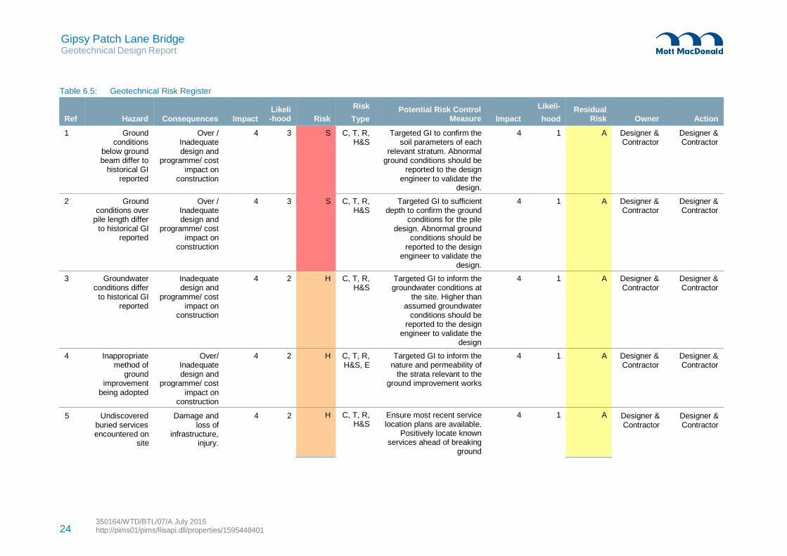
Gipsy Patch Lane Bridge Geotechnical Design Report
350164/WTD/BTL/07/A July 2015 http://pims01/pims/llisapi.dll/properties/1595448401 24
5 Undiscovered Damage and 4 2 Designer & Designer &
buried services loss of Contractor Contractor
encountered on site
infrastructure, injury.
Table 6.5: Geotechnical Risk Register
Ref
Hazard
Consequences
Impact
Likeli -hood
Risk
Risk
Type
Potential Risk Control
Measure
Impact
Likeli-
hood
Residual
Risk
Owner
Action
1 Ground conditions
below ground beam differ to
historical GI reported
Over / Inadequate design and
programme/ cost impact on
construction
4 3 S C, T, R, H&S
Targeted GI to confirm the soil parameters of each
relevant stratum. Abnormal ground conditions should be
reported to the design engineer to validate the
design.
4 1 A Designer & Contractor
Designer & Contractor
2 Ground conditions over
pile length differ to historical GI
reported
Over / Inadequate design and
programme/ cost impact on
construction
4 3 S C, T, R, H&S
Targeted GI to sufficient depth to confirm the ground
conditions for the pile design. Abnormal ground
conditions should be reported to the design
engineer to validate the design.
4 1 A Designer & Contractor
Designer & Contractor
3 Groundwater conditions differ
to historical GI reported
Inadequate design and
programme/ cost impact on
construction
4 2 H C, T, R, H&S
Targeted GI to inform the groundwater conditions at
the site. Higher than assumed groundwater
conditions should be reported to the design
engineer to validate the design
4 1 A Designer & Contractor
Designer & Contractor
4 Inappropriate method of
ground improvement
being adopted
Over/ Inadequate design and
programme/ cost impact on
construction
4 2 H C, T, R, H&S, E
Targeted GI to inform the nature and permeability of
the strata relevant to the ground improvement works
4 1 A Designer & Contractor
Designer & Contractor
H C, T, R, H&S
Ensure most recent service location plans are available.
Positively locate known services ahead of breaking
ground
4 1 A
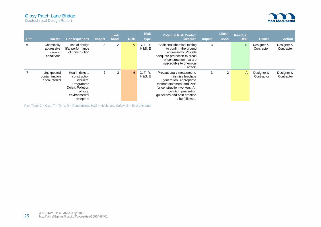
Gipsy Patch Lane Bridge Geotechnical Design Report
350164/WTD/BTL/07/A July 2015 http://pims01/pims/llisapi.dll/properties/1595448401 25
7 Unexpected contamination
encountered
Health risks to construction
workers.
3 3 Designer & Contractor
Designer & Contractor
Programme Delay. Pollution
of local environmental
receptors
Ref
Hazard
Consequences
Impact
Likeli -hood
Risk
Risk
Type
Potential Risk Control
Measure
Impact
Likeli-
hood
Residual
Risk
Owner
Action
6 Chemically aggressive
ground conditions
Loss of design life/ performance
of construction
3 2 A C, T, R, H&S, E
Additional chemical testing to confirm the ground aggressivity. Provide
adequate protection to areas of construction that are susceptible to chemical
attack.
3 1 N Designer & Contractor
Designer & Contractor
H C, T, R, H&S, E
Precautionary measures to minimise leachate
generation. Appropriate method statement and PPE for construction workers. All
pollution prevention guidelines and best practice
to be followed.
3 2 A
Risk Type: C = Cost; T = Time; R = Reputational; H&S = Health and Safety; E = Environmental
Gipsy Patch Lane Bridge Geotechnical Design Report
350164/WTD/BTL/07/A July 2015 http://pims01/pims/llisapi.dll/properties/1595448401
26
7 REFERENCES
BRE. (2001). Concrete in aggressive ground. Garston: Building Research Establishment.
British Geological Survey. (2015). British Geological Survey: Onshore Geoindex. Retrieved 2015, from
British Geological Survey: Onshore Geoindex: http://www.bgs.ac.uk/GeoIndex/
British Standards Insitution. (2004). BS EN 1997-1:2004 Eurocode 7: Geotechnical design - Part 1:
General rules.
British Standards Institution. (1999). BS 5930, 'Code of practice for site investigations' (Superseded).
British Standards Institution. (2003). BS EN 14689-1:2003; Geotechnical investigation and testing -
identification and classification of rock - Part 1: Identification and description.
British Standards Institution. (2014). NA+A1:2014 to BS EN 1997-1; UK National Annex to Eurocode 7:
Geotechnical design - Part 1: General rules.
British Standards Institution. (Amended 2001). BS 8002: Code of practice for earth retaining structures.
London: British Standards Institution.
Burland, J. B. (1979). Movements around excavations in London Clay. Proc. 7th European Conf. SMFE.
Vol 1.
CIRIA. (1995). CIRIA Report 143: The Standard Penetration Test (SPT): Method of Use. CIRIA.
CIRIA. (1999). CIRIA C504: Engineering in glacial tills.
CIRIA. (1999). CIRIA Report 181, 'Piled Foundation in Weak Rock'. London: CIRIA.
CIRIA. (2001). CIRIA C570 - Engineering in Mercia Mudstone. London.
CJ Associates Geotechnical Limited. (2010). Ground Investigation No. X0440, 'Parkway & Patchway
Station Subways Bristol'.
Conestoga-Rovers & Associates (Europe) LTD. (2006). Phase II Site Investigation Final Report, 'Rolls-
Royce PLC, East Works, Filton, Bristol', Ref. No. 933317(4).
Fleming, W. G. (1992). A new method for single pile settlement prediction and analysis. Geotechnique,
42(No. 3, 411-425).
Geological Society. (2006). Engineering Geology Special Publications 2006; v21- Appendix B. Properties
data. P. 461-474.
Geosolve. (2013). WALLAP Retaining Wall Analysis Programme Version 6.05.
Gipsy Patch Lane Bridge Geotechnical Design Report
350164/WTD/BTL/07/A July 2015 http://pims01/pims/llisapi.dll/properties/1595448401
27
Highways England. (2009). IAN 73/06 Revision 1 (2009) - Design Guidance for Road Pavement
Foundations.
Mott MacDonald. (2015). Gypsy Patch Lane Option Selection Report, Report Ref. 350164/WTD/BTL/01.
O'Brien, A. S., & Bown, A. S. (2008). Pile Foundations - Emerging Design Methods. Piling and
Foundations, Ground Engineering Conference.
Tomlinson, M. J. (2001). Foundation Design and Construction (7th ed.). Harlow: Pearson Education Ltd.
Tomlinson, M. J. (2008). Pile Design and Construction Practice (5th ed.). Abingdon: Taylor & Francis.

Gipsy Patch Lane Bridge Geotechnical Design Report
350164/WTD/BTL/07/A July 2015 http://pims01/pims/llisapi.dll/properties/1595448401
28
Appendix A. Drawings
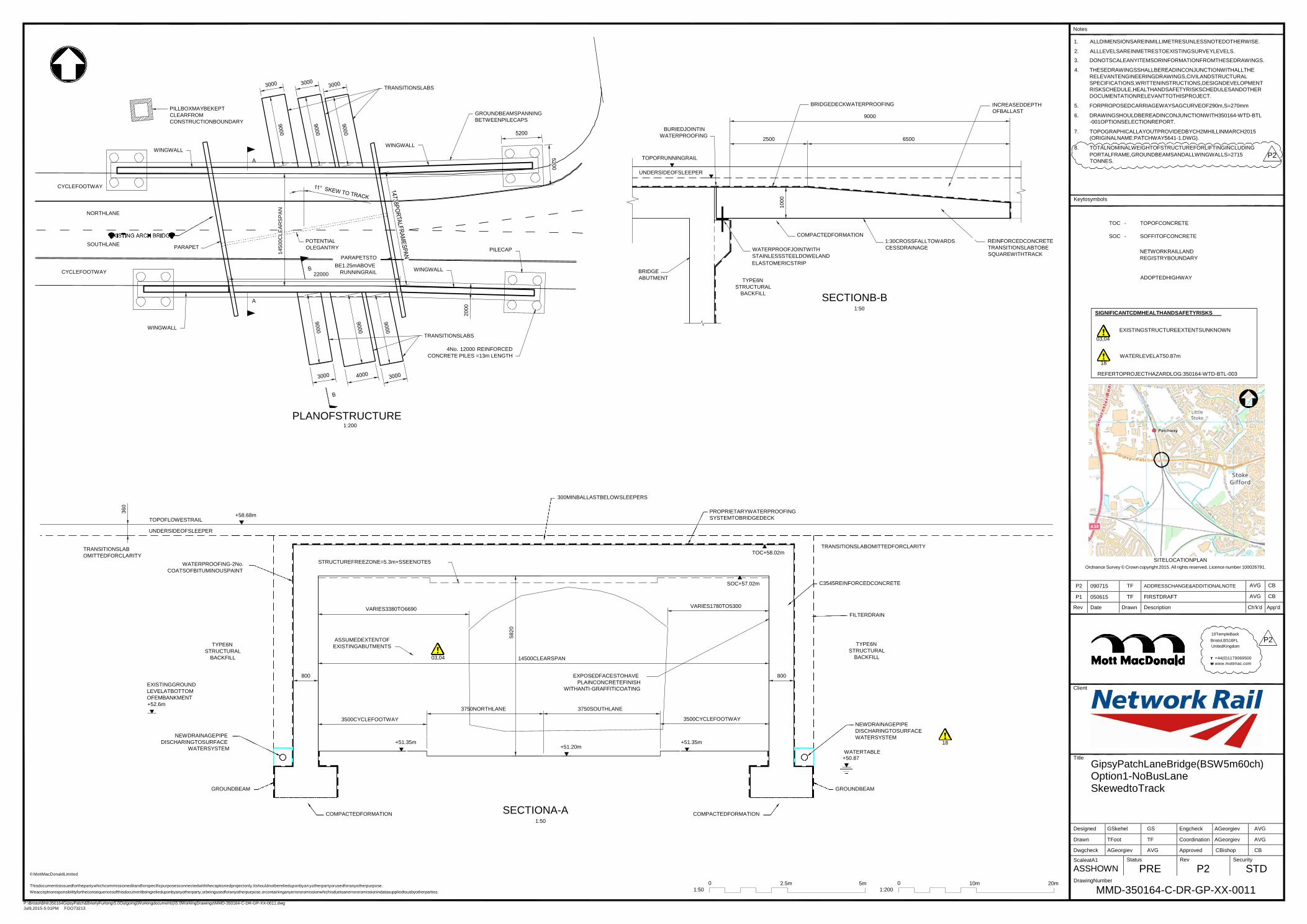
Notes
1.
2.
ALLDIMENSIONSAREINMILLIMETRESUNLESSNOTEDOTHERWISE.
ALLLEVELSAREINMETRESTOEXISTINGSURVEYLEVELS.
P2 090715 TF ADDRESSCHANGE&ADDITIONALNOTE AVG CB
P1 050615 TF FIRSTDRAFT AVG CB
Rev Date Drawn Description Ch'k'd App'd
Designed GSkehel GS Engcheck AGeorgiev AVG
Drawn TFoot TF Coordination AGeorgiev AVG
Dwgcheck AGeorgiev AVG Approved CBishop CB
ScaleatA1
ASSHOWN Status
PRE Rev
P2 Security
STD
360
14500C
LE
AR
SP
AN
2000
5820
1000
PILLBOXMAYBEKEPT
CLEARFROM
CONSTRUCTIONBOUNDARY
WINGWALL
TRANSITIONSLABS
WINGWALL
GROUNDBEAMSPANNING
BETWEENPILECAPS
BURIEDJOINTIN
WATERPROOFING
TOPOFRUNNINGRAIL
BRIDGEDECKWATERPROOFING
9000
2500 6500
INCREASEDDEPTH
OFBALLAST
3. DONOTSCALEANYITEMSORINFORMATIONFROMTHESEDRAWINGS.
4. THESEDRAWINGSSHALLBEREADINCONJUNCTIONWITHALLTHE
RELEVANTENGINEERINGDRAWINGS,CIVILANDSTRUCTURAL
SPECIFICATIONS,WRITTENINSTRUCTIONS,DESIGNDEVELOPMENT
RISKSCHEDULE,HEALTHANDSAFETYRISKSCHEDULESANDOTHER
DOCUMENTATIONRELEVANTTOTHISPROJECT.
5. FORPROPOSEDCARRIAGEWAYSAGCURVEOF290m,S=270mm
6. DRAWINGSHOULDBEREADINCONJUNCTIONWITH350164-WTD-BTL
-001OPTIONSELECTIONREPORT.
7. TOPOGRAPHICALLAYOUTPROVIDEDBYCH2MHILLINMARCH2015
(ORIGINALNAME:PATCHWAY5641-1.DWG).
8. TOTALNOMINALWEIGHTOFSTRUCTUREFORLIFTINGINCLUDING
PORTALFRAME,GROUNDBEAMSANDALLWINGWALLS=2715 P2 TONNES.
UNDERSIDEOFSLEEPER
CYCLEFOOTWAY
Keytosymbols
NORTHLANE
SOUTHLANE
PARAPET
POTENTIAL
OLEGANTRY
PARAPETSTO
PILECAP
COMPACTEDFORMATION
WATERPROOFJOINTWITH
STAINLESSSTEELDOWELAND
1:30CROSSFALLTOWARDS
CESSDRAINAGE
REINFORCEDCONCRETE
TRANSITIONSLABTOBE
SQUAREWITHTRACK
TOC - TOPOFCONCRETE
SOC - SOFFITOFCONCRETE
NETWORKRAILLAND
REGISTRYBOUNDARY
CYCLEFOOTWAY
22000
BE1.25mABOVE
RUNNINGRAIL
WINGWALL
BRIDGE
ABUTMENT
ELASTOMERICSTRIP
TYPE6N
STRUCTURAL
BACKFILL
SECTIONB-B 1:50
ADOPTEDHIGHWAY
SIGNIFICANTCDMHEALTHANDSAFETYRISKS
WINGWALL TRANSITIONSLABS
4No. 12000 REINFORCED
CONCRETE PILES =13m LENGTH
03,04
18
EXISTINGSTRUCTUREEXTENTSUNKNOWN
WATERLEVELAT50.87m
REFERTOPROJECTHAZARDLOG:350164-WTD-BTL-003
PLANOFSTRUCTURE 1:200
300MINBALLASTBELOWSLEEPERS
TOPOFLOWESTRAIL
UNDERSIDEOFSLEEPER
+58.68m
PROPRIETARYWATERPROOFING
SYSTEMTOBRIDGEDECK
TRANSITIONSLAB
OMITTEDFORCLARITY
WATERPROOFING-2No.
COATSOFBITUMINOUSPAINT
STRUCTUREFREEZONE=5.3m+SSEENOTE5
TOC+58.02m
SOC+57.02m
TRANSITIONSLABOMITTEDFORCLARITY
C3545REINFORCEDCONCRETE
SITELOCATIONPLAN
Ordnance Survey © Crown copyright 2015. All rights reserved. Licence number 100026791.
VARIES3380TO6690 VARIES1780TO5300
FILTERDRAIN
TYPE6N
STRUCTURAL
BACKFILL
ASSUMEDEXTENTOF
EXISTINGABUTMENTS
03,04
14500CLEARSPAN
TYPE6N
STRUCTURAL
BACKFILL
10TempleBack
Bristol,BS16FL P2 UnitedKingdom
T +44(0)1179069500
W www.mottmac.com
EXISTINGGROUND
LEVELATBOTTOM
OFEMBANKMENT
+52.6m
NEWDRAINAGEPIPE
DISCHARINGTOSURFACE
WATERSYSTEM
GROUNDBEAM
800
3500CYCLEFOOTWAY
+51.35m
3750NORTHLANE
EXPOSEDFACESTOHAVE
PLAINCONCRETEFINISH
WITHANTI-GRAFFITICOATING
3750SOUTHLANE
+51.20m
3500CYCLEFOOTWAY
+51.35m
800
NEWDRAINAGEPIPE
DISCHARINGTOSURFACE
WATERSYSTEM 18
WATERTABLE +50.87
GROUNDBEAM
Client
Title
GipsyPatchLaneBridge(BSW5m60ch)
Option1-NoBusLane SkewedtoTrack
COMPACTEDFORMATION SECTIONA-A
1:50
COMPACTEDFORMATION
© MottMacDonaldLimited
Thisdocumentisissuedforthepartywhichcommissioneditandforspecificpurposesconnectedwiththecaptionedprojectonly.Itshouldnotberelieduponbyanyotherpartyorusedforanyotherpurpose.
Weacceptnoresponsibilityfortheconsequencesofthisdocumentbeingrelieduponbyanyotherparty,orbeingusedforanyotherpurpose,orcontaininganyerrororomissionwhichisduetoanerrororomissionindatasuppliedtousbyotherparties.
0
1:50
2.5m 5m
0
1:200
10m 20m
DrawingNumber
MMD-350164-C-DR-GP-XX-0011
P:\Bristol\BNI\350164GipsyPatch&BrierlyFurlong\5.0Outgoing(Workingdocuments)\5.0WorkingDrawings\MMD-350164-C-DR-GP-XX-0011.dwg
Jul9,2015-5:01PM FOO73213
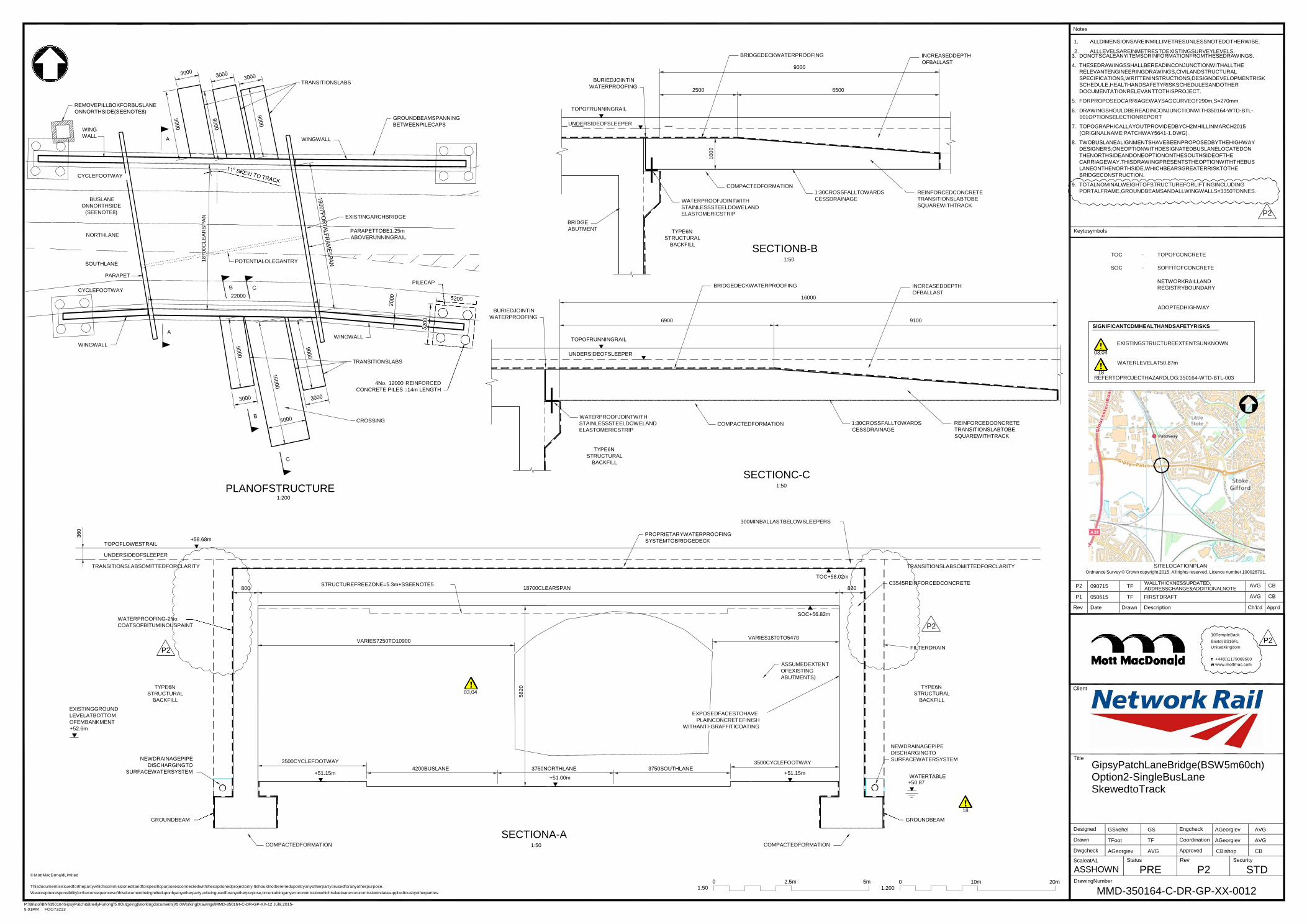
Notes
1.
2.
ALLDIMENSIONSAREINMILLIMETRESUNLESSNOTEDOTHERWISE.
ALLLEVELSAREINMETRESTOEXISTINGSURVEYLEVELS.
P:\Bristol\BNI\350164GipsyPatch&BrierlyFurlong\5.0Outgoing(Workingdocuments)\5.0WorkingDrawings\MMD-350164-C-DR-GP-XX-12 Jul9,2015-
5:01PM FOO73213
P2 090715 TF WALLTHICKNESSUPDATED, ADDRESSCHANGE&ADDITIONALNOTE
AVG CB
P1 050615 TF FIRSTDRAFT AVG CB
Rev Date Drawn Description Ch'k'd App'd
Designed GSkehel GS Engcheck AGeorgiev AVG
Drawn TFoot TF Coordination AGeorgiev AVG
Dwgcheck AGeorgiev AVG Approved CBishop CB
ScaleatA1
ASSHOWN
Status
PRE Rev
P2 Security
STD
22000
360
18700C
LE
AR
SP
AN
5820
1000
REMOVEPILLBOXFORBUSLANE
ONNORTHSIDE(SEENOTE8)
WING
WALL A
CYCLEFOOTWAY
TRANSITIONSLABS
WINGWALL
GROUNDBEAMSPANNING
BETWEENPILECAPS
BURIEDJOINTIN
WATERPROOFING
TOPOFRUNNINGRAIL
UNDERSIDEOFSLEEPER
BRIDGEDECKWATERPROOFING
9000
2500 6500
COMPACTEDFORMATION 1:30CROSSFALLTOWARDS
INCREASEDDEPTH
OFBALLAST
REINFORCEDCONCRETE
3. DONOTSCALEANYITEMSORINFORMATIONFROMTHESEDRAWINGS.
4. THESEDRAWINGSSHALLBEREADINCONJUNCTIONWITHALLTHE
RELEVANTENGINEERINGDRAWINGS,CIVILANDSTRUCTURAL
SPECIFICATIONS,WRITTENINSTRUCTIONS,DESIGNDEVELOPMENTRISK
SCHEDULE,HEALTHANDSAFETYRISKSCHEDULESANDOTHER
DOCUMENTATIONRELEVANTTOTHISPROJECT.
5. FORPROPOSEDCARRIAGEWAYSAGCURVEOF290m,S=270mm
6. DRAWINGSHOULDBEREADINCONJUNCTIONWITH350164-WTD-BTL-
001OPTIONSELECTIONREPORT
7. TOPOGRAPHICALLAYOUTPROVIDEDBYCH2MHILLINMARCH2015
(ORIGINALNAME:PATCHWAY5641-1.DWG).
8. TWOBUSLANEALIGNMENTSHAVEBEENPROPOSEDBYTHEHIGHWAY
DESIGNERS;ONEOPTIONWITHDESIGNATEDBUSLANELOCATEDON
THENORTHSIDEANDONEOPTIONONTHESOUTHSIDEOFTHE
CARRIAGEWAY.THISDRAWINGPRESENTSTHEOPTIONWITHTHEBUS
LANEONTHENORTHSIDE,WHICHBEARSGREATERRISKTOTHE
BRIDGECONSTRUCTION.
9. TOTALNOMINALWEIGHTOFSTRUCTUREFORLIFTINGINCLUDING
PORTALFRAME,GROUNDBEAMSANDALLWINGWALLS=3350TONNES.
BUSLANE
ONNORTHSIDE
(SEENOTE8)
NORTHLANE
EXISTINGARCHBRIDGE
PARAPETTOBE1.25m
ABOVERUNNINGRAIL
BRIDGE
ABUTMENT
WATERPROOFJOINTWITH
STAINLESSSTEELDOWELAND
ELASTOMERICSTRIP
TYPE6N
STRUCTURAL
CESSDRAINAGE TRANSITIONSLABTOBE
SQUAREWITHTRACK
P2
Keytosymbols
SOUTHLANE
PARAPET
CYCLEFOOTWAY
A
WINGWALL
POTENTIALOLEGANTRY
WINGWALL
TRANSITIONSLABS
PILECAP
BURIEDJOINTIN
WATERPROOFING
TOPOFRUNNINGRAIL
UNDERSIDEOFSLEEPER
BACKFILL
6900
SECTIONB-B 1:50
BRIDGEDECKWATERPROOFING
16000
INCREASEDDEPTH
OFBALLAST
9100
TOC - TOPOFCONCRETE
SOC - SOFFITOFCONCRETE
NETWORKRAILLAND
REGISTRYBOUNDARY
ADOPTEDHIGHWAY
SIGNIFICANTCDMHEALTHANDSAFETYRISKS
EXISTINGSTRUCTUREEXTENTSUNKNOWN
03,04
WATERLEVELAT50.87m
18 REFERTOPROJECTHAZARDLOG:350164-WTD-BTL-003
4No. 12000 REINFORCED
CONCRETE PILES ::14m LENGTH
CROSSING WATERPROOFJOINTWITH
STAINLESSSTEELDOWELAND
ELASTOMERICSTRIP
COMPACTEDFORMATION
1:30CROSSFALLTOWARDS
CESSDRAINAGE
REINFORCEDCONCRETE
TRANSITIONSLABTOBE
SQUAREWITHTRACK
PLANOFSTRUCTURE 1:200
TYPE6N
STRUCTURAL
BACKFILL
SECTIONC-C
1:50
300MINBALLASTBELOWSLEEPERS
TOPOFLOWESTRAIL
+58.68m
PROPRIETARYWATERPROOFING
SYSTEMTOBRIDGEDECK
UNDERSIDEOFSLEEPER
TRANSITIONSLABSOMITTEDFORCLARITY
800
STRUCTUREFREEZONE=5.3m+SSEENOTE5
18700CLEARSPAN
TOC+58.02m
800
TRANSITIONSLABSOMITTEDFORCLARITY
C3545REINFORCEDCONCRETE
SITELOCATIONPLAN Ordnance Survey © Crown copyright 2015. All rights reserved. Licence number 100026791.
WATERPROOFING-2No.
COATSOFBITUMINOUSPAINT
P2
TYPE6N
STRUCTURAL
BACKFILL
SOC+56.82m
VARIES7250TO10900 VARIES1870TO5470
ASSUMEDEXTENT
OFEXISTING
ABUTMENTS)
03,04
P2
FILTERDRAIN
TYPE6N
STRUCTURAL
BACKFILL
Client
10TempleBack
Bristol,BS16FL P2 UnitedKingdom
T +44(0)1179069500
W www.mottmac.com
EXISTINGGROUND
LEVELATBOTTOM
OFEMBANKMENT
+52.6m
EXPOSEDFACESTOHAVE
PLAINCONCRETEFINISH
WITHANTI-GRAFFITICOATING
NEWDRAINAGEPIPE
DISCHARGINGTO
SURFACEWATERSYSTEM
3500CYCLEFOOTWAY
+51.15m
4200BUSLANE
3750NORTHLANE
+51.00m
3750SOUTHLANE
3500CYCLEFOOTWAY
+51.15m
NEWDRAINAGEPIPE
DISCHARGINGTO
SURFACEWATERSYSTEM
WATERTABLE +50.87
Title
GipsyPatchLaneBridge(BSW5m60ch)
Option2-SingleBusLane SkewedtoTrack
18
GROUNDBEAM GROUNDBEAM
SECTIONA-A COMPACTEDFORMATION 1:50 COMPACTEDFORMATION
© MottMacDonaldLimited
Thisdocumentisissuedforthepartywhichcommissioneditandforspecificpurposesconnectedwiththecaptionedprojectonly.Itshouldnotberel ieduponbyanyotherpartyorusedforanyotherpurpose.
Weacceptnoresponsibilityfortheconsequencesofthisdocumentbeingrelieduponbyanyotherparty,orbeingusedforanyotherpurpose,orcontaininganyerrororomissionwhichisduetoanerrororomissionindatasuppliedtousbyotherparties.
0
1:50
2.5 m 5m
0
1:200
10m 20m
DrawingNumber
MMD-350164-C-DR-GP-XX-0012
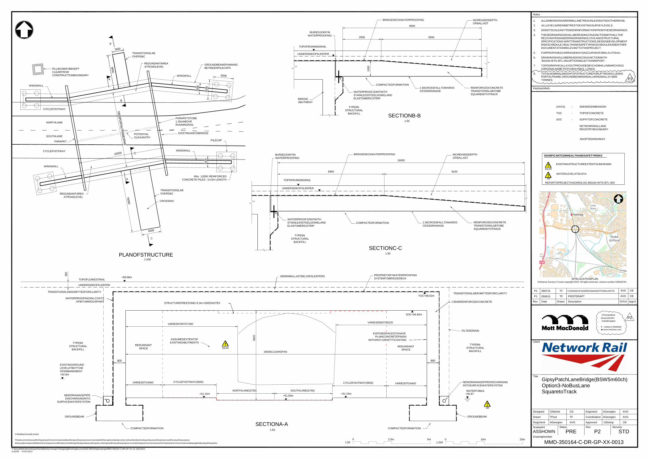
Notes
P:\Bristol\BNI\350164GipsyPatch&BrierlyFurlong\5.0Outgoing(Workingdocuments)\5.0WorkingDrawings\MMD-350164-C-DR-GP-XX-13 Jul9,2015-
5:02PM FOO73213
P2 090715 TF CHANGEOFADDRESS&ADDITIONALNOTE AVG CB
P1 050615 TF FIRSTDRAFT AVG CB
Rev Date Drawn Description Ch'k'd App'd
Designed GSkehel GS Engcheck AGeorgiev AVG
Drawn TFoot TF Coordination AGeorgiev AVG
Dwgcheck AGeorgiev AVG Approved CBishop CB
ScaleatA1
ASSHOWN Status
PRE Rev
P2 Security
STD
360
3000
5820
1000
PILLBOXMAYBEKEPT
CLEARFROM
CONSTRUCTIONBOUNDARY
TRANSITIONSLAB
OVERS&C
REDUNDANTAREA
ATROADLEVEL
WINGWALL
GROUNDBEAMSPANNING
BETWEENPILECAPS
BURIEDJOINTIN
WATERPROOFING
TOPOFRUNNINGRAIL
UNDERSIDEOFSLEEPER
BRIDGEDECKWATERPROOFING
9000
2500 6500
INCREASEDDEPTH
OFBALLAST
1. ALLDIMENSIONSAREINMILLIMETRESUNLESSNOTEDOTHERWISE.
2. ALLLEVELSAREINMETRESTOEXISTINGSURVEYLEVELS.
3. DONOTSCALEANYITEMSORINFORMATIONFROMTHESEDRAWINGS.
4. THESEDRAWINGSSHALLBEREADINCONJUNCTIONWITHALLTHE
RELEVANTENGINEERINGDRAWINGS,CIVILANDSTRUCTURAL
SPECIFICATIONS,WRITTENINSTRUCTIONS,DESIGNDEVELOPMENT
RISKSCHEDULE,HEALTHANDSAFETYRISKSCHEDULESANDOTHER
DOCUMENTATIONRELEVANTTOTHISPROJECT.
5. FORPROPOSEDCARRIAGEWAYSAGCURVEOF290m,S=270mm.
6. DRAWINGSHOULDBEREADIONCONJUNCTIONWITH
350164-WTD-BTL-001OPTIONSELECTIONREPORT.
7. TOPOGRAPHICALLAYOUTPROVIDEDBYCH2MHILLINMARCH2015
(ORIGINALNAME:PATCHWAY5641-1.DWG).
8. TOTALNOMINALWEIGHTOFSTRUCTUREFORLIFTINGINCLUDING PORTALFRAME,GROUNDBEAMSANDALLWINGWALLS=3605
WINGWALL
CYCLEFOOTWAY
BRIDGE
ABUTMENT
COMPACTEDFORMATION
WATERPROOFJOINTWITH
STAINLESSSTEELDOWELAND
ELASTOMERICSTRIP
TYPE6N
STRUCTURAL
1:30CROSSFALLTOWARDS
CESSDRAINAGE
REINFORCEDCONCRETE
TRANSITIONSLABTOBE
SQUAREWITHTRACK
TONNES.
Keytosymbols
P2
(XXXX) - SKEWEDDIMENSION
NORTHLANE
SOUTHLANE
PARAPET
POTENTIAL
OLEGANTRY
PARAPETSTOBE
1.25mABOVE
RUNNINGRAIL
EXISTINGARCHBRIDGE
PILECAP
BACKFILL SECTIONB-B
1:50
TOC - TOPOFCONCRETE
SOC - SOFFITOFCONCRETE
NETWORKRAILLAND
REGISTRYBOUNDARY
ADOPTEDHIGHWAY
CYCLEFOOTWAY
WINGWALL
WINGWALL BURIEDJOINTIN
WATERPROOFING
BRIDGEDECKWATERPROOFING
16000
INCREASEDDEPTH
OFBALLAST
SIGNIFICANTCDMHEALTHANDSAFETYRISKS
EXISTINGSTRUCTUREEXTENTSUNKNOWN
4No. 12000 REINFORCED
CONCRETE PILES ::14.5m LENGTH
TOPOFRUNNINGRAIL
6900
9100 03,04
18
WATERLEVELAT50.87m
REFERTOPROJECTHAZARDLOG:350164-WTD-BTL-003
REDUNDANTAREA
ATROADLEVEL
TRANSITIONSLAB
OVERS&C
CROSSING
UNDERSIDEOFSLEEPER
WATERPROOFJOINTWITH
STAINLESSSTEELDOWELAND
ELASTOMERICSTRIP
COMPACTEDFORMATION
1:30CROSSFALLTOWARDS
CESSDRAINAGE
REINFORCEDCONCRETE
TRANSITIONSLABTOBE
SQUAREWITHTRACK
PLANOFSTRUCTURE 1:200
TYPE6N
STRUCTURAL
BACKFILL
SECTIONC-C
1:50
TOPOFLOWESTRAIL
UNDERSIDEOFSLEEPER
TRANSITIONSLABSOMITTEDFORCLARITY
WATERPROOFING2No.COATS
OFBITUMINOUSPAINT
+58.68m
STRUCTUREFREEZONE=5.3m+SSEENOTE5
300MINBALLASTBELOWSLEEPERS PROPRIETARYWATERPROOFING
SYSTEMTOBRIDGEDECK
TOC+58.02m
TRANSITIONSLABSOMITTEDFORCLARITY
C3545REINFORCEDCONCRETE
SITELOCATIONPLAN
Ordnance Survey © Crown copyright 2015. All rights reserved. Licence number 100026791.
VARIES6760TO7340
VARIES5550TO6220
SOC+56.82m
FILTERDRAIN
10TempleBack
Bristol,BS16FL P2 UnitedKingdom
T +44(0)1179069500
W www.mottmac.com
TYPE6N
STRUCTURAL
BACKFILL
REDUNDANT
SPACE
ASSUMEDEXTENTOF
EXISTINGABUTMENTS
03,04
19500CLEARSPAN
EXPOSEDFACESTOHAVE
PLAINCONCRETEFINISH
WITHANTI-GRAFITTICOATING
REDUNDANT
SPACE
TYPE6N
STRUCTURAL
BACKFILL
Client
EXISTINGGROUND
LEVELATBOTTOM
OFEMBANKMENT
+52.6m
NEWDRAINAGEPIPE
DISCHARGINGINTO
SURFACEWATERSYSTEM
VARIES0TO4400
CYCLEFOOTWAY(3500)
+51.15m
NORTHLANE(3750)
SOUTHLANE(3750)
+51.00m
CYCLEFOOTWAY(3500)
+51.15m
VARIES0TO4400
NEWDRAINAGEPIPEDISCHARGING
INTOSURFACEWATERSYSTEM
WATERTABLE +50.87
Title
GipsyPatchLaneBridge(BSW5m60ch)
Option3-NoBusLane SquaretoTrack
18
GROUNDBEAM GROUNDBEAM
SECTIONA-A
© MottMacDonaldLimited
COMPACTEDFORMATION 1:50
COMPACTEDFORMATION
DrawingNumber Thisdocumentisissuedforthepartywhichcommissioneditandforspecificpurposesconnectedwiththecaptionedprojectonly.Itshouldnotberel ieduponbyanyotherpartyorusedforanyotherpurpose.
Weacceptnoresponsibilityfortheconsequencesofthisdocumentbeingrelieduponbyanyotherparty,orbeingusedforanyotherpurpose,orcontaininganyerrororomissionwhichisduetoanerrororomissionindatasuppliedtousbyotherparties.
0 1:50
2.5m 5m 0 1:200
10m 20m
MMD-350164-C-DR-GP-XX-0013
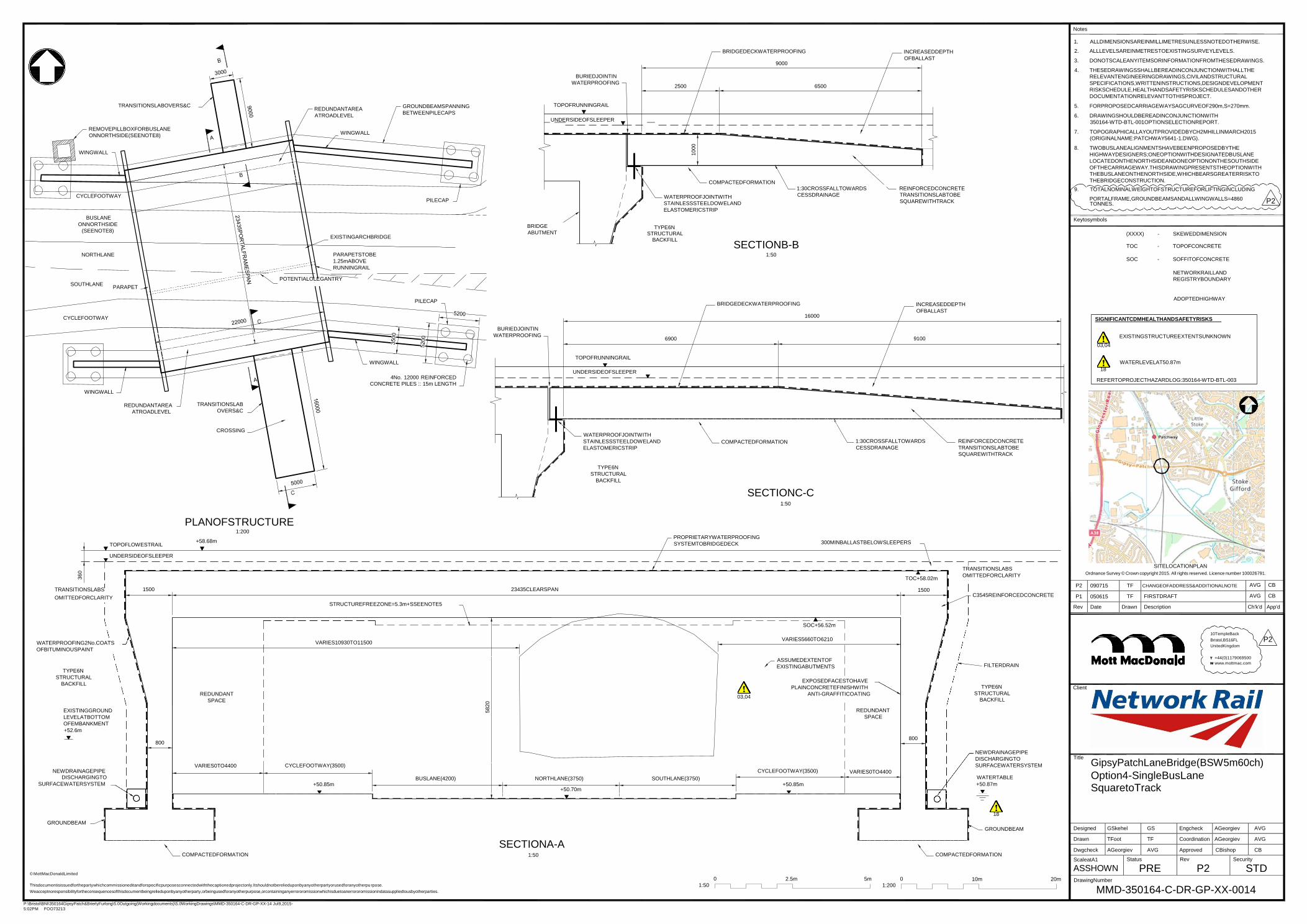
P:\Bristol\BNI\350164GipsyPatch&BrierlyFurlong\5.0Outgoing(Workingdocuments)\5.0WorkingDrawings\MMD-350164-C-DR-GP-XX-14 Jul9,2015-
5:02PM FOO73213
Notes
1. ALLDIMENSIONSAREINMILLIMETRESUNLESSNOTEDOTHERWISE.
P2 090715 TF CHANGEOFADDRESS&ADDITIONALNOTE AVG CB
P1 050615 TF FIRSTDRAFT AVG CB
Rev Date Drawn Description Ch'k'd App'd
Designed GSkehel GS Engcheck AGeorgiev AVG
Drawn TFoot TF Coordination AGeorgiev AVG
Dwgcheck AGeorgiev AVG Approved CBishop CB
ScaleatA1
ASSHOWN Status
PRE Rev
P2 Security
STD
360
5820
1000
TRANSITIONSLABOVERS&C
REMOVEPILLBOXFORBUSLANE
ONNORTHSIDE(SEENOTE8)
WINGWALL
REDUNDANTAREA
ATROADLEVEL
WINGWALL
GROUNDBEAMSPANNING
BETWEENPILECAPS
BURIEDJOINTIN
WATERPROOFING
TOPOFRUNNINGRAIL
UNDERSIDEOFSLEEPER
BRIDGEDECKWATERPROOFING
9000
2500 6500
COMPACTEDFORMATION 1:30CROSSFALLTOWARDS
INCREASEDDEPTH
OFBALLAST
REINFORCEDCONCRETE
2. ALLLEVELSAREINMETRESTOEXISTINGSURVEYLEVELS.
3. DONOTSCALEANYITEMSORINFORMATIONFROMTHESEDRAWINGS.
4. THESEDRAWINGSSHALLBEREADINCONJUNCTIONWITHALLTHE
RELEVANTENGINEERINGDRAWINGS,CIVILANDSTRUCTURAL
SPECIFICATIONS,WRITTENINSTRUCTIONS,DESIGNDEVELOPMENT
RISKSCHEDULE,HEALTHANDSAFETYRISKSCHEDULESANDOTHER
DOCUMENTATIONRELEVANTTOTHISPROJECT.
5. FORPROPOSEDCARRIAGEWAYSAGCURVEOF290m,S=270mm.
6. DRAWINGSHOULDBEREADINCONJUNCTIONWITH
350164-WTD-BTL-001OPTIONSELECTIONREPORT.
7. TOPOGRAPHICALLAYOUTPROVIDEDBYCH2MHILLINMARCH2015
(ORIGINALNAME:PATCHWAY5641-1.DWG).
8. TWOBUSLANEALIGNMENTSHAVEBEENPROPOSEDBYTHE
HIGHWAYDESIGNERS;ONEOPTIONWITHDESIGNATEDBUSLANE
LOCATEDONTHENORTHSIDEANDONEOPTIONONTHESOUTHSIDE
OFTHECARRIAGEWAY.THISDRAWINGPRESENTSTHEOPTIONWITH
THEBUSLANEONTHENORTHSIDE,WHICHBEARSGREATERRISKTO
THEBRIDGECONSTRUCTION.
9. TOTALNOMINALWEIGHTOFSTRUCTUREFORLIFTINGINCLUDING
CYCLEFOOTWAY
BUSLANE
ONNORTHSIDE
(SEENOTE8)
EXISTINGARCHBRIDGE
PILECAP
BRIDGE
ABUTMENT
WATERPROOFJOINTWITH
STAINLESSSTEELDOWELAND
ELASTOMERICSTRIP
TYPE6N
STRUCTURAL BACKFILL
CESSDRAINAGE TRANSITIONSLABTOBE
SQUAREWITHTRACK PORTALFRAME,GROUNDBEAMSANDALLWINGWALLS=4860 P2 TONNES.
Keytosymbols
(XXXX) - SKEWEDDIMENSION
NORTHLANE
PARAPETSTOBE
1.25mABOVE
RUNNINGRAIL
POTENTIALOLEGANTRY
SECTIONB-B 1:50
TOC - TOPOFCONCRETE
SOC - SOFFITOFCONCRETE
NETWORKRAILLAND
REGISTRYBOUNDARY SOUTHLANE
CYCLEFOOTWAY
PARAPET
PILECAP
BURIEDJOINTIN
WATERPROOFING
6900
BRIDGEDECKWATERPROOFING
16000
INCREASEDDEPTH
OFBALLAST
9100
ADOPTEDHIGHWAY
SIGNIFICANTCDMHEALTHANDSAFETYRISKS
EXISTINGSTRUCTUREEXTENTSUNKNOWN
03,04
WINGWALL
TOPOFRUNNINGRAIL
UNDERSIDEOFSLEEPER
WATERLEVELAT50.87m
18
WINGWALL
4No. 12000 REINFORCED
CONCRETE PILES :: 15m LENGTH REFERTOPROJECTHAZARDLOG:350164-WTD-BTL-003
REDUNDANTAREA
ATROADLEVEL
TRANSITIONSLAB
OVERS&C
CROSSING
WATERPROOFJOINTWITH
STAINLESSSTEELDOWELAND
ELASTOMERICSTRIP
COMPACTEDFORMATION
1:30CROSSFALLTOWARDS
CESSDRAINAGE
REINFORCEDCONCRETE
TRANSITIONSLABTOBE
SQUAREWITHTRACK
TOPOFLOWESTRAIL
PLANOFSTRUCTURE 1:200
+58.68m
TYPE6N
STRUCTURAL
BACKFILL
SECTIONC-C
1:50
PROPRIETARYWATERPROOFING
SYSTEMTOBRIDGEDECK
300MINBALLASTBELOWSLEEPERS
TRANSITIONSLABS
UNDERSIDEOFSLEEPER
1500
23435CLEARSPAN
TOC+58.02m
1500
TRANSITIONSLABS
OMITTEDFORCLARITY
SITELOCATIONPLAN
Ordnance Survey © Crown copyright 2015. All rights reserved. Licence number 100026791.
OMITTEDFORCLARITY STRUCTUREFREEZONE=5.3m+SSEENOTE5
C3545REINFORCEDCONCRETE
WATERPROOFING2No.COATS
OFBITUMINOUSPAINT
TYPE6N
STRUCTURAL
BACKFILL
SOC+56.52m
VARIES10930TO11500
VARIES5660TO6210
ASSUMEDEXTENTOF
EXISTINGABUTMENTS
EXPOSEDFACESTOHAVE
PLAINCONCRETEFINISHWITH
FILTERDRAIN
TYPE6N
Client
10TempleBack
Bristol,BS16FL P2 UnitedKingdom
T +44(0)1179069500
W www.mottmac.com
EXISTINGGROUND
LEVELATBOTTOM
OFEMBANKMENT
+52.6m
800
REDUNDANT
SPACE
VARIES0TO4400
CYCLEFOOTWAY(3500)
03,04 ANTI-GRAFFITICOATING
REDUNDANT
SPACE
800
STRUCTURAL
BACKFILL
NEWDRAINAGEPIPE
DISCHARGINGTO
SURFACEWATERSYSTEM
Title
GipsyPatchLaneBridge(BSW5m60ch) NEWDRAINAGEPIPE
DISCHARGINGTO
BUSLANE(4200)
NORTHLANE(3750)
SOUTHLANE(3750)
CYCLEFOOTWAY(3500) VARIES0TO4400 WATERTABLE Option4-SingleBusLane
SURFACEWATERSYSTEM +50.85m +50.85m +50.70m
+50.87m SquaretoTrack
GROUNDBEAM
COMPACTEDFORMATION
SECTIONA-A 1:50
18
GROUNDBEAM
COMPACTEDFORMATION
© MottMacDonaldLimited
Thisdocumentisissuedforthepartywhichcommissioneditandforspecificpurposesconnectedwiththecaptionedprojectonly.Itshouldnotberelieduponbyanyotherpartyorusedforanyotherpu rpose.
Weacceptnoresponsibilityfortheconsequencesofthisdocumentbeingrelieduponbyanyotherparty,orbeingusedforanyotherpurpose,orcontaininganyerrororomissionwhichisduetoanerrororomissionindatasuppliedtousbyotherparties.
0
1:50
2.5m 5m
0
1:200
10m 20m
DrawingNumber
MMD-350164-C-DR-GP-XX-0014

P:\Bristol\BNI\350164GipsyPatch&BrierlyFurlong\5.0Outgoing(Workingdocuments)\5.0WorkingDrawings\MMD-350164-C-DR-GP-XX-15 Jul9,2015-
5:02PM FOO73213
Notes
1. ALLDIMENSIONSAREINMILLIMETRESUNLESSNOTEDOTHERWISE.
P1 090715 TF FIRSTDRAFT AVG CB
Rev Date Drawn Description Ch'k'd App'd
22000
360
24400C
LE
AR
SP
AN
3500
5200
5820
1000
1000
REMOVEPILLBOX
WING
WALL A
CYCLEFOOTWAY
TRANSITIONSLABS
WINGWALL
GROUNDBEAMSPANNING
BETWEENPILECAPS
5200
BURIEDJOINTIN
WATERPROOFING
TOPOFRUNNINGRAIL
UNDERSIDEOFSLEEPER
BRIDGEDECKWATERPROOFING
9000
2500 6500
INCREASEDDEPTH
OFBALLAST
2. ALLLEVELSAREINMETRESTOEXISTINGSURVEYLEVELS.
3. DONOTSCALEANYITEMSORINFORMATIONFROMTHESEDRAWINGS.
4. THESEDRAWINGSSHALLBEREADINCONJUNCTIONWITHALLTHE
RELEVANTENGINEERINGDRAWINGS,CIVILANDSTRUCTURAL
SPECIFICATIONS,WRITTENINSTRUCTIONS,DESIGNDEVELOPMENTRISK
SCHEDULE,HEALTHANDSAFETYRISKSCHEDULESANDOTHER
DOCUMENTATIONRELEVANTTOTHISPROJECT.
5. FORPROPOSEDCARRIAGEWAYSAGCURVEOF290m,S=270mm
6. DRAWINGSHOULDBEREADINCONJUNCTIONWITH350164-WTD-BTL-
001OPTIONSELECTIONREPORT
7. TOPOGRAPHICALLAYOUTPROVIDEDBYCH2MHILLINMARCH2015
(ORIGINALNAME:PATCHWAY5641-1.DWG).
8. TOTALNOMINALWEIGHTOFSTRUCTUREFORLIFTINGINCLUDING
PORTALFRAME,GROUNDBEAMSANDALLWINGWALLS=5280TONNES.
NORTHBUSLANE
NORTHLANE
EXISTINGARCHBRIDGE
PARAPETTOBE1.25m
ABOVERUNNINGRAIL
BRIDGE
ABUTMENT
COMPACTEDFORMATION
WATERPROOFJOINTWITH
STAINLESSSTEELDOWELAND
ELASTOMERICSTRIP
TYPE6N
STRUCTURAL
1:30CROSSFALLTOWARDS
CESSDRAINAGE
REINFORCEDCONCRETE
TRANSITIONSLABTOBE
SQUAREWITHTRACK
Keytosymbols
TOC - TOPOFCONCRETE
SOUTHLANE
PARAPET
POTENTIALOLEGANTRY BACKFILL SECTIONB-B
1:50
SOC - SOFFITOFCONCRETE
NETWORKRAILLAND
REGISTRYBOUNDARY
03,04
SOUTHBUSLANE
CYCLEFOOTWAY
PILECAP
BURIEDJOINTIN
WATERPROOFING
BRIDGEDECKWATERPROOFING
10000
2500 7500
INCREASEDDEPTH
OFBALLAST
ADOPTEDHIGHWAY
SIGNIFICANTCDMHEALTHANDSAFETYRISKS
A
WINGWALL
WINGWALL
TOPOFRUNNINGRAIL
UNDERSIDEOFSLEEPER
03,04
18
EXISTINGSTRUCTUREEXTENTSUNKNOWN
WATERLEVELAT50.87m
REFERTOPROJECTHAZARDLOG:350164-WTD-BTL-003
TRANSITIONSLABS
4No. 12000 REINFORCED
CONCRETE PILES ::16.5m LENGTH
CROSSING
COMPACTEDFORMATION
WATERPROOFJOINTWITH
STAINLESSSTEELDOWELAND
ELASTOMERICSTRIP
1:30CROSSFALLTOWARDS
CESSDRAINAGE
REINFORCEDCONCRETE
TRANSITIONSLABTOBE
SQUAREWITHTRACK
PLANOFSTRUCTURE 1:200
BRIDGE
ABUTMENT
TYPE6N
STRUCTURAL
BACKFILL
SECTIONC-C 1:50
TOPOFLOWESTRAIL
+58.68m
PROPRIETARYWATERPROOFING
SYSTEMTOBRIDGEDECK
300MINBALLAST
BELOWSLEEPERS
UNDERSIDEOFSLEEPER
TRANSITIONSLABS
OMITTEDFORCLARITY
1600
STRUCTUREFREEZONE=5.3m+SSEENOTE5
24400CLEARSPAN
TOC+58.02m
1600
TRANSITIONSLABS
OMITTEDFORCLARITY
C3545REINFORCED
CONCRETE
SITELOCATIONPLAN Ordnance Survey © Crown copyright 2015. All rights reserved. Licence number 100026791.
WATERPROOFING-
2No.COATSOF
BITUMINOUSPAINT
VARIES7250TO10900 VARIES11330TO7670
SOC+56.42m
FILTERDRAIN
10TempleBack
Bristol,BS16FL
UnitedKingdom
TYPE6N
STRUCTURAL
BACKFILL
EXISTINGGROUND
LEVELATBOTTOM
OFEMBANKMENT
+52.6m
NEWDRAINAGE
PIPEDISCHARGING
TOSURFACE
WATERSYSTEM
1000
3500CYCLEFOOTWAY
+50.75m
03,04
4200NORTHBUSLANE
3750NORTHLANE
3750SOUTHLANE
+50.60m
ASSUMEDEXTENT
OFEXISTING
ABUTMENTS)
4200SOUTHBUSLANE
EXPOSEDFACESTOHAVE
PLAINCONCRETEFINISH
WITHANTI-GRAFFITICOATING
5000CYCLEFOOTWAY
+50.75m
1000
TYPE6N
STRUCTURAL
BACKFILL
NEWDRAINAGEPIPE
DISCHARGINGTO
SURFACEWATERSYSTEM
WATERTABLE +50.87
Client
Title
T +44(0)1179069500
W www.mottmac.com
GipsyPatchLaneBridge(BSW5m60ch)
Option5-DualBusLane SkewedtoTrack
GROUNDBEAM
SECTIONA-A
1:50
COMPACTEDFORMATION COMPACTEDFORMATION
18
GROUNDBEAM
Designed
Drawn
Dwgcheck
ScaleatA1
GSkehel GS
TFoot TF
AGeorgiev AVG
Status
Engcheck
Coordination
Approved
Rev
AGeorgiev AVG
AGeorgiev AVG
CBishop CB
Security
© MottMacDonaldLimited
Thisdocumentisissuedforthepartywhichcommissioneditandforspecificpurposesconnectedwiththecaptionedprojectonly.Itshouldnotberelieduponbyanyotherpartyorusedforanyotherpurpose.
0 2.5m 5m 0
10m 20m
ASSHOWN PRE DrawingNumber
P1 STD
Weacceptnoresponsibilityfortheconsequencesofthisdocumentbeingrelieduponbyanyotherparty,orbeingusedforanyotherpurpose,orcontaininganyerrororomissionwhichisduetoanerrororomissionindatasuppliedtousbyotherparties. 1:50 1:200 MMD-350164-C-DR-GP-XX-0015
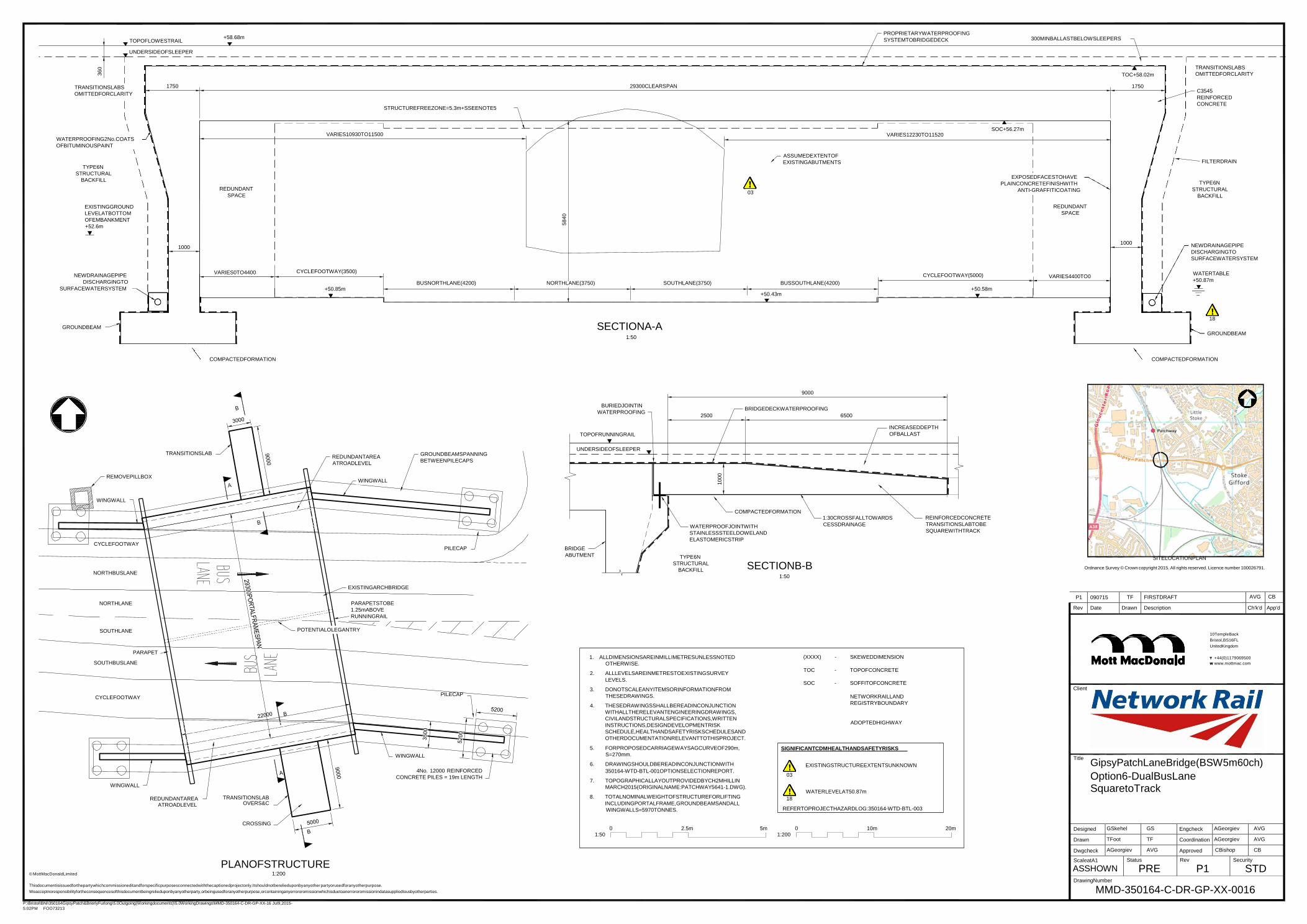
P:\Bristol\BNI\350164GipsyPatch&BrierlyFurlong\5.0Outgoing(Workingdocuments)\5.0WorkingDrawings\MMD-350164-C-DR-GP-XX-16 Jul9,2015-
5:02PM FOO73213
P1 090715 TF FIRSTDRAFT AVG CB
Rev Date Drawn Description Ch'k'd App'd
Designed GSkehel GS Engcheck AGeorgiev AVG
Drawn TFoot TF Coordination AGeorgiev AVG
Dwgcheck AGeorgiev AVG Approved CBishop CB
ScaleatA1
ASSHOWN Status
PRE Rev
P1 Security
STD
360
5840
1000
TOPOFLOWESTRAIL
UNDERSIDEOFSLEEPER
+58.68m
PROPRIETARYWATERPROOFING
SYSTEMTOBRIDGEDECK
300MINBALLASTBELOWSLEEPERS
TRANSITIONSLABS
OMITTEDFORCLARITY
1750
STRUCTUREFREEZONE=5.3m+SSEENOTE5
29300CLEARSPAN
TOC+58.02m
1750
TRANSITIONSLABS
OMITTEDFORCLARITY
C3545
REINFORCED
CONCRETE
WATERPROOFING2No.COATS
OFBITUMINOUSPAINT
TYPE6N
STRUCTURAL
BACKFILL
EXISTINGGROUND
LEVELATBOTTOM
OFEMBANKMENT
+52.6m
REDUNDANT
SPACE
VARIES10930TO11500 VARIES12230TO11520
ASSUMEDEXTENTOF
EXISTINGABUTMENTS
03
SOC+56.27m
EXPOSEDFACESTOHAVE
PLAINCONCRETEFINISHWITH
ANTI-GRAFFITICOATING
REDUNDANT
SPACE
FILTERDRAIN
TYPE6N
STRUCTURAL
BACKFILL
NEWDRAINAGEPIPE
DISCHARGINGTO
1000
VARIES0TO4400
CYCLEFOOTWAY(3500)
BUSNORTHLANE(4200)
NORTHLANE(3750)
SOUTHLANE(3750)
BUSSOUTHLANE(4200)
CYCLEFOOTWAY(5000)
VARIES4400TO0
1000
NEWDRAINAGEPIPE
DISCHARGINGTO
SURFACEWATERSYSTEM
WATERTABLE
+50.87m
SURFACEWATERSYSTEM +50.85m +50.58m +50.43m
GROUNDBEAM
SECTIONA-A 1:50
18
GROUNDBEAM
COMPACTEDFORMATION COMPACTEDFORMATION
BURIEDJOINTIN
WATERPROOFING
9000
BRIDGEDECKWATERPROOFING
2500 6500
TOPOFRUNNINGRAIL
INCREASEDDEPTH
OFBALLAST
TRANSITIONSLAB
REDUNDANTAREA
ATROADLEVEL
GROUNDBEAMSPANNING
BETWEENPILECAPS
UNDERSIDEOFSLEEPER
REMOVEPILLBOX
WINGWALL
WINGWALL
CYCLEFOOTWAY
PILECAP
BRIDGE
ABUTMENT
COMPACTEDFORMATION
WATERPROOFJOINTWITH
STAINLESSSTEELDOWELAND
ELASTOMERICSTRIP
TYPE6N
1:30CROSSFALLTOWARDS
CESSDRAINAGE
REINFORCEDCONCRETE
TRANSITIONSLABTOBE
SQUAREWITHTRACK
SITELOCATIONPLAN
NORTHBUSLANE
STRUCTURAL
BACKFILL SECTIONB-B 1:50
Ordnance Survey © Crown copyright 2015. All rights reserved. Licence number 100026791.
EXISTINGARCHBRIDGE
NORTHLANE PARAPETSTOBE
1.25mABOVE
RUNNINGRAIL
SOUTHLANE
PARAPET
POTENTIALOLEGANTRY
1. ALLDIMENSIONSAREINMILLIMETRESUNLESSNOTED
(XXXX) - SKEWEDDIMENSION
10TempleBack
Bristol,BS16FL
UnitedKingdom
T +44(0)1179069500
SOUTHBUSLANE
CYCLEFOOTWAY
WINGWALL
PILECAP
OTHERWISE.
2. ALLLEVELSAREINMETRESTOEXISTINGSURVEY
LEVELS.
3. DONOTSCALEANYITEMSORINFORMATIONFROM
THESEDRAWINGS.
4. THESEDRAWINGSSHALLBEREADINCONJUNCTION
WITHALLTHERELEVANTENGINEERINGDRAWINGS,
CIVILANDSTRUCTURALSPECIFICATIONS,WRITTEN
INSTRUCTIONS,DESIGNDEVELOPMENTRISK
SCHEDULE,HEALTHANDSAFETYRISKSCHEDULESAND
OTHERDOCUMENTATIONRELEVANTTOTHISPROJECT.
5. FORPROPOSEDCARRIAGEWAYSAGCURVEOF290m,
S=270mm.
6. DRAWINGSHOULDBEREADINCONJUNCTIONWITH
TOC - TOPOFCONCRETE
SOC - SOFFITOFCONCRETE
NETWORKRAILLAND
REGISTRYBOUNDARY
ADOPTEDHIGHWAY
SIGNIFICANTCDMHEALTHANDSAFETYRISKS
EXISTINGSTRUCTUREEXTENTSUNKNOWN
Client
Title
W www.mottmac.com
GipsyPatchLaneBridge(BSW5m60ch)
WINGWALL
REDUNDANTAREA
ATROADLEVEL
TRANSITIONSLAB OVERS&C
4No. 12000 REINFORCED
CONCRETE PILES = 19m LENGTH 350164-WTD-BTL-001OPTIONSELECTIONREPORT.
7. TOPOGRAPHICALLAYOUTPROVIDEDBYCH2MHILLIN
MARCH2015(ORIGINALNAME:PATCHWAY5641-1.DWG).
8. TOTALNOMINALWEIGHTOFSTRUCTUREFORLIFTING
INCLUDINGPORTALFRAME,GROUNDBEAMSANDALL
03
WATERLEVELAT50.87m
18
Option6-DualBusLane SquaretoTrack
WINGWALLS=5970TONNES. REFERTOPROJECTHAZARDLOG:350164-WTD-BTL-003
CROSSING 0
1:50
2.5m 5m
0
1:200
10m 20m
© MottMacDonaldLimited
PLANOFSTRUCTURE 1:200
DrawingNumber Thisdocumentisissuedforthepartywhichcommissioneditandforspecificpurposesconnectedwiththecaptionedprojectonly.Itshouldnotberelieduponbyanyother partyorusedforanyotherpurpose.
Weacceptnoresponsibilityfortheconsequencesofthisdocumentbeingrelieduponbyanyotherparty,orbeingusedforanyotherpurpose,orcontaininganyerrororomissionwhichisduetoanerrororomissionindatasuppliedtousbyotherparties. MMD-350164-C-DR-GP-XX-0016
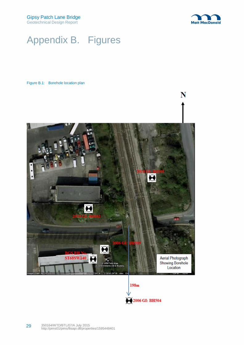
Gipsy Patch Lane Bridge Geotechnical Design Report
Appendix B. Figures
Figure B.1: Borehole location plan
29 350164/WTD/BTL/07/A July 2015 http://pims01/pims/llisapi.dll/properties/1595448401
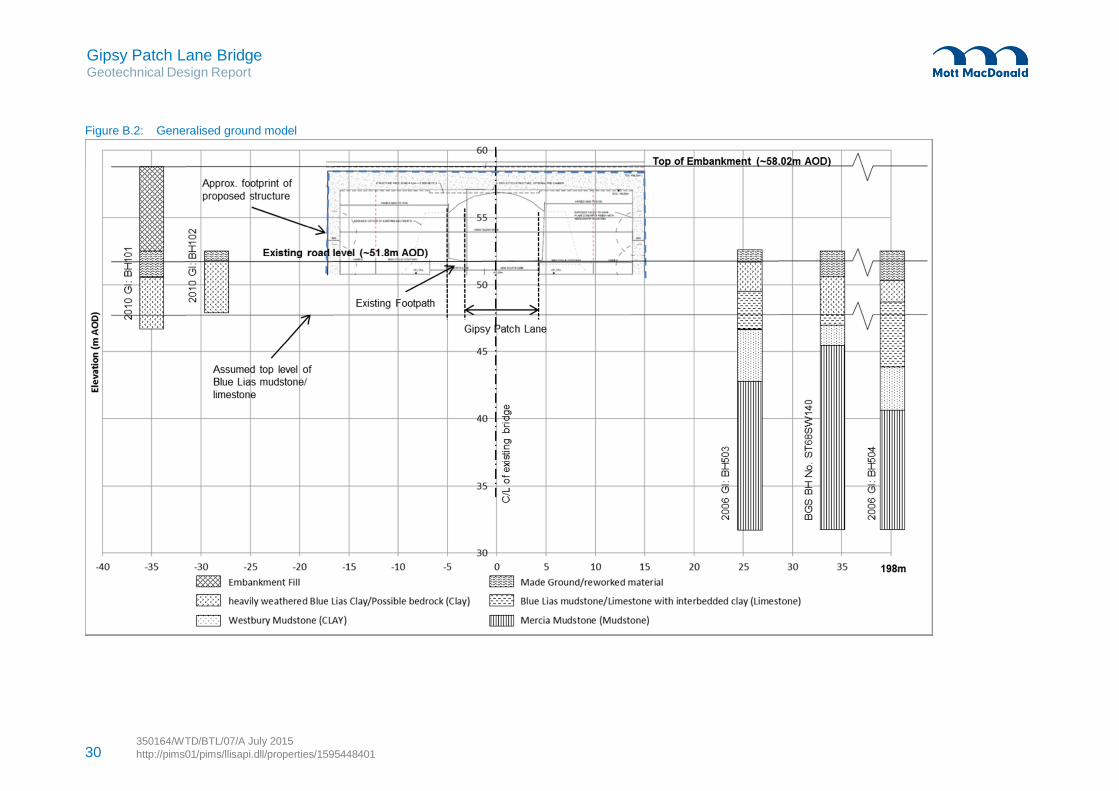
Gipsy Patch Lane Bridge Geotechnical Design Report
Figure B.2: Generalised ground model
350164/WTD/BTL/07/A July 2015 30 http://pims01/pims/llisapi.dll/properties/1595448401

Gipsy Patch Lane Bridge Geotechnical Design Report
31 350164/WTD/BTL/07/A July 2015 http://pims01/pims/llisapi.dll/properties/1595448401
Ref: 350164/WTD/BTL/01
Version: 03
Date: September 2015
Appendix H
Carbon Footprint Calculations
Governance for Railway Investment Projects

Gipsy Patch Lane - Option 1
Bridge Portal Frame
Estimate
Quantities
(length)
Units
Estimate
Quantities
(mass)
Units
Emissions
Factors*
Units
Total
Units
Capital Carbon in
Design
Concrete (35/45); exceeding 500mm thick to Portal Walls 206 m3 2400 kg/m
3 0.123 kgCO₂e/kg 60,811 kgCO₂e
385.4 tCO2e Concrete (35/45); exceeding 500mm thick to Deck Portal 354 m3 2400 kg/m
3 0.123 kgCO₂e/kg 104,501 kgCO₂e
Reinforcement; to Bridge Portal 168036 kg 1.31 kgCO₂e/kg 220127.16 kgCO₂e
Ground Beams Estimate
Quantities Units
Estimate Quantities
Units Emissions Factors*
Units Total Units Capital Carbon in
Design
Blinding concrete; 75mm thick to Ground Beams 14 m3 2400 kg/m
3 0.123 kgCO₂e/kg 4,133 kgCO₂e
148.5 tCO2e Concrete (32/40); exceeding 500mm thick to Ground Beams
210 m3 2400 kg/m3
0.123 kgCO₂e/kg
61,992 kgCO₂e
Reinforcement; to Ground Beams 62889 kg 1.31 kgCO₂e/kg 82,385 kgCO₂e
Wing Walls
Estimate Quantities
Units Estimate
Quantities Units
Emissions Factors*
Units Total Units Capital Carbon in
Design
Concrete (35/45); exceeding 500mm thick to Wing Walls 104 m3 2400 kg/m
3 0.123 kgCO₂e/kg 30,701 kgCO₂e
64.9 tCO2e Reinforcement; to Wing Walls 26,075 tonne 1.31 kgCO₂e/kg 34,158 kgCO₂e
Parapet Walls Estimate
Quantities Units
Estimate Quantities
Units Emissions Factors*
Units Total Units Capital Carbon in
Design
Concrete (35/45); 400mm thick to Parapet walls 24 m3 2400 kg/m
3 0.123 kgCO₂e/kg 7,085 kgCO₂e 16.8 tCO2e
Reinforcement; to parapet walls 7,380 kg 1.31 kgCO₂e/kg 9,668 kgCO₂e
`
Transition Slabs Estimate
Quantities Units
Estimate Quantities
Units Emissions Factors*
Units Total Units Capital Carbon in
Design
Concrete (35/45); to Transition Slabs 138 m3 2400 kg/m
3 0.123 kgCO₂e/kg 40,738 kgCO₂e
99.1 tCO2e Blinding concrete; 75mm thick to Transition Slabs 14 m3 2400 kg/m
3 0.123 kgCO₂e/kg 4,133 kgCO₂e
Reinforcement; to Transition Slabs 41400 kg 1.31 kgCO₂e/kg 54,234 kgCO₂e
Concrete Pilecaps Estimate
Quantities Units
Estimate Quantities
Units Emissions Factors*
Units Total Units Capital Carbon in
Design
Blinding concrete; 75mm thick to Pile Caps 9 m3 2400 kg/m
3 0.123 kgCO₂e/kg 2,657 kgCO₂e
84.3 tCO2e Concrete (32/40); exceeding 500mm thick to Pile Caps 208 m3 2400 kg/m
3 0.123 kgCO₂e/kg 26 kgCO₂e
Reinforcement; to Pile Caps 62304 kg 1.31 81,618 kgCO₂e
Concrete Piles
Estimate
Quantities
(length)
Units
Estimate
Quantities
(mass)
Units
Emissions
Factors*
Units
Total
Units
Capital Carbon in
Design
Piles; 1.2m diameter - Concreted Length 235 m3 2400 kg/m
3 0.123 kgCO₂e/kg 69,444 kgCO₂e
115.6 tCO2e Piles; 1.2m diameter - Reinforcement 35,256 kg kg/m
3 1.31 kgCO₂e/kg 46,185 kgCO₂e
Total Carbon
914.6 tCO2e
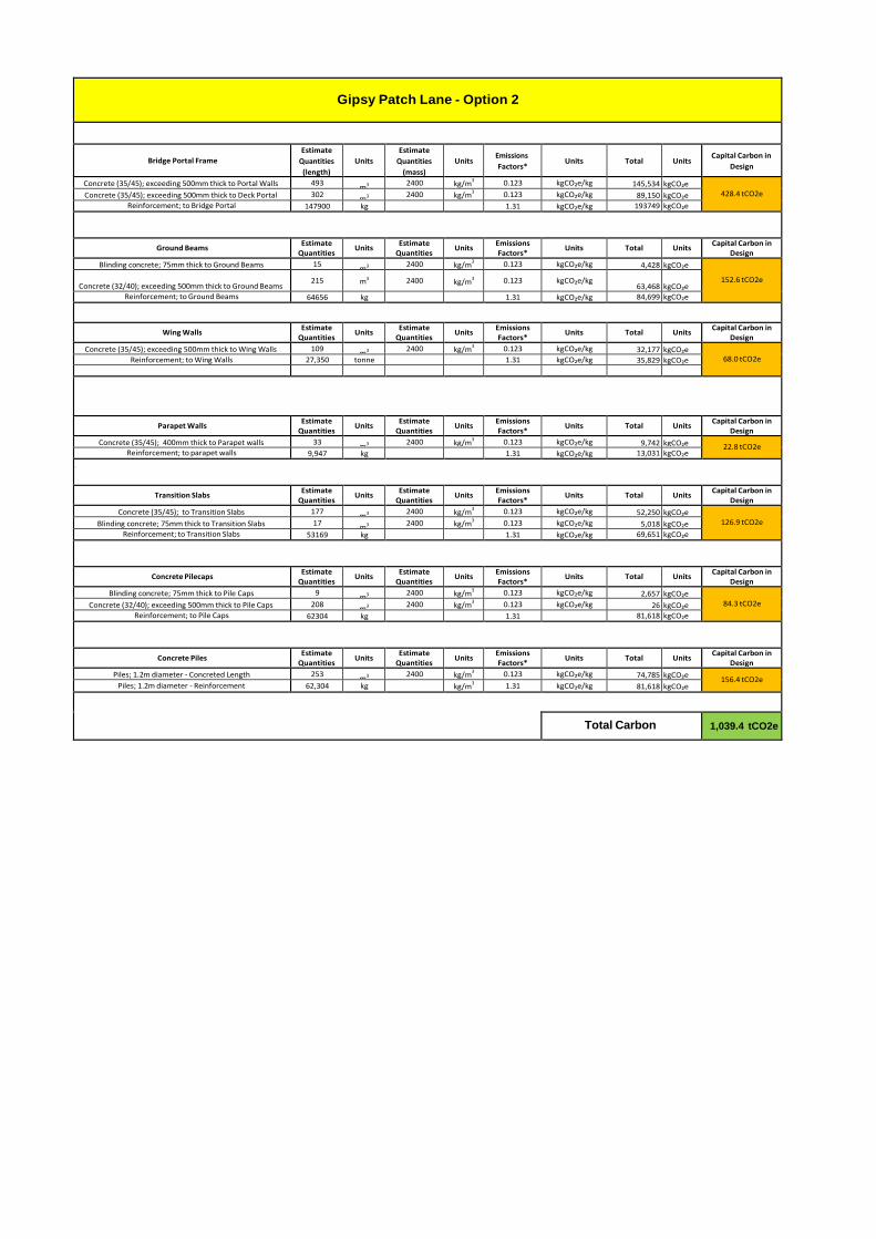
Gipsy Patch Lane - Option 2
Bridge Portal Frame
Estimate
Quantities
(length)
Units
Estimate
Quantities
(mass)
Units
Emissions
Factors*
Units
Total
Units
Capital Carbon in
Design
Concrete (35/45); exceeding 500mm thick to Portal Walls 493 m3 2400 kg/m
3 0.123 kgCO₂e/kg 145,534 kgCO₂e
428.4 tCO2e Concrete (35/45); exceeding 500mm thick to Deck Portal 302 m3 2400 kg/m
3 0.123 kgCO₂e/kg 89,150 kgCO₂e
Reinforcement; to Bridge Portal 147900 kg 1.31 kgCO₂e/kg 193749 kgCO₂e
Ground Beams Estimate
Quantities Units
Estimate Quantities
Units Emissions Factors*
Units Total Units Capital Carbon in
Design
Blinding concrete; 75mm thick to Ground Beams 15 m3 2400 kg/m
3 0.123 kgCO₂e/kg 4,428 kgCO₂e
152.6 tCO2e Concrete (32/40); exceeding 500mm thick to Ground Beams
215 m3 2400 kg/m3
0.123 kgCO₂e/kg
63,468 kgCO₂e
Reinforcement; to Ground Beams 64656 kg 1.31 kgCO₂e/kg 84,699 kgCO₂e
Wing Walls
Estimate Quantities
Units Estimate
Quantities Units
Emissions Factors*
Units Total Units Capital Carbon in
Design
Concrete (35/45); exceeding 500mm thick to Wing Walls 109 m3 2400 kg/m
3 0.123 kgCO₂e/kg 32,177 kgCO₂e
68.0 tCO2e Reinforcement; to Wing Walls 27,350 tonne 1.31 kgCO₂e/kg 35,829 kgCO₂e
Parapet Walls Estimate
Quantities Units
Estimate Quantities
Units Emissions Factors*
Units Total Units Capital Carbon in
Design
Concrete (35/45); 400mm thick to Parapet walls 33 m3 2400 kg/m
3 0.123 kgCO₂e/kg 9,742 kgCO₂e 22.8 tCO2e
Reinforcement; to parapet walls 9,947 kg 1.31 kgCO₂e/kg 13,031 kgCO₂e
`
Transition Slabs Estimate
Quantities Units
Estimate Quantities
Units Emissions Factors*
Units Total Units Capital Carbon in
Design
Concrete (35/45); to Transition Slabs 177 m3 2400 kg/m
3 0.123 kgCO₂e/kg 52,250 kgCO₂e
126.9 tCO2e Blinding concrete; 75mm thick to Transition Slabs 17 m3 2400 kg/m
3 0.123 kgCO₂e/kg 5,018 kgCO₂e
Reinforcement; to Transition Slabs 53169 kg 1.31 kgCO₂e/kg 69,651 kgCO₂e
Concrete Pilecaps Estimate
Quantities Units
Estimate Quantities
Units Emissions Factors*
Units Total Units Capital Carbon in
Design
Blinding concrete; 75mm thick to Pile Caps 9 m3 2400 kg/m
3 0.123 kgCO₂e/kg 2,657 kgCO₂e
84.3 tCO2e Concrete (32/40); exceeding 500mm thick to Pile Caps 208 m3 2400 kg/m
3 0.123 kgCO₂e/kg 26 kgCO₂e
Reinforcement; to Pile Caps 62304 kg 1.31 81,618 kgCO₂e
Concrete Piles Estimate
Quantities Units
Estimate Quantities
Units Emissions Factors*
Units Total Units Capital Carbon in
Design
Piles; 1.2m diameter - Concreted Length 253 m3 2400 kg/m
3 0.123 kgCO₂e/kg 74,785 kgCO₂e
156.4 tCO2e Piles; 1.2m diameter - Reinforcement 62,304 kg kg/m
3 1.31 kgCO₂e/kg 81,618 kgCO₂e
Total Carbon
1,039.4 tCO2e

Gipsy Patch Lane - Option 3
Bridge Portal Frame
Estimate
Quantities
(length)
Units
Estimate
Quantities
(mass)
Units
Emissions
Factors*
Units
Total
Units
Capital Carbon in
Design
Concrete (35/45); exceeding 500mm thick to Portal Walls 206 m3 2400 kg/m
3 0.123 kgCO₂e/kg 60,811 kgCO₂e
525.1 tCO2e Concrete (35/45); exceeding 500mm thick to Deck Portal 557 m3 2400 kg/m
3 0.123 kgCO₂e/kg 164,426 kgCO₂e
Reinforcement; to Bridge Portal 228890 kg 1.31 kgCO₂e/kg 299845.9 kgCO₂e
Ground Beams Estimate
Quantities Units
Estimate Quantities
Units Emissions Factors*
Units Total Units Capital Carbon in
Design
Blinding concrete; 75mm thick to Ground Beams 21 m3 2400 kg/m
3 0.123 kgCO₂e/kg 6,199 kgCO₂e
221.8 tCO2e Concrete (32/40); exceeding 500mm thick to Ground Beams
313 m3 2400 kg/m3
0.123 kgCO₂e/kg
92,398 kgCO₂e
Reinforcement; to Ground Beams 94074 kg 1.31 kgCO₂e/kg 123,237 kgCO₂e
Wing Walls
Estimate Quantities
Units Estimate
Quantities Units
Emissions Factors*
Units Total Units Capital Carbon in
Design
Concrete (35/45); exceeding 500mm thick to Wing Walls 104 m3 2400 kg/m
3 0.123 kgCO₂e/kg 30,701 kgCO₂e
64.6 tCO2e Reinforcement; to Wing Walls 25,887 tonne 1.31 kgCO₂e/kg 33,912 kgCO₂e
Parapet Walls Estimate
Quantities Units
Estimate Quantities
Units Emissions Factors*
Units Total Units Capital Carbon in
Design
Concrete (35/45); 400mm thick to Parapet walls 33 m3 2400 kg/m
3 0.123 kgCO₂e/kg 9,742 kgCO₂e 22.8 tCO2e
Reinforcement; to parapet walls 9,972 kg 1.31 kgCO₂e/kg 13,063 kgCO₂e
`
Transition Slabs Estimate
Quantities Units
Estimate Quantities
Units Emissions Factors*
Units Total Units Capital Carbon in
Design
Concrete (35/45); to Transition Slabs 88 m3 2400 kg/m
3 0.123 kgCO₂e/kg 25,978 kgCO₂e
63.1 tCO2e Blinding concrete; 75mm thick to Transition Slabs 9 m3 2400 kg/m
3 0.123 kgCO₂e/kg 2,527 kgCO₂e
Reinforcement; to Transition Slabs 26400 kg 1.31 kgCO₂e/kg 34,584 kgCO₂e
Concrete Pilecaps Estimate
Quantities Units
Estimate Quantities
Units Emissions Factors*
Units Total Units Capital Carbon in
Design
Blinding concrete; 75mm thick to Pile Caps 9 m3 2400 kg/m
3 0.123 kgCO₂e/kg 2,657 kgCO₂e
84.3 tCO2e Concrete (32/40); exceeding 500mm thick to Pile Caps 208 m3 2400 kg/m
3 0.123 kgCO₂e/kg 26 kgCO₂e
Reinforcement; to Pile Caps 62304 kg 1.31 81,618 kgCO₂e
Concrete Piles
Estimate
Quantities
(length)
Units
Estimate
Quantities
(mass)
Units
Emissions
Factors*
Units
Total
Units
Capital Carbon in
Design
Piles; 1.2m diameter - Concreted Length 262 m3 2400 kg/m
3 0.123 kgCO₂e/kg 77,456 kgCO₂e
129.0 tCO2e Piles; 1.2m diameter - Reinforcement 39,336 kg kg/m
3 1.31 kgCO₂e/kg 51,530 kgCO₂e
Total Carbon
1,110.7 tCO2e

Gipsy Patch Lane - Option 4
Bridge Portal Frame
Estimate
Quantities
(length)
Units
Estimate
Quantities
(mass)
Units
Emissions
Factors*
Units
Total
Units
Capital Carbon in
Design
Concrete (35/45); exceeding 500mm thick to Portal Walls 245 m3 2400 kg/m
3 0.123 kgCO₂e/kg 72,324 kgCO₂e
769.1 tCO2e Concrete (35/45); exceeding 500mm thick to Deck Portal 873 m3 2400 kg/m
3 0.123 kgCO₂e/kg 257,710 kgCO₂e
Reinforcement; to Bridge Portal 335190 kg 1.31 kgCO₂e/kg 439098.9 kgCO₂e
Ground Beams Estimate
Quantities Units
Estimate Quantities
Units Emissions Factors*
Units Total Units Capital Carbon in
Design
Blinding concrete; 75mm thick to Ground Beams 26 m3 2400 kg/m
3 0.123 kgCO₂e/kg 7,675 kgCO₂e
267.2 tCO2e Concrete (32/40); exceeding 500mm thick to Ground Beams
377 m3 2400 kg/m3
0.123 kgCO₂e/kg
111,290 kgCO₂e
Reinforcement; to Ground Beams 113142 kg 1.31 kgCO₂e/kg 148,216 kgCO₂e
Wing Walls
Estimate Quantities
Units Estimate
Quantities Units
Emissions Factors*
Units Total Units Capital Carbon in
Design
Concrete (35/45); exceeding 500mm thick to Wing Walls 109 m3 2400 kg/m
3 0.123 kgCO₂e/kg 32,177 kgCO₂e
68.0 tCO2e Reinforcement; to Wing Walls 27,353 tonne 1.31 kgCO₂e/kg 35,832 kgCO₂e
Parapet Walls Estimate
Quantities Units
Estimate Quantities
Units Emissions Factors*
Units Total Units Capital Carbon in
Design
Concrete (35/45); 400mm thick to Parapet walls 40 m3 2400 kg/m
3 0.123 kgCO₂e/kg 11,808 kgCO₂e 27.7 tCO2e
Reinforcement; to parapet walls 12,120 kg 1.31 kgCO₂e/kg 15,877 kgCO₂e
`
Transition Slabs Estimate
Quantities Units
Estimate Quantities
Units Emissions Factors*
Units Total Units Capital Carbon in
Design
Concrete (35/45); to Transition Slabs 88 m3 2400 kg/m
3 0.123 kgCO₂e/kg 25,978 kgCO₂e
63.1 tCO2e Blinding concrete; 75mm thick to Transition Slabs 9 m3 2400 kg/m
3 0.123 kgCO₂e/kg 2,527 kgCO₂e
Reinforcement; to Transition Slabs 26400 kg 1.31 kgCO₂e/kg 34,584 kgCO₂e
Concrete Pilecaps Estimate
Quantities Units
Estimate Quantities
Units Emissions Factors*
Units Total Units Capital Carbon in
Design
Blinding concrete; 75mm thick to Pile Caps 9 m3 2400 kg/m
3 0.123 kgCO₂e/kg 2,657 kgCO₂e
84.3 tCO2e Concrete (32/40); exceeding 500mm thick to Pile Caps 208 m3 2400 kg/m
3 0.123 kgCO₂e/kg 26 kgCO₂e
Reinforcement; to Pile Caps 62304 kg 1.31 81,618 kgCO₂e
Concrete Piles
Estimate
Quantities
(length)
Units
Estimate
Quantities
(mass)
Units
Emissions
Factors*
Units
Total
Units
Capital Carbon in
Design
Piles; 1.2m diameter - Concreted Length 271 m3 2400 kg/m
3 0.123 kgCO₂e/kg 80,127 kgCO₂e
133.5 tCO2e Piles; 1.2m diameter - Reinforcement 40,728 kg kg/m
3 1.31 kgCO₂e/kg 53,354 kgCO₂e
Total Carbon
1,412.9 tCO2e

Gipsy Patch Lane - Option 5
Bridge Portal Frame
Estimate
Quantities
(length)
Units
Estimate
Quantities
(mass)
Units
Emissions
Factors*
Units
Total
Units
Capital Carbon in
Design
Concrete (35/45); exceeding 500mm thick to Portal Walls 271 m3 2400 kg/m
3 0.123 kgCO₂e/kg 79,999 kgCO₂e
855.4 tCO2e Concrete (35/45); exceeding 500mm thick to Deck Portal 972 m3 2400 kg/m
3 0.123 kgCO₂e/kg 286,934 kgCO₂e
Reinforcement; to Bridge Portal 372900 kg 1.31 kgCO₂e/kg 488499 kgCO₂e
Ground Beams Estimate
Quantities Units
Estimate Quantities
Units Emissions Factors*
Units Total Units Capital Carbon in
Design
Blinding concrete; 75mm thick to Ground Beams 29 m3 2400 kg/m
3 0.123 kgCO₂e/kg 8,561 kgCO₂e
213.2 tCO2e Concrete (32/40); exceeding 500mm thick to Ground Beams
383 m3 2400 kg/m3
0.123 kgCO₂e/kg
113,062 kgCO₂e
Reinforcement; to Ground Beams 69900 kg 1.31 kgCO₂e/kg 91,569 kgCO₂e
Wing Walls
Estimate Quantities
Units Estimate
Quantities Units
Emissions Factors*
Units Total Units Capital Carbon in
Design
Concrete (35/45); exceeding 500mm thick to Wing Walls 263 m3 2400 kg/m
3 0.123 kgCO₂e/kg 77,638 kgCO₂e
181.2 tCO2e Reinforcement; to Wing Walls 79,086 tonne 1.31 kgCO₂e/kg 103,603 kgCO₂e
Parapet Walls Estimate
Quantities Units
Estimate Quantities
Units Emissions Factors*
Units Total Units Capital Carbon in
Design
Concrete (35/45); 400mm thick to Parapet walls 41 m3 2400 kg/m
3 0.123 kgCO₂e/kg 12,103 kgCO₂e 28.2 tCO2e
Reinforcement; to parapet walls 12,300 kg 1.31 kgCO₂e/kg 16,113 kgCO₂e
`
Transition Slabs Estimate
Quantities Units
Estimate Quantities
Units Emissions Factors*
Units Total Units Capital Carbon in
Design
Concrete (35/45); to Transition Slabs 138 m3 2400 kg/m
3 0.123 kgCO₂e/kg 40,738 kgCO₂e
99.1 tCO2e Blinding concrete; 75mm thick to Transition Slabs 14 m3 2400 kg/m
3 0.123 kgCO₂e/kg 4,133 kgCO₂e
Reinforcement; to Transition Slabs 41400 kg 1.31 kgCO₂e/kg 54,234 kgCO₂e
Concrete Pilecaps Estimate
Quantities Units
Estimate Quantities
Units Emissions Factors*
Units Total Units Capital Carbon in
Design
Blinding concrete; 75mm thick to Pile Caps 9 m3 2400 kg/m
3 0.123 kgCO₂e/kg 2,657 kgCO₂e
84.3 tCO2e Concrete (32/40); exceeding 500mm thick to Pile Caps 208 m3 2400 kg/m
3 0.123 kgCO₂e/kg 26 kgCO₂e
Reinforcement; to Pile Caps 62304 kg 1.31 81,618 kgCO₂e
Concrete Piles
Estimate
Quantities
(length)
Units
Estimate
Quantities
(mass)
Units
Emissions
Factors*
Units
Total
Units
Capital Carbon in
Design
Piles; 1.2m diameter - Concreted Length 271 m3 2400 kg/m
3 0.123 kgCO₂e/kg 80,127 kgCO₂e
133.5 tCO2e Piles; 1.2m diameter - Reinforcement 40,728 kg kg/m
3 1.31 kgCO₂e/kg 53,354 kgCO₂e
Total Carbon
1,595.0 tCO2e

Gipsy Patch Lane - Option 6
Bridge Portal Frame
Estimate
Quantities
(length)
Units
Estimate
Quantities
(mass)
Units
Emissions
Factors*
Units
Total
Units
Capital Carbon in
Design
Concrete (35/45); exceeding 500mm thick to Portal Walls 311 m3 2400 kg/m
3 0.123 kgCO₂e/kg 91,807 kgCO₂e
1,119.0 tCO2e Concrete (35/45); exceeding 500mm thick to Deck Portal 1,315 m3 2400 kg/m
3 0.123 kgCO₂e/kg 388,188 kgCO₂e
Reinforcement; to Bridge Portal 487800 kg 1.31 kgCO₂e/kg 639018 kgCO₂e
Ground Beams Estimate
Quantities Units
Estimate Quantities
Units Emissions Factors*
Units Total Units Capital Carbon in
Design
Blinding concrete; 75mm thick to Ground Beams 35 m3 2400 kg/m
3 0.123 kgCO₂e/kg 10,332 kgCO₂e
331.1 tCO2e Concrete (32/40); exceeding 500mm thick to Ground Beams
467 m3 2400 kg/m3
0.123 kgCO₂e/kg
137,858 kgCO₂e
Reinforcement; to Ground Beams 139650 kg 1.31 kgCO₂e/kg 182,942 kgCO₂e
Wing Walls
Estimate Quantities
Units Estimate
Quantities Units
Emissions Factors*
Units Total Units Capital Carbon in
Design
Concrete (35/45); exceeding 500mm thick to Wing Walls 291 m3 2400 kg/m
3 0.123 kgCO₂e/kg 85,903 kgCO₂e
200.3 tCO2e Reinforcement; to Wing Walls 87,300 tonne 1.31 kgCO₂e/kg 114,363 kgCO₂e
Parapet Walls Estimate
Quantities Units
Estimate Quantities
Units Emissions Factors*
Units Total Units Capital Carbon in
Design
Concrete (35/45); 400mm thick to Parapet walls 50 m3 2400 kg/m
3 0.123 kgCO₂e/kg 14,760 kgCO₂e 34.4 tCO2e
Reinforcement; to parapet walls 15,000 kg 1.31 kgCO₂e/kg 19,650 kgCO₂e
`
Transition Slabs Estimate
Quantities Units
Estimate Quantities
Units Emissions Factors*
Units Total Units Capital Carbon in
Design
Concrete (35/45); to Transition Slabs 59 m3 2400 kg/m
3 0.123 kgCO₂e/kg 17,417 kgCO₂e
42.3 tCO2e Blinding concrete; 75mm thick to Transition Slabs 6 m3 2400 kg/m
3 0.123 kgCO₂e/kg 1,771 kgCO₂e
Reinforcement; to Transition Slabs 17652 kg 1.31 kgCO₂e/kg 23,124 kgCO₂e
Concrete Pilecaps Estimate
Quantities Units
Estimate Quantities
Units Emissions Factors*
Units Total Units Capital Carbon in
Design
Blinding concrete; 75mm thick to Pile Caps 9 m3 2400 kg/m
3 0.123 kgCO₂e/kg 2,657 kgCO₂e
84.3 tCO2e Concrete (32/40); exceeding 500mm thick to Pile Caps 208 m3 2400 kg/m
3 0.123 kgCO₂e/kg 26 kgCO₂e
Reinforcement; to Pile Caps 62304 kg 1.31 81,618 kgCO₂e
Concrete Piles
Estimate
Quantities
(length)
Units
Estimate
Quantities
(mass)
Units
Emissions
Factors*
Units
Total
Units
Capital Carbon in
Design
Piles; 1.2m diameter - Concreted Length 344 m3 2400 kg/m
3 0.123 kgCO₂e/kg 101,494 kgCO₂e
169.1 tCO2e Piles; 1.2m diameter - Reinforcement 51,579 kg kg/m
3 1.31 kgCO₂e/kg 67,568 kgCO₂e
Total Carbon
1,980.5 tCO2e
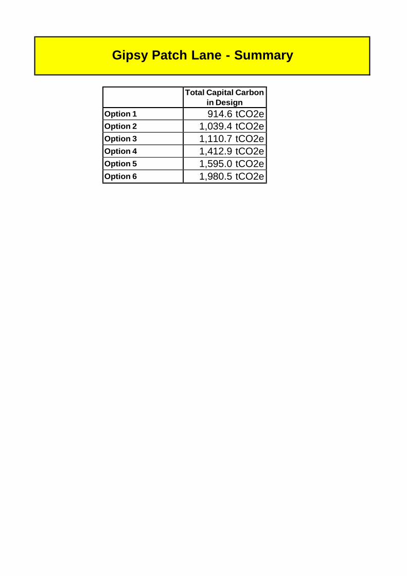
Gipsy Patch Lane - Summary
Total Capital Carbon
in Design
Option 1 914.6 tCO2e
Option 2 1,039.4 tCO2e
Option 3 1,110.7 tCO2e
Option 4 1,412.9 tCO2e
Option 5 1,595.0 tCO2e
Option 6 1,980.5 tCO2e
Project Risks Actions and Exposure
Ref: 350164/WTD/BTL/01
Version: 03
Date: September 2015
Appendix I
Project Risk Register
Local Government (Access to Information) Act 1985: The project risks have been redacted from publication because it is commercially sensitive, such that it would dis-advantage the commercial position of the council in relation to the cost and delivery of the scheme.
Governance for Railway Investment Projects