Embed Size (px)
Citation preview
GOS-6103 OSCILLOSCOPE
USER MANUAL
⎯ i ⎯
CONTENTS PAGE1. PRODUCT INTRODUCTION................................................
1-1.Description……………………………………………….1-2.Feature…………………………………………………...
1 1 2
2. TECHNICAL SPECIFICATION………………………….. 4
3. PRECAUTIONS BEFORE OPERATION…….…………..3-1.Unpacking the instrument………………….…………..3-2.Checking the Line Voltage…………………..………….3-3.Environment……………………………………..………3-4.Equipment Installation and Operation………………....3-5.CRT Intensity……………………………………………3-6.Withstanding Voltage of Input Terminals……………...
7 7 7 8 8 8 8
4. PANEL INTRODUCTION……………………..…………..4-1.Front Panel……………………………………………….4-2.Rear Panel……………………………………….………
91130
5. OPERATION METHOD………………………………...…5-1.Readout Display……………………………………..…...5-2.Connecting Input Signals..………………………………5-3.Adjustment and Checks…………………………………5-4.Function Check…..………………………………………5-5.Basic Operation………….….…………………………...5-6.Measurement Application……………………………….
32323435373947
6. MAINTENANCE……………………………………………6-1.Fuse Replacement………………………………………..6-2.Line Voltage…………………………………………..….6-3.Cleaning………………………………………………….
51515152
7. BLOCK DIAGRAM………………………………………... 53
GOS-6103 OSCILLOSCOPE
USER MANUAL
⎯ ii ⎯
SAFETY TERMS AND SYMBOLS
These terms may appear in this manual or on the product:
WARNING. Warning statements identify condition or
practices that could result in injury or loss of life.
CAUTION. Caution statements identify conditions orpractices that could result in damage to this product orother property.
The following symbols may appear in this manual or on the product:
DANGER ATTENTION Protective Earth(ground)High Voltage refer to Manual Conductor Terminal
Terminal
GOS-6103 OSCILLOSCOPE
USER MANUAL
⎯ iii ⎯
FOR UNITED KINGDOM ONLY
NOTE: This lead/appliance must only be wired by competent persons
WARNING: THIS APPLIANCE MUST BE EARTHED
IMPORTANT: The wires in this lead are coloured in accordance with
the following code:
Green/ Yellow: EarthBlue: NeutralBrown: Live (Phase)
As the colours of the wires in main leads may not correspond with thecolours marking identified in your plug/appliance, proceed as follows:
The wire which is coloured Green & Yellow must be connected to the
Earth terminal marked with the letter E or by the earth symbol
or coloured Green or Green & Yellow.
The wire which is coloured Blue must be connected to the terminalwhich is marked with the letter N or coloured Blue or Black.
The wire which is coloured Brown must be connected to the terminalmarked with the letter L or P or coloured Brown or Red.
If in doubt, consult the instructions provided with the equipment orcontact the supplier.
GOS-6103 OSCILLOSCOPE
USER MANUAL
⎯ iv ⎯
This cable/appliance should be protected by a suitably rated andapproved HBC mains fuse: refer to the rating information on theequipment and/or user instructions for details. As a guide, cable of0.75mm2 should be protected by a 3A or 5A fuse. Larger conductorswould normally require 13A types, depending on the connectionmethod used.
Any moulded mains connector that requires removal /replacementmust be destroyed by removal of any fuse & fuse carrier and disposedof immediately, as a plug with bared wires is hazardous if a engagedin live socket. Any re-wiring must be carried out in accordance withthe information detailed on this label.
GOS-6103 OSCILLOSCOPE
USER MANUAL
⎯ v ⎯
EC Declaration of ConformityWeGOOD WILL INSTRUMENT CO., LTD.
No. 7-1, Jhongsing Rd., Tucheng City, Taipei County 236, TaiwanGOOD WILL INSTRUMENT (SUZHOU) CO., LTD.No. 69 Lushan Road, Suzhou New District Jiangsu, China.
declares that the below mentioned productGOS-6103
is herewith confirmed to comply with the requirements set out in the CouncilDirective on the Approximation of the Law of Member States relating toElectromagnetic Compatibility (89/336/EEC, 92/31/EEC, 93/68/EEC) and LowVoltage Equipment Directive (73/23/EEC, 93/68/EEC).For the evaluation regarding the Electromagnetic Compatibility and Low VoltageEquipment Directive, the following standards were applied:
EN 61326-1: Electrical equipment for measurement, control and laboratory use ––EMC requirements (1997+A1: 1998)
Conducted and Radiated EmissionsEN 55011 class B: 1991
Electrostatic DischargeEN 61000-4-2: 1994
Current HarmonicEN 61000-3-2: 1995
Radiated ImmunityENV 50140: 1993
Voltage FluctuationEN 61000-3-3: 1995
Electrical Fast TransientsEN 61000-4-4: 1995
──────────────Surge ImmunityEN 61000-4-5: 1995
──────────────Conducted SusceptibilityEN 61000-4-6: 1996
──────────────Power Frequency Magnetic fieldEN 61000-4-8: 1993
──────────────Voltage Dips/ InterruptsEN 61000-4-11: 1994
Low Voltage Equipment Directive 73/23/EEC & amended by 93/68/EECSafety Requirements
IEC/EN 61010-1: 2001
GOS-6103 OSCILLOSCOPE
USER MANUAL
⎯ 1 ⎯
1.PRODUCT INTRODUCTION
1-1. Description
The GOS-6103 is a 100MHz, two-channel, dual-sweep, portable oscilloscopefor general purpose use. A microprocessor-based operating system controlsmost of the functions of the instrument, including cursor readout and
digitized panel setting. On-screen alphanumeric readout and cursor function
for voltage, time, frequency and phase measurement provide extraordinaryoperational convenience. Ten different user defined instrument settings canbe saved and recalled without restriction.
The vertical deflection system has two input channels. Each channel has 11
basic deflection factors from 2mV to 5V per division. The horizontal
deflection system provides single, dual or delayed sweeps from 0.5s to 50nsper division (delayed sweep, 50ms to 50ns per division). The trigger system
provides stable triggering over the full bandwidth of the vertical deflection
system.
GOS-6103 OSCILLOSCOPE
USER MANUAL
⎯ 2 ⎯
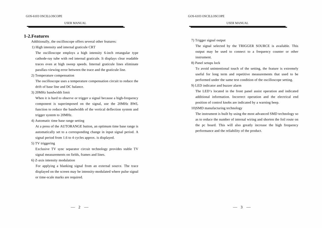
1-2.FeaturesAdditionally, the oscilloscope offers several other features:1) High intensity and internal graticule CRT
The oscilloscope employs a high intensity 6-inch retangular typecathode-ray tube with red internal graticule. It displays clear readabletraces even at high sweep speeds. Internal graticule lines eliminate
parallax-viewing error between the trace and the graticule line.
2) Temperature compensationThe oscilloscope uses a temperature compensation circuit to reduce thedrift of base line and DC balance.
3) 20MHz bandwidth limit
When it is hard to observe or trigger a signal because a high-frequency
component is superimposed on the signal, use the 20MHz BWL
function to reduce the bandwidth of the vertical deflection system andtrigger system to 20MHz.
4) Automatic time base range setting
At a press of the AUTORANGE button, an optimum time base range is
automatically set to a corresponding change in input signal period. A
signal period from 1.6 to 4 cycles approx. is displayed.
5) TV triggeringExclusive TV sync separator circuit technology provides stable TV
signal measurements on fields, frames and lines.
6) Z-axis intensity modulation
For applying a blanking signal from an external source. The trace
displayed on the screen may be intensity-modulated where pulse signal
or time-scale marks are required.
GOS-6103 OSCILLOSCOPE
USER MANUAL
⎯ 3 ⎯
7) Trigger signal output
The signal selected by the TRIGGER SOURCE is available. Thisoutput may be used to connect to a frequency counter or otherinstrument.
8) Panel setups lock
To avoid unintentional touch of the setting, the feature is extremelyuseful for long term and repetitive measurements that used to beperformed under the same test condition of the oscilloscope setting.
9) LED indicator and buzzer alarm
The LED’s located in the front panel assist operation and indicatedadditional information. Incorrect operation and the electrical end
position of control knobs are indicated by a warning beep.10)SMD manufacturing technology
The instrument is built by using the most advanced SMD technology so
as to reduce the number of internal wiring and shorten the foil route on
the pc board. This will also greatly increase the high frequency
performance and the reliability of the product.
GOS-6103 OSCILLOSCOPE
USER MANUAL
⎯ 4 ⎯
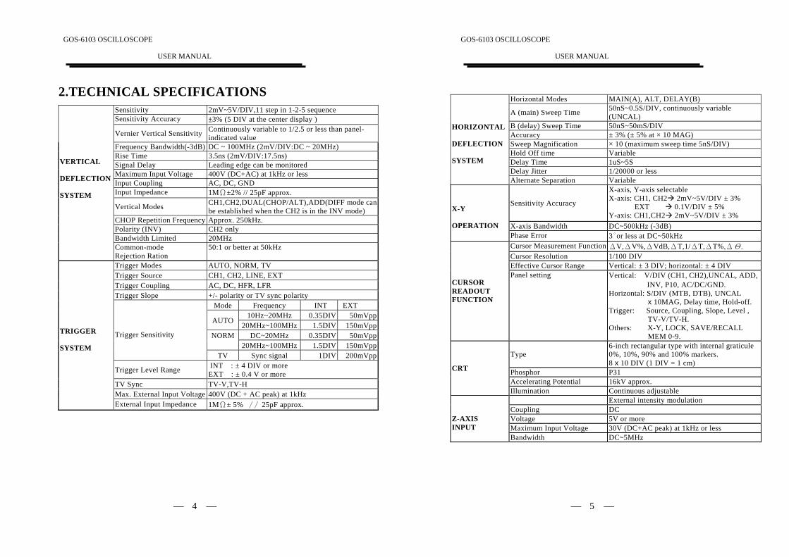
2.TECHNICAL SPECIFICATIONSSensitivity 2mV~5V/DIV,11 step in 1-2-5 sequenceSensitivity Accuracy ±3% (5 DIV at the center display )
Vernier Vertical Sensitivity Continuously variable to 1/2.5 or less than panel-indicated value
Frequency Bandwidth(-3dB) DC ~ 100MHz (2mV/DIV:DC ~ 20MHz)Rise Time 3.5ns (2mV/DIV:17.5ns)Signal Delay Leading edge can be monitoredMaximum Input Voltage 400V (DC+AC) at 1kHz or lessInput Coupling AC, DC, GNDInput Impedance 1MΩ±2% // 25pF approx.
Vertical Modes CH1,CH2,DUAL(CHOP/ALT),ADD(DIFF mode canbe established when the CH2 is in the INV mode)
CHOP Repetition Frequency Approx. 250kHz.Polarity (INV) CH2 onlyBandwidth Limited 20MHz
VERTICAL
DEFLECTION
SYSTEM
Common-modeRejection Ration
50:1 or better at 50kHz
Trigger Modes AUTO, NORM, TVTrigger Source CH1, CH2, LINE, EXTTrigger Coupling AC, DC, HFR, LFRTrigger Slope +/- polarity or TV sync polarity
Mode Frequency INT EXT10Hz~20MHz 0.35DIV 50mVpp
AUTO20MHz~100MHz 1.5DIV 150mVpp
DC~20MHz 0.35DIV 50mVppNORM20MHz~100MHz 1.5DIV 150mVpp
Trigger Sensitivity
TV Sync signal 1DIV 200mVpp
Trigger Level Range INT : ± 4 DIV or moreEXT : ± 0.4 V or more
TV Sync TV-V,TV-HMax. External Input Voltage 400V (DC + AC peak) at 1kHz
TRIGGER
SYSTEM
External Input Impedance 1MΩ± 5% ∕∕ 25pF approx.
GOS-6103 OSCILLOSCOPE
USER MANUAL
⎯ 5 ⎯
Horizontal Modes MAIN(A), ALT, DELAY(B)
A (main) Sweep Time 50nS~0.5S/DIV, continuously variable(UNCAL)
B (delay) Sweep Time 50nS~50mS/DIVAccuracy ± 3% (± 5% at × 10 MAG)Sweep Magnification × 10 (maximum sweep time 5nS/DIV)Hold Off time VariableDelay Time 1uS~5SDelay Jitter 1/20000 or less
HORIZONTAL
DEFLECTION
SYSTEM
Alternate Separation Variable
Sensitivity Accuracy
X-axis, Y-axis selectableX-axis: CH1, CH2 2mV~5V/DIV ± 3%
EXT 0.1V/DIV ± 5%Y-axis: CH1,CH2 2mV~5V/DIV ± 3%
X-axis Bandwidth DC~500kHz (-3dB)
X-Y
OPERATIONPhase Error 3°or less at DC~50kHzCursor Measurement Function ΔV,ΔV%,ΔVdB,ΔT,1/ΔT,ΔT%,ΔΘ.
Cursor Resolution 1/100 DIVEffective Cursor Range Vertical: ± 3 DIV; horizontal: ± 4 DIV
CURSORREADOUTFUNCTION
Panel setting Vertical: V/DIV (CH1,CH2),UNCAL, ADD, INV, P10, AC/DC/GND.
Horizontal: S/DIV (MTB, DTB), UNCAL x 10MAG, Delay time, Hold-off.Trigger: Source, Coupling, Slope, Level , TV-V/TV-H.Others: X-Y, LOCK, SAVE/RECALL MEM 0-9.
Type6-inch rectangular type with internal graticule0%, 10%, 90% and 100% markers.8 x 10 DIV (1 DIV = 1 cm)
Phosphor P31Accelerating Potential 16kV approx.
CRT
Illumination Continuous adjustableExternal intensity modulation
Coupling DCVoltage 5V or moreMaximum Input Voltage 30V (DC+AC peak) at 1kHz or less
Z-AXISINPUT
Bandwidth DC~5MHz
GOS-6103 OSCILLOSCOPE
USER MANUAL
⎯ 6 ⎯
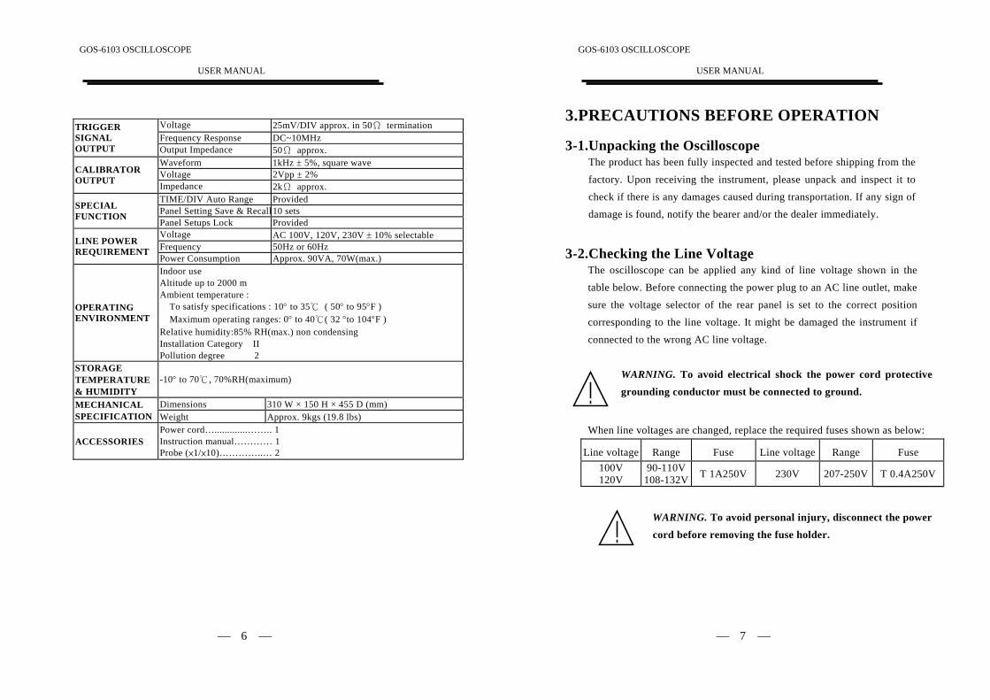
Voltage 25mV/DIV approx. in 50Ω terminationFrequency Response DC~10MHz
TRIGGERSIGNALOUTPUT Output Impedance 50Ω approx.
Waveform 1kHz ± 5%, square waveVoltage 2Vpp ± 2%CALIBRATOR
OUTPUT Impedance 2kΩ approx.TIME/DIV Auto Range ProvidedPanel Setting Save & Recall 10 setsSPECIAL
FUNCTIONPanel Setups Lock ProvidedVoltage AC 100V, 120V, 230V ± 10% selectableFrequency 50Hz or 60HzLINE POWER
REQUIREMENTPower Consumption Approx. 90VA, 70W(max.)
OPERATINGENVIRONMENT
Indoor useAltitude up to 2000 mAmbient temperature : To satisfy specifications : 10° to 35℃ ( 50° to 95°F ) Maximum operating ranges: 0° to 40℃( 32 °to 104°F )Relative humidity:85% RH(max.) non condensingInstallation Category IIPollution degree 2
STORAGETEMPERATURE& HUMIDITY
-10° to 70℃, 70%RH(maximum)
Dimensions 310 W × 150 H × 455 D (mm)MECHANICALSPECIFICATION Weight Approx. 9kgs (19.8 lbs)
ACCESSORIESPower cord….............…….. 1Instruction manual………… 1Probe (×1/×10)…………..… 2
GOS-6103 OSCILLOSCOPE
USER MANUAL
⎯ 7 ⎯
3.PRECAUTIONS BEFORE OPERATION
3-1.Unpacking the OscilloscopeThe product has been fully inspected and tested before shipping from thefactory. Upon receiving the instrument, please unpack and inspect it tocheck if there is any damages caused during transportation. If any sign of
damage is found, notify the bearer and/or the dealer immediately.
3-2.Checking the Line VoltageThe oscilloscope can be applied any kind of line voltage shown in the
table below. Before connecting the power plug to an AC line outlet, makesure the voltage selector of the rear panel is set to the correct position
corresponding to the line voltage. It might be damaged the instrument if
connected to the wrong AC line voltage.
WARNING. To avoid electrical shock the power cord protective
grounding conductor must be connected to ground.
When line voltages are changed, replace the required fuses shown as below:
Line voltage Range Fuse Line voltage Range Fuse100V120V
90-110V108-132V T 1A250V 230V 207-250V T 0.4A250V
WARNING. To avoid personal injury, disconnect the power
cord before removing the fuse holder.
GOS-6103 OSCILLOSCOPE
USER MANUAL
⎯ 8 ⎯
3-3.EnvironmentThe normal ambient temperature range of this instrument is from 0° to
40°C (32° to 104°F). To operate the instrument over this specifictemperature range may cause damage to the circuits.Do not use the instrument in a place where strong magnetic or electric
field exists as it may disturb the measurement.
3-4.Equipment Installation, and OperationEnsure there is proper ventilation for the vents in the oscilloscope case. Ifthe equipment is used not according to the specification, the protection
provided by the equipment may be impaired.
3-5.CRT IntensityTo prevent permanent damage to the CRT phosphor, do not make theCRT trace brighten excessively or leave the spot stay for an unreasonably
long time.
3-6.Withstanding Voltages of Input TerminalsThe withstanding voltages of the instrument input terminals and probe
Input terminals are shown in the following table. Do not apply voltages
higher than these limits.Input terminal Maximum input voltageCH1, CH2, inputs 400V (DC + AC peak)EXT TRIG input 400V (DC + AC peak)
Probe inputs 600V (DC + AC peak)Z AXIS input 30V (DC + AC peak)
CAUTION. To avoid damaging the instrument, do not apply
input voltages of the frequency over 1 kHz to the instrument.
GOS-6103 OSCILLOSCOPE
USER MANUAL
⎯ 9 ⎯
4. PANEL INTRODUCTIONAfter the instrument is switched on, all the important settings are displayedin the readout. The LED’s located on the front panel assist operation andindicate additional information. Incorrect operation and the electrical end
positions of control knobs are indicated by a warning beep.
Except the Power pushbutton (POWER), the Focus control (FOCUS), theScale Illumination control (ILLUM) and the Trace Rotation control, all
other controls are electronically selected, and their functions and settings
can therefore be stored.
The front panel is subdivided into six sections:
Display controls
Vertical controls
Horizontal controls
Trigger controls
Measurement and SAVE/RECALL controls Input connectors
GOS-6103 OSCILLOSCOPE
USER MANUAL
⎯ 10 ⎯
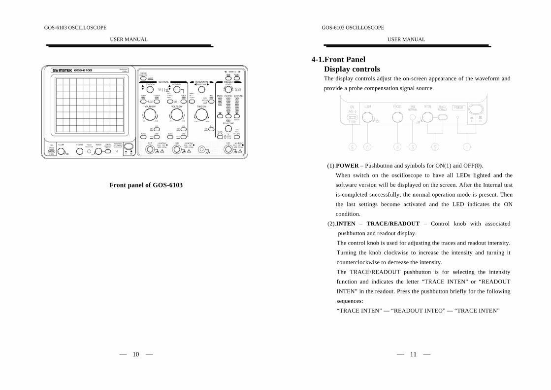
Front panel of GOS-6103
GOS-6103 OSCILLOSCOPE
USER MANUAL
⎯ 11 ⎯
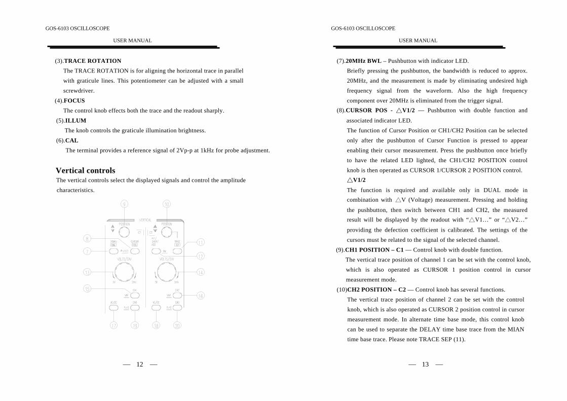
4-1.Front PanelDisplay controlsThe display controls adjust the on-screen appearance of the waveform andprovide a probe compensation signal source.
(1).POWER – Pushbutton and symbols for ON(1) and OFF(0).When switch on the oscilloscope to have all LEDs lighted and thesoftware version will be displayed on the screen. After the Internal test
is completed successfully, the normal operation mode is present. Then
the last settings become activated and the LED indicates the ON
condition.
(2).INTEN – TRACE/READOUT – Control knob with associatedpushbutton and readout display.The control knob is used for adjusting the traces and readout intensity.
Turning the knob clockwise to increase the intensity and turning it
counterclockwise to decrease the intensity.
The TRACE/READOUT pushbutton is for selecting the intensity
function and indicates the letter “TRACE INTEN” or “READOUT
INTEN” in the readout. Press the pushbutton briefly for the followingsequences:
“TRACE INTEN” — “READOUT INTEO” — “TRACE INTEN”
GOS-6103 OSCILLOSCOPE
USER MANUAL
⎯ 12 ⎯
(3).TRACE ROTATIONThe TRACE ROTATION is for aligning the horizontal trace in parallelwith graticule lines. This potentiometer can be adjusted with a small
screwdriver.
(4).FOCUSThe control knob effects both the trace and the readout sharply.
(5).ILLUMThe knob controls the graticule illumination brightness.
(6).CALThe terminal provides a reference signal of 2Vp-p at 1kHz for probe adjustment.
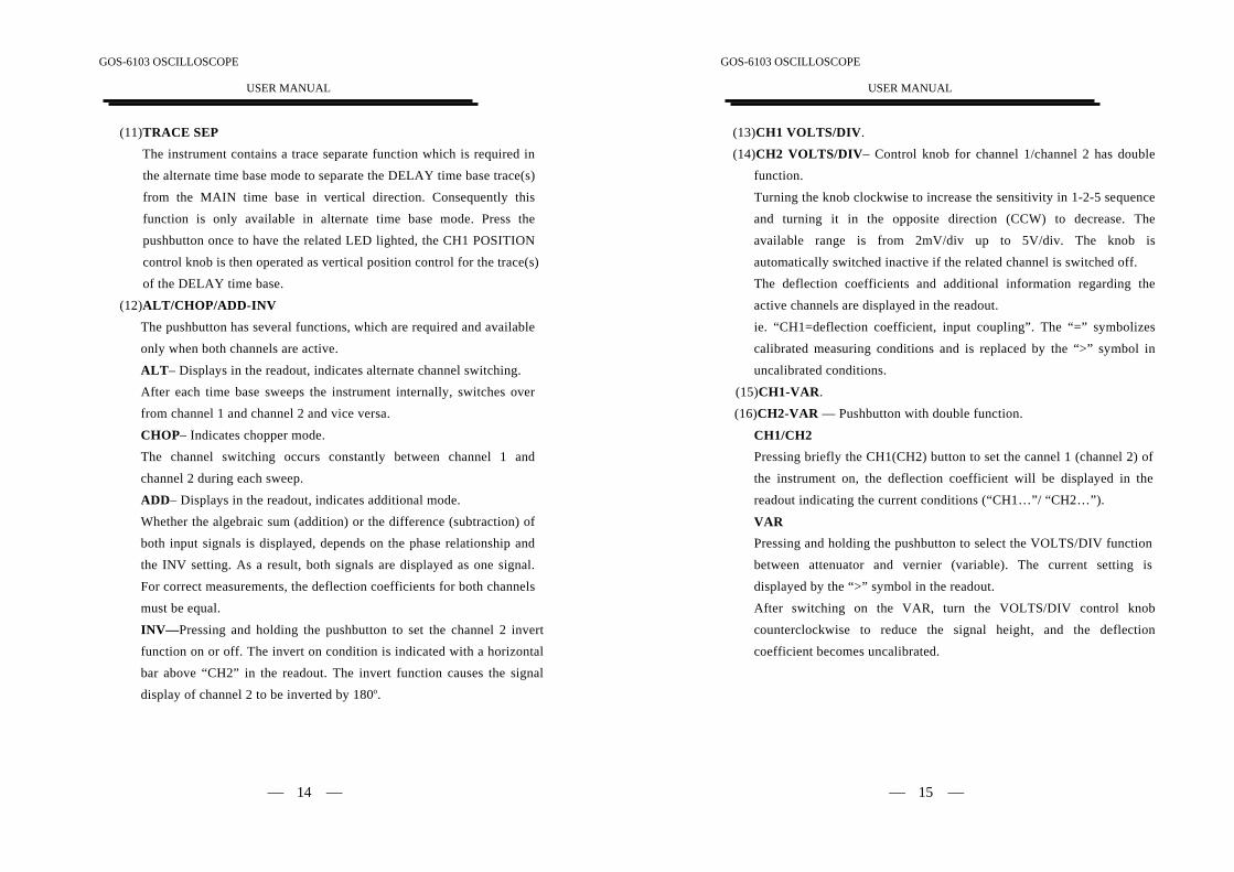
Vertical controlsThe vertical controls select the displayed signals and control the amplitudecharacteristics.
GOS-6103 OSCILLOSCOPE
USER MANUAL
⎯ 13 ⎯
(7).20MHz BWL – Pushbutton with indicator LED.Briefly pressing the pushbutton, the bandwidth is reduced to approx.20MHz, and the measurement is made by eliminating undesired high
frequency signal from the waveform. Also the high frequencycomponent over 20MHz is eliminated from the trigger signal.
(8).CURSOR POS - △V1/2 — Pushbutton with double function and
associated indicator LED.The function of Cursor Position or CH1/CH2 Position can be selected
only after the pushbutton of Cursor Function is pressed to appearenabling their cursor measurement. Press the pushbutton once brieflyto have the related LED lighted, the CH1/CH2 POSITION control
knob is then operated as CURSOR 1/CURSOR 2 POSITION control.△V1/2
The function is required and available only in DUAL mode incombination with △V (Voltage) measurement. Pressing and holding
the pushbutton, then switch between CH1 and CH2, the measuredresult will be displayed by the readout with “△V1…” or “△V2…”
providing the defection coefficient is calibrated. The settings of the
cursors must be related to the signal of the selected channel.
(9).CH1 POSITION – C1 — Control knob with double function.The vertical trace position of channel 1 can be set with the control knob,
which is also operated as CURSOR 1 position control in cursor
measurement mode.
(10)CH2 POSITION – C2 — Control knob has several functions.The vertical trace position of channel 2 can be set with the controlknob, which is also operated as CURSOR 2 position control in cursor
measurement mode. In alternate time base mode, this control knob
can be used to separate the DELAY time base trace from the MIAN
time base trace. Please note TRACE SEP (11).
GOS-6103 OSCILLOSCOPE
USER MANUAL
⎯ 14 ⎯
(11)TRACE SEPThe instrument contains a trace separate function which is required inthe alternate time base mode to separate the DELAY time base trace(s)
from the MAIN time base in vertical direction. Consequently thisfunction is only available in alternate time base mode. Press the
pushbutton once to have the related LED lighted, the CH1 POSITION
control knob is then operated as vertical position control for the trace(s)of the DELAY time base.
(12)ALT/CHOP/ADD-INVThe pushbutton has several functions, which are required and available
only when both channels are active.
ALT– Displays in the readout, indicates alternate channel switching.After each time base sweeps the instrument internally, switches overfrom channel 1 and channel 2 and vice versa.
CHOP– Indicates chopper mode.The channel switching occurs constantly between channel 1 and
channel 2 during each sweep.
ADD– Displays in the readout, indicates additional mode.Whether the algebraic sum (addition) or the difference (subtraction) ofboth input signals is displayed, depends on the phase relationship and
the INV setting. As a result, both signals are displayed as one signal.
For correct measurements, the deflection coefficients for both channels
must be equal.
INV—Pressing and holding the pushbutton to set the channel 2 invertfunction on or off. The invert on condition is indicated with a horizontalbar above “CH2” in the readout. The invert function causes the signal
display of channel 2 to be inverted by 180o.
GOS-6103 OSCILLOSCOPE
USER MANUAL
⎯ 15 ⎯
(13)CH1 VOLTS/DIV.(14)CH2 VOLTS/DIV– Control knob for channel 1/channel 2 has double
function.
Turning the knob clockwise to increase the sensitivity in 1-2-5 sequenceand turning it in the opposite direction (CCW) to decrease. Theavailable range is from 2mV/div up to 5V/div. The knob is
automatically switched inactive if the related channel is switched off.The deflection coefficients and additional information regarding the
active channels are displayed in the readout.ie. “CH1=deflection coefficient, input coupling”. The “=” symbolizescalibrated measuring conditions and is replaced by the “>” symbol in
uncalibrated conditions.
(15)CH1-VAR.(16)CH2-VAR — Pushbutton with double function.
CH1/CH2Pressing briefly the CH1(CH2) button to set the cannel 1 (channel 2) of
the instrument on, the deflection coefficient will be displayed in the
readout indicating the current conditions (“CH1…”/ “CH2…”).
VARPressing and holding the pushbutton to select the VOLTS/DIV function
between attenuator and vernier (variable). The current setting is
displayed by the “>” symbol in the readout.
After switching on the VAR, turn the VOLTS/DIV control knob
counterclockwise to reduce the signal height, and the deflection
coefficient becomes uncalibrated.
GOS-6103 OSCILLOSCOPE
USER MANUAL
⎯ 16 ⎯
(17)CH1 AC/DC.(18)CH2 AC/DC
Pressing the pushbutton briefly to switch over from AC (~ symbol) to
DC (= symbol) input coupling. The setting is displayed in the readoutwith the deflection coefficient.
(19)CH1 GND– P×10
(20)CH2 GND – P×10 –Pushbutton has two functions.
GNDEach time when the pushbutton is pressed briefly, the input of the
vertical amplifier is grounded. It is displayed in the readout as an earth(ground) symbol “ ”.P×10
Pressing and holding the pushbutton to select the indicated deflectioncoefficient of the channel displayed in the readout between 1:1 and 10:1.
The probe factor of 10:1 is displayed in the readout with the probe
symbol in front of channel indication (e.g. “P10”, CH1) When proceed
cursor voltage measurement, the probe factor will be automatically
included. The symbol must not be activated unless a 10:1 attenuator
probes are used.
GOS-6103 OSCILLOSCOPE
USER MANUAL
⎯ 17 ⎯
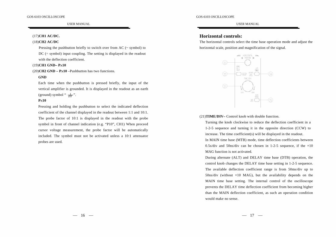
Horizontal controls:The horizontal controls select the time base operation mode and adjust the
horizontal scale, position and magnification of the signal.
(21)TIME/DIV– Control knob with double function.Turning the knob clockwise to reduce the deflection coefficient in a
1-2-5 sequence and turning it in the opposite direction (CCW) to
increase. The time coefficient(s) will be displayed in the readout.In MAIN time base (MTB) mode, time deflection coefficients between
0.5s/div and 50ns/div can be chosen in 1-2-5 sequence, if the ×10
MAG function is not activated.
During alternate (ALT) and DELAY time base (DTB) operation, the
control knob changes the DELAY time base setting in 1-2-5 sequence.
The available deflection coefficient range is from 50ms/div up to50ns/div (without ×10 MAG), but the availability depends on the
MAIN time base setting. The internal control of the oscilloscope
prevents the DELAY time deflection coefficient from becoming higher
than the MAIN deflection coefficient, as such an operation condition
would make no sense.
GOS-6103 OSCILLOSCOPE
USER MANUAL
⎯ 18 ⎯
(22)MAIN/ALT/DELAY—X-Y – Pushbutton for time base modeselection.The instrument contains two-time base designated MAIN and DELAY.
With the aid of the DELAY time base, signal parts displayed by theMAIN time base can be expanded in X-direction. The expansion ratio
depends on the time deflection coefficient ratio of both time bases (ie.“MTB=0.1ms”, “DTB=1μs”=100). With higher expansion ratio the
DELAY time base trace intensity reduces. Each time when press thepushbutton briefly, the time base mode changes in the sequence ofMAIN-ALT-DELAY-MAIN. The actual setting is displayed in the
readout.
MAINThe TIME/DIV control knob is operated only under the MAIN timebase mode. The readout then displays the main time coefficient alone.
The time base setting for this condition will be stored if the time base
mode is changed.
ALTIf the alternate time base mode is selected, the TIME/DIV knob only
controls the DELAY time base switch. The alternate time base mode isa sub-function of the DELAY time base mode and both time base
traces can be displayed simultaneously. Consequently the readout can
display both time deflection coefficient. A window sector which
indicates part of signal is also visible on the MAIN trace and is
displayed by the DELAY time base.
The window segment can be shifted horizontally by the DELAY TIMEcontrol continuously. The difference between the beginning of both the
MAIN time base trace and the window sector shows the delay time.
The information is also displayed in the readout with an approximate
value (e.g. “DLY=0.125ns”) related to the calibrated MAIN time
GOS-6103 OSCILLOSCOPE
USER MANUAL
⎯ 19 ⎯
coefficient (uncalibrated i.e. “DLY>0.125ms”). The width of thewindow segment decreases when the DELAY time coefficient is set to
a lower value (higher time deflection speed).
For better reading, the vertical position of the DELAY time base traceposition can be shifted (please note TRACE SEP (11)).
DELAYIn the DELAY time base mode, the display of the MAIN traces, thewindow sector and the MAIN time coefficient will disappear from the
readout. As the trace separation is no longer required under thecircumstances, the function would be switched off too. Consequently,only the DELAY time coefficient is displayed by the readout.
X-YSwitch on or off the X-Y mode by pressing and holding the button. Inthe X-Y mode, the deflection coefficient is displayed in the readout.
The Y axis input is selected by setting the vertical mode pushbutton to
the CH1, CH2 and both modes, and the X axis input is selected by
setting the TRIGGER SOURCE pushbutton to the CH1, CH2 and EXT.
(23)H POSITIONThe control knob enables a horizontal position shift of the signals. Incombination with ×10 MAG the function makes it possible to shift any
part of the signal on the screen.
(24)×10 MAG—SETUPS LOCK— Pushbutton has double function andassociated MAG LED.
Each time when this pushbutton is pressed, the MAG LED located
above will be switch on or off. If the MAG LED is lighted, the signaldisplay in all time base modes will be expanded 10 folds and
consequently only a tenth part of the signal curve is visible. The
interesting part of the signal can be made visible with the aid of the H.
POSITION control.
GOS-6103 OSCILLOSCOPE
USER MANUAL
⎯ 20 ⎯
SETUPS LOCKPressing and holding the pushbutton, then switch the panel setups lockfunction on or off. To avoid unintentional touch of the setting, thefeature is extremely useful for long term and repetitive measurements
that need to be performed under the same test condition of the
oscilloscope setting.(25)AUTO RANGE-VAR – Pushbutton with double function.
AUTO RANGEEach time when the pushbutton is pressed briefly the incoming signal
is selected, then the time range would change automatically and approx.
1.6 to 4 waveforms are displayed on the screen. If in the ×10 MAGmode, the ten times of waveform of 1.6 to 4 cycles can be displayed.For signal of 100Hz or in the absence of a trigger, the time range is set
to 5ms/div, and for the signals of approx. 8MHz or more, it is set to
50ns/div. The time range change automatically following the different
incoming signal.
The AUTO RANGE does not function when the trigger is not obtained.
The AUTO RANGE functions with the trigger signal selected by theTRIGGER SOURCE, COUPLING and LEVEL control. The time base
mode should be set to MAIN.
In case of measuring a complex waveform such as a TV signal, it may
take several seconds to perform the AUTO RANGE function.
VARPressing and holding the pushbutton to select the TIME/DIV (21)control knob function between time base switch and vernier (variable).
The variable function is activated in the MAIN time base only.
After switching on the VAR, the time deflection coefficient is still
calibrated until further adjustments are made. Turn the TIME/DIV (21)
control knob counter clockwise to increase the time deflection
GOS-6103 OSCILLOSCOPE
USER MANUAL
⎯ 21 ⎯
coefficient (reduce the deflection speed) and the deflection coefficientbecomes uncalibrated. Instead of “A=10μs”, the readout then displays
“A>10μs” indicating the uncalibrated condition. This setting is stored
if the instrument is switched to ALT or DELAY time base mode.Switch off the VAR by pressing and holding the pushbutton of time
base mode again, then set the time deflection coefficient back into the
calibrated condition.
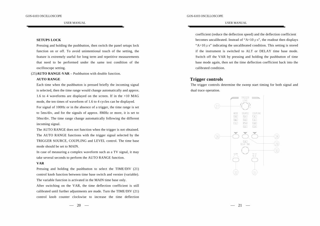
Trigger controlsThe trigger controls determine the sweep start timing for both signal anddual trace operation.
GOS-6103 OSCILLOSCOPE
USER MANUAL
⎯ 22 ⎯
(26)MODE – Pushbutton and indicator LEDs.Pressing the pushbutton to select the trigger mode. The actual setting isindicated by a LED.
Each time when the MODE pushbutton is pressed the trigger modechanges in the sequence:
ATO—NML—TV—ATO
ATO (Auto)Select the automatical mode, the sweep free-runs will display abaseline trace when there is no trigger signal or the frequency is below10Hz. The setting of triggering level changed only when the TRIGGER
LEVEL control is adjusted to a new level setting.
NML (Normal)Select the normal mode, the input signal will trigger the sweep whenthe TRIGGER LEVEL control is set within the peak-to-peak limits of
an adequate trigger signal. When the sweep is not triggered, no
baseline trace will be displayed.
TVSeparate the video sync signal from the composite waveform and direct
it to the triggering circuit. The horizontal or vertical sync signals areselected by TV-V/TV-H pushbutton. Please refer to the TV-V/TV-H
(31).
(27)LEVEL—Control knobTurning the control knob causes a different trigger input setting
(voltage), and set to a suitable position for the starting of triggered
sweep of the waveform. An approximate trigger level setting (voltage)value will be displayed in the readout. When rotate clockwise the
control knob, the trigger point moves toward the positive peak of the
trigger signal and rotate it counterclockwise to move the trigger point
toward the negative peak of the trigger signal.
GOS-6103 OSCILLOSCOPE
USER MANUAL
⎯ 23 ⎯
When the setting (voltage) value is out of the changing portion of theobservation waveform, the synchronization sweep stops. Sometimes a
“?” will be displayed on the left of the valued display, that indicates
that direct reading is impossible if AC, HFR, LFR coupling or VAR ofvertical deflection is set.
(28)COUPLING –Pushbutton and indicator LEDs.Pressing the pushbutton to select the trigger coupling. The actualsetting is indicated by a LED and by the readout (“source, slope, AC”).
Each time when the COUPLING pushbutton is pressed the triggercoupling changes in the sequence:
AC—DC—HFR—LFR
ACAttenuates trigger signal frequency components below 10Hz andblocks the DC component of the signal.
AC coupling is useful for triggering on AC waveforms that have a
large DC offset.
DCCouples DC and all frequency components of a triggering signal to the
trigger circuitry.DC coupling is useful for most signals, especially for providing a
stable display of low-frequency or low-repetition-rate signals.
HFR (High Frequency Reject)Attenuates high-frequency triggering signal components above 40kHz.
HFR coupling is useful for providing a stable display of low-frequency
components of complex waveforms and eliminates high-frequencyinterference from the trigger signal.
GOS-6103 OSCILLOSCOPE
USER MANUAL
⎯ 24 ⎯
LFR (Low Frequency Reject)Attenuates low-frequency triggering signal components below 40kHzand blocks the DC component of the trigger signal.
LFR coupling is useful for producing stable triggering on the high-frequency components of complex waveforms and rejecting low-frequency interference or power supply hum from the trigger signal.
(29)SOURCE—Pushbutton and associated LEDs.Pressing the pushbutton to select the trigger signal source or the Xsignal for an X-Y operation. The actual setting is indicated in a LEDand by the readout (“SOURCE”, slope, coupling).
CH1The signal applied to the channel 1 input connector is the source of
the trigger signal.
CH2The signal applied to the channel 2 input connector is the source of
the trigger signal.
(Line)The triggering signal is obtained from a sample of the AC power
source waveform. The trigger source is useful when the displayedwaveform frequency is time related to the AC power source
frequency.
EXTThe external signal applied through the EXT input connector is used
for the external triggering source signal. When in the dual X-Y
operation, the X-axis operates with the external signal.
GOS-6103 OSCILLOSCOPE
USER MANUAL
⎯ 25 ⎯
(30)DELAY-HO—Control knob with a double function and associatedLED.The control knob has two different functions depending on the time
base mode.
HO (Hold-off time)In MAIN time base mode, the control knob applies to the hold off
time setting, the HO-LED associated with the knob is dark, the holdoff time is set to minimum.
Switch on the LED by turning the control knob clockwise and extendthe hold off time until the maximum is reached. An approximate holdoff time value will be displayed in the readout (“HO: %”).
The hold off time is automatically set to minimum (LED is dark), if
the MAIN time base setting is changed. The hold off time setting isstored and deactivated if ALT (MAIN and DELAY) or DELAY time
base mode is selected.
DELAY TIMEIn ALT (MAIN and DELAY) and DELAY time mode, the knob
controls the delay time setting.
Under the ALT time base mode, the delay time is visible on the maintrace, beginning at the trace start and ending at the start of the
window sector. An approximate delay time value will be displayed in
the readout (“DLY=”).
If only select DELAY time base, the delay time can also be varied,
but there would be no window sector as the main trace is not visible.
GOS-6103 OSCILLOSCOPE
USER MANUAL
⎯ 26 ⎯
(31)TV-V/TV-H—Pushbutton for video sync signal selection.
TV-VStart the main trace at the beginning of a video signal field. SLOPE
polarity must match the composite sync polarity (i.e, “–” for negativesync) to obtain TV field triggering on the vertical sync pulse.
TV-HStart the main trace at the beginning of a video signal line. SLOPEpolarity must match the composite sync polarity to obtain TV line
triggering on the horizontal sync pulse.The current setting is displayed in the readout under item “source,video polarity, TV-H”.
(32)SLOPE ( )—Pushbutton for the triggering slope or videopolarity selection.If in the AUTO or NML trigger mode, briefly pressing the pushbutton
to select the slope of the signal which is used for triggering the time
base generator. Each time when the pushbutton is briefly pressed, the
slope direction will switch from falling edge to rising edge, and vice
versa.
The current setting is displayed in the readout under item “source,SLOPE, coupling”.
If in the TV trigger mode, briefly pressing the pushbutton to select the
video polarity, which will be displayed in the readout with a “+”
symbol of positive video signal and a “–” symbol of negative video
signal.
GOS-6103 OSCILLOSCOPE
USER MANUAL
⎯ 27 ⎯
Measurement and Panel setting ControlThe measurement section controls the on-screen readout and the cursor
measurements. For more information, please refer to page 9 “PANELINTRODUCTION” section for the instrument to store and recall thepanel setting.
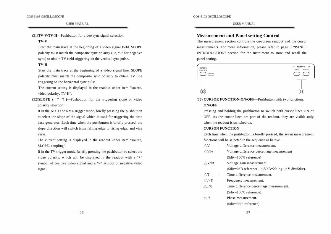
(33) CURSOR FUNCTION-ON/OFF—Pushbutton with two functions.
ON/OFFPressing and holding the pushbutton to switch both cursor lines ON or
OFF. As the cursor lines are part of the readout, they are visible only
when the readout is switched on.
CURSON FUNCTIONEach time when the pushbutton is briefly pressed, the seven measurement
functions will be selected in the sequence as below:△V : Voltage difference measurement.
△V% : Voltage difference percentage measurement
(5div=100% reference)△VdB : Voltage gain measurement.
(5div=0dB reference, △VdB=20 log △V div/5div).
△T : Time difference measurement.1/△T : Frequency measurement.
△T% : Time difference percentage measurement.
(5div=100% reference).△θ : Phase measurement.
(5div=360o reference).
GOS-6103 OSCILLOSCOPE
USER MANUAL
⎯ 28 ⎯
(34)◁ MEMO- 9 ▷—SAVE/RECALLThe instrument contains 10 non-volatile memories, which can be used
by the operator to save instrument setting and to recall them. It relatesto all controls which are electronically selected.
Press ◁ or ▷ pushbutton to select the memory location. The readoutthen indicates the letter “MEN” followed by a cipher between 0 and 9.
Each time the ▷ pushbutton is briefly pressed the memory locationcipher increases until the number 9 is reached. The ◁ pushbutton issimilar but decreases the memory location cipher until the number 0 isreached. Pressing and holding SAVE for approx. 3 seconds to write
the instrument settings in the memory and indicate the associated
readout information of “SAVED”.To recall a front panel setup, select a memory location as describedabove. Recall the settings by pressing and holding the RECALL
pushbutton for approx. 3 seconds, the readout then indicates the
associated readout information of “RECALLED”.
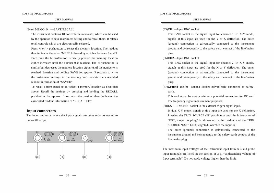
Input connectorsThe input section is where the input signals are commonly connected tothe oscilloscope.
GOS-6103 OSCILLOSCOPE
USER MANUAL
⎯ 29 ⎯
(35)CH1—Input BNC socketThis BNC socket is the signal input for channel 1. In X-Y mode,signals at this input are used for the Y or X deflection. The outer
(ground) connection is galvanically connected to the instrumentground and consequently to the safety earth contact of the line/mains
plug.
(36)CH2—Input BNC socketThis BNC socket is the signal input for channel 2. In X-Y mode,signals at this input are used for the X or Y deflection. The outer
(ground) connection is galvanically connected to the instrument
ground and consequently to the safety earth contact of the line/mainsplug.
(37)Ground socket—Banana Socket galvanically connected to safetyearth.
This socket can be used a reference potential connection for DC and
low frequency signal measurement purposes.
(38)EXT—This BNC socket is the external trigger signal input.In dual X-Y mode, signals at this input are used for the X deflection.
Pressing the TRIG. SOURCE (29) pushbutton until the information of“EXT, slope, coupling” is shown up in the readout and the TRIG.
SOURCE “EXT” LED is lighted, switches the input on.
The outer (ground) connection is galvanically connected to the
instrument ground and consequently to the safety earth contact of the
line/mains plug.
The maximum input voltages of the instrument input terminals and probe
input terminals are listed in the section of 3-6. “Withstanding voltage of
Input terminals”. Do not apply voltage higher than the limit.
GOS-6103 OSCILLOSCOPE
USER MANUAL
⎯ 30 ⎯
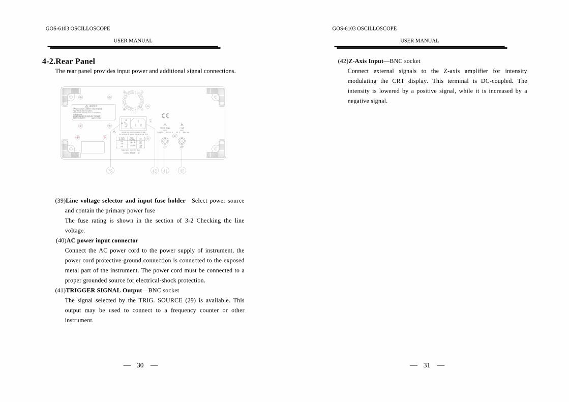
4-2.Rear PanelThe rear panel provides input power and additional signal connections.
(39)Line voltage selector and input fuse holder—Select power sourceand contain the primary power fuse
The fuse rating is shown in the section of 3-2 Checking the line
voltage.
(40)AC power input connectorConnect the AC power cord to the power supply of instrument, the
power cord protective-ground connection is connected to the exposed
metal part of the instrument. The power cord must be connected to a
proper grounded source for electrical-shock protection.
(41)TRIGGER SIGNAL Output—BNC socketThe signal selected by the TRIG. SOURCE (29) is available. Thisoutput may be used to connect to a frequency counter or other
instrument.
GOS-6103 OSCILLOSCOPE
USER MANUAL
⎯ 31 ⎯
(42)Z-Axis Input—BNC socketConnect external signals to the Z-axis amplifier for intensitymodulating the CRT display. This terminal is DC-coupled. The
intensity is lowered by a positive signal, while it is increased by anegative signal.
GOS-6103 OSCILLOSCOPE
USER MANUAL
⎯ 32 ⎯
5. OPERATION METHODThis section contains basic operation information and techniques thatshould be considered before proceeding any measurement. As for thelocation and function of instrument controls, connectors, and indicators,
refer to the “Instruction of Front Panel and Rear Panel” of this manual.
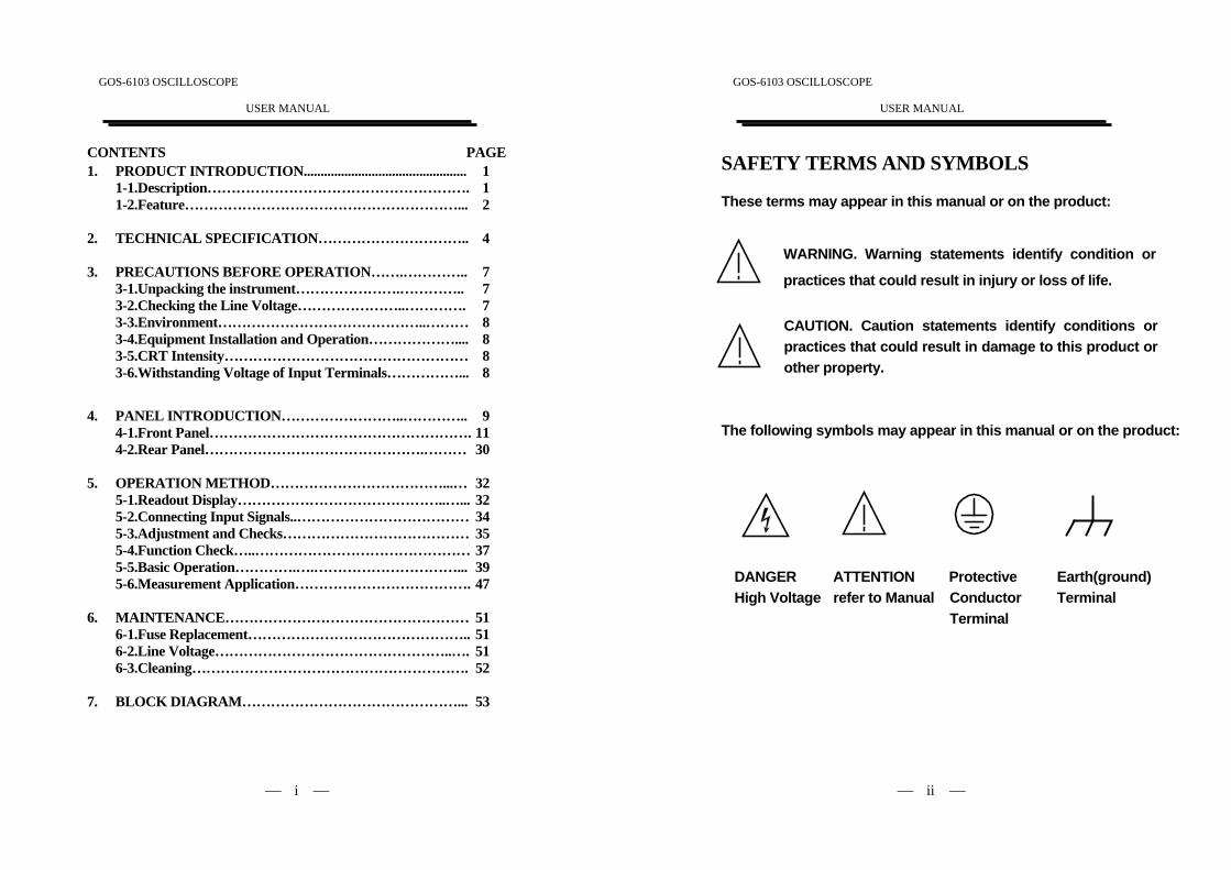
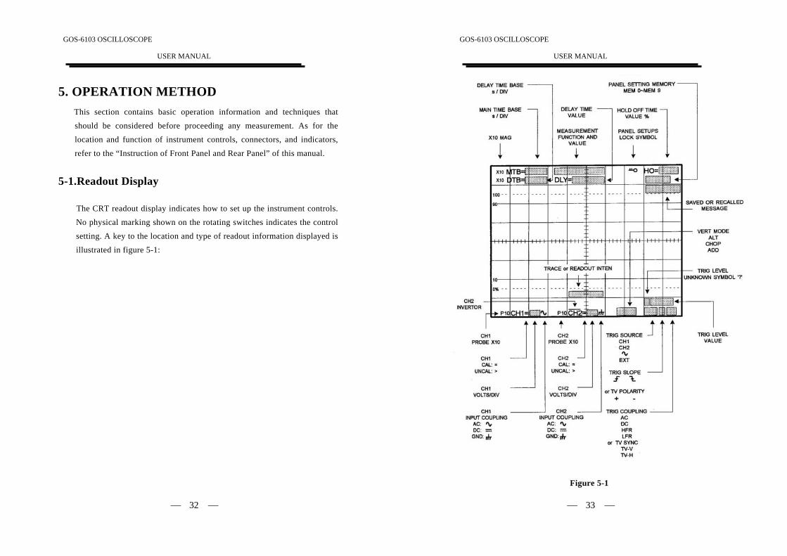
5-1.Readout Display
The CRT readout display indicates how to set up the instrument controls.No physical marking shown on the rotating switches indicates the control
setting. A key to the location and type of readout information displayed is
illustrated in figure 5-1:
GOS-6103 OSCILLOSCOPE
USER MANUAL
⎯ 33 ⎯
Figure 5-1
GOS-6103 OSCILLOSCOPE
USER MANUAL
⎯ 34 ⎯
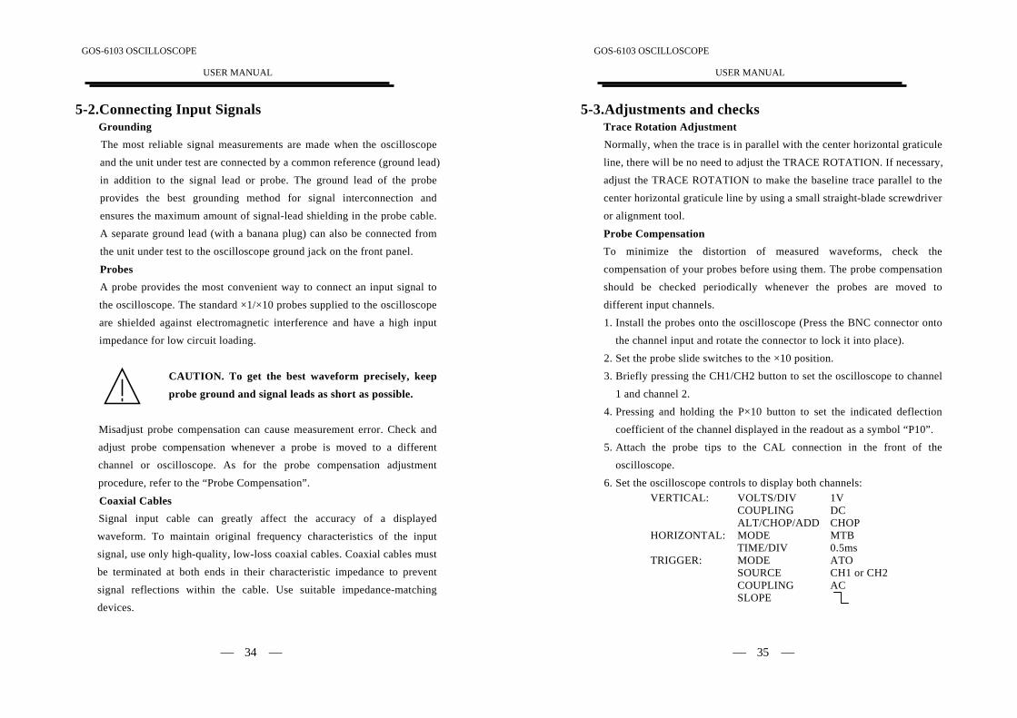
5-2.Connecting Input SignalsGroundingThe most reliable signal measurements are made when the oscilloscopeand the unit under test are connected by a common reference (ground lead)in addition to the signal lead or probe. The ground lead of the probe
provides the best grounding method for signal interconnection and
ensures the maximum amount of signal-lead shielding in the probe cable.A separate ground lead (with a banana plug) can also be connected fromthe unit under test to the oscilloscope ground jack on the front panel.
ProbesA probe provides the most convenient way to connect an input signal to
the oscilloscope. The standard ×1/×10 probes supplied to the oscilloscopeare shielded against electromagnetic interference and have a high inputimpedance for low circuit loading.
CAUTION. To get the best waveform precisely, keep
probe ground and signal leads as short as possible.
Misadjust probe compensation can cause measurement error. Check andadjust probe compensation whenever a probe is moved to a different
channel or oscilloscope. As for the probe compensation adjustment
procedure, refer to the “Probe Compensation”.
Coaxial CablesSignal input cable can greatly affect the accuracy of a displayed
waveform. To maintain original frequency characteristics of the inputsignal, use only high-quality, low-loss coaxial cables. Coaxial cables must
be terminated at both ends in their characteristic impedance to prevent
signal reflections within the cable. Use suitable impedance-matching
devices.
GOS-6103 OSCILLOSCOPE
USER MANUAL
⎯ 35 ⎯
5-3.Adjustments and checksTrace Rotation AdjustmentNormally, when the trace is in parallel with the center horizontal graticuleline, there will be no need to adjust the TRACE ROTATION. If necessary,adjust the TRACE ROTATION to make the baseline trace parallel to the
center horizontal graticule line by using a small straight-blade screwdriver
or alignment tool.
Probe CompensationTo minimize the distortion of measured waveforms, check thecompensation of your probes before using them. The probe compensation
should be checked periodically whenever the probes are moved to
different input channels.1. Install the probes onto the oscilloscope (Press the BNC connector onto
the channel input and rotate the connector to lock it into place).
2. Set the probe slide switches to the ×10 position.
3. Briefly pressing the CH1/CH2 button to set the oscilloscope to channel
1 and channel 2.
4. Pressing and holding the P×10 button to set the indicated deflection
coefficient of the channel displayed in the readout as a symbol “P10”.5. Attach the probe tips to the CAL connection in the front of the
oscilloscope.
6. Set the oscilloscope controls to display both channels:VERTICAL: VOLTS/DIV 1V
COUPLING DCALT/CHOP/ADD CHOP
HORIZONTAL: MODE MTBTIME/DIV 0.5ms
TRIGGER: MODE ATOSOURCE CH1 or CH2COUPLING ACSLOPE
GOS-6103 OSCILLOSCOPE
USER MANUAL
⎯ 36 ⎯
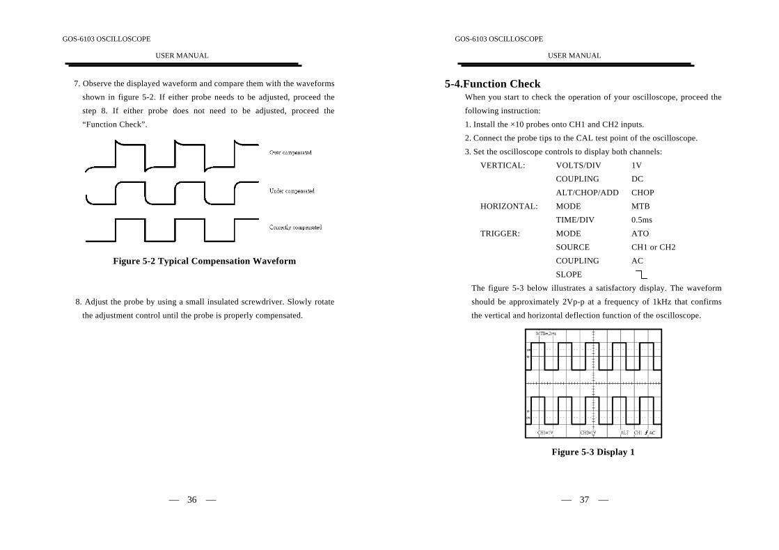
7. Observe the displayed waveform and compare them with the waveformsshown in figure 5-2. If either probe needs to be adjusted, proceed the
step 8. If either probe does not need to be adjusted, proceed the
“Function Check”.
Figure 5-2 Typical Compensation Waveform
8. Adjust the probe by using a small insulated screwdriver. Slowly rotate
the adjustment control until the probe is properly compensated.
GOS-6103 OSCILLOSCOPE
USER MANUAL
⎯ 37 ⎯
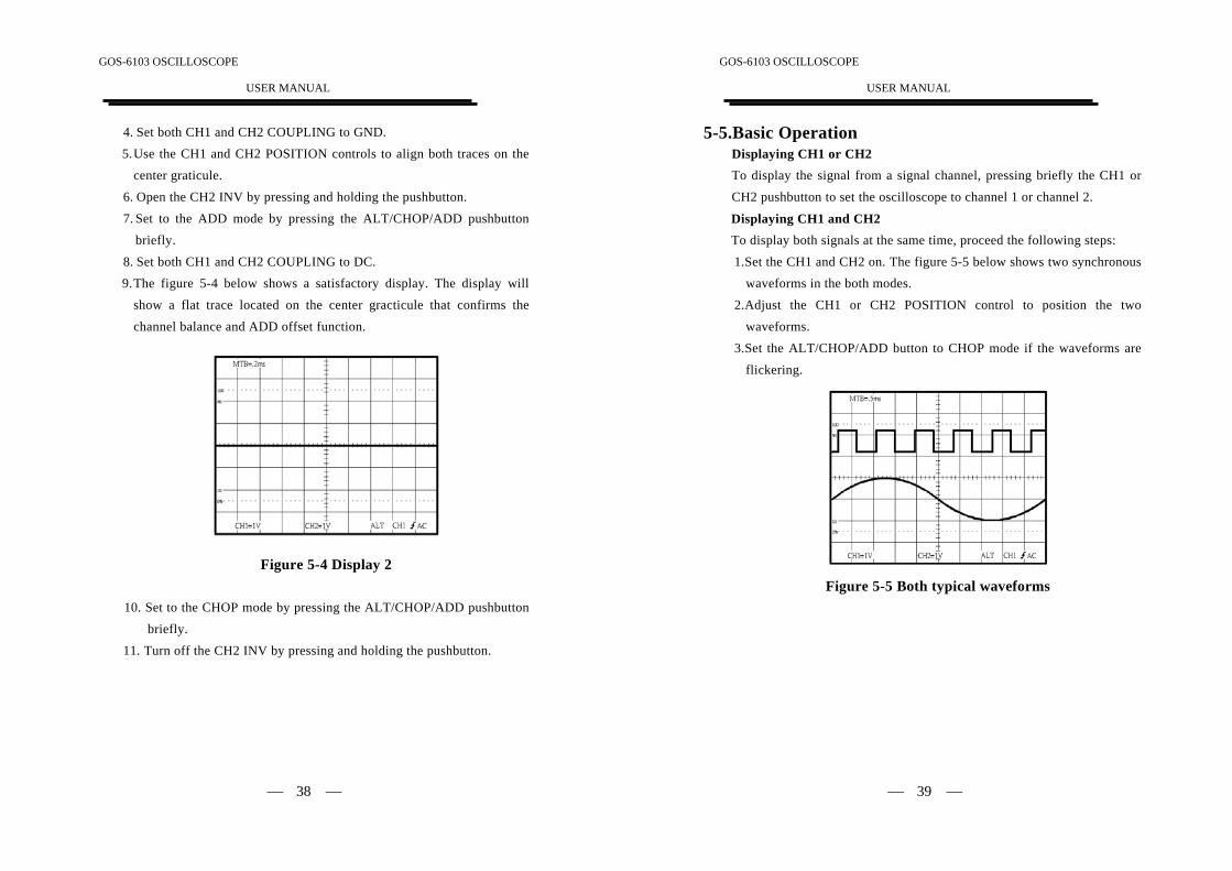
5-4.Function CheckWhen you start to check the operation of your oscilloscope, proceed the
following instruction:1. Install the ×10 probes onto CH1 and CH2 inputs.2. Connect the probe tips to the CAL test point of the oscilloscope.
3. Set the oscilloscope controls to display both channels:
VERTICAL: VOLTS/DIV 1VCOUPLING DCALT/CHOP/ADD CHOP
HORIZONTAL: MODE MTB
TIME/DIV 0.5msTRIGGER: MODE ATO
SOURCE CH1 or CH2COUPLING AC
SLOPE
The figure 5-3 below illustrates a satisfactory display. The waveform
should be approximately 2Vp-p at a frequency of 1kHz that confirms
the vertical and horizontal deflection function of the oscilloscope.
Figure 5-3 Display 1
GOS-6103 OSCILLOSCOPE
USER MANUAL
⎯ 38 ⎯
4. Set both CH1 and CH2 COUPLING to GND.5. Use the CH1 and CH2 POSITION controls to align both traces on the
center graticule.
6. Open the CH2 INV by pressing and holding the pushbutton.7. Set to the ADD mode by pressing the ALT/CHOP/ADD pushbutton
briefly.
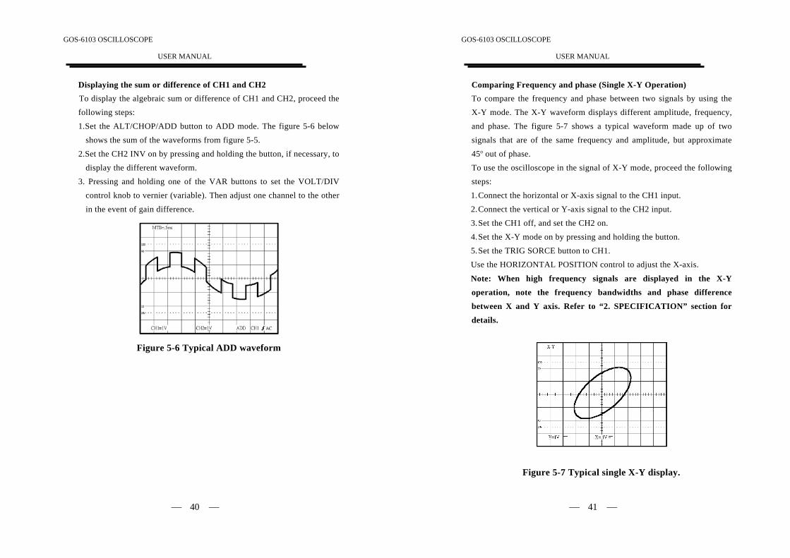
8. Set both CH1 and CH2 COUPLING to DC.9. The figure 5-4 below shows a satisfactory display. The display will
show a flat trace located on the center gracticule that confirms thechannel balance and ADD offset function.
Figure 5-4 Display 2
10. Set to the CHOP mode by pressing the ALT/CHOP/ADD pushbutton
briefly.
11. Turn off the CH2 INV by pressing and holding the pushbutton.
GOS-6103 OSCILLOSCOPE
USER MANUAL
⎯ 39 ⎯
5-5.Basic OperationDisplaying CH1 or CH2To display the signal from a signal channel, pressing briefly the CH1 orCH2 pushbutton to set the oscilloscope to channel 1 or channel 2.
Displaying CH1 and CH2To display both signals at the same time, proceed the following steps:
1.Set the CH1 and CH2 on. The figure 5-5 below shows two synchronouswaveforms in the both modes.
2.Adjust the CH1 or CH2 POSITION control to position the twowaveforms.
3.Set the ALT/CHOP/ADD button to CHOP mode if the waveforms are
flickering.
Figure 5-5 Both typical waveforms
GOS-6103 OSCILLOSCOPE
USER MANUAL
⎯ 40 ⎯
Displaying the sum or difference of CH1 and CH2To display the algebraic sum or difference of CH1 and CH2, proceed the
following steps:
1.Set the ALT/CHOP/ADD button to ADD mode. The figure 5-6 belowshows the sum of the waveforms from figure 5-5.
2.Set the CH2 INV on by pressing and holding the button, if necessary, to
display the different waveform.3. Pressing and holding one of the VAR buttons to set the VOLT/DIV
control knob to vernier (variable). Then adjust one channel to the otherin the event of gain difference.
Figure 5-6 Typical ADD waveform
GOS-6103 OSCILLOSCOPE
USER MANUAL
⎯ 41 ⎯
Comparing Frequency and phase (Single X-Y Operation)To compare the frequency and phase between two signals by using the
X-Y mode. The X-Y waveform displays different amplitude, frequency,
and phase. The figure 5-7 shows a typical waveform made up of twosignals that are of the same frequency and amplitude, but approximate45o out of phase.
To use the oscilloscope in the signal of X-Y mode, proceed the followingsteps:
1. Connect the horizontal or X-axis signal to the CH1 input.2. Connect the vertical or Y-axis signal to the CH2 input.3. Set the CH1 off, and set the CH2 on.
4. Set the X-Y mode on by pressing and holding the button.
5. Set the TRIG SORCE button to CH1.Use the HORIZONTAL POSITION control to adjust the X-axis.
Note: When high frequency signals are displayed in the X-Y
operation, note the frequency bandwidths and phase difference
between X and Y axis. Refer to “2. SPECIFICATION” section for
details.
Figure 5-7 Typical single X-Y display.
GOS-6103 OSCILLOSCOPE
USER MANUAL
⎯ 42 ⎯
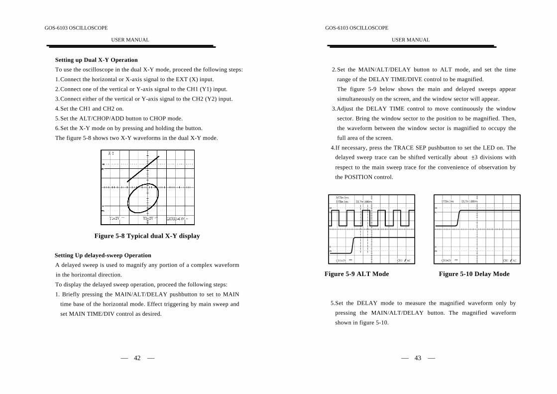
Setting up Dual X-Y OperationTo use the oscilloscope in the dual X-Y mode, proceed the following steps:
1. Connect the horizontal or X-axis signal to the EXT (X) input.
2. Connect one of the vertical or Y-axis signal to the CH1 (Y1) input.3. Connect either of the vertical or Y-axis signal to the CH2 (Y2) input.4. Set the CH1 and CH2 on.
5. Set the ALT/CHOP/ADD button to CHOP mode.6. Set the X-Y mode on by pressing and holding the button.
The figure 5-8 shows two X-Y waveforms in the dual X-Y mode.
Figure 5-8 Typical dual X-Y display
Setting Up delayed-sweep OperationA delayed sweep is used to magnify any portion of a complex waveform
in the horizontal direction.
To display the delayed sweep operation, proceed the following steps:
1. Briefly pressing the MAIN/ALT/DELAY pushbutton to set to MAINtime base of the horizontal mode. Effect triggering by main sweep and
set MAIN TIME/DIV control as desired.
GOS-6103 OSCILLOSCOPE
USER MANUAL
⎯ 43 ⎯
2. Set the MAIN/ALT/DELAY button to ALT mode, and set the time
range of the DELAY TIME/DIVE control to be magnified.The figure 5-9 below shows the main and delayed sweeps appearsimultaneously on the screen, and the window sector will appear.
3.Adjust the DELAY TIME control to move continuously the window
sector. Bring the window sector to the position to be magnified. Then,the waveform between the window sector is magnified to occupy thefull area of the screen.
4.If necessary, press the TRACE SEP pushbutton to set the LED on. Thedelayed sweep trace can be shifted vertically about ±3 divisions with
respect to the main sweep trace for the convenience of observation bythe POSITION control.
Figure 5-9 ALT Mode Figure 5-10 Delay Mode
5.Set the DELAY mode to measure the magnified waveform only bypressing the MAIN/ALT/DELAY button. The magnified waveform
shown in figure 5-10.
GOS-6103 OSCILLOSCOPE
USER MANUAL
⎯ 44 ⎯
Magnifying Waveform EventsUse the ×10 MAG pushbutton to view small portions of a waveform as
which is too far back from the starting point to view by using the
TIME/DIV control. To use the ×10 MAG button, proceed the followingsteps:1. Adjust the TIME/DIV to the fastest sweep that displays the event.
2. Rotate the HORIZONTAL POSITION control to move the event todisplay on the center of screen.
3. Press the ×10 MAG button to switch the MAG LED on.
When above procedures have been done, the displayed waveform will beexpanded 10 times to the right and left from the center of screen as center
of expansion.
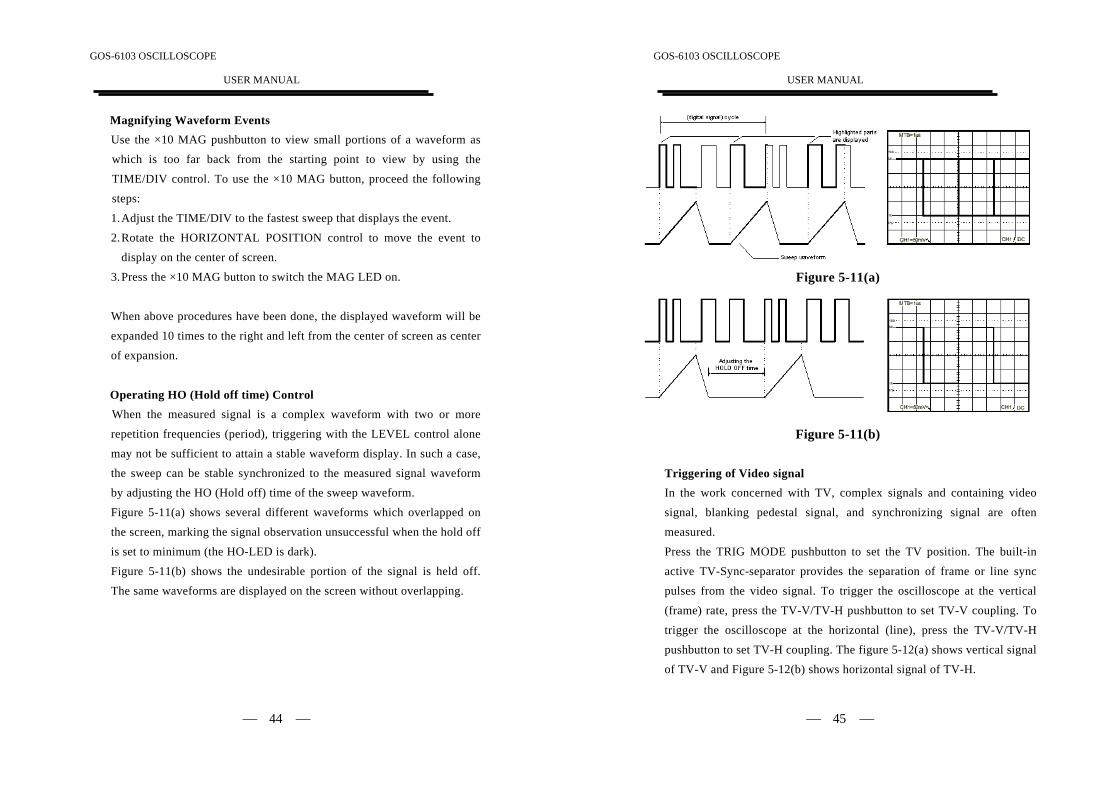
Operating HO (Hold off time) ControlWhen the measured signal is a complex waveform with two or more
repetition frequencies (period), triggering with the LEVEL control alone
may not be sufficient to attain a stable waveform display. In such a case,
the sweep can be stable synchronized to the measured signal waveformby adjusting the HO (Hold off) time of the sweep waveform.
Figure 5-11(a) shows several different waveforms which overlapped on
the screen, marking the signal observation unsuccessful when the hold off
is set to minimum (the HO-LED is dark).
Figure 5-11(b) shows the undesirable portion of the signal is held off.
The same waveforms are displayed on the screen without overlapping.
GOS-6103 OSCILLOSCOPE
USER MANUAL
⎯ 45 ⎯
Figure 5-11(a)
Figure 5-11(b)
Triggering of Video signalIn the work concerned with TV, complex signals and containing video
signal, blanking pedestal signal, and synchronizing signal are often
measured.
Press the TRIG MODE pushbutton to set the TV position. The built-in
active TV-Sync-separator provides the separation of frame or line sync
pulses from the video signal. To trigger the oscilloscope at the vertical(frame) rate, press the TV-V/TV-H pushbutton to set TV-V coupling. To
trigger the oscilloscope at the horizontal (line), press the TV-V/TV-H
pushbutton to set TV-H coupling. The figure 5-12(a) shows vertical signal
of TV-V and Figure 5-12(b) shows horizontal signal of TV-H.
GOS-6103 OSCILLOSCOPE
USER MANUAL
⎯ 46 ⎯
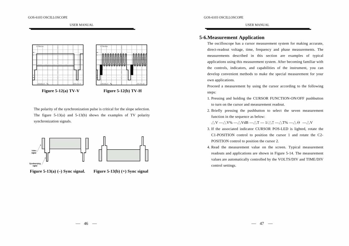
Figure 5-12(a) TV-V Figure 5-12(b) TV-H
The polarity of the synchronization pulse is critical for the slope selection.The figure 5-13(a) and 5-13(b) shows the examples of TV polarity
synchronization signals.
Figure 5-13(a) (–) Sync signal. Figure 5-13(b) (+) Sync signal
GOS-6103 OSCILLOSCOPE
USER MANUAL
⎯ 47 ⎯
5-6.Measurement ApplicationThe oscilloscope has a cursor measurement system for making accurate,
direct-readout voltage, time, frequency and phase measurements. Themeasurements described in this section are examples of typicalapplications using this measurement system. After becoming familiar with
the controls, indicators, and capabilities of the instrument, you can
develop convenient methods to make the special measurement for yourown applications.Proceed a measurement by using the cursor according to the following
steps:
1. Pressing and holding the CURSOR FUNCTION-ON/OFF pushbuttonto turn on the cursor and measurement readout.
2. Briefly pressing the pushbutton to select the seven measurementfunction in the sequence as below:△ V —△V% —△VdB —△T — 1/△T —△T% —△Θ —△V
3. If the associated indicator CURSOR POS-LED is lighted, rotate the
C1-POSITION control to position the cursor 1 and rotate the C2-
POSITION control to position the cursor 2.
4. Read the measurement value on the screen. Typical measurementreadouts and applications are shown in Figure 5-14. The measurement
values are automatically controlled by the VOLTS/DIV and TIME/DIV
control settings.
GOS-6103 OSCILLOSCOPE
USER MANUAL
⎯ 48 ⎯
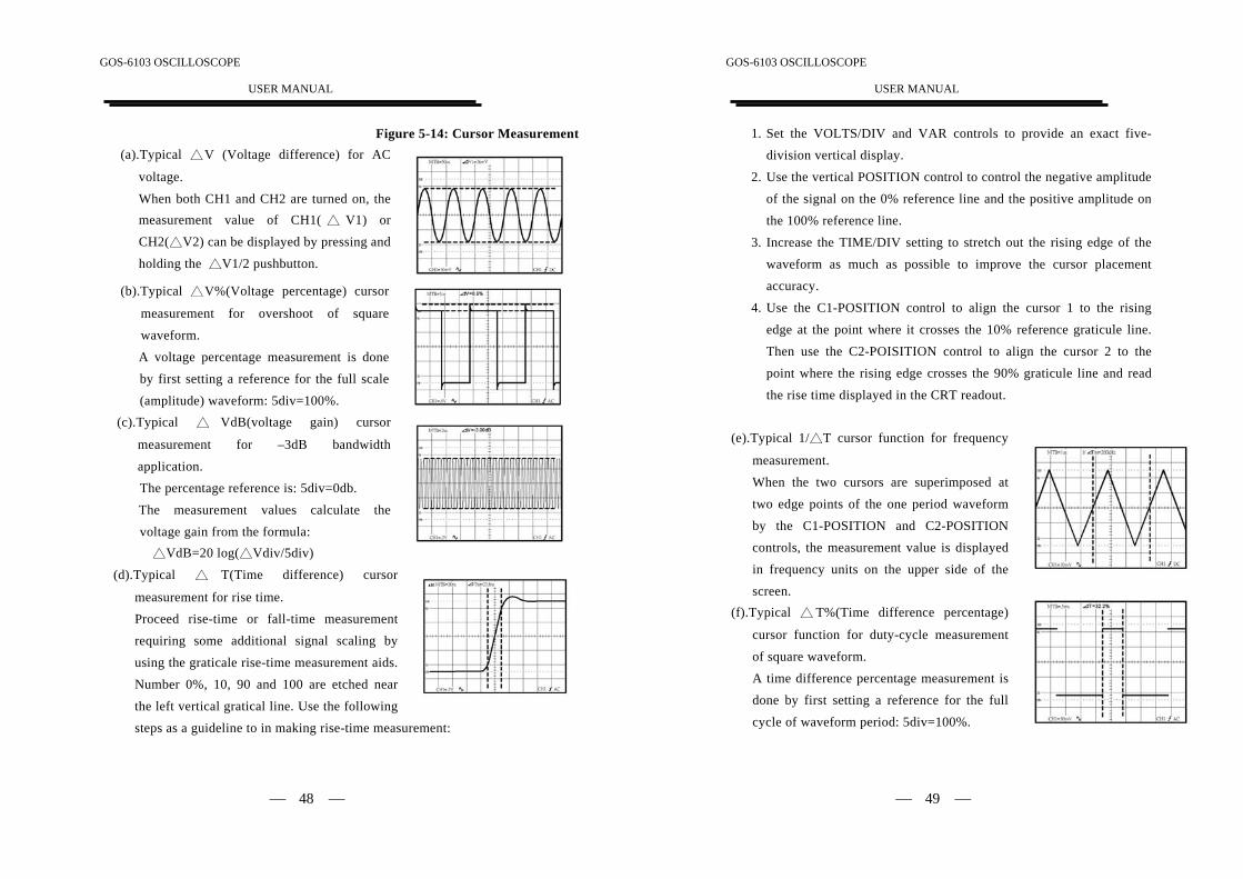
Figure 5-14: Cursor Measurement(a).Typical △V (Voltage difference) for AC
voltage.When both CH1 and CH2 are turned on, themeasurement value of CH1( △ V1) or
CH2(△V2) can be displayed by pressing andholding the △V1/2 pushbutton.
(b).Typical △V%(Voltage percentage) cursor
measurement for overshoot of squarewaveform.A voltage percentage measurement is done
by first setting a reference for the full scale
(amplitude) waveform: 5div=100%.(c).Typical △ VdB(voltage gain) cursor
measurement for –3dB bandwidth
application.The percentage reference is: 5div=0db.
The measurement values calculate the
voltage gain from the formula: △VdB=20 log(△Vdiv/5div)
(d).Typical △ T(Time difference) cursor
measurement for rise time.Proceed rise-time or fall-time measurement
requiring some additional signal scaling by
using the graticale rise-time measurement aids.
Number 0%, 10, 90 and 100 are etched near
the left vertical gratical line. Use the following
steps as a guideline to in making rise-time measurement:
GOS-6103 OSCILLOSCOPE
USER MANUAL
⎯ 49 ⎯
1. Set the VOLTS/DIV and VAR controls to provide an exact five-division vertical display.
2. Use the vertical POSITION control to control the negative amplitude
of the signal on the 0% reference line and the positive amplitude onthe 100% reference line.
3. Increase the TIME/DIV setting to stretch out the rising edge of the
waveform as much as possible to improve the cursor placementaccuracy.
4. Use the C1-POSITION control to align the cursor 1 to the risingedge at the point where it crosses the 10% reference graticule line.Then use the C2-POISITION control to align the cursor 2 to the
point where the rising edge crosses the 90% graticule line and read
the rise time displayed in the CRT readout.
(e).Typical 1/△T cursor function for frequency
measurement.
When the two cursors are superimposed at
two edge points of the one period waveform
by the C1-POSITION and C2-POSITIONcontrols, the measurement value is displayed
in frequency units on the upper side of the
screen.(f).Typical △ T%(Time difference percentage)
cursor function for duty-cycle measurement
of square waveform.A time difference percentage measurement is
done by first setting a reference for the full
cycle of waveform period: 5div=100%.
GOS-6103 OSCILLOSCOPE
USER MANUAL
⎯ 50 ⎯
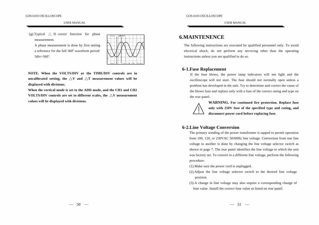
(g).Typical △ Θ cursor function for phase
measurement.
A phase measurement is done by first settinga reference for the full 360o waveform period:5div=360o.
NOTE. When the VOLTS/DIV or the TIME/DIV controls are inuncalibrated setting, the △V and △T measurement values will be
displayed with divisions.
When the vertical mode is set to the ADD mode, and the CH1 and CH2VOLTS/DIV controls are set to different scales, the △V measurement
values will be displayed with divisions.
GOS-6103 OSCILLOSCOPE
USER MANUAL
⎯ 51 ⎯
6.MAINTENENCEThe following instructions are executed by qualified personnel only. To avoidelectrical shock, do not perform any servicing other than the operatinginstructions unless you are qualified to do so.
6-1.Fuse ReplacementIf the fuse blows, the power lamp indicators will not light and theoscilloscope will not start. The fuse should not normally open unless a
problem has developed in the unit. Try to determine and correct the cause ofthe blown fuse and replace only with a fuse of the correct rating and type on
the rear panel.
WARNING. For continued fire protection. Replace fuseonly with 250V fuse of the specified type and rating, anddisconnect power cord before replacing fuse.
6-2.Line Voltage ConversionThe primary winding of the power transformer is tapped to permit operation
from 100, 120, or 230VAC 50/60Hz line voltage. Conversion from one line
voltage to another is done by changing the line voltage selector switch as
shown in page 7. The rear panel identifies the line voltage to which the unit
was factory set. To convert to a different line voltage, perform the followingprocedure:
(1).Make sure the power cord is unplugged.
(2).Adjust the line voltage selector switch to the desired line voltage
position.
(3).A change in line voltage may also require a corresponding change of
fuse value. Install the correct fuse value as listed on rear panel.
GOS-6103 OSCILLOSCOPE
USER MANUAL
⎯ 52 ⎯
6-3.CleaningTo clean the oscilloscope, use a soft cloth dampened in a solution of milddetergent and water. Do not spray cleaner directly onto the oscilloscope
because it may leak into the cabinet and cause damage.Do not use chemicals containing benzine, benzene, toluene, xylene,acetone, or similar solvents. Do not use abrasive cleaners on any portion of
the oscilloscope.
GOS-6103 OSCILLOSCOPE
USER MANUAL
⎯ 53 ⎯
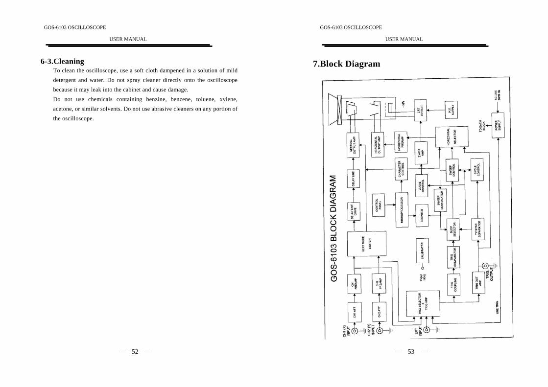
7.Block Diagram


![[Exempt From Filing Fee Government Code § 6103]](https://img.pdfslide.us/doc/110x75/624b00a8c6bb4f313d335a53/exempt-from-filing-fee-government-code-6103.jpg)