Embed Size (px)
Citation preview
Considerations for oscilloscope measurements
of electrical and optical PAM4 signalsPavel Zivny, Tektronix ; Contributors:
Greg LeCheminant, Keysight Technologies; Jan Peters Weem, Tektronix
2015/09 prz
V1.0
Considerations for oscilloscope measurements of electrical and optical PAM4 signals
Sampling oscilloscopes: modes of operation with respective
features/limitations
Real-time oscilloscopes: modes of operation with respective
features/limitations
2015/09 zivny_3bs_01_0915 V1.0 measurements on PAM42
Oscilloscopes: signal constraints vs. depth of analysis: basic eye capture on Sampling*
Two acquisition types are possible on a sampling* oscilloscope:
1. Capture with no decomposition of statistical properties
e.g. capture of the eye diagram.
– No need for Pattern Trigger (Pattern Lock);
– No possibility of SW DSP (no SW equalization possible).
– Works on any pattern or traffic, incl. PRBS31
– BW controllable as a 4th order Bessel-Thomson from ~40% to 100% of
BWMAX ; this is a valid filter for all components of the signal
2015/09 zivny_3bs_01_0915 measurements on PAM43
*Equivalent time sampling oscilloscope
Oscilloscopes: signal constraints vs. depth of analysis: pattern capture on Sampling
… two acquisition types are possible on a sampling oscilloscope:
2. Capture with separation and decomposition of statistical properties
– Repetitive pattern and Pattern Lock or (Pattern Trigger) are necessary
– Realistic pattern length: PRBS15 in several minutes
(so ok for design, for manufacturing, shorter would be better)
Note that for statistical analysis, many passes of the pattern must be analyzed –
capture of just repeat of pattern won’t allow collection of statistical behavior
– Jitter components decomposed and measured (RJ, DDJ, RN, DDN, ...)*
– HW filter as in 1. remains
– Correlated** information (the waveform w/o random noise/jitter) has
correct spectrum and can be exported as a waveform;
can also be equalized in a SW CTLE/FFE/DFE etc.
– Uncorrelated information (RJ, RN, PJ, PN, etc.) known only in distribution,
not as a true time-step vector. Spectral shaping based on assumptions
(e.g. RN is white, thus will be limited in certain way by e.g. an CTLE).
2015/09 zivny_3bs_01_0915 measurements on PAM44
*Random Jitter, Data Dependent Jitter, etc. **correlated to the pattern
Basic facts for Sampling Oscilloscopes
Excellent noise performance (e.g. 600 uVRMS for 33 GHz of BW)
Excellent bandwidth at low cost ( BW>80 GHz )
Optical plug-ins available for most signals’ needs
Trigger signal necessary (a CR, or a Clock e.g. from the signal
source)
Clock recovery behavior (PLL Loop BW, etc.) in HW of the clock
recovery (CR)
2015/09 zivny_3bs_01_0915 V1.0 measurements on PAM45
Oscilloscopes: signal constraints vs. depth of analysis: pattern capture on Real Time
Two acquisition types are possible on a real-time oscilloscope:
3. Capture with no decomposition of statistical properties
– e.g. capture a segment of the pattern, or 1 repeat of it.
– Works on any pattern or traffic, incl. PRBS31
– Jitter / Noise decomposition not possible (not enough data for good
analysis from 1 repeat of a waveform)
– BW controllable fully; DSP processing (SW equalizers) fully available
2015/09 zivny_3bs_01_091 measurements on PAM46
Oscilloscopes: signal constraints vs. depth of analysis: pattern capture on Real Time
… two acquisition types are possible on a real-time oscilloscope:
4. Capture with decomposition of signal components
- capture many (e.g. 100) repeats of the pattern
– Repetitive pattern with length ca. < PRBS21 is necessary*
– For statistical analysis a repetitive waveform that can be digitized
completely about 100 times is highly desirable:
Jitter components decomposed and measured (RJ, DDJ, RN, DDN, ...)
– BW controllable fully; DSP processing (SW equalizers) fully available
– Noise performance
2015/09 zivny_3bs_01_091 measurements on PAM47
*necessary for high quality of result; random data partially analyzed
Equalization capabilities of oscilloscopes
Two acquisition modes for sampling oscilloscopes:
– Basic Eye Diagrams:
– No restrictions on pattern length (includes live traffic)
– Simple clock triggering
– Limited analysis of statistical properties
– No post processing (no SW equalization)
– Pattern Locked analysis
– Requires repetitive pattern and Pattern Trigger
– More accurate analysis of signal properties
– Realistic pattern length: PRBS15 is viable, test time driven by pattern length
– Allows variety of SW equalization tools
Real Time oscilloscopes – Can acquire and process any waveform without pattern length and triggering
restrictions
– For statistical analysis and equalization, repetitive waveforms with multiple
observations highly desirable
2015/09 zivny_3bs_01_0915 measurements on PAM48
Basic facts for Real-Time Oscilloscopes
Good noise performance (e.g. 1200 uVRMS for 33 GHz of BW)
Trigger signal not needed
Clock recovery available in SW (highly flexible)
2015/09 zivny_3bs_01_0915 V1.0 measurements on PAM49
Measurement bandwidth requirements for electrical and optical signals
An example of proposal for bandwith required for oscilloscope
measurements of PAM4 signals follows.
The goal of proposal is to receive feedback; not final numbers
2015/09 zivny_3bs_01_0915 measurements on PAM410
Measurement bandwidth requirements for electrical and optical signals
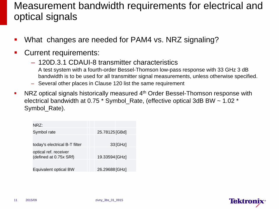
What changes are needed for PAM4 vs. NRZ signaling?
Current requirements:
– 120D.3.1 CDAUI-8 transmitter characteristicsA test system with a fourth-order Bessel-Thomson low-pass response with 33 GHz 3 dB
bandwidth is to be used for all transmitter signal measurements, unless otherwise specified.
– Several other places in Clause 120 list the same requirement
NRZ optical signals historically measured 4th Order Bessel-Thomson response with
electrical bandwidth at 0.75 * Symbol_Rate, (effective optical 3dB BW ~ 1.02 *
Symbol_Rate).
2015/09 zivny_3bs_01_091511
NRZ:
Symbol rate 25.78125 [GBd]
today's electrical B-T filter 33 [GHz]
optical ref. receiver
(defined at 0.75x SRf) 19.33594 [GHz]
Equivalent optical BW 26.29688 [GHz]
What is the proper bandwidth for PAM4 waveform analysis optical signals
What are the essential signal properties that must be observed to provide
confidence that a signal will yield an operable link
What is the proper observation BW to measure those properties?
Is the 33 GHz (3 dB B-T bandwidth) appropriate for electrical signals?
What Optical Reference Receiver (ORR) bandwidth should be used for PAM4
NRZ at
– 26.5625 GBd
– 54.29 GBd
What is the measure of goodness of a reference receiver? (for either electrical
or optical)
2015/09 zivny_3bs_01_091512
Recommend continued use of Bessel-Thomson design
Best time domain response (constant group delay in pass band yields
best flatness of step response)
Consider a bandwidth that yields comparable vertical eye closure to
that of legacy PAM2 NRZ
This is a general recommendation applicable to an eye mask test or
other measurements.
– Acknowledging that measurements are still being defined, with a
possibility of closed eyes
Can existing optical reference receivers be leveraged for 802.3 bs?
– 802.3ba, 802.3 bm: 19.34 GHz
– 32xFibre Channel : 21 GHz
2015/09 zivny_3bs_01_091513
The impact of the measurement bandwidth on the PAM4 NRZ signal: test signal
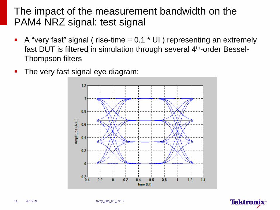
A “very fast” signal ( rise-time = 0.1 * UI ) representing an extremely
fast DUT is filtered in simulation through several 4th-order Bessel-
Thompson filters
The very fast signal eye diagram:
2015/09 zivny_3bs_01_091514
The evaluation of the impact of the test equipment
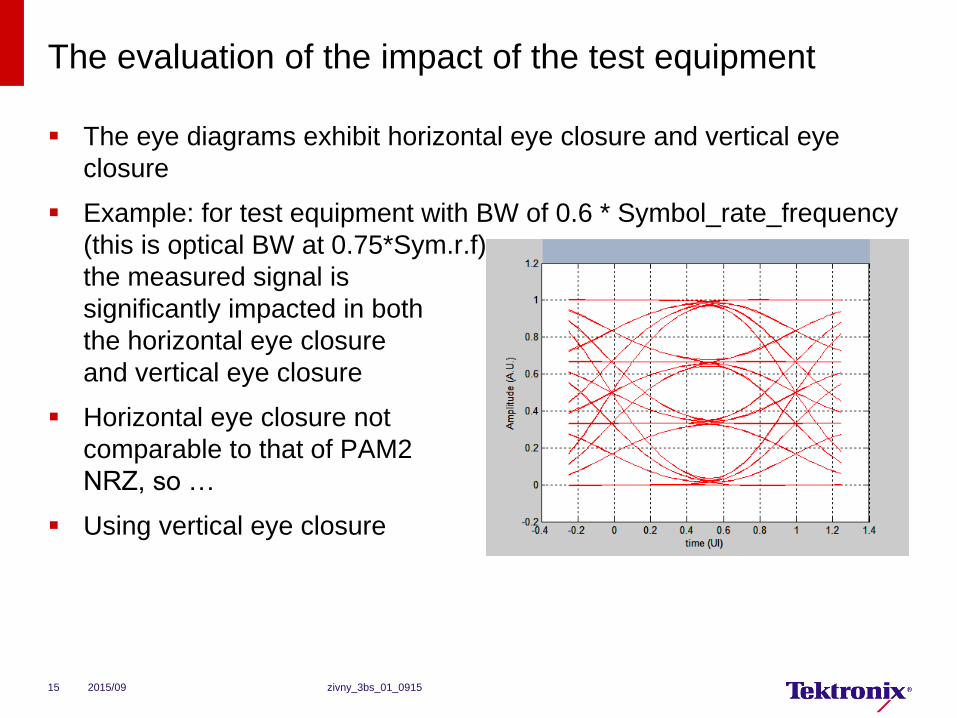
The eye diagrams exhibit horizontal eye closure and vertical eye
closure
Example: for test equipment with BW of 0.6 * Symbol_rate_frequency
(this is optical BW at 0.75*Sym.r.f)
the measured signal is
significantly impacted in both
the horizontal eye closure
and vertical eye closure
Horizontal eye closure not
comparable to that of PAM2
NRZ, so …
Using vertical eye closure
2015/09 zivny_3bs_01_091515
Comparison of the relative eye closure of PAM2 and PAM4 NRZ vs. relative Reference Receiver Bandwidth
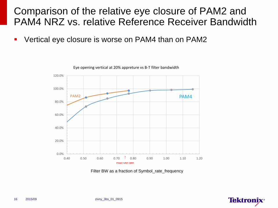
Vertical eye closure is worse on PAM4 than on PAM2
2015/09 zivny_3bs_01_091516
PAM2 NRZ ORR
↑
Filter BW as a fraction of Symbol_rate_frequency
0.0%
20.0%
40.0%
60.0%
80.0%
100.0%
120.0%
0.40 0.50 0.60 0.70 0.80 0.90 1.00 1.10 1.20
PAM4
Eye opening vertical at 20% appreture vs B-T filter bandwidth
PAM2
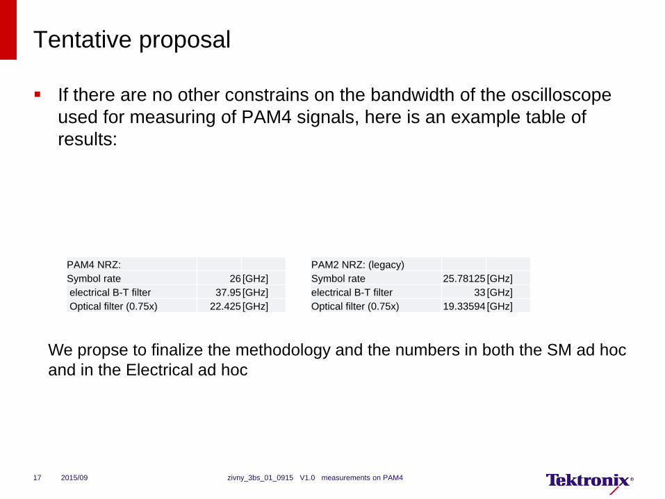
Tentative proposal
If there are no other constrains on the bandwidth of the oscilloscope
used for measuring of PAM4 signals, here is an example table of
results:
2015/09 zivny_3bs_01_0915 V1.0 measurements on PAM417
PAM2 NRZ: (legacy)
Symbol rate 25.78125 [GHz]
electrical B-T filter 33 [GHz]
Optical filter (0.75x) 19.33594 [GHz]
PAM4 NRZ:
Symbol rate 26 [GHz]
electrical B-T filter 37.95 [GHz]
Optical filter (0.75x) 22.425 [GHz]
We propse to finalize the methodology and the numbers in both the SM ad hoc
and in the Electrical ad hoc

End.
Thank you.
2015/09 zivny_3bs_01_0915 V1.0 measurements on PAM418