Embed Size (px)
Citation preview
HAL Id: hal-00498967https://hal.archives-ouvertes.fr/hal-00498967
Submitted on 9 Jul 2010
HAL is a multi-disciplinary open accessarchive for the deposit and dissemination of sci-entific research documents, whether they are pub-lished or not. The documents may come fromteaching and research institutions in France orabroad, or from public or private research centers.
L’archive ouverte pluridisciplinaire HAL, estdestinée au dépôt et à la diffusion de documentsscientifiques de niveau recherche, publiés ou non,émanant des établissements d’enseignement et derecherche français ou étrangers, des laboratoirespublics ou privés.
Parametric study and multiple correlations on air-sideheat transfer and friction characteristics of fin-and-tube
heat exchangers with large number of large-diametertube rows
Gongnan Xie, Qiuwang Wang, Bengt Sunden
To cite this version:Gongnan Xie, Qiuwang Wang, Bengt Sunden. Parametric study and multiple correlations onair-side heat transfer and friction characteristics of fin-and-tube heat exchangers with large num-ber of large-diameter tube rows. Applied Thermal Engineering, Elsevier, 2008, 29 (1), pp.1.�10.1016/j.applthermaleng.2008.01.014�. �hal-00498967�
Accepted Manuscript
Parametric study and multiple correlations on air-side heat transfer and friction
characteristics of fin-and-tube heat exchangers with large number of large-di‐
ameter tube rows
Gongnan Xie, Qiuwang Wang, Bengt Sunden
PII: S1359-4311(08)00029-X
DOI: 10.1016/j.applthermaleng.2008.01.014
Reference: ATE 2363
To appear in: Applied Thermal Engineering
Received Date: 9 August 2007
Revised Date: 8 January 2008
Accepted Date: 8 January 2008
Please cite this article as: G. Xie, Q. Wang, B. Sunden, Parametric study and multiple correlations on air-side heat
transfer and friction characteristics of fin-and-tube heat exchangers with large number of large-diameter tube rows,
Applied Thermal Engineering (2008), doi: 10.1016/j.applthermaleng.2008.01.014
This is a PDF file of an unedited manuscript that has been accepted for publication. As a service to our customers
we are providing this early version of the manuscript. The manuscript will undergo copyediting, typesetting, and
review of the resulting proof before it is published in its final form. Please note that during the production process
errors may be discovered which could affect the content, and all legal disclaimers that apply to the journal pertain.
ACCEPTED MANUSCRIPT
1
NOTE: The revised words are marked in blue color.
Parametric study and multiple correlations
on air-side heat transfer and friction characteristics of fin-and-tube heat exchangers with large number of
large-diameter tube rows
Gongnan Xiea, Qiuwang Wanga,, Bengt Sundenb
Gongnan Xie a , Qiuwang Wang a*
a State Key Laboratory of Multiphase Flow in Power Engineering, School of Energy and Power Engineering, Xi’an Jiaotong University, Xi’an, 710049, China. [email protected] (G.N.Xie) Corresponding author: [email protected] (Q.W.Wang) Tel and Fax: +86-29-82663502
Bengt Sunden b bDivision of Heat Transfer, Department of Energy Sciences, Lund University, P.O. Box 118, SE-221 00, Lund, Sweden. [email protected] (B.Sunden) Tel.: +46-46-2228605, fax: +46-46-2224717
Revised Manuscript
ACCEPTED MANUSCRIPT
2
Parametric study and multiple correlations on air-side heat transfer and friction characteristics of fin-and-tube heat exchangers with large
number of large-diameter tube rows
Abstract
In the present study, for industrial applications of large inter-coolers employed in
multi-stage compressor systems the air-side laminar heat transfer and fluid flow
characteristics of plain fin-and-tube heat exchangers with large number of tube rows and
large diameter of the tubes are investigated numerically through three-dimensional
simulations based on the SIMPLE algorithm in Cartesian coordinates. The effects of
parameters such as Reynolds number, the number of tube rows, tube diameter, tube
pitch and fin pitch are examined, and the variations of heat transfer due to variations of
fin materials are also observed. It is found that the heat transfer and fluid flow approach
fully developed conditions when the number of tube rows is greater than six, and the
tube diameter as well as the fin pitch have much more significant effects than the tube
pitch, and the heat transfer of high-conductivity material is larger than that of
low-conductivity material especially in the high Reynolds number regime. Due to the
fact that the existing correlations are not valid for large tube diameters and number of
tube rows, the heat transfer and flow friction of the presented heat exchangers are
correlated in the multiple forms. The correlation is so obtained that it can be used for
further studies such as performance prediction or geometrical optimization.
Keywords: Plain fin-and-tube heat exchanger; Heat transfer; Friction factor; Parametric
study; Multiple correlation

ACCEPTED MANUSCRIPT
3
Nomenclature
c1, c2, c3, c4 Coefficient of formulation
A Area, m2
Af Fin surface area, m2
Amin Minimum flow area, m2
Ao Total surface area, m2
cp Specific heat at constant pressure, J kg-1K-1
Dc Fin collar outside diameter, Dc= Do+2δ , mm
Di Inside diameter of tube, mm
Do Outside diameter of tube, mm f Friction factor
Fp Fin pitch, mm
h Heat transfer coefficient, W m-2 K-1
M Number of decision variables
N Number of tube rows
Nd Number of sets of data used for correlating
Nu Nusselt number
�P Pressure drop, Pa
Pl Longitudinal tube pitch, mm
Pt Transverse tube pitch, mm
Re Reynolds number based on Dc
T Temperature, K
�T Logarithmic mean temperature difference, K
u,v,w Velocity, m s-1
umax Maximum velocity at minimum cross-section, m s-1
Vfr Air frontal velocity, m s-1
x,y,z Coordinates, m
Greek symbols ρ Density, kg m-3
λ Thermal conductivity of fluid, W m-1 K-1
fλ Thermal conductivity of fin, W m-1 K-1 µ Dynamic viscosity of fluid, kg m-1s-1
fη Fin efficiency

ACCEPTED MANUSCRIPT
4
� Fin surface efficiency
δ f Fin thickness, mm
� Heat transfer rate, W
Subscripts
air air side
f fin surface
in air-side inlet
max maximum value
out air-side outlet
p plain fin
w tube wall
ACCEPTED MANUSCRIPT
5
1. Introduction
To increase thermal performance of heat exchangers, it is necessary and effective
to employ extended surfaces (or referred to as finned surfaces) on the gas side to
compensate for the low heat transfer coefficient, which maybe 10-to-100 times smaller
than that of the liquid-side. Compact Heat Exchangers (CHEs), including two types of
heat exchangers such as plate-fin types and fin-and-tube (tube-fin) types, are widely
used for gas-gas or gas-liquid applications. CHEs own merits of compactness, small
volume, low weight, high effectiveness and low cost. Fin-and-Tube Heat Exchangers
(FTHEs) are employed in many power engineering and chemical engineering
applications such as compressor intercoolers, air-coolers, fan coils as well as HVAC&R
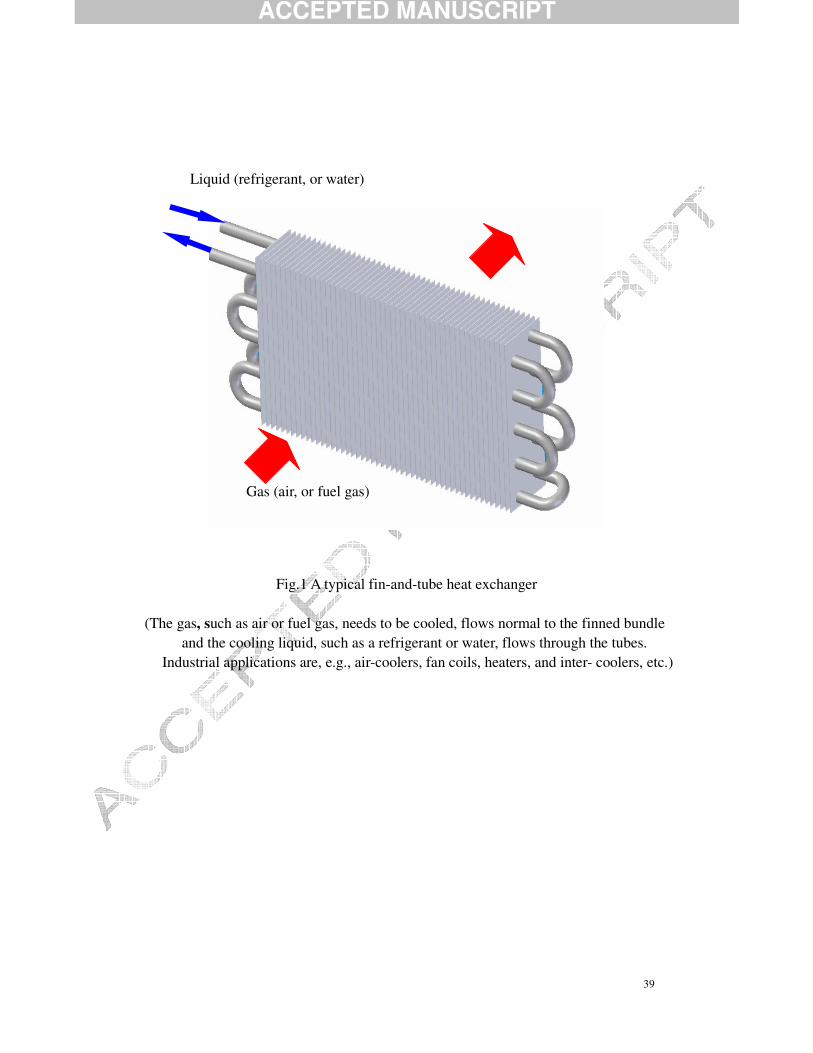
(heating, ventilating, air-conditioning and refrigeration). FTHE (as shown in Fig.1) is
one of the successful improvements of the tubular heat exchangers. Because the
relatively large thermal resistance, which often accounts to 90% of the overall thermal
resistance, is encountered on the gas-side (generally air-side), fins are employed on the
gas-side to enlarge the heat exchanger surface area and increase the disturbance of the
flow. According to the traditional understanding of the heat transfer enhancement
mechanism, an accepted conventional idea adopted in fin surfaces is to disturb the
pattern of flow and destroy the boundary layer. Therefore, to satisfy the desire to
enhance heat transfer, a variety of plate fin surfaces have been developed and applied
successfully.
Although many high-performance fins such as slotted fins, offset strip fins,
ACCEPTED MANUSCRIPT
6
louvered fins as well as fins with longitudinal vortex generators have been developed
and applied for significant heat transfer enhancements, the corresponding additional
pressure drops involved in convective heat transfer are dramatic penalties. For the
application where the pressure drop is strictly considered within the specified
requirements, the plain fin-and-tube heat exchanger under the design conditions might
be a typical type among the choices. At this point, the fin-and-tube heat exchangers
having plain fins would not be replaced by those having high-performance fins. Thus,
due to the virtues of simple configuration, easy manufacturing, low pressure drop and
good reliability, the plain fin-and-tube heat exchangers are still widely used in
engineering applications, in which the consumptions of pump or compressor power
should be severely managed.
A large number of investigations on the air-side performance for different fin
patterns by means of either experimental measures or numerical computations have
been carried out. Extensive experimental data or correlations of plain fin-and-tube heat
exchangers for refrigeration and air-conditioning applications were established in [1-11].
McQuiston [1] earlier carried out experiments on two samples having the same tube
outside diameter of 10.3 mm and fin pitch of 1.78 mm and 3.18 mm, respectively, the
test air velocity was ranging between 0.5 m/s and 5.9 m/s. By having tested fourteen
samples Rich [2-3] then reported that under the experimental range the intensity of heat
transfer did not depend on the fin pitch and the pressure drop per tube was independent
of the number of tube rows. McQuiston [4,5] combined the data tested by Rich and his
ACCEPTED MANUSCRIPT
7
own data for the same tube diameter of 0.392 in (9.96mm) and fin density of 4, 8, 10, 12
and 14, respectively, and established the widely-known correlations of heat transfer and
pressure drop with deviations of ± 10 and ± 35 , respectively. Gray and Webb
[6] finally proposed the heat transfer and pressure drop correlations with a square error
of 7.3% and 7.8%, respectively. The correlations, having much better precision than that
correlated by Rich, are valid for big tubes, large tube pitch and multi-rows. It is
emphasized that the correlations were based on the experimental results of four
tube-rows and regarded that heat transfer performance was independent of the fin pitch.
Kang et al. [7] reported experimental results for nine test samples having the same tube
diameter 10.15 mm and fin pitches 2.0 mm, 2.6 mm and 3.2 mm and the number of
tube-rows equal to 2, 3 and 4. They provided multiple correlations for all samples
within the experimental range. They pointed out that the effect of the fin pitch varies
with the Reynolds number and the heat transfer for two tube-rows is better than that for
three tube-rows while the heat transfer for three or four tube-rows is similar. Recently,
Wang et al. [8-11] stated that for one and two tube-rows the heat transfer is affected by
the fin pitch. Having measured the 74 test samples, they established the so-far precise
correlation of heat transfer and friction factor having the average deviation of 7.5% and
8.3%, respectively. The correlations have such a wide validation range that they could
be applied in the following ranges; tube diameter from 6.35 mm to 12.7 mm, fin pitch
from 1.19 mm to 8.7 mm, transverse tube pitch from 17.7 to 31.5 mm, longitudinal tube
pitch from 12.4 mm to 27.5 mm as well as the number of tube rows from one to six.
ACCEPTED MANUSCRIPT
8
Considerable efforts on numerical studies of plain fin-and-tube heat exchangers
were reported in [12-17]. Bestani et al. [18] earlier conducted three-dimensional
simulations on pattern of flow passing around a cylinder. Torikoshi and Xi [13]
simulated the heat transfer and fluid flow for one and two tube-rows plain fins, in which
they found the existing problem. They also compared results obtained from
two-dimensional and three-dimensional computations and found difficulties in the
three-dimensional simulations. Jang et al. [14] reported that the heat transfer is
independent of the number of tube-rows when this number is larger than four, and the
heat transfer coefficient and friction factor of staggered tube arrangement offers 15% to
27%, and 20% to 25%, respectively, higher than those of in-line tube arrangement.
Jang and Yang [15] conducted numerical computations and experimental measurements
of plain fin-and-tube heat exchangers having round tubes and flat tubes, respectively.
They found that for the same perimeter of the tubes, the heat transfer coefficient for the
flat tube heat exchanger was 35% to 50% higher than that for the round tube heat
exchanger while the pressure drop of the former is 25% to 30% of that of the latter. He
et al. [16] computed laminar heat transfer of plain fin-and-tube heat exchangers with the
number of tube rows from one to three, based on the SIMPLER algorithm in body-fitted
coordinates. From the field synergy principle point of view, they analyzed the
mechanism of heat transfer enhancement for describing their numerical results. Erek et
al. [17] used CFD to study the effects of geometrical parameters on performance of
plain fin-and-tube heat exchangers with flat tubes, and they suggested that the increase

ACCEPTED MANUSCRIPT
9
of ellipticity could increase the heat transfer together with a distinct decrease of the
pressure drop.
From the foregoing reviews of recent findings, one can examine that most of the
studies focused only on small numbers of tube rows (mostly less than 4) or small tube
diameter (mostly in the range of 8 to 13 mm), which are usually used in the HVAC&R
engineering. However, only a small quantity of efforts has focused on large number of
tube rows and large tube diameter. In some certain applications of large industry, such
as the intercooler of multi-stage compressor, the number of tube rows (might be larger
than 4 or much larger) and the outside diameter of tubes is large (might be larger than
13 mm or much larger). The industrial background of the present study is that heat
exchangers are applied and operating as inter-coolers in multi-stage compressors to
decrease the outlet temperature of compressors and the power input for the compression.
This results in improved compressor efficiency and hence improved global efficiency of
high pressure thermal plants like as gas turbine plants. Such a kind of heat exchanger
is operated under a large heat duty associated with large heat transfer area that might be
achieved by a large number of large-diameter tube rows (6 to 12 or higher), because
more fins are arranged in the line along the flow direction while a heat exchanger with
few tube rows in the flow direction sometimes cannot satisfy the real requirement.
Furthermore, at such conditions of gas turbine plants, the consideration of pressure
losses in the compressor systems will be very important. Therefore, it is essential to
investigate the heat transfer and friction characteristics of fin-and-tube heat exchangers
ACCEPTED MANUSCRIPT
10
with large number of tube rows and large tube-diameter (Xie [18], Tang et al. [19,20]).
On the other hand, for the presented fin-and-tube heat exchanger having large number
of tube-rows and large tube diameter it might not be possible to find suitable
correlations for prediction of heat transfer and fluid flow even if there are many existing
precise correlations that can be borrowed. So based on the numerical computations of
the present study the heat transfer and friction factor should be correlated in certain
assumed forms and in turn these correlations could be used for further studies such as
design optimizations [21,24] and performance predictions [25,26].The above-mentioned
reasons indicate that the results of the present study should be used as a reference. For
this reason, the objectives of this study are to examine the effects of geometrical
parameters on laminar heat transfer of plain fin-and-tube heat exchangers and to
correlate the performance in multiple forms based on the numerical results.
In the following sections, the problem and physical model investigated are first
described in Section 2, and the reasons for the selection of flow model and
computational domain are included. Having introduced the computational model, the
governing equations and boundary conditions are then specified, and the numerical
method is also briefly described in Section 3. The experimental sample tested by Kang
et al. [7] is then numerically computed and the corresponding numerical results are
compared with the experimental results as well as those by Wang et al. [8-11]. This is so
to verify the reliability of the assumed model and code developed in this study as well as
the grid independence. All these matters are provided in Section 4. The effects of six
ACCEPTED MANUSCRIPT
11
parameters are examined in Section 5, where also results and discussion are included.
Based on the numerical results in the previous sections, multiple correlations are
obtained in Section 6. The conclusions are drawn in the final section.
2. Physical model and assumptions
2.1 Physical model
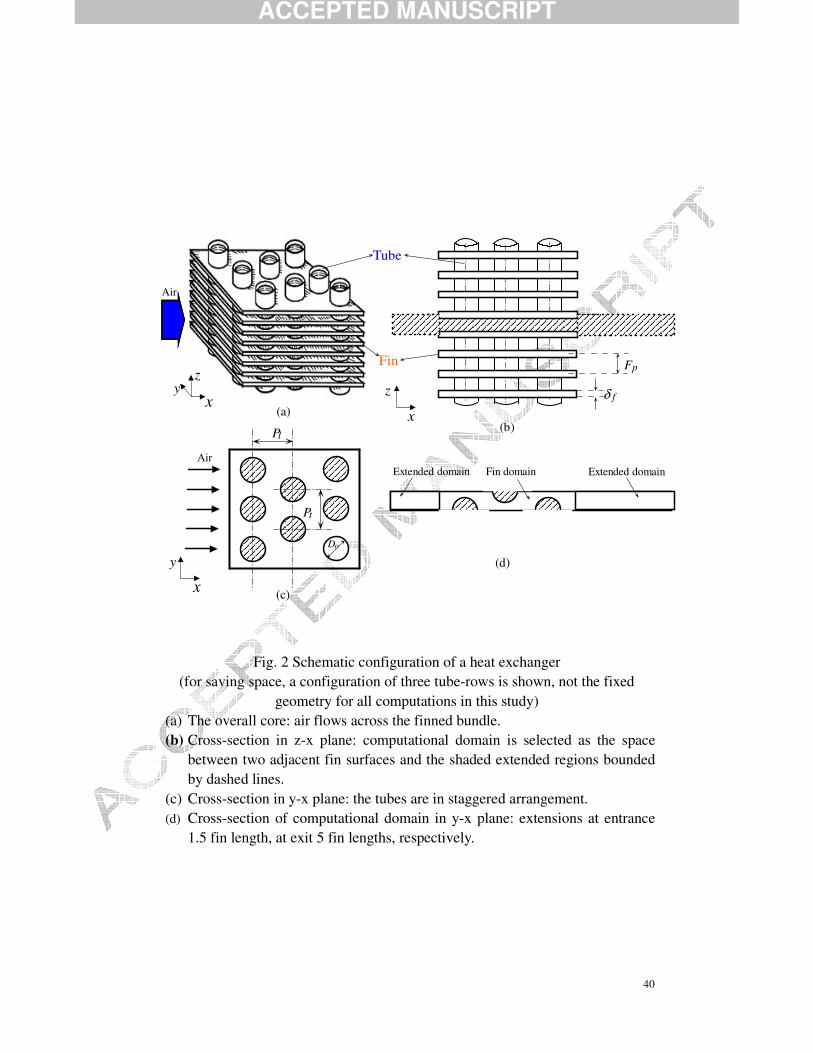
A schematic diagram of a plain fin-and-tube heat exchanger is shown in Figure 2.
It is noted that for saving space and to provide a clear description, the core of a
fin-and-tube heat exchanger having three tube-rows is only schematically pictured
(however, the effects of the number of tube-rows from two to seven are examined). In
fact, in most practical manufacturing, the heat exchanger cores with large tube-rows are
often combined from cores with three tube-rows. The fact is that the samples with six or
nine tube-rows manufactured in our Laboratory are indeed created from cores having
three tube-rows. As shown in Fig. 2(a), hot air flows across a finned tube bundle while
cold water flows inside the round tubes that are arranged staggered. The heat is
transmitted to the air through the tube wall and fin surfaces, resulting in cooling of the
water. The heat transfer and pressure drop characteristics on the air side are to be found
by numerical computations based on the suggested model. There are many parameters
to describe the configuration of the heat exchanger. Among these parameters the main
geometrical parameters are tube outside diameter (Do), fin pitch (Fp), tube transverse
pitch (Pt) and tube longitudinal pitch (Pl). Their nominal values are 18 mm, 3 mm, 42
ACCEPTED MANUSCRIPT
12
mm and 34 mm, respectively. The tubes and fins are made of copper (later the effect
of material is also observed). The fluid is assumed to be incompressible with constant
properties, and the flow is steady state. Due to the relatively large heat transfer
coefficient between the cooling water and the inner wall of the tube and the large
thermal conductivity of the tube wall, the tube is assumed to be at constant temperature.
However, the temperature distribution in the fin surface has to be calculated. Therefore,
the computations are of conjugated type, in which both the temperature in the solid fin
surface and in the fluid are to be determined simultaneously [27].
2.2 Adoption of flow model
Prior to conducting the numerical computations, discussion is now focused on the
adoption of flow regime for the computational model, i.e., laminar or turbulent. The
choice of flow model should be motivated in some way as the flow is complex inside
compact heat exchanger passage and sufficient experimental data is not available for
judgement. In this study a laminar flow model is adopted in all computations with the
Reynolds number being varied from 1000 to 6000 (based on fin collar outside diameter,
Dc= Do+2δ f), the corresponding air frontal velocity is ranged from 0.67 m/s to 4 m/s.
The basic considerations are as follows. First, if the flow between two adjacent fin
surfaces is regarded as a flow between parallel plates, i.e., a channel flow, the transition
Reynolds number may take a value around 2300 using twice the space/pitch between
the plates as the reference length. It should be noted that in this study the tube
diameter is six times larger than the fin pitch (18 mm and 3 mm, respectively). Thus the
ACCEPTED MANUSCRIPT
13
value of Reynolds number of 2300 corresponds to around 6900 based on the fin collar
outside tube diameter as reference length in the Reynolds number estimation. The flow
may become turbulent when the Reynolds number exceeds 7000. Also, if the flow
between two adjacent fin surfaces, where the tube-obstacle is inserted, is considered as a
flow past a cylinder, textbooks in fluid mechanics show that turbulent flow occurs at
Reynolds numbers larger than 51.4 10× based on the diameter of the cylinder. Thus the
calculated Reynolds number in the present study is also less than this value. In
addition, several studies including laminar heat transfer using similar computational
models have been published in international journals [14-16, 28-32]. This gives support
and justification that a laminar flow model might be acceptable in the computations.
2.3 Computational domain
Having selected the laminar model for computations, the computational domain
then has to be clearly specified. Based on the geometrical configuration of symmetry
and periodicity, the cell between two adjacent fin surfaces is simulated, i.e., the fin
surfaces include half of the fin thickness at the upper and bottom sides while the air
flows inside a channel set up by the two solid-fluid interfaces and the obstructing tubes.
The computational domain is schematically shown in Fig. 2 (d). In this figure, x refers
to the stream-wise coordinate, y denotes the span-wise coordinate, and z stands for the
fin pitch direction. Because of the thickness of the fin, the air velocity profile at the
entrance is not uniform. The computational domain is then extended upstream 1.5 times
the stream-wise fin length so that a uniform velocity distribution can be ensured at the
ACCEPTED MANUSCRIPT
14
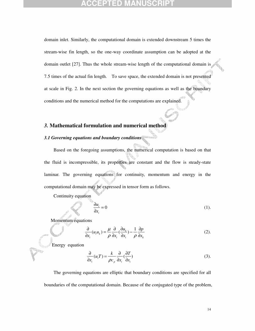
domain inlet. Similarly, the computational domain is extended downstream 5 times the
stream-wise fin length, so the one-way coordinate assumption can be adopted at the
domain outlet [27]. Thus the whole stream-wise length of the computational domain is
7.5 times of the actual fin length. To save space, the extended domain is not presented
at scale in Fig. 2. In the next section the governing equations as well as the boundary
conditions and the numerical method for the computations are explained.
3. Mathematical formulation and numerical method
3.1 Governing equations and boundary conditions
Based on the foregoing assumptions, the numerical computation is based on that
the fluid is incompressible, its properties are constant and the flow is steady-state
laminar. The governing equations for continuity, momentum and energy in the
computational domain may be expressed in tensor form as follows.
Continuity equation
0i
i
ux
∂ =∂
(1).
Momentum equations
1
( ) ( )ki k
i i i k
u pu u
x x x xµρ ρ
∂∂ ∂ ∂= −∂ ∂ ∂ ∂
(2).
Energy equation
( ) ( )ii p i i
k Tu T
x c x xρ∂ ∂ ∂=
∂ ∂ ∂ (3).
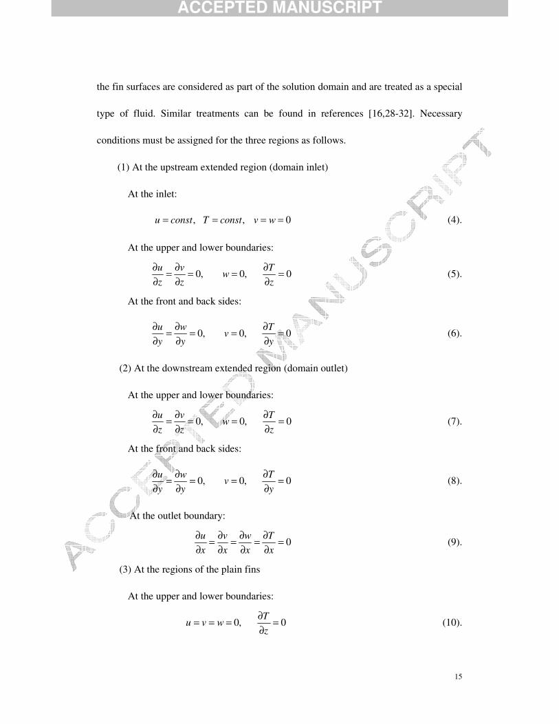
The governing equations are elliptic that boundary conditions are specified for all
boundaries of the computational domain. Because of the conjugated type of the problem,
ACCEPTED MANUSCRIPT
15
the fin surfaces are considered as part of the solution domain and are treated as a special
type of fluid. Similar treatments can be found in references [16,28-32]. Necessary
conditions must be assigned for the three regions as follows.
(1) At the upstream extended region (domain inlet)
At the inlet:
, , 0u const T const v w= = = = (4).
At the upper and lower boundaries:
0, 0, 0u v T
wz z z
∂ ∂ ∂= = = =∂ ∂ ∂
(5).
At the front and back sides:
0, 0, 0u w T
vy y y
∂ ∂ ∂= = = =∂ ∂ ∂
(6).
(2) At the downstream extended region (domain outlet)
At the upper and lower boundaries:
0, 0, 0u v T
wz z z
∂ ∂ ∂= = = =∂ ∂ ∂
(7).
At the front and back sides:
0, 0, 0u w T
vy y y
∂ ∂ ∂= = = =∂ ∂ ∂
(8).
At the outlet boundary:
0u v w Tx x x x
∂ ∂ ∂ ∂= = = =∂ ∂ ∂ ∂
(9).
(3) At the regions of the plain fins
At the upper and lower boundaries:
0, 0T
u v wz
∂= = = =∂
(10).
ACCEPTED MANUSCRIPT
16
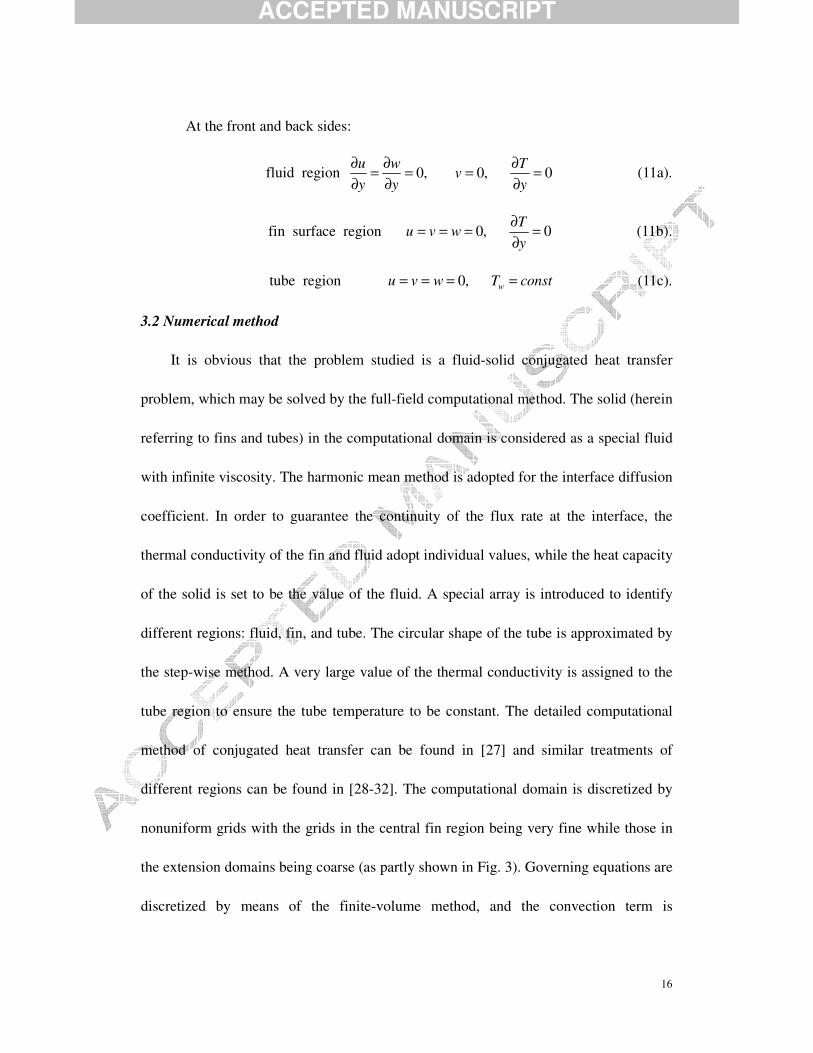
At the front and back sides:
fluid region 0, 0, 0u w T
vy y y
∂ ∂ ∂= = = =∂ ∂ ∂
(11a).
fin surface region 0, 0T
u v wy
∂= = = =∂
(11b).
tube region 0, wu v w T const= = = = (11c).
3.2 Numerical method
It is obvious that the problem studied is a fluid-solid conjugated heat transfer
problem, which may be solved by the full-field computational method. The solid (herein
referring to fins and tubes) in the computational domain is considered as a special fluid
with infinite viscosity. The harmonic mean method is adopted for the interface diffusion
coefficient. In order to guarantee the continuity of the flux rate at the interface, the
thermal conductivity of the fin and fluid adopt individual values, while the heat capacity
of the solid is set to be the value of the fluid. A special array is introduced to identify
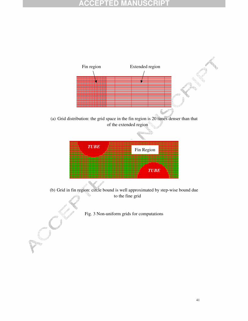
different regions: fluid, fin, and tube. The circular shape of the tube is approximated by
the step-wise method. A very large value of the thermal conductivity is assigned to the
tube region to ensure the tube temperature to be constant. The detailed computational
method of conjugated heat transfer can be found in [27] and similar treatments of
different regions can be found in [28-32]. The computational domain is discretized by
nonuniform grids with the grids in the central fin region being very fine while those in
the extension domains being coarse (as partly shown in Fig. 3). Governing equations are
discretized by means of the finite-volume method, and the convection term is
ACCEPTED MANUSCRIPT
17
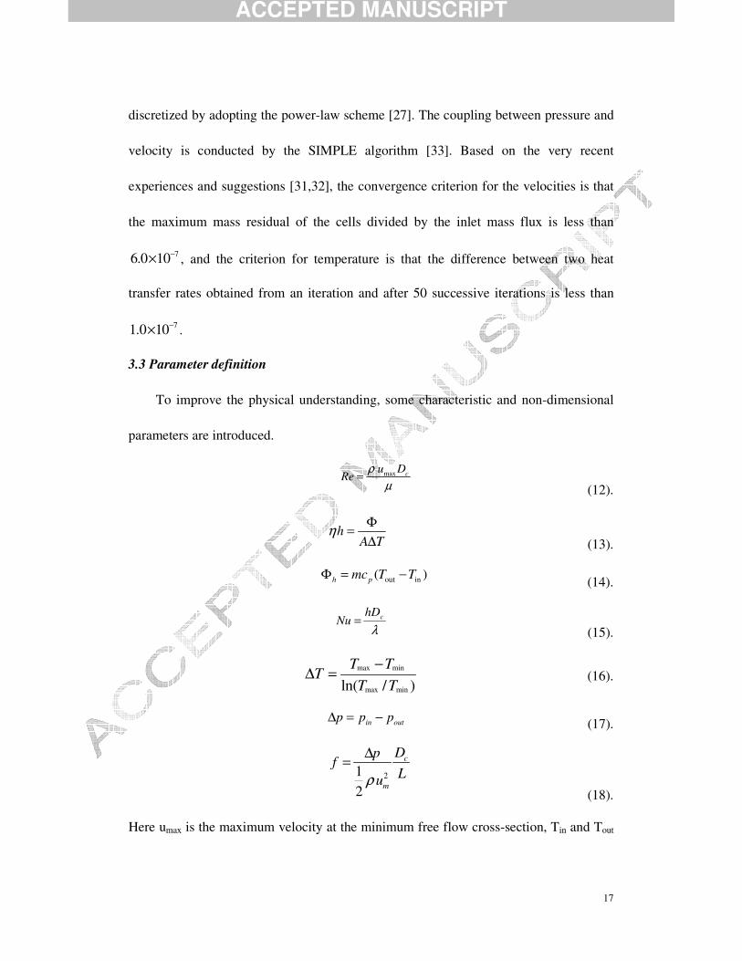
discretized by adopting the power-law scheme [27]. The coupling between pressure and
velocity is conducted by the SIMPLE algorithm [33]. Based on the very recent
experiences and suggestions [31,32], the convergence criterion for the velocities is that
the maximum mass residual of the cells divided by the inlet mass flux is less than
76.0 10−× , and the criterion for temperature is that the difference between two heat
transfer rates obtained from an iteration and after 50 successive iterations is less than
71.0 10−× .
3.3 Parameter definition
To improve the physical understanding, some characteristic and non-dimensional
parameters are introduced.
max cu D
Reρ
µ=
(12).
hA TΦ=∆
η (13).
out in( )h pmc T TΦ = − (14).
λchD
Nu = (15).
max min
max minln( / )T T
TT T
−∆ = (16).
in outp p p∆ = − (17).
212
c
m
Dpf
Luρ
∆=
(18).
Here umax is the maximum velocity at the minimum free flow cross-section, Tin and Tout
ACCEPTED MANUSCRIPT
18
are the bulk temperatures at the inlet and outlet section of the fin surface, respectively,
and ( )woutwin TTTTT −−= ,maxmax ( )woutwin TTTTT −−= ,minmin Pin and Pout are the
bulk pressures at inlet and outlet section of the fin surface, respectively.
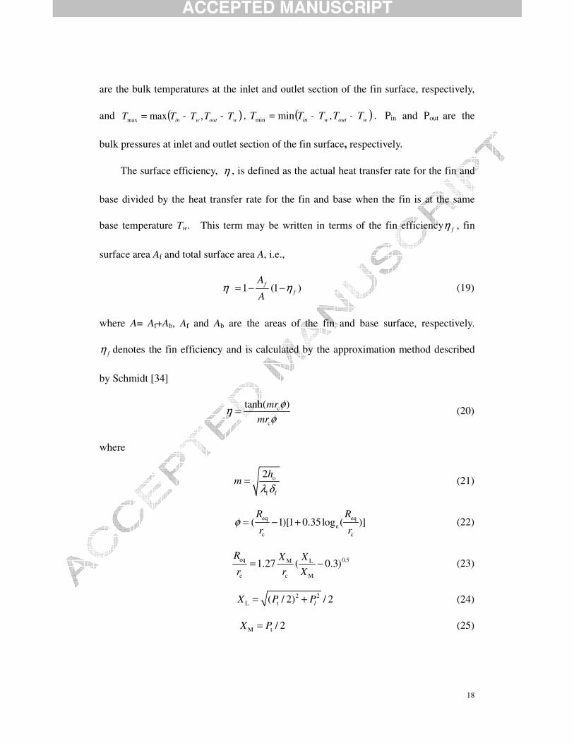
The surface efficiency, η , is defined as the actual heat transfer rate for the fin and
base divided by the heat transfer rate for the fin and base when the fin is at the same
base temperature Tw. This term may be written in terms of the fin efficiency fη , fin
surface area Af and total surface area A, i.e.,
1 (1 )ff
A
Aη η= − − (19)
where A= Af+Ab, Af and Ab are the areas of the fin and base surface, respectively.
fη denotes the fin efficiency and is calculated by the approximation method described
by Schmidt [34]
c
c
tanh( )mrmr
φηφ
= (20)
where
o
f f
2hm
λ δ= (21)
eq eqe
c c
( 1)[1 0.35log ( )]R R
r rφ = − + (22)
eq 0.5M L
c c M
1.27 ( 0.3)R X Xr r X
= − (23)
2 2L t( / 2) / 2lX P P= + (24)
M t / 2X P= (25)

ACCEPTED MANUSCRIPT
19
4. Validation of the model and grid independence
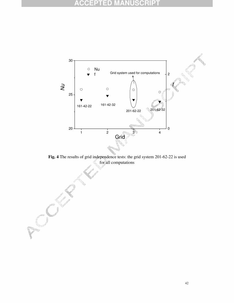
4.1 Grid independence
Before examining the effects of geometrical parameters on the performance of heat
transfer and flow friction, it is necessary to adopt an appropriate grid system for
computations in turn leading to a correct physical understanding. Thus a grid refinement
study was conducted to investigate the influence of the grid density on the
computational results. Four sets of grid system, 161-42-22, 161-42-32, 201-62-22 and
201-62-32 were selected to check the grid independence, and the computations are
performed for a case with Reynolds number being 3000. The results of the four sets of
grid system are shown in Fig. 4. By examining the results, the difference between
161-42-22, 161-42-32 and 201-62-22 is not so evident. Through the test experience for
the present model, it is found that the finer grid system will result in slightly smaller
Nusselt number and friction factor. Comparing the results on the finest grid 201-62-32
with those of the grid 201-62-22 yields 1.2% higher Nusselt number (being 25.86 and
25.39, respectively). Thus to save computer resources and keeping a balance between
computational economics and accuracy, the grid system 201-62-22 is adopted in all
computations. These are performed on a PC with a CPU frequency of 2.8G and a core
memory of 1G. A typical running time for computation of a case is about one to two
days, and all of cases composing 46 different tests will last more than three months.
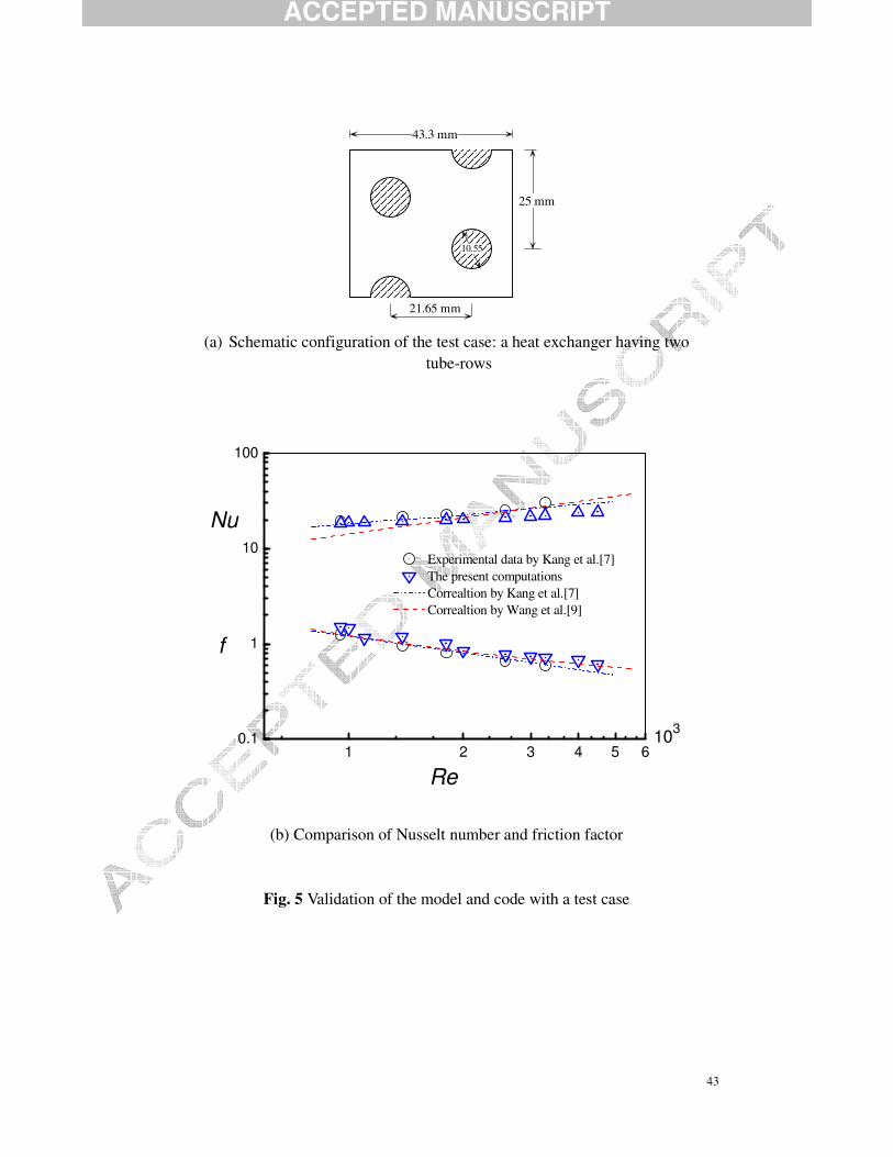
4.2 Validation of the computational model and code
Prior to conducting the computations for examination, it is very necessary to
ACCEPTED MANUSCRIPT
20
validate the computational model and the code developed in this study. Preliminary
computations were first conducted for a plain fin-and-tube heat exchanger having two
tube-rows, for which measurements had been performed by Kang et al. [7]. The
geometrical configuration is schematically shown in Fig. 5 (a). The predicted pressure
drop and Nusselt number were compared with the corresponding correlations as well as
experimental correlations established by Wang et al. [8-11] as shown in Fig. 5 (b). It has
to be recalled that the correlations developed by Wang et al. were developed based on
74 samples of plain fins and could describe 85.1% of the database for pressure drop and
88.6% of the database for heat transfer [9]. From the Fig. 5(b), the maximum deviation
in pressure drop and the Nusselt number are less than 15% with the average deviation
being around 8%. The good agreement between the predicted and tested results shows
the reliability of the physical model and the developed code.
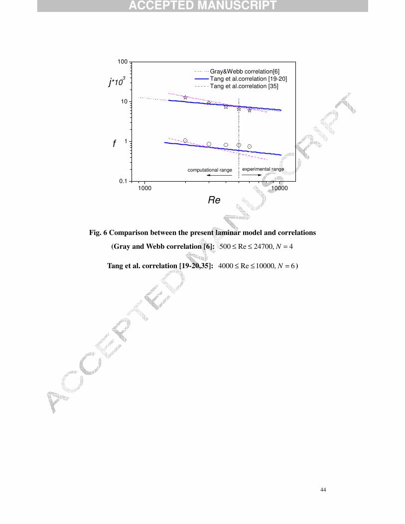
An additional comparison between the present numerical results and correlations
by Wang’s group [18-20, 35] was made, as shown in Fig.6. It should be noted that Tang
et al. [19-20] conducted experiments in the Reynolds number range from 4,000 to
10,000 because of restrictions of the wind tunnel capacity. Tang et al. [35] used the
commercial software FLUENT to compute turbulent heat transfer of the configuration
at Reynolds numbers being 4,000 to 8,000 flow status might be regarded as transition or
turbulent flow. The correlations by Gray and Webb [6] might predict the performance of
heat exchangers having large-diameter tubes, but the number of tube rows are restricted
to four. From the figure, the average deviation of the j-factors is around 10% while the
ACCEPTED MANUSCRIPT
21
average deviation of the f-factors is around 20% in the computational Re range. It may
not be reliable to extend the correlations developed in the experimental Re range are
extended to the low Re region where the laminar flow may occur. As one expects, the
heat transfer j-factor of the present computations is lower than that of the correlation
while the friction factor of the former is higher than that of the latter in the experimental
range.
As discussed in Section 2.2, a laminar flow model might be acceptable in the
computations. Thus from the above two comparisons, the presented model for
computations of laminar flow is validated for the specified Reynolds numbers of 1,000
to 6,000 in this study (ReDh=250~800, u=0.5~4 m/s). Similar validation can be found in
[28-32]. It is concluded that the desire to fill the data in low Reynolds number regions,
the laminar model for computations is accurate enough to predict the heat transfer and
friction characteristics of such heat exchangers in the industry applications with the inlet
frontal velocity usually being in the range of 2 to 4 m/s.
5. Numerical results and discussion
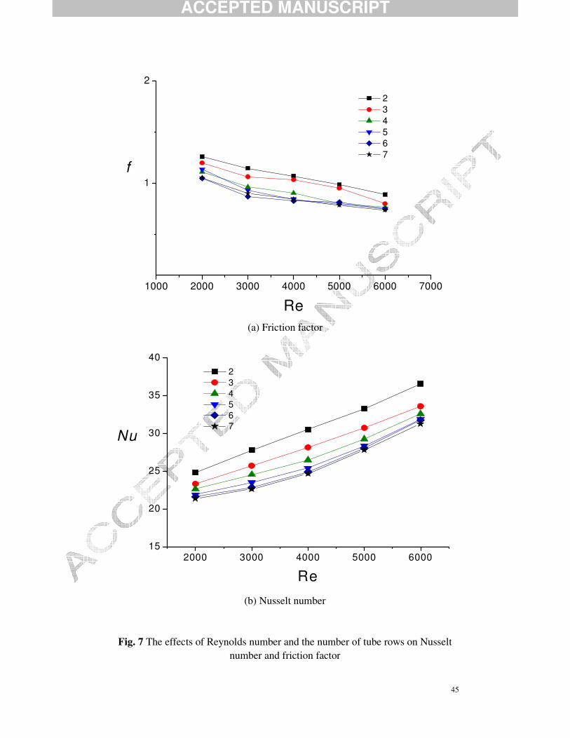
5.1 The effect of number of tube rows
First the effect of the number of tube rows on laminar heat transfer are examined
based on the nominal sizes: Do=18 mm, Pt=42 mm, Pl=34 mm, fin pitch=3 mm, while
the number of tube rows being varied from two to seven (N=2~7). The numerical
results of Nusselt number and friction factor with different number of tube-rows are

ACCEPTED MANUSCRIPT
22
shown in Fig. 7. The characteristics may be summarized as follows. Firstly, it is clear
for understanding that with the increase of Reynolds number the Nusselt number Nu
increases (hence the higher heat transfer) while the friction factor f decreases. Secondly,
one can carefully examine that the Nusselt number and friction factor are almost
identical to those of a heat exchanger with the number of tube rows being six when the
number of tube rows being larger than six. That is to say, the heat transfer and pressure
drop characteristics are independent upon the number of tube rows when this value is
larger than six, after which the heat transfer and fluid flow approach the fully developed
state. Thus for the present computational model, there is no need to compute the laminar
heat transfer when N>=8.
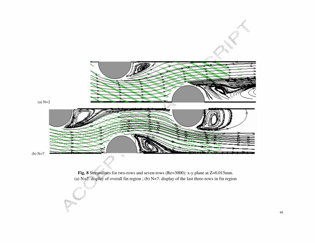
Figure 8 presents the local distributions of the streamlines for the middle section in
the x-y plane at z=0.015 between the upper and lower sides of the fin for Re=3000 and
N=2,7. For clearity reasons, the last three-rows distribution of N=7 is presented. It can
be clearly seen from the figure that there are larger recirculation zones behind each tube
of N=7 than those of N=2. It is recognized from fluid mechanics that a dead flow zone
is characterized by a stationary recirculation region that formed in such conditions that
the flow separates at the rear portion of a tube and reattaches ar the front of the
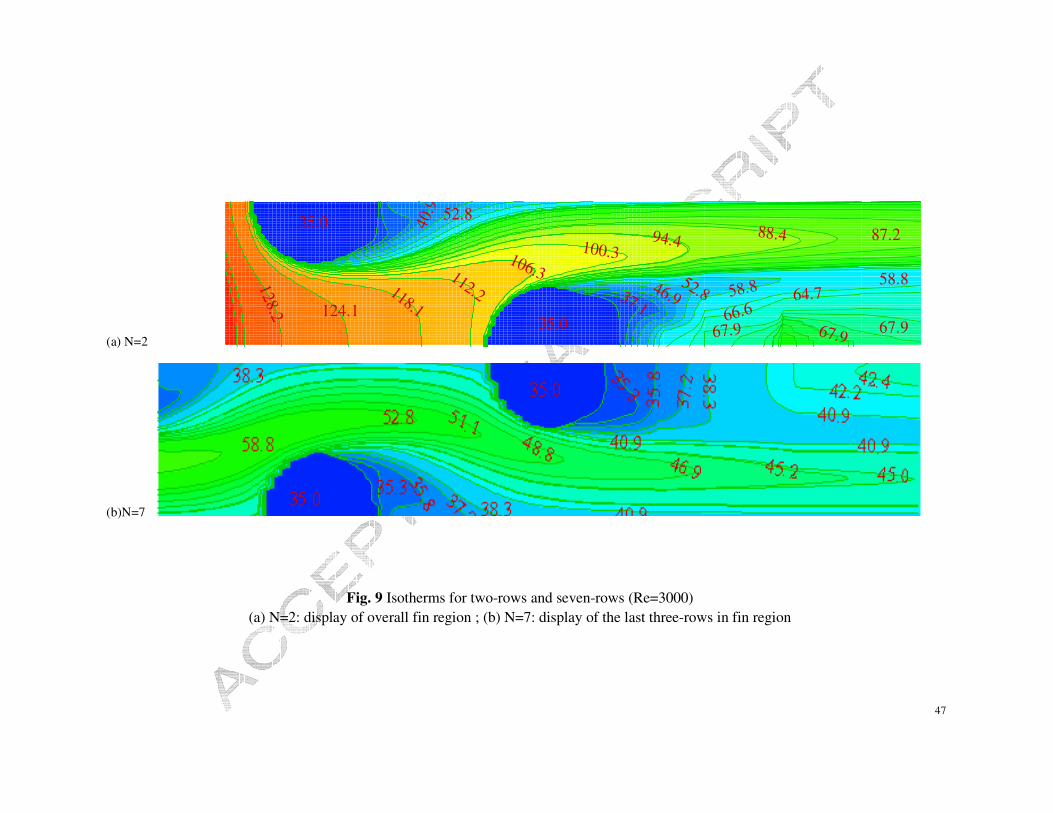
following tube. The dead flow zone will deteriorate the convective heat transfer. This
can be analyzed by Figure 9. Comparing the isotherms of N=2 and N=7, bigger
temperature gradients around tubes exist for the N=2, indicating a larger heat flux
between the tubes and fluid resulting in large local heat transfer and hence global heat
ACCEPTED MANUSCRIPT
23
transfer. This is reflected in the Nusselt number (hence the heat transfer coefficient),
which is larger for N=2 than for N=7. Another feature can be clearly seen in Fig. 9. The
convective heat transfer coefficient for N=7 approaches the fully developed state which
is characterized by a marked periodic temperature level while for N=2 the heat transfer
occurs in the inlet region.
5.2 The effect of tube diameter
Having examined the effects of the number of tube rows, it will be expected that
under different the number of tube rows the trends of effects of other parameters, e.g.,
fin pitch, tube diameter and tube pitch, might be similar. Thus for saving the
computational resources and the main objective is to observe the effects of fin pitch,
tube diameter and tube pitch, the computations are conducted under number of tube
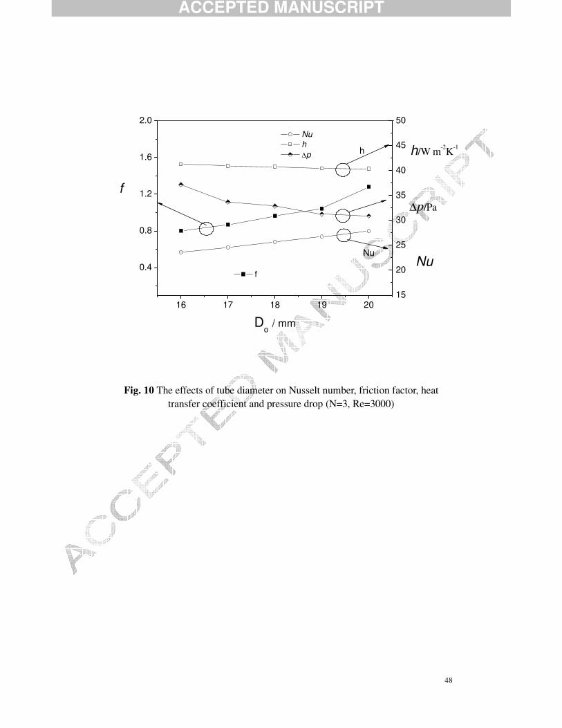
rows of three and the Reynolds number Re of 3000. Figure 10 shows the effect of the
tube diameter on laminar heat transfer. The tube diameter is varied from 16 mm to 20
mm. It can be seen that both the Nusselt number Nu and friction factor f increase with
increasing tube diameter. However, it will not indicate that both the heat transfer and
the pressure drop increase with the increase of tube diameter. Actually the heat
transfer coefficient decreases with increasing tube diameter. This is because that by
keeping the same Reynolds number at the definition of max /cRe u Dρ µ= , the increase
of tube diameter means a decrease in velocity, which results in decreases of the heat
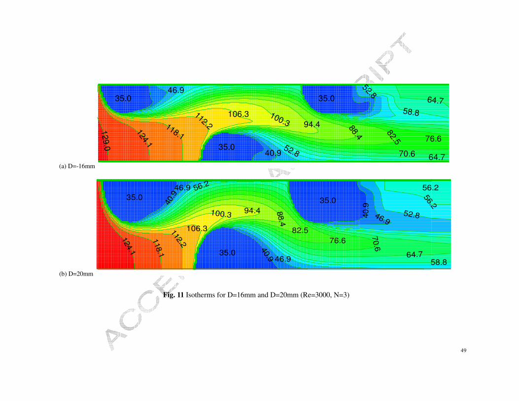
transfer coefficient and pressure drop. The isotherms on similar position for D=16
mm and D=20 mm are displayed in Figure 11. It can be clearly seen from the marked
ACCEPTED MANUSCRIPT
24
temperature level that there are bigger temperature gradients around tubes of D=20
mm than those of D=16 mm, indicating that a larger local heat flux, and hence global
heat transfer, occurs for D=20 mm. It can also be seen that the temperature gradient
along the longitudinal flow direction for D=20 mm is much larger than that of D=16
mm. Consequently it can be concluded that for a fixed Reynolds number the heat
transfer enhancement may be increased by increasing the diameter of the tubes
employed in finned-tube heat exchangers. In contrast, for a fixed inlet frontal velocity
the heat transfer can be improved by decreasing the tube diameter.
The idea to use smaller-diameter tubes in Refrigeration Engineering for heat
transfer enhancement is witnessed from this point. But for the present heat exchanger
which is applied for large inter-coolers with the cooling media being water, the
decrease of tube diameter will lead to decrease of heat transfer under the same water
velocity inside the tubes, while under the same mass flow rate the decrease of tube
diameter will lead to an increase of water velocity, resulting in larger pressure drop
inside the tube. According to the background of large inter-coolers, the heat transfer
and pressure drop should be considered at a balance for design and operation. Thus it
is an essential issue of investigating the heat exchanger with both tube diameter and
the number of tube rows being large, which fortunately is addressed in this study.
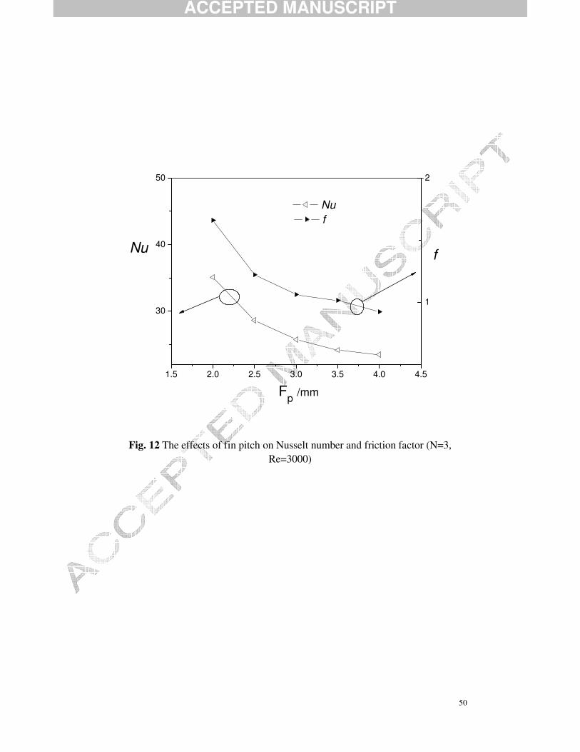
5.3 The effect of fin pitch
The effect of fin pitch on laminar heat transfer is shown in Fig. 12. The number of
tube rows is three and the Reynolds number is 3000. The fin pitch is ranging from 1.5
ACCEPTED MANUSCRIPT
25
mm to 4.5 mm. From the figure, it can be clearly seen that with the increase of fin pitch
the Nusselt number Nu and friction factor f decrease. That is, both the heat transfer and
pressure drop increase with the decrease of fin pitch. The decrease of fin pitch means
the decrease of space of channel width, resulting in higher velocity and temperature
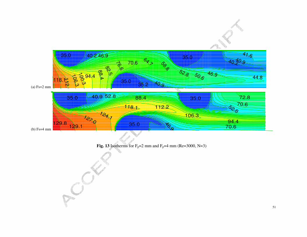
gradient at the fin wall, hence the higher pressure drop and heat transfer. Figure 13
presents the isotherms at similar positions for Fp=2 mm and Fp =4 mm. It also can be
clearly seen from the marked temperature level that the temperature gradients around
the tubes and along the flow direction of Fp=2 mm are larger than those of Fp=4 mm.
This feature can be interpreted so that a smaller fin pitch results in larger heat transfer.
It is a fact that for the fixed volume of the heat exchanger the compactness will increase
as the fin pitch decreases, since in this way more fins will be stacked together resulting
in enlargement of the extended fin surface area. So the pursuit of adding area will lead
to heat exchanger being more compact. At this point, by the use of narrow channel the
enhancement of heat transfer might be fulfilled.
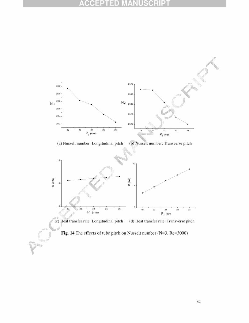
5.4 The effect of tube pitch
Figure 14 shows the effect of the tube pitch on laminar heat transfer. The number
of tube rows is three and the Reynolds number Re is fixed at 3000. The longitudinal
pitch is varied from 32 mm to 36 mm and the transverse pitch is varied from 19 mm to
23 mm (because of the symmetrical domain, the real transverse pitch is varied from 38
mm to 46 mm). Two features can be noted as follows. Firstly, it is found that for the
same air maximum velocity at minimum free flow cross-section, umax, the overall
ACCEPTED MANUSCRIPT
26
Nusselt number decreases with the increase of the tube pitch, shown in Fig.14(a) and
Fig.14(b). However, it is not stated that the heat transfer is decreased by increasing the
tube pitch under the fixing the Reynolds number. In fact, as shown in Fig.14(c) and
Fig.14(d), the heat transfer rate increases with the increase of tube pitch. Since the
Reynolds number and hence the maximum velocity is fixed, an increased of
span-wise/transverse tube pitch means an increased inlet/oncoming flow velocity hence
an improved heat transfer. Saying on the contrary way, if the oncoming flow velocity is
fixed the maximum velocity will be decreased by increasing the tube pitch, thus with a
fixed oncoming flow velocity the increase of tube pitches will lead to an decrease of
heat transfer. Similar trends can be found in previous works by He et al. [16].
Secondly, by comparing carefully on heat transfer rate, the effect of transverse pitch is
more pronounced than that of the longitudinal pitch. However, for the test ranges of the
tube pitches, the effects are relatively smaller than those of the tube diameter and fin
pitch.
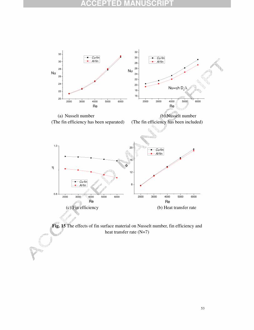
5.5 The effect of material of fin
The above numerical results are based on copper as the fin material. In some
certain applications, e.g., HVAC&R engineering, fin surfaces are widely made in
aluminum. In this study the effect will be observed by the numerical computations. The
results of the fin surface material in copper (labeled by Cu-fin) and aluminum (labeled
by Al-fin) are shown in Figure 15. The number of tube rows is seven while other
geometrical parameters are kept at nominal values. The individual feature for each
ACCEPTED MANUSCRIPT
27
sub-figure can be stated as follows. In Fig. 15(a), the Nusselt number of the Cu-fin is
smaller than that of the Al-fin. This will not indicate that the heat transfer of Al-fin is
higher than that of Cu-fin. Recall that in Eq. (13) and Eq. (15) the heat transfer
coefficient is separated from the total heat transfer coefficient (although in some
countries like Japan or Korea the heat transfer coefficient includes the fin surface
efficiency). The total heat transfer coefficients, including the fin surface efficiency, are
shown in Fig. 15 (b). It can be clearly seen that the Nusselt number of the Cu-fin is
much higher than that of the Al-fin. Without further thinking one might get the
impression that the features from Fig. 15(a) and Fig. 15(b) seem inconsistent. In this
situation, a further analysis should clarify this. Going back to Eq. (20) and Eq. (21),
the increase of the fin thermal conductivity will lead to a decrease of mH, resulting in an
increase of the fin efficiency due to the characteristics of the tangent function. The
thermal conductivity of the Cu-fin is 398 W/(m.K) while that of the Al-fin is 170
W/(m.K). Obviously, for the same conditions the efficiency of the Cu-fin is surely larger
than that of the Al-fin. This feature is confirmed in Fig. 15(c). Another traditional
feature is that the fin efficiency decreases as the Reynolds number is increasing. The
heat transfer rate for the two kinds of fins are compared in Fig. 15(d). By examining
carefully, it is found that the heat transfer rate of the Cu-fin is higher than that of the
Al-fin. Therefore a somewhat important conclusion is that the heat transfer performance
of the fin surface will be enhanced especially at high air velocities, since higher thermal
conductivity of the fin surface will lead to a smaller thermal resistance.
ACCEPTED MANUSCRIPT
28
6. Multiple correlations
6.1 The assumed form of correlations
Based on the above series of parametric computations, it is not sufficient to end up
only with the numerical results, but the data of heat transfer and flow friction should be
compressed in compact form so that further studies are enabled. This is a common way
to follow because it is of interest to extend the heat transfer and friction factor data at
other conditions than those included in the present computations. Based on the
principle of similarity theory, the present data can be extrapolated or interpolated to
other conditions by established correlations. For this reason, it is useful to try to obtain
suitable correlations. This is another direct motivation of the present study. A
question may arise whether or not correlations already exist that can predict the
performance of the present heat exchanger. According to the authors’ knowledge, no
suitable correlations can be applied in such heat exchangers with the tube diameter
around 18 mm and the number of tube-rows being larger than six. The most accurate
and reliable correlations, developed by Wang et al. [8-11], with wide validation ranges
is known to the present authors. However, it is again noted that the valid range for the
tube diameter is between 6.35 mm and 12.7 mm, which is much smaller than that of the
present model (Do=18 mm).
The forms for correlations may be diversified, however, in order to reduce the
difficulty involved in correlating the data and to refer to previous forms, the following
forms are assumed.
ACCEPTED MANUSCRIPT
29
2 3 4
1 Re ( ) ( )p tC C C
o l
F Pf C N
D P= ⋅
(26)
2 3 41 Re ( ) ( )p tC C C
o l
F PNu C N
D P= ⋅
(27)
The four coefficients C1 C2 C3 C4 should be determined by means of multiple
regression technique rather than log-linear regression, which can be used to correlate a
very simple form like logNu=C1+C2*logRe. The brief idea of multiple regression is
described as follows.
6.2 Brief description of multiple regression
Consider a variable y which is related to the decision variables x1, x2,…, xM-1, xM.
The data, obtained by computations or measurements are as presented as follows.
,1 ,2 ,3 , 2 , 1 ,( , , ,....., , , ; ) , 1, 2,..., 1,t t t t M t M t M tx x x x x x y t Nd Nd− − = −
Assume that the form of regression equations is
0 1 1 1 1ˆt M M M My b b x b x b x− −= + + + +� (28)
It should be noted that the form of Eqs. (26) and (27) can be transformed into the
form of Eq. (28) by adopting the logarithm on the two sides of these equations with
1 2 3Re, ,p t
o l
F Px x N x
D P= = ⋅ = .
Thus the residual error is
2
1
ˆ( )N
t t
t
EQ y y=
= −∑ (29)
By using the least square theorem and the extremum theorem to find the minimum
of EQ, the following equations yield
ACCEPTED MANUSCRIPT
30
0 1 1
0M M
EQ EQ EQ EQb b b b−
∂ ∂ ∂ ∂= = = = =∂ ∂ ∂ ∂
�
(30)
The above equation can be organized as
( )T TX X b X Y=�� � � �
(31)
where
1 11 12 1 1
1 21 22 2 1
1 2
11
, ,
1
M
M
Nd Nd Nd NdM Nd
y x x x by x x x b
Y X b
y x x x b
= = =
�
�� � �
� � � � � � �
�
.
Denoting 1( ) , ,T TA X X B X Y C A−= = =� � � �
, Eq. (31) can be written as
1Ab B b CB A B−= ==> = =� �
(32)
Finally, by solving the above equation, Eq. (32), the coefficients b0, b1, .. , bM can be
obtained.
6.3 Multiple correlations
For the assumed form of the heat transfer and friction factor correlations, there are
three decision variables, 1 2 3Re, ,p t
o l
F Px x N x
D P= = ⋅ = , and four coefficients to be
determined: 1 1 2 2 3 3 4 4log , log , log , logb C b C b C b C= = = = . Having introduced the idea
of multiple regression, Eq. (32) is then solved by encoding the program in FORTRAN,
based on the foregoing numerical data. After solving the equation, the four
coefficients are determined as follows.
C1 20.713 C2 -0.3489 C3 -0.1676 C4 0.6562
The correlation for the friction factor becomes
0.3489 0.1676 0.626520.713Re ( ) ( )p t
o l
F Pf N
D P− −= ⋅
(33)
ACCEPTED MANUSCRIPT
31
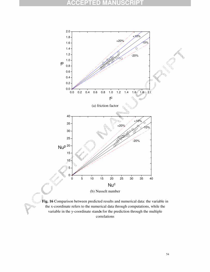
By using the correlation, the predicted results and original data are compared as
shown in Fig. 16(a). 85% of the deviations are within 10%, and the average deviation
is around 6.5%, indicating that the correlation is of sufficient accuracy.
A similar treatment for solving the transformed form of Eq. (27), gives the
corresponding four coefficients as follows.
C1 1.565 C2 0.3414 C3 -0.165 C4 0.0558
The correlation for the Nusselt number is then written as
0.3414 0..165 0.05581.565Re ( ) ( )p t
o l
F PNu N
D P−= ⋅ (34)
The predicted results and numerical data are compared as shown in Fig. 16(b). All
deviations are within 10%, and the average deviation is around 3.7%, indicating that the
heat transfer correlation is of sufficient accuracy. Thus the heat transfer and fluid flow
correlations are established as the forms of Eq.(33) and Eq.(34), and here it should be
organized again that the application ranges of the present correaltions are listed as
follows:
0.67 ~ 4.0 m/s, Re 1000 ~ 6000, 16 ~ 20 mm2 ~ 4 mm, 38 ~ 46 mm, 32 ~ 36 mm
fr o
t l
V D
Fp P P
= = == = = .
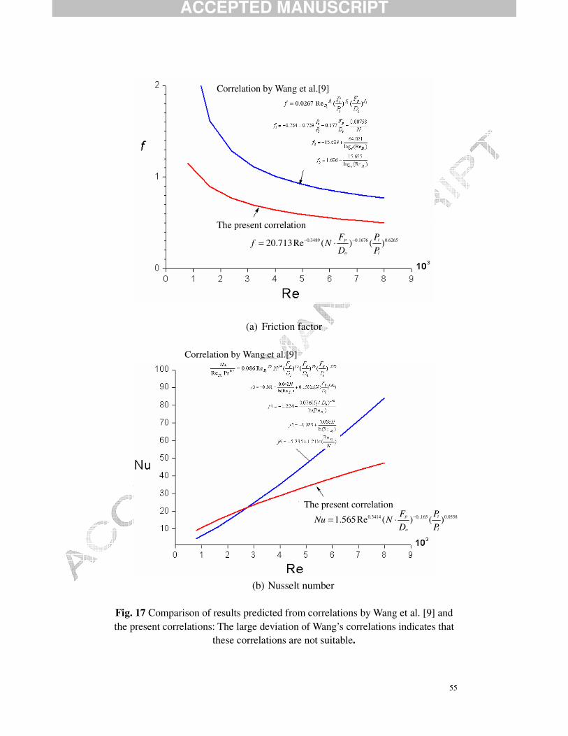
Returning back to the analysis of applying the correlations by Wang et al. [8-11], a
comparison of the results are now shown in Fig. 17. Clearly, the predicted results by
such correlations are far from the present computations. This is maybe because the
established correlations have some certain application ranges, and the present
geometerical parameters, e.g., the tube diameter and tube longtitudinal pitch are 18 mm
ACCEPTED MANUSCRIPT
32
and 34 mm, respectively, are beyond the bounding values of 12.7 mm and 32 mm,
respectively. Although the correlations developed by Wang et al. are so-far of much
accurcy, the prediced results by those correlations are not valid for design the present
heat exchangers. At this point, it is essential and necessary to develop corresponding
correlations based on the numerical computations, and in turn more work such as
optimization or prediction will be moved extensively forward.
7. Conclusions
In this paper, 3D-computations on air-side laminar flow and heat transfer of plain
fin-and-tube heat exchangers are conducted to reveal the effects of Reynolds number,
the number of tube rows, diameter of tube, fin pitch and tube pitch on the overall
Nusselt number and friction factor. Also the effect of the fin surface material is
observed. Based on the numerical results, the heat transfer and flow friction correlations
are established. The major findings are summarized as follows.
(1). The Nusselt number and friction factor decrease with the increase of the
number of tube rows, and the laminar flow and heat transfer are fully developed when
the number of tube rows is larger than six.
(2). An increase of tube diameter or fin pitch decreases the heat transfer and
pressure drop. The effects of tube pitch are relatively smaller than that of tube diameter
and fin pitch.
(3). The heat transfer for a fin surface material with a large thermal conductivity
ACCEPTED MANUSCRIPT
33
can be enhanced due to the decrease of the thermal resistance. The operational air
velocity has also a significant effect.
(4). Due to the lack of suitable correlations applicable for the present heat
exchanger, multiple correlations of the Nusselt number and friction factor have been
established.
Acknowledgments
This work is supported by National Nature Science Foundation of China
(No.50521604) and Program for New Century Excellent Talents in University (No.
NCET-04-0938).
References
[1]. F.C.McQuiston, D.R.Tree, Heat transfer and flow friction data for two fin-tube
surfaces, ASME J. Heat Transfer, 93(1971) 249-250.
[2]. D.G.Rich, The effect of fin spacing on the heat transfer and friction performance of
multi-row, smooth plate fin-and-tube heat exchangers, ASHRAE Transaction, ,
79(1973) 135-145.
[3]. D.G.Rich, The effect of the number of tubes rows on heat transfer performance of
smooth plate fin-and-tube heat exchangers, ASHRAE Transaction, 81(1975)
307-317.
[4]. F.C.McQuiston, Heat mass and momentum transfer data for five plate-fin-tube heat
transfer surfaces, ASHRAE Transaction, Part 1, 84(1978) 266-293.
[5]. F.C.McQuiston, Correlation of heat mass and momentum transport coefficients for
plate-fin-tube heat transfer surfaces with staggered tubes, ASHRAE Transaction,
ACCEPTED MANUSCRIPT
34
Part 1, 84(1978) 294-308.
[6]. D.L.Gray, and R.L.Webb, Heat transfer and friction correlations for plate
fin-and-tube heat exchangers having plain fins, Proc. 8th International Heat
Transfer Conference, San Francisco, California, vol. 6, pp. 2745-2750, 1986.
[7]. H.J.Kang, W.Li, H.J.Li, R.C.Xin, and W.Q.Tao, Experimental Study on Heat
Transfer and Pressure Drop Characteristics of Four Types of Plate Fin-and-Tube
Heat Exchanger Surfaces, J. Thermal Science, 3(1994) 34–42.
[8]. C.C.Wang, and K.Y.Chi, Heat transfer and friction characteristics of plate
fin-and-tube heat exchangers, part I: new experimental data, Int. J. Heat Mass
Transfer, 43(2000) 2681-2691.
[9]. C.C.Wang, K.Y.Chi, and C.J.Chang, Heat transfer and friction characteristics of
plate fin-and-tube heat exchangers, part II: Correlation, Int. J. Heat Mass Transfer,
43(2000) 2693-2700.
[10]. C.C.Wang, Recent Progress on the Air-Side Performance of Fin-and-Tube Heat
Exchangers, Int. J. Heat Exchangers, 2(2000) 57-84.
[11]. C.C.Wang, Heat Exchanger Design, Taiwan: Wunan Press, China, 2003. (In
Chinese)
[12]. A.Bestani, N.K.Mitra, and M.Fiebig, Numerical simulation of flow field in a fin
tube heat exchanger, ASME J. Fluids Engineering, 101(1990) 91-96.
[13]. K.Torikoshi, G.Xi, Y.Nakazama, and H.Asano, Flow and heat transfer performance
of a plate-fin and tube heat exchanger, Heat Transfer, 4(1994) 411-416.
[14]. J.Y.Jang, M.C.Wu, and W.J.Chang, Numerical and experimental studies of
three-dimensional plate-fin and tube heat exchangers, lnt. J. Heat Mass Transfer,
39(1996) 3057-3066.
[15]. J.Y.Jang, and J.Y.Yang, Experimental and 3-D numerical analysis of the
thermal-hydraulic characteristics of elliptic finned-tube heat exchangers, Heat
Transfer Engineering, 19(1998) 55-67.
[16]. Y. L.He, W.Q.Tao, F.Q.Song, and W.Zhang, Three-dimensional numerical study of
ACCEPTED MANUSCRIPT
35
heat transfer characteristics of plain plate fin-and-tube heat exchangers from view
point of field synergy principle, Int. J. Heat Fluid Flow, 6(2005) 459-473.
[17]. A.Erek, B.Ozerdem, and L.Bilir, Effect of geometrical parameters on heat transfer
and pressure drop characteristics of plate fin and tube heat exchangers, Applied
Thermal Engineering, 25(2005) 2421-2431.
[18]. G.N.Xie., Improvements of fin-and-tube heat exchangers and their Design
Optimizations, Ph.D. Thesis, School of Energy and Power Engineering, Xi’an
Jiaotong University, 2007. (In Chinese)
[19]. L.H.Tang, M.Zeng, G.N.Xie, and Q.W.Wang, Fin pattern effects on air-side heat
transfer and friction characteristics of fin-and-tube heat exchangers with large
number of large-diameter tube rows, Heat Transfer Engineering, accepted, 2007.
[20]. L.H.Tang, G.N.Xie, M.Zeng, H.G.Wang, X.H.Yan, and Q.W.Wang, Experimental
investigation on heat transfer and flow friction characteristics in three types of
plate fin-and-tube heat exchangers, Journal of Xi'an Jiaotong University, 41(2007):
521-525. (In Chinese)
[21]. G.N.Xie, Q.W.Wang, and B.Sunden, Application of a genetic algorithm for
thermal design of fin-and-tube heat exchangers, Heat Transfer Engineering,
accepted, in press, 2007.
[22]. G.N.Xie, B.Sunden, and Q.W.Wang, Optimization of Compact Heat Exchangers
by a Genetic Algorithm Applied Thermal Engineering accepted, in press, 2007.
[23]. G.N.Xie, Q.Y.Chen, M.Zeng, and Q.W.Wang, Thermal design of heat exchangers
with fins inside and outside of tubes, Proceedings of GT2006, ASME Turbo Expo
2006, May 8-11, 2006, Barcelona, Spain. Paper.no GT2006-90260.
[24]. G.N.Xie, Q.W.Wang, and M.Zeng, Genetic algorithm based design and
optimization of outer-fins and inner-fins tube heat exchangers, Proceedings of
GT2007, ASME Turbo Expo 2007, May 14-17, 2007, Montreal, Canada. Paper.no
GT2007-27889.
[25]. G.N.Xie, Q.W.Wang, M.Zeng, and L.Q.Luo, Heat transfer analysis for
ACCEPTED MANUSCRIPT
36
shell-and-tube heat exchangers with experimental data by artificial neural networks
approach, Applied Thermal Engineering, 27(2007) 1096-1104.
[26]. Q.W.Wang, G.N.Xie, M.Zeng, and L.Q.Luo, Prediction of heat transfer rates for
shell-and-tube heat exchangers by artificial neural network approach, Journal of
Thermal Science, 15(2006) 257-262.
[27]. W.Q.Tao, Numerical Heat Transfer, 2d ed., Xi’an Jiaotong University Press, Xi
an, China, 2001. (In Chinese)
[28]. Y.P.Cheng Z.G.Qu and W.Q.Tao, Numerical design of efficient slotted fin
surface based on the field synergy principle, Numerical Heat Transfer, Part A,
45(2004) 517-538.
[29]. Z.G.Qu, W.Q.Tao, and Y.L.He, 3D numerical simulation on laminar heat transfer
and fluid flow characteristics of strip fin surface with X-arrangement of strip,
ASME J. Heat Transfer, 126(2004) 69-707.
[30]. J.J.Zhou, and W.Q.Tao, Three dimensional numerical simulation and analysis of
the airside performance of slotted fin surfaces with radial strips, Engineering
Computations, 22(2005) 940-957.
[31]. W.Q.Tao, W.W.Jin, Y.L.He, Z.G.Qu, and C.C.Zhang, Optimum design of two-row
slotted fin surface with x-shape strip arrangement positioned by ‘‘front coarse and
rear dense’’ principle, Part I: physical/mathematical models and numerical methods.
Numerical Heat Transfer, Part A, 50(2006) 731-749.
[32]. W.W.Jin, Y.L.He, Z.G.Qu, and W.Q.Tao, Optimum design of two-row slotted fin
surface with x-shape strip arrangement positioned by “front coarse and rear dense”’
principle, Part II: results and discussion. Numerical Heat Transfer, Part A ,
50(2006) 751-771.
[33]. S.V.Patankar, Numerical Heat Transfer and Fluid Flow, McGraw-Hill, New York,
1980.
[34]. T.E.Schmidt, Heat transfer calculations for extended surfaces, Refrigerating
Engineering, 57(1949) 351-357.

ACCEPTED MANUSCRIPT
37
[35]. L.H.Tang, G.N.Xie, M.Zeng, Q.W.Wang, Numerical simulation of fin patterns on
air-side heat transfer and flow friction characteristics of fin-and-tube heat
exchangers, Proceedings of ASCHT07, 1st Asian Symposium on Computational
Heat Transfer and Fluid Flow, October 18-21, 2007, Xi’an, China.

ACCEPTED MANUSCRIPT
38
Figure Captions Fig. 1 A typical fin-and-tube heat exchanger
Fig. 2 Schematic configuration of a heat exchanger
Fig. 3 Non-uniform grids for computations
Fig. 4 The results of grid independence tests
Fig. 5 Validation of the model and code with a test case
Fig. 6 Comparison between the present laminar model and correlations
Fig. 7 The effects of Reynolds number and the number of tube rows on
Nusselt number and friction factor
Fig. 8 Streamlines for two-rows and seven-rows (Re=3000)
Fig. 9 Isotherms for two-rows and seven-rows (Re=3000)
Fig. 10 The effects of tube diameter on Nusselt number, friction factor, heat
transfer coefficient and pressure drop
Fig. 11 Isotherms for D=16mm and D=20mm (Re=3000)
Fig. 12 The effects of fin pitch on Nusselt number and friction factor
Fig. 13 Isotherms for Fp=2 mm and Fp=4 mm (Re=3000)
Fig. 14 The effects of tube pitch on Nusselt number
Fig. 15 The effects of fin surface material on Nusselt number, fin efficiency
and heat transfer rate
Fig. 16 Comparison between predicted results and original data
Fig. 17 Comparison of results from correlations by Wang et al. [9] and the
present correlations
ACCEPTED MANUSCRIPT
39
Fig.1 A typical fin-and-tube heat exchanger
(The gas, such as air or fuel gas, needs to be cooled, flows normal to the finned bundle and the cooling liquid, such as a refrigerant or water, flows through the tubes.
Industrial applications are, e.g., air-coolers, fan coils, heaters, and inter- coolers, etc.)
Liquid (refrigerant, or water)
Gas (air, or fuel gas)
ACCEPTED MANUSCRIPT
40
Air
tPtP tP
x
x
zy
y
z
x
Tube
Fin
oD
lP
pF
fδ
Extended domain
(a)(b)
(d)
(c)
Air
Extended domain Fin domain
Fig. 2 Schematic configuration of a heat exchanger (for saving space, a configuration of three tube-rows is shown, not the fixed
geometry for all computations in this study) (a) The overall core: air flows across the finned bundle. (b) Cross-section in z-x plane: computational domain is selected as the space
between two adjacent fin surfaces and the shaded extended regions bounded by dashed lines.
(c) Cross-section in y-x plane: the tubes are in staggered arrangement. (d) Cross-section of computational domain in y-x plane: extensions at entrance
1.5 fin length, at exit 5 fin lengths, respectively.
ACCEPTED MANUSCRIPT
41
(a) Grid distribution: the grid space in the fin region is 20 times denser than that of the extended region
(b) Grid in fin region: circle bound is well approximated by step-wise bound due to the fine grid
Fig. 3 Non-uniform grids for computations
Fin region Extended region
Fin Region
TUBE
TUBE
ACCEPTED MANUSCRIPT
42
1 2 3 420
25
30
0
2
201-62-32201-62-22
161-42-32
Nu
f
Nu
Grid
161-42-22
Grid system used for computations f
Fig. 4 The results of grid independence tests: the grid system 201-62-22 is used for all computations
ACCEPTED MANUSCRIPT
43
43.3 mm
21.65 mm
10.55
25 mm
(a) Schematic configuration of the test case: a heat exchanger having two
tube-rows
1 2 3 4 5 60.1
1
10
100
Experimental data by Kang et al.[7] The present computations Correaltion by Kang et al.[7] Correaltion by Wang et al.[9]
f
Nu
Re
103
(b) Comparison of Nusselt number and friction factor
Fig. 5 Validation of the model and code with a test case
ACCEPTED MANUSCRIPT
44
1000 100000.1
1
10
100
Gray&Webb correlation[6] Tang et al.correlation [19-20] Tang et al.correlation [35]
computational range
f
j*103
Re
experimental range
Fig. 6 Comparison between the present laminar model and correlations
(Gray and Webb correlation [6]: 500 Re 24700, 4N≤ ≤ =
Tang et al. correlation [19-20,35]: 4000 Re 10000, 6N≤ ≤ = )
ACCEPTED MANUSCRIPT
45
1000 2000 3000 4000 5000 6000 7000
1
2
2 3 4 5 6 7
f
Re
(a) Friction factor
2000 3000 4000 5000 600015
20
25
30
35
40 2 3 4 5 6 7
Nu
Re
(b) Nusselt number
Fig. 7 The effects of Reynolds number and the number of tube rows on Nusselt number and friction factor
ACCEPTED MANUSCRIPT
46
(a) N=2
(b) N=7
Fig. 8 Streamlines for two-rows and seven-rows (Re=3000): x-y plane at Z=0.015mm. (a) N=2: display of overall fin region ; (b) N=7: display of the last three-rows in fin region
ACCEPTED MANUSCRIPT
47
(a) N=2
128.2 124.1118.1
112.2
106.3100.3
94.4 88.435.0
35.0
58.8 64.737.1
87.2
58.8
67.967.967.966.6
40.9 52.8
46.952.8
(b)N=7
Fig. 9 Isotherms for two-rows and seven-rows (Re=3000) (a) N=2: display of overall fin region ; (b) N=7: display of the last three-rows in fin region
ACCEPTED MANUSCRIPT
48
16 17 18 19 20
0.4
0.8
1.2
1.6
2.0
15
20
25
30
35
40
45
50
f
∆p/Pa
Nu
h/W m-2K-1
f
Do / mm
h
Nu
Nu h ∆p
Fig. 10 The effects of tube diameter on Nusselt number, friction factor, heat transfer coefficient and pressure drop (N=3, Re=3000)
ACCEPTED MANUSCRIPT
49
(a) D=-16mm
124.1
118.1
112.2106.3 100.3 94.4 88.4 82.5
35.0
35.0
35.0
129.0
64.758.8
76.6
46.9
52.852.840.9 70.6 64.7
(b) D=20mm
35.0
35.035.0
124.1
118.1
112.2
106.3
100.3 94.4
56.2
56.2
52.846.9
70.676.682.5
88.4
64.758.846.9
46.9 56.2
4 0.9
40.9
40.9
Fig. 11 Isotherms for D=16mm and D=20mm (Re=3000, N=3)
ACCEPTED MANUSCRIPT
50
1.5 2.0 2.5 3.0 3.5 4.0 4.5
30
40
50
1
2
Nu
Nu
Fp /mm
f
f
Fig. 12 The effects of fin pitch on Nusselt number and friction factor (N=3, Re=3000)
ACCEPTED MANUSCRIPT
51
(a) Fs=2 mm
35.0
35.0
35.0
118.1
112.2106.3
100.3
94.4
88.482.5
76.6
70.664.7 58.8
52.8 46.9
41.640.940.2
35.2 40.9
40.2 46.9
50.6 44.8
(b) Fs=4 mm
35.0
35.0
35.0
129.8129.1
127.0
124.1
118.1 112.2
106.3
72.870.652.8
94.470.6
46.9
40.9 52.8 88.4
Fig. 13 Isotherms for Fp=2 mm and Fp=4 mm (Re=3000, N=3)
ACCEPTED MANUSCRIPT
52
32 33 34 35 36
25.2
25.4
25.6
25.8
26.0
26.2
Nu
Pl
(mm)19 20 21 22 23
25.60
25.65
25.70
25.75
25.80
Pt /mm
Nu
(a) Nusselt number: Longitudinal pitch (b) Nusselt number: Transverse pitch
32 33 34 35 366
8
10
Φ (k
W)
Pl
(mm)19 20 21 22 23
6
8
10
Pt /mm
Φ (k
W)
(c) Heat transfer rate: Longitudinal pitch (d) Heat transfer rate: Transverse pitch
Fig. 14 The effects of tube pitch on Nusselt number (N=3, Re=3000)
ACCEPTED MANUSCRIPT
53
2000 3000 4000 5000 600020
22
24
26
28
30
32
Nu
Re
Cu-fin Al-fin
2000 3000 4000 5000 6000
16
18
20
22
24
26
28
30
32
Cu-fin Al-fin
Nu
Re
Nu=ηh Dc/λ
(a) Nusselt number (b) Nusselt number (The fin efficiency has been separated) (The fin efficiency has been included)
2000 3000 4000 5000 60000.8
1.0
Cu-fin Al-fin
η
Re2000 3000 4000 5000 6000
8
12
16
20 Cu-fin Al-fin
Φ
Re (c) Fin efficiency (b) Heat transfer rate
Fig. 15 The effects of fin surface material on Nusselt number, fin efficiency and heat transfer rate (N=7)
ACCEPTED MANUSCRIPT
54
0.0 0.2 0.4 0.6 0.8 1.0 1.2 1.4 1.6 1.8 2.00.0
0.2
0.4
0.6
0.8
1.0
1.2
1.4
1.6
1.8
2.0
fp
-10%
+10%
-20%
fc
+20%
(a) friction factor
0 5 10 15 20 25 30 35 400
5
10
15
20
25
30
35
40
Nup
-10%
+10%
-20%
Nuc
+20%
(b) Nusselt number
Fig. 16 Comparison between predicted results and numerical data: the variable in the x-coordinate refers to the numerical data through computations, while the
variable in the y-coordinate stands for the prediction through the multiple correlations
ACCEPTED MANUSCRIPT
55
(a) Friction factor
(b) Nusselt number
Fig. 17 Comparison of results predicted from correlations by Wang et al. [9] and the present correlations: The large deviation of Wang’s correlations indicates that
these correlations are not suitable.
0.3489 0.1676 0.626520.713Re ( ) ( )p t
o l
F Pf N
D P− −= ⋅
0.3414 0..165 0.05581.565Re ( ) ( )p t
o l
F PNu N
D P−= ⋅
Correlation by Wang et al.[9]
Correlation by Wang et al.[9]
The present correlation
The present correlation


![[Bengt B. Broms] Lateral Resistance of Pile](https://img.pdfslide.us/doc/110x75/577c7ad21a28abe0549643cd/bengt-b-broms-lateral-resistance-of-pile.jpg)