Embed Size (px)
Citation preview

USER'S GUIDE
Vaisala CARBOCAP® Carbon Dioxide ProbeGMP343
M210514EN-C

PUBLISHED BY
Visit our Internet pages at http://www.vaisala.com/
© Vaisala 2007
No part of this manual may be reproduced in any form or by any means, electronic or mechanical (including photocopying), nor may its contents be communicated to a third party without prior written permission of the copyright holder.
The contents are subject to change without prior notice.
Please observe that this manual does not create any legally binding obligations for Vaisala towards the customer or end user. All legally binding commitments and agreements are included exclusively in the applicable supply contract or Conditions of Sale.
Vaisala Oyj Phone (int.): +358 9 8949 1P.O. Box 26 Fax: +358 9 8949 2227FIN-00421 HelsinkiFinland
________________________________________________________________________________
Table of Contents
CHAPTER 1GENERAL INFORMATION . . . . . . . . . . . . . . . . . . . . . . . . . . . . . . . . . . . . . .9
About This Manual . . . . . . . . . . . . . . . . . . . . . . . . . . . . . . . . .9Version Information . . . . . . . . . . . . . . . . . . . . . . . . . . . . . . . 9General Safety Considerations . . . . . . . . . . . . . . . . . . . . .10Feedback . . . . . . . . . . . . . . . . . . . . . . . . . . . . . . . . . . . . . . 10
ESD Protection . . . . . . . . . . . . . . . . . . . . . . . . . . . . . . . . . . .10Warranty . . . . . . . . . . . . . . . . . . . . . . . . . . . . . . . . . . . . . . . .11
CHAPTER 2PRODUCT OVERVIEW . . . . . . . . . . . . . . . . . . . . . . . . . . . . . . . . . . . . . . . 13
Introduction to GMP343 . . . . . . . . . . . . . . . . . . . . . . . . . . . . 13GMP343 Transmitter Components . . . . . . . . . . . . . . . . . . .14User Configurable CO2 Measurement . . . . . . . . . . . . . . . .15Principle of Operation . . . . . . . . . . . . . . . . . . . . . . . . . . . . . . 15Optics Heating . . . . . . . . . . . . . . . . . . . . . . . . . . . . . . . . . . . .16Gas Sampling . . . . . . . . . . . . . . . . . . . . . . . . . . . . . . . . . . . . 16
Diffusion Sampling . . . . . . . . . . . . . . . . . . . . . . . . . . . . . . .16Flow-Through Sampling . . . . . . . . . . . . . . . . . . . . . . . . . . . 17Sampling System . . . . . . . . . . . . . . . . . . . . . . . . . . . . . . . . 17
Optional Accessories . . . . . . . . . . . . . . . . . . . . . . . . . . . . . . 18Soil Adapter Kits for In-Soil Applications . . . . . . . . . . . . . .19MI70 Indicator Connection . . . . . . . . . . . . . . . . . . . . . . . . . 19
Recharging the Battery Pack . . . . . . . . . . . . . . . . . . . . 19Structure of the MI70 Indicator . . . . . . . . . . . . . . . . . . 20Using MI70 as a Display . . . . . . . . . . . . . . . . . . . . . . . 21
Introduction of Function Keys and Menu Structure. 21Initialization of MI70 . . . . . . . . . . . . . . . . . . . . . . . . 21Navigation in Menu . . . . . . . . . . . . . . . . . . . . . . . . . 22
Using MI70 in Recording . . . . . . . . . . . . . . . . . . . . . . . 23Transferring Recorded Data to PC . . . . . . . . . . . . . . . 23
CHAPTER 3INSTALLATION . . . . . . . . . . . . . . . . . . . . . . . . . . . . . . . . . . . . . . . . . . . . .25
Mounting . . . . . . . . . . . . . . . . . . . . . . . . . . . . . . . . . . . . . . . .25Wiring . . . . . . . . . . . . . . . . . . . . . . . . . . . . . . . . . . . . . . . . . . 26
Wiring of the Junction Box . . . . . . . . . . . . . . . . . . . . . . . . . 27
VAISALA________________________________________________________________________ 1
________________________________________________________________________________
CHAPTER 4OPERATION . . . . . . . . . . . . . . . . . . . . . . . . . . . . . . . . . . . . . . . . . . . . . . . .29
Connecting GMP343 to PC . . . . . . . . . . . . . . . . . . . . . . . . . .29Connection Cables . . . . . . . . . . . . . . . . . . . . . . . . . . . . . . .29
Installing the Driver for the USB Cable . . . . . . . . . . . . 29Opening a Terminal Connection . . . . . . . . . . . . . . . . . . . .30
Operation modes of the GMP343 . . . . . . . . . . . . . . . . . . . . .32Getting the Measurement Message . . . . . . . . . . . . . . . . . . .33
Measurement Units . . . . . . . . . . . . . . . . . . . . . . . . . . . . . .33Starting the Continuous Outputting . . . . . . . . . . . . . . . . . .33Stopping the Continuous Outputting . . . . . . . . . . . . . . . . .33Setting the Continuous Outputting Interval . . . . . . . . . . . .34Outputting the Reading Once . . . . . . . . . . . . . . . . . . . . . . .34Setting the Serial Interface Measurement Mode . . . . . . . .35Setting Communication Hardware . . . . . . . . . . . . . . . . . . .35Serial Communication Settings . . . . . . . . . . . . . . . . . . . . .36
Formatting the Measurement Message . . . . . . . . . . . . . . . .36Formatting the Message . . . . . . . . . . . . . . . . . . . . . . . . . .36Setting Time . . . . . . . . . . . . . . . . . . . . . . . . . . . . . . . . . . . .38
Networking Operation . . . . . . . . . . . . . . . . . . . . . . . . . . . . . .39Setting the Transmitter Address . . . . . . . . . . . . . . . . . . . . .39Open and Close . . . . . . . . . . . . . . . . . . . . . . . . . . . . . . . . .39Setting Echoing Mode . . . . . . . . . . . . . . . . . . . . . . . . . . . .40Preparation for Network Operation . . . . . . . . . . . . . . . . . .40Commands during Network Operation . . . . . . . . . . . . . . . .41
Measurement Range, Data Filtering and Linearization . . .41Setting the Measurement Range . . . . . . . . . . . . . . . . . . . .41Measurement Data Filtering . . . . . . . . . . . . . . . . . . . . . . . .42
Median Filter . . . . . . . . . . . . . . . . . . . . . . . . . . . . . . . . 43Averaging Filter . . . . . . . . . . . . . . . . . . . . . . . . . . . . . . 43Smoothing Filter . . . . . . . . . . . . . . . . . . . . . . . . . . . . . . 44How the Filtering Affects the Response Time . . . . . . . 44
Setting the Median Filter . . . . . . . . . . . . . . . . . . . . . . . . . .45Setting the Averaging Filter . . . . . . . . . . . . . . . . . . . . . . . .45Setting the Smoothing Filter . . . . . . . . . . . . . . . . . . . . . . . .45Flushing the Filters (Resynchronization) . . . . . . . . . . . . . .46Linearization . . . . . . . . . . . . . . . . . . . . . . . . . . . . . . . . . . . .46Setting the Linearization ON/OFF . . . . . . . . . . . . . . . . . . .46
Temperature, Pressure, Relative Humidity, and OxygenCompensations . . . . . . . . . . . . . . . . . . . . . . . . . . . . . . . . . . .47
Temperature Compensation ON/OFF . . . . . . . . . . . . . . . .48Setting the Oxygen Concentration . . . . . . . . . . . . . . . . . . .49
Setting Oxygen When the Device Is in POLL-mode . . 49Oxygen Compensation Mode . . . . . . . . . . . . . . . . . . . . . . .49Setting the Ambient Pressure (hPa) . . . . . . . . . . . . . . . . . .50
Setting Pressure When the Device Is in POLL-mode . 50Pressure Compensation ON/OFF . . . . . . . . . . . . . . . . . . .51Setting Ambient Relative Humidity . . . . . . . . . . . . . . . . . . .51
Setting Humidity When the Device Is in POLL-mode. . 51Relative Humidity Compensation ON/OFF . . . . . . . . . . . .52
2 _______________________________________________________________________________
________________________________________________________________________________
Setting and Testing the Analog Outputs . . . . . . . . . . . . . .52Analog Output Hardware . . . . . . . . . . . . . . . . . . . . . . . . . .53Setting the Limit of the Current Output Range . . . . . . . . . .53Setting the High Limit of the Voltage Output Range . . . . . 54Setting the High Limit of the Concentration Range . . . . . .54Setting the Low Limit of the Concentration Range . . . . . . . 55Setting the Analog Output Overrange Clip . . . . . . . . . . . . .55Testing the Analog Output . . . . . . . . . . . . . . . . . . . . . . . . . 56Setting the Analog Output Error Level . . . . . . . . . . . . . . . .56
Device Information and Other General Commands . . . . . . 57Device Information List . . . . . . . . . . . . . . . . . . . . . . . . . . .57Show the Output Quantities . . . . . . . . . . . . . . . . . . . . . . . . 57Linear and Multipoint Corrections . . . . . . . . . . . . . . . . . . .58Error Messages . . . . . . . . . . . . . . . . . . . . . . . . . . . . . . . . . 58Command List . . . . . . . . . . . . . . . . . . . . . . . . . . . . . . . . . . 59Showing the Parameters . . . . . . . . . . . . . . . . . . . . . . . . . . 59Software Version Information . . . . . . . . . . . . . . . . . . . . . . .60
Memory Handling . . . . . . . . . . . . . . . . . . . . . . . . . . . . . . . . . 60Reverting the Factory Parameters . . . . . . . . . . . . . . . . . . . 60Saving the Setting . . . . . . . . . . . . . . . . . . . . . . . . . . . . . . . 60
Setting the Optics Heating ON/OFF . . . . . . . . . . . . . . . . . . . 61Resetting the Transmitter . . . . . . . . . . . . . . . . . . . . . . . . . . . 61
CHAPTER 5CALIBRATION AND ADJUSTMENT . . . . . . . . . . . . . . . . . . . . . . . . . . . . .63
Calibration Interval . . . . . . . . . . . . . . . . . . . . . . . . . . . . . . . .63Factory Calibration and Adjustment . . . . . . . . . . . . . . . . . .64Calibration and Adjustment by the User . . . . . . . . . . . . . . .64
Calibration (Checking) . . . . . . . . . . . . . . . . . . . . . . . . . . . . 64Checking the Compensations . . . . . . . . . . . . . . . . . . . 64Measurements in Reference Gases . . . . . . . . . . . . . . 65
Adjustment in 1...2 Points . . . . . . . . . . . . . . . . . . . . . . . . . 66Adjustment in 3...8 Points . . . . . . . . . . . . . . . . . . . . . . . . . 67
Example of the 2-Point Adjustment Procedure . . . . . . 67
CHAPTER 6MAINTENANCE . . . . . . . . . . . . . . . . . . . . . . . . . . . . . . . . . . . . . . . . . . . . .71
Cleaning the Optics (Diffusion Model Only) . . . . . . . . . . . . 71Changing the Filter (Diffusion Model Only) . . . . . . . . . . . . 73Error States . . . . . . . . . . . . . . . . . . . . . . . . . . . . . . . . . . . . . . 74Technical Support . . . . . . . . . . . . . . . . . . . . . . . . . . . . . . . . . 75Return Instructions . . . . . . . . . . . . . . . . . . . . . . . . . . . . . . . . 75Vaisala Service Centers . . . . . . . . . . . . . . . . . . . . . . . . . . . . 76
VAISALA________________________________________________________________________ 3
________________________________________________________________________________
CHAPTER 7TECHNICAL DATA . . . . . . . . . . . . . . . . . . . . . . . . . . . . . . . . . . . . . . . . . . .77
Performance . . . . . . . . . . . . . . . . . . . . . . . . . . . . . . . . . . . . .77Effects of Temperature, Pressure, Relative Humidity,and Oxygen . . . . . . . . . . . . . . . . . . . . . . . . . . . . . . . . . . . . . .78
Temperature . . . . . . . . . . . . . . . . . . . . . . . . . . . . . . . . . . . .78Pressure . . . . . . . . . . . . . . . . . . . . . . . . . . . . . . . . . . . . . . .79Humidity . . . . . . . . . . . . . . . . . . . . . . . . . . . . . . . . . . . . . . .79Oxygen . . . . . . . . . . . . . . . . . . . . . . . . . . . . . . . . . . . . . . . .79
Response time (90 %) . . . . . . . . . . . . . . . . . . . . . . . . . . . . . .80Inputs and Outputs . . . . . . . . . . . . . . . . . . . . . . . . . . . . . . . .80Operating Conditions . . . . . . . . . . . . . . . . . . . . . . . . . . . . . .81Materials . . . . . . . . . . . . . . . . . . . . . . . . . . . . . . . . . . . . . . . . .82Spare Parts and Accessories . . . . . . . . . . . . . . . . . . . . . . . .82
APPENDIX ADIMENSIONS . . . . . . . . . . . . . . . . . . . . . . . . . . . . . . . . . . . . . . . . . . . . . . .83
GMP343 (Flow-through) . . . . . . . . . . . . . . . . . . . . . . . . . . . .84GMP343 (Diffusion) . . . . . . . . . . . . . . . . . . . . . . . . . . . . . . . .85Calibration Cap . . . . . . . . . . . . . . . . . . . . . . . . . . . . . . . . . . .86Mounting Flange . . . . . . . . . . . . . . . . . . . . . . . . . . . . . . . . . .87Junction Box . . . . . . . . . . . . . . . . . . . . . . . . . . . . . . . . . . . . .88Mounting Bracket . . . . . . . . . . . . . . . . . . . . . . . . . . . . . . . . .89
APPENDIX BLIST OF COMMANDS . . . . . . . . . . . . . . . . . . . . . . . . . . . . . . . . . . . . . . . .91
Measurement Commands . . . . . . . . . . . . . . . . . . . . . . . . . . .91Filtering Commands . . . . . . . . . . . . . . . . . . . . . . . . . . . . . . .92P, T and RH Compensation Commands . . . . . . . . . . . . . . .92Device Handling Commands . . . . . . . . . . . . . . . . . . . . . . . .92Device Information Display Commands . . . . . . . . . . . . . . .92Calibration Commands . . . . . . . . . . . . . . . . . . . . . . . . . . . . .93Setting and Testing the Analog Outputs . . . . . . . . . . . . . . .93Advanced Measurement Commands . . . . . . . . . . . . . . . . .93
4 _______________________________________________________________________________
________________________________________________________________________________
List of Figures
Figure 1 Two Models of GMP343. . . . . . . . . . . . . . . . . . . . . . . . . . . . . . 14Figure 2 Principle of Operation . . . . . . . . . . . . . . . . . . . . . . . . . . . . . . . 15Figure 3 Components of the Sampling System . . . . . . . . . . . . . . . . . . .18Figure 4 Examples of Optional Accessories. . . . . . . . . . . . . . . . . . . . . . 18Figure 5 Structure of the MI70 Indicator. . . . . . . . . . . . . . . . . . . . . . . . . 20Figure 6 Keyboard of MI70 . . . . . . . . . . . . . . . . . . . . . . . . . . . . . . . . . . 21Figure 7 Mounting GMP343 . . . . . . . . . . . . . . . . . . . . . . . . . . . . . . . . . .25Figure 8 Entering Measurement Values. . . . . . . . . . . . . . . . . . . . . . . . . 42Figure 9 The Difference of the Two Filters in Time Response . . . . . . . .44Figure 10 Optics . . . . . . . . . . . . . . . . . . . . . . . . . . . . . . . . . . . . . . . . . . . .71Figure 11 GMP343 Operating Conditions . . . . . . . . . . . . . . . . . . . . . . . .81
VAISALA________________________________________________________________________ 5

________________________________________________________________________________
6 _______________________________________________________________________________
________________________________________________________________________________
List of Tables
Table 1 Manual Revisions. . . . . . . . . . . . . . . . . . . . . . . . . . . . . . . . . . . . . 9Table 2 Wiring Pins . . . . . . . . . . . . . . . . . . . . . . . . . . . . . . . . . . . . . . . . . . 26Table 3 Communication Parameters. . . . . . . . . . . . . . . . . . . . . . . . . . . . . 31Table 4 Quantities. . . . . . . . . . . . . . . . . . . . . . . . . . . . . . . . . . . . . . . . . . . 37Table 5 Modifiers . . . . . . . . . . . . . . . . . . . . . . . . . . . . . . . . . . . . . . . . . . . 37Table 6 Averaging Times . . . . . . . . . . . . . . . . . . . . . . . . . . . . . . . . . . . . .43Table 7 Troubleshooting Errors. . . . . . . . . . . . . . . . . . . . . . . . . . . . . . . . .74Table 8 Effect of Temperature on Accuracy with Temperature
Compensation . . . . . . . . . . . . . . . . . . . . . . . . . . . . . . . . . . . . . . .78Table 9 Effect of Pressure on Accuracy with Pressure Compensation. . .79Table 10 Diffusion Model . . . . . . . . . . . . . . . . . . . . . . . . . . . . . . . . . . . . . . 80Table 11 Flow-through Model . . . . . . . . . . . . . . . . . . . . . . . . . . . . . . . . . . . 80Table 12 List of Spare Parts and Accessories . . . . . . . . . . . . . . . . . . . . . . 82
VAISALA________________________________________________________________________ 7

________________________________________________________________________________
8 _______________________________________________________________________________
Chapter 1 ________________________________________________________ General Information
CHAPTER 1GENERAL INFORMATION
This chapter provides general notes for the manual and the product.
About This ManualThis manual provides information for installing, operating, and maintaining the Vaisala CARBOCAP® Carbon Dioxide Probe GMP343.
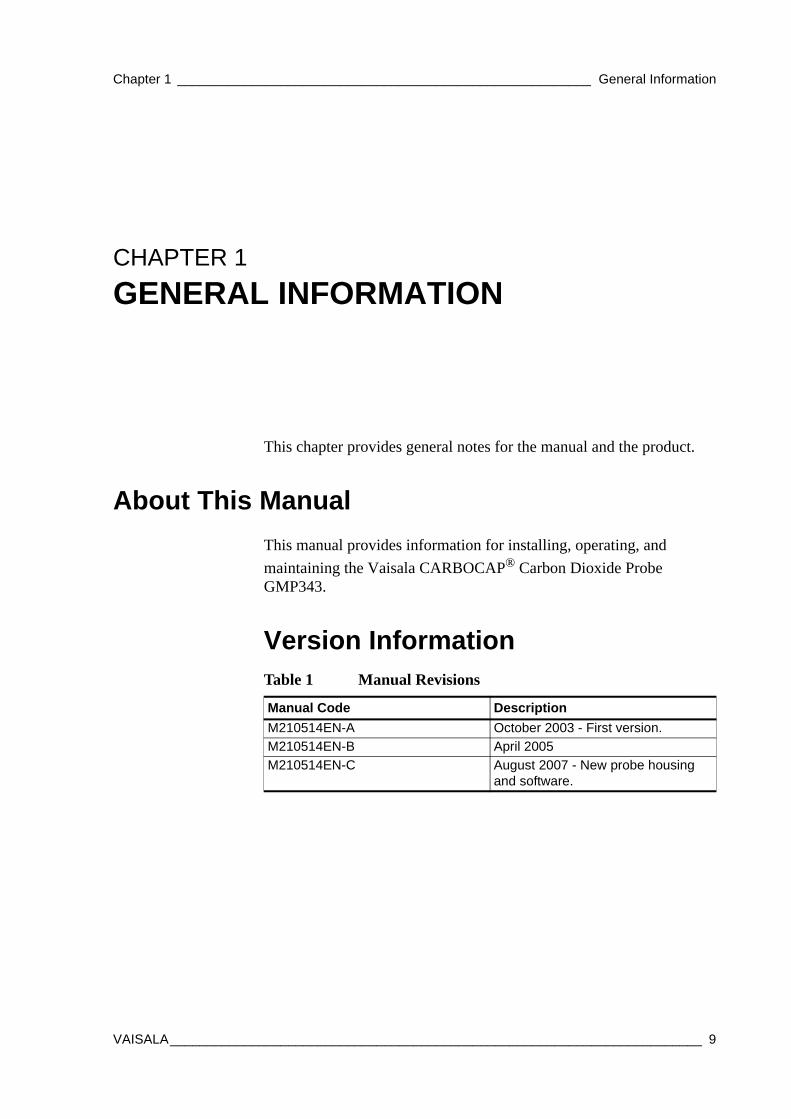
Version InformationTable 1 Manual Revisions
Manual Code DescriptionM210514EN-A October 2003 - First version.M210514EN-B April 2005M210514EN-C August 2007 - New probe housing
and software.
VAISALA________________________________________________________________________ 9
User's Guide ______________________________________________________________________
General Safety ConsiderationsThroughout the manual, important safety considerations are highlighted as follows:
FeedbackVaisala Customer Documentation Team welcomes your comments and suggestions on the quality and usefulness of this publication. If you find errors or have other suggestions for improvement, please indicate the chapter, section, and page number. You can send comments to us by e-mail: [email protected].
ESD ProtectionElectrostatic Discharge (ESD) can cause immediate or latent damage to electronic circuits. Vaisala products are adequately protected against ESD for their intended use. However, it is possible to damage the product by delivering electrostatic discharges when touching, removing, or inserting any objects inside the equipment housing.To make sure you are not delivering high static voltages yourself handle ESD sensitive components on a properly grounded and protected ESD workbench. When this is not possible, ground yourself to the equipment chassis before touching the connections. Ground yourself with a wrist strap and a resistive connection cord. When neither of the above is possible, touch a conductive part of the equipment chassis with your other hand before touching the boards.
WARNING Warning alerts you to a serious hazard. If you do not read and follow instructions very carefully at this point, there is a risk of injury or even death.
CAUTION Caution warns you of a potential hazard. If you do not read and follow instructions carefully at this point, the product could be damaged or important data could be lost.
NOTE Note highlights important information on using the product.
10 __________________________________________________________________ M210514EN-C
Chapter 1 ________________________________________________________ General Information
WarrantyVaisala hereby represents and warrants all Products manufactured by Vaisala and sold hereunder to be free from defects in workmanship or material during a period of twelve (12) months from the date of delivery save for products for which a special warranty is given. If any Product proves however to be defective in workmanship or material within the period herein provided Vaisala undertakes to the exclusion of any other remedy to repair or at its own option replace the defective Product or part thereof free of charge and otherwise on the same conditions as for the original Product or part without extension to original warranty time. Defective parts replaced in accordance with this clause shall be placed at the disposal of Vaisala.
Vaisala also warrants the quality of all repair and service works performed by its employees to products sold by it. In case the repair or service works should appear inadequate or faulty and should this cause malfunction or nonfunction of the product to which the service was performed Vaisala shall at its free option either repair or have repaired or replace the product in question. The working hours used by employees of Vaisala for such repair or replacement shall be free of charge to the client. This service warranty shall be valid for a period of six (6) months from the date the service measures were completed.
This warranty is however subject to following conditions:
a) A substantiated written claim as to any alleged defects shall have been received by Vaisala within thirty (30) days after the defect or fault became known or occurred, and
b) The allegedly defective Product or part shall, should Vaisala so require, be sent to the works of Vaisala or to such other place as Vaisala may indicate in writing, freight and insurance prepaid and properly packed and labelled, unless Vaisala agrees to inspect and repair the Product or replace it on site.
This warranty does not however apply when the defect has been caused through
a) normal wear and tear or accident;
b) misuse or other unsuitable or unauthorized use of the Product or negligence or error in storing, maintaining or in handling the Product or any equipment thereof;
c) wrong installation or assembly or failure to service the Product or otherwise follow Vaisala's service instructions including any repairs or installation or assembly or service made by unauthorized personnel not approved by Vaisala or replacements with parts not manufactured or supplied by Vaisala;
d) modifications or changes of the Product as well as any adding to it without Vaisala's prior authorization;
e) other factors depending on the Customer or a third party.
Notwithstanding the aforesaid Vaisala's liability under this clause shall not apply to any defects arising out of materials, designs or instructions provided by the Customer.
This warranty is expressly in lieu of and excludes all other conditions, warranties and liabilities, express or implied, whether under law, statute or otherwise, including without limitation any implied warranties of merchantability or fitness for a particular purpose and all other obligations and liabilities of Vaisala or its representatives with respect to any defect or deficiency applicable to or resulting directly or indirectly from the Products supplied hereunder, which obligations and liabilities are hereby expressly cancelled and waived. Vaisala's liability shall under no circumstances exceed the invoice price of any Product for which a warranty claim is made, nor shall Vaisala in any circumstances be liable for lost profits or other consequential loss whether direct or indirect or for special damages.
VAISALA_______________________________________________________________________ 11

User's Guide ______________________________________________________________________
12 __________________________________________________________________ M210514EN-C
Chapter 2 __________________________________________________________ Product Overview
CHAPTER 2PRODUCT OVERVIEW
This chapter introduces the features of the GMP343.
Introduction to GMP343Vaisala CARBOCAP® Carbon Dioxide Probe GMP343 is designed for high accuracy CO2 measurements. The measurement is based on the advanced CARBOCAP® Single-Beam Dual-Wavelength NDIR technology. GMP343 consists of a CO2 sensor, electronics, and a housing suitable for long-term outdoor use.There are two GMP343 models available: a flow-through model and a diffusion model. One adjustable analog output can be configured to output voltage or current signal (0 ... 2.5 V, 0 ... 5 V, 4 ... 20 mA). A digital output for RS232/RS485 communication is available. The measuring range options vary from 0 ... 1000 ppm to 0 ... 2 %CO2.
The GMP343 can be ordered with various adapter, filter, and connection cable options. For a list of spare parts and accessories, see section Spare Parts and Accessories on page 82.
VAISALA_______________________________________________________________________ 13
User's Guide ______________________________________________________________________
GMP343 Transmitter Components
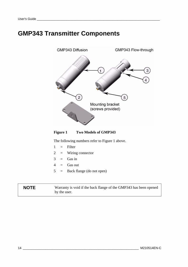
Figure 1 Two Models of GMP343
The following numbers refer to Figure 1 above. 1 = Filter2 = Wiring connector3 = Gas in4 = Gas out5 = Back flange (do not open)
NOTE Warranty is void if the back flange of the GMP343 has been opened by the user.
14 __________________________________________________________________ M210514EN-C
Chapter 2 __________________________________________________________ Product Overview
User Configurable CO2 MeasurementThe measurement output of the GMP343 is user configurable. You may have the raw data without filtering or compensation, or you may set the filtering levels, enable compensation (pressure, temperature, relative humidity, and oxygen) and linearization.
You can also select the measurement range to optimize the performance of the GMP343 for a certain concentration level. Selecting an appropriate measurement range increases accuracy, since it enables the range-specific compensation and linearization settings. For more information, see sections Setting the Measurement Range on page 41 and Temperature, Pressure, Relative Humidity, and Oxygen Compensations on page 47.
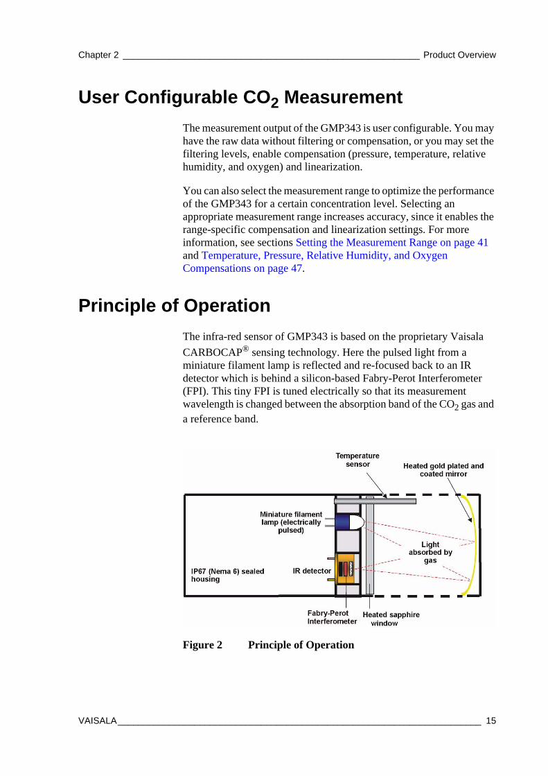
Principle of OperationThe infra-red sensor of GMP343 is based on the proprietary Vaisala CARBOCAP® sensing technology. Here the pulsed light from a miniature filament lamp is reflected and re-focused back to an IR detector which is behind a silicon-based Fabry-Perot Interferometer (FPI). This tiny FPI is tuned electrically so that its measurement wavelength is changed between the absorption band of the CO2 gas and a reference band.
Figure 2 Principle of Operation
VAISALA_______________________________________________________________________ 15
User's Guide ______________________________________________________________________
When the passband of the FPI coincides with the absorption wavelength of the CO2 gas, the IR detector sees a decrease in the light transmission. The measurement wavelength of the FPI is then changed to the reference band (that has no absorption lines) and the IR detector sees a full light transmission. The ratio of these two signals indicates the degree of light absorption in the gas and is proportional to the gas concentration. It takes 2 seconds to measure this sequence and to calculate one reading.
Use of numerical filtering reduces the noise of the raw data. On the other hand, the filtering increases the response time of the device (see Figure 9 on page 44).
Optics HeatingTwo heating elements are placed in the optics; one behind the mirror and one behind the window of the sensor. Heating should always be turned on when there is a risk of dew formation on the optics surface. The heating maintains the surface temperature of the optics a few degrees above the ambient temperature.
The heating is disabled by default. For instructions on how to control the optics heating, refer to section Setting the Optics Heating ON/OFF on page 61.
Gas SamplingThere are two GMP343 models available: a flow-through model and a diffusion model.
Diffusion SamplingNo sampling system is needed with the GMP343 diffusion model. The diffusion filter and the plastic filter cover protect the measuring chamber from dirt, water, and contaminants.
NOTE The optics heating is automatically disabled when you connect the GMP343 to a MI70 indicator.
16 __________________________________________________________________ M210514EN-C
Chapter 2 __________________________________________________________ Product Overview
In order to have a quick measurement with very short response time the filter can be removed; see section Response time (90 %) on page 80. In this case the optics are openly exposed to contamination and cleaning of optics may be necessary more often. For instructions on cleaning the optics, refer to section Cleaning the Optics (Diffusion Model Only) on page 71. Removal of the filter is not recommended if there is a risk of getting water or dirt particles on the optics.
Flow-Through SamplingThe maximum gas flow rate is 10 liters/min. When using high flow rates, please note how the flow rate affects the accuracy, see Specifications, Oxygen, on page 79 (flow dependence). The volume of the internal measurement chamber is 59 ml ± 1 ml.
The gas sample must not include acidic gases.
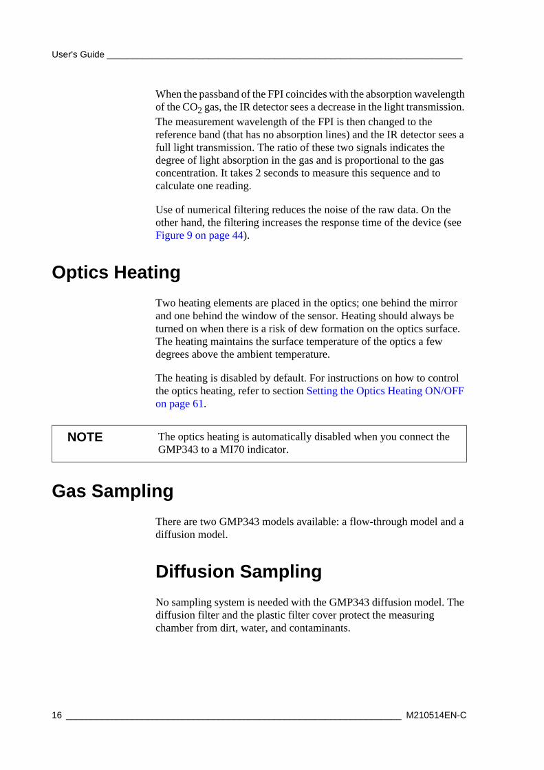
Sampling SystemThe GMP343 flow-through model has no diffusion filter inside the measuring chamber and the optics of the flow-through model cannot be cleaned by the user. Therefore the sample gas must always be filtered and dried before it is pumped to the measuring chamber. A hydrophobic diffusion filter before the inlet of the measuring chamber is needed in order to prevent particles and water from the surroundings from getting into the sensor. The diffusion filter needs to be exchanged often enough to provide a sufficient flow.
In humid environments it is important to avoid water condensation inside the measuring chamber. This can be avoided by drying the sample air. The most common method of drying the sample air is cooling and re-heating the air. A simple system may consist for example of a cooling coil and a water trap which are either cooled or located in a cool environment, followed by a re-heating system. The idea is to get the moisture in the sample to condensate on the walls of the copper tube, trap this water and then lower the relative humidity by heating the sample. If the temperature inside the measurement chamber is essentially higher than the surroundings the cooling coil and the water trap can be simply located outside the chamber. For re-heating, the heat
CAUTION Liquids or acidic vapors may seriously damage the sensor.
VAISALA_______________________________________________________________________ 17
User's Guide ______________________________________________________________________
generated by a pumping system may sometimes be adequate, meaning that no additional heater is needed. A simplified schema of a sample system removing particles and moisture is illustrated below.
All sampling system components are commercially available.
Figure 3 Components of the Sampling System
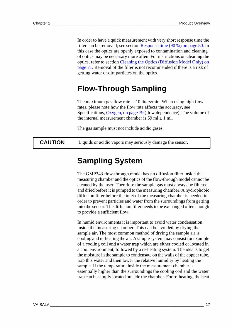
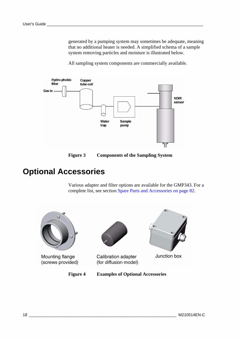
Optional AccessoriesVarious adapter and filter options are available for the GMP343. For a complete list, see section Spare Parts and Accessories on page 82.
Figure 4 Examples of Optional Accessories
18 __________________________________________________________________ M210514EN-C
Chapter 2 __________________________________________________________ Product Overview
Soil Adapter Kits for In-Soil ApplicationsThe vertical/horizontal soil adapter kit consists of a soil adapter and a hydrophobic sintered PTFE filter. The kits are designed for in-soil CO2 measurements to be used with the diffusion model of GMP343.
MI70 Indicator ConnectionVaisala MI70 indicator is an optional accessory to be used as a display, communication, and data-logging device for GMP343. When taking measurements GMP343 is powered via MI70.
Recharging the Battery Pack
MI70 indicator is equipped with a rechargable battery pack when shipped from factory. The battery pack is located behind the back plate of the indicator. The recharger is provided with one of the following AC-adapters: Euro, UK, US or AUS.
1. Recharge the battery pack as follows: Plug in the recharger connector into the connector on top of the indicator and connect the recharger to a wall socket. A battery symbol in the corner of the display starts to roll.
- It is not recommended to use MI70 during the first recharging. Later on MI70 can be used while recharging.
- Duration of recharging depends on the charge level of the battery pack being 4 hours typical. The recommended first recharging time is 6 hours.
2. The battery pack is full when the battery symbol in the display stops rolling.
3. Disconnect the recharger.
VAISALA_______________________________________________________________________ 19
User's Guide ______________________________________________________________________
Structure of the MI70 Indicator
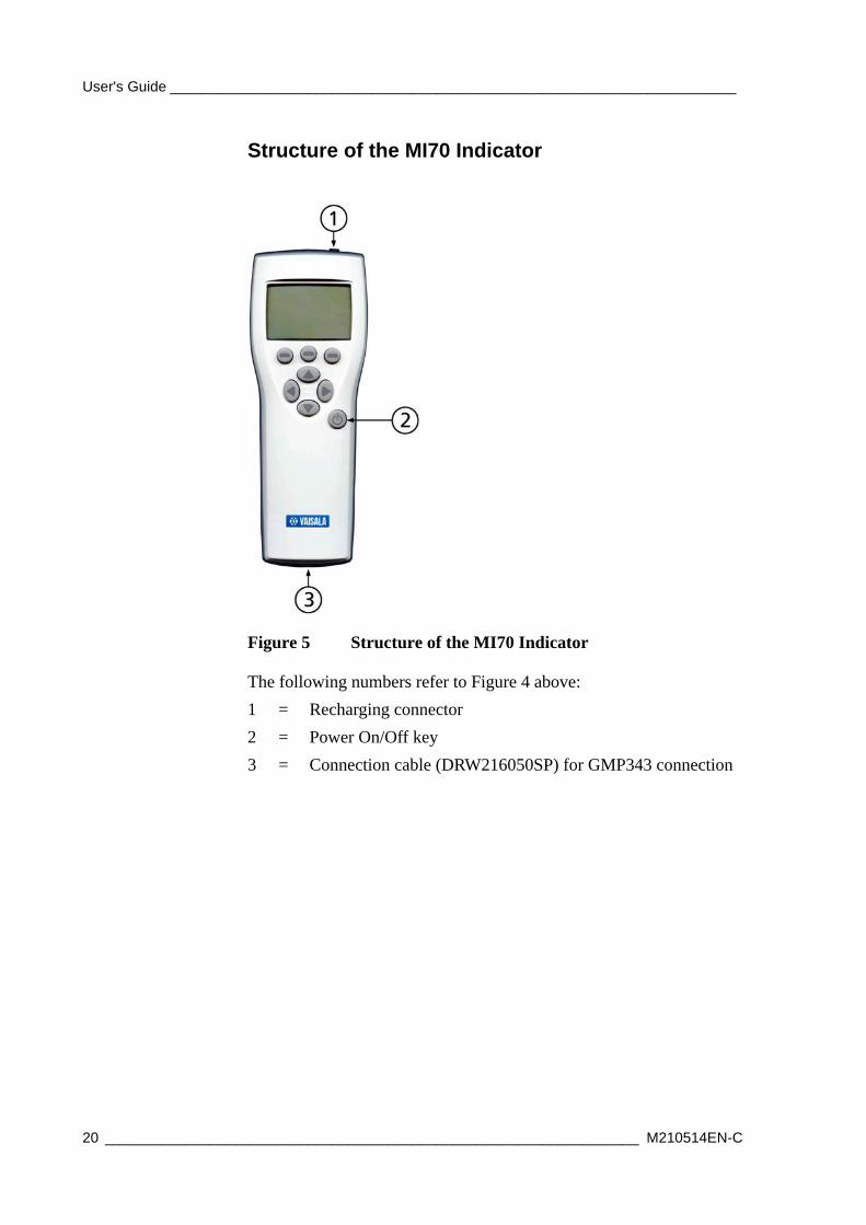
Figure 5 Structure of the MI70 Indicator
The following numbers refer to Figure 4 above: 1 = Recharging connector2 = Power On/Off key3 = Connection cable (DRW216050SP) for GMP343 connection
20 __________________________________________________________________ M210514EN-C
Chapter 2 __________________________________________________________ Product Overview
Using MI70 as a Display
Introduction of Function Keys and Menu Structure
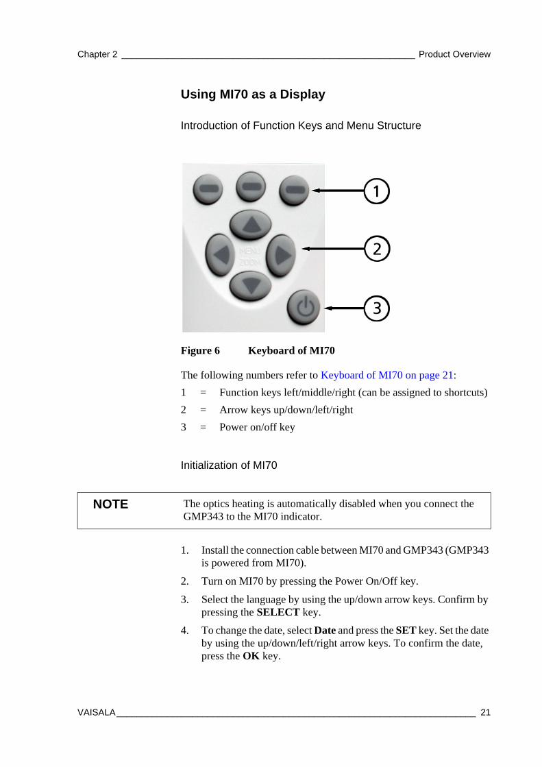
0704-034Figure 6 Keyboard of MI70
Initialization of MI70
1. Install the connection cable between MI70 and GMP343 (GMP343 is powered from MI70).
2. Turn on MI70 by pressing the Power On/Off key.
3. Select the language by using the up/down arrow keys. Confirm by pressing the SELECT key.
4. To change the date, select Date and press the SET key. Set the date by using the up/down/left/right arrow keys. To confirm the date, press the OK key.
The following numbers refer to Keyboard of MI70 on page 21:1 = Function keys left/middle/right (can be assigned to shortcuts)2 = Arrow keys up/down/left/right 3 = Power on/off key
NOTE The optics heating is automatically disabled when you connect the GMP343 to the MI70 indicator.
VAISALA_______________________________________________________________________ 21
User's Guide ______________________________________________________________________
5. To change the time, select Time and press the SET key. Set the time by using the up/down/left/right arrow keys. To confirm the time, press the OK key.
6. To check and change the environment settings, select YES. Enter ambient pressure, humidity, and oxygen values. Press the EXIT key.
Navigation in Menu
- To turn the indicator on or off, press the Power On/Off key.
- To open the main menu, press any of the arrow keys and then the middlemost function key in sequence.
- To move in a menu and select an option, press the up/down arrow keys. To enter sub-menu of selected option, press the right arrow key. To return to the previous menu level, press the left arrow key.
- To activate a function: press a function key according to the guiding text below the key.
- To return to the basic display directly from any menu levels, press the function key EXIT.
The main settings are found in the following menu locations:
- To change language, enter: Settings - User interface - Language.
- To select display quantities (carbon dioxide and temperature), enter: Display - Quantities and units. The carbon dioxide concentration is shown in ppm or in %-units and temperature in °C or °F.
- To set the ambient conditions enter Environment menu. Options to choose from: 1013 hPa, 50 % RH, and 20.9 % O2.
22 __________________________________________________________________ M210514EN-C
Chapter 2 __________________________________________________________ Product Overview
Using MI70 in Recording
Record continuous measurement data and view the recorded data by using the MI70. This function is found from the menu RECORDING/VIEWING.
You can switch MI70 off during recording to save battery power. Display message tells you that recording continues undisturbed even when the power is off. If the indicator is switched off during recording, the progress bar is shown on the display every 10 seconds (all the time, if the charger is connected). This bar shows the amount of recorded data.
Save individual measurement data points with Hold/Save function (DISPLAY-HOLD/SAVE DISPLAY) and view the saved data from the RECORDING/VIEWING menu.
Transferring Recorded Data to PC
The recorded data can be transferred to a PC by using MI70 Link program. MI70 Link program can be ordered from Vaisala, see Table 12, List of Spare Parts and Accessories, on page 82. You can examine the recorded data easily in Windows and transfer it further to a spreadsheet program (such as Microsoft® Excel) for modification.
More information on the data transfer and software features is found in the HELP-file of MI70 Link program.
CAUTION Do not disconnect the probe when the data recording is on, even if the indicator is off. This may cause loss of recorded data.
VAISALA_______________________________________________________________________ 23

User's Guide ______________________________________________________________________
24 __________________________________________________________________ M210514EN-C
Chapter 3 _______________________________________________________________ Installation
CHAPTER 3INSTALLATION
This chapter provides you with information that is intended to help you install this product.
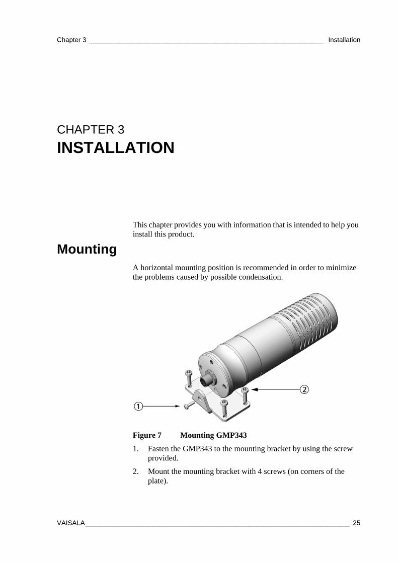
MountingA horizontal mounting position is recommended in order to minimize the problems caused by possible condensation.
0704-020Figure 7 Mounting GMP343
1. Fasten the GMP343 to the mounting bracket by using the screw provided.
2. Mount the mounting bracket with 4 screws (on corners of the plate).
VAISALA_______________________________________________________________________ 25
User's Guide ______________________________________________________________________
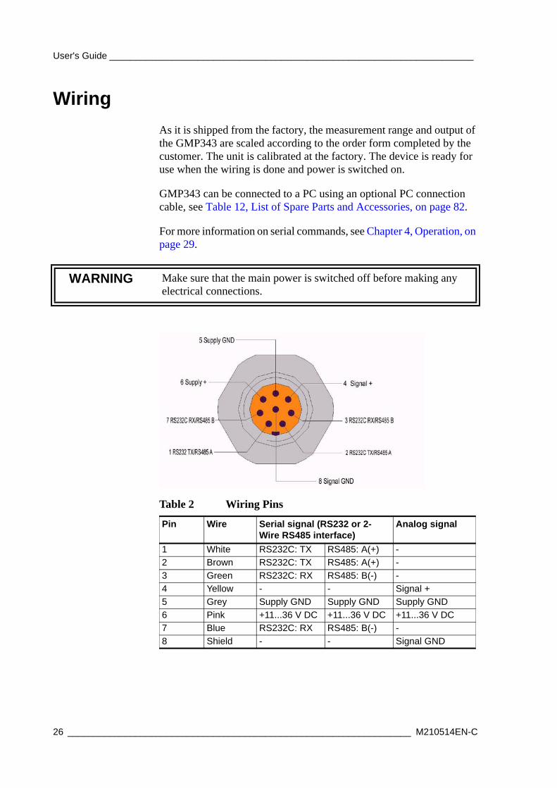
Wiring As it is shipped from the factory, the measurement range and output of the GMP343 are scaled according to the order form completed by the customer. The unit is calibrated at the factory. The device is ready for use when the wiring is done and power is switched on.
GMP343 can be connected to a PC using an optional PC connection cable, see Table 12, List of Spare Parts and Accessories, on page 82.
For more information on serial commands, see Chapter 4, Operation, on page 29.
WARNING Make sure that the main power is switched off before making any electrical connections.
Table 2 Wiring Pins
Pin Wire Serial signal (RS232 or 2-Wire RS485 interface)
Analog signal
1 White RS232C: TX RS485: A(+) -2 Brown RS232C: TX RS485: A(+) -3 Green RS232C: RX RS485: B(-) -4 Yellow - - Signal +5 Grey Supply GND Supply GND Supply GND6 Pink +11...36 V DC +11...36 V DC +11...36 V DC7 Blue RS232C: RX RS485: B(-) -8 Shield - - Signal GND
26 __________________________________________________________________ M210514EN-C
Chapter 3 _______________________________________________________________ Installation
There are two pins per signal internally hardwired in parallel (pins 1 and 2, pins 3 and 7). You should connect the RS232C signal 'TX' (or 2-Wire RS485 signal 'A') either to the pin 1 or 2 and the RS232C signal 'RX' (or 2-Wire RS485 signal 'B') either to the pin 3 or 7.
Note that there is either an RS232 or a 2-wire RS485 communication interface available according to initial configuration. However, if the device is configured in RS485 output mode, the device can still be switched into RS232 mode by re-configuration via PC . For more information on serial commands and RS232/485 modes, see Chapter 4, Operation, on page 29.
Wiring of the Junction BoxThe optional 8-pole junction box enables practical in-line connection. The box is provided with 8 numbered terminals.
VAISALA_______________________________________________________________________ 27

User's Guide ______________________________________________________________________
28 __________________________________________________________________ M210514EN-C
Chapter 4 ________________________________________________________________ Operation
CHAPTER 4OPERATION
This chapter contains information that is needed to operate the GMP343.
Connecting GMP343 to PC
Connection CablesTo connect the GMP343 to a PC, you need the PC Connection Cable (optional accessory 213379). If your PC does not have a serial port, you also need the USB-D9 Serial Connection Cable (optional accessory 219686). By connecting the two cables, you can use a standard type A USB port to connect the GMP343 to a PC.
Both cables are included in the PC Connection Kit that can be ordered with the GMP343.
Installing the Driver for the USB Cable
Before taking the USB cable into use, you must install the provided USB driver on your PC. When installing the driver, you must acknowledge any security prompts that may appear. The driver is compatible with Windows 2000, Windows XP, Windows Server 2003, and Windows Vista.
VAISALA_______________________________________________________________________ 29
User's Guide ______________________________________________________________________
1. Check that the USB cable is not connected. Disconnect the cable if you have already connected it.
2. Insert the media that came with the cable, or download the driver from www.vaisala.com.
3. Execute the USB driver installation program (setup.exe), and accept the installation defaults. The installation of the driver may take several minutes.
4. After the driver has been installed, connect the USB cable to a USB port on your PC. Windows will detect the new device, and use the driver automatically.
5. The installation has reserved a COM port for the cable. Verify the port number, and the status of the cable, using the Vaisala USB Instrument Finder program that has been installed in the Windows Start menu. The reserved ports are also visible in the Ports section of the Windows Device Manager.
Remember to use the correct port in the settings of your terminal program. Windows will recognize each individual cable as a different device, and reserve a new COM port.
There is no reason to uninstall the driver for normal use. However, if you wish to remove the driver files and all Vaisala USB cable devices, you can do so by uninstalling the entry for Vaisala USB Instrument Driver from the Add or Remove Programs (Programs and Features in Windows Vista) in the Windows Control Panel.
Opening a Terminal ConnectionThe communication interface of GMP343 is RS-232 or RS-485. In case your device is configured to RS-485 communication mode you can still start communication in RS-232 mode (for example when changing the probe setting). See step number 4 in the following instructions.
1. Connect the GMP343 to the PC using the connection cable(s). Refer to section Connection Cables on page 29.
2. Connect the power cables to a 11 ... 36 V power supply.
30 __________________________________________________________________ M210514EN-C
Chapter 4 ________________________________________________________________ Operation
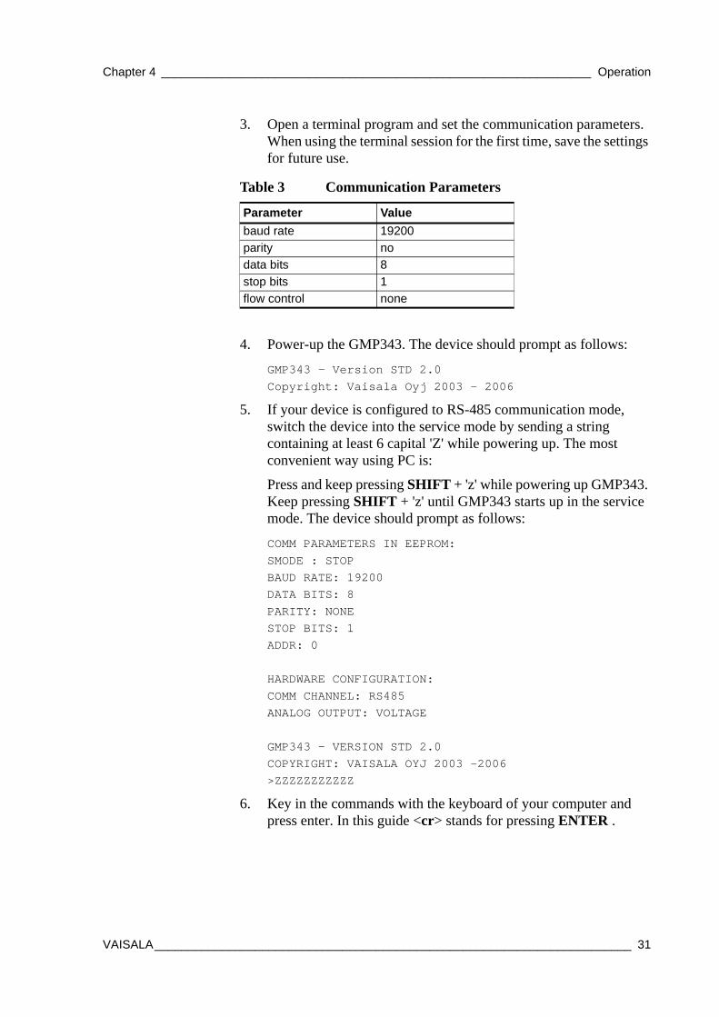
3. Open a terminal program and set the communication parameters. When using the terminal session for the first time, save the settings for future use.
4. Power-up the GMP343. The device should prompt as follows:
GMP343 - Version STD 2.0Copyright: Vaisala Oyj 2003 - 2006
5. If your device is configured to RS-485 communication mode, switch the device into the service mode by sending a string containing at least 6 capital 'Z' while powering up. The most convenient way using PC is:
Press and keep pressing SHIFT + 'z' while powering up GMP343. Keep pressing SHIFT + 'z' until GMP343 starts up in the service mode. The device should prompt as follows:
COMM PARAMETERS IN EEPROM:SMODE : STOPBAUD RATE: 19200DATA BITS: 8 PARITY: NONESTOP BITS: 1ADDR: 0
HARDWARE CONFIGURATION: COMM CHANNEL: RS485ANALOG OUTPUT: VOLTAGE
GMP343 - VERSION STD 2.0COPYRIGHT: VAISALA OYJ 2003 -2006>ZZZZZZZZZZZ
6. Key in the commands with the keyboard of your computer and press enter. In this guide <cr> stands for pressing ENTER .
Table 3 Communication Parameters
Parameter Valuebaud rate 19200parity nodata bits 8stop bits 1flow control none
VAISALA_______________________________________________________________________ 31
User's Guide ______________________________________________________________________
Operation modes of the GMP343The GMP343 can operate in three different modes:
- RUN mode
- STOP mode
- POLL mode
In the RUN mode, the GMP343 sends measurement results at regular intervals. The included parameters and the interval can be set by the user. While in the RUN mode, the device will not answer any other command except the S command, which stops the RUN mode and switches the device to STOP mode.
The STOP mode is the default mode of operation for the GMP343, where most of the commands listed in this document are available. You can enter the STOP mode from the RUN mode with the S command, or from the POLL mode with the OPEN <addr> command, where <addr> is the unique address of the GMP343. While in the STOP mode, the GMP343 will respond to all unknown commands with the following string:
Unknown command.[cr][lf]>
The POLL mode is dedicated for bus interfacing. To work in the poll mode, each device must have its own unique address. You can enter the POLL mode by giving the CLOSE command in the STOP mode.
Only a single device can be accessed at a time in the POLL mode. In the POLL mode, you can request a single measumement message from the GMP343 using the SEND <addr> command. While in the POLL mode, the GMP343 will ignore all unknown commands.
NOTE Responses from the GMP343 are terminated by the following string:
[cr][lf]>
That is a carriage return character, a line feed, and a right angle bracket.
32 __________________________________________________________________ M210514EN-C
Chapter 4 ________________________________________________________________ Operation
Getting the Measurement Message
Measurement UnitsGMP343 outputs the following units:
- Carbon dioxide (ppm)
- Temperature (ºC)
For other measurement units (%, non-metric units), use the Vaisala MI70 indicator.
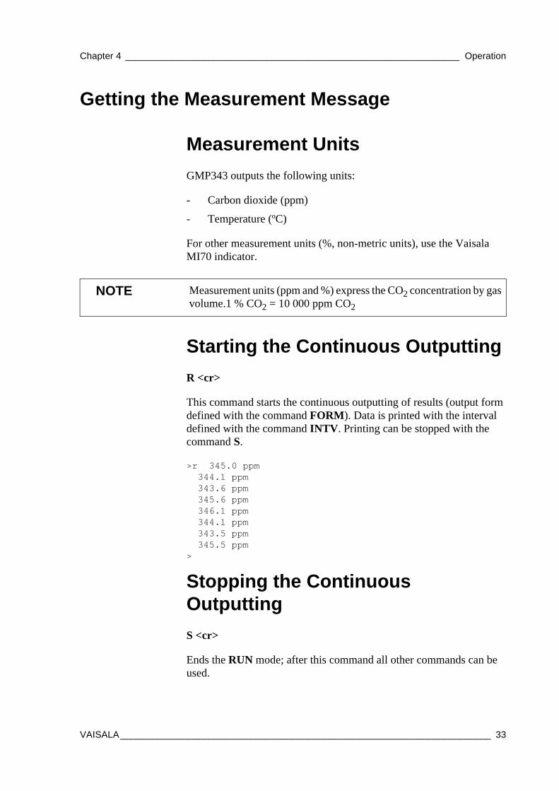
Starting the Continuous OutputtingR <cr>
This command starts the continuous outputting of results (output form defined with the command FORM). Data is printed with the interval defined with the command INTV. Printing can be stopped with the command S.
>r 345.0 ppm 344.1 ppm 343.6 ppm 345.6 ppm 346.1 ppm 344.1 ppm 343.5 ppm 345.5 ppm>
Stopping the Continuous OutputtingS <cr>
Ends the RUN mode; after this command all other commands can be used.
NOTE Measurement units (ppm and %) express the CO2 concentration by gas volume.1 % CO2 = 10 000 ppm CO2
VAISALA_______________________________________________________________________ 33
User's Guide ______________________________________________________________________
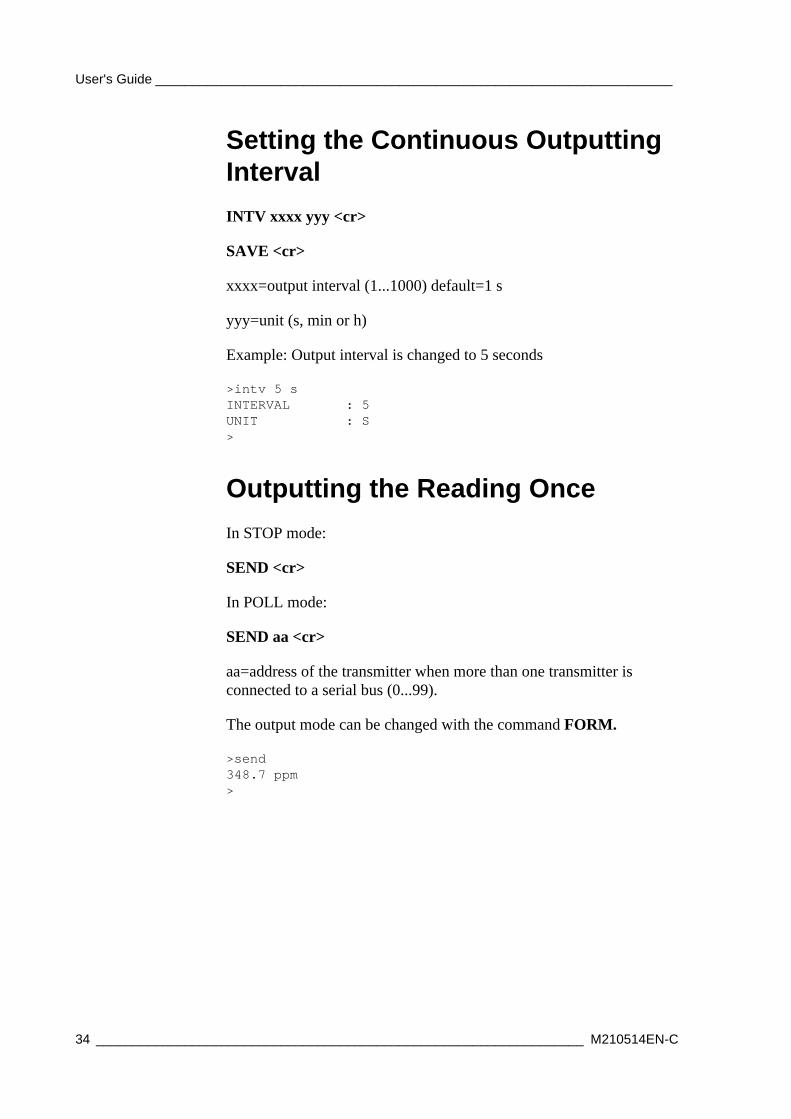
Setting the Continuous Outputting IntervalINTV xxxx yyy <cr>
SAVE <cr>
xxxx=output interval (1...1000) default=1 s
yyy=unit (s, min or h)
Example: Output interval is changed to 5 seconds
>intv 5 sINTERVAL : 5UNIT : S>
Outputting the Reading OnceIn STOP mode:
SEND <cr>
In POLL mode:
SEND aa <cr>
aa=address of the transmitter when more than one transmitter is connected to a serial bus (0...99).
The output mode can be changed with the command FORM.
>send348.7 ppm>
34 __________________________________________________________________ M210514EN-C
Chapter 4 ________________________________________________________________ Operation
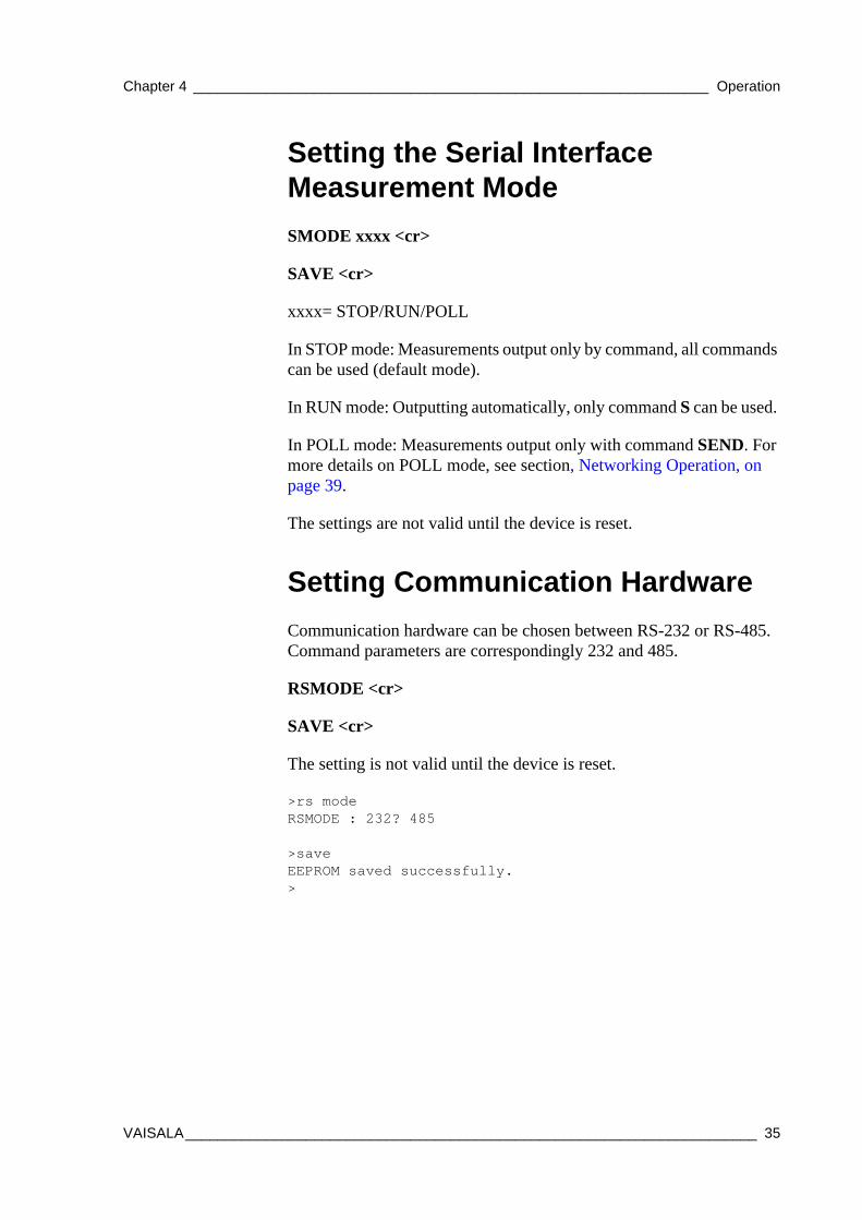
Setting the Serial Interface Measurement ModeSMODE xxxx <cr>
SAVE <cr>
xxxx= STOP/RUN/POLL
In STOP mode: Measurements output only by command, all commands can be used (default mode).
In RUN mode: Outputting automatically, only command S can be used.
In POLL mode: Measurements output only with command SEND. For more details on POLL mode, see section, Networking Operation, on page 39.
The settings are not valid until the device is reset.
Setting Communication HardwareCommunication hardware can be chosen between RS-232 or RS-485. Command parameters are correspondingly 232 and 485.
RSMODE <cr>
SAVE <cr>
The setting is not valid until the device is reset.
>rs modeRSMODE : 232? 485
>saveEEPROM saved successfully. >
VAISALA_______________________________________________________________________ 35
User's Guide ______________________________________________________________________
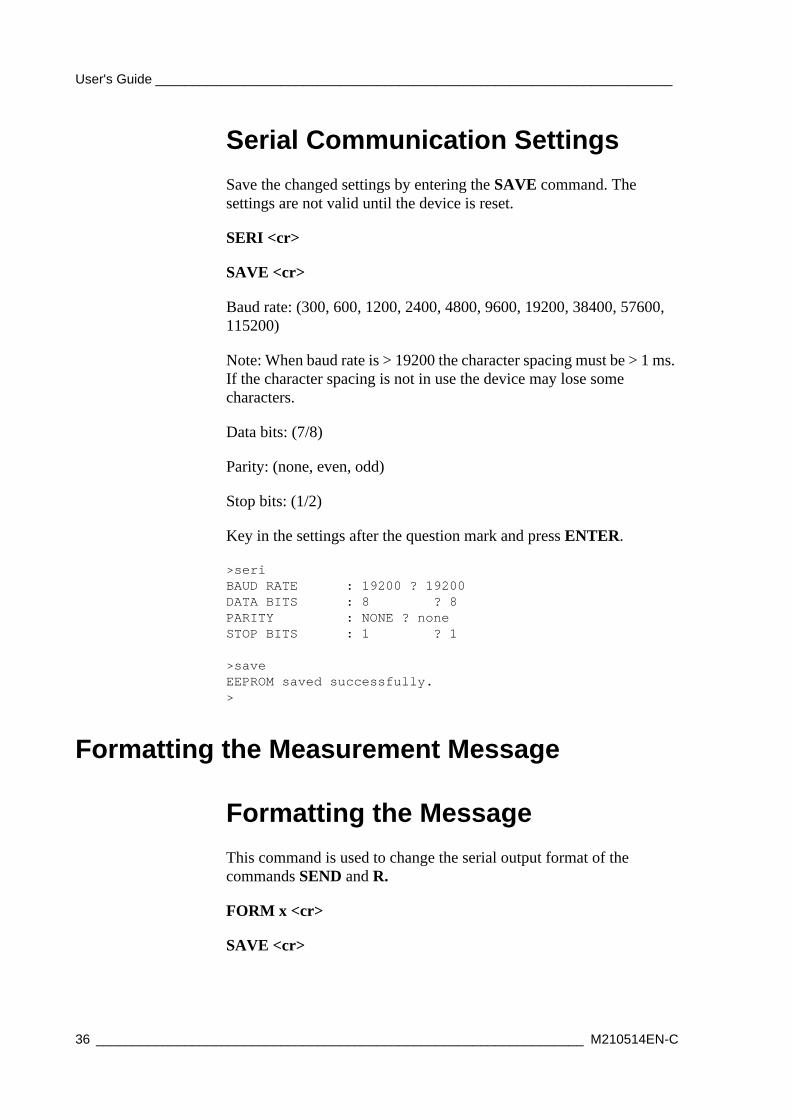
Serial Communication SettingsSave the changed settings by entering the SAVE command. The settings are not valid until the device is reset.
SERI <cr>
SAVE <cr>
Baud rate: (300, 600, 1200, 2400, 4800, 9600, 19200, 38400, 57600, 115200)
Note: When baud rate is > 19200 the character spacing must be > 1 ms. If the character spacing is not in use the device may lose some characters.
Data bits: (7/8)
Parity: (none, even, odd)
Stop bits: (1/2)
Key in the settings after the question mark and press ENTER.
>seriBAUD RATE : 19200 ? 19200DATA BITS : 8 ? 8PARITY : NONE ? noneSTOP BITS : 1 ? 1
>saveEEPROM saved successfully.>
Formatting the Measurement Message
Formatting the MessageThis command is used to change the serial output format of the commands SEND and R.
FORM x <cr>
SAVE <cr>
36 __________________________________________________________________ M210514EN-C
Chapter 4 ________________________________________________________________ Operation
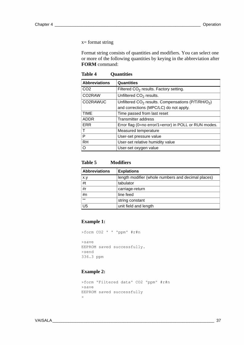
x= format string
Format string consists of quantities and modifiers. You can select one or more of the following quantities by keying in the abbreviation after FORM command:
Example 1:
>form CO2 " " "ppm" #r#n
>saveEEPROM saved successfully.>send336.3 ppm
Example 2:
>form "Filtered data" CO2 "ppm" #r#n>saveEEPROM saved successfully>
Table 4 Quantities
Abbreviations QuantitiesCO2 Filtered CO2 results. Factory setting.CO2RAW Unfiltered CO2 results.CO2RAWUC Unfiltered CO2 results. Compensations (P/T/RH/O2)
and corrections (MPC/LC) do not apply. TIME Time passed from last resetADDR Transmitter addressERR Error flag (0=no error/1=error) in POLL or RUN modes. T Measured temperatureP User-set pressure valueRH User-set relative humidity valueO User-set oxygen value
Table 5 Modifiers
Abbreviations Explations x.y length modifier (whole numbers and decimal places)#t tabulator#r carriage-return #n line feed"" string constantU5 unit field and length
VAISALA_______________________________________________________________________ 37
User's Guide ______________________________________________________________________
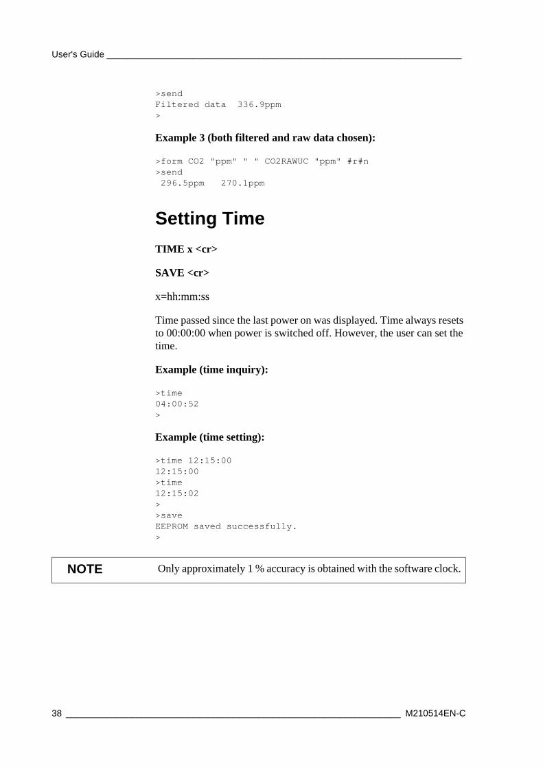
>sendFiltered data 336.9ppm>
Example 3 (both filtered and raw data chosen):
>form CO2 "ppm" " " CO2RAWUC "ppm" #r#n>send 296.5ppm 270.1ppm
Setting TimeTIME x <cr>
SAVE <cr>
x=hh:mm:ss
Time passed since the last power on was displayed. Time always resets to 00:00:00 when power is switched off. However, the user can set the time.
Example (time inquiry):
>time04:00:52>
Example (time setting):
>time 12:15:0012:15:00>time12:15:02>>saveEEPROM saved successfully.>
NOTE Only approximately 1 % accuracy is obtained with the software clock.
38 __________________________________________________________________ M210514EN-C
Chapter 4 ________________________________________________________________ Operation
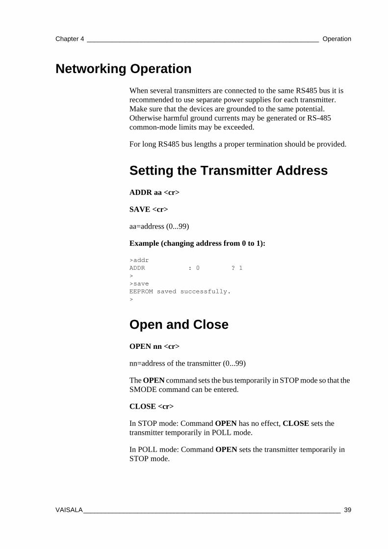
Networking OperationWhen several transmitters are connected to the same RS485 bus it is recommended to use separate power supplies for each transmitter. Make sure that the devices are grounded to the same potential. Otherwise harmful ground currents may be generated or RS-485 common-mode limits may be exceeded.
For long RS485 bus lengths a proper termination should be provided.
Setting the Transmitter AddressADDR aa <cr>
SAVE <cr>
aa=address (0...99)
Example (changing address from 0 to 1):
>addrADDR : 0 ? 1>>saveEEPROM saved successfully.>
Open and CloseOPEN nn <cr>
nn=address of the transmitter (0...99)
The OPEN command sets the bus temporarily in STOP mode so that the SMODE command can be entered.
CLOSE <cr>
In STOP mode: Command OPEN has no effect, CLOSE sets the transmitter temporarily in POLL mode.
In POLL mode: Command OPEN sets the transmitter temporarily in STOP mode.
VAISALA_______________________________________________________________________ 39
User's Guide ______________________________________________________________________
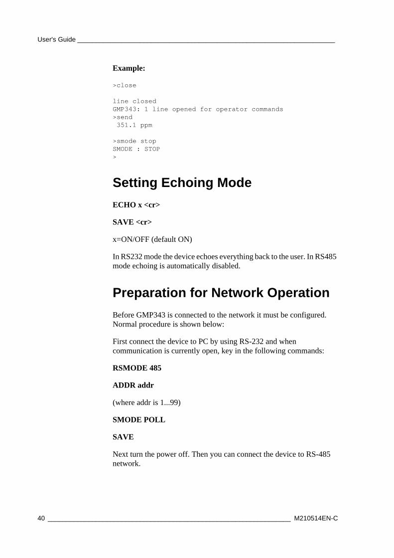
Example:
>close
line closedGMP343: 1 line opened for operator commands>send 351.1 ppm
>smode stopSMODE : STOP>
Setting Echoing ModeECHO x <cr>
SAVE <cr>
x=ON/OFF (default ON)
In RS232 mode the device echoes everything back to the user. In RS485 mode echoing is automatically disabled.
Preparation for Network OperationBefore GMP343 is connected to the network it must be configured. Normal procedure is shown below:
First connect the device to PC by using RS-232 and when communication is currently open, key in the following commands:
RSMODE 485
ADDR addr
(where addr is 1...99)
SMODE POLL
SAVE
Next turn the power off. Then you can connect the device to RS-485 network.
40 __________________________________________________________________ M210514EN-C
Chapter 4 ________________________________________________________________ Operation
Commands during Network OperationWhen GMP343 is connected to the network, the following commands can be entered:
Compensation values that are entered with compensation commands (XP, XO, XRH) are used for compensation but they are not stored permanently. Note that compensation commands do not give any reply. If value in command is not acceptable, the command is rejected.
Measurement Range, Data Filtering and Linearization
Setting the Measurement RangeThe measurement range of the GMP343 has been set at factory according to the order form. However, you can change the measurement range to optimize measurement performance for a certain concentration level.
To achieve the most accurate 'ppm CO2' measurement, the measurement should be compensated for T, P, %RH, and O2 concentration in the environment. The compensation settings are specific to the selected measurement range, so selecting a suitable measurement range optimizes the compensation performance. Each range also has its own linearization function; see section Linearization on page 46.
SEND addr Return latest CO2 value
XP addr pressure Set pressure for compensationXO addr oxygen Set oxygen for compensationXRH addr humidity
Set humidity for compensation
OPEN addr Open device for normal communication (i.e. to STOP-mode)
CLOSE Switch the device from STOP-mode to POLL-mode.
VAISALA_______________________________________________________________________ 41
User's Guide ______________________________________________________________________
There are 6 measurement ranges available. The range always begins with zero and only upper end value is changed.
RANGE x
SAVE
x = 1...6
Example:
>range 41. SPAN (ppm) : 1000.002. SPAN (ppm) : 2000.003. SPAN (ppm) : 3000.004. SPAN (ppm) : 4000.005. SPAN (ppm) : 5000.006. SPAN (ppm) : 20000.00
RANGE : 4>>saveEEPROM saved successfully.
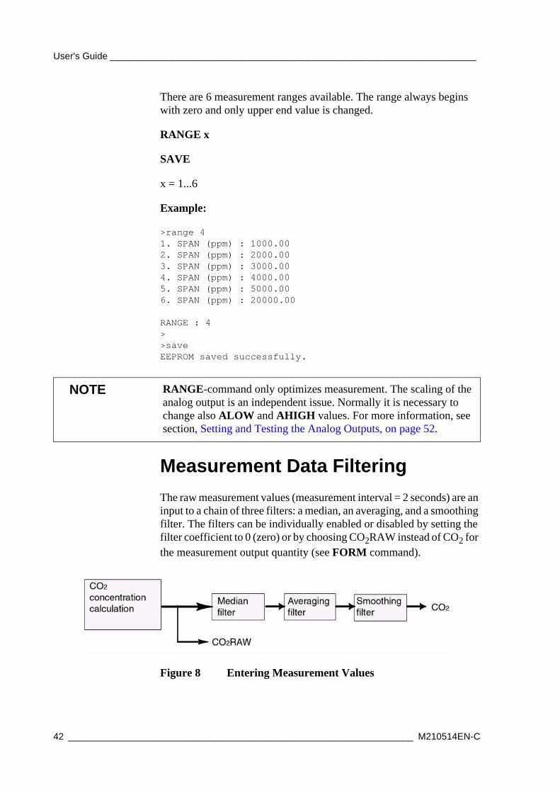
Measurement Data FilteringThe raw measurement values (measurement interval = 2 seconds) are an input to a chain of three filters: a median, an averaging, and a smoothing filter. The filters can be individually enabled or disabled by setting the filter coefficient to 0 (zero) or by choosing CO2RAW instead of CO2 for the measurement output quantity (see FORM command).
Figure 8 Entering Measurement Values
NOTE RANGE-command only optimizes measurement. The scaling of the analog output is an independent issue. Normally it is necessary to change also ALOW and AHIGH values. For more information, see section, Setting and Testing the Analog Outputs, on page 52.
42 __________________________________________________________________ M210514EN-C
Chapter 4 ________________________________________________________________ Operation
Median Filter
Median filter is the first section in the filter chain, removing random peak values caused by external interference. The output of the median filter is the moving median of the values over the set number of measurements. The median filter arranges the values in the order of magnitude and outputs the middle value (not the average) if the number of the measurements is odd. In case an even number is set, the output is the average of the two middlemost measurements.
The lowest reasonable set number of measurements is 3. Note that if the noise distribution is somewhat uniform the median filter does not give any additional value.
The number of the measurements is set by the MEDIAN command. Maximum number of measurements is 13. The default value is 0 (meaning that the median filter is disabled).
Averaging Filter
The averaging filter calculates a moving average over the user-set period of time. The longer the averaging time is the lower the noise at the measurement signal. For example, if the averaging is set to 30 seconds, the most recent average filter output is the average of the last 15 measurements (2 seconds measurement interval).
The averaging time is set by the AVERAGE command. The default value is 10 seconds, and the maximum filter length is 60 seconds. For longer averaging times, use the smoothing filter instead. Table 6 on page 43 presents the measurement noise as a function of averaging time at 370 ppm CO2:
Table 6 Averaging Times
Averaging Time Noise0 s 3 ppm10 s 2 ppm30 s 1 ppm
VAISALA_______________________________________________________________________ 43
User's Guide ______________________________________________________________________
Smoothing Filter
The smoothing filter calculates the running average by weighting the most recent measurement by the user-set proportion of the preceding measurement.
By using the smoothing filter, averaging up to even 15 minute periods can be accomplished. The smoothing filter is feasible for the background measurement where fast changes in the CO2 concentration are not common. See the next section to find the difference between smoothing and averaging in regard to response time.
The smoothing factor is set by the SMOOTH command, where the range of the factor is 0 ... 255. The relationship between averaging and smoothing from the noise reducing point of view is like follows:
(SMOOTHING FACTOR × 4) = approx. AVERAGING TIME (s)
The default value is 0 (meaning that the smoothing filter is disabled).
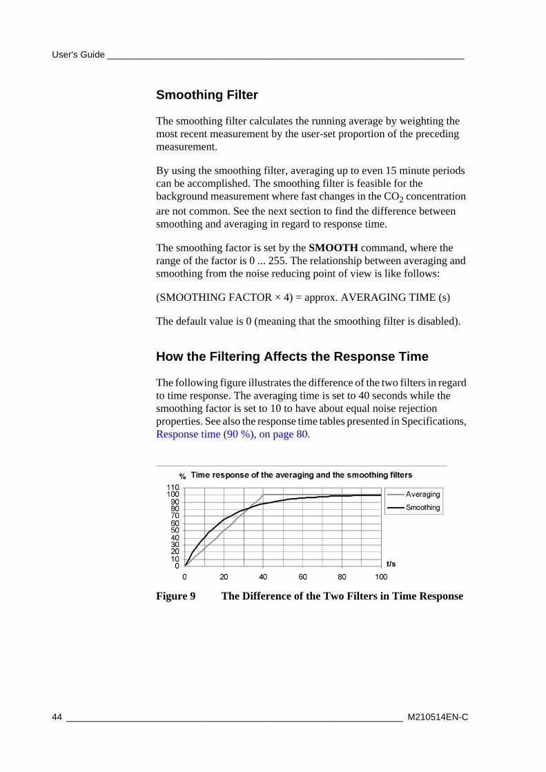
How the Filtering Affects the Response Time
The following figure illustrates the difference of the two filters in regard to time response. The averaging time is set to 40 seconds while the smoothing factor is set to 10 to have about equal noise rejection properties. See also the response time tables presented in Specifications, Response time (90 %), on page 80.
Figure 9 The Difference of the Two Filters in Time Response
44 __________________________________________________________________ M210514EN-C
Chapter 4 ________________________________________________________________ Operation
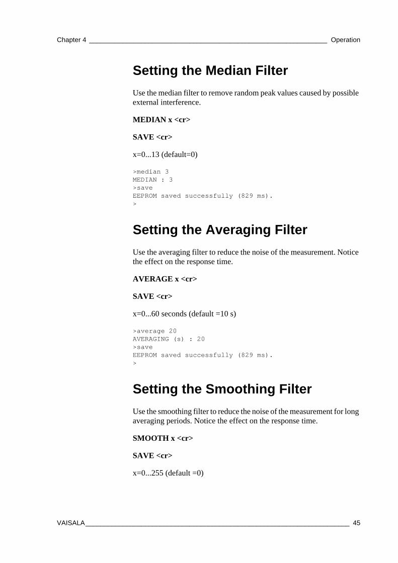
Setting the Median FilterUse the median filter to remove random peak values caused by possible external interference.
MEDIAN x <cr>
SAVE <cr>
x=0...13 (default=0)
>median 3MEDIAN : 3>saveEEPROM saved successfully (829 ms).>
Setting the Averaging FilterUse the averaging filter to reduce the noise of the measurement. Notice the effect on the response time.
AVERAGE x <cr>
SAVE <cr>
x=0...60 seconds (default =10 s)
>average 20AVERAGING (s) : 20>saveEEPROM saved successfully (829 ms).>
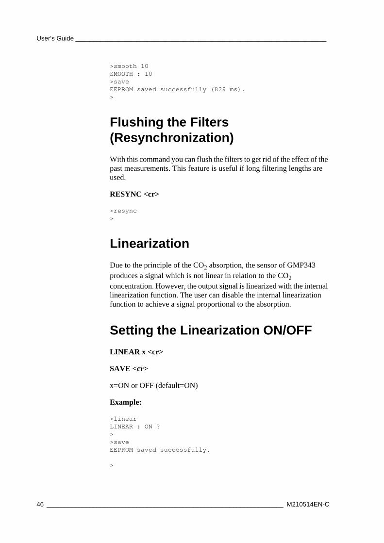
Setting the Smoothing FilterUse the smoothing filter to reduce the noise of the measurement for long averaging periods. Notice the effect on the response time.
SMOOTH x <cr>
SAVE <cr>
x=0...255 (default =0)
VAISALA_______________________________________________________________________ 45
User's Guide ______________________________________________________________________
>smooth 10SMOOTH : 10>saveEEPROM saved successfully (829 ms).>
Flushing the Filters (Resynchronization)With this command you can flush the filters to get rid of the effect of the past measurements. This feature is useful if long filtering lengths are used.
RESYNC <cr>
>resync>
LinearizationDue to the principle of the CO2 absorption, the sensor of GMP343 produces a signal which is not linear in relation to the CO2 concentration. However, the output signal is linearized with the internal linearization function. The user can disable the internal linearization function to achieve a signal proportional to the absorption.
Setting the Linearization ON/OFFLINEAR x <cr>
SAVE <cr>
x=ON or OFF (default=ON)
Example:
>linearLINEAR : ON ?>>saveEEPROM saved successfully.
>
46 __________________________________________________________________ M210514EN-C
Chapter 4 ________________________________________________________________ Operation
Temperature, Pressure, Relative Humidity, and Oxygen Compensations
The measurement result of an NDIR CO2 sensor such as the GMP343 is proportional to the absolute number of CO2 molecules in the active volume of the sensor. Hence, according to the ideal gas law, the 'ppm CO2' output is pressure and temperature dependent. Additionally, background gases such as humidity and oxygen have an effect on the absorption strength of CO2.
The factory calibration of GMP343 is carried out using dry N2 and CO2 mixtures. In other words, the relative humidity and the oxygen concentration of the calibration gases are 0 %.
To achieve the most accurate 'ppm CO2' measurement, the measurement should be compensated for T, P, % RH, and O2 concentration in the environment. In GMP343 these compensations are a built-in option. The compensated output corresponds to 'ppm CO2' in the actual environment (T, P, RH, and O2). The temperature, pressure, relative humidity, and oxygen compensations are enabled as a factory default (default environmental parameters: pressure 1013 hPa, relative humidity 50 % RH, oxygen 20.95 % O2). The compensation settings are specific to the selected measurement range, so selecting a suitable measurement range also optimizes the compensation performance.
The compensation algorithm of GMP343 eliminates the dependences of the CO2 measurement, whether they are related to the physics of the measurement or the instrument itself. The temperature compensation of GMP343 is based on built-in temperature sensor while the values of the other environmental parameters should be changed by the user, if they vary from the default.
Note, that from the measurement accuracy point of view, the effect of humidity and oxygen is less significant compared to the effect of temperature and pressure.
Without compensation, the effect of oxygen on the CO2 reading is approximately - 0.09 % of reading / % O2. In most circumstances, the oxygen concentration does not vary from the default, so normally there is no need to change the oxygen concentration settings.
VAISALA_______________________________________________________________________ 47
User's Guide ______________________________________________________________________
Without compensation, the effect of humidity on the CO2 reading is approximately 0.05 % of reading / g/m3 H2O. Since relative humidity is strongly dependent on temperature, the humidity dependence is in terms of absolute humidity, g/m3 H2O.
Compensation of each environmental parameter can be disabled/enabled individually by setting the corresponding software parameter 'OFF' or 'ON', or by choosing CO2RAWUC for the measurement quantity (see FORM command).
The internal compensation of GMP343 is the most accurate way to compensate for changing environmental parameters. However, if more information is needed on different compensations, please contact your Vaisala representative.
Temperature Compensation ON/OFFThe internal temperature sensor is located in the measurement chamber. Temperature compensation is done automatically unless for some reason you want to take the compensation feature off.
To enable or disable temperature compensation, use the commands:
TC x <cr>
SAVE <cr>
x=ON/OFF (default =ON)
>tc onTC : ON>tc offTC : OFF>>saveEEPROM saved successfully.>
48 __________________________________________________________________ M210514EN-C
Chapter 4 ________________________________________________________________ Operation
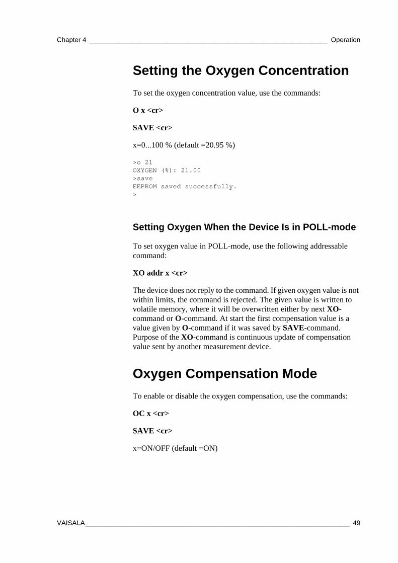
Setting the Oxygen ConcentrationTo set the oxygen concentration value, use the commands:
O x <cr>
SAVE <cr>
x=0...100 % (default =20.95 %)
>o 21OXYGEN (%): 21.00>saveEEPROM saved successfully.>
Setting Oxygen When the Device Is in POLL-mode
To set oxygen value in POLL-mode, use the following addressable command:
XO addr x <cr>
The device does not reply to the command. If given oxygen value is not within limits, the command is rejected. The given value is written to volatile memory, where it will be overwritten either by next XO-command or O-command. At start the first compensation value is a value given by O-command if it was saved by SAVE-command. Purpose of the XO-command is continuous update of compensation value sent by another measurement device.
Oxygen Compensation ModeTo enable or disable the oxygen compensation, use the commands:
OC x <cr>
SAVE <cr>
x=ON/OFF (default =ON)
VAISALA_______________________________________________________________________ 49
User's Guide ______________________________________________________________________
>oc onOC: ON>>saveEEPROM saved successfully.>
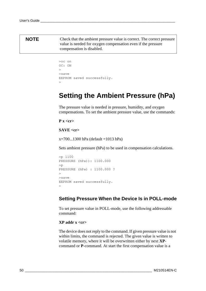
Setting the Ambient Pressure (hPa)The pressure value is needed in pressure, humidity, and oxygen compensations. To set the ambient pressure value, use the commands:
P x <cr>
SAVE <cr>
x=700...1300 hPa (default =1013 hPa)
Sets ambient pressure (hPa) to be used in compensation calculations.
>p 1100PRESSURE (hPa)): 1100.000>pPRESSURE (hPa) : 1100.000 ?>>saveEEPROM saved successfully.>
Setting Pressure When the Device Is in POLL-mode
To set pressure value in POLL-mode, use the following addressable command:
XP addr x <cr>
The device does not reply to the command. If given pressure value is not within limits, the command is rejected. The given value is written to volatile memory, where it will be overwritten either by next XP-command or P-command. At start the first compensation value is a
NOTE Check that the ambient pressure value is correct. The correct pressure value is needed for oxygen compensation even if the pressure compensation is disabled.
50 __________________________________________________________________ M210514EN-C
Chapter 4 ________________________________________________________________ Operation
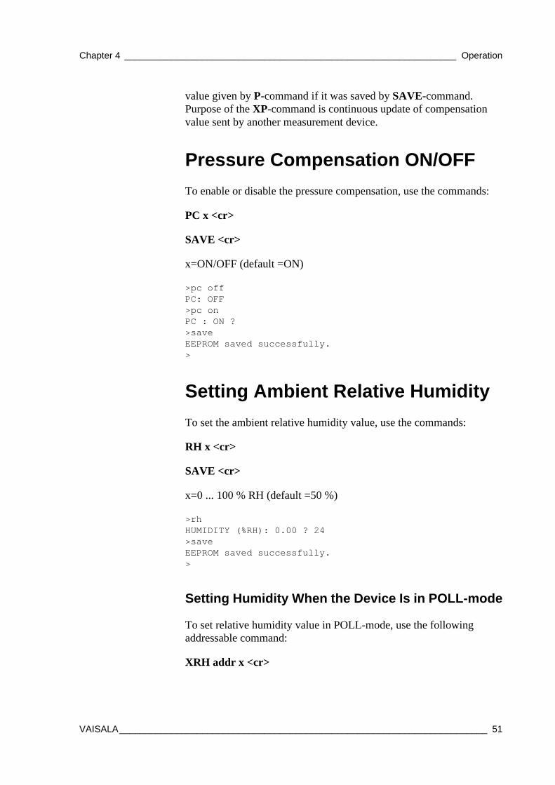
value given by P-command if it was saved by SAVE-command. Purpose of the XP-command is continuous update of compensation value sent by another measurement device.
Pressure Compensation ON/OFFTo enable or disable the pressure compensation, use the commands:
PC x <cr>
SAVE <cr>
x=ON/OFF (default =ON)
>pc offPC: OFF>pc onPC : ON ?>saveEEPROM saved successfully.>
Setting Ambient Relative HumidityTo set the ambient relative humidity value, use the commands:
RH x <cr>
SAVE <cr>
x=0 ... 100 % RH (default =50 %)
>rhHUMIDITY (%RH): 0.00 ? 24>saveEEPROM saved successfully.>
Setting Humidity When the Device Is in POLL-mode
To set relative humidity value in POLL-mode, use the following addressable command:
XRH addr x <cr>
VAISALA_______________________________________________________________________ 51
User's Guide ______________________________________________________________________
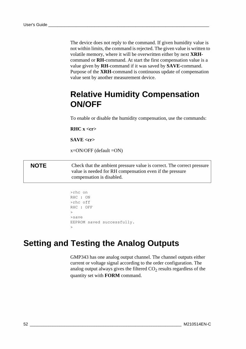
The device does not reply to the command. If given humidity value is not within limits, the command is rejected. The given value is written to volatile memory, where it will be overwritten either by next XRH-command or RH-command. At start the first compensation value is a value given by RH-command if it was saved by SAVE-command. Purpose of the XRH-command is continuous update of compensation value sent by another measurement device.
Relative Humidity Compensation ON/OFFTo enable or disable the humidity compensation, use the commands:
RHC x <cr>
SAVE <cr>
x=ON/OFF (default =ON)
>rhc onRHC : ON >rhc off RHC : OFF>>saveEEPROM saved successfully.>
Setting and Testing the Analog OutputsGMP343 has one analog output channel. The channel outputs either current or voltage signal according to the order configuration. The analog output always gives the filtered CO2 results regardless of the quantity set with FORM command.
NOTE Check that the ambient pressure value is correct. The correct pressure value is needed for RH compensation even if the pressure compensation is disabled.
52 __________________________________________________________________ M210514EN-C
Chapter 4 ________________________________________________________________ Operation
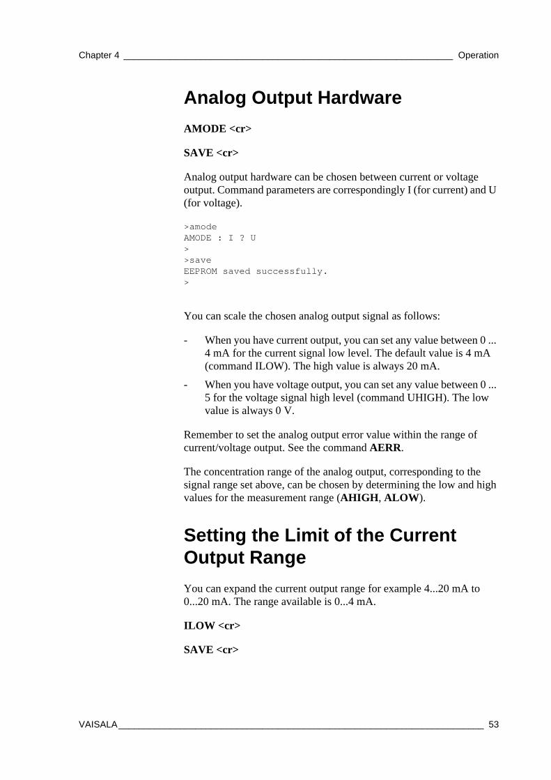
Analog Output HardwareAMODE <cr>
SAVE <cr>
Analog output hardware can be chosen between current or voltage output. Command parameters are correspondingly I (for current) and U (for voltage).
>amodeAMODE : I ? U>>saveEEPROM saved successfully. >
You can scale the chosen analog output signal as follows:
- When you have current output, you can set any value between 0 ... 4 mA for the current signal low level. The default value is 4 mA (command ILOW). The high value is always 20 mA.
- When you have voltage output, you can set any value between 0 ... 5 for the voltage signal high level (command UHIGH). The low value is always 0 V.
Remember to set the analog output error value within the range of current/voltage output. See the command AERR.
The concentration range of the analog output, corresponding to the signal range set above, can be chosen by determining the low and high values for the measurement range (AHIGH, ALOW).
Setting the Limit of the Current Output RangeYou can expand the current output range for example 4...20 mA to 0...20 mA. The range available is 0...4 mA.
ILOW <cr>
SAVE <cr>
VAISALA_______________________________________________________________________ 53
User's Guide ______________________________________________________________________
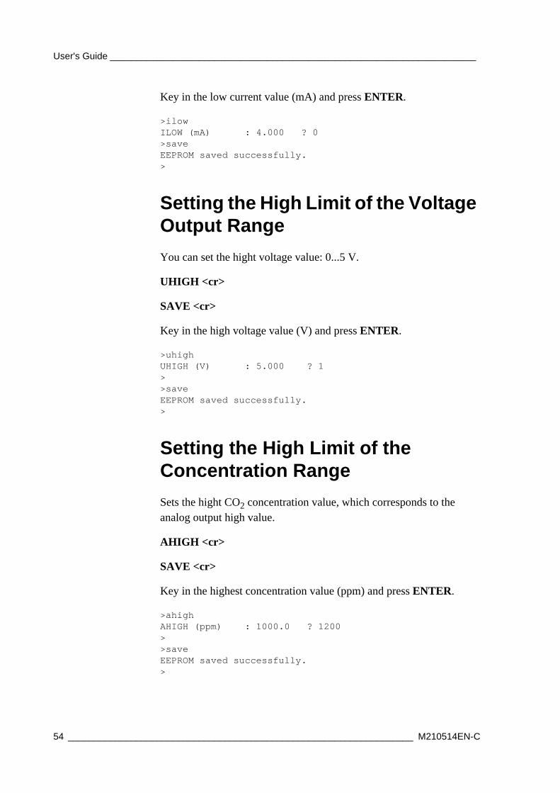
Key in the low current value (mA) and press ENTER.
>ilowILOW (mA) : 4.000 ? 0>saveEEPROM saved successfully.>
Setting the High Limit of the Voltage Output RangeYou can set the hight voltage value: 0...5 V.
UHIGH <cr>
SAVE <cr>
Key in the high voltage value (V) and press ENTER.
>uhighUHIGH (V) : 5.000 ? 1>>saveEEPROM saved successfully.>
Setting the High Limit of the Concentration RangeSets the hight CO2 concentration value, which corresponds to the analog output high value.
AHIGH <cr>
SAVE <cr>
Key in the highest concentration value (ppm) and press ENTER.
>ahighAHIGH (ppm) : 1000.0 ? 1200>>saveEEPROM saved successfully.>
54 __________________________________________________________________ M210514EN-C
Chapter 4 ________________________________________________________________ Operation
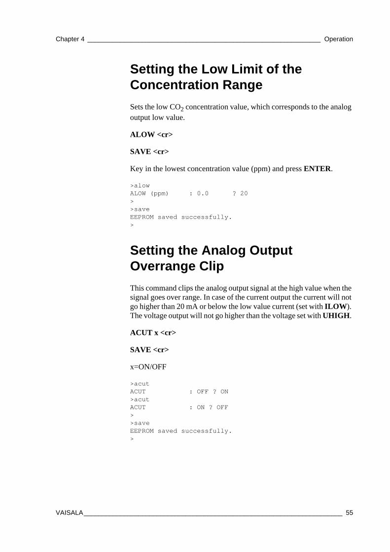
Setting the Low Limit of the Concentration RangeSets the low CO2 concentration value, which corresponds to the analog output low value.
ALOW <cr>
SAVE <cr>
Key in the lowest concentration value (ppm) and press ENTER.
>alowALOW (ppm) : 0.0 ? 20>>saveEEPROM saved successfully.>
Setting the Analog Output Overrange ClipThis command clips the analog output signal at the high value when the signal goes over range. In case of the current output the current will not go higher than 20 mA or below the low value current (set with ILOW). The voltage output will not go higher than the voltage set with UHIGH.
ACUT x <cr>
SAVE <cr>
x=ON/OFF
>acutACUT : OFF ? ON>acutACUT : ON ? OFF>>saveEEPROM saved successfully.>
VAISALA_______________________________________________________________________ 55
User's Guide ______________________________________________________________________
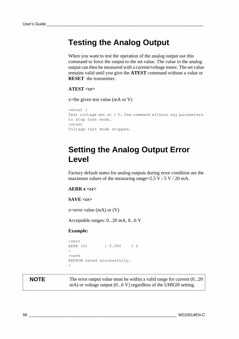
Testing the Analog OutputWhen you want to test the operation of the analog output use this command to force the output to the set value. The value in the analog output can then be measured with a current/voltage meter. The set value remains valid until you give the ATEST command without a value or RESET the transmitter.
ATEST <cr>
x=the given test value (mA or V)
>atest 1Test voltage set at 1 V. Use command without any parameters to stop test mode.>atestVoltage test mode stopped.
Setting the Analog Output Error LevelFactory default states for analog outputs during error condition are the maximum values of the measuring range=2.5 V / 5 V / 20 mA.
AERR x <cr>
SAVE <cr>
x=error value (mA) or (V)
Acceptable ranges: 0...20 mA, 0...6 V
Example:
>aerrAERR (V) : 5.000 ? 0>>saveEEPROM saved successfully.>
NOTE The error output value must be within a valid range for current (0...20 mA) or voltage output (0...6 V) regardless of the UHIGH setting.
56 __________________________________________________________________ M210514EN-C
Chapter 4 ________________________________________________________________ Operation
Device Information and Other General Commands
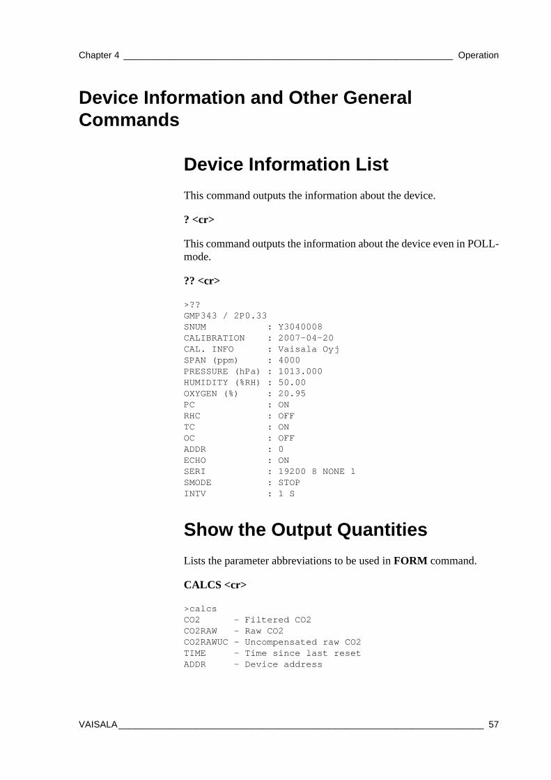
Device Information ListThis command outputs the information about the device.
? <cr>
This command outputs the information about the device even in POLL-mode.
?? <cr>
>??GMP343 / 2P0.33SNUM : Y3040008CALIBRATION : 2007-04-20CAL. INFO : Vaisala OyjSPAN (ppm) : 4000PRESSURE (hPa) : 1013.000HUMIDITY (%RH) : 50.00OXYGEN (%) : 20.95PC : ONRHC : OFFTC : ONOC : OFFADDR : 0ECHO : ONSERI : 19200 8 NONE 1SMODE : STOPINTV : 1 S
Show the Output QuantitiesLists the parameter abbreviations to be used in FORM command.
CALCS <cr>
>calcsCO2 - Filtered CO2CO2RAW - Raw CO2CO2RAWUC - Uncompensated raw CO2TIME - Time since last resetADDR - Device address
VAISALA_______________________________________________________________________ 57
User's Guide ______________________________________________________________________
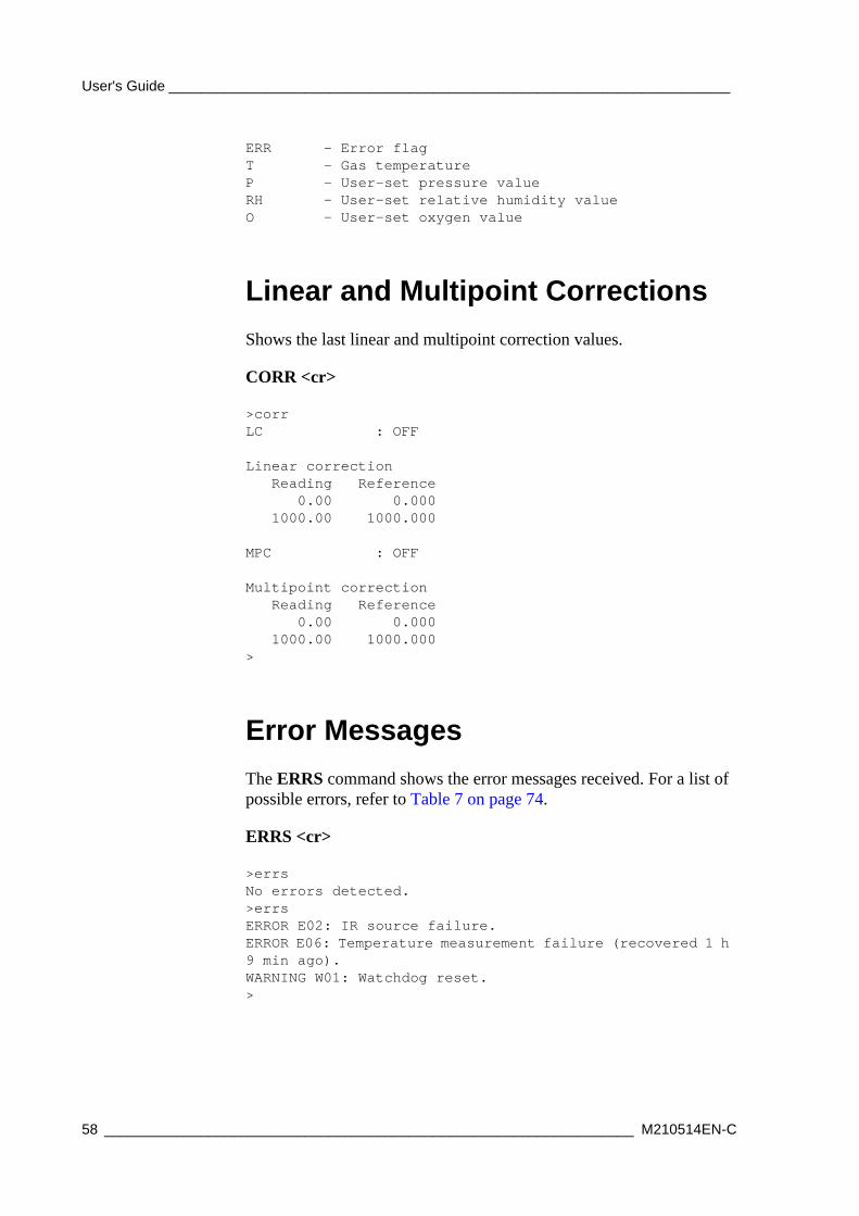
ERR - Error flagT - Gas temperatureP - User-set pressure valueRH - User-set relative humidity valueO - User-set oxygen value
Linear and Multipoint CorrectionsShows the last linear and multipoint correction values.
CORR <cr>
>corrLC : OFF
Linear correction Reading Reference 0.00 0.000 1000.00 1000.000
MPC : OFF
Multipoint correction Reading Reference 0.00 0.000 1000.00 1000.000>
Error MessagesThe ERRS command shows the error messages received. For a list of possible errors, refer to Table 7 on page 74.
ERRS <cr>
>errsNo errors detected.>errsERROR E02: IR source failure.ERROR E06: Temperature measurement failure (recovered 1 h 9 min ago).WARNING W01: Watchdog reset.>
58 __________________________________________________________________ M210514EN-C
Chapter 4 ________________________________________________________________ Operation
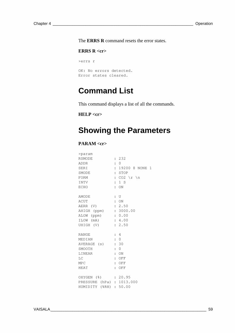
The ERRS R command resets the error states.
ERRS R <cr>
>errs r
OK: No errors detected. Error states cleared.
Command ListThis command displays a list of all the commands.
HELP <cr>
Showing the ParametersPARAM <cr>
>paramRSMODE : 232ADDR : 0SERI : 19200 8 NONE 1SMODE : STOPFORM : CO2 \r \nINTV : 1 SECHO : ON
AMODE : UACUT : ONAERR (V) : 2.50AHIGH (ppm) : 3000.00ALOW (ppm) : 0.00ILOW (mA) : 4.00UHIGH (V) : 2.50
RANGE : 4MEDIAN : 0AVERAGE (s) : 30SMOOTH : 0LINEAR : ONLC : OFFMPC : OFFHEAT : OFF
OXYGEN (%) : 20.95PRESSURE (hPa) : 1013.000HUMIDITY (%RH) : 50.00
VAISALA_______________________________________________________________________ 59
User's Guide ______________________________________________________________________
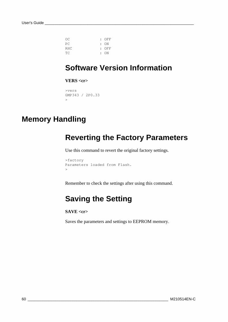
OC : OFFPC : ONRHC : OFFTC : ON
Software Version InformationVERS <cr>
>versGMP343 / 2P0.33>
Memory Handling
Reverting the Factory ParametersUse this command to revert the original factory settings.
>factoryParameters loaded from Flash.>
Remember to check the settings after using this command.
Saving the SettingSAVE <cr>
Saves the parameters and settings to EEPROM memory.
60 __________________________________________________________________ M210514EN-C
Chapter 4 ________________________________________________________________ Operation
Setting the Optics Heating ON/OFFEnables or disables optics heating.
HEAT <cr>
x=ON or OFF (default =ON)
Example:
>heatHEAT : ON ? off>
Resetting the TransmitterRESET <cr>
This command resets the device. If the device is in RUN mode, outputting the results starts immediately after resetting.
VAISALA_______________________________________________________________________ 61

User's Guide ______________________________________________________________________
62 __________________________________________________________________ M210514EN-C
Chapter 5 __________________________________________________ Calibration and Adjustment
CHAPTER 5CALIBRATION AND ADJUSTMENT
This chapter contains information for performing the calibration and adjustment of the GMP343.
In this user's guide the term calibration means comparing the transmitter's reading to a reference concentration. Adjustment, which is usually done after calibration, the reading of the transmitter is changed to correspond to the reference concentration. After adjustment, the original calibration certificate shipped with the product is not valid anymore.
The GMP343 can be sent to Vaisala for calibration, or be calibrated by the user.
Calibration IntervalGMP343 is calibrated as shipped from the factory. The recommended calibration interval is one year. The operating conditions affect the long-term stability. For more information, see Specifications, Operating Conditions, on page 81 and, Performance, on page 77 (long-term stability). In a harsh operating environment it is recommended to check readings more often than in an easy environment.
VAISALA_______________________________________________________________________ 63
User's Guide ______________________________________________________________________
Factory Calibration and AdjustmentYou can send the device to Vaisala Service Center for calibration and adjustment, for more information, see, Vaisala Service Centers, on page 76.
Calibration and Adjustment by the UserCalibration and adjustment are carried out by using the serial communications and the calibration gas(es).
Additional equipment needed:
- power supply 11...36 VDC
- PC and PC connection cable (Vaisala order code 213379) with optional USB adapter (Vaisala order code 219686)
- calibration gases and tubing
- calibration adapter is required for calibrating the diffusion model (Vaisala order code GMP343ADAPTER)
- pressure regulator and flow meter
- barometer (for measuring ambient pressure)
Calibration (Checking)The gas concentration of the reference gases must cover the measurement range of the device.
Checking the Compensations
1. Connect GMP343 to a PC and open the terminal program. For more information, see section Connecting GMP343 to PC on page 29.
2. Connect the 24 VDC supply power to GMP343.
3. Compensations must always be enabled during the calibration procedure. Use the ? command to verify the status of the compensations for ambient pressure, temperature, relative humidity, and oxygen concentration:
?<cr>
64 __________________________________________________________________ M210514EN-C
Chapter 5 __________________________________________________ Calibration and Adjustment
4. If all compensations are not enabled, make note of the current settings so that you can restore them after the calibration if desired. Then issue the following commands to enable the compensations:
PC ON<cr>
TC ON<cr>
RHC ON<cr>
OC ON<cr>
5. You must also set the ambient pressure, relative humidity, and oxygen concentration values of the calibration gas correctly. Typically the relative humidity of the calibration gases is 0 % RH. Oxygen concentration of nitrogen mixture gases is usually 0 %. If necessary, adjust the values. For example:
P 1000.3<cr>
RH 0<cr>
O 0<cr>
For more information on compensations, see section Temperature, Pressure, Relative Humidity, and Oxygen Compensations on page 47.
Measurements in Reference Gases
1. If your GMP343 is the diffusion model, remove the filter cover and place the calibration adapter onto the probe.
2. Let the device warm up for 30 minutes to achieve full calibration accuracy.
3. Turn on the calibration mode by giving the command CALIB ON. This changes some of the transmitter parameters for the duration of the calibration.
CALIB ON <cr>
4. Connect the reference gas to the inlet of GMP343 transmitter and let the gas flow for 5 minutes (about 0.5 l / min).
5. To output the measurement result, key in the command R. Check that the reading is stabilized and write down the CO2 reading (ppm). Enter command S to stop outputting. For the best calibration result, it is recommended to calculate an average of 20 measurements instead of a single reading.
VAISALA_______________________________________________________________________ 65
User's Guide ______________________________________________________________________
6. Shut off the reference gas flow and remove the tubings from the gas bottle. When calibrating at several points, connect the other gases to GMP343 similar to the first gas and carry out the measurements as instructed above (steps 6 and 7).
7. After measurements turn off the calibration mode by giving the command CALIB OFF (this reverts to the original transmitter settings).
CALIB OFF <cr>
Adjustment in 1...2 PointsFirst carry out checking the compensations and perform the reference gas measurements as instructed in the previous section, Calibration and Adjustment by the User on page 64. Then continue as follows:
1. Key in the command
LCI <cr>
2. Key in the reading at the reference gas (ppm) and press ENTER (1.Reading?).
3. Key in the reference gas concentration (ppm) and press ENTER (Reference?).
4. When making a one-point calibration press ENTER again and go to step 6 in this list. When making a two-point calibration, key in the reading at the second reference gas and press ENTER (2.Reading?).
5. Key in the reference gas 2 concentration (ppm) and press ENTER (Reference?).
6. Now the correction values are calculated, but the adjustment is not valid until the correction is confirmed.
7. Confirm the new correction values with the command
LC ON <cr>
8. Use the command R to check with both reference gases that the correction has taken place and the readings are ok.
9. Save the settings:
SAVE <cr>
10. Saves parameters and settings to EEPROM memory.
66 __________________________________________________________________ M210514EN-C
Chapter 5 __________________________________________________ Calibration and Adjustment
Adjustment in 3...8 PointsFirst carry out checking the compensations and perform the reference gas measurements as instructed in the previous section, Calibration and Adjustment by the User on page 64. Then continue as follows:
1. Feed the readings (Reading?) and the corresponding concentrations (Reference?) with the command
MPCI <cr>
2. Confirm the adjustment and the new correction values with the command
MPC ON <cr>
3. Save the settings with the command
SAVE <cr>
4. Saves parameters and settings to EEPROM-memory.
Example of the 2-Point Adjustment Procedure
The following section presents an example of the 2-point adjustment procedure with reference gas concentrations of 0 ppm and 1007 ppm.
1. First turn on the calibration mode for measuring reference gases.
>>calib onCalibration mode started. Use CALIB OFF to stop the mode.
2. The GMP is now measuring the first reference gas (0 ppm). Use command R and let the reading stabilize for several minutes. Calculate the average reading (reading 1).
>r...28.228.228.128.128.2
NOTE Use the actual concentrations given usually in the side of the gas bottle. For example, a gas with a nominal 1000 ppm CO2 concentration might actually contain 1007 ppm CO2.
VAISALA_______________________________________________________________________ 67
User's Guide ______________________________________________________________________
3. The GMP343 is now measuring the second reference gas (1007 ppm). Use command R and let the reading stabilize for several minutes. Calculate the average reading (reading 2).
>>r1067.11066.81067.21066.71066.6
4. Turn off the calibration mode with command CALIB OFF.
>calib offCalibration mode stopped.
5. Next feed the readings: use command LCI to feed the first and second reference gas readings (28 ppm and 1066 ppm), and the corrected values (= the concentrations of the reference gases, 0 ppm and 1007 ppm).
>lci
Reading Reference 0.00 0.000
1000.00 1000.000
NOTE: Entering new correction values all previous correction points!Abort without losing correction pointsby using ESC.
1. Reading ? 28Reference ? 0
2. Reading? 1066Reference? 1007
6. Confirm the adjustment with command LC ON.
>lcLC : OFF ? on
7. Check the reading with the second reference gas, 1007 ppm.
>r1005.41006.21007.11007.1
68 __________________________________________________________________ M210514EN-C
Chapter 5 __________________________________________________ Calibration and Adjustment
8. Check the reading with the first reference gas, 0 ppm.
>r0.20.1-0.1-0.1-0.0-0.2
9. Save the settings.
save>EEPROM saved successfully.>
NOTE The factory settings can be reverted with the command FACTORY.
VAISALA_______________________________________________________________________ 69

User's Guide ______________________________________________________________________
70 __________________________________________________________________ M210514EN-C
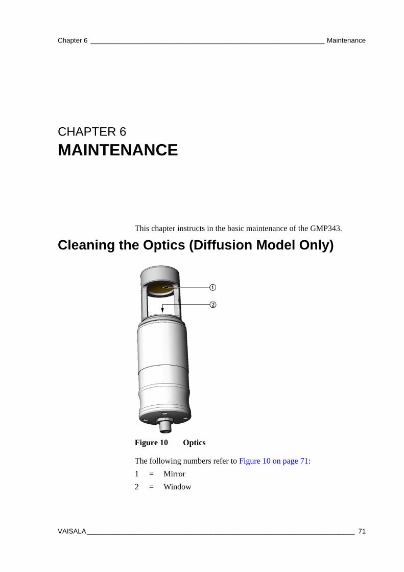
Chapter 6 ______________________________________________________________ Maintenance
CHAPTER 6MAINTENANCE
This chapter instructs in the basic maintenance of the GMP343.
Cleaning the Optics (Diffusion Model Only)
0704-021Figure 10 Optics
The following numbers refer to Figure 10 on page 71:1 = Mirror2 = Window
VAISALA_______________________________________________________________________ 71
User's Guide ______________________________________________________________________
1. Rotate and remove the filter cover.
2. Take a firm hold on the frame of the diffusion filter, and pull it out. Note that the threads for the filter cover are sharp.
3. Blow on the mirror and window area with instrument air to remove any loose particles. In case there is still some dirt on the surfaces, proceed to step 3.
4. Pour some distilled water on the optical surfaces so that they are covered with water. Pour out the excess water.
5. Take a piece of soft, clean paper tissue (optical or clean room grade tissue) and gently dry the surface with rotating movements.
6. If the mirror and/or window surface still seems dirty after water cleaning, clean the dirty surface with pure ethanol or isopropyl alcohol. Pour out the excess liquid carefully.
After cleaning the surfaces should appear clear, without any oily stains, spots, or dust.
7. After cleaning, replace the diffusion filter. Push the end of the filter gently to snap it into place.
8. Replace the filter cover.
NOTE Handle the diffusion filter carefully to prevent contaminants or mechanical stress from damaging the filtering surface.
72 __________________________________________________________________ M210514EN-C
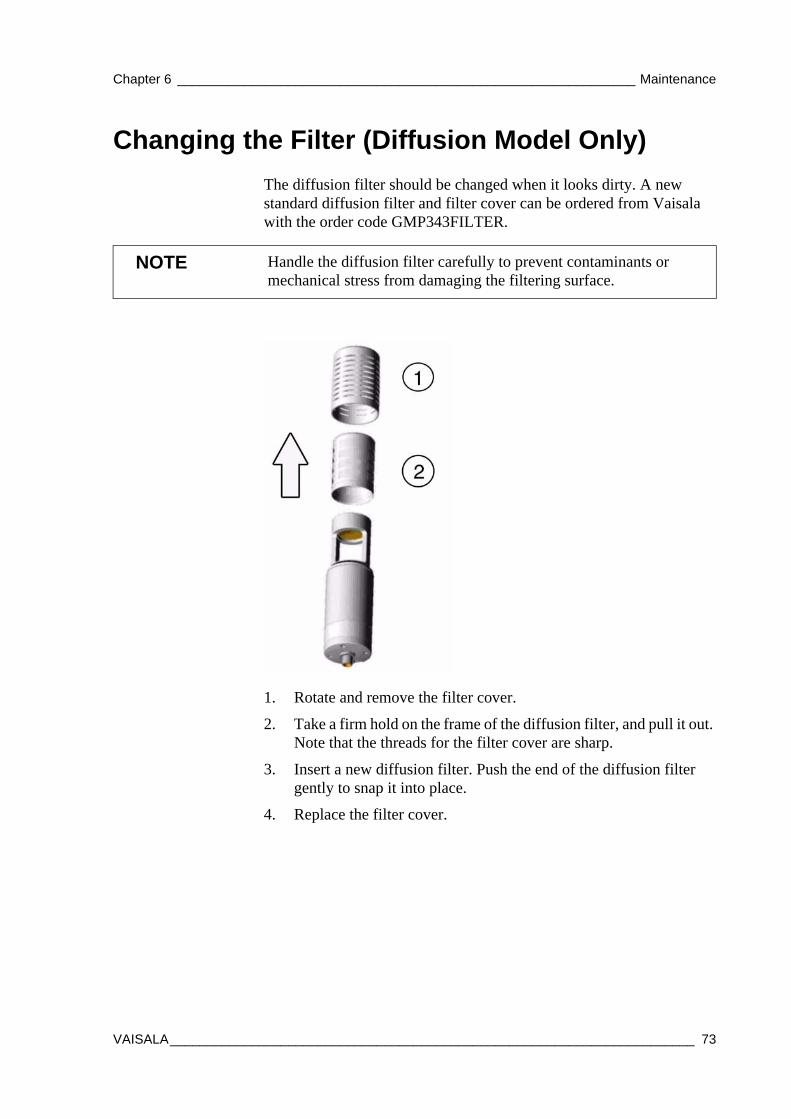
Chapter 6 ______________________________________________________________ Maintenance
Changing the Filter (Diffusion Model Only)The diffusion filter should be changed when it looks dirty. A new standard diffusion filter and filter cover can be ordered from Vaisala with the order code GMP343FILTER.
1. Rotate and remove the filter cover.
2. Take a firm hold on the frame of the diffusion filter, and pull it out. Note that the threads for the filter cover are sharp.
3. Insert a new diffusion filter. Push the end of the diffusion filter gently to snap it into place.
4. Replace the filter cover.
NOTE Handle the diffusion filter carefully to prevent contaminants or mechanical stress from damaging the filtering surface.
VAISALA_______________________________________________________________________ 73
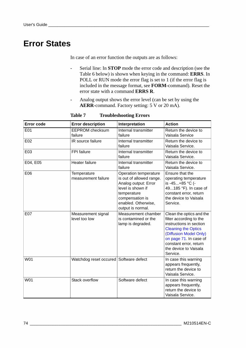
User's Guide ______________________________________________________________________
Error StatesIn case of an error function the outputs are as follows:
- Serial line: In STOP mode the error code and description (see the Table 6 below) is shown when keying in the command: ERRS. In POLL or RUN mode the error flag is set to 1 (if the error flag is included in the message format, see FORM-command). Reset the error state with a command ERRS R.
- Analog output shows the error level (can be set by using the AERR-command. Factory setting: 5 V or 20 mA).
Table 7 Troubleshooting Errors
Error code Error description Interpretation ActionE01 EEPROM checksum
failureInternal transmitter failure
Return the device to Vaisala Service
E02 IR source failure Internal transmitter failure
Return the device to Vaisala Service.
E03 FPI failure Internal transmitter failure
Return the device to Vaisala Service.
E04, E05 Heater failure Internal transmitter failure
Return the device to Vaisala Service.
E06 Temperature measurement failure
Operation temperature is out of allowed range. Analog output: Error level is shown if temperature compensation is enabled. Otherwise, output is normal.
Ensure that the operating temperature is -45...+85 °C (-49...185 °F). In case of constant error, return the device to Vaisala Service.
E07 Measurement signal level too low
Measurement chamber is contamined or the lamp is degraded.
Clean the optics and the filter according to the instructions in section Cleaning the Optics (Diffusion Model Only) on page 71. In case of constant error, return the device to Vaisala Service.
W01 Watchdog reset occured Software defect In case this warning appears frequently, return the device to Vaisala Service.
W01 Stack overflow Software defect In case this warning appears frequently, return the device to Vaisala Service.
74 __________________________________________________________________ M210514EN-C
Chapter 6 ______________________________________________________________ Maintenance
In all error cases first check that the probe is connected properly, then reset the transmitter by disconnecting it. In case of constant error, please contact a Vaisala Service Center. See section Vaisala Service Centers on page 76.
Technical Support
Return InstructionsIf the product needs repair, please follow the instructions below to speed up the process and to avoid extra costs to you.
1. Read the section Warranty on page 11.
2. Contact a Vaisala Service Center or a local Vaisala representative. The latest contact information and instructions are available from www.vaisala.com/returns. Addresses of the Service Centers are provided in section Vaisala Service Centers on page 76.
Please have the following information on hand:
- serial number of the unit
- date and place of purchase or last calibration
- description of the fault
- circumstances in which the fault occurs/occurred
- name and contact information of a technically competent person who can provide further information on the problem
3. Pack the faulty product in a strong box of adequate size, with proper cushioning material to avoid damage.
4. Include the information specified in step 2 in the box with the faulty product. Also include a detailed return address.
5. Ship the box to the address specified by your Vaisala contact.
CAUTION Please note that there are no user-serviceable parts inside the GMP343 transmitter body. The back flange shall not be opened except by authorized Vaisala service personnel.
For technical questions, contact the Vaisala technical support:E-mail [email protected] +358 9 8949 2790
VAISALA_______________________________________________________________________ 75
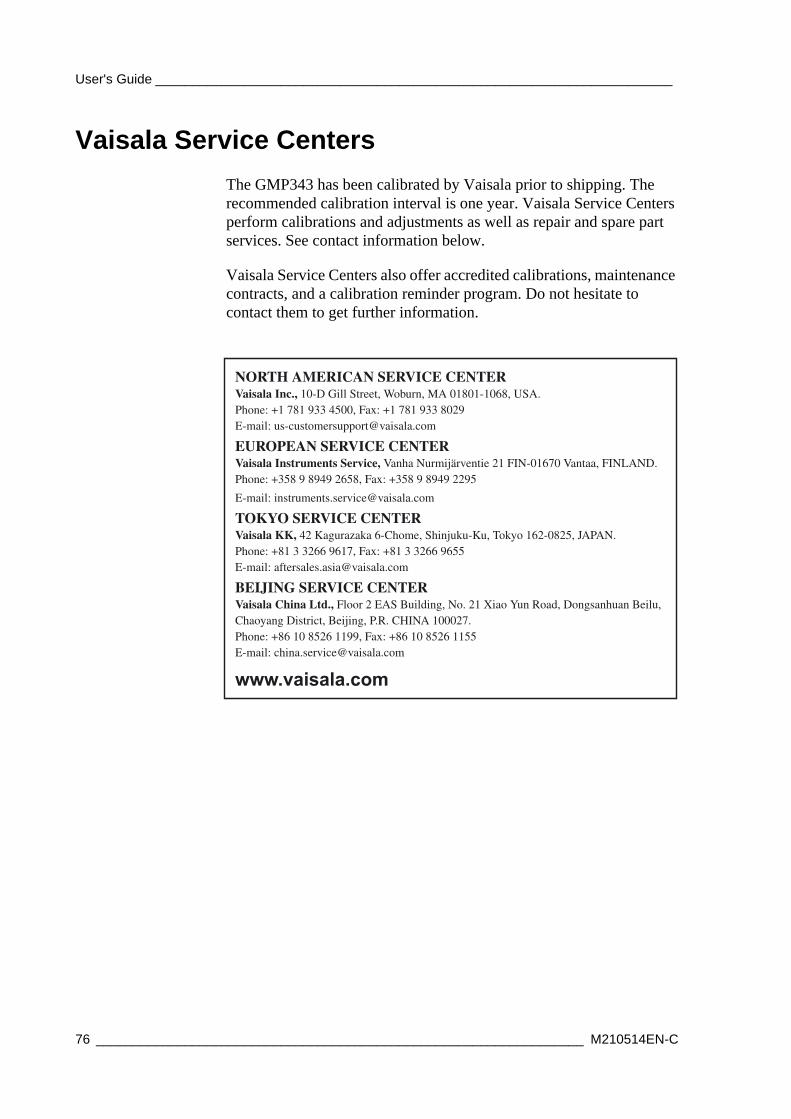
User's Guide ______________________________________________________________________
Vaisala Service CentersThe GMP343 has been calibrated by Vaisala prior to shipping. The recommended calibration interval is one year. Vaisala Service Centers perform calibrations and adjustments as well as repair and spare part services. See contact information below.
Vaisala Service Centers also offer accredited calibrations, maintenance contracts, and a calibration reminder program. Do not hesitate to contact them to get further information.
NORTH AMERICAN SERVICE CENTERVaisala Inc., 10-D Gill Street, Woburn, MA 01801-1068, USA.Phone: +1 781 933 4500, Fax: +1 781 933 8029E-mail: [email protected]
EUROPEAN SERVICE CENTERVaisala Instruments Service, Vanha Nurmijärventie 21 FIN-01670 Vantaa, FINLAND. Phone: +358 9 8949 2658, Fax: +358 9 8949 2295
E-mail: [email protected]
TOKYO SERVICE CENTERVaisala KK, 42 Kagurazaka 6-Chome, Shinjuku-Ku, Tokyo 162-0825, JAPAN. Phone: +81 3 3266 9617, Fax: +81 3 3266 9655 E-mail: [email protected]
BEIJING SERVICE CENTERVaisala China Ltd., Floor 2 EAS Building, No. 21 Xiao Yun Road, Dongsanhuan Beilu,Chaoyang District, Beijing, P.R. CHINA 100027.Phone: +86 10 8526 1199, Fax: +86 10 8526 1155E-mail: [email protected]
www.vaisala.com
76 __________________________________________________________________ M210514EN-C
Chapter 7 ____________________________________________________________ Technical Data
CHAPTER 7TECHNICAL DATA
This chapter provides the technical data of the GMP343.
PerformanceSensor Vaisala CARBOCAP®
Measuring principle Single-Beam Dual-Wavelength NDIRMeasurement range options 0 ... 1000 ppm
0 ... 2000 ppm0 ... 3000 ppm0 ... 4000 ppm0 ... 5000 ppm0 ... 2 %
Accuracy (excluding noise) at 25 °C and 1013 hPa afterfactory calibration with 0.5 % accurate gases with different range options
0 ... 1000 ppm0 ... 2000 ppm - 0 ... 2 %*
± (3 ppm CO2 + 1 % of reading)± (5 ppm CO2 + 2 % of reading)
* Accuracy below 200 ppm CO2 not specified for the 2 % range option
VAISALA_______________________________________________________________________ 77
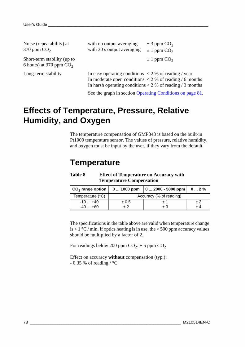
User's Guide ______________________________________________________________________
Effects of Temperature, Pressure, Relative Humidity, and Oxygen
The temperature compensation of GMP343 is based on the built-in Pt1000 temperature sensor. The values of pressure, relative humidity, and oxygen must be input by the user, if they vary from the default.
Temperature
The specifications in the table above are valid when temperature change is < 1 °C / min. If optics heating is in use, the > 500 ppm accuracy values should be multiplied by a factor of 2.
For readings below 200 ppm CO2: ± 5 ppm CO2
Effect on accuracy without compensation (typ.):- 0.35 % of reading / °C
Noise (repeatability) at370 ppm CO2
with no output averagingwith 30 s output averaging
± 3 ppm CO2± 1 ppm CO2
Short-term stability (up to 6 hours) at 370 ppm CO2
± 1 ppm CO2
Long-term stability In easy operating conditionsIn moderate oper. conditionsIn harsh operating conditions
< 2 % of reading / year< 2 % of reading / 6 months< 2 % of reading / 3 months
See the graph in section Operating Conditions on page 81.
Table 8 Effect of Temperature on Accuracy with Temperature Compensation
CO2 range option 0 ... 1000 ppm 0 ... 2000 - 5000 ppm 0 ... 2 %Temperature (°C) Accuracy (% of reading)
-10 ... +40-40 ... +60
± 0.5± 2
± 1± 3
± 2± 4
78 __________________________________________________________________ M210514EN-C
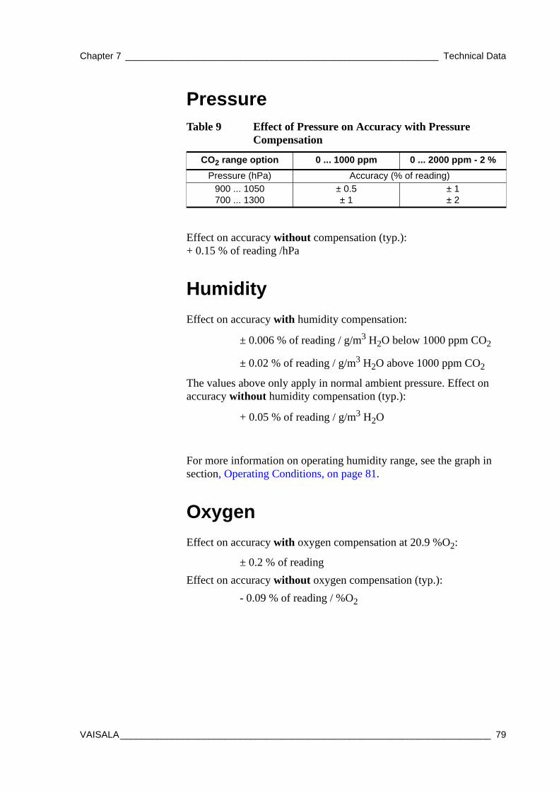
Chapter 7 ____________________________________________________________ Technical Data
Pressure
Effect on accuracy without compensation (typ.):+ 0.15 % of reading /hPa
Humidity
For more information on operating humidity range, see the graph in section, Operating Conditions, on page 81.
Oxygen
Table 9 Effect of Pressure on Accuracy with Pressure Compensation
CO2 range option 0 ... 1000 ppm 0 ... 2000 ppm - 2 %Pressure (hPa) Accuracy (% of reading)
900 ... 1050700 ... 1300
± 0.5± 1
± 1± 2
Effect on accuracy with humidity compensation:
± 0.006 % of reading / g/m3 H2O below 1000 ppm CO2
± 0.02 % of reading / g/m3 H2O above 1000 ppm CO2
The values above only apply in normal ambient pressure. Effect on accuracy without humidity compensation (typ.):
+ 0.05 % of reading / g/m3 H2O
Effect on accuracy with oxygen compensation at 20.9 %O2:
± 0.2 % of readingEffect on accuracy without oxygen compensation (typ.):
- 0.09 % of reading / %O2
VAISALA_______________________________________________________________________ 79
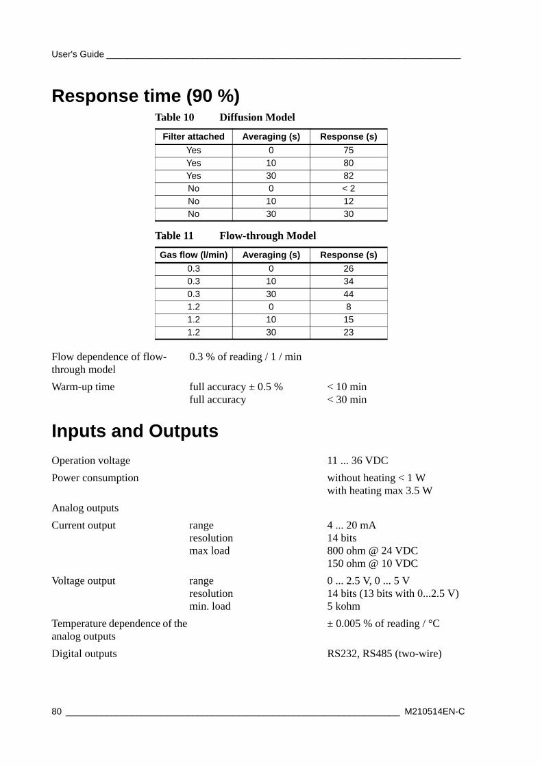
User's Guide ______________________________________________________________________
Response time (90 %)
Inputs and Outputs
Table 10 Diffusion Model
Filter attached Averaging (s) Response (s)Yes 0 75Yes 10 80Yes 30 82No 0 < 2No 10 12No 30 30
Table 11 Flow-through Model
Gas flow (l/min) Averaging (s) Response (s)0.3 0 260.3 10 340.3 30 441.2 0 81.2 10 151.2 30 23
Flow dependence of flow-through model
0.3 % of reading / 1 / min
Warm-up time full accuracy ± 0.5 %full accuracy
< 10 min< 30 min
Operation voltage 11 ... 36 VDCPower consumption without heating < 1 W
with heating max 3.5 WAnalog outputsCurrent output range
resolutionmax load
4 ... 20 mA14 bits800 ohm @ 24 VDC150 ohm @ 10 VDC
Voltage output rangeresolutionmin. load
0 ... 2.5 V, 0 ... 5 V14 bits (13 bits with 0...2.5 V)5 kohm
Temperature dependence of the analog outputs
± 0.005 % of reading / °C
Digital outputs RS232, RS485 (two-wire)
80 __________________________________________________________________ M210514EN-C
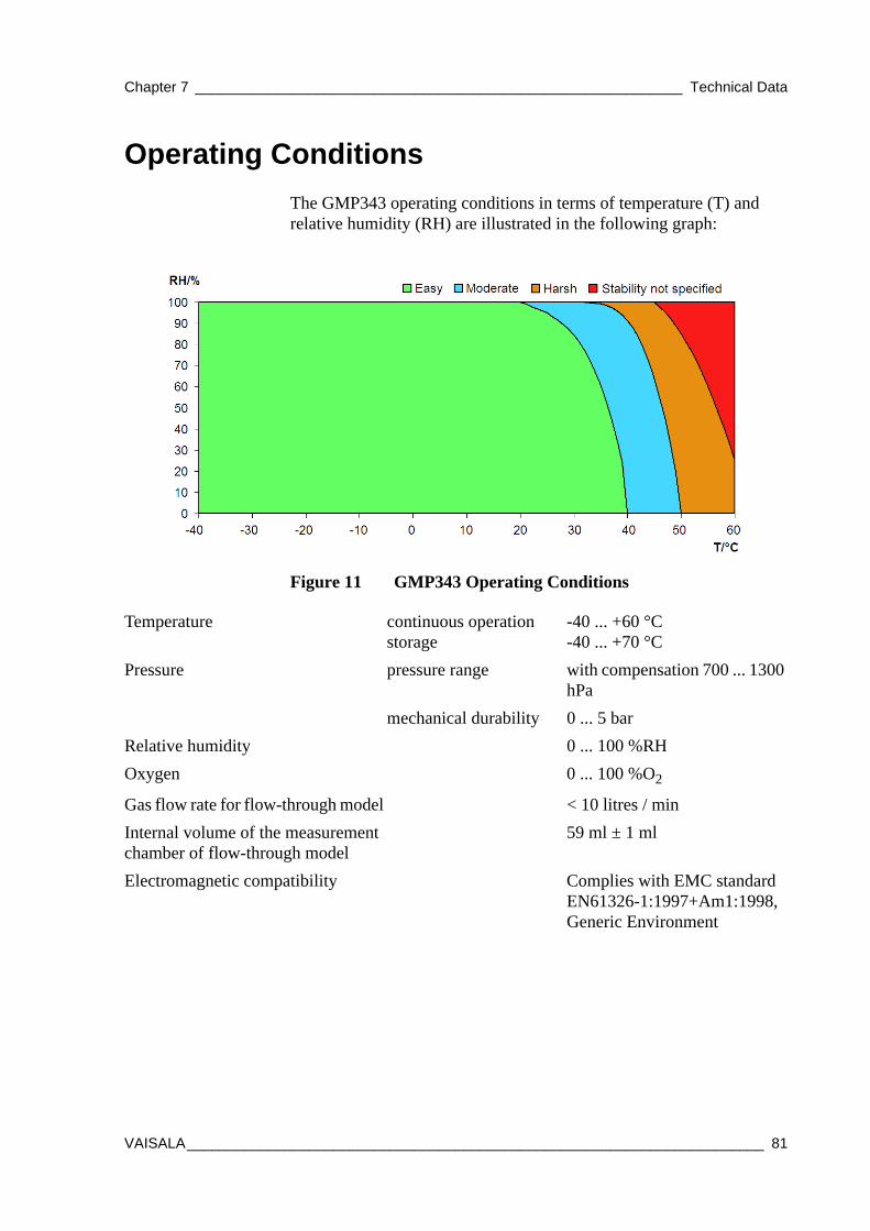
Chapter 7 ____________________________________________________________ Technical Data
Operating ConditionsThe GMP343 operating conditions in terms of temperature (T) and relative humidity (RH) are illustrated in the following graph:
0704-024Figure 11 GMP343 Operating Conditions
Temperature continuous operationstorage
-40 ... +60 °C-40 ... +70 °C
Pressure pressure range with compensation 700 ... 1300 hPa
mechanical durability 0 ... 5 barRelative humidity 0 ... 100 %RHOxygen 0 ... 100 %O2
Gas flow rate for flow-through model < 10 litres / minInternal volume of the measurement chamber of flow-through model
59 ml ± 1 ml
Electromagnetic compatibility Complies with EMC standard EN61326-1:1997+Am1:1998, Generic Environment
VAISALA_______________________________________________________________________ 81
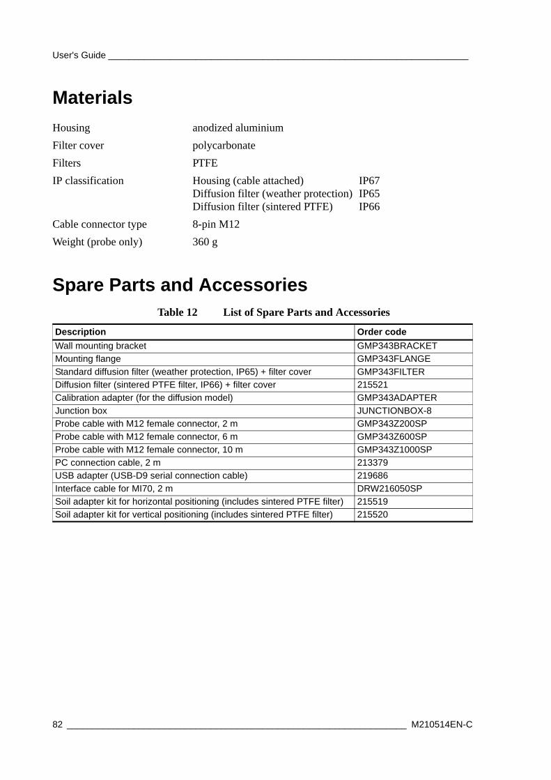
User's Guide ______________________________________________________________________
Materials
Spare Parts and Accessories
Housing anodized aluminiumFilter cover polycarbonateFilters PTFEIP classification Housing (cable attached)
Diffusion filter (weather protection)Diffusion filter (sintered PTFE)
IP67IP65IP66
Cable connector type 8-pin M12Weight (probe only) 360 g
Table 12 List of Spare Parts and Accessories
Description Order codeWall mounting bracket GMP343BRACKETMounting flange GMP343FLANGEStandard diffusion filter (weather protection, IP65) + filter cover GMP343FILTERDiffusion filter (sintered PTFE filter, IP66) + filter cover 215521Calibration adapter (for the diffusion model) GMP343ADAPTERJunction box JUNCTIONBOX-8Probe cable with M12 female connector, 2 m GMP343Z200SPProbe cable with M12 female connector, 6 m GMP343Z600SPProbe cable with M12 female connector, 10 m GMP343Z1000SPPC connection cable, 2 m 213379USB adapter (USB-D9 serial connection cable) 219686Interface cable for MI70, 2 m DRW216050SPSoil adapter kit for horizontal positioning (includes sintered PTFE filter) 215519Soil adapter kit for vertical positioning (includes sintered PTFE filter) 215520
82 __________________________________________________________________ M210514EN-C
Appendix A ______________________________________________________________ Dimensions
APPENDIX ADIMENSIONS
This appendix contains the dimension drawings for the GMP343.
VAISALA_______________________________________________________________________ 83
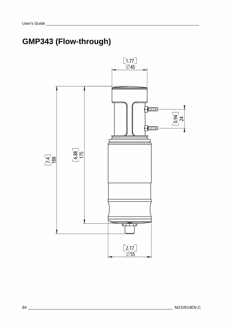
User's Guide ______________________________________________________________________
GMP343 (Flow-through)
451.77
552.17
4249.0
8814.7
57188.6
84 __________________________________________________________________ M210514EN-C
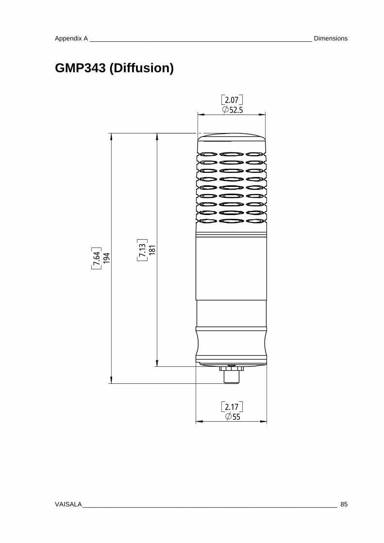
Appendix A ______________________________________________________________ Dimensions
GMP343 (Diffusion)
552.17
52.52.07
49146.7
18131.7
VAISALA_______________________________________________________________________ 85
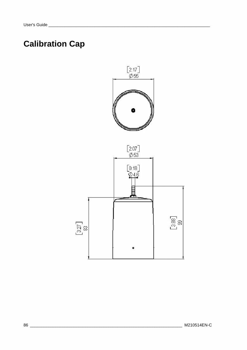
User's Guide ______________________________________________________________________
Calibration Cap
86 __________________________________________________________________ M210514EN-C
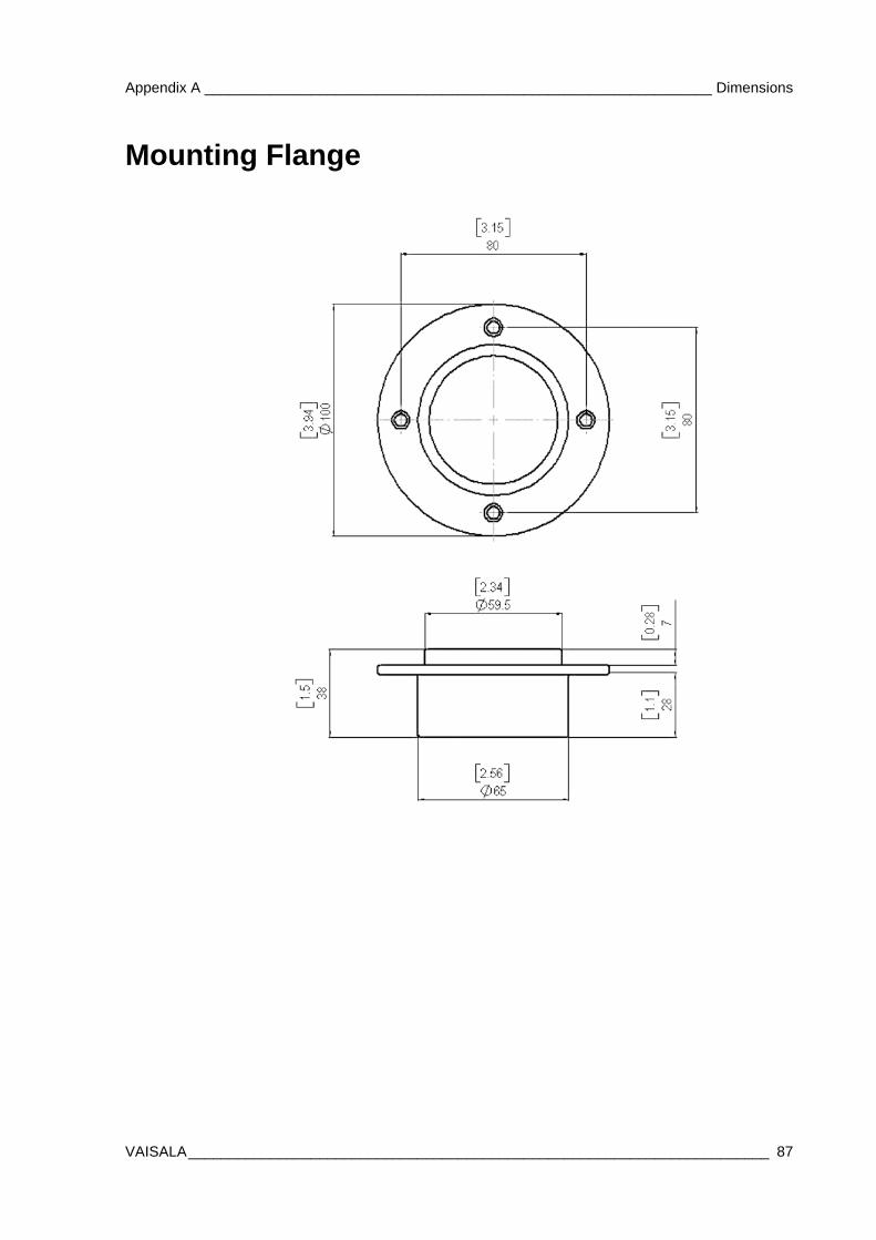
Appendix A ______________________________________________________________ Dimensions
Mounting Flange
VAISALA_______________________________________________________________________ 87
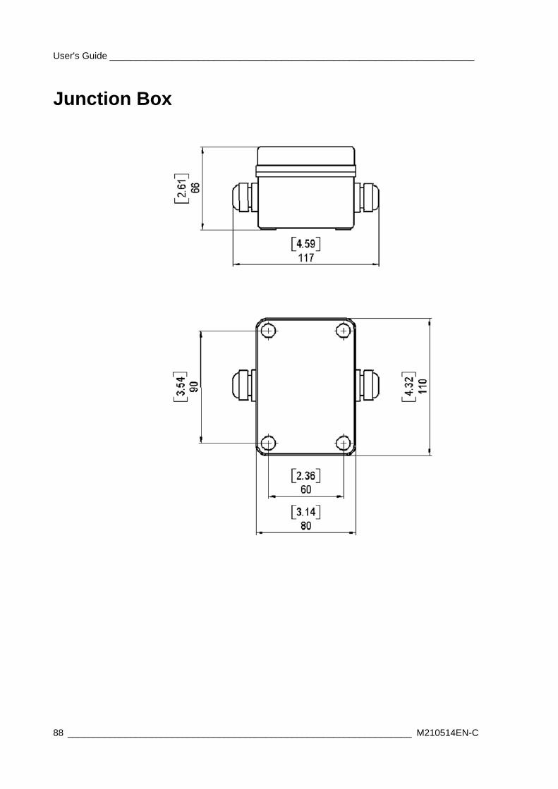
User's Guide ______________________________________________________________________
Junction Box
88 __________________________________________________________________ M210514EN-C
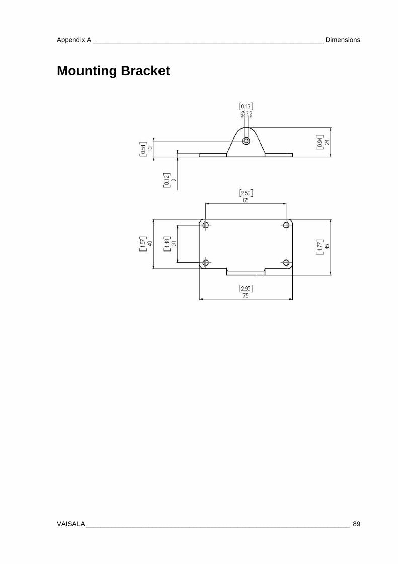
Appendix A ______________________________________________________________ Dimensions
Mounting Bracket
VAISALA_______________________________________________________________________ 89

User's Guide ______________________________________________________________________
90 __________________________________________________________________ M210514EN-C
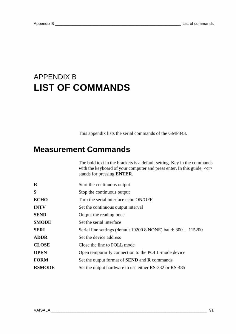
Appendix B _________________________________________________________ List of commands
APPENDIX BLIST OF COMMANDS
This appendix lists the serial commands of the GMP343.
Measurement CommandsThe bold text in the brackets is a default setting. Key in the commands with the keyboard of your computer and press enter. In this guide, <cr> stands for pressing ENTER.
R Start the continuous outputS Stop the continuous outputECHO Turn the serial interface echo ON/OFFINTV Set the continuous output intervalSEND Output the reading once SMODE Set the serial interfaceSERI Serial line settings (default 19200 8 NONE) baud: 300 ... 115200ADDR Set the device addressCLOSE Close the line to POLL modeOPEN Open temporarily connection to the POLL-mode deviceFORM Set the output format of SEND and R commandsRSMODE Set the output hardware to use either RS-232 or RS-485
VAISALA_______________________________________________________________________ 91
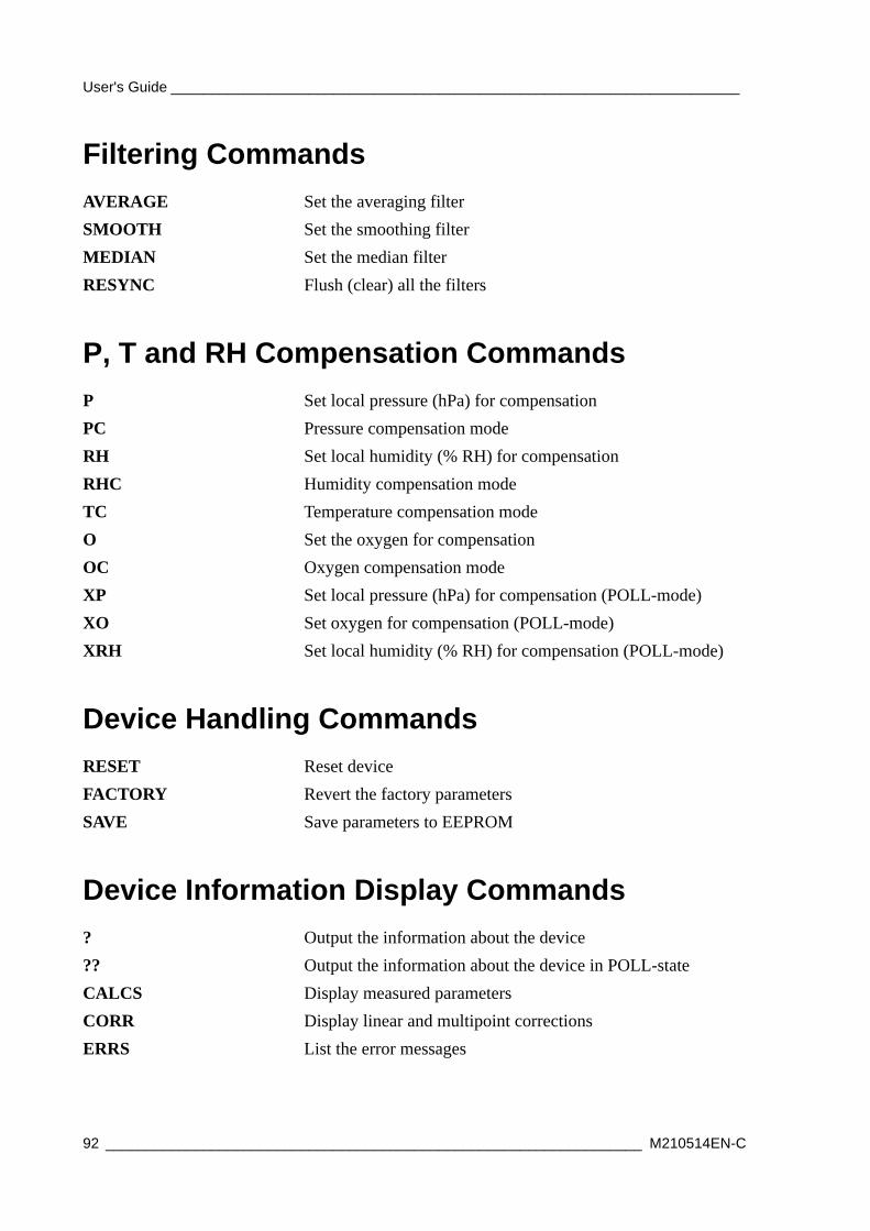
User's Guide ______________________________________________________________________
Filtering Commands
P, T and RH Compensation Commands
Device Handling Commands
Device Information Display Commands
AVERAGE Set the averaging filterSMOOTH Set the smoothing filterMEDIAN Set the median filterRESYNC Flush (clear) all the filters
P Set local pressure (hPa) for compensationPC Pressure compensation modeRH Set local humidity (% RH) for compensationRHC Humidity compensation modeTC Temperature compensation modeO Set the oxygen for compensationOC Oxygen compensation modeXP Set local pressure (hPa) for compensation (POLL-mode)XO Set oxygen for compensation (POLL-mode)XRH Set local humidity (% RH) for compensation (POLL-mode)
RESET Reset deviceFACTORY Revert the factory parametersSAVE Save parameters to EEPROM
? Output the information about the device?? Output the information about the device in POLL-stateCALCS Display measured parametersCORR Display linear and multipoint correctionsERRS List the error messages
92 __________________________________________________________________ M210514EN-C
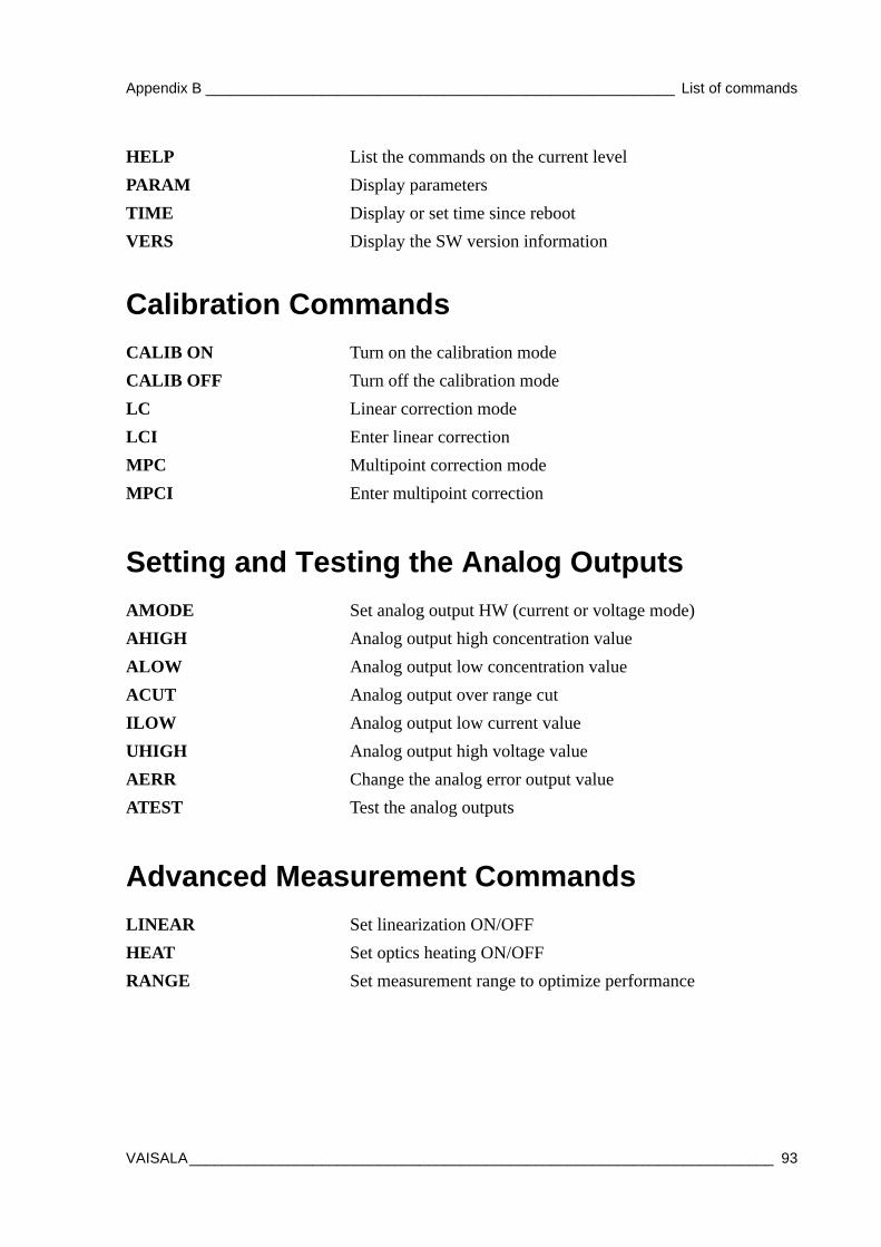
Appendix B _________________________________________________________ List of commands
Calibration Commands
Setting and Testing the Analog Outputs
Advanced Measurement Commands
HELP List the commands on the current levelPARAM Display parametersTIME Display or set time since rebootVERS Display the SW version information
CALIB ON Turn on the calibration modeCALIB OFF Turn off the calibration modeLC Linear correction modeLCI Enter linear correctionMPC Multipoint correction modeMPCI Enter multipoint correction
AMODE Set analog output HW (current or voltage mode)AHIGH Analog output high concentration valueALOW Analog output low concentration valueACUT Analog output over range cutILOW Analog output low current valueUHIGH Analog output high voltage valueAERR Change the analog error output value ATEST Test the analog outputs
LINEAR Set linearization ON/OFFHEAT Set optics heating ON/OFFRANGE Set measurement range to optimize performance
VAISALA_______________________________________________________________________ 93

User's Guide ______________________________________________________________________
94 __________________________________________________________________ M210514EN-C