Embed Size (px)
Citation preview

Manual Instruction
Condor
Staging and sequencing control GLW 4 GLW 4, GLW 4 -S and GLW 4-S kompl.

Staging and sequencing control GLW 4
Page 2 www.condor-cpc.com
GLW 4 GLW 4 without wiring, enclosure
GLW 4 –S GLW 4 in pre-wired plastic enclosure, (dimensions: 420x300 x170mm), DIN-Rail mounting, internal terminal blocks and wiring diagram.
GLW 4-S complete GLW 4 in pre-wired plastic enclosure, (dimensions: 420x300 x170mm), DIN-Rail mounting, internal terminal blocks and wiring diagram. Additionally wired for 4 compressors: isolator, rotary switch „bridge timer“, rotary switch compressor 1 - 4, indicator lamps for voltage supply and compressors 1 – 4.
Operating Manual GLW 4 / GLW 4S Condor Pressure Control GmbH
Warendorfer Straße 47 – 51 D 59320 Ennigerloh Phone: +49 (0) 25 87 / 89-0 Telefax: +49 (0) 25 87 / 89-140 e-Mail: [email protected] http: www.condor-cpc.com
Please observe the safety guidelines in chapter 2 Doku.-Version: 00 - 3.01 Data: Manual Instruction GLW 4 010627 Part No: 237761 (GLW 4); 255475 (GLW 4-S); 255482 (GLW 4-SK) SW-Version: V 1.01 HW-Version: V 3.00 Data: 16.09.2010
Staging and sequencing control GLW 4
www.condor-cpc.com Page 3
Table of Contents
1 Introduction 4 2 Safety guidelines 4
2.1 Marking of guidelines in the operating manual 4 2.2 To be observed 5 2.3 Additional documents 5
3 General 5 4 Hardware 6
4.1 Pressure measuring methods 7 4.2 Remote release input (I51) 7 4.3 Compressor inputs (I11 up to I42) 7 4.4 Alarm output (51/52/54) 7 4.5 Time switch 7 4.6 Bridging time switch (I61, I62) 8 4.7 Ball valve/Output K4 8 4.8 External pressure measurement (p+ / p-) 8
5 Programming 8 5.1 First steps 9 5.2 Front view 9 5.3 Main menu 10
5.3.1 Menu: Main menu 10 5.4 Operating hours 11 5.5 General settings 11
5.5.1 General settings: Operating mode profiles 11 5.5.2 General settings: External input 11 5.5.3 General settings: Alarm pressure, Alarm time, Alarm relay 11 5.5.4 General settings: Logic inputs 11 5.5.5 General settings: Buzzer 11 5.5.6 General settings: Ball valve/Output K4 11 5.5.7 General settings: Immediate load changeover 11 5.5.8 Menu: General settings 12
5.6 Time switch program 12 5.6.1 Menu: Time switch program 13
5.7 Selecting profiles 14 5.7.1 Standby-time (Waiting time) 14 5.7.2 Load changeover time 14 5.7.3 Monitoring time 14 5.7.4 Menu: Profile 1 up to max. Profile 6 15 6 Time delay start 16 7 State of delivery 16 8 Terminal connections 16 9 PC interface 16 10 Technical data 17 11 Conformity 17 12 Connecting diagram GLW 4 18 13 Connecting diagram GLW 4S 19 14 Connecting diagram GLW K 20 13 Programming example, page 1 21 13.1 Programming example, page 22

Staging and sequencing control GLW 4
Page 4 www.condor-cpc.com
1 Introduction In applications where several compressors are used for an air pressure supply system, it is desirable to use a supervisory staging and sequencing control. This control has been realized for many years by the CONDOR GLW 16 and as of June 2004 by the GLW 4 (with many additional functions such as time switch, ball valve function, primary load/load changeover and much more). A staging and sequencing control regulates uniform distribution of the individual compressors hours and guarantees an optimal efficient and economical operation of several compressors. The individual compressor parameters can be programmed in up to 6 different profiles which, considering the general settings, are controlled by the internal time switch. 2 Safety guidelines This operating manual exclusively describes the control unit. It contains important references and warnings, and therefore should be read by the installer as well as by the relevant operator before installing and operating the unit. Note! Not only should the general safety references mentioned in this “Safety guidelines” section be observed, but also any special safety references referred to in the other sections of the manual.
2.1 Marking of guidelines in the operating manual Safety references contained in this operating manual, which can cause personal danger on failure to observe them, are
marked with this general danger symbol.
marked with this general danger warning symbol against electric voltage. .
Staging and sequencing control GLW 4
www.condor-cpc.com Page 5
2.2 To be observed The description and instructions in this operating manual relate to the GLW 4 control. This operating manual does not take into account either all possible design details, styles or all possible coincidences and incidents, which may occur during mounting, operation and maintenance. The control is to be used by professionally trained personnel (see EN 50 110-1). In such case that not all of the information and instructions are found in this operating manual, please ask the manufacturer, Condor-Werke (address see page 2). CONDOR-WERKE Gebr. Frede GmbH & Co. KG takes no responsibility in case the operating manual is disregarded.
Connecting and maintenance of the control may be carried out by qualified personnel only. Before operation, the GLW 4 must be installed in a suitable enclosure. Before operating, make sure that:
• The complete installation is voltage free and secured against power up when mounting and servicing,
• The terminals of the GLW 4 have been properly connected,
• The technical condition of the connected compressors are adjusted to the special settings of the GLW 4,
• The connections have been carried out with diligence,
• The installation has been professionally secured.
2.3 Additional documents In addition to this operating manual and depending on the layout of the switchgear, further documents and manuals may be attached to this operating manual and they are to be observed, such as: • Switching and connecting diagrams • Programming examples 3 General If several compressors are to be used in a in a pressurized air system, it is convenient to assign the primary and peak-demand load operating mode to the compressors. Primary load is the operation of a compressor on low air demand. Should the demand for air rise such that one compressor cannot meet the demand alone, then a second compressor is staged in order to cover the peak-load demand. The GLW 4 is a staging and sequencing control for up to 4 compressors! All settings, e.g. load changeover time and thresholds are programmed by means of three keys next to the LCD display without any special programming knowledge. All specific compressor data are programmed in so called profiles. The internal time switch can control up to 6 different profiles. Connection to the pressurized air system is not yet required.

Staging and sequencing control GLW 4
Page 6 www.condor-cpc.com
Further Advantages For each compressor, cut-in and cut-out thresholds can be programmed. In case only two compressors need to be controlled, then the other two remaining switching hysteresis can be used for additional monitoring purposes. Besides the staging and sequencing features, the following special functions are available:
- Freely programmable integrated time switch.
- Free assignment of primary load and load changeover (i.e. the primary compressor runs always, the other compressors are sequenced)
- Freely programmable ball valve function, with max. three compressors.
- Four separate inputs for power up time, operating hours, errors or switching cycles.
- Following completion of a preset stand-by time the next compressor, if desired, will be activated, even if it has not yet reached its own activation threshold
- The function "release input", e.g. switches the GLW 4 off for servicing purposes, after reaching the next cut-out threshold.
- Programming protection: programming is only possible if the password is known!
- All settings can be deactivated separately!
- Freely programmable voltage free SPDT as alarm output.
With the GLW 4, CONDOR-WERKE offers an electronic solution for staging and sequencing up to max. 4 compressors. The GLW 4 is laid out for 35mm DIN-rail mounting according to DIN EN 50022. The system can be used to control piston as well as screw compressors. A rotation of the compressor starting sequence ensures that all connected compressors are equally used. Rotation of the pressure threshold points associated with each compressor is automatically carried out by entering the "load changeover time". A load changeover time of 0 to 999,9 can be programmed. When entering "Off", the load changeover is not carried out. By entering "primary load", the connected compressor will not be considered during rotation. Rotation only then takes place after both the load changeover time and the highest cut-in pressure setting have been reached. The possibility is also given to program all compressors with identical cut-off pressures. However, setting the same cut-in pressures is not possible. 4 Hardware The GLW 4 is a compressor control unit featuring an integrated relative pressure transducer (0-16 bar, quick connect ) for DIN-rail mounting, 6 optocoupler inputs, 5 voltage free SPDT's, an analog input (two wire, 4...20 mA) for external pressure measurement, a graphic LCD display, 3 key operation and a V24 interface. The following technical points should be observed:

Staging and sequencing control GLW 4
www.condor-cpc.com Page 7
4.1 Pressure measuring methods The GLW 4 can measure pressure using two methods:
a.) Internal pressure transducer The control is connected directly with the air pressure system by means of a quick connect for a 6 mm pneumatic tube (e.g. FESTO Type PAN 6X1). Measuring range: 0 to 16 bar
b.) External pressure transducer A standard pressure transducer (two wire, 4...20 mA) can be connected to p+ and p- terminals of the controller. It must be activated in the main menu under general settings "Pressure measurement external".
The internal pressure sensor can only be used for a max. measuring range of 0..16 bar. When connecting an external pressure transducer, please observe the polarity.
4.2 Remote release input (I51) (GLW 4: I51; GLW 4-S and GLW 4-SK: X2-4) In operating mode, a voltage (230 V AC) must be applied to terminal I51. As soon as the voltage on I51 is switched off (e.g. night time switchboard power down) the GLW 4 is powered down after exceeding the cut-in threshold 1. When the voltage is again applied to I 51, the GLW 4 will continue to operate. When using this function, all set times are not deleted but continue to function after powering up. The corresponding reference potential (generally the N conductor) must be applied to terminals I52/I62. 4.3 Compressor inputs (GLW 4: I11 bis I42; GLW 4-S and GLW 4-SK: X2-6 bis 9) The input terminals I11 up to I42 can be used to additionally monitor the connected compressors (operating hours or error messages or switching cycles). The input logic (NO or NC) of the inputs can changed in the menu "Logic inputs" under general settings. NO = An action follows when applying a voltage. NC = An action follows when removing a voltage. This function requires the corresponding compressor inputs be connected. 4.4 Alarm output (GLW 4: 51/52/54; GLW 4-S and GLW 4-SK: X2-1 bis 3) If the system pressure sinks below the set alarm pressure and if the set monitoring time has elapsed and if the alarm relay in the menu has been set to „ON“, then an alarm is given over the alarm output (voltage free SPDT). Furthermore, an alarm is given when the cut-out pressures are exceeded as soon as the monitoring time has elapsed and the alarm relay in the menu has been activated (On). 4.5 Time switch Very often in compressor applications, timer functions are required. The timer functions are activated when under general settings, operating profiles, "Time switch" has been set. This means that the selected profiles in the timer program are executed. Before this, however, date and time under general settings should be checked and eventually updated. An automatic summer/winter changeover is not available.

Staging and sequencing control GLW 4
Page 8 www.condor-cpc.com
4.6 Bridging time switch (GLW 4: I 61 and I52/I62; GLW 4-S: X2-5 and X1-N) The time switch function is switched off as soon as e.g., a 230 V AC voltage is applied to terminal I61 and the reference potential (generally the N conductor) has been connected to terminals I52/I62 and under general settings, function external input, the profile selected at the time has been programmed. 4.7 Ball valve/Output K4 Once the function ball valve/output K4 has been programmed to "On", then only three compressors can be controlled while the fourth connection is used as a ball valve control. This means, e.g. that the fourth voltage free SPDT can be used to control a weekend disconnection, hereby reducing energy costs caused by air leakage in the pressure line(s). 4.8 External pressure measurement (GLW 4: p+ / p-; GLW 4-S and GLW 4-SK: X2-10
and 11) When selecting "external" for pressure measurement under general settings, the internal pressure transducer is deactivated and the external pressure transducer (two wire, 4...29 mA) is activated. Furthermore, the corresponding measuring range end value must also be entered. Any standard two wire pressure transducer, 4...20 mA, UB 18-21V DC can be used.
Please observe the polarity when connecting an external pressure transducer!
5 Programming Programming is carried out using the 3 keys. In order to change a parameter, a password must be entered! The default password of the GLW 4 control is „0190“. Changing the password can be carried out under general setting and should only be done with the necessary corresponding care. Reactivating the control is only possible by CONDOR WERKE Gebr. Frede GmbH & Co. KG upon loss of the password. Once the operating voltage is applied, the Condor Logo (a short acoustic signal can be heard) with the type designation GLW 4 and software version are displayed. When pressing one of the keys, the main display appears:

Staging and sequencing control GLW 4
www.condor-cpc.com Page 9
By pressing the OK key, the error messages (if available) and the status of the control are displayed in clear text. By pressing the arrow keys you can scroll through the main menu. Pressing the OK key will access the corresponding sub menu, use the arrow keys to scroll through the selected menu. 5.1 First steps In the general settings menu, all basic settings are carried out. In the first step, the "general settings" are entered: pressure measurement; unit; language; password; operating method profile, i.e. using the time switch or a specific profile; function of the external input; date, time; alarm settings; logic inputs of the compressors; ball valve function; direct load changeover or only upon reaching the cut-out threshold and the buzzer (on/off). Thereafter if required, the time switch settings in the menu "Time switch program" are carried out and the corresponding profiles specified. Finally, the respective profiles are programmed. Up to 6 different profiles can be programmed as long as the time switch is activated and the different profiles in the time switch program have been selected. 5.2 Front view

Staging and sequencing control GLW 4
Page 10 www.condor-cpc.com
5.3 Main menu The arrow keys can be used to scroll through the main menu. When the OK key is pressed, a sub menu is accessed or it confirms the selected setting 5.3.1 Menu: Main menu
Delete errors; GLW 4 Status
Main Menu Operating Hours
Power up time,Operating hours, Errors,Switching cycles
Main Menu General Settings
Menu General Settings
Main Menu Time Switch Program
Menu Time Switch Program
Main Menu Select Profile Profile 1
Profile 1
Main Menu Select Profile Profile 6
Profile 2

Staging and sequencing control GLW 4
www.condor-cpc.com Page 11
5.4 Operating hours When in the main menu operating hours is selected by pressing the OK key, the respective monitoring data (mains power up time, operating hours, number of errors, switching cycles) is displayed. This, however, is only possible when the corresponding logic has been programmed. Pressing all three keys simultaneously, will delete the monitoring data. 5.5 General settings Basic settings are carried out in the general settings menu. All special sub-menu settings are explained below as follows: 5.5.1 General settings: Operating mode profiles In this menu, the basic logic of the rules are programmed: Off The control is powered down. P1 up to P6 Only the selected profile is executed. Time switch The control executes the settings made in the time switch program. 5.5.2 General settings: External input In this menu, the basic logic of the rules are programmed: Off The control is powered down. P1 up to P6 Only the selected profile is executed. Time switch The control executes the settings made in the time switch program. 5.5.3 General settings: Alarm pressure, Alarm time, Alarm relay Under alarm pressure, the alarm level is set, how long the alarm should last and whether also the voltage free SPDT is active. An alarm is given as soon as the alarm time has elapsed and the set alarm level has still not been exceeded. 5.5.4 General settings: Logic inputs Here, the logic of the inputs for mains power up time, operating hours, errors and switching cycles can be programmed 5.5.5 General settings: Buzzer When selecting "On", the internal alarm buzzer is activated. 5.5.6 General settings: Ball valve/Output K4 When selecting "On", only three compressors can be controlled. With the fourth contact, an electric ball valve can be controlled (e.g. week end power down 5.5.7 General settings: Immediate load changeover After the load change time has expired and upon reaching the next cut-out threshold, the chronological order of the compressors change. If "On" has been selected in the menu, the load changeover is carried out immediately without reaching the next cut-out threshold.

Staging and sequencing control GLW 4
Page 12 www.condor-cpc.com
5.5.8 Menu: General settings
Back to Main Menu
General Settings Pressure Measurement Internal
Switch from internal sensor to external sensor connection.
General Settings Alarm press. 05.00bar Alarm time: 999sec Alarm relay: Off
Change Values: Alarm pressure, Alarm time and status of Alarm relay
General Settings Unit: bar Unit: psi
Change unit from bar to psi
General Settings Logic Inputs Operation/Errors... 1NO 2NO 3NO 4NO
Change Logic of Inputs 1 to 4
General Settings Language:German/ English/Italian
Change language: German, English, Italian
General Settings Ball valve/Output K4 On
Change Logic of Compressor Output 4 (41,42,44): On, Off
General Settings Change Password: **** ****
Change of password
General Settings Load Changeover Switch immediately Off
Change Logic after Load Changeover: On: Rotation takes place immediately. Off: Rotation takes place only after reaching the next cut-off threshold.
General Settings Operating Mode Profiles Time Switch
Change logic: Time switch, P1 to P6, Off
General Settings Buzzer Off
Buzzer activation and interface release
General Settings Function ext. Input No Function
Change logic of input I61: Off, No function, OK P1 up to P6
Back to Main Menu Back to Main Menu
General Settings Date/Time: Mo 10.05.200417:44:32
Change Logic of Inputs 1 to 4
General Settings Pressure measurement Internal
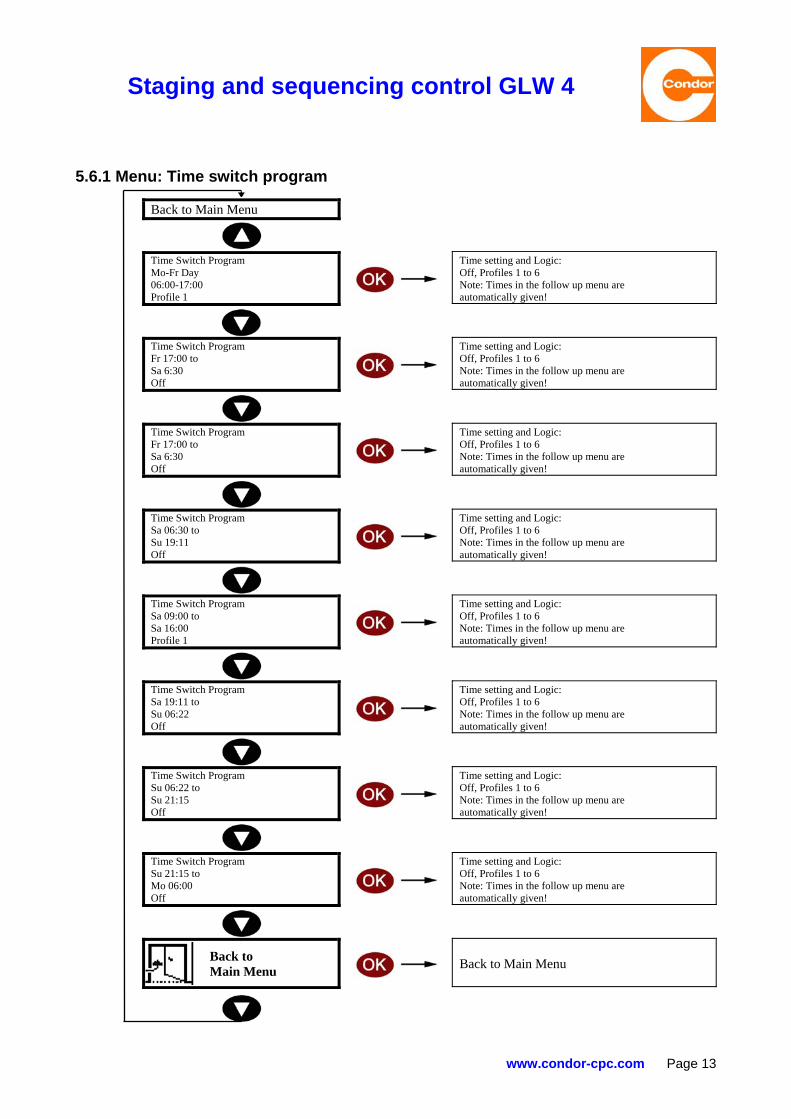
5.6 Time switch program All specific compressor settings are entered in a so called profile. The time switch function is activated once the setting "Time switch" under general settings "Operating mode profile" has been selected. In the time switch program, a 7 day, 24 hour partition can be found. By programming the desired time periods and assigning the desired profiles, the GLW 4 operates only according to the time switch guidelines. Start and stop times for the following time periods are always the same. The start time period in the follow up menu is automatically given. By changing to a profile (P1 to P6) in "Operating mode Profile" under general settings, the time switch function is deactivated and only the programmed profile is then executed
Staging and sequencing control GLW 4
www.condor-cpc.com Page 13
5.6.1 Menu: Time switch program
Back to Main Menu
Time Switch Program Mo-Fr Day 06:00-17:00 Profile 1
Time setting and Logic: Off, Profiles 1 to 6 Note: Times in the follow up menu are automatically given!
Time Switch Program Fr 17:00 to Sa 6:30 Off
Time setting and Logic: Off, Profiles 1 to 6 Note: Times in the follow up menu are automatically given!
Time Switch Program Fr 17:00 to Sa 6:30 Off
Time setting and Logic: Off, Profiles 1 to 6 Note: Times in the follow up menu are automatically given!
Time Switch Program Sa 06:30 to Su 19:11 Off
Time setting and Logic: Off, Profiles 1 to 6 Note: Times in the follow up menu are automatically given!
Time Switch Program Sa 09:00 to Sa 16:00 Profile 1
Time setting and Logic: Off, Profiles 1 to 6 Note: Times in the follow up menu are automatically given!
Time Switch Program Sa 19:11 to Su 06:22 Off
Time setting and Logic: Off, Profiles 1 to 6 Note: Times in the follow up menu are automatically given!
Time Switch Program Su 06:22 to Su 21:15 Off
Time setting and Logic: Off, Profiles 1 to 6 Note: Times in the follow up menu are automatically given!
Time Switch Program Su 21:15 to Mo 06:00 Off
Time setting and Logic: Off, Profiles 1 to 6 Note: Times in the follow up menu are automatically given!
Back to Main Menu
Back to Main Menu

Staging and sequencing control GLW 4
Page 14 www.condor-cpc.com
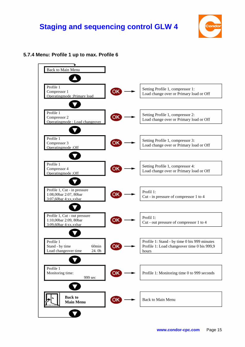
5.7 Selecting profiles In the menu "Select profile" the individual compressor data are entered in the selected profile. Up to 6 different profiles can be programmed. Under "Select profile" "Operating mode", 3 different settings are possible. Primary load (the compressor is not considered when rotating), Load changeover (the compressor is considered when rotating) and OFF (no compressors connected). Finally, the cut-in and cut-out pressures of the individual compressors are programmed. All special settings are described below in detail as follows: 5.7.1 Standby-time (Waiting time) In case the relevant compressor has not reached the programmed cut-out threshold after the standby-time (0 to 999 minutes) has elapsed, the next compressor in line is automatically staged. When selecting "0", this function is deactivated. 5.7.2 Load changeover time The load changeover time determines the actual rotation time period between the connected compressors! The changeover time is the time in which compressor 1 is triggered, i.e. the load changeover does not take place after e.g. 24 hours have elapsed but only when the relevant compressor has been triggered for the length of the programmed time. After the load changeover time has elapsed, the primary load changes then to the next compressor. A load change over time of 0 to 999 hours can be programmed. If under General Settings "Load changeover switch immediately" has been set to On, the load changeover is carried out immediately. If Off has been selected, then the load changeover is carried out when reaching the highest cut-in threshold.
Please note that the load changeover time is the time during which the compressor is triggered!
5.7.3 Monitoring time The monitoring time is initiated once the applied system pressure sinks below the set alarm pressure or rises above the highest cut-out threshold. If after the monitoring time has elapsed and the system pressure is still below the set alarm level (or above the highest cut-out threshold), then the alarm output is activated.
Staging and sequencing control GLW 4
www.condor-cpc.com Page 15
5.7.4 Menu: Profile 1 up to max. Profile 6
Back to Main Menu
Profile 1 Compressor 1 Operatingmode :Primary load
Setting Profile 1, compressor 1: Load change over or Primary load or Off
Profile 1 Compressor 2 Operatingmode : Load changeover
Setting Profile 1, compressor 2: Load change over or Primary load or Off
Profile 1 Compressor 3 Operatingmode :Off
Setting Profile 1, compressor 3: Load change over or Primary load or Off
Profile 1 Compressor 4 Operatingmode :Off
Setting Profile 1, compressor 4: Load change over or Primary load or Off
Profile 1, Cut - in pressure 1:08,00bar 2:07, 80bar 3:07,60bar 4:xx,xxbar
Profil 1: Cut - in pressure of compressor 1 to 4
Profile 1, Cut - out pressure 1:10,00bar 2:09, 80bar 3:09,60bar 4:xx,xxbar
Profil 1: Cut - out pressure of compressor 1 to 4
Profile 1 Stand - by time 60min Load changeover time 24. 0h
Profile 1: Stand - by time 0 bis 999 minutes Profile 1: Load changeover time 0 bis 999,9 hours
Profile 1 Monitoring time: 999 sec
Profile 1: Monitoring time 0 to 999 seconds
Back to Main Menu
Back to Main Menu

Staging and sequencing control GLW 4
Page 16 www.condor-cpc.com
6 Time delay start Due to existing safety standards, all programmed compressors are switched on after a delay time of 10 s when operating the control (system pressure: 0 bar). This setting cannot be switched off. 7 State of delivery When delivered, the time switch, external pressure sensor and ball valve functions are not activated. Bitte bedenken Sie die manuell erforderliche Umstellungen von Sommer- auf Winterzeit und umgekehrt. 8 Kurzanleitung GLW 4, für die Anwendung 230V-AC Folgende Schritte sind für einen ersten Betrieb mindestens zu erledigen und zu beachten:
1.) GLW 4: A1 und I51 an 230V-AC anschließen! 2.) GLW 4: A2 und I52/62 an N anschließen! 3.) Druckluft anschließen! 4.) Profil 1 programmieren, mit Passwort 0190 (Auslieferzustand)! 5.) Die Lastwechselzeit ist die reine Lastzeit, der Kompressoren! 6.) Die Eingänge I 11 bis I 41 sind nur für die Funktionen Betriebsstundenanzeige usw. verwendbar.
Die Kompressoren werden über den jeweiligen potentialfreien Wechselkontakt (GLW 4: Klemmen 11/12/14, z. B. für Kompressor 1 und Klemmen 21/22/24 für Kompressor 2) angesteuert.
Bei Fragen und technischen Problemen wenden Sie sich bitte an: Condor Pressure Control GmbH Warendorfer Straße 47-51 D-59320 Ennigerloh
Phone: +49 (0)2587 89 - 0 Telefax: +49 (0)2587 89 - 140
[email protected] www.condor-cpc.com
9 Terminal connections GLW 4 Terminals Function A1 Mains voltage connection 230 V AC A2 Connection N conductor I11 Compressor 1 I12 Reference input I 11 (N conductor) I21 Compressor 2 I22 Reference input I 21 (N conductor) I31 Compressor 3 I32 Reference input I 31 (N conductor) I41 Compressor 4 I42 Reference input I 41 (N conductor) I51 Voltage connection alarm relays I52 / I62 Reference input I 51 / I 61 (N conductor) I61 Bridge time switch 11 / 12 / 14 Voltage free output compressor 1 21 / 22 / 24 Voltage free output compressor 2 31 / 32 / 34 Voltage free output compressor 3 41 / 42 / 44 Voltage free output compressor 4 51 / 52 / 54 Voltage free alarm output P+ /p- Externanl pressure transducer connecton (two wire) 10 PC interface The GLW 4 control features a V24 interface which allows programming of settings and more with a PC. The interface features a protective cap. This function is not yet active with the software version V1.00.

Staging and sequencing control GLW 4
www.condor-cpc.com Page 17
11 Technical data The GLW 4 is a compressor control unit featuring an integrated relative pressure transducer (0-16 bar, quick connect ) for DIN-rail mounting, 6 optocoupler inputs, 5 voltage free SPDT's, an analog input (two wire, 4...20 mA) for external pressure measurement, a graphic LCD display, 3 key operation and a V24 interface (at the moment without function). Programming is carried out with the use of three keys and the help of the LCD-Display. Internal pressure sensor (Relative pressure transducer) Pneumatic tube cross-section 6mm, suitable tube: FESTO PAN 6X1 Cu-in and cu-out pressure in bar/psi 1 to 16 bar (14.5 – 232 psi) Max. permissible pressure 25 bar (363 psi) Error (at 25°C) typically +/-0.2 bar +/- 1 digit Operational data Power supply (A1/A2) 90 to 265 V-AC, 50/60 Hz Duty factor 100% Permissible ambient and media temperature 0°C up to + 50°C Permissible ambient air humidity 10%-90% relative humidity, non condensing Permissible storage temperature -40°C up to + 80°C Air and creepage distances according to DIN VDE 0110-1 Mounting position optional Power consumption max. 10 VA Housing data Dimensions 140 x 90 x 59 mm Material PC – GF, light gray Mounting Snap-On DIN-rail mounting, 35 mm, according to EN
50022 Degree of protection, housing IP 40 Shock protection according to VBG 4 Number of Terminals 32 Connection unloseable clamp screws, Philips Max. connecting cross-section 2 x 2,5 mm2
2x 1,5 mm2 wire DIN 46 228-1/-2/-3/-4 Max. current (Relay contact) max. 250 V-AC / 5A AC1
max. 30 V-DC / 2A
Digital Inputs optocoupler, 250V-AC1 / 30V-DC Analog input for external pressure sensor UB 18 up to 21 V-DC, two-wire, 4...20 mA 12 Conformity The staging and sequencing control type GLW 4 corresponds to the following directives/standards: EMI/Directive 2004 / 108 / EG EN 61000-6-3 (2007) EN 61000-6-1 (2007) EN 61000-3-2 (2010) Low Voltage Direction 2006 / 9S / EG EN 60204-1 (2007) We want you to use only state of the art products, therefore we reserve the right to make any necessary technical changes without prior warning.

Staging and sequencing control GLW 4
Page 18 www.condor-cpc.com
13 Connecting diagram GLW
Input compressor 1
Input compressor 2
Input compressor 3
Input compressor 4
Input: Remote release Input: Bridge time switch
Output compressor 1 Output compressor 2 Output compressor 3 Output compressor 4 Output Alarm relay
Warning! When connecting the GLW 4,
the Technical Data under Chapter 10
are to be observed
Connection: External pressure
transducer
Qucik connect

Staging and sequencing control GLW 4
www.condor-cpc.com Page 19
14 Connecting diagram GLW 4-S
Co
mp
ress
or
1 C
om
pre
sso
r 2
Co
mp
ress
or
3 C
om
pre
sso
r 4
Ou
tpu
t al
arm
rel
ay
Ou
tpu
t ex
tern
P
ress
ure
tra
nsd
uce
r

Staging and sequencing control GLW 4
Page 20 www.condor-cpc.com
15 Connecting diagram GLW 4-SK
Series terminals X2
Series terminals X1
Bridging time switch
ON / OFF
OPERATING
Compressor 4
Compressor 3
Compressor 2
Compressor 1
Main
Connecting extern Pressure transducer
Output Alarm relay Compressor 4 Compressor 3 Compressor 2 Compressor 1
GLW 4
Input Compressor 4Input Compressor 3 Input Compressor 2 Input Compressor 1 Bridging time switch Voltage connection alarm relays
Compressor 4
Compressor 3
Compressor 2
Compressor 1
Staging and sequencing control GLW 4
www.condor-cpc.com Page 21
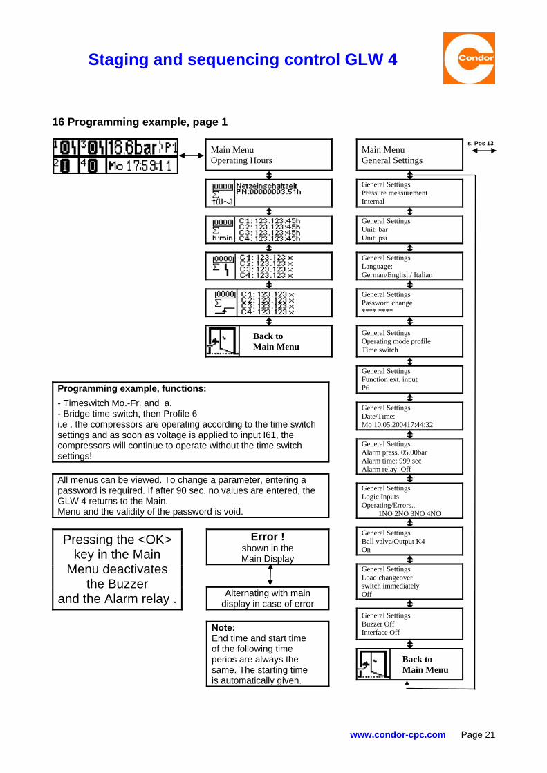
16 Programming example, page 1 Main Menu
Operating Hours Main Menu
General Settings
s. Pos 13
General Settings Pressure measurement Internal
General Settings Unit: bar Unit: psi
General Settings Language: German/English/ Italian
General Settings Password change **** ****
Back to Main Menu
General Settings Operating mode profile Time switch
General Settings Function ext. input P6
General Settings Date/Time: Mo 10.05.200417:44:32
General Settings Alarm press. 05.00bar Alarm time: 999 sec Alarm relay: Off
General Settings Logic Inputs Operating/Errors...
1NO 2NO 3NO 4NO
General Settings Ball valve/Output K4 On
General Settings Load changeover switch immediately Off
General Settings Buzzer Off Interface Off
Back to Main Menu
Programming example, functions:
- Timeswitch Mo.-Fr. and a. - Bridge time switch, then Profile 6 i.e . the compressors are operating according to the time switch settings and as soon as voltage is applied to input I61, the compressors will continue to operate without the time switch settings! All menus can be viewed. To change a parameter, entering a password is required. If after 90 sec. no values are entered, the GLW 4 returns to the Main. Menu and the validity of the password is void.
Error ! shown in the Main Display
Pressing the <OK> key in the Main
Menu deactivates the Buzzer
and the Alarm relay . Alternating with main display in case of error
Note: End time and start time of the following time perios are always the same. The starting time is automatically given.

Staging and sequencing control GLW 4
Page 22 www.condor-cpc.com
16.1 Programming example, page 2 s. Pos 13
Main Menu Time Switch Prog.
Main Menu Select Profile Profile 1
Main Menu Select Profile Profile 6
s. Pos 13
Time Switch Prog. Mo-Fr Day 06:00-17:00 Profile 1
Profile 1 Compressor 1 Operating Mode: Primary load
Profile 6 Compressor 1 Operating Mode: Primary load
Time Switch Prog. Mo-Fr Night 17:00-06:00 Off
Profile 1 Compressor 2 Operating Mode: Load changeover
Profile 6 Compressor 2 Operating mode: Load changeover
Time Switch Prog. Fr 17:00 to Sa 6:30 Off
Profile 1 Compressor 3 Operating mode: Load changeover
Profile 6 Compressor 3 Operating mode: Load changeover
Time Switch Prog. Sa 06:30 to Su 19:11 Off
Profile 1 Compressor 4 Operating mode: Off
Profile 6 Compressor 4 Operating mode: Off
Time Switch Prog. Sa 09:00 to Sa 16:00 Profile 1
Profile 1 Cut-in pressure 1:08,00bar 2:07,80bar 3:07,60bar 4:XX,XXbar
Profile 6 Cut-in pressure 1:08,00bar 2:07,80bar 3:07,60bar 4:XX,XXbar
Time Switch Prog. Sa 19:11 to Su 06:22 Off
Profile 1 Cut-out pressure 1:10,00bar 2:09,80bar 3:09,60bar 4:XX,XXbar
Profile 6 Cut-out pressure 1:10,00bar 2:09,80bar 3:09,60bar 4:XX,XXbar
Time Switch Prog. Su 06:22 to Su 21:15 Off
Profile 1 Stand-by time
60min.
Profile 6 Stand-by time
60min.
Time Switch Prog. Su 21:15 to Mo 06:00 Off
Profile 1 Load changeover time
24.0h
Profile 6 Load changeover
24.0h
Back to Main Menu
Profile 1 Monitoring time
999sec.
Profile 6 Monitoring time
999sec.
Profile 1 Copying Profile P1 -> Pn <CR>
Profile 6 Copying Profile P6 -> Pn <CR>
Back to
Main Menu
Back to Main Menu

Staging and sequencing control GLW 4
www.condor-cpc.com Page 23
Condor Pressure Control GmbH
Warendorfer Straße 47 – 51 D 59320 Ennigerloh
Phone: +49 (0) 25 87 / 89-0 Telefax: +49 (0) 25 87 / 89-140
e-Mail: [email protected] http: www.condor-cpc.com

Staging and sequencing control GLW 4
Page 24 www.condor-cpc.com