Embed Size (px)
Citation preview
800-543-9038 USA 866-805-7089 CANADA 203-791-8396 LATIN AMERICA
28
L300
43 -
07/0
9 - S
UBJE
CT T
O CH
ANGE
. © B
ELIM
O AI
RCON
TROL
S (U
SA),
INC.
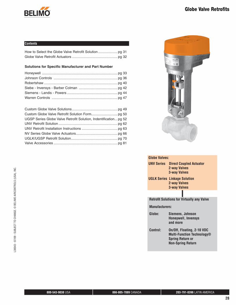
Globe Valve Retrofits
Contents
How to Select the Globe Valve Retrofit Solution .................... pg 31Globe Valve Retrofit Actuators ............................................... pg 32
Solutions for Specific Manufacturer and Part Number
Honeywell .............................................................................. pg 33Johnson Controls .................................................................. pg 36Robertshaw ............................................................................ pg 40Siebe - Invensys - Barber Colman ........................................ pg 42Siemens - Landis - Powers .................................................... pg 44Warren Controls .................................................................... pg 47
Custom Globe Valve Solutions ............................................... pg 49Custom Globe Valve Retrofit Solution Form ........................... pg 50UGSP Series Globe Valve Retrofit Solution, Indentification ... pg 52UNV Retrofit Solution ............................................................. pg 62UNV Retrofit Installation Instructions ..................................... pg 63 NV Series Globe Valve Actuators ........................................... pg 66UGLK/UGSP Retrofit Solution ................................................ pg 70Valve Accessories .................................................................. pg 81
Retrofi t Solutions for Virtually any Valve
Manufacturers:
Globe: Siemens, Johnson Honeywell, Invensys and more
Control: On/Off, Floating, 2-10 VDC Multi-Function Technology® Spring Return or Non-Spring Return
Globe Valves:
UNV Series Direct Coupled Actuator 2-way Valves 3-way Valves
UGLK Series Linkage Solution 2-way Valves 3-way Valves
800-543-9038 USA 866-805-7089 CANADA 203-791-8396 LATIN AMERICA
29
L300
43 -
07/0
9 - S
UBJE
CT T
O CH
ANGE
. © B
ELIM
O AI
RCON
TROL
S (U
SA),
INC.
Globe Valve Retrofits
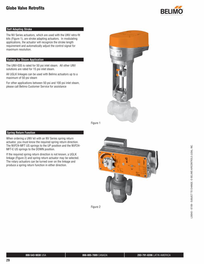
Self Adapting Stroke
The NV Series actuators, which are used with the UNV retro-fit kits (Figure 1), are stroke adapting actuators. In modulating applications, the actuator will recognize the stroke length requirement and automatically adjust the control signal for maximum resolution.
Ratings for Steam Application
The UNV-035 is rated for 50 psi inlet steam. All other UNV solutions are rated for 15 psi inlet steam.
All UGLK linkages can be used with Belimo actuators up to a maximum of 50 psi steam
For other applications between 50 psi and 100 psi inlet steam, please call Belimo Customer Service for assistance
Figure 1
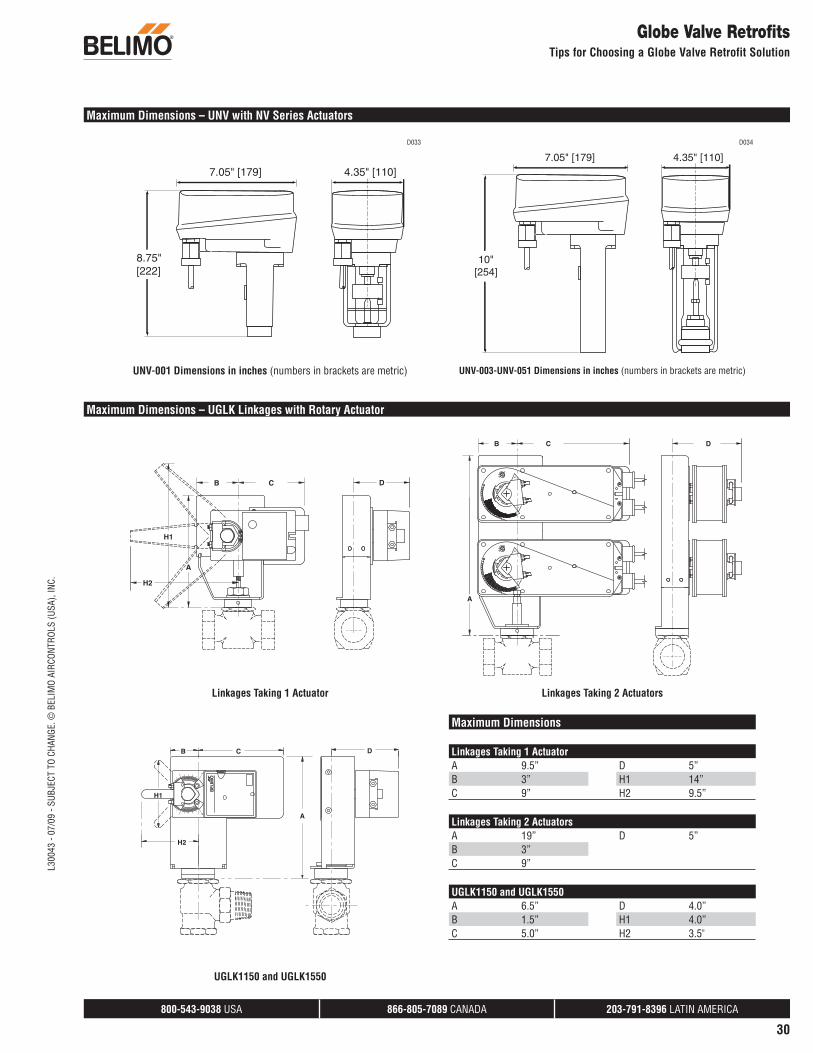
Spring Return Function
When ordering a UNV kit with an NV Series spring return actuator, you must know the required spring return direction. The NVF24-MFT US springs to the UP position and the NVF24-MFT-E US springs to the DOWN position.
If the required spring return direction is not known, a UGLK linkage (Figure 2) and spring return actuator may be selected. The rotary actuators can be turned over on the linkage and produce a spring return function in either direction.
Figure 2
800-543-9038 USA 866-805-7089 CANADA 203-791-8396 LATIN AMERICA
30
L300
43 -
07/0
9 - S
UBJE
CT T
O CH
ANGE
. © B
ELIM
O AI
RCON
TROL
S (U
SA),
INC.
Globe Valve RetrofitsTips for Choosing a Globe Valve Retrofit Solution
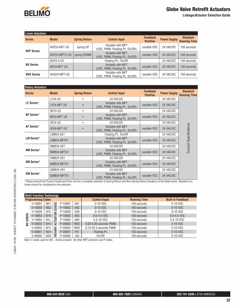
Maximum Dimensions – UNV with NV Series Actuators
D033
8.75" [222]
7.05" [179] 4.35" [110]
UNV-001 Dimensions in inches (numbers in brackets are metric)
D034
10" [254]
7.05" [179] 4.35" [110]
UNV-003-UNV-051 Dimensions in inches (numbers in brackets are metric)
Maximum Dimensions – UGLK Linkages with Rotary Actuator
A
B C
H1
H2
D
Linkages Taking 1 Actuator
A
B C
H2
H1
D
01
UGLK1150 and UGLK1550
A
RL
L
B
R
C D
Linkages Taking 2 Actuators
Maximum Dimensions
Linkages Taking 1 ActuatorA 9.5” D 5”B 3” H1 14”C 9” H2 9.5”
Linkages Taking 2 ActuatorsA 19” D 5”B 3”C 9”
UGLK1150 and UGLK1550A 6.5” D 4.0”B 1.5” H1 4.0”C 5.0” H2 3.5"
800-543-9038 USA 866-805-7089 CANADA 203-791-8396 LATIN AMERICA
32
Globe Valve Retrofi t ActuatorsLinkage/Actuator Selection Guide
Linear Actuators
Series Model Spring Return Control Input Feedback Position Power Supply Standard
Running Time
NVF SeriesNVF24-MFT US spring UP Variable with MFT
(VDC, PWM, Floating Pt., On/Off) variable VDC 24 VAC/DC 150 seconds
NVF24-MFT-E US spring DOWN Variable with MFT(VDC, PWM, Floating Pt., On/Off) variable VDC 24 VAC/DC 150 seconds
NV SeriesNV24-3 US Floating Pt., On/Off 24 VAC/DC 150 seconds
NV24-MFT US Variable with MFT(VDC, PWM, Floating Pt., On/Off) variable VDC 24 VAC/DC 150 seconds
NVG Series NVG24-MFT US Variable with MFT(VDC, PWM, Floating Pt., On/Off) variable VDC 24 VAC/DC 150 seconds
Rotary Actuators
Series Model Spring Return Control Input Feedback Position Power Supply Standard
Running Time
LF Series*LF24 US • 24 VAC/DC 24 VAC/DC
Cons
ult S
peci
fi cat
ions
LF24-MFT US • Variable with MFT(VDC, PWM, Floating Pt., On/Off) variable VDC 24 VAC/DC
NF Series*NF24 US • 24 VAC/DC 24 VAC/DC
NF24-MFT US • Variable with MFT(VDC, PWM, Floating Pt., On/Off) variable VDC 24 VAC/DC
AF Series*AF24 US • 24 VAC/DC 24 VAC/DC
AF24-MFT US • Variable with MFT(VDC, PWM, Floating Pt., On/Off) variable VDC 24 VAC/DC
LM Series*LMB24-3X1 Floating Pt., On/Off 24 VAC/DC
LMB24-MFTX1 Variable with MFT(VDC, PWM, Floating Pt., On/Off) variable VDC 24 VAC/DC
NM Series*NMB24-3X1 24 VAC/DC 24 VAC/DC
NMB24-MFTX1 Variable with MFT(VDC, PWM, Floating Pt., On/Off) variable VDC 24 VAC/DC
AM Series*AMB24-3X1 24 VAC/DC 24 VAC/DC
AMB24-MFTX1 Variable with MFT(VDC, PWM, Floating Pt., On/Off) variable VDC 24 VAC/DC
GM Series*GMB24-3X1 24 VAC/DC 24 VAC/DC
GMB24-MFTX1 Variable with MFT(VDC, PWM, Floating Pt., On/Off) variable VDC 24 VAC/DC
*Please consult the Product Guide and Price List for a complete selection of Spring Return and Non-Spring Return Acuators of the listed series. Standard run times should be considered in the selection.
Multi-Function TechnologyProgramming Codes Control Input Running Time Built-in Feedback
NV C
ODES
V-10001 N01
ROTA
RY A
CTUA
TOR
CODE
S P-10001 A01 2-10 VDC 150 seconds 2-10 VDCV-10002 N02 P-10002 A02 0-10 VDC 150 seconds 0-10 VDCV-10028 N1E P-10028 A28 0-10 VDC 150 seconds 0-10 VDCV-10063 N1K P-10063 A63 0.5-4.5 VDC 150 seconds 0.5-4.5 VDCV-10064 N1L P-10064 A64 5.5-10 VDC 150 seconds 5.5-10 VDCV-20002 N1U P-20002 W02 0.02-5.00 seconds PWM 150 seconds 2-10 VDCV-20003 N1V P-20003 W03 0.10-25.5 seconds PWM 150 seconds 2-10 VDCV-30001 N24 P-30001 F01 Floating Pt. 150 seconds 2-10 VDCV-40002 N29 P-40002 J02 On/Off 150 seconds 2-10 VDC
Note: V-codes used for NV…Series actuator. All other MFT actuators use P-codes.
L300
43 -
07/0
9 - S
UBJE
CT T
O CH
ANGE
. © B
ELIM
O AI
RCON
TROL
S (U
SA),
INC.
800-543-9038 USA 866-805-7089 CANADA 203-791-8396 LATIN AMERICA
41
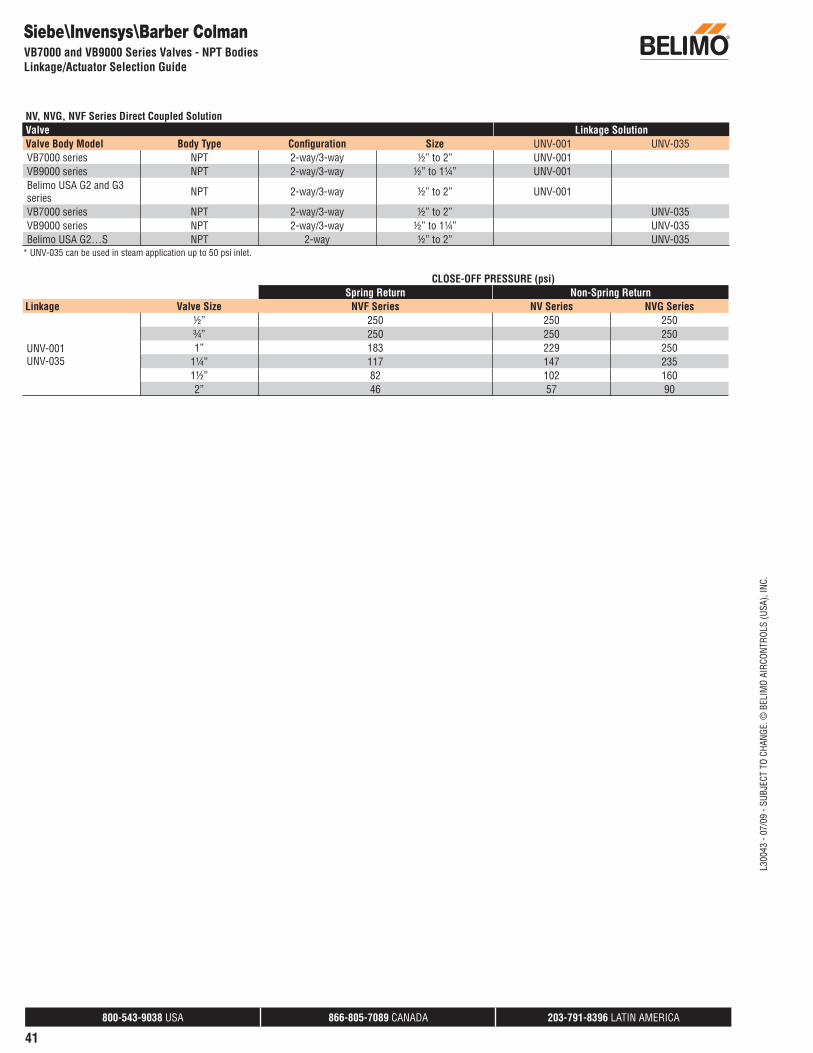
NV, NVG, NVF Series Direct Coupled SolutionValve Linkage SolutionValve Body Model Body Type Confi guration Size UNV-001 UNV-035VB7000 series NPT 2-way/3-way ½” to 2” UNV-001VB9000 series NPT 2-way/3-way ½” to 1¼” UNV-001 Belimo USA G2 and G3 series NPT 2-way/3-way ½” to 2” UNV-001
VB7000 series NPT 2-way/3-way ½” to 2” UNV-035 VB9000 series NPT 2-way/3-way ½” to 1¼” UNV-035Belimo USA G2…S NPT 2-way ½” to 2” UNV-035
* UNV-035 can be used in steam application up to 50 psi inlet.
CLOSE-OFF PRESSURE (psi)Spring Return Non-Spring Return
Linkage Valve Size NVF Series NV Series NVG Series
UNV-001UNV-035
½” 250 250 250¾” 250 250 2501” 183 229 250
1¼” 117 147 2351½” 82 102 1602” 46 57 90
Siebe\Invensys\Barber ColmanVB7000 and VB9000 Series Valves - NPT BodiesLinkage/Actuator Selection Guide
L300
43 -
07/0
9 - S
UBJE
CT T
O CH
ANGE
. © B
ELIM
O AI
RCON
TROL
S (U
SA),
INC.

800-543-9038 USA 866-805-7089 CANADA 203-791-8396 LATIN AMERICA
62
L300
43 -
07/0
9 - S
UBJE
CT T
O CH
ANGE
. © B
ELIM
O AI
RCON
TROL
S (U
SA),
INC.
UNV Retrofit Solution Components
UNV Multi-box Kit Components
Part No. Description
UNV-BKT-001 SIEBE bracket (UNV-001)UNV-BKT-002 Universal bracket (UNV-003 through UNV-035)UNV-COL-004 Collar-004 and set screwsUNV-COL-005 Collar-005UNV-COL-006 Collar-006 and set screwsUNV-COL-007 Collar-007UNV-COL-008 Collar-008UNV-COL-009 Collar-009UNV-COL-035 Collar-035UNV-COL-040 Collar-040UNV-STEM-001-SET Stem Adaptor-001,005UNV-STEM-003 Stem Adaptor-003UNV-STEM-004-SET Stem Adaptor-004,008,009
Part No. Description
UNV-STEM-006 Stem Adaptor-006UNV-STEM-007 Stem Adaptor-007UNV-STEM-035 Stem Adaptor-035UNV-STEM-040 Stem Adaptor-040UNV-NUT-001 1/4”-28 Locking Nut (UNV-001, 004, 005, 006, 008, 009, 035)UNV-NUT-007 1/4”-32 Locking Nut (UNV-007)UNV-BOLT Kit of U-bolt, Nuts for U-boltUNV-SCREW Kit of ScrewsUNV-STROKE IND Kit of Stroke indicatorsUNV-CPL CouplingUNV-CPL Coupling-10 pc setUNV-Override NV Manual Override
Actuator
Adaptor Bracket
Plunger (part of actuator)
Coupling
Stem Adaptor
Locking Nut
Screws(4 used to
mount bracket)
Stroke Indicators
Collar
U-Bolt Assembly
UNV-Box-Kit
Multi Box Starter Kit for UNV
Refillable with below items.
UNV Dimensional Details
Dimensional Data UNV-001 UNV-003 UNV-004 UNV-005 UNV006 UNV-007 UNV-008 UNV-009 UNV-035 UNV-040 UNV-051
Length of Stem Adaptor 1 7/16” 2” 2 1/8” 1 7/16” 1 1/8” 2 1/8” 2 1/8” 2 1/8” 3 7/16” 2 1/8” 1-1/4”
Stem Adaptor Diameter 1/4” 5/8” 1/4” 1/4” 1/4” 1/4” 1/4” 1/4” 1/4” 1/4” 3/8”
Stem Adaptor-Threads Per In. 28 N/A 28 28 28 32 28 28 28 28 24
Locking Nut 1/4”-28 N/A 1/4”-28 1/4”-28 1/4”-28 1/4”-32 1/4”-28 1/4”-28 1/4”-28 1/4”-28 3/8”-24
CollarMolded into
Bracket N/A
YES 1/4”-20
set screws YES
YES 1/4”-20
set screws YES YES YES YES-303 SS YES YES
U-Bolt N/A YES YES YES YES YES YES YES YES YES YES
Adaptor Bracket UNV-BKT-001 UNV-BKT-002 UNV-BKT-002 UNV-BKT-002 UNV-BKT-002 UNV-BKT-002 UNV-BKT-002 UNV-BKT-002 UNV-BKT-002 UNV-BKT-002 UNV-BKT-002
800-543-9038 USA 866-805-7089 CANADA 203-791-8396 LATIN AMERICA
63
L300
43 -
07/0
9 - S
UBJE
CT T
O CH
ANGE
. © B
ELIM
O AI
RCON
TROL
S (U
SA),
INC.
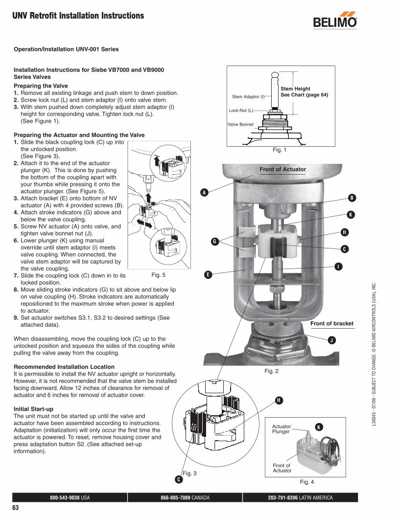
Installation Instructions for Siebe VB7000 and VB9000Series Valves
Preparing the Valve1. Remove all existing linkage and push stem to down position.2. Screw lock nut (L) and stem adaptor (I) onto valve stem.3. With stem pushed down completely adjust stem adaptor (I)
height for corresponding valve. Tighten lock nut (L). (See Figure 1).
Preparing the Actuator and Mounting the Valve1. Slide the black coupling lock (C) up into
the unlocked position. (See Figure 3).2. Attach it to the end of the actuator
plunger (K). This is done by pushing the bottom of the coupling apart with your thumbs while pressing it onto the actuator plunger. (See Figure 5).
3. Attach bracket (E) onto bottom of NV actuator (A) with 4 provided screws (B).
4. Attach stroke indicators (G) above and below the valve coupling.
5. Screw NV actuator (A) onto valve, and tighten valve bonnet nut (J).
6. Lower plunger (K) using manual override until stem adaptor (I) meets valve coupling. When connected, the valve stem adaptor will be captured by the valve coupling.
7. Slide the coupling lock (C) down in to its locked position.
8. Move sliding stroke indicators (G) to sit above and below lip on valve coupling (H). Stroke indicators are automatically repositioned to the maximum stroke when power is applied to actuator.
9. Set actuator switches S3.1, S3.2 to desired settings (See attached data).
When disassembling, move the coupling lock (C) up to the unlocked position and squeeze the sides of the coupling while pulling the valve away from the coupling.
Recommended Installation LocationIt is permissible to install the NV actuator upright or horizontally. However, it is not recommended that the valve stem be installed facing downward. Allow 12 inches of clearance for removal of actuator and 6 inches for removal of actuator cover.
Initial Start-upThe unit must not be started up until the valve and actuator have been assembled according to instructions. Adaptation (initialization) will only occur the first time the actuator is powered. To reset, remove housing cover and press adaptation button S2. (See attached set-up information).
UNV Retrofit Installation Instructions
A
K
E
G
H
B
C
Stem HeightAdjustment
lock-nut
stem adaptor
valvebonnetnut
Fig. 1
I
J
Fig. 4
H
Stem HeightSee Chart (page 64)
Front of Actuator
Front of bracket
Stem Adaptor (I)
Lock-Nut (L)
Actuator Plunger
K
Front of Actuator
Operation/Installation UNV-001 Series
Fig. 2
Fig. 5
CFig. 3
Valve Bonnet

800-543-9038 USA 866-805-7089 CANADA 203-791-8396 LATIN AMERICA
64
L300
43 -
07/0
9 - S
UBJE
CT T
O CH
ANGE
. © B
ELIM
O AI
RCON
TROL
S (U
SA),
INC.
UNV Retrofit Installation Instructions
Preparing The Valve
Kits with Threaded CollarsUNV-005, UNV-007, UNV-008 UNV-009, UNV-035, UNV-040, UNV-0511. Remove all existing linkage from the valve.2. Push stem into the fully down position.3. Screw the Collar onto the valve neck and tighten. *Flats should
be on the top for UNV-008 UNV-009, UNV-035, UNV-040 and UNV-051.Flats should be on the bottom for UNV-005 and UNV-007.
4. Screw the Lock Nut and the Stem Adapter onto the valve stem.Use chart to determine the correct height of the stem adapter.(Height is measure from the top of the valve collar to the top ofthe stem adapter, when the stem is in the fully down position.)
5. Tighten the Lock Nut against the Stem Adapter.
Kits with Set Screw CollarsUNV-004 and UNV-0061. Remove all existing linkage from the valve.2. Push stem into the fully down position.3. Slide the Collar down over the valve neck and secure in place by
installing and tightening the Setscrews. (The threaded Setscrewholes in the collar should be towards the bottom.)
4. Screw the Lock Nut and the Stem Adapter onto the valve stem.Use chart to determine the correct height of the stem adapter.(Height is measure from the top of the valve collar to the top ofthe stem adapter, when the stem is in the fully down position.)
5. Tighten the Lock Nut against the Stem Adapter.
Kit UNV-003, UNV-0131. Remove all existing linkage from the valve.2. Pull the existing slotted stem adaptor into the fully up position.3. Place Stem Nut (2) over Stem Adaptor (1).4. Slide Threaded Stopper (3) over existing slotted stem adaptor.5. Insert Retaining Clip (4) onto existing slotted stem adaptor.6. Screw and tighten assembly (1,2,3) to existing slotted stem
adaptor.
Operation/Installation UNV-003 to UNV-051 Series
Stem HeightAdjustment
collar
stem adaptor
flat
stem nut
stem adapter
retaining clip
threaded stopper
1
2
3
4Stem Adjustment
UNV NumberHeight
inches [mm]
UNV-001 1.77 [45]
UNV-003 N/A
UNV-004 2.36 [60]
UNV-005 2.56 [65]
UNV-006 2.56 [65]
UNV-007* 2.36 [60]
UNV-008 2.36 [60]
UNV-009 2.56 [65]
UNV-035 2.64 [67]
UNV-040 2.87 [73]
UNV-051 2.56 [65]
*When retrofi tting a V6800 series valve, the stem adjustment is 64 mm.
800-543-9038 USA 866-805-7089 CANADA 203-791-8396 LATIN AMERICA
65
L300
43 -
07/0
9 - S
UBJE
CT T
O CH
ANGE
. © B
ELIM
O AI
RCON
TROL
S (U
SA),
INC.
A
UNV Retrofit Installation Instructions
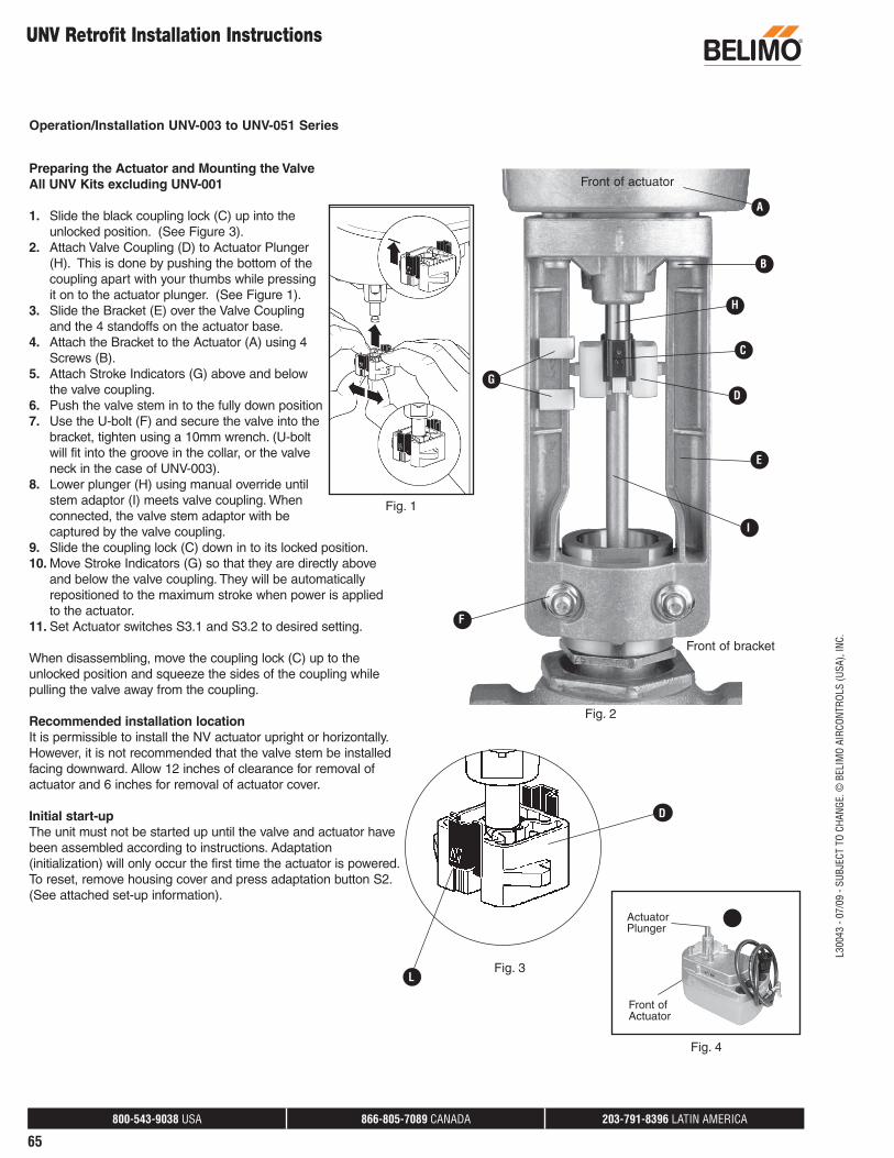
Preparing the Actuator and Mounting the ValveAll UNV Kits excluding UNV-001
1. Slide the black coupling lock (C) up into the unlocked position. (See Figure 3).
2. Attach Valve Coupling (D) to Actuator Plunger (H). This is done by pushing the bottom of the coupling apart with your thumbs while pressing it on to the actuator plunger. (See Figure 1).
3. Slide the Bracket (E) over the Valve Coupling and the 4 standoffs on the actuator base.
4. Attach the Bracket to the Actuator (A) using 4 Screws (B).
5. Attach Stroke Indicators (G) above and below the valve coupling.
6. Push the valve stem in to the fully down position7. Use the U-bolt (F) and secure the valve into the
bracket, tighten using a 10mm wrench. (U-bolt will fit into the groove in the collar, or the valve neck in the case of UNV-003).
8. Lower plunger (H) using manual override until stem adaptor (I) meets valve coupling. When connected, the valve stem adaptor with be captured by the valve coupling.
9. Slide the coupling lock (C) down in to its locked position.10. Move Stroke Indicators (G) so that they are directly above
and below the valve coupling. They will be automatically repositioned to the maximum stroke when power is applied to the actuator.
11. Set Actuator switches S3.1 and S3.2 to desired setting.
When disassembling, move the coupling lock (C) up to the unlocked position and squeeze the sides of the coupling while pulling the valve away from the coupling.
Recommended installation locationIt is permissible to install the NV actuator upright or horizontally. However, it is not recommended that the valve stem be installed facing downward. Allow 12 inches of clearance for removal of actuator and 6 inches for removal of actuator cover.
Initial start-upThe unit must not be started up until the valve and actuator have been assembled according to instructions. Adaptation (initialization) will only occur the first time the actuator is powered. To reset, remove housing cover and press adaptation button S2. (See attached set-up information).
Fig. 4
Fig. 3
D
B
D
H
C
F
G
E
I
L
Operation/Installation UNV-003 to UNV-051 Series
Fig. 2
Actuator Plunger
Front of Actuator
Fig. 1
Front of bracket
Front of actuator
800-543-9038 USA 866-805-7089 CANADA 203-791-8396 LATIN AMERICA
66
L300
43 -
07/0
9 - S
UBJE
CT T
O CH
ANGE
. © B
ELIM
O AI
RCON
TROL
S (U
SA),
INC.
NV Series Globe Valve Actuators
Operation/Installation
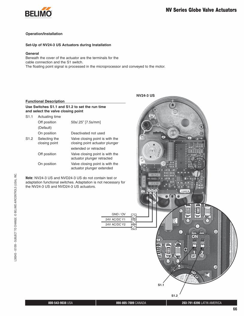
NV24-3 US
S1.2
S1.1
Functional Description
Use Switches S1.1 and S1.2 to set the run timeand select the valve closing point
S1.1 Actuating time
Off position 50s/.25” [7.5s/mm]
(Default)
On position Deactivated not used
S1.2 Selecting the Valve closing point is with the closing point closing point actuator plunger
extended or retracted
Off position Valve closing point is with the actuator plunger retracted
On position Valve closing point is with the actuator plunger extended
Note: NV24-3 US and NVD24-3 US do not contain test or adaptation functional switches. Adaptation is not necessary for the NV24-3 US and NVD24-3 US actuators.
Set-Up of NV24-3 US Actuators during Installation
GeneralBeneath the cover of the actuator are the terminals for thecable connection and the S1 switch.The floating point signal is processed in the microprocessor and conveyed to the motor.
GND / OV
24V AC/DC Y1
24V AC/DC Y2
800-543-9038 USA 866-805-7089 CANADA 203-791-8396 LATIN AMERICA
67
L300
43 -
07/0
9 - S
UBJE
CT T
O CH
ANGE
. © B
ELIM
O AI
RCON
TROL
S (U
SA),
INC.
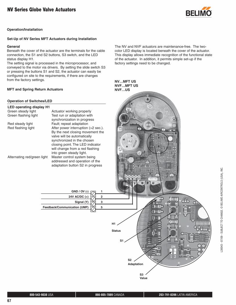
GeneralBeneath the cover of the actuator are the terminals for the cable connection, the S1 and S2 buttons, S3 switch, and the LED status display H1. The setting signal is processed in the microprocessor, and conveyed to the motor via drivers. By setting the slide switch S3 or pressing the buttons S1 and S2, the actuator can easily be configured on site to the requirements, if there are changes from the factory settings.
MFT and Spring Return Actuators
LED operating display H1Green steady light Actuator working properlyGreen flashing light Test run or adaptation with
synchronization in progressRed steady light Fault; repeat adaptationRed flashing light After power interruption (>2 sec.).
By the next closing movement the valve will be automatically synchronized in the chosen closing point. The LED indicator will change from a red flashing into green steady light.
Alternating red/green light Master control system being addressed and operation of the adaptation button S2 in progress
Operation of Switches/LED
The NV and NVF actuators are maintenance-free. The two-color LED display is located beneath the cover of the actuator. This display allows immediate recognition of the functional state of the actuator. In addition, it permits simple set-up if the factory settings need to be changed.
Set-Up of NV Series MFT Actuators during Installation
NV…MFT USNVF…MFT USNVF…US
S1
H1
Status
S2Adaptation
S3Value
GND / OV (-)
24V AC/DC (+)
Signal (Y)
Feedback/Communication (UMP)
1
2
3
5
Operation/Installation
NV Series Globe Valve Actuators
800-543-9038 USA 866-805-7089 CANADA 203-791-8396 LATIN AMERICA
68
L300
43 -
07/0
9 - S
UBJE
CT T
O CH
ANGE
. © B
ELIM
O AI
RCON
TROL
S (U
SA),
INC.
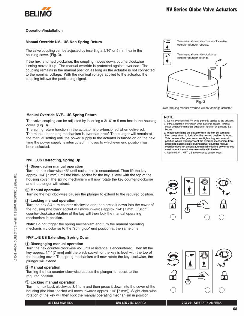
Manual Override NV…US Non-Spring Return
The valve coupling can be adjusted by inserting a 3/16” or 5 mm hex in the housing cover. (Fig. 3).
If the hex is turned clockwise, the coupling moves down; counterclockwise turning moves it up. The manual override is protected against overload. The coupling remains in the manual position as long as the actuator is not connected to the nominal voltage. With the nominal voltage applied to the actuator, the coupling follows the positioning signal.
Turn manual override counter-clockwise:Actuator plunger retracts.
Turn manual override clockwise:Actuator plunger extends.
Over-torquing manual override will not damage actuator.
Fig. 3
The valve coupling can be adjusted by inserting a 3/16” or 5 mm hex in the housing cover. (Fig. 3). The spring return function in the actuator is pre-tensioned when delivered.The manual operating mechanism is overload-proof. The plunger will remain at the manual setting until the power supply to the actuator is turned on or, the next time the power supply is interrupted, it moves to whichever end position has been selected.
NVF…US Retracting, Spring Up
1 Disengaging manual operation Turn the hex clockwise 45° until resistance is encountered. Then lift the key approx. 1/4” [7 mm] until the black socket for the key is level with the top of the housing cover. The spring mechanism will now rotate the key counter-clockwise and the plunger will retract.
2 Manual operation Turning the hex clockwise causes the plunger to extend to the required position.
3 Locking manual operation Turn the hex 3/4 turn counter-clockwise and then press it down into the cover of the housing (the black socket will move inwards approx. 1/4” [7 mm]). Slight counter-clockwise rotation of the key will then lock the manual operating mechanism in position.
Note: Do not trigger the spring mechanism and turn the manual operating mechanism clockwise to the "spring-up" end position at the same time.
NVF…-E US Extending, Spring Down
1 Disengaging manual operation Turn the hex counter-clockwise 45° until resistance is encountered. Then lift the key approx. 1/4” [7 mm] until the black socket for the key is level with the top of the housing cover. The spring mechanism will now rotate the key clockwise, the plunger will extend.
2 Manual operation Turning the hex counter-clockwise causes the plunger to retract to the required position.
3 Locking manual operation Turn the hex back clockwise 3/4 turn and then press it down into the cover of the housing (the black socket will move inwards approx. 1/4” [7 mm]). Slight clockwise rotation of the key will then lock the manual operating mechanism in position.
Manual Override NVF…US Spring ReturnNOTE: 1. Do not override the NVF while power is applied to the actuator.2. If the actuator is overridden while power is applied, remove cover and perform manual adaptation function by pressing S2 button.
3. When overriding the actuator turn the hex 3/4 turn and then press down to lock after the desired position is found. This prevents the gear from over-tightening into an end-position which would prevent the override mechanism from unlocking automatically during power up. If the manual override does not unlock automatically during power-up you must unlock the actuator manually with the hex.
4. Use the NV… MFT US in only closed control loops.
Operation/Installation
NV Series Globe Valve Actuators
800-543-9038 USA 866-805-7089 CANADA 203-791-8396 LATIN AMERICA
69
L300
43 -
07/0
9 - S
UBJE
CT T
O CH
ANGE
. © B
ELIM
O AI
RCON
TROL
S (U
SA),
INC.
NV Series Globe Valve Actuators
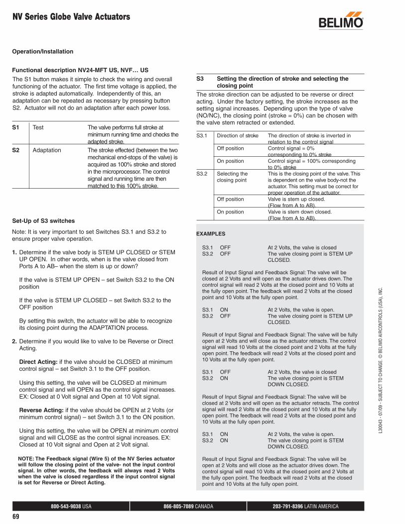
S1 Test The valve performs full stroke at minimum running time and checks the adapted stroke.
S2 Adaptation The stroke effected (between the two mechanical end-stops of the valve) is acquired as 100% stroke and stored in the microprocessor. The control signal and running time are then matched to this 100% stroke.
S3 Setting the direction of stroke and selecting the closing point
The S1 button makes it simple to check the wiring and overall functioning of the actuator. The first time voltage is applied, the stroke is adapted automatically. Independently of this, an adaptation can be repeated as necessary by pressing button S2. Actuator will not do an adaptation after each power loss.
Functional description NV24-MFT US, NVF… US
Note: It is very important to set Switches S3.1 and S3.2 to ensure proper valve operation.
1. Determine if the valve body is STEM UP CLOSED or STEM UP OPEN. In other words, when is the valve closed from Ports A to AB– when the stem is up or down?
If the valve is STEM UP OPEN – set Switch S3.2 to the ON position
If the valve is STEM UP CLOSED – set Switch S3.2 to the OFF position
By setting this switch, the actuator will be able to recognize its closing point during the ADAPTATION process.
2. Determine if you would like to valve to be Reverse or Direct Acting.
Direct Acting: if the valve should be CLOSED at minimum control signal – set Switch 3.1 to the OFF position.
Using this setting, the valve will be CLOSED at minimum control signal and will OPEN as the control signal increases. EX: Closed at 0 Volt signal and Open at 10 Volt signal.
Reverse Acting: if the valve should be OPEN at 2 Volts (or minimum control signal) – set Switch 3.1 to the ON position.
Using this setting, the valve will be OPEN at minimum control signal and will CLOSE as the control signal increases. EX: Closed at 10 Volt signal and Open at 2 Volt signal.
NOTE: The Feedback signal (Wire 5) of the NV Series actuator will follow the closing point of the valve- not the input control signal. In other words, the feedback will always read 2 Volts when the valve is closed regardless if the input control signal is set for Reverse or Direct Acting.
EXAMPLES
S3.1 OFF At 2 Volts, the valve is closed S3.2 OFF The valve closing point is STEM UP
CLOSED.
Result of Input Signal and Feedback Signal: The valve will be closed at 2 Volts and will open as the actuator drives down. The control signal will read 2 Volts at the closed point and 10 Volts at the fully open point. The feedback will read 2 Volts at the closed point and 10 Volts at the fully open point.
S3.1 ON At 2 Volts, the valve is open. S3.2 OFF The valve closing point is STEM UP
CLOSED.
Result of Input Signal and Feedback Signal: The valve will be fully open at 2 Volts and will close as the actuator retracts. The control signal will read 10 Volts at the closed point and 2 Volts at the fully open point. The feedback will read 2 Volts at the closed point and 10 Volts at the fully open point.
S3.1 OFF At 2 Volts, the valve is closed S3.2 ON The valve closing point is STEM
DOWN CLOSED.
Result of Input Signal and Feedback Signal: The valve will be closed at 2 Volts and will open as the actuator retracts. The control signal will read 2 Volts at the closed point and 10 Volts at the fully open point. The feedback will read 2 Volts at the closed point and 10 Volts at the fully open point.
S3.1 ON At 2 Volts, the valve is open. S3.2 ON The valve closing point is STEM
DOWN CLOSED.
Result of Input Signal and Feedback Signal: The valve will be open at 2 Volts and will close as the actuator drives down. The control signal will read 10 Volts at the closed point and 2 Volts at the fully open point. The feedback will read 2 Volts at the closed point and 10 Volts at the fully open point.
Set-Up of S3 switches
Operation/Installation
The stroke direction can be adjusted to be reverse or direct acting. Under the factory setting, the stroke increases as the setting signal increases. Depending upon the type of valve (NO/NC), the closing point (stroke = 0%) can be chosen with the valve stem retracted or extended.
S3.1 Direction of stroke The direction of stroke is inverted in relation to the control signal
Off position Control signal = 0% corresponding to 0% stroke On position Control signal = 100% corresponding
to 0% strokeS3.2 Selecting the This is the closing point of the valve. This closing point is dependent on the valve body-not the actuator. This setting must be correct for proper operation of the actuator. Off position Valve is stem up closed. (Flow from A to AB). On position Valve is stem down closed. (Flow from A to AB).