Embed Size (px)
DESCRIPTION
Global Mapper
Citation preview
4/7/13 Global Mapper - User's Manual
www.globalmapper.com/helpv11/Help_MenuBarAndToolBar.html 1/49
2 MENUBAR AND TOOLBAR
This section briefly reviews the menus and commands in order to understand the basic purpose of each.
The toolbar is displayed across the top of the application window, below the menu bar. The toolbar provides quick mouse access to manytools used in Global Mapper. To hide or display the toolbars or to switch to the old Toolbar display, which some users prefer, use theView menu commands for the toolbar.
Menu Headings
File MenuEdit MenuView MenuTools MenuSearch MenuGPS MenuHelp Menu
File Menu
The File menu offers the following commands:
Open Data File(s) CommandOpen Generic ASCII Text File(s) CommandOpen All Files in a Directory Tree CommandOpen ECW File from the Web CommandOpen Data File at Fixed Screen LocationUnload All CommandCreate New Map Catalog CommandFind Data Online CommandDownload Online Imagery/Topo/Terrain MapsLoad Workspace CommandSave Workspace CommandSave Workspace As CommandRun Script CommandCapture Screen Contents to Image CommandExport Global Mapper Package File CommandExport PDF File CommandExport Raster and Elevation Data
Export Arc ASCII Grid CommandExport BIL/BIP/BSQ CommandExport BMP CommandExport BT (Binary Terrain) CommandExport DEM CommandExport DTED CommandExport DXF 3D Face File CommandExport DXF Mesh CommandExport DXF Point File CommandExport ECW CommandExport Erdas Imagine CommandExport Float/Grid CommandExport Geosoft Grid CommandExport GeoTIFF CommandExport Global Mapper Grid CommandExport Gravsoft Grid CommandExport HF2/HFZ CommandExport Idrisi CommandExport JPG CommandExport JPG2000 CommandExport KML/KMZ CommandExport Lidar LAS CommandExport Leveller Heightfield CommandExport NITF CommandExport Optimi Terrain CommandExport PGM Grayscale Grid CommandExport PLS-CADD XYZ File CommandExport PNG CommandExport RockWorks Grid CommandExport STL CommandExport Surfer Grid (ASCII Format) CommandExport Surfer Grid (Binary v6 Format) CommandExport Surfer Grid (Binary v7 Format) CommandExport Terragen Terrain File CommandExport Vertical Mapper (MapInfo) Grid File CommandExport Vulcan3D Triangulation File CommandExport XYZ Grid CommandExport ZMap Plus Grid File Command
Export Vector DataExport Arc Ungenerate CommandExport CDF CommandExport CSV CommandExport Delft 3D (LDB) CommandExport DeLorme Text File Command
4/7/13 Global Mapper - User's Manual
www.globalmapper.com/helpv11/Help_MenuBarAndToolBar.html 2/49
Export DGN CommandExport DLG-O CommandExport DXF CommandExport DWG CommandExport Garmin TRK (PCX5) File CommandExport Garmin WPT (PCX5) File CommandExport GOG (Generalized Overlay Graphics) CommandExport GPX CommandExport InRoads ASCII CommandExport KML/KMZ CommandExport Landmark Graphics CommandExport Lidar LAS CommandExport LMN (Spectra Line Management Node) CommandExport Lowrance LCM (MapCreate) File CommandExport Lowrance USR CommandExport MapGen CommandExport MapInfo MIF/MID CommandExport MapInfo TAB/MAP CommandExport MatLab CommandExport Moss CommandExport NIMA ASC CommandExport OSM (OpenStreetMap.org) XML CommandExport Platte River/WhiteStar/Geographix File CommandExport PLS-CADD XYZ File CommandExport Polish MP (cGPSMapper) File CommandExport SEGP1 CommandExport Shapefile CommandExport Simple ASCII Text File CommandExport Surfer BLN CommandExport SVG CommandExport Tom Tom OV2 File CommandExport Tsunami OVR CommandExport UKOOA P/190 CommandExport WAsP MAP File CommandExport ZMap+ XYSegId File Command
Export Web Formats (Google Maps, VE, WW, etc.)Export Bing Maps (Virtual Earth) Tiles CommandExport Google Maps Tiles CommandExport KML/KMZ CommandExport SVG CommandExport VRML CommandExport World Wind Tiles CommandExport Zoomify Tiles Command
Batch Convert/ReprojectCombine Terrain LayersGenerate Contours CommandPrint CommandPrint Preview CommandPrint Setup CommandExit Command
Open Data File(s) Command
The Open Data File(s) command allows the user to open additional data files into the main Global Mapper view. If no other data isalready loaded and the user has not explicitly set a projection, the view will adopt the projection and datum of the first data file selectedfor loading. If other data is already loaded, the selected data files will be displayed in the current projection/datum.
Note: Global Mapper automatically opens files with tar.gz extensions without the use of a decompression tool such as Winzip. This isparticularly useful for SDTS transfers, which are typically distributed in a .tar.gz format.
Open Generic ASCII Text File(s) Command
The Open Generic ASCII Text File(s) command allows the user to import data from a wide variety of generic ASCII text formats.
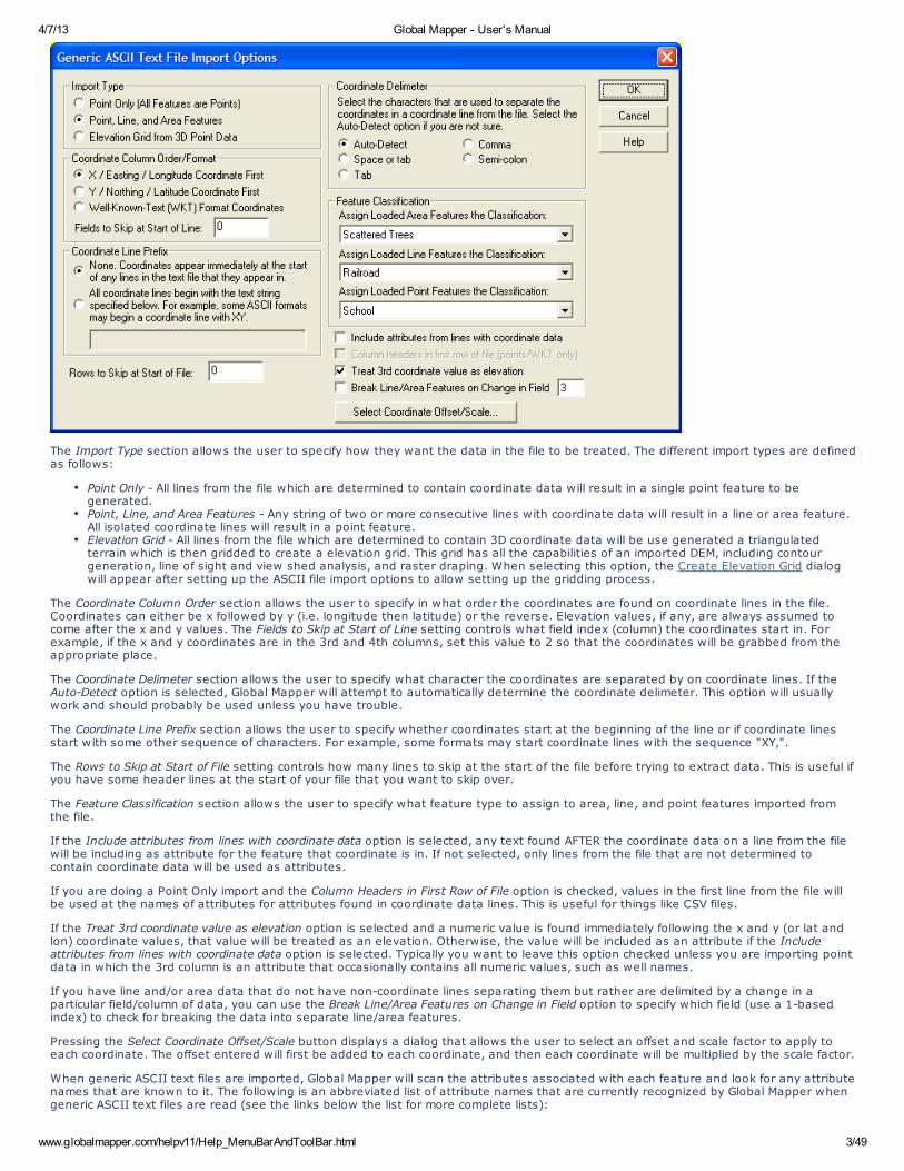
Selecting the Open Generic ASCII Text File command prompts the user to select the file(s) to load and then displays the Generic ASCIIText Import Options dialog (pictured below). This dialog allows the user to specify how the text file(s) are formatted so that they can beimported.
Global Mapper supports coordinates in decimal format as well as degree/minute and degree/minute/second coordinates.
4/7/13 Global Mapper - User's Manual
www.globalmapper.com/helpv11/Help_MenuBarAndToolBar.html 3/49
The Import Type section allows the user to specify how they want the data in the file to be treated. The different import types are definedas follows:
Point Only - All lines from the file which are determined to contain coordinate data will result in a single point feature to begenerated.Point, Line, and Area Features - Any string of two or more consecutive lines with coordinate data will result in a line or area feature.All isolated coordinate lines will result in a point feature.Elevation Grid - All lines from the file which are determined to contain 3D coordinate data will be use generated a triangulatedterrain which is then gridded to create a elevation grid. This grid has all the capabilities of an imported DEM, including contourgeneration, line of sight and view shed analysis, and raster draping. When selecting this option, the Create Elevation Grid dialogwill appear after setting up the ASCII file import options to allow setting up the gridding process.
The Coordinate Column Order section allows the user to specify in what order the coordinates are found on coordinate lines in the file.Coordinates can either be x followed by y (i.e. longitude then latitude) or the reverse. Elevation values, if any, are always assumed tocome after the x and y values. The Fields to Skip at Start of Line setting controls what field index (column) the coordinates start in. Forexample, if the x and y coordinates are in the 3rd and 4th columns, set this value to 2 so that the coordinates will be grabbed from theappropriate place.
The Coordinate Delimeter section allows the user to specify what character the coordinates are separated by on coordinate lines. If theAuto-Detect option is selected, Global Mapper will attempt to automatically determine the coordinate delimeter. This option will usuallywork and should probably be used unless you have trouble.
The Coordinate Line Prefix section allows the user to specify whether coordinates start at the beginning of the line or if coordinate linesstart with some other sequence of characters. For example, some formats may start coordinate lines with the sequence "XY,".
The Rows to Skip at Start of File setting controls how many lines to skip at the start of the file before trying to extract data. This is useful ifyou have some header lines at the start of your file that you want to skip over.
The Feature Classification section allows the user to specify what feature type to assign to area, line, and point features imported fromthe file.
If the Include attributes from lines with coordinate data option is selected, any text found AFTER the coordinate data on a line from the filewill be including as attribute for the feature that coordinate is in. If not selected, only lines from the file that are not determined tocontain coordinate data will be used as attributes.
If you are doing a Point Only import and the Column Headers in First Row of File option is checked, values in the first line from the file willbe used at the names of attributes for attributes found in coordinate data lines. This is useful for things like CSV files.
If the Treat 3rd coordinate value as elevation option is selected and a numeric value is found immediately following the x and y (or lat andlon) coordinate values, that value will be treated as an elevation. Otherwise, the value will be included as an attribute if the Includeattributes from lines with coordinate data option is selected. Typically you want to leave this option checked unless you are importing pointdata in which the 3rd column is an attribute that occasionally contains all numeric values, such as well names.
If you have line and/or area data that do not have non-coordinate lines separating them but rather are delimited by a change in aparticular field/column of data, you can use the Break Line/Area Features on Change in Field option to specify which field (use a 1-basedindex) to check for breaking the data into separate line/area features.
Pressing the Select Coordinate Offset/Scale button displays a dialog that allows the user to select an offset and scale factor to apply toeach coordinate. The offset entered will first be added to each coordinate, and then each coordinate will be multiplied by the scale factor.
When generic ASCII text files are imported, Global Mapper will scan the attributes associated with each feature and look for any attributenames that are known to it. The following is an abbreviated list of attribute names that are currently recognized by Global Mapper whengeneric ASCII text files are read (see the links below the list for more complete lists):
4/7/13 Global Mapper - User's Manual
www.globalmapper.com/helpv11/Help_MenuBarAndToolBar.html 4/49
NAME or LABEL - the value associated with an attribute of either of these names will be used as the feature name.DESC, DESCRIPTION, LAYER, or TYPE - the value associated with an attribute of any of these names will be used as the featuredescription.GM_TYPE - the value associated with an attribute with this name or any of the description names listed above will be used toattempt to assign a classification other than the default for each feature. The value must match one of the classification names inGlobal Mapper to work. It will also work for user-created custom types.ELEVATION, HEIGHT, or DEPTH - the value associated with an attribute of any of these names will be used as the feature'selevation.SYMBOL, POINT SYMBOL, or POINT_SYMBOL - the values associated with an attribute of any of these names will be comparedagainst the names of the symbols available in Global Mapper (including any custom symbols). If a match is found, that symbol willbe used for the point feature. These attribute names are ignored for line features. You can also specify custom dot and squaresymbol colors and sizes without having to add your own custom bitmaps for those symbols. Use names of the formDOT_CUSTOM_[SIZE]_[RED]_[GREEN]_[BLUE] and SQUARE_CUSTOM_[SIZE]_[RED]_[GREEN]_[BLUE] where the [SIZE] value is theradius in pixels of the dot or square, and the [RED], [GREEN], and [BLUE] values represent the color to use. For example, to specifya dot symbol of radius 10 pixels with a color or green, you would use a symbol name of DOT_CUSTOM_10_0_255_0.COLOR - the COLOR attribute should be formatted as RGB(red,green,blue). In the absence of a specific fill or line color, it will beused.LINE COLOR, LINE_COLOR, BORDER COLOR, BORDER_COLOR, PEN COLOR, or PEN_COLOR - the values associated with anattribute of any of these names will be used as the color for the pen used to draw line features. The values must be formattedaccording to the guidelines layed out for the COLOR attribute in order to be recognized.LINE WIDTH, LINE_WIDTH, BORDER WIDTH, BORDER_WIDTH, PEN WIDTH, or PEN_WIDTH - the values associated with anattribute of any of these names will be used as the width for the pen used to draw line features.LINE STYLE, LINE_STYLE, BORDER STYLE, BORDER_STYLE, PEN STYLE, or PEN_STYLE - the values associated with anattribute of any of these names will be used as the style for the pen used to draw line features. Valid values are Solid, Dash, Dot,Dash - Dot, Dash - Dot - Dot, and Null. Only the Solid value is valid for lines with a width greater than 1LABEL_ON_LINE - if this is set to "YES" or "TRUE", the label (if any) for this line feature should be rendered centered on the lineCLOSED - if this is set to "YES" or "TRUE", the feature will be treated as a closed area feature if it has at least three vertices.ISLAND - if this is set to "YES" or "TRUE", the feature will be treated as an island of the previous closed parent area feature if ithas at least three vertices. If there are no previous parent areas, this attribute will be ignored.FONT_NAME - specifies the name (e.g. Arial, Times New Roman, etc.) of the font to use when displaying the display label, if any,for this feature.FONT_COLOR - specifies the color of the font to use when displaying the display label, if any, for this feature. The values must beformatted according to the guidelines layed out for the COLOR attribute in order to be recognized.FONT_ANGLE - specifies the angle in degrees of the font to use when displaying the display label, if any, for this point feature.FONT_SIZE - specifies the point size of the font to use when displaying the display label, if any, for this feature.FONT_HEIGHT_METERS - specifies the height in meters of the font to use when displaying the display label, if any, for thisfeature. Using this causes the actual point size of the font to vary as you zoom in and out.FONT_CHARSET - specifies the numeric character set of the font to use when displaying the display label, if any, for this feature.These correspond to the Windows character set enumeration.
Click here for more instructions on creating generic ASCII data files with features of various types and click here for more documentationon the supported fields.
Download Online Imagery/Topo/Terrain Maps
The Download Online Imagery/Topo/Terrain Maps command allows the user to download mapping data from numerous built-in anduser-supplied sources. This includes premium access to high resolution color imagery for the entire world from DigitalGlobe, worldwidestreet maps from OpenStreetMap.org, as well as seamless USGS topographic maps and satellite imagery for the entire United Statesfrom MSRMaps.com/TerraServer-USA. In addition, access is provided to several built-in WMS (OpenGC Web Map Server) databases toprovide easy access to digitial terrain data (NED and SRTM) as well as color satellite imagery (Landsat7) for the entire world. You can alsoadd your own WMS data sources for access to any data published on a WMS server.
This is an extremely powerful feature as it puts many terabytes of usually very expensive data right at your fingertips in Global Mapperfor no additional cost (with the exception of access to the un-watermarked DigitalGlobe imagery, which is not free). Note that this featurerequires Internet access to work.
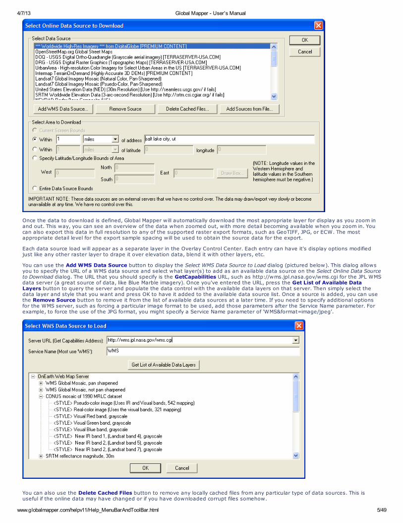
When you select the menu command, the Select Online Data Source to Download dialog (pictured below) is displayed. This dialog allowsyou to select the type, or theme, of data to download, as well as the extents of the data to download. You can either select to downloadthe current screen bounds, an area to download around an address, specify a lat/lon bounds explicitly, or select to download the entiredata source.
4/7/13 Global Mapper - User's Manual
www.globalmapper.com/helpv11/Help_MenuBarAndToolBar.html 5/49
Once the data to download is defined, Global Mapper will automatically download the most appropriate layer for display as you zoom inand out. This way, you can see an overview of the data when zoomed out, with more detail becoming available when you zoom in. Youcan also export this data in full resolution to any of the supported raster export formats, such as GeoTIFF, JPG, or ECW. The mostappropriate detail level for the export sample spacing will be used to obtain the source data for the export.
Each data source load will appear as a separate layer in the Overlay Control Center. Each entry can have it's display options modifiedjust like any other raster layer to drape it over elevation data, blend it with other layers, etc.
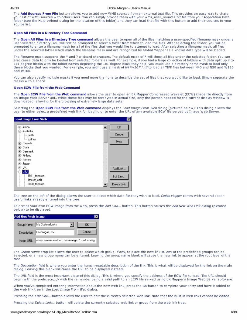
You can use the Add WMS Data Source button to display the Select WMS Data Source to Load dialog (pictured below). This dialog allowsyou to specify the URL of a WMS data source and select what layer(s) to add as an available data source on the Select Online Data Sourceto Download dialog. The URL that you should specify is the GetCapabilities URL, such as http://wms.jpl.nasa.gov/wms.cgi for the JPL WMSdata server (a great source of data, like Blue Marble imagery). Once you've entered the URL, press the Get List of Available DataLayers button to query the server and populate the data control with the available data layers on that server. Then simply select thedata layer and style that you want and press OK to have it added to the available data source list. Once a source is added, you can usethe Remove Source button to remove it from the list of available data sources at a later time. If you need to specify additional optionsfor the WMS server, such as forcing a particular image format to be used, add those parameters after the Service Name parameter. Forexample, to force the use of the JPG format, you might specify a Service Name parameter of 'WMS&format=image/jpeg'.
You can also use the Delete Cached Files button to remove any locally cached files from any particular type of data sources. This isuseful if the online data may have changed or if you have downloaded corrupt files somehow.
4/7/13 Global Mapper - User's Manual
www.globalmapper.com/helpv11/Help_MenuBarAndToolBar.html 6/49
The Add Sources From File button allows you to add new WMS sources from an external text file. This provides an easy way to shareyour list of WMS sources with other users. You can simply provide them with your wms_user_sources.txt file from your Application Datafolder (see the Help->About dialog for the location of this folder) and they can load that file with this button to add their sources to yoursource list.
Open All Files in a Directory Tree Command
The Open All Files in a Directory Tree command allows the user to open all of the files matching a user-specified filename mask under auser-selected directory. You will first be prompted to select a folder from which to load the files. After selecting the folder, you will beprompted to enter a filename mask for all of the files that you would like to attempt to load. After selecting a filename mask, all filesunder the selected folder which match the filename mask and are recognized by Global Mapper as a known data type will be loaded.
The filename mask supports the * and ? wildcard characters. The default mask of * will check all files under the selected folder. You canalso cause data to only be loaded from selected folders as well. For example, if you had a large collection of folders with data split up into1x1 degree blocks with the folder names depecting the 1x1 degree block they held, you could use a directory name mask to load onlythose blocks that you wanted. For example, you might use a mask of N4?W10?\*.tif to load all TIFF files between N40 and N50 and W110and W100.
You can also specify multiple masks if you need more than one to describe the set of files that you would like to load. Simply separate themasks with a space.
Open ECW File from the Web Command
The Open ECW File from the Web command allows the user to open an ER Mapper Compressed Wavelet (ECW) image file directly froman Image Web Server URL. While these files may be terabytes in actual size, only the portion needed for the current display window isdownloaded, allowing for the browsing of extremely large data sets.
Selecting the Open ECW File from the Web command displays the Load Image From Web dialog (pictured below). This dialog allows theuser to either select a predefined web link for loading or to enter the URL of any available ECW file served by Image Web Server.
The tree on the left of the dialog allows the user to select which data file they wish to load. Global Mapper comes with several dozenuseful links already entered into the tree.
To access your own ECW image from the web, press the Add Link... button. This button causes the Add New Web Link dialog (picturedbelow) to be displayed.
The Group Name drop list allows the user to select which group, if any, to place the new link in. Any of the predefined groups can beselected, or a new group name can be entered. Leaving the group name blank will cause the new link to appear at the root level of thetree.
The Description field is where you enter the human-readable description of the link. This is what will be displayed for the link on the maindialog. Leaving this blank will cause the URL to be displayed instead.
The URL field is the most important piece of this dialog. This is where you specify the address of the ECW file to load. The URL shouldbegin with the prefix ecwp:// with the remainder being a valid path to an ECW file served using ER Mapper's Image Web Server software.
When you've completed entering information about the new web link, press the OK button to complete your entry and have it added tothe web link tree in the Load Image From Web dialog.
Pressing the Edit Link... button allows the user to edit the currently selected web link. Note that the built-in web links cannot be edited.
Pressing the Delete Link... button will delete the currently selected web link or group from the web link tree.
4/7/13 Global Mapper - User's Manual
www.globalmapper.com/helpv11/Help_MenuBarAndToolBar.html 7/49
If you get an error message indicating that your settings have been updated to support the ECWP protocol whenever you try to load anECW layer from the web you need to download and install the latest ECW ActiveX plugin fromhttp://demo.ermapper.com/ecwplugins/DownloadIEPlugin.htm.
Open Data File at Fixed Screen Location
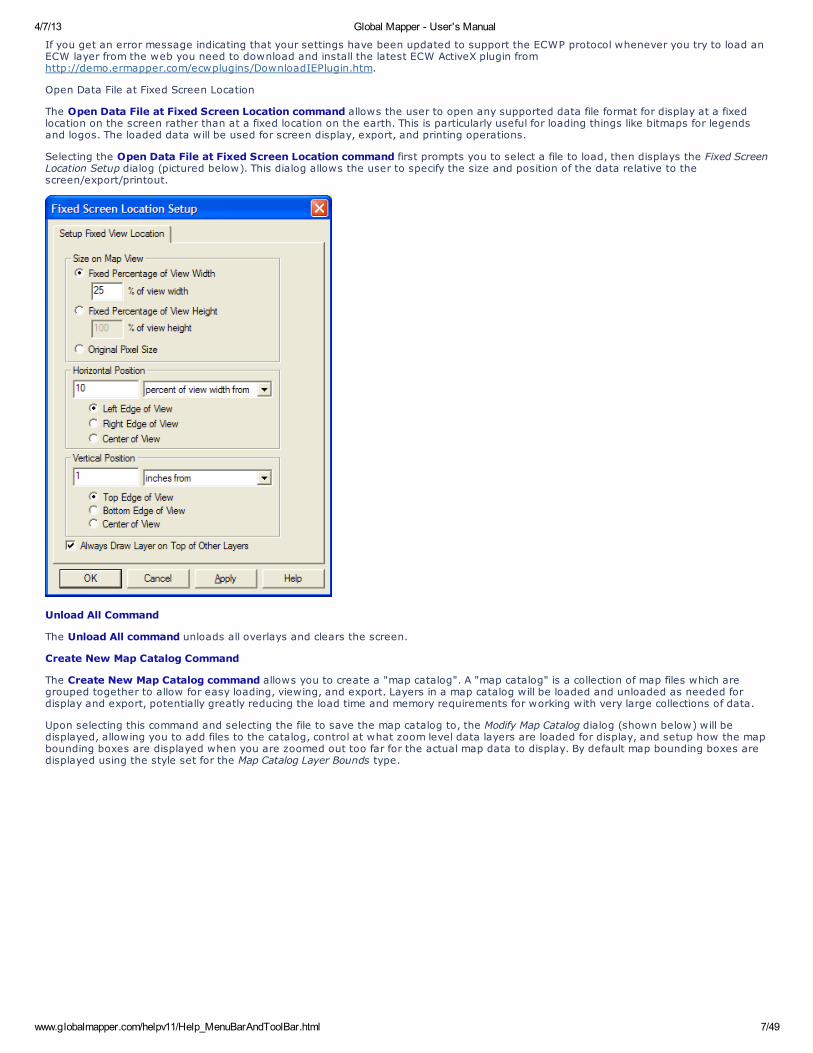
The Open Data File at Fixed Screen Location command allows the user to open any supported data file format for display at a fixedlocation on the screen rather than at a fixed location on the earth. This is particularly useful for loading things like bitmaps for legendsand logos. The loaded data will be used for screen display, export, and printing operations.
Selecting the Open Data File at Fixed Screen Location command first prompts you to select a file to load, then displays the Fixed ScreenLocation Setup dialog (pictured below). This dialog allows the user to specify the size and position of the data relative to thescreen/export/printout.
Unload All Command
The Unload All command unloads all overlays and clears the screen.
Create New Map Catalog Command
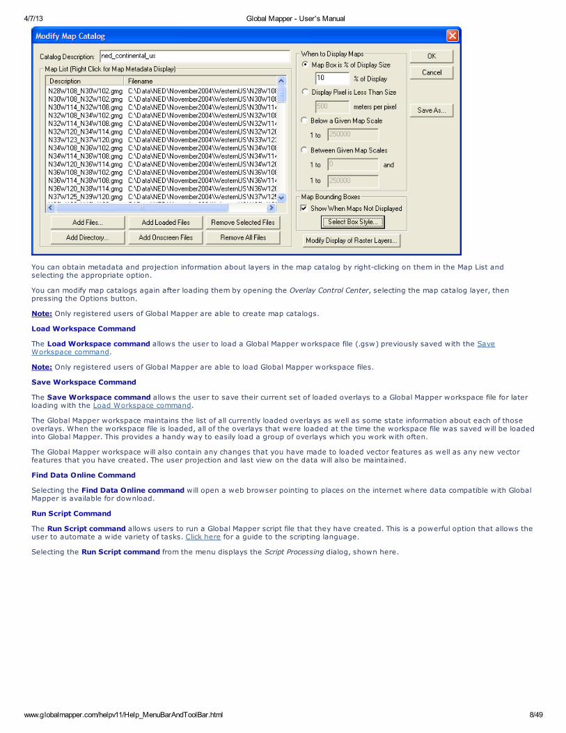
The Create New Map Catalog command allows you to create a "map catalog". A "map catalog" is a collection of map files which aregrouped together to allow for easy loading, viewing, and export. Layers in a map catalog will be loaded and unloaded as needed fordisplay and export, potentially greatly reducing the load time and memory requirements for working with very large collections of data.
Upon selecting this command and selecting the file to save the map catalog to, the Modify Map Catalog dialog (shown below) will bedisplayed, allowing you to add files to the catalog, control at what zoom level data layers are loaded for display, and setup how the mapbounding boxes are displayed when you are zoomed out too far for the actual map data to display. By default map bounding boxes aredisplayed using the style set for the Map Catalog Layer Bounds type.
4/7/13 Global Mapper - User's Manual
www.globalmapper.com/helpv11/Help_MenuBarAndToolBar.html 8/49
You can obtain metadata and projection information about layers in the map catalog by right-clicking on them in the Map List andselecting the appropriate option.
You can modify map catalogs again after loading them by opening the Overlay Control Center, selecting the map catalog layer, thenpressing the Options button.
Note: Only registered users of Global Mapper are able to create map catalogs.
Load Workspace Command
The Load Workspace command allows the user to load a Global Mapper workspace file (.gsw) previously saved with the SaveWorkspace command.
Note: Only registered users of Global Mapper are able to load Global Mapper workspace files.
Save Workspace Command
The Save Workspace command allows the user to save their current set of loaded overlays to a Global Mapper workspace file for laterloading with the Load Workspace command.
The Global Mapper workspace maintains the list of all currently loaded overlays as well as some state information about each of thoseoverlays. When the workspace file is loaded, all of the overlays that were loaded at the time the workspace file was saved will be loadedinto Global Mapper. This provides a handy way to easily load a group of overlays which you work with often.
The Global Mapper workspace will also contain any changes that you have made to loaded vector features as well as any new vectorfeatures that you have created. The user projection and last view on the data will also be maintained.
Find Data Online Command
Selecting the Find Data Online command will open a web browser pointing to places on the internet where data compatible with GlobalMapper is available for download.
Run Script Command
The Run Script command allows users to run a Global Mapper script file that they have created. This is a powerful option that allows theuser to automate a wide variety of tasks. Click here for a guide to the scripting language.
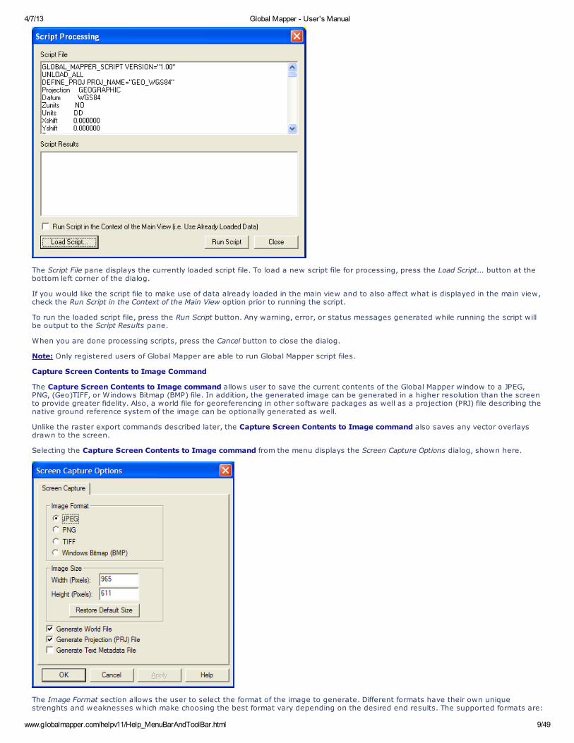
Selecting the Run Script command from the menu displays the Script Processing dialog, shown here.
4/7/13 Global Mapper - User's Manual
www.globalmapper.com/helpv11/Help_MenuBarAndToolBar.html 9/49
The Script File pane displays the currently loaded script file. To load a new script file for processing, press the Load Script... button at thebottom left corner of the dialog.
If you would like the script file to make use of data already loaded in the main view and to also affect what is displayed in the main view,check the Run Script in the Context of the Main View option prior to running the script.
To run the loaded script file, press the Run Script button. Any warning, error, or status messages generated while running the script willbe output to the Script Results pane.
When you are done processing scripts, press the Cancel button to close the dialog.
Note: Only registered users of Global Mapper are able to run Global Mapper script files.
Capture Screen Contents to Image Command
The Capture Screen Contents to Image command allows user to save the current contents of the Global Mapper window to a JPEG,PNG, (Geo)TIFF, or Windows Bitmap (BMP) file. In addition, the generated image can be generated in a higher resolution than the screento provide greater fidelity. Also, a world file for georeferencing in other software packages as well as a projection (PRJ) file describing thenative ground reference system of the image can be optionally generated as well.
Unlike the raster export commands described later, the Capture Screen Contents to Image command also saves any vector overlaysdrawn to the screen.
Selecting the Capture Screen Contents to Image command from the menu displays the Screen Capture Options dialog, shown here.
The Image Format section allows the user to select the format of the image to generate. Different formats have their own uniquestrenghts and weaknesses which make choosing the best format vary depending on the desired end results. The supported formats are:
4/7/13 Global Mapper - User's Manual
www.globalmapper.com/helpv11/Help_MenuBarAndToolBar.html 10/49
JPEG - JPEG is a lossy format that achieves excellent compression on images with a lot of color variation, such as pictures of realworld objects and shaded elevation data.PNG (Portable Network Graphic) - PNG is a lossless format that achieves excellent compression on images without a lot of colorvariation, such as line (vector) drawings and paper map scans such as DRGs. The generated PNG file will be of the 24-bit variety.(Geo)TIFF - TIFF is a lossless format that is supported by many GIS packages. Saving the screen to a TIFF with this commandgenerated a 24-bit uncompressed TIFF. In addition, all georeferencing data is stored in a GeoTIFF header attached to the TIFF,making the image completely self-describing.Windows Bitmap (BMP) - BMP is a widely support format on Windows platforms. Saving the screen to a BMP results in a 24-bituncompressed image.
The width and height of the generated image in pixels are specified in the Image Size panel. By default, the size of the Global Mapperview pane are used. Using these values will generate an image that exactly matches what you see. You can change these values togenerate a more or less resolute image with the obvious tradeoff of size vs. quality.
Checking the Generate World File option results in a world file being generated in addition to the image. The world file will be generated inthe same directory as the image and will have the same primary name as the image. The filename extension will depend on the selectedimage type (JPEG=.jpgw, PNG=.pngw, TIFF=.tfw,BMP=.bmpw).
Checking the Generate Projection (PRJ) File option results in a projection file being generated describing the ground reference system ofthe created image. The projection file will be generated in the same directory as the image and will have the same primary name as theimage with an extension of .prj.
Checking the Generate Text Metadata File option results in a text file being generated listing the metadata for the captured image.
Pressing the OK button prompts the user to select the name and location of the image to generate and then proceeds to generate theimage.
Note: Only registered users of Global Mapper are able capture the screen to an image file.
Export Global Mapper Package File Command
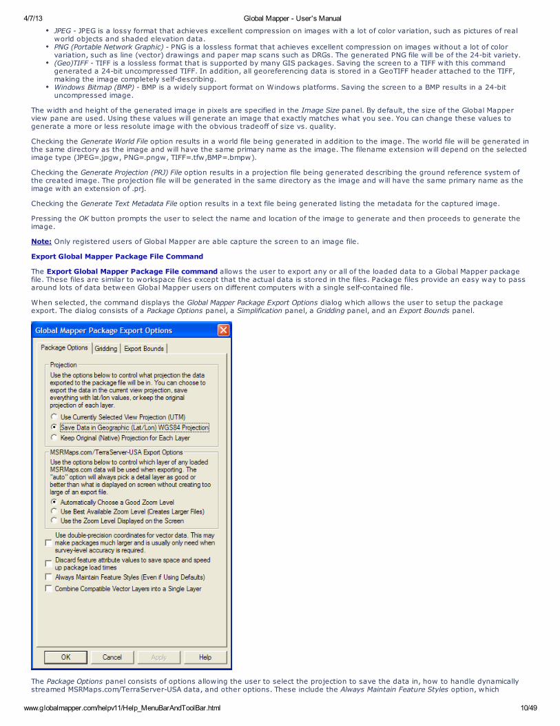
The Export Global Mapper Package File command allows the user to export any or all of the loaded data to a Global Mapper packagefile. These files are similar to workspace files except that the actual data is stored in the files. Package files provide an easy way to passaround lots of data between Global Mapper users on different computers with a single self-contained file.
When selected, the command displays the Global Mapper Package Export Options dialog which allows the user to setup the packageexport. The dialog consists of a Package Options panel, a Simplification panel, a Gridding panel, and an Export Bounds panel.
The Package Options panel consists of options allowing the user to select the projection to save the data in, how to handle dynamicallystreamed MSRMaps.com/TerraServer-USA data, and other options. These include the Always Maintain Feature Styles option, which
4/7/13 Global Mapper - User's Manual
www.globalmapper.com/helpv11/Help_MenuBarAndToolBar.html 11/49
specifies that any vector features stored in the package file should explicitly save the styling of that feature, even if they are using thedefault style for the feature classification. This can make it easier to maintain exact styling when transferring packages between GlobalMapper installations.
In the Projection section of the panel, the user can choose to save all loaded data in the currently selected view projection (this is theprojection selected on the Projection tab of the Configuration dialog), in latitude/longitude coordinates (the "Geographic" projection) withthe WGS84 datum, or to keep each layer in its original native projection.
In the TerraServer Export Options section of the panel, the user can select how displayed layers from the Download TerraServer menuoption are exported. The Automatic selection for imagery themes (i.e. DOQs, Urban Area imagery) will save data slightly more detailedthan what is displayed on the screen. For the DRG (topographic map) theme, the most detailed zoom range for the current scale of DRGmap being displayed (i.e. 24K, 100K, 250K) will be determined and data from that scale will be saved. The other alternatives either savethe most detailed scale available, creating potentially very large files, or the scale the most closely matches the current display scale onthe screen.
The Combine Compatible Vector Layers into a Single Layer option causes all vector features with the same native projection to be combinedinto a single layer within the package file rather than maintaining their original layer structure.
The Simplification panel allows the user to set up the threshold at which points that don't contribute much to the shape of the vector lineand area features being exported are removed in order to generate features with less vertices. By default, all vertices will be kept, butthe user can move the slider to the right to get rid of relatively insignificant vertices and realize significant space spacings at the cost ofsome fidelity.
The Gridding panel allows the user to split up the data into regularly spaced tiles on export if desired rather than just exporting a singlefile.
The Export Bounds panel allows the user to select what portion of the loaded data they wish to export.
Note: Only registered users of Global Mapper are able capture the screen to an image file.
Export PDF/GeoPDF File Command
The Export PDF File command allows the user to export any or all of the loaded data to a Geo-enabled PDF file. These are standard PDFfiles that can be read in Adobe Acrobat Reader. They also will have geopositioning information embedded in them so that mappingapplications like Global Mapper can automatically display the data in the PDF at the proper location.
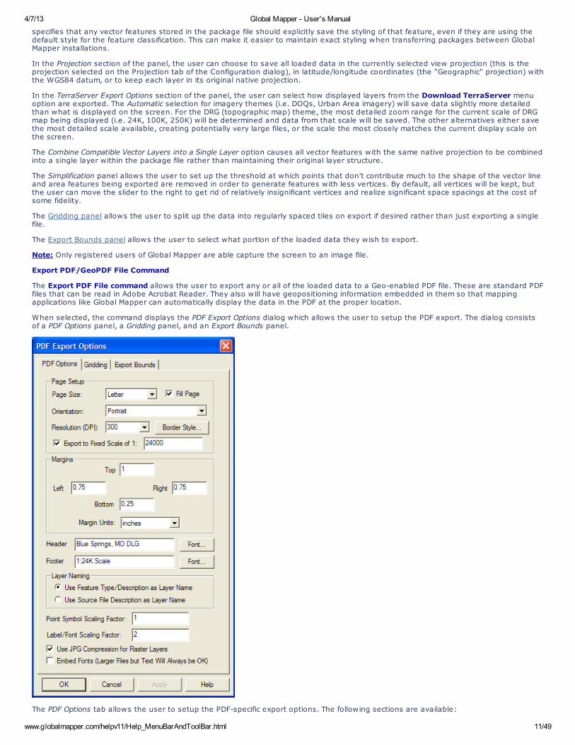
When selected, the command displays the PDF Export Options dialog which allows the user to setup the PDF export. The dialog consistsof a PDF Options panel, a Gridding panel, and an Export Bounds panel.
The PDF Options tab allows the user to setup the PDF-specific export options. The following sections are available:
4/7/13 Global Mapper - User's Manual
www.globalmapper.com/helpv11/Help_MenuBarAndToolBar.html 12/49
Page SetupPage Size - The page size setting controls the target paper size for the exportOrientation - This setting controls whether the target page uses landscape or portrait orientationFill Page - If checked, your specified export bounds will be expanded to fill the entire page if necessary. If you do not checkthis option, only your exact export bounds will be exported with the rest of the page remaining blank.Resolution (DPI) - This setting controls the resolution (dots-per-inch) of your output. Larger values result in more detail beingstored in the created PDF file, although the resulting file will also be larger.Border Style - Pressing this button brings up a dialog allowing you to setup the style of the border line drawn around yourdataExport to Fixed Scale - If you choose the option to export to a particular scale, the generated PDF file will have the specifiedscale. The specified export bounds will be adjusted around the selected center point to have the scale specified.
Margins - This section allows you to setup the size of the white margins around your dataHeader - Allows you to specify a header text to draw in the top margin of the output file.Footer - Allows you to specify a footer text to draw in the bottom margin of the output file.Layer Naming - This section controls how layers in the created PDF will be named. You can access PDF layers in the AcrobatReader
Use Feature Type/Description as Layer Name - The feature type name/description will be used as the layer name in the PDFfile.Use Source File Description as Layer Name - The Control Center layer name for the layer that the feature is in will be used asthe PDF layer name.
Point Symbol Scaling Factor - Specifies the scaling factor to apply when rendering point symbols to the PDF file. For example, use2.0 to double the size of your point symbols in the final PDF file, or 0.5 to make them half the size.Label/Font Scaling Factor - Specifies the size scaling factor to apply when rendering feature labels to the PDF file, allowing you toeasily grow or shrink all labels written to the PDF file. For example, use 2.0 to double the size of your labels in the final PDF file, or0.5 to make them half the size.Use JPG Compression for Raster Layers - Specifies that any raster layers exported to the PDF will be compressed in the PDF fileusing JPG compression. While there may be a slight loss in quality by using this option, the resulting files are typically much smallerand in most cases you cannot notice any loss in quality, so it is recommended to use this option.Embed Fonts - Specifies that any fonts used that might not be on every system will be embedded in the PDF file. Using this optionwill basically guarantee that your text will display the same on any system, but unless you are using an unusual font the increasein PDF file size might not be worth it as most users would have your font anyway.
The Gridding panel allows the user to split up the data into regularly spaced tiles on export if desired rather than just exporting a singlefile.
The Export Bounds panel allows the user to select what portion of the loaded data they wish to export.
Note: Only registered users of Global Mapper are able capture the screen to an image file.
Export Raster and Elevation Data
The commands on the Export Raster and Elevation Data submenu allow the user to export loaded raster and elevation data to variousformats.
Export Arc ASCII Grid Command
The Export Arc ASCII Grid command allows the user to export any loaded elevation grid data sets to an Arc ASCII Grid format file.
When selected, the command displays the Arc ASCII Grid Export Options dialog which allows the user to setup the export. The dialogconsists of a General options panel which allows the user to set up the grid spacing and vertical units, a Gridding panel and an ExportBounds panel which allows the user to set up the portion of the loaded data they wish to export.
Note: Only registered users of Global Mapper are able to export data to any format.
Export BIL/BIP/BSQ Command
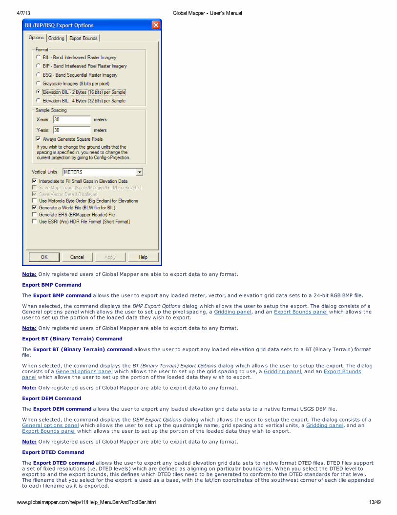
The Export BIL/BIP/BSQ command allows the user to export any loaded raster, vector, and/or elevation grid data to a BIL, BIP, or BSQformat file.
When selected, the command displays the BIL/BIP/BSQ Export Options dialog which allows the user to setup the export. The dialogconsists of an Options panel (pictured below), which allows the user to set up type of export to perform, the sample spacing, verticalunits, and other applicable options, a Gridding Panel, and an Export Bounds panel which allows the user to set up the portion of theloaded data they wish to export.
4/7/13 Global Mapper - User's Manual
www.globalmapper.com/helpv11/Help_MenuBarAndToolBar.html 13/49
Note: Only registered users of Global Mapper are able to export data to any format.
Export BMP Command
The Export BMP command allows the user to export any loaded raster, vector, and elevation grid data sets to a 24-bit RGB BMP file.
When selected, the command displays the BMP Export Options dialog which allows the user to setup the export. The dialog consists of aGeneral options panel which allows the user to set up the pixel spacing, a Gridding panel, and an Export Bounds panel which allows theuser to set up the portion of the loaded data they wish to export.
Note: Only registered users of Global Mapper are able to export data to any format.
Export BT (Binary Terrain) Command
The Export BT (Binary Terrain) command allows the user to export any loaded elevation grid data sets to a BT (Binary Terrain) formatfile.
When selected, the command displays the BT (Binary Terrain) Export Options dialog which allows the user to setup the export. The dialogconsists of a General options panel which allows the user to set up the grid spacing to use, a Gridding panel, and an Export Boundspanel which allows the user to set up the portion of the loaded data they wish to export.
Note: Only registered users of Global Mapper are able to export data to any format.
Export DEM Command
The Export DEM command allows the user to export any loaded elevation grid data sets to a native format USGS DEM file.
When selected, the command displays the DEM Export Options dialog which allows the user to setup the export. The dialog consists of aGeneral options panel which allows the user to set up the quadrangle name, grid spacing and vertical units, a Gridding panel, and anExport Bounds panel which allows the user to set up the portion of the loaded data they wish to export.
Note: Only registered users of Global Mapper are able to export data to any format.
Export DTED Command
The Export DTED command allows the user to export any loaded elevation grid data sets to native format DTED files. DTED files supporta set of fixed resolutions (i.e. DTED levels) which are defined as aligning on particular boundaries. When you select the DTED level toexport to and the export bounds, this defines which DTED tiles need to be generated to conform to the DTED standards for that level.The filename that you select for the export is used as a base, with the lat/lon coordinates of the southwest corner of each tile appendedto each filename as it is exported.
4/7/13 Global Mapper - User's Manual
www.globalmapper.com/helpv11/Help_MenuBarAndToolBar.html 14/49
When selected, the command displays the DTED Export Options dialog which allows the user to setup the export. The dialog consists of aDTED Options panel which allows the user to set up the DTED level and other options, a Gridding panel, and an Export Bounds panelwhich allows the user to set up the portion of the loaded data they wish to export.
ADVANCED USERS: You can change the accuracy value exported in DTED files by specifying your own string value (up to 4 characters inlength) at "HKEY_CURRENT_USER\Software\Global Mapper\DTEDAccuracy". The collection system value (up to 12 characters in length) canbe specified at "HKEY_CURRENT_USER\Software\Global Mapper\DTEDCollectionSystem".
Note: Only registered users of Global Mapper are able to export data to any format.
Export DXF 3D Face File Command
The Export DXF 3D Face File command allows the user to export any loaded gridded elevation data sets to a DXF 3D Face file.
When selected, the command displays the DXF 3D Face Export Options dialog which allows the user to setup the export. The dialogconsists of a General options panel which allows the user to set up the grid spacing and vertical units, a Gridding panel, and an ExportBounds panel which allows the user to set up the portion of the loaded data they wish to export.
Note: Only registered users of Global Mapper are able to export data to any format.
Export DXF Mesh Command
The Export DXF Mesh command allows the user to export any loaded elevation grid data sets to a 3D DXF Mesh file.
When selected, the command displays the DXF Mesh Export Options dialog which allows the user to setup the export. The dialog consistsof a General options panel which allows the user to set up the grid spacing and vertical units, a Gridding panel, and an Export Boundspanel which allows the user to set up the portion of the loaded data they wish to export.
Note: Only registered users of Global Mapper are able to export data to any format.
Export DXF Point Command
The Export DXF Point command allows the user to export any loaded elevation grid data sets to a 3D DXF Point file. The DXF file willconsist of a 3D DXF point for each point in the elevation grid defined by the spacing and extents that the user specifies. This option maybe useful when used with other software packages that do not specify the DXF mesh format.
When selected, the command displays the 3D DXF Point Export Options dialog which allows the user to setup the export. The dialogconsists of a General options panel which allows the user to set up the grid spacing and vertical units, a Gridding panel, and an ExportBounds panel which allows the user to set up the portion of the loaded data they wish to export.
Note: Only registered users of Global Mapper are able to export data to any format.
Export ECW Command
The Export ECW command allows the user to export any loaded raster, vector, and elevation grid data sets to an ECW file. ECW filesare highly compressed and great for storing things like satellite imagery. There is no size restriction on exported ECW files, so you canstore many terabytes worth of imagery within a single highly compressed ECW file.
When selected, the command displays the ECW Export Options dialog which allows the user to setup the export. The dialog consists of aGeneral options panel which allows the user to set up the pixel spacing and target compression ration, a Gridding panel, and an ExportBounds panel which allows the user to set up the portion of the loaded data they wish to export. If you would like to generate a losslessJPG2000 format file, simply slide the Target Compression Ratio slider all the way to the right (1:1 target compression ration).
Note: Only registered users of Global Mapper are able to export data to any format.
Export Erdas Imagine Command
The Export Erdas Imagine command allows the user to export any loaded raster, vector,and elevation grid data sets to an ErdasImagine file.
When selected, the command displays the Erdas Imagine Export Options dialog which allows the user to setup the export. The dialogconsists of a General options panel which allows the user to set up the pixel spacing and format, a Gridding panel, and an Export Boundspanel which allows the user to set up the portion of the loaded data they wish to export.
Note: Only registered users of Global Mapper are able to export data to any format.
Export Float/Grid Command
The Export Float/Grid command allows the user to export any loaded elevation grid data sets to a Float/Grid format file. The Float/Gridfile will consist of a 4-byte IEEE floating point number for each elevation sample in the file, starting at the top-left corner and proceedingacross, then down. In addition to the elevation data file, an ESRI-format .hdr file and .prj file will also be generated. There is also anoption to allow exporting slope values (in degrees) or slope directions (in bearings where 0 is north, 90 is east, etc.) rather thanelevation values at each sample location.
When selected, the command displays the Float/Grid Point Export Options dialog which allows the user to setup the export. The dialogconsists of a General options panel which allows the user to set up the grid spacing and vertical units, a Gridding panel, and an ExportBounds panel which allows the user to set up the portion of the loaded data they wish to export.
Note: Only registered users of Global Mapper are able to export data to any format.
Export Geosoft Grid Command
The Export Geosoft Grid command allows the user to export any loaded elevation grid data sets to a Geosoft Binary Grid format file.
When selected, the command displays the Geosoft Grid Export Options dialog which allows the user to setup the export. The dialogconsists of a General options panel which allows the user to set up the grid spacing to use, a Gridding panel, and an Export Boundspanel which allows the user to set up the portion of the loaded data they wish to export.
4/7/13 Global Mapper - User's Manual
www.globalmapper.com/helpv11/Help_MenuBarAndToolBar.html 15/49
Note: Only registered users of Global Mapper are able to export data to any format.
Export GeoTIFF Command
The Export GeoTIFF command allows the user to export any loaded raster, vector, and elevation data sets to a GeoTIFF format file.
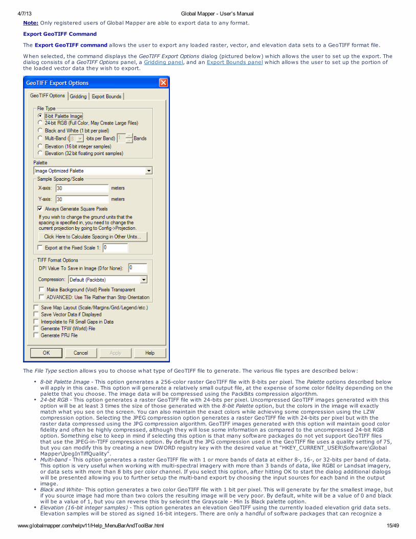
When selected, the command displays the GeoTIFF Export Options dialog (pictured below) which allows the user to set up the export. Thedialog consists of a GeoTIFF Options panel, a Gridding panel, and an Export Bounds panel which allows the user to set up the portion ofthe loaded vector data they wish to export.
The File Type section allows you to choose what type of GeoTIFF file to generate. The various file types are described below:
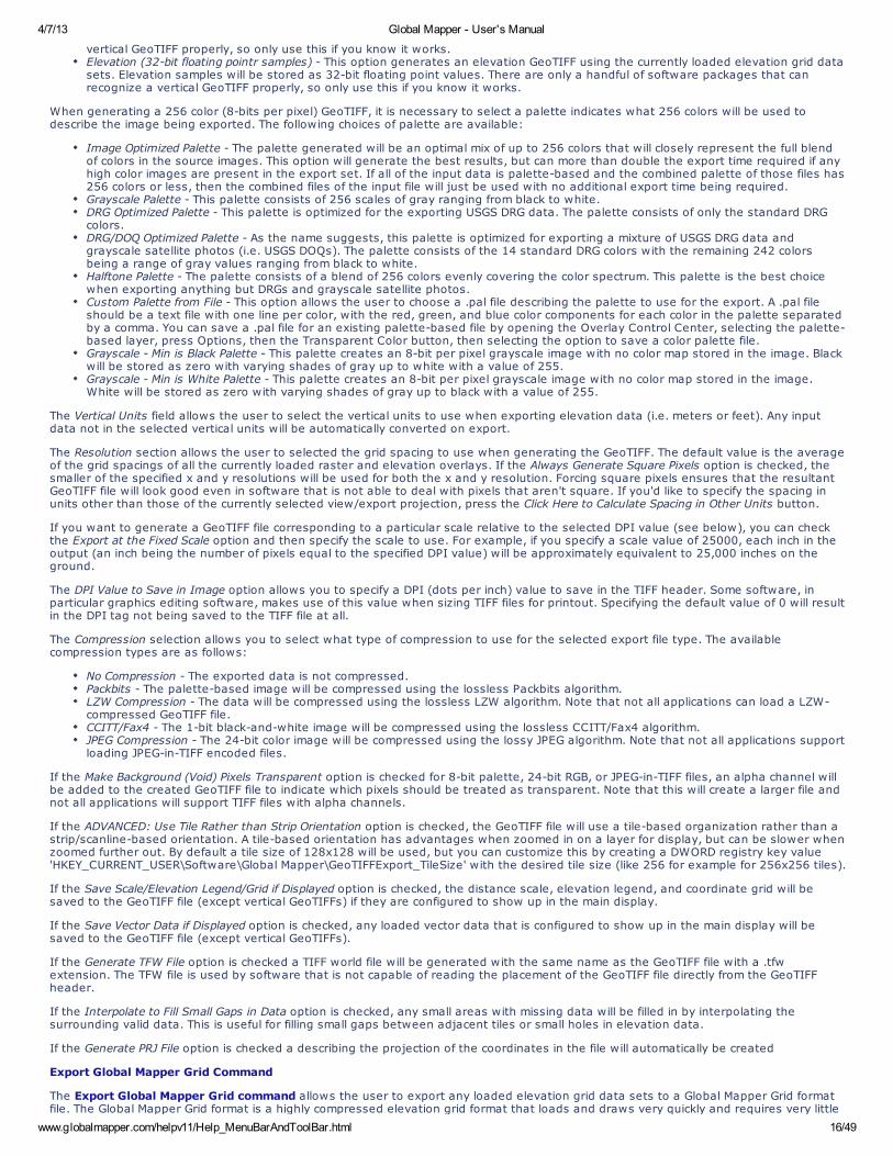
8-bit Palette Image - This option generates a 256-color raster GeoTIFF file with 8-bits per pixel. The Palette options described belowwill apply in this case. This option will generate a relatively small output file, at the expense of some color fidelity depending on thepalette that you choose. The image data will be compressed using the PackBits compression algorithm.24-bit RGB - This option generates a raster GeoTIFF file with 24-bits per pixel. Uncompressed GeoTIFF images generated with thisoption will be at least 3 times the size of those generated with the 8-bit Palette option, but the colors in the image will exactlymatch what you see on the screen. You can also maintain the exact colors while achieving some compression using the LZWcompression option. Selecting the JPEG compression option generates a raster GeoTIFF file with 24-bits per pixel but with theraster data compressed using the JPG compression algorithm. GeoTIFF images generated with this option will maintain good colorfidelity and often be highly compressed, although they will lose some information as compared to the uncompressed 24-bit RGBoption. Something else to keep in mind if selecting this option is that many software packages do not yet support GeoTIFF filesthat use the JPEG-in-TIFF compression option. By default the JPG compression used in the GeoTIFF file uses a quality setting of 75,but you can modify this by creating a new DWORD registry key with the desired value at "HKEY_CURRENT_USER\Software\GlobalMapper\JpegInTiffQuality".Multi-band - This option generates a raster GeoTIFF file with 1 or more bands of data at either 8-, 16-, or 32-bits per band of data.This option is very useful when working with multi-spectral imagery with more than 3 bands of data, like RGBI or Landsat imagery,or data sets with more than 8 bits per color channel. If you select this option, after hitting OK to start the dialog additional dialogswill be presented allowing you to further setup the multi-band export by choosing the input sources for each band in the outputimage.Black and White- This option generates a two color GeoTIFF file with 1 bit per pixel. This will generate by far the smallest image, butif you source image had more than two colors the resulting image will be very poor. By default, white will be a value of 0 and blackwill be a value of 1, but you can reverse this by selecint the Grayscale - Min Is Black palette option.Elevation (16-bit integer samples) - This option generates an elevation GeoTIFF using the currently loaded elevation grid data sets.Elevation samples will be stored as signed 16-bit integers. There are only a handful of software packages that can recognize a
4/7/13 Global Mapper - User's Manual
www.globalmapper.com/helpv11/Help_MenuBarAndToolBar.html 16/49
vertical GeoTIFF properly, so only use this if you know it works.Elevation (32-bit floating pointr samples) - This option generates an elevation GeoTIFF using the currently loaded elevation grid datasets. Elevation samples will be stored as 32-bit floating point values. There are only a handful of software packages that canrecognize a vertical GeoTIFF properly, so only use this if you know it works.
When generating a 256 color (8-bits per pixel) GeoTIFF, it is necessary to select a palette indicates what 256 colors will be used todescribe the image being exported. The following choices of palette are available:
Image Optimized Palette - The palette generated will be an optimal mix of up to 256 colors that will closely represent the full blendof colors in the source images. This option will generate the best results, but can more than double the export time required if anyhigh color images are present in the export set. If all of the input data is palette-based and the combined palette of those files has256 colors or less, then the combined files of the input file will just be used with no additional export time being required.Grayscale Palette - This palette consists of 256 scales of gray ranging from black to white.DRG Optimized Palette - This palette is optimized for the exporting USGS DRG data. The palette consists of only the standard DRGcolors.DRG/DOQ Optimized Palette - As the name suggests, this palette is optimized for exporting a mixture of USGS DRG data andgrayscale satellite photos (i.e. USGS DOQs). The palette consists of the 14 standard DRG colors with the remaining 242 colorsbeing a range of gray values ranging from black to white.Halftone Palette - The palette consists of a blend of 256 colors evenly covering the color spectrum. This palette is the best choicewhen exporting anything but DRGs and grayscale satellite photos.Custom Palette from File - This option allows the user to choose a .pal file describing the palette to use for the export. A .pal fileshould be a text file with one line per color, with the red, green, and blue color components for each color in the palette separatedby a comma. You can save a .pal file for an existing palette-based file by opening the Overlay Control Center, selecting the palette-based layer, press Options, then the Transparent Color button, then selecting the option to save a color palette file.Grayscale - Min is Black Palette - This palette creates an 8-bit per pixel grayscale image with no color map stored in the image. Blackwill be stored as zero with varying shades of gray up to white with a value of 255.Grayscale - Min is White Palette - This palette creates an 8-bit per pixel grayscale image with no color map stored in the image.White will be stored as zero with varying shades of gray up to black with a value of 255.
The Vertical Units field allows the user to select the vertical units to use when exporting elevation data (i.e. meters or feet). Any inputdata not in the selected vertical units will be automatically converted on export.
The Resolution section allows the user to selected the grid spacing to use when generating the GeoTIFF. The default value is the averageof the grid spacings of all the currently loaded raster and elevation overlays. If the Always Generate Square Pixels option is checked, thesmaller of the specified x and y resolutions will be used for both the x and y resolution. Forcing square pixels ensures that the resultantGeoTIFF file will look good even in software that is not able to deal with pixels that aren't square. If you'd like to specify the spacing inunits other than those of the currently selected view/export projection, press the Click Here to Calculate Spacing in Other Units button.
If you want to generate a GeoTIFF file corresponding to a particular scale relative to the selected DPI value (see below), you can checkthe Export at the Fixed Scale option and then specify the scale to use. For example, if you specify a scale value of 25000, each inch in theoutput (an inch being the number of pixels equal to the specified DPI value) will be approximately equivalent to 25,000 inches on theground.
The DPI Value to Save in Image option allows you to specify a DPI (dots per inch) value to save in the TIFF header. Some software, inparticular graphics editing software, makes use of this value when sizing TIFF files for printout. Specifying the default value of 0 will resultin the DPI tag not being saved to the TIFF file at all.
The Compression selection allows you to select what type of compression to use for the selected export file type. The availablecompression types are as follows:
No Compression - The exported data is not compressed.Packbits - The palette-based image will be compressed using the lossless Packbits algorithm.LZW Compression - The data will be compressed using the lossless LZW algorithm. Note that not all applications can load a LZW-compressed GeoTIFF file.CCITT/Fax4 - The 1-bit black-and-white image will be compressed using the lossless CCITT/Fax4 algorithm.JPEG Compression - The 24-bit color image will be compressed using the lossy JPEG algorithm. Note that not all applications supportloading JPEG-in-TIFF encoded files.
If the Make Background (Void) Pixels Transparent option is checked for 8-bit palette, 24-bit RGB, or JPEG-in-TIFF files, an alpha channel willbe added to the created GeoTIFF file to indicate which pixels should be treated as transparent. Note that this will create a larger file andnot all applications will support TIFF files with alpha channels.
If the ADVANCED: Use Tile Rather than Strip Orientation option is checked, the GeoTIFF file will use a tile-based organization rather than astrip/scanline-based orientation. A tile-based orientation has advantages when zoomed in on a layer for display, but can be slower whenzoomed further out. By default a tile size of 128x128 will be used, but you can customize this by creating a DWORD registry key value'HKEY_CURRENT_USER\Software\Global Mapper\GeoTIFFExport_TileSize' with the desired tile size (like 256 for example for 256x256 tiles).
If the Save Scale/Elevation Legend/Grid if Displayed option is checked, the distance scale, elevation legend, and coordinate grid will besaved to the GeoTIFF file (except vertical GeoTIFFs) if they are configured to show up in the main display.
If the Save Vector Data if Displayed option is checked, any loaded vector data that is configured to show up in the main display will besaved to the GeoTIFF file (except vertical GeoTIFFs).
If the Generate TFW File option is checked a TIFF world file will be generated with the same name as the GeoTIFF file with a .tfwextension. The TFW file is used by software that is not capable of reading the placement of the GeoTIFF file directly from the GeoTIFFheader.
If the Interpolate to Fill Small Gaps in Data option is checked, any small areas with missing data will be filled in by interpolating thesurrounding valid data. This is useful for filling small gaps between adjacent tiles or small holes in elevation data.
If the Generate PRJ File option is checked a describing the projection of the coordinates in the file will automatically be created
Export Global Mapper Grid Command
The Export Global Mapper Grid command allows the user to export any loaded elevation grid data sets to a Global Mapper Grid formatfile. The Global Mapper Grid format is a highly compressed elevation grid format that loads and draws very quickly and requires very little
4/7/13 Global Mapper - User's Manual
www.globalmapper.com/helpv11/Help_MenuBarAndToolBar.html 17/49
memory. If you have a choice for what format to store your gridded elevation data in, we suggest using the Global Mapper Grid format.
When selected, the command displays the Global Mapper Grid Export Options dialog which allows the user to setup the export. The dialogconsists of a General options panel which allows the user to set up the grid spacing and vertical units, a Gridding panel, and an ExportBounds panel which allows the user to set up the portion of the loaded data they wish to export.
Note: Only registered users of Global Mapper are able to export data to any format.
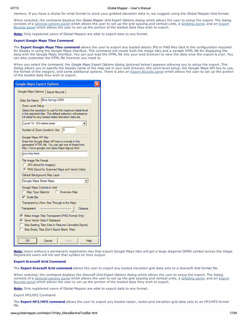
Export Google Maps Tiles Command
The Export Google Maps Tiles command allows the user to export any loaded datato JPG or PNG files tiled in the configuration requiredfor display in using the Google Maps interface. This command will create both the image tiles and a sample HTML file for displaying thedata with the Google Maps interface. You can just load the HTML file into your web browser to view the data once the export is over. Youcan also customize the HTML file however you need to.
When you select the command, the Google Maps Export Options dialog (pictured below) appears allowing you to setup the export. Thisdialog allows you to specify the display name of the map set in your web browser, the zoom level setup, the Google Maps API key to use,the format of the imagery, and some additional options. There is also an Export Bounds panel which allows the user to set up the portionof the loaded data they wish to export.
Note: Users without a permanent registration key that export Google Maps tiles will get a large diagonal DEMO symbol across the image.Registered users will not see that symbol on their output.
Export Gravsoft Grid Command
The Export Gravsoft Grid command allows the user to export any loaded elevation grid data sets to a Gravsoft Grid format file.
When selected, the command displays the Gravsoft Grid Export Options dialog which allows the user to setup the export. The dialogconsists of a General options panel which allows the user to set up the grid spacing and vertical units, a Gridding panel, and an ExportBounds panel which allows the user to set up the portion of the loaded data they wish to export.
Note: Only registered users of Global Mapper are able to export data to any format.
Export HF2/HFZ Command
The Export HF2/HFZ command allows the user to export any loaded raster, vector,and elevation grid data sets to an HF2/HFZ formatfile.
4/7/13 Global Mapper - User's Manual
www.globalmapper.com/helpv11/Help_MenuBarAndToolBar.html 18/49
When selected, the command displays the HF2/HFZ Export Options dialog which allows the user to setup the export. The dialog consistsof a General options panel which allows the user to set up the pixel spacing and format, a Gridding panel, and an Export Bounds panelwhich allows the user to set up the portion of the loaded data they wish to export.
Note: Only registered users of Global Mapper are able to export data to any format.
Export Idrisi Command
The Export Idrisi command allows the user to export any loaded raster, vector,and elevation grid data sets to an Idrisi file.
When selected, the command displays the Idrisi Export Options dialog which allows the user to setup the export. The dialog consists of aGeneral options panel which allows the user to set up the pixel spacing and format, a Gridding panel, and an Export Bounds panel whichallows the user to set up the portion of the loaded data they wish to export.
Note: Only registered users of Global Mapper are able to export data to any format.
Export JPG Command
The Export JPG command allows the user to export any loaded raster, vector, and elevation grid data sets to a JPG file.
When selected, the command displays the JPG Export Options dialog which allows the user to setup the export. The dialog consists of aGeneral options panel which allows the user to set up the pixel spacing, a Gridding panel, and an Export Bounds panel which allows theuser to set up the portion of the loaded data they wish to export.
Note: Only registered users of Global Mapper are able to export data to any format.
Export JPG2000 Command
The Export JPG2000 command allows the user to export any loaded raster, vector, and elevation grid data sets to a JPG2000 formatfile. JPG2000 files are highly compressed and great for storing things like satellite imagery. There is no size restriction on exportedJPG2000 files, so you can store many terabytes worth of imagery within a single highly compressed JPG2000 file.
When selected, the command displays the JPG2000 Export Options dialog which allows the user to setup the export. The dialog consistsof a General options panel which allows the user to set up the pixel spacing and target compression ration, a Gridding panel, and anExport Bounds panel which allows the user to set up the portion of the loaded data they wish to export. If you would like to generate alossless JPG2000 format file, simply slide the Target Compression Ratio slider all the way to the right (1:1 target compression ration).
Note: Only registered users of Global Mapper are able to export data to any format.
Export KML/KMZ Command
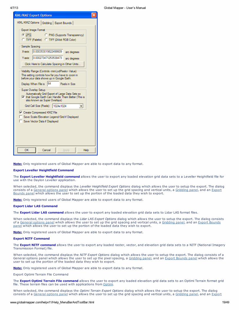
The Export KML/KMZ command allows the user to export any loaded raster, vector, and elevation grid data sets to a KML/KMZ formatfile for display in Google Earth. If you are wanting to export a vector KML/KMZ file from loaded vector data, use the File->Export VectorData->Export KML/KMZ menu command instead.
When selected, the command displays the KML/KMZ Export Options dialog (pictured below) which allows the user to setup the export. Thedialog consists of a KML/KMZ Options panel, a Gridding panel, and an Export Bounds panel which allows the user to set up the portion ofthe loaded data they wish to export.
The KML/KMZ Options panel allows the user to set up the target image format for storage and the sample spacing, as well as otheroptions such as whether to store all of the resulting files in a KMZ file (recommended) and whether or not to render and save loadedvector data. There is also an option to automatically grid the data on export (this creates what is known as a SuperOverlay). Enablingthis option allows very large quantities of data to be efficiently viewed using Google Earth. When using this option you can also controlthe tile size to use when creating the super overlays. For very large exports the larger sizes (1024x1024 or 2048x2048) arerecommended.
4/7/13 Global Mapper - User's Manual
www.globalmapper.com/helpv11/Help_MenuBarAndToolBar.html 19/49
Note: Only registered users of Global Mapper are able to export data to any format.
Export Leveller Heightfield Command
The Export Leveller Heightfield command allows the user to export any loaded elevation grid data sets to a Leveller Heightfield file foruse with the Daylon Leveller application.
When selected, the command displays the Leveller Heightfield Export Options dialog which allows the user to setup the export. The dialogconsists of a General options panel which allows the user to set up the grid spacing and vertical units, a Gridding panel, and an ExportBounds panel which allows the user to set up the portion of the loaded data they wish to export.
Note: Only registered users of Global Mapper are able to export data to any format.
Export Lidar LAS Command
The Export Lidar LAS command allows the user to export any loaded elevation grid data sets to Lidar LAS format files.
When selected, the command displays the Lidar LAS Export Options dialog which allows the user to setup the export. The dialog consistsof a General options panel which allows the user to set up the grid spacing and vertical units, a Gridding panel, and an Export Boundspanel which allows the user to set up the portion of the loaded data they wish to export.
Note: Only registered users of Global Mapper are able to export data to any format.
Export NITF Command
The Export NITF command allows the user to export any loaded raster, vector, and elevation grid data sets to a NITF (National ImageryTransmission Format) file.
When selected, the command displays the NITF Export Options dialog which allows the user to setup the export. The dialog consists of aGeneral options panel which allows the user to set up the pixel spacing, a Gridding panel, and an Export Bounds panel which allows theuser to set up the portion of the loaded data they wish to export.
Note: Only registered users of Global Mapper are able to export data to any format.
Export Optimi Terrain File Command
The Export Optimi Terrain File command allows the user to export any loaded elevation grid data sets to an Optimi Terrain format gridfile. These terrain files can be used with applications from Optimi.
When selected, the command displays the Optimi Terrain Export Options dialog which allows the user to setup the export. The dialogconsists of a General options panel which allows the user to set up the grid spacing and vertical units, a Gridding panel, and an Export
4/7/13 Global Mapper - User's Manual
www.globalmapper.com/helpv11/Help_MenuBarAndToolBar.html 20/49
Bounds panel which allows the user to set up the portion of the loaded data they wish to export.
Note: Only registered users of Global Mapper are able to export data to any format.
Export PGM File Command
The Export PGM File command allows the user to export any loaded elevation grid data sets to a PGM grayscale grid file. These grid filescan be used with any software application that supports PGM files.
When selected, the command displays the PGM Export Options dialog which allows the user to setup the export. The dialog consists of aGeneral options panel which allows the user to set up the grid spacing and vertical units, a Gridding panel, and an Export Bounds panelwhich allows the user to set up the portion of the loaded data they wish to export.
Note: Only registered users of Global Mapper are able to export data to any format.
Export PLS-CADD XYZ File Command
The Export PLS-CADD XYZ File command allows the user to export any loaded elevation grid data sets to a PLS-CADD XYZ format gridfile. These grid files can be used with the PLS-CADD software application.
When selected, the command displays the PLS-CADD XYZ Export Options dialog which allows the user to setup the export. The dialogconsists of a General options panel which allows the user to set up the grid spacing and vertical units, a Gridding panel, and an ExportBounds panel which allows the user to set up the portion of the loaded data they wish to export.
Note: Only registered users of Global Mapper are able to export data to any format.
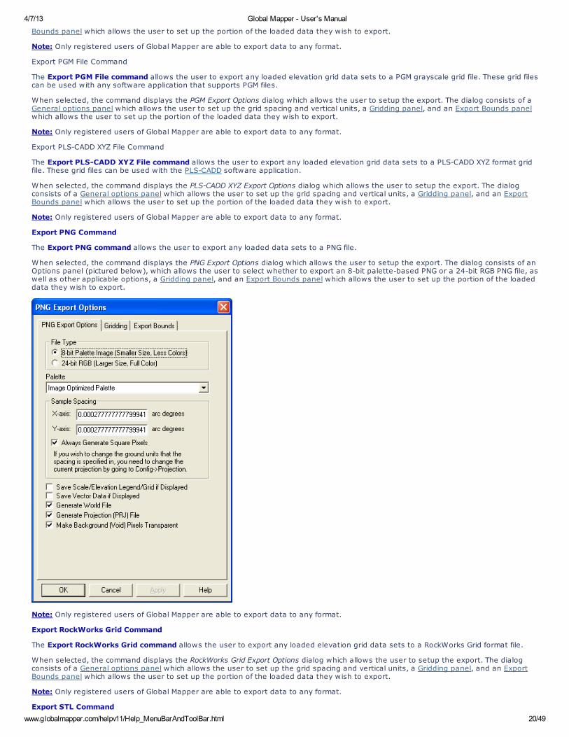
Export PNG Command
The Export PNG command allows the user to export any loaded data sets to a PNG file.
When selected, the command displays the PNG Export Options dialog which allows the user to setup the export. The dialog consists of anOptions panel (pictured below), which allows the user to select whether to export an 8-bit palette-based PNG or a 24-bit RGB PNG file, aswell as other applicable options, a Gridding panel, and an Export Bounds panel which allows the user to set up the portion of the loadeddata they wish to export.
Note: Only registered users of Global Mapper are able to export data to any format.
Export RockWorks Grid Command
The Export RockWorks Grid command allows the user to export any loaded elevation grid data sets to a RockWorks Grid format file.
When selected, the command displays the RockWorks Grid Export Options dialog which allows the user to setup the export. The dialogconsists of a General options panel which allows the user to set up the grid spacing and vertical units, a Gridding panel, and an ExportBounds panel which allows the user to set up the portion of the loaded data they wish to export.
Note: Only registered users of Global Mapper are able to export data to any format.
Export STL Command
4/7/13 Global Mapper - User's Manual
www.globalmapper.com/helpv11/Help_MenuBarAndToolBar.html 21/49
The Export STL command allows the user to export any loaded elevation grid data sets to a STL format file for use with some CADsystems.
When selected, the command displays the STL Export Options dialog which allows the user to setup the export. The dialog consists of aGeneral options panel which allows the user to set up the grid spacing and vertical units, a Gridding panel, and an Export Bounds panelwhich allows the user to set up the portion of the loaded data they wish to export.
Note: Only registered users of Global Mapper are able to export data to any format.
Export Surfer Grid (ASCII Format) Command
The Export Surfer Grid (ASCII Format) command allows the user to export any loaded elevation grid data sets to an ASCII formatSurfer Grid file.
When selected, the command displays the Surfer Grid Export Options dialog which allows the user to setup the export. The dialog consistsof a General options panel which allows the user to set up the grid spacing and vertical units, a Gridding panel, and an Export Boundspanel which allows the user to set up the portion of the loaded data they wish to export.
Note: Only registered users of Global Mapper are able to export data to any format.
Export Surfer Grid (Binary v6 Format) Command
The Export Surfer Grid (Binary v6 Format) command allows the user to export any loaded elevation grid data sets to a binary formatSurfer Grid file compatible with Surfer v6 and above. Binary format Surfer Grids will be smaller than their ASCII-format cousins, so if youcan use the binary format I would suggest it.
When selected, the command displays the Surfer Grid Export Options dialog which allows the user to setup the export. The dialog consistsof a General options panel which allows the user to set up the grid spacing and vertical units, a Gridding panel, and an Export Boundspanel which allows the user to set up the portion of the loaded data they wish to export.
Note: Only registered users of Global Mapper are able to export data to any format.
Export Surfer Grid (Binary v7 Format) Command
The Export Surfer Grid (Binary v7 Format) command allows the user to export any loaded elevation grid data sets to a binary formatSurfer Grid file compatible with Surfer v7 and above. Binary format Surfer Grids will be smaller than their ASCII-format cousins, so if youcan use the binary format I would suggest it.
When selected, the command displays the Surfer Grid Export Options dialog which allows the user to setup the export. The dialog consistsof a General options panel which allows the user to set up the grid spacing and vertical units, a Gridding panel, and an Export Boundspanel which allows the user to set up the portion of the loaded data they wish to export.
Note: Only registered users of Global Mapper are able to export data to any format.
Export Terragen Terrain File Command
The Export Terragen Terrain File command allows the user to export any loaded elevation grid data sets to a Terragen terrain file.
When selected, the command displays the Terragen Export Options dialog which allows the user to setup the export. The dialog consistsof a General options panel which allows the user to set up the grid spacing and an Export Bounds panel which allows the user to set upthe portion of the loaded data they wish to export.
Note: Only registered users of Global Mapper are able to export data to any format.
Export Vertical Mapper (MapInfo) Grid File Command
The Export Vetical Mapper (MapInfo) Grid File command allows the user to export any loaded elevation grid data sets to a VerticalMapper GRD format file.
When selected, the command displays the Vertical Mapper Export Options dialog which allows the user to setup the export. The dialogconsists of a General options panel which allows the user to set up the grid spacing and vertical units, a Gridding panel, and an ExportBounds panel which allows the user to set up the portion of the loaded data they wish to export.
Note: Only registered users of Global Mapper are able to export data to any format.
Export Vulcan3D Triangulation File Command
The Export Vulcan3D Triangulation File command allows the user to export any loaded elevation grid data sets to a Vulcan3Dtriangulation file.
When selected, the command displays the Vulcan3D Export Options dialog which allows the user to setup the export. The dialog consistsof a General options panel which allows the user to set up the grid spacing and vertical units, a Gridding panel, and an Export Boundspanel which allows the user to set up the portion of the loaded data they wish to export.
Note: Only registered users of Global Mapper are able to export data to any format.
Export VRML Command
The Export VRML command allows the user to export any loaded elevation grid data and raster data sets to a VRML file for display in aVRML viewer, such as the Cortona VRML Client.
When selected, the command displays the VRML World File Export Options dialog which allows the user to setup the export. The dialogconsists of a General options panel which allows the user to set up the grid spacing, vertical exaggeration, and compression options, andan Export Bounds panel which allows the user to set up the portion of the loaded data they wish to export.
Note: Only registered users of Global Mapper are able to export data to any format.
4/7/13 Global Mapper - User's Manual
www.globalmapper.com/helpv11/Help_MenuBarAndToolBar.html 22/49
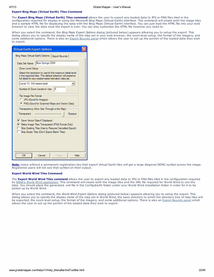
Export Bing Maps (Virtual Earth) Tiles Command
The Export Bing Maps (Virtual Earth) Tiles command allows the user to export any loaded data to JPG or PNG files tiled in theconfiguration required for display in using the Microsoft Bing Maps (Virtual Earth) interface. This command will create both the image tilesand a sample HTML file for displaying the data with the Bing Maps (Virtual Earth) interface. You can just load the HTML file into your webbrowser to view the data once the export is over. You can also customize the HTML file however you need to.
When you select the command, the Bing Maps Export Options dialog (pictured below) appears allowing you to setup the export. Thisdialog allows you to specify the display name of the map set in your web browser, the zoom level setup, the format of the imagery, andsome additional options. There is also an Export Bounds panel which allows the user to set up the portion of the loaded data they wishto export.
Note: Users without a permanent registration key that export Virtual Earth tiles will get a large diagonal DEMO symbol across the image.Registered users will not see that symbol on their output.
Export World Wind Tiles Command
The Export World Wind Tiles command allows the user to export any loaded data to JPG or PNG files tiled in the configuration requiredby NASA's World Wind application. This command will create both the image tiles and the XML file required for World Wind to use thedata. You should place the generated .xml file in the Config\Earth folder under your World Wind installation folder in order for it to bepicked up by World Wind.
When you select the command, the World Wind Export Options dialog (pictured below) appears allowing you to setup the export. Thisdialog allows you to specify the display name of the map set in World Wind, the base directory to which the directory tree of map tiles willbe exported, the zoom level setup, the format of the imagery, and some additional options. There is also an Export Bounds panel whichallows the user to set up the portion of the loaded data they wish to export.
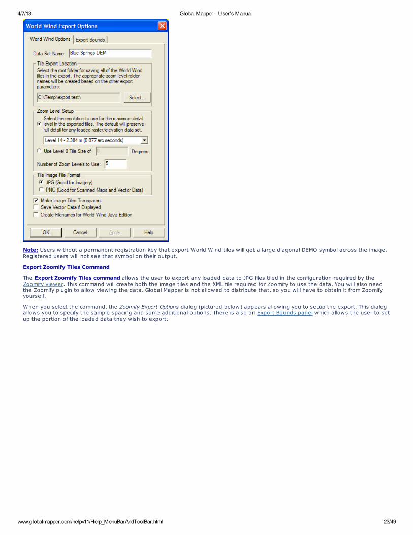
4/7/13 Global Mapper - User's Manual
www.globalmapper.com/helpv11/Help_MenuBarAndToolBar.html 23/49
Note: Users without a permanent registration key that export World Wind tiles will get a large diagonal DEMO symbol across the image.Registered users will not see that symbol on their output.
Export Zoomify Tiles Command
The Export Zoomify Tiles command allows the user to export any loaded data to JPG files tiled in the configuration required by theZoomify viewer. This command will create both the image tiles and the XML file required for Zoomify to use the data. You will also needthe Zoomify plugin to allow viewing the data. Global Mapper is not allowed to distribute that, so you will have to obtain it from Zoomifyyourself.
When you select the command, the Zoomify Export Options dialog (pictured below) appears allowing you to setup the export. This dialogallows you to specify the sample spacing and some additional options. There is also an Export Bounds panel which allows the user to setup the portion of the loaded data they wish to export.
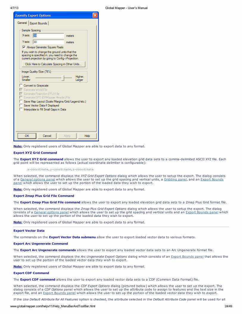
4/7/13 Global Mapper - User's Manual
www.globalmapper.com/helpv11/Help_MenuBarAndToolBar.html 24/49
Note: Only registered users of Global Mapper are able to export data to any format.
Export XYZ Grid Command
The Export XYZ Grid command allows the user to export any loaded elevation grid data sets to a comma-delimited ASCII XYZ file. Eachgrid point will be represented as follows (actual coordinate delimiter is configurable):
x-coordinate,y-coordinate,z-coordinate
When selected, the command displays the XYZ Grid Export Options dialog which allows the user to setup the export. The dialog consistsof a General options panel which allows the user to set up the grid spacing and vertical units, a Gridding panel, and an Export Boundspanel which allows the user to set up the portion of the loaded data they wish to export.
Note: Only registered users of Global Mapper are able to export data to any format.
Export Zmap Plus Grid File Command
The Export Zmap Plus Grid File command allows the user to export any loaded elevation grid data sets to a Zmap Plus Grid format file.
When selected, the command displays the Zmap Plus Grid Export Options dialog which allows the user to setup the export. The dialogconsists of a General options panel which allows the user to set up the grid spacing and vertical units and an Export Bounds panel whichallows the user to set up the portion of the loaded data they wish to export.
Note: Only registered users of Global Mapper are able to export data to any format.
Export Vector Data
The commands on the Export Vector Data submenu allow the user to export loaded vector data to various formats.
Export Arc Ungenerate Command
The Export Arc Ungenerate commands allows the user to export any loaded vector data sets to an Arc Ungenerate format file.
When selected, the command displays the Arc Ungenerate Export Options dialog which consists of an Export Bounds panel that allows theuser to set up the portion of the loaded vector data they wish to export.
Note: Only registered users of Global Mapper are able to export data to any format.
Export CDF Command
The Export CDF command allows the user to export any loaded vector data sets to a CDF (Common Data Format) file.
When selected, the command displays the CDF Export Options dialog (pictured below) which allows the user to set up the export. Thedialog consists of a CDF Options panel which allows the user to set up the attribute code to assign to features and the text size in theexport file, and an Export Bounds panel which allows the user to set up the portion of the loaded vector data they wish to export.
If the Use Default Attribute for All Features option is checked, the attribute selected in the Default Attribute Code panel will be used for all
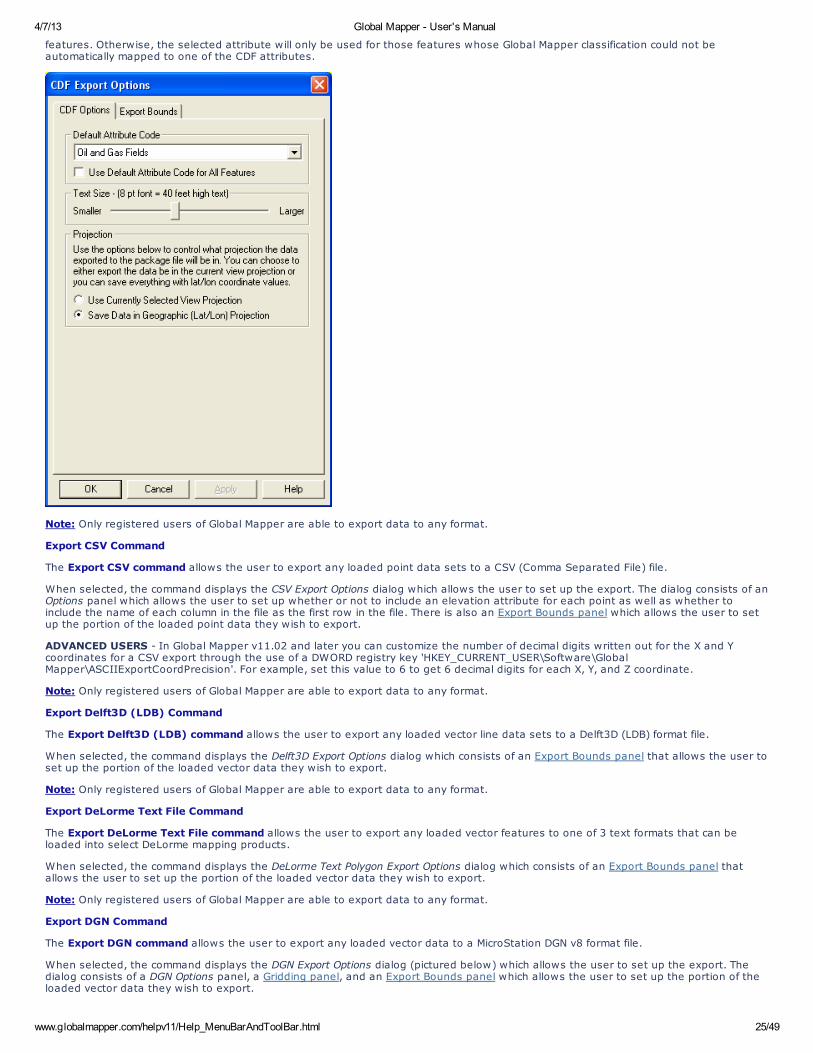
4/7/13 Global Mapper - User's Manual
www.globalmapper.com/helpv11/Help_MenuBarAndToolBar.html 25/49
features. Otherwise, the selected attribute will only be used for those features whose Global Mapper classification could not beautomatically mapped to one of the CDF attributes.
Note: Only registered users of Global Mapper are able to export data to any format.
Export CSV Command
The Export CSV command allows the user to export any loaded point data sets to a CSV (Comma Separated File) file.
When selected, the command displays the CSV Export Options dialog which allows the user to set up the export. The dialog consists of anOptions panel which allows the user to set up whether or not to include an elevation attribute for each point as well as whether toinclude the name of each column in the file as the first row in the file. There is also an Export Bounds panel which allows the user to setup the portion of the loaded point data they wish to export.
ADVANCED USERS - In Global Mapper v11.02 and later you can customize the number of decimal digits written out for the X and Ycoordinates for a CSV export through the use of a DWORD registry key 'HKEY_CURRENT_USER\Software\GlobalMapper\ASCIIExportCoordPrecision'. For example, set this value to 6 to get 6 decimal digits for each X, Y, and Z coordinate.
Note: Only registered users of Global Mapper are able to export data to any format.
Export Delft3D (LDB) Command
The Export Delft3D (LDB) command allows the user to export any loaded vector line data sets to a Delft3D (LDB) format file.
When selected, the command displays the Delft3D Export Options dialog which consists of an Export Bounds panel that allows the user toset up the portion of the loaded vector data they wish to export.
Note: Only registered users of Global Mapper are able to export data to any format.
Export DeLorme Text File Command
The Export DeLorme Text File command allows the user to export any loaded vector features to one of 3 text formats that can beloaded into select DeLorme mapping products.
When selected, the command displays the DeLorme Text Polygon Export Options dialog which consists of an Export Bounds panel thatallows the user to set up the portion of the loaded vector data they wish to export.
Note: Only registered users of Global Mapper are able to export data to any format.
Export DGN Command
The Export DGN command allows the user to export any loaded vector data to a MicroStation DGN v8 format file.
When selected, the command displays the DGN Export Options dialog (pictured below) which allows the user to set up the export. Thedialog consists of a DGN Options panel, a Gridding panel, and an Export Bounds panel which allows the user to set up the portion of theloaded vector data they wish to export.
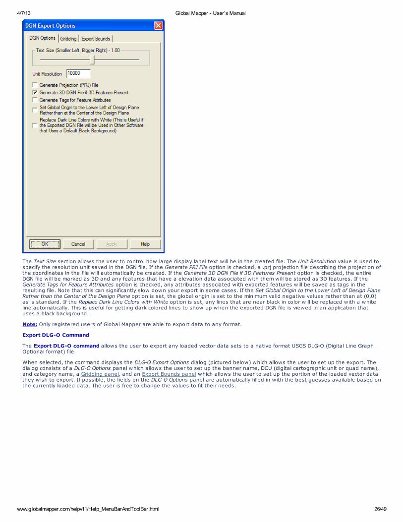
4/7/13 Global Mapper - User's Manual
www.globalmapper.com/helpv11/Help_MenuBarAndToolBar.html 26/49
The Text Size section allows the user to control how large display label text will be in the created file. The Unit Resolution value is used tospecify the resolution unit saved in the DGN file. If the Generate PRJ File option is checked, a .prj projection file describing the projection ofthe coordinates in the file will automatically be created. If the Generate 3D DGN File if 3D Features Present option is checked, the entireDGN file will be marked as 3D and any features that have a elevation data associated with them will be stored as 3D features. If theGenerate Tags for Feature Attributes option is checked, any attributes associated with exported features will be saved as tags in theresulting file. Note that this can significantly slow down your export in some cases. If the Set Global Origin to the Lower Left of Design PlaneRather than the Center of the Design Plane option is set, the global origin is set to the minimum valid negative values rather than at (0,0)as is standard. If the Replace Dark Line Colors with White option is set, any lines that are near black in color will be replaced with a whiteline automatically. This is useful for getting dark colored lines to show up when the exported DGN file is viewed in an application thatuses a black background.
Note: Only registered users of Global Mapper are able to export data to any format.
Export DLG-O Command
The Export DLG-O command allows the user to export any loaded vector data sets to a native format USGS DLG-O (Digital Line GraphOptional format) file.
When selected, the command displays the DLG-O Export Options dialog (pictured below) which allows the user to set up the export. Thedialog consists of a DLG-O Options panel which allows the user to set up the banner name, DCU (digital cartographic unit or quad name),and category name, a Gridding panel, and an Export Bounds panel which allows the user to set up the portion of the loaded vector datathey wish to export. If possible, the fields on the DLG-O Options panel are automatically filled in with the best guesses available based onthe currently loaded data. The user is free to change the values to fit their needs.

4/7/13 Global Mapper - User's Manual
www.globalmapper.com/helpv11/Help_MenuBarAndToolBar.html 27/49
Note: Only registered users of Global Mapper are able to export data to any format.
Export DXF Command
The Export DXF command allows the user to export any loaded vector data sets to an AutoCAD DXF format file.
When selected, the command displays the DXF Export Options dialog (pictured below) which allows the user to set up the export. Thedialog consists of a DXF Options panel, a Gridding panel, and an Export Bounds panel which allows the user to set up the portion of theloaded vector data they wish to export.
The Display Labels section allows you to control if you want feature display labels included in the DXF files and, if so, whether you wantthem represented as TEXT entities in their own layer (called FEATURE_LABEL) or as DXF attributes. The default is to have them includedas attributes associated with each feature. As some software packages cannot handle attributes in DXF files, you may have to switch toa different option (with the associated loss of information) to get your exported DXF files to work with some software packages. If you
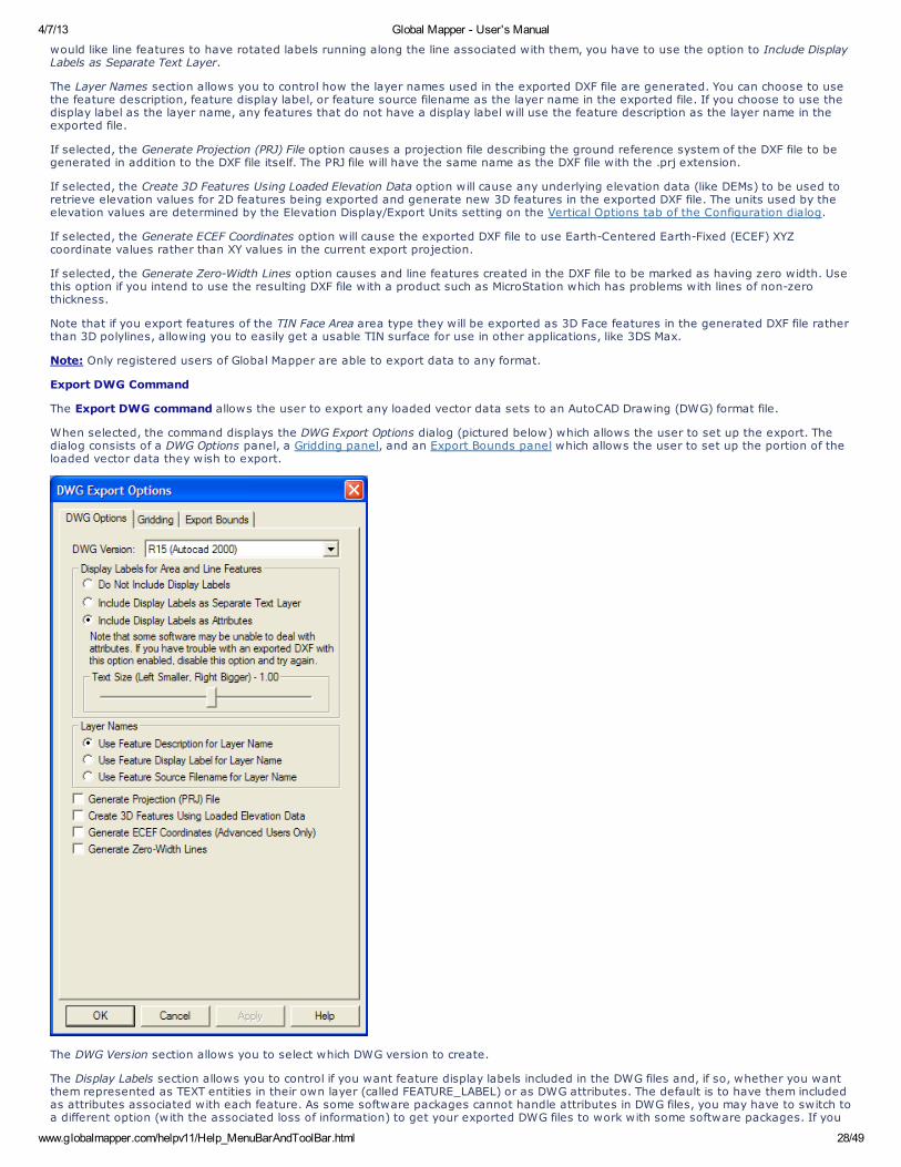
4/7/13 Global Mapper - User's Manual
www.globalmapper.com/helpv11/Help_MenuBarAndToolBar.html 28/49
would like line features to have rotated labels running along the line associated with them, you have to use the option to Include DisplayLabels as Separate Text Layer.
The Layer Names section allows you to control how the layer names used in the exported DXF file are generated. You can choose to usethe feature description, feature display label, or feature source filename as the layer name in the exported file. If you choose to use thedisplay label as the layer name, any features that do not have a display label will use the feature description as the layer name in theexported file.
If selected, the Generate Projection (PRJ) File option causes a projection file describing the ground reference system of the DXF file to begenerated in addition to the DXF file itself. The PRJ file will have the same name as the DXF file with the .prj extension.
If selected, the Create 3D Features Using Loaded Elevation Data option will cause any underlying elevation data (like DEMs) to be used toretrieve elevation values for 2D features being exported and generate new 3D features in the exported DXF file. The units used by theelevation values are determined by the Elevation Display/Export Units setting on the Vertical Options tab of the Configuration dialog.
If selected, the Generate ECEF Coordinates option will cause the exported DXF file to use Earth-Centered Earth-Fixed (ECEF) XYZcoordinate values rather than XY values in the current export projection.
If selected, the Generate Zero-Width Lines option causes and line features created in the DXF file to be marked as having zero width. Usethis option if you intend to use the resulting DXF file with a product such as MicroStation which has problems with lines of non-zerothickness.
Note that if you export features of the TIN Face Area area type they will be exported as 3D Face features in the generated DXF file ratherthan 3D polylines, allowing you to easily get a usable TIN surface for use in other applications, like 3DS Max.
Note: Only registered users of Global Mapper are able to export data to any format.
Export DWG Command
The Export DWG command allows the user to export any loaded vector data sets to an AutoCAD Drawing (DWG) format file.
When selected, the command displays the DWG Export Options dialog (pictured below) which allows the user to set up the export. Thedialog consists of a DWG Options panel, a Gridding panel, and an Export Bounds panel which allows the user to set up the portion of theloaded vector data they wish to export.
The DWG Version section allows you to select which DWG version to create.
The Display Labels section allows you to control if you want feature display labels included in the DWG files and, if so, whether you wantthem represented as TEXT entities in their own layer (called FEATURE_LABEL) or as DWG attributes. The default is to have them includedas attributes associated with each feature. As some software packages cannot handle attributes in DWG files, you may have to switch toa different option (with the associated loss of information) to get your exported DWG files to work with some software packages. If you
4/7/13 Global Mapper - User's Manual
www.globalmapper.com/helpv11/Help_MenuBarAndToolBar.html 29/49
would like line features to have rotated labels running along the line associated with them, you have to use the option to Include DisplayLabels as Separate Text Layer.
The Layer Names section allows you to control how the layer names used in the exported DWG file are generated. You can choose to usethe feature description, feature display label, or feature source filename as the layer name in the exported file. If you choose to use thedisplay label as the layer name, any features that do not have a display label will use the feature description as the layer name in theexported file.
If selected, the Generate Projection (PRJ) File option causes a projection file describing the ground reference system of the DWG file to begenerated in addition to the DWG file itself. The PRJ file will have the same name as the DWG file with the .prj extension.
If selected, the Create 3D Features Using Loaded Elevation Data option will cause any underlying elevation data (like DEMs) to be used toretrieve elevation values for 2D features being exported and generate new 3D features in the exported DWG file. The units used by theelevation values are determined by the Elevation Display/Export Units setting on the Vertical Options tab of the Configuration dialog.
If selected, the Generate ECEF Coordinates option will cause the exported DWG file to use Earth-Centered Earth-Fixed (ECEF) XYZcoordinate values rather than XY values in the current export projection.
If selected, the Generate Zero-Width Lines option causes and line features created in the DWG file to be marked as having zero width.Use this option if you intend to use the resulting DWG file with a product such as MicroStation which has problems with lines of non-zerothickness.
Note: Only registered users of Global Mapper are able to export data to any format.
Export Garmin TRK (PCX5) File Command
The Export Garmin TRK (PCX5) File command allows the user to export any loaded vector line data to a Garmin TRK (PCX5) format file.This file can be imported by a wide variety of GPS software, such as Garmin's MapSource®, to facilitate transferring track logs to a GPSunit.
When selected, the command displays the Garmin TRK Format Export Options dialog which allows the user to set up the export. Thedialog consists of an Export Bounds panel which allows the user to set up the portion of the loaded vector data they wish to export.
Note: Only registered users of Global Mapper are able to export data to any format.
Export Garmin WPT (PCX5) File Command
The Export Garmin WPT (PCX5) File command allows the user to export any loaded named point data to a Garmin WPT (PCX5) formatfile. This file can be imported by a wide variety of GPS software, such as Garmin's MapSource®, to facilitate transferring waypoints to aGPS unit.
When selected, the command displays the Garmin WPT Format Export Options dialog which allows the user to set up the export. Thedialog consists of an Export Bounds panel which allows the user to set up the portion of the loaded vector data they wish to export.
Note: Only registered users of Global Mapper are able to export data to any format.
Export GOG (Generalized Overlay Graphics) Command
The Export GOG (Generalized Overlay Graphics) command allows the user to export any loaded vector data sets to a GOG format file.
When selected, the command displays the GOG Export Options dialog which allows the user to set up the export. The dialog consists ofan Export Bounds panel which allows the user to set up the portion of the loaded vector data they wish to export.
Note: Only registered users of Global Mapper are able to export data to any format.
Export GPX (GPS eXchange Format) Command
The Export GPX (GPS eXchange Format) commands allows the user to export any loaded point and line data to a GPX (GPS eXchangeFormat) file.
When selected, the command displays the GPX Export Options dialog which consists of an Export Bounds panel that allows the user to setup the portion of the loaded vector data they wish to export. If you want to fill in the <cmt> field of a feature during a GPX export, simplyadd a COMMENT attribute to the feature with the desired comment.
Note: Only registered users of Global Mapper are able to export data to any format.
Export InRoads ASCII Command
The Export InRoads ASCII command allows the user to export any loaded vector data sets to an InRoads ASCII format file.
When selected, the command displays the InRoads ASCII Export Options dialog which allows the user to set up the export. The dialogconsists of an Export Bounds panel which allows the user to set up the portion of the loaded vector data they wish to export.
Note: Only registered users of Global Mapper are able to export data to any format.
Export KML/KMZ Command
The Export KML/KMZ command allows the user to export any loaded vector data sets to a KML/KMZ format file for use with GoogleEarth.
When selected, the command displays the KML/KMZ Export Options dialog (pictured below) which allows the user to set up the export.The dialog consists of a KML/KMZ Options panel, a Gridding panel, and an Export Bounds panel which allows the user to set up theportion of the loaded vector data they wish to export.
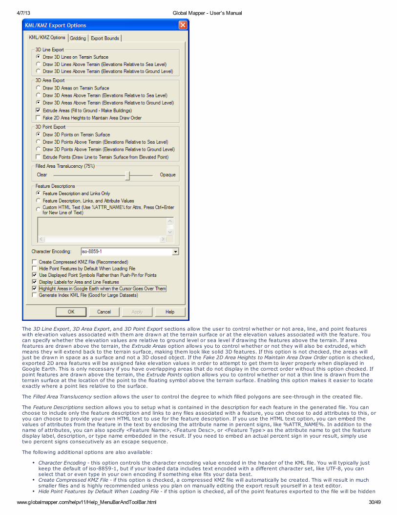
4/7/13 Global Mapper - User's Manual
www.globalmapper.com/helpv11/Help_MenuBarAndToolBar.html 30/49
The 3D Line Export, 3D Area Export, and 3D Point Export sections allow the user to control whether or not area, line, and point featureswith elevation values associated with them are drawn at the terrain surface or at the elevation values associated with the feature. Youcan specify whether the elevation values are relative to ground level or sea level if drawing the features above the terrain. If areafeatures are drawn above the terrain, the Extrude Areas option allows you to control whether or not they will also be extruded, whichmeans they will extend back to the terrain surface, making them look like solid 3D features. If this option is not checked, the areas willjust be drawn in space as a surface and not a 3D closed object. If the Fake 2D Area Heights to Maintain Area Draw Order option is checked,exported 2D area features will be assigned fake elevation values in order to attempt to get them to layer properly when displayed inGoogle Earth. This is only necessary if you have overlapping areas that do not display in the correct order without this option checked. Ifpoint features are drawn above the terrain, the Extrude Points option allows you to control whether or not a thin line is drawn from theterrain surface at the location of the point to the floating symbol above the terrain surface. Enabling this option makes it easier to locateexactly where a point lies relative to the surface.
The Filled Area Translucency section allows the user to control the degree to which filled polygons are see-through in the created file.
The Feature Descriptions section allows you to setup what is contained in the description for each feature in the generated file. You canchoose to include only the feature description and links to any files associated with a feature, you can choose to add attributes to this, oryou can choose to provide your own HTML text to use for the feature description. If you use the HTML text option, you can embed thevalues of attributes from the feature in the text by enclosing the attribute name in percent signs, like %ATTR_NAME%. In addition to thename of attributes, you can also specify <Feature Name>, <Feature Desc>, or <Feature Type> as the attribute name to get the featuredisplay label, description, or type name embedded in the result. If you need to embed an actual percent sign in your result, simply usetwo percent signs consecutively as an escape sequence.
The following additional options are also available:
Character Encoding - this option controls the character encoding value encoded in the header of the KML file. You will typically justkeep the default of iso-8859-1, but if your loaded data includes text encoded with a different character set, like UTF-8, you canselect that or even type in your own encoding if something else fits your data best.Create Compressed KMZ File - if this option is checked, a compressed KMZ file will automatically be created. This will result in muchsmaller files and is highly recommended unless you plan on manually editing the export result yourself in a text editor.Hide Point Features by Default When Loading File - if this option is checked, all of the point features exported to the file will be hidden
4/7/13 Global Mapper - User's Manual
www.globalmapper.com/helpv11/Help_MenuBarAndToolBar.html 31/49
by default in Google Earth so as not to clutter up the display with a bunch of point icons.Use Displayed Point Symbols Rather than Push-Pins for Points - if this option is checked, each point feature will be rendered with thesame symbol displayed in Global Mapper rather than using the default push-pin symbol from Google Earth. This will result in aseparate PNG file for each symbol used in the output file being included with the output data to provide the symbols.Display Area and Line Labels - if this option is checked, each exported line or area feature with a display label will also be markedwith a clickable placemark displaying the label for that area or line feature. This is the only way to get line or area features todisplay labels in Google Earth.Highlight Areas in Google Earth when the Cursor Goes Over Them - if this option is checked, area features will highlight when youmove your cursor over them in Google Earth. In addition, if you checked the option to display area and line labels, the area labelwill be hidden until you mouse over the area, at which time the label will popup.Generate Index KML File - if this option is checked, an additional index KML file will be generated which indexes all tiles exported bythe export command. This is very useful for dealing with very large data sets as it will automatically load and unload individual KMLtiles as needed for display in Google Earth, much as a map catalog does in Global Mapper. With this option you can load massivedata sets into Google Earth and they will still display quickly. The drawing style of the index tiles is controlled by the selecteddrawing style for the Coverage/Quad area type on the Area Styles tab of the Configuration dialog.
For advanced users, you can also customize what is displayed in the balloon text that appears in Google Earth when you click on a point.You are able to customize the <Balloon Style> tag to use text with the string value stored in the registry at'HKEY_CURRENT_USER\Software\Global Mapper\KmlExport_BalloonStyle'. If that value is empty the default setting from Google Earth willbe used.
Note: Only registered users of Global Mapper are able to export data to any format.
Export Landmark Graphics Command
The Export Landmark Graphics command allows the user to export any loaded vector data sets to a Landmark Graphics format file.
When selected, the command displays the Landmark Graphics Export Options dialog which allows the user to set up the export. The dialogconsists of an Export Bounds panel which allows the user to set up the portion of the loaded vector data they wish to export.
Note: Only registered users of Global Mapper are able to export data to any format.
Export Lidar LAS Command
The Export Lidar LAS command allows the user to export any loaded 3D vector data sets (like 3D point clouds loaded from other LASfiles) to new Lidar LAS format files. If the source data came from a Lidar format file, like a LAS or MrSid Lidar file, the attributes from theoriginal data will be maintained. For other points, in addition to the base position and elevation, if there is an INTENSITY attributeavailable for the point, the value of that attribute will be exported as the intensity for the point in the exported LAS file.
When selected, the command displays the Lidar LAS Export Options dialog which allows the user to setup the export. The dialog consistsof a Gridding panel, and an Export Bounds panel which allows the user to set up the portion of the loaded data they wish to export.
Note: Only registered users of Global Mapper are able to export data to any format.
Export LMN (Spectra Line Management Node) Command
The Export LMN (Spectra Line Management Node) command allows the user to export any loaded line features to a LMN format file foruse in applications that support the LMN format. Attributes named FEATURE_GROUP, FEATURE_TYPE, and FEATURE_REP are recognizedfor this export and will be used if present to fill in the appropriate data fields in the exported file.
When selected, the command displays the LMN Export Options dialog which allows the user to set up the export. The dialog consists of aGridding panel and an Export Bounds panel which allows the user to set up the portion of the loaded vector data they wish to export.
Note: Only registered users of Global Mapper are able to export data to any format.
Export Lowrance LCM Command
The Export Lowrance LCM (MapCreate) command allows the user to export any loaded vector data sets to a Lowrance LCM format filefor use in Lowrance brand GPS devices. This allows you to create custom maps for Lowrance devices from your data. Type assignmentwill be done based on the built-in type assignments. In addition, the MP_TYPE attribute classification used for Polish MP exports forGarmin devices will also work for Lowrance exports, so if you provide custom classifications via the MP_TYPE attribute the type mappingshould work for Lowrance exports as well.
The LCM export only has support for a limited set of types. Feature types that are not supported for LCM export will not be added to thegenerated LCM file, so it is important to use a built-in type (or a type with a custom MP_TYPE value that is supported) when exporting tothe LCM format. The following is a basic list of the types of features that are supported:
Area TypesLakesOceansParksSwamp/WetlandUrban Areas
Line TypesPolitical BoundariesContoursRailroadsRoadsTrailsStreams/Rivers
Point TypesAirportBoat RampCampgroundCar RepairCity
4/7/13 Global Mapper - User's Manual
www.globalmapper.com/helpv11/Help_MenuBarAndToolBar.html 32/49
ChurchDepartment Store/ShoppingGas Station/FuelHospitalNavaids/BuoysPharmacyPost OfficeRestaurantSchoolWater Features (Spring, Stream, Lake Name)Wrecks
When selected, the command displays the Lowrance LCM Export Options dialog which allows the user to set up the export. The dialogconsists of a Gridding panel and an Export Bounds panel which allows the user to set up the portion of the loaded vector data they wishto export.
Note: Only registered users of Global Mapper are able to export data to any format.
Export Lowrance USR Command
The Export Lowrance USR command allows the user to export any loaded vector data sets to a Lowrance USR format file for use inLowrance brand GPS devices.
When selected, the command displays the Lowrance USR Export Options dialog which allows the user to set up the export. The dialogconsists of a Gridding panel and an Export Bounds panel which allows the user to set up the portion of the loaded vector data they wishto export.
Note: Only registered users of Global Mapper are able to export data to any format.
Export MapGen Command
The Export MapGen command allows the user to export any loaded vector data sets to a MapGen format file.
When selected, the command displays the MapGen Export Options dialog which allows the user to set up the export. The dialog consistsof an Export Bounds panel which allows the user to set up the portion of the loaded vector data they wish to export.
Note: Only registered users of Global Mapper are able to export data to any format.
Export MapInfo MIF/MID Command
The Export MapInfo MIF/MID command allows the user to export any loaded vector data sets to a MapInfo MIF/MID format file.
When selected, the command displays the MapInfo Export Options dialog which allows the user to set up the export. The dialog consistsof a Gridding panel and an Export Bounds panel which allows the user to set up the portion of the loaded vector data they wish toexport.
Note: Only registered users of Global Mapper are able to export data to any format.
Export MapInfo TAB/MAP Command
The Export MapInfo TAB/MAP command allows the user to export any loaded vector data sets to a MapInfo TAB/MAP format file.
When selected, the command displays the MapInfo Export Options dialog which allows the user to set up the export. The dialog consistsof a Gridding panel and an Export Bounds panel which allows the user to set up the portion of the loaded vector data they wish toexport.
Note: Only registered users of Global Mapper are able to export data to any format.
Export MatLab Command
The Export MatLab command allows the user to export any loaded vector data sets to a MatLab format file.
When selected, the command displays the MatLab Export Options dialog which allows the user to set up the export. The dialog consists ofan Export Bounds panel which allows the user to set up the portion of the loaded vector data they wish to export.
Note: Only registered users of Global Mapper are able to export data to any format.
Export Moss Command
The Export Moss command allows the user to export any loaded area and line vector features to a Moss format file.
When selected, the command displays the Moss Export Options dialog which allows the user to set up the export. The dialog consists ofan Export Bounds panel which allows the user to set up the portion of the loaded vector data they wish to export.
Note: Only registered users of Global Mapper are able to export data to any format.
Export NIMA ASC Command
The Export NIMA ASC command allows the user to export any loaded vector data sets to a NIMA ASC format file that can be used onmany shipboard radar displays.
When selected, the command displays the NIMA ASC Export Options dialog which allows the user to set up the export. The dialog consistsof an Export Bounds panel which allows the user to set up the portion of the loaded vector data they wish to export.
Note: Only registered users of Global Mapper are able to export data to any format.
Export OSM (OpenStreetMap.org) XML Command
4/7/13 Global Mapper - User's Manual
www.globalmapper.com/helpv11/Help_MenuBarAndToolBar.html 33/49
The Export OSM (OpenStreetMap.org) XML command allows the user to export any loaded vector data sets to an OSM XML format filethat can be used to provide new data to the OpenStreetMap.org web site.
When selected, the command displays the OSM XML Export Options dialog which allows the user to set up the export. The dialog consistsof an Export Bounds panel which allows the user to set up the portion of the loaded vector data they wish to export.
Note: Only registered users of Global Mapper are able to export data to any format.
Export Platte River/WhiteStar/Geographix File Command
The Export Platte River/Whitestar/Geographix File command allows the user to export any loaded area features to a Platte RiverDigitizer/Whitestar/Geographix Township/Range ASCII format file. These files can be used with several applications.
When selected, the command displays the Platte River Export Options dialog which allows the user to setup the export. The dialogconsists of an Export Bounds panel which allows the user to set up the portion of the loaded data they wish to export.
The township, range, section, and meridian values saved for each area feature exported are derived either from the attribute values forthe area feature or the display label for "Survey Section" area types. The following attribute values names are recognized for each field:
Township Attributes - TOWNSHIP or TWPTownship Direction Attributes - TDIR (must have value of N or S)Range Attributes - RANGE or RNGRange Direction Attributes - RDIR (must have value of E or W)Section Attributes - SECTION, SECT, or SECMeridian Attributes - MERIDIAN or MER
Note: Only registered users of Global Mapper are able to export data to any format.
Export PLS-CADD XYZ File Command
The Export PLS-CADD XYZ File command allows the user to export any loaded vector data sets to a PLS-CADD XYZ format file. Thesefiles can be used with the PLS-CADD software application.
When selected, the command displays the PLS-CADD XYZ Export Options dialog which allows the user to setup the export. The dialogconsists of an Export Bounds panel which allows the user to set up the portion of the loaded data they wish to export.
Note: Only registered users of Global Mapper are able to export data to any format.
Export Polish MP (cGPSMapper) Command
TUTORIAL ALERT!
Getting Started with Global Mapper and cGPSMapper - Fantastic Guide to Creating Garmin-format Maps using Global Mapper,cGPSMapper, and the other supporting applications required to get your data into a Garmin unit as a new map.
The Export Polish MP command allows the user to export any loaded vector data sets to Polish MP format files. The Polish MP format isthe input format used by the cGPSMapper application which creates custom maps for Garmin GPS units.
When selected, the command displays the Polish MP Export Options dialog (pictured below) which allows the user to set up the export.The dialog consists of a Map Options panel, a Gridding panel, and an Export Bounds panel which allows the user to set up the portion ofthe loaded vector data they wish to export.
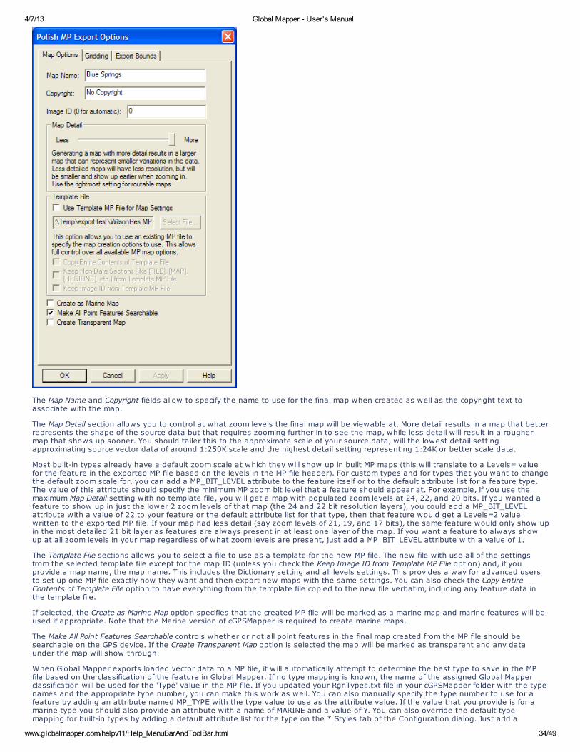
4/7/13 Global Mapper - User's Manual
www.globalmapper.com/helpv11/Help_MenuBarAndToolBar.html 34/49
The Map Name and Copyright fields allow to specify the name to use for the final map when created as well as the copyright text toassociate with the map.
The Map Detail section allows you to control at what zoom levels the final map will be viewable at. More detail results in a map that betterrepresents the shape of the source data but that requires zooming further in to see the map, while less detail will result in a roughermap that shows up sooner. You should tailer this to the approximate scale of your source data, will the lowest detail settingapproximating source vector data of around 1:250K scale and the highest detail setting representing 1:24K or better scale data.
Most built-in types already have a default zoom scale at which they will show up in built MP maps (this will translate to a Levels= valuefor the feature in the exported MP file based on the levels in the MP file header). For custom types and for types that you want to changethe default zoom scale for, you can add a MP_BIT_LEVEL attribute to the feature itself or to the default attribute list for a feature type.The value of this attribute should specify the minimum MP zoom bit level that a feature should appear at. For example, if you use themaximum Map Detail setting with no template file, you will get a map with populated zoom levels at 24, 22, and 20 bits. If you wanted afeature to show up in just the lower 2 zoom levels of that map (the 24 and 22 bit resolution layers), you could add a MP_BIT_LEVELattribute with a value of 22 to your feature or the default attribute list for that type, then that feature would get a Levels=2 valuewritten to the exported MP file. If your map had less detail (say zoom levels of 21, 19, and 17 bits), the same feature would only show upin the most detailed 21 bit layer as features are always present in at least one layer of the map. If you want a feature to always showup at all zoom levels in your map regardless of what zoom levels are present, just add a MP_BIT_LEVEL attribute with a value of 1.
The Template File sections allows you to select a file to use as a template for the new MP file. The new file with use all of the settingsfrom the selected template file except for the map ID (unless you check the Keep Image ID from Template MP File option) and, if youprovide a map name, the map name. This includes the Dictionary setting and all levels settings. This provides a way for advanced usersto set up one MP file exactly how they want and then export new maps with the same settings. You can also check the Copy EntireContents of Template File option to have everything from the template file copied to the new file verbatim, including any feature data inthe template file.
If selected, the Create as Marine Map option specifies that the created MP file will be marked as a marine map and marine features will beused if appropriate. Note that the Marine version of cGPSMapper is required to create marine maps.
The Make All Point Features Searchable controls whether or not all point features in the final map created from the MP file should besearchable on the GPS device. If the Create Transparent Map option is selected the map will be marked as transparent and any dataunder the map will show through.
When Global Mapper exports loaded vector data to a MP file, it will automatically attempt to determine the best type to save in the MPfile based on the classification of the feature in Global Mapper. If no type mapping is known, the name of the assigned Global Mapperclassification will be used for the 'Type' value in the MP file. If you updated your RgnTypes.txt file in your cGPSMapper folder with the typenames and the appropriate type number, you can make this work as well. You can also manually specify the type number to use for afeature by adding an attribute named MP_TYPE with the type value to use as the attribute value. If the value that you provide is for amarine type you should also provide an attribute with a name of MARINE and a value of Y. You can also override the default typemapping for built-in types by adding a default attribute list for the type on the * Styles tab of the Configuration dialog. Just add a
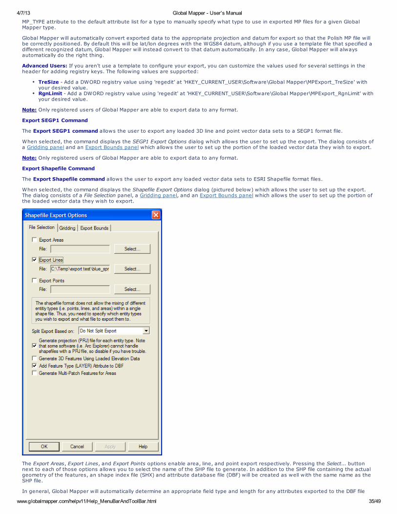
4/7/13 Global Mapper - User's Manual
www.globalmapper.com/helpv11/Help_MenuBarAndToolBar.html 35/49
MP_TYPE attribute to the default attribute list for a type to manually specify what type to use in exported MP files for a given GlobalMapper type.
Global Mapper will automatically convert exported data to the appropriate projection and datum for export so that the Polish MP file willbe correctly positioned. By default this will be lat/lon degrees with the WGS84 datum, although if you use a template file that specified adifferent recognized datum, Global Mapper will instead convert to that datum automatically. In any case, Global Mapper will alwaysautomatically do the right thing.
Advanced Users: If you aren't use a template to configure your export, you can customize the values used for several settings in theheader for adding registry keys. The following values are supported:
TreSize - Add a DWORD registry value using 'regedit' at 'HKEY_CURRENT_USER\Software\Global Mapper\MPExport_TreSize' withyour desired value.RgnLimit - Add a DWORD registry value using 'regedit' at 'HKEY_CURRENT_USER\Software\Global Mapper\MPExport_RgnLimit' withyour desired value.
Note: Only registered users of Global Mapper are able to export data to any format.
Export SEGP1 Command
The Export SEGP1 command allows the user to export any loaded 3D line and point vector data sets to a SEGP1 format file.
When selected, the command displays the SEGP1 Export Options dialog which allows the user to set up the export. The dialog consists ofa Gridding panel and an Export Bounds panel which allows the user to set up the portion of the loaded vector data they wish to export.
Note: Only registered users of Global Mapper are able to export data to any format.
Export Shapefile Command
The Export Shapefile command allows the user to export any loaded vector data sets to ESRI Shapefile format files.
When selected, the command displays the Shapefile Export Options dialog (pictured below) which allows the user to set up the export.The dialog consists of a File Selection panel, a Gridding panel, and an Export Bounds panel which allows the user to set up the portion ofthe loaded vector data they wish to export.
The Export Areas, Export Lines, and Export Points options enable area, line, and point export respectively. Pressing the Select... buttonnext to each of those options allows you to select the name of the SHP file to generate. In addition to the SHP file containing the actualgeometry of the features, an shape index file (SHX) and attribute database file (DBF) will be created as well with the same name as theSHP file.
In general, Global Mapper will automatically determine an appropriate field type and length for any attributes exported to the DBF file
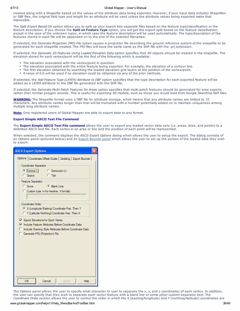
4/7/13 Global Mapper - User's Manual
www.globalmapper.com/helpv11/Help_MenuBarAndToolBar.html 36/49
created along with a Shapefile based on the values of the attribute data being exported. However, if your input data includes Shapefilesor DBF files, the original field type and length for an attribute will be used unless the attribute values being exported make thatimpossible.
The Split Export Based On option allows you to split up your export into separate files based on the feature type/classification or thefeature description. If you choose the Split on Feature Type option, you will get the export split based on the feature classification,except in the case of the unknown types, in which case the feature description will be used automatically. The type/description of thefeatures stored in each file will be appended on to the end of the selected filenames.
If selected, the Generate Projection (PRJ) File option causes a projection file describing the ground reference system of the shapefile to begenerated for each shapefile created. The PRJ files will have the same name as the SHP file with the .prj extension.
If selected, the Generate 3D Features Using Loaded Elevation Data option specifies that 3D objects should be created in the shapefile. Theelevation stored for each vertex/point will be the first of the following which is available:
The elevation associated with the vertex/point in question.The elevation associated with the entire feature being exported. For example, the elevation of a contour line.The first elevation obtained by searching the loaded elevation grid layers at the position of the vertex/point.A value of 0.0 will be used if no elevation could be obtained via any of the prior methods.
If selected, the Add Feature Type (LAYER) Attribute to DBF option specifies that the type description for each exported feature will beadded as a LAYER attribute to the DBF file generated with the SHP file.
If selected, the Generate Multi-Patch Features for Areas option specifies that multi-patch features should be generated for area exportsrather than normal polygon records. This is useful for exporting 3D models, such as those you would load from Google SketchUp SKP files.
WARNING: The Shapefile format uses a DBF file for attribute storage, which means that any attribute names are limited to 10characters. Any attribute names longer than that will be truncated with a number potentially added on to maintain uniqueness amongmultiple long attribute names.
Note: Only registered users of Global Mapper are able to export data to any format.
Export Simple ASCII Text File Command
The Export Simple ASCII Text File command allows the user to export any loaded vector data sets (i.e. areas, lines, and points) to adelimited ASCII text file. Each vertex in an area or line and the position of each point will be represented.
When selected, the command displays the ASCII Export Options dialog which allows the user to setup the export. The dialog consists ofan Options panel (pictured below) and an Export Bounds panel which allows the user to set up the portion of the loaded data they wishto export.
The Options panel allows the user to specify what character to user to separate the x, y, and z coordinates of each vertex. In addition,the user can specify that they wish to separate each vector feature with a blank line or some other custom separator text. TheCoordinate Order section allows the user to control the order in which the X (easting/longitude) and Y (northing/latitude) coordinates are
4/7/13 Global Mapper - User's Manual
www.globalmapper.com/helpv11/Help_MenuBarAndToolBar.html 37/49
exported. The export of elevation data is controlled with the Export Elevations option. The Include Feature Attributes Before Coordinate Dataand Include Drawing Style Attributes Before Coordinate Data options respectively control whether or not feature attributes or featuredrawing style information is saved to the file on the lines preceding the coordinate data for a feature.
If elevations are being exported, Global Mapper first looks for an elevation associated with the vertex being exported. If no elevation isassociated with the vertex, Global Mapper then checks all loaded elevation grid data in reverse order of display to see if any of themhave an elevation at the vertex location. If so, that elevation is used.
ADVANCED USERS - In Global Mapper v11.02 and later you can customize the number of decimal digits written out for the X and Ycoordinates for a Simple ASCII Text export through the use of a DWORD registry key 'HKEY_CURRENT_USER\Software\GlobalMapper\ASCIIExportCoordPrecision'. For example, set this value to 6 to get 6 decimal digits for each X, Y, and Z coordinate.
Note: Only registered users of Global Mapper are able to export data to any format.
Export Surfer BLN Command
The Export Surfer BLN command allows the user to export any loaded vector data sets to a Surfer BLN format file used by GoldenSoftware's Surfer package to specify breaklines.
When selected, the command displays the Surfer BLN Export Options dialog which allows the user to set up the export. The dialogconsists of an Export Bounds panel which allows the user to set up the portion of the loaded vector data they wish to export.
Note: Only registered users of Global Mapper are able to export data to any format.
Export SVG Command
The Export SVG command allows the user to export any loaded vector data sets to a SVG (Scalable Vector Graphic) format file suitablefor display on the web.
When selected, the command displays the SVG Export Options dialog which allows the user to set up the export. The dialog consists of anExport Bounds panel which allows the user to set up the portion of the loaded vector data they wish to export.
Note: Only registered users of Global Mapper are able to export data to any format.
Export Tom Tom OV2 Command
The Export Tom Tom OV2 command allows the user to export any loaded point data sets to a Tom Tom OV2 format file for use increating POI databases for Tom Tom GPS devices.
When selected, the command displays the Tom Tom OV2 Export Options dialog which allows the user to set up the export. The dialogconsists of an Export Bounds panel which allows the user to set up the portion of the loaded vector data they wish to export.
Note: Only registered users of Global Mapper are able to export data to any format.
Export Tsunami OVR Command
The Export Tsunami OVR command allows the user to export any loaded vector data sets to a Tsunami OVR format file for use in theTsunami software package.
When selected, the command displays the Tsunami OVR Export Options dialog which allows the user to set up the export. The dialogconsists of an Export Bounds panel which allows the user to set up the portion of the loaded vector data they wish to export.
Note: Only registered users of Global Mapper are able to export data to any format.
Export UKOOA P/190 Command
The Export UKOOA P/190 command allows the user to export any loaded 3D line and point vector data sets to an UKOOA P/190 formatfile.
When selected, the command displays the UKOOA Export Options dialog which allows the user to set up the export. The dialog consists ofa Gridding panel and an Export Bounds panel which allows the user to set up the portion of the loaded vector data they wish to export.
Note: Only registered users of Global Mapper are able to export data to any format.
Export WAsP MAP File Command
The Export WAsP MAP File command allows the user to export loaded line and area features to a WAsP MAP format file for use with theWAsP (Wind Analysis and Application Program) application (http://www.wasp.dk/.
Only those line features with an elevation and/or valid roughness attributes will be exported. Only those area features with validroughness attributes will be exported. Valid roughness attributes consist of a ROUGH_L and a ROUGH_R attribute containing numericvalues for the left and right roughness for the feature. If neither of those attributes exist but a RV attribute is available, that value will beused for both the left and right roughness for that feature.
When selected, the command displays the WAsP MAP Export Options dialog which allows the user to setup the export. The dialog consistsof an Export Bounds panel which allows the user to set up the portion of the loaded data they wish to export.
Note: Only registered users of Global Mapper are able to export data to any format.
Export ZMap+ XYSegId File Command
The Export ZMap+ XYSegId File command allows the user to export loaded line and area features to a ZMap+ text format file for usewith applications like Landmark Graphics..
When selected, the command displays the ZMap+ XYSegId Export Options dialog which allows the user to setup the export. The dialogconsists of an Export Bounds panel which allows the user to set up the portion of the loaded data they wish to export.
This format costs of one line per each input coordinate, with the X coordinate followed by the Y coordinate (optionally with a Z if
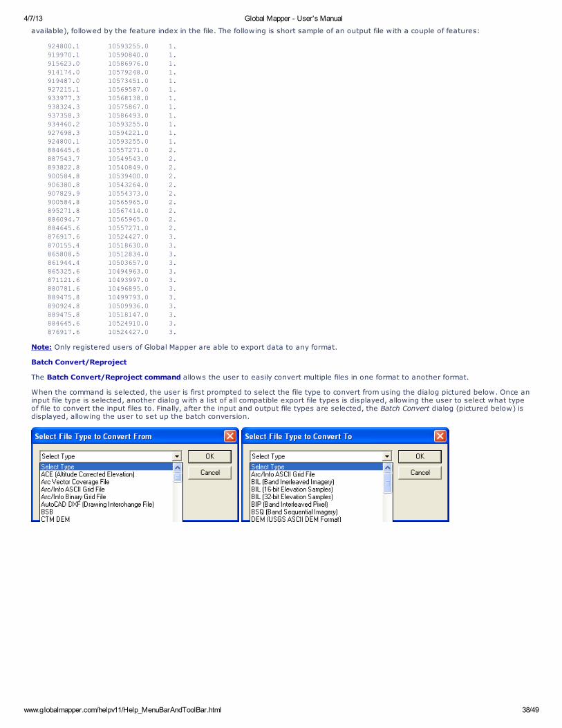
4/7/13 Global Mapper - User's Manual
www.globalmapper.com/helpv11/Help_MenuBarAndToolBar.html 38/49
available), followed by the feature index in the file. The following is short sample of an output file with a couple of features:
924800.1 10593255.0 1. 919970.1 10590840.0 1.
915623.0 10586976.0 1. 914174.0 10579248.0 1.
919487.0 10573451.0 1. 927215.1 10569587.0 1.
933977.3 10568138.0 1. 938324.3 10575867.0 1.
937358.3 10586493.0 1. 934460.2 10593255.0 1.
927698.3 10594221.0 1. 924800.1 10593255.0 1.
884645.6 10557271.0 2. 887543.7 10549543.0 2.
893822.8 10540849.0 2. 900584.8 10539400.0 2.
906380.8 10543264.0 2. 907829.9 10554373.0 2.
900584.8 10565965.0 2. 895271.8 10567414.0 2.
886094.7 10565965.0 2. 884645.6 10557271.0 2.
876917.6 10524427.0 3. 870155.4 10518630.0 3.
865808.5 10512834.0 3. 861944.4 10503657.0 3.
865325.6 10494963.0 3. 871121.6 10493997.0 3.
880781.6 10496895.0 3. 889475.8 10499793.0 3.
890924.8 10509936.0 3. 889475.8 10518147.0 3.
884645.6 10524910.0 3. 876917.6 10524427.0 3.
Note: Only registered users of Global Mapper are able to export data to any format.
Batch Convert/Reproject
The Batch Convert/Reproject command allows the user to easily convert multiple files in one format to another format.
When the command is selected, the user is first prompted to select the file type to convert from using the dialog pictured below. Once aninput file type is selected, another dialog with a list of all compatible export file types is displayed, allowing the user to select what typeof file to convert the input files to. Finally, after the input and output file types are selected, the Batch Convert dialog (pictured below) isdisplayed, allowing the user to set up the batch conversion.
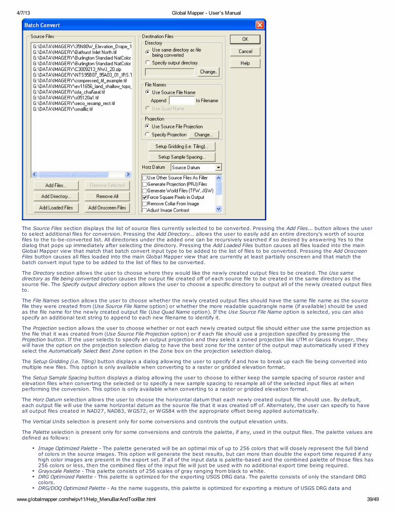
4/7/13 Global Mapper - User's Manual
www.globalmapper.com/helpv11/Help_MenuBarAndToolBar.html 39/49
The Source Files section displays the list of source files currently selected to be converted. Pressing the Add Files... button allows the userto select additional files for conversion. Pressing the Add Directory... allows the user to easily add an entire directory's worth of sourcefiles to the to-be-converted list. All directories under the added one can be recursively searched if so desired by answering Yes to thedialog that pops up immediately after selecting the directory. Pressing the Add Loaded Files button causes all files loaded into the mainGlobal Mapper view that match that batch convert input type to be added to the list of files to be converted. Pressing the Add OnscreenFiles button causes all files loaded into the main Global Mapper view that are currently at least partially onscreen and that match thebatch convert input type to be added to the list of files to be converted.
The Directory section allows the user to choose where they would like the newly created output files to be created. The Use samedirectory as file being converted option causes the output file created off of each source file to be created in the same directory as thesource file. The Specify output directory option allows the user to choose a specific directory to output all of the newly created output filesto.
The File Names section allows the user to choose whether the newly created output files should have the same file name as the sourcefile they were created from (Use Source File Name option) or whether the more readable quadrangle name (if available) should be usedas the file name for the newly created output file (Use Quad Name option). If the Use Source File Name option is selected, you can alsospecify an additional text string to append to each new filename to identify it.
The Projection section allows the user to choose whether or not each newly created output file should either use the same projection asthe file that it was created from (Use Source File Projection option) or if each file should use a projection specified by pressing theProjection button. If the user selects to specify an output projection and they select a zoned projection like UTM or Gauss Krueger, theywill have the option on the projection selection dialog to have the best zone for the center of the output map automatically used if theyselect the Automatically Select Best Zone option in the Zone box on the projection selection dialog.
The Setup Gridding (i.e. Tiling) button displays a dialog allowing the user to specify if and how to break up each file being converted intomultiple new files. This option is only available when converting to a raster or gridded elevation format.
The Setup Sample Spacing button displays a dialog allowing the user to choose to either keep the sample spacing of source raster andelevation files when converting the selected or to specify a new sample spacing to resample all of the selected input files at whenperforming the conversion. This option is only available when converting to a raster or gridded elevation format.
The Horz Datum selection allows the user to choose the horizontal datum that each newly created output file should use. By default,each output file will use the same horizontal datum as the source file that it was created off of. Alternately, the user can specify to haveall output files created in NAD27, NAD83, WGS72, or WGS84 with the appropriate offset being applied automatically.
The Vertical Units selection is present only for some conversions and controls the output elevation units.
The Palette selection is present only for some conversions and controls the palette, if any, used in the output files. The palette values aredefined as follows:
Image Optimized Palette - The palette generated will be an optimal mix of up to 256 colors that will closely represent the full blendof colors in the source images. This option will generate the best results, but can more than double the export time required if anyhigh color images are present in the export set. If all of the input data is palette-based and the combined palette of those files has256 colors or less, then the combined files of the input file will just be used with no additional export time being required.Grayscale Palette - This palette consists of 256 scales of gray ranging from black to white.DRG Optimized Palette - This palette is optimized for the exporting USGS DRG data. The palette consists of only the standard DRGcolors.DRG/DOQ Optimized Palette - As the name suggests, this palette is optimized for exporting a mixture of USGS DRG data and
4/7/13 Global Mapper - User's Manual
www.globalmapper.com/helpv11/Help_MenuBarAndToolBar.html 40/49
grayscale satellite photos (i.e. USGS DOQs). The palette consists of the 14 standard DRG colors with the remaining 242 colorsbeing a range of gray values ranging from black to white.Halftone Palette - The palette consists of a blend of 256 colors evenly covering the color spectrum. This palette is the best choicewhen exporting anything but DRGs and grayscale satellite photos.Custom Palette from File - This option allows the user to choose a .pal file describing the palette to use for the export. A .pal fileshould be a text file with one line per color, with the red, green, and blue color components for each color in the palette separatedby a comma. You can save a .pal file for an existing palette-based file by opening the Overlay Control Center, selecting the palette-based layer, press Options, then the Transparent Color button, then selecting the option to save a color palette file.24-bit RGB - Create a full 24-bit color image with no palette. This will create the best resulting image but will also take the mostspace.Keep Same as Source File - The new file will use the same color encoding as the source file, either palette-based, 24-bit RGB, multi-band, or grayscale.Multi-Band Image - The new file will use be a multi-band image using the same number of bands as the input file. You will be able tochoose either 8-bits or 16-bits per band.
The additional list of options varies depending on the particular conversion being performed. The meaning of those options is definedbelow:
Add Watermark Image - when this option is checked, you will be prompted to select an image to use as a watermark for your rasterformat export. You will also be allows to select display options for your watermark image, such as transparency, to provide thedesired effect. The selected watermark image will be stretched to cover the entire output image for each converted file.Adjust Image Contrast - causes the contrast of any input file to be automatically adjusted prior to being exported. This is useful forimproving the display of some types of imagery.Clamp Export to Lat/Lon Boundary - causes the export bounds of each image being converted to be clamped to the nearest 3.75'lat/lon boundary. This can be useful in limited cases, such as when reprojecting to geographic/arc degrees and the source imageshad a tiny collar to make the image square in the native projection.Convert to Grayscale - causes the exported imagery to be generated in only shades of gray.Crop to Selected Areas - this option specifies that each exported file will be cropped to any area features selected with the FeatureInfo or Digitizer Tools. If this option is selected, no output file will be generated for any input file that does not intersect any of theselected crop areas.Export Areas, Export Lines, and Export Points - these options respectively control whether area, line, and/or point shapefiles aregenerated from the source vector data files. At least one of these options must be selected.Fill Small Gaps in Data - this option specifies whether or not small gaps in the elevation or raster file being exported will be filled byinterpolating between nearby known values.Force Square Pixels in Output - causes the newly created files to have square pixels in whatever projection they are created in. Thisallows the files to be used with the widest variety of other software packages, many of which do not correctly handle non-squarepixels.Generate Projection (PRJ) File - causes a projection file describing the ground reference system of the output file to be generated foreach output file in addition to the output file itself. The PRJ file will have the same name as the output file with the .prj extension.Generate World File - causes a world file describing the location of the output file to be generated for each output file. The world filewill have the same name as the output file with the appropriate world file extension for the output type (i.e. TFW for GeoTIFF, JGWfor JPEG, etc.).Include Display Labels as Attributes - causes DXF attributes containing the name of the vector object to be associated with DXFPOLYLINE entities. As some software packages cannot handle attributes in DXF files, you may have to turn this option off (with theassociated loss of information) to get your exported DXF files to work with some packages.Include Feature Attributes in DBF - causes the attributes other than layer and elevation of each feature (if any) to be stored in theDBF file associated with the generated Shapefile. In addition, selecting this option will cause the DLG-3 attribute codes matchingeach feature to be stored in the DBF file.Include Feature Names in DBF - causes the name of each feature (if any) to be stored as a NAME attribute in the DBF file associatedwith the generated Shapefile.Make Single Color Transparent - allows the user to select a single color to treat as transparent in the source data files.Minimize Window During Conversion - this option causes the main map window to immediately be minimized when the batchconversion operation begins and stay that way until the operation completes.Never Anti-Alias Pixels (Interpolate) - this option disables anti-aliasing (interpolation) even for those layers to which it wouldnormally be applied by default (like gridded elevation layers) or imagery being reprojected or resampled.Never Automatically Adjust Contrast - this option disables automatic contrast adjustment even for those layers to which it wouldnormally be applied by default (like 16-bit per color channel images).Only Generate Metadata Files - causes only metadata files like world files, PRJ files, and TAB files to be generated. This is a veryhandy way to create metadata files for a large collection of files like GeoTIFF files in order to use the data in software that doesn'trecognize embedded positioning information.Remove Collar From Image - causes the collar of DRG-style images to be automatically removed from each image that is converted ifcollar bounds can be automatically determined. Note that some collar may remain in order to make the end result rectangular if thedestination projection in not geographic lat/lon. If you check this option and the file being converted is also loaded in the main mapview and has some custom collar cropping applied, those collar cropping options will be used rather than the automatic DRG-stylecollar setting.Skip Existing Output Files - this option causes any conversion operations for which the default output filename already exists to beskipped. This is useful when resuming batch conversion operations that failed or were cancelled.Use Big Endian For Elevations - causes stored elevations to use the big-endian (Motorola) byte order rather than the default little-endian (Intel) byte order.Use Lossless Compression - this option causes the lossless compression method to be used when generating Global Mapper Gridfiles. If it is not checked, some minor loss of data in areas of high terrain relief will be allowed in order to achieve a highercompression ratio.Use Other Source Files As Filler - causes all selected source files to be loaded and made available during export to fill holes in themain file being converted. This is useful when you have a collection of files that are being reprojected and you do not want to havea sliver around the edge of each new file filled with the background color when the source data does not make a perfect rectangle.You can even mark some files to only be used as filler by right clicking on them in the Files list and selecting the appropriate optionin the popup menu.
You can also right click on the list of files to convert and choose to save that list of files to a text file. This can be a convenient way tostart a Global Mapper script to do other processing on the files. Other right-click options include the ability to remove all archive files, like.zip and .tar.gz from the list and to fill the source files list with files listed in a text file.
Note: Only registered users of Global Mapper are able to perform batch conversions.

4/7/13 Global Mapper - User's Manual
www.globalmapper.com/helpv11/Help_MenuBarAndToolBar.html 41/49
Combine Terrain Layers Command
The Combine Terrain Layers command allows the user to generate a new gridded elevation (or other gridded value) layer by combiningand/or comparing the elevation values from two other loaded terrain layers.
When selected, the command displays the Combine Terrain Options dialog which allows the user to set up generation of the new terrainlayer. Once completed the new terrain layer is added to the Overlay Control Center and displayed.
The Combine Terrain Layers Options panel (displayed above) allows the user to select the name to assign to the newly generated layer,select the layers to combine to make the new layer, select the operation to perform when combining the new layer, and select thevertical units and sample spacing of the new layer. The available operations are described below:
Addition - values from each layer are added to each otherSubtraction (Difference) - Signed - value in new layer is assigned to the difference between the value in the first layer and thevalue in the second layerSubtraction (Difference) - Unsigned - value in new layer is assigned to the magnitude (absolute value) of the difference betweenthe value in the first layer and the value in the second layerAverage Elevation - value in new layer is assigned to the average of the value in the first layer and the value in the second layerMinimum Elevation - value in new layer is assigned to the smaller of the value in the first layer and the value in the second layerMaximum Elevation - value in new layer is assigned to the larger of the value in the first layer and the value in the second layerFilter (Keep First Value if Second Valid) - value in the new layer is assigned to the value in the first layer only if the value in thesecond layer is vaild. Otherwise the value in the new layer is marked as invalid (void). This is useful for applying a mask to a terrainlayer.Filter (Keep First Value if Greater Than Second) - value in the new layer is assigned to the value in the first layer only if the firstlayer value is greater than the second layer value. If either value is invalid or the first value is less than the second value, thevalue in the new layer is marked as invalid (void).Filter (Keep First Value if Less Than Second) - value in the new layer is assigned to the value in the first layer only if the firstlayer value is less than the second layer value. If either value is invalid or the first value is less than the second value, the value inthe new layer is marked as invalid (void).
Note: Only registered users of Global Mapper are able to combine terrain layers.
Generate Contours Command
The Generate Contours command allows the user to generate equally spaced contour lines from any loaded elevation grid data.
When selected, the command displays the Contour Generation Options dialog (pictured below) which allows the user to set up the contourgeneration process.
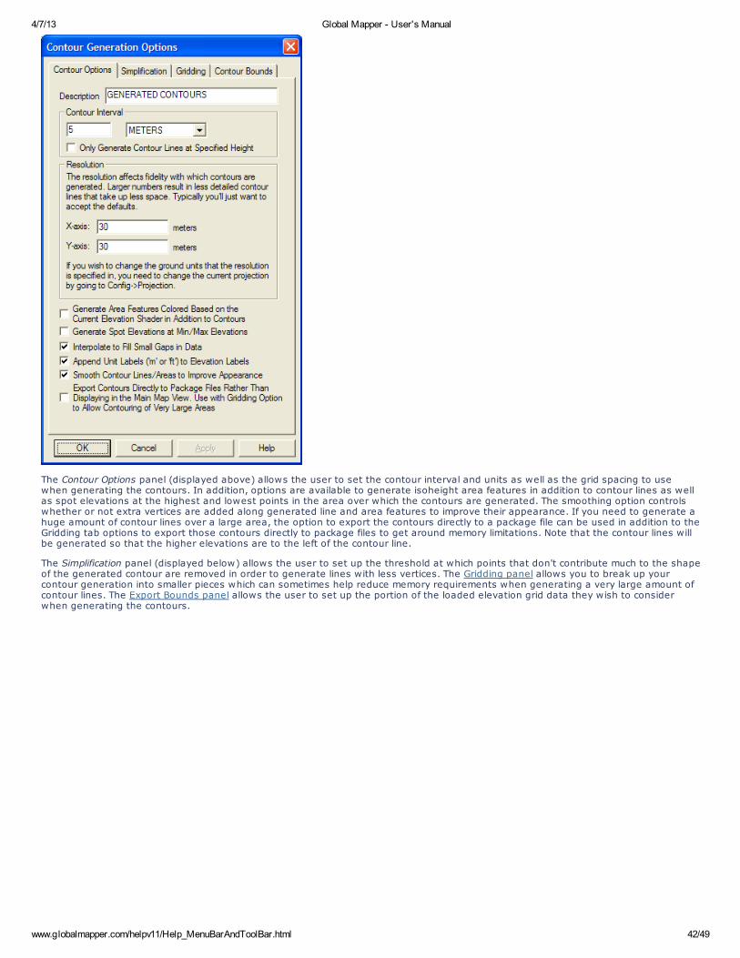
4/7/13 Global Mapper - User's Manual
www.globalmapper.com/helpv11/Help_MenuBarAndToolBar.html 42/49
The Contour Options panel (displayed above) allows the user to set the contour interval and units as well as the grid spacing to usewhen generating the contours. In addition, options are available to generate isoheight area features in addition to contour lines as wellas spot elevations at the highest and lowest points in the area over which the contours are generated. The smoothing option controlswhether or not extra vertices are added along generated line and area features to improve their appearance. If you need to generate ahuge amount of contour lines over a large area, the option to export the contours directly to a package file can be used in addition to theGridding tab options to export those contours directly to package files to get around memory limitations. Note that the contour lines willbe generated so that the higher elevations are to the left of the contour line.
The Simplification panel (displayed below) allows the user to set up the threshold at which points that don't contribute much to the shapeof the generated contour are removed in order to generate lines with less vertices. The Gridding panel allows you to break up yourcontour generation into smaller pieces which can sometimes help reduce memory requirements when generating a very large amount ofcontour lines. The Export Bounds panel allows the user to set up the portion of the loaded elevation grid data they wish to considerwhen generating the contours.
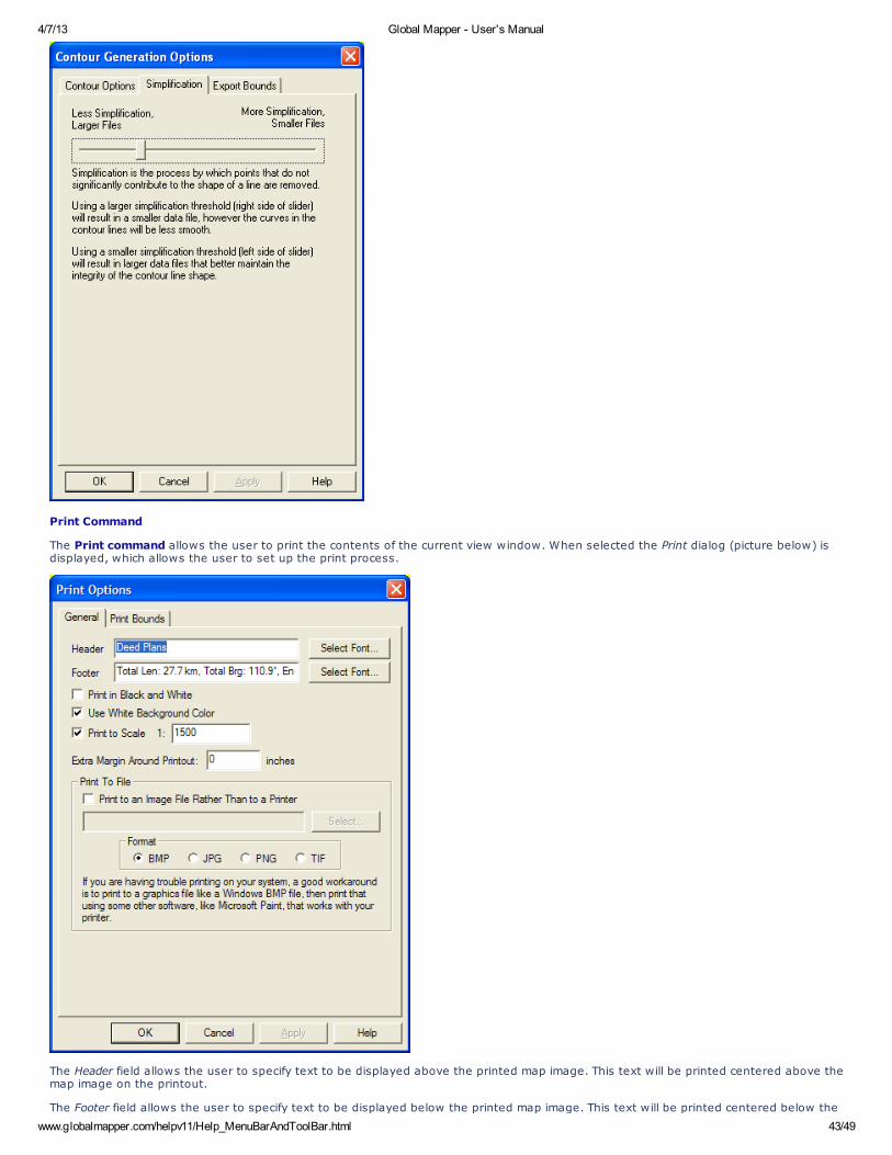
4/7/13 Global Mapper - User's Manual
www.globalmapper.com/helpv11/Help_MenuBarAndToolBar.html 43/49
Print Command
The Print command allows the user to print the contents of the current view window. When selected the Print dialog (picture below) isdisplayed, which allows the user to set up the print process.
The Header field allows the user to specify text to be displayed above the printed map image. This text will be printed centered above themap image on the printout.
The Footer field allows the user to specify text to be displayed below the printed map image. This text will be printed centered below the

4/7/13 Global Mapper - User's Manual
www.globalmapper.com/helpv11/Help_MenuBarAndToolBar.html 44/49
map image on the printout. The footer text will default to the text displayed on the status bar for the active tool, such as themeasurement information for the current measurement in the Measure Tool.
Selecting the Print in Black and White option causes the printout to be generated in black and white, rather than full color even whenprinting to a color printer. The generated image will be a 256-level grayscale image.
Selecting the Use White Background Color option causes any background areas being printed to be filled with white so as not to use anyprinter ink. Uncheck this option is you want the currently configured background color to be maintained on the printout.
The Extra Margin Around Printout setting allows you to specify an extra margin to draw around the output. This is useful when printing tothings like a PDF file that do not have any natural margins like a printer does.
The Print To Scale option allows you to specify that you want the printed result to match a certain scale, like 1:1000. This means that oneinch on the printed paper will correspond to 1000 inches in the real world. If you choose to print to a certain scale, the printout will becentered on the center of your current screen view, but the appropriate amount of information will be rendered to achieve the requestedscale.
The Print To File section allows you to specify that the printout be directed to an image file rather than to the printer. This can be handy ifyou either want to save the results of the printout to email to someone or post on a web site, or you are having trouble printing andwould like to print out the data generated by Global Mapper using another application.
The Print Bounds panel allows the user to select exactly what area to print (the default is the current screen contents). This panelbehaves just like the Export Bounds panel found on most export dialogs.
Print Preview Command
The Print Preview command allows the user to preview what a printout of the contents of the current view window would look like.
Print Setup Command
The Print Setup command allows the user to setup their printer for printing the current view window.
Exit Command
The Exit command closes the Global Mapper application.
View Menu
The View menu offers the following commands:
Toolbars - Shows or hides the toolbar(s)Status Bar - Shows or hides the status barBackground - Allows user to change the background colorCenter on Location - Allows user to recenter the view on a locationProperties - Displays Dialog with Properties of Current Map ViewFull View - Zooms such that all loaded data is visibleZoom In - Zooms in on loaded data by a factor of 2Zoom In Micro - Zooms in on loaded data by a small amountZoom Out - Zooms out on loaded data by a factor of 2Zoom Out Micro - Zooms out on loaded data by a small amountZoom To Scale - Zooms the current view to a given scaleZoom To Spacing (Pixel Size) - Zooms the current view to a given pixel sizeSave Current View - Saves the current view for later restorationRestore Last Saved View - Restores the last saved viewRestore Last Drawn View - Restores the last drawn viewName and Save Current View - Names and saves the current viewRestore Named View - Restores a previously saved named view
Toolbars
Use this command to display and hide the Toolbars, which includes buttons for some of the most common commands in Global Mapper. Acheck mark appears next to the menu item when the Toolbar is displayed
Status Bar
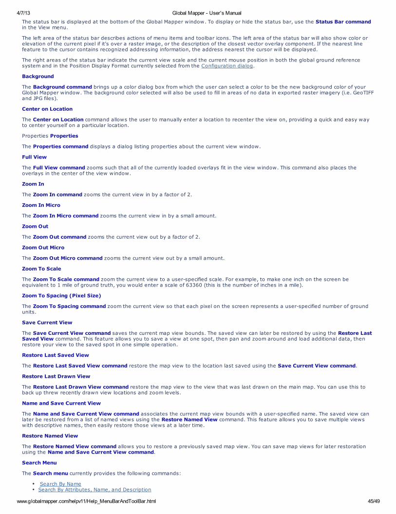
4/7/13 Global Mapper - User's Manual
www.globalmapper.com/helpv11/Help_MenuBarAndToolBar.html 45/49
The status bar is displayed at the bottom of the Global Mapper window. To display or hide the status bar, use the Status Bar commandin the View menu.
The left area of the status bar describes actions of menu items and toolbar icons. The left area of the status bar will also show color orelevation of the current pixel if it's over a raster image, or the description of the closest vector overlay component. If the nearest linefeature to the cursor contains recognized addressing information, the address nearest the cursor will be displayed.
The right areas of the status bar indicate the current view scale and the current mouse position in both the global ground referencesystem and in the Position Display Format currently selected from the Configuration dialog.
Background
The Background command brings up a color dialog box from which the user can select a color to be the new background color of yourGlobal Mapper window. The background color selected will also be used to fill in areas of no data in exported raster imagery (i.e. GeoTIFFand JPG files).
Center on Location
The Center on Location command allows the user to manually enter a location to recenter the view on, providing a quick and easy wayto center yourself on a particular location.
Properties Properties
The Properties command displays a dialog listing properties about the current view window.
Full View
The Full View command zooms such that all of the currently loaded overlays fit in the view window. This command also places theoverlays in the center of the view window.
Zoom In
The Zoom In command zooms the current view in by a factor of 2.
Zoom In Micro
The Zoom In Micro command zooms the current view in by a small amount.
Zoom Out
The Zoom Out command zooms the current view out by a factor of 2.
Zoom Out Micro
The Zoom Out Micro command zooms the current view out by a small amount.
Zoom To Scale
The Zoom To Scale command zoom the current view to a user-specified scale. For example, to make one inch on the screen beequivalent to 1 mile of ground truth, you would enter a scale of 63360 (this is the number of inches in a mile).
Zoom To Spacing (Pixel Size)
The Zoom To Spacing command zoom the current view so that each pixel on the screen represents a user-specified number of groundunits.
Save Current View
The Save Current View command saves the current map view bounds. The saved view can later be restored by using the Restore LastSaved View command. This feature allows you to save a view at one spot, then pan and zoom around and load additional data, thenrestore your view to the saved spot in one simple operation.
Restore Last Saved View
The Restore Last Saved View command restore the map view to the location last saved using the Save Current View command.
Restore Last Drawn View
The Restore Last Drawn View command restore the map view to the view that was last drawn on the main map. You can use this toback up threw recently drawn view locations and zoom levels.
Name and Save Current View
The Name and Save Current View command associates the current map view bounds with a user-specified name. The saved view canlater be restored from a list of named views using the Restore Named View command. This feature allows you to save multiple viewswith descriptive names, then easily restore those views at a later time.
Restore Named View
The Restore Named View command allows you to restore a previously saved map view. You can save map views for later restorationusing the Name and Save Current View command.
Search Menu
The Search menu currently provides the following commands:
Search By NameSearch By Attributes, Name, and Description

4/7/13 Global Mapper - User's Manual
www.globalmapper.com/helpv11/Help_MenuBarAndToolBar.html 46/49
Search and ReplaceFind AddressFind Features with Duplicate Attribute Values
Search By Name
The Search By Name command allows for searching for features in all loaded vector data by name. When selected, the Find By Namedialog is displayed.
The Find By Name dialog displays a list of all of the vector features (areas,lines, and/or points) whose label starts with the search stringspecified in the Search String field. This field can contain the ? and * wildcard characters. In addition, one can control which vector objecttypes (area,line, and/or point) to include in the search. Double-clicking on an item in the list will recenter the view on that object andshow a bullseye on it (hold down the ALT key when double-clicking to not show the bullseye).
The Edit Selected button displays a dialog allowing the user to modify the name, feature type, and drawing style of any features selected.
The Delete Selected button will mark all selected features as deleted.
This dialog is particulary handy with the GNIS (Geographic Names) database which is freely available for download.
Search By Attributes, Name, and Description
The Search By Attributes, Name, and Description command allows for searching for features in all loaded vector data by attribute value,name, and description/type. When selected, the Search Vector Data dialog is displayed.
The Search Vector Data dialog displays a list of all of the vector features (areas, lines, and/or points) which match the specified SearchCriteria. The Search Criteria can be applied to any attribute value of the loaded features, the display label field, or the description/typefield. Comparisons to the Compare Value can be done either textually or numerically. For text equal and not-equal searches, theCompare Value field can contain the ? and * wildcard characters.
In addition, one can control which vector object types (area, line, and/or point) to include in the search.

4/7/13 Global Mapper - User's Manual
www.globalmapper.com/helpv11/Help_MenuBarAndToolBar.html 47/49
Once you have your Search Criteria set how you want for the search, press the New Search button to actually perform the search anddisplay the matching results in the results list. The results will be sorted in ascending order by the names of the features by default, butyou can click on any column header to sort the results by the values in that column. Clicking the same column header again will reversethe order of the sort. You can also press the Search in Existing Results button to apply the new search criteria to the existing results.Using this you can create complicated searches based on multiple criteria.
Double-clicking on an item in the list will recenter the view on that object.
The Edit Selected button displays a dialog allowing the user to modify the name, feature type, and drawing style of any features selected.
The Delete Selected button will mark all selected features as deleted.
If you right click on the results list, additonal options will appear, such as the option to select all of the results in the list. If multiple linefeatures are selected in the results list, when you right click there will be an option to combine those line features into new line featuresif the selected lines connect at their endpoints. Options for copying the selected features to the clipboard and selecting the selectedsearch results with the Digitizer Tool for further editing will also appear if any results are selected.
ADVANCED USERS: You can change the default search string from '*' to whatever you want by creating a new registry string value withthe desired default search string at "HKEY_CURRENT_USER\Software\Global Mapper\DefaultVectorSearchStr".
Search and Replace
The Search and Replace command allows for searching for a particular text string in the attributes and name of loaded features andreplacing that with some other text string. When you select the command, the Search and Replace dialog (pictured below) is displayed,allowing you to setup the search-and-replace operation.
When searching, you can either enter a Search Text value of the string to match on, or you can enter an asterisk (*) to match any non-empty value. In the Replace Text box you have more options. You can specify a simple text string to replace the Search Text with, or youcan use a single wildcard to prepend or append text. For example, to prepend the text 'Sample' in front of your search string, enter areplace string of 'Sample*'. To append the text to your search string, use '*Sample'.
Find Address
The Find Address command displays the Search for an Address in the US dialog (pictured below) which allows searching for an address,city, or zip code in the United States.
If an address is found that matches the requested location, a results dialog (see sample below) is displayed with the matching locationinformation, as well as button to allow creating a new point feature at the address location, re-centering the map view on the address,and copying the address information to the Windows clipboard for easy pasting into another application.
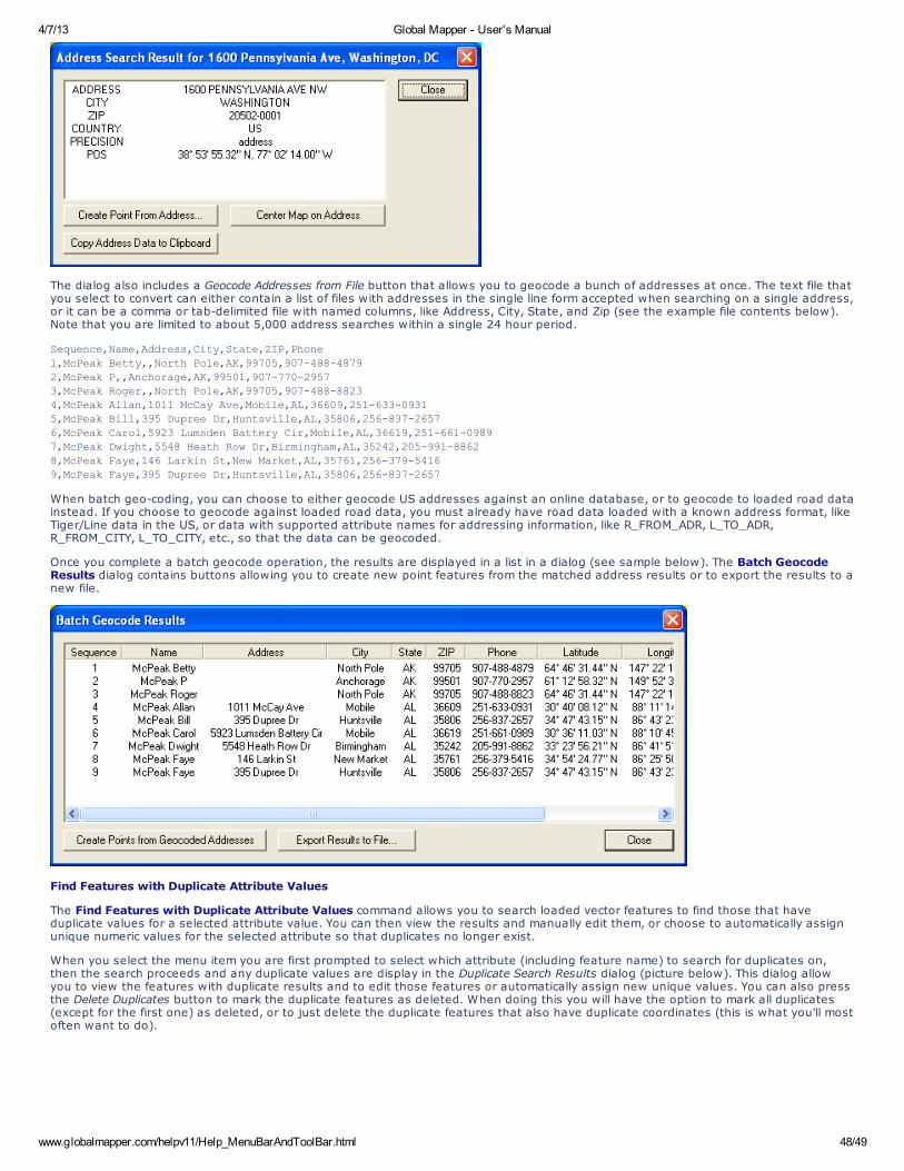
4/7/13 Global Mapper - User's Manual
www.globalmapper.com/helpv11/Help_MenuBarAndToolBar.html 48/49
The dialog also includes a Geocode Addresses from File button that allows you to geocode a bunch of addresses at once. The text file thatyou select to convert can either contain a list of files with addresses in the single line form accepted when searching on a single address,or it can be a comma or tab-delimited file with named columns, like Address, City, State, and Zip (see the example file contents below).Note that you are limited to about 5,000 address searches within a single 24 hour period.
Sequence,Name,Address,City,State,ZIP,Phone
1,McPeak Betty,,North Pole,AK,99705,907-488-4879
2,McPeak P,,Anchorage,AK,99501,907-770-29573,McPeak Roger,,North Pole,AK,99705,907-488-8823
4,McPeak Allan,1011 McCay Ave,Mobile,AL,36609,251-633-0931
5,McPeak Bill,395 Dupree Dr,Huntsville,AL,35806,256-837-2657
6,McPeak Carol,5923 Lumsden Battery Cir,Mobile,AL,36619,251-661-09897,McPeak Dwight,5548 Heath Row Dr,Birmingham,AL,35242,205-991-8862
8,McPeak Faye,146 Larkin St,New Market,AL,35761,256-379-5416
9,McPeak Faye,395 Dupree Dr,Huntsville,AL,35806,256-837-2657
When batch geo-coding, you can choose to either geocode US addresses against an online database, or to geocode to loaded road datainstead. If you choose to geocode against loaded road data, you must already have road data loaded with a known address format, likeTiger/Line data in the US, or data with supported attribute names for addressing information, like R_FROM_ADR, L_TO_ADR,R_FROM_CITY, L_TO_CITY, etc., so that the data can be geocoded.
Once you complete a batch geocode operation, the results are displayed in a list in a dialog (see sample below). The Batch GeocodeResults dialog contains buttons allowing you to create new point features from the matched address results or to export the results to anew file.
Find Features with Duplicate Attribute Values
The Find Features with Duplicate Attribute Values command allows you to search loaded vector features to find those that haveduplicate values for a selected attribute value. You can then view the results and manually edit them, or choose to automatically assignunique numeric values for the selected attribute so that duplicates no longer exist.
When you select the menu item you are first prompted to select which attribute (including feature name) to search for duplicates on,then the search proceeds and any duplicate values are display in the Duplicate Search Results dialog (picture below). This dialog allowyou to view the features with duplicate results and to edit those features or automatically assign new unique values. You can also pressthe Delete Duplicates button to mark the duplicate features as deleted. When doing this you will have the option to mark all duplicates(except for the first one) as deleted, or to just delete the duplicate features that also have duplicate coordinates (this is what you'll mostoften want to do).
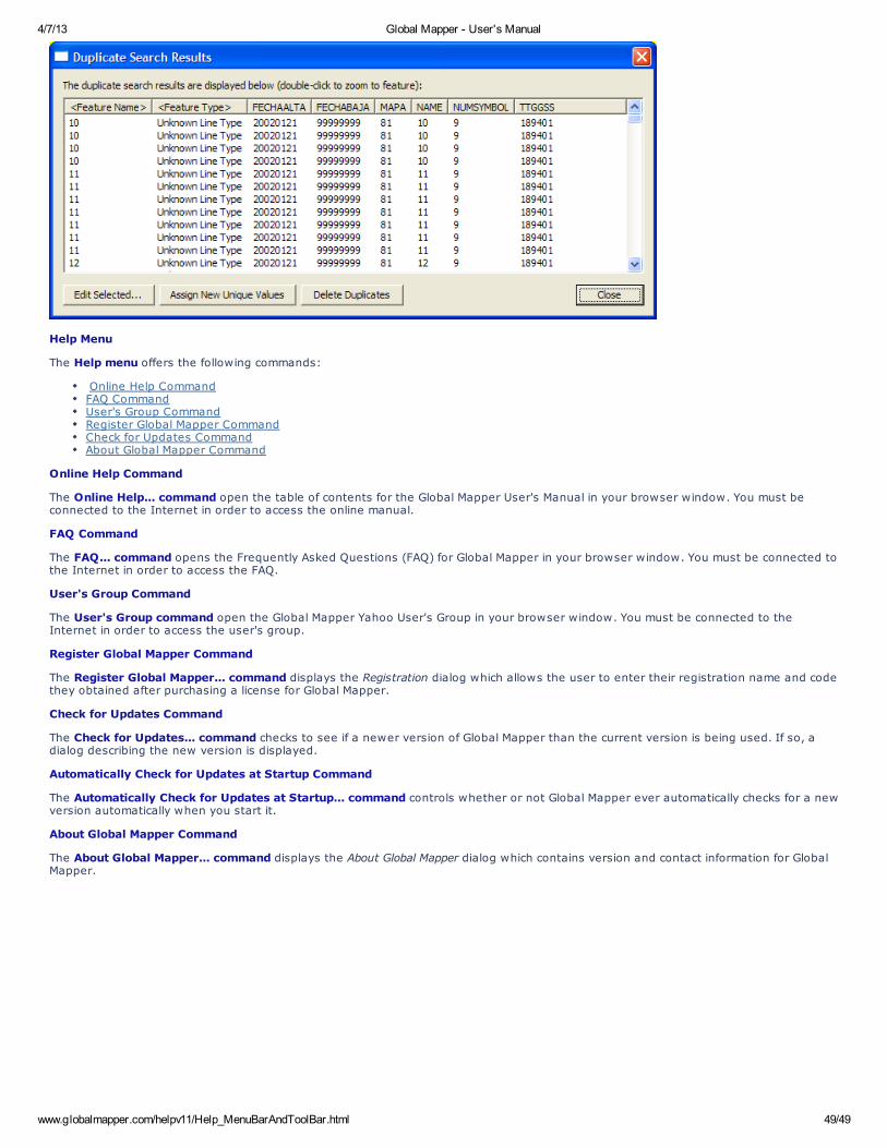
4/7/13 Global Mapper - User's Manual
www.globalmapper.com/helpv11/Help_MenuBarAndToolBar.html 49/49
Help Menu
The Help menu offers the following commands:
Online Help CommandFAQ CommandUser's Group CommandRegister Global Mapper CommandCheck for Updates CommandAbout Global Mapper Command
Online Help Command
The Online Help... command open the table of contents for the Global Mapper User's Manual in your browser window. You must beconnected to the Internet in order to access the online manual.
FAQ Command
The FAQ... command opens the Frequently Asked Questions (FAQ) for Global Mapper in your browser window. You must be connected tothe Internet in order to access the FAQ.
User's Group Command
The User's Group command open the Global Mapper Yahoo User's Group in your browser window. You must be connected to theInternet in order to access the user's group.
Register Global Mapper Command
The Register Global Mapper... command displays the Registration dialog which allows the user to enter their registration name and codethey obtained after purchasing a license for Global Mapper.
Check for Updates Command
The Check for Updates... command checks to see if a newer version of Global Mapper than the current version is being used. If so, adialog describing the new version is displayed.
Automatically Check for Updates at Startup Command
The Automatically Check for Updates at Startup... command controls whether or not Global Mapper ever automatically checks for a newversion automatically when you start it.
About Global Mapper Command
The About Global Mapper... command displays the About Global Mapper dialog which contains version and contact information for GlobalMapper.


![[Tutorial] Crop Daa Citra Satelit Menggunakan Global Mapper](https://img.pdfslide.us/doc/110x75/577c7b371a28abe054979067/tutorial-crop-daa-citra-satelit-menggunakan-global-mapper.jpg)