Embed Size (px)
Citation preview
INSTALLATION INSTRUCTIONS
INTEGRATED PRIVACY™ SYSTEM POWDER COATED AND
STAINLESS STEEL PARTITIONS
160 Tower Drive, Burr Ridge, IL 60527 | Tel: (708) 442-6800/ Fax (708) 442-7439 | www.asi-accuratepar ti ons.com
GlobalPartitions
Thank you for choosing ASI Accurate Par ons
This installa on guide was designed to cover as many varia ons of hardware and moun ng styles as possible, while also trying to keep it light and focused.
While all materials and standard moun ng selec ons are present, in order to cover the numerous choices of hardware, we have presented each material with it’s
default hardware. Therefore, while each type is covered, it will be with it’s most common moun ng style (i.e. con nuous brackets on ceiling-hung, piano hinges on
Solid Plastic (HDPE), etc).
Please read all steps in their en rety before beginning actual install, as some fi eld condi ons and hardware combina ons may require alternate installa on.
GlobalPartitions
160 Tower Drive, Burr Ridge, IL 60527 | Tel: (708) 442-6800/ Fax (708) 442-7439 | www.asi-accuratepar ti ons.com
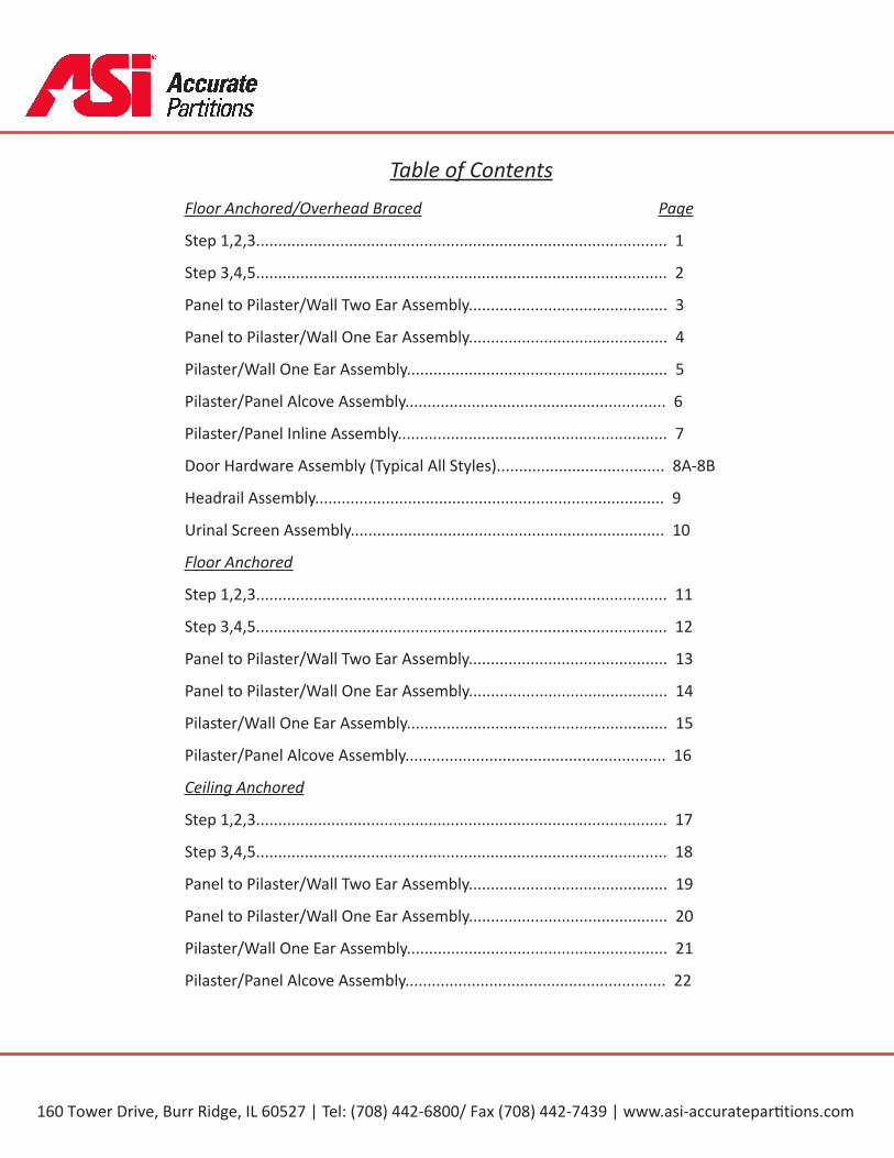
Table of ContentsFloor Anchored/Overhead Braced Page
Step 1,2,3............................................................................................. 1
Step 3,4,5............................................................................................. 2
Panel to Pilaster/Wall Two Ear Assembly............................................. 3
Panel to Pilaster/Wall One Ear Assembly............................................. 4
Pilaster/Wall One Ear Assembly........................................................... 5
Pilaster/Panel Alcove Assembly........................................................... 6
Pilaster/Panel Inline Assembly............................................................. 7
Door Hardware Assembly (Typical All Styles)...................................... 8A-8B
Headrail Assembly............................................................................... 9
Urinal Screen Assembly....................................................................... 10
Floor Anchored
Step 1,2,3............................................................................................. 11
Step 3,4,5............................................................................................. 12
Panel to Pilaster/Wall Two Ear Assembly............................................. 13
Panel to Pilaster/Wall One Ear Assembly............................................. 14
Pilaster/Wall One Ear Assembly........................................................... 15
Pilaster/Panel Alcove Assembly........................................................... 16
Ceiling Anchored
Step 1,2,3............................................................................................. 17
Step 3,4,5............................................................................................. 18
Panel to Pilaster/Wall Two Ear Assembly............................................. 19
Panel to Pilaster/Wall One Ear Assembly............................................. 20
Pilaster/Wall One Ear Assembly........................................................... 21
Pilaster/Panel Alcove Assembly........................................................... 22
GlobalPartitions
160 Tower Drive, Burr Ridge, IL 60527 | Tel: (708) 442-6800/ Fax (708) 442-7439 | www.asi-accuratepar ti ons.com
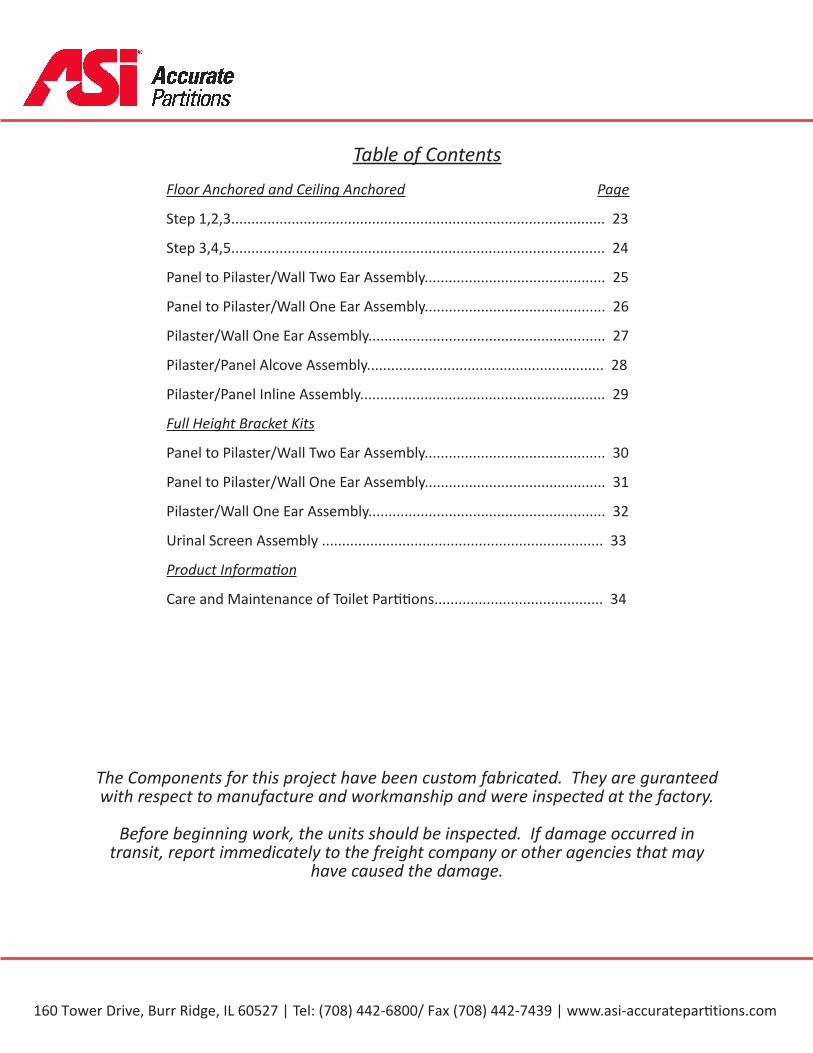
Table of ContentsFloor Anchored and Ceiling Anchored Page
Step 1,2,3............................................................................................. 23
Step 3,4,5............................................................................................. 24
Panel to Pilaster/Wall Two Ear Assembly............................................. 25
Panel to Pilaster/Wall One Ear Assembly............................................. 26
Pilaster/Wall One Ear Assembly........................................................... 27
Pilaster/Panel Alcove Assembly........................................................... 28
Pilaster/Panel Inline Assembly............................................................. 29
Full Height Bracket Kits
Panel to Pilaster/Wall Two Ear Assembly............................................. 30
Panel to Pilaster/Wall One Ear Assembly............................................. 31
Pilaster/Wall One Ear Assembly........................................................... 32
Urinal Screen Assembly ...................................................................... 33
Product Informa on
Care and Maintenance of Toilet Par ons.......................................... 34
The Components for this project have been custom fabricated. They are guranteed with respect to manufacture and workmanship and were inspected at the factory.
Before beginning work, the units should be inspected. If damage occurred in transit, report immedicately to the freight company or other agencies that may
have caused the damage.
GlobalPartitions
160 Tower Drive, Burr Ridge, IL 60527 | Tel: (708) 442-6800/ Fax (708) 442-7439 | www.asi-accuratepar ti ons.com
Page 1
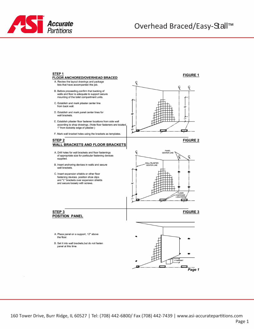
Overhead Braced/Easy-Stall™GlobalPartitions
160 Tower Drive, Burr Ridge, IL 60527 | Tel: (708) 442-6800/ Fax (708) 442-7439 | www.asi-accuratepar ti ons.com
Page 2
GlobalPartitions
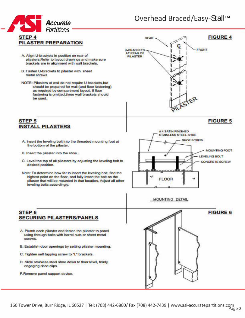
STEP 4PILASTER PREPARATION
FIGURE 4
FRONTU-SRACKETSAT REAft OFPILASTERA. Align LNaracdcaCa in pasfflio-n an rear of
pilasle-rs_Refer bo layout drawings and make surebrackets are in alignment wiQi wall brackets.
B. Fasten U-frrackets to p4aster with sheetmetal screws.
NOTE: Pilasters at wan dc not require U-brackafcs.buEshould be prepared Far wail (and Hoar fastening )as required fry compartment layout. If floorfastening as omitted,ihree wail brackets shouldbe used.
STEP 5 FIGURE 5INSTALL PILASTERS
d 4 SATiN F0-4I&HEDSTAINLESS STEEL SHOE
SHOE SCREWA_ insert the leveling bolt into the threaded mounting fool atthe bottom of the pilaster.
MOUNTING FOOTB. insert the pilaster into the shoe.
,— LEvEsJNG &QLT
F2C. Level the cop of all pslasters fry adjusbng the ievei:ng bolt todeseed position.
CONCRETE SCREW8
i
Note: To determine how far 1o insert the leveling bolt, find theh«jhes1 point on Ehe floor, and fully insert the bolt on thepilasienhai wHi be mounted in that location. Adjust all otherleveling baffle accordingly.
FLOOR
A
yPUNTING DETAIL
STEP 6 FIGURE 6SECURING PILASTERS/PANELS
A_ Plumb each pilaster and fasten the pilaster to panelusing through bolts with barrel nuts or sheet metalscrews.
B. Establish door openings by setting pilaster mounting.
C.Tighten self tapping sere*1 to "L brackets.
D. Slide stairless steel shoe down to floor level, firmlyengaging shoe clips.
F.Remove panel support dewce.
Overhead Braced/Easy-Stall™
160 Tower Drive, Burr Ridge, IL 60527 | Tel: (708) 442-6800/ Fax (708) 442-7439 | www.asi-accuratepar ti ons.com
Page 3
GlobalPartitions
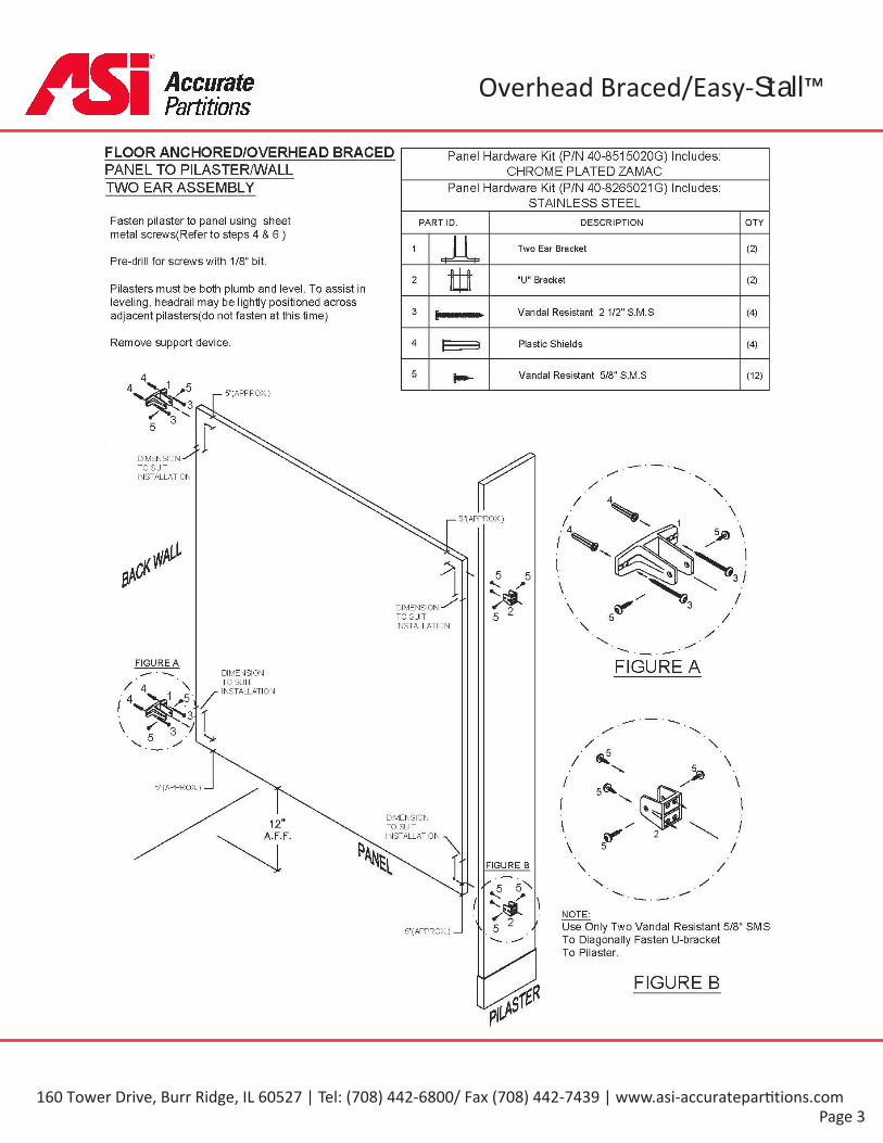
FLOOR ANCHORED/OVERHEAD BRACED Panel Hardware Kit (PIN 40-8515020G) Includes:CHROME PLATED ZAMACPANEL TO PILASTERA/VALL
TWO EAR ASSEMBLY Panel Hardware Kit (P/N 40-8265021G) Includes:STAINLESS STEEL
Fasten pilaster to panel using sheetmetal screws(Refer to steps 4 & 6 )
PART ID. DESCRIPTION OTY
1 Two Ear Bracket (2)Pre-drill for screws with 1/8" bit.
2 "U" Bracket (2)Pilasters must be both plumb and level. To assist inleveling, headrail may be lightly positioned acrossadjacent pilasters(do not fasten at this time) 3 Vandal Resistant 2 1/2" S.M.S (4)
Remove support device. 4 Plastic Shields (4)
5 Vandal Resistant 5/8" S.M.S (12)
5"(APPROX.)
DIMENSIONTO SUITINSTALLATION
5"( APPROX.)
> 3 /5 5
* 25 ^DIMENSIONTO SUITINSTALLATION
FIGURE A FIGURE ADIMENSIONTO SUITINSTALLATION./
5"(APPROX) —I
DIMENSIONTO SUITINSTALLATION
12"A.F.F. \: FIGURE B
I \NOTE:
\ t Use Only Two Vandal Resistant 5/8" SMSTo Diagonally Fasten U-bracketTo Pilaster.
/V5"(APPROX.) —I
FIGURE B
Overhead Braced/Easy-Stall™
160 Tower Drive, Burr Ridge, IL 60527 | Tel: (708) 442-6800/ Fax (708) 442-7439 | www.asi-accuratepar ti ons.com
Page 4
GlobalPartitions
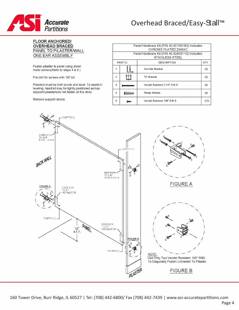
FLOOR ANCHORED/OVERHEAD BRACED Panel Hardware Kit (P/N 40-851501OG) Includes:
CHROME PLATED ZAMACPANEL TO PILASTER/WALLPanel Hardware Kit (P/N 40-8265011G) Includes:
STAINLESS STEELONE EAR ASSEMBLY
PART ID. DESCRIPTION QTYFasten pilaster to panel using sheetmetal screws(Refer to steps 4 & 6 ) 1 One Ear Bracket (2)
2 "U" Bracket (2)Pre-drill for screws with 1/8" bit.
Pilasters must be both plumb and level. To assist inleveling, headrail may be lightly positioned acrossadjacent pilasters(do not fasten at this time)
3 Vandal Resistant 2 1/2" S.M.S (4)
4 Plastic Shields (4)
Remove support device. 5 Vandal Resistant 5/8" S.M.S (12)
5"(APPROX.)
DIMENSIONTO SUITINSTALLATION
5"(APPROX.)
5DIMENSIONTO SUITINSTALLATION
5
FIGURE AFIGURE A DIMENSIONTO SUITINSTALLATION./
1V
a?/5"(APPROX.) —I
/DIMENSIONTO SUITINSTALLATION
5®*12 \A.F.F.iv FIGURE B
/ 15"(APPROX.) _l \
\ NOTE:Use Only Two Vandal Resistant 5/8" SMSTo Diagonally Fasten U-bracket To Pilaster.
FIGURE B
Overhead Braced/Easy-Stall™
160 Tower Drive, Burr Ridge, IL 60527 | Tel: (708) 442-6800/ Fax (708) 442-7439 | www.asi-accuratepar ti ons.com
Page 5
GlobalPartitions
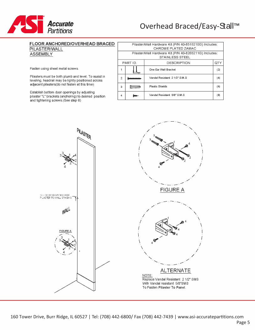
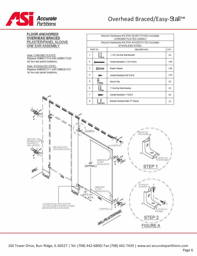
FLOOR ANCHORED/OVERHEAD BRACED Pilaster/Wall Hardware Kit (P/N 40-8515210G) Includes:CHROME PLATED ZAMACPILASTER/WALL
Pilaster/Wall Hardware Kit (P/N 40-8265211G) Includes:STAINLESS STEEL
ASSEMBLY
PART ID. DESCRIPTION QTY
Fasten using sheet metal screws. 1 One Ear Wall Bracket (2)
Pilasters must be both plumb and level. To assist inleveling, headrail may be lightly positioned acrossadjacent pilasters(do not fasten at this time)
Vandal Resistant 2 1/2" S.M.S (4)2
Plastic Shields (4)3
Establish bottom door openings by adjustingpilaster "L" brackets (anchoring) to desired positionand tightening screws.(See step 6)
Vandal Resistant 5/8" S.M.S (8)4
FIGURE ASEE SHOP DRAWINGS FORPILASTER TO WALL SPACING
FIGURE A
ALTERNATENOTE:Replace Vandal Resistant 2 1/2" SMSWith Vandal resistant 5/8"SMSTo Fasten Pilaster To Panel.
Overhead Braced/Easy-Stall™
160 Tower Drive, Burr Ridge, IL 60527 | Tel: (708) 442-6800/ Fax (708) 442-7439 | www.asi-accuratepar ti ons.com
Page 6
GlobalPartitions
Overhead Braced/Easy-Stall™
160 Tower Drive, Burr Ridge, IL 60527 | Tel: (708) 442-6800/ Fax (708) 442-7439 | www.asi-accuratepar ti ons.com

Page 7
GlobalPartitions
Overhead Braced/Easy-Stall™
160 Tower Drive, Burr Ridge, IL 60527 | Tel: (708) 442-6800/ Fax (708) 442-7439 | www.asi-accuratepar ti ons.com
Page 8A
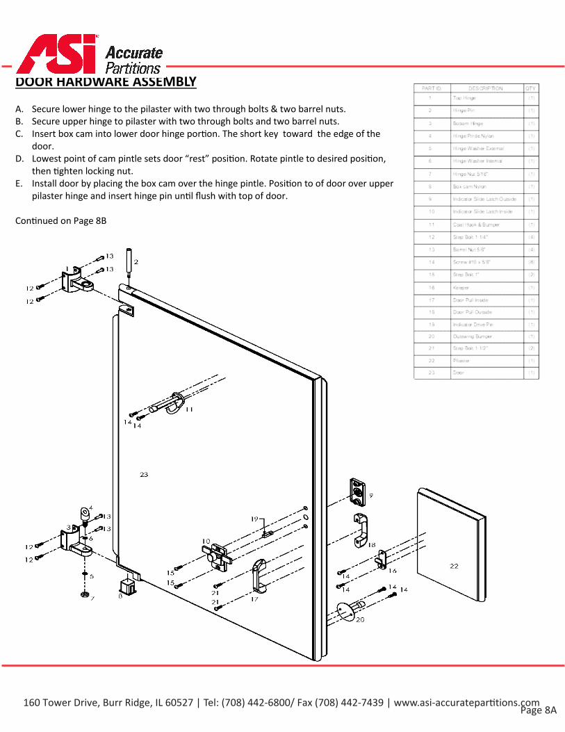
DOOR HARDWARE ASSEMBLY
A. Secure lower hinge to the pilaster with two through bolts & two barrel nuts.B. Secure upper hinge to pilaster with two through bolts and two barrel nuts.C. Insert box cam into lower door hinge por�on. The short key toward the edge of the
door.D. Lowest point of cam pintle sets door “rest” posi�on. Rotate pintle to desired posi�on,
then �ghten locking nut.E. Install door by placing the box cam over the hinge pintle. Posi�on to of door over upper
pilaster hinge and insert hinge pin un�l flush with top of door.
Con�nued on Page 8B
160 Tower Drive, Burr Ridge, IL 60527 | Tel: (708) 442-6800/ Fax (708) 442-7439 | www.asi-accuratepar ti ons.com
Page 8B
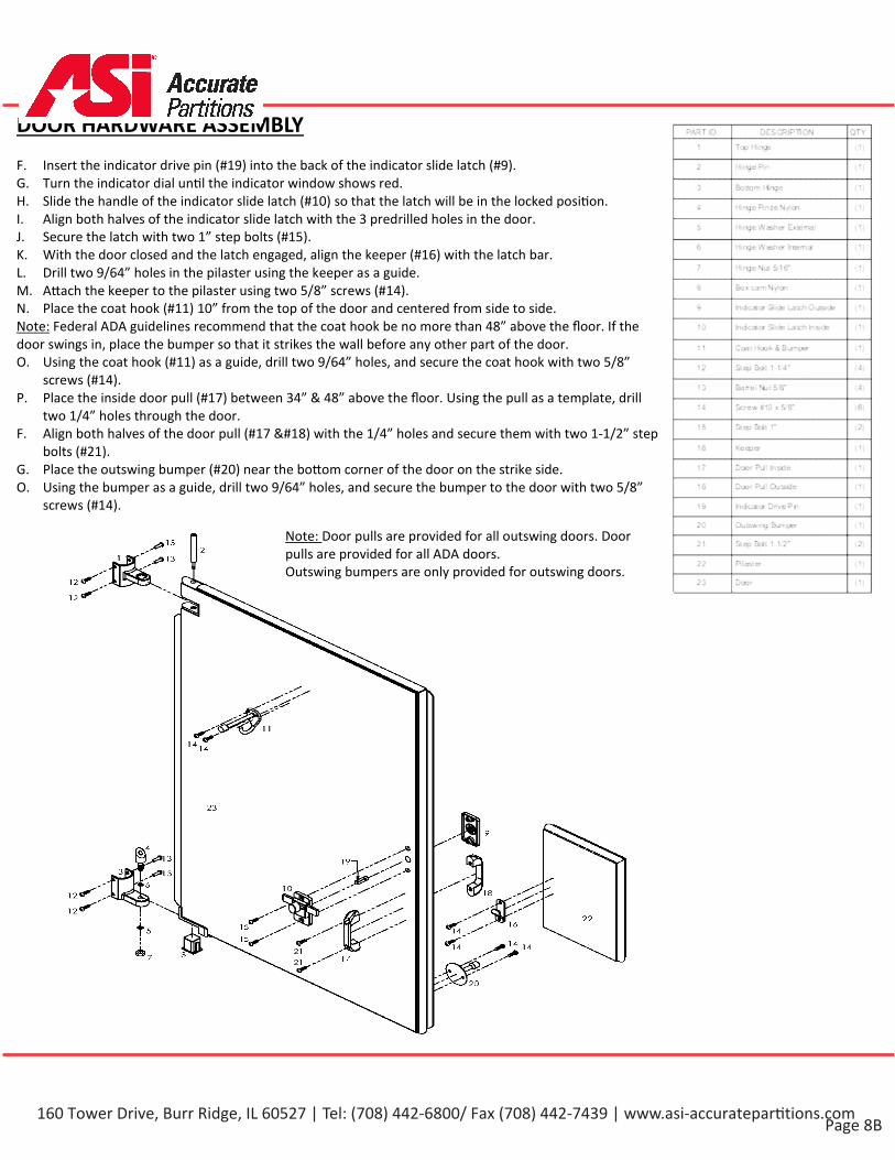
DOOR HARDWARE ASSEMBLY
F. Insert the indicator drive pin (#19) into the back of the indicator slide latch (#9).G. Turn the indicator dial un�l the indicator window shows red.H. Slide the handle of the indicator slide latch (#10) so that the latch will be in the locked posi�on.I. Align both halves of the indicator slide latch with the 3 predrilled holes in the door.J. Secure the latch with two 1” step bolts (#15).K. With the door closed and the latch engaged, align the keeper (#16) with the latch bar.L. Drill two 9/64” holes in the pilaster using the keeper as a guide.M. A�ach the keeper to the pilaster using two 5/8” screws (#14).N. Place the coat hook (#11) 10” from the top of the door and centered from side to side.Note: Federal ADA guidelines recommend that the coat hook be no more than 48” above the floor. If thedoor swings in, place the bumper so that it strikes the wall before any other part of the door.O. Using the coat hook (#11) as a guide, drill two 9/64” holes, and secure the coat hook with two 5/8”
screws (#14).P. Place the inside door pull (#17) between 34” & 48” above the floor. Using the pull as a template, drill
two 1/4” holes through the door.F. Align both halves of the door pull (#17 ) with the 1/4” holes and secure them with two 1-1/2” step
bolts (#21).G. Place the outswing bumper (#20) near the bo�om corner of the door on the strike side.O. Using the bumper as a guide, drill two 9/64” holes, and secure the bumper to the door with two 5/8”
screws (#14).
Note: Door pulls are provided for all outswing doors. Door pulls are provided for all ADA doors. Outswing bumpers are only provided for outswing doors.
160 Tower Drive, Burr Ridge, IL 60527 | Tel: (708) 442-6800/ Fax (708) 442-7439 | www.asi-accuratepar ti ons.com

Page 9
GlobalPartitions
Headrail Hardware Kit (P/N 40-84481OOG) Includes:
PART ID. DESCRIPTION QTY
Headrail Satin "F" Zamac Bracket (2)
Headrail Cap Satin Zamac (1)
Vandal Resistant S/S 2 1/2" S.M.S (2)
Plastic Shield (2)
VandalResistant S/S 5/8" S.M.S (4)
EXPLODED ASSEMBLY
Overhead Braced/Easy-Stall™
160 Tower Drive, Burr Ridge, IL 60527 | Tel: (708) 442-6800/ Fax (708) 442-7439 | www.asi-accuratepar ti ons.com
Page 10
GlobalPartitions
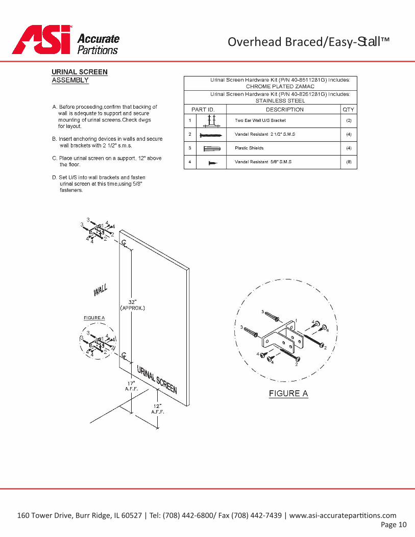
URINAL SCREENASSEMBLY Urinal Screen Hardware Kit (P/N 40-8511281G) Includes:
CHROME PLATED ZAMACUrinal Screen Hardware Kit (P/N 40-8261281G) Includes:
STAINLESS STEELA. Before proceeding,confirm that backing of
wall is adequate to support and securemounting of urinal screens.Check dwgsfor layout.
PART ID. DESCRIPTION QTY
1 Two Ear Wall U/S Bracket (2)
2 Vandal Resistant 2 1/2" S.M.S (4)B. Insert anchoring devices in walls and secure
wall brackets with 2 1/2" s.m.s. 3 Plastic Shields (4)
C. Place urinal screen on a support, 12" abovethe floor. 4 Vandal Resistant 5/8" S.M.S (8)
D. Set U/S into wall brackets and fastenurinal screen at this time,using 5/8"fasteners.
32"(APPROX.)
FIGURE A
17”A.F.F.
FIGURE A12»
A.F.F.
Overhead Braced/Easy-Stall™
160 Tower Drive, Burr Ridge, IL 60527 | Tel: (708) 442-6800/ Fax (708) 442-7439 | www.asi-accuratepar ti ons.com
Page 11
Floor AnchoredGlobalPartitions
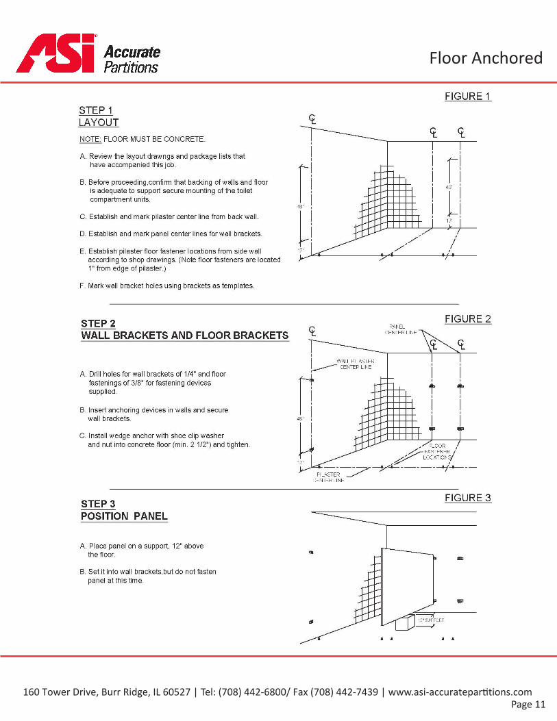
FIGURE 1STEP 1LAYOUTNOTE: FLOOR MUST BE CONCRETE.
A. Review the layout drawngs and package lists thathave accompanied this job.
B. Before proceeding,confirm that backing of walls and flooris adequate to support secure mounting of the toiletcompartment units.
48"
48"
C. Establish and mark pilaster center line from back wall. 17"
D. Establish and mark panel center lines for wall brackets.
/E. Establish pilaster floor fastener locations from sidewall
according to shop drawings. (Note floor fasteners are located1" from edge of pilaster.)
17"
F. Mark wall bracket holes using brackets as templates.
FIGURE 2STEP 2 PANELCENTER LINEWALL BRACKETS AND FLOOR BRACKETS
ftMWALL PILASTER
CENTER LINEA. Drill holes for wall brackets of 1/4" and floor
fastenings of 3/8" for fastening devicessupplied. f t
i i
B. Insert anchoring devices in walls and securewall brackets. 48"
W3 W3
C. Install wedge anchor with shoe clip washerand nut into concrete floor (min. 2 1/2") and tighten. FLOOR /
FASTENER /LOCATIONS/
<7
17" --vuPILASTER
CENTER LINE
FIGURE 3STEP 3POSITION PANEL
A. Place panel on a support, 12" abovethe floor. ta stb
B. Set it into wall brackets,but do not fastenpanel at this time.
3 W3
12" SUPPORT
-yA A A
160 Tower Drive, Burr Ridge, IL 60527 | Tel: (708) 442-6800/ Fax (708) 442-7439 | www.asi-accuratepar ti ons.com
Page 12
Floor AnchoredGlobalPartitions
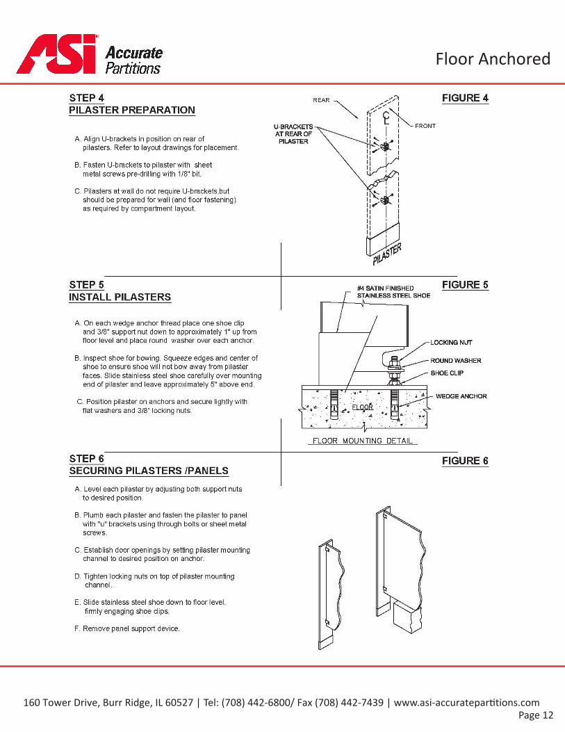
STEP 4 FIGURE 4REAR
PILASTER PREPARATIONFRONTU-BRACKETS
AT REAR OFPILASTERA. Align U-brackets in position on rear of
pilasters. Refer to layout drawings for placement.
B. Fasten U-brackets to pilaster with sheetmetal screws pre-drilling with 1/8" bit.
C. Pilasters at wall do not require U-brackets,butshould be prepared for wall (and floor fastening)as required by compartment layout.
STEP 5 FIGURE 5#4 SATIN FINISHEDSTAINLESS STEEL SHOEINSTALL PILASTERS
A. On each wedge anchor thread place one shoe clipand 3/8" support nut down to approximately 1" up fromfloor level and place round washer over each anchor. LOCKING NUT
B. Inspect shoe for bowing. Squeeze edges and center ofshoe to ensure shoe will not bow away from pilasterfaces. Slide stainless steel shoe carefully over mountingend of pilaster and leave approximately 5" above end.
ROUND WASHER
SHOE CLIP
. * - 4 WEDGE ANCHORC. Position pilaster on anchors and secure lightly with
flat washers and 3/8" locking nuts. I j FLOPft :•.• , 4«. .4
• * :
FLOOR MOUNTING DETAIL
STEP 6 FIGURE 6SECURING PILASTERS /PANELS
A. Level each pilaster by adjusting both support nutsto desired position.
B. Plumb each pilaster and fasten the pilaster to panelwith "u" brackets using through bolts or sheet metalscrews.
C. Establish door openings by setting pilaster mountingchannel to desired position on anchor.
D. Tighten locking nuts on top of pilaster mountingchannel.
E. Slide stainless steel shoe down to floor levelfirmly engaging shoe clips.
F. Remove panel support device.
160 Tower Drive, Burr Ridge, IL 60527 | Tel: (708) 442-6800/ Fax (708) 442-7439 | www.asi-accuratepar ti ons.com

Page 13
Floor AnchoredGlobalPartitions
FLOOR ANCHORED Panel Hardware Kit (P/N 40-8515020G) Includes:CHROME PLATED ZAMACPANEL TO PILASTER/WALL
TWO EAR ASSEMBLY Panel Hardware Kit (P/N 40-8265021G) Includes:STAINLESS STEEL
Fasten pilaster to panel using sheetmetal screws(Refer to steps 4 & 6 )
PART ID. DESCRIPTION OTY
1 Two Ear Bracket (2)Pre-drill for screws with 1/8" bit.
2 "U" Bracket (2)Pilasters must be both plumb and level. To assist inleveling, headrail may be lightly positioned acrossadjacent pilasters(do not fasten at this time) 3 VandalResistant C/P 2 1/2" S.M.S (4)
Remove support device. 4 Plastic Shields (4)
5 Vandal Resistant C/P 5/8" S.M.S (12)
5"(APPROX.)
*V
. 'DIMENSIONTO SUITINSTALLATION
5"( APPROX.)
> 5 5
* 25 zDIMENSIONTO SUITINSTALLATION
FIGURE A FIGURE ADIMENSIONTO SUITINSTALLATION
1
5"(APPROX.) —I
DIMENSIONTO SUITINSTALLATION
12"A.F.F. \t FIGURE B
I \NOTE:Use Only Two Vandal Resistant 5/8"SMS To Diagonally Fasten U-bracketTo Pilaster.
\ t\ /5"(APPROX.) —
FIGURE B
160 Tower Drive, Burr Ridge, IL 60527 | Tel: (708) 442-6800/ Fax (708) 442-7439 | www.asi-accuratepar ti ons.com
Page 14
Floor AnchoredGlobalPartitions
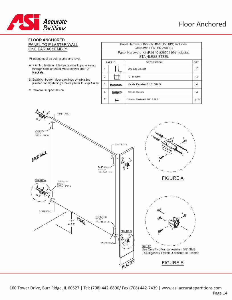
FLOOR ANCHOREDPANEL TO PILASTER/WALL Panel Hardware Kit (P/N 40-851501OG) Includes:
CHROME PLATED ZAMACONE EAR ASSEMBLYPanel Hardware Kit (P/N 40-8265011G) Includes:
STAINLESS STEELPilasters must be both plumb and level.PART ID. DESCRIPTION QTY
A. Plumb pilaster and fasten pilaster to panel usingthrough bolts or sheet metal screws and "U"brackets.
(2)1 One Ear Bracket
2 "U" Bracket (2)B. Establish bottom door openings by adjusting
pilaster and tightening screws.(Refer to step 4 & 6) 3 Vandal Resistant 2 1/2" S.M.S (4)
C. Remove support device. 4 Plastic Shields (4)
5 Vandal Resistant 5/8" S.M.S (12)
5"(APPROX.)
^|V
DIMENSIONTO SUITINSTALLATION
I— 5"(APPROX.)
>DIMENSIONTO SUITINSTALLATION
FIGURE AFIGURE A DIMENSIONTO SUITINSTALLATION
./1'Sc
/5"( APPROX.) —I
/DIMENSIONTO SUITINSTALLATION
512 \A.F.F.
I FIGURE B
I \5"(APPROX.) — v i
NOTE:/\
Use Only Two Vandal resistant 5/8" SMSTo Diagonally Fasten U-bracket To Pilaster.
FIGURE B
160 Tower Drive, Burr Ridge, IL 60527 | Tel: (708) 442-6800/ Fax (708) 442-7439 | www.asi-accuratepar ti ons.com
Page 15
Floor AnchoredGlobalPartitions
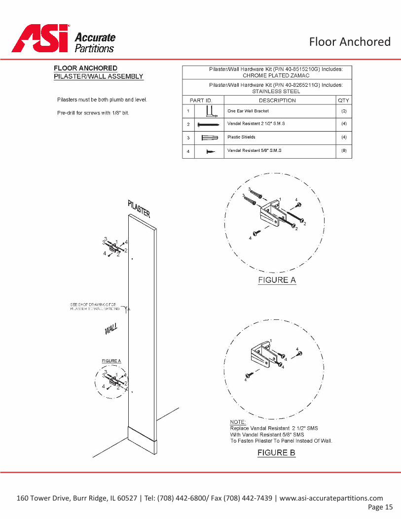
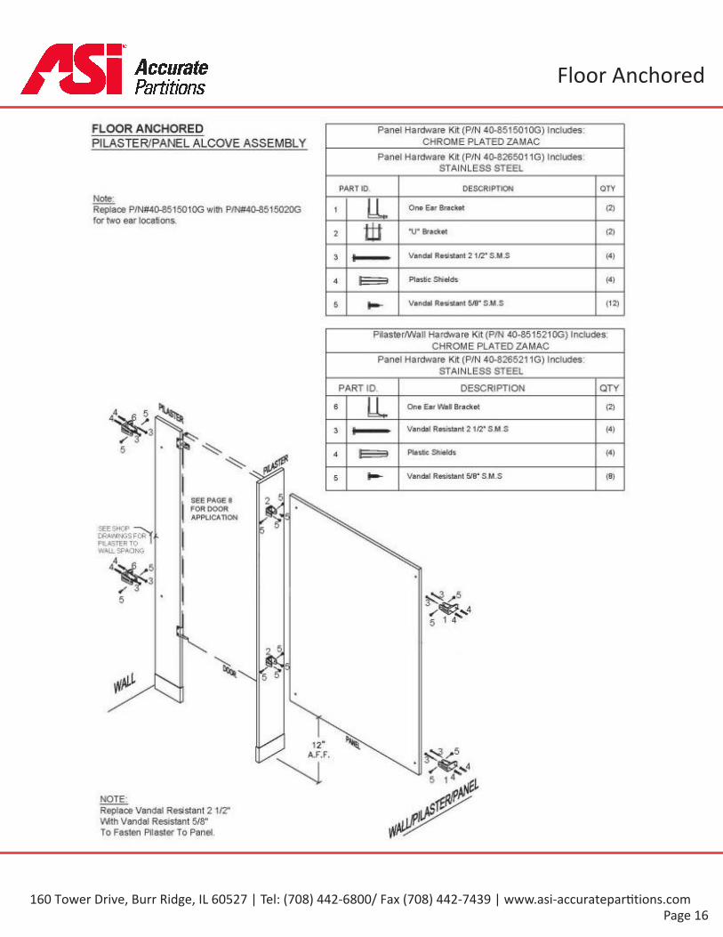
FLOOR ANCHORED Pilaster/Wall Hardware Kit (P/N 40-851521OG) Includes:CHROME PLATED ZAMACPILASTER/WALL ASSEMBLY
Pilaster/Wall Hardware Kit (P/N 40-8265211G) Includes:STAINLESS STEEL
Pilasters must be both plumb and level. PART ID. DESCRIPTION QTY
1 One Ear Wall Bracket (2)Pre-drill for screws with 1/8" bit.
Vandal Resistant 2 1/2" S.M.S (4)2
Plastic Shields (4)3
Vandal Resistant 5/8" S.M.S (8)4
FIGURE A
SEE SHOP DRAWINGS FORPILASTER TO WALL SPACING1L
FIGURE A
NOTE:Replace Vandal Resistant 2 1/2" SMSWith Vandal Resistant 5/8" SMSTo Fasten Pilaster To Panel Instead Of Wall.
FIGURE B
160 Tower Drive, Burr Ridge, IL 60527 | Tel: (708) 442-6800/ Fax (708) 442-7439 | www.asi-accuratepar ti ons.com
Page 16
Floor AnchoredGlobalPartitions
160 Tower Drive, Burr Ridge, IL 60527 | Tel: (708) 442-6800/ Fax (708) 442-7439 | www.asi-accuratepar ti ons.com
Page 17
Ceiling AnchoredGlobalPartitions
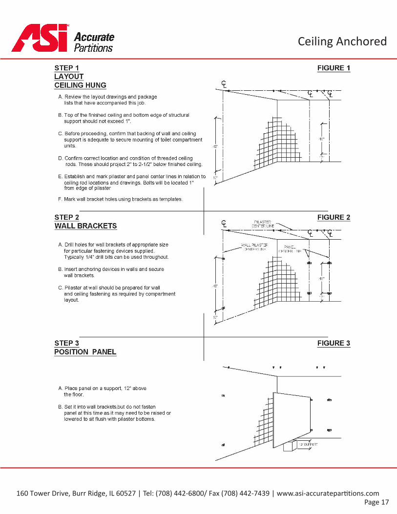
STEP 1 FIGURE 1LAYOUTCEILING HUNG
A. Review the layout drawings and packagelists that have accompanied this job.
B. Top of the finished ceiling and bottom edge of structuralsupport should not exceed 1".
C. Before proceeding, confirm that backing of wall and ceilingsupport is adequate to secure mounting of toilet compartmentunits.
48"
48"
17"D. Confirm correct location and condition of threaded ceilingrods. These should project 2" to 2-1/2" below finished ceiling.
E. Establish and mark pilaster and panel center lines in relation toceiling rod locations and drawings. Bolts will be located 1"from edge of pilaster
17"
F. Mark wall bracket holes using brackets as templates.
STEP 2 FIGURE 2<L PILASTERCENTER LINEWALL BRACKETS
\
A. Drill holes for wall brackets of appropriate sizefor particular fastening devices supplied.Typically 1/4" drill bits can be used throughout.
WALL PILASTERCENTER LINE PANEL
CENTERLINEr
ti
B. Insert anchoring devices in walls and securewall brackets.
48"
48"C. Pilaster at wall should be prepared for walland ceiling fastening as required by compartmentlayout. 17"
17"
STEP 3 FIGURE 3POSITION PANEL
t t t
A. Place panel on a support, 12" abovethe floor.
ti Etta
B. Set it into wall brackets,but do not fastenpanel at this time as it may need to be raised orlowered to sit flush with pilaster bottoms.
3 9P
TT12'' SUPPORT
-y
160 Tower Drive, Burr Ridge, IL 60527 | Tel: (708) 442-6800/ Fax (708) 442-7439 | www.asi-accuratepar ti ons.com
Page 18
Ceiling AnchoredGlobalPartitions
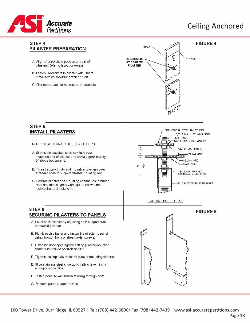
STEP 4 FIGURE 4PILASTER PREPARATION
FRONTU-BRACKETSAT REAR OFPILASTER
A. Align U-brackets in position on rear ofpilasters.Refer to layout drawings.
B. Fasten U-brackets to pilaster with sheetmetal screws pre-drilling with 1/8" bit.
C. Pilasters at wall do not require U-brackets.
STEPSSTRUCTURAL STEEL BY OTHERS
3/8 ” DIA. x 6" LONG STUD%/y— 3/8 " NUT
13/16” DIA. LOCK WASHER
INSTALL PILASTERS
NOTE: STRUCTURAL STEEL BY OTHERSI 13/16" DIA. WASHER1"
A. Slide stainless steel shoe carefully overmounting end of pilaster and leave approximately5" above bottom end.
I'/ // // //^/ // A
CEILING GRIDY/ // // // //^/ .
CEILING GRIDSHOE CLIP2"-2j"
B. Thread support nuts and mounting washers overthreaded rods to support pilaster mounting bar. SATIN FINISHED
STAINLESS STEEL SHOE
C. Position pilaster and mounting channel on threadedrods and attach lightly with square flat washer,lockwasher and locking nut.
11 GAUGE STIRRUP BRACKET
CEILING BOLT DETAIL
STEP 6 FIGURE 6SECURING PILASTERS TO PANELS
A. Level each pilaster by adjusting both support nutsto desired position.
B. Plumb each pilaster and fasten the pilaster to panelusing through bolts or sheet metal screws.
C. Establish door openings by setting pilaster mountingchannel to desired position on stud.
D. Tighten locking nuts on top of pilaster mounting channel.
E. Slide stainless steel shoe up to ceiling level, firmlyengaging shoe clips.
F. Fasten panel to wall brackets using through bolts.
G. Remove panel support device.
160 Tower Drive, Burr Ridge, IL 60527 | Tel: (708) 442-6800/ Fax (708) 442-7439 | www.asi-accuratepar ti ons.com

Page 19
Ceiling AnchoredGlobalPartitions
CEILING HUNG Panel Hardware Kit (P/N 40-8515020G) Includes:CHROME PLATED ZAMACPANEL TO PILASTER/WALL
TWO EAR ASSEMBLY Panel Hardware Kit (P/N 40-8265021G) Includes:STAINLESS STEEL
Fasten pilaster to panel using through boltswith barrel nuts or sheet metal screws.
PART ID. DESCRIPTION QTY
1 Two Ear Bracket (2)Pilasters must be both plumb and level,(do not fasten at this time) 2 "U" Bracket (2)
Establish bottom door openings by adjustingpilaster and tightening screws.(Refer to step 6) 3 Vandal Resistant 2 1/2" S.M.S (4)
4 Plastic Shields (4)
5 Vandal Resistant 5/8" S.M.S (12)
5"(APPROX.)
Nr
5"(APPROX.)
3 /
5
FIGURE AFIGURE A
/ <sw5/
5^5"(APPROX.) —I
12»
FIGURE BA.F.F.*s v*/
N o NOTE:Use Only TwoVandal resistant 5/8"SMSTo Diagonally Fasten U-bracket To Pilaster.
P5"( APPROX.) —I 12"
A.F.F.FIGURE B
160 Tower Drive, Burr Ridge, IL 60527 | Tel: (708) 442-6800/ Fax (708) 442-7439 | www.asi-accuratepar ti ons.com
Page 20
Ceiling AnchoredGlobalPartitions
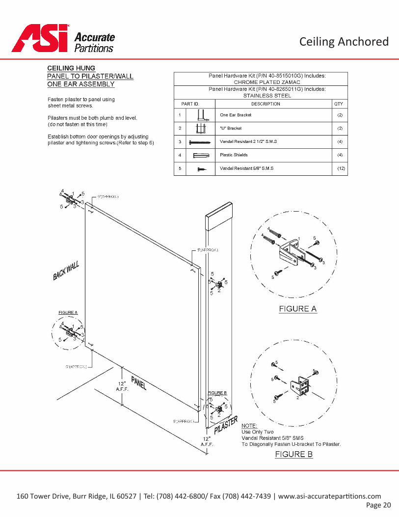
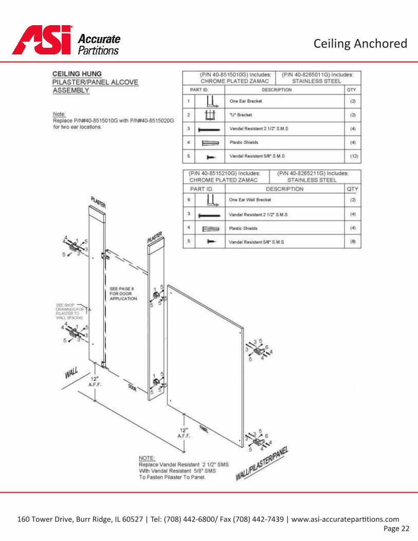
CEILING HUNGPANEL TO PILASTER/WALL Panel Hardware Kit (P/N 40-851501OG) Includes:
CHROME PLATED ZAMACONE EAR ASSEMBLYPanel Hardware Kit (P/N 40-8265011G) Includes:
STAINLESS STEELFasten pilaster to panel usingsheet metal screws. DESCRIPTION QTYPART ID.
1 One Ear Bracket (2)Pilasters must be both plumb and level,(do not fasten at this time)
2 "U" Bracket (2)
Establish bottom door openings by adjustingpilaster and tightening screws.(Refer to step 6) Vandal Resistant 2 1/2" S.M.S (4)3 #
Plastic Shields (4)4
Vandal Resistant 5/8" S.M.S (12)5
5"(APPROX.)
I— 5"(APPROX.)
5V
5V5
5 2
FIGURE AFIGURE A
V
5"(APPROX.) —
12A.F.F.
rIGURE B
S r PI\
5"( APPROX.)_lNOTE:Use Only TwoVandal Resistant 5/8" SMSTo Diagonally Fasten U-bracket To Pilaster.
12”A.F.F.
FIGURE B
160 Tower Drive, Burr Ridge, IL 60527 | Tel: (708) 442-6800/ Fax (708) 442-7439 | www.asi-accuratepar ti ons.com
Page 21
Ceiling AnchoredGlobalPartitions
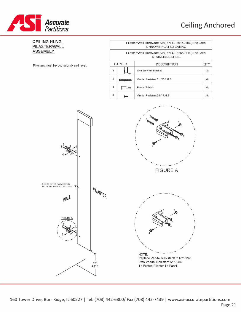
CEILING HUNG Pilaster/Wall Hardware Kit (P/N 40-851521OG) Includes:CHROME PLATED ZAMACPILASTER/WALL
ASSEMBLY PilasterAA/all Hardware Kit (P/N 40-8265211G) Includes:STAINLESS STEEL
PART ID. DESCRIPTION QTYPilasters must be both plumb and level.1 One Ear Wall Bracket (2)
2 Vandal Resistant 2 1/2" S.M.S (4)
3 Plastic Shields (4)
4 Vandal Resistant 5/8" S.M.S (8)8-fX
FIGURE A
SEE SHOP DRAWINGS FORPILASTER TO WALL SPACING1-
\/\
/\/
\/FIGURE A
/\ /\/
\ /X
NOTE:Replace Vandal Resistantt 2 1/2" SMSWith Vandal Resistant 5/8"SMSTo Fasten Pilaster To Panel.
12»
A.F.F.
160 Tower Drive, Burr Ridge, IL 60527 | Tel: (708) 442-6800/ Fax (708) 442-7439 | www.asi-accuratepar ti ons.com
Page 22
Ceiling AnchoredGlobalPartitions
160 Tower Drive, Burr Ridge, IL 60527 | Tel: (708) 442-6800/ Fax (708) 442-7439 | www.asi-accuratepar ti ons.com
Page 23
Floor Anchored and Ceiling AnchoredGlobalPartitions
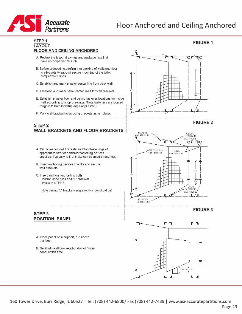
STEP 1 FIGURE 1LAYOUTFLOOR AND CEILING ANCHORED
A. Review the layout drawings and package lists thathave accompanied this job.
B. Before proceeding,confirm that backing of walls and flooris adequate to support secure mounting of the toiletcompartment units.
48"C. Establish and mark pilaster center line from back wall.
48"D. Establish and mark panel centerlines for wall brackets.
E. Establish pilaster floor and ceiling fastener locations from sidewall according to shop drawings. (Note fasteners are located
roughly 1" from lockstrip edge of pilaster.)17"
F. Mark wall bracket holes using brackets as templates.i
f- FIGURE 2i
STEP 2iWALL BRACKETS AND FLOOR BRACKETS PILASTER CEILING
ENTER LINE FASTENER
A. Drill holes for wall brackets and floor fastenings ofappropriate size for particular fastening devicessupplied. Typically 1/4" drill bits can be used throughout.
WALL PILASTER PANELCENTER LINE CENTER LINE
B. Insert anchoring devices in walls and securewall brackets.
C. Insert anchors and ceiling bolts.Position shoe clips and "L" brackets .Details in STEP 5.
48"
[ >(Note ceiling "L" brackets engraved for identification)
17"
PILASTERCENTER LINEi
I FIGURE 3STEP 3
i
POSITION PANELr i
A. Place panel on a support, 12" abovethe floor. a dfa
B. Set it into wall brackets,but do not fastenpanel at this time.
3 W
*12" SUPPORT
J L J
160 Tower Drive, Burr Ridge, IL 60527 | Tel: (708) 442-6800/ Fax (708) 442-7439 | www.asi-accuratepar ti ons.com

Page 24
Floor Anchored and Ceiling Anchored
NOTEStructural steel should be 2 1/2"inches MAX from the bottom ofthe finished ceiling.
GlobalPartitions
STEP 4 FIGURE 4REARPILASTER PREPARATION
FRONTU-BRACKETSAT REAR OF
PILASTERA. Align U-brackets in position on rear of
pilasters.Refer to layout drawings.
B. Fasten U-brackets to pilaster with sheetmetal screws.
C. Pilasters at wall do not require U-brackets,butshould be prepared for wall (floor & ceiling fastening)as required by compartment layout.
STEP 5 FIGURE 5INSTALL PILASTERS
#4 SATIN FINISHEDSTAINLESS STEEL SHOE6" x 3/8” DIA. STUD
J/-3/8” NUT13/16” LOCK WASHER
-— 3/8” FLAT WASHER
•3/8” FLAT WASHER' 3/8” NUT
SHOE CLIP-3/8” NUT
-13/16” LOCK WASHER3/8” FLAT WASHER
3/8" NUTSELF TAPPING SCREW
STRUCTURAL STEELBY OTHERS CADMIUM PLATED
JACK BOLT*MOUNTING FOOT2-1/2”L" BRACKETS\ FINISHED
CEILINGSELF TAPPINGSCREWw j -TOP ”L”
BRACKET Jih =SHOE CLIP
A. Slide stainless steel shoescarefully over mounting ends ofpilaster and leave approximately 5"space from end.
* • i *FLOPft : - • \> . •T. *<T * • r . ..
• ** ^z 4..4 . **«
#4 SATIN FINISHEDSTAINLESS STEEL SHOE * *A.'
FLOOR MOUNTING DETAILB. Place pilaster between "L"brackets adjust jack leveling boltand fasten loosely with screws atpredrilled locations at each side.
CEILING MOUNTING DETAIL
STEP 6 FIGURE 6SECURING PILASTERS TO PANELS
A. Plumb each pilaster by adjusting self tapping screws at top & bottom todesired position & tighten.
B. Fasten the pilaster to panel using sheet metal screws.
C. Establish door openings by setting pilaster to desired position. (Referto layout drawings)
D. Slide stainless steel shoe up to ceiling level & down to floor levelfirmly engaging shoe clips.
E. Fasten panel to wall brackets using sheet metal screws.
F. Remove panel support device.
160 Tower Drive, Burr Ridge, IL 60527 | Tel: (708) 442-6800/ Fax (708) 442-7439 | www.asi-accuratepar ti ons.com
Page 25
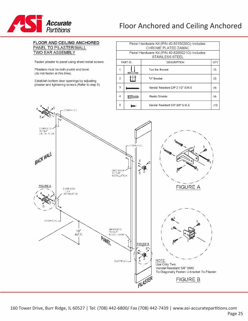
Floor Anchored and Ceiling AnchoredGlobalPartitions
FLOOR AND CEILING ANCHORED Panel Hardware Kit (P/N 40-8515020G) Includes:CHROME PLATED ZAMACPANEL TO PILASTER/WALL
TWO EAR ASSEMBLY Panel Hardware Kit (P/N 40-8265021G) Includes:STAINLESS STEEL
Fasten pilaster to panel using sheet metal screws. PART ID. DESCRIPTION OTY
LLPilasters must be both plumb and level,(do not fasten at this time)
1 Two Ear Bracket (2)
tJ2 "IT Bracket (2)Establish bottom door openings by adjustingpilaster and tightening screws.(Refer to step 6)
3 Vandal Resistant C/P 2 1/2" S.M.S (4)
4 Plastic Shields (4)
5 Vandal Resistant C/P 5/8" S.M.S (12)
5"(APPROX.)
DIMENSIONTO SUITINSTALLATION
5"(APPROX.)
'S 5 5V
VS 25 ZDIMENSION
TO SUITINSTALLATION
FIGURE A FIGURE ADIMENSIONTO SUITINSTALLATION
5"(APPROX.) —I
DIMENSIONTO SUITINSTALLATION
12»
A.F.F. \FIGURE B
V 5N/I \
^ 2\ NOTE:. 5 /5"(APPROX.) —IUse Only TwoVandal Resistant 5/8" SMSTo Diagonally Fasten U-bracket To Pilaster.
FIGURE B
160 Tower Drive, Burr Ridge, IL 60527 | Tel: (708) 442-6800/ Fax (708) 442-7439 | www.asi-accuratepar ti ons.com

Page 26
Floor Anchored and Ceiling AnchoredGlobalPartitions
FLOOR AND CEILING ANCHOREDPANEL TO PILASTER/WALL Panel Hardware Kit (P/N 40-851501OG) Includes:
CHROME PLATED ZAMACONE EAR ASSEMBLYPanel Hardware Kit (P/N 40-8265011G) Includes:
STAINLESS STEELFasten pilaster to panel using sheet metal screws.
PART ID. DESCRIPTION OTY
Pilasters must be both plumb and level,(do not fasten at this time)
1 One Ear Bracket (2)
2 "IT Bracket (2)Establish bottom door openings by adjustingpilaster and tightening screws.(Refer to step 6)
3 Vandal Resistant 2 1/2" S.M.S (4)
4 Plastic Shields (4)
5 Vandal Resistant 5/8" S.M.S (12)
5"(APPROX.)
=r iDIMENSIONTO SUITINSTALLATION
5"(APPROX.)
5 5
DIMENSIONTO SUITINSTALLATION
FIGURE AFIGURE A DIMENSIONTO SUITINSTALLATION
5"(APPROX.) —I
DIMENSIONTO SUITINSTALLATION
»12 \A.F.F.
FIGURE B
^5 s6s.•s/ V
S 25"(APPROX.) —I \
NOTE:5Use Only Two Vandal Resistant 5/8"To Diagonally Fasten U-bracket To Pilaster.
FIGURE B
160 Tower Drive, Burr Ridge, IL 60527 | Tel: (708) 442-6800/ Fax (708) 442-7439 | www.asi-accuratepar ti ons.com

Page 27
Floor Anchored and Ceiling AnchoredGlobalPartitions
FLOOR AND CEILING ANCHORED Pilaster/Wall Hardware Kit (P/N 40-8515210G) Includes:CHROME PLATED ZAMACPILASTER/WALL
Pilaster/Wall Hardware Kit (P/N 40-8265211G) Includes:STAINLESS STEEL
ASSEMBLY
PART ID. DESCRIPTION QTYFasten pilaster to panel using sheet metal screws.1 (2)One Ear Wall Bracket
Pilasters must be both plumb and level,
(do not fasten at this time) Vandal Resistant 2 1/2" S.M.S (4)2
Establish bottom door openings by adjustingpilaster and tightening screws.(Refer to step 6) Plastic Shields (4)3
Vandal Resistant 5/8" S.M.S (8)4
FIGURE ASEE SHOP DRAWINGS FORPILASTER TO WALL SPACING
FIGURE A
ALTERNATENOTE:Replace vandal Resistant 2 1/2" SMSWith Tamper Resistant 5/8" SMSTo Fasten Pilaster To Panel .
160 Tower Drive, Burr Ridge, IL 60527 | Tel: (708) 442-6800/ Fax (708) 442-7439 | www.asi-accuratepar ti ons.com

Page 28
Floor Anchored and Ceiling AnchoredGlobalPartitions
160 Tower Drive, Burr Ridge, IL 60527 | Tel: (708) 442-6800/ Fax (708) 442-7439 | www.asi-accuratepar ti ons.com

Page 29
Floor Anchored and Ceiling AnchoredGlobalPartitions
160 Tower Drive, Burr Ridge, IL 60527 | Tel: (708) 442-6800/ Fax (708) 442-7439 | www.asi-accuratepar ti ons.com

Full Height Bracket Kits
Page 30
OPTIONAL FULL HEIGHTPANEL TO PILASTER/WALLTWO EAR ASSEMBLY
GlobalPartitions
Panel Hardware KHt (P/N 8446020) Includes:ALUMINUM FULL HEIGHT
PART ID. DESCRIPTION QTY
1 5442750 Two Ear Bracket (1)
(D5449540 "IT Bracket2
3 3910600 Theft Resistant C/P Stop Bolt*1" Long (12)
3910690 Theft Resistant C/P Banal Nut4 (12)
3910450 Theft Resistant C/P #14 x21/2* S.M.S (12)5
6 3080000 Plastic Shields (12)
6^ 3914120 Theft Resistant C/P #14 x 5/8* S.M.S7 (12)
u6vv
AVAILABLE DM STADMLISSV 53 5
.OlO8> *T6 V <4
S_ 53 5
8>6v .<4
S 5 3
58 hole (location tosuit Installation6 V u 7v 45
5 3
7v 4
3
7v 43
160 Tower Drive, Burr Ridge, IL 60527 | Tel: (708) 442-6800/ Fax (708) 442-7439 | www.asi-accuratepar ti ons.com
Full Height Bracket Kits
Page 31
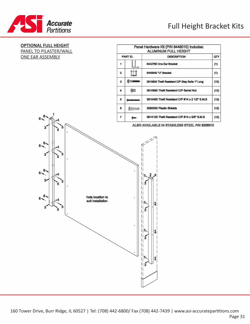
OPTIONAL FULL HEIGHTPANEL TO PILASTER/WALLONE EAR ASSEMBLY
GlobalPartitions
Panel Hardware Kit (P/N 8446010) Includes:ALUMINUM FULL HEIGHT
PART ID. DESCRIPTION QTY
1 5442780 One Ear Bracket (1)
ttt (D2 5449540 “IP Bracket
3910600 Theft Resists*C/P 8tep Bolts 1* Long3 (12)
& 3910690 Theft Resistant C/P Barrel Nut4 (12)
3910450 Theft Resistant C/P #14 x 21/2* S.M.S (12)5
3060000 Plastic Shields6 (12)
13914120 Theft ResistantC/P #14 x 5/8* S.M.S7 (12)
Mjm AVAILABLE m OTAONILE83 §TCEL m3 5
.OlO6v If8y ,-4.
53 5
6v6v •4 7,iV3** S_ 5 r5
hole location tosuit Installation
6 V ..-4x 7v •4
3 S. 55 3
7v -43
7v --43
160 Tower Drive, Burr Ridge, IL 60527 | Tel: (708) 442-6800/ Fax (708) 442-7439 | www.asi-accuratepar ti ons.com
Full Height Bracket Kits
Page 32
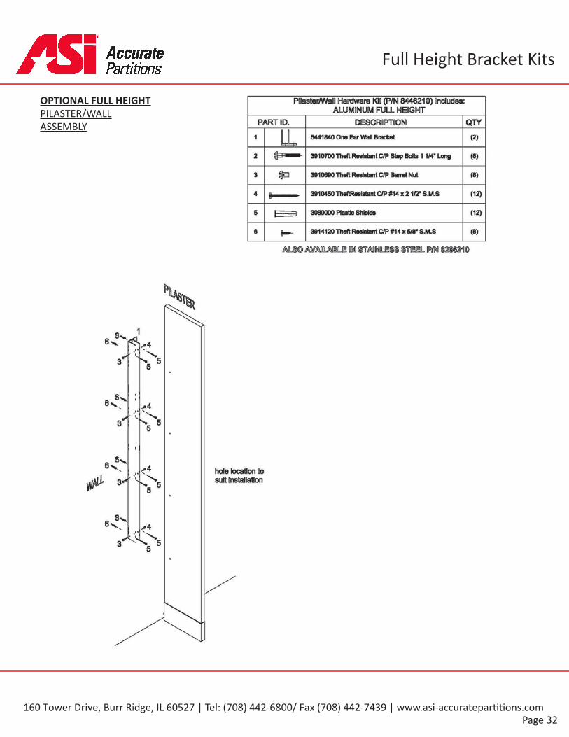
OPTIONAL FULL HEIGHTPILASTER/WALLASSEMBLY
GlobalPartitions
PHaster/WaH Hardware Kit (P/N 8446210) Dndydes:ALUMINUM FULL HEIGHT
PART ID. DESCRIPTION QTY1 5441840 One Ear Wall Bracket (2)
2 3910700 Theft Resistant C/P Step Bolts11/4" Long (B)
3 3910690 Theft C/P Barrel Nut (B)
3910450 TheftReelatarriC/P #14 x 21/2* S.M.S (12)4
3060000 Plastic Shields (12)5
6 3914120 Theft Reelstirrt C/P #14 x 5/8* S.M.S (B)
Mm AVAHLABILE DM STADNILESS STEELm
sM
3 5
6v6v .-4
"V 63 5
6V6 >v .«4x hole location to
suit Installation3" % 55
e«v6v .*4x.
3 *055
160 Tower Drive, Burr Ridge, IL 60527 | Tel: (708) 442-6800/ Fax (708) 442-7439 | www.asi-accuratepar ti ons.com
Full Height Bracket Kits
Page 33
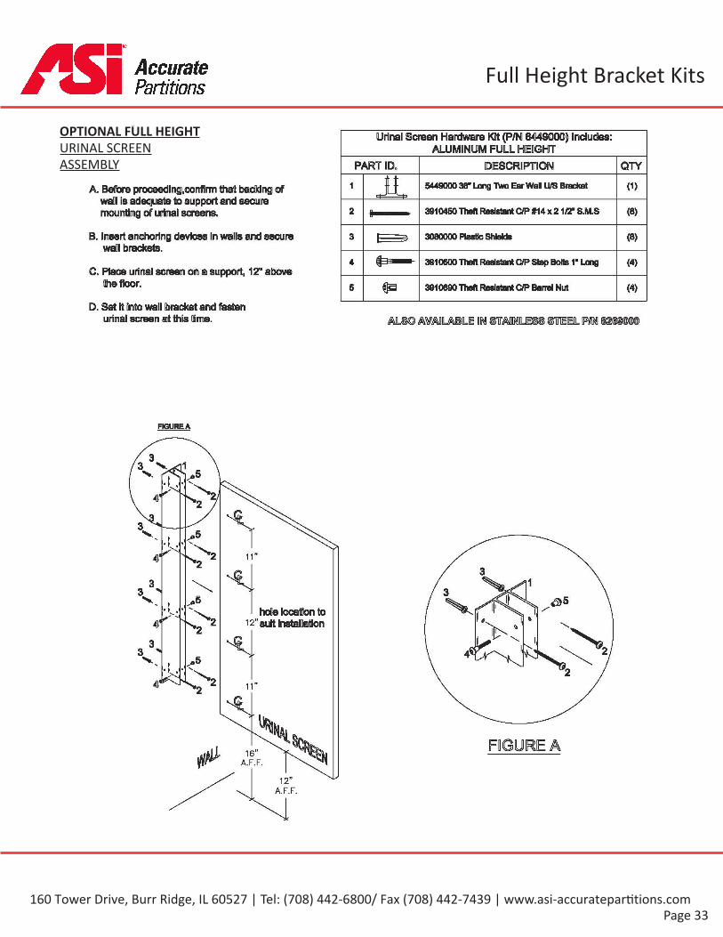
OPTIONAL FULL HEIGHTURINAL SCREENASSEMBLY
GlobalPartitions
Urinal Screen Hardware KBt (P/N 8449000) Includes:ALUMINUM FULL HEDGHT
PART ID. DESCRIPTION QTY
1 5449000 36* Long Two Ear Wall U/S Bracket (1)A.Before proceedln^conflnm than backing ofwaDI is adequate to support and securemounting of urinal screens. 2 3910450 Theft Resistant C/P #14 x2 1/2” S.M.S (8)
B. Insert anchoring devices In walls and securewafll brackets. 3 3080000 Plastic Shields (8)
4 3910600 Theft Resistant C/PStep Botts 1” Long (4)C.Place uiirttafl screen on a support, 12" above
the floor. 5 3910690 Theft Resistant C/PBarrel Nut (4)
D.Set St Onto wall bracket and fastenurinal screen at this time. mmA¥ADLAHLE M STOIMLESS STEEL WN«SM
FIGURE A
33V
4'
3V
4'
33 ^V
hoOe Docatfonto12"suit Installation4'
33 >V
FIGURE A
A.F.F.
160 Tower Drive, Burr Ridge, IL 60527 | Tel: (708) 442-6800/ Fax (708) 442-7439 | www.asi-accuratepar ti ons.com

CARE AND MAINTENANCE OFTOILET PARTITIONS
In order to provide toilet par ons with thecare and maintenance, the following instruc ons
must be followed.
A. All surfaces must be kept clean with water andmild soap solu on only.
B. In high humidity areas, the rooms must beproperly ven lated.
C. “Hosing down” or wet washing of these units maycause water absorp on and damage
D. For maximum protec on, periodic applicaton ofany standard furniture wax will be benefi cial.
E. In order to provide toilet par ons with theproper care and maintenance, the above instruc ons
must be followed.
WARNING
Under no circumstances should the components be subjected to:
* Abrasive powders or pads*Water closet cleaners*Ceramic le cleaners
*Solu ons containing more than 1% by volume ofammonia
*Solu ons containing acids or lye*Solu ons containing enzymes
A en on to work progress during new construc on or renova on is important.
Other trades and cleaning services may use agents for ceramics and les that will damage these
components.
Product Informa on
Page 34
GlobalPartitions
160 Tower Drive, Burr Ridge, IL 60527 | Tel: (708) 442-6800/ Fax (708) 442-7439 | www.asi-accuratepar ti ons.com