Embed Size (px)
Citation preview
Global Beautification of Layoutswith Interactive Ambiguity Resolution
Pengfei Xu1 Hongbo Fu2 Takeo Igarashi3 Chiew-Lan Tai11HKUST 2City University of Hong Kong 3The University of Tokyo
ABSTRACTAutomatic global beautification methods have been proposedfor sketch-based interfaces, but they can lead to undesired re-sults due to ambiguity in the user’s input. To facilitate ambi-guity resolution in layout beautification, we present a noveluser interface for visualizing and editing inferred relation-ships. First, our interface provides a preview of the beautifiedlayout with inferred constraints, without directly modifyingthe input layout. In this way, the user can easily keep refiningbeautification results by interactively repositioning and/or re-sizing elements in the input layout. Second, we present a ges-tural interface for editing automatically inferred constraintsby directly interacting with the visualized constraints via sim-ple gestures. Our efficient implementation of the beautifi-cation system provides the user instant feedback. Our userstudies validate that our tool is capable of creating, editingand refining layouts of graphic elements and is significantlyfaster than the standard snap-dragging and command-basedalignment tools.
Author KeywordsGlobal beautification; layout editing; snapping; alignment;ambiguity resolution; gestural interface
ACM Classification KeywordsH.5.2 Information Interfaces and Presentation (e.g. HCI):User Interfaces – Graphical user interfaces (GUI)
INTRODUCTIONSpecifying precise relationships, such as alignment andequal-spacing between graphic elements, might be one of themost fundamental operations when creating or editing dia-grams and other graphical documents. This is commonlyachieved in commercial software packages, like Adobe Illus-trator and Microsoft PowerPoint, by using command-basedarrangement tools (e.g., issuing a command to equally spacethe selected elements horizontally) and/or direct positioningaided by snapping.
Snapping might be the simplest beautification technique. Itfirst infers spatial relationships between an element being ma-nipulated and each of the existing elements, and then pro-vides snapping suggestions to interactively achieve desired
Permission to make digital or hard copies of all or part of this work for personal orclassroom use is granted without fee provided that copies are not made or distributedfor profit or commercial advantage and that copies bear this notice and the full cita-tion on the first page. Copyrights for components of this work owned by others thanACM must be honored. Abstracting with credit is permitted. To copy otherwise, or re-publish, to post on servers or to redistribute to lists, requires prior specific permissionand/or a fee. Request permissions from [email protected] 2014, October 5–8, 2014, Honolulu, HI, USA.Copyright c© 2014 ACM 978-1-4503-3069-5/14/10 ...$15.00.http://dx.doi.org/10.1145/2642918.2647398
Input window Preview window
Figure 1. Our novel interface for global beautification of layouts ofgraphic elements with the power of interactive ambiguity resolution.Grids are visualized for reference purpose only but not for editing.
relationships [5]. We classify snapping as a local beautifica-tion technique, since each time only a current element is beingbeautified while all existing elements are kept fixed, leadingto an element-by-element beautification process. Due to its lo-cal nature, snapping itself is not very effective for designingconstrained global patterns (e.g., equal-spacing patterns withthe ending elements aligned, as shown in Figure 1). There-fore, snapping-based alignment tools are often used togetherwith command-based tools. As we will discuss shortly, suchtraditional tools are rather tedious and require a carefully or-dered set of manual operations to achieve a desired layout.
On the other hand, humans are able to unambiguously tellthe desired layouts of graphic elements by viewing all ele-ments as a whole. This motivates us to design a tool forglobal beautification of layouts of graphic elements, i.e., tofirst infer perceptually meaningful relationships among a setof roughly placed graphic elements and then refine their posi-tions and sizes to get a well-aligned layout that involves onlysmall changes to the input layout. While similar conceptsof global beautification have been proposed for sketch-baseduser interfaces, the existing methods (e.g., [12, 22]) simplyapply global beautification results directly to elements beingedited, as often done for local beautification interfaces. Earlybeautification of elements being edited would prevent the userfrom placing them freely to form a global pattern, thus dis-turbing the process of layout design.
We present a novel user interface for addressing a commonlyknown ambiguity problem in global layout beautification. Asshown in Figure 1, our interface shows a preview of the beau-tification, without immediately modifying any input element.In our prototype, this preview is displayed in a separated win-dow. While this interface is simple, it has the following ben-efits. First, the user can focus on the layout design by manip-ulating individual elements in the input window. Second, theuser might refine the beautification results by slightly mod-ifying the input elements. To facilitate a more direct con-
(d)
(b)
(a)
(c)
Input Preview
Figure 2. To refine a beautified layout, as previewed in the right column,the user may directly reposition (a-1) or resize (a-2) individual elements,or remove inferred (b-1) or add new (b-2) edge-alignment relationships,or remove inferred (c-1) or add new (c-2 and c-3) equal-spacing relation-ships.
trol of the beautification results, we also present a gesturalinterface, which allows easy editing of automatically inferredconstraints, i.e., desired relationships between elements in theinput window. See Figure 2 and the accompanying video forlive demos.
We present an efficient and effective implementation of theproposed global layout beautification interface. Our tool al-lows interactive refinement of graphic elements and/or con-straints, with instant beautification feedback. We conducttwo studies to verify the effectiveness of our interface. Firstwe run a study to evaluate the effectiveness of beautifica-tion preview. Second, we run a study to evaluate whetherour tool could replace the standard snapping and alignmentcommands, omitting other layout helper features (e.g., equal-sizing, auto-align) which can peacefully coexist with our tool.Our results are promising and show that our tool providesa faster way for creating, editing, and refining the test lay-outs. The intuitiveness and ease-of-use of our interface arealso confirmed by the user study participants.
RELATED WORKIt is hard to track down the history of shape alignment tools.Command-based alignment tools might be one of the mostcommon ways to align objects [24]. They adopt a two-step
procedure: first select a group of objects to be aligned andthen issue a certain arrangement command (e.g., left-alignor equally space the selected objects). Snapping is anotherwidely used technique [4, 5]. It provides aligned positionsby snapping an object to either the background grids, manu-ally created guides, or other objects [11]. Snapping supportsdirect manipulation and is thus more intuitive to use, whilecommand-based tools are more effective in aligning multi-ple objects simultaneously and have a better control of globalalignment. Given their unique advantages, these traditionaltools collectively are capable of creating very complex well-aligned layouts of graphic elements. However, even a simplearrangement task as shown in Figure 1 already demands a se-ries of operations with the traditional alignment tools. Therepeated use of operations like snapping, element selection,and command selection, is tedious and error-prone, especiallyfor complex layouts. In addition, since different ordering ofsuch operations might lead to different results, a user has toplan a series of operations beforehand and pay special atten-tion to their order during editing. This somewhat diverts theuser from the tasks of layout design and creation.
Beyond the basic snapping and alignment commands, thereexist many layout helper features, some of which have al-ready been integrated into commercial editors. For exam-ple, many algorithms have been proposed for automatic orsemi-automatic graph layout generation [25, 26, 29], e.g., theauto-align and auto-space tools in Microsoft Visio. How-ever, they often significantly change the layout of the inputelements, without attempting to infer and maintain the under-lying patterns in the input layout. The equal-sizing feature inMicrosoft Visio allows easy size-adjustment of selected ele-ments. Several editors such as OmniGraffle and PowerPointsupport easy creation of equally spaced elements when dupli-cating an element multiple times. These helper features arevery efficient for only specific tasks and are orthogonal to ourtool.
Our work is inspired by the previous efforts on beautifica-tion, which also aims to bring as little change as possiblewhen improving content aesthetics. There are plenty of beau-tification techniques mainly developed for sketch-based userinterfaces to tolerate errors from freehand input sketches.These existing techniques can be largely categorized into twogroups [23]: local beautification and global beautification.Similar to snap-dragging [5], local beautification of freehandsketches beautifies a current input stroke based on either itself(often through sketch recognition [1, 2, 14, 21]) or its geo-metric relationship(s) to the existing elements (e.g., [18, 33,34]). A typical user interface for local beautification achievesbeautification progressively, stroke by stroke. Each stroke isreplaced with its beautified version and kept fixed during thebeautification of subsequent strokes. Due to the local nature,such interfaces are often easy to control. However, unfortu-nately, local beautification is not suitable for the beautifica-tion of layouts, which should be treated globally.
Compared to local beautification, global beautification hasbeen insufficiently explored. Pavlidis and Van Wyk [22]present the first automatic beautifier for drawings and illus-

trations. Their algorithm focuses on inferring and enforcingrelations among points and lines, and thus can be extendedfor our layout beautification problem by considering specialrequirements like how to preserve aspect ratios of elements.However, they do not give details about the user interface oftheir system. Bolz [6] presents for the first time a user in-terface for global beautification of drawings. It concentrateson how to deal with parameter settings (e.g., via a parame-ter menu). Due to possibly frequent parameter changes, thebeautifier by default is manually activated each time, thoughit is discussed that automatic activation of the beautifier (likeours) is a desired feature. Bolz’s system overlays the beauti-fied drawing with an outline of the unmodified version forsome seconds. A similar visualization of the original andbeautified versions is adopted in [12], which however delib-erately defers the beautifier’s feedback. Otherwise, the usermay easily get disturbed by beautification results. In contrast,our user interface allows instant feedback with minimal dis-turbance. Cheema et al. [7] present a novel sketch beautifica-tion algorithm but adopt a simple interface similar to Bolz’s.None of the above methods has explored an interface for edit-ing constraints.
Our optimization strategy for determining valid constraintsbears some resemblance to the previous solutions for identi-fying geometric features towards sketch recognition. For ex-ample, Veselova and Davis [30] employ studies of human per-ception to determine which geometric features are the mostimportant for symbol recognition. Hammond and Davis [15]present a graphical debugging tool for learning structural de-scriptions from automatically generated near-miss examples.Similar to earlier work [18, 22], we adopt an automatic, iter-ative approach to avoid dramatic changes to the input layout.
It is not always possible to infer desired relationships amongroughly placed elements, especially when there are ambi-guities. A possible solution for ambiguity resolution is toprovide multiple alternatives as suggestions from which theuser can then choose [17, 18, 20]. The effectiveness of suchsuggestion-based interfaces has been demonstrated for pro-gressive beautification [18, 20]. It is unclear whether sugges-tions can be used to effectively resolve the ambiguity fromglobal beautification, since a handful of ambiguous relation-ships may easily lead to a large set of suggestions. Insteadof attempting to select the best suggestions from a big pool,we design a gestural interface for directly editing a limitednumber of constraints.
Constraint-based systems have been extensively studied anda detailed review is beyond the scope of this paper. Mostconstraint-based systems require the user to specify con-straints explicitly (e.g., [9, 13, 28]). Instead, our beautifi-cation interface focuses on automatic inference of geomet-ric constraints, and thus only very few edits on constraints(after roughly placing elements) are needed to achieve a de-sired layout. Note that our current system performs once-off alignment only and does not maintain inferred constraintsduring subsequent editing [31]. Recently Zeidler et al. [32]introduce a novel layout preview but focus on the resizing be-havior of a constraint-based layout during the design phase.
Since constraint-based systems often need to deal with vari-ous linear and nonlinear constraints, possibly with complexinteractions among them, significant effort has been devotedto the topic of constraint solving (e.g., [3, 16, 19, 27]). Suchsolvers can be potentially used for our beautification opti-mization problem.
USER INTERFACEIn this section we first describe our main interface for globalbeautification and then present our gestural interface for edit-ing constraints. To make it simple, we first assume that thebeautifier is already activated and applied to all input ele-ments, and will discuss how our beautifier can coexist withother tools at the end of this section.
Global Beautifier InterfaceOur global beautifier takes a set of roughly placed elements asinput and returns a well-aligned layout as output. Since thedesired relationships might not be immediately clear duringediting, even to a human viewer, we design a user interfacethat does not directly change the location and size of elementsin the input layout, but rather gives a preview of the refinedlayout in another window (Figure 1). In this way the usercan focus on layout design itself by placing elements roughly,without being disturbed by the beautifier’s feedback.
Since the input layout is not immediately replaced with thebeautified version, the user may keep editing the current lay-out by translating or resizing individual elements, and ourbeautifier gives instant feedback in the preview window. Thissimple interface is suitable for creating, editing or refininglayouts. At any point the user may confirm to apply the beau-tified layout to the input one.
Gestural Interface for Editing ConstraintsAutomatically inferring underlying relationships among ele-ments plays a vital role in layout beautification. Since rela-tionships are formulated as constraints in the beautificationoptimization, we will use the terms relationships and con-straints interchangeably in the following discussion.
Automatically inferred relationships might not always bewholly desirable. This problem might be indirectly solvedby interactive refinement of certain elements’ position and/orsize. Alternatively the user may directly add or remove rela-tionships using a gestural interface as shown in Figure 2 (b)and (c). Our implemented beautifier currently supports twotypes of geometric relationships: edge alignment and equal-spacing.
At any time the user may edit constraints in the input window,where he or she may edit elements for interactive refinement.To facilitate the editing of constraints, we display all automat-ically inferred relationships using dashed lines and arrows inboth the input and preview windows (Figure 1). The visual-ized constraints in the input window are editable via the ges-tural interface while those in the preview window are read-only for examining the currently achieved relationships. Inreal-world applications, constraints may be displayed on de-mand to avoid visual clutter, since in many cases only veryfew constraint edits often suffice.

(a) (b) (c)Figure 3. Two examples of our gestural interface for adding alignmentconstraints. An appropriate constraint is automatically determined byexamining the relative location of two involved elements and the positionof the stroke’s ending points relative to the elements.
The user enters the mode for editing edge alignment con-straints by clicking an “alignment constraint editing” button,which might be replaced with a gesture in the future imple-mentation. In this mode, repositioning and resizing of indi-vidual elements are disabled. To remove an existing align-ment constraint, the user performs a cutting gesture on aconstraint of interest (Figure 2 (b-1)), i.e., drawing a strokeroughly perpendicular to the dashed line corresponding to theconstraint. To add a new alignment constraint, the user simplydraws a stroke connecting a pair of elements of interest (Fig-ure 2 (b-2)). Our interface automatically determines whethera horizontal or vertical alignment constraint is needed by ex-amining the relative location of the two elements. For ex-ample, the stroke in Figure 3 (a) is interpreted as an inten-tion for vertical alignment while the stroke in Figure 3 (b) isfor horizontal alignment. For horizontal alignment, the usermay indicate the preference for top-, middle- or bottom-alignby placing the ending points of the stroke into the respectiveparts of the elements. For this reason, the stroke in Figure 3(b) is recognized for achieving middle alignment. A similarcontrol exists for vertical alignment (see an example in Fig-ure 3 (a)). To make the interface more user-friendly, we mayput three control handles (e.g., small translucent circles) oneach side of an element, indicating that the user can drag fromone handle to another in order to set alignments. The modefor editing alignment constraints is deactivated when the userswitches to other editing modes.
For simplicity, the activation and deactivation of our gestu-ral tool for editing equal-spacing constraints are achieved viamode-switching buttons. To remove an equal-spacing con-straint the user performs a cutting gesture (Figure 2 (c-1)). Toadd a new equal-spacing constraint, the user invokes multi-ple (at least two) strokes, with each of them connecting a pairof elements (Figure 2 (c-2 and c-3)). Constraints for equal-spacing between the specified pairs of elements will then beadded. Horizontal or vertical equal-spacing is automaticallydetermined by looking into the relative position of pairs ofelements.
Not all automatically inferred constraints can be enforced atthe same time. Our interface only visualizes the constraintsthat can coexist. However, the user may introduce constraintsthat conflict with the existing ones. To capture the user’s lat-est intention, any constraint that is in conflict with the newlyadded constraint will be removed. Thus in some cases theuser may see one or more existing constraints removed due tothe new constraints.
IMPLEMENTATIONNow we describe how we implement the proposed beautifierinterface. Our implementation essentially follows the gen-eral beautification framework proposed by Pavlidis and VanWyk [22]. We describe our implementation details for com-pleteness.
Pattern DetectionWe focus only on axis-aligned edge alignment and equal-spacing relationships, since they already enable all the func-tions of snapping and alignment commands. For illustra-tion, we always use rectangles to represent graphic elements,since element alignment is often achieved at the bounding boxlevel.
Inferring edge-alignment relationships. We will explainonly the implementation for horizontal alignment. Detectingrelationships for vertical alignment is done similarly. Fol-lowing the snapping tools in existing editors like MicrosoftVisio, we allow horizontal edge-alignment to happen only atthe top edge denoted as st, bottom edge sb and middle edgesm (i.e., a horizontal segment passing through the center) ofthe bounding box of an element. Given a group of n graphicelements (Figure 4 (a)), we thus have 3n edges (Figure 4 (b)),from which our beautifier will infer desired alignment rela-tionships (Figure 4 (d)), i.e., detect a set of horizontal linesalong which the relevant elements get aligned (Figure 4 (c)).This is essentially a 1D clustering problem. Although thereexist many general techniques for such clustering problems,most of them require indicating the scale of the cluster by pa-rameters, which in most techniques are global. However, thealignment lines in a given layout may have different qualities.Some of them would be invalid if all alignment lines are de-tected under the same configuration. Therefore, the clusteringalgorithm should be adaptive to each alignment line.
Our solution is a variant of the classic RANSAC algo-rithm [10]. Since the number of edges is usually not big(from dozens to hundreds), it is possible to find globally op-timal lines without randomness. Specifically, for every edge,we use the following iterative procedure to find a candidatealignment line: 1) the current edge as an initial inlier givesan initial fitted line. 2) All other edges are tested against thefitted line to find an updated set of inliers. 3) Refit the lineto the updated set of inliers. Steps 2 and 3 are repeated tillconvergence. Each edge as the initial inlier gives a candidatealignment line, and we pick the best line as the determinatealignment line. The inliers (edges) of the picked line are thenremoved from the current set of edges (initially, 3n edges)and we repeat the above iterative procedure to find the nextalignment line till no more lines can be found. See the ap-pendix for more details of Steps 2 and 3.
Once we find a candidate alignment line for each edge, weselect the best alignment line Pa. Generally we prefer analignment line with a larger group of inliers and a lower vari-ance of the vertical coordinate among the inliers. All the inlieredges corresponding to the selected alignment line have edge-alignment relationships between each other (Figure 4 (d)).

(a) (b)
(d)(c)
Figure 4. Illustration for inferring relationships (dashed lines) for hori-zontal alignment.
Inferring equal-spacing relationships. In our implemen-tation we allow the existence of equal-spacing relationshipsonly in a group of graphic elements that have edge-alignmentrelationships. We use an iterative bottom-up clustering ap-proach to detect equal-spacing relationships. The spacing isdefined as the distance between every pair of adjacent ele-ments. Initially, each spacing cluster consists of only onespacing. Each iteration groups two clusters with the small-est distance. The distance between two spacings d1 and d2 isdefined as |d1− d2|/(d1 + d2). For two spacing clusters, it isdefined as the difference of the average spacing between twoclusters. The clustering process continues until the distanceof the best pair of spacing groups is larger than a predefinedthreshold (we set as 0.15). Note that our gestural interfaceallows interactively adding equal-spacing constraints to non-adjacent pairs of elements (see an example in Figure 2 (c)).
Layout Refinement by OptimizationFollowing the previous beautification works [22], we use anoptimization-based approach to refine the layout to satisfy theinferred relationships while retaining as much as possible theoriginal layout, in terms of both the position and size of eachgraphic element.
Objective. Let st, sb, sm, sl, sr, sc denote the top, bottom,(horizontal) middle, left, right, (vertical) center edges of agraphic element. The objective of bringing the least changeto the original layout can be achieved by preserving the coor-dinates p(·) of the edges s∗ of each graphic element g ∈ G,where G is the set of input graphic elements. Specifically, forvertical edges, sl, sc and sr, p(·) are their horizontal coordi-nates, and for horizontal edges, st, sm and sb, p(·) are theirvertical coordinates. To retain the original layout we mini-mize the following objective function:
E =∑g∈G
∑∗(p′(sg∗)− p(sg∗))2, (1)
where p′(·) denotes the changed coordinates of the edges afterrefinement.
Constraints. The above minimization is subject to a set ofconstraints. We first identify the intrinsic constraints of eachgraphic element g, which are p′(sgl ) + p′(sgr) = 2p′(sgc) andp′(sgt ) + p′(sgb) = 2p′(sgm). If the aspect ratio ag needs tobe retained during the refinement (e.g., for images), an extraconstraint is added: p′(sgr) − p′(s
gl ) = ag(p′(sgt ) − p′(s
gb)).
(a) (b) (c)
Figure 5. Top: input layouts. Middle: results by simultaneously en-forcing all detected constraints, leading to degenerating cases in (b) and(c). Bottom: our results, by automatically rejecting the highlighted con-straints. Note that the constraint of keeping the aspect ratios of elementsis enforced in (b) and (c) but not (a).
These three constraints hold for every graphic element andmust be satisfied by the optimal solution.
The rest of the constraints are derived from the detected rela-tionships. Let Sa denote a set of inliers that will be aligned tothe same line Pa. If the edges si and sj have edge-alignmentrelationships between them, we have p′(si) = p′(sj). Eachpair of neighboring graphic elements in Pa gives rise to onesuch equality constraint, resulting in a total of |Sa| − 1 con-straints, where |Sa| is the cardinality of Sa. Let Ss be a set ofelement pairs with the equal-spacing relationship detected forevery element pair. Similarly, this introduces another |Ss|−1equality constraints.
Optimization. In general, only a subset of the constraints canbe enforced during the optimization. This is because simul-taneously enforcing some constraints may cause the refinedlayout to deviate too much from the original layout (Figure 5(a)). Worse, the layout may become degenerate in that thesizes of some graphic elements may become zero or negative(Figure 5 (b) and (c)).
Similar to [18, 22], we use an iterative approach to determinevalid constraints. Specifically, we iteratively check the valid-ity of each of our alignment and spacing equality constraintsby examining the optimized layout. After adding each con-straint to the system, we check the current optimal solutionand drop the constraint if the layout becomes degenerate orchanges too much. Since all the constraints are in the linearequality form, and the constraints are added incrementally,this strategy works efficiently. The alignment constraints areadded in the order in which the corresponding alignment linesare detected, i.e., the constraints are preserved in a higher pri-ority if the corresponding alignment line is detected earlier.Within the |Pa| − 1 edge-alignment constraints correspond-ing to a specific alignment line, we rank them by their align-ment error. This means that a constraint p′(si) = p′(sj) hasa higher priority if ||p(si) − p(sj)|| is smaller. After consid-ering all the constraints of an edge-alignment pattern, we addthe detected equal-spacing relationships from this alignmentpattern. All constraints of an equal-spacing pattern are simul-taneously added, and they are all rejected if the new layoutbecomes degenerate or deviates too much from the originallayout, since equal-spacing often exists as a global pattern.We use the CHOLMOD sparse linear system solver [8] to in-
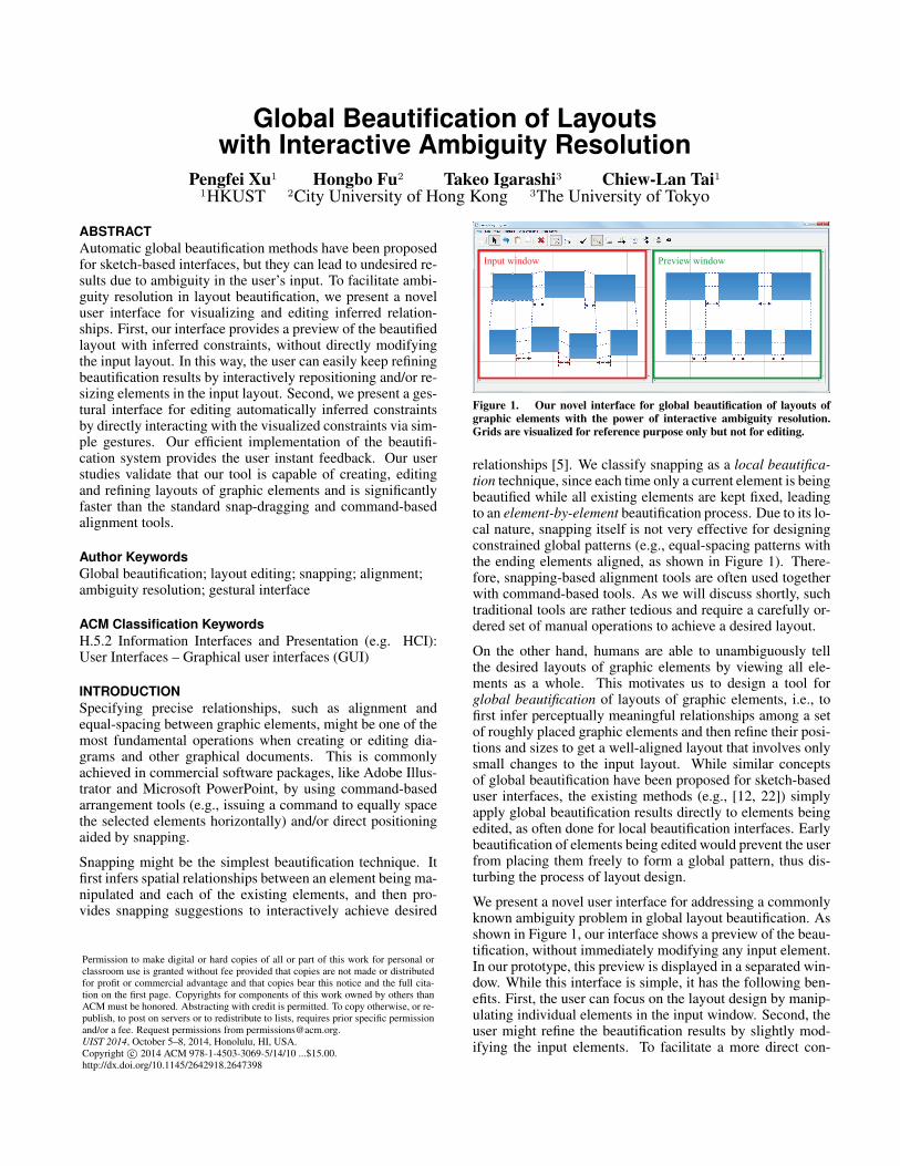
Task 1
Task 20
2
4
6
8
10
12
14
AVG 1 2
Number of constraint edits
0
10
20
30
40
50
60
70
80
AVG 1 2
Number of general operations
0
50
100
150
200
250
AVG 1 2
Completion time
With preview
Without preview
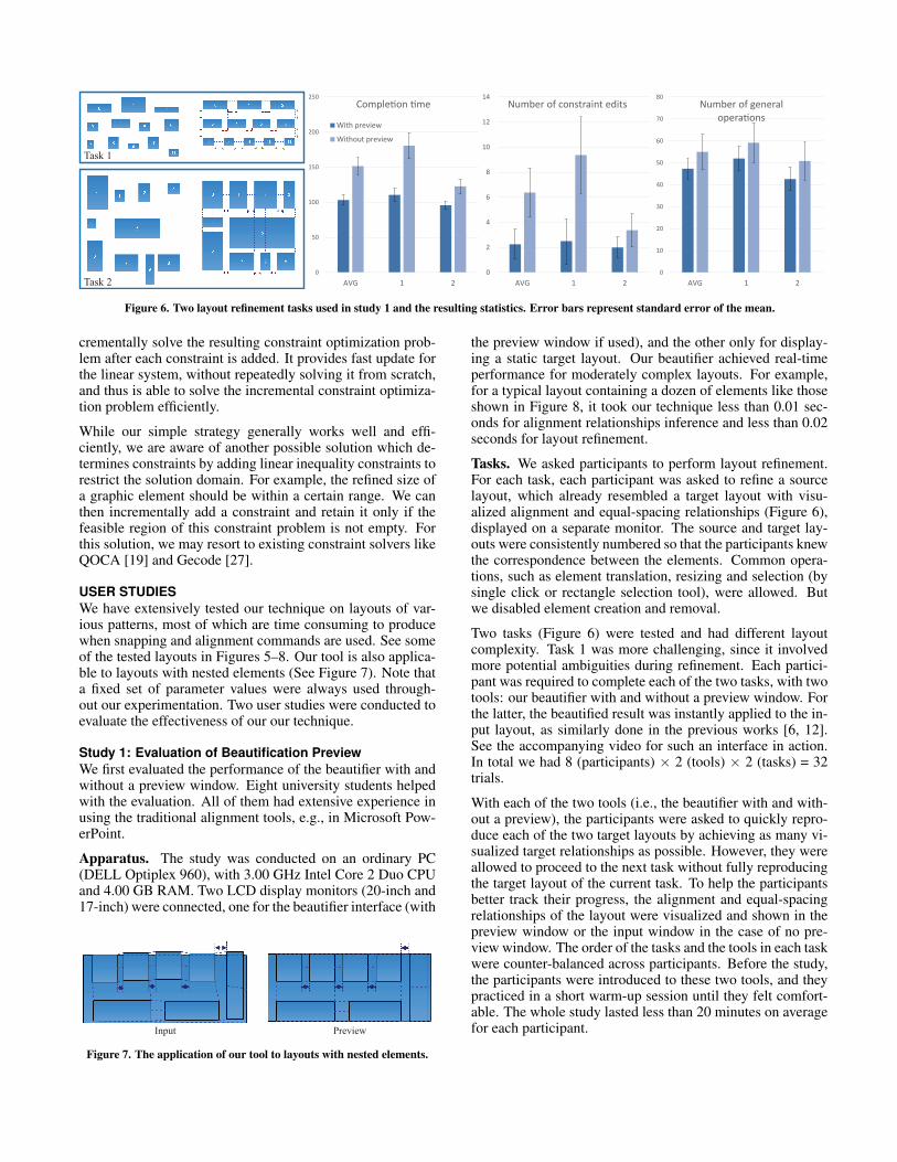
Figure 6. Two layout refinement tasks used in study 1 and the resulting statistics. Error bars represent standard error of the mean.
crementally solve the resulting constraint optimization prob-lem after each constraint is added. It provides fast update forthe linear system, without repeatedly solving it from scratch,and thus is able to solve the incremental constraint optimiza-tion problem efficiently.
While our simple strategy generally works well and effi-ciently, we are aware of another possible solution which de-termines constraints by adding linear inequality constraints torestrict the solution domain. For example, the refined size ofa graphic element should be within a certain range. We canthen incrementally add a constraint and retain it only if thefeasible region of this constraint problem is not empty. Forthis solution, we may resort to existing constraint solvers likeQOCA [19] and Gecode [27].
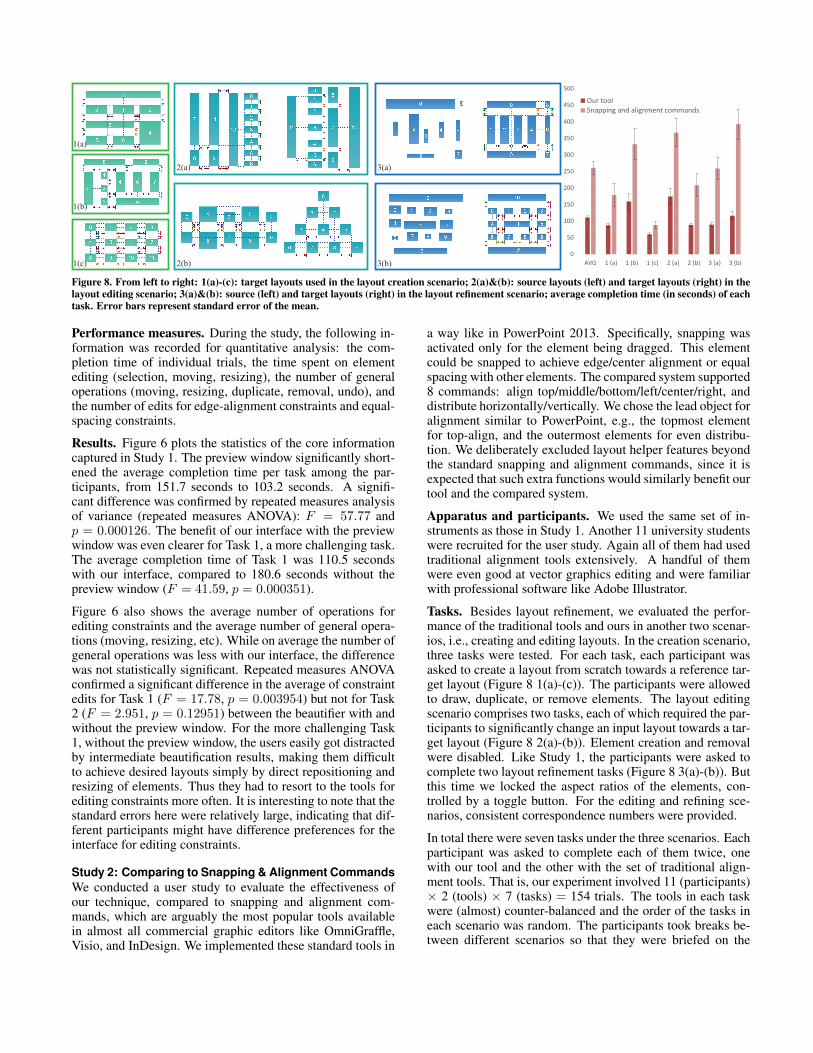
USER STUDIESWe have extensively tested our technique on layouts of var-ious patterns, most of which are time consuming to producewhen snapping and alignment commands are used. See someof the tested layouts in Figures 5–8. Our tool is also applica-ble to layouts with nested elements (See Figure 7). Note thata fixed set of parameter values were always used through-out our experimentation. Two user studies were conducted toevaluate the effectiveness of our our technique.
Study 1: Evaluation of Beautification PreviewWe first evaluated the performance of the beautifier with andwithout a preview window. Eight university students helpedwith the evaluation. All of them had extensive experience inusing the traditional alignment tools, e.g., in Microsoft Pow-erPoint.
Apparatus. The study was conducted on an ordinary PC(DELL Optiplex 960), with 3.00 GHz Intel Core 2 Duo CPUand 4.00 GB RAM. Two LCD display monitors (20-inch and17-inch) were connected, one for the beautifier interface (with
Input Preview
Figure 7. The application of our tool to layouts with nested elements.
the preview window if used), and the other only for display-ing a static target layout. Our beautifier achieved real-timeperformance for moderately complex layouts. For example,for a typical layout containing a dozen of elements like thoseshown in Figure 8, it took our technique less than 0.01 sec-onds for alignment relationships inference and less than 0.02seconds for layout refinement.
Tasks. We asked participants to perform layout refinement.For each task, each participant was asked to refine a sourcelayout, which already resembled a target layout with visu-alized alignment and equal-spacing relationships (Figure 6),displayed on a separate monitor. The source and target lay-outs were consistently numbered so that the participants knewthe correspondence between the elements. Common opera-tions, such as element translation, resizing and selection (bysingle click or rectangle selection tool), were allowed. Butwe disabled element creation and removal.
Two tasks (Figure 6) were tested and had different layoutcomplexity. Task 1 was more challenging, since it involvedmore potential ambiguities during refinement. Each partici-pant was required to complete each of the two tasks, with twotools: our beautifier with and without a preview window. Forthe latter, the beautified result was instantly applied to the in-put layout, as similarly done in the previous works [6, 12].See the accompanying video for such an interface in action.In total we had 8 (participants) × 2 (tools) × 2 (tasks) = 32trials.
With each of the two tools (i.e., the beautifier with and with-out a preview), the participants were asked to quickly repro-duce each of the two target layouts by achieving as many vi-sualized target relationships as possible. However, they wereallowed to proceed to the next task without fully reproducingthe target layout of the current task. To help the participantsbetter track their progress, the alignment and equal-spacingrelationships of the layout were visualized and shown in thepreview window or the input window in the case of no pre-view window. The order of the tasks and the tools in each taskwere counter-balanced across participants. Before the study,the participants were introduced to these two tools, and theypracticed in a short warm-up session until they felt comfort-able. The whole study lasted less than 20 minutes on averagefor each participant.
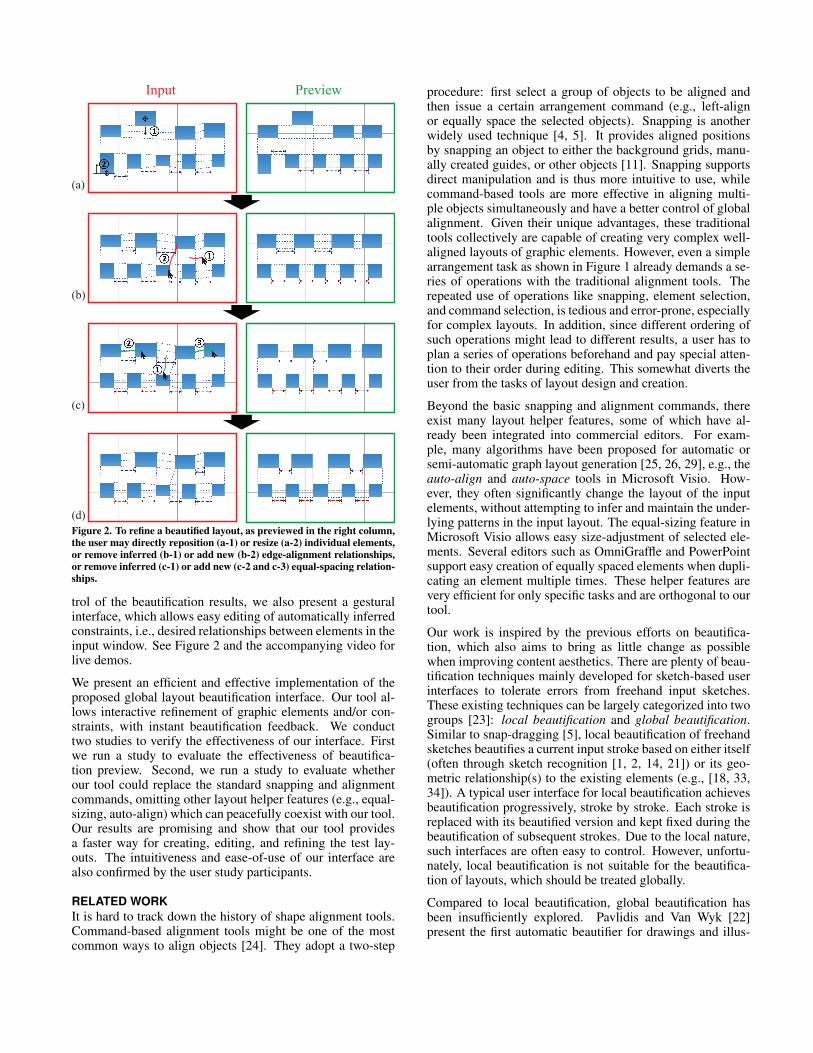
1(a)
1(b)
1(c)
2(a)
2(b)
3(a)
3(b)0
50
100
150
200
250
300
350
400
450
500
AVG 1 (a) 1 (b) 1 (c) 2 (a) 2 (b) 3 (a) 3 (b)
Our toolSnapping and alignment commands
Figure 8. From left to right: 1(a)-(c): target layouts used in the layout creation scenario; 2(a)&(b): source layouts (left) and target layouts (right) in thelayout editing scenario; 3(a)&(b): source (left) and target layouts (right) in the layout refinement scenario; average completion time (in seconds) of eachtask. Error bars represent standard error of the mean.
Performance measures. During the study, the following in-formation was recorded for quantitative analysis: the com-pletion time of individual trials, the time spent on elementediting (selection, moving, resizing), the number of generaloperations (moving, resizing, duplicate, removal, undo), andthe number of edits for edge-alignment constraints and equal-spacing constraints.
Results. Figure 6 plots the statistics of the core informationcaptured in Study 1. The preview window significantly short-ened the average completion time per task among the par-ticipants, from 151.7 seconds to 103.2 seconds. A signifi-cant difference was confirmed by repeated measures analysisof variance (repeated measures ANOVA): F = 57.77 andp = 0.000126. The benefit of our interface with the previewwindow was even clearer for Task 1, a more challenging task.The average completion time of Task 1 was 110.5 secondswith our interface, compared to 180.6 seconds without thepreview window (F = 41.59, p = 0.000351).
Figure 6 also shows the average number of operations forediting constraints and the average number of general opera-tions (moving, resizing, etc). While on average the number ofgeneral operations was less with our interface, the differencewas not statistically significant. Repeated measures ANOVAconfirmed a significant difference in the average of constraintedits for Task 1 (F = 17.78, p = 0.003954) but not for Task2 (F = 2.951, p = 0.12951) between the beautifier with andwithout the preview window. For the more challenging Task1, without the preview window, the users easily got distractedby intermediate beautification results, making them difficultto achieve desired layouts simply by direct repositioning andresizing of elements. Thus they had to resort to the tools forediting constraints more often. It is interesting to note that thestandard errors here were relatively large, indicating that dif-ferent participants might have difference preferences for theinterface for editing constraints.
Study 2: Comparing to Snapping & Alignment CommandsWe conducted a user study to evaluate the effectiveness ofour technique, compared to snapping and alignment com-mands, which are arguably the most popular tools availablein almost all commercial graphic editors like OmniGraffle,Visio, and InDesign. We implemented these standard tools in
a way like in PowerPoint 2013. Specifically, snapping wasactivated only for the element being dragged. This elementcould be snapped to achieve edge/center alignment or equalspacing with other elements. The compared system supported8 commands: align top/middle/bottom/left/center/right, anddistribute horizontally/vertically. We chose the lead object foralignment similar to PowerPoint, e.g., the topmost elementfor top-align, and the outermost elements for even distribu-tion. We deliberately excluded layout helper features beyondthe standard snapping and alignment commands, since it isexpected that such extra functions would similarly benefit ourtool and the compared system.
Apparatus and participants. We used the same set of in-struments as those in Study 1. Another 11 university studentswere recruited for the user study. Again all of them had usedtraditional alignment tools extensively. A handful of themwere even good at vector graphics editing and were familiarwith professional software like Adobe Illustrator.
Tasks. Besides layout refinement, we evaluated the perfor-mance of the traditional tools and ours in another two scenar-ios, i.e., creating and editing layouts. In the creation scenario,three tasks were tested. For each task, each participant wasasked to create a layout from scratch towards a reference tar-get layout (Figure 8 1(a)-(c)). The participants were allowedto draw, duplicate, or remove elements. The layout editingscenario comprises two tasks, each of which required the par-ticipants to significantly change an input layout towards a tar-get layout (Figure 8 2(a)-(b)). Element creation and removalwere disabled. Like Study 1, the participants were asked tocomplete two layout refinement tasks (Figure 8 3(a)-(b)). Butthis time we locked the aspect ratios of the elements, con-trolled by a toggle button. For the editing and refining sce-narios, consistent correspondence numbers were provided.
In total there were seven tasks under the three scenarios. Eachparticipant was asked to complete each of them twice, onewith our tool and the other with the set of traditional align-ment tools. That is, our experiment involved 11 (participants)× 2 (tools) × 7 (tasks) = 154 trials. The tools in each taskwere (almost) counter-balanced and the order of the tasks ineach scenario was random. The participants took breaks be-tween different scenarios so that they were briefed on the

newly enabled or disabled operations before each scenario.For simplicity no break was allowed between tasks in eachscenario.
Performance measures. Besides the measures used in Study1, the following information was also recorded: the timespent on drawing the elements (for the creation scenarioonly), and the number of specific operations with the tradi-tional tools (commands like edge alignment and equal spac-ing).
Results. Figure 8 shows the target layouts in each task, andthe corresponding average completion times. Repeated mea-sures ANOVA found a significant difference in the averagecompletion time per task among the participants between ourtool and the traditional tools (F = 78.8, p < 4 × 10⁻⁶).On average, significantly less time was needed to accomplisheach task using our tool (110.7 seconds) compared to the tra-ditional tools (260.7 seconds).
Our tool performed much better than the traditional tools fortarget layouts involving complex relationships such as Tasks1(b) and 2(a). For easier tasks, such as Tasks 1(a) and 1(c),our tool was still faster. For the tasks in the refinement sce-nario, due to the locked aspect ratios of the elements, the edit-ing freedom was seriously restricted, making such tasks morechallenging to complete for the traditional tools. The perfor-mance of the traditional tools was severely affected by thisrestriction on editing freedom. More than half of the partici-pants failed to reproduce the target layouts with the traditionaltools, while all of them had no difficulty with our tool.
In Figure 9 we show more statistics from the user study.There was no statistically significant difference in the draw-ing time between the two tools (p = 0.465), though we ob-served that our tool was still slightly faster. Our tool requiredsignificantly fewer general operations (p < 5 × 10⁻⁵). Thetask success rates also reflects the effectiveness of our tool.For almost all the tasks, each participant could successfullyreproduce the target layouts with our tool. In contrast, thecompletion rates for the traditional tools were much lower,despite they had been used by all the participants on a regularbasis. This confirms the ease of use of our tool, even for thefirst-time users.
Figure 9 also shows the average number of edits on edgealignment and equal-spacing constraints for individual tasks.While the number of edits was small, constraint editing wasperformed for 5 out of 7 tasks. We speculate that the numberof constraint edits needed is correlated with layout complex-ity, which is somewhat reflected by the (average) completiontime. For example, the number of constraint edits used forTask 1(b) was much bigger than that for Task 1(a) and Task1(c). A similar conclusion on the average completion time ofthese tasks could be reached.
It can be seen that the standard error of the mean (shown aserror bars in Figures 8 and 9) of the completion time, edit-ing time, and editing number is much larger with the tradi-tional tools. This means that the performance of our tool wasmore consistent across all participants. In other words our
0
20
40
60
80
100
120
140
160
180
AVG 1 (a) 1 (b) 1 (c) 2 (a) 2 (b) 3 (a) 3 (b)
Number of general operations
0
0.1
0.2
0.3
0.4
0.5
0.6
0.7
0.8
0.9
1
AVG 1 (a) 1 (b) 1 (c) 2 (a) 2 (b) 3 (a) 3 (b)
Success rates
0
1
2
3
4
5
6
1 (a) 1 (b) 1 (c) 2 (a) 2 (b) 3 (a) 3 (b)
Number of constraint edits
Edge alignment
Equal-spacing
0
20
40
60
80
100
120
140
160
180
AVG 1 (a) 1 (b) 1 (c) 2 (a) 2 (b) 3 (a) 3 (b)
Number of general operationsOur tool
Snapping and alignment commands
Figure 9. More statistics. The timings are in seconds. Error bars repre-sent standard error of the mean.
tool was less dependent on the experience of the individualparticipants.
Our statistics show that on average each participant per-formed 0.97 edge-alignment commands and 1.90 equal-spacing commands per task. This is mainly because equal-spacing commands were more indispensable, while edge-alignment commands could be replaced with more intuitivesnapping operations. This reiterates the fact that snappinghas to be used together with command-based alignment toolsin many cases.
We also got some interesting observations from the userstudy. With our tool, some participants tended to draw or editelements carefully at the beginning despite being told that ourtool can tolerate rough inputs. However, they quickly get usedto our tool and performed the creation and editing operationsmore casually. Another observation was that, in the refiningscenario, when using the traditional tools, some participantsmoved all the elements away before editing, though most ofthe input elements were already located very close to the tar-get positions. Such behavior was never observed with ourtool. This behavior was largely due to the not-aligned ele-ments triggering often excessive and distracting suggestionsfrom snap-dragging.
After completing the tasks, we asked each participant to pro-vide feedback on the two tools in terms of their ease of use.All participants except one preferred our tool. They expressedthat our tool enables them to disregard the order of specificoperations and focus on the layout design. One participantwho preferred the traditional tools liked the full user controland disliked rough inputs. This concern could be addressedby integrating snap-dragging into our framework.
DISCUSSIONSTo use our tool in existing graphic editors like PowerPoint,the user may first select a set of target elements and then entera “layout beautification mode”, for example, via an activationbutton, menu or gesture. Similar to the interface described

in our prototype, we may pop up a dialog to edit elementsand/or constraints while previewing the beautified layout inthe input panel. In the mode of element editing, our interfaceis completely compatible with existing layout helper features.All edits are confirmed after the user hits the “apply” button;otherwise they are canceled.
While the results of Study 1 imply the usefulness of having apreview of the refined layout in the experimental condition,rendering the original and refined layouts in separate win-dows might cause the problem of divided attention. To al-leviate this problem we might use a smaller preview windowinstead of a full-scale copy of the design. We believe that itis not necessary to always activate the preview window espe-cially when the input layout is undergoing dramatic changes,e.g., at the beginning of layout editing and creation tasks inStudy 2.
To further solve the problem of divided attention and to savespace required by an extra preview window, we could showthe preview in place. For example we might overlay the beau-tified layout as a translucent layer on top of the original lay-out. Since this solution easily results in visual clutter, it mightwork well for only relatively simple layouts with fewer ele-ments, but would likely not be able to scale to very complexdiagrams. In the future it is worth evaluating whether suchalternative solutions would be more effective than a simplepreview window in our current prototype.
Since our main goal in this work is to find a better alternativeto snapping and alignment commands, we focused only ona limited set of simple constraints, i.e., alignment and equalspacing. However, it is easy to incorporate new constraints,such as symmetry and length equality into our framework, asalready suggested by Pavlidis and Van Wyk [22]. Similarly,although our current prototype concentrated on grid-like lay-outs, it is possible to handle more general layouts by intro-ducing advanced pattern detectors, e.g., to detect elementsdistributed roughly along an arbitrary line, circle etc.
CONCLUSION AND FUTURE WORKWe presented a novel user interface for layout beautification.Our user studies confirmed that our technique is very effec-tive and can even be used as a better replacement of the stan-dard snapping and command-based alignment tools, given itsfaster performance and better ease of use. We speculate thatthe advantages of our tool would be even clearer to noviceusers who have little or no experience in creating precise lay-outs. It would be interesting to apply our tool to real-worldexamples like posters and to really integrate it with existinggraphic editors to examine the interplay between our tool andother layout helper features. Our current implementation re-quires explicit mode switching to activate or deactivate thegesture interface for editing geometric constraints. In thefuture we will explore a modeless interface where the usercould use the editing operations of both element and con-straint without explicit mode switching. We are also inter-ested in extending the proposed interface to 3D layout design,where the traditional tools are even more cumbersome.
AcknowledgementsWe thank the reviewers for their constructive comments andthe user study participants for their time. This work was par-tially supported by grants from the Research Grants Coun-cil of HKSAR, China (Project No. 113513, 619611, and11204014) and the City University of Hong Kong (ProjectNo. 7003058).
REFERENCES1. Alvarado, C. Sketch recognition user interfaces:
Guidelines for design and development. In Proceedingsof AAAI Fall Symposium on Intelligent Pen-basedInterfaces, vol. 1 (2004).
2. Arvo, J., and Novins, K. Fluid sketches: continuousrecognition and morphing of simple hand-drawn shapes.In UIST ’00 (2000), 73–80.
3. Badros, G. J., Borning, A., and Stuckey, P. J. Thecassowary linear arithmetic constraint solving algorithm.ACM Transactions on Computer-Human Interaction(TOCHI) 8, 4 (2001), 267–306.
4. Baudisch, P., Cutrell, E., Hinckley, K., and Eversole, A.Snap-and-go: helping users align objects without themodality of traditional snapping. In CHI (2005),301–310.
5. Bier, E. A., and Stone, M. C. Snap-dragging. In ACMSIGGRAPH Computer Graphics, vol. 20 (1986),233–240.
6. Bolz, D. Some aspects of the user interface of aknowledge based beautifier for drawings. In IUI ’93(1993), 45–52.
7. Cheema, S., Gulwani, S., and LaViola, J. Quickdraw:Improving drawing experience for geometric diagrams.In CHI ’12 (2012), 1037–1064.
8. Davis, T. Cholmod: a sparse supernodal choleskyfactorization package., version 2.1.2, 2013. Universityof Florida, Available online athttp://www.cise.ufl.edu/research/sparse/cholmod/.
9. Dwyer, T., Marriott, K., and Wybrow, M. Dunnart: Aconstraint-based network diagram authoring tool. InGraph Drawing (2009), 420–431.
10. Fischler, M. A., and Bolles, R. C. Random sampleconsensus: a paradigm for model fitting withapplications to image analysis and automatedcartography. Commun. ACM 24, 6 (1981), 381–395.
11. Frisch, M., Kleinau, S., Langner, R., and Dachselt, R.Grids & guides: multi-touch layout and alignment tools.In CHI ’11 (2011), 1615–1618.
12. Galindo, D., and Faure, C. Perceptually-basedrepresentation of network diagrams. In InternationalConference on Document Analysis and Recognition,vol. 1 (1997), 352–356.
13. Gleicher, M., and Witkin, A. Drawing with constraints.The Visual Computer 11, 1 (1994), 39–51.

14. Hammond, T., and Davis, R. Automaticallytransforming symbolic shape descriptions for use insketch recognition. In AAAI ’04, AAAI’04, AAAI Press(2004), 450–456.
15. Hammond, T., and Davis, R. Interactive learning ofstructural shape descriptions from automaticallygenerated near-miss examples. In IUI ’06 (2006),210–217.
16. Hosobe, H. A modular geometric constraint solver foruser interface applications. In UIST ’01 (2001), 91–100.
17. Igarashi, T., and Hughes, J. F. A suggestive interface for3D drawing. In UIST ’01 (2001), 173–181.
18. Igarashi, T., Matsuoka, S., Kawachiya, S., and Tanaka,H. Interactive beautification: a technique for rapidgeometric design. In UIST ’97 (1997), 105–114.
19. Marriott, K., and Chok, S. S. Qoca: A constraint solvingtoolkit for interactive graphical applications. Constraints7, 3-4 (2002), 229–254.
20. Murugappan, S., Sellamani, S., and Ramani, K. Towardsbeautification of freehand sketches using suggestions. In6th Eurographics Symposium on Sketch-BasedInterfaces and Modeling (2009), 69–76.
21. Paulson, B., and Hammond, T. PaleoSketch: accurateprimitive sketch recognition and beautification. In IUI’08 (2008), 1–10.
22. Pavlidis, T., and Van Wyk, C. J. An automatic beautifierfor drawings and illustrations. In ACM SIGGRAPHComputer Graphics, vol. 19 (1985), 225–234.
23. Plimmer, B., and Grundy, J. Beautifyingsketching-based design tool content: issues andexperiences. In Proceedings of the Sixth Australasianconference on User interface-Volume 40 (2005), 31–38.
24. Raisamo, R., and Raiha, K.-J. A new directmanipulation technique for aligning objects in drawingprograms. In UIST (1996), 157–164.
25. Reinert, B., Ritschel, T., and Seidel, H.-P. Interactiveby-example design of artistic packing layouts. ACMTrans. Graph. 31, 6 (2013).
26. Ryall, K., Marks, J., and Shieber, S. An interactiveconstraint-based system for drawing graphs. In UIST ’97(1997), 97–104.
27. Schulte, C., Lagerkvist, M., and Tack, G. Gecode.Software download and online material at the website:http://www. gecode. org (2006).
28. Sutherland, I. E. Sketch pad a man-machine graphicalcommunication system. In Proceedings of the SHAREdesign automation workshop (1964), 6–329.
29. Tollis, I., Eades, P., Di Battista, G., and Tollis, L. Graphdrawing: algorithms for the visualization of graphs,vol. 1. Prentice Hall New York, 1998.
30. Veselova, O., and Davis, R. Perceptually based learningof shape descriptions for sketch recognition. In AAAI’04 (2004).
31. Wybrow, M., Marriott, K., Mciver, L., and Stuckey, P. J.Comparing usability of one-way and multi-wayconstraints for diagram editing. ACM Transactions onComputer-Human Interaction (TOCHI) 14, 4 (2008), 19.
32. Zeidler, C., Lutteroth, C., Sturzlinger, W., and Weber, G.The auckland layout editor: an improved gui layoutspecification process. In UIST ’13 (2013), 343–352.
33. Zeleznik, R. C., Bragdon, A., Liu, C.-C., and Forsberg,A. Lineogrammer: creating diagrams by drawing. InUIST ’08 (2008), 161–170.
34. Zitnick, C. L. Handwriting beautification using tokenmeans. ACM Trans. Graph. 32, 4 (2013), 53:1–53:8.
APPENDIXWe first describe how we estimate a (horizontal) line Pi froma set of inliers Si at iteration i (Step 3). We estimate the verti-cal coordinate of Pi as the weighted mean of the vertical co-ordinates of all inliers in Si. Specifically, the weight of eachinlier s ∈ Si is defined as w(s) = e−(y(Pi−1)−y(s))2/l(s)2 ,where l(s) is the length of the inlier edge s, y(s) and y(Pi−1)are the vertical coordinates of s and the line estimated in theprevious iteration Pi−1, respectively. This Gaussian weight-ing scheme indicates that the contribution of an inlier to thenew line is higher if the inlier is longer or closer to the pre-vious line. The vertical coordinate of the new estimated linePi is then computed as
∑s∈Si w(s)y(s), where w(s) is the
normalized weight.
Now we give the details of Step 2: how to get an updated setof inliers Si+1 given the line Pi. We introduce an adaptive in-lier range for robust inliers detection. Specifically, an edge tis added into Si+1 if and only if y(t) ∈ [y(Pi)−r, y(Pi)+r],where r = min(r(1 + σ)h(t), 2r) is adaptively determined.r is fixed as the average size of the input elements, multi-plied by a fixed factor (0.125 in our implementation). σ =√∑
s∈Si w(s)(y(Pi)− y(s))2 measures the variance of thevertical coordinate among the inliers in Si. This changes therange adaptively with respect to the degree of alignment ofthe previous set of inliers. The term h(t) is motivated by theGestalt law of proximity: objects that are near to one anotherare perceived as belonging together as a unit. We thus defineh(t) = e−d
2t , where dt measures the horizontal distance be-
tween t and the inliers in Si, normalized by the average hori-zontal and vertical distance between neighboring elements inthe input layout. When t is away from the previous set ofinliers, it is less likely to be detected as an inlier.

![Interactive Modeling of City Layouts using Layers of ... · Interactive Modeling of City Layouts using ... [Computer Graphics]: ... Wonka & M. Wimmer / Interactive Modeling of City](https://img.pdfslide.us/doc/110x75/5b3fdc017f8b9aff118c9e2a/interactive-modeling-of-city-layouts-using-layers-of-interactive-modeling.jpg)


![DEBrowser: interactive differential expression …...using generic shiny components and layouts [39]. In par-ticular, DEBrowser relies on R’s plotly package [40] both for interactive](https://img.pdfslide.us/doc/110x75/5f5b60799c96ce4f6a2cc360/debrowser-interactive-differential-expression-using-generic-shiny-components.jpg)