Embed Size (px)
Citation preview
19
GLC GDC GUC
GLF GDF GUF
GLO GDO GUO
GLS GDS GUS
GLR GDR GUR
GLZ GDZ GUZ
.25
.50
.25
.50
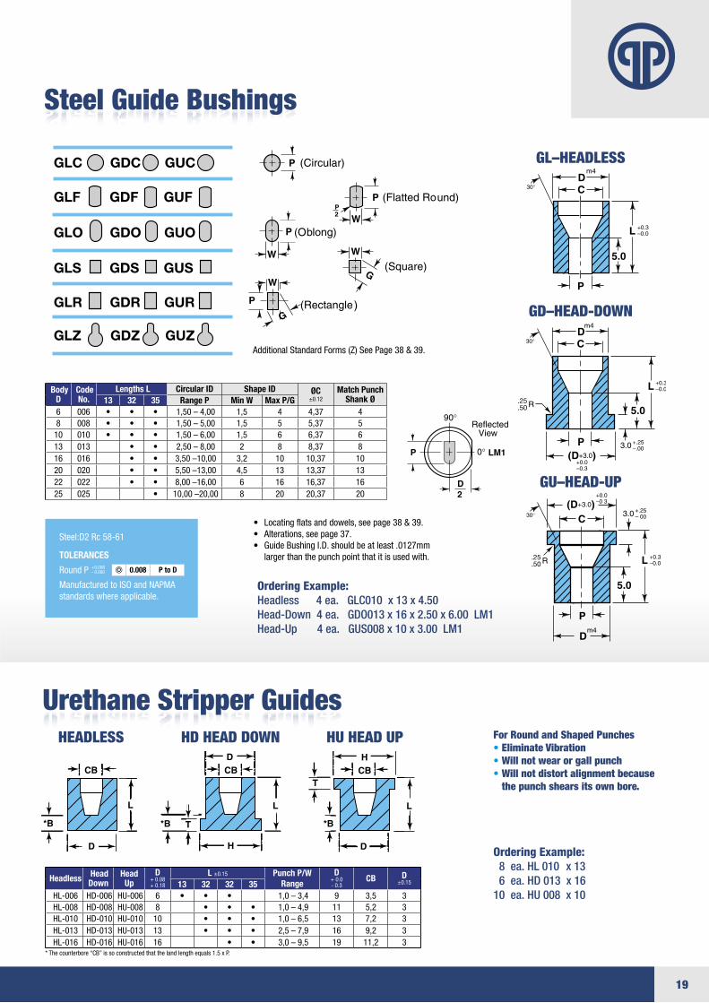
Urethane Stripper GuidesFor Round and Shaped Punches• Eliminate Vibration• Will not wear or gall punch• Will not distort alignment because
the punch shears its own bore.
Porter’s Slug keeper can be added to any round or shape die to reduce slug pulling
* The counterbore “CB” is so constructed that the land length equals 1.5 x P.
Additional Standard Forms (Z) See Page 38 & 39.
• Locatingflatsanddowels,seepage38&39.• Alterations,seepage37.• GuideBushingI.D.shouldbeatleast.0127mm largerthanthepunchpointthatitisusedwith.
Ordering Example: Headless 4 ea. GLC010 x 13 x 4.50Head-Down 4 ea. GDO013 x 16 x 2.50 x 6.00 LM1Head-Up 4 ea. GUS008 x 10 x 3.00 LM1
Ordering Example: 8 ea. HL 010 x 13 6 ea. HD 013 x 16 10 ea. HU 008 x 10
Steel Guide Bushings
Body D
Code No.
Lengths L Circular ID Shape ID ØC±0.12
Match Punch Shank Ø13 32 35 Range P Min W Max P/G
6 006 • • • 1,50–4,00 1,5 4 4,37 48 008 • • • 1,50–5,00 1,5 5 5,37 510 010 • • • 1,50–6,00 1,5 6 6,37 613 013 • • 2,50–8,00 2 8 8,37 816 016 • • 3,50–10,00 3,2 10 10,37 1020 020 • • 5,50–13,00 4,5 13 13,37 1322 022 • • 8,00–16,00 6 16 16,37 1625 025 • 10,00–20,00 8 20 20,37 20
GLC GDC GUC
GLF GDF GUF
GLO GDO GUO
GLS GDS GUS
GLR GDR GUR
GLZ GDZ GUZ
.25
.50
.25
.50
GL–HEADLESS
GD–HEAD-DOWN
GU–HEAD-UP
GLC GDC GUC
GLF GDF GUF
GLO GDO GUO
GLS GDS GUS
GLR GDR GUR
GLZ GDZ GUZ
.25
.50
.25
.50
Steel:D2Rc58-61
TOLERANCES
RoundP
ManufacturedtoISOandNAPMAstandardswhereapplicable.
+0.008-0.000 0.008 P to D
GLC GDC GUC
GLF GDF GUF
GLO GDO GUO
GLS GDS GUS
GLR GDR GUR
GLZ GDZ GUZ
.25
.50
.25
.50
HEADLESS HD HEAD DOWN HU HEAD UP
Headless Head Down
Head Up
D+0.08 +0.18
L ±0.15 Punch P/WRange
D+0.0 -0.3
CB D±0.1513 32 32 35
HL-006 HD-006HU-006 6 • • • 1,0–3,4 9 3,5 3HL-008 HD-008HU-008 8 • • • 1,0–4,9 11 5,2 3HL-010 HD-010HU-010 10 • • • 1,0–6,5 13 7,2 3HL-013 HD-013HU-013 13 • • • 2,5–7,9 16 9,2 3HL-016 HD-016HU-016 16 • • 3,0–9,5 19 11,2 3

20
Less than4 mm whenP < 6 mm
Under6 mmDia.
6 mmDia.
Over6 mmDia.
4 mm = N
+0.3 -0.0
m4
REF
20 min.
13 R
H=+0.0 -0.3
2+1.0 -0.0
.25
.50
+0.13 -0.00
2
m4REF
20 min.
13 R
H=+0.0 -0.3
+1.0 -0.0
+0.3 -0.0
.25
.5013R
+0.13 -0.00
BreakCorner
m4REF
20 min.13 R
H=+0.0 -0.3
+0.3 -0.0
2+1.0 -0.0
.25
.50
+0.13 -0.00
Standard Alterations are changes that are beyond the ranges listed in the catalog that can be altered for a minimal charge. See page 37.
Ultra Precision Headed Pilots
All Porter Ultra Precision Pilots are “DeepCryogenically”treatedfor1. Wear2.Toughness3.DimensionalStabilitySeepage42formoredetails.
+1.0 -0.0
.25
.50
+0.13 -0.00
H
.25
.50
+0.13 -0.00
Steel:D2L≤100OALRc58-61,M260-63,PM4,Rc63-65HeadsRc40-55(25mmØandsmallerandL≥50)
TOLERANCES
RoundP
ManufacturedtoISOandNAPMAstandardswhereapplicable.
+0.005-0.000 0.008 P to D
Ultra Precision Regular Pilot
Ultra Precision Angular Pilot-PAP Type Long Parabolic Locator Pilot–PLP Type
B & L Lengths do not include Pilot Tip N
B & L Lengths do not include Pilot Tip N
Ordering Example: Qty Steel Type Code L2/L P 50 M2 PP 004 27/92 x 3.75
Ordering Example: Qty Steel Type Code L2/L P 13 D2 PAP 016 21/62 x 10.50
Ordering Example: Qty Steel Type Code L2/L P 10 PM4 PLP 008 15/92 x 5.20
AllLengths110mmandunderOALinLightBlue Panel have Hot Forged Heads for addedstrength and toughness.
Headless Punch Pilots are also available.To order call out: Regular Pilot = HRP Locator Pilot = HLP Angular Pilot = HAP
Shank Head L2 Lengths L N Dim
Round Range PD Pilot Type H T 10 15 21 27 47 52 58 62 65 72 73 82 92 102 112 127
4 PP004 7 5 • • • • • • • • • • • • • 4 1,55–4,005 PP005 8 5 • • • • • • • • • • • • • 4 1,55–5,006 PP006 9 5 • • • • • • • • • • • • • 4 1,55–6,008 PP008 11 5 • • • • • • • • • • • • • • 4 2,45–8,0010 PP010 13 5 • • • • • • • • • • • • • • • 4 3,15–10,0013 PP013 16 5 • • • • • • • • • • • • • • 4 4,95–13,0016 PP016 19 5 • • • • • • • • • • • • • • 4 7,95–16,0020 PP020 23 5 • • • • • • • • • • • • • • 4 8,95–20,0022 PP022 25 5 • • • • • • • • • • • • • 4 9,95–22,0025 PP025 28 5 • • • • • • • • • • • • • • 4 11,95–25,0032 PP032 35 5 • • • • • • • • • • • 4 15,95–32,00
Shank Head L2 Lengths L N Dim
Round Range P Pilot Type
D Pilot Type H T 10 15 21 27 65 72 73 82 92 102 112 1278 PAP008 11 5 • • • • • • • • • • • 7 2,45–8,00 PLP00810 PAP010 13 5 • • • • • • • • • • • • 8 4,85–10,00 PLP01013 PAP013 16 5 • • • • • • • • • • • • 10 6,30–13,00 PLP01316 PAP016 19 5 • • • • • • • • • • • • 15 9,95–16,00 PLP01620 PAP020 23 5 • • • • • • • • • • • • 20 13,60–20,00 PLP02022 PAP022 25 5 • • • • • • • • 22 15,00–22,00 PLP02225 PAP025 28 5 • • • • • • • • • • • 25 17,75–25,00 PLP02532 PAP032 35 5 • • • • • • • • • 30 20,85–32,00 PLP032
•ThesesizesalsoavailableinPM4material.Pbelow1.60L2=10maxPbelow2.50L2=21max
•ThesesizesalsoavailableinPM4material.Pbelow1.60L2=10maxPbelow2.50L2=21max
Less than4 mm whenP < 6 mm
Under6 mmDia.
6 mmDia.
Over6 mmDia.
4 mm = N
+0.3 -0.0
m4
REF
20 min.
13 R
H=+0.0 -0.3
2+1.0 -0.0
.25
.50
+0.13 -0.00
2
m4REF
20 min.
13 R
H=+0.0 -0.3
+1.0 -0.0
+0.3 -0.0
.25
.5013R
+0.13 -0.00
BreakCorner
m4REF
20 min.13 R
H=+0.0 -0.3
+0.3 -0.0
2+1.0 -0.0
.25
.50
+0.13 -0.00
B & L Lengths do not include Pilot Tip N
AllLengths110mmandunderOALinLightBluePanelhaveHot Forged Heads for added strength and toughness.
21
Standard Alterations are changes that are beyond the ranges listed in the catalog that can be altered for a minimal charge. See page 37.
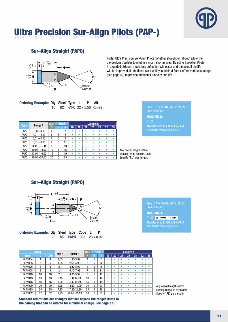
Ordering Example: Qty Steel Type L P Alt. 10 D2 PAPQ 22 x 5.50 RL=29
Ordering Example: Qty Steel Type Code L P 20 M2 PAPN 025 28 x 8.02
Headless Punch Pilots are also available.To order call out: Regular Pilot = HRP Locator Pilot = HLP Angular Pilot = HAP
PorterUltraPrecisionSur-AlignPilots(whetherstraightornibbed)allowthe diedesigner/buildertopilotinamuchshorterarea.ByusingSur-AlignPilots inaguidedstripper,muchlessdeflectionwilloccurandtheoveralldielife willbeimproved.IfadditionalwearabilityisdesiredPorteroffersvariouscoatings (seepage42)toprovideadditionallubricityandlife.
Type Range P Max N
Head Lengths L H T 16 20 22 25 28 32 35
PAPQ 3,00–4,00 4 5 7 • • • • • • • PAPQ 4,01–5,00 5 5 8 • • • • • • • PAPQ 5,01–6,00 6 5 9 • • • • • • • PAPQ 6,01–8,00 7 5 11 • • • • • • • PAPQ 8,01–10,00 8 5 13 • • • • • • • PAPQ 10,01–13,00 10 5 16 • • • • • • • PAPQ 13,01–16,00 15 5 19 • • • • • • • PAPQ 16,01–20,00 20 5 23 • • • • • •
ShankMin P Range P Max
NHead Lengths L
Type D Code H T 16 20 22 25 28 32 35PAPN004 4 4 1,55 1,95-3,99 4 5 7 • • • • • • •PAPN005 5 5 1,55 2,65-4,99 5 5 8 • • • • • • •PAPN006 6 6 2,1 3,40-5,99 6 5 9 • • • • • • •PAPN008 8 8 2,1 4,10-7,99 7 5 11 • • • • • • •PAPN010 10 10 2,1 4,85-9,99 8 5 13 • • • • • • •PAPN013 13 13 3,15 6,30-12,99 10 5 16 • • • • • • •PAPN016 16 16 5,95 9,95-15,99 15 5 19 • • • • • • •PAPN020 20 20 5,95 13,60-19,99 20 5 23 • • • • • •PAPN025 25 25 7,95 17,25-24,99 25 5 28 • • • • • •PAPN032 32 32 9,95 20,85-31,99 30 5 35 • • • • • •
40•
BreakCorner
+0.1- 0.0
0.30.5
+0.0- 0.3
+0.3- 0.0
13
40•
3mm RBreakCorner
+0.1- 0.0
0.30.5
+0.8- 0.0
+0.3- 0.0
13 R
m5
3.0
+0.0- 0.3
Anyoveralllengthwithincatalog range no extra costSpecify”RL”pluslength.
Anyoveralllengthwithincatalog range no extra costSpecify”RL”pluslength.
Ultra Precision Sur-Align Pilots (PAP-)
Steel:D2Rc58-61,M2Rc60-63PM4Rc63-65
TOLERANCES
P
ManufacturedtoISOandNAPMAstandardswhereapplicable.
+0.005-0.000
40•
BreakCorner
+0.1- 0.0
0.30.5
+0.0- 0.3
+0.3- 0.0
13
40•
3mm RBreakCorner
+0.1- 0.0
0.30.5
+0.8- 0.0
+0.3- 0.0
13 R
m5
3.0
+0.0- 0.3
Sur–Align Straight (PAPQ)
Sur–Align Straight (PAPQ)
Steel:D2Rc58-61,M2Rc60-63PM4Rc63-65
TOLERANCES
P
ManufacturedtoISOandNAPMAstandardswhereapplicable.
+0.005-0.000 0.008 P to D
22
TSC TSF TSO TSS TSR
TSQ
TRC TRF TRO TRS TRR
TRQ
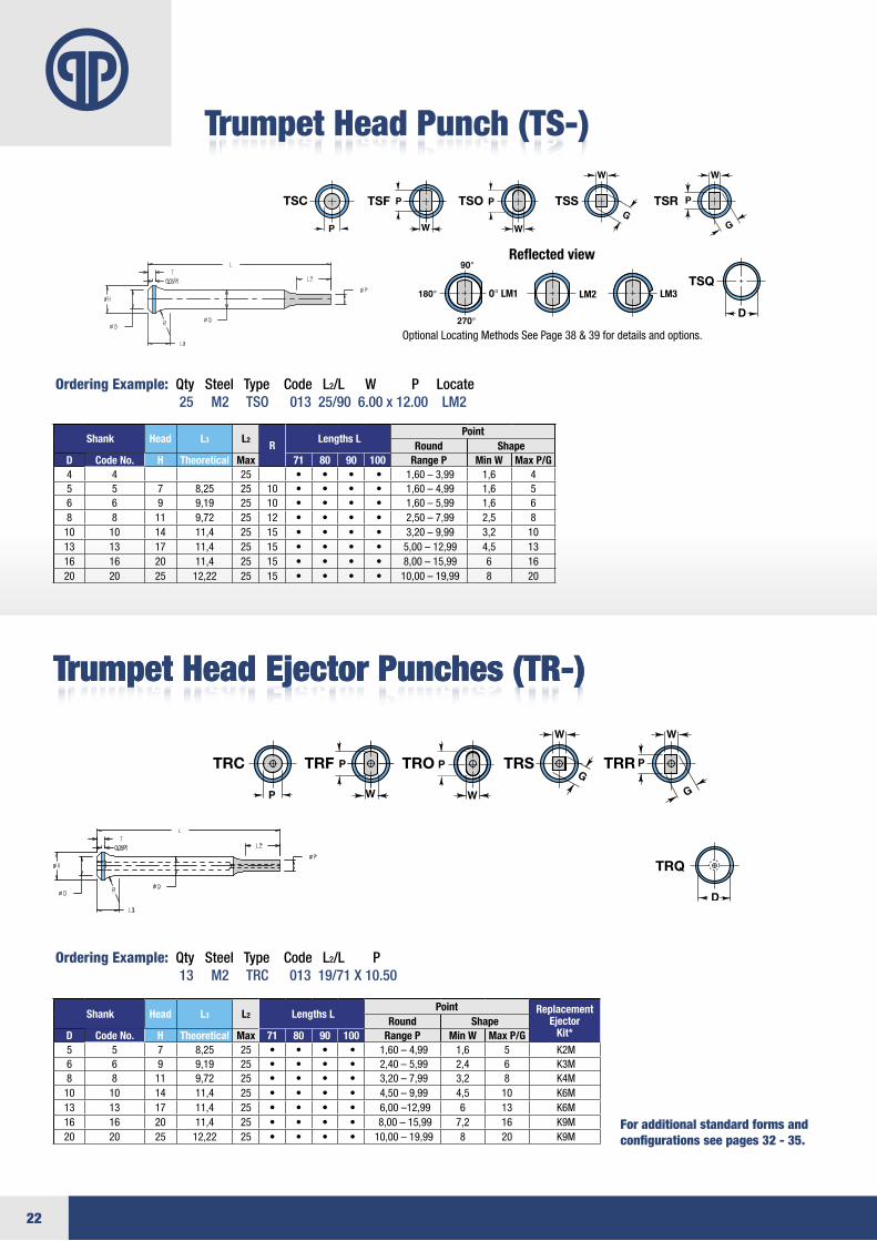
Trumpet Head Punch (TS-)
Ordering Example: Qty Steel Type Code L2/L W P Locate 25 M2 TSO 013 25/90 6.00 x 12.00 LM2
Shank Head L3 L2R
Lengths L Point
Round ShapeD Code No. H Theoretical Max 71 80 90 100 Range P Min W Max P/G4 4 25 • • • • 1,60–3,99 1,6 45 5 7 8,25 25 10 • • • • 1,60–4,99 1,6 56 6 9 9,19 25 10 • • • • 1,60–5,99 1,6 68 8 11 9,72 25 12 • • • • 2,50–7,99 2,5 810 10 14 11,4 25 15 • • • • 3,20–9,99 3,2 1013 13 17 11,4 25 15 • • • • 5,00–12,99 4,5 1316 16 20 11,4 25 15 • • • • 8,00–15,99 6 1620 20 25 12,22 25 15 • • • • 10,00–19,99 8 20
Shank Head L3 L2 Lengths L Point Replacement
EjectorKit*
Round ShapeD Code No. H Theoretical Max 71 80 90 100 Range P Min W Max P/G5 5 7 8,25 25 • • • • 1,60–4,99 1,6 5 K2M6 6 9 9,19 25 • • • • 2,40–5,99 2,4 6 K3M 8 8 11 9,72 25 • • • • 3,20–7,99 3,2 8 K4M10 10 14 11,4 25 • • • • 4,50–9,99 4,5 10 K6M 13 13 17 11,4 25 • • • • 6,00–12,99 6 13 K6M 16 16 20 11,4 25 • • • • 8,00–15,99 7,2 16 K9M 20 20 25 12,22 25 • • • • 10,00–19,99 8 20 K9M
OptionalLocatingMethodsSeePage38&39fordetailsandoptions.
Reflected view
Trumpet Head Ejector Punches (TR-)Trumpet Head Ejector Punches (TR-)
TSC TSF TSO TSS TSR
TSQ
TRC TRF TRO TRS TRR
TRQ
For additional standard forms andconfigurations see pages 32 - 35.
Ordering Example: Qty Steel Type Code L2/L P 13 M2 TRC 013 19/71 X 10.50
23
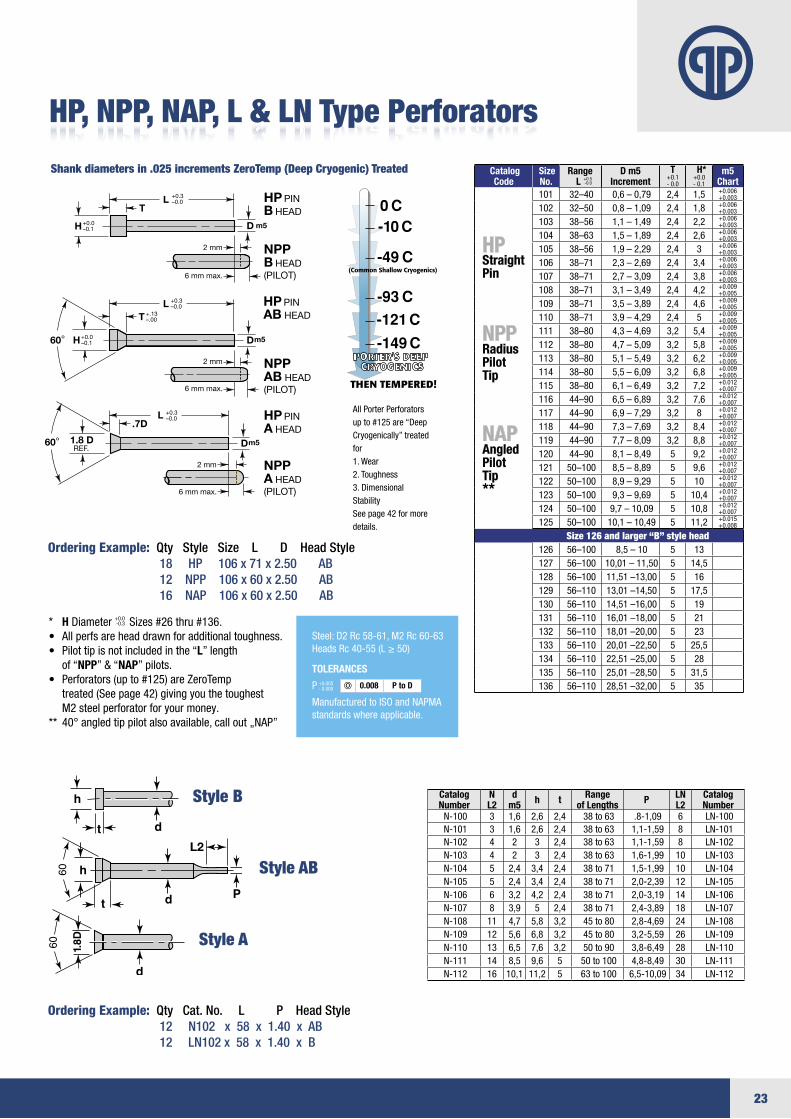
Ordering Example: Qty Style Size L D Head Style 18 HP 106 x 71 x 2.50 AB 12 NPP 106 x 60 x 2.50 AB 16 NAP 106 x 60 x 2.50 AB
Shank diameters in .025 increments ZeroTemp (Deep Cryogenic) Treated
Catalog Number
N L2
d m5 h t Range
of Lengths P LN L2
Catalog Number
N-100 3 1,6 2,6 2,4 38 to 63 .8-1,09 6 LN-100N-101 3 1,6 2,6 2,4 38 to 63 1,1-1,59 8 LN-101N-102 4 2 3 2,4 38 to 63 1,1-1,59 8 LN-102N-103 4 2 3 2,4 38 to 63 1,6-1,99 10 LN-103N-104 5 2,4 3,4 2,4 38to71 1,5-1,99 10 LN-104N-105 5 2,4 3,4 2,4 38to71 2,0-2,39 12 LN-105N-106 6 3,2 4,2 2,4 38to71 2,0-3,19 14 LN-106N-107 8 3,9 5 2,4 38to71 2,4-3,89 18 LN-107N-108 11 4,7 5,8 3,2 45to80 2,8-4,69 24 LN-108N-109 12 5,6 6,8 3,2 45to80 3,2-5,59 26 LN-109N-110 13 6,5 7,6 3,2 50to90 3,8-6,49 28 LN-110N-111 14 8,5 9,6 5 50to100 4,8-8,49 30 LN-111N-112 16 10,1 11,2 5 63to100 6,5-10,09 34 LN-112
L
D
D
1.8 DREF.
.7D
LT
T
+.13–.00
L +0.3–0.0
60°
H
+0.0–0.1H
60°
2 mm
HP PIN A HEAD
HP PIN AB HEAD
NPP
A HEAD(PILOT)
NPP
AB HEAD(PILOT)
HP PIN B HEAD
NPP
B HEAD(PILOT)
m5
m5
6 mm max.
2 mm
6 mm max.
2 mm
6 mm max.
+0.3–0.0
+0.3–0.0
+0.0–0.1
Dm5
L2
HP, NPP, NAP, L & LN Type Perforators
All Porter Perforatorsupto#125are“DeepCryogenically” treatedfor1. Wear2.Toughness3.DimensionalStabilitySeepage42formoredetails.
+1.0 -0.0
.25
.50
+0.13 -0.00
H
.25
.50
+0.13 -0.00
Catalog Code
Size No.
Range L +0.5
-0.0 D m5
IncrementT+0.1 -0.0
H*+0.0 -0.1
m5 Chart
101 32–40 0,6–0,79 2,4 1,5 +0.006+0.003
102 32–50 0,8–1,09 2,4 1,8 +0.006+0.003
103 38–56 1,1–1,49 2,4 2,2 +0.006+0.003
104 38–63 1,5–1,89 2,4 2,6 +0.006+0.003
105 38–56 1,9–2,29 2,4 3 +0.006+0.003
106 38–71 2,3–2,69 2,4 3,4 +0.006+0.003
107 38–71 2,7–3,09 2,4 3,8 +0.006+0.003
108 38–71 3,1–3,49 2,4 4,2 +0.009+0.005
109 38–71 3,5–3,89 2,4 4,6 +0.009+0.005
110 38–71 3,9–4,29 2,4 5 +0.009+0.005
111 38–80 4,3–4,69 3,2 5,4 +0.009+0.005
112 38–80 4,7–5,09 3,2 5,8 +0.009+0.005
113 38–80 5,1–5,49 3,2 6,2 +0.009+0.005
114 38–80 5,5–6,09 3,2 6,8 +0.009+0.005
115 38–80 6,1–6,49 3,2 7,2 +0.012+0.007
116 44–90 6,5–6,89 3,2 7,6 +0.012+0.007
117 44–90 6,9–7,29 3,2 8 +0.012+0.007
118 44–90 7,3–7,69 3,2 8,4 +0.012+0.007
119 44–90 7,7–8,09 3,2 8,8 +0.012+0.007
120 44–90 8,1–8,49 5 9,2 +0.012+0.007
121 50–100 8,5–8,89 5 9,6 +0.012+0.007
122 50–100 8,9–9,29 5 10 +0.012+0.007
123 50–100 9,3–9,69 5 10,4 +0.012+0.007
124 50–100 9,7–10,09 5 10,8 +0.012+0.007
125 50–100 10,1–10,49 5 11,2 +0.015+0.008
Size 126 and larger “B” style head126 56–100 8,5–10 5 13127 56–100 10,01–11,50 5 14,5128 56–100 11,51–13,00 5 16129 56–110 13,01–14,50 5 17,5130 56–110 14,51–16,00 5 19131 56–110 16,01–18,00 5 21132 56–110 18,01–20,00 5 23133 56–110 20,01–22,50 5 25,5134 56–110 22,51–25,00 5 28135 56–110 25,01–28,50 5 31,5136 56–110 28,51–32,00 5 35
HPStraightPin
NPPRadiusPilotTip
NAPAngledPilotTip**
* HDiameter+0.0-0.3 Sizes#26thru#136.• Allperfsareheaddrawnforadditionaltoughness.• Pilottipisnotincludedinthe“L” length
of “NPP” & “NAP” pilots.• Perforators(upto#125)areZeroTemp treated(Seepage42)givingyouthetoughest M2steelperforatorforyourmoney.
** 40°angledtippilotalsoavailable,callout„NAP”
L
D
D
1.8 DREF.
.7D
LT
T
+.13–.00
L +0.3–0.0
60°
H
+0.0–0.1H
60°
2 mm
HP PIN A HEAD
HP PIN AB HEAD
NPP
A HEAD(PILOT)
NPP
AB HEAD(PILOT)
HP PIN B HEAD
NPP
B HEAD(PILOT)
m5
m5
6 mm max.
2 mm
6 mm max.
2 mm
6 mm max.
+0.3–0.0
+0.3–0.0
+0.0–0.1
Dm5
L2
Ordering Example: Qty Cat. No. L P Head Style 12 N102 x 58 x 1.40 x AB 12 LN102 x 58 x 1.40 x B
Style B
Style AB
Style A
Steel:D2Rc58-61,M2Rc60-63HeadsRc40-55(L≥50)
TOLERANCES
P
ManufacturedtoISOandNAPMAstandardswhereapplicable.
+0.005-0.000 0.008 P to D
24
L +0.3–0.0
Dg5
2
+1.0 -0.02
38 min.
+0.3 -0.0
Dg5
REF
L +0.3–0.0
Dg5
2
+1.0 -0.02
38 min.
+0.3 -0.0
Dg5
REF
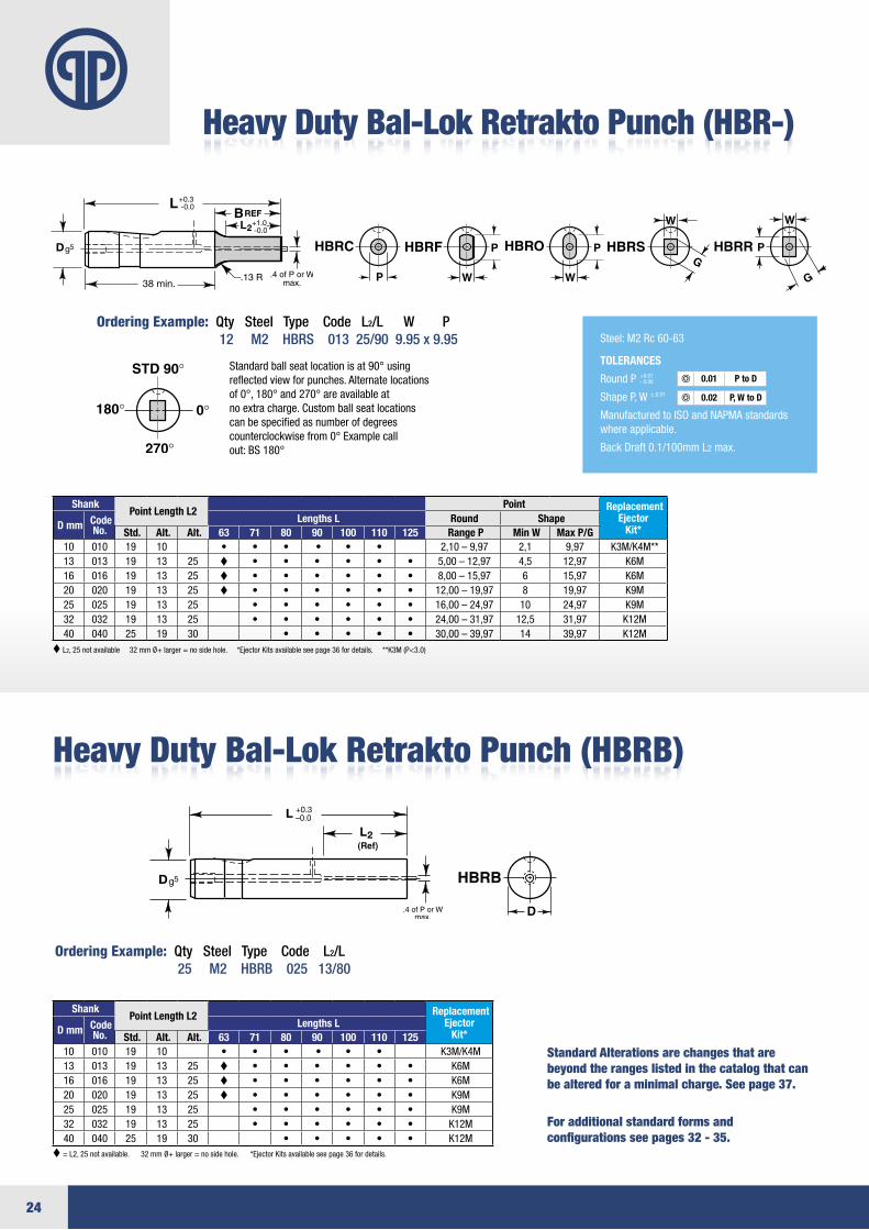
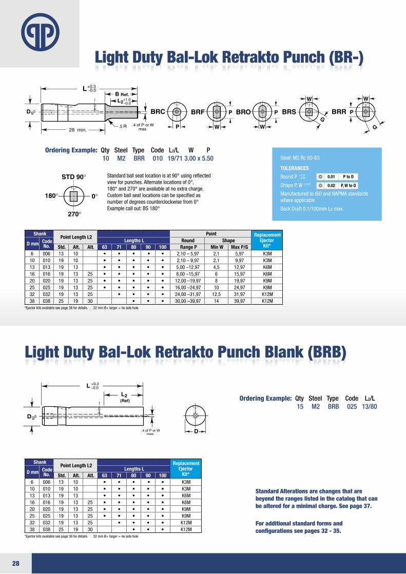
Heavy Duty Bal-Lok Retrakto Punch (HBR-)
Ordering Example: Qty Steel Type Code L2/L W P 12 M2 HBRS 013 25/90 9.95 x 9.95
Standardballseatlocationisat90°usingreflectedviewforpunches.Alternatelocationsof0°,180°and270°areavailableatno extra charge. Custom ball seat locationscan be specified as number of degreescounterclockwisefrom0°Examplecallout:BS180°
Heavy Duty Bal-Lok Retrakto Punch (HBRB)
For additional standard forms andconfigurations see pages 32 - 35.
Ordering Example: Qty Steel Type Code L2/L 25 M2 HBRB 025 13/80
Shank Point Length L2
Point Replacement Ejector
Kit* D mm Code No.
Lengths L Round Shape Std. Alt. Alt. 63 71 80 90 100 110 125 Range P Min W Max P/G
10 010 19 10 • • • • • • 2,10–9,97 2,1 9,97 K3M/K4M**13 013 19 13 25 • • • • • • 5,00–12,97 4,5 12,97 K6M 16 016 19 13 25 • • • • • • 8,00–15,97 6 15,97 K6M 20 020 19 13 25 • • • • • • 12,00–19,97 8 19,97 K9M 25 025 19 13 25 • • • • • • 16,00–24,97 10 24,97 K9M 32 032 19 13 25 • • • • • • 24,00–31,97 12,5 31,97 K12M40 040 25 19 30 • • • • • 30,00–39,97 14 39,97 K12M
Shank Point Length L2 Replacement
Ejector Kit* D mm Code
No. Lengths L
Std. Alt. Alt. 63 71 80 90 100 110 12510 010 19 10 • • • • • • K3M/K4M13 013 19 13 25 • • • • • • K6M 16 016 19 13 25 • • • • • • K6M 20 020 19 13 25 • • • • • • K9M 25 025 19 13 25 • • • • • • K9M 32 032 19 13 25 • • • • • • K12M40 040 25 19 30 • • • • • K12M
Steel:M2Rc60-63
TOLERANCES
RoundP
ShapeP,W
ManufacturedtoISOandNAPMAstandards whereapplicable.
BackDraft0.1/100mmL2 max.
+0.01-0.00
±.0.01
0.01
0.02
P to D
P, W to D
L2,25notavailable32mmØ+larger=nosidehole.*EjectorKitsavailableseepage36fordetails.**K3M(P<3.0)
=L2,25notavailable.32mmØ+larger=nosidehole.*EjectorKitsavailableseepage36fordetails.
L +0.3–0.0
Dg5
2
+1.0 -0.02
38 min.
+0.3 -0.0
Dg5
REF
Standard Alterations are changes that are beyond the ranges listed in the catalog that can be altered for a minimal charge. See page 37.

25
+0.3 -0.0
Dg5
35 min.
+0.3 -0.0
REF
g5
+1.0 -0.02
+0.3 -0.0
Dg5
35 min.
+0.3 -0.0
REF
g5
+1.0 -0.02
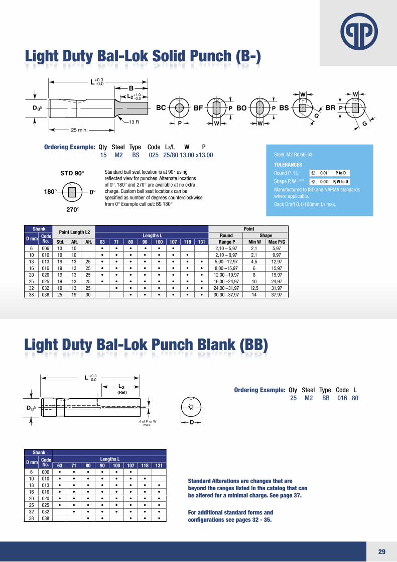
Ordering Example: Qty Steel Type Code L2/L W P 13 M2 HBO 016 19/80 7.50 x 15.00
Standardballseatlocationisat90°usingreflectedviewforpunches.Alternatelocationsof0°,180°and270°areavailableatno extra charge. Custom ball seat locationscan be specified as number of degreescounterclockwisefrom0°Examplecallout:BS180°
Heavy Duty Bal-Lok Punch Blank (HBB)
For additional standard forms andconfigurations see pages 32 - 35.
Ordering Example: Qty Steel Type Code L 6 M2 HBB 025 110
Shank Point Length L2
Point Replacement Ejector
Kit* D mm Code No.
Lengths L Round Shape Std. Alt. Alt. 63 71 80 90 100 110 125 150 Range P Min W Max P/G
10 010 19 10 • • • • • • 2,10–9,97 2,1 9,97 K3M/K4M**13 013 19 13 25 • • • • • • • 5,00–12,97 4,5 12,97 K6M 16 016 19 13 25 • • • • • • • 8,00–15,97 6 15,97 K6M 20 020 19 13 25 • • • • • • • 12,00–19,97 8 19,97 K9M 25 025 19 13 25 • • • • • • • 16,00–24,97 10 24,97 K9M 32 032 19 13 25 • • • • • • • 24,00–31,97 12,5 31,97 K12M40 040 25 19 30 • • • • • 30,00–39,97 14 39,97 K12M
Shank
D mm Code No.
Lengths L 63 71 80 90 100 110 125
10 010 • • • • • • 13 013 • • • • • • •16 016 • • • • • • •20 020 • • • • • • •25 025 • • • • • •32 032 • • • • • •40 040 • • • • •
Steel:M2Rc60-63
TOLERANCES
RoundP
ShapeP,W
ManufacturedtoISOandNAPMAstandards whereapplicable.
BackDraft0.1/100mmL2 max.
+0.01-0.00
±.0.01
0.01
0.02
P to D
P, W to D
=L2,25isnotavailable.
+0.3 -0.0
Dg5
35 min.
+0.3 -0.0
REF
g5
+1.0 -0.02
Standard Alterations are changes that are beyond the ranges listed in the catalog that can be altered for a minimal charge. See page 37.
Heavy Duty Bal-Lok Solid Punch (HB-)
26
+0.3 -0.0
2
+0.3 -0.0
2
HBKCHBKRC
HBKFHBKRF
HBKOHBKRO
HBKSHBKRS
HBKRHBKRR
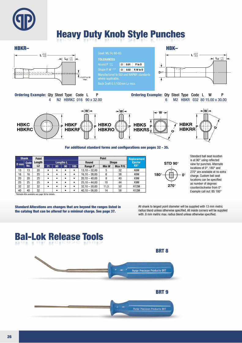
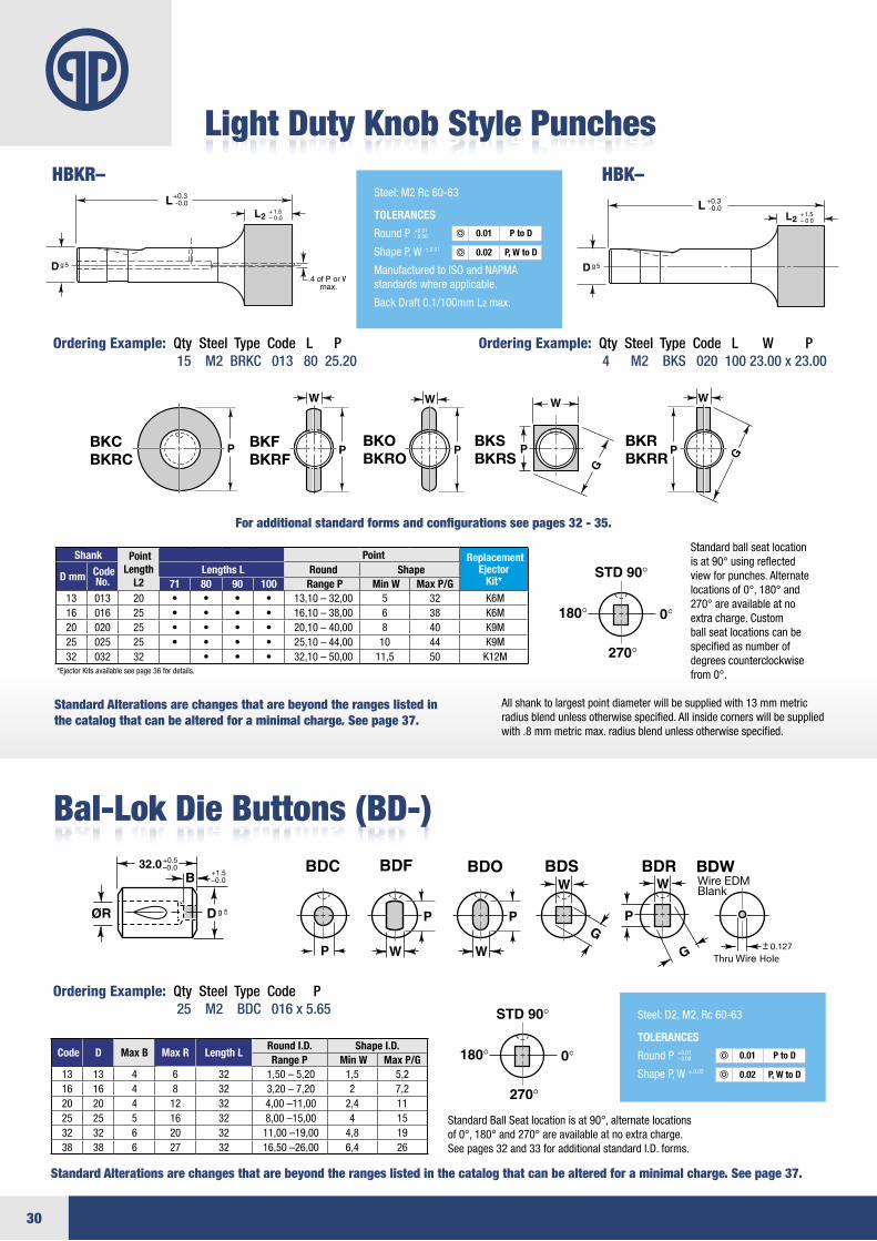
Heavy Duty Knob Style Punches
Ordering Example: Qty Steel Type Code L P 4 N2 HBRKC 016 90 x 32.00
Ordering Example: Qty Steel Type Code L W P 6 M2 HBKR 032 80 15.00 x 30.00
Standard ball seat location isat90°usingreflectedviewforpunches.Alternatelocationsof0°,180°and270°areavailableatnoextracharge. Custom ball seat locations can be specified as number of degrees counterclockwisefrom0°Examplecallout:BS180°
Allshanktolargestpointdiameterwillbesuppliedwith13mmmetricradiusblendunlessotherwisespecified.Allinsidecornerswillbesuppliedwith.8mmmetricmax.radiusblendunlessotherwisespecified.
Bal-Lok Release Tools
Shank Point Length
L2
Point Replacement Ejector
Kit* D mm Code No.
Lengths L Round Shape 71 80 90 100 Range P Min W Max P/G
13 13 20 • • • • 13,10–32,00 5 32 K6M 16 16 25 • • • • 16,10–38,00 6 38 K6M 20 20 25 • • • • 20,10–40,00 8 40 K9M 25 25 25 • • • • 25,10–44,00 10 44 K9M 32 32 32 • • • • 32,10–50,00 11,5 50 K12M40 40 32 • • • 40,10–56,00 14 56 K12M
*RetraktoKitsavailableseepage36fordetails.
L +0.3–0.0
Dg5
2
+1.0 -0.02
38 min.
+0.3 -0.0
Dg5
REF
+0.3 -0.0
2
+0.3 -0.0
2
HBKCHBKRC
HBKFHBKRF
HBKOHBKRO
HBKSHBKRS
HBKRHBKRR
Steel:M2Rc60-63
TOLERANCES
RoundP
ShapeP,W
ManufacturedtoISOandNAPMAstandards whereapplicable.
BackDraft0.1/100mmL2 max.
+0.01-0.00
±.0.01
0.01
0.02
P to D
P, W to D
HBKR– HBK–+0.3 -0.0
2
+0.3 -0.0
2
HBKCHBKRC
HBKFHBKRF
HBKOHBKRO
HBKSHBKRS
HBKRHBKRR
For additional standard forms and configurations see pages 32 - 35.
Standard Alterations are changes that are beyond the ranges listed in the catalog that can be altered for a minimal charge. See page 37.
BRT 8
BRT 9
27
P
LB
13 R
+0.3–0.0 N
Dg5
35 min+1.0 -0.02
4.06mm
N = 4.0
Under6mmDia,
6mmDia,
Over6mmDia,
P13 R
Dg5
NLB
+0.3–0.0
35 min+1.0 -0.02
13RBreakCorner
P13 R
N
Parabolic Point
Dg5
LB
+0.3–0.0
35 min+1.0 -0.02
P
LB
13 R
+0.3–0.0 N
Dg5
35 min+1.0 -0.02
4.06mm
N = 4.0
Under6mmDia,
6mmDia,
Over6mmDia,
P13 R
Dg5
NLB
+0.3–0.0
35 min+1.0 -0.02
13RBreakCorner
P13 R
N
Parabolic Point
Dg5
LB
+0.3–0.0
35 min+1.0 -0.02
Standard Alterations are changes that are beyond the ranges listed inthe catalog that can be altered for a minimal charge. See page 37.
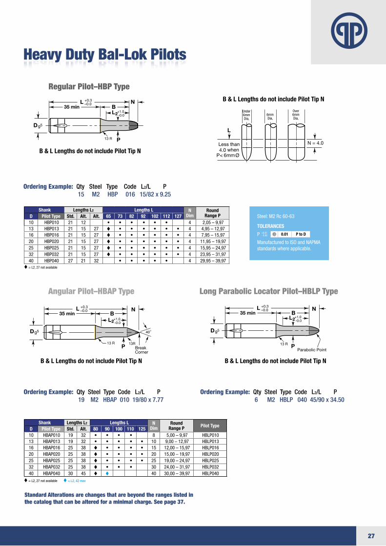
Heavy Duty Bal-Lok Pilots
Regular Pilot–HBP Type
Angular Pilot–HBAP Type Long Parabolic Locator Pilot–HBLP Type
B & L Lengths do not include Pilot Tip N
B & L Lengths do not include Pilot Tip N
B & L Lengths do not include Pilot Tip N
Ordering Example: Qty Steel Type Code L2/L P 15 M2 HBP 016 15/82 x 9.25
Ordering Example: Qty Steel Type Code L2/L P 19 M2 HBAP 010 19/80 x 7.77
Ordering Example: Qty Steel Type Code L2/L P 6 M2 HBLP 040 45/90 x 34.50
Shank Lengths L2 Lengths L N Dim
Round Range PD Pilot Type Std. Alt. Alt. 65 73 82 92 102 112 127
10 HBP010 21 12 • • • • • • 4 2,05–9,9713 HBP013 21 15 27 • • • • • • 4 4,95–12,9716 HBP016 21 15 27 • • • • • • 4 7,95–15,9720 HBP020 21 15 27 • • • • • • 4 11,95–19,9725 HBP025 21 15 27 • • • • • • 4 15,95–24,9732 HBP032 21 15 27 • • • • • • 4 23,95–31,9740 HBP040 27 21 32 • • • • • 4 29,95–39,97
Shank Lengths L2 Lengths L N Dim
Round Range P Pilot Type
D Pilot Type Std. Alt. 80 90 100 110 12510 HBAP010 19 32 • • • • 8 5,00–9,97 HBLP01013 HBAP013 19 32 • • • • • 10 9,00–12,97 HBLP01316 HBAP016 25 38 • • • • 15 12,00–15,97 HBLP01620 HBAP020 25 38 • • • • 20 15,00–19,97 HBLP02025 HBAP025 25 38 • • • • 25 19,00–24,97 HBLP02532 HBAP032 25 38 • • • 30 24,00–31,97 HBLP03240 HBAP040 30 45 40 30,00–39,97 HBLP040
=L2,27notavailable
=L2,27notavailable=L2,42max
B & L Lengths do not include Pilot Tip N
Steel:M2Rc60-63
TOLERANCES
P
ManufacturedtoISOandNAPMAstandardswhereapplicable.
+0.01-0.00 0.01 P to D
28
L +0.3–0.0
Dg5
2
+1.0 -0.02
28 min.
+0.3 -0.0
Dg5
.5
B Ref.
Light Duty Bal-Lok Retrakto Punch (BR-)
Ordering Example: Qty Steel Type Code L2/L W P 10 M2 BRR 010 19/71 3.00 x 5.50
Standardballseatlocationisat90°usingreflectedviewforpunches.Alternatelocationsof0°,180°and270°areavailableatnoextracharge.Custom ball seat locations can be specified asnumberofdegreescounterclockwisefrom0°Examplecallout:BS180°
Light Duty Bal-Lok Retrakto Punch Blank (BRB)
For additional standard forms andconfigurations see pages 32 - 35.
Ordering Example: Qty Steel Type Code L2/L 15 M2 BRB 025 13/80
Shank Point Length L2
Point Replacement Ejector
Kit* D mm Code No.
Lengths L Round Shape Std. Alt. Alt. 63 71 80 90 100 Range P Min W Max P/G
6 006 13 10 • • • • • 2,10–5,97 2,1 5,97 K3M 10 010 19 10 • • • • • 2,10–9,97 2,1 9,97 K3M 13 013 19 13 • • • • • 5,00–12,97 4,5 12,97 K6M 16 016 19 13 25 • • • • • 8,00–15,97 6 15,97 K6M 20 020 19 13 25 • • • • • 12,00–19,97 8 19,97 K9M 25 025 19 13 25 • • • • • 16,00–24,97 10 24,97 K9M 32 032 19 13 25 • • • • 24,00–31,97 12,5 31,97 K12M38 038 25 19 30 • • • 30,00–39,97 14 39,97 K12M
Shank Point Length L2 Replacement
Ejector Kit* D mm Code
No. Lengths L
Std. Alt. Alt. 63 71 80 90 1006 006 13 10 • • • • • K3M 10 010 19 10 • • • • • K3M 13 013 19 13 • • • • • K6M 16 016 19 13 25 • • • • • K6M 20 020 19 13 25 • • • • • K9M 25 025 19 13 25 • • • • • K9M 32 032 19 13 25 • • • • K12M38 038 25 19 30 • • • K12M
Steel:M2Rc60-63
TOLERANCES
RoundP
ShapeP,W
ManufacturedtoISOandNAPMAstandards whereapplicable.
BackDraft0.1/100mmL2 max.
+0.01-0.00
±.0.01
0.01
0.02
P to D
P, W to D
*Ejectorkitsavailableseepage36fordetails.32mmØ+larger=nosidehole
*Ejectorkitsavailableseepage36fordetails.32mmØ+larger=nosidehole
L +0.3–0.0
Dg5
2
+1.0 -0.02
38 min.
+0.3 -0.0
Dg5
REF
Standard Alterations are changes that are beyond the ranges listed in the catalog that can be altered for a minimal charge. See page 37.
L +0.3–0.0
Dg5
2
+1.0 -0.02
28 min.
+0.3 -0.0
Dg5
.5
B Ref.
L +0.3–0.0
Dg5
2
+1.0 -0.02
28 min.
+0.3 -0.0
Dg5
.5
B Ref.
29
25 min.
+1.0 -0.0
+0.3 -0.0
Dg5
2
L +0.3–0.0
Dg5
Shank Lengths LD Code No. 63 71 80 90 100 107 118 1316 006 • • • • • •10 010 • • • • • • •13 013 • • • • • • • •16 016 • • • • • • • •20 020 • • • • • • • •25 025 • • • • • • • •32 032 • • • • • • •38 038 • • • • • •
Light Duty Bal-Lok Solid Punch (B-)
Ordering Example: Qty Steel Type Code L2/L W P 15 M2 BS 025 25/80 13.00 x13.00
Standardballseatlocationisat90°usingreflectedviewforpunches.Alternatelocationsof0°,180°and270°areavailableatnoextracharge. Custom ball seat locations can bespecifiedasnumberofdegreescounterclockwisefrom0°Examplecallout:BS180°
Light Duty Bal-Lok Punch Blank (BB)
For additional standard forms andconfigurations see pages 32 - 35.
Ordering Example: Qty Steel Type Code L2/L 15 M2 BRB 025 13/80
Ordering Example: Qty Steel Type Code L 25 M2 BB 016 80
Shank Point Length L2
Point
D mm Code No.
Lengths L Round Shape Std. Alt. Alt. 63 71 80 90 100 107 118 131 Range P Min W Max P/G
6 006 13 10 • • • • • • 2,10–5,97 2,1 5,9710 010 19 10 • • • • • • • 2,10–9,97 2,1 9,9713 013 19 13 25 • • • • • • • • 5,00–12,97 4,5 12,9716 016 19 13 25 • • • • • • • • 8,00–15,97 6 15,9720 020 19 13 25 • • • • • • • • 12,00–19,97 8 19,9725 025 19 13 25 • • • • • • • • 16,00–24,97 10 24,9732 032 19 13 25 • • • • • • • 24,00–31,97 12,5 31,9738 038 25 19 30 • • • • • • 30,00–37,97 14 37,97
Shank
D mm Code No.
Lengths L 63 71 80 90 100 107 118 131
6 006 • • • • • •10 010 • • • • • • • 13 013 • • • • • • • •16 016 • • • • • • • •20 020 • • • • • • • •25 025 • • • • • • • •32 032 • • • • • • •38 038 • • • • •
Steel:M2Rc60-63
TOLERANCES
RoundP
ShapeP,W
ManufacturedtoISOandNAPMAstandards whereapplicable.
BackDraft0.1/100mmL2 max.
+0.01-0.00
±.0.01
0.01
0.02
P to D
P, W to D
L +0.3–0.0
Dg5
2
+1.0 -0.02
38 min.
+0.3 -0.0
Dg5
REF
Standard Alterations are changes that are beyond the ranges listed in the catalog that can be altered for a minimal charge. See page 37.
L +0.3–0.0
Dg5
2
+1.0 -0.02
28 min.
+0.3 -0.0
Dg5
.5
B Ref.
30
+0.3 -0.0
2
+0.3 -0.0
2
BKCBKRC
BKFBKRF
BKOBKRO
BKSBKRS
BKRBKRR
+1.5–0.0
+0.5–0.0 BDW
Wire EDMBlank
Thru Wire Hole 0.127
+–
+0.3 -0.0
2
+0.3 -0.0
2
BKCBKRC
BKFBKRF
BKOBKRO
BKSBKRS
BKRBKRR
+1.5–0.0
+0.5–0.0 BDW
Wire EDMBlank
Thru Wire Hole 0.127
+–
Light Duty Knob Style Punches
Ordering Example: Qty Steel Type Code L P 15 M2 BRKC 013 80 25.20
Ordering Example: Qty Steel Type Code P 25 M2 BDC 016 x 5.65
Ordering Example: Qty Steel Type Code L W P 4 M2 BKS 020 100 23.00 x 23.00
Standard ball seat locationisat90°usingreflectedviewforpunches.Alternatelocationsof0°,180°and270°areavailableatno extra charge. Custom ball seat locations can be specified as number ofdegreescounterclockwisefrom0°.
StandardBallSeatlocationisat90°,alternatelocationsof0°,180°and270°areavailableatnoextracharge.Seepages32and33foradditionalstandardI.D.forms.
Allshanktolargestpointdiameterwillbesuppliedwith13mmmetricradiusblendunlessotherwisespecified.Allinsidecornerswillbesuppliedwith.8mmmetricmax.radiusblendunlessotherwisespecified.
Shank Point Length
L2
Point Replacement Ejector
Kit* D mm Code No.
Lengths L Round Shape 71 80 90 100 Range P Min W Max P/G
13 013 20 • • • • 13,10–32,00 5 32 K6M 16 016 25 • • • • 16,10–38,00 6 38 K6M 20 020 25 • • • • 20,10–40,00 8 40 K9M 25 025 25 • • • • 25,10–44,00 10 44 K9M 32 032 32 • • • 32,10–50,00 11,5 50 K12M
Code D Max B Max R Length LRound I.D. Shape I.D. Range P Min W Max P/G
13 13 4 6 32 1,50–5,20 1,5 5,216 16 4 8 32 3,20–7,20 2 7,220 20 4 12 32 4,00–11,00 2,4 1125 25 5 16 32 8,00–15,00 4 1532 32 6 20 32 11,00–19,00 4,8 1938 38 6 27 32 16,50–26,00 6,4 26
*EjectorKitsavailableseepage36fordetails.
L +0.3–0.0
Dg5
2
+1.0 -0.02
38 min.
+0.3 -0.0
Dg5
REF
L +0.3–0.0
Dg5
2
+1.0 -0.02
38 min.
+0.3 -0.0
Dg5
REF
Steel:M2Rc60-63
TOLERANCES
RoundP
ShapeP,W
ManufacturedtoISOandNAPMA standardswhereapplicable.
BackDraft0.1/100mmL2 max.
+0.01-0.00
±.0.01
0.01
0.02
P to D
P, W to D
Steel:D2,M2,Rc60-63
TOLERANCES
RoundP
ShapeP,W
+0.01-0.00
±.0.02
0.01
0.02
P to D
P, W to D
HBKR– HBK–
For additional standard forms and configurations see pages 32 - 35.
Standard Alterations are changes that are beyond the ranges listed in the catalog that can be altered for a minimal charge. See page 37.
Standard Alterations are changes that are beyond the ranges listed in the catalog that can be altered for a minimal charge. See page 37.
+0.3 -0.0
2
+0.3 -0.0
2
BKCBKRC
BKFBKRF
BKOBKRO
BKSBKRS
BKRBKRR
+1.5–0.0
+0.5–0.0 BDW
Wire EDMBlank
Thru Wire Hole 0.127
+–
+0.3 -0.0
2
+0.3 -0.0
2
BKCBKRC
BKFBKRF
BKOBKRO
BKSBKRS
BKRBKRR
+1.5–0.0
+0.5–0.0 BDW
Wire EDMBlank
Thru Wire Hole 0.127
+–
Bal-Lok Die Buttons (BD-)

31
+0.3 -0.0
2
+0.3 -0.0
2
BKCBKRC
BKFBKRF
BKOBKRO
BKSBKRS
BKRBKRR
+1.5–0.0
+0.5–0.0 BDW
Wire EDMBlank
Thru Wire Hole 0.127
+–
P
LB
13 R
+0.3–0.0
+1.0–0.0
N
D
25 min
2
g 5
4.06mm
N = 4.0
Under6mmDia,
6mmDia,
Over6mmDia,
P
13 R
D
NLB
+0.3–0.0
+1.0–0.0
25 min2
g 5
13RBreakCorner
P
13 R
N
Parabolic Point
Dg 5
LB
+0.3–0.0
+1.0–0.0
25 min2
P
LB
13 R
+0.3–0.0
+1.0–0.0
N
D
25 min
2
g 5
4.06mm
N = 4.0
Under6mmDia,
6mmDia,
Over6mmDia,
P
13 R
D
NLB
+0.3–0.0
+1.0–0.0
25 min2
g 5
13RBreakCorner
P
13 R
N
Parabolic Point
Dg 5
LB
+0.3–0.0
+1.0–0.0
25 min2
Standard Alterations are changes that are beyond the ranges listed inthe catalog that can be altered for a minimal charge. See page 37.
Light Duty Bal-Lok Pilots
Regular Parabolic Pilot–BP
Angular Pilot–BAP Type Long Parabolic Locator Pilot–BLP Type
B & L Lengths do not include Pilot Tip N
B & L Lengths do not include Pilot Tip N
B & L Lengths do not include Pilot Tip N
Ordering Example: Qty Steel Type Code L2/L P 7 M2 BP 020 27/92 x 15.00
Ordering Example: Qty Steel Type Code L2/L P 19 M2 BAP 010 19/80 x 7.77
Ordering Example: Qty Steel Type Code L2/L P 6 M2 BLP 038 45/90 x 34.50
Shank Lengths L2 Lengths L N Dim
Round Range PD Pilot Type Std. Alt. Alt. 65 73 82 92 102 112 127
6 BP006 15 12 • • • • • 4 2,05–5,9710 BP010 21 12 • • • • • • • 4 2,05–9,9713 BP013 21 15 27 • • • • • • • 4 4,95–12,9716 BP016 21 15 27 • • • • • • 4 7,95–15,9720 BP020 21 15 27 • • • • • • 4 11,95–19,9725 BP025 21 15 27 • • • • • • 4 15,95–24,9732 BP032 21 15 27 • • • • 4 23,95–31,9738 BP038 21 21 32 • 4 29,95–37,97
Shank Lengths L2 Lengths L N Dim
Round Range P Pilot Type
D Pilot Type Std. Alt. 80 90 100 110 12510 BAP010 19 32 • • • 8 5,00–9,97 BLP01013 BAP013 19 32 • • • • 10 9,00–12,97 BLP01316 BAP016 25 38 • • • • 15 12,00–15,97 BLP01620 BAP020 25 38 • • • • 20 15,00–19,97 BLP02025 BAP025 25 38 • • • • 25 19,00–24,97 BLP02532 BAP032 25 38 • • • 30 24,00–31,97 BLP03238 BAP038 30 45 • 35 30,00–37,97 BLP038
=L2,33Max
=L2,2733Max=L2,42max
B & L Lengths do not include Pilot Tip N
Steel:M2Rc60-63
TOLERANCES
P
ManufacturedtoISOandNAPMAstandardswhereapplicable.
+0.01-0.00 0.01 P to D
32
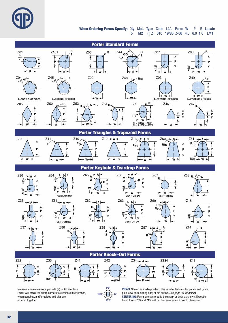
When Ordering Forms Specify: Qty Mat. Type Code L2/L Form W P R Locate 5 M2 ( ) Z 010 19/80 Z-06 4.0 6.0 1.0 LM1
Incaseswhereclearanceperside(Ø)is.08ØorlessPorterwillbreakthesharpcornerstoeliminateinterference,whenpunches,and/orguidesanddiesareordered together.
VIEWS:Shownasin-dieposition.Thisisreflectedviewforpunchandguide,planview(thrucuttingend)ofdiebutton.See page 39 for details.CENTERING:Formsarecenteredtotheshankorbodyasshown.ExceptionbeingformsZ09andZ15,willnotbecenteredonPduetoclearance.
Porter Standard Forms
Porter Triangles & Trapezoid Forms
Porter Keyhole & Teardrop Forms
Porter Knock–Out Forms
33
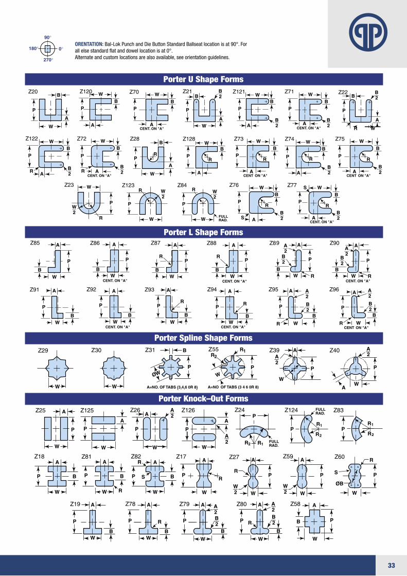
ORENTATION:Bal-LokPunchandDieButtonStandardBallseatlocationisat90°.Forallelsestandardflatanddowellocationisat0°.Alternateandcustomlocationsarealsoavailable,seeorientationguidelines.
Porter U Shape Forms
Porter L Shape Forms
Porter Spline Shape Forms
Porter Knock–Out Forms
34
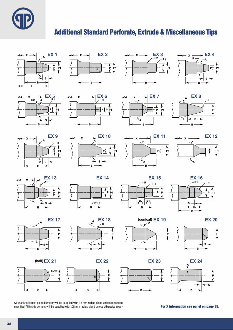
Additional Standard Perforate, Extrude & Miscellaneous Tips
Allshanktolargestpointdiameterwillbesuppliedwith13mmradiusblendunlessotherwisespecified.Allinsidecornerswillbesuppliedwith.08mmradiusblendunlessotherwisespeci- For X information see panel on page 35.