Embed Size (px)
Citation preview

GLAST LAT Project DOE/NASA Baseline-Preliminary Design Review, January 8, 2002
J. Eric Grove CAL Ground Software 1
GLAST Large Area Telescope:GLAST Large Area Telescope:
Calorimeter Ground Software
J. Eric GroveNaval Research Lab, Washington DCCalorimeter Ground Software [email protected]
Gamma-ray Large Gamma-ray Large Area Space Area Space TelescopeTelescope
GLAST LAT Project DOE/NASA Baseline-Preliminary Design Review, January 8, 2002
J. Eric Grove CAL Ground Software 2
OutlineOutline
Organization and Manpower Scope of Task
Energy reconstruction Direction reconstruction Calibration
Work Plan
Supporting materials

GLAST LAT Project DOE/NASA Baseline-Preliminary Design Review, January 8, 2002
J. Eric Grove CAL Ground Software 3
CAL Software OrganizationCAL Software Organization
Calorimeter Subsystem Manager W.N. Johnson (NRL)
CAL Software Manager J.E. Grove (NRL) A. Djannati-Atai (CdF)
CAL software team at NRL Manpower
• Scientists 1.25 FTE
• Data Analyst 0.4 FTE
CAL software team in France Manpower
• Scientists 1.5 FTE
• Grad students 1.0 FTE
Given 4.1 FTE in CAL team, WAG levels of effort allocation Design & Doc (50%) 2.0 FTE Coding (15%) 0.6 FTE Testing/Running (35%) 1.5 FTE Total 4.1 FTE
Note: not including CAL work at GSFC, SLAC, WU, …

GLAST LAT Project DOE/NASA Baseline-Preliminary Design Review, January 8, 2002
J. Eric Grove CAL Ground Software 4
Scope of Software TaskScope of Software Task
Primary Responsibilities CAL event reconstruction
• Energy reconstruction
• Direction reconstruction CAL calibration
• Electronic calibration
• GCR calibration Secondary or Supporting Responsibilities
Simulation Background rejection State tracking
• Performance state (e.g. dead channels)
• Failure remediation Instrument Response Function
• Spectral deconvolution

GLAST LAT Project DOE/NASA Baseline-Preliminary Design Review, January 8, 2002
J. Eric Grove CAL Ground Software 5
Energy ReconstructionEnergy Reconstruction
Primary scientific function of calorimeter is to measure energy of incident photons By design, segmentation of CAL provides opportunity to improve
knowledge of photon E To first order, incident energy is sum of signals in CsI Several correction factors:
• Energy loss in TKR– Dominant at low E (~100 MeV)– Correction: count hits in Si, scale by magic factor– Status: algorithm in use, but should be improved
» Work in progress in France» Future work in coordination with TKR team
• Longitudinal leakage– Dominant at high E (~100 GeV)– Correction: shower profiling or leakage correlation– Status: good algorithms in use

GLAST LAT Project DOE/NASA Baseline-Preliminary Design Review, January 8, 2002
J. Eric Grove CAL Ground Software 6
Energy reconstructionEnergy reconstruction
More correction factors...• Side leakage
– ~10-20% of Aeff has significant escape out the side– Correction: same algorithms as longitudinal leakage
» Special cases, different coefs for leakage correlation– Status: in development in France
• Passive material in CAL– Most important contributor: grid walls– Correction: change in profiling or correlation coefs– Status: in development in France
• Direct deposition in PIN diodes– Small correction– Status: future work
Iterative procedure• TKR needs CAL energy to seed its direction finder, and CAL
needs TKR direction to generate correction factors– Status: algorithm exists, but will be rewritten

GLAST LAT Project DOE/NASA Baseline-Preliminary Design Review, January 8, 2002
J. Eric Grove CAL Ground Software 7
Energy ResolutionEnergy Resolution
How well does it work? Beam test of prototype CAL

GLAST LAT Project DOE/NASA Baseline-Preliminary Design Review, January 8, 2002
J. Eric Grove CAL Ground Software 8
Direction reconstructionDirection reconstruction
By design, the CAL is hodoscopic Useful for
• Background rejection• Calorimeter-only trajectories
Shower passage through xtal has three coordinates, two from xtal ID and a third at the Center of Light (CoL) position
• Use light asymmetry to measure CoL– Status: good algorithm in use
» Depends on good asymmetry maps, to be updated
• Ensemble of position measurements gives incident direction
– Status: basic algorithm in use
» Two 2D projections
» Future work on other algorithms

GLAST LAT Project DOE/NASA Baseline-Preliminary Design Review, January 8, 2002
J. Eric Grove CAL Ground Software 9
Positioning by “light asymmetry”Positioning by “light asymmetry”
(segments)
(Rig
ht
- L
eft)
/ (R
igh
t +
Lef
t) Darkening the ends straightensthe light asymmetry.

GLAST LAT Project DOE/NASA Baseline-Preliminary Design Review, January 8, 2002
J. Eric Grove CAL Ground Software 10
Position Resolution, SLAC ’97 BeamPosition Resolution, SLAC ’97 Beam
Longitudinal position resolution:• x = 0.04 cm - 0.4 cm.• 3 3 19 cm crystals.
Position resolution is a function of:• Slope of asymmetry measure;• Energy deposited in crystal;• Shower multiplicity;• Transverse shower development.

GLAST LAT Project DOE/NASA Baseline-Preliminary Design Review, January 8, 2002
J. Eric Grove CAL Ground Software 11
Calibration NeedsCalibration Needs
What needs to be calibrated? CAL needs to make energy and position measurements
• Gain scale (conversion of ADC bins to MeV)• Map of scintillation response
How often? Timescales likely to be ~ months to year (TBR).
Where do the data come from? Ground calibration of Engineering Model (EM), Qual Module
(QM), Calibration Unit (CU), Flight Modules (FMs) Beam tests of EM, CU In-flight calibration of FM

GLAST LAT Project DOE/NASA Baseline-Preliminary Design Review, January 8, 2002
J. Eric Grove CAL Ground Software 12
Calorimeter CalibrationCalorimeter Calibration
Functional requirements (top level) Pedestals: FSW shall generate the pedestal centroid and width for each gain
range for each PIN diode. • Pedestal centroid and width for 12288 channels.• Code exists, in use; need similar flight s/w process.
Electronic gain: eCalib shall generate a linear gain model for each gain range for each PIN diode.
• Gain slope (bins/fC), slope uncertainty, offset, offset uncertainty for 12288 channels.
• Prototype code exists, in use.
Integral non-linearity: eCalib shall generate look-up table for each gain range for each PIN diode.
• ~50 ordered pairs (pulse input, ADC output) for 12288 channels.• Prototype code exists, in use.
Differential non-linearity: eCalib shall generate look-up table for each gain range for each PIN diode.
• ~4000 values (ADC output) for 12288 channels.• No code exists.

GLAST LAT Project DOE/NASA Baseline-Preliminary Design Review, January 8, 2002
J. Eric Grove CAL Ground Software 13
Calorimeter CalibrationCalorimeter Calibration
Functional requirements (top level) Scintillation efficiency: pre-flight beam tests shall determine scintillation
efficiency (i.e. light yield as fcn of GCR charge) for sample crystals. • TBD (~5) coeffs and uncertainties.• No code exists
Light yield: GCRCalib shall calculate the light yield (i.e. electrons per MeV) at the center of each log for each PIN diode.
• Light yield, statistical error, systematic error for 6144 diodes.• Prototype code exists, in use.
Light attenuation: GCRCalib shall produce maps of light attenuation (i.e. light yield as a fcn of longitudinal position) for each face (P, M) and the sum of faces (P+M) for each log.
• TBD (~6) coeffs and uncertainties for 9216 maps.• Prototype code exists, in use.
Light asymmetry: GCRCalib shall produce maps of light asymmetry (i.e. (P-M)/(P+M) as a fcn of longitudinal position) for each log.
• TBD (~6) coeffs and uncertainties for 3072 xtals.• Prototype code exists, in use.
GLAST LAT Project DOE/NASA Baseline-Preliminary Design Review, January 8, 2002
J. Eric Grove CAL Ground Software 14
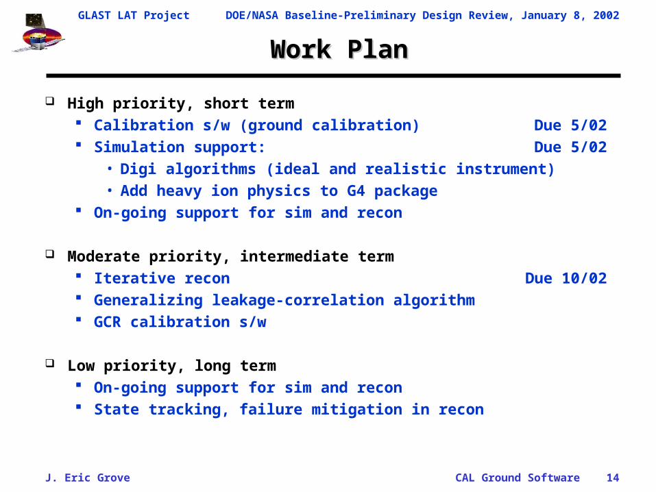
Work PlanWork Plan
High priority, short term Calibration s/w (ground calibration) Due 5/02 Simulation support: Due 5/02
• Digi algorithms (ideal and realistic instrument)• Add heavy ion physics to G4 package
On-going support for sim and recon
Moderate priority, intermediate term Iterative recon Due 10/02 Generalizing leakage-correlation algorithm GCR calibration s/w
Low priority, long term On-going support for sim and recon State tracking, failure mitigation in recon

GLAST LAT Project DOE/NASA Baseline-Preliminary Design Review, January 8, 2002
J. Eric Grove CAL Ground Software 15
Supporting MaterialsSupporting Materials
Appendix 1: Energy reconstruction Appendix 2: Direction reconstruction Appendix 3: Iterative recon Appendix 4: Calibration requirements Appendix 5: Cosmic ray calibration Appendix 6: State tracking Appendix 7: Spectral deconvolution

GLAST LAT Project DOE/NASA Baseline-Preliminary Design Review, January 8, 2002
J. Eric Grove CAL Ground Software 16
Appendix 1: Energy ReconstructionAppendix 1: Energy Reconstruction
Primary scientific fcn of CAL is to measure energy of incident photons. Much of the incident energy escapes the calorimeter
• At low E, small fraction of E reaches CAL.– For Einc = 100 MeV, <Eobs> ~ 50 MeV
• At high E, most E blows out the back.– For Einc = 100 GeV, <Eobs> ~ 40 GeV
By design, segmentation of CAL provides opportunity to improve knowledge of incident energy of photon.
Functional requirements (top level) Energy per xtal: Recon shall calculate the energy
deposited within individual CsI xtals. Incident energy: Recon shall estimate the incident
photon/particle energy.

GLAST LAT Project DOE/NASA Baseline-Preliminary Design Review, January 8, 2002
J. Eric Grove CAL Ground Software 17
Appendix 1: Energy ReconstructionAppendix 1: Energy Reconstruction
Correcting for energy escaping out the back of the CAL Simplest: Geometric correction.
• Look-up table corrects deposited energy and shower pathlength to typical incident energy.
– Derived from mean shower profiles.– Resulting incident total energy will have low tail from shower
fluctuations, late-starting showers.
More advanced: Shower-profile fitting.
• Mean longitudinal profile is well-described by gamma distribution:
• Profile fitting corrects the low E depositions of late-starting showers, i.e. it removes some of the low-energy tail
• Shower fluctuations are still significant, shower leaks out the back of calorimeter.
/
11 xex
dx
dE
GLAST LAT Project DOE/NASA Baseline-Preliminary Design Review, January 8, 2002
J. Eric Grove CAL Ground Software 18
Appendix 1: Energy ReconstructionAppendix 1: Energy Reconstruction
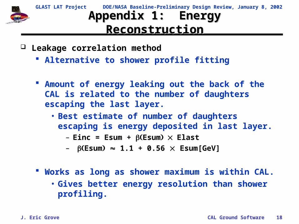
Leakage correlation method Alternative to shower profile fitting
Amount of energy leaking out the back of the CAL is related to the number of daughters escaping the last layer.
• Best estimate of number of daughters escaping is energy deposited in last layer.
– Einc = Esum + EsumElast
– Esum 1.1 + 0.56 Esum[GeV]
Works as long as shower maximum is within CAL.• Gives better energy resolution than shower profiling.

GLAST LAT Project DOE/NASA Baseline-Preliminary Design Review, January 8, 2002
J. Eric Grove CAL Ground Software 19
Appendix 1: Energy ReconstructionAppendix 1: Energy Reconstruction
Shower profile fitting Mean longitudinal profile is well-described by gamma
distribution:
Code exists and is in use Leakage correlation
Amount of energy leaking out back of CAL is related to number of daughters escaping last CAL layer.
• Best estimate of number of daughters is energy deposited in last layer
– Einc = Esum + Esum,Elast Code exists, is in use, needs generalization
Leakage correlation generally gives better resolution than profiling
/
11 xex
dx
dE

GLAST LAT Project DOE/NASA Baseline-Preliminary Design Review, January 8, 2002
J. Eric Grove CAL Ground Software 20

GLAST LAT Project DOE/NASA Baseline-Preliminary Design Review, January 8, 2002
J. Eric Grove CAL Ground Software 21

GLAST LAT Project DOE/NASA Baseline-Preliminary Design Review, January 8, 2002
J. Eric Grove CAL Ground Software 22

GLAST LAT Project DOE/NASA Baseline-Preliminary Design Review, January 8, 2002
J. Eric Grove CAL Ground Software 23
Appendix 1: Energy ResolutionAppendix 1: Energy Resolution
How well does it work? Beam test of prototype CAL
GLAST LAT Project DOE/NASA Baseline-Preliminary Design Review, January 8, 2002
J. Eric Grove CAL Ground Software 24
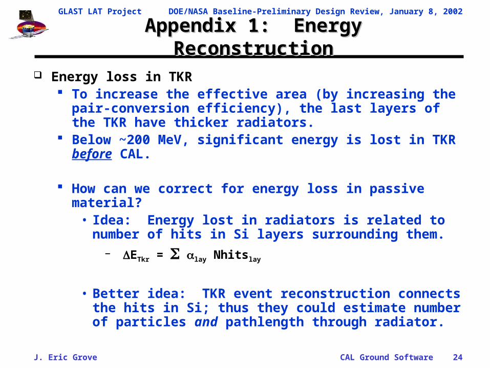
Appendix 1: Energy ReconstructionAppendix 1: Energy Reconstruction
Energy loss in TKR To increase the effective area (by increasing the pair-
conversion efficiency), the last layers of the TKR have thicker radiators.
Below ~200 MeV, significant energy is lost in TKR before CAL.
How can we correct for energy loss in passive material?• Idea: Energy lost in radiators is related to number of
hits in Si layers surrounding them.– ETkr = lay Nhitslay
• Better idea: TKR event reconstruction connects the hits in Si; thus they could estimate number of particles and pathlength through radiator.

GLAST LAT Project DOE/NASA Baseline-Preliminary Design Review, January 8, 2002
J. Eric Grove CAL Ground Software 25
Appendix 2: Direction ReconstructionAppendix 2: Direction Reconstruction
Calorimeter-only trajectories By design, the CAL is hodoscopic
• Shower passage through xtal has three coordinates, two according to xtal ID and a third at the Center of Light position
• Ensemble of position measurements gives incident direction TKR has primary responsibility of shower imaging, but
• Conversion deep in TKR can benefit from CAL information• Low-E photons may benefit from CAL clustering (i.e. energy
per pair daughter)• CAL-only imaging may be useful in some cases (e.g. timing
studies)
Functional requirements (top level) Position calculation: Recon shall calculate positions of
interactions within individual CsI xtals. Direction calculation: Recon shall estimate the incident photon
direction from CAL information, and support TKR direction recon.

GLAST LAT Project DOE/NASA Baseline-Preliminary Design Review, January 8, 2002
J. Eric Grove CAL Ground Software 26
Appendix 2: Position ReconstructionAppendix 2: Position Reconstruction
Each crystal provides three spatial coordinates for E. Xtal ID gives two coordinates, z and x or y.
• Gives resolution z = 20/12 = 6 mm and systematic bias to center of xtal
Difference in signal between ends of xtal gives third coordinate.• “Longitudinal” position
• Gives much better resolution, x = 0.4 – 3 mm, and no bias.
• Resolution is fcn of E, spread of shower, and shower multiplicity Longitudinal position determination
If light falls linearly with distance along xtal, then position is proportional to difference in signals at two ends.
Scaling the difference by the total light removes the energy dependence from the position.
Thus, the “light asymmetry measure”
)(
)(
LeftRight
LeftRightA

GLAST LAT Project DOE/NASA Baseline-Preliminary Design Review, January 8, 2002
J. Eric Grove CAL Ground Software 27
App 2: Positioning by “light asymmetry”App 2: Positioning by “light asymmetry”
(segments)
(Rig
ht
- L
eft)
/ (R
igh
t +
Lef
t) Darkening the ends straightensthe light asymmetry.

GLAST LAT Project DOE/NASA Baseline-Preliminary Design Review, January 8, 2002
J. Eric Grove CAL Ground Software 28
App 2: Position Resolution, SLAC ’97 BeamApp 2: Position Resolution, SLAC ’97 Beam
Longitudinal position resolution:• x = 0.04 cm - 0.4 cm.• 3 3 19 cm crystals.
Position resolution is a function of:• Slope of asymmetry measure;• Energy deposited in crystal;• Shower multiplicity;• Transverse shower development.

GLAST LAT Project DOE/NASA Baseline-Preliminary Design Review, January 8, 2002
J. Eric Grove CAL Ground Software 29
Appendix 2: Direction ReconstructionAppendix 2: Direction Reconstruction
How should we convert the positions in the xtals into an incident direction? Typical number of xtals hit is ~30 (recall 8 layers). Cloud of spatial coordinates with differing weights.
Candidate algorithms Minimize squared perpendicular distance to track axis
• Uses longitudinal and xtal ID positions, uneven weights• Requires numerical search in 4-D parameter space
Minimize squared distance to each layer crossing• May use only longitudinal positions (which are more precise,
unbiased)• Analytic solution in xz and yz planes. Very fast.
Connect the dots, top and bottom• Works quite well on corn-rows
And others…
GLAST LAT Project DOE/NASA Baseline-Preliminary Design Review, January 8, 2002
J. Eric Grove CAL Ground Software 30
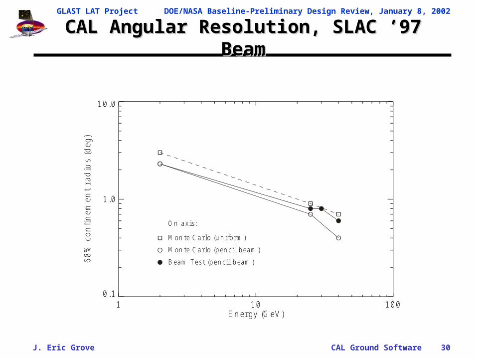
CAL Angular Resolution, SLAC ’97 BeamCAL Angular Resolution, SLAC ’97 Beam
1 10 100E n ergy (G eV )
0.1
1.0
10.0
68
% c
onfi
nem
ent
rad
ius
(deg
)
M on te C ar lo (u n iform )
M on te C ar lo (pen cil beam )
B eam Test (pen cil beam )
O n axis:

GLAST LAT Project DOE/NASA Baseline-Preliminary Design Review, January 8, 2002
J. Eric Grove CAL Ground Software 31
Appendix 3: Iterative ReconAppendix 3: Iterative Recon
Outline of process
1. CAL: Convert to charge units
– Use electronic calib. Convert from ADC bins to charge at FEE.
2. CAL: Calculate energy in each xtal
– Convert to MeV at center of xtal. Assume position = center of xtal.
3. CAL: Calculate total energy deposited
– Simple xtal sum
4. CAL+TKR: Make simple energy corrections
– Scale by avg-profile correction, f(Eobs,)?
– Add simple TKR energy correction, i.e. scale by num hits?
5. CAL: Simple energy centroid
– Calculate centroid in XZ and YZ planes using logID positions.

GLAST LAT Project DOE/NASA Baseline-Preliminary Design Review, January 8, 2002
J. Eric Grove CAL Ground Software 32
Appendix 3: Iterative ReconAppendix 3: Iterative Recon
Outline of process (cont.)
5. TKR: Direction recon– Insert the real TKR stuff.
6. TKR: Energy recon– Do the best TKR energy-loss correction, following daughters
or whatever.7. CAL: Recalculate energy in each xtal
– Use TKR direction. Accounts for failures and light tapering maps.
8. CAL: Recalculate total energy deposited– Total all xtal energies, having accounted for failures and
taper.9. CAL: Recalculate simple energy centroid
– Repeat simple centroid, having accounted for failures and taper.

GLAST LAT Project DOE/NASA Baseline-Preliminary Design Review, January 8, 2002
J. Eric Grove CAL Ground Software 33
Appendix 3: Iterative ReconAppendix 3: Iterative Recon
Outline of process (cont.)
10.ACD+CAL+TKR: Particle ID (necessary here, or later?)
– Some complicated algorithms to confirm photon or particle.
11.TKR(+CAL): Direction recon
– Do the real TKR direction recon. Use CAL info to improve direction for late conversions, if possible.
12.CAL+TKR: Energy recon
– Use best CAL and TKR information to estimate incident energy.
– Use profiling, leakage correlation, TKR info, whatever.
13. Iterate steps 10-12 as necessary

GLAST LAT Project DOE/NASA Baseline-Preliminary Design Review, January 8, 2002
J. Eric Grove CAL Ground Software 34
Appendix 4: Calibration RequirementsAppendix 4: Calibration Requirements
Pedestal Calibration Pedestals: FSW shall generate the pedestal centroid and width for each
gain range for each PIN diode. • Pedestal centroid and width for 12288 channels.
Generated when?• Module Assy & Test at NRL• Instrument I&T at SLAC• S/C integration and end-to-end at ??• Flight
– Updated ~ monthly? Generated how?
• Flight s/w process (or TEM simulator) histograms, fits centroid and width, telemeters centroid and width. Diagnostic mode telems histograms.
Data volume• 2 x 12288 floats = 103kB per month
Status• Prototyped in IDL, find_pedestals.pro, and ROOT• Needed for EM

GLAST LAT Project DOE/NASA Baseline-Preliminary Design Review, January 8, 2002
J. Eric Grove CAL Ground Software 35
Appendix 4: Calibration RequirementsAppendix 4: Calibration Requirements
Electronic Gain Calibration Electronic gain: eCalib shall generate a linear gain model for each gain
range for each PIN diode. • Gain slope (bins/fC), slope uncertainty, offset, offset uncertainty for
12288 channels. Generated when?
• Module Assy & Test at NRL• Instrument I&T at SLAC, CU at SLAC etc.• S/C integration and end-to-end at ??• Flight
– Updated ~ quarterly? Generated how?
• Data created by on-board chg-calib process, telem in calib mode.• GSW identifies two fiducial charge peaks, fits line.
Data volume• 4 x 12288 floats = 200kB per month
Status• Prototyped in IDL, fit_intlin_fits.pro• Needed for EM

GLAST LAT Project DOE/NASA Baseline-Preliminary Design Review, January 8, 2002
J. Eric Grove CAL Ground Software 36
Appendix 4: Calibration RequirementsAppendix 4: Calibration Requirements
Integral Non-Linearity Calibration Integral non-linearity: eCalib shall generate look-up table for each gain
range for each PIN diode. • ~50 ordered pairs (pulse input, ADC output) for 12288 channels.
Generated when?• Module Assy & Test at NRL• Instrument I&T at SLAC, CU at SLAC etc.• S/C integration and end-to-end at ??• Flight
– Updated ~ quarterly? Generated how?
• Data created by on-board chg-calib process, telem in calib mode.• GSW fits all charge peaks, matches with input charge.
Data volume• ~100 x 12288 long integers = 5.2MB per month
Status• Prototyped in IDL, fit_intlin.pro• Needed for EM
GLAST LAT Project DOE/NASA Baseline-Preliminary Design Review, January 8, 2002
J. Eric Grove CAL Ground Software 37
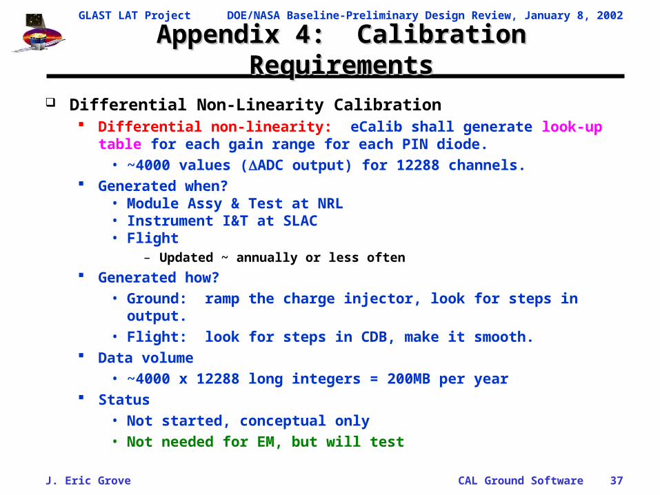
Appendix 4: Calibration RequirementsAppendix 4: Calibration Requirements
Differential Non-Linearity Calibration Differential non-linearity: eCalib shall generate look-up table for each gain
range for each PIN diode. • ~4000 values (ADC output) for 12288 channels.
Generated when?• Module Assy & Test at NRL• Instrument I&T at SLAC• Flight
– Updated ~ annually or less often
Generated how?• Ground: ramp the charge injector, look for steps in output.• Flight: look for steps in CDB, make it smooth.
Data volume• ~4000 x 12288 long integers = 200MB per year
Status• Not started, conceptual only• Not needed for EM, but will test

GLAST LAT Project DOE/NASA Baseline-Preliminary Design Review, January 8, 2002
J. Eric Grove CAL Ground Software 38
Appendix 4: Calibration RequirementsAppendix 4: Calibration Requirements
Scintillation Efficiency Calibration Scintillation efficiency: pre-flight beam tests shall determine scintillation
efficiency (i.e. light yield as fcn of GCR charge) for sample crystals. • TBD (~5) coeffs and uncertainties. How many xtals?
Generated when?• Calibration Unit• Other xtal samples?• Never updated.
Generated how?• Heavy ion beam tests of CU and maybe test crystals.• Fit dL/dE, a fcn of Z.
Data volume• I dunno. Not much. Never updated.
Status• No serious code exists yet, just some playing in IDL.• Not needed for EM. Will be measured with EM.

GLAST LAT Project DOE/NASA Baseline-Preliminary Design Review, January 8, 2002
J. Eric Grove CAL Ground Software 39
Appendix 4: Calibration RequirementsAppendix 4: Calibration Requirements Light Yield Calibration
Light yield: GCRCalib shall calculate the light yield (i.e. electrons per MeV) at the center of each log for each PIN diode.
• Light yield, statistical error, systematic error for 6144 diodes. Generated when?
• Module Assy & Test at NRL, with muons• Instrument I&T at SLAC, CU at SLAC etc., with muons & nuclei• S/C integration and end-to-end at ?? With muons• Flight, with GCRs
– Updated ~ monthly? Generated how?
• From muons, heavy ion beams, or GCRs, telemetered in calib mode.• For muons, define beam geometry through xtals, select MIPs, and fit
Landau.• For GCRs, complicated process described elsewhere.
Data volume• 3 x 6144 floats = 80kB per month
Status• For muons, prototyped in IDL, mu_checkout.pro• For GCRs, algorithm outlined but not coded or tested.• Needed for EM.

GLAST LAT Project DOE/NASA Baseline-Preliminary Design Review, January 8, 2002
J. Eric Grove CAL Ground Software 40
Appendix 4: Calibration RequirementsAppendix 4: Calibration Requirements Light Attenuation Calibration
Light attenuation: GCRCalib shall produce maps of light attenuation (i.e. light yield as a fcn of longitudinal position) for each face (P, M) and the sum of faces (P+M) for each log.
• TBD (~6) coeffs and uncertainties for 9216 maps. Generated when?
• Module Assy & Test at NRL, with muons. This is best dataset.• Instrument I&T at SLAC, CU at SLAC etc., verification• Flight, with GCRs
– Updated ~ annually? Generated how?
• For muons, define beam geometry through xtals, select MIPs, and fit Landau.
• For GCRs, complicated process described in Appendix. Data volume
• ~12 x 9216 floats = 450 kB per month Status
• Prototyped in IDL, mu_checkout.pro and find_slopes.pro• Needs more sophisticated attenuation model. GCR process needs
work.• Needed for EM

GLAST LAT Project DOE/NASA Baseline-Preliminary Design Review, January 8, 2002
J. Eric Grove CAL Ground Software 41
Appendix 4: Calibration RequirementsAppendix 4: Calibration Requirements Light Asymmetry Calibration
Light asymmetry: GCRCalib shall produce maps of light asymmetry (i.e. (P-M)/(P+M) as a fcn of longitudinal position) for each log.
• TBD (~6) coeffs and uncertainties for 3072 xtals. Generated when?
• Module Assy & Test at NRL, with muons. This is best dataset.• Instrument I&T at SLAC, CU at SLAC etc., verification• Flight, with GCRs
– Updated ~ annually? Generated how?
• For muons, define beam geometry through xtals, select MIPs, and fit Landau.
• For GCRs, complicated process described in Appendix. Data volume
• ~12 x 3072 floats = 150 kB per month Status
• Prototyped in IDL, mu_checkout.pro and find_slopes.pro, and ROOT.• Needs more sophisticated asymmetry model. GCR process needs
work.• Needed for EM

GLAST LAT Project DOE/NASA Baseline-Preliminary Design Review, January 8, 2002
J. Eric Grove CAL Ground Software 42
Appendix 5: GCR CalibrationAppendix 5: GCR Calibration
Cosmic Ray Calibration (new) High flux of GCRs gives good calibration over full dynamic range (see
Appendix). Derive calibration with statistical precision of better than few % each day
over full dynamic range.
Flight s/w flags and telemeters GCR data in Calibration Mode (4-Range Mode).
• Might be pre-scaled to reduce data volume.– This would give longer times between calibration.
Functional Requirements GCRCalib shall process Calibration Mode telemetry. GCRCalib shall query Perf State to modify algorithms, fault tolerance. GCRCalib shall identify non-interacting GCRs with clean TKR trajectories through
logs. GCRCalib shall accumulate energy loss and light asymmetry maps in GCR DB.
• See algorithms.
He: ~140 HzCNO: ~10 Hz ~1100 per xtal per daySi: ~0.4 HzFe: ~0.8 Hz ~70 per xtal per day

GLAST LAT Project DOE/NASA Baseline-Preliminary Design Review, January 8, 2002
J. Eric Grove CAL Ground Software 43
Appendix 5: GCR Calibration ProcessAppendix 5: GCR Calibration Process
Algorithms Physics inputs:
• dE/dx for heavy ions. Code expressions from the literature.• dL/dE for heavy ions. Measure it, then code it. Analytic expr. exist.
Elements of calibration process:1. Extract multiMIP events.2. Identify likely GCRs, reject obvious junk.3. Fit tracks.4. Accept events with clean track through log, no edges or glancing hits.5. Identify charges.6. Identify charge-changing interactions.7. Identify mass-changing interactions.8. Fit dE/dx.9. Accumulate energy losses and light asymmetries.

GLAST LAT Project DOE/NASA Baseline-Preliminary Design Review, January 8, 2002
J. Eric Grove CAL Ground Software 44
Appendix 5: Calibration with Cosmic RaysAppendix 5: Calibration with Cosmic Rays
Nuclear interactions Majority of GCRs suffer
nuclear interactions as they pass through calorimeter.
Interaction lengths:
• N,CsI = 86 g/cm2
• Fe,CsI = 58 g/cm2
GCR at 45 deg traverses ~100 g/cm2 of CsI
• ~30% of CNO group and ~20% of Fe survive without interacting.
How many per day in each CsI bar? ~1100 non-interacting CNO. ~70 non-interacting Fe.
Scintillation efficiency Light output of CsI(Tl) is not
strictly proportional to DE for heavy ions. dL/dE, the light output per
unit energy loss, decreases slowly with increasing dE/dx for heavy ions, but is constant for EM showers.
dL/dE is fcn of dE/dx, rather than charge of the beam.
Magnitude (in NaI!!):• ~0.9 near minimum
ionizing.• ~0.3 near end of range.
Need to measure in heavy ion beam!
GLAST LAT Project DOE/NASA Baseline-Preliminary Design Review, January 8, 2002
J. Eric Grove CAL Ground Software 45
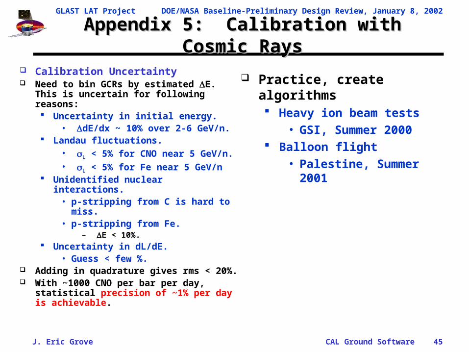
Appendix 5: Calibration with Cosmic RaysAppendix 5: Calibration with Cosmic Rays
Calibration Uncertainty Need to bin GCRs by estimated E. This
is uncertain for following reasons: Uncertainty in initial energy.
• dE/dx ~ 10% over 2-6 GeV/n. Landau fluctuations.
• L < 5% for CNO near 5 GeV/n.• L < 5% for Fe near 5 GeV/n
Unidentified nuclear interactions.• p-stripping from C is hard to
miss.• p-stripping from Fe.
– E < 10%. Uncertainty in dL/dE.
• Guess < few %. Adding in quadrature gives rms < 20%. With ~1000 CNO per bar per day,
statistical precision of ~1% per day is achievable.
Practice, create algorithms Heavy ion beam tests
• GSI, Summer 2000 Balloon flight
• Palestine, Summer 2001

GLAST LAT Project DOE/NASA Baseline-Preliminary Design Review, January 8, 2002
J. Eric Grove CAL Ground Software 46
Appendix 5: Ni beam at GSIAppendix 5: Ni beam at GSI
Ni beam into test box Test box xtals are 37 cm,
dual PIN with Sylgard bond. Fragments are created in
beam monitor• 1 cm plastic paddle
upstream At this energy, all species
penetrate both CsI layers, but there is slowing down (note downstream signal is bigger than upstream).
Similar plot for C and daughters.
Charges are easy to identify.

GLAST LAT Project DOE/NASA Baseline-Preliminary Design Review, January 8, 2002
J. Eric Grove CAL Ground Software 47
Appendix 5: Ni beam at GSIAppendix 5: Ni beam at GSI
Same Ni beam, same crystals, but added material upstream 2” polyethylene slows
down primary beam and creates fragments with varying energies (from varying depths of creation).
Ni through Ti stop in second CsI layer.
Sc and smaller penetrate second CsI layer.
Demonstrates that identifying charges in CsI is quite simple, even in the presence of a spectrum of incident energies.
Ni beam , 700 M eV/n, 2" poly upstream , run 308
0 500 1000 1500 2000Downstream log, sum of b ig P INs (ADC bins)
0
1000
2000
3000
Ups
trea
m lo
g, s
um
of
big
PIN
s (A
DC
bin
s) Ni
Co
Fe
Mn
CrV
T iS c
CaK

GLAST LAT Project DOE/NASA Baseline-Preliminary Design Review, January 8, 2002
J. Eric Grove CAL Ground Software 48
Appendix 6: State TrackingAppendix 6: State Tracking
State Tracking Level 1 PDA must track the state of the instrument
1. Command State• The verified configuration of the h/w.• Analysis needs to know data modes, etc.• Created by first-pass L1 processing, MOPS tasks.
2. Performance State• Documents performance or anomalous conditions not
described by Cmd State: dead logs, bad gain ranges, etc.• Created by first-pass L1 processing.• Output feeds into Cal Recon, allows fault tolerance in Recon.
3. Calibration State• Created by Calibration in L1 processing.• Output feeds into Cal Recon, Cal Calib Parameter DB.
Develop in concert with TKR, ACD. System-wide service.

GLAST LAT Project DOE/NASA Baseline-Preliminary Design Review, January 8, 2002
J. Eric Grove CAL Ground Software 49
Appendix 7: Spectral DeconvolutionAppendix 7: Spectral Deconvolution
Resolution broadening is important for steep spectra. More-abundant low-energy photons look like high-energy photons. Observed spectrum is artificially flattened. So even if you make your best guess of the energy of each photon,
you can still get the wrong spectral index. Still need to do resolution deconvolution.
Spectral deconvolution is more than just energy reconstruction. Shower profiling helps correct observed E into incident photon
energy, but … Need to account for
1. resolution broadening, which can be increased by profiling.2. conversion efficiency (cm2)3. livetime.
GLAST LAT Project DOE/NASA Baseline-Preliminary Design Review, January 8, 2002
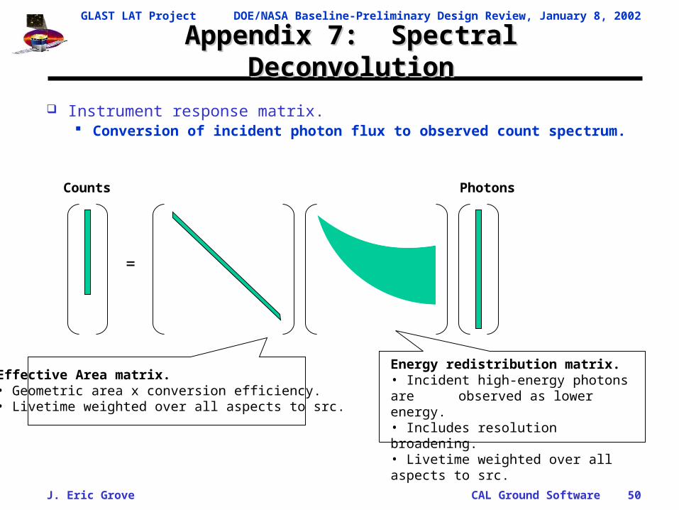
J. Eric Grove CAL Ground Software 50
Counts Photons
=
Energy redistribution matrix.• Incident high-energy photons are
observed as lower energy.• Includes resolution broadening.• Livetime weighted over all aspects to src.
Effective Area matrix.• Geometric area x conversion efficiency.• Livetime weighted over all aspects to src.
Appendix 7: Spectral DeconvolutionAppendix 7: Spectral Deconvolution
Instrument response matrix. Conversion of incident photon flux to observed count spectrum.

GLAST LAT Project DOE/NASA Baseline-Preliminary Design Review, January 8, 2002
J. Eric Grove CAL Ground Software 51
Appendix 7: Spectral DeconvolutionAppendix 7: Spectral Deconvolution
Spectral deconvolution Forward-Folding Deconvolution from an ensemble of detected
gamma rays. Create Instrument Response Matrix
• Transforms measured energy deposition into incident energy as a function of zenith and azimuth.
• Columns of response matrix are Green’s functions at a large number of incident energies.
» i.e. the spectra that should be produced by monoenergetic beams
Candidate incident spectrum is multiplied by the response matrix and compared to the observed spectrum.
Parameters of the candidate spectrum are varied to minimize 2.