Embed Size (px)
Citation preview
GEOTECHNICALINVESTIGATION
REPORT
GLADESVILLE SHOPPING VILLAGERETAIL AND RESIDENTIAL
DEVELOPMENTCOWELL, FLAGSTAFF AND MASSEY
STREETS, GLADESVILLE
Prepared for
GSV Developments Pty Ltd
Report No. GS4992/2-A
25th July 2012
July 2012Geotechnical Investigation Report, Ref: GS4992/2-AGladesville Shopping Centre, Gladesville NSW page 2 of 36
_______________________________________________________________________________________© Aargus Pty Ltd
CONTROLLED DOCUMENT
DISTRIBUTION AND REVISION REGISTER
DISTRIBUTION LIST
Copy No. Custodian Location
_____________________________________________________________________
1 Nick Kariotoglou Aargus (Library)
2 GSV Developments Level 1 Suite 1, No. 10 Help Street,
Pty Ltd Chatswood NSW 2067
3 (electronic) Bernard Young Design [email protected]
Group Pty Ltd
(Mr Adrin Wong)
Note: This register identifies the current custodians of controlled copies of the subject
document.
It is expected that these custodians would be responsible for:
The storage of the document.
Ensuring prompt incorporation of amendments.
Making the document available to pertinent personnel within the organisation.
Encouraging observance of the document by such personnel.
Making the document available for audit.
DOCUMENT HISTORY
Revision No. Issue Date Description
_____________________________________________________________________
25/07/2012 Initial Issue
Issued By:
July 2012Geotechnical Investigation Report, Ref: GS4992/2-AGladesville Shopping Centre, Gladesville NSW page 3 of 36
_______________________________________________________________________________________© Aargus Pty Ltd
EXECUTIVE SUMMARY
Aargus Pty Ltd (‘Aargus’) was requested to conduct a geotechnical investigation at an area
surrounding the existing Gladesville Shopping Centre complex bounded by Massey Street,
Flagstaff Street, Cowell Street and an additional retail precinct fronting Victoria Road. A
retail and residential development consisting of two storeys of commercial development
and four residential towers was proposed.
The purpose of this report was to assess the subsurface conditions within accessible areas
of the site and provide geotechnical recommendations for the design and construction of
the proposed development.
The fieldwork involved a detailed walk-over inspection of the site and surrounds and the
drilling of six boreholes, BH1 and BH6, using TC-bit and solid flight augers, diamond bit
and NMLC coring within the bedrock profile and Standard Penetration Tests (SPT) within
the profile to assess the characteristics of subsurface materials. A standpipe piezometer
was installed in one borehole to monitor groundwater levels.
The subsurface profile generally consisted of minor fill and natural soil profiles overlying
shale and sandstone bedrock sequences of varying weathering and strength.
Shallow pad or strip foundations or deeper piles or rock sockets founded within either Class
IV or Class III shale or the underlying Class III and Class II sandstones appear likely and
appropriate for foundation systems associated with the building structures.
Based on the results of this investigation, it is considered the proposed development is
feasible at this site subject to the recommendations provided in this report.
July 2012Geotechnical Investigation Report, Ref: GS4992/2-AGladesville Shopping Centre, Gladesville NSW page 4 of 36
_______________________________________________________________________________________© Aargus Pty Ltd
TABLE OF CONTENTS
1.0 INTRODUCTION...............................................................................................................7
2.0 SITE DESCRIPTION .........................................................................................................8
3.0 REGIONAL GEOLOGY......................................................................................................9
4.0 AVAILABLE INFORMATION .........................................................................................9
5.0 FIELDWORK................................................................................................................... 10
6.0 INVESTIGATION RESULTS......................................................................................... 12
6.1 Sub-surface Conditions.................................................................................................................12
6.2 Groundwater Conditions..............................................................................................................15
7.0 LABORATORY TEST RESULTS.................................................................................. 16
7.1 Point Load Strength Test Results...............................................................................................16
8.0 DISCUSSION & RECOMMENDATIONS .................................................................... 18
8.1 General ...........................................................................................................................................18
8.2 Excavation Conditions ..................................................................................................................21
8.3 Groundwater Management ..........................................................................................................24
8.4 Temporary Batter Slopes..............................................................................................................25
8.5 Excavation Support.......................................................................................................................26
8.6 Retaining Structures .....................................................................................................................26
8.7 Foundation Systems ......................................................................................................................27
9.0 CONCLUSIONS................................................................................................................ 30
10.0 LIMITATIONS................................................................................................................. 36
July 2012Geotechnical Investigation Report, Ref: GS4992/2-AGladesville Shopping Centre, Gladesville NSW page 5 of 36
_______________________________________________________________________________________© Aargus Pty Ltd
LIST OF TABLES
TABLE 1 – FIELDWORK RESULTS 12
TABLE 2 – GROUND WATER RESULTS 16
TABLE 3 – POINT LOAD STRENGTH TEST RESULTS 17
TABLE 4 – GENERALISED PROFILES BASED ON ESTIMATED ROCK 21
STRENGTHS
TABLE 5 – MINIMUM TEMPORARY BATTER SLOPES 25
TABLE 6 – GEOTECHNICAL DESIGN PARAMETERS 27
TABLE 7 – ESTIMATED DEPTHS TO VARYING ROCK CLASSES 28
July 2012Geotechnical Investigation Report, Ref: GS4992/2-AGladesville Shopping Centre, Gladesville NSW page 6 of 36
_______________________________________________________________________________________© Aargus Pty Ltd
LIST OF APPENDICES
APPENDIX A IMPORTANT INFORMATION ABOUT YOUR
GEOTECHNICAL REPORT
APPENDIX B SITE LOCALITY MAP (FIGURE 1), SITE PLAN (FIGURE 2) &
GEOTECHNICAL CROSS SECTIONS
APPENDIX C ENGINEERING BOREHOLE LOGS AND COREHOLE LOGS
APPENDIX D SITE PHOTOGRAPHS
REFERENCES
1.Australian Standard – Geotechnical Site Investigation, AS1726-1993.
2.Australian Standard – Piling – Design and Installation, AS2159-2009.
3.Pells, P.J.N, Mostyn, G. & Walker B.F., “Foundations on Sandstone and Shale in the
Sydney region”, Australian Geomechanics Journal, 1998
July 2012Geotechnical Investigation Report, Ref: GS4992/2-AGladesville Shopping Centre, Gladesville NSW page 7 of 36
_______________________________________________________________________________________© Aargus Pty Ltd
1.0 INTRODUCTION
This report presents and interprets the findings of the geotechnical investigation carried out
between 6th to 8th and 14th June 2012 at an area surrounding the existing Gladesville
Shopping Centre complex, Gladesville NSW, for a proposed retail and residential
development consisting of two storeys of commercial development and four residential
towers. While it is envisaged the existing basements carparks may be utilised for parts of
the development, basements to approximately four levels have been proposed towards the
southern areas of the development. The proposed development would involve demolition
of existing structures within the site area.
The investigation was requested by Mr Adrin Wong of Bernard Young Design Group Pty
Ltd on behalf of Gladesville Shopping Village (GSV) Developments Pty Ltd.
The purpose of this investigation was to assess the existing site and subsurface conditions
and provide geotechnical input for the conceptual stage design of the proposed
development.
The following are addressed in this report:
Method of investigation,
Site description, including surface and sub-surface conditions,
Site plan indicating borehole locations and footprint of the proposed
development,
Indications of groundwater or seepages, including water table levels.
Excavation conditions and possible excavation methods, site trafficability and
potential vibration conditions.
Results of the field in-situ tests and laboratory testing.
Design parameters for retaining structures and temporary measures.
Recommendations on foundation systems and allowable bearing capacities.
Any other geotechnical information or issues considered relevant to design and
construction processes.
July 2012Geotechnical Investigation Report, Ref: GS4992/2-AGladesville Shopping Centre, Gladesville NSW page 8 of 36
_______________________________________________________________________________________© Aargus Pty Ltd
2.0 SITE DESCRIPTION
The site of the existing Gladesville Shopping Centre complex was located within the
Hunter’s Hill Local Government Area (Municipality of Hunter’s Hill), about 10 kilometres
to the north-west of Sydney CBD. The development site was bounded by Massey Street
and townhouse residential development to the north, Flagstaff Street to the west, Cowell
Street to the south and an additional retail precinct, fronting Victoria Road, to the west.
This retail area did not form part of the development site and was separated by carpark
areas, access roadways and footways.
At the time of the investigation the proposed site included an existing whitegoods retail
store operated under Betta, which fronted Massey Street, but excluded existing residences
fronting Massey Street to its intersection with Flagstaff Street. It included the existing
shopping centre complex over the central area of the site, encompassing a Coles
supermarket, additional variety and specialty shops and two levels of parking under the
complex.
The southern area of the development site encompassed a house at No. 10 Cowell Street
(intersection of Cowell and Flagstaff Streets) utilised as Centre Management by CSV
Developments, an adjoining block of home units fronting Cowell Street, an open carpark
and vehicle access from Cowell Street to the shopping centre, and an additional residence
in the south-west corner. Provided information indicated that at the time of the
investigation the proposed development area was the property of GSV Developments,
except for 10 Cowell Street and the open carpark and vehicle access from Cowell Street,
which were property of Hunter’s Hill Council.
Remaining natural profiles tended to slope down from Massey Street in the north to Cowell
Street to the south and from Victoria Road in the west to Flagstaff Street in the east.
Cowell Street sloped down from the south-west corner to the north-east with its
intersection with Flagstaff Street, this intersection, encompassing 10 Cowell Street, being
the lowest area of the site. Carpark levels beneath the existing shopping complex had been
excavated into the original topographic profile during its initial construction.
July 2012Geotechnical Investigation Report, Ref: GS4992/2-AGladesville Shopping Centre, Gladesville NSW page 9 of 36
_______________________________________________________________________________________© Aargus Pty Ltd
The site locations have been shown on Figure 1, “Site Locality Map”, and Figure 2, “Site
Plan.”
3.0 REGIONAL GEOLOGY
Reference to the Sydney 1:100,000 Geological Series Sheet 9130 Edition 1, 1983,
indicated the site may be close to boundaries between the Ashfield Shale (Rwa) and
Hawkesbury Sandstone (Rh) of the Wianamatta Group. Ashfield Shale generally
comprises black to dark grey shale and laminate while the Hawkesbury Sandstone
generally consists of medium to coarse-grained quartz sandstone, with very minor shale
and laminate lenses.
4.0 AVAILABLE INFORMATION
At the time of preparation of this report, the following drawings were made available to
Aargus:
Survey plans of the site and neighbouring area undertaken by Craig & Rhodes
(Surveyors Engineers Planners) for Moch Pty Ltd, Ref 67/05, Drawing File
6705T03, Sheets 1 to 8 of 8, dated 5/2005, updated 10/08/2005.
Architectural drawings of the existing shopping complex by Bernard Young
Design Group P/L including:
Precinct 4-Existing Plan – Existing Basement 2, Ref 03-11-403, Drawing
No. DA/B-08A, dated 19/04/2012.
Precinct 4-Existing Plan – Existing Retail/Basement 1, Ref 03-11-403,
Drawing No. DA/B-09A, dated 19/04/2012.
Precinct 4-Existing Plan – Existing Shopping Level 2, Ref 03-11-403,
Drawing No. DA/B-10A, dated 19/04/2012.
Architectural drawings of the proposed development basements provided by
Bernard Young Design Group P/L including:
July 2012Geotechnical Investigation Report, Ref: GS4992/2-AGladesville Shopping Centre, Gladesville NSW page 10 of 36
_______________________________________________________________________________________© Aargus Pty Ltd
Precinct 4-Existing Replan, Precinct 4-New Extension, Precinct 3-New
Extension – Plaza and Shopping Level 2, Ref 03-11-403, Drawing No.
DA/PS-10, dated 09/05/12.
Precinct 4-Existing Replan, Precinct 4-New Extension, Precinct 3-New
Extension – Roof Plan, Ref 03-11-403, Drawing No. DA/R-12, dated
09/05/12.
Precinct 4- New Extension – Proposed Basement 3 & 3A, Ref 03-11-403,
Drawing No. DA/B-05, dated 09/05/12.
Precinct 4- New Extension – Proposed Basement 4 & 4A, Ref 03-11-403,
Drawing No. DA/B-06, dated 09/05/12.
Precinct 4-Existing Replan, Precinct 4-New Extension, Precinct 3-New
Extension – Proposed Basement 2 & 2A, Ref 03-11-403, Drawing No.
DA/B-08, dated 09/05/12.
Precinct 4-Existing Replan, Precinct 4-New Extension, Precinct 3-New
Extension – Proposed Retail/Basement 1, Ref 03-11-403, Drawing No.
DA/B-09, dated 09/05/12.
South and East Elevations, Ref 03-11-403, Drawing No. DA/EL-12, dated
26/07/11.
North Elevation, West Elevation, Massey Street Elevation, Ref 03-11-403,
Drawing No. DA/EL-13, dated 26/07/11.
5.0 FIELDWORK
Fieldwork for the geotechnical investigation was carried out by an engineering team from
Aargus, and comprised the following works:
A detailed walk-over inspection of the site to determine the overall surface
conditions and to confirm geotechnical consistency with the surrounding
landform.
Drilling of six boreholes, BH1 to BH6, using a track-mounted Dando Terrier
drilling rig owned and operated by Tightsite. The boreholes were drilled using
a TC-bit with solid flight augers, taken the depths of TC-bit refusal, except
BH1, and thence progressed with diamond bit and NMLC coring within the
July 2012Geotechnical Investigation Report, Ref: GS4992/2-AGladesville Shopping Centre, Gladesville NSW page 11 of 36
_______________________________________________________________________________________© Aargus Pty Ltd
bedrock profile. Surface levels at the borehole locations were estimated from
provided survey drawings.
Standard Penetration Tests (SPT) undertaken at regular intervals within the
boreholes to assess the in-situ strength of subsurface soil layers.
One standpipe piezometer installed in borehole BH4 to determine water table
levels.
Reinstatement of the boreholes with displaced soils and coal mix materials.
The six boreholes were located to cover the approximate locations of the proposed
towers. BH1 was located within the existing Hunter’s Hill Council carpark in the
south-west corner of the proposed development site with BH3 located in the south-east
corner within No. 10 Cowell Street. BH4 was located in the grassed area at the rear of
the existing residential unit block at No. 8 Cowell Street. These boreholes were
estimated to be within the approximated area of the tower block comprising four levels
of basements. BH5 and BH6 were located on the lower carpark level within the
existing shopping complex, designated as Basement 2 on provided drawings of the
existing facility or as P1 within the centre. BH5 was located in the northern corner of
the carpark with BH6 at the southern end. Locations were selected to not only cover
the areas of investigation but also in locations so as to have minimal impact on
operations within the complex. BH2 was located within the access laneway to the
north-east of the commercial facility being utilised as a whitegoods retail outlet by
Betta, which fronts to Massey Street. The approximate locations and designations of
the boreholes are presented in Figure 2, “Site Plan”.
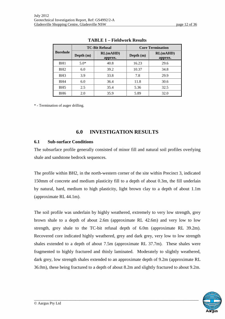
The approximate depths to TC-bit refusal and borehole termination for the six
boreholes have been presented in Table 1.
July 2012Geotechnical Investigation Report, Ref: GS4992/2-AGladesville Shopping Centre, Gladesville NSW page 12 of 36
_______________________________________________________________________________________© Aargus Pty Ltd
TABLE 1 – Fieldwork Results
BoreholeTC-Bit Refusal Core Termination
Depth (m)RL(mAHD)
approx.Depth (m)
RL(mAHD)approx.
BH1 5.0* 40.8 16.23 29.6
BH2 6.0 39.2 10.37 34.8
BH3 3.9 33.8 7.8 29.9
BH4 6.0 36.4 11.8 30.6
BH5 2.5 35.4 5.36 32.5
BH6 2.0 35.9 5.89 32.0
* - Termination of auger drilling.
6.0 INVESTIGATION RESULTS
6.1 Sub-surface Conditions
The subsurface profile generally consisted of minor fill and natural soil profiles overlying
shale and sandstone bedrock sequences.
The profile within BH2, in the north-western corner of the site within Precinct 3, indicated
150mm of concrete and medium plasticity fill to a depth of about 0.3m, the fill underlain
by natural, hard, medium to high plasticity, light brown clay to a depth of about 1.1m
(approximate RL 44.1m).
The soil profile was underlain by highly weathered, extremely to very low strength, grey
brown shale to a depth of about 2.6m (approximate RL 42.6m) and very low to low
strength, grey shale to the TC-bit refusal depth of 6.0m (approximate RL 39.2m).
Recovered core indicated highly weathered, grey and dark grey, very low to low strength
shales extended to a depth of about 7.5m (approximate RL 37.7m). These shales were
fragmented to highly fractured and thinly laminated. Moderately to slightly weathered,
dark grey, low strength shales extended to an approximate depth of 9.2m (approximate RL
36.0m), these being fractured to a depth of about 8.2m and slightly fractured to about 9.2m.
July 2012Geotechnical Investigation Report, Ref: GS4992/2-AGladesville Shopping Centre, Gladesville NSW page 13 of 36
_______________________________________________________________________________________© Aargus Pty Ltd
The shale bedrock was underlain by slightly weathered, medium to high strength, grey
white, slightly fractured sandstone to the BH2 termination depth of about 10.4m.
Boreholes BH5 and BH6, located in the existing lower level basement within Precinct 4-
Existing Replan, indicated 150mm and 120mm thick concrete pavement slabs respectively
and minor fill underlain by shale and sandstone bedrock. Light grey sandy gravel fill was
encountered under the concrete to a depth of 0.4m (approximate RL 37.5m) in BH6.
Shale bedrock was encountered from respective depths of 0.15m (approximate RL 37.75m)
and 0.4m (approximate RL 37.5m) in BH5 and BH6. Moderately weathered, very low to
low strength, grey shale was evidenced to depths of about 2.3m (approximate RL 35.6m) in
BH5 and 1.6m (approximate RL 36.3m) in BH6, these materials being underlain by low to
medium strength shale to TC-bit refusal depths of 2.5m (approximate RL 35.4m) and 2.0m
(approximate RL 35.9m) in BH5 and BH6 respectively. Recovered rock core indicated the
grey, low to medium strength shales extended to respective depths of about 2.9m
(approximate RL 35.0m) and 3.3m (approximate RL 34.6m) in BH5 and BH6. The shales
ranged from highly weathered to slightly weathered and from fragmented to fractured.
The shales were underlain by slightly weathered, medium to high strength, light grey
sandstone with yellow staining in BH5 to the borehole termination depth of 5.36m
(approximate RL 32.5m). These sandstones were generally slightly fractured. In BH6
moderately weathered, medium strength, fractured to slightly fractured, grey sandstone
with yellow staining was encountered to a depth of about 4.3m (approximate RL 33.6m),
the materials becoming slightly fractured to a depth of about 5.3m (approximate RL
32.6m). Slightly weathered, high strength sandstone was evidenced to the BH6
termination depth of 5.89m (approximate RL 32.0m).
Boreholes BH1, BH3 and BH4, located in the area designated as being Precinct 4-New
Extension, generally comprised clayey sand fills and clay based natural soils overlying
shale and sandstone bedrock.
BH1, located within the existing carpark, encountered dense, grey and grey brown, clayey
sand fill to a depth of about 1.1m (approximate RL 44.7m) underlain by hard, brown,
July 2012Geotechnical Investigation Report, Ref: GS4992/2-AGladesville Shopping Centre, Gladesville NSW page 14 of 36
_______________________________________________________________________________________© Aargus Pty Ltd
sandy clay fill to about 1.3m (approximate RL 44.5m). BH3, within the south-east corner
of No. 10 Cowell Street, encountered firm, low plasticity, dark grey silty clay topsoil and
fill to a depth of about 0.4m (approximate RL 37.3m) underlain by natural, firm, dark grey
silty clay to about 0.9m (approximate RL 36.8m). BH4, located at the rear of the unit
block at No. 8 Cowell Street, encountered natural, very stiff, medium to high plasticity, red
brown clay to a depth of about 1.1m (approximate RL 41.3m).
The soil profiles were underlain by shale bedrock from depths of about 1.3m (approximate
RL 44.5m), 1.1m (approximate RL 41.3m) and 0.9m (approximate RL 36.8m) in BH1,
BH4 and BH3 respectively.
Very low to low strength, light grey to dark grey shales were encountered to a TC-bit
termination depth of about 5.0m (approximate RL 40.8m) in BH1. Bands of extremely low
strength and medium strength materials were located within the profile. Recovered core
indicated highly weathered, extremely low to very low strength, fragmented, light to dark
grey shales continued to a depth of about 7.0m (approximate RL 38.8m) underlain by low
strength , dark grey, highly fractured shale to about 8.1m (approximate RL 37.7m).
BH4 encountered extremely low strength, grey brown shale to a depth of about 1.5m
(approximate RL 40.9m) underlain by very low to low strength materials to about 4.2m
(approximate RL 38.2m) and low strength shale to TC-bit refusal depth of 6.0m
(approximate RL 36.4m). Some medium strength rock was recorded as present within this
profile.
Very low to low strength, grey shale was encountered to a depth of about 3.6m
(approximate RL 34.1m) in BH3 underlain by low to medium strength shale to the TC-bit
refusal depth of 3.9m (approximate RL 33.8m).
The shale bedrock profile was underlain by sandstones from about 8.1m (approximate RL
37.7m), 6.0m (approximate RL 36.4m) and 3.9m (approximate RL 33.8m) in BH1, BH4
and BH3 respectively.
July 2012Geotechnical Investigation Report, Ref: GS4992/2-AGladesville Shopping Centre, Gladesville NSW page 15 of 36
_______________________________________________________________________________________© Aargus Pty Ltd
Moderately to slightly weathered, low to medium strength, fractured, grey, stained
sandstone was encountered to a depth of about 9.0m (approximate RL 36.80m) in BH1
underlain by medium strength, slightly fractured rock to about 11.8m (approximate RL
34.0m) and high strength sandstone to 12.8m (approximate RL 33.0m). These layers were
composed of essentially fine to medium grained sandstone. Slightly weathered to fresh,
medium strength, slightly fractured, grey and light grey sandstone of fine to coarse grain
was encountered to a depth of about 14.5m (approximate RL 31.2m) underlain by high
strength material to the borehole termination depth of 16.23m (approximate RL 29.6m).
Medium to high strength, medium to coarse grained, grey sandstone was encountered
throughout the cored profile within BH4 from a depth of about 6.0m (approximate RL
36.4m) to a borehole termination depth of 11.8m (approximate RL 30.6m). Moderately to
slightly weathered, fractured to slightly fractured bedrock was encountered to a depth of
about 7.4m (approximate RL 35.0m) underlain by slightly weathered to fresh, slightly
fractured sandstone to about 10.5m (approximate RL 31.9m) and thence light grey, slightly
weathered, slightly fractured material to 11.8m.
Moderately to slightly weathered, medium strength, fine to coarse grained, yellow and grey
sandstones were encountered to a depth of about 5.6m (approximate RL 32.1m) in BH3,
being underlain by slightly weathered, slightly fractured, yellow brown and grey, bedrock
to about 7.0m (approximate RL 30.7m). Medium to high strength, grey, medium to coarse
grained sandstone was encountered to the borehole termination depth of 7.8m. This
sandstone was also considered to be slightly weathered and slightly fractured.
The generalised subsurface strata have been presented on the geological cross sections
presented in Appendix B with the detailed subsurface conditions encountered within the
boreholes provided on the Engineering Borehole Logs given in Appendix C.
6.2 Groundwater Conditions
Groundwater or seepage was encountered within the augered soil profile within a number
of boreholes at the time of the investigation. The levels have been given in Table 2.
July 2012Geotechnical Investigation Report, Ref: GS4992/2-AGladesville Shopping Centre, Gladesville NSW page 16 of 36
_______________________________________________________________________________________© Aargus Pty Ltd
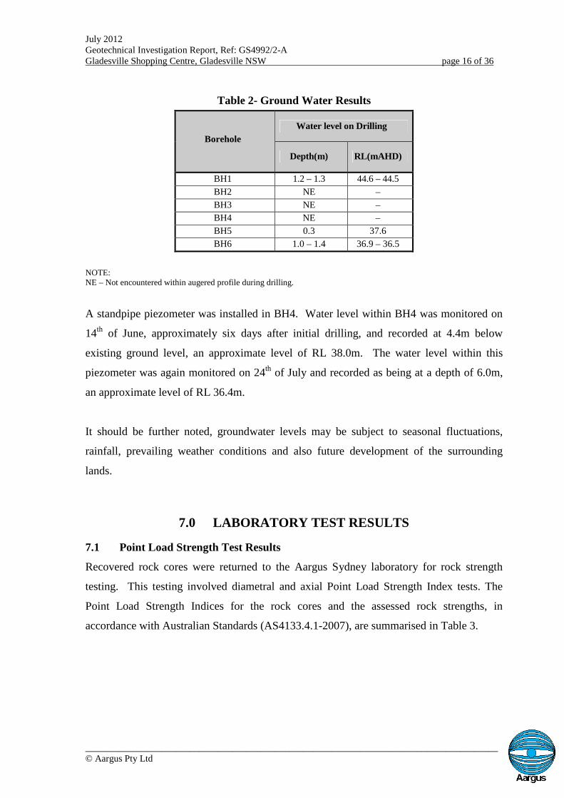
Table 2- Ground Water Results
Borehole
Water level on Drilling
Depth(m) RL(mAHD)
BH1 1.2 – 1.3 44.6 – 44.5
BH2 NE –
BH3 NE –
BH4 NE –
BH5 0.3 37.6
BH6 1.0 – 1.4 36.9 – 36.5
NOTE:NE – Not encountered within augered profile during drilling.
A standpipe piezometer was installed in BH4. Water level within BH4 was monitored on
14th of June, approximately six days after initial drilling, and recorded at 4.4m below
existing ground level, an approximate level of RL 38.0m. The water level within this
piezometer was again monitored on 24th of July and recorded as being at a depth of 6.0m,
an approximate level of RL 36.4m.
It should be further noted, groundwater levels may be subject to seasonal fluctuations,
rainfall, prevailing weather conditions and also future development of the surrounding
lands.
7.0 LABORATORY TEST RESULTS
7.1 Point Load Strength Test Results
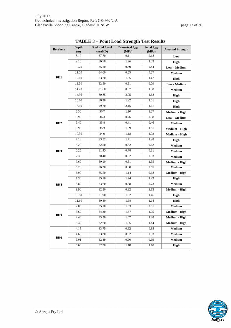
Recovered rock cores were returned to the Aargus Sydney laboratory for rock strength
testing. This testing involved diametral and axial Point Load Strength Index tests. The
Point Load Strength Indices for the rock cores and the assessed rock strengths, in
accordance with Australian Standards (AS4133.4.1-2007), are summarised in Table 3.
July 2012Geotechnical Investigation Report, Ref: GS4992/2-AGladesville Shopping Centre, Gladesville NSW page 17 of 36
_______________________________________________________________________________________© Aargus Pty Ltd
TABLE 3 – Point Load Strength Test Results
BoreholeDepth
(m)
Reduced Level
(mAHD)
Diametral Is(50)
(MPa)
Axial Is(50)
(MPa)Assessed Strength
BH1
8.10 37.70 0.11 0.18 Low
9.10 36.70 1.26 1.03 High
10.70 35.10 0.39 0.44 Low – Medium
11.20 34.60 0.85 0.37 Medium
12.10 33.70 1.35 1.47 High
13.30 32.50 0.51 0.09 Low - Medium
14.20 31.60 0.67 1.00 Medium
14.95 30.85 2.05 1.68 High
15.60 30.20 1.92 1.51 High
16.10 29.70 2.15 1.61 High
BH2
8.50 36.7 1.10 1.37 Medium - High
8.90 36.3 0.26 0.88 Low – Medium
9.40 35.8 0.41 0.46 Medium
9.90 35.3 1.09 1.51 Medium – High
10.30 34.9 1.18 1.03 Medium – High
BH3
4.18 33.52 1.71 1.28 High
5.20 32.50 0.52 0.62 Medium
6.25 31.45 0.78 0.81 Medium
7.30 30.40 0.82 0.93 Medium
7.60 30.10 0.81 1.35 Medium - High
BH4
6.20 36.20 0.60 0.65 Medium
6.90 35.50 1.14 0.68 Medium - High
7.30 35.10 1.24 1.43 High
8.80 33.60 0.88 0.73 Medium
9.90 32.50 0.82 1.13 Medium - High
10.50 31.90 1.32 1.46 High
11.60 30.80 1.58 1.68 High
BH5
2.80 35.10 1.03 0.91 Medium
3.60 34.30 1.67 1.05 Medium - High
4.40 33.50 1.07 1.38 Medium - High
5.30 32.60 1.05 1.44 Medium - High
BH6
4.15 33.75 0.92 0.95 Medium
4.60 33.30 0.82 0.93 Medium
5.01 32.89 0.90 0.99 Medium
5.60 32.30 1.18 1.10 High
July 2012Geotechnical Investigation Report, Ref: GS4992/2-AGladesville Shopping Centre, Gladesville NSW page 18 of 36
_______________________________________________________________________________________© Aargus Pty Ltd
8.0 DISCUSSION & RECOMMENDATIONS
8.1 General
The subsurface profile generally consisted of minor fill and natural soil profiles overlying
shale and sandstone bedrock sequences.
The profile within BH2, in the north-eastern corner of the site within Precinct 3, indicated
150mm of concrete and medium plasticity fill to a depth of about 0.3m, the fill underlain
by natural, hard, medium to high plasticity, light brown clay to a depth of about 1.1m.
The soil profile was underlain by highly weathered, extremely to very low strength, grey
brown shale to a depth of about 2.6m and highly weathered, grey and dark grey, very low
to low strength shales to about 7.5m (approximate RL 37.7m). Moderately to slightly
weathered, dark grey, low strength shales extended to an approximate depth of 9.2m
(approximate RL 36.0m).
The shale bedrock was underlain by slightly weathered, medium to high strength, grey
white, slightly fractured sandstone to the BH2 termination depth of about 10.4m.
Boreholes BH5 and BH6, located in the existing lower level basement within Precinct 4-
Existing Replan, indicated 150mm and 120mm thick concrete pavement slabs respectively
and minor fill underlain by shale and sandstone bedrock. Light grey sandy gravel fill was
encountered under the concrete to a depth of 0.4m.
Shale bedrock was encountered from respective depths of 0.15m (approximate RL 37.75m)
and 0.4m (approximate RL 37.5m) in BH5 and BH6. Moderately weathered, very low to
low strength, grey shale was evidenced to depths of about 2.3m in BH5 and 1.6m in BH6,
being underlain by grey, low to medium strength shales to respective depths of about 2.9m
(approximate RL 35.0m) and 3.3m (approximate RL 34.6m).
The shales were underlain by slightly weathered, medium to high strength, generally
slightly fractured, light grey sandstone with yellow staining in BH5 to the borehole
termination depth of 5.36m (approximate RL 32.5m). In BH6 moderately weathered,
July 2012Geotechnical Investigation Report, Ref: GS4992/2-AGladesville Shopping Centre, Gladesville NSW page 19 of 36
_______________________________________________________________________________________© Aargus Pty Ltd
medium strength, fractured to slightly fractured, grey sandstone with yellow staining was
encountered to a depth of about 4.3m, the materials becoming slightly fractured to a depth
of about 5.3m (approximate RL 32.6m). Slightly weathered, high strength sandstone was
evidenced to the BH6 termination depth of 5.89m (approximate RL 32.0m).
Boreholes BH1, BH3 and BH4, located in the area designated as being Precinct 4-New
Extension, generally comprised clayey sand fills and clay based natural soils overlying
shale and sandstone bedrock.
BH1, located within the existing carpark, encountered dense, grey and grey brown, clayey
sand fill to a depth of about 1.1m (approximate RL 44.7m) underlain by hard, brown,
sandy clay fill to about 1.3m (approximate RL 44.5m). BH4, located at the rear of the unit
block at No. 8 Cowell Street, encountered natural, very stiff, medium to high plasticity, red
brown clay to a depth of about 1.1m (approximate RL 41.3m). BH3, within the south-east
corner of No. 10 Cowell Street, encountered firm, low plasticity, dark grey silty clay
topsoil and fill to a depth of about 0.4m (approximate RL 37.3m) underlain by natural,
firm, dark grey silty clay to about 0.9m (approximate RL 36.8m).
The soil profiles were underlain by shale bedrock from depths of about 1.3m (approximate
RL 44.5m), 1.1m (approximate RL 41.3m) and 0.9m (approximate RL 36.8m) in BH1,
BH4 and BH3 respectively.
Very low to low strength, light grey to dark grey shales were encountered to an augering
termination depth of about 5.0m (approximate RL 40.8m) in BH1 with bands of extremely
low strength and medium strength materials located within this profile. Recovered core
indicated highly weathered, extremely low to very low strength, fragmented, light to dark
grey shales continued to a depth of about 7.0m (approximate RL 38.8m) underlain by low
strength , dark grey, highly fractured shale to about 8.1m (approximate RL 37.7m).
BH4 encountered extremely low strength, grey brown shale to a depth of about 1.5m
(approximate RL 40.9m) underlain by very low to low strength materials to about 4.2m
(approximate RL 38.2m) and low strength shale to 6.0m (approximate RL 36.4m). Some
medium strength rock was recorded as present within this profile.
July 2012Geotechnical Investigation Report, Ref: GS4992/2-AGladesville Shopping Centre, Gladesville NSW page 20 of 36
_______________________________________________________________________________________© Aargus Pty Ltd
Very low to low strength, grey shale was encountered to a depth of about 3.6m
(approximate RL 34.1m) in BH3 underlain by low to medium strength shale to the TC-bit
refusal depth of 3.9m (approximate RL 33.8m).
The shale bedrock profile was underlain by sandstones from about 8.1m (approximate RL
37.7m), 6.0m (approximate RL 36.4m) and 3.9m (approximate RL 33.8m) in BH1, BH4
and BH3 respectively.
Moderately to slightly weathered, low to medium strength, fractured, grey, stained
sandstone of essentially fine to medium grain was encountered to a depth of about 9.0m
(approximate RL 36.80m) in BH1 underlain by medium strength, slightly fractured rock to
about 11.8m (approximate RL 34.0m) and high strength sandstone to 12.8m (approximate
RL 33.0m). Slightly weathered to fresh, medium strength, slightly fractured, fine to coarse
grained, grey and light grey sandstone was encountered to a depth of about 14.5m
(approximate RL 31.2m) underlain by high strength material to 16.23m (approximate RL
29.6m).
Medium to high strength, medium to coarse grained, grey sandstone was encountered
throughout the cored profile within BH4 from a depth of about 6.0m (approximate RL
36.4m) to 11.8m (approximate RL 30.6m). Moderately to slightly weathered, fractured
bedrock was encountered to a depth of about 7.4m underlain by slightly weathered to fresh,
slightly fractured sandstone to 11.8m.
Moderately to slightly weathered, medium strength, fine to coarse grained, yellow and grey
sandstones were encountered to a depth of about 5.6m in BH3, being underlain by slightly
weathered, slightly fractured, yellow brown and grey, bedrock to about 7.0m (approximate
RL 30.7m). Medium to high strength, slightly weathered, slightly fractured, grey, medium
to coarse grained sandstone was encountered to a depth of 7.8m.
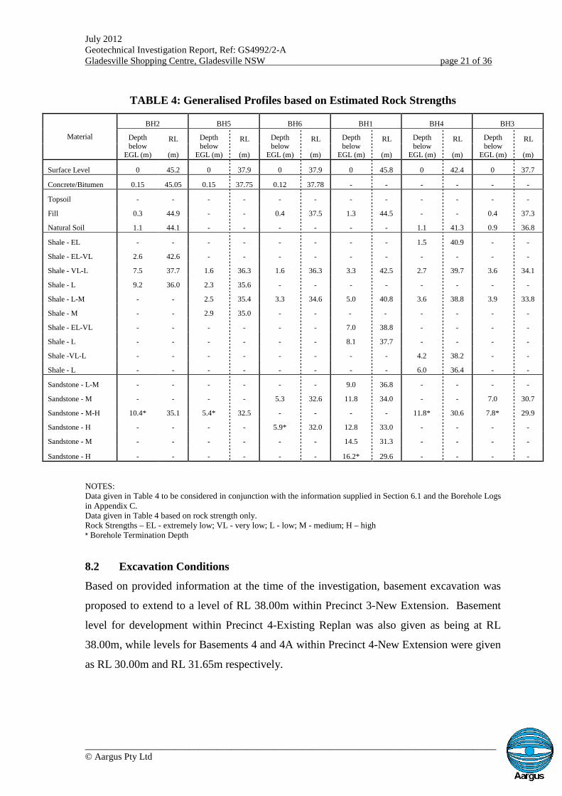
Generalised profiles within the boreholes based on estimated rock strengths have been
given in Table 4.
July 2012Geotechnical Investigation Report, Ref: GS4992/2-AGladesville Shopping Centre, Gladesville NSW page 21 of 36
_______________________________________________________________________________________© Aargus Pty Ltd
TABLE 4: Generalised Profiles based on Estimated Rock Strengths
Material
BH2 BH5 BH6 BH1 BH4 BH3
Depthbelow
EGL (m)
RL Depthbelow
EGL (m)
RL Depthbelow
EGL (m)
RL Depthbelow
EGL (m)
RL Depthbelow
EGL (m)
RL Depthbelow
EGL (m)
RL
(m) (m) (m) (m) (m) (m)
Surface Level 0 45.2 0 37.9 0 37.9 0 45.8 0 42.4 0 37.7
Concrete/Bitumen 0.15 45.05 0.15 37.75 0.12 37.78 - - - - - -
Topsoil - - - - - - - - - - - -
Fill 0.3 44.9 - - 0.4 37.5 1.3 44.5 - - 0.4 37.3
Natural Soil 1.1 44.1 - - - - - - 1.1 41.3 0.9 36.8
Shale - EL - - - - - - - - 1.5 40.9 - -
Shale - EL-VL 2.6 42.6 - - - - - - - - - -
Shale - VL-L 7.5 37.7 1.6 36.3 1.6 36.3 3.3 42.5 2.7 39.7 3.6 34.1
Shale - L 9.2 36.0 2.3 35.6 - - - - - - - -
Shale - L-M - - 2.5 35.4 3.3 34.6 5.0 40.8 3.6 38.8 3.9 33.8
Shale - M - - 2.9 35.0 - - - - - - - -
Shale - EL-VL - - - - - - 7.0 38.8 - - - -
Shale - L - - - - - - 8.1 37.7 - - - -
Shale -VL-L - - - - - - - - 4.2 38.2 - -
Shale - L - - - - - - - - 6.0 36.4 - -
Sandstone - L-M - - - - - - 9.0 36.8 - - - -
Sandstone - M - - - - 5.3 32.6 11.8 34.0 - - 7.0 30.7
Sandstone - M-H 10.4* 35.1 5.4* 32.5 - - - - 11.8* 30.6 7.8* 29.9
Sandstone - H - - - - 5.9* 32.0 12.8 33.0 - - - -
Sandstone - M - - - - - - 14.5 31.3 - - - -
Sandstone - H - - - - - - 16.2* 29.6 - - - -
NOTES:Data given in Table 4 to be considered in conjunction with the information supplied in Section 6.1 and the Borehole Logsin Appendix C.Data given in Table 4 based on rock strength only.Rock Strengths – EL - extremely low; VL - very low; L - low; M - medium; H – high* Borehole Termination Depth
8.2 Excavation Conditions
Based on provided information at the time of the investigation, basement excavation was
proposed to extend to a level of RL 38.00m within Precinct 3-New Extension. Basement
level for development within Precinct 4-Existing Replan was also given as being at RL
38.00m, while levels for Basements 4 and 4A within Precinct 4-New Extension were given
as RL 30.00m and RL 31.65m respectively.
July 2012Geotechnical Investigation Report, Ref: GS4992/2-AGladesville Shopping Centre, Gladesville NSW page 22 of 36
_______________________________________________________________________________________© Aargus Pty Ltd
Observations on site showed the lower level of the current store facility occupying
proposed Precinct 3 exited into the retail complex at existing shopping level two.
Information from drawings relating to the existing complex indicated this level is
approximately RL 44.60m. Therefore excavation of approximately 7m may be required to
achieve the new basement level of RL 38.00m, pending the configuration of the existing
structure within Precinct 3.
Drawings of the existing complex indicated the level of the lower level basement,
designated as existing basement two and encompassing much of the development area
considered as Precinct 4-Existing Plan, to be at approximately RL 38.00m, this being the
same level as provided for the new development. Therefore, it is anticipated further
excavation for development within this area may be minimal based on supplied concepts.
Estimated ground surface levels at BH1, BH4 and BH3, within Precinct 4-New Extension,
were recorded as approximately RL 45.8m, RL 42.4m and RL 37.7m respectively. It may
be likely excavation depths ranging between approximately 8m to 15m may be expected
for basement construction.
Excavation of soil-based materials and weathered, lower strength shales and sandstones
may be possible using conventional earthmoving equipment such as backhoes or tracked
excavators.
It is likely heavy ripping and/or vibratory rock breaking techniques will be required within
the more competent, less weathered shales and sandstones of medium to high strength.
Should vibratory rock breaking equipment be required for excavations in bedrock, it is
recommended it be complemented with saw cutting using an appropriate excavator
mounted rock saw or approved alternative measure prior to excavation so as to minimise
transmission of vibrations to adjoining structures. Hammering should be carried out
horizontally along bedding planes where possible to minimise transmission of vibrations to
adjoining structures.
July 2012Geotechnical Investigation Report, Ref: GS4992/2-AGladesville Shopping Centre, Gladesville NSW page 23 of 36
_______________________________________________________________________________________© Aargus Pty Ltd
Induced vibrations in structures adjacent to the excavation should not exceed a peak
particle velocity (PPV) of 10mm/sec for structures in good condition or 2mm/sec for
heritage or poor-conditioned structures. Consideration of a possible reduction of the PPV
value to 5mm/sec may be appropriate where some existing commercial and residential
structures are likely to be in close proximity to deep excavations. If vibrations in adjacent
structures exceed these values or appear excessive, excavation should cease and Aargus
should be contacted immediately for appropriate reviews.
Should the development of induced vibrations be considered possible during construction,
it is recommended a structural assessment of adjoining structures be undertaken prior to
project excavation proceeding.
The investigation indicated the presence of existing structures and pavements over the site
with vegetated areas. All topsoil and fill materials, vegetation, including root systems, and
deleterious materials, including old footings, services and concrete and bituminous
pavement materials should be stripped and removed from development areas to spoil.
Site earthworks should be appropriately drained to minimise the effects of wetting up and
softening of exposed, natural materials, which may be caused by extraneous water sources
and climatic variations. Should possible bulk excavation be terminated within weathered
bedrock layers, and particularly within weathered shales, it is considered the natural
materials at the base of such excavations may require the incorporation of a granular
surfacing so as to remain trafficable under unfavourable and adverse climatic conditions.
Trafficability problems may also be possible where “wetting” from groundwater sources
may occur.
If loose or soft rocks or clay seams are encountered within the basement floor areas it is
recommended removal to competent rock and replacement with mass concrete be
considered.

July 2012Geotechnical Investigation Report, Ref: GS4992/2-AGladesville Shopping Centre, Gladesville NSW page 24 of 36
_______________________________________________________________________________________© Aargus Pty Ltd
8.3 Groundwater Management
Groundwater or seepage was encountered within the augered soil profile in boreholes BH1,
BH5 and BH6 during the investigation drilling with the initial levels recorded being given
in Table 2. A standpipe piezometer was installed in BH4.
Groundwater during initial drilling was encountered between approximate levels of RL
36.5m and RL 37.6m (approximately 1.4m to 0.3m below the surface) within BH6 and
BH5 in the development area considered as Precinct 4-Existing Plan.
Groundwater or seepage levels in BH1, within Precinct 4-New Extension, recorded during
initial drilling ranged between depths of approximately 1.2m to 1.3m below the surface,
that is, an average level of approximately RL 44.55m. Water level within BH4 was
monitored on 14th of June, approximately six days after initial drilling, and recorded at
4.4m below existing ground level, an approximate level of RL 38.0m. The water level was
again monitored on 24th of July and recorded as being at a depth of 6.0m, an approximate
level of RL 36.4m.
Water level monitoring indicated some basement level excavation and excavations for
foundations may likely be required to be undertaken at depths below recorded water levels.
It is recommended ongoing groundwater presence or levels be assessed if construction is
undertaken during or following adverse weather or if a significant time period elapses
between this investigation and construction.
Dewatering systems on the site should be evaluated and designed mindful of groundwater
presence within and effects on adjoining areas. Dewatering of the development site may not
only lower water tables directly on this site but also result in a lowering of levels within
adjoining areas. The effects of dewatering on this site and on developments on adjoining
sites should be evaluated prior to the adoption of a system.
During all stages of the excavation, observations of excavated faces for any presence of
effects of water flow should be carried out to ensure any local softening of material
resulting from a possible groundwater regime is pre-empted.
July 2012Geotechnical Investigation Report, Ref: GS4992/2-AGladesville Shopping Centre, Gladesville NSW page 25 of 36
_______________________________________________________________________________________© Aargus Pty Ltd
It is recommended the final construction drawings be provided to Aargus for further
assessment and confirmation of a suitable dewatering system, if required.
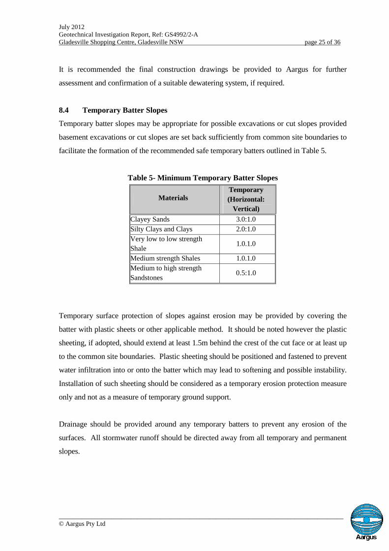
8.4 Temporary Batter Slopes
Temporary batter slopes may be appropriate for possible excavations or cut slopes provided
basement excavations or cut slopes are set back sufficiently from common site boundaries to
facilitate the formation of the recommended safe temporary batters outlined in Table 5.
Table 5- Minimum Temporary Batter Slopes
MaterialsTemporary
(Horizontal:
Vertical)
Clayey Sands 3.0:1.0
Silty Clays and Clays 2.0:1.0
Very low to low strength
Shale1.0.1.0
Medium strength Shales 1.0.1.0
Medium to high strength
Sandstones0.5:1.0
Temporary surface protection of slopes against erosion may be provided by covering the
batter with plastic sheets or other applicable method. It should be noted however the plastic
sheeting, if adopted, should extend at least 1.5m behind the crest of the cut face or at least up
to the common site boundaries. Plastic sheeting should be positioned and fastened to prevent
water infiltration into or onto the batter which may lead to softening and possible instability.
Installation of such sheeting should be considered as a temporary erosion protection measure
only and not as a measure of temporary ground support.
Drainage should be provided around any temporary batters to prevent any erosion of the
surfaces. All stormwater runoff should be directed away from all temporary and permanent
slopes.
July 2012Geotechnical Investigation Report, Ref: GS4992/2-AGladesville Shopping Centre, Gladesville NSW page 26 of 36
_______________________________________________________________________________________© Aargus Pty Ltd
8.5 Excavation Support
Where there is insufficient space for batter slopes, it is likely to be necessary to install
continuous support systems. Such a system may consist of continuous piles, secant piles or
diaphragm walls, each of which may be suitable for the materials encountered during the
time if this investigation.
Diaphragm walls may be installed to provide a clean surface finish as well as providing
structural support for the buildings. The concrete floors can also be keyed into the
diaphragm wall to provide a watertight unit. Secant pile walls may also provide a good
interlocking watertight wall. Secant piles are the most economical methods of creating an
effective water control barriers.
Contiguous piles may also be considered in the excavation areas which may be above the
current water table pending the positioning of multi-level basements. These systems may
not be water tight should groundwater levels rise after wet periods.
8.6 Retaining Structures
In the long term, the excavation faces must be retained by engineered retaining structures.
These structures should be designed to withstand the applied lateral pressures of the
soil/rock layers, the existing surcharges in their zone of influence; including existing
structures, and construction related activities, and also hydrostatic pressures (if it is
appropriate). Contiguous or Secant Pile walls are feasible options for this purpose.
The pressure distribution on cantilever retaining structures, only due to the earth pressures
and surcharges behind the wall, may be assumed to be triangular and estimated as follows
(ignoring cohesion effect):
ph = kH + qk
Where,
ph = Horizontal pressure (kN/m2)
= Wet density (kN/m3)
k = Coefficient of earth pressure (ka or ko)
H = Retained height (m)
July 2012Geotechnical Investigation Report, Ref: GS4992/2-AGladesville Shopping Centre, Gladesville NSW page 27 of 36
_______________________________________________________________________________________© Aargus Pty Ltd
q = Surcharge pressure behind retaining wall (kN/m2)
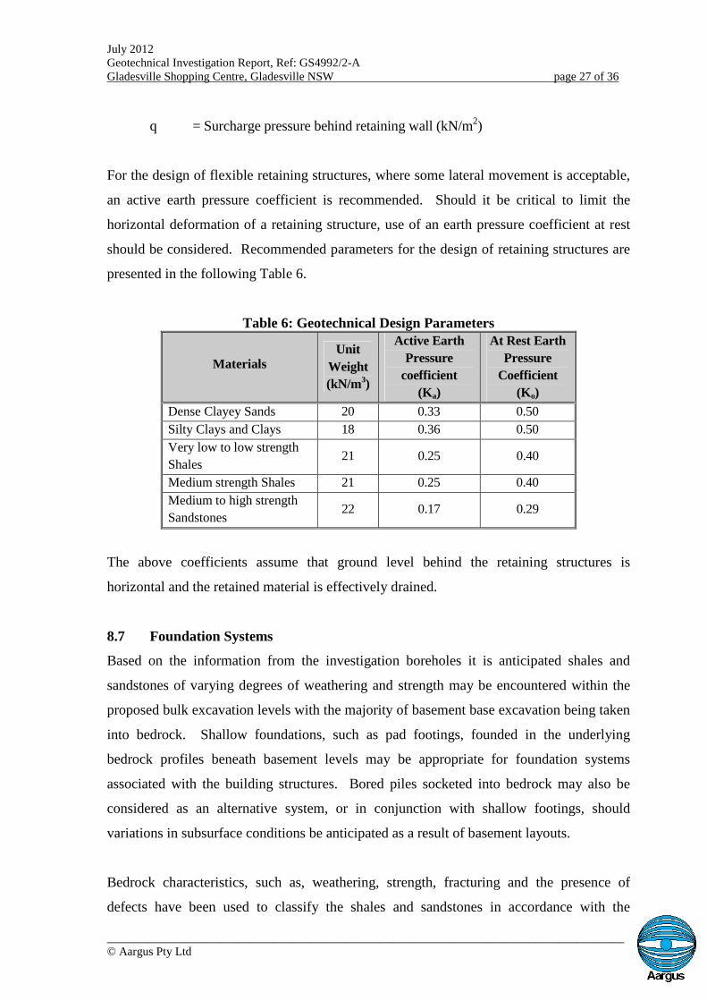
For the design of flexible retaining structures, where some lateral movement is acceptable,
an active earth pressure coefficient is recommended. Should it be critical to limit the
horizontal deformation of a retaining structure, use of an earth pressure coefficient at rest
should be considered. Recommended parameters for the design of retaining structures are
presented in the following Table 6.
Table 6: Geotechnical Design Parameters
MaterialsUnit
Weight
(kN/m3)
Active Earth
Pressure
coefficient
(Ka)
At Rest Earth
Pressure
Coefficient
(Ko)
Dense Clayey Sands 20 0.33 0.50
Silty Clays and Clays 18 0.36 0.50
Very low to low strength
Shales21 0.25 0.40
Medium strength Shales 21 0.25 0.40
Medium to high strength
Sandstones22 0.17 0.29
The above coefficients assume that ground level behind the retaining structures is
horizontal and the retained material is effectively drained.
8.7 Foundation Systems
Based on the information from the investigation boreholes it is anticipated shales and
sandstones of varying degrees of weathering and strength may be encountered within the
proposed bulk excavation levels with the majority of basement base excavation being taken
into bedrock. Shallow foundations, such as pad footings, founded in the underlying
bedrock profiles beneath basement levels may be appropriate for foundation systems
associated with the building structures. Bored piles socketed into bedrock may also be
considered as an alternative system, or in conjunction with shallow footings, should
variations in subsurface conditions be anticipated as a result of basement layouts.
Bedrock characteristics, such as, weathering, strength, fracturing and the presence of
defects have been used to classify the shales and sandstones in accordance with the
July 2012Geotechnical Investigation Report, Ref: GS4992/2-AGladesville Shopping Centre, Gladesville NSW page 28 of 36
_______________________________________________________________________________________© Aargus Pty Ltd
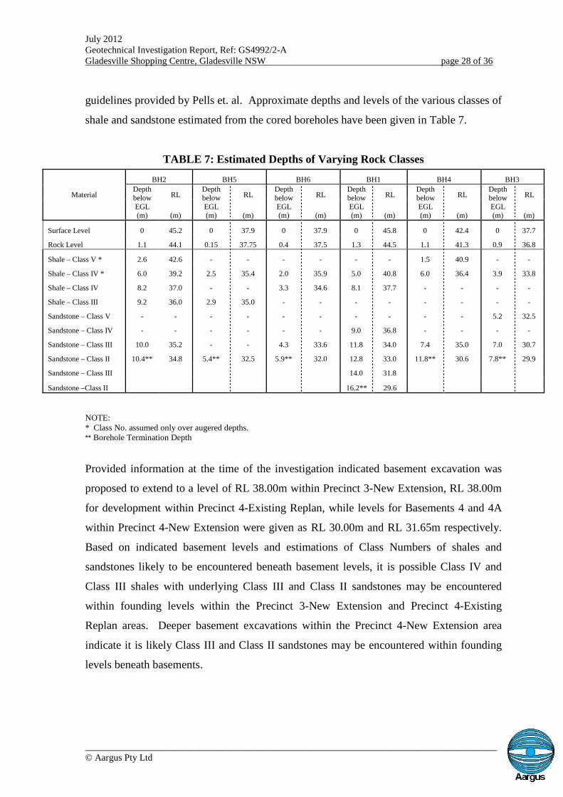
guidelines provided by Pells et. al. Approximate depths and levels of the various classes of
shale and sandstone estimated from the cored boreholes have been given in Table 7.
TABLE 7: Estimated Depths of Varying Rock Classes
Material
BH2 BH5 BH6 BH1 BH4 BH3
DepthbelowEGL(m)
RLDepthbelowEGL(m)
RLDepthbelowEGL(m)
RLDepthbelowEGL(m)
RLDepthbelowEGL(m)
RLDepthbelowEGL(m)
RL
(m) (m) (m) (m) (m) (m)
Surface Level 0 45.2 0 37.9 0 37.9 0 45.8 0 42.4 0 37.7
Rock Level 1.1 44.1 0.15 37.75 0.4 37.5 1.3 44.5 1.1 41.3 0.9 36.8
Shale – Class V * 2.6 42.6 - - - - - - 1.5 40.9 - -
Shale – Class IV * 6.0 39.2 2.5 35.4 2.0 35.9 5.0 40.8 6.0 36.4 3.9 33.8
Shale – Class IV 8.2 37.0 - - 3.3 34.6 8.1 37.7 - - - -
Shale – Class III 9.2 36.0 2.9 35.0 - - - - - - - -
Sandstone – Class V - - - - - - - - - - 5.2 32.5
Sandstone – Class IV - - - - - - 9.0 36.8 - - - -
Sandstone – Class III 10.0 35.2 - - 4.3 33.6 11.8 34.0 7.4 35.0 7.0 30.7
Sandstone – Class II 10.4** 34.8 5.4** 32.5 5.9** 32.0 12.8 33.0 11.8** 30.6 7.8** 29.9
Sandstone – Class III 14.0 31.8
Sandstone –Class II 16.2** 29.6
NOTE:* Class No. assumed only over augered depths.** Borehole Termination Depth
Provided information at the time of the investigation indicated basement excavation was
proposed to extend to a level of RL 38.00m within Precinct 3-New Extension, RL 38.00m
for development within Precinct 4-Existing Replan, while levels for Basements 4 and 4A
within Precinct 4-New Extension were given as RL 30.00m and RL 31.65m respectively.
Based on indicated basement levels and estimations of Class Numbers of shales and
sandstones likely to be encountered beneath basement levels, it is possible Class IV and
Class III shales with underlying Class III and Class II sandstones may be encountered
within founding levels within the Precinct 3-New Extension and Precinct 4-Existing
Replan areas. Deeper basement excavations within the Precinct 4-New Extension area
indicate it is likely Class III and Class II sandstones may be encountered within founding
levels beneath basements.
July 2012Geotechnical Investigation Report, Ref: GS4992/2-AGladesville Shopping Centre, Gladesville NSW page 29 of 36
_______________________________________________________________________________________© Aargus Pty Ltd
Shallow pad or strip foundations or piles or rock sockets founded within Class IV or Class
III shale may be designed with maximum allowable end bearing pressures of 1000 kPa and
3500 kPa respectively. Pads, strips or socketed piles founded in medium strength Class III
sandstone may be designed with a maximum allowable end bearing pressure of 3500 kPa.
This value may be increased to a value of 6000 kPa for foundations embedded into Class II
sandstone. A minimum embedment depth for footings or socket length for piles of 0.3m
into the underlying bedrock should be adopted.
Shaft adhesion that may be applied to socketed piles should be adopted to conform to
appropriate classes of shale and sandstone in accordance with Pells et. al and levels of shaft
sidewall cleanliness and roughness. A shaft adhesion value of 350 kPa may be applied to
socket lengths within Class III shale and Class III sandstone with the value being increased
to 600 kPa for sockets within Class II sandstone. The rock socket sidewalls should be free
of soil and/or crushed rock to the extent that natural rock is exposed over at least 80% of
the socket sidewall. Shaft adhesion should not be applied to the upper 500mm of socket
length within the bedrock sequence or socket lengths that are smeared and fail to satisfy
cleanliness requirements. Reduced shaft adhesion values will be applicable for sockets that
fail to satisfy the necessary criteria.
To minimise the effects of differential settlement all foundations should be founded on
consistent, natural in-situ layers of similar bearing capacity.
Should groundwater flow, seepages or surface runoff be encountered within foundation
excavations, the excavations should be dewatered prior to concrete placement or correct
underwater placement techniques should be adopted. Any loose debris and wet soils
should also be removed from excavations.
A geotechnical consultant should inspect foundation base excavations at the time of
excavation to ensure the foundation bases have been taken to suitable materials of
appropriate bearing capacity. It is likely this will only be possible where foundation
excavations, either as shallow footings, such as pads, or shafts, in the case of piles, are
dewatered. The presence of groundwater within foundation excavations may negate
July 2012Geotechnical Investigation Report, Ref: GS4992/2-AGladesville Shopping Centre, Gladesville NSW page 30 of 36
_______________________________________________________________________________________© Aargus Pty Ltd
satisfactory examination of founding surfaces and certification of founding material
quality. Where shaft adhesion may be adopted, shaft lengths should be inspected to verify
rock conditions and other criteria in accordance with industry adopted practice have been
satisfied. Foundation and shaft inspections should only be undertaken under conditions
satisfying OHS requirements.
9.0 CONCLUSIONS
This report presents and interprets the findings of the geotechnical investigation carried out
within an area surrounding the existing Gladesville Shopping Centre complex, Gladesville,
NSW, for a proposed retail and residential development consisting of two storeys of
commercial development and four residential towers. It is envisaged the existing
basements carparks may be utilised for parts of the development with basements to
approximately four levels proposed towards the southern areas of the development.
The subsurface profile generally consisted of minor fill and natural soil profiles overlying
shale and sandstone bedrock sequences.
The profile within BH2, in the north-eastern corner of the site within Precinct 3, indicated
concrete and medium plasticity fill underlain by natural, hard, medium to high plasticity,
light brown clay. The soil profile was underlain by generally highly weathered, very low
to low strength, shale and moderately to slightly weathered, low strength shales. The shale
bedrock was underlain by slightly weathered, medium to high strength, grey white, slightly
fractured sandstone.
Boreholes BH5 and BH6, located in the existing lower level basement within Precinct 4-
Existing Replan, indicated concrete pavement slabs and minor fill underlain by shale and
sandstone bedrock. Moderately weathered, very low to low strength shale was underlain
by grey, low to medium strength shales. The shales were underlain by generally slightly
weathered, medium to high strength, slightly fractured, light grey sandstones.
July 2012Geotechnical Investigation Report, Ref: GS4992/2-AGladesville Shopping Centre, Gladesville NSW page 31 of 36
_______________________________________________________________________________________© Aargus Pty Ltd
Boreholes BH1, BH3 and BH4, located in the area designated as being Precinct 4-New
Extension, generally comprised clayey sand fills and clay based natural soils overlying
shale and sandstone bedrock.
BH1, located within the existing carpark, encountered clayey sand fill underlain by sandy
clay fill. BH4, located at the rear of the unit block at No. 8 Cowell Street, encountered
natural, red brown clay and BH3, within the south-east corner of No. 10 Cowell Street,
encountered silty clay topsoil and fill underlain by natural, silty clay.
The soil profiles were underlain by shale bedrock from depths of about 1.3m, 1.1m and
0.9m in BH1, BH4 and BH3 respectively. Very low to low strength shales were
encountered with bands of extremely low strength and medium strength materials located
within the profile. Recovered core indicated shales ranging from fragmented to fractured.
The shale bedrock profile was underlain by sandstones from about 8.1m, 6.0m and 3.9m in
BH1, BH4 and BH3 respectively. These generally ranged from low to medium strength
materials becoming medium to high strength with depth and slightly weathered and slight
fractured.
Materials likely to be encountered during basement excavation may generally comprise
very low to low strength shales with some medium strength layers with underlying medium
to high strength sandstones.
Excavation of soil-based materials and weathered, lower strength shales and sandstones
may be possible using conventional earthmoving equipment such as backhoes or tracked
excavators.
It is possible heavy ripping and/or vibratory rock breaking techniques will be required
within the more competent, less weathered shales and sandstones of medium to high
strength. Should vibratory rock breaking equipment be required for proposed excavations,
it is considered the excavation processes should be complemented with saw cutting using
an appropriate excavator mounted rock saw or approved alternative measure prior to
July 2012Geotechnical Investigation Report, Ref: GS4992/2-AGladesville Shopping Centre, Gladesville NSW page 32 of 36
_______________________________________________________________________________________© Aargus Pty Ltd
excavation so as to minimise transmission of vibrations to adjoining structures.
Hammering should be carried out horizontally along bedding planes where possible.
Induced vibrations in structures adjacent to the excavation should not exceed a peak
particle velocity (PPV) of 10mm/sec for structures in good condition or 2mm/sec for
heritage or poor-conditioned structures. Consideration of a possible reduction of the PPV
value to 5mm/sec may be appropriate where some existing commercial and residential
structures are likely to be in close proximity to deep excavations.
Should the development of induced vibrations be considered possible during construction,
it is recommended a structural assessment of adjoining structures be undertaken prior to
project excavation proceeding.
The investigation indicated the presence of existing structures and pavements over the site
with vegetated areas. All topsoil and fill materials, vegetation, including root systems, and
deleterious materials, including old footings, services and concrete and bituminous
pavement materials should be stripped and removed from development areas to spoil.
Site earthworks should be appropriately drained to minimise the effects of wetting up and
softening of exposed, natural materials, which may be caused by extraneous water sources
and climatic variations. Trafficability problems may also be possible where “wetting”
from groundwater sources may occur and may require the incorporation of a granular
surfacing so as to remain trafficable under unfavourable and adverse climatic conditions.
If loose or soft rocks or clay seams are encountered within the basement floor areas it is
recommended removal to competent rock and replacement with mass concrete be
considered.
Groundwater or seepage was encountered on the site within the augered soil profile. It
should be noted groundwater levels may further vary subject to seasonal fluctuations,
rainfall, prevailing weather conditions and also future development of the surrounding
lands.
July 2012Geotechnical Investigation Report, Ref: GS4992/2-AGladesville Shopping Centre, Gladesville NSW page 33 of 36
_______________________________________________________________________________________© Aargus Pty Ltd
Water level monitoring indicated some basement level excavation and excavations for
foundations may likely be required to be undertaken at depths below recorded water levels.
It is recommended ongoing groundwater presence or levels be assessed if construction is
undertaken during or following adverse weather or if a significant time period elapses
between this investigation and construction.
Dewatering systems on the site should be evaluated and designed mindful of groundwater
presence within and effects on adjoining areas with the effects of dewatering being evaluated
prior to the adoption of a system.
During all stages of the excavation, observations of excavated faces for any presence of
effects of water flow should be carried out to ensure any local softening of material
resulting from a possible groundwater regime is pre-empted.
Temporary batter slopes may be appropriate for possible excavations or cut slopes provided
basement excavations or cut slopes are set back sufficiently from common site boundaries to
facilitate the formation of the recommended safe temporary batters outlined in Table 5.
Where there is insufficient space for batter slopes, it is likely to be necessary to install
continuous support systems. Such a system may consist of continuous piles, secant piles or
diaphragm walls, each of which may be suitable for the materials encountered during the
time if this investigation.
Temporary surface protection of slopes against erosion may be provided by covering the
batter with plastic sheets or other applicable method. Installation of such measures should be
considered as a temporary erosion protection measure only and not as a method of temporary
ground support. Drainage should be provided around any temporary batters to prevent any
erosion. All runoff should be directed away from all temporary and permanent slopes.
Recommended parameters for the design of retaining structures are presented in Table 6.

July 2012Geotechnical Investigation Report, Ref: GS4992/2-AGladesville Shopping Centre, Gladesville NSW page 34 of 36
_______________________________________________________________________________________© Aargus Pty Ltd
Shallow foundations, such as pad footings, founded in the underlying bedrock profiles
beneath basement levels may be appropriate for foundation systems associated with the
building structures. Bored piles socketed into bedrock may also be considered as an
alternative system, or in conjunction with shallow footings, should variations in subsurface
conditions be anticipated as a result of basement layouts.
Bedrock characteristics, such as, weathering, strength, fracturing and the presence of
defects have been used to classify the shales and sandstones in accordance with the
guidelines provided by Pells et. al. Approximate depths and levels of the various classes of
shale and sandstone estimated from the cored boreholes have been given in Table 7.
Foundation systems founded within Class IV or Class III shale may be designed with
maximum allowable end bearing pressures of 1000 kPa and 3500 kPa respectively.
Systems founded in medium strength Class III sandstone may be designed with a
maximum allowable end bearing pressure of 3500 kPa. This value may be increased to a
value of 6000 kPa for foundations embedded into Class II sandstone. A minimum
embedment depth for footings or socket length for piles of 0.3m into the underlying
bedrock should be adopted.
Shaft adhesion that may be applied to socketed piles should be adopted to conform to
appropriate classes of shale and sandstone in accordance with Pells et. al and levels of shaft
sidewall cleanliness and roughness. A shaft adhesion value of 350 kPa may be applied to
socket lengths within Class III shale and Class III sandstone with the value being increased
to 600 kPa for sockets within Class II sandstone.
Shaft adhesion should not be applied to the upper 500mm of socket length within the
bedrock sequence or socket lengths that are smeared and fail to satisfy cleanliness
requirements. Reduced shaft adhesion values will be applicable for sockets that fail to
satisfy the necessary criteria.
To minimise the effects of differential settlement all foundations should be founded on
consistent, natural in-situ layers of similar bearing capacity.
July 2012Geotechnical Investigation Report, Ref: GS4992/2-AGladesville Shopping Centre, Gladesville NSW page 35 of 36
_______________________________________________________________________________________© Aargus Pty Ltd
Should groundwater flow, seepages or surface runoff be encountered within foundation
excavations, the excavations should be dewatered prior to concrete placement or correct
underwater placement techniques should be adopted. Any loose debris and wet soils
should also be removed from excavations.
A geotechnical consultant should inspect foundation base excavations at the time of
excavation to ensure the foundation bases have been taken to suitable materials of
appropriate bearing capacity. The presence of groundwater within foundation excavations
may negate satisfactory examination of founding surfaces and certification of founding
material quality.
Where shaft adhesion may be adopted, shaft lengths should be inspected to verify rock
conditions and other criteria in accordance with industry adopted practice have been
satisfied. Foundation and shaft inspections should only be undertaken under conditions
satisfying OHS requirements.
Based on supplied conceptual information and the findings of this investigation, it is
considered proposed development of this site is feasible provided recommendations given
in this report are taken into account.
For and on behalf of
Aargus Pty Ltd Reviewed by
Michael Ferry Noriman Mak
BSc, MSc, MBA, MIEAust,
BE, MEngSc ,MIEAust, CPEng RPE (Civ, Geo) NPER (Civ, Geo)
Senior Geotechnical Engineer National Engineering Manager
(MM)
July 2012Geotechnical Investigation Report, Ref: GS4992/2-AGladesville Shopping Centre, Gladesville NSW page 36 of 36
_______________________________________________________________________________________© Aargus Pty Ltd
10.0 LIMITATIONS
The assessment of the sub-surface profile and geotechnical conditions within the proposed
development area and the conclusions and recommendations presented in this report have
been based on available information obtained from the drilling and associated site works
carried out at provided locations over the period of 6th to 8th and 14th June 2012 together
with survey plans of the site and neighbouring area undertaken by Craig & Rhodes
(Surveyors Engineers Planners) for Moch Pty Ltd, Ref 67/05, Drawing File 6705T03,
Sheets 1 to 8 of 8, dated 5/2005, updated 10/08/2005, and architectural drawings of the
existing shopping complex (Drawing Nos DA/B-08A to DA/B-10A, dated 19/04/2012) and
proposed development (Drawing Nos. DA/PS-10, DA/R-12, DA/B-05, DA/B-06, DA/B-08
AND DA/B-09, dated 09/05/12, and DA/EL-12 and DA/EL-13, dated 26/07/2011)
provided by Bernard Young Design Group P/L, Ref 03-11-403.
Any site inspections and certifications should be performed by experienced Geotechnical
Engineers, Engineering Geologists and field testing personnel.
It is recommended that should ground conditions encountered during construction vary
substantially from those anticipated within this report, Aargus be contacted immediately
for further advice and any necessary review of recommendations or if surface and
groundwater conditions encountered during excavation and construction vary from those
presented in this report
Aargus does not assume any liability for site conditions not observed or accessible during
the time of the investigation. This report and associated documentation and the
information herein have been prepared solely for the use of GSV Developments Pty Ltd
and any reliance assumed by third parties on this report shall be at such parties’ own risk.
Any ensuing liability resulting from use of the report by third parties cannot be transferred
to Aargus.
The conclusions and recommendations of this report should be read in conjunction with the
entire report.
APPENDIX A
_____________________________IMPORTANT INFORMATIONABOUT YOUR GEOTECHNICALREPORT
IMPORTANT INFORMATION ABOUT YOURGEOTECHNICAL ENGINEERING REPORT
More construction problems are caused by sitesubsurface conditions than any other factor. Astroublesome as subsurface problems can be, theirfrequency and extent have been lessenedconsiderably in recent years, due in largemeasure to programs and publications of ASFE/The Association of Engineering Firms Practicingin the Geosciences.
The following suggestions and observations areoffered to help you reduce the geotechnical-related delays, cost-overruns and other costlyheadaches that can occur during a constructionproject.
A GEOTECHNICAL ENGINEERING
REPORT IS BASED ON A UNIQUE SET
OF PROJECT-SPECIFIC FACTORS
A geotechnical engineering report is based on asubsurface exploration plan designed toincorporate a unique set of project-specificfactors. These typically include the generalnature of the structure involved, its size andconfiguration, the location of the structure on thesite and its orientation, physical concomitantssuch as access roads, parking lots, andunderground utilities, and the level of additionalrisk which the client assumed by virtue oflimitations imposed upon the exploratoryprogram.
To help avoid costly problems, consult thegeotechnical engineer to determine how anyfactors which change subsequent to the date ofthe report may affect its recommendations.
Unless your consulting geotechnical engineerindicates otherwise, your geotechnicalengineering report should NOT be used:
when the nature of the proposed structure ischanged: for example, if an office building willbe erected instead of a parking garage, or if arefrigerated warehouse will be built instead ofan un-refrigerated one,
when the size or configuration of the proposedstructure is altered,
when the location or orientation of the proposedstructure is modified,
when there is a change of ownership, or
for application to an adjacent site.
Geotechnical engineers cannot acceptresponsibility for problems which may develop ifthey are not consulted after factors considered intheir report's development have changed.
Geotechnical reports present the results ofinvestigations carried out for a specific project andusually for a specific phase of the project. Thereport may not be relevant for other phases of theproject, or where project details change.
The advice herein relates only to this project and thescope of works provided by the Client.
Soil and Rock Descriptions are based on AS1726-1993, using visual and tactile assessment except atdiscrete locations where field and/or laboratory testshave been carried out. Refer to the attached termsand symbols sheets for definitions.
MOST GEOTECHNICAL "FINDINGS"
ARE PROFESSIONAL ESTIMATES
Site exploration identifies actual subsurfaceconditions only at those points where samples aretaken, when they are taken. Data derived throughsampling and subsequent laboratory testing areextrapolated by geotechnical engineers who thenrender an opinion about overall subsurfaceconditions, their likely reaction to proposedconstruction activity, and appropriate foundationdesign. Even under optimal circumstances actualconditions may differ from those inferred to exist,because no geotechnical engineer, no matter how
_______________________________________________________________________________________Page 2 of 3 Important Information About Your Geotechnical Engineering Report
qualified, and no subsurface explorationprogram, no matter how comprehensive, canreveal what is hidden by earth, rock and time.The actual interface between materials maybe far more gradual or abrupt than a reportindicates. Actual conditions in areas notsampled may differ from predictions. Nothingcan be done to prevent the unanticipated, butsteps can be taken to help minimize theirimpact. For this reason, most experiencedowners retain their geotechnical consultantsthrough the construction stage, to identifyvariances, conduct additional tests which maybe needed, and to recommend solutions toproblems encountered on site.
SUBSURFACE CONDITIONS CAN
CHANGE
Subsurface conditions may be modified byconstantly changing natural forces. Because ageotechnical engineering report is based onconditions which existed at the time ofsubsurface exploration, construction decisionsshould not be based on a geotechnicalengineering report whose adequacy may havebeen affected by time. Speak with thegeotechnical consultant to learn if additionaltests are advisable before construction starts.
Construction operations at or adjacent to thesite and natural events such as floods,earthquakes or groundwater fluctuationsmay also affect subsurface conditions, andthus, the continuing adequacy of a geotechnicalreport. The geotechnical engineer should bekept apprised of any such events, and should beconsulted to determine if additional tests arenecessary.
Subsurface conditions can change with timeand can vary between test locations.Construction activities at or adjacent to the siteand natural events such as flood, earthquake orgroundwater fluctuations can also affect thesubsurface conditions.
GEOTECHNICAL SERVICES ARE
PERFORMED FOR SPECIFIC
PURPOSES AND PERSONS
Geotechnical engineers’ reports are prepared to meetthe specific needs of specific individuals. A reportprepared for a consulting civil engineer may not beadequate for a construction contractor, or even someother consulting civil engineer. Unless indicatedotherwise, this report was prepared expressly for theclient involved and expressly for purposes indicatedby the client. Use by any other persons for anypurpose, or by the client for a different purpose, mayresult in problems.No individual other than the client should applythis report for its intended purpose without firstconferring with the geotechnical engineer. Noperson should apply this report for any purposeother than that originally contemplated withoutfirst conferring with the geotechnical engineer.
A GEOTECHNICAL ENGINEERING
REPORT IS SUBJECT TO
MISINTERPRETATION
Costly problems can occur when other designprofessional develop their plans based onmisinterpretations of a geotechnicalengineering report. To help avoid theseproblems, the geotechnical engineer should beretained to work with other appropriate designprofessionals to explain relevant geotechnicalfindings and to review the adequacy of theirplans and specifications relative togeotechnical issues.
The interpretation of the discussion andrecommendations contained in this report are basedon extrapolation/interpretation from data obtained atdiscrete locations. Actual conditions in areas notsampled or investigated may differ from thosepredicted
BORING LOGS SHOULD NOT BE
SEPARATED FROM THE ENGINEERING
REPORT
Final boring logs are developed bygeotechnical engineers based upon theirinterpretation of field logs (assembled by sitepersonnel) and laboratory evaluation of fieldsamples. Only final boring logs customarilyare included in geotechnical engineeringreports. These logs should not under anycircumstances be redrawn for inclusion inarchitectural or other design drawings becausedrafters may commit errors or omissions in the
_______________________________________________________________________________________Page 3 of 3 Important Information About Your Geotechnical Engineering Report
transfer process. Although photographicreproduction eliminates this problem, itdoes nothing to minimize the possibilityof contractors misinterpreting the logsduring bid preparation. When this occurs,delays, disputes and unanticipated costsare the all-too-frequent result.
To minimise the likelihood of boring logmisinterpretation, give contractors readyaccess in the complete geotechnicalengineering report prepared or authorizedfor their use. Those who do not providesuch access may proceed under mistakenimpression that simply disclaimingresponsibility for the accuracy ofsubsurface information always insulatesthem from attendant liability. Providingthe best available information tocontractors helps prevent costlyconstruction problems and the adversarialattitudes which aggravate them todisproportionate scale.READ RESPONSIBILITY
CLAUSES CLOSELY
Because geotechnical engineering is basedextensively on judgment and opinion, it isfar less exact than other designdisciplines. This situation has resulted inwholly unwarranted claims being lodgedagainst geotechnical consultants. To helpprevent this problem, geotechnicalengineers have developed model clausesfor use in written transmittals. These arenot exculpatory clauses designed to foistgeotechnical engineers’ liabilities ontosomeone else. Rather, they are definitiveclauses which identify where geotechnicalengineers' responsibilities begin and end.Their use helps all parties involved rec-ognize their individual responsibilitiesand take appropriate action. Some ofthese definitive clauses are likely toappear in your geotechnical engineeringreport, and you are encouraged to readthem closely. Your geotechnical engineerwill be pleased to give full and frankanswers to your questions.
OTHER STEPS YOU CAN TAKE TO
REDUCE RISK
Your consulting geotechnical engineerwill be pleased to discuss other
techniques which can be employed to mitigaterisk. In addition, ASFE has developed avariety of materials which may be beneficial.Contact ASFE for a complimentary copy of itspublications directory.
FURTHER GENERAL NOTES
Groundwater levels indicated on the logs are takenat the time of measurement and may not reflect theactual groundwater levels at those specific locations.It should be noted that groundwater levels canfluctuate due to seasonal and tidal activities.
This report is subject to copyright and shall not bereproduced either totally or in part without theexpress permission of the Company. Whereinformation from this report is to be included incontract documents or engineering specifications forthe project, the entire report should be included inorder to minimise the likelihood ofmisinterpretation.
APPENDIX B
________________________________SITE LOCALITY MAP (FIGURE 1),SITE PLAN (FIGURE 2) &GEOTECHNICAL CROSS SECTION
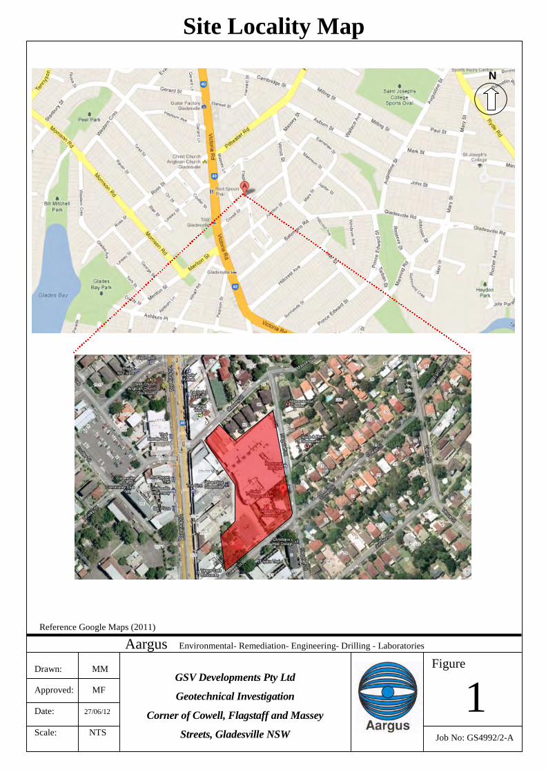
Reference Google Maps (2011)
Drawn: MM
Approved: MF
Date: 27/06/12
Scale: NTS
Aargus Environmental- Remediation- Engineering- Drilling - Laboratories
Job No: GS4992/2-A
Site Locality Map
N
GSV Developments Pty Ltd
Geotechnical Investigation
Corner of Cowell, Flagstaff and Massey
Streets, Gladesville NSW
Figure
1
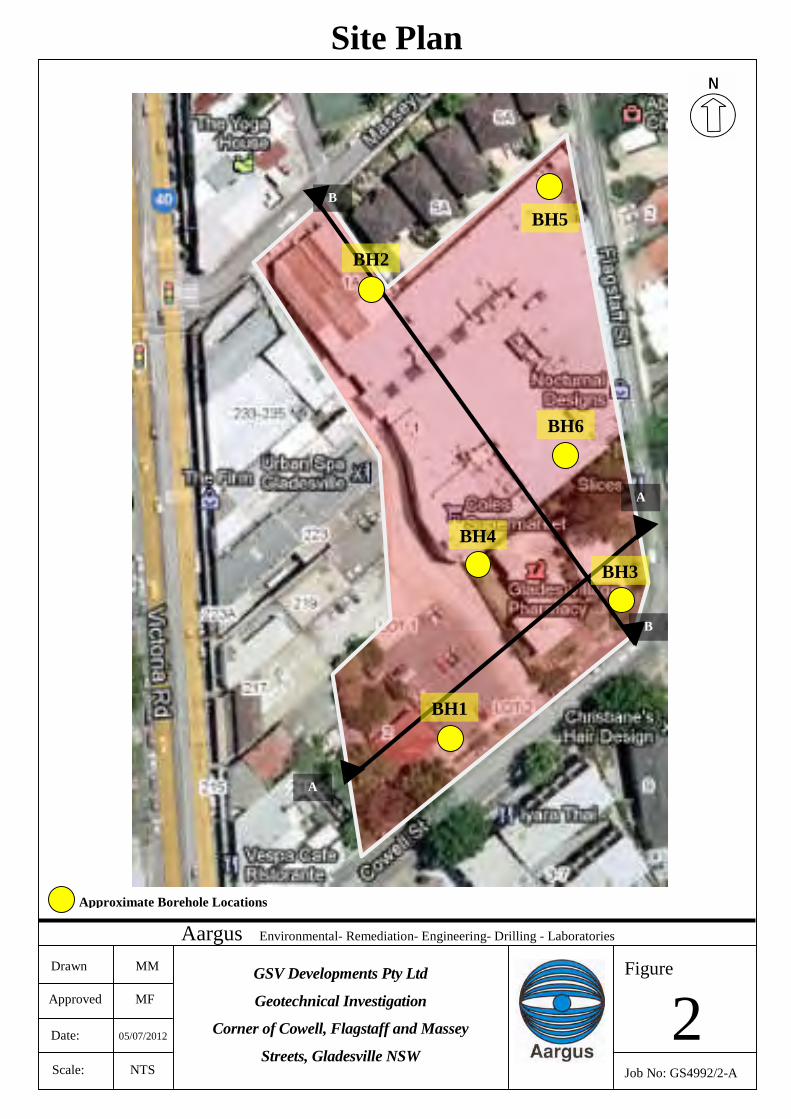
Scale: NTS
Date: 05/07/2012
Approved MF
Drawn MM
Aargus Environmental- Remediation- Engineering- Drilling - Laboratories
Figure
Job No: GS4992/2-A
Site Plan
2GSV Developments Pty Ltd
Geotechnical Investigation
Corner of Cowell, Flagstaff and Massey
Streets, Gladesville NSW
Approximate Borehole Locations
BH6
BH5
BH4
B
B
A
A
BH2
BH1
BH3
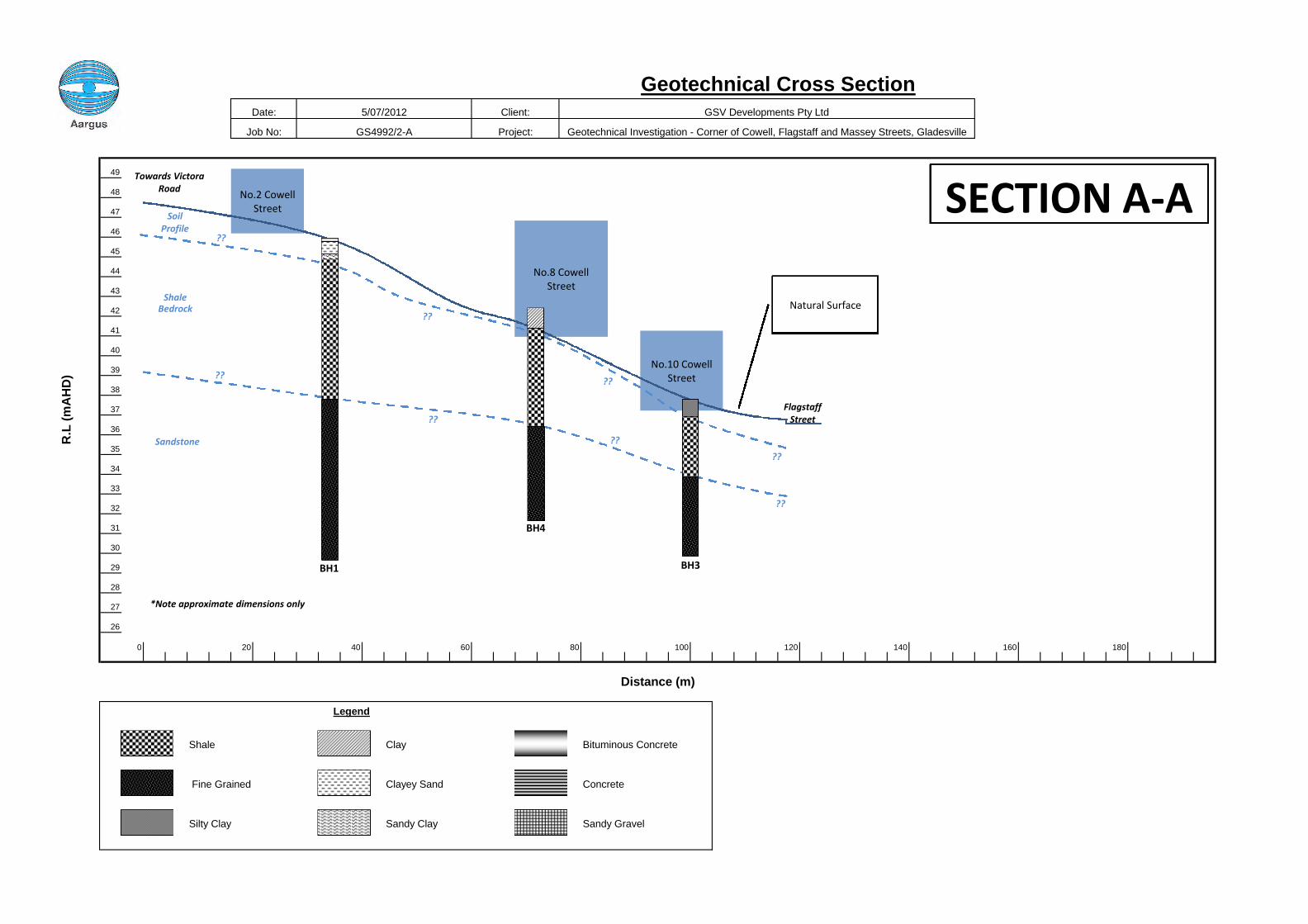
49
48
47
46
45
44
43
42
41
40
39
38
37
36
35
34
33
32
31
30
29
28
27
26
0 20 40 60 80 100 120 140 160 180
Geotechnical Cross SectionDate: 5/07/2012 Client: GSV Developments Pty Ltd
Project:
Bituminous Concrete
Concrete
Legend
Job No: GS4992/2-A
Shale
Silty Clay
Fine Grained
R.L
(mA
HD
)
Distance (m)
Geotechnical Investigation - Corner of Cowell, Flagstaff and Massey Streets, Gladesville
Sandy Gravel
Clay
Clayey Sand
Sandy Clay
No.10 CowellStreet
No.2 CowellStreet
No.8 CowellStreet
BH1
BH4
BH3
FlagstaffStreet
ShaleBedrock
Sandstone
Natural Surface
SoilProfile
SECTION A-A??
??
??
??
??
??
??
??
Towards VictoraRoad
*Note approximate dimensions only
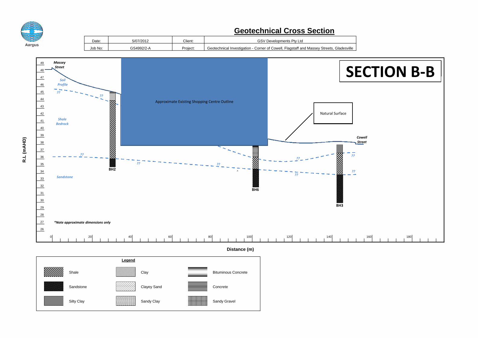
49
48
47
46
45
44
43
42
41
40
39
38
37
36
35
34 ^
33
32
31
30
29
28
27
26
0 20 40 60 80 100 120 140 160 180
GS4992/2-A Project: Geotechnical Investigation - Corner of Cowell, Flagstaff and Massey Streets, Gladesville
Silty Clay Sandy Clay Sandy Gravel
Legend
Shale Clay Bituminous Concrete
Sandstone Clayey Sand Concrete
R.L
(mA
HD
)
Distance (m)
Geotechnical Cross SectionDate: 5/07/2012 Client: GSV Developments Pty Ltd
Job No:
Approximate Existing Shopping Centre Outline
BH2
MasseyStreet
ShaleBedrock
Sandstone
Natural Surface
BH3
SoilProfile
SECTION B-B
CowellStreet
??
?? ??
????
????
????
*Note approximate dimensions only
BH6
APPENDIX C
_________________________________ENGINEERING BOREHOLE LOGSAND COREHOLE LOGS
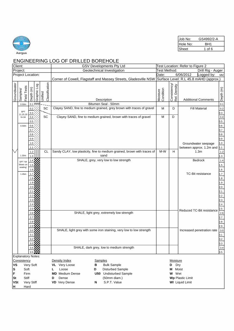
Job No: GS4992/2-A
Hole No: BH1
Sheet 1 of 6
ENGINEERING LOG OF DRILLED BOREHOLEClient: GSV Developments Pty Ltd Test Location: Refer to Figure 2Project: Geotechnical Investigation Test Method: Drill Rig - AugerProject Location: Date: Logged by: MM
Gro
un
dw
ate
r
Sa
mp
les/
Fie
ldT
ests
De
pth
(m)
Gra
ph
icL
og
Un
ifie
d
Cla
ssific
atio
n
Description Mo
istu
re
Co
nd
itio
n
Co
nsis
ten
cy/
Re
l.D
en
sity
Additional Comments De
pth
(m)
0.1 Bitumen Seal - 50mm 0.1
0.2 M 0.2
0.3 0.3
0.4 Clayey SAND, fine to medium grained, brown with traces of gravel M 0.4
0.5 0.5
0.6 0.6
0.7 0.7
0.8 0.8
0.9 0.9
1.0 1.0
1.1 1.1
1.2 M-W 1.2
1.3 1.3
1.4 SHALE, grey, very low to low strength 1.4
1.5 1.5
1.6 1.6
1.7 1.7
1.8 1.8
1.9 1.9
2.0 2.0
2.1 2.1
2.2 2.2
2.3 2.3
2.4 2.4
2.5 2.5
2.6 SHALE, light grey, extremely low strength 2.6
2.7 2.7
2.8 2.8
2.9 2.9
3.0 SHALE, light grey with some iron staining, very low to low strength 3.0
3.1 3.1
3.2 3.2
3.3 3.3
3.4 SHALE, dark grey, low to medium strength 3.4
3.5 3.5
Explanatory Notes:
Consistency Density Index Samples Moisture
VS Very Soft VL Very Loose B Bulk Sample D Dry
S Soft L Loose D Disturbed Sample M Moist
F Firm MD Medium Dense U50 Undisturbed Sample W Wet
St Stiff D Dense (50mm diam.) Wp Plastic Limit
VSt Very Stiff VD Very Dense N S.P.T. Value Wl Liquid Limit
H Hard
Corner of Cowell, Flagstaff and Massey Streets, Gladesville NSW6/06/2012
Surface Level: R.L 45.8 mAHD (approx.)
0.50m
SPT
11,15,19
N=34
SC Clayey SAND, fine to medium grained, grey brown with traces of gravel D Fill Material
SC D
0.50m
Groundwater seepage
between approx. 1.2m and
1.3mCL Sandy CLAY, low plasticity, fine to medium grained, brown with traces of
sandH
1.30m
SPT '64
blows on
seating'
Bedrock
1.45m TC-Bit resistance
Reduced TC-Bit resistance
Increased penetration rate
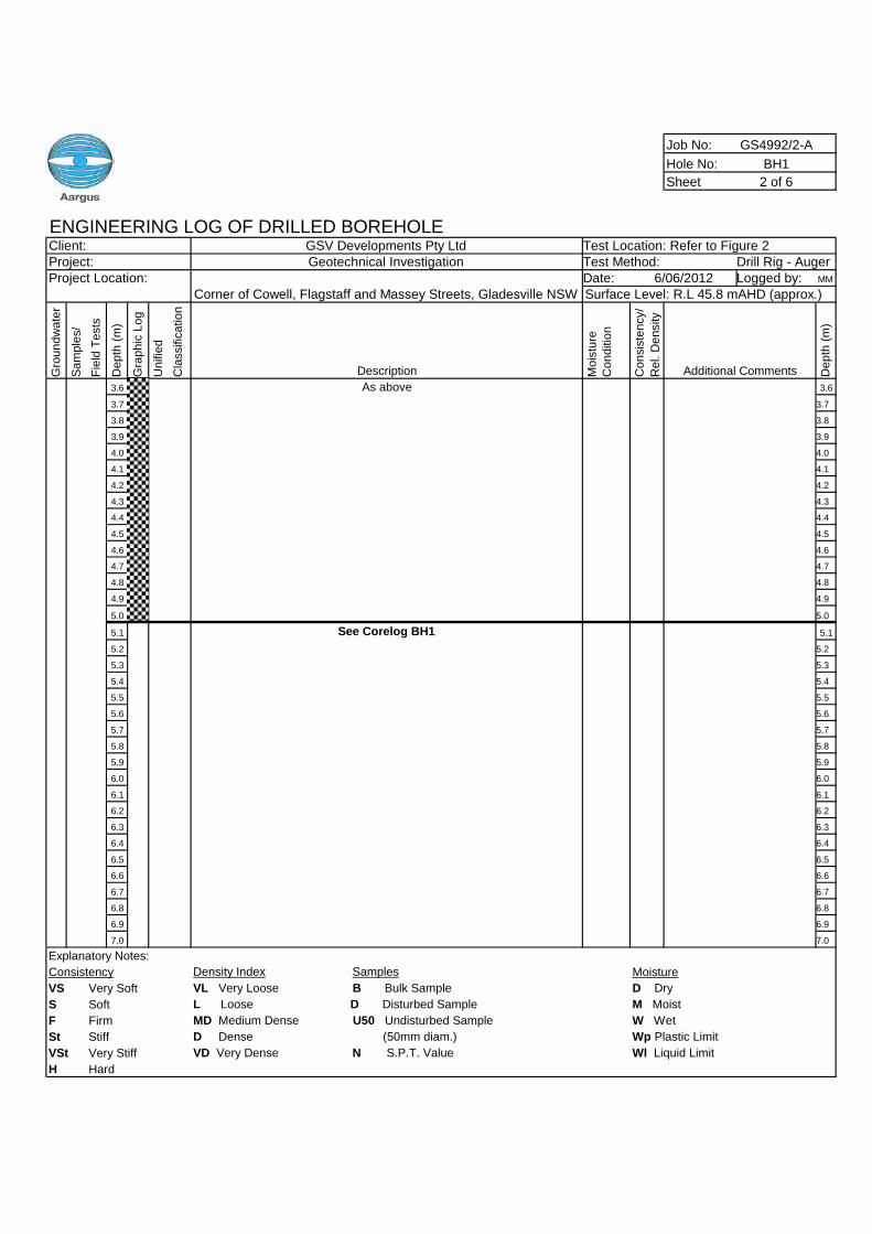
Job No: GS4992/2-A
Hole No: BH1
Sheet 2 of 6
ENGINEERING LOG OF DRILLED BOREHOLEClient: GSV Developments Pty Ltd Test Location: Refer to Figure 2Project: Geotechnical Investigation Test Method: Drill Rig - AugerProject Location: Date: Logged by: MM
Gro
un
dw
ate
r
Sa
mp
les/
Fie
ldT
ests
De
pth
(m)
Gra
ph
icL
og
Un
ifie
d
Cla
ssific
atio
n
Description Mo
istu
re
Co
nd
itio
n
Co
nsis
ten
cy/
Re
l.D
en
sity
Additional Comments De
pth
(m)
3.6 As above 3.6
3.7 3.7
3.8 3.8
3.9 3.9
4.0 4.0
4.1 4.1
4.2 4.2
4.3 4.3
4.4 4.4
4.5 4.5
4.6 4.6
4.7 4.7
4.8 4.8
4.9 4.9
5.0 5.0
5.1 See Corelog BH1 5.1
5.2 5.2
5.3 5.3
5.4 5.4
5.5 5.5
5.6 5.6
5.7 5.7
5.8 5.8
5.9 5.9
6.0 6.0
6.1 6.1
6.2 6.2
6.3 6.3
6.4 6.4
6.5 6.5
6.6 6.6
6.7 6.7
6.8 6.8
6.9 6.9
7.0 7.0
Explanatory Notes:
Consistency Density Index Samples Moisture
VS Very Soft VL Very Loose B Bulk Sample D Dry
S Soft L Loose D Disturbed Sample M Moist
F Firm MD Medium Dense U50 Undisturbed Sample W Wet
St Stiff D Dense (50mm diam.) Wp Plastic Limit
VSt Very Stiff VD Very Dense N S.P.T. Value Wl Liquid Limit
H Hard
Corner of Cowell, Flagstaff and Massey Streets, Gladesville NSW6/06/2012
Surface Level: R.L 45.8 mAHD (approx.)
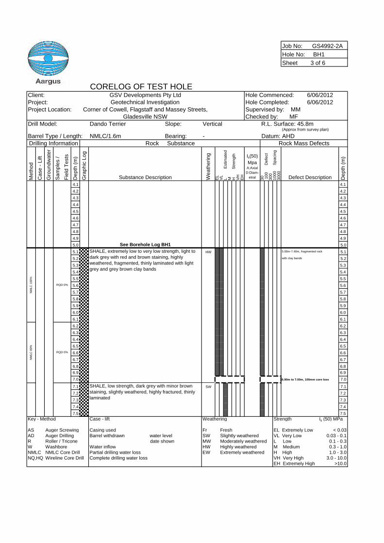
Job No: GS4992-2A
Hole No: BH1
Sheet 3 of 6
CORELOG OF TEST HOLEClient: GSV Developments Pty Ltd Hole Commenced: 6/06/2012Project: Geotechnical Investigation Hole Completed: 6/06/2012Project Location: Corner of Cowell, Flagstaff and Massey Streets,
Gladesville NSWDrill Model: Dando Terrier Slope: Vertical
(Approx from survey plan)
Barrel Type / Length: NMLC/1.6m Bearing: - AHDDrilling Information Rock Substance Rock Mass Defects
Me
tho
d
Ca
se
-L
ift
Gro
un
dw
ate
r
Sa
mp
les
/
Fie
ldT
ests
De
pth
(m)
Gra
ph
icL
og
Substance Description We
ath
eri
ng
EL
VL
LE
stim
ate
dM H
Str
en
gth
VH
EH
Is(50)
MpaA:Axial
D:Diam-
etral 30 10
0D
efe
ct
30
01
00
0S
pa
cin
g3
00
0
Defect Description De
pth
(m)
4.1 4.1
4.2 4.2
4.3 4.3
4.4 4.4
4.5 4.5
4.6 4.6
4.7 4.7
4.8 4.8
4.9 4.9
5.0 See Borehole Log BH1 5.0
5.1 HW 5.00m-7.40m, fragmented rock 5.1
5.2 with clay bands 5.2
5.3 5.3
5.4 5.4
5.5 5.5
5.6 5.6
5.7 5.7
5.8 5.8
5.9 5.9
6.0 6.0
6.1 6.1
6.2 6.2
6.3 6.3
6.4 6.4
6.5 6.5
6.6 6.6
6.7 6.7
6.8 6.8
6.9 6.9
7.0 6.90m to 7.00m, 100mm core loss 7.0
7.1 SW 7.1
7.2 7.2
7.3 7.3
7.4 7.4
7.5 7.5
Key - Method Case - lift Weathering Strength Is (50) MPa
AS Auger Screwing Casing used Fr Fresh EL Extremely Low < 0.03AD Auger Drilling Barrel withdrawn water level SW Slightly weathered VL Very Low 0.03 - 0.1R Roller / Tricone date shown MW Moderately weathered L Low 0.1 - 0.3W Washbore Water inflow HW Highly weathered M Medium 0.3 - 1.0NMLC NMLC Core Drill Partial drilling water loss EW Extremely weathered H High 1.0 - 3.0NQ,HQ Wireline Core Drill Complete drilling water loss VH Very High 3.0 - 10.0
EH Extremely High >10.0
NM
LC
89%
SHALE, low strength, dark grey with minor brown
staining, slightly weathered, highly fractured, thinly
laminated
RQD 0%
NM
LC
100%
SHALE, extremely low to very low strength, light to
dark grey with red and brown staining, highly
weathered, fragmented, thinly laminated with light
grey and grey brown clay bands
Supervised by: MMChecked by: MF
RQD 0%
R.L. Surface: 45.8m
Datum:
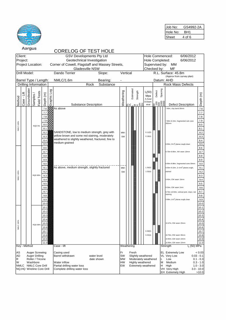
Job No: GS4992-2A
Hole No: BH1
Sheet 4 of 6
CORELOG OF TEST HOLEClient: GSV Developments Pty Ltd Hole Commenced: 6/06/2012Project: Geotechnical Investigation Hole Completed: 6/06/2012Project Location: Corner of Cowell, Flagstaff and Massey Streets,
Gladesville NSWDrill Model: Dando Terrier Slope: Vertical
(Approx from survey plan)
Barrel Type / Length: NMLC/1.6m Bearing: - AHDDrilling Information Rock Substance Rock Mass Defects
Me
tho
d
Ca
se
-L
ift
Gro
un
dw
ate
r
Sa
mp
les
/
Fie
ldT
ests
De
pth
(m)
Gra
ph
icL
og
Substance Description We
ath
eri
ng
EL
VL
LE
stim
ate
dM H
Str
en
gth
VH
EH
Is(50)
MpaA:Axial
D:Diam-
etral 30 10
0D
efe
ct
30
01
00
0S
pa
cin
g3
00
0
Defect Description De
pth
(m)
7.6 As above 7.60m, clay band 30mm 7.6
7.7 7.7
7.8 7.8
7.9 7.9
8.0 8.0
8.1 8.1
8.2 MW- 0.11(D) 8.2
8.3 SW 0.18(A) 8.3
8.4 8.4
8.5 8.50m, B=00,planar,rough,clean 8.5
8.6 8.6
8.7 8.70m-8.80m, XW seam 10mm 8.7
8.8 8.8
8.9 8.9
9.0 8.95m-8.98m, fragmented zone 30mm 9.0
9.1 As above, medium strength, slightly fractured MW- 1.26(D) 9.05m-9.10m, 2× B=00,planar,rough, 9.1
9.2 SW 1.03(A) stained 9.2
9.3 9.3
9.4 9.40m, EW seam 10mm 9.4
9.5 9.5
9.6 9.54m, EW seam 2mm 9.6
9.7 9.7
9.8 9.8
9.9 9.88m, B=00,planar,rough,clean 9.9
10.0 10.0
10.1 10.1
10.2 10.2
10.3 10.3
10.4 10.4
10.5 10.47m, EW seam 20mm 10.5
10.6 10.6
10.7 0.39(D) 10.7
10.8 0.44(A) 10.76m, EW seam 40mm 10.8
10.9 10.85m, EW seam 10mm 10.9
11.0 10.96m, EW seam 10mm 11.0
Key - Method Case - lift Weathering Strength Is (50) MPa
AS Auger Screwing Casing used Fr Fresh EL Extremely Low < 0.03AD Auger Drilling Barrel withdrawn water level SW Slightly weathered VL Very Low 0.03 - 0.1R Roller / Tricone date shown MW Moderately weathered L Low 0.1 - 0.3W Washbore Water inflow HW Highly weathered M Medium 0.3 - 1.0NMLC NMLC Core Drill Partial drilling water loss EW Extremely weathered H High 1.0 - 3.0NQ,HQ Wireline Core Drill Complete drilling water loss VH Very High 3.0 - 10.0
EH Extremely High >10.0
RQD 98%
NM
LC
100%
NM
LC
100%
9.70m-10.50m, vertical joint, intact, red
staining
Supervised by: MMChecked by: MF
NM
LC
100%
R.L. Surface: 45.8m
SANDSTONE, low to medium strength, grey with
yellow brown and some red staining, moderately
weathered to slightly weathered, fractured, fine to
medium grained
7.80m-8.10m, fragmented rock zone
300mm
Datum:
RQD 9%
RQD 85%
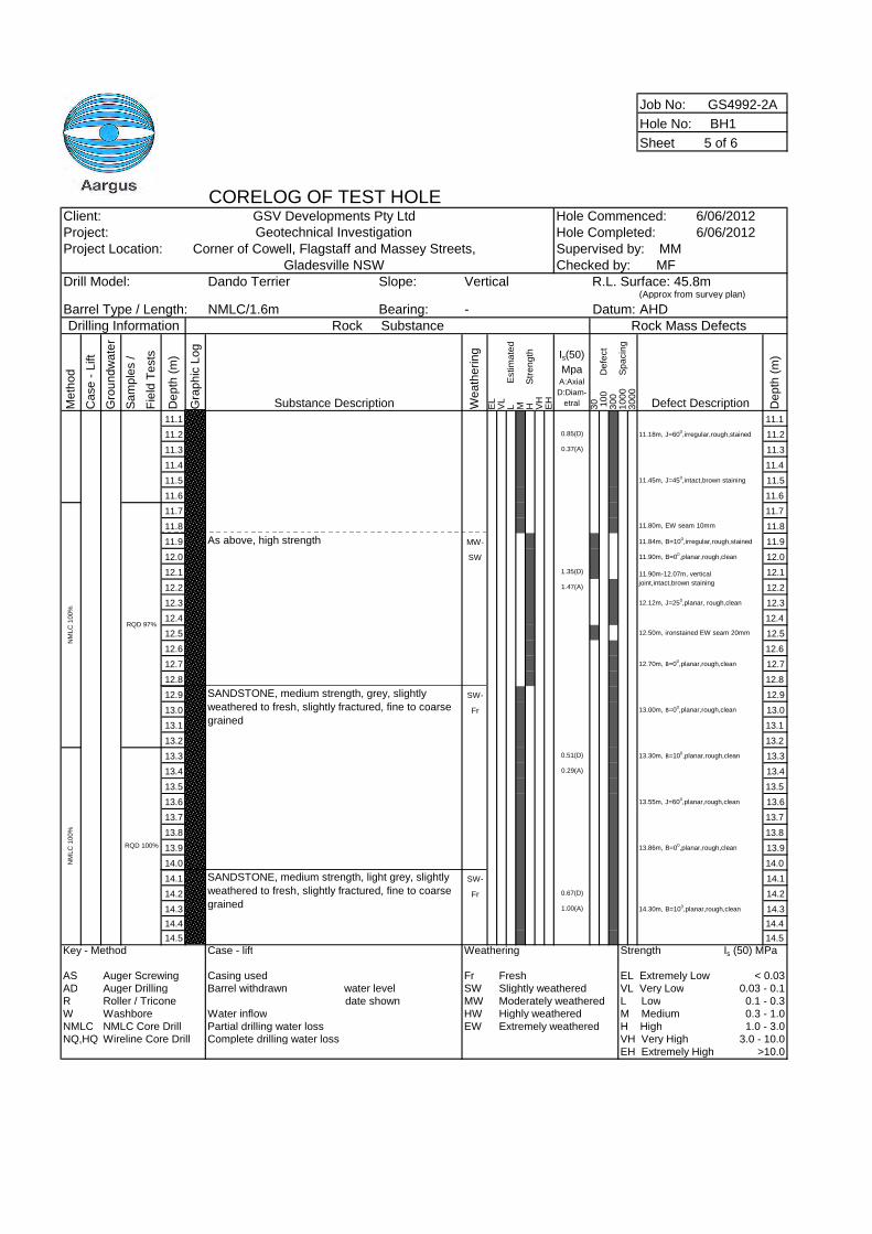
Job No: GS4992-2A
Hole No: BH1
Sheet 5 of 6
CORELOG OF TEST HOLEClient: GSV Developments Pty Ltd Hole Commenced: 6/06/2012Project: Geotechnical Investigation Hole Completed: 6/06/2012Project Location: Corner of Cowell, Flagstaff and Massey Streets,
Gladesville NSWDrill Model: Dando Terrier Slope: Vertical
(Approx from survey plan)
Barrel Type / Length: NMLC/1.6m Bearing: - AHDDrilling Information Rock Substance Rock Mass Defects
Me
tho
d
Ca
se
-L
ift
Gro
un
dw
ate
r
Sa
mp
les
/
Fie
ldT
ests
De
pth
(m)
Gra
ph
icL
og
Substance Description We
ath
eri
ng
EL
VL
LE
stim
ate
dM H
Str
en
gth
VH
EH
Is(50)
MpaA:Axial
D:Diam-
etral 30 10
0D
efe
ct
30
01
00
0S
pa
cin
g3
00
0
Defect Description De
pth
(m)
11.1 11.1
11.2 0.85(D) 11.18m, J=600,irregular,rough,stained 11.2
11.3 0.37(A) 11.3
11.4 11.4
11.5 11.45m, J=450,intact,brown staining 11.5
11.6 11.6
11.7 11.7
11.8 11.80m, EW seam 10mm 11.8
11.9 As above, high strength MW- 11.84m, B=100,irregular,rough,stained 11.9
12.0 SW 11.90m, B=00,planar,rough,clean 12.0
12.1 1.35(D) 12.1
12.2 1.47(A) 12.2
12.3 12.12m, J=250,planar, rough,clean 12.3
12.4 12.4
12.5 12.50m, ironstained EW seam 20mm 12.5
12.6 12.6
12.7 12.70m, B=00,planar,rough,clean 12.7
12.8 12.8
12.9 SW- 12.9
13.0 Fr 13.00m, B=00,planar,rough,clean 13.0
13.1 13.1
13.2 13.2
13.3 0.51(D) 13.30m, B=100,planar,rough,clean 13.3
13.4 0.29(A) 13.4
13.5 13.5
13.6 13.55m, J=600,planar,rough,clean 13.6
13.7 13.7
13.8 13.8
13.9 13.86m, B=00,planar,rough,clean 13.9
14.0 14.0
14.1 SW- 14.1
14.2 Fr 0.67(D) 14.2
14.3 1.00(A) 14.30m, B=100,planar,rough,clean 14.3
14.4 14.4
14.5 14.5
Key - Method Case - lift Weathering Strength Is (50) MPa
AS Auger Screwing Casing used Fr Fresh EL Extremely Low < 0.03AD Auger Drilling Barrel withdrawn water level SW Slightly weathered VL Very Low 0.03 - 0.1R Roller / Tricone date shown MW Moderately weathered L Low 0.1 - 0.3W Washbore Water inflow HW Highly weathered M Medium 0.3 - 1.0NMLC NMLC Core Drill Partial drilling water loss EW Extremely weathered H High 1.0 - 3.0NQ,HQ Wireline Core Drill Complete drilling water loss VH Very High 3.0 - 10.0
EH Extremely High >10.0
Supervised by: MMChecked by: MF
RQD 100%
RQD 97%
NM
LC
100%
SANDSTONE, medium strength, grey, slightly
weathered to fresh, slightly fractured, fine to coarse
grained
NM
LC
100%
R.L. Surface: 45.8m
11.90m-12.07m, vertical
joint,intact,brown staining
Datum:
SANDSTONE, medium strength, light grey, slightly
weathered to fresh, slightly fractured, fine to coarse
grained
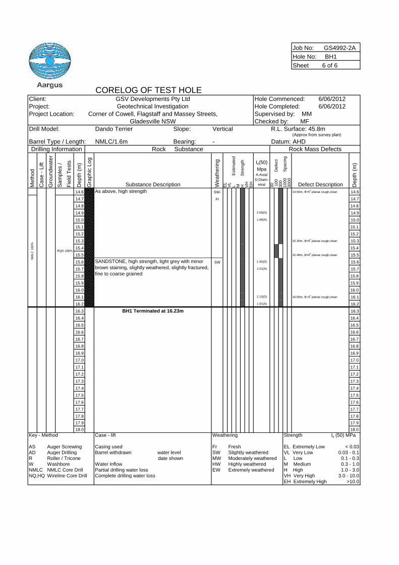
Job No: GS4992-2A
Hole No: BH1
Sheet 6 of 6
CORELOG OF TEST HOLEClient: GSV Developments Pty Ltd Hole Commenced: 6/06/2012Project: Geotechnical Investigation Hole Completed: 6/06/2012Project Location: Corner of Cowell, Flagstaff and Massey Streets,
Gladesville NSWDrill Model: Dando Terrier Slope: Vertical
(Approx from survey plan)
Barrel Type / Length: NMLC/1.6m Bearing: - AHDDrilling Information Rock Substance Rock Mass Defects
Me
tho
d
Ca
se
-L
ift
Gro
un
dw
ate
r
Sa
mp
les
/
Fie
ldT
ests
De
pth
(m)
Gra
ph
icL
og
Substance Description We
ath
eri
ng
EL
VL
LE
stim
ate
dM H
Str
en
gth
VH
EH
Is(50)
MpaA:Axial
D:Diam-
etral 30 10
0D
efe
ct
30
01
00
0S
pa
cin
g3
00
0
Defect Description De
pth
(m)
14.6 As above, high strength SW- 14.56m, B=50,planar,rough,clean 14.6
14.7 Fr 14.7
14.8 14.8
14.9 2.05(D) 14.9
15.0 1.68(A) 15.0
15.1 15.1
15.2 15.2
15.3 15.30m, B=00,planar,rough,clean 15.3
15.4 15.4
15.5 15.48m, B=00,planar,rough,clean 15.5
15.6 SW 1.92(D) 15.6
15.7 1.51(A) 15.7
15.8 15.8
15.9 15.9
16.0 16.0
16.1 2.15(D) 16.05m, B=00,planar,rough,clean 16.1
16.2 1.61(A) 16.2
16.3 BH1 Terminated at 16.23m 16.3
16.4 16.4
16.5 16.5
16.6 16.6
16.7 16.7
16.8 16.8
16.9 16.9
17.0 17.0
17.1 17.1
17.2 17.2
17.3 17.3
17.4 17.4
17.5 17.5
17.6 17.6
17.7 17.7
17.8 17.8
17.9 17.9
18.0 18.0
Key - Method Case - lift Weathering Strength Is (50) MPa
AS Auger Screwing Casing used Fr Fresh EL Extremely Low < 0.03AD Auger Drilling Barrel withdrawn water level SW Slightly weathered VL Very Low 0.03 - 0.1R Roller / Tricone date shown MW Moderately weathered L Low 0.1 - 0.3W Washbore Water inflow HW Highly weathered M Medium 0.3 - 1.0NMLC NMLC Core Drill Partial drilling water loss EW Extremely weathered H High 1.0 - 3.0NQ,HQ Wireline Core Drill Complete drilling water loss VH Very High 3.0 - 10.0
EH Extremely High >10.0
NM
LC
100%
SANDSTONE, high strength, light grey with minor
brown staining, slightly weathered, slightly fractured,
fine to coarse grained
RQD 100%
Supervised by: MMChecked by: MF
R.L. Surface: 45.8m
Datum:
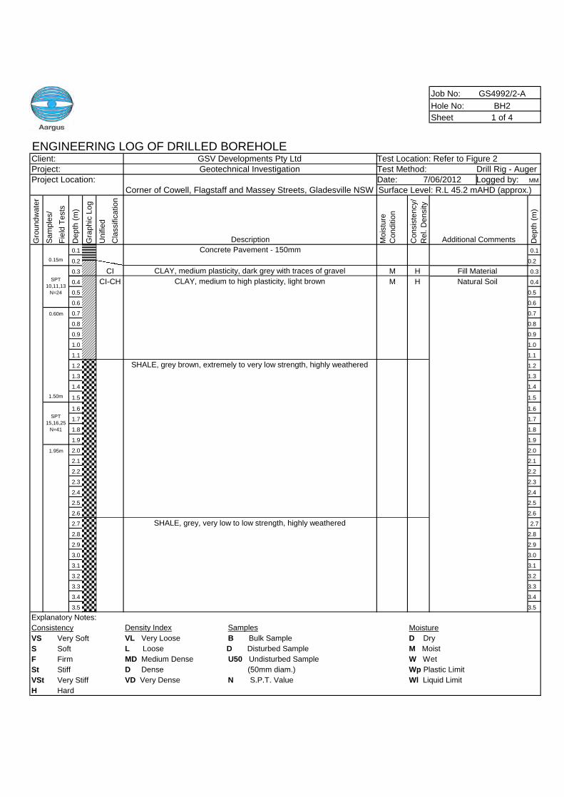
Job No: GS4992/2-A
Hole No: BH2
Sheet 1 of 4
ENGINEERING LOG OF DRILLED BOREHOLEClient: GSV Developments Pty Ltd Test Location: Refer to Figure 2Project: Geotechnical Investigation Test Method: Drill Rig - AugerProject Location: Date: Logged by: MM
Gro
un
dw
ate
r
Sa
mp
les/
Fie
ldT
ests
De
pth
(m)
Gra
ph
icL
og
Un
ifie
d
Cla
ssific
atio
n
Description Mo
istu
re
Co
nd
itio
n
Co
nsis
ten
cy/
Re
l.D
en
sity
Additional Comments De
pth
(m)
0.1 Concrete Pavement - 150mm 0.1
0.2 0.2
0.3 CLAY, medium plasticity, dark grey with traces of gravel M 0.3
0.4 CLAY, medium to high plasticity, light brown M 0.4
0.5 0.5
0.6 0.6
0.7 0.7
0.8 0.8
0.9 0.9
1.0 1.0
1.1 1.1
1.2 1.2
1.3 1.3
1.4 1.4
1.5 1.5
1.6 1.6
1.7 1.7
1.8 1.8
1.9 1.9
2.0 2.0
2.1 2.1
2.2 2.2
2.3 2.3
2.4 2.4
2.5 2.5
2.6 2.6
2.7 SHALE, grey, very low to low strength, highly weathered 2.7
2.8 2.8
2.9 2.9
3.0 3.0
3.1 3.1
3.2 3.2
3.3 3.3
3.4 3.4
3.5 3.5
Explanatory Notes:
Consistency Density Index Samples Moisture
VS Very Soft VL Very Loose B Bulk Sample D Dry
S Soft L Loose D Disturbed Sample M Moist
F Firm MD Medium Dense U50 Undisturbed Sample W Wet
St Stiff D Dense (50mm diam.) Wp Plastic Limit
VSt Very Stiff VD Very Dense N S.P.T. Value Wl Liquid Limit
H Hard
Corner of Cowell, Flagstaff and Massey Streets, Gladesville NSW7/06/2012
Surface Level: R.L 45.2 mAHD (approx.)
0.15m
SPT
10,11,13
N=24
CI H Fill Material
CI-CH H Natural Soil
0.60m
SHALE, grey brown, extremely to very low strength, highly weathered
1.50m
SPT
15,16,25
N=41
1.95m
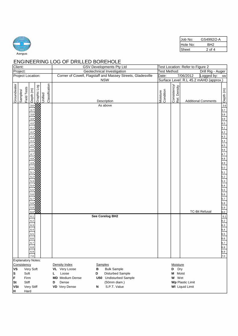
Job No: GS4992/2-A
Hole No: BH2
Sheet 2 of 4
ENGINEERING LOG OF DRILLED BOREHOLEClient: GSV Developments Pty Ltd Test Location: Refer to Figure 2Project: Geotechnical Investigation Test Method: Drill Rig - AugerProject Location: Date: Logged by: MM
Gro
un
dw
ate
r
Sa
mp
les/
Fie
ldT
ests
De
pth
(m)
Gra
ph
icL
og
Un
ifie
d
Cla
ssific
atio
n
Description Mo
istu
re
Co
nd
itio
n
Co
nsis
ten
cy/
Re
l.D
en
sity
Additional Comments De
pth
(m)
3.6 As above 3.6
3.7 3.7
3.8 3.8
3.9 3.9
4.0 4.0
4.1 4.1
4.2 4.2
4.3 4.3
4.4 4.4
4.5 4.5
4.6 4.6
4.7 4.7
4.8 4.8
4.9 4.9
5.0 5.0
5.1 5.1
5.2 5.2
5.3 5.3
5.4 5.4
5.5 5.5
5.6 5.6
5.7 5.7
5.8 5.8
5.9 5.9
6.0 6.0
6.1 See Corelog BH2 6.1
6.2 6.2
6.3 6.3
6.4 6.4
6.5 6.5
6.6 6.6
6.7 6.7
6.8 6.8
6.9 6.9
7.0 7.0
Explanatory Notes:
Consistency Density Index Samples Moisture
VS Very Soft VL Very Loose B Bulk Sample D Dry
S Soft L Loose D Disturbed Sample M Moist
F Firm MD Medium Dense U50 Undisturbed Sample W Wet
St Stiff D Dense (50mm diam.) Wp Plastic Limit
VSt Very Stiff VD Very Dense N S.P.T. Value Wl Liquid Limit
H Hard
Corner of Cowell, Flagstaff and Massey Streets, GladesvilleNSW
7/06/2012Surface Level: R.L 45.2 mAHD (approx.)
TC-Bit Refusal
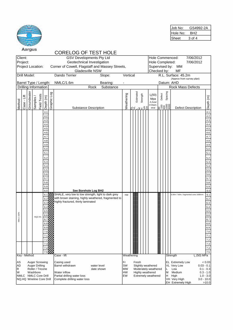
Job No: GS4992-2A
Hole No: BH2
Sheet 3 of 4
CORELOG OF TEST HOLEClient: GSV Developments Pty Ltd Hole Commenced: 7/06/2012Project: Geotechnical Investigation Hole Completed: 7/06/2012Project Location: Corner of Cowell, Flagstaff and Massey Streets,
Gladesville NSWDrill Model: Dando Terrier Slope: Vertical
(Approx from survey plan)
Barrel Type / Length: NMLC/1.6m Bearing: - AHDDrilling Information Rock Substance Rock Mass Defects
Me
tho
d
Ca
se
-L
ift
Gro
un
dw
ate
r
Sa
mp
les
/
Fie
ldT
ests
De
pth
(m)
Gra
ph
icL
og
Substance Description We
ath
eri
ng
EL
VL
LE
stim
ate
dM H
Str
en
gth
VH
EH
Is(50)
MpaA:Axial
D:Diam-
etral 30 10
0D
efe
ct
30
01
00
0S
pa
cin
g3
00
0
Defect Description De
pth
(m)
4.1 4.1
4.2 4.2
4.3 4.3
4.4 4.4
4.5 4.5
4.6 4.6
4.7 4.7
4.8 4.8
4.9 4.9
5.0 5.0
5.1 5.1
5.2 5.2
5.3 5.3
5.4 5.4
5.5 5.5
5.6 5.6
5.7 5.7
5.8 5.8
5.9 5.9
6.0 See Borehole Log BH2 6.0
6.1 HW 6.00m-7.60m, fragmented zone 1600mm 6.1
6.2 6.2
6.3 6.3
6.4 6.4
6.5 6.5
6.6 6.6
6.7 6.7
6.8 6.8
6.9 6.9
7.0 7.0
7.1 7.1
7.2 7.2
7.3 7.3
7.4 7.4
7.5 7.5
Key - Method Case - lift Weathering Strength Is (50) MPa
AS Auger Screwing Casing used Fr Fresh EL Extremely Low < 0.03AD Auger Drilling Barrel withdrawn water level SW Slightly weathered VL Very Low 0.03 - 0.1R Roller / Tricone date shown MW Moderately weathered L Low 0.1 - 0.3W Washbore Water inflow HW Highly weathered M Medium 0.3 - 1.0NMLC NMLC Core Drill Partial drilling water loss EW Extremely weathered H High 1.0 - 3.0NQ,HQ Wireline Core Drill Complete drilling water loss VH Very High 3.0 - 10.0
EH Extremely High >10.0
NM
LC
100%
SHALE, very low to low strength, light to dark grey
with brown staining, highly weathered, fragmented to
highly fractured, thinly laminated
Supervised by: MMChecked by: MF
RQD 0%
R.L. Surface: 45.2m
Datum:
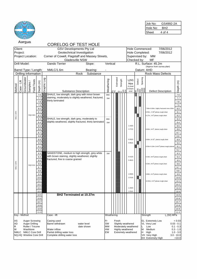
Job No: GS4992-2A
Hole No: BH2
Sheet 4 of 4
CORELOG OF TEST HOLEClient: GSV Developments Pty Ltd Hole Commenced: 7/06/2012Project: Geotechnical Investigation Hole Completed: 7/06/2012Project Location: Corner of Cowell, Flagstaff and Massey Streets,
Gladesville NSWDrill Model: Dando Terrier Slope: Vertical
(Approx from survey plan)
Barrel Type / Length: NMLC/1.6m Bearing: - AHDDrilling Information Rock Substance Rock Mass Defects
Me
tho
d
Ca
se
-L
ift
Gro
un
dw
ate
r
Sa
mp
les
/
Fie
ldT
ests
De
pth
(m)
Gra
ph
icL
og
Substance Description We
ath
eri
ng
EL
VL
LE
stim
ate
dM H
Str
en
gth
VH
EH
Is(50)
MpaA:Axial
D:Diam-
etral 30 10
0D
efe
ct
30
01
00
0S
pa
cin
g3
00
0
Defect Description De
pth
(m)
7.6 MW- 7.6
7.7 SW 7.7
7.8 7.8
7.9 7.9
8.0 7.90m-8.00m, highly fractured zone 100m 8.0
8.1 8.05m, J=300,planar,rough,clean 8.1
8.2 8.17m, J=50,planar,rough,clean 8.2
8.3 MW- 8.3
8.4 SW 8.4
8.5 1.10(D) 8.5
8.6 1.37(A) 8.60m, B=00, planar,rough,clean 8.6
8.7 8.7
8.8 8.8
8.9 0.26(D) 8.90m, B=150, planar,rough,clean 8.9
9.0 0.88(A) 9.0
9.1 9.05m-9.10m 2×B=50,planar,rough,stained 9.1
9.2 9.2
9.3 SW 9.3
9.4 0.41(D) 9.33m, B=00,planar,rough,clean 9.4
9.5 0.46(A) 9.5
9.6 9.54m, B=00,planar,rough,clean 9.6
9.7 9.7
9.8 9.8
9.9 1.09(D) 9.88m, B=00,planar,rough,clean 9.9
10.0 1.51(A) 10.0
10.1 10.02m, B=00,planar,rough,clean 10.1
10.2 10.2
10.3 1.18(D) 10.3
10.4 1.03(A) 10.4
10.5 BH2 Terminated at 10.37m 10.5
10.6 10.6
10.7 10.7
10.8 10.8
10.9 10.9
11.0 11.0
Key - Method Case - lift Weathering Strength Is (50) MPa
AS Auger Screwing Casing used Fr Fresh EL Extremely Low < 0.03AD Auger Drilling Barrel withdrawn water level SW Slightly weathered VL Very Low 0.03 - 0.1R Roller / Tricone date shown MW Moderately weathered L Low 0.1 - 0.3W Washbore Water inflow HW Highly weathered M Medium 0.3 - 1.0NMLC NMLC Core Drill Partial drilling water loss EW Extremely weathered H High 1.0 - 3.0NQ,HQ Wireline Core Drill Complete drilling water loss VH Very High 3.0 - 10.0
EH Extremely High >10.0
Supervised by: MMChecked by: MF
RQD 56%
RQD 91%
SHALE, low strength, dark grey with minor brown
staining, moderately to slightly weathered, fractured,
thinly laminated
NM
LC
100%
SHALE, low strength, dark grey, moderately to
slightly weathered, slighlty fractured, thinly laminated
SANDSTONE, medium to high strength, grey white
with brown staining, slightly weathered, slightly
fractured, fine to coarse grained
NM
LC
100%
R.L. Surface: 45.2m
Datum:
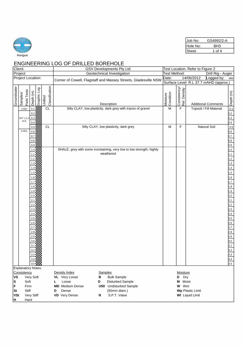
Job No: GS4992/2-A
Hole No: BH3
Sheet 1 of 4
ENGINEERING LOG OF DRILLED BOREHOLEClient: GSV Developments Pty Ltd Test Location: Refer to Figure 2Project: Geotechnical Investigation Test Method: Drill Rig - AugerProject Location: Date: Logged by: MM
Gro
un
dw
ate
r
Sa
mp
les/
Fie
ldT
ests
De
pth
(m)
Gra
ph
icL
og
Un
ifie
d
Cla
ssific
atio
n
Description Mo
istu
re
Co
nd
itio
n
Co
nsis
ten
cy/
Re
l.D
en
sity
Additional Comments De
pth
(m)
0.1 Silty CLAY, low plasticity, dark grey with traces of gravel M 0.1
0.2 0.2
0.3 0.3
0.4 0.4
0.5 Silty CLAY, low plasticity, dark grey M 0.5
0.6 0.6
0.7 0.7
0.8 0.8
0.9 0.9
1.0 1.0
1.1 1.1
1.2 1.2
1.3 1.3
1.4 1.4
1.5 1.5
1.6 1.6
1.7 1.7
1.8 1.8
1.9 1.9
2.0 2.0
2.1 2.1
2.2 2.2
2.3 2.3
2.4 2.4
2.5 2.5
2.6 2.6
2.7 2.7
2.8 2.8
2.9 2.9
3.0 3.0
3.1 3.1
3.2 3.2
3.3 3.3
3.4 3.4
3.5 3.5
Explanatory Notes:
Consistency Density Index Samples Moisture
VS Very Soft VL Very Loose B Bulk Sample D Dry
S Soft L Loose D Disturbed Sample M Moist
F Firm MD Medium Dense U50 Undisturbed Sample W Wet
St Stiff D Dense (50mm diam.) Wp Plastic Limit
VSt Very Stiff VD Very Dense N S.P.T. Value Wl Liquid Limit
H Hard
Corner of Cowell, Flagstaff and Massey Streets, Gladesville NSW14/06/2012
Surface Level: R.L 37.7 mAHD (approx.)
0.00m CL F Topsoil / Fill Material
CL F Natural Soil0.45m
SPT 1,2,4
N=6
SHALE, grey with some ironstaining, very low to low strength, highly
weathered
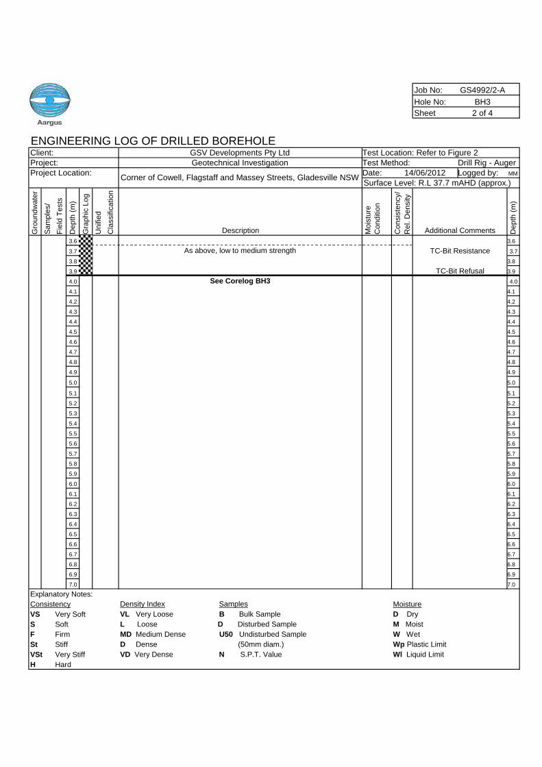
Job No: GS4992/2-A
Hole No: BH3
Sheet 2 of 4
ENGINEERING LOG OF DRILLED BOREHOLEClient: GSV Developments Pty Ltd Test Location: Refer to Figure 2Project: Geotechnical Investigation Test Method: Drill Rig - AugerProject Location: Date: Logged by: MM
Gro
un
dw
ate
r
Sa
mp
les/
Fie
ldT
ests
De
pth
(m)
Gra
ph
icL
og
Un
ifie
d
Cla
ssific
atio
n
Description Mo
istu
re
Co
nd
itio
n
Co
nsis
ten
cy/
Re
l.D
en
sity
Additional Comments De
pth
(m)
3.6 3.6
3.7 As above, low to medium strength 3.7
3.8 3.8
3.9 3.9
4.0 See Corelog BH3 4.0
4.1 4.1
4.2 4.2
4.3 4.3
4.4 4.4
4.5 4.5
4.6 4.6
4.7 4.7
4.8 4.8
4.9 4.9
5.0 5.0
5.1 5.1
5.2 5.2
5.3 5.3
5.4 5.4
5.5 5.5
5.6 5.6
5.7 5.7
5.8 5.8
5.9 5.9
6.0 6.0
6.1 6.1
6.2 6.2
6.3 6.3
6.4 6.4
6.5 6.5
6.6 6.6
6.7 6.7
6.8 6.8
6.9 6.9
7.0 7.0
Explanatory Notes:
Consistency Density Index Samples Moisture
VS Very Soft VL Very Loose B Bulk Sample D Dry
S Soft L Loose D Disturbed Sample M Moist
F Firm MD Medium Dense U50 Undisturbed Sample W Wet
St Stiff D Dense (50mm diam.) Wp Plastic Limit
VSt Very Stiff VD Very Dense N S.P.T. Value Wl Liquid Limit
H Hard
Corner of Cowell, Flagstaff and Massey Streets, Gladesville NSW14/06/2012
Surface Level: R.L 37.7 mAHD (approx.)
TC-Bit Resistance
TC-Bit Refusal
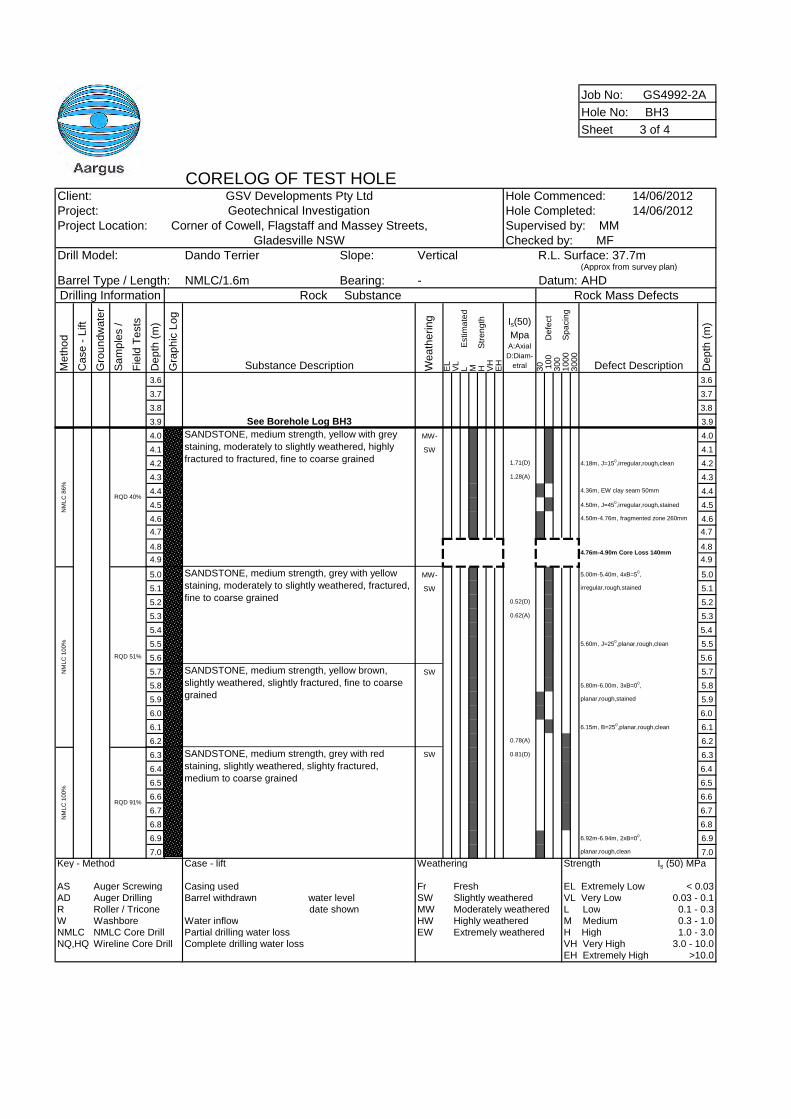
Job No: GS4992-2A
Hole No: BH3
Sheet 3 of 4
CORELOG OF TEST HOLEClient: GSV Developments Pty Ltd Hole Commenced: 14/06/2012Project: Geotechnical Investigation Hole Completed: 14/06/2012Project Location: Corner of Cowell, Flagstaff and Massey Streets,
Gladesville NSWDrill Model: Dando Terrier Slope: Vertical
(Approx from survey plan)
Barrel Type / Length: NMLC/1.6m Bearing: - AHDDrilling Information Rock Substance Rock Mass Defects
Me
tho
d
Ca
se
-L
ift
Gro
un
dw
ate
r
Sa
mp
les
/
Fie
ldT
ests
De
pth
(m)
Gra
ph
icL
og
Substance Description We
ath
eri
ng
EL
VL
LE
stim
ate
dM H
Str
en
gth
VH
EH
Is(50)
MpaA:Axial
D:Diam-
etral 30 10
0D
efe
ct
30
01
00
0S
pa
cin
g3
00
0
Defect Description De
pth
(m)
3.6 3.6
3.7 3.7
3.8 3.8
3.9 See Borehole Log BH3 3.9
4.0 MW- 4.0
4.1 SW 4.1
4.2 1.71(D) 4.18m, J=150,irregular,rough,clean 4.2
4.3 1.28(A) 4.3
4.4 4.36m, EW clay seam 50mm 4.4
4.5 4.50m, J=450,irregular,rough,stained 4.5
4.6 4.50m-4.76m, fragmented zone 260mm 4.6
4.7 4.7
4.8 4.8
4.9 4.9
5.0 MW- 5.00m-5.40m, 4xB=50, 5.0
5.1 SW irregular,rough,stained 5.1
5.2 0.52(D) 5.2
5.3 0.62(A) 5.3
5.4 5.4
5.5 5.60m, J=250,planar,rough,clean 5.5
5.6 5.6
5.7 SW 5.7
5.8 5.80m-6.00m, 3xB=00, 5.8
5.9 planar,rough,stained 5.9
6.0 6.0
6.1 6.15m, B=250,planar,rough,clean 6.1
6.2 0.78(A) 6.2
6.3 SW 0.81(D) 6.3
6.4 6.4
6.5 6.5
6.6 6.6
6.7 6.7
6.8 6.8
6.9 6.92m-6.94m, 2xB=00, 6.9
7.0 planar,rough,clean 7.0
Key - Method Case - lift Weathering Strength Is (50) MPa
AS Auger Screwing Casing used Fr Fresh EL Extremely Low < 0.03AD Auger Drilling Barrel withdrawn water level SW Slightly weathered VL Very Low 0.03 - 0.1R Roller / Tricone date shown MW Moderately weathered L Low 0.1 - 0.3W Washbore Water inflow HW Highly weathered M Medium 0.3 - 1.0NMLC NMLC Core Drill Partial drilling water loss EW Extremely weathered H High 1.0 - 3.0NQ,HQ Wireline Core Drill Complete drilling water loss VH Very High 3.0 - 10.0
EH Extremely High >10.0
Supervised by: MMChecked by: MF
RQD 40%
RQD 51%
R.L. Surface: 37.7m
Datum:
SANDSTONE, medium strength, yellow brown,
slightly weathered, slightly fractured, fine to coarse
grained
NM
LC
100%
4.76m-4.90m Core Loss 140mm
NM
LC
86%
NM
LC
100%
SANDSTONE, medium strength, yellow with grey
staining, moderately to slightly weathered, highly
fractured to fractured, fine to coarse grained
SANDSTONE, medium strength, grey with yellow
staining, moderately to slightly weathered, fractured,
fine to coarse grained
RQD 91%
SANDSTONE, medium strength, grey with red
staining, slightly weathered, slighty fractured,
medium to coarse grained
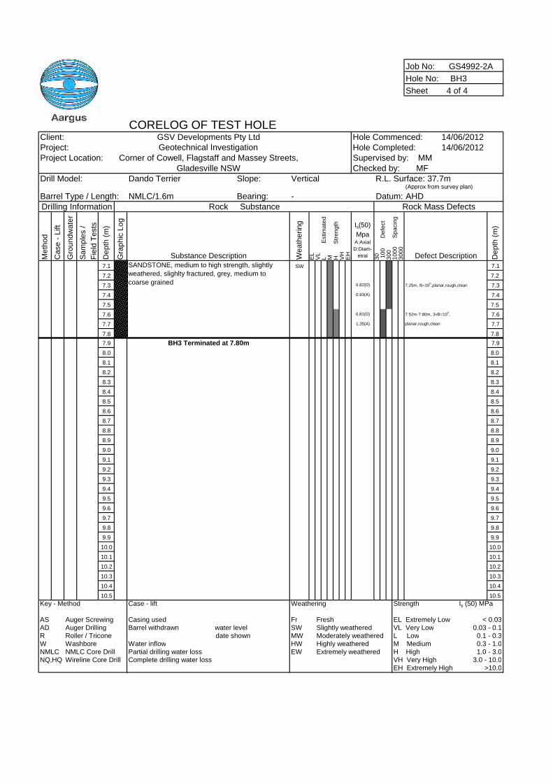
Job No: GS4992-2A
Hole No: BH3
Sheet 4 of 4
CORELOG OF TEST HOLEClient: GSV Developments Pty Ltd Hole Commenced: 14/06/2012Project: Geotechnical Investigation Hole Completed: 14/06/2012Project Location: Corner of Cowell, Flagstaff and Massey Streets,
Gladesville NSWDrill Model: Dando Terrier Slope: Vertical
(Approx from survey plan)
Barrel Type / Length: NMLC/1.6m Bearing: - AHDDrilling Information Rock Substance Rock Mass Defects
Me
tho
d
Ca
se
-L
ift
Gro
un
dw
ate
r
Sa
mp
les
/
Fie
ldT
ests
De
pth
(m)
Gra
ph
icL
og
Substance Description We
ath
eri
ng
EL
VL
LE
stim
ate
dM H
Str
en
gth
VH
EH
Is(50)
MpaA:Axial
D:Diam-
etral 30 10
0D
efe
ct
30
01
00
0S
pa
cin
g3
00
0
Defect Description De
pth
(m)
7.1 SW 7.1
7.2 7.2
7.3 0.82(D) 7.25m, B=100,planar,rough,clean 7.3
7.4 0.93(A) 7.4
7.5 7.5
7.6 0.81(D) 7.52m-7.80m, 3×B=100, 7.6
7.7 1.35(A) planar,rough,clean 7.7
7.8 7.8
7.9 BH3 Terminated at 7.80m 7.9
8.0 8.0
8.1 8.1
8.2 8.2
8.3 8.3
8.4 8.4
8.5 8.5
8.6 8.6
8.7 8.7
8.8 8.8
8.9 8.9
9.0 9.0
9.1 9.1
9.2 9.2
9.3 9.3
9.4 9.4
9.5 9.5
9.6 9.6
9.7 9.7
9.8 9.8
9.9 9.9
10.0 10.0
10.1 10.1
10.2 10.2
10.3 10.3
10.4 10.4
10.5 10.5
Key - Method Case - lift Weathering Strength Is (50) MPa
AS Auger Screwing Casing used Fr Fresh EL Extremely Low < 0.03AD Auger Drilling Barrel withdrawn water level SW Slightly weathered VL Very Low 0.03 - 0.1R Roller / Tricone date shown MW Moderately weathered L Low 0.1 - 0.3W Washbore Water inflow HW Highly weathered M Medium 0.3 - 1.0NMLC NMLC Core Drill Partial drilling water loss EW Extremely weathered H High 1.0 - 3.0NQ,HQ Wireline Core Drill Complete drilling water loss VH Very High 3.0 - 10.0
EH Extremely High >10.0
Supervised by: MMChecked by: MF
SANDSTONE, medium to high strength, slightly
weathered, slighlty fractured, grey, medium to
coarse grained
R.L. Surface: 37.7m
Datum:
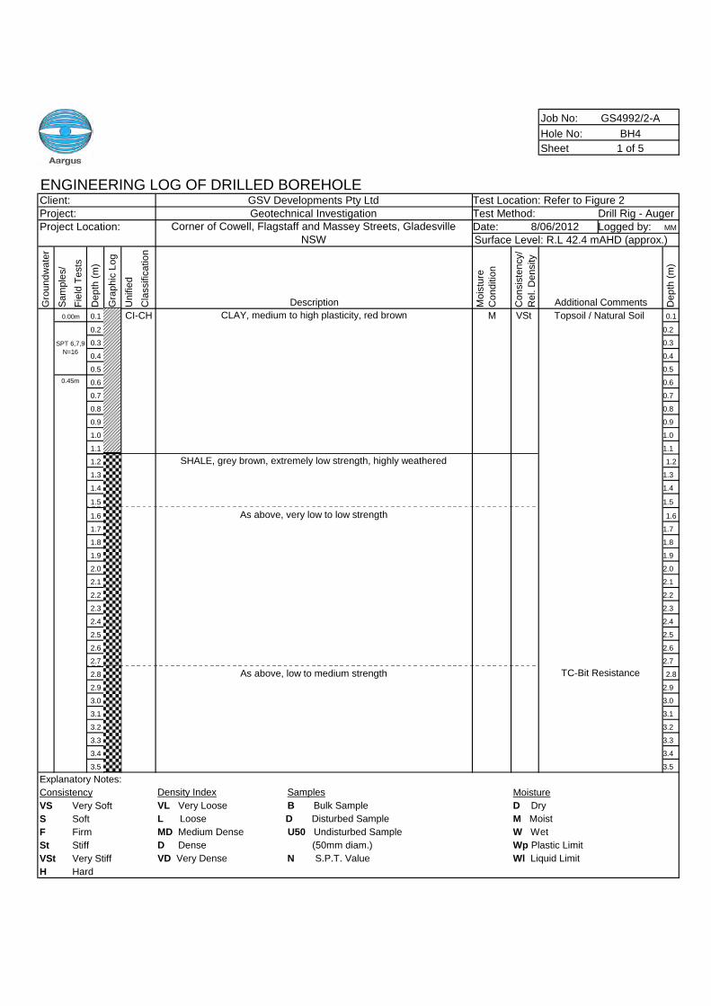
Job No: GS4992/2-A
Hole No: BH4
Sheet 1 of 5
ENGINEERING LOG OF DRILLED BOREHOLEClient: GSV Developments Pty Ltd Test Location: Refer to Figure 2Project: Geotechnical Investigation Test Method: Drill Rig - AugerProject Location: Date: Logged by: MM
Gro
un
dw
ate
r
Sa
mp
les/
Fie
ldT
ests
De
pth
(m)
Gra
ph
icL
og
Un
ifie
d
Cla
ssific
atio
n
Description Mo
istu
re
Co
nd
itio
n
Co
nsis
ten
cy/
Re
l.D
en
sity
Additional Comments De
pth
(m)
0.1 CLAY, medium to high plasticity, red brown M 0.1
0.2 0.2
0.3 0.3
0.4 0.4
0.5 0.5
0.6 0.6
0.7 0.7
0.8 0.8
0.9 0.9
1.0 1.0
1.1 1.1
1.2 SHALE, grey brown, extremely low strength, highly weathered 1.2
1.3 1.3
1.4 1.4
1.5 1.5
1.6 As above, very low to low strength 1.6
1.7 1.7
1.8 1.8
1.9 1.9
2.0 2.0
2.1 2.1
2.2 2.2
2.3 2.3
2.4 2.4
2.5 2.5
2.6 2.6
2.7 2.7
2.8 As above, low to medium strength 2.8
2.9 2.9
3.0 3.0
3.1 3.1
3.2 3.2
3.3 3.3
3.4 3.4
3.5 3.5
Explanatory Notes:
Consistency Density Index Samples Moisture
VS Very Soft VL Very Loose B Bulk Sample D Dry
S Soft L Loose D Disturbed Sample M Moist
F Firm MD Medium Dense U50 Undisturbed Sample W Wet
St Stiff D Dense (50mm diam.) Wp Plastic Limit
VSt Very Stiff VD Very Dense N S.P.T. Value Wl Liquid Limit
H Hard
Corner of Cowell, Flagstaff and Massey Streets, GladesvilleNSW
8/06/2012Surface Level: R.L 42.4 mAHD (approx.)
0.00m CI-CH VSt Topsoil / Natural Soil
SPT 6,7,9
N=16
0.45m
TC-Bit Resistance
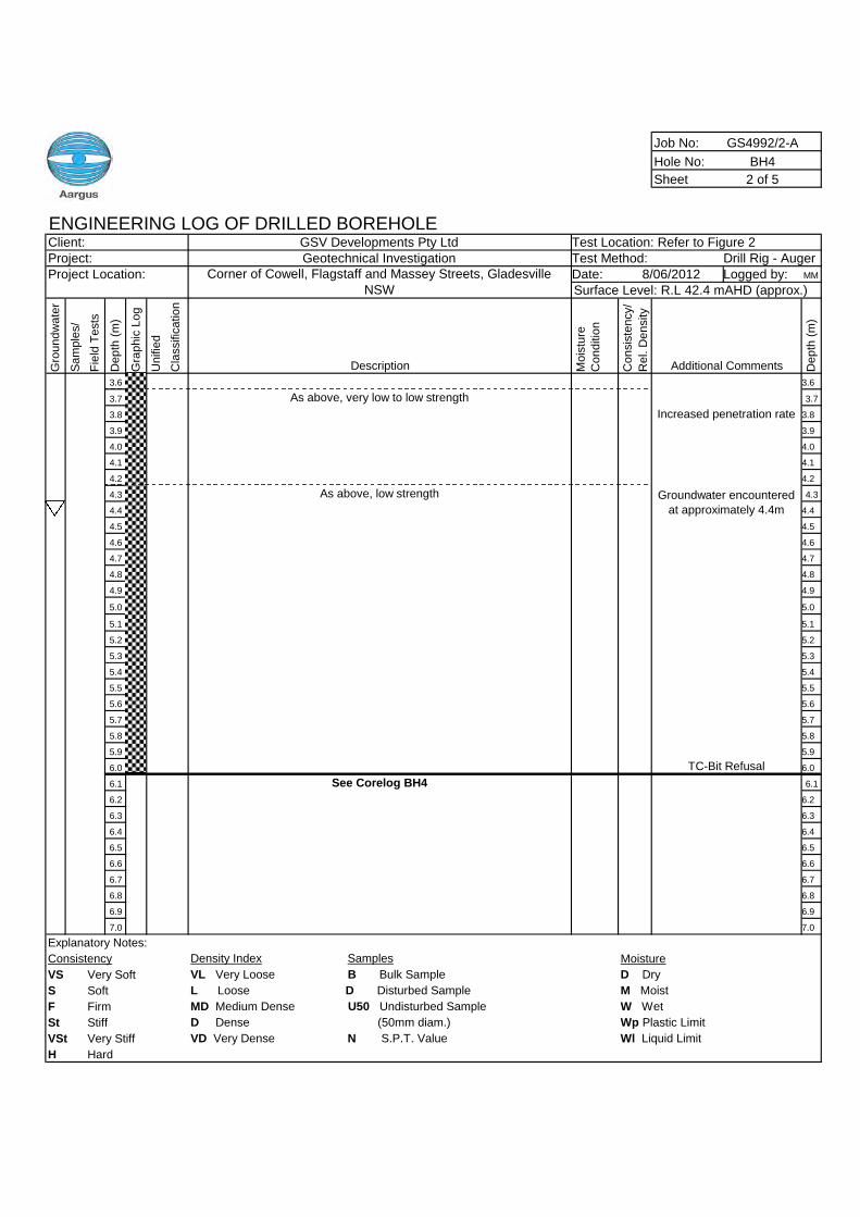
Job No: GS4992/2-A
Hole No: BH4
Sheet 2 of 5
ENGINEERING LOG OF DRILLED BOREHOLEClient: GSV Developments Pty Ltd Test Location: Refer to Figure 2Project: Geotechnical Investigation Test Method: Drill Rig - AugerProject Location: Date: Logged by: MM
Gro
un
dw
ate
r
Sa
mp
les/
Fie
ldT
ests
De
pth
(m)
Gra
ph
icL
og
Un
ifie
d
Cla
ssific
atio
n
Description Mo
istu
re
Co
nd
itio
n
Co
nsis
ten
cy/
Re
l.D
en
sity
Additional Comments De
pth
(m)
3.6 3.6
3.7 As above, very low to low strength 3.7
3.8 3.8
3.9 3.9
4.0 4.0
4.1 4.1
4.2 4.2
4.3 As above, low strength 4.3
4.4 4.4
4.5 4.5
4.6 4.6
4.7 4.7
4.8 4.8
4.9 4.9
5.0 5.0
5.1 5.1
5.2 5.2
5.3 5.3
5.4 5.4
5.5 5.5
5.6 5.6
5.7 5.7
5.8 5.8
5.9 5.9
6.0 6.0
6.1 See Corelog BH4 6.1
6.2 6.2
6.3 6.3
6.4 6.4
6.5 6.5
6.6 6.6
6.7 6.7
6.8 6.8
6.9 6.9
7.0 7.0
Explanatory Notes:
Consistency Density Index Samples Moisture
VS Very Soft VL Very Loose B Bulk Sample D Dry
S Soft L Loose D Disturbed Sample M Moist
F Firm MD Medium Dense U50 Undisturbed Sample W Wet
St Stiff D Dense (50mm diam.) Wp Plastic Limit
VSt Very Stiff VD Very Dense N S.P.T. Value Wl Liquid Limit
H Hard
Corner of Cowell, Flagstaff and Massey Streets, GladesvilleNSW
8/06/2012Surface Level: R.L 42.4 mAHD (approx.)
Increased penetration rate
Groundwater encountered
at approximately 4.4m
TC-Bit Refusal
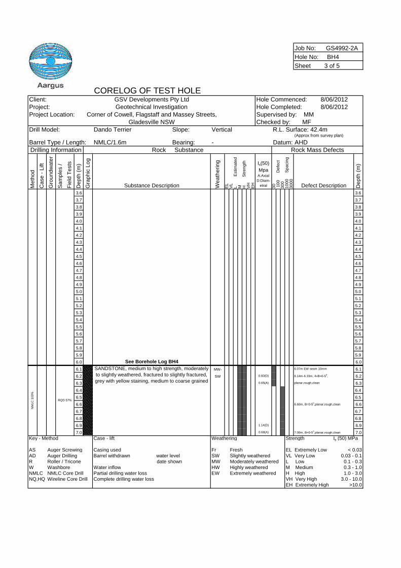
Job No: GS4992-2A
Hole No: BH4
Sheet 3 of 5
CORELOG OF TEST HOLEClient: GSV Developments Pty Ltd Hole Commenced: 8/06/2012Project: Geotechnical Investigation Hole Completed: 8/06/2012Project Location: Corner of Cowell, Flagstaff and Massey Streets,
Gladesville NSWDrill Model: Dando Terrier Slope: Vertical
(Approx from survey plan)
Barrel Type / Length: NMLC/1.6m Bearing: - AHDDrilling Information Rock Substance Rock Mass Defects
Me
tho
d
Ca
se
-L
ift
Gro
un
dw
ate
r
Sa
mp
les
/
Fie
ldT
ests
De
pth
(m)
Gra
ph
icL
og
Substance Description We
ath
eri
ng
EL
VL
LE
stim
ate
dM H
Str
en
gth
VH
EH
Is(50)
MpaA:Axial
D:Diam-
etral 30 10
0D
efe
ct
30
01
00
0S
pa
cin
g3
00
0
Defect Description De
pth
(m)
3.6 3.6
3.7 3.7
3.8 3.8
3.9 3.9
4.0 4.0
4.1 4.1
4.2 4.2
4.3 4.3
4.4 4.4
4.5 4.5
4.6 4.6
4.7 4.7
4.8 4.8
4.9 4.9
5.0 5.0
5.1 5.1
5.2 5.2
5.3 5.3
5.4 5.4
5.5 5.5
5.6 5.6
5.7 5.7
5.8 5.8
5.9 5.9
6.0 See Borehole Log BH4 6.0
6.1 MW- 6.07m EW seam 10mm 6.1
6.2 SW 0.60(D) 6.14m-6.33m, 4×B=0-50, 6.2
6.3 0.65(A) planar,rough,clean 6.3
6.4 6.4
6.5 6.5
6.6 6.60m, B=0-50,planar,rough,clean 6.6
6.7 6.7
6.8 6.8
6.9 1.14(D) 6.9
7.0 0.68(A) 7.00m, B=0-50,planar,rough,clean 7.0
Key - Method Case - lift Weathering Strength Is (50) MPa
AS Auger Screwing Casing used Fr Fresh EL Extremely Low < 0.03AD Auger Drilling Barrel withdrawn water level SW Slightly weathered VL Very Low 0.03 - 0.1R Roller / Tricone date shown MW Moderately weathered L Low 0.1 - 0.3W Washbore Water inflow HW Highly weathered M Medium 0.3 - 1.0NMLC NMLC Core Drill Partial drilling water loss EW Extremely weathered H High 1.0 - 3.0NQ,HQ Wireline Core Drill Complete drilling water loss VH Very High 3.0 - 10.0
EH Extremely High >10.0
NM
LC
100%
SANDSTONE, medium to high strength, moderately
to slightly weathered, fractured to slightly fractured,
grey with yellow staining, medium to coarse grained
Supervised by: MMChecked by: MF
RQD 57%
R.L. Surface: 42.4m
Datum:
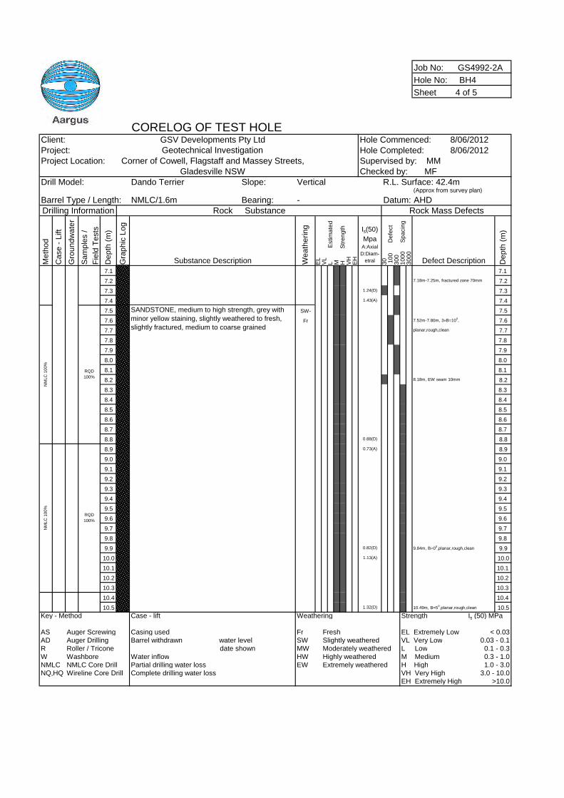
Job No: GS4992-2A
Hole No: BH4
Sheet 4 of 5
CORELOG OF TEST HOLEClient: GSV Developments Pty Ltd Hole Commenced: 8/06/2012Project: Geotechnical Investigation Hole Completed: 8/06/2012Project Location: Corner of Cowell, Flagstaff and Massey Streets,
Gladesville NSWDrill Model: Dando Terrier Slope: Vertical
(Approx from survey plan)
Barrel Type / Length: NMLC/1.6m Bearing: - AHDDrilling Information Rock Substance Rock Mass Defects
Me
tho
d
Ca
se
-L
ift
Gro
un
dw
ate
r
Sa
mp
les
/
Fie
ldT
ests
De
pth
(m)
Gra
ph
icL
og
Substance Description We
ath
eri
ng
EL
VL
LE
stim
ate
dM H
Str
en
gth
VH
EH
Is(50)
MpaA:Axial
D:Diam-
etral 30 10
0D
efe
ct
30
01
00
0S
pa
cin
g3
00
0
Defect Description De
pth
(m)
7.1 7.1
7.2 7.18m-7.25m, fractured zone 70mm 7.2
7.3 1.24(D) 7.3
7.4 1.43(A) 7.4
7.5 SW- 7.5
7.6 Fr 7.52m-7.80m, 3×B=100, 7.6
7.7 planar,rough,clean 7.7
7.8 7.8
7.9 7.9
8.0 8.0
8.1 8.1
8.2 8.18m, EW seam 10mm 8.2
8.3 8.3
8.4 8.4
8.5 8.5
8.6 8.6
8.7 8.7
8.8 0.88(D) 8.8
8.9 0.73(A) 8.9
9.0 9.0
9.1 9.1
9.2 9.2
9.3 9.3
9.4 9.4
9.5 9.5
9.6 9.6
9.7 9.7
9.8 9.8
9.9 0.82(D) 9.84m, B=00,planar,rough,clean 9.9
10.0 1.13(A) 10.0
10.1 10.1
10.2 10.2
10.3 10.3
10.4 10.4
10.5 1.32(D) 10.49m, B=50,planar,rough,clean 10.5
Key - Method Case - lift Weathering Strength Is (50) MPa
AS Auger Screwing Casing used Fr Fresh EL Extremely Low < 0.03AD Auger Drilling Barrel withdrawn water level SW Slightly weathered VL Very Low 0.03 - 0.1R Roller / Tricone date shown MW Moderately weathered L Low 0.1 - 0.3W Washbore Water inflow HW Highly weathered M Medium 0.3 - 1.0NMLC NMLC Core Drill Partial drilling water loss EW Extremely weathered H High 1.0 - 3.0NQ,HQ Wireline Core Drill Complete drilling water loss VH Very High 3.0 - 10.0
EH Extremely High >10.0
NM
LC
100%
NM
LC
100%
SANDSTONE, medium to high strength, grey with
minor yellow staining, slightly weathered to fresh,
slightly fractured, medium to coarse grained
RQD
100%
RQD
100%
Supervised by: MMChecked by: MF
R.L. Surface: 42.4m
Datum:
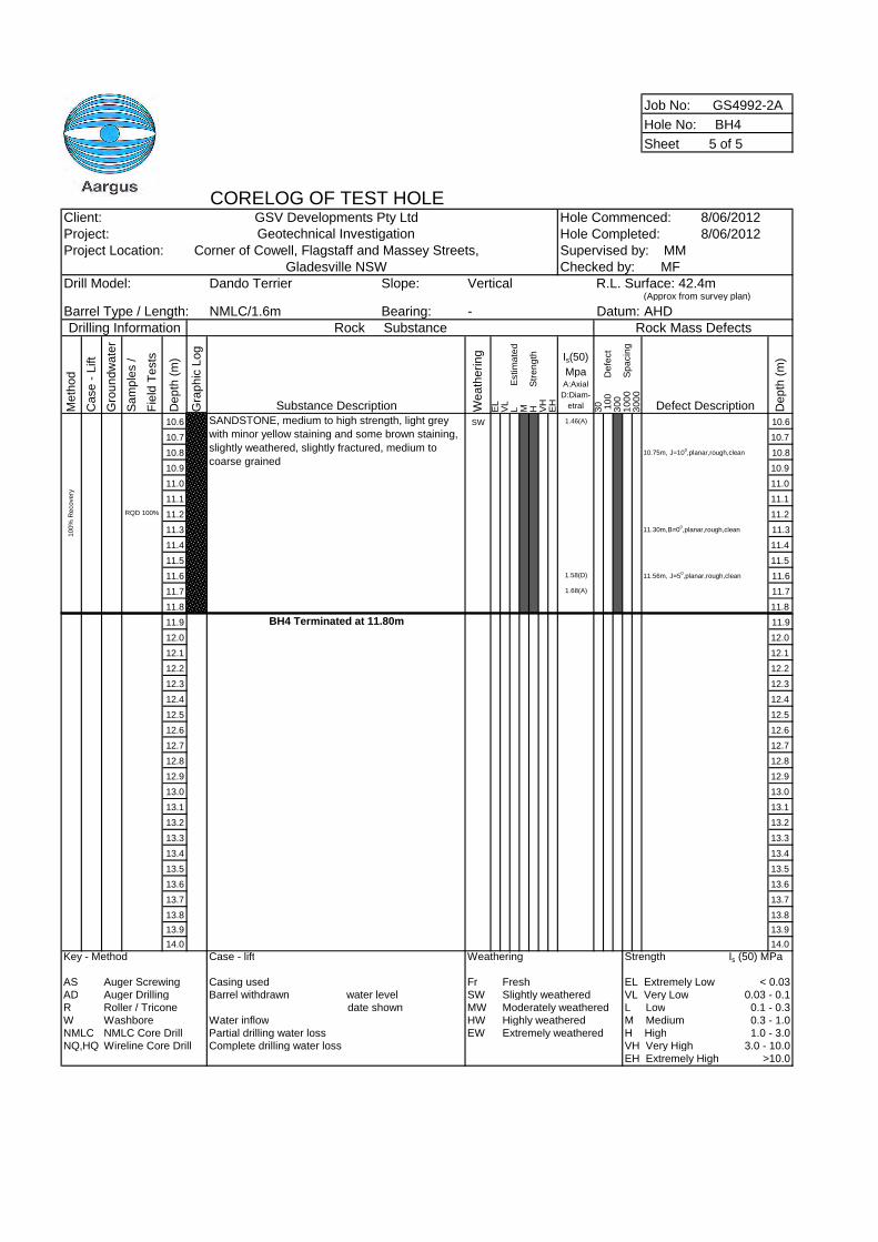
Job No: GS4992-2A
Hole No: BH4
Sheet 5 of 5
CORELOG OF TEST HOLEClient: GSV Developments Pty Ltd Hole Commenced: 8/06/2012Project: Geotechnical Investigation Hole Completed: 8/06/2012Project Location: Corner of Cowell, Flagstaff and Massey Streets,
Gladesville NSWDrill Model: Dando Terrier Slope: Vertical
(Approx from survey plan)
Barrel Type / Length: NMLC/1.6m Bearing: - AHDDrilling Information Rock Substance Rock Mass Defects
Me
tho
d
Ca
se
-L
ift
Gro
un
dw
ate
r
Sa
mp
les
/
Fie
ldT
ests
De
pth
(m)
Gra
ph
icL
og
Substance Description We
ath
eri
ng
EL
VL
LE
stim
ate
dM H
Str
en
gth
VH
EH
Is(50)
MpaA:Axial
D:Diam-
etral 30 10
0D
efe
ct
30
01
00
0S
pa
cin
g3
00
0
Defect Description De
pth
(m)
10.6 SW 1.46(A) 10.6
10.7 10.7
10.8 10.75m, J=100,planar,rough,clean 10.8
10.9 10.9
11.0 11.0
11.1 11.1
11.2 11.2
11.3 11.30m,B=00,planar,rough,clean 11.3
11.4 11.4
11.5 11.5
11.6 1.58(D) 11.56m, J=50,planar,rough,clean 11.6
11.7 1.68(A) 11.7
11.8 11.8
11.9 BH4 Terminated at 11.80m 11.9
12.0 12.0
12.1 12.1
12.2 12.2
12.3 12.3
12.4 12.4
12.5 12.5
12.6 12.6
12.7 12.7
12.8 12.8
12.9 12.9
13.0 13.0
13.1 13.1
13.2 13.2
13.3 13.3
13.4 13.4
13.5 13.5
13.6 13.6
13.7 13.7
13.8 13.8
13.9 13.9
14.0 14.0
Key - Method Case - lift Weathering Strength Is (50) MPa
AS Auger Screwing Casing used Fr Fresh EL Extremely Low < 0.03AD Auger Drilling Barrel withdrawn water level SW Slightly weathered VL Very Low 0.03 - 0.1R Roller / Tricone date shown MW Moderately weathered L Low 0.1 - 0.3W Washbore Water inflow HW Highly weathered M Medium 0.3 - 1.0NMLC NMLC Core Drill Partial drilling water loss EW Extremely weathered H High 1.0 - 3.0NQ,HQ Wireline Core Drill Complete drilling water loss VH Very High 3.0 - 10.0
EH Extremely High >10.0
100%
Recovery
RQD 100%
Supervised by: MMChecked by: MF
SANDSTONE, medium to high strength, light grey
with minor yellow staining and some brown staining,
slightly weathered, slightly fractured, medium to
coarse grained
R.L. Surface: 42.4m
Datum:
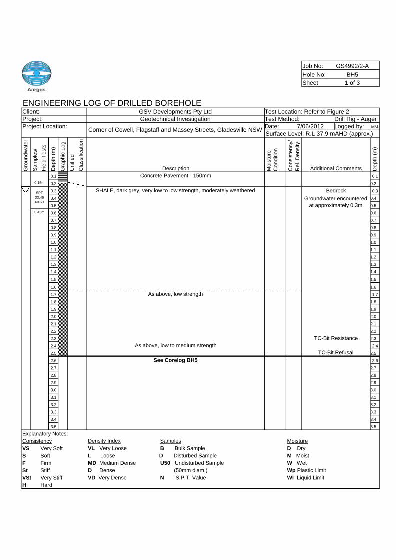
Job No: GS4992/2-A
Hole No: BH5
Sheet 1 of 3
ENGINEERING LOG OF DRILLED BOREHOLEClient: GSV Developments Pty Ltd Test Location: Refer to Figure 2Project: Geotechnical Investigation Test Method: Drill Rig - AugerProject Location: Date: Logged by: MM
Gro
un
dw
ate
r
Sa
mp
les/
Fie
ldT
ests
De
pth
(m)
Gra
ph
icL
og
Un
ifie
d
Cla
ssific
atio
n
Description Mo
istu
re
Co
nd
itio
n
Co
nsis
ten
cy/
Re
l.D
en
sity
Additional Comments De
pth
(m)
0.1 Concrete Pavement - 150mm 0.1
0.2 0.2
0.3 SHALE, dark grey, very low to low strength, moderately weathered 0.3
0.4 0.4
0.5 0.5
0.6 0.6
0.7 0.7
0.8 0.8
0.9 0.9
1.0 1.0
1.1 1.1
1.2 1.2
1.3 1.3
1.4 1.4
1.5 1.5
1.6 1.6
1.7 As above, low strength 1.7
1.8 1.8
1.9 1.9
2.0 2.0
2.1 2.1
2.2 2.2
2.3 2.3
2.4 As above, low to medium strength 2.4
2.5 2.5
2.6 See Corelog BH5 2.6
2.7 2.7
2.8 2.8
2.9 2.9
3.0 3.0
3.1 3.1
3.2 3.2
3.3 3.3
3.4 3.4
3.5 3.5
Explanatory Notes:
Consistency Density Index Samples Moisture
VS Very Soft VL Very Loose B Bulk Sample D Dry
S Soft L Loose D Disturbed Sample M Moist
F Firm MD Medium Dense U50 Undisturbed Sample W Wet
St Stiff D Dense (50mm diam.) Wp Plastic Limit
VSt Very Stiff VD Very Dense N S.P.T. Value Wl Liquid Limit
H Hard
Corner of Cowell, Flagstaff and Massey Streets, Gladesville NSW7/06/2012
Surface Level: R.L 37.9 mAHD (approx.)
0.15m
SPT
33,46
N>60
Bedrock
Groundwater encountered
at approximately 0.3m0.45m
TC-Bit Resistance
TC-Bit Refusal
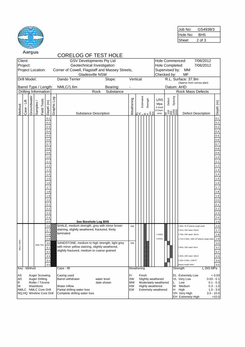
Job No: GS4938/3
Hole No: BH5
Sheet 2 of 3
CORELOG OF TEST HOLEClient: GSV Developments Pty Ltd Hole Commenced: 7/06/2012Project: Geotechnical Investigation Hole Completed: 7/06/2012Project Location: Corner of Cowell, Flagstaff and Massey Streets,
Gladesville NSWDrill Model: Dando Terrier Slope: Vertical
(Approx from survey plan)
Barrel Type / Length: NMLC/1.6m Bearing: - AHDDrilling Information Rock Substance Rock Mass Defects
Me
tho
d
Ca
se
-L
ift
Gro
un
dw
ate
r
Sa
mp
les
/
Fie
ldT
ests
De
pth
(m)
Gra
ph
icL
og
Substance Description We
ath
eri
ng
EL
VL
LE
stim
ate
dM H
Str
en
gth
VH
EH
Is(50)
MpaA:Axial
D:Diam-
etral 30 10
0D
efe
ct
30
01
00
0S
pa
cin
g3
00
0
Defect Description De
pth
(m)
0.1 0.1
0.2 0.2
0.3 0.3
0.4 0.4
0.5 0.5
0.6 0.6
0.7 0.7
0.8 0.8
0.9 0.9
1.0 1.0
1.1 1.1
1.2 1.2
1.3 1.3
1.4 1.4
1.5 1.5
1.6 1.6
1.7 1.7
1.8 1.8
1.9 1.9
2.0 2.0
2.1 2.1
2.2 2.2
2.3 2.3
2.4 2.4
2.5 See Borehole Log BH5 2.5
2.6 SW 2.56m, B=50,planar,rough,clean 2.6
2.7 2.61m, EW seam 10mm 2.7
2.8 1.03(D) 2.70m, EW seam 15mm 2.8
2.9 0.91(A) 2.72m-2.90m, 5xB=100,planar,rough,clean 2.9
3.0 SW 3.0
3.1 3.05m, EW seam 5mm 3.1
3.2 3.2
3.3 3.30m, EW seam 10mm 3.3
3.4 3.42m-3.45m, 2×B=50, 3.4
3.5 planar,rough,clean 3.5
Key - Method Case - lift Weathering Strength Is (50) MPa
AS Auger Screwing Casing used Fr Fresh EL Extremely Low < 0.03AD Auger Drilling Barrel withdrawn water level SW Slightly weathered VL Very Low 0.03 - 0.1R Roller / Tricone date shown MW Moderately weathered L Low 0.1 - 0.3W Washbore Water inflow HW Highly weathered M Medium 0.3 - 1.0NMLC NMLC Core Drill Partial drilling water loss EW Extremely weathered H High 1.0 - 3.0NQ,HQ Wireline Core Drill Complete drilling water loss VH Very High 3.0 - 10.0
EH Extremely High >10.0
RQD 75%SANDSTONE, medium to high strength, light grey
with minor yellow staining, slightly weathered,
slightly fractured, medium to coarse grainedNM
LC
100%
SHALE, medium strength, grey with minor brown
staining, slightly weathered, fractured, thinly
laminated
R.L. Surface: 37.9m
Datum:
Supervised by: MMChecked by: MF
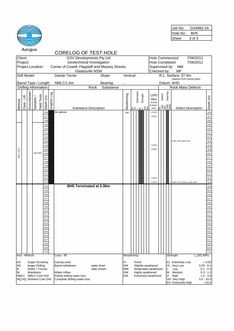
Job No: GS4992-2A
Hole No: BH5
Sheet 3 of 3
CORELOG OF TEST HOLEClient: GSV Developments Pty Ltd Hole Commenced: 7/06/2012Project: Geotechnical Investigation Hole Completed: 7/06/2012Project Location: Corner of Cowell, Flagstaff and Massey Streets,
Gladesville NSWDrill Model: Dando Terrier Slope: Vertical
(Approx from survey plan)
Barrel Type / Length: NMLC/1.6m Bearing: - AHDDrilling Information Rock Substance Rock Mass Defects
Me
tho
d
Ca
se
-L
ift
Gro
un
dw
ate
r
Sa
mp
les
/
Fie
ldT
ests
De
pth
(m)
Gra
ph
icL
og
Substance Description We
ath
eri
ng
EL
VL
LE
stim
ate
dM H
Str
en
gth
VH
EH
Is(50)
MpaA:Axial
D:Diam-
etral 30 10
0D
efe
ct
30
01
00
0S
pa
cin
g3
00
0
Defect Description De
pth
(m)
3.6 As above SW 1.67(D) 3.6
3.7 1.05(A) 3.7
3.8 3.8
3.9 3.9
4.0 4.0
4.1 4.1
4.2 4.2
4.3 4.26m, EW seam 3mm 4.3
4.4 1.07(D) 4.4
4.5 1.38(A) 4.5
4.6 4.6
4.7 4.7
4.8 4.8
4.9 4.9
5.0 5.0
5.1 5.1
5.2 1.05(D) 5.2
5.3 1.44(A) 5.30m, B=00,planar,rough,clean 5.3
5.4 BH5 Terminated at 5.36m 5.4
5.5 5.5
5.6 5.6
5.7 5.7
5.8 5.8
5.9 5.9
6.0 6.0
6.1 6.1
6.2 6.2
6.3 6.3
6.4 6.4
6.5 6.5
6.6 6.6
6.7 6.7
6.8 6.8
6.9 6.9
7.0 7.0
Key - Method Case - lift Weathering Strength Is (50) MPa
AS Auger Screwing Casing used Fr Fresh EL Extremely Low < 0.03AD Auger Drilling Barrel withdrawn water level SW Slightly weathered VL Very Low 0.03 - 0.1R Roller / Tricone date shown MW Moderately weathered L Low 0.1 - 0.3W Washbore Water inflow HW Highly weathered M Medium 0.3 - 1.0NMLC NMLC Core Drill Partial drilling water loss EW Extremely weathered H High 1.0 - 3.0NQ,HQ Wireline Core Drill Complete drilling water loss VH Very High 3.0 - 10.0
EH Extremely High >10.0
NM
LC
100%
RQD 98%
Supervised by: MMChecked by: MF
R.L. Surface: 37.9m
Datum:
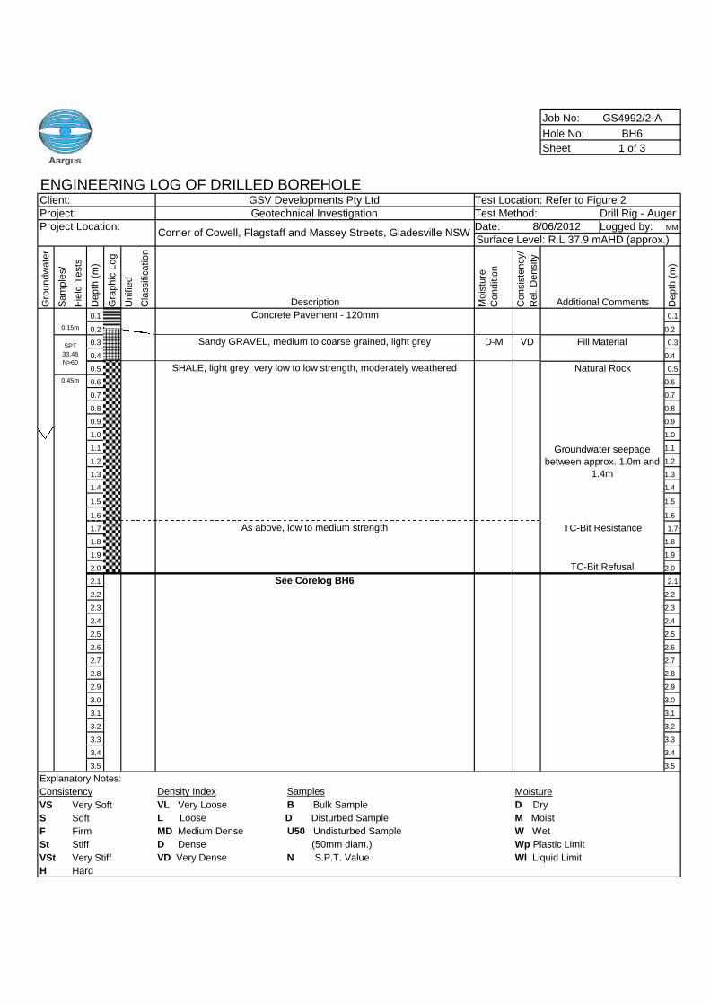
Job No: GS4992/2-A
Hole No: BH6
Sheet 1 of 3
ENGINEERING LOG OF DRILLED BOREHOLEClient: GSV Developments Pty Ltd Test Location: Refer to Figure 2Project: Geotechnical Investigation Test Method: Drill Rig - AugerProject Location: Date: Logged by: MM
Gro
un
dw
ate
r
Sa
mp
les/
Fie
ldT
ests
De
pth
(m)
Gra
ph
icL
og
Un
ifie
d
Cla
ssific
atio
n
Description Mo
istu
re
Co
nd
itio
n
Co
nsis
ten
cy/
Re
l.D
en
sity
Additional Comments De
pth
(m)
0.1 Concrete Pavement - 120mm 0.1
0.2 0.2
0.3 Sandy GRAVEL, medium to coarse grained, light grey D-M 0.3
0.4 0.4
0.5 SHALE, light grey, very low to low strength, moderately weathered 0.5
0.6 0.6
0.7 0.7
0.8 0.8
0.9 0.9
1.0 1.0
1.1 1.1
1.2 1.2
1.3 1.3
1.4 1.4
1.5 1.5
1.6 1.6
1.7 As above, low to medium strength 1.7
1.8 1.8
1.9 1.9
2.0 2.0
2.1 See Corelog BH6 2.1
2.2 2.2
2.3 2.3
2.4 2.4
2.5 2.5
2.6 2.6
2.7 2.7
2.8 2.8
2.9 2.9
3.0 3.0
3.1 3.1
3.2 3.2
3.3 3.3
3.4 3.4
3.5 3.5
Explanatory Notes:
Consistency Density Index Samples Moisture
VS Very Soft VL Very Loose B Bulk Sample D Dry
S Soft L Loose D Disturbed Sample M Moist
F Firm MD Medium Dense U50 Undisturbed Sample W Wet
St Stiff D Dense (50mm diam.) Wp Plastic Limit
VSt Very Stiff VD Very Dense N S.P.T. Value Wl Liquid Limit
H Hard
Corner of Cowell, Flagstaff and Massey Streets, Gladesville NSW8/06/2012
Surface Level: R.L 37.9 mAHD (approx.)
0.15m
SPT
33,46
N>60
VD Fill Material
Natural Rock0.45m
Groundwater seepage
between approx. 1.0m and
1.4m
TC-Bit Resistance
TC-Bit Refusal
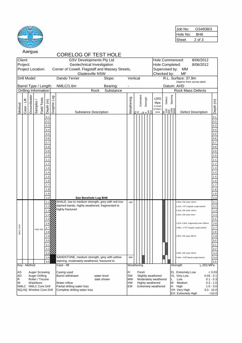
Job No: GS4938/3
Hole No: BH6
Sheet 2 of 3
CORELOG OF TEST HOLEClient: GSV Developments Pty Ltd Hole Commenced: 8/06/2012Project: Geotechnical Investigation Hole Completed: 8/06/2012Project Location: Corner of Cowell, Flagstaff and Massey Streets,
Gladesville NSWDrill Model: Dando Terrier Slope: Vertical
(Approx from survey plan)
Barrel Type / Length: NMLC/1.6m Bearing: - AHDDrilling Information Rock Substance Rock Mass Defects
Me
tho
d
Ca
se
-L
ift
Gro
un
dw
ate
r
Sa
mp
les
/
Fie
ldT
ests
De
pth
(m)
Gra
ph
icL
og
Substance Description We
ath
eri
ng
EL
VL
LE
stim
ate
dM H
Str
en
gth
VH
EH
Is(50)
MpaA:Axial
D:Diam-
etral 30 10
0D
efe
ct
30
01
00
0S
pa
cin
g3
00
0
Defect Description De
pth
(m)
0.1 0.1
0.2 0.2
0.3 0.3
0.4 0.4
0.5 0.5
0.6 0.6
0.7 0.7
0.8 0.8
0.9 0.9
1.0 1.0
1.1 1.1
1.2 1.2
1.3 1.3
1.4 1.4
1.5 1.5
1.6 1.6
1.7 1.7
1.8 1.8
1.9 1.9
2.0 See Borehole Log BH6 2.0
2.1 HW 2.08m, EW seam 10mm 2.1
2.2 2.14m, J=50,irregular,rough,stained 2.2
2.3 2.25m, EW seam 10mm 2.3
2.4 2.30m, EW seam 5mm 2.4
2.5 2.5
2.6 2.42m-2.60m, fragmented zone 180mm 2.6
2.7 2.68m, J=700,irregular,rough,stained 2.7
2.8 2.8
2.9 2.90m, EW seam 80mm 2.9
3.0 3.0
3.1 3.1
3.2 3.2
3.3 3.28m, EW seam 20mm 3.3
3.4 MW 3.36m, J=300,planar,rough,stained 3.4
3.5 3.5
Key - Method Case - lift Weathering Strength Is (50) MPa
AS Auger Screwing Casing used Fr Fresh EL Extremely Low < 0.03AD Auger Drilling Barrel withdrawn water level SW Slightly weathered VL Very Low 0.03 - 0.1R Roller / Tricone date shown MW Moderately weathered L Low 0.1 - 0.3W Washbore Water inflow HW Highly weathered M Medium 0.3 - 1.0NMLC NMLC Core Drill Partial drilling water loss EW Extremely weathered H High 1.0 - 3.0NQ,HQ Wireline Core Drill Complete drilling water loss VH Very High 3.0 - 10.0
EH Extremely High >10.0
Supervised by: MMChecked by: MF
R.L. Surface: 37.9m
Datum:
SANDSTONE, medium strength, grey with yellow
staining, moderately weathered, fractured to
NM
LC
100%
SHALE, low to medium strength, grey with red iron
stained bands, highly weathered, fragmented to
highly fractured
RQD 18%
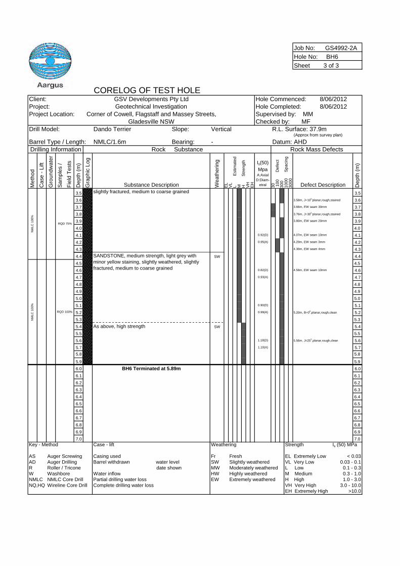
Job No: GS4992-2A
Hole No: BH6
Sheet 3 of 3
CORELOG OF TEST HOLEClient: GSV Developments Pty Ltd Hole Commenced: 8/06/2012Project: Geotechnical Investigation Hole Completed: 8/06/2012Project Location: Corner of Cowell, Flagstaff and Massey Streets,
Gladesville NSWDrill Model: Dando Terrier Slope: Vertical
(Approx from survey plan)
Barrel Type / Length: NMLC/1.6m Bearing: - AHDDrilling Information Rock Substance Rock Mass Defects
Me
tho
d
Ca
se
-L
ift
Gro
un
dw
ate
r
Sa
mp
les
/
Fie
ldT
ests
De
pth
(m)
Gra
ph
icL
og
Substance Description We
ath
eri
ng
EL
VL
LE
stim
ate
dM H
Str
en
gth
VH
EH
Is(50)
MpaA:Axial
D:Diam-
etral 30 10
0D
efe
ct
30
01
00
0S
pa
cin
g3
00
0
Defect Description De
pth
(m)
3.5 slightly fractured, medium to coarse grained 3.5
3.6 3.58m, J=100,planar,rough,stained 3.6
3.7 3.66m, EW seam 30mm 3.7
3.8 3.76m, J=300,planar,rough,stained 3.8
3.9 3.80m, EW seam 20mm 3.9
4.0 4.0
4.1 0.92(D) 4.07m, EW seam 10mm 4.1
4.2 0.95(A) 4.20m, EW seam 3mm 4.2
4.3 4.30m, EW seam 4mm 4.3
4.4 SW 4.4
4.5 4.5
4.6 0.82(D) 4.56m, EW seam 10mm 4.6
4.7 0.93(A) 4.7
4.8 4.8
4.9 4.9
5.0 5.0
5.1 0.90(D) 5.1
5.2 0.99(A) 5.20m, B=00,planar,rough,clean 5.2
5.3 5.3
5.4 As above, high strength SW 5.4
5.5 5.5
5.6 1.18(D) 5.56m, J=250,planar,rough,clean 5.6
5.7 1.10(A) 5.7
5.8 5.8
5.9 5.9
6.0 BH6 Terminated at 5.89m 6.0
6.1 6.1
6.2 6.2
6.3 6.3
6.4 6.4
6.5 6.5
6.6 6.6
6.7 6.7
6.8 6.8
6.9 6.9
7.0 7.0
Key - Method Case - lift Weathering Strength Is (50) MPa
AS Auger Screwing Casing used Fr Fresh EL Extremely Low < 0.03AD Auger Drilling Barrel withdrawn water level SW Slightly weathered VL Very Low 0.03 - 0.1R Roller / Tricone date shown MW Moderately weathered L Low 0.1 - 0.3W Washbore Water inflow HW Highly weathered M Medium 0.3 - 1.0NMLC NMLC Core Drill Partial drilling water loss EW Extremely weathered H High 1.0 - 3.0NQ,HQ Wireline Core Drill Complete drilling water loss VH Very High 3.0 - 10.0
EH Extremely High >10.0
RQD 100%
NM
LC
100%
Datum:
NM
LC
100%
Supervised by: MMChecked by: MF
SANDSTONE, medium strength, light grey with
minor yellow staining, slightly weathered, slightly
fractured, medium to coarse grained
RQD 75%
R.L. Surface: 37.9m
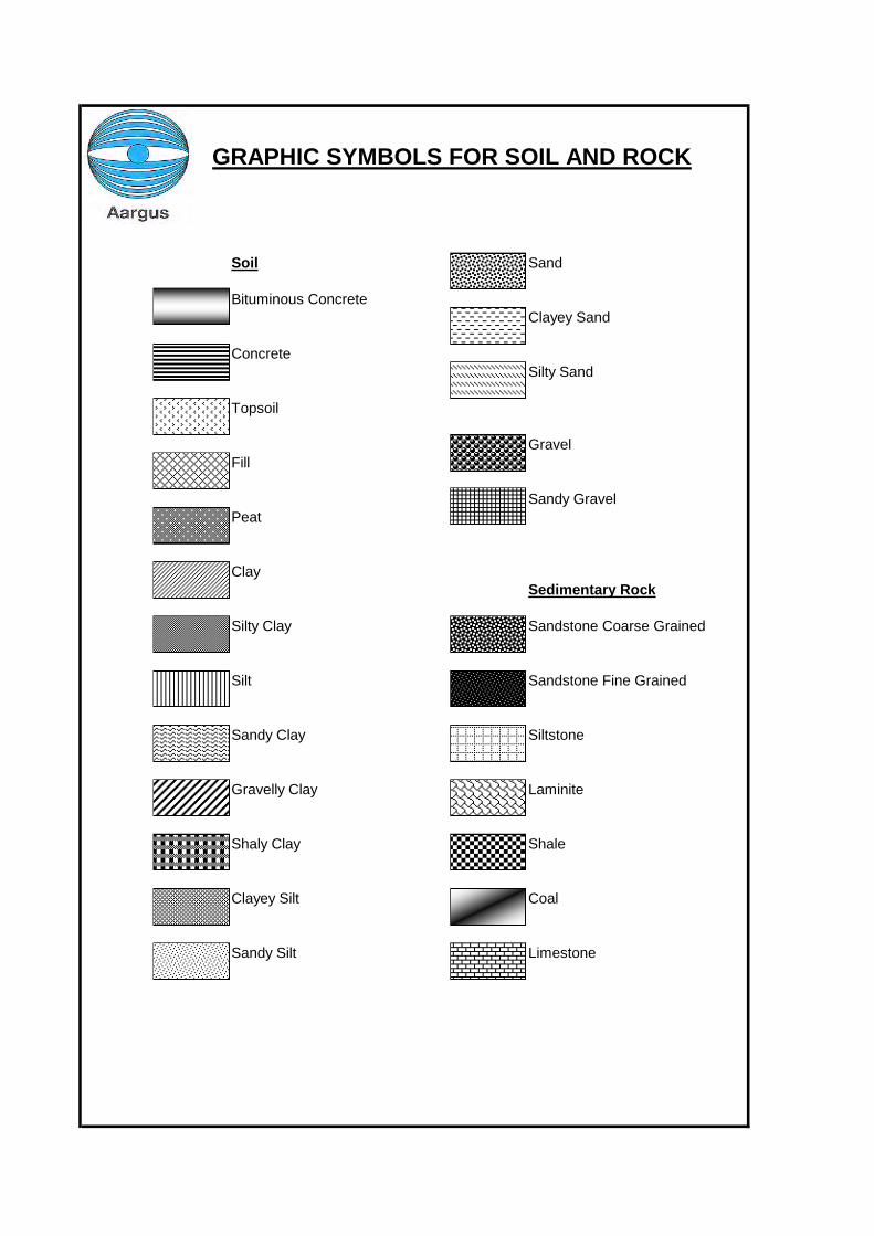
Soil Sand
Bituminous ConcreteClayey Sand
ConcreteSilty Sand
Topsoil
GravelFill
Sandy GravelPeat
ClaySedimentary Rock
Silty Clay Sandstone Coarse Grained
Silt Sandstone Fine Grained
Sandy Clay Siltstone
Gravelly Clay Laminite
Shaly Clay Shale
Clayey Silt Coal
Sandy Silt Limestone
GRAPHIC SYMBOLS FOR SOIL AND ROCK
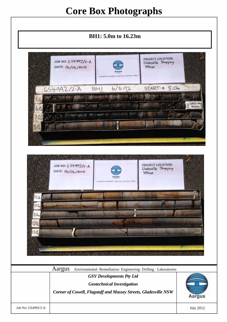
Aargus Environmental- Remediation- Engineering- Drilling - Laboratories
Job No: GS4992/2-A
Core Box Photographs
GSV Developments Pty Ltd
Geotechnical Investigation
Corner of Cowell, Flagstaff and Massey Streets, Gladesville NSW
July 2012
BH1: 5.0m to 16.23m
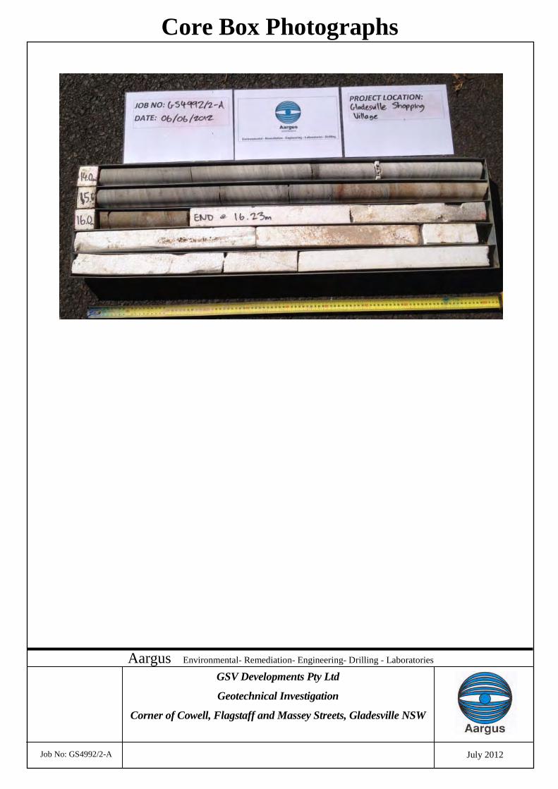
Aargus Environmental- Remediation- Engineering- Drilling - Laboratories
Job No: GS4992/2-A
Core Box Photographs
GSV Developments Pty Ltd
Geotechnical Investigation
Corner of Cowell, Flagstaff and Massey Streets, Gladesville NSW
July 2012
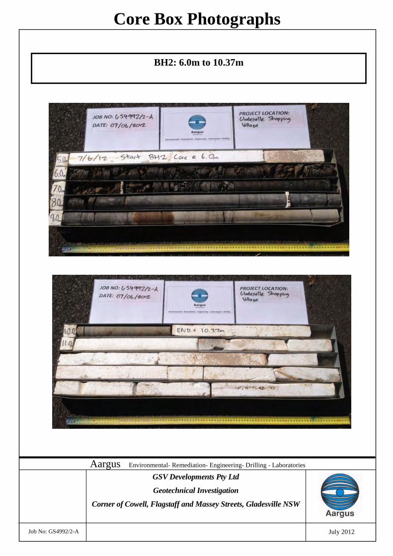
Aargus Environmental- Remediation- Engineering- Drilling - Laboratories
Job No: GS4992/2-A
Core Box Photographs
GSV Developments Pty Ltd
Geotechnical Investigation
Corner of Cowell, Flagstaff and Massey Streets, Gladesville NSW
July 2012
BH2: 6.0m to 10.37m
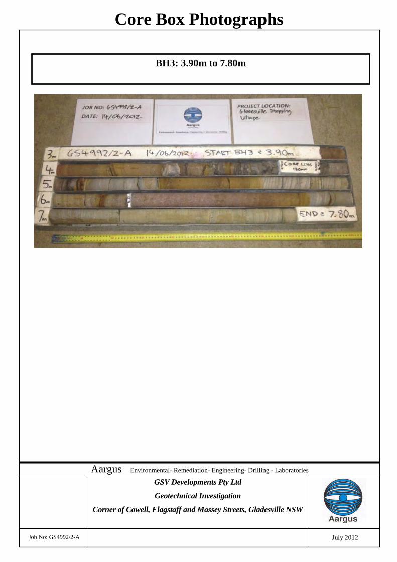
Aargus Environmental- Remediation- Engineering- Drilling - Laboratories
Job No: GS4992/2-A
Core Box Photographs
GSV Developments Pty Ltd
Geotechnical Investigation
Corner of Cowell, Flagstaff and Massey Streets, Gladesville NSW
July 2012
BH3: 3.90m to 7.80m
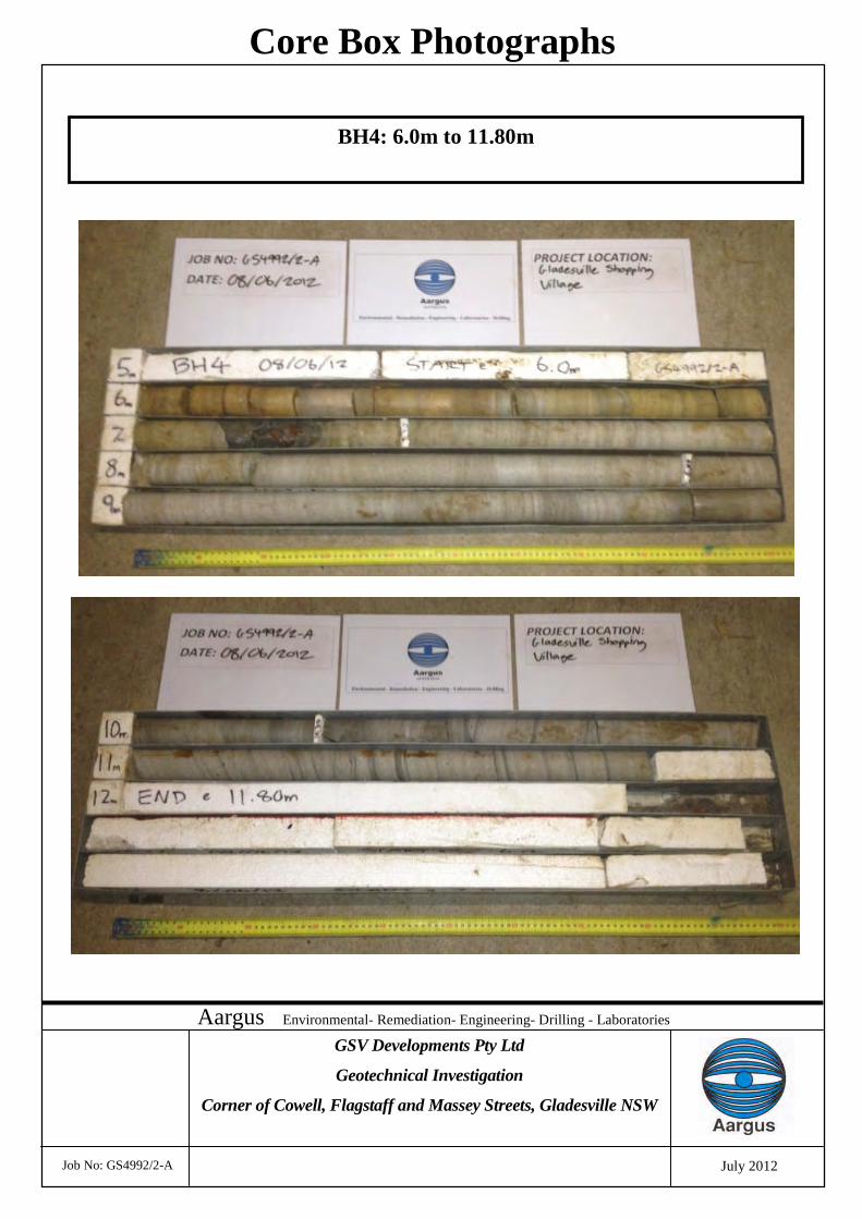
Aargus Environmental- Remediation- Engineering- Drilling - Laboratories
Job No: GS4992/2-A
Core Box Photographs
GSV Developments Pty Ltd
Geotechnical Investigation
Corner of Cowell, Flagstaff and Massey Streets, Gladesville NSW
July 2012
BH4: 6.0m to 11.80m
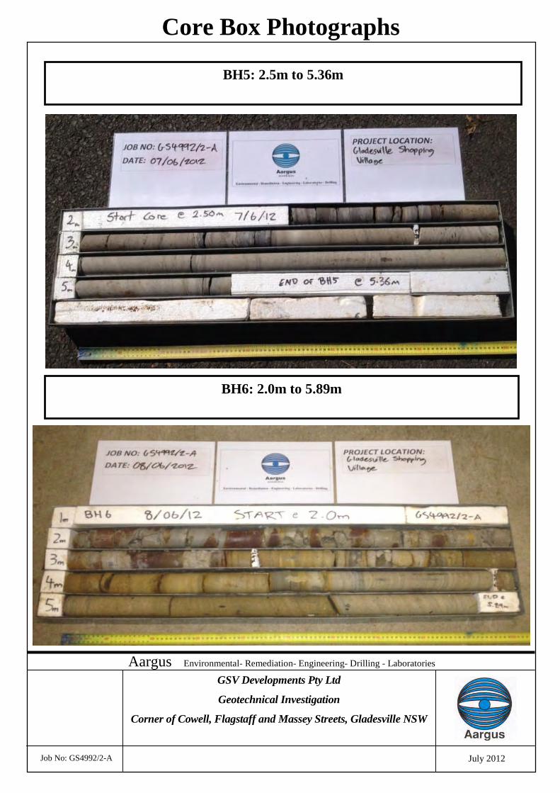
Aargus Environmental- Remediation- Engineering- Drilling - Laboratories
Job No: GS4992/2-A
Core Box Photographs
GSV Developments Pty Ltd
Geotechnical Investigation
Corner of Cowell, Flagstaff and Massey Streets, Gladesville NSW
July 2012
BH6: 2.0m to 5.89m
BH5: 2.5m to 5.36m

APPENDIX D
________________________________SITE PHOTOGRAPHS
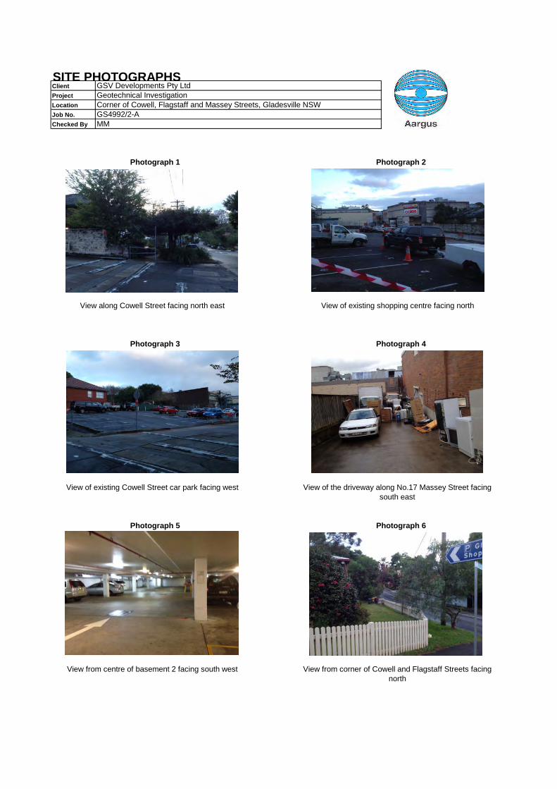
Client GSV Developments Pty LtdProject Geotechnical InvestigationLocation Corner of Cowell, Flagstaff and Massey Streets, Gladesville NSWJob No. GS4992/2-AChecked By MM
Photograph 1 Photograph 2
View along Cowell Street facing north east View of existing shopping centre facing north
Photograph 3 Photograph 4
Photograph 6Photograph 5
View from centre of basement 2 facing south west
View of existing Cowell Street car park facing west View of the driveway along No.17 Massey Street facingsouth east
View from corner of Cowell and Flagstaff Streets facingnorth
SITE PHOTOGRAPHS