Embed Size (px)
Citation preview
University of Aberdeen
Geological Map Project 2015-2016
GL4023
A Comparison of the Minor Structures within the Igneous Layered Sequence and the Torridonian Sedimentary Group on the Isle of Rum,
Inner Hebrides. Peter J. Denheen
Student number: 51227548
B.Sc. Petroleum Geology (2015/2016)
2
University of Aberdeen
Geological Map Project 2015-2016.
Declaration of academic integrity
I declare that this piece of work is my own and does not contain any unacknowledged work from other sources.
Signed: ……………………………………………………………………………………..
Name: PETER J. DENHEEN Date: 01/02/16
GL4023 Geological Map Project – Peter J. Denheen
3
CONTENTS:
ABSTRACT 4
INTRODUCTION 5
LITHOLOGICAL DESCRIPTIONS 7
GEOLOGICAL HISTORY 29
LITERATURE REVIEW 31
CRITICAL STUDY – MINOR STRUCTURES WITHIN THE ILI AND MAF 36
CONCLUSION 44
REFEENCES 45
APPENDIX 1 – SEDIMENTARY SYMBOLS FOR STRATIGRAPHIC LOGS 47
GL4023 Geological Map Project – Peter J. Denheen
4
ABSTRACT:
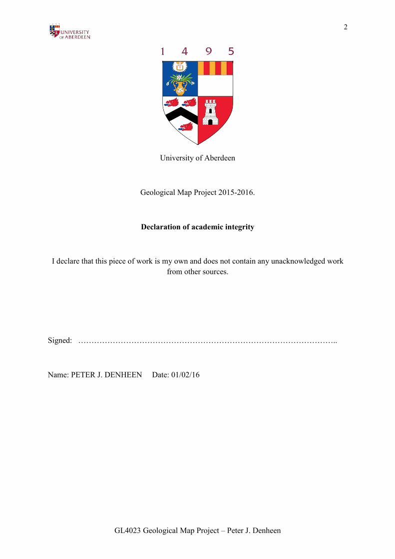
The Isle of Rum is a perfect example of a Paleocene Igneous Complex in Britain. It is an island
split in two distinct geological halves, with the mountainous landscape of the Igneous Complex
to the south incorporating the major peaks of Hallival and Askival, and the flatter, undulating
topography of the various sedimentary successions to the north. During a seven-week period
in the summer of 2015, fieldwork was carried out on a section of the east coast of the island
and a geological map of the various lithologies within an area of around 10km2 was produced
(see plate 1 (attached)). As a result of this fieldwork, it became possible to separate these
lithologies into three separate special groups; these included the sedimentary Mullach Ard
Formation (MAF), the Cnapan Breaca Assemblage (CBA) which is itself composed of the
sedimentary Cnapan Breaca Formation (CBF) and the Cnapan Breaca Conformable Sequence
(CBCS), and the Igneous Layered Intrusion (ILI). Furthermore, both the MAF and CBF are
themselves grouped into the East of Rum Group (EoRG). From measurements of the
orientation and the analysis of lithological boundaries, it became possible to produce a series
of cross sections of the area as well as a basic interpretation of the geological history. In
addition, detailed comparative analysis was carried out on the minor structures within the
igneous lithologies of the ILI and the sedimentary member of the MAF.
GL4023 Geological Map Project – Peter J. Denheen
5
INTRODUCTION:
The Isle of Rum is situated within the Inner Hebrides in the north-west of Scotland. It is a
National Nature Reserve (NNR) owned and managed by Scottish Natural Heritage (SNH) with
a small community located at the east coast of the island in the village of Kinloch. Within the
mapping area the topographical scenery is profoundly affected by the lithologies present (see
fig. 1 and 2). The main purpose of this fieldwork was to provide a geological map showing the
spatial distributions of these lithologies with cross-sections portraying an interpretation of the
relationship of these lithologies in the subsurface in order to understand the geological history
of the area. The main problem that was faced during the majority of the project was to provide
an interpretation of the interactions between the lithologies present. This was most apparent
with the interaction between the ILI and the surrounding lithologies which were separated by
intrusive boundaries which showed no clear orientation of dip. Complex faulting within the
area also made the organisation of the lithologies into a plausible stratigraphic order difficult.
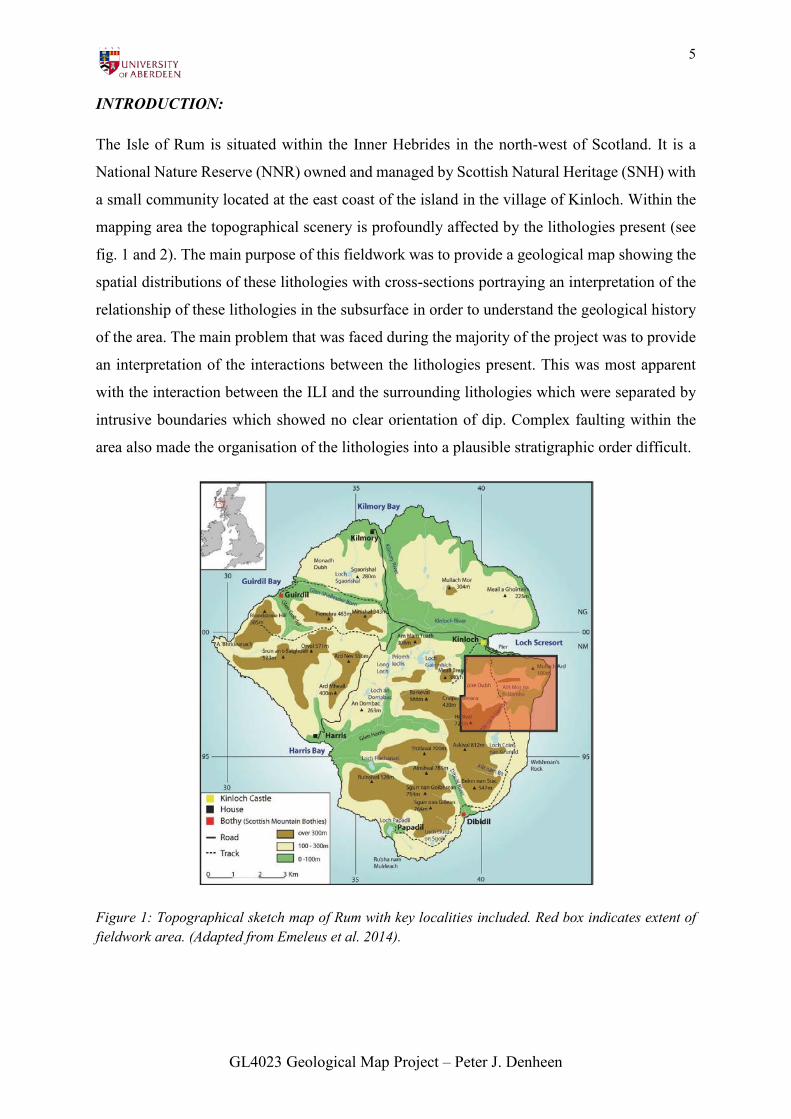
Figure 1: Topographical sketch map of Rum with key localities included. Red box indicates extent of fieldwork area. (Adapted from Emeleus et al. 2014).
GL4023 Geological Map Project – Peter J. Denheen
6
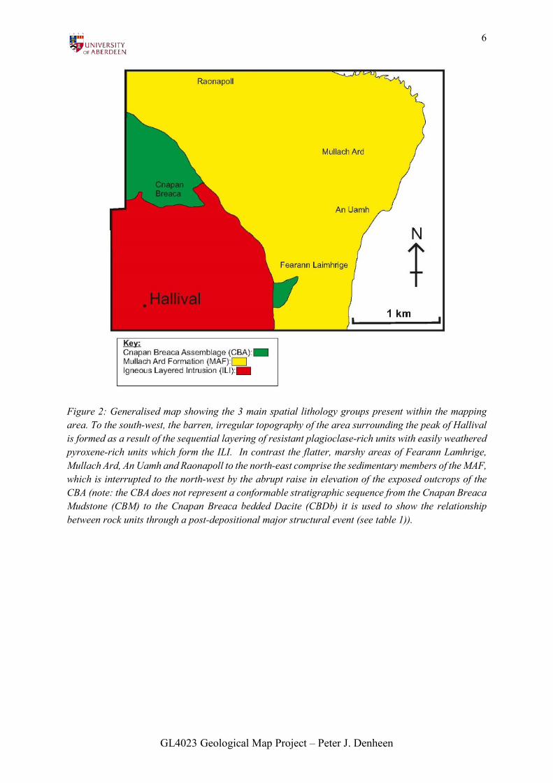
Figure 2: Generalised map showing the 3 main spatial lithology groups present within the mapping area. To the south-west, the barren, irregular topography of the area surrounding the peak of Hallival is formed as a result of the sequential layering of resistant plagioclase-rich units with easily weathered pyroxene-rich units which form the ILI. In contrast the flatter, marshy areas of Fearann Lamhrige, Mullach Ard, An Uamh and Raonapoll to the north-east comprise the sedimentary members of the MAF, which is interrupted to the north-west by the abrupt raise in elevation of the exposed outcrops of the CBA (note: the CBA does not represent a conformable stratigraphic sequence from the Cnapan Breaca Mudstone (CBM) to the Cnapan Breaca bedded Dacite (CBDb) it is used to show the relationship between rock units through a post-depositional major structural event (see table 1)).
GL4023 Geological Map Project – Peter J. Denheen
7
LITHOLOGICAL DESCRIPTIONS:
Note: The nomenclature used to describe
the various lithologies present within the
mapping area were invented by the author
during fieldwork. Please see tables 5-7 for
a comparison between fieldwork and
literature nomenclature of lithologies and
faults as well as the full names of
abbreviated fieldwork lithologies.
IGNEOUS LITHOLOGIES:
Cnapan Breaca Dacite (CBD):
With Bedding (CBDb):
Lithology: Rectangular, stubby, lath-
shaped, (1-3mm) milky-white plagioclase
crystals are present within a melanocratic,
aphantic fine-grained matrix. These
plagioclase crystals are consistent
throughout the entire lithology as well as
within the lenticular bedding features
present. Smaller whiter crystals (<1mm)
which appear more fractured are also
present which are thought to represent
quartz.
Major faulting: None.
Orientation: Layered structures present dip
moderately to the south-west.
Minor structures: Layering structures (see
fig.2).
Boundaries: Fourth member of the CBCS
(see table 1). Intruded by intrusions of IBM
and OG on the margin of the ILI (see
fig.12).
Inferred genesis: Due to the presence of
fine grained layering features within an
igneous lithology it is inferred that the
CBDb formed as a result of an ash flow
deposit from some form of volcanic
eruption.
Without Bedding (CBDw):
Lithology: Similar base lithology to CBDb
with euhedral plagioclase feldspar present
within a fine-grained, melanocratic,
aphantic matrix. Only difference is the
presence of some rare small, pinkish
crystals that may possibly represent K-
feldspar.
Major faulting: None.
Orientation: No preferential orientation
due to inferred vertical intrusive nature of
lithology.
Minor structures: None, uniform intrusive
structure. Fragments of basic material
similar to the basaltic dikes are visible.
Boundaries: The lithology cross-cuts the
CBS to the north and the CB-SDBu to the
south as a singular, narrow, winding
intrusion. There are visible signs of thermal
GL4023 Geological Map Project – Peter J. Denheen
8
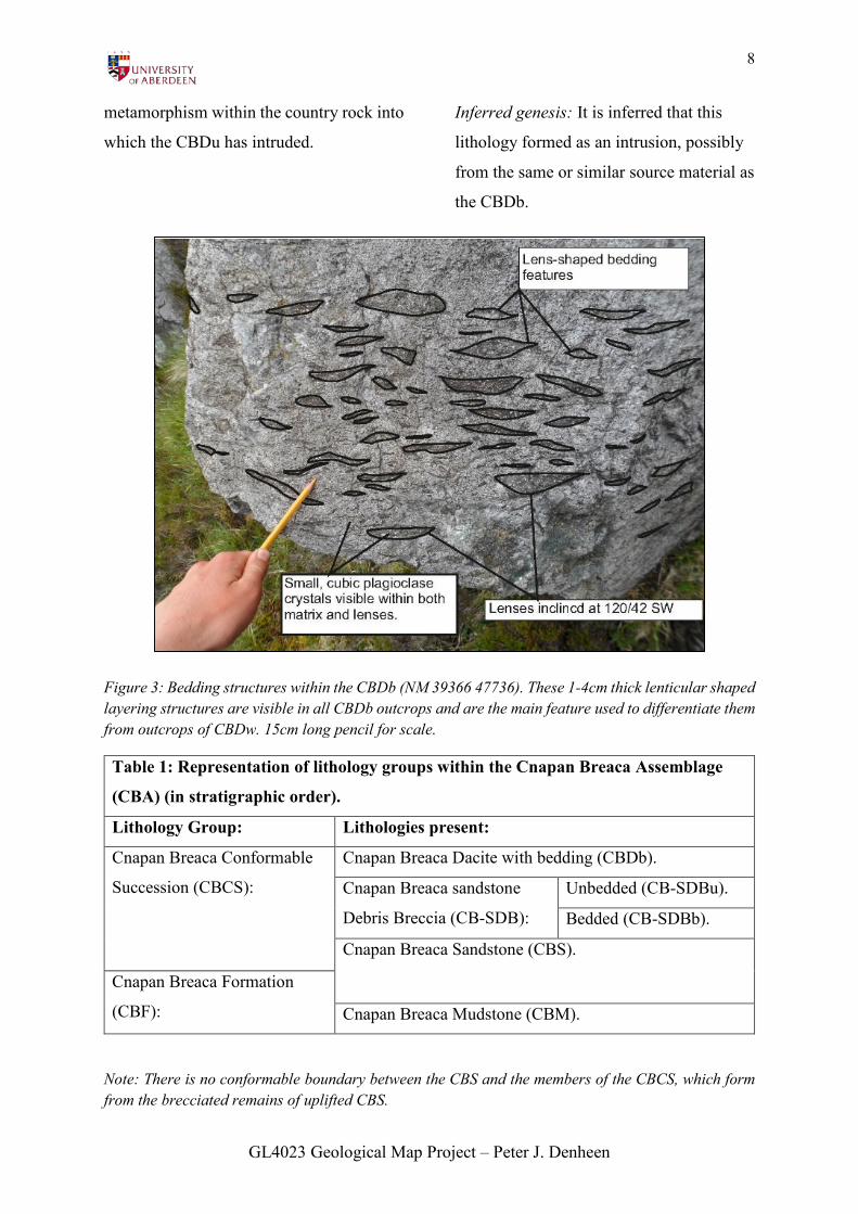
metamorphism within the country rock into
which the CBDu has intruded.
Inferred genesis: It is inferred that this
lithology formed as an intrusion, possibly
from the same or similar source material as
the CBDb.
Figure 3: Bedding structures within the CBDb (NM 39366 47736). These 1-4cm thick lenticular shaped layering structures are visible in all CBDb outcrops and are the main feature used to differentiate them from outcrops of CBDw. 15cm long pencil for scale.
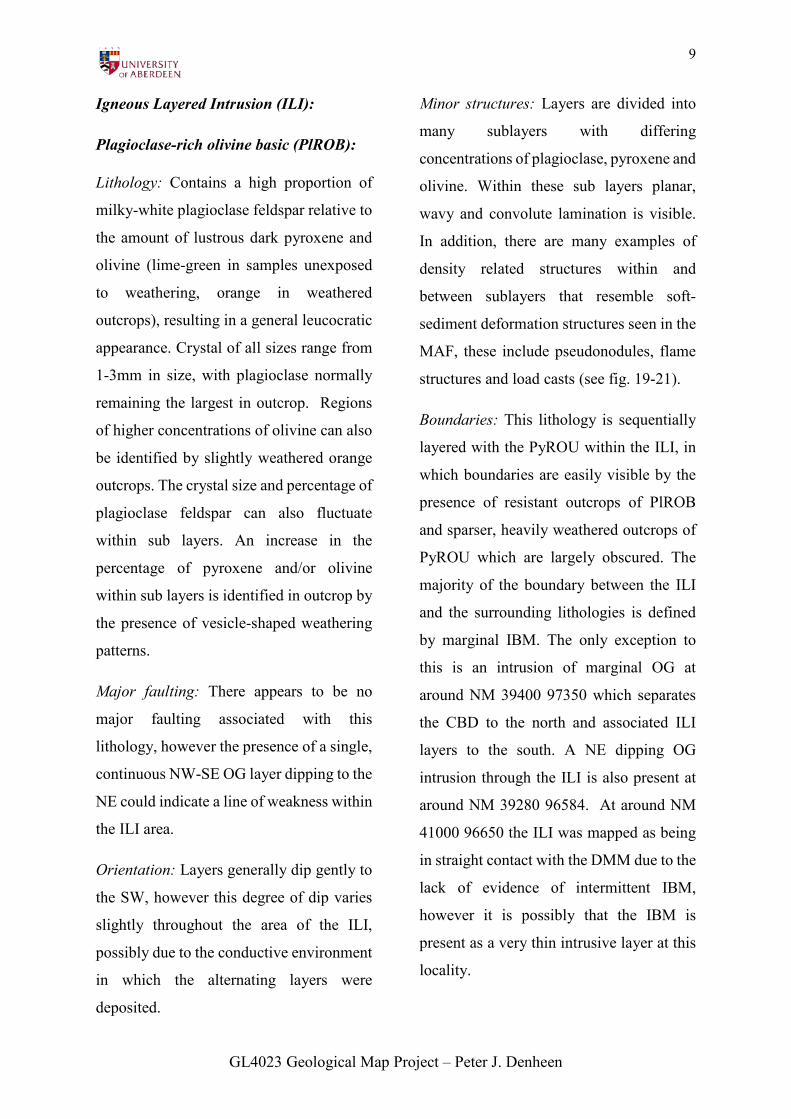
Table 1: Representation of lithology groups within the Cnapan Breaca Assemblage
(CBA) (in stratigraphic order).
Lithology Group: Lithologies present:
Cnapan Breaca Conformable
Succession (CBCS):
Cnapan Breaca Dacite with bedding (CBDb).
Cnapan Breaca sandstone
Debris Breccia (CB-SDB):
Unbedded (CB-SDBu).
Bedded (CB-SDBb).
Cnapan Breaca Sandstone (CBS).
Cnapan Breaca Formation
(CBF): Cnapan Breaca Mudstone (CBM).
Note: There is no conformable boundary between the CBS and the members of the CBCS, which form from the brecciated remains of uplifted CBS.
GL4023 Geological Map Project – Peter J. Denheen
9
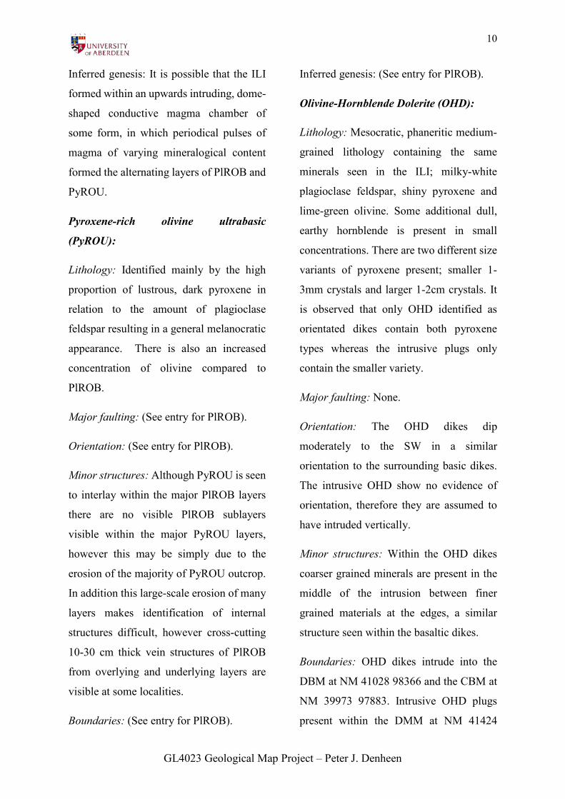
Igneous Layered Intrusion (ILI):
Plagioclase-rich olivine basic (PlROB):
Lithology: Contains a high proportion of
milky-white plagioclase feldspar relative to
the amount of lustrous dark pyroxene and
olivine (lime-green in samples unexposed
to weathering, orange in weathered
outcrops), resulting in a general leucocratic
appearance. Crystal of all sizes range from
1-3mm in size, with plagioclase normally
remaining the largest in outcrop. Regions
of higher concentrations of olivine can also
be identified by slightly weathered orange
outcrops. The crystal size and percentage of
plagioclase feldspar can also fluctuate
within sub layers. An increase in the
percentage of pyroxene and/or olivine
within sub layers is identified in outcrop by
the presence of vesicle-shaped weathering
patterns.
Major faulting: There appears to be no
major faulting associated with this
lithology, however the presence of a single,
continuous NW-SE OG layer dipping to the
NE could indicate a line of weakness within
the ILI area.
Orientation: Layers generally dip gently to
the SW, however this degree of dip varies
slightly throughout the area of the ILI,
possibly due to the conductive environment
in which the alternating layers were
deposited.
Minor structures: Layers are divided into
many sublayers with differing
concentrations of plagioclase, pyroxene and
olivine. Within these sub layers planar,
wavy and convolute lamination is visible.
In addition, there are many examples of
density related structures within and
between sublayers that resemble soft-
sediment deformation structures seen in the
MAF, these include pseudonodules, flame
structures and load casts (see fig. 19-21).
Boundaries: This lithology is sequentially
layered with the PyROU within the ILI, in
which boundaries are easily visible by the
presence of resistant outcrops of PlROB
and sparser, heavily weathered outcrops of
PyROU which are largely obscured. The
majority of the boundary between the ILI
and the surrounding lithologies is defined
by marginal IBM. The only exception to
this is an intrusion of marginal OG at
around NM 39400 97350 which separates
the CBD to the north and associated ILI
layers to the south. A NE dipping OG
intrusion through the ILI is also present at
around NM 39280 96584. At around NM
41000 96650 the ILI was mapped as being
in straight contact with the DMM due to the
lack of evidence of intermittent IBM,
however it is possibly that the IBM is
present as a very thin intrusive layer at this
locality.
GL4023 Geological Map Project – Peter J. Denheen
10
Inferred genesis: It is possible that the ILI
formed within an upwards intruding, dome-
shaped conductive magma chamber of
some form, in which periodical pulses of
magma of varying mineralogical content
formed the alternating layers of PlROB and
PyROU.
Pyroxene-rich olivine ultrabasic
(PyROU):
Lithology: Identified mainly by the high
proportion of lustrous, dark pyroxene in
relation to the amount of plagioclase
feldspar resulting in a general melanocratic
appearance. There is also an increased
concentration of olivine compared to
PlROB.
Major faulting: (See entry for PlROB).
Orientation: (See entry for PlROB).
Minor structures: Although PyROU is seen
to interlay within the major PlROB layers
there are no visible PlROB sublayers
visible within the major PyROU layers,
however this may be simply due to the
erosion of the majority of PyROU outcrop.
In addition this large-scale erosion of many
layers makes identification of internal
structures difficult, however cross-cutting
10-30 cm thick vein structures of PlROB
from overlying and underlying layers are
visible at some localities.
Boundaries: (See entry for PlROB).
Inferred genesis: (See entry for PlROB).
Olivine-Hornblende Dolerite (OHD):
Lithology: Mesocratic, phaneritic medium-
grained lithology containing the same
minerals seen in the ILI; milky-white
plagioclase feldspar, shiny pyroxene and
lime-green olivine. Some additional dull,
earthy hornblende is present in small
concentrations. There are two different size
variants of pyroxene present; smaller 1-
3mm crystals and larger 1-2cm crystals. It
is observed that only OHD identified as
orientated dikes contain both pyroxene
types whereas the intrusive plugs only
contain the smaller variety.
Major faulting: None.
Orientation: The OHD dikes dip
moderately to the SW in a similar
orientation to the surrounding basic dikes.
The intrusive OHD show no evidence of
orientation, therefore they are assumed to
have intruded vertically.
Minor structures: Within the OHD dikes
coarser grained minerals are present in the
middle of the intrusion between finer
grained materials at the edges, a similar
structure seen within the basaltic dikes.
Boundaries: OHD dikes intrude into the
DBM at NM 41028 98366 and the CBM at
NM 39973 97883. Intrusive OHD plugs
present within the DMM at NM 41424
GL4023 Geological Map Project – Peter J. Denheen
11
96979 and NM 41712 96521 and on the
outer faulted boundary between the DBM
and the CBM at NM 41000 97830.
Inferred genesis: The two slightly different
varieties of OHD suggests that they could
have possibly intruded into the system at
different times but from a similar source
material, the order of which is unclear as
there are no cross-cutting relationships
present. The presence of an OHD intrusive
plug on the outer fault between suggests
that it postdates the activation of major
faults in the region.
Olivine Gabbro (OG):
Lithology: Coarse-grained melanocratic
lithology containing a high proportion of
milky-white plagioclase feldspar, alongside
lower concentrations of dark, glassy
pyroxene and lime-green olivine. The
noticeably larger grain size is the main
criteria used to differentiate it from the
members of the ILI (see fig.4).
Major Faulting: None.
Orientation: The inclined intrusive layer
mentioned above is the only example of OG
in the mapping area with visible bedding
which dips moderately to the NE. The
marginal OG shows no signs of orientation,
however due to its emplacement at the edge
of the ILI it is inferred to have intruded
upwards in a curved path along the edge of
the domed ILI magma chamber. In
addition, the lack of solid outcrop could
also have concealed bedding features. The
OG intrusive plugs are assumed to have
intruded vertically upwards.
Minor structures: The intrusive plugs of
OG as well as the marginal OG contains no
visible structural features and crystals are
arranged uniformly. The layering within
the inclined OG intrusion within the ILI is
identified by faint, distorted thick regions of
aligned plagioclase feldspar.
Boundaries: Intrusive plugs of OG are
visible within the DBM (NM 39620 98450)
and DMM (NM 41200 96900). As
mentioned above there are two example of
intrusions of OG within the ILI which are
inferred to be interconnected; one at NM
39280 96584 and another at the northern
ILI margin at NM 39400 97350 (see fig.12).
Inferred genesis: All OG examples are
inferred to have intruded from the same
igneous source, either vertically, or along
possible major lines of weaknesses in the
case of the marginal and layered OG.
GL4023 Geological Map Project – Peter J. Denheen
12
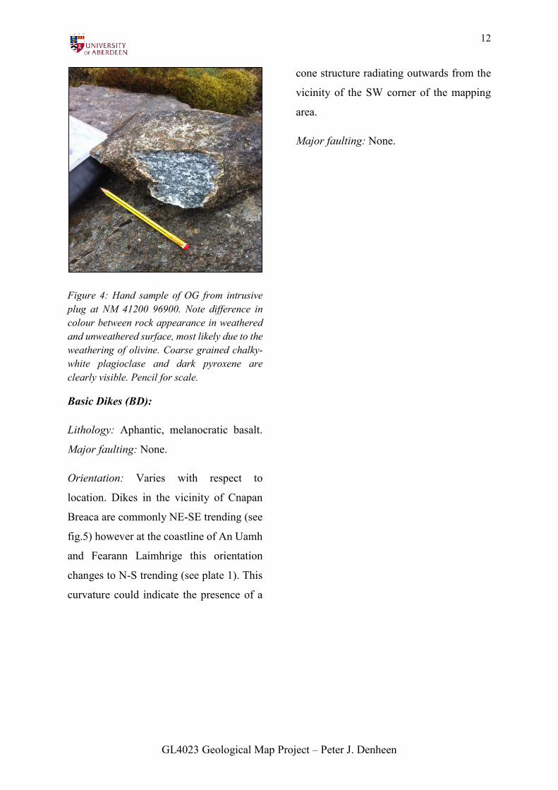
Figure 4: Hand sample of OG from intrusive plug at NM 41200 96900. Note difference in colour between rock appearance in weathered and unweathered surface, most likely due to the weathering of olivine. Coarse grained chalky-white plagioclase and dark pyroxene are clearly visible. Pencil for scale.
Basic Dikes (BD):
Lithology: Aphantic, melanocratic basalt.
Major faulting: None.
Orientation: Varies with respect to
location. Dikes in the vicinity of Cnapan
Breaca are commonly NE-SE trending (see
fig.5) however at the coastline of An Uamh
and Fearann Laimhrige this orientation
changes to N-S trending (see plate 1). This
curvature could indicate the presence of a
cone structure radiating outwards from the
vicinity of the SW corner of the mapping
area.
Major faulting: None.
GL4023 Geological Map Project – Peter J. Denheen
13
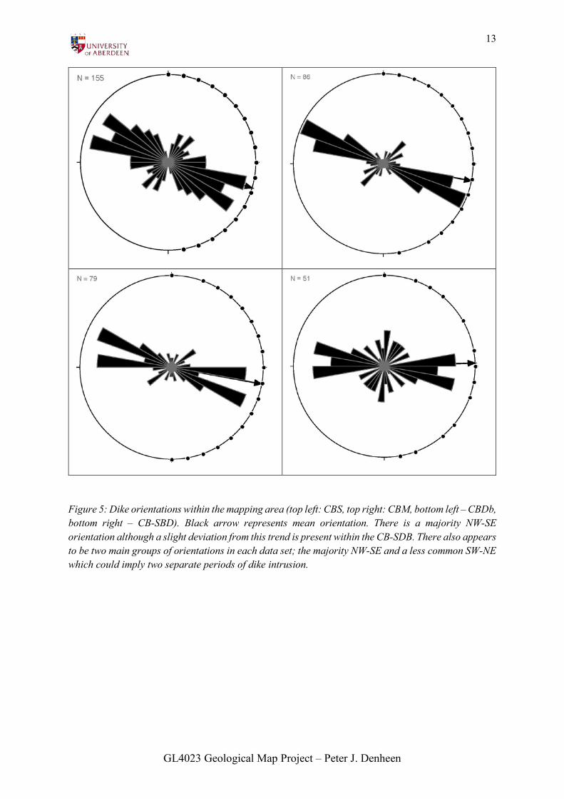
Figure 5: Dike orientations within the mapping area (top left: CBS, top right: CBM, bottom left – CBDb, bottom right – CB-SBD). Black arrow represents mean orientation. There is a majority NW-SE orientation although a slight deviation from this trend is present within the CB-SDB. There also appears to be two main groups of orientations in each data set; the majority NW-SE and a less common SW-NE which could imply two separate periods of dike intrusion.
GL4023 Geological Map Project – Peter J. Denheen
14
SEDIMENTARY LITHOLOGIES:
East of Rum Group (EoRG):
Dobhrain Bhig Member (DBM):
Lithology: The large majority of this
member is composed of a conglomeritic,
coarse-grained, medium-poorly sorted,
sub-angular-angular, arkosic sandstone
assemblage. The major visible minerals
include opaque, sub-rounded – sub-angular
quartz and sub-angular clasts of pinkish K-
feldspar. Some fine-grained sandstone and
siltstone interbeds are also present.
Within around 9km distance from the
boundary of the ILI, the K-feldspar grains
have undergone a bleaching effect and are
visible as dull white grains having lost their
characteristic pinkish tinge. This boundary
of bleaching can be traced around the
circular outline of the ILI. This effect is
only visible within sandstone layers and is
also present in the DMM within the
bleaching radius (see fig.11). In addition
within the vicinity of the immediate
boundary with the ILI the DBM is bleached
and baked.
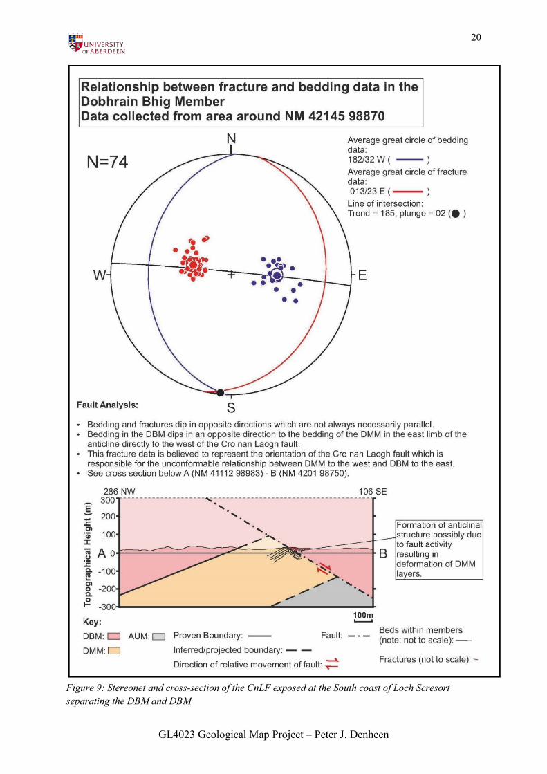
Major faulting: Exposure of major low
angle Cro nan Laogh Fault (CnLF) at NM
42118 98924 in which DBM from the west
has been faulted over DMM resulting in a
major lateral eastwards displacement of the
DBM. Intensive SW dipping fracture
planes are visible in the DBM to the east of
the fault. The CnLF can be traced around
the peninsula of the Mullach Ard to Bàgh
na Uamha where the fault is seen to cut
perpendicularly in map view through
conformable successions of DMM and
AUM (see fig. 9).
Structural Integrity: All members of the
MAF weather normally with good coastal
exposure and sparser exposure inland.
Orientation: The majority of beds within all
members of the MAF dip at around 25° to
the west. The exception to this in the DBM
is the area north of the outer fault with the
CBM in which there is a gradual steepening
of the dip of DBM bedding towards the
boundary.
Minor Structures: The majority of layers
show examples of soft-sediment
deformation structures, such as flame
structures and chaotic bedding. Cross-
bedding is also widely visible within cosets
of about 10-50cm in thickness. This
evidence was used to infer that the DBM
represents the paleoenvironment with the
highest energy input out of the three
conformable sedimentary lithologies.
Boundaries: To the SW there is a
conformable boundary with the DMM in
addition to faulted contacts with the DMM,
AUM and CBM. IBM is present on contact
with the ILI.
GL4023 Geological Map Project – Peter J. Denheen
15
Inferred genesis: It is likely that the DBM
represents the paleoenvironment with the
highest energy input in the MAF, possibly
forming as rapidly deposited sandy river
channels
Dobhrain Mhor Member (DMM):
Lithology: Fine grained arkosic medium-
very fine-grained sandstone interbedded
with siltstone.
Major faulting: Affected by CnLF. An
anticlinal structure with its axial plane
inclined to the W is present directly to the
west of the fault. This is interpreted to have
formed due to interaction of the
sedimentary faults with fault movement
(see fig. 8).
Orientation: (See entry for DBM).
Minor structures: Layers of medium
sandstone contain similar features found in
the DBM such as cross-bedding and
convolute layers (albeit on a less chaotic
scale). Finer layers show planar lamination,
asymmetric ripples, cross bedding and
desiccation cracks as well as examples of
soft sediment deformation such as
pseudonodules, flame structures, graded
bedding and load casts (see fig. 6 -7 and
18).
Boundaries: Conformable boundaries
present with the DBM and AUM, which
define the stratigraphic top and base of the
DMM in addition to the faulted contact with
the DBM. Also in contact with some of the
eastern margin of the ILI as well as a faulted
contact with the CBM.
Inferred genesis: The lack of mudstone
within the DMM represents an increase in
energy input to the paleoenvironment
compared to the AUM. The presence of
cross bedding and river channels suggests a
sinuous sandy river formation
interconnected by sand bars.
An Uamh Member (AUM):
Lithology: Medium-very-fine grained
arkosic sandstone interbedded with
siltstone and mudstone. The proportion of
mudstone is far greater at the stratigraphic
base of the member than at the top.
Major faulting: Affected by the CnLF
which cuts the member at a right angle at
An Uamh with a visible contact of the fault
present in a cave at Bàgh na Uamha (NM
42281 97362).
Orientation: (See entry for DBM).
Minor structures: Cross bedding, ripples
and wavy lamination are present. Within
outcrops exposed at the beach at An Uamh
the 3-D outlines of river channels are
visible. Evidence of soft-sediment
deformation is present in the form of load
casts. At the base of the sequence the
GL4023 Geological Map Project – Peter J. Denheen
16
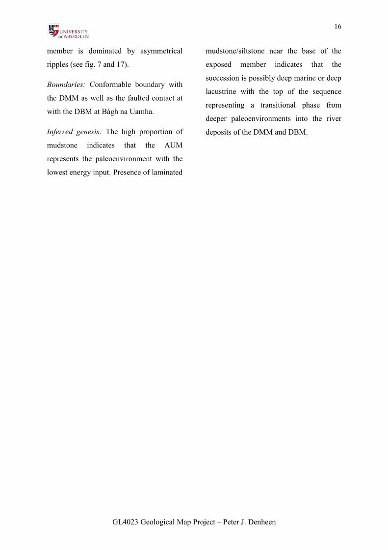
member is dominated by asymmetrical
ripples (see fig. 7 and 17).
Boundaries: Conformable boundary with
the DMM as well as the faulted contact at
with the DBM at Bàgh na Uamha.
Inferred genesis: The high proportion of
mudstone indicates that the AUM
represents the paleoenvironment with the
lowest energy input. Presence of laminated
mudstone/siltstone near the base of the
exposed member indicates that the
succession is possibly deep marine or deep
lacustrine with the top of the sequence
representing a transitional phase from
deeper paleoenvironments into the river
deposits of the DMM and DBM.
GL4023 Geological Map Project – Peter J. Denheen
17
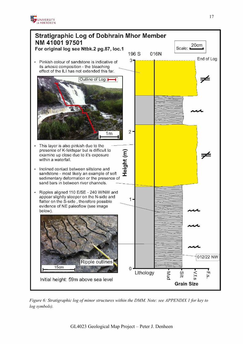
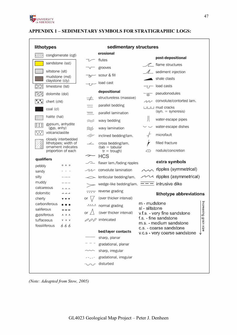
Figure 6: Stratigraphic log of minor structures within the DMM. Note: see APPENDIX 1 for key to log symbols).
GL4023 Geological Map Project – Peter J. Denheen
18
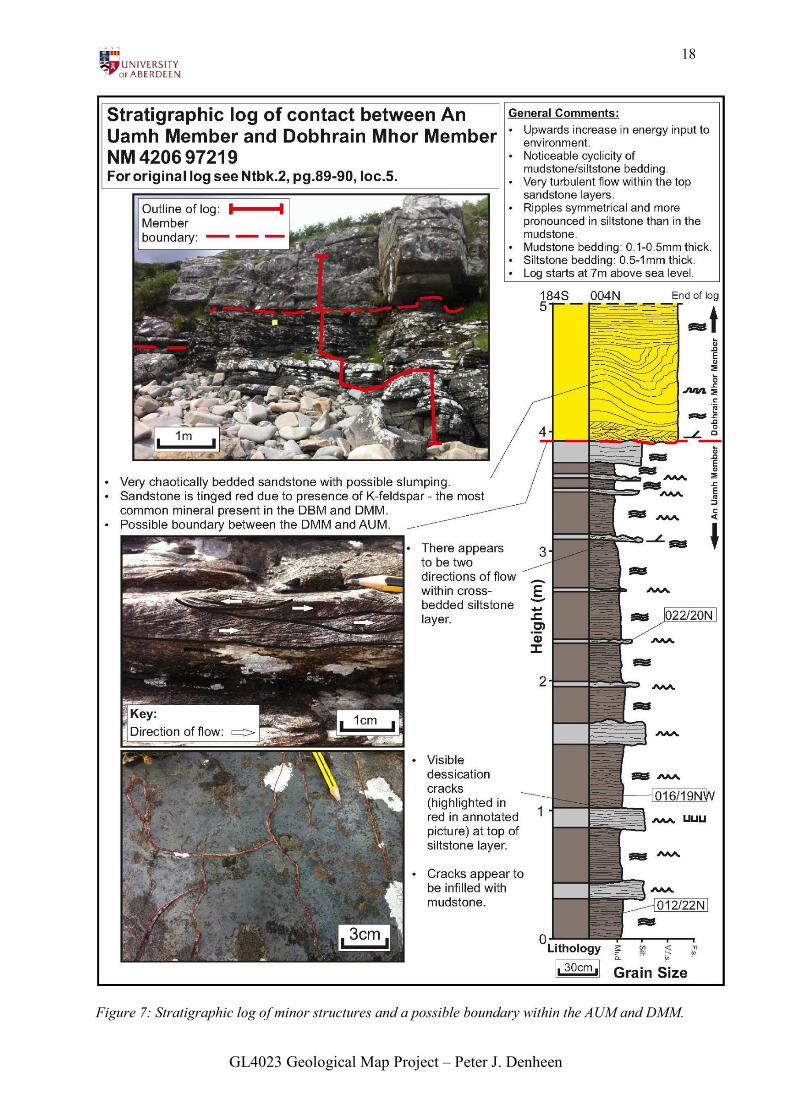
Figure 7: Stratigraphic log of minor structures and a possible boundary within the AUM and DMM.
GL4023 Geological Map Project – Peter J. Denheen
19
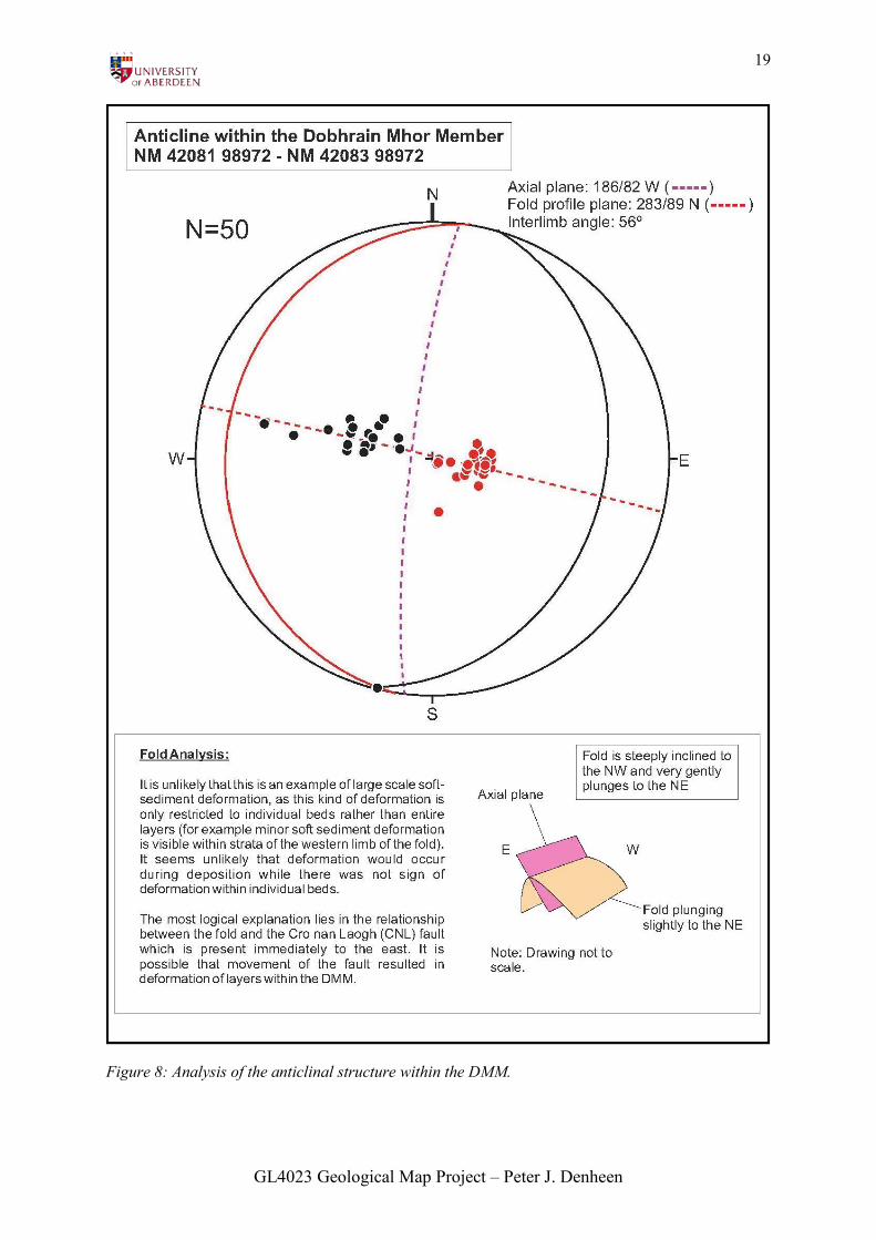
Figure 8: Analysis of the anticlinal structure within the DMM.
GL4023 Geological Map Project – Peter J. Denheen
20
Figure 9: Stereonet and cross-section of the CnLF exposed at the South coast of Loch Scresort separating the DBM and DBM
GL4023 Geological Map Project – Peter J. Denheen
21
Cnapan Breaca Formation (CBF):
Cnapan Breaca Mudstone (CBM):
Lithology: Finely laminated (0.2 – 1mm
thick) mudstone.
Major faulting: At Cnapan Breaca the
CBM is affected by two major faults; the
Cnapan Breaca inner (CBFSi) and outer
(CBFSo) faults. It is also affected by the
Fearann Laimhrige Fault (FLF) to the
south. All of these faults are assumed to be
vertically orientated.
Orientation: CBM bedding dips steeply to
the SW at the eastern edge of Cnapan
Breaca and transits to vertical and steeply
dipping to the NE at the vicinity of the
hydroelectric dam at Allt Slugan a’
Chollich. The bedding exposed at Fearann
Laimhrige dips to the NW and becomes
increasingly steeper towards the ILI
margin.
Minor structures: Parallel and wavy
lamination is visible in all CBM outcrops.
Overturned, stretched and broken
lamination suggests that they have been
subjected to localised structural effects
related to the faulted boundaries.
Laminations are also seen to become
increasingly fractured and broken with
increasing proximity to fault boundaries
and are affected by ductile deformation
nearer to boundaries with the ILI and other
intrusions.
Boundaries: In addition to the faulted
boundaries with the DBM, CBS and DMM
the CBM is intruded by the ILI and
associated IBM (see fig.. 10-11).
Inferred genesis: Due to the highly
deformed nature of some strata is difficult
to identify particular structures that could
be used to identify the paleoenvironment. It
is assumed that before deformation, the
strata was planar and continuous mudstone
that could suggest a deep marine/lacustrine
low energy environment. Due to the outer
fault boundary with the MAF it is difficult
to determine whether it relates conformably
with the base of the AUM.
Cnapan Breaca Sandstone (CBS):
Lithology: Very fine-coarse grained
sandstone containing visible quartz.
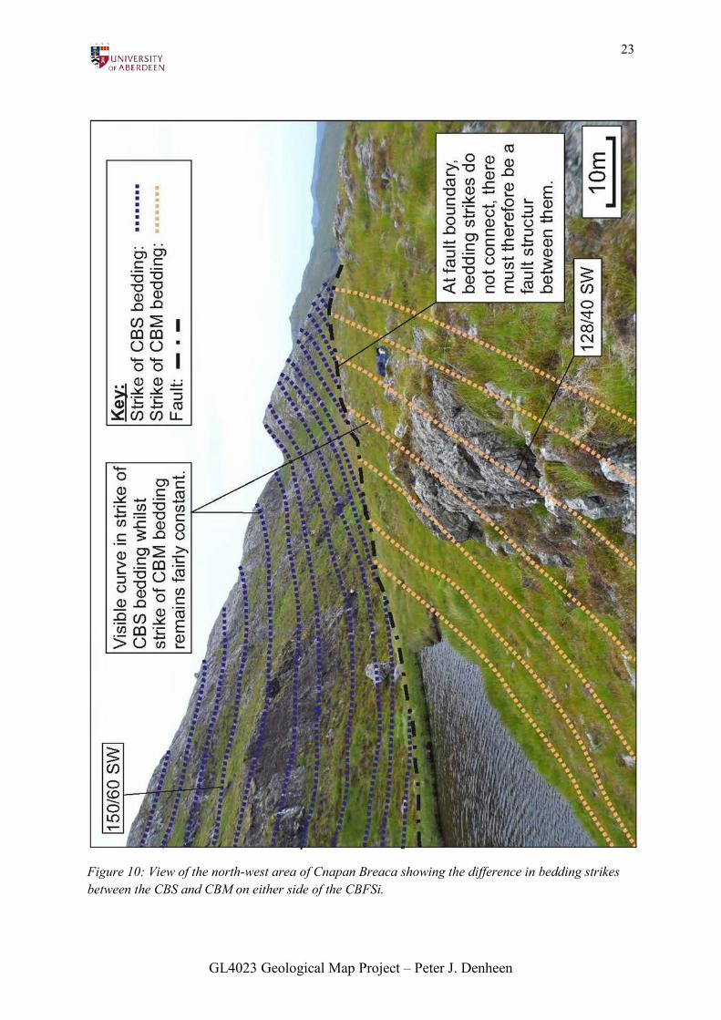
Major faulting: The CBS is affected by the
vertical CBFSi (see fig.10).
Orientation: On average, most bedding
dips steeply to the SW, however strike
direction can varies from SW to SE
throughout the lithology, especially in the
central area of Cnapan Breaca bordering the
OG in which most bedding is randomly
orientated and dip varies from moderate to
vertical. Strike of bedding is also seen to
GL4023 Geological Map Project – Peter J. Denheen
22
‘curve’ in a wide arc around the north of
Cnapan Breaca (see fig.10).
Minor structures: Normal and reverse
grading can be seen in outcrop. The vast
majority of layers and lamination are
strongly curved and convoluted. However
as with the CBM, the high amount of
structural deformation of layers makes it
difficult to identify particular structures
used to determine paleoenvironment. Large
fractures (1-3m wide) infilled with CB-
SDB are present which often cut strata at
right angles.
Boundaries: Separated from the CBM by
the CBFSi. First in the CBCS (see table 1
and fig.12). Intruded by a thin, nodular
section of CBDw.
Inferred genesis: As with the CBM, the
high amount of structural deformation of
layers makes it difficult to determine the
paleoenvironment, however the presence of
graded layers as well as fine and coarse
grains of the only identifiable mineral grain,
quartz, could signify an environment of
fluctuating energy input which was
deposited far from its source material.
GL4023 Geological Map Project – Peter J. Denheen
23
Figure 10: View of the north-west area of Cnapan Breaca showing the difference in bedding strikes between the CBS and CBM on either side of the CBFSi.
GL4023 Geological Map Project – Peter J. Denheen
24
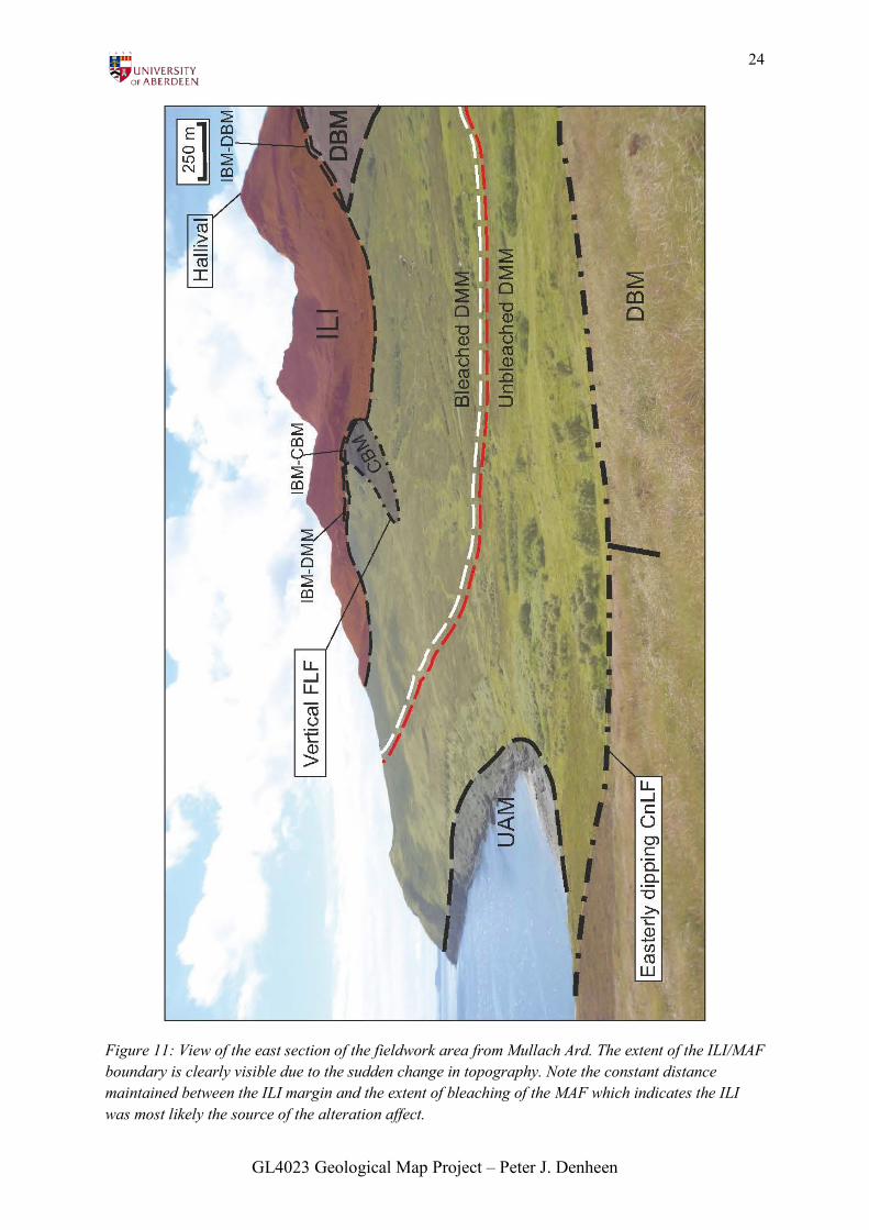
Figure 11: View of the east section of the fieldwork area from Mullach Ard. The extent of the ILI/MAF boundary is clearly visible due to the sudden change in topography. Note the constant distance maintained between the ILI margin and the extent of bleaching of the MAF which indicates the ILI was most likely the source of the alteration affect.
GL4023 Geological Map Project – Peter J. Denheen
25
BRECCIATED ROCK UNITS:
Igneous Breccia Matrix (IBM):
Lithology: The IBM lithology itself is
composed of an aphantic, melanocratic
igneous matrix of very small (<1mm)
crystals of plagioclase feldspar and
pyroxene. The area of the country lithology
into which the IBM intrudes is commonly
deformed and thermally affected normally
with features such as deformed layers, dike
fragments or angular/sub-angular clasts
(1cm – 5cm) present within a replacive
IBM matrix. There also appears to be
various magnetic anomalies present within
the IB.
Major faulting: None.
Orientation: There is no evidence of
orientation present within the IBM.
Minor structures: A faint form of bedding
(usually incorporated from the country rock
into which the IB has intruded) is very
wavy and deformed in a ductile manner. At
one locality (NM 40465 97396) criss-
crossing patterns are visible within clasts
with a weathering appearance similar to
that seen in members of the ILI.
Boundaries: The IBM itself acts as a
boundary lithology between the ILI margin
and the surrounding lithologies with some
exceptions (see entry for PlROB) (see
fig.11).
Inferred genesis: Due to the lack of any
features that could be used to deduce
orientation of intrusion, the IBM is assumed
to have intruded vertically along the
curvature of the hypothetical ILI magma
dome, much like the marginal OG.
Cnapan Breaca sandstone Debris Breccia
(CB-SDB):
Unbedded (CB-SDBu):
Lithology: Contains a variety of clast sizes,
and shapes, all of which appear to have
originated from the CBS to the NE. Clasts
are supported within a fine grained matrix
Major faulting: None.
Orientation: None visible, clasts all appear
to be randomly orientated.
Minor structures: (See table 2 for clast size
distribution).
Boundaries: Second member of the CBCS
(see table 1 and fig. 12). A small section is
intruded by the marginal OG.
Inferred genesis: Clasts originate from the
underlying CBS. The boundary with the
CBS is very irregular most likely due a high
intensity of fracturing and brecciation of the
CBS. This could be related to the fault
activity of the CBFS.
Bedded (CB-SDBb):
Lithology: (See entry for CB-SDBu).
GL4023 Geological Map Project – Peter J. Denheen

26
Major faulting: The distribution of major
and minor faults is the same as in the CB-
SDBu.
Orientation: None.
Minor structures: Linear bedding-like
features are present within the CB-SDBb.
The vast majority of these lineations have a
similar strike and dip orientation to that of
the CBDb however a small number are
orientated at right angles to these. The two
orientations of lineations also appear to
conjoin rather than cross-cut one another.
These features are the main criteria used to
distinguish the CB-SDBb from the CB-
SDBu. Various clast types and sizes are
also present, like the CB-SDBu (see table
2).
There are also noticeable 20-40cm wide
intrusion-like features that cross cut the
NW-SE orientated intrusions at right
angles. They contain more clasts of CBS
than the surrounding breccia.
Boundaries: The CB-SDBb is the third
member of the CBCS (see table 1 and
fig.12).
Inferred genesis: A continuation on from
the brecciation of the CBS. The presence of
layering features could suggest coeval
activity of the same process that led to the
deposition of the CBDb.
GL4023 Geological Map Project – Peter J. Denheen
27
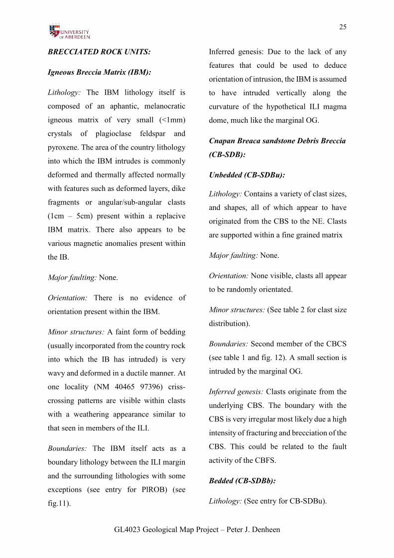
Figure 12: View of Cnapan Breaca from NM 39532 97640 showing contacts between members of the CBCS. Note the nodular intrusion of OG that branches off from the main marginal intrusion as well as the difference in thickness between the CB-SDBu and CB-SDBb.
GL4023 Geological Map Project – Peter J. Denheen
28
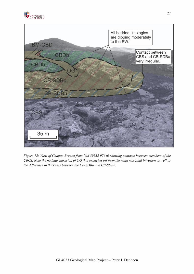
Table 2: Comparison of clast count within the CB-SDBu and CB-SDBb.
CB-SDBu (data collected as SDB boundary): CB-SDBb (data collected at CBDb boundary):
Comparison: Size: The data from the CB-SDBb contains a higher percentage of smaller (<1cm) grains than that of the CB-SDBu which contains larger grains. It also contains very large (>10cm) clasts that are not present in the CB-SDBb. Shape: The CB-SDBu contains more angular /sub angular clats whilst those in the CB-SDBb are mostly rounded/sub-angular. Structures: Both contain mostly non-layered clasts but there are more layered in the CB-SDBb than the CB-SDBu. Grains within clasts: Medium-fine is the most common in both lithologies althought there is a higher number of fine in the CB-SDBb. General comments: Indication of normal grading in which coarser clasts are deposited first, followed by smaller, rounded clasts as energy imput diminishes
Size
<1cm1cm-5cm5cm-10cm>10cm
Size
<1cm1cm-5cm5cm-10cm>10cm
Structures
Layered
Non-layered
Structures
Layered
Non-layered
Grains within clasts
Very fineFineMedium
Shape
RoundedSub-roundedSub-angularAngular
Shape
RoundedSub-roundedSub-angularAngular
Grains within clasts
Very fine FineMedium Coarse
GL4023 Geological Map Project – Peter J. Denheen
29
GEOLOGICAL HISTORY:
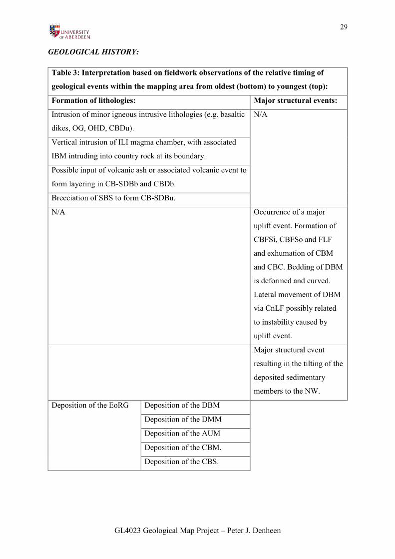
Table 3: Interpretation based on fieldwork observations of the relative timing of
geological events within the mapping area from oldest (bottom) to youngest (top):
Formation of lithologies: Major structural events:
Intrusion of minor igneous intrusive lithologies (e.g. basaltic
dikes, OG, OHD, CBDu).
N/A
Vertical intrusion of ILI magma chamber, with associated
IBM intruding into country rock at its boundary.
Possible input of volcanic ash or associated volcanic event to
form layering in CB-SDBb and CBDb.
Brecciation of SBS to form CB-SDBu.
N/A Occurrence of a major
uplift event. Formation of
CBFSi, CBFSo and FLF
and exhumation of CBM
and CBC. Bedding of DBM
is deformed and curved.
Lateral movement of DBM
via CnLF possibly related
to instability caused by
uplift event.
Major structural event
resulting in the tilting of the
deposited sedimentary
members to the NW.
Deposition of the EoRG Deposition of the DBM
Deposition of the DMM
Deposition of the AUM
Deposition of the CBM.
Deposition of the CBS.
GL4023 Geological Map Project – Peter J. Denheen
30
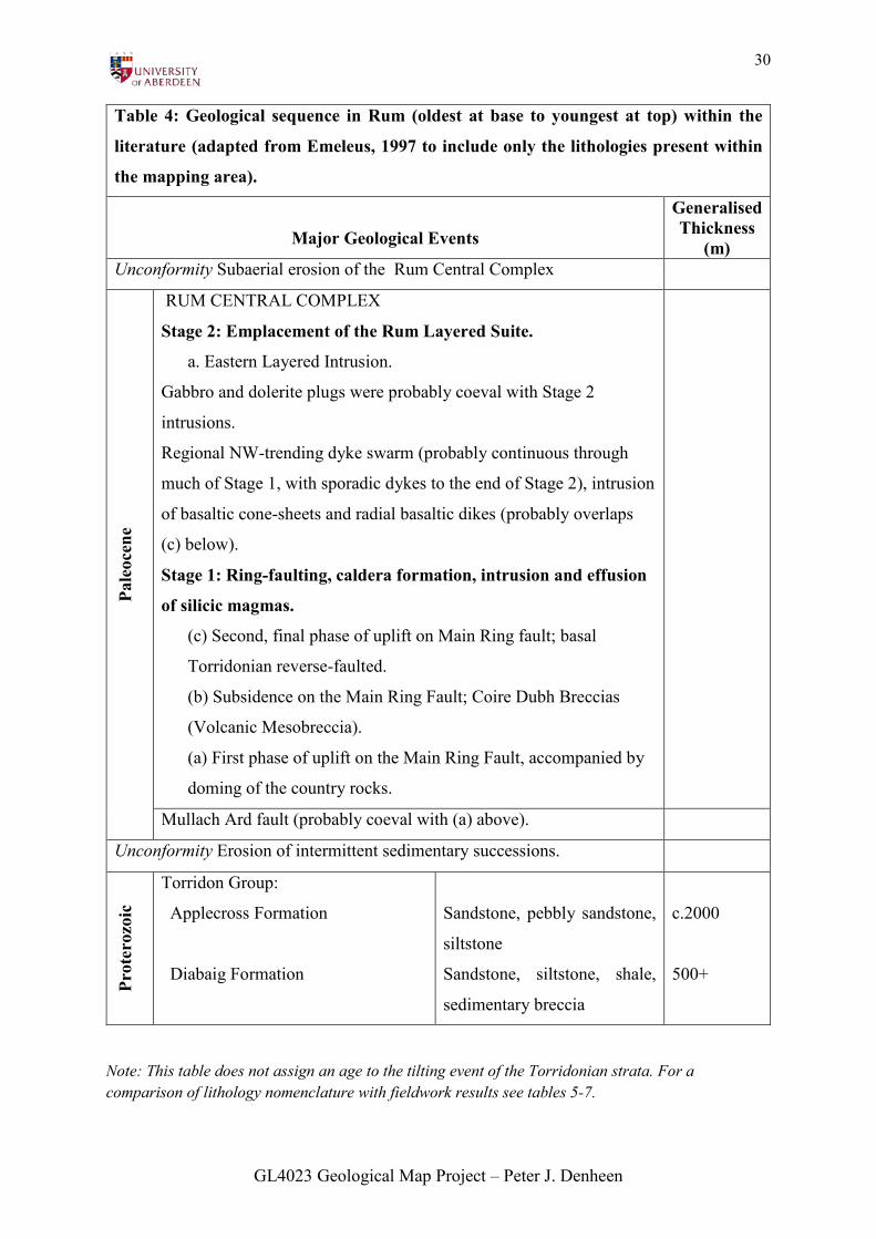
Table 4: Geological sequence in Rum (oldest at base to youngest at top) within the
literature (adapted from Emeleus, 1997 to include only the lithologies present within
the mapping area).
Major Geological Events
Generalised Thickness
(m) Unconformity Subaerial erosion of the Rum Central Complex
Pale
ocen
e
RUM CENTRAL COMPLEX
Stage 2: Emplacement of the Rum Layered Suite.
a. Eastern Layered Intrusion.
Gabbro and dolerite plugs were probably coeval with Stage 2
intrusions.
Regional NW-trending dyke swarm (probably continuous through
much of Stage 1, with sporadic dykes to the end of Stage 2), intrusion
of basaltic cone-sheets and radial basaltic dikes (probably overlaps
(c) below).
Stage 1: Ring-faulting, caldera formation, intrusion and effusion
of silicic magmas.
(c) Second, final phase of uplift on Main Ring fault; basal
Torridonian reverse-faulted.
(b) Subsidence on the Main Ring Fault; Coire Dubh Breccias
(Volcanic Mesobreccia).
(a) First phase of uplift on the Main Ring Fault, accompanied by
doming of the country rocks.
Mullach Ard fault (probably coeval with (a) above).
Unconformity Erosion of intermittent sedimentary successions.
Prot
eroz
oic
Torridon Group:
Applecross Formation
Diabaig Formation
Sandstone, pebbly sandstone,
siltstone
Sandstone, siltstone, shale,
sedimentary breccia
c.2000
500+
Note: This table does not assign an age to the tilting event of the Torridonian strata. For a comparison of lithology nomenclature with fieldwork results see tables 5-7.
GL4023 Geological Map Project – Peter J. Denheen
31
LITERATURE REVIEW:
Through consultation of literature based on
past fieldwork of the mapping area there
has been some notable correlation with the
findings of this fieldwork. For a
comprehensive layout of this comparison
see tables 3-4 for the geological history,
table 5 and 7 for lithology nomenclature
and table 6 for fault nomenclature.
The most outstanding difference is the
alternate criteria used to differentiate the
members of the ILI (see table 4). The
difference in nomenclature and distribution
of some of the lithologies in the CBCS (see
fig. 14 and 15) as well as the stratigraphic
arrangement of some of the sedimentary
members (see table 5 and fig.13) is also
noticeable.
Previous studies have also been very useful
in understanding the true depositional
environments of the sedimentary
lithologies. Within the Diabaig formation,
the Fiachanis member was deposited in
channelised flows on alluvial fans, which
explains the presence of grading. The
Laimhrig member is believed to have
formed in lakes into which these fans fed
into which was the predicted fieldwork
paleoenvironment (Stewart, 1982; 1988b;
Stewart and Parker, 1979), with the
laminated silt-mud alternations
representing seasonal varves in a deep
lacustrine setting below wave base (Rodd,
1983). Personally I am sceptical about the
decision to combine what I believed were
two different members in the case of the
Laimhrig as I saw only one lithology and
structure present in the CBM whilst the
AUM was more varied in its appearance.
However due to the constraints of the
mapping area size I may not have seen other
examples of outcrops on Rum that could
connect these lithologies.
The Applecross formation is interpreted as
fluvio-deltaic in origin and the Scresort is
believed to have formed on a major fluvial
braid plain filled with sandy-braided rivers
(Nicholson, 1992a; 1992b; 1993). This is
similar to the expected paleoenvironment
based on fieldwork findings.
These interpretations correlate with the
inferred increasing energy
paleoenvironment noted within the MAF
during the fieldwork, with a movement
from deep marine/lacustrine to continental
fluvial.
GL4023 Geological Map Project – Peter J. Denheen
32
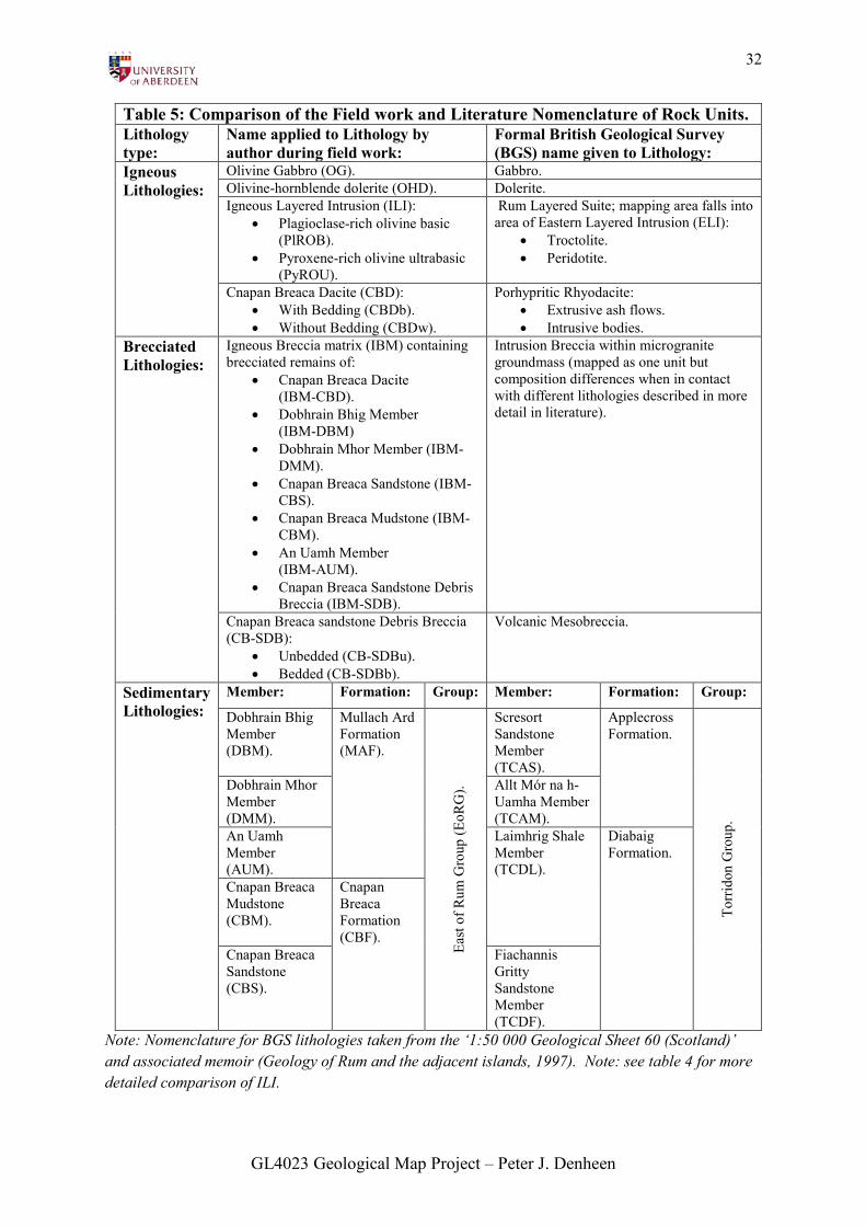
Table 5: Comparison of the Field work and Literature Nomenclature of Rock Units. Lithology type:
Name applied to Lithology by author during field work:
Formal British Geological Survey (BGS) name given to Lithology:
Igneous Lithologies:
Olivine Gabbro (OG). Gabbro. Olivine-hornblende dolerite (OHD). Dolerite. Igneous Layered Intrusion (ILI):
• Plagioclase-rich olivine basic (PlROB).
• Pyroxene-rich olivine ultrabasic (PyROU).
Rum Layered Suite; mapping area falls into area of Eastern Layered Intrusion (ELI):
• Troctolite. • Peridotite.
Cnapan Breaca Dacite (CBD): • With Bedding (CBDb). • Without Bedding (CBDw).
Porhypritic Rhyodacite: • Extrusive ash flows. • Intrusive bodies.
Brecciated Lithologies:
Igneous Breccia matrix (IBM) containing brecciated remains of:
• Cnapan Breaca Dacite (IBM-CBD).
• Dobhrain Bhig Member (IBM-DBM)
• Dobhrain Mhor Member (IBM-DMM).
• Cnapan Breaca Sandstone (IBM-CBS).
• Cnapan Breaca Mudstone (IBM-CBM).
• An Uamh Member (IBM-AUM).
• Cnapan Breaca Sandstone Debris Breccia (IBM-SDB).
Intrusion Breccia within microgranite groundmass (mapped as one unit but composition differences when in contact with different lithologies described in more detail in literature).
Cnapan Breaca sandstone Debris Breccia (CB-SDB):
• Unbedded (CB-SDBu). • Bedded (CB-SDBb).
Volcanic Mesobreccia.
Sedimentary Lithologies:
Member: Formation: Group: Member: Formation: Group:
Dobhrain Bhig Member (DBM).
Mullach Ard Formation (MAF).
Ea
st o
f Rum
Gro
up (E
oRG
).
Scresort Sandstone Member (TCAS).
Applecross Formation.
To
rrid
on G
roup
.
Dobhrain Mhor Member (DMM).
Allt Mór na h-Uamha Member (TCAM).
An Uamh Member (AUM).
Laimhrig Shale Member (TCDL).
Diabaig Formation.
Cnapan Breaca Mudstone (CBM).
Cnapan Breaca Formation (CBF).
Cnapan Breaca Sandstone (CBS).
Fiachannis Gritty Sandstone Member (TCDF).
Note: Nomenclature for BGS lithologies taken from the ‘1:50 000 Geological Sheet 60 (Scotland)’ and associated memoir (Geology of Rum and the adjacent islands, 1997). Note: see table 4 for more detailed comparison of ILI.
GL4023 Geological Map Project – Peter J. Denheen
33
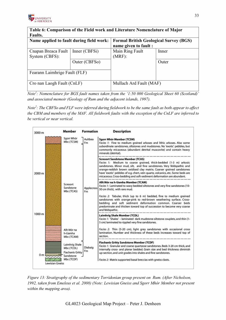
Table 6: Comparison of the Field work and Literature Nomenclature of Major Faults. Name applied to fault during field work: Formal British Geological Survey (BGS)
name given to fault : Cnapan Breaca Fault System (CBFS):
Inner (CBFSi)
Main Ring Fault (MRF):
Inner
Outer (CBFSo)
Outer
Fearann Laimhrige Fault (FLF) Cro nan Laogh Fault (CnLF)
Mullach Ard Fault (MAF)
Note1: Nomenclature for BGS fault names taken from the ‘1:50 000 Geological Sheet 60 (Scotland)’ and associated memoir (Geology of Rum and the adjacent islands, 1997).
Note2: The CBFSo and FLF were inferred during fieldwork to be the same fault as both appear to affect the CBM and members of the MAF. All fieldwork faults with the exception of the CnLF are inferred to be vertical or near vertical.
Figure 13: Stratigraphy of the sedimentary Torridonian group present on Rum. (After Nicholson, 1992, taken from Emeleus et al. 2008) (Note: Lewisian Gneiss and Sgorr Mhòr Member not present within the mapping area).
GL4023 Geological Map Project – Peter J. Denheen
34
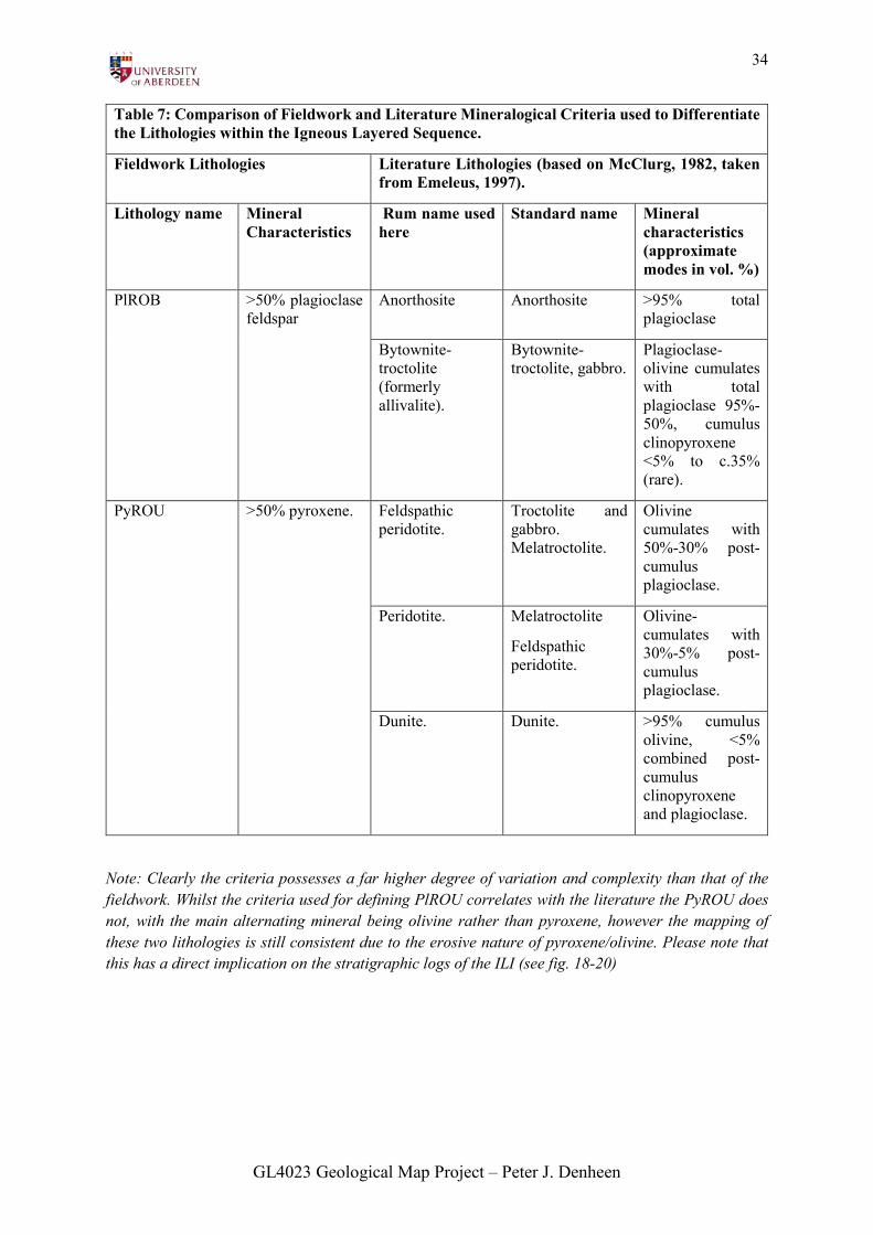
Table 7: Comparison of Fieldwork and Literature Mineralogical Criteria used to Differentiate the Lithologies within the Igneous Layered Sequence.
Fieldwork Lithologies Literature Lithologies (based on McClurg, 1982, taken from Emeleus, 1997).
Lithology name Mineral Characteristics
Rum name used here
Standard name Mineral characteristics (approximate modes in vol. %)
PlROB >50% plagioclase feldspar
Anorthosite Anorthosite >95% total plagioclase
Bytownite-troctolite (formerly allivalite).
Bytownite-troctolite, gabbro.
Plagioclase-olivine cumulates with total plagioclase 95%-50%, cumulus clinopyroxene <5% to c.35% (rare).
PyROU >50% pyroxene. Feldspathic peridotite.
Troctolite and gabbro. Melatroctolite.
Olivine cumulates with 50%-30% post-cumulus plagioclase.
Peridotite. Melatroctolite
Feldspathic peridotite.
Olivine-cumulates with 30%-5% post-cumulus plagioclase.
Dunite. Dunite. >95% cumulus olivine, <5% combined post-cumulus clinopyroxene and plagioclase.
Note: Clearly the criteria possesses a far higher degree of variation and complexity than that of the fieldwork. Whilst the criteria used for defining PlROU correlates with the literature the PyROU does not, with the main alternating mineral being olivine rather than pyroxene, however the mapping of these two lithologies is still consistent due to the erosive nature of pyroxene/olivine. Please note that this has a direct implication on the stratigraphic logs of the ILI (see fig. 18-20)
GL4023 Geological Map Project – Peter J. Denheen
35
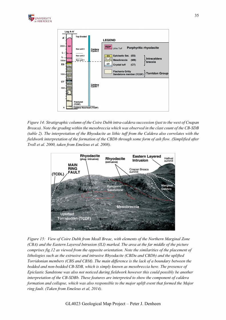
Figure 14: Stratigraphic column of the Coire Dubh intra-caldera succession (just to the west of Cnapan Breaca). Note the grading within the mesobreccia which was observed in the clast count of the CB-SDB (table 2). The interpretation of the Rhyodacite as lithic tuff from the Caldera also correlates with the fieldwork interpretation of the formation of the CBDb through some form of ash flow. (Simplified after Troll et al. 2000, taken from Emeleus et al. 2008).
Figure 15: View of Coire Dubh from Meall Breac, with elements of the Northern Marginal Zone (CBA) and the Eastern Layered Intrusion (ILI) marked. The area at the far middle of the picture comprises fig.12 as viewed from the opposite orientation. Note the similarities of the placement of lithologies such as the extrusive and intrusive Rhyodacite (CBDu and CBDb) and the uplifted Torridonian members (CBS and CBM). The main difference is the lack of a boundary between the bedded and non-bedded CB-SDB, which is simply known as mesobreccia here. The presence of Epiclastic Sandstone was also not noticed during fieldwork however this could possibly be another interpretation of the CB-SDBb. These features are interpreted to show the component of caldera formation and collapse, which was also responsible to the major uplift event that formed the Major ring fault. (Taken from Emeleus et al, 2014).
GL4023 Geological Map Project – Peter J. Denheen
36
CRITICAL STUDY – MINOR
STRUCTURES WITHIN THE ILI AND
MAF:
The lithologies within the ILI and MAF
both appear to contain similar minor
structures which show characteristics of
having been formed by the process of soft-
sediment deformation (SSD). These
structures include:
• Load casts.
• Flame structures.
• Pseudonodules.
• Distorted/ wavy lamination.
Within the clastic sedimentary members,
these features are known to form due to the
load of sediment on interfaces between
sediments with different physical
properties. For example a material of higher
density (e.g. sand) on a less dense material
(e.g. mud). According to (Lucci, 1995) A
convective-like motion starts, but the
attempts of the two "fluids" to overturn the
bedding and replace each other abort at a
certain stage owing to frictional resistance,
effectively freezing the deformation.
This principle also applies to
pseudonodules, distorted lamination and
flame structures, however these features
cannot form by load and inverted density
gradients alone and require the liquefaction
of both the substratum and the sand as well
as fluidisation through groundwater flow
(see fig.18).
In the ILI I believe that a similar
gravity/density driven process has occurred
during the formation of the alternating
layers, with the density differences of
plagioclase and pyroxene resulting in the
formation of these SSD features with wavy
lamination forming due to the convective
nature in which the alternating beds are laid
down on the floor of the intrusive magma
chamber. However, there were also
examples of cross-cutting relationships
within some of the logs constructed (see fig.
19 and 21) that do not appear to have been
formed through the same processes as
clastic sediment SSD and appear more to
have been formed by intrusions, possibly
due to pulses of late ILI layers through
those already lithified .
For many years most academics held a
similar interpretation that the deposition of
the Layered Suite was through a
sedimentary-like process, with early-
forming crystals and crystal aggregates
settling in less dense magma at rates that
depended on densities and sizes. In
addition, the accumulation and deposition
of these crystals was facilitated by
convectional magmatic currents which,
according to (Brothers, 1964), were also a
GL4023 Geological Map Project – Peter J. Denheen
37
major contributor to the strong lamination
found in many troctolites.
However, in addition to this gravity-driven
method of crystal settling and deposition,
Bédard et al (1988) introduced a
replacement origin in which metasomatism
occurs via the movement of pricritic
magma from intrusive sheets of peridotite
into the partly solidified troctolite layers
resulting in the formation of overprinting
peridotite veins and undulating, wavy
contacts
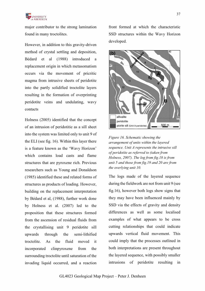
Holness (2005) identified that the concept
of an intrusion of peridotitie as a sill sheet
into the system was limited only to unit 9 of
the ELI (see fig. 16). Within this layer there
is a feature known as the ‘Wavy Horizon’
which contains load casts and flame
structures that are pyroxene rich. Previous
researchers such as Young and Donaldson
(1985) identified these and related forms of
structures as products of loading. However,
building on the replacement interpretation
by Bédard et al, (1988), further work done
by Holness et al. (2007) led to the
proposition that these structures formed
from the ascension of residual fluids from
the crystallising unit 9 peridotite sill
upwards through the semi-lithified
troctolite. As the fluid moved it
incorporated clinpyroxene from the
surrounding troctolite until saturation of the
invading liquid occurred, and a reaction
front formed at which the characteristic
SSD structures within the Wavy Horizon
developed.
Figure 16. Schematic showing the arrangement of units within the layered sequence. Unit A represents the intrusive sill of peridotite as referred to (taken from Holness, 2007). The log from fig.18 is from unit 5 and those from fig.19 and 20 are from the overlying unit 10.
The logs made of the layered sequence
during the fieldwork are not from unit 9 (see
fig.16), however both logs show signs that
they may have been influenced mainly by
SSD via the effects of gravity and density
differences as well as some localised
examples of what appears to be cross
cutting relationships that could indicate
upwards vertical fluid movement. This
could imply that the processes outlined in
both interpretations are present throughout
the layered sequence, with possibly smaller
intrusions of peridotite resulting in
GL4023 Geological Map Project – Peter J. Denheen

38
localised metasomatism rather than the
intrusion of sheet like sills affecting whole
layers. This could explain why another
‘Wavy Horizon’ has not been noticed
elsewhere is the layered sequence.
GL4023 Geological Map Project – Peter J. Denheen
39
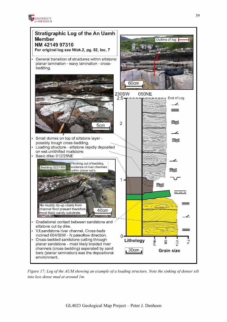
Figure 17: Log of the AUM showing an example of a loading structure. Note the sinking of denser silt into less dense mud at around 1m.
GL4023 Geological Map Project – Peter J. Denheen
40
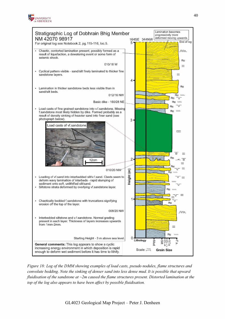
Figure 18: Log of the DMM showing examples of load casts, pseudo nodules, flame structures and convolute bedding. Note the sinking of denser sand into less dense mud. It is possible that upward fluidisation of the sandstone at ~2m caused the flame structures present. Distorted lamination at the top of the log also appears to have been affect by possible fluidisation.
GL4023 Geological Map Project – Peter J. Denheen
41
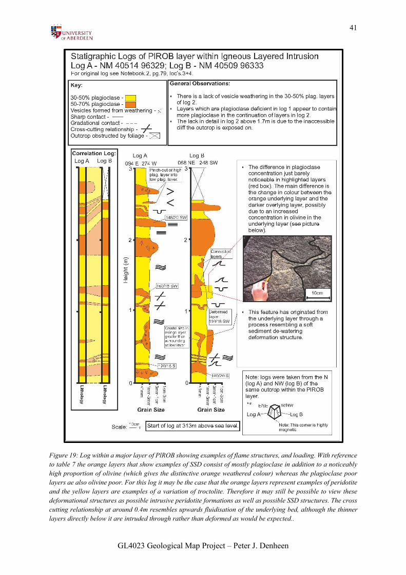
Figure 19: Log within a major layer of PlROB showing examples of flame structures, and loading. With reference to table 7 the orange layers that show examples of SSD consist of mostly plagioclase in addition to a noticeably high proportion of olivine (which gives the distinctive orange weathered colour) whereas the plagioclase poor layers ae also olivine poor. For this log it may be the case that the orange layers represent examples of peridotite and the yellow layers are examples of a variation of troctolite. Therefore it may still be possible to view these deformational structures as possible intrusive peridotite formations as well as possible SSD structures. The cross cutting relationship at around 0.4m resembles upwards fluidisation of the underlying bed, although the thinner layers directly below it are intruded through rather than deformed as would be expected..
GL4023 Geological Map Project – Peter J. Denheen
42
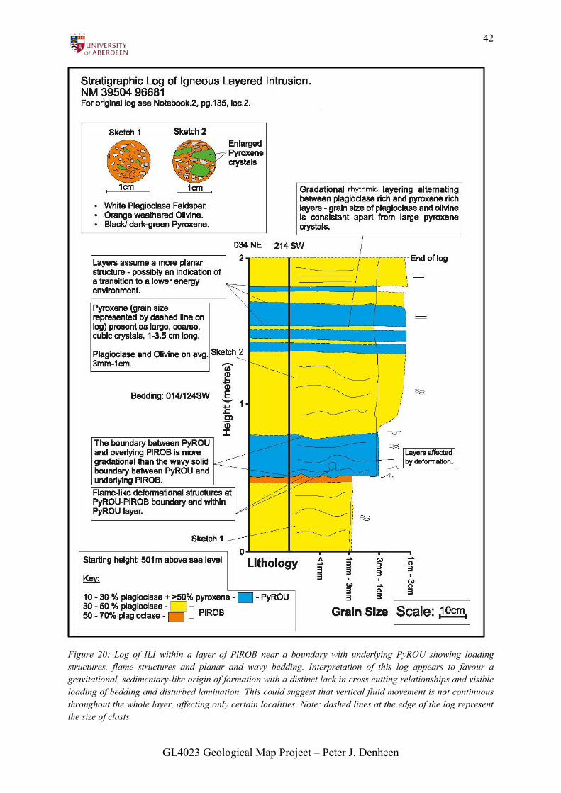
Figure 20: Log of ILI within a layer of PlROB near a boundary with underlying PyROU showing loading structures, flame structures and planar and wavy bedding. Interpretation of this log appears to favour a gravitational, sedimentary-like origin of formation with a distinct lack in cross cutting relationships and visible loading of bedding and disturbed lamination. This could suggest that vertical fluid movement is not continuous throughout the whole layer, affecting only certain localities. Note: dashed lines at the edge of the log represent the size of clasts.
GL4023 Geological Map Project – Peter J. Denheen
43
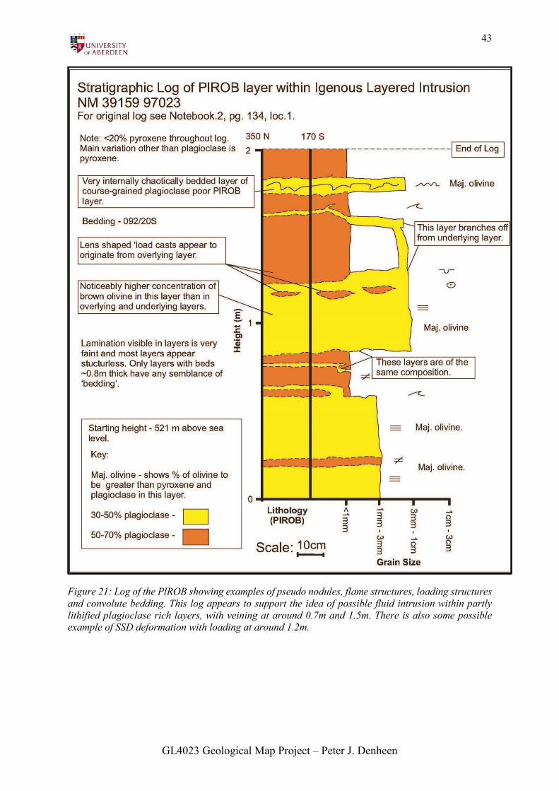
Figure 21: Log of the PlROB showing examples of pseudo nodules, flame structures, loading structures and convolute bedding. This log appears to support the idea of possible fluid intrusion within partly lithified plagioclase rich layers, with veining at around 0.7m and 1.5m. There is also some possible example of SSD deformation with loading at around 1.2m.
GL4023 Geological Map Project – Peter J. Denheen
44
CONCLUSION:
This study has managed to provide a limited interpretation of the spatial variations and
relationships of the lithologies present, with some findings correlating well with past fieldwork
undertaken in and around the mapping area. However there are some differences, as discussed,
which would most likely have been avoided by the more experienced geologist.
Through the creation of the map and cross section (see plate 1 (attached)), an interpretation of
features in map view and in the subsurface such as the dome-like magma chamber of the ILI
and the north-westerly dipping members of the MAF has been successfully produced. This in
turn has allowed for the creation of a general geological history of the area which has been
separated into separate geological events leading to the creation of different lithology groups
(e.g. the CBCS, the ILI etc.).
The study of the similar features within the igneous ILI and sedimentary MAF, whilst
recognising that the process of soft sediment deformation may be prevalent within both
lithology groups, indicates an additional unique vertical fluid injection component within the
ILI which is most likely related to post depositional intrusions of peridotite (or PyROU) into
the layered sequence, resulting in a cross-cutting rather than deformational effect on the
surrounding troctolite (PlROB) that would be expected in sedimentary deformation. Bearing
these features in mind, it is clear that the formation of the layered sequence on Rum is still an
area that is contested in the academic world and would benefit greatly from further detailed
study.
GL4023 Geological Map Project – Peter J. Denheen

45
REFERENCES:
BÉDARD et al. (1988). Peridotite sills and metasomatic gabbros in the Eastern Layered Series of the Rhum complex. Journal of the Geological Society, London, 145, 207-224.
BRADWELL, T and GOODENOUGH, K. (2004). Rum and the Small Isles: A Landscape Fashioned by Geology. Scottish Natural Heritage, Perth.
BROTHERS, R.N. (1964). Petrofabric analyses of Rhum and Skaergaard rocks. Journal of Petrology, 5, 255-274.
EMELEUS, C.H. (1994). 1:50 000 Solid and Drift Geology Map of Rum. Sheet 60 (Scotland) British Geological Survey, Keyworth, Nottingham, UK.
EMELEUS, C.H. (1997). Geology of Rum and the Adjacent Islands. Memoir of the British Geological Survey, Sheet 60 (Scotland) Brtitsh Geological Survey, Keyworth, Nottingham, UK.
EMELEUS, C.H. and TROLL, V.R. (2008). A geological excursion guide to Rum: the Paleocene igneous rocks of the Isle of Rum, Inner Hebrides. Edinburgh Geological Society, Edinburgh.
EMELEUS, C.H. and TROLL, V.R. (2014). The Rum Igneous Centre, Scotland. Mineralogical Magazine, 79, 805-839.
FRANCO, R.L. (1995). Deformation Structures. Sedimentographica: photographic atlas of sedimentary structures. New York: Columbia University Press.
HOLNESS, M.B. (2005). Spatial constraints on magma chamber events from textural observations on cumulates: the Rum Layered Intrusion, Scotland. Journal of Petrology, 46, 1585-1601.
HOLNESS, M.B. (2007). Textural immaturity of cumulates as an indicator of magma chamber processes: infiltration and crystal accumulation in the Rum layered suite. Journal of the Geological Society, London, 164, 529-539.
HOLNESS, M.B. and WINPENNY, B. (2009). The Unit 12 allivalite, Eastern Layered Intrusion, Isle of Rum: a textural and geochemical study of an open-system magma chamber, Geological Magazine, 146, 437-460.
MCCLURG, J.E. (1982). Petrology and evolution of the northern part of the Rhum ultrabasic complex. Unpublished PhD thesis, University of Edinburgh, 2 volumes. (As seen in Emeleus, 1997).
NICHOLSON, P.G. (1992a). Precambrian: Upper Proterozoic Torridonian Group. 5-7 in Atlas of palaeogeography and lithofacies, Memoir of the Geological Society of London, 14. (As seen in Emeleus, 1997).
GL4023 Geological Map Project – Peter J. Denheen
46
NICHOLSON, P.G. (1992b). Sedimentation of the fluvial ‘Torridonian’ Applecross Formation, NW Scotland. Unpublished PhD thesis, University of Glasgow. (As seen in Emeleus, 1997).
NICHOLSON, P.G. (1993). A basin reappraisal of the Proterozoic Torridon Group, north west Scotland. 183-202 in Sedimentation and tectonics, Special Publications of the International Association of Sedimentologists, 20. (As seen in Emeleus, 1997).
STEWART, A.D. and PARKER A. (1979). Palaeosalinity and environmental interpretation of red beds from the Late Precambrian (‘Torridonian’) of Scotland. Sedimentary Geology, 22, 229-241. (As seen in Emeleus, 1997).
STEWART, A.D. (1982). Late Proterozoic rifting in NW Scotland: the genesis of the ‘Torridonian’. Journal of the Geological Society of London, 139, 413-420. (As seen in Emeleus, 1997).
STEWART, A.D. (1988b). The Sleat and Torridon groups. Later Proterozoic stratigraphy of the North Atlantic regions. Blackie, Glasgow. (As seen in Emeleus, 1997).
STOW, D.A.V. (2005). Sedimentary Rocks in the Field: A Color Guide. Manson Publshing, London.
RODD, J.A. (1983). The sedimentology and geochemistry of the Type Diabaig Formation in the Upper Proterozoic Torridonian Group of Scotland. Unpublished PhD thesis, University of Reading. (As seen in Emeleus, 1997).
WAGNER, L.R. and BROWN, G.M. (1968). Layered Igneous Rock. Oliver and Boyd, Edinburgh.
YOUNG, I.M. and DONALDSON, C.H. (1985). Formation of granular-textured layers and laminae within the Rhum crystal pile. Geological Magazine, 122, 519-528.
GL4023 Geological Map Project – Peter J. Denheen
47
APPENDIX 1 – SEDIMENTARY SYMBOLS FOR STRATIGRAPHIC LOGS:
(Note: Adeapted from Stow, 2005)
GL4023 Geological Map Project – Peter J. Denheen


![Opdc Draft Local Plan Iia Scoping Report - Finalised Version1[1]](https://img.pdfslide.us/doc/110x75/5695d0371a28ab9b02917abc/opdc-draft-local-plan-iia-scoping-report-finalised-version11.jpg)