Embed Size (px)
Citation preview
Doc. IHS-5000 2 Feb 2000
GIS Interface Development A Guide for Resource and Patient Management System (RPMS) Developers
February 2, 2000
Prepared by Science Application International Corporation
GIS Interface Development i Table of Contents
TABLE OF CONTENTS 1.0 SYSTEM OVERVIEW .......................................................................................... 1
1.1 Primary System Components .................................................................... 1 1.1.1 Application ................................................................................. 2 1.1.2 Formatter ................................................................................... 2 1.1.3 Transaction Type ....................................................................... 2 1.1.4 Interface Script File .................................................................... 2 1.1.5 Receiver..................................................................................... 2 1.1.6 UIF--Universal Interface File ...................................................... 2 1.1.7 Interface Destination File ........................................................... 2 1.1.8 Output Controller ....................................................................... 3 1.1.9 Transmitter................................................................................. 3 1.1.10 Application Deformatter ............................................................. 4 1.1.11 System Control .......................................................................... 4
1.2 Transaction Flow Through the GIS ............................................................ 4 1.2.1 Outbound Transactions ............................................................. 4 1.2.2 TCP/IP Transmitters/Receivers ................................................. 6 1.2.3 TCP/IP Transmitters/Receivers ................................................. 8 1.2.4 Interactive transactions ............................................................ 10
1.3 Quick Guide ............................................................................................. 12 1.3.1 Create the message ................................................................ 13 1.3.2 Send the message (outgoing) .................................................. 13 1.3.3 Receive the message (incoming) ............................................. 14 1.3.4 Route the message (store-and-forward) .................................. 14
2.0 INTERFACE MESSAGE DESIGN ..................................................................... 15
2.1 Script Generator: HL7 .............................................................................. 16 2.1.1 HL7 Summary .......................................................................... 17 2.1.2 Field Data Types ...................................................................... 17 2.1.3 Field Definition ......................................................................... 20
2.1.3.1 Field Data Location ............................................................ 22 2.1.3.2 Field Data Location for Set ID Fields .................................. 25 2.1.3.3 Field Data Location for Word Processing Fields ................. 26 2.1.3.4 Field Data Location Using Special Variables ...................... 27
2.1.4 Segment Definition .................................................................. 27 2.1.5 Message Definition .................................................................. 29 2.1.6 Message/Transaction Type Link .............................................. 34 2.1.7 Incoming vs. Outgoing Transactions ........................................ 35
2.2 Script Generator X12 Modifications ......................................................... 35 2.2.1 Field Data Types ...................................................................... 36 2.2.2 Field Definition ......................................................................... 36 2.2.3 Segment Definition .................................................................. 37 2.2.4 Message Definition .................................................................. 37 2.2.5 Compiled X12 Script Characteristics ....................................... 39
2.2.5.1 Create Sequence Number .................................................. 41
User Manual ii Table of Contents
2.3 Programmer APIs .................................................................................... 42 2.3.1 Programmer-Defined Lookup/Store Options ............................ 42 2.3.2 M Calls From Compiled Scripts ............................................... 43
2.3.2.1 Variable arrays used in M Calls .......................................... 44 2.3.3 Error handling .......................................................................... 47
2.4 Generate/Compile Scripts ........................................................................ 48 2.5 Error Conditions ....................................................................................... 50 2.6 Message Definition Hints ......................................................................... 51
3.0 TRANSACTION ROUTING ................................................................................ 53
3.1 Outgoing Transactions ............................................................................. 53 3.1.1 Parent Transaction Type Definition .......................................... 53 3.1.2 Application Program Interface (API) Call ................................. 55 3.1.3 Child Transaction Type Definition ............................................ 57 3.1.4 Destination Definition ............................................................... 59 3.1.5 Destination for the Background Process .................................. 61 3.1.6 Transaction Replication To Multiple Destinations .................... 65
3.2 Incoming Transactions ............................................................................. 68 3.2.1 Destination-Transaction Type Pair ........................................... 70 3.2.2 Destination-Background Process Pair ..................................... 73 3.2.3 HL7 Message Type Recognition (Destination Determination) . 77 3.2.4 X12 Message Recognition ....................................................... 78 3.2.5 X12 Validation .......................................................................... 79 3.2.6 Functional Identifiers (Message Type) and Message
Recognition .............................................................................. 80 3.3 Responses to Incoming Transactions ...................................................... 80
3.3.1 HL7 Accept Acknowledgments ................................................ 80 3.3.2 HL7 Application Acknowledgments .......................................... 83 3.3.3 Queries and Specialized Acknowledgments ............................ 84
3.3.3.1 Query Status API ................................................................ 84 3.3.4 X12 Query Responses ............................................................. 85 3.3.5 X12 Transaction Acknowledgments ......................................... 85 3.3.6 X12 Functional Acknowledgments ........................................... 85
3.4 The Bi-directional Interface ...................................................................... 86 3.5 Routing a Store-And-Forward Transaction .............................................. 89 3.6 Transient Connection ............................................................................... 90
4.0 SELECTIVE ROUTING ...................................................................................... 93
4.1 Concept of Operations ............................................................................. 93 4.1.1 Inbound transactions ............................................................... 93 4.1.2 Outbound transactions ............................................................. 94
4.2 Application Screening Logic ..................................................................... 94 4.2.1 INA Array ................................................................................. 95 4.2.2 INDA Array............................................................................... 95 4.2.3 INSRCTL Array ........................................................................ 95 4.2.4 INSRDATA Array ..................................................................... 96
4.3 Selective Routing (SRMC) Code Placement ............................................ 97
User Manual iii Table of Contents
4.3.1 Interface Transaction Type File ............................................... 97 4.3.2 Interface Destination File ......................................................... 97 4.3.3 Background Process Control File ............................................ 98
4.4 Screening Points ...................................................................................... 98 4.4.1 Receiver Screens .................................................................... 99 4.4.2 Message Replicator Screens ................................................... 99
4.5 Primary Destinations and Subordinate Destinations .............................. 100 4.5.1 Outbound ............................................................................... 100 4.5.2 Inbound .................................................................................. 101
4.6 Route ID and Interface Destination Mapping ......................................... 102 4.6.1 Creating Destination Specific MSH Segments ....................... 102 4.6.2 MSH Facility and Application Precedence ............................. 104
4.7 Routing Activity Logs ............................................................................. 104 4.8 Application Acknowledgment Routing .................................................... 104 4.9 Sample Screening Logic Code .............................................................. 105 4.10 Supporting Utilities ................................................................................. 106
4.10.1 PARSEG^INHUT ................................................................... 108 4.10.2 GETSEG^INHUT ................................................................... 108 4.10.3 RCVSCRN^INHUT ................................................................ 108
4.11 Application Acknowledgment Routing .................................................... 109 4.11.1 GETDEST^INHUT ................................................................. 109
5.0 THE GIS IN OPERATION ................................................................................ 111
5.1 Universal Interface File (UIF) ................................................................. 111 5.2 Interface Error File ................................................................................. 113 5.3 Status levels .......................................................................................... 115
5.3.1 X12 Status Levels .................................................................. 116 5.4 Testing/Debugging Concepts and Utilities ............................................. 117
5.4.1 Transaction Search Functions ............................................... 117 5.4.2 Error Search Functions .......................................................... 119 5.4.3 List Queued Transactions ...................................................... 120
5.5 INHPSAM .............................................................................................. 121 5.5.1 Preparing Transactions for Distribution .................................. 121 5.5.2 Activating/Deactivating an Interface ....................................... 123
6.0 QUERY RESPONSE FUNCTIONS .................................................................. 125
6.1 Log on Server ........................................................................................ 125 6.1.1 Background LoS Process Definition ...................................... 125
6.2 Application Server .................................................................................. 127 6.2.1 ApS Background Process Definition ...................................... 128 6.2.2 Variable arrays for incoming and outgoing scripts ................. 128 6.2.3 ApS User Time Out ................................................................ 130
6.3 Transaction Re-queue Warning ............................................................. 130 6.4 Testing/Debugging hints ........................................................................ 131
7.0 DATA TRANSFORMS AND CHARACTER CONVERSION ............................ 132
Appendix A: ........................................................................................................ 133

GIS Interface Development i Introduction
Introduction
The GIS Applications Development Manual provides an overview of the Generic Interface System (GIS), an interface tool of Science Applications International Corporation (SAIC). The document is intended for applications developers, including both systems analysts and programmers. It explains how to define GIS messages and how to route messages from one system to another. It includes examples of data input screens with an explanation of the various fields on the screens and how they are used.
This document does not explain all functionality in the GIS, but focuses on the functions needed to develop and test interface messages. Many of the system utilities are used primarily by site management personnel, and are not explained in this manual.
Applications developers should also consult the appropriate ICD and implementation guide for the specific interface(s) being developed. Other sources of information on the GIS and on interface development include the following.
Health Level 7 3300 Washtenaw Avenue, Suite 227 Ann Arbor, MI 48101-4250 http://www.mcis.duke.edu/standards/HL7/hl7.htm
GIS Interface Development i GIS Changes Specific to the RPMS
GIS Changes Specific to the RPMS
The Generic Interface System (GIS) was initially developed on the Composite Health Care System (CHCS). This document has been adapted from the original CHCS version specifically for the GIS application to the Resource and Patient Management System (RPMS) of the Indian Health Services (IHS) system.
Overview of Changes The following changes have been made to the original CHCS software in order to port the GIS to the RPMS:
• Screens in the CHCS GIS menu options have been converted to ScreenMan for use with the RPMS. An analysis was performed to determine the feasibility of porting the CHCS WindowMan and VA ListMan functions to RPMS. It was concluded that it would require significant effort because of the graphic control characters and extensive use of the keyboard (DWK) and terminal control (DIJC) arrays.
• The GIS functionality is the same as in CHCS, but the user interface is different because of ScreenMan functionality. The screens used in this document represent screen changes made for the RPMS.
• The GIS functionality ported to the RPMS is comparable to the CHCS version 4.602 baseline with the enhancements developed for version 4.603 that were available at the time of conversion for RPMS.
• The following CHCS GIS menu options were not included in the conversion to RPMS:
− BSC Background Process Security Control − STAT Interface Statistics Generator − IES Interface Error Statistics Generator
GIS Interface Development 1 System Overview
1.0 System Overview The Generic Interface System (GIS) is a transaction oriented, information transfer and format processing system used to create, manage, and interpret messages flowing from one system to another. Its primary use is to provide interface messaging between the RPMS and other computer systems such as offboard anatomic pathology, blood bank, clinical chemistry, and between other the RPMS and VA systems.
The GIS is symmetric in design which allows messages from any source to be routed to any destination. This allows the GIS to serve as a message source, a message processor, and a message router.
The GIS provides an application independent interface. This allows interfaces to be accomplished using a simple, standardized tool. Functional analysts can create and modify interface message formats with minimal programmer intervention. The GIS also provides independence from hardware and software platforms.
The GIS is essentially two different tools. The first provides the ability to define both incoming and outgoing interface messages/transactions. This capability can be operational for any database that utilizes a FileMan Data Dictionary. The message definition function is called the Script Generator Subsystem.
The second tool is a message router. It is an "interface engine" used to route transactions/messages between any two systems. The GIS has the capability of routing "store-and-forward" interface transactions which are neither created nor stored in the local application database.
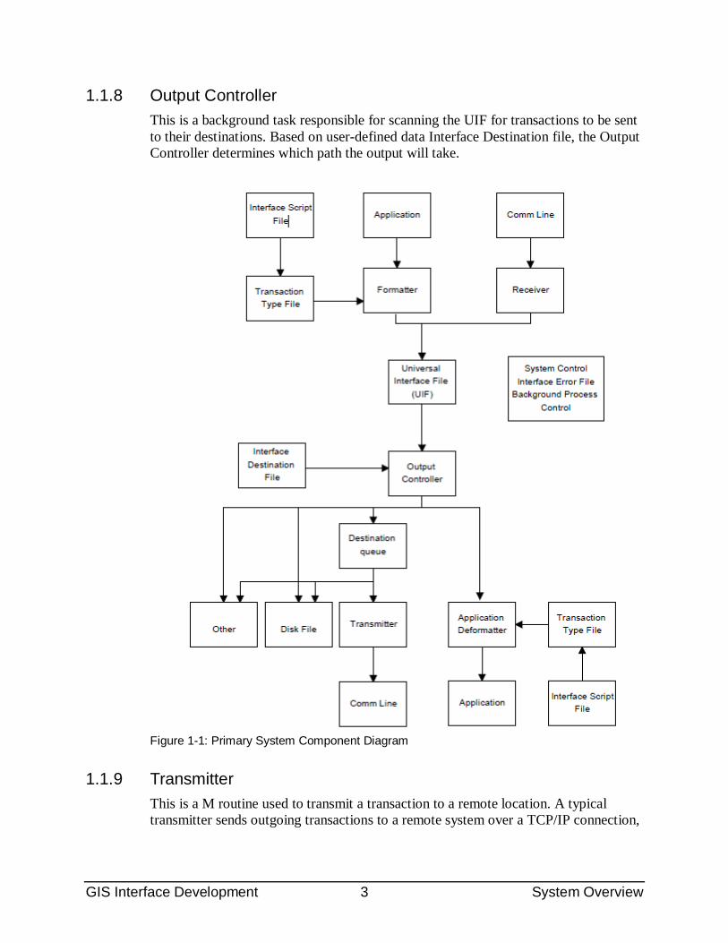
1.1 Primary System Components The following is an overview of the primary system components. Figure 1.1 illustrates the relationship between components. Notice in the diagram that the Universal Interface File (UIF) and the Interface Destination File are at the center of the diagram.
Both outgoing messages/transactions and incoming messages/transactions are treated as inputs to the UIF. Outgoing messages/transactions are processed through system components shown in the upper left of the diagram. Incoming messages/transactions are processed through system components shown in the upper right of the diagram.
All messages must have a valid destination. The Output Controller routes all messages based on their destinations. Messages are either routed to a remote system (as shown in the lower left of the diagram) or to an application/database (as shown in the lower right of the diagram).
GIS Interface Development 2 System Overview
1.1.1 Application An application is any application program which initiates an interface transaction or interprets a remote transaction.
1.1.2 Formatter The job of the formatter is to process application requests to generate interface transactions. The formatter consists of the format queue and the Format Controller. Application requests to generate a transaction are queued to the Format Controller. This queuing process enables application programs to experience very little delay. When calling the Formatter, application programs must specify a Transaction Type and a file entry. From the queue, the format controller processes each application request. The format controller extracts data from the database, formats the data into an outbound transaction, and places the formatted transaction in the Universal Interface File.
1.1.3 Transaction Type Transaction Types contain the information necessary to create and route transactions.
1.1.4 Interface Script File Scripts are used to both create and interpret messages. Transaction Types point to the appropriate script for interpretation.
1.1.5 Receiver A receiver is a program written to receive information from a remote system. The receiver can either run as a GIS-controlled background task or can be invoked by other events. A typical receiver accepts data from a remote system, files transaction in the Universal Interface File, and returns an acknowledgment. There can be many simultaneously active receivers.
1.1.6 UIF--Universal Interface File This file contains all interface transactions regardless of destination. It also contains all status and tracking information for the transactions.
1.1.7 Interface Destination File This contains the information necessary to route an interface transaction to its destination. Each UIF entry must have a destination.
GIS Interface Development 3 System Overview
1.1.8 Output Controller This is a background task responsible for scanning the UIF for transactions to be sent to their destinations. Based on user-defined data Interface Destination file, the Output Controller determines which path the output will take.
Figure 1-1: Primary System Component Diagram
1.1.9 Transmitter This is a M routine used to transmit a transaction to a remote location. A typical transmitter sends outgoing transactions to a remote system over a TCP/IP connection,
GIS Interface Development 4 System Overview
receive an acknowledgment of the transmission, and updates the status of the transactions.
1.1.10 Application Deformatter This module processes transactions with the aid of a Transaction Type and prepares the data for storage on the local database. Using an input script, it handles data interpretation, transformation, validity checking, and storing.
1.1.11 System Control This module consists of several components which are responsible for monitoring and controlling the entire GIS. Major components are the Background Process Control, the Interface Error File, and various utilities used to search for transactions, re-queue transactions, remove entries from various queues, and others.
1.2 Transaction Flow Through the GIS The following is an overview of the flow of transactions as they are routed through the GIS. Both outgoing and an incoming flows are described.
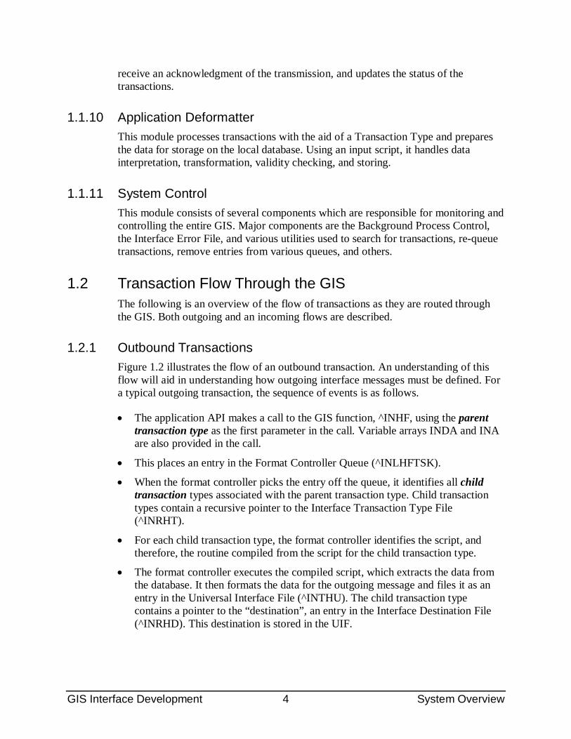
1.2.1 Outbound Transactions Figure 1.2 illustrates the flow of an outbound transaction. An understanding of this flow will aid in understanding how outgoing interface messages must be defined. For a typical outgoing transaction, the sequence of events is as follows.
• The application API makes a call to the GIS function, ^INHF, using the parent transaction type as the first parameter in the call. Variable arrays INDA and INA are also provided in the call.
• This places an entry in the Format Controller Queue (^INLHFTSK).
• When the format controller picks the entry off the queue, it identifies all child transaction types associated with the parent transaction type. Child transaction types contain a recursive pointer to the Interface Transaction Type File (^INRHT).
• For each child transaction type, the format controller identifies the script, and therefore, the routine compiled from the script for the child transaction type.
• The format controller executes the compiled script, which extracts the data from the database. It then formats the data for the outgoing message and files it as an entry in the Universal Interface File (^INTHU). The child transaction type contains a pointer to the “destination”, an entry in the Interface Destination File (^INRHD). This destination is stored in the UIF.
GIS Interface Development 5 System Overview
• As it executes, the script also makes an entry in either the Output Controller Queue (^INLHSCH) or a Destination Queue (^INLHDEST), depending on a flag specified in the Interface Destination File. The queues contain a pointer to the entry in the UIF, along with the priority and the time-to-process of the message. The latter two are based on data stored in the Interface Transaction Type File.
• As the output controller picks the entry from the Output Controller Queue, it identifies the destination stored as part of the entry. The controller then references the entry in the Interface Destination File to obtain the name of the routine to process the message (only outbound destinations contain a routine name).
• If the destination is a remote system, the transaction will typically be sent via a transmitter which operates as a background process. The output controller will queue the transaction on a destination queue, where it will be sent when the background process is active.
GIS Interface Development 6 System Overview
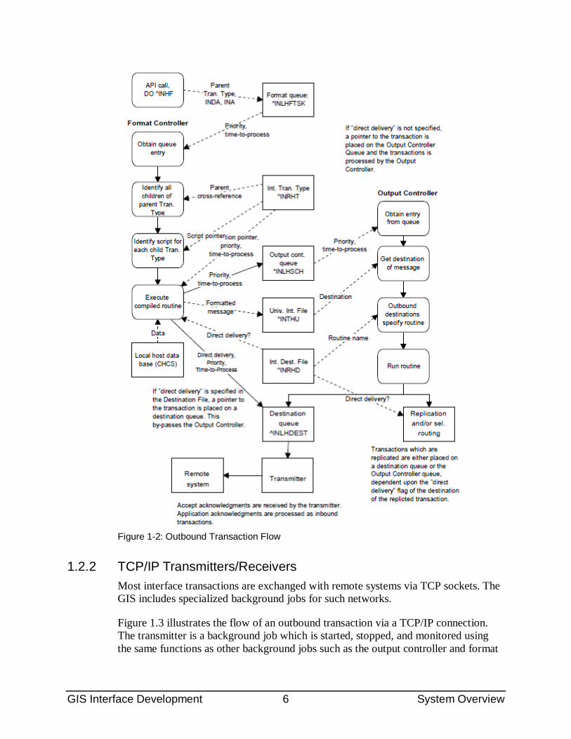
Figure 1-2: Outbound Transaction Flow
1.2.2 TCP/IP Transmitters/Receivers Most interface transactions are exchanged with remote systems via TCP sockets. The GIS includes specialized background jobs for such networks.
Figure 1.3 illustrates the flow of an outbound transaction via a TCP/IP connection. The transmitter is a background job which is started, stopped, and monitored using the same functions as other background jobs such as the output controller and format
GIS Interface Development 7 System Overview
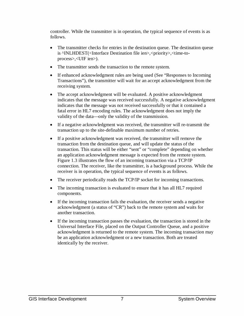
controller. While the transmitter is in operation, the typical sequence of events is as follows.
• The transmitter checks for entries in the destination queue. The destination queue is ^INLHDEST(<Interface Destination file ien>,<priority>,<time-to-process>,<UIF ien>).
• The transmitter sends the transaction to the remote system.
• If enhanced acknowledgment rules are being used (See “Responses to Incoming Transactions”), the transmitter will wait for an accept acknowledgment from the receiving system.
• The accept acknowledgment will be evaluated. A positive acknowledgment indicates that the message was received successfully. A negative acknowledgment indicates that the message was not received successfully or that it contained a fatal error in HL7 encoding rules. The acknowledgment does not imply the validity of the data—only the validity of the transmission.
• If a negative acknowledgment was received, the transmitter will re-transmit the transaction up to the site-definable maximum number of retries.
• If a positive acknowledgment was received, the transmitter will remove the transaction from the destination queue, and will update the status of the transaction. This status will be either “sent” or “complete” depending on whether an application acknowledgment message is expected from the remote system. Figure 1.3 illustrates the flow of an incoming transaction via a TCP/IP connection. The receiver, like the transmitter, is a background process. While the receiver is in operation, the typical sequence of events is as follows.
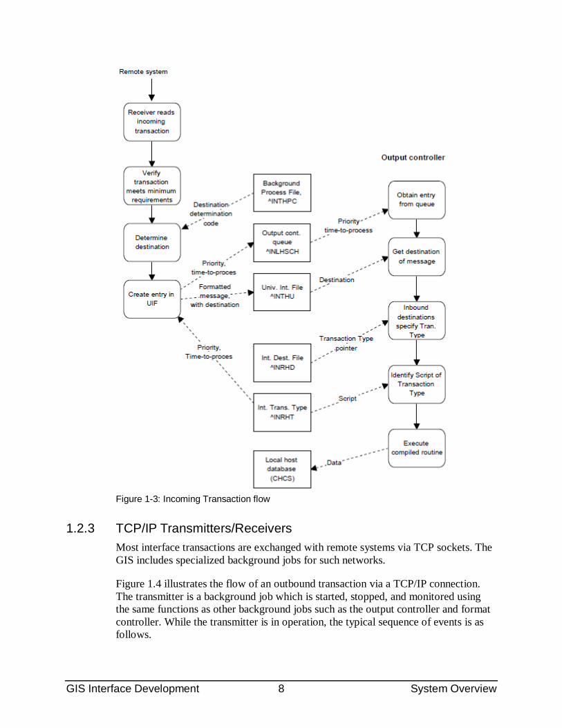
• The receiver periodically reads the TCP/IP socket for incoming transactions.
• The incoming transaction is evaluated to ensure that it has all HL7 required components.
• If the incoming transaction fails the evaluation, the receiver sends a negative acknowledgment (a status of “CR”) back to the remote system and waits for another transaction.
• If the incoming transaction passes the evaluation, the transaction is stored in the Universal Interface File, placed on the Output Controller Queue, and a positive acknowledgment is returned to the remote system. The incoming transaction may be an application acknowledgment or a new transaction. Both are treated identically by the receiver.
GIS Interface Development 8 System Overview
Figure 1-3: Incoming Transaction flow
1.2.3 TCP/IP Transmitters/Receivers Most interface transactions are exchanged with remote systems via TCP sockets. The GIS includes specialized background jobs for such networks.
Figure 1.4 illustrates the flow of an outbound transaction via a TCP/IP connection. The transmitter is a background job which is started, stopped, and monitored using the same functions as other background jobs such as the output controller and format controller. While the transmitter is in operation, the typical sequence of events is as follows.
GIS Interface Development 9 System Overview
• The transmitter checks for entries in the destination queue. The destination queue is ^INLHDEST(<Interface Destination file ien>,<priority>,<time-to-process>,<UIF ien>).
• The transmitter sends the transaction to the remote system.
• If enhanced acknowledgment rules are being used (See “Responses to Incoming Transactions”), the transmitter will wait for an accept acknowledgment from the receiving system.
• The accept acknowledgment will be evaluated. A positive acknowledgment indicates that the message was received successfully. A negative acknowledgment indicates that the message was not received successfully or that it contained a fatal error in HL7 encoding rules. The acknowledgment does not imply the validity of the data—only the validity of the transmission.
• If a negative acknowledgment was received, the transmitter will re-transmit the transaction up to the site-definable maximum number of retries.
• If a positive acknowledgment was received, the transmitter will remove the transaction from the destination queue, and will update the status of the transaction. This status will be either “sent” or “complete” depending on whether an application acknowledgment message is expected from the remote system.
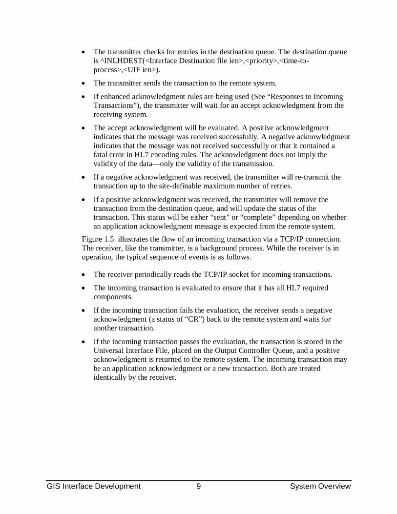
Figure 1.5 illustrates the flow of an incoming transaction via a TCP/IP connection. The receiver, like the transmitter, is a background process. While the receiver is in operation, the typical sequence of events is as follows.
• The receiver periodically reads the TCP/IP socket for incoming transactions.
• The incoming transaction is evaluated to ensure that it has all HL7 required components.
• If the incoming transaction fails the evaluation, the receiver sends a negative acknowledgment (a status of “CR”) back to the remote system and waits for another transaction.
• If the incoming transaction passes the evaluation, the transaction is stored in the Universal Interface File, placed on the Output Controller Queue, and a positive acknowledgment is returned to the remote system. The incoming transaction may be an application acknowledgment or a new transaction. Both are treated identically by the receiver.
GIS Interface Development 10 System Overview
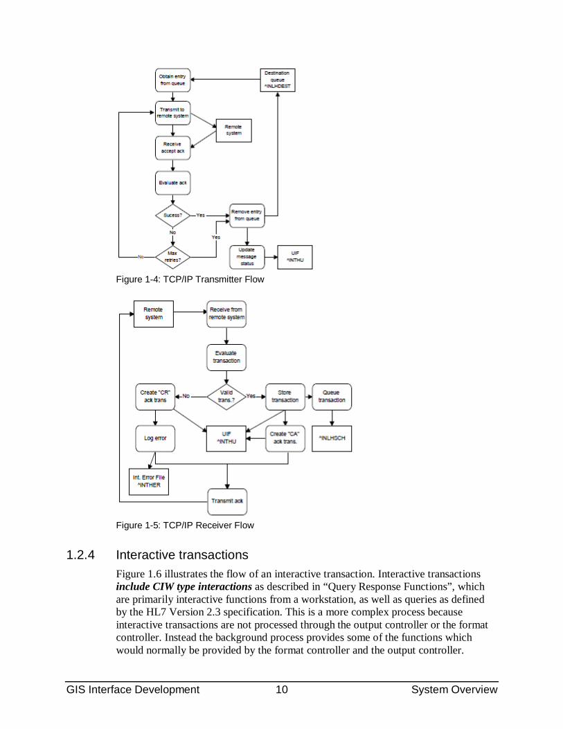
Figure 1-4: TCP/IP Transmitter Flow
Figure 1-5: TCP/IP Receiver Flow
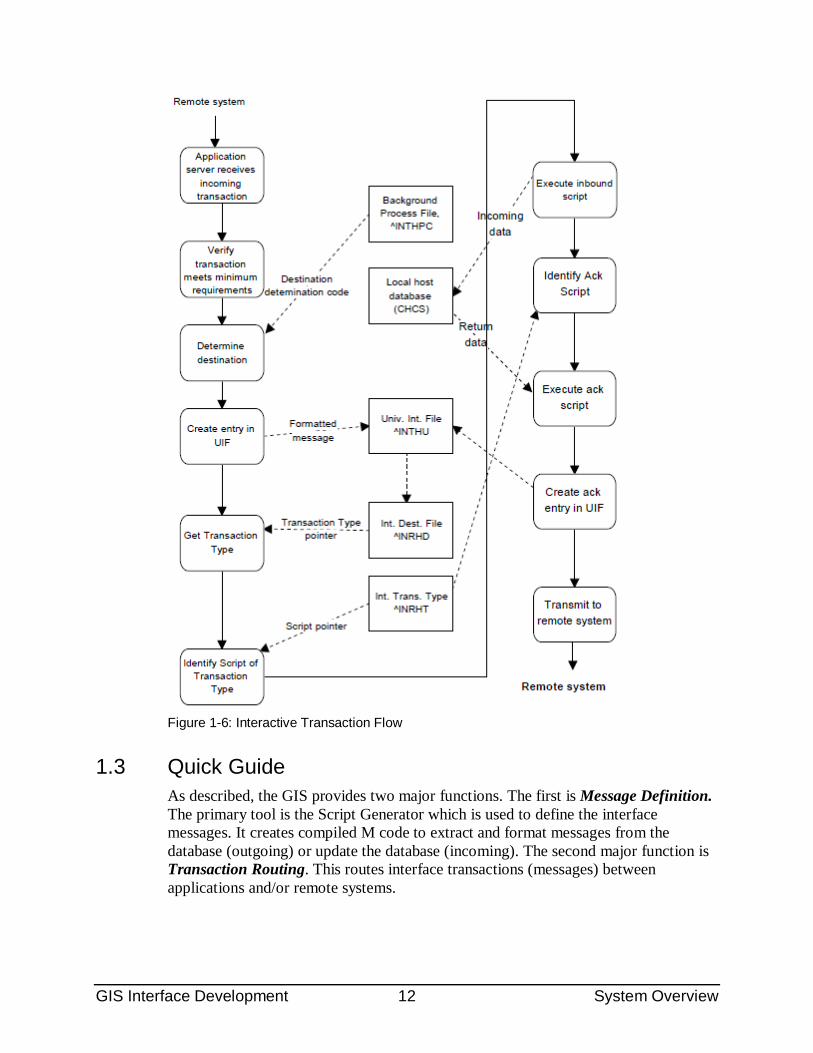
1.2.4 Interactive transactions Figure 1.6 illustrates the flow of an interactive transaction. Interactive transactions include CIW type interactions as described in “Query Response Functions”, which are primarily interactive functions from a workstation, as well as queries as defined by the HL7 Version 2.3 specification. This is a more complex process because interactive transactions are not processed through the output controller or the format controller. Instead the background process provides some of the functions which would normally be provided by the format controller and the output controller.
GIS Interface Development 11 System Overview
Interactive transactions are typically initiated by a remote system, which is illustrated in the figure.
• The incoming transaction is received by a specialized receiver process.
• The receiver is responsible for initial validation of the incoming transaction. If valid, the receiver will store the transaction in the Universal Interface File (^INTHU).
• In addition, the receiver identifies the destination of the transaction. It then references the entry in the Interface Destination File (^INRHD) to obtain the name of the entry in the Interface Transaction Type File (^INRHT). Only inbound destinations contain a pointer to the Transaction Type File. Incoming transactions have a one-to-one relationship between an entry in the Interface Destination File and an entry in the Interface Transaction Type File. (Note that the concept of “parent” and “child” transaction types only applies to outgoing transaction types, not to incoming transactions.)
• The receiver references the Interface Transaction Type File to identify the script and the routine compiled from the script.
• The compiled routine is executed. It parses the message and stores the data into the database.
• The receiver then identifies the application acknowledgment Transaction Type from the Interface Transaction Type File. The acknowledgment script may be complex. Many interactive transactions are requests for data from the local database, such as a request for patient information. These acknowledgment messages can contain a significant amount of data in addition to the message header and the status information. However, the GIS processes complex acknowledgment transactions the same as simple acknowledgments.
• The receiver executes the acknowledgment script. The variable array from execution of the incoming script is available and is used to pass data into the acknowledgment script.
• Execution of the script results in a new entry in the Universal Interface File.
• The acknowledgment transaction for an interactive process differs from a “normal” process in that it is not placed on the Output Controller queue. Instead, the receiver process transmits the transaction back to the remote system over the same connection (typically a TCP socket) on which the incoming transaction was received.
GIS Interface Development 12 System Overview
Figure 1-6: Interactive Transaction Flow
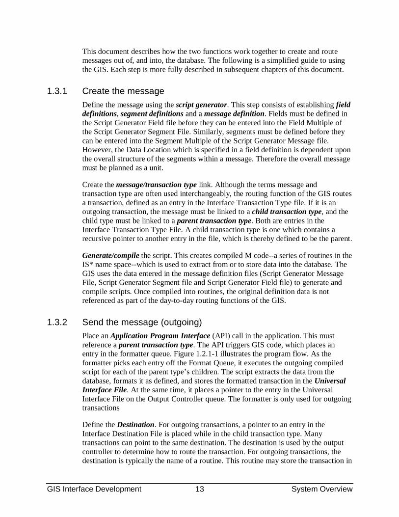
1.3 Quick Guide As described, the GIS provides two major functions. The first is Message Definition. The primary tool is the Script Generator which is used to define the interface messages. It creates compiled M code to extract and format messages from the database (outgoing) or update the database (incoming). The second major function is Transaction Routing. This routes interface transactions (messages) between applications and/or remote systems.
GIS Interface Development 13 System Overview
This document describes how the two functions work together to create and route messages out of, and into, the database. The following is a simplified guide to using the GIS. Each step is more fully described in subsequent chapters of this document.
1.3.1 Create the message Define the message using the script generator. This step consists of establishing field definitions, segment definitions and a message definition. Fields must be defined in the Script Generator Field file before they can be entered into the Field Multiple of the Script Generator Segment File. Similarly, segments must be defined before they can be entered into the Segment Multiple of the Script Generator Message file. However, the Data Location which is specified in a field definition is dependent upon the overall structure of the segments within a message. Therefore the overall message must be planned as a unit.
Create the message/transaction type link. Although the terms message and transaction type are often used interchangeably, the routing function of the GIS routes a transaction, defined as an entry in the Interface Transaction Type file. If it is an outgoing transaction, the message must be linked to a child transaction type, and the child type must be linked to a parent transaction type. Both are entries in the Interface Transaction Type File. A child transaction type is one which contains a recursive pointer to another entry in the file, which is thereby defined to be the parent.
Generate/compile the script. This creates compiled M code--a series of routines in the IS* name space--which is used to extract from or to store data into the database. The GIS uses the data entered in the message definition files (Script Generator Message File, Script Generator Segment file and Script Generator Field file) to generate and compile scripts. Once compiled into routines, the original definition data is not referenced as part of the day-to-day routing functions of the GIS.
1.3.2 Send the message (outgoing) Place an Application Program Interface (API) call in the application. This must reference a parent transaction type. The API triggers GIS code, which places an entry in the formatter queue. Figure 1.2.1-1 illustrates the program flow. As the formatter picks each entry off the Format Queue, it executes the outgoing compiled script for each of the parent type’s children. The script extracts the data from the database, formats it as defined, and stores the formatted transaction in the Universal Interface File. At the same time, it places a pointer to the entry in the Universal Interface File on the Output Controller queue. The formatter is only used for outgoing transactions
Define the Destination. For outgoing transactions, a pointer to an entry in the Interface Destination File is placed while in the child transaction type. Many transactions can point to the same destination. The destination is used by the output controller to determine how to route the transaction. For outgoing transactions, the destination is typically the name of a routine. This routine may store the transaction in
GIS Interface Development 14 System Overview
a file (such as a VMS file) or place the transaction on a destination-specific queue for transmission to a remote system. It can also transmit the transaction directly. The most common destination is a remote system, and the GIS contains standard routines to place the transaction on a destination-specific queue for transmission by a TCP/IP background process.
Create the destination-background process link. Outgoing transactions may be "sent" to a disk file, a remote system, etc. This is controlled by a background process which handles all of the transactions for a specified destination. The background processes can be started, stopped, and monitored with system utilities.
1.3.3 Receive the message (incoming) Define the destination and link the transaction type to a destination. For incoming transactions, this means defining a Destination-Transaction Type Pair. The transaction type must be pointed to by an entry in the Interface Destination File in a one-to-one relationship.
1.3.4 Route the message (store-and-forward) Store and forward transactions do not need message scripts. They are transactions which are received from a remote system, stored in the Universal Interface File, then forwarded to another remote system. To route a store-and-forward transaction, it is only necessary to define the incoming background process, a destination, an outgoing background process.
User Manual 15 Interface Message Design
2.0 Interface Message Design The Generic Interface System provides a robust tool which allows applications developers to define the structure of interface messages. The format of a message follows the structure specified in the Health Level Seven (HL7) encoding rules, but is general and robust enough to support other standards. With this structure, HL7 data fields are organized into logical groupings called segments. Each segment typically contains logically related fields, such as patient demographic data, observation data, etc. Segments are then organized into messages. For more information on HL7 rules, refer to HL7 Version 2.3 documentation published by the Health Level Seven Conference.
Fields, segments and messages can be defined using the Script Generator. This consists of a series of tables which allow applications developers to define message elements using simple file and table build. Once defined, the GIS generates a message script based on the data entered in the tables. For complex messages, the script can contain imbedded calls to external M routines which perform complex functions beyond the ability of FileMan. This subsystem is robust enough to define most messages that are required for data exchange with remote systems.
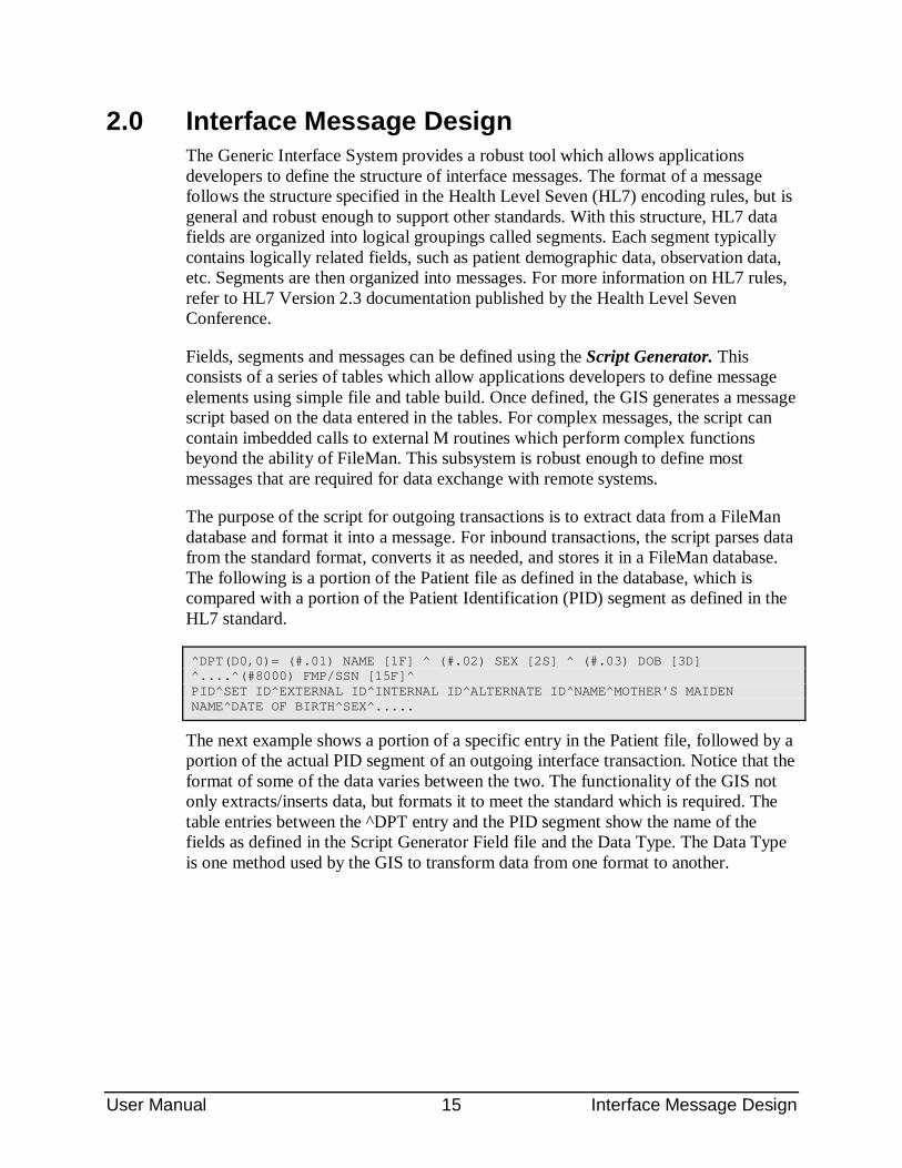
The purpose of the script for outgoing transactions is to extract data from a FileMan database and format it into a message. For inbound transactions, the script parses data from the standard format, converts it as needed, and stores it in a FileMan database. The following is a portion of the Patient file as defined in the database, which is compared with a portion of the Patient Identification (PID) segment as defined in the HL7 standard.
^DPT(D0,0)= (#.01) NAME [1F] ^ (#.02) SEX [2S] ^ (#.03) DOB [3D] ^....^(#8000) FMP/SSN [15F]^ PID^SET ID^EXTERNAL ID^INTERNAL ID^ALTERNATE ID^NAME^MOTHER’S MAIDEN NAME^DATE OF BIRTH^SEX^.....
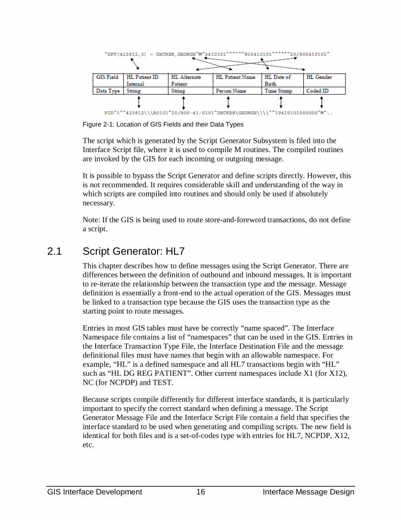
The next example shows a portion of a specific entry in the Patient file, followed by a portion of the actual PID segment of an outgoing interface transaction. Notice that the format of some of the data varies between the two. The functionality of the GIS not only extracts/inserts data, but formats it to meet the standard which is required. The table entries between the ^DPT entry and the PID segment show the name of the fields as defined in the Script Generator Field file and the Data Type. The Data Type is one method used by the GIS to transform data from one format to another.
GIS Interface Development 16 Interface Message Design
Figure 2-1: Location of GIS Fields and their Data Types
The script which is generated by the Script Generator Subsystem is filed into the Interface Script file, where it is used to compile M routines. The compiled routines are invoked by the GIS for each incoming or outgoing message.
It is possible to bypass the Script Generator and define scripts directly. However, this is not recommended. It requires considerable skill and understanding of the way in which scripts are compiled into routines and should only be used if absolutely necessary.
Note: If the GIS is being used to route store-and-foreword transactions, do not define a script.
2.1 Script Generator: HL7 This chapter describes how to define messages using the Script Generator. There are differences between the definition of outbound and inbound messages. It is important to re-iterate the relationship between the transaction type and the message. Message definition is essentially a front-end to the actual operation of the GIS. Messages must be linked to a transaction type because the GIS uses the transaction type as the starting point to route messages.
Entries in most GIS tables must have be correctly “name spaced”. The Interface Namespace file contains a list of “namespaces” that can be used in the GIS. Entries in the Interface Transaction Type File, the Interface Destination File and the message definitional files must have names that begin with an allowable namespace. For example, “HL” is a defined namespace and all HL7 transactions begin with “HL” such as “HL DG REG PATIENT”. Other current namespaces include X1 (for X12), NC (for NCPDP) and TEST.
Because scripts compile differently for different interface standards, it is particularly important to specify the correct standard when defining a message. The Script Generator Message File and the Interface Script File contain a field that specifies the interface standard to be used when generating and compiling scripts. The new field is identical for both files and is a set-of-codes type with entries for HL7, NCPDP, X12, etc.
GIS Interface Development 17 Interface Message Design
The field is specified as an “identifier”. This means that the user is automatically prompted to make an entry in this field the first (and only the first) time they create a message. Once they make an entry in this field, the code will take them to the proper message definition screen. They will never be prompted again, nor will they be able to modify the “standard” being used other than through fileman. The value stored in the message file is automatically carried forward into the script file.
2.1.1 HL7 Summary The GIS is a generalized interface tool. It is not specific to the Health Level Seven (HL7) standard but it supports HL7 specifications. For example, the subsystem will create the
HL7-specific MSH (message header) segment on outgoing messages using HL7-specific MSH fields.
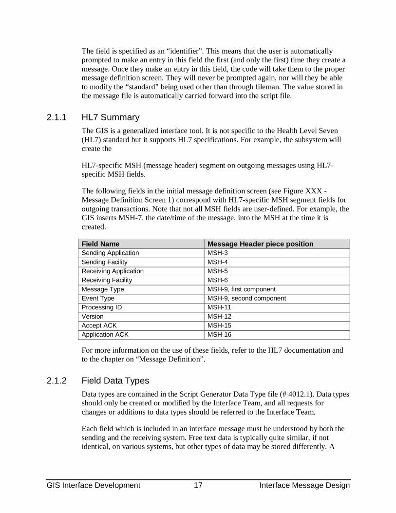
The following fields in the initial message definition screen (see Figure XXX - Message Definition Screen 1) correspond with HL7-specific MSH segment fields for outgoing transactions. Note that not all MSH fields are user-defined. For example, the GIS inserts MSH-7, the date/time of the message, into the MSH at the time it is created.
Field Name Message Header piece position Sending Application MSH-3 Sending Facility MSH-4 Receiving Application MSH-5 Receiving Facility MSH-6 Message Type MSH-9, first component Event Type MSH-9, second component Processing ID MSH-11 Version MSH-12 Accept ACK MSH-15 Application ACK MSH-16
For more information on the use of these fields, refer to the HL7 documentation and to the chapter on “Message Definition”.
2.1.2 Field Data Types Data types are contained in the Script Generator Data Type file (# 4012.1). Data types should only be created or modified by the Interface Team, and all requests for changes or additions to data types should be referred to the Interface Team.
Each field which is included in an interface message must be understood by both the sending and the receiving system. Free text data is typically quite similar, if not identical, on various systems, but other types of data may be stored differently. A
GIS Interface Development 18 Interface Message Design
date, for example, may be stored as 2950614 in a FileMan system, 06141995 in a second, 6/14/95 in a third, etc.
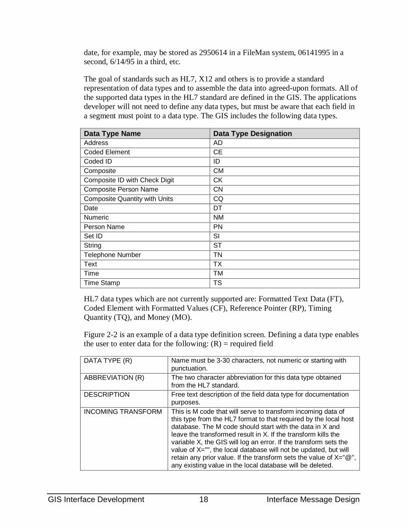
The goal of standards such as HL7, X12 and others is to provide a standard representation of data types and to assemble the data into agreed-upon formats. All of the supported data types in the HL7 standard are defined in the GIS. The applications developer will not need to define any data types, but must be aware that each field in a segment must point to a data type. The GIS includes the following data types.
Data Type Name Data Type Designation Address AD Coded Element CE Coded ID ID Composite CM Composite ID with Check Digit CK Composite Person Name CN Composite Quantity with Units CQ Date DT Numeric NM Person Name PN Set ID SI String ST Telephone Number TN Text TX Time TM Time Stamp TS
HL7 data types which are not currently supported are: Formatted Text Data (FT), Coded Element with Formatted Values (CF), Reference Pointer (RP), Timing Quantity (TQ), and Money (MO).
Figure 2-2 is an example of a data type definition screen. Defining a data type enables the user to enter data for the following: (R) = required field
DATA TYPE (R) Name must be 3-30 characters, not numeric or starting with punctuation.
ABBREVIATION (R) The two character abbreviation for this data type obtained from the HL7 standard.
DESCRIPTION Free text description of the field data type for documentation purposes.
INCOMING TRANSFORM This is M code that will serve to transform incoming data of this type from the HL7 format to that required by the local host database. The M code should start with the data in X and leave the transformed result in X. If the transform kills the variable X, the GIS will log an error. If the transform sets the value of X="", the local database will not be updated, but will retain any prior value. If the transform sets the value of X="@", any existing value in the local database will be deleted.
GIS Interface Development 19 Interface Message Design
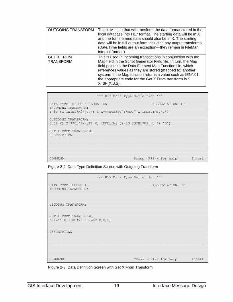
OUTGOING TRANSFORM This is M code that will transform the data format stored in the local database into HL7 format. The starting data will be in X and the transformed data should also be in X. The starting data will be in full output form including any output transforms. (Date/Time fields are an exception—they remain in FileMan internal format.)
GET X FROM TRANSFORM
This is used in Incoming transactions in conjunction with the Map field in the Script Generator Field file. In turn, the Map field points to the Data Element Map Function file, which references values as they are stored (mapped to) another system. If the Map function returns a value such as IEN^.01, the appropriate code for the Get X From transform is S X=$P(X,U,2).
*** HL7 Data Type Definition *** DATA TYPE: HL CODED LOCATION ABBREVIATION: CE INCOMING TRANSFORM: I $P($G(INTHL7F2),U,4) S X=$$SUBESC^INHUT7(X,INDELIMS,"I") OUTGOING TRANSFORM: S:$L(X) X=$$CL^INHUT1(X,.INDELIMS,$P($G(INTHL7F2),U,4),"O") GET X FROM TRANSFORM: DESCRIPTION: ___________________________________________________________________________ COMMAND: Press <PF1>H for help Insert
Figure 2-2: Data Type Definition Screen with Outgoing Transform
*** HL7 Data Type Definition *** DATA TYPE: CODED ID ABBREVIATION: ID INCOMING TRANSFORM: UTGOING TRANSFORM: GET X FROM TRANSFORM: K:X="" X I $D(X) S X=$P(X,U,2) DESCRIPTION: ___________________________________________________________________________ COMMAND: Press <PF1>H for help Insert
Figure 2-3: Data Definition Screen with Get X From Transform
GIS Interface Development 20 Interface Message Design
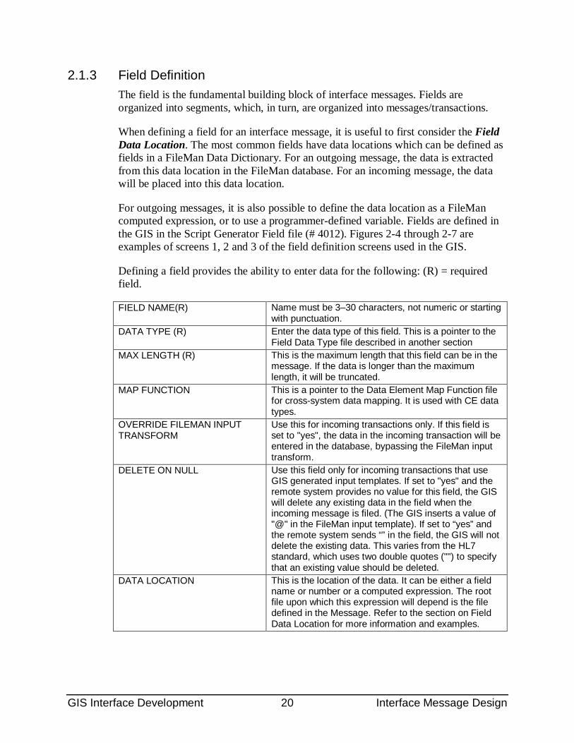
2.1.3 Field Definition The field is the fundamental building block of interface messages. Fields are organized into segments, which, in turn, are organized into messages/transactions.
When defining a field for an interface message, it is useful to first consider the Field Data Location. The most common fields have data locations which can be defined as fields in a FileMan Data Dictionary. For an outgoing message, the data is extracted from this data location in the FileMan database. For an incoming message, the data will be placed into this data location.
For outgoing messages, it is also possible to define the data location as a FileMan computed expression, or to use a programmer-defined variable. Fields are defined in the GIS in the Script Generator Field file (# 4012). Figures 2-4 through 2-7 are examples of screens 1, 2 and 3 of the field definition screens used in the GIS.
Defining a field provides the ability to enter data for the following: (R) = required field.
FIELD NAME(R) Name must be 3–30 characters, not numeric or starting with punctuation.
DATA TYPE (R) Enter the data type of this field. This is a pointer to the Field Data Type file described in another section
MAX LENGTH (R) This is the maximum length that this field can be in the message. If the data is longer than the maximum length, it will be truncated.
MAP FUNCTION This is a pointer to the Data Element Map Function file for cross-system data mapping. It is used with CE data types.
OVERRIDE FILEMAN INPUT TRANSFORM
Use this for incoming transactions only. If this field is set to "yes", the data in the incoming transaction will be entered in the database, bypassing the FileMan input transform.
DELETE ON NULL Use this field only for incoming transactions that use GIS generated input templates. If set to "yes" and the remote system provides no value for this field, the GIS will delete any existing data in the field when the incoming message is filed. (The GIS inserts a value of "@" in the FileMan input template). If set to “yes” and the remote system sends “” in the field, the GIS will not delete the existing data. This varies from the HL7 standard, which uses two double quotes ("") to specify that an existing value should be deleted.
DATA LOCATION This is the location of the data. It can be either a field name or number or a computed expression. The root file upon which this expression will depend is the file defined in the Message. Refer to the section on Field Data Location for more information and examples.
GIS Interface Development 21 Interface Message Design
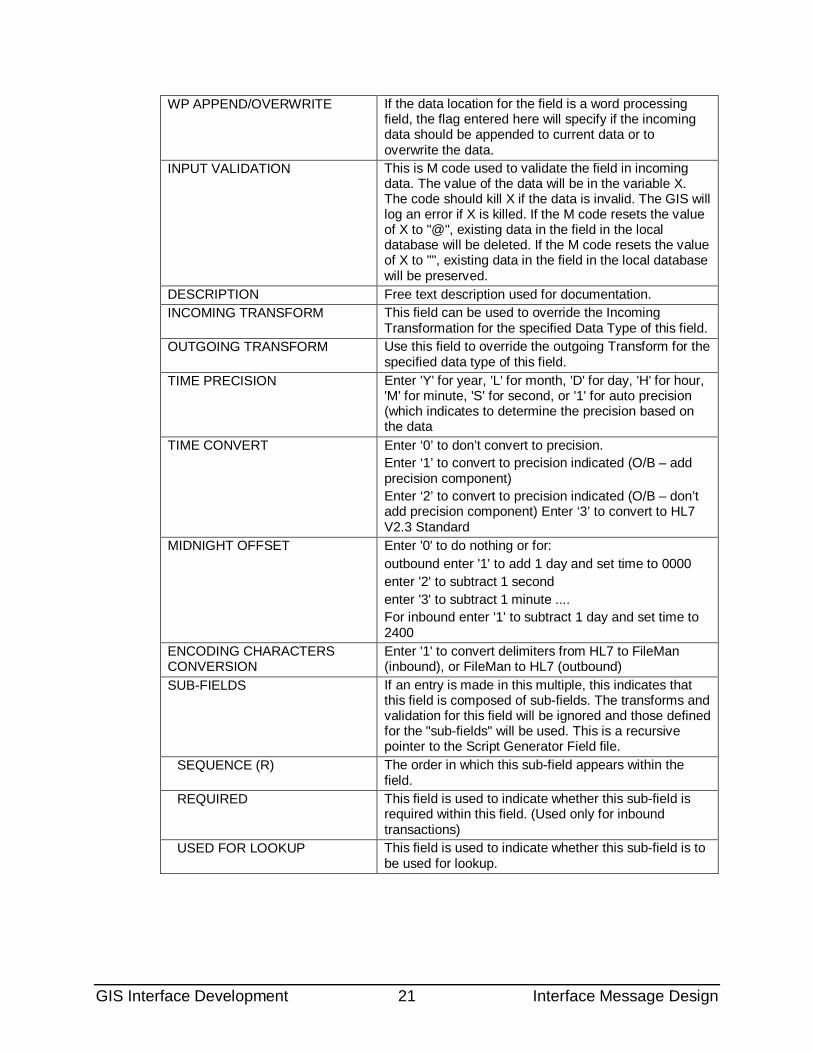
WP APPEND/OVERWRITE If the data location for the field is a word processing field, the flag entered here will specify if the incoming data should be appended to current data or to overwrite the data.
INPUT VALIDATION This is M code used to validate the field in incoming data. The value of the data will be in the variable X. The code should kill X if the data is invalid. The GIS will log an error if X is killed. If the M code resets the value of X to "@", existing data in the field in the local database will be deleted. If the M code resets the value of X to "", existing data in the field in the local database will be preserved.
DESCRIPTION Free text description used for documentation. INCOMING TRANSFORM This field can be used to override the Incoming
Transformation for the specified Data Type of this field. OUTGOING TRANSFORM Use this field to override the outgoing Transform for the
specified data type of this field. TIME PRECISION Enter 'Y' for year, 'L' for month, 'D' for day, 'H' for hour,
'M' for minute, 'S' for second, or '1' for auto precision (which indicates to determine the precision based on the data
TIME CONVERT Enter ‘0’ to don’t convert to precision. Enter ‘1’ to convert to precision indicated (O/B – add precision component) Enter ‘2’ to convert to precision indicated (O/B – don’t add precision component) Enter ‘3’ to convert to HL7 V2.3 Standard
MIDNIGHT OFFSET Enter '0' to do nothing or for: outbound enter '1' to add 1 day and set time to 0000 enter '2' to subtract 1 second enter '3' to subtract 1 minute .... For inbound enter '1' to subtract 1 day and set time to 2400
ENCODING CHARACTERS CONVERSION
Enter '1' to convert delimiters from HL7 to FileMan (inbound), or FileMan to HL7 (outbound)
SUB-FIELDS If an entry is made in this multiple, this indicates that this field is composed of sub-fields. The transforms and validation for this field will be ignored and those defined for the "sub-fields" will be used. This is a recursive pointer to the Script Generator Field file.
SEQUENCE (R) The order in which this sub-field appears within the field.
REQUIRED This field is used to indicate whether this sub-field is required within this field. (Used only for inbound transactions)
USED FOR LOOKUP This field is used to indicate whether this sub-field is to be used for lookup.
GIS Interface Development 22 Interface Message Design
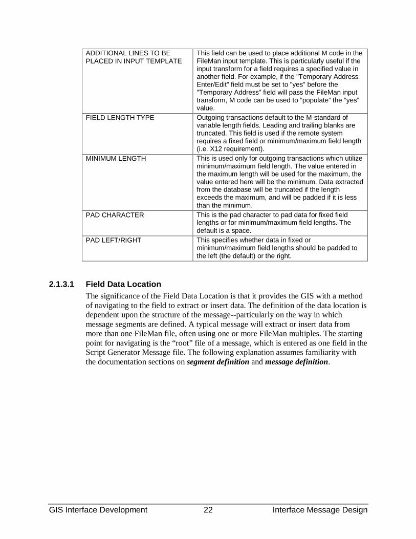
ADDITIONAL LINES TO BE PLACED IN INPUT TEMPLATE
This field can be used to place additional M code in the FileMan input template. This is particularly useful if the input transform for a field requires a specified value in another field. For example, if the "Temporary Address Enter/Edit" field must be set to "yes" before the "Temporary Address" field will pass the FileMan input transform, M code can be used to “populate” the “yes” value.
FIELD LENGTH TYPE Outgoing transactions default to the M-standard of variable length fields. Leading and trailing blanks are truncated. This field is used if the remote system requires a fixed field or minimum/maximum field length (i.e. X12 requirement).
MINIMUM LENGTH This is used only for outgoing transactions which utilize minimum/maximum field length. The value entered in the maximum length will be used for the maximum, the value entered here will be the minimum. Data extracted from the database will be truncated if the length exceeds the maximum, and will be padded if it is less than the minimum.
PAD CHARACTER This is the pad character to pad data for fixed field lengths or for minimum/maximum field lengths. The default is a space.
PAD LEFT/RIGHT This specifies whether data in fixed or minimum/maximum field lengths should be padded to the left (the default) or the right.
2.1.3.1 Field Data Location The significance of the Field Data Location is that it provides the GIS with a method of navigating to the field to extract or insert data. The definition of the data location is dependent upon the structure of the message--particularly on the way in which message segments are defined. A typical message will extract or insert data from more than one FileMan file, often using one or more FileMan multiples. The starting point for navigating is the “root” file of a message, which is entered as one field in the Script Generator Message file. The following explanation assumes familiarity with the documentation sections on segment definition and message definition.
GIS Interface Development 23 Interface Message Design
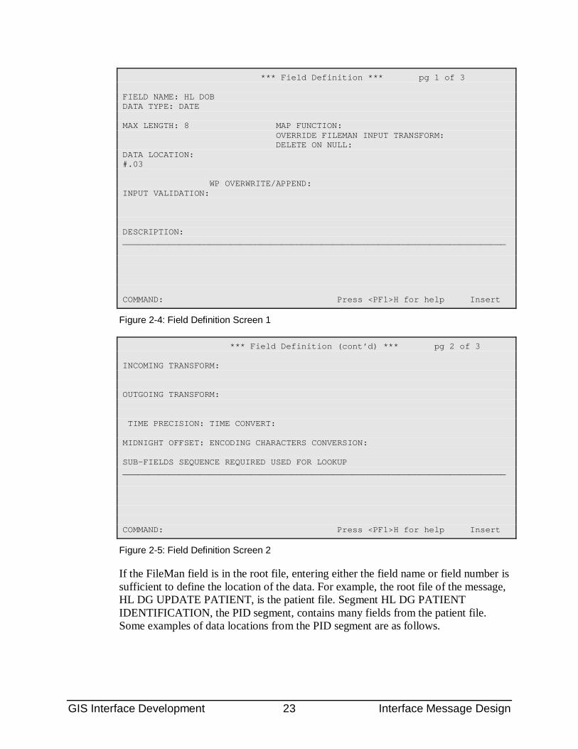
*** Field Definition *** pg 1 of 3 FIELD NAME: HL DOB DATA TYPE: DATE MAX LENGTH: 8 MAP FUNCTION: OVERRIDE FILEMAN INPUT TRANSFORM: DELETE ON NULL: DATA LOCATION: #.03 WP OVERWRITE/APPEND: INPUT VALIDATION: DESCRIPTION: ___________________________________________________________________________ COMMAND: Press <PF1>H for help Insert
Figure 2-4: Field Definition Screen 1
*** Field Definition (cont’d) *** pg 2 of 3 INCOMING TRANSFORM: OUTGOING TRANSFORM: TIME PRECISION: TIME CONVERT: MIDNIGHT OFFSET: ENCODING CHARACTERS CONVERSION: SUB-FIELDS SEQUENCE REQUIRED USED FOR LOOKUP ___________________________________________________________________________ COMMAND: Press <PF1>H for help Insert
Figure 2-5: Field Definition Screen 2
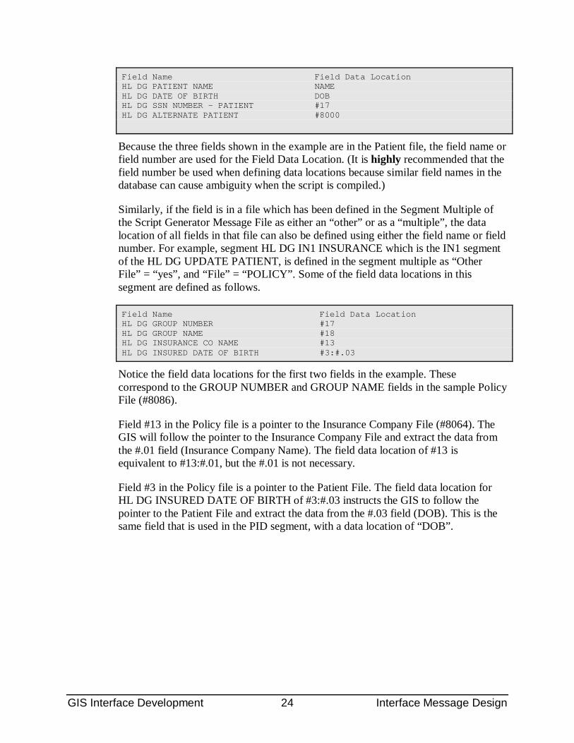
If the FileMan field is in the root file, entering either the field name or field number is sufficient to define the location of the data. For example, the root file of the message, HL DG UPDATE PATIENT, is the patient file. Segment HL DG PATIENT IDENTIFICATION, the PID segment, contains many fields from the patient file. Some examples of data locations from the PID segment are as follows.
GIS Interface Development 24 Interface Message Design
Field Name Field Data Location HL DG PATIENT NAME NAME HL DG DATE OF BIRTH DOB HL DG SSN NUMBER - PATIENT #17 HL DG ALTERNATE PATIENT #8000
Because the three fields shown in the example are in the Patient file, the field name or field number are used for the Field Data Location. (It is highly recommended that the field number be used when defining data locations because similar field names in the database can cause ambiguity when the script is compiled.)
Similarly, if the field is in a file which has been defined in the Segment Multiple of the Script Generator Message File as either an “other” or as a “multiple”, the data location of all fields in that file can also be defined using either the field name or field number. For example, segment HL DG IN1 INSURANCE which is the IN1 segment of the HL DG UPDATE PATIENT, is defined in the segment multiple as “Other File” = “yes”, and “File” = “POLICY”. Some of the field data locations in this segment are defined as follows.
Field Name Field Data Location HL DG GROUP NUMBER #17 HL DG GROUP NAME #18 HL DG INSURANCE CO NAME #13 HL DG INSURED DATE OF BIRTH #3:#.03
Notice the field data locations for the first two fields in the example. These correspond to the GROUP NUMBER and GROUP NAME fields in the sample Policy File (#8086).
Field #13 in the Policy file is a pointer to the Insurance Company File (#8064). The GIS will follow the pointer to the Insurance Company File and extract the data from the #.01 field (Insurance Company Name). The field data location of #13 is equivalent to #13:#.01, but the #.01 is not necessary.
Field #3 in the Policy file is a pointer to the Patient File. The field data location for HL DG INSURED DATE OF BIRTH of #3:#.03 instructs the GIS to follow the pointer to the Patient File and extract the data from the #.03 field (DOB). This is the same field that is used in the PID segment, with a data location of “DOB”.
GIS Interface Development 25 Interface Message Design
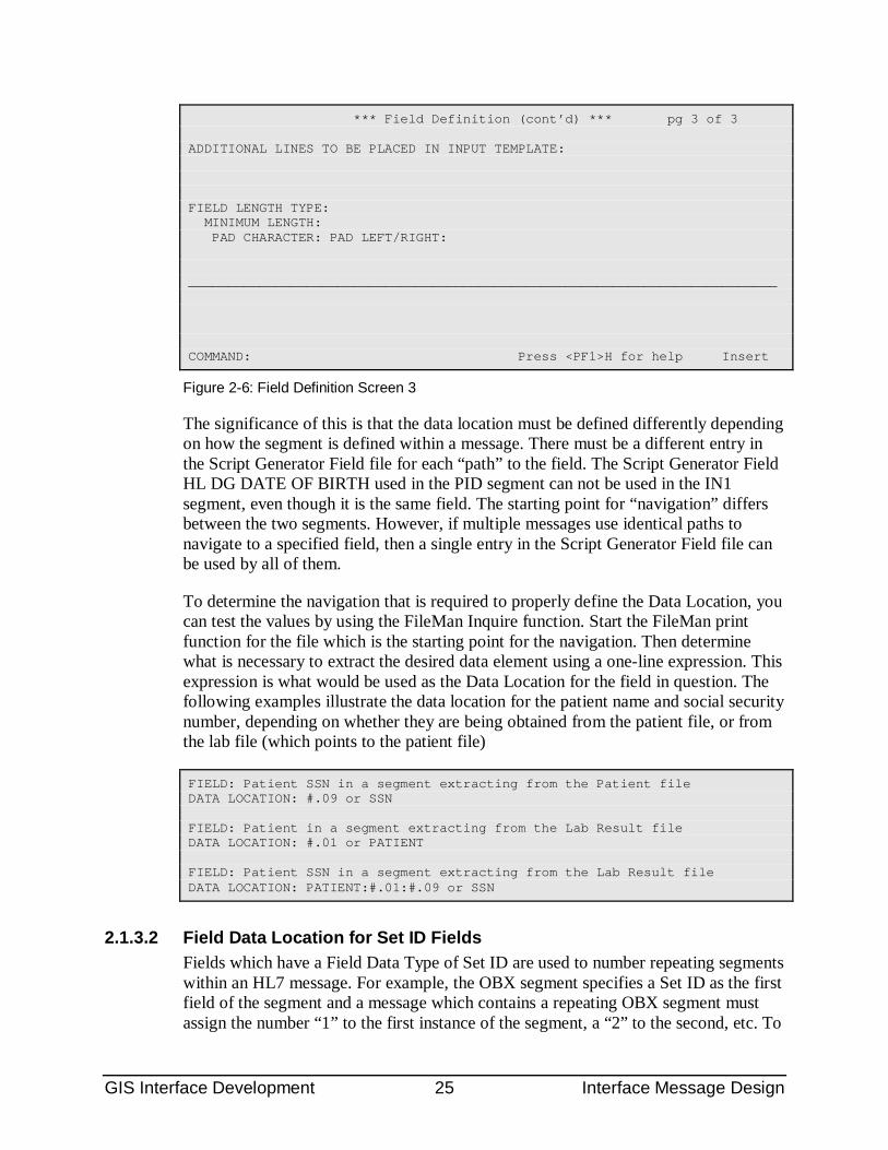
*** Field Definition (cont’d) *** pg 3 of 3 ADDITIONAL LINES TO BE PLACED IN INPUT TEMPLATE: FIELD LENGTH TYPE: MINIMUM LENGTH: PAD CHARACTER: PAD LEFT/RIGHT: ___________________________________________________________________________ COMMAND: Press <PF1>H for help Insert
Figure 2-6: Field Definition Screen 3
The significance of this is that the data location must be defined differently depending on how the segment is defined within a message. There must be a different entry in the Script Generator Field file for each “path” to the field. The Script Generator Field HL DG DATE OF BIRTH used in the PID segment can not be used in the IN1 segment, even though it is the same field. The starting point for “navigation” differs between the two segments. However, if multiple messages use identical paths to navigate to a specified field, then a single entry in the Script Generator Field file can be used by all of them.
To determine the navigation that is required to properly define the Data Location, you can test the values by using the FileMan Inquire function. Start the FileMan print function for the file which is the starting point for the navigation. Then determine what is necessary to extract the desired data element using a one-line expression. This expression is what would be used as the Data Location for the field in question. The following examples illustrate the data location for the patient name and social security number, depending on whether they are being obtained from the patient file, or from the lab file (which points to the patient file)
FIELD: Patient SSN in a segment extracting from the Patient file DATA LOCATION: #.09 or SSN FIELD: Patient in a segment extracting from the Lab Result file DATA LOCATION: #.01 or PATIENT FIELD: Patient SSN in a segment extracting from the Lab Result file DATA LOCATION: PATIENT:#.01:#.09 or SSN
2.1.3.2 Field Data Location for Set ID Fields Fields which have a Field Data Type of Set ID are used to number repeating segments within an HL7 message. For example, the OBX segment specifies a Set ID as the first field of the segment and a message which contains a repeating OBX segment must assign the number “1” to the first instance of the segment, a “2” to the second, etc. To
GIS Interface Development 26 Interface Message Design
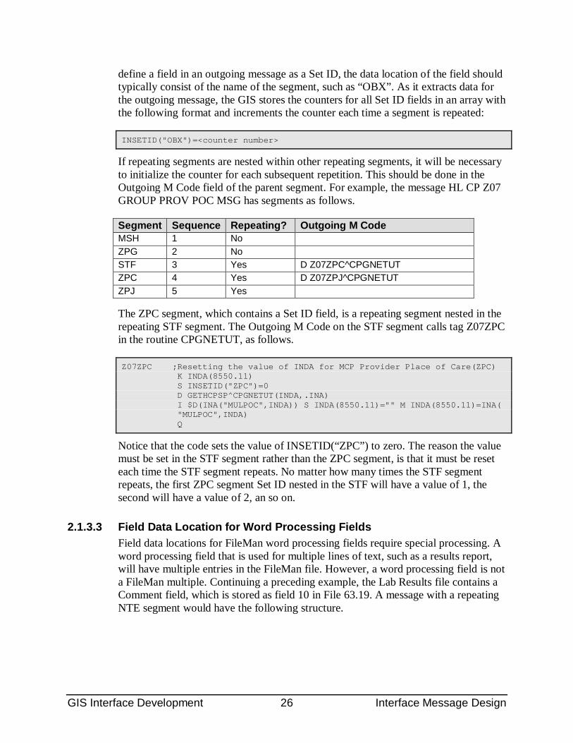
define a field in an outgoing message as a Set ID, the data location of the field should typically consist of the name of the segment, such as “OBX”. As it extracts data for the outgoing message, the GIS stores the counters for all Set ID fields in an array with the following format and increments the counter each time a segment is repeated:
INSETID("OBX")=<counter number>
If repeating segments are nested within other repeating segments, it will be necessary to initialize the counter for each subsequent repetition. This should be done in the Outgoing M Code field of the parent segment. For example, the message HL CP Z07 GROUP PROV POC MSG has segments as follows.
Segment Sequence Repeating? Outgoing M Code MSH 1 No ZPG 2 No STF 3 Yes D Z07ZPC^CPGNETUT ZPC 4 Yes D Z07ZPJ^CPGNETUT ZPJ 5 Yes
The ZPC segment, which contains a Set ID field, is a repeating segment nested in the repeating STF segment. The Outgoing M Code on the STF segment calls tag Z07ZPC in the routine CPGNETUT, as follows.
Z07ZPC ;Resetting the value of INDA for MCP Provider Place of Care(ZPC) K INDA(8550.11) S INSETID("ZPC")=0 D GETHCPSP^CPGNETUT(INDA,.INA) I $D(INA("MULPOC",INDA)) S INDA(8550.11)="" M INDA(8550.11)=INA( "MULPOC",INDA) Q
Notice that the code sets the value of INSETID(“ZPC”) to zero. The reason the value must be set in the STF segment rather than the ZPC segment, is that it must be reset each time the STF segment repeats. No matter how many times the STF segment repeats, the first ZPC segment Set ID nested in the STF will have a value of 1, the second will have a value of 2, an so on.
2.1.3.3 Field Data Location for Word Processing Fields Field data locations for FileMan word processing fields require special processing. A word processing field that is used for multiple lines of text, such as a results report, will have multiple entries in the FileMan file. However, a word processing field is not a FileMan multiple. Continuing a preceding example, the Lab Results file contains a Comment field, which is stored as field 10 in File 63.19. A message with a repeating NTE segment would have the following structure.
GIS Interface Development 27 Interface Message Design
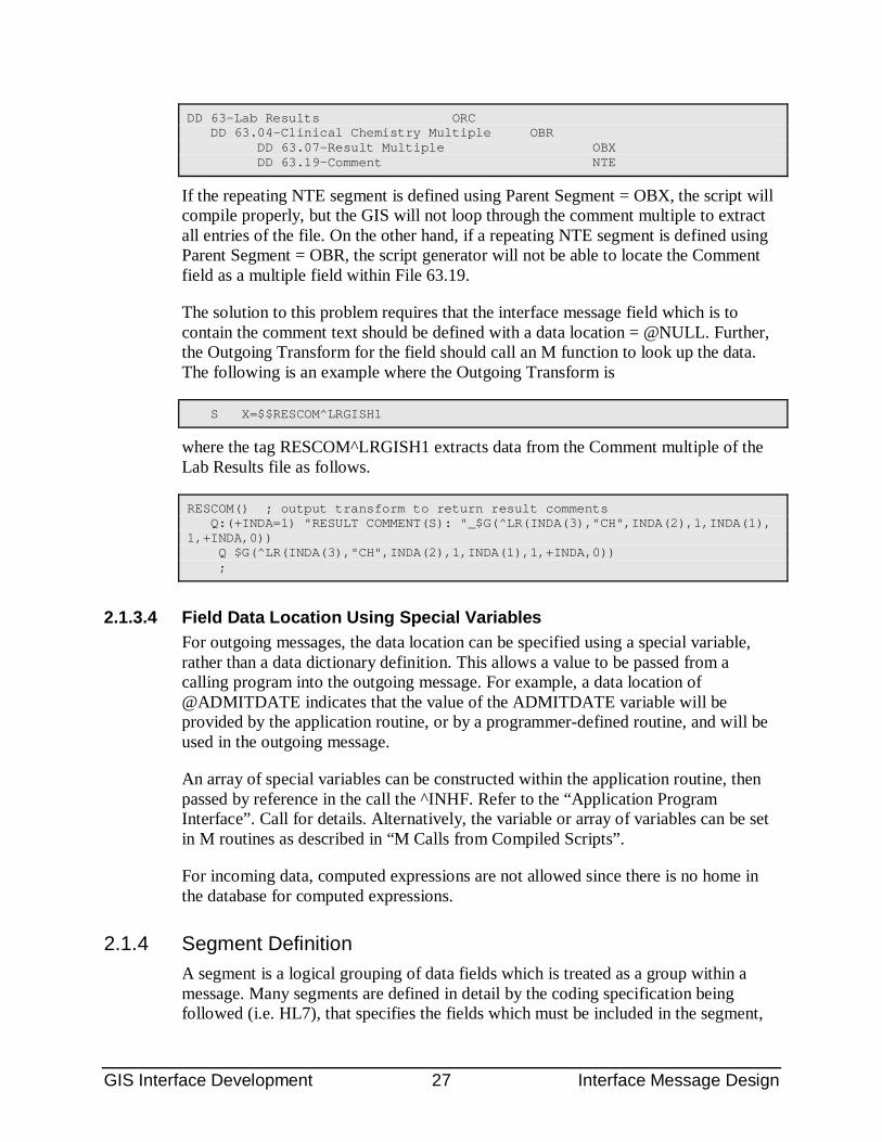
DD 63-Lab Results ORC DD 63.04-Clinical Chemistry Multiple OBR DD 63.07-Result Multiple OBX DD 63.19-Comment NTE
If the repeating NTE segment is defined using Parent Segment = OBX, the script will compile properly, but the GIS will not loop through the comment multiple to extract all entries of the file. On the other hand, if a repeating NTE segment is defined using Parent Segment = OBR, the script generator will not be able to locate the Comment field as a multiple field within File 63.19.
The solution to this problem requires that the interface message field which is to contain the comment text should be defined with a data location = @NULL. Further, the Outgoing Transform for the field should call an M function to look up the data. The following is an example where the Outgoing Transform is
S X=$$RESCOM^LRGISH1
where the tag RESCOM^LRGISH1 extracts data from the Comment multiple of the Lab Results file as follows.
RESCOM() ; output transform to return result comments Q:(+INDA=1) "RESULT COMMENT(S): "_$G(^LR(INDA(3),"CH",INDA(2),1,INDA(1), 1,+INDA,0)) Q $G(^LR(INDA(3),"CH",INDA(2),1,INDA(1),1,+INDA,0)) ;
2.1.3.4 Field Data Location Using Special Variables For outgoing messages, the data location can be specified using a special variable, rather than a data dictionary definition. This allows a value to be passed from a calling program into the outgoing message. For example, a data location of @ADMITDATE indicates that the value of the ADMITDATE variable will be provided by the application routine, or by a programmer-defined routine, and will be used in the outgoing message.
An array of special variables can be constructed within the application routine, then passed by reference in the call the ^INHF. Refer to the “Application Program Interface”. Call for details. Alternatively, the variable or array of variables can be set in M routines as described in “M Calls from Compiled Scripts”.
For incoming data, computed expressions are not allowed since there is no home in the database for computed expressions.
2.1.4 Segment Definition A segment is a logical grouping of data fields which is treated as a group within a message. Many segments are defined in detail by the coding specification being followed (i.e. HL7), that specifies the fields which must be included in the segment,
GIS Interface Development 28 Interface Message Design
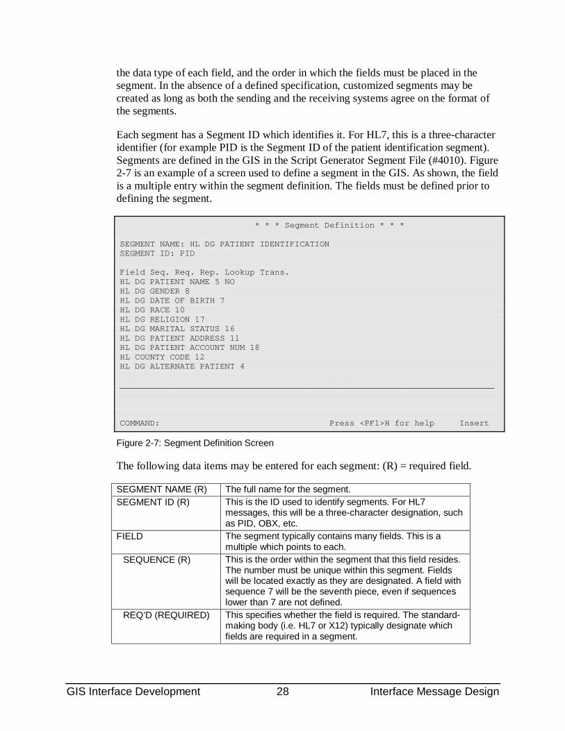
the data type of each field, and the order in which the fields must be placed in the segment. In the absence of a defined specification, customized segments may be created as long as both the sending and the receiving systems agree on the format of the segments.
Each segment has a Segment ID which identifies it. For HL7, this is a three-character identifier (for example PID is the Segment ID of the patient identification segment). Segments are defined in the GIS in the Script Generator Segment File (#4010). Figure 2-7 is an example of a screen used to define a segment in the GIS. As shown, the field is a multiple entry within the segment definition. The fields must be defined prior to defining the segment.
* * * Segment Definition * * * SEGMENT NAME: HL DG PATIENT IDENTIFICATION SEGMENT ID: PID Field Seq. Req. Rep. Lookup Trans. HL DG PATIENT NAME 5 NO HL DG GENDER 8 HL DG DATE OF BIRTH 7 HL DG RACE 10 HL DG RELIGION 17 HL DG MARITAL STATUS 16 HL DG PATIENT ADDRESS 11 HL DG PATIENT ACCOUNT NUM 18 HL COUNTY CODE 12 HL DG ALTERNATE PATIENT 4 ___________________________________________________________________________ COMMAND: Press <PF1>H for help Insert
Figure 2-7: Segment Definition Screen
The following data items may be entered for each segment: (R) = required field.
SEGMENT NAME (R) The full name for the segment. SEGMENT ID (R) This is the ID used to identify segments. For HL7
messages, this will be a three-character designation, such as PID, OBX, etc.
FIELD The segment typically contains many fields. This is a multiple which points to each.
SEQUENCE (R) This is the order within the segment that this field resides. The number must be unique within this segment. Fields will be located exactly as they are designated. A field with sequence 7 will be the seventh piece, even if sequences lower than 7 are not defined.
REQ’D (REQUIRED) This specifies whether the field is required. The standard-making body (i.e. HL7 or X12) typically designate which fields are required in a segment.
GIS Interface Development 29 Interface Message Design
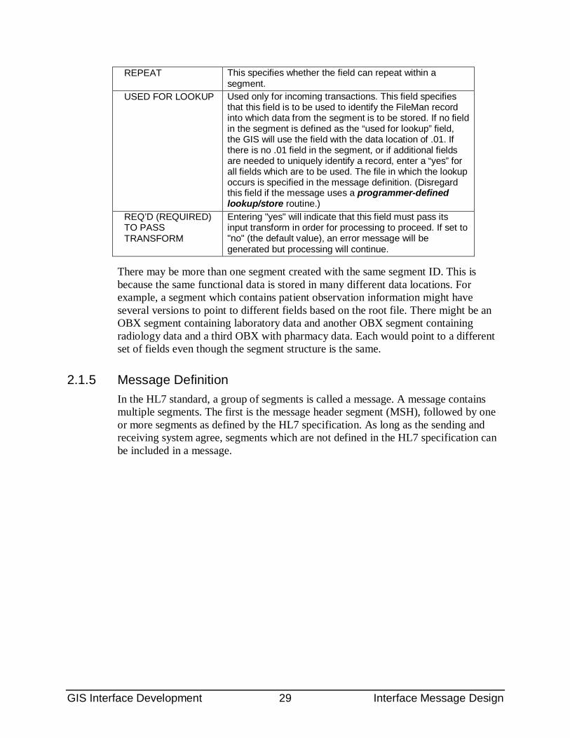
REPEAT This specifies whether the field can repeat within a segment.
USED FOR LOOKUP Used only for incoming transactions. This field specifies that this field is to be used to identify the FileMan record into which data from the segment is to be stored. If no field in the segment is defined as the “used for lookup” field, the GIS will use the field with the data location of .01. If there is no .01 field in the segment, or if additional fields are needed to uniquely identify a record, enter a “yes” for all fields which are to be used. The file in which the lookup occurs is specified in the message definition. (Disregard this field if the message uses a programmer-defined lookup/store routine.)
REQ’D (REQUIRED) TO PASS TRANSFORM
Entering "yes" will indicate that this field must pass its input transform in order for processing to proceed. If set to "no" (the default value), an error message will be generated but processing will continue.
There may be more than one segment created with the same segment ID. This is because the same functional data is stored in many different data locations. For example, a segment which contains patient observation information might have several versions to point to different fields based on the root file. There might be an OBX segment containing laboratory data and another OBX segment containing radiology data and a third OBX with pharmacy data. Each would point to a different set of fields even though the segment structure is the same.
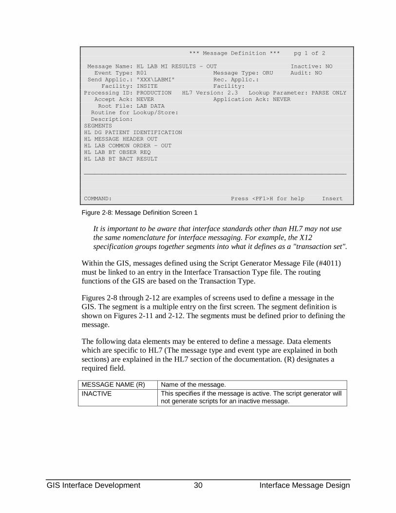
2.1.5 Message Definition In the HL7 standard, a group of segments is called a message. A message contains multiple segments. The first is the message header segment (MSH), followed by one or more segments as defined by the HL7 specification. As long as the sending and receiving system agree, segments which are not defined in the HL7 specification can be included in a message.
GIS Interface Development 30 Interface Message Design
*** Message Definition *** pg 1 of 2 Message Name: HL LAB MI RESULTS - OUT Inactive: NO Event Type: R01 Message Type: ORU Audit: NO Send Applic.: "XXX\LABMI" Rec. Applic.: Facility: INSITE Facility: Processing ID: PRODUCTION HL7 Version: 2.3 Lookup Parameter: PARSE ONLY Accept Ack: NEVER Application Ack: NEVER Root File: LAB DATA Routine for Lookup/Store: Description: SEGMENTS HL DG PATIENT IDENTIFICATION HL MESSAGE HEADER OUT HL LAB COMMON ORDER - OUT HL LAB BT OBSER REQ HL LAB BT BACT RESULT ___________________________________________________________________________ COMMAND: Press <PF1>H for help Insert
Figure 2-8: Message Definition Screen 1
It is important to be aware that interface standards other than HL7 may not use the same nomenclature for interface messaging. For example, the X12 specification groups together segments into what it defines as a "transaction set".
Within the GIS, messages defined using the Script Generator Message File (#4011) must be linked to an entry in the Interface Transaction Type file. The routing functions of the GIS are based on the Transaction Type.
Figures 2-8 through 2-12 are examples of screens used to define a message in the GIS. The segment is a multiple entry on the first screen. The segment definition is shown on Figures 2-11 and 2-12. The segments must be defined prior to defining the message.
The following data elements may be entered to define a message. Data elements which are specific to HL7 (The message type and event type are explained in both sections) are explained in the HL7 section of the documentation. (R) designates a required field.
MESSAGE NAME (R) Name of the message. INACTIVE This specifies if the message is active. The script generator will
not generate scripts for an inactive message.
GIS Interface Development 31 Interface Message Design
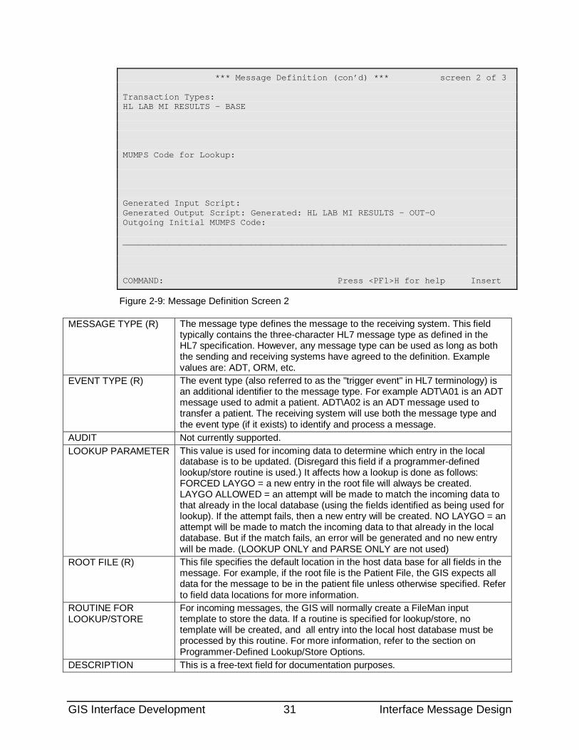
*** Message Definition (con’d) *** screen 2 of 3 Transaction Types: HL LAB MI RESULTS - BASE MUMPS Code for Lookup: Generated Input Script: Generated Output Script: Generated: HL LAB MI RESULTS - OUT-O Outgoing Initial MUMPS Code: ___________________________________________________________________________ COMMAND: Press <PF1>H for help Insert
Figure 2-9: Message Definition Screen 2
MESSAGE TYPE (R) The message type defines the message to the receiving system. This field typically contains the three-character HL7 message type as defined in the HL7 specification. However, any message type can be used as long as both the sending and receiving systems have agreed to the definition. Example values are: ADT, ORM, etc.
EVENT TYPE (R) The event type (also referred to as the "trigger event" in HL7 terminology) is an additional identifier to the message type. For example ADT\A01 is an ADT message used to admit a patient. ADT\A02 is an ADT message used to transfer a patient. The receiving system will use both the message type and the event type (if it exists) to identify and process a message.
AUDIT Not currently supported. LOOKUP PARAMETER This value is used for incoming data to determine which entry in the local
database is to be updated. (Disregard this field if a programmer-defined lookup/store routine is used.) It affects how a lookup is done as follows: FORCED LAYGO = a new entry in the root file will always be created. LAYGO ALLOWED = an attempt will be made to match the incoming data to that already in the local database (using the fields identified as being used for lookup). If the attempt fails, then a new entry will be created. NO LAYGO = an attempt will be made to match the incoming data to that already in the local database. But if the match fails, an error will be generated and no new entry will be made. (LOOKUP ONLY and PARSE ONLY are not used)
ROOT FILE (R) This file specifies the default location in the host data base for all fields in the message. For example, if the root file is the Patient File, the GIS expects all data for the message to be in the patient file unless otherwise specified. Refer to field data locations for more information.
ROUTINE FOR LOOKUP/STORE
For incoming messages, the GIS will normally create a FileMan input template to store the data. If a routine is specified for lookup/store, no template will be created, and all entry into the local host database must be processed by this routine. For more information, refer to the section on Programmer-Defined Lookup/Store Options.
DESCRIPTION This is a free-text field for documentation purposes.
GIS Interface Development 32 Interface Message Design
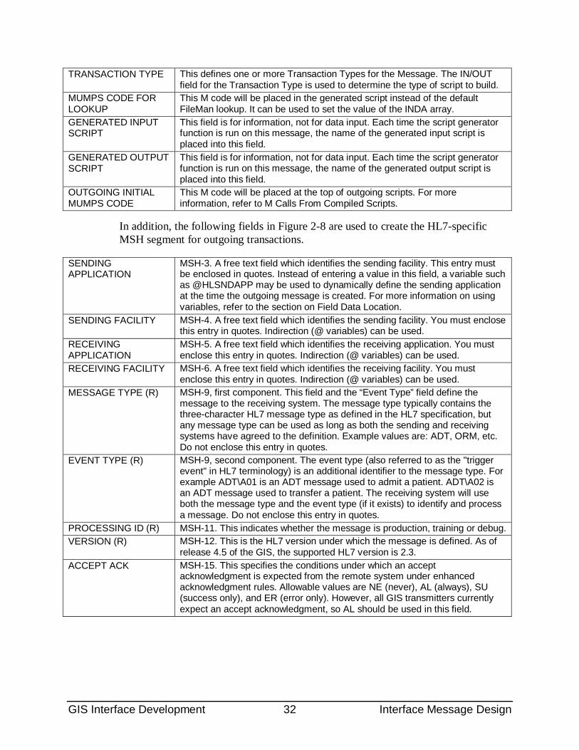
TRANSACTION TYPE This defines one or more Transaction Types for the Message. The IN/OUT field for the Transaction Type is used to determine the type of script to build.
MUMPS CODE FOR LOOKUP
This M code will be placed in the generated script instead of the default FileMan lookup. It can be used to set the value of the INDA array.
GENERATED INPUT SCRIPT
This field is for information, not for data input. Each time the script generator function is run on this message, the name of the generated input script is placed into this field.
GENERATED OUTPUT SCRIPT
This field is for information, not for data input. Each time the script generator function is run on this message, the name of the generated output script is placed into this field.
OUTGOING INITIAL MUMPS CODE
This M code will be placed at the top of outgoing scripts. For more information, refer to M Calls From Compiled Scripts.
In addition, the following fields in Figure 2-8 are used to create the HL7-specific MSH segment for outgoing transactions.
SENDING APPLICATION
MSH-3. A free text field which identifies the sending facility. This entry must be enclosed in quotes. Instead of entering a value in this field, a variable such as @HLSNDAPP may be used to dynamically define the sending application at the time the outgoing message is created. For more information on using variables, refer to the section on Field Data Location.
SENDING FACILITY MSH-4. A free text field which identifies the sending facility. You must enclose this entry in quotes. Indirection (@ variables) can be used.
RECEIVING APPLICATION
MSH-5. A free text field which identifies the receiving application. You must enclose this entry in quotes. Indirection (@ variables) can be used.
RECEIVING FACILITY MSH-6. A free text field which identifies the receiving facility. You must enclose this entry in quotes. Indirection (@ variables) can be used.
MESSAGE TYPE (R) MSH-9, first component. This field and the “Event Type” field define the message to the receiving system. The message type typically contains the three-character HL7 message type as defined in the HL7 specification, but any message type can be used as long as both the sending and receiving systems have agreed to the definition. Example values are: ADT, ORM, etc. Do not enclose this entry in quotes.
EVENT TYPE (R) MSH-9, second component. The event type (also referred to as the "trigger event" in HL7 terminology) is an additional identifier to the message type. For example ADT\A01 is an ADT message used to admit a patient. ADT\A02 is an ADT message used to transfer a patient. The receiving system will use both the message type and the event type (if it exists) to identify and process a message. Do not enclose this entry in quotes.
PROCESSING ID (R) MSH-11. This indicates whether the message is production, training or debug. VERSION (R) MSH-12. This is the HL7 version under which the message is defined. As of
release 4.5 of the GIS, the supported HL7 version is 2.3. ACCEPT ACK MSH-15. This specifies the conditions under which an accept
acknowledgment is expected from the remote system under enhanced acknowledgment rules. Allowable values are NE (never), AL (always), SU (success only), and ER (error only). However, all GIS transmitters currently expect an accept acknowledgment, so AL should be used in this field.
GIS Interface Development 33 Interface Message Design
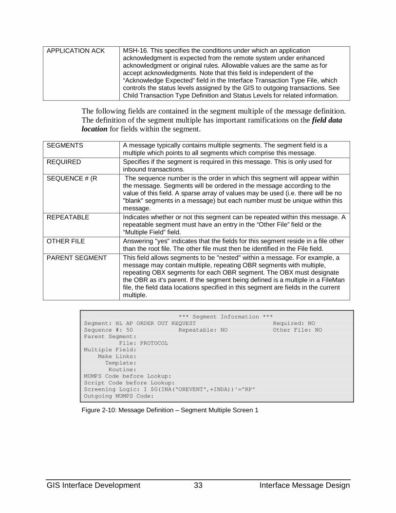
APPLICATION ACK MSH-16. This specifies the conditions under which an application acknowledgment is expected from the remote system under enhanced acknowledgment or original rules. Allowable values are the same as for accept acknowledgments. Note that this field is independent of the “Acknowledge Expected” field in the Interface Transaction Type File, which controls the status levels assigned by the GIS to outgoing transactions. See Child Transaction Type Definition and Status Levels for related information.
The following fields are contained in the segment multiple of the message definition. The definition of the segment multiple has important ramifications on the field data location for fields within the segment.
SEGMENTS A message typically contains multiple segments. The segment field is a multiple which points to all segments which comprise this message.
REQUIRED Specifies if the segment is required in this message. This is only used for inbound transactions.
SEQUENCE # (R The sequence number is the order in which this segment will appear within the message. Segments will be ordered in the message according to the value of this field. A sparse array of values may be used (i.e. there will be no "blank" segments in a message) but each number must be unique within this message.
REPEATABLE Indicates whether or not this segment can be repeated within this message. A repeatable segment must have an entry in the “Other File” field or the “Multiple Field” field.
OTHER FILE Answering "yes" indicates that the fields for this segment reside in a file other than the root file. The other file must then be identified in the File field.
PARENT SEGMENT This field allows segments to be "nested" within a message. For example, a message may contain multiple, repeating OBR segments with multiple, repeating OBX segments for each OBR segment. The OBX must designate the OBR as it's parent. If the segment being defined is a multiple in a FileMan file, the field data locations specified in this segment are fields in the current multiple.
*** Segment Information *** Segment: HL AP ORDER OUT REQUEST Required: NO Sequence #: 50 Repeatable: NO Other File: NO Parent Segment: File: PROTOCOL Multiple Field: Make Links: Template: Routine: MUMPS Code before Lookup: Script Code before Lookup: Screening Logic: I $G(INA("OREVENT",+INDA))'="RP" Outgoing MUMPS Code:
Figure 2-10: Message Definition – Segment Multiple Screen 1
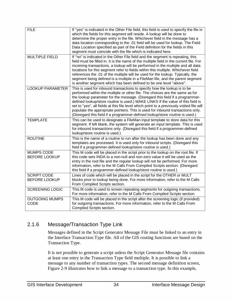
GIS Interface Development 34 Interface Message Design
FILE If "yes" is indicated in the Other File field, this field is used to specify the file in which the fields for this segment will reside. A lookup will be done to determine the proper entry in the file. Whichever field in the message has a data location corresponding to the .01 field will be used for lookup. The Field Data Location specified as part of the Field definition for the fields in this segment must coincide with the file which is indicated here.
MULTIPLE FIELD If "no" is indicated in the Other File field and the segment is repeating, this field must be filled in. It is the name of the multiple field in the current file. For incoming transactions, a lookup will be performed in the multiple and all data locations for this segment refer to fields within this multiple. Whichever field references the .01 of the multiple will be used for the lookup. Typically, the segment being defined is a multiple in a FileMan file, and the parent segment is another segment which has been defined to be one level "above".
LOOKUP PARAMETER This is used for inbound transactions to specify how the lookup is to be performed within the multiple or other file. The choices are the same as for the lookup parameter for the message. (Disregard this field if a programmer-defined lookup/store routine is used.) MAKE LINKS If the value of this field is set to "yes", all fields at this file level which point to a previously visited file will populate the appropriate pointers. This is used for inbound transactions only. (Disregard this field if a programmer-defined lookup/store routine is used.)
TEMPLATE This can be used to designate a FileMan input template to store data for this segment. If left blank, the system will generate an input template. This is used for inbound transactions only. (Disregard this field if a programmer-defined lookup/store routine is used.)
ROUTINE This is the name of a routine to run after the lookup has been done and any templates are processed. It is used only for inbound scripts. (Disregard this field if a programmer-defined lookup/store routine is used.)
MUMPS CODE BEFORE LOOKUP
This M code will be placed in the script prior to the lookup on the root file. If this code sets INDA to a non-null and non-zero value it will be used as the entry in the root file and the regular lookup will not be performed. For more information, refer to the M Calls From Compiled Scripts section. (Disregard this field if a programmer-defined lookup/store routine is used.)
SCRIPT CODE BEFORE LOOKUP
Lines of code which will be placed in the script for the OTHER or MULT blocks prior to lookup being done. For more information, refer to the M Calls From Compiled Scripts section.
SCREENING LOGIC This M code is used to screen repeating segments for outgoing transactions. For more information, refer to the M Calls From Compiled Scripts section.
OUTGOING MUMPS CODE
This M code will be placed in the script after the screening logic (if provided) for outgoing transactions. For more information, refer to the M Calls From Compiled Scripts section.
2.1.6 Message/Transaction Type Link Messages defined in the Script Generator Message File must be linked to an entry in the Interface Transaction Type file. All of the GIS routing functions are based on the Transaction Type.
It is not possible to generate a script unless the Script Generator Message file contains at least one entry in the Transaction Type field multiple. It is possible to link a message to any number of transaction types. The second message definition screen, Figure 2-9 illustrates how to link a message to a transaction type. In this example,
GIS Interface Development 35 Interface Message Design
several transaction types are created from this single message definition. The message generator creates a script for each transaction type. Once a script is generated and compiled, it is these Transaction Types which are routed through the GIS as part of the normal routing of interface messages.
The Message generator populates the field in the Interface Transaction Type file which points to the entry in the Interface Script file.
2.1.7 Incoming vs. Outgoing Transactions There are a number of differences between incoming and outgoing messages and transaction types. Some are obvious from the prompts on the various table definitions, while others are not. The following are some of the significant differences.
Outgoing transactions must have a parent transaction type which is called from the application. Incoming transactions have no parent transaction types.
The HL7 fields which are used to define the MSH segment are only used for outgoing transactions. Entries such as sending facility, receiving application, etc. are not used for incoming transactions.
For outgoing transactions, the data location entered in screen 1 of the field definition may consist of a variable such as @HLACKTYPE. The value for this variable is then passed into the outgoing script in a programmer-defined INA array. For incoming transactions, such indirection is not valid and the script will not compile. Developers may leave the data location blank and use logic in the programmer-defined lookup/store routine to update the database.
2.2 Script Generator X12 Modifications The GIS supports the X12 standard for interface messaging. In general, the process of defining and routing X12 messages is the same as for HL7 messages and it is recommended that the user read the preceding sections on HL7 messaging before proceeding to this section. However, there are important differences between the structures of X12 and HL7 messages that must be considered when building X12 messages in the GIS.
On difference is that the actual X12 transaction set is nested within three sets of "wrappers" or "control structures". Because X12 can be used for batch transmission, the outer set of wrappers (the ISA and IEA segments) wrap around a set of group wrappers (the GS and GE segments), which in turn wrap around the actual transaction (contained within the ST and SE segments). In batch mode, X12 allows multiple ST/SE pairs within a group, and multiple groups within the message.
The GIS does not support "batch" X12 transmissions that contain multiple X12 groups within an ISA/ISE wrapper, nor does it support multiple transactions within a group. Because of this, the GIS creates a single identifier for outbound
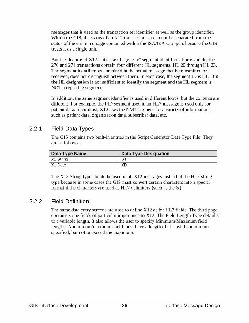
GIS Interface Development 36 Interface Message Design
messages that is used as the transaction set identifier as well as the group identifier. Within the GIS, the status of an X12 transaction set can not be separated from the status of the entire message contained within the ISA/IEA wrappers because the GIS treats it as a single unit.
Another feature of X12 is it's use of "generic" segment identifiers. For example, the 270 and 271 transactions contain four different HL segments, HL 20 through HL 23. The segment identifier, as contained in the actual message that is transmitted or received, does not distinguish between them. In each case, the segment ID is HL. But the HL designation is not sufficient to identify the segment and the HL segment is NOT a repeating segment.
In addition, the same segment identifier is used in different loops, but the contents are different. For example, the PID segment used in an HL7 message is used only for patient data. In contrast, X12 uses the NM1 segment for a variety of information, such as patient data, organization data, subscriber data, etc.
2.2.1 Field Data Types The GIS contains two built-in entries in the Script Generator Data Type File. They are as follows.
Data Type Name Data Type Designation X1 String ST X1 Date XD
The X12 String type should be used in all X12 messages instead of the HL7 string type because in some cases the GIS must convert certain characters into a special format if the characters are used as HL7 delimiters (such as the &).
2.2.2 Field Definition The same data entry screens are used to define X12 as for HL7 fields. The third page contains some fields of particular importance to X12. The Field Length Type defaults to a variable length. It also allows the user to specify Minimum/Maximum field lengths. A minimum/maximum field must have a length of at least the minimum specified, but not to exceed the maximum.
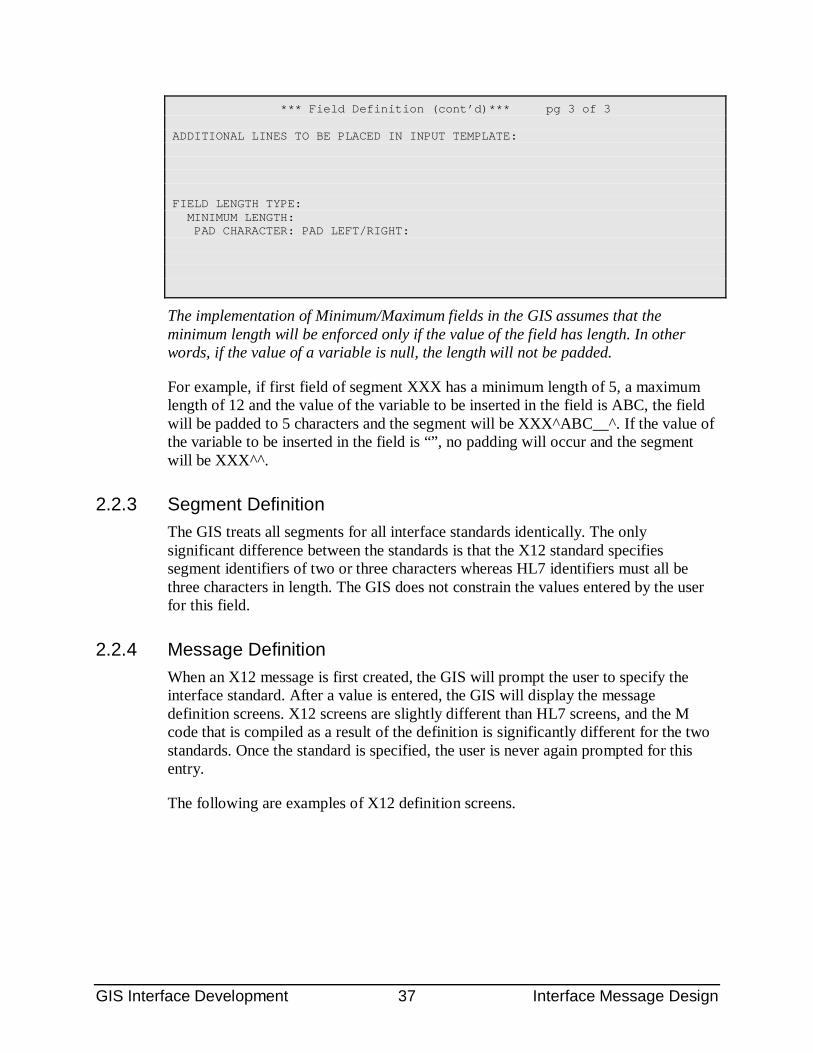
GIS Interface Development 37 Interface Message Design
*** Field Definition (cont’d)*** pg 3 of 3 ADDITIONAL LINES TO BE PLACED IN INPUT TEMPLATE: FIELD LENGTH TYPE: MINIMUM LENGTH: PAD CHARACTER: PAD LEFT/RIGHT:
The implementation of Minimum/Maximum fields in the GIS assumes that the minimum length will be enforced only if the value of the field has length. In other words, if the value of a variable is null, the length will not be padded.
For example, if first field of segment XXX has a minimum length of 5, a maximum length of 12 and the value of the variable to be inserted in the field is ABC, the field will be padded to 5 characters and the segment will be XXX^ABC__^. If the value of the variable to be inserted in the field is “”, no padding will occur and the segment will be XXX^^.
2.2.3 Segment Definition The GIS treats all segments for all interface standards identically. The only significant difference between the standards is that the X12 standard specifies segment identifiers of two or three characters whereas HL7 identifiers must all be three characters in length. The GIS does not constrain the values entered by the user for this field.
2.2.4 Message Definition When an X12 message is first created, the GIS will prompt the user to specify the interface standard. After a value is entered, the GIS will display the message definition screens. X12 screens are slightly different than HL7 screens, and the M code that is compiled as a result of the definition is significantly different for the two standards. Once the standard is specified, the user is never again prompted for this entry.
The following are examples of X12 definition screens.
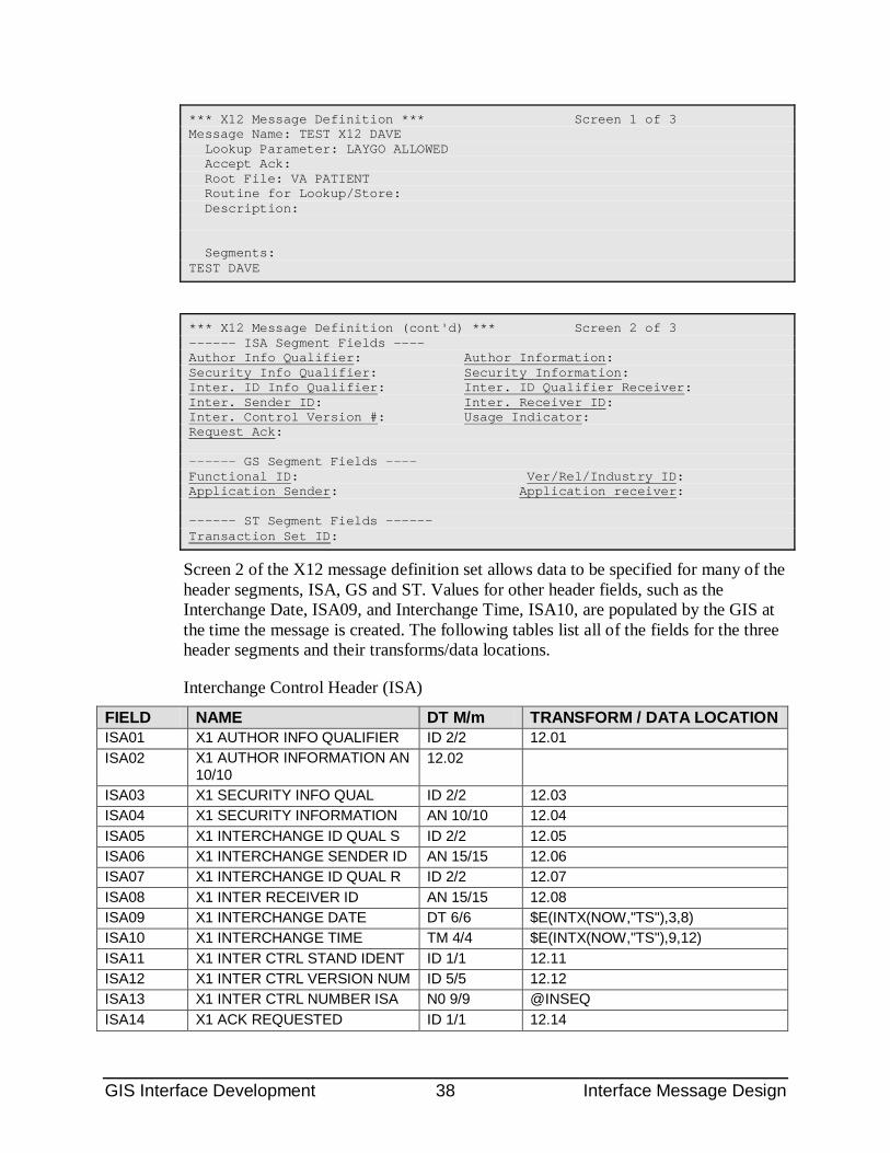
GIS Interface Development 38 Interface Message Design
*** X12 Message Definition *** Screen 1 of 3 Message Name: TEST X12 DAVE Lookup Parameter: LAYGO ALLOWED Accept Ack: Root File: VA PATIENT Routine for Lookup/Store: Description: Segments: TEST DAVE
*** X12 Message Definition (cont'd) *** Screen 2 of 3 ------ ISA Segment Fields ---- Author Info Qualifier: Author Information: Security Info Qualifier: Security Information: Inter. ID Info Qualifier: Inter. ID Qualifier Receiver: Inter. Sender ID: Inter. Receiver ID: Inter. Control Version #: Usage Indicator: Request Ack: ------ GS Segment Fields ---- Functional ID: Ver/Rel/Industry ID: Application Sender: Application receiver: ------ ST Segment Fields ------ Transaction Set ID:
Screen 2 of the X12 message definition set allows data to be specified for many of the header segments, ISA, GS and ST. Values for other header fields, such as the Interchange Date, ISA09, and Interchange Time, ISA10, are populated by the GIS at the time the message is created. The following tables list all of the fields for the three header segments and their transforms/data locations.
Interchange Control Header (ISA)
FIELD NAME DT M/m TRANSFORM / DATA LOCATION ISA01 X1 AUTHOR INFO QUALIFIER ID 2/2 12.01 ISA02 X1 AUTHOR INFORMATION AN
10/10 12.02
ISA03 X1 SECURITY INFO QUAL ID 2/2 12.03 ISA04 X1 SECURITY INFORMATION AN 10/10 12.04 ISA05 X1 INTERCHANGE ID QUAL S ID 2/2 12.05 ISA06 X1 INTERCHANGE SENDER ID AN 15/15 12.06 ISA07 X1 INTERCHANGE ID QUAL R ID 2/2 12.07 ISA08 X1 INTER RECEIVER ID AN 15/15 12.08 ISA09 X1 INTERCHANGE DATE DT 6/6 $E(INTX(NOW,"TS"),3,8) ISA10 X1 INTERCHANGE TIME TM 4/4 $E(INTX(NOW,"TS"),9,12) ISA11 X1 INTER CTRL STAND IDENT ID 1/1 12.11 ISA12 X1 INTER CTRL VERSION NUM ID 5/5 12.12 ISA13 X1 INTER CTRL NUMBER ISA N0 9/9 @INSEQ ISA14 X1 ACK REQUESTED ID 1/1 12.14
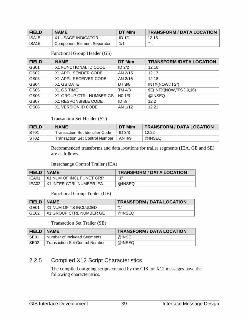
GIS Interface Development 39 Interface Message Design
FIELD NAME DT M/m TRANSFORM / DATA LOCATION ISA15 X1 USAGE INDICATOR ID 1/1 12.15 ISA16 Component Element Separator 1/1 “” : “
Functional Group Header (GS)
FIELD NAME DT M/m TRANSFORM /DATA LOCATION GS01 X1 FUNCTIONAL ID CODE ID 2/2 12.16 GS02 X1 APPL SENDER CODE AN 2/15 12.17 GS03 X1 APPL RECEIVER CODE AN 2/15 12.18 GS04 X1 GS DATE DT 8/8 INTX(NOW,"TS") GS05 X1 GS TIME TM 4/8 $E(INTX(NOW,"TS"),9,16) GS06 X1 GROUP CTRL NUMBER GS N0 1/9 @INSEQ GS07 X1 RESPONSIBLE CODE ID ½ 12.2 GS08 X1 VERSION ID CODE AN 1/12 12.21
Transaction Set Header (ST)
FIELD NAME DT M/m TRANSFORM / DATA LOCATION ST01 Transaction Set Identifier Code ID 3/3 12.22 ST02 Transaction Set Control Number AN 4/9 @INSEQ
Recommended transforms and data locations for trailer segments (IEA, GE and SE) are as follows.
Interchange Control Trailer (IEA)
FIELD NAME TRANSFORM / DATA LOCATION IEA01 X1 NUM OF INCL FUNCT GRP “1” IEA02 X1 INTER CTRL NUMBER IEA @INSEQ
Functional Group Trailer (GE)
FIELD NAME TRANSFORM / DATA LOCATION GE01 X1 NUM OF TS INCLUDED “1” GE02 X1 GROUP CTRL NUMBER GE @INSEQ
Transaction Set Trailer (SE)
FIELD NAME TRANSFORM / DATA LOCATION SE01 Number of Included Segments @INSE SE02 Transaction Set Control Number @INSEQ
2.2.5 Compiled X12 Script Characteristics The compiled outgoing scripts created by the GIS for X12 messages have the following characteristics.
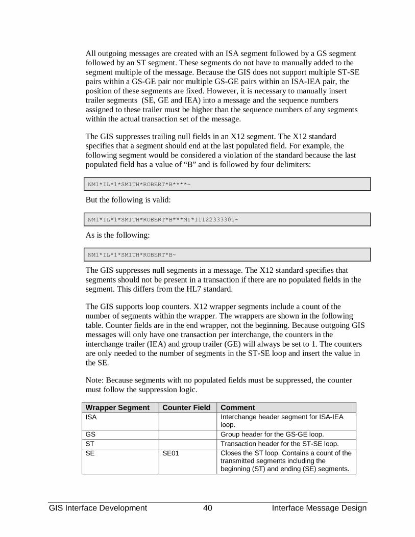
GIS Interface Development 40 Interface Message Design
All outgoing messages are created with an ISA segment followed by a GS segment followed by an ST segment. These segments do not have to manually added to the segment multiple of the message. Because the GIS does not support multiple ST-SE pairs within a GS-GE pair nor multiple GS-GE pairs within an ISA-IEA pair, the position of these segments are fixed. However, it is necessary to manually insert trailer segments (SE, GE and IEA) into a message and the sequence numbers assigned to these trailer must be higher than the sequence numbers of any segments within the actual transaction set of the message.
The GIS suppresses trailing null fields in an X12 segment. The X12 standard specifies that a segment should end at the last populated field. For example, the following segment would be considered a violation of the standard because the last populated field has a value of “B” and is followed by four delimiters:
NM1*IL*1*SMITH*ROBERT*B****~
But the following is valid:
NM1*IL*1*SMITH*ROBERT*B***MI*11122333301~
As is the following:
NM1*IL*1*SMITH*ROBERT*B~
The GIS suppresses null segments in a message. The X12 standard specifies that segments should not be present in a transaction if there are no populated fields in the segment. This differs from the HL7 standard.
The GIS supports loop counters. X12 wrapper segments include a count of the number of segments within the wrapper. The wrappers are shown in the following table. Counter fields are in the end wrapper, not the beginning. Because outgoing GIS messages will only have one transaction per interchange, the counters in the interchange trailer (IEA) and group trailer (GE) will always be set to 1. The counters are only needed to the number of segments in the ST-SE loop and insert the value in the SE.
Note: Because segments with no populated fields must be suppressed, the counter must follow the suppression logic.
Wrapper Segment Counter Field Comment ISA Interchange header segment for ISA-IEA
loop. GS Group header for the GS-GE loop. ST Transaction header for the ST-SE loop. SE SE01 Closes the ST loop. Contains a count of the
transmitted segments including the beginning (ST) and ending (SE) segments.
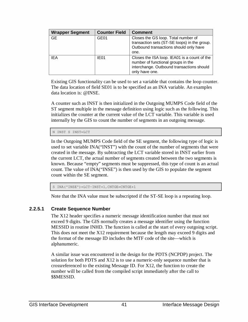
GIS Interface Development 41 Interface Message Design
Wrapper Segment Counter Field Comment GE GE01 Closes the GS loop. Total number of
transaction sets (ST-SE loops) in the group. Outbound transactions should only have one.
IEA IE01 Closes the ISA loop. IEA01 is a count of the number of functional groups in the interchange. Outbound transactions should only have one.
Existing GIS functionality can be used to set a variable that contains the loop counter. The data location of field SE01 is to be specified as an INA variable. An examples data location is: @INSE.
A counter such as INST is then initialized in the Outgoing MUMPS Code field of the ST segment multiple in the message definition using logic such as the following. This initializes the counter at the current value of the LCT variable. This variable is used internally by the GIS to count the number of segments in an outgoing message.
N INST S INST=LCT
In the Outgoing MUMPS Code field of the SE segment, the following type of logic is used to set variable INA(“INST”) with the count of the number of segments that were created in the message. By subtracting the LCT variable stored in INST earlier from the current LCT, the actual number of segments created between the two segments is known. Because “empty” segments must be suppressed, this type of count is an actual count. The value of INA(“INSE”) is then used by the GIS to populate the segment count within the SE segment.
S INA("INSE")=LCT-INST+1,CNTGE=CNTGE+1
Note that the INA value must be subscripted if the ST-SE loop is a repeating loop.
2.2.5.1 Create Sequence Number The X12 header specifies a numeric message identification number that must not exceed 9 digits. The GIS normally creates a message identifier using the function MESSID in routine INHD. The function is called at the start of every outgoing script. This does not meet the X12 requirement because the length may exceed 9 digits and the format of the message ID includes the MTF code of the site—which is alphanumeric.
A similar issue was encountered in the design for the PDTS (NCPDP) project. The solution for both PDTS and X12 is to use a numeric-only sequence number that is crossreferenced to the existing Message ID. For X12, the function to create the number will be called from the compiled script immediately after the call to $$MESSID.
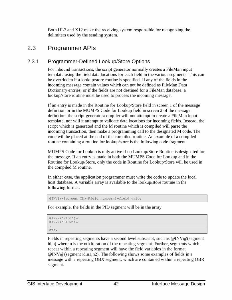
GIS Interface Development 42 Interface Message Design
Both HL7 and X12 make the receiving system responsible for recognizing the delimiters used by the sending system.
2.3 Programmer APIs
2.3.1 Programmer-Defined Lookup/Store Options For inbound transactions, the script generator normally creates a FileMan input template using the field data locations for each field in the various segments. This can be overridden if a lookup/store routine is specified. If any of the fields in the incoming message contain values which can not be defined as FileMan Data Dictionary entries, or if the fields are not destined for a FileMan database, a lookup/store routine must be used to process the incoming message.
If an entry is made in the Routine for Lookup/Store field in screen 1 of the message definition or in the MUMPS Code for Lookup field in screen 2 of the message definition, the script generator/compiler will not attempt to create a FileMan input template, nor will it attempt to validate data locations for incoming fields. Instead, the script which is generated and the M routine which is compiled will parse the incoming transaction, then make a programming call to the designated M code. The code will be placed at the end of the compiled routine. An example of a compiled routine containing a routine for lookup/store is the following code fragment.
MUMPS Code for Lookup is only active if no Lookup/Store Routine is designated for the message. If an entry is made in both the MUMPS Code for Lookup and in the Routine for Lookup/Store, only the code in Routine for Lookup/Store will be used in the compiled M routine.
In either case, the application programmer must write the code to update the local host database. A variable array is available to the lookup/store routine in the following format.
@INV@(<Segment ID><Field number>)=field value
For example, the fields in the PID segment will be in the array
@INV@(”PID1”)=1 @INV@(“PID2”)= . etc.
Fields in repeating segments have a second level subscript, such as @INV@(segment id,n) where n is the nth iteration of the repeating segment. Further, segments which repeat within a repeating segment will have the field variables in the format @INV@(segment id,n1,n2). The following shows some examples of fields in a message with a repeating OBX segment, which are contained within a repeating OBR segment.
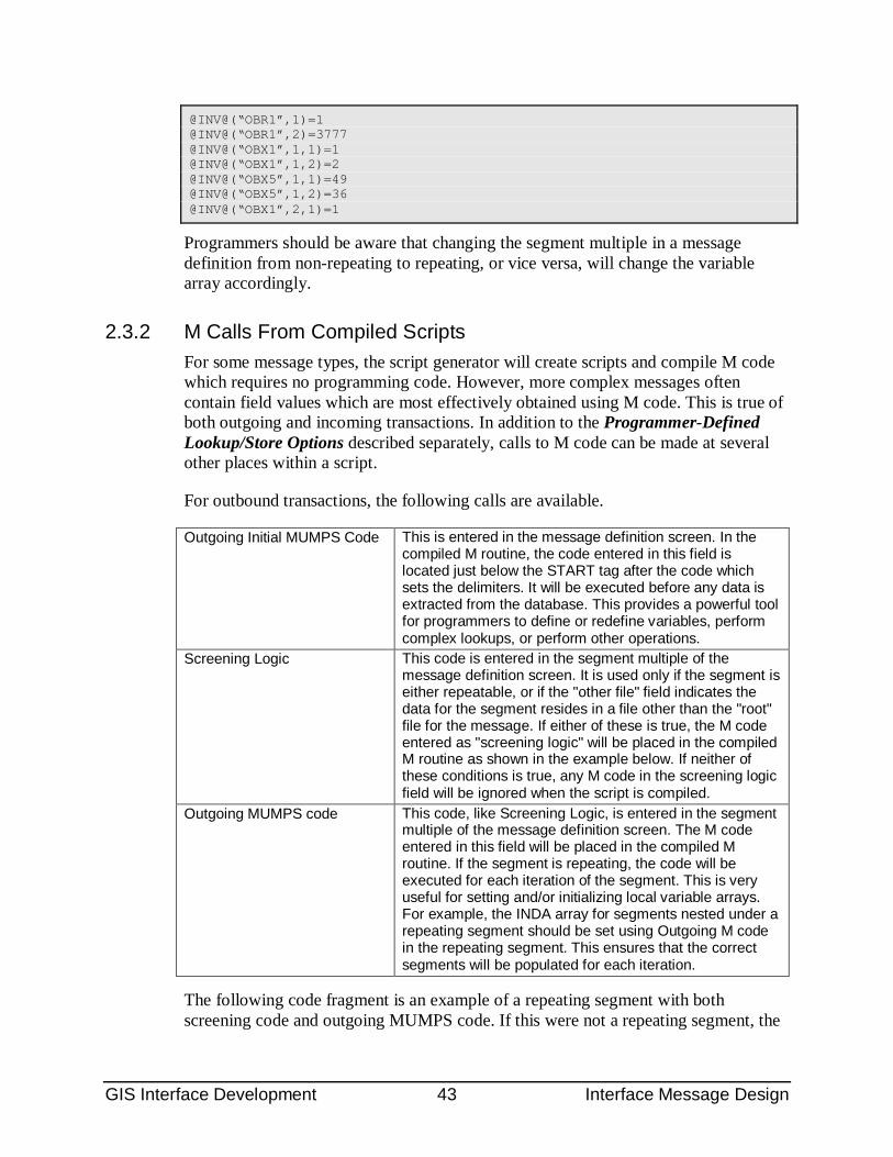
GIS Interface Development 43 Interface Message Design
@INV@(“OBR1”,1)=1 @INV@(“OBR1”,2)=3777 @INV@(“OBX1”,1,1)=1 @INV@(“OBX1”,1,2)=2 @INV@(“OBX5”,1,1)=49 @INV@(“OBX5”,1,2)=36 @INV@(“OBX1”,2,1)=1
Programmers should be aware that changing the segment multiple in a message definition from non-repeating to repeating, or vice versa, will change the variable array accordingly.
2.3.2 M Calls From Compiled Scripts For some message types, the script generator will create scripts and compile M code which requires no programming code. However, more complex messages often contain field values which are most effectively obtained using M code. This is true of both outgoing and incoming transactions. In addition to the Programmer-Defined Lookup/Store Options described separately, calls to M code can be made at several other places within a script.
For outbound transactions, the following calls are available.
Outgoing Initial MUMPS Code This is entered in the message definition screen. In the compiled M routine, the code entered in this field is located just below the START tag after the code which sets the delimiters. It will be executed before any data is extracted from the database. This provides a powerful tool for programmers to define or redefine variables, perform complex lookups, or perform other operations.
Screening Logic This code is entered in the segment multiple of the message definition screen. It is used only if the segment is either repeatable, or if the "other file" field indicates the data for the segment resides in a file other than the "root" file for the message. If either of these is true, the M code entered as "screening logic" will be placed in the compiled M routine as shown in the example below. If neither of these conditions is true, any M code in the screening logic field will be ignored when the script is compiled.
Outgoing MUMPS code This code, like Screening Logic, is entered in the segment multiple of the message definition screen. The M code entered in this field will be placed in the compiled M routine. If the segment is repeating, the code will be executed for each iteration of the segment. This is very useful for setting and/or initializing local variable arrays. For example, the INDA array for segments nested under a repeating segment should be set using Outgoing M code in the repeating segment. This ensures that the correct segments will be populated for each iteration.
The following code fragment is an example of a repeating segment with both screening code and outgoing MUMPS code. If this were not a repeating segment, the
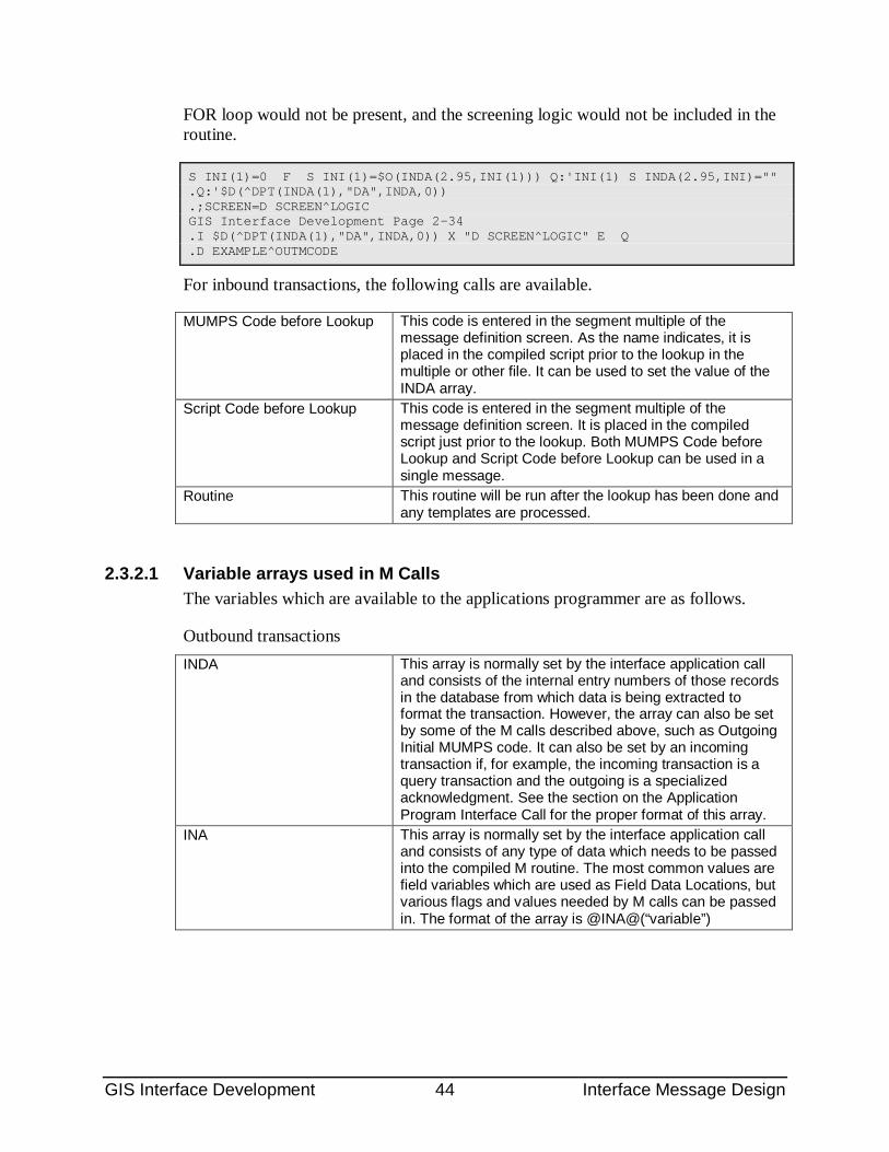
GIS Interface Development 44 Interface Message Design
FOR loop would not be present, and the screening logic would not be included in the routine.
S INI(1)=0 F S INI(1)=$O(INDA(2.95,INI(1))) Q:'INI(1) S INDA(2.95,INI)="" .Q:'$D(^DPT(INDA(1),"DA",INDA,0)) .;SCREEN=D SCREEN^LOGIC GIS Interface Development Page 2-34 .I $D(^DPT(INDA(1),"DA",INDA,0)) X "D SCREEN^LOGIC" E Q .D EXAMPLE^OUTMCODE
For inbound transactions, the following calls are available.
MUMPS Code before Lookup This code is entered in the segment multiple of the message definition screen. As the name indicates, it is placed in the compiled script prior to the lookup in the multiple or other file. It can be used to set the value of the INDA array.
Script Code before Lookup This code is entered in the segment multiple of the message definition screen. It is placed in the compiled script just prior to the lookup. Both MUMPS Code before Lookup and Script Code before Lookup can be used in a single message.
Routine This routine will be run after the lookup has been done and any templates are processed.
2.3.2.1 Variable arrays used in M Calls The variables which are available to the applications programmer are as follows.
Outbound transactions INDA This array is normally set by the interface application call
and consists of the internal entry numbers of those records in the database from which data is being extracted to format the transaction. However, the array can also be set by some of the M calls described above, such as Outgoing Initial MUMPS code. It can also be set by an incoming transaction if, for example, the incoming transaction is a query transaction and the outgoing is a specialized acknowledgment. See the section on the Application Program Interface Call for the proper format of this array.
INA This array is normally set by the interface application call and consists of any type of data which needs to be passed into the compiled M routine. The most common values are field variables which are used as Field Data Locations, but various flags and values needed by M calls can be passed in. The format of the array is @INA@(“variable”)
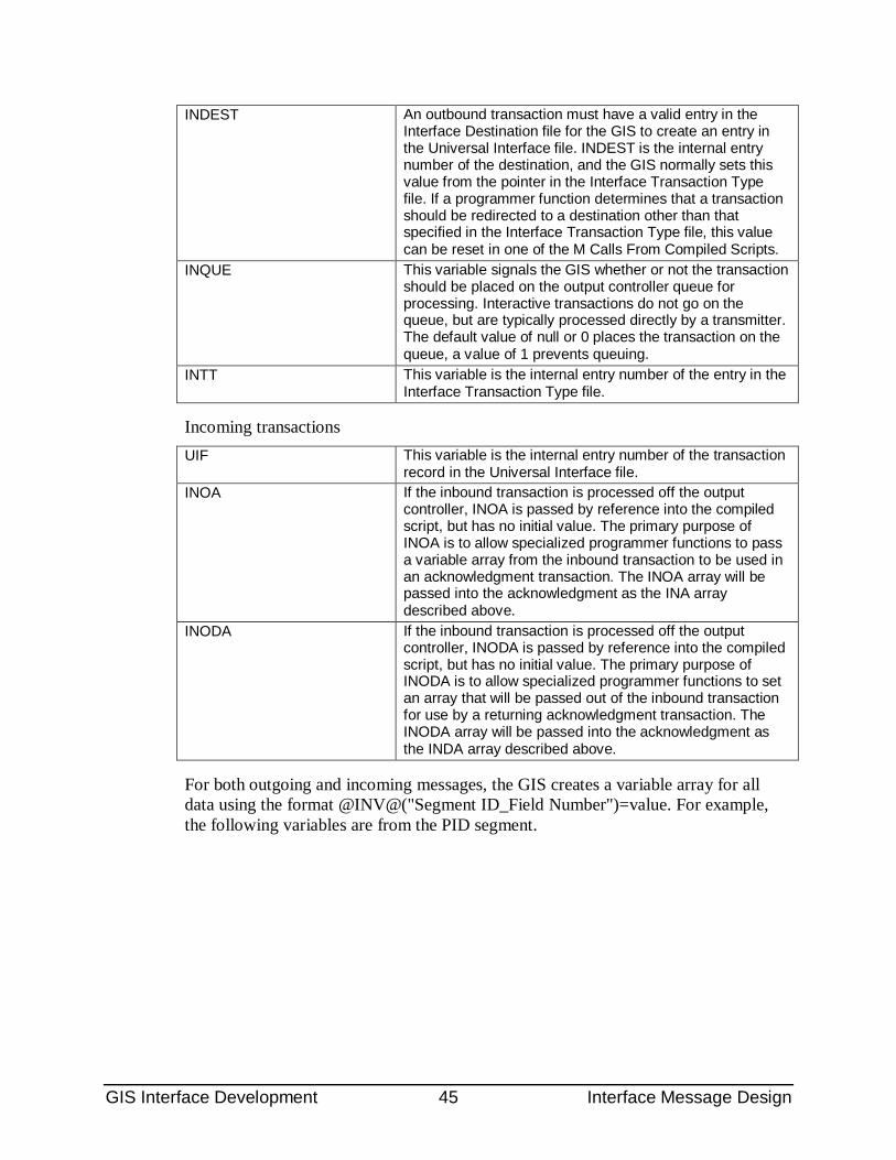
GIS Interface Development 45 Interface Message Design
INDEST An outbound transaction must have a valid entry in the Interface Destination file for the GIS to create an entry in the Universal Interface file. INDEST is the internal entry number of the destination, and the GIS normally sets this value from the pointer in the Interface Transaction Type file. If a programmer function determines that a transaction should be redirected to a destination other than that specified in the Interface Transaction Type file, this value can be reset in one of the M Calls From Compiled Scripts.
INQUE This variable signals the GIS whether or not the transaction should be placed on the output controller queue for processing. Interactive transactions do not go on the queue, but are typically processed directly by a transmitter. The default value of null or 0 places the transaction on the queue, a value of 1 prevents queuing.
INTT This variable is the internal entry number of the entry in the Interface Transaction Type file.
Incoming transactions UIF This variable is the internal entry number of the transaction
record in the Universal Interface file. INOA If the inbound transaction is processed off the output
controller, INOA is passed by reference into the compiled script, but has no initial value. The primary purpose of INOA is to allow specialized programmer functions to pass a variable array from the inbound transaction to be used in an acknowledgment transaction. The INOA array will be passed into the acknowledgment as the INA array described above.
INODA If the inbound transaction is processed off the output controller, INODA is passed by reference into the compiled script, but has no initial value. The primary purpose of INODA is to allow specialized programmer functions to set an array that will be passed out of the inbound transaction for use by a returning acknowledgment transaction. The INODA array will be passed into the acknowledgment as the INDA array described above.
For both outgoing and incoming messages, the GIS creates a variable array for all data using the format @INV@("Segment ID_Field Number")=value. For example, the following variables are from the PID segment.
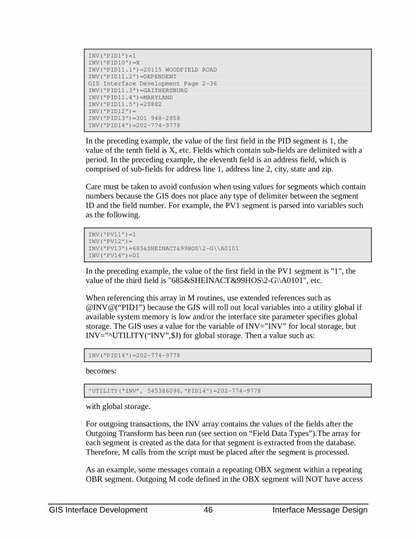
GIS Interface Development 46 Interface Message Design
INV("PID1")=1 INV("PID10")=X INV("PID11.1")=20115 WOODFIELD ROAD INV("PID11.2")=DEPENDENT GIS Interface Development Page 2-36 INV("PID11.3")=GAITHERSBURG INV("PID11.4")=MARYLAND INV("PID11.5")=20882 INV("PID12")= INV("PID13")=301 948-2858 INV("PID14")=202-774-9778
In the preceding example, the value of the first field in the PID segment is 1, the value of the tenth field is X, etc. Fields which contain sub-fields are delimited with a period. In the preceding example, the eleventh field is an address field, which is comprised of sub-fields for address line 1, address line 2, city, state and zip.
Care must be taken to avoid confusion when using values for segments which contain numbers because the GIS does not place any type of delimiter between the segment ID and the field number. For example, the PV1 segment is parsed into variables such as the following.
INV("PV11")=1 INV("PV12")= INV("PV13")=685&SHEINACT&99HOS\2-G\\A0101 INV("PV14")=DI
In the preceding example, the value of the first field in the PV1 segment is "1", the value of the third field is "685&SHEINACT&99HOS\2-G\\A0101", etc.
When referencing this array in M routines, use extended references such as @INV@(“PID1”) because the GIS will roll out local variables into a utility global if available system memory is low and/or the interface site parameter specifies global storage. The GIS uses a value for the variable of INV=”INV” for local storage, but INV=”^UTILITY(“INV”,$J) for global storage. Then a value such as:
INV(“PID14")=202-774-9778
becomes:
^UTILITY(“INV”, 545386096,"PID14")=202-774-9778
with global storage.
For outgoing transactions, the INV array contains the values of the fields after the Outgoing Transform has been run (see section on “Field Data Types”).The array for each segment is created as the data for that segment is extracted from the database. Therefore, M calls from the script must be placed after the segment is processed.
As an example, some messages contain a repeating OBX segment within a repeating OBR segment. Outgoing M code defined in the OBX segment will NOT have access
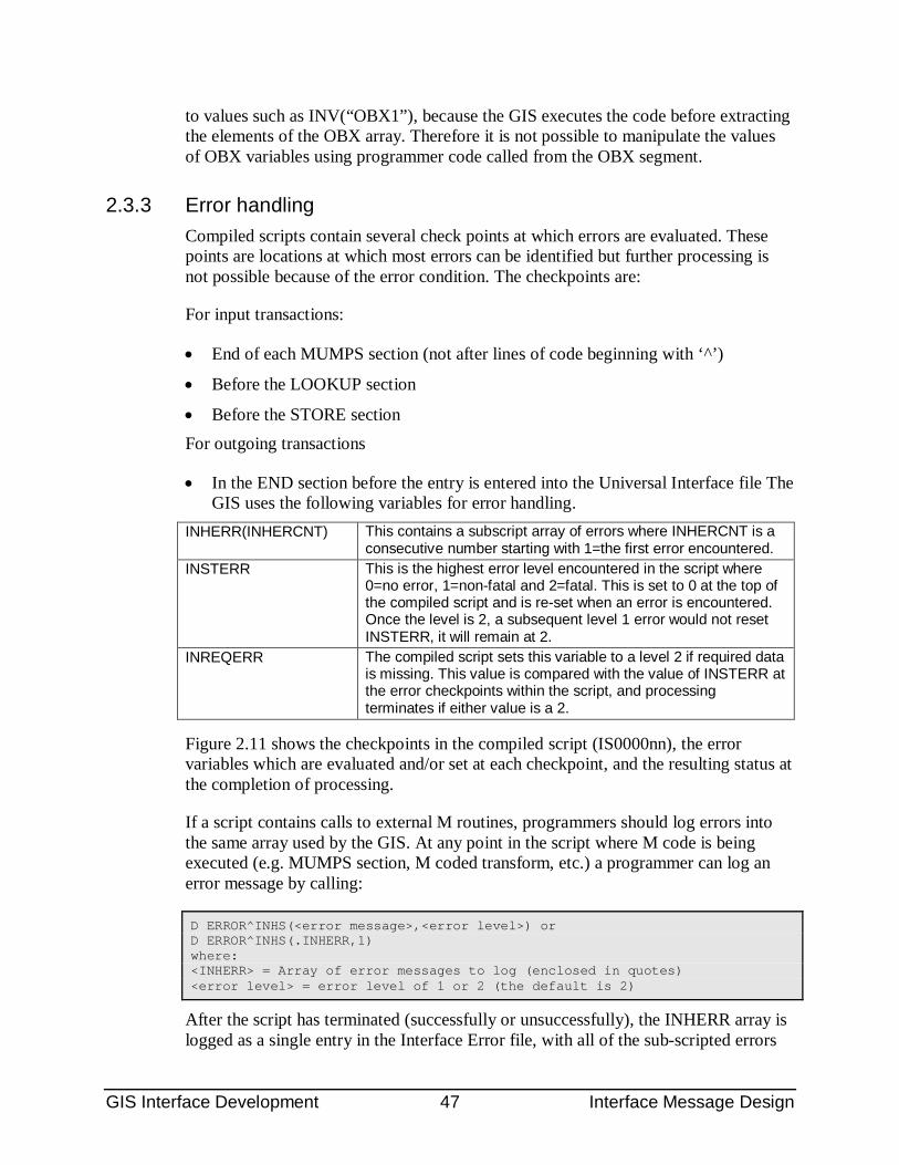
GIS Interface Development 47 Interface Message Design
to values such as INV(“OBX1”), because the GIS executes the code before extracting the elements of the OBX array. Therefore it is not possible to manipulate the values of OBX variables using programmer code called from the OBX segment.
2.3.3 Error handling Compiled scripts contain several check points at which errors are evaluated. These points are locations at which most errors can be identified but further processing is not possible because of the error condition. The checkpoints are:
For input transactions:
• End of each MUMPS section (not after lines of code beginning with ‘^’)
• Before the LOOKUP section
• Before the STORE section For outgoing transactions
• In the END section before the entry is entered into the Universal Interface file The GIS uses the following variables for error handling.
INHERR(INHERCNT) This contains a subscript array of errors where INHERCNT is a consecutive number starting with 1=the first error encountered.
INSTERR This is the highest error level encountered in the script where 0=no error, 1=non-fatal and 2=fatal. This is set to 0 at the top of the compiled script and is re-set when an error is encountered. Once the level is 2, a subsequent level 1 error would not reset INSTERR, it will remain at 2.
INREQERR The compiled script sets this variable to a level 2 if required data is missing. This value is compared with the value of INSTERR at the error checkpoints within the script, and processing terminates if either value is a 2.
Figure 2.11 shows the checkpoints in the compiled script (IS0000nn), the error variables which are evaluated and/or set at each checkpoint, and the resulting status at the completion of processing.
If a script contains calls to external M routines, programmers should log errors into the same array used by the GIS. At any point in the script where M code is being executed (e.g. MUMPS section, M coded transform, etc.) a programmer can log an error message by calling:
D ERROR^INHS(<error message>,<error level>) or D ERROR^INHS(.INHERR,1) where: <INHERR> = Array of error messages to log (enclosed in quotes) <error level> = error level of 1 or 2 (the default is 2)
After the script has terminated (successfully or unsuccessfully), the INHERR array is logged as a single entry in the Interface Error file, with all of the sub-scripted errors
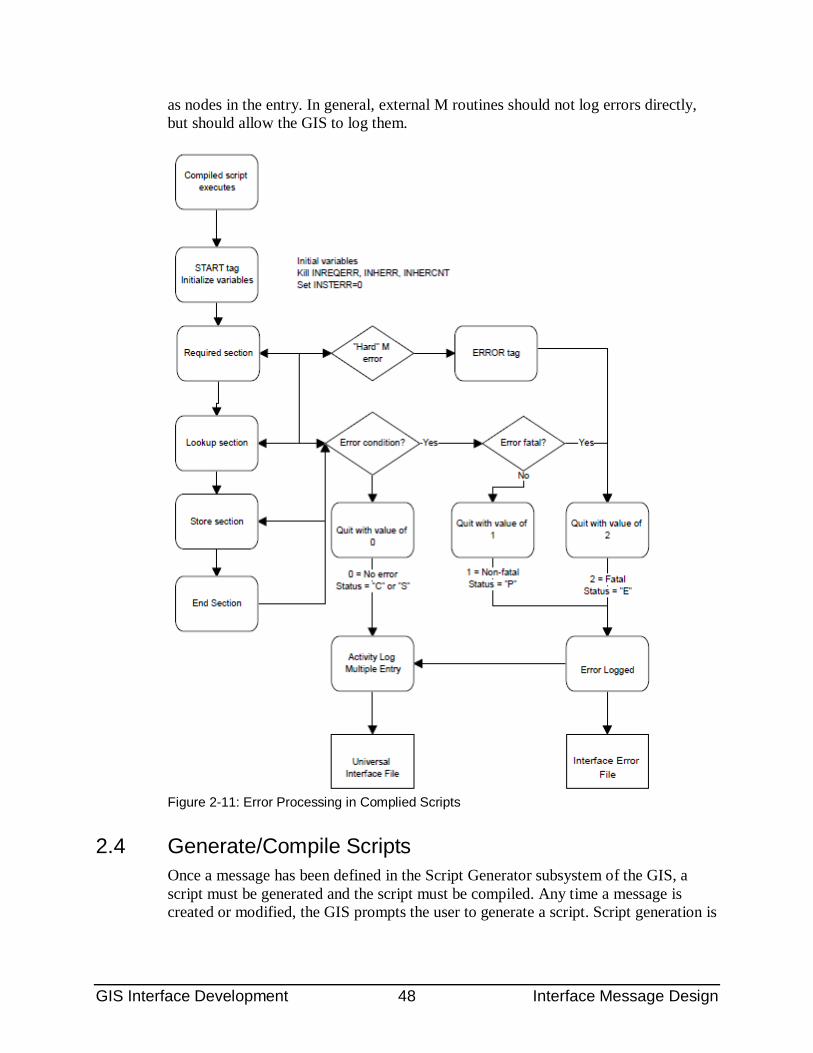
GIS Interface Development 48 Interface Message Design
as nodes in the entry. In general, external M routines should not log errors directly, but should allow the GIS to log them.
Figure 2-11: Error Processing in Complied Scripts
2.4 Generate/Compile Scripts Once a message has been defined in the Script Generator subsystem of the GIS, a script must be generated and the script must be compiled. Any time a message is created or modified, the GIS prompts the user to generate a script. Script generation is
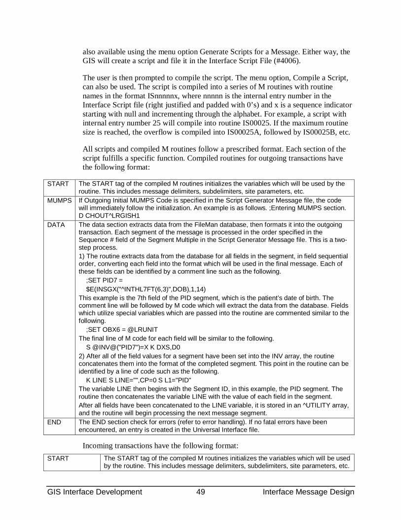
GIS Interface Development 49 Interface Message Design
also available using the menu option Generate Scripts for a Message. Either way, the GIS will create a script and file it in the Interface Script File (#4006).
The user is then prompted to compile the script. The menu option, Compile a Script, can also be used. The script is compiled into a series of M routines with routine names in the format ISnnnnnx, where nnnnn is the internal entry number in the Interface Script file (right justified and padded with 0’s) and x is a sequence indicator starting with null and incrementing through the alphabet. For example, a script with internal entry number 25 will compile into routine IS00025. If the maximum routine size is reached, the overflow is compiled into IS00025A, followed by IS00025B, etc.
All scripts and compiled M routines follow a prescribed format. Each section of the script fulfills a specific function. Compiled routines for outgoing transactions have the following format:
START The START tag of the compiled M routines initializes the variables which will be used by the routine. This includes message delimiters, subdelimiters, site parameters, etc.
MUMPS If Outgoing Initial MUMPS Code is specified in the Script Generator Message file, the code will immediately follow the initialization. An example is as follows. ;Entering MUMPS section. D CHOUT^LRGISH1
DATA The data section extracts data from the FileMan database, then formats it into the outgoing transaction. Each segment of the message is processed in the order specified in the Sequence # field of the Segment Multiple in the Script Generator Message file. This is a two-step process. 1) The routine extracts data from the database for all fields in the segment, in field sequential order, converting each field into the format which will be used in the final message. Each of these fields can be identified by a comment line such as the following. ;SET PID7 = $E(INSGX("^INTHL7FT(6,3)",DOB),1,14) This example is the 7th field of the PID segment, which is the patient’s date of birth. The comment line will be followed by M code which will extract the data from the database. Fields which utilize special variables which are passed into the routine are commented similar to the following. ;SET OBX6 = @LRUNIT The final line of M code for each field will be similar to the following. S @INV@("PID7")=X K DXS,D0 2) After all of the field values for a segment have been set into the INV array, the routine concatenates them into the format of the completed segment. This point in the routine can be identified by a line of code such as the following. K LINE S LINE="",CP=0 S L1="PID" The variable LINE then begins with the Segment ID, in this example, the PID segment. The routine then concatenates the variable LINE with the value of each field in the segment. After all fields have been concatenated to the LINE variable, it is stored in an ^UTILITY array, and the routine will begin processing the next message segment.
END The END section check for errors (refer to error handling). If no fatal errors have been encountered, an entry is created in the Universal Interface file.
Incoming transactions have the following format:
START The START tag of the compiled M routines initializes the variables which will be used by the routine. This includes message delimiters, subdelimiters, site parameters, etc.
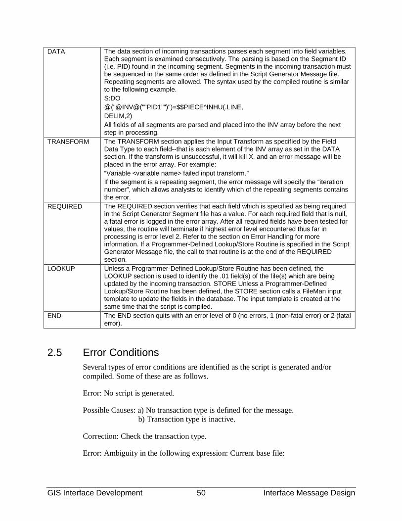
GIS Interface Development 50 Interface Message Design
DATA The data section of incoming transactions parses each segment into field variables. Each segment is examined consecutively. The parsing is based on the Segment ID (i.e. PID) found in the incoming segment. Segments in the incoming transaction must be sequenced in the same order as defined in the Script Generator Message file. Repeating segments are allowed. The syntax used by the compiled routine is similar to the following example. S:DO @("@INV@(""PID1"")")=$$PIECE^INHU(.LINE, DELIM,2) All fields of all segments are parsed and placed into the INV array before the next step in processing.
TRANSFORM The TRANSFORM section applies the Input Transform as specified by the Field Data Type to each field--that is each element of the INV array as set in the DATA section. If the transform is unsuccessful, it will kill X, and an error message will be placed in the error array. For example: “Variable <variable name> failed input transform.” If the segment is a repeating segment, the error message will specify the “iteration number”, which allows analysts to identify which of the repeating segments contains the error.
REQUIRED The REQUIRED section verifies that each field which is specified as being required in the Script Generator Segment file has a value. For each required field that is null, a fatal error is logged in the error array. After all required fields have been tested for values, the routine will terminate if highest error level encountered thus far in processing is error level 2. Refer to the section on Error Handling for more information. If a Programmer-Defined Lookup/Store Routine is specified in the Script Generator Message file, the call to that routine is at the end of the REQUIRED section.
LOOKUP Unless a Programmer-Defined Lookup/Store Routine has been defined, the LOOKUP section is used to identify the .01 field(s) of the file(s) which are being updated by the incoming transaction. STORE Unless a Programmer-Defined Lookup/Store Routine has been defined, the STORE section calls a FileMan input template to update the fields in the database. The input template is created at the same time that the script is compiled.
END The END section quits with an error level of 0 (no errors, 1 (non-fatal error) or 2 (fatal error).
2.5 Error Conditions Several types of error conditions are identified as the script is generated and/or compiled. Some of these are as follows.
Error: No script is generated.
Possible Causes: a) No transaction type is defined for the message. b) Transaction type is inactive.
Correction: Check the transaction type.
Error: Ambiguity in the following expression: Current base file:
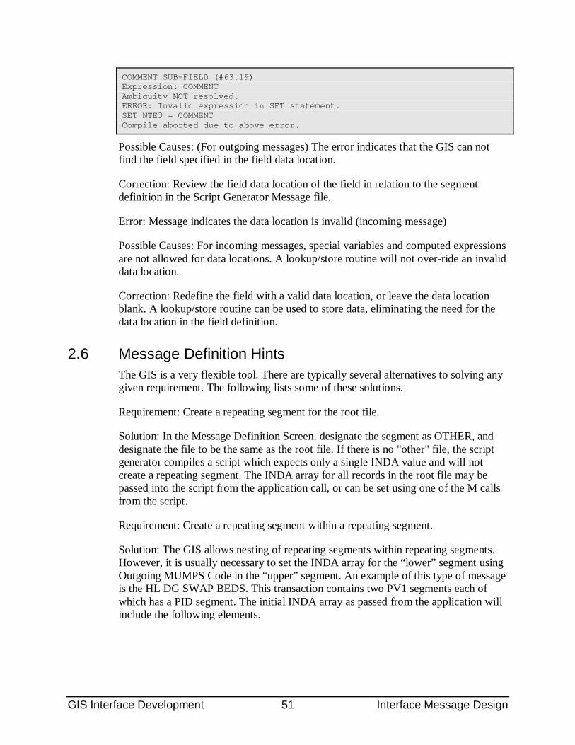
GIS Interface Development 51 Interface Message Design
COMMENT SUB-FIELD (#63.19) Expression: COMMENT Ambiguity NOT resolved. ERROR: Invalid expression in SET statement. SET NTE3 = COMMENT Compile aborted due to above error.
Possible Causes: (For outgoing messages) The error indicates that the GIS can not find the field specified in the field data location.
Correction: Review the field data location of the field in relation to the segment definition in the Script Generator Message file.
Error: Message indicates the data location is invalid (incoming message)
Possible Causes: For incoming messages, special variables and computed expressions are not allowed for data locations. A lookup/store routine will not over-ride an invalid data location.
Correction: Redefine the field with a valid data location, or leave the data location blank. A lookup/store routine can be used to store data, eliminating the need for the data location in the field definition.
2.6 Message Definition Hints The GIS is a very flexible tool. There are typically several alternatives to solving any given requirement. The following lists some of these solutions.
Requirement: Create a repeating segment for the root file.
Solution: In the Message Definition Screen, designate the segment as OTHER, and designate the file to be the same as the root file. If there is no "other" file, the script generator compiles a script which expects only a single INDA value and will not create a repeating segment. The INDA array for all records in the root file may be passed into the script from the application call, or can be set using one of the M calls from the script.
Requirement: Create a repeating segment within a repeating segment.
Solution: The GIS allows nesting of repeating segments within repeating segments. However, it is usually necessary to set the INDA array for the “lower” segment using Outgoing MUMPS Code in the “upper” segment. An example of this type of message is the HL DG SWAP BEDS. This transaction contains two PV1 segments each of which has a PID segment. The initial INDA array as passed from the application will include the following elements.
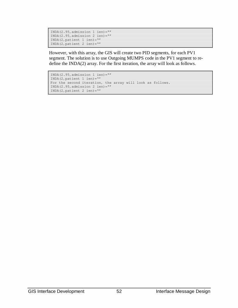
GIS Interface Development 52 Interface Message Design
INDA(2.95,admission 1 ien)=“” INDA(2.95,admission 2 ien)=“” INDA(2,patient 1 ien)=“” INDA(2,patient 2 ien)=“”
However, with this array, the GIS will create two PID segments, for each PV1 segment. The solution is to use Outgoing MUMPS code in the PV1 segment to re-define the INDA(2) array. For the first iteration, the array will look as follows.
INDA(2.95,admission 1 ien)=“” INDA(2,patient 1 ien)=“” For the second iteration, the array will look as follows. INDA(2.95,admission 2 ien)=“” INDA(2,patient 2 ien)=“”
GIS Interface Development 53 Transaction Routing
3.0 Transaction Routing The primary function of the GIS is to route electronic interface transactions between systems. Transactions can be routed between and/or among "local" databases or remote databases. Transaction routing is controlled by entries in several tables, primarily the Interface Transaction Type file, the Interface Destination file, the Interface Replication File and the Background Control file.
This section is intended to provide a quick guide to routing a transaction. It is divided into sections on routing outbound transactions, routing inbound transactions, routing storeand-forward transactions and selective routing.
3.1 Outgoing Transactions An outgoing transaction is one which contains extracted data which originated in the host database that is being sent to an external system. An outgoing transaction typically consists of the following elements.
• A defined message in the Script Generator Message file, with the child transaction type entered in the Transaction Type multiple of the message.
• A parent transaction type.
• A child transaction type.
• An application program interface (API) call in system using the parent transaction type.
• A pointer from the child transaction type to an entry in the Interface Destination file.
• Unless selective routine or message replication is required, the Destination of the child transaction type should specify “direct routing”. This streamlines processing because the transaction does not have to be processed by the Output Controller. Alternatively, the Destination can specify a routine to control distribution of the transaction.
• A background process such as a TCP/IP transmitter or a routine which writes the transaction to a flat file.
The steps which are required to route an outgoing transaction are described in subsequent sections.
3.1.1 Parent Transaction Type Definition For outgoing transactions there are two kinds of transaction types: parent and child. When creating an entry in the Interface Transaction Type file, there is no obvious distinction between parent and child. A child transaction type contains a recursive pointer in the field, Parent Transaction Type, while a parent transaction type does not.

GIS Interface Development 54 Transaction Routing
(A replicated transaction is ultimately copied from a single child, but it must not point to a parent in the Interface Transaction Type file.)
A parent transaction type contains no routing or formatting information and is used as the name called from an application program. Once a parent transaction type has been defined and activated, the name should never be changed in the Name (#.01) field unless the M code in the calling application is also changed. The string value of the Name field is called from the application program, not the internal entry number. If the name is changed for an active parent transaction type, the GIS will not be able to identify it. A parent transaction type can have many child transaction types associated with it. The relationship between parent and child is shown in the following diagram.
A parent transaction type can have many child transaction types associated with it. The relationship between parent and child is shown in the following diagram.
Figure 3-1: Child/Parent Transaction Types
As shown, the child transaction types point to the parent transaction type. Each child will have a compiled script. When a parent is invoked from an application, all child transaction types that point to that parent will be processed—one script per child. All transaction types can be made active or inactive. If a child is inactive it will be skipped. If a parent is inactive no transactions will be generated.
If an outgoing transaction can be triggered from an existing application, there is no need to create a new parent transaction type--only another child which points to the parent. However, if an entirely new transaction is created both a parent and a child are needed. Figure 3-1 is an example of a parent transaction type in the Interface Transaction Type file. For a parent transaction type, only the following fields are needed. Other fields are not used.
NAME This is the name of the transaction type. For clarity, it is useful to designate that it is a parent. For example, HL ADT REG OUT (PARENT).
ACTIVE This specifies that this transaction type is active. The default value is inactive, so you must make an entry in this field to activate your transaction type.
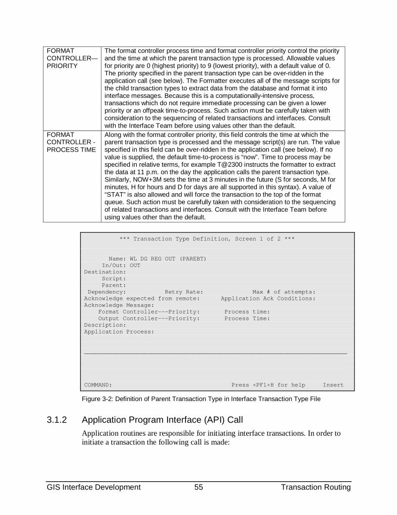
GIS Interface Development 55 Transaction Routing
FORMAT CONTROLLER—PRIORITY
The format controller process time and format controller priority control the priority and the time at which the parent transaction type is processed. Allowable values for priority are 0 (highest priority) to 9 (lowest priority), with a default value of 0. The priority specified in the parent transaction type can be over-ridden in the application call (see below). The Formatter executes all of the message scripts for the child transaction types to extract data from the database and format it into interface messages. Because this is a computationally-intensive process, transactions which do not require immediate processing can be given a lower priority or an offpeak time-to-process. Such action must be carefully taken with consideration to the sequencing of related transactions and interfaces. Consult with the Interface Team before using values other than the default.
FORMAT CONTROLLER - PROCESS TIME
Along with the format controller priority, this field controls the time at which the parent transaction type is processed and the message script(s) are run. The value specified in this field can be over-ridden in the application call (see below). If no value is supplied, the default time-to-process is “now”. Time to process may be specified in relative terms, for example T@2300 instructs the formatter to extract the data at 11 p.m. on the day the application calls the parent transaction type. Similarly, NOW+3M sets the time at 3 minutes in the future (S for seconds, M for minutes, H for hours and D for days are all supported in this syntax). A value of “STAT” is also allowed and will force the transaction to the top of the format queue. Such action must be carefully taken with consideration to the sequencing of related transactions and interfaces. Consult with the Interface Team before using values other than the default.
*** Transaction Type Definition, Screen 1 of 2 *** Name: WL DG REG OUT (PAREBT) In/Out: OUT Destination: Script: Parent: Dependency: Retry Rate: Max # of attempts: Acknowledge expected from remote: Application Ack Conditions: Acknowledge Message: Format Controller---Priority: Process time: Output Controller---Priority: Process Time: Description: Application Process: ___________________________________________________________________________ COMMAND: Press <PF1>H for help Insert
Figure 3-2: Definition of Parent Transaction Type in Interface Transaction Type File
3.1.2 Application Program Interface (API) Call Application routines are responsible for initiating interface transactions. In order to initiate a transaction the following call is made:
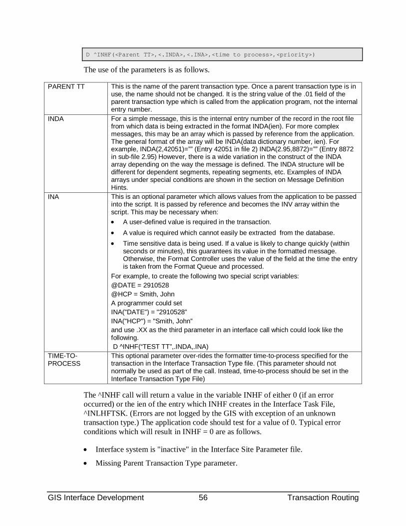
GIS Interface Development 56 Transaction Routing
D ^INHF(<Parent TT>,<.INDA>,<.INA>,<time to process>,<priority>)
The use of the parameters is as follows.
PARENT TT This is the name of the parent transaction type. Once a parent transaction type is in use, the name should not be changed. It is the string value of the .01 field of the parent transaction type which is called from the application program, not the internal entry number.
INDA For a simple message, this is the internal entry number of the record in the root file from which data is being extracted in the format INDA(ien). For more complex messages, this may be an array which is passed by reference from the application. The general format of the array will be INDA(data dictionary number, ien). For example, INDA(2,42051)=”” (Entry 42051 in file 2) INDA(2.95,8872)=”” (Entry 8872 in sub-file 2.95) However, there is a wide variation in the construct of the INDA array depending on the way the message is defined. The INDA structure will be different for dependent segments, repeating segments, etc. Examples of INDA arrays under special conditions are shown in the section on Message Definition Hints.
INA This is an optional parameter which allows values from the application to be passed into the script. It is passed by reference and becomes the INV array within the script. This may be necessary when: • A user-defined value is required in the transaction. • A value is required which cannot easily be extracted from the database. • Time sensitive data is being used. If a value is likely to change quickly (within
seconds or minutes), this guarantees its value in the formatted message. Otherwise, the Format Controller uses the value of the field at the time the entry is taken from the Format Queue and processed.
For example, to create the following two special script variables: @DATE = 2910528 @HCP = Smith, John A programmer could set INA("DATE") = "2910528” INA("HCP") = "Smith, John” and use .XX as the third parameter in an interface call which could look like the following. D ^INHF(“TEST TT”,.INDA,.INA)
TIME-TO-PROCESS
This optional parameter over-rides the formatter time-to-process specified for the transaction in the Interface Transaction Type file. (This parameter should not normally be used as part of the call. Instead, time-to-process should be set in the Interface Transaction Type File)
The ^INHF call will return a value in the variable INHF of either 0 (if an error occurred) or the ien of the entry which INHF creates in the Interface Task File, ^INLHFTSK. (Errors are not logged by the GIS with exception of an unknown transaction type.) The application code should test for a value of 0. Typical error conditions which will result in INHF = 0 are as follows.
• Interface system is "inactive" in the Interface Site Parameter file.
• Missing Parent Transaction Type parameter.
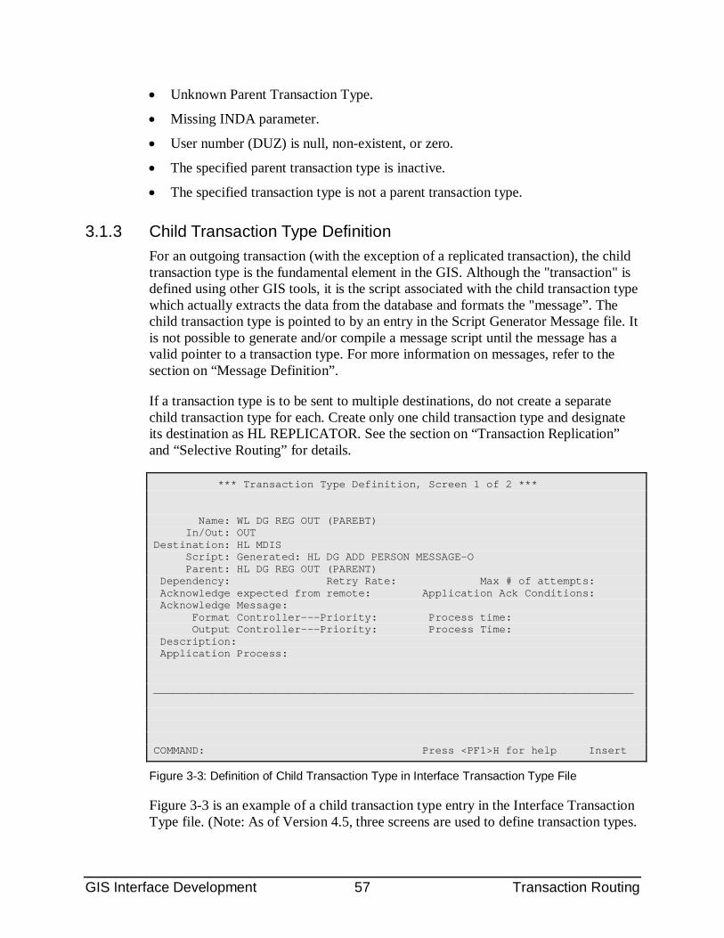
GIS Interface Development 57 Transaction Routing
• Unknown Parent Transaction Type.
• Missing INDA parameter.
• User number (DUZ) is null, non-existent, or zero.
• The specified parent transaction type is inactive.
• The specified transaction type is not a parent transaction type.
3.1.3 Child Transaction Type Definition For an outgoing transaction (with the exception of a replicated transaction), the child transaction type is the fundamental element in the GIS. Although the "transaction" is defined using other GIS tools, it is the script associated with the child transaction type which actually extracts the data from the database and formats the "message”. The child transaction type is pointed to by an entry in the Script Generator Message file. It is not possible to generate and/or compile a message script until the message has a valid pointer to a transaction type. For more information on messages, refer to the section on “Message Definition”.
If a transaction type is to be sent to multiple destinations, do not create a separate child transaction type for each. Create only one child transaction type and designate its destination as HL REPLICATOR. See the section on “Transaction Replication” and “Selective Routing” for details.
*** Transaction Type Definition, Screen 1 of 2 *** Name: WL DG REG OUT (PAREBT) In/Out: OUT Destination: HL MDIS Script: Generated: HL DG ADD PERSON MESSAGE-O Parent: HL DG REG OUT (PARENT) Dependency: Retry Rate: Max # of attempts: Acknowledge expected from remote: Application Ack Conditions: Acknowledge Message: Format Controller---Priority: Process time: Output Controller---Priority: Process Time: Description: Application Process: ___________________________________________________________________________ COMMAND: Press <PF1>H for help Insert
Figure 3-3: Definition of Child Transaction Type in Interface Transaction Type File
Figure 3-3 is an example of a child transaction type entry in the Interface Transaction Type file. (Note: As of Version 4.5, three screens are used to define transaction types.
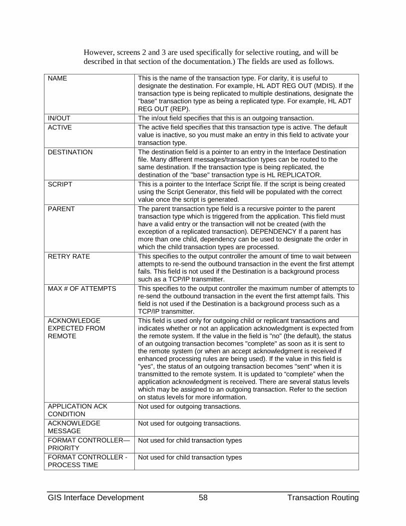
GIS Interface Development 58 Transaction Routing
However, screens 2 and 3 are used specifically for selective routing, and will be described in that section of the documentation.) The fields are used as follows.
NAME This is the name of the transaction type. For clarity, it is useful to designate the destination. For example, HL ADT REG OUT (MDIS). If the transaction type is being replicated to multiple destinations, designate the "base" transaction type as being a replicated type. For example, HL ADT REG OUT (REP).
IN/OUT The in/out field specifies that this is an outgoing transaction. ACTIVE The active field specifies that this transaction type is active. The default
value is inactive, so you must make an entry in this field to activate your transaction type.
DESTINATION The destination field is a pointer to an entry in the Interface Destination file. Many different messages/transaction types can be routed to the same destination. If the transaction type is being replicated, the destination of the "base" transaction type is HL REPLICATOR.
SCRIPT This is a pointer to the Interface Script file. If the script is being created using the Script Generator, this field will be populated with the correct value once the script is generated.
PARENT The parent transaction type field is a recursive pointer to the parent transaction type which is triggered from the application. This field must have a valid entry or the transaction will not be created (with the exception of a replicated transaction). DEPENDENCY If a parent has more than one child, dependency can be used to designate the order in which the child transaction types are processed.
RETRY RATE This specifies to the output controller the amount of time to wait between attempts to re-send the outbound transaction in the event the first attempt fails. This field is not used if the Destination is a background process such as a TCP/IP transmitter.
MAX # OF ATTEMPTS This specifies to the output controller the maximum number of attempts to re-send the outbound transaction in the event the first attempt fails. This field is not used if the Destination is a background process such as a TCP/IP transmitter.
ACKNOWLEDGE EXPECTED FROM REMOTE
This field is used only for outgoing child or replicant transactions and indicates whether or not an application acknowledgment is expected from the remote system. If the value in the field is "no" (the default), the status of an outgoing transaction becomes "complete" as soon as it is sent to the remote system (or when an accept acknowledgment is received if enhanced processing rules are being used). If the value in this field is "yes", the status of an outgoing transaction becomes "sent" when it is transmitted to the remote system. It is updated to “complete” when the application acknowledgment is received. There are several status levels which may be assigned to an outgoing transaction. Refer to the section on status levels for more information.
APPLICATION ACK CONDITION
Not used for outgoing transactions.
ACKNOWLEDGE MESSAGE
Not used for outgoing transactions.
FORMAT CONTROLLER—PRIORITY
Not used for child transaction types
FORMAT CONTROLLER - PROCESS TIME
Not used for child transaction types
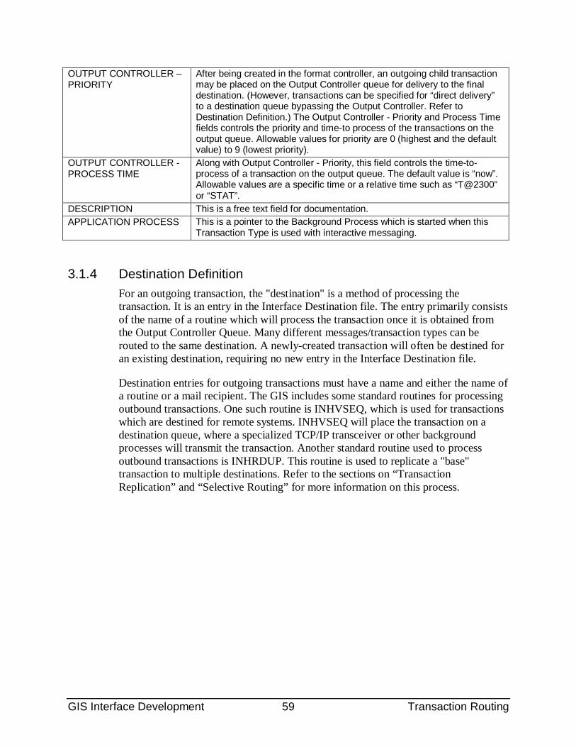
GIS Interface Development 59 Transaction Routing
OUTPUT CONTROLLER – PRIORITY
After being created in the format controller, an outgoing child transaction may be placed on the Output Controller queue for delivery to the final destination. (However, transactions can be specified for “direct delivery” to a destination queue bypassing the Output Controller. Refer to Destination Definition.) The Output Controller - Priority and Process Time fields controls the priority and time-to process of the transactions on the output queue. Allowable values for priority are 0 (highest and the default value) to 9 (lowest priority).
OUTPUT CONTROLLER - PROCESS TIME
Along with Output Controller - Priority, this field controls the time-to-process of a transaction on the output queue. The default value is “now”. Allowable values are a specific time or a relative time such as “T@2300” or “STAT”.
DESCRIPTION This is a free text field for documentation. APPLICATION PROCESS This is a pointer to the Background Process which is started when this
Transaction Type is used with interactive messaging.
3.1.4 Destination Definition For an outgoing transaction, the "destination" is a method of processing the transaction. It is an entry in the Interface Destination file. The entry primarily consists of the name of a routine which will process the transaction once it is obtained from the Output Controller Queue. Many different messages/transaction types can be routed to the same destination. A newly-created transaction will often be destined for an existing destination, requiring no new entry in the Interface Destination file.
Destination entries for outgoing transactions must have a name and either the name of a routine or a mail recipient. The GIS includes some standard routines for processing outbound transactions. One such routine is INHVSEQ, which is used for transactions which are destined for remote systems. INHVSEQ will place the transaction on a destination queue, where a specialized TCP/IP transceiver or other background processes will transmit the transaction. Another standard routine used to process outbound transactions is INHRDUP. This routine is used to replicate a "base" transaction to multiple destinations. Refer to the sections on “Transaction Replication” and “Selective Routing” for more information on this process.
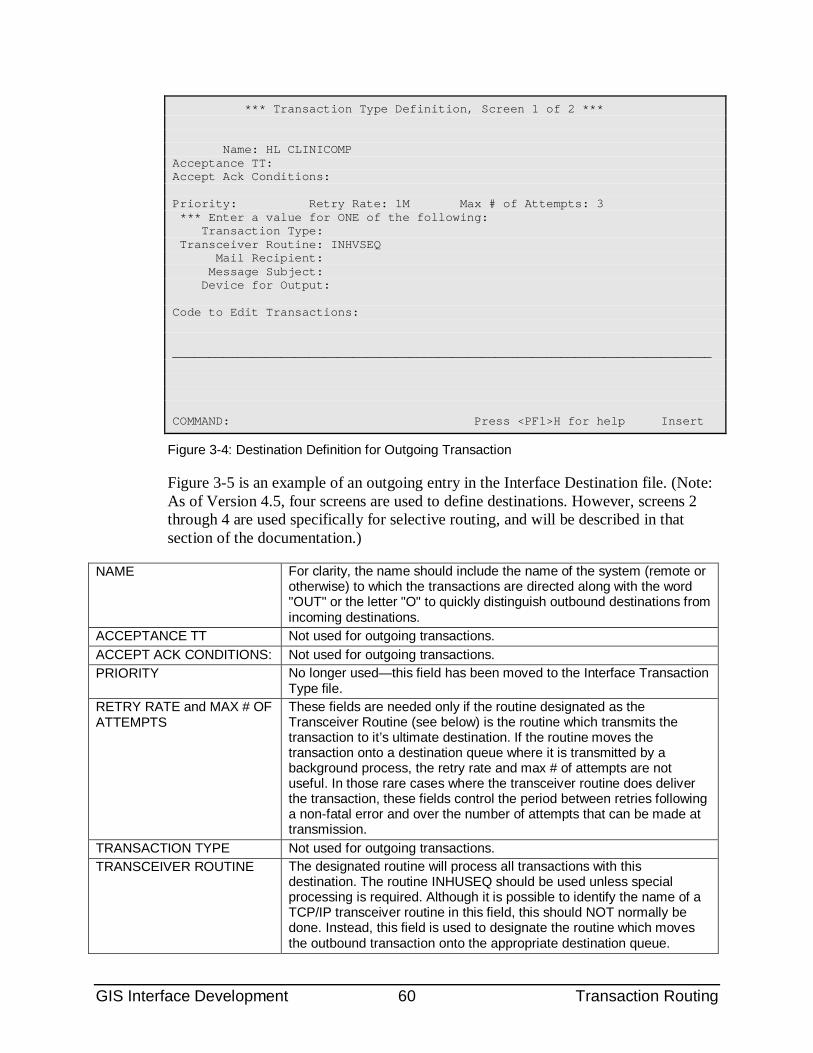
GIS Interface Development 60 Transaction Routing
*** Transaction Type Definition, Screen 1 of 2 *** Name: HL CLINICOMP Acceptance TT: Accept Ack Conditions: Priority: Retry Rate: 1M Max # of Attempts: 3 *** Enter a value for ONE of the following: Transaction Type: Transceiver Routine: INHVSEQ Mail Recipient: Message Subject: Device for Output: Code to Edit Transactions: ___________________________________________________________________________ COMMAND: Press <PF1>H for help Insert
Figure 3-4: Destination Definition for Outgoing Transaction
Figure 3-5 is an example of an outgoing entry in the Interface Destination file. (Note: As of Version 4.5, four screens are used to define destinations. However, screens 2 through 4 are used specifically for selective routing, and will be described in that section of the documentation.)
NAME For clarity, the name should include the name of the system (remote or otherwise) to which the transactions are directed along with the word "OUT" or the letter "O" to quickly distinguish outbound destinations from incoming destinations.
ACCEPTANCE TT Not used for outgoing transactions. ACCEPT ACK CONDITIONS: Not used for outgoing transactions. PRIORITY No longer used—this field has been moved to the Interface Transaction
Type file. RETRY RATE and MAX # OF ATTEMPTS
These fields are needed only if the routine designated as the Transceiver Routine (see below) is the routine which transmits the transaction to it’s ultimate destination. If the routine moves the transaction onto a destination queue where it is transmitted by a background process, the retry rate and max # of attempts are not useful. In those rare cases where the transceiver routine does deliver the transaction, these fields control the period between retries following a non-fatal error and over the number of attempts that can be made at transmission.
TRANSACTION TYPE Not used for outgoing transactions. TRANSCEIVER ROUTINE The designated routine will process all transactions with this
destination. The routine INHUSEQ should be used unless special processing is required. Although it is possible to identify the name of a TCP/IP transceiver routine in this field, this should NOT normally be done. Instead, this field is used to designate the routine which moves the outbound transaction onto the appropriate destination queue.
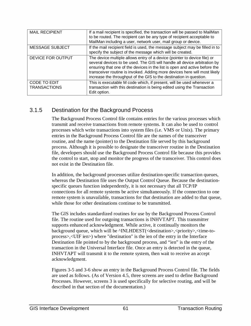
GIS Interface Development 61 Transaction Routing
MAIL RECIPIENT If a mail recipient is specified, the transaction will be passed to MailMan to be routed. The recipient can be any type of recipient acceptable to MailMan including a user, network user, mail group or device.
MESSAGE SUBJECT If the mail recipient field is used, the message subject may be filled in to specify the subject of the message which will be created.
DEVICE FOR OUTPUT The device multiple allows entry of a device (pointer to device file) or several devices to be used. The GIS will handle all device arbitration by ensuring that one of the devices in the list is open and active before the transceiver routine is invoked. Adding more devices here will most likely increase the throughput of the GIS to the destination in question.
CODE TO EDIT TRANSACTIONS
This is executable M code which, if present, will be used whenever a transaction with this destination is being edited using the Transaction Edit option.
3.1.5 Destination for the Background Process The Background Process Control file contains entries for the various processes which transmit and receive transactions from remote systems. It can also be used to control processes which write transactions into system files (i.e. VMS or Unix). The primary entries in the Background Process Control file are the names of the transceiver routine, and the name (pointer) to the Destination file served by this background process. Although it is possible to designate the transceiver routine in the Destination file, developers should use the Background Process Control file because this provides the control to start, stop and monitor the progress of the transceiver. This control does not exist in the Destination file.
In addition, the background processes utilize destination-specific transaction queues, whereas the Destination file uses the Output Control Queue. Because the destination-specific queues function independently, it is not necessary that all TCP/IP connections for all remote systems be active simultaneously. If the connection to one remote system is unavailable, transactions for that destination are added to that queue, while those for other destinations continue to be transmitted.
The GIS includes standardized routines for use by the Background Process Control file. The routine used for outgoing transactions is INHVTAPT. This transmitter supports enhanced acknowledgment. While active, it continually monitors the background queue, which will be ^INLHDEST(<destination>,<priority>,<time-to-process>,<UIF ien>) where "destination" is the ien of the entry in the Interface Destination file pointed to by the background process, and “ien” is the entry of the transaction in the Universal Interface file. Once an entry is detected in the queue, INHVTAPT will transmit it to the remote system, then wait to receive an accept acknowledgment.
Figures 3-5 and 3-6 show an entry in the Background Process Control file. The fields are used as follows. (As of Version 4.5, three screens are used to define Background Processes. However, screens 3 is used specifically for selective routing, and will be described in that section of the documentation.)
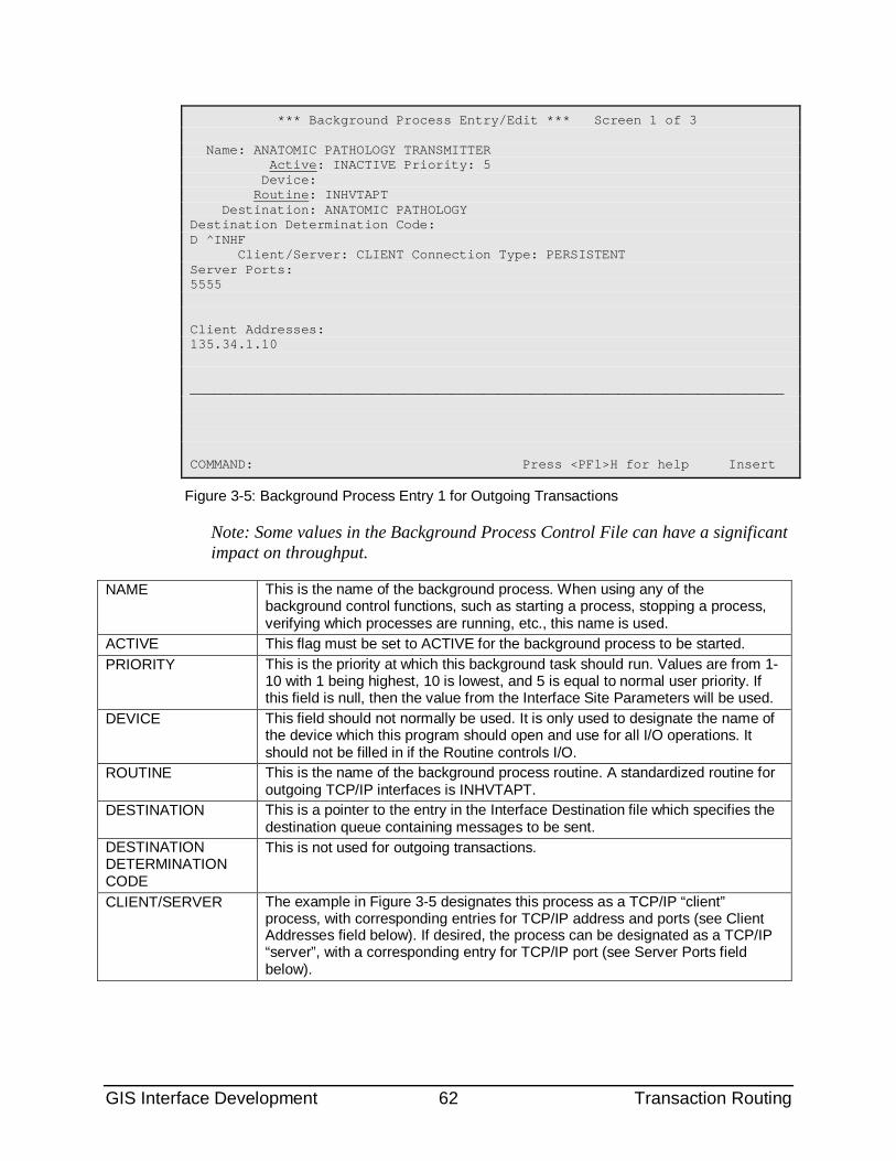
GIS Interface Development 62 Transaction Routing
*** Background Process Entry/Edit *** Screen 1 of 3 Name: ANATOMIC PATHOLOGY TRANSMITTER Active: INACTIVE Priority: 5 Device: Routine: INHVTAPT Destination: ANATOMIC PATHOLOGY Destination Determination Code: D ^INHF Client/Server: CLIENT Connection Type: PERSISTENT Server Ports: 5555 Client Addresses: 135.34.1.10 ___________________________________________________________________________ COMMAND: Press <PF1>H for help Insert
Figure 3-5: Background Process Entry 1 for Outgoing Transactions
Note: Some values in the Background Process Control File can have a significant impact on throughput.
NAME This is the name of the background process. When using any of the background control functions, such as starting a process, stopping a process, verifying which processes are running, etc., this name is used.
ACTIVE This flag must be set to ACTIVE for the background process to be started. PRIORITY This is the priority at which this background task should run. Values are from 1-
10 with 1 being highest, 10 is lowest, and 5 is equal to normal user priority. If this field is null, then the value from the Interface Site Parameters will be used.
DEVICE This field should not normally be used. It is only used to designate the name of the device which this program should open and use for all I/O operations. It should not be filled in if the Routine controls I/O.
ROUTINE This is the name of the background process routine. A standardized routine for outgoing TCP/IP interfaces is INHVTAPT.
DESTINATION This is a pointer to the entry in the Interface Destination file which specifies the destination queue containing messages to be sent.
DESTINATION DETERMINATION CODE
This is not used for outgoing transactions.
CLIENT/SERVER The example in Figure 3-5 designates this process as a TCP/IP “client” process, with corresponding entries for TCP/IP address and ports (see Client Addresses field below). If desired, the process can be designated as a TCP/IP “server”, with a corresponding entry for TCP/IP port (see Server Ports field below).
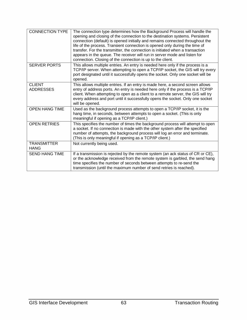
GIS Interface Development 63 Transaction Routing
CONNECTION TYPE The connection type determines how the Background Process will handle the opening and closing of the connection to the destination systems. Persistent connection (default) is opened initially and remains connected throughout the life of the process. Transient connection is opened only during the time of transfer. For the transmitter, the connection is initiated when a transaction appears in the queue. The receiver will run in server mode and listen for connection. Closing of the connection is up to the client.
SERVER PORTS This allows multiple entries. An entry is needed here only if the process is a TCP/IP server. When attempting to open a TCP/IP socket, the GIS will try every port designated until it successfully opens the socket. Only one socket will be opened.
CLIENT ADDRESSES
This allows multiple entries. If an entry is made here, a second screen allows entry of address ports. An entry is needed here only if the process is a TCP/IP client. When attempting to open as a client to a remote server, the GIS will try every address and port until it successfully opens the socket. Only one socket will be opened.
OPEN HANG TIME Used as the background process attempts to open a TCP/IP socket, it is the hang time, in seconds, between attempts to open a socket. (This is only meaningful if opening as a TCP/IP client.)
OPEN RETRIES This specifies the number of times the background process will attempt to open a socket. If no connection is made with the other system after the specified number of attempts, the background process will log an error and terminate. (This is only meaningful if opening as a TCP/IP client.)
TRANSMITTER HANG
Not currently being used.
SEND HANG TIME If a transmission is rejected by the remote system (an ack status of CR or CE), or the acknowledge received from the remote system is garbled, the send hang time specifies the number of seconds between attempts to re-send the transmission (until the maximum number of send retries is reached).
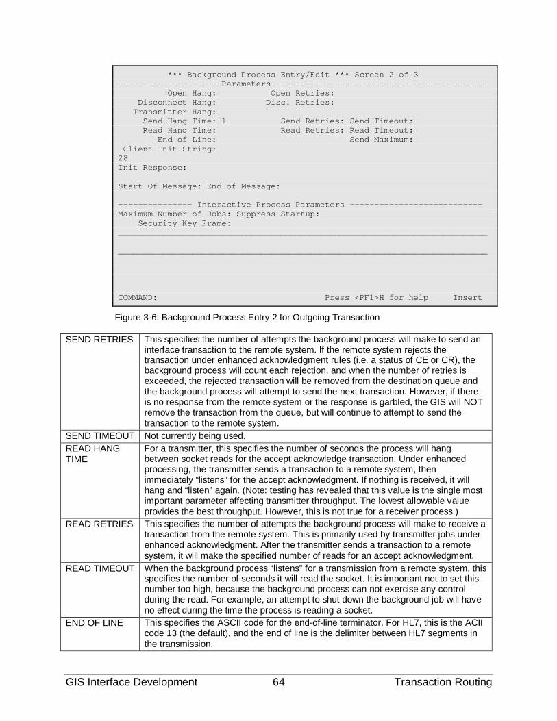
GIS Interface Development 64 Transaction Routing
*** Background Process Entry/Edit *** Screen 2 of 3 -------------------- Parameters ------------------------------------------- Open Hang: Open Retries: Disconnect Hang: Disc. Retries: Transmitter Hang: Send Hang Time: 1 Send Retries: Send Timeout: Read Hang Time: Read Retries: Read Timeout: End of Line: Send Maximum: Client Init String: 28 Init Response: Start Of Message: End of Message: --------------- Interactive Process Parameters --------------------------- Maximum Number of Jobs: Suppress Startup: Security Key Frame: ___________________________________________________________________________ ___________________________________________________________________________ COMMAND: Press <PF1>H for help Insert
Figure 3-6: Background Process Entry 2 for Outgoing Transaction
SEND RETRIES This specifies the number of attempts the background process will make to send an interface transaction to the remote system. If the remote system rejects the transaction under enhanced acknowledgment rules (i.e. a status of CE or CR), the background process will count each rejection, and when the number of retries is exceeded, the rejected transaction will be removed from the destination queue and the background process will attempt to send the next transaction. However, if there is no response from the remote system or the response is garbled, the GIS will NOT remove the transaction from the queue, but will continue to attempt to send the transaction to the remote system.
SEND TIMEOUT Not currently being used. READ HANG TIME
For a transmitter, this specifies the number of seconds the process will hang between socket reads for the accept acknowledge transaction. Under enhanced processing, the transmitter sends a transaction to a remote system, then immediately “listens” for the accept acknowledgment. If nothing is received, it will hang and “listen” again. (Note: testing has revealed that this value is the single most important parameter affecting transmitter throughput. The lowest allowable value provides the best throughput. However, this is not true for a receiver process.)
READ RETRIES This specifies the number of attempts the background process will make to receive a transaction from the remote system. This is primarily used by transmitter jobs under enhanced acknowledgment. After the transmitter sends a transaction to a remote system, it will make the specified number of reads for an accept acknowledgment.
READ TIMEOUT When the background process “listens” for a transmission from a remote system, this specifies the number of seconds it will read the socket. It is important not to set this number too high, because the background process can not exercise any control during the read. For example, an attempt to shut down the background job will have no effect during the time the process is reading a socket.
END OF LINE This specifies the ASCII code for the end-of-line terminator. For HL7, this is the ACII code 13 (the default), and the end of line is the delimiter between HL7 segments in the transmission.
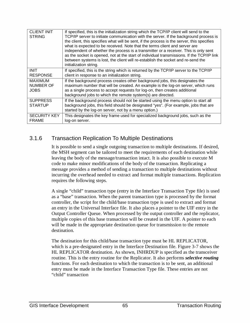
GIS Interface Development 65 Transaction Routing
CLIENT INIT STRING
If specified, this is the initialization string which the TCP/IP client will send to the TCP/IP server to initiate communication with the server. If the background process is the client, this specifies what will be sent, if the process is the server, this specifies what is expected to be received. Note that the terms client and server are independent of whether the process is a transmitter or a receiver. This is only sent as the socket is opened, not at the start of individual transmissions. If the TCP/IP link between systems is lost, the client will re-establish the socket and re-send the initialization string.
INIT RESPONSE
If specified, this is the string which is returned by the TCP/IP server to the TCP/IP client in response to an initialization string.
MAXIMUM NUMBER OF JOBS
If the background process creates other background jobs, this designates the maximum number that will be created. An example is the log-on server, which runs as a single process to accept requests for log-on, then creates additional background jobs to which the remote system(s) are directed.
SUPPRESS STARTUP
If the background process should not be started using the menu option to start all background jobs, this field should be designated “yes”. (For example, jobs that are started by the log-on server, not by a menu option.)
SECURITY KEY FRAME
This designates the key frame used for specialized background jobs, such as the log-on server.
3.1.6 Transaction Replication To Multiple Destinations It is possible to send a single outgoing transaction to multiple destinations. If desired, the MSH segment can be tailored to meet the requirements of each destination while leaving the body of the message/transaction intact. It is also possible to execute M code to make minor modifications of the body of the transaction. Replicating a message provides a method of sending a transaction to multiple destinations without incurring the overhead needed to extract and format multiple transactions. Replication requires the following steps.
A single “child” transaction type (entry in the Interface Transaction Type file) is used as a “base” transaction. When the parent transaction type is processed by the format controller, the script for the child/base transaction type is used to extract and format an entry in the Universal Interface file. It also places a pointer to the UIF entry in the Output Controller Queue. When processed by the output controller and the replicator, multiple copies of this base transaction will be created in the UIF. A pointer to each will be made in the appropriate destination queue for transmission to the remote destination.
The destination for this child/base transaction type must be HL REPLICATOR, which is a pre-designated entry in the Interface Destination file. Figure 3-7 shows the HL REPLICATOR destination. As shown, INHRDUP is specified as the transceiver routine. This is the entry routine for the Replicator. It also performs selective routing functions. For each destination to which the transaction is to be sent, an additional entry must be made in the Interface Transaction Type file. These entries are not “child” transaction
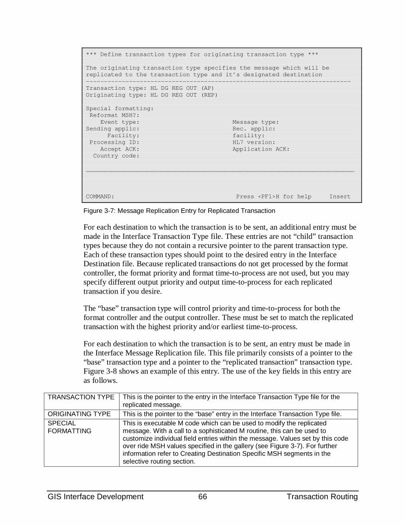
GIS Interface Development 66 Transaction Routing
*** Define transaction types for originating transaction type *** The originating transaction type specifies the message which will be replicated to the transaction type and it’s designated destination -------------------------------------------------------------------------- Transaction type: HL DG REG OUT (AP) Originating type: HL DG REG OUT (REP) Special formatting: Reformat MSH?: Event type: Message type: Sending applic: Rec. applic: Facility: facility: Processing ID: HL7 version: Accept ACK: Application ACK: Country code: ___________________________________________________________________________ COMMAND: Press <PF1>H for help Insert
Figure 3-7: Message Replication Entry for Replicated Transaction
For each destination to which the transaction is to be sent, an additional entry must be made in the Interface Transaction Type file. These entries are not “child” transaction types because they do not contain a recursive pointer to the parent transaction type. Each of these transaction types should point to the desired entry in the Interface Destination file. Because replicated transactions do not get processed by the format controller, the format priority and format time-to-process are not used, but you may specify different output priority and output time-to-process for each replicated transaction if you desire.
The “base” transaction type will control priority and time-to-process for both the format controller and the output controller. These must be set to match the replicated transaction with the highest priority and/or earliest time-to-process.
For each destination to which the transaction is to be sent, an entry must be made in the Interface Message Replication file. This file primarily consists of a pointer to the “base” transaction type and a pointer to the “replicated transaction” transaction type. Figure 3-8 shows an example of this entry. The use of the key fields in this entry are as follows.
TRANSACTION TYPE This is the pointer to the entry in the Interface Transaction Type file for the replicated message.
ORIGINATING TYPE This is the pointer to the “base” entry in the Interface Transaction Type file. SPECIAL FORMATTING
This is executable M code which can be used to modify the replicated message. With a call to a sophisticated M routine, this can be used to customize individual field entries within the message. Values set by this code over ride MSH values specified in the gallery (see Figure 3-7). For further information refer to Creating Destination Specific MSH segments in the selective routing section.
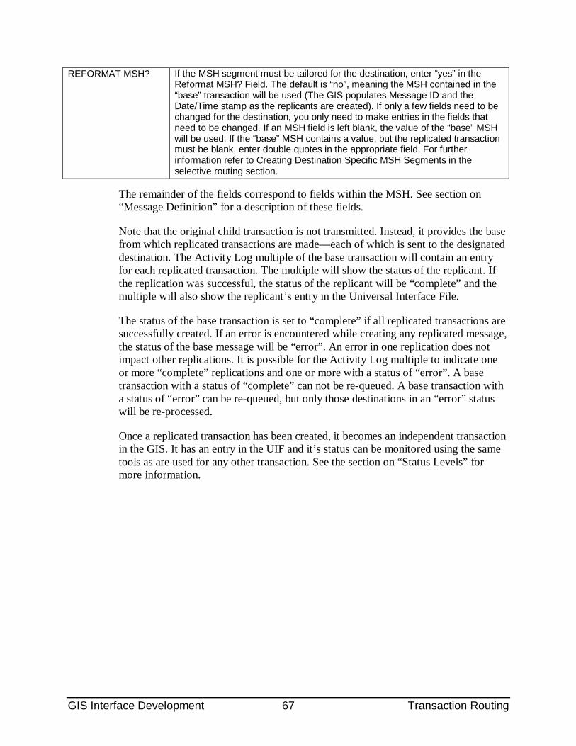
GIS Interface Development 67 Transaction Routing
REFORMAT MSH? If the MSH segment must be tailored for the destination, enter “yes” in the Reformat MSH? Field. The default is “no”, meaning the MSH contained in the “base” transaction will be used (The GIS populates Message ID and the Date/Time stamp as the replicants are created). If only a few fields need to be changed for the destination, you only need to make entries in the fields that need to be changed. If an MSH field is left blank, the value of the “base” MSH will be used. If the “base” MSH contains a value, but the replicated transaction must be blank, enter double quotes in the appropriate field. For further information refer to Creating Destination Specific MSH Segments in the selective routing section.
The remainder of the fields correspond to fields within the MSH. See section on “Message Definition” for a description of these fields.
Note that the original child transaction is not transmitted. Instead, it provides the base from which replicated transactions are made—each of which is sent to the designated destination. The Activity Log multiple of the base transaction will contain an entry for each replicated transaction. The multiple will show the status of the replicant. If the replication was successful, the status of the replicant will be “complete” and the multiple will also show the replicant’s entry in the Universal Interface File.
The status of the base transaction is set to “complete” if all replicated transactions are successfully created. If an error is encountered while creating any replicated message, the status of the base message will be “error”. An error in one replication does not impact other replications. It is possible for the Activity Log multiple to indicate one or more “complete” replications and one or more with a status of “error”. A base transaction with a status of “complete” can not be re-queued. A base transaction with a status of “error” can be re-queued, but only those destinations in an “error” status will be re-processed.
Once a replicated transaction has been created, it becomes an independent transaction in the GIS. It has an entry in the UIF and it’s status can be monitored using the same tools as are used for any other transaction. See the section on “Status Levels” for more information.
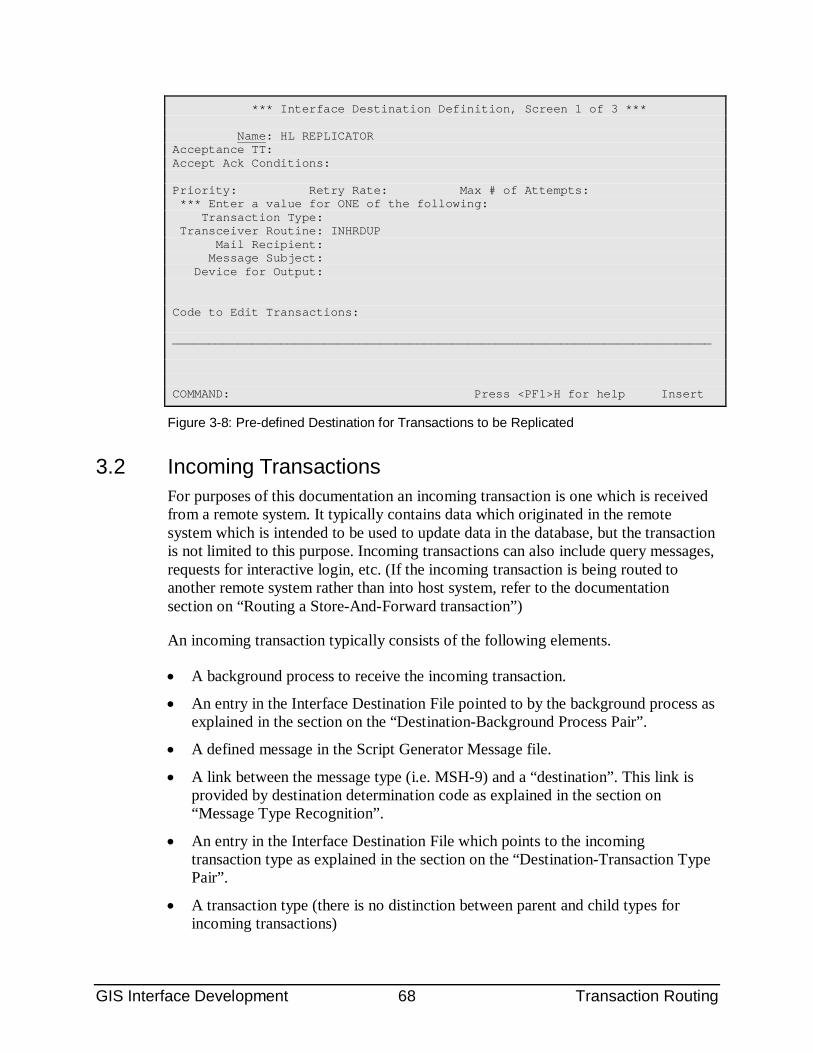
GIS Interface Development 68 Transaction Routing
*** Interface Destination Definition, Screen 1 of 3 *** Name: HL REPLICATOR Acceptance TT: Accept Ack Conditions: Priority: Retry Rate: Max # of Attempts: *** Enter a value for ONE of the following: Transaction Type: Transceiver Routine: INHRDUP Mail Recipient: Message Subject: Device for Output: Code to Edit Transactions: ___________________________________________________________________________ COMMAND: Press <PF1>H for help Insert
Figure 3-8: Pre-defined Destination for Transactions to be Replicated
3.2 Incoming Transactions For purposes of this documentation an incoming transaction is one which is received from a remote system. It typically contains data which originated in the remote system which is intended to be used to update data in the database, but the transaction is not limited to this purpose. Incoming transactions can also include query messages, requests for interactive login, etc. (If the incoming transaction is being routed to another remote system rather than into host system, refer to the documentation section on “Routing a Store-And-Forward transaction”)
An incoming transaction typically consists of the following elements.
• A background process to receive the incoming transaction.
• An entry in the Interface Destination File pointed to by the background process as explained in the section on the “Destination-Background Process Pair”.
• A defined message in the Script Generator Message file.
• A link between the message type (i.e. MSH-9) and a “destination”. This link is provided by destination determination code as explained in the section on “Message Type Recognition”.
• An entry in the Interface Destination File which points to the incoming transaction type as explained in the section on the “Destination-Transaction Type Pair”.
• A transaction type (there is no distinction between parent and child types for incoming transactions)
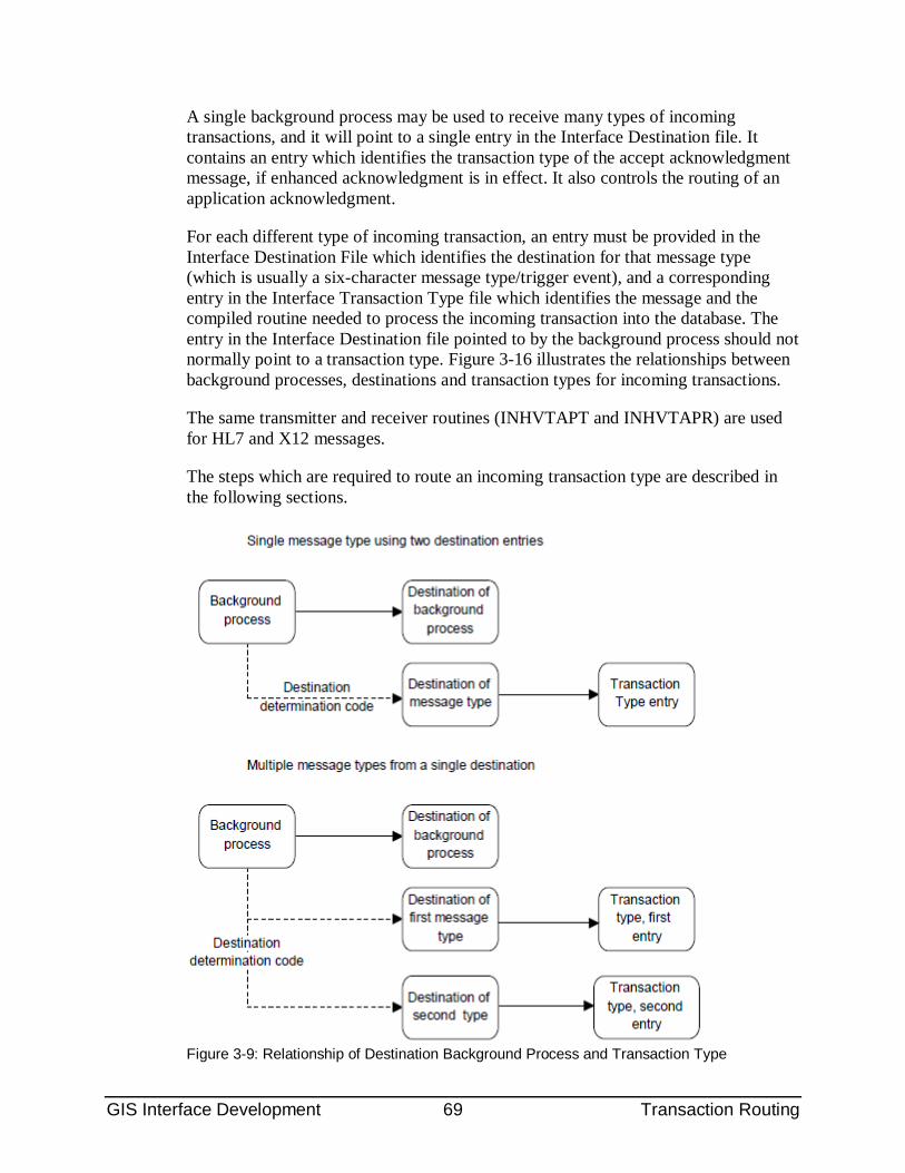
GIS Interface Development 69 Transaction Routing
A single background process may be used to receive many types of incoming transactions, and it will point to a single entry in the Interface Destination file. It contains an entry which identifies the transaction type of the accept acknowledgment message, if enhanced acknowledgment is in effect. It also controls the routing of an application acknowledgment.
For each different type of incoming transaction, an entry must be provided in the Interface Destination File which identifies the destination for that message type (which is usually a six-character message type/trigger event), and a corresponding entry in the Interface Transaction Type file which identifies the message and the compiled routine needed to process the incoming transaction into the database. The entry in the Interface Destination file pointed to by the background process should not normally point to a transaction type. Figure 3-16 illustrates the relationships between background processes, destinations and transaction types for incoming transactions.
The same transmitter and receiver routines (INHVTAPT and INHVTAPR) are used for HL7 and X12 messages.
The steps which are required to route an incoming transaction type are described in the following sections.
Figure 3-9: Relationship of Destination Background Process and Transaction Type
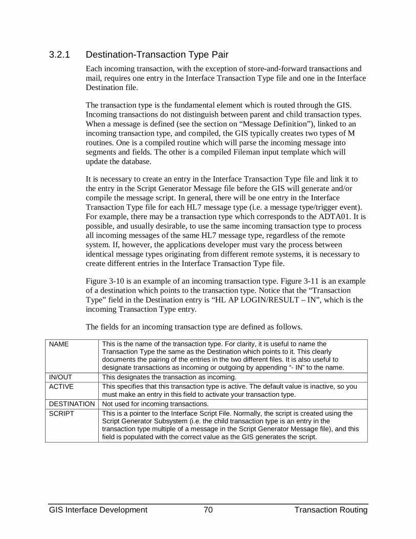
GIS Interface Development 70 Transaction Routing
3.2.1 Destination-Transaction Type Pair Each incoming transaction, with the exception of store-and-forward transactions and mail, requires one entry in the Interface Transaction Type file and one in the Interface Destination file.
The transaction type is the fundamental element which is routed through the GIS. Incoming transactions do not distinguish between parent and child transaction types. When a message is defined (see the section on “Message Definition”), linked to an incoming transaction type, and compiled, the GIS typically creates two types of M routines. One is a compiled routine which will parse the incoming message into segments and fields. The other is a compiled Fileman input template which will update the database.
It is necessary to create an entry in the Interface Transaction Type file and link it to the entry in the Script Generator Message file before the GIS will generate and/or compile the message script. In general, there will be one entry in the Interface Transaction Type file for each HL7 message type (i.e. a message type/trigger event). For example, there may be a transaction type which corresponds to the ADTA01. It is possible, and usually desirable, to use the same incoming transaction type to process all incoming messages of the same HL7 message type, regardless of the remote system. If, however, the applications developer must vary the process between identical message types originating from different remote systems, it is necessary to create different entries in the Interface Transaction Type file.
Figure 3-10 is an example of an incoming transaction type. Figure 3-11 is an example of a destination which points to the transaction type. Notice that the “Transaction Type” field in the Destination entry is “HL AP LOGIN/RESULT – IN”, which is the incoming Transaction Type entry.
The fields for an incoming transaction type are defined as follows.
NAME This is the name of the transaction type. For clarity, it is useful to name the Transaction Type the same as the Destination which points to it. This clearly documents the pairing of the entries in the two different files. It is also useful to designate transactions as incoming or outgoing by appending “- IN” to the name.
IN/OUT This designates the transaction as incoming. ACTIVE This specifies that this transaction type is active. The default value is inactive, so you
must make an entry in this field to activate your transaction type. DESTINATION Not used for incoming transactions. SCRIPT This is a pointer to the Interface Script File. Normally, the script is created using the
Script Generator Subsystem (i.e. the child transaction type is an entry in the transaction type multiple of a message in the Script Generator Message file), and this field is populated with the correct value as the GIS generates the script.
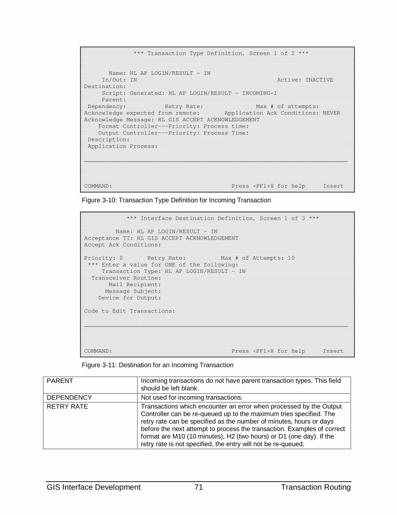
GIS Interface Development 71 Transaction Routing
*** Transaction Type Definition, Screen 1 of 2 *** Name: HL AP LOGIN/RESULT – IN In/Out: IN Active: INACTIVE Destination: Script: Generated: HL AP LOGIN/RESULT – INCOMING-I Parent: Dependency: Retry Rate: Max # of attempts: Acknowledge expected from remote: Application Ack Conditions: NEVER Acknowledge Message: HL GIS ACCEPT ACKNOWLEDGEMENT Format Controller---Priority: Process time: Output Controller---Priority: Process Time: Description: Application Process: ___________________________________________________________________________ COMMAND: Press <PF1>H for help Insert
Figure 3-10: Transaction Type Definition for Incoming Transaction
*** Interface Destination Definition, Screen 1 of 3 *** Name: HL AP LOGIN/RESULT – IN Acceptance TT: HL GIS ACCEPT ACKNOWLEDGEMENT Accept Ack Conditions: Priority: 0 Retry Rate: Max # of Attempts: 10 *** Enter a value for ONE of the following: Transaction Type: HL AP LOGIN/RESULT – IN Transceiver Routine: Mail Recipient: Message Subject: Device for Output: Code to Edit Transactions: ___________________________________________________________________________ COMMAND: Press <PF1>H for help Insert
Figure 3-11: Destination for an Incoming Transaction
PARENT Incoming transactions do not have parent transaction types. This field should be left blank.
DEPENDENCY Not used for incoming transactions. RETRY RATE Transactions which encounter an error when processed by the Output
Controller can be re-queued up to the maximum tries specified. The retry rate can be specified as the number of minutes, hours or days before the next attempt to process the transaction. Examples of correct format are M10 (10 minutes), H2 (two hours) or D1 (one day). If the retry rate is not specified, the entry will not be re-queued.
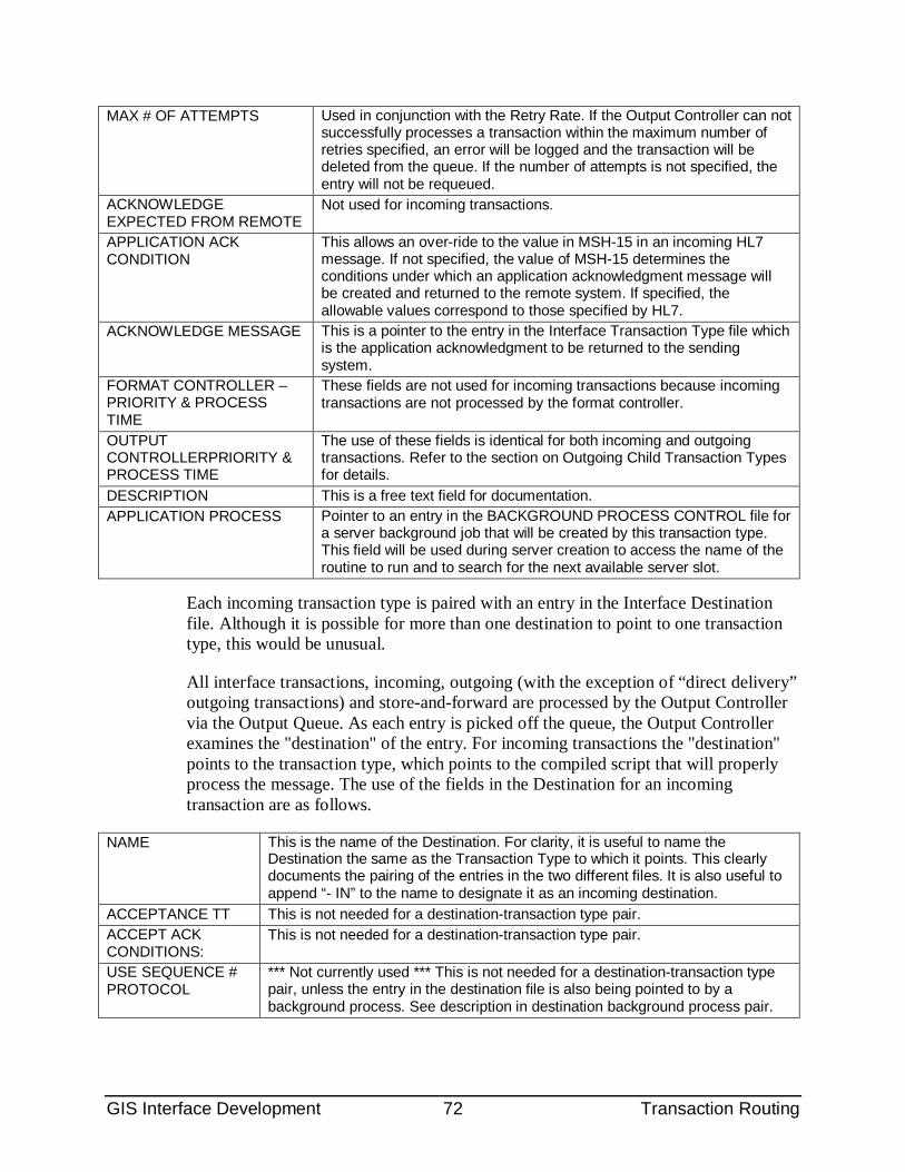
GIS Interface Development 72 Transaction Routing
MAX # OF ATTEMPTS Used in conjunction with the Retry Rate. If the Output Controller can not successfully processes a transaction within the maximum number of retries specified, an error will be logged and the transaction will be deleted from the queue. If the number of attempts is not specified, the entry will not be requeued.
ACKNOWLEDGE EXPECTED FROM REMOTE
Not used for incoming transactions.
APPLICATION ACK CONDITION
This allows an over-ride to the value in MSH-15 in an incoming HL7 message. If not specified, the value of MSH-15 determines the conditions under which an application acknowledgment message will be created and returned to the remote system. If specified, the allowable values correspond to those specified by HL7.
ACKNOWLEDGE MESSAGE This is a pointer to the entry in the Interface Transaction Type file which is the application acknowledgment to be returned to the sending system.
FORMAT CONTROLLER – PRIORITY & PROCESS TIME
These fields are not used for incoming transactions because incoming transactions are not processed by the format controller.
OUTPUT CONTROLLERPRIORITY & PROCESS TIME
The use of these fields is identical for both incoming and outgoing transactions. Refer to the section on Outgoing Child Transaction Types for details.
DESCRIPTION This is a free text field for documentation. APPLICATION PROCESS Pointer to an entry in the BACKGROUND PROCESS CONTROL file for
a server background job that will be created by this transaction type. This field will be used during server creation to access the name of the routine to run and to search for the next available server slot.
Each incoming transaction type is paired with an entry in the Interface Destination file. Although it is possible for more than one destination to point to one transaction type, this would be unusual.
All interface transactions, incoming, outgoing (with the exception of “direct delivery” outgoing transactions) and store-and-forward are processed by the Output Controller via the Output Queue. As each entry is picked off the queue, the Output Controller examines the "destination" of the entry. For incoming transactions the "destination" points to the transaction type, which points to the compiled script that will properly process the message. The use of the fields in the Destination for an incoming transaction are as follows.
NAME This is the name of the Destination. For clarity, it is useful to name the Destination the same as the Transaction Type to which it points. This clearly documents the pairing of the entries in the two different files. It is also useful to append “- IN” to the name to designate it as an incoming destination.
ACCEPTANCE TT This is not needed for a destination-transaction type pair. ACCEPT ACK CONDITIONS:
This is not needed for a destination-transaction type pair.
USE SEQUENCE # PROTOCOL
*** Not currently used *** This is not needed for a destination-transaction type pair, unless the entry in the destination file is also being pointed to by a background process. See description in destination background process pair.
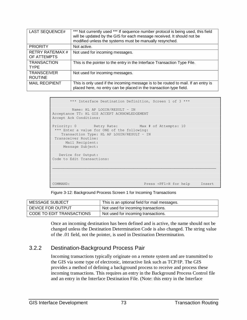
GIS Interface Development 73 Transaction Routing
LAST SEQUENCE# *** Not currently used *** If sequence number protocol is being used, this field will be updated by the GIS for each message received. It should not be modified unless the systems must be manually resynched.
PRIORITY Not active. RETRY RATE/MAX # OF ATTEMPTS
Not used for incoming messages.
TRANSACTION TYPE
This is the pointer to the entry in the Interface Transaction Type File.
TRANSCEIVER ROUTINE
Not used for incoming messages.
MAIL RECIPIENT This is only used if the incoming message is to be routed to mail. If an entry is placed here, no entry can be placed in the transaction type field.
*** Interface Destination Definition, Screen 1 of 3 *** Name: HL AP LOGIN/RESULT - IN Acceptance TT: HL GIS ACCEPT ACKNOWLEDGEMENT Accept Ack Conditions: Priority: 0 Retry Rate: Max # of Attempts: 10 *** Enter a value for ONE of the following: Transaction Type: HL AP LOGIN/RESULT - IN Transceiver Routine: Mail Recipient: Message Subject: Device for Output: Code to Edit Transactions: ___________________________________________________________________________ COMMAND: Press <PF1>H for help Insert
Figure 3-12: Background Process Screen 1 for Incoming Transactions
MESSAGE SUBJECT This is an optional field for mail messages. DEVICE FOR OUTPUT Not used for incoming transactions. CODE TO EDIT TRANSACTIONS Not used for incoming transactions.
Once an incoming destination has been defined and is active, the name should not be changed unless the Destination Determination Code is also changed. The string value of the .01 field, not the pointer, is used in Destination Determination.
3.2.2 Destination-Background Process Pair Incoming transactions typically originate on a remote system and are transmitted to the GIS via some type of electronic, interactive link such as TCP/IP. The GIS provides a method of defining a background process to receive and process these incoming transactions. This requires an entry in the Background Process Control file and an entry in the Interface Destination File. (Note: this entry in the Interface
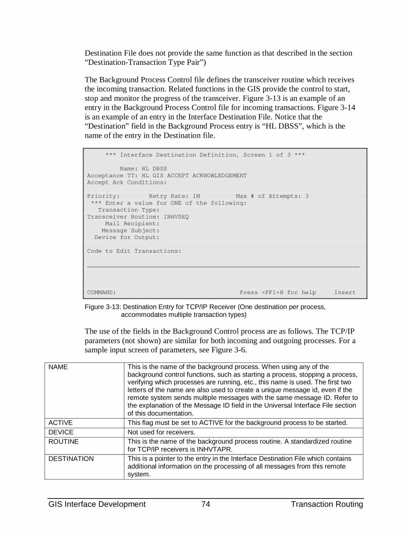
GIS Interface Development 74 Transaction Routing
Destination File does not provide the same function as that described in the section “Destination-Transaction Type Pair”)
The Background Process Control file defines the transceiver routine which receives the incoming transaction. Related functions in the GIS provide the control to start, stop and monitor the progress of the transceiver. Figure 3-13 is an example of an entry in the Background Process Control file for incoming transactions. Figure 3-14 is an example of an entry in the Interface Destination File. Notice that the “Destination” field in the Background Process entry is “HL DBSS”, which is the name of the entry in the Destination file.
*** Interface Destination Definition, Screen 1 of 3 *** Name: HL DBSS Acceptance TT: HL GIS ACCEPT ACKNOWLEDGEMENT Accept Ack Conditions: Priority: Retry Rate: 1M Max # of Attempts: 3 *** Enter a value for ONE of the following: Transaction Type: Transceiver Routine: INHVSEQ Mail Recipient: Message Subject: Device for Output: Code to Edit Transactions: ___________________________________________________________________________ COMMAND: Press <PF1>H for help Insert
Figure 3-13: Destination Entry for TCP/IP Receiver (One destination per process, accommodates multiple transaction types)
The use of the fields in the Background Control process are as follows. The TCP/IP parameters (not shown) are similar for both incoming and outgoing processes. For a sample input screen of parameters, see Figure 3-6.
NAME This is the name of the background process. When using any of the background control functions, such as starting a process, stopping a process, verifying which processes are running, etc., this name is used. The first two letters of the name are also used to create a unique message id, even if the remote system sends multiple messages with the same message ID. Refer to the explanation of the Message ID field in the Universal Interface File section of this documentation.
ACTIVE This flag must be set to ACTIVE for the background process to be started. DEVICE Not used for receivers. ROUTINE This is the name of the background process routine. A standardized routine
for TCP/IP receivers is INHVTAPR. DESTINATION This is a pointer to the entry in the Interface Destination File which contains
additional information on the processing of all messages from this remote system.
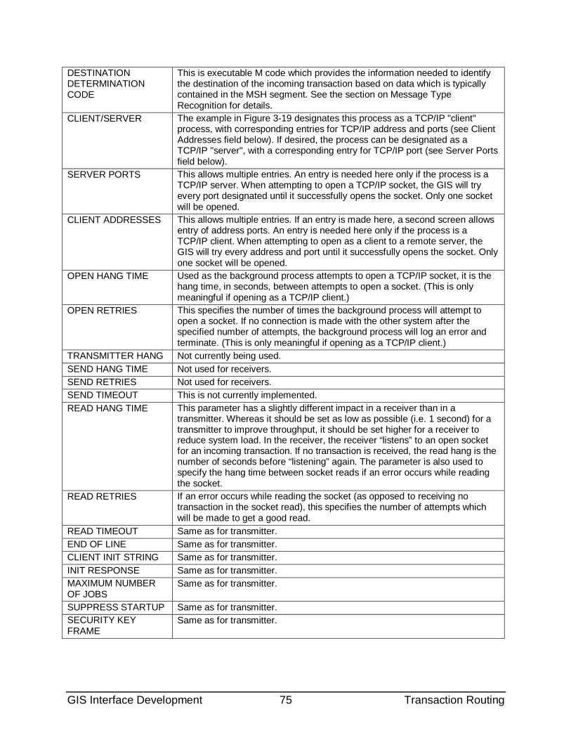
GIS Interface Development 75 Transaction Routing
DESTINATION DETERMINATION CODE
This is executable M code which provides the information needed to identify the destination of the incoming transaction based on data which is typically contained in the MSH segment. See the section on Message Type Recognition for details.
CLIENT/SERVER The example in Figure 3-19 designates this process as a TCP/IP "client" process, with corresponding entries for TCP/IP address and ports (see Client Addresses field below). If desired, the process can be designated as a TCP/IP "server", with a corresponding entry for TCP/IP port (see Server Ports field below).
SERVER PORTS This allows multiple entries. An entry is needed here only if the process is a TCP/IP server. When attempting to open a TCP/IP socket, the GIS will try every port designated until it successfully opens the socket. Only one socket will be opened.
CLIENT ADDRESSES This allows multiple entries. If an entry is made here, a second screen allows entry of address ports. An entry is needed here only if the process is a TCP/IP client. When attempting to open as a client to a remote server, the GIS will try every address and port until it successfully opens the socket. Only one socket will be opened.
OPEN HANG TIME Used as the background process attempts to open a TCP/IP socket, it is the hang time, in seconds, between attempts to open a socket. (This is only meaningful if opening as a TCP/IP client.)
OPEN RETRIES This specifies the number of times the background process will attempt to open a socket. If no connection is made with the other system after the specified number of attempts, the background process will log an error and terminate. (This is only meaningful if opening as a TCP/IP client.)
TRANSMITTER HANG Not currently being used. SEND HANG TIME Not used for receivers. SEND RETRIES Not used for receivers. SEND TIMEOUT This is not currently implemented. READ HANG TIME This parameter has a slightly different impact in a receiver than in a
transmitter. Whereas it should be set as low as possible (i.e. 1 second) for a transmitter to improve throughput, it should be set higher for a receiver to reduce system load. In the receiver, the receiver “listens” to an open socket for an incoming transaction. If no transaction is received, the read hang is the number of seconds before “listening” again. The parameter is also used to specify the hang time between socket reads if an error occurs while reading the socket.
READ RETRIES If an error occurs while reading the socket (as opposed to receiving no transaction in the socket read), this specifies the number of attempts which will be made to get a good read.
READ TIMEOUT Same as for transmitter. END OF LINE Same as for transmitter. CLIENT INIT STRING Same as for transmitter. INIT RESPONSE Same as for transmitter. MAXIMUM NUMBER OF JOBS
Same as for transmitter.
SUPPRESS STARTUP Same as for transmitter. SECURITY KEY FRAME
Same as for transmitter.
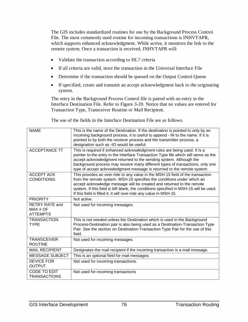
GIS Interface Development 76 Transaction Routing
The GIS includes standardized routines for use by the Background Process Control File. The most commonly used routine for incoming transactions is INHVTAPR, which supports enhanced acknowledgment. While active, it monitors the link to the remote system. Once a transaction is received, INHVTAPR will:
• Validate the transaction according to HL7 criteria
• If all criteria are valid, store the transaction in the Universal Interface File
• Determine if the transaction should be queued on the Output Control Queue
• If specified, create and transmit an accept acknowledgment back to the originating system.
The entry in the Background Process Control file is paired with an entry in the Interface Destination File. Refer to Figure 3-20. Notice that no values are entered for Transaction Type, Transceiver Routine or Mail Recipient.
The use of the fields in the Interface Destination File are as follows.
NAME This is the name of the Destination. If the destination is pointed to only by an incoming background process, it is useful to append - IN to the name. If it is pointed to by both the receiver process and the transmitter process, a designation such as -IO would be useful.
ACCEPTANCE TT This is required if enhanced acknowledgment rules are being used. It is a pointer to the entry in the Interface Transaction Type file which will serve as the accept acknowledgment returned to the sending system. Although the background process may receive many different types of transactions, only one type of accept acknowledgment message is returned to the remote system.
ACCEPT ACK CONDITIONS:
This provides an over-ride to any value in the MSH-15 field of the transaction from the remote system. MSH-15 specifies the conditions under which an accept acknowledge message will be created and returned to the remote system. If this field is left blank, the conditions specified in MSH-15 will be used. If this field is filled it, it will over-ride any value in MSH-15.
PRIORITY Not active. RETRY RATE and MAX # OF ATTEMPTS
Not used for incoming messages.
TRANSACTION TYPE
This is not needed unless the Destination which is used in the Background Process-Destination pair is also being used as a Destination-Transaction Type Pair. See the section on Destination-Transaction Type Pair for the use of this field.
TRANSCEIVER ROUTINE
Not used for incoming messages.
MAIL RECIPIENT Designates the mail recipient if the incoming transaction is a mail message. MESSAGE SUBJECT This is an optional field for mail messages. DEVICE FOR OUTPUT
Not used for incoming transactions.
CODE TO EDIT TRANSACTIONS
Not used for incoming transactions
GIS Interface Development 77 Transaction Routing
3.2.3 HL7 Message Type Recognition (Destination Determination) The HL7 standard specifies that the message type is contained in ninth field of the MSH (message header) segment of each message. The message type consists of a three-character message type which is, optionally, coupled with a three-character trigger event. Examples are ADTA01, ADTA02, etc.
The GIS contains a set of routines which are called from the receiver routine, INHVTAPR. These parse each incoming HL7 message and identify the HL7 message type. The applications developer must provide the link between the message type and the appropriate entry in the Interface Destination File. For incoming transactions, the destination entry points to an entry in the Interface Transaction Type file. For a store-and forward transaction, the destination entry points to another Destination.
Developers should provide executable code in the entry in the Destination Determination Code field in the Background Process Control File. An example of this is shown in Figure 3-18.
As each incoming transaction is processed, this executable code will attempt to identify an entry in the Interface Destination File which corresponds to the message type in the ninth field of the MSH. As the incoming transaction is filed into the Universal Interface File, it is this destination which is used as the Destination (.02) field of that file. Subsequently, when the transaction is processed by the Output Controller, this destination will enable the GIS to identify the inbound transaction type and it’s associated compiled script which will update the database.
The Destination Determination Code, either directly, or via an M routine which is executed, must either 1) create an array in the variable INDEST(<message type><trigger event>)=the string value of the .01 field in the Interface Destination file and call the tag DEST^INHUSEN or 2) set the variable INDSTP = to the ien of the entry in the Interface Destination File. Method 1 is preferred, though method 2 may be useful if only a single message type is being processed. For either method, the variables which are available to the applications developer are:
INTYP = the three-character HL7 message type INEVN = the three-character HL7 trigger event
The following entry in the Destination Determination Code field is an example of the first method.
S INDEST("ORU")="HL LA DII LSI INBOUND" D DEST^INHUSEN
An example of the second method is the following routine fragment, which is called from the Destination Determination Code field. This example accommodates several types of inbound HL7 messages and uses order type in addition to message type to determine the inbound destination.
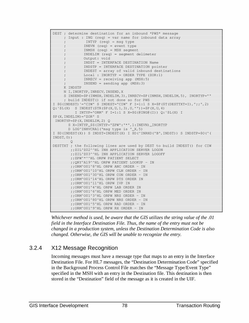
GIS Interface Development 78 Transaction Routing
DEST ; determine destination for an inbound *PWS* message ; Input : ING (req) = var name for inbound data array ; INTYP (req) = msg type ; INEVN (req) = event type ; INMSH (req) = MSH segment ; INDELIM (req) = segment delimeter ; Output: void ; INDST = INTERFACE DESTINATION Name ; INDSTP = INTERFACE DESTINATION pointer ; INDEST = array of valid inbound destinations ; Local : INORTYP = ORDER TYPE (ZOR:1) ; INRECV = receiving app (MSH:5) ; INSEND = sending app (MSH:3) K INDSTP N I,INORTYP,INRECV,INSEND,X S INSEND=$P(INMSH,INDELIM,3),INRECV=$P(INMSH,INDELIM,5), INORTYP="" ; build INDEST() if not done so for PWS I $G(INDEST)'="CIW" S INDEST="CIW" F I=1:1 S X=$P($T(DESTTXT+I),";;",2) Q:'$L(X) S INDEST($TR($P(X,U,1,3),U,""))=$P(X,U,4) I INTYP="ORM" F I=1:1 S X=$G(@ING@(I)) Q:'$L(X) I $P(X,INDELIM)="ZOR" S INORTYP=$P(X,INDELIM,2) Q S X=INTYP_$S(INTYP="ZPW":"*",1:INEVN)_INORTYP D LOG^INHVCRA1("msg type is "_X,5) I $D(INDEST(X)) S INDST=INDEST(X) I $D(^INRHD("B",INDST)) S INDSTP=$O(^( INDST,0)) Q DESTTXT ; the following lines are used by DEST to build INDEST() for CIW ;;ZIL^Z02^^HL INH APPLICATION SERVER LOGON ;;ZIL^Z03^^HL INH APPLICATION SERVER LOGOFF ;;ZPW^*^^HL ORPW PATIENT SELECT ;;QRY^A19^^HL ORPW PATIENT LOOKUP - IN ;;ORM^O01^8^HL ORPW ANC ORDER - IN ;;ORM^O01^10^HL ORPW CLN ORDER - IN ;;ORM^O01^30^HL ORPW CON ORDER - IN ;;ORM^O01^14^HL ORPW DTS ORDER IN ;;ORM^O01^11^HL ORPW IVP IN ;;ORM^O01^4^HL ORPW LAB ORDER IN ;;ORM^O01^6^HL ORPW MED ORDER IN ;;ORM^O01^3^HL ORPW NRS ORDER - IN ;;ORM^O01^80^HL ORPW NRS ORDER - IN ;;ORM^O01^5^HL ORPW RAD ORDER - IN ;;ORM^O01^9^HL ORPW RX ORDER - IN
Whichever method is used, be aware that the GIS utilizes the string value of the .01 field in the Interface Destination File. Thus, the name of the entry must not be changed in a production system, unless the Destination Determination Code is also changed. Otherwise, the GIS will be unable to recognize the entry.
3.2.4 X12 Message Recognition Incoming messages must have a message type that maps to an entry in the Interface Destination File. For HL7 messages, the “Destination Determination Code” specified in the Background Process Control File matches the “Message Type/Event Type” specified in the MSH with an entry in the Destination file. This destination is then stored in the “Destination” field of the message as it is created in the UIF.
GIS Interface Development 79 Transaction Routing
The X12 term for message type is “functional identifier”. It is not specified in the ISA header, but in the first field of the GS loop header (GS01). Values in this field equate to X12 message types. For example, FA (Functional Acknowledgment) equates to the 997 message, HB (Health Care Eligibility/Benefit Information) equates to the 271, etc.
The functional identifier will be used for X12 messages in the same way that the Message Type is used for HL7 messages. The “Destination Determination Code” specified in the Background Process Control File will map the functional identifier to an entry in the Interface Destination File. With properly constructed Destination Determination Code it will transparent whether the incoming message is an X12 message with a functional identifier or an HL7 message with a message type.
3.2.5 X12 Validation As with HL7, all X12 messages that are received by either the receiver (messages) or the transmitter (acknowledgements) are passed into IN^INHUSEN to be validated. Messages that begin with an ISA segment are assumed to be X12 messages and are validated according to X12 rules. The logic that returns properly formatted communication-level acknowledgements is also handled within the INHUSEN set of routines. Depending on the messaging partner, either a TA or a 997 may be used as the communication-level acknowledgement.
The overall design points for the message recognition/validation functions are as follows.
• All incoming messages, whether received by the transmitter or the receiver, are first validated according to X12 validation rules (refer to validation section for detailed validation design).
• All validated messages are stored in the UIF.
• FA or 997 acknowledgments update the “commit acknowledgment” field in the original outgoing message using the same logic as HL7 commit acknowledgments. For example, if the transaction type of the outgoing message does not specify that an application acknowledgment is required then receipt of the 997 updates the status of the original message to “complete”. Otherwise it updates to “sent” (or “error”).
Validation rules are as follows.
• The fourth character in the ISA segment will be identified as the delimiter. It will be used to parse the message. Any character can be used (but if it is a character that is also used in the text of the X12 message unpredictable parsing will occur).
GIS Interface Development 80 Transaction Routing
• The second segment must be either a “GS” or a “TA1”. A message that fails this requirement will be rejected. If the failed message is received by a transmitter, no further action will be taken and the retry logic of the transmitter will be followed. If the failed message is received by a receiver, a 997 acknowledgment message will be returned to the sending system.
• Unless the message is a TA1, it must contain one GE, ST and SE segment. The number of segments specified in the GE01 must match the number of segment in the ST-SE loop.
• Multiple ST-SE loops are not supported and will cause the entire message to be rejected. The same is true for multiple GS-GE loops.
• If the message is a 997, it must have an AK9 segment. The AK901 field must have an error code of A (Accepted), E (Accepted with errors) or R (Rejected). An “A” or “E” value will update the status of the original/outgoing message to either “Sent” (if an application acknowledgment is expected) or “Complete” (if not). An “R” value will update the status to “Commit Error” (check this)
• All error segments in a 997 (e.g. AK1, AK2, AK3, etc.) will be added to the error array and logged in the Interface Error File.
• If the incoming message specifies a trace number of an original message (such as a query sent from the RPMS system), the trace number will be identified. The location of this trace number varies depending on the type of message.
3.2.6 Functional Identifiers (Message Type) and Message Recognition
3.3 Responses to Incoming Transactions Upon receipt of an incoming transaction, it is often necessary for the receiving system to create and return some type of message to the sending system. One example of this is an acknowledgment transaction to indicate that the incoming transaction was received. Another type of response is required if the incoming transaction is a query for information. Yet another type of response supports logon requests from remote systems. This section of the documentation describes some of the responses which can be created using the GIS.
3.3.1 HL7 Accept Acknowledgments An accept acknowledgment (sometimes referred to as a “commit” acknowledgment) is an HL7 message which indicates that the receiving system has received the message transmitted by the sending system. The status field in the MSA segment indicates the success (CA = Commit Accept) or failure (CR = Commit Reject or CE = Commit Error). Accept acknowledgment (Refer to HL7 specifications, chapter 2.5, Application Processing Rules) is an optional feature of the HL7 version 2.3 specification.
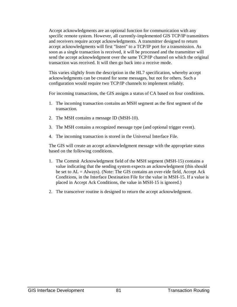
GIS Interface Development 81 Transaction Routing
Accept acknowledgments are an optional function for communication with any specific remote system. However, all currently-implemented GIS TCP/IP transmitters and receivers require accept acknowledgments. A transmitter designed to return accept acknowledgments will first "listen" to a TCP/IP port for a transmission. As soon as a single transaction is received, it will be processed and the transmitter will send the accept acknowledgment over the same TCP/IP channel on which the original transaction was received. It will then go back into a receive mode.
This varies slightly from the description in the HL7 specification, whereby accept acknowledgments can be created for some messages, but not for others. Such a configuration would require two TCP/IP channels to implement reliably.
For incoming transactions, the GIS assigns a status of CA based on four conditions.
1. The incoming transaction contains an MSH segment as the first segment of the transaction.
2. The MSH contains a message ID (MSH-10).
3. The MSH contains a recognized message type (and optional trigger event).
4. The incoming transaction is stored in the Universal Interface File.
The GIS will create an accept acknowledgment message with the appropriate status based on the following conditions.
1. The Commit Acknowledgment field of the MSH segment (MSH-15) contains a value indicating that the sending system expects an acknowledgment (this should be set to AL = Always). (Note: The GIS contains an over-ride field, Accept Ack Conditions, in the Interface Destination File for the value in MSH-15. If a value is placed in Accept Ack Conditions, the value in MSH-15 is ignored.)
2. The transceiver routine is designed to return the accept acknowledgment.
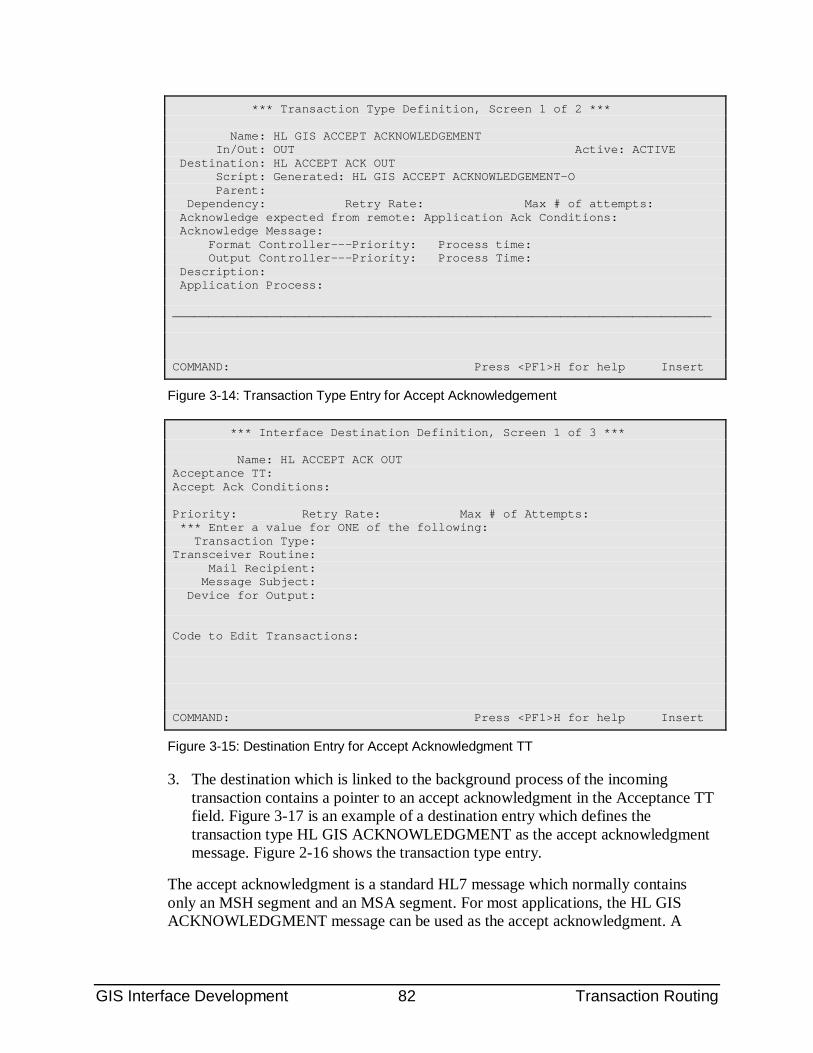
GIS Interface Development 82 Transaction Routing
*** Transaction Type Definition, Screen 1 of 2 *** Name: HL GIS ACCEPT ACKNOWLEDGEMENT In/Out: OUT Active: ACTIVE Destination: HL ACCEPT ACK OUT Script: Generated: HL GIS ACCEPT ACKNOWLEDGEMENT-O Parent: Dependency: Retry Rate: Max # of attempts: Acknowledge expected from remote: Application Ack Conditions: Acknowledge Message: Format Controller---Priority: Process time: Output Controller---Priority: Process Time: Description: Application Process: ___________________________________________________________________________ COMMAND: Press <PF1>H for help Insert
Figure 3-14: Transaction Type Entry for Accept Acknowledgement
*** Interface Destination Definition, Screen 1 of 3 *** Name: HL ACCEPT ACK OUT Acceptance TT: Accept Ack Conditions: Priority: Retry Rate: Max # of Attempts: *** Enter a value for ONE of the following: Transaction Type: Transceiver Routine: Mail Recipient: Message Subject: Device for Output: Code to Edit Transactions: COMMAND: Press <PF1>H for help Insert
Figure 3-15: Destination Entry for Accept Acknowledgment TT
3. The destination which is linked to the background process of the incoming transaction contains a pointer to an accept acknowledgment in the Acceptance TT field. Figure 3-17 is an example of a destination entry which defines the transaction type HL GIS ACKNOWLEDGMENT as the accept acknowledgment message. Figure 2-16 shows the transaction type entry.
The accept acknowledgment is a standard HL7 message which normally contains only an MSH segment and an MSA segment. For most applications, the HL GIS ACKNOWLEDGMENT message can be used as the accept acknowledgment. A
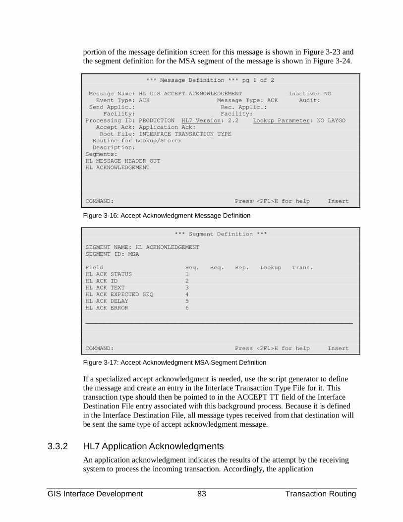
GIS Interface Development 83 Transaction Routing
portion of the message definition screen for this message is shown in Figure 3-23 and the segment definition for the MSA segment of the message is shown in Figure 3-24.
*** Message Definition *** pg 1 of 2 Message Name: HL GIS ACCEPT ACKNOWLEDGEMENT Inactive: NO Event Type: ACK Message Type: ACK Audit: Send Applic.: Rec. Applic.: Facility: Facility: Processing ID: PRODUCTION HL7 Version: 2.2 Lookup Parameter: NO LAYGO Accept Ack: Application Ack: Root File: INTERFACE TRANSACTION TYPE Routine for Lookup/Store: Description: Segments: HL MESSAGE HEADER OUT HL ACKNOWLEDGEMENT COMMAND: Press <PF1>H for help Insert
Figure 3-16: Accept Acknowledgment Message Definition
*** Segment Definition *** SEGMENT NAME: HL ACKNOWLEDGEMENT SEGMENT ID: MSA Field Seq. Req. Rep. Lookup Trans. HL ACK STATUS 1 HL ACK ID 2 HL ACK TEXT 3 HL ACK EXPECTED SEQ 4 HL ACK DELAY 5 HL ACK ERROR 6 ___________________________________________________________________________ COMMAND: Press <PF1>H for help Insert
Figure 3-17: Accept Acknowledgment MSA Segment Definition
If a specialized accept acknowledgment is needed, use the script generator to define the message and create an entry in the Interface Transaction Type File for it. This transaction type should then be pointed to in the ACCEPT TT field of the Interface Destination File entry associated with this background process. Because it is defined in the Interface Destination File, all message types received from that destination will be sent the same type of accept acknowledgment message.
3.3.2 HL7 Application Acknowledgments An application acknowledgment indicates the results of the attempt by the receiving system to process the incoming transaction. Accordingly, the application
GIS Interface Development 84 Transaction Routing
acknowledgment is created at the time the incoming transaction is processed by the output controller. If the output controller queue contains a significant number of entries, there may be a time lag between the receipt of the transaction and the processing of the transaction--and thereby a lag in the creation of the application acknowledgment. Thus, the application acknowledgment is not created "interactively" by the transceiver rouine, as is the accept acknowledgment. It will not be transmitted back to the initiating system over the same TCP/IP channel used to receive the initial transaction.
The transaction type which is used to create an application acknowledgment is defined by the Acknowledge Message field of the incoming Interface Transaction Type entry. Therefore, it is possible to create a different acknowledge transaction type for each different incoming HL7 message type received from a single destination. This is in contrast to the accept acknowledgment, which utilizes the same transaction type for all incoming message types from a destination.
To create an application acknowledgment, use the script generator to define the message. Create the corresponding entry in the Interface Transaction Type File. This name of this transaction type should then be entered in the Acknowledge Message field of the Interface Transaction Type File entry of the incoming transaction. The Destination of the acknowledgment Transaction Type will be the one used to transmit outbound messages from the RPMS to the remote system.
3.3.3 Queries and Specialized Acknowledgments The GIS is being used to support various interactive processes whereby the GIS receives a transaction from a remote system, processes this transaction, and sends some type of transaction back to the remote system. The transaction which is sent back to the remote system is an application acknowledgment. The acknowledgment message returned by the GIS is an application acknowledgment because it has been processed by the receiving system and contains significantly more data than a typical accept acknowledgment.
Specialized transceiver routines are required to process these types of interfaces. The transceiver must perform some of the functions which are normally performed by the output controller. The incoming transactions do not get placed on the output controller queue to be processed in the background, but are processed by the transceiver, interactively.
3.3.3.1 Query Status API It is sometimes necessary to create query messages for which the user is waiting for the response from the remote system. The Applications Programmer can access an API to determine when the response has been received by the GIS.
The syntax of the call is as follows.
GIS Interface Development 85 Transaction Routing
S X=$$SRCH^INTQRY(INTSK,.INUIFARRAY)
The following is an example.
S X=$$SRCH^INTQRY(INTSK,.ARRAY) ZW ARRAY ARRAY(294)=N00259-122648 ARRAY(295)=E
In this array, 294 and 295 are the internal entry numbers of two outgoing query messages triggered by a single Formatter task. A response has been received to the first message and filed in the UIF with a message identifier of “N00259-122648”. The second is in an error status. It is anticipated that most queries will consist of a single outgoing message, but the design is flexible enough to support multiple messages from a single application team trigger.
3.3.4 X12 Query Responses The location of the trace number varies among X12 message types. The logic that identifies the trace number is hard coded in routine INHUSEN7. Examples are as follows.
• If the incoming message is a 271, the value in TRN02 may be the original number, depending on the value in TRN01. If TRN01 is a 1, it indicates the value in TRN02 is an originating trace number. If TRN01 is a 2, it indicated the TRN02 field is referencing the trace number in the original 270 query.
• Despite the above, it appears that the BHT03 is the correct trace number for a 271 or a 278.
The BGN02 is the trace number for a 834 or 824.
3.3.5 X12 Transaction Acknowledgments As with an HL7 message, if the receiver gets an X12 message, the acknowledge (such as a FA or 997) is specified in the “ACCEPTANCE TT field of the Destination pointed to by the Background File.
3.3.6 X12 Functional Acknowledgments If the incoming message is a FA or a TA1, the receiver must identify the original outgoing message for which the response has been received.
• If the incoming message is a TA1, the identification code of the original message is in the first field of the TA1 segment (TA101).
If the incoming message is a 997 (functional identifier of FA), the identification code of the original message is in the first second field of the ST segment (ST02).
GIS Interface Development 86 Transaction Routing
3.4 The Bi-directional Interface The preceding sections have focused on routing outgoing transactions which are typically transmitted from the host system via a TCP/IP transmitter--and incoming transactions which are typically received via a TCP/IP receiver. In many cases, a system communicates with a remote system using both a transmitter and a receiver. This section outlines configuration guidelines to make bi-directional communications operational. In addition, this section references and summarizes the explanations contained in other sections.
Figure 3-18 is an example of a configuration in which CHCS is communicating with a single, remote DBSS system. The top half illustrates the outgoing/transmitter communication, the bottom half illustrates the incoming/receiver communication. The direction of the arrows show the pointer relationships.
As shown in the upper left of the diagram, many different outgoing Interface Transaction Types can point to HL DBSS, which is a single entry in the Interface Destination File. The Destination File entry equates to the remote system. Outgoing transaction types such as HL DG MERGE PATIENT OUT (BB), HL DG UPDATE OUT (BB), HL LAB DBSS ACCESSION (R), and use this destination entry. As described in routing Outgoing Transactions, the GIS places those outgoing transaction types on the HL DBSS destination queue.
Note also that the DBSS TRANSMITTER, which is an entry in the Background Process Control File, also points to the HL DBSS destination. This transmitter scans the HL DBSS destination queue for transactions to send. For each transaction sent, the transmitter expects an Accept Acknowledgment before sending the next transaction.
Incoming transactions from the DBSS system are received by the DBSS RECEIVER, which is an entry in the Background Process Control File. Note in the diagram that the receiver points to the same destination (HL DBSS) as does the transmitter. As described in Destination-Background Process Pair, the destination includes a pointer to the Accept Acknowledgment Transaction Type, which tells the receiver how to respond to the incoming transaction. In the diagram, this is the HL GIS ACCEPT
ACKNOWLEDGMENT. This is the standard accept message returned by the GIS.
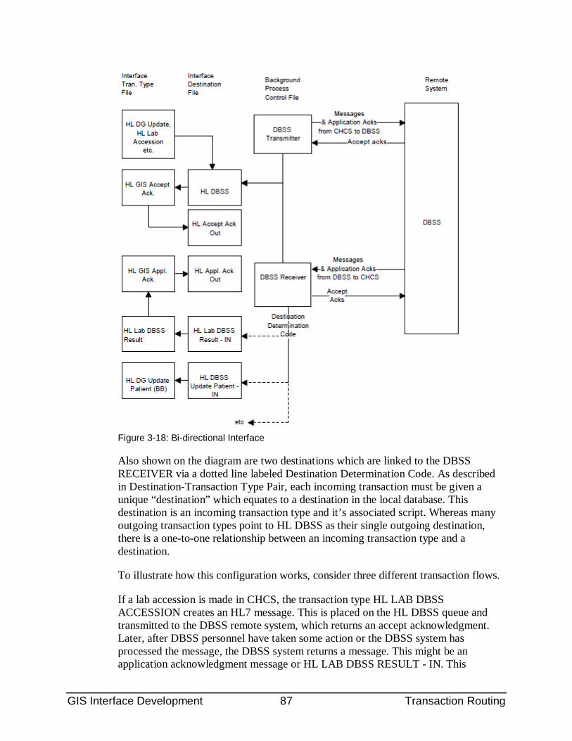
GIS Interface Development 87 Transaction Routing
Figure 3-18: Bi-directional Interface
Also shown on the diagram are two destinations which are linked to the DBSS RECEIVER via a dotted line labeled Destination Determination Code. As described in Destination-Transaction Type Pair, each incoming transaction must be given a unique “destination” which equates to a destination in the local database. This destination is an incoming transaction type and it’s associated script. Whereas many outgoing transaction types point to HL DBSS as their single outgoing destination, there is a one-to-one relationship between an incoming transaction type and a destination.
To illustrate how this configuration works, consider three different transaction flows.
If a lab accession is made in CHCS, the transaction type HL LAB DBSS ACCESSION creates an HL7 message. This is placed on the HL DBSS queue and transmitted to the DBSS remote system, which returns an accept acknowledgment. Later, after DBSS personnel have taken some action or the DBSS system has processed the message, the DBSS system returns a message. This might be an application acknowledgment message or HL LAB DBSS RESULT - IN. This
GIS Interface Development 88 Transaction Routing
message will be received on the CHCS DBSS RECEIVER. The HL DBSS destination specifies that HL GIS ACCEPT ACKNOWLEDGMENT is the transaction type needed to create the accept acknowledgment. The receiver runs the HL GIS ACCEPT ACKNOWLEDGMENT script and returns the accept acknowledgment to DBSS.
As the DBSS RECEIVER receives the message, it parses the message header (MSH) to find the message type. If the type is ACK, the GIS receiver processes the message as an incoming application acknowledgment. If the type is ORUR01, destination determination code identifies this as a HL LAB DBSS RESULT transaction type (see “Message Type Recognition”). This incoming transaction type is pointed to by the HL LAB DBSS RESULT -IN destination. The GIS places the transaction in the UIF and places a pointer to the UIF on the Output Controller queue. Subsequently, the output controller processes the queue entry and uses the destination to identify the incoming transaction type and run the proper script. As diagrammed in the example, no application acknowledgment is identified in the incoming transaction type, therefore no such acknowledgment will be returned.
Next, consider a transaction that originates on DBSS, such as an ORUR01, which corresponds to the incoming transaction type HL LAB DBSS RESULT -IN. This message is received, identified and placed on the output controller queue with the transaction destination of HL DBSS UPDATE PATIENT -IN. From the receiver destination, HL DBSS, the receiver identifies HL GIS ACCEPT ACKNOWLEDGMENT as the script to execute to create the acknowledgment, and the resulting transaction is returned by the receiver to DBSS.
Later, when the output controller processes this entry, it identifies the script for the transaction type HL LAB DBSS RESULT based on the destination HL DBSS UPDATE PATIENT -IN. In addition, from the entry in the Interface Transaction Type file it determines that the HL GIS APPL ACKNOWLEDGMENT should be returned to the DBSS system as the application acknowledgment. However, HL GIS APPL ACKNOWLEDGMENT is a “generic” acknowledgment, which is pointed to by many incoming transactions.
In turn, this transaction type points to the destination, HL APPL ACK OUT. This is a “dummy” destination, no routine is designated in the destination so it has no method of processing by the output controller. (Such a dummy destination is required because the GIS will not run a script and create an entry in the Universal Interface File if there is no destination designated in the Interface Transaction Type File).
So a key question is, how does the GIS know where to route this acknowledgment? Normally, outgoing transactions point to an entry in the Interface Destination File to be routed to a remote system. But in the case of simple acknowledgments, this solution would require that multiple acknowledgment transaction types be created, one for each remote system, each of which points to the destination for that remote system.
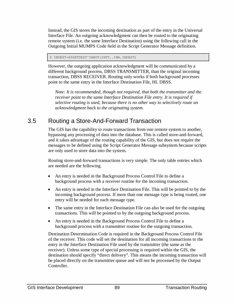
GIS Interface Development 89 Transaction Routing
Instead, the GIS stores the incoming destination as part of the entry in the Universal Interface File. An outgoing acknowledgment can then be routed to the originating remote system (i.e. the same Interface Destination) using the following call in the Outgoing Initial MUMPS Code field in the Script Generator Message definition.
S INDEST=$$GETDEST^INHUT(INTT,.INA,INDEST)
However, the outgoing application acknowledgment will be communicated by a different background process, DBSS TRANSMITTER, than the original incoming transaction, DBSS RECEIVER. Routing only works if both background processes point to the same entry in the Interface Destination File, HL DBSS.
Note: It is recommended, though not required, that both the transmitter and the receiver point to the same Interface Destination File entry. It is required if selective routing is used, because there is no other way to selectively route an acknowledgment back to the originating system.
3.5 Routing a Store-And-Forward Transaction The GIS has the capability to route transactions from one remote system to another, bypassing any processing of data into the database. This is called store-and-forward, and it takes advantage of the routing capability of the GIS, but does not require the messages to be defined using the Script Generator Message subsystem because scripts are only used to store data into the system.
Routing store-and-forward transactions is very simple. The only table entries which are needed are the following.
• An entry is needed in the Background Process Control File to define a background process with a receiver routine for the incoming transaction.
• An entry is needed in the Interface Destination File. This will be pointed to by the incoming background process. If more than one message type is being routed, one entry will be needed for each message type.
• The same entry in the Interface Destination File can also be used for the outgoing transactions. This will be pointed to by the outgoing background process.
• An entry is needed in the Background Process Control File to define a background process with a transmitter routine for the outgoing transaction.
Destination Determination Code is required in the Background Process Control File of the receiver. This code will set the destination for all incoming transactions to the entry in the Interface Destination File used by the transmitter (the same as the receiver). Unless some type of special processing is required within the GIS, the destination should specify “direct delivery”. This means the incoming transaction will be placed directly on the transmitter queue and will not be processed by the Output Controller.
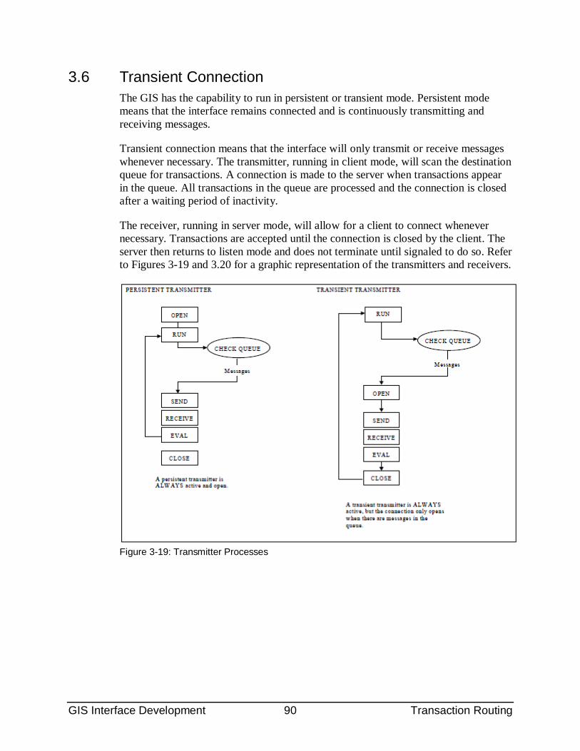
GIS Interface Development 90 Transaction Routing
3.6 Transient Connection The GIS has the capability to run in persistent or transient mode. Persistent mode means that the interface remains connected and is continuously transmitting and receiving messages.
Transient connection means that the interface will only transmit or receive messages whenever necessary. The transmitter, running in client mode, will scan the destination queue for transactions. A connection is made to the server when transactions appear in the queue. All transactions in the queue are processed and the connection is closed after a waiting period of inactivity.
The receiver, running in server mode, will allow for a client to connect whenever necessary. Transactions are accepted until the connection is closed by the client. The server then returns to listen mode and does not terminate until signaled to do so. Refer to Figures 3-19 and 3.20 for a graphic representation of the transmitters and receivers.
Figure 3-19: Transmitter Processes
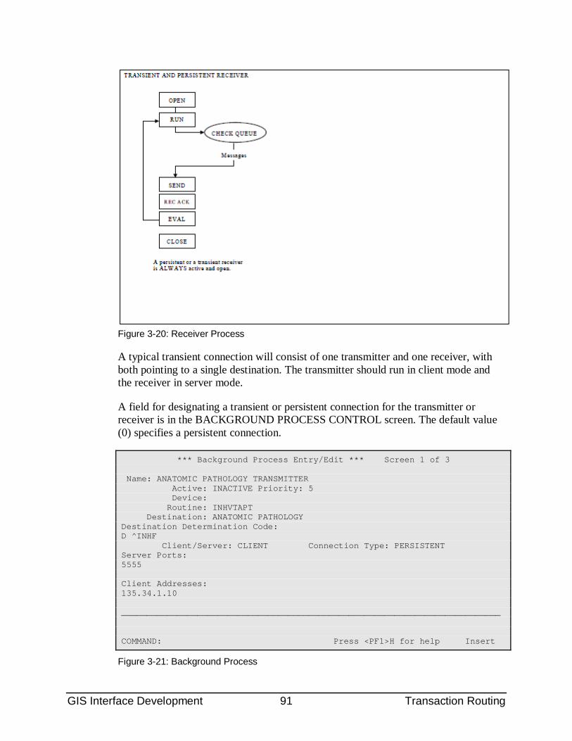
GIS Interface Development 91 Transaction Routing
Figure 3-20: Receiver Process
A typical transient connection will consist of one transmitter and one receiver, with both pointing to a single destination. The transmitter should run in client mode and the receiver in server mode.
A field for designating a transient or persistent connection for the transmitter or receiver is in the BACKGROUND PROCESS CONTROL screen. The default value (0) specifies a persistent connection.
*** Background Process Entry/Edit *** Screen 1 of 3 Name: ANATOMIC PATHOLOGY TRANSMITTER Active: INACTIVE Priority: 5 Device: Routine: INHVTAPT Destination: ANATOMIC PATHOLOGY Destination Determination Code: D ^INHF Client/Server: CLIENT Connection Type: PERSISTENT Server Ports: 5555 Client Addresses: 135.34.1.10 ___________________________________________________________________________ COMMAND: Press <PF1>H for help Insert
Figure 3-21: Background Process
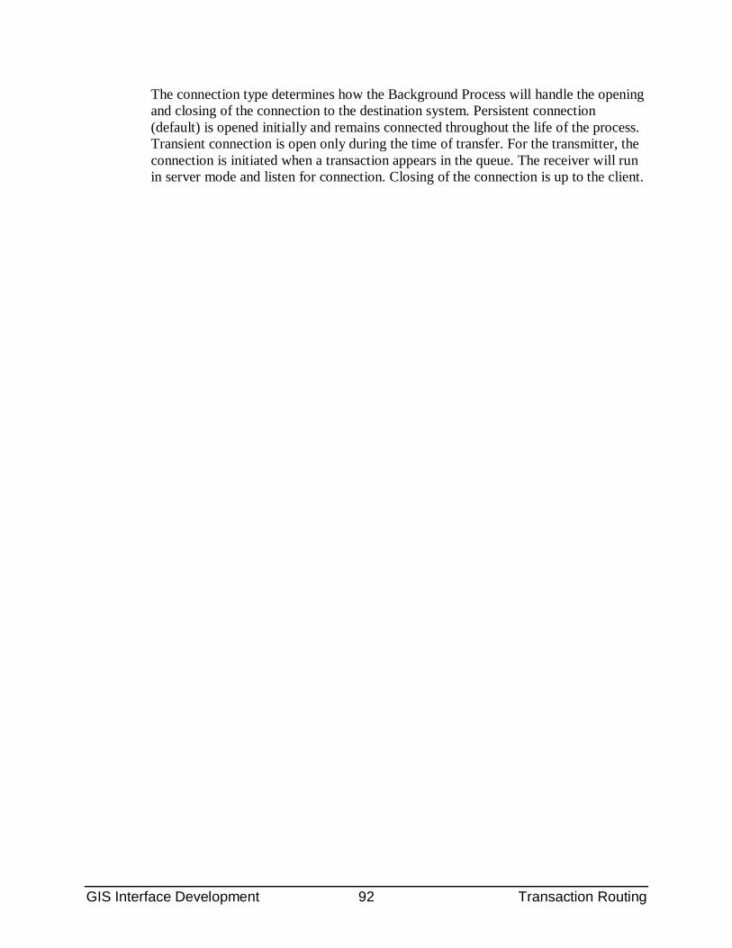
GIS Interface Development 92 Transaction Routing
The connection type determines how the Background Process will handle the opening and closing of the connection to the destination system. Persistent connection (default) is opened initially and remains connected throughout the life of the process. Transient connection is open only during the time of transfer. For the transmitter, the connection is initiated when a transaction appears in the queue. The receiver will run in server mode and listen for connection. Closing of the connection is up to the client.
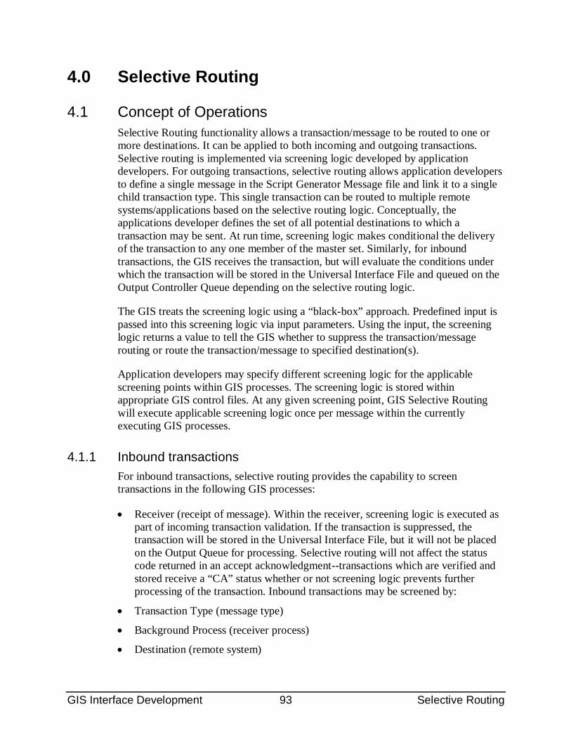
GIS Interface Development 93 Selective Routing
4.0 Selective Routing
4.1 Concept of Operations Selective Routing functionality allows a transaction/message to be routed to one or more destinations. It can be applied to both incoming and outgoing transactions. Selective routing is implemented via screening logic developed by application developers. For outgoing transactions, selective routing allows application developers to define a single message in the Script Generator Message file and link it to a single child transaction type. This single transaction can be routed to multiple remote systems/applications based on the selective routing logic. Conceptually, the applications developer defines the set of all potential destinations to which a transaction may be sent. At run time, screening logic makes conditional the delivery of the transaction to any one member of the master set. Similarly, for inbound transactions, the GIS receives the transaction, but will evaluate the conditions under which the transaction will be stored in the Universal Interface File and queued on the Output Controller Queue depending on the selective routing logic.
The GIS treats the screening logic using a “black-box” approach. Predefined input is passed into this screening logic via input parameters. Using the input, the screening logic returns a value to tell the GIS whether to suppress the transaction/message routing or route the transaction/message to specified destination(s).
Application developers may specify different screening logic for the applicable screening points within GIS processes. The screening logic is stored within appropriate GIS control files. At any given screening point, GIS Selective Routing will execute applicable screening logic once per message within the currently executing GIS processes.
4.1.1 Inbound transactions For inbound transactions, selective routing provides the capability to screen transactions in the following GIS processes:
• Receiver (receipt of message). Within the receiver, screening logic is executed as part of incoming transaction validation. If the transaction is suppressed, the transaction will be stored in the Universal Interface File, but it will not be placed on the Output Queue for processing. Selective routing will not affect the status code returned in an accept acknowledgment--transactions which are verified and stored receive a “CA” status whether or not screening logic prevents further processing of the transaction. Inbound transactions may be screened by:
• Transaction Type (message type)
• Background Process (receiver process)
• Destination (remote system)
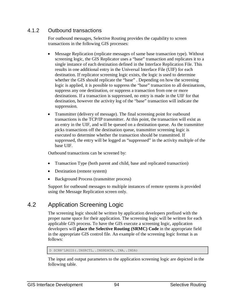
GIS Interface Development 94 Selective Routing
4.1.2 Outbound transactions For outbound messages, Selective Routing provides the capability to screen transactions in the following GIS processes:
• Message Replication (replicate messages of same base transaction type). Without screening logic, the GIS Replicator uses a “base” transaction and replicates it to a single instance of each destination defined in the Interface Replication File. This results in one additional entry in the Universal Interface File (UIF) for each destination. If replicator screening logic exists, the logic is used to determine whether the GIS should replicate the “base” . Depending on how the screening logic is applied, it is possible to suppress the “base” transaction to all destinations, suppress any one destination, or suppress a transaction from one or more destinations. If a transaction is suppressed, no entry is made in the UIF for that destination, however the activity log of the “base” transaction will indicate the suppression.
• Transmitter (delivery of message). The final screening point for outbound transactions is the TCP/IP transmitter. At this point, the transaction will exist as an entry in the UIF, and will be queued on a destination queue. As the transmitter picks transactions off the destination queue, transmitter screening logic is executed to determine whether the transaction should be transmitted. If suppressed, the entry will be logged as “suppressed” in the activity multiple of the base UIF.
Outbound transactions can be screened by:
• Transaction Type (both parent and child, base and replicated transaction)
• Destination (remote system)
• Background Process (transmitter process) Support for outbound messages to multiple instances of remote systems is provided using the Message Replication screen only.
4.2 Application Screening Logic The screening logic should be written by application developers prefixed with the proper name space for their application. The screening logic will be written for each applicable GIS process. To have the GIS execute a screening logic, application developers will place the Selective Routing (SRMC) Code in the appropriate field in the appropriate GIS control file. An example of the screening logic format is as follows:
D SCRN^LRGIS(.INSRCTL,.INSRDATA,.INA,.INDA)
The input and output parameters to the application screening logic are depicted in the following table.
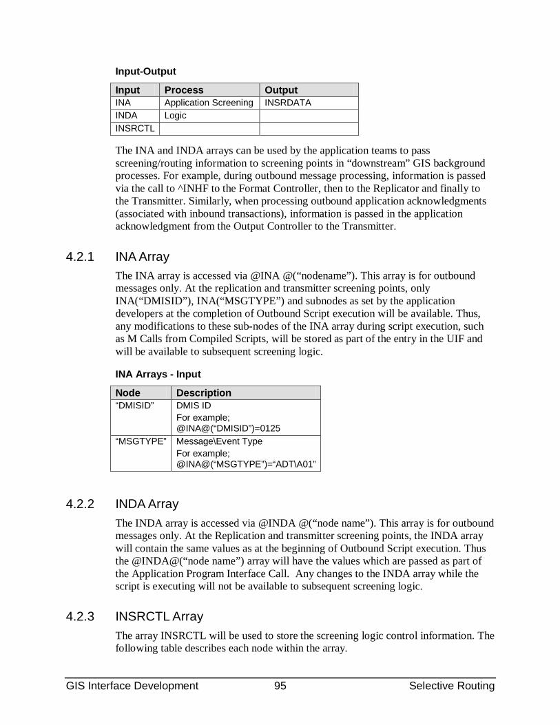
GIS Interface Development 95 Selective Routing
Input-Output
Input Process Output INA Application Screening INSRDATA INDA Logic INSRCTL
The INA and INDA arrays can be used by the application teams to pass screening/routing information to screening points in “downstream” GIS background processes. For example, during outbound message processing, information is passed via the call to ^INHF to the Format Controller, then to the Replicator and finally to the Transmitter. Similarly, when processing outbound application acknowledgments (associated with inbound transactions), information is passed in the application acknowledgment from the Output Controller to the Transmitter.
4.2.1 INA Array The INA array is accessed via @INA @(“nodename”). This array is for outbound messages only. At the replication and transmitter screening points, only INA(“DMISID”), INA(“MSGTYPE”) and subnodes as set by the application developers at the completion of Outbound Script execution will be available. Thus, any modifications to these sub-nodes of the INA array during script execution, such as M Calls from Compiled Scripts, will be stored as part of the entry in the UIF and will be available to subsequent screening logic.
INA Arrays - Input
Node Description “DMISID” DMIS ID
For example; @INA@(“DMISID”)=0125
“MSGTYPE” Message\Event Type For example; @INA@(“MSGTYPE”)=“ADT\A01”
4.2.2 INDA Array The INDA array is accessed via @INDA @(“node name”). This array is for outbound messages only. At the Replication and transmitter screening points, the INDA array will contain the same values as at the beginning of Outbound Script execution. Thus the @INDA@(“node name”) array will have the values which are passed as part of the Application Program Interface Call. Any changes to the INDA array while the script is executing will not be available to subsequent screening logic.
4.2.3 INSRCTL Array The array INSRCTL will be used to store the screening logic control information. The following table describes each node within the array.
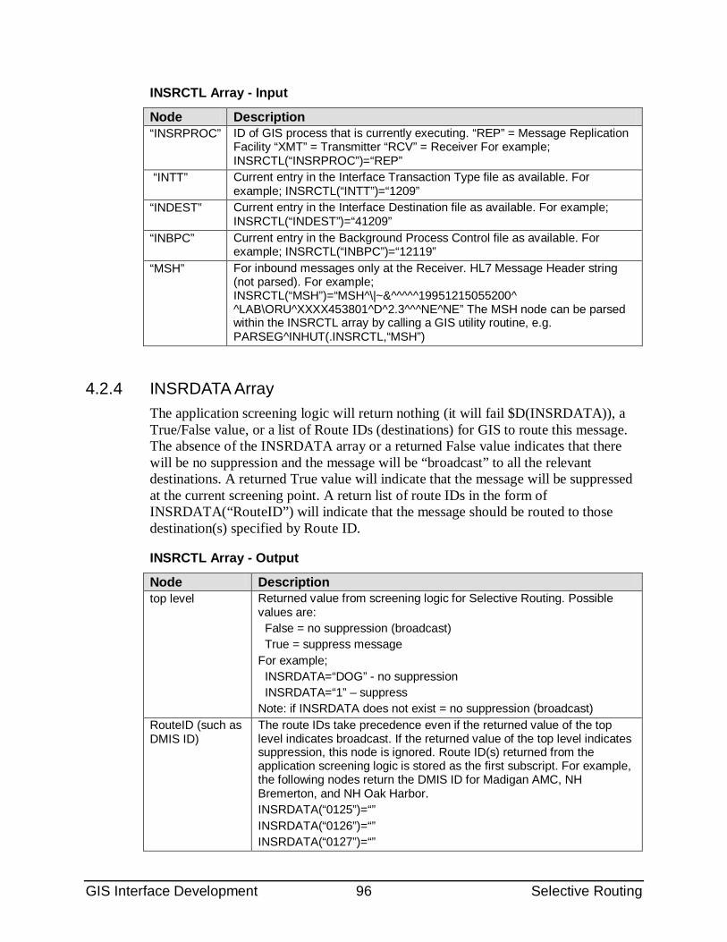
GIS Interface Development 96 Selective Routing
INSRCTL Array - Input
Node Description “INSRPROC” ID of GIS process that is currently executing. “REP” = Message Replication
Facility “XMT” = Transmitter “RCV” = Receiver For example; INSRCTL(“INSRPROC”)=“REP”
“INTT” Current entry in the Interface Transaction Type file as available. For example; INSRCTL(“INTT”)=“1209”
“INDEST” Current entry in the Interface Destination file as available. For example; INSRCTL(“INDEST”)=“41209”
“INBPC” Current entry in the Background Process Control file as available. For example; INSRCTL(“INBPC”)=“12119”
“MSH” For inbound messages only at the Receiver. HL7 Message Header string (not parsed). For example; INSRCTL(“MSH”)=“MSH^\|~&^^^^^19951215055200^ ^LAB\ORU^XXXX453801^D^2.3^^^NE^NE” The MSH node can be parsed within the INSRCTL array by calling a GIS utility routine, e.g. PARSEG^INHUT(.INSRCTL,“MSH”)
4.2.4 INSRDATA Array The application screening logic will return nothing (it will fail $D(INSRDATA)), a True/False value, or a list of Route IDs (destinations) for GIS to route this message. The absence of the INSRDATA array or a returned False value indicates that there will be no suppression and the message will be “broadcast” to all the relevant destinations. A returned True value will indicate that the message will be suppressed at the current screening point. A return list of route IDs in the form of INSRDATA(“RouteID”) will indicate that the message should be routed to those destination(s) specified by Route ID.
INSRCTL Array - Output
Node Description top level Returned value from screening logic for Selective Routing. Possible
values are: False = no suppression (broadcast) True = suppress message For example; INSRDATA=“DOG” - no suppression INSRDATA=“1” – suppress Note: if INSRDATA does not exist = no suppression (broadcast)
RouteID (such as DMIS ID)
The route IDs take precedence even if the returned value of the top level indicates broadcast. If the returned value of the top level indicates suppression, this node is ignored. Route ID(s) returned from the application screening logic is stored as the first subscript. For example, the following nodes return the DMIS ID for Madigan AMC, NH Bremerton, and NH Oak Harbor. INSRDATA(“0125”)=“” INSRDATA(“0126”)=“” INSRDATA(“0127”)=“”
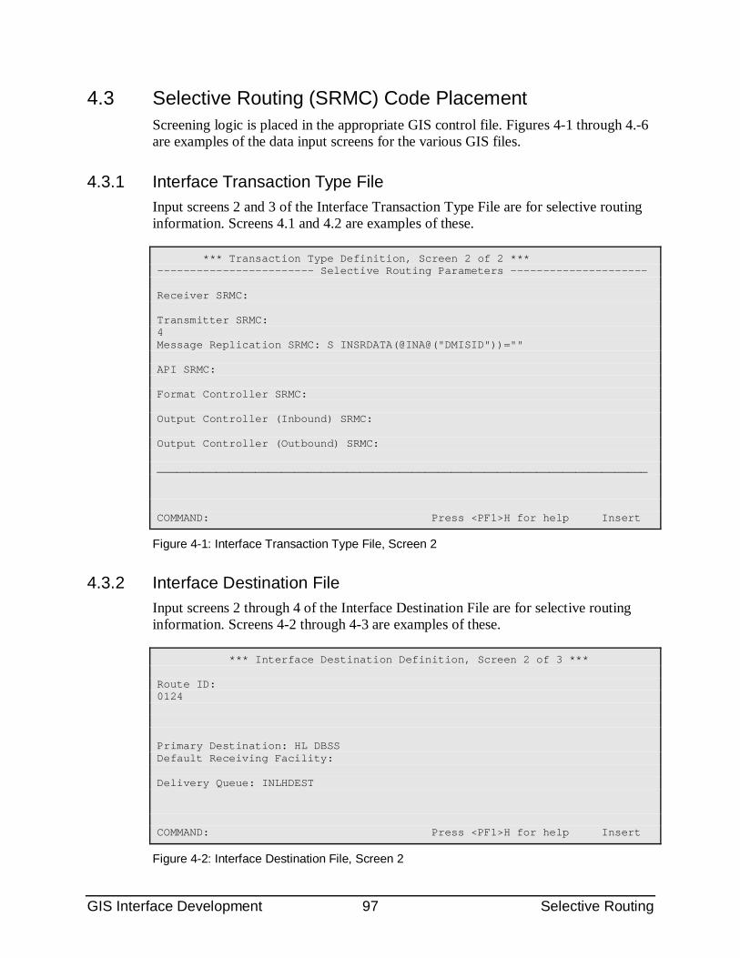
GIS Interface Development 97 Selective Routing
4.3 Selective Routing (SRMC) Code Placement Screening logic is placed in the appropriate GIS control file. Figures 4-1 through 4.-6 are examples of the data input screens for the various GIS files.
4.3.1 Interface Transaction Type File Input screens 2 and 3 of the Interface Transaction Type File are for selective routing information. Screens 4.1 and 4.2 are examples of these.
*** Transaction Type Definition, Screen 2 of 2 *** ------------------------ Selective Routing Parameters --------------------- Receiver SRMC: Transmitter SRMC: 4 Message Replication SRMC: S INSRDATA(@INA@("DMISID"))="" API SRMC: Format Controller SRMC: Output Controller (Inbound) SRMC: Output Controller (Outbound) SRMC: ___________________________________________________________________________ COMMAND: Press <PF1>H for help Insert
Figure 4-1: Interface Transaction Type File, Screen 2
4.3.2 Interface Destination File Input screens 2 through 4 of the Interface Destination File are for selective routing information. Screens 4-2 through 4-3 are examples of these.
*** Interface Destination Definition, Screen 2 of 3 *** Route ID: 0124 Primary Destination: HL DBSS Default Receiving Facility: Delivery Queue: INLHDEST COMMAND: Press <PF1>H for help Insert
Figure 4-2: Interface Destination File, Screen 2
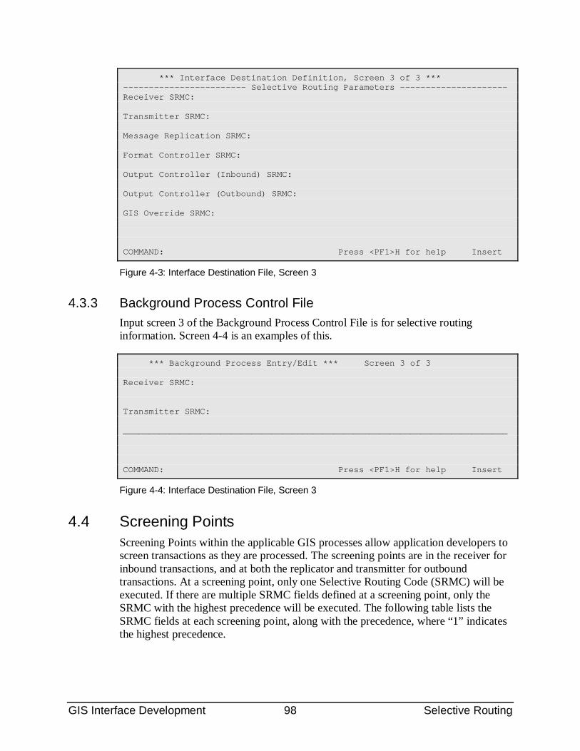
GIS Interface Development 98 Selective Routing
*** Interface Destination Definition, Screen 3 of 3 *** ------------------------ Selective Routing Parameters --------------------- Receiver SRMC: Transmitter SRMC: Message Replication SRMC: Format Controller SRMC: Output Controller (Inbound) SRMC: Output Controller (Outbound) SRMC: GIS Override SRMC: COMMAND: Press <PF1>H for help Insert
Figure 4-3: Interface Destination File, Screen 3
4.3.3 Background Process Control File Input screen 3 of the Background Process Control File is for selective routing information. Screen 4-4 is an examples of this.
*** Background Process Entry/Edit *** Screen 3 of 3 Receiver SRMC: Transmitter SRMC: ___________________________________________________________________________ COMMAND: Press <PF1>H for help Insert
Figure 4-4: Interface Destination File, Screen 3
4.4 Screening Points Screening Points within the applicable GIS processes allow application developers to screen transactions as they are processed. The screening points are in the receiver for inbound transactions, and at both the replicator and transmitter for outbound transactions. At a screening point, only one Selective Routing Code (SRMC) will be executed. If there are multiple SRMC fields defined at a screening point, only the SRMC with the highest precedence will be executed. The following table lists the SRMC fields at each screening point, along with the precedence, where “1” indicates the highest precedence.
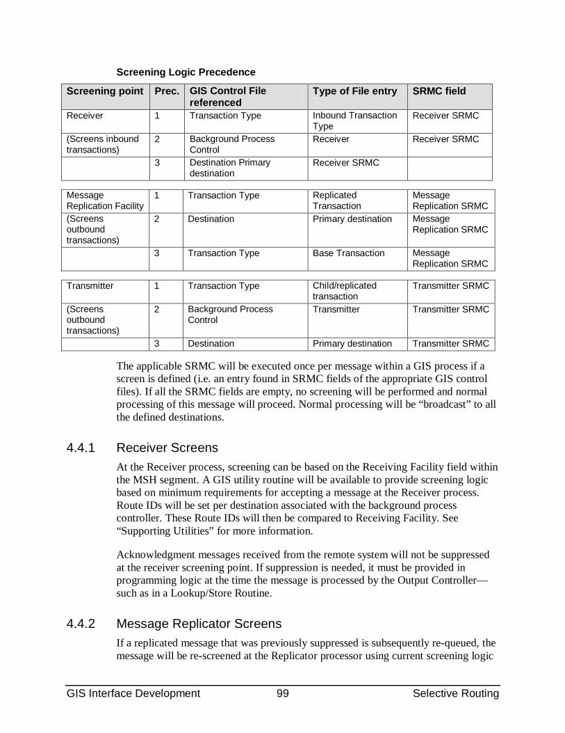
GIS Interface Development 99 Selective Routing
Screening Logic Precedence
Screening point Prec. GIS Control File referenced
Type of File entry SRMC field
Receiver 1 Transaction Type Inbound Transaction Type
Receiver SRMC
(Screens inbound transactions)
2 Background Process Control
Receiver Receiver SRMC
3 Destination Primary destination
Receiver SRMC
Message Replication Facility
1 Transaction Type Replicated Transaction
Message Replication SRMC
(Screens outbound transactions)
2 Destination Primary destination Message Replication SRMC
3 Transaction Type Base Transaction Message Replication SRMC
Transmitter 1 Transaction Type Child/replicated
transaction Transmitter SRMC
(Screens outbound transactions)
2 Background Process Control
Transmitter Transmitter SRMC
3 Destination Primary destination Transmitter SRMC
The applicable SRMC will be executed once per message within a GIS process if a screen is defined (i.e. an entry found in SRMC fields of the appropriate GIS control files). If all the SRMC fields are empty, no screening will be performed and normal processing of this message will proceed. Normal processing will be “broadcast” to all the defined destinations.
4.4.1 Receiver Screens At the Receiver process, screening can be based on the Receiving Facility field within the MSH segment. A GIS utility routine will be available to provide screening logic based on minimum requirements for accepting a message at the Receiver process. Route IDs will be set per destination associated with the background process controller. These Route IDs will then be compared to Receiving Facility. See “Supporting Utilities” for more information.
Acknowledgment messages received from the remote system will not be suppressed at the receiver screening point. If suppression is needed, it must be provided in programming logic at the time the message is processed by the Output Controller—such as in a Lookup/Store Routine.
4.4.2 Message Replicator Screens If a replicated message that was previously suppressed is subsequently re-queued, the message will be re-screened at the Replicator processor using current screening logic
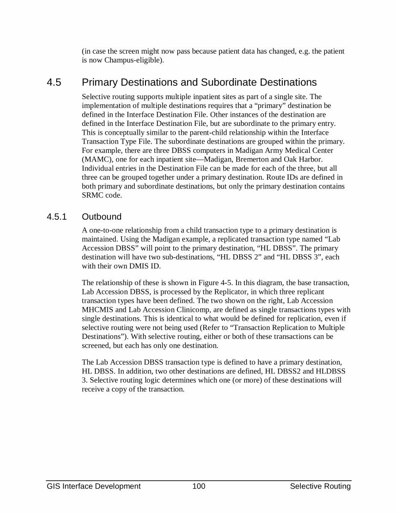
GIS Interface Development 100 Selective Routing
(in case the screen might now pass because patient data has changed, e.g. the patient is now Champus-eligible).
4.5 Primary Destinations and Subordinate Destinations Selective routing supports multiple inpatient sites as part of a single site. The implementation of multiple destinations requires that a “primary” destination be defined in the Interface Destination File. Other instances of the destination are defined in the Interface Destination File, but are subordinate to the primary entry. This is conceptually similar to the parent-child relationship within the Interface Transaction Type File. The subordinate destinations are grouped within the primary. For example, there are three DBSS computers in Madigan Army Medical Center (MAMC), one for each inpatient site—Madigan, Bremerton and Oak Harbor. Individual entries in the Destination File can be made for each of the three, but all three can be grouped together under a primary destination. Route IDs are defined in both primary and subordinate destinations, but only the primary destination contains SRMC code.
4.5.1 Outbound A one-to-one relationship from a child transaction type to a primary destination is maintained. Using the Madigan example, a replicated transaction type named “Lab Accession DBSS” will point to the primary destination, “HL DBSS”. The primary destination will have two sub-destinations, “HL DBSS 2” and “HL DBSS 3”, each with their own DMIS ID.
The relationship of these is shown in Figure 4-5. In this diagram, the base transaction, Lab Accession DBSS, is processed by the Replicator, in which three replicant transaction types have been defined. The two shown on the right, Lab Accession MHCMIS and Lab Accession Clinicomp, are defined as single transactions types with single destinations. This is identical to what would be defined for replication, even if selective routing were not being used (Refer to “Transaction Replication to Multiple Destinations”). With selective routing, either or both of these transactions can be screened, but each has only one destination.
The Lab Accession DBSS transaction type is defined to have a primary destination, HL DBSS. In addition, two other destinations are defined, HL DBSS2 and HLDBSS 3. Selective routing logic determines which one (or more) of these destinations will receive a copy of the transaction.
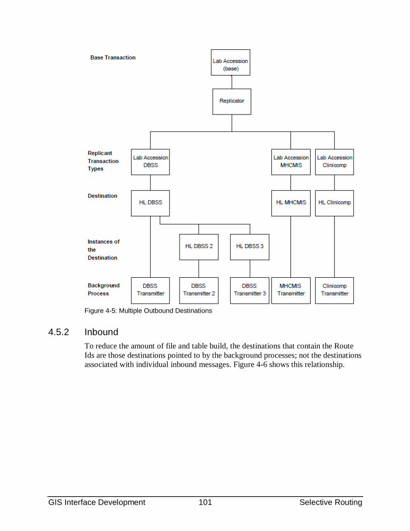
GIS Interface Development 101 Selective Routing
Figure 4-5: Multiple Outbound Destinations
4.5.2 Inbound To reduce the amount of file and table build, the destinations that contain the Route Ids are those destinations pointed to by the background processes; not the destinations associated with individual inbound messages. Figure 4-6 shows this relationship.
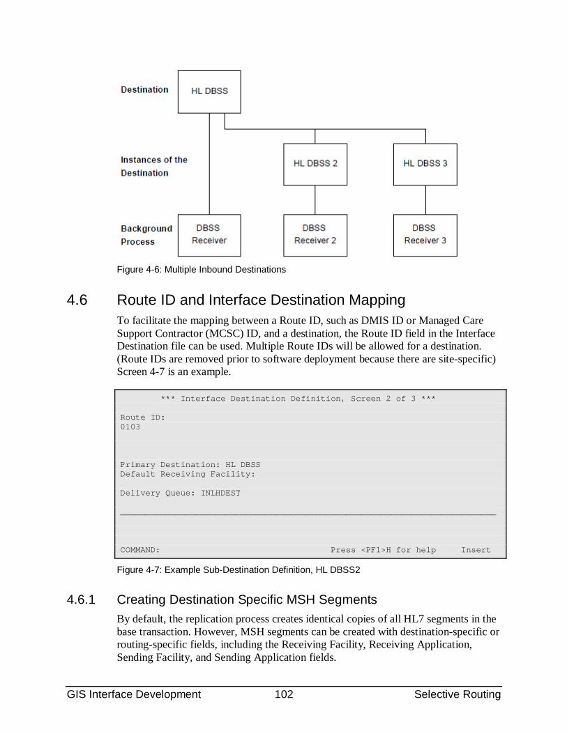
GIS Interface Development 102 Selective Routing
Figure 4-6: Multiple Inbound Destinations
4.6 Route ID and Interface Destination Mapping To facilitate the mapping between a Route ID, such as DMIS ID or Managed Care Support Contractor (MCSC) ID, and a destination, the Route ID field in the Interface Destination file can be used. Multiple Route IDs will be allowed for a destination. (Route IDs are removed prior to software deployment because there are site-specific) Screen 4-7 is an example.
*** Interface Destination Definition, Screen 2 of 3 *** Route ID: 0103 Primary Destination: HL DBSS Default Receiving Facility: Delivery Queue: INLHDEST ___________________________________________________________________________ COMMAND: Press <PF1>H for help Insert
Figure 4-7: Example Sub-Destination Definition, HL DBSS2
4.6.1 Creating Destination Specific MSH Segments By default, the replication process creates identical copies of all HL7 segments in the base transaction. However, MSH segments can be created with destination-specific or routing-specific fields, including the Receiving Facility, Receiving Application, Sending Facility, and Sending Application fields.
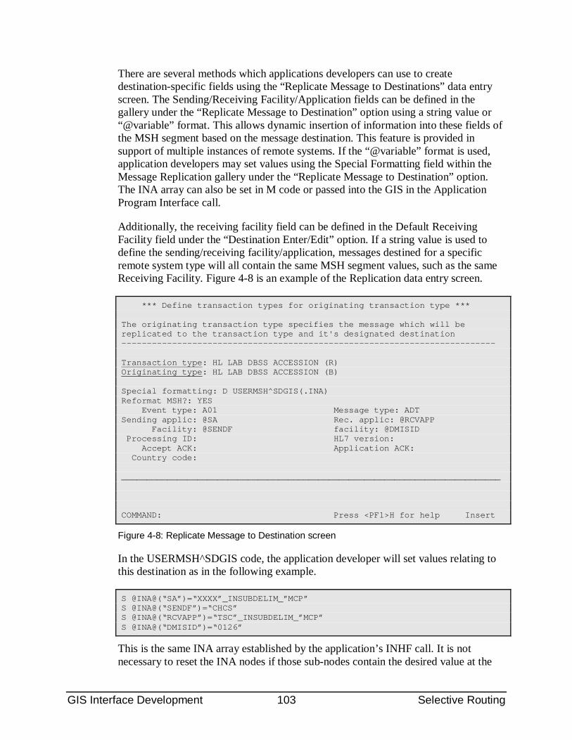
GIS Interface Development 103 Selective Routing
There are several methods which applications developers can use to create destination-specific fields using the “Replicate Message to Destinations” data entry screen. The Sending/Receiving Facility/Application fields can be defined in the gallery under the “Replicate Message to Destination” option using a string value or “@variable” format. This allows dynamic insertion of information into these fields of the MSH segment based on the message destination. This feature is provided in support of multiple instances of remote systems. If the “@variable” format is used, application developers may set values using the Special Formatting field within the Message Replication gallery under the “Replicate Message to Destination” option. The INA array can also be set in M code or passed into the GIS in the Application Program Interface call.
Additionally, the receiving facility field can be defined in the Default Receiving Facility field under the “Destination Enter/Edit” option. If a string value is used to define the sending/receiving facility/application, messages destined for a specific remote system type will all contain the same MSH segment values, such as the same Receiving Facility. Figure 4-8 is an example of the Replication data entry screen.
*** Define transaction types for originating transaction type *** The originating transaction type specifies the message which will be replicated to the transaction type and it's designated destination -------------------------------------------------------------------------- Transaction type: HL LAB DBSS ACCESSION (R) Originating type: HL LAB DBSS ACCESSION (B) Special formatting: D USERMSH^SDGIS(.INA) Reformat MSH?: YES Event type: A01 Message type: ADT Sending applic: @SA Rec. applic: @RCVAPP Facility: @SENDF facility: @DMISID Processing ID: HL7 version: Accept ACK: Application ACK: Country code: ___________________________________________________________________________ COMMAND: Press <PF1>H for help Insert
Figure 4-8: Replicate Message to Destination screen
In the USERMSH^SDGIS code, the application developer will set values relating to this destination as in the following example.
S @INA@(“SA”)=“XXXX”_INSUBDELIM_”MCP” S @INA@(“SENDF”)=“CHCS” S @INA@(“RCVAPP”)=“TSC”_INSUBDELIM_”MCP” S @INA@(“DMISID”)=“0126”
This is the same INA array established by the application’s INHF call. It is not necessary to reset the INA nodes if those sub-nodes contain the desired value at the
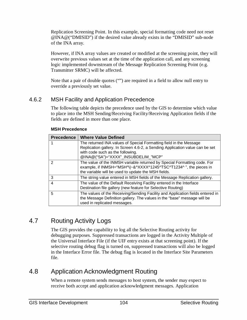
GIS Interface Development 104 Selective Routing
Replication Screening Point. In this example, special formatting code need not reset @INA@(“DMISID”) if the desired value already exists in the “DMISID” sub-node of the INA array.
However, if INA array values are created or modified at the screening point, they will overwrite previous values set at the time of the application call, and any screening logic implemented downstream of the Message Replication Screening Point (e.g. Transmitter SRMC) will be affected.
Note that a pair of double quotes (“”) are required in a field to allow null entry to override a previously set value.
4.6.2 MSH Facility and Application Precedence The following table depicts the precedence used by the GIS to determine which value to place into the MSH Sending/Receiving Facility/Receiving Application fields if the fields are defined in more than one place.
MSH Precedence
Precedence Where Value Defined 1 The returned INA values of Special Formatting field in the Message
Replication gallery. In Screen 4.6-2, a Sending Application value can be set with code such as the following. @INA@(“SA”)=“XXXX”_INSUBDELIM_”MCP”
2 The value of the INMSH variable returned by Special Formatting code. For example, if INMSH=“MSH^\|~&^XXXX^1245^TSC^T1234^ ”, the pieces in the variable will be used to update the MSH fields.
3 The string value entered in MSH fields of the Message Replication gallery. 4 The value of the Default Receiving Facility entered in the Interface
Destination file gallery (new feature for Selective Routing) 5 The values of the Receiving/Sending Facility and Application fields entered in
the Message Definition gallery. The values in the “base” message will be used in replicated messages.
4.7 Routing Activity Logs The GIS provides the capability to log all the Selective Routing activity for debugging purposes. Suppressed transactions are logged in the Activity Multiple of the Universal Interface File (if the UIF entry exists at that screening point). If the selective routing debug flag is turned on, suppressed transactions will also be logged in the Interface Error file. The debug flag is located in the Interface Site Parameters file.
4.8 Application Acknowledgment Routing When a remote system sends messages to host system, the sender may expect to receive both accept and application acknowledgment messages. Application
GIS Interface Development 105 Selective Routing
acknowledgments are considered to be "new" outbound messages which must be returned to the destination that originated the inbound message. This does not require "selective" routing because no SRMC fields are used. However, the GIS must be configured precisely for the application acknowledgment to be returned to the correct destination.
The primary and sub-destination entries in the Interface Destination file used for outbound messages must also be used for inbound messages (Refer to “Primary Destinations and Subordinate Destinations”). For example, DBSS TRANSMITTER 2 and DBSS RECEIVER 2 background process entries point to the same destination entry, HL DBSS 2. The sharing of a single destination for inbound and outbound activity implies the sharing of a single set of Route IDs (within that destination) for inbound and outbound screening logic. Consequently, inbound Route IDs cannot match outbound Route Ids. Otherwise, unexpected routing may occur.
In addition, a GIS utility routine is available to support application acknowledgment routing. It allows the caller to modify the message destination during outbound script execution. While this routine provides the user with several options, the highest precedence is to use the destination pointed to by the associated GIS receiver process. Application teams can create their own application acknowledge transaction type, or use the standard HL GIS APPLICATION ACKNOWLEDGMENT. See section on “Supporting Utilities” for more information.
4.9 Sample Screening Logic Code It is recommended that application code have one entry point. Within that entry point, the application code will check the screening point and execute code appropriate to that screening point. The following is an example of screening logic.
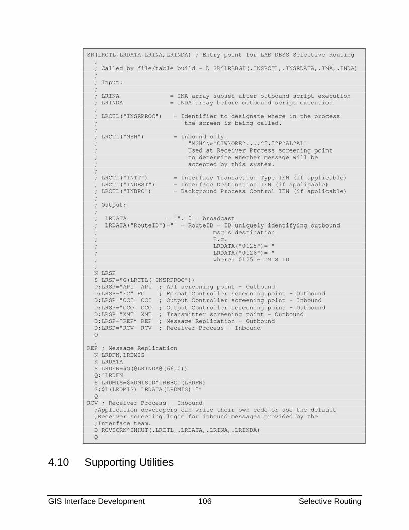
GIS Interface Development 106 Selective Routing
SR(LRCTL,LRDATA,LRINA,LRINDA) ; Entry point for LAB DBSS Selective Routing ; ; Called by file/table build - D SR^LRBBGI(.INSRCTL,.INSRDATA,.INA,.INDA) ; ; Input: ; ; LRINA = INA array subset after outbound script execution ; LRINDA = INDA array before outbound script execution ; ; LRCTL("INSRPROC") = Identifier to designate where in the process ; the screen is being called. ; ; LRCTL("MSH") = Inbound only. ; "MSH^\&^CIW\ORE^....^2.3^P^AL^AL" ; Used at Receiver Process screening point ; to determine whether message will be ; accepted by this system. ; ; LRCTL("INTT") = Interface Transaction Type IEN (if applicable) ; LRCTL("INDEST") = Interface Destination IEN (if applicable) ; LRCTL("INBPC") = Background Process Control IEN (if applicable) ; ; Output: ; ; LRDATA = "", 0 = broadcast ; LRDATA("RouteID")="" = RouteID = ID uniquely identifying outbound ; msg's destination ; E.g. ; LRDATA("0125")="" ; LRDATA("0126")="" ; where: 0125 = DMIS ID ; N LRSP S LRSP=$G(LRCTL("INSRPROC")) D:LRSP="API" API ; API screening point - Outbound D:LRSP="FC" FC ; Format Controller screening point - Outbound D:LRSP="OCI" OCI ; Output Controller screening point - Inbound D:LRSP="OCO" OCO ; Output Controller screening point - Outbound D:LRSP="XMT" XMT ; Transmitter screening point - Outbound D:LRSP=“REP” REP ; Message Replication - Outbound D:LRSP="RCV" RCV ; Receiver Process - Inbound Q ; REP ; Message Replication N LRDFN,LRDMIS K LRDATA S LRDFN=$O(@LRINDA@(66,0)) Q:’LRDFN S LRDMIS=$$DMISID^LRBBGI(LRDFN) S:$L(LRDMIS) LRDATA(LRDMIS)=“” Q RCV ; Receiver Process - Inbound ;Application developers can write their own code or use the default ;Receiver screening logic for inbound messages provided by the ;Interface team. D RCVSCRN^INHUT(.LRCTL,.LRDATA,.LRINA,.LRINDA) Q
4.10 Supporting Utilities
GIS Interface Development 107 Selective Routing
The following utilities are provided in support of the Receiver processing screening point.
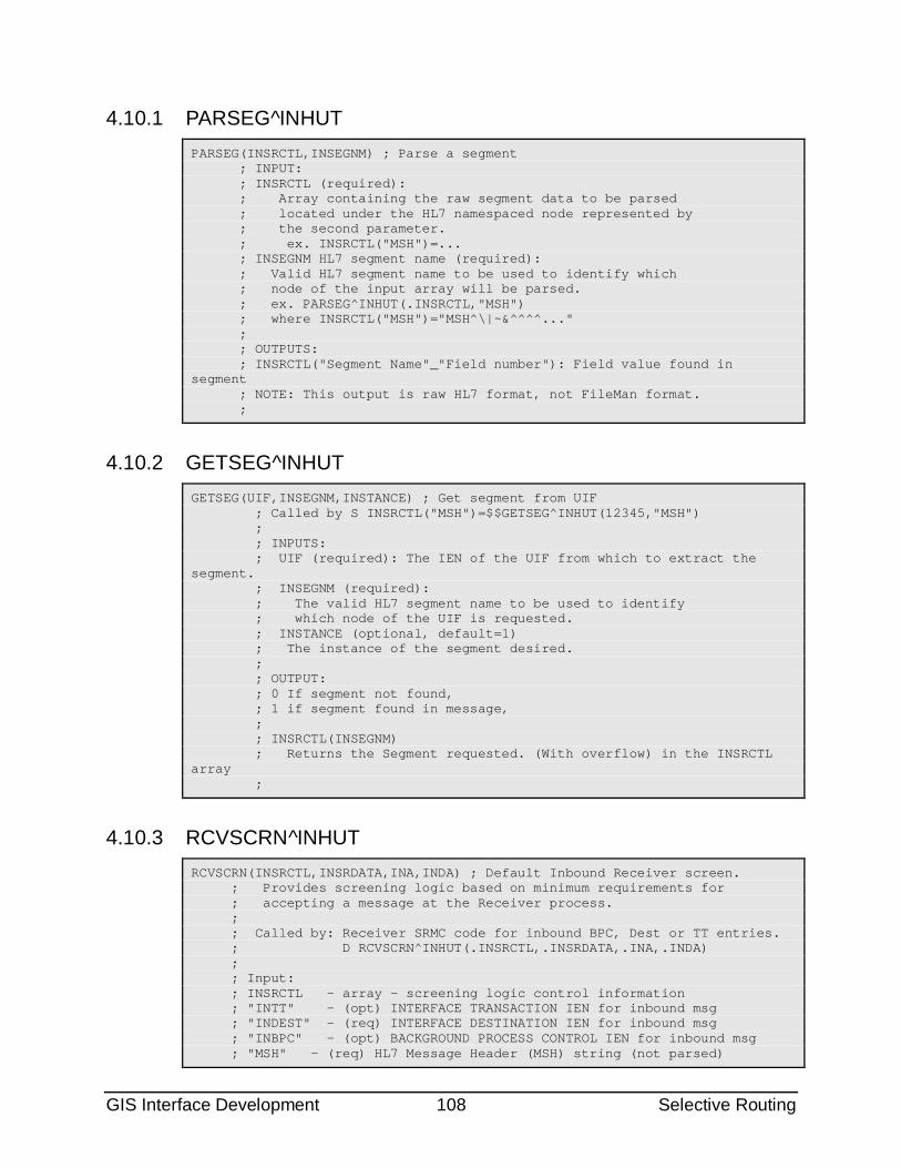
GIS Interface Development 108 Selective Routing
4.10.1 PARSEG^INHUT PARSEG(INSRCTL,INSEGNM) ; Parse a segment ; INPUT: ; INSRCTL (required): ; Array containing the raw segment data to be parsed ; located under the HL7 namespaced node represented by ; the second parameter. ; ex. INSRCTL("MSH")=... ; INSEGNM HL7 segment name (required): ; Valid HL7 segment name to be used to identify which ; node of the input array will be parsed. ; ex. PARSEG^INHUT(.INSRCTL,"MSH") ; where INSRCTL("MSH")="MSH^\|~&^^^^..." ; ; OUTPUTS: ; INSRCTL("Segment Name"_"Field number"): Field value found in segment ; NOTE: This output is raw HL7 format, not FileMan format. ;
4.10.2 GETSEG^INHUT GETSEG(UIF,INSEGNM,INSTANCE) ; Get segment from UIF ; Called by S INSRCTL("MSH")=$$GETSEG^INHUT(12345,"MSH") ; ; INPUTS: ; UIF (required): The IEN of the UIF from which to extract the segment. ; INSEGNM (required): ; The valid HL7 segment name to be used to identify ; which node of the UIF is requested. ; INSTANCE (optional, default=1) ; The instance of the segment desired. ; ; OUTPUT: ; 0 If segment not found, ; 1 if segment found in message, ; ; INSRCTL(INSEGNM) ; Returns the Segment requested. (With overflow) in the INSRCTL array ;
4.10.3 RCVSCRN^INHUT RCVSCRN(INSRCTL,INSRDATA,INA,INDA) ; Default Inbound Receiver screen. ; Provides screening logic based on minimum requirements for ; accepting a message at the Receiver process. ; ; Called by: Receiver SRMC code for inbound BPC, Dest or TT entries. ; D RCVSCRN^INHUT(.INSRCTL,.INSRDATA,.INA,.INDA) ; ; Input: ; INSRCTL - array - screening logic control information ; "INTT" - (opt) INTERFACE TRANSACTION IEN for inbound msg ; "INDEST" - (req) INTERFACE DESTINATION IEN for inbound msg ; "INBPC" - (opt) BACKGROUND PROCESS CONTROL IEN for inbound msg ; "MSH" - (req) HL7 Message Header (MSH) string (not parsed)
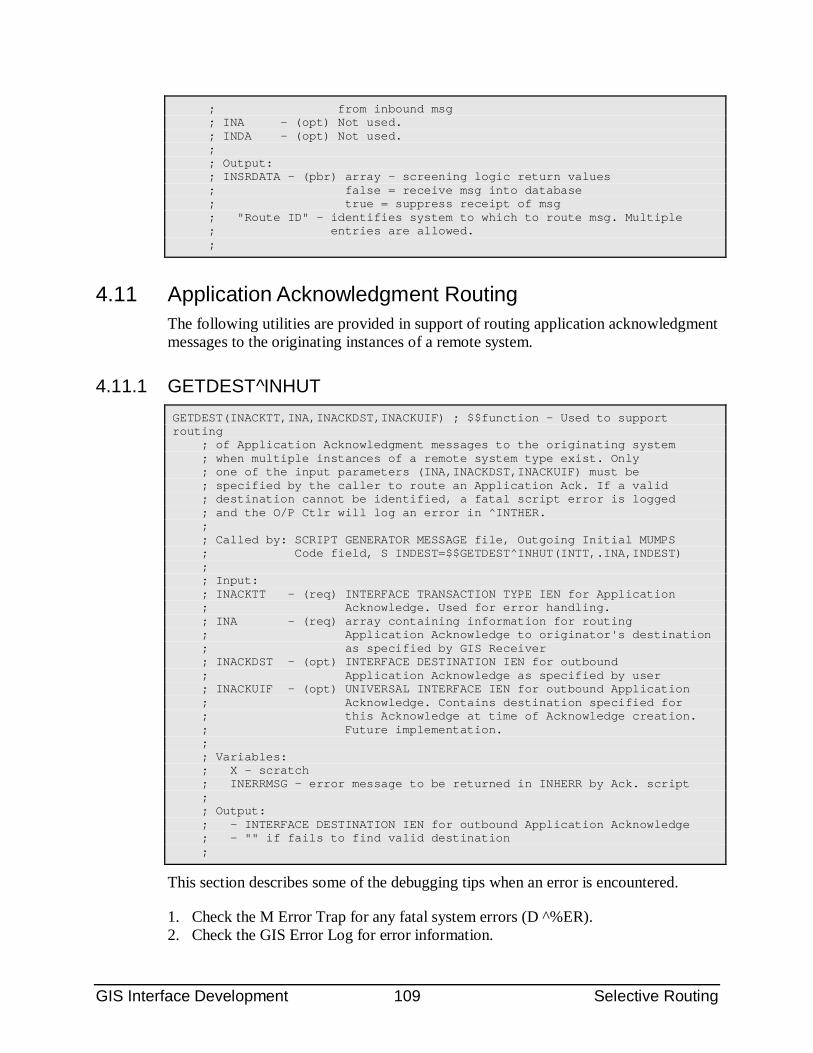
GIS Interface Development 109 Selective Routing
; from inbound msg ; INA - (opt) Not used. ; INDA - (opt) Not used. ; ; Output: ; INSRDATA - (pbr) array - screening logic return values ; false = receive msg into database ; true = suppress receipt of msg ; "Route ID" - identifies system to which to route msg. Multiple ; entries are allowed. ;
4.11 Application Acknowledgment Routing The following utilities are provided in support of routing application acknowledgment messages to the originating instances of a remote system.
4.11.1 GETDEST^INHUT GETDEST(INACKTT,INA,INACKDST,INACKUIF) ; $$function - Used to support routing ; of Application Acknowledgment messages to the originating system ; when multiple instances of a remote system type exist. Only ; one of the input parameters (INA,INACKDST,INACKUIF) must be ; specified by the caller to route an Application Ack. If a valid ; destination cannot be identified, a fatal script error is logged ; and the O/P Ctlr will log an error in ^INTHER. ; ; Called by: SCRIPT GENERATOR MESSAGE file, Outgoing Initial MUMPS ; Code field, S INDEST=$$GETDEST^INHUT(INTT,.INA,INDEST) ; ; Input: ; INACKTT - (req) INTERFACE TRANSACTION TYPE IEN for Application ; Acknowledge. Used for error handling. ; INA - (req) array containing information for routing ; Application Acknowledge to originator's destination ; as specified by GIS Receiver ; INACKDST - (opt) INTERFACE DESTINATION IEN for outbound ; Application Acknowledge as specified by user ; INACKUIF - (opt) UNIVERSAL INTERFACE IEN for outbound Application ; Acknowledge. Contains destination specified for ; this Acknowledge at time of Acknowledge creation. ; Future implementation. ; ; Variables: ; X - scratch ; INERRMSG - error message to be returned in INHERR by Ack. script ; ; Output: ; - INTERFACE DESTINATION IEN for outbound Application Acknowledge ; - "" if fails to find valid destination ;
This section describes some of the debugging tips when an error is encountered.
1. Check the M Error Trap for any fatal system errors (D ^%ER). 2. Check the GIS Error Log for error information.
GIS Interface Development 110 Selective Routing
Menu path: SM-INT-GIS-EM-ES Enter start and end dates based on when the error is believed to have occurred. Error Start Date (e.g. T@1205 = Today at 12.05pm) Error End Date (Now) 3. Verify GIS file/table is setup for desired routing results, e.g., Route IDs are set in appropriate Interface Destination file entries. 4. Verify that data is selected for desired routing results, e.g., location of the patient (DIV A) correlates to Route ID for the desired destination. 5. Verify that screening logic returns desired results to the GIS, e.g., if integration testing, use debugging techniques appropriate for background jobs. 6. Turn on Selective Routing Debug Flag in the Interface Site Parameters file and rerun test. If the message was suppressed: a) Re-check the GIS Error Log for additional error information. b) Examine the Activity Log Multiple of the associated message in the Universal Interface file and verify that: i) Log Action field is equal to “X”. ii) Log Message field contains message identifying the location of the SRMC that was executed at this screening point. c) Turn off Selective Routing Debug Flag in the Interface Site Parameters file when debugging is complete.
User Manual 111 The GIS in Operation
5.0 The GIS in Operation To develop and test transactions/messages, the GIS must be operational. This section of the documentation assumes a basic understanding of the sections on Message Definition and Transaction Routing.
Outgoing transactions are triggered by the Application Program Interface Call. This places an entry in the format queue for the parent transaction type. The format controller then performs the following functions.
• It picks the entry of the queue
• It identifies all child transaction types associated with the parent transaction type
• It executes runs the appropriate script
• It places an entry in the Universal Interface File (UIF)
• It places a pointer to the UIF entry in either the Output Controller Queue or one of the Destination Queues.
5.1 Universal Interface File (UIF) The Universal Interface File (UIF), is the central file of the GIS. All transactions are filed in the UIF, both incoming and outgoing. This includes all acknowledgment messages received or transmitted in response to incoming or outgoing transactions.
When developing a new transaction, or modifying/testing an existing transaction, the first check is to verify that an entry is created in the UIF. The second check is for the status information contained in the UIF entry.
There are several methods of viewing the UIF entry, including the FileMan Inquiry and Search functions and the Inquire into Universal Interface File function and Transaction Search on the GIS Transaction Control menu.
The following table list the fields of the UIF, and testing/debudding tips.
Date/Time This is the .01 field, and is the FileMan format date/time the entry is made in the UIF. For outgoing transactions, this is the time the format controller created and stored the transaction. For incoming transactions, it is the time the receiver validated and stored the transaction.
Destination The pointer to the Interface Destination File. All entries in the UIF will have a destination. For outgoing transactions, the destination is typically an outgoing destination, which will also be pointed to by a background transmitter process. The GIS will queue an outgoing transaction to either the output controller queue, or a destination queue.
Status This is the last status recorded for the transaction. New transactions have a status of “New”. Subsequently, each GIS process updates the status, and records the activity in the Activity Log Multiple. See the section on Status Levels for details.
User Manual 112 The GIS in Operation
Acknowledge Required Used only for outgoing transactions to indicate whether an application acknowledgment is expected from the remote system and determines how the status is updated.
Message ID This is the message identification number. For outgoing transactions, it is identical to the MSH-10 field, and is normally the MTF code followed by a number. For incoming transactions, the GIS will concatenate the first two letters from the background job and a counter to the MSH-10 value to create a unique identifier within the UIF, and is cross-referenced. For example, if two transactions received from the DBSS RECEIVER background process both have DBSRCV001423 in the MSH-10 field, the GIS will assign the Message DBSRCV001423-DB-1 to the first and DBSRCV001423-DB-2 to the second. The original message id, DBSRCV001423, will be stored in the INCOMING MESSAGE ID field, which is also cross-referenced.
Ack Message (Application)
This is a recursive pointer which points to the record in the UIF containing the application acknowledgment received from a remote system in response to the original transaction.
Parent Message This is a recursive pointer used for acknowledgment transactions to identify the original transaction. Under enhanced acknowledgment, there may be both an accept acknowledgment transaction (more than one if the transmitter has to re-transmit until a “commit accept” status is received from the remote system) and an application acknowledgment. All will point back to the original transaction. This field is also used by replicated transactions, each of which point to the original or “base” transaction.
Source Used for incoming transactions, this contains the name of the background process which received the transaction. An example of an entry is: Incoming Message From Transceiver: DBSS RECEIVER
Last Date/Time This specifies the most recent date/time that an outgoing transaction was processed by the Output Controller. If the Output Controller encounters a non-fatal error, it will automatically attempt to process the transaction again, and will update the “Attempts” field in the UIF up to the “maximum number of retries” as specified in the Interface Transaction Type File. This functionality does NOT include retransmission of a transaction by a TCP/IP transmitter.
In/Out Identifies whether the transaction is incoming from a remote system or outgoing from the host system.
Originating Transaction Type
Used only for outgoing transactions, it contains a pointer to the entry in the Interface Transaction Type File that created the entry in the UIF.
Attempts See description for the field, “Last Date/Time”. Device Attempts The number of attempts of the output controller to send a transaction to a
device. This is not used for TCP/IP communications and the field is rarely used in current implementations.
Last Activity Date This corresponds to the latest date/time entered in the Activity Log multiple. User who Edited Identifies the user who last edited this transactions. Priority This is the priority used to process this transaction in the output controller
queue and the destination queue. The original value is set in the Interface Transaction Type file (unless overridden by the application call to INHF). In a search to determine if the transaction is currently queued, the GIS will search based on this value, along with the time-to-process, ^INLHSCH(priority,time-to-process,UIF). If the transaction is re-queued the user may change the priority.
Sequence Number *** Not currently used *** If sequence number protocol is used, the sequence number is stored here.
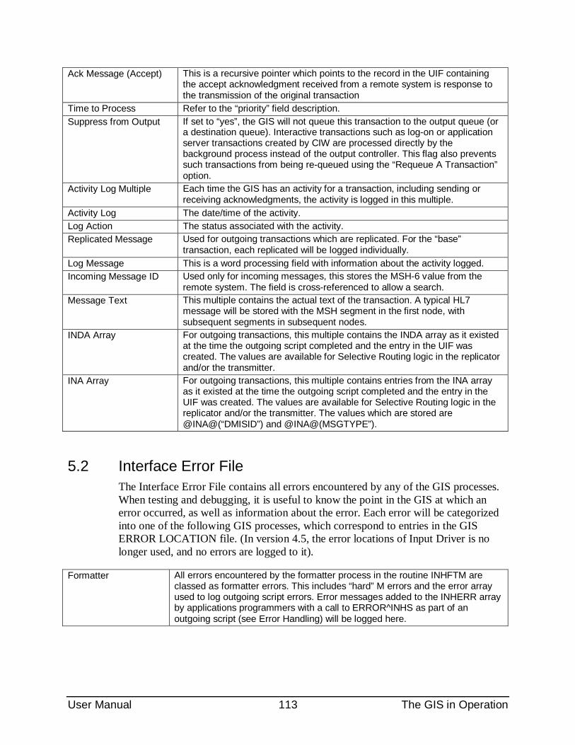
User Manual 113 The GIS in Operation
Ack Message (Accept) This is a recursive pointer which points to the record in the UIF containing the accept acknowledgment received from a remote system is response to the transmission of the original transaction
Time to Process Refer to the “priority” field description. Suppress from Output If set to “yes”, the GIS will not queue this transaction to the output queue (or
a destination queue). Interactive transactions such as log-on or application server transactions created by CIW are processed directly by the background process instead of the output controller. This flag also prevents such transactions from being re-queued using the “Requeue A Transaction” option.
Activity Log Multiple Each time the GIS has an activity for a transaction, including sending or receiving acknowledgments, the activity is logged in this multiple.
Activity Log The date/time of the activity. Log Action The status associated with the activity. Replicated Message Used for outgoing transactions which are replicated. For the “base”
transaction, each replicated will be logged individually. Log Message This is a word processing field with information about the activity logged. Incoming Message ID Used only for incoming messages, this stores the MSH-6 value from the
remote system. The field is cross-referenced to allow a search. Message Text This multiple contains the actual text of the transaction. A typical HL7
message will be stored with the MSH segment in the first node, with subsequent segments in subsequent nodes.
INDA Array For outgoing transactions, this multiple contains the INDA array as it existed at the time the outgoing script completed and the entry in the UIF was created. The values are available for Selective Routing logic in the replicator and/or the transmitter.
INA Array For outgoing transactions, this multiple contains entries from the INA array as it existed at the time the outgoing script completed and the entry in the UIF was created. The values are available for Selective Routing logic in the replicator and/or the transmitter. The values which are stored are @INA@(“DMISID”) and @INA@(MSGTYPE”).
5.2 Interface Error File The Interface Error File contains all errors encountered by any of the GIS processes. When testing and debugging, it is useful to know the point in the GIS at which an error occurred, as well as information about the error. Each error will be categorized into one of the following GIS processes, which correspond to entries in the GIS ERROR LOCATION file. (In version 4.5, the error locations of Input Driver is no longer used, and no errors are logged to it).
Formatter All errors encountered by the formatter process in the routine INHFTM are classed as formatter errors. This includes “hard” M errors and the error array used to log outgoing script errors. Error messages added to the INHERR array by applications programmers with a call to ERROR^INHS as part of an outgoing script (see Error Handling) will be logged here.
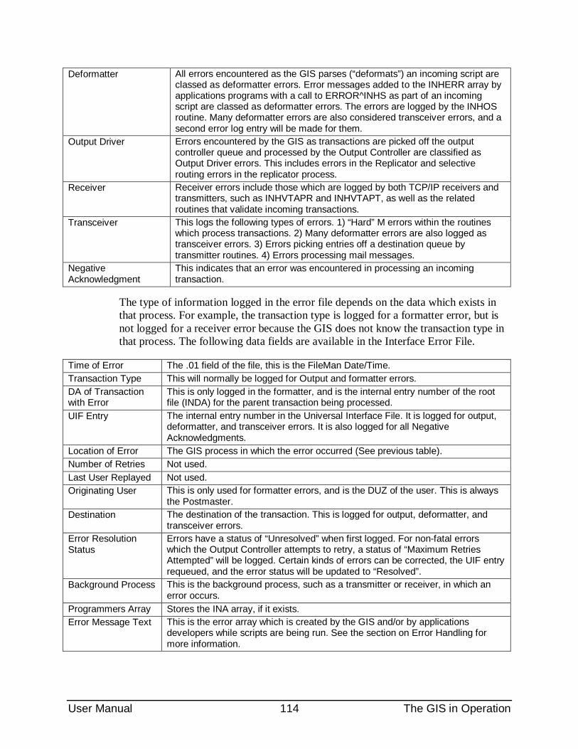
User Manual 114 The GIS in Operation
Deformatter All errors encountered as the GIS parses (“deformats”) an incoming script are classed as deformatter errors. Error messages added to the INHERR array by applications programs with a call to ERROR^INHS as part of an incoming script are classed as deformatter errors. The errors are logged by the INHOS routine. Many deformatter errors are also considered transceiver errors, and a second error log entry will be made for them.
Output Driver Errors encountered by the GIS as transactions are picked off the output controller queue and processed by the Output Controller are classified as Output Driver errors. This includes errors in the Replicator and selective routing errors in the replicator process.
Receiver Receiver errors include those which are logged by both TCP/IP receivers and transmitters, such as INHVTAPR and INHVTAPT, as well as the related routines that validate incoming transactions.
Transceiver This logs the following types of errors. 1) “Hard” M errors within the routines which process transactions. 2) Many deformatter errors are also logged as transceiver errors. 3) Errors picking entries off a destination queue by transmitter routines. 4) Errors processing mail messages.
Negative Acknowledgment
This indicates that an error was encountered in processing an incoming transaction.
The type of information logged in the error file depends on the data which exists in that process. For example, the transaction type is logged for a formatter error, but is not logged for a receiver error because the GIS does not know the transaction type in that process. The following data fields are available in the Interface Error File.
Time of Error The .01 field of the file, this is the FileMan Date/Time. Transaction Type This will normally be logged for Output and formatter errors. DA of Transaction with Error
This is only logged in the formatter, and is the internal entry number of the root file (INDA) for the parent transaction being processed.
UIF Entry The internal entry number in the Universal Interface File. It is logged for output, deformatter, and transceiver errors. It is also logged for all Negative Acknowledgments.
Location of Error The GIS process in which the error occurred (See previous table). Number of Retries Not used. Last User Replayed Not used. Originating User This is only used for formatter errors, and is the DUZ of the user. This is always
the Postmaster. Destination The destination of the transaction. This is logged for output, deformatter, and
transceiver errors. Error Resolution Status
Errors have a status of “Unresolved” when first logged. For non-fatal errors which the Output Controller attempts to retry, a status of “Maximum Retries Attempted” will be logged. Certain kinds of errors can be corrected, the UIF entry requeued, and the error status will be updated to “Resolved”.
Background Process This is the background process, such as a transmitter or receiver, in which an error occurs.
Programmers Array Stores the INA array, if it exists. Error Message Text This is the error array which is created by the GIS and/or by applications
developers while scripts are being run. See the section on Error Handling for more information.
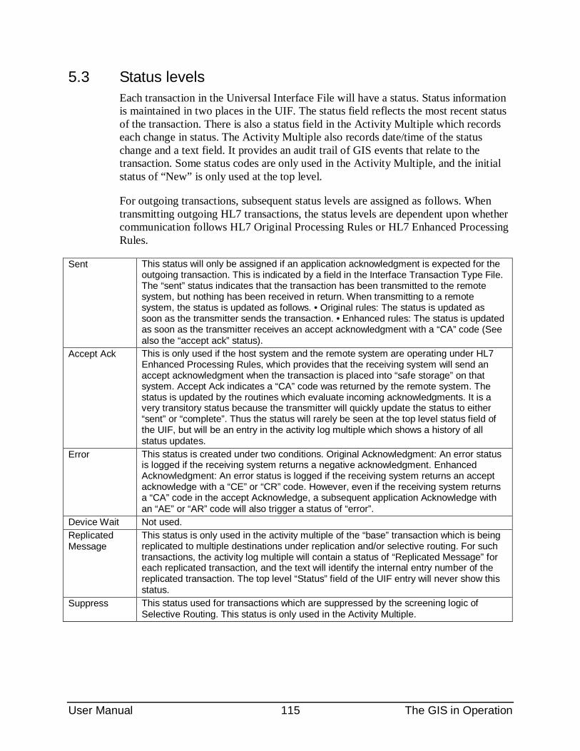
User Manual 115 The GIS in Operation
5.3 Status levels Each transaction in the Universal Interface File will have a status. Status information is maintained in two places in the UIF. The status field reflects the most recent status of the transaction. There is also a status field in the Activity Multiple which records each change in status. The Activity Multiple also records date/time of the status change and a text field. It provides an audit trail of GIS events that relate to the transaction. Some status codes are only used in the Activity Multiple, and the initial status of “New” is only used at the top level.
For outgoing transactions, subsequent status levels are assigned as follows. When transmitting outgoing HL7 transactions, the status levels are dependent upon whether communication follows HL7 Original Processing Rules or HL7 Enhanced Processing Rules.
Sent This status will only be assigned if an application acknowledgment is expected for the outgoing transaction. This is indicated by a field in the Interface Transaction Type File. The “sent” status indicates that the transaction has been transmitted to the remote system, but nothing has been received in return. When transmitting to a remote system, the status is updated as follows. • Original rules: The status is updated as soon as the transmitter sends the transaction. • Enhanced rules: The status is updated as soon as the transmitter receives an accept acknowledgment with a “CA” code (See also the “accept ack” status).
Accept Ack This is only used if the host system and the remote system are operating under HL7 Enhanced Processing Rules, which provides that the receiving system will send an accept acknowledgment when the transaction is placed into “safe storage” on that system. Accept Ack indicates a “CA” code was returned by the remote system. The status is updated by the routines which evaluate incoming acknowledgments. It is a very transitory status because the transmitter will quickly update the status to either “sent” or “complete”. Thus the status will rarely be seen at the top level status field of the UIF, but will be an entry in the activity log multiple which shows a history of all status updates.
Error This status is created under two conditions. Original Acknowledgment: An error status is logged if the receiving system returns a negative acknowledgment. Enhanced Acknowledgment: An error status is logged if the receiving system returns an accept acknowledge with a “CE” or “CR” code. However, even if the receiving system returns a “CA” code in the accept Acknowledge, a subsequent application Acknowledge with an “AE” or “AR” code will also trigger a status of “error”.
Device Wait Not used. Replicated Message
This status is only used in the activity multiple of the “base” transaction which is being replicated to multiple destinations under replication and/or selective routing. For such transactions, the activity log multiple will contain a status of “Replicated Message” for each replicated transaction, and the text will identify the internal entry number of the replicated transaction. The top level “Status” field of the UIF entry will never show this status.
Suppress This status used for transactions which are suppressed by the screening logic of Selective Routing. This status is only used in the Activity Multiple.
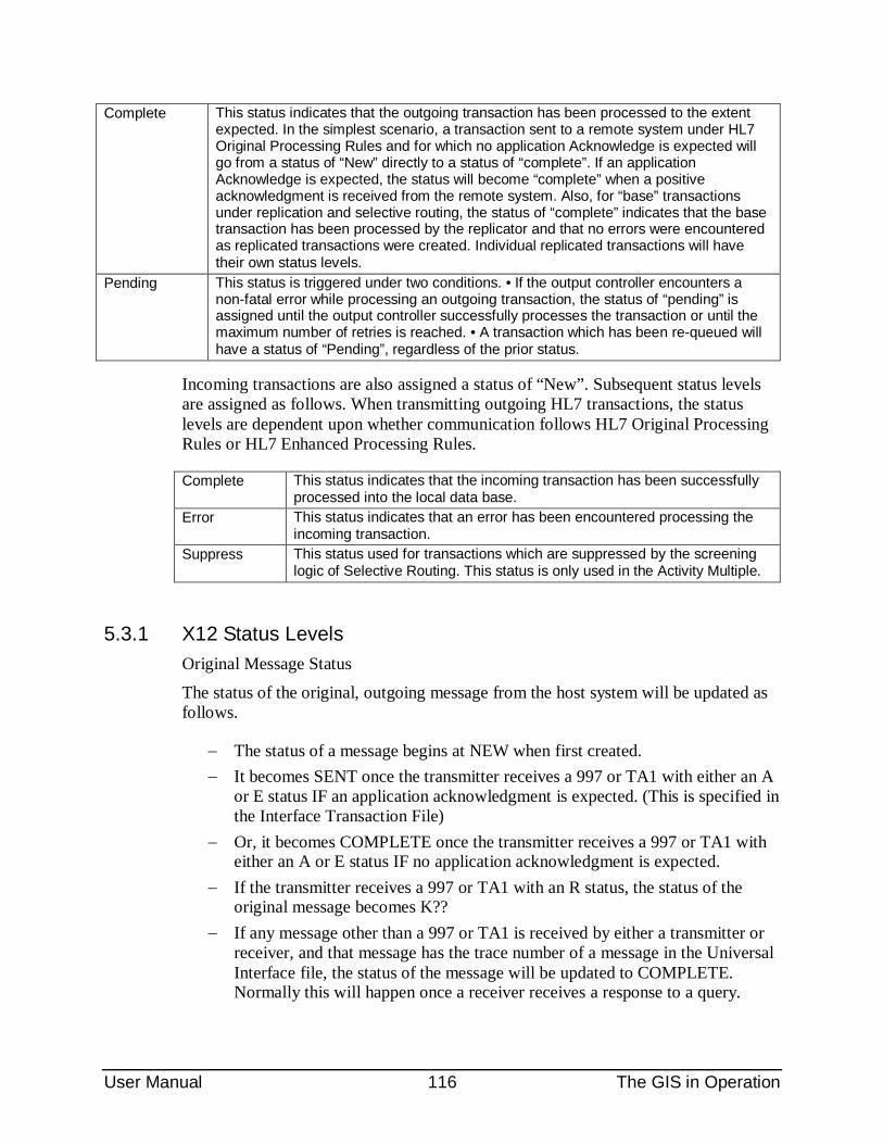
User Manual 116 The GIS in Operation
Complete This status indicates that the outgoing transaction has been processed to the extent expected. In the simplest scenario, a transaction sent to a remote system under HL7 Original Processing Rules and for which no application Acknowledge is expected will go from a status of “New” directly to a status of “complete”. If an application Acknowledge is expected, the status will become “complete” when a positive acknowledgment is received from the remote system. Also, for “base” transactions under replication and selective routing, the status of “complete” indicates that the base transaction has been processed by the replicator and that no errors were encountered as replicated transactions were created. Individual replicated transactions will have their own status levels.
Pending This status is triggered under two conditions. • If the output controller encounters a non-fatal error while processing an outgoing transaction, the status of “pending” is assigned until the output controller successfully processes the transaction or until the maximum number of retries is reached. • A transaction which has been re-queued will have a status of “Pending”, regardless of the prior status.
Incoming transactions are also assigned a status of “New”. Subsequent status levels are assigned as follows. When transmitting outgoing HL7 transactions, the status levels are dependent upon whether communication follows HL7 Original Processing Rules or HL7 Enhanced Processing Rules.
Complete This status indicates that the incoming transaction has been successfully processed into the local data base.
Error This status indicates that an error has been encountered processing the incoming transaction.
Suppress This status used for transactions which are suppressed by the screening logic of Selective Routing. This status is only used in the Activity Multiple.
5.3.1 X12 Status Levels Original Message Status
The status of the original, outgoing message from the host system will be updated as follows.
− The status of a message begins at NEW when first created. − It becomes SENT once the transmitter receives a 997 or TA1 with either an A
or E status IF an application acknowledgment is expected. (This is specified in the Interface Transaction File)
− Or, it becomes COMPLETE once the transmitter receives a 997 or TA1 with either an A or E status IF no application acknowledgment is expected.
− If the transmitter receives a 997 or TA1 with an R status, the status of the original message becomes K??
− If any message other than a 997 or TA1 is received by either a transmitter or receiver, and that message has the trace number of a message in the Universal Interface file, the status of the message will be updated to COMPLETE. Normally this will happen once a receiver receives a response to a query.
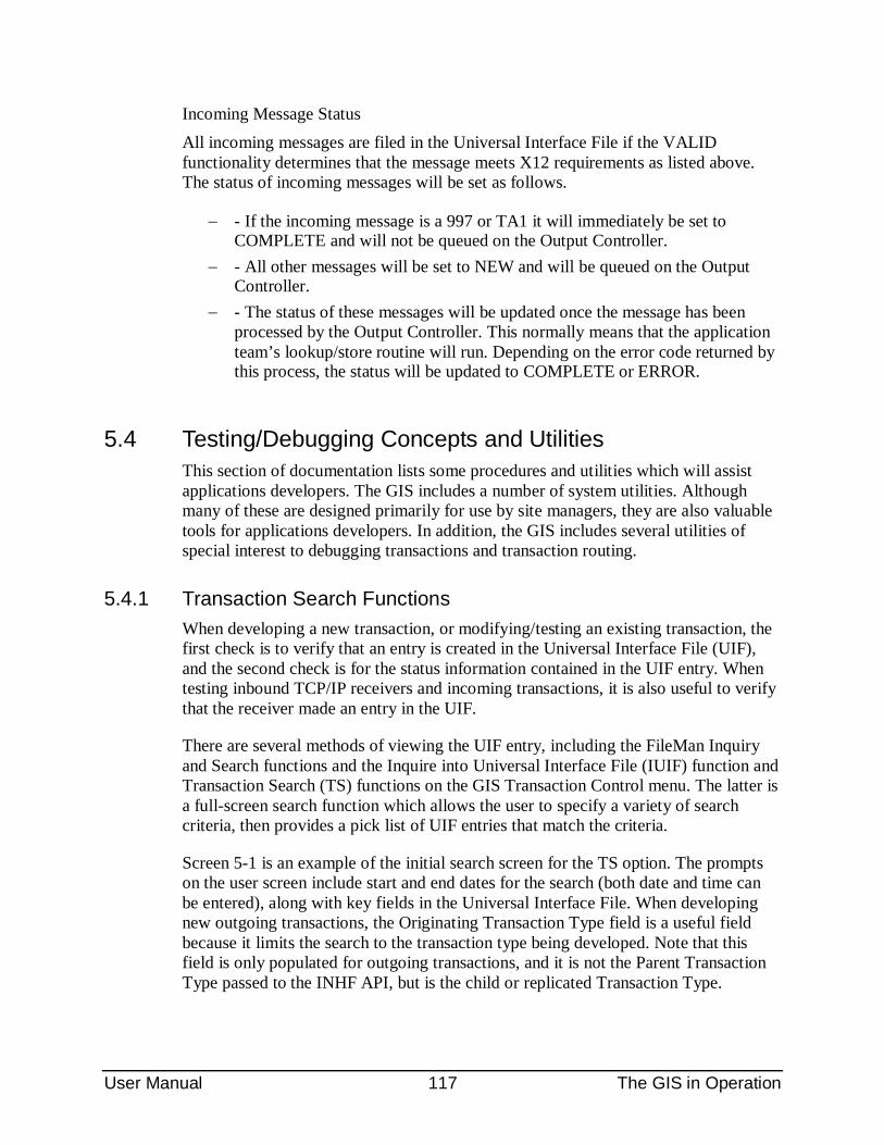
User Manual 117 The GIS in Operation
Incoming Message Status All incoming messages are filed in the Universal Interface File if the VALID functionality determines that the message meets X12 requirements as listed above. The status of incoming messages will be set as follows.
− - If the incoming message is a 997 or TA1 it will immediately be set to COMPLETE and will not be queued on the Output Controller.
− - All other messages will be set to NEW and will be queued on the Output Controller.
− - The status of these messages will be updated once the message has been processed by the Output Controller. This normally means that the application team’s lookup/store routine will run. Depending on the error code returned by this process, the status will be updated to COMPLETE or ERROR.
5.4 Testing/Debugging Concepts and Utilities This section of documentation lists some procedures and utilities which will assist applications developers. The GIS includes a number of system utilities. Although many of these are designed primarily for use by site managers, they are also valuable tools for applications developers. In addition, the GIS includes several utilities of special interest to debugging transactions and transaction routing.
5.4.1 Transaction Search Functions When developing a new transaction, or modifying/testing an existing transaction, the first check is to verify that an entry is created in the Universal Interface File (UIF), and the second check is for the status information contained in the UIF entry. When testing inbound TCP/IP receivers and incoming transactions, it is also useful to verify that the receiver made an entry in the UIF.
There are several methods of viewing the UIF entry, including the FileMan Inquiry and Search functions and the Inquire into Universal Interface File (IUIF) function and Transaction Search (TS) functions on the GIS Transaction Control menu. The latter is a full-screen search function which allows the user to specify a variety of search criteria, then provides a pick list of UIF entries that match the criteria.
Screen 5-1 is an example of the initial search screen for the TS option. The prompts on the user screen include start and end dates for the search (both date and time can be entered), along with key fields in the Universal Interface File. When developing new outgoing transactions, the Originating Transaction Type field is a useful field because it limits the search to the transaction type being developed. Note that this field is only populated for outgoing transactions, and it is not the Parent Transaction Type passed to the INHF API, but is the child or replicated Transaction Type.
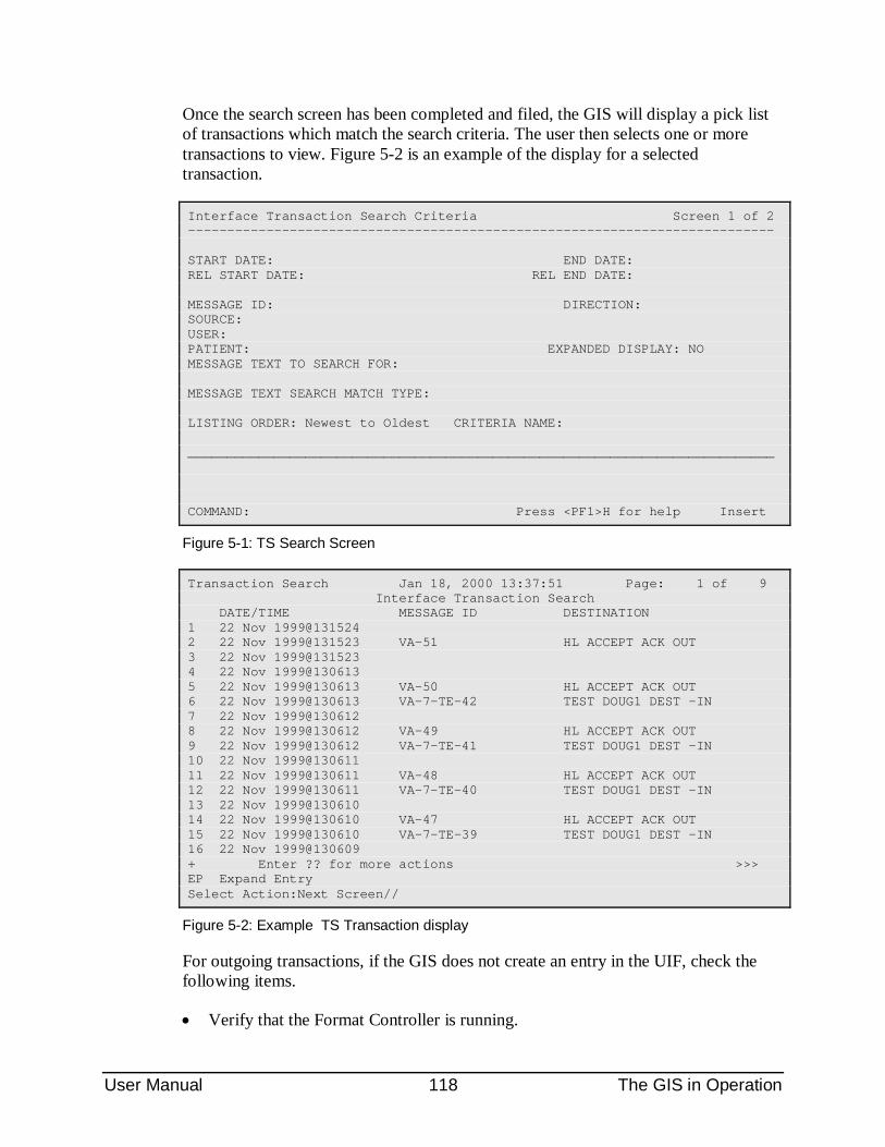
User Manual 118 The GIS in Operation
Once the search screen has been completed and filed, the GIS will display a pick list of transactions which match the search criteria. The user then selects one or more transactions to view. Figure 5-2 is an example of the display for a selected transaction.
Interface Transaction Search Criteria Screen 1 of 2 --------------------------------------------------------------------------- START DATE: END DATE: REL START DATE: REL END DATE: MESSAGE ID: DIRECTION: SOURCE: USER: PATIENT: EXPANDED DISPLAY: NO MESSAGE TEXT TO SEARCH FOR: MESSAGE TEXT SEARCH MATCH TYPE: LISTING ORDER: Newest to Oldest CRITERIA NAME: ___________________________________________________________________________ COMMAND: Press <PF1>H for help Insert
Figure 5-1: TS Search Screen
Transaction Search Jan 18, 2000 13:37:51 Page: 1 of 9 Interface Transaction Search DATE/TIME MESSAGE ID DESTINATION 1 22 Nov 1999@131524 2 22 Nov 1999@131523 VA-51 HL ACCEPT ACK OUT 3 22 Nov 1999@131523 4 22 Nov 1999@130613 5 22 Nov 1999@130613 VA-50 HL ACCEPT ACK OUT 6 22 Nov 1999@130613 VA-7-TE-42 TEST DOUG1 DEST -IN 7 22 Nov 1999@130612 8 22 Nov 1999@130612 VA-49 HL ACCEPT ACK OUT 9 22 Nov 1999@130612 VA-7-TE-41 TEST DOUG1 DEST -IN 10 22 Nov 1999@130611 11 22 Nov 1999@130611 VA-48 HL ACCEPT ACK OUT 12 22 Nov 1999@130611 VA-7-TE-40 TEST DOUG1 DEST -IN 13 22 Nov 1999@130610 14 22 Nov 1999@130610 VA-47 HL ACCEPT ACK OUT 15 22 Nov 1999@130610 VA-7-TE-39 TEST DOUG1 DEST -IN 16 22 Nov 1999@130609 + Enter ?? for more actions >>> EP Expand Entry Select Action:Next Screen//
Figure 5-2: Example TS Transaction display
For outgoing transactions, if the GIS does not create an entry in the UIF, check the following items.
• Verify that the Format Controller is running.
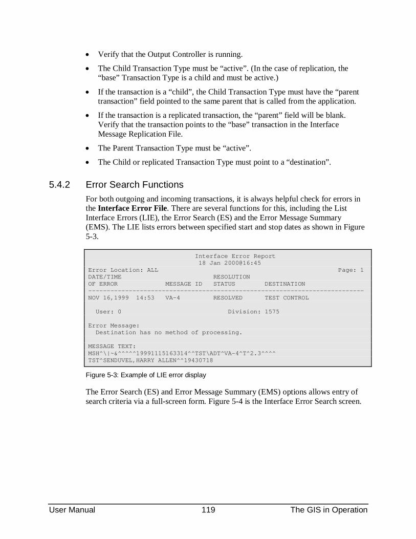
User Manual 119 The GIS in Operation
• Verify that the Output Controller is running.
• The Child Transaction Type must be “active”. (In the case of replication, the “base” Transaction Type is a child and must be active.)
• If the transaction is a “child”, the Child Transaction Type must have the “parent transaction” field pointed to the same parent that is called from the application.
• If the transaction is a replicated transaction, the “parent” field will be blank. Verify that the transaction points to the “base” transaction in the Interface Message Replication File.
• The Parent Transaction Type must be “active”.
• The Child or replicated Transaction Type must point to a “destination”.
5.4.2 Error Search Functions For both outgoing and incoming transactions, it is always helpful check for errors in the Interface Error File. There are several functions for this, including the List Interface Errors (LIE), the Error Search (ES) and the Error Message Summary (EMS). The LIE lists errors between specified start and stop dates as shown in Figure 5-3.
Interface Error Report 18 Jan 2000@16:45 Error Location: ALL Page: 1 DATE/TIME RESOLUTION OF ERROR MESSAGE ID STATUS DESTINATION --------------------------------------------------------------------------- NOV 16,1999 14:53 VA-4 RESOLVED TEST CONTROL User: 0 Division: 1575 Error Message: Destination has no method of processing. MESSAGE TEXT: MSH^\|~&^^^^^19991115163314^^TST\ADT^VA-4^T^2.3^^^^ TST^SENDUVEL,HARRY ALLEN^^19430718
Figure 5-3: Example of LIE error display
The Error Search (ES) and Error Message Summary (EMS) options allows entry of search criteria via a full-screen form. Figure 5-4 is the Interface Error Search screen.
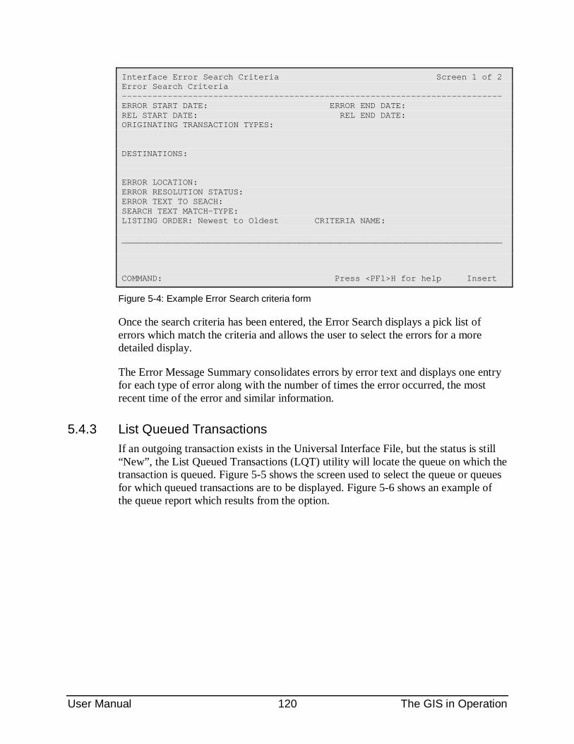
User Manual 120 The GIS in Operation
Interface Error Search Criteria Screen 1 of 2 Error Search Criteria --------------------------------------------------------------------------- ERROR START DATE: ERROR END DATE: REL START DATE: REL END DATE: ORIGINATING TRANSACTION TYPES: DESTINATIONS: ERROR LOCATION: ERROR RESOLUTION STATUS: ERROR TEXT TO SEACH: SEARCH TEXT MATCH-TYPE: LISTING ORDER: Newest to Oldest CRITERIA NAME: ___________________________________________________________________________ COMMAND: Press <PF1>H for help Insert
Figure 5-4: Example Error Search criteria form
Once the search criteria has been entered, the Error Search displays a pick list of errors which match the criteria and allows the user to select the errors for a more detailed display.
The Error Message Summary consolidates errors by error text and displays one entry for each type of error along with the number of times the error occurred, the most recent time of the error and similar information.
5.4.3 List Queued Transactions If an outgoing transaction exists in the Universal Interface File, but the status is still “New”, the List Queued Transactions (LQT) utility will locate the queue on which the transaction is queued. Figure 5-5 shows the screen used to select the queue or queues for which queued transactions are to be displayed. Figure 5-6 shows an example of the queue report which results from the option.
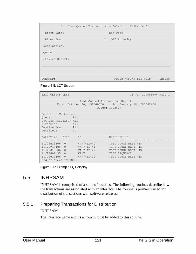
User Manual 121 The GIS in Operation
*** List Queued Transaction - Selection Criteria *** Start Date: End Date: Direction: Cut Off Priority: Destination: Queue: Detailed Report: ___________________________________________________________________________ COMMAND: Press <PF1>H for help Insert
Figure 5-5: LQT Screen
SAIC WEBTOP TEST 18 Jan 2000@1656 Page 1 List Queued Transaction Report From: October 20, 1999@0000 To: January 18, 2000@2400 Queue: INLHSCH Selection Criteria: Queue: All Cut Off Priority: All Direction: All Destination: All Detailed: No Date/Time Prio ID Destination --------------------------------------------------------------------------- 11/22@13:06 0 VA-7-TE-40 TEST DOUG1 DEST -IN 11/22@13:06 0 VA-7-TE-41 TEST DOUG1 DEST -IN 11/22@13:06 0 VA-7-TE-42 TEST DOUG1 DEST -IN 11/19@09:55 0 VA-7 TEST SEQUENCE 11/22@13:06 0 VA-7-TE-39 TEST DOUG1 DEST -IN End of queue INLHSCH
Figure 5-6: Example LQT display
5.5 INHPSAM INHPSAM is comprised of a suite of routines. The following routines describe how the transactions are associated with an interface. The routine is primarily used for distribution of transactions with software releases.
5.5.1 Preparing Transactions for Distribution INHPSAM The interface name and its acronym must be added to this routine.
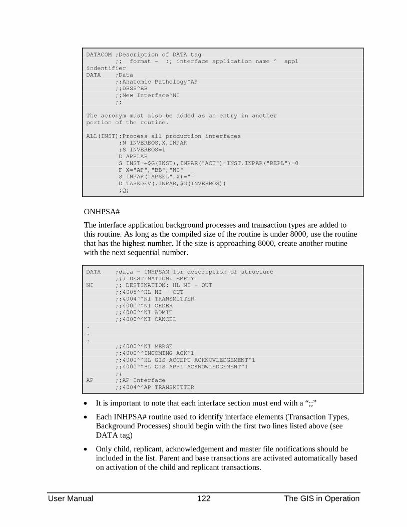
User Manual 122 The GIS in Operation
DATACOM ;Description of DATA tag ;; format - ;; interface application name ^ appl indentifier DATA ;Data ;;Anatomic Pathology^AP ;;DBSS^BB ;;New Interface^NI ;; The acronym must also be added as an entry in another portion of the routine. ALL(INST);Process all production interfaces ;N INVERBOS,X,INPAR ;S INVERBOS=1 D APPLAR S INST=+$G(INST),INPAR("ACT")=INST,INPAR("REPL")=0 F X="AP","BB","NI" S INPAR("APSEL",X)="" D TASKDEV(.INPAR,$G(INVERBOS)) ;Q;
ONHPSA#
The interface application background processes and transaction types are added to this routine. As long as the compiled size of the routine is under 8000, use the routine that has the highest number. If the size is approaching 8000, create another routine with the next sequential number.
DATA ;data - INHPSAM for description of structure ;;; DESTINATION: EMPTY NI ;; DESTINATION: HL NI - OUT ;;4005^^HL NI - OUT ;;4004^^NI TRANSMITTER ;;4000^^NI ORDER ;;4000^^NI ADMIT ;;4000^^NI CANCEL . . . ;;4000^^NI MERGE ;;4000^^INCOMING ACK^1 ;;4000^^HL GIS ACCEPT ACKNOWLEDGEMENT^1 ;;4000^^HL GIS APPL ACKNOWLEDGEMENT^1 ;; AP ;;AP Interface ;;4004^^AP TRANSMITTER
• It is important to note that each interface section must end with a “;;”
• Each INHPSA# routine used to identify interface elements (Transaction Types, Background Processes) should begin with the first two lines listed above (see DATA tag)
• Only child, replicant, acknowledgement and master file notifications should be included in the list. Parent and base transactions are activated automatically based on activation of the child and replicant transactions.
User Manual 123 The GIS in Operation
• The transactions for Incoming ACK, HL GIS ACCEPT ACKNOWLEDGEMENT and HL GIS APPL ACKNOWLEDGEMENT should always be included for each GIS HL7 interface.
• The transactions for Incoming ACK, HL GIS ACCEPT ACKNOWLEDGEMENT and HL GIS APPL ACKNOWLEDGEMENT include a “^1” at the end. This indicates that these transactions are also used in other interfaces. If the interface is deactivated by INHPSAM, transactions indicated as such will not be inactivated so that other interfaces will not be affected. Any new Transaction Types that are used by more than one interface should also include an “^1” at the end.
INHPSA2
This routine contains the help text. The text displays on screen after the routine is run for activating an interface. The help text contains activation reminders for site-specific activities . For example, this help text may include a reminder to enter the IP address and port numbers for the background processes.
NMIS ;NMIS ;;Remember to enter the CLIENT IP ADDRESS and IP ;; PORT for the NMIS TRANSMITTER background process. ;;Do this through the GIS menu. GIS->FTM->BPE ;;Also, enter destination identifiers in the ROUTE ;; ID multiple of HL NI - OUT interface destination. ;;Do this through the GIS menu. GIS->FTM->DE Q
5.5.2 Activating/Deactivating an Interface The routine INHPSAM can also be used to activate or deactivate a selected interface in one step. The routine is called INHPSAM and is invoked by typing a command at the MSM prompt. When invoked, a list of eligible interfaces is displayed:
>D EN^INHPSAM AP Anatomic Pathology BB DBSS Select Interface Application:
INHPSAM contains all of the background processes and transaction types for a given interface that must be in a status of ACTIVE in order for the interface to be started. This routine activates the interface, but does not turn on the interface connection. By activating the interface, several things will occur:
• The activated background process will appear in the picklist of processes when selecting the option (GIS – BPC – S1) to start an interface.
• The activated background process will appear in the option to verify status of interfaces (GIS – TCM – VS).
User Manual 124 The GIS in Operation
• Activated transaction types will allow the application to trigger an HL7 message.
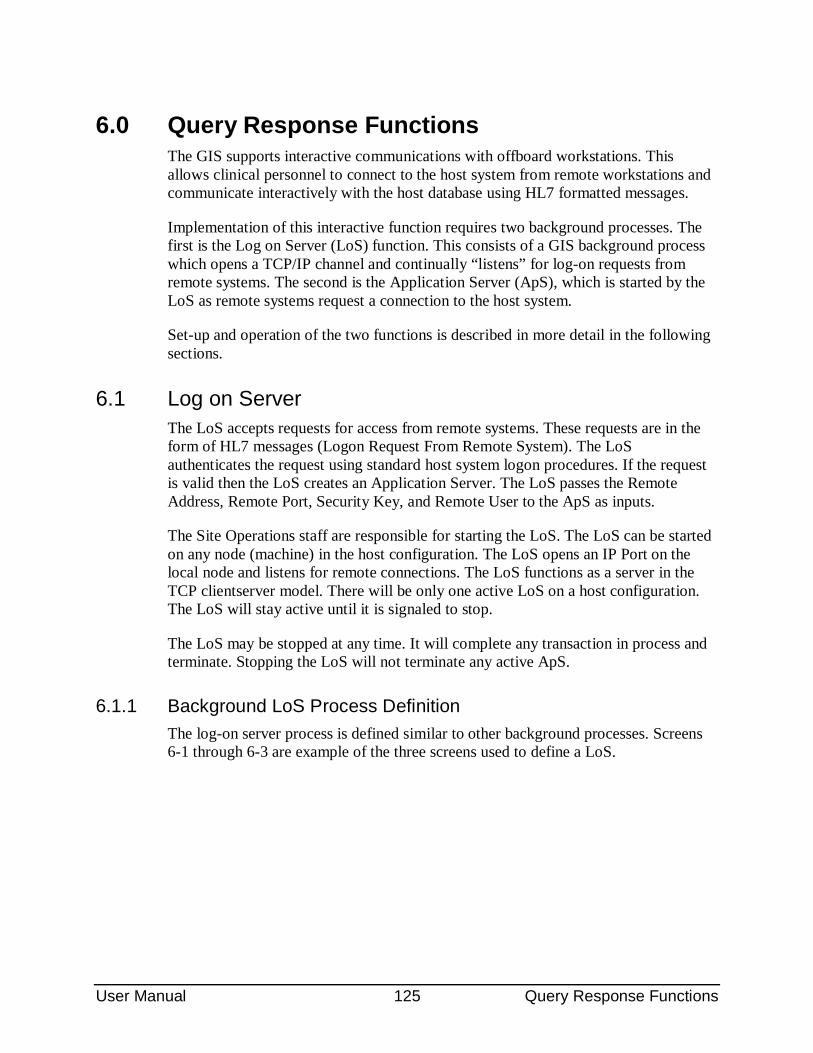
User Manual 125 Query Response Functions
6.0 Query Response Functions The GIS supports interactive communications with offboard workstations. This allows clinical personnel to connect to the host system from remote workstations and communicate interactively with the host database using HL7 formatted messages.
Implementation of this interactive function requires two background processes. The first is the Log on Server (LoS) function. This consists of a GIS background process which opens a TCP/IP channel and continually “listens” for log-on requests from remote systems. The second is the Application Server (ApS), which is started by the LoS as remote systems request a connection to the host system.
Set-up and operation of the two functions is described in more detail in the following sections.
6.1 Log on Server The LoS accepts requests for access from remote systems. These requests are in the form of HL7 messages (Logon Request From Remote System). The LoS authenticates the request using standard host system logon procedures. If the request is valid then the LoS creates an Application Server. The LoS passes the Remote Address, Remote Port, Security Key, and Remote User to the ApS as inputs.
The Site Operations staff are responsible for starting the LoS. The LoS can be started on any node (machine) in the host configuration. The LoS opens an IP Port on the local node and listens for remote connections. The LoS functions as a server in the TCP clientserver model. There will be only one active LoS on a host configuration. The LoS will stay active until it is signaled to stop.
The LoS may be stopped at any time. It will complete any transaction in process and terminate. Stopping the LoS will not terminate any active ApS.
6.1.1 Background LoS Process Definition The log-on server process is defined similar to other background processes. Screens 6-1 through 6-3 are example of the three screens used to define a LoS.
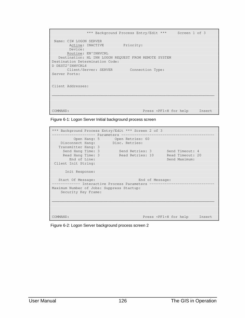
User Manual 126 The GIS in Operation
*** Background Process Entry/Edit *** Screen 1 of 3 Name: CIW LOGON SERVER Active: INACTIVE Priority: Device: Routine: EN^INHVCRL Destination: HL INH LOGON REQUEST FROM REMOTE SYSTEM Destination Determination Code: D DEST2^INHVCRL4 Client/Server: SERVER Connection Type: Server Ports: Client Addresses: ___________________________________________________________________________ COMMAND: Press <PF1>H for help Insert
Figure 6-1: Logon Server Initial background process screen
*** Background Process Entry/Edit *** Screen 2 of 3 -------------------- Parameters ------------------------------------------- Open Hang: 5 Open Retries: 60 Disconnect Hang: Disc. Retries: Transmitter Hang: 3 Send Hang Time: 3 Send Retries: 3 Send Timeout: 4 Read Hang Time: 3 Read Retries: 10 Read Timeout: 20 End of Line: Send Maximum: Client Init String: Init Response: Start Of Message: End of Message: ------------- Interactive Process Parameters ------------------------------ Maximum Number of Jobs: Suppress Startup: Security Key Frame: ___________________________________________________________________________ COMMAND: Press <PF1>H for help Insert
Figure 6-2: Logon Server background process screen 2
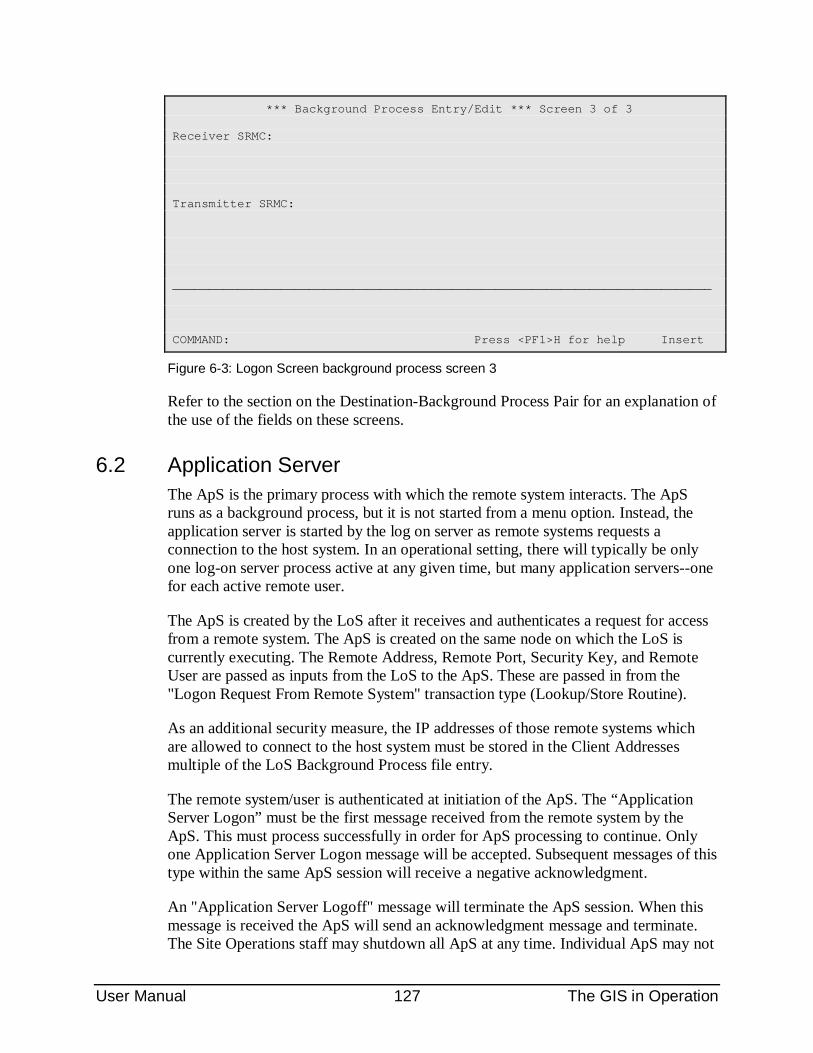
User Manual 127 The GIS in Operation
*** Background Process Entry/Edit *** Screen 3 of 3 Receiver SRMC: Transmitter SRMC: ___________________________________________________________________________ COMMAND: Press <PF1>H for help Insert
Figure 6-3: Logon Screen background process screen 3
Refer to the section on the Destination-Background Process Pair for an explanation of the use of the fields on these screens.
6.2 Application Server The ApS is the primary process with which the remote system interacts. The ApS runs as a background process, but it is not started from a menu option. Instead, the application server is started by the log on server as remote systems requests a connection to the host system. In an operational setting, there will typically be only one log-on server process active at any given time, but many application servers--one for each active remote user.
The ApS is created by the LoS after it receives and authenticates a request for access from a remote system. The ApS is created on the same node on which the LoS is currently executing. The Remote Address, Remote Port, Security Key, and Remote User are passed as inputs from the LoS to the ApS. These are passed in from the "Logon Request From Remote System" transaction type (Lookup/Store Routine).
As an additional security measure, the IP addresses of those remote systems which are allowed to connect to the host system must be stored in the Client Addresses multiple of the LoS Background Process file entry.
The remote system/user is authenticated at initiation of the ApS. The “Application Server Logon” must be the first message received from the remote system by the ApS. This must process successfully in order for ApS processing to continue. Only one Application Server Logon message will be accepted. Subsequent messages of this type within the same ApS session will receive a negative acknowledgment.
An "Application Server Logoff" message will terminate the ApS session. When this message is received the ApS will send an acknowledgment message and terminate. The Site Operations staff may shutdown all ApS at any time. Individual ApS may not
User Manual 128 The GIS in Operation
be terminated. When the ApS receive the signal to terminate they will complete the processing of any transaction in progress and terminate. No notification will be sent to the remote system.
The ApS connects to the IP port at the remote port and address specified by the LoS. Typically, the ApS functions as a client in the TCP client-server model.
6.2.1 ApS Background Process Definition The application server process is defined similar to other background processes. Figures 6-4 through 6-7 are example of the three screens used to define an Aps. In the example shown on Screen 6-5 the “Maximum Number of Jobs” is set at 75. This indicates that up to 75 application server jobs can be active at any one time--meaning that up to 75 workstations can be interactively communicating. If this field is null, the default will be 9999. The actual maximum is dependent upon system resource limitations. Also shown on this screen is that the “Suppress Startup” field is set to “yes”. This is used by the GIS to prevent application servers from being started from the Background Process Control menu.
The field “Security Key Frame” is a security feature of the system. The key frame is used as a frame for the key supplied to a workstation during logon. Each workstation that wishes to connect to a server must have this key frame defined and pass it to the ApS with the security key provided by the LoS.
6.2.2 Variable arrays for incoming and outgoing scripts Because the application server is communicating interactively with the remote users, transactions are not queued on either the format controller queue or the output controller queue. This eliminates any delay in processing. Further, the application server maintains control over the entire message processing activity rather than pass it to other GIS processes such as the format or output controllers. However, this requires the application server to provide some of the functionality which is normally provided by those controllers. For incoming transactions, the application server identifies the proper entry in the Interface Transaction Type File and runs the appropriate script to update the database. To respond to the remote system, the entry in the Transaction Type File for the incoming transaction should point to an outgoing Transaction Type in the field, ACKNOWLEGE MESSAGE. The application server will then run the script for the outgoing transaction and transmit it back to the remote system.
For example, an incoming transaction that queries the host database for a patient identifier may point to an outgoing transaction which contains a message containing a PID segment for the patient being queried.
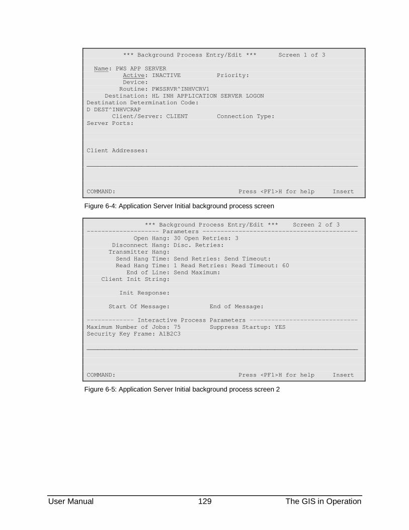
User Manual 129 The GIS in Operation
*** Background Process Entry/Edit *** Screen 1 of 3 Name: PWS APP SERVER Active: INACTIVE Priority: Device: Routine: PWSSRVR^INHVCRV1 Destination: HL INH APPLICATION SERVER LOGON Destination Determination Code: D DEST^INHVCRAP Client/Server: CLIENT Connection Type: Server Ports: Client Addresses: ___________________________________________________________________________ COMMAND: Press <PF1>H for help Insert
Figure 6-4: Application Server Initial background process screen
*** Background Process Entry/Edit *** Screen 2 of 3 -------------------- Parameters ------------------------------------------- Open Hang: 30 Open Retries: 3 Disconnect Hang: Disc. Retries: Transmitter Hang: Send Hang Time: Send Retries: Send Timeout: Read Hang Time: 1 Read Retries: Read Timeout: 60 End of Line: Send Maximum: Client Init String: Init Response: Start Of Message: End of Message: ------------- Interactive Process Parameters ------------------------------ Maximum Number of Jobs: 75 Suppress Startup: YES Security Key Frame: A1B2C3 ___________________________________________________________________________ COMMAND: Press <PF1>H for help Insert
Figure 6-5: Application Server Initial background process screen 2
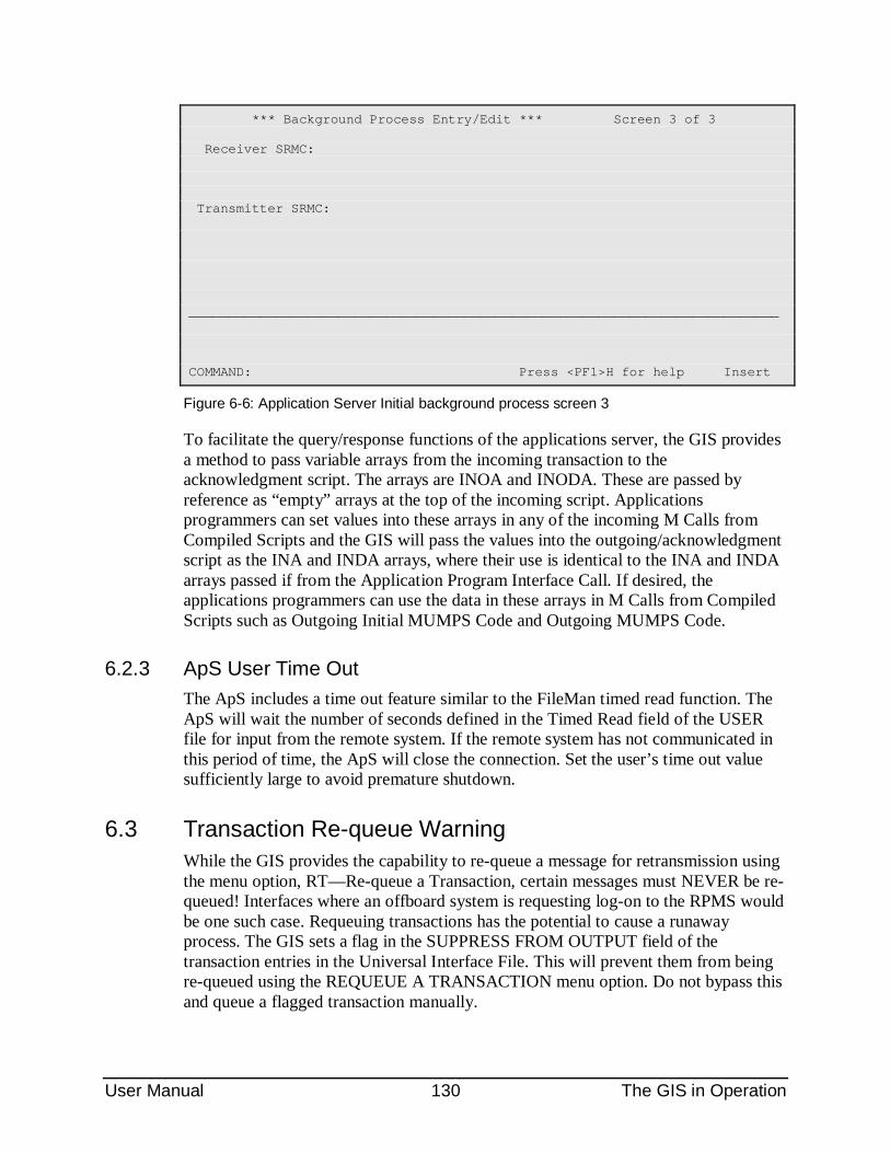
User Manual 130 The GIS in Operation
*** Background Process Entry/Edit *** Screen 3 of 3 Receiver SRMC: Transmitter SRMC: ___________________________________________________________________________ COMMAND: Press <PF1>H for help Insert
Figure 6-6: Application Server Initial background process screen 3
To facilitate the query/response functions of the applications server, the GIS provides a method to pass variable arrays from the incoming transaction to the acknowledgment script. The arrays are INOA and INODA. These are passed by reference as “empty” arrays at the top of the incoming script. Applications programmers can set values into these arrays in any of the incoming M Calls from Compiled Scripts and the GIS will pass the values into the outgoing/acknowledgment script as the INA and INDA arrays, where their use is identical to the INA and INDA arrays passed if from the Application Program Interface Call. If desired, the applications programmers can use the data in these arrays in M Calls from Compiled Scripts such as Outgoing Initial MUMPS Code and Outgoing MUMPS Code.
6.2.3 ApS User Time Out The ApS includes a time out feature similar to the FileMan timed read function. The ApS will wait the number of seconds defined in the Timed Read field of the USER file for input from the remote system. If the remote system has not communicated in this period of time, the ApS will close the connection. Set the user’s time out value sufficiently large to avoid premature shutdown.
6.3 Transaction Re-queue Warning While the GIS provides the capability to re-queue a message for retransmission using the menu option, RT—Re-queue a Transaction, certain messages must NEVER be re-queued! Interfaces where an offboard system is requesting log-on to the RPMS would be one such case. Requeuing transactions has the potential to cause a runaway process. The GIS sets a flag in the SUPPRESS FROM OUTPUT field of the transaction entries in the Universal Interface File. This will prevent them from being re-queued using the REQUEUE A TRANSACTION menu option. Do not bypass this and queue a flagged transaction manually.
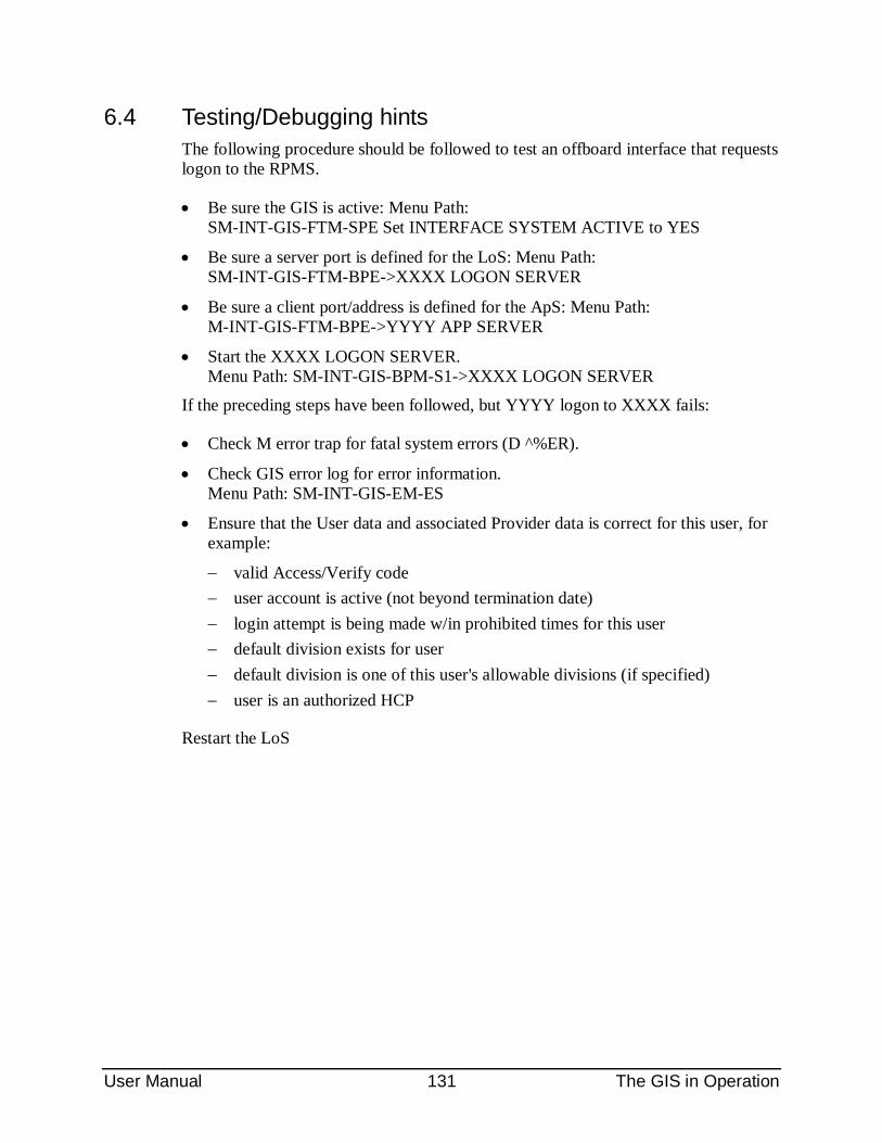
User Manual 131 The GIS in Operation
6.4 Testing/Debugging hints The following procedure should be followed to test an offboard interface that requests logon to the RPMS.
• Be sure the GIS is active: Menu Path: SM-INT-GIS-FTM-SPE Set INTERFACE SYSTEM ACTIVE to YES
• Be sure a server port is defined for the LoS: Menu Path: SM-INT-GIS-FTM-BPE->XXXX LOGON SERVER
• Be sure a client port/address is defined for the ApS: Menu Path: M-INT-GIS-FTM-BPE->YYYY APP SERVER
• Start the XXXX LOGON SERVER. Menu Path: SM-INT-GIS-BPM-S1->XXXX LOGON SERVER
If the preceding steps have been followed, but YYYY logon to XXXX fails:
• Check M error trap for fatal system errors (D ^%ER).
• Check GIS error log for error information. Menu Path: SM-INT-GIS-EM-ES
• Ensure that the User data and associated Provider data is correct for this user, for example:
− valid Access/Verify code − user account is active (not beyond termination date) − login attempt is being made w/in prohibited times for this user − default division exists for user − default division is one of this user's allowable divisions (if specified) − user is an authorized HCP
Restart the LoS
User Manual 132Data Transforms and Character Conversion
7.0 Data Transforms and Character Conversion Data Transforms can be defined in two different places in the GIS.
• The “Outgoing Tranform” and “Incoming Transform” fields in the Script Generator Data Type file. These allow transforms to be applied to all fields of a particular type, such as an HL date type or a composite person type.
• The “Outgoing Transform” and “Incoming Transform” fields in the Script Generator Field File. These allow transforms to be applied to a single field, regardless of it’s type.
If a field transform exists, it over-rides any transform in the data type file.
The HL7 standard also specifies that delimiter characters should be converted. For example, the ampersand is used in some HL7 implementations as part of the delimiter set. Because the ampersand may also exist in the transmitted date (e.g. Smith & Jones Insurance Co.), the embedded ampersand in data must be converted by the transmitted system into a different character and converted back into the ampersand when the receiving system processes the message into it’s data base. In the GIS, this is accomplished by setting the “Encoding Characters Conversion“ flag in the Script Generator Field File.
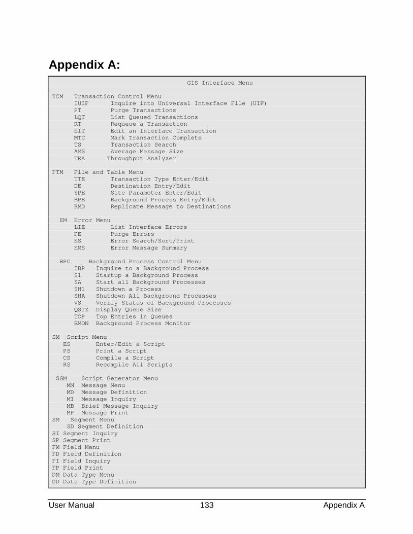
User Manual 133 Appendix A
Appendix A: GIS Interface Menu TCM Transaction Control Menu IUIF Inquire into Universal Interface File (UIF) PT Purge Transactions LQT List Queued Transactions RT Requeue a Transaction EIT Edit an Interface Transaction MTC Mark Transaction Complete TS Transaction Search AMS Average Message Size TRA Throughput Analyzer FTM File and Table Menu TTE Transaction Type Enter/Edit DE Destination Entry/Edit SPE Site Parameter Enter/Edit BPE Background Process Entry/Edit RMD Replicate Message to Destinations EM Error Menu LIE List Interface Errors PE Purge Errors ES Error Search/Sort/Print EMS Error Message Summary BPC Background Process Control Menu IBP Inquire to a Background Process S1 Startup a Background Process SA Start all Background Processes SH1 Shutdown a Process SHA Shutdown All Background Processes VS Verify Status of Background Processes QSIZ Display Queue Size TOP Top Entries in Queues BMON Background Process Monitor SM Script Menu ES Enter/Edit a Script PS Print a Script CS Compile a Script RS Recompile All Scripts SGM Script Generator Menu MM Message Menu MD Message Definition MI Message Inquiry MB Brief Message Inquiry MP Message Print SM Segment Menu SD Segment Definition SI Segment Inquiry SP Segment Print FM Field Menu FD Field Definition FI Field Inquiry FP Field Print DM Data Type Menu DD Data Type Definition
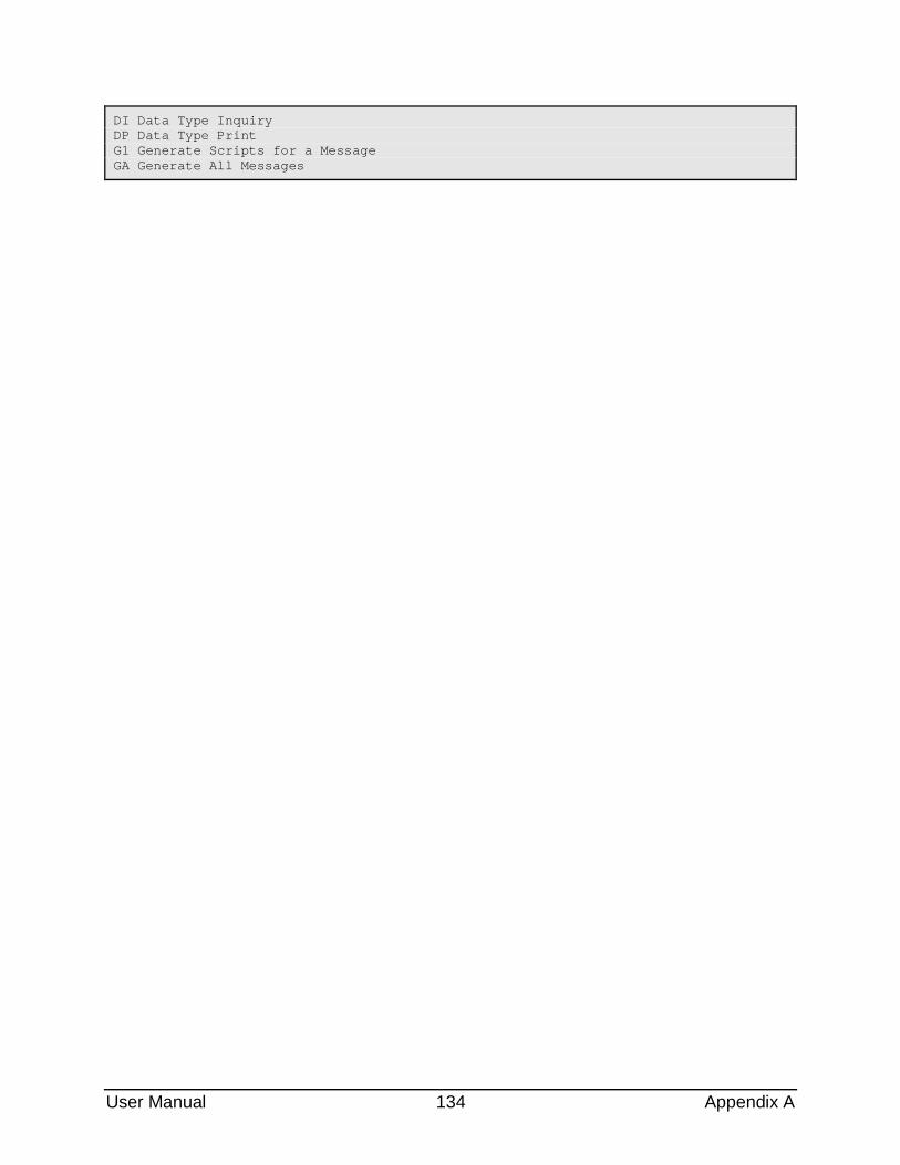
User Manual 134 Appendix A
DI Data Type Inquiry DP Data Type Print G1 Generate Scripts for a Message GA Generate All Messages


![Geographic Information System [GIS]](https://img.pdfslide.us/doc/110x75/56813e57550346895da84a4e/geographic-information-system-gis-568e78fe5e678.jpg)