Embed Size (px)
Citation preview
GIMP User Manual
December 19, 2004

Copyright c© 2002, 2003, 2004 The GIMP Documentation TeamLegal Notice
Permission is granted to copy, distribute and/or modify this document under the terms of the GNUFree Documentation License, Version 1.2 or any later version published by the Free Software Founda-tion; with no Invariant Sections, no Front-Cover Texts, and no Back-Cover Texts. A copy of the licenseis included in the section entitled GNU Free Documentation License
Contents
1 Introduction 51.1 Welcome to The GIMP . . . . . . . . . . . . . . . . . . . . . . . . . . . . . . . . . . . . . . . 5
1.1.1 Known platforms . . . . . . . . . . . . . . . . . . . . . . . . . . . . . . . . . . . . . . 51.1.2 The GIMP-Help system . . . . . . . . . . . . . . . . . . . . . . . . . . . . . . . . . . 51.1.3 Language . . . . . . . . . . . . . . . . . . . . . . . . . . . . . . . . . . . . . . . . . . 51.1.4 Features and Capabilities . . . . . . . . . . . . . . . . . . . . . . . . . . . . . . . . . 61.1.5 Authors . . . . . . . . . . . . . . . . . . . . . . . . . . . . . . . . . . . . . . . . . . . 6
1.2 What’s New in The Gimp 2.0? . . . . . . . . . . . . . . . . . . . . . . . . . . . . . . . . . . . 61.3 Introduction . . . . . . . . . . . . . . . . . . . . . . . . . . . . . . . . . . . . . . . . . . . . . 61.4 Basic tools . . . . . . . . . . . . . . . . . . . . . . . . . . . . . . . . . . . . . . . . . . . . . . 71.5 Tool options . . . . . . . . . . . . . . . . . . . . . . . . . . . . . . . . . . . . . . . . . . . . . 71.6 User Interface . . . . . . . . . . . . . . . . . . . . . . . . . . . . . . . . . . . . . . . . . . . . 71.7 Handling Tabs and Docks . . . . . . . . . . . . . . . . . . . . . . . . . . . . . . . . . . . . . 81.8 Scripting . . . . . . . . . . . . . . . . . . . . . . . . . . . . . . . . . . . . . . . . . . . . . . . 81.9 The Text Tool . . . . . . . . . . . . . . . . . . . . . . . . . . . . . . . . . . . . . . . . . . . . . 81.10 The Path Tool . . . . . . . . . . . . . . . . . . . . . . . . . . . . . . . . . . . . . . . . . . . . 91.11 Other improvements . . . . . . . . . . . . . . . . . . . . . . . . . . . . . . . . . . . . . . . . 91.12 Gimp History . . . . . . . . . . . . . . . . . . . . . . . . . . . . . . . . . . . . . . . . . . . . 101.13 Reporting Bugs and Requesting Enhancements . . . . . . . . . . . . . . . . . . . . . . . . . 11
1.13.1 Making sure it’s a Bug . . . . . . . . . . . . . . . . . . . . . . . . . . . . . . . . . . . 111.13.2 Reporting the Bug . . . . . . . . . . . . . . . . . . . . . . . . . . . . . . . . . . . . . 121.13.3 What Happens to a Bug Report after you Submit it . . . . . . . . . . . . . . . . . . 13
2 Using Gimp 152.1 Starting Gimp the first time . . . . . . . . . . . . . . . . . . . . . . . . . . . . . . . . . . . . 152.2 How to Set Your Tile Cache . . . . . . . . . . . . . . . . . . . . . . . . . . . . . . . . . . . . 202.3 Running Gimp . . . . . . . . . . . . . . . . . . . . . . . . . . . . . . . . . . . . . . . . . . . . 222.4 Command Line Arguments . . . . . . . . . . . . . . . . . . . . . . . . . . . . . . . . . . . . 222.5 Basic Gimp Usage . . . . . . . . . . . . . . . . . . . . . . . . . . . . . . . . . . . . . . . . . . 25
2.5.1 Introduction . . . . . . . . . . . . . . . . . . . . . . . . . . . . . . . . . . . . . . . . . 252.5.2 The Main Toolbox . . . . . . . . . . . . . . . . . . . . . . . . . . . . . . . . . . . . . 272.5.3 Image Window . . . . . . . . . . . . . . . . . . . . . . . . . . . . . . . . . . . . . . . 282.5.4 Dialogs and Docking . . . . . . . . . . . . . . . . . . . . . . . . . . . . . . . . . . . . 31
2.6 Docking Bars . . . . . . . . . . . . . . . . . . . . . . . . . . . . . . . . . . . . . . . . . . . . . 312.7 Docking Drag Handles . . . . . . . . . . . . . . . . . . . . . . . . . . . . . . . . . . . . . . . 322.8 Image Menu . . . . . . . . . . . . . . . . . . . . . . . . . . . . . . . . . . . . . . . . . . . . . 332.9 Tab Menu . . . . . . . . . . . . . . . . . . . . . . . . . . . . . . . . . . . . . . . . . . . . . . . 342.10 Removing Tabs . . . . . . . . . . . . . . . . . . . . . . . . . . . . . . . . . . . . . . . . . . . 362.11 Creating Dialogs . . . . . . . . . . . . . . . . . . . . . . . . . . . . . . . . . . . . . . . . . . 37
2.11.1 Basic Gimp Concepts . . . . . . . . . . . . . . . . . . . . . . . . . . . . . . . . . . . . 382.12 Working with Images . . . . . . . . . . . . . . . . . . . . . . . . . . . . . . . . . . . . . . . . 39
2.12.1 Image types . . . . . . . . . . . . . . . . . . . . . . . . . . . . . . . . . . . . . . . . . 392.12.2 QuickMask . . . . . . . . . . . . . . . . . . . . . . . . . . . . . . . . . . . . . . . . . 41
2.13 Overview . . . . . . . . . . . . . . . . . . . . . . . . . . . . . . . . . . . . . . . . . . . . . . . 412.14 Properties . . . . . . . . . . . . . . . . . . . . . . . . . . . . . . . . . . . . . . . . . . . . . . 422.15 Usage . . . . . . . . . . . . . . . . . . . . . . . . . . . . . . . . . . . . . . . . . . . . . . . . . 42
2.15.1 Layers . . . . . . . . . . . . . . . . . . . . . . . . . . . . . . . . . . . . . . . . . . . . 422.16 Creating New Layers . . . . . . . . . . . . . . . . . . . . . . . . . . . . . . . . . . . . . . . . 44
2.16.1 The Selection . . . . . . . . . . . . . . . . . . . . . . . . . . . . . . . . . . . . . . . . 452.16.2 Undoing . . . . . . . . . . . . . . . . . . . . . . . . . . . . . . . . . . . . . . . . . . . 46
2.17 Things that cannot be Undone . . . . . . . . . . . . . . . . . . . . . . . . . . . . . . . . . . . 472.17.1 Grids and Guides . . . . . . . . . . . . . . . . . . . . . . . . . . . . . . . . . . . . . . 48
2.18 The Image Grid . . . . . . . . . . . . . . . . . . . . . . . . . . . . . . . . . . . . . . . . . . . 482.19 Guides . . . . . . . . . . . . . . . . . . . . . . . . . . . . . . . . . . . . . . . . . . . . . . . . 51
3
CONTENTS
2.20 Rendering a Grid . . . . . . . . . . . . . . . . . . . . . . . . . . . . . . . . . . . . . . . . . . 522.20.1 Paths . . . . . . . . . . . . . . . . . . . . . . . . . . . . . . . . . . . . . . . . . . . . . 52
2.21 Paths and Selections . . . . . . . . . . . . . . . . . . . . . . . . . . . . . . . . . . . . . . . . 532.22 Stroking a Path . . . . . . . . . . . . . . . . . . . . . . . . . . . . . . . . . . . . . . . . . . . 542.23 Transforming Paths . . . . . . . . . . . . . . . . . . . . . . . . . . . . . . . . . . . . . . . . . 542.24 Paths and Text . . . . . . . . . . . . . . . . . . . . . . . . . . . . . . . . . . . . . . . . . . . . 552.25 Paths and SVG files . . . . . . . . . . . . . . . . . . . . . . . . . . . . . . . . . . . . . . . . . 55
2.25.1 Brushes . . . . . . . . . . . . . . . . . . . . . . . . . . . . . . . . . . . . . . . . . . . 562.26 Adding New Brushes . . . . . . . . . . . . . . . . . . . . . . . . . . . . . . . . . . . . . . . . 582.27 The GIH dialog box . . . . . . . . . . . . . . . . . . . . . . . . . . . . . . . . . . . . . . . . . 58
2.27.1 Gradients . . . . . . . . . . . . . . . . . . . . . . . . . . . . . . . . . . . . . . . . . . 632.27.2 Patterns . . . . . . . . . . . . . . . . . . . . . . . . . . . . . . . . . . . . . . . . . . . 642.27.3 Palettes . . . . . . . . . . . . . . . . . . . . . . . . . . . . . . . . . . . . . . . . . . . . 66
2.28 Colormap . . . . . . . . . . . . . . . . . . . . . . . . . . . . . . . . . . . . . . . . . . . . . . 682.28.1 Text and Fonts . . . . . . . . . . . . . . . . . . . . . . . . . . . . . . . . . . . . . . . . 69
2.29 Embellishing Text . . . . . . . . . . . . . . . . . . . . . . . . . . . . . . . . . . . . . . . . . . 702.30 Adding Fonts . . . . . . . . . . . . . . . . . . . . . . . . . . . . . . . . . . . . . . . . . . . . 702.31 Font Problems . . . . . . . . . . . . . . . . . . . . . . . . . . . . . . . . . . . . . . . . . . . . 71
2.31.1 Stroking a Selection or Path . . . . . . . . . . . . . . . . . . . . . . . . . . . . . . . . 722.32 Files . . . . . . . . . . . . . . . . . . . . . . . . . . . . . . . . . . . . . . . . . . . . . . . . . . 722.33 Opening Files . . . . . . . . . . . . . . . . . . . . . . . . . . . . . . . . . . . . . . . . . . . . 722.34 Saving Files . . . . . . . . . . . . . . . . . . . . . . . . . . . . . . . . . . . . . . . . . . . . . 732.35 Working with Digital Camera Photos . . . . . . . . . . . . . . . . . . . . . . . . . . . . . . . 74
2.35.1 Introduction . . . . . . . . . . . . . . . . . . . . . . . . . . . . . . . . . . . . . . . . . 742.35.2 Improving Composition . . . . . . . . . . . . . . . . . . . . . . . . . . . . . . . . . . 74
2.36 Rotating an Image . . . . . . . . . . . . . . . . . . . . . . . . . . . . . . . . . . . . . . . . . . 742.37 Cropping . . . . . . . . . . . . . . . . . . . . . . . . . . . . . . . . . . . . . . . . . . . . . . . 74
2.37.1 Improving Colors . . . . . . . . . . . . . . . . . . . . . . . . . . . . . . . . . . . . . . 752.38 Automated Tools . . . . . . . . . . . . . . . . . . . . . . . . . . . . . . . . . . . . . . . . . . 752.39 Exposure Problems . . . . . . . . . . . . . . . . . . . . . . . . . . . . . . . . . . . . . . . . . 762.40 Adjusting Hue and Saturation . . . . . . . . . . . . . . . . . . . . . . . . . . . . . . . . . . . 77
2.40.1 Adjusting Sharpness . . . . . . . . . . . . . . . . . . . . . . . . . . . . . . . . . . . . 772.41 Unblurring . . . . . . . . . . . . . . . . . . . . . . . . . . . . . . . . . . . . . . . . . . . . . . 772.42 Reducing Graininess . . . . . . . . . . . . . . . . . . . . . . . . . . . . . . . . . . . . . . . . 782.43 Softening . . . . . . . . . . . . . . . . . . . . . . . . . . . . . . . . . . . . . . . . . . . . . . . 78
2.43.1 Removing Unwanted Objects from an Image . . . . . . . . . . . . . . . . . . . . . . 782.44 Despeckling . . . . . . . . . . . . . . . . . . . . . . . . . . . . . . . . . . . . . . . . . . . . . 782.45 Garbage Removal . . . . . . . . . . . . . . . . . . . . . . . . . . . . . . . . . . . . . . . . . . 792.46 Removing Red-eye . . . . . . . . . . . . . . . . . . . . . . . . . . . . . . . . . . . . . . . . . 79
2.46.1 Saving Your Results . . . . . . . . . . . . . . . . . . . . . . . . . . . . . . . . . . . . 792.47 Files . . . . . . . . . . . . . . . . . . . . . . . . . . . . . . . . . . . . . . . . . . . . . . . . . . 792.48 Printing Your Photos . . . . . . . . . . . . . . . . . . . . . . . . . . . . . . . . . . . . . . . . 802.49 EXIF Data . . . . . . . . . . . . . . . . . . . . . . . . . . . . . . . . . . . . . . . . . . . . . . 802.50 Preparing your Images for the web . . . . . . . . . . . . . . . . . . . . . . . . . . . . . . . . 80
2.50.1 Squeezing Filesize a bit more . . . . . . . . . . . . . . . . . . . . . . . . . . . . . . . 812.51 Plugins . . . . . . . . . . . . . . . . . . . . . . . . . . . . . . . . . . . . . . . . . . . . . . . . 81
2.51.1 Introduction . . . . . . . . . . . . . . . . . . . . . . . . . . . . . . . . . . . . . . . . . 812.51.2 Using Plugins . . . . . . . . . . . . . . . . . . . . . . . . . . . . . . . . . . . . . . . . 822.51.3 Installing New Plugins . . . . . . . . . . . . . . . . . . . . . . . . . . . . . . . . . . . 83
2.52 Linux . . . . . . . . . . . . . . . . . . . . . . . . . . . . . . . . . . . . . . . . . . . . . . . . . 832.53 Windows . . . . . . . . . . . . . . . . . . . . . . . . . . . . . . . . . . . . . . . . . . . . . . . 842.54 Macintosh . . . . . . . . . . . . . . . . . . . . . . . . . . . . . . . . . . . . . . . . . . . . . . 84
2.54.1 Writing Plugins . . . . . . . . . . . . . . . . . . . . . . . . . . . . . . . . . . . . . . . 842.55 Using Script-Fu Scripts . . . . . . . . . . . . . . . . . . . . . . . . . . . . . . . . . . . . . . . 842.56 Script-Fu? . . . . . . . . . . . . . . . . . . . . . . . . . . . . . . . . . . . . . . . . . . . . . . 842.57 Installing Script-Fus . . . . . . . . . . . . . . . . . . . . . . . . . . . . . . . . . . . . . . . . . 852.58 Do’s and Don’ts . . . . . . . . . . . . . . . . . . . . . . . . . . . . . . . . . . . . . . . . . . . 852.59 Different Kinds Of Script-Fus . . . . . . . . . . . . . . . . . . . . . . . . . . . . . . . . . . . 852.60 Standalone Scripts . . . . . . . . . . . . . . . . . . . . . . . . . . . . . . . . . . . . . . . . . . 85
4
CONTENTS
2.61 Image-Dependent Scripts . . . . . . . . . . . . . . . . . . . . . . . . . . . . . . . . . . . . . 872.62 A Script-Fu Tutorial . . . . . . . . . . . . . . . . . . . . . . . . . . . . . . . . . . . . . . . . . 87
2.62.1 Getting Acquainted With Scheme . . . . . . . . . . . . . . . . . . . . . . . . . . . . 882.63 Let’s Start Scheme’ing . . . . . . . . . . . . . . . . . . . . . . . . . . . . . . . . . . . . . . . 882.64 Examples Of Prefix, Infix, And Postfix Notations . . . . . . . . . . . . . . . . . . . . . . . . 882.65 Practicing In Scheme . . . . . . . . . . . . . . . . . . . . . . . . . . . . . . . . . . . . . . . . 882.66 The Script-Fu Console Window . . . . . . . . . . . . . . . . . . . . . . . . . . . . . . . . . . 882.67 Watch Out For Extra Parens . . . . . . . . . . . . . . . . . . . . . . . . . . . . . . . . . . . . 892.68 Make Sure You Have The Proper Spacing, Too . . . . . . . . . . . . . . . . . . . . . . . . . 89
2.68.1 Variables And Functions . . . . . . . . . . . . . . . . . . . . . . . . . . . . . . . . . . 892.69 Declaring Variables . . . . . . . . . . . . . . . . . . . . . . . . . . . . . . . . . . . . . . . . . 902.70 What Is A Local Variable? . . . . . . . . . . . . . . . . . . . . . . . . . . . . . . . . . . . . . 902.71 The General Syntax Of [code] let* [/code] . . . . . . . . . . . . . . . . . . . . . . . . . . . . 902.72 White Space . . . . . . . . . . . . . . . . . . . . . . . . . . . . . . . . . . . . . . . . . . . . . 912.73 Assigning A New Value To A Variable . . . . . . . . . . . . . . . . . . . . . . . . . . . . . . 912.74 Functions . . . . . . . . . . . . . . . . . . . . . . . . . . . . . . . . . . . . . . . . . . . . . . . 91
2.74.1 Lists, Lists And More Lists . . . . . . . . . . . . . . . . . . . . . . . . . . . . . . . . 922.75 Defining A List . . . . . . . . . . . . . . . . . . . . . . . . . . . . . . . . . . . . . . . . . . . 922.76 How To Think Of Lists . . . . . . . . . . . . . . . . . . . . . . . . . . . . . . . . . . . . . . . 932.77 Creating Lists Through Concatenation (The Cons Function) . . . . . . . . . . . . . . . . . . 932.78 Defining A List Using The list Function . . . . . . . . . . . . . . . . . . . . . . . . . . . . . 932.79 Accessing Values In A List . . . . . . . . . . . . . . . . . . . . . . . . . . . . . . . . . . . . . 942.80 The [code] car [/code] Function . . . . . . . . . . . . . . . . . . . . . . . . . . . . . . . . . . 942.81 The [code] cdr [/code] function . . . . . . . . . . . . . . . . . . . . . . . . . . . . . . . . . . 942.82 Accessing Other Elements In A List . . . . . . . . . . . . . . . . . . . . . . . . . . . . . . . . 95
2.82.1 Your First Script-Fu Script . . . . . . . . . . . . . . . . . . . . . . . . . . . . . . . . . 952.83 Creating A Text Box Script . . . . . . . . . . . . . . . . . . . . . . . . . . . . . . . . . . . . . 952.84 Editing And Storing Your Scripts . . . . . . . . . . . . . . . . . . . . . . . . . . . . . . . . . 962.85 The Bare Essentials . . . . . . . . . . . . . . . . . . . . . . . . . . . . . . . . . . . . . . . . . 962.86 Naming Conventions . . . . . . . . . . . . . . . . . . . . . . . . . . . . . . . . . . . . . . . . 962.87 Registering The Function . . . . . . . . . . . . . . . . . . . . . . . . . . . . . . . . . . . . . . 962.88 Steps For Registering The Script . . . . . . . . . . . . . . . . . . . . . . . . . . . . . . . . . . 972.89 Registering The Script’s Parameters . . . . . . . . . . . . . . . . . . . . . . . . . . . . . . . 97
2.89.1 Giving Our Script Some Guts . . . . . . . . . . . . . . . . . . . . . . . . . . . . . . . 982.90 Creating A New Image . . . . . . . . . . . . . . . . . . . . . . . . . . . . . . . . . . . . . . . 982.91 Adding A New Layer To The Image . . . . . . . . . . . . . . . . . . . . . . . . . . . . . . . 992.92 Adding The Text . . . . . . . . . . . . . . . . . . . . . . . . . . . . . . . . . . . . . . . . . . . 992.93 Clearing The Dirty Flag . . . . . . . . . . . . . . . . . . . . . . . . . . . . . . . . . . . . . . 100
2.93.1 Extending The Text Box Script . . . . . . . . . . . . . . . . . . . . . . . . . . . . . . 1012.94 Handling Undo Correctly . . . . . . . . . . . . . . . . . . . . . . . . . . . . . . . . . . . . . 1012.95 Extending The Script A Little More . . . . . . . . . . . . . . . . . . . . . . . . . . . . . . . . 1012.96 Modifying The Parameters And The Registration Function . . . . . . . . . . . . . . . . . . 1012.97 Adding The New Code . . . . . . . . . . . . . . . . . . . . . . . . . . . . . . . . . . . . . . . 1022.98 Getting Unstuck . . . . . . . . . . . . . . . . . . . . . . . . . . . . . . . . . . . . . . . . . . . 1032.99 Stuck! . . . . . . . . . . . . . . . . . . . . . . . . . . . . . . . . . . . . . . . . . . . . . . . . . 1032.100Common causes of GIMP non-responsiveness . . . . . . . . . . . . . . . . . . . . . . . . . 103
3 Toolbox 1093.1 The Toolbox . . . . . . . . . . . . . . . . . . . . . . . . . . . . . . . . . . . . . . . . . . . . . 109
3.1.1 Tool Options . . . . . . . . . . . . . . . . . . . . . . . . . . . . . . . . . . . . . . . . . 1103.2 Selection Tools . . . . . . . . . . . . . . . . . . . . . . . . . . . . . . . . . . . . . . . . . . . . 111
3.2.1 Common Features . . . . . . . . . . . . . . . . . . . . . . . . . . . . . . . . . . . . . 1113.3 Key modifiers (Defaults) . . . . . . . . . . . . . . . . . . . . . . . . . . . . . . . . . . . . . . 1113.4 Options . . . . . . . . . . . . . . . . . . . . . . . . . . . . . . . . . . . . . . . . . . . . . . . . 1123.5 Additional information . . . . . . . . . . . . . . . . . . . . . . . . . . . . . . . . . . . . . . . 113
3.5.1 Rectangle Selection Tool . . . . . . . . . . . . . . . . . . . . . . . . . . . . . . . . . . 1133.6 How to Activate . . . . . . . . . . . . . . . . . . . . . . . . . . . . . . . . . . . . . . . . . . . 1143.7 Key modifiers . . . . . . . . . . . . . . . . . . . . . . . . . . . . . . . . . . . . . . . . . . . . 1143.8 Tool Options . . . . . . . . . . . . . . . . . . . . . . . . . . . . . . . . . . . . . . . . . . . . . 114
5

CONTENTS
3.8.1 Ellipse Selection Tool . . . . . . . . . . . . . . . . . . . . . . . . . . . . . . . . . . . . 1163.9 How to Activate . . . . . . . . . . . . . . . . . . . . . . . . . . . . . . . . . . . . . . . . . . . 1163.10 Key modifiers . . . . . . . . . . . . . . . . . . . . . . . . . . . . . . . . . . . . . . . . . . . . 1163.11 Options . . . . . . . . . . . . . . . . . . . . . . . . . . . . . . . . . . . . . . . . . . . . . . . . 117
3.11.1 Free Selection Tool (Lasso) . . . . . . . . . . . . . . . . . . . . . . . . . . . . . . . . . 1183.12 How to Activate . . . . . . . . . . . . . . . . . . . . . . . . . . . . . . . . . . . . . . . . . . . 1193.13 Key modifiers . . . . . . . . . . . . . . . . . . . . . . . . . . . . . . . . . . . . . . . . . . . . 1193.14 Options . . . . . . . . . . . . . . . . . . . . . . . . . . . . . . . . . . . . . . . . . . . . . . . . 119
3.14.1 Fuzzy Selection Tool (Magic Wand) . . . . . . . . . . . . . . . . . . . . . . . . . . . 1203.15 How to Activate . . . . . . . . . . . . . . . . . . . . . . . . . . . . . . . . . . . . . . . . . . . 1203.16 Key modifiers (Defaults) . . . . . . . . . . . . . . . . . . . . . . . . . . . . . . . . . . . . . . 1203.17 Options . . . . . . . . . . . . . . . . . . . . . . . . . . . . . . . . . . . . . . . . . . . . . . . . 121
3.17.1 Select By Color Tool . . . . . . . . . . . . . . . . . . . . . . . . . . . . . . . . . . . . 1223.18 How to Activate . . . . . . . . . . . . . . . . . . . . . . . . . . . . . . . . . . . . . . . . . . . 1223.19 Key modifiers (Defaults) . . . . . . . . . . . . . . . . . . . . . . . . . . . . . . . . . . . . . . 1223.20 Options . . . . . . . . . . . . . . . . . . . . . . . . . . . . . . . . . . . . . . . . . . . . . . . . 123
3.20.1 Scissors Tool . . . . . . . . . . . . . . . . . . . . . . . . . . . . . . . . . . . . . . . . . 1243.21 How to Activate . . . . . . . . . . . . . . . . . . . . . . . . . . . . . . . . . . . . . . . . . . . 1253.22 Key modifiers (Defaults) . . . . . . . . . . . . . . . . . . . . . . . . . . . . . . . . . . . . . . 1253.23 Options . . . . . . . . . . . . . . . . . . . . . . . . . . . . . . . . . . . . . . . . . . . . . . . . 1253.24 Brush Tools . . . . . . . . . . . . . . . . . . . . . . . . . . . . . . . . . . . . . . . . . . . . . . 126
3.24.1 Common Features . . . . . . . . . . . . . . . . . . . . . . . . . . . . . . . . . . . . . 1263.25 Key modifiers . . . . . . . . . . . . . . . . . . . . . . . . . . . . . . . . . . . . . . . . . . . . 1263.26 Tool Options . . . . . . . . . . . . . . . . . . . . . . . . . . . . . . . . . . . . . . . . . . . . . 1273.27 Further Information . . . . . . . . . . . . . . . . . . . . . . . . . . . . . . . . . . . . . . . . . 128
3.27.1 Painting Tools (Pencil, Paintbrush, Airbrush) . . . . . . . . . . . . . . . . . . . . . . 1293.28 Key modifiers . . . . . . . . . . . . . . . . . . . . . . . . . . . . . . . . . . . . . . . . . . . . 1293.29 Options . . . . . . . . . . . . . . . . . . . . . . . . . . . . . . . . . . . . . . . . . . . . . . . . 129
3.29.1 Pencil . . . . . . . . . . . . . . . . . . . . . . . . . . . . . . . . . . . . . . . . . . . . . 1313.30 Activate Tool . . . . . . . . . . . . . . . . . . . . . . . . . . . . . . . . . . . . . . . . . . . . . 1323.31 Key modifiers (Defaults) . . . . . . . . . . . . . . . . . . . . . . . . . . . . . . . . . . . . . . 1323.32 Options . . . . . . . . . . . . . . . . . . . . . . . . . . . . . . . . . . . . . . . . . . . . . . . . 132
3.32.1 Paintbrush Tool . . . . . . . . . . . . . . . . . . . . . . . . . . . . . . . . . . . . . . . 1333.33 Activate Tool . . . . . . . . . . . . . . . . . . . . . . . . . . . . . . . . . . . . . . . . . . . . . 1343.34 Key modifiers (Defaults) . . . . . . . . . . . . . . . . . . . . . . . . . . . . . . . . . . . . . . 1343.35 Options . . . . . . . . . . . . . . . . . . . . . . . . . . . . . . . . . . . . . . . . . . . . . . . . 134
3.35.1 Eraser . . . . . . . . . . . . . . . . . . . . . . . . . . . . . . . . . . . . . . . . . . . . 1353.36 How to Activate . . . . . . . . . . . . . . . . . . . . . . . . . . . . . . . . . . . . . . . . . . . 1363.37 Key modifiers . . . . . . . . . . . . . . . . . . . . . . . . . . . . . . . . . . . . . . . . . . . . 1363.38 Tool Options . . . . . . . . . . . . . . . . . . . . . . . . . . . . . . . . . . . . . . . . . . . . . 136
3.38.1 Airbrush Tool . . . . . . . . . . . . . . . . . . . . . . . . . . . . . . . . . . . . . . . . 1383.39 Activate Tool . . . . . . . . . . . . . . . . . . . . . . . . . . . . . . . . . . . . . . . . . . . . . 1383.40 Key modifiers (Defaults) . . . . . . . . . . . . . . . . . . . . . . . . . . . . . . . . . . . . . . 1383.41 Options . . . . . . . . . . . . . . . . . . . . . . . . . . . . . . . . . . . . . . . . . . . . . . . . 138
3.41.1 Ink Tool . . . . . . . . . . . . . . . . . . . . . . . . . . . . . . . . . . . . . . . . . . . 1403.42 Activate Tool . . . . . . . . . . . . . . . . . . . . . . . . . . . . . . . . . . . . . . . . . . . . . 1403.43 Key modifiers (Defaults) . . . . . . . . . . . . . . . . . . . . . . . . . . . . . . . . . . . . . . 1403.44 Options . . . . . . . . . . . . . . . . . . . . . . . . . . . . . . . . . . . . . . . . . . . . . . . . 140
3.44.1 Clone Tool . . . . . . . . . . . . . . . . . . . . . . . . . . . . . . . . . . . . . . . . . . 1423.45 How to Activate . . . . . . . . . . . . . . . . . . . . . . . . . . . . . . . . . . . . . . . . . . . 1423.46 Key modifiers . . . . . . . . . . . . . . . . . . . . . . . . . . . . . . . . . . . . . . . . . . . . 1423.47 Tool Options . . . . . . . . . . . . . . . . . . . . . . . . . . . . . . . . . . . . . . . . . . . . . 1433.48 Further Information . . . . . . . . . . . . . . . . . . . . . . . . . . . . . . . . . . . . . . . . . 144
3.48.1 Convolve (Blur/Sharpen) . . . . . . . . . . . . . . . . . . . . . . . . . . . . . . . . . 1453.49 How to Activate . . . . . . . . . . . . . . . . . . . . . . . . . . . . . . . . . . . . . . . . . . . 1463.50 Key modifiers . . . . . . . . . . . . . . . . . . . . . . . . . . . . . . . . . . . . . . . . . . . . 1463.51 Tool Options . . . . . . . . . . . . . . . . . . . . . . . . . . . . . . . . . . . . . . . . . . . . . 146
3.51.1 Dodge or Burn . . . . . . . . . . . . . . . . . . . . . . . . . . . . . . . . . . . . . . . 1473.52 Activate Tool . . . . . . . . . . . . . . . . . . . . . . . . . . . . . . . . . . . . . . . . . . . . . 147
6
CONTENTS
3.53 Key modifiers (Defaults) . . . . . . . . . . . . . . . . . . . . . . . . . . . . . . . . . . . . . . 1473.54 Options . . . . . . . . . . . . . . . . . . . . . . . . . . . . . . . . . . . . . . . . . . . . . . . . 148
3.54.1 Smudge Tool . . . . . . . . . . . . . . . . . . . . . . . . . . . . . . . . . . . . . . . . 1493.55 Activate Tool . . . . . . . . . . . . . . . . . . . . . . . . . . . . . . . . . . . . . . . . . . . . . 1493.56 Key modifiers (Defaults) . . . . . . . . . . . . . . . . . . . . . . . . . . . . . . . . . . . . . . 1493.57 Options . . . . . . . . . . . . . . . . . . . . . . . . . . . . . . . . . . . . . . . . . . . . . . . . 1493.58 Transform Tools . . . . . . . . . . . . . . . . . . . . . . . . . . . . . . . . . . . . . . . . . . . 150
3.58.1 Move Tool . . . . . . . . . . . . . . . . . . . . . . . . . . . . . . . . . . . . . . . . . . 1503.59 Activate Tool . . . . . . . . . . . . . . . . . . . . . . . . . . . . . . . . . . . . . . . . . . . . . 1503.60 Key modifiers (Defaults) . . . . . . . . . . . . . . . . . . . . . . . . . . . . . . . . . . . . . . 1513.61 Options . . . . . . . . . . . . . . . . . . . . . . . . . . . . . . . . . . . . . . . . . . . . . . . . 151
3.61.1 Crop Tool . . . . . . . . . . . . . . . . . . . . . . . . . . . . . . . . . . . . . . . . . . 1523.62 Activate Tool . . . . . . . . . . . . . . . . . . . . . . . . . . . . . . . . . . . . . . . . . . . . . 1523.63 Key modifiers (Defaults) . . . . . . . . . . . . . . . . . . . . . . . . . . . . . . . . . . . . . . 1523.64 Options . . . . . . . . . . . . . . . . . . . . . . . . . . . . . . . . . . . . . . . . . . . . . . . . 152
3.64.1 Rotate Tool . . . . . . . . . . . . . . . . . . . . . . . . . . . . . . . . . . . . . . . . . . 1533.65 Activate Tool . . . . . . . . . . . . . . . . . . . . . . . . . . . . . . . . . . . . . . . . . . . . . 1543.66 Key modifiers (Defaults) . . . . . . . . . . . . . . . . . . . . . . . . . . . . . . . . . . . . . . 154
3.66.1 Scale Tool . . . . . . . . . . . . . . . . . . . . . . . . . . . . . . . . . . . . . . . . . . 1553.67 Activate Tool . . . . . . . . . . . . . . . . . . . . . . . . . . . . . . . . . . . . . . . . . . . . . 1553.68 Key modifiers (Defaults) . . . . . . . . . . . . . . . . . . . . . . . . . . . . . . . . . . . . . . 1553.69 Options . . . . . . . . . . . . . . . . . . . . . . . . . . . . . . . . . . . . . . . . . . . . . . . . 155
3.69.1 Shear Tool . . . . . . . . . . . . . . . . . . . . . . . . . . . . . . . . . . . . . . . . . . 1563.70 Activate Tool . . . . . . . . . . . . . . . . . . . . . . . . . . . . . . . . . . . . . . . . . . . . . 1573.71 Key modifiers (Defaults) . . . . . . . . . . . . . . . . . . . . . . . . . . . . . . . . . . . . . . 1573.72 Options . . . . . . . . . . . . . . . . . . . . . . . . . . . . . . . . . . . . . . . . . . . . . . . . 157
3.72.1 Perspective Tool . . . . . . . . . . . . . . . . . . . . . . . . . . . . . . . . . . . . . . . 1583.73 Activate Tool . . . . . . . . . . . . . . . . . . . . . . . . . . . . . . . . . . . . . . . . . . . . . 1583.74 Key modifiers (Defaults) . . . . . . . . . . . . . . . . . . . . . . . . . . . . . . . . . . . . . . 1583.75 Options . . . . . . . . . . . . . . . . . . . . . . . . . . . . . . . . . . . . . . . . . . . . . . . . 158
3.75.1 Flip Tool . . . . . . . . . . . . . . . . . . . . . . . . . . . . . . . . . . . . . . . . . . . 1593.76 Activate Tool . . . . . . . . . . . . . . . . . . . . . . . . . . . . . . . . . . . . . . . . . . . . . 1593.77 Key modifiers (Defaults) . . . . . . . . . . . . . . . . . . . . . . . . . . . . . . . . . . . . . . 1593.78 Options . . . . . . . . . . . . . . . . . . . . . . . . . . . . . . . . . . . . . . . . . . . . . . . . 1603.79 Color Tools . . . . . . . . . . . . . . . . . . . . . . . . . . . . . . . . . . . . . . . . . . . . . . 160
3.79.1 Color Balance Tool . . . . . . . . . . . . . . . . . . . . . . . . . . . . . . . . . . . . . 1603.80 Activate Tool . . . . . . . . . . . . . . . . . . . . . . . . . . . . . . . . . . . . . . . . . . . . . 1603.81 Options . . . . . . . . . . . . . . . . . . . . . . . . . . . . . . . . . . . . . . . . . . . . . . . . 161
3.81.1 Hue-Saturation Tool . . . . . . . . . . . . . . . . . . . . . . . . . . . . . . . . . . . . 1613.82 Activate Tool . . . . . . . . . . . . . . . . . . . . . . . . . . . . . . . . . . . . . . . . . . . . . 1613.83 Options . . . . . . . . . . . . . . . . . . . . . . . . . . . . . . . . . . . . . . . . . . . . . . . . 161
3.83.1 Colorize Tool . . . . . . . . . . . . . . . . . . . . . . . . . . . . . . . . . . . . . . . . 1623.84 Activate Tool . . . . . . . . . . . . . . . . . . . . . . . . . . . . . . . . . . . . . . . . . . . . . 1623.85 Options . . . . . . . . . . . . . . . . . . . . . . . . . . . . . . . . . . . . . . . . . . . . . . . . 162
3.85.1 Brightness-Contrast tool . . . . . . . . . . . . . . . . . . . . . . . . . . . . . . . . . . 1633.86 Activate Tool . . . . . . . . . . . . . . . . . . . . . . . . . . . . . . . . . . . . . . . . . . . . . 1633.87 Options . . . . . . . . . . . . . . . . . . . . . . . . . . . . . . . . . . . . . . . . . . . . . . . . 163
3.87.1 Threshold Tool . . . . . . . . . . . . . . . . . . . . . . . . . . . . . . . . . . . . . . . 1633.88 Activate Tool . . . . . . . . . . . . . . . . . . . . . . . . . . . . . . . . . . . . . . . . . . . . . 1633.89 Options . . . . . . . . . . . . . . . . . . . . . . . . . . . . . . . . . . . . . . . . . . . . . . . . 164
3.89.1 Levels tool . . . . . . . . . . . . . . . . . . . . . . . . . . . . . . . . . . . . . . . . . . 1643.90 Activate Tool . . . . . . . . . . . . . . . . . . . . . . . . . . . . . . . . . . . . . . . . . . . . . 1643.91 Options . . . . . . . . . . . . . . . . . . . . . . . . . . . . . . . . . . . . . . . . . . . . . . . . 165
3.91.1 Curves Tool . . . . . . . . . . . . . . . . . . . . . . . . . . . . . . . . . . . . . . . . . 1663.92 Activate Tool . . . . . . . . . . . . . . . . . . . . . . . . . . . . . . . . . . . . . . . . . . . . . 1663.93 Adjust Color Curves . . . . . . . . . . . . . . . . . . . . . . . . . . . . . . . . . . . . . . . . 166
3.93.1 Posterize Tool . . . . . . . . . . . . . . . . . . . . . . . . . . . . . . . . . . . . . . . . 1673.94 Activate Tool . . . . . . . . . . . . . . . . . . . . . . . . . . . . . . . . . . . . . . . . . . . . . 1673.95 Options . . . . . . . . . . . . . . . . . . . . . . . . . . . . . . . . . . . . . . . . . . . . . . . . 168
7
CONTENTS
3.96 Other . . . . . . . . . . . . . . . . . . . . . . . . . . . . . . . . . . . . . . . . . . . . . . . . . 1683.96.1 Path Tool . . . . . . . . . . . . . . . . . . . . . . . . . . . . . . . . . . . . . . . . . . . 168
3.97 Activate Tool . . . . . . . . . . . . . . . . . . . . . . . . . . . . . . . . . . . . . . . . . . . . . 1683.98 Key modifiers (Defaults) . . . . . . . . . . . . . . . . . . . . . . . . . . . . . . . . . . . . . . 1683.99 Options . . . . . . . . . . . . . . . . . . . . . . . . . . . . . . . . . . . . . . . . . . . . . . . . 169
3.99.1 Bucket Fill . . . . . . . . . . . . . . . . . . . . . . . . . . . . . . . . . . . . . . . . . . 1703.100Activate Tool . . . . . . . . . . . . . . . . . . . . . . . . . . . . . . . . . . . . . . . . . . . . . 1713.101Key modifiers (Defaults) . . . . . . . . . . . . . . . . . . . . . . . . . . . . . . . . . . . . . . 1713.102Options . . . . . . . . . . . . . . . . . . . . . . . . . . . . . . . . . . . . . . . . . . . . . . . . 171
3.102.1 Gradient Tool . . . . . . . . . . . . . . . . . . . . . . . . . . . . . . . . . . . . . . . . 1723.103Activate Tool . . . . . . . . . . . . . . . . . . . . . . . . . . . . . . . . . . . . . . . . . . . . . 1733.104Key modifiers (Defaults) . . . . . . . . . . . . . . . . . . . . . . . . . . . . . . . . . . . . . . 1733.105Options . . . . . . . . . . . . . . . . . . . . . . . . . . . . . . . . . . . . . . . . . . . . . . . . 173
3.105.1 Color Picker Tool . . . . . . . . . . . . . . . . . . . . . . . . . . . . . . . . . . . . . . 1753.106Activate Tool . . . . . . . . . . . . . . . . . . . . . . . . . . . . . . . . . . . . . . . . . . . . . 1753.107Key modifiers (Defaults) . . . . . . . . . . . . . . . . . . . . . . . . . . . . . . . . . . . . . . 1763.108Options . . . . . . . . . . . . . . . . . . . . . . . . . . . . . . . . . . . . . . . . . . . . . . . . 176
3.108.1 Magnify Tool . . . . . . . . . . . . . . . . . . . . . . . . . . . . . . . . . . . . . . . . 1763.109Activate Tool . . . . . . . . . . . . . . . . . . . . . . . . . . . . . . . . . . . . . . . . . . . . . 1773.110Key modifiers (Defaults) . . . . . . . . . . . . . . . . . . . . . . . . . . . . . . . . . . . . . . 1773.111Options . . . . . . . . . . . . . . . . . . . . . . . . . . . . . . . . . . . . . . . . . . . . . . . . 177
3.111.1 Measure Tool . . . . . . . . . . . . . . . . . . . . . . . . . . . . . . . . . . . . . . . . 1773.112Activate Tool . . . . . . . . . . . . . . . . . . . . . . . . . . . . . . . . . . . . . . . . . . . . . 1783.113Key modifiers . . . . . . . . . . . . . . . . . . . . . . . . . . . . . . . . . . . . . . . . . . . . 1783.114Options . . . . . . . . . . . . . . . . . . . . . . . . . . . . . . . . . . . . . . . . . . . . . . . . 178
3.114.1 Texttool . . . . . . . . . . . . . . . . . . . . . . . . . . . . . . . . . . . . . . . . . . . 1783.115Activate Tool . . . . . . . . . . . . . . . . . . . . . . . . . . . . . . . . . . . . . . . . . . . . . 1793.116Key modifiers (Defaults) . . . . . . . . . . . . . . . . . . . . . . . . . . . . . . . . . . . . . . 1793.117Options . . . . . . . . . . . . . . . . . . . . . . . . . . . . . . . . . . . . . . . . . . . . . . . . 1793.118Color and Indicator Area . . . . . . . . . . . . . . . . . . . . . . . . . . . . . . . . . . . . . . 1803.119Color Area . . . . . . . . . . . . . . . . . . . . . . . . . . . . . . . . . . . . . . . . . . . . . . 1813.120Indicator Area . . . . . . . . . . . . . . . . . . . . . . . . . . . . . . . . . . . . . . . . . . . . 181
4 Dialogs 1834.1 Dialog introduction . . . . . . . . . . . . . . . . . . . . . . . . . . . . . . . . . . . . . . . . . 1834.2 Layers dialog . . . . . . . . . . . . . . . . . . . . . . . . . . . . . . . . . . . . . . . . . . . . 183
4.2.1 Activate Dialog . . . . . . . . . . . . . . . . . . . . . . . . . . . . . . . . . . . . . . . 1834.2.2 Using the Layerdialog . . . . . . . . . . . . . . . . . . . . . . . . . . . . . . . . . . . 1844.2.3 Layer masks . . . . . . . . . . . . . . . . . . . . . . . . . . . . . . . . . . . . . . . . . 186
4.3 Channels dialog . . . . . . . . . . . . . . . . . . . . . . . . . . . . . . . . . . . . . . . . . . . 1874.3.1 Calling the Dialog . . . . . . . . . . . . . . . . . . . . . . . . . . . . . . . . . . . . . 1884.3.2 Using the Channeldialog . . . . . . . . . . . . . . . . . . . . . . . . . . . . . . . . . 1884.3.3 Channels Menu . . . . . . . . . . . . . . . . . . . . . . . . . . . . . . . . . . . . . . . 1904.3.4 Selection masks . . . . . . . . . . . . . . . . . . . . . . . . . . . . . . . . . . . . . . . 190
4.4 Using Selectionmasks . . . . . . . . . . . . . . . . . . . . . . . . . . . . . . . . . . . . . . . . 1914.4.1 Quick Mask . . . . . . . . . . . . . . . . . . . . . . . . . . . . . . . . . . . . . . . . . 192
4.5 Activate Tool . . . . . . . . . . . . . . . . . . . . . . . . . . . . . . . . . . . . . . . . . . . . . 1924.6 Creating a Quick Mask . . . . . . . . . . . . . . . . . . . . . . . . . . . . . . . . . . . . . . . 1924.7 Using Quick Mask’s . . . . . . . . . . . . . . . . . . . . . . . . . . . . . . . . . . . . . . . . . 1934.8 Usage . . . . . . . . . . . . . . . . . . . . . . . . . . . . . . . . . . . . . . . . . . . . . . . . . 1944.9 Path dialog . . . . . . . . . . . . . . . . . . . . . . . . . . . . . . . . . . . . . . . . . . . . . . 194
4.9.1 Dialog call . . . . . . . . . . . . . . . . . . . . . . . . . . . . . . . . . . . . . . . . . . 1944.9.2 Using the Paths dialog . . . . . . . . . . . . . . . . . . . . . . . . . . . . . . . . . . . 1944.9.3 Buttons . . . . . . . . . . . . . . . . . . . . . . . . . . . . . . . . . . . . . . . . . . . . 1954.9.4 Paths Menu . . . . . . . . . . . . . . . . . . . . . . . . . . . . . . . . . . . . . . . . . 196
4.10 Indexed Palette dialog . . . . . . . . . . . . . . . . . . . . . . . . . . . . . . . . . . . . . . . 1994.11 Colormaps and Indexed Images . . . . . . . . . . . . . . . . . . . . . . . . . . . . . . . . . . 1994.12 Histogram dialog . . . . . . . . . . . . . . . . . . . . . . . . . . . . . . . . . . . . . . . . . . 2014.13 About Histograms . . . . . . . . . . . . . . . . . . . . . . . . . . . . . . . . . . . . . . . . . 201
8
CONTENTS
4.14 Navigation Dialog . . . . . . . . . . . . . . . . . . . . . . . . . . . . . . . . . . . . . . . . . . 2044.15 Overview . . . . . . . . . . . . . . . . . . . . . . . . . . . . . . . . . . . . . . . . . . . . . . . 2044.16 Activate the dialog . . . . . . . . . . . . . . . . . . . . . . . . . . . . . . . . . . . . . . . . . 2044.17 Using the Navigation Dialog . . . . . . . . . . . . . . . . . . . . . . . . . . . . . . . . . . . 2054.18 Undo History dialog . . . . . . . . . . . . . . . . . . . . . . . . . . . . . . . . . . . . . . . . 2054.19 Using the Undo History dialog . . . . . . . . . . . . . . . . . . . . . . . . . . . . . . . . . . 2064.20 Colors dialog . . . . . . . . . . . . . . . . . . . . . . . . . . . . . . . . . . . . . . . . . . . . 2064.21 Overview . . . . . . . . . . . . . . . . . . . . . . . . . . . . . . . . . . . . . . . . . . . . . . . 2074.22 Activate Dialog . . . . . . . . . . . . . . . . . . . . . . . . . . . . . . . . . . . . . . . . . . . 2074.23 The GIMP Selector . . . . . . . . . . . . . . . . . . . . . . . . . . . . . . . . . . . . . . . . . 2074.24 CMYK . . . . . . . . . . . . . . . . . . . . . . . . . . . . . . . . . . . . . . . . . . . . . . . . 2074.25 Triangle . . . . . . . . . . . . . . . . . . . . . . . . . . . . . . . . . . . . . . . . . . . . . . . . 2074.26 Watercolor . . . . . . . . . . . . . . . . . . . . . . . . . . . . . . . . . . . . . . . . . . . . . . 2074.27 Scales . . . . . . . . . . . . . . . . . . . . . . . . . . . . . . . . . . . . . . . . . . . . . . . . . 2074.28 Color picker . . . . . . . . . . . . . . . . . . . . . . . . . . . . . . . . . . . . . . . . . . . . . 2074.29 Brushes dialog . . . . . . . . . . . . . . . . . . . . . . . . . . . . . . . . . . . . . . . . . . . . 2084.30 Grid/List modes . . . . . . . . . . . . . . . . . . . . . . . . . . . . . . . . . . . . . . . . . . 2084.31 Using the Brushes dialog (Grid mode) . . . . . . . . . . . . . . . . . . . . . . . . . . . . . . 2094.32 Using the Brushes dialog (List mode) . . . . . . . . . . . . . . . . . . . . . . . . . . . . . . . 2104.33 Brush Editor . . . . . . . . . . . . . . . . . . . . . . . . . . . . . . . . . . . . . . . . . . . . . 2104.34 Patterns dialog . . . . . . . . . . . . . . . . . . . . . . . . . . . . . . . . . . . . . . . . . . . . 2114.35 Grid/List modes . . . . . . . . . . . . . . . . . . . . . . . . . . . . . . . . . . . . . . . . . . 2114.36 Using the Patterns dialog (Grid mode) . . . . . . . . . . . . . . . . . . . . . . . . . . . . . . 2124.37 Using the Patterns dialog (List view) . . . . . . . . . . . . . . . . . . . . . . . . . . . . . . . 2124.38 Gradients dialog . . . . . . . . . . . . . . . . . . . . . . . . . . . . . . . . . . . . . . . . . . . 213
4.38.1 Grid/List modes . . . . . . . . . . . . . . . . . . . . . . . . . . . . . . . . . . . . . . 2134.38.2 Using the Gradients dialog . . . . . . . . . . . . . . . . . . . . . . . . . . . . . . . . 2134.38.3 Gradient Editor . . . . . . . . . . . . . . . . . . . . . . . . . . . . . . . . . . . . . . . 214
4.39 Gradient Editor Menu . . . . . . . . . . . . . . . . . . . . . . . . . . . . . . . . . . . . . . . 2164.40 The first four gradients in the list . . . . . . . . . . . . . . . . . . . . . . . . . . . . . . . . . 2194.41 Palettes . . . . . . . . . . . . . . . . . . . . . . . . . . . . . . . . . . . . . . . . . . . . . . . . 219
4.41.1 Dialog . . . . . . . . . . . . . . . . . . . . . . . . . . . . . . . . . . . . . . . . . . . . 2194.42 Grid/List modes . . . . . . . . . . . . . . . . . . . . . . . . . . . . . . . . . . . . . . . . . . 2204.43 Using the Palettes dialog . . . . . . . . . . . . . . . . . . . . . . . . . . . . . . . . . . . . . . 220
4.43.1 Palettes Menu . . . . . . . . . . . . . . . . . . . . . . . . . . . . . . . . . . . . . . . . 2214.44 Edit Palette . . . . . . . . . . . . . . . . . . . . . . . . . . . . . . . . . . . . . . . . . . . . . . 2214.45 New Palette . . . . . . . . . . . . . . . . . . . . . . . . . . . . . . . . . . . . . . . . . . . . . 2214.46 Import Palette . . . . . . . . . . . . . . . . . . . . . . . . . . . . . . . . . . . . . . . . . . . . 2224.47 Duplicate Palette . . . . . . . . . . . . . . . . . . . . . . . . . . . . . . . . . . . . . . . . . . 2234.48 Merge Palettes . . . . . . . . . . . . . . . . . . . . . . . . . . . . . . . . . . . . . . . . . . . . 2234.49 Delete Palette . . . . . . . . . . . . . . . . . . . . . . . . . . . . . . . . . . . . . . . . . . . . 2234.50 Refresh Palettes . . . . . . . . . . . . . . . . . . . . . . . . . . . . . . . . . . . . . . . . . . . 223
4.50.1 Palette Editor . . . . . . . . . . . . . . . . . . . . . . . . . . . . . . . . . . . . . . . . 2234.51 Using the Palette Editor . . . . . . . . . . . . . . . . . . . . . . . . . . . . . . . . . . . . . . 224
4.51.1 Palette Editor Menu . . . . . . . . . . . . . . . . . . . . . . . . . . . . . . . . . . . . 2244.52 Edit Color . . . . . . . . . . . . . . . . . . . . . . . . . . . . . . . . . . . . . . . . . . . . . . 2254.53 New Color from FG; New Color from BG . . . . . . . . . . . . . . . . . . . . . . . . . . . . 2254.54 Delete Color . . . . . . . . . . . . . . . . . . . . . . . . . . . . . . . . . . . . . . . . . . . . . 2254.55 Zoom Out . . . . . . . . . . . . . . . . . . . . . . . . . . . . . . . . . . . . . . . . . . . . . . 2254.56 Zoom In . . . . . . . . . . . . . . . . . . . . . . . . . . . . . . . . . . . . . . . . . . . . . . . 2254.57 Zoom All . . . . . . . . . . . . . . . . . . . . . . . . . . . . . . . . . . . . . . . . . . . . . . . 2254.58 Fonts dialog . . . . . . . . . . . . . . . . . . . . . . . . . . . . . . . . . . . . . . . . . . . . . 2254.59 Grid/List modes . . . . . . . . . . . . . . . . . . . . . . . . . . . . . . . . . . . . . . . . . . 2264.60 Using the Fonts dialog . . . . . . . . . . . . . . . . . . . . . . . . . . . . . . . . . . . . . . . 2264.61 Buffers dialog . . . . . . . . . . . . . . . . . . . . . . . . . . . . . . . . . . . . . . . . . . . . 2274.62 Grid/List modes . . . . . . . . . . . . . . . . . . . . . . . . . . . . . . . . . . . . . . . . . . 2284.63 Using the Buffers dialog . . . . . . . . . . . . . . . . . . . . . . . . . . . . . . . . . . . . . . 2284.64 Document History dialog . . . . . . . . . . . . . . . . . . . . . . . . . . . . . . . . . . . . . 2294.65 Options . . . . . . . . . . . . . . . . . . . . . . . . . . . . . . . . . . . . . . . . . . . . . . . . 229
9
CONTENTS
4.66 Tools dialog . . . . . . . . . . . . . . . . . . . . . . . . . . . . . . . . . . . . . . . . . . . . . 2304.67 Grid/List modes . . . . . . . . . . . . . . . . . . . . . . . . . . . . . . . . . . . . . . . . . . 2304.68 Using the Tools dialog . . . . . . . . . . . . . . . . . . . . . . . . . . . . . . . . . . . . . . . 2304.69 Preferences . . . . . . . . . . . . . . . . . . . . . . . . . . . . . . . . . . . . . . . . . . . . . . 231
4.69.1 Introduction . . . . . . . . . . . . . . . . . . . . . . . . . . . . . . . . . . . . . . . . . 2314.69.2 New Image Preferences . . . . . . . . . . . . . . . . . . . . . . . . . . . . . . . . . . 2324.69.3 Default Image Grid . . . . . . . . . . . . . . . . . . . . . . . . . . . . . . . . . . . . . 2334.69.4 Interface . . . . . . . . . . . . . . . . . . . . . . . . . . . . . . . . . . . . . . . . . . . 2334.69.5 Theme . . . . . . . . . . . . . . . . . . . . . . . . . . . . . . . . . . . . . . . . . . . . 2354.69.6 Help System . . . . . . . . . . . . . . . . . . . . . . . . . . . . . . . . . . . . . . . . . 237
4.70 Options . . . . . . . . . . . . . . . . . . . . . . . . . . . . . . . . . . . . . . . . . . . . . . . . 2374.70.1 Tool Options . . . . . . . . . . . . . . . . . . . . . . . . . . . . . . . . . . . . . . . . . 238
4.71 Options . . . . . . . . . . . . . . . . . . . . . . . . . . . . . . . . . . . . . . . . . . . . . . . . 2394.71.1 Toolbox . . . . . . . . . . . . . . . . . . . . . . . . . . . . . . . . . . . . . . . . . . . 240
4.72 Options . . . . . . . . . . . . . . . . . . . . . . . . . . . . . . . . . . . . . . . . . . . . . . . . 2424.72.1 Image Windows . . . . . . . . . . . . . . . . . . . . . . . . . . . . . . . . . . . . . . . 242
4.73 Options . . . . . . . . . . . . . . . . . . . . . . . . . . . . . . . . . . . . . . . . . . . . . . . . 2434.73.1 Image Window Appearance . . . . . . . . . . . . . . . . . . . . . . . . . . . . . . . . 2444.73.2 Image Window Title and Statusbar . . . . . . . . . . . . . . . . . . . . . . . . . . . . 245
4.74 Choosing a Format . . . . . . . . . . . . . . . . . . . . . . . . . . . . . . . . . . . . . . . . . 2464.74.1 Display . . . . . . . . . . . . . . . . . . . . . . . . . . . . . . . . . . . . . . . . . . . . 248
4.75 Options . . . . . . . . . . . . . . . . . . . . . . . . . . . . . . . . . . . . . . . . . . . . . . . . 2484.76 Get Monitor Resolution . . . . . . . . . . . . . . . . . . . . . . . . . . . . . . . . . . . . . . 249
4.76.1 Window Managment . . . . . . . . . . . . . . . . . . . . . . . . . . . . . . . . . . . . 2494.77 Options . . . . . . . . . . . . . . . . . . . . . . . . . . . . . . . . . . . . . . . . . . . . . . . . 250
4.77.1 Environment . . . . . . . . . . . . . . . . . . . . . . . . . . . . . . . . . . . . . . . . 2514.78 Options . . . . . . . . . . . . . . . . . . . . . . . . . . . . . . . . . . . . . . . . . . . . . . . . 251
4.78.1 Folders . . . . . . . . . . . . . . . . . . . . . . . . . . . . . . . . . . . . . . . . . . . . 2534.78.2 Data Folders . . . . . . . . . . . . . . . . . . . . . . . . . . . . . . . . . . . . . . . . . 254
5 Menus 2575.1 Toolbox Menu . . . . . . . . . . . . . . . . . . . . . . . . . . . . . . . . . . . . . . . . . . . . 2575.2 File . . . . . . . . . . . . . . . . . . . . . . . . . . . . . . . . . . . . . . . . . . . . . . . . . . 259
5.2.1 New . . . . . . . . . . . . . . . . . . . . . . . . . . . . . . . . . . . . . . . . . . . . . 2605.2.2 Open . . . . . . . . . . . . . . . . . . . . . . . . . . . . . . . . . . . . . . . . . . . . . 264
5.3 Activate Dialog . . . . . . . . . . . . . . . . . . . . . . . . . . . . . . . . . . . . . . . . . . . 2645.4 File browsing . . . . . . . . . . . . . . . . . . . . . . . . . . . . . . . . . . . . . . . . . . . . 264
5.4.1 Open Recent . . . . . . . . . . . . . . . . . . . . . . . . . . . . . . . . . . . . . . . . . 2655.4.2 Save . . . . . . . . . . . . . . . . . . . . . . . . . . . . . . . . . . . . . . . . . . . . . 266
5.5 Activate Dialog . . . . . . . . . . . . . . . . . . . . . . . . . . . . . . . . . . . . . . . . . . . 2665.6 The Save Dialog . . . . . . . . . . . . . . . . . . . . . . . . . . . . . . . . . . . . . . . . . . . 2665.7 Preferences affect this menu . . . . . . . . . . . . . . . . . . . . . . . . . . . . . . . . . . . . 2675.8 Additional information . . . . . . . . . . . . . . . . . . . . . . . . . . . . . . . . . . . . . . . 267
5.8.1 Save as . . . . . . . . . . . . . . . . . . . . . . . . . . . . . . . . . . . . . . . . . . . . 2675.9 Overview . . . . . . . . . . . . . . . . . . . . . . . . . . . . . . . . . . . . . . . . . . . . . . . 267
5.9.1 Save a Copy . . . . . . . . . . . . . . . . . . . . . . . . . . . . . . . . . . . . . . . . . 2685.9.2 Save as Template . . . . . . . . . . . . . . . . . . . . . . . . . . . . . . . . . . . . . . 2685.9.3 Revert . . . . . . . . . . . . . . . . . . . . . . . . . . . . . . . . . . . . . . . . . . . . 2685.9.4 Close . . . . . . . . . . . . . . . . . . . . . . . . . . . . . . . . . . . . . . . . . . . . . 2685.9.5 Quit . . . . . . . . . . . . . . . . . . . . . . . . . . . . . . . . . . . . . . . . . . . . . 268
5.10 Edit . . . . . . . . . . . . . . . . . . . . . . . . . . . . . . . . . . . . . . . . . . . . . . . . . . 2695.10.1 Undo . . . . . . . . . . . . . . . . . . . . . . . . . . . . . . . . . . . . . . . . . . . . . 2695.10.2 Redo . . . . . . . . . . . . . . . . . . . . . . . . . . . . . . . . . . . . . . . . . . . . . 2695.10.3 Undo History . . . . . . . . . . . . . . . . . . . . . . . . . . . . . . . . . . . . . . . . 2695.10.4 Cut . . . . . . . . . . . . . . . . . . . . . . . . . . . . . . . . . . . . . . . . . . . . . . 2705.10.5 Copy . . . . . . . . . . . . . . . . . . . . . . . . . . . . . . . . . . . . . . . . . . . . . 2705.10.6 Copy Visible . . . . . . . . . . . . . . . . . . . . . . . . . . . . . . . . . . . . . . . . . 2705.10.7 Paste . . . . . . . . . . . . . . . . . . . . . . . . . . . . . . . . . . . . . . . . . . . . . 270
5.11 Overview . . . . . . . . . . . . . . . . . . . . . . . . . . . . . . . . . . . . . . . . . . . . . . . 270
10
CONTENTS
5.12 Shortcut . . . . . . . . . . . . . . . . . . . . . . . . . . . . . . . . . . . . . . . . . . . . . . . 2705.12.1 Paste Into . . . . . . . . . . . . . . . . . . . . . . . . . . . . . . . . . . . . . . . . . . 271
5.13 Overview . . . . . . . . . . . . . . . . . . . . . . . . . . . . . . . . . . . . . . . . . . . . . . . 2715.13.1 Paste as New . . . . . . . . . . . . . . . . . . . . . . . . . . . . . . . . . . . . . . . . 271
5.14 Overview . . . . . . . . . . . . . . . . . . . . . . . . . . . . . . . . . . . . . . . . . . . . . . . 2715.14.1 Buffers . . . . . . . . . . . . . . . . . . . . . . . . . . . . . . . . . . . . . . . . . . . . 271
5.15 Cut named . . . . . . . . . . . . . . . . . . . . . . . . . . . . . . . . . . . . . . . . . . . . . . 2715.16 Copy Named . . . . . . . . . . . . . . . . . . . . . . . . . . . . . . . . . . . . . . . . . . . . 2715.17 Paste Named . . . . . . . . . . . . . . . . . . . . . . . . . . . . . . . . . . . . . . . . . . . . . 271
5.17.1 Clear . . . . . . . . . . . . . . . . . . . . . . . . . . . . . . . . . . . . . . . . . . . . . 2725.18 Shortcut . . . . . . . . . . . . . . . . . . . . . . . . . . . . . . . . . . . . . . . . . . . . . . . 272
5.18.1 Fill with . . . . . . . . . . . . . . . . . . . . . . . . . . . . . . . . . . . . . . . . . . . 2725.19 Shortcut . . . . . . . . . . . . . . . . . . . . . . . . . . . . . . . . . . . . . . . . . . . . . . . 272
5.19.1 Fill with FG Color . . . . . . . . . . . . . . . . . . . . . . . . . . . . . . . . . . . . . 2725.19.2 Fill with BG Color . . . . . . . . . . . . . . . . . . . . . . . . . . . . . . . . . . . . . 2725.19.3 Fill with Pattern . . . . . . . . . . . . . . . . . . . . . . . . . . . . . . . . . . . . . . . 2725.19.4 Stroke Selection . . . . . . . . . . . . . . . . . . . . . . . . . . . . . . . . . . . . . . . 273
5.20 Options . . . . . . . . . . . . . . . . . . . . . . . . . . . . . . . . . . . . . . . . . . . . . . . . 2735.20.1 Stroke Path . . . . . . . . . . . . . . . . . . . . . . . . . . . . . . . . . . . . . . . . . 274
5.21 Options . . . . . . . . . . . . . . . . . . . . . . . . . . . . . . . . . . . . . . . . . . . . . . . . 2745.22 Select . . . . . . . . . . . . . . . . . . . . . . . . . . . . . . . . . . . . . . . . . . . . . . . . . 276
5.22.1 Select All . . . . . . . . . . . . . . . . . . . . . . . . . . . . . . . . . . . . . . . . . . . 2765.23 Shortcut . . . . . . . . . . . . . . . . . . . . . . . . . . . . . . . . . . . . . . . . . . . . . . . 276
5.23.1 None . . . . . . . . . . . . . . . . . . . . . . . . . . . . . . . . . . . . . . . . . . . . . 2765.24 Shortcut . . . . . . . . . . . . . . . . . . . . . . . . . . . . . . . . . . . . . . . . . . . . . . . 276
5.24.1 Invert . . . . . . . . . . . . . . . . . . . . . . . . . . . . . . . . . . . . . . . . . . . . . 2765.25 Shortcut . . . . . . . . . . . . . . . . . . . . . . . . . . . . . . . . . . . . . . . . . . . . . . . 277
5.25.1 From Path . . . . . . . . . . . . . . . . . . . . . . . . . . . . . . . . . . . . . . . . . . 2775.26 Shortcut . . . . . . . . . . . . . . . . . . . . . . . . . . . . . . . . . . . . . . . . . . . . . . . 277
5.26.1 Float . . . . . . . . . . . . . . . . . . . . . . . . . . . . . . . . . . . . . . . . . . . . . 2775.27 Shortcut . . . . . . . . . . . . . . . . . . . . . . . . . . . . . . . . . . . . . . . . . . . . . . . 277
5.27.1 By Color . . . . . . . . . . . . . . . . . . . . . . . . . . . . . . . . . . . . . . . . . . . 2775.27.2 Feather . . . . . . . . . . . . . . . . . . . . . . . . . . . . . . . . . . . . . . . . . . . . 2775.27.3 Sharpen . . . . . . . . . . . . . . . . . . . . . . . . . . . . . . . . . . . . . . . . . . . 2785.27.4 Shrink . . . . . . . . . . . . . . . . . . . . . . . . . . . . . . . . . . . . . . . . . . . . 2785.27.5 Grow . . . . . . . . . . . . . . . . . . . . . . . . . . . . . . . . . . . . . . . . . . . . . 2785.27.6 Border . . . . . . . . . . . . . . . . . . . . . . . . . . . . . . . . . . . . . . . . . . . . 2785.27.7 Toggle QuickMask . . . . . . . . . . . . . . . . . . . . . . . . . . . . . . . . . . . . . 2795.27.8 Save to Channel . . . . . . . . . . . . . . . . . . . . . . . . . . . . . . . . . . . . . . . 2795.27.9 To Path . . . . . . . . . . . . . . . . . . . . . . . . . . . . . . . . . . . . . . . . . . . . 279
5.28 View . . . . . . . . . . . . . . . . . . . . . . . . . . . . . . . . . . . . . . . . . . . . . . . . . 2805.28.1 New View . . . . . . . . . . . . . . . . . . . . . . . . . . . . . . . . . . . . . . . . . . 2805.28.2 Dot for Dot . . . . . . . . . . . . . . . . . . . . . . . . . . . . . . . . . . . . . . . . . 2805.28.3 Zoom . . . . . . . . . . . . . . . . . . . . . . . . . . . . . . . . . . . . . . . . . . . . . 2815.28.4 Shrink Wrap . . . . . . . . . . . . . . . . . . . . . . . . . . . . . . . . . . . . . . . . . 282
5.29 Shortcut . . . . . . . . . . . . . . . . . . . . . . . . . . . . . . . . . . . . . . . . . . . . . . . 2825.29.1 Full Screen . . . . . . . . . . . . . . . . . . . . . . . . . . . . . . . . . . . . . . . . . . 282
5.30 Shortcut . . . . . . . . . . . . . . . . . . . . . . . . . . . . . . . . . . . . . . . . . . . . . . . 2825.30.1 Info Window . . . . . . . . . . . . . . . . . . . . . . . . . . . . . . . . . . . . . . . . 283
5.31 Elements of the Info Window . . . . . . . . . . . . . . . . . . . . . . . . . . . . . . . . . . . 2835.31.1 Navigation Window . . . . . . . . . . . . . . . . . . . . . . . . . . . . . . . . . . . . 284
5.32 Shortcut . . . . . . . . . . . . . . . . . . . . . . . . . . . . . . . . . . . . . . . . . . . . . . . 2845.32.1 Show Selection . . . . . . . . . . . . . . . . . . . . . . . . . . . . . . . . . . . . . . . 284
5.33 Shortcut . . . . . . . . . . . . . . . . . . . . . . . . . . . . . . . . . . . . . . . . . . . . . . . 2845.33.1 Show Layer Boundary . . . . . . . . . . . . . . . . . . . . . . . . . . . . . . . . . . . 2845.33.2 Show Guides . . . . . . . . . . . . . . . . . . . . . . . . . . . . . . . . . . . . . . . . 284
5.34 Shortcut . . . . . . . . . . . . . . . . . . . . . . . . . . . . . . . . . . . . . . . . . . . . . . . 2845.34.1 Snap to Guides . . . . . . . . . . . . . . . . . . . . . . . . . . . . . . . . . . . . . . . 2845.34.2 Show Grid . . . . . . . . . . . . . . . . . . . . . . . . . . . . . . . . . . . . . . . . . . 284
11
CONTENTS
5.35 Additional information . . . . . . . . . . . . . . . . . . . . . . . . . . . . . . . . . . . . . . . 2845.35.1 Snap to Grid . . . . . . . . . . . . . . . . . . . . . . . . . . . . . . . . . . . . . . . . . 2855.35.2 Show Menubar . . . . . . . . . . . . . . . . . . . . . . . . . . . . . . . . . . . . . . . 2855.35.3 Show Rulers . . . . . . . . . . . . . . . . . . . . . . . . . . . . . . . . . . . . . . . . . 285
5.36 Shortcut . . . . . . . . . . . . . . . . . . . . . . . . . . . . . . . . . . . . . . . . . . . . . . . 2855.36.1 Show Scrollbars . . . . . . . . . . . . . . . . . . . . . . . . . . . . . . . . . . . . . . . 2855.36.2 Show Statusbar . . . . . . . . . . . . . . . . . . . . . . . . . . . . . . . . . . . . . . . 285
5.37 Image . . . . . . . . . . . . . . . . . . . . . . . . . . . . . . . . . . . . . . . . . . . . . . . . . 2855.37.1 Duplicate . . . . . . . . . . . . . . . . . . . . . . . . . . . . . . . . . . . . . . . . . . 286
5.38 Shortcut . . . . . . . . . . . . . . . . . . . . . . . . . . . . . . . . . . . . . . . . . . . . . . . 2865.38.1 Mode . . . . . . . . . . . . . . . . . . . . . . . . . . . . . . . . . . . . . . . . . . . . . 286
5.39 Overview . . . . . . . . . . . . . . . . . . . . . . . . . . . . . . . . . . . . . . . . . . . . . . . 2865.40 Mode Menuitems . . . . . . . . . . . . . . . . . . . . . . . . . . . . . . . . . . . . . . . . . . 286
5.40.1 Transform . . . . . . . . . . . . . . . . . . . . . . . . . . . . . . . . . . . . . . . . . . 2885.40.2 Canvas Size . . . . . . . . . . . . . . . . . . . . . . . . . . . . . . . . . . . . . . . . . 289
5.41 Overview . . . . . . . . . . . . . . . . . . . . . . . . . . . . . . . . . . . . . . . . . . . . . . . 2895.42 Size . . . . . . . . . . . . . . . . . . . . . . . . . . . . . . . . . . . . . . . . . . . . . . . . . . 2905.43 Offset . . . . . . . . . . . . . . . . . . . . . . . . . . . . . . . . . . . . . . . . . . . . . . . . . 290
5.43.1 Scale Image . . . . . . . . . . . . . . . . . . . . . . . . . . . . . . . . . . . . . . . . . 2915.44 Overview . . . . . . . . . . . . . . . . . . . . . . . . . . . . . . . . . . . . . . . . . . . . . . . 2915.45 Pixel Dimensions . . . . . . . . . . . . . . . . . . . . . . . . . . . . . . . . . . . . . . . . . . 2915.46 Print Size & Display Unit . . . . . . . . . . . . . . . . . . . . . . . . . . . . . . . . . . . . . . 2925.47 Interpolation Type . . . . . . . . . . . . . . . . . . . . . . . . . . . . . . . . . . . . . . . . . 292
5.47.1 Crop Image . . . . . . . . . . . . . . . . . . . . . . . . . . . . . . . . . . . . . . . . . 2935.47.2 Autocrop Image . . . . . . . . . . . . . . . . . . . . . . . . . . . . . . . . . . . . . . . 2935.47.3 Merge Visible Layers . . . . . . . . . . . . . . . . . . . . . . . . . . . . . . . . . . . . 293
5.48 Shortcut . . . . . . . . . . . . . . . . . . . . . . . . . . . . . . . . . . . . . . . . . . . . . . . 2945.48.1 Flatten Image . . . . . . . . . . . . . . . . . . . . . . . . . . . . . . . . . . . . . . . . 2945.48.2 Configure Grid . . . . . . . . . . . . . . . . . . . . . . . . . . . . . . . . . . . . . . . 295
5.49 Layers . . . . . . . . . . . . . . . . . . . . . . . . . . . . . . . . . . . . . . . . . . . . . . . . 2965.49.1 Main Menu . . . . . . . . . . . . . . . . . . . . . . . . . . . . . . . . . . . . . . . . . 296
5.50 New Layer . . . . . . . . . . . . . . . . . . . . . . . . . . . . . . . . . . . . . . . . . . . . . . 2975.51 Duplicate layer . . . . . . . . . . . . . . . . . . . . . . . . . . . . . . . . . . . . . . . . . . . 2975.52 Anchor layer . . . . . . . . . . . . . . . . . . . . . . . . . . . . . . . . . . . . . . . . . . . . . 2985.53 Merge down . . . . . . . . . . . . . . . . . . . . . . . . . . . . . . . . . . . . . . . . . . . . . 2985.54 Delete layer . . . . . . . . . . . . . . . . . . . . . . . . . . . . . . . . . . . . . . . . . . . . . 2985.55 Edit Layer Attributes . . . . . . . . . . . . . . . . . . . . . . . . . . . . . . . . . . . . . . . . 2985.56 Layer Boundary Size . . . . . . . . . . . . . . . . . . . . . . . . . . . . . . . . . . . . . . . . 2985.57 Layer to Image Size . . . . . . . . . . . . . . . . . . . . . . . . . . . . . . . . . . . . . . . . . 2985.58 Scale Layer . . . . . . . . . . . . . . . . . . . . . . . . . . . . . . . . . . . . . . . . . . . . . . 298
5.58.1 Stack . . . . . . . . . . . . . . . . . . . . . . . . . . . . . . . . . . . . . . . . . . . . . 2995.59 Select Previous Layer . . . . . . . . . . . . . . . . . . . . . . . . . . . . . . . . . . . . . . . . 2995.60 Select Next Layer . . . . . . . . . . . . . . . . . . . . . . . . . . . . . . . . . . . . . . . . . . 2995.61 Select Top Layer . . . . . . . . . . . . . . . . . . . . . . . . . . . . . . . . . . . . . . . . . . . 2995.62 Select Bottom Layer . . . . . . . . . . . . . . . . . . . . . . . . . . . . . . . . . . . . . . . . . 3005.63 Raise Layer . . . . . . . . . . . . . . . . . . . . . . . . . . . . . . . . . . . . . . . . . . . . . . 3005.64 Lower layer . . . . . . . . . . . . . . . . . . . . . . . . . . . . . . . . . . . . . . . . . . . . . 3005.65 Raise Layer to top . . . . . . . . . . . . . . . . . . . . . . . . . . . . . . . . . . . . . . . . . . 3005.66 Layer to bottom . . . . . . . . . . . . . . . . . . . . . . . . . . . . . . . . . . . . . . . . . . . 300
5.66.1 Colors . . . . . . . . . . . . . . . . . . . . . . . . . . . . . . . . . . . . . . . . . . . . 3015.67 Desaturate . . . . . . . . . . . . . . . . . . . . . . . . . . . . . . . . . . . . . . . . . . . . . . 3015.68 Invert . . . . . . . . . . . . . . . . . . . . . . . . . . . . . . . . . . . . . . . . . . . . . . . . . 3015.69 Submenu: Auto . . . . . . . . . . . . . . . . . . . . . . . . . . . . . . . . . . . . . . . . . . . 3025.70 Equalize . . . . . . . . . . . . . . . . . . . . . . . . . . . . . . . . . . . . . . . . . . . . . . . 3025.71 Color Enhance . . . . . . . . . . . . . . . . . . . . . . . . . . . . . . . . . . . . . . . . . . . . 3025.72 Normalize . . . . . . . . . . . . . . . . . . . . . . . . . . . . . . . . . . . . . . . . . . . . . . 3025.73 Stretch Contrast . . . . . . . . . . . . . . . . . . . . . . . . . . . . . . . . . . . . . . . . . . . 3025.74 Stretch HSV . . . . . . . . . . . . . . . . . . . . . . . . . . . . . . . . . . . . . . . . . . . . . 302
5.74.1 Mask . . . . . . . . . . . . . . . . . . . . . . . . . . . . . . . . . . . . . . . . . . . . . 303
12
CONTENTS
5.75 Add Layer Mask . . . . . . . . . . . . . . . . . . . . . . . . . . . . . . . . . . . . . . . . . . 3035.76 Apply Layer Mask . . . . . . . . . . . . . . . . . . . . . . . . . . . . . . . . . . . . . . . . . 3045.77 Delete Layer Mask . . . . . . . . . . . . . . . . . . . . . . . . . . . . . . . . . . . . . . . . . 3045.78 Mask to Selection (or Add; Subtract; Intersect) . . . . . . . . . . . . . . . . . . . . . . . . . 304
5.78.1 Transparency . . . . . . . . . . . . . . . . . . . . . . . . . . . . . . . . . . . . . . . . 3055.79 Add Alpha Channel . . . . . . . . . . . . . . . . . . . . . . . . . . . . . . . . . . . . . . . . 3055.80 Color to Alpha . . . . . . . . . . . . . . . . . . . . . . . . . . . . . . . . . . . . . . . . . . . . 3055.81 Semi-flatten . . . . . . . . . . . . . . . . . . . . . . . . . . . . . . . . . . . . . . . . . . . . . 3055.82 Threshold Alpha . . . . . . . . . . . . . . . . . . . . . . . . . . . . . . . . . . . . . . . . . . 3055.83 Alpha to Selection [or Add, Subtract, Intersect] . . . . . . . . . . . . . . . . . . . . . . . . . 306
5.83.1 Transform . . . . . . . . . . . . . . . . . . . . . . . . . . . . . . . . . . . . . . . . . . 3065.84 Flip Horizontally [or Vertically] . . . . . . . . . . . . . . . . . . . . . . . . . . . . . . . . . . 3065.85 Rotate 90 degrees CW [or CCW, or 180 degrees] . . . . . . . . . . . . . . . . . . . . . . . . 3065.86 Arbitrary Rotation . . . . . . . . . . . . . . . . . . . . . . . . . . . . . . . . . . . . . . . . . 3065.87 Offset . . . . . . . . . . . . . . . . . . . . . . . . . . . . . . . . . . . . . . . . . . . . . . . . . 3075.88 Tools . . . . . . . . . . . . . . . . . . . . . . . . . . . . . . . . . . . . . . . . . . . . . . . . . 308
5.88.1 Tools . . . . . . . . . . . . . . . . . . . . . . . . . . . . . . . . . . . . . . . . . . . . . 3085.89 Filters . . . . . . . . . . . . . . . . . . . . . . . . . . . . . . . . . . . . . . . . . . . . . . . . . 3095.90 Repeat Last . . . . . . . . . . . . . . . . . . . . . . . . . . . . . . . . . . . . . . . . . . . . . . 3095.91 Re-show Last . . . . . . . . . . . . . . . . . . . . . . . . . . . . . . . . . . . . . . . . . . . . 3105.92 Reset All Filters . . . . . . . . . . . . . . . . . . . . . . . . . . . . . . . . . . . . . . . . . . . 310
6 Filters 3116.1 Filter introduction . . . . . . . . . . . . . . . . . . . . . . . . . . . . . . . . . . . . . . . . . . 3116.2 Blur filters . . . . . . . . . . . . . . . . . . . . . . . . . . . . . . . . . . . . . . . . . . . . . . 311
6.2.1 Blur filters introduction . . . . . . . . . . . . . . . . . . . . . . . . . . . . . . . . . . 3116.2.2 Blur . . . . . . . . . . . . . . . . . . . . . . . . . . . . . . . . . . . . . . . . . . . . . . 313
6.3 Overview . . . . . . . . . . . . . . . . . . . . . . . . . . . . . . . . . . . . . . . . . . . . . . . 3136.4 Activate the dialog . . . . . . . . . . . . . . . . . . . . . . . . . . . . . . . . . . . . . . . . . 3136.5 Options . . . . . . . . . . . . . . . . . . . . . . . . . . . . . . . . . . . . . . . . . . . . . . . . 314
6.5.1 Gaussian Blur . . . . . . . . . . . . . . . . . . . . . . . . . . . . . . . . . . . . . . . . 3146.6 Overview . . . . . . . . . . . . . . . . . . . . . . . . . . . . . . . . . . . . . . . . . . . . . . . 3146.7 Options . . . . . . . . . . . . . . . . . . . . . . . . . . . . . . . . . . . . . . . . . . . . . . . . 314
6.7.1 Selective Gaussian Blur . . . . . . . . . . . . . . . . . . . . . . . . . . . . . . . . . . 3156.8 Overview . . . . . . . . . . . . . . . . . . . . . . . . . . . . . . . . . . . . . . . . . . . . . . . 3156.9 Options . . . . . . . . . . . . . . . . . . . . . . . . . . . . . . . . . . . . . . . . . . . . . . . . 315
6.9.1 Motion Blur . . . . . . . . . . . . . . . . . . . . . . . . . . . . . . . . . . . . . . . . . 3156.10 Overview . . . . . . . . . . . . . . . . . . . . . . . . . . . . . . . . . . . . . . . . . . . . . . . 3156.11 Options . . . . . . . . . . . . . . . . . . . . . . . . . . . . . . . . . . . . . . . . . . . . . . . . 316
6.11.1 Pixelise . . . . . . . . . . . . . . . . . . . . . . . . . . . . . . . . . . . . . . . . . . . . 3166.12 Overview . . . . . . . . . . . . . . . . . . . . . . . . . . . . . . . . . . . . . . . . . . . . . . . 3166.13 Options . . . . . . . . . . . . . . . . . . . . . . . . . . . . . . . . . . . . . . . . . . . . . . . . 316
6.13.1 Tileable Blur . . . . . . . . . . . . . . . . . . . . . . . . . . . . . . . . . . . . . . . . . 3176.14 Overview . . . . . . . . . . . . . . . . . . . . . . . . . . . . . . . . . . . . . . . . . . . . . . . 3176.15 Options . . . . . . . . . . . . . . . . . . . . . . . . . . . . . . . . . . . . . . . . . . . . . . . . 3176.16 Additionnal information . . . . . . . . . . . . . . . . . . . . . . . . . . . . . . . . . . . . . . 3176.17 Color filters . . . . . . . . . . . . . . . . . . . . . . . . . . . . . . . . . . . . . . . . . . . . . 317
6.17.1 Color filters introduction . . . . . . . . . . . . . . . . . . . . . . . . . . . . . . . . . 3176.17.2 Adjust FG-BG . . . . . . . . . . . . . . . . . . . . . . . . . . . . . . . . . . . . . . . . 318
6.18 Overview . . . . . . . . . . . . . . . . . . . . . . . . . . . . . . . . . . . . . . . . . . . . . . . 3186.19 Options . . . . . . . . . . . . . . . . . . . . . . . . . . . . . . . . . . . . . . . . . . . . . . . . 318
6.19.1 Alien Map . . . . . . . . . . . . . . . . . . . . . . . . . . . . . . . . . . . . . . . . . . 3186.20 Overview . . . . . . . . . . . . . . . . . . . . . . . . . . . . . . . . . . . . . . . . . . . . . . . 3186.21 Options . . . . . . . . . . . . . . . . . . . . . . . . . . . . . . . . . . . . . . . . . . . . . . . . 318
6.21.1 Alien Map 2 . . . . . . . . . . . . . . . . . . . . . . . . . . . . . . . . . . . . . . . . . 3206.22 Overview . . . . . . . . . . . . . . . . . . . . . . . . . . . . . . . . . . . . . . . . . . . . . . . 3206.23 Options . . . . . . . . . . . . . . . . . . . . . . . . . . . . . . . . . . . . . . . . . . . . . . . . 320
6.23.1 Two Colors Exchange . . . . . . . . . . . . . . . . . . . . . . . . . . . . . . . . . . . 3216.24 Overview . . . . . . . . . . . . . . . . . . . . . . . . . . . . . . . . . . . . . . . . . . . . . . . 321
13
CONTENTS
6.25 Options . . . . . . . . . . . . . . . . . . . . . . . . . . . . . . . . . . . . . . . . . . . . . . . . 3216.25.1 Colormap Rotation . . . . . . . . . . . . . . . . . . . . . . . . . . . . . . . . . . . . . 322
6.26 Overview . . . . . . . . . . . . . . . . . . . . . . . . . . . . . . . . . . . . . . . . . . . . . . . 3226.27 Preview . . . . . . . . . . . . . . . . . . . . . . . . . . . . . . . . . . . . . . . . . . . . . . . . 3236.28 Main . . . . . . . . . . . . . . . . . . . . . . . . . . . . . . . . . . . . . . . . . . . . . . . . . 3236.29 Misc . . . . . . . . . . . . . . . . . . . . . . . . . . . . . . . . . . . . . . . . . . . . . . . . . . 323
6.29.1 Map Color Range . . . . . . . . . . . . . . . . . . . . . . . . . . . . . . . . . . . . . . 3246.30 Overview . . . . . . . . . . . . . . . . . . . . . . . . . . . . . . . . . . . . . . . . . . . . . . . 3246.31 Options . . . . . . . . . . . . . . . . . . . . . . . . . . . . . . . . . . . . . . . . . . . . . . . . 324
6.31.1 Sample Colorize . . . . . . . . . . . . . . . . . . . . . . . . . . . . . . . . . . . . . . 3256.32 Overview . . . . . . . . . . . . . . . . . . . . . . . . . . . . . . . . . . . . . . . . . . . . . . . 3256.33 Options . . . . . . . . . . . . . . . . . . . . . . . . . . . . . . . . . . . . . . . . . . . . . . . . 325
6.33.1 Gradient Map . . . . . . . . . . . . . . . . . . . . . . . . . . . . . . . . . . . . . . . . 3276.33.2 Border Average . . . . . . . . . . . . . . . . . . . . . . . . . . . . . . . . . . . . . . . 327
6.34 Overview . . . . . . . . . . . . . . . . . . . . . . . . . . . . . . . . . . . . . . . . . . . . . . . 3276.35 Options . . . . . . . . . . . . . . . . . . . . . . . . . . . . . . . . . . . . . . . . . . . . . . . . 327
6.35.1 Channel Mixer . . . . . . . . . . . . . . . . . . . . . . . . . . . . . . . . . . . . . . . 3286.36 Overview . . . . . . . . . . . . . . . . . . . . . . . . . . . . . . . . . . . . . . . . . . . . . . . 3286.37 Options . . . . . . . . . . . . . . . . . . . . . . . . . . . . . . . . . . . . . . . . . . . . . . . . 3286.38 Buttons . . . . . . . . . . . . . . . . . . . . . . . . . . . . . . . . . . . . . . . . . . . . . . . . 328
6.38.1 Color Cube Analysis . . . . . . . . . . . . . . . . . . . . . . . . . . . . . . . . . . . . 3296.39 Overview . . . . . . . . . . . . . . . . . . . . . . . . . . . . . . . . . . . . . . . . . . . . . . . 3296.40 Options . . . . . . . . . . . . . . . . . . . . . . . . . . . . . . . . . . . . . . . . . . . . . . . . 329
6.40.1 Colorify . . . . . . . . . . . . . . . . . . . . . . . . . . . . . . . . . . . . . . . . . . . 3296.41 Overview . . . . . . . . . . . . . . . . . . . . . . . . . . . . . . . . . . . . . . . . . . . . . . . 3296.42 Options . . . . . . . . . . . . . . . . . . . . . . . . . . . . . . . . . . . . . . . . . . . . . . . . 330
6.42.1 Color to Alpha . . . . . . . . . . . . . . . . . . . . . . . . . . . . . . . . . . . . . . . 3306.43 Overview . . . . . . . . . . . . . . . . . . . . . . . . . . . . . . . . . . . . . . . . . . . . . . . 3306.44 Options . . . . . . . . . . . . . . . . . . . . . . . . . . . . . . . . . . . . . . . . . . . . . . . . 330
6.44.1 Compose . . . . . . . . . . . . . . . . . . . . . . . . . . . . . . . . . . . . . . . . . . . 3316.45 Overview . . . . . . . . . . . . . . . . . . . . . . . . . . . . . . . . . . . . . . . . . . . . . . . 3316.46 Options . . . . . . . . . . . . . . . . . . . . . . . . . . . . . . . . . . . . . . . . . . . . . . . . 331
6.46.1 Decompose . . . . . . . . . . . . . . . . . . . . . . . . . . . . . . . . . . . . . . . . . 3326.47 Overview . . . . . . . . . . . . . . . . . . . . . . . . . . . . . . . . . . . . . . . . . . . . . . . 3326.48 Options . . . . . . . . . . . . . . . . . . . . . . . . . . . . . . . . . . . . . . . . . . . . . . . . 332
6.48.1 Filter Pack . . . . . . . . . . . . . . . . . . . . . . . . . . . . . . . . . . . . . . . . . . 3346.49 Overview . . . . . . . . . . . . . . . . . . . . . . . . . . . . . . . . . . . . . . . . . . . . . . . 3346.50 Options . . . . . . . . . . . . . . . . . . . . . . . . . . . . . . . . . . . . . . . . . . . . . . . . 334
6.50.1 Hot . . . . . . . . . . . . . . . . . . . . . . . . . . . . . . . . . . . . . . . . . . . . . . 3356.51 Overview . . . . . . . . . . . . . . . . . . . . . . . . . . . . . . . . . . . . . . . . . . . . . . . 3366.52 Options . . . . . . . . . . . . . . . . . . . . . . . . . . . . . . . . . . . . . . . . . . . . . . . . 336
6.52.1 Max RGB . . . . . . . . . . . . . . . . . . . . . . . . . . . . . . . . . . . . . . . . . . 3366.53 Overview . . . . . . . . . . . . . . . . . . . . . . . . . . . . . . . . . . . . . . . . . . . . . . . 3366.54 Preview . . . . . . . . . . . . . . . . . . . . . . . . . . . . . . . . . . . . . . . . . . . . . . . . 3366.55 Options . . . . . . . . . . . . . . . . . . . . . . . . . . . . . . . . . . . . . . . . . . . . . . . . 337
6.55.1 Semi-Flatten . . . . . . . . . . . . . . . . . . . . . . . . . . . . . . . . . . . . . . . . . 3376.56 Overview . . . . . . . . . . . . . . . . . . . . . . . . . . . . . . . . . . . . . . . . . . . . . . . 3376.57 Options . . . . . . . . . . . . . . . . . . . . . . . . . . . . . . . . . . . . . . . . . . . . . . . . 337
6.57.1 Smooth Palette . . . . . . . . . . . . . . . . . . . . . . . . . . . . . . . . . . . . . . . 3376.58 Overview . . . . . . . . . . . . . . . . . . . . . . . . . . . . . . . . . . . . . . . . . . . . . . . 3376.59 Options . . . . . . . . . . . . . . . . . . . . . . . . . . . . . . . . . . . . . . . . . . . . . . . . 338
6.59.1 Value invert . . . . . . . . . . . . . . . . . . . . . . . . . . . . . . . . . . . . . . . . . 3386.60 Overview . . . . . . . . . . . . . . . . . . . . . . . . . . . . . . . . . . . . . . . . . . . . . . . 3386.61 Options . . . . . . . . . . . . . . . . . . . . . . . . . . . . . . . . . . . . . . . . . . . . . . . . 3386.62 Noise filters . . . . . . . . . . . . . . . . . . . . . . . . . . . . . . . . . . . . . . . . . . . . . 338
6.62.1 Noise filters introduction . . . . . . . . . . . . . . . . . . . . . . . . . . . . . . . . . 3386.62.2 Hurl . . . . . . . . . . . . . . . . . . . . . . . . . . . . . . . . . . . . . . . . . . . . . 338
6.63 Overview . . . . . . . . . . . . . . . . . . . . . . . . . . . . . . . . . . . . . . . . . . . . . . . 3386.64 Options . . . . . . . . . . . . . . . . . . . . . . . . . . . . . . . . . . . . . . . . . . . . . . . . 338
14
CONTENTS
6.64.1 Noisify . . . . . . . . . . . . . . . . . . . . . . . . . . . . . . . . . . . . . . . . . . . . 3396.65 Overview . . . . . . . . . . . . . . . . . . . . . . . . . . . . . . . . . . . . . . . . . . . . . . . 3396.66 Options . . . . . . . . . . . . . . . . . . . . . . . . . . . . . . . . . . . . . . . . . . . . . . . . 339
6.66.1 Pick . . . . . . . . . . . . . . . . . . . . . . . . . . . . . . . . . . . . . . . . . . . . . . 3406.67 Overview . . . . . . . . . . . . . . . . . . . . . . . . . . . . . . . . . . . . . . . . . . . . . . . 3406.68 Options . . . . . . . . . . . . . . . . . . . . . . . . . . . . . . . . . . . . . . . . . . . . . . . . 340
6.68.1 Scatter HSV . . . . . . . . . . . . . . . . . . . . . . . . . . . . . . . . . . . . . . . . . 3416.69 Overview . . . . . . . . . . . . . . . . . . . . . . . . . . . . . . . . . . . . . . . . . . . . . . . 3416.70 Options . . . . . . . . . . . . . . . . . . . . . . . . . . . . . . . . . . . . . . . . . . . . . . . . 341
6.70.1 Slur . . . . . . . . . . . . . . . . . . . . . . . . . . . . . . . . . . . . . . . . . . . . . . 3426.71 Overview . . . . . . . . . . . . . . . . . . . . . . . . . . . . . . . . . . . . . . . . . . . . . . . 3426.72 Options . . . . . . . . . . . . . . . . . . . . . . . . . . . . . . . . . . . . . . . . . . . . . . . . 342
6.72.1 Spread . . . . . . . . . . . . . . . . . . . . . . . . . . . . . . . . . . . . . . . . . . . . 3426.73 Overview . . . . . . . . . . . . . . . . . . . . . . . . . . . . . . . . . . . . . . . . . . . . . . . 3426.74 Options . . . . . . . . . . . . . . . . . . . . . . . . . . . . . . . . . . . . . . . . . . . . . . . . 3436.75 Edge-detect filters . . . . . . . . . . . . . . . . . . . . . . . . . . . . . . . . . . . . . . . . . . 343
6.75.1 Edge-detect introduction . . . . . . . . . . . . . . . . . . . . . . . . . . . . . . . . . 3436.75.2 Edge . . . . . . . . . . . . . . . . . . . . . . . . . . . . . . . . . . . . . . . . . . . . . 344
6.76 Overview . . . . . . . . . . . . . . . . . . . . . . . . . . . . . . . . . . . . . . . . . . . . . . . 3446.77 Options . . . . . . . . . . . . . . . . . . . . . . . . . . . . . . . . . . . . . . . . . . . . . . . . 344
6.77.1 Difference of Gaussians . . . . . . . . . . . . . . . . . . . . . . . . . . . . . . . . . . 3456.78 Overview . . . . . . . . . . . . . . . . . . . . . . . . . . . . . . . . . . . . . . . . . . . . . . . 3456.79 Options . . . . . . . . . . . . . . . . . . . . . . . . . . . . . . . . . . . . . . . . . . . . . . . . 345
6.79.1 Laplace . . . . . . . . . . . . . . . . . . . . . . . . . . . . . . . . . . . . . . . . . . . . 3466.80 Overview . . . . . . . . . . . . . . . . . . . . . . . . . . . . . . . . . . . . . . . . . . . . . . . 346
6.80.1 Sobel . . . . . . . . . . . . . . . . . . . . . . . . . . . . . . . . . . . . . . . . . . . . . 3466.81 Overview . . . . . . . . . . . . . . . . . . . . . . . . . . . . . . . . . . . . . . . . . . . . . . . 3466.82 Options . . . . . . . . . . . . . . . . . . . . . . . . . . . . . . . . . . . . . . . . . . . . . . . . 3466.83 Enhance filters . . . . . . . . . . . . . . . . . . . . . . . . . . . . . . . . . . . . . . . . . . . . 346
6.83.1 Enhance filters introduction . . . . . . . . . . . . . . . . . . . . . . . . . . . . . . . . 3466.83.2 Deinterlace . . . . . . . . . . . . . . . . . . . . . . . . . . . . . . . . . . . . . . . . . 347
6.84 Overview . . . . . . . . . . . . . . . . . . . . . . . . . . . . . . . . . . . . . . . . . . . . . . . 3476.85 Options . . . . . . . . . . . . . . . . . . . . . . . . . . . . . . . . . . . . . . . . . . . . . . . . 347
6.85.1 Despeckle . . . . . . . . . . . . . . . . . . . . . . . . . . . . . . . . . . . . . . . . . . 3476.86 Overview . . . . . . . . . . . . . . . . . . . . . . . . . . . . . . . . . . . . . . . . . . . . . . . 348
6.86.1 Destripe . . . . . . . . . . . . . . . . . . . . . . . . . . . . . . . . . . . . . . . . . . . 3486.87 Overview . . . . . . . . . . . . . . . . . . . . . . . . . . . . . . . . . . . . . . . . . . . . . . . 3486.88 Options . . . . . . . . . . . . . . . . . . . . . . . . . . . . . . . . . . . . . . . . . . . . . . . . 349
6.88.1 NL Filter . . . . . . . . . . . . . . . . . . . . . . . . . . . . . . . . . . . . . . . . . . . 3496.89 Overview . . . . . . . . . . . . . . . . . . . . . . . . . . . . . . . . . . . . . . . . . . . . . . . 3496.90 Options . . . . . . . . . . . . . . . . . . . . . . . . . . . . . . . . . . . . . . . . . . . . . . . . 3496.91 Operating Modes . . . . . . . . . . . . . . . . . . . . . . . . . . . . . . . . . . . . . . . . . . 350
6.91.1 Sharpen . . . . . . . . . . . . . . . . . . . . . . . . . . . . . . . . . . . . . . . . . . . 3516.92 Overview . . . . . . . . . . . . . . . . . . . . . . . . . . . . . . . . . . . . . . . . . . . . . . . 3516.93 Options . . . . . . . . . . . . . . . . . . . . . . . . . . . . . . . . . . . . . . . . . . . . . . . . 351
6.93.1 Unsharp Mask . . . . . . . . . . . . . . . . . . . . . . . . . . . . . . . . . . . . . . . 3526.94 Overview . . . . . . . . . . . . . . . . . . . . . . . . . . . . . . . . . . . . . . . . . . . . . . . 3526.95 Options . . . . . . . . . . . . . . . . . . . . . . . . . . . . . . . . . . . . . . . . . . . . . . . . 3526.96 More informations . . . . . . . . . . . . . . . . . . . . . . . . . . . . . . . . . . . . . . . . . 3526.97 Generic filters . . . . . . . . . . . . . . . . . . . . . . . . . . . . . . . . . . . . . . . . . . . . 352
6.97.1 Generic filters introduction . . . . . . . . . . . . . . . . . . . . . . . . . . . . . . . . 3526.97.2 Convolution matrix . . . . . . . . . . . . . . . . . . . . . . . . . . . . . . . . . . . . . 353
6.98 Overview . . . . . . . . . . . . . . . . . . . . . . . . . . . . . . . . . . . . . . . . . . . . . . . 3536.99 Options . . . . . . . . . . . . . . . . . . . . . . . . . . . . . . . . . . . . . . . . . . . . . . . . 3546.100Examples . . . . . . . . . . . . . . . . . . . . . . . . . . . . . . . . . . . . . . . . . . . . . . . 354
6.100.1 Dilate . . . . . . . . . . . . . . . . . . . . . . . . . . . . . . . . . . . . . . . . . . . . . 3556.101Overview . . . . . . . . . . . . . . . . . . . . . . . . . . . . . . . . . . . . . . . . . . . . . . . 3556.102Options . . . . . . . . . . . . . . . . . . . . . . . . . . . . . . . . . . . . . . . . . . . . . . . . 3566.103Examples . . . . . . . . . . . . . . . . . . . . . . . . . . . . . . . . . . . . . . . . . . . . . . . 356
15
CONTENTS
6.103.1 Erode . . . . . . . . . . . . . . . . . . . . . . . . . . . . . . . . . . . . . . . . . . . . . 3576.104Overview . . . . . . . . . . . . . . . . . . . . . . . . . . . . . . . . . . . . . . . . . . . . . . . 3576.105Options . . . . . . . . . . . . . . . . . . . . . . . . . . . . . . . . . . . . . . . . . . . . . . . . 3576.106Example . . . . . . . . . . . . . . . . . . . . . . . . . . . . . . . . . . . . . . . . . . . . . . . 3576.107Glass Effects filters . . . . . . . . . . . . . . . . . . . . . . . . . . . . . . . . . . . . . . . . . 357
6.107.1 Glass Effects filters introduction . . . . . . . . . . . . . . . . . . . . . . . . . . . . . 3576.107.2 Apply Lens . . . . . . . . . . . . . . . . . . . . . . . . . . . . . . . . . . . . . . . . . 357
6.108Overview . . . . . . . . . . . . . . . . . . . . . . . . . . . . . . . . . . . . . . . . . . . . . . . 3586.109Options . . . . . . . . . . . . . . . . . . . . . . . . . . . . . . . . . . . . . . . . . . . . . . . . 358
6.109.1 Glass Tile . . . . . . . . . . . . . . . . . . . . . . . . . . . . . . . . . . . . . . . . . . 3586.110Overview . . . . . . . . . . . . . . . . . . . . . . . . . . . . . . . . . . . . . . . . . . . . . . . 3586.111Preview . . . . . . . . . . . . . . . . . . . . . . . . . . . . . . . . . . . . . . . . . . . . . . . . 3586.112Options . . . . . . . . . . . . . . . . . . . . . . . . . . . . . . . . . . . . . . . . . . . . . . . . 3586.113Light Effects filters . . . . . . . . . . . . . . . . . . . . . . . . . . . . . . . . . . . . . . . . . 359
6.113.1 Light Effects filters introduction . . . . . . . . . . . . . . . . . . . . . . . . . . . . . 3596.113.2 FlareFX . . . . . . . . . . . . . . . . . . . . . . . . . . . . . . . . . . . . . . . . . . . . 359
6.114Overview . . . . . . . . . . . . . . . . . . . . . . . . . . . . . . . . . . . . . . . . . . . . . . . 3596.115Preview . . . . . . . . . . . . . . . . . . . . . . . . . . . . . . . . . . . . . . . . . . . . . . . . 3596.116Options . . . . . . . . . . . . . . . . . . . . . . . . . . . . . . . . . . . . . . . . . . . . . . . . 359
6.116.1 Gflare . . . . . . . . . . . . . . . . . . . . . . . . . . . . . . . . . . . . . . . . . . . . . 3606.117Overview . . . . . . . . . . . . . . . . . . . . . . . . . . . . . . . . . . . . . . . . . . . . . . . 3606.118Preview . . . . . . . . . . . . . . . . . . . . . . . . . . . . . . . . . . . . . . . . . . . . . . . . 3606.119Settings . . . . . . . . . . . . . . . . . . . . . . . . . . . . . . . . . . . . . . . . . . . . . . . . 3606.120Selector . . . . . . . . . . . . . . . . . . . . . . . . . . . . . . . . . . . . . . . . . . . . . . . . 3616.121Gflare Editor . . . . . . . . . . . . . . . . . . . . . . . . . . . . . . . . . . . . . . . . . . . . . 361
6.121.1 Lighting Effects . . . . . . . . . . . . . . . . . . . . . . . . . . . . . . . . . . . . . . . 3636.122Overview . . . . . . . . . . . . . . . . . . . . . . . . . . . . . . . . . . . . . . . . . . . . . . . 3636.123Preview . . . . . . . . . . . . . . . . . . . . . . . . . . . . . . . . . . . . . . . . . . . . . . . . 3636.124General Options . . . . . . . . . . . . . . . . . . . . . . . . . . . . . . . . . . . . . . . . . . . 3636.125Light . . . . . . . . . . . . . . . . . . . . . . . . . . . . . . . . . . . . . . . . . . . . . . . . . 3646.126Material . . . . . . . . . . . . . . . . . . . . . . . . . . . . . . . . . . . . . . . . . . . . . . . 3646.127Bump Map . . . . . . . . . . . . . . . . . . . . . . . . . . . . . . . . . . . . . . . . . . . . . . 3646.128Environment Map . . . . . . . . . . . . . . . . . . . . . . . . . . . . . . . . . . . . . . . . . . 364
6.128.1 Sparkle . . . . . . . . . . . . . . . . . . . . . . . . . . . . . . . . . . . . . . . . . . . . 3656.129Overview . . . . . . . . . . . . . . . . . . . . . . . . . . . . . . . . . . . . . . . . . . . . . . . 3656.130Parameter Settings . . . . . . . . . . . . . . . . . . . . . . . . . . . . . . . . . . . . . . . . . 365
6.130.1 SuperNova . . . . . . . . . . . . . . . . . . . . . . . . . . . . . . . . . . . . . . . . . 3676.131Overview . . . . . . . . . . . . . . . . . . . . . . . . . . . . . . . . . . . . . . . . . . . . . . . 3676.132Parameter Settings . . . . . . . . . . . . . . . . . . . . . . . . . . . . . . . . . . . . . . . . . 3676.133Distort filters . . . . . . . . . . . . . . . . . . . . . . . . . . . . . . . . . . . . . . . . . . . . . 368
6.133.1 Distort filters introduction . . . . . . . . . . . . . . . . . . . . . . . . . . . . . . . . . 3686.133.2 Blinds . . . . . . . . . . . . . . . . . . . . . . . . . . . . . . . . . . . . . . . . . . . . 368
6.134Overview . . . . . . . . . . . . . . . . . . . . . . . . . . . . . . . . . . . . . . . . . . . . . . . 3686.135Options . . . . . . . . . . . . . . . . . . . . . . . . . . . . . . . . . . . . . . . . . . . . . . . . 3686.136Example . . . . . . . . . . . . . . . . . . . . . . . . . . . . . . . . . . . . . . . . . . . . . . . 369
6.136.1 Curve Bend . . . . . . . . . . . . . . . . . . . . . . . . . . . . . . . . . . . . . . . . . 3696.137Overview . . . . . . . . . . . . . . . . . . . . . . . . . . . . . . . . . . . . . . . . . . . . . . . 3696.138Preview . . . . . . . . . . . . . . . . . . . . . . . . . . . . . . . . . . . . . . . . . . . . . . . . 3706.139Options . . . . . . . . . . . . . . . . . . . . . . . . . . . . . . . . . . . . . . . . . . . . . . . . 3706.140Modify Curve . . . . . . . . . . . . . . . . . . . . . . . . . . . . . . . . . . . . . . . . . . . . 3706.141Example . . . . . . . . . . . . . . . . . . . . . . . . . . . . . . . . . . . . . . . . . . . . . . . 371
6.141.1 Emboss . . . . . . . . . . . . . . . . . . . . . . . . . . . . . . . . . . . . . . . . . . . . 3716.142Overview . . . . . . . . . . . . . . . . . . . . . . . . . . . . . . . . . . . . . . . . . . . . . . . 3716.143Options . . . . . . . . . . . . . . . . . . . . . . . . . . . . . . . . . . . . . . . . . . . . . . . . 371
6.143.1 IWarp . . . . . . . . . . . . . . . . . . . . . . . . . . . . . . . . . . . . . . . . . . . . . 3726.144Overview . . . . . . . . . . . . . . . . . . . . . . . . . . . . . . . . . . . . . . . . . . . . . . . 3726.145Preview . . . . . . . . . . . . . . . . . . . . . . . . . . . . . . . . . . . . . . . . . . . . . . . . 3726.146Settings . . . . . . . . . . . . . . . . . . . . . . . . . . . . . . . . . . . . . . . . . . . . . . . . 3726.147Animate . . . . . . . . . . . . . . . . . . . . . . . . . . . . . . . . . . . . . . . . . . . . . . . 373
16
CONTENTS
6.148Example . . . . . . . . . . . . . . . . . . . . . . . . . . . . . . . . . . . . . . . . . . . . . . . 3746.148.1 Mosaic . . . . . . . . . . . . . . . . . . . . . . . . . . . . . . . . . . . . . . . . . . . . 374
6.149Overview . . . . . . . . . . . . . . . . . . . . . . . . . . . . . . . . . . . . . . . . . . . . . . . 3746.150Options . . . . . . . . . . . . . . . . . . . . . . . . . . . . . . . . . . . . . . . . . . . . . . . . 374
6.150.1 Page Curl . . . . . . . . . . . . . . . . . . . . . . . . . . . . . . . . . . . . . . . . . . 3756.151Overview . . . . . . . . . . . . . . . . . . . . . . . . . . . . . . . . . . . . . . . . . . . . . . . 3756.152Options . . . . . . . . . . . . . . . . . . . . . . . . . . . . . . . . . . . . . . . . . . . . . . . . 3756.153Example . . . . . . . . . . . . . . . . . . . . . . . . . . . . . . . . . . . . . . . . . . . . . . . 376
6.153.1 Polar Coords . . . . . . . . . . . . . . . . . . . . . . . . . . . . . . . . . . . . . . . . 3766.154Overview . . . . . . . . . . . . . . . . . . . . . . . . . . . . . . . . . . . . . . . . . . . . . . . 3766.155Options . . . . . . . . . . . . . . . . . . . . . . . . . . . . . . . . . . . . . . . . . . . . . . . . 3766.156Examples . . . . . . . . . . . . . . . . . . . . . . . . . . . . . . . . . . . . . . . . . . . . . . . 377
6.156.1 Ripple . . . . . . . . . . . . . . . . . . . . . . . . . . . . . . . . . . . . . . . . . . . . 3786.157Overview . . . . . . . . . . . . . . . . . . . . . . . . . . . . . . . . . . . . . . . . . . . . . . . 3786.158Options . . . . . . . . . . . . . . . . . . . . . . . . . . . . . . . . . . . . . . . . . . . . . . . . 378
6.158.1 Shift . . . . . . . . . . . . . . . . . . . . . . . . . . . . . . . . . . . . . . . . . . . . . 3796.159Overview . . . . . . . . . . . . . . . . . . . . . . . . . . . . . . . . . . . . . . . . . . . . . . . 3796.160Options . . . . . . . . . . . . . . . . . . . . . . . . . . . . . . . . . . . . . . . . . . . . . . . . 379
6.160.1 Newsprint . . . . . . . . . . . . . . . . . . . . . . . . . . . . . . . . . . . . . . . . . . 3806.161Overview . . . . . . . . . . . . . . . . . . . . . . . . . . . . . . . . . . . . . . . . . . . . . . . 3806.162Options . . . . . . . . . . . . . . . . . . . . . . . . . . . . . . . . . . . . . . . . . . . . . . . . 381
6.162.1 Video . . . . . . . . . . . . . . . . . . . . . . . . . . . . . . . . . . . . . . . . . . . . . 3826.163Overview . . . . . . . . . . . . . . . . . . . . . . . . . . . . . . . . . . . . . . . . . . . . . . . 3826.164Preview . . . . . . . . . . . . . . . . . . . . . . . . . . . . . . . . . . . . . . . . . . . . . . . . 3826.165Options . . . . . . . . . . . . . . . . . . . . . . . . . . . . . . . . . . . . . . . . . . . . . . . . 382
6.165.1 Value Propagate . . . . . . . . . . . . . . . . . . . . . . . . . . . . . . . . . . . . . . . 3836.166Overview . . . . . . . . . . . . . . . . . . . . . . . . . . . . . . . . . . . . . . . . . . . . . . . 3836.167Options . . . . . . . . . . . . . . . . . . . . . . . . . . . . . . . . . . . . . . . . . . . . . . . . 383
6.167.1 Waves . . . . . . . . . . . . . . . . . . . . . . . . . . . . . . . . . . . . . . . . . . . . 3856.168Overview . . . . . . . . . . . . . . . . . . . . . . . . . . . . . . . . . . . . . . . . . . . . . . . 3856.169Options . . . . . . . . . . . . . . . . . . . . . . . . . . . . . . . . . . . . . . . . . . . . . . . . 385
6.169.1 Whirl and Pinch . . . . . . . . . . . . . . . . . . . . . . . . . . . . . . . . . . . . . . 3866.170Overview . . . . . . . . . . . . . . . . . . . . . . . . . . . . . . . . . . . . . . . . . . . . . . . 3866.171Parameter Settings . . . . . . . . . . . . . . . . . . . . . . . . . . . . . . . . . . . . . . . . . 386
6.171.1 Wind . . . . . . . . . . . . . . . . . . . . . . . . . . . . . . . . . . . . . . . . . . . . . 3886.172Overview . . . . . . . . . . . . . . . . . . . . . . . . . . . . . . . . . . . . . . . . . . . . . . . 3886.173Preview . . . . . . . . . . . . . . . . . . . . . . . . . . . . . . . . . . . . . . . . . . . . . . . . 3886.174Parameter Settings . . . . . . . . . . . . . . . . . . . . . . . . . . . . . . . . . . . . . . . . . 3886.175Artistic filters . . . . . . . . . . . . . . . . . . . . . . . . . . . . . . . . . . . . . . . . . . . . 390
6.175.1 Artistic filters introduction . . . . . . . . . . . . . . . . . . . . . . . . . . . . . . . . 3906.175.2 Apply Canvas . . . . . . . . . . . . . . . . . . . . . . . . . . . . . . . . . . . . . . . . 391
6.176Overview . . . . . . . . . . . . . . . . . . . . . . . . . . . . . . . . . . . . . . . . . . . . . . . 3916.177Options . . . . . . . . . . . . . . . . . . . . . . . . . . . . . . . . . . . . . . . . . . . . . . . . 391
6.177.1 Cubism . . . . . . . . . . . . . . . . . . . . . . . . . . . . . . . . . . . . . . . . . . . . 3916.178Overview . . . . . . . . . . . . . . . . . . . . . . . . . . . . . . . . . . . . . . . . . . . . . . . 3916.179Options . . . . . . . . . . . . . . . . . . . . . . . . . . . . . . . . . . . . . . . . . . . . . . . . 392
6.179.1 GIMPressionist . . . . . . . . . . . . . . . . . . . . . . . . . . . . . . . . . . . . . . . 3926.180Overview . . . . . . . . . . . . . . . . . . . . . . . . . . . . . . . . . . . . . . . . . . . . . . . 3936.181Preview . . . . . . . . . . . . . . . . . . . . . . . . . . . . . . . . . . . . . . . . . . . . . . . . 3936.182Presets . . . . . . . . . . . . . . . . . . . . . . . . . . . . . . . . . . . . . . . . . . . . . . . . 3936.183Paper . . . . . . . . . . . . . . . . . . . . . . . . . . . . . . . . . . . . . . . . . . . . . . . . . 3936.184Brush . . . . . . . . . . . . . . . . . . . . . . . . . . . . . . . . . . . . . . . . . . . . . . . . . 3936.185Orientation . . . . . . . . . . . . . . . . . . . . . . . . . . . . . . . . . . . . . . . . . . . . . . 3946.186Size . . . . . . . . . . . . . . . . . . . . . . . . . . . . . . . . . . . . . . . . . . . . . . . . . . 3946.187Placement . . . . . . . . . . . . . . . . . . . . . . . . . . . . . . . . . . . . . . . . . . . . . . 3956.188General . . . . . . . . . . . . . . . . . . . . . . . . . . . . . . . . . . . . . . . . . . . . . . . . 395
6.188.1 GIMPressionist- Orientation Map Editor . . . . . . . . . . . . . . . . . . . . . . . . 3966.188.2 GIMPressionist- Size Map Editor . . . . . . . . . . . . . . . . . . . . . . . . . . . . . 397
6.189Overview . . . . . . . . . . . . . . . . . . . . . . . . . . . . . . . . . . . . . . . . . . . . . . . 398
17
CONTENTS
6.189.1 Oilify . . . . . . . . . . . . . . . . . . . . . . . . . . . . . . . . . . . . . . . . . . . . . 3986.190Overview . . . . . . . . . . . . . . . . . . . . . . . . . . . . . . . . . . . . . . . . . . . . . . . 3986.191Options . . . . . . . . . . . . . . . . . . . . . . . . . . . . . . . . . . . . . . . . . . . . . . . . 3996.192Rendering filters . . . . . . . . . . . . . . . . . . . . . . . . . . . . . . . . . . . . . . . . . . . 399
6.192.1 Render filters introduction . . . . . . . . . . . . . . . . . . . . . . . . . . . . . . . . 3996.192.2 Plasma . . . . . . . . . . . . . . . . . . . . . . . . . . . . . . . . . . . . . . . . . . . . 399
6.193Overview . . . . . . . . . . . . . . . . . . . . . . . . . . . . . . . . . . . . . . . . . . . . . . . 4006.194Options . . . . . . . . . . . . . . . . . . . . . . . . . . . . . . . . . . . . . . . . . . . . . . . . 400
6.194.1 Solid Noise . . . . . . . . . . . . . . . . . . . . . . . . . . . . . . . . . . . . . . . . . 4016.195Overview . . . . . . . . . . . . . . . . . . . . . . . . . . . . . . . . . . . . . . . . . . . . . . . 4016.196Options . . . . . . . . . . . . . . . . . . . . . . . . . . . . . . . . . . . . . . . . . . . . . . . . 401
6.196.1 Flame . . . . . . . . . . . . . . . . . . . . . . . . . . . . . . . . . . . . . . . . . . . . . 4026.197Overview . . . . . . . . . . . . . . . . . . . . . . . . . . . . . . . . . . . . . . . . . . . . . . . 4036.198Options . . . . . . . . . . . . . . . . . . . . . . . . . . . . . . . . . . . . . . . . . . . . . . . . 403
6.198.1 IFS Compose . . . . . . . . . . . . . . . . . . . . . . . . . . . . . . . . . . . . . . . . 4066.199Overview . . . . . . . . . . . . . . . . . . . . . . . . . . . . . . . . . . . . . . . . . . . . . . . 4066.200Options . . . . . . . . . . . . . . . . . . . . . . . . . . . . . . . . . . . . . . . . . . . . . . . . 4076.201A Brief Tutorial . . . . . . . . . . . . . . . . . . . . . . . . . . . . . . . . . . . . . . . . . . . 407
6.201.1 Diffraction Patterns . . . . . . . . . . . . . . . . . . . . . . . . . . . . . . . . . . . . . 4106.202Overview . . . . . . . . . . . . . . . . . . . . . . . . . . . . . . . . . . . . . . . . . . . . . . . 410
6.202.1 Grid . . . . . . . . . . . . . . . . . . . . . . . . . . . . . . . . . . . . . . . . . . . . . 4116.203Overview . . . . . . . . . . . . . . . . . . . . . . . . . . . . . . . . . . . . . . . . . . . . . . . 4116.204Options . . . . . . . . . . . . . . . . . . . . . . . . . . . . . . . . . . . . . . . . . . . . . . . . 412
6.204.1 Jigsaw . . . . . . . . . . . . . . . . . . . . . . . . . . . . . . . . . . . . . . . . . . . . 4126.205Overview . . . . . . . . . . . . . . . . . . . . . . . . . . . . . . . . . . . . . . . . . . . . . . . 4126.206Options . . . . . . . . . . . . . . . . . . . . . . . . . . . . . . . . . . . . . . . . . . . . . . . . 413
6.206.1 Maze . . . . . . . . . . . . . . . . . . . . . . . . . . . . . . . . . . . . . . . . . . . . . 4146.207Overview . . . . . . . . . . . . . . . . . . . . . . . . . . . . . . . . . . . . . . . . . . . . . . . 4156.208Options . . . . . . . . . . . . . . . . . . . . . . . . . . . . . . . . . . . . . . . . . . . . . . . . 415
6.208.1 QBist . . . . . . . . . . . . . . . . . . . . . . . . . . . . . . . . . . . . . . . . . . . . . 4166.209Overview . . . . . . . . . . . . . . . . . . . . . . . . . . . . . . . . . . . . . . . . . . . . . . . 4166.210Options . . . . . . . . . . . . . . . . . . . . . . . . . . . . . . . . . . . . . . . . . . . . . . . . 416
6.210.1 Sinus . . . . . . . . . . . . . . . . . . . . . . . . . . . . . . . . . . . . . . . . . . . . . 4176.211Overview . . . . . . . . . . . . . . . . . . . . . . . . . . . . . . . . . . . . . . . . . . . . . . . 4186.212Options . . . . . . . . . . . . . . . . . . . . . . . . . . . . . . . . . . . . . . . . . . . . . . . . 4186.213Combine filters . . . . . . . . . . . . . . . . . . . . . . . . . . . . . . . . . . . . . . . . . . . 419
6.213.1 Combine filters introduction . . . . . . . . . . . . . . . . . . . . . . . . . . . . . . . 4196.213.2 Depth Merge . . . . . . . . . . . . . . . . . . . . . . . . . . . . . . . . . . . . . . . . 419
6.214Overview . . . . . . . . . . . . . . . . . . . . . . . . . . . . . . . . . . . . . . . . . . . . . . . 4196.215Options . . . . . . . . . . . . . . . . . . . . . . . . . . . . . . . . . . . . . . . . . . . . . . . . 420
6.215.1 Film . . . . . . . . . . . . . . . . . . . . . . . . . . . . . . . . . . . . . . . . . . . . . 4206.216Overview . . . . . . . . . . . . . . . . . . . . . . . . . . . . . . . . . . . . . . . . . . . . . . . 4216.217Selection Options . . . . . . . . . . . . . . . . . . . . . . . . . . . . . . . . . . . . . . . . . . 4216.218Advanced Options . . . . . . . . . . . . . . . . . . . . . . . . . . . . . . . . . . . . . . . . . 421
Glossary 436
Bibliography 437
A GNU Free Documentation License 439A.1 PREAMBLE . . . . . . . . . . . . . . . . . . . . . . . . . . . . . . . . . . . . . . . . . . . . . 439A.2 APPLICABILITY AND DEFINITIONS . . . . . . . . . . . . . . . . . . . . . . . . . . . . . . 439A.3 VERBATIM COPYING . . . . . . . . . . . . . . . . . . . . . . . . . . . . . . . . . . . . . . . 440A.4 COPYING IN QUANTITY . . . . . . . . . . . . . . . . . . . . . . . . . . . . . . . . . . . . . 440A.5 MODIFICATIONS . . . . . . . . . . . . . . . . . . . . . . . . . . . . . . . . . . . . . . . . . 441A.6 COMBINING DOCUMENTS . . . . . . . . . . . . . . . . . . . . . . . . . . . . . . . . . . . 442A.7 COLLECTIONS OF DOCUMENTS . . . . . . . . . . . . . . . . . . . . . . . . . . . . . . . . 442A.8 AGGREGATION WITH INDEPENDENT WORKS . . . . . . . . . . . . . . . . . . . . . . . 442A.9 TRANSLATION . . . . . . . . . . . . . . . . . . . . . . . . . . . . . . . . . . . . . . . . . . . 443
18
CONTENTS
A.10 TERMINATION . . . . . . . . . . . . . . . . . . . . . . . . . . . . . . . . . . . . . . . . . . . 443A.11 FUTURE REVISIONS OF THIS LICENSE . . . . . . . . . . . . . . . . . . . . . . . . . . . . 443A.12 ADDENDUM: How to use this License for your documents . . . . . . . . . . . . . . . . . 443
B Eeek! a help is missing 445
Index 448
19

Chapter 1
Introduction
1.1 Welcome to The GIMP
The GIMP is a multiplatform photo manipulation tool. GIMP is an acronym for GNU Image Manip-ulation Program. The GIMP is suitable for a variety of image manipulation tasks, including photoretouching, image composition, and image construction.
It has many capabilities. It can be used as a simple paint program, an expert quality photo retouch-ing program, an online batch processing system, a mass production image renderer, an image formatconverter, etc.
GIMP is expandable and extensible. It is designed to be augmented with plug-ins and extensions todo just about anything. The advanced scripting interface allows everything from the simplest task tothe most complex image manipulation procedures to be easily scripted.
One of The GIMP’s strengths is its free availability from many sources for many operating systems.Most GNU/Linux distributions include The GIMP as a standard application. The GIMP is also availablefor other operating systems such as Microsoft Windows or Apple’s Mac OS X (Darwin). The GIMP isnot freeware. It is an Open Source Software application covered by the General Public License (GPLlicense <http://www.gnu.org/licenses/gpl/ >). The GPL provides users with the freedom toaccess and alter the source code that makes up computer programs.
1.1.1 Known platforms
The GIMP is the most widely supported image manipulation available today. The platforms that TheGIMP is known to work on include GNU/Linux, Apple Mac OS X (Darwin), Microsoft Windows 95, 98,Me, XP, NT4, and 2000, OpenBSD, NetBSD, FreeBSD, Solaris, SunOS, AIX, HP-UX, Tru64, Digital UNIX,OSF/1, IRIX, OS/2, and BeOS.
The GIMP can easily be ported to other operating systems because of its source code availability.
1.1.2 The GIMP-Help system
The GIMP-Help system provides you with the information necessary to understand how to use TheGIMP. You can get context sensitive help while using GIMP by pressing the F1 key. Help on specificmenu items can be accessed by pressing the F1 key while the mouse focuses the menu item. Read on tobegin your GIMP journey.
1.1.3 Language
All being well, GIMP detects the system language. This may fail on some machines and you may wantuse another language. It is possible to change the language:
• Under LINUX: in console mode, type LANGUAGE=en gimpor LANG=en gimp replacing en by fr,de, ... according to the language you want.
• Under WINDOWS XP: Control Panel/System/ Advanced/”Environment” button/ In ”SystemVariables” area: ”Add” button: Enter LANG for Name and fr or de... for Value.
21
1.2. WHAT’S NEW IN THE GIMP 2.0? CHAPTER 1. INTRODUCTION
• Under Windows Me: Start/Programs/ Accessories/System Tools/System Informations/Tools/SystemConfiguration Utility/”Environment” tab/”New” button: Enter LANG for Name and fr or de...for Value.
• Under Mac: Go to System Preferences, click on the International icon, and in the Language tab, thedesired language should be the first in the list.
1.1.4 Features and Capabilities
This is only a brief list of Gimp features:
• Full suite of painting tools including brushes, a pencil, an airbrush, cloning, etc.
• Tile-based memory management so image size is limited only by available disk space
• Sub-pixel sampling for all paint tools for high-quality anti-aliasing
• Full Alpha channel support
• Layers and channels
• A procedural database for calling internal Gimp functions from external programs, such as Script-Fu
• Advanced scripting capabilities
• Multiple undo/redo (limited only by disk space)
• Transformation tools including rotate, scale, shear and flip
• File formats supported include GIF, JPEG, PNG, XPM, TIFF, TGA, MPEG, PS, PDF, PCX, BMP andmany others
• Load, display, convert and save to many file formats
• Selection tools including rectangle, ellipse, free, fuzzy, bezier and intelligent
• Plug-ins that allow for the easy addition of new file formats and new effect filters
1.1.5 Authors
The first version of the Gimp was written by Peter Mattis and Spencer Kimball. Many other developershave contributed more recently, and thousands have provided support and testing. Gimp releases arecurrently being orchestrated by Sven Neumann and Mitch Natterer and many other people called theGimp-Team.
1.2 What’s New in The Gimp 2.0?
1.3 Introduction
Gimp 1.0 evolved gradually into the very stable and widely used 1.2 release. Three years later, as Gimpdevelopment came closer to the next stable release, the development team decided that the level offundamental change to the inner workings of the program justified calling the new stable version 2.0.Let’s see the changes brought by the new Gimp release.
First, a statistic: the Gimp code base contains about 230,000 lines of C code, and most of these lineswere rewritten in the evolution from 1.2 to 2.0. From the user’s point of view, however, Gimp 2 isfundamentally similar to Gimp 1; the features are similar enough that Gimp 1 users won’t be lost. Aspart of the restructuring work, the developers cleaned up the code greatly, an investment that, whilenot directly visible to the user, will ease maintenance and make future additions less painful. Thus, theGimp 2 code base is significantly better organized and more maintainable than was the case for Gimp1.2.
22
CHAPTER 1. INTRODUCTION 1.4. BASIC TOOLS
1.4 Basic tools
The basic tools in Gimp 2 are not very different from their predecessors in Gimp 1. The ”Select Regionsby Color” tool is now shown in the Gimp toolbox, but was already included in Gimp 1 as a menuoption in the Select menu. The Transform tool has been divided into several specialized tools: Rotation,Scale, Shearing and Perspective. Color operations are now associated with layers in the menu ”Layer->Colors”, but this is merely a cleanup: they were already present in the Image menu (illogically, sincethey are layer operations). Thus no completely new tools appear in this release, but two of the toolshave been totally revamped compared to the older versions: the Text tool and the Path tool. More onthis below.
The user interface for tools has also changed significantly. The ”Tool Options” dialog box was modi-fied to not resize itself when a new tool is chosen. Most users felt that the window changing size when anew tool was selected was annoying. Now, by default the ”Tool Options” dialog is constantly open anddocked under the toolbox, where it can easily be found.
1.5 Tool options
The ”Tool Options” for many tools have new possibilities that weren’t available in Gimp 1. Withoutbeing exhaustive, here are the most noticeable improvements.
All selection tools now have mode buttons: Replace, Add, Subtract and Intersect. In Gimp 1 the onlyway to change the selection mode was to use the Ctrl or Shift buttons, which could get very confusingbecause those buttons also had other functions. For example, pressing and holding the Shift key whileusing the Rectangle selection tool forces the rectangle to be a square. Thus, to add a square selection youwould first press Shift, then click the mouse, then release Shift, then press Shift again, then sweep outthe selection with the mouse, then release Shift. It can now be done more easily.
For transformation tools, buttons now control which object (layer, selection or path) is affected by thetransformation. You can for example transform a rectangular selection to various quadrilateral shapes.Path transformation in particular is now easier than it was before.
”Fade out” and ”Paint Using Gradient” are now available for all drawing tools. In fact, all drawingtools now have their own individual brush, gradient and pattern settings, in contrast to Gimp 1 wherethere was a single global setting that applied to all drawing tools. Now you can select different brushesfor the Pencil and the Paint Brush, or different patterns for the Clone and Fill tools. You can change thesesetting by using your mouse wheel over the relevant resource button (this is most useful for quickly andeasily choosing a brush).
1.6 User Interface
The most visible changes in Gimp 2 concern the user interface. Gimp now uses the GTK2+ graphicaltoolkit in place of GTK+. One of the nice features brought by the new libraries is dockable dialogs, andtab navigation between dialogs docked in the same window – a feature present in several popular webbrowsers. Gimp 1 was famous for opening dialogs anywhere on your screen; Gimp 2 can be told to usefixed boxes. Dialogs now include a little tab-customization menu, which provides maximum flexibilityin organizing your workspace.
The Image window has some interesting new features. These are not necessarily activated by default,but they can be checked as options in the ”Preferences->Interface->Image Windows” menu. ”ShowBrush Outline”, for example, allows you to see the outline of the brush when using drawing tools. In the”Appearance” sub-section, you can toggle whether a menu bar is present at the top of image windows.You can set an option to work with the new fullscreen mode. Viewing options are also available fromall image windows using right click to bring up the menu, then selecting ”View”. The so-called ”image”menu is also available by clicking on a little triangle in the top left corner of the drawing space. Thesetting you choose in the ”Preferences” dialog is used as the default value, and options you set from animage are used only for that image. (You can also toggle fullscreen mode by using the F11 key; the Esckey also exits fullscreen mode).
Gimp 2 features keyboard accelerators to ease menu access. If you find that navigating throughmenus using your mouse is onerous, the solution may be to use the keyboard. For example, if the menubar is present, to create a new image just hit Alt-F-N. Without the menu bar, hit Shift-F10 to open thetop-left menu, and use direction keys or F then N to create the new image. Keyboard accelerators are
23
1.7. HANDLING TABS AND DOCKS CHAPTER 1. INTRODUCTION
different from shortcuts: accelerators are useful to navigate through menus, whereas shortcuts call aspecific menu item directly. For example, Ctrl-N is a shortcut, and the quickest way to open a newimage.
To ease access to your most commonly used menu items, the Gimp has provided dynamic shortcutsfor many years. When a menu is open, you can hover over the desired menu item and hold down yourshortcut combination. This feature is still present, but is deactivated by default in the Gimp 2.0, to avoidaccidental re-assigning of existing shortcuts.
The Gimp also ships with a number of sets of key-bindings for its menus. If you would like to replacethe default Gimp keybindings by Photoshop bindings, for example, you can move the file ”menurc” inyour user data directory to ”oldmenurc”, and rename ”ps-menurc” to ”menurc”.
1.7 Handling Tabs and Docks
The Gimp 2.0 introduces a system of tabbed dialogs to allow you to make your workspace look the wayyou want it to be. Almost all dialogs can be dragged to another dialog window and dropped to make atabbed dialog set.
Furthermore, at the bottom of each dialog, there is a dockable area: drag and drop tabs here to attachdialogs beneath the bottom tab group.
1.8 Scripting
”Python-fu” is now the standard external scripting interface for Gimp 2. This means that you can nowuse Gimp functions in Python scripts, or conversely use Python to write Gimp plug-ins. Python isrelatively easy to understand even for a beginner, especially in comparison to the Lisp-like Schemelanguage used for Script-fu in Gimp 1. The Python bindings are augmented by a set of classes forcommon operations, so you are not forced to search through the complete Gimp Procedural Database inorder to carry out basic operations. Moreover, Python has integrated development environments and agigantic library, and runs not only on Linux but also on Microsoft Windows and Macintosh OS X. Thebiggest drawback, for Gimp 2.0, is that the standard user interface offered in Python-fu does not use thecomplete power of the Python language. The interface is currently designed to support simple scripts,but a more sophisticated version is a goal of future development.
Gimp-Perl is no longer distributed with the standard Gimp 2 distribution, but is available as a sepa-rate package. Currently, Gimp-Perl is supported only on Unix-like operating systems. It includes both asimple scripting language, and the ability to code more polished interfaces using the Gtk2 perl module.Direct pixel manipulation is available through the use of PDL.
Script-fu, based on Scheme, has the same drawbacks as before: not intuitive, hard to use and lackinga real development environment. It does, however, have one major advantage compared to Python-fu:Script-fu scripts are directly interpreted by Gimp and do not require any additional software installation.Python-fu requires that you install a package for the Python language.
1.9 The Text Tool
The big problem with the standard text tool in Gimp 1 was that text could not be modified after it wasrendered. If you wanted to change anything about the text, all you could do was ”undo” and try again(if you were lucky enough to have sufficient undo history available, and then of course you would alsoundo any other work you had done in the meantime). In Gimp 1.2 there was also a ”dynamic text”plugin that allowed you to create special text layers and keep them around indefinitely, in a modifiableform, but it was buggy and awkward to use. The second generation Text tool is an enhanced combi-nation of the old Text tool and the Dynamic Text plugin. Now all options are available in the ”ToolOptions”: font, font size, text color, justify, antialiasing, indent, spacing. To create a new text item, clickin the image and a little editor pops up. Text appears on the image while you are editing (and carriagereturns are handled properly!). A new dedicated layer is created; this layer resizes dynamically to matchthe text you key in. You can import plain text from a file, and you can even do things like writing fromright to left in Arabic. If you select a text layer, clicking on it opens the editor, and you can then modifyyour text.
24
CHAPTER 1. INTRODUCTION 1.10. THE PATH TOOL
1.10 The Path Tool
The second generation Path tool has a completely new interface. The first major difference you noticeis that paths are no longer required to be closed. A path can be made up of a number of disjoint curvesegments. The next major difference is that now the path tool has three different modes, Design, Editand Move.
In Design mode, you can create a path, add nodes to an existing path and modify the shape of acurve either by dragging edges of the curve or dragging the ”handles” of a node.
In Edit mode, you can add nodes in the middle of curve edges, and remove nodes or edges, as wellas change the shape of the curve. You can also connect two path components.
The third mode, Move, is, as you might expect, used to move path components. If your path hasseveral components, you can move each path component separately. To move all components at once,use the Shift key.
Two other path-related features are new in the Gimp 2.0. The Gimp can not only import an SVGimage as a raster image, but can also keep SVG paths intact as Gimp paths. This means that the Gimpis now more able than ever to complement your favourite vector drawing tool. The other feature whichhas made the path tool much better is the introduction of vector-based stroking. In previous versions,stroking paths and selections was a matter of drawing a brush-stroke along the path. This mode is stillavailable, but it is now possible to stroke a curve accurately, using the vector library libart.
1.11 Other improvements
Some other improvements in brief:
• Higher-quality antialiasing in some places – most notibly in the Text tool.
• Icons and menus are skinnable. You can create your own icon set and apply it to the toolbox usingthe ”Preference->Interface” menu option. A theme called ”small” is included with the standarddistribution.
• An image can be saved as a template and used to create new images.
• There are four new combination modes for layers that lie one on top of another within an image:Hard Light, Soft Light, Grain Extract and Grain Merge.
• If there is an active selection, you can crop the image directly to the selection size using imagemenu ”Image->Crop”.
• As well as being able to create guides, there’s now a grid functionality in Gimp. It is complimen-tary to the guides functionality and makes it easier to position objects so that they align perfectly.
• The Layers dialog is more coherent, in that there are no more hidden functions accessed onlywith right click on the miniature image of the layer that appears there. You can now handle layeroperations directly from the image menu: Layer Mask, Transparency, Transformation and LayerColor operations are directly in Layer submenu.
• Color display filters are now available from the image menu ”View->Display Filters”. Using them,you can simulate different gamma values, different contrasts, or even color deficient vision, with-out altering your original image. This actually has been a feature of the Gimp developer versionsfor a long time, but it has never been stable enough to appear in a stable version of the Gimpbefore.
• The color selection dialog has a new CMYK mode, associated with the printer icon.
• Data stored in EXIF tags by digital cameras are now handled in read and write mode for JPEGfiles.
• MNG animations are now supported. The MNG file format can be considered as animated PNG.It has all the advantages of PNG over GIF, such as more colors, 256 levels of transparency, andperhaps most importantly, lack of patent encumbrance. The format is a web standard and allrecent popular web browsers support it.
25
1.12. GIMP HISTORY CHAPTER 1. INTRODUCTION
• The Gimp Animation package now does onion-skinning, a bluescreen feature was added as wellas audio support.
• A channel mixer filter, previously available from the web as an add-on, appears in ”Filters->Colors”.
1.12 Gimp History
According to Peter Mattis and Spencer Kimball, the original creators of Gimp, in their announcement ofGimp 0.54:
The Gimp arose from the ashes of a hideously crafted cs164 (compilers) class project. The setting:early morning. We were both weary from lack of sleep and the terrible strain of programming a compilerin LISP. The limits of our patience had long been exceeded, and yet still the dam held.
And then it happened. Common LISP messily dumped core when it could not allocate the 17 MB itneeded to generate a parser for a simple grammar using yacc. An unbelieving moment passed, there wasone shared look of disgust, and then our project was vapor. We had to write something...ANYTHING...useful.Something in C. Something that did not rely on nested lists to represent a bitmap. Thus, the Gimp wasborn.
Like the phoenix, glorious, new life sprung out of the burnt remnants of LISP and yacc. Ideas wentflying, decisions were made, the Gimp began to take form.
An image manipulation program was the consensus. A program that would at the very least lessenthe necessity of using commercial software under ‘Windoze’ or on the ‘Macintoy.’ A program that wouldprovide the features missing from the other X painting and imaging tools. A program that would helpmaintain the long tradition of excellent and free UNIX applications.
Six months later, we’ve reached an early beta stage. We want to release now to start working on com-patibility issues and cross-platform stability. Also, we feel now that the program is actually usable andwould like to see other interested programmers developing plug-ins and various file format support.
Version 0.54 was released in February 1996, and had a major impact as the first truly professionalfree image manipulation program. This was the first free program that could compete with the bigcommercial image manipulation programs.
Version 0.54 was a beta release, but it was so stable that you could use it for daily work. However,one of the major drawbacks of 0.54 was that the toolkit (the slidebars, menus, dialog boxes, etc.) wasbuilt on Motif, a commercial toolkit. This was a big drawback for systems like Linux, because you hadto buy Motif if you wanted to use the faster, dynamically linked Gimp. Many developers were alsostudents running Linux, who could not afford to buy Motif.
When 0.60 was released in July 1996, it had been under S and P (Spencer and Peter) developmentfor four months. Main programming advantages were the new toolkits, GTK (Gimp Toolkit) and gdk(Gimp Drawing Kit), which eliminated the reliance on Motif. For the graphic artist, 0.60 was full ofnew features like: basic layers; improved painting tools (sub-pixel sampling, brush spacing); a betterairbrush; paint modes; etc.
Version 0.60 was only a developer’s release, and was not intended for widespread use. It servedas a workbench for 0.99 and the final 1.0 version, so functions and enhancement could be tested anddropped or changed. You can look at 0.60 as the alpha version of 0.99.
In February 1997, 0.99 came on the scene. Together with other developers, S and P had made severalchanges to Gimp and added even more features. The main difference was the new API and the PDB,which made it possible to write scripts; Script-Fus (or macros) could now automate things that youwould normally do by hand. GTK/gdk had also changed and was now called GTK+. In addition, 0.99used a new form of tile-based memory handling that made it possible to load huge images into Gimp(loading a 100 MB image into Gimp is no problem). Version 0.99 also introduced a new native Gimp fileformat called XCF.
The new API made it really easy to write extensions and plug-ins for Gimp. Several new plug-ins andextensions emerged to make Gimp even more useful (such as SANE, which enables scanning directlyinto Gimp).
In the summer of 1997, Gimp had reached version 0.99.10, and S and P had to drop most of theirsupport since they had graduated and begun jobs. However, the other developers of Gimp continuedunder the orchestration of Federico Mena to make Gimp ready for primetime.
GTK+ was separated from Gimp in September 1997. GTK+ had been recognized as an excellenttoolkit, and other developers began using it to build their own applications.
26
CHAPTER 1. INTRODUCTION 1.13. REPORTING BUGS AND REQUESTING ENHANCEMENTS
Gimp went into feature freeze in October 1997. This meant that no new features would be added tothe Gimp core libraries and program. GUM version 0.5 was also released early in October 1997. Thedeveloping work continued to make Gimp stable and ready for version 1.0.
Gimp version 1.0 was released on June 5, 1998. Finally, Gimp was considered stable enough towarrant a worldwide announcement and professional use.
1.13 Reporting Bugs and Requesting Enhancements
Sad to say, no version of Gimp has yet been absolutely perfect. Even sadder, it is likely that no versionever will be. In spite of all efforts to make everything work, a program as complicated as Gimp is boundto screw things up occasionally, or even crash.
But the fact that bugs are unavoidable does not mean that they should be passively accepted. If youfind a bug in Gimp, the developers would like to know about it so they can at least try to fix it.
Suppose, then, that you have found a bug, or at least think you have: you try to do something, andthe results are not what you expect. What should you do? How should you report it?
NOTE
The procedure for making an enhancement request–that is, for asking the devel-opers to add a missing feature–is nearly the same as the procedure for reportinga bug. The only thing you do differently is to mark the report as an ”enhance-ment” at the appropriate stage, as described below.
In common with many other free software projects, Gimp uses a bug-reporting mechanism calledBugzilla. This is a very powerful web-based system, capable of managing thousands of bug reportswithout losing track. In fact, Gimp shares its Bugzilla database with the entire Gnome project. At thetime this is being written, Gnome Bugzilla contains 148632 bug reports–no, make that 148633.
1.13.1 Making sure it’s a Bug
The first thing you should do, before reporting a bug, is to make an effort to verify that what you areseeing really is a bug. It is hard to give a method for doing this that applies to all situations, but readingthe documentation will often be useful, and discussing the question on IRC or a mailing list may also bequite helpful. If you are seeing a crash, as opposed to mere misbehavior, the odds that it is a true bug arepretty high: well written software programs are not designed to crash under any circumstances. In anycase, if you have made an conscientious effort to decide whether it is really a bug, and at the end stillaren’t sure, then please go ahead and report it: the worst that can happen is that you will waste a bit oftime for the development team.
NOTE
Actually there are a few things that are known to cause Gimp to crash but haveturned out to be too inconvenient to be worth fixing. One of them is asking Gimpto do something that requires vast amounts of memory, such as creating animage one million pixels on a side.
You should also make sure that you are using an up-to-date version of Gimp: reporting bugs thathave already been fixed is just a waste of everybody’s time. (Gimp 1 is no longer maintained, so if youuse it and find bugs, either upgrade to Gimp 2 or live with them.) Particularly if you are using thedevelopment version of Gimp, make sure that you can see the bug in the latest release before filing areport.
If after due consideration you still think you have a legitimate bug report or enhancement request,the next step is to go to Gimp’s bugzilla query page (http://bugzilla.gnome.org/query.cgi), and try tosee whether somebody else has already reported the same thing. The query page allows you to search
27
1.13. REPORTING BUGS AND REQUESTING ENHANCEMENTS CHAPTER 1. INTRODUCTION
the bug database in a variety of ways. Unfortunately this page is a bit more complicated to use than itreally ought to be, but here is basically what you should do:
Summary: Set this to ”contains any of the words/strings”.
(the adjoining entry area) Give one or more words that somebody would be likely to use in writing aone-sentence summary of a bug similar to yours. For example, if the problem is that zooming toomuch causes Gimp to crash, the word ”zoom” would be good.
Product: Set this to ”GIMP”
Component:, Version:, Target: Don’t do anything for these.
Text information: For now, leave this alone. If your search does not turn up anything, it might be worthentering your search terms in the ”comment” area here, but this often turns out to give you eithergreat masses of stuff or nothing.
Status: This field encodes the status of a bug report: whether it is still open, has been resolved, etc. Youwant to see all relevant bug reports, regardless of status, so you should hold down the mouse andsweep it across all entries. Leaving it alone will not work.
When you have set these things up, click on the ”Search” button at either the top or bottom; they bothdo the same thing. The result is either a list of bug reports–hopefully not too long–or a message saying”Zarro boogs found”. If you don’t find a related bug report by doing this, it may be worth tryinganother search with different terms. If in spite of your best efforts, you file a bug report and it endsup being resolved as ”Duplicate”, don’t be too upset: it has happened repeatedly to the author of thisdocumentation, who works with Gimp Bugzilla nearly every day.
1.13.2 Reporting the Bug
Okay, so you have done everything you could to make sure, and you still think it’s probably a bug. Youshould then go ahead and file a bug report. To do this, begin by going to http://bugzilla.gnome.org/enter bug.cgi,and go down the page until you can select the component ”Gimp”.
NOTE
The first time you file a bug report, you will be asked to create a Bugzilla account.The process is easy and painless, and you probably won’t even get any spam asa result.
This takes you to the bug report form, which you should fill out as follows. Note that most of theinformation you enter can be changed later by the developers if you get it wrong, so try to get it rightbut don’t be obsessive about it.
Summary Give a one-sentence summary that is descriptive enough so that somebody searching forsimilar bugs would find your bug report on the basis of the words this summary contains.
Steps to reproduce the bug Follow the directions. Be as specific as you can, and include all informationthat you think might possibly be relevant. The classic totally useless bug report is, ”Gimp crashes.This program sucks”. There is no hope that the developers can solve a problem if they can’t tellwhat it is. If at all possible, give a procedure that will reliably reproduce the buggy behavior, andgive it in enough detail so that a moron could follow it.
28
CHAPTER 1. INTRODUCTION 1.13. REPORTING BUGS AND REQUESTING ENHANCEMENTS
Component Set this to the part of Gimp that the bug affects. You have to pick something here, but ifyou aren’t sure, make a guess and don’t worry about it.
Severity In most cases you should either leave this as ”Normal” or set it to ”Enhancement”, if it is anenhancement request rather than a malfunction. The maintainers will adjust the severity if theythink it is warranted.
Priority, Priorite In most cases you should leave this at ”Normal”, and allow the maintainers to adjustit. Setting the priority to ”Immediate” or ”Urgent” usually just manages to annoy people.
Version Set this to the version of Gimp that you are using. Leave the Gnome version unspecified.
Operating System Set this to your OS unless you have a very good reason for thinking that the bugapplies to all operating systems.
You can ignore the rest. When you have filled out all of these things, press the ”Commit” button andyour bug report will be submitted. It will be assigned a number, which you may want to make note of;you will, however, be emailed any time somebody makes a comment on your bug report or otherwisealters it, so you will receive reminders in any case. You can see the current state of your bug report atany time by going to http://bugzilla.gnome.org and, at the bottom of the page, in the ”Actions:” area,entering the bug number and pressing the ”Find” button.
Sometimes it is very helpful to augment a bug report with a screenshot or some other type of data. Ifyou need to do this, go to the web page for your bug report, click on the link ”Create a New Attachment”,and follow the directions. But please don’t do this unless you think the attachment is really going to beuseful–and if you need to attach a screenshot, don’t make it any larger than necessary. Bug reports arelikely to remain on the system for years, so there is no sense in wasting memory.
1.13.3 What Happens to a Bug Report after you Submit it
At any time after it is submitted, a bug report has a ”Status” that describes how it is currently beinghandled. Here are the possible values of Status and what they mean:
Unconfirmed This is the initial status of a bug report, from the time it is submitted until one of themaintainers reads it and decides whether it is really a valid bug report. Sometimes the maintainersaren’t sure, and in the meantime leave the status as ”Unconfirmed”. In the worst cases, a bugreport can stay unconfirmed for a year or longer, but this is considered a bad thing and does nothappen very often.
New This means that the bug report has been read by one of the maintainers, and is considered, for themoment at least, to be valid. It does not necessarily mean that anything is going to be done aboutit immediately: some bug reports, especially enhancement requests, may be perfectly valid andstill go for a long time before anybody is able to deal with them. Many bugs, on the other hand,are fixed within hours of being reported.
Assigned This means that a specific person has agreed to work on the bug. It does not, this world beingthe kind of world that it is, mean that that person will actually do anything in particular, so forpractical purposes this status means nearly the same thing as ”New”.
Reopened This means that the bug report was at some point considered by the maintainers to be re-solved (i.e., finished), but new information came in that caused them to change their minds: mostlikely, a change that was intended to fix the problem did not completely work.
29
1.13. REPORTING BUGS AND REQUESTING ENHANCEMENTS CHAPTER 1. INTRODUCTION
Needinfo This is a status you should pay particular attention to. It means that you did not supplyenough information in your bug report to enable anything to be done about it. In most cases, nofurther action will be taken on the bug report until you supply additional information (by addinga comment). If too much time goes by without any input from you, the bug report will eventuallybe resolved as ”Incomplete”.
Resolved This means that the maintainers believe that they have finished dealing with the bug report.If you disagree, you can re-open it, but since you cannot force anybody to work on a bug againsttheir will, you should have a good reason for doing so. Bugs can be resolved in a variety of ways.Here are the possible values of Resolution and what they mean:
Fixed The bug report is considered valid, and Gimp has been changed in a way that is consideredto fix it.
Wontfix The maintainers agree that the bug report is valid, but it would take so much effort to fix,in relation to its importance, that it is not worth the trouble.
Duplicate This means that the same bug has already been reported by somebody else. If you seethis resolution, you will also see a pointer to the earlier bug report, which will often give youa lot of useful information.
Notabug This means that the behavior described in the bug report is intentional. It may seemlike a bug to you (and there may be many people who agree with you), but the program isworking the way it was intended to work, and the developers don’t want to change it.
NotGnome The bug report is valid, but it can’t be addressed by changing Gimp. Problems inoperating systems, window managers, or libaries that Gimp depends on will often be giventhis resolution. Sometimes the next appropriate step is to file a bug report for the softwarethat is really at fault.
Incomplete The bug report did not contain enough information for anything to be done about it,and the reporter did not respond to requests for more information. Usually a bug report willbe open for at least a month or two before it is resolved in this way.
Invalid Something is wrong with the form of the bug report: most commonly, the reporter has ac-cidentally submitted the same bug report multiple times. (This can easily happen by mistakewith some web browsers.) Bug reports that incorrectly discribe how the program behavesmay also be resolved as Invalid.
NOTE
If you disagree with the resolution of a bug report, you are always free toadd your comments to it. Any comment added to any bug report, resolvedor not, causes email to be sent to the Gimp Bugzilla mailing list, so it will atleast be seen by the maintainers. This does not, of course, mean that theywill necessarily respond to it.
30
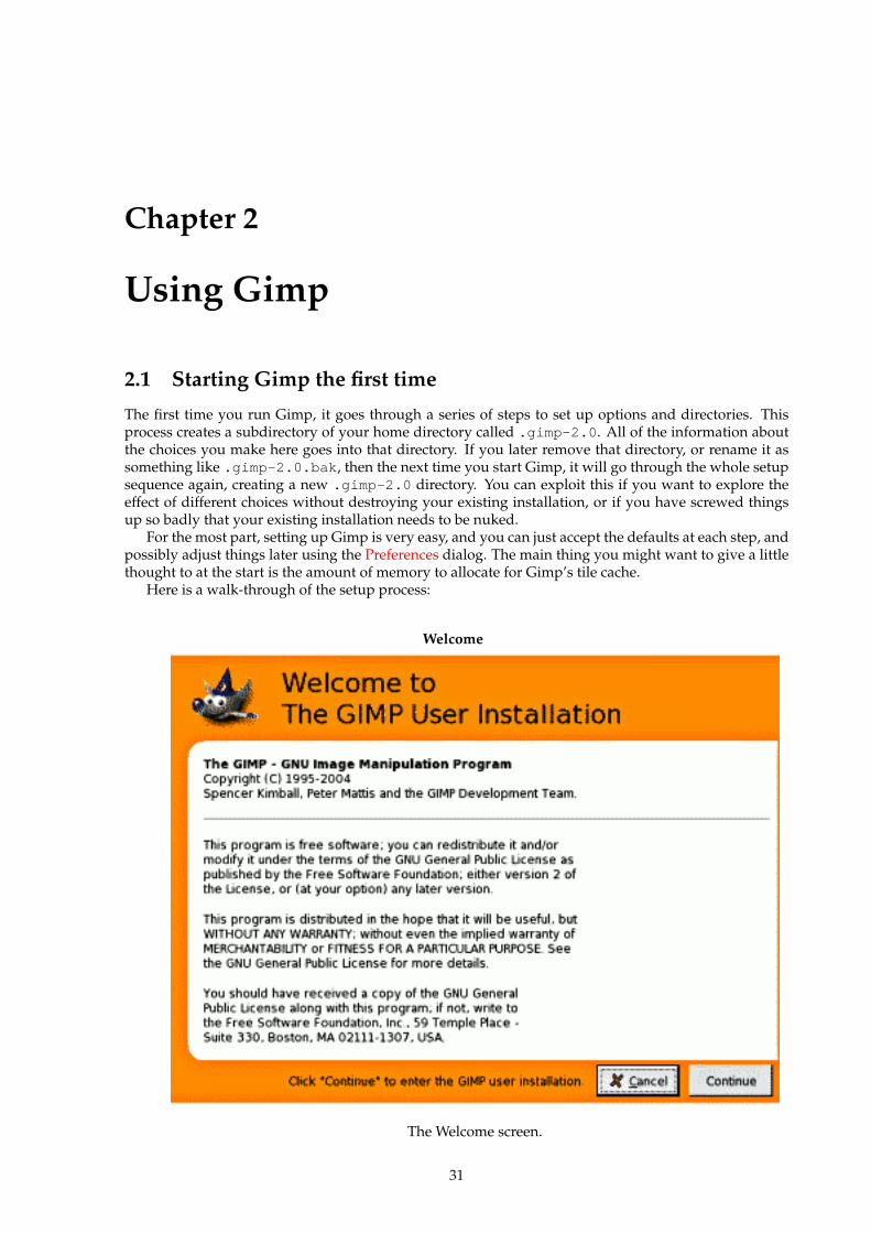
Chapter 2
Using Gimp
2.1 Starting Gimp the first time
The first time you run Gimp, it goes through a series of steps to set up options and directories. Thisprocess creates a subdirectory of your home directory called .gimp-2.0 . All of the information aboutthe choices you make here goes into that directory. If you later remove that directory, or rename it assomething like .gimp-2.0.bak , then the next time you start Gimp, it will go through the whole setupsequence again, creating a new .gimp-2.0 directory. You can exploit this if you want to explore theeffect of different choices without destroying your existing installation, or if you have screwed thingsup so badly that your existing installation needs to be nuked.
For the most part, setting up Gimp is very easy, and you can just accept the defaults at each step, andpossibly adjust things later using the Preferences dialog. The main thing you might want to give a littlethought to at the start is the amount of memory to allocate for Gimp’s tile cache.
Here is a walk-through of the setup process:
Welcome
The Welcome screen.
31
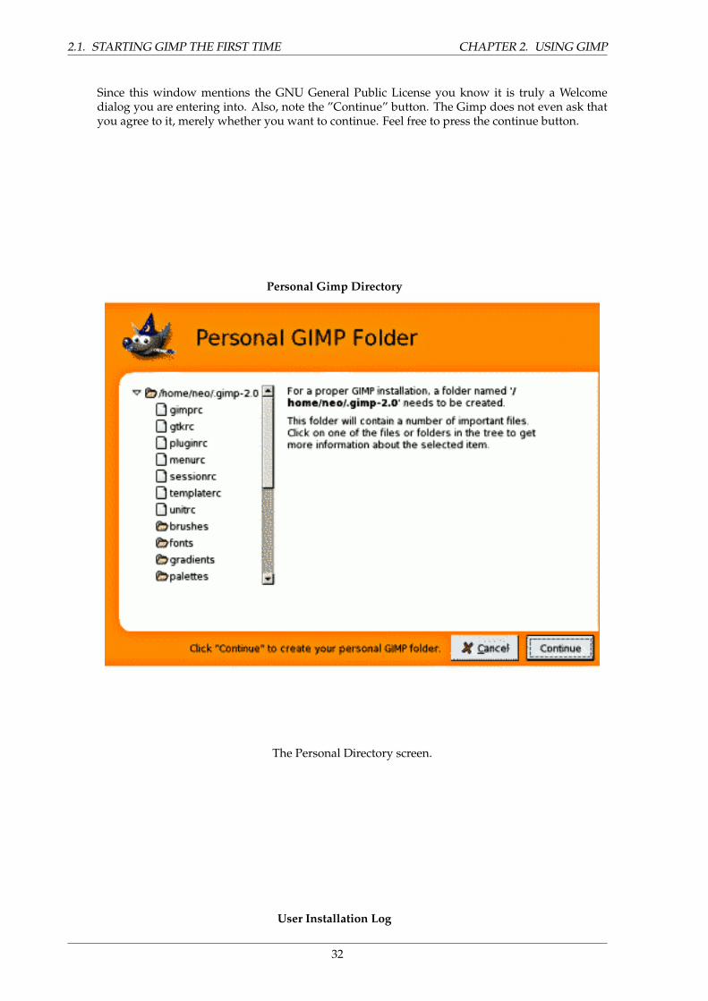
2.1. STARTING GIMP THE FIRST TIME CHAPTER 2. USING GIMP
Since this window mentions the GNU General Public License you know it is truly a Welcomedialog you are entering into. Also, note the ”Continue” button. The Gimp does not even ask thatyou agree to it, merely whether you want to continue. Feel free to press the continue button.
Personal Gimp Directory
The Personal Directory screen.
User Installation Log
32
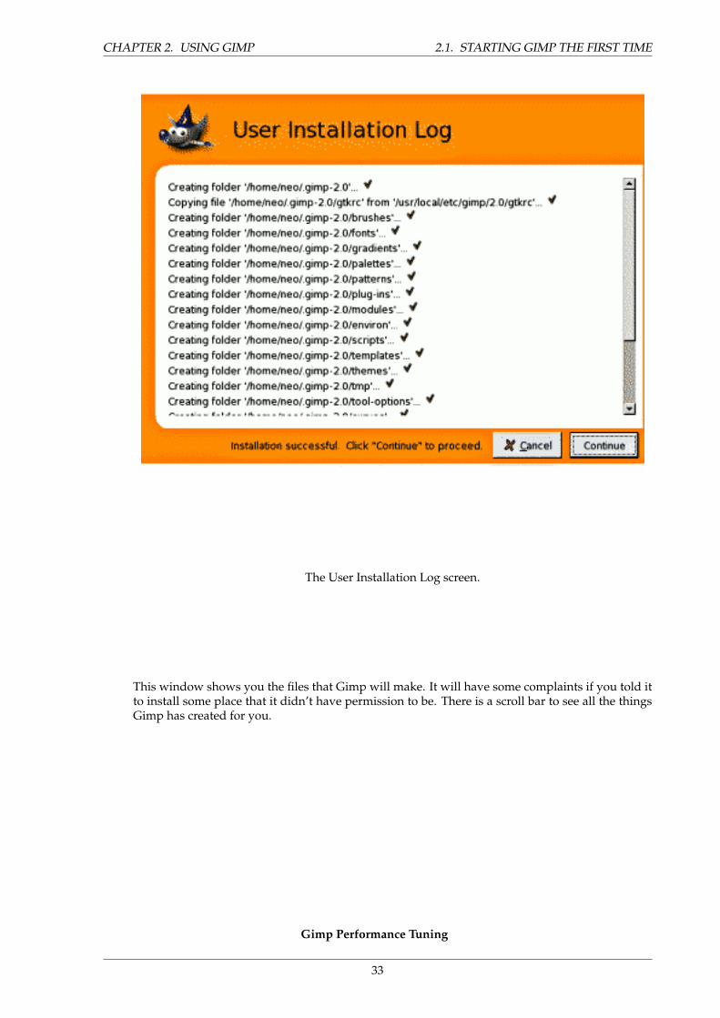
CHAPTER 2. USING GIMP 2.1. STARTING GIMP THE FIRST TIME
The User Installation Log screen.
This window shows you the files that Gimp will make. It will have some complaints if you told itto install some place that it didn’t have permission to be. There is a scroll bar to see all the thingsGimp has created for you.
Gimp Performance Tuning
33
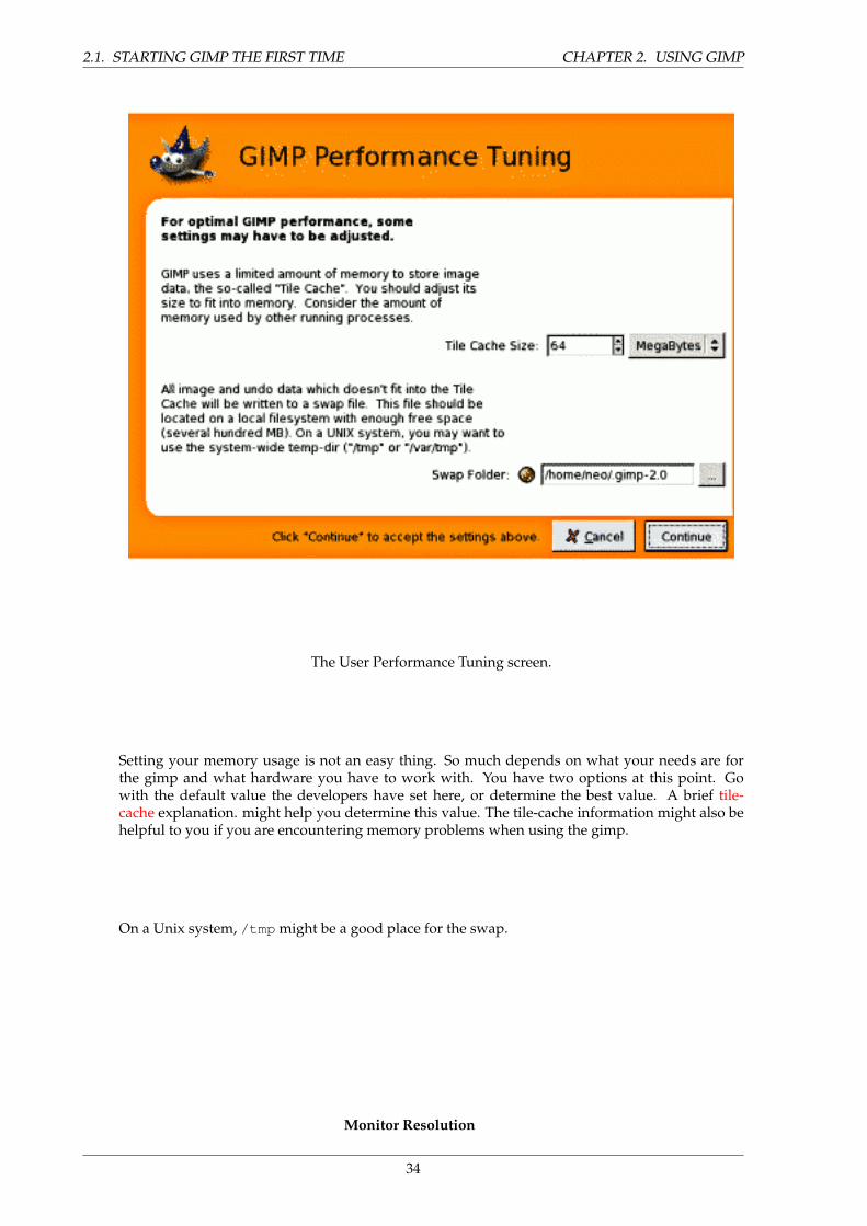
2.1. STARTING GIMP THE FIRST TIME CHAPTER 2. USING GIMP
The User Performance Tuning screen.
Setting your memory usage is not an easy thing. So much depends on what your needs are forthe gimp and what hardware you have to work with. You have two options at this point. Gowith the default value the developers have set here, or determine the best value. A brief tile-cache explanation. might help you determine this value. The tile-cache information might also behelpful to you if you are encountering memory problems when using the gimp.
On a Unix system, /tmp might be a good place for the swap.
Monitor Resolution
34
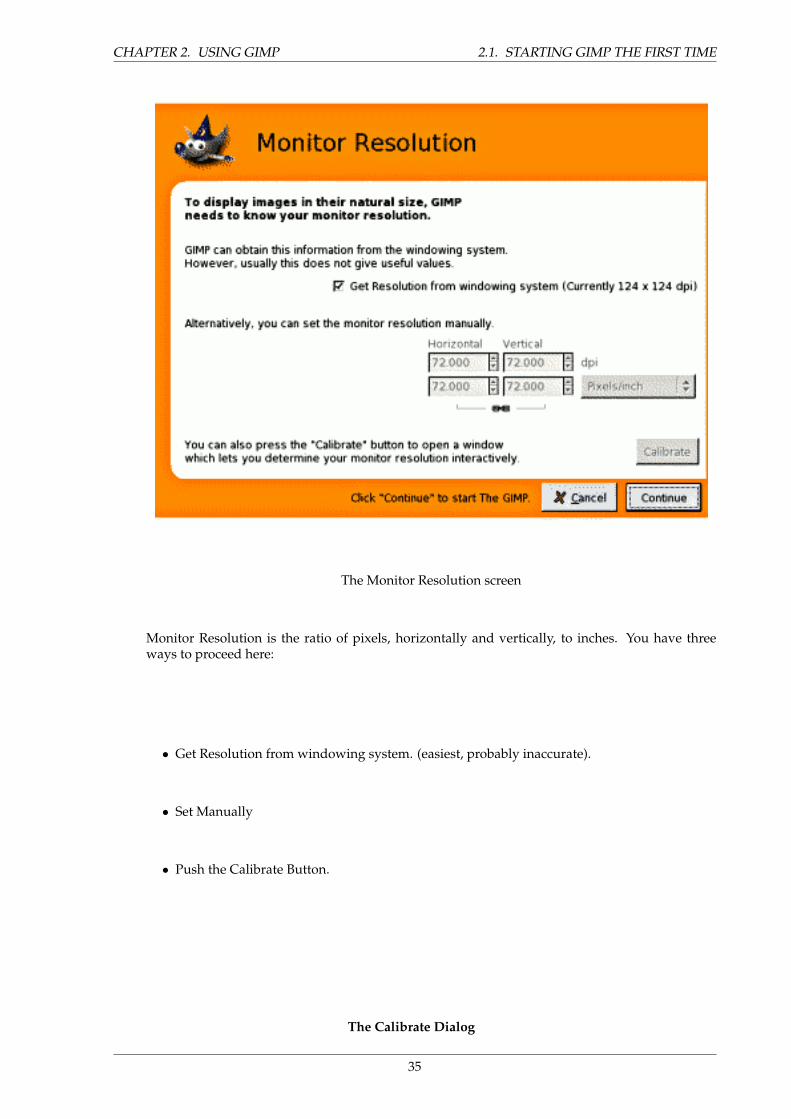
CHAPTER 2. USING GIMP 2.1. STARTING GIMP THE FIRST TIME
The Monitor Resolution screen
Monitor Resolution is the ratio of pixels, horizontally and vertically, to inches. You have threeways to proceed here:
• Get Resolution from windowing system. (easiest, probably inaccurate).
• Set Manually
• Push the Calibrate Button.
The Calibrate Dialog
35
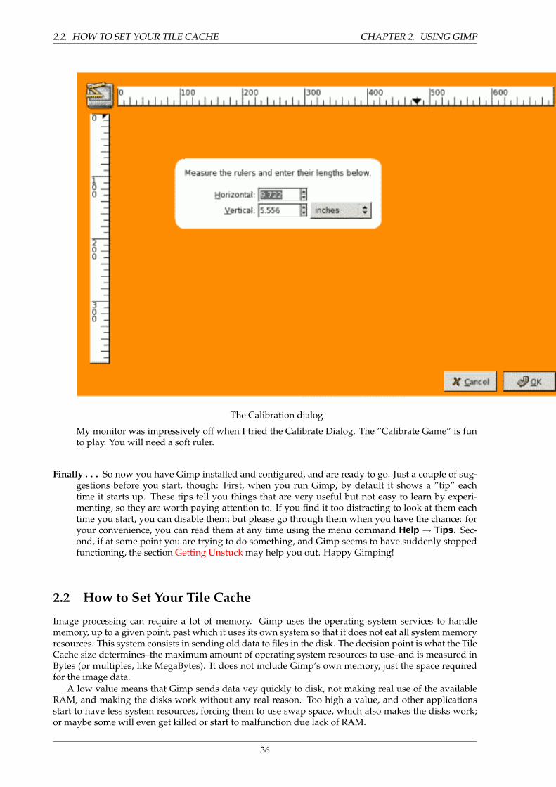
2.2. HOW TO SET YOUR TILE CACHE CHAPTER 2. USING GIMP
The Calibration dialog
My monitor was impressively off when I tried the Calibrate Dialog. The ”Calibrate Game” is funto play. You will need a soft ruler.
Finally . . . So now you have Gimp installed and configured, and are ready to go. Just a couple of sug-gestions before you start, though: First, when you run Gimp, by default it shows a ”tip” eachtime it starts up. These tips tell you things that are very useful but not easy to learn by experi-menting, so they are worth paying attention to. If you find it too distracting to look at them eachtime you start, you can disable them; but please go through them when you have the chance: foryour convenience, you can read them at any time using the menu command Help → Tips . Sec-ond, if at some point you are trying to do something, and Gimp seems to have suddenly stoppedfunctioning, the section Getting Unstuck may help you out. Happy Gimping!
2.2 How to Set Your Tile Cache
Image processing can require a lot of memory. Gimp uses the operating system services to handlememory, up to a given point, past which it uses its own system so that it does not eat all system memoryresources. This system consists in sending old data to files in the disk. The decision point is what the TileCache size determines–the maximum amount of operating system resources to use–and is measured inBytes (or multiples, like MegaBytes). It does not include Gimp’s own memory, just the space requiredfor the image data.
A low value means that Gimp sends data vey quickly to disk, not making real use of the availableRAM, and making the disks work without any real reason. Too high a value, and other applicationsstart to have less system resources, forcing them to use swap space, which also makes the disks work;or maybe some will even get killed or start to malfunction due lack of RAM.
36
CHAPTER 2. USING GIMP 2.2. HOW TO SET YOUR TILE CACHE
How to choose a number for the Tile Cache size? Here are some ways you could decide what valueto use, as well as a few tricks:
• The easiest method is to just forget about this and hope the default works. This was a usablemethod when computers had little RAM, and most people just tried to make small images withGimp while running one or two other applications at the same time. If you want something easyand only use Gimp to make screenshots and logos, this is probably the best solution.
• If you have a modern computer with plenty of memory–say, 512 MB or more–setting the TileCache to half of your RAM will probably give good performance for Gimp in most situationswithout depriving other applications. Probably even 3/4 of your RAM would be fine.
• Ask someone to do it for you, which in the case of a computer serving multiple users at the sametime can be a good idea: that way the administrator and other users do not get mad at you forabusing the machine, nor do you get a badly underperfoming Gimp. If it is your machine andonly serves a single user at a given time, this could mean money, or drinks, as price for the service.
• Start changing the value a bit each time and check that it goes faster and faster with each increase,but the system does not complain about lack of memory. Be forewarned that sometimes lack ofmemory shows up suddenly with some applications being killed to make space for the others.
• Do some simple math and calculate a viable value. Maybe you will have to tune it later, butmaybe you have to tune it anyway with the other previous methods. At least you know what ishappening and can get the best from your computer.
Let’s suppose you prefer the last option, and want to get a good value to start with. First, you needto get some data about your computer. This data is the amount of RAM installed in your system, theoperating system’s swap space available, and a general idea about the speed of the disks that store theoperating system’s swap and the directory used for Gimp’s swap. You do not need to do disk tests, norcheck the RPM of the disks, the thing is to see which one seems clearly faster or slower, or whether allare similar. You can change Gimp’s swap directory in the Folders page of the Preferences dialog.
The next thing to do is to see how much resources you require for other apps you want to run at thesame time than Gimp. So start all your tools and do some work with them, except Gimp of course, andcheck the usage. You can use applications like free or top, depending in what OS and what environmentyou use. The numbers you want is the memory left, including file cache. Modern Unix keeps a verysmall area free, in order to be able to keep large file and buffer caches. Linux’s free command does themaths for you: check the column that says ”free”, and the line ”-/+ buffers/cache”. Note down also thefree swap
Now time for decisions and a bit of simple math. Basically the concept is to decide if you want tobase all Tile Cache in RAM, or RAM plus operating system swap:
1. Do you change applications a lot? Or keep working in Gimp for a long time? If you spend a lot oftime in Gimp, you can consider free RAM plus free swap as available; if not, you need to go to thefollowing steps. (If you’re feeling unsure about it, check the following steps.) If you are sure youswitch apps every few minutes, only count the free RAM and just go to the final decision; no morethings to check.
2. Does the operating system swap live in the same physical disk as Gimp swap? If so, add RAMand swap. Otherwise go to the next step.
3. Is the disk that holds the OS swap faster or the same speed as the disk that holds the Gimp swap?If slower, take only the free RAM; if faster or similar, add free RAM and swap.
4. You now have a number, be it just the free RAM or the free RAM plus the free OS swap. Reduce ita bit, to be on the safe side, and that is the Tile Cache you could use as a good start.
As you can see, all is about checking the free resources, and decide if the OS swap is worth using orwill cause more problems than help.
There are some reasons you want to adjust this value, though. The basic one is changes in yourcomputer usage pattern, or changing hardware. That could mean your assumptions about how you useyour computer, or the speed of it, are no longer valid. That would require a reevaluation of the previoussteps, which can drive you to a similar value or a completly new value.
37
2.3. RUNNING GIMP CHAPTER 2. USING GIMP
Another reason to change the value is because it seems that Gimp runs too slowly, while changingto other applications is fast: this means that Gimp could use more memory without impairing the otherapplications. On the other hand, if you get complaints from other applications about not having enoughmemory, then it may benefit you to not let Gimp hog so much of it.
If you decided to use only RAM and Gimp runs slowly, you could try increasing the value a bit, butnever to use also all the free swap. If the case is the contrary, using both RAM and swap, and you haveproblems about lack of resources, then you should decrease the amount of RAM available to Gimp.
Another tricks is to put the Swap Dir in a very fast disk, or in a different disk than the one wheremost of your files reside. Spreading the operating system swap over multiple disks is also a good wayto speed up things, in general. And of course, maybe you have to buy more RAM or stop using lots ofprograms at the same time: you can not expect to edit a poster in a computer with 16MB and be fast.
You can also check what memory requirements your images have. The larger the images, and thenumber of undos, the more resources you need. This is another way to choose a number, but it is onlygood if you always work with the same kind of images, and thus the real requirements do not vary. It isalso helpful to know if you will require more RAM and/or disk space.
2.3 Running Gimp
Most often, you start Gimp either by clicking on an icon (if your system is set up to provide you withone), or by typing gimp on a command line. If you have multiple versions of the Gimp installed, youmay need to type gimp-2.2 to get the latest version. You can, if you want, give a list of image files on thecommand line after the program name, and they will automatically be opened by Gimp as it starts. It isalso possible, though, to open files from within Gimp once it is running.
In most operating systems, you can set things up so that various types of image files are ”associated”with Gimp, and cause it to start automatically when icons for them are double-clicked.
TIP
If you want to cause a certain file type to automatically open in Gimp, you shouldassociate it with ”gimp-remote” rather than with ”gimp”. The gimp-remote pro-gram is an auxiliary that comes with gimp. If gimp is not already running on thesystem when gimp-remote is executed, it is started and the image given as ar-gument to gimp-remote is loaded. If gimp is already running, though, the imageis simply loaded into the already-running program.
2.4 Command Line Arguments
Ordinarily you don’t need to give any arguments when starting Gimp, but here is a list of some thatmay at one time or anther be useful. This is not a complete list; on Unix systems you can get a completelist by running man gimp in a terminal window.
-h, –help Display a list of all commandline options.
-v, –version Print the version of Gimp being used, and exit.
–verbose Show detailed startup messages.
-d, –no-data Do not load patterns, gradients, palettes, or brushes. Often useful in non-interactive situa-tions where startup time is to be minimized.
–display display Use the designated X display (does not apply to Gimp on Microsoft Windows).
38
CHAPTER 2. USING GIMP 2.4. COMMAND LINE ARGUMENTS
-s, –no-splash Do not show the splash screen while starting.
–session name Use a different sessionrc for this GIMP session. The given session name is appended tothe default sessionrc filename.
-g, –gimprc gimprc Use an alternative gimprc instead of the default one. The ”gimprc” file contains arecord of your preferences. Useful in cases where plugins paths or machine specs may be different.
-c, –console-messages Do not popup dialog boxes on errors or warnings. Print the messages on theconsole instead.
-b, –batch commands Execute the set of commands non-interactively. The set of commands is typicallyin the form of a script that can be executed by one of the GIMP scripting extensions. When com-mands is - , the commands are read from standard input.
39
2.4. COMMAND LINE ARGUMENTS CHAPTER 2. USING GIMP
40
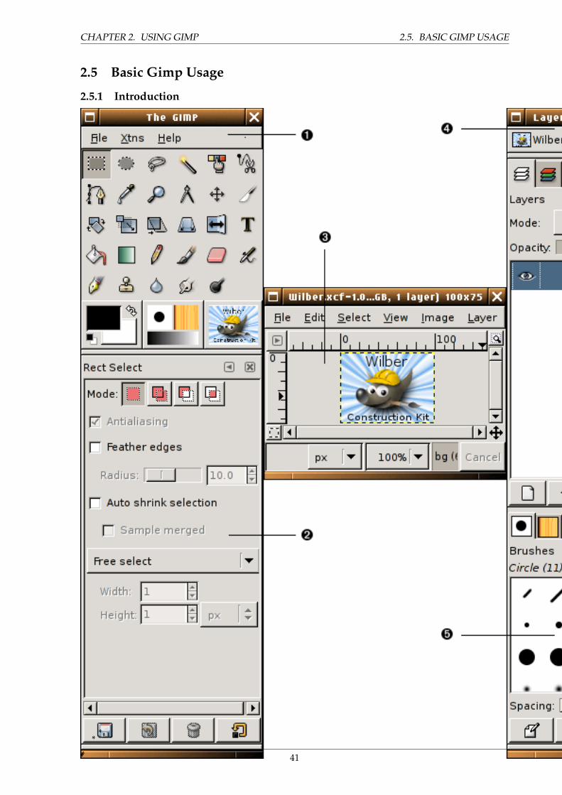
CHAPTER 2. USING GIMP 2.5. BASIC GIMP USAGE
2.5 Basic Gimp Usage
2.5.1 Introduction
**
*** 41
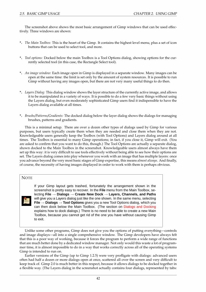
2.5. BASIC GIMP USAGE CHAPTER 2. USING GIMP
The screenshot above shows the most basic arrangement of Gimp windows that can be used effec-tively. Three windows are shown:
*. The Main Toolbox: This is the heart of the Gimp. It contains the highest level menu, plus a set of iconbuttons that can be used to select tool, and more.
*. Tool options: Docked below the main Toolbox is a Tool Options dialog, showing options for the cur-rently selected tool (in this case, the Rectangle Select tool).
*. An image window: Each image open in Gimp is displayed in a separate window. Many images can beopen at the same time: the limit is set only by the amount of system resources. It is possible to runGimp without having any images open, but there are not very many useful things to do then.
*. Layers Dialog: This dialog window shows the layer structure of the currently active image, and allowsit to be manipulated in a variety of ways. It is possible to do a few very basic things without usingthe Layers dialog, but even moderately sophisticated Gimp users find it indispensible to have theLayers dialog available at all times.
*. Brushs/Patterns/Gradients: The docked dialog below the layer dialog shows the dialogs for managingbrushes, patterns and gradients.
This is a minimal setup. There are over a dozen other types of dialogs used by Gimp for variouspurposes, but users typically create them when they are needed and close them when they are not.Knowledgeable users generally keep the Toolbox (with Tool Options) and Layers dialog around at alltimes. The Toolbox is essential to many Gimp operations; in fact, if you close it, Gimp will exit. (Youare asked to confirm that you want to do this, though.) The Tool Options are actually a separate dialog,shown docked to the Main Toolbox in the screenshot. Knowledgeable users almost always have themset up this way: it is very difficult to use tools effectively without being able to see how their options areset. The Layers dialog comes into play whenever you work with an image that has multiple layers: onceyou advance beyond the very most basic stages of Gimp expertise, this means almost always. And finally,of course, the necessity of having images displayed in order to work with them is perhaps obvious.
NOTE
If your Gimp layout gets trashed, fortunately the arrangement shown in thescreenshot is pretty easy to recover. In the File menu from the Main Toolbox, se-lecting File → Dialogs → Create New Dock → Layers, Channels, and Pathswill give you a Layers dialog just like the one shown. In the same menu, selectingFile → Dialogs → Tool Options gives you a new Tool Options dialog, which youcan then dock below the Main Toolbox. (The section on Dialogs and Dockingexplains how to dock dialogs.) There is no need to be able to create a new MainToolbox, because you cannot get rid of the one you have without causing Gimpto exit.
Unlike some other programs, Gimp does not give you the options of putting everything—controlsand image displays—all into a single comprehensive window. The Gimp developers have always feltthat this is a poor way of working, because it forces the program to perform a wide range of functionsthat are much better done by a dedicated window manager. Not only would this waste a lot of program-mer time, it is almost impossible to do in a way that works correctly across all of the operating systemsGimp is intended to run on.
Earlier versions of the Gimp (up to Gimp 1.2.5) were very profligate with dialogs: advanced usersoften had half a dozen or more dialogs open at once, scattered all over the screen and very difficult tokeep track of. Gimp 2.0 is much better in this respect, because it allows dialogs to be docked together ina flexible way. (The Layers dialog in the screenshot actually contains four dialogs, represented by tabs:
42
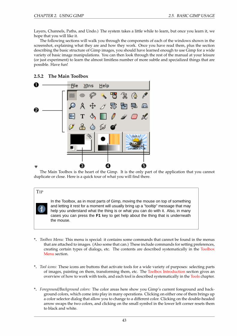
CHAPTER 2. USING GIMP 2.5. BASIC GIMP USAGE
Layers, Channels, Paths, and Undo.) The system takes a little while to learn, but once you learn it, wehope that you will like it.
The following sections will walk you through the components of each of the windows shown in thescreenshot, explaining what they are and how they work. Once you have read them, plus the sectiondescribing the basic structure of Gimp images, you should have learned enough to use Gimp for a widevariety of basic image manipulations. You can then look through the rest of the manual at your leisure(or just experiment) to learn the almost limitless number of more subtle and specialized things that arepossible. Have fun!
2.5.2 The Main Toolbox
*****The Main Toolbox is the heart of the Gimp. It is the only part of the application that you cannot
duplicate or close. Here is a quick tour of what you will find there.
TIP
In the Toolbox, as in most parts of Gimp, moving the mouse on top of somethingand letting it rest for a moment will usually bring up a ”tooltip” message that mayhelp you understand what the thing is or what you can do with it. Also, in manycases you can press the F1 key to get help about the thing that is underneaththe mouse.
*. Toolbox Menu: This menu is special: it contains some commands that cannot be found in the menusthat are attached to images. (Also some that can.) These include commands for setting preferences,creating certain types of dialogs, etc. The contents are described systematically in the ToolboxMenu section.
*. Tool icons: These icons are buttons that activate tools for a wide variety of purposes: selecting partsof images, painting on them, transforming them, etc. The Toolbox Introduction section gives anoverview of how to work with tools, and each tool is described systematically in the Tools chapter.
*. Foreground/Background colors: The color areas here show you Gimp’s current foreground and back-ground colors, which come into play in many operations. Clicking on either one of them brings upa color selector dialog that allow you to change to a different color. Clicking on the double-headedarrow swaps the two colors, and clicking on the small symbol in the lower left corner resets themto black and white.
43
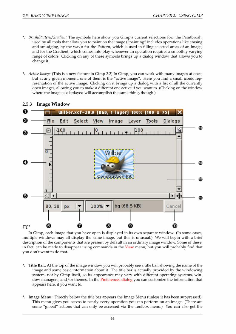
2.5. BASIC GIMP USAGE CHAPTER 2. USING GIMP
*. Brush/Pattern/Gradient The symbols here show you Gimp’s current selections for: the Paintbrush,used by all tools that allow you to paint on the image (”painting” includes operations like erasingand smudging, by the way); for the Pattern, which is used in filling selected areas of an image;and for the Gradient, which comes into play whenever an operation requires a smoothly varyingrange of colors. Clicking on any of these symbols brings up a dialog window that allows you tochange it.
*. Active Image: (This is a new feature in Gimp 2.2) In Gimp, you can work with many images at once,but at any given moment, one of them is the ”active image”. Here you find a small iconic rep-resentation of the active image. Clicking on it brings up a dialog with a list of all the currentlyopen images, allowing you to make a different one active if you want to. (Clicking on the windowwhere the image is displayed will accomplish the same thing, though.)
2.5.3 Image Window
**************In Gimp, each image that you have open is displayed in its own separate window. (In some cases,
multiple windows may all display the same image, but this is unusual.) We will begin with a briefdescription of the components that are present by default in an ordinary image window. Some of these,in fact, can be made to disappear using commands in the View menu; but you will probably find thatyou don’t want to do that.
*. Title Bar:. At the top of the image window you will probably see a title bar, showing the name of theimage and some basic information about it. The title bar is actually provided by the windowingsystem, not by Gimp itself, so its appearance may vary with different operating systems, win-dow managers, and/or themes. In the Preferences dialog you can customize the information thatappears here, if you want to.
*. Image Menu:. Directly below the title bar appears the Image Menu (unless it has been suppressed).This menu gives you access to nearly every operation you can perform on an image. (There aresome ”global” actions that can only be accessed via the Toolbox menu.) You can also get the
44
CHAPTER 2. USING GIMP 2.5. BASIC GIMP USAGE
Image Menu by right-clicking inside the image1, or by left-clicking on the little ”arrow” symbol inthe upper left corner, if for some reason you find one of these more convenient. More: most menuoperations can also be activated from the keyboard, using Alt plus an ”accelerator” key underlinedin the menu title. More: you can define your own custom shortcuts for menu actions, if you enableUse Dynamic Keyboard Shortcuts in the Preferences dialog.
*. Menu Button:. Clicking on this little button gives you the Image Menu, except in a column instead ofa row. Mnemonics users who don’t want the menu bar visible can acces to this menu by pressingthe Shift F10 key.
*. Ruler:. In the default layout, rulers are shown above and to the left of the image, indicating coordi-nates within the image. You can control what type of coordinates are shown if you want to. Bydefault, pixels are used, but you can change to other units, using the Units setting described below.
One of the most important uses of rulers is to create guides. If you click on a ruler and drag intothe image display, a guideline will be created, which you can use to help you position thingsaccurately. Guides can be moved by clicking on them and dragging, or deleted by dragging themout of the image display.
*. QuickMask Toggle:. At the lower left corner of the image display is a small button that toggles on oroff the Quick Mask, which is an alternate, and often extremely useful, way of viewing the selectedarea within the image. For more details see QuickMask.
*. Pointer coordinates:. In the lower left corner of the window is a rectangular area used to show thecurrent pointer coordinates (that is, the mouse location, if you are using a mouse), whenever thepointer is within the image boundaries. The units are the same as for the rulers.
*. Units menu:. (This feature is new in Gimp 2.2; it does not appear in Gimp 2.0). By default, the unitsused for the rulers and several other purposes are pixels. You can change to inches, cm, or severalother possibilities using this menu. (If you do, note that the setting of ”Dot for dot” in the Viewmenu affects how the display is scaled: see Dot for Dot for more information.
*. Zoom button:. (This feature is new in Gimp 2.2; it does not appear in Gimp 2.0). There are a numberof ways to zoom the image in or out, but this menu is perhaps the simplest.
*. Status Area:. The Status Area appears below the image display. Most of the time, by default, it showswhich part of the image is currently active, and the amount of system memory that the image isconsuming. You can customize the information that appears here, by changing your Preferences.When you perform time-consuming operations, the status area changes temporarily to show whatoperation is being performed, and its state of progress.
*. Cancel Button:. At the lower right corner of the window appears the Cancel button. If you start acomplex, time-consuming operation (most commonly a plug-in), and then decide, while it is beingcomputed, that you didn’t really want to do it after all, this button will cancel it immediately.
NOTE
There are a few plug-ins that respond badly to being canceled, possiblyleaving corrupted pieces of images behind.
1Users with an Apple Macintosh can use Ctrl+left mousebutton.
45
2.5. BASIC GIMP USAGE CHAPTER 2. USING GIMP
NOTE
Il y a quelques greffons qui repondent mal a l’arret et peuvent corrompredes morceaux d’image.
*. Navigation control:. This is a small cross-shaped button at the lower right corner of the image dis-play. Clicking on it, and holding the left mouse button down, brings up a window showing aminiature view of the image, with the displayed area outlined. You can pan to a different part ofthe image by moving the mouse while keeping the button depressed. For large images of whichonly a small part is displayed, the navigation window is often the most convenient way of gettingto the part of the image you are looking for. (See Navigation Dialog for other ways to access theNavigation Window).
*. inactive padding area:. This padding area seperates the active image display and the inactive paddingarea, so you’re able to distinguish between them. You cannot apply any Filters or Operations ingenerall on the inactive area.
*. Image Display:. The most important part of the image window is, of course, the image display. Itoccupies the central area of the window, surrounded by a yellow dotted line showing the imageboundary, against a neutral gray background. You can change the zoom level of the image displayin a variety of ways, including the Zoom setting described below.
*. image window resize toggle:. If this button is pressed, the image itself will be resized if the imagewindow is resized.
46
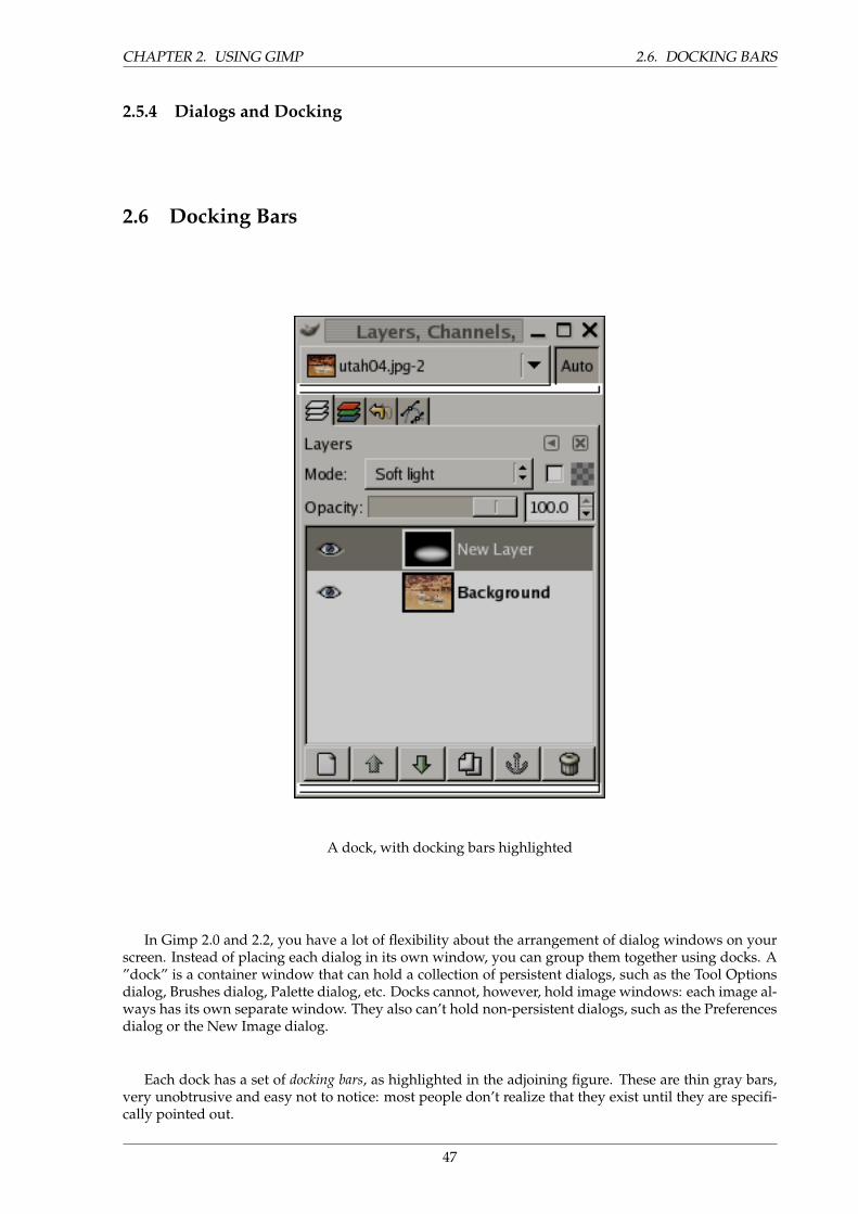
CHAPTER 2. USING GIMP 2.6. DOCKING BARS
2.5.4 Dialogs and Docking
2.6 Docking Bars
A dock, with docking bars highlighted
In Gimp 2.0 and 2.2, you have a lot of flexibility about the arrangement of dialog windows on yourscreen. Instead of placing each dialog in its own window, you can group them together using docks. A”dock” is a container window that can hold a collection of persistent dialogs, such as the Tool Optionsdialog, Brushes dialog, Palette dialog, etc. Docks cannot, however, hold image windows: each image al-ways has its own separate window. They also can’t hold non-persistent dialogs, such as the Preferencesdialog or the New Image dialog.
Each dock has a set of docking bars, as highlighted in the adjoining figure. These are thin gray bars,very unobtrusive and easy not to notice: most people don’t realize that they exist until they are specifi-cally pointed out.
47
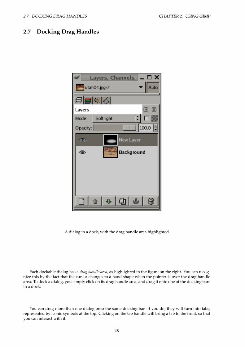
2.7. DOCKING DRAG HANDLES CHAPTER 2. USING GIMP
2.7 Docking Drag Handles
A dialog in a dock, with the drag handle area highlighted
Each dockable dialog has a drag handle area, as highlighted in the figure on the right. You can recog-nize this by the fact that the cursor changes to a hand shape when the pointer is over the drag handlearea. To dock a dialog, you simply click on its drag handle area, and drag it onto one of the docking barsin a dock.
You can drag more than one dialog onto the same docking bar. If you do, they will turn into tabs,represented by iconic symbols at the top. Clicking on the tab handle will bring a tab to the front, so thatyou can interact with it.
48
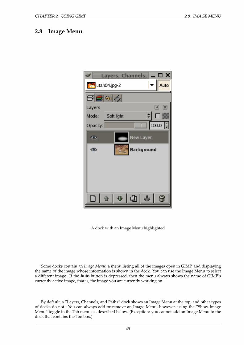
CHAPTER 2. USING GIMP 2.8. IMAGE MENU
2.8 Image Menu
A dock with an Image Menu highlighted
Some docks contain an Image Menu: a menu listing all of the images open in GIMP, and displayingthe name of the image whose information is shown in the dock. You can use the Image Menu to selecta different image. If the Auto button is depressed, then the menu always shows the name of GIMP’scurrently active image, that is, the image you are currently working on.
By default, a ”Layers, Channels, and Paths” dock shows an Image Menu at the top, and other typesof docks do not. You can always add or remove an Image Menu, however, using the ”Show ImageMenu” toggle in the Tab menu, as described below. (Exception: you cannot add an Image Menu to thedock that contains the Toolbox.)
49
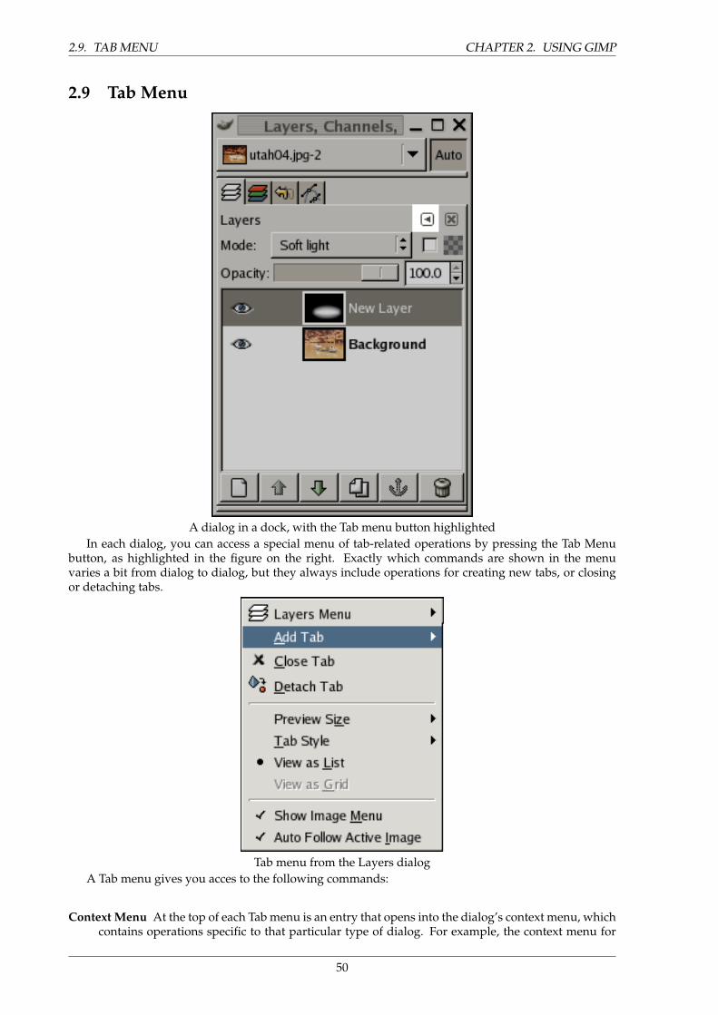
2.9. TAB MENU CHAPTER 2. USING GIMP
2.9 Tab Menu
A dialog in a dock, with the Tab menu button highlightedIn each dialog, you can access a special menu of tab-related operations by pressing the Tab Menu
button, as highlighted in the figure on the right. Exactly which commands are shown in the menuvaries a bit from dialog to dialog, but they always include operations for creating new tabs, or closingor detaching tabs.
Tab menu from the Layers dialogA Tab menu gives you acces to the following commands:
Context Menu At the top of each Tab menu is an entry that opens into the dialog’s context menu, whichcontains operations specific to that particular type of dialog. For example, the context menu for
50
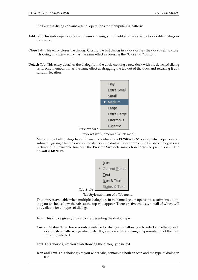
CHAPTER 2. USING GIMP 2.9. TAB MENU
the Patterns dialog contains a set of operations for manipulating patterns.
Add Tab This entry opens into a submenu allowing you to add a large variety of dockable dialogs asnew tabs.
Close Tab This entry closes the dialog. Closing the last dialog in a dock causes the dock itself to close.Choosing this menu entry has the same effect as pressing the ”Close Tab” button.
Detach Tab This entry detaches the dialog from the dock, creating a new dock with the detached dialogas its only member. It has the same effect as dragging the tab out of the dock and releasing it at arandom location.
Preview SizePreview Size submenu of a Tab menu
Many, but not all, dialogs have Tab menus containing a Preview Size option, which opens into asubmenu giving a list of sizes for the items in the dialog. For example, the Brushes dialog showspictures of all available brushes: the Preview Size determines how large the pictures are. Thedefault is Medium .
Tab StyleTab Style submenu of a Tab menu
This entry is available when multiple dialogs are in the same dock: it opens into a submenu allow-ing you to choose how the tabs at the top will appear. There are five choices, not all of which willbe available for all types of dialogs:
Icon This choice gives you an icon representing the dialog type.
Current Status This choice is only available for dialogs that allow you to select something, suchas a brush, a pattern, a gradient, etc. It gives you a tab showing a representation of the itemcurrently selected.
Text This choice gives you a tab showing the dialog type in text.
Icon and Text This choice gives you wider tabs, containing both an icon and the type of dialog intext.
51
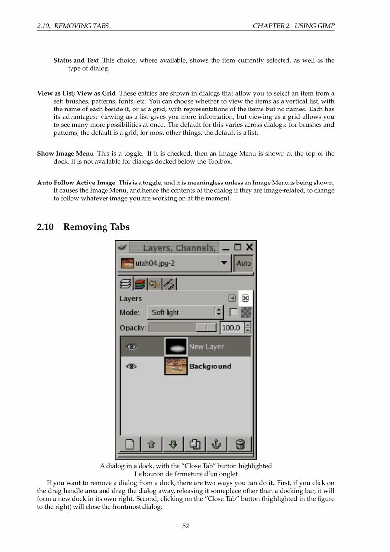
2.10. REMOVING TABS CHAPTER 2. USING GIMP
Status and Text This choice, where available, shows the item currently selected, as well as thetype of dialog.
View as List; View as Grid These entries are shown in dialogs that allow you to select an item from aset: brushes, patterns, fonts, etc. You can choose whether to view the items as a vertical list, withthe name of each beside it, or as a grid, with representations of the items but no names. Each hasits advantages: viewing as a list gives you more information, but viewing as a grid allows youto see many more possibilities at once. The default for this varies across dialogs: for brushes andpatterns, the default is a grid; for most other things, the default is a list.
Show Image Menu This is a toggle. If it is checked, then an Image Menu is shown at the top of thedock. It is not available for dialogs docked below the Toolbox.
Auto Follow Active Image This is a toggle, and it is meaningless unless an Image Menu is being shown.It causes the Image Menu, and hence the contents of the dialog if they are image-related, to changeto follow whatever image you are working on at the moment.
2.10 Removing Tabs
A dialog in a dock, with the ”Close Tab” button highlightedLe bouton de fermeture d’un onglet
If you want to remove a dialog from a dock, there are two ways you can do it. First, if you click onthe drag handle area and drag the dialog away, releasing it someplace other than a docking bar, it willform a new dock in its own right. Second, clicking on the ”Close Tab” button (highlighted in the figureto the right) will close the frontmost dialog.
52
CHAPTER 2. USING GIMP 2.11. CREATING DIALOGS
2.11 Creating Dialogs
Most dockable dialogs can be created in more than one way, but all of them can be created using theFile → Dialogs menu from the Main Toolbox, or by using the Add command in the Tab menu from anydialog. As a convenience, there are also three pre-built docks you can create using the File → Dialogs→ Create New Dock menu path from the Main Toolbox:
Layers, Channels and Paths This gives you a dock containing:
• The Channels dialog
• The Layers dialog
• The Paths dialog
• The Undo dialog
Brushes, Patterns and Gradients This gives you a dock containing:
• The Brushes dialog
• The Patterns dialog
• The Gradients dialog
• The Palettes dialog
• The Fonts dialog
Misc. Stuff This gives you a dock containing:
• The Buffers dialog
• The Images dialog
• The Document History dialog
• The Image Templates dialog
TIP
Just because you have a lot of flexibility does not mean that all choices areequally good. There are at least two things we recommend:
1. Keep the Tool Options dialog docked directly beneath the Main Toolbox atall times.
2. Keep the Layers dialog around at all times, in a separate dock from theMain Toolbox, with an Image Menu above it. (Use ”Show Image Menu” inthe dialog Tab menu to display the Image menu if you have somehow lostit.)
53
2.11. CREATING DIALOGS CHAPTER 2. USING GIMP
2.11.1 Basic Gimp Concepts
This section is intended to give you a brief introduction to the basic concepts and terminology you willneed to understand in order to make sense to the rest of the documentation. Everything here is explainedin much greater depth elsewhere. With a few exceptions, we have avoided cluttering this section witha lot of links and cross-references: everything mentioned here is so high-level that you should easily beable to locate it in the index.
Overview The Gimp is an image manipulation program. At the most sweeping level, using Gimpinvolves three basic steps: (1) opening images or creating new ones; (2) altering those images; (3)saving the results.
Opening Images Depending on how Gimp was started, there may already be one or more imagesopen when you begin. You can open new images from files using the Open command fromthe File menu. Gimp is capable of opening a large variety of graphics file formats; see Filesfor more information. Depending on how your system is set up, you may also be able to openimages by clicking on icons in a file manager, or by drag-and-drop from other programs. Ifyou aren’t sure whether you can do this, just try it. The worst thing that can happen is thatyour computer could explode.
Altering Images Gimp provides you with an enormous number of ways of acting on images:painting tools, color manipulation tools, transformation tools, filters, etc. The bulk of thismanual is devoted to describing these tools and how to work with them.
Saving Images When you are finished working with an image, you will want to save the results.(In fact, it is often a good idea to save at intermediate stages too: Gimp is a pretty robustprogram, but we have heard rumors, possibly apocryphal, that it may have been known onrare and mysterious occasions to crash.) Most of the file formats that Gimp can open, canalso be used for saving. There is one file format that is special, though: XCF is Gimp’s nativeformat, and is useful because it stores everything about an image (well, almost everything; itdoes not store ”undo” information). Thus, the XCF format is especially suitable for savingintermediate results, and for saving images to be re-opened later in Gimp. XCF files are notreadable by most other programs that display images, so once you have finished, you willprobably also want to save the image in a more widely used format, such as JPEG, PNG,TIFF, etc.
Images Images are the basic entities that Gimp works with. Roughly speaking, an ”image” correspondsto a single file, such as a TIFF or JPEG file. You can also think of an image as corresponding to asingle display window, but this is not quite correct: it is possible to have multiple windows alldisplaying the same image. It is not possible to have a single window display more than oneimage, though, or for an image to have no window displaying it.
A Gimp image may be quite a complicated thing. Instead of thinking of it as something like asheet of paper with a picture on it, you should think of it as more like a book, whose pages arecalled ”layers”. In addition to a stack of layers, a Gimp image may contain a selection mask, a setof channels, and a set of paths. In fact, Gimp provides a mechanism for attaching arbitrary piecesof data to an image, as what are called ”parasites”.
In Gimp, it is possible to have many images open at the same time. If they are large, each imagemay use many megabytes of memory, but Gimp uses a sophisticated tile-based memory manage-ment system that allows it to handle even very large images gracefully. There are, however, limits,and it is usually beneficial when working with images to put as much memory into your systemas possible.
Layers If an image is like a book, then a layer is like a page within the book. The simplest images onlycontain a single layer, and can be treated like single sheets of paper, but sophisticated Gimp usersoften deal with images containing many layers, even dozens of them. Layers need not be opaque,
54
CHAPTER 2. USING GIMP 2.12. WORKING WITH IMAGES
and they need not cover the entire extent of an image, so when you look at an image’s display, youmay see more than just the top layer: you may see elements of many layers.
Channels TO BE WRITTEN
Selections Often when you do something to an image, you only want a part of it to be affected. The”selection” mechanism makes this possible. Each image has its own selection, which you normallysee as an moving dashed line separating the selected parts from the unselected parts (the so-called”marching ants”). Actually this is a bit misleading: selection in Gimp is really graded, not all-or-nothing, and really the selection is represented by a full-fledged grayscale channel. The dashedline that you normally see is simply a contour line at the 50%-selected level. At any time, though,you can visualize the selection channel in all its glorious detail by toggling the QuickMask button.
A large component of learning how to use Gimp effectively is acquiring the art of making goodselections—selections that contain exactly what you need and nothing more. Because selection-handling is so centrally important, Gimp gives you a large number of tools for doing it: an assort-ment of selection-making tools, a menu of selection operations, and the ability to switch to QuickMask mode, in which you can treat the selection channel as though it were a color channel, thereby”painting the selection”.
Undoing When you make mistakes, you can undo them. Nearly everything you can do to an imageis undoable. In fact, you can usually undo a substantial number of the most recent things youdid, if you decide that they were misguided. Gimp makes this possible by keeping a historyof your actions. This history consumes memory, though, so undoability is not infinite. Someactions use very little undo memory, so that you can do dozens of them before the earliest onesare deleted from this history; other types of actions require massive amounts of undo memory.You can configure the amount of memory Gimp allows for the undo history of each image, butin any situation, you should always be able to undo at least your 2-3 most recent actions. (Themost important action that is not undoable is closing an image. For this reason, Gimp asks you toconfirm that you really want to close the image if you have made any changes to it.)
Plug-ins Many, probably most, of the things you do to an image in Gimp are done by the Gimp appli-cation itself. However, Gimp also makes extensive use of ”plug-ins”, which are external programsthat interact very closely with Gimp, and are capable of manipulating images and other Gimpobjects in very sophisticated ways. Many important plug-ins come packaged together with Gimp,but there are also many available by other means. In fact, the ability to write plug-ins (and scripts)is the easiest way for people not on the Gimp development team to add new capabilities to Gimp.
All of the commands in the Filters menu, and a substantial number of commands in other menus,are actually implemented by plug-ins.
Scripts In addition to plug-ins, which are programs written in the C language, Gimp can also make useof scripts. The largest number of existing scripts are written in a language called Script-Fu, whichis special to Gimp (for those who care, it is a dialect of the Lisp-like language called Scheme).It is also possible to write Gimp scripts in Python or Perl. These languages are more flexibleand powerful than Script-Fu; their disadvantage is that they depend on software that does notautomatically come packaged with Gimp, so they are not guaranteed to work correctly in everyGimp installation.
2.12 Working with Images
2.12.1 Image types
It is tempting to think of an image as something that corresponds a single display window, or to a singlefile such as a JPEG file, but really a Gimp image is a rather complicated structure, containing a stack oflayers plus several other types of objects: a selection mask, a set of channels, a set of paths, an ”undo”
55
2.12. WORKING WITH IMAGES CHAPTER 2. USING GIMP
history, etc. In this section we are going to take a detailed look at all of the components of an image, andthe things you can do with them.
The most basic property of an image is its mode. There are three possible modes: RGB, grayscale, andindexed. RGB stands for Red-Green-Blue, and indicates that each point in the image is represented bya ”red” level, a ”green” level, and a ”blue” level. Because every humanly distinguishable color can berepresented as a combination of red, green, and blue, RGB images are full-color. Each color channel has256 possible intensity levels. More details in Color Models
In a grayscale image, each point is represented by a brightness value, ranging from 0 (black) to 255(white), with intermediate values representing different levels of gray.
Essentially the difference between a grayscale image and an RGB image is the number of ”colorchannels”: a grayscale image has one; an RGB image has three. An RGB image can be thought of asthree superimposed grayscale images, one colored red, one green, and one blue.
Actually, both RGB and grayscale images have one additional color channel, called the alpha channel,representing opacity. When the alpha value at a given location in a given layer is zero, the layer iscompletely transparent, and the color at that location is determined by what lies underneath. Whenalpha is maximal, the layer is opaque, and the color is determined by the color of the layer. Intermediatealpha values correspond to varying degrees of translucency: the color at the location is a proportionlmixture of color from the layer and color from underneath.
In Gimp, every color channel, including the alpha channel, has a range of possible values from 0 to255; in computing terminology, a depth of 8 bits. Some digital cameras can produce image files with adepth of 16 bits per color channel. Gimp cannot load such a file without losing resolution. In most casesthe effects are too subtle to be detected by the human eye, but in some cases, mainly where there arelarge areas with slowly varying color gradients, the difference may be perceptible.
The third type, indexed images, is a bit more complicated to understand. In an indexed image, only alimited set of discrete colors are used, usually 256 or less. These colors form the ”colormap” of the image,and each point in the image is assigned a color from the colormap. Indexed images have the advantagethat they can be represented inside a computer in a way that consumes relatively little memory, andback in the dark ages (say, ten years ago), they were very commmonly used. As time goes on, they areused less and less, but they are still important enough to be worth supporting in Gimp. (Also, there area few important kinds of image manipulation that are easier to implement with indexed images thanwith continuous-color RGB images.)
Some very commonly used types of files (including GIF) produce indexed images when they areopened in Gimp. Many of Gimp’s tools don’t work very well on indexed images–and many filters don’twork at all–because of the limited number of colors available. Because of this, it is usually best to convertan image to RGB mode before working on it. If necessary, you can convert it back to indexed mode whenyou are ready of save it
Gimp makes it easy to convert from one image type to another, using the Mode command in theImage menu. Some types of conversions, of course (RGB to grayscale or indexed, for example) loseinformation that cannot be regained by converting back in the other direction.
NOTE
If you are trying to use a filter on an image, and it appears grayed out in themenu, usually the cause is that the image (or, more specifically, the layer) youare working on is the wrong type. Many filters can’t be used on indexed images.Some can be used only on RGB images, or only on grayscale images. Somealso require the presence or absence of an alpha channel. Usually the fix is toconvert the image to a different type, most commonly RGB.
56
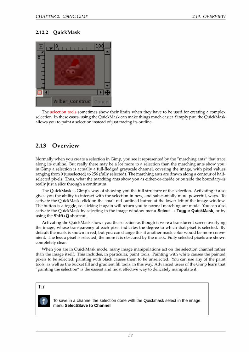
CHAPTER 2. USING GIMP 2.13. OVERVIEW
2.12.2 QuickMask
The selection tools sometimes show their limits when they have to be used for creating a complexselection. In these cases, using the QuickMask can make things much easier. Simply put, the QuickMaskallows you to paint a selection instead of just tracing its outline.
2.13 Overview
Normally when you create a selection in Gimp, you see it represented by the ”marching ants” that tracealong its outline. But really there may be a lot more to a selection than the marching ants show you:in Gimp a selection is actually a full-fledged grayscale channel, covering the image, with pixel valuesranging from 0 (unselected) to 256 (fully selected). The marching ants are drawn along a contour of half-selected pixels. Thus, what the marching ants show you as either-or–inside or outside the boundary–isreally just a slice through a continuum.
The QuickMask is Gimp’s way of showing you the full structure of the selection. Activating it alsogives you the ability to interact with the selection in new, and substantially more powerful, ways. Toactivate the QuickMask, click on the small red-outlined button at the lower left of the image window.The button is a toggle, so clicking it again will return you to normal marching-ant mode. You can alsoactivate the QuickMask by selecting in the image window menu Select → Toggle QuickMask , or byusing the Shift+Q shortcut.
Activating the QuickMask shows you the selection as though it were a translucent screen overlyingthe image, whose transparency at each pixel indicates the degree to which that pixel is selected. Bydefault the mask is shown in red, but you can change this if another mask color would be more conve-nient. The less a pixel is selected, the more it is obscured by the mask. Fully selected pixels are showncompletely clear.
When you are in QuickMask mode, many image manipulations act on the selection channel ratherthan the image itself. This includes, in particular, paint tools. Painting with white causes the paintedpixels to be selected; painting with black causes them to be unselected. You can use any of the painttools, as well as the bucket fill and gradient fill tools, in this way. Advanced users of the Gimp learn that”painting the selection” is the easiest and most effective way to delicately manipulate it.
TIP
To save in a channel the selection done with the Quickmask select in the imagemenu Select/Save to Channel
57
2.14. PROPERTIES CHAPTER 2. USING GIMP
TIP
When QuickMask is active, Cut and Paste act on the selection rather than theimage. You can sometimes make use of this as the most convenient way oftransferring a selection from one image to another.
You can learn more on Quickmask and Selection masks in the section dedicated to the channel dialog.
2.14 Properties
There are two QuickMask properties you can change by right-clicking on the QuickMask button.
• Normally the QuickMask shows unselected areas ”fogged over” and selected areas ”in clear”, butyou can reverse this by choosing ”Mask Selected Areas” instead of the default ”Mask UnselectedAreas”.
• By choosing ”Configure Color and Opacity”, you can bring up a dialog that allows you to set theseto values other than the defaults, which are red at 50% opacity.
2.15 Usage
1. Open an image or begin a new document;
2. Activate the Quickmask using the left-bottom button in the image window. If a selection is presentthe mask is initialized with the content of the selection;
3. Choose any drawing tool and use it with greyscale colors on the QuickMask;
4. Toggle off the Quickmask using the left-bottom button in the image window;
2.15.1 Layers
A good way to visualize a Gimp image is as a stack of transparencies: in Gimp terminology, each indi-vidual transparency is called a layer. There is no limit, in principle, to the number of layers an image canhave: only the amount of memory available on the system. It is not uncommon for advanced users towork with images containing dozens of layers.
The organization of layers in an image is shown by the Layers dialog, which is the second mostimportant type of dialog window in Gimp, after the Main Toolbox. The appearance of the Layers dialogis shown in the adjoining illustration. How it works is described in detail in the Layers Dialog section,but we will touch on some aspects of it here, in relation to the layer properties that they display.
Each open image has at any time a single active drawable. A ”drawable” is a Gimp concept thatincludes layers, but also several other types of things, such as channels, layer masks, and the selectionmask. (Basically, a ”drawable” is anything that can be drawn on with painting tools.) If a layer iscurrently active, it is shown highlighted in the Layers dialog, and its name is shown in the status areaof the image window. If not, you can activate it by clicking on it. If none of the layers is highlighted, itmeans the active drawable is something other than a layer.
In the menubar above an image window, you can find a menu called Layer , containing a number ofcommands that affect the active layer of the image. The same menu can be accessed by right-clicking inthe Layers dialog.
Each layer in an image has a number of important attributes:
Name Every layer has a name. This is assigned automatically when the layer is created, but you canchange it. You can change the name of a layer either by double-clicking on it in the Layers dialog,or by right-clicking there and then selecting the top entry in the menu that appears, Edit LayerAttributes .
58
CHAPTER 2. USING GIMP 2.15. USAGE
Presence or absence of an alpha channel As explained in the previous section, an alpha channel en-codes information about how transparent a layer is at each pixel. It is visible in the Channel Dialog:white is complete opacity, black is complete transparency and grey levels are partial transparen-cies. Not every layer is required to have an alpha channel, though. In many cases, the bottom layerof an image (often named ”Background”) lacks any alpha channel: this means that it is completelyopaque at every point. Alphaless layers are created when you open an image from a file formatthat does not support transparency, or when you create a new image using File → New with atransparent Fill Type, or when you flatten an image into a single layer.
Every layer other than the bottom layer of an image must have an alpha channel. For the bottomlayer, it is optional. Many operations cannot be performed on layers that lack an alpha channel.Moving the layer to a different position in the layer stack is one obvious example (since only bot-tom layers are allowed not to have an alpha channel), but any operation involving transparencywould also be included. You can add an alpha channel to a layer that lacks one using the menucommand Layer → Transparency → Add Alpha Channel , or by right-clicking in the Layers di-alog and selecting Add Alpha Channel from the popup menu that appears. To remove an alphachannel, activate the bottom layer by clicking on it in the Layers dialog, and then select Layer →Transparency → Semi-Flatten .
Layer type The layer type is determined by the image type (see previous section) and the presence orabsence of an alpha channel. These are the possible layer types:
• RGB
• RGBA
• Gray
• GrayA
• Indexed
• IndexedA
The main reason this matters is that most filters (in the Filters menu) only accept a subset of layertypes, and appear grayed out in the menu if the active layer does not have an acceptable type.Often you can rectify this either by changing the mode of the image or by adding or removing analpha channel.
Visibility It is possible to temporarily remove a layer from an image, without destroying it, by clickingon the ”open eye” symbol in the Layers dialog. This is called ”toggling the visibility” of the layer.Most operations on an image treat toggled-off layers as if they did not exist. When you work withimages containing many layers, with varying opacity, you often can get a better picture of thecontents of the layer you want to work on by hiding some of the other layers.
NOTE
If you Shift-click on the eye symbol, this will cause all layers except the oneyou click on to be hidden.
Linkage to other layers If you click between the eye icon and the layer thumbnail, you get a chain icon,which enables you to group layers for operations on multiple layers (for example with the Movetool or a transform tool).
Size, Taille In Gimp, the boundaries of a layer do not necessarily match the boundaries of the imagethat contains it. When you create text, for example, each text item goes into its own separate
59
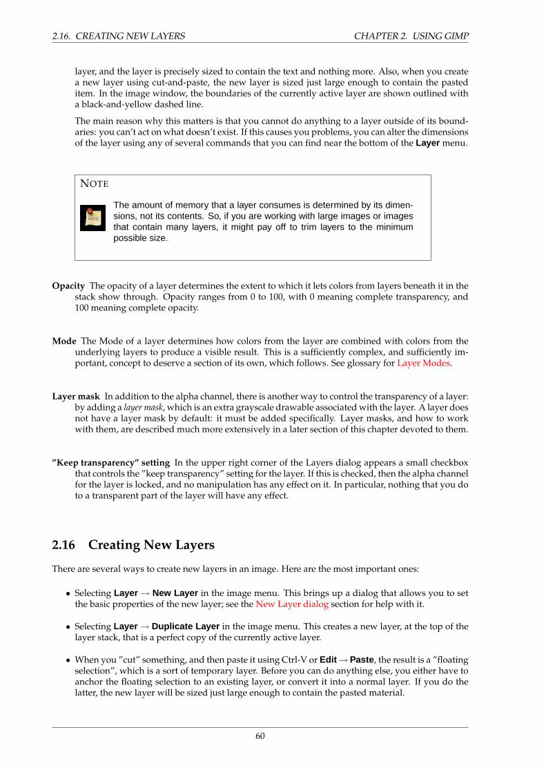
2.16. CREATING NEW LAYERS CHAPTER 2. USING GIMP
layer, and the layer is precisely sized to contain the text and nothing more. Also, when you createa new layer using cut-and-paste, the new layer is sized just large enough to contain the pasteditem. In the image window, the boundaries of the currently active layer are shown outlined witha black-and-yellow dashed line.
The main reason why this matters is that you cannot do anything to a layer outside of its bound-aries: you can’t act on what doesn’t exist. If this causes you problems, you can alter the dimensionsof the layer using any of several commands that you can find near the bottom of the Layer menu.
NOTE
The amount of memory that a layer consumes is determined by its dimen-sions, not its contents. So, if you are working with large images or imagesthat contain many layers, it might pay off to trim layers to the minimumpossible size.
Opacity The opacity of a layer determines the extent to which it lets colors from layers beneath it in thestack show through. Opacity ranges from 0 to 100, with 0 meaning complete transparency, and100 meaning complete opacity.
Mode The Mode of a layer determines how colors from the layer are combined with colors from theunderlying layers to produce a visible result. This is a sufficiently complex, and sufficiently im-portant, concept to deserve a section of its own, which follows. See glossary for Layer Modes.
Layer mask In addition to the alpha channel, there is another way to control the transparency of a layer:by adding a layer mask, which is an extra grayscale drawable associated with the layer. A layer doesnot have a layer mask by default: it must be added specifically. Layer masks, and how to workwith them, are described much more extensively in a later section of this chapter devoted to them.
”Keep transparency” setting In the upper right corner of the Layers dialog appears a small checkboxthat controls the ”keep transparency” setting for the layer. If this is checked, then the alpha channelfor the layer is locked, and no manipulation has any effect on it. In particular, nothing that you doto a transparent part of the layer will have any effect.
2.16 Creating New Layers
There are several ways to create new layers in an image. Here are the most important ones:
• Selecting Layer → New Layer in the image menu. This brings up a dialog that allows you to setthe basic properties of the new layer; see the New Layer dialog section for help with it.
• Selecting Layer → Duplicate Layer in the image menu. This creates a new layer, at the top of thelayer stack, that is a perfect copy of the currently active layer.
• When you ”cut” something, and then paste it using Ctrl-V or Edit → Paste , the result is a ”floatingselection”, which is a sort of temporary layer. Before you can do anything else, you either have toanchor the floating selection to an existing layer, or convert it into a normal layer. If you do thelatter, the new layer will be sized just large enough to contain the pasted material.
60
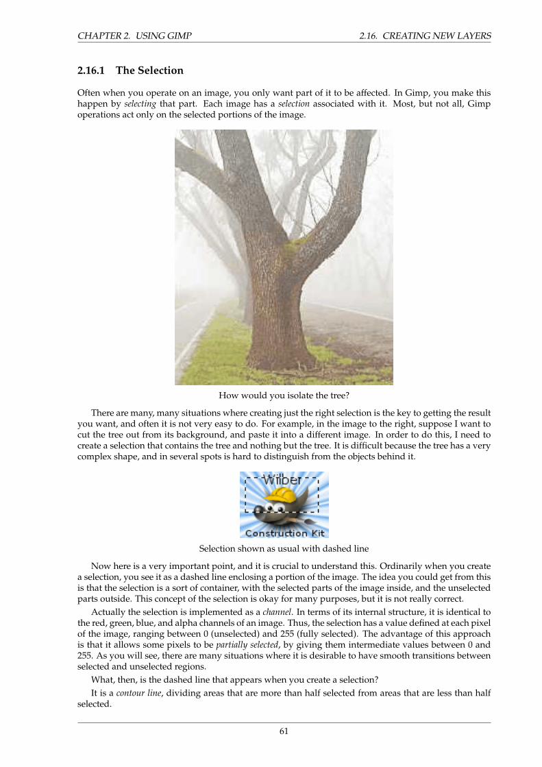
CHAPTER 2. USING GIMP 2.16. CREATING NEW LAYERS
2.16.1 The Selection
Often when you operate on an image, you only want part of it to be affected. In Gimp, you make thishappen by selecting that part. Each image has a selection associated with it. Most, but not all, Gimpoperations act only on the selected portions of the image.
How would you isolate the tree?
There are many, many situations where creating just the right selection is the key to getting the resultyou want, and often it is not very easy to do. For example, in the image to the right, suppose I want tocut the tree out from its background, and paste it into a different image. In order to do this, I need tocreate a selection that contains the tree and nothing but the tree. It is difficult because the tree has a verycomplex shape, and in several spots is hard to distinguish from the objects behind it.
Selection shown as usual with dashed line
Now here is a very important point, and it is crucial to understand this. Ordinarily when you createa selection, you see it as a dashed line enclosing a portion of the image. The idea you could get from thisis that the selection is a sort of container, with the selected parts of the image inside, and the unselectedparts outside. This concept of the selection is okay for many purposes, but it is not really correct.
Actually the selection is implemented as a channel. In terms of its internal structure, it is identical tothe red, green, blue, and alpha channels of an image. Thus, the selection has a value defined at each pixelof the image, ranging between 0 (unselected) and 255 (fully selected). The advantage of this approachis that it allows some pixels to be partially selected, by giving them intermediate values between 0 and255. As you will see, there are many situations where it is desirable to have smooth transitions betweenselected and unselected regions.
What, then, is the dashed line that appears when you create a selection?It is a contour line, dividing areas that are more than half selected from areas that are less than half
selected.
61
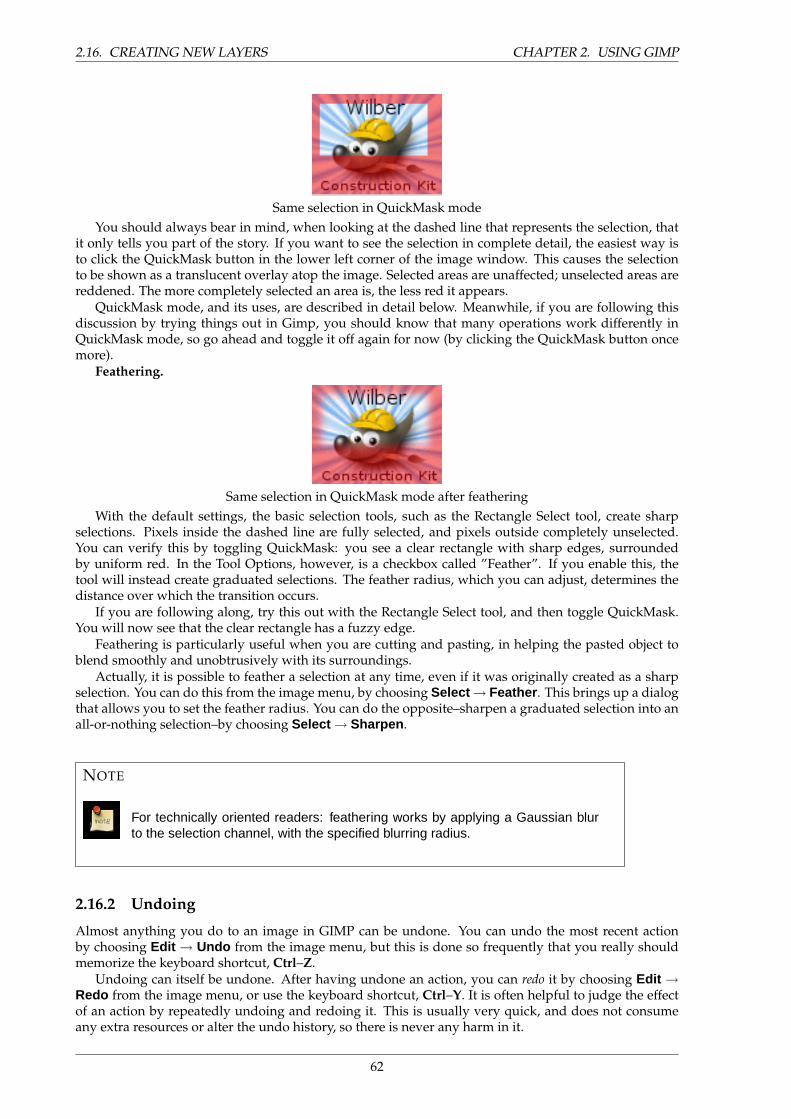
2.16. CREATING NEW LAYERS CHAPTER 2. USING GIMP
Same selection in QuickMask modeYou should always bear in mind, when looking at the dashed line that represents the selection, that
it only tells you part of the story. If you want to see the selection in complete detail, the easiest way isto click the QuickMask button in the lower left corner of the image window. This causes the selectionto be shown as a translucent overlay atop the image. Selected areas are unaffected; unselected areas arereddened. The more completely selected an area is, the less red it appears.
QuickMask mode, and its uses, are described in detail below. Meanwhile, if you are following thisdiscussion by trying things out in Gimp, you should know that many operations work differently inQuickMask mode, so go ahead and toggle it off again for now (by clicking the QuickMask button oncemore).
Feathering.
Same selection in QuickMask mode after featheringWith the default settings, the basic selection tools, such as the Rectangle Select tool, create sharp
selections. Pixels inside the dashed line are fully selected, and pixels outside completely unselected.You can verify this by toggling QuickMask: you see a clear rectangle with sharp edges, surroundedby uniform red. In the Tool Options, however, is a checkbox called ”Feather”. If you enable this, thetool will instead create graduated selections. The feather radius, which you can adjust, determines thedistance over which the transition occurs.
If you are following along, try this out with the Rectangle Select tool, and then toggle QuickMask.You will now see that the clear rectangle has a fuzzy edge.
Feathering is particularly useful when you are cutting and pasting, in helping the pasted object toblend smoothly and unobtrusively with its surroundings.
Actually, it is possible to feather a selection at any time, even if it was originally created as a sharpselection. You can do this from the image menu, by choosing Select → Feather . This brings up a dialogthat allows you to set the feather radius. You can do the opposite–sharpen a graduated selection into anall-or-nothing selection–by choosing Select → Sharpen .
NOTE
For technically oriented readers: feathering works by applying a Gaussian blurto the selection channel, with the specified blurring radius.
2.16.2 Undoing
Almost anything you do to an image in GIMP can be undone. You can undo the most recent actionby choosing Edit → Undo from the image menu, but this is done so frequently that you really shouldmemorize the keyboard shortcut, Ctrl–Z.
Undoing can itself be undone. After having undone an action, you can redo it by choosing Edit →Redo from the image menu, or use the keyboard shortcut, Ctrl–Y. It is often helpful to judge the effectof an action by repeatedly undoing and redoing it. This is usually very quick, and does not consumeany extra resources or alter the undo history, so there is never any harm in it.
62
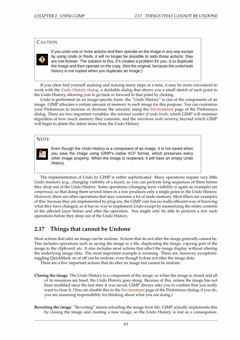
CHAPTER 2. USING GIMP 2.17. THINGS THAT CANNOT BE UNDONE
CAUTION
If you undo one or more actions and then operate on the image in any way exceptby using Undo or Redo, it will no longer be possible to redo those actions: theyare lost forever. The solution to this, if it creates a problem for you, is to duplicatethe image and then operate on the copy. (Not the original, because the undo/redohistory is not copied when you duplicate an image.)
If you often find yourself undoing and redoing many steps at a time, it may be more convenient towork with the Undo History dialog, a dockable dialog that shows you a small sketch of each point inthe Undo History, allowing you to go back or forward to that point by clicking.
Undo is performed on an image-specific basis: the ”Undo History” is one of the components of animage. GIMP allocates a certain amount of memory to each image for this purpose. You can customizeyour Preferences to increase or decrease the amount, using the Environment page of the Preferencesdialog. There are two important variables: the minimal number of undo levels, which GIMP will maintainregardless of how much memory they consume, and the maximum undo memory, beyond which GIMPwill begin to delete the oldest items from the Undo History.
NOTE
Even though the Undo History is a component of an image, it is not saved whenyou save the image using GIMP’s native XCF format, which preserves everyother image property. When the image is reopened, it will have an empty UndoHistory.
The implementation of Undo by GIMP is rather sophisticated. Many operations require very littleUndo memory (e.g., changing visibility of a layer), so you can perform long sequences of them beforethey drop out of the Undo History. Some operations (changing layer visibility is again an example) arecompressed, so that doing them several times in a row produces only a single point in the Undo History.However, there are other operations that may consume a lot of undo memory. Most filters are examplesof this: because they are implemented by plug-ins, the GIMP core has no really efficient way of knowingwhat they have changed, so it has no way to implement Undo except by memorizing the entire contentsof the affected layer before and after the operation. You might only be able to perform a few suchoperations before they drop out of the Undo History.
2.17 Things that cannot be Undone
Most actions that alter an image can be undone. Actions that do not alter the image generally cannot be.This includes operations such as saving the image to a file, duplicating the image, copying part of theimage to the clipboard, etc. It also includes most actions that affect the image display without alteringthe underlying image data. The most important example is zooming. There are, however, exceptions:toggling QuickMask on or off can be undone, even though it does not alter the image data.
There are a few important actions that do alter an image but cannot be undone:
Closing the image The Undo History is a component of the image, so when the image is closed and allof its resources are freed, the Undo History goes along. Because of this, unless the image has notbeen modified since the last time it was saved, GIMP always asks you to confirm that you reallywant to close it. (You can disable this in the Environment page of the Preferences dialog; if you do,you are assuming responsibility for thinking about what you are doing.)
Reverting the image ”Reverting” means reloading the image from file. GIMP actually implements thisby closing the image and creating a new image, so the Undo History is lost as a consequence.
63
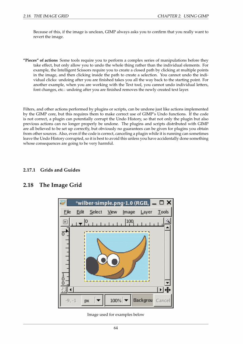
2.18. THE IMAGE GRID CHAPTER 2. USING GIMP
Because of this, if the image is unclean, GIMP always asks you to confirm that you really want torevert the image.
”Pieces” of actions Some tools require you to perform a complex series of manipulations before theytake effect, but only allow you to undo the whole thing rather than the individual elements. Forexample, the Intelligent Scissors require you to create a closed path by clicking at multiple pointsin the image, and then clicking inside the path to create a selection. You cannot undo the indi-vidual clicks: undoing after you are finished takes you all the way back to the starting point. Foranother example, when you are working with the Text tool, you cannot undo individual letters,font changes, etc.: undoing after you are finished removes the newly created text layer.
Filters, and other actions performed by plugins or scripts, can be undone just like actions implementedby the GIMP core, but this requires them to make correct use of GIMP’s Undo functions. If the codeis not correct, a plugin can potentially corrupt the Undo History, so that not only the plugin but alsoprevious actions can no longer properly be undone. The plugins and scripts distributed with GIMPare all believed to be set up correctly, but obviously no guarantees can be given for plugins you obtainfrom other sources. Also, even if the code is correct, canceling a plugin while it is running can sometimesleave the Undo History corrupted, so it is best to avoid this unless you have accidentally done somethingwhose consequences are going to be very harmful.
2.17.1 Grids and Guides
2.18 The Image Grid
Image used for examples below
64
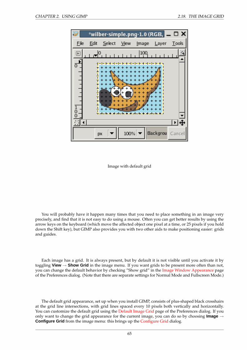
CHAPTER 2. USING GIMP 2.18. THE IMAGE GRID
Image with default grid
You will probably have it happen many times that you need to place something in an image veryprecisely, and find that it is not easy to do using a mouse. Often you can get better results by using thearrow keys on the keyboard (which move the affected object one pixel at a time, or 25 pixels if you holddown the Shift key), but GIMP also provides you with two other aids to make positioning easier: gridsand guides.
Each image has a grid. It is always present, but by default it is not visible until you activate it bytoggling View → Show Grid in the image menu. If you want grids to be present more often than not,you can change the default behavior by checking ”Show grid” in the Image Window Appearance pageof the Preferences dialog. (Note that there are separate settings for Normal Mode and Fullscreen Mode.)
The default grid appearance, set up when you install GIMP, consists of plus-shaped black crosshairsat the grid line intersections, with grid lines spaced every 10 pixels both vertically and horizontally.You can customize the default grid using the Default Image Grid page of the Preferences dialog. If youonly want to change the grid appearance for the current image, you can do so by choosing Image →Configure Grid from the image menu: this brings up the Configure Grid dialog.
65
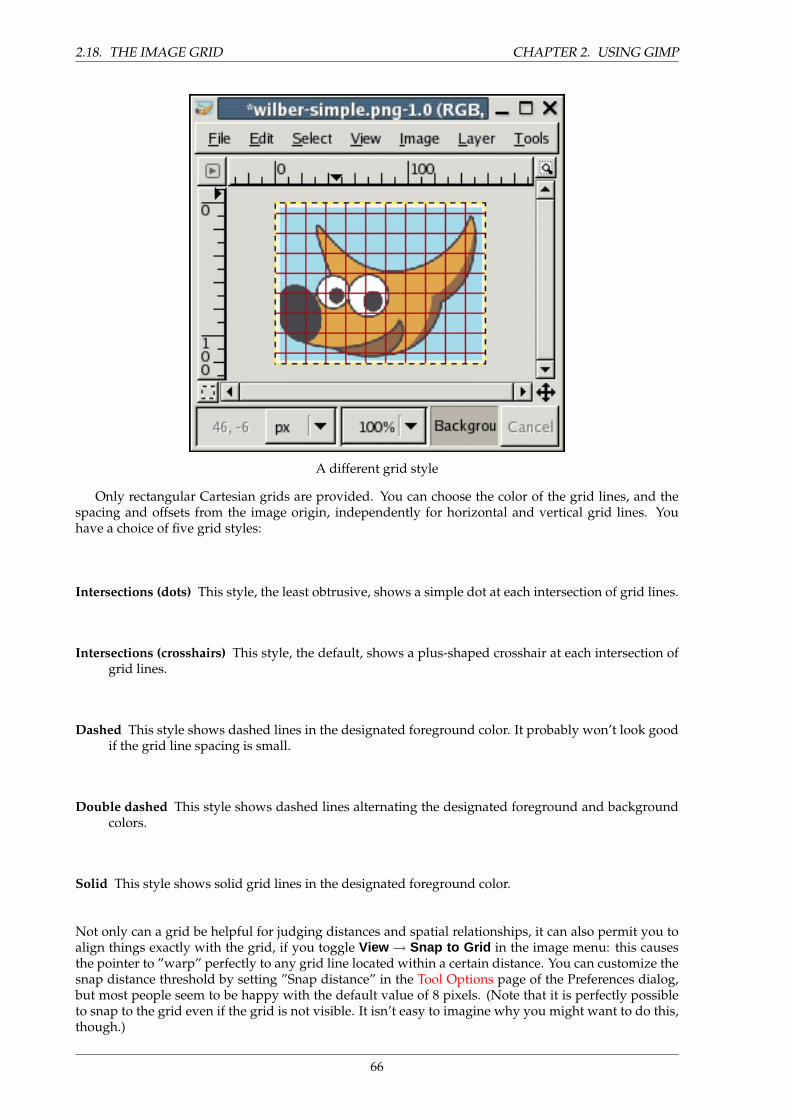
2.18. THE IMAGE GRID CHAPTER 2. USING GIMP
A different grid style
Only rectangular Cartesian grids are provided. You can choose the color of the grid lines, and thespacing and offsets from the image origin, independently for horizontal and vertical grid lines. Youhave a choice of five grid styles:
Intersections (dots) This style, the least obtrusive, shows a simple dot at each intersection of grid lines.
Intersections (crosshairs) This style, the default, shows a plus-shaped crosshair at each intersection ofgrid lines.
Dashed This style shows dashed lines in the designated foreground color. It probably won’t look goodif the grid line spacing is small.
Double dashed This style shows dashed lines alternating the designated foreground and backgroundcolors.
Solid This style shows solid grid lines in the designated foreground color.
Not only can a grid be helpful for judging distances and spatial relationships, it can also permit you toalign things exactly with the grid, if you toggle View → Snap to Grid in the image menu: this causesthe pointer to ”warp” perfectly to any grid line located within a certain distance. You can customize thesnap distance threshold by setting ”Snap distance” in the Tool Options page of the Preferences dialog,but most people seem to be happy with the default value of 8 pixels. (Note that it is perfectly possibleto snap to the grid even if the grid is not visible. It isn’t easy to imagine why you might want to do this,though.)
66
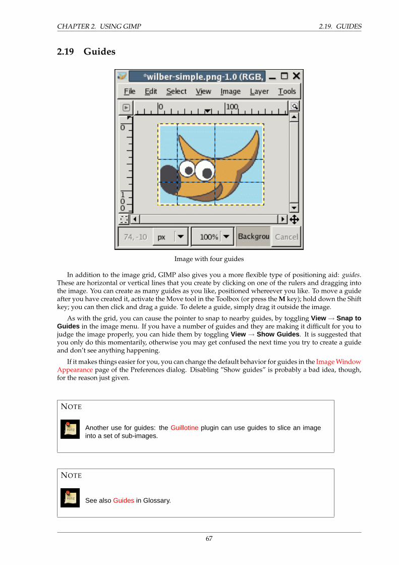
CHAPTER 2. USING GIMP 2.19. GUIDES
2.19 Guides
Image with four guides
In addition to the image grid, GIMP also gives you a more flexible type of positioning aid: guides.These are horizontal or vertical lines that you create by clicking on one of the rulers and dragging intothe image. You can create as many guides as you like, positioned whereever you like. To move a guideafter you have created it, activate the Move tool in the Toolbox (or press the M key); hold down the Shiftkey; you can then click and drag a guide. To delete a guide, simply drag it outside the image.
As with the grid, you can cause the pointer to snap to nearby guides, by toggling View → Snap toGuides in the image menu. If you have a number of guides and they are making it difficult for you tojudge the image properly, you can hide them by toggling View → Show Guides . It is suggested thatyou only do this momentarily, otherwise you may get confused the next time you try to create a guideand don’t see anything happening.
If it makes things easier for you, you can change the default behavior for guides in the Image WindowAppearance page of the Preferences dialog. Disabling ”Show guides” is probably a bad idea, though,for the reason just given.
NOTE
Another use for guides: the Guillotine plugin can use guides to slice an imageinto a set of sub-images.
NOTE
See also Guides in Glossary.
67

2.20. RENDERING A GRID CHAPTER 2. USING GIMP
2.20 Rendering a Grid
What if you want to create a grid that is actually part of the image? You can’t do this using the imagegrid: it is only an aid, and only visible on the monitor or in a screenshot. You can, however, use theGrid plugin to render a grid very similar to the image grid (actually the plugin has substantially moreoptions).
2.20.1 Paths
Four examples of GIMP paths: one closed and polygonal; one open and polygonal; one closed andcurved; one with a mixture of straight and curved segments.
A path is a one-dimensional curve. Paths are used for two main purposes:
• A closed path can be converted into a selection.
• An open or closed path can be stroked, that is, painted on the image, in a variety of ways.
Paths can be created and manipulated using the Path tool. Paths, like layers and channels, are compo-nents of an image. When an image is saved in GIMP’s native XCF file format, any paths it has are savedalong with it. The list of paths in an image can be viewed and operated on using the Paths dialog. If youwant to move a path from one image to another, you can do so by copying and pasting using the popupmenu in the Paths dialog, or by dragging an icon from the Paths dialog into the destination image’swindow.
68
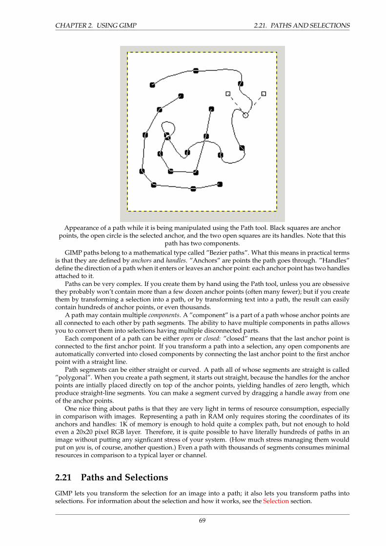
CHAPTER 2. USING GIMP 2.21. PATHS AND SELECTIONS
Appearance of a path while it is being manipulated using the Path tool. Black squares are anchorpoints, the open circle is the selected anchor, and the two open squares are its handles. Note that this
path has two components.GIMP paths belong to a mathematical type called ”Bezier paths”. What this means in practical terms
is that they are defined by anchors and handles. ”Anchors” are points the path goes through. ”Handles”define the direction of a path when it enters or leaves an anchor point: each anchor point has two handlesattached to it.
Paths can be very complex. If you create them by hand using the Path tool, unless you are obsessivethey probably won’t contain more than a few dozen anchor points (often many fewer); but if you createthem by transforming a selection into a path, or by transforming text into a path, the result can easilycontain hundreds of anchor points, or even thousands.
A path may contain multiple components. A ”component” is a part of a path whose anchor points areall connected to each other by path segments. The ability to have multiple components in paths allowsyou to convert them into selections having multiple disconnected parts.
Each component of a path can be either open or closed: ”closed” means that the last anchor point isconnected to the first anchor point. If you transform a path into a selection, any open components areautomatically converted into closed components by connecting the last anchor point to the first anchorpoint with a straight line.
Path segments can be either straight or curved. A path all of whose segments are straight is called”polygonal”. When you create a path segment, it starts out straight, because the handles for the anchorpoints are intially placed directly on top of the anchor points, yielding handles of zero length, whichproduce straight-line segments. You can make a segment curved by dragging a handle away from oneof the anchor points.
One nice thing about paths is that they are very light in terms of resource consumption, especiallyin comparison with images. Representing a path in RAM only requires storing the coordinates of itsanchors and handles: 1K of memory is enough to hold quite a complex path, but not enough to holdeven a 20x20 pixel RGB layer. Therefore, it is quite possible to have literally hundreds of paths in animage without putting any signficant stress of your system. (How much stress managing them wouldput on you is, of course, another question.) Even a path with thousands of segments consumes minimalresources in comparison to a typical layer or channel.
2.21 Paths and Selections
GIMP lets you transform the selection for an image into a path; it also lets you transform paths intoselections. For information about the selection and how it works, see the Selection section.
69
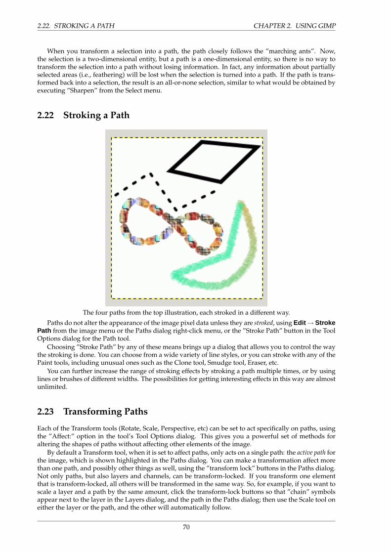
2.22. STROKING A PATH CHAPTER 2. USING GIMP
When you transform a selection into a path, the path closely follows the ”marching ants”. Now,the selection is a two-dimensional entity, but a path is a one-dimensional entity, so there is no way totransform the selection into a path without losing information. In fact, any information about partiallyselected areas (i.e., feathering) will be lost when the selection is turned into a path. If the path is trans-formed back into a selection, the result is an all-or-none selection, similar to what would be obtained byexecuting ”Sharpen” from the Select menu.
2.22 Stroking a Path
The four paths from the top illustration, each stroked in a different way.
Paths do not alter the appearance of the image pixel data unless they are stroked, using Edit → StrokePath from the image menu or the Paths dialog right-click menu, or the ”Stroke Path” button in the ToolOptions dialog for the Path tool.
Choosing ”Stroke Path” by any of these means brings up a dialog that allows you to control the waythe stroking is done. You can choose from a wide variety of line styles, or you can stroke with any of thePaint tools, including unusual ones such as the Clone tool, Smudge tool, Eraser, etc.
You can further increase the range of stroking effects by stroking a path multiple times, or by usinglines or brushes of different widths. The possibilities for getting interesting effects in this way are almostunlimited.
2.23 Transforming Paths
Each of the Transform tools (Rotate, Scale, Perspective, etc) can be set to act specifically on paths, usingthe ”Affect:” option in the tool’s Tool Options dialog. This gives you a powerful set of methods foraltering the shapes of paths without affecting other elements of the image.
By default a Transform tool, when it is set to affect paths, only acts on a single path: the active path forthe image, which is shown highlighted in the Paths dialog. You can make a transformation affect morethan one path, and possibly other things as well, using the ”transform lock” buttons in the Paths dialog.Not only paths, but also layers and channels, can be transform-locked. If you transform one elementthat is transform-locked, all others will be transformed in the same way. So, for example, if you want toscale a layer and a path by the same amount, click the transform-lock buttons so that ”chain” symbolsappear next to the layer in the Layers dialog, and the path in the Paths dialog; then use the Scale tool oneither the layer or the path, and the other will automatically follow.
70
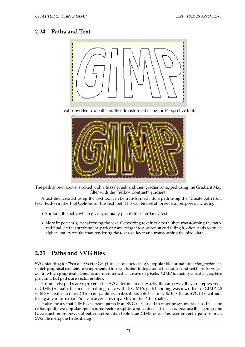
CHAPTER 2. USING GIMP 2.24. PATHS AND TEXT
2.24 Paths and Text
Text converted to a path and then transformed using the Perspective tool.
The path shown above, stroked with a fuzzy brush and then gradient-mapped using the Gradient Mapfilter with the ”Yellow Contrast” gradient.
A text item created using the Text tool can be transformed into a path using the ”Create path fromtext” button in the Tool Options for the Text tool. This can be useful for several purposes, including:
• Stroking the path, which gives you many possibilities for fancy text.
• More importantly, transforming the text. Converting text into a path, then transforming the path,and finally either stroking the path or converting it to a selection and filling it, often leads to muchhigher-quality results than rendering the text as a layer and transforming the pixel data.
2.25 Paths and SVG files
SVG, standing for ”Scalable Vector Graphics”, is an increasingly popular file format for vector graphics, inwhich graphical elements are represented in a resolution-independent format, in contrast to raster graph-ics, in which graphical elements are represented as arrays of pixels. GIMP is mainly a raster graphicsprogram, but paths are vector entities.
Fortunately, paths are represented in SVG files in almost exactly the same way they are representedin GIMP. (Actually fortune has nothing to do with it: GIMP’s path handling was rewritten for GIMP 2.0with SVG paths in mind.) This compatibility makes it possible to store GIMP paths as SVG files withoutlosing any information. You can access this capability in the Paths dialog.
It also means that GIMP can create paths from SVG files saved in other programs, such as Inkscapeor Sodipodi, two popular open-source vector graphics applications. This is nice because those programshave much more powerful path-manipulation tools than GIMP does. You can import a path from anSVG file using the Paths dialog.
71
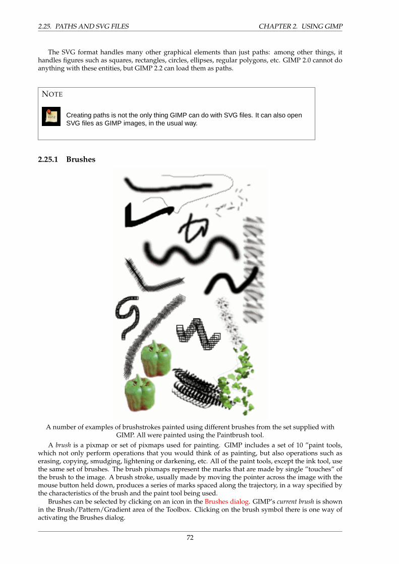
2.25. PATHS AND SVG FILES CHAPTER 2. USING GIMP
The SVG format handles many other graphical elements than just paths: among other things, ithandles figures such as squares, rectangles, circles, ellipses, regular polygons, etc. GIMP 2.0 cannot doanything with these entities, but GIMP 2.2 can load them as paths.
NOTE
Creating paths is not the only thing GIMP can do with SVG files. It can also openSVG files as GIMP images, in the usual way.
2.25.1 Brushes
A number of examples of brushstrokes painted using different brushes from the set supplied withGIMP. All were painted using the Paintbrush tool.
A brush is a pixmap or set of pixmaps used for painting. GIMP includes a set of 10 ”paint tools,which not only perform operations that you would think of as painting, but also operations such aserasing, copying, smudging, lightening or darkening, etc. All of the paint tools, except the ink tool, usethe same set of brushes. The brush pixmaps represent the marks that are made by single ”touches” ofthe brush to the image. A brush stroke, usually made by moving the pointer across the image with themouse button held down, produces a series of marks spaced along the trajectory, in a way specified bythe characteristics of the brush and the paint tool being used.
Brushes can be selected by clicking on an icon in the Brushes dialog. GIMP’s current brush is shownin the Brush/Pattern/Gradient area of the Toolbox. Clicking on the brush symbol there is one way ofactivating the Brushes dialog.
72
CHAPTER 2. USING GIMP 2.25. PATHS AND SVG FILES
When you install GIMP, it comes presupplied with a number of basic brushes, plus a few bizarreones that serve mainly to give you examples of what is possible (i. e., the ”green pepper” brush in theillustration). You can also create new brushes, or download them and install them so that GIMP willrecognize them.
GIMP can use several different types of brushes. All of them, however, are used in the same way,and for most purposes you don’t need to be aware of the differences when you paint with them. Hereare the available types of brushes:
Ordinary brushes Most of the brushes supplied with GIMP fall into this category. They are representedin the Brushes dialog by grayscale pixmaps. When you paint using them, the current foregroundcolor (as shown in the Color Area of the Toolbox) is substituted for black, and the pixmap shownin the brushes dialog represents the mark that the brush makes on the image.
To create such a brush: Create a small image in gray levels using zoom. Save it with the .gbr exten-sion. Click on Refresh button in the Brush Dialog to get it in preview without it being necessary torestart GIMP.
Color brushes Brushes in this category are represented by colored images in the Brushes dialog. Theycan be a text. When you paint with them, the colors are used as shown; the current foregroundcolor does not come into play. Otherwise they work the same way as ordinary brushes.
To create such a brush, create a small RGBA image. For this, open New Image, select RGB forimage type and Transparent for fill type. Draw your image and save it first to .xcf file to keep itsproperties. Then save it to .gbr format. Click on Refresh button in Brush Dialog to get your brushwithout it being necessary to restart Gimp.
TIP
You can transform a selection to a brush by using the Selection/To Brushscript-fu.
Image hoses / Image pipes Brushes in this category can make more than one kind of mark on an im-age. They are indicated by small red triangles at th lower right corner of the brush symbol in theBrushes dialog. They are sometimes called ”animated brushes” because the marks change as youtrace out a brushstroke. In principle, image hose brushes can be very sophisticated, especially ifyou use a tablet, changing shape as a function of pressure, angle, etc. These possibilities havenever really been exploited, however; and the ones supplied with GIMP are relatively simple (butstill quite useful).
Parametric brushes These are brushes created using the Brush Editor, which allows you to generate awide variety of brush shapes by using a simple graphical interface. A nice feature of parametricbrushes is that they are resizable. In GIMP 2.2, it is possible, using the Preferences dialog, to makekey presses or mouse wheel rotations cause the current brush to become larger or smaller, if it is aparametric brush.
One category that GIMP does not have is full-fledged procedural brushes: brushes whose marks are cal-culated procedurally, instead of being taken from a fixed pixmap. (Actually this is not quite correct: theInk tool uses a procedural brush, but it is the only one available in GIMP.) A more extensive implemen-tation of procedural brushes is a goal of future development for GIMP.
In addition to the brush pixmap, each GIMP brush has one other important property: the brushSpacing. This represents the distance between consecutive brush-marks when a continuous brushstrokeis painted. Each brush has an assigned default value for this, which can be modified using the Brushesdialog.
73
2.26. ADDING NEW BRUSHES CHAPTER 2. USING GIMP
2.26 Adding New Brushes
To add a new brush, after either creating it or downloading it, so that it shows up in the Brushes dialog,you need to save it in a format GIMP can use, in a folder included in GIMP’s brush search path, then toRefresh the Brush Dialog (or re-start GIMP). GIMP uses three file formats for brushes:
GBR The .gbr (”gimp brush”) format is used for ordinary and color brushes. You can convert manyother types of images, including many brushes used by other programs, into GIMP brushes byopening them in GIMP and saving them with file names ending in .gbr . This brings up a dialogbox in which you can set the default Spacing for the brush. A more complete description of theGBR file format can be found in the file gbr.txt in the devel-docs directory of the GIMP sourcedistribution.
GIH The .gih (”gimp image hose”) format is used for animated brushes. These brushes are constructedfrom images containing multiple layers: each layer may contain multiple brush-shapes, arrangedin a grid. When you save an image as a .gih file, a dialog comes up that allows you to describe theformat of the brush. The GIH format is rather complicated: a complete description can be foundin the file gih.txt in the devel-docs directory of the GIMP source distribution. See The GIHdialog box
VBR The .vbr format is used for parametric brushes, i. e., brushes created using the Brush Editor.There is really no other meaningful way of obtaining files in this format.
Le format .vbr est utilise pour les brosses parametriques, cad les brosses creees avec l’Editeur debrosse. Il n’y a vraiment pas d’autre facon valable d’obtenir les fichiers de ce format.
To make a brush available, place it in one of the folders in GIMP’s brush search path. By default, thebrush search path includes two folders, the system brushes folder, which you should not use or alter,and the brushes folder inside your personal GIMP directory. You can add new folders to the brushsearch path using the Brush Folders page of the Preferences dialog. Any GBR, GIH, or VBR file includedin a folder in the brush search path will show up in the Brushes dialog the next time you start GIMP, oras soon as you press the Refresh button in the Brushes dialog.
NOTE
When you create a new parametric brush using the Brush Editor, it is automati-cally saved in your personal brushes folder.
There are a number of web sites with downloadable collections of GIMP brushes. Rather than sup-plying a list of links that will soon be out of date, the best advice is to do a Google search for ”Gimpbrushes”. There are also many collections of brushes for other programs with painting functionality.Some can be converted easily into GIMP brushes, some require special conversion utilities, and somecannot be converted at all. Most fancy procedural brush types fall into the last category. If you need toknow, look around on the web, and if you don’t find anything, look for an expert to ask.
2.27 The GIH dialog box
This dialog box has several options not easy to understand. They allow you to determine the way yourbrush is animated.
Spacing (Percent) ”Spacing” is the distance between consecutive brush marks when you trace out abrushstroke with the pointer. You must consider drawing with a brush, whatever the paint tool,like stamping. If Spacing is low, stamps will be very close and stroke look continuous. If spacing
74
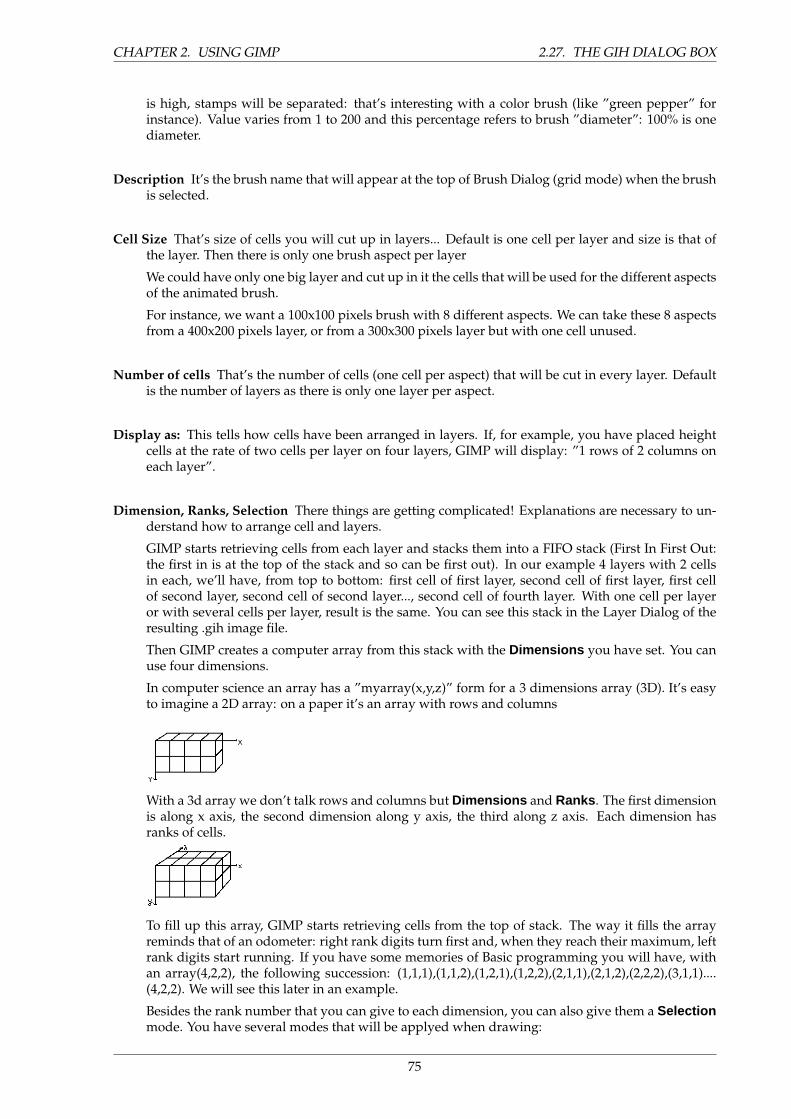
CHAPTER 2. USING GIMP 2.27. THE GIH DIALOG BOX
is high, stamps will be separated: that’s interesting with a color brush (like ”green pepper” forinstance). Value varies from 1 to 200 and this percentage refers to brush ”diameter”: 100% is onediameter.
Description It’s the brush name that will appear at the top of Brush Dialog (grid mode) when the brushis selected.
Cell Size That’s size of cells you will cut up in layers... Default is one cell per layer and size is that ofthe layer. Then there is only one brush aspect per layer
We could have only one big layer and cut up in it the cells that will be used for the different aspectsof the animated brush.
For instance, we want a 100x100 pixels brush with 8 different aspects. We can take these 8 aspectsfrom a 400x200 pixels layer, or from a 300x300 pixels layer but with one cell unused.
Number of cells That’s the number of cells (one cell per aspect) that will be cut in every layer. Defaultis the number of layers as there is only one layer per aspect.
Display as: This tells how cells have been arranged in layers. If, for example, you have placed heightcells at the rate of two cells per layer on four layers, GIMP will display: ”1 rows of 2 columns oneach layer”.
Dimension, Ranks, Selection There things are getting complicated! Explanations are necessary to un-derstand how to arrange cell and layers.
GIMP starts retrieving cells from each layer and stacks them into a FIFO stack (First In First Out:the first in is at the top of the stack and so can be first out). In our example 4 layers with 2 cellsin each, we’ll have, from top to bottom: first cell of first layer, second cell of first layer, first cellof second layer, second cell of second layer..., second cell of fourth layer. With one cell per layeror with several cells per layer, result is the same. You can see this stack in the Layer Dialog of theresulting .gih image file.
Then GIMP creates a computer array from this stack with the Dimensions you have set. You canuse four dimensions.
In computer science an array has a ”myarray(x,y,z)” form for a 3 dimensions array (3D). It’s easyto imagine a 2D array: on a paper it’s an array with rows and columns
With a 3d array we don’t talk rows and columns but Dimensions and Ranks . The first dimensionis along x axis, the second dimension along y axis, the third along z axis. Each dimension hasranks of cells.
To fill up this array, GIMP starts retrieving cells from the top of stack. The way it fills the arrayreminds that of an odometer: right rank digits turn first and, when they reach their maximum, leftrank digits start running. If you have some memories of Basic programming you will have, withan array(4,2,2), the following succession: (1,1,1),(1,1,2),(1,2,1),(1,2,2),(2,1,1),(2,1,2),(2,2,2),(3,1,1)....(4,2,2). We will see this later in an example.
Besides the rank number that you can give to each dimension, you can also give them a Selectionmode. You have several modes that will be applyed when drawing:
75
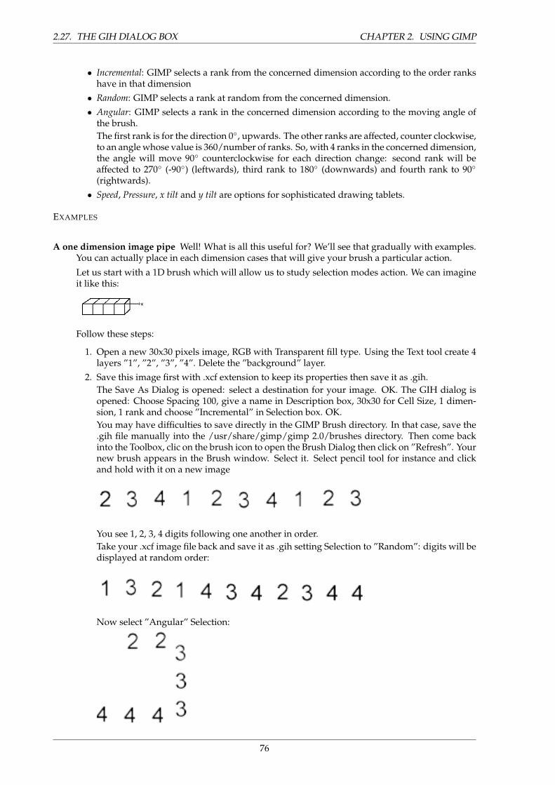
2.27. THE GIH DIALOG BOX CHAPTER 2. USING GIMP
• Incremental: GIMP selects a rank from the concerned dimension according to the order rankshave in that dimension
• Random: GIMP selects a rank at random from the concerned dimension.• Angular: GIMP selects a rank in the concerned dimension according to the moving angle of
the brush.The first rank is for the direction 0◦, upwards. The other ranks are affected, counter clockwise,to an angle whose value is 360/number of ranks. So, with 4 ranks in the concerned dimension,the angle will move 90◦ counterclockwise for each direction change: second rank will beaffected to 270◦ (-90◦) (leftwards), third rank to 180◦ (downwards) and fourth rank to 90◦
(rightwards).• Speed, Pressure, x tilt and y tilt are options for sophisticated drawing tablets.
EXAMPLES
A one dimension image pipe Well! What is all this useful for? We’ll see that gradually with examples.You can actually place in each dimension cases that will give your brush a particular action.
Let us start with a 1D brush which will allow us to study selection modes action. We can imagineit like this:
Follow these steps:
1. Open a new 30x30 pixels image, RGB with Transparent fill type. Using the Text tool create 4layers ”1”, ”2”, ”3”, ”4”. Delete the ”background” layer.
2. Save this image first with .xcf extension to keep its properties then save it as .gih.The Save As Dialog is opened: select a destination for your image. OK. The GIH dialog isopened: Choose Spacing 100, give a name in Description box, 30x30 for Cell Size, 1 dimen-sion, 1 rank and choose ”Incremental” in Selection box. OK.You may have difficulties to save directly in the GIMP Brush directory. In that case, save the.gih file manually into the /usr/share/gimp/gimp 2.0/brushes directory. Then come backinto the Toolbox, clic on the brush icon to open the Brush Dialog then click on ”Refresh”. Yournew brush appears in the Brush window. Select it. Select pencil tool for instance and clickand hold with it on a new image
You see 1, 2, 3, 4 digits following one another in order.Take your .xcf image file back and save it as .gih setting Selection to ”Random”: digits will bedisplayed at random order:
Now select ”Angular” Selection:
76
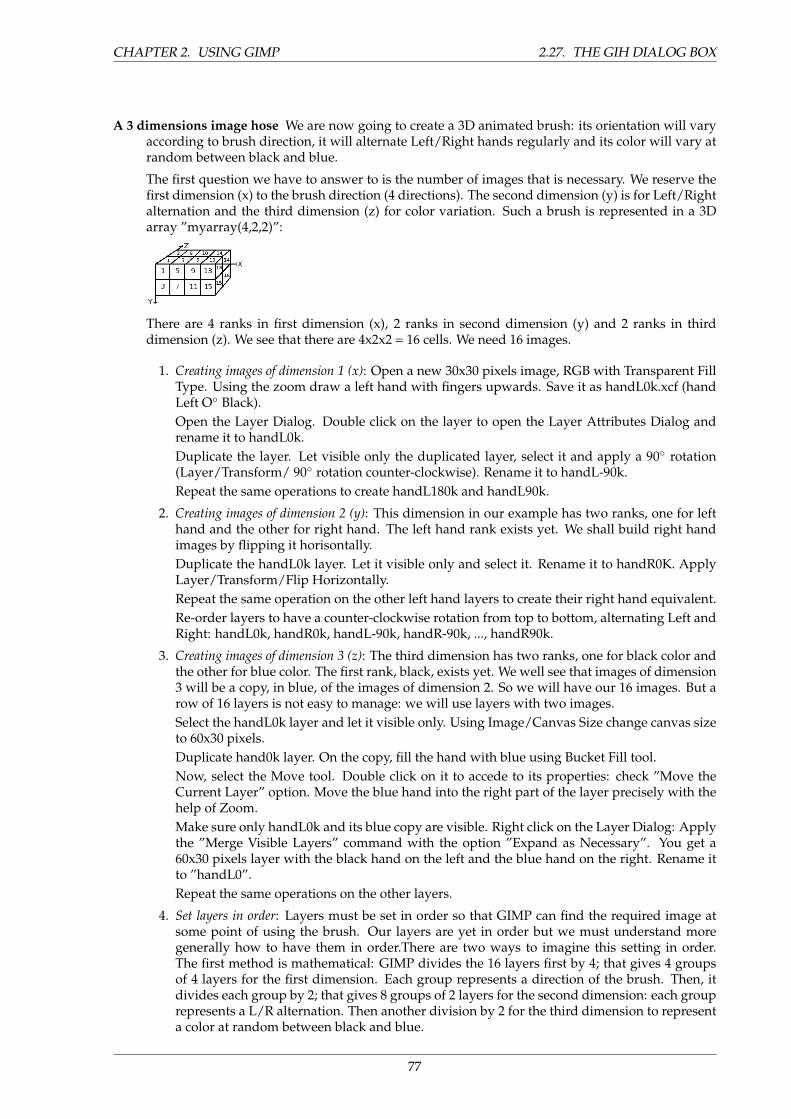
CHAPTER 2. USING GIMP 2.27. THE GIH DIALOG BOX
A 3 dimensions image hose We are now going to create a 3D animated brush: its orientation will varyaccording to brush direction, it will alternate Left/Right hands regularly and its color will vary atrandom between black and blue.
The first question we have to answer to is the number of images that is necessary. We reserve thefirst dimension (x) to the brush direction (4 directions). The second dimension (y) is for Left/Rightalternation and the third dimension (z) for color variation. Such a brush is represented in a 3Darray ”myarray(4,2,2)”:
There are 4 ranks in first dimension (x), 2 ranks in second dimension (y) and 2 ranks in thirddimension (z). We see that there are 4x2x2 = 16 cells. We need 16 images.
1. Creating images of dimension 1 (x): Open a new 30x30 pixels image, RGB with Transparent FillType. Using the zoom draw a left hand with fingers upwards. Save it as handL0k.xcf (handLeft O◦ Black).Open the Layer Dialog. Double click on the layer to open the Layer Attributes Dialog andrename it to handL0k.Duplicate the layer. Let visible only the duplicated layer, select it and apply a 90◦ rotation(Layer/Transform/ 90◦ rotation counter-clockwise). Rename it to handL-90k.Repeat the same operations to create handL180k and handL90k.
2. Creating images of dimension 2 (y): This dimension in our example has two ranks, one for lefthand and the other for right hand. The left hand rank exists yet. We shall build right handimages by flipping it horisontally.Duplicate the handL0k layer. Let it visible only and select it. Rename it to handR0K. ApplyLayer/Transform/Flip Horizontally.Repeat the same operation on the other left hand layers to create their right hand equivalent.Re-order layers to have a counter-clockwise rotation from top to bottom, alternating Left andRight: handL0k, handR0k, handL-90k, handR-90k, ..., handR90k.
3. Creating images of dimension 3 (z): The third dimension has two ranks, one for black color andthe other for blue color. The first rank, black, exists yet. We well see that images of dimension3 will be a copy, in blue, of the images of dimension 2. So we will have our 16 images. But arow of 16 layers is not easy to manage: we will use layers with two images.Select the handL0k layer and let it visible only. Using Image/Canvas Size change canvas sizeto 60x30 pixels.Duplicate hand0k layer. On the copy, fill the hand with blue using Bucket Fill tool.Now, select the Move tool. Double click on it to accede to its properties: check ”Move theCurrent Layer” option. Move the blue hand into the right part of the layer precisely with thehelp of Zoom.Make sure only handL0k and its blue copy are visible. Right click on the Layer Dialog: Applythe ”Merge Visible Layers” command with the option ”Expand as Necessary”. You get a60x30 pixels layer with the black hand on the left and the blue hand on the right. Rename itto ”handL0”.Repeat the same operations on the other layers.
4. Set layers in order: Layers must be set in order so that GIMP can find the required image atsome point of using the brush. Our layers are yet in order but we must understand moregenerally how to have them in order.There are two ways to imagine this setting in order.The first method is mathematical: GIMP divides the 16 layers first by 4; that gives 4 groupsof 4 layers for the first dimension. Each group represents a direction of the brush. Then, itdivides each group by 2; that gives 8 groups of 2 layers for the second dimension: each grouprepresents a L/R alternation. Then another division by 2 for the third dimension to representa color at random between black and blue.
77
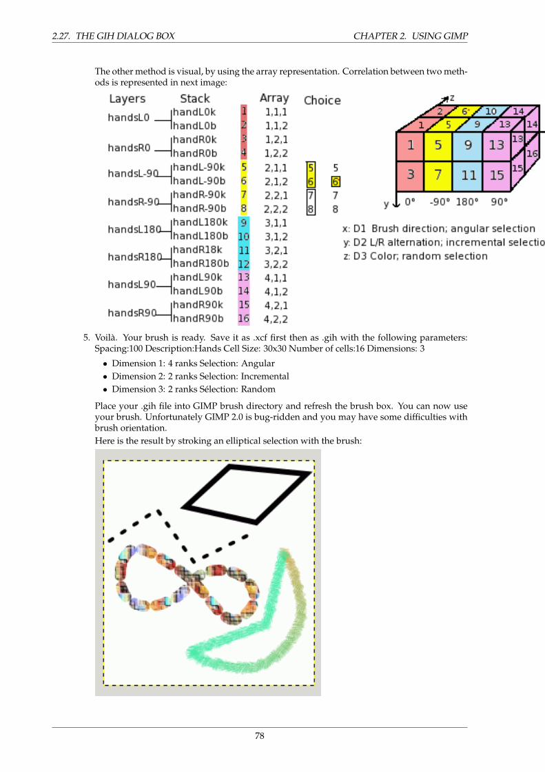
2.27. THE GIH DIALOG BOX CHAPTER 2. USING GIMP
The other method is visual, by using the array representation. Correlation between two meth-ods is represented in next image:
5. Voila. Your brush is ready. Save it as .xcf first then as .gih with the following parameters:Spacing:100 Description:Hands Cell Size: 30x30 Number of cells:16 Dimensions: 3
• Dimension 1: 4 ranks Selection: Angular• Dimension 2: 2 ranks Selection: Incremental• Dimension 3: 2 ranks Selection: Random
Place your .gih file into GIMP brush directory and refresh the brush box. You can now useyour brush. Unfortunately GIMP 2.0 is bug-ridden and you may have some difficulties withbrush orientation.Here is the result by stroking an elliptical selection with the brush:
78
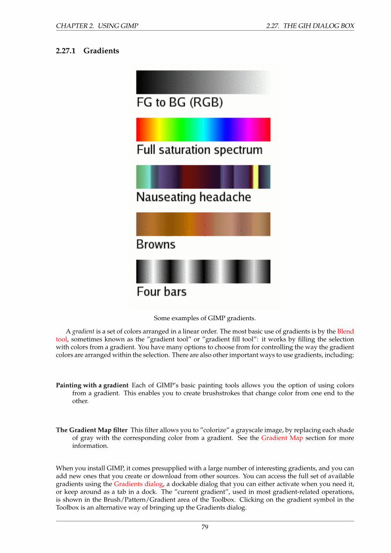
CHAPTER 2. USING GIMP 2.27. THE GIH DIALOG BOX
2.27.1 Gradients
Some examples of GIMP gradients.
A gradient is a set of colors arranged in a linear order. The most basic use of gradients is by the Blendtool, sometimes known as the ”gradient tool” or ”gradient fill tool”: it works by filling the selectionwith colors from a gradient. You have many options to choose from for controlling the way the gradientcolors are arranged within the selection. There are also other important ways to use gradients, including:
Painting with a gradient Each of GIMP’s basic painting tools allows you the option of using colorsfrom a gradient. This enables you to create brushstrokes that change color from one end to theother.
The Gradient Map filter This filter allows you to ”colorize” a grayscale image, by replacing each shadeof gray with the corresponding color from a gradient. See the Gradient Map section for moreinformation.
When you install GIMP, it comes presupplied with a large number of interesting gradients, and you canadd new ones that you create or download from other sources. You can access the full set of availablegradients using the Gradients dialog, a dockable dialog that you can either activate when you need it,or keep around as a tab in a dock. The ”current gradient”, used in most gradient-related operations,is shown in the Brush/Pattern/Gradient area of the Toolbox. Clicking on the gradient symbol in theToolbox is an alternative way of bringing up the Gradients dialog.
79
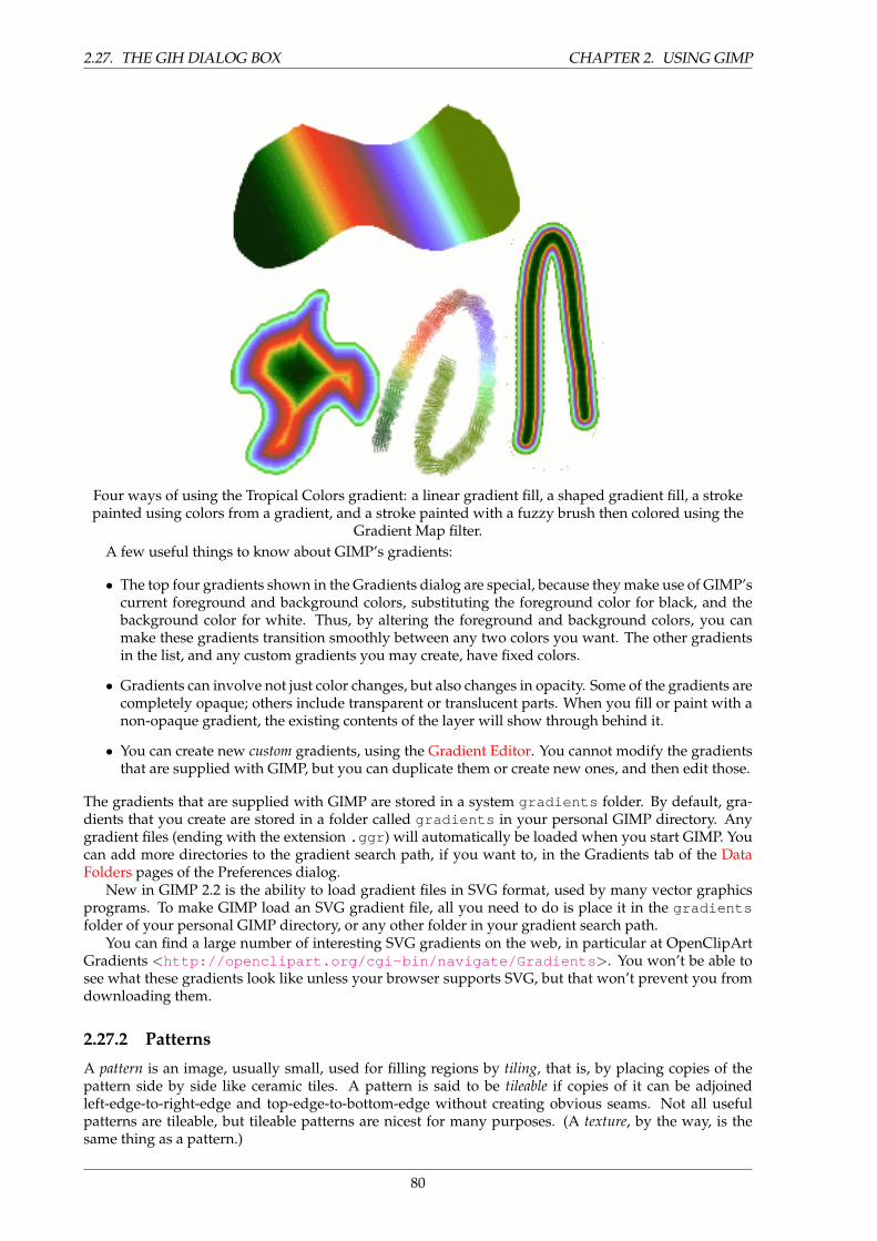
2.27. THE GIH DIALOG BOX CHAPTER 2. USING GIMP
Four ways of using the Tropical Colors gradient: a linear gradient fill, a shaped gradient fill, a strokepainted using colors from a gradient, and a stroke painted with a fuzzy brush then colored using the
Gradient Map filter.A few useful things to know about GIMP’s gradients:
• The top four gradients shown in the Gradients dialog are special, because they make use of GIMP’scurrent foreground and background colors, substituting the foreground color for black, and thebackground color for white. Thus, by altering the foreground and background colors, you canmake these gradients transition smoothly between any two colors you want. The other gradientsin the list, and any custom gradients you may create, have fixed colors.
• Gradients can involve not just color changes, but also changes in opacity. Some of the gradients arecompletely opaque; others include transparent or translucent parts. When you fill or paint with anon-opaque gradient, the existing contents of the layer will show through behind it.
• You can create new custom gradients, using the Gradient Editor. You cannot modify the gradientsthat are supplied with GIMP, but you can duplicate them or create new ones, and then edit those.
The gradients that are supplied with GIMP are stored in a system gradients folder. By default, gra-dients that you create are stored in a folder called gradients in your personal GIMP directory. Anygradient files (ending with the extension .ggr ) will automatically be loaded when you start GIMP. Youcan add more directories to the gradient search path, if you want to, in the Gradients tab of the DataFolders pages of the Preferences dialog.
New in GIMP 2.2 is the ability to load gradient files in SVG format, used by many vector graphicsprograms. To make GIMP load an SVG gradient file, all you need to do is place it in the gradientsfolder of your personal GIMP directory, or any other folder in your gradient search path.
You can find a large number of interesting SVG gradients on the web, in particular at OpenClipArtGradients <http://openclipart.org/cgi-bin/navigate/Gradients >. You won’t be able tosee what these gradients look like unless your browser supports SVG, but that won’t prevent you fromdownloading them.
2.27.2 Patterns
A pattern is an image, usually small, used for filling regions by tiling, that is, by placing copies of thepattern side by side like ceramic tiles. A pattern is said to be tileable if copies of it can be adjoinedleft-edge-to-right-edge and top-edge-to-bottom-edge without creating obvious seams. Not all usefulpatterns are tileable, but tileable patterns are nicest for many purposes. (A texture, by the way, is thesame thing as a pattern.)
80
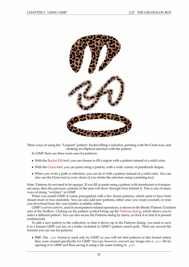
CHAPTER 2. USING GIMP 2.27. THE GIH DIALOG BOX
Three ways of using the ”Leopard” pattern: bucket-filling a selection, painting with the Clone tool, andstroking an elliptical selection with the pattern.
In GIMP there are three main uses for patterns:
• With the Bucket Fill tool, you can choose to fill a region with a pattern instead of a solid color.
• With the Clone tool, you can paint using a pattern, with a wide variety of paintbrush shapes.
• When you stroke a path or selection, you can do it with a pattern instead of a solid color. You canalso use the Clone tool as your choice if you stroke the selection using a painting tool.
Note: Patterns do not need to be opaque. If you fill or paint using a pattern with translucent or transpar-ent areas, then the previous contents of the area will show through from behind it. This is one of manyways of doing ”overlays” in GIMP.
When you install GIMP, it comes presupplied with a few dozen patterns, which seem to have beenchosen more or less randomly. You can also add new patterns, either ones you create yourself, or onesyou download from the vast number available online.
GIMP’s current pattern, used in most pattern-related operations, is shown in the Brush/Pattern/Gradientarea of the Toolbox. Clicking on the pattern symbol brings up the Patterns dialog, which allows you toselect a different pattern. You can also access the Patterns dialog by menu, or dock it so that it is presentcontinuously.
To add a new pattern to the collection, so that it shows up in the Patterns dialog, you need to saveit in a format GIMP can use, in a folder included in GIMP’s pattern search path. There are several fileformats you can use for patterns:
• PAT. The .pat format is used only by GIMP, so you will not find patterns in this format unlessthey were created specifically for GIMP. You can, however, convert any image into a .pat file byopening it in GIMP and then saving it using a file name ending in .pat .
81
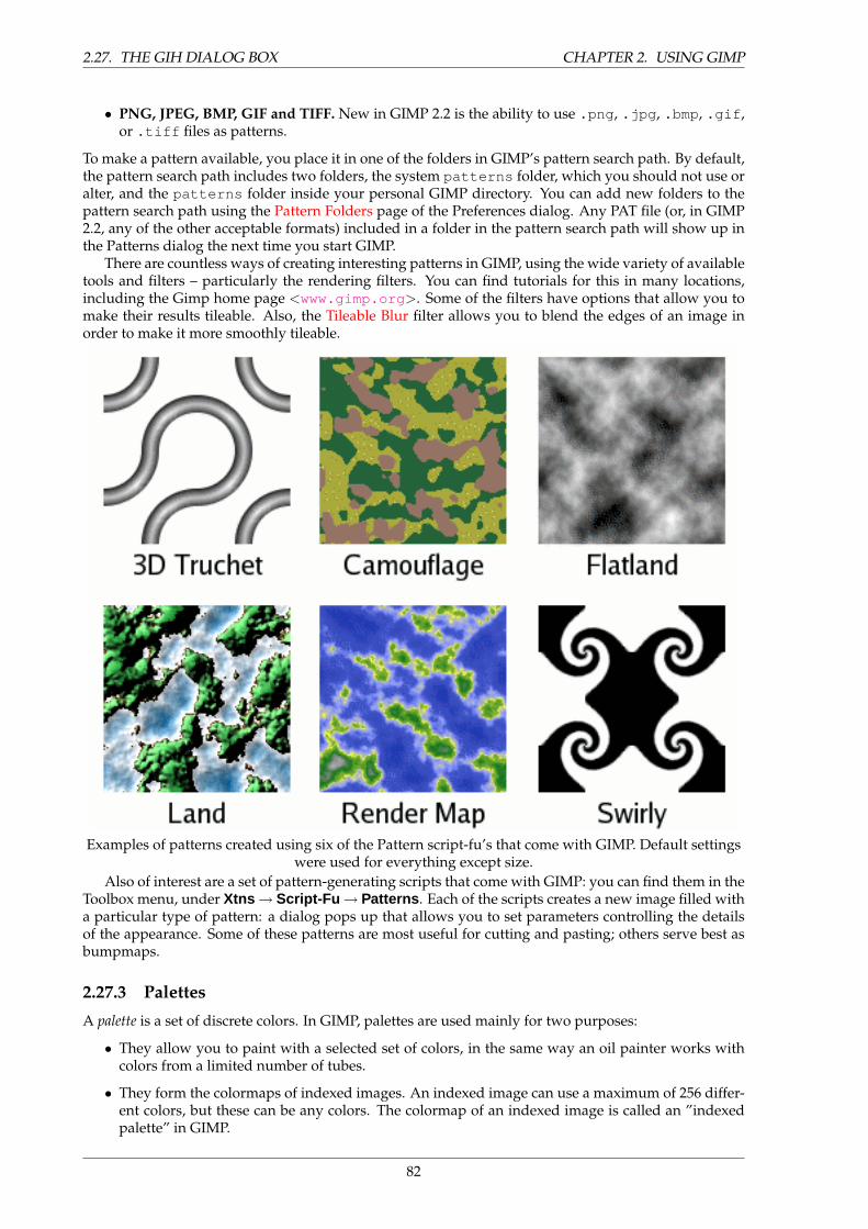
2.27. THE GIH DIALOG BOX CHAPTER 2. USING GIMP
• PNG, JPEG, BMP, GIF and TIFF. New in GIMP 2.2 is the ability to use .png , .jpg , .bmp , .gif ,or .tiff files as patterns.
To make a pattern available, you place it in one of the folders in GIMP’s pattern search path. By default,the pattern search path includes two folders, the system patterns folder, which you should not use oralter, and the patterns folder inside your personal GIMP directory. You can add new folders to thepattern search path using the Pattern Folders page of the Preferences dialog. Any PAT file (or, in GIMP2.2, any of the other acceptable formats) included in a folder in the pattern search path will show up inthe Patterns dialog the next time you start GIMP.
There are countless ways of creating interesting patterns in GIMP, using the wide variety of availabletools and filters – particularly the rendering filters. You can find tutorials for this in many locations,including the Gimp home page <www.gimp.org >. Some of the filters have options that allow you tomake their results tileable. Also, the Tileable Blur filter allows you to blend the edges of an image inorder to make it more smoothly tileable.
Examples of patterns created using six of the Pattern script-fu’s that come with GIMP. Default settingswere used for everything except size.
Also of interest are a set of pattern-generating scripts that come with GIMP: you can find them in theToolbox menu, under Xtns → Script-Fu → Patterns . Each of the scripts creates a new image filled witha particular type of pattern: a dialog pops up that allows you to set parameters controlling the detailsof the appearance. Some of these patterns are most useful for cutting and pasting; others serve best asbumpmaps.
2.27.3 Palettes
A palette is a set of discrete colors. In GIMP, palettes are used mainly for two purposes:
• They allow you to paint with a selected set of colors, in the same way an oil painter works withcolors from a limited number of tubes.
• They form the colormaps of indexed images. An indexed image can use a maximum of 256 differ-ent colors, but these can be any colors. The colormap of an indexed image is called an ”indexedpalette” in GIMP.
82
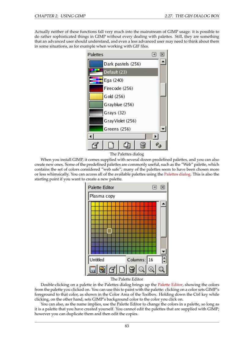
CHAPTER 2. USING GIMP 2.27. THE GIH DIALOG BOX
Actually neither of these functions fall very much into the mainstream of GIMP usage: it is possible todo rather sophisticated things in GIMP without every dealing with palettes. Still, they are somethingthat an advanced user should understand, and even a less advanced user may need to think about themin some situations, as for example when working with GIF files.
The Palettes dialogWhen you install GIMP, it comes supplied with several dozen predefined palettes, and you can also
create new ones. Some of the predefined palettes are commonly useful, such as the ”Web” palette, whichcontains the set of colors considered ”web safe”; many of the palettes seem to have been chosen moreor less whimsically. You can access all of the available palettes using the Palettes dialog. This is also thestarting point if you want to create a new palette.
The Palette EditorDouble-clicking on a palette in the Palettes dialog brings up the Palette Editor, showing the colors
from the palette you clicked on. You can use this to paint with the palette: clicking on a color sets GIMP’sforeground to that color, as shown in the Color Area of the Toolbox. Holding down the Ctrl key whileclicking, on the other hand, sets GIMP’s background color to the color you click on.
You can also, as the name implies, use the Palette Editor to change the colors in a palette, so long asit is a palette that you have created yourself. You cannot edit the palettes that are supplied with GIMP;however you can duplicate them and then edit the copies.
83
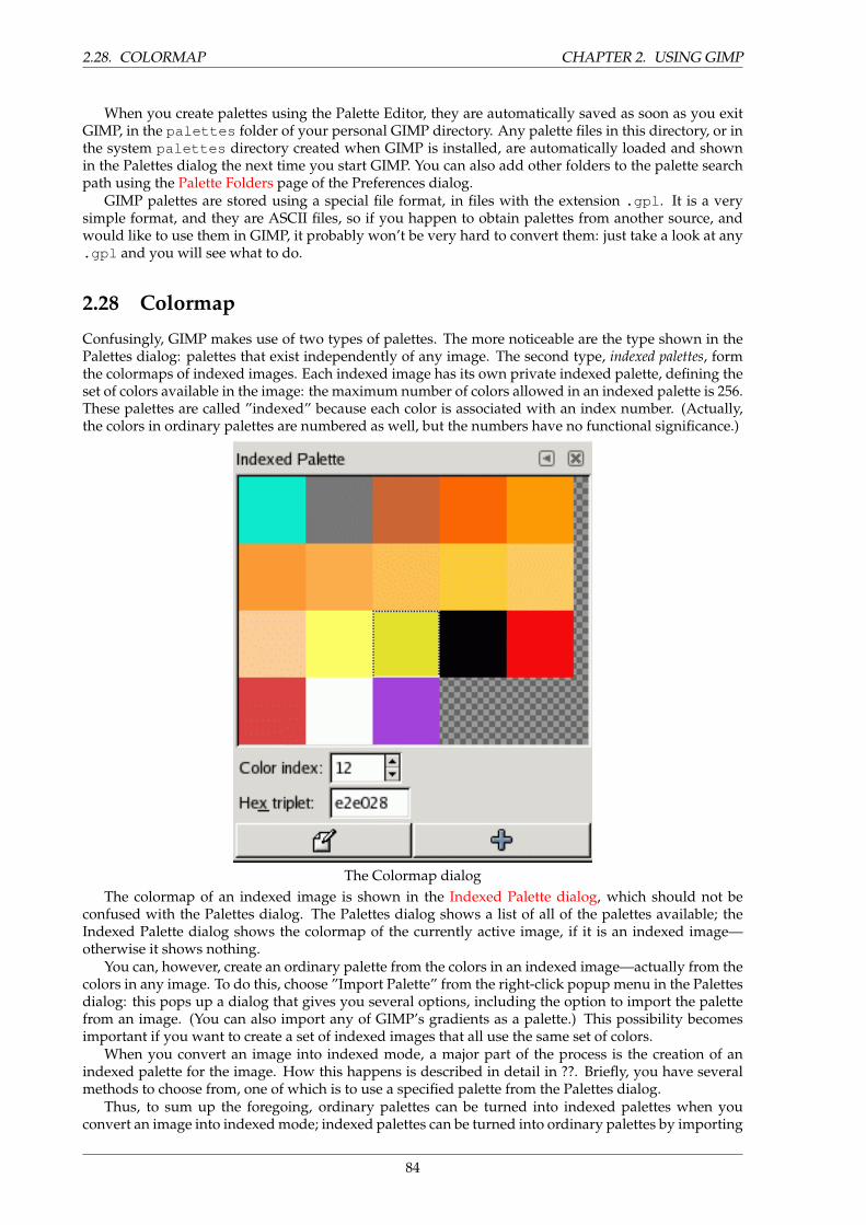
2.28. COLORMAP CHAPTER 2. USING GIMP
When you create palettes using the Palette Editor, they are automatically saved as soon as you exitGIMP, in the palettes folder of your personal GIMP directory. Any palette files in this directory, or inthe system palettes directory created when GIMP is installed, are automatically loaded and shownin the Palettes dialog the next time you start GIMP. You can also add other folders to the palette searchpath using the Palette Folders page of the Preferences dialog.
GIMP palettes are stored using a special file format, in files with the extension .gpl . It is a verysimple format, and they are ASCII files, so if you happen to obtain palettes from another source, andwould like to use them in GIMP, it probably won’t be very hard to convert them: just take a look at any.gpl and you will see what to do.
2.28 Colormap
Confusingly, GIMP makes use of two types of palettes. The more noticeable are the type shown in thePalettes dialog: palettes that exist independently of any image. The second type, indexed palettes, formthe colormaps of indexed images. Each indexed image has its own private indexed palette, defining theset of colors available in the image: the maximum number of colors allowed in an indexed palette is 256.These palettes are called ”indexed” because each color is associated with an index number. (Actually,the colors in ordinary palettes are numbered as well, but the numbers have no functional significance.)
The Colormap dialogThe colormap of an indexed image is shown in the Indexed Palette dialog, which should not be
confused with the Palettes dialog. The Palettes dialog shows a list of all of the palettes available; theIndexed Palette dialog shows the colormap of the currently active image, if it is an indexed image—otherwise it shows nothing.
You can, however, create an ordinary palette from the colors in an indexed image—actually from thecolors in any image. To do this, choose ”Import Palette” from the right-click popup menu in the Palettesdialog: this pops up a dialog that gives you several options, including the option to import the palettefrom an image. (You can also import any of GIMP’s gradients as a palette.) This possibility becomesimportant if you want to create a set of indexed images that all use the same set of colors.
When you convert an image into indexed mode, a major part of the process is the creation of anindexed palette for the image. How this happens is described in detail in ??. Briefly, you have severalmethods to choose from, one of which is to use a specified palette from the Palettes dialog.
Thus, to sum up the foregoing, ordinary palettes can be turned into indexed palettes when youconvert an image into indexed mode; indexed palettes can be turned into ordinary palettes by importing
84
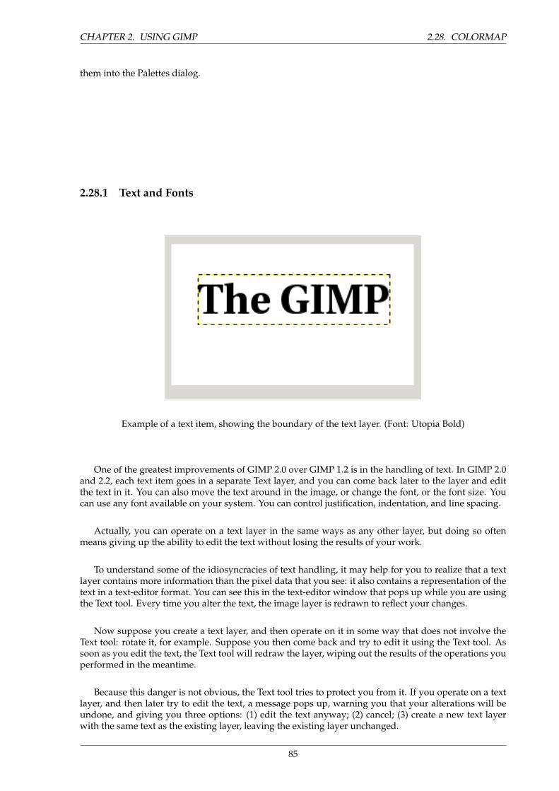
CHAPTER 2. USING GIMP 2.28. COLORMAP
them into the Palettes dialog.
2.28.1 Text and Fonts
Example of a text item, showing the boundary of the text layer. (Font: Utopia Bold)
One of the greatest improvements of GIMP 2.0 over GIMP 1.2 is in the handling of text. In GIMP 2.0and 2.2, each text item goes in a separate Text layer, and you can come back later to the layer and editthe text in it. You can also move the text around in the image, or change the font, or the font size. Youcan use any font available on your system. You can control justification, indentation, and line spacing.
Actually, you can operate on a text layer in the same ways as any other layer, but doing so oftenmeans giving up the ability to edit the text without losing the results of your work.
To understand some of the idiosyncracies of text handling, it may help for you to realize that a textlayer contains more information than the pixel data that you see: it also contains a representation of thetext in a text-editor format. You can see this in the text-editor window that pops up while you are usingthe Text tool. Every time you alter the text, the image layer is redrawn to reflect your changes.
Now suppose you create a text layer, and then operate on it in some way that does not involve theText tool: rotate it, for example. Suppose you then come back and try to edit it using the Text tool. Assoon as you edit the text, the Text tool will redraw the layer, wiping out the results of the operations youperformed in the meantime.
Because this danger is not obvious, the Text tool tries to protect you from it. If you operate on a textlayer, and then later try to edit the text, a message pops up, warning you that your alterations will beundone, and giving you three options: (1) edit the text anyway; (2) cancel; (3) create a new text layerwith the same text as the existing layer, leaving the existing layer unchanged.
85
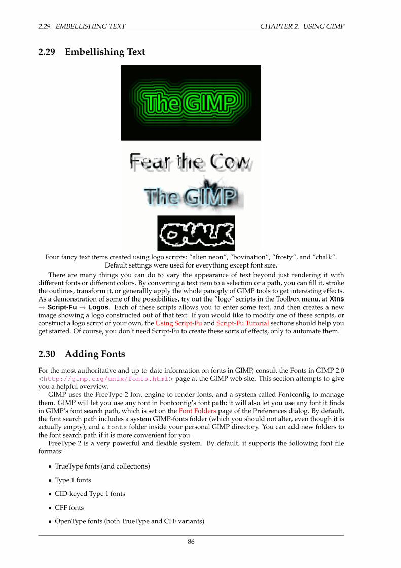
2.29. EMBELLISHING TEXT CHAPTER 2. USING GIMP
2.29 Embellishing Text
Four fancy text items created using logo scripts: ”alien neon”, ”bovination”, ”frosty”, and ”chalk”.Default settings were used for everything except font size.
There are many things you can do to vary the appearance of text beyond just rendering it withdifferent fonts or different colors. By converting a text item to a selection or a path, you can fill it, strokethe outlines, transform it, or generallly apply the whole panoply of GIMP tools to get interesting effects.As a demonstration of some of the possibilities, try out the ”logo” scripts in the Toolbox menu, at Xtns→ Script-Fu → Logos . Each of these scripts allows you to enter some text, and then creates a newimage showing a logo constructed out of that text. If you would like to modify one of these scripts, orconstruct a logo script of your own, the Using Script-Fu and Script-Fu Tutorial sections should help youget started. Of course, you don’t need Script-Fu to create these sorts of effects, only to automate them.
2.30 Adding Fonts
For the most authoritative and up-to-date information on fonts in GIMP, consult the Fonts in GIMP 2.0<http://gimp.org/unix/fonts.html > page at the GIMP web site. This section attempts to giveyou a helpful overview.
GIMP uses the FreeType 2 font engine to render fonts, and a system called Fontconfig to managethem. GIMP will let you use any font in Fontconfig’s font path; it will also let you use any font it findsin GIMP’s font search path, which is set on the Font Folders page of the Preferences dialog. By default,the font search path includes a system GIMP-fonts folder (which you should not alter, even though it isactually empty), and a fonts folder inside your personal GIMP directory. You can add new folders tothe font search path if it is more convenient for you.
FreeType 2 is a very powerful and flexible system. By default, it supports the following font fileformats:
• TrueType fonts (and collections)
• Type 1 fonts
• CID-keyed Type 1 fonts
• CFF fonts
• OpenType fonts (both TrueType and CFF variants)
86
CHAPTER 2. USING GIMP 2.31. FONT PROBLEMS
• SFNT-based bitmap fonts
• X11 PCF fonts
• Windows FNT fonts
• BDF fonts (including anti-aliased ones)
• PFR fonts
• Type42 fonts (limited support)
You can also add modules to support other types of font files. See FREETYPE 2 <http://www.freetype.org/freetype2/index.html#features > for more information.
Linux. On a Linux system, if the Fontconfig utility is set up as usual, all you need to do to add a newfont is to place the file in the directory ˜/.fonts . This will make the font available not only to GIMP,but to any other program that uses Fontconfig. If for some reason you want the font to be available toGIMP only, you can place it in the fonts subdirectory of your personal GIMP directory, or some otherlocation in your font search path. Doing either will cause the font to show up the next time you startGIMP. If you want to use it in an already running GIMP, press the Refresh button in the Fonts dialog.
Windows. The easiest way to install a font is to drag the file onto the Fonts directory and let theshell do its magic. Unless you’ve done something creative, it’s probably in its default location ofC:\windows\fonts or C:\winnt\fonts . Sometimes double-clicking on a font will install it as wellas display it; sometimes it only displays it. This method will make the font available not only to GIMP,but also to other Windows applications.
To install a Type 1 file, you need both the .pfb and .pfm files. Drag the one that gets an icon intothe fonts folder. The other one doesn’t strictly need to be in the same directory when you drag the file,since it uses some kind of search algorithm to find it if it’s not, but in any case putting it in the samedirectory does no harm.
In principle, GIMP can use any type of font on Windows that FreeType can handle; however, for fontsthat Windows can’t handle natively, you should install them by placing the font files in the fonts folderof your personal GIMP directory, or some other location in your font search path. The support Windowshas varies by version. All that GIMP runs on support at least TrueType, Windows FON, and WindowsFNT. Windows 2000 and later support Type 1 and OpenType. Windows ME supports OpenType andpossibly Type 1 (but the most widely used Windows GIMP installer does not officially support WindowsME, although it may work anyway).
NOTE
GIMP uses Fontconfig to manage fonts on Windows as well as Linux. The in-structions above work because Fontconfig by default uses the Windows fontsdirectory, i. e., the same fonts that Windows uses itself. If for some reason yourFontconfig is set up differently, you will have to figure out where to put fonts sothat GIMP can find them: in any case, the fonts folder of your personal GIMPdirectory should work.
2.31 Font Problems
Problems with fonts have probably been responsible for more GIMP 2 bug reports than any other singlecause, although they have become much less frequent in the most recent releases in the 2.0 series. Inmost cases they have been caused by malformed font files giving trouble to Fontconfig. If you experiencecrashes at startup when GIMP scans your font directories, the best solution is to upgrade to a versionof Fontconfig newer than 2.2.0. As a quick workaround you can start gimp with the --no-fontscommand-line option, but then you will not be able to use the text tool.
Another known problem is that Pango 1.2 cannot load fonts that don’t provide an Unicode charactermapping. (Pango is the text layout library used by GIMP.) A lot of symbol fonts fall into this category.
87
2.32. FILES CHAPTER 2. USING GIMP
On some systems, using such a font can cause GIMP to crash. Updating to Pango 1.4 will fix this problemand makes symbol fonts available in GIMP.
A frequent source of confusion occurs on Windows systems, when GIMP encounters a malformedfont file and generates an error message: this causes a console window to pop up so that you can seethe message. Do not close that console window. It is harmless, and closing it will shut down GIMP. Whenthis happens, it often seems to users that GIMP has crashed. It hasn’t: closing the console windowcauses Windows to shut GIMP down. Unfortunately, this annoying situation is caused by an interactionbetween Windows and the libraries that GIMP links to: it cannot be fixed within GIMP. All you need todo, though, if this happens, is minimize the console window and ignore it.
2.31.1 Stroking a Selection or Path
TO BE WRITTEN
2.32 Files
The GIMP is capable of reading and writing a large variety of graphics file formats. With the exceptionof GIMP’s native XCF file type, file handling is done by plug-ins. Thus, it is relatively easy to extendGIMP to new file types when the need arises.
Not all file types are equally good for all purposes. This part of the documentation should help youunderstand the advantages and disadvantages of each type.
2.33 Opening Files
There are several ways of opening an existing image in GIMP:
• The most obvious is to open it using a menu, by choosing File → Open from either the Toolboxmenu or an image menu. This brings up a File Chooser dialog, allowing you to navigate to thefile and click on its name. This method works well if you know the name of the file you want toopen, and where it is located. It is not so convenient if you want to find the file on the basis of athumbnail.
• If instead of a file name, you have a URI (i.e., a web address) for the image, you can open it usingthe menu, by choosing File → Open Location from either the Toolbox menu or an image menu.This brings up a small dialog that allows you to enter the URI.
• If the image is one that you previously created using GIMP, perhaps the easiest way to open it isfrom the menu, using File →Open Recent . This gives you a scrollable list of the images you havemost recently worked on in, with icons beside them. You need only select the one you want, andit will be opened.
• If you have associated the file type of the image with GIMP, either when you installed GIMP orlater, then you can navigate to the file using a file manager (such as Nautilus in Linux, or WindowsExplorer in Windows), and once you have found it, double-click on the icon. If things are set upproperly, this will cause the image to open in GIMP.
• Alternatively, once you have found the file, you can click on its icon and drag it into the GIMPToolbox. (If instead you drag it into an existing GIMP image, it will be added to that image as anew layer or set of layers.)
• For many applications, you can click on a displayed image (a full image, not just a thumbnail) anddrag it into the GIMP toolbox.
• Also for many applications, if the application gives you a way of copying the image to the clip-board, you can then open the image in GIMP by choosing File → Acquire → Paste as New fromthe Toolbox menu. Support for this is somewhat variable, however, so your best bet is to try it andsee whether it works.
88
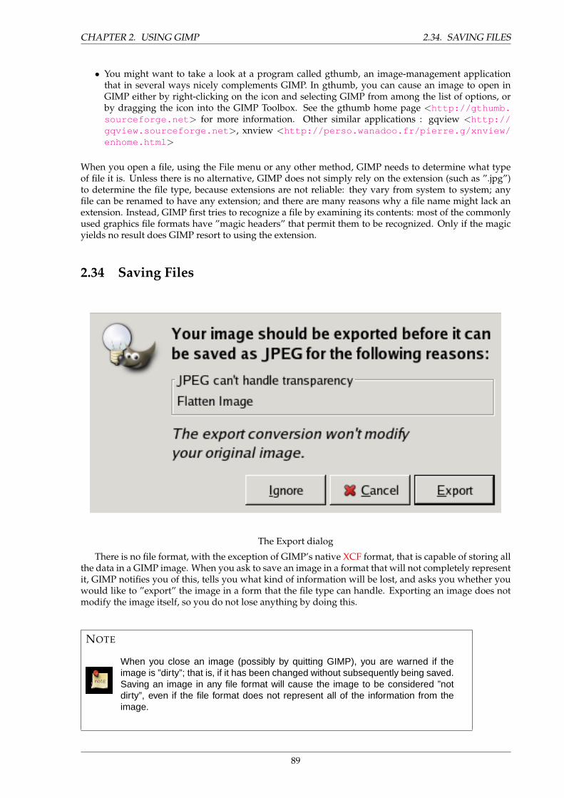
CHAPTER 2. USING GIMP 2.34. SAVING FILES
• You might want to take a look at a program called gthumb, an image-management applicationthat in several ways nicely complements GIMP. In gthumb, you can cause an image to open inGIMP either by right-clicking on the icon and selecting GIMP from among the list of options, orby dragging the icon into the GIMP Toolbox. See the gthumb home page <http://gthumb.sourceforge.net > for more information. Other similar applications : gqview <http://gqview.sourceforge.net >, xnview <http://perso.wanadoo.fr/pierre.g/xnview/enhome.html >
When you open a file, using the File menu or any other method, GIMP needs to determine what typeof file it is. Unless there is no alternative, GIMP does not simply rely on the extension (such as ”.jpg”)to determine the file type, because extensions are not reliable: they vary from system to system; anyfile can be renamed to have any extension; and there are many reasons why a file name might lack anextension. Instead, GIMP first tries to recognize a file by examining its contents: most of the commonlyused graphics file formats have ”magic headers” that permit them to be recognized. Only if the magicyields no result does GIMP resort to using the extension.
2.34 Saving Files
The Export dialog
There is no file format, with the exception of GIMP’s native XCF format, that is capable of storing allthe data in a GIMP image. When you ask to save an image in a format that will not completely representit, GIMP notifies you of this, tells you what kind of information will be lost, and asks you whether youwould like to ”export” the image in a form that the file type can handle. Exporting an image does notmodify the image itself, so you do not lose anything by doing this.
NOTE
When you close an image (possibly by quitting GIMP), you are warned if theimage is ”dirty”; that is, if it has been changed without subsequently being saved.Saving an image in any file format will cause the image to be considered ”notdirty”, even if the file format does not represent all of the information from theimage.
89
2.35. WORKING WITH DIGITAL CAMERA PHOTOS CHAPTER 2. USING GIMP
2.35 Working with Digital Camera Photos
2.35.1 Introduction
One of the most common uses of the Gimp is to fix digital camera images that for some reason are lessthan perfect. Maybe the image is overexposed or underexposed; maybe rotated a bit; maybe out offocus: these are all common problems for which Gimp has good tools. The purpose of this chapter isto give you an overview of those tools and the situations in which they are useful. You will not finddetailed tutorials here: in most cases it is easier to learn how to use the tools by experimenting withthem than by reading about them. (Also, each tool is described more thoroughly in the Help sectiondevoted to it.) You will also not find anything in this chapter about the multitude of ”special effects”that you can apply to an image using Gimp. You should be familiar with basic Gimp concepts beforereading this chapter, but you certainly don’t need to be an expert–if you are, you probably know most ofthis anyway. And don’t hesitate to experiment: Gimp’s powerful ”undo” system allows you to recoverfrom almost any mistake with a simple Ctrl-Z.
Most commonly the things that you want to do to clean up an imperfect photo are of four types:improving the composition; improving the colors; improving the sharpness; and removing artifacts orother undesirable elements of the image.
2.35.2 Improving Composition
2.36 Rotating an Image
It is easy, when taking a picture, to hold the camera not quite perfectly vertical, resulting in a picturewhere things are tilted at an angle. In Gimp, the way to fix this is to use the Rotate tool. Activate thisby clicking its icon in the Toolbox, or by pressing the ”R” key capitalized) while inside the image. Makesure the Tool Options are visible, and at the top, make sure for ”Affect:” that the left button (”TransformLayer”) is selected. If you then click the mouse inside the image and drag it, you will see a grid appearthat rotates as you drag. When the grid looks right, click okay and the image will be rotated.
Now as a matter of fact, it isn’t so easy to get things right by this method: you often find that thingsare better but not quite perfect. One solution is to rotate a bit more, but there is a disadvantage to thatapproach. Each time you rotate an image, because the rotated pixels don’t line up precisely with theoriginal pixels, the image inevitably gets blurred a little bit. For a single rotation, the amount of blurringis quite small, but two rotations cause twice as much blurring as one, and there is no reason to blurthings more than you have to. A better alternative is to undo the rotation and then do another, adjustingthe angle.
Fortunately, Gimp provides another way of doing it that is considerably easier to use: in the RotateTool Options, for the Transform Direction you can select ”Backward (Corrective)”. When you do this,instead of rotating the grid to compensate for the error, you can rotate it to line up with the error. If thisseems confusing, try it and you will see that it is quite straightforward.
NOTE
Note: New in Gimp 2.2 is the option to preview the results of transformations,instead of just seeing a grid. This makes it easier to get things right on the firsttry.
After you have rotated an image, there will be unpleasant triangular ”holes” at the corners. Oneway to fix them is to create a background that fills the holes with some unobtrusive or neutral color, butusually a better solution is to crop the image. The greater the rotation, the more cropping is required, soit is best to get the camera aligned as well as possible when you take the picture in the first place.
2.37 Cropping
When you take a picture with a digital camera, you have some control over what gets included in theimage but often not as much as you would like: the result is images that could benefit from trimming.
90
CHAPTER 2. USING GIMP 2.38. AUTOMATED TOOLS
Beyond this, it is often possible to enhance the impact of an image by trimming it so that the mostimportant elements are placed at key points. A rule of thumb, not always to be followed but good tokeep in mind, is the ”rule of thirds”, which says that maximum impact is obtained by placing the centerof interest one-third of the way across the image, both widthwise and heightwise.
To crop an image, activate the Crop tool in the Toolbox, or by pressing the ”C” key (capitalized)while inside the image. With the tool active, clicking and dragging in the image will sweep out a croprectangle. It will also pop up a dialog that allows you to adjust the dimensions of the crop region if theyaren’t quite right. When everything is perfect, hit the Crop button in the dialog.
2.37.1 Improving Colors
2.38 Automated Tools
In spite of sophisticated exposure-control systems, pictures taken with digital cameras often come outover- or under-exposed, or with color casts due to imperfections in lighting. Gimp gives you a varietyof tools to correct colors in an image, ranging to automated tools that run with a simple button-clickto highly sophisticated tools that give you many parameters of control. We will start with the simplestfirst.
Gimp gives you five automated color correction tools. Unfortunately they don’t usually give youquite the results you are looking for, but they only take a moment to try out, and if nothing else theyoften give you an idea of some of the possibilities inherent in the image. Except for ”Auto Levels”, youcan find them in the Layer menu, by following the menu path Layer → Colors → Auto in the imagemenu.
Here they are, with a few words about each:
Normalize This tool (it is really a plug-in) is useful for underexposed images: it adjusts the wholeimage uniformly until the brightest point is right at the saturation limit, and the darkest point isblack. The downside is that the amount of brightening is determined entirely by the lightest anddarkest points in the image, so even one single white pixel and/or one single black pixel will makenormalization ineffective.
Equalize This is a very powerful adjustment that tries to spread the colors in the image evenly acrossthe range of possible intensities. In some cases the effect is amazing, bringing out contrasts thatare very difficult to get in any other way; but more commonly, it just makes the image look weird.Oh well, it only takes a moment to try.
Color Enhance Help me, what exactly does this do? Obviously it makes some things more saturated.
Stretch Contrast This is like ”Normalize”, except that it operates on the red, green, and blue channelsindependently. It often has the useful effect of reducing color casts.
Auto Levels This is done by activating the Levels tool ( Tools → Color Tools → Levels in the imagemenu), clicking on the image to bring up the tool dialog, and then pressing the Auto button nearthe center of the dialog. You will see a preview of the result; you must press Okay for it to takeeffect. Pressing Cancel instead will cause your image to revert to its previous state.
If you can find a point in the image that ought to be perfect white, and a second point that oughtto be perfect black, then you can use the Levels tool to do a semi-automatic adjustment that willoften do a good job of fixing both brightness and colors throughout the image. First, bring upthe Levels tool as previously described. Now, look down near the bottom of the Layers dialogfor three buttons with symbols on them that look like eye-droppers (at least, that is what they aresupposed to look like). The one on the left, if you mouse over it, shows its function to be ”PickBlack Point”. Click on this, then click on a point in the image that ought to be black–really trulyperfectly black, not just sort of dark–and watch the image change. Next, click on the rightmost ofthe three buttons (”Pick White Point”), and then click a point in the image that ought to be white,
91
2.39. EXPOSURE PROBLEMS CHAPTER 2. USING GIMP
and once more watch the image change. If you are happy with the result, click the Okay buttonotherwise Cancel .
Those are the automated color adjustments: if you find that none of them quite does the job for you, it istime to try one of the interactive color tools. All of these, except one, can be accessed via Tools->ColorTools in the image menu. After you select a color tool, click on the image (anywhere) to activate it andbring up its dialog.
2.39 Exposure Problems
The simplest tool to use is the Brightness/Contrast tool. It is also the least powerful, but in many casesit does everything you need. This tool is often useful for images that are overexposed or underexposed;it is not useful for correcting color casts. The tool gives you two sliders to adjust, for ”Brightness” and”Contrast”. If you have the option ”Preview” checked (and almost certainly you should), you will seeany adjustments you make reflected in the image. When you are happy with the results, press Okayand they will take effect. If you can’t get results that you are happy with, press Cancel and the imagewill revert to its previous state.
A more sophisticated, and only slightly more difficult, way of correcting exposure problems is to usethe Levels tool. The dialog for this tool looks very complicated, but for the basic usage we have in mindhere, the only part you need to deal with is the ”Input Levels” area, specifically the three triangularsliders that appear below the histogram. We refer you to the Levels Tool Help for instructions; butactually the easiest way to learn how to use it is to experiment by moving the three sliders around, andwatching how the image is affected. (Make sure that ”Preview” is checked at the bottom of the dialog.)
A very powerful way of correcting exposure problems is to use the Curves tool. This tool allowsyou to click and drag control points on a curve, in order to create a function mapping input bright-ness levels to output brightness levels. The Curves tool can replicate any effect you can achieve withBrightness/Contrast or the Levels tool, so it is more powerful than either of them. Once again, we referyou to the Curves Tool Helpfor detailed instructions, but the easiest way to learn how to use it is byexperimenting.
The most powerful approach to adjusting brightness and contrast across an image, for more expertGimp users, is to create a new layer above the one you are working on, and then in the Layers dialogset the Mode for the upper layer to ”Multiply”. The new layer then serves as a ”gain control” layerfor the layer below it, with white yielding maximum gain and black yielding a gain of zero. Thus, bypainting on the new layer, you can selectively adjust the gain for each area of the image, giving you veryfine control. You should try to paint only with smooth gradients, because sudden changes in gain willgive rise to spurious edges in the result. Paint only using shades of gray, not colors, unless you want toproduce color shifts in the image.
Actually, ”Multiply” is not the only mode that is useful for gain control. In fact, ”Multiply” modecan only darken parts of an image, never lighten them, so it is only useful where some parts of an imageare overexposed. Using ”Divide” mode has the opposite effect: it can brighten areas of an image but notdarken them. Here is a trick that is often useful for bringing out the maximum amount of detail acrossall areas of an image:
1. Duplicate the layer (producing a new layer above it).
2. Desaturate the new layer.
3. Apply a Gaussian blur to the result, with a large radius (100 or more).
4. Set Mode in the Layers dialog to Divide.
5. Control the amount of correction by adjusting opacity in the Layers dialog, or by using Bright-ness/Contrast, Levels, or Curves tools on the new layer.
6. When you are happy with the result, you can use Merge Down to combine the control layer andthe original layer into a single layer.
In addition to ”Multiply” and ”Divide”, you may every so often get useful effects with other layercombination modes, such as ”Dodge”, ”Burn”, or ”Soft Light”. It is all too easy, though, once you startplaying with these things, to look away from the computer for a moment and suddenly find that youhave just spent an hour twiddling parameters. Be warned: the more options you have, the harder it isto make a decision.
92
CHAPTER 2. USING GIMP 2.40. ADJUSTING HUE AND SATURATION
2.40 Adjusting Hue and Saturation
In our experience, if your image has a color cast—too much red, too much blue, etc—the easiest way tocorrect it is to use the Levels tool, adjusting levels individually on the red, green, and blue channels. Ifthis doesn’t work for you, it might be worth your while to try the Color Balance tool or the Curves tool,but these are much more difficult to use effectively. (They are very good for creating certain types ofspecial effects, though.)
Sometimes it is hard to tell whether you have adjusted colors adequately. A good, objective techniqueis to find a point in the image that you know should be either white or a shade of gray. Activate the ColorPicker tool (the eyedropper symbol in the Toolbox), and click on the aforesaid point: this brings up theColor Picker dialog. If the colors are correctly adjusted, then the red, green, and blue components ofthe reported color should all be equal; if not, then you should see what sort of adjustment you need tomake. This technique, when well used, allows even color-blind people to color-correct an image.
If your image is washed out—which can easily happen when you take pictures in bright light—trythe Hue/Saturation tool, which gives you three sliders to manipulate, for Hue, Lightness, and Satura-tion. Raising the saturation will probably make the image look better. In same cases it is useful to adjustthe lightness at the same time. (”Lightness” here is similar to ”Brightness” in the Brightness/Contrasttool, except that they are formed from different combinations of the red, green, and blue channels.) TheHue/Saturation tool gives you the option of adjusting restricted subranges of colors (using the buttonsat the top of the dialog), but if you want to get natural-looking colors, in most cases you should avoiddoing this.
TIP
Even if an image does not seemed washed out, often you can increase its impactby pushing up the saturation a bit. Veterans of the film era sometimes call thistrick ”Fujifying”, after Fujichrome film, which is notorious for producing highlysaturated prints.
When you take pictures in low light conditions, in some cases you have the opposite problem: toomuch saturation. In this case too the Hue/Saturation tool is a good one to use, only by reducing thesaturation instead of increasing it.
2.40.1 Adjusting Sharpness
2.41 Unblurring
If the focus on the camera is not set perfectly, or the camera is moving when the picture is taken, theresult is a blurred image. If there is a lot of blurring, you probably won’t be able to do much about itwith any technique, but if there is only a moderate amount, you should be able to improve the image.
The most generally useful technique for sharpening a fuzzy image is called the Unsharp Mask. Inspite of the rather confusing name, which derives from its origins as a technique used by film developers,its result is to make the image sharper, not ”unsharp”. It is a plug-in, and you can access it as Filters->Enhance->Unsharp Mask in the image menu. There are two parameters, ”Radius” and ”Amount”.The default values often work pretty well, so you should try them first. Increasing either the radius orthe amount increases the strength of the effect. Don’t get carried away, though: if you make the unsharpmask too strong, it will amplify noise in the image and also give rise to visible artifacts where there aresharp edges.
93
2.42. REDUCING GRAININESS CHAPTER 2. USING GIMP
TIP
Sometimes using Unsharp Mask can cause color distortion where there arestrong contrasts in an image. When this happens, you can often get better re-sults by decomposing the image into separate Hue-Saturation-Value (HSV) lay-ers, and running Unsharp Mask on the Value layer only, then recomposing. Thisworks because the human eye has much finer resolution for brightness than forcolor. See the sections on Decompose and Compose for more information.
Next to ”Unsharp Mask” in the Filters menu is another filter called Sharpen, which does similarthings. It is a little easier to use but not nearly as effective: our recommendation is that you ignore it andgo straight to Unsharp Mask.
In some situations, you may be able to get useful results by selectively sharpening specific parts of animage using the Blur or Sharpen tool from the Toolbox, in ”Sharpen” mode. This allows you to increasethe sharpness in areas by painting over them with any paintbrush. You should be restrained about this,though, or the results will not look very natural: sharpening increases the apparent sharpness of edgesin the image, but also amplifies noise.
2.42 Reducing Graininess
When you take pictures in low-light conditions or with a very fast exposure time, the camera does notget enough data to make good estimates of the true color at each pixel, and consequently the resultingimage looks grainy. You can ”smooth out” the graininess by blurring the image, but then you will alsolose sharpness. There are a couple of approaches that may give better results. Probably the best, if thegraininess is not too bad, is to use the filter called Selective Blur, setting the blurring radius to 1 or 2pixels. The other approach is to use the Despeckle filter. This has a nice preview, so you can play withthe settings and try to find some that give good results. When graininess is really bad, though, it is oftenvery difficult to fix by anything except heroic measures (i.e., retouching with paint tools).
2.43 Softening
Every so often you have the opposite problem: an image is too crisp. The solution is to blur it a bit:fortunately blurring an image is much easier than sharpening it. Since you probably don’t want to blurit very much, the simplest method is to use the ”Blur” plug-in, accessed via Filters->Blur from the imagemenu. With the default settings and a repeat count of 1, this will soften the focus of the image a little bit.If you want more softening, just repeat until you get the result you desire.
2.43.1 Removing Unwanted Objects from an Image
There are two kinds of objects you might want to remove from an image: first, artifacts caused by junksuch as dust or hair on the lens; second, things that were really present but impair the quality of theimage, such as a telephone wire running across the edge of a beautiful mountain landscape.
2.44 Despeckling
A good tool for removing dust and other types of lens grunge is the Despeckle filter, accessed as Filters->Enhance->Despeckle from the image menu. Very important: to use this filter effectively, you mustbegin by making a small selection containing the artifact and a small area around it. The selection mustbe small enough so that the artifact pixels are statistically distinguishable from the other pixels insidethe selection. If you try to run despeckle on the whole image, you will hardly ever get anything useful.Once you have created a reasonable selection, activate Despeckle, and watch the preview as you adjustthe parameters. If you are lucky, you will be able to find a setting that removes the junk while minimallyaffecting the area around it. The more the junk stands out from the area around it, the better your resultsare likely to be. If it isn’t working for you, it might be worthwhile to cancel the filter, create a differentselection, and then try again.
94
CHAPTER 2. USING GIMP 2.45. GARBAGE REMOVAL
If you have more than one artifact in the image, it is necessary to use Despeckle on each individually.
2.45 Garbage Removal
The most useful method for removing unwanted ”clutter” from an image is the Clone tool, which allowsyou to paint over one part of an image using pixel data taken from another part (or even from a differentimage). The trick to using the clone tool effectively is to be able to find a different part of the image thatcan be used to ”copy over” the unwanted part: if the area surrounding the unwanted object is verydifferent from the rest of the image, you won’t have much luck. For example, if you have a lovely beachscene, with a nasty human walking across the beach who you would like to teleport away, you willprobably be able to find an empty part of the beach that looks similar to the part he is walking across,and use it to clone over him. It is quite astonishing how natural the results can look when this techniqueworks well.
Consult the Clone Tool Help for more detailed instructions. Cloning is as much an art as a science,and the more you practice at it, the better you will get. At first it may seem impossible to produceanything except ugly blotches, but persistence will pay off.
In some cases you may be able to get good results by simply cutting out the offending object from theimage, and then using a plug-in called ”Resynthesizer” to fill in the void. This plug-in is not includedwith the main Gimp distribution, but it can be obtained from the author’s Resynthesizer <http://www.logarithmic.net/pfh/resynthesizer > web site. As with many things, your mileage mayvary.
2.46 Removing Red-eye
When you take a flash picture of somebody who is looking directly toward the camera, the iris of theeye can bounce the light of the flash back toward the camera in such a way as to make the eye appearbright red: this effect is called ”red eye”, and looks very bizarre. Many modern cameras have specialflash modes that minimize red-eye, but they only work if you use them, and even then they don’t alwayswork perfectly. Interestingly, the same effect occurs with animals, but the eyes may show up as othercolors, such as green.
Gimp does not include a special tool for removing red-eye, but it isn’t all that hard to do. Basicallythe idea is to zoom the area around the eye so that it is nice and large and easy to work with; then makea selection of the red part of the eye and a bit of the area around it; feather the selection so that you don’tcreate sharp-looking edges; and finally desaturate the red channel inside the selection using one of thecolor tools—Levels, Curves, or Hue/Saturation. It takes a little practice the first few times, but once youhave the technique mastered, you should be able to quickly and easily create quite a natural looking eyecolor.
If you would like a more automated approach, you can try downloading a recently created redeye<http://registry.gimp.org/plugin?id=4212 > plug-in from the Gimp Plug-in Registry. Wehave not received any feedback so far about how well it works. It comes in source code form, so youwill need to be able compile it in order to use it. (See Installing New Plug-ins for information on how todo this.)
2.46.1 Saving Your Results
2.47 Files
What file format should you use to save the results of your work, and should you resize it? The answersdepend on what you intend to use the image for.
• If you intend to open the image in Gimp again for further work, you should save it in Gimp’snative XCF format (i. e., name it something.xcf), because this is the only format that guaranteesthat none of the information in the image is lost.
• If you intend to print the image on paper, you should avoid shrinking the image, except by crop-ping it. The reason is that printers are capable of achieving much higher dot resolutions than videomonitors—600 to 1400 dots per inch for typical printers, as compared to 72 to 100 dots per inch for
95

2.48. PRINTING YOUR PHOTOS CHAPTER 2. USING GIMP
monitors. A 3000 x 5000 image looks huge on a monitor, but it only comes to about 5 inches by 8inches on paper at 600 dpi. There is usually no good reason to expand the image either: you can’tincrease the true resolution that way, and it can always be scaled up at the time it is printed. As forthe file format, it will usually be fine to use JPEG at a quality level of 75 to 85. In rare cases, wherethere are large swaths of nearly uniform color, you may need to set the quality level even higheror use a lossless format such as TIFF instead.
• If you intend to display the image on screen or project it with a video projector, bear in mindthat the highest screen resolution for most commonly available systems is 1600 x 1200, so there isnothing to gain by keeping the image larger than that. For this purpose, the JPEG format is almostalways a good choice.
• If you want to put the image on a web page or send it by email, it is a good idea to make everyeffort to keep the file size as small as possible. First, scale the image down to the smallest size thatmakes it possible to see the relevant details (bear in mind that other people may be using differentsized monitors and/or different monitor resolution settings). Second, save the image as a JPEGfile. In the JPEG save dialog, check the option to ”Preview in image window”, and then adjustthe Quality slider to the lowest level that gives you acceptable image quality. (You will see in theimage the effects of each change.) Make sure that the image is zoomed at 1:1 while you do this, soyou are not misled by the effects of zooming.
See the File Formats section for more information.
2.48 Printing Your Photos
[This needs to be written.]
2.49 EXIF Data
Modern digital cameras, when you take a picture, add information to the data file about the camerasettings and the circumstances under which the picture was taken. This data is included in JPEG orTIFF files in a structured format called EXIF. For JPEG files, Gimp is capable of maintaining EXIF data,if it is built appropriately: it depends on a library called ”libexif”, which may not be available on allsystems. If Gimp is built with EXIF support enabled, then loading a JPEG file with EXIF data, andresaving the resulting image in JPEG format, will cause the EXIF data to be preserved unchanged. Thisis not, strictly speaking, the right way for an image editor to handle EXIF data, but it is better thansimply removing it, which is what earlier versions of Gimp did.
If you would like to see the contents of the EXIF data, you can download from the registry an ExifBrowser plug-in <http://registry.gimp.org/plugin?id=4153 >. If you are able to build andinstall it on your system, you can access it as Filters->Generic->Exif Browser from the image menu. (SeeInstalling New Plug-ins for help.)
2.50 Preparing your Images for the web
One of the most common purposes GIMP is used for, is to prepare images for adding them to a website. This means that the images should look as nice as possible while keeping the file size as smallas possible. This little step-by-step guide will tell you how to achieve a smaller file size with minimaldegradation of image quality.
1. First open the image as usual. I opened our Wilber as an example image.
The Wilber image opened in the RGBA mode.
96
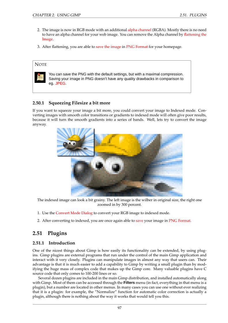
CHAPTER 2. USING GIMP 2.51. PLUGINS
2. The image is now in RGB mode with an additional alpha channel (RGBA). Mostly there is no needto have an alpha channel for your web image. You can remove the Alpha channel by flattening theImage.
3. After flattening, you are able to save the image in PNG Format for your homepage.
NOTE
You can save the PNG with the default settings, but with a maximal compression.Saving your image in PNG doesn’t have any quality drawbacks in comparison toeg. JPEG.
2.50.1 Squeezing Filesize a bit more
If you want to squeeze your image a bit more, you could convert your image to Indexed mode. Con-verting images with smooth color transitions or gradients to indexed mode will often give poor results,because it will turn the smooth gradients into a series of bands. Well, lets try to convert the imageanyway.
The indexed image can look a bit grainy. The left image is the wilber in original size, the right onezoomed in by 300 percent.
1. Use the Convert Mode Dialog to convert your RGB image to indexed mode.
2. After converting to indexed, you are once again able to save your image in PNG Format.
2.51 Plugins
2.51.1 Introduction
One of the nicest things about Gimp is how easily its functionality can be extended, by using plug-ins. Gimp plugins are external programs that run under the control of the main Gimp application andinteract with it very closely. Plugins can manipulate images in almost any way that users can. Theiradvantage is that it is much easier to add a capability to Gimp by writing a small plugin than by mod-ifying the huge mass of complex code that makes up the Gimp core. Many valuable plugins have Csource code that only comes to 100-200 lines or so.
Several dozen plugins are included in the main Gimp distribution, and installed automatically alongwith Gimp. Most of them can be accessed through the Filters menu (in fact, everything in that menu is aplugin), but a number are located in other menus. In many cases you can use one without ever realizingthat it is a plugin: for example, the ”Normalize” function for automatic color correction is actually aplugin, although there is nothing about the way it works that would tell you this.
97
2.51. PLUGINS CHAPTER 2. USING GIMP
In addition to the plugins included with Gimp, many more are available on the net. A large numbercan be found at the Gimp Plugin Registry <http://registry.gimp.org >, a web site whose pur-pose is to provide a central repository for plugins. Creators of plugins can upload them there; users insearch of plugins for a specific purpose can search the site in a variety of ways.
Anybody in the world can write a Gimp plugin and make it available over the web, either via theRegistry or a personal web site, and many very valuable plugins can be obtained in this way some aredescribed elsewhere in the User’s Manual. With this freedom from constraint comes a certain degreeof risk, though: the fact that anybody can do it means that there is no effective quality control. Theplugins distributed with Gimp have all been tested and tuned by the developers, but many that you candownload were just hacked together in a few hours and then tossed to the winds. Some plugin creatorsjust don’t care about robustness, and even for those who do, their ability to test on a variety of systemsin a variety of situations is often quite limited. Basically, when you download a plugin, you are gettingsomething for free, and sometimes you get exactly what you pay for. This is not said in an attempt todiscourage you, just to make sure you understand reality.
WARNING
Plugins, being full-fledged executable programs, can do any of the things that anyother program can do, including install back-doors on your system or otherwisecompromise its security. Don’t install a plugin unless it comes from a trustedsource.
These caveats apply as much to the Plugin Registry as to any other source of plugins. The Registryis available to any plugin creator who wants to use it: there is no systematic oversight. Obviously if themaintainers became aware that something evil was there, they would remove it. (That hasn’t happenedyet.) There is, however, for Gimp and its plugins the same warranty as for any other free software:namely, none.
CAUTION
Plugins have been a feature of Gimp for many versions. However, plugins writtenfor one version of Gimp can hardly ever be used successfully with other versions.They need to be ported: sometimes this is easy, sometimes not. Many pluginsare already available in several versions. Bottom line: before trying to install aplugin, make sure that it is written for your version of Gimp.
2.51.2 Using Plugins
For the most part you can use a plugin like any other Gimp tool, without needing to be aware that it isa plugin. But there are a few things about plugins that are useful to understand.
One is that plugins are generally not as robust as the Gimp core. When Gimp crashes, it is considereda very serious thing: it can cost the user a lot of trouble and headache. When a plugin crashes, the con-sequences are usually not so serious. In most cases you can just continuing working without worryingabout it.
NOTE
Because plugins are separate programs, they communicate with the Gimp corein a special way: the Gimp developers call it ”talking over a wire”. When a plugincrashes, the communication breaks down, and you will see an error messageabout a ”wire read error”.
98
CHAPTER 2. USING GIMP 2.52. LINUX
TIP
When a plugin crashes, Gimp gives you a very ominous-looking message tellingyou that the plugin may have left Gimp in a corrupted state, and you shouldconsider saving your images and exiting. Strictly speaking, this is quite correct,because plugins have the power to alter almost anything in Gimp, but for practicalpurposes, experience has shown that corruption is actually quite rare, and manyusers just continue working and don’t worry about it. Our advice is that you simplythink about how much trouble it would cause you if something went wrong, andweigh it against the odds.
Because of the way plugins communicate with Gimp, they do not have any mechanism for beinginformed about changes you make to an image after the plugin has been started. If you start a plugin,and then alter the image using some other tool, the plugin will often crash, and when it doesn’t willusually give a bogus result. You should avoid running more than one plugin at a time on an image, andavoid doing anything to the image until the plugin has finished working on it. If you ignore this advice,not only will you probably screw up the image, you will probably screw up the undo system as well, sothat you won’t even be able to recover from your foolishness.
2.51.3 Installing New Plugins
The plugins that are distributed with Gimp don’t require any special installation. Plugins that youdownload yourself do. There are several scenarios, depending on what OS you are using and how theplugin is structured. In Linux it is usually pretty easy to install a new plugin; in Windows, it is eithereasy or very hard. In any case, the two are best considered separately.
2.52 Linux
Most plugins fall into two categories: small ones whose source code is distributed as a single .c file,and larger ones whose source code is distributed as a directory containing multiple files including aMakefile.
For a simple one-file plugin, call it borker.c , installing it is just a matter of running the commandgimptool-2.0 –install borker.c. This command compiles the plugin and installs it in your personal plu-gin directory, ˜/gimp-2.0/plugins unless you have changed it. This will cause it to be loaded au-tomatically the next time you start Gimp. You don’t need to be root to do these things; in fact, youshouldn’t be. If the plugin fails to compile, well, be creative.
Once you have installed the plugin, how do you activate it? The menu path is determined by theplugin itself, so to answer this you need to either look at the documentation for the plugin (if there isany), or launch the Plugin Description dialog (from Xtns/Plugins Details) search the plug-in by its nameand look ot the Tree view tab. If you still don’t find, finally explore the menus or look at the source codein the Register section – whichever is easiest.
For more complex plugins, organized as a directory with multiple files, there ought to be a file insidecalled either INSTALL or README, with instructions. If not, the best advice is to toss the plugin inthe trash and spend your time on something else: any code written with so little concern for the user islikely to be frustrating in myriad ways.
Some plugins (specifically those based on the Gimp Plugin Template) are designed to be installed inthe main system Gimp directory, rather than your home directory. For these, you will need to be root toperform the final stage of installation (”make install”).
If you install in your personal plugin directory a plugin that has the same name as one in the systemplugin directory, only one can be loaded, and it will be the one in your home directory. You will receivemessages telling you this each time you start Gimp. This is probably a situation best avoided.
99
2.53. WINDOWS CHAPTER 2. USING GIMP
2.53 Windows
Windows is a much more problematic environment for building software than Linux. Every decentLinux distribution comes fully supplied with tools for compiling software, and they are all very similarin the way they work, but Windows does not come with such tools. It is possible to set up a goodsoftware-building environment in Windows, but it requires either a substantial amount of money or asubstantial amount of effort and knowledge.
Windows est un environnement plus problematique que Linux pour la construction de logiciels.Toute distribution decente de Linux vient avec tous les outils necessaires a la compilation de logiciels, etils ont tous un mode de fonctionnement similaire, mais Windows n’offre pas de tels outils. Il est possiblede configurer un bon environnement de developpement sous Windows, mais cela necessite une bonnequantite d’argent ou de connaissances et d’efforts.
What this means in relation to Gimp plugins is the following: either you have an environment inwhich you can build software, or you don’t. If you don’t, then your best hope is to find a precompiledversion of the plugin somewhere (or persuade somebody to compile it for you), in which case yousimply need to put it into your personal plugin directory. If you do have an environment in whichyou can build software (which for present purposes means an environment in which you can buildGimp), then you no doubt already know quite a bit about these things, and just need to follow the Linuxinstructions.
If you would like to set up a build environment, and are ready for the heroism involved, youcan find a reasonably recent description of how to go about it in the Gimp Wiki, at HowToCompi-leGimp/MicrosoftWindows <http://wiki.gimp.org/gimp/HowToCompileGimp_2fMicrosoftWindows >.Since it is a Wiki, anybody is free to edit it, so please keep it up to date by adding advice based on yourown experiences.
2.54 Macintosh
We could use some material here.
2.54.1 Writing Plugins
If you want to learn how to write a plugin, you can find plenty of help at the Gimp Developers website, developer.gimp.org <http://developer.gimp.org/plug-ins.html >. Gimp is a complexprogram, but the development team has made strenuous efforts to flatten the learning curve for pluginwriting: there are good instructions and examples, and the main library that plugins use to interfacewith Gimp (called ”libgimp”) has a well-documented API. Good programmers, learning by modifyingexisting plugins, are often able to accomplish interesting things after just a couple of days of work.
2.55 Using Script-Fu Scripts
2.56 Script-Fu?
Script-Fu is what the Windows world would call ”macros” But Script-Fu is more powerful than that.Script-Fu is based on an interpreting language called Scheme, and works by using querying functionsto the Gimp database. You can do all kinds of things with Script-Fu, but an ordinary Gimp user willprobably use it for automating things that:
• You want to do frequently.
• Are really complicated to do, and hard to remember.
Remember that you can do a whole lot with Script-Fu. The scripts that come with Gimp can be quiteuseful, but they can also serve as models for learning Script-Fu, or at least as a framework and sourceof modification when you make your own script. Read the Script-Fu Tutorial in the next section if youwant to learn more about how to make scripts.
We will describe some of the most useful scripts in this chapter, but we won’t cover them all. Thereare simply too many scripts. Some of the scripts are also very simple and you will probably not needany documentation to be able to use them.
100
CHAPTER 2. USING GIMP 2.57. INSTALLING SCRIPT-FUS
Script-Fu (a dialect of Scheme) isn’t the only scripting language available for Gimp. But Script-Fu isthe only scripting language that is installed by default. Other available scripting extensions are Perl andTcl. You can download and install both extensions at the Gimp Plugin Registry <http://registry.gimp.org >.
2.57 Installing Script-Fus
One of the great things about Script-Fu is that you can share your script with all your Gimp friends.There are many scripts that come with Gimp by default, but there are also vast quantities of scripts thatare available for download all around the Internet.
TIP
If you have downloaded a script, copy or move your new script to your .gimp-2.0/scripts directory and do a refresh. The script will now appear in one ofyour menus. If you don’t find it, look for it under the root file menu filters. If itdoesn’t appear at all, something was wrong with the script.
Note that you can’t use more than one Script-Fu dialog at a time, so don’t open a script and one moreafter that. The last one will never be opened and displayed.
2.58 Do’s and Don’ts
A common error when you are dealing with Script-Fus is that you simply bring them up and press theOK button. When nothing happens, you probably think that the script is broken or buggy, but there ismost likely nothing wrong with it.
Think again. Did you really read the information in the dialog, or did you just press the button? Ifyou forgot an input the script needs, or if you gave it the wrong input, the script will fail. One of themost common errors is that the font specified in the script dialog hasn’t been installed on your system.So please check the information in the dialog before blaming the script.
2.59 Different Kinds Of Script-Fus
There are two kinds of Script-Fus – standalone scripts and image-dependent scripts. You will find thestandalone variants under Xtns → Script-Fu → Type of Script in the main toolbox menu, and theimage-dependent scripts are placed under Script-Fu → Type of Script in the image menu.
2.60 Standalone Scripts
We will not try to describe every script in depth. Most Script-Fus are very easy to understand and use.At the time of this writing, the following types are installed by default:
• Patterns
• Web page themes
• Logos
• Buttons
• Utils
• Make Brush
• Misc.
101
2.60. STANDALONE SCRIPTS CHAPTER 2. USING GIMP
Patterns You will find all kinds of pattern-generating scripts here. Generally, they are quite usefulbecause you can add many arguments to your own patterns.
We’ll take a look at the Land script. In this script you have to set the image/pattern size, andspecify what levels of random to use for your land creation. The colors used to generate the landmap are taken from the currently selected gradient in the gradient editor. You must also supplyvalues for the level of detail, land and sea height/depth and the scale. Scale refers to the scale ofyour map, just as in an ordinary road map, 1:10 will be typed as 10.
Web Page Themes Here is clearly a practical use for scripts. By creating a script for making customtext, logos, buttons arrows, etc., for your web site, you will give them all the same style and shape.You will also be saving a lot of time, because you don’t have to create every logo, text or button byhand.
You will find the Gimp.org theme under the Web page theme submenu. If you want to create yourown theme, this script will serve as an excellent template that you can modify to create a themefor your web site.
Most of the scripts are quite self-explanatory, but here are some hints:
• Leave all strange characters like ’ and ” intact.
• Make sure that the pattern specified in the script exists.
• Padding refers to the amount of space around your text.
• A high value for bevel width gives the illusion of a higher button.
• If you type TRUE for ”Press”, the button will look pushed down.
• Choose transparency if you don’t want a solid background. If you choose a solid background,make sure it is the same color as the web page background.
Logos Here you will find all kinds of logo-generating scrips. This is nice, but use it with care, as peoplemight recognize your logo as being made by a known Gimp script. You should rather regard it asa base that you can modify to fit your needs. The dialog for making a logo is more or less the samefor all such scripts:
1. In the Text String field, type your logo name, like Frozenriver.
2. In the Font Size text field, type the size of your logo in pixels.
3. In the Font text field, type the name of the font that you want to use for your logo.
4. To choose the color of your logo, just click on the color button. This brings up a color dialog.
5. If you look at the current command field, you can watch the script run.
Make Buttons Under this headline you’ll find a script that makes beveled buttons. The script has adozen parameters or so, and most of them are similar to those in the logo scripts. You can experi-ment with different settings to come up with a button you like.
Utils Under Utils you will find a small but nice script: the Fontmap script, which makes an image ofyour fonts. You will have to type the names of the fonts you want displayed in the Fonts text field.
The Custom gradient script creates an image of the current custom gradient in the gradient editor.This can be useful if you want to pick colors from a gradient as in a palette.
Misc. Under Misc. you’ll find scripts that can be quite useful, but aren’t suitable for the other submenus.An example is the Sphere script. You will have to set the radius in pixels to determine the spheresize. The lighting angle is where at the sphere you point the spotlight. This value also has animpact on the sphere shadow. If you don’t want a shadow, you will have to type FALSE. The lastthing you have to select is background color, and the color of your sphere.
102
CHAPTER 2. USING GIMP 2.61. IMAGE-DEPENDENT SCRIPTS
Make Brush This script lets you make your own custom rectangular/circular brushes, with or withoutfeathered (blurred) edges. The script will automatically store your brush in your personal brushdirectory. You just have to press refresh in the Brush Selection dialog to use your newly createdbrush.
2.61 Image-Dependent Scripts
These are scripts that perform operations on an existing image. In many ways they are like the plug-insin the Filters menu. The following script groups are installed by default:
• Decor
• Modify
• Animators
• Stencil Ops
• Alchemy
• Shadow
• Render
• Utils
• Selection
Stencil Ops Here, you’ll find two scripts: Carve-It and Chrome-It, which can render some truly niceartistic effects on grayscale images.
Drop Shadow Drop Shadow will cast a shadow behind your selected object. It has three importantparameters. X and Y offset determine where the shadow will be placed in relation to the selectedobject. Offset is measured in pixels. High values make the shadow look like it’s far away, and lowvalues will make it look closer to the object. The blur value is also important, because a shadowthat is cast far from the object has a higher blur level.
Perspective Shadow Perspective Shadow has a very important parameter: the perspective angle. If thisangle is set to 0 or 180, there will be no shadow, because the script assumes that the object has nothickness. This also means that this script looks fine in certain angles, but unnatural in others. Theother parameters are quite self-explanatory. You’ll get more blur if the horizon is far away, and theshadow length is the length in relation to the selected object.
2.62 A Script-Fu Tutorial
In this training course, we’ll introduce you to the fundamentals of Scheme necessary to use Script-Fu,and then build a handy script that you can add to your toolbox of scripts. The script prompts the userfor some text, then creates a new image sized perfectly to the text. We will then enhance the script toallow for a buffer of space around the text. We will conclude with a few suggestions for ways to rampup your knowledge of Script-Fu.
103
2.63. LET’S START SCHEME’ING CHAPTER 2. USING GIMP
NOTE
This section as adapted from a tutorial written for the Gimp 1 User Manual byMike Terry.
2.62.1 Getting Acquainted With Scheme
2.63 Let’s Start Scheme’ing
The first thing to learn is that:Every statement in Scheme is surrounded by parentheses ().The second thing you need to know is that:The function name/operator is always the first item in the parentheses, and the rest of the items
are parameters to the function.However, not everything enclosed in parentheses is a function – they can also be items in a list –
but we’ll get to that later. This notation is referred to as prefix notation, because the function prefixeseverything else. If you’re familiar with postfix notation, or own a calculator that uses Reverse Polish No-tation (such as most HP calculators), you should have no problem adapting to formulating expressionsin Scheme.
The third thing to understand is that:Mathematical operators are also considered functions, and thus are listed first when writing math-
ematical expressions.This follows logically from the prefix notation that we just mentioned.
2.64 Examples Of Prefix, Infix, And Postfix Notations
Here are some quick examples illustrating the differences between prefix, infix, and postfix notations.We’ll add a 1 and 3 together:
• Prefix notation: + 1 3 (the way Scheme will want it)
• Infix notation: 1 + 3 (the way we ”normally” write it)
• Postfix notation: 1 3 + (the way many HP calculators will want it)
2.65 Practicing In Scheme
Now, let’s practice what we have just learned. Start up Gimp, if you have not already done so, andchoose Xtns/Script-Fu/Console. This will start up the Script-Fu Console window, which allows us towork interactively in Scheme. In a matter of moments, the Script-Fu Console will appear:
2.66 The Script-Fu Console Window
At the bottom of this window is an entry-field entitled Current Command. Here, we can test out simpleScheme commands interactively. Let’s start out easy, and add some numbers:
(+ 3 5)
Typing this in and hitting Return yields the expected answer of 8 in the center window.Now, what if we wanted to add more than one number? The ”+” function can take two or more
arguments, so this is not a problem:
104
CHAPTER 2. USING GIMP 2.67. WATCH OUT FOR EXTRA PARENS
(+ 3 5 6)
This also yields the expected answer of 14.So far, so good – we type in a Scheme statement and it’s executed immediately in the Script-Fu
Console window. Now for a word of caution....
2.67 Watch Out For Extra Parens
If you’re like me, you’re used to being able to use extra parentheses whenever you want to – like whenyou’re typing a complex mathematical equation and you want to separate the parts by parentheses tomake it clearer when you read it. In Scheme, you have to be careful and not insert these extra parenthesesincorrectly. For example, say we wanted to add 3 to the result of adding 5 and 6 together:
3 + (5 + 6) + 7= ?
Knowing that the + operator can take a list of numbers to add, you might be tempted to convert theabove to the following:
(+ 3 (5 6) 7)
However, this is incorrect – remember, every statement in Scheme starts and ends with parens, sothe Scheme interpreter will think that you’re trying to call a function named ”5” in the second group ofparens, rather than summing those numbers before adding them to 3.
The correct way to write the above statement would be:
(+ 3 (+ 5 6) 7)
2.68 Make Sure You Have The Proper Spacing, Too
If you are familiar with other programming languages, like C/C++, Perl or Java, you know that youdon’t need white space around mathematical operators to properly form an expression:
{\verb 3+5, 3 +5, 3+ 5}
These are all accepted by C/C++, Perl and Java compilers. However, the same is not true for Scheme.You must have a space after a mathematical operator (or any other function name or operator) in Schemefor it to be correctly interpreted by the Scheme interpreter.
Practice a bit with simple mathematical equations in the Script-Fu Console until you’re totally com-fortable with these initial concepts.
2.68.1 Variables And Functions
Now that we know that every Scheme statement is enclosed in parentheses, and that the functionname/operator is listed first, we need to know how to create and use variables, and how to createand use functions. We’ll start with the variables.
105
2.69. DECLARING VARIABLES CHAPTER 2. USING GIMP
2.69 Declaring Variables
Although there are a couple of different methods for declaring variables, the preferred method is to usethe let* construct. If you’re familiar with other programming languages, this construct is equivalentto defining a list of local variables and a scope in which they’re active. As an example, to declare twovariables, a and b, initialized to 1 and 2, respectively, you’d write:
(let* ((a 1)(b 2)
)(+ a b)
)
or, as one line:
(let* ( (a 1) (b 2) ) (+ a b) )
NOTE
You’ll have to put all of this on one line if you’re using the console window. Ingeneral, however, you’ll want to adopt a similar practice of indentation to helpmake your scripts more readable. We’ll talk a bit more about this in the sectionon White Space.
This declares two local variables, a and b, initializes them, then prints the sum of the two variables.
2.70 What Is A Local Variable?
You’ll notice that we wrote the summation [code] (+ a b) [/code] within the parens of the [code] let*[/code] expression, not after it.
This is because the [code] let* [/code] statement defines an area in your script in which the declaredvariables are usable; if you type the (+ a b) statement after the (let* ...) statement, you’ll get an error,because the declared variables are only valid within the context of the [code] let* [/code] statement;they are what programmers call local variables.
2.71 The General Syntax Of [code] let* [/code]
The general form of a [code] let* [/code] statement is:
(let* ( variables ) expressions )
where variables are declared within parens, e.g., (a 2), and expressions are any valid Scheme expres-sions. Remember that the variables declared here are only valid within the [code] let* [/code] statement– they’re local variables.
106
CHAPTER 2. USING GIMP 2.72. WHITE SPACE
2.72 White Space
Previously, we mentioned the fact that you’ll probably want to use indentation to help clarify and orga-nize your scripts. This is a good policy to adopt, and is not a problem in Scheme – white space is ignoredby the Scheme interpreter, and can thus be liberally applied to help clarify and organize the code withina script. However, if you’re working in Script-Fu’s Console window, you’ll have to enter an entire ex-pression on one line; that is, everything between the opening and closing parens of an expression mustcome on one line in the Script-Fu Console window.
2.73 Assigning A New Value To A Variable
Once you’ve initialized a variable, you might need to change its value later on in the script. Use the set!statement to change the variable’s value:
(let* ( (theNum 10) ) (set! theNum (+ theNum \ theNum)) )
Try to guess what the above statement will do, then go ahead and enter it in the Script-Fu Consolewindow.
NOTE
The ”\” indicates that there is no line break. Ignore it (don’t type it in your Script-Fu console and don’t hit Enter), just continue with the next line.
2.74 Functions
Now that you’ve got the hang of variables, let’s get to work with some functions. You declare a functionwith the following syntax:
(define (name param-list) expressions)
where name is the name assigned to this function, param-list is a space-delimited list of parameternames, and expressions is a series of expressions that the function executes when it’s called. Forexample:
(define (AddXY inX inY) (+ inX inY) )
AddXY is the function’s name and inX and inY are the variables. This function takes its two param-eters and adds them together.
If you’ve programmed in other imperative languages (like C/C++, Java, Pascal, etc.), you might no-tice that a couple of things are absent in this function definition when compared to other programminglanguages.
• First, notice that the parameters don’t have any ”types” (that is, we didn’t declare them as strings,or integers, etc.). Scheme is a type-less language. This is handy and allows for quicker scriptwriting.
• Second, notice that we don’t need to worry about how to ”return” the result of our function –the last statement is the value ”returned” when calling this function. Type the function into theconsole, then try something like:
107
2.75. DEFINING A LIST CHAPTER 2. USING GIMP
(AddXY (AddXY 5 6) 4)
2.74.1 Lists, Lists And More Lists
We’ve trained you in variables and functions, and now enter the murky swamps of Scheme’s lists.
2.75 Defining A List
Before we talk more about lists, it is necessary that you know the difference between atomic values andlists.
You’ve already seen atomic values when we initialized variables in the previous lesson. An atomicvalue is a single value. So, for example, we can assign the variable ”x” the single value of 8 in thefollowing statement:
(let* ( (x 8) ) x)
(We added the expression x at the end to print out the value assigned to x– normally you won’t needto do this. Notice how [code] let* [/code] operates just like a function: The value of the last statement isthe value returned.)
A variable may also refer to a list of values, rather than a single value. To assign the variable x thelist of values 1, 3, 5, we’d type:
(let* ( (x ’(1 3 5))) x)
Try typing both statements into the Script-Fu Console and notice how it replies. When you type thefirst statement in, it simply replies with the result:
8
However, when you type in the other statement, it replies with the following result:
(1 3 5)
When it replies with the value 8 it is informing you that x contains the atomic value 8. However,when it replies with (1 3 5), it is then informing you that x contains not a single value, but a list ofvalues. Notice that there are no commas in our declaration or assignment of the list, nor in the printedresult.
The syntax to define a list is:
’(a b c)
where a, b, and c are literals. We use the apostrophe (’) to indicate that what follows in the paren-theses is a list of literal values, rather than a function or expression.
An empty list can be defined as such:
’()
108
CHAPTER 2. USING GIMP 2.76. HOW TO THINK OF LISTS
or simply:
()
Lists can contain atomic values, as well as other lists:
(let*(
(x’("The Gimp" (1 2 3) ("is" ("great" () ) ) )
))
x)
Notice that after the first apostrophe, you no longer need to use an apostrophe when defining theinner lists. Go ahead and copy the statement into the Script-Fu Console and see what it returns.
You should notice that the result returned is not a list of single, atomic values; rather, it is a list of aliteral [code] (”The Gimp”) [/code] , the list [code] (1 2 3) [/code] , etc.
2.76 How To Think Of Lists
It’s useful to think of lists as composed of a ”head” and a ”tail.” The head is the first element of the list,the tail the rest of the list. You’ll see why this is important when we discuss how to add to lists and howto access elements in the list.
2.77 Creating Lists Through Concatenation (The Cons Function)
One of the more common functions you’ll encounter is the cons function. It takes a value and prependsit to its second argument, a list. From the previous section, I suggested that you think of a list as beingcomposed of an element (the head) and the remainder of the list (the tail). This is exactly how consfunctions – it adds an element to the head of a list. Thus, you could create a list as follows:
(cons 1 ’(2 3 4) )
The result is the list [code] (1 2 3 4) [/code] .You could also create a list with one element:
(cons 1 () )
You can use previously declared variables in place of any literals, as you would expect.
2.78 Defining A List Using The list Function
To define a list composed of literals or previously declared variables, use the list function:
(list 5 4 3 a b c)
109
2.79. ACCESSING VALUES IN A LIST CHAPTER 2. USING GIMP
This will compose and return a list containing the values held by the variables a, b and c . Forexample:
(let* ((a 1)(b 2)(c 3)
)(list 5 4 3 a b c)
)
This code creates the list [code] (5 4 3 1 2 3) [/code] .
2.79 Accessing Values In A List
To access the values in a list, use the functions [code] car [/code] and [code] cdr [/code] , which returnthe first element of the list and the rest of the list, respectively. These functions break the list down intothe head::tail construct I mentioned earlier.
2.80 The [code] car [/code] Function
[code] car [/code] returns the first element of the list (the head of the list). The list needs to be non-null.Thus, the following returns the first element of the list:
(car ’("first" 2 "third"))
which is:
"first"
2.81 The [code] cdr [/code] function
[code] cdr [/code] returns the rest of the list after the first element (the tail of the list). If there is onlyone element in the list, it returns an empty list.
(cdr ’("first" 2 "third"))
returns:
(2 "third")
whereas the following:
(cdr ’("one and only"))
returns:
()
110
CHAPTER 2. USING GIMP 2.82. ACCESSING OTHER ELEMENTS IN A LIST
2.82 Accessing Other Elements In A List
OK, great, we can get the first element in a list, as well as the rest of the list, but how do we accessthe second, third or other elements of a list? There exist several ”convenience” functions to access, forexample, the head of the head of the tail of a list ( [code] caadr [/code] ), the tail of the tail of a list ([code] cddr [/code] ), etc.
The basic naming convention is easy: The a’s and d’s represent the heads and tails of lists, so
(car (cdr (car x) ) )
could be written as:
(cadar x)
To view a full list of the list functions, refer to the Appendix, which lists the available functions forthe version of Scheme used by Script-Fu.
To get some practice with list-accessing functions, try typing in the following (except all on one lineif you’re using the console); use different variations of car and cdr to access the different elements of thelist:
(let* ((x ’( (1 2 (3 4 5) 6) 7 8 (9 10) ))
); place your car/cdr code here
)
Try accessing the number 3 in the list using only two function calls. If you can do that, you’re onyour way to becoming a Script-Fu Master!
NOTE
In Scheme, a semicolon (”;”) marks a comment. It, and anything that follows iton the same line, are ignored by the script interpreter, so you can use this to addcomments to jog your memory when you look at the script later.
2.82.1 Your First Script-Fu Script
Do you not need to stop and catch your breath? No? Well then, let’s proceed with your fourth lesson –your first Script-Fu Script.
2.83 Creating A Text Box Script
One of the most common operations I perform in Gimp is creating a box with some text in it for a webpage, a logo or whatever. However, you never quite know how big to make the initial image when youstart out. You don’t know how much space the text will fill with the font and font size you want.
The Script-Fu Master (and student) will quickly realize that this problem can easily be solved andautomated with Script-Fu.
We will, therefore, create a script, called Text Box, which creates an image correctly sized to fit snuglyaround a line of text the user inputs. We’ll also let the user choose the font, font size and text color.
111
2.84. EDITING AND STORING YOUR SCRIPTS CHAPTER 2. USING GIMP
2.84 Editing And Storing Your Scripts
Up until now, we’ve been working in the Script-Fu Console. Now, however, we’re going to switch toediting script text files.
Where you place your scripts is a matter of preference – if you have access to Gimp’s default scriptdirectory, you can place your scripts there. However, I prefer keeping my personal scripts in my ownscript directory, to keep them separate from the factory-installed scripts.
In the .gimp-2.0 directory that Gimp made off of your home directory, you should find a directorycalled scripts . Gimp will automatically look in your .gimp-2.0 directory for a scripts directory, andadd the scripts in this directory to the Script-Fu database. You should place your personal scripts here.
2.85 The Bare Essentials
Every Script-Fu script defines at least one function, which is the script’s main function. This is whereyou do the work.
Every script must also register with the procedural database, so you can access it within Gimp.We’ll define the main function first:
(define (script-fu-text-box inText inFont inFontSize inTextColor))
Here, we’ve defined a new function called script-fu-text-box that takes four parameters, which willlater correspond to some text, a font, the font size, and the text’s color. The function is currently emptyand thus does nothing. So far, so good – nothing new, nothing fancy.
2.86 Naming Conventions
Scheme’s naming conventions seem to prefer lowercase letters with hyphens, which I’ve followed in thenaming of the function. However, I’ve departed from the convention with the parameters. I like moredescriptive names for my parameters and variables, and thus add the ”in” prefix to the parameters so Ican quickly see that they’re values passed into the script, rather than created within it. I use the prefix”the” for variables defined within the script.
It’s Gimp convention to name your script functions script-fu-abc, because then when they’re listedin the procedural database, they’ll all show up under script-fu when you’re listing the functions. Thisalso helps distinguish them from plug-ins.
2.87 Registering The Function
Now, let’s register the function with Gimp. This is done by calling the function [code] script-fu-register[/code] . When Gimp reads in a script, it will execute this function, which registers the script with theprocedural database. You can place this function call wherever you wish in your script, but I usuallyplace it at the end, after all my other code.
Here’s the listing for registering this function (I will explain all its parameters in a minute):
(script-fu-register"script-fu-text-box" ;func name"<Toolbox>/Xtns/Script-Fu/Text/Text Box" ;menu pos"Creates a simple text box, sized to fit\
around the user’s choice of text,\font, font size, and color." ;description
"Michael Terry" ;author"copyright 1997, Michael Terry" ;copyright notice"October 27, 1997" ;date created"" ;image type that the script works on
112
CHAPTER 2. USING GIMP 2.88. STEPS FOR REGISTERING THE SCRIPT
SF-VALUE "Text:" "\"Text Box\"" ;a text variableSF-VALUE "Font:" "\"Charter\"" ;a text variableSF-VALUE "Font size:" "45" ;a text variableSF-COLOR "Color:" ’(0 0 0) ;color variable
)
If you save these functions in a text file with a .scm suffix in your script directory, then choose Xtns→ Script-Fu → Refresh , this new script will appear as Xtns → Script-Fu → Text → Text Box .
If you invoke this new script, it won’t do anything, of course, but you can view the prompts youcreated when registering the script (more information about what we did is covered next).
Finally, if you invoke the DB Browser (the procedural database browser – Xtns → DB Browser ),you’ll notice that our script now appears in the database.
2.88 Steps For Registering The Script
To register our script with Gimp, we call the function script-fu-register, fill in the seven required pa-rameters and add our script’s own parameters, along with a description and default value for eachparameter.
THE REQUIRED PARAMETERS
• The name of the function we defined. This is the function called when our script is invoked (theentry-point into our script). This is necessary because we may define additional functions withinthe same file, and Gimp needs to know which of these functions to call. In our example, we onlydefined one function, text-box, which we registered.
• The location in the menu where the script will be inserted. The exact location of the script isspecified like a path in Unix, with the root of the path being either toolbox or right-click.
• If your script does not operate on an existing image (and thus creates a new image, like our TextBox script will), you’ll want to insert it in the toolbox menu – this is the menu in Gimp’s mainwindow (where all the tools are located: the selection tools, magnifying glass, etc.).
If your script is intended to work on an image being edited, you’ll want to insert it in the menuthat appears when you right-click on an open image. The rest of the path points to the menu lists,menus and sub-menus. Thus, we registered our Text Box script in the Text menu of the Script-Fumenu of the Xtns menu of the toolbox ( Xtns → Script-Fu → Text → Text Box ).
If you notice, the Text sub-menu in the Script-Fu menu wasn’t there when we began – Gimp auto-matically creates any menus not already existing.
• A description of your script, to be displayed in the DB Browser.
• Your name (the author of the script).
• Copyright information.
• The date the script was made, or the last revision of the script.
• The types of images the script works on. This may be any of the following: RGB, RGBA, GRAY,GRAYA, INDEXED, INDEXEDA. Or it may be none at all – in our case, we’re creating an image,and thus don’t need to define the type of image on which we work.
2.89 Registering The Script’s Parameters
Once we have listed the required parameters, we then need to list the parameters that correspond to theparameters our script needs. When we list these params, we give hints as to what their types are. Thisis for the dialog which pops up when the user selects our script. We also provide a default value.
This section of the registration process has the following format:
113
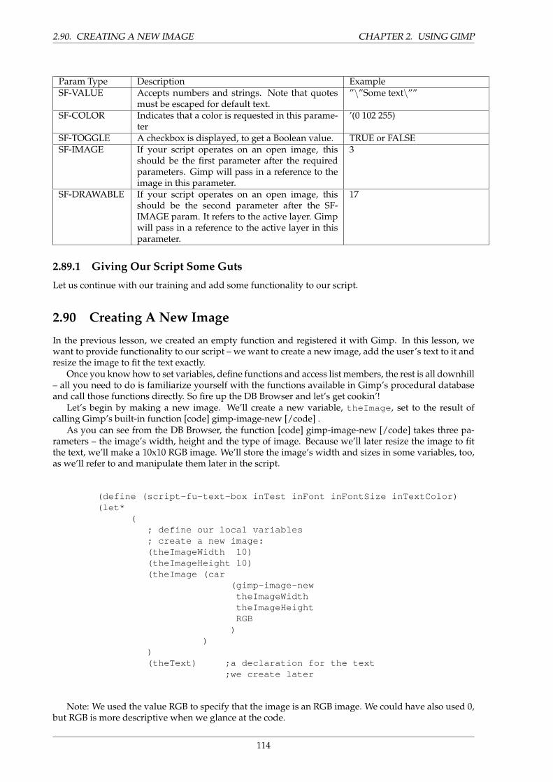
2.90. CREATING A NEW IMAGE CHAPTER 2. USING GIMP
Param Type Description ExampleSF-VALUE Accepts numbers and strings. Note that quotes
must be escaped for default text.”\”Some text\””
SF-COLOR Indicates that a color is requested in this parame-ter
’(0 102 255)
SF-TOGGLE A checkbox is displayed, to get a Boolean value. TRUE or FALSESF-IMAGE If your script operates on an open image, this
should be the first parameter after the requiredparameters. Gimp will pass in a reference to theimage in this parameter.
3
SF-DRAWABLE If your script operates on an open image, thisshould be the second parameter after the SF-IMAGE param. It refers to the active layer. Gimpwill pass in a reference to the active layer in thisparameter.
17
2.89.1 Giving Our Script Some Guts
Let us continue with our training and add some functionality to our script.
2.90 Creating A New Image
In the previous lesson, we created an empty function and registered it with Gimp. In this lesson, wewant to provide functionality to our script – we want to create a new image, add the user’s text to it andresize the image to fit the text exactly.
Once you know how to set variables, define functions and access list members, the rest is all downhill– all you need to do is familiarize yourself with the functions available in Gimp’s procedural databaseand call those functions directly. So fire up the DB Browser and let’s get cookin’!
Let’s begin by making a new image. We’ll create a new variable, theImage , set to the result ofcalling Gimp’s built-in function [code] gimp-image-new [/code] .
As you can see from the DB Browser, the function [code] gimp-image-new [/code] takes three pa-rameters – the image’s width, height and the type of image. Because we’ll later resize the image to fitthe text, we’ll make a 10x10 RGB image. We’ll store the image’s width and sizes in some variables, too,as we’ll refer to and manipulate them later in the script.
(define (script-fu-text-box inTest inFont inFontSize inTextColor)(let*
(; define our local variables; create a new image:(theImageWidth 10)(theImageHeight 10)(theImage (car
(gimp-image-newtheImageWidththeImageHeightRGB
))
)(theText) ;a declaration for the text
;we create later
Note: We used the value RGB to specify that the image is an RGB image. We could have also used 0,but RGB is more descriptive when we glance at the code.
114
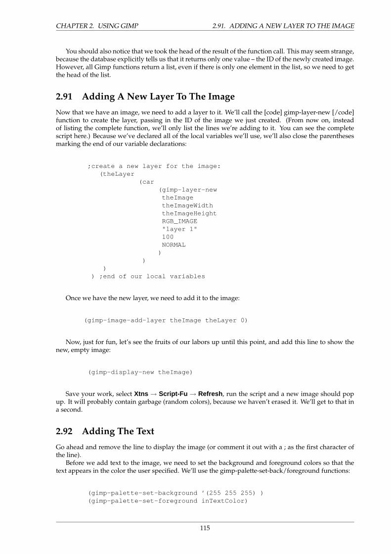
CHAPTER 2. USING GIMP 2.91. ADDING A NEW LAYER TO THE IMAGE
You should also notice that we took the head of the result of the function call. This may seem strange,because the database explicitly tells us that it returns only one value – the ID of the newly created image.However, all Gimp functions return a list, even if there is only one element in the list, so we need to getthe head of the list.
2.91 Adding A New Layer To The Image
Now that we have an image, we need to add a layer to it. We’ll call the [code] gimp-layer-new [/code]function to create the layer, passing in the ID of the image we just created. (From now on, insteadof listing the complete function, we’ll only list the lines we’re adding to it. You can see the completescript here.) Because we’ve declared all of the local variables we’ll use, we’ll also close the parenthesesmarking the end of our variable declarations:
;create a new layer for the image:(theLayer
(car(gimp-layer-new
theImagetheImageWidththeImageHeightRGB_IMAGE"layer 1"100NORMAL
))
)) ;end of our local variables
Once we have the new layer, we need to add it to the image:
(gimp-image-add-layer theImage theLayer 0)
Now, just for fun, let’s see the fruits of our labors up until this point, and add this line to show thenew, empty image:
(gimp-display-new theImage)
Save your work, select Xtns → Script-Fu → Refresh , run the script and a new image should popup. It will probably contain garbage (random colors), because we haven’t erased it. We’ll get to that ina second.
2.92 Adding The Text
Go ahead and remove the line to display the image (or comment it out with a ; as the first character ofthe line).
Before we add text to the image, we need to set the background and foreground colors so that thetext appears in the color the user specified. We’ll use the gimp-palette-set-back/foreground functions:
(gimp-palette-set-background ’(255 255 255) )(gimp-palette-set-foreground inTextColor)
115

2.93. CLEARING THE DIRTY FLAG CHAPTER 2. USING GIMP
With the colors properly set, let’s now clean out the garbage currently in the image. We’ll selecteverything in the image, and call clear:
(gimp-selection-all theImage)(gimp-edit-clear theImage theLayer)(gimp-selection-none theImage)
With the image cleared, we’re ready to add some text:
(set! theText(car
(gimp-texttheImagetheLayer0 0inText0TRUEinFontSizePIXELS"*" "*" "*"
))
)
Although a long function call, it’s fairly straightforward if you go over the parameters while lookingat the function’s entry in the DB Browser. Basically, we’re creating a new text layer and assigning it tothe variable theText .
Now that we have the text, we can grab its width and height and resize the image and the image’slayer to the text’s size:
(set! theImageWidth (car (gimp-drawable-width theText) ) )(set! theImageHeight (car (gimp-drawable-height theText) ) )
(gimp-image-resize theImage theImageWidth theImageHeight 0 0)
(gimp-layer-resize theLayer theImageWidth theImageHeight 0 0)
If you’re like me, you’re probably wondering what a drawable is when compared to a layer. Thedifference between the two is that a drawable is anything that can be drawn into, including layers butalso channels, layer masks, the selection, etc; a layer is a more specific version of a drawable. In mostcases, the distinction is not important.
With the image ready to go, we can now re-add our display line:
(gimp-display-new theImage)
Save your work, refresh the database and give your first script a run!
2.93 Clearing The Dirty Flag
If you try to close the image created without first saving the file, Gimp will ask you if you want to saveyour work before you close the image. It asks this because the image is marked as dirty, or unsaved. In
116
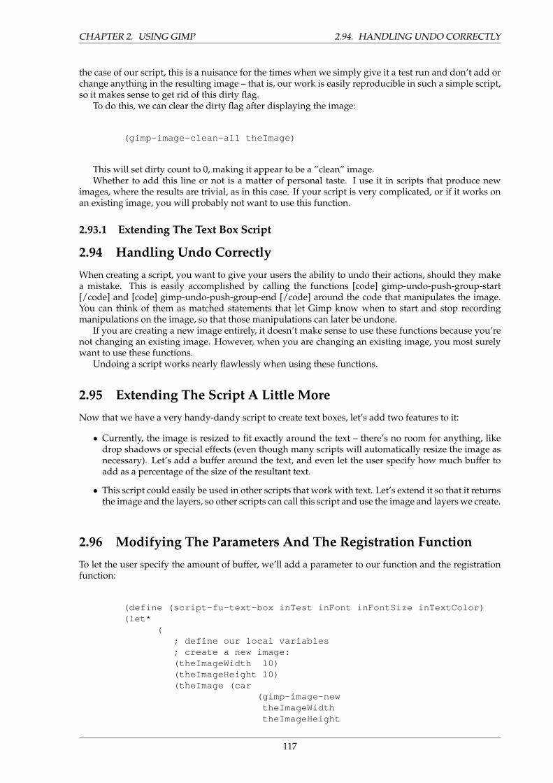
CHAPTER 2. USING GIMP 2.94. HANDLING UNDO CORRECTLY
the case of our script, this is a nuisance for the times when we simply give it a test run and don’t add orchange anything in the resulting image – that is, our work is easily reproducible in such a simple script,so it makes sense to get rid of this dirty flag.
To do this, we can clear the dirty flag after displaying the image:
(gimp-image-clean-all theImage)
This will set dirty count to 0, making it appear to be a ”clean” image.Whether to add this line or not is a matter of personal taste. I use it in scripts that produce new
images, where the results are trivial, as in this case. If your script is very complicated, or if it works onan existing image, you will probably not want to use this function.
2.93.1 Extending The Text Box Script
2.94 Handling Undo Correctly
When creating a script, you want to give your users the ability to undo their actions, should they makea mistake. This is easily accomplished by calling the functions [code] gimp-undo-push-group-start[/code] and [code] gimp-undo-push-group-end [/code] around the code that manipulates the image.You can think of them as matched statements that let Gimp know when to start and stop recordingmanipulations on the image, so that those manipulations can later be undone.
If you are creating a new image entirely, it doesn’t make sense to use these functions because you’renot changing an existing image. However, when you are changing an existing image, you most surelywant to use these functions.
Undoing a script works nearly flawlessly when using these functions.
2.95 Extending The Script A Little More
Now that we have a very handy-dandy script to create text boxes, let’s add two features to it:
• Currently, the image is resized to fit exactly around the text – there’s no room for anything, likedrop shadows or special effects (even though many scripts will automatically resize the image asnecessary). Let’s add a buffer around the text, and even let the user specify how much buffer toadd as a percentage of the size of the resultant text.
• This script could easily be used in other scripts that work with text. Let’s extend it so that it returnsthe image and the layers, so other scripts can call this script and use the image and layers we create.
2.96 Modifying The Parameters And The Registration Function
To let the user specify the amount of buffer, we’ll add a parameter to our function and the registrationfunction:
(define (script-fu-text-box inTest inFont inFontSize inTextColor)(let*
(; define our local variables; create a new image:(theImageWidth 10)(theImageHeight 10)(theImage (car
(gimp-image-newtheImageWidththeImageHeight
117
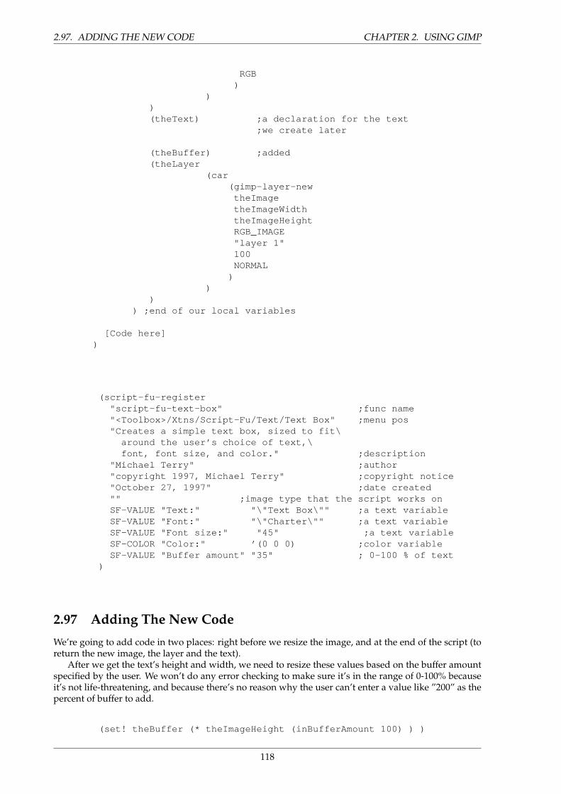
2.97. ADDING THE NEW CODE CHAPTER 2. USING GIMP
RGB)
))(theText) ;a declaration for the text
;we create later
(theBuffer) ;added(theLayer
(car(gimp-layer-new
theImagetheImageWidththeImageHeightRGB_IMAGE"layer 1"100NORMAL
))
)) ;end of our local variables
[Code here])
(script-fu-register"script-fu-text-box" ;func name"<Toolbox>/Xtns/Script-Fu/Text/Text Box" ;menu pos"Creates a simple text box, sized to fit\
around the user’s choice of text,\font, font size, and color." ;description
"Michael Terry" ;author"copyright 1997, Michael Terry" ;copyright notice"October 27, 1997" ;date created"" ;image type that the script works onSF-VALUE "Text:" "\"Text Box\"" ;a text variableSF-VALUE "Font:" "\"Charter\"" ;a text variableSF-VALUE "Font size:" "45" ;a text variableSF-COLOR "Color:" ’(0 0 0) ;color variableSF-VALUE "Buffer amount" "35" ; 0-100 % of text
)
2.97 Adding The New Code
We’re going to add code in two places: right before we resize the image, and at the end of the script (toreturn the new image, the layer and the text).
After we get the text’s height and width, we need to resize these values based on the buffer amountspecified by the user. We won’t do any error checking to make sure it’s in the range of 0-100% becauseit’s not life-threatening, and because there’s no reason why the user can’t enter a value like ”200” as thepercent of buffer to add.
(set! theBuffer (* theImageHeight (inBufferAmount 100) ) )
118
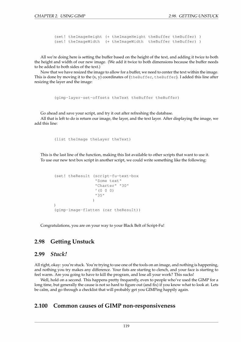
CHAPTER 2. USING GIMP 2.98. GETTING UNSTUCK
(set! theImageHeight (+ theImageHeight theBuffer theBuffer) )(set! theImageWidth (+ theImageWidth theBuffer theBuffer) )
All we’re doing here is setting the buffer based on the height of the text, and adding it twice to boththe height and width of our new image. (We add it twice to both dimensions because the buffer needsto be added to both sides of the text.)
Now that we have resized the image to allow for a buffer, we need to center the text within the image.This is done by moving it to the (x, y) coordinates of (theBuffer , theBuffer ). I added this line afterresizing the layer and the image:
(gimp-layer-set-offsets theText theBuffer theBuffer)
Go ahead and save your script, and try it out after refreshing the database.All that is left to do is return our image, the layer, and the text layer. After displaying the image, we
add this line:
(list theImage theLayer theText)
This is the last line of the function, making this list available to other scripts that want to use it.To use our new text box script in another script, we could write something like the following:
(set! theResult (script-fu-text-box"Some text""Charter" "30"’(0 0 0)"35"
))(gimp-image-flatten (car theResult))
Congratulations, you are on your way to your Black Belt of Script-Fu!
2.98 Getting Unstuck
2.99 Stuck!
All right, okay: you’re stuck. You’re trying to use one of the tools on an image, and nothing is happening,and nothing you try makes any difference. Your fists are starting to clench, and your face is starting tofeel warm. Are you going to have to kill the program, and lose all your work? This sucks!
Well, hold on a second. This happens pretty frequently, even to people who’ve used the GIMP for along time, but generally the cause is not so hard to figure out (and fix) if you know what to look at. Letsbe calm, and go through a checklist that will probably get you GIMPing happily again.
2.100 Common causes of GIMP non-responsiveness
119
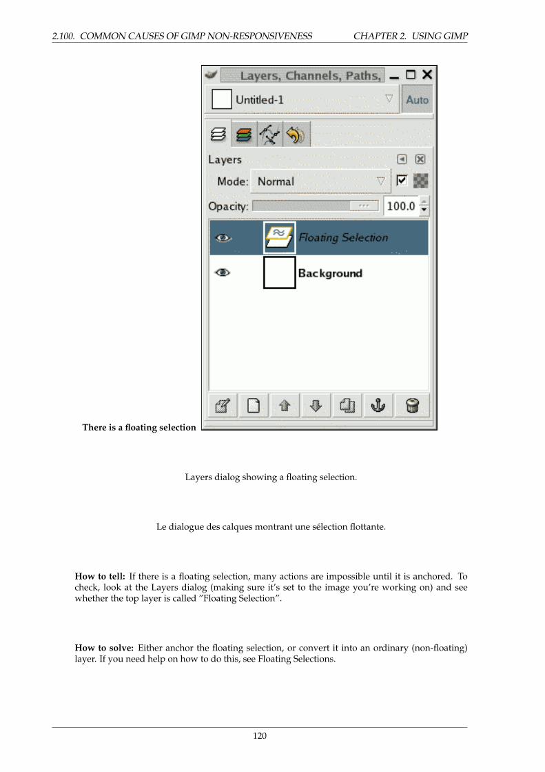
2.100. COMMON CAUSES OF GIMP NON-RESPONSIVENESS CHAPTER 2. USING GIMP
There is a floating selection
Layers dialog showing a floating selection.
Le dialogue des calques montrant une selection flottante.
How to tell: If there is a floating selection, many actions are impossible until it is anchored. Tocheck, look at the Layers dialog (making sure it’s set to the image you’re working on) and seewhether the top layer is called ”Floating Selection”.
How to solve: Either anchor the floating selection, or convert it into an ordinary (non-floating)layer. If you need help on how to do this, see Floating Selections.
120
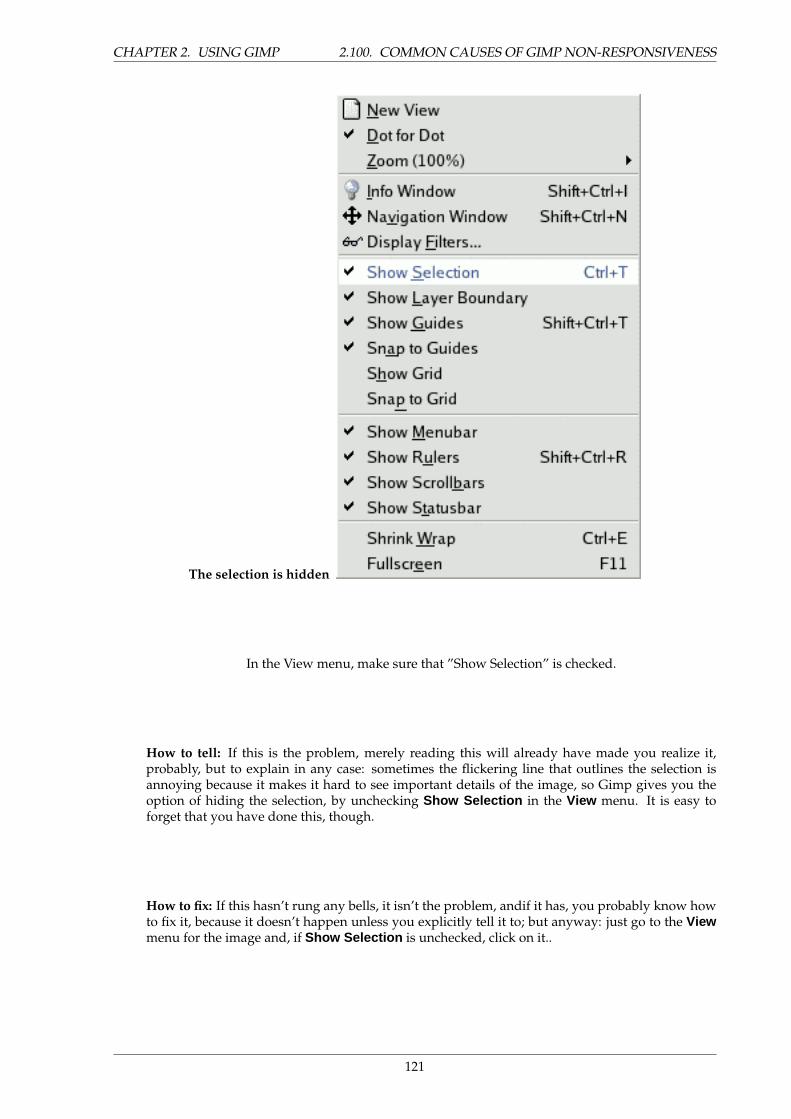
CHAPTER 2. USING GIMP 2.100. COMMON CAUSES OF GIMP NON-RESPONSIVENESS
The selection is hidden
In the View menu, make sure that ”Show Selection” is checked.
How to tell: If this is the problem, merely reading this will already have made you realize it,probably, but to explain in any case: sometimes the flickering line that outlines the selection isannoying because it makes it hard to see important details of the image, so Gimp gives you theoption of hiding the selection, by unchecking Show Selection in the View menu. It is easy toforget that you have done this, though.
How to fix: If this hasn’t rung any bells, it isn’t the problem, andif it has, you probably know howto fix it, because it doesn’t happen unless you explicitly tell it to; but anyway: just go to the Viewmenu for the image and, if Show Selection is unchecked, click on it..
121
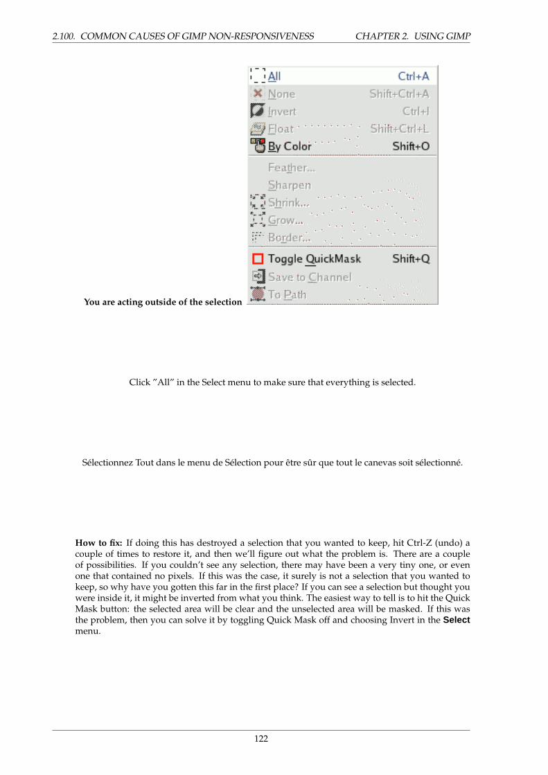
2.100. COMMON CAUSES OF GIMP NON-RESPONSIVENESS CHAPTER 2. USING GIMP
You are acting outside of the selection
Click ”All” in the Select menu to make sure that everything is selected.
Selectionnez Tout dans le menu de Selection pour etre sur que tout le canevas soit selectionne.
How to fix: If doing this has destroyed a selection that you wanted to keep, hit Ctrl-Z (undo) acouple of times to restore it, and then we’ll figure out what the problem is. There are a coupleof possibilities. If you couldn’t see any selection, there may have been a very tiny one, or evenone that contained no pixels. If this was the case, it surely is not a selection that you wanted tokeep, so why have you gotten this far in the first place? If you can see a selection but thought youwere inside it, it might be inverted from what you think. The easiest way to tell is to hit the QuickMask button: the selected area will be clear and the unselected area will be masked. If this wasthe problem, then you can solve it by toggling Quick Mask off and choosing Invert in the Selectmenu.
122
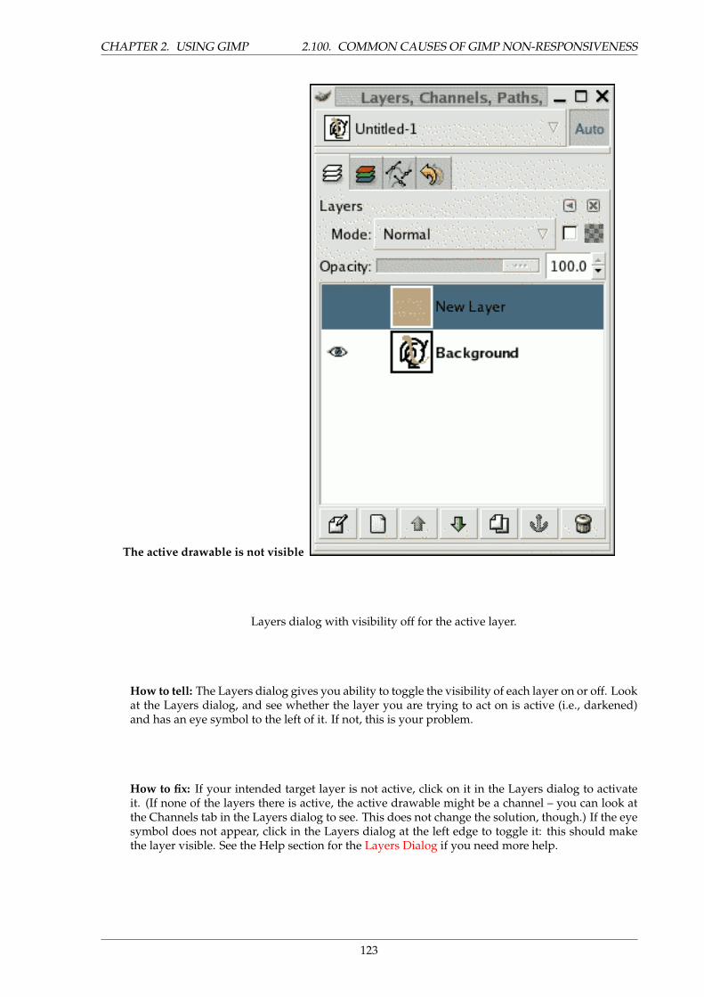
CHAPTER 2. USING GIMP 2.100. COMMON CAUSES OF GIMP NON-RESPONSIVENESS
The active drawable is not visible
Layers dialog with visibility off for the active layer.
How to tell: The Layers dialog gives you ability to toggle the visibility of each layer on or off. Lookat the Layers dialog, and see whether the layer you are trying to act on is active (i.e., darkened)and has an eye symbol to the left of it. If not, this is your problem.
How to fix: If your intended target layer is not active, click on it in the Layers dialog to activateit. (If none of the layers there is active, the active drawable might be a channel – you can look atthe Channels tab in the Layers dialog to see. This does not change the solution, though.) If the eyesymbol does not appear, click in the Layers dialog at the left edge to toggle it: this should makethe layer visible. See the Help section for the Layers Dialog if you need more help.
123
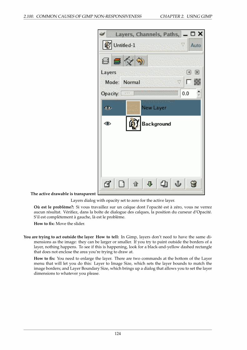
2.100. COMMON CAUSES OF GIMP NON-RESPONSIVENESS CHAPTER 2. USING GIMP
The active drawable is transparent
Layers dialog with opacity set to zero for the active layer.
Ou est le probleme?: Si vous travaillez sur un calque dont l’opacite est a zero, vous ne verrezaucun resultat. Verifiez, dans la boıte de dialogue des calques, la position du curseur d’Opacite.S’il est completement a gauche, la est le probleme.
How to fix: Move the slider.
You are trying to act outside the layer How to tell: In Gimp, layers don’t need to have the same di-mensions as the image: they can be larger or smaller. If you try to paint outside the borders of alayer, nothing happens. To see if this is happening, look for a black-and-yellow dashed rectanglethat does not enclose the area you’re trying to draw at.
How to fix: You need to enlarge the layer. There are two commands at the bottom of the Layermenu that will let you do this: Layer to Image Size, which sets the layer bounds to match theimage borders; and Layer Boundary Size, which brings up a dialog that allows you to set the layerdimensions to whatever you please.
124
Chapter 3
Toolbox
3.1 The Toolbox
The GIMP provides a comprehensive toolbox in order to quickly perform basic tasks such as makingselections or drawing paths. The many tools contained within The GIMP’s toolbox are discussed indetail here.
The GIMP has a diverse assortment of tools that let you perform a large variety of tasks. The toolscan be thought of as falling into five categories: Selection tools, which specify or modify the portion ofthe image that will be affected by subsequent actions; Paint tools, which alter the colors in some part ofthe image; Transform tools, which alter the geometry of the image; Color tools, which alter the distributionof colors across the entire image; and Other tools, which don’t fall into the other four categories.
(In case you’re curious, in Gimp lingo a ”tool” is a way of acting on an image that requires accessto its display, either to let you indicate what you want to do by moving the pointer around inside thedisplay, or to show you interactively the results of changes that you have made. But if you want to thinkof a tool as a saw, and an image as a piece of wood, it probably won’t do you a great deal of harm.)
Most tools can be activated by clicking on an icon in the Toolbox. Some, however (namely, the Colortools), are accessible only via the menus, either as Tools->Color Tools or as Layer->Colors. Every tool, infact, can be activated from the Tools menu; also, every tool can be activated from the keyboard using anaccelerator key.
In the default setup, created when GIMP is first installed, not all tools show icons in the Toolbox: theColor tools are omitted. You can customize the set of tools that are shown in the Toolbox using the Toolsdialog. There are two reasons you might want to do this: first, if you only rarely use a tool, it might beeasier to find the tools you want if the distracting icon is removed; second, if you use the Color tools alot, you might find it convenient to have icons for them easily available. In any case, regardless of theToolbox, you can always access any tool at any time using the Tools menu from an image menubar.
The shape of the cursor changes when it is inside an image, to one that indicates which tool is active.
125
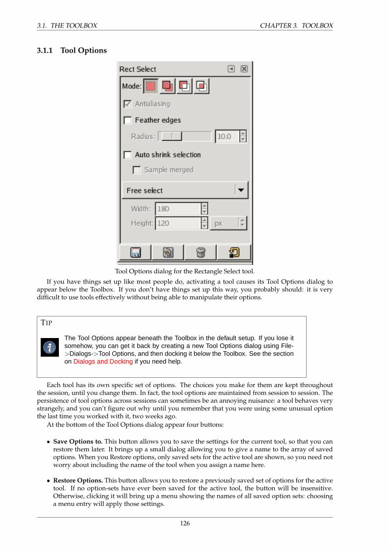
3.1. THE TOOLBOX CHAPTER 3. TOOLBOX
3.1.1 Tool Options
Tool Options dialog for the Rectangle Select tool.
If you have things set up like most people do, activating a tool causes its Tool Options dialog toappear below the Toolbox. If you don’t have things set up this way, you probably should: it is verydifficult to use tools effectively without being able to manipulate their options.
TIP
The Tool Options appear beneath the Toolbox in the default setup. If you lose itsomehow, you can get it back by creating a new Tool Options dialog using File->Dialogs->Tool Options, and then docking it below the Toolbox. See the sectionon Dialogs and Docking if you need help.
Each tool has its own specific set of options. The choices you make for them are kept throughoutthe session, until you change them. In fact, the tool options are maintained from session to session. Thepersistence of tool options across sessions can sometimes be an annoying nuisance: a tool behaves verystrangely, and you can’t figure out why until you remember that you were using some unusual optionthe last time you worked with it, two weeks ago.
At the bottom of the Tool Options dialog appear four buttons:
• Save Options to. This button allows you to save the settings for the current tool, so that you canrestore them later. It brings up a small dialog allowing you to give a name to the array of savedoptions. When you Restore options, only saved sets for the active tool are shown, so you need notworry about including the name of the tool when you assign a name here.
• Restore Options. This button allows you to restore a previously saved set of options for the activetool. If no option-sets have ever been saved for the active tool, the button will be insensitive.Otherwise, clicking it will bring up a menu showing the names of all saved option sets: choosinga menu entry will apply those settings.
126

CHAPTER 3. TOOLBOX 3.2. SELECTION TOOLS
• Delete Options. This button allows you to delete a previously saved set of options for the activetool. If no option-sets have ever been saved for the active tool, the button will be insensitive.Otherwise, clicking it will bring up a menu showing the names of all saved option sets: choosinga menu entry will delete those settings.
• Reset Options. This button resets the options for the active tool to their default values.
3.2 Selection Tools
3.2.1 Common Features
Selection tools are designed to select regions from images or layers so you can work on them withoutaffecting the unselected areas. Each tool has its own individual properties, but the selection tools alsoshare a number of options and features in common. These common features are described here; thevariations are explained in the following sections for each tool specifically. If you need help with whata ”selection” is in Gimp, and how it works, see Selection.
There are six selection tools:
• Rectangle Select
• Ellipse Select
• Free Select (the Lasso)
• Select Contiguous Regions (the Magic Wand)
• Select by Color
• Select Shapes from Image (Intelligent Scissors)
In some ways the Path tool can also be thought of as a selection tool: any closed path can be convertedinto a selection. It also can do a great deal more, though, and does not share the same set of options withthe other selection tools.
3.3 Key modifiers (Defaults)
The behavior of selection tools is modified if you hold down the Ctrl, Shift, and/or Alt keys while youuse them.
NOTE
Advanced users find the modifier keys very valuable, but novice users often findthem confusing. Fortunately, it is possible for most purposes to use the Modebuttons (described below) instead of modifier keys.
Ctrl Holding Ctrl while creating a selection can have as many as two effects simultaneously. The firsteffect is variable depending on which tool you are using: see the individual tool’s documentationfor this. The second effect, is common to all selection tools: it puts the tool into subtraction mode,so that the region you trace out is subtracted from the pre-existing selection. If you only want oneof these actions to take place, you can release the Ctrl key prior to releasing the mouse button.Doing so will leave the selection in subtraction mode, but not perform the tool-specific action.
Alt Holding Alt will allow movement of the current selection (only its frame, not its content). If thewhole image is moved instead of the selection only, try Shift+Alt. Note that the Alt key is some-times intercepted by the windowing system (meaning that Gimp never knows that it was pressed),so this may not work for everybody.
127
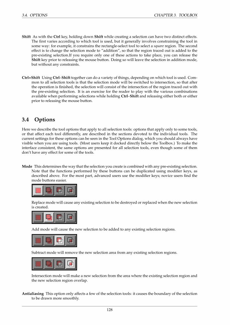
3.4. OPTIONS CHAPTER 3. TOOLBOX
Shift As with the Ctrl key, holding down Shift while creating a selection can have two distinct effects.The first varies according to which tool is used, but it generally involves constraining the tool insome way: for example, it constrains the rectangle-select tool to select a square region. The secondeffect is to change the selection mode to ”addition”, so that the region traced out is added to thepre-existing selection.If you require only one of these actions to take place, you can release theShift key prior to releasing the mouse button. Doing so will leave the selection in addition mode,but without any constraints.
Ctrl+Shift Using Ctrl–Shift together can do a variety of things, depending on which tool is used. Com-mon to all selection tools is that the selection mode will be switched to intersection, so that afterthe operation is finished, the selection will consist of the intersection of the region traced out withthe pre-existing selection. It is an exercise for the reader to play with the various combinationsavailable when performing selections while holding Ctrl–Shift and releasing either both or eitherprior to releasing the mouse button.
3.4 Options
Here we describe the tool options that apply to all selection tools: options that apply only to some tools,or that affect each tool differently, are described in the sections devoted to the individual tools. Thecurrent settings for these options can be seen in the Tool Options dialog, which you should always havevisible when you are using tools. (Most users keep it docked directly below the Toolbox.) To make theinterface consistent, the same options are presented for all selection tools, even though some of themdon’t have any effect for some of the tools.
Mode This determines the way that the selection you create is combined with any pre-existing selection.Note that the functions performed by these buttons can be duplicated using modifier keys, asdescribed above. For the most part, advanced users use the modifier keys; novice users find themode buttons easier.
Replace mode will cause any existing selection to be destroyed or replaced when the new selectionis created.
Add mode will cause the new selection to be added to any existing selection regions.
Subtract mode will remove the new selection area from any existing selection regions.
Intersection mode will make a new selection from the area where the existing selection region andthe new selection region overlap.
Antialiasing This option only affects a few of the selection tools: it causes the boundary of the selectionto be drawn more smoothly.
128
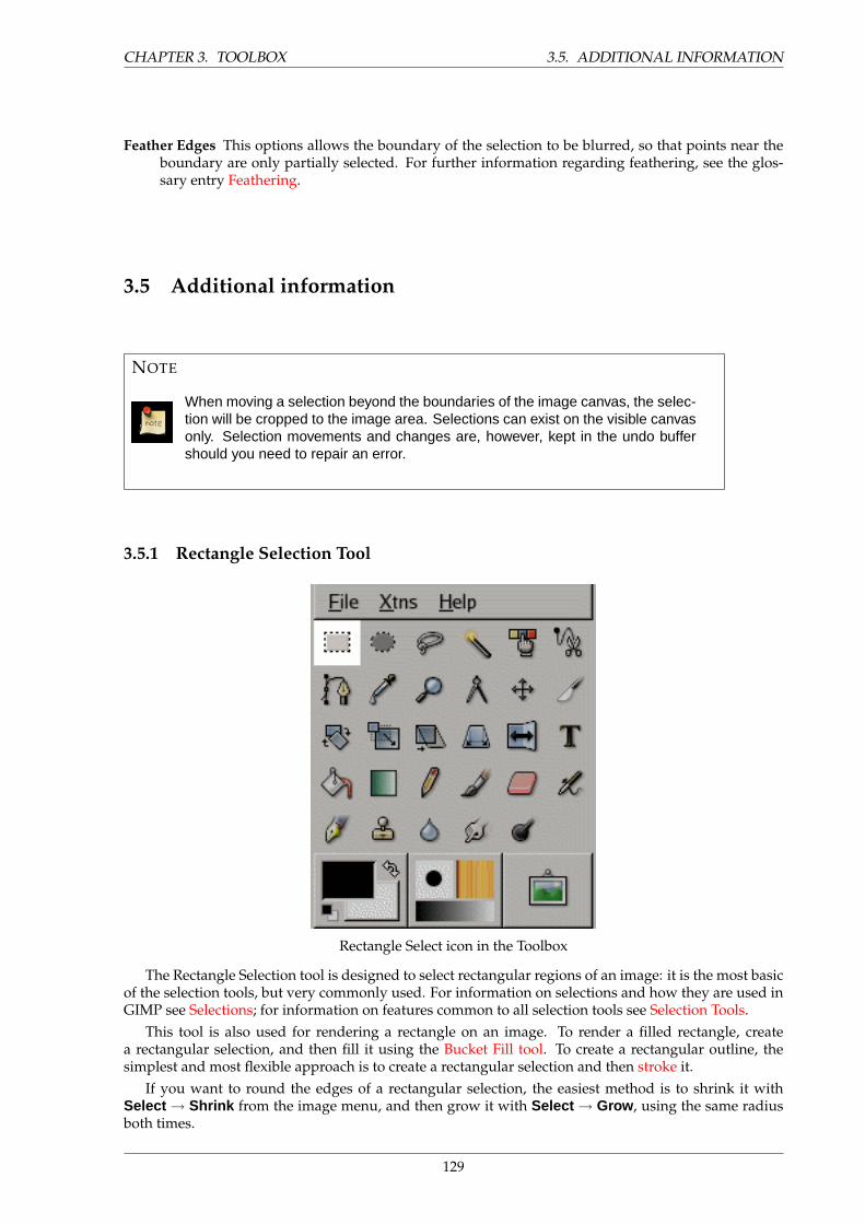
CHAPTER 3. TOOLBOX 3.5. ADDITIONAL INFORMATION
Feather Edges This options allows the boundary of the selection to be blurred, so that points near theboundary are only partially selected. For further information regarding feathering, see the glos-sary entry Feathering.
3.5 Additional information
NOTE
When moving a selection beyond the boundaries of the image canvas, the selec-tion will be cropped to the image area. Selections can exist on the visible canvasonly. Selection movements and changes are, however, kept in the undo buffershould you need to repair an error.
3.5.1 Rectangle Selection Tool
Rectangle Select icon in the Toolbox
The Rectangle Selection tool is designed to select rectangular regions of an image: it is the most basicof the selection tools, but very commonly used. For information on selections and how they are used inGIMP see Selections; for information on features common to all selection tools see Selection Tools.
This tool is also used for rendering a rectangle on an image. To render a filled rectangle, createa rectangular selection, and then fill it using the Bucket Fill tool. To create a rectangular outline, thesimplest and most flexible approach is to create a rectangular selection and then stroke it.
If you want to round the edges of a rectangular selection, the easiest method is to shrink it withSelect → Shrink from the image menu, and then grow it with Select → Grow , using the same radiusboth times.
129

3.6. HOW TO ACTIVATE CHAPTER 3. TOOLBOX
3.6 How to Activate
The Rectangle Selection Tool can be activated from an image menu as Tools → Selection Tools → Rect
Select ; from the Toolbox by clicking on the tool icon ; or from the keyboard using the shortcut r.
3.7 Key modifiers
NOTE
See Selection Tools for help with modifier keys that affect all these tools in thesame way. Only effects that are specific to the Rectangle Select tool are ex-plained here.
• Ctrl: Pressing the Ctrl key after starting your selection, and holding it down until you are finished,causes your starting point to be used as the center of the selected rectangle, instead of a corner.Note that if you press the Ctrl key before starting to make the selection, the resulting selection willbe subtracted from the existing selection.
• Shift: Pressing the Shift key after starting your selection, and holding it down until you are fin-ished, constrains the selection to be square. Note that if you press the Shift key before starting tomake the selection, the resulting selection will be added to the existing selection.
• Ctrl–Shift: Pressing both keys combines the two effects, giving you a square selection centered onyour starting point.
3.8 Tool Options
130
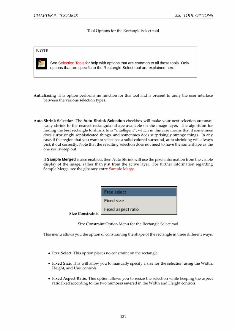
CHAPTER 3. TOOLBOX 3.8. TOOL OPTIONS
Tool Options for the Rectangle Select tool
NOTE
See Selection Tools for help with options that are common to all these tools. Onlyoptions that are specific to the Rectangle Select tool are explained here.
Antialiasing This option performs no function for this tool and is present to unify the user interfacebetween the various selection types.
Auto Shrink Selection The Auto Shrink Selection checkbox will make your next selection automat-ically shrink to the nearest rectangular shape available on the image layer. The algorithm forfinding the best rectangle to shrink to is ”intelligent”, which in this case means that it sometimesdoes surprisingly sophisticated things, and sometimes does surprisingly strange things. In anycase, if the region that you want to select has a solid-colored surround, auto-shrinking will alwayspick it out correctly. Note that the resulting selection does not need to have the same shape as theone you sweep out.
If Sample Merged is also enabled, then Auto Shrink will use the pixel information from the visibledisplay of the image, rather than just from the active layer. For further information regardingSample Merge, see the glossary entry Sample Merge.
Size Constraints
Size Constraint Option Menu for the Rectangle Select tool
This menu allows you the option of constraining the shape of the rectangle in three different ways.
• Free Select. This option places no constraint on the rectangle.
• Fixed Size. This will allow you to manually specify a size for the selection using the Width,Height, and Unit controls.
• Fixed Aspect Ratio. This option allows you to resize the selection while keeping the aspectratio fixed according to the two numbers entered in the Width and Height controls.
131
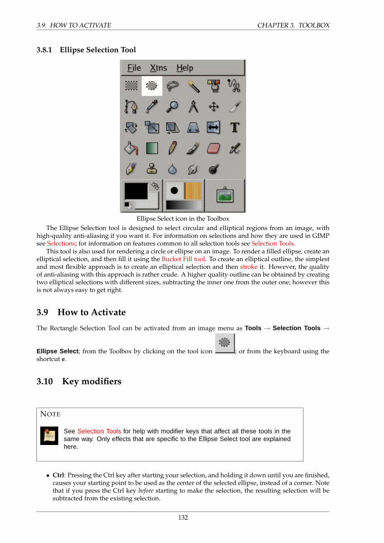
3.9. HOW TO ACTIVATE CHAPTER 3. TOOLBOX
3.8.1 Ellipse Selection Tool
Ellipse Select icon in the ToolboxThe Ellipse Selection tool is designed to select circular and elliptical regions from an image, with
high-quality anti-aliasing if you want it. For information on selections and how they are used in GIMPsee Selections; for information on features common to all selection tools see Selection Tools.
This tool is also used for rendering a circle or ellipse on an image. To render a filled ellipse, create anelliptical selection, and then fill it using the Bucket Fill tool. To create an elliptical outline, the simplestand most flexible approach is to create an elliptical selection and then stroke it. However, the qualityof anti-aliasing with this approach is rather crude. A higher quality outline can be obtained by creatingtwo elliptical selections with different sizes, subtracting the inner one from the outer one; however thisis not always easy to get right.
3.9 How to Activate
The Rectangle Selection Tool can be activated from an image menu as Tools → Selection Tools →
Ellipse Select ; from the Toolbox by clicking on the tool icon ; or from the keyboard using theshortcut e.
3.10 Key modifiers
NOTE
See Selection Tools for help with modifier keys that affect all these tools in thesame way. Only effects that are specific to the Ellipse Select tool are explainedhere.
• Ctrl: Pressing the Ctrl key after starting your selection, and holding it down until you are finished,causes your starting point to be used as the center of the selected ellipse, instead of a corner. Notethat if you press the Ctrl key before starting to make the selection, the resulting selection will besubtracted from the existing selection.
132
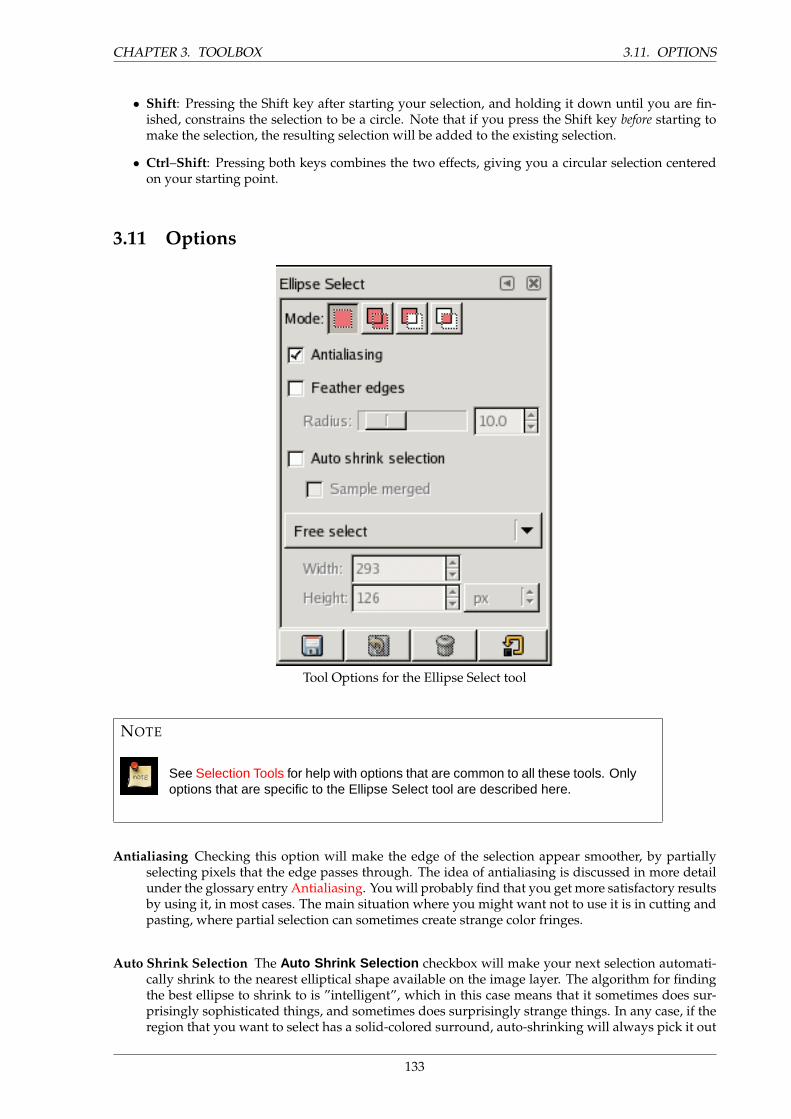
CHAPTER 3. TOOLBOX 3.11. OPTIONS
• Shift: Pressing the Shift key after starting your selection, and holding it down until you are fin-ished, constrains the selection to be a circle. Note that if you press the Shift key before starting tomake the selection, the resulting selection will be added to the existing selection.
• Ctrl–Shift: Pressing both keys combines the two effects, giving you a circular selection centeredon your starting point.
3.11 Options
Tool Options for the Ellipse Select tool
NOTE
See Selection Tools for help with options that are common to all these tools. Onlyoptions that are specific to the Ellipse Select tool are described here.
Antialiasing Checking this option will make the edge of the selection appear smoother, by partiallyselecting pixels that the edge passes through. The idea of antialiasing is discussed in more detailunder the glossary entry Antialiasing. You will probably find that you get more satisfactory resultsby using it, in most cases. The main situation where you might want not to use it is in cutting andpasting, where partial selection can sometimes create strange color fringes.
Auto Shrink Selection The Auto Shrink Selection checkbox will make your next selection automati-cally shrink to the nearest elliptical shape available on the image layer. The algorithm for findingthe best ellipse to shrink to is ”intelligent”, which in this case means that it sometimes does sur-prisingly sophisticated things, and sometimes does surprisingly strange things. In any case, if theregion that you want to select has a solid-colored surround, auto-shrinking will always pick it out
133
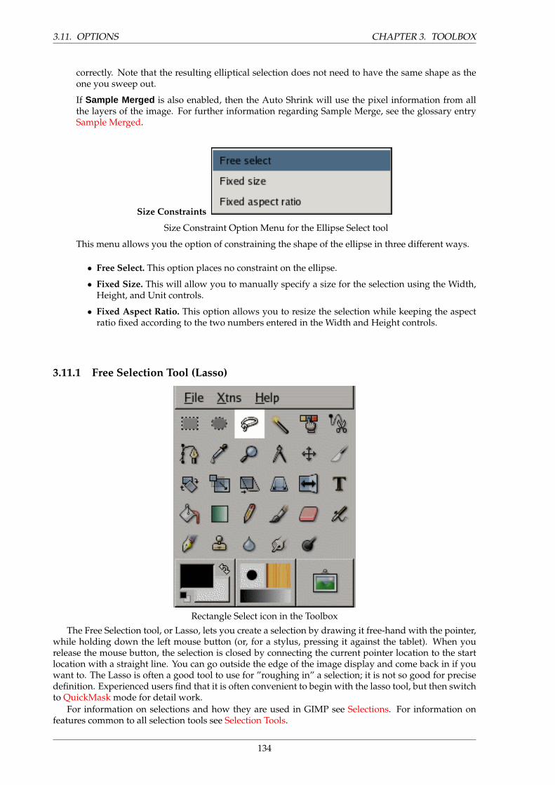
3.11. OPTIONS CHAPTER 3. TOOLBOX
correctly. Note that the resulting elliptical selection does not need to have the same shape as theone you sweep out.
If Sample Merged is also enabled, then the Auto Shrink will use the pixel information from allthe layers of the image. For further information regarding Sample Merge, see the glossary entrySample Merged.
Size Constraints
Size Constraint Option Menu for the Ellipse Select tool
This menu allows you the option of constraining the shape of the ellipse in three different ways.
• Free Select. This option places no constraint on the ellipse.
• Fixed Size. This will allow you to manually specify a size for the selection using the Width,Height, and Unit controls.
• Fixed Aspect Ratio. This option allows you to resize the selection while keeping the aspectratio fixed according to the two numbers entered in the Width and Height controls.
3.11.1 Free Selection Tool (Lasso)
Rectangle Select icon in the Toolbox
The Free Selection tool, or Lasso, lets you create a selection by drawing it free-hand with the pointer,while holding down the left mouse button (or, for a stylus, pressing it against the tablet). When yourelease the mouse button, the selection is closed by connecting the current pointer location to the startlocation with a straight line. You can go outside the edge of the image display and come back in if youwant to. The Lasso is often a good tool to use for ”roughing in” a selection; it is not so good for precisedefinition. Experienced users find that it is often convenient to begin with the lasso tool, but then switchto QuickMask mode for detail work.
For information on selections and how they are used in GIMP see Selections. For information onfeatures common to all selection tools see Selection Tools.
134
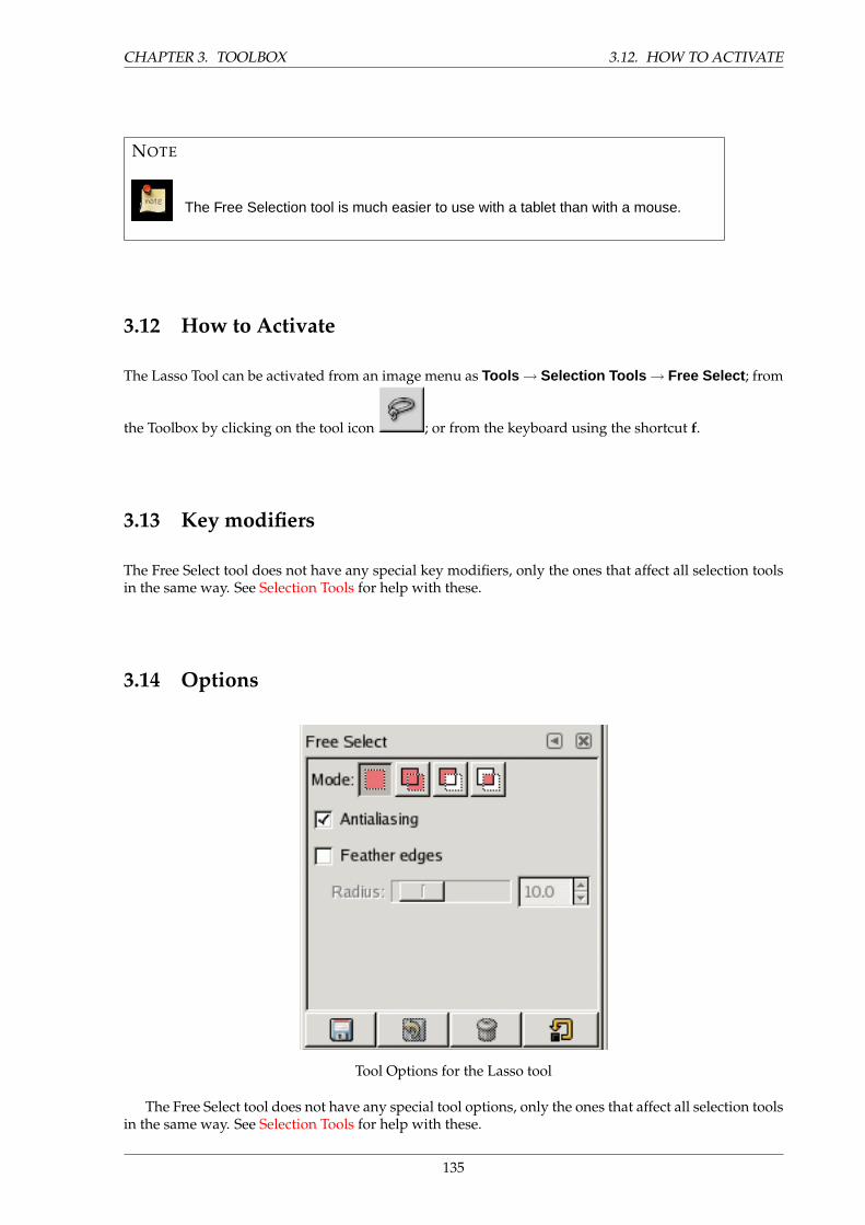
CHAPTER 3. TOOLBOX 3.12. HOW TO ACTIVATE
NOTE
The Free Selection tool is much easier to use with a tablet than with a mouse.
3.12 How to Activate
The Lasso Tool can be activated from an image menu as Tools → Selection Tools → Free Select ; from
the Toolbox by clicking on the tool icon ; or from the keyboard using the shortcut f.
3.13 Key modifiers
The Free Select tool does not have any special key modifiers, only the ones that affect all selection toolsin the same way. See Selection Tools for help with these.
3.14 Options
Tool Options for the Lasso tool
The Free Select tool does not have any special tool options, only the ones that affect all selection toolsin the same way. See Selection Tools for help with these.
135
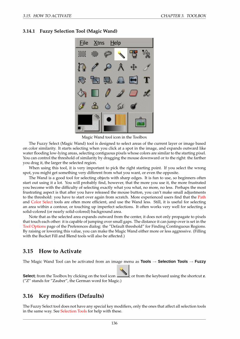
3.15. HOW TO ACTIVATE CHAPTER 3. TOOLBOX
3.14.1 Fuzzy Selection Tool (Magic Wand)
Magic Wand tool icon in the Toolbox
The Fuzzy Select (Magic Wand) tool is designed to select areas of the current layer or image basedon color similarity. It starts selecting when you click at a spot in the image, and expands outward likewater flooding low-lying areas, selecting contiguous pixels whose colors are similar to the starting pixel.You can control the threshold of similarity by dragging the mouse downward or to the right: the fartheryou drag it, the larger the selected region.
When using this tool, it is very important to pick the right starting point. If you select the wrongspot, you might get something very different from what you want, or even the opposite.
The Wand is a good tool for selecting objects with sharp edges. It is fun to use, so beginners oftenstart out using it a lot. You will probably find, however, that the more you use it, the more frustratedyou become with the difficulty of selecting exactly what you what, no more, no less. Perhaps the mostfrustrating aspect is that after you have released the mouse button, you can’t make small adjustmentsto the threshold: you have to start over again from scratch. More experienced users find that the Pathand Color Select tools are often more efficient, and use the Wand less. Still, it is useful for selectingan area within a contour, or touching up imperfect selections. It often works very well for selecting asolid-colored (or nearly solid-colored) background area.
Note that as the selected area expands outward from the center, it does not only propagate to pixelsthat touch each other: it is capable of jumping over small gaps. The distance it can jump over is set in theTool Options page of the Preferences dialog: the ”Default threshold” for Finding Continguous Regions.By raising or lowering this value, you can make the Magic Wand either more or less aggressive. (Fillingwith the Bucket Fill and Blend tools will also be affected.)
3.15 How to Activate
The Magic Wand Tool can be activated from an image menu as Tools → Selection Tools → Fuzzy
Select ; from the Toolbox by clicking on the tool icon ; or from the keyboard using the shortcut z.(”Z” stands for ”Zauber”, the German word for Magic.)
3.16 Key modifiers (Defaults)
The Fuzzy Select tool does not have any special key modifiers, only the ones that affect all selection toolsin the same way. See Selection Tools for help with these.
136
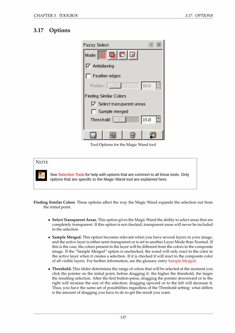
CHAPTER 3. TOOLBOX 3.17. OPTIONS
3.17 Options
Tool Options for the Magic Wand tool
NOTE
See Selection Tools for help with options that are common to all these tools. Onlyoptions that are specific to the Magic Wand tool are explained here.
Finding Similar Colors These options affect the way the Magic Wand expands the selection out fromthe initial point.
• Select Transparent Areas. This option gives the Magic Wand the ability to select areas that arecompletely transparent. If this option is not checked, transparent areas will never be includedin the selection.
• Sample Merged. This option becomes relevant when you have several layers in your image,and the active layer is either semi-transparent or is set to another Layer Mode than Normal. Ifthis is the case, the colors present in the layer will be different from the colors in the compositeimage. If the ”Sample Merged” option is unchecked, the wand will only react to the color inthe active layer when it creates a selection. If it is checked it will react to the composite colorof all visible layers. For further information, see the glossary entry Sample Merged.
• Threshold. This slider determines the range of colors that will be selected at the moment youclick the pointer on the initial point, before dragging it: the higher the threshold, the largerthe resulting selection. After the first button-press, dragging the pointer downward or to theright will increase the size of the selection; dragging upward or to the left will decrease it.Thus, you have the same set of possibilities regardless of the Threshold setting: what differsis the amount of dragging you have to do to get the result you want.
137
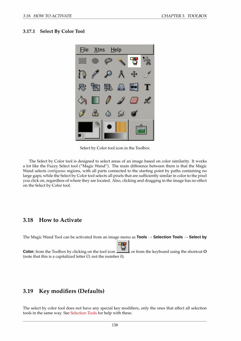
3.18. HOW TO ACTIVATE CHAPTER 3. TOOLBOX
3.17.1 Select By Color Tool
Select by Color tool icon in the Toolbox
The Select by Color tool is designed to select areas of an image based on color similarity. It worksa lot like the Fuzzy Select tool (”Magic Wand”). The main difference between them is that the MagicWand selects contiguous regions, with all parts connected to the starting point by paths containing nolarge gaps; while the Select by Color tool selects all pixels that are sufficiently similar in color to the pixelyou click on, regardless of where they are located. Also, clicking and dragging in the image has no effecton the Select by Color tool.
3.18 How to Activate
The Magic Wand Tool can be activated from an image menu as Tools → Selection Tools → Select by
Color ; from the Toolbox by clicking on the tool icon ; or from the keyboard using the shortcut O(note that this is a capitalized letter O, not the number 0).
3.19 Key modifiers (Defaults)
The select by color tool does not have any special key modifiers, only the ones that affect all selectiontools in the same way. See Selection Tools for help with these.
138
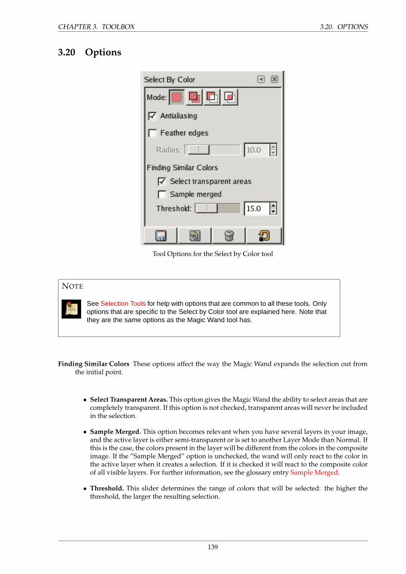
CHAPTER 3. TOOLBOX 3.20. OPTIONS
3.20 Options
Tool Options for the Select by Color tool
NOTE
See Selection Tools for help with options that are common to all these tools. Onlyoptions that are specific to the Select by Color tool are explained here. Note thatthey are the same options as the Magic Wand tool has.
Finding Similar Colors These options affect the way the Magic Wand expands the selection out fromthe initial point.
• Select Transparent Areas. This option gives the Magic Wand the ability to select areas that arecompletely transparent. If this option is not checked, transparent areas will never be includedin the selection.
• Sample Merged. This option becomes relevant when you have several layers in your image,and the active layer is either semi-transparent or is set to another Layer Mode than Normal. Ifthis is the case, the colors present in the layer will be different from the colors in the compositeimage. If the ”Sample Merged” option is unchecked, the wand will only react to the color inthe active layer when it creates a selection. If it is checked it will react to the composite colorof all visible layers. For further information, see the glossary entry Sample Merged.
• Threshold. This slider determines the range of colors that will be selected: the higher thethreshold, the larger the resulting selection.
139
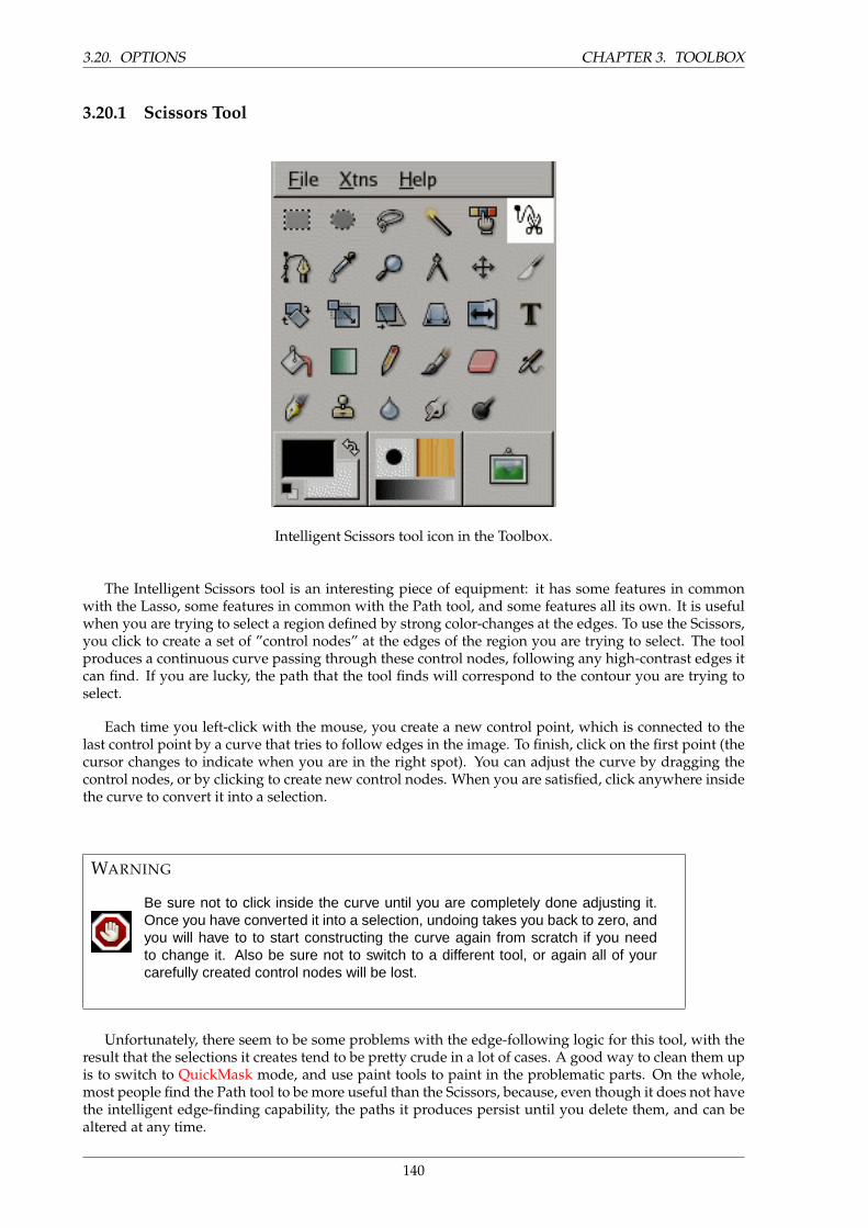
3.20. OPTIONS CHAPTER 3. TOOLBOX
3.20.1 Scissors Tool
Intelligent Scissors tool icon in the Toolbox.
The Intelligent Scissors tool is an interesting piece of equipment: it has some features in commonwith the Lasso, some features in common with the Path tool, and some features all its own. It is usefulwhen you are trying to select a region defined by strong color-changes at the edges. To use the Scissors,you click to create a set of ”control nodes” at the edges of the region you are trying to select. The toolproduces a continuous curve passing through these control nodes, following any high-contrast edges itcan find. If you are lucky, the path that the tool finds will correspond to the contour you are trying toselect.
Each time you left-click with the mouse, you create a new control point, which is connected to thelast control point by a curve that tries to follow edges in the image. To finish, click on the first point (thecursor changes to indicate when you are in the right spot). You can adjust the curve by dragging thecontrol nodes, or by clicking to create new control nodes. When you are satisfied, click anywhere insidethe curve to convert it into a selection.
WARNING
Be sure not to click inside the curve until you are completely done adjusting it.Once you have converted it into a selection, undoing takes you back to zero, andyou will have to to start constructing the curve again from scratch if you needto change it. Also be sure not to switch to a different tool, or again all of yourcarefully created control nodes will be lost.
Unfortunately, there seem to be some problems with the edge-following logic for this tool, with theresult that the selections it creates tend to be pretty crude in a lot of cases. A good way to clean them upis to switch to QuickMask mode, and use paint tools to paint in the problematic parts. On the whole,most people find the Path tool to be more useful than the Scissors, because, even though it does not havethe intelligent edge-finding capability, the paths it produces persist until you delete them, and can bealtered at any time.
140
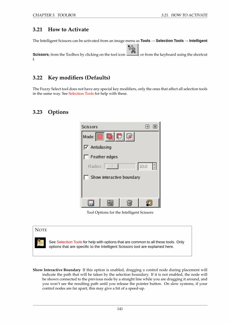
CHAPTER 3. TOOLBOX 3.21. HOW TO ACTIVATE
3.21 How to Activate
The Intelligent Scissors can be activated from an image menu as Tools → Selection Tools → Intelligent
Scissors ; from the Toolbox by clicking on the tool icon ; or from the keyboard using the shortcuti.
3.22 Key modifiers (Defaults)
The Fuzzy Select tool does not have any special key modifiers, only the ones that affect all selection toolsin the same way. See Selection Tools for help with these.
3.23 Options
Tool Options for the Intelligent Scissors
NOTE
See Selection Tools for help with options that are common to all these tools. Onlyoptions that are specific to the Intelligent Scissors tool are explained here.
Show Interactive Boundary If this option is enabled, dragging a control node during placement willindicate the path that will be taken by the selection boundary. If it is not enabled, the node willbe shown connected to the previous node by a straight line while you are dragging it around, andyou won’t see the resulting path until you release the pointer button. On slow systems, if yourcontrol nodes are far apart, this may give a bit of a speed-up.
141
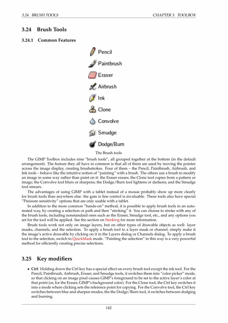
3.24. BRUSH TOOLS CHAPTER 3. TOOLBOX
3.24 Brush Tools
3.24.1 Common Features
The Brush tools
The GIMP Toolbox includes nine ”brush tools”, all grouped together at the bottom (in the defaultarrangement). The feature they all have in common is that all of them are used by moving the pointeracross the image display, creating brushstrokes. Four of them – the Pencil, Paintbrush, Airbrush, andInk tools – behave like the intuitive notion of ”painting” with a brush. The others use a brush to modifyan image in some way rather than paint on it: the Eraser erases; the Clone tool copies from a pattern orimage; the Convolve tool blurs or sharpens; the Dodge/Burn tool lightens or darkens; and the Smudgetool smears.
The advantages of using GIMP with a tablet instead of a mouse probably show up more clearlyfor brush tools than anywhere else: the gain is fine control is invaluable. These tools also have special”Pressure sensitivity” options that are only usable with a tablet.
In addition to the more common ”hands-on” method, it is possible to apply brush tools in an auto-mated way, by creating a selection or path and then ”stroking” it. You can choose to stroke with any ofthe brush tools, including nonstandard ones such as the Eraser, Smudge tool, etc., and any options youset for the tool will be applied. See the section on Stroking for more information.
Brush tools work not only on image layers, but on other types of drawable objects as well: layermasks, channels, and the selection. To apply a brush tool to a layer mask or channel, simply make itthe image’s active drawable by clicking on it in the Layers dialog or Channels dialog. To apply a brushtool to the selection, switch to QuickMask mode. ”Painting the selection” in this way is a very powerfulmethod for efficiently creating precise selections.
3.25 Key modifiers
• Ctrl: Holding down the Ctrl key has a special effect on every brush tool except the ink tool. For thePencil, Paintbrush, Airbrush, Eraser, and Smudge tools, it switches them into ”color picker” mode,so that clicking on an image pixel causes GIMP’s foreground to be set to the active layer’s color atthat point (or, for the Eraser, GIMP’s background color). For the Clone tool, the Ctrl key switches itinto a mode where clicking sets the reference point for copying. For the Convolve tool, the Ctrl keyswitches between blur and sharpen modes; the the Dodge/Burn tool, it switches between dodgingand burning.
142
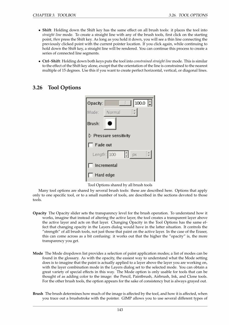
CHAPTER 3. TOOLBOX 3.26. TOOL OPTIONS
• Shift: Holding down the Shift key has the same effect on all brush tools: it places the tool intostraight line mode. To create a straight line with any of the brush tools, first click on the startingpoint, then press the Shift key. As long as you hold it down, you will see a thin line connecting thepreviously clicked point with the current pointer location. If you click again, while continuing tohold down the Shift key, a straight line will be rendered. You can continue this process to create aseries of connected line segments.
• Ctrl–Shift: Holding down both keys puts the tool into constrained straight line mode. This is similarto the effect of the Shift key alone, except that the orientation of the line is constrained to the nearestmultiple of 15 degrees. Use this if you want to create perfect horizontal, vertical, or diagonal lines.
3.26 Tool Options
Tool Options shared by all brush toolsMany tool options are shared by several brush tools: these are described here. Options that apply
only to one specific tool, or to a small number of tools, are described in the sections devoted to thosetools.
Opacity The Opacity slider sets the transparency level for the brush operation. To understand how itworks, imagine that instead of altering the active layer, the tool creates a transparent layer abovethe active layer and acts on that layer. Changing Opacity in the Tool Options has the same ef-fect that changing opacity in the Layers dialog would have in the latter situation. It controls the”strength” of all brush tools, not just those that paint on the active layer. In the case of the Eraser,this can come across as a bit confusing: it works out that the higher the ”opacity” is, the moretransparency you get.
Mode The Mode dropdown list provides a selection of paint application modes; a list of modes can befound in the glossary. As with the opacity, the easiest way to understand what the Mode settingdoes is to imagine that the paint is actually applied to a layer above the layer you are working on,with the layer combination mode in the Layers dialog set to the selected mode. You can obtain agreat variety of special effects in this way. The Mode option is only usable for tools that can bethought of as adding color to the image: the Pencil, Paintbrush, Airbrush, Ink, and Clone tools.For the other brush tools, the option appears for the sake of consistency but is always grayed out.
Brush The brush determines how much of the image is affected by the tool, and how it is affected, whenyou trace out a brushstroke with the pointer. GIMP allows you to use several different types of
143
3.27. FURTHER INFORMATION CHAPTER 3. TOOLBOX
brushes, which are described in the Brushes section. The same brush choices are available for allbrush tools except the Ink tool, which uses a unique type of procedurally generated brush. Thecolors of a brush only come into play for tools where they are meaningful: the Pencil, Paintbrush,and Airbrush tools. For the other brush tools, only the intensity distribution of a brush is relevant.
Pressure Sensitivity The Pressure Sensitivity section is only meaningful if you are using a tablet: itallows you to decide which aspects of the tool’s action should be affected by how hard you pressthe stylus against the tablet. The possibilities are ”opacity”, ”hardness”, ”rate”, ”size”, and ”color”.They work together: you can enable as many of them as you like. For each tool, only the ones thatare meaningful are listed. Here is what they do:
Opacity The effect of this option is described above.
Hardness This option applies to brushes with fuzzy edges. If it is enabled, the harder you press,the darker the fuzzy parts of the brush will appear.
Rate This option applies to the Airbrush, Convolve tool, and Smudge tool, all of which have time-based effects. Pressing harder makes these tools act more rapidly.
Size This option applies to all of the pressure sensitive brush tools, but only if you are using aparametric brush, that is, a brush created using the Brush Editor. If the option is checked, andthe brush is parametric, then pressing harder will increase the size of the area affected by thebrush.
Color This option only applies to the painting tools: the Pencil, Paintbrush, and Airbrush; andonly if you are using colors from a gradient. If these conditions are met, then pressing hardercauses colors to be taken from higher in the gradient.
Fade Out This option causes each stroke to fade out over the specified distance. It is easiest to visualfor painting tools, but applies to all of the brush tools. It is equivalent to gradually reducing theopacity along the trajectory of the stroke. Note that, if you are using a tablet, this option does notchange the effects of brush pressure.
Incremental The Incremental checkbox activates incremental mode for the tool. If it is deactivated, themaximum effect of a single stroke is determined by the opacity, and moving the brush repeatedlyover the same spot will not increase the effect beyond this limit. If Incremental is active, eachadditional pass with the brush will increase the effect. This option is available for all brush toolsexcept those that have a ”rate” control, which automatically implies an incremental effect.
Hard Edge Activating this option causes fuzzy brushes to be treated as though they were black-and-white, and inactivates sub-pixel anti-aliasing. The consequence is that all pixels affected by thetool are affected to the same degree. This is often useful if you work at a very high zoom level, andwant to have precise control of every single pixel.
”Hard edge” is available for all brush tools except the painting tools (Pencil, Paintbrush, and Air-brush), where it would be redundant, because giving a hard edge to the Paintbrush or Airbrushwould simply make them behave like the Pencil tool.
3.27 Further Information
Advanced users may be interested to know that brush tools actually operate at a sub-pixel level, inorder to avoid producing jagged-looking results. One consequence of this is that even if you work witha hard-edged brush, such as one of the Circle brushes, pixels on the edge of the brushstroke will only
144
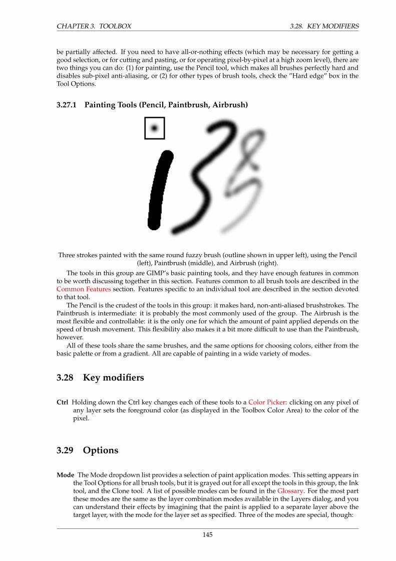
CHAPTER 3. TOOLBOX 3.28. KEY MODIFIERS
be partially affected. If you need to have all-or-nothing effects (which may be necessary for getting agood selection, or for cutting and pasting, or for operating pixel-by-pixel at a high zoom level), there aretwo things you can do: (1) for painting, use the Pencil tool, which makes all brushes perfectly hard anddisables sub-pixel anti-aliasing, or (2) for other types of brush tools, check the ”Hard edge” box in theTool Options.
3.27.1 Painting Tools (Pencil, Paintbrush, Airbrush)
Three strokes painted with the same round fuzzy brush (outline shown in upper left), using the Pencil(left), Paintbrush (middle), and Airbrush (right).
The tools in this group are GIMP’s basic painting tools, and they have enough features in commonto be worth discussing together in this section. Features common to all brush tools are described in theCommon Features section. Features specific to an individual tool are described in the section devotedto that tool.
The Pencil is the crudest of the tools in this group: it makes hard, non-anti-aliased brushstrokes. ThePaintbrush is intermediate: it is probably the most commonly used of the group. The Airbrush is themost flexible and controllable: it is the only one for which the amount of paint applied depends on thespeed of brush movement. This flexibility also makes it a bit more difficult to use than the Paintbrush,however.
All of these tools share the same brushes, and the same options for choosing colors, either from thebasic palette or from a gradient. All are capable of painting in a wide variety of modes.
3.28 Key modifiers
Ctrl Holding down the Ctrl key changes each of these tools to a Color Picker: clicking on any pixel ofany layer sets the foreground color (as displayed in the Toolbox Color Area) to the color of thepixel.
3.29 Options
Mode The Mode dropdown list provides a selection of paint application modes. This setting appears inthe Tool Options for all brush tools, but it is grayed out for all except the tools in this group, the Inktool, and the Clone tool. A list of possible modes can be found in the Glossary. For the most partthese modes are the same as the layer combination modes available in the Layers dialog, and youcan understand their effects by imagining that the paint is applied to a separate layer above thetarget layer, with the mode for the layer set as specified. Three of the modes are special, though:
145
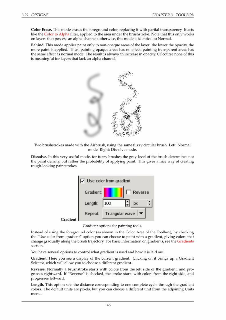
3.29. OPTIONS CHAPTER 3. TOOLBOX
Color Erase. This mode erases the foreground color, replacing it with partial transparency. It actslike the Color to Alpha filter, applied to the area under the brushstroke. Note that this only workson layers that possess an alpha channel; otherwise, this mode is identical to Normal.
Behind. This mode applies paint only to non-opaque areas of the layer: the lower the opacity, themore paint is applied. Thus, painting opaque areas has no effect; painting transparent areas hasthe same effect as normal mode. The result is always an increase in opacity. Of course none of thisis meaningful for layers that lack an alpha channel.
Two brushstrokes made with the Airbrush, using the same fuzzy circular brush. Left: Normalmode. Right: Dissolve mode.
Dissolve. In this very useful mode, for fuzzy brushes the gray level of the brush determines notthe paint density, but rather the probability of applying paint. This gives a nice way of creatingrough-looking paintstrokes.
Gradient
Gradient options for painting tools.
Instead of using the foreground color (as shown in the Color Area of the Toolbox), by checkingthe ”Use color from gradient” option you can choose to paint with a gradient, giving colors thatchange gradually along the brush trajectory. For basic information on gradients, see the Gradientssection.
You have several options to control what gradient is used and how it is laid out:
Gradient. Here you see a display of the current gradient. Clicking on it brings up a GradientSelector, which will allow you to choose a different gradient.
Reverse. Normally a brushstroke starts with colors from the left side of the gradient, and pro-gresses rightward. If ”Reverse” is checked, the stroke starts with colors from the right side, andprogresses leftward.
Length. This option sets the distance corresponding to one complete cycle through the gradientcolors. The default units are pixels, but you can choose a different unit from the adjoining Unitsmenu.
146
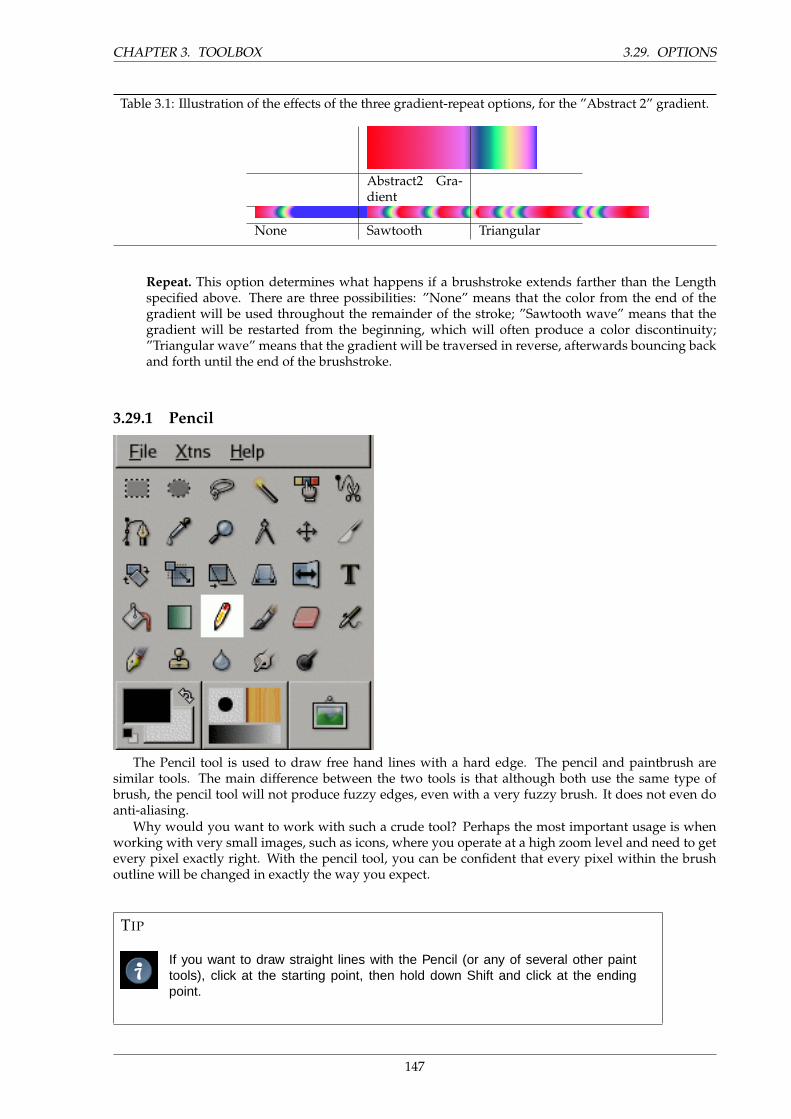
CHAPTER 3. TOOLBOX 3.29. OPTIONS
Table 3.1: Illustration of the effects of the three gradient-repeat options, for the ”Abstract 2” gradient.
Abstract2 Gra-dient
None Sawtooth Triangular
Repeat. This option determines what happens if a brushstroke extends farther than the Lengthspecified above. There are three possibilities: ”None” means that the color from the end of thegradient will be used throughout the remainder of the stroke; ”Sawtooth wave” means that thegradient will be restarted from the beginning, which will often produce a color discontinuity;”Triangular wave” means that the gradient will be traversed in reverse, afterwards bouncing backand forth until the end of the brushstroke.
3.29.1 Pencil
The Pencil tool is used to draw free hand lines with a hard edge. The pencil and paintbrush aresimilar tools. The main difference between the two tools is that although both use the same type ofbrush, the pencil tool will not produce fuzzy edges, even with a very fuzzy brush. It does not even doanti-aliasing.
Why would you want to work with such a crude tool? Perhaps the most important usage is whenworking with very small images, such as icons, where you operate at a high zoom level and need to getevery pixel exactly right. With the pencil tool, you can be confident that every pixel within the brushoutline will be changed in exactly the way you expect.
TIP
If you want to draw straight lines with the Pencil (or any of several other painttools), click at the starting point, then hold down Shift and click at the endingpoint.
147
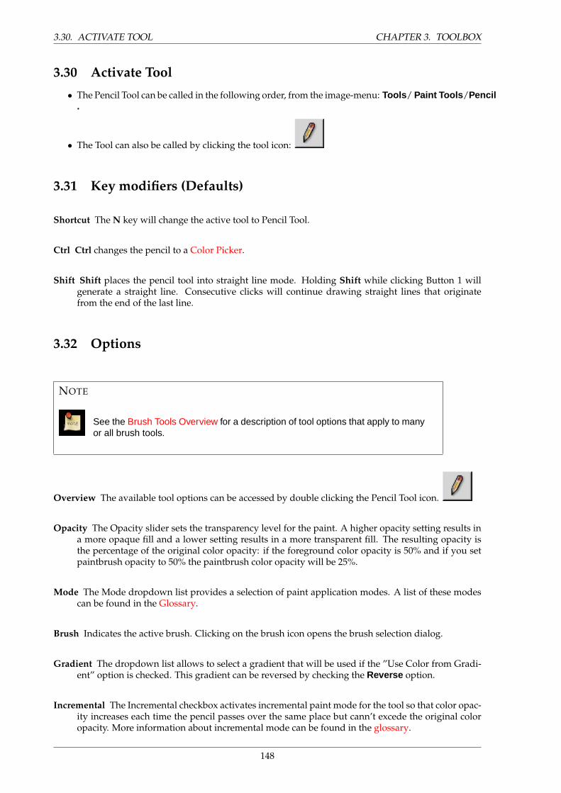
3.30. ACTIVATE TOOL CHAPTER 3. TOOLBOX
3.30 Activate Tool
• The Pencil Tool can be called in the following order, from the image-menu: Tools / Paint Tools /Pencil.
• The Tool can also be called by clicking the tool icon:
3.31 Key modifiers (Defaults)
Shortcut The N key will change the active tool to Pencil Tool.
Ctrl Ctrl changes the pencil to a Color Picker.
Shift Shift places the pencil tool into straight line mode. Holding Shift while clicking Button 1 willgenerate a straight line. Consecutive clicks will continue drawing straight lines that originatefrom the end of the last line.
3.32 Options
NOTE
See the Brush Tools Overview for a description of tool options that apply to manyor all brush tools.
Overview The available tool options can be accessed by double clicking the Pencil Tool icon.
Opacity The Opacity slider sets the transparency level for the paint. A higher opacity setting results ina more opaque fill and a lower setting results in a more transparent fill. The resulting opacity isthe percentage of the original color opacity: if the foreground color opacity is 50% and if you setpaintbrush opacity to 50% the paintbrush color opacity will be 25%.
Mode The Mode dropdown list provides a selection of paint application modes. A list of these modescan be found in the Glossary.
Brush Indicates the active brush. Clicking on the brush icon opens the brush selection dialog.
Gradient The dropdown list allows to select a gradient that will be used if the ”Use Color from Gradi-ent” option is checked. This gradient can be reversed by checking the Reverse option.
Incremental The Incremental checkbox activates incremental paint mode for the tool so that color opac-ity increases each time the pencil passes over the same place but cann’t excede the original coloropacity. More information about incremental mode can be found in the glossary.
148
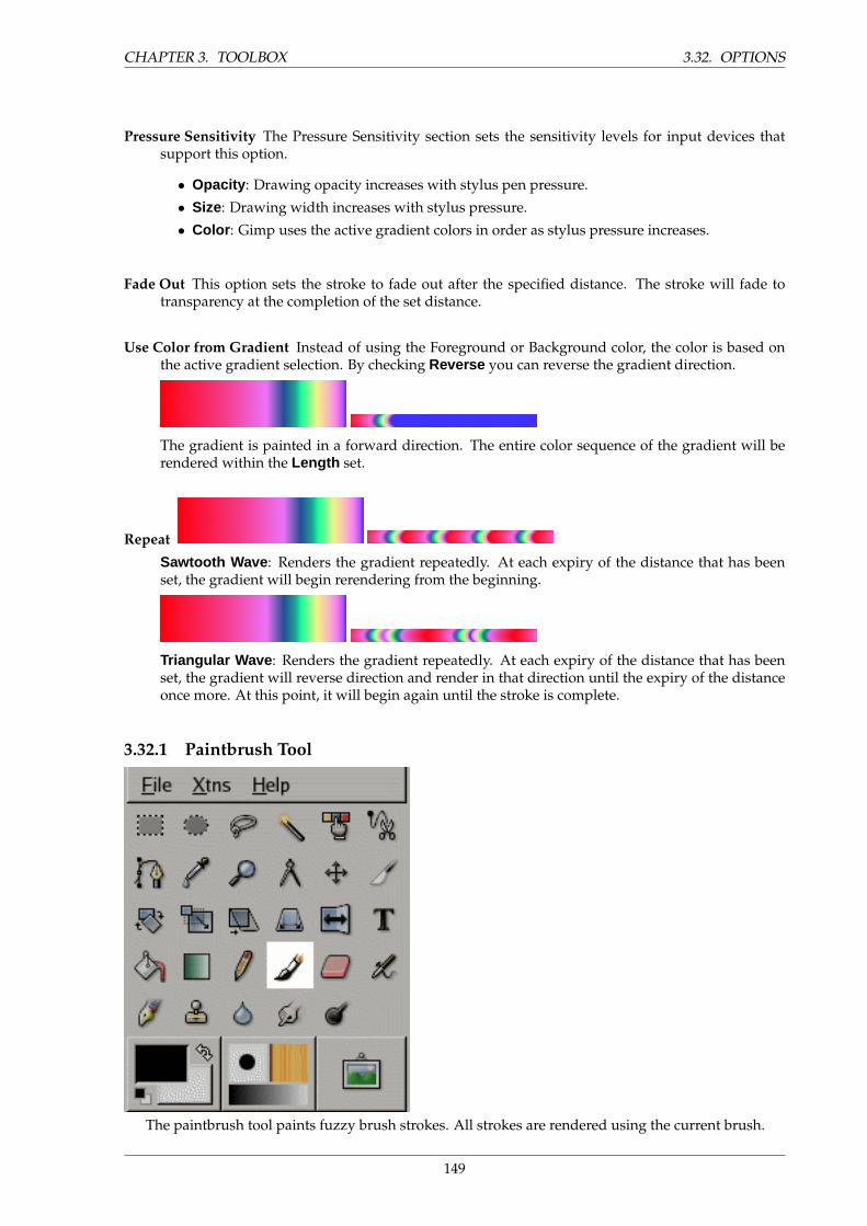
CHAPTER 3. TOOLBOX 3.32. OPTIONS
Pressure Sensitivity The Pressure Sensitivity section sets the sensitivity levels for input devices thatsupport this option.
• Opacity : Drawing opacity increases with stylus pen pressure.
• Size: Drawing width increases with stylus pressure.
• Color : Gimp uses the active gradient colors in order as stylus pressure increases.
Fade Out This option sets the stroke to fade out after the specified distance. The stroke will fade totransparency at the completion of the set distance.
Use Color from Gradient Instead of using the Foreground or Background color, the color is based onthe active gradient selection. By checking Reverse you can reverse the gradient direction.
The gradient is painted in a forward direction. The entire color sequence of the gradient will berendered within the Length set.
Repeat
Sawtooth Wave : Renders the gradient repeatedly. At each expiry of the distance that has beenset, the gradient will begin rerendering from the beginning.
Triangular Wave : Renders the gradient repeatedly. At each expiry of the distance that has beenset, the gradient will reverse direction and render in that direction until the expiry of the distanceonce more. At this point, it will begin again until the stroke is complete.
3.32.1 Paintbrush Tool
The paintbrush tool paints fuzzy brush strokes. All strokes are rendered using the current brush.
149
3.33. ACTIVATE TOOL CHAPTER 3. TOOLBOX
3.33 Activate Tool
• The Paintbrush Tool can be called in the following order, from the image-menu: Tools / PaintTools /Paintbrush .
• The Tool can also be called by clicking the tool icon:
3.34 Key modifiers (Defaults)
Shortcut The P key will change the active tool to Paintbrush Tool.
Ctrl Ctrl changes the paintbrush to a Color Picker.
Shift Shift places the paintbrush into straight line mode. Holding Shift while clicking Button 1 willgenerate a straight line. Consecutive clicks will continue drawing straight lines that originatefrom the end of the last line.
3.35 Options
NOTE
See the Brush Tools Overview for a description of tool options that apply to manyor all brush tools.
Overview The available tool options can be accessed by double clicking the Paintbrush Tool icon.
Opacity The Opacity slider sets the transparency level for the paint. A higher opacity setting results ina more opaque fill and a lower setting results in a more transparent fill. The resulting opacity isthe percentage of the original color opacity: if the foreground color opacity is 50% and if you setpaintbrush opacity to 50% the paintbrush color opacity will be 25%.
Mode The Mode dropdown list provides a selection of paint application modes. A list of these modescan be found in the Glossary.
Brush Indicates the active brush. Clicking on the brush icon opens the brush selection dialog.
Gradient The dropdown list allows to select a gradient that will be used if the ”Use Color from Gradi-ent” option is checked. This gradient can be reversed by checking the Reverse option.
Incremental The Incremental checkbox activates incremental paint mode for the tool so that color opac-ity increases each time the brush passes over the same place but cann’t excede the original coloropacity. More information about incremental mode can be found in the glossary.
150
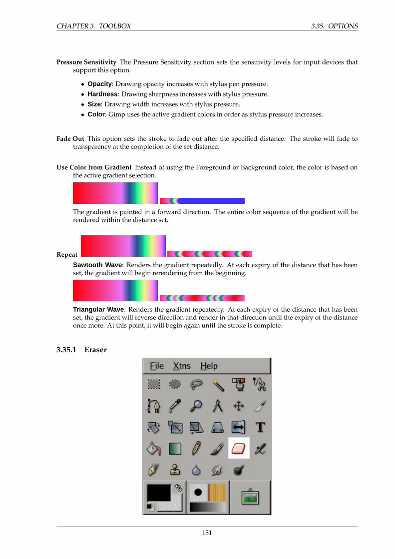
CHAPTER 3. TOOLBOX 3.35. OPTIONS
Pressure Sensitivity The Pressure Sensitivity section sets the sensitivity levels for input devices thatsupport this option.
• Opacity : Drawing opacity increases with stylus pen pressure.
• Hardness : Drawing sharpness increases with stylus pressure.
• Size: Drawing width increases with stylus pressure.
• Color : Gimp uses the active gradient colors in order as stylus pressure increases.
Fade Out This option sets the stroke to fade out after the specified distance. The stroke will fade totransparency at the completion of the set distance.
Use Color from Gradient Instead of using the Foreground or Background color, the color is based onthe active gradient selection.
The gradient is painted in a forward direction. The entire color sequence of the gradient will berendered within the distance set.
Repeat
Sawtooth Wave : Renders the gradient repeatedly. At each expiry of the distance that has beenset, the gradient will begin rerendering from the beginning.
Triangular Wave : Renders the gradient repeatedly. At each expiry of the distance that has beenset, the gradient will reverse direction and render in that direction until the expiry of the distanceonce more. At this point, it will begin again until the stroke is complete.
3.35.1 Eraser
151
3.36. HOW TO ACTIVATE CHAPTER 3. TOOLBOX
Eraser tool icon in the Toolbox
The Eraser is used to remove areas of color from the current layer, selection, or image. If the Eraseris used on something that does not support transparency (a channel, a layer mask, or the Backgroundlayer if it lacks an alpha channel), then erasing will show the background color, as displayed in the ColorArea of the Toolbox. Otherwise, erasing will produce either partial or full transparency, depending onthe settings for the tool options.
If you need to erase some group of pixels completely, leaving no trace behind of their previous con-tents, you should check the ”Hard edge” box in the Tool Options. Otherwise, sub-pixel brush placementwill cause partial erasure at the edges of the brush-stroke, even if you use a hard-edged brush.
TIP
If you use GIMP with a tablet, you may find it convenient to treat the reverse endof the stylus as an eraser. To make this work, all you need to do is click thereverse end on the Eraser tool in the Toolbox. Because each end of the stylus istreated as a separate input device, and each input device has its own separatetool assignment, the reverse end will then continue to function as an Eraser aslong as you don’t select a different tool with it.
3.36 How to Activate
The Eraser can be activated from an image menu as Tools → Paint Tools → Eraser ; from the Toolbox
by clicking on the tool icon ; or from the keyboard using the shortcut E.
3.37 Key modifiers
See the Brush Tools Overview for a description of key modifiers that have the same effect on all brushtools.
• Ctrl: For the Eraser, holding down the Ctrl key puts it into ”color picker” mode, so that it selectsthe color of any pixel it is clicked on. Unlike other brush tools, however, the Eraser sets the back-ground color rather than the foreground color. This is more useful, because on drawables that don’tsupport transparency, erasing replaces the erased areas with the current background color.
• Alt: For the Eraser, holding down the Alt key switches it into ”anti-erase” mode, as describedbelow in the Tool Options section. Note that on some systems, the Alt key is trapped by theWindow Manager. If this happens to you, you may be able to use Shift-Alt instead.
3.38 Tool Options
NOTE
See the Brush Tools Overview for a description of tool options that apply to manyor all brush tools.
152
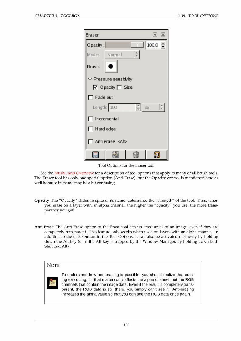
CHAPTER 3. TOOLBOX 3.38. TOOL OPTIONS
Tool Options for the Eraser tool
See the Brush Tools Overview for a description of tool options that apply to many or all brush tools.The Eraser tool has only one special option (Anti-Erase), but the Opacity control is mentioned here aswell because its name may be a bit confusing.
Opacity The ”Opacity” slider, in spite of its name, determines the ”strength” of the tool. Thus, whenyou erase on a layer with an alpha channel, the higher the ”opacity” you use, the more trans-parency you get!
Anti Erase The Anti Erase option of the Erase tool can un-erase areas of an image, even if they arecompletely transparent. This feature only works when used on layers with an alpha channel. Inaddition to the checkbutton in the Tool Options, it can also be activated on-the-fly by holdingdown the Alt key (or, if the Alt key is trapped by the Window Manager, by holding down bothShift and Alt).
NOTE
To understand how anti-erasing is possible, you should realize that eras-ing (or cutting, for that matter) only affects the alpha channel, not the RGBchannels that contain the image data. Even if the result is completely trans-parent, the RGB data is still there, you simply can’t see it. Anti-erasingincreases the alpha value so that you can see the RGB data once again.
153
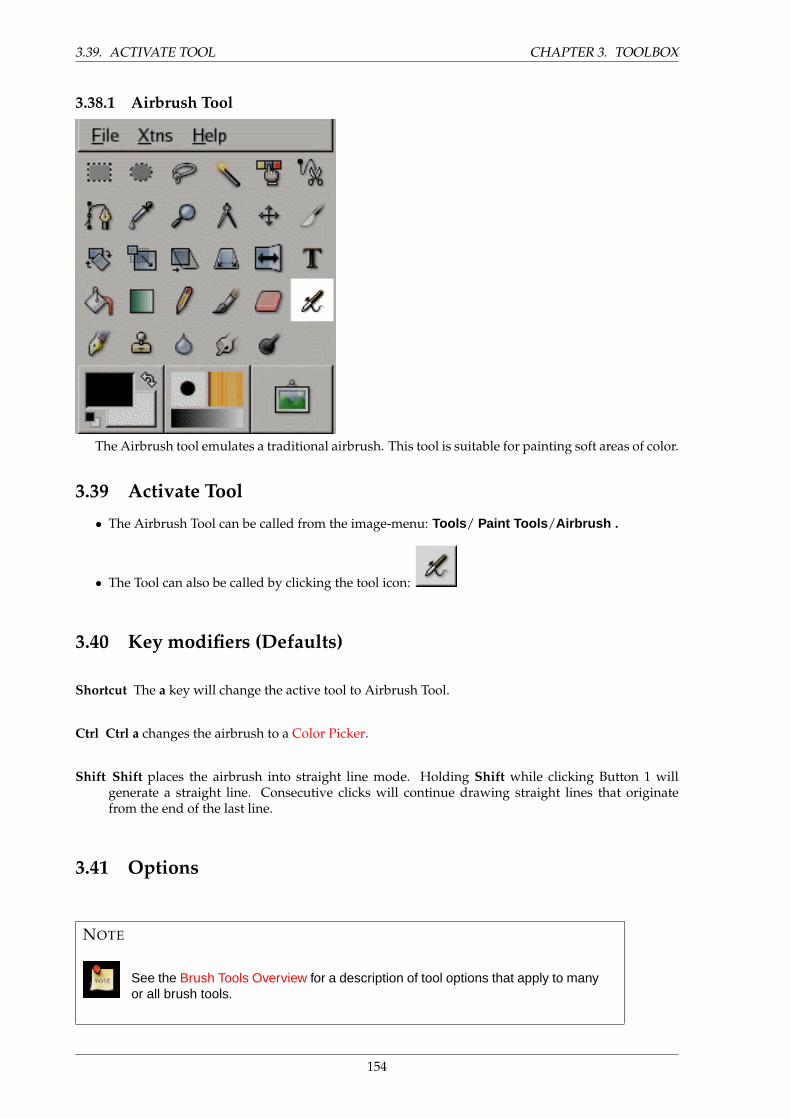
3.39. ACTIVATE TOOL CHAPTER 3. TOOLBOX
3.38.1 Airbrush Tool
The Airbrush tool emulates a traditional airbrush. This tool is suitable for painting soft areas of color.
3.39 Activate Tool
• The Airbrush Tool can be called from the image-menu: Tools / Paint Tools /Airbrush .
• The Tool can also be called by clicking the tool icon:
3.40 Key modifiers (Defaults)
Shortcut The a key will change the active tool to Airbrush Tool.
Ctrl Ctrl a changes the airbrush to a Color Picker.
Shift Shift places the airbrush into straight line mode. Holding Shift while clicking Button 1 willgenerate a straight line. Consecutive clicks will continue drawing straight lines that originatefrom the end of the last line.
3.41 Options
NOTE
See the Brush Tools Overview for a description of tool options that apply to manyor all brush tools.
154
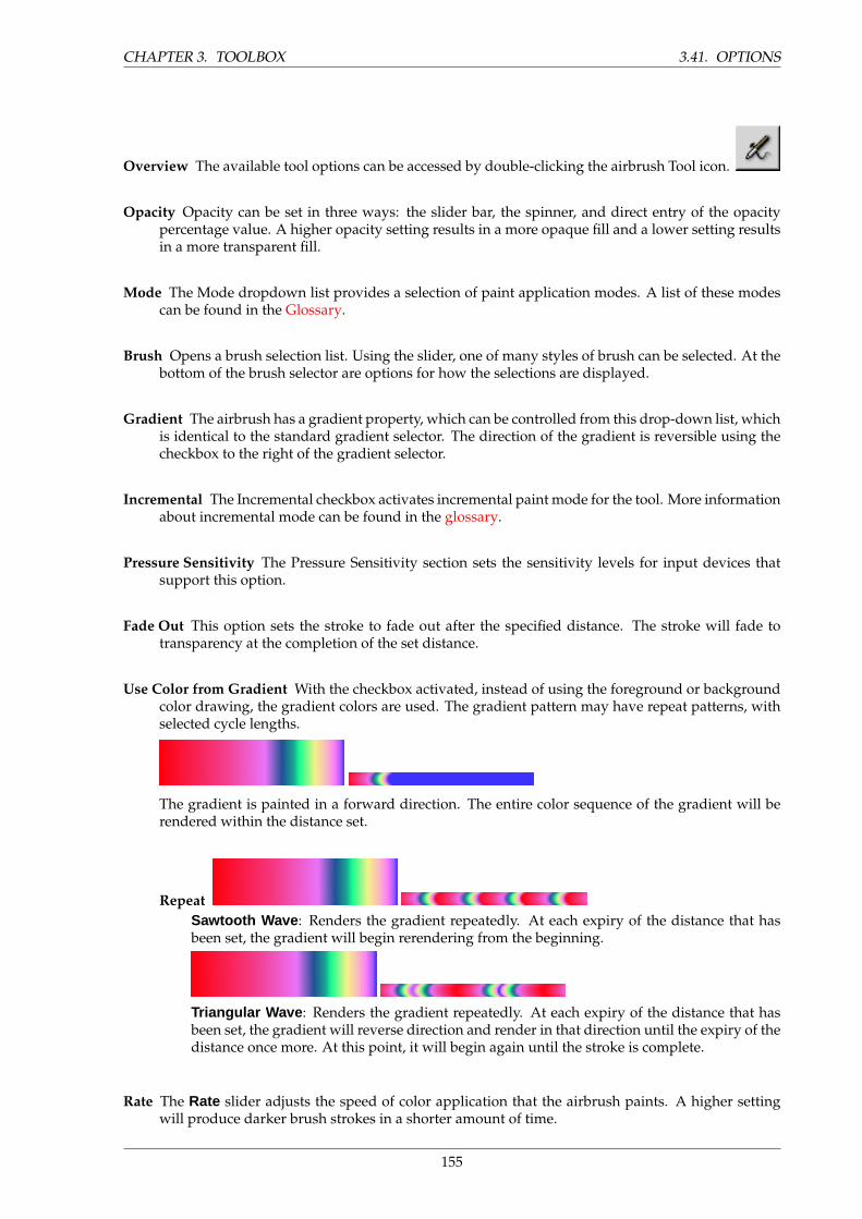
CHAPTER 3. TOOLBOX 3.41. OPTIONS
Overview The available tool options can be accessed by double-clicking the airbrush Tool icon.
Opacity Opacity can be set in three ways: the slider bar, the spinner, and direct entry of the opacitypercentage value. A higher opacity setting results in a more opaque fill and a lower setting resultsin a more transparent fill.
Mode The Mode dropdown list provides a selection of paint application modes. A list of these modescan be found in the Glossary.
Brush Opens a brush selection list. Using the slider, one of many styles of brush can be selected. At thebottom of the brush selector are options for how the selections are displayed.
Gradient The airbrush has a gradient property, which can be controlled from this drop-down list, whichis identical to the standard gradient selector. The direction of the gradient is reversible using thecheckbox to the right of the gradient selector.
Incremental The Incremental checkbox activates incremental paint mode for the tool. More informationabout incremental mode can be found in the glossary.
Pressure Sensitivity The Pressure Sensitivity section sets the sensitivity levels for input devices thatsupport this option.
Fade Out This option sets the stroke to fade out after the specified distance. The stroke will fade totransparency at the completion of the set distance.
Use Color from Gradient With the checkbox activated, instead of using the foreground or backgroundcolor drawing, the gradient colors are used. The gradient pattern may have repeat patterns, withselected cycle lengths.
The gradient is painted in a forward direction. The entire color sequence of the gradient will berendered within the distance set.
RepeatSawtooth Wave : Renders the gradient repeatedly. At each expiry of the distance that hasbeen set, the gradient will begin rerendering from the beginning.
Triangular Wave : Renders the gradient repeatedly. At each expiry of the distance that hasbeen set, the gradient will reverse direction and render in that direction until the expiry of thedistance once more. At this point, it will begin again until the stroke is complete.
Rate The Rate slider adjusts the speed of color application that the airbrush paints. A higher settingwill produce darker brush strokes in a shorter amount of time.
155
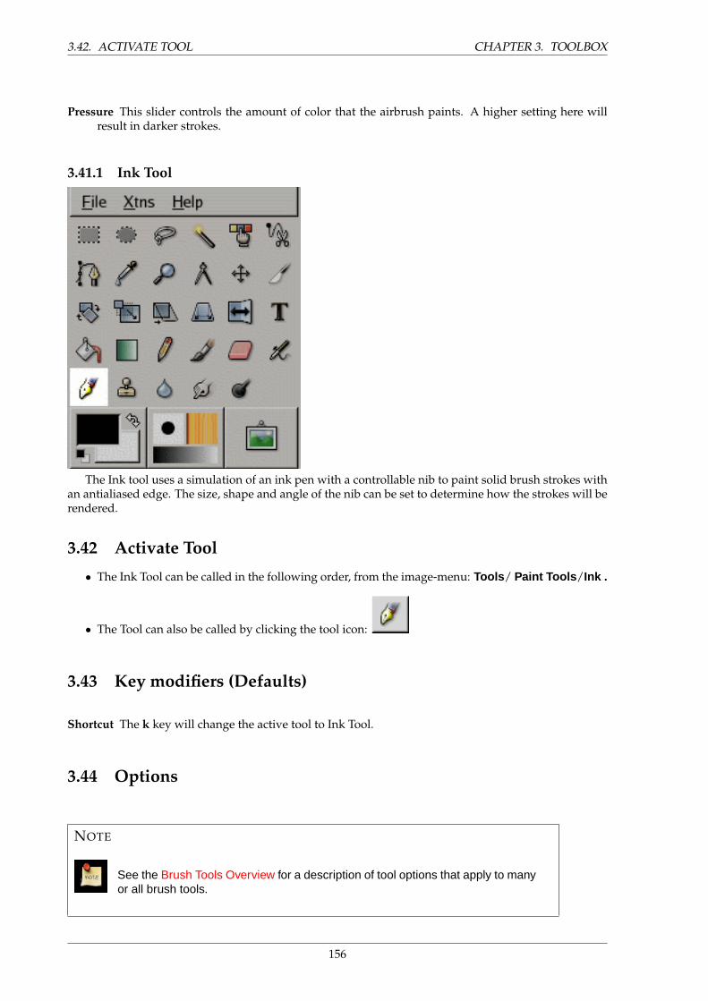
3.42. ACTIVATE TOOL CHAPTER 3. TOOLBOX
Pressure This slider controls the amount of color that the airbrush paints. A higher setting here willresult in darker strokes.
3.41.1 Ink Tool
The Ink tool uses a simulation of an ink pen with a controllable nib to paint solid brush strokes withan antialiased edge. The size, shape and angle of the nib can be set to determine how the strokes will berendered.
3.42 Activate Tool
• The Ink Tool can be called in the following order, from the image-menu: Tools / Paint Tools /Ink .
• The Tool can also be called by clicking the tool icon:
3.43 Key modifiers (Defaults)
Shortcut The k key will change the active tool to Ink Tool.
3.44 Options
NOTE
See the Brush Tools Overview for a description of tool options that apply to manyor all brush tools.
156
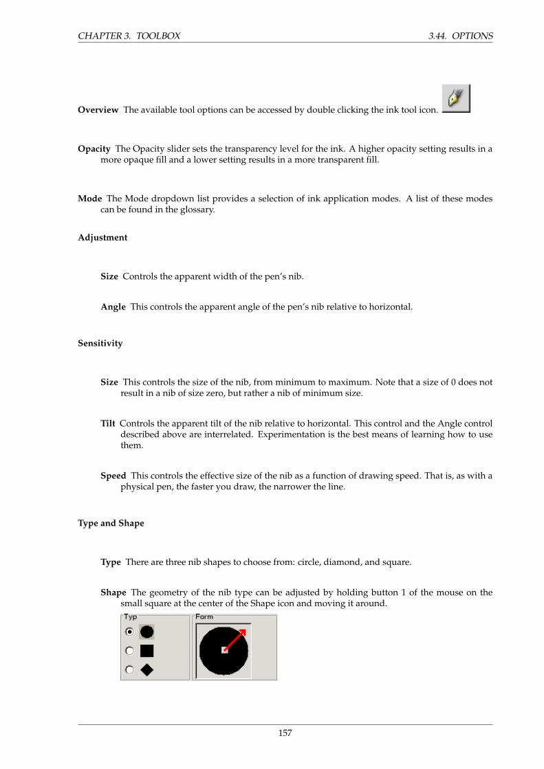
CHAPTER 3. TOOLBOX 3.44. OPTIONS
Overview The available tool options can be accessed by double clicking the ink tool icon.
Opacity The Opacity slider sets the transparency level for the ink. A higher opacity setting results in amore opaque fill and a lower setting results in a more transparent fill.
Mode The Mode dropdown list provides a selection of ink application modes. A list of these modescan be found in the glossary.
Adjustment
Size Controls the apparent width of the pen’s nib.
Angle This controls the apparent angle of the pen’s nib relative to horizontal.
Sensitivity
Size This controls the size of the nib, from minimum to maximum. Note that a size of 0 does notresult in a nib of size zero, but rather a nib of minimum size.
Tilt Controls the apparent tilt of the nib relative to horizontal. This control and the Angle controldescribed above are interrelated. Experimentation is the best means of learning how to usethem.
Speed This controls the effective size of the nib as a function of drawing speed. That is, as with aphysical pen, the faster you draw, the narrower the line.
Type and Shape
Type There are three nib shapes to choose from: circle, diamond, and square.
Shape The geometry of the nib type can be adjusted by holding button 1 of the mouse on thesmall square at the center of the Shape icon and moving it around.
157
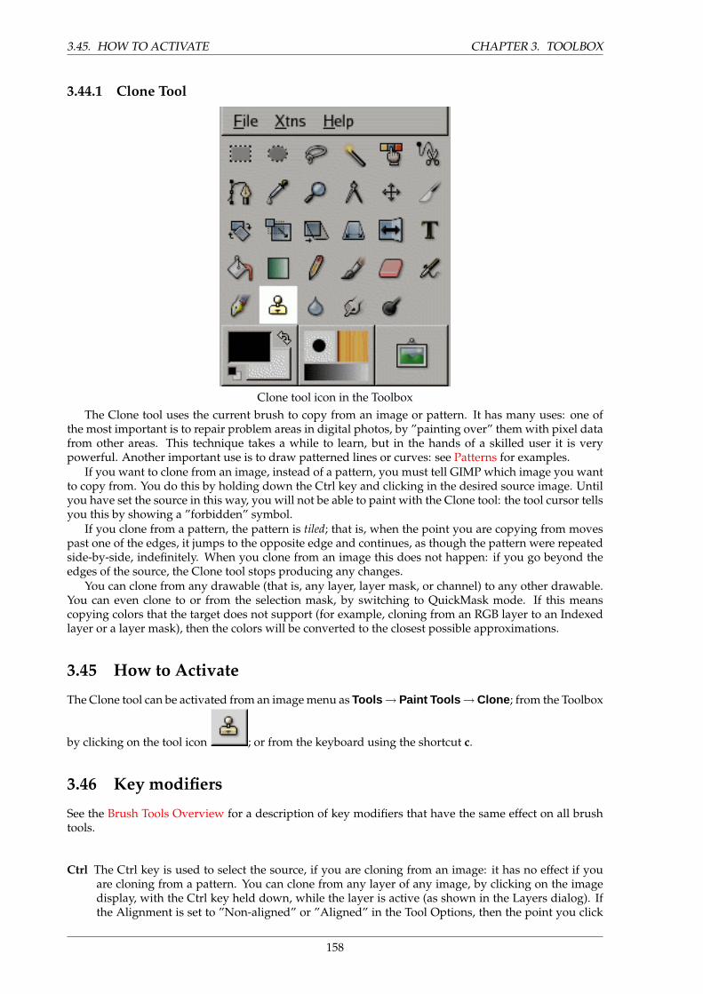
3.45. HOW TO ACTIVATE CHAPTER 3. TOOLBOX
3.44.1 Clone Tool
Clone tool icon in the ToolboxThe Clone tool uses the current brush to copy from an image or pattern. It has many uses: one of
the most important is to repair problem areas in digital photos, by ”painting over” them with pixel datafrom other areas. This technique takes a while to learn, but in the hands of a skilled user it is verypowerful. Another important use is to draw patterned lines or curves: see Patterns for examples.
If you want to clone from an image, instead of a pattern, you must tell GIMP which image you wantto copy from. You do this by holding down the Ctrl key and clicking in the desired source image. Untilyou have set the source in this way, you will not be able to paint with the Clone tool: the tool cursor tellsyou this by showing a ”forbidden” symbol.
If you clone from a pattern, the pattern is tiled; that is, when the point you are copying from movespast one of the edges, it jumps to the opposite edge and continues, as though the pattern were repeatedside-by-side, indefinitely. When you clone from an image this does not happen: if you go beyond theedges of the source, the Clone tool stops producing any changes.
You can clone from any drawable (that is, any layer, layer mask, or channel) to any other drawable.You can even clone to or from the selection mask, by switching to QuickMask mode. If this meanscopying colors that the target does not support (for example, cloning from an RGB layer to an Indexedlayer or a layer mask), then the colors will be converted to the closest possible approximations.
3.45 How to Activate
The Clone tool can be activated from an image menu as Tools → Paint Tools →Clone ; from the Toolbox
by clicking on the tool icon ; or from the keyboard using the shortcut c.
3.46 Key modifiers
See the Brush Tools Overview for a description of key modifiers that have the same effect on all brushtools.
Ctrl The Ctrl key is used to select the source, if you are cloning from an image: it has no effect if youare cloning from a pattern. You can clone from any layer of any image, by clicking on the imagedisplay, with the Ctrl key held down, while the layer is active (as shown in the Layers dialog). Ifthe Alignment is set to ”Non-aligned” or ”Aligned” in the Tool Options, then the point you click
158
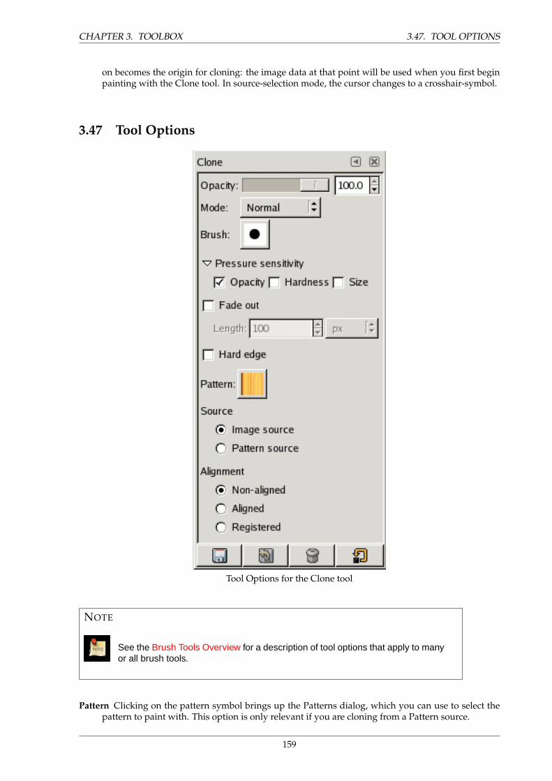
CHAPTER 3. TOOLBOX 3.47. TOOL OPTIONS
on becomes the origin for cloning: the image data at that point will be used when you first beginpainting with the Clone tool. In source-selection mode, the cursor changes to a crosshair-symbol.
3.47 Tool Options
Tool Options for the Clone tool
NOTE
See the Brush Tools Overview for a description of tool options that apply to manyor all brush tools.
Pattern Clicking on the pattern symbol brings up the Patterns dialog, which you can use to select thepattern to paint with. This option is only relevant if you are cloning from a Pattern source.
159
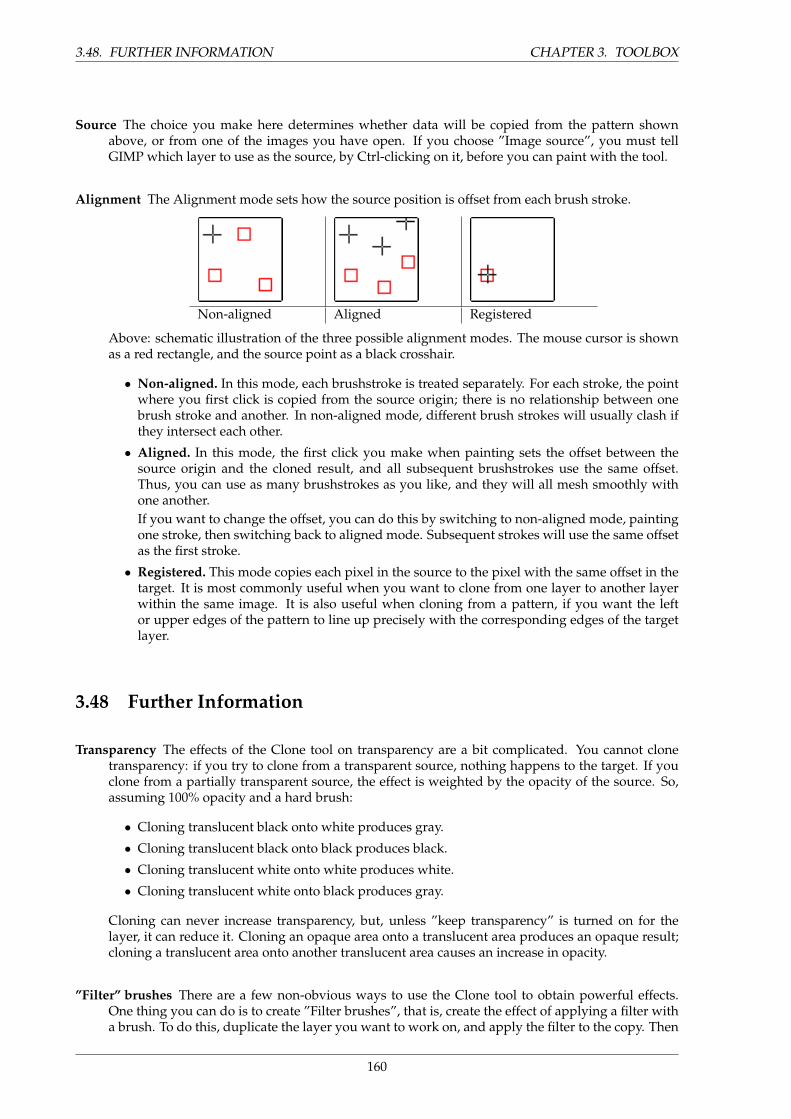
3.48. FURTHER INFORMATION CHAPTER 3. TOOLBOX
Source The choice you make here determines whether data will be copied from the pattern shownabove, or from one of the images you have open. If you choose ”Image source”, you must tellGIMP which layer to use as the source, by Ctrl-clicking on it, before you can paint with the tool.
Alignment The Alignment mode sets how the source position is offset from each brush stroke.
Non-aligned Aligned Registered
Above: schematic illustration of the three possible alignment modes. The mouse cursor is shownas a red rectangle, and the source point as a black crosshair.
• Non-aligned. In this mode, each brushstroke is treated separately. For each stroke, the pointwhere you first click is copied from the source origin; there is no relationship between onebrush stroke and another. In non-aligned mode, different brush strokes will usually clash ifthey intersect each other.
• Aligned. In this mode, the first click you make when painting sets the offset between thesource origin and the cloned result, and all subsequent brushstrokes use the same offset.Thus, you can use as many brushstrokes as you like, and they will all mesh smoothly withone another.If you want to change the offset, you can do this by switching to non-aligned mode, paintingone stroke, then switching back to aligned mode. Subsequent strokes will use the same offsetas the first stroke.
• Registered. This mode copies each pixel in the source to the pixel with the same offset in thetarget. It is most commonly useful when you want to clone from one layer to another layerwithin the same image. It is also useful when cloning from a pattern, if you want the leftor upper edges of the pattern to line up precisely with the corresponding edges of the targetlayer.
3.48 Further Information
Transparency The effects of the Clone tool on transparency are a bit complicated. You cannot clonetransparency: if you try to clone from a transparent source, nothing happens to the target. If youclone from a partially transparent source, the effect is weighted by the opacity of the source. So,assuming 100% opacity and a hard brush:
• Cloning translucent black onto white produces gray.
• Cloning translucent black onto black produces black.
• Cloning translucent white onto white produces white.
• Cloning translucent white onto black produces gray.
Cloning can never increase transparency, but, unless ”keep transparency” is turned on for thelayer, it can reduce it. Cloning an opaque area onto a translucent area produces an opaque result;cloning a translucent area onto another translucent area causes an increase in opacity.
”Filter” brushes There are a few non-obvious ways to use the Clone tool to obtain powerful effects.One thing you can do is to create ”Filter brushes”, that is, create the effect of applying a filter witha brush. To do this, duplicate the layer you want to work on, and apply the filter to the copy. Then
160
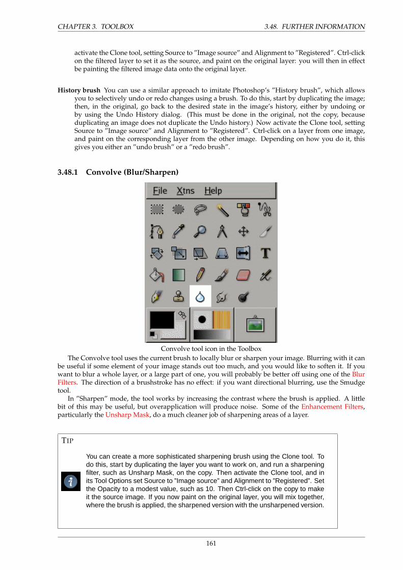
CHAPTER 3. TOOLBOX 3.48. FURTHER INFORMATION
activate the Clone tool, setting Source to ”Image source” and Alignment to ”Registered”. Ctrl-clickon the filtered layer to set it as the source, and paint on the original layer: you will then in effectbe painting the filtered image data onto the original layer.
History brush You can use a similar approach to imitate Photoshop’s ”History brush”, which allowsyou to selectively undo or redo changes using a brush. To do this, start by duplicating the image;then, in the original, go back to the desired state in the image’s history, either by undoing orby using the Undo History dialog. (This must be done in the original, not the copy, becauseduplicating an image does not duplicate the Undo history.) Now activate the Clone tool, settingSource to ”Image source” and Alignment to ”Registered”. Ctrl-click on a layer from one image,and paint on the corresponding layer from the other image. Depending on how you do it, thisgives you either an ”undo brush” or a ”redo brush”.
3.48.1 Convolve (Blur/Sharpen)
Convolve tool icon in the ToolboxThe Convolve tool uses the current brush to locally blur or sharpen your image. Blurring with it can
be useful if some element of your image stands out too much, and you would like to soften it. If youwant to blur a whole layer, or a large part of one, you will probably be better off using one of the BlurFilters. The direction of a brushstroke has no effect: if you want directional blurring, use the Smudgetool.
In ”Sharpen” mode, the tool works by increasing the contrast where the brush is applied. A littlebit of this may be useful, but overapplication will produce noise. Some of the Enhancement Filters,particularly the Unsharp Mask, do a much cleaner job of sharpening areas of a layer.
TIP
You can create a more sophisticated sharpening brush using the Clone tool. Todo this, start by duplicating the layer you want to work on, and run a sharpeningfilter, such as Unsharp Mask, on the copy. Then activate the Clone tool, and inits Tool Options set Source to ”Image source” and Alignment to ”Registered”. Setthe Opacity to a modest value, such as 10. Then Ctrl-click on the copy to makeit the source image. If you now paint on the original layer, you will mix together,where the brush is applied, the sharpened version with the unsharpened version.
161

3.49. HOW TO ACTIVATE CHAPTER 3. TOOLBOX
Both blurring and sharpening work incrementally: moving the brush repeatedly over an area willincrease the effect with each additional pass. The Rate control allows you to determine how quickly themodifications accumulate. The Opacity control, however, can be used to limit the amount of blurringthat can be produced by a single brushstroke, regardless of how many passes are made with it.
3.49 How to Activate
The Convolve tool can be activated from an image menu as Tools → Paint Tools → Convolve ; from the
Toolbox by clicking on the tool icon ; or from the keyboard using the shortcut V.
3.50 Key modifiers
See the Brush Tools Overview for a description of key modifiers that have the same effect on all brushtools.
• Ctrl: Holding down the Ctrl key toggles between Blur and Sharpen modes; it reverses the settingshown in the Tool Options.
3.51 Tool Options
Tool Options for the Convolve tool
162
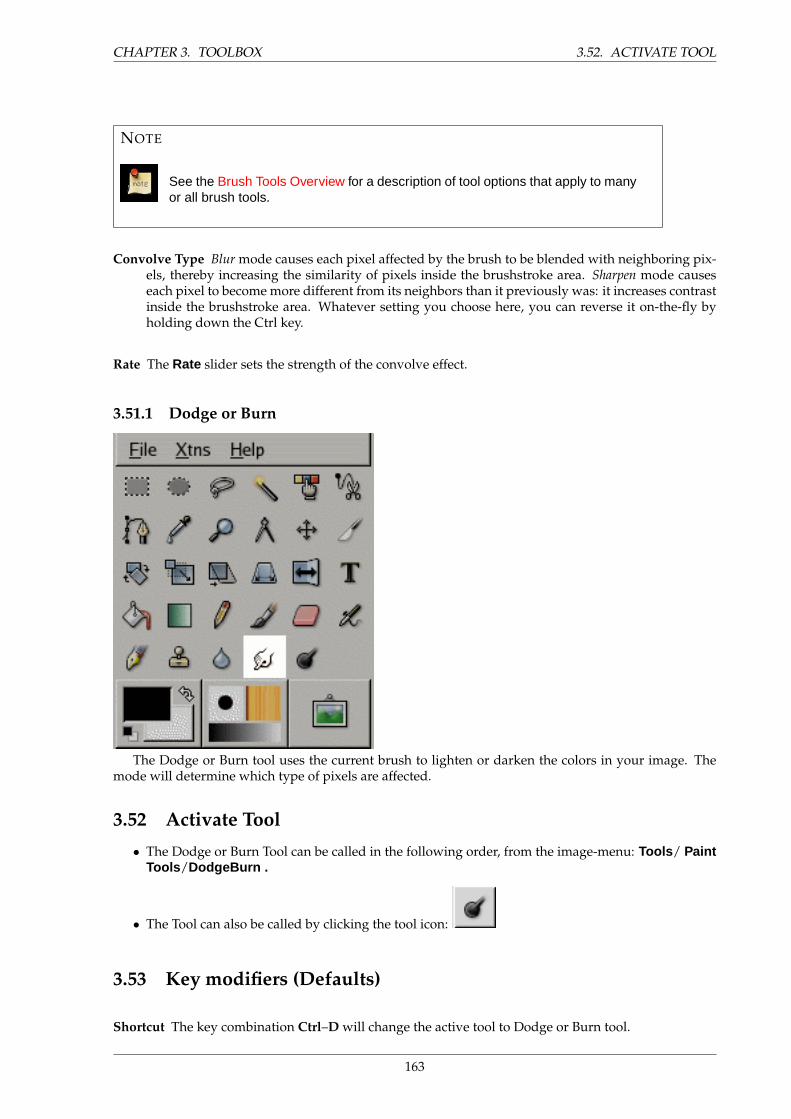
CHAPTER 3. TOOLBOX 3.52. ACTIVATE TOOL
NOTE
See the Brush Tools Overview for a description of tool options that apply to manyor all brush tools.
Convolve Type Blur mode causes each pixel affected by the brush to be blended with neighboring pix-els, thereby increasing the similarity of pixels inside the brushstroke area. Sharpen mode causeseach pixel to become more different from its neighbors than it previously was: it increases contrastinside the brushstroke area. Whatever setting you choose here, you can reverse it on-the-fly byholding down the Ctrl key.
Rate The Rate slider sets the strength of the convolve effect.
3.51.1 Dodge or Burn
The Dodge or Burn tool uses the current brush to lighten or darken the colors in your image. Themode will determine which type of pixels are affected.
3.52 Activate Tool
• The Dodge or Burn Tool can be called in the following order, from the image-menu: Tools / PaintTools /DodgeBurn .
• The Tool can also be called by clicking the tool icon:
3.53 Key modifiers (Defaults)
Shortcut The key combination Ctrl–D will change the active tool to Dodge or Burn tool.
163
3.54. OPTIONS CHAPTER 3. TOOLBOX
Ctrl Ctrl toggles between dodge or burn types. The type will remain switched until Ctrl is released.
Shift Shift places the Dodge or Burn tool into straight line mode. Holding Shift while clicking Button1will Dodge or Burn in a straight line. Consecutive clicks will continue Dodge or Burn in straightlines that originate from the end of the last line.
3.54 Options
NOTE
See the Brush Tools Overview for a description of tool options that apply to manyor all brush tools.
Overview The available tool options for the Dodge or Burn Tool can be accessed by double clicking the
Dodge or Burn Tool icon.
Opacity The Opacity slider sets the transparency level for the operation. A higher opacity setting resultsin a more opaque render and a lower setting results in a more transparent one.
Brush Indicates the active brush. Clicking on the brush icon opens the brush selection dialog.
Hard Edge If this option is toggled on, the tool behaves like the Pencil tool, in the sense that there is noanti-aliasing, and pixels are affected in an all-or-nothing way, even if it is being used with a softbrush.
Pressure Sensitivity The Pressure Sensitivity section sets whether hardness, rate, or size will be affectedby pressure for input devices that support this option.
Fade Out This option causes a transition to the background over a distance set by the Length field.
Type The dodge effect lightens colors.
The burn effect darkens colors.
Mode There are three modes:
• Shadows restricts the effect to transparent pixels.
• Midtones restricts the effect to pixels of average tone.
• Highlights restricts the effect to dark pixels.
Exposure Exposure defines how much the tool effect will be strong, as a more or less exposed photo-graph. Default slider is 50 but can vary from 0 to 100.
164
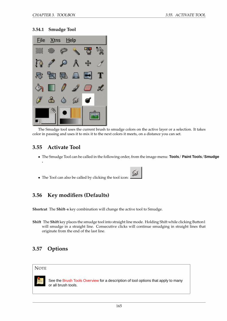
CHAPTER 3. TOOLBOX 3.55. ACTIVATE TOOL
3.54.1 Smudge Tool
The Smudge tool uses the current brush to smudge colors on the active layer or a selection. It takescolor in passing and uses it to mix it to the next colors it meets, on a distance you can set.
3.55 Activate Tool
• The Smudge Tool can be called in the following order, from the image-menu: Tools / Paint Tools /Smudge.
• The Tool can also be called by clicking the tool icon:
3.56 Key modifiers (Defaults)
Shortcut The Shift–s key combination will change the active tool to Smudge.
Shift The Shift key places the smudge tool into straight line mode. Holding Shift while clicking Button1will smudge in a straight line. Consecutive clicks will continue smudging in straight lines thatoriginate from the end of the last line.
3.57 Options
NOTE
See the Brush Tools Overview for a description of tool options that apply to manyor all brush tools.
165
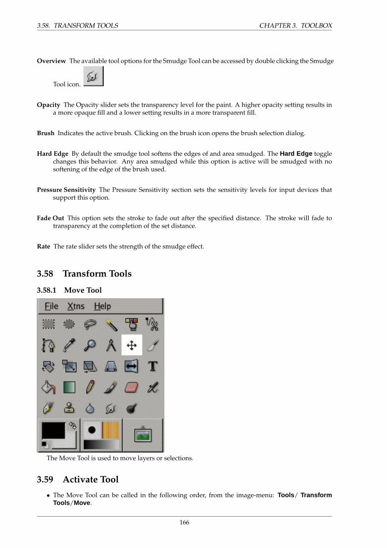
3.58. TRANSFORM TOOLS CHAPTER 3. TOOLBOX
Overview The available tool options for the Smudge Tool can be accessed by double clicking the Smudge
Tool icon.
Opacity The Opacity slider sets the transparency level for the paint. A higher opacity setting results ina more opaque fill and a lower setting results in a more transparent fill.
Brush Indicates the active brush. Clicking on the brush icon opens the brush selection dialog.
Hard Edge By default the smudge tool softens the edges of and area smudged. The Hard Edge togglechanges this behavior. Any area smudged while this option is active will be smudged with nosoftening of the edge of the brush used.
Pressure Sensitivity The Pressure Sensitivity section sets the sensitivity levels for input devices thatsupport this option.
Fade Out This option sets the stroke to fade out after the specified distance. The stroke will fade totransparency at the completion of the set distance.
Rate The rate slider sets the strength of the smudge effect.
3.58 Transform Tools
3.58.1 Move Tool
The Move Tool is used to move layers or selections.
3.59 Activate Tool
• The Move Tool can be called in the following order, from the image-menu: Tools / TransformTools /Move .
166
CHAPTER 3. TOOLBOX 3.60. KEY MODIFIERS (DEFAULTS)
• The Tool can also be called by clicking the tool icon:
• The Move tool is automatically activated when you create a selection or a guide.
3.60 Key modifiers (Defaults)
Shortcut The m key will change the active tool to Move.
Alt Holding Alt selections can be moved without altering your image. Only the frame is moved, not itscontent. If Alt doesn’t work try Shift+Alt.
Using Arrow Keys Instead of mouse you can use arrow keys to move the object by one pixel. By press-ing Shift you move by 25 pixels.
3.61 Options
Overview The available tool options for Move can be found by double clicking the Move Tool icon.
Three buttons allow to choose which entity Move tool will act on: Layer, Selection or Path. Options toTool toggle are somewhat different:
1. Layer : When this option is selected, you can choose, either by clicking on a radio-button orby pressing Shift key, between
• Pick a Layer or Guide to move: If your image has several layers, they must be visible andhave at least a few non-transparent pixels so that you can find them (only the active layerhas a dotted border). The mouse pointer turns to a small hand you can use to click on thelayer you want pick. You must click first on a non-transparent pixel to active the layerand move it.The Move tool is used also to move guides. See glossary for Guides.To place guides precisely think of Measure tool.
• Move the Active Layer, i.e the layer with a dotted border in the image and highlighted inthe Layer Dialog.
2. Selection : one possibility only in this case: Move the selection.
3. Path : possibilities are the same as for layers: Pick the path to move and Move the active path.
167
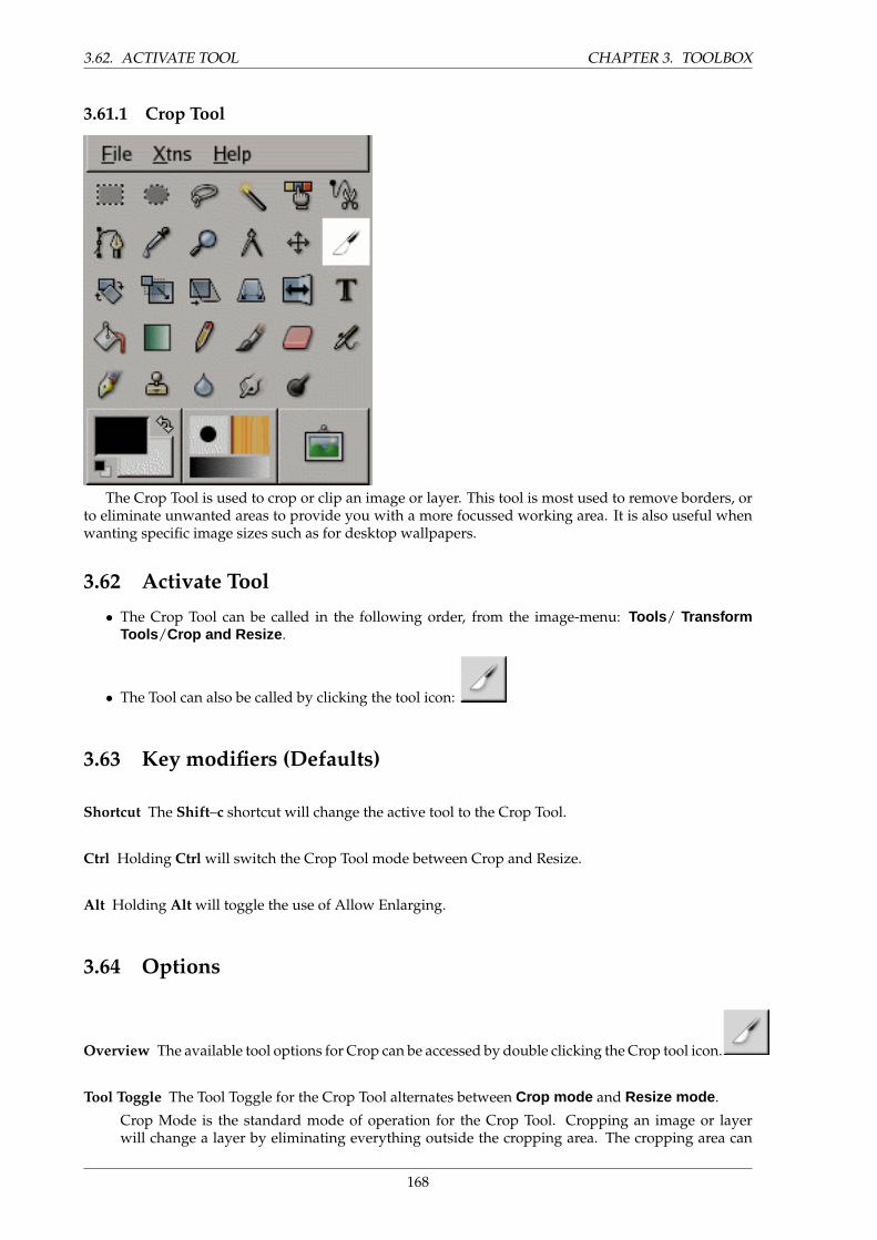
3.62. ACTIVATE TOOL CHAPTER 3. TOOLBOX
3.61.1 Crop Tool
The Crop Tool is used to crop or clip an image or layer. This tool is most used to remove borders, orto eliminate unwanted areas to provide you with a more focussed working area. It is also useful whenwanting specific image sizes such as for desktop wallpapers.
3.62 Activate Tool
• The Crop Tool can be called in the following order, from the image-menu: Tools / TransformTools /Crop and Resize .
• The Tool can also be called by clicking the tool icon:
3.63 Key modifiers (Defaults)
Shortcut The Shift–c shortcut will change the active tool to the Crop Tool.
Ctrl Holding Ctrl will switch the Crop Tool mode between Crop and Resize.
Alt Holding Alt will toggle the use of Allow Enlarging.
3.64 Options
Overview The available tool options for Crop can be accessed by double clicking the Crop tool icon.
Tool Toggle The Tool Toggle for the Crop Tool alternates between Crop mode and Resize mode .
Crop Mode is the standard mode of operation for the Crop Tool. Cropping an image or layerwill change a layer by eliminating everything outside the cropping area. The cropping area can
168
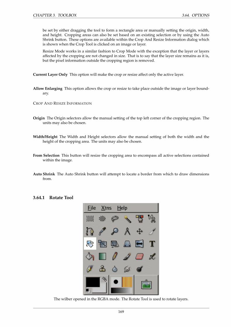
CHAPTER 3. TOOLBOX 3.64. OPTIONS
be set by either dragging the tool to form a rectangle area or manually setting the origin, width,and height. Cropping areas can also be set based on an existing selection or by using the AutoShrink button. These options are available within the Crop And Resize Information dialog whichis shown when the Crop Tool is clicked on an image or layer.
Resize Mode works in a similar fashion to Crop Mode with the exception that the layer or layersaffected by the cropping are not changed in size. That is to say that the layer size remains as it is,but the pixel information outside the cropping region is removed.
Current Layer Only This option will make the crop or resize affect only the active layer.
Allow Enlarging This option allows the crop or resize to take place outside the image or layer bound-ary.
CROP AND RESIZE INFORMATION
Origin The Origin selectors allow the manual setting of the top left corner of the cropping region. Theunits may also be chosen.
Width/Height The Width and Height selectors allow the manual setting of both the width and theheight of the cropping area. The units may also be chosen.
From Selection This button will resize the cropping area to encompass all active selections containedwithin the image.
Auto Shrink The Auto Shrink button will attempt to locate a border from which to draw dimensionsfrom.
3.64.1 Rotate Tool
The wilber opened in the RGBA mode. The Rotate Tool is used to rotate layers.
169

3.65. ACTIVATE TOOL CHAPTER 3. TOOLBOX
3.65 Activate Tool
• The Rotate Tool can be called in the following order, from the image-menu: Tools / TransformTools /Rotate .
• The Tool can also be called by clicking the tool icon:
3.66 Key modifiers (Defaults)
Shortcut The Shift–r key combination will change the active tool to Rotate.
Ctrl Holding Ctrl will constrain the rotation angles to those only evenly divisible by 15 degrees.
OPTIONS
Overview The available tool options for the Rotate Tool can be accessed by double clicking the Rotate
Tool icon.
Affect The Rotate tool can affect the Layer, the Selection, and the Path differently. These three buttonsassociate the remainder of the options to one of those three elements.
Transform Direction The Transform Direction sets which way or direction a layer is rotated. The Tra-ditional mode will rotate the layer as one might expect. If a layer is rotated 10 degrees to the right,then the layer will be rendered as such. This behaviour is contrary to Corrective rotation.
Corrective Rotation is primarily used to repair scanned images that are not straight. If the image is13 degrees askew then you need not try to rotate by that angle. By using Corrective Rotation youcan rotate visually and line up the layer with the image. Because the transformation is reversed,or performed backwards, the image will be rotated with sufficient angle to correct the error.
Interpolation The Interpolation drop-down list allows you to choose the quality of the transformation.For more information about the different methods that can be employed, see the glossary entryInterpolation.
Clip Result This option will clip the rotated layer to the original layer size.
Grid Options The three available grid options are used to change the visual display of the rotation grid.
Don’t Show Grid will display only the outline of the rotation rectangle.
Number of Grid Lines will allow control over the total number of displayed grid lines. Use theDensity slider to set the number of grid lines.
Grid Line Spacing allows control over the distance between the grid lines. Use the Density sliderto set the distance.
Constraints 15 Degrees will constrain the rotation to angles divisible by 15 degrees.
170
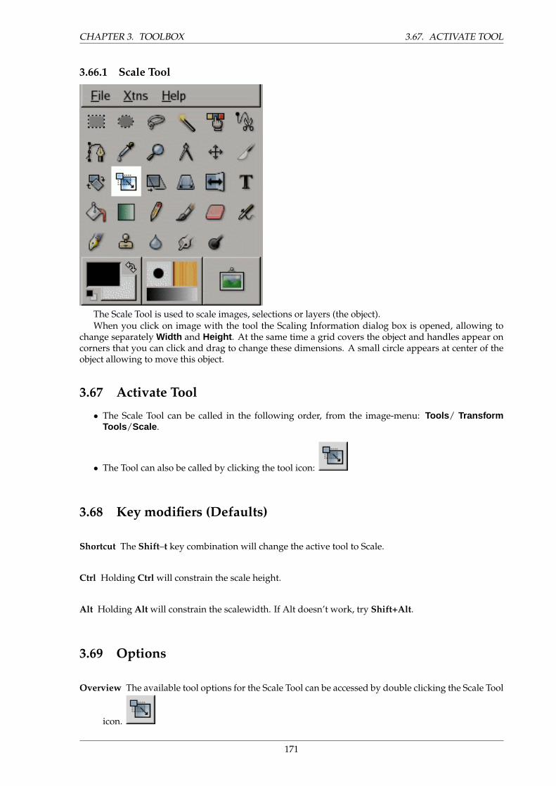
CHAPTER 3. TOOLBOX 3.67. ACTIVATE TOOL
3.66.1 Scale Tool
The Scale Tool is used to scale images, selections or layers (the object).When you click on image with the tool the Scaling Information dialog box is opened, allowing to
change separately Width and Height . At the same time a grid covers the object and handles appear oncorners that you can click and drag to change these dimensions. A small circle appears at center of theobject allowing to move this object.
3.67 Activate Tool
• The Scale Tool can be called in the following order, from the image-menu: Tools / TransformTools /Scale .
• The Tool can also be called by clicking the tool icon:
3.68 Key modifiers (Defaults)
Shortcut The Shift–t key combination will change the active tool to Scale.
Ctrl Holding Ctrl will constrain the scale height.
Alt Holding Alt will constrain the scalewidth. If Alt doesn’t work, try Shift+Alt.
3.69 Options
Overview The available tool options for the Scale Tool can be accessed by double clicking the Scale Tool
icon.
171
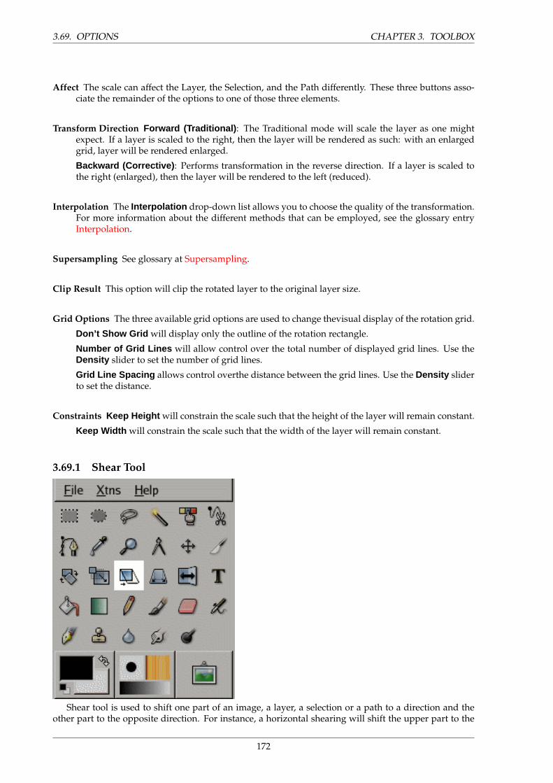
3.69. OPTIONS CHAPTER 3. TOOLBOX
Affect The scale can affect the Layer, the Selection, and the Path differently. These three buttons asso-ciate the remainder of the options to one of those three elements.
Transform Direction Forward (Traditional) : The Traditional mode will scale the layer as one mightexpect. If a layer is scaled to the right, then the layer will be rendered as such: with an enlargedgrid, layer will be rendered enlarged.
Backward (Corrective) : Performs transformation in the reverse direction. If a layer is scaled tothe right (enlarged), then the layer will be rendered to the left (reduced).
Interpolation The Interpolation drop-down list allows you to choose the quality of the transformation.For more information about the different methods that can be employed, see the glossary entryInterpolation.
Supersampling See glossary at Supersampling.
Clip Result This option will clip the rotated layer to the original layer size.
Grid Options The three available grid options are used to change thevisual display of the rotation grid.
Don’t Show Grid will display only the outline of the rotation rectangle.
Number of Grid Lines will allow control over the total number of displayed grid lines. Use theDensity slider to set the number of grid lines.
Grid Line Spacing allows control overthe distance between the grid lines. Use the Density sliderto set the distance.
Constraints Keep Height will constrain the scale such that the height of the layer will remain constant.
Keep Width will constrain the scale such that the width of the layer will remain constant.
3.69.1 Shear Tool
Shear tool is used to shift one part of an image, a layer, a selection or a path to a direction and theother part to the opposite direction. For instance, a horizontal shearing will shift the upper part to the
172
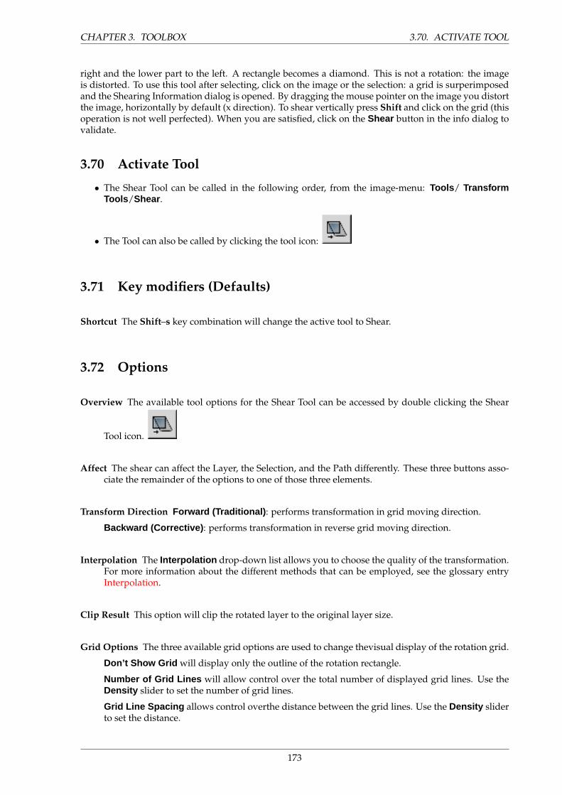
CHAPTER 3. TOOLBOX 3.70. ACTIVATE TOOL
right and the lower part to the left. A rectangle becomes a diamond. This is not a rotation: the imageis distorted. To use this tool after selecting, click on the image or the selection: a grid is surperimposedand the Shearing Information dialog is opened. By dragging the mouse pointer on the image you distortthe image, horizontally by default (x direction). To shear vertically press Shift and click on the grid (thisoperation is not well perfected). When you are satisfied, click on the Shear button in the info dialog tovalidate.
3.70 Activate Tool
• The Shear Tool can be called in the following order, from the image-menu: Tools / TransformTools /Shear .
• The Tool can also be called by clicking the tool icon:
3.71 Key modifiers (Defaults)
Shortcut The Shift–s key combination will change the active tool to Shear.
3.72 Options
Overview The available tool options for the Shear Tool can be accessed by double clicking the Shear
Tool icon.
Affect The shear can affect the Layer, the Selection, and the Path differently. These three buttons asso-ciate the remainder of the options to one of those three elements.
Transform Direction Forward (Traditional) : performs transformation in grid moving direction.
Backward (Corrective) : performs transformation in reverse grid moving direction.
Interpolation The Interpolation drop-down list allows you to choose the quality of the transformation.For more information about the different methods that can be employed, see the glossary entryInterpolation.
Clip Result This option will clip the rotated layer to the original layer size.
Grid Options The three available grid options are used to change thevisual display of the rotation grid.
Don’t Show Grid will display only the outline of the rotation rectangle.
Number of Grid Lines will allow control over the total number of displayed grid lines. Use theDensity slider to set the number of grid lines.
Grid Line Spacing allows control overthe distance between the grid lines. Use the Density sliderto set the distance.
173

3.73. ACTIVATE TOOL CHAPTER 3. TOOLBOX
3.72.1 Perspective Tool
The Perspective Tool is used to change the perspective of layers.
3.73 Activate Tool
• The Perspective Tool can be called in the following order, from the image-menu: Tools / Trans-form Tools /Perspective .
• The Tool can also be called by clicking the tool icon:
3.74 Key modifiers (Defaults)
Shortcut The Shift–p key combination will change the active tool to Perspective.
3.75 Options
Overview The available tool options for the Perspective Tool can be accessed by double clicking the
Perspective Tool icon.
Affect The transformation can affect the Layer, the Selection, and the Path differently. These threebuttons associate the remainder of the options to one of those three elements.
Transform Direction Forward (Traditional) : Performs transformation according to the direction of gridlines: if grid is bent 10◦ to the left then the image will be bent 10◦ to the left too.
Backward (Corrective) : Performs transformation in the reverse direction of grid lines: if grid isbent 10◦ to the left then the image will be bent 10◦ to the right and so will be set upright. Thisoption is used to correct perspective deformations. You bend grid lines to align them on the image
174
CHAPTER 3. TOOLBOX 3.76. ACTIVATE TOOL
lines that you want straighten up then you click Transform in the Info Window. You can have toclip the image after this transformation.
Interpolation The Interpolation drop-down list allows you to choose the quality of the transformation.For more information about the different methods that can be employed, see the glossary entryInterpolation.
Clip Result This option will clip the rotated layer to the original layer size.
Grid Options The three available grid options are used to change thevisual display of the rotation grid.
Don’t Show Grid will display only the outline of the rotation rectangle.
Number of Grid Lines will allow control over the total number of displayed grid lines. Use theDensity slider to set the number of grid lines.
Grid Line Spacing allows control overthe distance between the grid lines. Use the Density sliderto set the distance.
3.75.1 Flip Tool
The Flip tool provides the ability to flip layers or selections either horizontally or vertically.
3.76 Activate Tool
• The Flip Tool can be called in the following order, from the image-menu: Tools / TransformTools /Flip .
• The Tool can also be called by clicking the tool icon:
3.77 Key modifiers (Defaults)
Shortcut The Shift–f key combination will change the active tool to Flip.
175
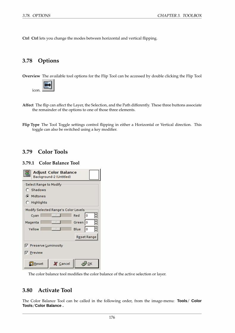
3.78. OPTIONS CHAPTER 3. TOOLBOX
Ctrl Ctrl lets you change the modes between horizontal and vertical flipping.
3.78 Options
Overview The available tool options for the Flip Tool can be accessed by double clicking the Flip Tool
icon.
Affect The flip can affect the Layer, the Selection, and the Path differently. These three buttons associatethe remainder of the options to one of those three elements.
Flip Type The Tool Toggle settings control flipping in either a Horizontal or Vertical direction. Thistoggle can also be switched using a key modifier.
3.79 Color Tools
3.79.1 Color Balance Tool
The color balance tool modifies the color balance of the active selection or layer.
3.80 Activate Tool
The Color Balance Tool can be called in the following order, from the image-menu: Tools / ColorTools /Color Balance .
176
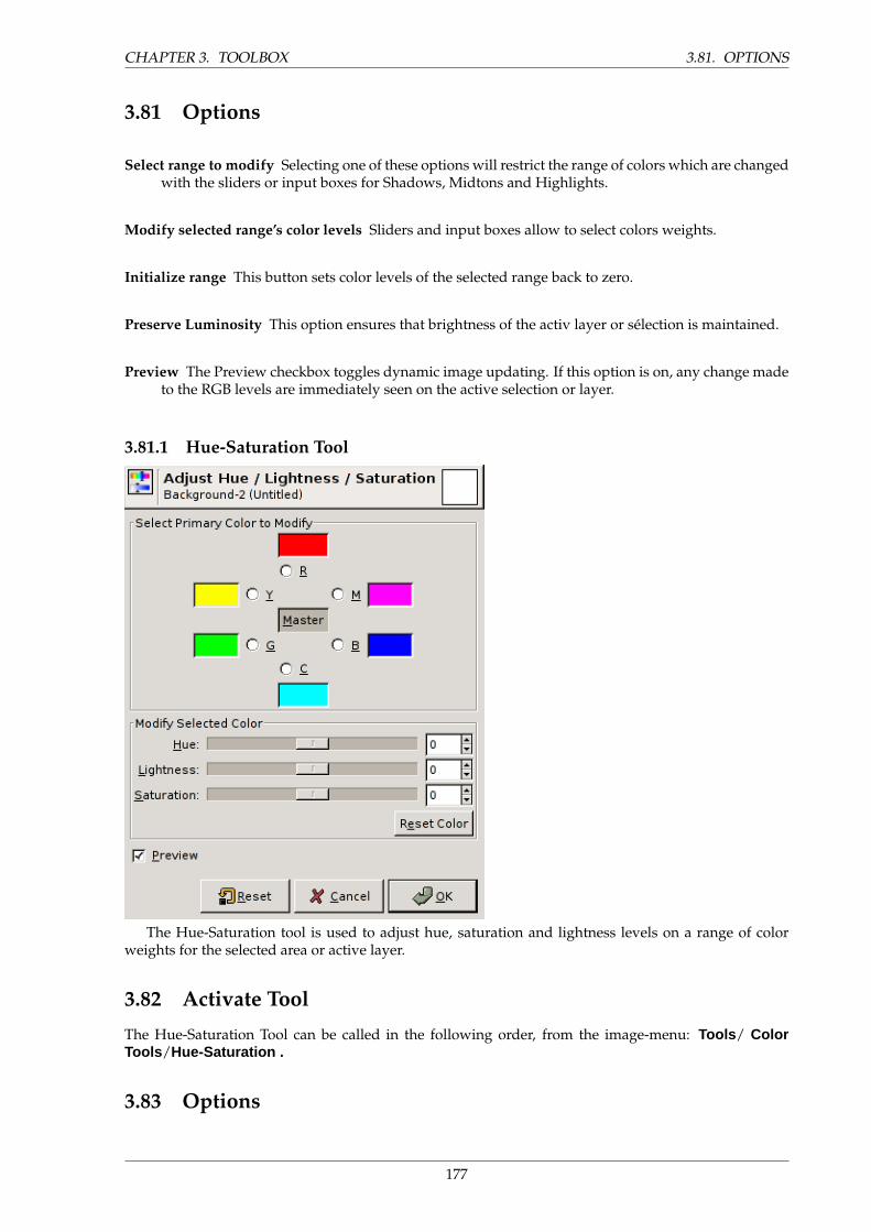
CHAPTER 3. TOOLBOX 3.81. OPTIONS
3.81 Options
Select range to modify Selecting one of these options will restrict the range of colors which are changedwith the sliders or input boxes for Shadows, Midtons and Highlights.
Modify selected range’s color levels Sliders and input boxes allow to select colors weights.
Initialize range This button sets color levels of the selected range back to zero.
Preserve Luminosity This option ensures that brightness of the activ layer or selection is maintained.
Preview The Preview checkbox toggles dynamic image updating. If this option is on, any change madeto the RGB levels are immediately seen on the active selection or layer.
3.81.1 Hue-Saturation Tool
The Hue-Saturation tool is used to adjust hue, saturation and lightness levels on a range of colorweights for the selected area or active layer.
3.82 Activate Tool
The Hue-Saturation Tool can be called in the following order, from the image-menu: Tools / ColorTools /Hue-Saturation .
3.83 Options
177
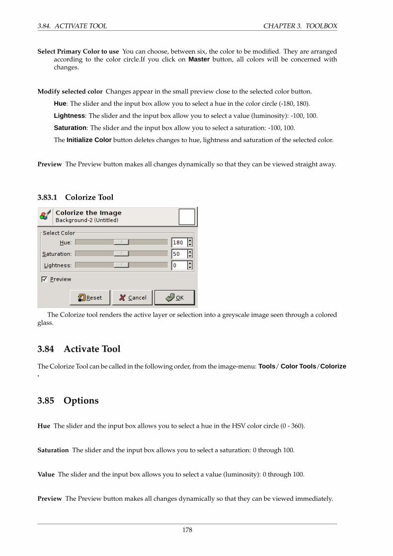
3.84. ACTIVATE TOOL CHAPTER 3. TOOLBOX
Select Primary Color to use You can choose, between six, the color to be modified. They are arrangedaccording to the color circle.If you click on Master button, all colors will be concerned withchanges.
Modify selected color Changes appear in the small preview close to the selected color button.
Hue: The slider and the input box allow you to select a hue in the color circle (-180, 180).
Lightness : The slider and the input box allow you to select a value (luminosity): -100, 100.
Saturation : The slider and the input box allow you to select a saturation: -100, 100.
The Initialize Color button deletes changes to hue, lightness and saturation of the selected color.
Preview The Preview button makes all changes dynamically so that they can be viewed straight away.
3.83.1 Colorize Tool
The Colorize tool renders the active layer or selection into a greyscale image seen through a coloredglass.
3.84 Activate Tool
The Colorize Tool can be called in the following order, from the image-menu: Tools / Color Tools /Colorize.
3.85 Options
Hue The slider and the input box allows you to select a hue in the HSV color circle (0 - 360).
Saturation The slider and the input box allows you to select a saturation: 0 through 100.
Value The slider and the input box allows you to select a value (luminosity): 0 through 100.
Preview The Preview button makes all changes dynamically so that they can be viewed immediately.
178
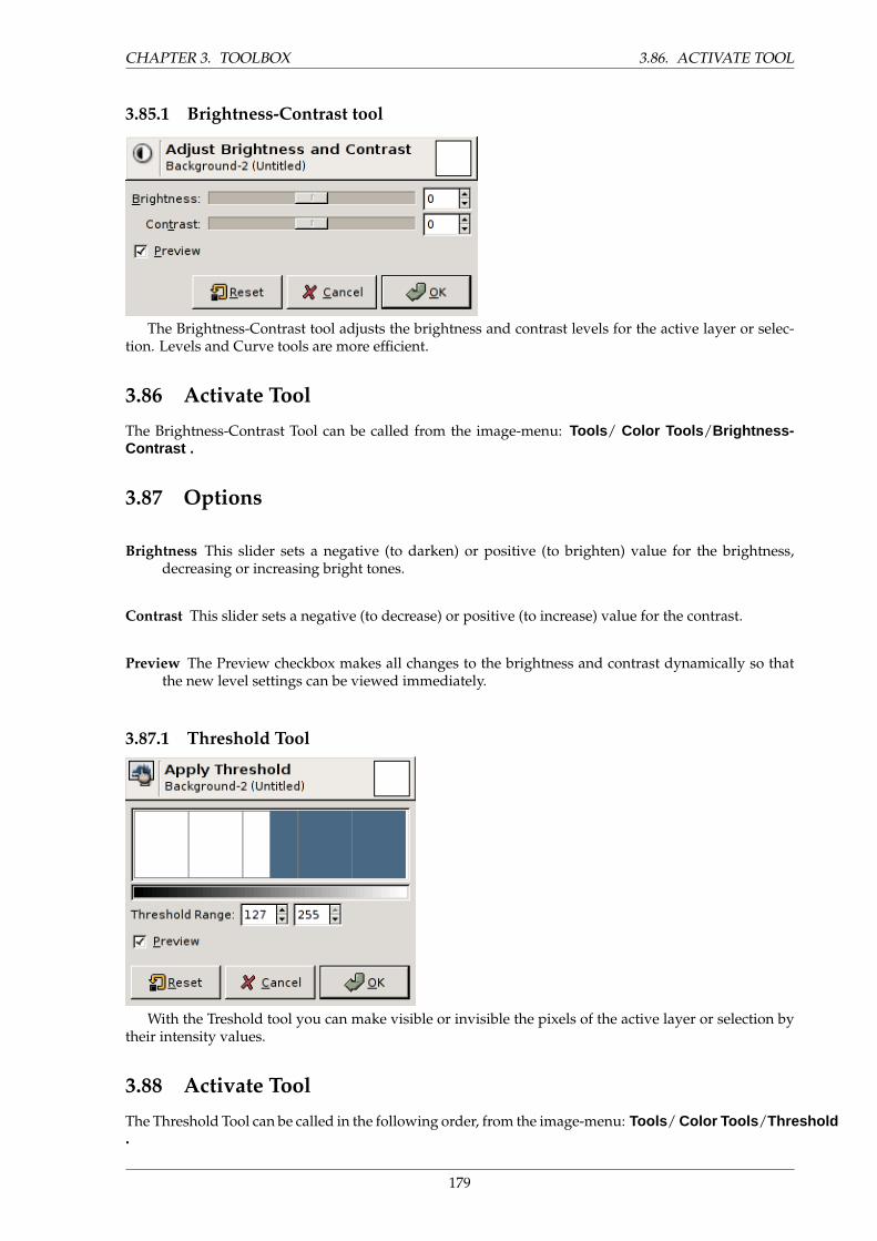
CHAPTER 3. TOOLBOX 3.86. ACTIVATE TOOL
3.85.1 Brightness-Contrast tool
The Brightness-Contrast tool adjusts the brightness and contrast levels for the active layer or selec-tion. Levels and Curve tools are more efficient.
3.86 Activate Tool
The Brightness-Contrast Tool can be called from the image-menu: Tools / Color Tools /Brightness-Contrast .
3.87 Options
Brightness This slider sets a negative (to darken) or positive (to brighten) value for the brightness,decreasing or increasing bright tones.
Contrast This slider sets a negative (to decrease) or positive (to increase) value for the contrast.
Preview The Preview checkbox makes all changes to the brightness and contrast dynamically so thatthe new level settings can be viewed immediately.
3.87.1 Threshold Tool
With the Treshold tool you can make visible or invisible the pixels of the active layer or selection bytheir intensity values.
3.88 Activate Tool
The Threshold Tool can be called in the following order, from the image-menu: Tools / Color Tools /Threshold.
179
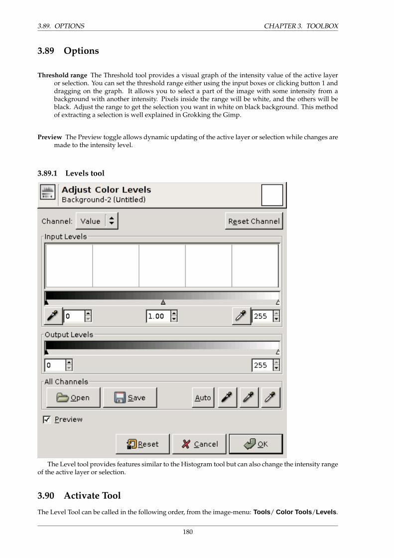
3.89. OPTIONS CHAPTER 3. TOOLBOX
3.89 Options
Threshold range The Threshold tool provides a visual graph of the intensity value of the active layeror selection. You can set the threshold range either using the input boxes or clicking button 1 anddragging on the graph. It allows you to select a part of the image with some intensity from abackground with another intensity. Pixels inside the range will be white, and the others will beblack. Adjust the range to get the selection you want in white on black background. This methodof extracting a selection is well explained in Grokking the Gimp.
Preview The Preview toggle allows dynamic updating of the active layer or selection while changes aremade to the intensity level.
3.89.1 Levels tool
The Level tool provides features similar to the Histogram tool but can also change the intensity rangeof the active layer or selection.
3.90 Activate Tool
The Level Tool can be called in the following order, from the image-menu: Tools / Color Tools /Levels .
180
CHAPTER 3. TOOLBOX 3.91. OPTIONS
3.91 Options
Modify Levels for Channel You can select the specific channel which will be modified by the tool:Value makes changes to the luminosity of all pixels in the image. Color channels allow to changesaturation. Alpha channel works on transparency. Initialize channel cancels changes to the se-lected channel.
Input Levels The main area is a graphic representation of image dark, mid and light tones content. Theyare on abscissa from level 0 (black) to level 255 (white). Pixel number for a level is on ordinate axis.The curve surface represents all the pixels of the image for the selected channel. A well balancedimage is an image with levels (tones) distributed all over the whole range. An image with a bluepredominant color, for example, will produce a histogram shifted to the left in Green and Redchannels, signified by green and red lacking on highlights.
Level ranges can be modified in three ways:
• Three triangles as sliders: one black for dark tones, one grey for midtones (often calledGamma value), one white for light tones.
• Three eyedroppers: use the left one to pick the darkest color, the mid one to pick the mid tonecolor, the right one to pick the lightest color on the image. You can use View/Info Window tofind these colors.
• Three input boxes to enter values directly.
Output Levels Output Levels allows manual selection of a constrained output level range. There arealso arrow-heads located here that can be used to interactively change the Output Levels.
All Channels Load : This button allows you to select a file holding level settings.
Save: Allows you to save any levels you have set to a file that can be loaded later.
Auto : Performs an automatic setting of the levels.
Three eyedroppers : These three controls determine three points on the grayscale. Any levelbelow the ”Black Point” is black; any point above the ”White Point” is white. The ”Gray Point”,which must be between the other two, determines the middle level of Gray. All shades of gray arecalculated from these three levels.
Preview The Preview button makes all changes to the levels dynamically so that the new level settingscan be viewed straight away.
181
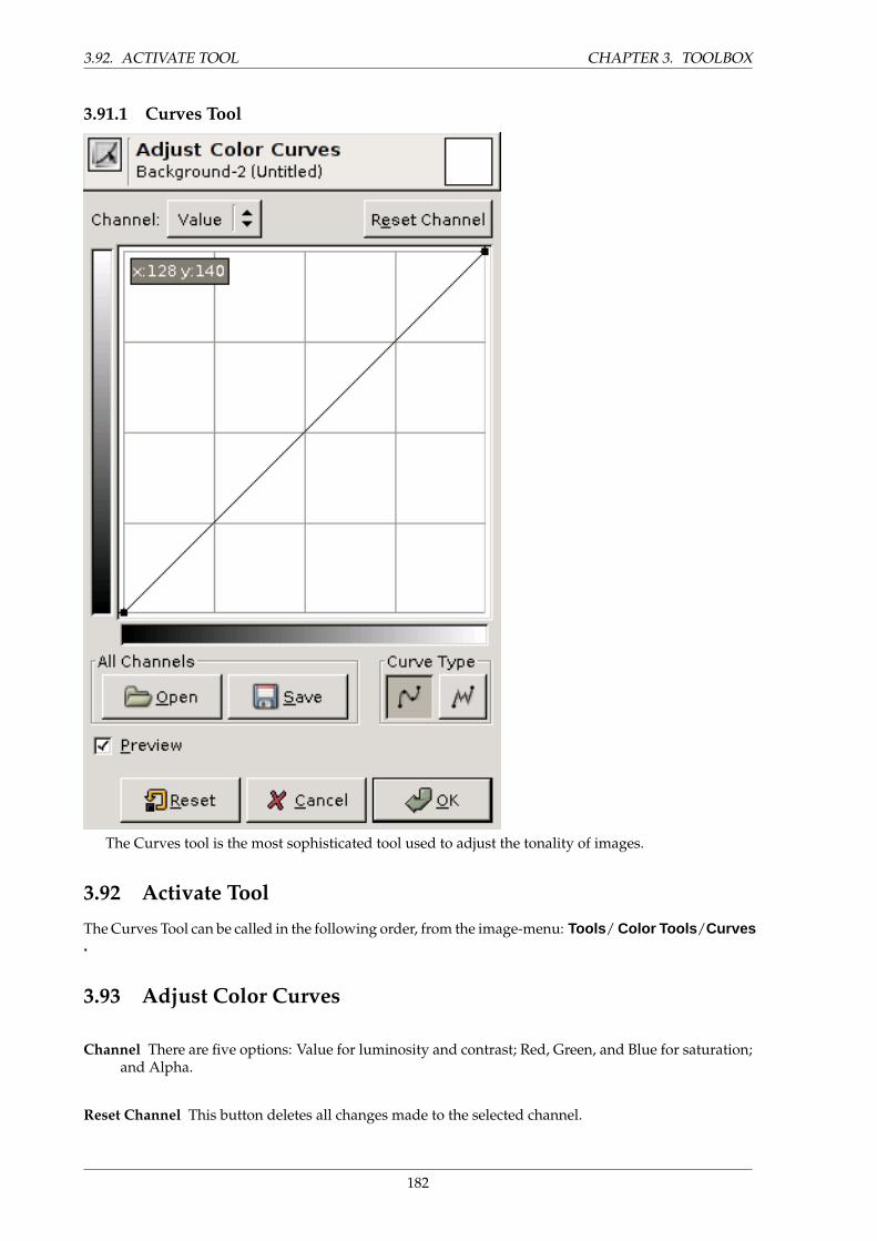
3.92. ACTIVATE TOOL CHAPTER 3. TOOLBOX
3.91.1 Curves Tool
The Curves tool is the most sophisticated tool used to adjust the tonality of images.
3.92 Activate Tool
The Curves Tool can be called in the following order, from the image-menu: Tools / Color Tools /Curves.
3.93 Adjust Color Curves
Channel There are five options: Value for luminosity and contrast; Red, Green, and Blue for saturation;and Alpha.
Reset Channel This button deletes all changes made to the selected channel.
182
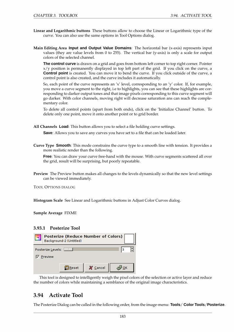
CHAPTER 3. TOOLBOX 3.94. ACTIVATE TOOL
Linear and Logarithmic buttons These buttons allow to choose the Linear or Logarithmic type of thecurve. You can also use the same options in Tool Options dialog.
Main Editing Area Input and Output Value Domains : The horizontal bar (x-axis) represents inputvalues (they are value levels from 0 to 255). The vertical bar (y-axis) is only a scale for outputcolors of the selected channel.
The control curve is drawn on a grid and goes from bottom left corner to top right corner. Pointerx/y position is permanently displayed in top left part of the grid. If you click on the curve, aControl point is created. You can move it to bend the curve. If you click outside of the curve, acontrol point is also created, and the curve includes it automatically.
So, each point of the curve represents an ’x’ level, corresponding to an ’y’ color. If, for example,you move a curve segment to the right, i.e to highlights, you can see that these highlights are cor-responding to darker output tones and that image pixels corresponding to this curve segment willgo darker. With color channels, moving right will decrease saturation ans can reach the comple-mentary color.
To delete all control points (apart from both ends), click on the ’Initialize Channel’ button. Todelete only one point, move it onto another point or to grid border.
All Channels Load : This button allows you to select a file holding curve settings.
Save: Allows you to save any curves you have set to a file that can be loaded later.
Curve Type Smooth : This mode constrains the curve type to a smooth line with tension. It provides amore realistic render than the following.
Free: You can draw your curve free-hand with the mouse. With curve segments scattered all overthe grid, result will be surprising, but poorly repeatable.
Preview The Preview button makes all changes to the levels dynamically so that the new level settingscan be viewed immediately.
TOOL OPTIONS DIALOG
Histogram Scale See Linear and Logarithmic buttons in Adjust Color Curves dialog.
Sample Average FIXME
3.93.1 Posterize Tool
This tool is designed to intelligently weigh the pixel colors of the selection or active layer and reducethe number of colors while maintaining a semblance of the original image characteristics.
3.94 Activate Tool
The Posterize Dialog can be called in the following order, from the image-menu: Tools / Color Tools /Posterize .
183
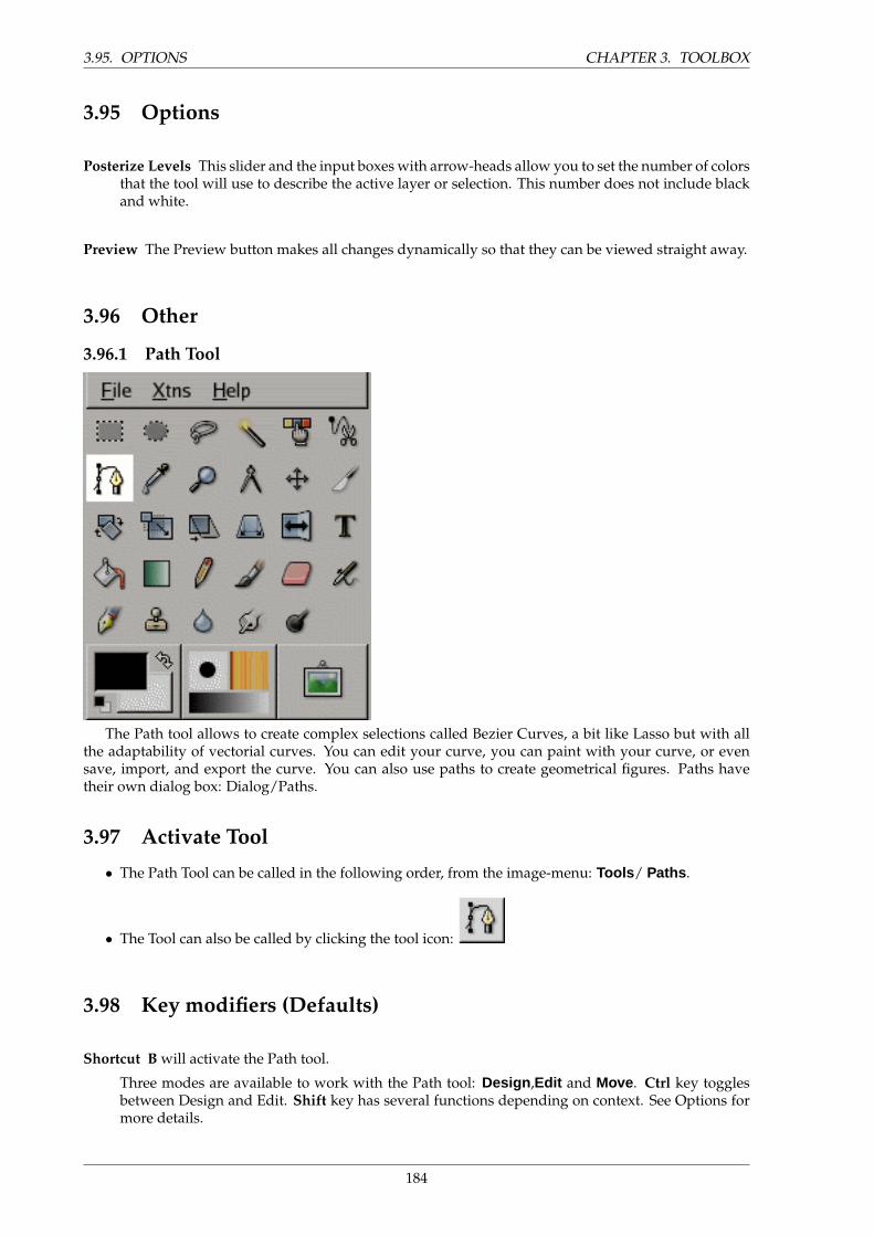
3.95. OPTIONS CHAPTER 3. TOOLBOX
3.95 Options
Posterize Levels This slider and the input boxes with arrow-heads allow you to set the number of colorsthat the tool will use to describe the active layer or selection. This number does not include blackand white.
Preview The Preview button makes all changes dynamically so that they can be viewed straight away.
3.96 Other
3.96.1 Path Tool
The Path tool allows to create complex selections called Bezier Curves, a bit like Lasso but with allthe adaptability of vectorial curves. You can edit your curve, you can paint with your curve, or evensave, import, and export the curve. You can also use paths to create geometrical figures. Paths havetheir own dialog box: Dialog/Paths.
3.97 Activate Tool
• The Path Tool can be called in the following order, from the image-menu: Tools / Paths .
• The Tool can also be called by clicking the tool icon:
3.98 Key modifiers (Defaults)
Shortcut B will activate the Path tool.
Three modes are available to work with the Path tool: Design ,Edit and Move . Ctrl key togglesbetween Design and Edit. Shift key has several functions depending on context. See Options formore details.
184
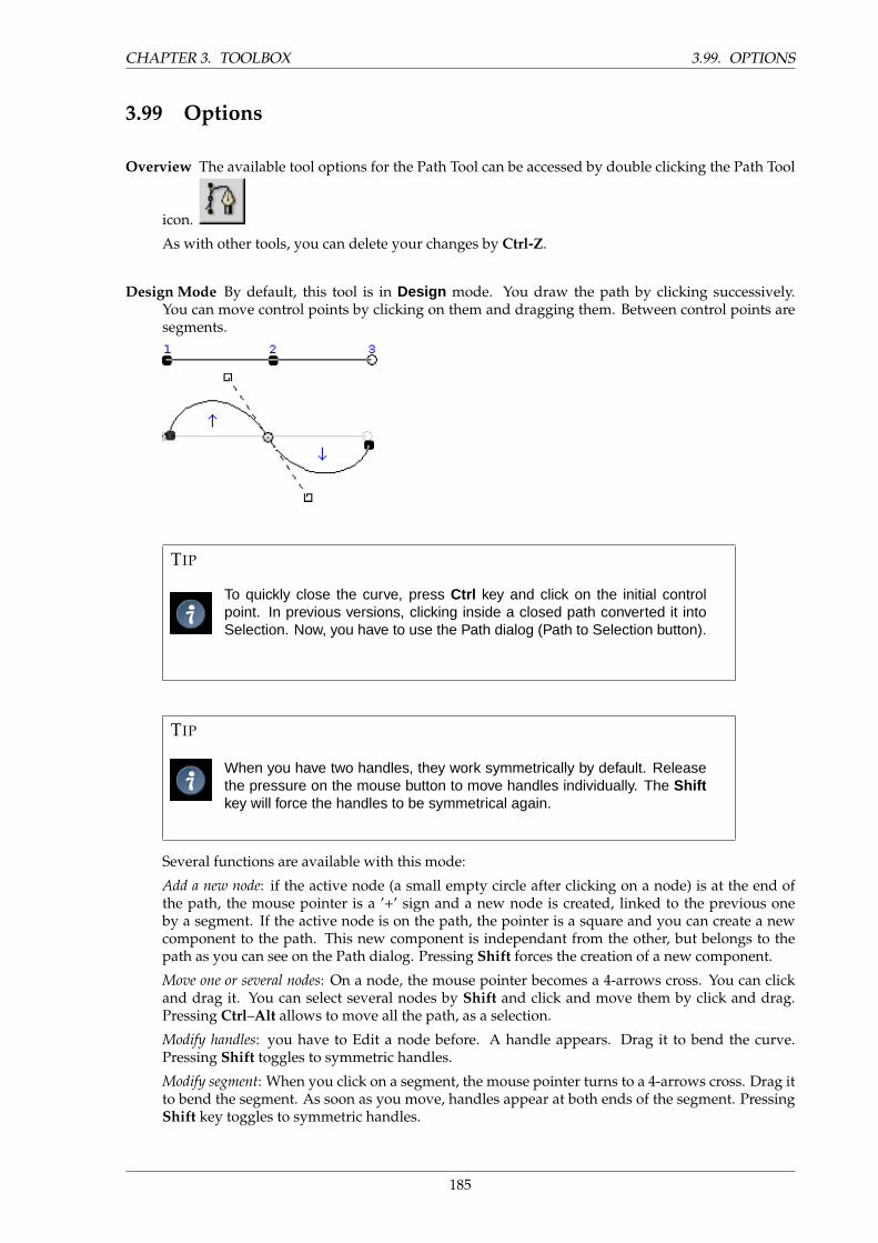
CHAPTER 3. TOOLBOX 3.99. OPTIONS
3.99 Options
Overview The available tool options for the Path Tool can be accessed by double clicking the Path Tool
icon.
As with other tools, you can delete your changes by Ctrl-Z.
Design Mode By default, this tool is in Design mode. You draw the path by clicking successively.You can move control points by clicking on them and dragging them. Between control points aresegments.
TIP
To quickly close the curve, press Ctrl key and click on the initial controlpoint. In previous versions, clicking inside a closed path converted it intoSelection. Now, you have to use the Path dialog (Path to Selection button).
TIP
When you have two handles, they work symmetrically by default. Releasethe pressure on the mouse button to move handles individually. The Shiftkey will force the handles to be symmetrical again.
Several functions are available with this mode:
Add a new node: if the active node (a small empty circle after clicking on a node) is at the end ofthe path, the mouse pointer is a ’+’ sign and a new node is created, linked to the previous oneby a segment. If the active node is on the path, the pointer is a square and you can create a newcomponent to the path. This new component is independant from the other, but belongs to thepath as you can see on the Path dialog. Pressing Shift forces the creation of a new component.
Move one or several nodes: On a node, the mouse pointer becomes a 4-arrows cross. You can clickand drag it. You can select several nodes by Shift and click and move them by click and drag.Pressing Ctrl–Alt allows to move all the path, as a selection.
Modify handles: you have to Edit a node before. A handle appears. Drag it to bend the curve.Pressing Shift toggles to symmetric handles.
Modify segment: When you click on a segment, the mouse pointer turns to a 4-arrows cross. Drag itto bend the segment. As soon as you move, handles appear at both ends of the segment. PressingShift key toggles to symmetric handles.
185
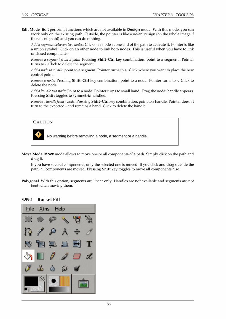
3.99. OPTIONS CHAPTER 3. TOOLBOX
Edit Mode Edit performs functions which are not available in Design mode. With this mode, you canwork only on the existing path. Outside, the pointer is like a no-entry sign (on the whole image ifthere is no path!) and you can do nothing.
Add a segment between two nodes: Click on a node at one end of the path to activate it. Pointer is likea union symbol. Click on an other node to link both nodes. This is useful when you have to linkunclosed components.
Remove a segment from a path: Pressing Shift–Ctrl key combination, point to a segment. Pointerturns to -. Click to delete the segment.
Add a node to a path: point to a segment. Pointer turns to +. Click where you want to place the newcontrol point.
Remove a node: Pressing Shift–Ctrl key combination, point to a node. Pointer turns to -. Click todelete the node.
Add a handle to a node: Point to a node. Pointer turns to small hand. Drag the node: handle appears.Pressing Shift toggles to symmetric handles.
Remove a handle from a node: Pressing Shift–Ctrl key combination, point to a handle. Pointer doesn’tturn to the expected - and remains a hand. Click to delete the handle.
CAUTION
No warning before removing a node, a segment or a handle.
Move Mode Move mode allows to move one or all components of a path. Simply click on the path anddrag it.
If you have several components, only the selected one is moved. If you click and drag outside thepath, all components are moved. Pressing Shift key toggles to move all components also.
Polygonal With this option, segments are linear only. Handles are not available and segments are notbent when moving them.
3.99.1 Bucket Fill
186
CHAPTER 3. TOOLBOX 3.100. ACTIVATE TOOL
This tool fills a selection with the current foreground color. If you Shift+click and use the Bucket tool,it will use the background color instead. Depending on how the tool options are set, the Bucket Fill toolwill either fill the entire selection, or only parts whose colors are similar to the point you click on. Thetool options also affect the way transparency is handled.
The amount of fill depends on what Fill Threshold you have specified. The fill threshold determineshow far the fill will spread (similar to the way in which the magic wand works). The fill starts at thepoint where you click and spreads outward until the color or alpha value becomes ”too different.”
When you fill objects in a transparent layer (such as letters in a text layer) with a different colorthan before, you may find that a border of the old color still surrounds the objects. This is due to a lowfill-threshold in the Bucket Fill options dialog. With a low threshold, the bucket tool won’t fill semi-transparent pixels, and they will stand out against the fill because they have kept their original color. Ifyou want to fill areas that are totally transparent, you have to choose right-click|Select|Select All, andmake sure that the layer’s ”Keep Transparency” button (in the Layers dialog) is unchecked. If the KeepTransparency button is checked, only the opaque parts of the layer will be filled, and if you don’t usethe Select All command, only the opaque ”island” that you clicked on will be filled.
3.100 Activate Tool
• The Bucket Fill can be called in the following order, from the image-menu: Tools / Paint Tools /BucketFill.
• The Tool can also be called by clicking the tool icon:
3.101 Key modifiers (Defaults)
Shortcut The Shift–b keys will change the active tool to Bucket Fill.
Ctrl Ctrl toggles the use of BG Color Fill or FG Color Fill on the fly.
Ctrl toggles the use of Fill Similar Color or Fill Whole Selection on the fly.
3.102 Options
Overview The available tool options for the Fill Tool can be accessed by double clicking the Fill Tool
icon.
Opacity The Opacity slider sets the transparency level for the fill. A higher opacity setting results in amore opaque fill and a lower setting results in a more transparent fill.
Mode The Mode dropdown list provides a selection of paint application modes. A list of these modescan be found in the Glossary.
Pattern This dropdown list allows the user to select one of many fill patterns to use on the next filloperation. The manner in which the list is presented is controlled by the four buttons at the bottomof the selector.
187
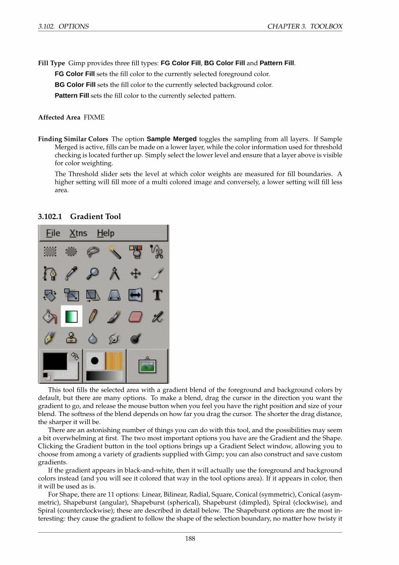
3.102. OPTIONS CHAPTER 3. TOOLBOX
Fill Type Gimp provides three fill types: FG Color Fill , BG Color Fill and Pattern Fill .
FG Color Fill sets the fill color to the currently selected foreground color.
BG Color Fill sets the fill color to the currently selected background color.
Pattern Fill sets the fill color to the currently selected pattern.
Affected Area FIXME
Finding Similar Colors The option Sample Merged toggles the sampling from all layers. If SampleMerged is active, fills can be made on a lower layer, while the color information used for thresholdchecking is located further up. Simply select the lower level and ensure that a layer above is visiblefor color weighting.
The Threshold slider sets the level at which color weights are measured for fill boundaries. Ahigher setting will fill more of a multi colored image and conversely, a lower setting will fill lessarea.
3.102.1 Gradient Tool
This tool fills the selected area with a gradient blend of the foreground and background colors bydefault, but there are many options. To make a blend, drag the cursor in the direction you want thegradient to go, and release the mouse button when you feel you have the right position and size of yourblend. The softness of the blend depends on how far you drag the cursor. The shorter the drag distance,the sharper it will be.
There are an astonishing number of things you can do with this tool, and the possibilities may seema bit overwhelming at first. The two most important options you have are the Gradient and the Shape.Clicking the Gradient button in the tool options brings up a Gradient Select window, allowing you tochoose from among a variety of gradients supplied with Gimp; you can also construct and save customgradients.
If the gradient appears in black-and-white, then it will actually use the foreground and backgroundcolors instead (and you will see it colored that way in the tool options area). If it appears in color, thenit will be used as is.
For Shape, there are 11 options: Linear, Bilinear, Radial, Square, Conical (symmetric), Conical (asym-metric), Shapeburst (angular), Shapeburst (spherical), Shapeburst (dimpled), Spiral (clockwise), andSpiral (counterclockwise); these are described in detail below. The Shapeburst options are the most in-teresting: they cause the gradient to follow the shape of the selection boundary, no matter how twisty it
188
CHAPTER 3. TOOLBOX 3.103. ACTIVATE TOOL
is. Unlike the other shapes, Shapeburst gradients are not affected by the length or direction of the lineyou draw: for them as well as every other type of gradient you are required to click inside the selectionand move the mouse, but a Shapeburst appears the same no matter where you click or how you move.
TIP
Check out the Difference option in the Mode menu, where doing the same thing(even with full opacity) will result in fantastic swirling patterns, changing andadding every time you drag the cursor.
3.103 Activate Tool
• The Blend Tool can be called in the following order, from the image-menu: Tools / Paint Tools /Blend .
• The Tool can also be called by clicking the tool icon:
3.104 Key modifiers (Defaults)
Shortcut The L key will change the active tool to Gradient Fill.
Ctrl Ctrl is used to create straight lines that are constrained to 15 degree absolute angles.
3.105 Options
Overview The available tool options can be accessed by double clicking the Gradient Tool icon.
Opacity The Opacity slider sets the transparency level for the gradient. A higher opacity setting resultsin a more opaque fill and a lower setting results in a more transparent fill.
Mode The Mode dropdown list provides a selection of paint application modes. A list of these modescan be found in the Glossary.
Gradient A variety of gradient patterns can be selected from the drop-down list. The tool causes ashading pattern that transitions from foreground to background color, in the direction the userdetermines by drawing a line in the image. For the purposes of drawing the gradient, the Reversecheckbox switches foreground and background.
Offset The Offset Value is the ”slope” of the gradient.
Shape The Gimp provides 11 shapes, which can be selected from the drop-down list. Details on eachof the shapes are given below.
189
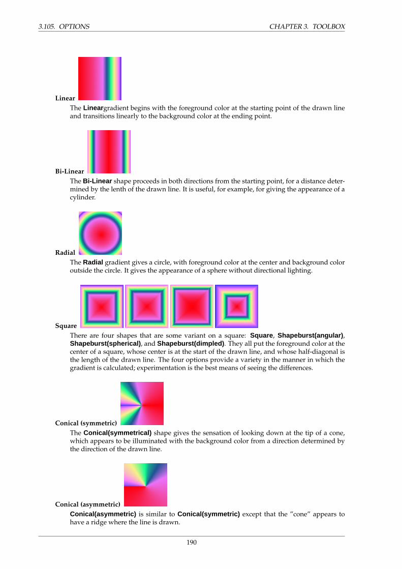
3.105. OPTIONS CHAPTER 3. TOOLBOX
LinearThe Linear gradient begins with the foreground color at the starting point of the drawn lineand transitions linearly to the background color at the ending point.
Bi-LinearThe Bi-Linear shape proceeds in both directions from the starting point, for a distance deter-mined by the lenth of the drawn line. It is useful, for example, for giving the appearance of acylinder.
RadialThe Radial gradient gives a circle, with foreground color at the center and background coloroutside the circle. It gives the appearance of a sphere without directional lighting.
SquareThere are four shapes that are some variant on a square: Square , Shapeburst(angular) ,Shapeburst(spherical) , and Shapeburst(dimpled) . They all put the foreground color at thecenter of a square, whose center is at the start of the drawn line, and whose half-diagonal isthe length of the drawn line. The four options provide a variety in the manner in which thegradient is calculated; experimentation is the best means of seeing the differences.
Conical (symmetric)The Conical(symmetrical) shape gives the sensation of looking down at the tip of a cone,which appears to be illuminated with the background color from a direction determined bythe direction of the drawn line.
Conical (asymmetric)Conical(asymmetric) is similar to Conical(symmetric) except that the ”cone” appears tohave a ridge where the line is drawn.
190
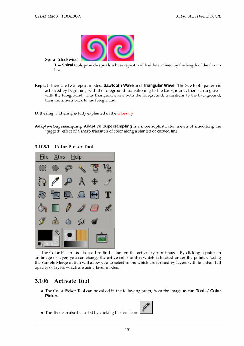
CHAPTER 3. TOOLBOX 3.106. ACTIVATE TOOL
Spiral (clockwise)The Spiral tools provide spirals whose repeat width is determined by the length of the drawnline.
Repeat There are two repeat modes: Sawtooth Wave and Triangular Wave . The Sawtooth pattern isachieved by beginning with the foreground, transitioning to the background, then starting overwith the foreground. The Triangular starts with the foreground, transitions to the background,then transitions back to the foreground.
Dithering Dithering is fully explained in the Glossary
Adaptive Supersampling Adaptive Supersampling is a more sophisticated means of smoothing the”jagged” effect of a sharp transiton of color along a slanted or curved line.
3.105.1 Color Picker Tool
The Color Picker Tool is used to find colors on the active layer or image. By clicking a point onan image or layer, you can change the active color to that which is located under the pointer. Usingthe Sample Merge option will allow you to select colors which are formed by layers with less than fullopacity or layers which are using layer modes.
3.106 Activate Tool
• The Color Picker Tool can be called in the following order, from the image-menu: Tools / ColorPicker.
• The Tool can also be called by clicking the tool icon:
191
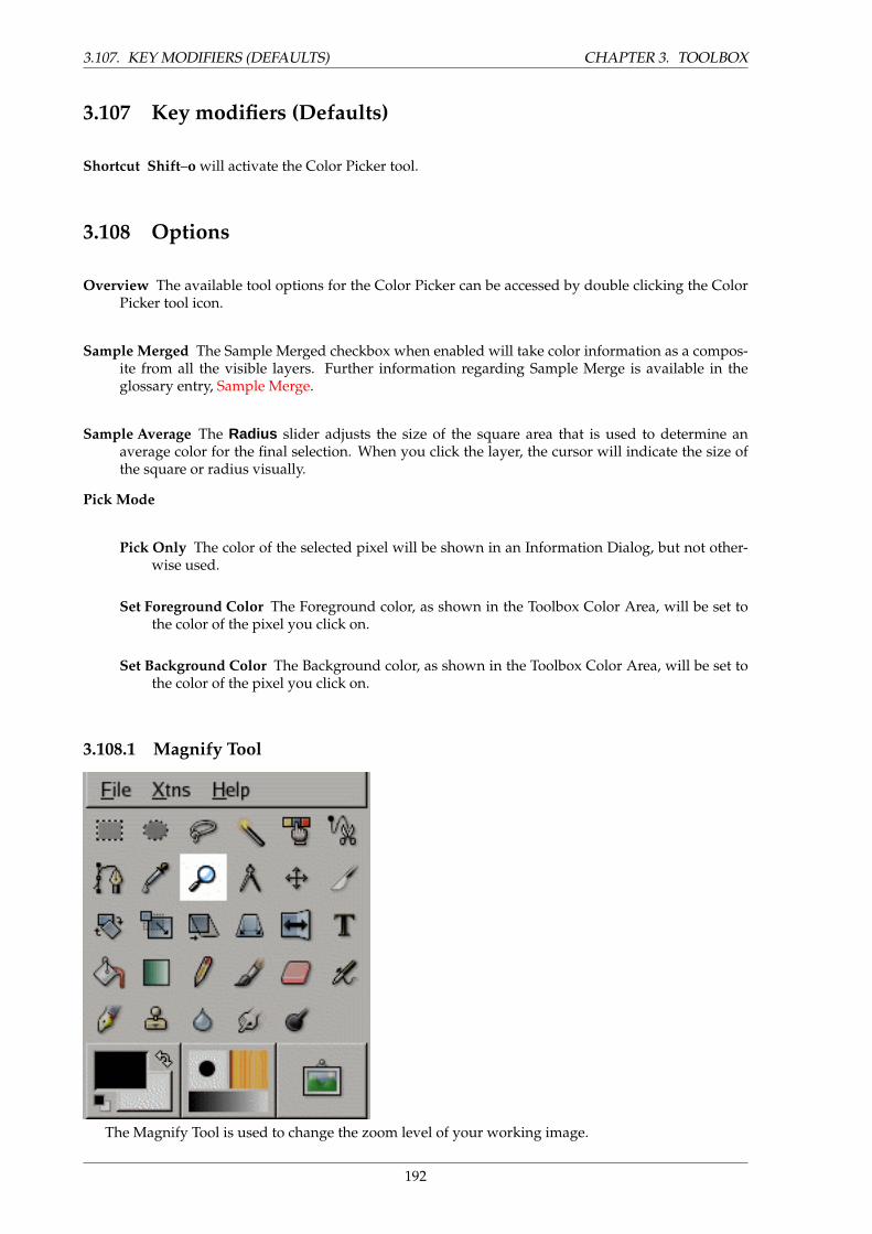
3.107. KEY MODIFIERS (DEFAULTS) CHAPTER 3. TOOLBOX
3.107 Key modifiers (Defaults)
Shortcut Shift–o will activate the Color Picker tool.
3.108 Options
Overview The available tool options for the Color Picker can be accessed by double clicking the ColorPicker tool icon.
Sample Merged The Sample Merged checkbox when enabled will take color information as a compos-ite from all the visible layers. Further information regarding Sample Merge is available in theglossary entry, Sample Merge.
Sample Average The Radius slider adjusts the size of the square area that is used to determine anaverage color for the final selection. When you click the layer, the cursor will indicate the size ofthe square or radius visually.
Pick Mode
Pick Only The color of the selected pixel will be shown in an Information Dialog, but not other-wise used.
Set Foreground Color The Foreground color, as shown in the Toolbox Color Area, will be set tothe color of the pixel you click on.
Set Background Color The Background color, as shown in the Toolbox Color Area, will be set tothe color of the pixel you click on.
3.108.1 Magnify Tool
The Magnify Tool is used to change the zoom level of your working image.
192
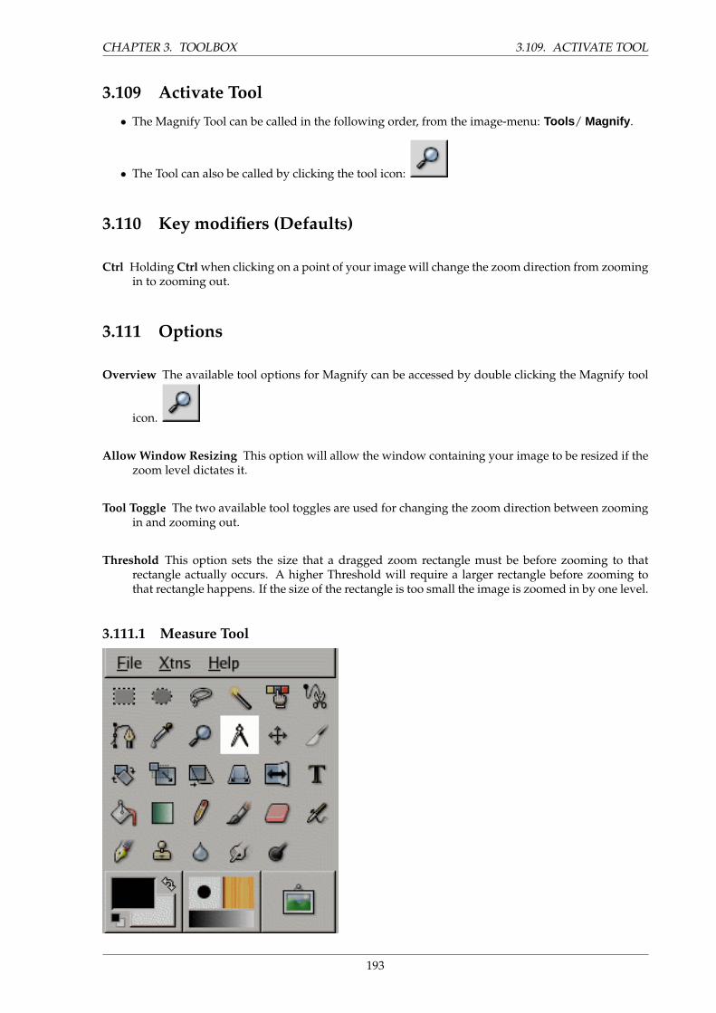
CHAPTER 3. TOOLBOX 3.109. ACTIVATE TOOL
3.109 Activate Tool
• The Magnify Tool can be called in the following order, from the image-menu: Tools / Magnify .
• The Tool can also be called by clicking the tool icon:
3.110 Key modifiers (Defaults)
Ctrl Holding Ctrl when clicking on a point of your image will change the zoom direction from zoomingin to zooming out.
3.111 Options
Overview The available tool options for Magnify can be accessed by double clicking the Magnify tool
icon.
Allow Window Resizing This option will allow the window containing your image to be resized if thezoom level dictates it.
Tool Toggle The two available tool toggles are used for changing the zoom direction between zoomingin and zooming out.
Threshold This option sets the size that a dragged zoom rectangle must be before zooming to thatrectangle actually occurs. A higher Threshold will require a larger rectangle before zooming tothat rectangle happens. If the size of the rectangle is too small the image is zoomed in by one level.
3.111.1 Measure Tool
193
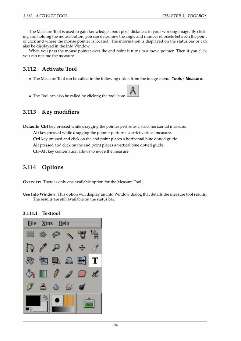
3.112. ACTIVATE TOOL CHAPTER 3. TOOLBOX
The Measure Tool is used to gain knowledge about pixel distances in your working image. By click-ing and holding the mouse button, you can determine the angle and number of pixels between the pointof click and where the mouse pointer is located. The information is displayed on the status bar or canalso be displayed in the Info Window.
When you pass the mouse pointer over the end point it turns to a move pointer. Then if you clickyou can resume the measure.
3.112 Activate Tool
• The Measure Tool can be called in the following order, from the image-menu: Tools / Measure .
• The Tool can also be called by clicking the tool icon:
3.113 Key modifiers
Defaults Ctrl key pressed while dragging the pointer performs a strict horizontal measure.
Alt key pressed while dragging the pointer performs a strict vertical measure.
Ctrl key pressed and click on the end point places a horizontal blue dotted guide.
Alt pressed and click on the end point places a vertical blue dotted guide.
Ctr–Alt key combination allows to move the measure.
3.114 Options
Overview There is only one available option for the Measure Tool.
Use Info Window This option will display an Info Window dialog that details the measure tool results.The results are still available on the status bar.
3.114.1 Texttool
194
CHAPTER 3. TOOLBOX 3.115. ACTIVATE TOOL
The Text tool places text into an image. When you click on an image with this tool the Text Editordialog is opened where you can type your text.
3.115 Activate Tool
• The Text Tool can be called in the following order, from the image-menu: Tools / Text .
• The Tool can also be called by clicking the tool icon:
3.116 Key modifiers (Defaults)
t The t key will change the active tool to the Text Tool.
3.117 Options
Overview The available tool options for the Texttool can be accessed by double clicking the texttool
icon.
Font There are two ways of selecting fonts in the GIMP. The first is from the image Dialogs/Fonts menu.The second is with the Font selector in this tool. Both methods select from the installed X fonts.When you select a font it is interactively applied to your text.
Size This control sets the size of the font in any of several selectable units.
Hinting Uses the indices of adjustment to modify the characters in order to produce clear letters insmall font sizes.
Force Auto-Hinter Auto Hinter tries to automatically compute information for better representation ofthe character font.
Antialiasing Antialiasing will render the text with much smoother edges and curves. This is achievedby slight blurring and merging of the edges. This option can radically improve the visual appear-ance of the rendered typeface. Caution should be exercised when using antialiasing on imagesthat are not in RGB color space.
Color Color of the text that will be drawn next. Defaults to black. Selectable from the color picker dialogbox that opens when the current color sample is clickes.
Justify Causes the text to be justified according to any of four rules selectable from the associated icons.
Indent Controls the indent spacing from the left margin.
Line Spacing Controls the spacing between successive lines of text. This setting is interactive: it appearsat the same time in image text.
195
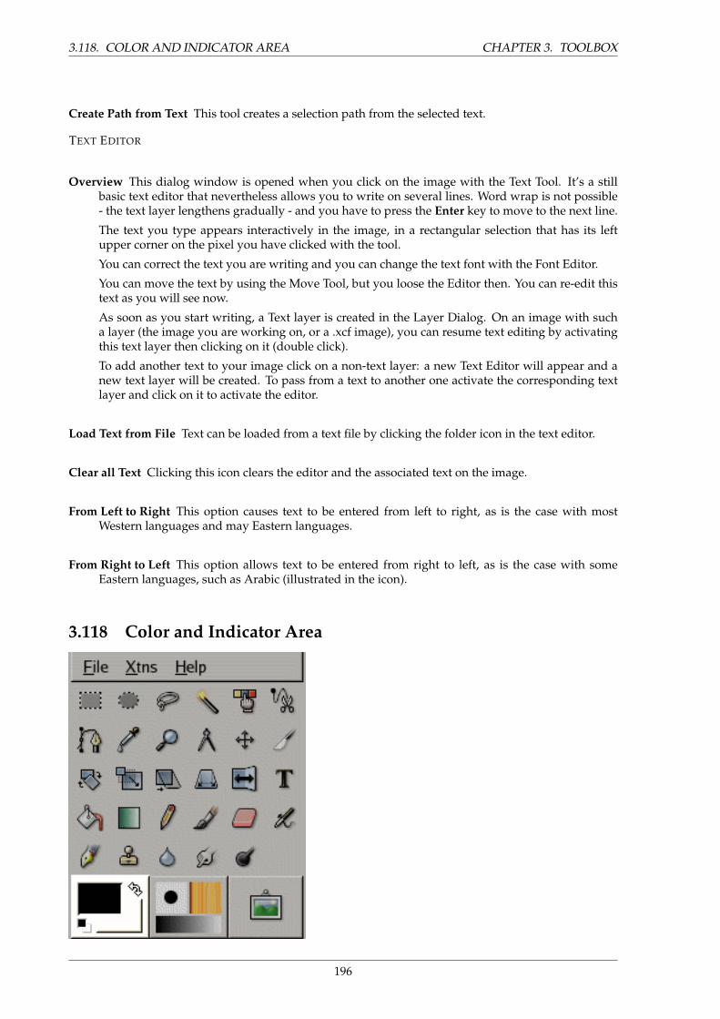
3.118. COLOR AND INDICATOR AREA CHAPTER 3. TOOLBOX
Create Path from Text This tool creates a selection path from the selected text.
TEXT EDITOR
Overview This dialog window is opened when you click on the image with the Text Tool. It’s a stillbasic text editor that nevertheless allows you to write on several lines. Word wrap is not possible- the text layer lengthens gradually - and you have to press the Enter key to move to the next line.
The text you type appears interactively in the image, in a rectangular selection that has its leftupper corner on the pixel you have clicked with the tool.
You can correct the text you are writing and you can change the text font with the Font Editor.
You can move the text by using the Move Tool, but you loose the Editor then. You can re-edit thistext as you will see now.
As soon as you start writing, a Text layer is created in the Layer Dialog. On an image with sucha layer (the image you are working on, or a .xcf image), you can resume text editing by activatingthis text layer then clicking on it (double click).
To add another text to your image click on a non-text layer: a new Text Editor will appear and anew text layer will be created. To pass from a text to another one activate the corresponding textlayer and click on it to activate the editor.
Load Text from File Text can be loaded from a text file by clicking the folder icon in the text editor.
Clear all Text Clicking this icon clears the editor and the associated text on the image.
From Left to Right This option causes text to be entered from left to right, as is the case with mostWestern languages and may Eastern languages.
From Right to Left This option allows text to be entered from right to left, as is the case with someEastern languages, such as Arabic (illustrated in the icon).
3.118 Color and Indicator Area
196
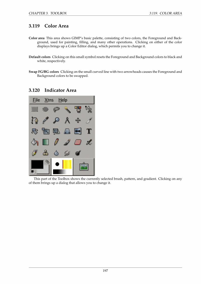
CHAPTER 3. TOOLBOX 3.119. COLOR AREA
3.119 Color Area
Color area This area shows GIMP’s basic palette, consisting of two colors, the Foreground and Back-ground, used for painting, filling, and many other operations. Clicking on either of the colordisplays brings up a Color Editor dialog, which permits you to change it.
Default colors Clicking on this small symbol resets the Foreground and Background colors to black andwhite, respectively.
Swap FG/BG colors Clicking on the small curved line with two arrowheads causes the Foreground andBackground colors to be swapped.
3.120 Indicator Area
This part of the Toolbox shows the currently selected brush, pattern, and gradient. Clicking on anyof them brings up a dialog that allows you to change it.
197


Chapter 4
Dialogs
4.1 Dialog introduction
Dialogs are the most common means of setting options and controls in the GIMP. The most importantdialogs are explained in this section.
4.2 Layers dialog
The Layer dialog is the main interface to edit, modify and manage your layers. You can think oflayers as a stack of slides or clothes on your body. Using layers, you can construct an image of severalconceptual parts which can be manipulated without affecting any other part of the image. Layers arestacked on top of each other. The bottom layer is the background of the image and the components inthe foreground of the image come above it.
4.2.1 Activate Dialog
The Layer dialog can be called in many ways :
• from the toolbox-menu: File/ Dialog / Layers
• from the image-menu: Dialog / Layers
• from an other dialog-menu: Add Tab / Layers
• from the (default) shortcut: Ctrl+L.
199
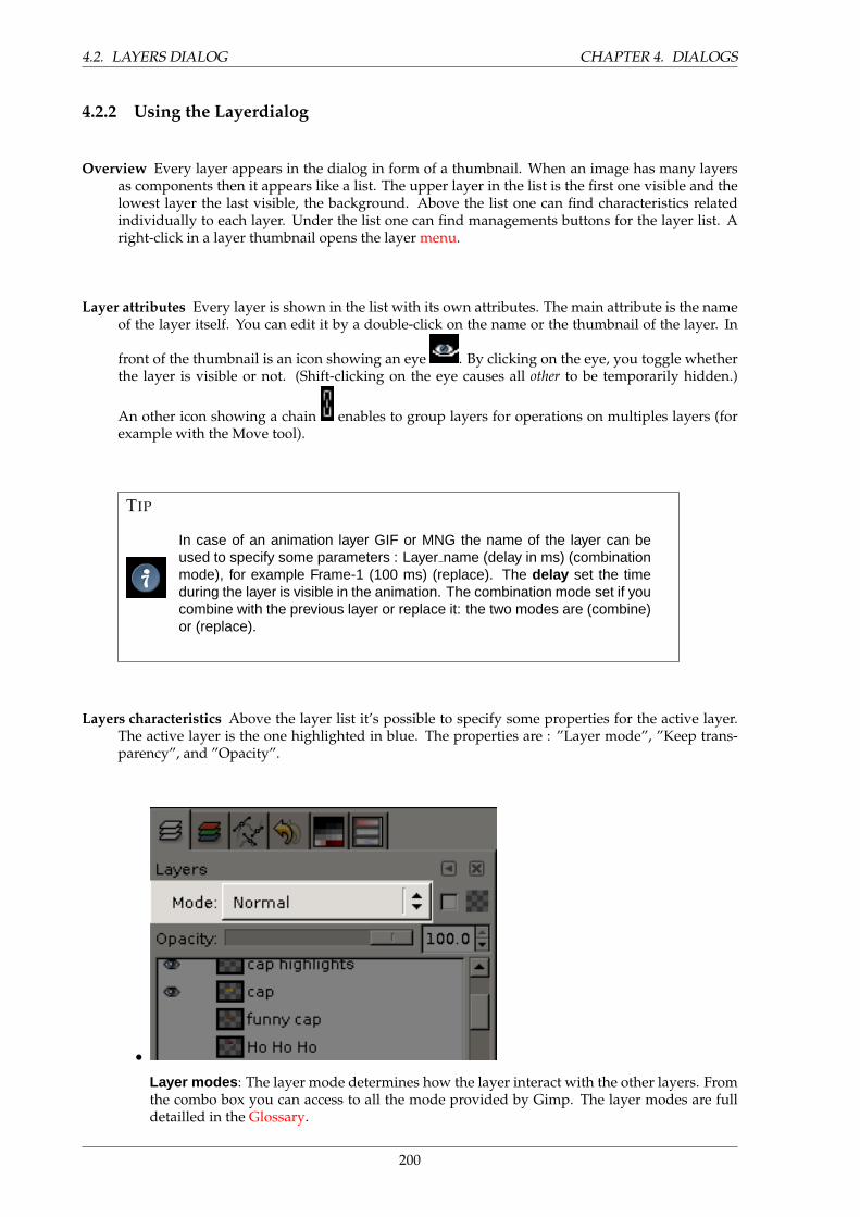
4.2. LAYERS DIALOG CHAPTER 4. DIALOGS
4.2.2 Using the Layerdialog
Overview Every layer appears in the dialog in form of a thumbnail. When an image has many layersas components then it appears like a list. The upper layer in the list is the first one visible and thelowest layer the last visible, the background. Above the list one can find characteristics relatedindividually to each layer. Under the list one can find managements buttons for the layer list. Aright-click in a layer thumbnail opens the layer menu.
Layer attributes Every layer is shown in the list with its own attributes. The main attribute is the nameof the layer itself. You can edit it by a double-click on the name or the thumbnail of the layer. In
front of the thumbnail is an icon showing an eye . By clicking on the eye, you toggle whetherthe layer is visible or not. (Shift-clicking on the eye causes all other to be temporarily hidden.)
An other icon showing a chain enables to group layers for operations on multiples layers (forexample with the Move tool).
TIP
In case of an animation layer GIF or MNG the name of the layer can beused to specify some parameters : Layer name (delay in ms) (combinationmode), for example Frame-1 (100 ms) (replace). The delay set the timeduring the layer is visible in the animation. The combination mode set if youcombine with the previous layer or replace it: the two modes are (combine)or (replace).
Layers characteristics Above the layer list it’s possible to specify some properties for the active layer.The active layer is the one highlighted in blue. The properties are : ”Layer mode”, ”Keep trans-parency”, and ”Opacity”.
•
Layer modes : The layer mode determines how the layer interact with the other layers. Fromthe combo box you can access to all the mode provided by Gimp. The layer modes are fulldetailled in the Glossary.
200

CHAPTER 4. DIALOGS 4.2. LAYERS DIALOG
•Keep transparency : If you check this option the transparent areas of the layer will be keeped,this even if you have checked the Fill transparent areas option for the Bucket fill tool.
•Opacity : By moving the slider you give less or more opacity to the layer. With a 0 opacityvalue the layer is transparent and full invisible. Don’t mistake with the Layer mask (seechapter Layer mask) that sets the transparency pixel by pixel.
Layer management Under the layer list a set of buttons allows you to perform some basis operationson the layer list.
• Edit layer attributs : You can change here the name of the active layer in the list.
• New layer : You can create here a new layer. A dialog is opened where you have to fillthe Layer name , perhaps change default Height and Width choose the Layer fill type whichwill be the new layer background.
• Raise layer : You can here put the layer up a level in the list. Press the Shift key to movethe layer to the top of the list.
• Lower layer : You can here put the layer down a level in the list. Press the Shift key tomove the layer to the bottom of the list.
TIP
To move a layer at the bottom of the list, first give a transparencychannel to the Backgrpund layer (also called Alpha channel). Rightclick on the Background layer and select Add Alpha channel in themenu.
201
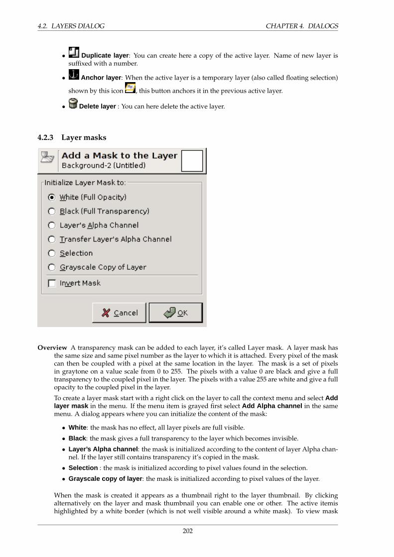
4.2. LAYERS DIALOG CHAPTER 4. DIALOGS
• Duplicate layer : You can create here a copy of the active layer. Name of new layer issuffixed with a number.
• Anchor layer : When the active layer is a temporary layer (also called floating selection)
shown by this icon , this button anchors it in the previous active layer.
• Delete layer : You can here delete the active layer.
4.2.3 Layer masks
Overview A transparency mask can be added to each layer, it’s called Layer mask. A layer mask hasthe same size and same pixel number as the layer to which it is attached. Every pixel of the maskcan then be coupled with a pixel at the same location in the layer. The mask is a set of pixelsin graytone on a value scale from 0 to 255. The pixels with a value 0 are black and give a fulltransparency to the coupled pixel in the layer. The pixels with a value 255 are white and give a fullopacity to the coupled pixel in the layer.
To create a layer mask start with a right click on the layer to call the context menu and select Addlayer mask in the menu. If the menu item is grayed first select Add Alpha channel in the samemenu. A dialog appears where you can initialize the content of the mask:
• White : the mask has no effect, all layer pixels are full visible.
• Black : the mask gives a full transparency to the layer which becomes invisible.
• Layer’s Alpha channel : the mask is initialized according to the content of layer Alpha chan-nel. If the layer still contains transparency it’s copied in the mask.
• Selection : the mask is initialized according to pixel values found in the selection.
• Grayscale copy of layer : the mask is initialized according to pixel values of the layer.
When the mask is created it appears as a thumbnail right to the layer thumbnail. By clickingalternatively on the layer and mask thumbnail you can enable one or other. The active itemishighlighted by a white border (which is not well visible around a white mask). To view mask
202
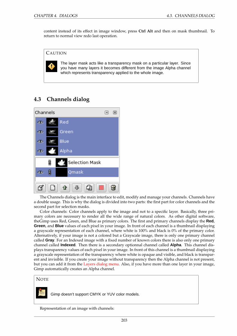
CHAPTER 4. DIALOGS 4.3. CHANNELS DIALOG
content instead of its effect in image window, press Ctrl Alt and then on mask thumbnail. Toreturn to normal view redo last operation.
CAUTION
The layer mask acts like a transparency mask on a particular layer. Sinceyou have many layers it becomes different from the image Alpha channelwhich represents transparency applied to the whole image.
4.3 Channels dialog
The Channels dialog is the main interface to edit, modify and manage your channels. Channels havea double usage. This is why the dialog is divided into two parts: the first part for color channels and thesecond part for selection masks.
Color channels: Color channels apply to the image and not to a specific layer. Basically, three pri-mary colors are necessary to render all the wide range of natural colors. As other digital software,theGimp uses Red, Green, and Blue as primary colors. The first and primary channels display the Red,Green , and Blue values of each pixel in your image. In front of each channel is a thumbnail displayinga grayscale representation of each channel, where white is 100% and black is 0% of the primary color.Alternatively, if your image is not a colored but a Grayscale image, there is only one primary channelcalled Gray . For an Indexed image with a fixed number of known colors there is also only one primarychannel called Indexed . Then there is a secondary optionnal channel called Alpha . This channel dis-plays transparency values of each pixel in your image. In front of this channel is a thumbnail displayinga grayscale representation of the transparency where white is opaque and visible, and black is transpar-ent and invisible. If you create your image without transparency then the Alpha channel is not present,but you can add it from the Layers dialog menu. Also, if you have more than one layer in your image,Gimp automatically creates an Alpha channel.
NOTE
Gimp doesn’t support CMYK or YUV color models.
Representation of an image with channels:
203
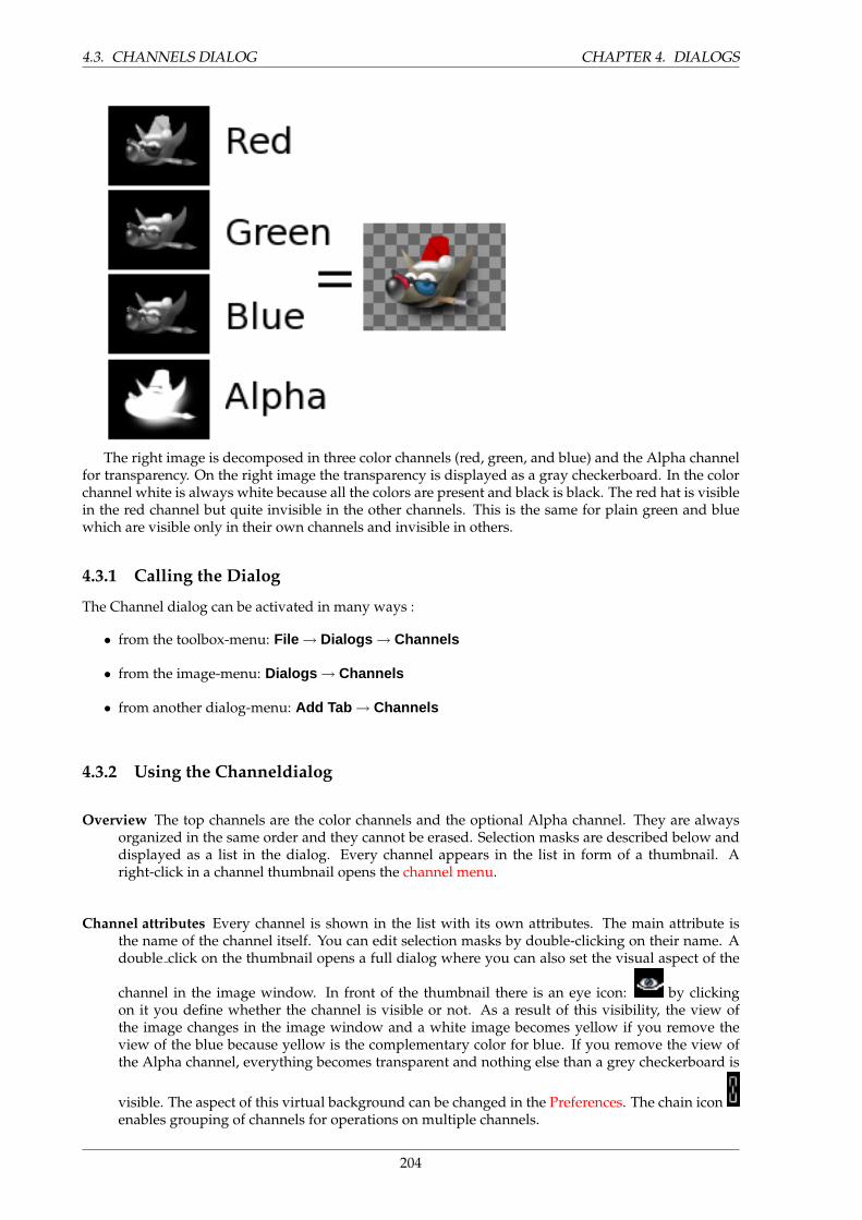
4.3. CHANNELS DIALOG CHAPTER 4. DIALOGS
The right image is decomposed in three color channels (red, green, and blue) and the Alpha channelfor transparency. On the right image the transparency is displayed as a gray checkerboard. In the colorchannel white is always white because all the colors are present and black is black. The red hat is visiblein the red channel but quite invisible in the other channels. This is the same for plain green and bluewhich are visible only in their own channels and invisible in others.
4.3.1 Calling the Dialog
The Channel dialog can be activated in many ways :
• from the toolbox-menu: File → Dialogs → Channels
• from the image-menu: Dialogs → Channels
• from another dialog-menu: Add Tab → Channels
4.3.2 Using the Channeldialog
Overview The top channels are the color channels and the optional Alpha channel. They are alwaysorganized in the same order and they cannot be erased. Selection masks are described below anddisplayed as a list in the dialog. Every channel appears in the list in form of a thumbnail. Aright-click in a channel thumbnail opens the channel menu.
Channel attributes Every channel is shown in the list with its own attributes. The main attribute isthe name of the channel itself. You can edit selection masks by double-clicking on their name. Adouble click on the thumbnail opens a full dialog where you can also set the visual aspect of the
channel in the image window. In front of the thumbnail there is an eye icon: by clickingon it you define whether the channel is visible or not. As a result of this visibility, the view ofthe image changes in the image window and a white image becomes yellow if you remove theview of the blue because yellow is the complementary color for blue. If you remove the view ofthe Alpha channel, everything becomes transparent and nothing else than a grey checkerboard is
visible. The aspect of this virtual background can be changed in the Preferences. The chain iconenables grouping of channels for operations on multiple channels.
204
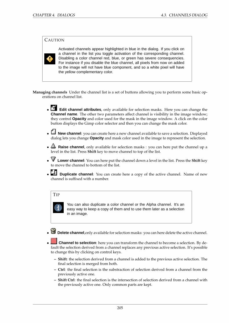
CHAPTER 4. DIALOGS 4.3. CHANNELS DIALOG
CAUTION
Activated channels appear highlighted in blue in the dialog. If you click ona channel in the list you toggle activation of the corresponding channel.Disabling a color channel red, blue, or green has severe consequencies.For instance if you disable the blue channel, all pixels from now on addedto the image will not have blue component, and so a white pixel will havethe yellow complementary color.
Managing channels Under the channel list is a set of buttons allowing you to perform some basic op-erations on channel list.
• Edit channel attributes , only available for selection masks. Here you can change theChannel name . The other two parameters affect channel is visibility in the image window;they control Opacity and color used for the mask in the image window. A click on the colorbutton displays the Gimp color selector and then you can change the mask color.
• New channel : you can create here a new channel available to save a selection. Displayeddialog lets you change Opacity and mask color used in the image to represent the selection.
• Raise channel , only available for selection masks : you can here put the channel up alevel in the list. Press Shift key to move channel to top of the list.
• Lower channel : You can here put the channel down a level in the list. Press the Shift keyto move the channel to bottom of the list.
• Duplicate channel : You can create here a copy of the active channel. Name of newchannel is suffixed with a number.
TIP
You can also duplicate a color channel or the Alpha channel. It’s aneasy way to keep a copy of them and to use them later as a selectionin an image.
• Delete channel ,only available for selection masks: you can here delete the active channel.
• Channel to selection : here you can transform the channel to become a selection. By de-fault the selection derived from a channel replaces any previous active selection. It’s possibleto change this by clicking on control keys.
– Shift: the selection derived from a channel is added to the previous active selection. Thefinal selection is merged from both.
– Ctrl: the final selection is the substraction of selection derived from a channel from thepreviously active one.
– Shift Ctrl: the final selection is the intersection of selection derived from a channel withthe previously active one. Only common parts are kept.
205
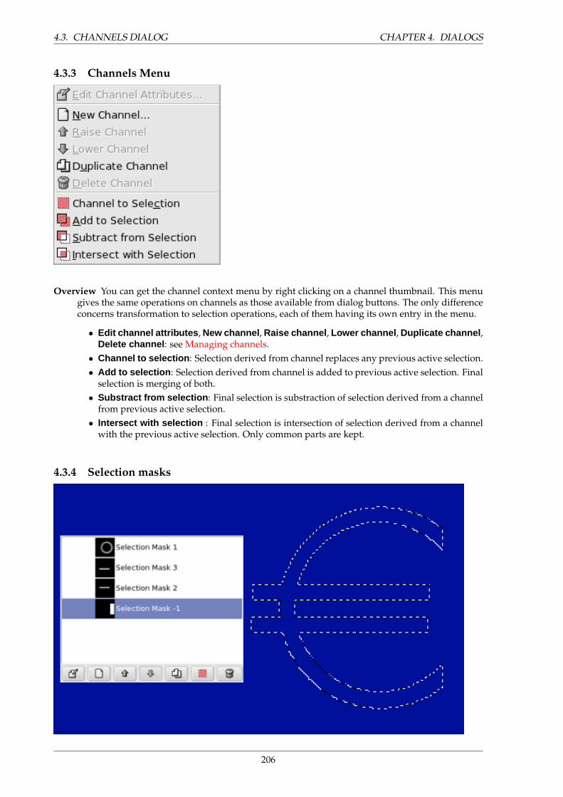
4.3. CHANNELS DIALOG CHAPTER 4. DIALOGS
4.3.3 Channels Menu
Overview You can get the channel context menu by right clicking on a channel thumbnail. This menugives the same operations on channels as those available from dialog buttons. The only differenceconcerns transformation to selection operations, each of them having its own entry in the menu.
• Edit channel attributes , New channel , Raise channel , Lower channel , Duplicate channel ,Delete channel : see Managing channels.
• Channel to selection : Selection derived from channel replaces any previous active selection.• Add to selection : Selection derived from channel is added to previous active selection. Final
selection is merging of both.• Substract from selection : Final selection is substraction of selection derived from a channel
from previous active selection.• Intersect with selection : Final selection is intersection of selection derived from a channel
with the previous active selection. Only common parts are kept.
4.3.4 Selection masks
206
CHAPTER 4. DIALOGS 4.4. USING SELECTIONMASKS
Channels can be used to save and restore your selections. Clicking on the Quick mask button onthe Image window automatically creates a new channel called Qmask and saves the displayed activeselection to a thumbail in front of the channel.There are many selection tools in the Gimp like rectangularselection tool or fuzzy selection for continuous selections. Selection Masks are a graphical way to buildselections into a gray level channel where white pixels are selected and black pixels are not selected.Therefore gray pixels are partially selected. You can think of them as feathering the selection, a smoothtransition between selected and not selected. This is important to avoid the ugly pixelization effect whenyou fill the selection or when you erase its content after isolating a subject from background.
Creating Selection Masks There are several ways to initialize a selection mask. From the image win-dow menu Select / Save to Channel is available if there is an active selection. From the imagewindow the bottom-left button creates a Quick Mask; the content will be initialized with the activeselection. From the channel dialog, when you click on the New channel button or from the contextmenu.
4.4 Using Selectionmasks
Once the channel is initialized, selected (highlighted in blue), visible (eye-icon in the dialog), and dis-played as you want (color and opacity attributes), you can start to work with all the paint tools. Thecolors used are important. If you paint with some color other than white, grey, or black, the color Value(luminosity) will be used to define a gray (medium, light, or dark). When your mask is painted, you cantransform it to a selection by clicking on the Channel to selection button or from the context menu.
TIP
You can work in selection masks not only with the paint tool but also with othertools. For instance, you can use the selection tools to fill areas uniformly withgradients or patterns. By adding many selection masks in your list you can easilycompose very complex selections. One can say that a selection mask is to aselection as a layer is to an image.
CAUTION
As long as a selection mask is activated you are working in the mask and notin the image. To work in the image you have to deactivate all selection masks.Don’t forget also to stop displaying masks in the image by removing the eye icon.Check also that all RGB and Alpha channels are activated and displayed in theimage.
207
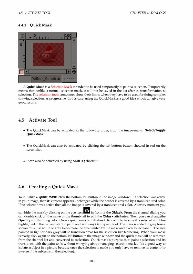
4.5. ACTIVATE TOOL CHAPTER 4. DIALOGS
4.4.1 Quick Mask
A Quick Mask is a Selection Mask intended to be used temporarily to paint a selection. Temporarilymeans that, unlike a normal selection mask, it will not be saved in the list after its transformation toselection. The selection tools sometimes show their limits when they have to be used for doing complexdrawing selection, as progressive. In this case, using the QuickMask is a good idea which can give verygood results.
4.5 Activate Tool
• The QuickMask can be activated in the following order, from the image-menu: Select/ToggleQuickMask .
• The QuickMask can also be activated by clicking the left-bottom button showed in red on thescreenshot.
• It can also be activated by using Shift+Q shortcut.
4.6 Creating a Quick Mask
To initialize a Quick Mask , click the bottom-left button in the image window. If a selection was activein your image, then its content appears unchangedwhile the border is covered by a tranlucent red color.If no selection was active then all the image is covered by a tranlucent red color. At every moment you
can hide the maskby clicking on the eye icon in front of the QMask . From the channel dialog youcan double click on the name or the thumbnail to edit the QMask attributes. Then you can changetheOpacity and its filling color. Once a quick mask is initialized click on it to be sure it is selected and bluehighlighted in the list, and start to paint on it with any Gimp paint tool. The mask is coded in gray tones,so you must use white or gray to decrease the area limited by the mask and black to increase it. The areapainted in light or dark gray will be transition areas for the selection like feathering. When your maskis ready, click again on the bottom-left button in the image window and the quick maskwill be removedfrom the channel list and converted to aselection. Quick mask’s purpose is to paint a selection and itstransitions with the paint tools without worrying about managing selection masks. It’s a good way toisolate asubject in a picture because once the selection is made you only have to remove its content (orinverse if the subject is in the selection).
208
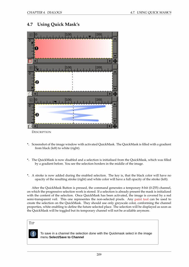
CHAPTER 4. DIALOGS 4.7. USING QUICK MASK’S
4.7 Using Quick Mask’s
***
DESCRIPTION
*. Screenshot of the image window with activated QuickMask. The QuickMask is filled with a gradientfrom black (left) to white (right).
*. The QuickMask is now disabled and a selection is initialised from the QuickMask, which was filledby a gradient before. You see the selection borders in the middle of the image.
*. A stroke is now added during the enabled selection. The key is, that the black color will have noopacity of the resulting stroke (right) and white color will have a full opacity of the stroke (left).
After the QuickMask Button is pressed, the command generates a temporary 8-bit (0-255) channel,on which the progressive selection work is stored. If a selection is already present the mask is initializedwith the content of the selection. Once QuickMask has been activated, the image is covered by a redsemi-transparent veil. This one representes the non-selected pixels. Any paint tool can be used tocreate the selection on the QuickMask. They should use only greyscale color, conforming the channelproperties, white enabling to define the future selected place. The selection will be displayed as soon asthe QuickMask will be toggled but its temporary channel will not be available anymore.
TIP
To save in a channel the selection done with the Quickmask select in the imagemenu Select/Save to Channel
209

4.8. USAGE CHAPTER 4. DIALOGS
4.8 Usage
1. Open an image or begin a new document.
2. Activate the Quickmask using the left-bottom button in the image window. If a selection is presentthe mask is initialized with the content of the selection.
3. Choose a drawing tool and use it with greyscale colors on the QuickMask.
4. Deactivate the Quickmask using the left-bottom button in the image window.
4.9 Path dialog
The Paths dialogThe Paths dialog is used to manage paths, allowing you to create or delete them, save them, convert
them to and from selections, etc.The Paths dialog is a dockable dialog; see the section on Dialogs and Docking for help on manipu-
lating it. It can be activated in several ways:
4.9.1 Dialog call
• From the Toolbox menu: File → Dialogs → Paths .
• From the Toolbox menu: File → Dialogs → Create New Dock → Layers, Channels, and Paths .This gives you a dock containing three dialogs, with the Paths dialog one of them.
• From an image menu: Dialogs → Paths .
• From the Tab menu in any dockable dialog: Add Tab → Paths .
4.9.2 Using the Paths dialog
Each path belongs to one image: paths are components of images just like layers. The Paths dialogshows you a list of all paths belonging to the currently active image: switching images causes the dialogto show a different list of paths. If the Paths dialog is embedded in a ”Layers, Channels, and Paths”dock, you can see the name of the active image in the Image Menu at the top of the dock. (Otherwise,you can add an Image Menu to the dock by choosing ”Show Image Menu” from the Tab menu.)
If you are familiar with the Layers dialog, you have a head start, because the Paths dialog is in severalways similar. It shows a list of all paths that exist in the image, with four items for each path:
210
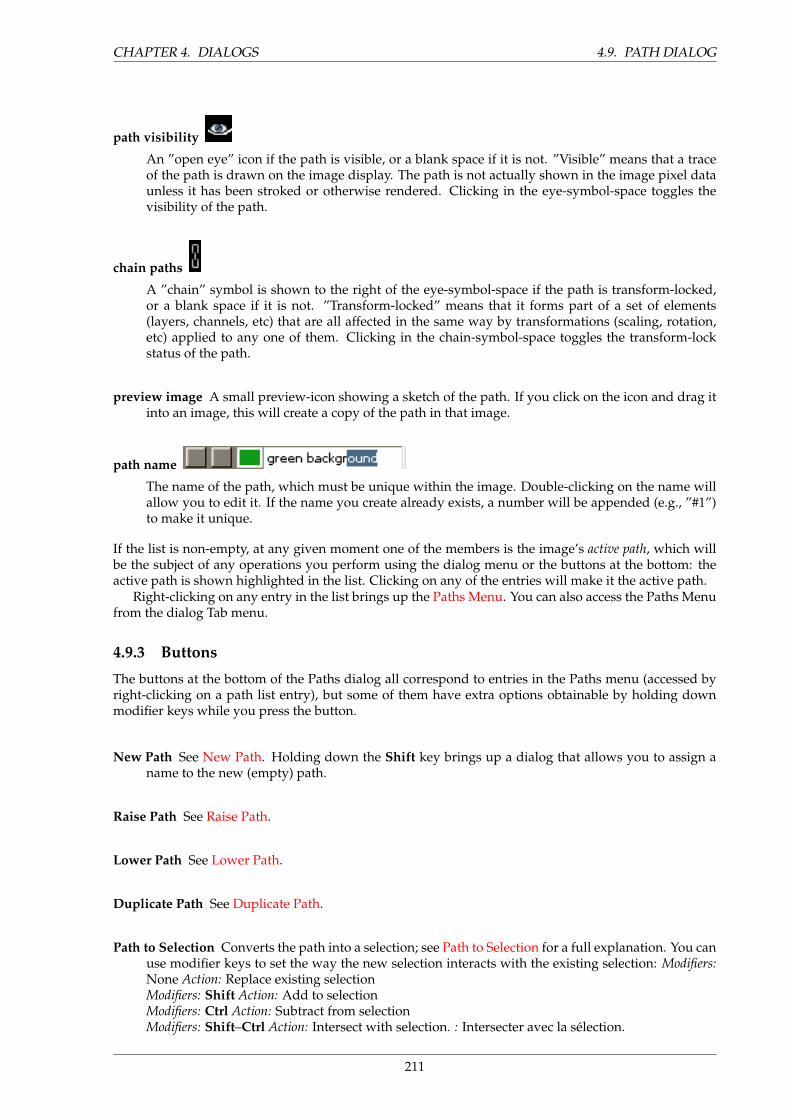
CHAPTER 4. DIALOGS 4.9. PATH DIALOG
path visibility
An ”open eye” icon if the path is visible, or a blank space if it is not. ”Visible” means that a traceof the path is drawn on the image display. The path is not actually shown in the image pixel dataunless it has been stroked or otherwise rendered. Clicking in the eye-symbol-space toggles thevisibility of the path.
chain paths
A ”chain” symbol is shown to the right of the eye-symbol-space if the path is transform-locked,or a blank space if it is not. ”Transform-locked” means that it forms part of a set of elements(layers, channels, etc) that are all affected in the same way by transformations (scaling, rotation,etc) applied to any one of them. Clicking in the chain-symbol-space toggles the transform-lockstatus of the path.
preview image A small preview-icon showing a sketch of the path. If you click on the icon and drag itinto an image, this will create a copy of the path in that image.
path name
The name of the path, which must be unique within the image. Double-clicking on the name willallow you to edit it. If the name you create already exists, a number will be appended (e.g., ”#1”)to make it unique.
If the list is non-empty, at any given moment one of the members is the image’s active path, which willbe the subject of any operations you perform using the dialog menu or the buttons at the bottom: theactive path is shown highlighted in the list. Clicking on any of the entries will make it the active path.
Right-clicking on any entry in the list brings up the Paths Menu. You can also access the Paths Menufrom the dialog Tab menu.
4.9.3 Buttons
The buttons at the bottom of the Paths dialog all correspond to entries in the Paths menu (accessed byright-clicking on a path list entry), but some of them have extra options obtainable by holding downmodifier keys while you press the button.
New Path See New Path. Holding down the Shift key brings up a dialog that allows you to assign aname to the new (empty) path.
Raise Path See Raise Path.
Lower Path See Lower Path.
Duplicate Path See Duplicate Path.
Path to Selection Converts the path into a selection; see Path to Selection for a full explanation. You canuse modifier keys to set the way the new selection interacts with the existing selection: Modifiers:None Action: Replace existing selectionModifiers: Shift Action: Add to selectionModifiers: Ctrl Action: Subtract from selectionModifiers: Shift–Ctrl Action: Intersect with selection. : Intersecter avec la selection.
211
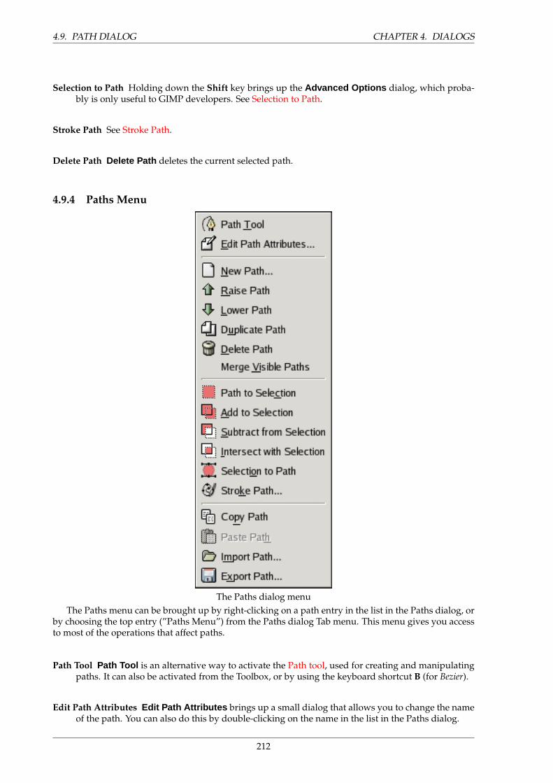
4.9. PATH DIALOG CHAPTER 4. DIALOGS
Selection to Path Holding down the Shift key brings up the Advanced Options dialog, which proba-bly is only useful to GIMP developers. See Selection to Path.
Stroke Path See Stroke Path.
Delete Path Delete Path deletes the current selected path.
4.9.4 Paths Menu
The Paths dialog menuThe Paths menu can be brought up by right-clicking on a path entry in the list in the Paths dialog, or
by choosing the top entry (”Paths Menu”) from the Paths dialog Tab menu. This menu gives you accessto most of the operations that affect paths.
Path Tool Path Tool is an alternative way to activate the Path tool, used for creating and manipulatingpaths. It can also be activated from the Toolbox, or by using the keyboard shortcut B (for Bezier).
Edit Path Attributes Edit Path Attributes brings up a small dialog that allows you to change the nameof the path. You can also do this by double-clicking on the name in the list in the Paths dialog.
212
CHAPTER 4. DIALOGS 4.9. PATH DIALOG
New Path New Path creates a new path, adds it to the list in the Paths dialog, and makes it the activepath for the image. It brings up a dialog that allows you to give a name to the path. The new pathis created with no anchor points, so you will need to use the Path tool to give it some before youcan use it for anything.
Raise Path Raise Path moves the path one slot higher in the list in the Paths dialog. The position ofa path in the list has no functional significance, so this is simply a convenience to help you keepthings organized.
Lower Path Lower Path moves the path one slot lower in the list in the Paths dialog. The position ofa path in the list has no functional significance, so this is simply a convenience to help you keepthings organized.
Duplicate Path ”Duplicate Path” creates a copy of the active path, assigns it a unique name, adds it tothe list in the Paths dialog, and makes it the active path for the image. The copy will be visibleonly if the original path was visible.
NOTE
Note that copying a visible path will make the path ”disappear” from theimage display: this happens because paths are drawn in XOR mode, whichhas the curious property that drawing an item twice ”undraws” it. The pathsare still there even though you don’t see anything: if you move one of them,you will be able to see both.
Delete Path Delete Path deletes the current selected path.
Merge Visible Paths Merge Visible Paths takes all the paths in the image that are visible (that is, allthat show ”open eye” symbols in the Paths dialog), and turns them into components of a singlepath. This may be convenient if you want to stroke them all in the same way, etc.
Path to Selection; Add to Selection; Subtract from Selection; Intersect with Selection These commandsall convert the active path into a selection, and then combine it with the existing selection in thespecified ways. (”Path to Selection” discards the existing selection and replaces it with one formedfrom the path.) If necessary, any unclosed components of the path are closed by connecting the lastanchor point to the first anchor point with a straight line. The ”marching ants” for the resultingselection should closely follow the path, but don’t expect the correspondence to be perfect.
Selection to Path This operation can be accesssed in several ways:
• From an image menubar, as Select → To Path
• From the Paths dialog menu, as Selection to Path .
• From the Selection to Path button at the bottom of the Paths dialog.
• From the ”Selection to Path” button in the Tool Options for the Path tool.
Selection to Path creates a new path from the image’s selection. In most cases the resulting pathwill closely follow the ”marching ants” of the selection, but the correspondence will not usuallybe perfect.
213
4.9. PATH DIALOG CHAPTER 4. DIALOGS
Converting a two-dimensional selection mask into a one-dimensional path involves some rathertricky algorithms: you can alter the way it is done using the Advanced Options , which are ac-cessed by holding down the Shift key while pressing the Selection to Path button at the bottomof the Paths dialog. This brings up the Advanced Options dialog, which allows you to set 20 dif-ferent options and variables, all with cryptic names. The Advanced Options are really intendedfor developers only, and help with them goes beyond the scope of this documentation. Generallyspeaking, Selection to Path will do what you expect it to, and you don’t need to worry abouthow it is done (unless you want to).
Stroke Path This operation can be accesssed in several ways:
• From an image menubar, as Edit → Stroke Path
• From the Paths dialog menu, as Stroke Path .
• From the Stroke Path button at the bottom of the Paths dialog.
• From the Stroke Path button in the Tool Options for the Path tool.
”Stroke Path” renders the active path on the active layer of the image, permitting a wide varietyof line styles and stroking options. See the section on Stroking for more information.
Copy Path ”Copy Path” copies the active path to the Paths Clipboard, enabling you to paste it into adifferent image.
TIP
You can also copy and paste a path by dragging its icon from the Pathsdialog into the target image’s display.
Paste Path Paste Path creates a new path from the contents of the Path Clipboard, adds it to the list inthe Paths dialog, and makes it the active path for the image. If no path has previously been copiedinto the clipboard, the menu entry will be insensitive.
Import Path ”Import Path” creates a new path from an SVG file: it pops up a file chooser dialog thatallows you to navigate to the file. See the Paths section for information on SVG files and how theyrelate to GIMP paths.
Export Path Export Path allows you to save a path to a file: it pops up a file save dialog that allowsyou to specify the file name and location. You can later add this path to any GIMP image using theImport Path command. The format used for saving paths is SVG: this means that vector-graphicsprograms such as Sodipodi or Inkscape will also be able to import the paths you save. See thePaths section for more information on SVG files and how they relate to GIMP paths.
214
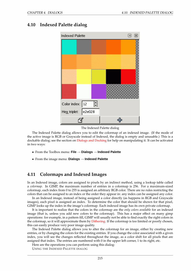
CHAPTER 4. DIALOGS 4.10. INDEXED PALETTE DIALOG
4.10 Indexed Palette dialog
The Indexed Palette dialogThe Indexed Palette dialog allows you to edit the colormap of an indexed image. (If the mode of
the active image is RGB or Grayscale instead of Indexed, the dialog is empty and unusable.) This is adockable dialog; see the section on Dialogs and Docking for help on manipulating it. It can be activatedin two ways:
• From the Toolbox menu: File → Dialogs → Indexed Palette
• From the image menu: Dialogs → Indexed Palette
4.11 Colormaps and Indexed Images
In an Indexed image, colors are assigned to pixels by an indirect method, using a lookup table calleda colormap. In GIMP, the maximum number of entries in a colormap is 256. For a maximum-sizedcolormap, each index from 0 to 255 is assigned an arbitrary RGB color. There are no rules restricting thecolors that can be assigned to an index or the order they appear in: any index can be assigned any color.
In an Indexed image, instead of being assigned a color directly (as happens in RGB and Grayscaleimages), each pixel is assigned an index. To determine the color that should be shown for that pixel,GIMP looks up the index in the image’s colormap. Each indexed image has its own private colormap.
It is important to realize that the colors in the colormap are the only colors available for an indexedimage (that is, unless you add new colors to the colormap). This has a major effect on many gimpoperations: for example, in a pattern fill, GIMP will usually not be able to find exactly the right colors inthe colormap, so it will approximate them by Dithering. If the colormap is too limited or poorly chosen,this can easily produce very poor image quality.
The Indexed Palette dialog allows you to alter the colormap for an image, either by creating newentries, or by changing the colors for the existing entries. If you change the color associated with a givenindex, you will see the changes reflected throughout the image, as a color shift for all pixels that areassigned that index. The entries are numbered with 0 in the upper left corner, 1 to its right, etc.
Here are the operations you can perform using this dialog:USING THE INDEXED PALETTE DIALOG
215
4.11. COLORMAPS AND INDEXED IMAGES CHAPTER 4. DIALOGS
Click on a color entry This sets GIMP’s foreground color to the color you click on, as shown in theToolbox color area. As a result, this color will be used for the next painting operation you do.
Ctrl-click on a color entry Le Ctrl-clic sur une case de couleur place cette couleur en couleur d’Arriere-plan dans la Boıte a outils.
Double-click on a color entry This sets GIMP’s foreground color to the color you click on, and alsobrings up a Color Editor that allows you to change that colormap entry to a new color.
Color index You can select a different colormap entry by typing its index here, or clicking the spinbut-ton to the right.
Hex triplet This area shows a hex-code representation (such as is used in HTML) for the color assignedto the currently selected colormap entry. You can edit the color here, instead of using a ColorEditor, if you want to. See HexTriplet
Edit color This button (in the lower left corner of the dialog) brings up a Color Editor that allows you tochange the color for the currently selected colormap entry. The effect is similar to double-clickingon the entry, except that it does not set GIMP’s foreground color.
Add color This button (in the lower right corner of the dialog) allows you to add new colors to thecolormap. If you click on the button, the current foreground color, as shown in the Toolbox, willbe tacked on to the end of the colormap. If instead you hold down Ctrl and click, the backgroundcolor from the Toolbox will be added. (If the colormap contains 256 entries, it is full, and trying toadd more will have no effect.)
TIP
If you make a mistake, you can undo it by focusing the pointer in the image whosecolormap you have changed, and then pressing Ctrl-Z or choosing Edit → Undoin the image menu.
NOTE
This dialog is not the only way of altering the colormap for an indexed image.The color tools, such as Brightness/Contrast, Hue/Saturation, etc, also changethe colors in the colormap.
216
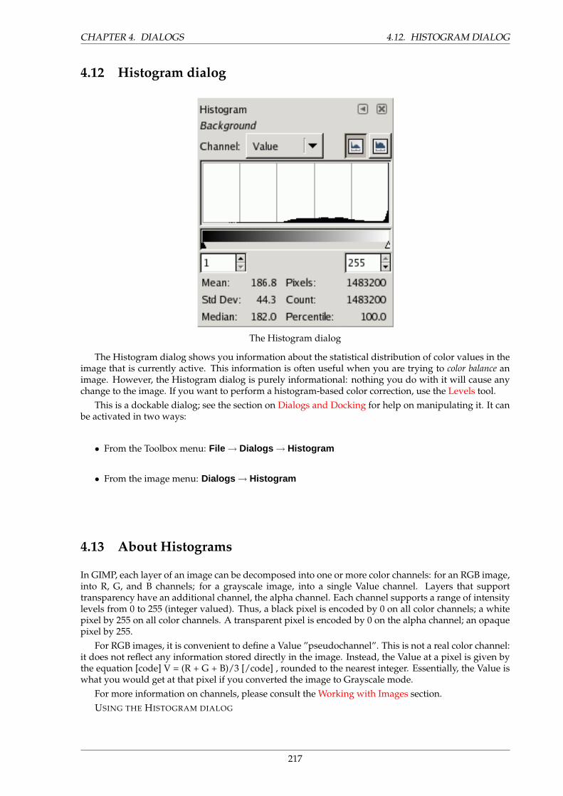
CHAPTER 4. DIALOGS 4.12. HISTOGRAM DIALOG
4.12 Histogram dialog
The Histogram dialog
The Histogram dialog shows you information about the statistical distribution of color values in theimage that is currently active. This information is often useful when you are trying to color balance animage. However, the Histogram dialog is purely informational: nothing you do with it will cause anychange to the image. If you want to perform a histogram-based color correction, use the Levels tool.
This is a dockable dialog; see the section on Dialogs and Docking for help on manipulating it. It canbe activated in two ways:
• From the Toolbox menu: File → Dialogs → Histogram
• From the image menu: Dialogs → Histogram
4.13 About Histograms
In GIMP, each layer of an image can be decomposed into one or more color channels: for an RGB image,into R, G, and B channels; for a grayscale image, into a single Value channel. Layers that supporttransparency have an additional channel, the alpha channel. Each channel supports a range of intensitylevels from 0 to 255 (integer valued). Thus, a black pixel is encoded by 0 on all color channels; a whitepixel by 255 on all color channels. A transparent pixel is encoded by 0 on the alpha channel; an opaquepixel by 255.
For RGB images, it is convenient to define a Value ”pseudochannel”. This is not a real color channel:it does not reflect any information stored directly in the image. Instead, the Value at a pixel is given bythe equation [code] V = (R + G + B)/3 [/code] , rounded to the nearest integer. Essentially, the Value iswhat you would get at that pixel if you converted the image to Grayscale mode.
For more information on channels, please consult the Working with Images section.USING THE HISTOGRAM DIALOG
217
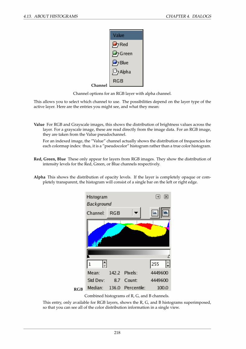
4.13. ABOUT HISTOGRAMS CHAPTER 4. DIALOGS
Channel
Channel options for an RGB layer with alpha channel.
This allows you to select which channel to use. The possibilities depend on the layer type of theactive layer. Here are the entries you might see, and what they mean:
Value For RGB and Grayscale images, this shows the distribution of brightness values across thelayer. For a grayscale image, these are read directly from the image data. For an RGB image,they are taken from the Value pseudochannel.
For an indexed image, the ”Value” channel actually shows the distribution of frequencies foreach colormap index: thus, it is a ”pseudocolor” histogram rather than a true color histogram.
Red, Green, Blue These only appear for layers from RGB images. They show the distribution ofintensity levels for the Red, Green, or Blue channels respectively.
Alpha This shows the distribution of opacity levels. If the layer is completely opaque or com-pletely transparent, the histogram will consist of a single bar on the left or right edge.
RGB
Combined histograms of R, G, and B channels.
This entry, only available for RGB layers, shows the R, G, and B histograms superimposed,so that you can see all of the color distribution information in a single view.
218
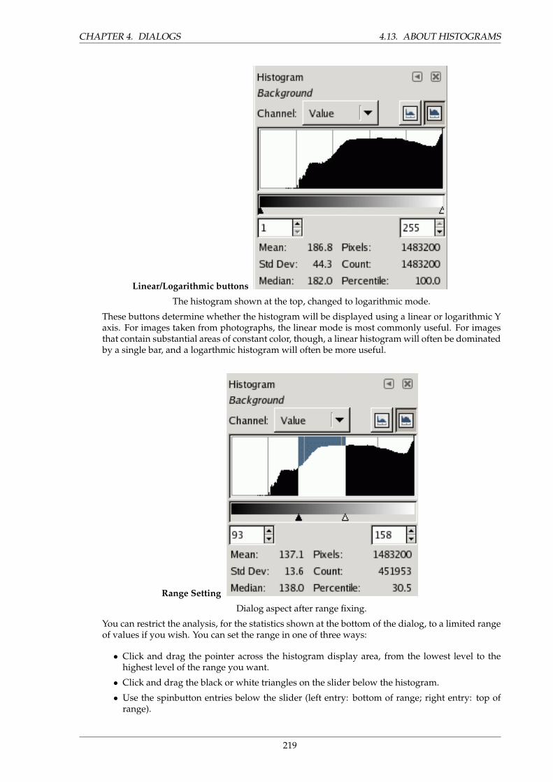
CHAPTER 4. DIALOGS 4.13. ABOUT HISTOGRAMS
Linear/Logarithmic buttons
The histogram shown at the top, changed to logarithmic mode.
These buttons determine whether the histogram will be displayed using a linear or logarithmic Yaxis. For images taken from photographs, the linear mode is most commonly useful. For imagesthat contain substantial areas of constant color, though, a linear histogram will often be dominatedby a single bar, and a logarthmic histogram will often be more useful.
Range Setting
Dialog aspect after range fixing.
You can restrict the analysis, for the statistics shown at the bottom of the dialog, to a limited rangeof values if you wish. You can set the range in one of three ways:
• Click and drag the pointer across the histogram display area, from the lowest level to thehighest level of the range you want.
• Click and drag the black or white triangles on the slider below the histogram.
• Use the spinbutton entries below the slider (left entry: bottom of range; right entry: top ofrange).
219
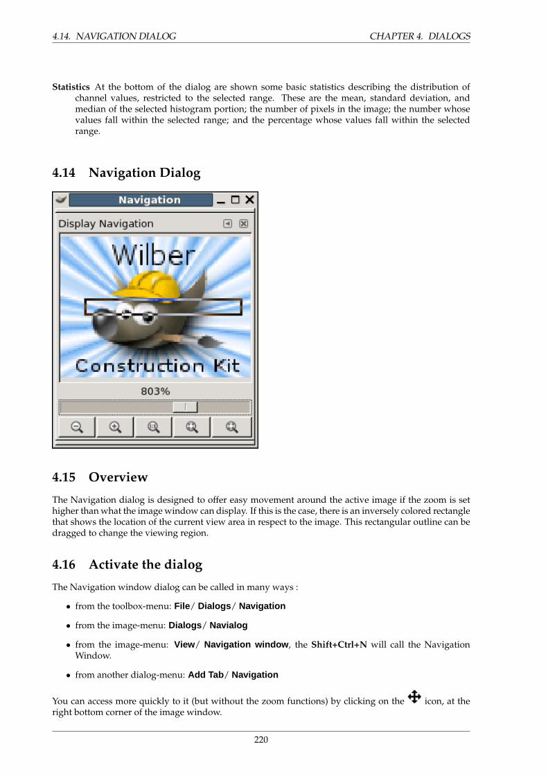
4.14. NAVIGATION DIALOG CHAPTER 4. DIALOGS
Statistics At the bottom of the dialog are shown some basic statistics describing the distribution ofchannel values, restricted to the selected range. These are the mean, standard deviation, andmedian of the selected histogram portion; the number of pixels in the image; the number whosevalues fall within the selected range; and the percentage whose values fall within the selectedrange.
4.14 Navigation Dialog
4.15 Overview
The Navigation dialog is designed to offer easy movement around the active image if the zoom is sethigher than what the image window can display. If this is the case, there is an inversely colored rectanglethat shows the location of the current view area in respect to the image. This rectangular outline can bedragged to change the viewing region.
4.16 Activate the dialog
The Navigation window dialog can be called in many ways :
• from the toolbox-menu: File/ Dialogs / Navigation
• from the image-menu: Dialogs / Navialog
• from the image-menu: View/ Navigation window , the Shift+Ctrl+N will call the NavigationWindow.
• from another dialog-menu: Add Tab / Navigation
You can access more quickly to it (but without the zoom functions) by clicking on the icon, at theright bottom corner of the image window.
220
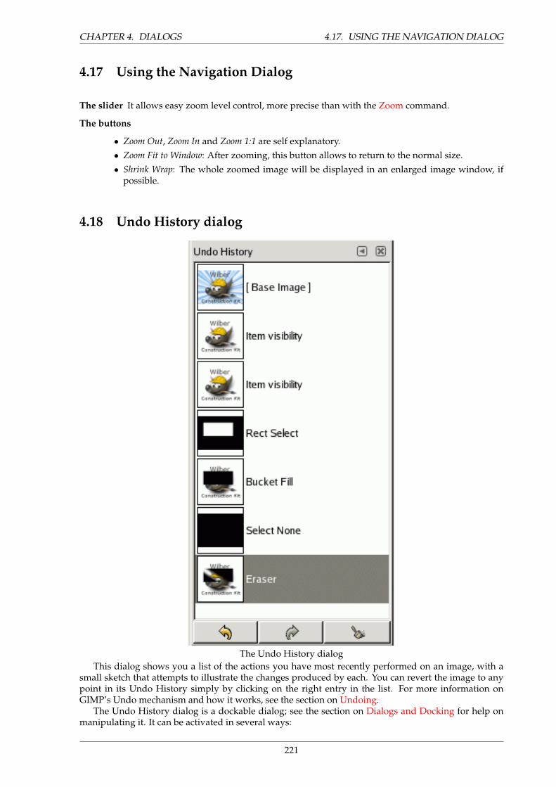
CHAPTER 4. DIALOGS 4.17. USING THE NAVIGATION DIALOG
4.17 Using the Navigation Dialog
The slider It allows easy zoom level control, more precise than with the Zoom command.
The buttons
• Zoom Out, Zoom In and Zoom 1:1 are self explanatory.• Zoom Fit to Window: After zooming, this button allows to return to the normal size.• Shrink Wrap: The whole zoomed image will be displayed in an enlarged image window, if
possible.
4.18 Undo History dialog
The Undo History dialogThis dialog shows you a list of the actions you have most recently performed on an image, with a
small sketch that attempts to illustrate the changes produced by each. You can revert the image to anypoint in its Undo History simply by clicking on the right entry in the list. For more information onGIMP’s Undo mechanism and how it works, see the section on Undoing.
The Undo History dialog is a dockable dialog; see the section on Dialogs and Docking for help onmanipulating it. It can be activated in several ways:
221
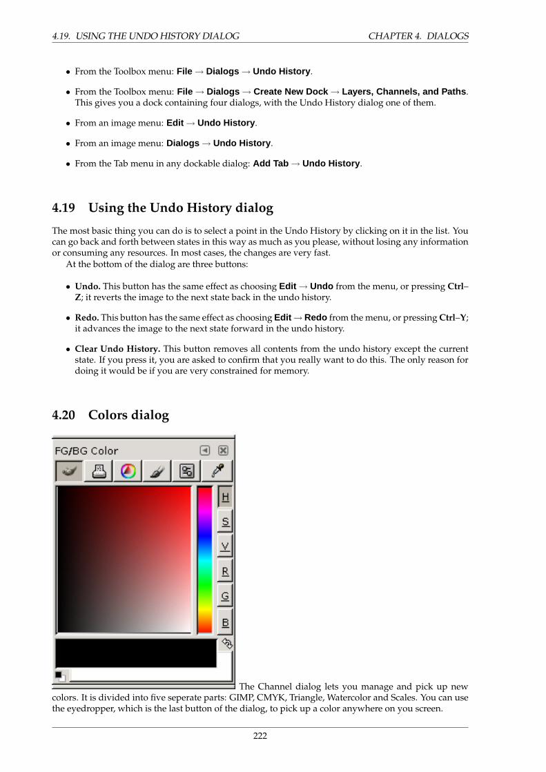
4.19. USING THE UNDO HISTORY DIALOG CHAPTER 4. DIALOGS
• From the Toolbox menu: File → Dialogs → Undo History .
• From the Toolbox menu: File → Dialogs → Create New Dock → Layers, Channels, and Paths .This gives you a dock containing four dialogs, with the Undo History dialog one of them.
• From an image menu: Edit → Undo History .
• From an image menu: Dialogs → Undo History .
• From the Tab menu in any dockable dialog: Add Tab → Undo History .
4.19 Using the Undo History dialog
The most basic thing you can do is to select a point in the Undo History by clicking on it in the list. Youcan go back and forth between states in this way as much as you please, without losing any informationor consuming any resources. In most cases, the changes are very fast.
At the bottom of the dialog are three buttons:
• Undo. This button has the same effect as choosing Edit → Undo from the menu, or pressing Ctrl–Z; it reverts the image to the next state back in the undo history.
• Redo. This button has the same effect as choosing Edit →Redo from the menu, or pressing Ctrl–Y;it advances the image to the next state forward in the undo history.
• Clear Undo History. This button removes all contents from the undo history except the currentstate. If you press it, you are asked to confirm that you really want to do this. The only reason fordoing it would be if you are very constrained for memory.
4.20 Colors dialog
The Channel dialog lets you manage and pick up newcolors. It is divided into five seperate parts: GIMP, CMYK, Triangle, Watercolor and Scales. You can usethe eyedropper, which is the last button of the dialog, to pick up a color anywhere on you screen.
222

CHAPTER 4. DIALOGS 4.21. OVERVIEW
4.21 Overview
Introduction
4.22 Activate Dialog
The dialog can be called in the following ways :
• from the toolbox-menu: File → Dialogs → Colors
• from the toolbox: click on the current Foreground or Background color.
• from the image-menu: Dialogs → Colors
• from an other dialog-menu: Add Tab → Colors
4.23 The GIMP Selector
With the GIMP Color Selector, you select a color by clicking on a one-dimensional strip located at theright edge, and then in a two-dimensional area located on the left. The one-dimensional strip can encodeany of the color parameters H, S, V, R, G, or B, as determined by which of the adjoining buttons ispressed. The two-dimensional area then encodes the two complementary color parameters.
4.24 CMYK
The CMYK view gives you the possibility to manage colors from the CMYK color model.
4.25 Triangle
The Triangle selector is made up of a chromatic circle that allows to select Hue by click-and-drag a smallcircle and of a triangle that has also a small circle to vary intuitively Saturation and Value.
4.26 Watercolor
FIXME
4.27 Scales
FIXME
4.28 Color picker
The color picker has a completly different behaviour, than the color picker tool. Instead of picking thecolors from the active image, you’re able to pick colors from the entire screen.
223
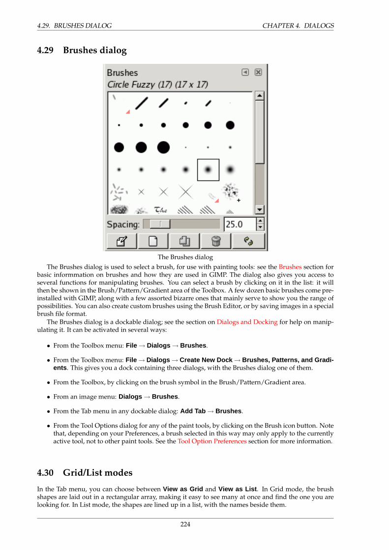
4.29. BRUSHES DIALOG CHAPTER 4. DIALOGS
4.29 Brushes dialog
The Brushes dialogThe Brushes dialog is used to select a brush, for use with painting tools: see the Brushes section for
basic informmation on brushes and how they are used in GIMP. The dialog also gives you access toseveral functions for manipulating brushes. You can select a brush by clicking on it in the list: it willthen be shown in the Brush/Pattern/Gradient area of the Toolbox. A few dozen basic brushes come pre-installed with GIMP, along with a few assorted bizarre ones that mainly serve to show you the range ofpossibilities. You can also create custom brushes using the Brush Editor, or by saving images in a specialbrush file format.
The Brushes dialog is a dockable dialog; see the section on Dialogs and Docking for help on manip-ulating it. It can be activated in several ways:
• From the Toolbox menu: File → Dialogs → Brushes .
• From the Toolbox menu: File → Dialogs → Create New Dock → Brushes, Patterns, and Gradi-ents . This gives you a dock containing three dialogs, with the Brushes dialog one of them.
• From the Toolbox, by clicking on the brush symbol in the Brush/Pattern/Gradient area.
• From an image menu: Dialogs → Brushes .
• From the Tab menu in any dockable dialog: Add Tab → Brushes .
• From the Tool Options dialog for any of the paint tools, by clicking on the Brush icon button. Notethat, depending on your Preferences, a brush selected in this way may only apply to the currentlyactive tool, not to other paint tools. See the Tool Option Preferences section for more information.
4.30 Grid/List modes
In the Tab menu, you can choose between View as Grid and View as List . In Grid mode, the brushshapes are laid out in a rectangular array, making it easy to see many at once and find the one you arelooking for. In List mode, the shapes are lined up in a list, with the names beside them.
224
CHAPTER 4. DIALOGS 4.31. USING THE BRUSHES DIALOG (GRID MODE)
4.31 Using the Brushes dialog (Grid mode)
At the top of the dialog appears the name of the currently selected brush, and its size in pixels.
In the center appears a grid view of all available brushes, with the currently selected one outlined. Ifyou see a little ”+” to the right of a brush, it means the brush is actually larger than it appears. If you seea little red triangle, it means the brush is an animated brush, also known as an ”image hose”. Clickingon a brush causes it to be selected as GIMP’s current brush. Double-clicking activates the Brush Editor.
Below the grid appears a scale entry for ”Spacing”, which is the distance between consecutive brushmarks when you trace out a brushstroke with the pointer.
The buttons at the bottom of the dialog allow you to operate on brushes in several ways:
Edit Brush This activates the Brush Editor. Pressing the button will open the Editor for any brush. Itonly works, however, for parametric brushes: for any other type, the Editor will show you thebrush but not allow you to do anything with it.
New Brush This creates a new parametric brush, initializes it with a small fuzzy round shape, andopens the Brush Editor so that you can modify it. The new brush is automatically saved in yourpersonal brushes folder.
Duplicate Brush This button is only enabled if the currently selected brush is a parametric brush. Ifso, the brush is duplicated, and the Brush Editor is opened so that you can modify the copy. Theresult is automatically saved in your personal brushes folder.
Delete Brush This removes all traces of the brush, both from the dialog and the folder where its file isstored, if you have permission to do so. It asks for confirmation before doing anything.
Refresh Brushes If you add brushes to your personal brushes folder or any other folder in your brushsearch path, by some means other than the Brush Editor, this button causes the list to be reloaded,so that the new entries will be available in the dialog.
The functions performed by these buttons can also be accessed from the dialog pop-up menu, activatedby right-clicking anywhere in the brush grid/list, or by choosing the top item, Brushes menu , from thedialog Tab menu..
225
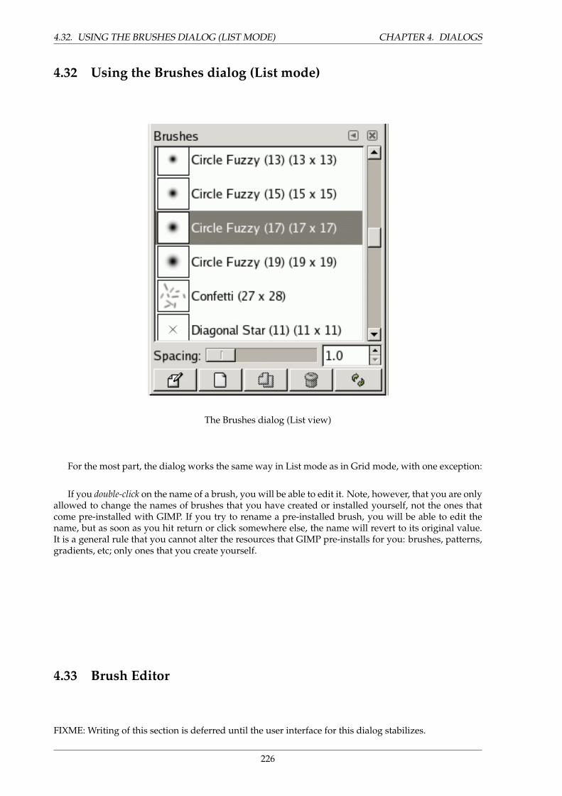
4.32. USING THE BRUSHES DIALOG (LIST MODE) CHAPTER 4. DIALOGS
4.32 Using the Brushes dialog (List mode)
The Brushes dialog (List view)
For the most part, the dialog works the same way in List mode as in Grid mode, with one exception:
If you double-click on the name of a brush, you will be able to edit it. Note, however, that you are onlyallowed to change the names of brushes that you have created or installed yourself, not the ones thatcome pre-installed with GIMP. If you try to rename a pre-installed brush, you will be able to edit thename, but as soon as you hit return or click somewhere else, the name will revert to its original value.It is a general rule that you cannot alter the resources that GIMP pre-installs for you: brushes, patterns,gradients, etc; only ones that you create yourself.
4.33 Brush Editor
FIXME: Writing of this section is deferred until the user interface for this dialog stabilizes.
226
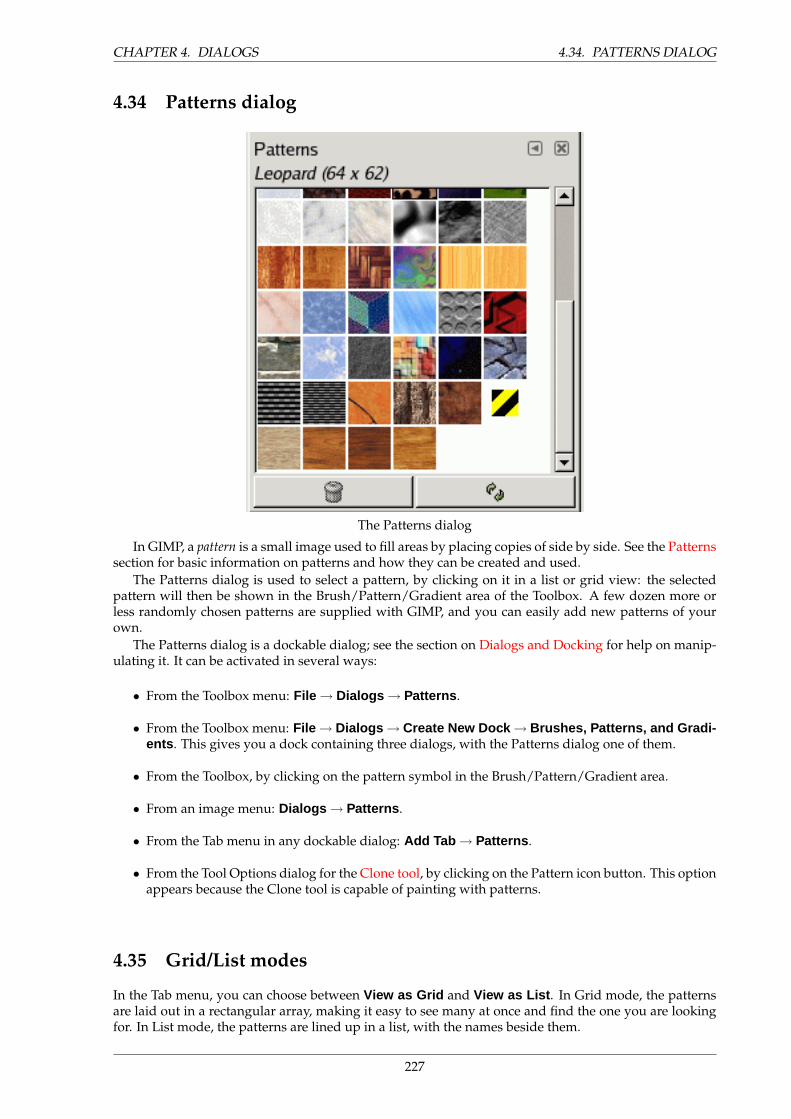
CHAPTER 4. DIALOGS 4.34. PATTERNS DIALOG
4.34 Patterns dialog
The Patterns dialog
In GIMP, a pattern is a small image used to fill areas by placing copies of side by side. See the Patternssection for basic information on patterns and how they can be created and used.
The Patterns dialog is used to select a pattern, by clicking on it in a list or grid view: the selectedpattern will then be shown in the Brush/Pattern/Gradient area of the Toolbox. A few dozen more orless randomly chosen patterns are supplied with GIMP, and you can easily add new patterns of yourown.
The Patterns dialog is a dockable dialog; see the section on Dialogs and Docking for help on manip-ulating it. It can be activated in several ways:
• From the Toolbox menu: File → Dialogs → Patterns .
• From the Toolbox menu: File → Dialogs → Create New Dock → Brushes, Patterns, and Gradi-ents . This gives you a dock containing three dialogs, with the Patterns dialog one of them.
• From the Toolbox, by clicking on the pattern symbol in the Brush/Pattern/Gradient area.
• From an image menu: Dialogs → Patterns .
• From the Tab menu in any dockable dialog: Add Tab → Patterns .
• From the Tool Options dialog for the Clone tool, by clicking on the Pattern icon button. This optionappears because the Clone tool is capable of painting with patterns.
4.35 Grid/List modes
In the Tab menu, you can choose between View as Grid and View as List . In Grid mode, the patternsare laid out in a rectangular array, making it easy to see many at once and find the one you are lookingfor. In List mode, the patterns are lined up in a list, with the names beside them.
227

4.36. USING THE PATTERNS DIALOG (GRID MODE) CHAPTER 4. DIALOGS
4.36 Using the Patterns dialog (Grid mode)
At the top appears the name of the currently selected patterns, and its dimenions in pixels.In the center appears a grid view of all available patterns, with the currently selected one outlined.
Clicking on one of them sets it as GIMP’s current pattern, and causes it to appear in the Brush/Pattern/Gradientarea of the Toolbox.
Below the grid appear two buttons:
• Delete Pattern. Pressing this button removes the pattern from the list and causes the file represent-ing it to be deleted from disk. Note that you cannot remove any of the patterns that are suppliedwith GIMP and installed in the system patterns directory; you can only remove patterns thatyou have added to folders where you have write permission.
• Refresh Patterns. Pressing this button causes GIMP to rescan the folders in your pattern searchpath, adding any newly discovered patterns to the list. This button is useful if you add newpatterns to a folder, and want to make them available without having to restart GIMP.
4.37 Using the Patterns dialog (List view)
The Patterns dialog (List view)Le dialogue des motifs (vue sous forme de liste)
In this view, instead of a grid, you see a list of patterns, each labeled with its name and size. Clickingon a row in the list sets that pattern as GIMP’s current pattern, just as it does in the grid view.
If you double-click on the name of a pattern, you will be able to edit the name. Note that you are onlyallowed to rename patterns that you have added yourself, not the ones that are supplied with GIMP.If you edit a name that you don’t have permission to change, as soon as you hit return or move to adifferent control, the name will revert back to its previous value.
Everything else in the List view works the same way as it does in the Grid view.
228
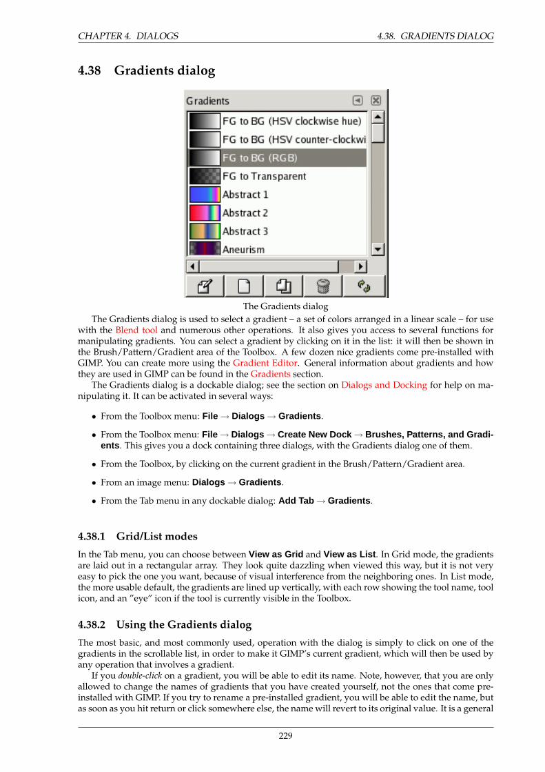
CHAPTER 4. DIALOGS 4.38. GRADIENTS DIALOG
4.38 Gradients dialog
The Gradients dialogThe Gradients dialog is used to select a gradient – a set of colors arranged in a linear scale – for use
with the Blend tool and numerous other operations. It also gives you access to several functions formanipulating gradients. You can select a gradient by clicking on it in the list: it will then be shown inthe Brush/Pattern/Gradient area of the Toolbox. A few dozen nice gradients come pre-installed withGIMP. You can create more using the Gradient Editor. General information about gradients and howthey are used in GIMP can be found in the Gradients section.
The Gradients dialog is a dockable dialog; see the section on Dialogs and Docking for help on ma-nipulating it. It can be activated in several ways:
• From the Toolbox menu: File → Dialogs → Gradients .
• From the Toolbox menu: File → Dialogs → Create New Dock → Brushes, Patterns, and Gradi-ents . This gives you a dock containing three dialogs, with the Gradients dialog one of them.
• From the Toolbox, by clicking on the current gradient in the Brush/Pattern/Gradient area.
• From an image menu: Dialogs → Gradients .
• From the Tab menu in any dockable dialog: Add Tab → Gradients .
4.38.1 Grid/List modes
In the Tab menu, you can choose between View as Grid and View as List . In Grid mode, the gradientsare laid out in a rectangular array. They look quite dazzling when viewed this way, but it is not veryeasy to pick the one you want, because of visual interference from the neighboring ones. In List mode,the more usable default, the gradients are lined up vertically, with each row showing the tool name, toolicon, and an ”eye” icon if the tool is currently visible in the Toolbox.
4.38.2 Using the Gradients dialog
The most basic, and most commonly used, operation with the dialog is simply to click on one of thegradients in the scrollable list, in order to make it GIMP’s current gradient, which will then be used byany operation that involves a gradient.
If you double-click on a gradient, you will be able to edit its name. Note, however, that you are onlyallowed to change the names of gradients that you have created yourself, not the ones that come pre-installed with GIMP. If you try to rename a pre-installed gradient, you will be able to edit the name, butas soon as you hit return or click somewhere else, the name will revert to its original value. It is a general
229
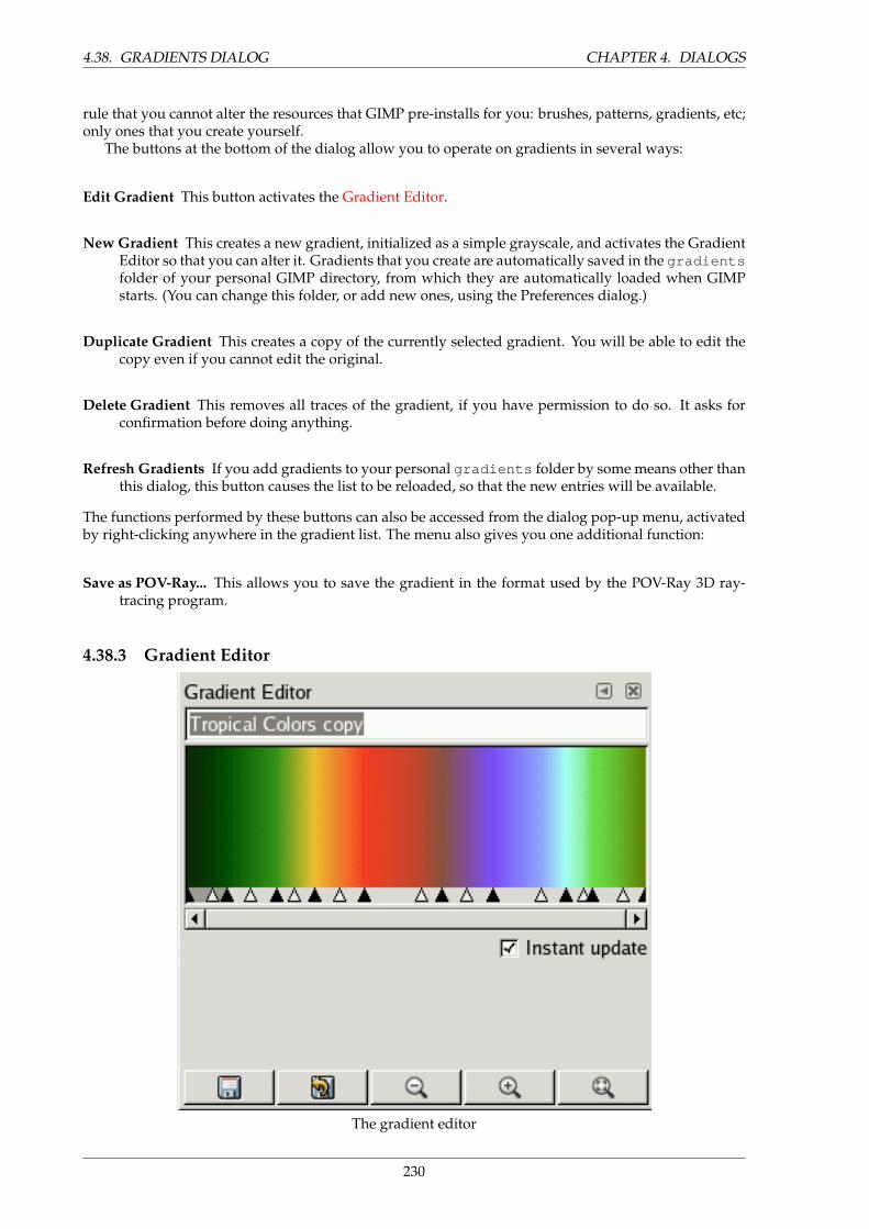
4.38. GRADIENTS DIALOG CHAPTER 4. DIALOGS
rule that you cannot alter the resources that GIMP pre-installs for you: brushes, patterns, gradients, etc;only ones that you create yourself.
The buttons at the bottom of the dialog allow you to operate on gradients in several ways:
Edit Gradient This button activates the Gradient Editor.
New Gradient This creates a new gradient, initialized as a simple grayscale, and activates the GradientEditor so that you can alter it. Gradients that you create are automatically saved in the gradientsfolder of your personal GIMP directory, from which they are automatically loaded when GIMPstarts. (You can change this folder, or add new ones, using the Preferences dialog.)
Duplicate Gradient This creates a copy of the currently selected gradient. You will be able to edit thecopy even if you cannot edit the original.
Delete Gradient This removes all traces of the gradient, if you have permission to do so. It asks forconfirmation before doing anything.
Refresh Gradients If you add gradients to your personal gradients folder by some means other thanthis dialog, this button causes the list to be reloaded, so that the new entries will be available.
The functions performed by these buttons can also be accessed from the dialog pop-up menu, activatedby right-clicking anywhere in the gradient list. The menu also gives you one additional function:
Save as POV-Ray... This allows you to save the gradient in the format used by the POV-Ray 3D ray-tracing program.
4.38.3 Gradient Editor
The gradient editor
230
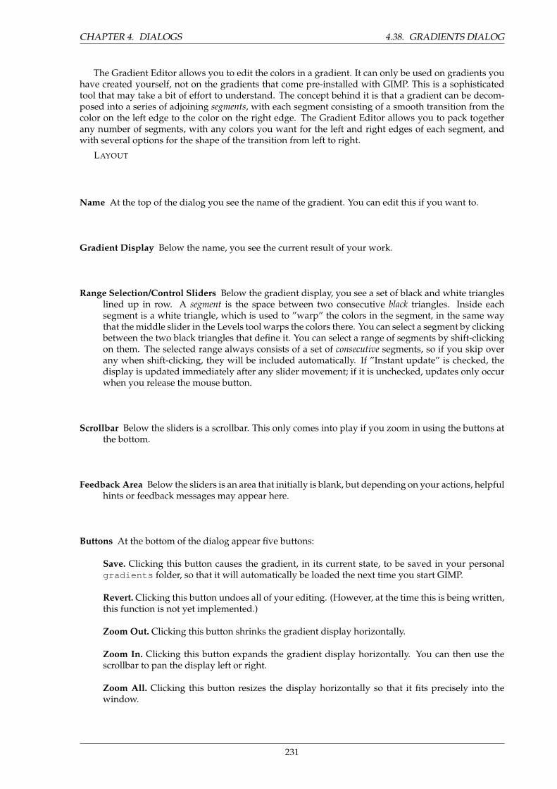
CHAPTER 4. DIALOGS 4.38. GRADIENTS DIALOG
The Gradient Editor allows you to edit the colors in a gradient. It can only be used on gradients youhave created yourself, not on the gradients that come pre-installed with GIMP. This is a sophisticatedtool that may take a bit of effort to understand. The concept behind it is that a gradient can be decom-posed into a series of adjoining segments, with each segment consisting of a smooth transition from thecolor on the left edge to the color on the right edge. The Gradient Editor allows you to pack togetherany number of segments, with any colors you want for the left and right edges of each segment, andwith several options for the shape of the transition from left to right.
LAYOUT
Name At the top of the dialog you see the name of the gradient. You can edit this if you want to.
Gradient Display Below the name, you see the current result of your work.
Range Selection/Control Sliders Below the gradient display, you see a set of black and white triangleslined up in row. A segment is the space between two consecutive black triangles. Inside eachsegment is a white triangle, which is used to ”warp” the colors in the segment, in the same waythat the middle slider in the Levels tool warps the colors there. You can select a segment by clickingbetween the two black triangles that define it. You can select a range of segments by shift-clickingon them. The selected range always consists of a set of consecutive segments, so if you skip overany when shift-clicking, they will be included automatically. If ”Instant update” is checked, thedisplay is updated immediately after any slider movement; if it is unchecked, updates only occurwhen you release the mouse button.
Scrollbar Below the sliders is a scrollbar. This only comes into play if you zoom in using the buttons atthe bottom.
Feedback Area Below the sliders is an area that initially is blank, but depending on your actions, helpfulhints or feedback messages may appear here.
Buttons At the bottom of the dialog appear five buttons:
Save. Clicking this button causes the gradient, in its current state, to be saved in your personalgradients folder, so that it will automatically be loaded the next time you start GIMP.
Revert. Clicking this button undoes all of your editing. (However, at the time this is being written,this function is not yet implemented.)
Zoom Out. Clicking this button shrinks the gradient display horizontally.
Zoom In. Clicking this button expands the gradient display horizontally. You can then use thescrollbar to pan the display left or right.
Zoom All. Clicking this button resizes the display horizontally so that it fits precisely into thewindow.
231
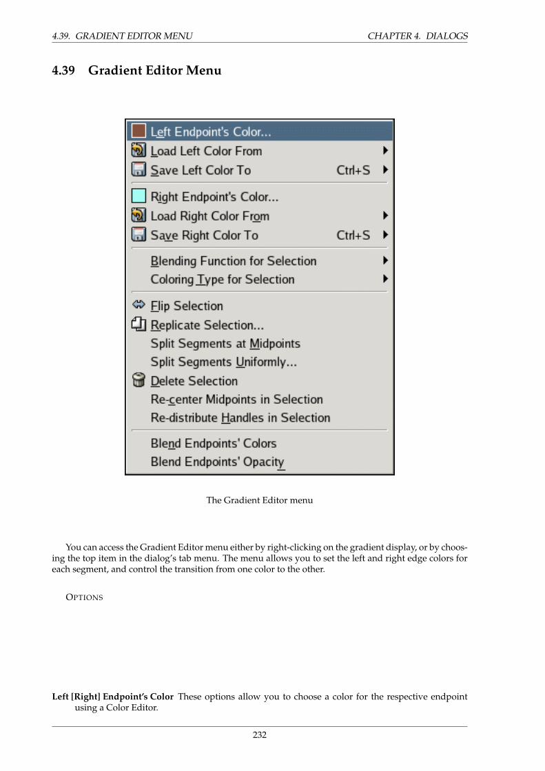
4.39. GRADIENT EDITOR MENU CHAPTER 4. DIALOGS
4.39 Gradient Editor Menu
The Gradient Editor menu
You can access the Gradient Editor menu either by right-clicking on the gradient display, or by choos-ing the top item in the dialog’s tab menu. The menu allows you to set the left and right edge colors foreach segment, and control the transition from one color to the other.
OPTIONS
Left [Right] Endpoint’s Color These options allow you to choose a color for the respective endpointusing a Color Editor.
232
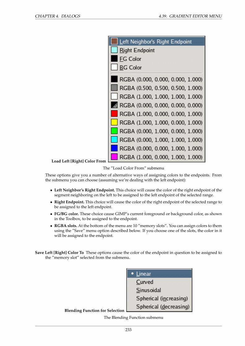
CHAPTER 4. DIALOGS 4.39. GRADIENT EDITOR MENU
Load Left [Right] Color From
The ”Load Color From” submenu
These options give you a number of alternative ways of assigning colors to the endpoints. Fromthe submenu you can choose (assuming we’re dealing with the left endpoint):
• Left Neighbor’s Right Endpoint. This choice will cause the color of the right endpoint of thesegment neighboring on the left to be assigned to the left endpoint of the selected range.
• Right Endpoint. This choice will cause the color of the right endpoint of the selected range tobe assigned to the left endpoint.
• FG/BG color. These choice cause GIMP’s current foreground or background color, as shownin the Toolbox, to be assigned to the endpoint.
• RGBA slots. At the bottom of the menu are 10 ”memory slots”. You can assign colors to themusing the ”Save” menu option described below. If you choose one of the slots, the color in itwill be assigned to the endpoint.
Save Left [Right] Color To These options cause the color of the endpoint in question to be assigned tothe ”memory slot” selected from the submenu.
Blending Function for Selection
The Blending Function submenu
233
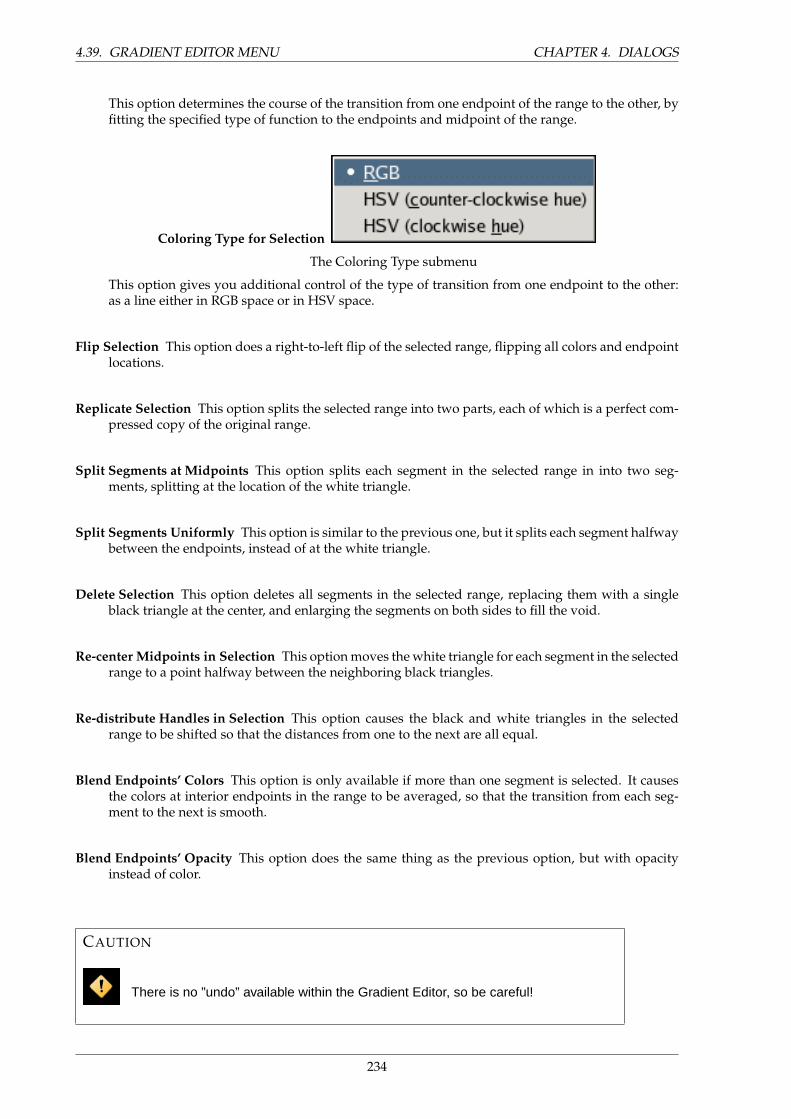
4.39. GRADIENT EDITOR MENU CHAPTER 4. DIALOGS
This option determines the course of the transition from one endpoint of the range to the other, byfitting the specified type of function to the endpoints and midpoint of the range.
Coloring Type for Selection
The Coloring Type submenu
This option gives you additional control of the type of transition from one endpoint to the other:as a line either in RGB space or in HSV space.
Flip Selection This option does a right-to-left flip of the selected range, flipping all colors and endpointlocations.
Replicate Selection This option splits the selected range into two parts, each of which is a perfect com-pressed copy of the original range.
Split Segments at Midpoints This option splits each segment in the selected range in into two seg-ments, splitting at the location of the white triangle.
Split Segments Uniformly This option is similar to the previous one, but it splits each segment halfwaybetween the endpoints, instead of at the white triangle.
Delete Selection This option deletes all segments in the selected range, replacing them with a singleblack triangle at the center, and enlarging the segments on both sides to fill the void.
Re-center Midpoints in Selection This option moves the white triangle for each segment in the selectedrange to a point halfway between the neighboring black triangles.
Re-distribute Handles in Selection This option causes the black and white triangles in the selectedrange to be shifted so that the distances from one to the next are all equal.
Blend Endpoints’ Colors This option is only available if more than one segment is selected. It causesthe colors at interior endpoints in the range to be averaged, so that the transition from each seg-ment to the next is smooth.
Blend Endpoints’ Opacity This option does the same thing as the previous option, but with opacityinstead of color.
CAUTION
There is no ”undo” available within the Gradient Editor, so be careful!
234
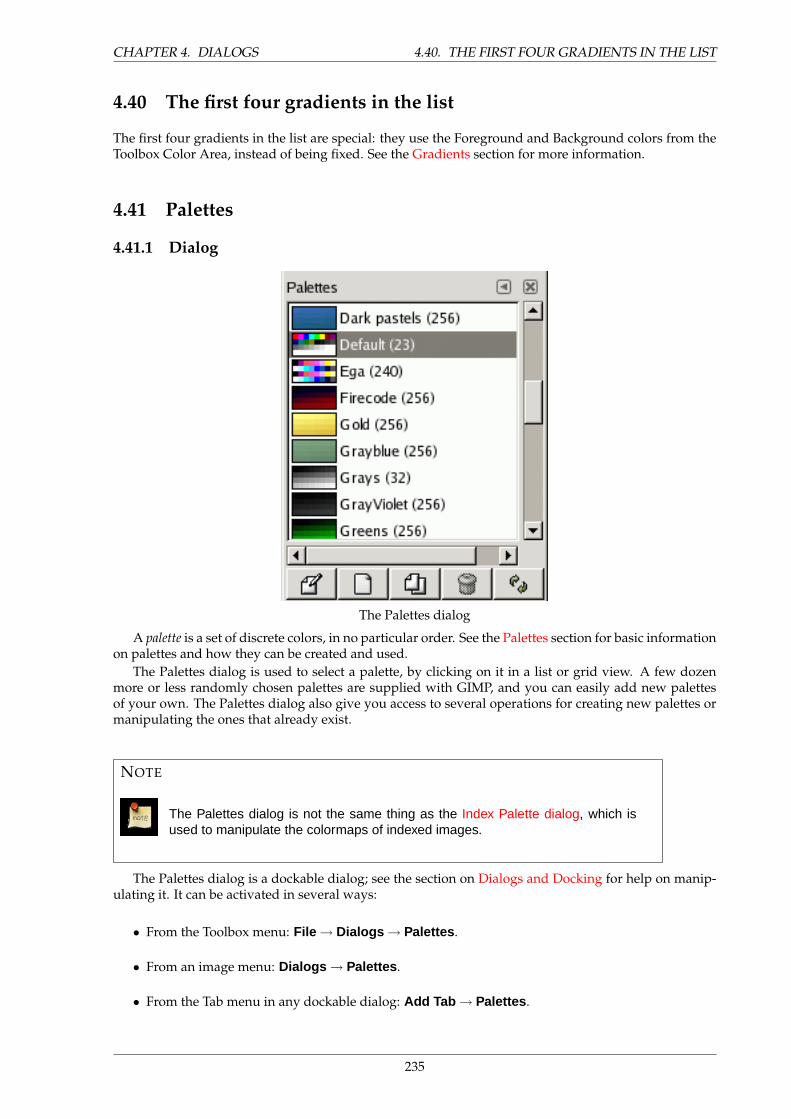
CHAPTER 4. DIALOGS 4.40. THE FIRST FOUR GRADIENTS IN THE LIST
4.40 The first four gradients in the list
The first four gradients in the list are special: they use the Foreground and Background colors from theToolbox Color Area, instead of being fixed. See the Gradients section for more information.
4.41 Palettes
4.41.1 Dialog
The Palettes dialog
A palette is a set of discrete colors, in no particular order. See the Palettes section for basic informationon palettes and how they can be created and used.
The Palettes dialog is used to select a palette, by clicking on it in a list or grid view. A few dozenmore or less randomly chosen palettes are supplied with GIMP, and you can easily add new palettesof your own. The Palettes dialog also give you access to several operations for creating new palettes ormanipulating the ones that already exist.
NOTE
The Palettes dialog is not the same thing as the Index Palette dialog, which isused to manipulate the colormaps of indexed images.
The Palettes dialog is a dockable dialog; see the section on Dialogs and Docking for help on manip-ulating it. It can be activated in several ways:
• From the Toolbox menu: File → Dialogs → Palettes .
• From an image menu: Dialogs → Palettes .
• From the Tab menu in any dockable dialog: Add Tab → Palettes .
235
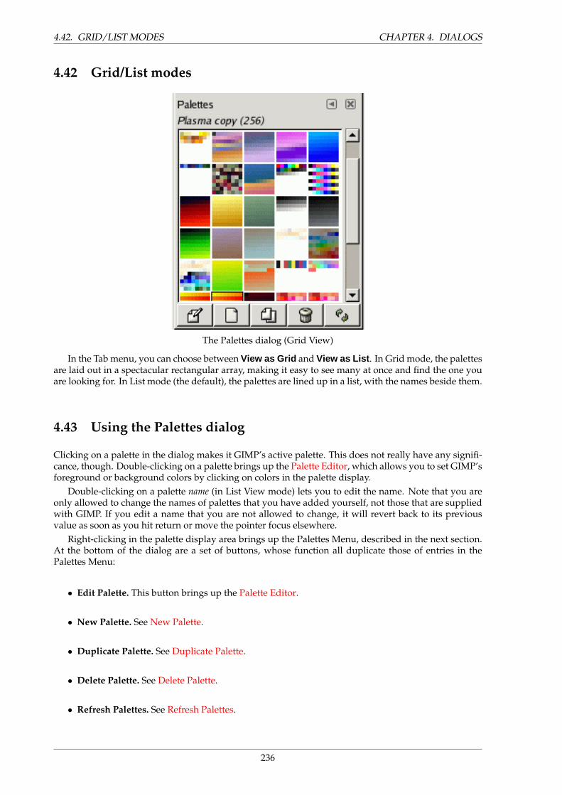
4.42. GRID/LIST MODES CHAPTER 4. DIALOGS
4.42 Grid/List modes
The Palettes dialog (Grid View)
In the Tab menu, you can choose between View as Grid and View as List . In Grid mode, the palettesare laid out in a spectacular rectangular array, making it easy to see many at once and find the one youare looking for. In List mode (the default), the palettes are lined up in a list, with the names beside them.
4.43 Using the Palettes dialog
Clicking on a palette in the dialog makes it GIMP’s active palette. This does not really have any signifi-cance, though. Double-clicking on a palette brings up the Palette Editor, which allows you to set GIMP’sforeground or background colors by clicking on colors in the palette display.
Double-clicking on a palette name (in List View mode) lets you to edit the name. Note that you areonly allowed to change the names of palettes that you have added yourself, not those that are suppliedwith GIMP. If you edit a name that you are not allowed to change, it will revert back to its previousvalue as soon as you hit return or move the pointer focus elsewhere.
Right-clicking in the palette display area brings up the Palettes Menu, described in the next section.At the bottom of the dialog are a set of buttons, whose function all duplicate those of entries in thePalettes Menu:
• Edit Palette. This button brings up the Palette Editor.
• New Palette. See New Palette.
• Duplicate Palette. See Duplicate Palette.
• Delete Palette. See Delete Palette.
• Refresh Palettes. See Refresh Palettes.
236
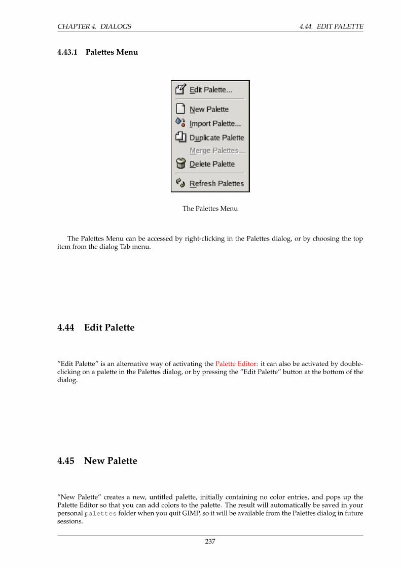
CHAPTER 4. DIALOGS 4.44. EDIT PALETTE
4.43.1 Palettes Menu
The Palettes Menu
The Palettes Menu can be accessed by right-clicking in the Palettes dialog, or by choosing the topitem from the dialog Tab menu.
4.44 Edit Palette
”Edit Palette” is an alternative way of activating the Palette Editor: it can also be activated by double-clicking on a palette in the Palettes dialog, or by pressing the ”Edit Palette” button at the bottom of thedialog.
4.45 New Palette
”New Palette” creates a new, untitled palette, initially containing no color entries, and pops up thePalette Editor so that you can add colors to the palette. The result will automatically be saved in yourpersonal palettes folder when you quit GIMP, so it will be available from the Palettes dialog in futuresessions.
237
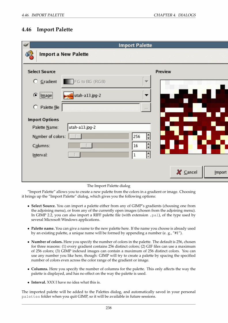
4.46. IMPORT PALETTE CHAPTER 4. DIALOGS
4.46 Import Palette
The Import Palette dialog
”Import Palette” allows you to create a new palette from the colors in a gradient or image. Choosingit brings up the ”Import Palette” dialog, which gives you the following options:
• Select Source. You can import a palette either from any of GIMP’s gradients (choosing one fromthe adjoining menu), or from any of the currently open images (chosen from the adjoining menu).In GIMP 2.2, you can also import a RIFF palette file (with extension .pal ), of the type used byseveral Microsoft Windows applications.
• Palette name. You can give a name to the new palette here. If the name you choose is already usedby an existing palette, a unique name will be formed by appending a number (e. g., ”#1”).
• Number of colors. Here you specify the number of colors in the palette. The default is 256, chosenfor three reasons: (1) every gradient contains 256 distinct colors; (2) GIF files can use a maximumof 256 colors; (3) GIMP indexed images can contain a maximum of 256 distinct colors. You canuse any number you like here, though: GIMP will try to create a palette by spacing the specifiednumber of colors even across the color range of the gradient or image.
• Columns. Here you specify the number of columns for the palette. This only affects the way thepalette is displayed, and has no effect on the way the palette is used.
• Interval. XXX I have no idea what this is.
The imported palette will be added to the Palettes dialog, and automatically saved in your personalpalettes folder when you quit GIMP, so it will be available in future sessions.
238
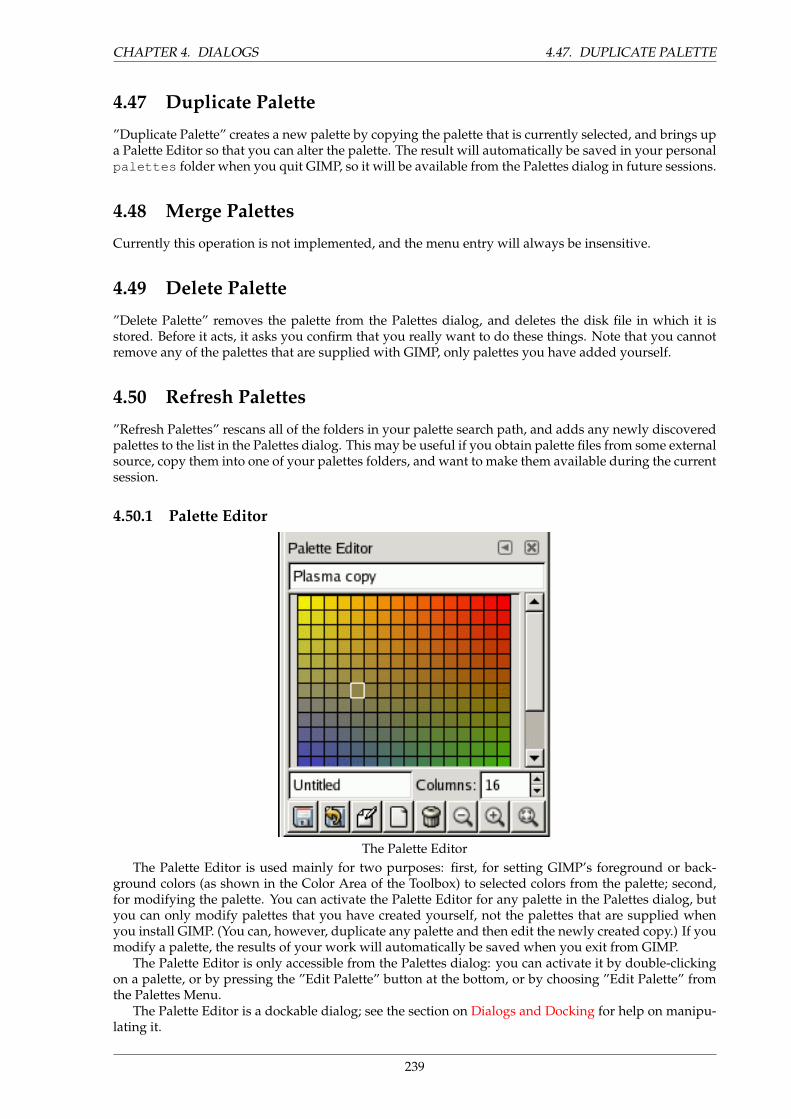
CHAPTER 4. DIALOGS 4.47. DUPLICATE PALETTE
4.47 Duplicate Palette
”Duplicate Palette” creates a new palette by copying the palette that is currently selected, and brings upa Palette Editor so that you can alter the palette. The result will automatically be saved in your personalpalettes folder when you quit GIMP, so it will be available from the Palettes dialog in future sessions.
4.48 Merge Palettes
Currently this operation is not implemented, and the menu entry will always be insensitive.
4.49 Delete Palette
”Delete Palette” removes the palette from the Palettes dialog, and deletes the disk file in which it isstored. Before it acts, it asks you confirm that you really want to do these things. Note that you cannotremove any of the palettes that are supplied with GIMP, only palettes you have added yourself.
4.50 Refresh Palettes
”Refresh Palettes” rescans all of the folders in your palette search path, and adds any newly discoveredpalettes to the list in the Palettes dialog. This may be useful if you obtain palette files from some externalsource, copy them into one of your palettes folders, and want to make them available during the currentsession.
4.50.1 Palette Editor
The Palette EditorThe Palette Editor is used mainly for two purposes: first, for setting GIMP’s foreground or back-
ground colors (as shown in the Color Area of the Toolbox) to selected colors from the palette; second,for modifying the palette. You can activate the Palette Editor for any palette in the Palettes dialog, butyou can only modify palettes that you have created yourself, not the palettes that are supplied whenyou install GIMP. (You can, however, duplicate any palette and then edit the newly created copy.) If youmodify a palette, the results of your work will automatically be saved when you exit from GIMP.
The Palette Editor is only accessible from the Palettes dialog: you can activate it by double-clickingon a palette, or by pressing the ”Edit Palette” button at the bottom, or by choosing ”Edit Palette” fromthe Palettes Menu.
The Palette Editor is a dockable dialog; see the section on Dialogs and Docking for help on manipu-lating it.
239
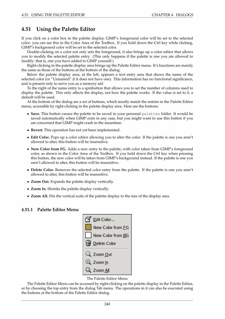
4.51. USING THE PALETTE EDITOR CHAPTER 4. DIALOGS
4.51 Using the Palette Editor
If you click on a color box in the palette display, GIMP’s foreground color will be set to the selectedcolor: you can see this in the Color Area of the Toolbox. If you hold down the Ctrl key while clicking,GIMP’s background color will be set to the selected color.
Double-clicking on a color not only sets the foreground, it also brings up a color editor that allowsyou to modify the selected palette entry. (This only happens if the palette is one you are allowed tomodify: that is, one you have added to GIMP yourself.)
Right-clicking in the palette display area brings up the Palette Editor menu. It’s functions are mainlythe same as those of the buttons at the bottom of the dialog.
Below the palette display area, at the left, appears a text entry area that shows the name of theselected color (or ”Unnamed” if it does not have one). This information has no functional significance,and is present only to serve you as a memory aid.
To the right of the name entry is a spinbutton that allows you to set the number of columns used todisplay the palette. This only affects the display, not how the palette works. If the value is set to 0, adefault will be used.
At the bottom of the dialog are a set of buttons, which mostly match the entries in the Palette Editormenu, accessible by right-clicking in the palette display area. Here are the buttons:
• Save. This button causes the palette to be saved in your personal palettes folder. It would besaved automatically when GIMP exits in any case, but you might want to use this button if youare concerned that GIMP might crash in the meantime.
• Revert. This operation has not yet been implemented.
• Edit Color. Pops up a color editor allowing you to alter the color. If the palette is one you aren’tallowed to alter, this button will be insensitive.
• New Color from FG. Adds a new entry to the palette, with color taken from GIMP’s foregroundcolor, as shown in the Color Area of the Toolbox. If you hold down the Ctrl key when pressingthis button, the new color will be taken from GIMP’s background instead. If the palette is one youaren’t allowed to alter, this button will be insensitive.
• Delete Color. Removes the selected color entry from the palette. If the palette is one you aren’tallowed to alter, this button will be insensitive.
• Zoom Out. Expands the palette display vertically.
• Zoom In. Shrinks the palette display vertically.
• Zoom All. Fits the vertical scale of the palette display to the size of the display area.
4.51.1 Palette Editor Menu
The Palette Editor MenuThe Palette Editor Menu can be accessed by right-clicking on the palette display in the Palette Editor,
or by choosing the top entry from the dialog Tab menu. The operations in it can also be executed usingthe buttons at the bottom of the Palette Editor dialog.
240
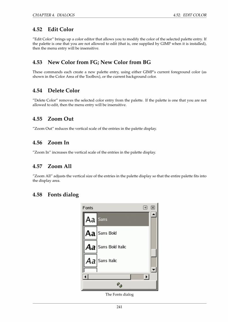
CHAPTER 4. DIALOGS 4.52. EDIT COLOR
4.52 Edit Color
”Edit Color” brings up a color editor that allows you to modify the color of the selected palette entry. Ifthe palette is one that you are not allowed to edit (that is, one supplied by GIMP when it is installed),then the menu entry will be insensitive.
4.53 New Color from FG; New Color from BG
These commands each create a new palette entry, using either GIMP’s current foreground color (asshown in the Color Area of the Toolbox), or the current background color.
4.54 Delete Color
”Delete Color” removes the selected color entry from the palette. If the palette is one that you are notallowed to edit, then the menu entry will be insensitive.
4.55 Zoom Out
”Zoom Out” reduces the vertical scale of the entries in the palette display.
4.56 Zoom In
”Zoom In” increases the vertical scale of the entries in the palette display.
4.57 Zoom All
”Zoom All” adjusts the vertical size of the entries in the palette display so that the entire palette fits intothe display area.
4.58 Fonts dialog
The Fonts dialog
241
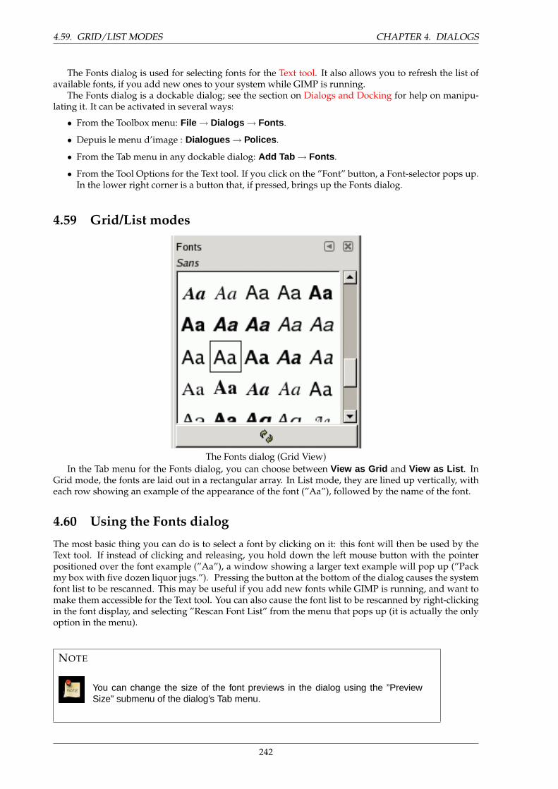
4.59. GRID/LIST MODES CHAPTER 4. DIALOGS
The Fonts dialog is used for selecting fonts for the Text tool. It also allows you to refresh the list ofavailable fonts, if you add new ones to your system while GIMP is running.
The Fonts dialog is a dockable dialog; see the section on Dialogs and Docking for help on manipu-lating it. It can be activated in several ways:
• From the Toolbox menu: File → Dialogs → Fonts .
• Depuis le menu d’image : Dialogues → Polices .
• From the Tab menu in any dockable dialog: Add Tab → Fonts .
• From the Tool Options for the Text tool. If you click on the ”Font” button, a Font-selector pops up.In the lower right corner is a button that, if pressed, brings up the Fonts dialog.
4.59 Grid/List modes
The Fonts dialog (Grid View)In the Tab menu for the Fonts dialog, you can choose between View as Grid and View as List . In
Grid mode, the fonts are laid out in a rectangular array. In List mode, they are lined up vertically, witheach row showing an example of the appearance of the font (”Aa”), followed by the name of the font.
4.60 Using the Fonts dialog
The most basic thing you can do is to select a font by clicking on it: this font will then be used by theText tool. If instead of clicking and releasing, you hold down the left mouse button with the pointerpositioned over the font example (”Aa”), a window showing a larger text example will pop up (”Packmy box with five dozen liquor jugs.”). Pressing the button at the bottom of the dialog causes the systemfont list to be rescanned. This may be useful if you add new fonts while GIMP is running, and want tomake them accessible for the Text tool. You can also cause the font list to be rescanned by right-clickingin the font display, and selecting ”Rescan Font List” from the menu that pops up (it is actually the onlyoption in the menu).
NOTE
You can change the size of the font previews in the dialog using the ”PreviewSize” submenu of the dialog’s Tab menu.
242
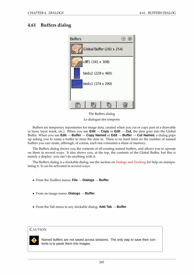
CHAPTER 4. DIALOGS 4.61. BUFFERS DIALOG
4.61 Buffers dialog
The Buffers dialog
Le dialogue des tampons
Buffers are temporary repositories for image data, created when you cut or copy part of a drawable(a layer, layer mask, etc.). When you use Edit → Copy or Edit → Cut , the data goes into the GlobalBuffer. When you use Edit → Buffer → Copy Named or Edit → Buffer → Cut Named , a dialog popsup asking you to name a buffer to store the data in. There is no hard limit on the number of namedbuffers you can create, although, of course, each one consumes a share of memory.
The Buffers dialog shows you the contents of all existing named buffers, and allows you to operateon them in several ways. It also shows you, at the top, the contents of the Global Buffer, but this ismerely a display: you can’t do anything with it.
The Buffers dialog is a dockable dialog; see the section on Dialogs and Docking for help on manipu-lating it. It can be activated in several ways:
• From the Toolbox menu: File → Dialogs → Buffer .
• From an image menu: Dialogs → Buffer .
• From the Tab menu in any dockable dialog: Add Tab → Buffer .
CAUTION
Named buffers are not saved across sessions. The only way to save their con-tents is to paste them into images.
243
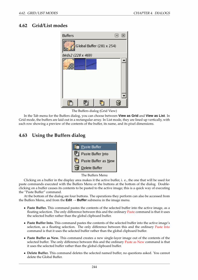
4.62. GRID/LIST MODES CHAPTER 4. DIALOGS
4.62 Grid/List modes
The Buffers dialog (Grid View)In the Tab menu for the Buffers dialog, you can choose between View as Grid and View as List . In
Grid mode, the buffers are laid out in a rectangular array. In List mode, they are lined up vertically, witheach row showing a preview of the contents of the buffer, its name, and its pixel dimensions.
4.63 Using the Buffers dialog
The Buffers MenuClicking on a buffer in the display area makes it the active buffer, i. e., the one that will be used for
paste commands executed with the Buffers Menu or the buttons at the bottom of the dialog. Double-clicking on a buffer causes its contents to be pasted to the active image; this is a quick way of executingthe ”Paste Buffer” command.
At the bottom of the dialog are four buttons. The operations they perform can also be accessed fromthe Buffers Menu, and from the Edit → Buffer submenu in the image menu.
• Paste Buffer. This command pastes the contents of the selected buffer into the active image, as afloating selection. The only difference between this and the ordinary Paste command is that it usesthe selected buffer rather than the global clipboard buffer.
• Paste Buffer Into. This command pastes the contents of the selected buffer into the active image’sselection, as a floating selection. The only difference between this and the ordinary Paste Intocommand is that it uses the selected buffer rather than the global clipboard buffer.
• Paste Buffer as New. This command creates a new single-layer image out of the contents of theselected buffer. The only difference between this and the ordinary Paste as New command is thatit uses the selected buffer rather than the global clipboard buffer.
• Delete Buffer. This command deletes the selected named buffer, no questions asked. You cannotdelete the Global Buffer.
244

CHAPTER 4. DIALOGS 4.64. DOCUMENT HISTORY DIALOG
NOTE
You can change the size of the buffer previews in the dialog using the ”PreviewSize” submenu of the dialog’s Tab menu.
4.64 Document History dialog
4.65 Options
The scroll bar allows you to browse all images you have opened before.
The Open the selected entry button allows you to open the image you have selected. With ”Shift” keypressed, it raises an image hidden behind others. With ”Ctrl” key pressed, it opens the Open Imagedialog.
The Recreate Preview button updates preview in case of change. With ”Shift” key pressed, it acts onall previews. With ”Ctrl” key pressed, previews that can’t be found out are deleted.
245
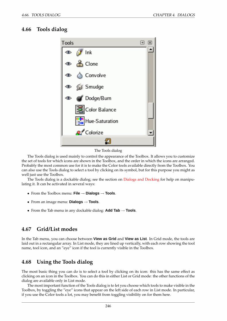
4.66. TOOLS DIALOG CHAPTER 4. DIALOGS
4.66 Tools dialog
The Tools dialogThe Tools dialog is used mainly to control the appearance of the Toolbox. It allows you to customize
the set of tools for which icons are shown in the Toolbox, and the order in which the icons are arranged.Probably the most common use for it is to make the Color tools available directly from the Toolbox. Youcan also use the Tools dialog to select a tool by clicking on its symbol, but for this purpose you might aswell just use the Toolbox.
The Tools dialog is a dockable dialog; see the section on Dialogs and Docking for help on manipu-lating it. It can be activated in several ways:
• From the Toolbox menu: File → Dialogs → Tools .
• From an image menu: Dialogs → Tools .
• From the Tab menu in any dockable dialog: Add Tab → Tools .
4.67 Grid/List modes
In the Tab menu, you can choose between View as Grid and View as List . In Grid mode, the tools arelaid out in a rectangular array. In List mode, they are lined up vertically, with each row showing the toolname, tool icon, and an ”eye” icon if the tool is currently visible in the Toolbox.
4.68 Using the Tools dialog
The most basic thing you can do is to select a tool by clicking on its icon: this has the same effect asclicking on an icon in the Toolbox. You can do this in either List or Grid mode: the other functions of thedialog are available only in List mode.
The most important function of the Tools dialog is to let you choose which tools to make visible in theToolbox, by toggling the ”eye” icons that appear on the left side of each row in List mode. In particular,if you use the Color tools a lot, you may benefit from toggling visibility on for them here.
246

CHAPTER 4. DIALOGS 4.69. PREFERENCES
You can also change the order of tools in the Toolbox, by clicking on an item in the Tools dialog, inList mode, and dragging it up or down in the list. If you screw things up, you can always press the”Reset” button at the bottom of the dialog, to restore the defaults for order and visibility.
Right-clicking inside the dialog produces the Tools menu, which gives you an alternative way oftoggling visibility or restoring the defaults.
4.69 Preferences
4.69.1 Introduction
List of preference pages
The preferences dialog can be accessed from the Toolbox menu, as File → Preferences . It lets youcustomize many aspects of the way GIMP works. The following sections detail the settings that you
247
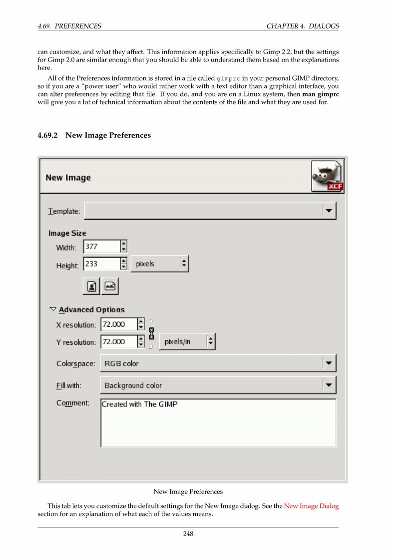
4.69. PREFERENCES CHAPTER 4. DIALOGS
can customize, and what they affect. This information applies specifically to Gimp 2.2, but the settingsfor Gimp 2.0 are similar enough that you should be able to understand them based on the explanationshere.
All of the Preferences information is stored in a file called gimprc in your personal GIMP directory,so if you are a ”power user” who would rather work with a text editor than a graphical interface, youcan alter preferences by editing that file. If you do, and you are on a Linux system, then man gimprcwill give you a lot of technical information about the contents of the file and what they are used for.
4.69.2 New Image Preferences
New Image Preferences
This tab lets you customize the default settings for the New Image dialog. See the New Image Dialogsection for an explanation of what each of the values means.
248
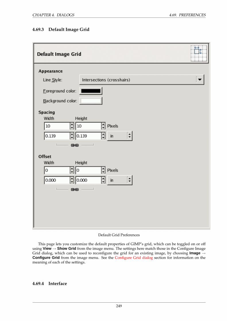
CHAPTER 4. DIALOGS 4.69. PREFERENCES
4.69.3 Default Image Grid
Default Grid Preferences
This page lets you customize the default properties of GIMP’s grid, which can be toggled on or offusing View → Show Grid from the image menu. The settings here match those in the Configure ImageGrid dialog, which can be used to reconfigure the grid for an existing image, by choosing Image →Configure Grid from the image menu. See the Configure Grid dialog section for information on themeaning of each of the settings.
4.69.4 Interface
249

4.69. PREFERENCES CHAPTER 4. DIALOGS
Assorted Interface Preferences
This page lets you customize layer/channel previews and keyboard shortcuts.OPTIONS
Previews By default, GIMP shows miniature previews of the contents of layers and channels in severalplaces, including the Layers dialog. If for some reason you would prefer to disable these, you cando it by unchecking ”Enable layer and channel previews”. If you do want previews to be shown,you can customize their sizes using the menus for ”Default layer and channel preview size” and”Navigation preview size”.
Keyboard Shortcuts Any menu item can be activated by holding down Alt and pressing a sequence ofkeys. Normally, the key associated with each menu entry is shown as an underlined letter in thetext. If for some reason you would prefer the underlines to go away (maybe because you thinkthey’re ugly and you don’t use them anyway), then you can make this happen by unchecking”Show menu mnemonics”.
250
CHAPTER 4. DIALOGS 4.69. PREFERENCES
GIMP can give you the ability to create keyboard shortcuts (key combinations that activate a menuentry) dynamically, by pressing the keys while the pointer hovers over the desired menu entry.However, this capability is disabled by default, because it might lead novice users to accidentallyoverwrite the standard keyboard shortcuts. If you want to enable it, check ”Use dynamics key-board shortcuts” here.
Pressing the button for ”Configure Keyboard Shortcuts” brings up the Shortcut Editor, which givesyou a graphical interface to select menu items and assign shortcuts to them.
If you change shortcuts, you will probably want your changes to continue to apply in future GIMPsessions. If not, uncheck ”Save keyboard shortcuts on exit”. But remember that you have donethis, or you may be frustrated later. If you don’t want to save shortcuts on exit every session,you can save the current settings at any time using the ”Save Keyborad Shortcuts Now” button,and they will be applied to future sessions. If you decide that you have made some bad decisionsconcerning shortcuts, you can reset them to their original state by pressing ”Reset Saved KeyboardShortcuts to Default Values”.
4.69.5 Theme
251
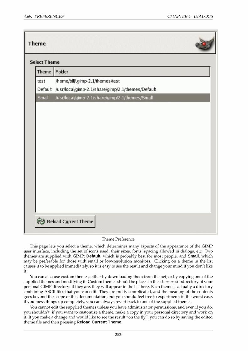
4.69. PREFERENCES CHAPTER 4. DIALOGS
Theme Preference
This page lets you select a theme, which determines many aspects of the appearance of the GIMPuser interface, including the set of icons used, their sizes, fonts, spacing allowed in dialogs, etc. Twothemes are supplied with GIMP: Default , which is probably best for most people, and Small , whichmay be preferable for those with small or low-resolution monitors. Clicking on a theme in the listcauses it to be applied immediately, so it is easy to see the result and change your mind if you don’t likeit.
You can also use custom themes, either by downloading them from the net, or by copying one of thesupplied themes and modifying it. Custom themes should be places in the themes subdirectory of yourpersonal GIMP directory: if they are, they will appear in the list here. Each theme is actually a directorycontaining ASCII files that you can edit. They are pretty complicated, and the meaning of the contentsgoes beyond the scope of this documentation, but you should feel free to experiment: in the worst case,if you mess things up completely, you can always revert back to one of the supplied themes.
You cannot edit the supplied themes unless you have administrator permissions, and even if you do,you shouldn’t: if you want to customize a theme, make a copy in your personal directory and work onit. If you make a change and would like to see the result ”on the fly”, you can do so by saving the editedtheme file and then pressing Reload Current Theme .
252
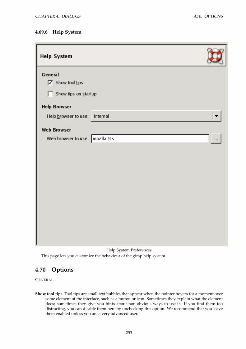
CHAPTER 4. DIALOGS 4.70. OPTIONS
4.69.6 Help System
Help System PreferencesThis page lets you customize the behaviour of the gimp help system.
4.70 Options
GENERAL
Show tool tips Tool tips are small text bubbles that appear when the pointer hovers for a moment oversome element of the interface, such as a button or icon. Sometimes they explain what the elementdoes; sometimes they give you hints about non-obvious ways to use it. If you find them toodistracting, you can disable them here by unchecking this option. We recommend that you leavethem enabled unless you are a very advanced user.
253
4.70. OPTIONS CHAPTER 4. DIALOGS
[GIMP 2.0] ”F1” shows context-dependent help In GIMP 2.0, this options controls whether pressingthe ”F1” key will evoke Help information for the object in which the mouse pointer is currentlylocated. GIMP 2.2 no longer gives you the ability to disable this function.
Show tips on startup Startup tips are helpful hints that appear each time you start GIMP. You canswitch them on or off here. If you have switched them off by unchecking ”Show tip next timeGIMP starts” in the tip window, you can switch them back on by checking here. Whatever youdecide to do, at some point you should take the time to go through the list of tips: they are con-sidered to be very useful, and the things they tell you are not easy to discover by experimenting.If you prefer, you can read them at any time by choosing Help → Tip of the Day in the Toolboxmenu.
HELP BROWSER
Help browser to use GIMP Help is supplied in the form of HTML files, i. e., web pages. You can viewthem using either a special help browser that comes with GIMP, or a web browser of your choice.Here you choose which option to use. Because the help pages were carefully checked to make surethey work well with GIMP’s browser, whereas other web browsers are somewhat variable in theirsupport of features, the safer option is to use the internal browser; but really any modern webbrowser should be okay.
WEB BROWSER
Web browser to use If you selected ”Internal” for the Help browser, this option has no effect. If youselected ”Web browser”, you can decide here which browser to use, and how to invoke it, byentering the command that will be used to run the browser. The button to the right brings up afile selector, which you can use to locate the executable file for the browser if you like, but in mostcases it is probably easier to enter a command by hand.
NOTE
The command should look something like ”mozilla %s”. If you leave out the”%s”, then the browser will open with your default starting page rather thanthe desired help page, so don’t do that.
4.70.1 Tool Options
254
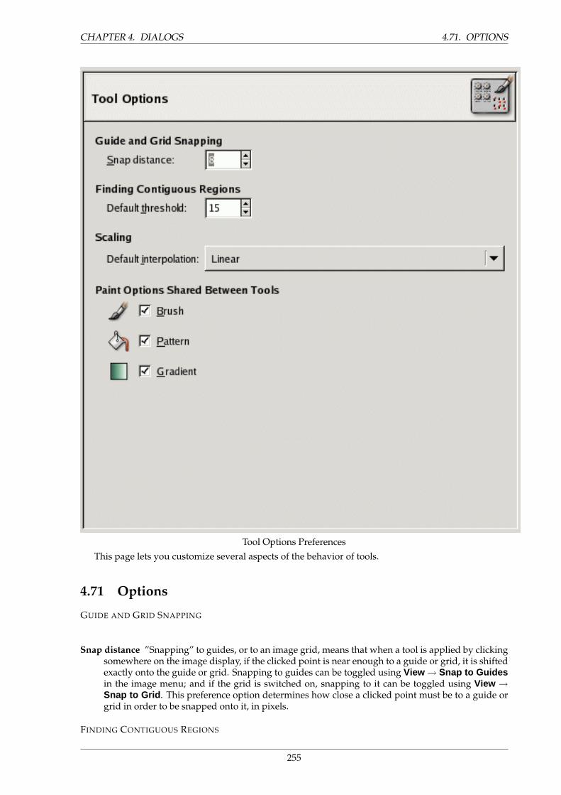
CHAPTER 4. DIALOGS 4.71. OPTIONS
Tool Options Preferences
This page lets you customize several aspects of the behavior of tools.
4.71 Options
GUIDE AND GRID SNAPPING
Snap distance ”Snapping” to guides, or to an image grid, means that when a tool is applied by clickingsomewhere on the image display, if the clicked point is near enough to a guide or grid, it is shiftedexactly onto the guide or grid. Snapping to guides can be toggled using View → Snap to Guidesin the image menu; and if the grid is switched on, snapping to it can be toggled using View →Snap to Grid . This preference option determines how close a clicked point must be to a guide orgrid in order to be snapped onto it, in pixels.
FINDING CONTIGUOUS REGIONS
255
4.71. OPTIONS CHAPTER 4. DIALOGS
Default threshold The ”magic wand” tool creates selections that consist of contiguous regions, i. e.,regions that are not divided by swaths of open space. This option determines how near each othertwo pixels need to be in order to be considered contiguous.
SCALING
Default interpolation When you scale something, each pixel in the result is calculated by interpolatingseveral pixels in the source. This option determines the default interpolation method: it can alwaysbe changed, though, in the Tool Options dialog. There are three choices: None, Linear, and Cubic.”None” is fastest, but quite crude: you should only consider using it if your machine is veryseriously speed-impaired. ”Linear” is the default, and is good enough for most purposes. ”Cubic”is the best (although it can actually look worse than Linear for some types of images), but also theslowest.
PAINT OPTIONS SHARED BETWEEN TOOLS
Brush, Pattern, Gradient You can decide here whether changing the brush etc for one tool should causethe new item to be used for all tools, or whether each individual tool (pencil, paintbrush, airbrush,etc) should remember the item that was last used for it specifically.
4.71.1 Toolbox
256
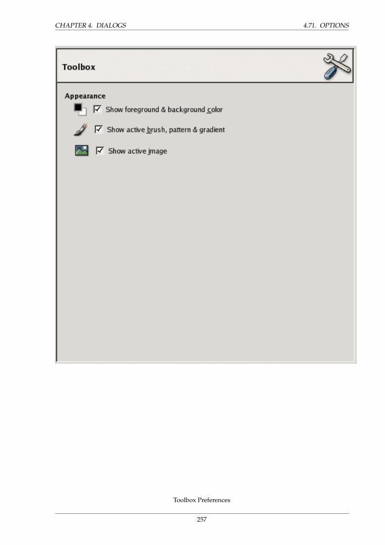
CHAPTER 4. DIALOGS 4.71. OPTIONS
Toolbox Preferences
257
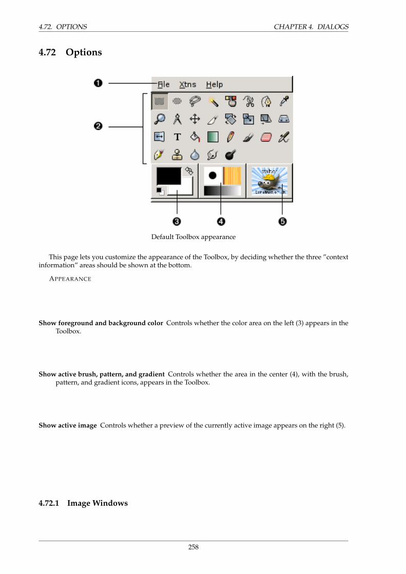
4.72. OPTIONS CHAPTER 4. DIALOGS
4.72 Options
Default Toolbox appearance
This page lets you customize the appearance of the Toolbox, by deciding whether the three ”contextinformation” areas should be shown at the bottom.
APPEARANCE
Show foreground and background color Controls whether the color area on the left (3) appears in theToolbox.
Show active brush, pattern, and gradient Controls whether the area in the center (4), with the brush,pattern, and gradient icons, appears in the Toolbox.
Show active image Controls whether a preview of the currently active image appears on the right (5).
4.72.1 Image Windows
258
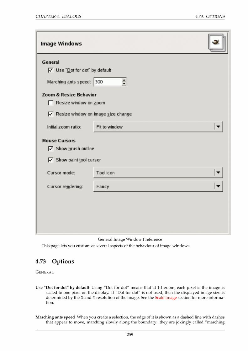
CHAPTER 4. DIALOGS 4.73. OPTIONS
General Image Window Preference
This page lets you customize several aspects of the behaviour of image windows.
4.73 Options
GENERAL
Use ”Dot for dot” by default Using ”Dot for dot” means that at 1:1 zoom, each pixel is the image isscaled to one pixel on the display. If ”Dot for dot” is not used, then the displayed image size isdetermined by the X and Y resolution of the image. See the Scale Image section for more informa-tion.
Marching ants speed When you create a selection, the edge of it is shown as a dashed line with dashesthat appear to move, marching slowly along the boundary: they are jokingly called ”marching
259
4.73. OPTIONS CHAPTER 4. DIALOGS
ants”. The smaller the value entered here, the faster the ants march (and consequently the moredistracting they are!).
ZOOM AND RESIZE BEHAVIOR
Resize window on zoom If this option is checked, then each time you zoom the image, the image win-dow will automatically resize to follow it. Otherwise, the image window will maintain the samesize when you zoom the image.
Resize window on image size change If this option is checked, then each time change the size of theimage, by cropping or resizing it, the image window will automatically resize to follow. Otherwise,the image window will maintain the same size.
Initial zoom ratio You can choose either to have images, when they are first opened, scaled so that thewhole image fits comfortably on your display, or else shown at 1:1 zoom. If you choose the secondoption, and the image is too large to fit on your display, then the image window will show onlypart of it (but you will be able to scroll to other parts).
MOUSE CURSORS
Show brush outline If this option is checked, then when you use a paint tool, the outline of the brushwill be shown on the image as you move the pointer around. On slow systems, if the brush is verylarge, this could occasionally cause some lag in GIMP’s ability to follow your movements: if so,switching this off might help. Otherwise, you will probably find it quite useful.
Show paint tool cursor If this is checked, a cursor will be shown. This is in addition to the brush out-line, if the brush outline is being shown. The type of cursor is determined by the next option.
Cursor mode This option has no effect unless ”Show paint tool cursor” is checked. If it is, you havethree choices: ”Tool icon”, which causes a small iconic representation of the currently active toolto be shown beside the cursor; ”Tool icon with crosshair”, which shows the icon as well as acrosshair indicating the center of the cursor; or ”Crosshair only”.
Cursor rendering If you choose ”Fancy” here, the cursor is drawn in grayscale. If you choose ”Blackand White”, it is drawn in a simpler way that may speed things up a little bit if you have speedissues.
4.73.1 Image Window Appearance
260
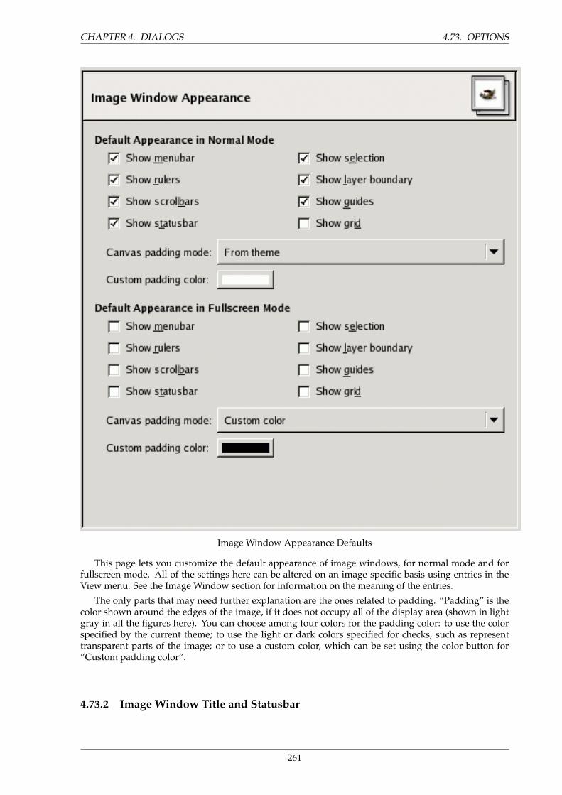
CHAPTER 4. DIALOGS 4.73. OPTIONS
Image Window Appearance Defaults
This page lets you customize the default appearance of image windows, for normal mode and forfullscreen mode. All of the settings here can be altered on an image-specific basis using entries in theView menu. See the Image Window section for information on the meaning of the entries.
The only parts that may need further explanation are the ones related to padding. ”Padding” is thecolor shown around the edges of the image, if it does not occupy all of the display area (shown in lightgray in all the figures here). You can choose among four colors for the padding color: to use the colorspecified by the current theme; to use the light or dark colors specified for checks, such as representtransparent parts of the image; or to use a custom color, which can be set using the color button for”Custom padding color”.
4.73.2 Image Window Title and Statusbar
261
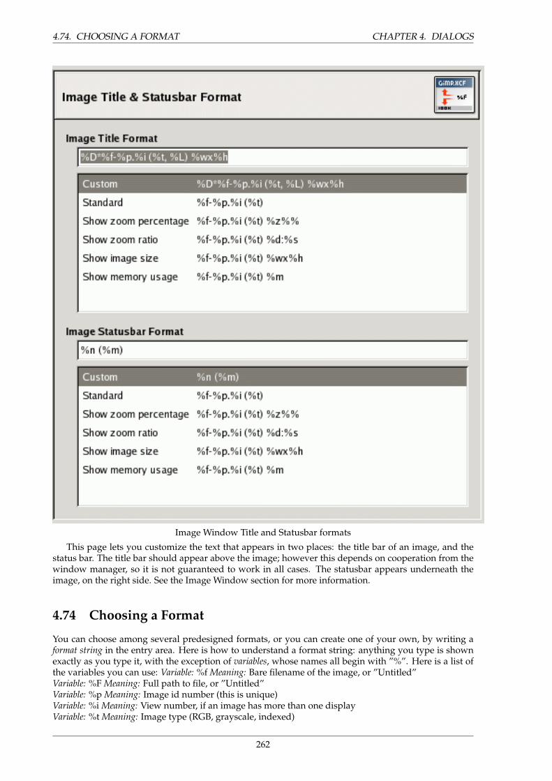
4.74. CHOOSING A FORMAT CHAPTER 4. DIALOGS
Image Window Title and Statusbar formats
This page lets you customize the text that appears in two places: the title bar of an image, and thestatus bar. The title bar should appear above the image; however this depends on cooperation from thewindow manager, so it is not guaranteed to work in all cases. The statusbar appears underneath theimage, on the right side. See the Image Window section for more information.
4.74 Choosing a Format
You can choose among several predesigned formats, or you can create one of your own, by writing aformat string in the entry area. Here is how to understand a format string: anything you type is shownexactly as you type it, with the exception of variables, whose names all begin with ”%”. Here is a list ofthe variables you can use: Variable: %f Meaning: Bare filename of the image, or ”Untitled”Variable: %F Meaning: Full path to file, or ”Untitled”Variable: %p Meaning: Image id number (this is unique)Variable: %i Meaning: View number, if an image has more than one displayVariable: %t Meaning: Image type (RGB, grayscale, indexed)
262

CHAPTER 4. DIALOGS 4.74. CHOOSING A FORMAT
Variable: %z Meaning: Zoom factor as a percentageVariable: %s Meaning: Source scale factor (zoom level = %d/%s)Variable: %d Meaning: Destination scale factor (zoom level = %d/%s)Variable: %Dx Meaning: Expands to x if the image is dirty, nothing otherwiseVariable: %Cx Meaning: Expands to x if the image is clean, nothing otherwiseVariable: %l Meaning: The number of layersVariable: %L Meaning: Number of layers (long form)Variable: %m Meaning: Memory used by the imageVariable: %n Meaning: Name of the active layer/channelVariable: %P Meaning: id of the active layer/channelVariable: %w Meaning: Image width in pixelsVariable: %W Meaning: Image width in real-world unitsVariable: %h Meaning: Image height in pixelsVariable: %H Meaning: Image height in real-world unitsVariable: %u Meaning: Unit symbol (eg. px for Pixel)Variable: %U Meaning: Unit abbreviationVariable: %% Meaning: A literal ”%” symbol
263
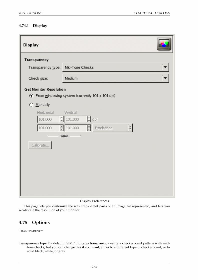
4.75. OPTIONS CHAPTER 4. DIALOGS
4.74.1 Display
Display Preferences
This page lets you customize the way transparent parts of an image are represented, and lets yourecalibrate the resolution of your monitor.
4.75 Options
TRANSPARENCY
Transparency type By default, GIMP indicates transparency using a checkerboard pattern with mid-tone checks, but you can change this if you want, either to a different type of checkerboard, or tosolid black, white, or gray.
264
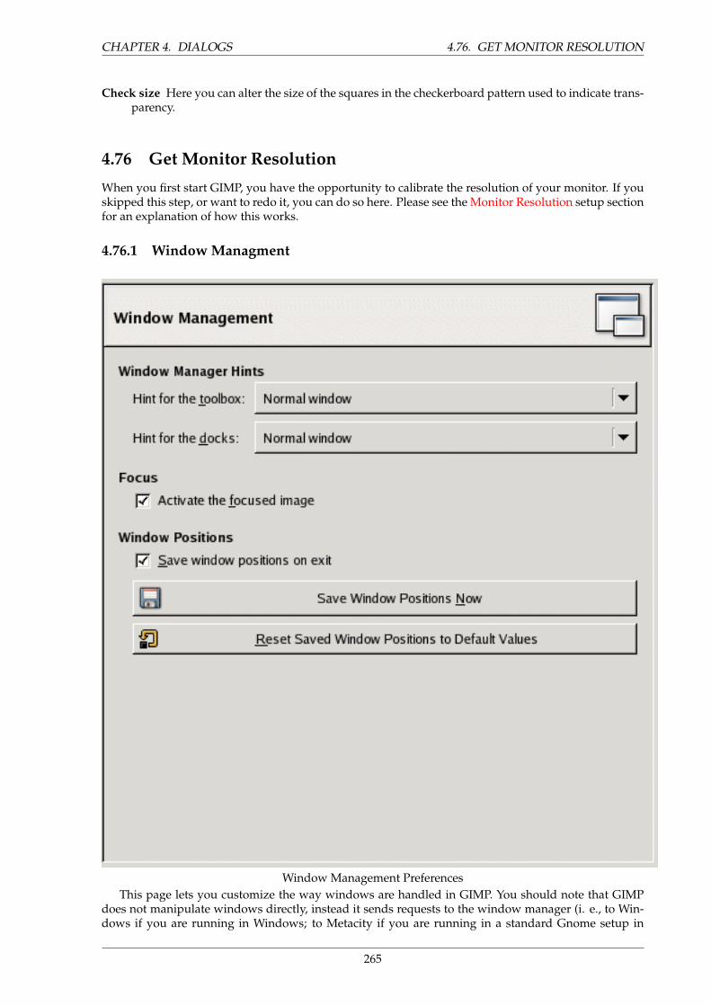
CHAPTER 4. DIALOGS 4.76. GET MONITOR RESOLUTION
Check size Here you can alter the size of the squares in the checkerboard pattern used to indicate trans-parency.
4.76 Get Monitor Resolution
When you first start GIMP, you have the opportunity to calibrate the resolution of your monitor. If youskipped this step, or want to redo it, you can do so here. Please see the Monitor Resolution setup sectionfor an explanation of how this works.
4.76.1 Window Managment
Window Management PreferencesThis page lets you customize the way windows are handled in GIMP. You should note that GIMP
does not manipulate windows directly, instead it sends requests to the window manager (i. e., to Win-dows if you are running in Windows; to Metacity if you are running in a standard Gnome setup in
265
4.77. OPTIONS CHAPTER 4. DIALOGS
Linux; etc). Because there are many window managers, and not all of them are well behaved, it cannotbe guaranteed that the functions described here will actually work as described. However, if you areusing a modern, standards-compliant window manager, they ought to.
4.77 Options
WINDOW MANAGER HINTS
Envois pour la boite d’outils et les fenetres attachables The choices you make here determine how theToolbox, and the docks that hold dialogs, will be treated. If you choose ”Normal Window”, theywill be treated like any other windows. If you choose ”Utility Window”, they will be raised intovisibility whenever you activate an image window, and kept in front of every image window. Ifyou choose ”Keep above”, they will be kept in front of every other window at all times. Note thatchanges you make here will not take effect until the next time you start GIMP.
FOCUS
Activate the focused image Normally, when you focus an image window (usually indicated by a changein the color of the frame), it becomes the ”active image” for GIMP, and therefore the target for anyimage-related actions you perform. Some people, though, prefer to set up their window managerssuch that any window entered by the pointer is automatically focused. If you do this, you mayfind that it is inconvenient for focused images to automatically become active, and may be happierif you uncheck this option.
WINDOW POSITIONS
Save window positions on exit If this option is checked, the next time you start GIMP, you will see thesame set of dialog windows, in the same positions they occupied when you last exited.
Save Window Positions Now This button is only useful if ”Save window positions on exit” is unchecked.It allows you to set up your windows they way you like, click the button, and then have them comeup in that arrangement each time you start GIMP.
Reset Saved Window Positions to Default Values If you decide that you are unhappy with the ar-rangement of windows you have saved, and would rather go back to the default arrangementthan spend time moving them around, you can do so by pressing this button.
266
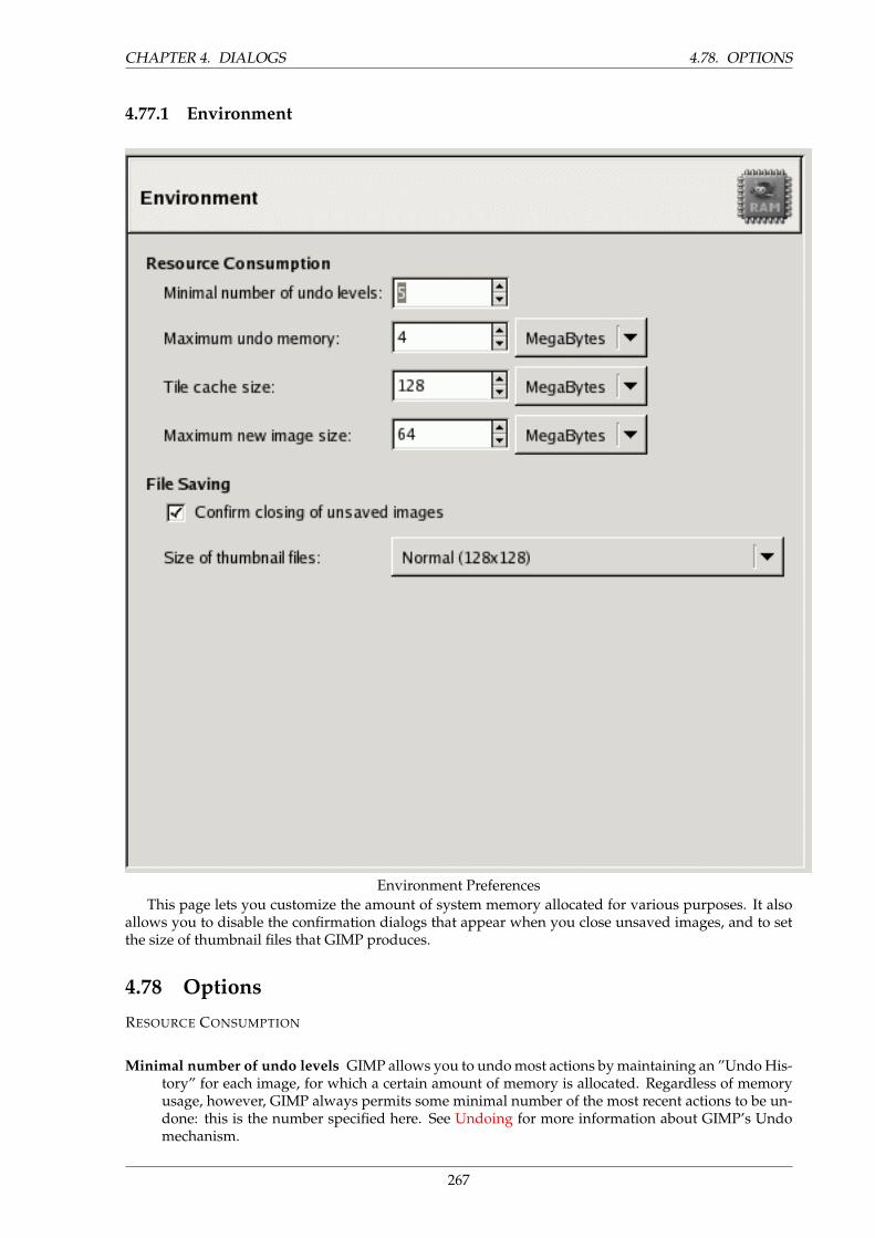
CHAPTER 4. DIALOGS 4.78. OPTIONS
4.77.1 Environment
Environment PreferencesThis page lets you customize the amount of system memory allocated for various purposes. It also
allows you to disable the confirmation dialogs that appear when you close unsaved images, and to setthe size of thumbnail files that GIMP produces.
4.78 Options
RESOURCE CONSUMPTION
Minimal number of undo levels GIMP allows you to undo most actions by maintaining an ”Undo His-tory” for each image, for which a certain amount of memory is allocated. Regardless of memoryusage, however, GIMP always permits some minimal number of the most recent actions to be un-done: this is the number specified here. See Undoing for more information about GIMP’s Undomechanism.
267
4.78. OPTIONS CHAPTER 4. DIALOGS
Maximum undo memory This is the amount of undo memory allocated for each image. If the UndoHistory size exceeds this, the oldest points are deleted, unless this would result in fewer pointsbeing present than the minimal number specified above.
Tile cache size This is the amount of system RAM allocated for GIMP image data. If GIMP requiresmore memory than this, it begins to swap to disk, which may in some circumstances cause adramatic slowdown. You are given an opportunity to set this number when you install GIMP, butyou can alter it here. See How to Set Your Tile Cache for more information.
Maximum new image size This is not a hard contraint: if you try to create a new image larger than thespecified size, you are asked to confirm that you really want to do it. This is to prevent you fromaccidentally creating images much larger than you intend, which can either crash GIMP or causeit to respond verrrrrrrry slowwwwwwwwly.
IMAGE THUMBNAILS
Size of thumbnails This options allows you to set the size of the thumbnails shown in the File Opendialog (and also saved for possible use by other programs). The options are ”None”, ”Normal(128x128)”, and ”Large (256x256)”.
Maximum filesize for thumbnailing If an image file is larger than the specified maximum size, GIMPwill not generate a thumbnail for it. This options allows you to prevent thumbnailing of extremelylarge image files from slowing GIMP to a crawl.
SAVING IMAGES
Confirm closing of unsaved images Closing an image is not undoable, so by default GIMP asks you toconfirm that you really want to do it, whenever it would lead to a loss of unsaved changes. Youcan disable this if you find it annoying; but then of course you are responsible for rememberingwhat you have and have not saved.
Size of thumbnail files Here you can set the size of thumbnail files that GIMP generates. Regardless ofthis value, GIMP will still be capable of reading thumbnail files of any size.
268
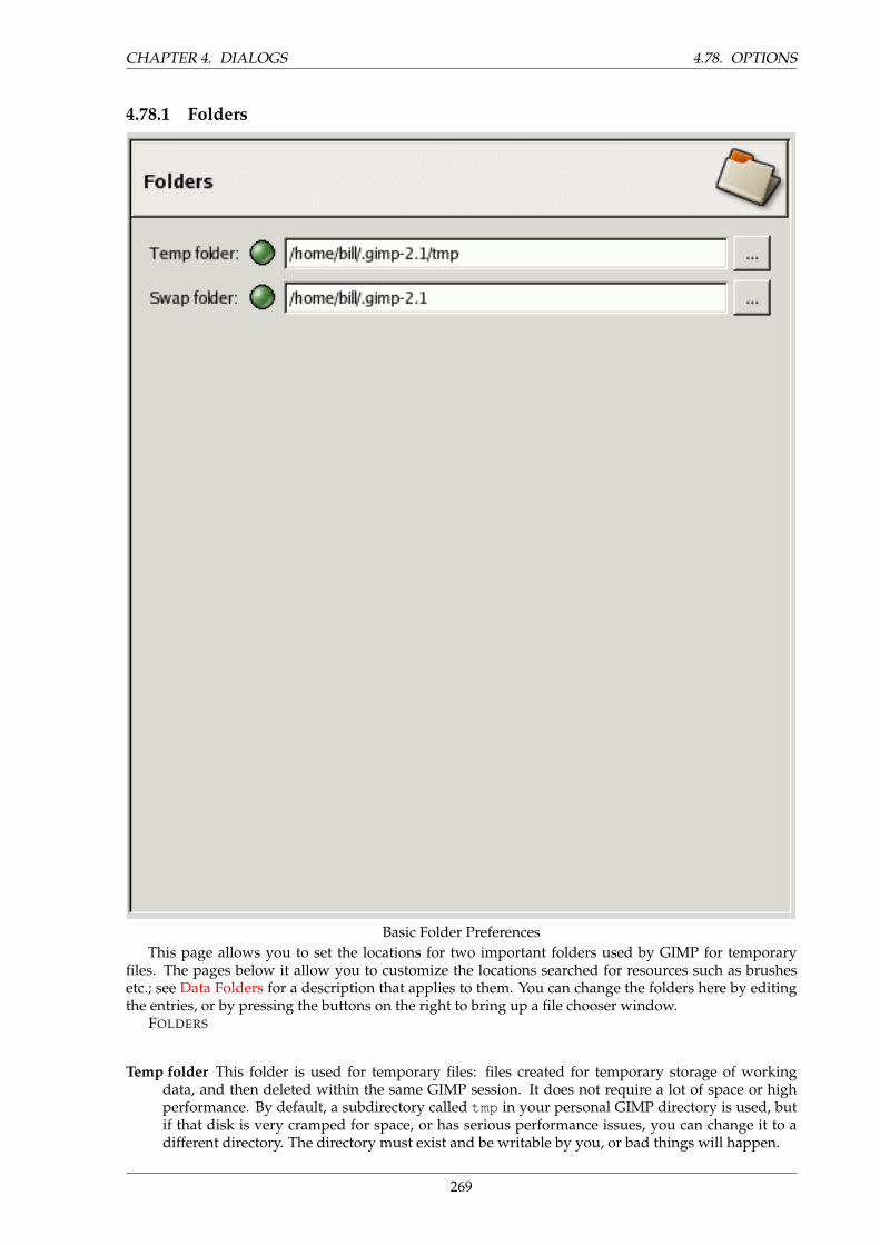
CHAPTER 4. DIALOGS 4.78. OPTIONS
4.78.1 Folders
Basic Folder PreferencesThis page allows you to set the locations for two important folders used by GIMP for temporary
files. The pages below it allow you to customize the locations searched for resources such as brushesetc.; see Data Folders for a description that applies to them. You can change the folders here by editingthe entries, or by pressing the buttons on the right to bring up a file chooser window.
FOLDERS
Temp folder This folder is used for temporary files: files created for temporary storage of workingdata, and then deleted within the same GIMP session. It does not require a lot of space or highperformance. By default, a subdirectory called tmp in your personal GIMP directory is used, butif that disk is very cramped for space, or has serious performance issues, you can change it to adifferent directory. The directory must exist and be writable by you, or bad things will happen.
269
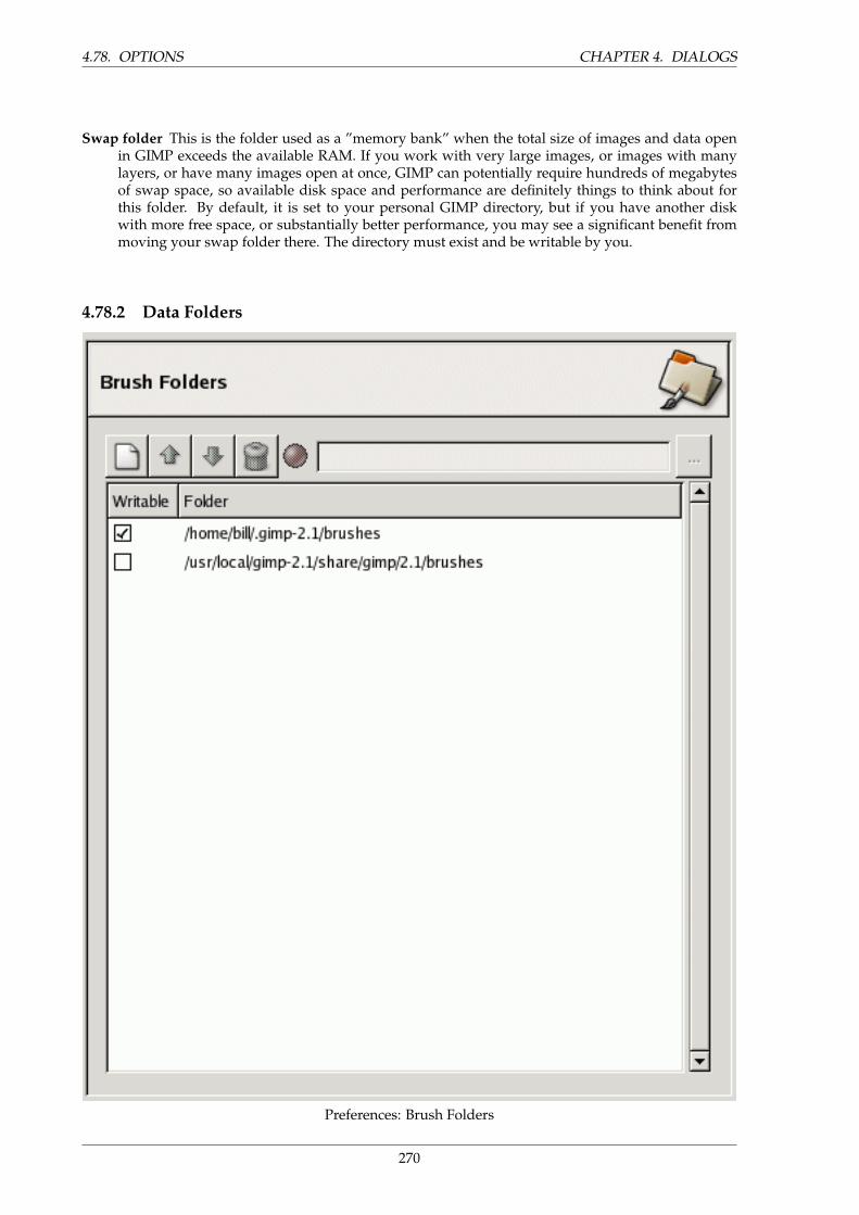
4.78. OPTIONS CHAPTER 4. DIALOGS
Swap folder This is the folder used as a ”memory bank” when the total size of images and data openin GIMP exceeds the available RAM. If you work with very large images, or images with manylayers, or have many images open at once, GIMP can potentially require hundreds of megabytesof swap space, so available disk space and performance are definitely things to think about forthis folder. By default, it is set to your personal GIMP directory, but if you have another diskwith more free space, or substantially better performance, you may see a significant benefit frommoving your swap folder there. The directory must exist and be writable by you.
4.78.2 Data Folders
Preferences: Brush Folders
270
CHAPTER 4. DIALOGS 4.78. OPTIONS
GIMP uses several types of resources – such as brushes, patterns, gradients, etc. – for which a basicset are supplied by GIMP when it is installed, and others can be created or downloaded by the user. Foreach such resource type, there is a Preference page that allows you to specify the search path: the set ofdirectories from which items of the type in question are automatically loaded when GIMP starts. Thesepages all look very much the same: the page for brushes is shown to the right as an example.
By default, the search path includes two folders: a system folder, where items installed along withGIMP are placed, and a personal folder, inside your personal GIMP directory, where items added by youshould be placed. The system folder should not be marked as writable, and you should not try to alterits contents. The personal folder must be marked as writable or it is useless, because there is nothinginside it except what you put there.
You can customize the search path with the buttons at the top of the dialog.OPTIONS
Select a Folder If you click on one of the folders in the list, it is selected for whatever action comes next.
Add/Replace Folder If you type the name of a folder in the entry space, or navigate to it using the filechooser button on the right, and then click the left button, this will replace the selected folder withthe one you have specified. If nothing in the list is selected, the folder you specify will be addedto the list. If the light-symbol to the left of the text entry area is red instead of green, it means thatthe folder you have specified does not exist. GIMP will not create it for you, so you should do thisimmediately.
Move Up/Down If you click on the up-arrow or down-arrow buttons, the selected folder will be changedto the following or preceding one in the list.
Delete Folder If you click the trash-can button, the selected folder will be deleted from the list. (Thefolder itself is not affected; it is merely removed from the search path.) Deleting the system folderis probably a bad idea, but nothing prevents you from doing it.
271

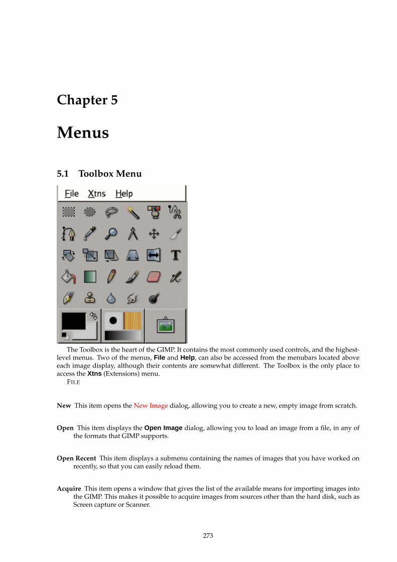
Chapter 5
Menus
5.1 Toolbox Menu
The Toolbox is the heart of the GIMP. It contains the most commonly used controls, and the highest-level menus. Two of the menus, File and Help , can also be accessed from the menubars located aboveeach image display, although their contents are somewhat different. The Toolbox is the only place toaccess the Xtns (Extensions) menu.
FILE
New This item opens the New Image dialog, allowing you to create a new, empty image from scratch.
Open This item displays the Open Image dialog, allowing you to load an image from a file, in any ofthe formats that GIMP supports.
Open Recent This item displays a submenu containing the names of images that you have worked onrecently, so that you can easily reload them.
Acquire This item opens a window that gives the list of the available means for importing images intothe GIMP. This makes it possible to acquire images from sources other than the hard disk, such asScreen capture or Scanner.
273
5.1. TOOLBOX MENU CHAPTER 5. MENUS
Preferences This item displays the Preferences dialog, allowing you to alter a variety of settings thataffect the look, feel, and performance of the GIMP. If you want to customize GIMP, this is the placeto do it.
Dialogs This item shows a submenu containing a list of available dialogs that may be useful duringimage editing – patterns, palettes, brushes, etc. You can open and close dialogs as needed, or, ifyou want them to stay around, you can dock them.
Debug This item is only useful for developers.
Quit Selecting this item ends your session with The GIMP. You will be given an opportunity to saveany images that have unsaved modifications.
XTNS
Module Manager Selecting this item displays the modules that are available to The GIMP. You can alsocontrol which modules are loaded the next time the GIMP is launched, affecting functionality andlaunch time. Modules are dynamically loaded libraries, loaded by the GIMP while it is running,that perform functions such as color-choosing and display filtering. Currently only a few modulesexist, and they are loaded automatically at startup, so you will probably not find it necessary touse.
DB Browser This item displays the available procedures in the PDB. This is mainly intended for ad-vanced uses, such as script writing, and may not be particularly relevant to everyday users.
Plugin Details This item displays both a list and a tree-based heirarchy of all the loaded plug-ins thatThe GIMP has loaded. If you want to use a plug-in, this is not the place to access it; you can get toit via the Filters menu in the individual image menubars.
Unit Editor Selecting this item displays the Unit Editor dialog, which not only details the units that arecurrently being used, but also allows the creation of new units for use within the GIMP.
Script-Fu This item displays a submenu containing many Script-Fu scripts and options including theScript-Fu console. Script-Fu is a language for scripting GIMP operations, so that sequences of themcan be executed in an automated way.
HELP
Help Selecting this item displays the help browser.
TIP
If this does not seem to work, please verify that you have the Gimp UserManual installed.
Context Help Selecting this item changes the behaviour of the pointer such that the next click willdisplay help for the clicked item, if available. This item is mainly present as an aid to the clueless:you can also access context help at any time simply by pressing the ”F1” key with the pointer overthe thing for which you want help.
274
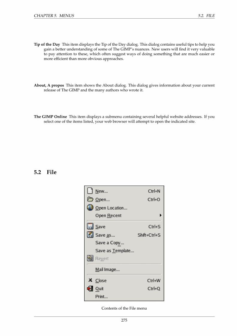
CHAPTER 5. MENUS 5.2. FILE
Tip of the Day This item displays the Tip of the Day dialog. This dialog contains useful tips to help yougain a better understanding of some of The GIMP’s nuances. New users will find it very valuableto pay attention to these, which often suggest ways of doing something that are much easier ormore efficient than more obvious approaches.
About, A propos This item shows the About dialog. This dialog gives information about your currentrelease of The GIMP and the many authors who wrote it.
The GIMP Online This item displays a submenu containing several helpful website addresses. If youselect one of the items listed, your web browser will attempt to open the indicated site.
5.2 File
Contents of the File menu
275
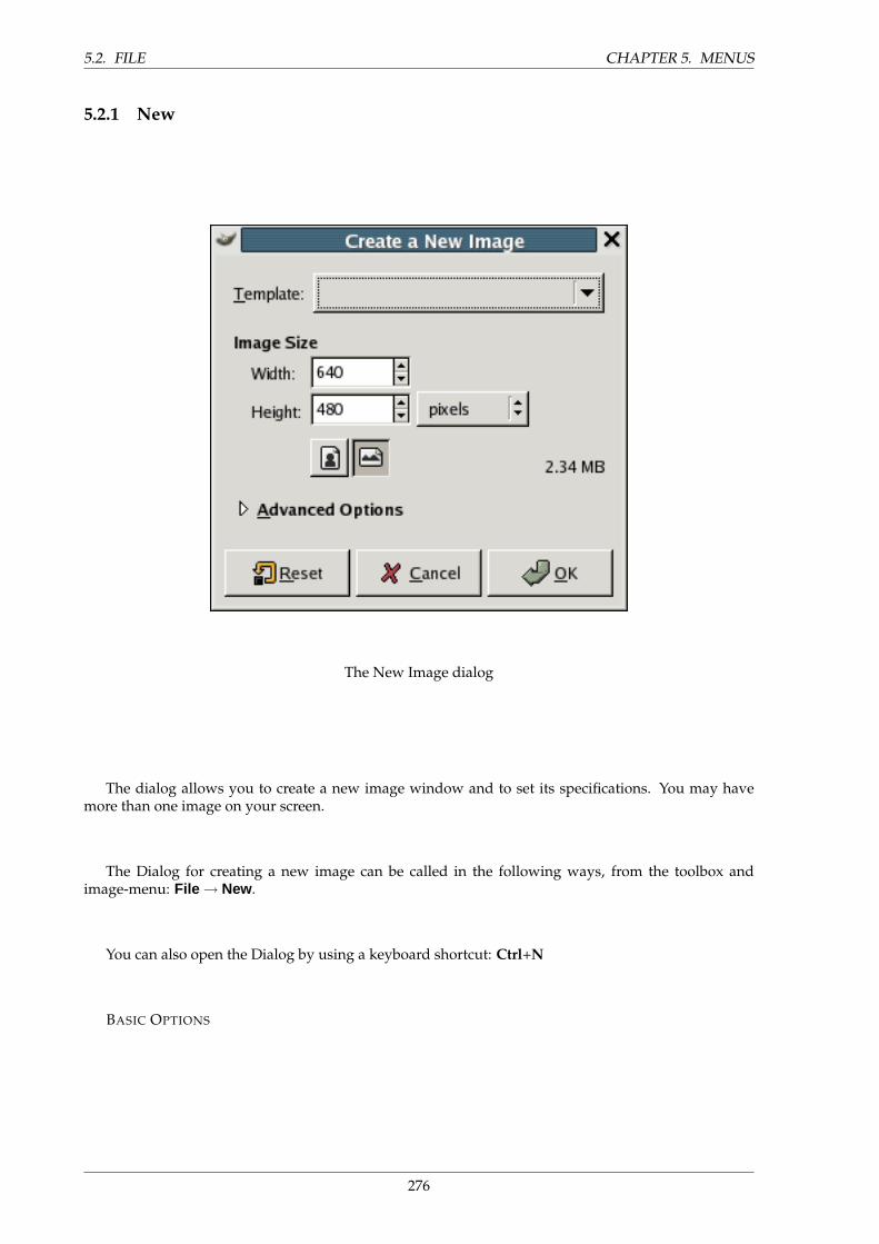
5.2. FILE CHAPTER 5. MENUS
5.2.1 New
The New Image dialog
The dialog allows you to create a new image window and to set its specifications. You may havemore than one image on your screen.
The Dialog for creating a new image can be called in the following ways, from the toolbox andimage-menu: File → New.
You can also open the Dialog by using a keyboard shortcut: Ctrl+N
BASIC OPTIONS
276
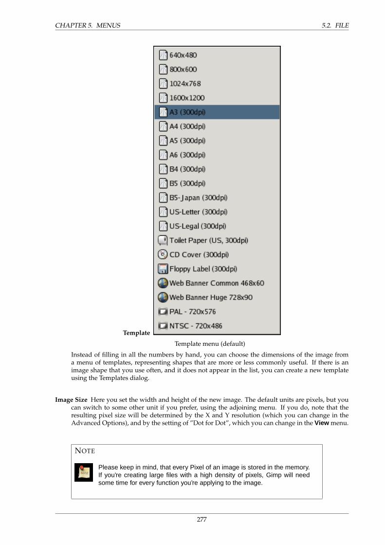
CHAPTER 5. MENUS 5.2. FILE
Template
Template menu (default)
Instead of filling in all the numbers by hand, you can choose the dimensions of the image froma menu of templates, representing shapes that are more or less commonly useful. If there is animage shape that you use often, and it does not appear in the list, you can create a new templateusing the Templates dialog.
Image Size Here you set the width and height of the new image. The default units are pixels, but youcan switch to some other unit if you prefer, using the adjoining menu. If you do, note that theresulting pixel size will be determined by the X and Y resolution (which you can change in theAdvanced Options), and by the setting of ”Dot for Dot”, which you can change in the View menu.
NOTE
Please keep in mind, that every Pixel of an image is stored in the memory.If you’re creating large files with a high density of pixels, Gimp will needsome time for every function you’re applying to the image.
277
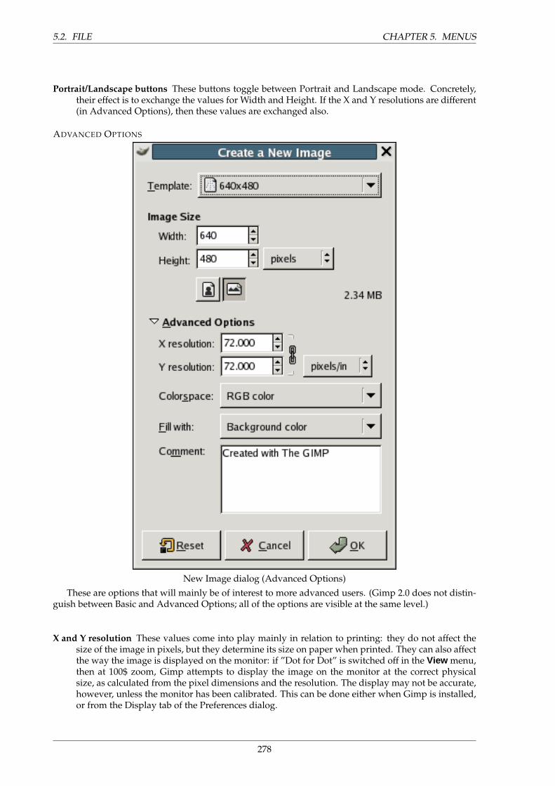
5.2. FILE CHAPTER 5. MENUS
Portrait/Landscape buttons These buttons toggle between Portrait and Landscape mode. Concretely,their effect is to exchange the values for Width and Height. If the X and Y resolutions are different(in Advanced Options), then these values are exchanged also.
ADVANCED OPTIONS
New Image dialog (Advanced Options)
These are options that will mainly be of interest to more advanced users. (Gimp 2.0 does not distin-guish between Basic and Advanced Options; all of the options are visible at the same level.)
X and Y resolution These values come into play mainly in relation to printing: they do not affect thesize of the image in pixels, but they determine its size on paper when printed. They can also affectthe way the image is displayed on the monitor: if ”Dot for Dot” is switched off in the View menu,then at 100$ zoom, Gimp attempts to display the image on the monitor at the correct physicalsize, as calculated from the pixel dimensions and the resolution. The display may not be accurate,however, unless the monitor has been calibrated. This can be done either when Gimp is installed,or from the Display tab of the Preferences dialog.
278
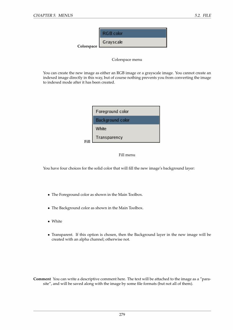
CHAPTER 5. MENUS 5.2. FILE
Colorspace
Colorspace menu
You can create the new image as either an RGB image or a grayscale image. You cannot create anindexed image directly in this way, but of course nothing prevents you from converting the imageto indexed mode after it has been created.
Fill
Fill menu
You have four choices for the solid color that will fill the new image’s background layer:
• The Foreground color as shown in the Main Toolbox.
• The Background color as shown in the Main Toolbox.
• White
• Transparent. If this option is chosen, then the Background layer in the new image will becreated with an alpha channel; otherwise not.
Comment You can write a descriptive comment here. The text will be attached to the image as a ”para-site”, and will be saved along with the image by some file formats (but not all of them).
279
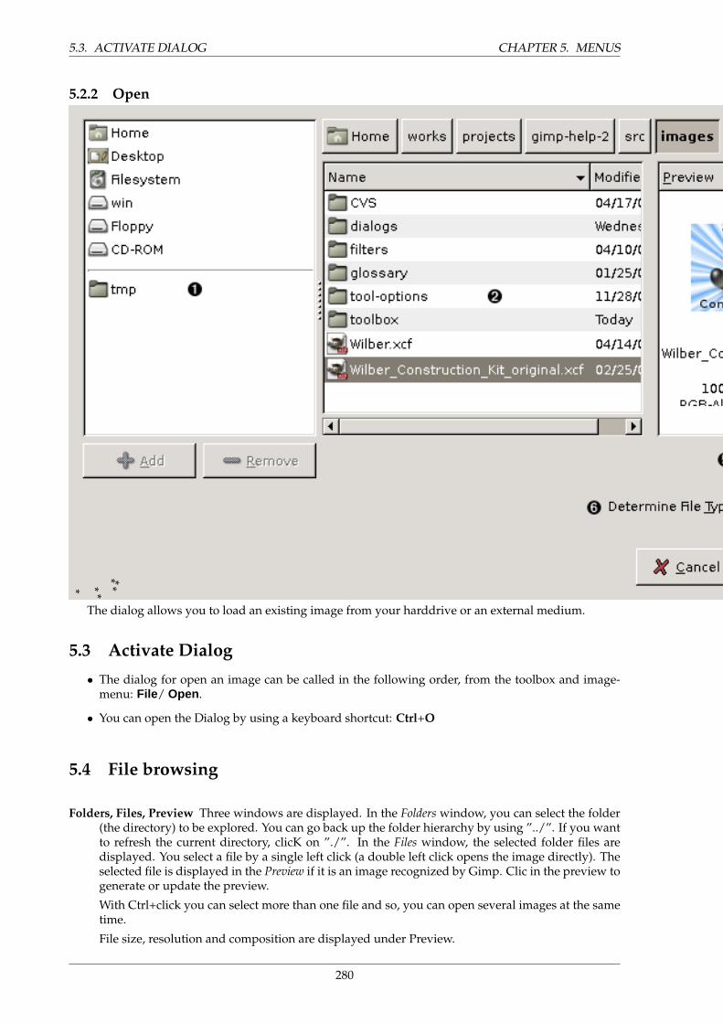
5.3. ACTIVATE DIALOG CHAPTER 5. MENUS
5.2.2 Open
* * **
**
The dialog allows you to load an existing image from your harddrive or an external medium.
5.3 Activate Dialog
• The dialog for open an image can be called in the following order, from the toolbox and image-menu: File/ Open .
• You can open the Dialog by using a keyboard shortcut: Ctrl+O
5.4 File browsing
Folders, Files, Preview Three windows are displayed. In the Folders window, you can select the folder(the directory) to be explored. You can go back up the folder hierarchy by using ”../”. If you wantto refresh the current directory, clicK on ”./”. In the Files window, the selected folder files aredisplayed. You select a file by a single left click (a double left click opens the image directly). Theselected file is displayed in the Preview if it is an image recognized by Gimp. Clic in the preview togenerate or update the preview.
With Ctrl+click you can select more than one file and so, you can open several images at the sametime.
File size, resolution and composition are displayed under Preview.
280
CHAPTER 5. MENUS 5.4. FILE BROWSING
Selection After clicking on this text box, you can input a file name. You enjoy autocompletion: you enterfirst letters of the file and press TAB key. Only files beginning by these letters will be displayed inFiles window, and if only one file has these letters, its name will automatically be displayed in textbox. It’s a handy way to find a file out of a large list.
Determine File Type Automatic option allows file type to be determined automatically. With Linux,file extensions (.bmp, .png...) is not priority. File type is determined according to proper filecharacteristics. In some exceptionnal cases, when Gimp doesn’t recognize file type, you can set itby selecting it in the dropping list. Only files with this type can then be openned.
Three buttons at top Three buttons at top of window: Create a file, Delete File and Rename File are self-explanatory.
5.4.1 Open Recent
This menu item can be reached from the toolbox or image menus, as File → Open Rcent , or by usingthe keyboard shortcut Ctrl–O.
Selecting it shows a submenu with the names of files that you have opened recently in GIMP. Justchoose a name with the pointer to reopen it. You can customize the number of items shown in the menu,by changing the ”Open Recent Menu Size” value in the Interface page of the Preferences dialog. See theDocument History dialog section for more information.
281
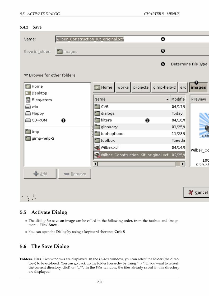
5.5. ACTIVATE DIALOG CHAPTER 5. MENUS
5.4.2 Save
* * *** ** *
*
5.5 Activate Dialog
• The dialog for save an image can be called in the following order, from the toolbox and image-menu: File/ Save.
• You can open the Dialog by using a keyboard shortcut: Ctrl+S
5.6 The Save Dialog
Folders, Files Two windows are displayed. In the Folders window, you can select the folder (the direc-tory) to be explored. You can go back up the folder hierarchy by using ”../”. If you want to refreshthe current directory, clicK on ”./”. In the Files window, the files already saved in this directoryare displayed.
282
CHAPTER 5. MENUS 5.7. PREFERENCES AFFECT THIS MENU
Determine File Type With the Determine File Type option, file type will be that you will write followingyour file name, for instance myfile.bmp. If you forget this extension, an error message will callyou to order.
You can also scroll the extension list and select the one you like. Consult the file formats chapter formore informations.
NOTE
The nativ format of Gimp is XCF. To keep all your datas in the source filesalways choose the .xcf format
Selection After clicking on this text box, you can input a file name. You enjoy autocompletion: youenter the first letters of the file and press TAB key. Only files beginning by these letters will bedisplayed in Files window, and if only one file has these letters, its name will automatically bedisplayed in the text box. It’s a handy way if you have to save many files whose names are slightlydifferent.
Three buttons at top Three buttons at top of window: Create a file, Delete File and Rename File have anevident meaning and need no explanation.
5.7 Preferences affect this menu
Environment You can customize the file save behavior in File Saving view.
5.8 Additional information
If your image is named already, this function saves your image without asking you any question. In theEnvironment dialog, you can decide whether the image must be saved systematically or only if it hasbeen changed.
If your image is new, ”untitled”, the Save dialog will be displayed.You may want not to save your image. In that case click on the exit cross, or File/Exit , or Ctrl-Q. If
your image has a name and has been changed, a message will ask you for confirmation.
5.8.1 Save as
5.9 Overview
Accessing the dialog This function is found in Image>File/Save as and also in Toolbox >File/Saveas.
It is identical to Save, but a file name is systematically requested, even if the file is named yet, sothat you can change it, may be with a new extension.
283
5.9. OVERVIEW CHAPTER 5. MENUS
5.9.1 Save a Copy
This command can be accessed from an image menubar as File → Save a Copy... . It does not have adefault shortcut.
”Save a Copy” does the same things as the Save command, except that it does not change the nameof the image, and does not cause the image to be marked as ”clean”. The effect of this is that if youtry to delete the image, or exit from GIMP, you will be informed that the image is dirty and given anopportunity to save it.
5.9.2 Save as Template
This command can be accessed from an image menubar as File → Save as Template... . It does not havea default shortcut.
”Save as Template” creates a template with the same dimensions and colorspace as the image. A dia-log pops up asking you to name the new template, after which it is saved so that it becomes available inthe New Image dialog. If you give a name that already exists, a unique name is generated by appendinga number to it. You can use the Templates dialog to modify or delete templates.
5.9.3 Revert
File → Revert . It does not have a default shortcut.”Revert” causes the image to be reloaded from disk, so that it will look just like it did the last time
it was saved—unless, that is, the file has in the meantime been overwritten by you or some applicationother than GIMP, in which case the new contents will be loaded. For technical reasons, when GIMPreverts a file, it actually closes the existing image and creates a new image. Because of this, reverting animage is not undoable, and causes the undo history of the image to be lost. GIMP tries to protect youfrom losing your work in this way by asking you to confirm that you really want to revert the image.
5.9.4 Close
This command can be accessed from an image menubar as File → Close , or by using the keyboardshortcut Ctrl–W. In most environments, it can also be executed by clicking a ”Close” button somewhereon the image window titlebar. The location and appearance of this button are determined by the win-dowing system and window manager.
”Close” closes the image and removes its window. Closing an image is not undoable: once it isclosed, everything is gone, including the undo history. If the image is not clean—that is, if you havechanged it since the last time you saved it—then you will be asked to confirm that you really want toclose it. Note that images are marked as clean when saved to a file even if the file format chosen doesnot preserve all information present in the image, so it is a good idea to think for a moment about whatyou are doing before closing an image. If there is the slightest possibility that you will regret it, it can’thurt to save a copy as an XCF file.
Fermer va fermer l’image et sa fenetre. Fermer une image n’est pas annulable : une fois qu’elleest ferme tout est perdu y compris l’historique d’annulation. Si l’image a subi des modifications uneconfirmation vous sera demandee pour la fermer. Noter que l’image est consideree comme non modifieedes qu’elle a ete enregistree dans un fichier meme si le format choisi ne permet de conserver toutes lesinformations possibles. Si vous ne souhaitez n’avoir aucun regret voyez d’abord comment enregistrerun fichier dans le format natif Gimp XCF.
5.9.5 Quit
This command can be accessed from the Toolbox or an image menubar as File → Quit , or by using thekeyboard shortcut Ctrl–Q. In most environments, it can also be executed by clicking a ”Close” buttonsomewhere on the Toolbox window. The location and appearance of this button are determined by thewindowing system and window manager.
”Quit” causes GIMP to close all images and exit. If there are any images open that are not markedas ”clean”, you are notified of this and given an opportunity to cancel the action. (In GIMP 2.2., youare given a list of the unsaved images and asked which of them, if any, you would like to save beforequitting.) Note that if you have a large number of images open, or are using a large proportion of theRAM on your system, it may take a little while for everything to shut down.
284
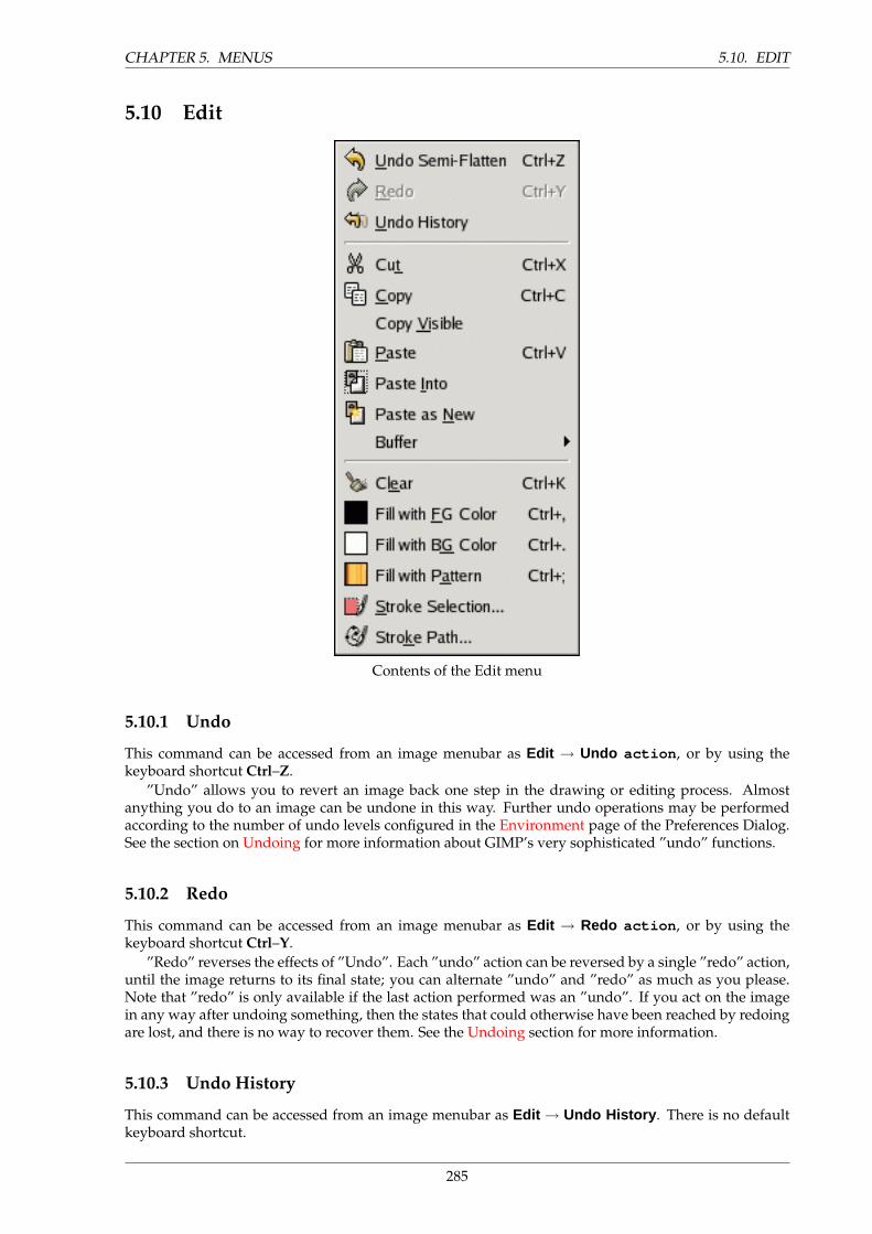
CHAPTER 5. MENUS 5.10. EDIT
5.10 Edit
Contents of the Edit menu
5.10.1 Undo
This command can be accessed from an image menubar as Edit → Undo action , or by using thekeyboard shortcut Ctrl–Z.
”Undo” allows you to revert an image back one step in the drawing or editing process. Almostanything you do to an image can be undone in this way. Further undo operations may be performedaccording to the number of undo levels configured in the Environment page of the Preferences Dialog.See the section on Undoing for more information about GIMP’s very sophisticated ”undo” functions.
5.10.2 Redo
This command can be accessed from an image menubar as Edit → Redo action , or by using thekeyboard shortcut Ctrl–Y.
”Redo” reverses the effects of ”Undo”. Each ”undo” action can be reversed by a single ”redo” action,until the image returns to its final state; you can alternate ”undo” and ”redo” as much as you please.Note that ”redo” is only available if the last action performed was an ”undo”. If you act on the imagein any way after undoing something, then the states that could otherwise have been reached by redoingare lost, and there is no way to recover them. See the Undoing section for more information.
5.10.3 Undo History
This command can be accessed from an image menubar as Edit → Undo History . There is no defaultkeyboard shortcut.
285
5.11. OVERVIEW CHAPTER 5. MENUS
”Undo History” activates the Undo History dialog, which allows you to jump back and forth in theundo history of the image. This is especially useful when you work on difficult tasks, where you oftenneed to undo several steps at once.
5.10.4 Cut
This command can be accessed from an image menubar as Edit → Cut , or by using the keyboard short-cut Ctrl–X.
”Cut” deletes the contents of GIMP’s selection, and saves them in a clipboard so that they can laterbe pasted using the Paste , Paste Into , or Paste As New commands. If no selection is made, the entirecurrent layer will be cut. The areas whose contents are cut out are left transparent if the layer has analpha channel, or filled with the layer’s background color otherwise. ”Cut” only works on the currentactive layer. Any layers above or below the active one are ignored.
5.10.5 Copy
This command can be accessed from an image menubar as Edit → Copy , or by using the keyboardshortcut Ctrl–C.
The Copy command allows the user to make a copy of the current selection, which is then stored inThe GIMP Clipboard . The information can be recalled using the using the Paste, Paste Into, and PasteAs New commands. If no selection has been made, the entire current layer will be copied. ”Copy” willonly work on the current active layer. Any layers above or below the active one are ignored.
5.10.6 Copy Visible
This command is found at Edit → Copy Visible .Contrary to the ”Copy” command which copies the current layer, the ”Copy Visible” command
copies the visible layers, that ones you have marked with an ”eye”. But the informations about layersare lost during this copy. If you paste the clipboard content you have got so, you will get only one layer,fusion of all marked layers.
5.10.7 Paste
5.11 Overview
This command can be accessed from an image menubar as Edit / Paste... .The Paste command puts whatever is in The GIMP Clipboard from the last Copy or Cut command
into the current image. The pasted section will be placed as a Floating Selection and is shown as aseparate layer in the Layers Dialog .
If there is an existing selection on the canvas, it will be used to align the pasted data. Any data pastedwhen a selection already exists will be pasted using the selection as a center point. If the selection is tobe used as a clipping region for the pasted data, this can be achieved by using the Paste Into command.
NOTE
You can only have one floating selection at any one time and cannot work on alayer while there is a floating selection.
5.12 Shortcut
The Ctrl+V will call the Undo function
286
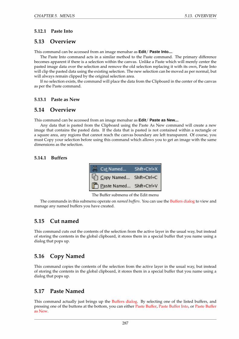
CHAPTER 5. MENUS 5.13. OVERVIEW
5.12.1 Paste Into
5.13 Overview
This command can be accessed from an image menubar as Edit / Paste Into... .The Paste Into command acts in a similar method to the Paste command. The primary difference
becomes apparent if there is a selection within the canvas. Unlike a Paste which will merely center thepasted image data over the selection and remove the old selection replacing it with its own, Paste Intowill clip the pasted data using the existing selection. The new selection can be moved as per normal, butwill always remain clipped by the original selection area.
If no selection exists, the command will place the data from the Clipboard in the center of the canvasas per the Paste command.
5.13.1 Paste as New
5.14 Overview
This command can be accessed from an image menubar as Edit / Paste as New... .Any data that is pasted from the Clipboard using the Paste As New command will create a new
image that contains the pasted data. If the data that is pasted is not contained within a rectangle ora square area, any regions that cannot reach the canvas boundary are left transparent. Of course, youmust Copy your selection before using this command which allows you to get an image with the samedimensions as the selection.
5.14.1 Buffers
The Buffer submenu of the Edit menu
The commands in this submenu operate on named buffers. You can use the Buffers dialog to view andmanage any named buffers you have created.
5.15 Cut named
This command cuts out the contents of the selection from the active layer in the usual way, but insteadof storing the contents in the global clipboard, it stores them in a special buffer that you name using adialog that pops up.
5.16 Copy Named
This command copies the contents of the selection from the active layer in the usual way, but insteadof storing the contents in the global clipboard, it stores them in a special buffer that you name using adialog that pops up.
5.17 Paste Named
This command actually just brings up the Buffers dialog. By selecting one of the listed buffers, andpressing one of the buttons at the bottom, you can either Paste Buffer, Paste Buffer Into, or Paste Bufferas New.
287
5.18. SHORTCUT CHAPTER 5. MENUS
5.17.1 Clear
This command is found at Edit → Clear... .The Clear function allows the user to delete everything contained within the current selection. If
there is no current selection, the contents of the active layer will be removed. If the active layer hasan Alpha channel, the deleted selection will be made transparent. The original color can be restored tothe transparent area using the Eraser tool if it is set to Anti-Erase. If the layer does not have an alphachannel, the deleted area will be filled using the current background color.
Clearing a selection will not delete the selection itself. Unlike Cut , clear will not place the deletedcontents in the Clipboard and the contents of the clipboard are unaffected.
5.18 Shortcut
The Ctrl+K will call the Clear function
5.18.1 Fill with
This command is found at Edit → Fill with... .The Fill command will fill the selected area or active layer, if there is no selection, with the current
foreground, the background color or the selected pattern in the toolbox.
5.19 Shortcut
The Ctrl+, will fill with the FG colorThe Ctrl+. will fill with the BG color
5.19.1 Fill with FG Color
This command can be accessed from an image menubar as Edit → Fill with FG Color , or by using thekeyboard shortcut Ctrl–,.
”Fill with FG Color” causes the image’s selection to be filled with the solid color shown in the fore-ground part of the Color Area of the Toolbox. (The color is also shown to the left of the menu entry.) Ifsome areas of the image are only partially selected (for example, as a result of feathering the selection),they are filled in proportion to their degree of selectedness.
5.19.2 Fill with BG Color
This command can be accessed from an image menubar as Edit → Fill with BG Color , or by using thekeyboard shortcut Ctrl–..
”Fill with BG Color” causes the image’s selection to be filled with the solid color shown in the Back-ground part of the Color Area of the Toolbox. (The color is also shown to the left of the menu entry.)If some areas of the image are only partially selected, they are filled in proportion to their degree ofselectedness.
5.19.3 Fill with Pattern
This command can be accessed from an image menubar as Edit → Fill with Pattern , or by using thekeyboard shortcut Ctrl–;.
”Fill with Pattern” causes the image’s selection to be filled with the pattern shown in the Brush/Pattern/Gradientarea of the Toolbox. (The pattern is also shown to the left of the menu entry.) If some areas of the imageare only partially selected, they are filled in proportion to their degree of selectedness.
288
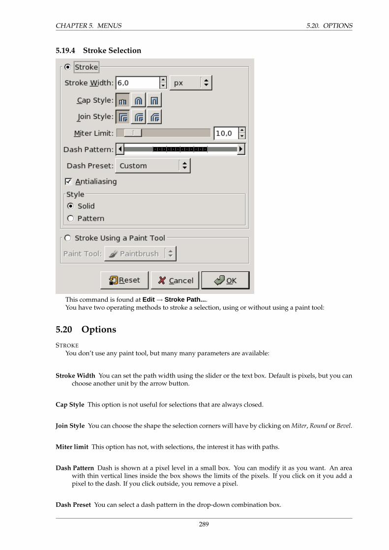
CHAPTER 5. MENUS 5.20. OPTIONS
5.19.4 Stroke Selection
This command is found at Edit → Stroke Path... .You have two operating methods to stroke a selection, using or without using a paint tool:
5.20 Options
STROKEYou don’t use any paint tool, but many many parameters are available:
Stroke Width You can set the path width using the slider or the text box. Default is pixels, but you canchoose another unit by the arrow button.
Cap Style This option is not useful for selections that are always closed.
Join Style You can choose the shape the selection corners will have by clicking on Miter, Round or Bevel.
Miter limit This option has not, with selections, the interest it has with paths.
Dash Pattern Dash is shown at a pixel level in a small box. You can modify it as you want. An areawith thin vertical lines inside the box shows the limits of the pixels. If you click on it you add apixel to the dash. If you click outside, you remove a pixel.
Dash Preset You can select a dash pattern in the drop-down combination box.
289
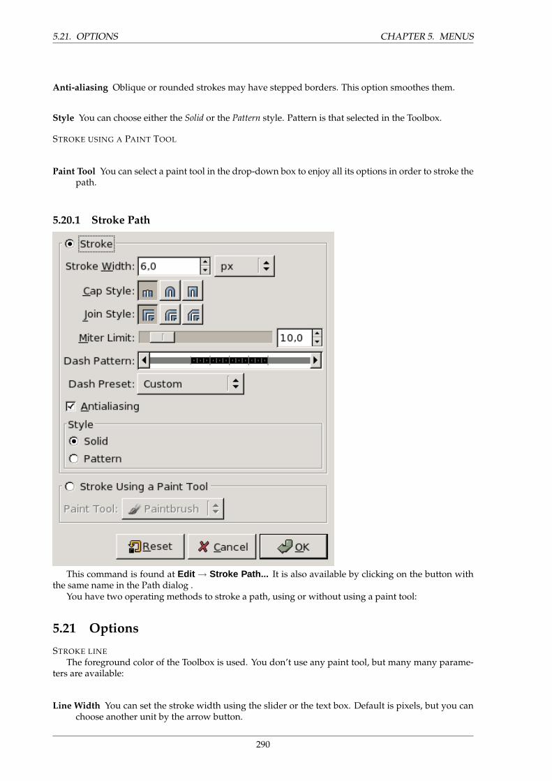
5.21. OPTIONS CHAPTER 5. MENUS
Anti-aliasing Oblique or rounded strokes may have stepped borders. This option smoothes them.
Style You can choose either the Solid or the Pattern style. Pattern is that selected in the Toolbox.
STROKE USING A PAINT TOOL
Paint Tool You can select a paint tool in the drop-down box to enjoy all its options in order to stroke thepath.
5.20.1 Stroke Path
This command is found at Edit → Stroke Path... It is also available by clicking on the button withthe same name in the Path dialog .
You have two operating methods to stroke a path, using or without using a paint tool:
5.21 Options
STROKE LINEThe foreground color of the Toolbox is used. You don’t use any paint tool, but many many parame-
ters are available:
Line Width You can set the stroke width using the slider or the text box. Default is pixels, but you canchoose another unit by the arrow button.
290
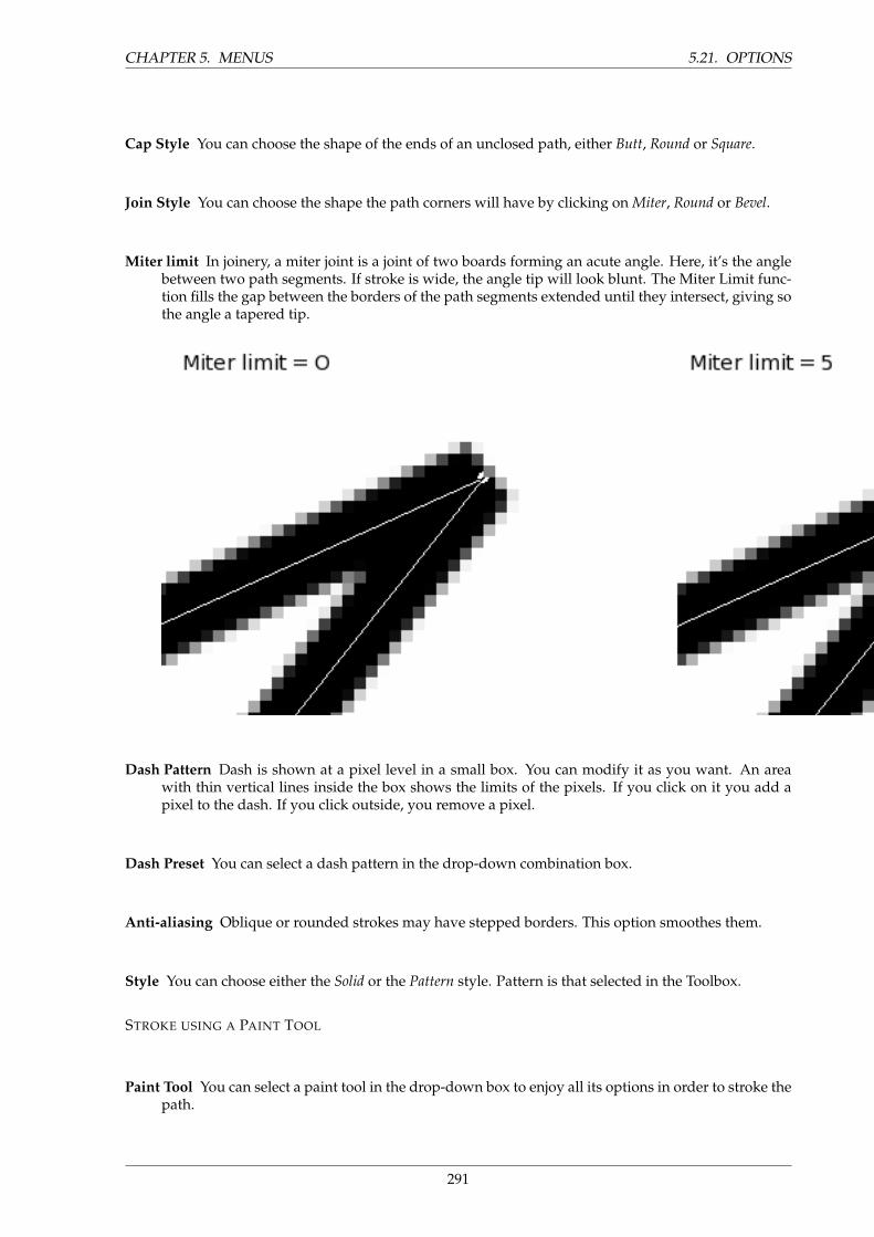
CHAPTER 5. MENUS 5.21. OPTIONS
Cap Style You can choose the shape of the ends of an unclosed path, either Butt, Round or Square.
Join Style You can choose the shape the path corners will have by clicking on Miter, Round or Bevel.
Miter limit In joinery, a miter joint is a joint of two boards forming an acute angle. Here, it’s the anglebetween two path segments. If stroke is wide, the angle tip will look blunt. The Miter Limit func-tion fills the gap between the borders of the path segments extended until they intersect, giving sothe angle a tapered tip.
Dash Pattern Dash is shown at a pixel level in a small box. You can modify it as you want. An areawith thin vertical lines inside the box shows the limits of the pixels. If you click on it you add apixel to the dash. If you click outside, you remove a pixel.
Dash Preset You can select a dash pattern in the drop-down combination box.
Anti-aliasing Oblique or rounded strokes may have stepped borders. This option smoothes them.
Style You can choose either the Solid or the Pattern style. Pattern is that selected in the Toolbox.
STROKE USING A PAINT TOOL
Paint Tool You can select a paint tool in the drop-down box to enjoy all its options in order to stroke thepath.
291
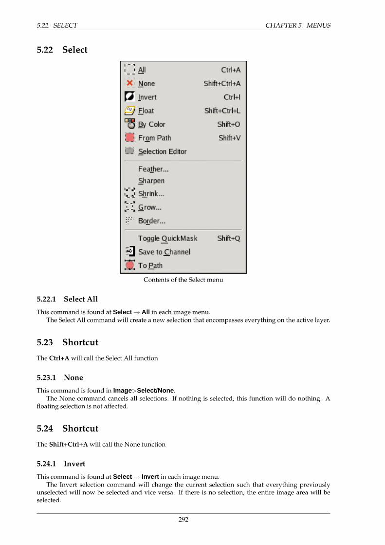
5.22. SELECT CHAPTER 5. MENUS
5.22 Select
Contents of the Select menu
5.22.1 Select All
This command is found at Select → All in each image menu.The Select All command will create a new selection that encompasses everything on the active layer.
5.23 Shortcut
The Ctrl+A will call the Select All function
5.23.1 None
This command is found in Image>Select/None .The None command cancels all selections. If nothing is selected, this function will do nothing. A
floating selection is not affected.
5.24 Shortcut
The Shift+Ctrl+A will call the None function
5.24.1 Invert
This command is found at Select → Invert in each image menu.The Invert selection command will change the current selection such that everything previously
unselected will now be selected and vice versa. If there is no selection, the entire image area will beselected.
292
CHAPTER 5. MENUS 5.25. SHORTCUT
5.25 Shortcut
The Ctrl+I will call the Invert function
5.25.1 From Path
This command is found at Select → From Path in each image menu. The same action is performed by
clicking on the Selection to Path button in the Path dialog.Selects the area contained within the path. If the path is not closed, it will be completed and the
internal areas selected. If the path is curving, the completing line will be curved. If it is straight, astraight line will be used to complete the path into the selection. The path persists in the Path dialog.
5.26 Shortcut
The Shift+V will call the From Path function
5.26.1 Float
This command is found at Select → Float in each image menu.Select Float converts a normal selection to a Floating Selection.Floating selections were used in the first ages of GIMP to perform operations on a limited part of the
image. Nowadays, you can do that more easily with layers. This option is persisting. More, a float isautomatically created when you move a selection using the move tool without pressing the ALT key (orShift Alt in Linux). A temporay layer is created in the Layer Dialog. Its name is ’Floating Selection’. Nomore operations can be performed on another layer until the float has been anchored.
Once the wanted operations have been performed on the floating selection, you have to anchor it,that is to say put it in a normal layer, more often the original layer, the last active, by clicking on theanchor button of the Layer Dialog or the ’Anchor Layer’ of the Layer menu. You can also put it in a newlayer by clicking on the New Layer button of the Layer Dialog.
5.27 Shortcut
The From Path function is available through the Shift+Ctrl+L key combination.
TIP
If you use ”Layer Boundary Size”, you may have some difficulties in selecting thepart of the image you want have in the layer. If you make a rectangular selectionand transform it into a float, you can anchor it in a new layer. You only have thento remove the old layer.
5.27.1 By Color
This command is found at Select → By Color in each image menu. This is just an alternate way ofactivating the ”Select by Color” tool, one of the basic Color Tools. For information on how to use it, seeSelect By Color
5.27.2 Feather
This command is found at Select → Feather in each image menu.Feathering selection borders is normally provided by the Feather Edges option of the selection tools.
This function allows you to take it up again.You only have to enter the width of the feathered border in the text box, in pixels or any unit you can
choose.
293
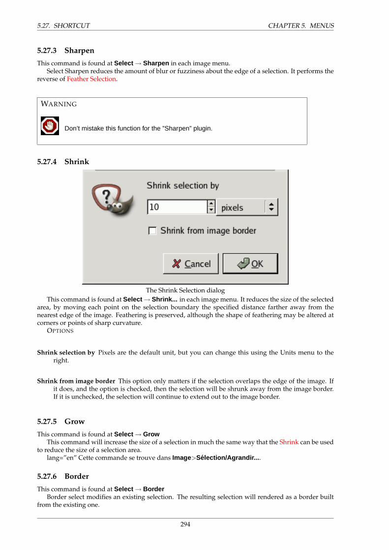
5.27. SHORTCUT CHAPTER 5. MENUS
5.27.3 Sharpen
This command is found at Select → Sharpen in each image menu.Select Sharpen reduces the amount of blur or fuzziness about the edge of a selection. It performs the
reverse of Feather Selection.
WARNING
Don’t mistake this function for the ”Sharpen” plugin.
5.27.4 Shrink
The Shrink Selection dialogThis command is found at Select → Shrink... in each image menu. It reduces the size of the selected
area, by moving each point on the selection boundary the specified distance farther away from thenearest edge of the image. Feathering is preserved, although the shape of feathering may be altered atcorners or points of sharp curvature.
OPTIONS
Shrink selection by Pixels are the default unit, but you can change this using the Units menu to theright.
Shrink from image border This option only matters if the selection overlaps the edge of the image. Ifit does, and the option is checked, then the selection will be shrunk away from the image border.If it is unchecked, the selection will continue to extend out to the image border.
5.27.5 Grow
This command is found at Select → GrowThis command will increase the size of a selection in much the same way that the Shrink can be used
to reduce the size of a selection area.lang=”en” Cette commande se trouve dans Image>Selection/Agrandir... .
5.27.6 Border
This command is found at Select → BorderBorder select modifies an existing selection. The resulting selection will rendered as a border built
from the existing one.
294
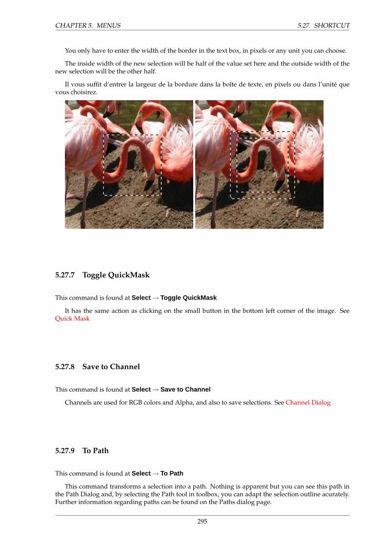
CHAPTER 5. MENUS 5.27. SHORTCUT
You only have to enter the width of the border in the text box, in pixels or any unit you can choose.
The inside width of the new selection will be half of the value set here and the outside width of thenew selection will be the other half.
Il vous suffit d’entrer la largeur de la bordure dans la boıte de texte, en pixels ou dans l’unite quevous choisirez.
5.27.7 Toggle QuickMask
This command is found at Select → Toggle QuickMask
It has the same action as clicking on the small button in the bottom left corner of the image. SeeQuick Mask
5.27.8 Save to Channel
This command is found at Select → Save to Channel
Channels are used for RGB colors and Alpha, and also to save selections. See Channel Dialog
5.27.9 To Path
This command is found at Select → To Path
This command transforms a selection into a path. Nothing is apparent but you can see this path inthe Path Dialog and, by selecting the Path tool in toolbox, you can adapt the selection outline acurately.Further information regarding paths can be found on the Paths dialog page.
295
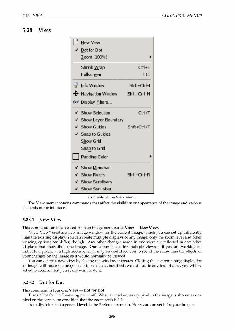
5.28. VIEW CHAPTER 5. MENUS
5.28 View
Contents of the View menuThe View menu contains commands that affect the visibility or appearance of the image and various
elements of the interface.
5.28.1 New View
This command can be accessed from an image menubar as View → New View .”New View” creates a new image window for the current image, which you can set up differently
than the existing display. You can create multiple displays of any image: only the zoom level and otherviewing options can differ, though. Any other changes made in one view are reflected in any otherdisplays that show the same image. One common use for multiple views is if you are working onindividual pixels, at a high zoom level: it may be useful for you to see at the same time the effects ofyour changes on the image as it would normally be viewed.
You can delete a new view by closing the window it creates. Closing the last remaining display foran image will cause the image itself to be closed, but if this would lead to any loss of data, you will beasked to confirm that you really want to do it.
5.28.2 Dot for Dot
This command is found at View → Dot for DotTurns ”Dot for Dot” viewing on or off. When turned on, every pixel in the image is shown as one
pixel on the screen, on condition that the zoom ratio is 1:1.Actually, it is set at a general level in the Preferences menu. Here, you can set it for your image.
296
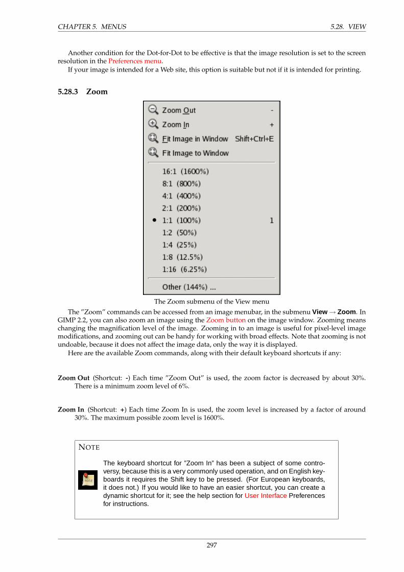
CHAPTER 5. MENUS 5.28. VIEW
Another condition for the Dot-for-Dot to be effective is that the image resolution is set to the screenresolution in the Preferences menu.
If your image is intended for a Web site, this option is suitable but not if it is intended for printing.
5.28.3 Zoom
The Zoom submenu of the View menu
The ”Zoom” commands can be accessed from an image menubar, in the submenu View → Zoom . InGIMP 2.2, you can also zoom an image using the Zoom button on the image window. Zooming meanschanging the magnification level of the image. Zooming in to an image is useful for pixel-level imagemodifications, and zooming out can be handy for working with broad effects. Note that zooming is notundoable, because it does not affect the image data, only the way it is displayed.
Here are the available Zoom commands, along with their default keyboard shortcuts if any:
Zoom Out (Shortcut: -) Each time ”Zoom Out” is used, the zoom factor is decreased by about 30%.There is a minimum zoom level of 6%.
Zoom In (Shortcut: +) Each time Zoom In is used, the zoom level is increased by a factor of around30%. The maximum possible zoom level is 1600%.
NOTE
The keyboard shortcut for ”Zoom In” has been a subject of some contro-versy, because this is a very commonly used operation, and on English key-boards it requires the Shift key to be pressed. (For European keyboards,it does not.) If you would like to have an easier shortcut, you can create adynamic shortcut for it; see the help section for User Interface Preferencesfor instructions.
297
5.29. SHORTCUT CHAPTER 5. MENUS
Fit Image in Window (Shortcut: Shift–Ctrl–E). This command zooms the image as large as possiblewhile still keeping it completely within the window. Padding will probably show on two sides ofthe image, but not on all four sides.
Fit Image to Window This command zooms the image as small as possible without requiring any paddingto be shown: it causes the image to fit the window perfectly in one dimension, and extend beyondthe window borders in the other dimension.
A:B Here you have a series of menu entries for specific zoom levels, including, most importantly, the100% zoom level, which has a simple keyboard shortcut: 1
Other This command brings up a dialog that allows you to choose any zoom level you want, within theallowed limits of 6% to 1600%.
5.28.4 Shrink Wrap
This command can be found at View → Shrink Wrap .
This function attempts to resize the image window such that the image window is as close to theimage size as possible. If the image is too large, the window will be resized at large as possible to showas much image as can be done within reason.
5.29 Shortcut
The Ctrl+E shortcut will activate the Shrink Wrap command.
5.29.1 Full Screen
This command can be found at View → Full Screen .
This function toggles the full screen to display the image, but the image keeps its normal size. Rightclick on the image to access to the image menu if the menubar is not displayed. Default appearance infull screen mode is set in the Preferences / Appearance menu.
5.30 Shortcut
The F11 shortcut will toggle Full Screen mode.
298
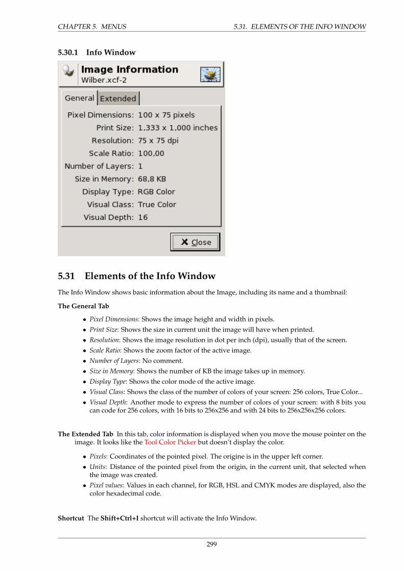
CHAPTER 5. MENUS 5.31. ELEMENTS OF THE INFO WINDOW
5.30.1 Info Window
5.31 Elements of the Info Window
The Info Window shows basic information about the Image, including its name and a thumbnail:
The General Tab
• Pixel Dimensions: Shows the image height and width in pixels.
• Print Size: Shows the size in current unit the image will have when printed.
• Resolution: Shows the image resolution in dot per inch (dpi), usually that of the screen.
• Scale Ratio: Shows the zoom factor of the active image.
• Number of Layers: No comment.
• Size in Memory: Shows the number of KB the image takes up in memory.
• Display Type: Shows the color mode of the active image.
• Visual Class: Shows the class of the number of colors of your screen: 256 colors, True Color...
• Visual Depth: Another mode to express the number of colors of your screen: with 8 bits youcan code for 256 colors, with 16 bits to 256x256 and with 24 bits to 256x256x256 colors.
The Extended Tab In this tab, color information is displayed when you move the mouse pointer on theimage. It looks like the Tool Color Picker but doesn’t display the color.
• Pixels: Coordinates of the pointed pixel. The origine is in the upper left corner.
• Units: Distance of the pointed pixel from the origin, in the current unit, that selected whenthe image was created.
• Pixel values: Values in each channel, for RGB, HSL and CMYK modes are displayed, also thecolor hexadecimal code.
Shortcut The Shift+Ctrl+I shortcut will activate the Info Window.
299
5.32. SHORTCUT CHAPTER 5. MENUS
5.31.1 Navigation Window
This command can be found at View → Navigation Window .This menu open the navigation window. Here you can zoom or move the image in its window.
Using it is described at the Navigation dialog chapter.
5.32 Shortcut
The Shift+Ctrl+N shortcut will activate the Navigation Window.
5.32.1 Show Selection
This command can be found at View → Show Selection .This option toggles the visual dotted line that denotes a selection within the image window. The
selection still exists even if this option is toggled. It is useful if you feel disturbed by this line at amoment.
5.33 Shortcut
The Ctrl+T shortcut will activate the Show Selection command.
5.33.1 Show Layer Boundary
This command can be found at View → Show Layer Boundary .This option toggles the yellow visual dotted line that denotes a layer within the image window. It
is merged with the image border when the layer has the same size as the image window. This line isusually not visible.
5.33.2 Show Guides
This command can be found at View → Show Guides .This option toggles the visibility of Guides within the image window.
5.34 Shortcut
The Shift+Ctrl+T shortcut will activate the Show Guides command.
5.34.1 Snap to Guides
This command can be found at View → Snap to Guides .This option in a way magnetizes the guides you have set (see Show Guides). When you move a layer
or a selection, they will get automatically onto the guides when they are near them. This allow to placethem accurately.
5.34.2 Show Grid
This command can be found at View → Show Grid .This option toggles the visibility of a grid superimposed to the image. It allows to line up different
selected elements of a layer.
5.35 Additional information
See also Configure Grid and Snap to Grid
300
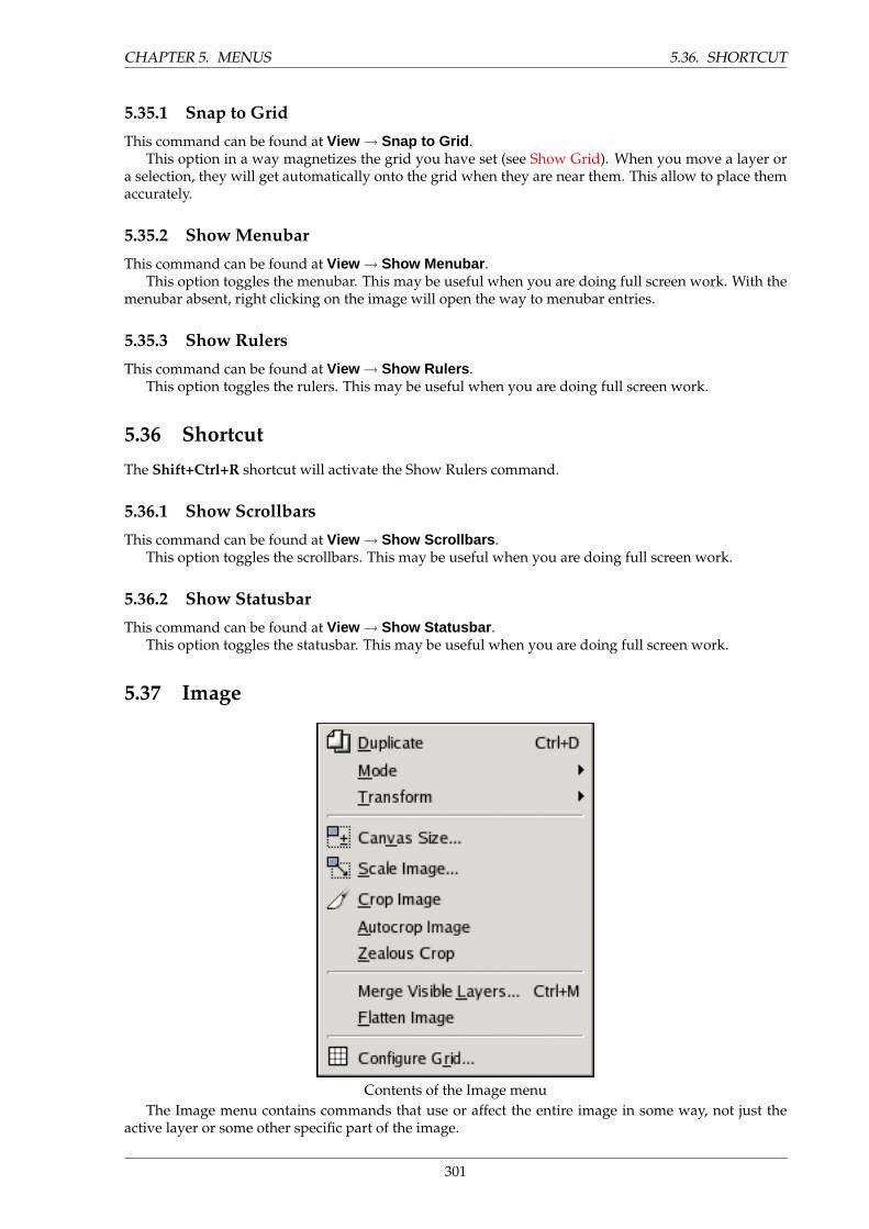
CHAPTER 5. MENUS 5.36. SHORTCUT
5.35.1 Snap to Grid
This command can be found at View → Snap to Grid .This option in a way magnetizes the grid you have set (see Show Grid). When you move a layer or
a selection, they will get automatically onto the grid when they are near them. This allow to place themaccurately.
5.35.2 Show Menubar
This command can be found at View → Show Menubar .This option toggles the menubar. This may be useful when you are doing full screen work. With the
menubar absent, right clicking on the image will open the way to menubar entries.
5.35.3 Show Rulers
This command can be found at View → Show Rulers .This option toggles the rulers. This may be useful when you are doing full screen work.
5.36 Shortcut
The Shift+Ctrl+R shortcut will activate the Show Rulers command.
5.36.1 Show Scrollbars
This command can be found at View → Show Scrollbars .This option toggles the scrollbars. This may be useful when you are doing full screen work.
5.36.2 Show Statusbar
This command can be found at View → Show Statusbar .This option toggles the statusbar. This may be useful when you are doing full screen work.
5.37 Image
Contents of the Image menuThe Image menu contains commands that use or affect the entire image in some way, not just the
active layer or some other specific part of the image.
301
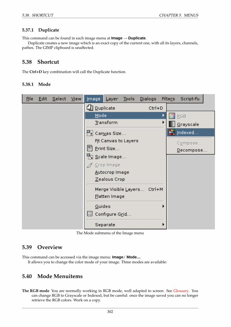
5.38. SHORTCUT CHAPTER 5. MENUS
5.37.1 Duplicate
This command can be found in each image menu at Image → Duplicate .Duplicate creates a new image which is an exact copy of the current one, with all its layers, channels,
pathes. The GIMP clipboard is unaffected.
5.38 Shortcut
The Ctrl+D key combination will call the Duplicate function.
5.38.1 Mode
The Mode submenu of the Image menu
5.39 Overview
This command can be accessed via the image menu: Image/ Mode... .It allows you to change the color mode of your image. Three modes are available:
5.40 Mode Menuitems
The RGB mode You are normally working in RGB mode, well adapted to screen. See Glossary. Youcan change RGB to Grayscale or Indexed, but be careful: once the image saved you can no longerretrieve the RGB colors. Work on a copy.
302
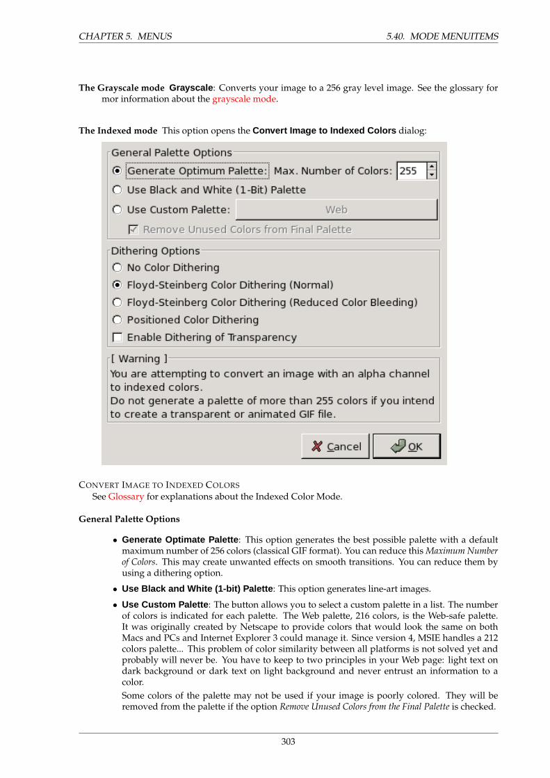
CHAPTER 5. MENUS 5.40. MODE MENUITEMS
The Grayscale mode Grayscale : Converts your image to a 256 gray level image. See the glossary formor information about the grayscale mode.
The Indexed mode This option opens the Convert Image to Indexed Colors dialog:
CONVERT IMAGE TO INDEXED COLORS
See Glossary for explanations about the Indexed Color Mode.
General Palette Options
• Generate Optimate Palette : This option generates the best possible palette with a defaultmaximum number of 256 colors (classical GIF format). You can reduce this Maximum Numberof Colors. This may create unwanted effects on smooth transitions. You can reduce them byusing a dithering option.
• Use Black and White (1-bit) Palette : This option generates line-art images.
• Use Custom Palette : The button allows you to select a custom palette in a list. The numberof colors is indicated for each palette. The Web palette, 216 colors, is the Web-safe palette.It was originally created by Netscape to provide colors that would look the same on bothMacs and PCs and Internet Explorer 3 could manage it. Since version 4, MSIE handles a 212colors palette... This problem of color similarity between all platforms is not solved yet andprobably will never be. You have to keep to two principles in your Web page: light text ondark background or dark text on light background and never entrust an information to acolor.Some colors of the palette may not be used if your image is poorly colored. They will beremoved from the palette if the option Remove Unused Colors from the Final Palette is checked.
303
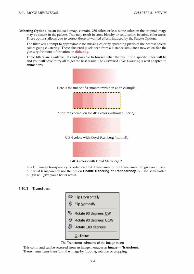
5.40. MODE MENUITEMS CHAPTER 5. MENUS
Dithering Options As an indexed image contains 256 colors or less, some colors in the original imagemay be absent in the palette. This may result in some blotchy or solid colors in subtle color areas.These options allows you to correct these unwanted effects induced by the Palette Options.
The filter will attempt to approximate the missing color by spreading pixels of the nearest palettecolors going clustering. These clustered pixels seen from a distance simulate a new color. See theglossary for more information on dithering.
Three filters are available. It’s not possible to foresee what the result of a specific filter will beand you will have to try all to get the best result. The Positioned Color Dithering is well adapted toanimations.
Here is the image of a smooth transition as an example.
After transformation to GIF 4 colors without dithering.
GIF 4 colors with Floyd-Sternberg (normal).
GIF 4 colors with Floyd-Sternberg-2.
In a GIF image transparency is coded on 1 bit: transparent or not transparent. To give an illusionof partial transparency use the option Enable Dithering of Transparency , but the semi-flattenplugin will give you a better result.
5.40.1 Transform
The Transform submenu of the Image menuThis command can be accessed from an image menubar as Image → Transform .These menu items transform the image by flipping, rotation or cropping.
304
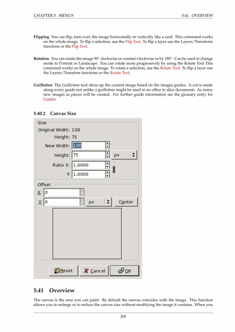
CHAPTER 5. MENUS 5.41. OVERVIEW
Flipping You can flip, turn over, the image horizontally or vertically like a card. This command workson the whole image. To flip a selection, use the Flip Tool. To flip a layer use the Layers/Transformfunctions or the Flip Tool.
Rotation You can rotate the image 90◦ clockwise or counter-clockwise or by 180◦. Can be used to changemode to Portrait or Landscape. You can rotate more progressively by using the Rotate Tool Thiscommand works on the whole image. To rotate a selection, use the Rotate Tool. To flip a layer usethe Layers/Transfom functions or the Rotate Tool.
Guillotine The Guillotine tool slices up the current image based on the images guides. A cut is madealong every guide not unlike a guillotine might be used in an office to slice documents. As manynew images as pieces will be created. For further guide information see the glossary entry forGuides
5.40.2 Canvas Size
5.41 Overview
The canvas is the area you can paint. By default the canvas coincides with the image. This functionallows you to enlarge or to reduce the canvas size without modifying the image it contains. When you
305
5.42. SIZE CHAPTER 5. MENUS
enlarge it you create a border around the image. When you reduce it you crop the image.
5.42 Size
You can set the Width and the Heigth you want give to the canvas. Default unit is pixel but you canchoose another one.
Ratio is the ratio between the original dimension and the new dimension, for each X and Y axis.Default is 1. You can change it. If the adjacent Chain is intact both axis will develop jointly. If you breakit by clicking on it, then you can set every axis separately.
5.43 Offset
Offset is used to place the image on canvas. The preview displays the image as a frame with a grayborder and the canvas, when it it different from the image, as a frame with a thin black border.
X and Y parameters are the coordinates of the upper left corner of the image against the same cornerof the canvas. They are negative when canvas is smaller than image. You can change them thanks to thetext boxes. Default unit is pixel but you can choose another one. When the mouse pointer is in a boxyou can use the Up and Down arrow keys to change pixel value one by one. When Shift is pressed inchange is ten by ten.
The Center button allows you to place the image center onto the canvas center.
NOTE
When you click on the OK button the new image version takes the size of canvas,but the drawing scale is unchanged.
The added part of canvas is transparent with a checker look and is not immedi-ately available for painting. You have to flatten it. You can also create a new layerand fill it with the background you want. You create so a digital passe-partout(a passe-partout is a kind of glass mount whose bottom can opened so that youcan slip a photo into it).
306
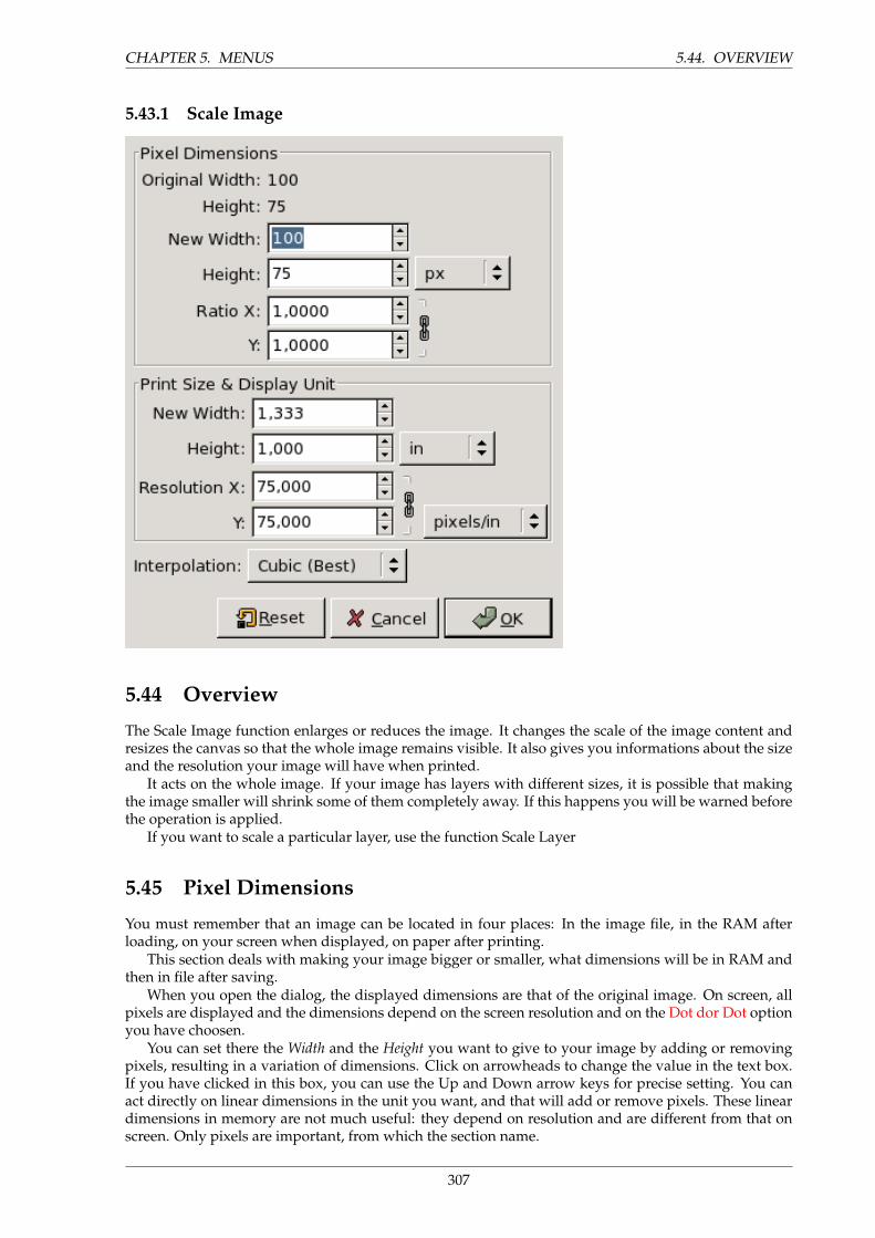
CHAPTER 5. MENUS 5.44. OVERVIEW
5.43.1 Scale Image
5.44 Overview
The Scale Image function enlarges or reduces the image. It changes the scale of the image content andresizes the canvas so that the whole image remains visible. It also gives you informations about the sizeand the resolution your image will have when printed.
It acts on the whole image. If your image has layers with different sizes, it is possible that makingthe image smaller will shrink some of them completely away. If this happens you will be warned beforethe operation is applied.
If you want to scale a particular layer, use the function Scale Layer
5.45 Pixel Dimensions
You must remember that an image can be located in four places: In the image file, in the RAM afterloading, on your screen when displayed, on paper after printing.
This section deals with making your image bigger or smaller, what dimensions will be in RAM andthen in file after saving.
When you open the dialog, the displayed dimensions are that of the original image. On screen, allpixels are displayed and the dimensions depend on the screen resolution and on the Dot dor Dot optionyou have choosen.
You can set there the Width and the Height you want to give to your image by adding or removingpixels, resulting in a variation of dimensions. Click on arrowheads to change the value in the text box.If you have clicked in this box, you can use the Up and Down arrow keys for precise setting. You canact directly on linear dimensions in the unit you want, and that will add or remove pixels. These lineardimensions in memory are not much useful: they depend on resolution and are different from that onscreen. Only pixels are important, from which the section name.
307
5.46. PRINT SIZE & DISPLAY UNIT CHAPTER 5. MENUS
Ratio is the ratio between the original dimension and the new dimension, for each X and Y axis.Default is 1. You can change it. If the adjacent Chain is intact both axis will develop jointly. If you breakit by clicking on it, then you can set every axis separately: this will result in deforming the image.
You can enlarge an image safely only if the original has a high resolution, pixels enough to avoidadding new pixels. Else, missing pixels are calculated by interpolation but no new detail is addedand the more enlarged the more blurred, with aliasing. You can improve the result by using the filterSharpen (after scaling) but the best method is to use a high resolution when scanning an image you planto enlarge.
Reducing your image may be necessary if you intend it to a Web page. You have to take in accountthat Internet users still have 15’ screens and that your big image cann’t be completely displayed on them.Most of screens work in 800x600 and 1024x768 resolution.
Adding or removing pixels is called ”Resampling”.
5.46 Print Size & Display Unit
This section deals with the size and resolution your image will have when printed. Remember that allthe pixels of the image will be printed and that there will be no splitting.
When you launch the Scale function GIMP displays the dimensions of the original image that willallow printing without deformation.
As for screen, you can enlarge or reduce the printed image with the same risks.Resolution deals with ouput resolution, that is the number of pixels that will be used in every inch
of the printed image. You must not mistake the output resolution with the printer resolution which isexpressed in dpi (dot per inch): several dots are necessary to print a pixel.
The resolution proposed by GIMP is the resolution of the original image. If you increase the outputresolution the printed image will be smaller since more pixels are used for an inch. Conversely and forthe same reason resizing modifies resolution.
Increasing resolution results in increasing the printed image sharpness. This is quite different fromsimply reducing the image size since no pixels are removed.
Modifying resolution also acts for the image file. It is not visible at the pixel level but it is at thedimension level (inch for example). By reducing resolution you decrease the dimensions in the imagefile. By combining resolution reduction and pixel reduction and by restablishing the original dimensionsof your image you can reduce the weight of your image file if PNG compression is not enough.
5.47 Interpolation Type
Here you can select the method used to interpolate the color of added pixels, valid for screen displayand printing.
• None: no interpolation is used. Pixels are simply enlarged as they are when zooming.
• Linear:
• Cubic: The best method but needing much calculation.
NOTE
To prepare your image for printing in a particular format use the Crop tool, withinch for unit: The displayed size is the printing size.
308
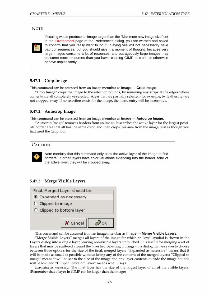
CHAPTER 5. MENUS 5.47. INTERPOLATION TYPE
NOTE
If scaling would produce an image larger than the ”Maximum new image size” setin the Environment page of the Preferences dialog, you are warned and askedto confirm that you really want to do it. Saying yes will not necessarily havebad consequences, but you should give it a moment of thought, because verylarge images consume a lot of resources, and outrageously large images mayconsume more resources than you have, causing GIMP to crash or otherwisebehave unpleasantly.
5.47.1 Crop Image
This command can be accessed from an image menubar as Image → Crop Image .”Crop Image” crops the image to the selection bounds, by removing any strips at the edges whose
contents are all completely unselected. Areas that are partially selected (for example, by feathering) arenot cropped away. If no selection exists for the image, the menu entry will be insensitive.
5.47.2 Autocrop Image
This command can be accessed from an image menubar as Image → Autocrop Image .”Autocrop Image” removes borders from an image. It searches the active layer for the largest possi-
ble border area that all has the same color, and then crops this area from the image, just as though youhad used the Crop tool.
CAUTION
Note carefully that this command only uses the active layer of the image to findborders. If other layers have color variations extending into the border zone ofthe active layer, they will be cropped away.
5.47.3 Merge Visible Layers
This command can be accessed from an image menubar as Image → Merge Visible Layers .”Merge Visible Layers” merges all layers of the image for which an ”eye” symbol is shown in the
Layers dialog into a single layer, leaving non-visible layers untouched. It is useful for merging a set oflayers that may be scattered around the layer list. Selecting it brings up a dialog that asks you to choosebetween three options for the size of the final, merged layer: ”Expanded as necessary” means that itwill be made as small as possible without losing any of the contents of the merged layers; ”Clipped toimage” means it will be set to the size of the image and any layer contents outside the image boundswill be lost; and ”Clipped to bottom layer” means what it says.
Expanded as necessary: The final layer has the size of the largest layer of all of the visible layers.(Remember that a layer in GIMP can be larger than the image)
309
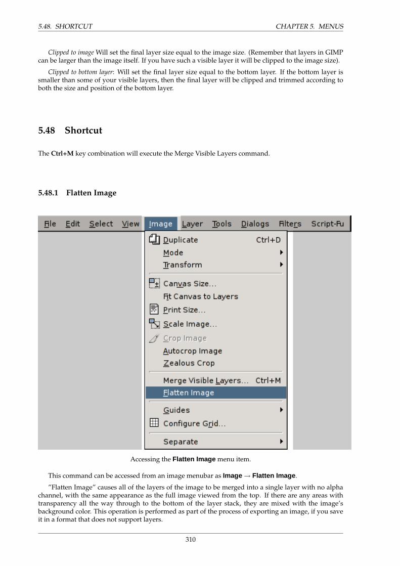
5.48. SHORTCUT CHAPTER 5. MENUS
Clipped to image Will set the final layer size equal to the image size. (Remember that layers in GIMPcan be larger than the image itself. If you have such a visible layer it will be clipped to the image size).
Clipped to bottom layer: Will set the final layer size equal to the bottom layer. If the bottom layer issmaller than some of your visible layers, then the final layer will be clipped and trimmed according toboth the size and position of the bottom layer.
5.48 Shortcut
The Ctrl+M key combination will execute the Merge Visible Layers command.
5.48.1 Flatten Image
Accessing the Flatten Image menu item.
This command can be accessed from an image menubar as Image → Flatten Image .
”Flatten Image” causes all of the layers of the image to be merged into a single layer with no alphachannel, with the same appearance as the full image viewed from the top. If there are any areas withtransparency all the way through to the bottom of the layer stack, they are mixed with the image’sbackground color. This operation is performed as part of the process of exporting an image, if you saveit in a format that does not support layers.
310

CHAPTER 5. MENUS 5.48. SHORTCUT
5.48.2 Configure Grid
OPTIONS
Overview Allows you to set grid parameters. See Show Grid.
Only a few explanations are necessary for this self-explanatory function:
Foreground Color is the color of the grid ”bars”. Background Color is also applied to the grid bars,but is visible only in double dashed line style.
Offset: This setting adjusts the starting point for the horizontal and vertical grid lines.
311

5.49. LAYERS CHAPTER 5. MENUS
5.49 Layers
5.49.1 Main Menu
In addition to the image menubar and image right-click menu, you can also get the Layers menu byright-clicking on a layer thumbnail in the Layers dialog. Several of the operations in this menu are alsoavailable from buttons in the Layers dialog: resizing a layer, managing layer transparency, and merginglayers.
312
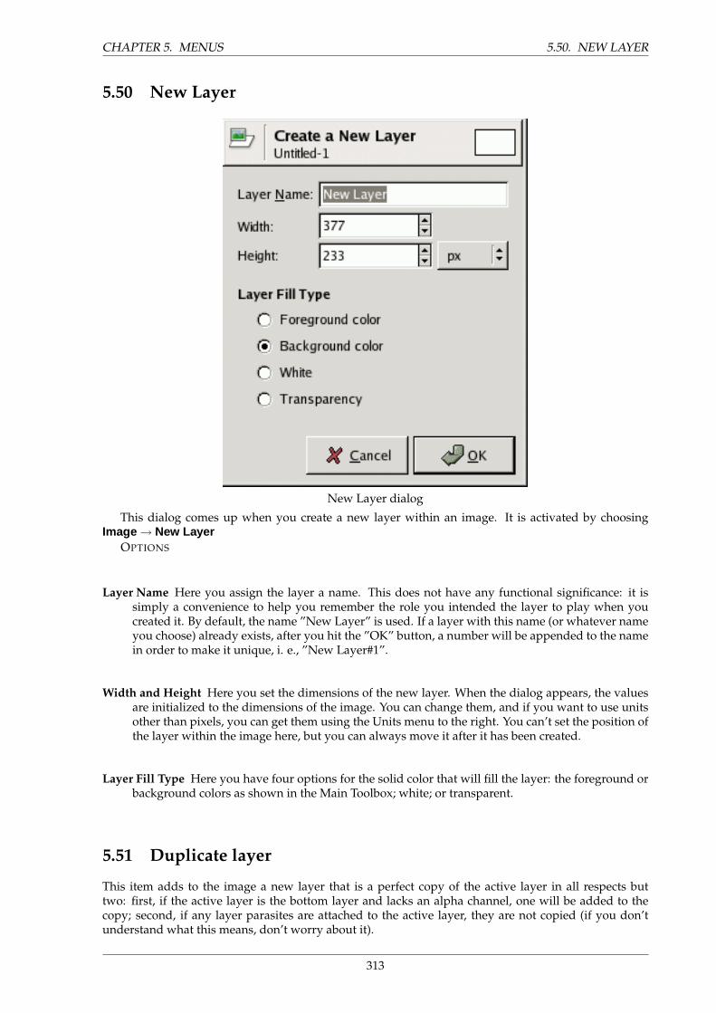
CHAPTER 5. MENUS 5.50. NEW LAYER
5.50 New Layer
New Layer dialog
This dialog comes up when you create a new layer within an image. It is activated by choosingImage → New Layer
OPTIONS
Layer Name Here you assign the layer a name. This does not have any functional significance: it issimply a convenience to help you remember the role you intended the layer to play when youcreated it. By default, the name ”New Layer” is used. If a layer with this name (or whatever nameyou choose) already exists, after you hit the ”OK” button, a number will be appended to the namein order to make it unique, i. e., ”New Layer#1”.
Width and Height Here you set the dimensions of the new layer. When the dialog appears, the valuesare initialized to the dimensions of the image. You can change them, and if you want to use unitsother than pixels, you can get them using the Units menu to the right. You can’t set the position ofthe layer within the image here, but you can always move it after it has been created.
Layer Fill Type Here you have four options for the solid color that will fill the layer: the foreground orbackground colors as shown in the Main Toolbox; white; or transparent.
5.51 Duplicate layer
This item adds to the image a new layer that is a perfect copy of the active layer in all respects buttwo: first, if the active layer is the bottom layer and lacks an alpha channel, one will be added to thecopy; second, if any layer parasites are attached to the active layer, they are not copied (if you don’tunderstand what this means, don’t worry about it).
313
5.52. ANCHOR LAYER CHAPTER 5. MENUS
5.52 Anchor layer
This item anchors the floating selection to the active layer. If the image does not contain a floatingselection, this menu entry will be insensitive.
5.53 Merge down
This item causes the active layer to be merged with the layer below it in the layer list, taking into accountthe active layer’s opacity and combination mode.
5.54 Delete layer
This item removes the active layer from the image.
5.55 Edit Layer Attributes
This item is used to change the name of the layer.
5.56 Layer Boundary Size
A layer does not always have same size as the image canvas. It can be smaller (consuming less memory)or larger, in which case some parts are hidden. Selecting this item will activate a dialog in which youcan set parameters for the layer dimensions: these parameters are Width and Height , or alternativelyRatio X Y . The layer ratio is maintained if the chain symbol has a ”locked” appearance. Clicking on thechain symbol will toggle it between locked and unlocked states. You can use a menu to select the unitsfor the new layer boundary size. Offset locates the upper left corner of the layer in the image’s canvas.In addition to editing the numbers, you can change the X and Y offsets by dragging the mouse in theinteractive image in the dialog. The old layer configuration is shown with a blurred border and the newlayer configuration with a hard border.
5.57 Layer to Image Size
This item resizes the layer boundaries to match the image bounds, without moving the contents of thelayer with respect to the image.
5.58 Scale Layer
With this item you can resize the layer and its contents. A dialog appears in which you can set param-eters for the layer size. Those parameters are Width and Height or also Ratio X Y . The layer ratio isretained if the icon behind the ratio values is a chain. When you click on this icon, the chain is brokenand the original ratio is no longer maintained. You can use a menu to select the units for the new layerboundary size. The Interpolation menu let you choose how the new layer pixels will be recalculated.When you resize the layer content either pixels are added or removed, and a recalculation is necessary.When the new size is smaller, the layer is cropped. When the new size is larger, a transparent area (orthe background color if the layer has no Alpha channel) is added around the previous contents of thelayer.
314
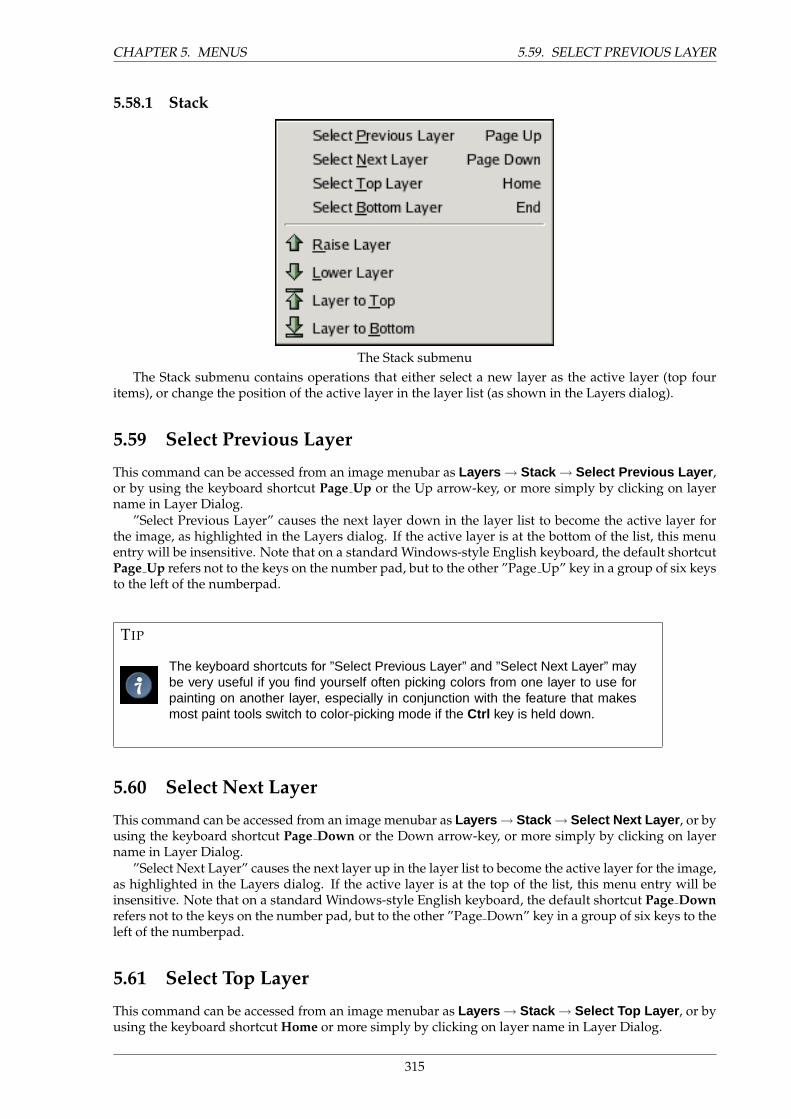
CHAPTER 5. MENUS 5.59. SELECT PREVIOUS LAYER
5.58.1 Stack
The Stack submenuThe Stack submenu contains operations that either select a new layer as the active layer (top four
items), or change the position of the active layer in the layer list (as shown in the Layers dialog).
5.59 Select Previous Layer
This command can be accessed from an image menubar as Layers → Stack → Select Previous Layer ,or by using the keyboard shortcut Page Up or the Up arrow-key, or more simply by clicking on layername in Layer Dialog.
”Select Previous Layer” causes the next layer down in the layer list to become the active layer forthe image, as highlighted in the Layers dialog. If the active layer is at the bottom of the list, this menuentry will be insensitive. Note that on a standard Windows-style English keyboard, the default shortcutPage Up refers not to the keys on the number pad, but to the other ”Page Up” key in a group of six keysto the left of the numberpad.
TIP
The keyboard shortcuts for ”Select Previous Layer” and ”Select Next Layer” maybe very useful if you find yourself often picking colors from one layer to use forpainting on another layer, especially in conjunction with the feature that makesmost paint tools switch to color-picking mode if the Ctrl key is held down.
5.60 Select Next Layer
This command can be accessed from an image menubar as Layers → Stack → Select Next Layer , or byusing the keyboard shortcut Page Down or the Down arrow-key, or more simply by clicking on layername in Layer Dialog.
”Select Next Layer” causes the next layer up in the layer list to become the active layer for the image,as highlighted in the Layers dialog. If the active layer is at the top of the list, this menu entry will beinsensitive. Note that on a standard Windows-style English keyboard, the default shortcut Page Downrefers not to the keys on the number pad, but to the other ”Page Down” key in a group of six keys to theleft of the numberpad.
5.61 Select Top Layer
This command can be accessed from an image menubar as Layers → Stack → Select Top Layer , or byusing the keyboard shortcut Home or more simply by clicking on layer name in Layer Dialog.
315
5.62. SELECT BOTTOM LAYER CHAPTER 5. MENUS
”Select Top Layer” causes the top layer in the layer list to become the active layer for the image,as highlighted in the Layers dialog. If the active layer is at the top of the list, this menu entry will beinsensitive. Note that on a standard Windows-style English keyboard, the default shortcut Home refersnot to the keys on the number pad, but to the other ”Home” key in a group of six keys to the left of thenumberpad.
5.62 Select Bottom Layer
This command can be accessed from an image menubar as Layers → Stack → Select Bottom Layer ,or by using the keyboard shortcut End or more simply by clicking on layer name in Layer Dialog.
”Select Bottom Layer” causes the bottom layer in the layer list to become the active layer for theimage, as highlighted in the Layers dialog. If the active layer is at the bottom of the list, this menu entrywill be insensitive. Note that on a standard Windows-style English keyboard, the default shortcut Endrefers not to the keys on the number pad, but to the other ”End” key in a group of six keys to the left ofthe numberpad.
5.63 Raise Layer
This command can be accessed from an image menubar as Layers → Stack → Raise Layer or by usingthe keyboard shortcut Shift–Page Up
”Raise layer” raises the active layer one level higher in the layer list. If it is already at the top, orthere is only one layer, the menu entry will be insensitive. If the active layer is at the bottom and lacksan alpha channel, it cannot be raised until an alpha channel is added to it.
5.64 Lower layer
This command can be accessed from an image menubar as Layers → Stack → Lower Layer or by usingthe keyboard shortcut Shift–Page Down.
This item lowers the active layer one level in the layer list. If it is already at the bottom, or there isonly one layer, the menu entry will be insensitive.
5.65 Raise Layer to top
This command can be accessed from an image menubar as Layers → Stack → Raise to Top or by usingthe keyboard shortcut Shift–Home.
This item raises the active layer to the top of the layer list. If it is already at the top, or there is onlyone layer, the menu entry will be insensitive. If the active layer is at the bottom and lacks an alphachannel, it cannot be raised until an alpha channel is added to it.
5.66 Layer to bottom
This command can be accessed from an image menubar as Layers → Stack → Layer to Bottom or byusing the keyboard shortcut Shift–End.
This item lowers the active layer to the bottom of the layer list. If it is already at the bottom, or thereis only one layer, the menu entry will be insensitive.
316
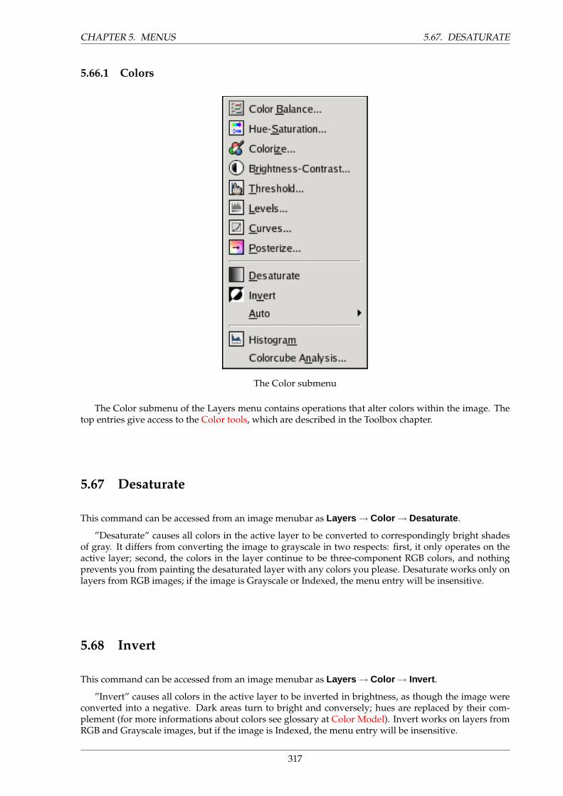
CHAPTER 5. MENUS 5.67. DESATURATE
5.66.1 Colors
The Color submenu
The Color submenu of the Layers menu contains operations that alter colors within the image. Thetop entries give access to the Color tools, which are described in the Toolbox chapter.
5.67 Desaturate
This command can be accessed from an image menubar as Layers → Color → Desaturate .
”Desaturate” causes all colors in the active layer to be converted to correspondingly bright shadesof gray. It differs from converting the image to grayscale in two respects: first, it only operates on theactive layer; second, the colors in the layer continue to be three-component RGB colors, and nothingprevents you from painting the desaturated layer with any colors you please. Desaturate works only onlayers from RGB images; if the image is Grayscale or Indexed, the menu entry will be insensitive.
5.68 Invert
This command can be accessed from an image menubar as Layers → Color → Invert .
”Invert” causes all colors in the active layer to be inverted in brightness, as though the image wereconverted into a negative. Dark areas turn to bright and conversely; hues are replaced by their com-plement (for more informations about colors see glossary at Color Model). Invert works on layers fromRGB and Grayscale images, but if the image is Indexed, the menu entry will be insensitive.
317
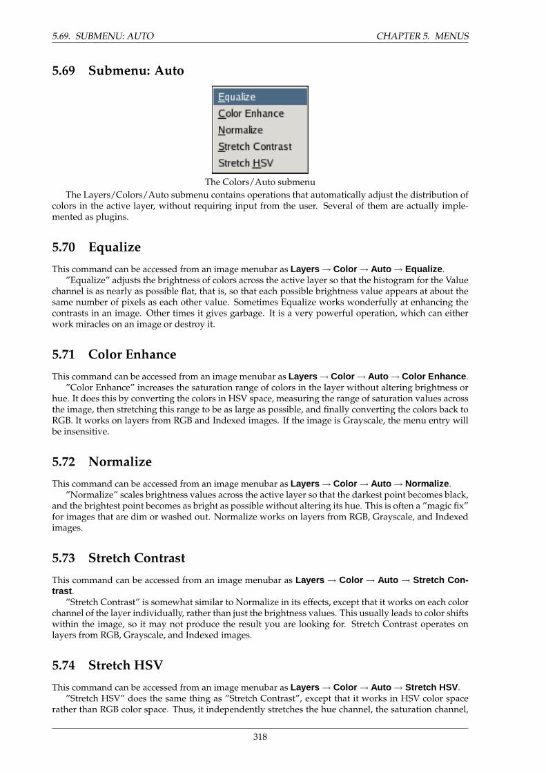
5.69. SUBMENU: AUTO CHAPTER 5. MENUS
5.69 Submenu: Auto
The Colors/Auto submenuThe Layers/Colors/Auto submenu contains operations that automatically adjust the distribution of
colors in the active layer, without requiring input from the user. Several of them are actually imple-mented as plugins.
5.70 Equalize
This command can be accessed from an image menubar as Layers → Color → Auto → Equalize .”Equalize” adjusts the brightness of colors across the active layer so that the histogram for the Value
channel is as nearly as possible flat, that is, so that each possible brightness value appears at about thesame number of pixels as each other value. Sometimes Equalize works wonderfully at enhancing thecontrasts in an image. Other times it gives garbage. It is a very powerful operation, which can eitherwork miracles on an image or destroy it.
5.71 Color Enhance
This command can be accessed from an image menubar as Layers → Color → Auto → Color Enhance .”Color Enhance” increases the saturation range of colors in the layer without altering brightness or
hue. It does this by converting the colors in HSV space, measuring the range of saturation values acrossthe image, then stretching this range to be as large as possible, and finally converting the colors back toRGB. It works on layers from RGB and Indexed images. If the image is Grayscale, the menu entry willbe insensitive.
5.72 Normalize
This command can be accessed from an image menubar as Layers → Color → Auto → Normalize .”Normalize” scales brightness values across the active layer so that the darkest point becomes black,
and the brightest point becomes as bright as possible without altering its hue. This is often a ”magic fix”for images that are dim or washed out. Normalize works on layers from RGB, Grayscale, and Indexedimages.
5.73 Stretch Contrast
This command can be accessed from an image menubar as Layers → Color → Auto → Stretch Con-trast .
”Stretch Contrast” is somewhat similar to Normalize in its effects, except that it works on each colorchannel of the layer individually, rather than just the brightness values. This usually leads to color shiftswithin the image, so it may not produce the result you are looking for. Stretch Contrast operates onlayers from RGB, Grayscale, and Indexed images.
5.74 Stretch HSV
This command can be accessed from an image menubar as Layers → Color → Auto → Stretch HSV .”Stretch HSV” does the same thing as ”Stretch Contrast”, except that it works in HSV color space
rather than RGB color space. Thus, it independently stretches the hue channel, the saturation channel,
318
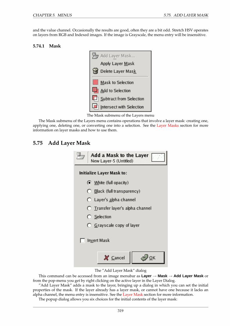
CHAPTER 5. MENUS 5.75. ADD LAYER MASK
and the value channel. Occasionally the results are good, often they are a bit odd. Stretch HSV operateson layers from RGB and Indexed images. If the image is Grayscale, the menu entry will be insensitive.
5.74.1 Mask
The Mask submenu of the Layers menuThe Mask submenu of the Layers menu contains operations that involve a layer mask: creating one,
applying one, deleting one, or converting one into a selection. See the Layer Masks section for moreinformation on layer masks and how to use them.
5.75 Add Layer Mask
The ”Add Layer Mask” dialogThis command can be accessed from an image menubar as Layer → Mask → Add Layer Mask or
from the pop-menu you get by right clicking on the active layer in the Layer Dialog.”Add Layer Mask” adds a mask to the layer, bringing up a dialog in which you can set the initial
properties of the mask. If the layer already has a layer mask, or cannot have one because it lacks analpha channel, the menu entry is insensitive. See the Layer Mask section for more information.
The popup dialog allows you six choices for the initial contents of the layer mask:
319
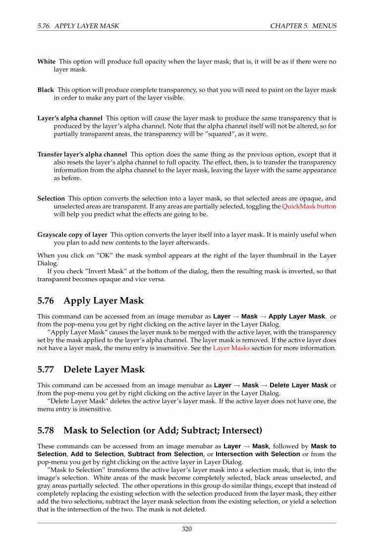
5.76. APPLY LAYER MASK CHAPTER 5. MENUS
White This option will produce full opacity when the layer mask; that is, it will be as if there were nolayer mask.
Black This option will produce complete transparency, so that you will need to paint on the layer maskin order to make any part of the layer visible.
Layer’s alpha channel This option will cause the layer mask to produce the same transparency that isproduced by the layer’s alpha channel. Note that the alpha channel itself will not be altered, so forpartially transparent areas, the transparency will be ”squared”, as it were.
Transfer layer’s alpha channel This option does the same thing as the previous option, except that italso resets the layer’s alpha channel to full opacity. The effect, then, is to transfer the transparencyinformation from the alpha channel to the layer mask, leaving the layer with the same appearanceas before.
Selection This option converts the selection into a layer mask, so that selected areas are opaque, andunselected areas are transparent. If any areas are partially selected, toggling the QuickMask buttonwill help you predict what the effects are going to be.
Grayscale copy of layer This option converts the layer itself into a layer mask. It is mainly useful whenyou plan to add new contents to the layer afterwards.
When you click on ”OK” the mask symbol appears at the right of the layer thumbnail in the LayerDialog.
If you check ”Invert Mask” at the bottom of the dialog, then the resulting mask is inverted, so thattransparent becomes opaque and vice versa.
5.76 Apply Layer Mask
This command can be accessed from an image menubar as Layer → Mask → Apply Layer Mask . orfrom the pop-menu you get by right clicking on the active layer in the Layer Dialog.
”Apply Layer Mask” causes the layer mask to be merged with the active layer, with the transparencyset by the mask applied to the layer’s alpha channel. The layer mask is removed. If the active layer doesnot have a layer mask, the menu entry is insensitive. See the Layer Masks section for more information.
5.77 Delete Layer Mask
This command can be accessed from an image menubar as Layer → Mask → Delete Layer Mask orfrom the pop-menu you get by right clicking on the active layer in the Layer Dialog.
”Delete Layer Mask” deletes the active layer’s layer mask. If the active layer does not have one, themenu entry is insensitive.
5.78 Mask to Selection (or Add; Subtract; Intersect)
These commands can be accessed from an image menubar as Layer → Mask , followed by Mask toSelection , Add to Selection , Subtract from Selection , or Intersection with Selection or from thepop-menu you get by right clicking on the active layer in Layer Dialog.
”Mask to Selection” transforms the active layer’s layer mask into a selection mask, that is, into theimage’s selection. White areas of the mask become completely selected, black areas unselected, andgray areas partially selected. The other operations in this group do similar things, except that instead ofcompletely replacing the existing selection with the selection produced from the layer mask, they eitheradd the two selections, subtract the layer mask selection from the existing selection, or yield a selectionthat is the intersection of the two. The mask is not deleted.
320
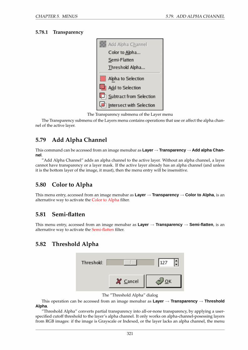
CHAPTER 5. MENUS 5.79. ADD ALPHA CHANNEL
5.78.1 Transparency
The Transparency submenu of the Layer menuThe Transparency submenu of the Layers menu contains operations that use or affect the alpha chan-
nel of the active layer.
5.79 Add Alpha Channel
This command can be accessed from an image menubar as Layer → Transparency → Add alpha Chan-nel .
”Add Alpha Channel” adds an alpha channel to the active layer. Without an alpha channel, a layercannot have transparency or a layer mask. If the active layer already has an alpha channel (and unlessit is the bottom layer of the image, it must), then the menu entry will be insensitive.
5.80 Color to Alpha
This menu entry, accessed from an image menubar as Layer → Transparency → Color to Alpha , is analternative way to activate the Color to Alpha filter.
5.81 Semi-flatten
This menu entry, accessed from an image menubar as Layer → Transparency → Semi-flatten , is analternative way to activate the Semi-flatten filter.
5.82 Threshold Alpha
The ”Threshold Alpha” dialogThis operation can be accessed from an image menubar as Layer → Transparency → Threshold
Alpha .”Threshold Alpha” converts partial transparency into all-or-none transparency, by applying a user-
specified cutoff threshold to the layer’s alpha channel. It only works on alpha-channel-posessing layersfrom RGB images: if the image is Grayscale or Indexed, or the layer lacks an alpha channel, the menu
321

5.83. ALPHA TO SELECTION [OR ADD, SUBTRACT, INTERSECT] CHAPTER 5. MENUS
entry will be insensitive. If ”Keep transparency” has been toggled on in the Layers dialog, the commandwill show an error message and refuse to operate.
5.83 Alpha to Selection [or Add, Subtract, Intersect]
These commands can be accessed from an image menubar as Layer → Transparency , followed byAlpha to Selection , Add to Selection , Subtract from Selection , or Intersection with Selection .
”Alpha to Selection” transforms the active layer’s alpha channel (which encodes transparency) intothe image’s selection. Opaque areas become fully selected, transparent areas unselected, and translucentareas partially selected. The other operations in this group do similar things, except that instead ofcompletely replacing the existing selection with the selection produced from the alpha channel, theyeither add the two selections, subtract the alpha-selection from the existing selection, or create a selectionthat is the intersection of the two.
5.83.1 Transform
The Transform submenu of the Layer menuThe Transform submenu of the Layers menu contains operations that flip or rotate the active layer of
the image.
5.84 Flip Horizontally [or Vertically]
These commands can be accessed from an image menubar as Layer → Transform , followed by FlipHorizontally or Flip Vertically
”Flip Horizontally” reverses the layer left-to-right, and ”Flip Vertically” reverses it top-to-bottom.Both commands leave the layer dimensions unchanged; neither causes any degradation of pixel data inthe layer.
5.85 Rotate 90 degrees CW [or CCW, or 180 degrees]
These commands can be accessed from an image menubar as Layer → Transform , followed by Rotate90 degrees CW , Rotate 90 degrees CCW , or Rotate 180 degrees .
Each of them rotates the layer in the specified way, with no degradation of pixel data. The shape ofthe layer is not altered: note that this may cause it to extend beyond the bounds of the image. (In GIMPthis is permitted, and does not force the layer to be cropped. You will not, however, be able to see theparts that extend outside the image unless you resize the image canvas or move the layer.) The centerof the layer will be located at the same place after rotation as it was before rotation.
5.86 Arbitrary Rotation
This command, accessed from an image menubar as Layer → Transform → Arbitrary Rotation , it is analternative way of activating the Rotate tool.
322
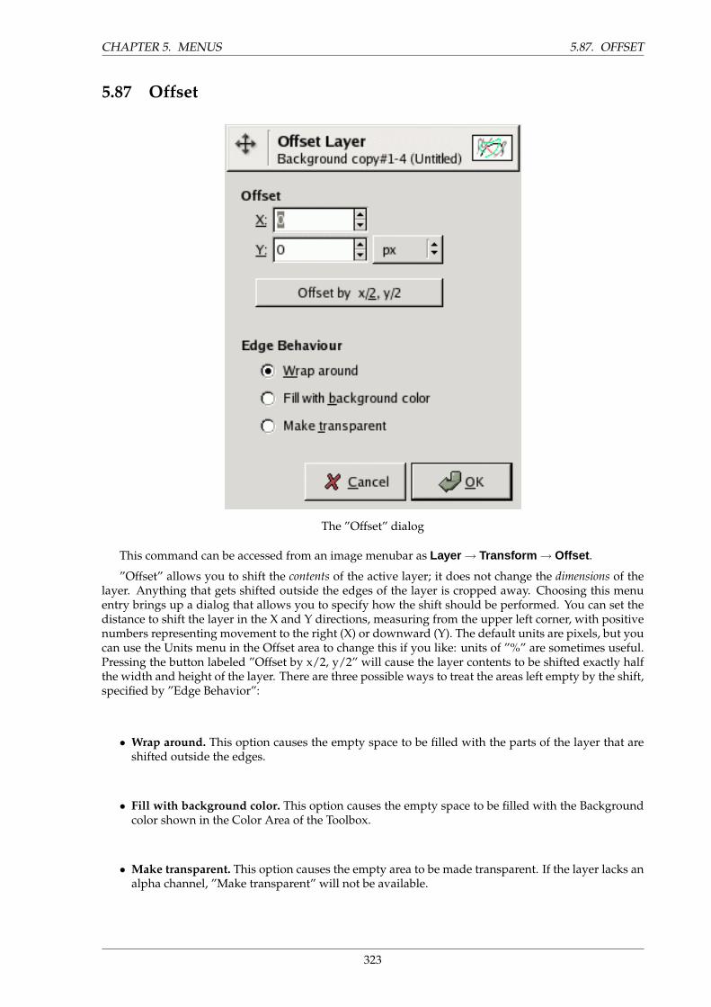
CHAPTER 5. MENUS 5.87. OFFSET
5.87 Offset
The ”Offset” dialog
This command can be accessed from an image menubar as Layer → Transform → Offset .
”Offset” allows you to shift the contents of the active layer; it does not change the dimensions of thelayer. Anything that gets shifted outside the edges of the layer is cropped away. Choosing this menuentry brings up a dialog that allows you to specify how the shift should be performed. You can set thedistance to shift the layer in the X and Y directions, measuring from the upper left corner, with positivenumbers representing movement to the right (X) or downward (Y). The default units are pixels, but youcan use the Units menu in the Offset area to change this if you like: units of ”%” are sometimes useful.Pressing the button labeled ”Offset by x/2, y/2” will cause the layer contents to be shifted exactly halfthe width and height of the layer. There are three possible ways to treat the areas left empty by the shift,specified by ”Edge Behavior”:
• Wrap around. This option causes the empty space to be filled with the parts of the layer that areshifted outside the edges.
• Fill with background color. This option causes the empty space to be filled with the Backgroundcolor shown in the Color Area of the Toolbox.
• Make transparent. This option causes the empty area to be made transparent. If the layer lacks analpha channel, ”Make transparent” will not be available.
323
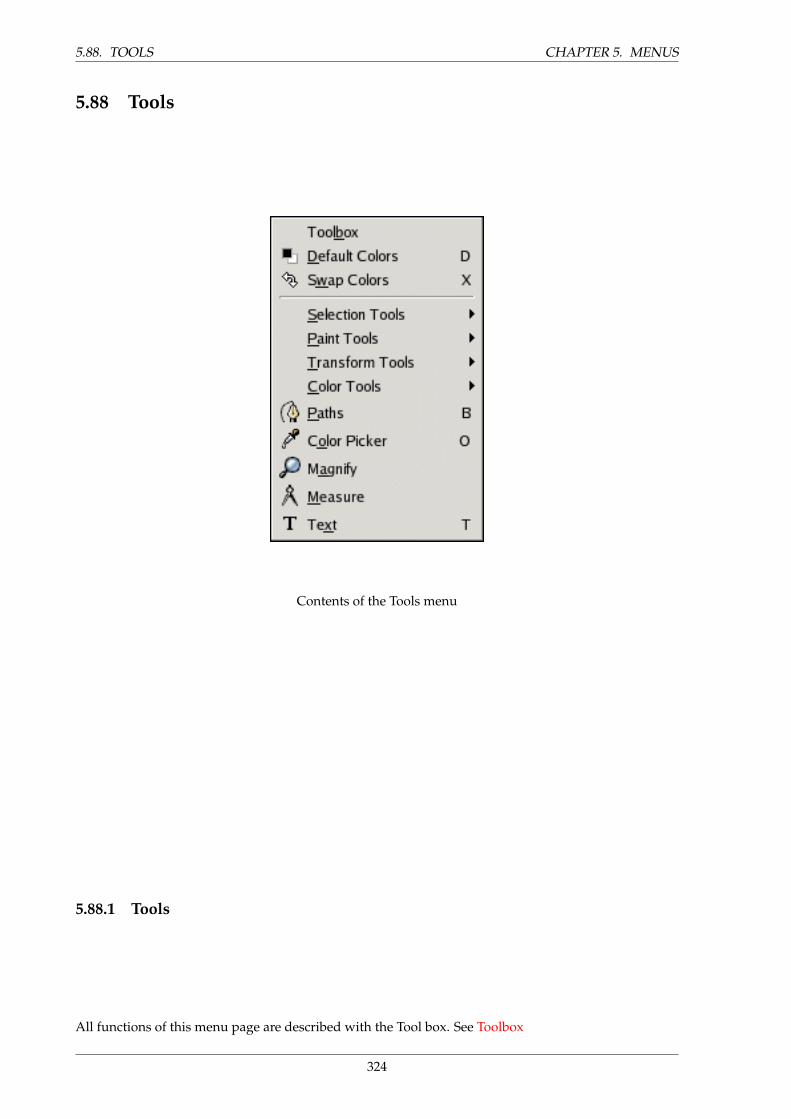
5.88. TOOLS CHAPTER 5. MENUS
5.88 Tools
Contents of the Tools menu
5.88.1 Tools
All functions of this menu page are described with the Tool box. See Toolbox
324
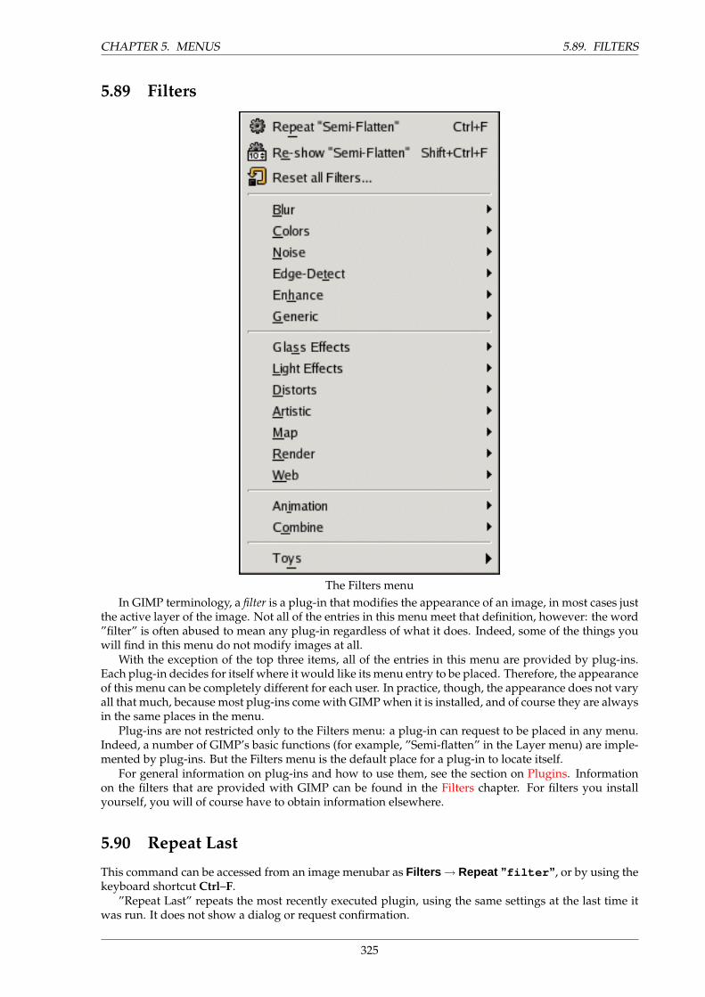
CHAPTER 5. MENUS 5.89. FILTERS
5.89 Filters
The Filters menuIn GIMP terminology, a filter is a plug-in that modifies the appearance of an image, in most cases just
the active layer of the image. Not all of the entries in this menu meet that definition, however: the word”filter” is often abused to mean any plug-in regardless of what it does. Indeed, some of the things youwill find in this menu do not modify images at all.
With the exception of the top three items, all of the entries in this menu are provided by plug-ins.Each plug-in decides for itself where it would like its menu entry to be placed. Therefore, the appearanceof this menu can be completely different for each user. In practice, though, the appearance does not varyall that much, because most plug-ins come with GIMP when it is installed, and of course they are alwaysin the same places in the menu.
Plug-ins are not restricted only to the Filters menu: a plug-in can request to be placed in any menu.Indeed, a number of GIMP’s basic functions (for example, ”Semi-flatten” in the Layer menu) are imple-mented by plug-ins. But the Filters menu is the default place for a plug-in to locate itself.
For general information on plug-ins and how to use them, see the section on Plugins. Informationon the filters that are provided with GIMP can be found in the Filters chapter. For filters you installyourself, you will of course have to obtain information elsewhere.
5.90 Repeat Last
This command can be accessed from an image menubar as Filters → Repeat ” filter ” , or by using thekeyboard shortcut Ctrl–F.
”Repeat Last” repeats the most recently executed plugin, using the same settings at the last time itwas run. It does not show a dialog or request confirmation.
325
5.91. RE-SHOW LAST CHAPTER 5. MENUS
NOTE
It is important to realize that this command repeats the most recently executedplugin, regardless of whether it can be found in the Filters menu.
5.91 Re-show Last
This command can be accessed from an image menubar as Filters → Re-show ” filter ” , or by usingthe keyboard shortcut Ctrl–Shift–F.
”Re-show Last” interactively runs the most recently executed plugin. If the plugin is one that uses adialog window, it does so here, with the settings initialized to the values you used the last time you ranthe plugin. (Assuming the plugin is correctly programmed, that is.)
TIP
It is very common, especially for plugins that lack a preview, to have to adjustparameters several times before the results are satisfactory. The most efficientway to do this is to memorize the keyboard shortcuts for ”undo” followed by ”re-show last”: Ctrl –Z followed by Ctrl –Shift –F.
5.92 Reset All Filters
This command can be accessed from an image menubar as Filters → Reset All Filters... .Normally, each time you run an interactive plugin, the dialog comes up with settings initialized to
the values you used the last time you ran it. Sometimes this can be very annoying, if you mess up thevalues and don’t remember what they were originally. One way to recover is to exit from GIMP and startagain, but this command provides a slightly less desperate solution: it resets the values for all pluginsto their defaults. Because it is a dramatic step, it asks you to confirm that you really want to do it. Becareful: this command is not undoable.
326
Chapter 6
Filters
6.1 Filter introduction
A filter is a special kind of tool designed to take an input layer or image, apply a mathematical algorithmto it, and return the input layer or image in a modified format. The GIMP uses filters to achieve a varietyof effects and those effects are discussed here.
The filters are divided into several categories:
• Blur
• Colors
• Noise
• Edge-Detect
• Enhance
• Generic
• Glass Effects
• Light Effects
• Distorts
• Artistic
• Map
• Render
• Web
• Animation
• Combine
6.2 Blur filters
6.2.1 Blur filters introduction
327
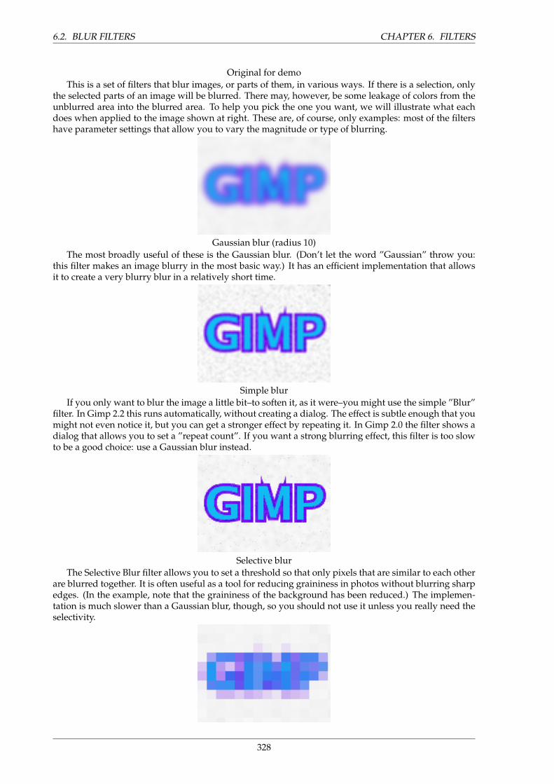
6.2. BLUR FILTERS CHAPTER 6. FILTERS
Original for demoThis is a set of filters that blur images, or parts of them, in various ways. If there is a selection, only
the selected parts of an image will be blurred. There may, however, be some leakage of colors from theunblurred area into the blurred area. To help you pick the one you want, we will illustrate what eachdoes when applied to the image shown at right. These are, of course, only examples: most of the filtershave parameter settings that allow you to vary the magnitude or type of blurring.
Gaussian blur (radius 10)The most broadly useful of these is the Gaussian blur. (Don’t let the word ”Gaussian” throw you:
this filter makes an image blurry in the most basic way.) It has an efficient implementation that allowsit to create a very blurry blur in a relatively short time.
Simple blurIf you only want to blur the image a little bit–to soften it, as it were–you might use the simple ”Blur”
filter. In Gimp 2.2 this runs automatically, without creating a dialog. The effect is subtle enough that youmight not even notice it, but you can get a stronger effect by repeating it. In Gimp 2.0 the filter shows adialog that allows you to set a ”repeat count”. If you want a strong blurring effect, this filter is too slowto be a good choice: use a Gaussian blur instead.
Selective blurThe Selective Blur filter allows you to set a threshold so that only pixels that are similar to each other
are blurred together. It is often useful as a tool for reducing graininess in photos without blurring sharpedges. (In the example, note that the graininess of the background has been reduced.) The implemen-tation is much slower than a Gaussian blur, though, so you should not use it unless you really need theselectivity.
328
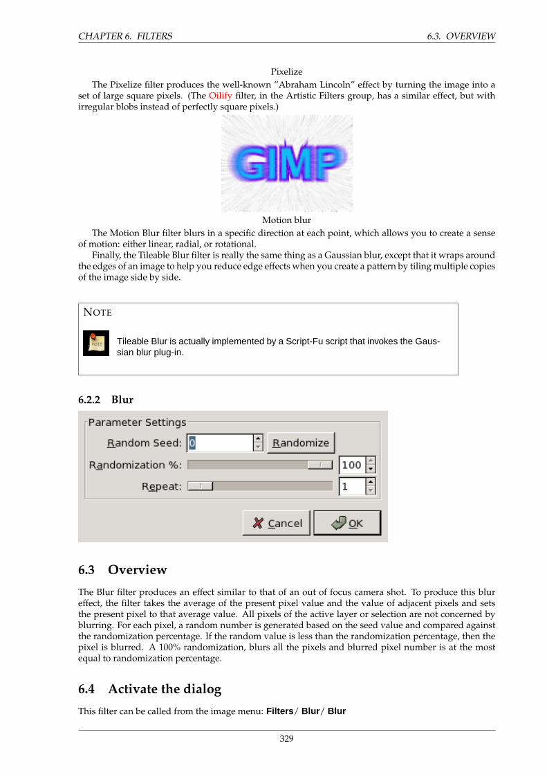
CHAPTER 6. FILTERS 6.3. OVERVIEW
PixelizeThe Pixelize filter produces the well-known ”Abraham Lincoln” effect by turning the image into a
set of large square pixels. (The Oilify filter, in the Artistic Filters group, has a similar effect, but withirregular blobs instead of perfectly square pixels.)
Motion blurThe Motion Blur filter blurs in a specific direction at each point, which allows you to create a sense
of motion: either linear, radial, or rotational.Finally, the Tileable Blur filter is really the same thing as a Gaussian blur, except that it wraps around
the edges of an image to help you reduce edge effects when you create a pattern by tiling multiple copiesof the image side by side.
NOTE
Tileable Blur is actually implemented by a Script-Fu script that invokes the Gaus-sian blur plug-in.
6.2.2 Blur
6.3 Overview
The Blur filter produces an effect similar to that of an out of focus camera shot. To produce this blureffect, the filter takes the average of the present pixel value and the value of adjacent pixels and setsthe present pixel to that average value. All pixels of the active layer or selection are not concerned byblurring. For each pixel, a random number is generated based on the seed value and compared againstthe randomization percentage. If the random value is less than the randomization percentage, then thepixel is blurred. A 100% randomization, blurs all the pixels and blurred pixel number is at the mostequal to randomization percentage.
6.4 Activate the dialog
This filter can be called from the image menu: Filters / Blur / Blur
329
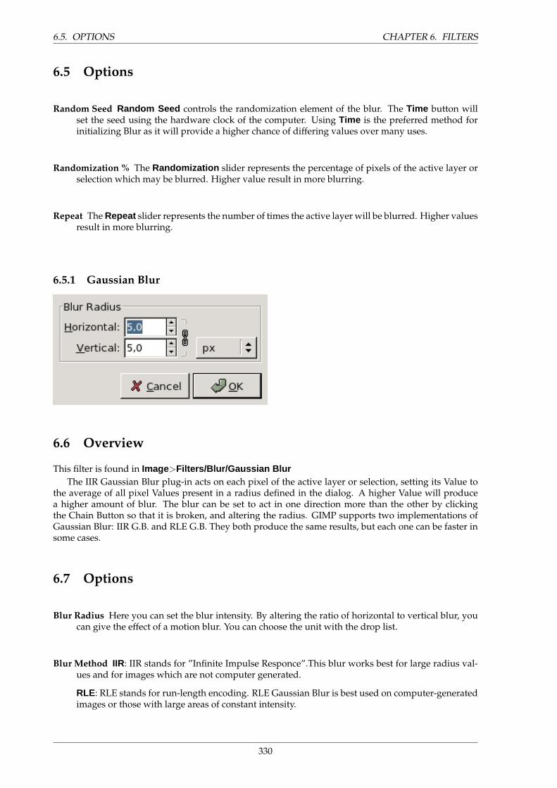
6.5. OPTIONS CHAPTER 6. FILTERS
6.5 Options
Random Seed Random Seed controls the randomization element of the blur. The Time button willset the seed using the hardware clock of the computer. Using Time is the preferred method forinitializing Blur as it will provide a higher chance of differing values over many uses.
Randomization % The Randomization slider represents the percentage of pixels of the active layer orselection which may be blurred. Higher value result in more blurring.
Repeat The Repeat slider represents the number of times the active layer will be blurred. Higher valuesresult in more blurring.
6.5.1 Gaussian Blur
6.6 Overview
This filter is found in Image>Filters/Blur/Gaussian BlurThe IIR Gaussian Blur plug-in acts on each pixel of the active layer or selection, setting its Value to
the average of all pixel Values present in a radius defined in the dialog. A higher Value will producea higher amount of blur. The blur can be set to act in one direction more than the other by clickingthe Chain Button so that it is broken, and altering the radius. GIMP supports two implementations ofGaussian Blur: IIR G.B. and RLE G.B. They both produce the same results, but each one can be faster insome cases.
6.7 Options
Blur Radius Here you can set the blur intensity. By altering the ratio of horizontal to vertical blur, youcan give the effect of a motion blur. You can choose the unit with the drop list.
Blur Method IIR: IIR stands for ”Infinite Impulse Responce”.This blur works best for large radius val-ues and for images which are not computer generated.
RLE: RLE stands for run-length encoding. RLE Gaussian Blur is best used on computer-generatedimages or those with large areas of constant intensity.
330
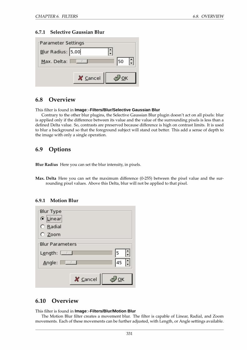
CHAPTER 6. FILTERS 6.8. OVERVIEW
6.7.1 Selective Gaussian Blur
6.8 Overview
This filter is found in Image>Filters/Blur/Selective Gaussian BlurContrary to the other blur plugins, the Selective Gaussian Blur plugin doesn’t act on all pixels: blur
is applied only if the difference between its value and the value of the surrounding pixels is less than adefined Delta value. So, contrasts are preserved because difference is high on contrast limits. It is usedto blur a background so that the foreground subject will stand out better. This add a sense of depth tothe image with only a single operation.
6.9 Options
Blur Radius Here you can set the blur intensity, in pixels.
Max. Delta Here you can set the maximum difference (0-255) between the pixel value and the sur-rounding pixel values. Above this Delta, blur will not be applied to that pixel.
6.9.1 Motion Blur
6.10 Overview
This filter is found in Image>Filters/Blur/Motion BlurThe Motion Blur filter creates a movement blur. The filter is capable of Linear, Radial, and Zoom
movements. Each of these movements can be further adjusted, with Length, or Angle settings available.
331
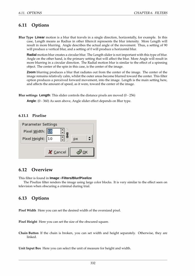
6.11. OPTIONS CHAPTER 6. FILTERS
6.11 Options
Blur Type Linear motion is a blur that travels in a single direction, horizontally, for example. In thiscase, Length means as Radius in other filters:it represents the blur intensity. More Length willresult in more blurring. Angle describes the actual angle of the movement. Thus, a setting of 90will produce a vertical blur, and a setting of 0 will produce a horizontal blur.
Radial motion blur creates a circular blur. The Length slider is not important with this type of blur.Angle on the other hand, is the primary setting that will affect the blur. More Angle will result inmore blurring in a circular direction. The Radial motion blur is similar to the effect of a spinningobject. The center of the spin in this case, is the center of the image.
Zoom blurring produces a blur that radiates out from the center of the image. The center of theimage remains relatively calm, whilst the outer areas become blurred toward the center. This filteroption produces a perceived forward movement, into the image. Length is the main setting here,and affects the amount of speed, as it were, toward the center of the image.
Blur settings Length : This slider controls the distance pixels are moved (0 - 256)
Angle : (0 - 360) As seen above, Angle slider effect depends on Blur type.
6.11.1 Pixelise
6.12 Overview
This filter is found in Image>Filters/Blur/PixelizeThe Pixelize filter renders the image using large color blocks. It is very similar to the effect seen on
television when obscuring a criminal during trial.
6.13 Options
Pixel Width Here you can set the desired width of the oversized pixel.
Pixel Height Here you can set the size of the obscured square.
Chain Button If the chain is broken, you can set width and height separately. Otherwise, they arelinked.
Unit Input Box Here you can select the unit of measure for height and width.
332
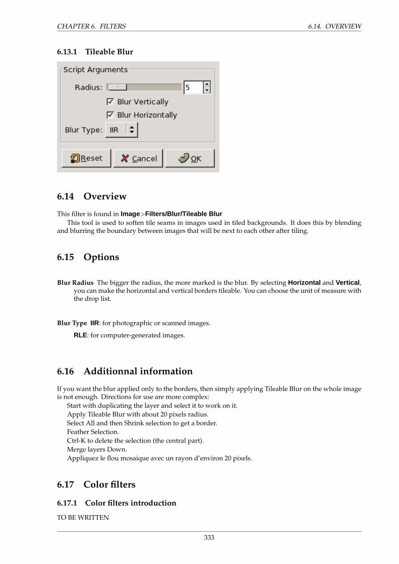
CHAPTER 6. FILTERS 6.14. OVERVIEW
6.13.1 Tileable Blur
6.14 Overview
This filter is found in Image>Filters/Blur/Tileable BlurThis tool is used to soften tile seams in images used in tiled backgrounds. It does this by blending
and blurring the boundary between images that will be next to each other after tiling.
6.15 Options
Blur Radius The bigger the radius, the more marked is the blur. By selecting Horizontal and Vertical ,you can make the horizontal and vertical borders tileable. You can choose the unit of measure withthe drop list.
Blur Type IIR: for photographic or scanned images.
RLE: for computer-generated images.
6.16 Additionnal information
If you want the blur applied only to the borders, then simply applying Tileable Blur on the whole imageis not enough. Directions for use are more complex:
Start with duplicating the layer and select it to work on it.Apply Tileable Blur with about 20 pixels radius.Select All and then Shrink selection to get a border.Feather Selection.Ctrl-K to delete the selection (the central part).Merge layers Down.Appliquez le flou mosaique avec un rayon d’environ 20 pixels.
6.17 Color filters
6.17.1 Color filters introduction
TO BE WRITTEN
333
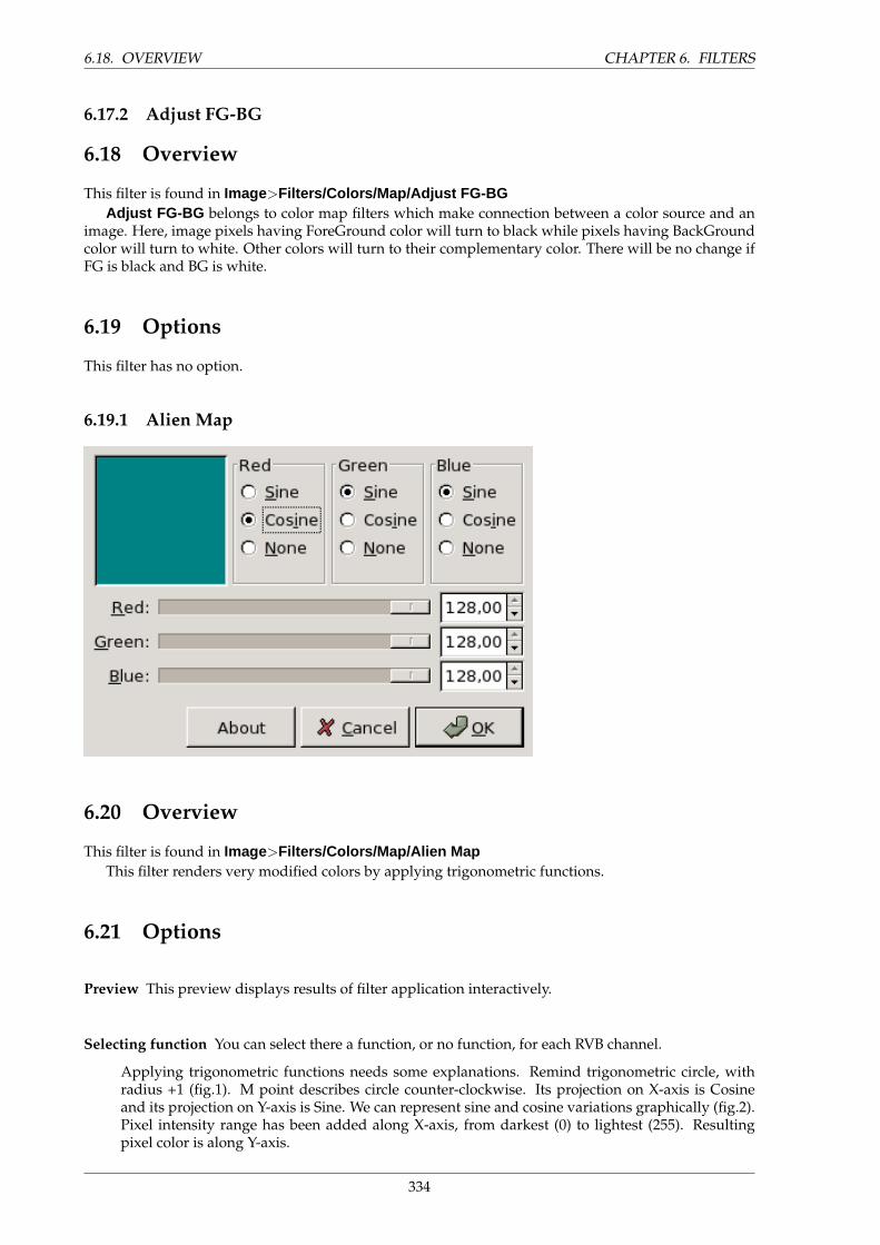
6.18. OVERVIEW CHAPTER 6. FILTERS
6.17.2 Adjust FG-BG
6.18 Overview
This filter is found in Image>Filters/Colors/Map/Adjust FG-BGAdjust FG-BG belongs to color map filters which make connection between a color source and an
image. Here, image pixels having ForeGround color will turn to black while pixels having BackGroundcolor will turn to white. Other colors will turn to their complementary color. There will be no change ifFG is black and BG is white.
6.19 Options
This filter has no option.
6.19.1 Alien Map
6.20 Overview
This filter is found in Image>Filters/Colors/Map/Alien MapThis filter renders very modified colors by applying trigonometric functions.
6.21 Options
Preview This preview displays results of filter application interactively.
Selecting function You can select there a function, or no function, for each RVB channel.
Applying trigonometric functions needs some explanations. Remind trigonometric circle, withradius +1 (fig.1). M point describes circle counter-clockwise. Its projection on X-axis is Cosineand its projection on Y-axis is Sine. We can represent sine and cosine variations graphically (fig.2).Pixel intensity range has been added along X-axis, from darkest (0) to lightest (255). Resultingpixel color is along Y-axis.
334
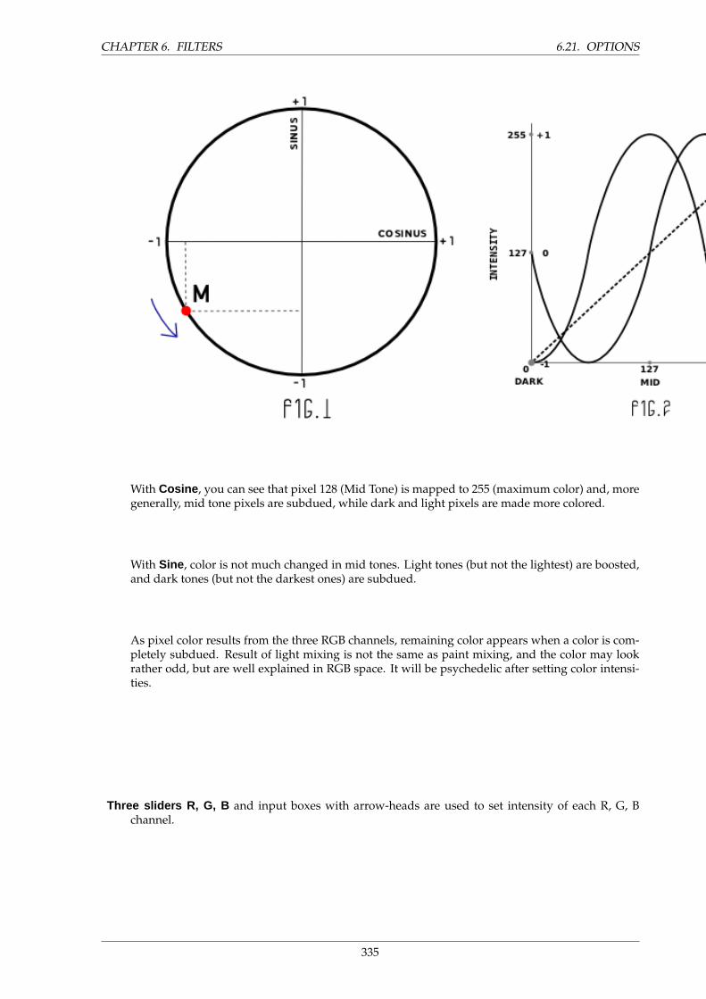
CHAPTER 6. FILTERS 6.21. OPTIONS
With Cosine , you can see that pixel 128 (Mid Tone) is mapped to 255 (maximum color) and, moregenerally, mid tone pixels are subdued, while dark and light pixels are made more colored.
With Sine , color is not much changed in mid tones. Light tones (but not the lightest) are boosted,and dark tones (but not the darkest ones) are subdued.
As pixel color results from the three RGB channels, remaining color appears when a color is com-pletely subdued. Result of light mixing is not the same as paint mixing, and the color may lookrather odd, but are well explained in RGB space. It will be psychedelic after setting color intensi-ties.
Three sliders R, G, B and input boxes with arrow-heads are used to set intensity of each R, G, Bchannel.
335
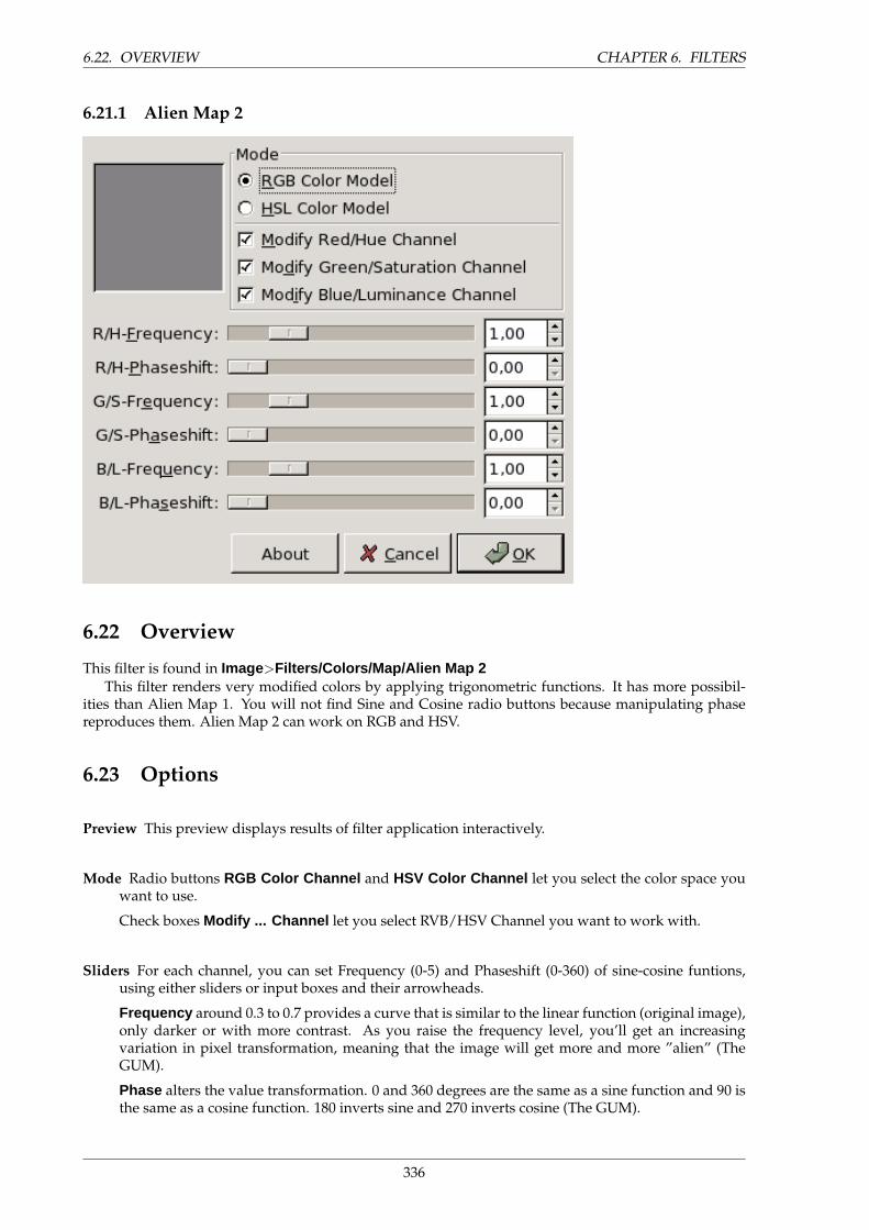
6.22. OVERVIEW CHAPTER 6. FILTERS
6.21.1 Alien Map 2
6.22 Overview
This filter is found in Image>Filters/Colors/Map/Alien Map 2This filter renders very modified colors by applying trigonometric functions. It has more possibil-
ities than Alien Map 1. You will not find Sine and Cosine radio buttons because manipulating phasereproduces them. Alien Map 2 can work on RGB and HSV.
6.23 Options
Preview This preview displays results of filter application interactively.
Mode Radio buttons RGB Color Channel and HSV Color Channel let you select the color space youwant to use.
Check boxes Modify ... Channel let you select RVB/HSV Channel you want to work with.
Sliders For each channel, you can set Frequency (0-5) and Phaseshift (0-360) of sine-cosine funtions,using either sliders or input boxes and their arrowheads.
Frequency around 0.3 to 0.7 provides a curve that is similar to the linear function (original image),only darker or with more contrast. As you raise the frequency level, you’ll get an increasingvariation in pixel transformation, meaning that the image will get more and more ”alien” (TheGUM).
Phase alters the value transformation. 0 and 360 degrees are the same as a sine function and 90 isthe same as a cosine function. 180 inverts sine and 270 inverts cosine (The GUM).
336
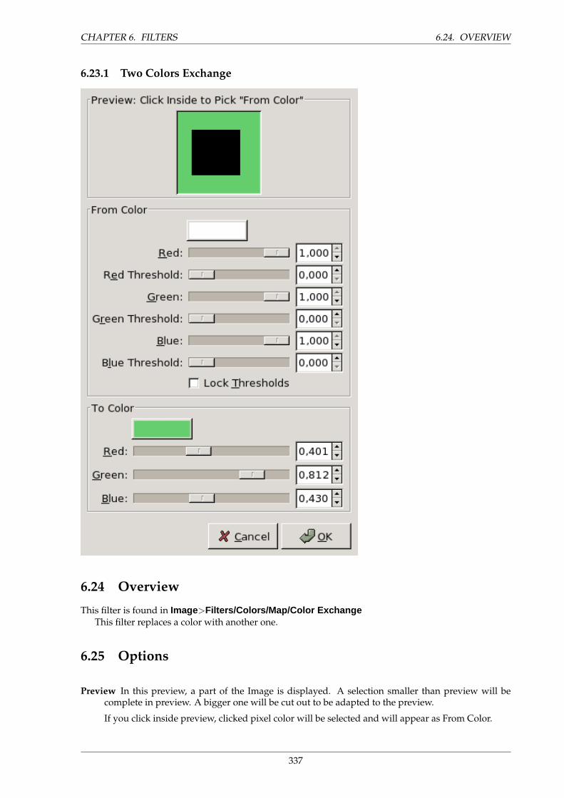
CHAPTER 6. FILTERS 6.24. OVERVIEW
6.23.1 Two Colors Exchange
6.24 Overview
This filter is found in Image>Filters/Colors/Map/Color ExchangeThis filter replaces a color with another one.
6.25 Options
Preview In this preview, a part of the Image is displayed. A selection smaller than preview will becomplete in preview. A bigger one will be cut out to be adapted to the preview.
If you click inside preview, clicked pixel color will be selected and will appear as From Color.
337
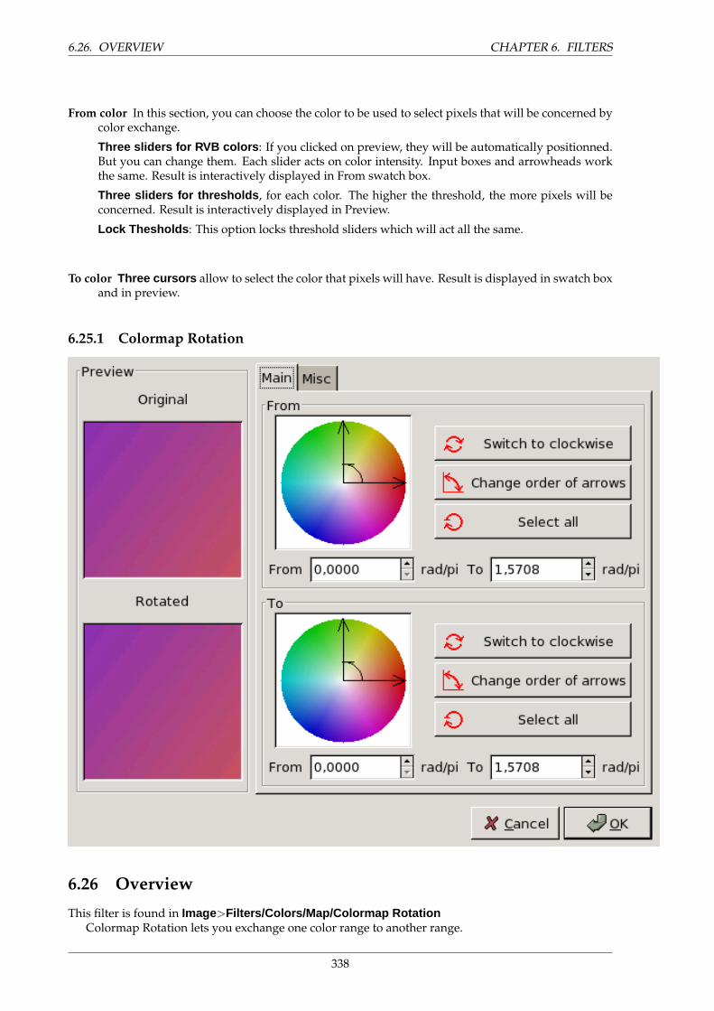
6.26. OVERVIEW CHAPTER 6. FILTERS
From color In this section, you can choose the color to be used to select pixels that will be concerned bycolor exchange.
Three sliders for RVB colors : If you clicked on preview, they will be automatically positionned.But you can change them. Each slider acts on color intensity. Input boxes and arrowheads workthe same. Result is interactively displayed in From swatch box.
Three sliders for thresholds , for each color. The higher the threshold, the more pixels will beconcerned. Result is interactively displayed in Preview.
Lock Thesholds : This option locks threshold sliders which will act all the same.
To color Three cursors allow to select the color that pixels will have. Result is displayed in swatch boxand in preview.
6.25.1 Colormap Rotation
6.26 Overview
This filter is found in Image>Filters/Colors/Map/Colormap RotationColormap Rotation lets you exchange one color range to another range.
338
CHAPTER 6. FILTERS 6.27. PREVIEW
6.27 Preview
Preview Preview : This Preview displays a thumbnail of the original image and another one displayingcolor changes interactively, before they are applied to Image.
6.28 Main
This tab deals with main options.
From The Color Circle : Two axis to define ”From” range. The curved arrow in angle lets to recognise”From” axis and ”To” axis of range. Click-drag these axis to change range.
Switch to Clockwise/Counterclockwise : Sets the direction the range is going.
Change Order of Arrows : Inverts From and To axis. This results in an important color change ascolors in selection angle are different.
Select All selects the whole color circle.
From and To boxes display start axis and end axis positions (in rad/PI) which are limiting theselected color range. You can enter these positions manually or with help of arrow-heads.
To This section options are the same as ”From” section ones.
6.29 Misc
This tab deals with miscellaneous options.
Gray In the ”Misc” tab, you can specify how to treat grey colors. By default, grey is not considered asa color. But all colors, when they are very desaturated, look like grey, and you can tell filter toconsider grey as a very desaturated color which will be affected by rotation.
What is Gray? : You specify there how much saturation will be considered grey. By increasingprogressively saturation, you will see an enlarging circle in color circle and enlarging selectedareas in Preview if Change To This option is checked.
Hue and Saturation : You set here the color you want grey to be transformed to. You do that, eitherby entering values into input boxes, or by click-dragging the small central circle in Hue/Saturationcircle.
Mode : With Treat as this option, there will be no change in preview, selected ”grey” areas willtake the selected color and a rotation will be performed on image. With Change to this option,the selected color will be applied to ”grey” areas and will appear in preview but no rotation willbe performed.
Preview Continuous Update displays color changes continuously in Rotated preview.
Zone : Entire Layer works on whole layer. Selection displays selection only, Context displaysselection in image context.
Units You can select here the angle unit used to locate colors in Hue/Saturation circle.
339
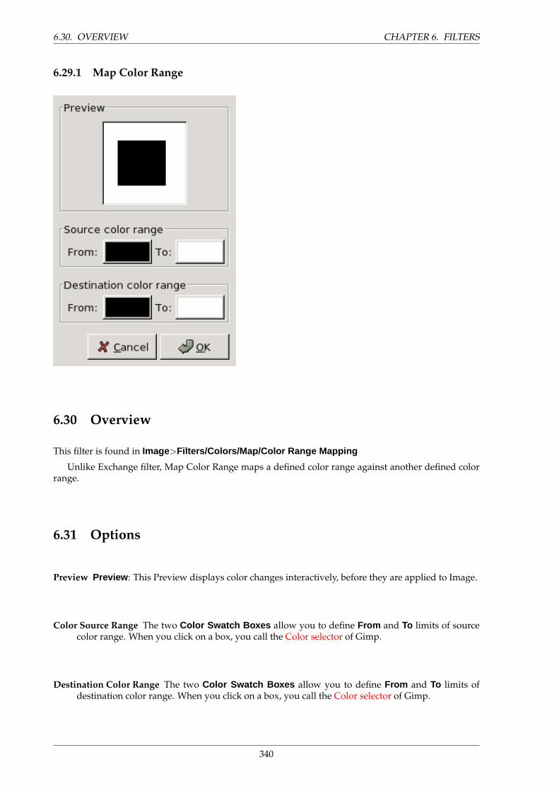
6.30. OVERVIEW CHAPTER 6. FILTERS
6.29.1 Map Color Range
6.30 Overview
This filter is found in Image>Filters/Colors/Map/Color Range Mapping
Unlike Exchange filter, Map Color Range maps a defined color range against another defined colorrange.
6.31 Options
Preview Preview : This Preview displays color changes interactively, before they are applied to Image.
Color Source Range The two Color Swatch Boxes allow you to define From and To limits of sourcecolor range. When you click on a box, you call the Color selector of Gimp.
Destination Color Range The two Color Swatch Boxes allow you to define From and To limits ofdestination color range. When you click on a box, you call the Color selector of Gimp.
340
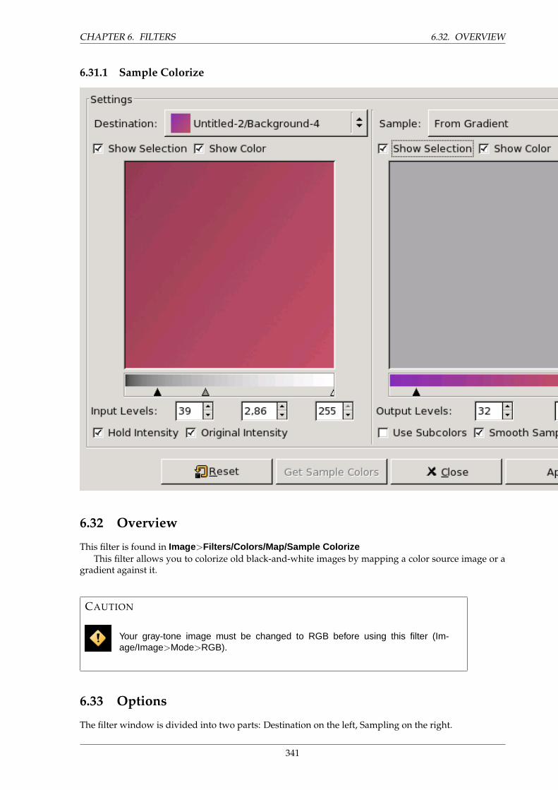
CHAPTER 6. FILTERS 6.32. OVERVIEW
6.31.1 Sample Colorize
6.32 Overview
This filter is found in Image>Filters/Colors/Map/Sample ColorizeThis filter allows you to colorize old black-and-white images by mapping a color source image or a
gradient against it.
CAUTION
Your gray-tone image must be changed to RGB before using this filter (Im-age/Image>Mode>RGB).
6.33 Options
The filter window is divided into two parts: Destination on the left, Sampling on the right.
341
6.33. OPTIONS CHAPTER 6. FILTERS
Destination , Sample By default, displayed image previews reproduce the image from which you in-voked the filter.
The sample can be the whole preview, or a selection of this preview. With the drop list, youcan select another sample-image among the names of images present on your screen when youcalled the filter. If you choose From Gradient (or From Inverse Gradient ), the selected gradientin Gradient Dialog (or its inverse) will be the sample. It will be displayed into the gradient barbelow the sample preview. The sampling preview is greyed out and two cursors allow you toselect the gradient range that will be applied to the image or selection.
Destination is, by default, the source image. The drop list displays the list of images present onyour screen when you evoked the filter and allow you to select another destination image. If thereis a selection in this image, it will be grayscaled, else the whole preview will be grayscaled.
Show Selection This option toggles between the whole image and the selection, if it exists.
Show Colors This option toggles between colors and greyscale.
Get Sample Colors When you click on this button, the gradient bar below the sample preview displayscolors of the sample. If your sample holds few colors, transitions may be abrupt. Check SmoothSample Colors option to improve them.
Use Subcolors is more difficult to understand. Let’s say first that in a greyscale image thereis information only for Value (luminosity, more or less light). In a RGB image, each pixel hasinformation for the three colors and Value. So, pixels with different color may have the sameValue. If this option is checked, colors will be mixed and applied to Destination pixels having thatValue. If it is unchecked, then the dominating color will be applied.
Out Levels Two input boxes and two sliders act the same: they limit the color range which will beapplied to destination image. You can choose this range accurately. Result appears interactivelyin destination preview.
In Levels Three input boxes and three sliders allow to fix importance of dark tones, mid tones and lighttones. Result appears interactively in destination preview.
Apply Button When you are satisfied with the result on destination preview, click on Apply to applyresults onto destination image.
Hold Intensity If this option is checked, the average light intensity of destination image will be thesame as that of source image.
Original Intensity If this option is checked, the In levels intensity settings will not be taken in account:original intensity will be preserved.
342
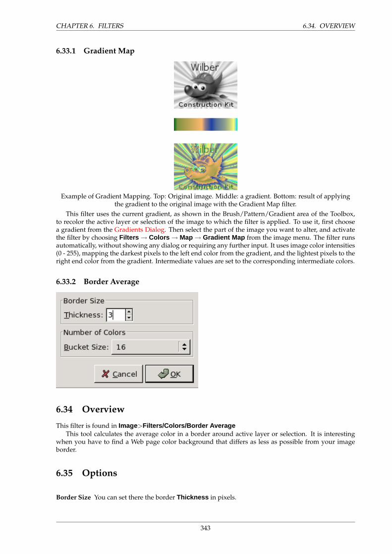
CHAPTER 6. FILTERS 6.34. OVERVIEW
6.33.1 Gradient Map
Example of Gradient Mapping. Top: Original image. Middle: a gradient. Bottom: result of applyingthe gradient to the original image with the Gradient Map filter.
This filter uses the current gradient, as shown in the Brush/Pattern/Gradient area of the Toolbox,to recolor the active layer or selection of the image to which the filter is applied. To use it, first choosea gradient from the Gradients Dialog. Then select the part of the image you want to alter, and activatethe filter by choosing Filters → Colors → Map → Gradient Map from the image menu. The filter runsautomatically, without showing any dialog or requiring any further input. It uses image color intensities(0 - 255), mapping the darkest pixels to the left end color from the gradient, and the lightest pixels to theright end color from the gradient. Intermediate values are set to the corresponding intermediate colors.
6.33.2 Border Average
6.34 Overview
This filter is found in Image>Filters/Colors/Border AverageThis tool calculates the average color in a border around active layer or selection. It is interesting
when you have to find a Web page color background that differs as less as possible from your imageborder.
6.35 Options
Border Size You can set there the border Thickness in pixels.
343

6.36. OVERVIEW CHAPTER 6. FILTERS
Number of Colors You can set there the Bucket Size , i.e the number of colors to be used when calcu-lating the average color (2 - 128).
6.35.1 Channel Mixer
6.36 Overview
This filter is found in Image>Filters/Colors/Channel MixerThis filter combine values of the RGB channels. It works with images with or without an alpha
channel. It has monochrome mode, preview.
6.37 Options
Output Channel From this menu you select the channel to mix to. Choices are Red, Green, or Blue. Itis insensitive when Monochrome option is checked.
Red, Green, Blue This three sliders set the contribution of red, green or blue channel to output. Can benegative.
Monochrome Sets all output channels to be the same. Makes the Output Channel menu insensitive.
Preserve Luminosity Maintains the luminosity at 100% regardless of the channel slider settings.
6.38 Buttons
Save Save settings to a file.
Open Load settings from a file.
344

CHAPTER 6. FILTERS 6.39. OVERVIEW
6.38.1 Color Cube Analysis
6.39 Overview
This filter is found in Image>Filters/Colors/Colorcube AnalysisIt gives data about image: dimensions, file size, color number, compression ratio...
6.40 Options
This filter has no option.
6.40.1 Colorify
6.41 Overview
This filter is found in Image>Filters/Colors/ColorifyIt renders a greyscaled image like it is seen through colored glass.
345
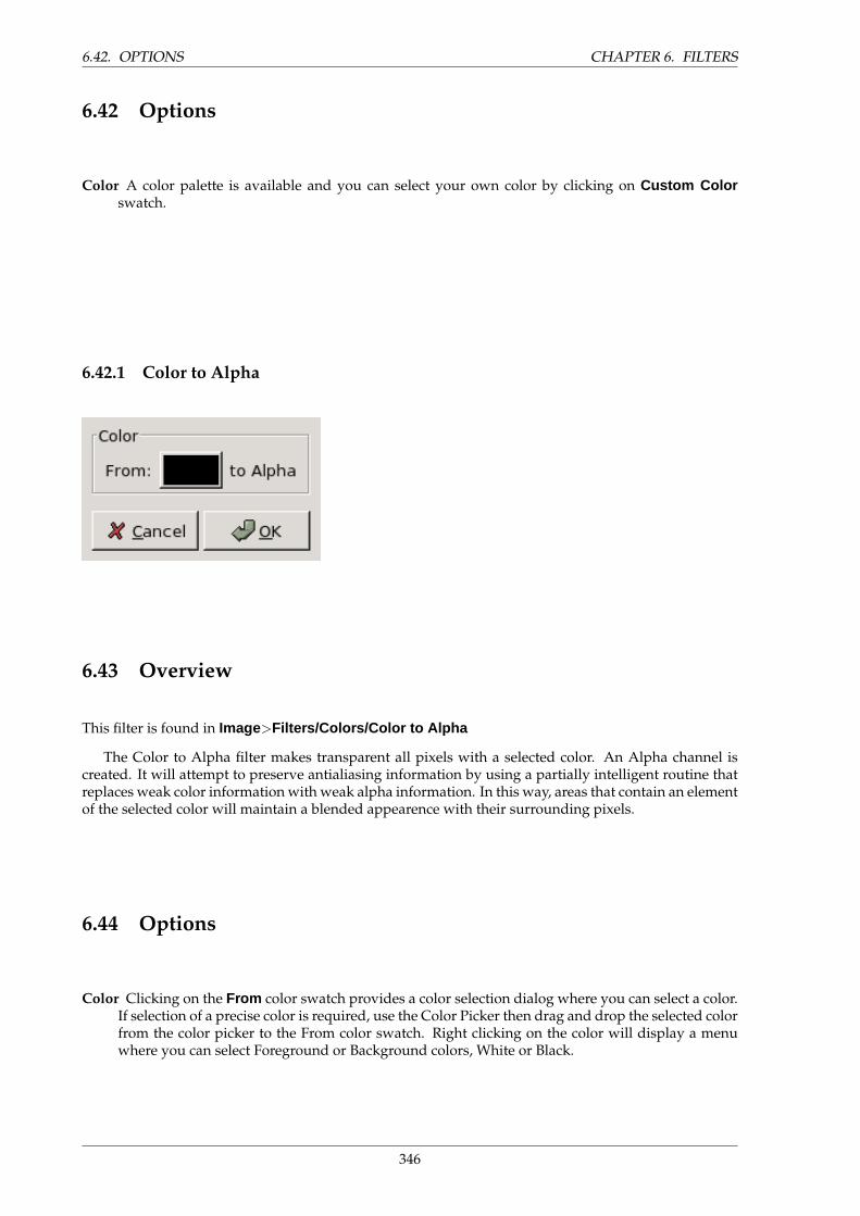
6.42. OPTIONS CHAPTER 6. FILTERS
6.42 Options
Color A color palette is available and you can select your own color by clicking on Custom Colorswatch.
6.42.1 Color to Alpha
6.43 Overview
This filter is found in Image>Filters/Colors/Color to Alpha
The Color to Alpha filter makes transparent all pixels with a selected color. An Alpha channel iscreated. It will attempt to preserve antialiasing information by using a partially intelligent routine thatreplaces weak color information with weak alpha information. In this way, areas that contain an elementof the selected color will maintain a blended appearence with their surrounding pixels.
6.44 Options
Color Clicking on the From color swatch provides a color selection dialog where you can select a color.If selection of a precise color is required, use the Color Picker then drag and drop the selected colorfrom the color picker to the From color swatch. Right clicking on the color will display a menuwhere you can select Foreground or Background colors, White or Black.
346
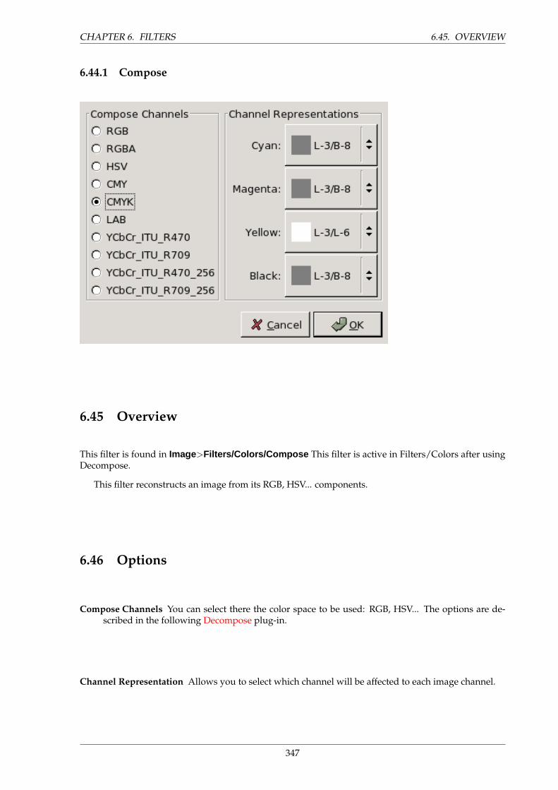
CHAPTER 6. FILTERS 6.45. OVERVIEW
6.44.1 Compose
6.45 Overview
This filter is found in Image>Filters/Colors/Compose This filter is active in Filters/Colors after usingDecompose.
This filter reconstructs an image from its RGB, HSV... components.
6.46 Options
Compose Channels You can select there the color space to be used: RGB, HSV... The options are de-scribed in the following Decompose plug-in.
Channel Representation Allows you to select which channel will be affected to each image channel.
347
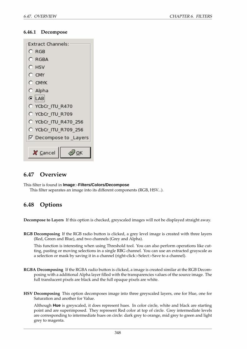
6.47. OVERVIEW CHAPTER 6. FILTERS
6.46.1 Decompose
6.47 Overview
This filter is found in Image>Filters/Colors/DecomposeThis filter separates an image into its different components (RGB, HSV...).
6.48 Options
Decompose to Layers If this option is checked, greyscaled images will not be displayed straight away.
RGB Decomposing If the RGB radio button is clicked, a grey level image is created with three layers(Red, Green and Blue), and two channels (Grey and Alpha).
This function is interesting when using Threshold tool. You can also perform operations like cut-ting, pasting or moving selections in a single RBG channel. You can use an extracted grayscale asa selection or mask by saving it in a channel (right-click>Select>Save to a channel).
RGBA Decomposing If the RGBA radio button is clicked, a image is created similar at the RGB Decom-posing with a additional Alpha layer filled with the transparencies values of the source image. Thefull translucent pixels are black and the full opaque pixels are white.
HSV Decomposing This option decomposes image into three greyscaled layers, one for Hue, one forSaturation and another for Value.
Although Hue is greyscaled, it does represent hues. In color circle, white and black are startingpoint and are superimposed. They represent Red color at top of circle. Grey intermediate levelsare corresponding to intermediate hues on circle: dark grey to orange, mid grey to green and lightgrey to magenta.
348
CHAPTER 6. FILTERS 6.48. OPTIONS
Saturation and Value : White is maximum Saturation (pure color) and maximum Value (verybright). Black is minimum Saturation (white) and minimum Value (black).
CMY Decomposing This option decomposes image into three greyscaled layers, one for Yellow, one forMagenta and another for Cyan.
This option might be useful to transfer image into printing softwares with CMY capabilities.
CMYK Decomposing This option is similar at the CMY Decomposing with a additonnal layer forBlack.
This option might be useful to transfer image into printing softwares with CMY capabilities.
Alpha Decomposing This option extracts the image transparency stored in the Alpha channel in Chan-nel dialog in a separate image. The full translucent pixels are Black the full opaque pixels arewhite. The graytones are smooth transitions of the transparency in the source image.
LAB Decomposing This option decomposes image into three greyscaled layers, layer ”L” for Lumi-nance, layer ”A” for colors between green and red, layer ”B” for colors between blue and yellow.
The LAB Decomposing is a color model of the Luminance-Color family. A channel is used for theLuminosity while two other channels are used for the Colors. The LAB color model is used byPhotoshop.
YCbCr Decomposing In Gimp there is four YCbCr decompositions with different values. Each optiondecomposes image in three greyscaled layers, a layer for Luminance and two other for bluenessand redness.
The YCbCr color model also called YUV is now used for digital video (initially for PAL analogvideo). It’s based on the idea that the human eye is most sensitive to luminosity, next to colors. TheYCbCr Decomposing use a transformation matrix and the different options are different valuesrecommanded by ITU (International Telecommunication Union) applied to the matrix .
349
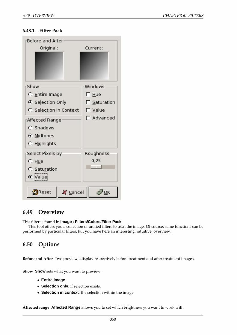
6.49. OVERVIEW CHAPTER 6. FILTERS
6.48.1 Filter Pack
6.49 Overview
This filter is found in Image>Filters/Colors/Filter PackThis tool offers you a collection of unified filters to treat the image. Of course, same functions can be
performed by particular filters, but you have here an interesting, intuitive, overview.
6.50 Options
Before and After Two previews display respectively before treatment and after treatment images.
Show Show sets what you want to preview:
• Entire image
• Selection only : if selection exists.
• Selection in context : the selection within the image.
Affected range Affected Range allows you to set which brightness you want to work with.
350

CHAPTER 6. FILTERS 6.50. OPTIONS
• Shadows : dark tones.
• Midtones
• Highlights : bright tones
Select pixels by Determines what HSV channel the selected range will affect. You can choose between:
• Hue
• Saturation
• Value
Roughness This slider sets how image will change when you click on a window: taking a short step ora large one (0 - 1).
Windows You can choose between:
• Hue makes one preview for each color appear. By clicking successively on a color, you addto this color into the affected range, according to Roughness. To substract color, click on theopposite color.
• Saturation : Three previews for more or less saturation.
• Value : Three previews for more or less luminosity.
• Advanced : developped later.
ADVANCED OPTIONS
Preview Size Something like a zoom on previews. Normal size is 80.
Smoothness of Aliasing This relates to the transition between tones. When the slider is set to zero,curve is rectangular and transition is abrupt. Small triangles are used to locate transitions betweentones.
TIP
In spite of Preview Size option, this size is often too small. You can compensatethis by working on an enlarged selection, for instance a face on a photo. Then,you invert selection to work on the other part of the image.
6.50.1 Hot
351
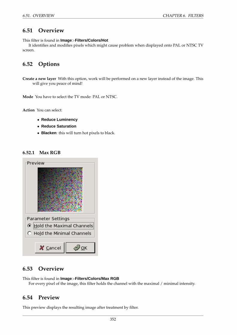
6.51. OVERVIEW CHAPTER 6. FILTERS
6.51 Overview
This filter is found in Image>Filters/Colors/HotIt identifies and modifies pixels which might cause problem when displayed onto PAL or NTSC TV
screen.
6.52 Options
Create a new layer With this option, work will be performed on a new layer instead of the image. Thiswill give you peace of mind!
Mode You have to select the TV mode: PAL or NTSC.
Action You can select:
• Reduce Luminency
• Reduce Saturation
• Blacken : this will turn hot pixels to black.
6.52.1 Max RGB
6.53 Overview
This filter is found in Image>Filters/Colors/Max RGBFor every pixel of the image, this filter holds the channel with the maximal / minimal intensity.
6.54 Preview
This preview displays the resulting image after treatment by filter.
352
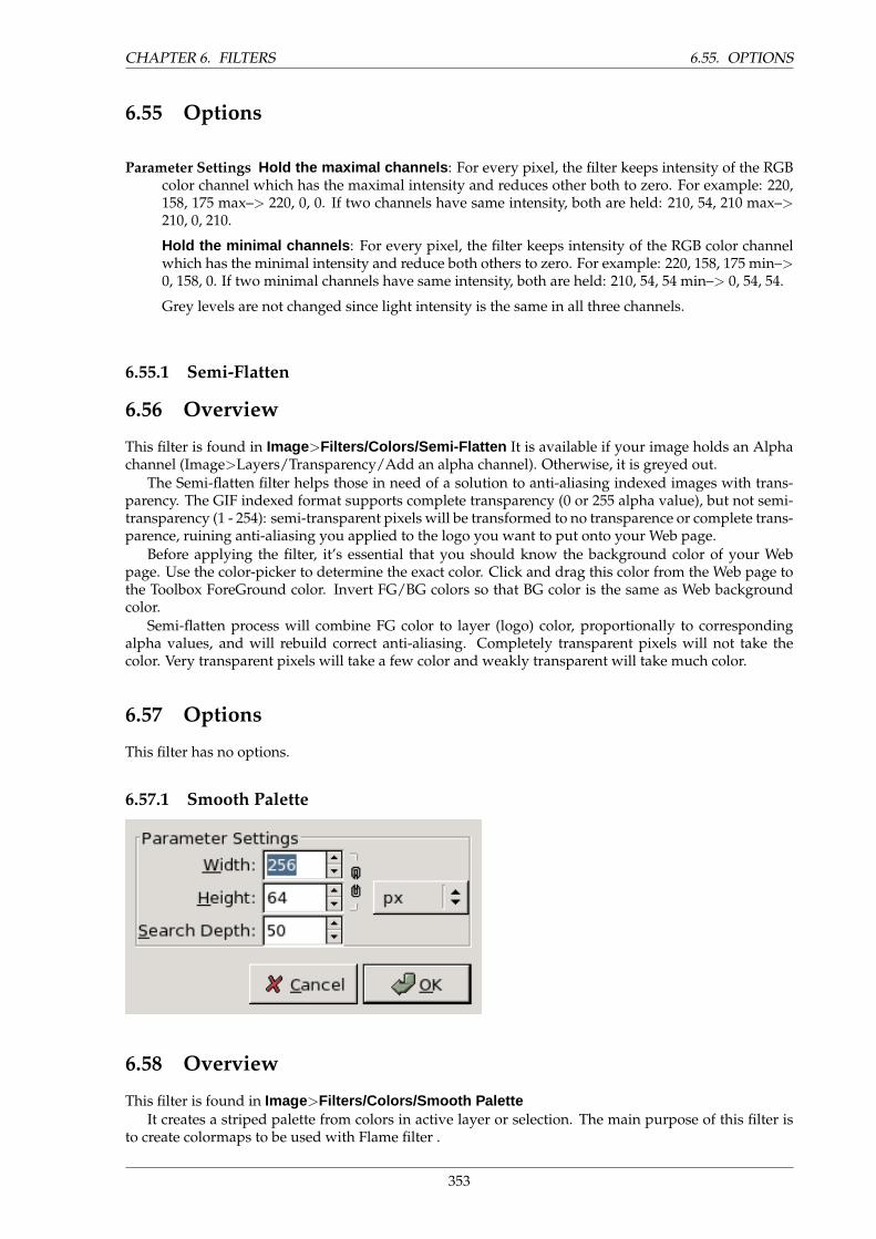
CHAPTER 6. FILTERS 6.55. OPTIONS
6.55 Options
Parameter Settings Hold the maximal channels : For every pixel, the filter keeps intensity of the RGBcolor channel which has the maximal intensity and reduces other both to zero. For example: 220,158, 175 max–> 220, 0, 0. If two channels have same intensity, both are held: 210, 54, 210 max–>210, 0, 210.
Hold the minimal channels : For every pixel, the filter keeps intensity of the RGB color channelwhich has the minimal intensity and reduce both others to zero. For example: 220, 158, 175 min–>0, 158, 0. If two minimal channels have same intensity, both are held: 210, 54, 54 min–> 0, 54, 54.
Grey levels are not changed since light intensity is the same in all three channels.
6.55.1 Semi-Flatten
6.56 Overview
This filter is found in Image>Filters/Colors/Semi-Flatten It is available if your image holds an Alphachannel (Image>Layers/Transparency/Add an alpha channel). Otherwise, it is greyed out.
The Semi-flatten filter helps those in need of a solution to anti-aliasing indexed images with trans-parency. The GIF indexed format supports complete transparency (0 or 255 alpha value), but not semi-transparency (1 - 254): semi-transparent pixels will be transformed to no transparence or complete trans-parence, ruining anti-aliasing you applied to the logo you want to put onto your Web page.
Before applying the filter, it’s essential that you should know the background color of your Webpage. Use the color-picker to determine the exact color. Click and drag this color from the Web page tothe Toolbox ForeGround color. Invert FG/BG colors so that BG color is the same as Web backgroundcolor.
Semi-flatten process will combine FG color to layer (logo) color, proportionally to correspondingalpha values, and will rebuild correct anti-aliasing. Completely transparent pixels will not take thecolor. Very transparent pixels will take a few color and weakly transparent will take much color.
6.57 Options
This filter has no options.
6.57.1 Smooth Palette
6.58 Overview
This filter is found in Image>Filters/Colors/Smooth PaletteIt creates a striped palette from colors in active layer or selection. The main purpose of this filter is
to create colormaps to be used with Flame filter .
353
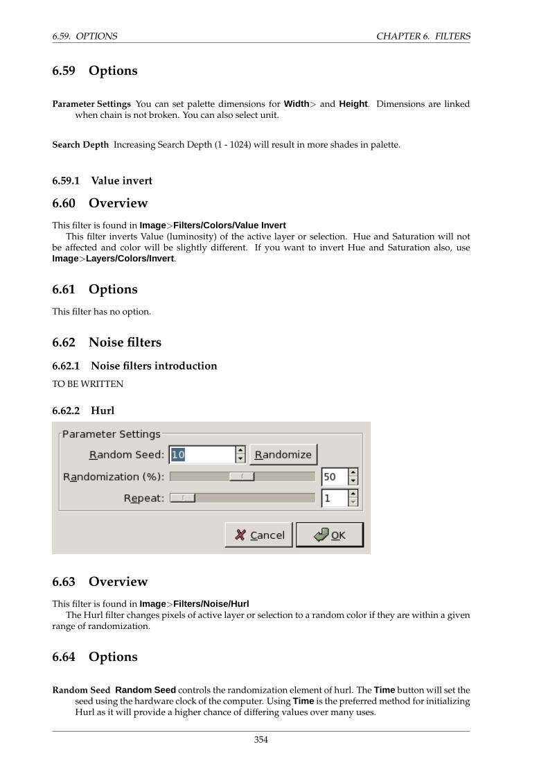
6.59. OPTIONS CHAPTER 6. FILTERS
6.59 Options
Parameter Settings You can set palette dimensions for Width > and Height . Dimensions are linkedwhen chain is not broken. You can also select unit.
Search Depth Increasing Search Depth (1 - 1024) will result in more shades in palette.
6.59.1 Value invert
6.60 Overview
This filter is found in Image>Filters/Colors/Value InvertThis filter inverts Value (luminosity) of the active layer or selection. Hue and Saturation will not
be affected and color will be slightly different. If you want to invert Hue and Saturation also, useImage>Layers/Colors/Invert .
6.61 Options
This filter has no option.
6.62 Noise filters
6.62.1 Noise filters introduction
TO BE WRITTEN
6.62.2 Hurl
6.63 Overview
This filter is found in Image>Filters/Noise/HurlThe Hurl filter changes pixels of active layer or selection to a random color if they are within a given
range of randomization.
6.64 Options
Random Seed Random Seed controls the randomization element of hurl. The Time button will set theseed using the hardware clock of the computer. Using Time is the preferred method for initializingHurl as it will provide a higher chance of differing values over many uses.
354
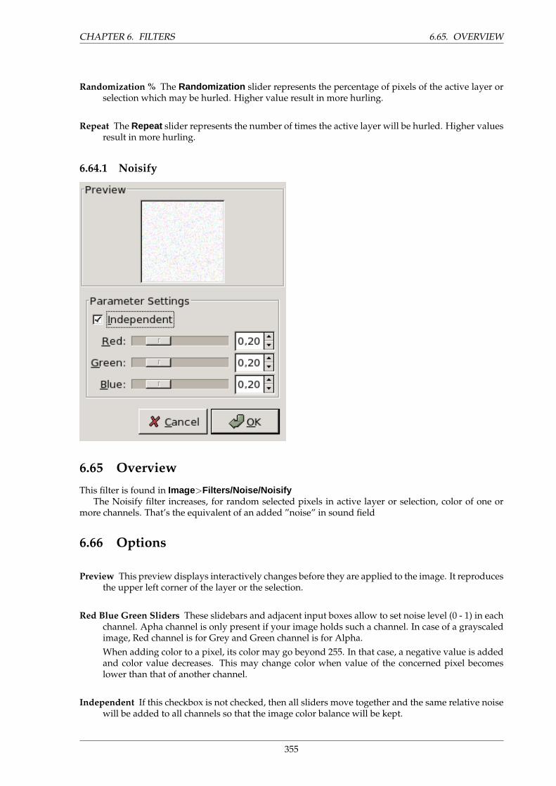
CHAPTER 6. FILTERS 6.65. OVERVIEW
Randomization % The Randomization slider represents the percentage of pixels of the active layer orselection which may be hurled. Higher value result in more hurling.
Repeat The Repeat slider represents the number of times the active layer will be hurled. Higher valuesresult in more hurling.
6.64.1 Noisify
6.65 Overview
This filter is found in Image>Filters/Noise/NoisifyThe Noisify filter increases, for random selected pixels in active layer or selection, color of one or
more channels. That’s the equivalent of an added ”noise” in sound field
6.66 Options
Preview This preview displays interactively changes before they are applied to the image. It reproducesthe upper left corner of the layer or the selection.
Red Blue Green Sliders These slidebars and adjacent input boxes allow to set noise level (0 - 1) in eachchannel. Apha channel is only present if your image holds such a channel. In case of a grayscaledimage, Red channel is for Grey and Green channel is for Alpha.When adding color to a pixel, its color may go beyond 255. In that case, a negative value is addedand color value decreases. This may change color when value of the concerned pixel becomeslower than that of another channel.
Independent If this checkbox is not checked, then all sliders move together and the same relative noisewill be added to all channels so that the image color balance will be kept.
355
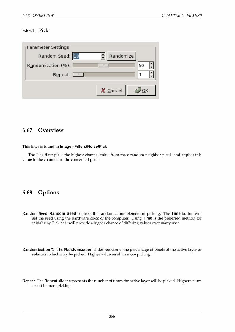
6.67. OVERVIEW CHAPTER 6. FILTERS
6.66.1 Pick
6.67 Overview
This filter is found in Image>Filters/Noise/Pick
The Pick filter picks the highest channel value from three random neighbor pixels and applies thisvalue to the channels in the concerned pixel.
6.68 Options
Random Seed Random Seed controls the randomization element of picking. The Time button willset the seed using the hardware clock of the computer. Using Time is the preferred method forinitializing Pick as it will provide a higher chance of differing values over many uses.
Randomization % The Randomization slider represents the percentage of pixels of the active layer orselection which may be picked. Higher value result in more picking.
Repeat The Repeat slider represents the number of times the active layer will be picked. Higher valuesresult in more picking.
356
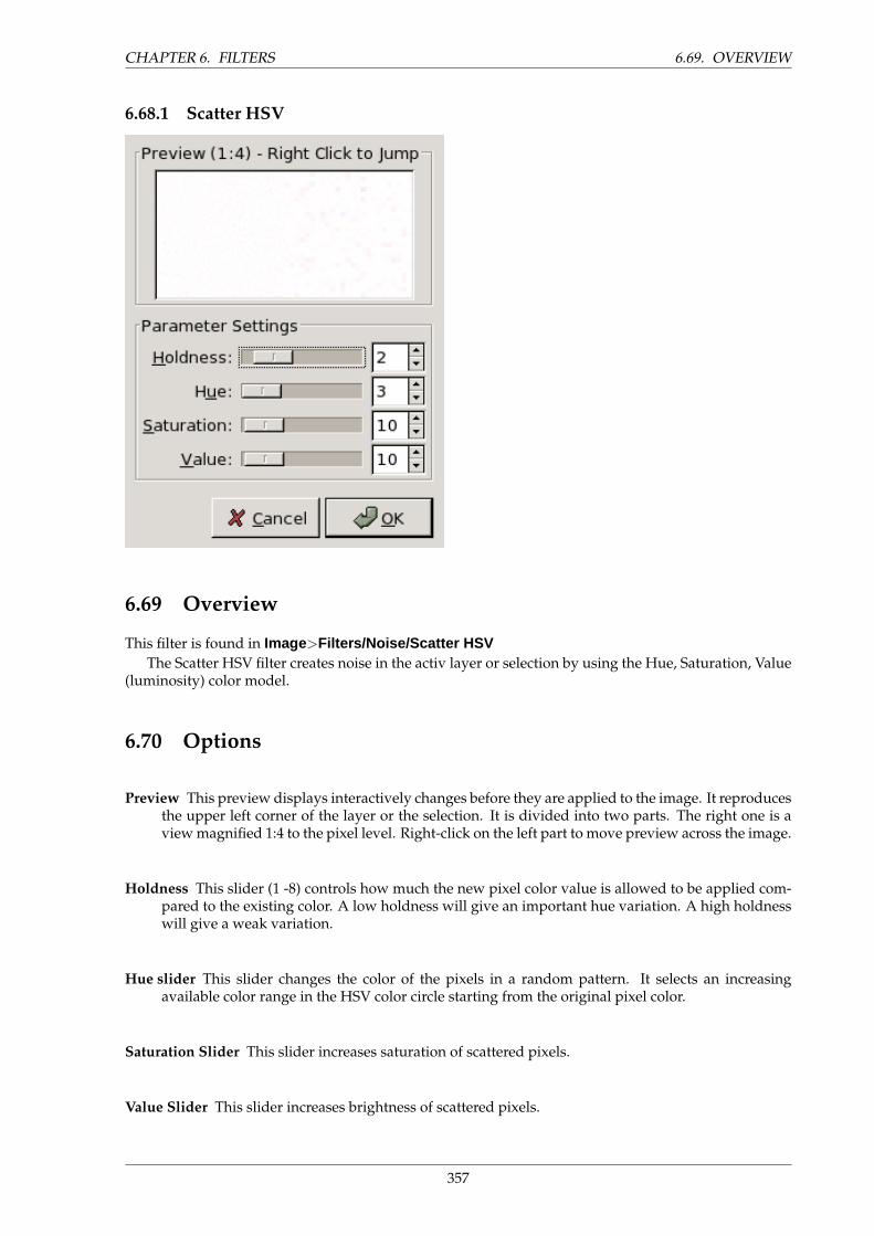
CHAPTER 6. FILTERS 6.69. OVERVIEW
6.68.1 Scatter HSV
6.69 Overview
This filter is found in Image>Filters/Noise/Scatter HSVThe Scatter HSV filter creates noise in the activ layer or selection by using the Hue, Saturation, Value
(luminosity) color model.
6.70 Options
Preview This preview displays interactively changes before they are applied to the image. It reproducesthe upper left corner of the layer or the selection. It is divided into two parts. The right one is aview magnified 1:4 to the pixel level. Right-click on the left part to move preview across the image.
Holdness This slider (1 -8) controls how much the new pixel color value is allowed to be applied com-pared to the existing color. A low holdness will give an important hue variation. A high holdnesswill give a weak variation.
Hue slider This slider changes the color of the pixels in a random pattern. It selects an increasingavailable color range in the HSV color circle starting from the original pixel color.
Saturation Slider This slider increases saturation of scattered pixels.
Value Slider This slider increases brightness of scattered pixels.
357
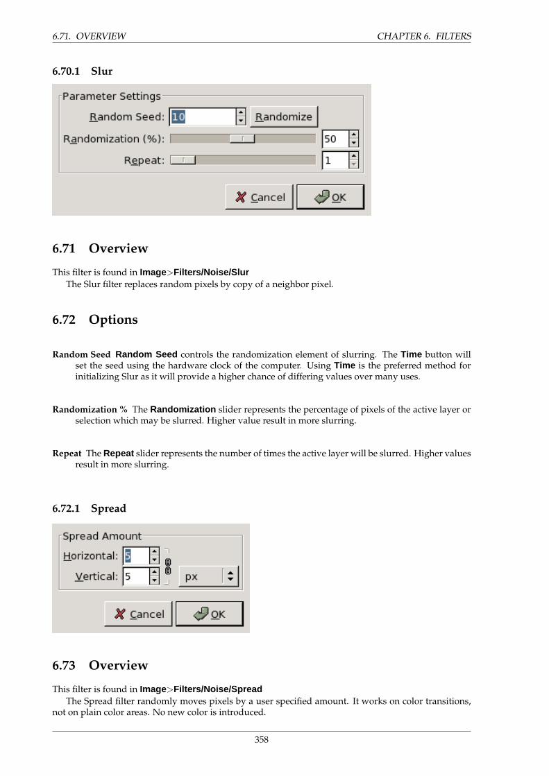
6.71. OVERVIEW CHAPTER 6. FILTERS
6.70.1 Slur
6.71 Overview
This filter is found in Image>Filters/Noise/SlurThe Slur filter replaces random pixels by copy of a neighbor pixel.
6.72 Options
Random Seed Random Seed controls the randomization element of slurring. The Time button willset the seed using the hardware clock of the computer. Using Time is the preferred method forinitializing Slur as it will provide a higher chance of differing values over many uses.
Randomization % The Randomization slider represents the percentage of pixels of the active layer orselection which may be slurred. Higher value result in more slurring.
Repeat The Repeat slider represents the number of times the active layer will be slurred. Higher valuesresult in more slurring.
6.72.1 Spread
6.73 Overview
This filter is found in Image>Filters/Noise/SpreadThe Spread filter randomly moves pixels by a user specified amount. It works on color transitions,
not on plain color areas. No new color is introduced.
358
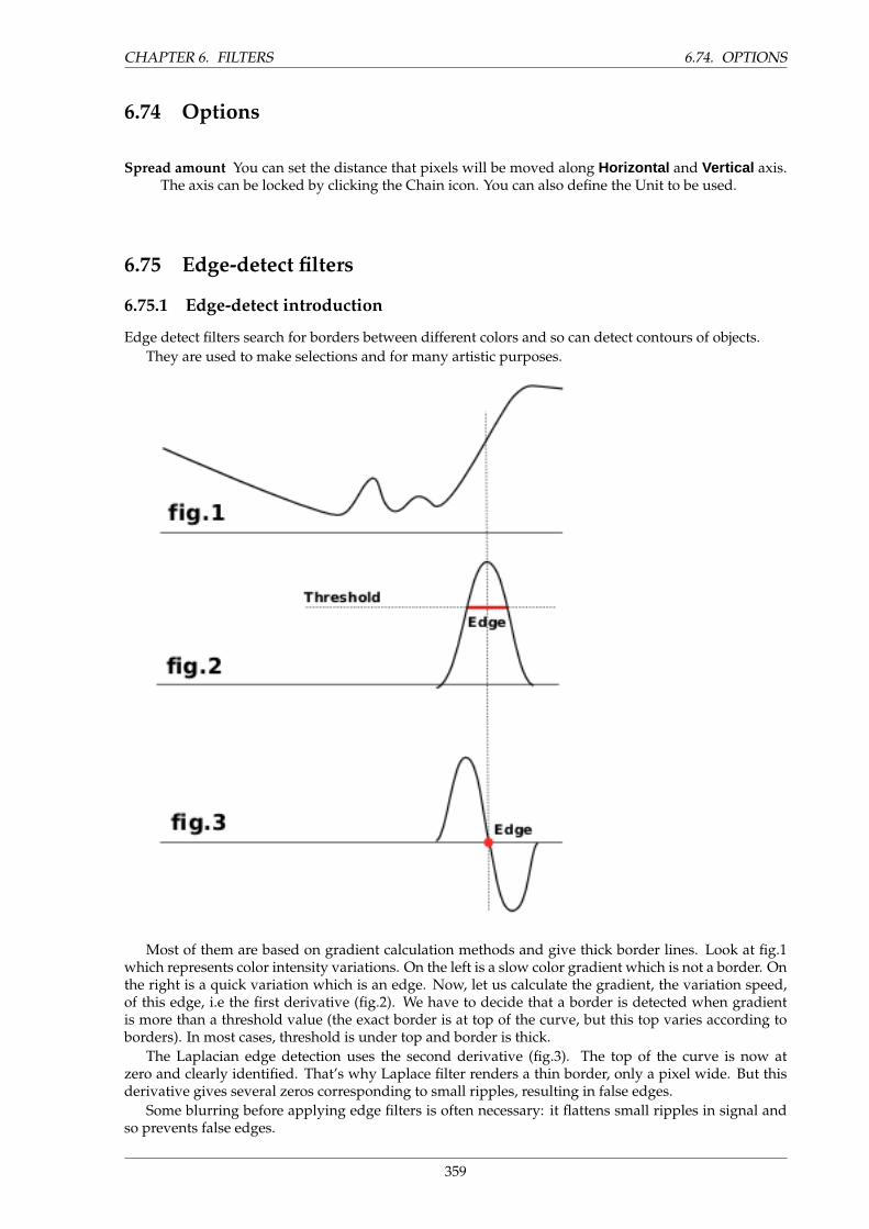
CHAPTER 6. FILTERS 6.74. OPTIONS
6.74 Options
Spread amount You can set the distance that pixels will be moved along Horizontal and Vertical axis.The axis can be locked by clicking the Chain icon. You can also define the Unit to be used.
6.75 Edge-detect filters
6.75.1 Edge-detect introduction
Edge detect filters search for borders between different colors and so can detect contours of objects.They are used to make selections and for many artistic purposes.
Most of them are based on gradient calculation methods and give thick border lines. Look at fig.1which represents color intensity variations. On the left is a slow color gradient which is not a border. Onthe right is a quick variation which is an edge. Now, let us calculate the gradient, the variation speed,of this edge, i.e the first derivative (fig.2). We have to decide that a border is detected when gradientis more than a threshold value (the exact border is at top of the curve, but this top varies according toborders). In most cases, threshold is under top and border is thick.
The Laplacian edge detection uses the second derivative (fig.3). The top of the curve is now atzero and clearly identified. That’s why Laplace filter renders a thin border, only a pixel wide. But thisderivative gives several zeros corresponding to small ripples, resulting in false edges.
Some blurring before applying edge filters is often necessary: it flattens small ripples in signal andso prevents false edges.
359
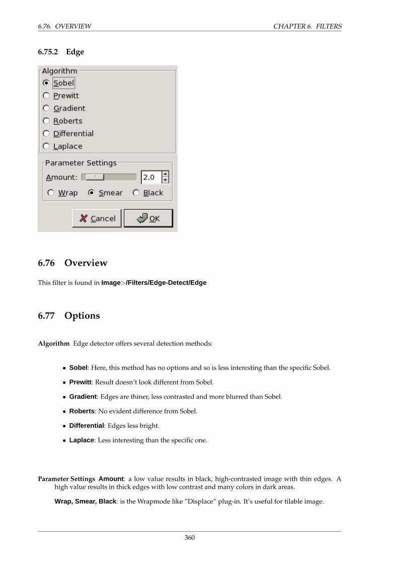
6.76. OVERVIEW CHAPTER 6. FILTERS
6.75.2 Edge
6.76 Overview
This filter is found in Image>/Filters/Edge-Detect/Edge
6.77 Options
Algorithm Edge detector offers several detection methods:
• Sobel : Here, this method has no options and so is less interesting than the specific Sobel.
• Prewitt : Result doesn’t look different from Sobel.
• Gradient : Edges are thiner, less contrasted and more blurred than Sobel.
• Roberts : No evident difference from Sobel.
• Differential : Edges less bright.
• Laplace : Less interesting than the specific one.
Parameter Settings Amount : a low value results in black, high-contrasted image with thin edges. Ahigh value results in thick edges with low contrast and many colors in dark areas.
Wrap, Smear, Black : is the Wrapmode like ”Displace” plug-in. It’s useful for tilable image.
360
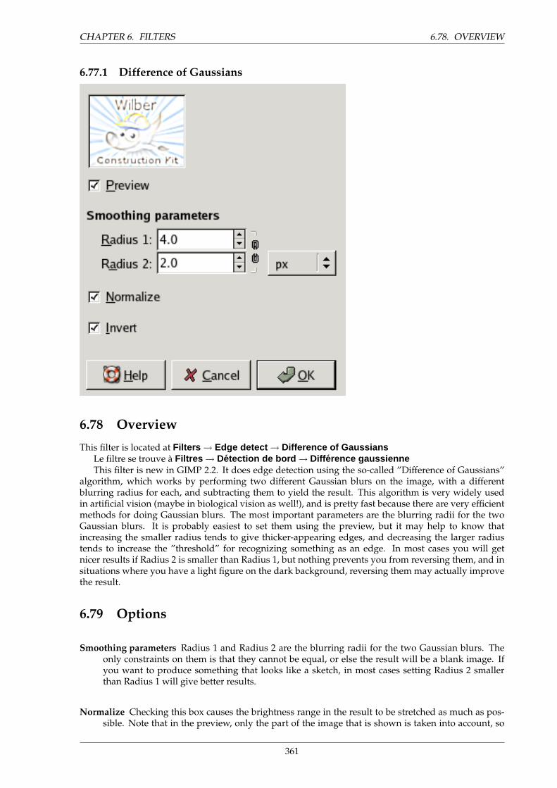
CHAPTER 6. FILTERS 6.78. OVERVIEW
6.77.1 Difference of Gaussians
6.78 Overview
This filter is located at Filters → Edge detect → Difference of GaussiansLe filtre se trouve a Filtres → Detection de bord → Diff erence gaussienneThis filter is new in GIMP 2.2. It does edge detection using the so-called ”Difference of Gaussians”
algorithm, which works by performing two different Gaussian blurs on the image, with a differentblurring radius for each, and subtracting them to yield the result. This algorithm is very widely usedin artificial vision (maybe in biological vision as well!), and is pretty fast because there are very efficientmethods for doing Gaussian blurs. The most important parameters are the blurring radii for the twoGaussian blurs. It is probably easiest to set them using the preview, but it may help to know thatincreasing the smaller radius tends to give thicker-appearing edges, and decreasing the larger radiustends to increase the ”threshold” for recognizing something as an edge. In most cases you will getnicer results if Radius 2 is smaller than Radius 1, but nothing prevents you from reversing them, and insituations where you have a light figure on the dark background, reversing them may actually improvethe result.
6.79 Options
Smoothing parameters Radius 1 and Radius 2 are the blurring radii for the two Gaussian blurs. Theonly constraints on them is that they cannot be equal, or else the result will be a blank image. Ifyou want to produce something that looks like a sketch, in most cases setting Radius 2 smallerthan Radius 1 will give better results.
Normalize Checking this box causes the brightness range in the result to be stretched as much as pos-sible. Note that in the preview, only the part of the image that is shown is taken into account, so
361
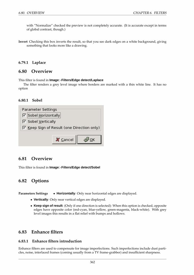
6.80. OVERVIEW CHAPTER 6. FILTERS
with ”Normalize” checked the preview is not completely accurate. (It is accurate except in termsof global contrast, though.)
Invert Checking this box inverts the result, so that you see dark edges on a white background, givingsomething that looks more like a drawing.
6.79.1 Laplace
6.80 Overview
This filter is found in Image>Filters/Edge detect/LaplaceThe filter renders a grey level image where borders are marked with a thin white line. It has no
option
6.80.1 Sobel
6.81 Overview
This filter is found in Image>Filters/Edge detect/Sobel
6.82 Options
Parameters Settings • Horizontally : Only near horizontal edges are displayed.
• Vertically : Only near vertical edges are displayed.
• Keep sign of result : (Only if one direction is selected): When this option is checked, oppositeedges have opposite color (red-cyan, blue-yellow, green-magenta, black-white). With greylevel images this results in a flat relief with bumps and hollows.
6.83 Enhance filters
6.83.1 Enhance filters introduction
Enhance filters are used to compensate for image imperfections. Such imperfections include dust parti-cles, noise, interlaced frames (coming usually from a TV frame-grabber) and insufficient sharpness.
362
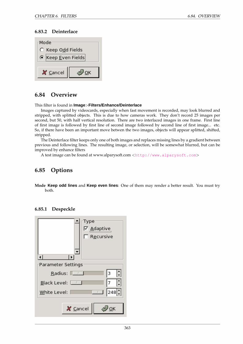
CHAPTER 6. FILTERS 6.84. OVERVIEW
6.83.2 Deinterlace
6.84 Overview
This filter is found in Image>Filters/Enhance/DeinterlaceImages captured by videocards, especially when fast movement is recorded, may look blurred and
stripped, with splitted objects. This is due to how cameras work. They don’t record 25 images persecond, but 50, with half vertical resolution. There are two interlaced images in one frame. First lineof first image is followed by first line of second image followed by second line of first image... etc.So, if there have been an important move betwen the two images, objects will appear splitted, shifted,stripped.
The Deinterlace filter keeps only one of both images and replaces missing lines by a gradient betweenprevious and following lines. The resulting image, or selection, will be somewhat blurred, but can beimproved by enhance filters
A test image can be found at www.alparysoft.com <http://www.alparysoft.com >
6.85 Options
Mode Keep odd lines and Keep even lines : One of them may render a better result. You must tryboth.
6.85.1 Despeckle
363
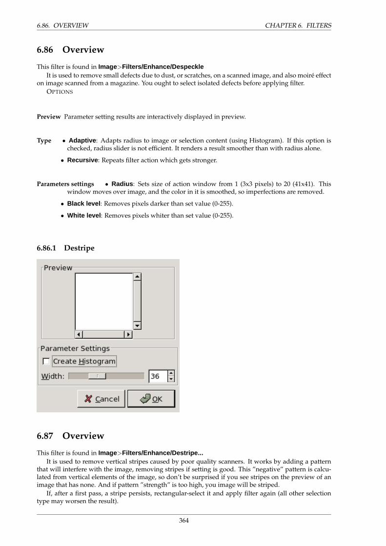
6.86. OVERVIEW CHAPTER 6. FILTERS
6.86 Overview
This filter is found in Image>Filters/Enhance/DespeckleIt is used to remove small defects due to dust, or scratches, on a scanned image, and also moire effect
on image scanned from a magazine. You ought to select isolated defects before applying filter.OPTIONS
Preview Parameter setting results are interactively displayed in preview.
Type • Adaptive : Adapts radius to image or selection content (using Histogram). If this option ischecked, radius slider is not efficient. It renders a result smoother than with radius alone.
• Recursive : Repeats filter action which gets stronger.
Parameters settings • Radius : Sets size of action window from 1 (3x3 pixels) to 20 (41x41). Thiswindow moves over image, and the color in it is smoothed, so imperfections are removed.
• Black level : Removes pixels darker than set value (0-255).
• White level : Removes pixels whiter than set value (0-255).
6.86.1 Destripe
6.87 Overview
This filter is found in Image>Filters/Enhance/Destripe...It is used to remove vertical stripes caused by poor quality scanners. It works by adding a pattern
that will interfere with the image, removing stripes if setting is good. This ”negative” pattern is calcu-lated from vertical elements of the image, so don’t be surprised if you see stripes on the preview of animage that has none. And if pattern ”strength” is too high, you image will be striped.
If, after a first pass, a stripe persists, rectangular-select it and apply filter again (all other selectiontype may worsen the result).
364
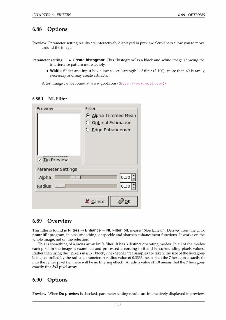
CHAPTER 6. FILTERS 6.88. OPTIONS
6.88 Options
Preview Parameter setting results are interactively displayed in preview. Scroll bars allow you to movearound the image.
Parameter setting • Create histogram : This ”histogram” is a black and white image showing theinterference pattern more legibly.
• Width : Slider and input box allow to set ”strength” of filter (2-100): more than 60 is rarelynecessary and may create artifacts.
A test image can be found at www.goof.com <http://www.goof.com >
6.88.1 NL Filter
6.89 Overview
This filter is found in Filters → Enhance → NL Filter . NL means ”Non Linear”. Derived from the Unixpnmnlfilt program, it joins smoothing, despeckle and sharpen enhancement functions. It works on thewhole image, not on the selection.
This is something of a swiss army knife filter. It has 3 distinct operating modes. In all of the modeseach pixel in the image is examined and processed according to it and its surrounding pixels values.Rather than using the 9 pixels in a 3x3 block, 7 hexagonal area samples are taken, the size of the hexagonsbeing controlled by the radius parameter. A radius value of 0.3333 means that the 7 hexagons exactly fitinto the center pixel (ie. there will be no filtering effect). A radius value of 1.0 means that the 7 hexagonsexactly fit a 3x3 pixel array.
6.90 Options
Preview When Do preview is checked, parameter setting results are interactively displayed in preview.
365
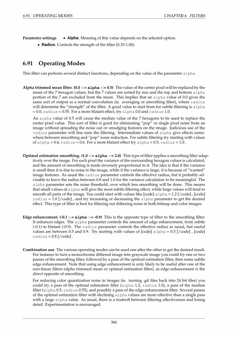
6.91. OPERATING MODES CHAPTER 6. FILTERS
Parameter settings • Alpha : Meaning of this value depends on the selected option.
• Radius : Controls the strength of the filter (0.33-1.00).
6.91 Operating Modes
This filter can perform several distinct functions, depending on the value of the parameter alpha .
Alpha trimmed mean filter. (0.0 <= alpha <= 0.5) The value of the center pixel will be replaced by themean of the 7 hexagon values, but the 7 values are sorted by size and the top and bottom alphaportion of the 7 are excluded from the mean. This implies that an alpha value of 0.0 gives thesame sort of output as a normal convolution (ie. averaging or smoothing filter), where radiuswill determine the ”strength” of the filter. A good value to start from for subtle filtering is alpha= 0.0, radius = 0.55. For a more blatant effect, try alpha 0.0 and radius 1.0.
An alpha value of 0.5 will cause the median value of the 7 hexagons to be used to replace thecenter pixel value. This sort of filter is good for eliminating ”pop” or single pixel noise from animage without spreading the noise out or smudging features on the image. Judicious use of theradius parameter will fine tune the filtering. Intermediate values of alpha give effects some-where between smoothing and ”pop” noise reduction. For subtle filtering try starting with valuesof alpha = 0.4, radius = 0.6. For a more blatant effect try alpha = 0.5, radius = 1.0 .
Optimal estimation smoothing. (1.0 <= alpha <= 2.0) This type of filter applies a smoothing filter adap-tively over the image. For each pixel the variance of the surrounding hexagon values is calculated,and the amount of smoothing is made inversely proportional to it. The idea is that if the varianceis small then it is due to noise in the image, while if the variance is large, it is because of ”wanted”image features. As usual the radius parameter controls the effective radius, but it probably ad-visable to leave the radius between 0.8 and 1.0 for the variance calculation to be meaningful. Thealpha parameter sets the noise threshold, over which less smoothing will be done. This meansthat small values of alpha will give the most subtle filtering effect, while large values will tend tosmooth all parts of the image. You could start with values like [code] alpha = 1.2 [/code] , [code]radius = 1.0 [/code] , and try increasing or decreasing the alpha parameter to get the desiredeffect. This type of filter is best for filtering out dithering noise in both bitmap and color images.
Edge enhancement. (-0.1 >= alpha >= -0.9) This is the opposite type of filter to the smoothing filter.It enhances edges. The alpha parameter controls the amount of edge enhancement, from subtle(-0.1) to blatant (-0.9). The radius parameter controls the effective radius as usual, but usefulvalues are between 0.5 and 0.9. Try starting with values of [code] alpha = 0.3 [/code] , [code]radius = 0.8 [/code] .
Combination use The various operating modes can be used one after the other to get the desired result.For instance to turn a monochrome dithered image into grayscale image you could try one or twopasses of the smoothing filter, followed by a pass of the optimal estimation filter, then some subtleedge enhancement. Note that using edge enhancement is only likely to be useful after one of thenon-linear filters (alpha trimmed mean or optimal estimation filter), as edge enhancement is thedirect opposite of smoothing.
For reducing color quantization noise in images (ie. turning .gif files back into 24 bit files) youcould try a pass of the optimal estimation filter (alpha 1.2, radius 1.0), a pass of the medianfilter (alpha 0.5, radius 0.55), and possibly a pass of the edge enhancement filter. Several passesof the optimal estimation filter with declining alpha values are more effective than a single passwith a large alpha value. As usual, there is a tradeoff between filtering effectiveness and losingdetail. Experimentation is encouraged.
366
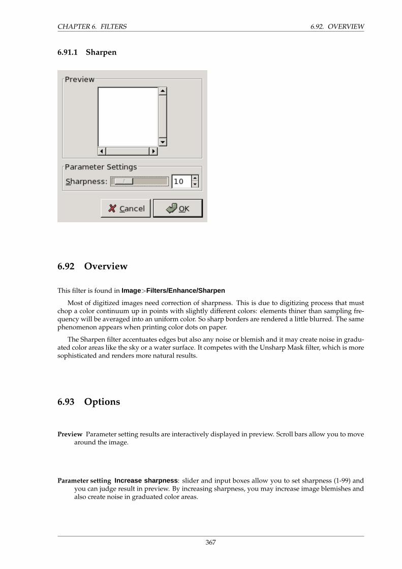
CHAPTER 6. FILTERS 6.92. OVERVIEW
6.91.1 Sharpen
6.92 Overview
This filter is found in Image>Filters/Enhance/Sharpen
Most of digitized images need correction of sharpness. This is due to digitizing process that mustchop a color continuum up in points with slightly different colors: elements thiner than sampling fre-quency will be averaged into an uniform color. So sharp borders are rendered a little blurred. The samephenomenon appears when printing color dots on paper.
The Sharpen filter accentuates edges but also any noise or blemish and it may create noise in gradu-ated color areas like the sky or a water surface. It competes with the Unsharp Mask filter, which is moresophisticated and renders more natural results.
6.93 Options
Preview Parameter setting results are interactively displayed in preview. Scroll bars allow you to movearound the image.
Parameter setting Increase sharpness : slider and input boxes allow you to set sharpness (1-99) andyou can judge result in preview. By increasing sharpness, you may increase image blemishes andalso create noise in graduated color areas.
367
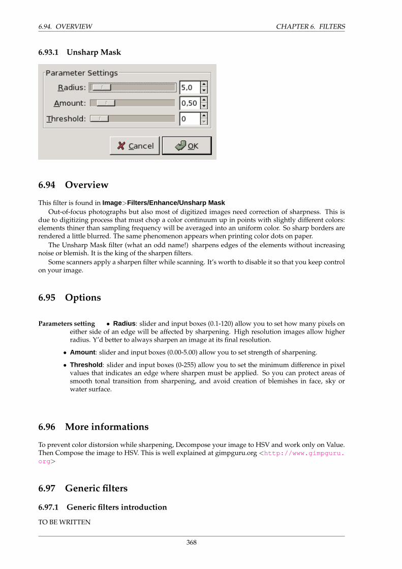
6.94. OVERVIEW CHAPTER 6. FILTERS
6.93.1 Unsharp Mask
6.94 Overview
This filter is found in Image>Filters/Enhance/Unsharp MaskOut-of-focus photographs but also most of digitized images need correction of sharpness. This is
due to digitizing process that must chop a color continuum up in points with slightly different colors:elements thiner than sampling frequency will be averaged into an uniform color. So sharp borders arerendered a little blurred. The same phenomenon appears when printing color dots on paper.
The Unsharp Mask filter (what an odd name!) sharpens edges of the elements without increasingnoise or blemish. It is the king of the sharpen filters.
Some scanners apply a sharpen filter while scanning. It’s worth to disable it so that you keep controlon your image.
6.95 Options
Parameters setting • Radius : slider and input boxes (0.1-120) allow you to set how many pixels oneither side of an edge will be affected by sharpening. High resolution images allow higherradius. Y’d better to always sharpen an image at its final resolution.
• Amount : slider and input boxes (0.00-5.00) allow you to set strength of sharpening.
• Threshold : slider and input boxes (0-255) allow you to set the minimum difference in pixelvalues that indicates an edge where sharpen must be applied. So you can protect areas ofsmooth tonal transition from sharpening, and avoid creation of blemishes in face, sky orwater surface.
6.96 More informations
To prevent color distorsion while sharpening, Decompose your image to HSV and work only on Value.Then Compose the image to HSV. This is well explained at gimpguru.org <http://www.gimpguru.org >
6.97 Generic filters
6.97.1 Generic filters introduction
TO BE WRITTEN
368
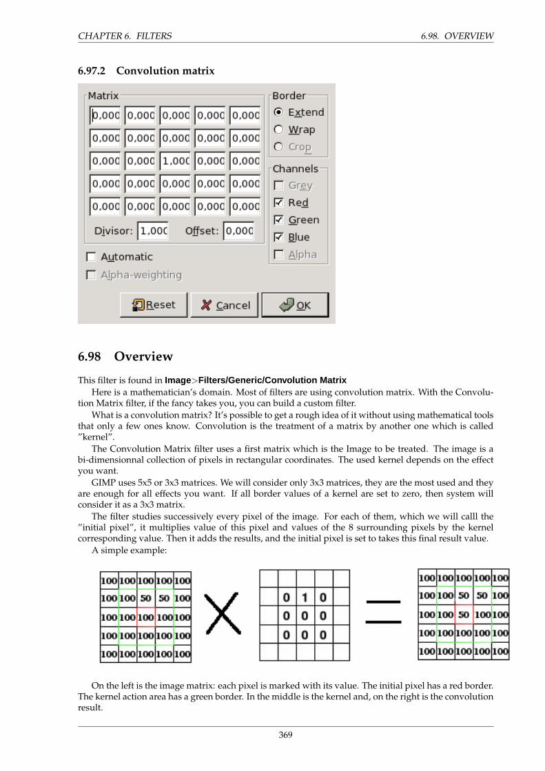
CHAPTER 6. FILTERS 6.98. OVERVIEW
6.97.2 Convolution matrix
6.98 Overview
This filter is found in Image>Filters/Generic/Convolution MatrixHere is a mathematician’s domain. Most of filters are using convolution matrix. With the Convolu-
tion Matrix filter, if the fancy takes you, you can build a custom filter.What is a convolution matrix? It’s possible to get a rough idea of it without using mathematical tools
that only a few ones know. Convolution is the treatment of a matrix by another one which is called”kernel”.
The Convolution Matrix filter uses a first matrix which is the Image to be treated. The image is abi-dimensionnal collection of pixels in rectangular coordinates. The used kernel depends on the effectyou want.
GIMP uses 5x5 or 3x3 matrices. We will consider only 3x3 matrices, they are the most used and theyare enough for all effects you want. If all border values of a kernel are set to zero, then system willconsider it as a 3x3 matrix.
The filter studies successively every pixel of the image. For each of them, which we will calll the”initial pixel”, it multiplies value of this pixel and values of the 8 surrounding pixels by the kernelcorresponding value. Then it adds the results, and the initial pixel is set to takes this final result value.
A simple example:
On the left is the image matrix: each pixel is marked with its value. The initial pixel has a red border.The kernel action area has a green border. In the middle is the kernel and, on the right is the convolutionresult.
369
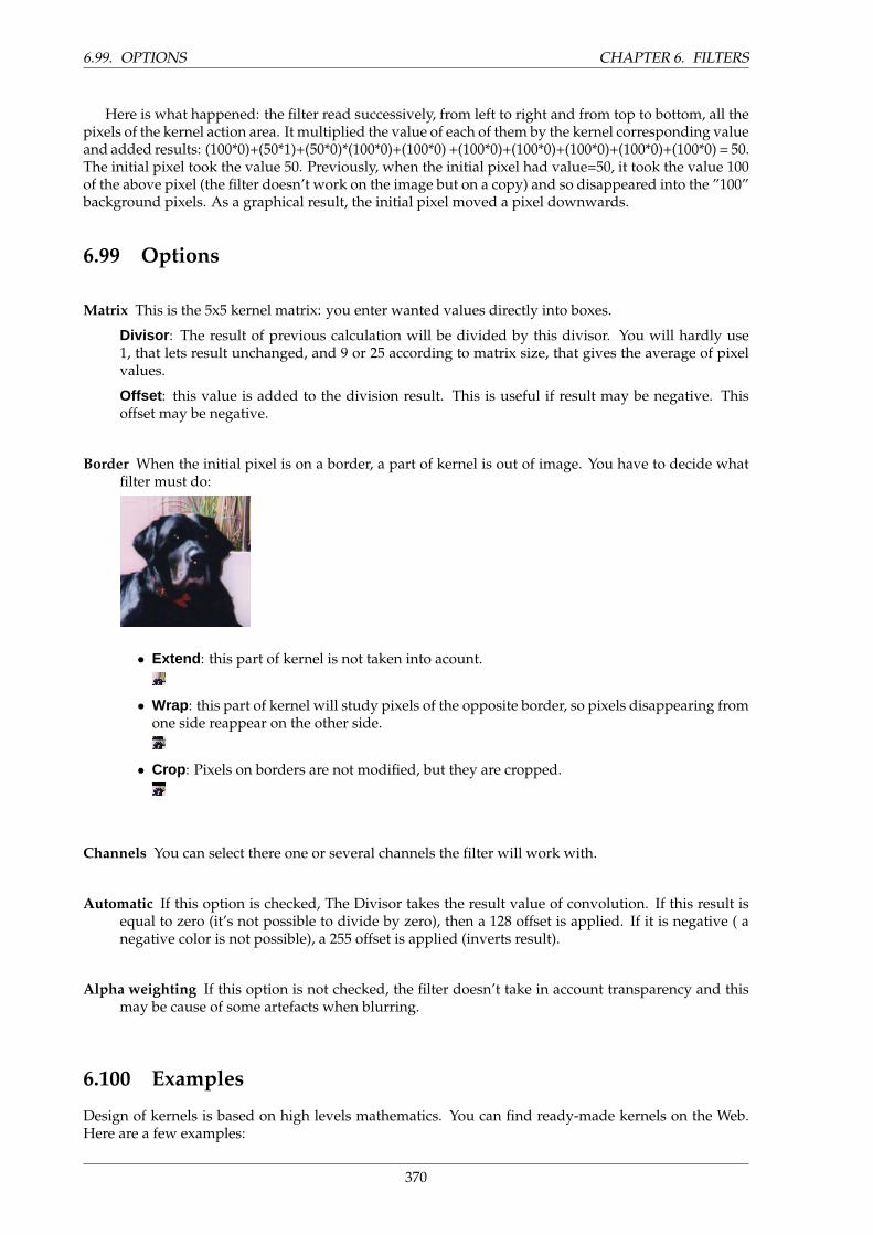
6.99. OPTIONS CHAPTER 6. FILTERS
Here is what happened: the filter read successively, from left to right and from top to bottom, all thepixels of the kernel action area. It multiplied the value of each of them by the kernel corresponding valueand added results: (100*0)+(50*1)+(50*0)*(100*0)+(100*0) +(100*0)+(100*0)+(100*0)+(100*0)+(100*0) = 50.The initial pixel took the value 50. Previously, when the initial pixel had value=50, it took the value 100of the above pixel (the filter doesn’t work on the image but on a copy) and so disappeared into the ”100”background pixels. As a graphical result, the initial pixel moved a pixel downwards.
6.99 Options
Matrix This is the 5x5 kernel matrix: you enter wanted values directly into boxes.
Divisor : The result of previous calculation will be divided by this divisor. You will hardly use1, that lets result unchanged, and 9 or 25 according to matrix size, that gives the average of pixelvalues.
Offset : this value is added to the division result. This is useful if result may be negative. Thisoffset may be negative.
Border When the initial pixel is on a border, a part of kernel is out of image. You have to decide whatfilter must do:
• Extend : this part of kernel is not taken into acount.
• Wrap : this part of kernel will study pixels of the opposite border, so pixels disappearing fromone side reappear on the other side.
• Crop : Pixels on borders are not modified, but they are cropped.
Channels You can select there one or several channels the filter will work with.
Automatic If this option is checked, The Divisor takes the result value of convolution. If this result isequal to zero (it’s not possible to divide by zero), then a 128 offset is applied. If it is negative ( anegative color is not possible), a 255 offset is applied (inverts result).
Alpha weighting If this option is not checked, the filter doesn’t take in account transparency and thismay be cause of some artefacts when blurring.
6.100 Examples
Design of kernels is based on high levels mathematics. You can find ready-made kernels on the Web.Here are a few examples:
370
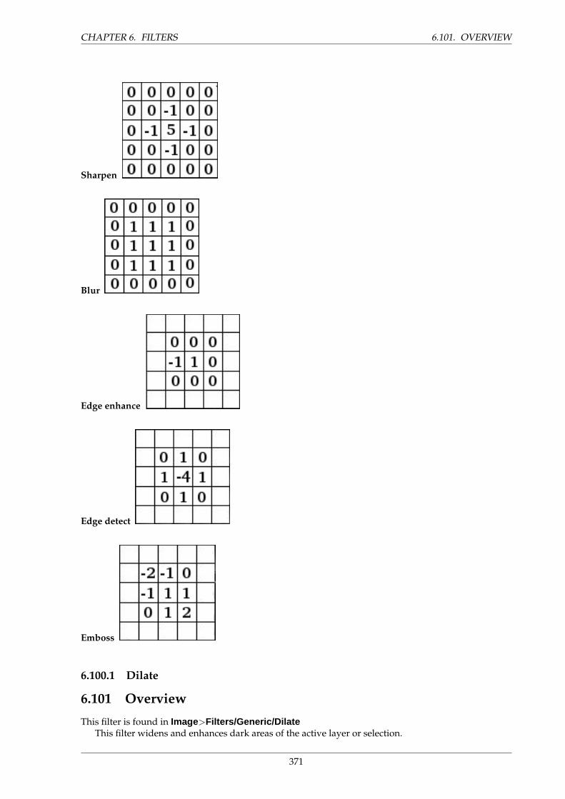
CHAPTER 6. FILTERS 6.101. OVERVIEW
Sharpen
Blur
Edge enhance
Edge detect
Emboss
6.100.1 Dilate
6.101 Overview
This filter is found in Image>Filters/Generic/DilateThis filter widens and enhances dark areas of the active layer or selection.
371

6.102. OPTIONS CHAPTER 6. FILTERS
For every image pixel, it brings the pixel Value (luminosity) into line with the lowest Value (thedarkest) of the 8 neighbouring pixels (3x3 matrix). So, a dark pixel is added around dark areas. Anisolated pixel on a brighter background will be changed to a big ”pixel”, composed of 9 pixels, and thatwill create some noise in the image.
In this image, the studied pixel has a red border and the studied matrix has a green border. I hopeyou have understood how to go on with the process and get a 3x3 pixel block: when the ”I” pixel isinside the green border, the studied pixel turns to black.
A larger dark area will dilate by one pixel in all directions:
The filter was applied 3 times.On more complex images, dark areas are widenned and enhanced the same, and somewhat pixel-
lated. Here, the filter was applied 3 times:
Of course, if background is darker than foreground, it will cover the whole image.
6.102 Options
This filter has no options.
6.103 Examples
Dilate text
Dilate neon effect
372
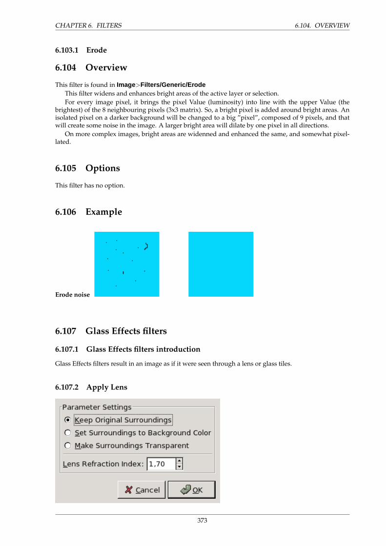
CHAPTER 6. FILTERS 6.104. OVERVIEW
6.103.1 Erode
6.104 Overview
This filter is found in Image>Filters/Generic/ErodeThis filter widens and enhances bright areas of the active layer or selection.For every image pixel, it brings the pixel Value (luminosity) into line with the upper Value (the
brightest) of the 8 neighbouring pixels (3x3 matrix). So, a bright pixel is added around bright areas. Anisolated pixel on a darker background will be changed to a big ”pixel”, composed of 9 pixels, and thatwill create some noise in the image. A larger bright area will dilate by one pixel in all directions.
On more complex images, bright areas are widenned and enhanced the same, and somewhat pixel-lated.
6.105 Options
This filter has no option.
6.106 Example
Erode noise
6.107 Glass Effects filters
6.107.1 Glass Effects filters introduction
Glass Effects filters result in an image as if it were seen through a lens or glass tiles.
6.107.2 Apply Lens
373
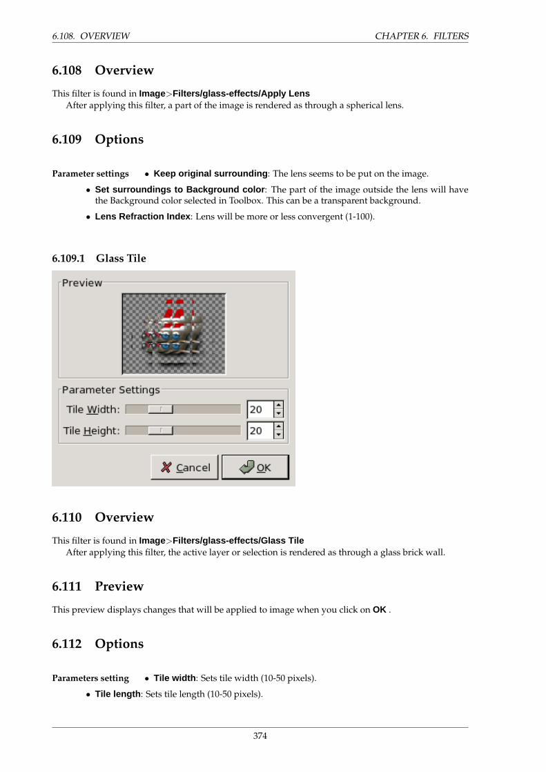
6.108. OVERVIEW CHAPTER 6. FILTERS
6.108 Overview
This filter is found in Image>Filters/glass-effects/Apply LensAfter applying this filter, a part of the image is rendered as through a spherical lens.
6.109 Options
Parameter settings • Keep original surrounding : The lens seems to be put on the image.
• Set surroundings to Background color : The part of the image outside the lens will havethe Background color selected in Toolbox. This can be a transparent background.
• Lens Refraction Index : Lens will be more or less convergent (1-100).
6.109.1 Glass Tile
6.110 Overview
This filter is found in Image>Filters/glass-effects/Glass TileAfter applying this filter, the active layer or selection is rendered as through a glass brick wall.
6.111 Preview
This preview displays changes that will be applied to image when you click on OK .
6.112 Options
Parameters setting • Tile width : Sets tile width (10-50 pixels).
• Tile length : Sets tile length (10-50 pixels).
374
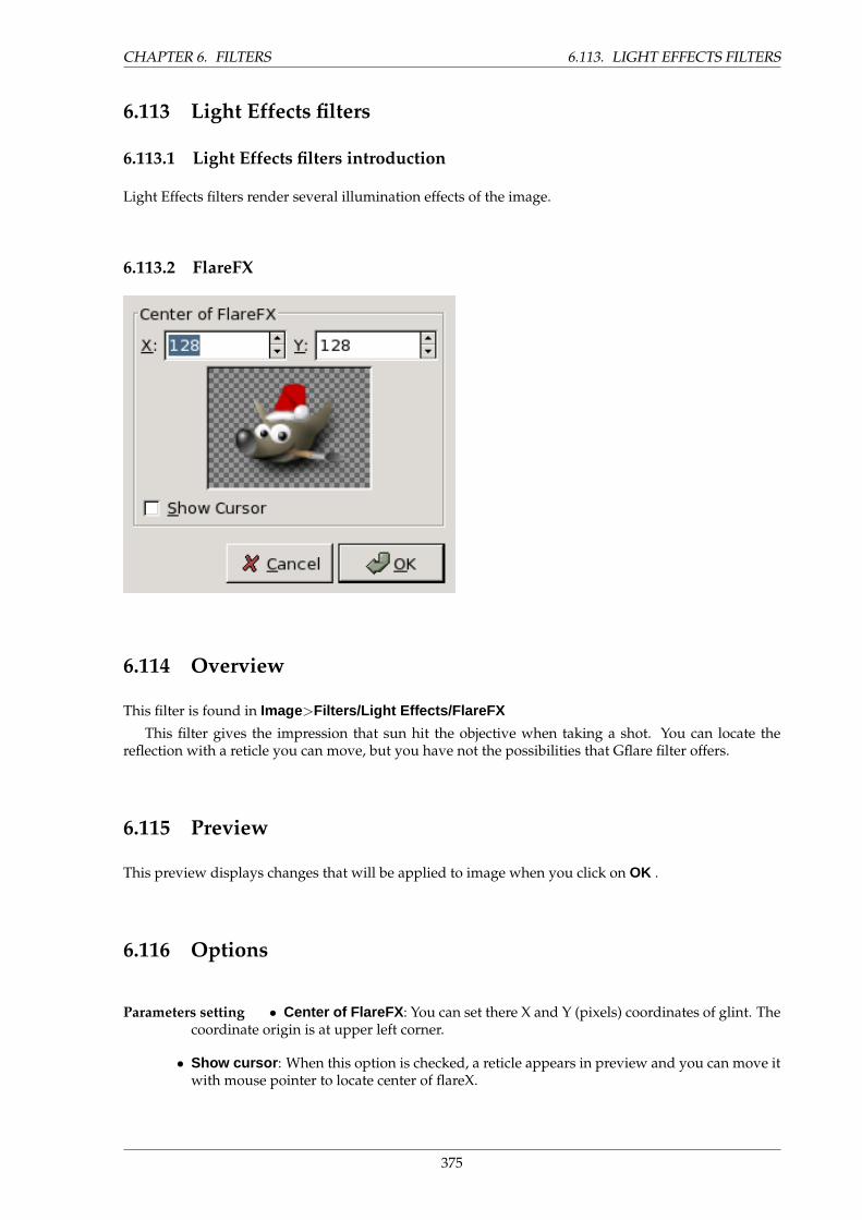
CHAPTER 6. FILTERS 6.113. LIGHT EFFECTS FILTERS
6.113 Light Effects filters
6.113.1 Light Effects filters introduction
Light Effects filters render several illumination effects of the image.
6.113.2 FlareFX
6.114 Overview
This filter is found in Image>Filters/Light Effects/FlareFX
This filter gives the impression that sun hit the objective when taking a shot. You can locate thereflection with a reticle you can move, but you have not the possibilities that Gflare filter offers.
6.115 Preview
This preview displays changes that will be applied to image when you click on OK .
6.116 Options
Parameters setting • Center of FlareFX : You can set there X and Y (pixels) coordinates of glint. Thecoordinate origin is at upper left corner.
• Show cursor : When this option is checked, a reticle appears in preview and you can move itwith mouse pointer to locate center of flareX.
375
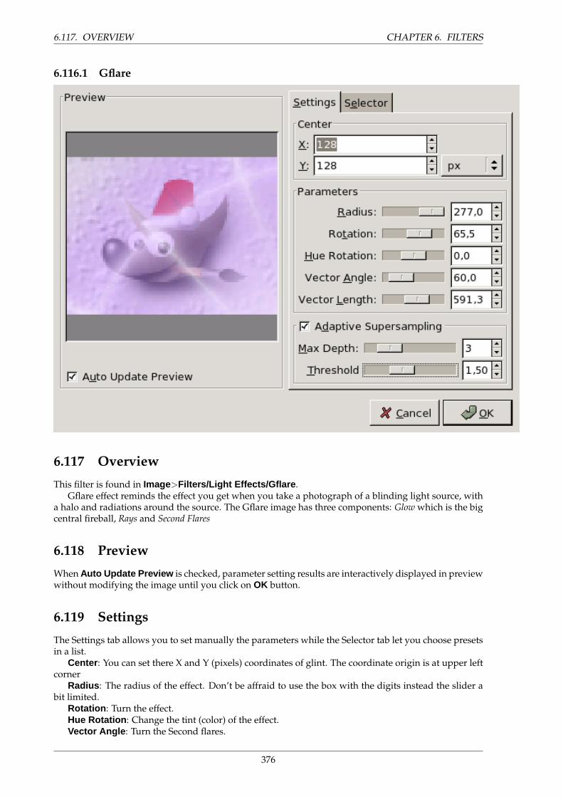
6.117. OVERVIEW CHAPTER 6. FILTERS
6.116.1 Gflare
6.117 Overview
This filter is found in Image>Filters/Light Effects/Gflare .Gflare effect reminds the effect you get when you take a photograph of a blinding light source, with
a halo and radiations around the source. The Gflare image has three components: Glow which is the bigcentral fireball, Rays and Second Flares
6.118 Preview
When Auto Update Preview is checked, parameter setting results are interactively displayed in previewwithout modifying the image until you click on OK button.
6.119 Settings
The Settings tab allows you to set manually the parameters while the Selector tab let you choose presetsin a list.
Center : You can set there X and Y (pixels) coordinates of glint. The coordinate origin is at upper leftcorner
Radius : The radius of the effect. Don’t be affraid to use the box with the digits instead the slider abit limited.
Rotation : Turn the effect.Hue Rotation : Change the tint (color) of the effect.Vector Angle : Turn the Second flares.
376
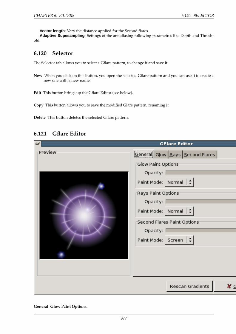
CHAPTER 6. FILTERS 6.120. SELECTOR
Vector length : Vary the distance applied for the Second flares.Adaptive Supesampling : Settings of the antialiasing following parametres like Depth and Thresh-
old.
6.120 Selector
The Selector tab allows you to select a Gflare pattern, to change it and save it.
New When you click on this button, you open the selected Gflare pattern and you can use it to create anew one with a new name.
Edit This button brings up the Gflare Editor (see below).
Copy This button allows you to save the modified Glare pattern, renaming it.
Delete This button deletes the selected Gflare pattern.
6.121 Gflare Editor
General Glow Paint Options.
377
6.121. GFLARE EDITOR CHAPTER 6. FILTERS
1. Opacity : Slider and input box give more opacity to glow (0-100).2. Paint Mode : You can choose between four modes:
• Normal: In this mode, the glow covers the image without taking into account what isbeneath.
• Addition: Pixel RGB values of glow are added to RGB values of the corresponding pixelsin the image. Colors get lighter and white areas may appear.
• Overlay: Light/Dark areas of glow enhance corresponding light/dark areas of image.• Screen: Dark areas of image are enlightened by corresponding light areas of glow. Imagin
two slides projected onto the same screen.
Rays Paint Options. Options are the same as for ”Glow”.
Second Flare Paint Options. Options are the same as for ”Glow”.
Glow Gradients.
1. By clicking on the rectangular buttons, you can develop a long list of gradients. ”%” gradientsbelong to the Editor.
2. Radial gradient : The selected gradient is drawn radially, from center to edge.3. Angular gradient : The selected gradient develops around center, counter-clockwise, start-
ing from three o’clock if ”Rotation” parameter is set to 0. Radial and angular gradients arecombined according to the Multiply mode: light areas are enhanced and colors are mixedaccording to CMYK color system (that of your printer).
4. Angular size gradient : This is a gradient of radius size which develops angularly. Radius iscontroled according to gradient Luminosity: if luminosity is zero (black), the radius is 0%. Ifluminosity is 100% (white), the radius is also 100%.
Parameters.
1. Size (%): Sets size (%) of glow (0-200).2. Rotation : Sets the origin of the angular gradient (-180 +180).3. Hue rotation : Sets glow color, according to the HSV color circle (-180 +180).
Rays Gradients.
1. The options are the same as for Glow.
Parameters.
1. The first three options are the same as in Glow. Two are new:2. # of spikes :This option determines the number of spikes (1-300) but also their texture.3. Spike Thickness : When spikes get wider (1-100), they look like flower petals
Second Flares Gradients. The options are the same as for Glow.
Parameters. Options are the same as in Glow.
Shape of Second Flares. Second flares, these satellites of the main flare, may have two shapes:Circle and Polygon. You can set the Number polygon sides. The option accepts 1 side (!), not 2.
Random seed and Randomize.
1. Random Seed : The random generator will use this value as a seed to generate randomnumbers. You can use the same value to repeat the same ”random” sequence several times.
2. Randomize : When you click on this button, you produce a random seed that will be used bythe random generator. It is each time different.
378
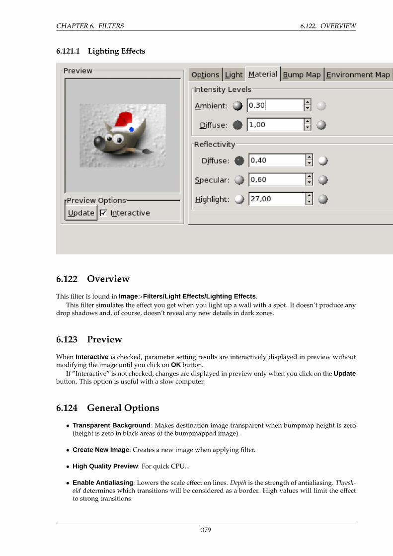
CHAPTER 6. FILTERS 6.122. OVERVIEW
6.121.1 Lighting Effects
6.122 Overview
This filter is found in Image>Filters/Light Effects/Lighting Effects .This filter simulates the effect you get when you light up a wall with a spot. It doesn’t produce any
drop shadows and, of course, doesn’t reveal any new details in dark zones.
6.123 Preview
When Interactive is checked, parameter setting results are interactively displayed in preview withoutmodifying the image until you click on OK button.
If ”Interactive” is not checked, changes are displayed in preview only when you click on the Updatebutton. This option is useful with a slow computer.
6.124 General Options
• Transparent Background : Makes destination image transparent when bumpmap height is zero(height is zero in black areas of the bumpmapped image).
• Create New Image : Creates a new image when applying filter.
• High Quality Preview : For quick CPU...
• Enable Antialiasing : Lowers the scale effect on lines. Depth is the strength of antialiasing. Thresh-old determines which transitions will be considered as a border. High values will limit the effectto strong transitions.
379
6.125. LIGHT CHAPTER 6. FILTERS
6.125 Light
Light Settings Light Type : Three types are available. Point displays a blue point at center of preview.You can click and drag it to move light all over the preview. Directional: the blue point is linkedto preview center by a line which indicates direction of light. The white light halo has an ellipticshape. None: there is no blue point. Light comes from the top left corner, the best to give a goodrelief effect.
Light Source Color : When you click on the color dwell, you bring a dialog up where you canselect the light source color.
Position : Determines the light point position according to three coordinates: X coordinate forhorizontal position, Y for vertical position, Z for source distance (the light darkens when distanceincreases). Values are from -1 to +1.
6.126 Material
Intensity Levels These options don’t concern light itself, but light reflected by objects.
Ambient : Sets the ambient light, i.e the indirect light which lightens all the scene out of the lightspot
Diffuse : When you increase this value, light progressively diffuses to the whole image
Reflectivity Diffuse : Higher values make the object reflect more light.
Specular : Controls how intense will be the highlights.
Highlights : Higher values make the highlights more focused.
6.127 Bump Map
Enable Bump Mapping Combined with ”Environment Map”, this option allows interesting bump map-ping. Only greyscale images can be used for bumpmaps (light areas are bumped, dark areas re-main unchanged). So, if you want to bumpmap against a RGB image, you have to turn it togreyscale first (<Image>Image/Mode/Grayscale). When you check this box, following optionsare enabled:
• Bump Map Image : You have to select there the greyscale image.• Curve : Four curve types are available: Linear, Logarithmic, Sinusoidal and Spherical. See Bump
Map plug-in for explanations.• Maximum Height : This is the maximum height of bumps.• Minimum Height : This is the minimum height of bumps.• Autostretch to fit Value Range : There is correspondence between grey level and height. If
difference between black and lightest grey is not enough to fill the height value range deter-mined above, then values are stretched.
6.128 Environment Map
Enable Environment Mapping When you check this box, the following option is enabled:
• Environment Image : You have to select there a RGB image.
380
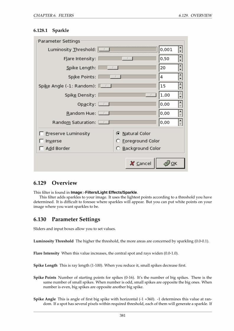
CHAPTER 6. FILTERS 6.129. OVERVIEW
6.128.1 Sparkle
6.129 Overview
This filter is found in Image>Filters/Light Effects/Sparkle .This filter adds sparkles to your image. It uses the lightest points according to a threshold you have
determined. It is difficult to foresee where sparkles will appear. But you can put white points on yourimage where you want sparkles to be.
6.130 Parameter Settings
Sliders and input boxes allow you to set values.
Luminosity Threshold The higher the threshold, the more areas are concerned by sparkling (0.0-0.1).
Flare Intensity When this value increases, the central spot and rays widen (0.0-1.0).
Spike Length This is ray length (1-100). When you reduce it, small spikes decrease first.
Spike Points Number of starting points for spikes (0-16). It’s the number of big spikes. There is thesame number of small spikes. When number is odd, small spikes are opposite the big ones. Whennumber is even, big spikes are opposite another big spike.
Spike Angle This is angle of first big spike with horizontal (-1 +360). -1 determines this value at ran-dom. If a spot has several pixels within required threshold, each of them will generate a sparkle. If
381
6.130. PARAMETER SETTINGS CHAPTER 6. FILTERS
angle is positive, they will all be superimposed. With -1, each sparkle will have a random rotationresulting in numerous thin spikes.
Spike Density This option determines the number of sparkles on your image. It indicates the percent-age (0.0-1.0) of all possible sparkles that will be preserved.
Opacity When you decrease Opacity (0.0-1.0), sparkles become more transparent and the layer beneathbecomes visible. If there is no other layer, sparkle saturation decreases.
Random Hue This option should change sparkle hue at random... (0.0-1.0)
Random Saturation This option should change sparkle saturation at random... (0.0-1.0)
Preserve Luminosity Gives to all central pixels the luminosity of the brightest pixel, resulting in in-creasing the whole sparkle luminosity.
Inverse Instead of selecting brightest pixels in image, Sparkle will select the darkest ones, resulting indark sparkles.
Add Border Instead of creating sparkles on brightest pixels, this option creates an image border madeup of numerous sparkles.
Colors You can change there the color of central pixels. This color will be added in Screen mode (Mul-tiply if Inverse is checked).
382
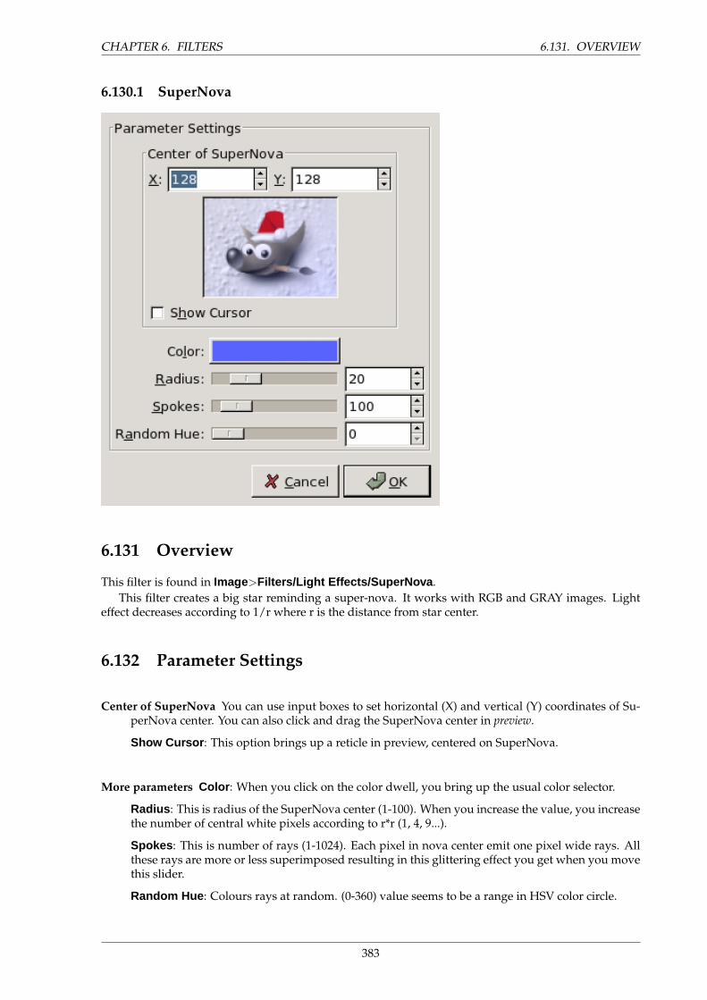
CHAPTER 6. FILTERS 6.131. OVERVIEW
6.130.1 SuperNova
6.131 Overview
This filter is found in Image>Filters/Light Effects/SuperNova .This filter creates a big star reminding a super-nova. It works with RGB and GRAY images. Light
effect decreases according to 1/r where r is the distance from star center.
6.132 Parameter Settings
Center of SuperNova You can use input boxes to set horizontal (X) and vertical (Y) coordinates of Su-perNova center. You can also click and drag the SuperNova center in preview.
Show Cursor : This option brings up a reticle in preview, centered on SuperNova.
More parameters Color : When you click on the color dwell, you bring up the usual color selector.
Radius : This is radius of the SuperNova center (1-100). When you increase the value, you increasethe number of central white pixels according to r*r (1, 4, 9...).
Spokes : This is number of rays (1-1024). Each pixel in nova center emit one pixel wide rays. Allthese rays are more or less superimposed resulting in this glittering effect you get when you movethis slider.
Random Hue : Colours rays at random. (0-360) value seems to be a range in HSV color circle.
383
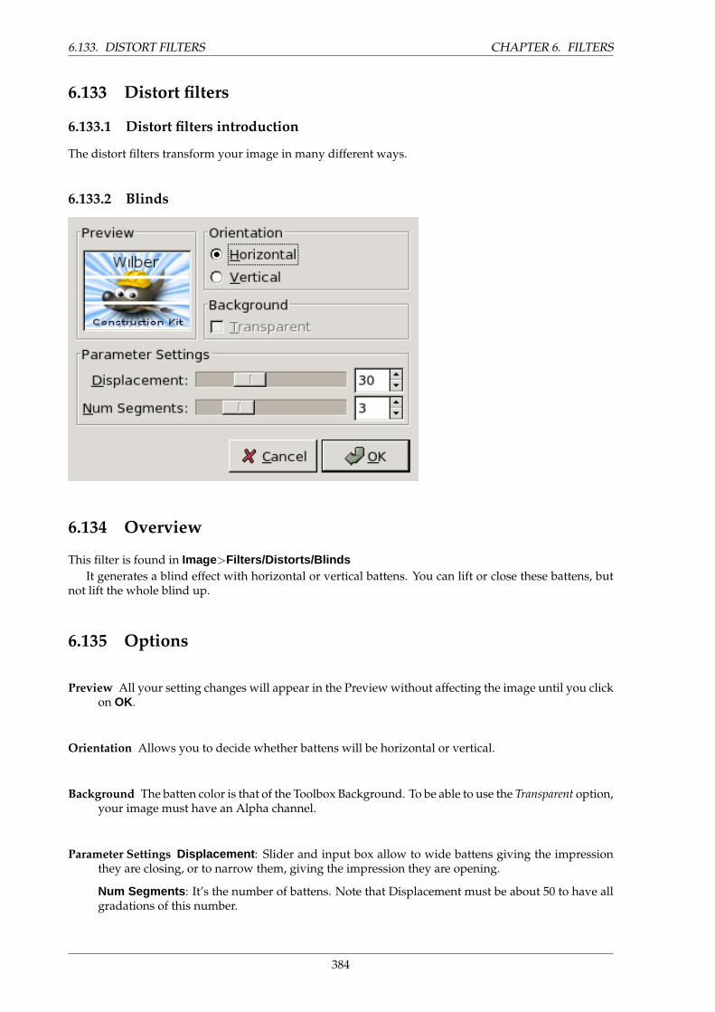
6.133. DISTORT FILTERS CHAPTER 6. FILTERS
6.133 Distort filters
6.133.1 Distort filters introduction
The distort filters transform your image in many different ways.
6.133.2 Blinds
6.134 Overview
This filter is found in Image>Filters/Distorts/BlindsIt generates a blind effect with horizontal or vertical battens. You can lift or close these battens, but
not lift the whole blind up.
6.135 Options
Preview All your setting changes will appear in the Preview without affecting the image until you clickon OK.
Orientation Allows you to decide whether battens will be horizontal or vertical.
Background The batten color is that of the Toolbox Background. To be able to use the Transparent option,your image must have an Alpha channel.
Parameter Settings Displacement : Slider and input box allow to wide battens giving the impressionthey are closing, or to narrow them, giving the impression they are opening.
Num Segments : It’s the number of battens. Note that Displacement must be about 50 to have allgradations of this number.
384
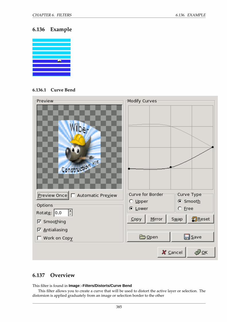
CHAPTER 6. FILTERS 6.136. EXAMPLE
6.136 Example
6.136.1 Curve Bend
6.137 Overview
This filter is found in Image>Filters/Distorts/Curve BendThis filter allows you to create a curve that will be used to distort the active layer or selection. The
distorsion is applied graduately from an image or selection border to the other
385
6.138. PREVIEW CHAPTER 6. FILTERS
6.138 Preview
The preview displays changes to image or selection without modifying the image until you press OK.
Preview Once This button allows you to update the preview each time you need it.
Automatic Preview With this option, preview is changed in real time. This needs much calculation andmay lengthen work. It is particularly evident when using ”Rotation”.
6.139 Options
Rotate There, you can set the application angle of filter (0-360 counter- clockwise). 0 is default setting:The curve will be applied from the upper border and/or from the lower. Set to 90, it will be appliedfrom left border and/or from the right one.
Smoothing and Antialiasing The distort process may create hard and stepped borders. These two op-tions improve this aspect.
Work on Copy This option creates a new layer called ”Curve bend dummy layer b” which becomesthe active layer, allowing you to see changes to your image in normal size without modifying theoriginal image until you press the ”OK” key.
6.140 Modify Curve
The Grid In this grid, you have a marked horizontal line, with a node at both ends, which representsby default the upper border of image. If you click on this curve, a new node appears, that you candrag to modify the curve as you want. You can create several nodes on the curve.
You can have only two curves on the grid, one for the so named ”upper” border and the other forthe so named ”lower” border. You can activate one of them by checking the Upper or Lower radiobutton.
If you use the Curve Type Free option, the curve you draw will replace the active curve.
Curve for Border There you can select whether the active curve must be applied to the Superior (or left)or the Inferior (or right) border, according to the rotation.
Curve Type With the Smooth, you get automatically a well rounded curve when you drag a node.
The Free option allows you to draw a curve freely. It will replace the active curve.
Buttons Copy : Copy the active curve to the other border.
Mirror : Mirror the active curve to the other border.
Swap : Swap the ”superior” and ”inferior” curves
Reset : Reset the active curve.
Open : Load the curve from a file.
Save: Save the curve to a file.
386
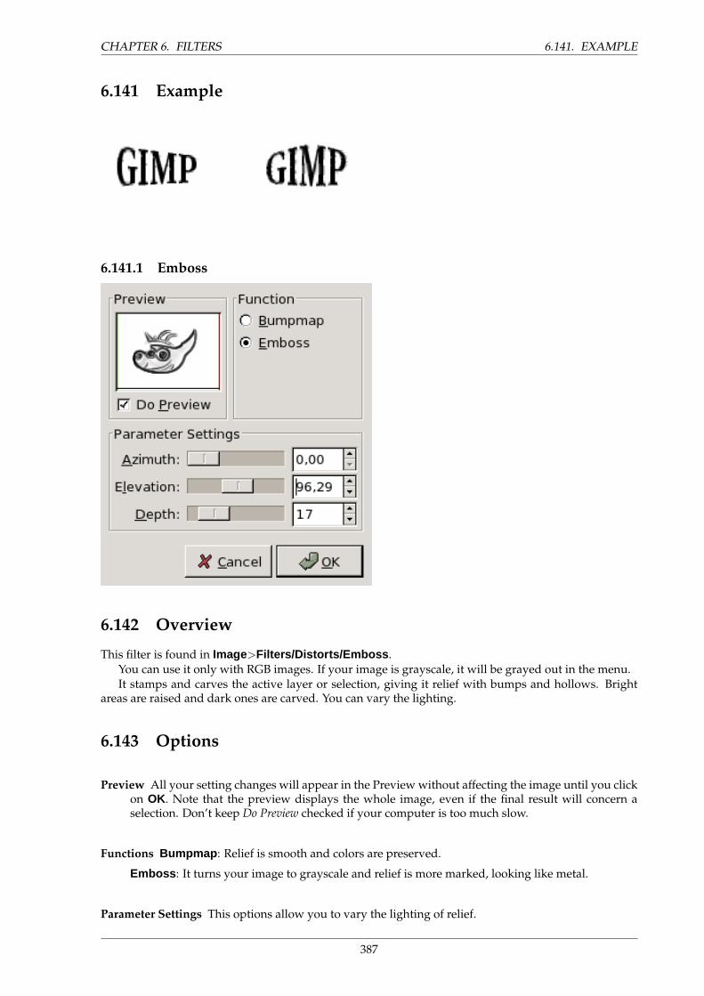
CHAPTER 6. FILTERS 6.141. EXAMPLE
6.141 Example
6.141.1 Emboss
6.142 Overview
This filter is found in Image>Filters/Distorts/Emboss .You can use it only with RGB images. If your image is grayscale, it will be grayed out in the menu.It stamps and carves the active layer or selection, giving it relief with bumps and hollows. Bright
areas are raised and dark ones are carved. You can vary the lighting.
6.143 Options
Preview All your setting changes will appear in the Preview without affecting the image until you clickon OK. Note that the preview displays the whole image, even if the final result will concern aselection. Don’t keep Do Preview checked if your computer is too much slow.
Functions Bumpmap : Relief is smooth and colors are preserved.
Emboss : It turns your image to grayscale and relief is more marked, looking like metal.
Parameter Settings This options allow you to vary the lighting of relief.
387

6.144. OVERVIEW CHAPTER 6. FILTERS
• Azimuth : This is about lighting according to the points of the compass (0 - 360). If yousuppose South is at the top of your image, then East (0◦) is on the left. Increasing value goescounter-clockwise.
• Elevation : That’s heighth from horizon (0◦), in principle up to zenith (90◦), but here up to theopposite horizon (180◦).
• Depth Seems to be the distance of the light source. Light decreases when value increases.
6.143.1 IWarp
6.144 Overview
This filter is found in Image>Filters/Distorts/IWarpThis filter allows you to deform interactively some parts of the image and, thanks to its Animate
option, to create the elements of a fade in/fade out animation between the original image and the de-formed one, that you can play and use in a Web page.
To use it, first select a deform type then click on the Preview and drag the mouse pointer.
6.145 Preview
Here, the Preview is your work space: You click on the Preview and drag mouse pointer. The under-lying part of image will be deformed according to the settings you have choosen. If your work is notconvenient, press Reset button.
6.146 Settings
The Settings tab allows you to set parameters which will affect the preview you are working on. So, youcan apply different deform modes to different parts of the preview.
388
CHAPTER 6. FILTERS 6.147. ANIMATE
Deform Radius Defines the radius, in pixels (5-100), of the filter action circle around the pixel pointedby the mouse.
Deform Amount Sets how much out of shape your image will be put (0.0-1.0).
Deform Mode Move : Allows you to stretch parts of the image.
Remove : This remove the distortion where you drag the mouse pointer, partially or completely.This allows you to avoid pressing Reset button, working on the whole image. Be careful whenworking on an animation: this option will affect one frame only.
Grow : This option inflates the pointed pattern.
Shrink : Self explanatory.
Swirl CCW : Create a vortex counter clockwise.
Swirl CW : Create a vortex clockwise.
Bilinear This option smoothes the IWarp effect.
Adaptative Supersample This option renders a better image at the cost of increased calculation.
Max Depth : FIXME
Threshold : FIXME
6.147 Animate
This option allows to generate several intermediate images between the original image and the finaldeformation of this image. You can play this animation thanks to the plugin Playback .
Number of Frames That’s the number of images in your animation (2-100). These frames are stored aslayers attached to your image. Use the XCF format when saving it.
Reverse This option plays the animation backwards.
Ping-Pong When the animation ends one way, it goes backwards.
389
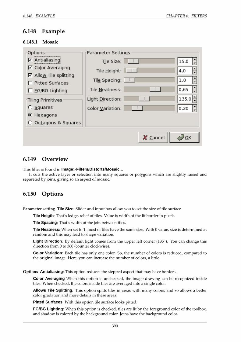
6.148. EXAMPLE CHAPTER 6. FILTERS
6.148 Example
6.148.1 Mosaic
6.149 Overview
This filter is found in Image>Filters/Distorts/Mosaic...It cuts the active layer or selection into many squares or polygons which are slightly raised and
separeted by joins, giving so an aspect of mosaic.
6.150 Options
Parameter setting Tile Size : Slider and input box allow you to set the size of tile surface.
Tile Heigth : That’s ledge, relief of tiles. Value is width of the lit border in pixels.
Tile Spacing : That’s width of the join between tiles.
Tile Neatness : When set to 1, most of tiles have the same size. With 0 value, size is determined atrandom and this may lead to shape variation.
Light Direction : By default light comes from the upper left corner (135◦). You can change thisdirection from 0 to 360 (counter clockwise).
Color Variation : Each tile has only one color. So, the number of colors is reduced, compared tothe original image. Here, you can increase the number of colors, a little.
Options Antialiasing : This option reduces the stepped aspect that may have borders.
Color Averaging When this option is unchecked, the image drawing can be recognized insidetiles. When checked, the colors inside tiles are averaged into a single color.
Allows Tile Splitting : This option splits tiles in areas with many colors, and so allows a bettercolor gradation and more details in these areas.
Pitted Surfaces : With this option tile surface looks pitted.
FG/BG Lighting : When this option is checked, tiles are lit by the foreground color of the toolbox,and shadow is colored by the background color. Joins have the background color.
390
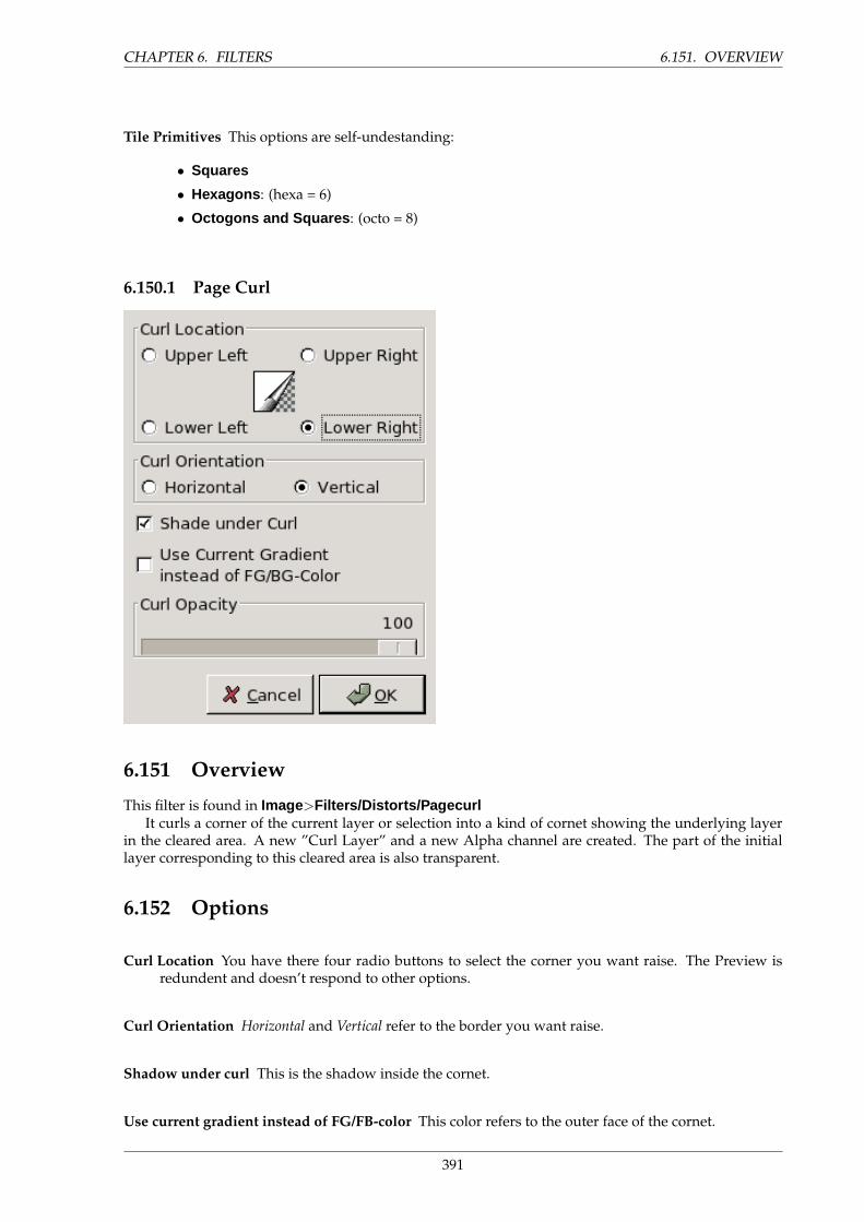
CHAPTER 6. FILTERS 6.151. OVERVIEW
Tile Primitives This options are self-undestanding:
• Squares
• Hexagons : (hexa = 6)
• Octogons and Squares : (octo = 8)
6.150.1 Page Curl
6.151 Overview
This filter is found in Image>Filters/Distorts/PagecurlIt curls a corner of the current layer or selection into a kind of cornet showing the underlying layer
in the cleared area. A new ”Curl Layer” and a new Alpha channel are created. The part of the initiallayer corresponding to this cleared area is also transparent.
6.152 Options
Curl Location You have there four radio buttons to select the corner you want raise. The Preview isredundent and doesn’t respond to other options.
Curl Orientation Horizontal and Vertical refer to the border you want raise.
Shadow under curl This is the shadow inside the cornet.
Use current gradient instead of FG/FB-color This color refers to the outer face of the cornet.
391
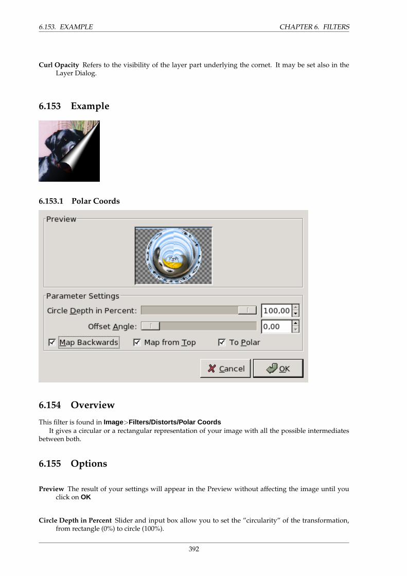
6.153. EXAMPLE CHAPTER 6. FILTERS
Curl Opacity Refers to the visibility of the layer part underlying the cornet. It may be set also in theLayer Dialog.
6.153 Example
6.153.1 Polar Coords
6.154 Overview
This filter is found in Image>Filters/Distorts/Polar CoordsIt gives a circular or a rectangular representation of your image with all the possible intermediates
between both.
6.155 Options
Preview The result of your settings will appear in the Preview without affecting the image until youclick on OK
Circle Depth in Percent Slider and input box allow you to set the ”circularity” of the transformation,from rectangle (0%) to circle (100%).
392
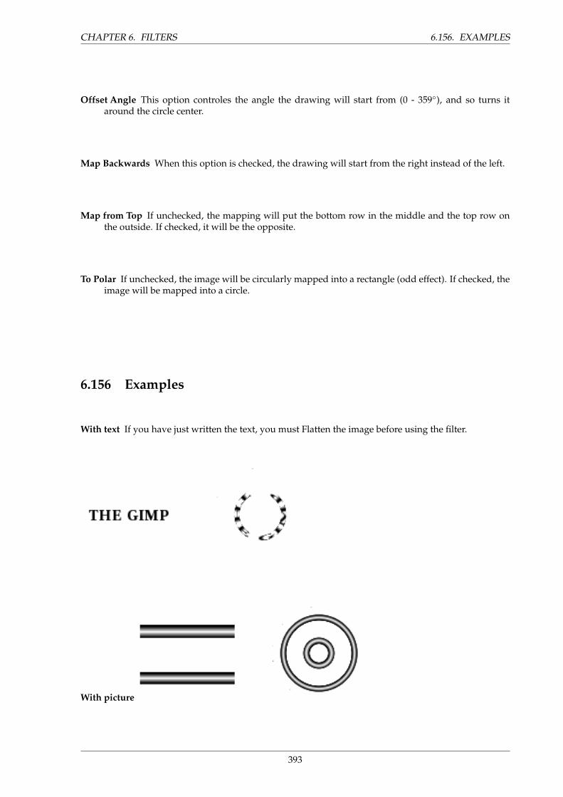
CHAPTER 6. FILTERS 6.156. EXAMPLES
Offset Angle This option controles the angle the drawing will start from (0 - 359◦), and so turns itaround the circle center.
Map Backwards When this option is checked, the drawing will start from the right instead of the left.
Map from Top If unchecked, the mapping will put the bottom row in the middle and the top row onthe outside. If checked, it will be the opposite.
To Polar If unchecked, the image will be circularly mapped into a rectangle (odd effect). If checked, theimage will be mapped into a circle.
6.156 Examples
With text If you have just written the text, you must Flatten the image before using the filter.
With picture
393
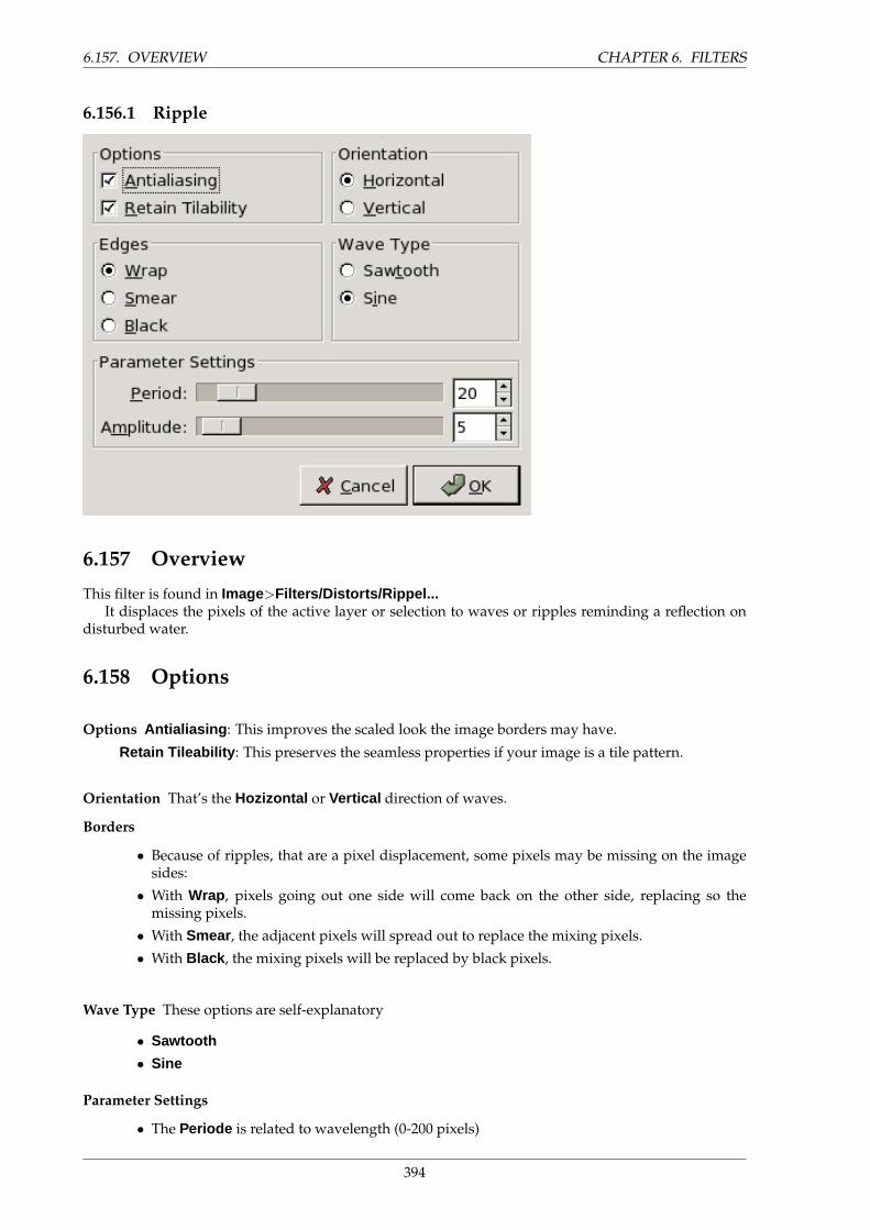
6.157. OVERVIEW CHAPTER 6. FILTERS
6.156.1 Ripple
6.157 Overview
This filter is found in Image>Filters/Distorts/Rippel...It displaces the pixels of the active layer or selection to waves or ripples reminding a reflection on
disturbed water.
6.158 Options
Options Antialiasing : This improves the scaled look the image borders may have.
Retain Tileability : This preserves the seamless properties if your image is a tile pattern.
Orientation That’s the Hozizontal or Vertical direction of waves.
Borders
• Because of ripples, that are a pixel displacement, some pixels may be missing on the imagesides:
• With Wrap , pixels going out one side will come back on the other side, replacing so themissing pixels.
• With Smear , the adjacent pixels will spread out to replace the mixing pixels.
• With Black , the mixing pixels will be replaced by black pixels.
Wave Type These options are self-explanatory
• Sawtooth
• Sine
Parameter Settings
• The Periode is related to wavelength (0-200 pixels)
394
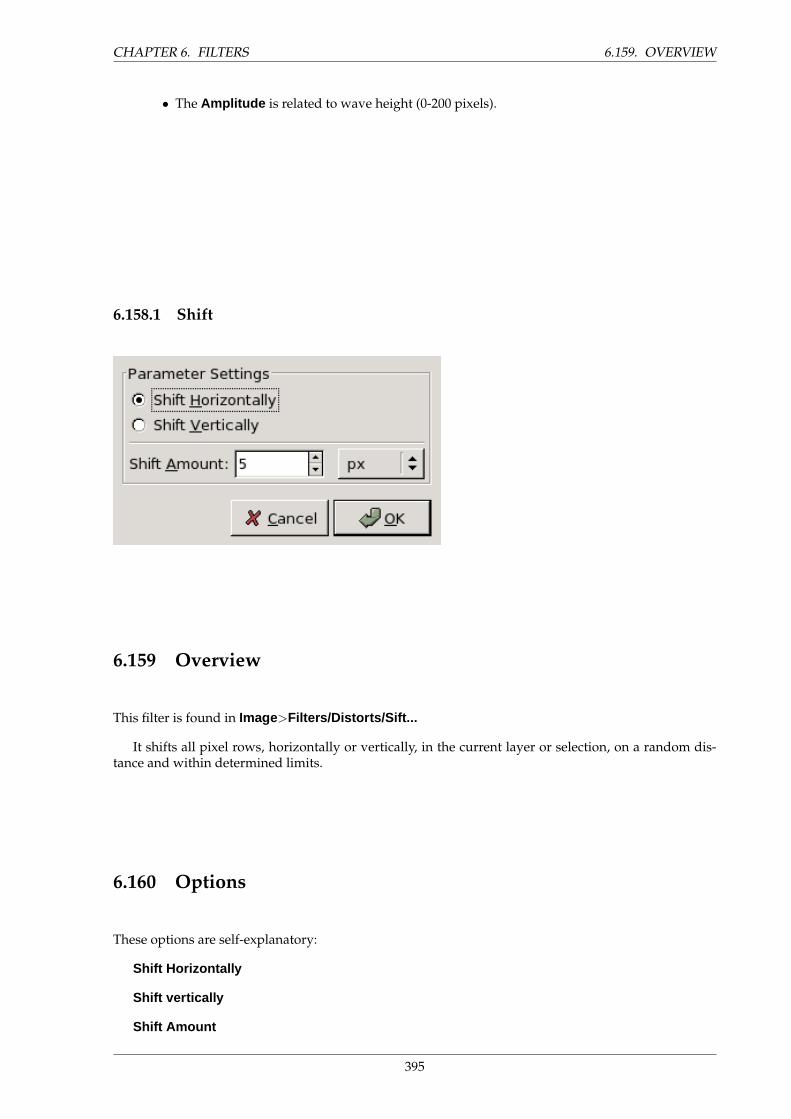
CHAPTER 6. FILTERS 6.159. OVERVIEW
• The Amplitude is related to wave height (0-200 pixels).
6.158.1 Shift
6.159 Overview
This filter is found in Image>Filters/Distorts/Sift...
It shifts all pixel rows, horizontally or vertically, in the current layer or selection, on a random dis-tance and within determined limits.
6.160 Options
These options are self-explanatory:
Shift Horizontally
Shift vertically
Shift Amount
395
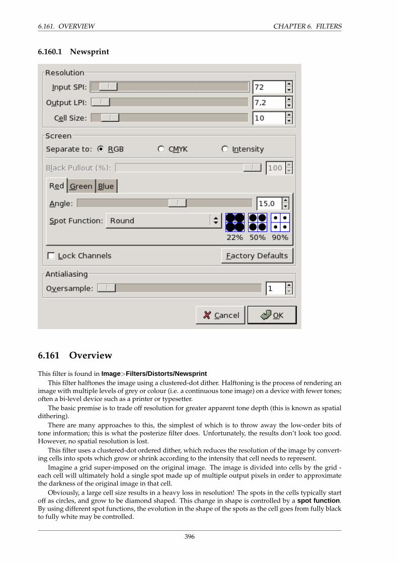
6.161. OVERVIEW CHAPTER 6. FILTERS
6.160.1 Newsprint
6.161 Overview
This filter is found in Image>Filters/Distorts/NewsprintThis filter halftones the image using a clustered-dot dither. Halftoning is the process of rendering an
image with multiple levels of grey or colour (i.e. a continuous tone image) on a device with fewer tones;often a bi-level device such as a printer or typesetter.
The basic premise is to trade off resolution for greater apparent tone depth (this is known as spatialdithering).
There are many approaches to this, the simplest of which is to throw away the low-order bits oftone information; this is what the posterize filter does. Unfortunately, the results don’t look too good.However, no spatial resolution is lost.
This filter uses a clustered-dot ordered dither, which reduces the resolution of the image by convert-ing cells into spots which grow or shrink according to the intensity that cell needs to represent.
Imagine a grid super-imposed on the original image. The image is divided into cells by the grid -each cell will ultimately hold a single spot made up of multiple output pixels in order to approximatethe darkness of the original image in that cell.
Obviously, a large cell size results in a heavy loss in resolution! The spots in the cells typically startoff as circles, and grow to be diamond shaped. This change in shape is controlled by a spot function .By using different spot functions, the evolution in the shape of the spots as the cell goes from fully blackto fully white may be controlled.
396
CHAPTER 6. FILTERS 6.162. OPTIONS
6.162 Options
Resolution This group controls the cell size, either by setting the input and output resolutions, or di-rectly.
• Input SPI : Resolution of the original input image, in Samples Per Inch (SPI). This is automat-ically initialised to the input image’s resolution.
• Output LPI : Desired output resolution, in Lines Per Inch (LPI).
• Cell Size : Resulting cell size, in pixels. Most often you will want to set this directly.
Screen
• Separate To RGB, CMYK, Intensity : Select which colourspace you wish to operate in. InRGB mode, no colourspace conversion is performed. In CMYK, the image is first internallyconverted to CMYK, then each colour channel is separately halftoned, before finally beingrecombined back to an RGB image. In Intensity mode, the image is internally converted togreyscale, halftoned, then the result used as the alpha channel for the input image. This isgood for special effects, but requires a little experimentation to achieve best results. Hint: tryCMYK if you don’t know which to go for initially.
• Black Pullout (%) When doing RGB->CMYK conversion, how much K (black) should beused?
• Angle : Cell grid angle for this channel.
• Spot Function : Spot function to be used for this angle (see preview in blue cell-boxes).
• Lock Channels : Make channel modifications apply to all channels.
• Factory Defaults : Restore the default settings which should give pleasing results.
Antialiasing Proper halftoning does not need antialiasing: the aim is to reduce the colour depth afterall! However, since this plugin is mainly for special effects, the results are displayed on screenrather than by a black/white printer. So it is often useful to apply a little anti-aliasing to simulateink smearing on paper. If you do want to print the resulting image then set the antialising to 1 (ie,off).
Oversample :Number of subpixels to sample to produce each output pixel. Set to 1 to disable thisfeature. Warning: large numbers here will lead to very long filter runtimes!
TIP
More explanations, illustrative diagrams, a gallery and a tutorial are to befound on the plug-in author site: http://www.cl.cam.ac.uk/˜and1000/newsprint/<http://www.cl.cam.ac.uk/˜and1000/newsprint/ > You are stronglyencouraged to visit it, since halftoning is a large and complex area.
Here is an example, from the author’s gallery:
397
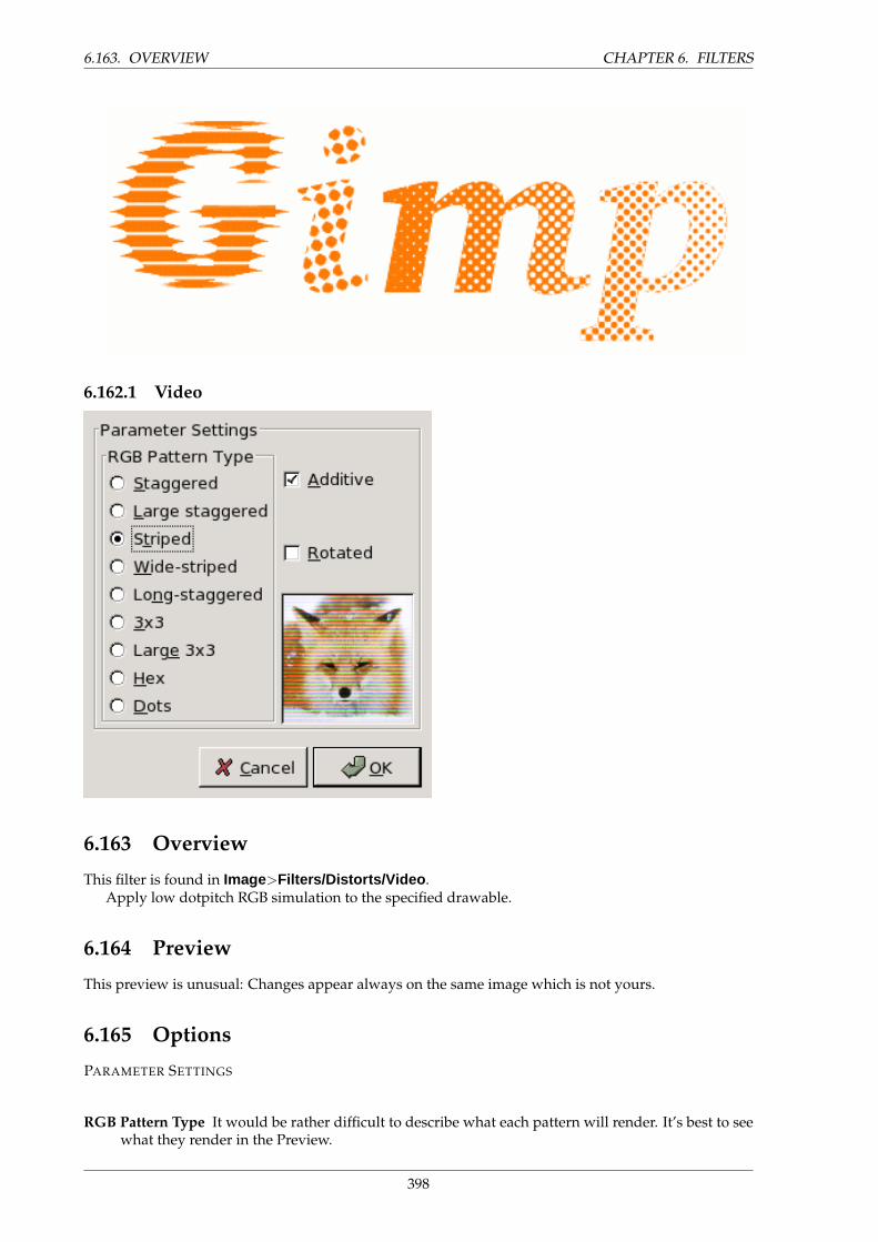
6.163. OVERVIEW CHAPTER 6. FILTERS
6.162.1 Video
6.163 Overview
This filter is found in Image>Filters/Distorts/Video .Apply low dotpitch RGB simulation to the specified drawable.
6.164 Preview
This preview is unusual: Changes appear always on the same image which is not yours.
6.165 Options
PARAMETER SETTINGS
RGB Pattern Type It would be rather difficult to describe what each pattern will render. It’s best to seewhat they render in the Preview.
398
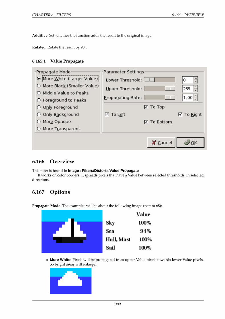
CHAPTER 6. FILTERS 6.166. OVERVIEW
Additive Set whether the function adds the result to the original image.
Rotated Rotate the result by 90◦.
6.165.1 Value Propagate
6.166 Overview
This filter is found in Image>Filters/Distorts/Value PropagateIt works on color borders. It spreads pixels that have a Value between selected thresholds, in selected
directions.
6.167 Options
Propagate Mode The examples will be about the following image (zomm x8):
• More White : Pixels will be propagated from upper Value pixels towards lower Value pixels.So bright areas will enlarge.
399
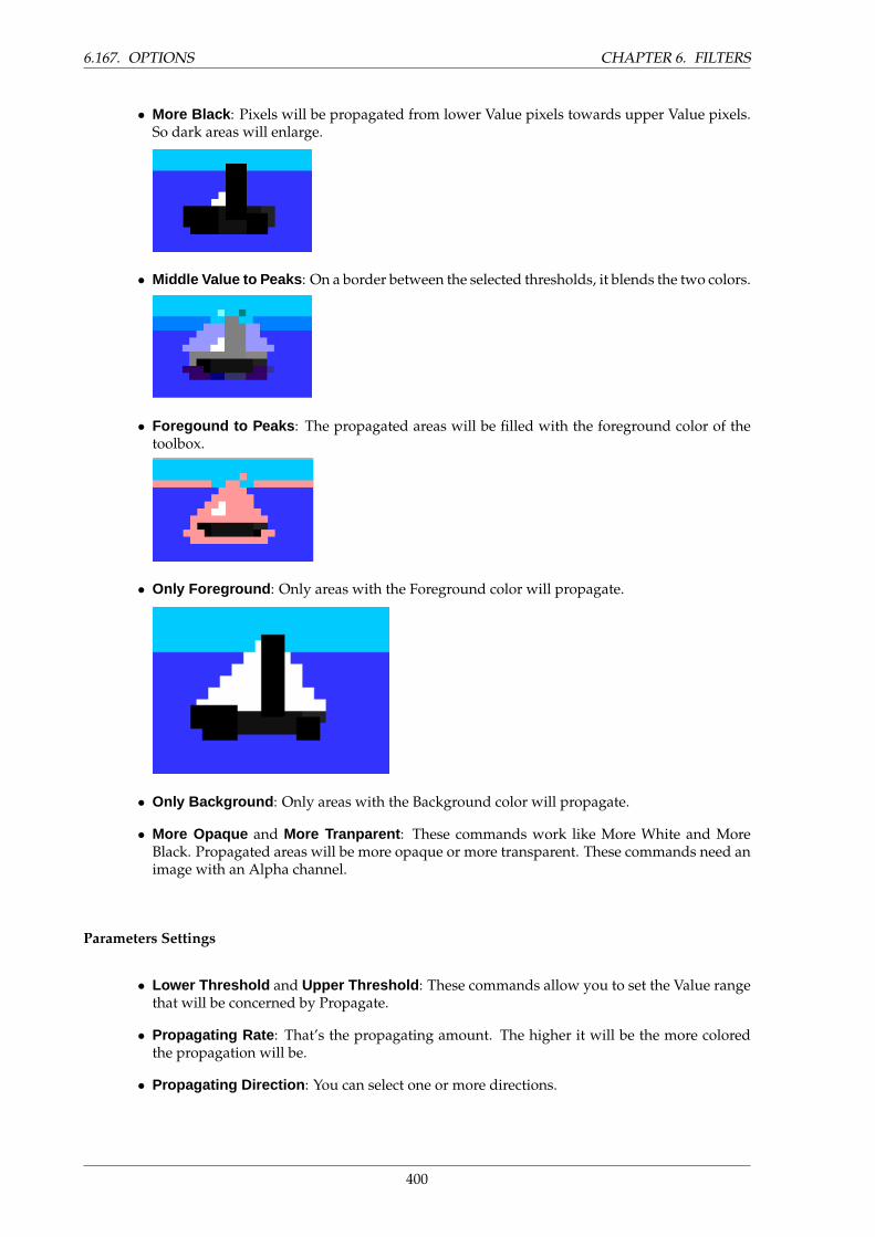
6.167. OPTIONS CHAPTER 6. FILTERS
• More Black : Pixels will be propagated from lower Value pixels towards upper Value pixels.So dark areas will enlarge.
• Middle Value to Peaks : On a border between the selected thresholds, it blends the two colors.
• Foregound to Peaks : The propagated areas will be filled with the foreground color of thetoolbox.
• Only Foreground : Only areas with the Foreground color will propagate.
• Only Background : Only areas with the Background color will propagate.
• More Opaque and More Tranparent : These commands work like More White and MoreBlack. Propagated areas will be more opaque or more transparent. These commands need animage with an Alpha channel.
Parameters Settings
• Lower Threshold and Upper Threshold : These commands allow you to set the Value rangethat will be concerned by Propagate.
• Propagating Rate : That’s the propagating amount. The higher it will be the more coloredthe propagation will be.
• Propagating Direction : You can select one or more directions.
400
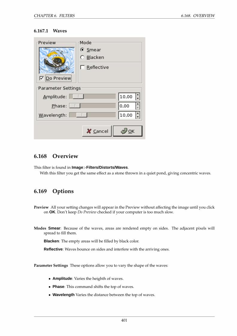
CHAPTER 6. FILTERS 6.168. OVERVIEW
6.167.1 Waves
6.168 Overview
This filter is found in Image>Filters/Distorts/Waves .With this filter you get the same effect as a stone thrown in a quiet pond, giving concentric waves.
6.169 Options
Preview All your setting changes will appear in the Preview without affecting the image until you clickon OK. Don’t keep Do Preview checked if your computer is too much slow.
Modes Smear : Because of the waves, areas are rendered empty on sides. The adjacent pixels willspread to fill them.
Blacken : The empty areas will be filled by black color.
Reflective : Waves bounce on sides and interfere with the arriving ones.
Parameter Settings These options allow you to vary the shape of the waves:
• Amplitude : Varies the heighth of waves.
• Phase : This command shifts the top of waves.
• Wavelength Varies the distance between the top of waves.
401
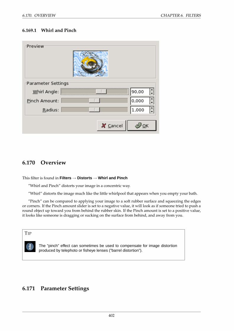
6.170. OVERVIEW CHAPTER 6. FILTERS
6.169.1 Whirl and Pinch
6.170 Overview
This filter is found in Filters → Distorts → Whirl and Pinch
”Whirl and Pinch” distorts your image in a concentric way.
”Whirl” distorts the image much like the little whirlpool that appears when you empty your bath.
”Pinch” can be compared to applying your image to a soft rubber surface and squeezing the edgesor corners. If the Pinch amount slider is set to a negative value, it will look as if someone tried to push around object up toward you from behind the rubber skin. If the Pinch amount is set to a positive value,it looks like someone is dragging or sucking on the surface from behind, and away from you.
TIP
The ”pinch” effect can sometimes be used to compensate for image distortionproduced by telephoto or fisheye lenses (”barrel distortion”).
6.171 Parameter Settings
402
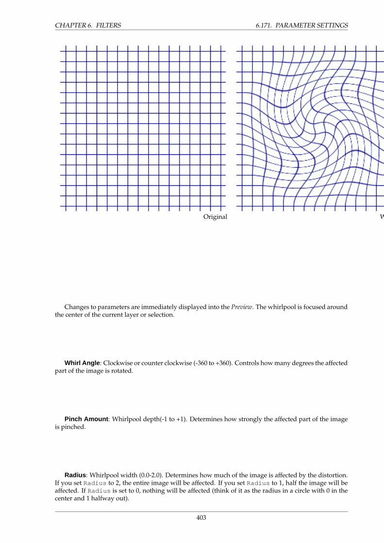
CHAPTER 6. FILTERS 6.171. PARAMETER SETTINGS
Original Whirled Pinched
Changes to parameters are immediately displayed into the Preview. The whirlpool is focused aroundthe center of the current layer or selection.
Whirl Angle : Clockwise or counter clockwise (-360 to +360). Controls how many degrees the affectedpart of the image is rotated.
Pinch Amount : Whirlpool depth(-1 to +1). Determines how strongly the affected part of the imageis pinched.
Radius : Whirlpool width (0.0-2.0). Determines how much of the image is affected by the distortion.If you set Radius to 2, the entire image will be affected. If you set Radius to 1, half the image will beaffected. If Radius is set to 0, nothing will be affected (think of it as the radius in a circle with 0 in thecenter and 1 halfway out).
403
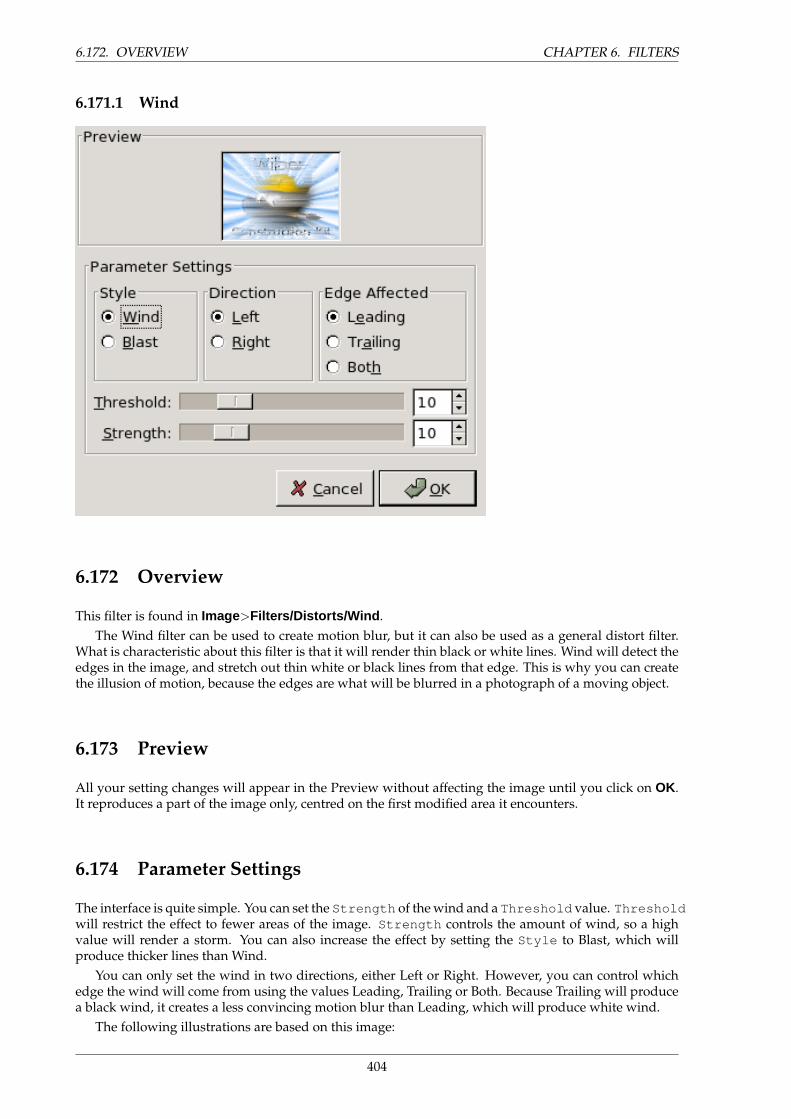
6.172. OVERVIEW CHAPTER 6. FILTERS
6.171.1 Wind
6.172 Overview
This filter is found in Image>Filters/Distorts/Wind .The Wind filter can be used to create motion blur, but it can also be used as a general distort filter.
What is characteristic about this filter is that it will render thin black or white lines. Wind will detect theedges in the image, and stretch out thin white or black lines from that edge. This is why you can createthe illusion of motion, because the edges are what will be blurred in a photograph of a moving object.
6.173 Preview
All your setting changes will appear in the Preview without affecting the image until you click on OK.It reproduces a part of the image only, centred on the first modified area it encounters.
6.174 Parameter Settings
The interface is quite simple. You can set the Strength of the wind and a Threshold value. Thresholdwill restrict the effect to fewer areas of the image. Strength controls the amount of wind, so a highvalue will render a storm. You can also increase the effect by setting the Style to Blast, which willproduce thicker lines than Wind.
You can only set the wind in two directions, either Left or Right. However, you can control whichedge the wind will come from using the values Leading, Trailing or Both. Because Trailing will producea black wind, it creates a less convincing motion blur than Leading, which will produce white wind.
The following illustrations are based on this image:
404
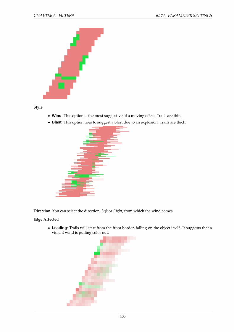
CHAPTER 6. FILTERS 6.174. PARAMETER SETTINGS
Style
• Wind : This option is the most suggestive of a moving effect. Trails are thin.
• Blast : This option tries to suggest a blast due to an explosion. Trails are thick.
Direction You can select the direction, Left or Right, from which the wind comes.
Edge Affected
• Leading : Trails will start from the front border, falling on the object itself. It suggests that aviolent wind is pulling color out.
405
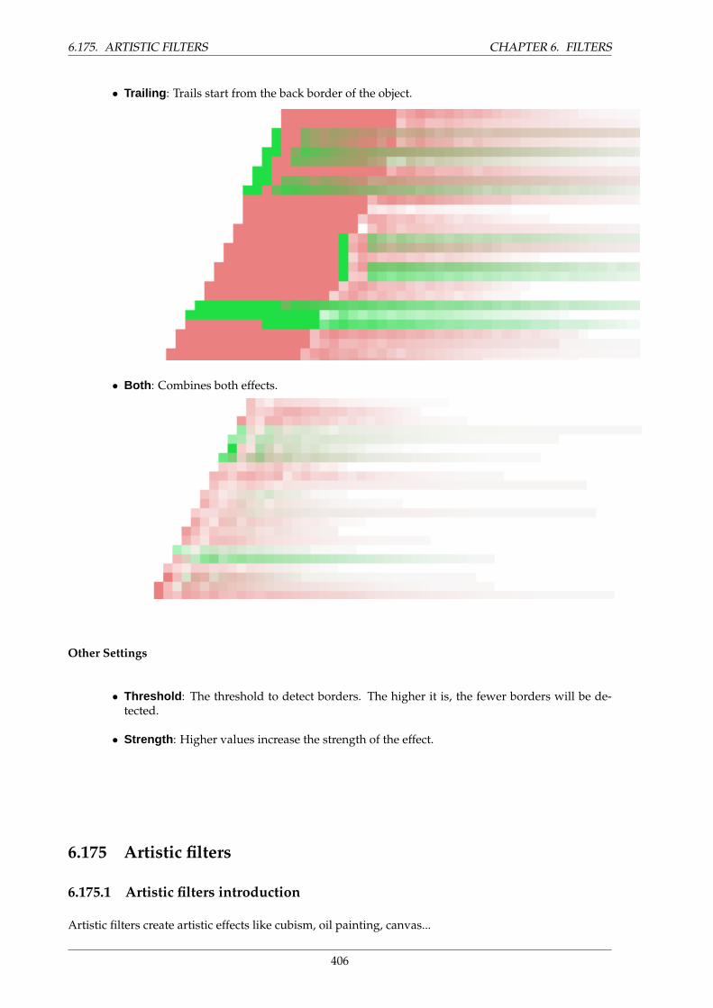
6.175. ARTISTIC FILTERS CHAPTER 6. FILTERS
• Trailing : Trails start from the back border of the object.
• Both : Combines both effects.
Other Settings
• Threshold : The threshold to detect borders. The higher it is, the fewer borders will be de-tected.
• Strength : Higher values increase the strength of the effect.
6.175 Artistic filters
6.175.1 Artistic filters introduction
Artistic filters create artistic effects like cubism, oil painting, canvas...
406
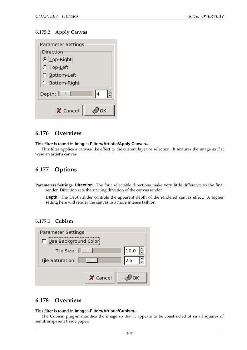
CHAPTER 6. FILTERS 6.176. OVERVIEW
6.175.2 Apply Canvas
6.176 Overview
This filter is found in Image>Filters/Artistic/Apply Canvas...This filter applies a canvas-like effect to the current layer or selection. It textures the image as if it
were an artist’s canvas.
6.177 Options
Parameters Settings Direction : The four selectable directions make very little difference to the finalrender. Direction sets the starting direction of the canvas render.
Depth : The Depth slider controls the apparent depth of the rendered canvas effect. A highersetting here will render the canvas in a more intense fashion.
6.177.1 Cubism
6.178 Overview
This filter is found in Image>Filters/Artistic/Cubism...The Cubism plug-in modifies the image so that it appears to be constructed of small squares of
semitransparent tissue paper.
407

6.179. OPTIONS CHAPTER 6. FILTERS
6.179 Options
Use Backgroundcolor This selection box determines whether the background color displayed in theToolbox should be used when applying the filter. If it is not checked, black will be used instead.
Tile Size This variable determines the size, in pixels, of the squares to be used. This is, in effect, the sizeof the little squares of tissue paper used in generating the new image. The slider can be used, theexact pixel size can be entered into the text box, or the arrow buttons can be used.
Tile Saturation This variable specifies how intense the color of the squares should be. This affects theopacity of the squares. A high value will render the squares very intensely and does not allowlower squares to show through. A lower value allows the lower squares to be more visible throughthe higher ones and causes more blending in the colors. If this is set to 0 and Use Background Coloris not checked, the entire layer will be rendered black. If it is checked and the value here is zero,the background color will fill the entire layer.
TIP
If you are using this to generate background images for web pages and the like,work with a small range of colors painted randomly on a small square. Then ap-ply the Cubism filter with the desired settings. As a last step, try Filters/Map/MakeSeamless to adjust the image so it will tile seamlessly in your background.
6.179.1 GIMPressionist
408
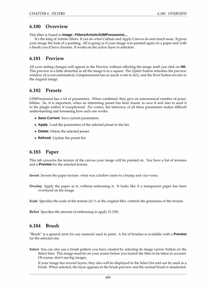
CHAPTER 6. FILTERS 6.180. OVERVIEW
6.180 Overview
This filter is found in Image>Filters/Artistic/GIMPressionist... .It’s the king of Artistic filters. It can do what Cubism and Apply Canvas do and much more. It gives
your image the look of a painting. All is going as if your image was painted again on a paper and witha brush you’d have choosen. It works on the active layer or selection.
6.181 Preview
All your setting changes will appear in the Preview without affecting the image until you click on OK.This preview is a little distorted as all the image is in a square. The Update button refreshes the previewwindow (it is not automatical, Gimpressionist has so much work to do!), and the Reset button reverts tothe original image.
6.182 Presets
GIMPressionist has a lot of parameters. When combined, they give an astronomical number of possi-bilities. So, it is important, when an interesting preset has been found, to save it and also to send itto the plugin author if exceptionnal. Per contra, the intricracy of all these parameters makes difficultunderstanding and foreseeing how each one works.
• Save Current : Save current parameters.
• Apply : Load the parameters of the selected preset in the list.
• Delete : Delete the selected preset.
• Refresh : Update the preset list.
6.183 Paper
This tab concerns the texture of the canvas your image will be painted on. You have a list of texturesand a Preview for the selected texture.
Invert Inverts the paper texture: what was a hollow turns to a bump and vice-versa.
Overlay Apply the paper as it, without embossing it. It looks like if a transparent paper has beenoverlayed on the image.
Scale Specifies the scale of the texture (in % of the original file): controls the graininess of the texture.
Relief Specifies the amount of embossing to apply (3-150).
6.184 Brush
”Brush” is a general term for any material used to paint. A list of brushes is available with a Previewfor the selected one.
Select You can also use a brush pattern you have created by selecting its image (arrow button on theSelect line). This image must be on your screen before you launch the filter to be taken in account.Of course, don’t use big images.
If your image has several layers, they also will be displayed in the Select list and can be used as abrush. When selected, the layer appears in the brush preview and the normal brush is deselected.
409
6.185. ORIENTATION CHAPTER 6. FILTERS
Save as
Gamma Changes the gamma (luminosity) of the selected brush. The gamma correction brightens ordarkens midtones.
Aspect ratio Specifies the brush proportions, height (0 -1) and width (0 +1).
Relief Specifies the amount of paint used for each stroke. This may evoke painting with a palette knife.
6.185 Orientation
This tab allows to set the orientation of the brush strokes. A painter is not obliged to go over with thesame paintbrush angle. To perform some effects, he can vary their orientation.
Directions Number of brushes to use. This would rather be how many times the brush will passthrough a same place, with each time a different direction, resulting in a more and more thinpaint.
Start Angle Specifies the general direction of the strokes, the angle the angle range will start from.Directions are often choosen to give some movement to the image.
Angle Span Specifies the angle, the sector, of the stroke ”fan”.
Orientation Specifies the direction of the brush strokes.
• Value : Let the Value (luminosity) of the region determine the direction of the stroke.
• Radius : The distance from the center of the image determines the direction of the stroke.
• Random : Select a random direction for each stroke.
• Radial : Let the direction from the center determine the direction of the stroke.
• Flowing : Not a direction question here: the strokes follow a ”flowing” pattern.
• Hue : Let the hue of the region determine the direction of the stroke.
• Adaptive : The brush direction that matches the original image the closest is selected.
• Manual : The Edit button opens the Edit orientation Map dialog that allows you to set thedirections manually.
6.186 Size
This tab allows you to set the number of brush sizes that will be used to paint, the limits of variation ofthese sizes and the criterion used to determine them.
Three Sliders You can specify how many brush sizes are to be used and their sizes.
• Sizes : The number of brush sizes to use.
• Minimum Size and Maximum Size : The brush sizes are between these two values. Greaterthe size, greater the length and width of strokes.
410
CHAPTER 6. FILTERS 6.187. PLACEMENT
Sizes You have there options to specify how the size of strokes will be determined.
• Value : Let the Value (luminosity) of the region determine the size of the stroke.
• Radius : The distance from the center of the image determines the size of the stroke.
• Random : Select a random size for each stroke.
• Radial : Let the direction from the center determine the size of the stroke.
• Flowing : Not a length question here: the strokes follow a ”flowing” pattern.
• Hue : Let the hue of the region determine the size of the stroke.
• Adaptive : The brush size that matches the original image the closest is selected.
• Manual : The Edit button opens the Size Map Editor That allows you to specify the size ofstrokes by yourself.
6.187 Placement
In this tab you can set how strokes will be distributed.
Placement In the preview of the Orientation Map Editor, all small arrows look like a flow around ob-jects. Inside this flow, strokes may be placed in two different ways:
• Randomly : Places strokes ramdomly. This produces a more realistic paint.
• Evenly : Strokes are evenly distributed across the image.
Other options
• Stroke Density : The greater the density the closer the strokes. With a low density, the paperor background may be visible in unstroke areas.
• Centerize : Focus brush strokes around center.
6.188 General
In this tab you can set what will be the background and the relief of brush strokes.
Background
• Keep Original : Preserve the original image as a background.
• From Paper : Copy the texture of the selected paper as a background.
• Solid : By clicking on the color dwell you can select a solid colored background.
• Transparent : Use a transparent background. Only the painted strokes will be visible. Thisoption is available only if your image has an Alpha channel.
Edge type
• Paint Edges : If it is disabled, a thin border will not be painted around the outside border ofthe image.
• Tileable : If checked, the resulting image will be seamlessly tileable. The right side will matchthe left side and the top will match the bottom. This is interesting if your image will berepeatedly used in a Web background.
• Edge Darken : How much to darken the edges of each brush stroke. This increases paintrelief or thickness.
411
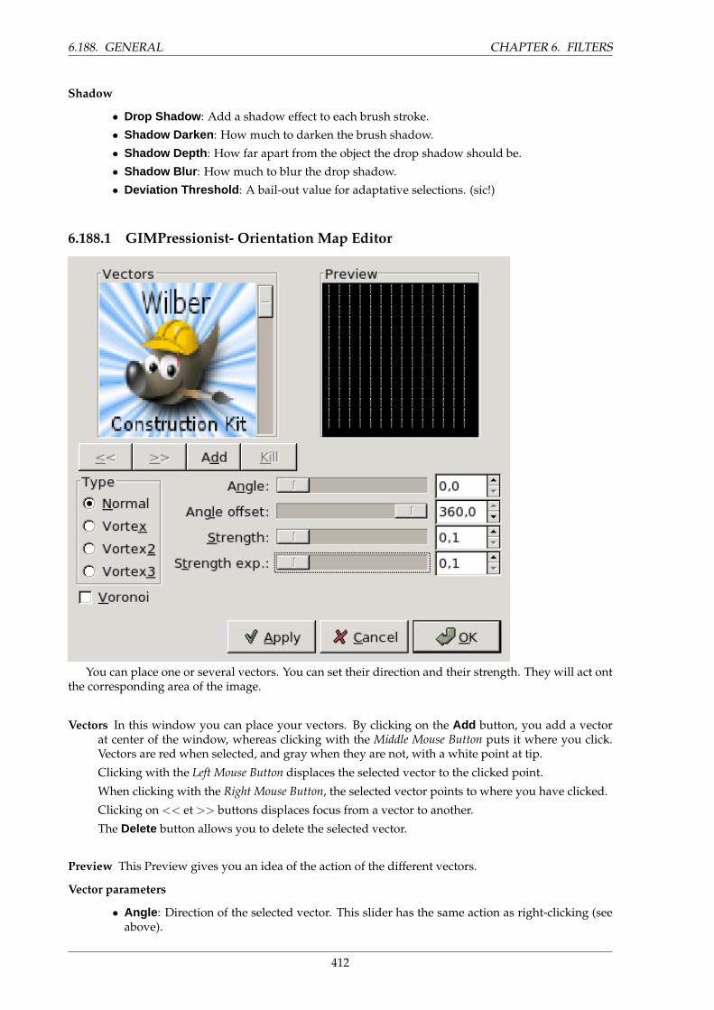
6.188. GENERAL CHAPTER 6. FILTERS
Shadow
• Drop Shadow : Add a shadow effect to each brush stroke.
• Shadow Darken : How much to darken the brush shadow.
• Shadow Depth : How far apart from the object the drop shadow should be.
• Shadow Blur : How much to blur the drop shadow.
• Deviation Threshold : A bail-out value for adaptative selections. (sic!)
6.188.1 GIMPressionist- Orientation Map Editor
You can place one or several vectors. You can set their direction and their strength. They will act ontthe corresponding area of the image.
Vectors In this window you can place your vectors. By clicking on the Add button, you add a vectorat center of the window, whereas clicking with the Middle Mouse Button puts it where you click.Vectors are red when selected, and gray when they are not, with a white point at tip.
Clicking with the Left Mouse Button displaces the selected vector to the clicked point.
When clicking with the Right Mouse Button, the selected vector points to where you have clicked.
Clicking on << et >> buttons displaces focus from a vector to another.
The Delete button allows you to delete the selected vector.
Preview This Preview gives you an idea of the action of the different vectors.
Vector parameters
• Angle : Direction of the selected vector. This slider has the same action as right-clicking (seeabove).
412
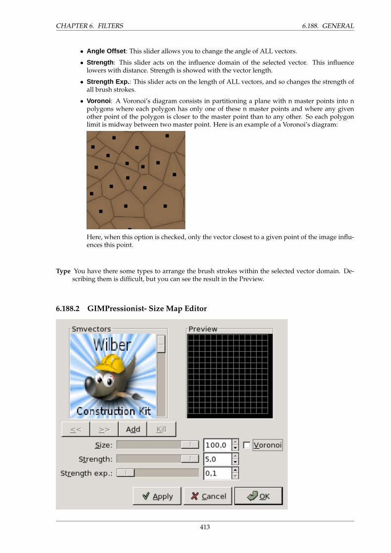
CHAPTER 6. FILTERS 6.188. GENERAL
• Angle Offset : This slider allows you to change the angle of ALL vectors.
• Strength : This slider acts on the influence domain of the selected vector. This influencelowers with distance. Strength is showed with the vector length.
• Strength Exp. : This slider acts on the length of ALL vectors, and so changes the strength ofall brush strokes.
• Voronoi : A Voronoi’s diagram consists in partitioning a plane with n master points into npolygons where each polygon has only one of these n master points and where any givenother point of the polygon is closer to the master point than to any other. So each polygonlimit is midway between two master point. Here is an example of a Voronoi’s diagram:
Here, when this option is checked, only the vector closest to a given point of the image influ-ences this point.
Type You have there some types to arrange the brush strokes within the selected vector domain. De-scribing them is difficult, but you can see the result in the Preview.
6.188.2 GIMPressionist- Size Map Editor
413
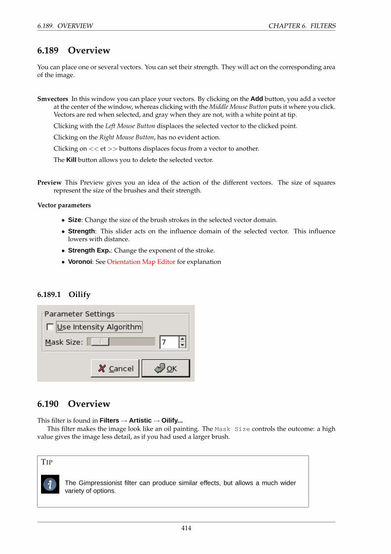
6.189. OVERVIEW CHAPTER 6. FILTERS
6.189 Overview
You can place one or several vectors. You can set their strength. They will act on the corresponding areaof the image.
Smvectors In this window you can place your vectors. By clicking on the Add button, you add a vectorat the center of the window, whereas clicking with the Middle Mouse Button puts it where you click.Vectors are red when selected, and gray when they are not, with a white point at tip.
Clicking with the Left Mouse Button displaces the selected vector to the clicked point.
Clicking on the Right Mouse Button, has no evident action.
Clicking on << et >> buttons displaces focus from a vector to another.
The Kill button allows you to delete the selected vector.
Preview This Preview gives you an idea of the action of the different vectors. The size of squaresrepresent the size of the brushes and their strength.
Vector parameters
• Size: Change the size of the brush strokes in the selected vector domain.
• Strength : This slider acts on the influence domain of the selected vector. This influencelowers with distance.
• Strength Exp. : Change the exponent of the stroke.
• Voronoi : See Orientation Map Editor for explanation
6.189.1 Oilify
6.190 Overview
This filter is found in Filters → Artistic → Oilify...This filter makes the image look like an oil painting. The Mask Size controls the outcome: a high
value gives the image less detail, as if you had used a larger brush.
TIP
The Gimpressionist filter can produce similar effects, but allows a much widervariety of options.
414
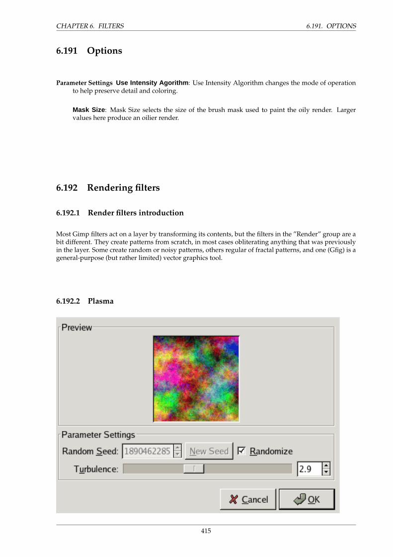
CHAPTER 6. FILTERS 6.191. OPTIONS
6.191 Options
Parameter Settings Use Intensity Agorithm : Use Intensity Algorithm changes the mode of operationto help preserve detail and coloring.
Mask Size : Mask Size selects the size of the brush mask used to paint the oily render. Largervalues here produce an oilier render.
6.192 Rendering filters
6.192.1 Render filters introduction
Most Gimp filters act on a layer by transforming its contents, but the filters in the ”Render” group are abit different. They create patterns from scratch, in most cases obliterating anything that was previouslyin the layer. Some create random or noisy patterns, others regular of fractal patterns, and one (Gfig) is ageneral-purpose (but rather limited) vector graphics tool.
6.192.2 Plasma
415
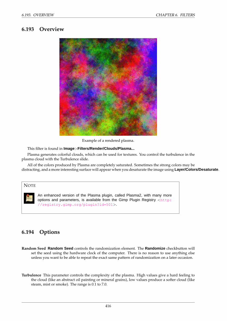
6.193. OVERVIEW CHAPTER 6. FILTERS
6.193 Overview
Example of a rendered plasma.
This filter is found in Image>Filters/Render/Clouds/Plasma...
Plasma generates colorful clouds, which can be used for textures. You control the turbulence in theplasma cloud with the Turbulence slide.
All of the colors produced by Plasma are completely saturated. Sometimes the strong colors may bedistracting, and a more interesting surface will appear when you desaturate the image using Layer/Colors/Desaturate .
NOTE
An enhanced version of the Plasma plugin, called Plasma2, with many moreoptions and parameters, is available from the Gimp Plugin Registry <http://registry.gimp.org/plugin?id=501 >.
6.194 Options
Random Seed Random Seed controls the randomization element. The Randomize checkbutton willset the seed using the hardware clock of the computer. There is no reason to use anything elseunless you want to be able to repeat the exact same pattern of randomization on a later occasion.
Turbulence This parameter controls the complexity of the plasma. High values give a hard feeling tothe cloud (like an abstract oil painting or mineral grains), low values produce a softer cloud (likesteam, mist or smoke). The range is 0.1 to 7.0.
416

CHAPTER 6. FILTERS 6.195. OVERVIEW
6.194.1 Solid Noise
6.195 Overview
Example of turbulent solid noise.This filter is found in Image>Filters/Render/Clouds/Solid Noise...Solid Noise is a great texture maker. Note that this noise is always gray, even if you applied it
to a very colorful image (it doesn’t matter what the original image looks like – this filter completelyoverwrites any existing background in the layer it is applied to). This is also a good tool for creatingdisplacement maps for the plug-in or for the plug-in. With the ”turbulence” setting active, the resultslook quite a bit like real clouds. An example is shown below.
6.196 Options
Random Seed Random Seed controls the randomization element. The Randomize checkbutton willset the seed using the hardware clock of the computer. There is no reason to use anything elseunless you want to be able to repeat the exact same pattern of randomization on a later occasion.
417
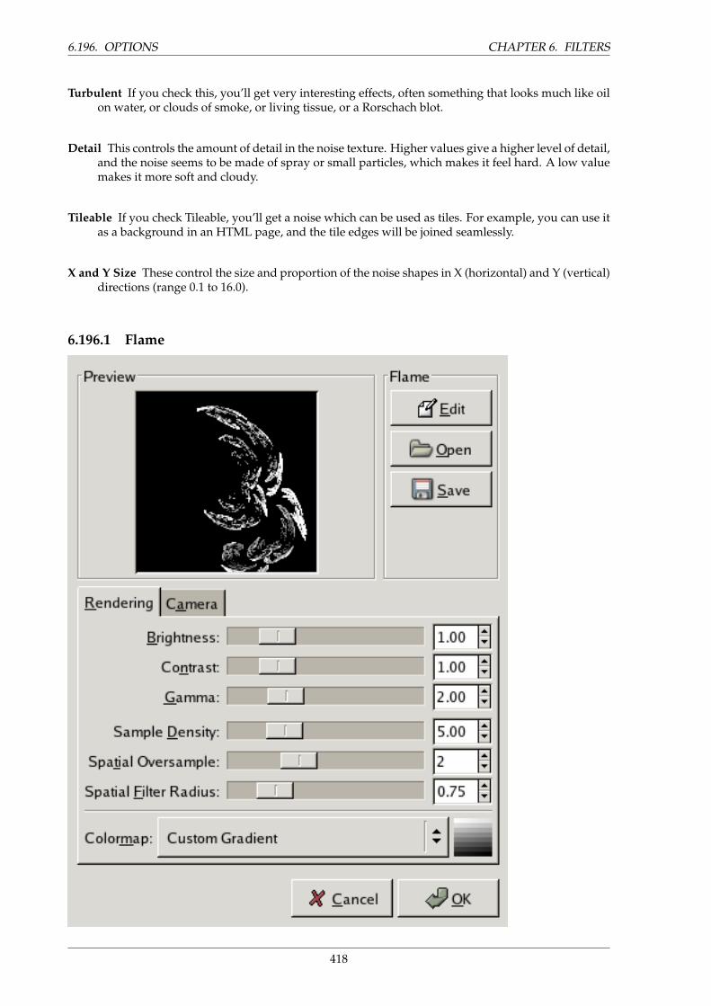
6.196. OPTIONS CHAPTER 6. FILTERS
Turbulent If you check this, you’ll get very interesting effects, often something that looks much like oilon water, or clouds of smoke, or living tissue, or a Rorschach blot.
Detail This controls the amount of detail in the noise texture. Higher values give a higher level of detail,and the noise seems to be made of spray or small particles, which makes it feel hard. A low valuemakes it more soft and cloudy.
Tileable If you check Tileable, you’ll get a noise which can be used as tiles. For example, you can use itas a background in an HTML page, and the tile edges will be joined seamlessly.
X and Y Size These control the size and proportion of the noise shapes in X (horizontal) and Y (vertical)directions (range 0.1 to 16.0).
6.196.1 Flame
418
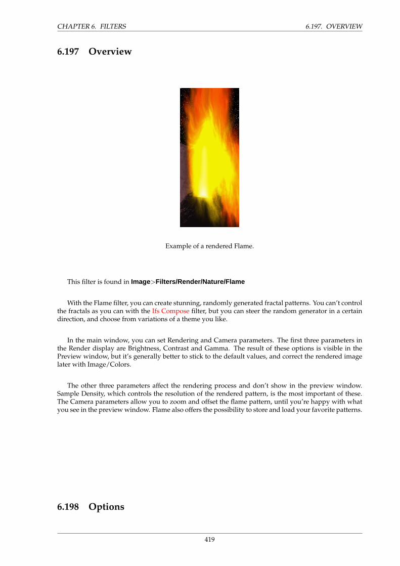
CHAPTER 6. FILTERS 6.197. OVERVIEW
6.197 Overview
Example of a rendered Flame.
This filter is found in Image>Filters/Render/Nature/Flame
With the Flame filter, you can create stunning, randomly generated fractal patterns. You can’t controlthe fractals as you can with the Ifs Compose filter, but you can steer the random generator in a certaindirection, and choose from variations of a theme you like.
In the main window, you can set Rendering and Camera parameters. The first three parameters inthe Render display are Brightness, Contrast and Gamma. The result of these options is visible in thePreview window, but it’s generally better to stick to the default values, and correct the rendered imagelater with Image/Colors.
The other three parameters affect the rendering process and don’t show in the preview window.Sample Density, which controls the resolution of the rendered pattern, is the most important of these.The Camera parameters allow you to zoom and offset the flame pattern, until you’re happy with whatyou see in the preview window. Flame also offers the possibility to store and load your favorite patterns.
6.198 Options
419
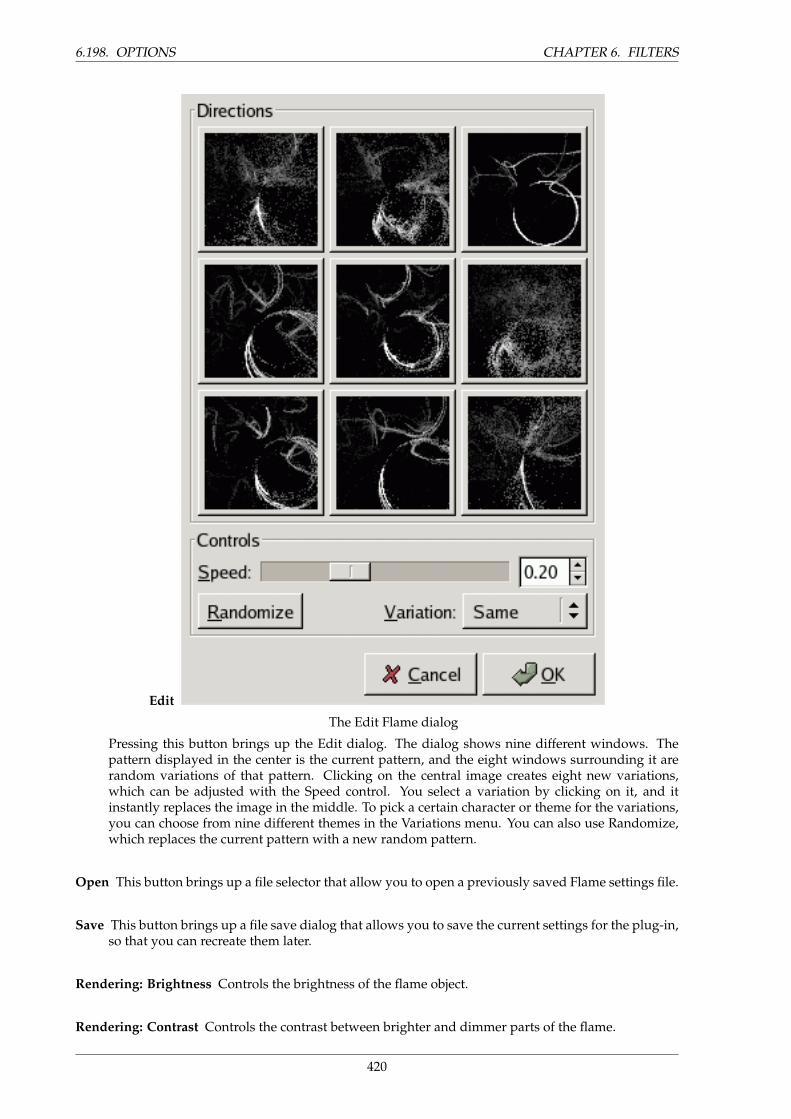
6.198. OPTIONS CHAPTER 6. FILTERS
Edit
The Edit Flame dialog
Pressing this button brings up the Edit dialog. The dialog shows nine different windows. Thepattern displayed in the center is the current pattern, and the eight windows surrounding it arerandom variations of that pattern. Clicking on the central image creates eight new variations,which can be adjusted with the Speed control. You select a variation by clicking on it, and itinstantly replaces the image in the middle. To pick a certain character or theme for the variations,you can choose from nine different themes in the Variations menu. You can also use Randomize,which replaces the current pattern with a new random pattern.
Open This button brings up a file selector that allow you to open a previously saved Flame settings file.
Save This button brings up a file save dialog that allows you to save the current settings for the plug-in,so that you can recreate them later.
Rendering: Brightness Controls the brightness of the flame object.
Rendering: Contrast Controls the contrast between brighter and dimmer parts of the flame.
420
CHAPTER 6. FILTERS 6.198. OPTIONS
Rendering: Gamma Sets a gamma correction for parts with intermediate brightness.
Rendering: Sample Density Controls the resolution of the rendered pattern. (Does not have any effecton the preview.) A high sample density results in soft and smooth rendering (like a spider’s web),whereas low density rendering resembles spray or particle clouds.
Rendering: Spatial Oversample What does this do?
Rendering: Spatial Filter Radius What does this do?
Rendering: Colormap This menu gives you several options to set the color blend in the flame pattern:
• The current gradient as shown in the Toolbox.
• A number of preset colormaps.
• The colors from images that are presently open in Gimp.
Camera: Zoom Allows you to zoom the flame in or out.
Camera: X, Y Allows you to move the flame around in the image area.
421
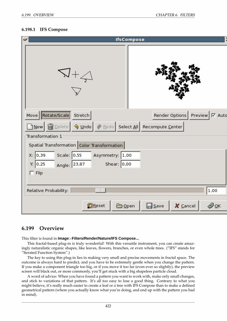
6.199. OVERVIEW CHAPTER 6. FILTERS
6.198.1 IFS Compose
6.199 Overview
This filter is found in Image>Filters/Render/Nature/IFS Compose...This fractal-based plug-in is truly wonderful! With this versatile instrument, you can create amaz-
ingly naturalistic organic shapes, like leaves, flowers, branches, or even whole trees. (”IFS” stands for”Iterated Function System”.)
The key to using this plug-in lies in making very small and precise movements in fractal space. Theoutcome is always hard to predict, and you have to be extremely gentle when you change the pattern.If you make a component triangle too big, or if you move it too far (even ever so slightly), the previewscreen will black out, or more commonly, you’ll get stuck with a big shapeless particle cloud.
A word of advice: When you have found a pattern you want to work with, make only small changes,and stick to variations of that pattern. It’s all too easy to lose a good thing. Contrary to what youmight believe, it’s really much easier to create a leaf or a tree with IFS Compose than to make a definedgeometrical pattern (where you actually know what you’re doing, and end up with the pattern you hadin mind).
422
CHAPTER 6. FILTERS 6.200. OPTIONS
For a brief introduction to IFS’s see Foley and van Dam, et al,. Computer Graphics, Principles andPractice, 2nd Ed., (Addison Wesley, 1990).
The Main Interface. The plug-in interface consists of the compose area to the left, a preview screento the right, and some tabs and option buttons at the bottom of the dialog. The Default setting (in thepreview window) is three equilateral triangles. (This gives rise to a fractal pattern called the SierpinskiTriangle).
6.200 Options
Relative Probability Determines influence or total impact of a certain fractal.
Spatial Transformation Gives you information on the active fractal, and allows you to type a valueinstead of changing it manually. Changing parameters with the mouse isn’t very accurate, so thisis a useful option when you need to be exact.
Simple color transformation Changes the color of the currently selected fractal component (which startsas the foreground color in the toolbox) to a color of your choice.
Full color transformation: Like the Simple color transformation but this time you can manage the colortransformation for each color channel and for the alpha channel (shown as a black channel).
Scale Hue/Value When you have many fractals with different colors, the colors blend into each other.So even if you set ”pure red” for a fractal, it might actually be quite blue in some places, whileanother ”red” fractal might have a lot of yellow in it. Scale Hue/Value changes the color strengthof the active fractal, or how influential that fractal’s color should be.
Render Options: Spot Radius Determines the density of the ”brushstrokes” in the rendered image. Alow spot radius is good for thin particle clouds or spray, while a high spot radius produces thick,solid color strokes much like watercolor painting. Be careful not to use too much spot radius – ittakes a lot of time to render.
Render Options: Subdivide Controls the level of detail.
Render Options: Iterations Determines how many times the fractal will repeat itself. (A high value forSubdivide and Iterations is for obvious reasons a waste of process time unless your image is verylarge.)
Render Options: Memory Enables you to speed up rendering time. This is especially useful whenworking with a large spot radius; just remember to use even multiples of the default value: 4096,8192, 16384, ...
6.201 A Brief Tutorial
This is a rather complex plug-in, so to help you understand it, we’ll guide you through an examplewhere you’ll create a leaf or branch.
Many forms of life, and especially plants, are built like mathematical fractals, i.e., a shape that repro-duces or repeats itself indefinitely into the smallest detail. You can easily reproduce the shape of a leafor a branch by using four (or more) fractals. Three fractals make up the tip and sides of the leaf, and thefourth represents the stem.
423
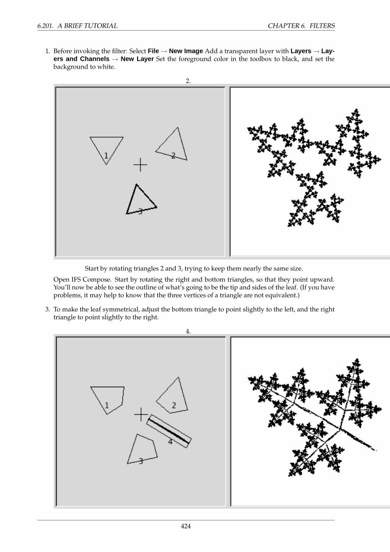
6.201. A BRIEF TUTORIAL CHAPTER 6. FILTERS
1. Before invoking the filter: Select File → New Image Add a transparent layer with Layers → Lay-ers and Channels → New Layer Set the foreground color in the toolbox to black, and set thebackground to white.
2.
Start by rotating triangles 2 and 3, trying to keep them nearly the same size.
Open IFS Compose. Start by rotating the right and bottom triangles, so that they point upward.You’ll now be able to see the outline of what’s going to be the tip and sides of the leaf. (If you haveproblems, it may help to know that the three vertices of a triangle are not equivalent.)
3. To make the leaf symmetrical, adjust the bottom triangle to point slightly to the left, and the righttriangle to point slightly to the right.
4.
424
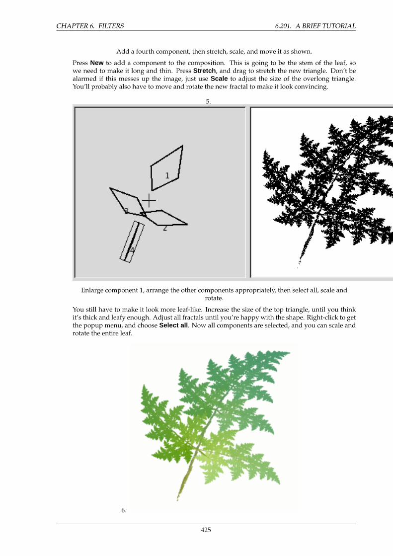
CHAPTER 6. FILTERS 6.201. A BRIEF TUTORIAL
Add a fourth component, then stretch, scale, and move it as shown.
Press New to add a component to the composition. This is going to be the stem of the leaf, sowe need to make it long and thin. Press Stretch , and drag to stretch the new triangle. Don’t bealarmed if this messes up the image, just use Scale to adjust the size of the overlong triangle.You’ll probably also have to move and rotate the new fractal to make it look convincing.
5.
Enlarge component 1, arrange the other components appropriately, then select all, scale androtate.
You still have to make it look more leaf-like. Increase the size of the top triangle, until you thinkit’s thick and leafy enough. Adjust all fractals until you’re happy with the shape. Right-click to getthe popup menu, and choose Select all . Now all components are selected, and you can scale androtate the entire leaf.
6.
425
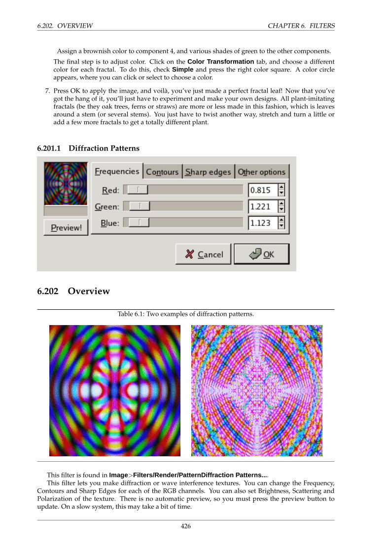
6.202. OVERVIEW CHAPTER 6. FILTERS
Assign a brownish color to component 4, and various shades of green to the other components.
The final step is to adjust color. Click on the Color Transformation tab, and choose a differentcolor for each fractal. To do this, check Simple and press the right color square. A color circleappears, where you can click or select to choose a color.
7. Press OK to apply the image, and voila, you’ve just made a perfect fractal leaf! Now that you’vegot the hang of it, you’ll just have to experiment and make your own designs. All plant-imitatingfractals (be they oak trees, ferns or straws) are more or less made in this fashion, which is leavesaround a stem (or several stems). You just have to twist another way, stretch and turn a little oradd a few more fractals to get a totally different plant.
6.201.1 Diffraction Patterns
6.202 Overview
Table 6.1: Two examples of diffraction patterns.
This filter is found in Image>Filters/Render/PatternDiffraction Patterns... .This filter lets you make diffraction or wave interference textures. You can change the Frequency,
Contours and Sharp Edges for each of the RGB channels. You can also set Brightness, Scattering andPolarization of the texture. There is no automatic preview, so you must press the preview button toupdate. On a slow system, this may take a bit of time.
426
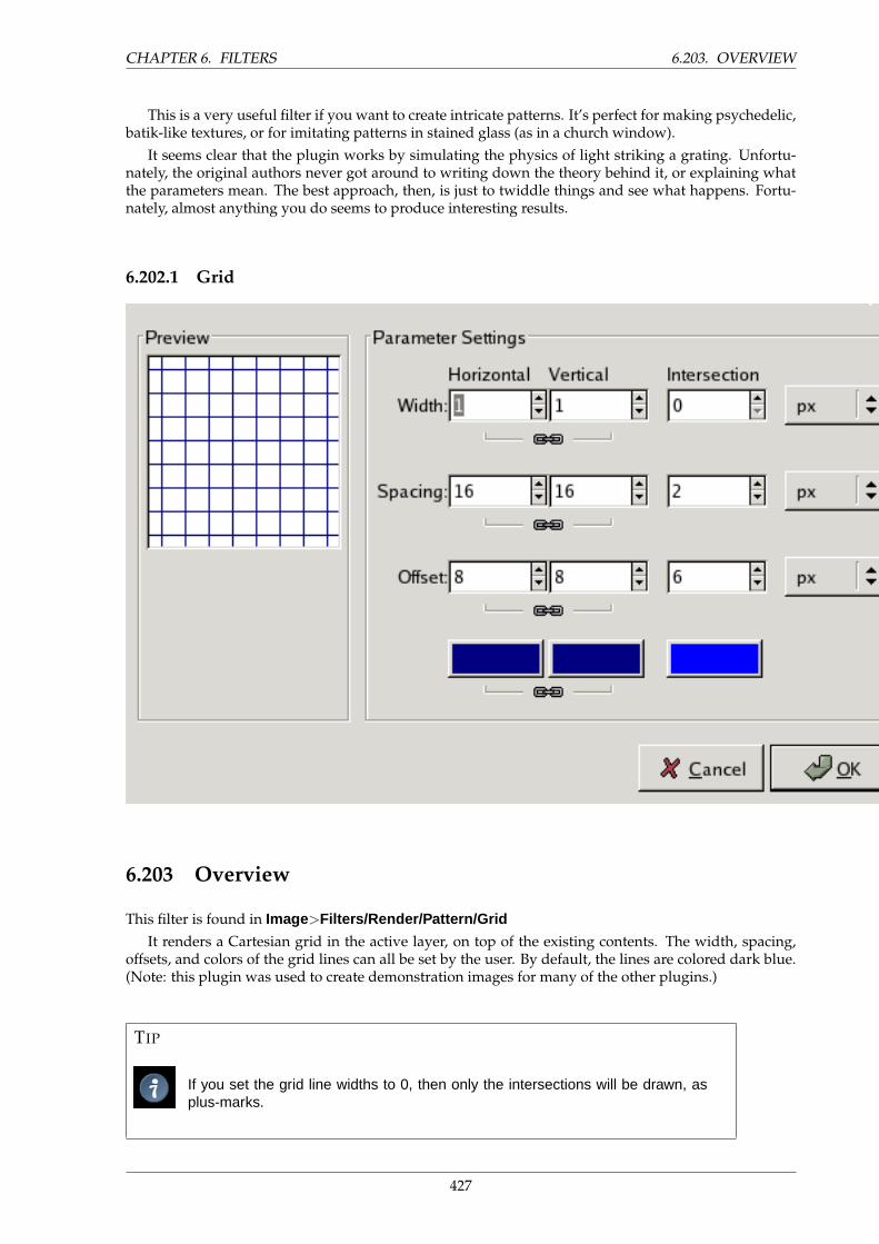
CHAPTER 6. FILTERS 6.203. OVERVIEW
This is a very useful filter if you want to create intricate patterns. It’s perfect for making psychedelic,batik-like textures, or for imitating patterns in stained glass (as in a church window).
It seems clear that the plugin works by simulating the physics of light striking a grating. Unfortu-nately, the original authors never got around to writing down the theory behind it, or explaining whatthe parameters mean. The best approach, then, is just to twiddle things and see what happens. Fortu-nately, almost anything you do seems to produce interesting results.
6.202.1 Grid
6.203 Overview
This filter is found in Image>Filters/Render/Pattern/Grid
It renders a Cartesian grid in the active layer, on top of the existing contents. The width, spacing,offsets, and colors of the grid lines can all be set by the user. By default, the lines are colored dark blue.(Note: this plugin was used to create demonstration images for many of the other plugins.)
TIP
If you set the grid line widths to 0, then only the intersections will be drawn, asplus-marks.
427
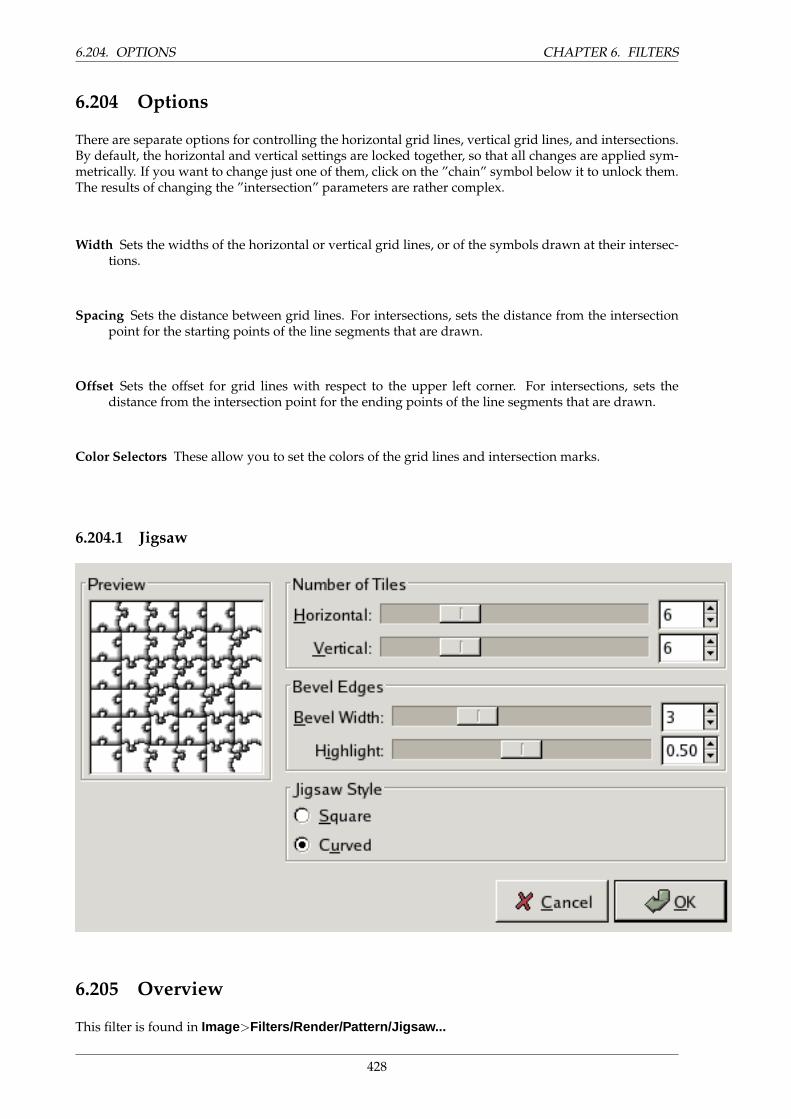
6.204. OPTIONS CHAPTER 6. FILTERS
6.204 Options
There are separate options for controlling the horizontal grid lines, vertical grid lines, and intersections.By default, the horizontal and vertical settings are locked together, so that all changes are applied sym-metrically. If you want to change just one of them, click on the ”chain” symbol below it to unlock them.The results of changing the ”intersection” parameters are rather complex.
Width Sets the widths of the horizontal or vertical grid lines, or of the symbols drawn at their intersec-tions.
Spacing Sets the distance between grid lines. For intersections, sets the distance from the intersectionpoint for the starting points of the line segments that are drawn.
Offset Sets the offset for grid lines with respect to the upper left corner. For intersections, sets thedistance from the intersection point for the ending points of the line segments that are drawn.
Color Selectors These allow you to set the colors of the grid lines and intersection marks.
6.204.1 Jigsaw
6.205 Overview
This filter is found in Image>Filters/Render/Pattern/Jigsaw...
428
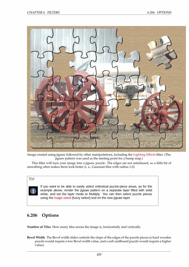
CHAPTER 6. FILTERS 6.206. OPTIONS
Image created using jigsaw followed by other manipulations, including the Lighting Effects filter. (Thejigsaw pattern was used as the starting point for a bump map.)
This filter will turn your image into a jigsaw puzzle. The edges are not antialiased, so a little bit ofsmoothing often makes them look better (i. e., Gaussian blur with radius 1.0).
TIP
If you want to be able to easily select individual puzzle-piece areas, as for theexample above, render the jigsaw pattern on a separate layer filled with solidwhite, and set the layer mode to Multiply. You can then select puzzle piecesusing the magic wand (fuzzy select) tool on the new jigsaw layer.
6.206 Options
Number of Tiles How many tiles across the image is, horizontally and vertically.
Bevel Width The Bevel width slider controls the slope of the edges of the puzzle pieces (a hard woodenpuzzle would require a low Bevel width value, and a soft cardboard puzzle would require a highervalue).
429
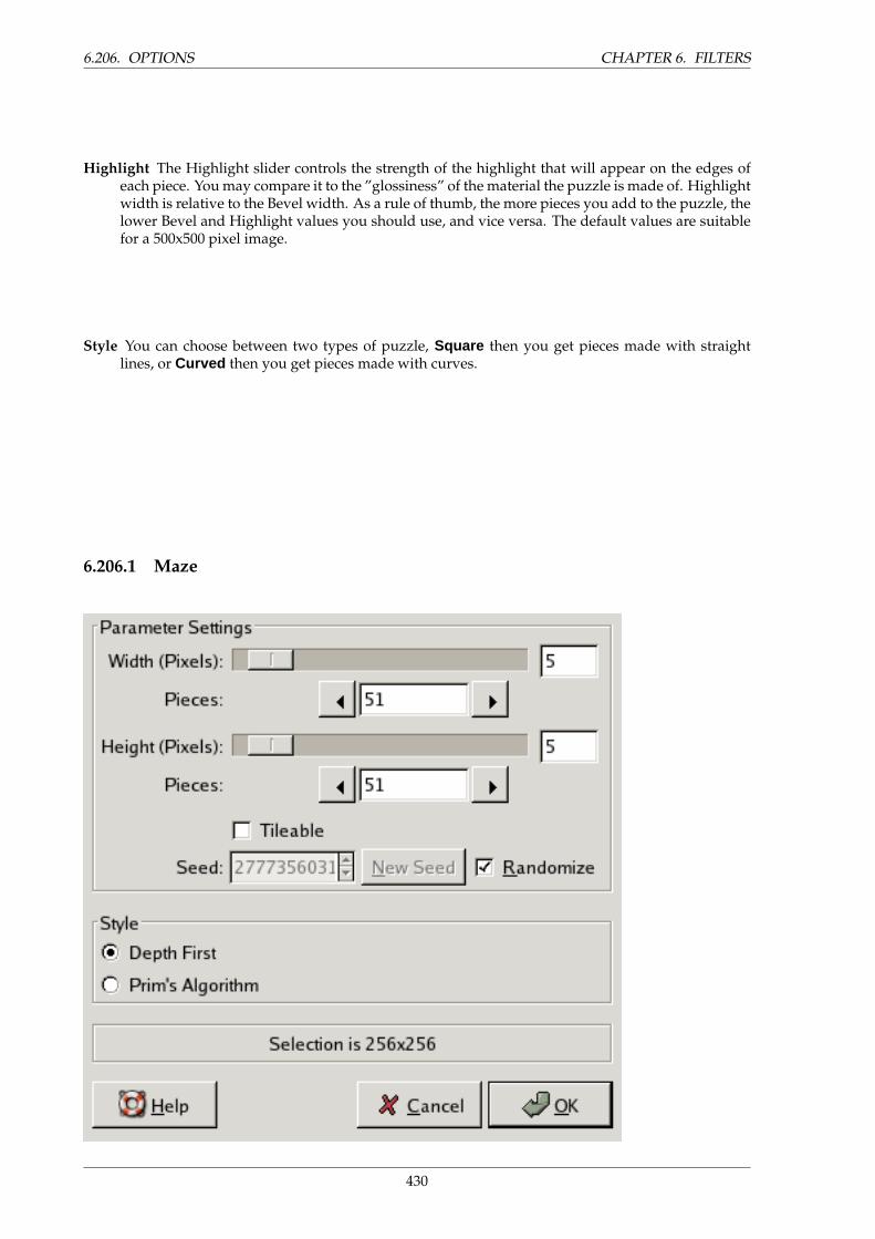
6.206. OPTIONS CHAPTER 6. FILTERS
Highlight The Highlight slider controls the strength of the highlight that will appear on the edges ofeach piece. You may compare it to the ”glossiness” of the material the puzzle is made of. Highlightwidth is relative to the Bevel width. As a rule of thumb, the more pieces you add to the puzzle, thelower Bevel and Highlight values you should use, and vice versa. The default values are suitablefor a 500x500 pixel image.
Style You can choose between two types of puzzle, Square then you get pieces made with straightlines, or Curved then you get pieces made with curves.
6.206.1 Maze
430
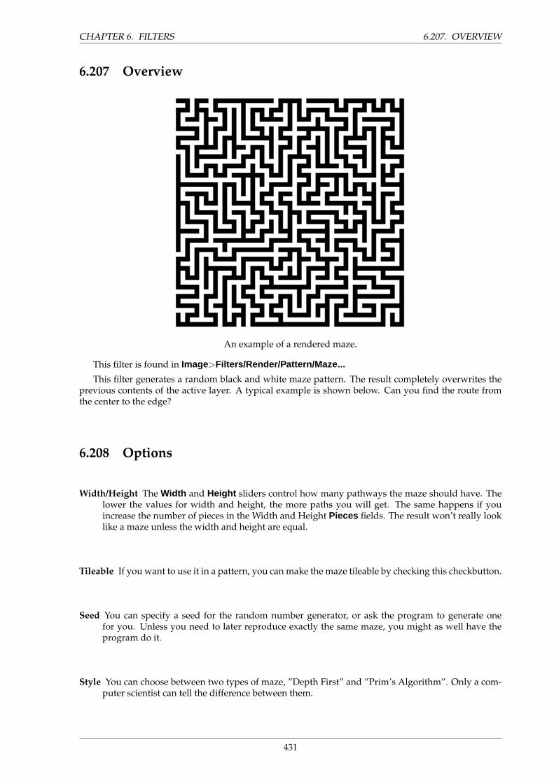
CHAPTER 6. FILTERS 6.207. OVERVIEW
6.207 Overview
An example of a rendered maze.
This filter is found in Image>Filters/Render/Pattern/Maze...
This filter generates a random black and white maze pattern. The result completely overwrites theprevious contents of the active layer. A typical example is shown below. Can you find the route fromthe center to the edge?
6.208 Options
Width/Height The Width and Height sliders control how many pathways the maze should have. Thelower the values for width and height, the more paths you will get. The same happens if youincrease the number of pieces in the Width and Height Pieces fields. The result won’t really looklike a maze unless the width and height are equal.
Tileable If you want to use it in a pattern, you can make the maze tileable by checking this checkbutton.
Seed You can specify a seed for the random number generator, or ask the program to generate onefor you. Unless you need to later reproduce exactly the same maze, you might as well have theprogram do it.
Style You can choose between two types of maze, ”Depth First” and ”Prim’s Algorithm”. Only a com-puter scientist can tell the difference between them.
431
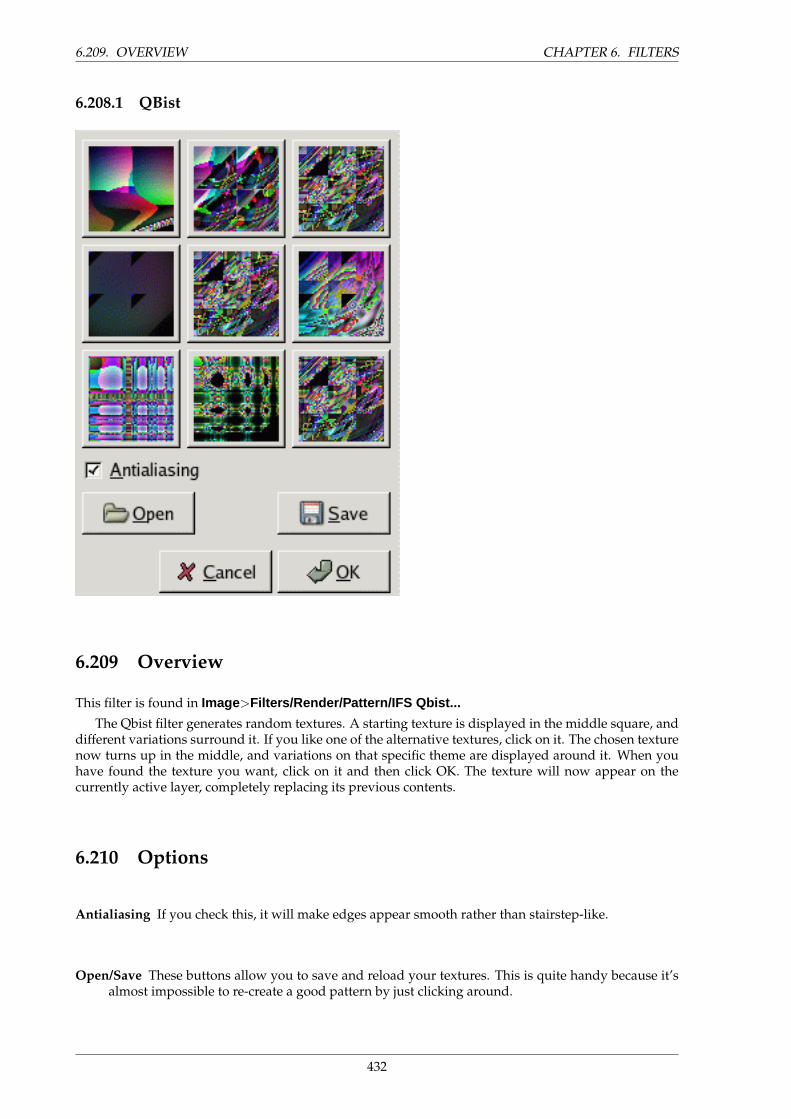
6.209. OVERVIEW CHAPTER 6. FILTERS
6.208.1 QBist
6.209 Overview
This filter is found in Image>Filters/Render/Pattern/IFS Qbist...
The Qbist filter generates random textures. A starting texture is displayed in the middle square, anddifferent variations surround it. If you like one of the alternative textures, click on it. The chosen texturenow turns up in the middle, and variations on that specific theme are displayed around it. When youhave found the texture you want, click on it and then click OK. The texture will now appear on thecurrently active layer, completely replacing its previous contents.
6.210 Options
Antialiasing If you check this, it will make edges appear smooth rather than stairstep-like.
Open/Save These buttons allow you to save and reload your textures. This is quite handy because it’salmost impossible to re-create a good pattern by just clicking around.
432
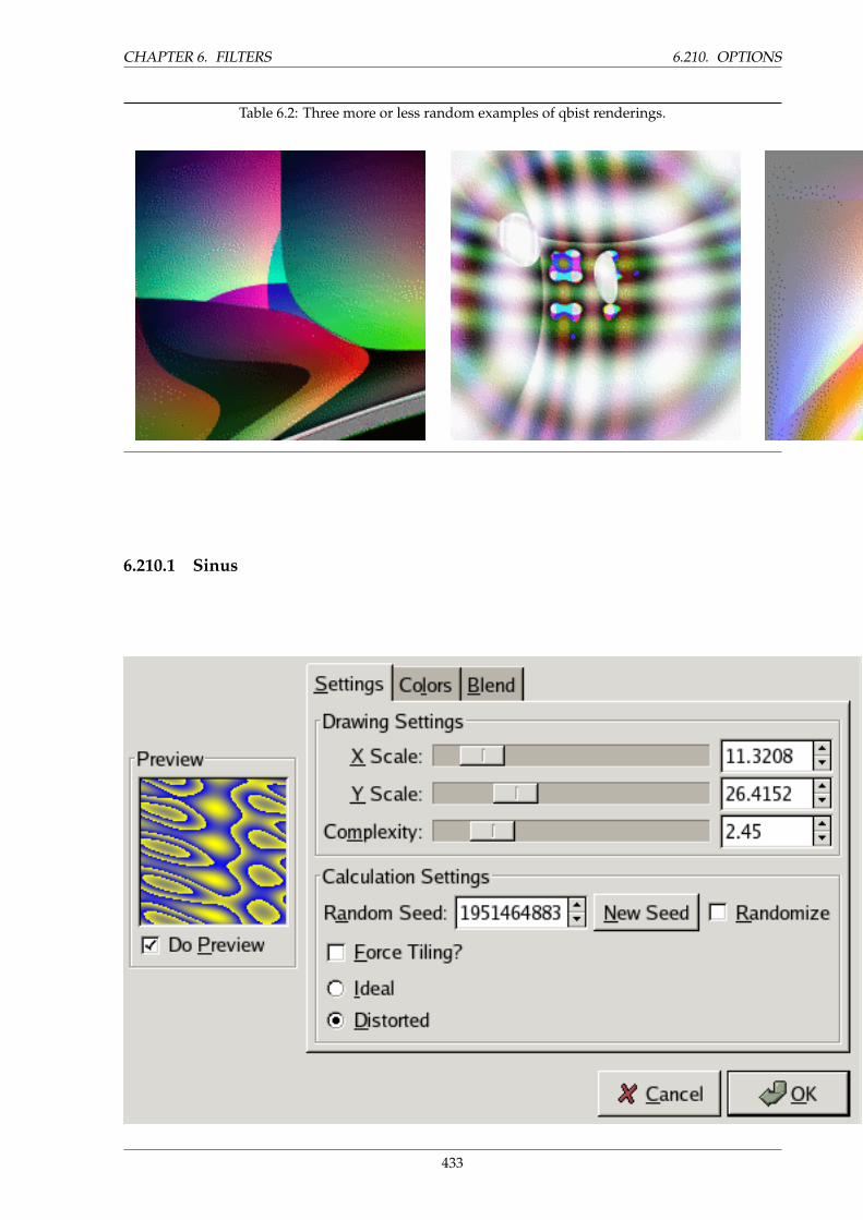
CHAPTER 6. FILTERS 6.210. OPTIONS
Table 6.2: Three more or less random examples of qbist renderings.
6.210.1 Sinus
433
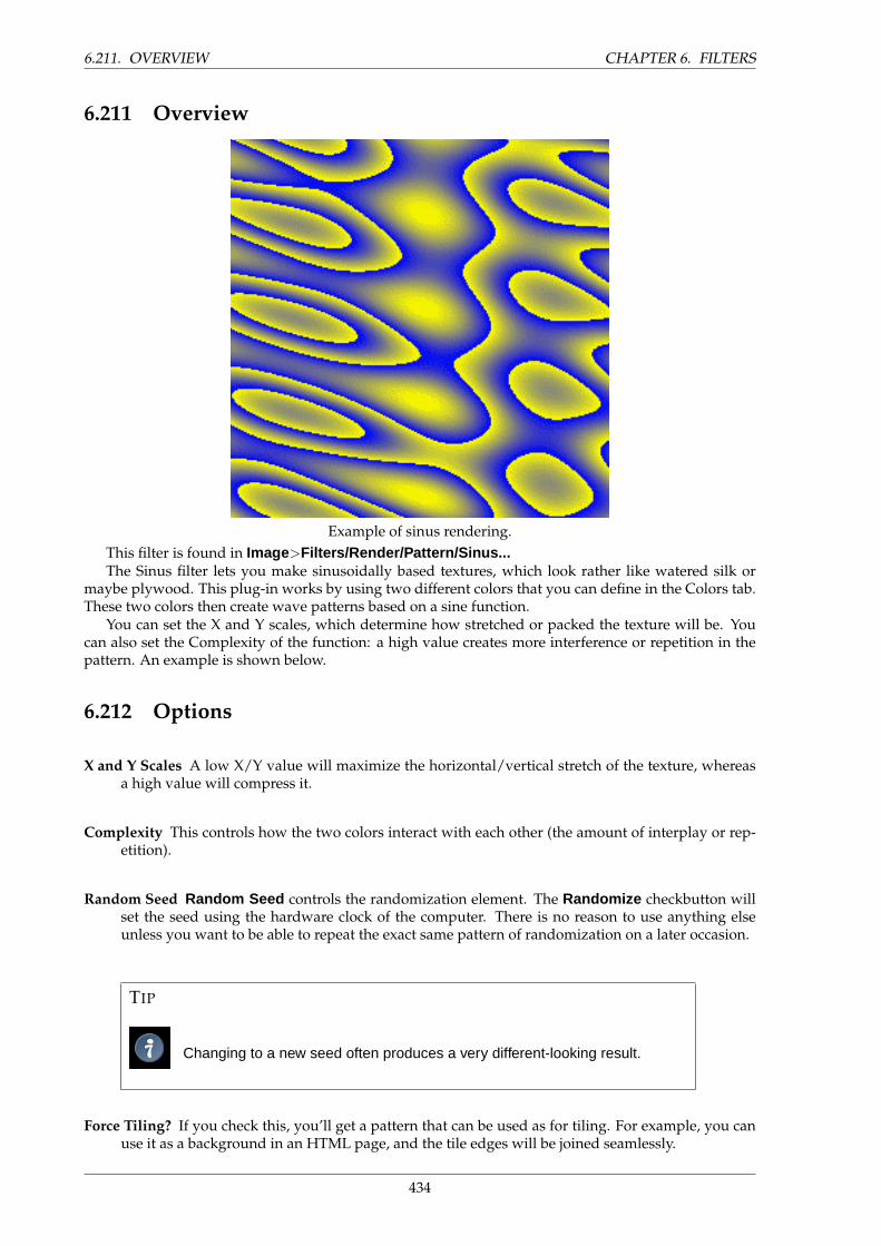
6.211. OVERVIEW CHAPTER 6. FILTERS
6.211 Overview
Example of sinus rendering.This filter is found in Image>Filters/Render/Pattern/Sinus...The Sinus filter lets you make sinusoidally based textures, which look rather like watered silk or
maybe plywood. This plug-in works by using two different colors that you can define in the Colors tab.These two colors then create wave patterns based on a sine function.
You can set the X and Y scales, which determine how stretched or packed the texture will be. Youcan also set the Complexity of the function: a high value creates more interference or repetition in thepattern. An example is shown below.
6.212 Options
X and Y Scales A low X/Y value will maximize the horizontal/vertical stretch of the texture, whereasa high value will compress it.
Complexity This controls how the two colors interact with each other (the amount of interplay or rep-etition).
Random Seed Random Seed controls the randomization element. The Randomize checkbutton willset the seed using the hardware clock of the computer. There is no reason to use anything elseunless you want to be able to repeat the exact same pattern of randomization on a later occasion.
TIP
Changing to a new seed often produces a very different-looking result.
Force Tiling? If you check this, you’ll get a pattern that can be used as for tiling. For example, you canuse it as a background in an HTML page, and the tile edges will be joined seamlessly.
434
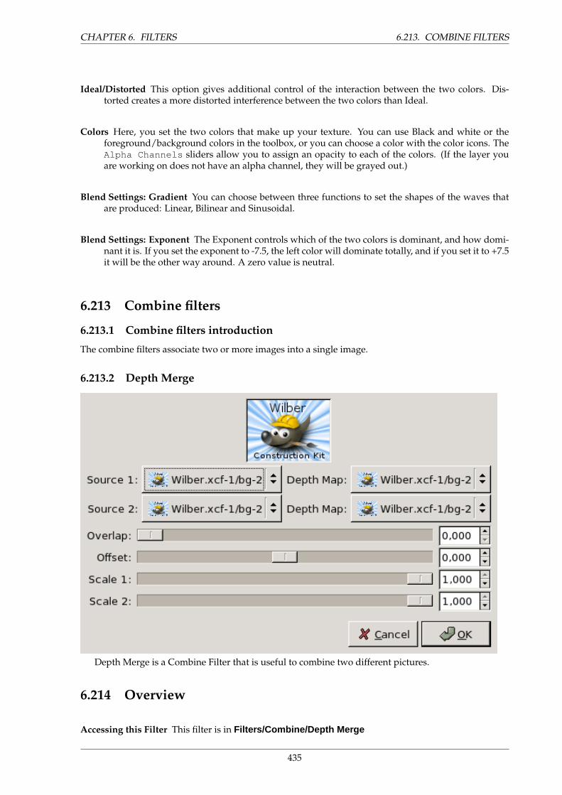
CHAPTER 6. FILTERS 6.213. COMBINE FILTERS
Ideal/Distorted This option gives additional control of the interaction between the two colors. Dis-torted creates a more distorted interference between the two colors than Ideal.
Colors Here, you set the two colors that make up your texture. You can use Black and white or theforeground/background colors in the toolbox, or you can choose a color with the color icons. TheAlpha Channels sliders allow you to assign an opacity to each of the colors. (If the layer youare working on does not have an alpha channel, they will be grayed out.)
Blend Settings: Gradient You can choose between three functions to set the shapes of the waves thatare produced: Linear, Bilinear and Sinusoidal.
Blend Settings: Exponent The Exponent controls which of the two colors is dominant, and how domi-nant it is. If you set the exponent to -7.5, the left color will dominate totally, and if you set it to +7.5it will be the other way around. A zero value is neutral.
6.213 Combine filters
6.213.1 Combine filters introduction
The combine filters associate two or more images into a single image.
6.213.2 Depth Merge
Depth Merge is a Combine Filter that is useful to combine two different pictures.
6.214 Overview
Accessing this Filter This filter is in Filters/Combine/Depth Merge
435
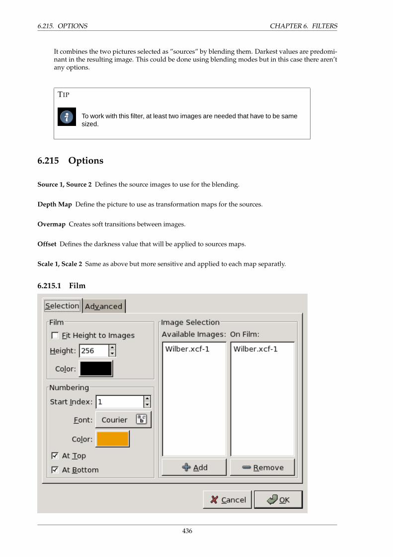
6.215. OPTIONS CHAPTER 6. FILTERS
It combines the two pictures selected as ”sources” by blending them. Darkest values are predomi-nant in the resulting image. This could be done using blending modes but in this case there aren’tany options.
TIP
To work with this filter, at least two images are needed that have to be samesized.
6.215 Options
Source 1, Source 2 Defines the source images to use for the blending.
Depth Map Define the picture to use as transformation maps for the sources.
Overmap Creates soft transitions between images.
Offset Defines the darkness value that will be applied to sources maps.
Scale 1, Scale 2 Same as above but more sensitive and applied to each map separatly.
6.215.1 Film
436
CHAPTER 6. FILTERS 6.216. OVERVIEW
6.216 Overview
Accessing this Filter This filter is in Image/Filters/Combine/Film
Film filter allows the user to merge several pictures into a photographic film drawing.
WARNING
It does not invert colors of originals documents as it should be in a realphotographic film.
6.217 Selection Options
Fit Height to images Applies the height of original pictures to the resulting one.
Height Allows to define the height of resulting picture. If originals have different sizes, they will bescaled to this size.
Color By clicking on the color dwell you can define the color of the film (around and between pictures).
Start Index Defines the begining number that will be used for the images.
Font Defines the font of digits.
Color By clicking on the the color dwell, you can define the font color of digits.
At Top, At Bottom Defines the position of the number.
Available Images Shows the pictures that can be used for the merging. The pictures are these that arealready opened in Gimp.
On Film Shows the pictures chosen to be merged.
Add This button allows the user to put an available image in the ”On film” section.
Remove This button allows to bring a picture from ”on Film” to ”available images”. After that, thepicture will not be used anymore in the resulting document.
6.218 Advanced Options
Image Height Defines the height of each pictures in the resulting image.
Image Spacing Defines the space between the pictures as they will be inserted in the future image.
437
6.218. ADVANCED OPTIONS CHAPTER 6. FILTERS
Hole Offset Defines the hole position from image border.
Hole Width Defines the width of the holes in the resulting image.
Hole Height Defines the height of the holes in the resulting image.
Hole Spacing Defines the space between holes
Number Height Defines the height of the index number, proportionnaly to the height of the picture.
438
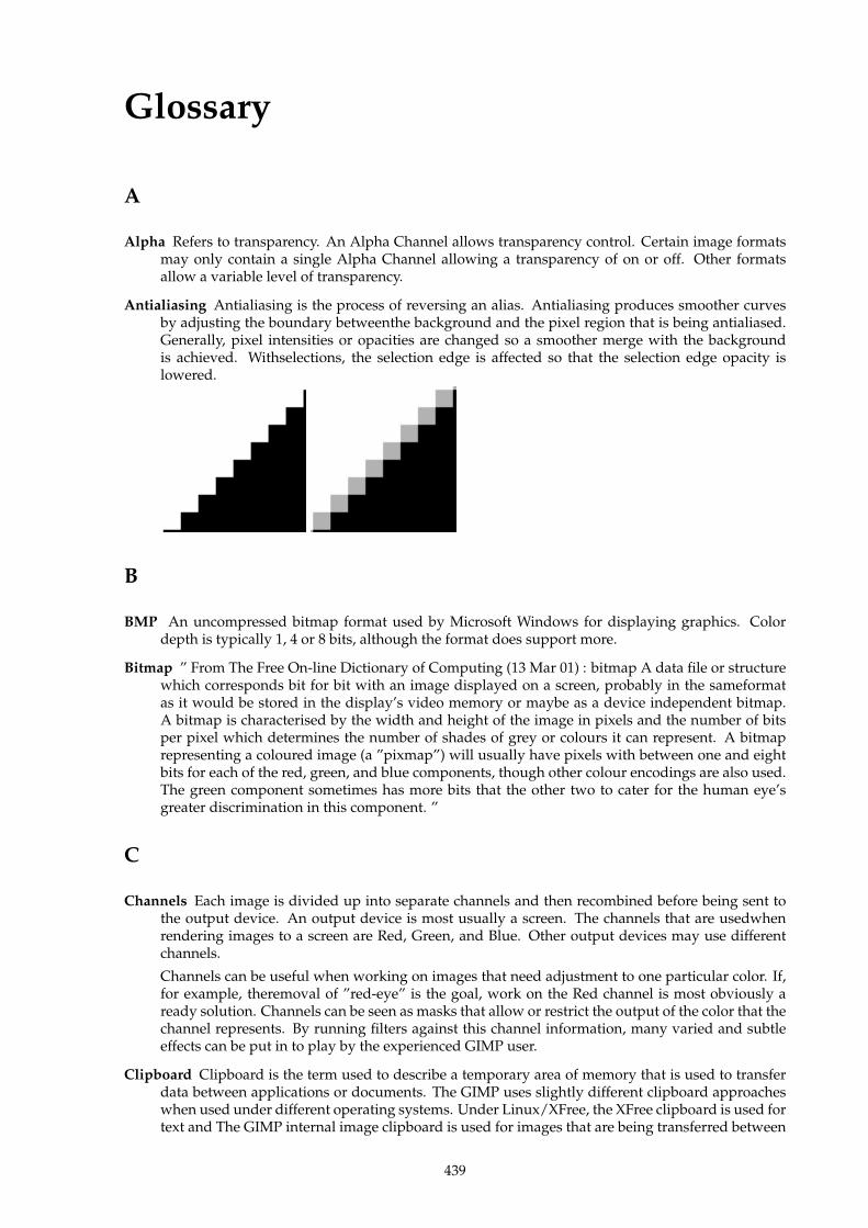
Glossary
A
Alpha Refers to transparency. An Alpha Channel allows transparency control. Certain image formatsmay only contain a single Alpha Channel allowing a transparency of on or off. Other formatsallow a variable level of transparency.
Antialiasing Antialiasing is the process of reversing an alias. Antialiasing produces smoother curvesby adjusting the boundary betweenthe background and the pixel region that is being antialiased.Generally, pixel intensities or opacities are changed so a smoother merge with the backgroundis achieved. Withselections, the selection edge is affected so that the selection edge opacity islowered.
B
BMP An uncompressed bitmap format used by Microsoft Windows for displaying graphics. Colordepth is typically 1, 4 or 8 bits, although the format does support more.
Bitmap ” From The Free On-line Dictionary of Computing (13 Mar 01) : bitmap A data file or structurewhich corresponds bit for bit with an image displayed on a screen, probably in the sameformatas it would be stored in the display’s video memory or maybe as a device independent bitmap.A bitmap is characterised by the width and height of the image in pixels and the number of bitsper pixel which determines the number of shades of grey or colours it can represent. A bitmaprepresenting a coloured image (a ”pixmap”) will usually have pixels with between one and eightbits for each of the red, green, and blue components, though other colour encodings are also used.The green component sometimes has more bits that the other two to cater for the human eye’sgreater discrimination in this component. ”
C
Channels Each image is divided up into separate channels and then recombined before being sent tothe output device. An output device is most usually a screen. The channels that are usedwhenrendering images to a screen are Red, Green, and Blue. Other output devices may use differentchannels.
Channels can be useful when working on images that need adjustment to one particular color. If,for example, theremoval of ”red-eye” is the goal, work on the Red channel is most obviously aready solution. Channels can be seen as masks that allow or restrict the output of the color that thechannel represents. By running filters against this channel information, many varied and subtleeffects can be put in to play by the experienced GIMP user.
Clipboard Clipboard is the term used to describe a temporary area of memory that is used to transferdata between applications or documents. The GIMP uses slightly different clipboard approacheswhen used under different operating systems. Under Linux/XFree, the XFree clipboard is used fortext and The GIMP internal image clipboard is used for images that are being transferred between
439
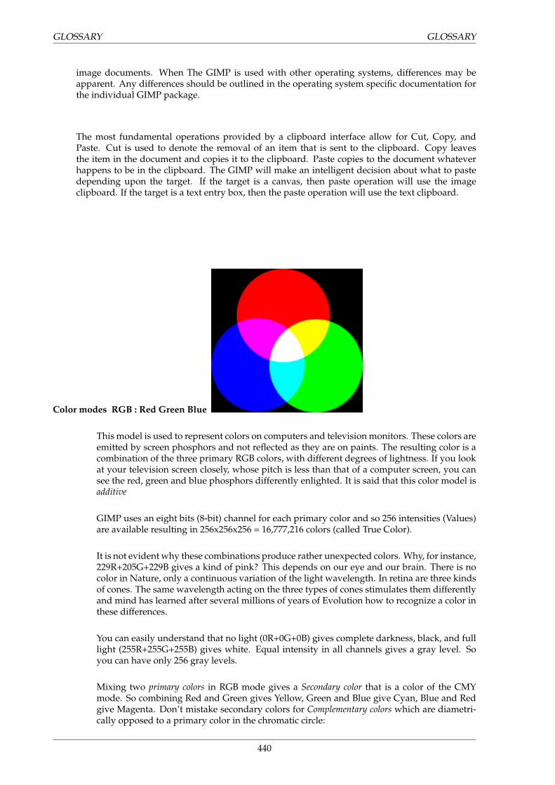
GLOSSARY GLOSSARY
image documents. When The GIMP is used with other operating systems, differences may beapparent. Any differences should be outlined in the operating system specific documentation forthe individual GIMP package.
The most fundamental operations provided by a clipboard interface allow for Cut, Copy, andPaste. Cut is used to denote the removal of an item that is sent to the clipboard. Copy leavesthe item in the document and copies it to the clipboard. Paste copies to the document whateverhappens to be in the clipboard. The GIMP will make an intelligent decision about what to pastedepending upon the target. If the target is a canvas, then paste operation will use the imageclipboard. If the target is a text entry box, then the paste operation will use the text clipboard.
Color modes RGB : Red Green Blue
This model is used to represent colors on computers and television monitors. These colors areemitted by screen phosphors and not reflected as they are on paints. The resulting color is acombination of the three primary RGB colors, with different degrees of lightness. If you lookat your television screen closely, whose pitch is less than that of a computer screen, you cansee the red, green and blue phosphors differently enlighted. It is said that this color model isadditive
GIMP uses an eight bits (8-bit) channel for each primary color and so 256 intensities (Values)are available resulting in 256x256x256 = 16,777,216 colors (called True Color).
It is not evident why these combinations produce rather unexpected colors. Why, for instance,229R+205G+229B gives a kind of pink? This depends on our eye and our brain. There is nocolor in Nature, only a continuous variation of the light wavelength. In retina are three kindsof cones. The same wavelength acting on the three types of cones stimulates them differentlyand mind has learned after several millions of years of Evolution how to recognize a color inthese differences.
You can easily understand that no light (0R+0G+0B) gives complete darkness, black, and fulllight (255R+255G+255B) gives white. Equal intensity in all channels gives a gray level. Soyou can have only 256 gray levels.
Mixing two primary colors in RGB mode gives a Secondary color that is a color of the CMYmode. So combining Red and Green gives Yellow, Green and Blue give Cyan, Blue and Redgive Magenta. Don’t mistake secondary colors for Complementary colors which are diametri-cally opposed to a primary color in the chromatic circle:
440
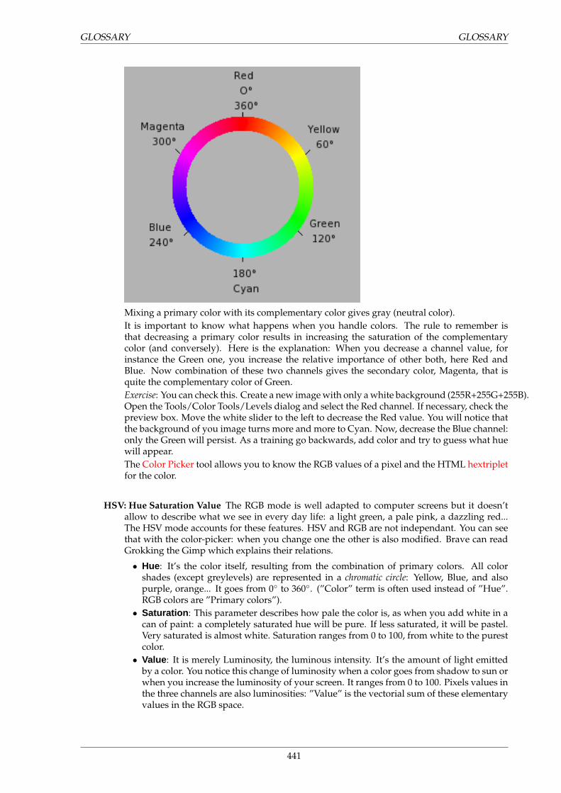
GLOSSARY GLOSSARY
Mixing a primary color with its complementary color gives gray (neutral color).It is important to know what happens when you handle colors. The rule to remember isthat decreasing a primary color results in increasing the saturation of the complementarycolor (and conversely). Here is the explanation: When you decrease a channel value, forinstance the Green one, you increase the relative importance of other both, here Red andBlue. Now combination of these two channels gives the secondary color, Magenta, that isquite the complementary color of Green.Exercise: You can check this. Create a new image with only a white background (255R+255G+255B).Open the Tools/Color Tools/Levels dialog and select the Red channel. If necessary, check thepreview box. Move the white slider to the left to decrease the Red value. You will notice thatthe background of you image turns more and more to Cyan. Now, decrease the Blue channel:only the Green will persist. As a training go backwards, add color and try to guess what huewill appear.The Color Picker tool allows you to know the RGB values of a pixel and the HTML hextripletfor the color.
HSV: Hue Saturation Value The RGB mode is well adapted to computer screens but it doesn’tallow to describe what we see in every day life: a light green, a pale pink, a dazzling red...The HSV mode accounts for these features. HSV and RGB are not independant. You can seethat with the color-picker: when you change one the other is also modified. Brave can readGrokking the Gimp which explains their relations.
• Hue: It’s the color itself, resulting from the combination of primary colors. All colorshades (except greylevels) are represented in a chromatic circle: Yellow, Blue, and alsopurple, orange... It goes from 0◦ to 360◦. (”Color” term is often used instead of ”Hue”.RGB colors are ”Primary colors”).
• Saturation : This parameter describes how pale the color is, as when you add white in acan of paint: a completely saturated hue will be pure. If less saturated, it will be pastel.Very saturated is almost white. Saturation ranges from 0 to 100, from white to the purestcolor.
• Value : It is merely Luminosity, the luminous intensity. It’s the amount of light emittedby a color. You notice this change of luminosity when a color goes from shadow to sun orwhen you increase the luminosity of your screen. It ranges from 0 to 100. Pixels values inthe three channels are also luminosities: ”Value” is the vectorial sum of these elementaryvalues in the RGB space.
441

GLOSSARY GLOSSARY
CMYK: Cyan Magenta Yellow blackLet us say first that Gimp doesn’t support the CMYK mode. (An experimental plugin provid-ing rudimentary CMYK support can be found at www.blackfiveservices.co.uk/separate.shtml<http://www.blackfiveservices.co.uk/separate.shtml >.)This mode is that of printing, that of your printer whose cartridges contain these colors. It’sthe mode of painting and of all the objects around us, where light is not emitted but reflected.Objects absorb apart of the light wave and we see only the reflected part. Notice that our eyewith its cones sees this reflected light in RGB mode. An object is red because Green and Bluehave been absorbed. Now, Green and Blue combination is Cyan. So, Cyan is absorbed whenyou add Red. Conversely, if you add Cyan the complementary Red is absorbed: this systemis substractive. If you add Yellow, you decrease Blue and if you add Magenta, you decreaseGreen.You could logically think that by mixing Cyan, Magenta and Yellow you substract Red, Greenand Blue, and so that the eye sees no light at all, that’s to say Black. The question is morecomplex. In fact you will see a dark brown. That’s why this mode has also the Black colorand why your printer has a Black cartridge. That’s finally cheaper: the printer has not to mixthe three other colors to create an imperfect black. It has only to add some Black.
Graylevel When you create a new image you can choose the graylevel mode (that you can col-orize later by transforming it to the RGB mode). You can also transform an existing im-age to graylevel (but all formats do not accept this transformation) thanks to the commandGraylevel.As we have explained in RGB mode, Gimp 24-bit images cann’t have more than 256 graylevels, coded on 8-bit. If you switch from graylevel to RGB mode you give your image a RGBstructure with three color channels but of course your image remains gray.Graylevel image files (8-bit) are smaller than RGB files.You can also transform a RGB image to graylevel by desaturating it thanks to the HSV optionof the Decompose filter, the Colorize tool, or the Hue-Saturation filter.
Indexed colors The indexed mode has been invented by Compuserve at the beginning of the Webto create small color image files, that could be easily transmitted. GIF (Graphic InterchangeFormat) was the first indexed format.The principle is to code each pixel color in a table attached to the image, all pixels with thesame color have the same code.You can see this palette when you have opened a GIF image thanks to the Dialogs / IndexedPalette. It allows you to edit and modify each color.See also Indexed Palette.In a GIF image, transparency is coded on one bit: transparent or not.
D
442
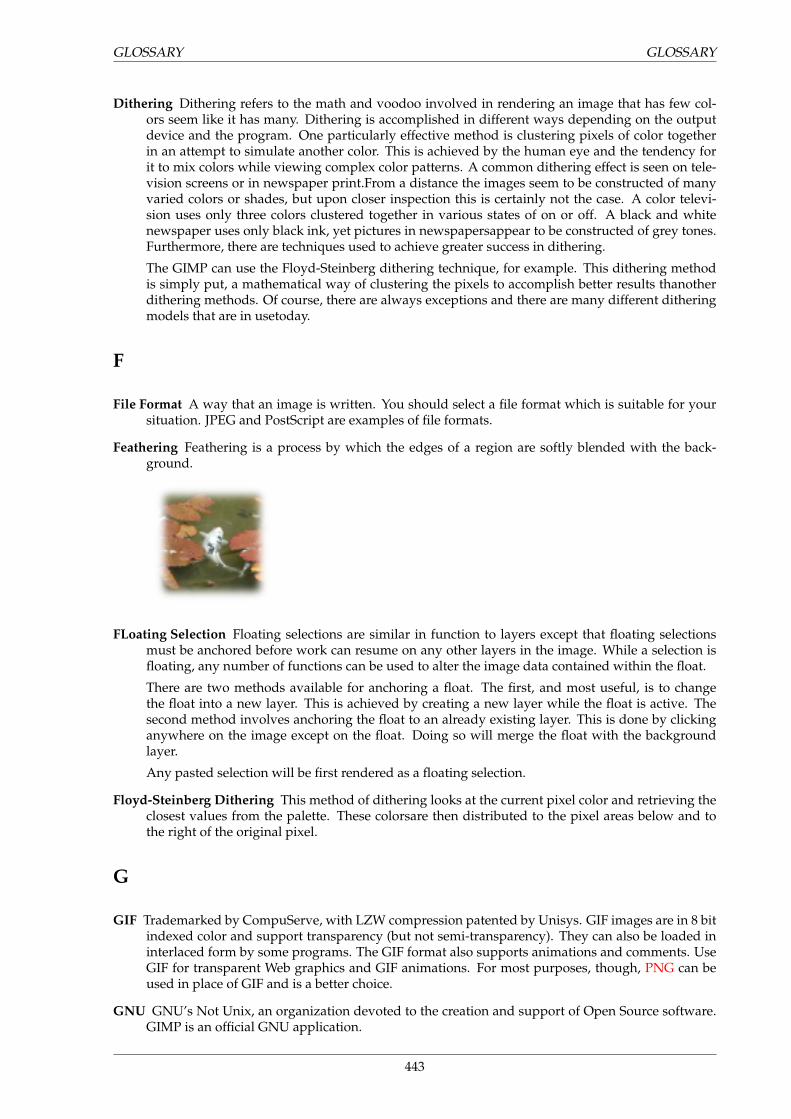
GLOSSARY GLOSSARY
Dithering Dithering refers to the math and voodoo involved in rendering an image that has few col-ors seem like it has many. Dithering is accomplished in different ways depending on the outputdevice and the program. One particularly effective method is clustering pixels of color togetherin an attempt to simulate another color. This is achieved by the human eye and the tendency forit to mix colors while viewing complex color patterns. A common dithering effect is seen on tele-vision screens or in newspaper print.From a distance the images seem to be constructed of manyvaried colors or shades, but upon closer inspection this is certainly not the case. A color televi-sion uses only three colors clustered together in various states of on or off. A black and whitenewspaper uses only black ink, yet pictures in newspapersappear to be constructed of grey tones.Furthermore, there are techniques used to achieve greater success in dithering.
The GIMP can use the Floyd-Steinberg dithering technique, for example. This dithering methodis simply put, a mathematical way of clustering the pixels to accomplish better results thanotherdithering methods. Of course, there are always exceptions and there are many different ditheringmodels that are in usetoday.
F
File Format A way that an image is written. You should select a file format which is suitable for yoursituation. JPEG and PostScript are examples of file formats.
Feathering Feathering is a process by which the edges of a region are softly blended with the back-ground.
FLoating Selection Floating selections are similar in function to layers except that floating selectionsmust be anchored before work can resume on any other layers in the image. While a selection isfloating, any number of functions can be used to alter the image data contained within the float.
There are two methods available for anchoring a float. The first, and most useful, is to changethe float into a new layer. This is achieved by creating a new layer while the float is active. Thesecond method involves anchoring the float to an already existing layer. This is done by clickinganywhere on the image except on the float. Doing so will merge the float with the backgroundlayer.
Any pasted selection will be first rendered as a floating selection.
Floyd-Steinberg Dithering This method of dithering looks at the current pixel color and retrieving theclosest values from the palette. These colorsare then distributed to the pixel areas below and tothe right of the original pixel.
G
GIF Trademarked by CompuServe, with LZW compression patented by Unisys. GIF images are in 8 bitindexed color and support transparency (but not semi-transparency). They can also be loaded ininterlaced form by some programs. The GIF format also supports animations and comments. UseGIF for transparent Web graphics and GIF animations. For most purposes, though, PNG can beused in place of GIF and is a better choice.
GNU GNU’s Not Unix, an organization devoted to the creation and support of Open Source software.GIMP is an official GNU application.
443
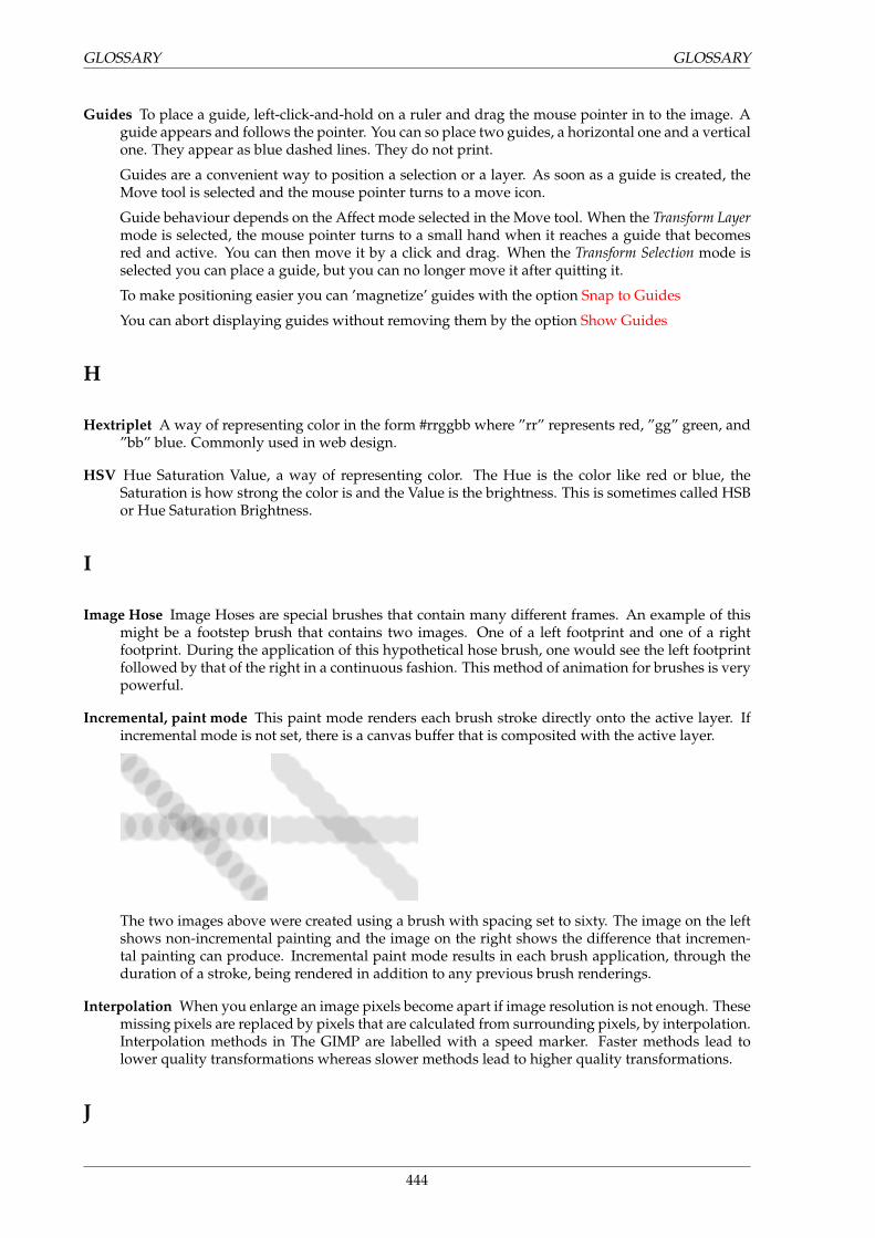
GLOSSARY GLOSSARY
Guides To place a guide, left-click-and-hold on a ruler and drag the mouse pointer in to the image. Aguide appears and follows the pointer. You can so place two guides, a horizontal one and a verticalone. They appear as blue dashed lines. They do not print.
Guides are a convenient way to position a selection or a layer. As soon as a guide is created, theMove tool is selected and the mouse pointer turns to a move icon.
Guide behaviour depends on the Affect mode selected in the Move tool. When the Transform Layermode is selected, the mouse pointer turns to a small hand when it reaches a guide that becomesred and active. You can then move it by a click and drag. When the Transform Selection mode isselected you can place a guide, but you can no longer move it after quitting it.
To make positioning easier you can ’magnetize’ guides with the option Snap to Guides
You can abort displaying guides without removing them by the option Show Guides
H
Hextriplet A way of representing color in the form #rrggbb where ”rr” represents red, ”gg” green, and”bb” blue. Commonly used in web design.
HSV Hue Saturation Value, a way of representing color. The Hue is the color like red or blue, theSaturation is how strong the color is and the Value is the brightness. This is sometimes called HSBor Hue Saturation Brightness.
I
Image Hose Image Hoses are special brushes that contain many different frames. An example of thismight be a footstep brush that contains two images. One of a left footprint and one of a rightfootprint. During the application of this hypothetical hose brush, one would see the left footprintfollowed by that of the right in a continuous fashion. This method of animation for brushes is verypowerful.
Incremental, paint mode This paint mode renders each brush stroke directly onto the active layer. Ifincremental mode is not set, there is a canvas buffer that is composited with the active layer.
The two images above were created using a brush with spacing set to sixty. The image on the leftshows non-incremental painting and the image on the right shows the difference that incremen-tal painting can produce. Incremental paint mode results in each brush application, through theduration of a stroke, being rendered in addition to any previous brush renderings.
Interpolation When you enlarge an image pixels become apart if image resolution is not enough. Thesemissing pixels are replaced by pixels that are calculated from surrounding pixels, by interpolation.Interpolation methods in The GIMP are labelled with a speed marker. Faster methods lead tolower quality transformations whereas slower methods lead to higher quality transformations.
J
444
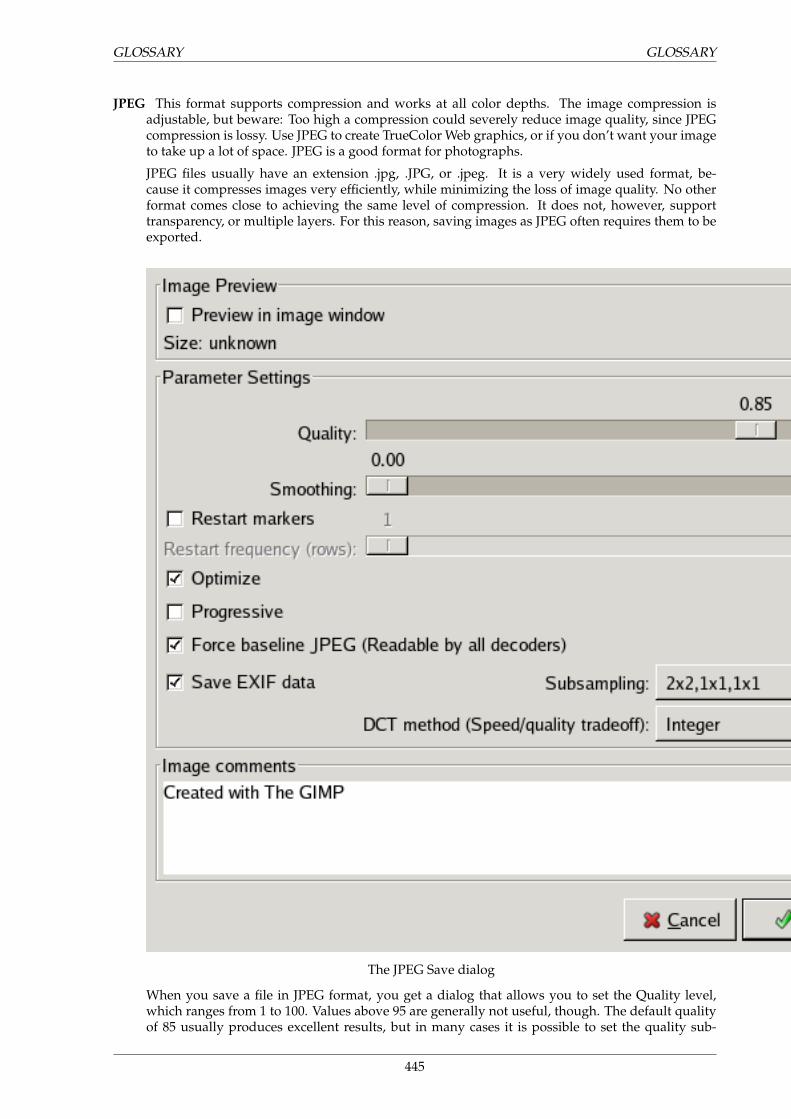
GLOSSARY GLOSSARY
JPEG This format supports compression and works at all color depths. The image compression isadjustable, but beware: Too high a compression could severely reduce image quality, since JPEGcompression is lossy. Use JPEG to create TrueColor Web graphics, or if you don’t want your imageto take up a lot of space. JPEG is a good format for photographs.
JPEG files usually have an extension .jpg, .JPG, or .jpeg. It is a very widely used format, be-cause it compresses images very efficiently, while minimizing the loss of image quality. No otherformat comes close to achieving the same level of compression. It does not, however, supporttransparency, or multiple layers. For this reason, saving images as JPEG often requires them to beexported.
The JPEG Save dialog
When you save a file in JPEG format, you get a dialog that allows you to set the Quality level,which ranges from 1 to 100. Values above 95 are generally not useful, though. The default qualityof 85 usually produces excellent results, but in many cases it is possible to set the quality sub-
445
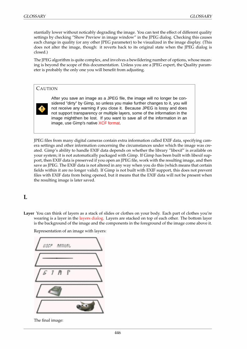
GLOSSARY GLOSSARY
stantially lower without noticably degrading the image. You can test the effect of different qualitysettings by checking ”Show Preview in image window” in the JPEG dialog. Checking this causeseach change in quality (or any other JPEG parameter) to be visualized in the image display. (Thisdoes not alter the image, though: it reverts back to its original state when the JPEG dialog isclosed.)
The JPEG algorithm is quite complex, and involves a bewildering number of options, whose mean-ing is beyond the scope of this documentation. Unless you are a JPEG expert, the Quality param-eter is probably the only one you will benefit from adjusting.
CAUTION
After you save an image as a JPEG file, the image will no longer be con-sidered ”dirty” by Gimp, so unless you make further changes to it, you willnot receive any warning if you close it. Because JPEG is lossy and doesnot support transparency or multiple layers, some of the information in theimage mightthen be lost. If you want to save all of the information in animage, use Gimp’s native XCF format.
JPEG files from many digital cameras contain extra information called EXIF data, specifying cam-era settings and other information concerning the circumstances under which the image was cre-ated. Gimp’s ability to handle EXIF data depends on whether the library ”libexif” is available onyour system; it is not automatically packaged with Gimp. If Gimp has been built with libexif sup-port, then EXIF data is preserved if you open an JPEG file, work with the resulting image, and thensave as JPEG. The EXIF data is not altered in any way when you do this (which means that certainfields within it are no longer valid). If Gimp is not built with EXIF support, this does not preventfiles with EXIF data from being opened, but it means that the EXIF data will not be present whenthe resulting image is later saved.
L
Layer You can think of layers as a stack of slides or clothes on your body. Each part of clothes you’rewearing is a layer in the layers dialog. Layers are stacked on top of each other. The bottom layeris the background of the image and the components in the foreground of the image come above it.
Representation of an image with layers:
The final image:
446
GLOSSARY GLOSSARY
M
Marching Ants The name for the dotted line which delineates a selection.
Layer Modes There are twenty-one available layer modes. Selecting a layer mode changes the way thatlayer or paint application is viewed based on the layer or layers beneath it.
NormalThis is the default layer mode. The layer will be viewed normally.
Dissolve The Dissolve layer mode dissolves the layer into the layer beneath it. It does so bydispersing pixels. This can best be seen ina close-up screenshot.
The image on the left illustrates a normal layer mode and the image on the right shows thesame two layers in dissolve mode.
MultiplyThis mode multiplies the pixel values of the layer with those that are visible beneath it.
DivideThis mode divides the pixel values of the layer by the values of the visible pixels beneath it.
447
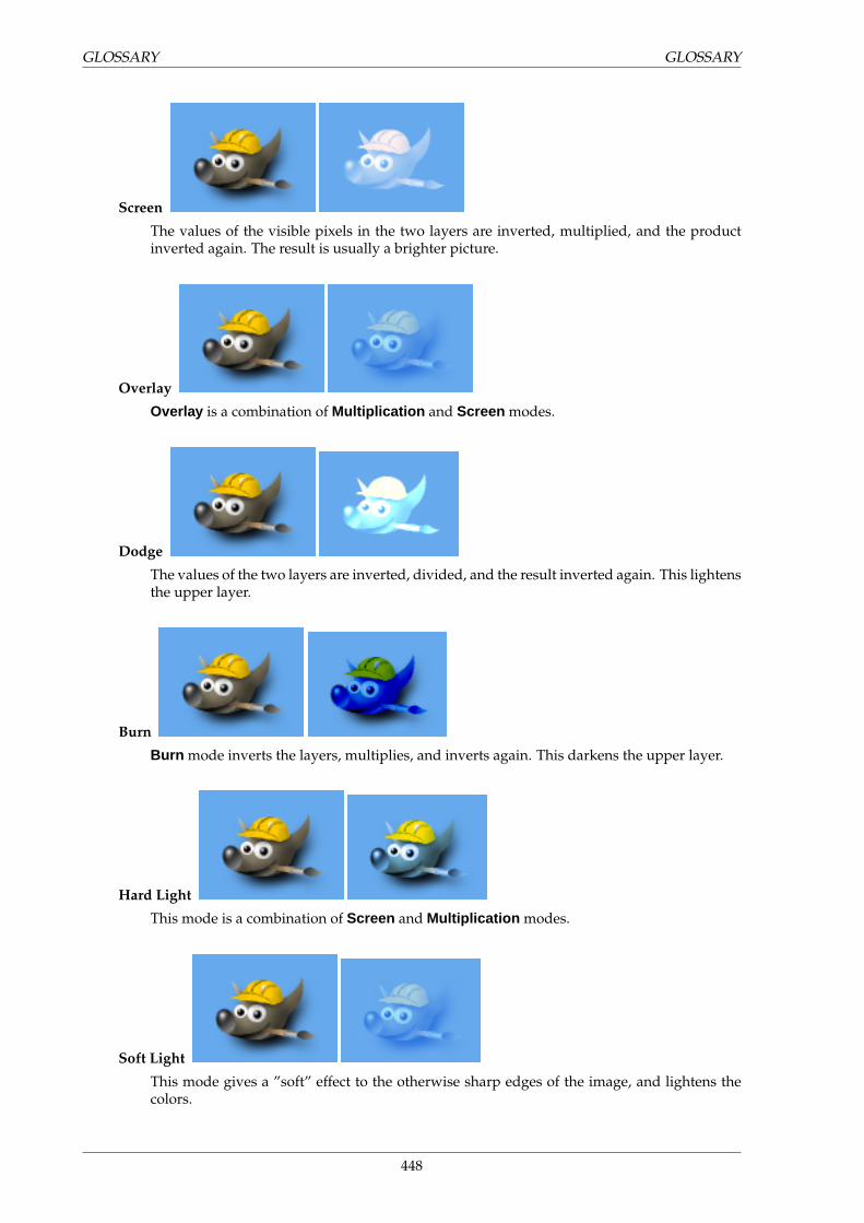
GLOSSARY GLOSSARY
Screen
The values of the visible pixels in the two layers are inverted, multiplied, and the productinverted again. The result is usually a brighter picture.
Overlay
Overlay is a combination of Multiplication and Screen modes.
Dodge
The values of the two layers are inverted, divided, and the result inverted again. This lightensthe upper layer.
Burn
Burn mode inverts the layers, multiplies, and inverts again. This darkens the upper layer.
Hard Light
This mode is a combination of Screen and Multiplication modes.
Soft Light
This mode gives a ”soft” effect to the otherwise sharp edges of the image, and lightens thecolors.
448
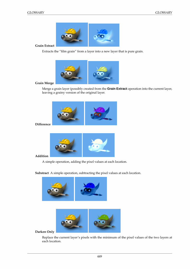
GLOSSARY GLOSSARY
Grain Extract
Extracts the ”film grain” from a layer into a new layer that is pure grain.
Grain Merge
Merge a grain layer (possibly created from the Grain Extract operation into the current layer,leaving a grainy version of the original layer.
Difference
Addition
A simple operation, adding the pixel values at each location.
Substract A simple operation, subtracting the pixel values at each location.
Darken Only
Replace the current layer’s pixels with the minimum of the pixel values of the two layers ateach location.
449
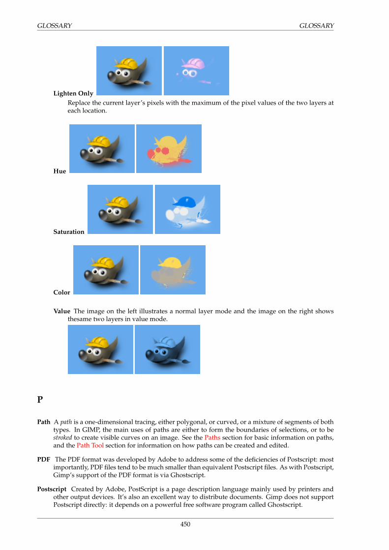
GLOSSARY GLOSSARY
Lighten OnlyReplace the current layer’s pixels with the maximum of the pixel values of the two layers ateach location.
Hue
Saturation
Color
Value The image on the left illustrates a normal layer mode and the image on the right showsthesame two layers in value mode.
P
Path A path is a one-dimensional tracing, either polygonal, or curved, or a mixture of segments of bothtypes. In GIMP, the main uses of paths are either to form the boundaries of selections, or to bestroked to create visible curves on an image. See the Paths section for basic information on paths,and the Path Tool section for information on how paths can be created and edited.
PDF The PDF format was developed by Adobe to address some of the deficiencies of Postscript: mostimportantly, PDF files tend to be much smaller than equivalent Postscript files. As with Postscript,Gimp’s support of the PDF format is via Ghostscript.
Postscript Created by Adobe, PostScript is a page description language mainly used by printers andother output devices. It’s also an excellent way to distribute documents. Gimp does not supportPostscript directly: it depends on a powerful free software program called Ghostscript.
450
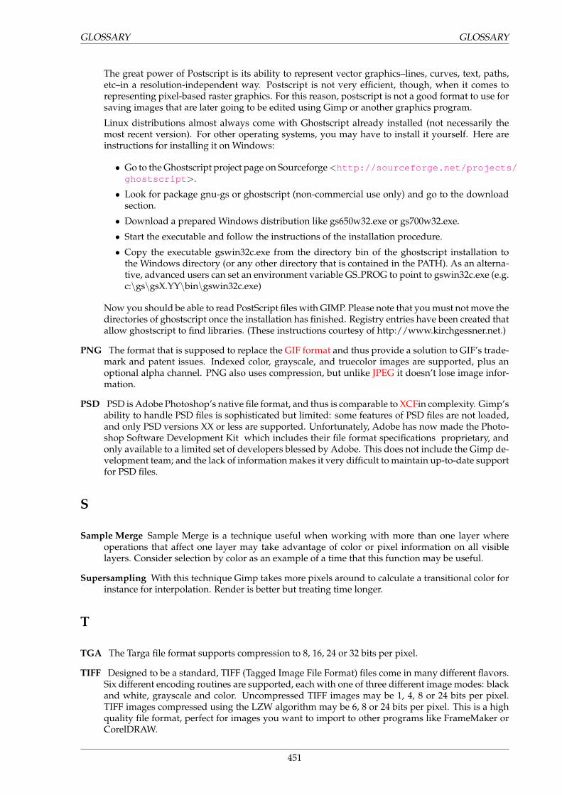
GLOSSARY GLOSSARY
The great power of Postscript is its ability to represent vector graphics–lines, curves, text, paths,etc–in a resolution-independent way. Postscript is not very efficient, though, when it comes torepresenting pixel-based raster graphics. For this reason, postscript is not a good format to use forsaving images that are later going to be edited using Gimp or another graphics program.
Linux distributions almost always come with Ghostscript already installed (not necessarily themost recent version). For other operating systems, you may have to install it yourself. Here areinstructions for installing it on Windows:
• Go to the Ghostscript project page on Sourceforge <http://sourceforge.net/projects/ghostscript >.
• Look for package gnu-gs or ghostscript (non-commercial use only) and go to the downloadsection.
• Download a prepared Windows distribution like gs650w32.exe or gs700w32.exe.
• Start the executable and follow the instructions of the installation procedure.
• Copy the executable gswin32c.exe from the directory bin of the ghostscript installation tothe Windows directory (or any other directory that is contained in the PATH). As an alterna-tive, advanced users can set an environment variable GS PROG to point to gswin32c.exe (e.g.c:\gs\gsX.YY\bin\gswin32c.exe)
Now you should be able to read PostScript files with GIMP. Please note that you must not move thedirectories of ghostscript once the installation has finished. Registry entries have been created thatallow ghostscript to find libraries. (These instructions courtesy of http://www.kirchgessner.net.)
PNG The format that is supposed to replace the GIF format and thus provide a solution to GIF’s trade-mark and patent issues. Indexed color, grayscale, and truecolor images are supported, plus anoptional alpha channel. PNG also uses compression, but unlike JPEG it doesn’t lose image infor-mation.
PSD PSD is Adobe Photoshop’s native file format, and thus is comparable to XCFin complexity. Gimp’sability to handle PSD files is sophisticated but limited: some features of PSD files are not loaded,and only PSD versions XX or less are supported. Unfortunately, Adobe has now made the Photo-shop Software Development Kit which includes their file format specifications proprietary, andonly available to a limited set of developers blessed by Adobe. This does not include the Gimp de-velopment team; and the lack of information makes it very difficult to maintain up-to-date supportfor PSD files.
S
Sample Merge Sample Merge is a technique useful when working with more than one layer whereoperations that affect one layer may take advantage of color or pixel information on all visiblelayers. Consider selection by color as an example of a time that this function may be useful.
Supersampling With this technique Gimp takes more pixels around to calculate a transitional color forinstance for interpolation. Render is better but treating time longer.
T
TGA The Targa file format supports compression to 8, 16, 24 or 32 bits per pixel.
TIFF Designed to be a standard, TIFF (Tagged Image File Format) files come in many different flavors.Six different encoding routines are supported, each with one of three different image modes: blackand white, grayscale and color. Uncompressed TIFF images may be 1, 4, 8 or 24 bits per pixel.TIFF images compressed using the LZW algorithm may be 6, 8 or 24 bits per pixel. This is a highquality file format, perfect for images you want to import to other programs like FrameMaker orCorelDRAW.
451
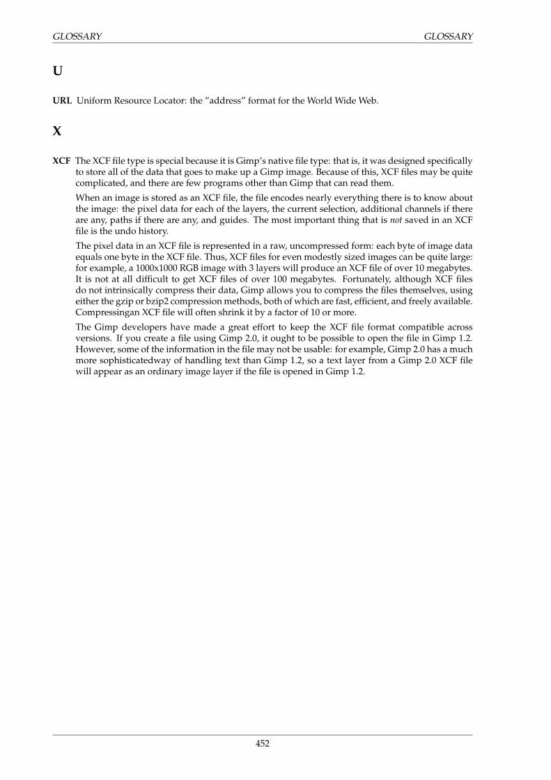
GLOSSARY GLOSSARY
U
URL Uniform Resource Locator: the ”address” format for the World Wide Web.
X
XCF The XCF file type is special because it is Gimp’s native file type: that is, it was designed specificallyto store all of the data that goes to make up a Gimp image. Because of this, XCF files may be quitecomplicated, and there are few programs other than Gimp that can read them.
When an image is stored as an XCF file, the file encodes nearly everything there is to know aboutthe image: the pixel data for each of the layers, the current selection, additional channels if thereare any, paths if there are any, and guides. The most important thing that is not saved in an XCFfile is the undo history.
The pixel data in an XCF file is represented in a raw, uncompressed form: each byte of image dataequals one byte in the XCF file. Thus, XCF files for even modestly sized images can be quite large:for example, a 1000x1000 RGB image with 3 layers will produce an XCF file of over 10 megabytes.It is not at all difficult to get XCF files of over 100 megabytes. Fortunately, although XCF filesdo not intrinsically compress their data, Gimp allows you to compress the files themselves, usingeither the gzip or bzip2 compression methods, both of which are fast, efficient, and freely available.Compressingan XCF file will often shrink it by a factor of 10 or more.
The Gimp developers have made a great effort to keep the XCF file format compatible acrossversions. If you create a file using Gimp 2.0, it ought to be possible to open the file in Gimp 1.2.However, some of the information in the file may not be usable: for example, Gimp 2.0 has a muchmore sophisticatedway of handling text than Gimp 1.2, so a text layer from a Gimp 2.0 XCF filewill appear as an ordinary image layer if the file is opened in Gimp 1.2.
452
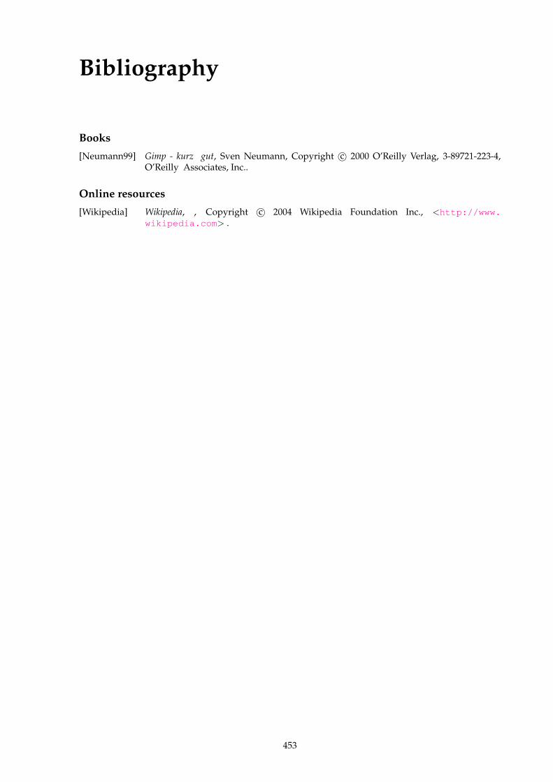
Bibliography
Books
[Neumann99] Gimp - kurz gut, Sven Neumann, Copyright c© 2000 O’Reilly Verlag, 3-89721-223-4,O’Reilly Associates, Inc..
Online resources
[Wikipedia] Wikipedia, , Copyright c© 2004 Wikipedia Foundation Inc., <http://www.wikipedia.com > .
453

Appendix A
GNU Free Documentation License
Copyright (C) 2000,2001,2002 Free Software Foundation, Inc. 59 Temple Place, Suite 330,Boston, MA 02111-1307 USA Everyone is permitted to copy and distribute verbatim copiesof this license document, but changing it is not allowed.
A.1 PREAMBLE
The purpose of this License is to make a manual, textbook, or other functional and useful document”free” in the sense of freedom: to assure everyone the effective freedom to copy and redistribute it, withor without modifying it, either commercially or noncommercially. Secondarily, this License preservesfor the author and publisher a way to get credit for their work, while not being considered responsiblefor modifications made by others.
This License is a kind of ”copyleft”, which means that derivative works of the document must them-selves be free in the same sense. It complements the GNU General Public License, which is a copyleftlicense designed for free software.
We have designed this License in order to use it for manuals for free software, because free softwareneeds free documentation: a free program should come with manuals providing the same freedomsthat the software does. But this License is not limited to software manuals; it can be used for any textualwork, regardless of subject matter or whether it is published as a printed book. We recommend thisLicense principally for works whose purpose is instruction or reference.
A.2 APPLICABILITY AND DEFINITIONS
This License applies to any manual or other work, in any medium, that contains a notice placed by thecopyright holder saying it can be distributed under the terms of this License. Such a notice grants aworld-wide, royalty-free license, unlimited in duration, to use that work under the conditions statedherein. The ”Document”, below, refers to any such manual or work. Any member of the public is alicensee, and is addressed as ”you”. You accept the license if you copy, modify or distribute the work ina way requiring permission under copyright law.
A ”Modified Version” of the Document means any work containing the Document or a portion of it,either copied verbatim, or with modifications and/or translated into another language.
A ”Secondary Section” is a named appendix or a front-matter section of the Document that dealsexclusively with the relationship of the publishers or authors of the Document to the Document’s overallsubject (or to related matters) and contains nothing that could fall directly within that overall subject.(Thus, if the Document is in part a textbook of mathematics, a Secondary Section may not explain anymathematics.) The relationship could be a matter of historical connection with the subject or with relatedmatters, or of legal, commercial, philosophical, ethical or political position regarding them.
The ”Invariant Sections” are certain Secondary Sections whose titles are designated, as being thoseof Invariant Sections, in the notice that says that the Document is released under this License. If a sectiondoes not fit the above definition of Secondary then it is not allowed to be designated as Invariant. TheDocument may contain zero Invariant Sections. If the Document does not identify any Invariant Sectionsthen there are none.
455
A.3. VERBATIM COPYING APPENDIX A. GNU FREE DOCUMENTATION LICENSE
The ”Cover Texts” are certain short passages of text that are listed, as Front-Cover Texts or Back-Cover Texts, in the notice that says that the Document is released under this License. A Front-CoverText may be at most 5 words, and a Back-Cover Text may be at most 25 words.
A ”Transparent” copy of the Document means a machine-readable copy, represented in a formatwhose specification is available to the general public, that is suitable for revisingthe document straight-forwardly with generic text editors or (for images composed of pixels) generic paint programs or (fordrawings) some widely available drawing editor, and that is suitable for input to text formatters or forautomatic translation to a variety of formats suitable for input to text formatters. A copy made in anotherwise Transparent file format whose markup, or absence of markup, has been arranged to thwart ordiscourage subsequent modification by readers is not Transparent. An image format is not Transparentif used for any substantial amount of text. A copy that is not ”Transparent” is called ”Opaque”.
Examples of suitable formats for Transparent copies include plain ASCII without markup, Tex-info input format, LaTeX input format, SGML or XML using a publicly available DTD, and standard-conforming simple HTML, PostScript or PDF designed for human modification. Examples of transpar-ent image formats include PNG, XCF and JPG. Opaque formats include proprietary formats that can beread and edited only by proprietary word processors, SGML or XML for which the DTD and/or process-ing tools are not generally available, and the machine-generated HTML, PostScript or PDF produced bysome word processors for output purposes only.
The ”Title Page” means, for a printed book, the title page itself, plus such following pages as areneeded to hold, legibly, the material this License requires to appear in the title page. For works informats which do not have any title page as such, ”Title Page” means the text near the most prominentappearance of the work’s title, preceding the beginning of the body of the text.
A section ”Entitled XYZ” means a named subunit of the Document whose title either is preciselyXYZ or contains XYZ in parentheses following text that translates XYZ in another language. (Here XYZstands for a specific section name mentioned below, such as ”Acknowledgements”, ”Dedications”, ”En-dorsements”, or ”History”.) To ”Preserve the Title” of such a section when you modify the Documentmeans that it remains a section ”Entitled XYZ” according to this definition.
The Document may include Warranty Disclaimers next to the notice which states that this Licenseapplies to the Document. These Warranty Disclaimers are considered to be included by reference inthis License, but only as regards disclaiming warranties: any other implication that these WarrantyDisclaimers may have is void and has no effect on the meaning of this License.
A.3 VERBATIM COPYING
You may copy and distribute the Document in any medium, either commercially or noncommercially,provided that this License, the copyright notices, and the license notice saying this License applies tothe Document are reproduced in all copies, and that you add no other conditions whatsoever to those ofthis License. You may not use technical measures to obstruct or control the reading or further copyingof the copies you make or distribute. However, you may accept compensation in exchange for copies. Ifyou distribute a large enough number of copies you must also follow the conditions in section3.
You may also lend copies, under the same conditions stated above, and you may publicly displaycopies.
A.4 COPYING IN QUANTITY
If you publish printed copies (or copies in media that commonly have printed covers) of the Document,numbering more than 100, and the Document’s license notice requires Cover Texts, you must enclosethe copies in covers that carry, clearly and legibly, all these Cover Texts: Front-Cover Texts on the frontcover, and Back-Cover Texts on the back cover. Both covers must also clearly and legibly identify you asthe publisher of these copies. The front cover must present the full title with all words of the title equallyprominent and visible. You may add other material on the covers in addition. Copying with changeslimited to the covers, as long as they preserve the title of the Document and satisfy these conditions, canbe treated as verbatim copying in other respects.
If the required texts for either cover are too voluminous to fit legibly, you should put the first oneslisted (as many as fit reasonably) on the actual cover, and continue the rest onto adjacent pages.
If you publish or distribute Opaque copies of the Document numbering more than 100, you must ei-ther include a machine-readable Transparent copy along with each Opaque copy, or state in or with each
456
APPENDIX A. GNU FREE DOCUMENTATION LICENSE A.5. MODIFICATIONS
Opaque copy a computer-network location from which the general network-using public has access todownload using public-standard network protocols a complete Transparent copy of the Document, freeof added material. If you use the latter option, you must take reasonably prudent steps, when youbegin distribution of Opaque copies in quantity, to ensure that this Transparent copy will remain thusaccessible at the stated location until at least one year after the last time you distribute an Opaque copy(directly or through your agents or retailers) of that edition to the public.
It is requested, but not required, that you contact the authors of the Document well before redis-tributing any large number of copies, to give them a chance to provide you with an updated version ofthe Document.
A.5 MODIFICATIONS
You may copy and distribute a Modified Version of the Document under the conditions of sections 2 and3 above, provided that you release the Modified Version under precisely this License, with the ModifiedVersion filling the role of the Document, thus licensing distribution and modification of the ModifiedVersion to whoever possesses a copy of it. In addition, you must do these things in the Modified Version:
A Use in the Title Page (and on the covers, if any) a title distinct from that of the Document, and fromthose of previous versions (which should, if there were any, be listed in the History section of theDocument). You may use the same title as a previous version if the original publisher of that versiongives permission.
B List on the Title Page, as authors, one or more persons or entities responsible for authorship of themodifications in the Modified Version, together with at least five of the principal authors of the Doc-ument (all of its principal authors, if it has fewer than five), unless they release you from this require-ment.
C State on the Title page the name of the publisher of the Modified Version, as the publisher.
D Preserve all the copyright notices of the Document.
E Add an appropriate copyright notice for your modifications adjacent to the other copyright notices.
F Include, immediately after the copyright notices, a license notice giving the public permission to usethe Modified Version under the terms of this License, in the form shown in the Addendum below.
G Preserve in that license notice the full lists of Invariant Sections and required Cover Texts given in theDocument’s license notice.
H Include an unaltered copy of this License.
I Preserve the section Entitled ”History”, Preserve its Title, and add to it an item stating at least the title,year, new authors, and publisher of the Modified Version as given on the Title Page. If there is nosection Entitled ”History” in the Document, create one stating the title, year, authors, and publisherof the Document as given on its Title Page, then add an item describing the Modified Version as statedin the previous sentence.
J Preserve the network location, if any, given in the Document for public access to a Transparent copyof the Document, and likewise the network locations given in the Document for previous versions itwas based on. These may be placed in the ”History” section. You may omit a network location for awork that was published at least four years before the Document itself, or if the original publisher ofthe version it refers to gives permission.
K For any section Entitled ”Acknowledgements” or ”Dedications”, Preserve the Title of the section,and preserve in the section all the substance and tone of each of the contributor acknowledgementsand/or dedications given therein.
L Preserve all the Invariant Sections of the Document, unaltered in their text and in their titles. Sectionnumbers or the equivalent are not considered part of the section titles.
M Delete any section Entitled ”Endorsements”. Such a section may not be included in the ModifiedVersion.
457
A.6. COMBINING DOCUMENTS APPENDIX A. GNU FREE DOCUMENTATION LICENSE
N Do not retitle any existing section to be Entitled ”Endorsements” or to conflict in title with any In-variant Section.
O Preserve any Warranty Disclaimers.
If the Modified Version includes new front-matter sections or appendices that qualify as SecondarySections and contain no material copied from the Document, you may at your option designate someor all of these sections as invariant. To do this, add their titles to the list of Invariant Sections in theModified Version’s license notice. These titles must be distinct from any other section titles.
You may add a section Entitled ”Endorsements”, provided it contains nothing but endorsements ofyour Modified Version by various parties–for example, statements of peer review or that the text hasbeen approved by an organization as the authoritative definition of a standard.
You may add a passage of up to five words as a Front-Cover Text, and a passage of up to 25 wordsas a Back-Cover Text, to the end of the list of Cover Texts in the Modified Version. Only one passage ofFront-Cover Text and one of Back-Cover Text may be added by (or through arrangements made by) anyone entity. If the Document already includes a cover text for the same cover, previously added by youor by arrangement made by the same entity you are acting on behalf of, you may not add another; butyou may replace the old one, on explicit permission from the previous publisher that added the old one.
The author(s) and publisher(s) of the Document do not by this License give permission to use theirnames for publicity for orto assert or imply endorsement of any Modified Version.
A.6 COMBINING DOCUMENTS
You may combine the Document with other documents released under this License, under the termsdefined in section 4 above for modified versions, provided that you include in the combination all of theInvariant Sections of all of the original documents, unmodified, and list them all as Invariant Sections ofyour combined work in its license notice, and that you preserve all their Warranty Disclaimers.
The combined work need only contain one copy of this License, and multiple identical InvariantSections may be replaced with a single copy. If there are multiple Invariant Sections with the samename but different contents, make the title of each such section unique by adding at the end of it, inparentheses, the name of the original author or publisher of that section if known, or else a uniquenumber. Make the same adjustment to the section titles in the list of Invariant Sections in the licensenotice of the combined work.
In the combination, you must combine any sections Entitled ”History” in the various original docu-ments, forming one section Entitled ”History”; likewise combine any sections Entitled ”Acknowledge-ments”, and any sections Entitled ”Dedications”. You must delete all sections Entitled ”Endorsements”.
A.7 COLLECTIONS OF DOCUMENTS
You may make a collection consisting of the Document and other documents released under this License,and replace the individual copies of this License in the various documents with a single copy that isincluded in the collection, provided that you follow the rules of this License for verbatim copying ofeach of the documents in allother respects.
You may extract a single document from such a collection, and distribute it individually under thisLicense, provided you insert a copy of this License into the extracted document, and follow this Licensein all other respects regarding verbatim copying of that document.
A.8 AGGREGATION WITH INDEPENDENT WORKS
A compilation of the Document or its derivatives with other separate and independent documents orworks, in or on a volume of a storage or distribution medium, is called an ”aggregate” if the copyrightresulting from the compilation is not used to limit the legal rights of the compilation’s users beyondwhat the individualworks permit. When the Document is included in an aggregate, this License does notapply to the other works in the aggregate which are not themselves derivative works of the Document.
If the Cover Text requirement of section 3 is applicable to these copies of the Document, then if theDocument is less than one half of the entire aggregate, the Document’s Cover Texts may be placed oncovers that bracket the Document within the aggregate, or the electronic equivalent of covers if the
458
APPENDIX A. GNU FREE DOCUMENTATION LICENSE A.9. TRANSLATION
Document is in electronic form. Otherwise they must appear on printed covers that bracket the wholeaggregate.
A.9 TRANSLATION
Translation is considered a kind of modification, so you may distribute translations of the Documentunder the terms of section 4. Replacing Invariant Sections with translations requires special permis-sion from their copyright holders, but you may include translations of some or all Invariant Sectionsin addition to the original versions of these Invariant Sections. You may include a translation of thisLicense, and all the license notices in the Document, and any Warranty Disclaimers, provided that youalso include the original English version of this License and the original versions of those notices anddisclaimers. In case of a disagreement between the translation and the original version of this Licenseor a notice or disclaimer, the original version will prevail.
If a section in the Document is Entitled ”Acknowledgements”, ”Dedications”, or ”History”, the re-quirement (section 4) to Preserve its Title (section 1) will typically require changing the actual title.
A.10 TERMINATION
You may not copy, modify, sublicense, or distribute the Document except as expressly provided forunder this License. Any other attempt to copy, modify, sublicense or distribute the Document is void,and will automatically terminate your rights under this License. However, parties who have receivedcopies, or rights, from you under this License will not have their licenses terminated so long as suchparties remain in full compliance.
A.11 FUTURE REVISIONS OF THIS LICENSE
The Free Software Foundation may publish new, revised versions of the GNU Free DocumentationLicense from time to time. Such new versions will be similar in spirit to the present version, but maydiffer in detail to address new problems or concerns. See http://www.gnu.org/copyleft/.
Each version of the License is given a distinguishing version number. If the Document specifies thata particular numbered version of this License ”or any later version” applies to it, you have the option offollowing the terms and conditions either of that specified version or of any later version that has beenpublished (not as a draft) by the Free Software Foundation. If the Document does not specify a versionnumber of this License, you may choose any version ever published (not as a draft) by the Free SoftwareFoundation.
A.12 ADDENDUM: How to use this License for your documents
To use this License in a document you have written, include a copy of the License in the document andput the following copyrightand license notices just after the title page:
Copyright (c) YEAR YOUR NAME. Permission is granted to copy, distribute and/or modifythis document under the terms of the GNU Free Documentation License, Version 1.2 or anylater version published by the Free Software Foundation; with no Invariant Sections, noFront-Cover Texts, and no Back-Cover Texts. A copy of the license is included in the sectionentitled ”GNU Free Documentation License”.
If you have Invariant Sections, Front-Cover Texts and Back-Cover Texts, replace the ”with...Texts.”line with this:
with the Invariant Sections being LIST THEIR TITLES, with the Front-Cover Texts beingLIST, and with the Back-Cover Texts being LIST.
If you have Invariant Sections without Cover Texts, or some other combination of the three, mergethose two alternatives to suitthe situation.
If your document contains nontrivial examples of program code, we recommend releasing theseexamples in parallel under your choice of free software license, such as the GNU General Public License,to permit their use in free software.
459

Appendix B
Eeek! a help is missing
Sorry, but a helpitem is missing for the function you’re looking for.Feel free to join us and fill the gap by writing documentation for the Gimp. For more informa-
tion, visit our project page on the Gimp Wiki <http://wiki.gimp.org/gimp/GimpDocs >. Thereis also a Mailinglist <https://lists.xcf.berkeley.edu/mailman/listinfo/gimp-docs/ >available. Generally, it’s a good idea to check the Gimp project page <http://www.gimp.org >.
461

Index
Apply Canvas, 391Apply Lens, 357
Blinds, 368Brushes, 56
Canvas Size, 289Clear, 272Color Area
Indicator Area, 180Copy, 270Copy Visible, 270Cubism, 391Curve Bend, 369Cut, 270
Deinterlace, 347Depth Merge, 419Despeckle, 347Destripe, 348Dialog, 206, 213
Brushes, 208Buffers, 227Channel
Managing channels, 187Color, 206Fonts, 225Histogram, 201History
Document history, 229Indexed Palette, 199Introduction to dialogs, 183Layer
Managing layers, 183Palettes, 219Paths, 194Patterns, 211Tools, 230Undo History, 205
DialogsPreferences
Help System, 237Image grid, 233Image Windows, 242, 244Title and Statusbar, 245Tool Options, 238Toolbox, 240Windowmanagment, 249
QuickMask, 192dialogs
preferences, 231data folders, 254display, 248environment, 251folders, 253interface, 233new image, 232
theme, 235Difference of Gaussians, 345Dot for Dot, 280Duplicate, 286
Edge, 344Emboss, 371
Fill with, 272Filter
ArtisticIntroduction, 390
Blur, 313Gauss, 314, 315Introduction, 311Motion, 315Pixelise, 316Tileable, 317
CategoryArtistic, 390Blur, 311Color, 317Combine, 419Distort, 368Edge-detect, 343Enhance, 346Generic, 352Glass Effects, 357Light Effects, 359Noise, 338Render, 399
Color, 317Alien map, 318, 320Alpha, 330Analysis, 329Border, 327Channel mixer, 328Colorify, 329Compose, 331, 332Exchange, 321FG BG, 318Flatten, 337Gradient Map, 327Hot, 335Max, 336Pack, 334Palette, 337Range mapping, 324Rotation, 322Sample, 325Value, 338
Combine, 419Film, 420
Distort, 368Generic
Convolution, 353Dilate, 355
463
INDEX INDEX
Erode, 357Introduction, 352
Glass EffectsIntroduction, 357
Introduction to enhance filters, 346Introduction to filters, 311Light Effects
Introduction, 359Noise, 338
Hurl, 338Noisify, 339Pick, 340Scatter, 341Slur, 342Spread, 342
RenderDiffraction, 410Flame, 402IFS Compose, 406Introduction, 399Jigsaw, 412Maze, 414Plasma, 399Qbist, 416Sinus, 417Solid noise, 401
RenduGrid, 411
FlareFX, 359Flatten, 294Full Screen, 282
Gflare, 360GIMPressionist, 392Glass Tile, 358Glossary, 423Grid
configure, 295
ImageGradients, 63Grid, 48Guides, 48Layers, 42Paths, 52Patterns, 64Stroking, 72Text, 69Undo, 46
Image menuFilters, 309View, 280
Image menu edit, 269Image menu file, 259Image menu image, 285Image menu layer, 296Image menu select, 276Image menu tools, 308Image Window, 28
Info Window, 283IWarp, 372
Laplace, 346Layers
MergeVisible, 293
Lighting Effects, 363
Mode, 286Mosaic, 374
Navigation Dialog, 204Navigation Window, 284New, 260New View, 280Newsprint, 380NL Filter, 349None, 276
Oilify, 398Open, 264Open Recent, 265Orientation Map Editor, 396
Page Curl, 375Paste, 270Paste as new, 271Paste Into, 271Polar Coords, 376
QuickMask, 41
Redo, 269Ripple, 378
Save, 266Save as, 267Scale Image, 291Selection
All, 276Border, 278By Color, 277Feather, 277Float, 277From Path, 277Grow, 278Invert, 276Save to Channel, 279Sharpen, 278Shrink, 278To Path, 279Toggle QuickMask, 279
Sharpen, 351Shift, 379Show Grid, 284Show Guides, 284Show Layer Boundary, 284Show Menubar, 285Show Rulers, 285
464
INDEX INDEX
Show Scrollbars, 285Show Selection, 284Show Statusbar, 285Shrink Wrap, 282Size Map Editor, 397Snap to Grid, 285Snap to Guides, 284Sobel, 346Sparkle, 365Stroke Path, 274Stroke Selection, 273SuperNova, 367
The GIMPBugs, 11Concepts, 38Files, 72Getting Unstuck, 103History, 10Introduction, 5Photography, 74Plugins, 81Script-fu, 84Setup, 15Toolbox, 109Using, 22Web, 80
Toolbox, 27Airbrush, 138Brush Tools, 126Clone, 142Color Picker
Eye Dropper, 175Convolve, 145, 147Crop
Clip, 152Erase, 135Fill, 170Flip
Transformation, 159Gradient, 172Ink, 140Magnify, 176Measure, 177Menu, 257Move, 150Paintbrush, 133Painting Tools, 129Path
Bezier Selection, 168Pencil, 131Perspective
Transformation, 158Rotate
Transformation, 153Scale
Transformation, 155Selection
by color, 122
Ellipse, 116Features, 111Free, 118Fuzzy, 120Rectangular, 113Scissors, 124
ShearTransformation, 156
Smudge, 149Text, 178
Tools, 308Transform, 288
Undo, 269Undo History, 269Unsharp Mask, 352
Value Propagate, 383Video, 382
Waves, 385Whirl and Pinch, 386Wind, 388
Zoom, 281
465