Embed Size (px)
Citation preview

Gilson 151/152UV/VIS Detectors
User’s Guide
LT1033/©2004 Gilson, Inc. All rights reserved March 2004


Table of Contents
Declaration of Conformity
1 IntroductionDescription ............................................................................ 1-1
Optics .............................................................................. 1-2Display ............................................................................ 1-2Features ........................................................................... 1-2
Unpacking............................................................................. 1-3Customer Service ................................................................. 1-4Technical Specifications ..................................................... 1-5Modes and Their Parameters ............................................ 1-9
Operation Mode ............................................................ 1-9Status Mode .................................................................... 1-9Setup Mode .................................................................... 1-9File Mode ........................................................................ 1-9
2 InstallationOperating Environment ..................................................... 2-1
Temperature ................................................................... 2-1Contaminants ................................................................ 2-1Ventilation ...................................................................... 2-1Condensation ................................................................. 2-1
Electrical Setup ..................................................................... 2-2Rear Panel Diagram ..................................................... 2-3Essential Setup ............................................................... 2-4Optional Connections .................................................. 2-6Unit ID and Baud Rate Selection ............................... 2-9Unit ID ............................................................................ 2-9Baud Rate ....................................................................... 2-10
Plumbing Setup .................................................................... 2-11Inlet Tubing .................................................................... 2-11Outlet Tubing ................................................................. 2-12

3 OperationOperation Flowchart ........................................................... 3-2Front Panel Diagram ........................................................... 3-4Software Structure .............................................................. 3-6
Mode Selection ............................................................... 3-6Parameter List ................................................................ 3-6
Start Up ................................................................................. 3-11Wake-Up Displays ........................................................ 3-11Selecting the Mode ........................................................ 3-13Error Messages ............................................................... 3-14
Detector Setup Parameters ................................................ 3-15First Display For Setup Mode ..................................... 3-15Second Display For Setup Mode ................................ 3-16Third Display For Setup Mode ................................... 3-17Fourth Display For Setup Mode ................................. 3-18
Operation Mode ................................................................... 3-19Display For Operation Mode ...................................... 3-19Output Channels ........................................................... 3-20Example Run .................................................................. 3-21
Programming the Detector ................................................ 3-23Remote Event ................................................................. 3-24Remote Zero ................................................................... 3-24Programming Tools ...................................................... 3-25Example 1: Startup File ................................................ 3-26Example 2: Programmed Run .................................... 3-29Example 3: Linking to Another File ........................... 3-36
Mobile Phase Tips ................................................................ 3-37Degas Solvents and Buffers ......................................... 3-37Check UV and Visible Absorbance of Solvents ....... 3-37
4 MaintenanceFlow Cell Maintenance ....................................................... 4-2
Cleaning the Inside of the Flow Cell (Analytical,Preparative, Microbore, and SFC only) .................... 4-2Unclogging the Flow Cell ............................................ 4-5Replacing Tubing and/or the Flow Cell ................... 4-5
Lamp Maintenance ............................................................. 4-22UV Lamp Maintenance ............................................... 4-22Visible Lamp Maintenance .......................................... 4-29
Fuse Replacement ................................................................ 4-35

5 TroubleshootingTroubleshooting ................................................................... 5-2
Detector Not Functioning ............................................ 5-2A Lamp Fails to Ignite/A Lamp Fails While On..... 5-2Status Lights Blinking/Screen Blank or Dark ......... 5-2Baseline Spikes ............................................................... 5-3Baseline Noise ................................................................ 5-4Baseline Drift .................................................................. 5-5Autozero Out of Range ................................................ 5-6Out of Range .................................................................. 5-6Peaks Too Broad ............................................................ 5-7Decreased Response to Known Sample .................... 5-7Abnormally High System Pressure ............................ 5-7
Diagnostics ............................................................................ 5-8Numeric Analyses on the 151 Detector .................... 5-8
Repair and Return Policies ................................................ 5-10Telephone Numbers ...................................................... 5-10Before Calling Us ........................................................... 5-10Warranty Repair ........................................................... 5-10Non-Warranty Repair .................................................. 5-10Rebuilt Exchange ........................................................... 5-11Return Procedure .......................................................... 5-11
Appendix A Defaults and LimitsSetup Mode ........................................................................... A-1Operation Mode ................................................................... A-1
Appendix B Mode-Specific FunctionsMode-Specific Output Channels ...................................... B-1Mode-Specific Remote Event andAutozero Functions ............................................................. B-1
Appendix C Sensitivity
Appendix D GSIOC ControlGSIOC Commands .............................................................. D-2FIFO Commands .................................................................. D-2GSIOC Command List ........................................................ D-2FIFO Command List ............................................................ D-10

Appendix E Replacement PartsLamp Assemblies ................................................................. E-1Cell/Accessory Kits ............................................................. E-1Flow Cell Assemblies ........................................................... E-2Inlet and Outlet Tubing ...................................................... E-2Miscellaneous ....................................................................... E-4
Appendix F Display Adjustment

Application of Council Directives:
89/336/EEC, 73/23/EEC
Standards to which Conformity is Declared:
EN61326, EN61000-3-3, EN61000-3-2, EN61010-1:2001
Manufacturer’s Name ........................................... Gilson, Inc.
Manufacturer’s Address ....................................... 3000 W. Beltline HighwayMiddleton, WI 53562
EC Office Address .................................................. Gilson S.A.S.19 Avenue des Entrepreneurs, B.P. 145F-95400 Villiers-le-Bel, France
Type of Equipment ................................................. Laboratory Equipment
Model. ....................................................................... 151 UV/VIS Detector
Beginning with Serial Number: 109F8E001
Month and Year of Manufacture: June 1998
Place: Middleton, WI (USA) Michael JacquartIssue Date: August 1998 Senior Vice President
Corporate Technology Development
I, the undersigned, hereby declare that the equipmentspecified above conforms to the above Directives and Standards.
Declaration of Conformity

Application of Council Directives:
89/336/EEC, 73/23/EEC
Standards to which Conformity is Declared:
EN61326, EN61000-3-3, EN61000-3-2, EN61010-1:2001
Manufacturer’s Name ........................................... Gilson, Inc.
Manufacturer’s Address ....................................... 3000 W. Beltline HighwayMiddleton, WI 53562
EC Office Address .................................................. Gilson S.A.S.19 Avenue des Entrepreneurs, B.P. 145F-95400 Villiers-le-Bel, France
Type of Equipment ................................................. Laboratory Equipment
Model. ....................................................................... 152 UV/VIS Detector
Beginning with Serial Number: 109A9F001
Month and Year of Manufacture: January 1999
Place: Middleton, WI (USA) Michael JacquartIssue Date: January 1999 Senior Vice President
Corporate Technology Development
I, the undersigned, hereby declare that the equipmentspecified above conforms to the above Directives and Standards.
Declaration of Conformity

1-1
1Introduction
Description
The Gilson 151 and 152 UV/VIS Detectors are microprocessor-controlled absorbancedetectors that provide single wavelength detection. Both detector models are compatiblecomponents of a Gilson modular HPLC system. And, the 151 Detector with its front panelcontrol is also compatible with other commercially available HPLC systems.
The 151 Detector can be controlled via its front panel or via external software, such asGilson UniPoint™ System Software. The 152 Detector must be controlled via externalsoftware since it does not have an integral front panel display. For information on how tocontrol the 152 Detector, refer to the user’s guide for the controlling software.
Gilson 151 UV/VIS Detector

1-2
Introduction 1De
scrip
tion Optics
Gilson’s optical design lets you monitor absorbanceat any wavelength from 190 to 700 nm.
The detector has a sensitivity range of 0.001 to 2.0AUFS (Absorbance Units, Full Scale).
Display
Gilson designed the 151 Detector software to becompletely self-guiding.
All parameters, values and commands appear onthe 4-line display.
All of your options are displayed above the six softkeys. Press a soft key to choose and carry out acommand. Numeric entries are made using thekeypad.
Features
You can choose from the following modes tospecify detection conditions and basic operatingparameters:
• operation• file• setup• status
1-3
Introduction 1Unpacking
Unpacking
Unpack the detector and its accessories carefullyfrom the carton.
Open the detector door and remove the foam insertfrom inside the detector.
Cross-check the contents against the checklistbelow and against your packing slip, to verify thatall parts are included and undamaged. Do this now,even if the detector will not be used immediately.Many carriers must receive concealed damageclaims within seven days of delivery.
The detector is shipped with its flow cell, lamps,and inlet/outlet tubing already installed. Thecarton should also contain:
• power cords• fuse drawers and fuses• two Pomona recorder cables• autozero/event cable• GSIOC cable
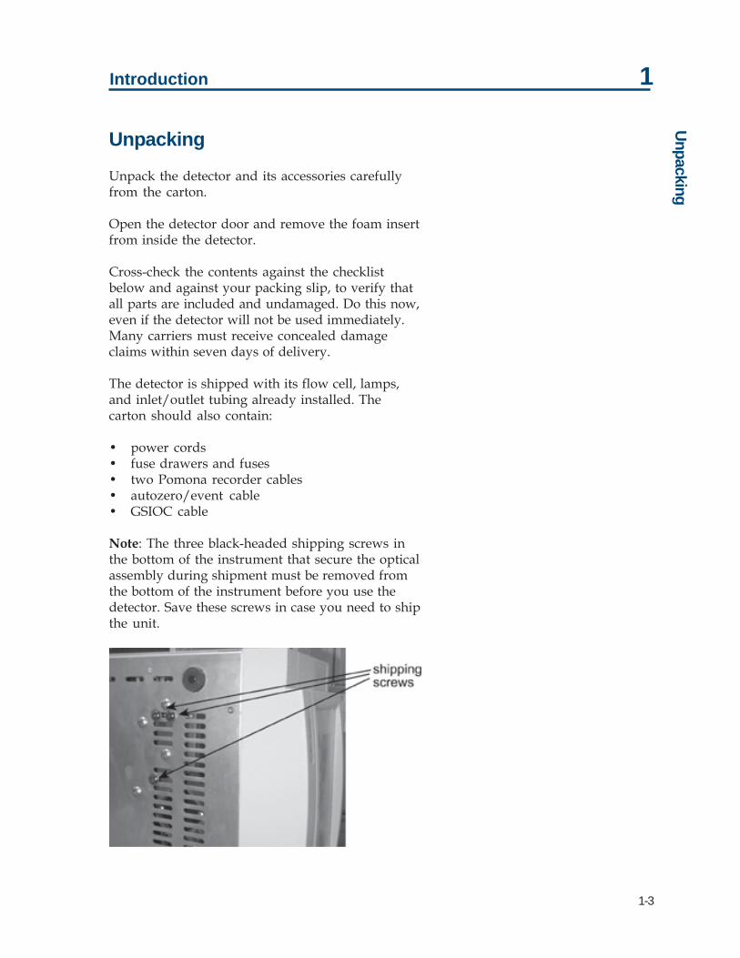
Note: The three black-headed shipping screws inthe bottom of the instrument that secure the opticalassembly during shipment must be removed fromthe bottom of the instrument before you use thedetector. Save these screws in case you need to shipthe unit.

1-4
Introduction 1C
usto
mer
Ser
vice Customer Service
Gilson, Inc., and its worldwide network of authorizedrepresentatives provide customers with these typesof assistance: sales, technical, applications, andinstrument repair.
If you need assistance and are in the UnitedStates, contact your Gilson representative or callthe Gilson Customer Service Department, toll-freeat 800-445-7661 or call 608-836-1551. You mayalso contact the Gilson Customer Service Departmentvia its e-mail address: [email protected].
Outside the United States, contact your Gilsonrepresentative if you need assistance. For morespecific contact information, refer to the Gilson website at www.gilson.com.
To help us serve you quickly and efficiently, pleaserefer to the Before Calling Us section page 5-10.

1-5
Introduction 1Technical Specifications
Technical Specifications
Warning! Changes or modifications to this devicenot expressly approved by Gilson could void thewarranty.
This device has been tested and found to complywith the limits for a Class A digital device,pursuant to Part 15 of the FCC commercialenvironment. This device generates, uses, and canradiate radio frequency energy and, if not installedand used in accordance with the instructions, maycause harmful interference to radio communications.Operation of this device in residential area is likelyto cause harmful interference; in which case, youmust correct the interference at your own expense.
You must use shielded cables with this device toensure compliance with the Class A FCC limits.
Note: The noise, drift, and sensitivities listed on thefollowing pages are maximums. Under mostcircumstances, you can expect performance thatsurpasses these specified limits.

1-6
Introduction 1Te
chni
cal S
peci
ficat
ions

1-7
Introduction 1Technical Specifications

1-8
Introduction 1Te
chni
cal S
peci
ficat
ions

1-9
Introduction 1
Modes and Their Parameters
The available modes and their parameters aredescribed below.
Operation Mode
Wavelength, Sensitivity 1, Sensitivity 2, Peak width
Status Mode
UV lamp status, UV lamp hours, Visible lamp status,Visible lamp hours, Wavelength, Event input
Setup Mode
Channel 1 scale and offset, Channel 2 scale andoffset, Channel 3 scale and offset, Lamp alarm,Event channel(s), Autorange channel(s), Autorangemultiplier, Concentration factor, Lamp saver
File Mode
With file mode, you can store as many as tenprogram files to save time and to enhance thereproducibility of your assays. A program fileinstructs the detector to change the detectionconditions and to modify the detectionparameters at specified times during the run.
Modes and Their Param
eters


2-1
2Installation
Operating Environment
You can use the detector in normal laboratory and cold room environments.
The factors described below will influence the performance of your detector.
Temperature
Changes in ambient temperature can produce noticeable output variations, especially athigher sensitivities.
Avoid areas which are in direct sunlight for part of the day and those which are subjectto draft; for example, do not place the detector near an open window or doorway.
Contaminants
Smoke, vapors, and acid fumes can cause baseline drift and noise.
Ventilation
You must allow at least 4 inches (10 cm) of clearance behind the detector to permitexhaust from the cooling fan to escape. Also, do not block the ventilation holes on thebottom of the detector.
Condensation
The detector has two power controls:
• the front panel LAMP ON/OFF key• the rear panel MAINS switch
To prevent condensation on optical surfaces, always leave the MAINS switch ON.
Turn the detector on and off using the LAMP ON/OFF switch.

2-2
Installation 2El
ectr
ical
Set
up Electrical Setup
Carefully follow instructions from start to finish.Electrical connections are clearly marked on thedetector’s rear panel.
You must complete these essential setup steps:
• insert fuse(s) and fuse drawer• connect output channels to other devices• connect power cord• turn on power
You can also make these optional connections:
• bidirectional communication with a Gilsonsystem controller on the Gilson Serial Input/Output Channel (GSIOC)
• remote contact control functions
The essential and optional setups are described indetail on the following pages.

2-3
Installation 2Electrical Setup
Rear Panel Diagram
1 fuse drawer Contains the fuses. If it’s not already installed, see page 2-4.
2 MAINS power switch Use this rocker switch to apply power to the detector. Oncethe detector is powered on, leave power on to the detectorunless you are performing maintenance procedures. Whenthe detector is not in use, press the front panel LAMP ON/OFFkey to turn off power to the lamps instead of turning power offto the detector.
3 power receptacle For connecting the power cord to the detector.
4 remote event/autozero For remote activation of some detector functions.
5 output channels For sending 3 channels of analog data to a recorder or stand-alone integrator.
6 SW1 selector For reviewing and changing the unit ID.
7 SW2 selector For reviewing and changing the baud rate.
8 GSIOC Gilson Serial Input/Output Channel, a 2-way communicationslink to a system controller.
9 RS-232 Serial connector, a 2-way communications link to a systemcontroller.

2-4
Installation 2El
ectr
ical
Set
up Essential Setup
Fuse installation
If you received the detector without the fuse drawerand fuses installed:
1 Locate the accessory package containing thefuse drawer appropriate for your line voltage.Discard the other fuse drawer.
2 Locate the accessory package containing the 2.5amp fuses.
3 Install the fuse(s) into the fuse drawer. The fusedrawer for 90–120V accepts one fuse. The fusedrawer for 220–240V accepts two fuses.
4 Insert the fuse drawer into its receptacle in thedetector. See the rear panel diagram on page 2-3.
Output connections
Note: If the detector is part of a Gilson HPLC system,you do not need to make output connections. Insteadmake the GSIOC connection between the detectorand system controller as described in OptionalConnections, page 2-6.
The detector has three output channels. All threeoutput channels are active. For more detail on theoutput channels see Detector Setup Parameters inSection 3, Operation.
You can direct output from the detector to a chartrecorder or stand-alone integrator.
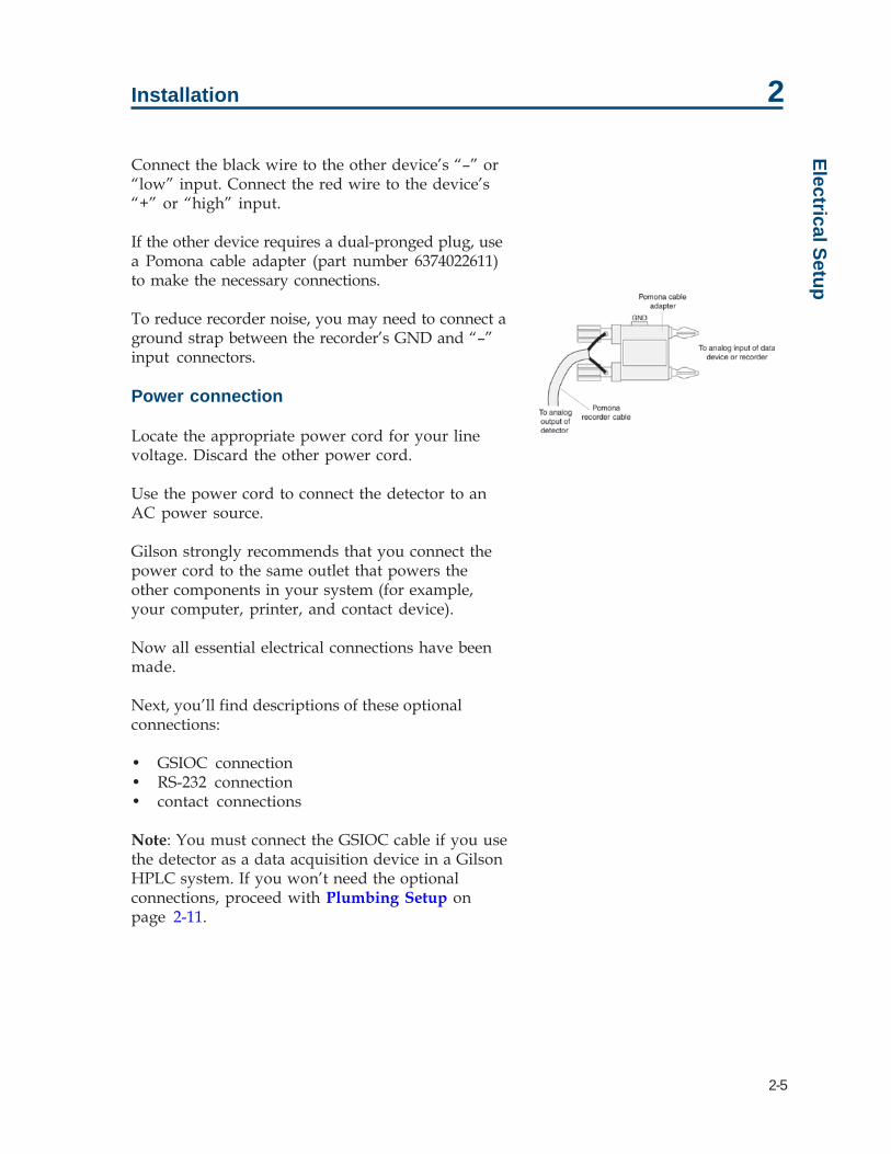
To connect an output channel, use a 5-foot shieldedPomona recorder cable from your accessory kit.One end of the cable has a dual-pronged plug. Theother end has two tinned wires.
Insert the dual-pronged plug into one of thedetector’s output channels. (Insert the prong withthe GND-labeled tab into the black jack and theadjacent prong into the red jack.)
2-5
Installation 2Electrical Setup
Connect the black wire to the other device’s “–” or“low” input. Connect the red wire to the device’s“+” or “high” input.
If the other device requires a dual-pronged plug, usea Pomona cable adapter (part number 6374022611)to make the necessary connections.
To reduce recorder noise, you may need to connect aground strap between the recorder’s GND and “–”input connectors.
Power connection
Locate the appropriate power cord for your linevoltage. Discard the other power cord.
Use the power cord to connect the detector to anAC power source.
Gilson strongly recommends that you connect thepower cord to the same outlet that powers theother components in your system (for example,your computer, printer, and contact device).
Now all essential electrical connections have beenmade.
Next, you’ll find descriptions of these optionalconnections:
• GSIOC connection• RS-232 connection• contact connections
Note: You must connect the GSIOC cable if you usethe detector as a data acquisition device in a GilsonHPLC system. If you won’t need the optionalconnections, proceed with Plumbing Setup onpage 2-11.

2-6
Installation 2El
ectr
ical
Set
up Optional Connections
GSIOC connection
If the detector is part of a Gilson HPLC system, theGSIOC port is used to transfer information betweenthe detector and computer. The detector, and otherGilson GSIOC devices, can convert the RS-232signal levels used by computers to the RS-422/485signal levels required by the GSIOC and vice versa.
When you connect the Gilson Serial I/O Channel(GSIOC) between the detector and an HPLCsystem controller, you can:
• issue detector commands directly from thecontroller
• send detector data to the controller for analysis• control and change detector setup parameters
For information on making rear panel connectionsfor Gilson HPLC system devices, see the installationguide supplied with the Gilson control software.
See Appendix D for a list of commands that can beissued to the detector via the GSIOC or RS-232connection.
RS-232 connection
If the detector is not part of an HPLC systemcontrolled by Gilson software, the RS-232 port canbe used to transfer information between thedetector and a computer.
Be sure your computer is turned off before makingany connections.
To connect your computer to the detector, you needan RS-232 cable. Obtain a cable with D-connectorsthat are appropriate for the detector and yourcomputer. The detector requires a 25-pin male D-connector. Refer to the back panel of your computeror its documentation to determine which type of D-connector it requires. RS-232 cables are availablefrom Gilson and your local computer store.

2-7
Installation 2Electrical Setup
See Appendix D for a list of commands that can beissued to the detector via the RS-232 or GSIOCconnection.
Contact connections
You can remotely activate some detector functions(described below) from devices that provide no-voltage contact closure switches.
You can make contact connections from:
• Microsoft Windows-based computer via Gilson506 contact outputs
• Gilson sampling injector, which acts as acontroller of an isocratic auto-analytical system
• Gilson fraction collector• Gilson pump, such as the 305 and 307 Pumps
You can specify the timing of contact events fromthe Gilson control software.
To make contact connections, use the autozero/eventcable. That cable has a 4-pin socket that connects toa receptacle on the detector rear panel (refer to thediagram on page 2-3). The other end of the cablecontains four tinned wires.
EventPins 1 and 2 are the event mark contacts.• The red wire is connected to pin 1.• The black wire is connected to pin 2 (which is
circuit ground).
AutozeroPins 3 and 4 are the autozero contacts.• The white wire is connected to pin 3.• The green wire is connected to pin 4 (which is
circuit ground).

2-8
Installation 2El
ectr
ical
Set
up Connect the tinned wires to the contact closureoutputs of the controller, sampling injector, fractioncollector, or pump according to that device’sinstruction manual. Be sure to match groundconnections.
To determine the state of the detector’s event orautozero input contact, use the status mode or theappropriate GSIOC command (refer to Section 3,Operation or Appendix D, GSIOC Control).
Contact-activated functions
In operation mode:
• a remote event contact causes a negative spiketo appear in the analog output.
If the event is sent via the GSIOC to Gilsoncontrol software (using a Gilson 506C SystemInterface), a positive spike or event markappears on the time line.
• a remote zero contact resets the trace of allabsorbance channels to zero and the percenttransmission output to 100%.
When running a program file:
• a remote event contact resumes the run after await.
• a remote zero contact tells the detector to begina pre-selected program file. See page 3-24.

2-9
Installation 2Electrical Setup
Unit ID and Baud Rate Selection
On the detector’s rear panel, use the SW1 selectorto choose a different unit ID and the SW2 to choosea different baud rate.
Unit ID
The unit ID identifies the detector to Gilson softwarepackages that can issue GSIOC commands to thedetector via the GSIOC or RS-232 cable connection.
At the factory, Gilson set the unit ID to 16. There isno need to change this number unless it is the sameas that assigned to another Gilson device that isalso connected along the GSIOC.
To change the unit ID:
1 Gently insert a small flat blade screwdriver intothe SW1 selector on the rear panel and turn it.
2 Align the white dot with one of the indicatednumbers. The unit ID is 10 plus the selectednumber.
Note: The unit ID set for the detector in the controlsoftware overrides the setting on the SW1 selector.To reset the SW1 selector to the default setting of16, set the SW1 selector to 6. Turn the detectorMAINS power switch off. Then turn the detectorMAINS power switch back on while pressing theLAMP ON/OFF button.

2-10
Installation 2El
ectr
ical
Set
up Baud Rate
As a default, the baud rate is set to “External,”indicating that the detector is a slave device in aGilson system and the baud rate is being clockedoutside of the detector.
Other baud rate selections are available if the detectoris being controlled by non-Gilson applications.
0 - External (default)1 - 192002 - 96003 - 48004 - 24005 - 12006 - 6007 - 3008 - Reserved9 - Reserved
To change the baud rate if the detector is beingcontrolled by a non-Gilson application:
1 Gently insert a small flat blade screwdriver intothe SW2 selector on the rear panel and turn it.
2 Align the white dot with one of the indicatednumbers.

2-11
Installation 2Plum
bing Setup
Plumbing Setup
The detector arrives with the flow cell, the inlet andoutlet tubing, and the end fittings already in place.
You must make these two plumbing connections:
1 Inlet tubing to your column outlet. See InletTubing, below, for details.
2 Outlet tubing to another detector or to a backpressure regulator if effluent is being directed toa fraction collector or to drain. See OutletTubing, on the next page, for details.
The detector accessory packages for analytical,microbore, preparative, and capillary flow cellsinclude a back pressure regulator.
Inlet Tubing
Analytical, microbore, preparative, and SFC
Connect the stainless steel inlet tubing to your columnoutlet with the Upchurch Fingertight fitting from theaccessory package. This fitting accommodates mostexisting female column outlets.
To connect the Upchurch Fingertight fitting, insertit onto the stainless steel tubing. Screw the fittinginto the column outlet; then finger tighten.
Instructions for replacing the inlet tubing andfittings are found in Section 4, Maintenance.

2-12
Installation 2Pl
umbi
ng S
etup Capillary
For the capillary flow cell the inlet and outletcapillaries are interchangeable. Designate one ofthe capillaries as the inlet and connect it to thecolumn outlet using the fitting from the accessorypackage.
Outlet Tubing
The detector’s outlet tubing can be directed threedifferent ways:
• to another type of detector where you canmonitor a second characteristic of your sample.Use the appropriate coupler to make theconnection.
• to the inlet of your fraction collector if you wantto collect the column effluent. Use theappropriate coupler to make the connection.
• to drain if you don’t need to save the columneffluent.
Back pressure regulator
When using an HPLC flow cell, you may needadditional back pressure on the outlet tubing toreduce bubble formation. If effluent is going to afraction collector or drain, connect the outlet tubingto a back pressure regulator before directing theeffluent to the fraction collector or drain.
Analytical, microbore, and preparative
The detector accessory packages for analytical,microbore, and preparative flow cells include theback pressure regulator shown on the left. Thearrow on the back pressure regulator identifies thedirection of flow.
Back Pressure Regulator

2-13
Installation 2
Ultra-Low Volume Back PressureRegulator
Capillary
The accessory package for the capillary flow cellincludes the Ultra-Low Volume Back PressureRegulator. The inlet tubing has an arrow pointingtoward the back pressure regulator and the outletarrow points away.
Plumbing Setup


3-1
3Operation
The Gilson 151 and 152 UV/VIS Detectors are versatile ultraviolet-visible absorptiondetectors that operate in any of several modes. Within a mode, you set parameters tooptimize sample detection using a wavelength between 190 and 700 nm.
You can also program the detector to choose new parameters at any preset time during arun.
The 151 Detector can be controlled via its front panel or via external software, such asGilson UniPoint System Software. The 152 Detector must be controlled via externalsoftware since that detector does not have a front panel display. For information on howto control the 152 Detector, refer to the user’s guide for the controlling software.
The 151 Detector’s display guides you through the mode and parameter selection using amenu format. The front panel provides operating control.
In this section, you’ll learn about:
• the front panel keys• the structure of the detector software• the wake-up state of the detector• the setup, detection, and program parameters of the detector
This section also includes a flow chart offering guidelines for operating the detector.

3-2
Operation 3O
pera
tion
Flow
char
t Operation Flowchart
The following page contains an operation flowchart.This flowchart can help you troubleshoot the mostcommon detector problems.
Some of the problems (for example, lamp age,coated flow cell) may not appear on a newdetector. They are included so the chart remainsuseful over the lifetime of the detector.
You can use this chart if all functions are locallycontrolled. This would be the case if you have notmade the optional electrical connections describedin Section 2, Installation.
If the detector is controlled by UniPoint™ SystemSoftware, refer to its user’s guide for controlinstructions and follow the detector operationflowchart as closely as possible.

3-3
Operation 3O
peration Flowchart
3-4
Operation 3Fr
ont P
anel
Dia
gram Front Panel Diagram
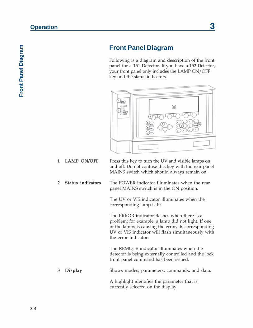
Following is a diagram and description of the frontpanel for a 151 Detector. If you have a 152 Detector,your front panel only includes the LAMP ON/OFFkey and the status indicators.
1 LAMP ON/OFF Press this key to turn the UV and visible lamps onand off. Do not confuse this key with the rear panelMAINS switch which should always remain on.
2 Status indicators The POWER indicator illuminates when the rearpanel MAINS switch is in the ON position.
The UV or VIS indicator illuminates when thecorresponding lamp is lit.
The ERROR indicator flashes when there is aproblem; for example, a lamp did not light. If oneof the lamps is causing the error, its correspondingUV or VIS indicator will flash simultaneously withthe error indicator.
The REMOTE indicator illuminates when thedetector is being externally controlled and the lockfront panel command has been issued.
3 Display Shows modes, parameters, commands, and data.
A highlight identifies the parameter that iscurrently selected on the display.

3-5
Operation 3Front Panel D
iagram
4 Soft keys Keys whose functions are determined by thesoftware. When you advance to a new display,the soft keys may assume new functions. Thecurrent soft key function is listed on the displaydirectly above each key.
5 HELP Press the HELP key to show a description of thecurrent display.
6 ESC (escape) Press the ESC key to exit the current display.
7 CLEAR When changing a parameter, press the CLEARkey if you typed a wrong number. PressingCLEAR removes the typed value and, in somecases, displays the default value for theparameter.
8 Arrow keys Pressing the arrow keys moves the cursorwithin and between parameters on the display,or moves to the next event selection if the filemode is active.
9 Keypad Use these keys to set parameter values, such asmonitor wavelength, sensitivity, and peakwidth.
10 ENTER Press the ENTER key to store the value assignedto a parameter into memory.

3-6
Operation 3So
ftwar
e St
ruct
ure Software Structure
To operate the detector, you select the operatingmode and then set the run conditions for thatmode. You press soft keys to show and selectoptions when in a mode.
Mode Selection
At the core of the detector software is modeselection. You can choose among these modes:
• operation mode• status mode• setup mode• file mode
The flow charts on the following pages show thedisplays associated with each mode. To select amode, press the Mode soft key and then press thesoft key for the desired mode.
Parameter List
After you select a mode, you’ll see the first displayfor that mode. The display shows current parametersset for the mode. You can then modify parameters.
Depending on the mode you selected, you’ll seesome or all of the following soft keys.
Next and Previous
If the mode includes additional parameters, youcan access the next parameter display by steppingforward (Next) or backward (Previous) through thelist. Any time you want to stop modifyingparameters, press ESC.
If you make a mistake while entering a parameter,press the CLEAR key. The detector removes theincorrect value so you can enter the correct one. Ifthe new value is correct, press ENTER to save theparameter and move the focus to the nextparameter.

3-7
Operation 3Softw
are Structure
The detector won’t let you enter an out-of-rangevalue for a parameter. If your entry is too high ortoo low, the software displays a message specifyingthe correct range of values for the parameter.
Change
Use this soft key to select predefined settings for aparameter. For example, you use the Change softkey to select between “On” and “Off” for the lampsaver option.
Event
Use this soft key to record a spike on the recorderor on-screen trace.
If the event is sent on one of the output channels toa recorder, a negative spike appears on the tracefor the selected output channel.
Set the event output channel when indicatingdetector setup parameters. Refer to Detector SetupParameters later in this section.
Zero
Use this soft key to set the output trace of eachchannel to zero. The autozero function can also beactivated remotely via the remote event/zeroconnector. See page 2-7.

3-8
Operation 3So
ftwar
e St
ruct
ure Mode
The Mode soft key returns you to the Select Modedisplay, shown below:
If you’re in the status or setup mode, press ESC toreturn to the operation mode display. Then pressMode to return to the Select Mode display.
If you are in the file mode you may need to pressESC several times to return to the operation modedisplay. Then, again, press Mode to return to theSelect Mode display.

3-9
Operation 3Softw
are Structure

3-10
Operation 3So
ftwar
e St
ruct
ure

3-11
Operation 3Start U
p
Start Up
Follow the instructions in Section 2, Installation, tomake all electrical and plumbing connections.
If you see an error message when starting thedetector, refer to page 3-14.
Wake-Up Displays
1 Turn on the detector by pressing the rear-panelMAINS switch. The POWER light illuminates.
2 Press the front panel LAMP ON/OFF key.You’ll see:
After several seconds, the UV lamp ignites.
Then you’ll see:
The detector locates the 656 nm line forwavelength calibration and then locates thelast-used wavelength.
3-12
Operation 3St
art U
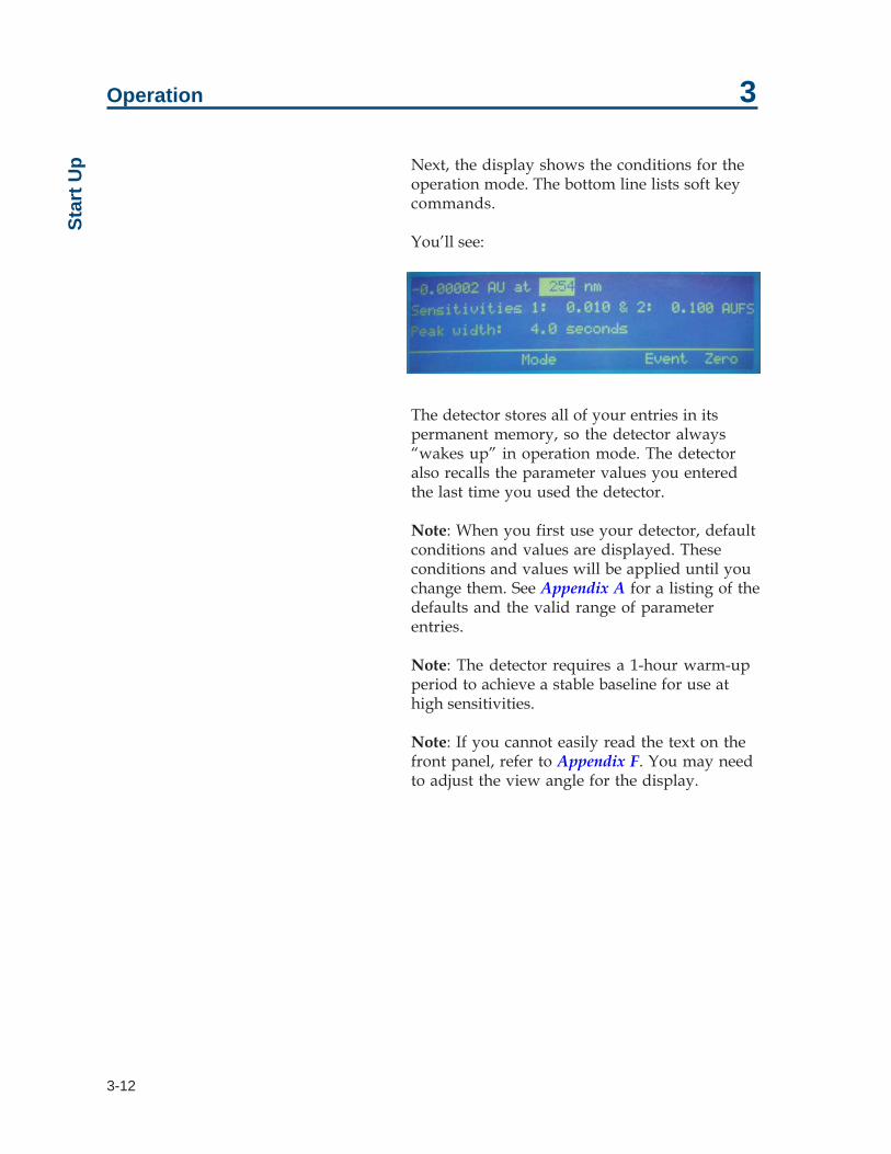
p Next, the display shows the conditions for theoperation mode. The bottom line lists soft keycommands.
You’ll see:
The detector stores all of your entries in itspermanent memory, so the detector always“wakes up” in operation mode. The detectoralso recalls the parameter values you enteredthe last time you used the detector.
Note: When you first use your detector, defaultconditions and values are displayed. Theseconditions and values will be applied until youchange them. See Appendix A for a listing of thedefaults and the valid range of parameterentries.
Note: The detector requires a 1-hour warm-upperiod to achieve a stable baseline for use athigh sensitivities.
Note: If you cannot easily read the text on thefront panel, refer to Appendix F. You may needto adjust the view angle for the display.

3-13
Operation 3Start U
p
Selecting the Mode
To access a different mode, press Mode. You’ll see:
Then press the soft key for the mode you want toenter. You’ll see the first display for the selectedmode. The soft keys identify the options available.
The remainder of this section describes how to usethe setup, operation, and file modes.
Status mode is not described in this section. Forinformation on that mode, see Section 5,Troubleshooting.

3-14
Operation 3St
art U
p Error Messages
The following table lists and describes the errormessages that could appear during wake-up. Toremove the error message from the display so youcan remedy the problem, press OK.
Error Message Possible Cause/Solution
Invalid Lamp ID The UV lamp may not be properly installed. SeeUV Lamp Maintenance on page 4-22. ContactGilson if the problem persists.
Lamp or Home Failure The UV lamp did not light, or there is an internalmisalignment. Follow the instructions in UV LampMaintenance on page 4-22. Contact Gilson if theproblem persists.
Low UV Energy The UV lamp needs to be replaced, or there is aninternal misalignment. Perform UV LampMaintenance as described on page 4-22. ContactGilson if the problem persists.
Low Visible Energy The visible lamp is disconnected or needs to bereplaced, or there is an internal misalignment.Perform Visible Lamp Maintenance as describedon page 4-29. Contact Gilson if the problempersists.

3-15
Operation 3D
etector Setup Parameters
Detector Setup Parameters
In setup mode, you can view and if necessarymodify the setup parameters currently specified forthe detector.
First Display For Setup Mode
Following is a description of the parameters on thefirst display for setup mode. When you’re finishedchecking or changing parameters, press the Nextsoft key to reveal the next display for setup mode.
Parameter(s) Description
Channel 1, 2, 3 For each output channel, set this parameter to show the full-scale range. The default for each channel is 10 mV, and the validrange is 1 to 1000 mV.
Offset For each output channel, use this parameter to move thebaseline away from the 0 position of the strip chart. You shouldspecify a channel offset that is up to half the full-scale range setfor the channel. The default for each channel is 0 mV, and thevalid range for channel offset is 0 to 1000 mV.
This parameter does not affect the output; it just enables you tosee a negative change in output. Channel offset is useful forgradient analyses where a change in the gradient causes theabsorbance to decrease and become a negative value.
Note: If you’re using Gilson control software and collecting datavia the GSIOC, the software uses the mV full scale and % offsetparameters set in its dialog box(es). The software does not usethe channel scale and offset parameters set in the detector.

3-16
Operation 3D
etec
tor S
etup
Par
amet
ers Second Display For Setup Mode
Following is a description of the parameters on thesecond display for setup mode. When you’refinished checking or changing parameters, pressthe Next soft key to reveal the next display forsetup mode.
Parameter Description
UV lamp alarm The detector’s status indicators flash when the UVlamp has been in use for the specified number ofhours. To enable the lamp alarm, specify a numberfrom 1 to 9999. To disable the lamp alarm, specify 0.
Vis lamp alarm The detector’s status indicators flash when thevisible lamp has been in use for the specifiednumber of hours. To enable the lamp alarm, specifya number from 1 to 9999. To disable the lampalarm, specify 0.

3-17
Operation 3D
etector Setup Parameters
Third Display For Setup Mode
Following is a description of the parameters on thethird display for setup mode. When you’re finishedchecking or changing parameters, press the Nextsoft key to reveal the next display for setup mode.
Parameter Description
Event channel(s) Set this parameter to tell the detector which output channel(s) touse for marking event spikes.
Enter 0 (for no event mark), 1, 2, and/or 3. For example,entering 2 activates channel 2; entering 123 activates all 3channels.
Autorange Set this parameter to designate the output channel(s) to autorange.channel(s) When the detector signal exceeds 100% of full scale, the autorange
feature attenuates the signal of the specified channel(s) to apercentage of actual value. The output on unspecified channel(s)is not affected.
Enter 0 (for no autoranging), 1, 2, and/or 3. For example, entering2 activates channel 2; entering 123 activates all 3 channels.
Autorange Use this parameter to designate the percent attenuation of themultiplier signal for the specified autorange channel(s).
For the multiplier, indicate a value from 0.1 to 0.5 (which is 10%to 50%). The default is 0.2 (which is 20%).
3-18
Operation 3D
etec
tor S
etup
Par
amet
ers Fourth Display For Setup Mode
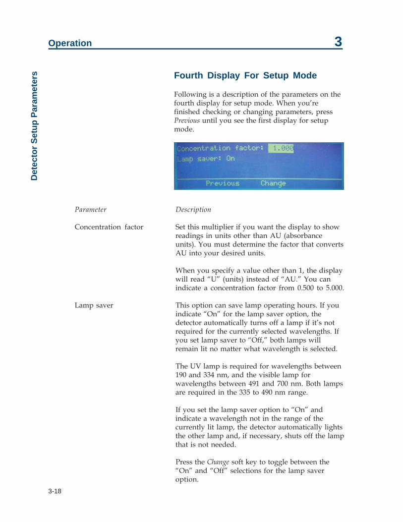
Following is a description of the parameters on thefourth display for setup mode. When you’refinished checking or changing parameters, pressPrevious until you see the first display for setupmode.
Parameter Description
Concentration factor Set this multiplier if you want the display to showreadings in units other than AU (absorbanceunits). You must determine the factor that convertsAU into your desired units.
When you specify a value other than 1, the displaywill read “U” (units) instead of “AU.” You canindicate a concentration factor from 0.500 to 5.000.
Lamp saver This option can save lamp operating hours. If youindicate “On” for the lamp saver option, thedetector automatically turns off a lamp if it’s notrequired for the currently selected wavelengths. Ifyou set lamp saver to “Off,” both lamps willremain lit no matter what wavelength is selected.
The UV lamp is required for wavelengths between190 and 334 nm, and the visible lamp forwavelengths between 491 and 700 nm. Both lampsare required in the 335 to 490 nm range.
If you set the lamp saver option to “On” andindicate a wavelength not in the range of thecurrently lit lamp, the detector automatically lightsthe other lamp and, if necessary, shuts off the lampthat is not needed.
Press the Change soft key to toggle between the“On” and “Off” selections for the lamp saveroption.
3-19
Operation 3O
peration Mode
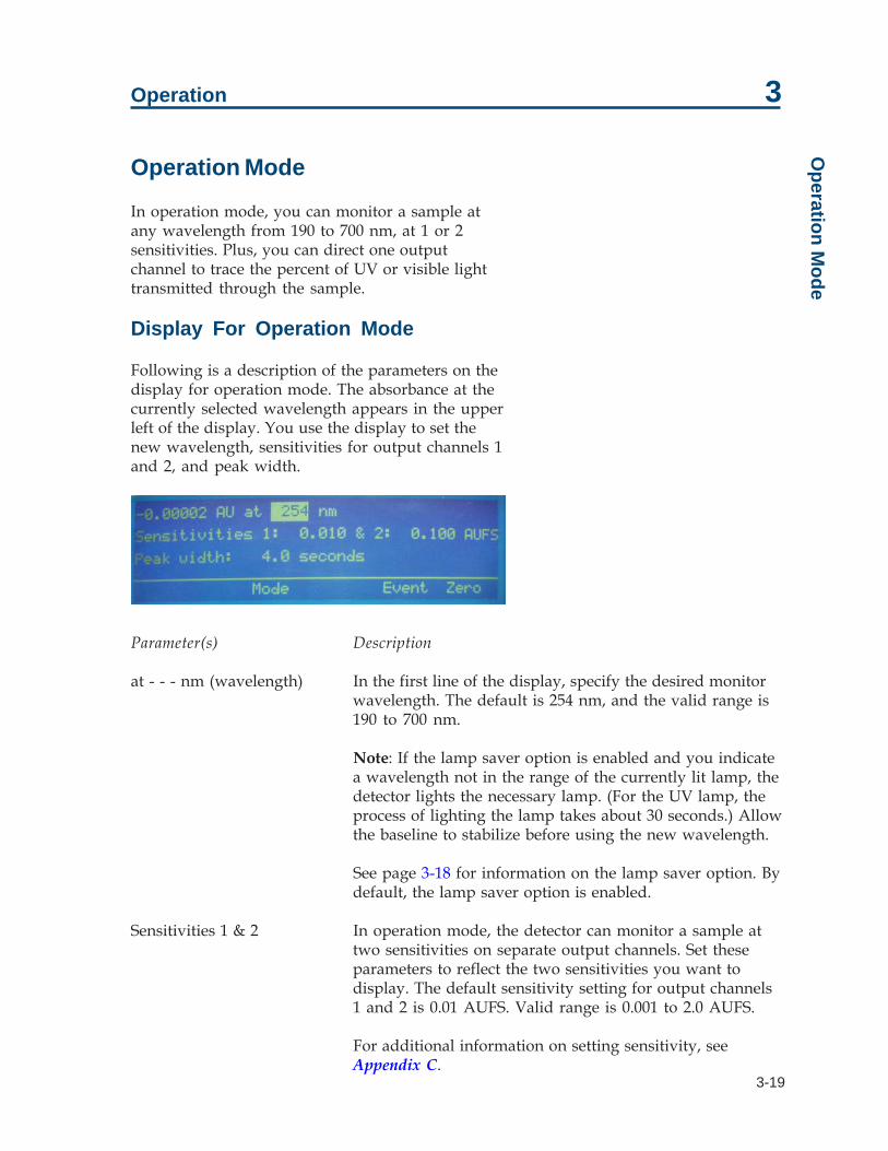
Operation Mode
In operation mode, you can monitor a sample atany wavelength from 190 to 700 nm, at 1 or 2sensitivities. Plus, you can direct one outputchannel to trace the percent of UV or visible lighttransmitted through the sample.
Display For Operation Mode
Following is a description of the parameters on thedisplay for operation mode. The absorbance at thecurrently selected wavelength appears in the upperleft of the display. You use the display to set thenew wavelength, sensitivities for output channels 1and 2, and peak width.
Parameter(s) Description
at - - - nm (wavelength) In the first line of the display, specify the desired monitorwavelength. The default is 254 nm, and the valid range is190 to 700 nm.
Note: If the lamp saver option is enabled and you indicatea wavelength not in the range of the currently lit lamp, thedetector lights the necessary lamp. (For the UV lamp, theprocess of lighting the lamp takes about 30 seconds.) Allowthe baseline to stabilize before using the new wavelength.
See page 3-18 for information on the lamp saver option. Bydefault, the lamp saver option is enabled.
Sensitivities 1 & 2 In operation mode, the detector can monitor a sample attwo sensitivities on separate output channels. Set theseparameters to reflect the two sensitivities you want todisplay. The default sensitivity setting for output channels1 and 2 is 0.01 AUFS. Valid range is 0.001 to 2.0 AUFS.
For additional information on setting sensitivity, seeAppendix C.

3-20
Operation 3O
pera
tion
Mod
e Parameter(s) Description
Peak width The detector must know the width of the narrowestpeak in your run. The detector uses this informationto optimize the presentation of peaks and tominimize baseline noise.
To set the peak width accurately, run achromatogram using the minimum peak widthsetting. Measure the width at half height of thenarrowest peak.
For most applications, the default setting of 10seconds is adequate. Valid range is 0 to 99.0 seconds.
Note: If the peak widths on your trace vary bymore than a factor of 3 and if your work is noise-sensitive, you may want to define a program file tomodify the peak width value at specified timesduring the run. See Programming the Detector onpage 3-23.
Output Channels
The following table lists what data are transmittedvia each output channel.
Channel 1: detection at sensitivity 1Channel 2: detection at sensitivity 2Channel 3: percent transmittance
Note: The output from channel 3 shows the percentof input UV or visible light that passes through thesample and reaches the active cell detector. Thisnumber is expressed as a percentage of the referencesignal. On the strip chart, 100% is at the top and 0%is at the bottom.

3-21
Operation 3O
peration Mode
Example Run
You can use your HPLC system to separate amixture of herbicides. You’ll monitor the columneffluent at 235 nm. And, since the components arepresent in low amounts, you’ll monitor at highsensitivity (0.005 AUFS). When monitoring at asingle sensitivity, you only need to connect outputchannel 1 to your recorder.
Start detector
If necessary, start the detector as described on page3-11.
Choose operation mode
If the following display is not shown, press ESCuntil you see the following screen:
Set parameters
Follow these steps to set the detection parameters:
1 To set the monitor wavelength (235 nm), press235 on the keypad, and then press ENTER.
2 To set the first sensitivity, press 0.005, and thenpress ENTER.
3 Since you won’t be charting the secondsensitivity, press ENTER to move the cursor tothe Peak width parameter.
4 At half height, the narrowest peak in the run is10 seconds in duration. If necessary, press 10,and then press ENTER.

3-22
Operation 3O
pera
tion
Mod
e Under these conditions, and at a chart speed of 1cm/min, the herbicide trace analysis looks like this:

3-23
Operation 3
Programming the Detector
In file mode, you can create a program file thatspecifies the parameters to be set each time you usethe detector. This is convenient in laboratorieswhere individuals operate the same detector underdifferent detector conditions.
File mode can also be used to vary the parametersduring a run. You direct the detector to show youthe peaks you want to see. For example, you can tellthe detector when to monitor at a new wavelengthor when to change the sensitivity setting.
Note: Since timed events direct the program file,reproducible chromatography is essential.
Keep the following in mind when setting up andusing program files:
• A program file can contain up to 100 timedevents.
• Up to 10 program files can be stored in thedetector’s permanent memory. Each file can beaccessed, edited, or deleted independently.
When you create a program file, the parameterscurrently stored in the detector’s memory arecopied into the created file. These conditions areset at 0.00 minutes.
To the program file, you can then include timedevents that change detection and setup parametersor reset the output baseline to 0 mV. These user-defined events should be set at 0.01 minutes or later.
A detector program file is open-ended. The end ofthe run is not scheduled. This permits the detectorto be used with a sampling injector, as a slavedevice for multiple runs, or when manual injectionis synchronized by control software.
Since the final conditions are in effect after the end ofthe programmed run, review the current conditionsbefore resuming non-programmed operation.
Programm
ing the Detector

3-24
Operation 3
Remote Event
A remote event signal tells the detector to continueprogrammed operation.
For example, you can specify a Wait for contactevent in the program file. Then, you can instructthe sampling injector to send a remote signal to thedetector after sample injection.
When you run the program file, the programpauses when it reaches the Wait for contact event.After the detector receives the signal from thesampling injector, the wait period ends and thedetector continues programmed operation. Forinformation on programming a wait into a detectorfile, see Example 2: Programmed Run on page 3-29.
Remote Zero
A remote zero signal tells the detector to begin aprogrammed operation. You must first access theprogram file display and specify which file toexecute.
For example, you can send a remote zero signalfrom a sampling injector after sample injection.After that signal is received, programmedoperation begins. The program clock begins at time0.00 after the signal is received.
If another remote zero signal is issued while aprogrammed operation is being executed, theoutput trace is set to zero.
Prog
ram
min
g th
e D
etec
tor

3-25
Operation 3
Programming Tools
Your programming tools are the numeric keypad,the arrow keys, and the soft keys found on the filemode displays.
You use the numeric keypad to enter values forparameters.
You use the up and down arrow keys to view theevents listing for the current file.
You use the file mode soft keys as described below.
• Edit is used to modify the events for the selectedfile number.
• Copy duplicates the current file and assigns itthe specified file number.
• Delete removes the current file from memory orremoves a timed event, depending on theprompt on the detector display.
• Run begins the programmed series of timedevents.
• Pause stops a programmed run during execution.
• Resume continues a programmed run after apause.
• Add inserts a timed event into the program file.
• Change is used to choose between text values fora parameter, such as “On” or “Off” for thelamp saver option.
Programm
ing the Detector

3-26
Operation 3
Example 1: Startup File
This tutorial shows you how to create a sampleprogram file. You’ll set up a file that containsdetection and setup parameters that you want touse each time you operate the detector. If you runthis file before using the detector, you can beassured that the parameters you use today are thesame as those used yesterday.
Set operation mode conditions
Before you create the file, review the setup anddetection conditions for operation mode. Do thisnow because these parameters are automaticallysaved to the program file when it’s created.
Access file mode and create file
After setting setup and detection parameters:
1 If necessary, access the display for operationmode.
2 Press Mode. You’ll see:
3 To access the file mode, press File. You’ll see:
Prog
ram
min
g th
e D
etec
tor

3-27
Operation 3
4 To create program file 1, press 1 on the keypad,and then press Edit.
Or, if file 1 already exists, choose 0 or a numberfrom 2 to 9. Then press Edit.
After you press Edit, all of the detection andsetup parameters in the detector’s memory arecopied to the file. They are set for time 0.00.
You’ll see a display like the following:
5 To scroll through the timed events, press the upand down arrow keys.
Add a timed event to set the baseline to zero
To the startup file, add a timed event thatautomatically sets the baseline to zero.
1 Press Add. You’ll see:
2 Press Misc. You’ll see:
Programm
ing the Detector

3-28
Operation 3
3 Type 0.01 and press ENTER.
4 Press Add to insert the event into the file. You’llsee:
Run the file
Now each time before you use the detector, run thefile you created above. To do this:
1 Access the file mode as described on page 3-26.
2 Type the number of the file.
3 Press Run.
The operating conditions for your analysis areautomatically loaded into the detector’s memoryand the detector sets the baseline to zero.
Prog
ram
min
g th
e D
etec
tor
3-29
Operation 3
Example 2: Programmed Run
This tutorial shows you how to program thedetector to:
• begin a run under one set of conditions• complete the run by monitoring at different
wavelength and sensitivity parameters
Conditions
You are monitoring a three-peak sample in operationmode at:
• 254 nm• a sensitivity of 0.01 AUFS
To accurately monitor the third peak, you want tochange the detection wavelength and sensitivityvalues to:
• 320 nm• a sensitivity of 0.02 AUFS
You’ll switch to the new conditions at 2.5 minutesinto the program, because:
• you’ll inject the sample at 1 minute into the run• you know from previous runs that the third
peak elutes a little later than 1.5 minutes post-injection.
You’ll also want to pause the run clock while thesample is prepared and injected. To do this, you’llset a wait event.
Programm
ing the Detector

3-30
Operation 3
Indicate first set of conditions usingoperation mode
As stated earlier, the detector automatically copiesall detector parameters currently in memory to anewly created program file. Therefore, you can setup the initial run conditions using operation modeinstead of the file mode. When you create the file,the detector automatically assigns time 0.00 to eachparameter. This saves you time so you don’t haveto set up a timed event for each of the initialconditions using the file mode.
To set up initial conditions using operation mode,do the following:
1 If the display for operation mode is not shown,press ESC (possibly several times) until you see:
2 To set the monitor wavelength, press 254 on thekeypad, and then press ENTER.
3 To set the sensitivity, press 0.01, and then pressENTER.
4 Since you only want to monitor at onesensitivity, do not change the second sensitivity.You can either ignore the trace generated atSensitivity 2 or disconnect output channel 2,which carries that trace, from the detector.
5 At half height, the narrowest peak in the run is10 seconds in duration. Press 10, and then pressENTER.
Prog
ram
min
g th
e D
etec
tor

3-31
Operation 3
Create file
Now that you’ve set the initial conditions foroperation mode, create the program file.
1 Press Mode then File to access the file mode.You’ll see:
2 To create program file 1, press 1 on the keypad,and then press Edit.
Or, if file 1 already exists, choose 0 or a numberfrom 2 to 9 by pressing a number key on thekeypad.
3 Press Edit.
The detector copies all parameters in its memoryto the file. That includes the ones you just set upfor operation mode. They are set for time 0.00.
Indicate user events
Once you’ve selected the file number, you’ll see:
In addition to the pre-stored time 0.00 events, you’llspecify events that do the following:
• zero the baseline at 0.01 min• indicate a wait (for sample injection) at 1.0 min• change the detection wavelength to 320 nm at
2.5 min• change the sensitivity to 0.02 AUFS at 2.5 min• zero the baseline again at 2.5 min
Programm
ing the Detector
3-32
Operation 3
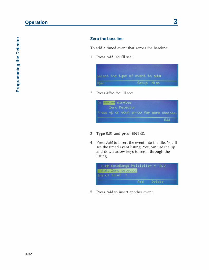
Zero the baseline
To add a timed event that zeroes the baseline:
1 Press Add. You’ll see:
2 Press Misc. You’ll see:
3 Type 0.01 and press ENTER.
4 Press Add to insert the event into the file. You’llsee the timed event listing. You can use the upand down arrow keys to scroll through thelisting.
5 Press Add to insert another event.
Prog
ram
min
g th
e D
etec
tor

3-33
Operation 3
Set the wait (for sample injection)
To set the wait event:
1 At the Select the type of event to add display,press Setup. You’ll see:
2 Press 1.0 on the keypad and press ENTER.
3 Press Add to insert the timed event.
4 At the display showing timed events, press Addto insert another event.
Change wavelength and sensitivity
To change the wavelength and sensitivity:
1 At the Select the type of event to add display,press Oper to select the operation mode. You’llsee:
2 For the minutes parameter, press 2.5 on thekeypad and press ENTER.
3 For the wavelength parameter, press 320 on thekeypad and press ENTER.
4 Press Add to insert the timed event.
5 At the display showing timed events, press Addto insert another event.
Programm
ing the Detector

3-34
Operation 3
6 At the Select the type of event to add display,press Oper to select the operation mode. You’llsee:
7 Press the down arrow key until you see:
8 For the minutes parameter, press 2.5 on thekeypad and press ENTER.
9 For the sensitivity parameter, press 0.02 on thekeypad and press ENTER.
10 Press Add to insert the timed event.
11 At the display showing timed events, press Addto insert another event.
Prog
ram
min
g th
e D
etec
tor

3-35
Operation 3
Zero the baseline
To set the event to zero the baseline:
1 At the Select the type of event to add display,press Misc. You’ll see:
2 Type 2.6 and press ENTER.
3 Press Add to insert the event into the file.
4 Since you’re done inserting events, press ESC.
Run the program file
You can now run the program that you just wrote.Doing so will help you learn how the displaypresents programmed events during an actual run.
1 At the following screen, type the number of thecreated file then press ENTER.
2 Press Run.
3 Be aware that the elapsed time readout pausesat the scheduled wait at 1.0 min.
During an actual run, the program controllingthe sampling injector would send an output tothe detector’s remote event input. When theremote event input closes, the detector programresumes operation.
Programm
ing the Detector

3-36
Operation 3
Example 3: Linking to Another File
1 At the following display, press Setup.
2 Press the down arrow key until you see:
3 Type the time at which to link from one file toanother and press ENTER.
4 Type the file number that you want to executeand press ENTER. If you indicate a file numberthat doesn’t exist, make sure you create the filebefore the run.
5 Press Add to insert the event in the program file.
Prog
ram
min
g th
e D
etec
tor

3-37
Operation 3
Mobile Phase Tips
Degas Solvents and Buffers
Always use degassed, HPLC-grade solvents(including water) and buffers for your mobile phase.
If the back pressure on the flow cell is sufficientlylow, gas bubbles may still appear, even when usingdegassed solvents. You can avoid this by using aback pressure regulator. The detector accessorypackages for analytical, microbore, preparative andcapillary flow cells include a back pressureregulator. Refer to page 2-12 for back pressureregulator installation instructions.
Check UV and Visible Absorbance ofSolvents
Remember to use only HPLC-grade solvents foryour mobile phase. Impure solvents can absorbsignificant quantities of UV or visible light evenwhen the cutoff may be below the monitoringwavelength. This can result in an inability toaccurately set the baseline to zero.
Manufacturer’s specifications list the UV andvisible cutoff for a solvent. This is the wavelengthbelow which a solvent should not be used for UVor visible detection. The cutoff is the wavelength atwhich the solvent is 90% opaque (absorbance 3 1.0AUFS). Interference can still occur above the ratedlimit, particularly when the solvent compositionchanges during a run. This frequently appears as agradual baseline shift.
Mobile Phase Tips

3-38
Operation 3
The table below lists commonly used solvents withlow UV and visible cutoffs.
Solvent UV/Visible cutoffAcetonitrile 190 nmCyclohexane 200 nmCyclopentane 200 nmDecahydronaphthalene 200 nmEthanol 210 nmHeptane 200 nmHexadecane 190 nmHexane 195 nmHexanes 210 nmIsooctane 197 nmMethanol 205 nmMethylene chloride 233 nmPentane 205 nmi-Pentanol 208 nmi-Propanol 205 nmn-Propanol 240 nmTetrahydrofuran 212 nmWater <190 nm
Mob
ile P
hase
Tip
s

4-1
4Maintenance
This section covers the maintenance procedures that you can perform:
• cleaning the inside of the flow cell• removing blockage from a flow cell• replacing the outlet and inlet tubing• changing the flow cell• replacing a lamp• replacing a fuse
Note: Refer to Section 5 to determine if your detector needs these maintenance procedures.
These procedures are the first line of defense against problems with the detector. Manyproblems can be corrected simply by cleaning the flow cell, replacing a lamp, or changinga fuse.
If these do not solve the problem, contact the Gilson Customer Service Department oryour Gilson representative. Refer to the Before Calling Us information on page 5-10.
Maintenance activities not described in this section require specialized tools and skills andshould not be attempted.

4-2
Maintenance 4Fl
ow C
ell M
aint
enan
ce Flow Cell Maintenance
Follow these instructions if you need to clean theflow cell, unclog the flow cell, replace the inlet oroutlet tubing, or replace the flow cell.
Be extremely careful when working with the flowcell and its fittings. Flow cells are consideredexpendable and are not covered by Gilson’swarranty if damaged or broken during anymaintenance procedure.
Cleaning the Inside of the Flow Cell(Analytical, Preparative, Microbore,and SFC only)
There are two ways to clean an active flow cell thathas become coated with light absorbing material:
• solvent cleaning• acid cleaning

4-3
Maintenance 4Flow
Cell M
aintenance
Solvent cleaning
If you suspect that droplets of an organic-solublecontaminant or immiscible solvent contaminate theactive flow cell, draw or pump a series of misciblesolvents through the cell.
If you were pumping a polar mobile phase, youshould draw methanol, tetrahydrofuran, methylenechloride, and then methanol through the flow cell.
If you were pumping a non-polar mobile phase,you should draw hexane, isopropanol, methanol,then water through the flow cell.
To clean the inside of the flow cell:
1 Disconnect the inlet and outlet tubing fromyour system.
2 Using a 1/4-28 coupler, connect a Luer-lockfitting to the Omnifit-type fitting on the outlettubing. Then attach a large glass syringe to theLuer-lock fitting.
3 Place the end of the inlet tubing into a reservoirof the first solvent of the series.
4 Draw solvent through the cell.
5 Repeat for each remaining solvent in the series.
6 Reconnect the inlet and outlet tubing to thesystem.
7 Check the detector’s performance by running asample through the system.

4-4
Maintenance 4Fl
ow C
ell M
aint
enan
ce Acid cleaning
If you suspect that residual proteins contaminatethe flow cell, draw 50% nitric acid through the cell.Acid cleaning is a more thorough technique,though much more care must be taken.
CAUTION! Take all necessary precautions so thatacid does not come into contact with eyes, skin,clothing and equipment surfaces.
To clean the inside of the flow cell:
1 Disconnect the inlet and outlet tubing fromyour system.
2 Using a 1/4-28 coupler, connect a Luer-lockfitting to the Omnifit-type fitting on the outlettubing. Then attach a large glass syringe to theLuer-lock fitting.
3 Place the end of the inlet tubing into a reservoirof 50% nitric acid.
4 Draw nitric acid through the cell.
CAUTION! Use nitric acid. Do not use halogenatedacid. Halogenated acid will damage stainless steel.
WARNING! Do not pump acid through the cell.Never put acid under pressure.
5 After the acid flush, draw HPLC-grade waterthrough the cell.
6 To be sure that all acid has been removed,monitor the pH of the final outflow.
7 Reconnect the inlet and outlet tubing to thesystem.
8 Check the detector’s performance by running asample through the system.

4-5
Maintenance 4Flow
Cell M
aintenance
Unclogging the Flow Cell
To try to eliminate a blockage in the active cell or inits inlet or outlet tubing, pump solvent backwardsthrough the flow cell.
1 Connect a high-pressure pump to the outletand direct the inlet to waste.
2 For the pump, set the maximum pressure below500 psi (34 bar).
3 Beginning at a flow rate of 0.1 mL/min,gradually increase the flow rate, in incrementsof 0.1 mL/min.
A significant pressure drop indicates that theblockage has been removed.
Note: For the capillary flow cell use a 100%solution of the organic solvent that the system isbeing run with. This procedure can also be usedto clean the capillary flow cell.
Replacing Tubing and/or the Flow Cell
To replace tubing and/or the flow cell, refer to theappropriate instructions for the type of flow cellinstalled.
• For an analytical or preparative flow cell, seepage 4-6.
• For a microbore flow cell, see page 4-12.• For an SFC flow cell, see page 4-16.• For a capillary flow cell, see page 4-21.
Be aware that the analytical, preparative, ormicrobore flow cell fit into the same flow cellassembly. Just make sure the correct inlet andoutlet tubing are used. The flow cell for the SFCflow cell is unique and cannot be installed in theassembly for another kind of flow cell. If you havethe SFC flow cell, you can purchase the flow cellassembly for another kind of flow cell and install itin the detector. See Appendix E for orderinginformation.

4-6
Maintenance 4Fl
ow C
ell M
aint
enan
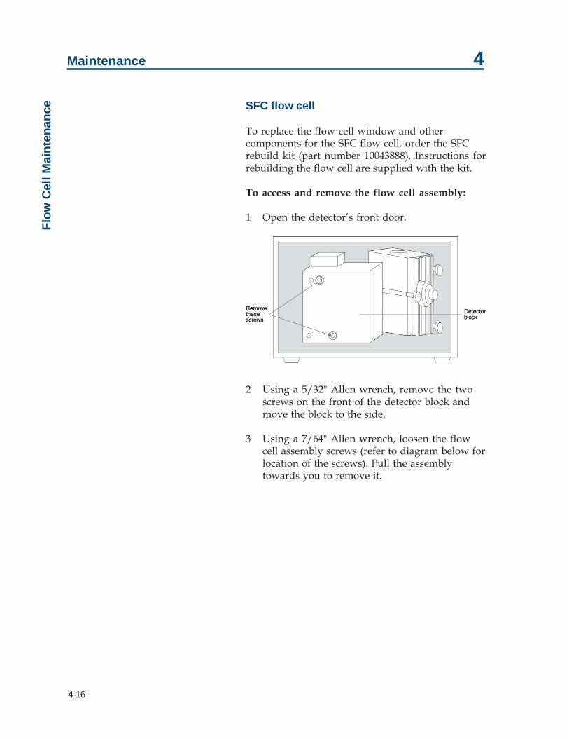
ce Analytical or preparative flow cell
To access and remove the flow cell assembly:
1 Open the detector’s front door.
2 Using a 5/32" Allen wrench, remove the twoscrews on the front of the detector block andmove the block to the side.
3 Using a Phillips screwdriver, remove the flowcell assembly screw (refer to diagram below forlocation of the screw). Then pull the flow cellassembly towards you to remove it.
4 Refer to the following procedures and diagramswhen replacing the analytical or preparativeflow cell and/or tubing.
Flow cell assembly, assembled Flow cell assembly, disassembled

4-7
Maintenance 4
To remove flow cell:
1 Loosen the fittings for the inlet and outlettubing. The inlet tubing enters the flow cellassembly from the bottom while the outlettubing exits from the top.
2 Using a 1/16" Allen wrench, loosen the stainlesssteel screw located on the left side of the flow cellassembly.
3 Carefully remove the flow cell using a pair oftweezers or by tilting the flow cell assembly untilthe flow cell drops into the palm of your hand.
Notice that there is only one way that the flowcell fits into the flow cell assembly.
To replace the outlet tubing:
When replacing the outlet tubing, ensure that itsID is appropriate for the flow cell (analytical orpreparative). See Appendix E for a list of replacementparts.
1 Remove the outlet tubing and fitting from theflow cell assembly.
2 Position a fitting and Omnifit gripper on theflow cell end of the replacement tubing. Use arazor blade to cut the end of the tubing at anangle and if necessary use needle-nosed pliersto pull the tubing through the Omnifit gripper.Then cut the end of the tubing so it is flush withthe gripper. See diagram to right.
3 Insert the fitting into the flow cell assembly.Slightly finger tighten the fitting. Don’tcompletely tighten it yet.
4 Route the free-end of the tubing through thecutout, located at the lower left of the detector’sfront panel.
5 If you’re not replacing the inlet tubing, skip thefollowing instructions and proceed with thesection on page 4-10 about how to clean andinsert the flow cell.
Flow C
ell Maintenance

4-8
Maintenance 4
To replace the inlet tubing:
When replacing the inlet tubing, ensure that itsID is appropriate for the flow cell (analytical orpreparative). See Appendix E for a list of replacementparts.
1 Remove the inlet tubing clamp and set it aside.
2 Unscrew the male nut that connects the inlettubing to the flow cell assembly.
3 Remove the inlet tubing. To do this, hold theflow cell assembly in one hand. Grasp theshorter segment of tubing leading away fromthe flow cell assembly. Then gently twist thetubing to the left to unseat the circular portionfrom the groove around the flow cell assembly.Once the circular portion is free, pull down onthe tubing to remove the segment from insidethe flow cell assembly.
4 If necessary, position the fitting and ferrule onthe flow cell end of the replacement inlettubing. The tubing should extend beyond theferrule. See diagram below.
5 Insert the inlet tubing into the bottom of theflow cell assembly. Position the circular segmentof tubing over the flow cell and seat it into thegroove around the flow cell.
6 Make sure the inlet tubing is seated in the flowcell assembly. Slightly finger tighten the fitting.Don’t completely tighten it yet.
Flow
Cel
l Mai
nten
ance

4-9
Maintenance 4
7 Press together the two segments of inlet tubingas shown in the diagrams below. The segmentleading away from the flow cell should bealmost in front of the segment leading into theflow cell.
8 Insert the inlet tubing clamp into its socket andtighten.
9 Route the free-end of the tubing through thecutout, located at the lower left of the detector’sfront panel.
10 If necessary, carefully dry all surfaces of theflow cell assembly with a piece of lens paper orlint-free towel.
Flow C
ell Maintenance

4-10
Maintenance 4
To clean and insert flow cell:
1 To clean the existing or replacement flow cellbefore installing it, dampen the quartzwindows with alcohol or a laboratory cleaningsolution. Then wipe the windows with a pieceof lens paper or lint-free towel.
2 Clean the inside of the flow cell mounting areawith a lint-free towel soaked in alcohol.
3 Carefully dry all surfaces of the assembly.
4 Without touching the quartz windows, insertthe flow cell into its chamber. Push the cell intothe chamber as far as it will go. A poorlyaligned flow cell may restrict or block flow.
To tighten the fittings:
1 Tighten the stainless steel screw into the leftside of the flow cell assembly.
2 Finger tighten the outlet (top) fitting.
3 Finger tighten the inlet (bottom) fitting.
4 Turn the outlet fitting an additional 1/16 turnusing pliers.
Flow
Cel
l Mai
nten
ance

4-11
Maintenance 4
To check for leaks:
1 To determine whether the fittings are leak-free,use a syringe to initiate flow through the cell.
2 Check carefully along the sides of the cell forbeads of liquid. A flashlight may be helpful.
3 If leakage is detected visually or if the areaaround the fitting feels cool to the touch, removeand clean the flow cell as well as its chamber.Then re-insert the flow cell and re-tighten thefittings.
To replace the flow cell assembly, replace thedetector block, and close the detector door:
1 Insert the flow cell assembly into the detectorand tighten the flow cell assembly screws.
2 Replace the detector block and tighten its twoscrews.
3 Close the detector’s front door.
Flow C
ell Maintenance

4-12
Maintenance 4
Microbore flow cell
To access and remove the flow cell assembly:
1 Open the detector’s front door.
2 Using a 5/32" Allen wrench, remove the twoscrews on the front of the detector block andmove the block to the side.
3 Using a Phillips screwdriver, remove the flowcell assembly screw (refer to diagram below forlocation of the screw). Then pull the flow cellassembly towards you to remove it.
4 Refer to the following diagrams when replacingthe flow cell and/or tubing.
Flow
Cel
l Mai
nten
ance
Flow cell assembly, assembled Flow cell assembly, disassembled

4-13
Maintenance 4
To remove the flow cell:
1 Loosen the fittings for the inlet and outlettubing. The inlet tubing enters the flow cellassembly from the bottom while the outlettubing exits from the top.
2 Using a 1/16" Allen wrench, loosen thestainless steel screw located on the left side ofthe flow cell assembly.
3 Carefully remove the flow cell using a pair oftweezers or by tilting the flow cell assemblyuntil the flow cell drops into the palm of yourhand.
Notice that there is only one way that the flowcell fits into the flow cell assembly.
To replace the inlet or outlet tubing:
1 If you’re replacing the inlet or outlet tubing orboth, remove the tubing and its fitting from theflow cell.
2 For the outlet tubing, position a fitting andOmnifit gripper on the flow-cell end of thereplacement tubing. Use a razor blade to cutthe end of the tubing at an angle and ifnecessary use needle-nosed pliers to pull thetubing through the Omnifit gripper. Then cutthe end of the tubing so it is flush with thegripper. See diagram to right.
For the inlet tubing, position a fitting and newferrule on the flow-cell end of the replacementtubing. The cone of the ferrule faces the fittingand the tubing should extend beyond theferrule. See diagram to right.
3 Insert the fitting into the flow cell assembly.Slightly finger tighten the fitting. Don’tcompletely tighten it yet.
4 Route the free-end of the tubing through thecutout, located at the lower left of the detector’sfront panel.
Flow C
ell Maintenance

4-14
Maintenance 4
To clean and insert the flow cell:
1 To clean the existing or replacement flow cellbefore installing it, dampen the quartz windowswith alcohol or a laboratory cleaning solution.Then wipe the windows with a piece of lenspaper or lint-free towel.
2 Clean the inside of the flow cell mounting areawith a lint-free towel soaked in alcohol.
3 Carefully dry all surfaces of the assembly.
4 Without touching the quartz windows, insertthe flow cell into its chamber. Push the cell intothe chamber as far as it will go. A poorlyaligned flow cell may restrict or block flow.
To tighten the fittings:
1 Tighten the stainless steel screw into the leftside of the flow cell assembly.
2 Finger tighten the outlet (top) fitting.
3 Finger tighten the inlet (bottom) fitting.
4 Turn the outlet fitting an additional 1/16 turnusing pliers.
5 Route the free-end of tubing through the cutoutlocated at the lower left of the detector’s frontpanel.
Flow
Cel
l Mai
nten
ance

4-15
Maintenance 4
To check for leaks:
1 To determine whether the fittings are leak-free,use a syringe to initiate flow through the cell.
2 Check carefully at the tubing connections to theflow cell for beads of liquid. If you notice leakage,carefully tighten the fittings and dry all surfaces.
3 If leakage is detected visually or if the areaaround the fitting feels cool to the touch, removeand clean the flow cell as well as its chamber.Then re-insert the flow cell and re-tighten thefittings.
To replace the flow cell assembly, replace thedetector block, and close the detector door:
1 Insert the flow cell assembly into the detectorand tighten the flow cell assembly screws.
2 Replace the detector block and tighten its twoscrews.
3 Close the detector’s front door.
Flow C
ell Maintenance
4-16
Maintenance 4
SFC flow cell
To replace the flow cell window and othercomponents for the SFC flow cell, order the SFCrebuild kit (part number 10043888). Instructions forrebuilding the flow cell are supplied with the kit.
To access and remove the flow cell assembly:
1 Open the detector’s front door.
2 Using a 5/32" Allen wrench, remove the twoscrews on the front of the detector block andmove the block to the side.
3 Using a 7/64" Allen wrench, loosen the flowcell assembly screws (refer to diagram below forlocation of the screws). Pull the assemblytowards you to remove it.
Flow
Cel
l Mai
nten
ance

4-17
Maintenance 4
4 Refer to the following diagrams when replacingthe flow cell and/or tubing.
To replace the outlet tubing:
When replacing the outlet tubing, ensure that its IDis appropriate for the SFC flow cell. See Appendix Efor a list of replacement parts.
1 Remove the outlet tubing and fitting from theflow cell assembly.
2 If necessary, position the fitting and ferrule onthe flow cell end of the replacement outlettubing. The tubing should extend 3 mm beyondthe ferrule. See diagram to right.
3 Seat the tubing into the top of the flow cellassembly. Then tighten the fitting. The twoparts of the ferrule seat when you tighten thefitting.
4 Route the free-end of tubing through the cutoutlocated at the lower left of the detector’s frontpanel.
5 If you’re not replacing the inlet tubing, skip thefollowing instructions and proceed with thecheck for leaks section on page 4-20.
Flow C
ell Maintenance
Flow cell assembly, assembled Flow cell assembly, disassembled

4-18
Maintenance 4
To replace the inlet tubing:
When replacing the inlet tubing, ensure that its IDis appropriate for the SFC flow cell. See Appendix Efor a list of replacement parts. If necessary, refer tothe flow cell diagrams on page 4-17 when replacingthe inlet tubing as described below.
1 Remove the inlet tubing clamp and set it aside.
2 Unscrew the male nut that connects the inlettubing to the flow cell.
3 Remove the inlet tubing. To do this, hold theflow cell assembly in one hand. Grasp theshorter segment of tubing leading away fromthe flow cell assembly. Then gently twist thetubing to the left to unseat the circular portionfrom the groove around the flow cell assembly.Once the circular portion is free, pull down onthe tubing to remove the segment from insidethe flow cell assembly.
4 If necessary, position the fitting and ferrule onthe flow cell end of the replacement inlettubing. The tubing should extend 3 mm beyondthe ferrule. See diagram to left.
5 Insert the inlet tubing into the bottom of theflow cell assembly. Position the circular segmentof tubing over the flow cell assembly and seat itinto the groove around the assembly.
6 Make sure the inlet tubing is seated in the flowcell assembly. Then tighten the fitting. The twoparts of the ferrule seat when you tighten thefitting.
Flow
Cel
l Mai
nten
ance

4-19
Maintenance 4
7 Press together the two segments of inlet tubingas shown in the diagrams below. The segmentleading away from the flow cell should bealmost in front of the segment leading into theflow cell.
8 Insert the inlet tubing clamp into its socket andtighten.
9 Route the free-end of tubing through the cutoutlocated at the lower left of the detector’s frontpanel.
10 If necessary, carefully dry all surfaces of theflow cell assembly with a piece of lens paper orlint-free towel.
Flow C
ell Maintenance
4-20
Maintenance 4
To check for leaks:
1 To determine whether the fittings are leak-free,use a syringe to initiate flow through the cell.
2 Check carefully at the tubing connections to theflow cell for beads of liquid. If you noticeleakage, carefully tighten the fittings and dry allsurfaces.
To replace the flow cell assembly, replace thedetector block, and close the detector door:
1 Insert the flow cell assembly into the detectorand tighten the flow cell assembly screws.
2 Replace the detector block and tighten its twoscrews.
3 Close the detector’s front door.
Flow
Cel
l Mai
nten
ance

4-21
Maintenance 4
Capillary flow cell
To access and remove the flow cell assembly:
CAUTION! The inlet and outlet tubing on thecapillary flow cell are fragile. Be careful whenopening and closing the front door of the detectorand removing the cell. If broken, this tubing cannotbe replaced.
1 Open the detector’s front door.
2 Using a 5/32" Allen wrench, remove the twoscrews on the front of the detector block andmove the block to the side.
3 Using a Phillips screwdriver, remove the flowcell assembly screw. Then pull the flow cellassembly towards you to remove it.
To replace the flow cell assembly, replace thedetector block, and close the detector door:
1 Insert the flow cell assembly into the detectorand tighten the flow cell assembly screws. Theassembly can be oriented so that both ends ofthe tubing exit either the top or the bottom ofthe flow cell.
2 Replace the detector block making sure that thetubing passes through the slot on either the topor the bottom of the detector block. Tighten itstwo screws.
3 Route the tubing through the cutout, located atthe lower left of the detector’s front door.
4 Close the detector’s front door.
Flow C
ell Maintenance

4-22
Maintenance 4
Lamp Maintenance
The detector contains a deuterium lamp formonitoring UV wavelengths and a tungsten/halogen lamp for monitoring visible wavelengths.
The UV lamp has a warranted life of 750 hours or180 days. The visible lamp has a 500-hour warrantedlife.
UV Lamp Maintenance
CAUTION: Always wear protective eyewearwhen looking at a UV-radiating lamp. Yourprescription glasses are acceptable, if they havePlasticon lenses. Plastic safety goggles providemaximum protection.
Never touch a hot lamp. After turning off thelamps, always wait 30 minutes or more beforereplacing a lamp.
What you’ll need
• Replacement lamp• Flashlight
Get detector ready for lamp maintenance
1 Press LAMP ON/OFF.
2 Turn off the unit using therear-panel MAINS switch.
3 Unplug the detector’spower cord from the outlet.
4 Open the detector’s frontdoor.
Lam
p M
aint
enan
ce

4-23
Maintenance 4
Disconnect visible lamp connector andremove lamp
1 Locate the visible lamp.
2 Follow the visible lamp’s wires to locate theconnector that links the wires to the internalcircuit board. Disconnect the connector fromthe internal circuit board.
3 Grasp the visible lamp and turn it until the flatedge faces upward. Usually, this is just a slightrotation of the lamp in either direction.
4 Remove the lamp by pulling it away from thelamp housing.
Lamp M
aintenance

4-24
Maintenance 4
Remove lamp housing and disconnect UVlamp connector
1 Loosen the three thumbscrews that secure thelamp housing to the monochromator casting.While loosening the last thumbscrew with yourright hand, support the lamp housing withyour left hand.
2 Bring the lamp housing towards you.
3 Follow the UV lamp’s wires to locate theconnector that links the wires to the internalcircuit board.
Note: If the connector is not secure in its socket,secure the connector, install the lamp housing andvisible lamp, and start the detector to determine ifthe loose connector was the problem.
4 Detach the UV lamp connector. You’ll have tosqueeze together the top and bottom of theconnector to remove it. As you remove theconnector to the old lamp, notice theorientation of the connector.
Remove old UV lamp and install new UVlamp
1 Loosen the three thumbscrews that anchor theUV lamp to the top of the lamp housing.
2 Grasp the UV lamp by its base and remove thelamp from the lamp housing.
CAUTION! Always handle the UV lampby the base, avoiding contact with its glasswindow. A hot lamp can cause a severe burn,and fingerprints can etch the window. To cleana lamp, use a soft cloth moistened with alcohol.
3 Make sure the replacement lamp is free offingerprints and other blemishes.
4 Install the replacement lamp.
Lam
p M
aint
enan
ce

4-25
Maintenance 4
Attach UV lamp connector and install lamphousing
1 Attach the UV lamp connector to its socket on theinternal circuit board. The side of the connectorwith the curved edge faces you when you installthe connector.
2 Mate the lamp housing with the monochromatorcasting. Be careful that the lamp age indicatordoes not get between the lamp housing andmonochromator casting.
3 Using the three thumbscrews, secure the lamphousing to the monochromator casting.
Install visible lamp
1 With the flat edge of the lamp facing upward,insert the lamp into the lamp housing.
2 Once the lamp is inserted, rotate it slightly ineither direction. Then gently pull on the lamp toensure that it’s secure.
3 Attach the lamp’s connector to the internalcircuit board.
Check out new lamp
1 Close the detector’s front door.
2 Plug the detector’s power cord into an outlet.
3 Turn on MAINS switch.
4 Press LAMP ON/OFF.
If the lamp fails again, there may be an internalalignment, a power supply, or a starting circuitryproblem. Contact the Gilson Customer ServiceDepartment or your Gilson representative. Seethe Before Calling Us information on page 5-10.
Lamp M
aintenance

4-26
Maintenance 4
Set lamp hours
After a new lamp is installed, and only at thattime, set the UV lamp hours to 0 (zero).
To set the lamp hours for the 152 Detector, refer tothe user’s guide for the controlling software. Thecontrolling software should include a commandthat sets the lamp hours to 0. Or, the softwareshould allow you to send a GSIOC command toreset the lamp hours. See Appendix D for a listingof GSIOC commands.
To reset the lamp hours via the front panel of a 151Detector:
1 At the display, press Mode. You’ll see:
2 Press Status to access status mode.
3 Press Next until you see:
4 Press NewUV to set the lamp hours to 0.
5 Press ESC to exit status mode.
Lam
p M
aint
enan
ce

4-27
Maintenance 4
(Optional) set lamp alarm
The detector can be instructed to flash the statusindicators when the lamp has been in use for acertain number of hours.
To set the lamp alarm for the 152 Detector, refer tothe user’s guide for the Gilson control software. Thesoftware should include a command that sets thelamp alarm. Or, the software should allow you tosend a GSIOC command to set the lamp alarm. SeeAppendix D for a listing of GSIOC commands.
To set the lamp alarm via the front panel of a 151Detector:
1 Press Mode.
2 Press Setup to access setup mode.
3 Press Next until you see:
4 To enable the lamp alarm feature, type anumber from 1 to 9999 and press ENTER.
To disable the lamp alarm feature, type 0 andpress ENTER.
5 Press ESC to exit setup mode.
Lamp M
aintenance

4-28
Maintenance 4
Reset lamp alarm
The detector will flash the error and lamp statusindicators when the lamp has been in use for anumber of hours that exceeds the setting for thelamp alarm. Do not turn the lamps off. Reset thelamp alarm.
To reset the lamp alarm for the 152 Detector, referto the user’s guide for the Gilson control software.The software should include a command that resetsthe lamp alarm. Or, the software should allow youto send a GSIOC command to reset the lamp alarm.See Appendix D for a listing of GSIOC commands.
To reset the lamp alarm:
1 Press Mode.
2 Press Setup to access setup mode.
3 Press Next until you a screen similar to:
4 Disable the lamp alarm feature by typing 0 andpressing ENTER.
5 Press ESC to exit setup mode.
6 Turn the lamps and MAINS switch off andreplace the lamp as described in this section.
Lam
p M
aint
enan
ce

4-29
Maintenance 4
Visible Lamp Maintenance
CAUTION! Never touch a hot lamp. Alwayswait 30 minutes or more after turning the lamp offbefore replacing the lamp
What you’ll need
• Replacement lamp• Flashlight
Get detector ready for lamp maintenance
1 Press LAMP ON/OFF.
2 Turn off the rear-panel MAINS switch.
3 Unplug the detector’s power cord from theoutlet.
4 Open the detector’s front door.
Lamp M
aintenance

4-30
Maintenance 4
Remove visible lamp
1 Locate the visible lamp.
2 Follow the visible lamp’s wires to locate theconnector that links the wires to the internalcircuit board. Disconnect the connector fromthe internal circuit board.
Note: If the connector was not secure in itssocket, you may want to secure the connectorand start the detector to determine if the looseconnector caused the problem.
3 Grasp the visible lamp and turn it until the flatedge faces upward. Usually, this is just a slightrotation of the lamp in either direction.
4 Remove the lamp by pulling it away from thelamp housing.
Lam
p M
aint
enan
ce

4-31
Maintenance 4
Install new lamp
1 With the flat edge of the new lamp facingupward, insert the lamp into the lamp housing.
2 Once the lamp is inserted, rotate it slightly ineither direction. Then gently pull on the lamp toensure that it’s secure.
3 Attach the visible lamp’s connector to theinternal circuit board.
Check out new lamp
1 Close detector’s front door.
2 Plug the detector’s power cord into an outlet.
3 Turn on MAINS switch.
4 Press LAMP ON/OFF.
If the lamp fails again, there may be an internalalignment, a power supply, or a starting circuitryproblem. Contact your local representative orGilson. See the Before Calling Us information onpage 5-10.
Lamp M
aintenance

4-32
Maintenance 4
Set lamp hours
After a new lamp is installed, and only at thattime, set the visible lamp hours to 0 (zero).
To set the lamp hours for the 152 Detector, refer tothe user’s guide for the controlling software. Thecontrolling software should include a commandthat sets the lamp hours to 0. Or, the softwareshould allow you to send a GSIOC command toreset the lamp hours. See Appendix D for a listingof GSIOC commands.
To reset the lamp hours via the front panel of a 151Detector:
1 At the display, press Mode. You’ll see:
2 Press Status to access status mode.
3 Press Next until you see:
4 Press NewVis to set the lamp hours to 0.
5 Press ESC to exit status mode.
Lam
p M
aint
enan
ce

4-33
Maintenance 4
(Optional) set lamp alarm
The detector will flash the error and lamp statusindicators when the lamp has been in use for anumber of hours that exceeds the setting for thelamp alarm. Do not turn the lamps off. Reset thelamp alarm.
To set the lamp alarm for the 152 Detector, refer tothe user’s guide for the Gilson control software. Thesoftware should include a command that sets thelamp alarm. Or, the software should allow you tosend a GSIOC command to set the lamp alarm. SeeAppendix D for a listing of GSIOC commands.
To set the lamp alarm via the front panel of a 151Detector:
1 Press Mode.
2 Press Setup to access setup mode.
3 Press Next until you see:
4 Press ENTER to move the highlight to the SetVis lamp alarm parameter.
5 To enable the lamp alarm feature, type anumber from 1 to 9999 and press ENTER.
To disable the lamp alarm feature, type 0 andpress ENTER.
6 Press ESC to exit setup mode.
Lamp M
aintenance

4-34
Maintenance 4
Reset lamp alarm
The detector will flash the error and lamp statusindicators when the lamp has been in use for anumber of hours that exceeds the setting for thelamp alarm.
To reset the lamp alarm for the 152 Detector, referto the user’s guide for the Gilson control software.The software should include a command that resetsthe lamp alarm. Or, the software should allow youto send a GSIOC command to reset the lamp alarm.See Appendix D for a listing of GSIOC commands.
To reset the lamp alarm:
1 Press Mode.
2 Press Setup to access setup mode.
3 Press Next until you see:
4 Press ENTER to move the highlight to the SetVis lamp alarm parameter.
5 Disable the lamp alarm feature by typing 0 andpressing ENTER.
6 Press ESC to exit setup mode.
7 Turn the lamps and MAINS power switch offand replace the lamp as described in thissection.
Lam
p M
aint
enan
ce

4-35
Maintenance 4
Fuse Replacement
To change a fuse, follow these steps.
1 Disconnect the power cord from the poweroutlet and from the rear panel receptacle.
2 Locate the fuse drawer on the back panel.
3 Insert a small screwdriver into the notchlocated below the fuse drawer.
4 Twist the screwdriver to open and remove thefuse drawer. The fuse drawer contains one fusefor a 90–120 voltage selection. It contains twofuses for a 220–240 voltage selection.
5 Remove the old fuse(s) and insert the newfuse(s). The replacement fuses must be 2.5 amp“T” type fuses. The size of the fuses is 5 x 20 mm.
6 Insert the fuse drawer into its receptacle in thedetector.
A blown fuse may indicate the existence of anotherproblem in the instrument. If the replacement fusesblow, don’t try others. Contact your localrepresentative or Gilson. Refer to the Before CallingUs information on page 5-10.
Fuse Replacement

5-1
5Troubleshooting
This section is composed of three parts:
• a chart of some frequently encountered problems, possible causes and remedies
• diagnostic techniques you can use with Gilson service personnel to troubleshoot problemswith the detector’s lamp and optics
• information about how and when to contact the Gilson Customer Service Departmentor your Gilson representative about repairs

5-2
Troubleshooting 5Tr
oubl
esho
otin
g Troubleshooting
Detector Not Functioning
• Check cord and power connection.
• Fuses may be blown. Refer to FuseReplacement on page 4-35.
If the problem persists, contact the Gilson CustomerService Department (refer to page 5-10 for contactinformation) or contact your Gilson representative.
A Lamp Fails to Ignite/A Lamp FailsWhile On
• Check for loose lamp connector or replace lamp.Refer to Lamp Maintenance on page 4-22.
If the problem persists, contact Gilson CustomerService (refer to page 5-10 for contact information)or contact your Gilson representative.
Status Lights Blinking/Screen Blankor Dark
• Turn off the detector (MAINS switch). Whilepressing the LAMP ON/OFF soft key, turn onthe detector (MAINS switch).
Note: This will clear all user-entered parametersand the detector resets to its factory default.

5-3
Troubleshooting 5Troubleshooting
Baseline Spikes
• Be sure solvents are degassed.
• Check fittings for a leak in system. Repair asneeded.
• Reduce pump noise by changing thecompressibility setting on the pump and byexamining check valves.
• Voltage transients on a single circuit caninterfere with detector output. Eliminatevoltage transients by connecting detector andrecorder power cords to a constant voltagetransformer or line filter.
• Check grounds on all instruments. Eliminateground loops by connecting the detector andrecorder to the same power outlet.
5-4
Troubleshooting 5Tr
oubl
esho
otin
g Baseline Noise
• Allow each lamp to warm up for at least 1 hour.
• Eliminate drafty air currents and variations inambient temperature. Move the detector awayfrom windows or doors.
• Eliminate smoke from the environment.
• Check grounds on all instruments. Eliminateground loops by connecting the detector andrecorder to the same power outlet.
• Be sure solvents are degassed.
• Check fittings for a leak in system. Repair asneeded.
• If you see baseline deflection when backpressure is exerted on the flow cell, youprobably have bubbles trapped in the cell. Tryone of these methods to eliminate bubbles:
- Increase back pressure on the cell byconnecting pressure regulator tubing to theflow cell outlet.
- Increase back pressure by raising flow rateand using a syringe or septum tomomentarily block exit stream.
- Flush flow cell using a syringe filled withfresh solvent.
- Raise the fraction collector vial to a levelhigher than the flow cell.
• A lamp may be weak. Refer to LampMaintenance on page 4-22.
• Check flow cell for contamination. Refer toFlow Cell Maintenance on page 4-2.

5-5
Troubleshooting 5Troubleshooting
Baseline Drift
• Allow each lamp to warm up for at least 1 hour.
• Eliminate changes in ambient temperature. Ifdrift is dependent on temperature, eliminatedrafts and avoid areas of direct sunlight.
• Check for contaminated or “bleeding” column.If drift disappears after removing columnconnections, regenerate or replace column.
• Be sure solvents are degassed.
• Check fittings for leak in system. Repair asneeded.
• If you see baseline deflection when backpressure is exerted on the flow cell, youprobably have bubbles trapped in the cell. Tryone of these methods to eliminate bubbles:
- Increase back pressure on the cell byconnecting pressure regulator tubing to theflow cell outlet.
- Increase back pressure by raising flow rateand using a syringe or septum tomomentarily block exit stream.
- Flush flow cell using a syringe filled withfresh solvent.
- Raise the fraction collector to a level higherthan the flow cell.
• Check pump or delivery system to determinethat flow rate is constant.
• A lamp may be weak. Refer to LampMaintenance on page 4-22.
• Check flow cell for leak or contamination. Referto Flow Cell Maintenance on page 4-2.

5-6
Troubleshooting 5
Autozero Out of Range
This message results from high backgroundabsorbance.
The detector cannot reduce the baseline to zero, butwill reduce the baseline as much as possible.Operation continues during and after you receivethis message.
• Flow cell may be coated with highly absorbingeluents. See pages 4-2 to 4-5 for flushinginstructions.
• Alternatively, you may need to select a newsolvent system or monitor wavelength. Refer toMobile Phase Tips on page 3-37.
Out of Range
• Check connections to recorder. Refer to recorder’stroubleshooting instructions.
• Check purity and UV/VIS-cutoff of solvents. Besure solvents are degassed, HPLC-grade solvents.
• There may be bubbles in the flow cell. Try oneof the following:
- Increase back pressure on the cell byconnecting pressure regulator tubing to theflow cell outlet.
- Increase back pressure by raising flow rateand using a syringe or septum to momentarilyblock exit stream.
- Flush flow cell using a syringe filled withfresh solvent.
- Raise the fraction collector vial to a levelhigher than the flow cell.
Trou
bles
hoot
ing

5-7
Troubleshooting 5
• Check for contaminated or “bleeding” column.If necessary, regenerate or replace column.
• Check flow cell for contamination or damage.Refer to Flow Cell Maintenance on page 4-2.
• A lamp may be weak. Refer to LampMaintenance on page 4-22.
• A lamp connector may be loose. Refer to LampMaintenance on page 4-22.
If none of the above fix the problem, contact theGilson Customer Service Department (refer to page5-10 for contact information) or your Gilsonrepresentative.
Peaks Too Broad
• Check peak width setting - it may be set toohigh. Measure the narrowest peak; then setnew value.
• Check for contaminated column. If necessary,regenerate or replace column.
Decreased Response to KnownSample
• A lamp may be weak. Refer to LampMaintenance on page 4-22.
• Check connections to recorder. Refer to therecorder’s troubleshooting instructions.
• Verify sample concentration and solvent.
• Check flow cell for contamination. Refer toFlow Cell Maintenance on page 4-2.
Abnormally High System Pressure
• Check for blockage in flow cell or tubing.
Troubleshooting

5-8
Troubleshooting 5
Diagnostics
The two beams of light that emerge from the beamsplitter form the reference and active beams. Thereference beam passes through an aperture to itsphotodiode. The active beam passes through theflow cell to its photodiode.
The flow cell receives your sample. The referencephotodiode monitors lamp intensity changes.
The photodiodes convert the light energy into anelectrical current. That current is proportional tothe intensity of the light.
Numeric Analyses on the 151 Detector
The Gilson service personnel can gain insight intodetector malfunction by examining voltagepercentages at various wavelengths. To providethis information to Gilson, do the following:
1 Ensure that the flow cell is dry or contains onlyHPLC-grade water.
2 Press ESC (possibly several times) until youreach the first display.
3 To select status mode, press Mode then Status.
4 Press Next until you see a display like thefollowing:
5 Type 190 for the wavelength and press ENTER.
6 Wait until the AU reading stabilizes.
Dia
gnos
tics

5-9
Troubleshooting 5
7 In tabular form, record the displayed AU,Active, and Reference values. For the Active %and Reference %, values up to 110% are withinnormal operating parameters for the detector.Values over 110% indicate there is too muchsignal reaching the active and referencephotodiodes.
For the active and reference photodiode, thesoftware calculates the Active % and Reference% as follows:
% = (Current Signal/Maximum Signal) * 100
8 Using 20 nm increments, repeat steps 5 through7 to obtain AU, Active, and Reference valuesfor 190 to 700 nm.
9 When finished, press ESC to return to thedisplay for operation mode. The wavelengthshown on the display is the last one you enteredin status mode.
10 Enter an appropriate value for the wavelengthto use for operation mode.
Diagnostics
5-10
Troubleshooting 5
Repair and Return Policies
Telephone Numbers
In the United States, Gilson Customer Service can bereached by calling 800-445-7661 or 608-836-1551.Outside the United States, contact your Gilsonrepresentative.
Before Calling Us
Gilson Customer Service personnel will be able toserve you more efficiently if you have the followinginformation:
• the serial number and model number of theequipment involved
• the installation procedure you used• list of concise symptoms• list of operating procedures and conditions you
were using when the problem arose• list of other devices connected to the detector
and a description of those connections• list of other electrical connections in the room
Warranty Repair
Devices covered under warranty will be repairedand returned to you at no charge. If you have anyquestions about applicability, please contact GilsonCustomer Service or your Gilson representative.
Non-Warranty Repair
For out-of-warranty repairs, contact GilsonCustomer Service or your Gilson representative.Gilson will discuss service options with you andcan assist in making arrangements to return thedevice, if necessary.
Rep
air a
nd R
etur
n Po
licie
s

5-11
Troubleshooting 5
Rebuilt Exchange
For some Gilson instruments, rebuilt exchangecomponents are available. Contact GilsonCustomer Service for details.
Return Procedure
In the United States, contact Gilson CustomerService to obtain authorization before returningany Gilson equipment. To return a piece ofequipment:
• Carefully pack the unit to prevent damage intransit. Check with Gilson regarding propermethod of shipment. No responsibility isassumed by Gilson for damage caused byimproperly packaged instruments. Indicate theauthorization on the carton and on the packingslip.
• Always insure for the replacement value of theunit.
• Include a description of symptoms, your name,address, phone number and purchase order tocover repair costs, return and shipping charges,if your institution requires it. Ship to:
Gilson, Inc.Attention: Customer Service(indicate the authorization here)3000 W. Beltline HighwayMiddleton, WI 53562-0027
Outside the United States, contact your Gilsonrepresentative for return procedures.
Repair and R
eturn Policies


A-1
ADefaults and Limits
Note: When you first use your new detector, default conditions and values are applieduntil modified.
Setup Mode
Parameter Default Low High Unit
Voltage scales 10 1 1000 mVChannel offsets 0 0 1000 mVVis lamp alarm 0 0 9999 hoursUV lamp alarm 0 0 9999 hoursEvent channels 0 0 3 -Autorange channels 0 0 3 -Autorange multiplier 0.2 0.1 0.5 -Concentration factor* 1.000 0.500 5.000 -Lamp saver option On - - -
*If factor is not equal to 1 then the reading is given in units other than AUFS.
Operation Mode
Parameter Default Low High Unit
Wavelength 254 190 700 nmSensitivity 1 0.010 0.001 2.000 AUFSSensitivity 2 0.010 0.001 2.000 AUFSPeak width 10.0 0.0 99.0 sec


B-1
BMode-Specific Functions
Mode-Specific Output Channels
Mode Channel 1 Channel 2 Channel 3
Operation wavelength 1 at sensitivity 1 wavelength 1 at sensitivity 2 % transmittance
Mode-Specific Remote Event and Autozero Functions
Note: The black and red wires are the remote event wires. The green and white wires arethe autozero wires.
Mode Event Autozero
Operation Causes event spike Automatically resets the baseline to zeroto appear all output channels
Program Resumes a program Starts a pre-selected program file (at time 0);file that was waiting synchronizes timing of program run withfor a contact closure other devices


C-1
CSensitivity
To set the sensitivity, you must consider the sample concentration.
You can ensure that your peaks appear on-scale by running test chromatograms atvarious SENSITIVITY settings.
When you set the SENSITIVITY to a small number, the detector will monitor at highsensitivity.
Consider the examples and diagrams on the following pages as guides for settingSENSITIVITY.

C-2
Appendix CSe
nsiti
vity At a constant SENSITIVITY setting, the peak height
varies as the sample concentration changes.
• At the same SENSITIVITY setting, a sample withan absorbance of greater than 1.0 produces apeak height that is greater than full scale.
• At the same SENSITIVITY setting, full-scalerecorder pen deflection occurs when the sampleflowing through the cell has an absorbance of1.0 AU.
• At a SENSITIVITY setting of 1.0 AUFS, asample with an absorbance of less than 1.0 AUproduces a maximum peak height that is lessthan full scale.

C-3
Appendix CSensitivity
At a constant sample concentration, the peakheight varies as the SENSITIVITY setting changes.
• At a SENSITIVITY setting of 1.0 AUFS, a samplewith an absorbance of 0.1 AU produces amaximum peak height that is less than full scale.
• At a SENSITIVITY setting of 0.1 AUFS, thatsame sample causes full-scale pen deflection.
• At a SENSITIVITY setting of 0.01 AUFS, thatsame sample produces a maximum peak heightthat is greater than full scale.


D-1
DGSIOC Control
The Gilson Serial Input/Output Channel (GSIOC) is an asynchronous serial communicationsinterface that enhances the power of Gilson devices, such as a 151 or 152 Detector.
Communication occurs via the GSIOC or RS-232 connection between the systemcontroller and detector.
The detector is a slave device and is identified by a unique number which must be knownto the slave device and to the system controller. The default ID code of the detector is 16.You can set it to another number, but remember to use the same ID number when issuingcommands to the detector via the system controller.
From the computer, you:
• specify the detector as the device that you want to control• issue commands that set operating parameters for, control operation of, or request
information from the detector
To control the detector via the GSIOC interface, you need:
• Gilson control software and 506C System Interface or• 706 Device Driver Software and your program

D-2
Appendix DG
SIO
C C
ontr
ol GSIOC Commands
There are two kinds of commands that you canissue from the system controller to the detector.
• Buffered commands send instructions to thedetector. These commands are executed one ata time.
• Immediate commands request status informationfrom the detector. These commands are executedimmediately, temporarily interrupting othercommands in progress.
FIFO Commands
Using GSIOC commands, you can requestcompressed data that are stored in the detector’sFIFO memory buffers. These commands are usefulto programmers who want to capture detector datafor analysis. The FIFO commands are listed afterthe GSIOC command list.
GSIOC Command List
In the command list below, the GSIOC commandmust be entered in the proper upper or lower caseformat. If a buffered command requires additionalinformation, you’ll see italicized text next to thecommand. The description of the commandidentifies what you need to enter in place of theitalicized text.
When the detector executes a buffered command,the detector returns “.” (a period). The informationreturned for an immediate command depends onthe command; refer to the following pages.
I=ImmediateB=Buffered

D-3
Appendix DG
SIOC
Control
Command Type Description
% I Identifies the detector. Returns a character string thatidentifies the model number and software version for thedetector, for example: “151V1.00”
^ I Determines if the display operation mode is shown. If theoperation mode display is shown, returns “T” for top.Otherwise, returns the screen number assigned to the displayin the detector software.
$ I Shuts down the detector and then turns on and resets thedetector to operation mode.
A I Reads active signal current and then returns “n..n” in µFSunits.
B B Causes the detector to beep for 0.1 second.
Dn B Turns off or on the front panel display depending on thenumber (0 to 2) that you assign to n:
0 - Turns off display.1 - Turns on display.2 - Restores automatic mode if you turn off or on the display
using “0” or “1.” With automatic mode; the display isautomatically turned off if there is no text on the display.
For example, to turn off the display, send the followingcommand: D0
Fn B Starts file number (0–9) that you assign to n.
For example, to start file 1, send the following command: F1
FE B Ends the execution of the file.
FP B Pauses the currently executing file.
FR B Resumes the currently paused file.

D-4
Appendix DG
SIO
C C
ontr
ol h I Identifies the editable field that has the focus. If the focus isat an editable field, returns “b,e,c” where:
b - Index of the beginning character of the editable fielde - Index of the last character of the editable fieldc - Index of the cursor
The index is a number from 0 to 159 that identifies a locationon the display. Index numbers 0 to 39 are on the first line ofthe display, 40 to 79 are on the second line of the display, 80to 119 are on the third line of the display, and 120 to 159 areon the fourth line of the display.
If the focus is not at an editable field, the detector returns a“|” (vertical bar).
Example 1. A response of “092,092,092” indicates that theeditable field is one character wide, and located on line 3,column 13 of the display. The cursor is located on line 3,column 13.
Example 2. A response of “052,054,053” indicates that theeditable field is three characters wide, and located on line 2,columns 13 to 15 of the screen. The cursor is located on line2, column 14.
I I Determines status of input contacts. Returns “ab”, where“a” and “b” are either “D” (disconnected or open) or “C”(connected or closed).
a - Status of the autozero contactb - Status of the remote event contact
For example, the detector returns “DD” if both contacts areopen or disconnected.

D-5
Appendix DG
SIOC
Control
K=xx...x B Simulates front panel key presses. Keystrokes are simulatedaccording to the key assignments shown in the diagrambelow.
For example, if you wanted to simulate the pressing of theHELP key, you would use the following command: K=H
To lock the keypad without sending any keystrokes, send thefollowing command: K=
To unlock the keypad so you can use it to specify parameters,send the following command: K
K I Returns keycode for up to last three keystrokes. Responseformat: “xxx” where “xxx” is an ASCII string of up to threecharacters encoding the last three keys that were pressed.
For example, if the last three keys that were pressed were theHELP, ESC, and CLEAR keys, the detector returns “HXC”.
If the detector was just turned on and no key has beenpressed, the detector returns “|”.
Ln B Turns the lamps on or off depending on the number (0 or 1)that you assign to n:
0 - Turns off the lamps.1 - Turns on the lamps.
L0X B Sets the UV lamp hours to 0 (zero).
D-6
Appendix DG
SIO
C C
ontr
ol L1X B Sets the visible lamp hours to 0 (zero).
L I If both lamps are lit, returns “uuuu vvvv” where:
uuuu - UV lamp hoursvvvv - Visible lamp hours
Pnn B Sets parameter pointer to the specified parameter, where nnidentifies the code assigned to the parameter; see table on thefollowing page.
Pnn=mmmmm B Assigns a value (mmmmm) to a parameter (nn). If the value isomitted, the parameter is set to zero. The table on the followingpage identifies the code assigned to each parameter within amode. It also lists the range of values that can be entered. SeeSection 3 and Section 5 if you need additional information onthe parameters within the modes.
P I Reads the value of a parameter. Returns “nn=mmmmm”,where “nn” identifies the parameter (see table on thefollowing page) and “mmmmm” identifies the value. Use thePnn command to indicate the parameter to be reviewed.

D-7
Appendix DG
SIOC
Control

D-8
Appendix DG
SIO
C C
ontr
ol R I Reads reference signal current. Returns: “n..n” in µFS units.
Wn=xx.xx B Disconnects and writes to the display. Or, reconnects thedisplay after it was disconnected. When specifyingparameters for the command:
n - Line number (0 to n–1, n being the line number). Forinstance, if you’re writing to line 1, indicate 0 for n.
xx..xx - Alphanumeric string of up to 40 characters. Thestring can be made up of letters (A–Z), numbers (0–9),or special characters, such as these: (!@$%^&*()_+-={}[]:;”<>,.?’/ and space)
If you specify more than 40 characters, theadditional characters are not shown on the display.
When the command is sent, the designated line isdisconnected from the detector’s software. Lines may beindividually reconnected to the detector’s software; seesyntax table below.
Following are several syntax examples for the buffered Wcommand:
Syntax example Description
W0=xx..x Disconnects and writes the character string(xx..x) to line 1 of the display.
Wn=xx..x Disconnects and writes the character string(xx..x) on line n. For n indicate a numberfrom 0 to 3, with 0 being line 1 of the display.
W= Disconnects the whole display.W0= Disconnects line 1.Wn= Disconnects line n. For n indicate a number
from 0 to 3, with 0 being line 1 of the display.W Reconnects all lines.W0 Reconnects line 1.Wn Reconnects line n. For n indicate a number
from 0 to 3, with 0 being line 1 of the display.

D-9
Appendix DG
SIOC
Control
W I Identifies the contents of the front panel display. Returns“Wn=xx..xx” where:
n - Display line number minus 1.xx...xx - Up to a 40-character alphanumeric string that was
written to the display using the buffered W command.
Note: The first line that is returned is the last defined by thebuffered W command. If the buffered W command has notbeen used, the first line of the display is read when theimmediate W command is issued. The next line is returned atthe next occurrence of the immediate W command, and soon.
w I Reads the display buffer. Returns “wn=xx..xx” where:
n - Display line number minus 1.xx...xx - Up to a 40-character alphanumeric string that
would be displayed on the corresponding line if thedisplay were connected to the detector’s software.
Z B Zeroes the detector’s output channels.
Z I Returns status of last zero command:
0 - Command was unsuccessful.1 - Command was successful.
z I Reads error status after start up attempt
00000000 - Detector is functioning properly00000001 - Digital Signal Processor malfunctioning00000002 - Invalid age for UV lamp00000004 - UV lamp too old. (Beyond lamp alarm setting)00000008 - Invalid age for VIS lamp.00000010 - VIS lamp too old (Beyond lamp alarm setting)00000020 - Invalid UV lamp identification00000040 - Monochromator not properly aligned (calibration
peak too close to stop), or UV lamp did not start00000080 - Monochromator not properly aligned (calibration
peak too far from stop), or UV lamp did not start00000100 - Too much stray light on low wavelength side of
calibration peak, or UV lamp did not start00000200 - Too much stray light on high wavelength side of
calibration peak, or UV lamp did not start
D-10
Appendix DG
SIO
C C
ontr
ol FIFO Command List
The compressed digital data from every input and output channel can be read by themaster device. To determine what data is present on each channel, consult the modedescriptions in Operation.
I=ImmediateB=Buffered
Command Type Description
0xxxx B Flushes FIFO 0 (Output channel 1 data). The parameter xxxx is a4-digit number that sets the sampling rate up to 8000 in 0.01 Hz.
0 I Reads FIFO 0 (Output channel 1 data).
1xxxx B Flushes FIFO 1 (Output channel 2 data). The parameter xxxx is a4-digit number that sets the sampling rate up to 8000 in 0.01 Hz.
1 I Reads FIFO 1 (Output channel 2 data).
2xxxx B Flushes FIFO 2 (Output channel 3 data). The parameter xxxx is a4-digit number that sets the sampling rate up to 8000 in 0.01 Hz.
2 I Reads FIFO 2 (Output channel 3 data).
9 B Clears contact event FIFO and reset event timer.
9 I Reads event FIFO. Return string “Xttttttt” where “X” describesthe state of the two contact inputs:
X Autozero Event@ Open OpenA Open CloseB Close OpenC Close Close
And, the string “ttttttt” identifies the time since the lastchange; expressed as a hexadecimal value in 10 ms.
The immediate 9 command returns “|000000” if no event isavailable in the queue.

E-1
EReplacement Parts
Lamp Assemblies
100326 Deuterium Lamp Assembly for 15X-series (UVwavelengths). Warranted 750 hours or 180 days.
100325 Tungsten/halogen Lamp Assembly for 15X-series(VIS wavelengths) 1500 hour life
Cell/Accessory Kits
104445 Analytical flow cell/accessory kit (5 mm pathlength,12 µL volume, quartz) with stainless steel inlet tubing
104445LP Low pressure flow cell/accessory kit (5 mm pathlength,12 µL volume, quartz) with stainless steel inlet tubing
104445PK Analytical flow cell/accessory kit (5mm pathlength,12 µL volume, quartz) with PEEK inlet tubing
104441 Preparative flow cell/accessory kit (0.2 mmpathlength, 0.7 µL volume, quartz) with stainlesssteel inlet tubing
104443 Preparative flow cell/accessory kit (0.05 mmpathlength, 0.16 µL volume, quartz) with stainlesssteel inlet tubing
104442 Microbore flow cell/accessory kit (2 mm pathlength,1.6 µL volume, quartz) with stainless steel inlet tubing
1044385 SFC flow cell/accessory kit (5 mm pathlength, 10 µLvolume, stainless steel and sapphire) with stainless steelinlet and outlet tubing

E-2
Appendix ER
epla
cem
ent P
arts 1044395 Preparative SFC flow cell/accessory kit (0.5 mm
pathlength, 2 µL volume, stainless steel and quartz)with stainless steel inlet and outlet tubing
104446 Capillary flow cell/accessory kit (8 mm pathlength,35 nL volume) glass capillary inlet and outlet tubing.
Flow Cell Assemblies
100405 Analytical flow cell (5 mm pathlength, 12 µL volume,quartz)
100401 Preparative flow cell (0.2 mm pathlength, 0.7 µLvolume, quartz)
100407 Preparative flow cell (0.05 mm pathlength, 0.16 µLvolume, quartz)
100402 Microbore flow cell (2 mm pathlength, 1.6 µL volume,quartz)
1004385 SFC flow cell (5 mm pathlength, 10 µL volume,stainless steel and sapphire)
1004395 Preparative SFC flow cell (0.5 mm pathlength, 2.0 µLvolume)
10043888 Rebuilding kit for SFC flow cell assembly (5 mmpathlength, 10 µL volume, stainless steel andsapphire)
Inlet and Outlet Tubing
49951309 Analytical inlet tubing, 0.010" PEEK, 30 cm length; nofittings, use S-822 male nut and P-200R ferrule tomake flow cell connection
10044121 Preparative inlet tubing, 0.030" stainless steel; nofittings, use S-822 male nut and P-200R ferrule tomake flow cell connection
10044231 Microbore inlet tubing, 0.005" stainless steel; nofittings, use S-822 male nut and P-200R ferrule tomake flow cell connection

E-3
Appendix ER
eplacement Parts
10043851 SFC inlet tubing, formed 0.005" ID stainless steel; nofittings, use Upchurch U-400 male nut and LT-100ferrule to make connection to flow cell
1007455 Analytical outlet tubing, 0.3 mm Teflon, with omnifitfittings
1007415 Preparative outlet tubing, 0.8 mm Teflon, withomnifit fittings
1007425 Microbore outlet tubing, 0.006" Teflon, with omnifitfittings
49938309 SFC outlet tubing, 0.005" ID stainless steel, 30 cmlength; no fittings
49041013 Upchurch S-822 short purple male nut for flow cellconnection
49041011 Upchurch P-200R 1/16" red ferrule for flow cellconnection
49041040 Upchurch U-400 male nut for SFC flow cellconnection
49041041 Upchurch LT-100 ferrule for SFC flow cell connection
49041001 Upchurch F-100N Fingertight fitting, 10-32 forcolumn connection
49010103 Omnifit gripper for outer end of Teflon outlet tubing
49010304 Male nut for use with Omnifit gripper
495018 Luer fitting, female
495019 Luer fitting, male
F1410050 1/4-28 couplers for outlet tubing fittings
E-4
Appendix ER
epla
cem
ent P
arts Miscellaneous
36070905 Back pressure regulator (75 psi), PEEK
36070906 Back pressure regulator (75 psi), stainless steel
4311562 Allen wrench, 5/32", for detector block mountingscrews
4310621 Allen wrench, 1/16", for stainless steel screw on leftside of flow cell assembly
10093872 Torque wrench for SFC flow cell assembly, 40 in-lbs
100731 Remote control (event/autozero) cable
36078143 Shielded GSIOC cable, 30"
6374022611 Pomona cable adapter, banana plugs to binding posts
7080316105 115V power cord
7080316106 220/240V power cord, European plug
6730254007 Fuse, 250 volts, 2.5 amp, T-type, 5 mm x 20 mm, Slo-Blo
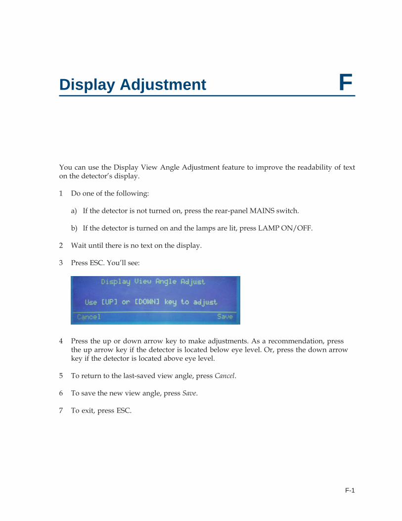
F-1
FDisplay Adjustment
You can use the Display View Angle Adjustment feature to improve the readability of texton the detector’s display.
1 Do one of the following:
a) If the detector is not turned on, press the rear-panel MAINS switch.
b) If the detector is turned on and the lamps are lit, press LAMP ON/OFF.
2 Wait until there is no text on the display.
3 Press ESC. You’ll see:
4 Press the up or down arrow key to make adjustments. As a recommendation, pressthe up arrow key if the detector is located below eye level. Or, press the down arrowkey if the detector is located above eye level.
5 To return to the last-saved view angle, press Cancel.
6 To save the new view angle, press Save.
7 To exit, press ESC.