Embed Size (px)
Citation preview
7/27/2019 Gilian Operating Manual
http://slidepdf.com/reader/full/gilian-operating-manual 1/37
: ~ ~ I n s t i t u t
F r e s e n i u s
U P E R A T I N G M A N U A L
Gilian HFS Air Sampling System
(~,hern sche und Biologische
i_r3ruratonen GmbH
6 2 0 4 T a u n u s s t e i n - h } e u h o f
Telefon 06128/744-0
T e l e t e x 6 1 2 8 9 2 5 b i o s d
T e l e f a x 0 6 1 2 8 / 7 4 4 8 9 0
Beirat Vors . Pro6. Dr. WilhelmFresenius ; Ste IIN.W.'ScFineider- Geschaftsfiihrer : Prot. Dr. R . F r e s e n i u s , L . Fres eniu s HRe 1338.Rad S¢hwaltiacli. ,
Die Veroffentlioh ung, VArvielfaltigung unse rerAtteste und Gutaohlen zu Werbezwecken sowie .deren auszugsweise Verwendung in sonstigen Fallen, bedJir/en umsererschrittll¢hen Genenrmgung .
//legacy.library.ucsf.edu/tid/rcm56e00/pdf
7/27/2019 Gilian Operating Manual
http://slidepdf.com/reader/full/gilian-operating-manual 2/37
//legacy.library.ucsf.edu/tid/rcm56e00/pdf
7/27/2019 Gilian Operating Manual
http://slidepdf.com/reader/full/gilian-operating-manual 3/37
WARRANTYi
Gilian llt,trnmc•. u t t c n j > . w c a r - c u t t , t o t l r c • p l t r d r e t s e r t f i u t u n V c • y t t i p t t t e t r t
t +t c r t t t t f u c t r t r e r c l l r i • i t i t u c ! I > t u n - i r r , 4 i t s u c u u c n l c t t e t o f i e f r e r f - m c l e f e t x "; i t t
t r r c r t c r i c t h r , r t r u r k + r t u t t . . L r i p . r r t r c l e r p r v p e r c t t t c d n o r r o t c t l i t s e c n t z l s e r t - i c e : c t s s
f , l l n u s i l f u t u t t 1 ' t i t t r c • r r • i t l r i r t / ' • r c r r J r a t u t l i e • c % t t c • c f s e r l c . t L i r p t t r c l u ts e • r
rlntifies tbc seller tLrut irt l,is op inion. the equipme nt is dc fl+ctit'v, and
r i 7 t r r - r r . ! / r c • r y t t i p a r r n l ' t t , t l ~ e : a ! t c r ' s u r i , r i i e c r t i t t , 4 ~ f c t c t t r r l ' . / r r c p c t i d a + r d t Li c •
s r l l i • r : < i i t s p c • c t i o t r f i u r l c t h e c • y r t i p t r r u t N t o l i u d c f r c 7 i t - c • i i t t u z t t u r i r t/ o r
tr r,r{rrucut . < l , i / r . t/ i r : c d / v r t r i l t / » • u t + r p t l t i ! C u r r c • c t i t l i t ' c • i t l.ic•r ctt its u/Niutt :
r c y r u i + ' i r ; A c u r l ' c l t f u i t i n c ' / i t + r t ' r , r r r t n h • r i c r l u r r c p l i t i i i { q i t f r c • t r o f c h a r g e
c r r t r l r r t t n - u :/upp (•tl7utr,ra cr, : 1 t r u u s y x , r t c u i o r r p r c • p c t i c l ! i f p r r r c C i u :e r
r c • c p t i ~ a + / , r c w t i i t t r r l r u r t . : p c ~ r t u t i r , r t , p r r r ~ / i c t s c r t t i l / h t • b i / l ~ • c t f u r c l i f f i n r r u c c ~
t t t t r u o r c / i , , r l r t t i r , r t L r , N n r l f i t t s p u c ! i r r t h t ' t l c :c t l u r c l h r s u u t d i s o l u s c • c t +t 1 '
r h • / r • ~ Y V + r r + r r t l c ~ r i c t l r , r t r r • r , ( • r r r c cr t a ~ i p . l l r c ~ i d l c v -. r ' i ; , t t l u r cL ~ u t ; q c • ~ t t ' i l l i t p p h ' .
7 7 ) t a t r c u a i c t t t v :/kr/ /hc•cf/e c7irc•r,uh'tf ixstctllitliou and »uciulcrtcutcc is
i t t c t t r I , r x l c r r t i < - t t i t h r , t r c - i u s l r t r i l i r , t r s t n u l « r r i l t c r t r t t u t / i c • r , f t t d c f c • c t ' i s
;, l t r u t r , N> c • ~ c / / c • r t r i l h i i r a v u / ~ p r r i r , c L T > i: t c c r r r r u t h ' i ~ c c ~ ' c l r t . ~ i r c • c r r u l i
: N t
l i i - r t " f o t r t v r , t l , t • r r t c r c c r t t t l i c s . r r r - i t t r t r . r,rn/ ur inrpliarG
l h t r c i c r r r , t t c u ' r c t r r t l ' r , f ~ u r r i l i t u t t c t h i l i t l • r , r f i t + t i ~ + a f i o r
(rrtl'/>n+pn : i• : Tlitr llul)t/ih' of tLa• s c•l/rr sL>ctll lzc• lintilc•c/!v t1>c• repair r„r
r 1 / ) ( c a c ' c v t t U t t t o f + + r c t t r r i c r l + u r / r c t r t s c f s c t h r r t c • s e t f i , r 7 L r ,
t G d, a n I n s t r u m e n t !C o r F- 1984F-PRO. - 1 2 0 7 1 8 5 1 5 0 0 0
0
//legacy.library.ucsf.edu/tid/rcm56e00/pdf
7/27/2019 Gilian Operating Manual
http://slidepdf.com/reader/full/gilian-operating-manual 4/37
~~ rr r~-7 .-i .-
:: ~~* ~ s-."". ZZ-a .. ~~ . ' .. ~ 1'-
..'
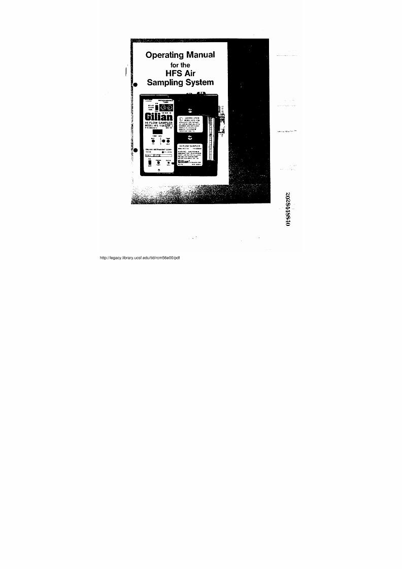
Operating Manual For
The HFS
Air Sampling System
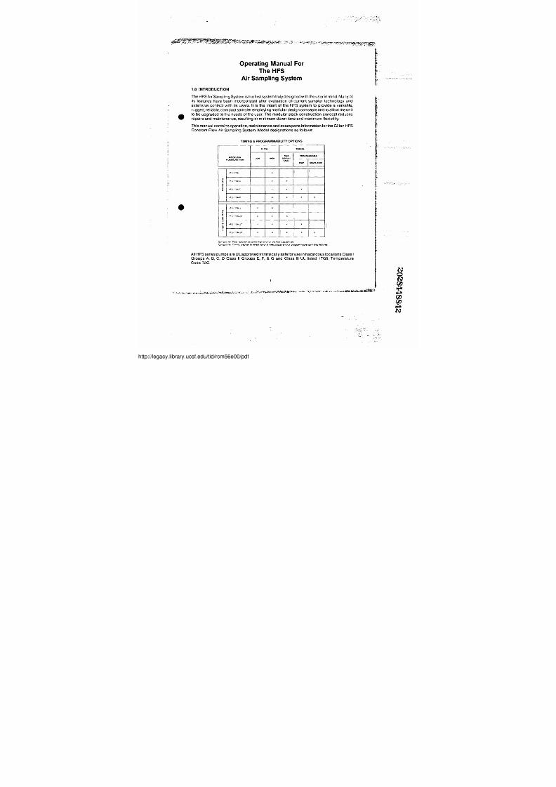
1 .0 INTRODUCTION
The HFS Air Sampling System is the first system truly designed with the user in mind . M a n y o f ' f
its features have been incorporated after evaluation of current s ampler technolbgy and
extens ive c ontact with it s us ers. It is the intent of the HFS system to provide a versatile,
rugged, reliable, compact sampler employing modular design concepts and to allow the unitt
r to be upgraded to the needs of the user . T h e m o d u l a r s t a c k c o n s t r u c t i o n c o n c e p t r e d u c e s
' repairs and maintenance, resulting in minimum down time and maximum flexibility .
This manual contains operation, maintenance and s pare parts information for the Gilian HFS'
Constant Fl ow Ai r Sampling Sys tem . Model!designations as follows :
TIMING & PROGRAMMABILITY OPTIONS
FLOW TIMXNG
TIME PlIOGRAMYAME&ODELS LOw GN OISPLAY•OES/GNATION FAWITi STOP START/STOP
ncS .,•3A A
3O -FS-•'3AC x x
IO_ -c5 "]A r x x x
..c5.~•7AP~
x' x x . x
. . f S . - , J A : J x x
~O
ncS-'•lA JC x . x
a .PS . .y p.J • x x x x
V
L.+FS."qAUP x x ∎ x It
C o r s i u a [Ne 'F t o w - 5 e ct i O n t o s e l e c t I l , g h a n t l A O r IU w f l O w C a p a b f l h21e5
Corsult. t h e . T :munq SKhpn t0 SMECt OpLOn311irn@tl,splay 0ndi Or prpyr2mmablestart/ StOp features
All HFS series pumps are UL approved intrinsically safe for use in hazardous locations Class I
Groups A , B, C, D Class II Groups E, F, & G and Class III UL listed 17G9, Tempera tureCode T3C
Yic, +c•~.,~r .w-sr ; y~ . 3 ' ~ ' ' ' .. ' , .
~ , .
//legacy.library.ucsf.edu/tid/rcm56e00/pdf
7/27/2019 Gilian Operating Manual
http://slidepdf.com/reader/full/gilian-operating-manual 5/37
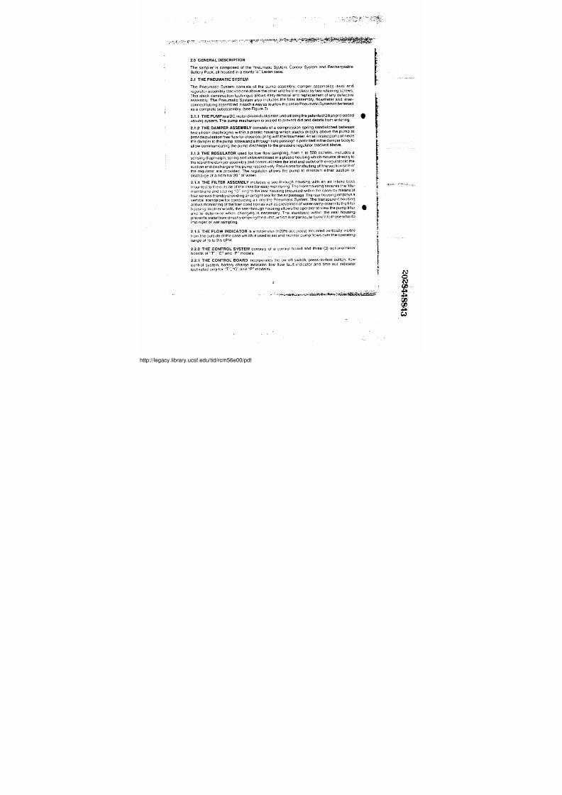
2 .0 GENERAL DESCRIPTION
The sampler is composed of the Pneumatic System, Control System and Rechargeable
Battery Pack, all housed in a sturdy'/a" Lexan case .
2.1 THE PNEUMATIC SYSTEM
The Pneumatic System consists of the pump assembly ; damper assemblies (two) and
regulator assembly stacked one above the other and held in place by two retaining screws .
This stack construction technique allows easy removal and replacement of any defective
assembly. The Pneumatic System also includes the filter assembly ; flowmeter and inter-
connect tubing assembled in such a way as to allow the entire Pneumatic System to be tested
as a complete subassembly . ( s e e F i g u r e 3 )
2. 1 .1 THE PUMP is a DC motor driven dual piston unit utilizing the patented Gilian preloaded
valving system . The pump mechanism is sealed to prevent dirt and debris from entering.
2. 1 .2 THE DAMPER ASSEMBLY consists of a compression spring sandwiched between
two silicon diaphragms within a plastic housing which stacks directfy above the pump to
provide pulsation free flow for close coupling,with the flowmeter. A n a i r i i n t a k e p o r t c o n n e c t s
the damper to the pump intake and a through hole passage is provided in the damper body to
allow communicating the pump discharge to the pressure regulator stacked abov e .
2. 1 .3 THE REGULATOR used for low flow sa mpling, fr om 1 to 500 cc/min . , i n c l u d e s a
sensing diaphragm, spring and valve enclosed in a plastic housing whichimounts directly to
the top of the damper assembly and communicates the inletiand outlet of the regulatortolthe
suction,and discharge of the pump respectively : P r o v i s i o n s f o r i s h u t t i n g o f f t h e s u c t i o n s i d ' e o f
the regulator are provided . The regulator allows the pump to maintain either suction or
discharge at a nominal 20" of water .
2 . 1 .4 THE FiLTER ASSEMBLY includes a see-through housing, with an air intak e boss
mounted to the outside of the case for easy monitoring . T h e f r o n t h o u s i n g s e c u r e s t h e f i l t e r
membrane and sealing "O" ring to the rear housing (mounted within the case) by means of
f o u r s c r e w s t h e r e b y p r o v i d i n g a n a i r t i g h t s e a l f o r t h e a i r p a s s a g e. The rear housing employs a
vertical standpipe for conducting air into the Pneumatic System . The transparent housing
a l l o w s m o n i t o r i n g o f t h e f i l t e r c o n d i t i o n a s w e l l a s p r e v e n t i o n o f w a t e r c a r r y - o v e r i n t o t h e f i l t e r
housing . In other words, the see-through housing allows the operator to view the pump filter
and to determine when changing is necessary . The standpipe within the rear housing,
prevents water from directly entering the pump, whichis of particularbenefit toShose who do
impinger or wet sampling .
2 . 1 .5 THE FLOW INDICATOR is a rotometer (±20% o accuracy) mounted v ertically vis ible
from the outside of the case which is used to set and monitor pumpiflows over the operating
r a n g e o f 1 / 2 t o , 3 1 / 2 L P M .
2 . 2 .0 THE CONTROL SYSTEM consists of a co ntrol board an 6 three (3) option al! timer
boards of "T"; "C" and "P" models :
2 . 2 .1 THE CONTROL BOARD incorporates the on-offi switch , press-to- test buttonj flow
controll system, battery, charge indicator, low flow fault' indicator and~ time out indicator
(activated only for "T", "C" and "P" models) .
2
.
•
//legacy.library.ucsf.edu/tid/rcm56e00/pdf
7/27/2019 Gilian Operating Manual
http://slidepdf.com/reader/full/gilian-operating-manual 6/37
0P1 0
. 0
i
®
P1 0 . 1
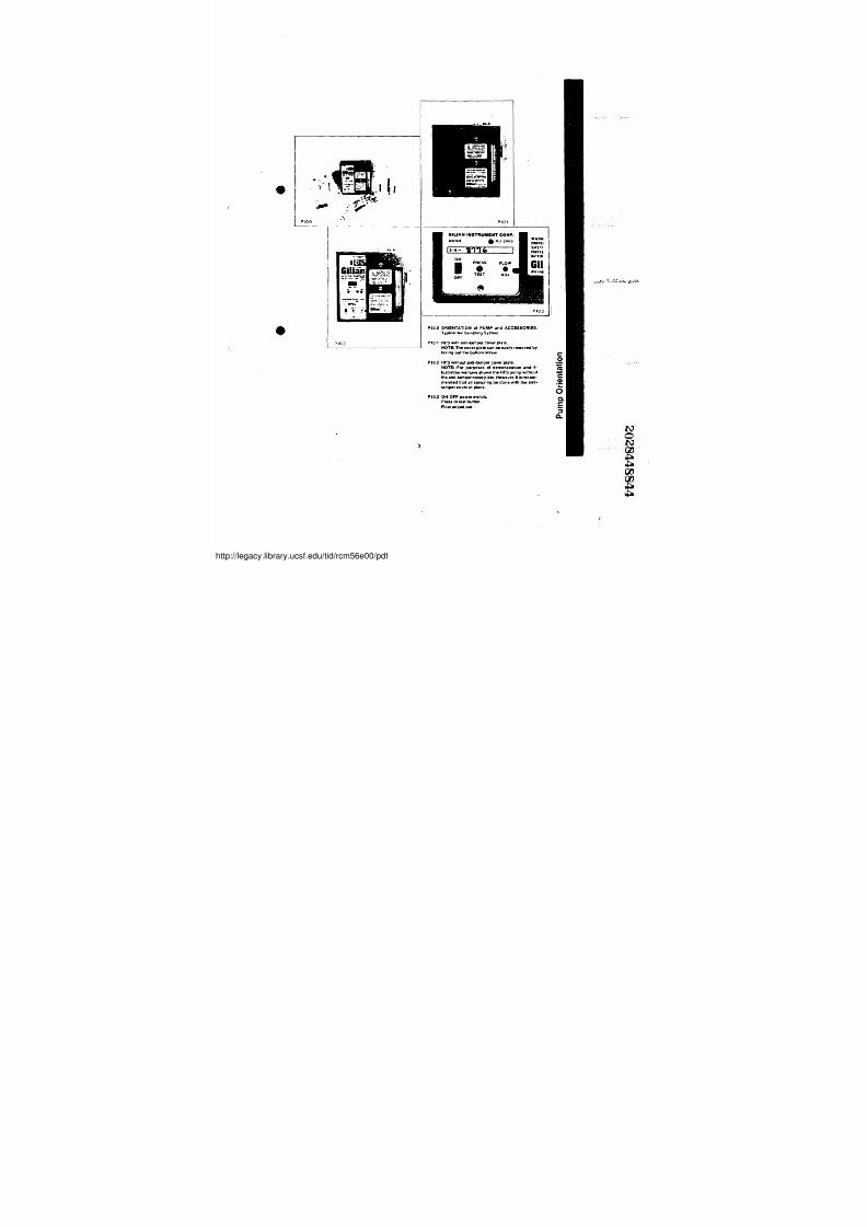
. P10.0 ORIENTATION ol PUMP and ACCESSORIES .
Typical Air Sampling System .
P1 0 . 2 P70A HFS with anti-tamper cover plate .NOTE : T h e c o v e r p l a t e c a n b e e a s i l y .removed byy
taking out the bottom screw . ~0P1 0.2 HFS without anti-tamper cover plate .NOTE: Fon purposes of demonstration and il- ~ustration we have shown the HFS pump without
t h e a n t i - t a m p e r c o v e r p l a t e . H o w e v e r , i t i s re c o m - ~mended that all sampling be d one with the anti-
tamper cover in place .
P1 0.3 ON-OFF power,swilch .
Press to test button .
Flowadjust po1 :
.i
cC
3
//legacy.library.ucsf.edu/tid/rcm56e00/pdf
7/27/2019 Gilian Operating Manual
http://slidepdf.com/reader/full/gilian-operating-manual 7/37
I
Pt 0 . 4
P'05
Ht FLOW SAMPLERMQOEL HFS 113A®P.N 0800070 REV. 8-
IME MfN .BAT F TIMECK L, OUT
GIl1AN INSTRUMENT CORP.
~U s . . L ..L1111OGRAMMMLETIMERONDELAY ,START 1 c6 ' 8 L ° ' 6 8 l ° jTIME OFF,G
l i l t a N i 1
10
Ht FLOW SAMPLER
®IIANNING iNV '•'0- :1tsw . c n S .. r . . L . . , .
SYi7r u S a: • +'• . -PMLML tM. S[MU.G l IN
yrrts[ P.c . .Nn .rS'1 .
rl
P10 7
Pt06
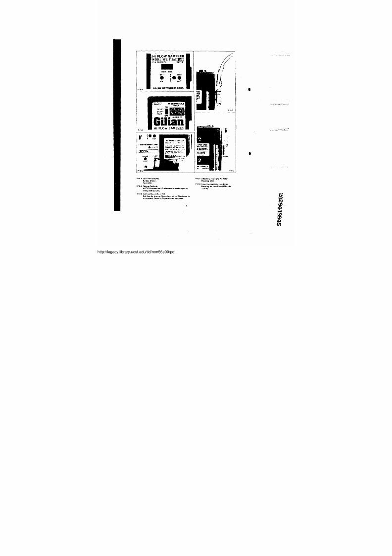
P1 0.4 LED T[me Display. P107 A t t a c h i n g t u b i n g t o A i r F i l t e r
Battery Check. Housing Inlet.
Fault LED: Pt0!6 InseAing restrictor intoF i l l e rP10.5 TLmi ng .Conlrols .. HousingforLowFlow(500cctoNOTE: See section 3 . 3 .0 in manual text tor specific 1LPM) :
t i m i n g i n s t r u c t i o n s .
P1D.6 Setting Flow Adj ust Pot.
Sel 0'ow by turning floww adj uslscrew . Clockwise to
increase or Counter Clockwise.to decrease .
4
~
'
'
//legacy.library.ucsf.edu/tid/rcm56e00/pdf
7/27/2019 Gilian Operating Manual
http://slidepdf.com/reader/full/gilian-operating-manual 8/37
0
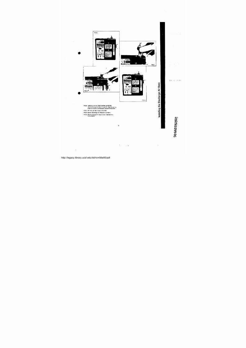
P20. o . INSTALLING the DISCHARGE AIR BOSS .
The Discharge Air. Boss is used :tor Bag Sampling
media orr where a discharge sample is required .
P20 . 1 . Remove air di scharge cover (y2) .
P20 .2 Screw Discharge Air Boss into sampler .
P20 . 3 . The Discharge Air,Boss is now insertedinto
the sampler .
5
//legacy.library.ucsf.edu/tid/rcm56e00/pdf
7/27/2019 Gilian Operating Manual
http://slidepdf.com/reader/full/gilian-operating-manual 9/37
p301
- ~ hiC3
G i l i a nr
.0~,
0.n •
~ . . , ~ ~ . , .sP 3 0 2
Lr aurINSTRUMENT CORP .
. N Ji-0
s ;
HI FLOW SAMPL€R .
Y O O E i ..rS ••ir • .
PRESS FLOw-TESTP3013
®P 30 .4
P3 0 : 5
~
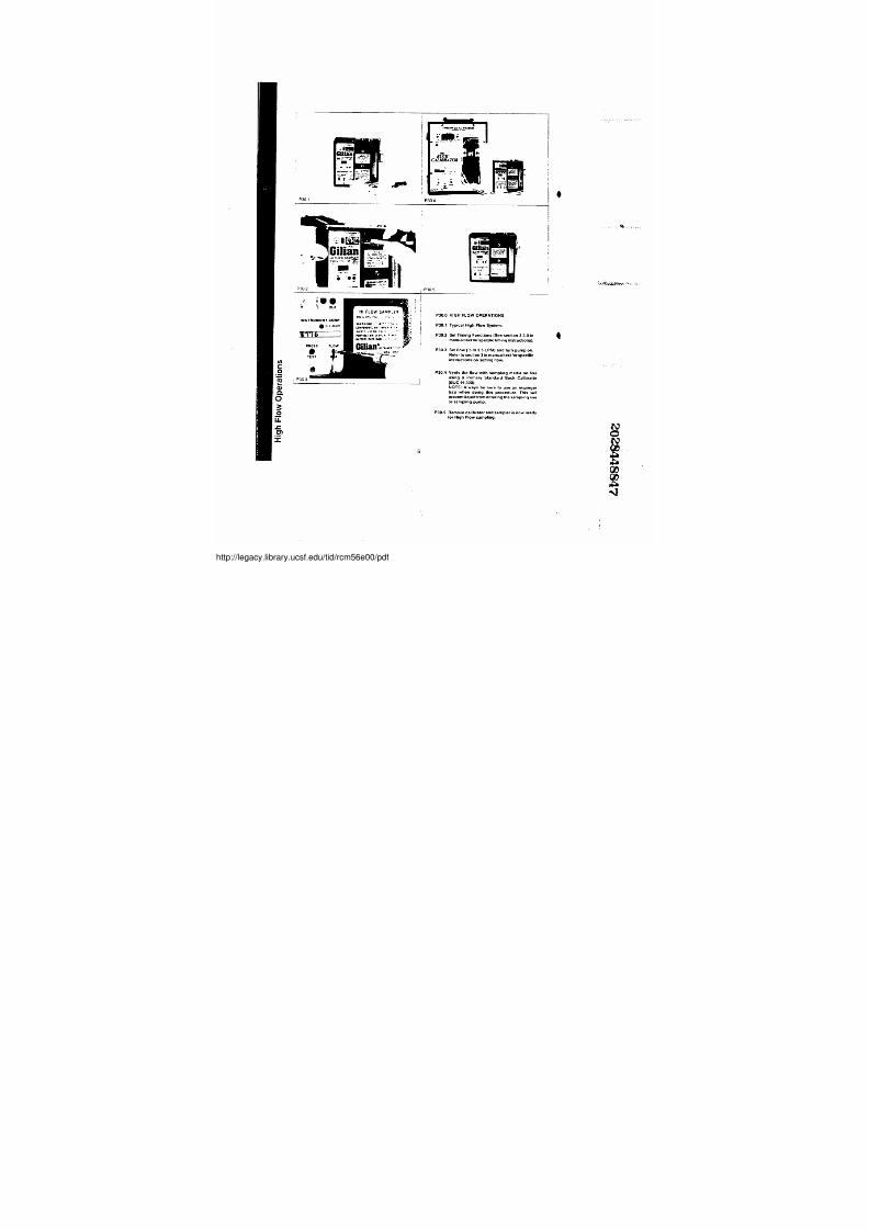
P3 0 :0 HIGH .FLOW OPERATIONSP3 0.1 Typical High Fbw.Syst em.!
P30.2 Set Timing Funclions(See section 3 . 3 . 0 i n
m a n u a l t e x t f o r s p e c i f i c t i m i n g i n s t r u c t i o n s ) .
P30.3 Set llow (.5 to 3 .5 L PM) and turn pump on .
Refer to sec tion 3 in manual text f or specific
instructionson setting ~tlow
P30.4 Verily the flow w ith sampling media on lineusing a Primary Standard'' Buck Calibrator
(BUC-H-300) .NOTE: Always be sure .to us e an impinger
trap when ~ doingg this procedure . This will
prevent liquid from entering the sampling line'
onsampliingg pump .
P30 .5 R emove cal ibrator andsampl!er is now readyfor High Flow sampiing .
s
,
N0N~XC D
PA~
//legacy.library.ucsf.edu/tid/rcm56e00/pdf
7/27/2019 Gilian Operating Manual
http://slidepdf.com/reader/full/gilian-operating-manual 10/37
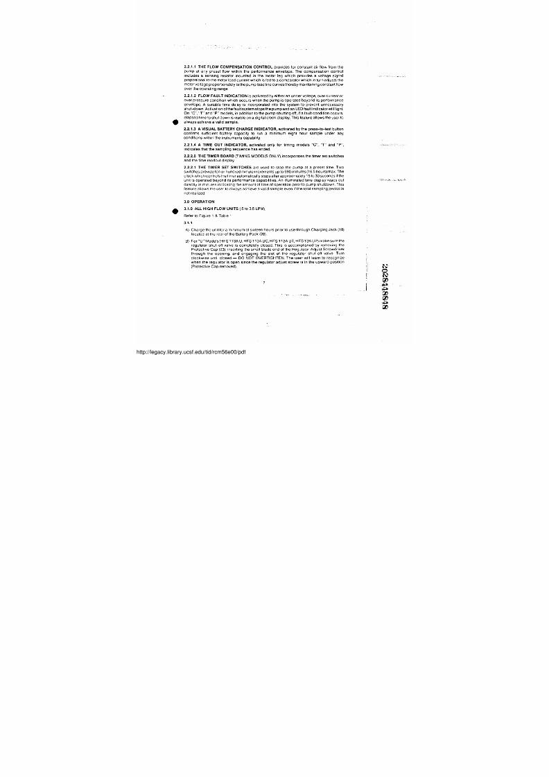
2 . 2 . 1 .1 THE FLOW COMPENSATION CONTROL provides for constant~air flow from the
pump at any preset flow within the performance envelope . The compensation control
includes a sensing resistor mounted in, the motor leg which provides a voltage signal
proportional to themotor load currentwhich isfied to a comparator which in turniadjusts the
motorvoltage proportionately to the pump load line curves thereby maintaining constant flow
over the operating range .
2 . 2 . 1 .2 FLOW FAULT INDICATION is activated by either an under voltage, over current or
over pressure condition which occurs when the pump is operated beyond'its performance
envelbpe : A suitable time delay is incorporatedi into the system to prevent unnecessary
shut-down . A c t i v a t i o n o f t h e f a u l t s y s t e m s t o p s t h e p u m p a n d a n J l E D f a u l t i n d i c a t o r w i l l l i g h t .
On "C" . " T " a n d " P " m o d e l s , i n a d d i t i o n t o t h e p u m p s h u t t i n g o f f , i f a f a u l t c o n d i t i o n ~ o c c u r s ,
elapsed time toshut down is visible on a digital clock display . T h i s f e a t u r e a l l o w s t h e u s e r t o
• always achieve a valid sample .
2 . 2 . 1 .3 A VISUAL BATTERY CHARGE INDICATOR, activated by the press-to-test button
confirms sufficient bottery capacity to run a minimum, eight hour sample under any
c o n d i t i o n s w i t h i n t h e i n s t r u m e n t s c a p a b i l i t y .
2 . 2 . 1 .4 A TIME OUT INDICATOR, activated only for timing models "C" ;, "T" and "P"; ,
indicates that the sampling sequence has ended.
2 . 2 . 2.0 THE TIMER B OARD (TIMING MODELS ONLY), incorporates the timer set switches
and the time readout display
2 . 2 . 2 .1 THE TIMER SET SWITCH'ES are used to~ stop the pump at a : p r e s e t t i m e . Two
switches provide ten or hundred minute increments up to 990 minutes (16 .5 hours) max . T h e
clbck which controls the timer automatically stops after approximately 15 to 30 seconds if the
u n i t : is operated beyond its performance capabilities. An illuminated time display reads out
directly in minutes indicating the amount of time of operation prior to pump shutdown . T h i s
feature allows the user toialways achieve a valid sample even if the total sampling period is
not~realized .
3.0 OPERATION• 31 .0 ALL HIGH FLOW UNITS ( : 5 t o 3 .5 LPM)
Refer to Figure 1 & Table 1
3 . 1 . 1
A) Chargethe unitfor a minimum of sixteen hours prior to use through Charging Jack (1i8)
located at the rear of the Battery Pack (20) .
B)! For "U"'Models (HFS 113A U, HFS 1i13A UC, HFS 113A UT, HFS 13A UP) makesure the
regulator shut-offvaive is completely closed . This is accomplished'b y removing the
Protective Cap (23) ; inserting the small blade end of the Regulator Adjust Screwdriver
through the opening, and6 engaging! the slot of the regulator shut-off valve. Turn
clockwise until closed - DO NOT OVERTIGHTEN . The user will learn.to recognize
when the regulator is open since the regulator adjust screw is in the upward position
(Protective Cap removed) .
7
//legacy.library.ucsf.edu/tid/rcm56e00/pdf
7/27/2019 Gilian Operating Manual
http://slidepdf.com/reader/full/gilian-operating-manual 11/37
M-t_~__!=~,."
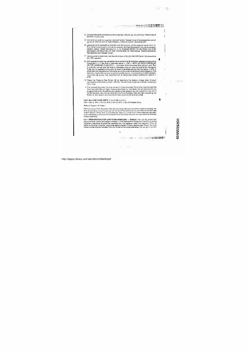
C) Connect the sampling head (cyclone, impinger, filter holder, etc . ) t o t h e a i r , i n t a k e b o s s o f
t h e f i l t e r h o u s i n g ( 1 5 ) .
D) Using thescrewd'river supplied, remove the Anti-Tamper Cover (7) to expose the control
pa ne ll (IF UNIT IS NOT A T IMER MODEL, STEP (E) IS NOT NECCESSARY .
E) Using the small screwdriver supplied with the sampler, set the programmable timer (1) .
The Left dial sets hundred minute increments, the Right diallsets ten minute increments .(WHEN USING TIMER MODELS (T, C, P), PLEASE REFER TO SECTION 3 . 3 .0 FORDETAILED INSTRUCTION INi THE OPERATION, OF INDIVIDUAL TIMER' BOARDS . )
Reinstall the Anti-Tamper Cover .
F. Using a small scre wdriver, t urn the unit on iby pushi ng the ON/OFF Switch (5) upwards t o
the "ON" positio n .
G ) W i t h i a s m a l l s c r e w d r i v e r „ a d j u s t t h e F l o w C o n t r o l P o t ( 9 ) t o t h e f l o w d e s i r e d o n t h e b u i l t - i n
Flowme ter ( 11), ,If the f low is adjust ed bel ow 1 LPM - WITH NO BACK PRESSURE(FILTER, SAMPUNG TUBE,,ETC . ) - o s c i l l a t i o n o f t h e f l o w m e t e r f l o a t w i l l b e n o t e d . T h i s
is perfectly normal and' will stop or decrease once an external load (Filter„ Sampling
Tube, etc .) is applied to the pump . I n o r d e r t o f a c i l i t a t e s e t t i n g t h e f l o w b e l o w 1 , L P M , a
small restrictor (supplie d with the sampler) will provide the necessary back pressure . T h e
restrictor may be left in place but wil l reduce the maximum back pressure of the sampler .CAUTION: BE SURE THE RESTRICTOR IS REMOVED WHEN SAMPLING ABOVE 1LPM .
H) Press the Press-to-Test Button (6) to determine the battery charge state through
illumina tion of the bat tery chec k LED (3B) : T h e L E D s h o u l d l i g h b u p o r f l i c k e r i n d i c a t i n g a
full charge .
I) The unit will stop when the time set on the Programmable Timer (1)1is reached and the
Time Out LED (3C) wil l lig ht . Pressing the Press-to-Test Button (6) will indicate the set
p r o g r a m m e d t i m e : Should the air supply to : the sampler be interrupted for a period of
15-30 seconds, the unit will stop and the Fault indicator (3A) will light': Actuating the
Press-to-Test Button will indicate the time at1which the fault occurred .
4
3 . 2 .0 ALL LOW FLOW UNITS (1 cc to 500 cc/ mi n.)~FS 113A U, HFS 113A UC, HFS 113A UT, HFS 113A UP'Models Onlij)
Refer to Figure 1 & Table 1 .
The Gilian Low Flow Regulator Models are desi gned to permit~either single or multip le low
flow sampling by using the appropr iate Variable Flow Controller found in the Universal Tube
Holder Syste m . Pump flow is controlled by means of a buil t-in constant pr essure regulator
and'is adjustedbymeansoftheVar iable Flow Controllerwhich is incorporated into the tube
h o l d e r a s s e m b l y .
3. 2 .1 PREPARATION FOR LOW FLOW SAMPLING - SINGLE . T u r n o n t h e p u m p a n d
adjust the flow control (9) to approximately 1 LPM . Remove the Protective Cap (23) using the
Regulator Adjusting Screwdriver, supplied with the sampler . Open the regulator Shut-off
Valve by turning it counter-cloc kwise approximate ly 5 turns, replace cap : Attach the tube
holder containing the Variable Flbw Controller to the pump inlet boss (15) ; u s i n g t h e s p e c i a l
8
//legacy.library.ucsf.edu/tid/rcm56e00/pdf
7/27/2019 Gilian Operating Manual
http://slidepdf.com/reader/full/gilian-operating-manual 12/37
e
~ -= 3!s_}_-~tY 1l
P4 0.0
~S
3~40 1
_.~-., ,.
P402~b ' ~ !
Ida40 . 3
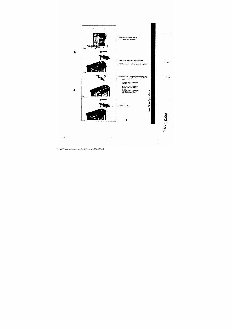
P4 0 .0 LOW FLOW OPERATIONSTypical Low Flow system .
CONVERTING PUMPS TO LOW FLOW MODEP4 0.1 To convert to law F!ow, remove the regulator
P40 j2 P l a c e e nd o l re gul a t o r s c re wd ri ve r i nt o t he
recess and engage the slot ot regulator shut-ol/
va l ve
To open valve,, turn shut+oM
v a l v e 4 o r 5 t u r n s
counterclockwise .NOTE: DO NOT OVERTURN'VALVE, IT WILL HAVE NOEFFECT.
To close valve, turn shut-oMvalveA or 5 turns cloclcwise .DO NOT .OVERTIGHTEN!
P40_3 Rep/ace Cap .
9
//legacy.library.ucsf.edu/tid/rcm56e00/pdf
7/27/2019 Gilian Operating Manual
http://slidepdf.com/reader/full/gilian-operating-manual 13/37
Mli iLOw SAYhEN•'Jrll ~MIS' ~n/ ~
fWP4 0 . 1 . 2 '
i : a: * 1 1 1 1 k : : :
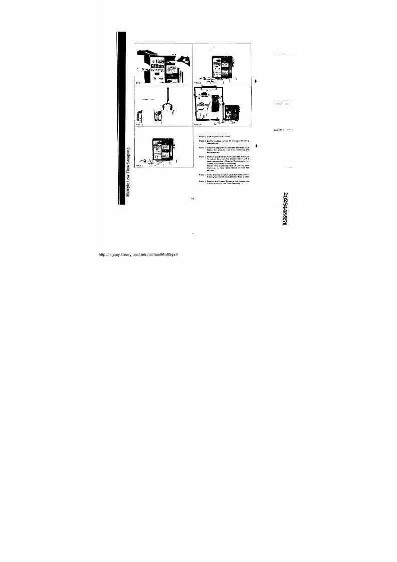
P40.1i0LOW'FLOW FUNCTIONSP40. 1 :1SetTiming (See section 3 . 3 . 0 f o r s p e c i f i c t i m i n g
i n s t r u c t i on s ) .
P40. 1 .2' Attach MultipleFlowControltenManitold Tube
Nblder for replicate Low Flow sampling and
turn pump'on .
P40 . 1 .3 Remove Cap Ends .on F Iow .Controller ,Manitold .
T o a d j u s t flo w t u rn t h e Ne e d le Va lve w i t h
( C o u nle r-C lo ckw rs e fo r ; i n -
c r e a s e . C l o c k w i s e : for'decrease) .NOTE : The combined Oow of all the Flow
Controllerr air Noww ratess cannot exceed 5000
c c /fnln
P40 . 1 . 4 . Verity the4low of each tube floww rate using a
Primary Standard Buck Calibrat or (BUC-L-300) .
P40 . 1 .5 Remove the Primary . St a nd a rd a nd t h e s a m p le risnow .ready for.Low Flow Sampling .
10
//legacy.library.ucsf.edu/tid/rcm56e00/pdf
7/27/2019 Gilian Operating Manual
http://slidepdf.com/reader/full/gilian-operating-manual 14/37
adaptor tubing provided (TUB-TH- 212) ; Using a calibrated rotometers bubble tube or Buck
Calibrator (BUC-L-300 or BUC-S-300), adjust the Variable Flow Controller to the desired
f l o w r a t e . The fl ow controller adjustment screw is located under the knurled knob protective
cover at the end of the unit.
3. 2 .2 MULTIPLE LOW FLOW SAMPLING . Proceed as in 3 .2 . 1 , e x c e p t i n p l a c e o f t h e s i n g l e
Variable Flow Controller, connec t the sampling manifold to the adaptor tubing . C o n t i n u e a s i n ,
3.2 : 7 . u n t i l a l l s t a t i o n s o f t h e m a n i f o l d a r e s e t t o t h e f l o w r a t e t h a t y o u r e q u i r e . NOTE: TOTALCOMBINED FLOW THROUGH A FLOW CONTROLLER MANIFOLD MAY NOT EXCEED 500CCCMIN .
TIMING+ 3 3 .0 GENERAL DESCRIPTION
T h e t i m e r b o a r d s d e s c r i b e d ' i n t h i s s e c t i o n p r o v i d e t h e f o l l o w i n g a d d i t i o n a l f e a t u r e s n o t
a v a i l a b l e i n t h e H F S 1 1 3 A T s e r i e s b o a r d s .
1 . P r o g r a m m a b l e s t a r t u p t o 9 9 0 m i n u t e s p r i o r t o d e s i r e d s a m p l i n g t i m e .
2 . O p t i o n t o r u n p u m p f o r u n l i m i t e d ' t i m e i n c r e m e n t s .
3 . D i s p l a y c l o c k r e a d - o u U o f u p t o 9 9 99 m i n u t e s .
4 . O p t i o n a l r e m o t e s t a r t / ' s t o p w i t h c u m u l a t i v e t i m e a v a i l a b l e o n s p e c i a l o r d e r .
3 . 3 .1 OPERATION OF C B OARD
1 . T h i s i s t h e b o a r d p r o v i d e d w i t h t h e H F S 1 1 3 A C a n d t h e H F S 1 1 3 A U C .
2. This board is a continuous running board only and has no programmable options .
Should'pump faultunder load ordue todow batteries, the timer will latch and maintain the
time up to 12 hours or until the pump is reset!
3 . 3 .2 OPERATION OF P BOARD
1 . This is the board provided with.the HFS 113A,P and HFS 1i13A UP .
2 . The programmable run features of this board are functionally identical to the HFS 113AT
• series board with the foll owing exceptions :
a . W h e n s e t t o 0 j 0 , t h e p u m p w i l l r u n f o r a n i n d e f i n i t e p e r i o d o f t i m e ( i ' e . , u n t i l t h e b a t t e r i e s
run out) .
b . T h e t i m e r d i s p l a y w i l l ! r e a d u p t o 9 9 9 9 m i n u t e s .
3 .4 .0 US E OF PROGRAMMABLE START TIME Refer to F igure 1 .
1 . Switch the delay start time switch (1a) to the "ON" position .
2 . C a l c u l a t e s t a r t t i m e d e l a y i n m i n u t e s a n d e n t e r o n s w i t c h e s ( 1 ) ( i .e :, 2 hours(120 minutes),
4 hours' (240 minutes) .
3. Turn pump on (5) .
4 . Confirm delay time by pressing test button (6) : Time remaining to start will be displayed
on LED(2), Flashing decimal point in Jower right hand c orner indicates operational timer
5. Proceed to set run time in normal manner (i .e ., 2 hours (120 minutes)~ 4 hours (240
minutes) . If run time is uncertain, itis recommended that you set timer to 9 90 minutes .
11
//legacy.library.ucsf.edu/tid/rcm56e00/pdf
7/27/2019 Gilian Operating Manual
http://slidepdf.com/reader/full/gilian-operating-manual 15/37
3 . 4 . 1 . USE OF PROGRAMMABLE RUN TIME (Refer to Figure 1)
WARNING: IF YOU DO NOT WISH TO USE PUMP IN PRESET START MODE, MAKE SURETHAT THE DELAY START TIME SWITCH IS IN THE "OFF" POSITION .
1 . S w i t c h t h e D e l a y S t a r t T i m e S w i t c h ( 1 a ) t o t h e " O F F " p o s i t i o n .
2. Calculate the run time delay in m inutes and enter on switches (1) .
3. Turn pump on .
4 . T o r e a d a c c u m u l a t e d t i m e , p r e s s t e s t b u t t o n ( 6 ) , a n d t h e a c t i v i t y i n d i c a t o r , w i l l b e a t t h e
l o w e r r i g h t h a n d s i d e o f t h e L E D d i s p l a y :
5 : P l e a s e n o t e p r o g r a m m a b l e t i m e r w i l l n o t o p e r a t e f o r l o n g e r t h a n 9 9 0 m i n u t e s ( 1 6 ' L s h r s ) ;
S h o u l d i t b e n e c e s s a r y t o o p e r a t e p u m p f o r l o n g e r t h a n 9 9 0 m i n u t e s , t i m e s w i t c h s h o u l d
b e s e t a t 0 / 0 .NOTE.THESE CONTROLS DO NOT AFFECT THE STANDARD HIGH AND/OR LOWFLOW' SETTING PROCEDURES. IF REVIEW OF THE FLOW SETTING PRO-
CEDURES ARE NECESSARY, PLEASE SEE SECTION 3 .
4.0 MAINTENANCE
4.1 BATTERY PACK REPLACEMENT (Refer to Figure 1)
REMOVAL : Remove the two screws (19) wh ich secure the Battery Pack (20) to the c ase front . .
C a r e f u l l y s l i d e t h e b a t t e r y p a c k t o t h e r i g h t o u t f r o m u n d e r t h e b e l t c l i p ( 1 7 ) b e i n g c a r e f u l n o t t o
c o c k i t a t a n a n g l e . R a i l s o n t h e b a t t e r y p a c k a n d t h e t o p o f i t h e b e l t c l i p g u i d e t h e b a t t e r y p a c k
o u t o f t h e u n i t .
4 . 1 .2 BATTERY CHARGINGA proper battery maintenance program is essential to insure maximum battery life and
pe r fo r m a n c e . Specific charging and d ischargin g procedures will va ry with the users needs
and /or applica tions . The following is a list of general recommendations which should help to
p r o v i d e e f f i c i e n t b a t t e r y l i f e a n d s e r v i c e a b i l i t y .
1 . Do not short the battery connec tors . T h i s w i l l r e s u l t l i n i r r e v e r s i b l e d a m a g e t o t h e b a t t e r y
pa c k .
2 . Donotoverchargebatteries:Youshoul dnotcha rgebatterypacksa tthehigh(stand ard)
rate for more tha n 24hours . Repeated overcharging will eventually Iead ; t o a d e t e r i o r a t i o n
in the performance level of the battery pack. I f y o u m u s t h a v e t h e b a t t e r i e s o n c h a r g e f o r
more than 24 hours, we recommend tha t you switch the charger to the Iow (trickle) rate :
3 . The long,term storage of pumps will require some special handl ing . If pumps are not :
scheduled to be used for long periods of time (more than 2 months ), it is recommended
that the following procedure be followed on a periodic basis .
a. Run pumps until shut down on low battery .
b . Recharge batteries overnight (16 hours) and returnipumps to storage .
REPLACEMENT: Place the pump on a soft level surface . S l i p t h e f r o n t e d g e o f t h e b a t t e r y
p a c k ( 2 0 ) u n d e r t h e b e l t c l i p ( 1 7 ) ~ a n d r o c k t h e b a t t e r y p a c k s o t h e r a i l s e n g a g e w i t h t h e s l o t s
o n t h e c a s e f r o n t ! P u s h t h e b a t t e r y p a c k t o t h e l e f t u n t i l i t i s p r o p e r l y l o c a t e d a n d r e i n s t a l l
screws (79) ;
1 2
~'1.4'...
1 1
:: ] ., ' ; , ' y :,
//legacy.library.ucsf.edu/tid/rcm56e00/pdf
7/27/2019 Gilian Operating Manual
http://slidepdf.com/reader/full/gilian-operating-manual 16/37
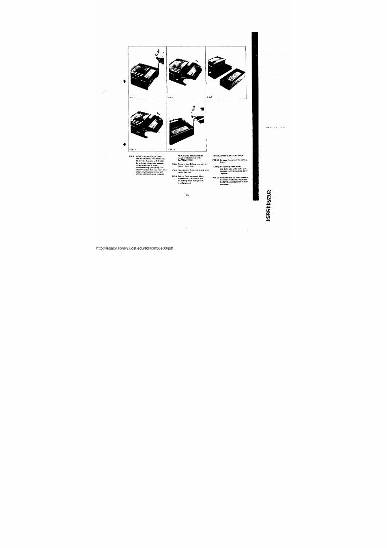
P50.0 REMOVAL/INSTALLATION7MAINTENANCE. This section is
to provide the user with aa basic
k n o w l e d § e o f s a m p l e r u p k e e p a n d ' m a i n t e n a n c e
. VVhenn
disassemtiti ng: your pump, . i t i s
recommended that you work on aclean, level surface with a soft
cloth underneath your sampler .
REPLACING THE BATTERYPACK /'REMOVING THEBATTERY PACKP50 .1, Remove the (2) Iong screwshom
B a t t e r y . P a c k r e a r ,
P50.2 Slide Battery Pack .out slowly fromunder beltc6p . ,
P50.3 Battery Pack removed. (Referto section 4 .0 of manual te)l'
on Battery Pack storage andmaintenance.)
13
INSTALLING the BATTERY PACK
P50 . 1 .1 Engage . t h e r a i l s o f t h e B a t t e r y .
Pack .
Genty,slide Battery Pack under
t h e b e l t . c t i p u n u l ~ b o t h ja c k s
e n g a g e a n d t h e p a c k s f t s f i n n t y
i n p l a c e .
P50 1 . 2 R e i n s t a l l I t h e ( Z ) l o n g s c r e w s
b a c k k i n t o t h e B a t t e r y P a c k r e a r
complete.
//legacy.library.ucsf.edu/tid/rcm56e00/pdf
7/27/2019 Gilian Operating Manual
http://slidepdf.com/reader/full/gilian-operating-manual 17/37
r
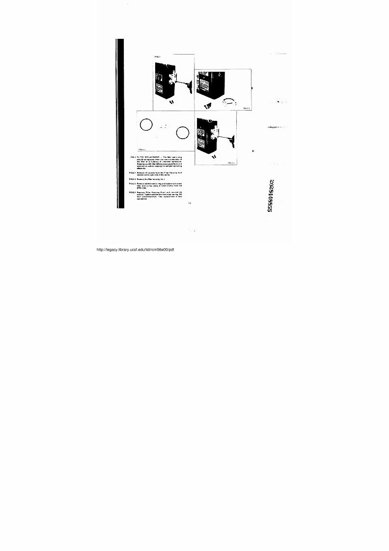
P50.2 FILTER REPLACEMENT - The filter and o-nngshould be replaced
: w h e n y o u s e e d i s c o l o r a t i o n o l t h e f i l t e r o r a b u i l d - u p o f ~ u n k n o w n p a r t i c u l a t e .
Keeping up with this will insure accurate flows and
samples as welll as keeping the sampler operating
efficiently .
P5 0 . 2 . 1 R e m o v e ( 4 ) s c r e w s f r o m t h e F i l t e r H o u s i n g f r o n l l o c a t e d a t t h e r i g h t s i d e o f t h e p u m p
P50 . 2 :2RemoveYhe filter housing fr ont .
P50 . 2 :3~ RemoveoFd.filterando-ringandreplacewithanewl i l t e r a n d o - r i n g , u s i n g a G i l i a n P u m p , F i l t e r K i l ( P F K ~ - 1 0 0 )
: .
P50 . 2 : 4. Replace Filter Housing, . Front and reinstall : ( 4 )
screws. Tighten screws unfil they stop turning . :D ONOT OVERTIGHTEN: Filter replaceme nt
14
4 1
r29'1~C;t I. ~ •
//legacy.library.ucsf.edu/tid/rcm56e00/pdf
7/27/2019 Gilian Operating Manual
http://slidepdf.com/reader/full/gilian-operating-manual 18/37
0
0
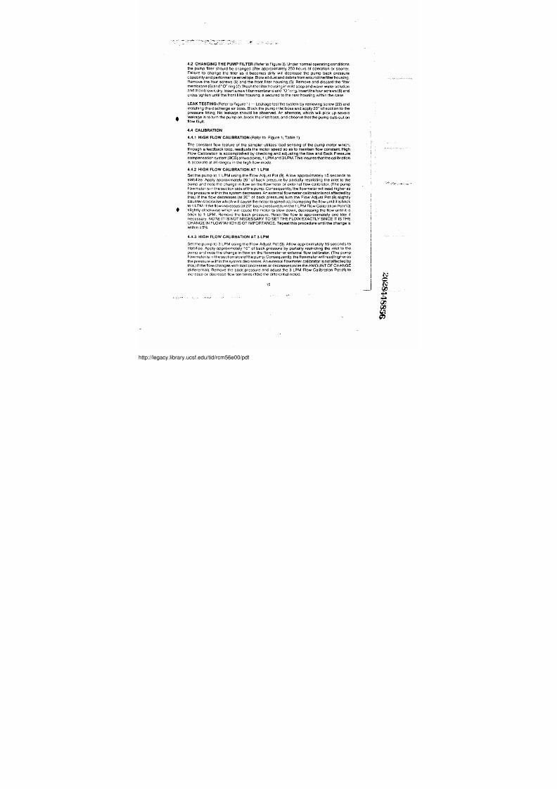
4.2 CHANGING THE PUMP FILTER (Refer to Figure 3) . Under normal'operating conditions
the pump filter should b e chan ged after approxima tely 250 hours of operation or sooner . .
Failure to change the filter as it becomes dirty, will d ecrease the pump bac k pressure
capab ility and performance envejope : B l o w a l l d u s t a n d d e b r i s f r o m a r o u n d t h e f i l t e r h o u s i n g .
Remove the four screws (8) and the front filter housing (5) . Remove and discard'the filter
membrane (6) and"O" ring (7) . Wash the filter housing in mild soap and warm water solution
and then b low itdry . Insert a new filter membrane and "0" ring . Insertthe four screws(8) ;an d
c r o s s t i g h t e n u n t i l t h e f r o n t f i l t e r h o u s i n g i s s e c u r e d t o t h e r e a r , h o u s i n g w i t h i n t h e c a s e .
LEAK TESTING (Refer to Figure 1) - Leakage test the s ystem b y removing s crew (22) and
installingithe discharge air boss. Block the pump inlet boss and apply 20"'of suction to the
p r e s s u r e f i t t i n g . No le ak age s houl d b e obs erved . An alternate, which will pick up severe
leakage is to turn the pump on, block the inlet boss, and observe thaUthe pump cuts out on
f l o w f a u l t
4.4 CALIBRATION
4 . 4 .1 HIGH FLOW CALIBRATION (Referto Figure 1i, Table 1)
The constan t flow feature of the sam pler utilizes load s ensing of the pump motor which,
through a feedbac k loop, readjusts the motor speed so as to main tain flow cons tant High
Flow Calibration is accomp lished'by ch ecking and adjusting the flow and Bac k Pressure
compens ation system (BCS) at two points, 1 LPM and 3iPM . T h i s i n s u r e s t h a t t h e c a l i b r a t i o n
is accurate at all ranges in the high flow mode .
4 . 4 .2 HIGH FLOW' CALIBRATION AT 1' LPM
Set the pump to 1 LPM using the Flow Adjust Pot (9) . Allow app roximately 15 seconds to
s t a b i l i z e . Apply approximately 20" of back pressure by partially restricting the inlet to the
pump a nd n ote the change in flow on the flowmeter or external flow calibrator . (The pump
flowmeter is in the suction side of the pump. Consequently, thefilowmeter wilCread higher as
the pressure within the s ystem decreases . A n e x t e r n a l f l o w m e t e r c a l i b r a t o r i s n o f a f f e c t e d b y
t h i s .) If the flow decreases (at 20" of back pressure) turn the Flow Adjust, Pot (9) slightly
counter clockwise which will' causethe motorto speed up ; i n c r e a s i n g t h e f l o w u n t i l ' . i t i s b a c k
to 1 LPM . If the flow increases (at 20" back pressure)turn1he 1 LPM Flow Calibration Pot (10)
slightly clockwise which will cause the motor to slow down, decreasing the flow until it, is
back to 1i LPM. Remove the back pressure . Reset the flow to approximately one liter if
necessary. NOTE. IT IS NOT NECESSARY TO SET THE FLO W EXACTLY SINCE IT IS THECHANGE IN FLOW WHICHIiS OF IMPORTANCE . Repeat this procedure until the change is
within ±5% .
4 .4 .3' HIGH' FLOW CALIB RATION AT 3 LPM
Set the pump~to 3 LPM usingithe Flow Adjust Pot~(9). Allow a pproximately 15 s econds to
s t a b i l i z e . Apply ap proximately 10" of back pressure by partially restricting!the inlet tolhe
pump and n ote the change irnflow on the flowmeter or external flow calibrator . (The pum p
flowmeter is in the,suctionside of the pump . Consequently„the ftowmeter will read'higher as
the pressure within rthe system decreases . A n e x t e r n a l f l b w m e t e r c a l i b r a t o r i s n o t a f f e c t e d b y
t h i s .) If the flow chan ges with load (inc reases or decreas es) note the AMOUNT OF CHANGE
( d i f f e r e n t i a l ) . Remove the back pressure an d ad just the 3 LPM Flow Calibration Pot~ (4) to
increase or decrease flow ten times (10x)lthe differential noted .
15
//legacy.library.ucsf.edu/tid/rcm56e00/pdf
7/27/2019 Gilian Operating Manual
http://slidepdf.com/reader/full/gilian-operating-manual 19/37
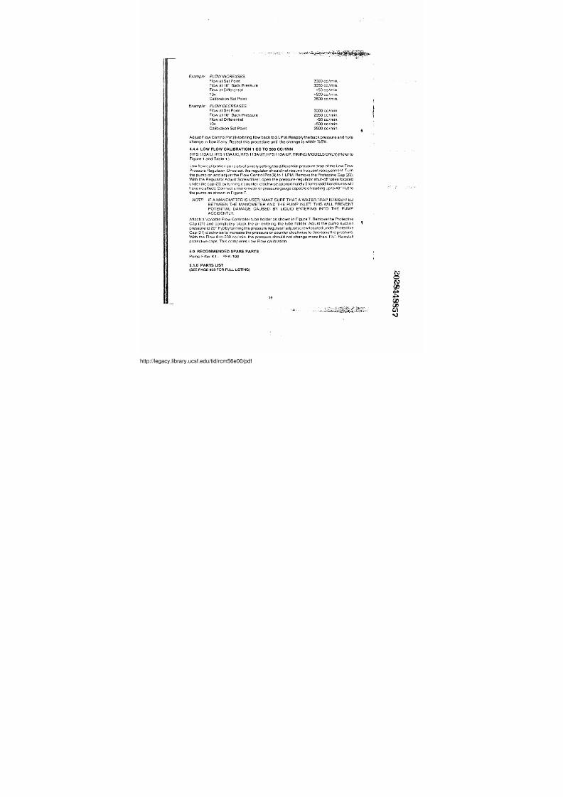
Example : FLOW INCREASESFlow at Set Point
Flow at 10" Back Pressure
F l o w a t D i f f e r e n t i a l
10 x
3000 cc/min .
3050 cc/min .
+50 cc/min .
+500 cc/min .
Example:
C a l i b r a t i o n : S e t P o i n t
FLOW DECREASES .
Fow at Set Point
Flow at~ 10" Back Pressure
F l o w a t D i f f e r e n t i a l
10 x
3500 cc/min .
3000 cc/min .
2950 cc/min .
-50 cc/min .
-500 cc/min .
Calibration Set Point 2500 cc/min .
Adjust Flow Control Pot (9) to bring flow back to 3 LPM : Reapply#he back pressure and note
change in flow it any ; Repeat this proced'ure until the change is within ~/e5% .
4 . 4.4 LOW FLOW CA LIBRATION 1 CC TO 500 CC/M IN
(HFS 11 3A U„HFS 11i3A UC, H FS 113A UT„HFS 1 13A U P, TIMING MODELS ONLY) (Refer to
Figure 1 andTable1i . ) ,
Low flow calibration consists of simply setting the dif ferential pressure drop of the Low Flow
Press ure Reg ulato r . Once set. the regulator should not require frequent readjustment . T u r n
the pump on and adjust the Flow ControllPoti(9) to 1 LPM . Remove the Protective Cap (23) :
With the Regulator Adjust S crewdriver, open the pressure regulator shut-off valve located
u n d e r t h e c a p ( 2 3 ) b y t u r n i n g i t c o u n t e r , - c l o c k w i s e a p p r o x i m a t e l y 5 t u r n s ( a d d i t i o n a l t u r n s w i l l
have no effect), Connect a manometer or pressure gauge capable of reading up to 40" H20 'to
the pump as shown in F igure 7 .
fu'OTE- IF A MANOMETER IS USED, MAKE SURE THAT A WATER TRAP IS INSERTEDBETWEEN THE MANOMETER AND THE PUMP INLET . T HI S WI L L P R EV ENTPOTENTIAL DAMAGE CAUSED BY LIQUID ENTERING INTO THE PUMP'ACCIDENTLY
Attach a Variable Flow Controller tube holder as shown in Figure 7 . Remove the Protective
Cap (21) and completely block the air entering the tube holder. Adjust the pump suction 1
pressure to20" H20 by turni ng the pressure regulator adjust screw located'under Prot ective
Cap (21) clockwise to i ncrease the pressure or counter clockwise to d ecrease the pressure :
With the Flow 0 to 2001cc/min/ the pressure should not change more than, 1'/z' ' : R e i n s t a l l l
protective caps . This completes Low Flow calibratio n .
5.0 RECOMMENDED: SPARE PARTSPump Filter Kit - PFK-100 ~5 . 1. 0 P A R T S L I S T
(SEE PAGE #28 FOR FUU- USTONG) NO~~16 1̀4--- , ~~
//legacy.library.ucsf.edu/tid/rcm56e00/pdf
7/27/2019 Gilian Operating Manual
http://slidepdf.com/reader/full/gilian-operating-manual 20/37
I
I
I
•
17
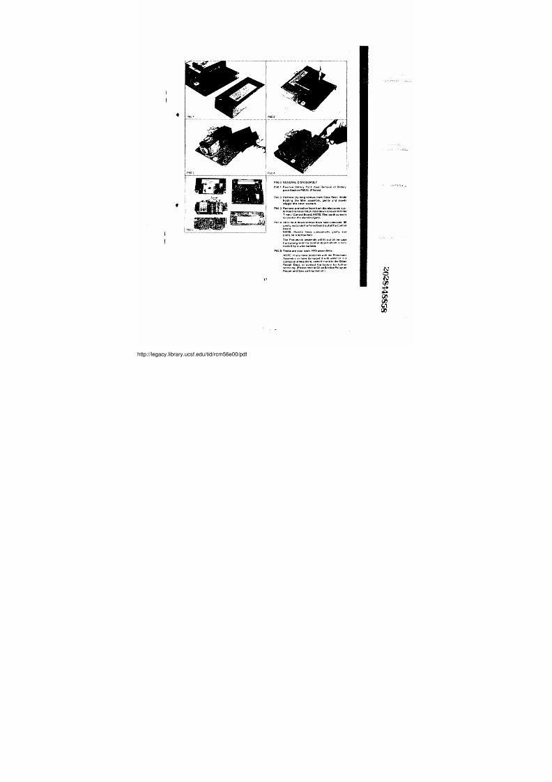
P60.0 GENERAL DISASSEMBLYP60 .1 RemoveBattery.Pack (See Removal of Batterypack .Sectlon P50 .0 ) . (Photos),
P60 .2 Remove. (4) long screwsfrom Case Rear. While
holding thefil~ter assembly, gently and slowlywigglee this cover upward .
P60 .3 Remove protective .foam from
. NOTE : The fourth screw is
located'in the electrical jack :
P6 0
. 4 A f t e r h o l d d o w n s c r e w s h a v e b e e n r e m o v e d , l i t t g e n t F y a n d s l i d e t h e T i m e r B o a r d o u t o f t h e C o n t r o l
Board .NOTE: HAndlethesecomponentse gently andplace on a soft surtace .
The Pneumatic assemoly will liWout .o/the case
front,along with the Control Board which is con-
nected by a wire harness .
P60 .5 Thesee are your basic HFS assemblies .
NOTE: II you have problems with th e Pneumatic
Assembly or have damaged'it .with water or in a
corrosive atmosphere, s end the unit to the Gilian
Repair Dept. or contact the factory lor, further
servicing . (Please refer to. Gitian Service Policy.on
Repair and Service Information . )
//legacy.library.ucsf.edu/tid/rcm56e00/pdf
7/27/2019 Gilian Operating Manual
http://slidepdf.com/reader/full/gilian-operating-manual 21/37
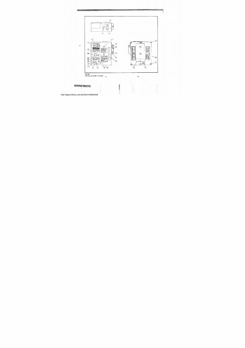
FIGURE 1
HFS 113A AIR SAMPLING PUMP +
s s s s vv 8 z o z
.:
,
legacy.library.ucsf.edu/tid/rcm56e00/pdf
7/27/2019 Gilian Operating Manual
http://slidepdf.com/reader/full/gilian-operating-manual 22/37
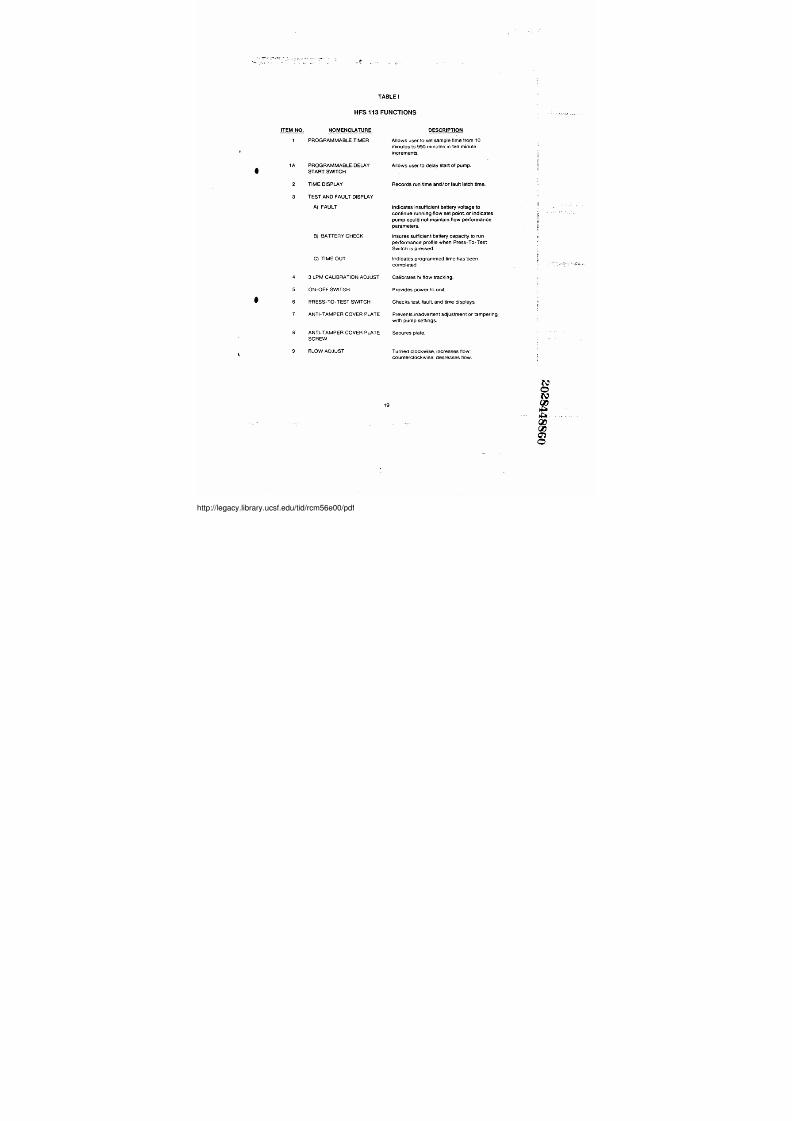
TABtEI
HFS 113 FUN'CTi IONS
ITEM NO . NOMENCLATURE DESCRIPTION
1 PROGRAMMABLE TIMER Allows user to set sample time from,10
1A PROGRAMMABLE DELAY
minutes to 990 minutes in ten minute
increments .
Allows user to delay start ofi pump .~ START SWITCH
2 TIME DISPLAY R e c o r d s r u n t i m e a n d / o r f a u l t l a t c h t i m e .
3 TEST AND FAULT DISPLAY
A) FAULTE
I n d i c a t e s i n s u f f i c i e n t b a t t e r y v o l t a g e t o
c o n t i n u e r u n n i n g f l o w s e t p o i n t , o r i n d i c a t e s :~pump could not maintain flow performance c~
4
B) BATTERY CH ECK'
C) TIME OUT
3 LPM CALIBRATION, ADJUST
parameters .
Insures sufficientibattery capacityto run
performa nce profile when Press-To-Test
Switch is pressed .
Indicates programmed!time has b een
completed .
Calibrates hi flow tracking.
5 ON-OFF SWITCH Provides powe r to unit,
, 6 PRESS-TO-TEST SWITCH Checks test, fault, and time displays .
7 ANTI-TAMPER COVER PLATE P r e v e n t s i n a d t r e r t e n t a d j u s t m e n t o r t a m p e r i n g
8 ANTI-TAMPER COVER PLATEw i t h p u m p s e t t i n g s .
S e c u r e s p l a t e .
9
SCREWFLOW'ADJUST Turned clockwise, increases flow ;
counterclockwise, decreases flow .
19
//legacy.library.ucsf.edu/tid/rcm56e00/pdf
7/27/2019 Gilian Operating Manual
http://slidepdf.com/reader/full/gilian-operating-manual 23/37
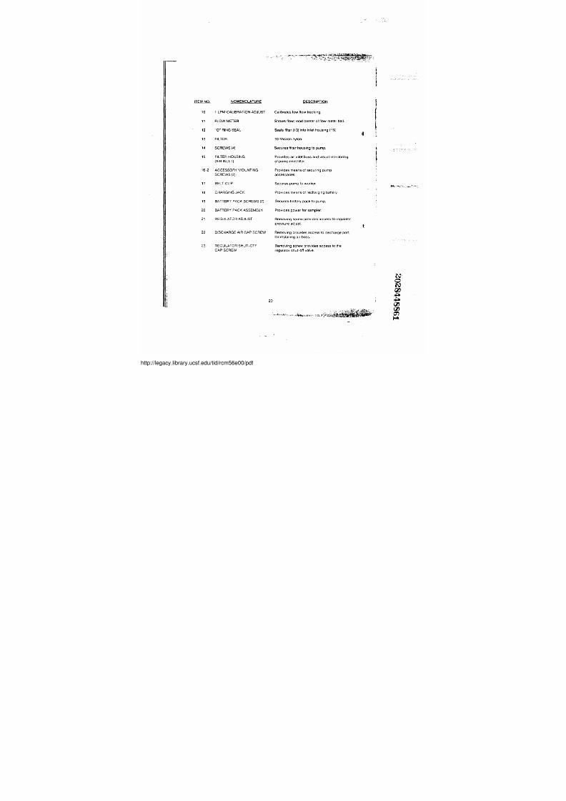
ITEM NO. NOMENCLATURE10 1 LPM CALIBRATION ADJUST11 FLOW'METiER12 "0" RING SEAL13 FILTER14 SCREWS (4)15 FILTER HOUSING
(AIR INLET)
16-2' ACCESSORY MOUNTINGSCREWS (2)1
17 BELT CLIP'18 CHARGING JACK19 BATTERY PACK SCREWS (2) .
20 BATTERY PACK,ASSEMBLY21 REGULATOR ADJUST
22 DISCHARGE AIR',CAP SCREW
23' REGULATOR SHUT-OFFCAP SCREW
20
I
~+}7er S~,xYs.pd~'iE}w1.1~f.'~etv~
DESCRIPTION
C a l i b r a t e s l o w f l o w t r a c k i n g .
Shows flow ; rea6center of flow meter ball .
S e a l s f i l t e r ( 1 3 ) i n t o i n l e t h o u s i n g ( 1 5 ) ;
10 Micron nylon .
S e c u r e s f i l t e r h o u s i n g t o p u m p .
Provides air inlet boss and'wisua l monitoring
o f ~ p u m p i n l e t f i l t e r . ,
Provides means of securing pu mp
acc essories .
Secures pump to worker
Provides means of recharging bat tery :
Secures battery pack to pum p
Provid es power for sam pler .
Removin g screw provides acc ess to regulator
pressure adj ust .
Removing provides access to discharge port,
f o r i n s t a l l i n g a i r b o s s .
Removing screw provides access to the
regulator shut-off valve
d
l ls
t
t
f
//legacy.library.ucsf.edu/tid/rcm56e00/pdf

7/27/2019 Gilian Operating Manual
http://slidepdf.com/reader/full/gilian-operating-manual 24/37
1 2
. yc
cq {
0
RNORN
WIRwG DIAGRAM
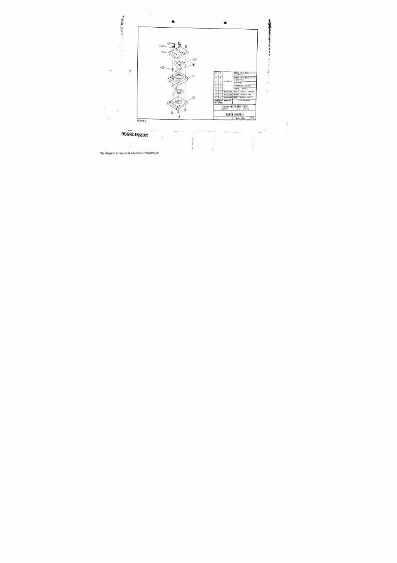
CASE ASSEMBLY (COMPLETE) P/N A-800051
CONSISTS OF ITEMS 3, 4, 5 . 7 , 8 . 1 1 , 1 2 , 1 3 , 1 4 6 1 5
~ 20T1---~-40025F,19 { 1 C-40025518
17
16
5
14
13
12
11
10
0
7
6
5
0
2
1
r-4002541
PART NO .
?IGD
MOD
C-400] 4G I CON9'H0L k0ARn
6
B - 2 0 0 0 42 F I T T I N G , O U T L E T - - S C R E W - , - - P A N H E A D ~ - ~ - ~M6-32 x 3/16"LG ',A-800052 . .O" RING
-8001091
3
C-2000501
1
1
A-200045B-200077
A-8000341 A-8000331 A-B000321 B-8000651 C-800012
F TEH TYNO. REQ
TTMIIK ; 17nAPD
fIMIN(, P.OAkDTTh1Ir1C nOAPn,
SCREW, R4-40 x 1 3/8"LGSCREW, SEALING 1/4-28SCREW, SEALING 3/8-20SCREW, M2-.56 x 3/16"LGSCREW, t2-56 x 7/16"LrINSERT, CASEBUTTON, pUSlI-TO-TESTWIRIN(1 f1ARNESSCOVER PLATE ASSEMBLYCASE ASS'Y, REARCASE ASS'Y, FRONTBATTERY PACKPNEUMATIC ASS'Y
DESCRIPTION
G I L I F I N I N S T R U M E N T C O R P .WAYNE NJ . 07470
C O N S T A N T F L O W S A M P L E R
FSKA 1139
z 9 ~ e ~ ~ s z o ~
legacy.library.ucsf.edu/tid/rcm56e00/pdf
7/27/2019 Gilian Operating Manual
http://slidepdf.com/reader/full/gilian-operating-manual 25/37
J
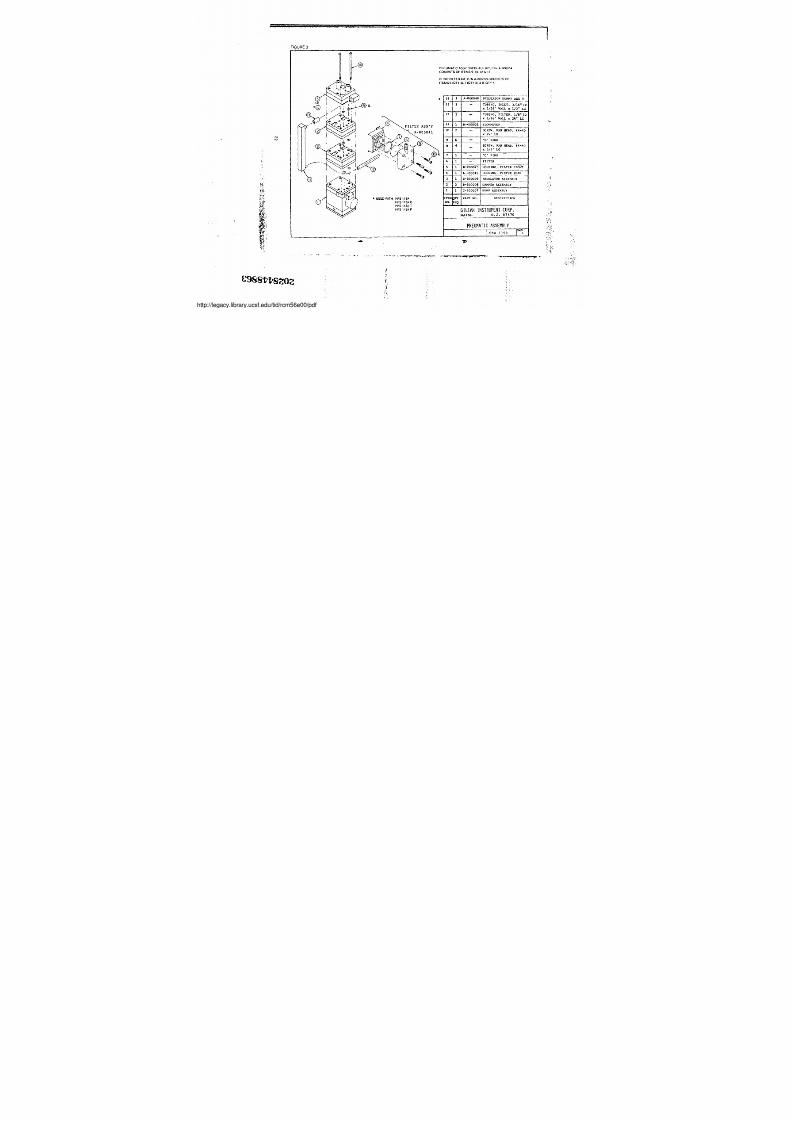
FIGURE 3
NN 19
s
I
~ USED WI TH: HFS 113AHFS113ACHFS 113A T
HFS 113A P
a
, . - . . . , ~ , - < . . . . . . , , . . . . , ~ . . . , . , , , , . , , r . ., .
E s ss vv e z o z
PNEUMA TIC ASSY OVERHAUL KIT, P/N A-800054
CONSISTS OF ITEMS 9 . 10 . 12 & 13
PUMP FILTER KIT, P/N A-800053 CONSISTS OF
ITEMS 6(OTY 3) . 7(OTY 3), & 8 (OTY 4)
• 14 1 A-800048 REGULATOR DUMMY ASS'Y17 1 - TUBING, INLET, 3/16" IDx 1/16" WALL x 1/2"LG
12 1_ TUBING, FILTER, 1/8" IDx 1/16" WALL x 25" LG
11 1 H- ---400021 I FLOWMETER -_-_-- .
10~I
2 - SGx REw, PAN HEAD, M24" LG 4-.40
9 6 "0" RING8 4 SC
x
REW, PAN ffEAD, N5/8" LG
4-40
7 1 "0 " RING6 FILTER5 1 1 I H-20002J HOUSING, FILTER FRONT'-= - t--- . ..
. - - - - . - - ~4 1 A'800045 H4USINQ, FILTER REAR1 C-800009 REGULATOR ASSEMBLY ~
B-800008 DAHPER ASSEMBLY---1 1 1 C-800007 PU MP ASSEMBLYITEM~NO. I
QTYREQ PART NO . I DESCRIPTION
G I L I A N I N S T R U M E N T C O R P ,WAYNE NJ . 07470
P N E U M A T I C A S S E M B L Y ~SKA 1159 A
: ~
legacy.library.ucsf.edu/tid/rcm56e00/pdf
7/27/2019 Gilian Operating Manual
http://slidepdf.com/reader/full/gilian-operating-manual 26/37
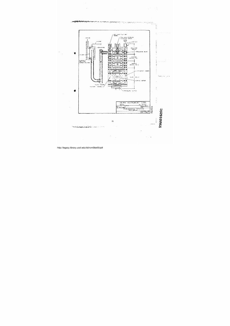
. „ _>> . . s ,n iO - lr"cwlA~ :Jw, - t~xrre
Fl:- l.~ 1~ .I .1V ~ -MC'M-CASE !r-TL-_ _ _ I I E""- /,- STAND Pi PE
~
i
/7 7 ! :V
0
0
.. 9_1i.®O
PNEUMATIC SYSTEh4PICTORVALL
R .F
S ~ t C i 1 3 8 1 . 1
23
~ _ ~
DArncERµODULE NO,2~
GILIAN INSTRUMENT CORP .WAY,N E, N1 . 074701
//legacy.library.ucsf.edu/tid/rcm56e00/pdf
7/27/2019 Gilian Operating Manual
http://slidepdf.com/reader/full/gilian-operating-manual 27/37
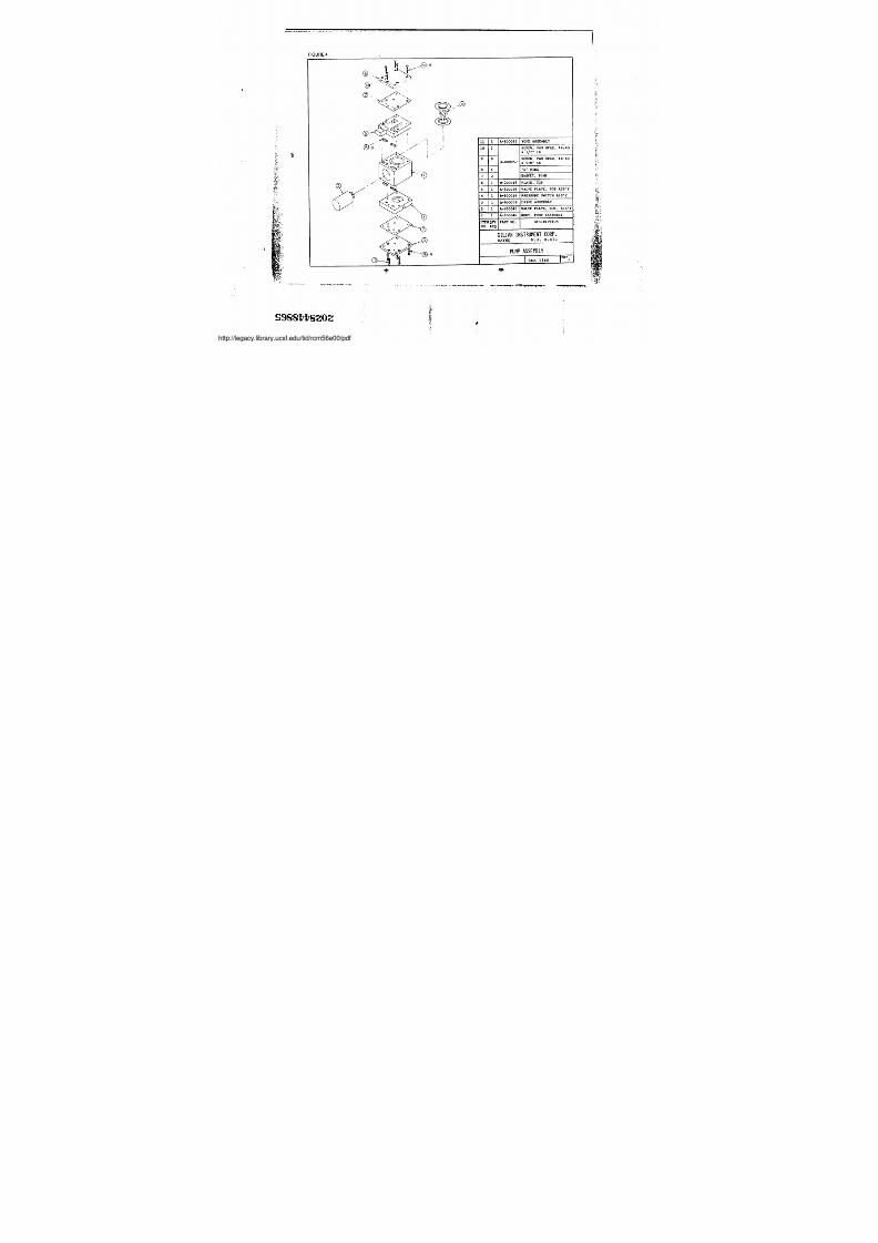
FIGURE 4
IJA11
10 ,
9
7
5
4
A-800043
0 A-H00057
1
B-200015A-800038
1
YOKE ASSEMBLYSCREW, PAN HEAD, N4-40x 1/2" LG -SCREW, PAN HEAD, M4-40x 5/8" LG"0" RINGGASKET, PUMPPLATE, TOPVALVE PLATE, TOP ASS'Y
B-800014 IPRESSURE SWITCH ASS'Y1 A-800039 IDRIVE ASSEMBLY
2 1 IA-800042 VALVE PLATE. BOT . ASS'Y1 I I IA-800046 BODY, PUMP ASSEMBLY
ITEl
NO .
QTYREQ IPART NO . DESCRIPTION
G I L I A N I N S T R U M E N T C O R P .WAYNE NJ . 07470P U M P A S S E M B L Y
1SRA 1160
k :
I
s s s s vv s z o z
legacy.library.ucsf.edu/tid/rcm56e00/pdf
7/27/2019 Gilian Operating Manual
http://slidepdf.com/reader/full/gilian-operating-manual 28/37
•
NN
,4 .
.~
0 1 SCREW, 3AN HEAD, N4-40x 1/2" Lc
1
7 SCREW, PAN HEAD, 14-40x 3/16" LGA-H0O0956 "O" RING5 2 DIAPHRAGM, DAMPER
1 SPRING, DAMPERB-200018 PFATE, DAMPER, BOTTOM8-200019 PLATE, DAMPER, TOP11-BO0047 BODY, DAMPER, ASS'Y
ITEMNO.
QTY PART NO . DESCRIPTION
G I L I A N I N S T R U M E N T C O R P .WAYNF lIJ . 07470
FIGURE 5
DAMPER ASSEM BL Y
SKA 1161 iM~inr
.7.7~8~ i/SGUC~
legacy.library.ucsf.edu/tid/rcm56e00/pdf
7/27/2019 Gilian Operating Manual
http://slidepdf.com/reader/full/gilian-operating-manual 29/37
NW
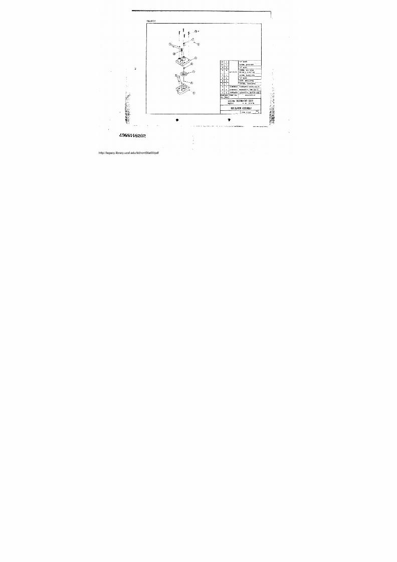
FIGURE 6
M11 1 1 "O" RING10 SCREW, SHUT-OFF9 3 "O" RING
0 4 SCREW, PAN READA-80005G 14-40 x 7/16" LG7 1 rSCREW, AD.IUSTING6 1 "O" RING
1 SEAT, REGULATOR4 1 SPRING, REGULATOR3 1 A-800040 REGULATOR VALVE ASS'Y
1 A-800049 REGULATOR, TOP ASS'Y'- -11 1 A-800050 REGULATOR, BOTTOM ASS'YJ
RTEMNO.
QTYREQ PART NO . DESCRIPTION
G I L I A N I N S T R U N E N T C O R P .WAYNE NJ. 07470R E G U L A T O R A S S E I S L Y
s1cA ils2 `~ A
I-+'+'w.-T.p;R -± . . .
6
iCl
4 s s e vv e z o z
legacy.library.ucsf.edu/tid/rcm56e00/pdf
7/27/2019 Gilian Operating Manual
http://slidepdf.com/reader/full/gilian-operating-manual 30/37
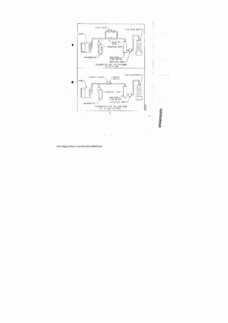
LOAD VA LVE
PUMP
0 -SHUT- OFFv A L V E
FILM FLOW M'ETER ;~n MOlSTURE TRAP
MANOMETER PRECISION-~ ~FLOW' METER
MOISTURE TRAPCALIBATION SET UP HI-FLOW'I/2 T04 LPM
( 6
ORIFICE HOLCER-\ ,-OR9FICE;~ 100 CCPUMP
M'A NOME TE R
MOISTURE TRAP'
DREClS10N, J`FLOW METERMCiiSTURE TRAP
FILM FLOW, METER7
H
CALIBRATION SET UP LOW FLOWI CC TO 400 CC/MIN27
//legacy.library.ucsf.edu/tid/rcm56e00/pdf
7/27/2019 Gilian Operating Manual
http://slidepdf.com/reader/full/gilian-operating-manual 31/37
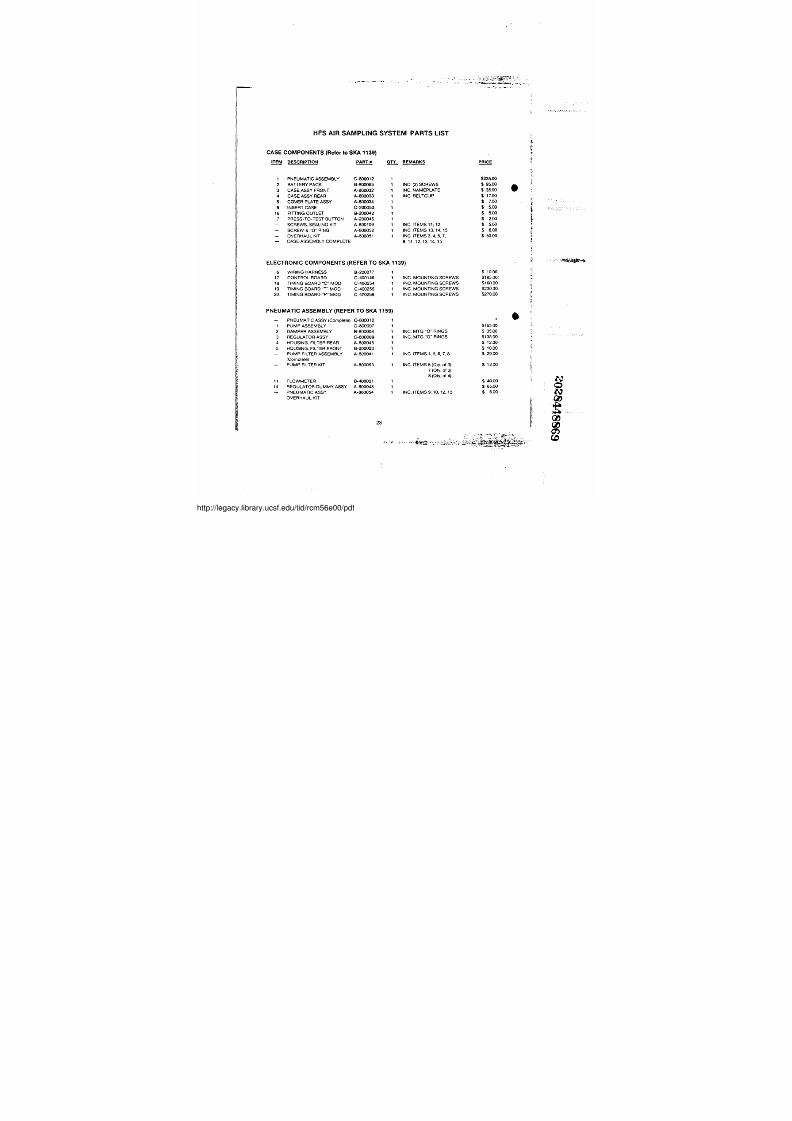
HFS AIR SAMPLING SYSTEM PARTS LISTCASE COMPONENTS (Refer to SKA 1139)
ITEM DESCRIPTION PART' # OTY . REMARKS PRICE
1 PNEUMATIC ASSEMBLY C-800012 1 $235 .0 0
2 BATTERY PACK B-800065 1 INC. (2) SCREWS $ 95.00 r3 CASE ASSY FRONT A-800032 1 INC. NAMEPLATE $ '. 3 5 . - 0 0
4 CASE ASSY REAR A-800033 1 INC: BELTCUP $ 17 .0 0
5 C OVER PLAT E A SSY A-800034 1 $ 7.0 0
8 INS ER T CA S E C-200050 t $ 5.0 0
16 FITTING OUTLET B-200042' 1 $ 5.0 0
7 PRESS-TO-TEST BUTTON A-200045 1 $ 2.0 0- SCREWS, SEALING KIT A-800109 1 INC . I T E M S 1 1 , 1 2 $ 5. 0 0- SCREW & "O" RING A-800052 1 INC . I T E M S 1 3 , 1 4 ; 1 5 $ 6.0 0- OVERHAULKIIf A-800051 1 INC. ITiEMS 3, 4 7 $ 50 .0 0- CASE ASSEMBLY COMPLETE , „
8,11i12,13.14„15
ELECT RONIC COMPONENTS (REFER TO SKA 1139 )
6 WIRING HARNESS B-200077 1 $ 10 :00
17 CONTROL BOARD C-400146 1 INC. MOUNTING SCREWS $185 . 0 0
18 TIMING BOARD "C" C-400254 1 INC. MOUNTING SCREWS $160 . 0 0
19 TIMING BOARD "T" MOD C-400255 1 INC. MOUNTING SCREWS $230 . 0 0
20 TIMING BOARD "P"'MOD C-400256 1 INC. MOUNTING SCREWS' $270. 0 0
PNEUMATIC ASSEMBLY (REFER TO SKA 115 9 )
- PNEUMATIC ASSY (Complete) C-800012 1
1 PUMP ASSEMBLY C-800007 1 $165 . 0 0
2 DAMPER ASSEMBLY B-800008 I INC. MTG "O" RINGS $ 35 .0 0
3 REGULATOR ASSY' C-800009' 1 IN i:. MTG "0" RINGS $135 : 0 0 ,
4 HOUSING. FILTER',REAR A-800045 1 $ 12 : 0 0 '
5 HOUSING . FILTER :FRONT B-200023, 1 $ 10 . 0 0- PUMP'FILTER ASSEMBLY A-800041 1 INC. ITEMS 4, 5 . 6 : 7 , 8 $ 20.00(Complete)',PUMP FILTER KIT A-800053 1 IN C . ITEMS 6(Ory : o f 3 ) ' , $ 12.00
11 FLOWMETER B-400021 1
7 ( O t y , o f 3 )
8 ( Q t y , o f 4 ) $ 40.0014 REGULATOR'DUMMY ASSY A-800048 1 $ 65 . 0 0- PNEUMATIC ASSY A-800054 1 INC: ITEMS 9 ; 1 0 ; 1 2 , 1 3 $ 6: 0 0
OVERHAUL KIT
28
r
//legacy.library.ucsf.edu/tid/rcm56e00/pdf

7/27/2019 Gilian Operating Manual
http://slidepdf.com/reader/full/gilian-operating-manual 32/37
PUMP ASSEMBLY (REFER TO SKA 1160)ITEM DESCRIPTION' PARTiB C ! T Y . REMARKS PRICE
- PUMP ASSY (Complete) C-800007 1 $165 . 0 0
1 BODY ASSY A-800046 1 $ 15 . 0 0
2 VALVE PLATE (BOTTOM) A-800042 1 PRE-ASSEMBLED/TESTED $ 12 . 0 0
5 VALVE PLATE (TOP) A-8000038 1 ' PRE-ASSEMBLED/TESTED $ 15 . 0 0
4 PRESSURE SWITCH ASSY B-800014 1 PRE-ASSEMBLED/TESTED $ 35 . 0 0
6 PLATE. TOP' B-200015 $ 5. 0 0
3 DRIVE ASSY A-800039 1 INC . MOTOR„BEARING $ 95 . 0 0
1 1 YOKE ASSY A-800043' 1
& ECCENTRIC
INC . YOKE, DIAPHRAGM, $ 17 : 0 0
- PUMP OVERHAUL KiT A-800057
& RETAINER
INC . ITEMS 7 . , 8 ; 9 : 1 0 $ 15 : 0 0
DAMPER ASSEMBLY (REFER TO SKA 1161 )
- DAMPER ASSY (Complete) B-800008 1 INC. MOUNTING "O" RINGS $ 35 . 0 0
1 BODY, DAMPER A-800047 1 $ 10 . 0 0
2 PLATE. DAMPER (TOP) B-200019 1 $ 5.003 PLATE . DAMPER (BOTTOM) B-200018 1 $ 5 . 0 0- DAMPER OVERHAUL KIT A-800055 1 INC . I T E M S 4 , 5 . 6 . 7 , 8 $ 15 . 0 0
REGULATOR ASSEMBLY (REFER TO SKA 1162 )• - REGULATOR ASSY (Com lete) C-800009 1 ASSEMBLED/TESTED S135.00p
1 REGULATOR ASSY (BOTTOM) A-800050 1
INCLUDES MOUNTING"0" RINGS
INC. I T E M S 1 , 5 S 3 5.0 0
2 REGULATOR ASSY (TOP) A-800049 1 S 4 0 . 0 0
3 REGULATOR'VALVE ASSY A-800040 1 INC. DIAPHRAGM . VALVE S 2 0 .0 0
- REGULATOR OVERHAUL KIT A-800056 1 I
& RETAINERINC . 4 . 5 : 6 : 7 , 8 , 9 . 1 ' 0 . 11 S 2 5 .0 0- REGULATOR. DUMMY A-800048 1 1 SPACER FOR S 3 5 .0 0NON-REGULATORMODELS HFS 113AHFS 113A C
HFS 113A THFS1I13AP
r
29
//legacy.library.ucsf.edu/tid/rcm56e00/pdf
7/27/2019 Gilian Operating Manual
http://slidepdf.com/reader/full/gilian-operating-manual 33/37
SERVICE POLICY
For a minimum fee of $75 : 0 0 ; G illan Instrument Corp . w i l l o v e r h a u l ,
repair and[or replace minor components , and recalibrate one
Sampler . Gilian reserves the rightto proceed withadditional repairs up
to a maximum cost of 5100 per pump without notifying t he customer . I f
major components must be replaced, Gilian will notify the customer
before proceeding with repairs .
When th e instrument(s) is returned, please include a purchase order
marked "Repair Costinot to Exceed $100 With out Customer Auth ori-
zation" . Also include company name, return shipping~ address, contact
name and phone number, serial~ number(s) of pump(s ) ; date of
purchase and description of problem . R e t u r n t o :
Gilian InstrurnentCorp .
8 Dawe s Hi g h w a y
Wayne, New Jersey 07470
Att Repair Department
30
`
0
//legacy.library.ucsf.edu/tid/rcm56e00/pdf
7/27/2019 Gilian Operating Manual
http://slidepdf.com/reader/full/gilian-operating-manual 34/37
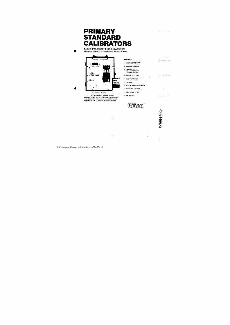
PRIMARYSTANDARDCALIBRATORSr M i c r o - P r o c e s s o r F i l m F l o w m e t e r s
3 Models to Provide a Complete Range of Primary Calibration
i I i i
l 3 C C h -
l 1 L 1 R R . • 1 T I a R
.OVe F-Ow'NOOEL &/GU-300,Available in 3 Flow Ranges
Mod el BUC-L-300 : 2-250 cc/min forlow flo w applications
Model BUC-S-300: 30cc-4 Ipmion stand ard'app Ncations
Model BUC-H-300: 3-24 Ipm for high fl ow applications .
FEATURES• DIRECT FLOW REA DOUT
• IMM EDIATE RESPONSE
• THREE MODELS-FLOw'RANGES FROM2 CC/M IN !TO 24 LPM
• ACCURACY ± 0.5%
• REPEATABIUTY 0.5% •• PORTABLE• BATTERY OR' AC UNE POWERED
• COIiAPAC T9x 12x4 . 5 d N .
• UGHTWEIGHT 4.5 LBS
• SPILLPROOF
MIM31
//legacy.library.ucsf.edu/tid/rcm56e00/pdf

7/27/2019 Gilian Operating Manual
http://slidepdf.com/reader/full/gilian-operating-manual 35/37
20284488'73
• .
l i
: : ~
legacy.library.ucsf.edu/tid/rcm56e00/pdf

7/27/2019 Gilian Operating Manual
http://slidepdf.com/reader/full/gilian-operating-manual 36/37
2028448874
!
"
!!q W~" ammaAM . . ..~4~ .. .m
0
.
- 0
A
.`
legacy.library.ucsf.edu/tid/rcm56e00/pdf
7/27/2019 Gilian Operating Manual
http://slidepdf.com/reader/full/gilian-operating-manual 37/37
COMPACT SM
niwee MOOUXES :
~ i Y .
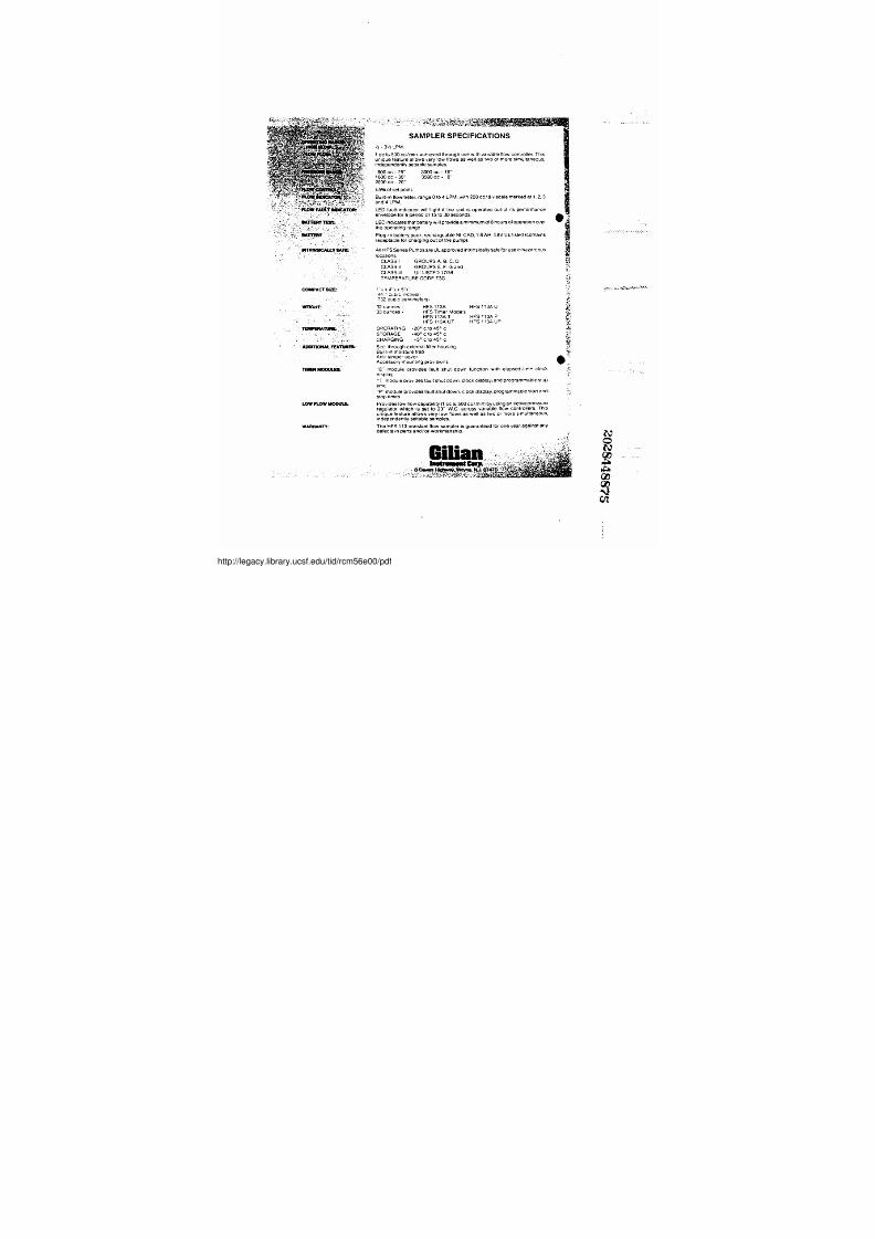
SAMPLER SPECIFICATIONS' / i - 3 ' / z L P M .
1 cc to 500 cc/min . achieved through use w ith variable flow controller . This
unique feature allows very low flows as well as two or more simultaneous :
independently se ttablesamptes .
500'cc - 25" 3000 cc - 15"
t000 cc - 30" 3500 cc - 8"2000cc-20"± 5 % o f s e t p o i n t .
Built-in flowmeter . range 04o4 LPM, with 200 cc/div scale marked at 1, 2 . 3and 4 LPM .
LED fault ind cator willili ght if the unit is operated out, of its performance
envel ope for a period of 15 to 30 seconds .
L E D i n d i c a t e s t h a t b a t t e r y w i l l p r o v i d e a m i n i m u m o t 8 h o u r s o f o p e r a t i o n o • r e r
t h e o p e r a t i n g r a n g e
Plug-in battery, pack, rechargeable NI+CAD . 1 .8 AH, 4.8V UL listed (contains
receptacle for charging out of the pump)
AII HFS Series Pumpsare UL approved intrinsieally sale foriuse in hazardous
locations.CLASS I GROUPS A. B . C . DCLASS Il GROUPS E. F . G andCLASS III UL LISTED 17G9TEMPERATURE CODE T3C1 - ~ x 4 ` s x 5 1 ' a ' "
144 7 7 cuboc .irchesl ~
1732 cub,c eent meters)
32 ounces - HFS 113A HFS 113AU3 3 ' o u n r , e s - HFS Timer Models
HFS 113A THFS 113A UT HFS' 113A PHFS'113A UP ~OPERATING -20' c to 45° c ~-STORAGE - 4 0 ° c t o 4 5 ° cCHARGING - 5 ° c t o 4 5 ° c
s . ;
See-through external filter housing
Bu lt- n mo sture trap
Anti-tamper cover,
Accessory mount ng provisions
"C m o d u l e p r o v id es f a u l t s h u t d o wn f u nc t io n wit h el a p s ed -t im< cl o c k
d splay,
"T~' module providesfaultshutdown, clock display : and programmable : s t o p
time .
"P" module provides fault shut down, clock display, programmable start and
stop times .
LOW FLOW fMOOUfE Provides low flow capabiliry (1 cc to 500 ccLmin)by using an active pressureregulator which is set to 20" W .C : across variable flow controNers. This
unique feature allows very low .flows as. w e l l .as two or more simultaneous .
independe ntly settable samples .
wARtiANTY:: The HFS 113 constant flow sampler is guaranteed for one year, against anydefects in parts and/orworkmanshi p .