Embed Size (px)
Citation preview

Gigabit TAP Probe User Guide
Document Number: GTAPUGRev. 10.x, 02/2014

Gigabit TAP Probe User Guide, Rev. 10.x, 02/2014
2 Freescale Semiconductor, Inc.

Contents
Section number Title Page
Chapter 1Introducing CodeWarrior Gigabit TAP probe
1.1 What is Gigabit TAP probe?...........................................................................................................................................9
1.1.1 Product highlights.............................................................................................................................................. 11
1.1.2 Gigabit TAP probe benefits............................................................................................................................... 12
1.2 Identifying components.................................................................................................................................................. 12
1.3 Operating requirements...................................................................................................................................................13
1.3.1 Target power requirements................................................................................................................................ 13
1.3.2 Standard electrostatic precautions......................................................................................................................14
1.3.3 Electrical requirements...................................................................................................................................... 14
1.3.3.1 Connecting power supply cable......................................................................................................... 15
1.3.3.2 Cycling power to system....................................................................................................................15
1.3.4 Operating temperature........................................................................................................................................16
1.3.5 Target system requirements............................................................................................................................... 16
1.4 Related documentation....................................................................................................................................................16
Chapter 2Connecting to network
2.1 Connecting Gigabit TAP probe to network.................................................................................................................... 17
2.1.1 Connecting to twisted pair interface.................................................................................................................. 17
2.2 Customizing Gigabit TAP probe.................................................................................................................................... 19
2.2.1 Establishing serial communication with Gigabit TAP probe.............................................................................19
2.2.2 Customizing Gigabit TAP probe network settings............................................................................................ 21
2.3 Testing network communication.....................................................................................................................................21
2.3.1 Verifying communication.................................................................................................................................. 21
Chapter 3Connecting to target system
3.1 Debug port connector information..................................................................................................................................23
3.2 Connecting to target JTAG/COP connector................................................................................................................... 24
Gigabit TAP Probe User Guide, Rev. 10.x, 02/2014
Freescale Semiconductor, Inc. 3

Section number Title Page
3.2.1 Connecting probe tip directly to debug port connector......................................................................................24
3.2.2 Connecting probe tip to target system JTAG connector.................................................................................... 24
3.2.3 Connecting JTAG header using extension cable............................................................................................... 26
3.2.3.1 Connecting flexible probe tip extension cable with JTAG header.................................................... 26
3.3 Connecting to target aurora nexus connector..................................................................................................................27
3.3.1 Connecting aurora nexus cable.......................................................................................................................... 27
3.4 Connecting to target system serial port...........................................................................................................................28
3.4.1 Connecting Gigabit TAP probe to target system............................................................................................... 28
3.4.1.1 Connecting serial cable between Gigabit TAP probe and serial port of target system......................29
3.4.2 Configuring target serial port.............................................................................................................................29
3.4.2.1 Configuring Gigabit TAP probe serial port....................................................................................... 29
3.4.2.2 Restoring target serial port to default settings................................................................................... 30
3.4.3 Accessing target serial port................................................................................................................................ 30
3.4.3.1 Telnet to target serial port.................................................................................................................. 30
Chapter 4Using Gigabit TAP probe
4.1 Debugging with Gigabit TAP system.............................................................................................................................33
4.1.1 Starting Gigabit TAP probe............................................................................................................................... 33
4.2 Accessing Gigabit TAP probe remotely......................................................................................................................... 34
4.2.1 Remotely accessing setup utility........................................................................................................................34
4.2.2 Connecting to your target's serial port remotely................................................................................................ 34
Chapter 5Hardware specifications
5.1 LEDs on Gigabit TAP probe...........................................................................................................................................35
5.1.1 Heartbeat indicator.............................................................................................................................................36
5.1.2 Run/Pause indicator........................................................................................................................................... 36
5.1.3 Target power indicator....................................................................................................................................... 37
5.1.4 Active indicator..................................................................................................................................................37
5.1.5 Measure indicator...............................................................................................................................................37
Gigabit TAP Probe User Guide, Rev. 10.x, 02/2014
4 Freescale Semiconductor, Inc.

Section number Title Page
5.1.6 RJ-45 Ethernet connector with Link and Activity indicators............................................................................ 37
5.1.7 Gigabit TAP probe status indicators.................................................................................................................. 38
5.2 Host connectors on Gigabit TAP probe.......................................................................................................................... 39
5.2.1 Reset button........................................................................................................................................................40
5.2.2 Power connector.................................................................................................................................................40
5.2.3 RJ-45 Ethernet connector...................................................................................................................................40
5.2.4 Config USB connector....................................................................................................................................... 40
5.3 Target connectors on Gigabit TAP probe....................................................................................................................... 40
5.3.1 Trigger in connector ..........................................................................................................................................41
5.3.2 Trigger out connector ........................................................................................................................................41
5.3.3 Aurora Nexus connector ................................................................................................................................... 41
5.3.4 RJ-25 target serial connector..............................................................................................................................42
5.3.5 Run control probe tip cable connector............................................................................................................... 42
5.3.6 Debug port connector.........................................................................................................................................42
5.4 Gigabit TAP probe specifications...................................................................................................................................43
5.4.1 Electrical characteristics.................................................................................................................................... 43
5.4.2 Physical characteristics...................................................................................................................................... 43
Chapter 6JTAG/COP connector information
Chapter 7OnCE connector information
Chapter 8Aurora high speed trace daughtercard information
8.1 General specifications.....................................................................................................................................................53
8.1.1 Simplex operation.............................................................................................................................................. 53
8.1.2 Duplex operation................................................................................................................................................54
8.1.3 Electrical specifications..................................................................................................................................... 55
8.1.4 AC coupling....................................................................................................................................................... 55
8.1.5 JTAG and optional signaling............................................................................................................................. 56
8.1.5.1 TCK, TMS, TRST, TDI, and TDO signals........................................................................................56
Gigabit TAP Probe User Guide, Rev. 10.x, 02/2014
Freescale Semiconductor, Inc. 5

Section number Title Page
8.1.5.2 VIO (Vsense) signal...........................................................................................................................56
8.1.5.3 Reset signal........................................................................................................................................ 56
8.1.5.4 Vendor IO 0-5 signals........................................................................................................................ 57
8.1.5.5 Recommended termination................................................................................................................ 57
8.2 Mechanical specification................................................................................................................................................ 57
8.2.1 Cables.................................................................................................................................................................58
8.2.2 Connectors......................................................................................................................................................... 58
8.2.3 PCB design and routing consideration...............................................................................................................60
8.2.4 Trigger signals....................................................................................................................................................60
Chapter 9Setting up standalone PC Ethernet
9.1 System requirements.......................................................................................................................................................63
9.2 Tutorial: Standalone Network for Ethernet setup........................................................................................................... 64
9.2.1 Installing and configuring TCP/IP software...................................................................................................... 64
9.2.2 Creating Windows hosts file.............................................................................................................................. 67
9.2.3 Connecting Gigabit TAP probe to host computer..............................................................................................68
9.3 Configuring the Gigabit TAP probe............................................................................................................................... 69
9.3.1 Starting setup utility........................................................................................................................................... 69
9.3.2 Storing IP address and netmask in flash EPROM..............................................................................................69
Chapter 10Gigabit TAP probe setup utility commands
10.1 Connecting to Gigabit TAP probe setup utility.............................................................................................................. 71
10.2 Gigabit TAP probe setup utility commands and variables............................................................................................. 72
10.2.1 Commands to configure communications..........................................................................................................72
10.2.1.1 netparam.............................................................................................................................................72
10.2.1.2 tgtty.................................................................................................................................................... 74
10.2.2 Commands to troubleshoot communication...................................................................................................... 75
10.2.2.1 arp.......................................................................................................................................................75
10.2.2.2 host..................................................................................................................................................... 75
Gigabit TAP Probe User Guide, Rev. 10.x, 02/2014
6 Freescale Semiconductor, Inc.

Section number Title Page
10.2.2.3 netstat................................................................................................................................................. 76
10.2.2.4 ping.....................................................................................................................................................76
10.2.2.5 route................................................................................................................................................... 77
Chapter 11Network administration
11.1 Gigabit TAP probe network ports...................................................................................................................................79
11.2 Configuring Gigabit TAP probe using netparam............................................................................................................80
11.2.1 Configuring dynamic IP Address.......................................................................................................................80
11.2.2 Configuring static IP Address............................................................................................................................ 80
11.2.3 Static routing...................................................................................................................................................... 81
11.2.3.1 Specify default gateway or static route table (optional).................................................................... 82
11.2.4 Changing existing route entry............................................................................................................................ 82
11.2.5 Entering static routes..........................................................................................................................................83
11.2.5.1 Static route example...........................................................................................................................83
11.3 Using CCS to search for Gigabit TAP probes................................................................................................................ 85
11.3.1 Sample output.................................................................................................................................................... 86
Chapter 12Gigabit TAP probe firmware (Core)
12.1 Gigabit TAP probe internal software overview.............................................................................................................. 87
12.1.1 Boot loader.........................................................................................................................................................87
12.1.2 Fallback boot loader...........................................................................................................................................87
12.1.3 Operating System...............................................................................................................................................88
12.1.4 Shell software.....................................................................................................................................................88
12.2 Reprogramming Gigabit TAP probe firmware images...................................................................................................88
12.2.1 Reprogramming firmware through Gigabit port................................................................................................88
Chapter 13Troubleshooting
13.1 Troubleshooting communications problems...................................................................................................................91
13.1.1 Verify network communication......................................................................................................................... 92
13.1.2 View network connections.................................................................................................................................92
Gigabit TAP Probe User Guide, Rev. 10.x, 02/2014
Freescale Semiconductor, Inc. 7

Section number Title Page
13.2 Troubleshooting power problems................................................................................................................................... 93
13.3 Troubleshooting overheating problems.......................................................................................................................... 93
Gigabit TAP Probe User Guide, Rev. 10.x, 02/2014
8 Freescale Semiconductor, Inc.

Chapter 1Introducing CodeWarrior Gigabit TAP probeThe CodeWarrior is a tool that helps you develop and debug software on FreescalePowerPC processors.
This chapter contains the following sections:
• What is Gigabit TAP probe?• Identifying components• Operating requirements• Related documentation
CAUTIONThe Gigabit TAP probe contains components that are subject todamage from electrostatic discharge. Whenever you are using,handling, or transporting the Gigabit TAP probe, or connectingto or disconnecting from a target system, always use properanti-static protection measures, including static-free bench padsand grounded wrist straps.
1.1 What is Gigabit TAP probe?The Gigabit TAP probe uses advanced emulation technology to provide control of andvisibility into your target system. Combined with a host debugger, the Gigabit TAP probespeeds the debugging process by letting you interactively control and examine the state ofyour target system. The Gigabit TAP is available in two configurations: the basic GigabitTAP, and the.
The basic Gigabit TAP probe system is composed of two parts:
Gigabit TAP Probe User Guide, Rev. 10.x, 02/2014
Freescale Semiconductor, Inc. 9

• The Gigabit TAP probe as shown in figure Figure 1-1, which provides visibility intoand control of your target system using a and connects to your host computer througha , or .
• A target system JTAG/COP probe tip, which is designed to provide a physical andelectrical interface to the target system processor that you want to gain visibility into.
Figure 1-1. Gigabit TAP probe
The Gigabit TAP + Trace probe includes two additional components to enable high speedtrace collection and downloads as shown in figure Figure 1-2 :
• An (internal) provides logic, buffers, and connectors for high speed trace collectionand downloads.
• A target system Aurora Nexus cable, which is used to connect the probe to the highspeed Aurora Nexus port of the target.
What is Gigabit TAP probe?
Gigabit TAP Probe User Guide, Rev. 10.x, 02/2014
10 Freescale Semiconductor, Inc.

Figure 1-2. Gigabit TAP + Trace
1.1.1 Product highlights
The Gigabit TAP probe has these features:
• Supports PowerPC™ processors• Supports all CPU core speeds• Lets you control and debug software running in-target, with minimal intrusion into
target system operation• Lets you debug code in cache, ROM, RAM, and flash memory• Provides high performance:
• Split-second single-step execution• Gigabit TAP probe is capable of JTAG download speeds greater than 1 MB per
second from host to the target system• Gigabit TAP probe + Trace is capable of Aurora download speeds of 6 MB per
second
NOTEThe actual download speed depends on the targetsystem processor, the debug port's clock frequency, thenetwork speed, and the debugger.
• Supports 10/100/1000BaseT Ethernet network connection• Supports telnet access to your target system's serial port, allowing you to interact
with your target system's serial port over the network• Supports both big and little endian byte-order
Chapter 1 Introducing CodeWarrior Gigabit TAP probe
Gigabit TAP Probe User Guide, Rev. 10.x, 02/2014
Freescale Semiconductor, Inc. 11

• Automatically supports target system signal levels from 1.2V to 3.3V• Software debug capabilities including:
• Control instruction execution• Display and modify target system memory• Examine and modify any processor registers• Run to breakpoints in ROM, RAM, or flash memory• Single-step through source and assembly language code views• Step into, over, or out of functions• Collect and analyze real-time data and execution trace
1.1.2 Gigabit TAP probe benefits
The Gigabit TAP probe provides these key benefits:
• Visibility: The Gigabit TAP probe makes it possible for you to observe registers andthe current state of target system memory. You can halt program execution atpredefined states and examine the data for a particular program state.
• Control: You can conveniently control the state of the target system by downloadingcode, manually modifying processor registers and memory, single-stepping throughthe code, or setting breakpoints.
• Trace: Gigabit TAP probes equipped with a trace module (Gigabit TAP + Trace)enable collection of 4 GB of real-time target execution and data trace.
1.2 Identifying componentsBefore you begin, check that these components are present:
• External power supply with four interchangeable plugs• The Gigabit TAP probe should include the following and :
• One standard debug port (JTAG/COP) probe tip cable assembly• One flexible probe tip extension cable• One RJ-45 cable• One RJ-25 cables• One 9-pin and one 25-pin cable adapters• One type A/B USB cable
• The Gigabit TAP + Trace probe should also include:• Aurora Nexus connector on the probe• Trigger OUT/IN connectors on the probe• One 70-pin Aurora Nexus cable
• Gigabit TAP Probe User Guide (this manual)
Identifying components
Gigabit TAP Probe User Guide, Rev. 10.x, 02/2014
12 Freescale Semiconductor, Inc.

1.3 Operating requirements
Before setting up the system, you should make sure that the operating environment isprepared.
1.3.1 Target power requirements
Several configurations are possible for providing power to the system. The preferredconfiguration is for all target DC power supplies to use a 3-wire AC input with an earth(safety) ground and with the earth ground isolated from the DC return. Table 1-1 showsvarious and the results of using each.
Table 1-1. Target system device power supply configurations
AC Input Isolation Result
Preferred configuration 3-wire system with earth(safety) wire
AC earth is isolated from DCreturn.Target system DC isfully isolated and is floating.
Normal operation
Acceptable configuration 2-wire system with no earth(safety) wire
AC return is isolated from DCreturn. Target system DC isfully isolated and is floating.
Normal operation
Acceptable configuration 3-wire system with earth(safety) wire
AC earth is tied to DC return.Target system DC is notisolated and is floating.
Configuration may result inunstable operation of DCsignals.
Prohibited configuration 2-wire system with no earth(safety) wire
AC return is tied to DC return.Target system DC is notisolated and is not floating.
Configuration may result inunstable operation of DCsignals and AC hum.A safetyhazard may result from powersupply or target system failurewhere DC voltage isconnected to AC return.
CAUTIONDo not use 2-wire AC input with the AC neutral tied to the DCreturn (Figure 1-3) on any power supply in the system. Afailure in a power supply or target system where DC voltagebecomes connected to AC neutral may result in personal injuryand damage to the equipment.
Chapter 1 Introducing CodeWarrior Gigabit TAP probe
Gigabit TAP Probe User Guide, Rev. 10.x, 02/2014
Freescale Semiconductor, Inc. 13

Figure 1-3. Prohibited target power supply connection
CAUTIONGood grounding practices should be observed when connectingdigital grounds to earth ground, since ground loops may inducesufficient currents to cause irregular operation of the combinedsystem. Under no circumstances, the third wire prong on anypower cord be removed or disconnected.
1.3.2 Standard electrostatic precautions
This instrument contains static-sensitive components that are subject to damage from .Use standard ESD precautions when transporting, handling, or using the Gigabit TAPprobe and the target system, when connecting/disconnecting the probe and the targetsystem, and when removing the cover of the instrument.
We recommend the use of the following precautions:
• Use wrist straps or heel bands with a 1 Mohm resistor connected to ground.• On the work surface and floor, use static conductive mats with a 1 Mohm resistor
connected to ground.• Keep high static-producing items, such as non-ESD-approved plastics, tape and
packaging foam away from the probe and the target system.
The above precautions should be considered as minimum requirements for a static-controlled environment.
Operating requirements
Gigabit TAP Probe User Guide, Rev. 10.x, 02/2014
14 Freescale Semiconductor, Inc.
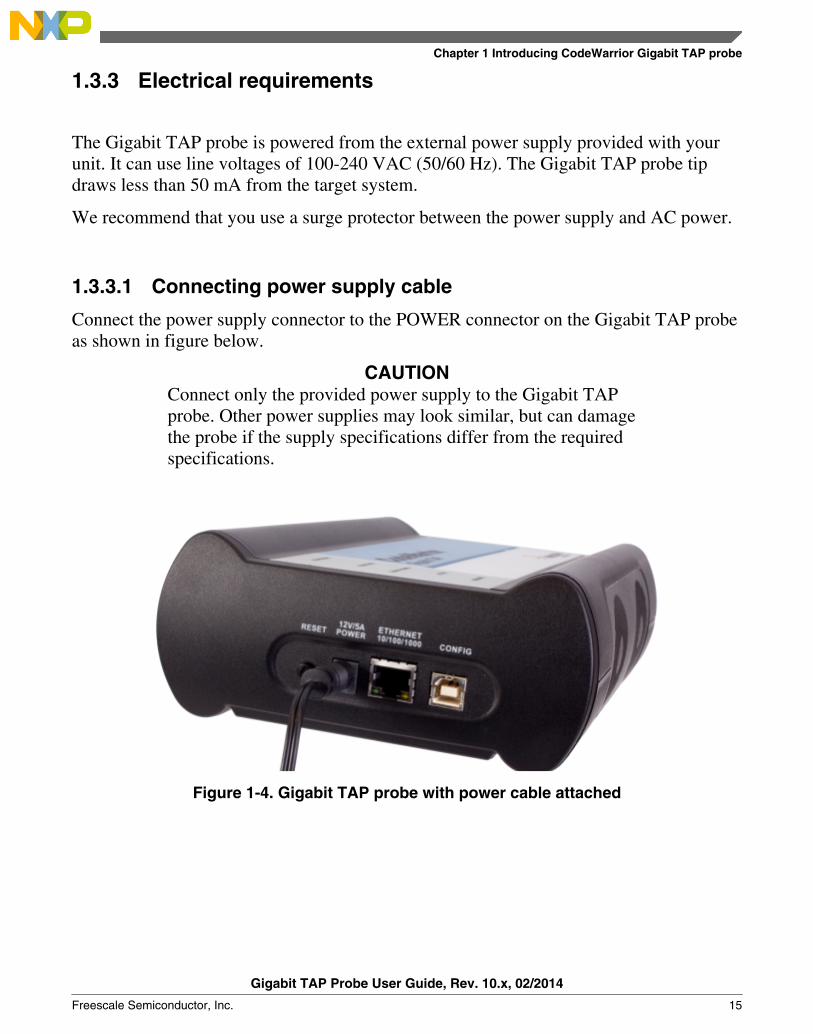
1.3.3 Electrical requirements
The Gigabit TAP probe is powered from the external power supply provided with yourunit. It can use line voltages of 100-240 VAC (50/60 Hz). The Gigabit TAP probe tipdraws less than 50 mA from the target system.
We recommend that you use a surge protector between the power supply and AC power.
1.3.3.1 Connecting power supply cable
Connect the power supply connector to the POWER connector on the Gigabit TAP probeas shown in figure below.
CAUTIONConnect only the provided power supply to the Gigabit TAPprobe. Other power supplies may look similar, but can damagethe probe if the supply specifications differ from the requiredspecifications.
Figure 1-4. Gigabit TAP probe with power cable attached
Chapter 1 Introducing CodeWarrior Gigabit TAP probe
Gigabit TAP Probe User Guide, Rev. 10.x, 02/2014
Freescale Semiconductor, Inc. 15

1.3.3.2 Cycling power to system
When you need to apply or cycle power to the Gigabit TAP probe, connect or disconnectthe power cable from the power source or from the probe. After you have connected theprobe to your target system, use the following sequence for applying or removing thepower:
1.3.4 Operating temperature
The Gigabit TAP probe can operate in a temperature range of 0 to 40 °C (32 to 104 ºF).
NOTEC is for celsius and F is for Fahrenheit
1.3.5 Target system requirements
The Gigabit TAP probe automatically supports target system signal levels from 1.2V to3.3V.
NOTEIn the case of PowerPC targets with a Qack signal, for theGigabit TAP probe to properly stop and restart the target,theQack signal must be pulled low. The Gigabit TAP probepulls this signal low through the probe tip.
1.4 Related documentationThis manual describes the procedures for unpacking the Gigabit TAP probe, connectingthe external power supply, setting up Ethernet communication, and connecting theGigabit TAP probe to your target system.
The CodeWarrior documentation explains how to install and configure the CodeWarriorIDE and debugger.
Related documentation
Gigabit TAP Probe User Guide, Rev. 10.x, 02/2014
16 Freescale Semiconductor, Inc.
Chapter 2Connecting to network
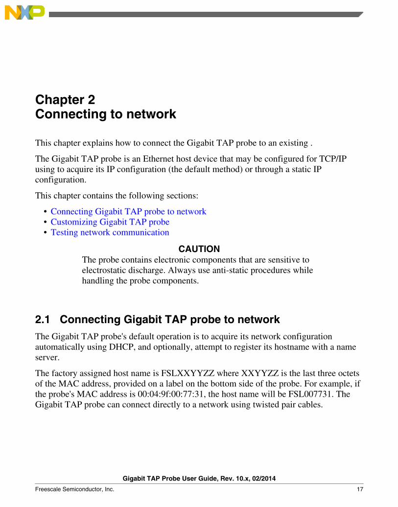
This chapter explains how to connect the Gigabit TAP probe to an existing .
The Gigabit TAP probe is an Ethernet host device that may be configured for TCP/IPusing to acquire its IP configuration (the default method) or through a static IPconfiguration.
This chapter contains the following sections:
• Connecting Gigabit TAP probe to network• Customizing Gigabit TAP probe• Testing network communication
CAUTIONThe probe contains electronic components that are sensitive toelectrostatic discharge. Always use anti-static procedures whilehandling the probe components.
2.1 Connecting Gigabit TAP probe to networkThe Gigabit TAP probe's default operation is to acquire its network configurationautomatically using DHCP, and optionally, attempt to register its hostname with a nameserver.
The factory assigned host name is FSLXXYYZZ where XXYYZZ is the last three octetsof the MAC address, provided on a label on the bottom side of the probe. For example, ifthe probe's MAC address is 00:04:9f:00:77:31, the host name will be FSL007731. TheGigabit TAP probe can connect directly to a network using twisted pair cables.
Gigabit TAP Probe User Guide, Rev. 10.x, 02/2014
Freescale Semiconductor, Inc. 17

2.1.1 Connecting to twisted pair interface1. Plug one end of the supplied (p/n 600-75499) into the RJ-45 connector of the Gigabit
TAP probe as shown in Figure 2-1.2. Connect the other end of the RJ-45 cable into the RJ-45 connector of your twisted
pair network or host computer.
NOTETo connect to a thinwire or thickwire network, use aconverter hub that accepts the twisted pair(10/100/1000BaseT) cable from the Gigabit TAP probe andconverts to the thinwire (10Base2) or thickwire (10Base5)cable from your network.
Figure 2-1. Gigabit TAP probe with an RJ-45 cable attached
NOTEWhen you configure the debugger for the hardwareconnection, you will need to specify the Gigabit TAP probeIP address or hostname. The CCS findcc utility is used tosearch any probe on the local subnet. See Using CCS tosearch for Gigabit TAP probes section for moreinformation.
NOTEDepending on the type and complexity of your network,your network administrator may need to update network
Connecting Gigabit TAP probe to network
Gigabit TAP Probe User Guide, Rev. 10.x, 02/2014
18 Freescale Semiconductor, Inc.

server tables so that the network accesses the Gigabit TAPprobe correctly. Updating network server tables requiresboth a detailed knowledge of Ethernet address resolutionand network routing with write access permission to theserver tables. See Network administration section for moreinformation on network administration.
2.2 Customizing Gigabit TAP probeIf you cannot use DHCP, you must configure the probe for your network using static IPaddress resolution.
As shipped, the Gigabit TAP probe acquires its network configuration automaticallyusing DHCP. To manually configure the network settings of the Gigabit TAP probe foryour network, connect a terminal to the probe configuration port and use the probe on-board setup utility netparam to change the probe network settings. The probe netparamutility lets you select and modify network parameters that are saved in probe memory.Use netparam to configure the probe to match your and .
If the probe is able to communicate with hosts on other subnets, you will need toconfigure the probe for one of the following routing options:
• Default gateways• tables
2.2.1 Establishing serial communication with Gigabit TAP probe
1. Connect one end of the USB cable (P/N 600-76787) to a on your host computer.2. Connect the other end of the USB cable to the USB connector of the Gigabit TAP
probe, labeled as shown in figure Figure 2-2.
Chapter 2 Connecting to network
Gigabit TAP Probe User Guide, Rev. 10.x, 02/2014
Freescale Semiconductor, Inc. 19
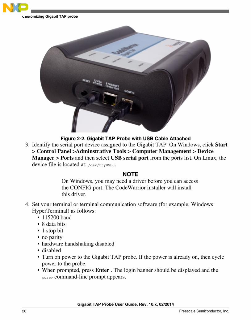
Figure 2-2. Gigabit TAP Probe with USB Cable Attached3. Identify the serial port device assigned to the Gigabit TAP. On Windows, click Start
> Control Panel >Adminstrative Tools > Computer Management > DeviceManager > Ports and then select USB serial port from the ports list. On Linux, thedevice file is located at: /dev/ttyUSB0.
NOTEOn Windows, you may need a driver before you can accessthe CONFIG port. The CodeWarrior installer will installthis driver.
4. Set your terminal or terminal communication software (for example, WindowsHyperTerminal) as follows:
• 115200 baud• 8 data bits• 1 stop bit• no parity• hardware handshaking disabled• disabled• Turn on power to the Gigabit TAP probe. If the power is already on, then cycle
power to the probe.• When prompted, press Enter . The login banner should be displayed and the
core> command-line prompt appears.
Customizing Gigabit TAP probe
Gigabit TAP Probe User Guide, Rev. 10.x, 02/2014
20 Freescale Semiconductor, Inc.
2.2.2 Customizing Gigabit TAP probe network settings
You need to have write permissions to the network database or the assistance of yournetwork system administrator.
1. Change the Gigabit TAP probe network settings.a. At the core> prompt, enter the netparam command to view the current settings.b. For network setup, see netparam section for syntax and options. For more
information on installing the Gigabit TAP probe on a network, see NetworkAdministration section.
c. At the core> prompt, enter the netparam commands and required parameters.2. At the core> prompt, enter reset to reboot the Gigabit TAP probe to activate the new
network settings.
Example: Assign a Static IP Address and Hostname to the Gigabit TAP Probe
If the Gigabit TAP probe has a static IP address of 195.121.1.2 and a hostname of lab01,enter the following commands:
core> netparam bootconfig static:lab01core> netparam static_ip_address 195.121.1.2core> reset
The netparam utility copies its settings into non-volatile memory on the probe. Followthese rules while using netparam utility:
• Each time you enter a netparam command, wait for the core> prompt to re-appearbefore entering the next command. The prompt indicates that the parameter changehas been logged.
• When you have finished entering all settings, type reset at the core> prompt. Whenthe probe restarts, it will use the new netparam parameters.
2.3 Testing network communication
You can use the ping command to ensure that the Gigabit TAP probe can communicatewith the host.
2.3.1 Verifying communication
Chapter 2 Connecting to network
Gigabit TAP Probe User Guide, Rev. 10.x, 02/2014
Freescale Semiconductor, Inc. 21
At a host command prompt, type the following:
ping hostname | ip_address
where hostname is the name and ip_address is the IP address assigned to the Gigabit TAPprobe.
If no output is displayed on the screen, check the following:
• The physical connections are tight.• The Gigabit TAP probe address and netmask in the hosts file match those in Gigabit
TAP probe flash.• The netmask used for the Gigabit TAP probe and for the are appropriate to the class
of the IP address.
Testing network communication
Gigabit TAP Probe User Guide, Rev. 10.x, 02/2014
22 Freescale Semiconductor, Inc.

Chapter 3Connecting to target system
To run your software using the Gigabit TAP probe, you must have working target systemhardware, prototype hardware, or an evaluation board.
This chapter explains how to connect a Gigabit TAP probe to the target system.
This chapter contains the following sections:
• Debug port connector information• Connecting to target JTAG/COP connector• Connecting to target aurora nexus connector• Connecting to target system serial port
CAUTIONThe Gigabit TAP probe contains components that are subject todamage from electrostatic discharge. Whenever you are using,handling, or transporting the Gigabit TAP probe, or connectingto or disconnecting from a target system, always use properanti-static protection measures, including static-free bench padsand grounded wrist straps.
3.1 Debug port connector informationThe Gigabit TAP probe offers debugging capabilities without modifying any targetsystem code or any special I/O port in the target system for communication with amonitor.
Target system connections can be made using any one of the debug ports (JTAG/COPor ). The basic Gigabit TAP probe connects to the target system in any of the followingways:
• Connect to the JTAG header on the target system directly with the probe tip.
Gigabit TAP Probe User Guide, Rev. 10.x, 02/2014
Freescale Semiconductor, Inc. 23
• Connect to the JTAG header on the target system using a flexible extension cable.Use it when more clearance is required.
• Connect to the Aurora Nexus socket on the target system directly with the AuroraNexus cable.
The extension cable is provided with your Gigabit TAP probe. A 70-pin Aurora Nexuscable is provided with the Gigabit TAP + Trace probe. A 22-pin Aurora Nexus cable isalso available and can be ordered separately.
JTAG/COP connector information chapter describes the debug port connectorspecifications.
3.2 Connecting to target JTAG/COP connectorYou can connect the Gigabit TAP probe to the target system in one of three ways. Thethree methods are explained in the following sections:
• Connecting probe tip directly to debug port connector• Connecting probe tip to target system JTAG connector• Connecting JTAG header using extension cable
CAUTIONFailure to connect the Gigabit TAP probe tip connector to thetarget system may damage the Gigabit TAP probe or targetsystem. Verify all connections before applying power.
3.2.1 Connecting probe tip directly to debug port connector
If your target system has debug port connectors, you can directly connect the probe tipand/or trace cables on the Gigabit TAP probe to one of the target system debug portconnectors.
3.2.2 Connecting probe tip to target system JTAG connector1. Turn off the power to the target system and the Gigabit TAP probe.2. Make sure all the pins of the probe tip or trace cable are properly aligned with the
debug port connector on the target system. Use mechanical keying and the label onthe probe tip as a guide. The Gigabit TAP probe JTAG/COP connector is shown infigure Figure 3-1.
Connecting to target JTAG/COP connector
Gigabit TAP Probe User Guide, Rev. 10.x, 02/2014
24 Freescale Semiconductor, Inc.

Figure 3-1. Gigabit TAP probe PPC JTAG/COP probe tip3. Connect the probe tip 50-pin ribbon cable to the RUN CONTROL connector on the
Gigabit TAP probe as shown in the figure Figure 3-2.4. Gently (but firmly) press the probe tip onto the target system debug port header.
Make sure that you properly align the Gigabit TAP multi-pin socket connector withthe multi-pin header on your target system.
NOTEEnsure that pin 1 of the probe tip is connected to the pin 1of the header.
Chapter 3 Connecting to target system
Gigabit TAP Probe User Guide, Rev. 10.x, 02/2014
Freescale Semiconductor, Inc. 25

Figure 3-2. Gigabit TAP probe with PPC-JTAG probe tip
3.2.3 Connecting JTAG header using extension cable
Use the supplied cable to connect the Gigabit TAP probe to your target system if there isnot enough clearance for the standard probe tip to fit onto the target system .
3.2.3.1 Connecting flexible probe tip extension cable with JTAGheader
1. Turn off the power to the target system and the Gigabit TAP probe.2. Attach the multi-pin header end of the flexible probe tip extension cable to the JTAG
socket of the Gigabit TAP probe tip as shown in Figure 3-3.
Connecting to target JTAG/COP connector
Gigabit TAP Probe User Guide, Rev. 10.x, 02/2014
26 Freescale Semiconductor, Inc.

Figure 3-3. Flexible probe tip extension cable attached to JTAG/COP header
The red stripe on the cable identifies pin 1. The pin assignment of the cable isidentical to that of the probe tip socket.
3. Connect the other end of the flexible probe tip extension cable to the debug portheader on your target system.
3.3 Connecting to target aurora nexus connectorYou can connect the Gigabit TAP + Trace probe to the target system with the AuroraNexus cable.
3.3.1 Connecting aurora nexus cable1. Turn off the power to the target system and the Gigabit TAP + Trace probe.2. Connect the Aurora Nexus cable to the AURORA NEXUS connector on the Gigabit
TAP + Trace probe as shown in figure Figure 3-4.
Chapter 3 Connecting to target system
Gigabit TAP Probe User Guide, Rev. 10.x, 02/2014
Freescale Semiconductor, Inc. 27

Figure 3-4. Gigabit TAP + Trace probe with aurora nexus cable
3.4 Connecting to target system serial portMany target system boards have a built-in serial port. A console interface connection tothe serial port of the target system lets you query and configure the state of your targetsystem.
The Gigabit TAP probe provides a serial port which can be configured to access the serialport of the target system. This is useful if you need to access the serial port of a remotelylocated target system over Ethernet from the host system.
The following sections explain how to access the serial port of the target system:
• Connecting Gigabit TAP probe to target system• Configuring target serial port• Accessing target serial port
3.4.1 Connecting Gigabit TAP probe to target system
An RJ-25 cable (P/N 600-76822) is provided with the Gigabit TAP probe to connect tothe serial port of your target system.
Connecting to target system serial port
Gigabit TAP Probe User Guide, Rev. 10.x, 02/2014
28 Freescale Semiconductor, Inc.

3.4.1.1 Connecting serial cable between Gigabit TAP probe and serialport of target system
1. Connect one end of the RJ-25 cable, and the appropriate adapter, to the serial port onyour target system board.
2. Connect the other end of the RJ-25 cable to the Gigabit TAP probe RJ-25 serialconnector, labeled TARGET SERIAL.
3.4.2 Configuring target serial port
Table 3-1 table shows the default settings of the Gigabit TAP Target Serial port.
Table 3-1. Gigabit TAP probe target serial port default settings
For this option... Select...
Baud rate 9600
Data bits data8
Stop bits stop1
Parity noparity
Hardware flow control nortscts
XON/XOFF flow control noxon
Target echo feature echo
If the Gigabit TAP probe Target Serial port settings do not match the serial port settingsof your target system, use the following steps:
3.4.2.1 Configuring Gigabit TAP probe serial port1. Make sure network communications have already been configured correctly. For
more information, see Connecting to network topic or Setting up standalone PCethernet topic.
2. Connect to the Gigabit TAP probe internal setup utility. For more information, seeConnecting to Gigabit TAP probe setup utility topic.
3. When the core> prompt appears on the terminal, enter the tgtty command to configurethe Gigabit TAP probe Target Serial port. The syntax is:
tgtty [9600|19200|38400|57600|115200] [data8|data5|data6|data7] [stop1|stop2] [noparity|oddparity|evenparity|lowparity|highparity] [rtscts|nortscts] [xon|noxon] [echo|noecho]
For example:
tgtty 19200 data8 stop2 noparity nortscts noxon echo
Chapter 3 Connecting to target system
Gigabit TAP Probe User Guide, Rev. 10.x, 02/2014
Freescale Semiconductor, Inc. 29

4. Verify the Target Serial port configuration at the core> prompt by entering the tgttycommand by itself:
tgtty
3.4.2.2 Restoring target serial port to default settings1. Make sure network communications has already been configured correctly. For more
information, see Connecting to network chapter or Setting up standalone PC ethernetappendix.
2. Connect to the CodeWarrior TAP probe internal setup utility. For more information,see Connecting to Gigabit TAP probe setup utility section.
3. When the core> prompt appears on the terminal, use the tgtty command to reset theTarget Serial port to the default settings: tgtty default
3.4.3 Accessing target serial port
You can use telnet to connect to the Gigabit TAP probe Target Serial port and access theserial port of your target system remotely over Ethernet.
3.4.3.1 Telnet to target serial port1. Make sure that you have physically connected the Gigabit TAP probe RJ-25 cable to
your target system (for more information, see Connecting the Gigabit TAP Probe tothe Target System topic).
2. Verify the serial port settings (see Configuring target serial port topic).3. Start a telnet session and connect to the Gigabit TAP probe Target Serial port:
telnet {hostname | ip_address}1082
Use the host name or IP address of the probe. For static IP, the host name must be thesame one you entered into the hosts database file; see Connecting to network topic orSetting up standalone PC ethernet topic. To identify the IP address of any probe onthe subnet, see Using CCS to search for Gigabit TAP probes topic. The Target Serialport number of the Gigabit TAP probe is 1082.
4. You should now have access to the serial port of your target system. You can use thisconnection in the same manner as if your host computer were connected directly tothe serial port of your target system.
Connecting to target system serial port
Gigabit TAP Probe User Guide, Rev. 10.x, 02/2014
30 Freescale Semiconductor, Inc.

NOTEIf you have not already installed it, you can now install theCodeWarrior software. Refer to the Targeting manual forinformation on how to configure the debugger and run aconfidence test.
Chapter 3 Connecting to target system
Gigabit TAP Probe User Guide, Rev. 10.x, 02/2014
Freescale Semiconductor, Inc. 31

Connecting to target system serial port
Gigabit TAP Probe User Guide, Rev. 10.x, 02/2014
32 Freescale Semiconductor, Inc.

Chapter 4Using Gigabit TAP probeThis chapter provides system startup procedures and explains how the Gigabit TAP probeis accessed remotely.
This chapter contains the following sections:
• Debugging with Gigabit TAP system• Accessing Ethernet TAP probe remotely
4.1 Debugging with Gigabit TAP systemThis section explains how to start debugging with the Gigabit TAP probe.
Before starting debug with the Gigabit TAP probe, make sure you have:
• Connected the Gigabit TAP probe to your network .• Connected the Gigabit TAP probe to the target system.• Installed the debugger software and properly configure it to communicate with the
Gigabit TAP probe.
4.1.1 Starting Gigabit TAP probe1. Apply power to the Gigabit TAP probe.2. Apply power to the target system.
NOTEThe Gigabit TAP probe draws power from the externalpower supply. The Gigabit TAP probe tip draws less than50 mA from the target in order to detect target power.
3. Start the debugger.4. Configure the debugger for the Gigabit TAP connection.
Gigabit TAP Probe User Guide, Rev. 10.x, 02/2014
Freescale Semiconductor, Inc. 33

LEDs are provided to indicate the status of the Gigabit TAP probe. For information onthe , see Ethernet TAP probe specifications topic.
You are now ready to begin your debug session. For information on using the debugger,see Targeting Users Guide .
4.2 Accessing Gigabit TAP probe remotelyYou can remotely access the internal setup utility and the Target Serial port of theGigabit TAP probe after you connect the probe to your network.
If the host computer is not physically located near the Gigabit TAP probe, remote accessis useful when you need to:
• reconfigure communications• use the serial port of your target system• reset the Gigabit TAP probe through your Ethernet connection
4.2.1 Remotely accessing setup utility
Open a telnet session and connect to the Gigabit TAP probe by entering the command:
telnet hostname | ip_address
Use the host name or IP address of the probe. For static IP, the host name must be thesame one you entered into the hosts database file; see Connecting to network topic orSetting up standalone PC Ethernet topic. To identify the IP address of any probe on thesubnet, see Using CCS to search for Gigabit TAP probes topic.
The login banner is displayed, followed by the core> command-line prompt.
4.2.2 Connecting to your target's serial port remotely
Make sure the Gigabit TAP probe Target Serial port is physically connected to yourtarget's serial port, and it has been configured correctly. For more information, seeAccessing target serial port topic.
Accessing Gigabit TAP probe remotely
Gigabit TAP Probe User Guide, Rev. 10.x, 02/2014
34 Freescale Semiconductor, Inc.
Chapter 5Hardware specificationsThis chapter provides hardware specifications for the Gigabit TAP probe.
This chapter contains the following sections:
• LEDs on Gigabit TAP probe• Host connectors on Gigabit TAP probe• Target connectors on Gigabit TAP probe• Gigabit TAP probe specifications
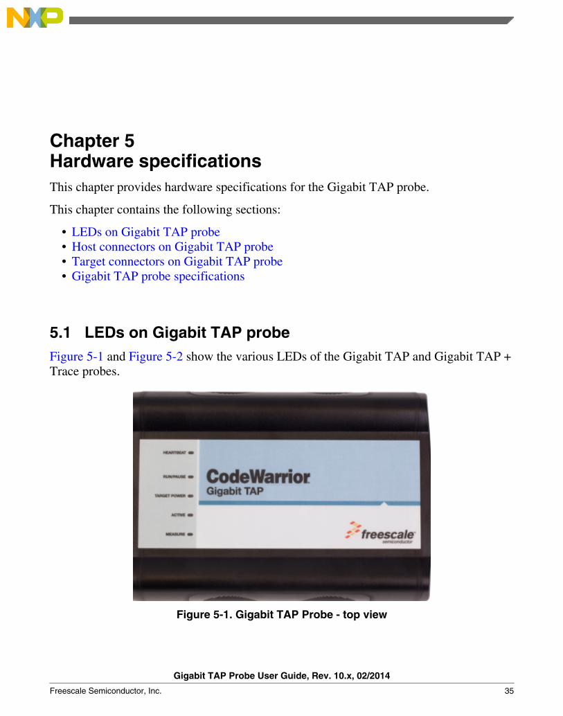
5.1 LEDs on Gigabit TAP probeFigure 5-1 and Figure 5-2 show the various LEDs of the Gigabit TAP and Gigabit TAP +Trace probes.
Figure 5-1. Gigabit TAP Probe - top view
Gigabit TAP Probe User Guide, Rev. 10.x, 02/2014
Freescale Semiconductor, Inc. 35

Figure 5-2. Gigabit TAP + Trace Probe - top view
5.1.1 Heartbeat indicator
The (labeled HEARTBEAT) indicates the status of communication between the GigabitTAP probe and the network as follows:
• The LED is red until the Gigabit TAP probe boot code starts running.• The LED flashes orange (1 Hz) during configuration of the network interface.• The LED flashes green (1 Hz) after network interface has been successfully
configured. During firmware updates, the LED flashes green at a higher frequency(5Hz).
NOTEDo not remove power, unplug the network, or press thereset button during firmware updates.
• The LED is unlit if the Gigabit TAP probe is not powered on.• The LED flashes red if the Gigabit TAP probe is overheating.
5.1.2 Run/Pause indicator
The status LED (labeled ) indicates the state of the target as follows:
• The LED is green when the target is in run mode.• The LED is red when the target is in pause mode.• The LED is orange when the target is in mixed mode.• The LED is initially unlit and remains so until the debugger is connected to the
Gigabit TAP probe.
LEDs on Gigabit TAP probe
Gigabit TAP Probe User Guide, Rev. 10.x, 02/2014
36 Freescale Semiconductor, Inc.

5.1.3 Target power indicator
The target power LED (labeled TARGET POWER) indicates whether the Gigabit TAPprobe detects target power.
• The LED is green when target power is detected.• The LED is unlit when no target power is detected.
NOTEIn Gigabit TAP + Trace systems, this LED is shared by therun control and Aurora Nexus cables and will light up iftarget power is detected on either cable.
5.1.4 Active indicator
The active (labeled ACTIVE) indicates the status of the Aurora Nexus interface.
• The LED is unlit if the Aurora Nexus link is down.• The LED is red if the Aurora Nexus lanes are up but the channel is not up.• The LED is green if the Aurora Nexus lanes are up and the channel is also up.• The LED is orange if the Aurora Nexus lanes are up and the channel is also up but
errors are occurring.
5.1.5 Measure indicator
The measure LED (labeled MEASURE) indicates the flow of data across the AuroraNexus channel and in and out of the trace buffer.
• The LED is unlit if the the unit is idle.• The LED flashes red if there is data flow on the Aurora Nexus channel, sending or
receiving.• The LED flashes green if the trace buffer is being read.• The LED flashes orange if there is data flow on the Aurora Nexus channel and also
the trace buffer is being read.
Chapter 5 Hardware specifications
Gigabit TAP Probe User Guide, Rev. 10.x, 02/2014
Freescale Semiconductor, Inc. 37
5.1.6 RJ-45 Ethernet connector with Link and Activity indicators
The Gigabit TAP probe interface consists of an RJ-45 connector and a built-in twistedpair MAU that connects directly to 10/100/1000BaseT twisted pair networks. SeeConnecting to network topic or Setting up standalone PC Ethernet topic for moreinformation on connecting to an network.
The Gigabit TAP probe link and activity indicators are integrated into the RJ-45 GigabitTAP probe connector. The yellow indicator is turned on when the Gigabit TAP probe isconnected to any network, and flickers when data is being transferred across the network.The green indicator is turned on when the Gigabit TAP probe is connected to a1000BaseT network, and flickers when data is being transferred across the network.
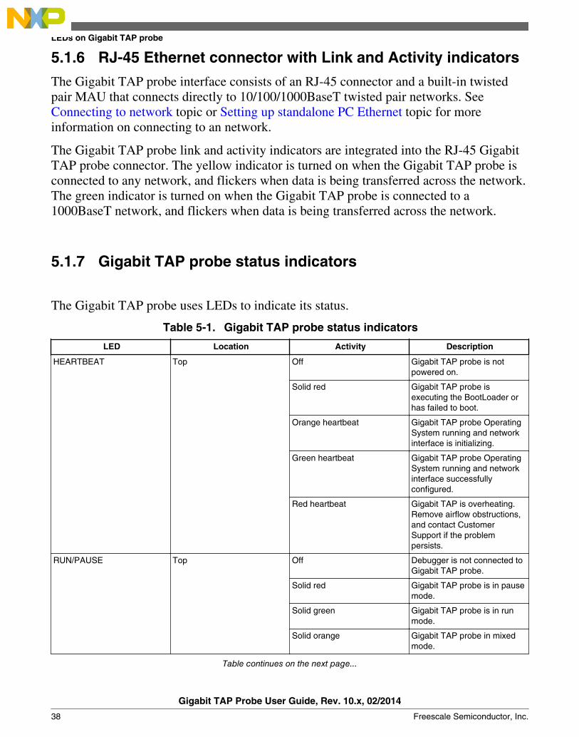
5.1.7 Gigabit TAP probe status indicators
The Gigabit TAP probe uses LEDs to indicate its status.
Table 5-1. Gigabit TAP probe status indicators
LED Location Activity Description
HEARTBEAT Top Off Gigabit TAP probe is notpowered on.
Solid red Gigabit TAP probe isexecuting the BootLoader orhas failed to boot.
Orange heartbeat Gigabit TAP probe OperatingSystem running and networkinterface is initializing.
Green heartbeat Gigabit TAP probe OperatingSystem running and networkinterface successfullyconfigured.
Red heartbeat Gigabit TAP is overheating.Remove airflow obstructions,and contact CustomerSupport if the problempersists.
RUN/PAUSE Top Off Debugger is not connected toGigabit TAP probe.
Solid red Gigabit TAP probe is in pausemode.
Solid green Gigabit TAP probe is in runmode.
Solid orange Gigabit TAP probe in mixedmode.
Table continues on the next page...
LEDs on Gigabit TAP probe
Gigabit TAP Probe User Guide, Rev. 10.x, 02/2014
38 Freescale Semiconductor, Inc.

Table 5-1. Gigabit TAP probe status indicators (continued)
LED Location Activity Description
TARGET POWER Top Off Target system power is notdetected.
Solid green Target system power isdetected.
ACTIVE Top Off Aurora Nexus link is down.
Solid red Aurora Nexus lanes are upbut the channel is not up.
Solid green Aurora Nexus lanes are upand the channel is also up.
Solid orange Aurora Nexus lanes are upand the channel is also up buterrors are occurring.
MEASURE Top Off Gigabit TAP is idle.
red Data flow on the AuroraNexus channel.
green Trace buffer is being read.
orange Data flow on the AuroraNexus channel and also thetrace buffer is being read.
ACTIVITY Ethernet Connector Off Ethernet is not transmitting orreceiving data.
Green heartbeat Ethernet is transmitting orreceiving.
LINK Ethernet Connector Off Ethernet is not linked.
Solid Orange Ethernet is linked.
5.2 Host connectors on Gigabit TAP probeThis figure shows the host connectors of the Gigabit TAP and Gigabit TAP + Traceprobes.
Chapter 5 Hardware specifications
Gigabit TAP Probe User Guide, Rev. 10.x, 02/2014
Freescale Semiconductor, Inc. 39
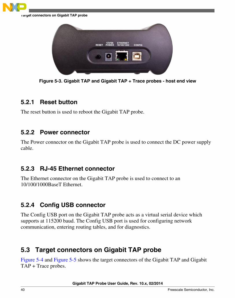
Figure 5-3. Gigabit TAP and Gigabit TAP + Trace probes - host end view
5.2.1 Reset button
The reset button is used to reboot the Gigabit TAP probe.
5.2.2 Power connector
The Power connector on the Gigabit TAP probe is used to connect the DC power supplycable.
5.2.3 RJ-45 Ethernet connector
The Ethernet connector on the Gigabit TAP probe is used to connect to an10/100/1000BaseT Ethernet.
5.2.4 Config USB connector
The Config USB port on the Gigabit TAP probe acts as a virtual serial device whichsupports at 115200 baud. The Config USB port is used for configuring networkcommunication, entering routing tables, and for diagnostics.
5.3 Target connectors on Gigabit TAP probeFigure 5-4 and Figure 5-5 shows the target connectors of the Gigabit TAP and GigabitTAP + Trace probes.
Target connectors on Gigabit TAP probe
Gigabit TAP Probe User Guide, Rev. 10.x, 02/2014
40 Freescale Semiconductor, Inc.

Figure 5-4. Gigabit TAP probe - target end view
Figure 5-5. Gigabit TAP + Trace probe - target end view
5.3.1 Trigger in connector
The TRIGGER IN port on the Gigabit TAP + Trace probe is a 3.5mm stereo socket, witha trigger input channel on pin 3 (right), and an trigger output channel on pin 2 (left).
5.3.2 Trigger out connector
The TRIGGER OUT port on the Gigabit TAP + Trace probe is a 3.5mm stereo socket,with a trigger output channel on pin 3 (right), and an trigger input channel on pin 2 (left).
Chapter 5 Hardware specifications
Gigabit TAP Probe User Guide, Rev. 10.x, 02/2014
Freescale Semiconductor, Inc. 41

5.3.3 Aurora Nexus connector
The Aurora Nexus cable is connected to the AURORA Nexus socket on the Gigabit TAP+ Trace probes.
5.3.4 RJ-25 target serial connector
The Gigabit TAP probe provides a target serial port which can be configured to accessyour target's serial port. This is particularly useful if your host computer is not near yourtarget and you need to access your target's serial port remotely over your network.
Figure below shows the pinout definition of the Target serial port.
Table 5-2. Pinout definition of the Target Serial port
Pin Signal
1 Ready To Send (RTS)
2 Ground
3 Receive Data (RxD)
4 Transmit Data (TxD)
5 Ground
6 Clear To Send (CTS)
Pin 1 is on the right side as you look at the RJ-11 socket (locking tab on the bottom).
5.3.5 Run control probe tip cable connector
The probe tip ribbon cable is connected to the 50-pin connector on the Gigabit TAPprobe.
5.3.6 Debug port connector
The debug port socket is on the end of the tip and is used to connect the Gigabit TAPprobe to a debug port header on your target system.
NOTEEnsure that Pin 1 of the probe tip is connected to the Pin 1 ofthe header.
Target connectors on Gigabit TAP probe
Gigabit TAP Probe User Guide, Rev. 10.x, 02/2014
42 Freescale Semiconductor, Inc.

5.4 Gigabit TAP probe specificationsThe dimensions of both Gigabit TAP and Gigabit TAP + Trace probes are same. Thefigure Figure 5-6 shows the dimensions of the Gigabit TAP + Trace probe.
Figure 5-6. Gigabit TAP + Trace probe dimensions
5.4.1 Electrical characteristics
The Gigabit TAP probe affects the load on only those signals that are connected to thedebug port connector. Loading depends on the method used to connect the Gigabit TAPprobe to the target system. See Connecting to target system topic for a description of eachconnection method.
The Gigabit TAP probe affects the target processor and target electrical characteristics.Caution should be taken in designing the target to accommodate the small signal delaysassociated with in-circuit emulator or other test equipment.
The Gigabit TAP probe automatically supports target signal levels from 1.2V to 3.3V.
5.4.2 Physical characteristics
The Gigabit TAP probe is designed to accommodate a trace expansion card, so theoverall system may be too large to physically fit in all target systems.
Chapter 5 Hardware specifications
Gigabit TAP Probe User Guide, Rev. 10.x, 02/2014
Freescale Semiconductor, Inc. 43
If you are unable to connect to the debug port on your target system, or if your targetsystem does not have a debug port connector, see Connecting JTAG header usingextension cable topic.
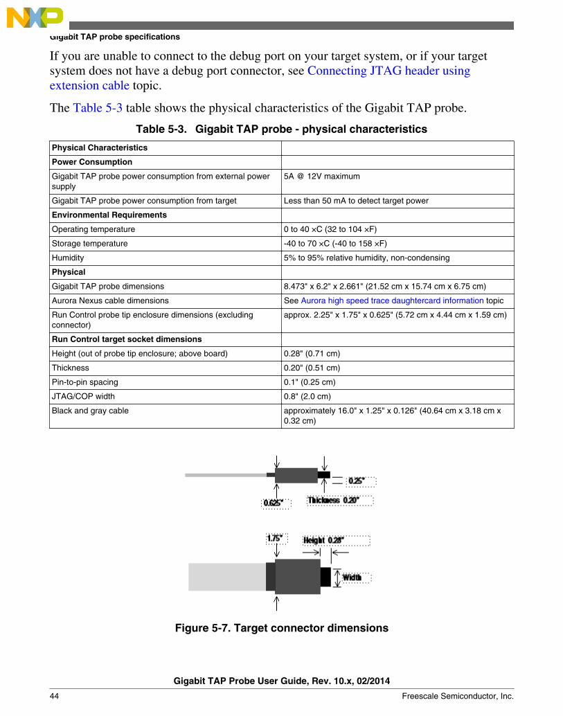
The Table 5-3 table shows the physical characteristics of the Gigabit TAP probe.
Table 5-3. Gigabit TAP probe - physical characteristics
Physical Characteristics
Power Consumption
Gigabit TAP probe power consumption from external powersupply
5A @ 12V maximum
Gigabit TAP probe power consumption from target Less than 50 mA to detect target power
Environmental Requirements
Operating temperature 0 to 40 ×C (32 to 104 ×F)
Storage temperature -40 to 70 ×C (-40 to 158 ×F)
Humidity 5% to 95% relative humidity, non-condensing
Physical
Gigabit TAP probe dimensions 8.473" x 6.2" x 2.661" (21.52 cm x 15.74 cm x 6.75 cm)
Aurora Nexus cable dimensions See Aurora high speed trace daughtercard information topic
Run Control probe tip enclosure dimensions (excludingconnector)
approx. 2.25" x 1.75" x 0.625" (5.72 cm x 4.44 cm x 1.59 cm)
Run Control target socket dimensions
Height (out of probe tip enclosure; above board) 0.28" (0.71 cm)
Thickness 0.20" (0.51 cm)
Pin-to-pin spacing 0.1" (0.25 cm)
JTAG/COP width 0.8" (2.0 cm)
Black and gray cable approximately 16.0" x 1.25" x 0.126" (40.64 cm x 3.18 cm x0.32 cm)
Figure 5-7. Target connector dimensions
Gigabit TAP probe specifications
Gigabit TAP Probe User Guide, Rev. 10.x, 02/2014
44 Freescale Semiconductor, Inc.
Chapter 6JTAG/COP connector informationThe CodeWarrior Gigabit TAP JTAG/COP probe has a 16-pin connector whichautomatically supports target system signal levels from 1.2V to 3.3V.
Figure 6-1 shows the pin assignments of the probe JTAG/COP connector.
Table 6-1 lists JTAG/COP signal names, direction, pin numbers, descriptions, and drivecapabilities for the probe JTAG/COP connector.
Table 6-2 provides a general description of each JTAG/COP signal and the operationalrequirements.
NOTEAll JTAG/COP signals must meet accepted standards forJTAG/COP signal design. To ensure proper and stableoperation between the Gigabit TAP probe and the targetsystem, the JTAG/COP signals must meet the requirementslisted in Table 6-2.
Gigabit TAP Probe User Guide, Rev. 10.x, 02/2014
Freescale Semiconductor, Inc. 45
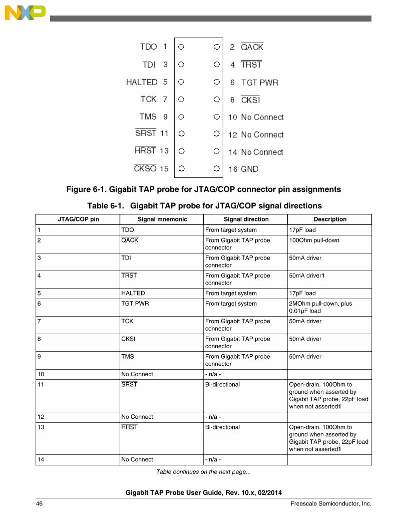
Figure 6-1. Gigabit TAP probe for JTAG/COP connector pin assignments
Table 6-1. Gigabit TAP probe for JTAG/COP signal directions
JTAG/COP pin Signal mnemonic Signal direction Description
1 TDO From target system 17pF load
2 QACK From Gigabit TAP probeconnector
100Ohm pull-down
3 TDI From Gigabit TAP probeconnector
50mA driver
4 TRST From Gigabit TAP probeconnector
50mA driver1
5 HALTED From target system 17pF load
6 TGT PWR From target system 2MOhm pull-down, plus0.01µF load
7 TCK From Gigabit TAP probeconnector
50mA driver
8 CKSI From Gigabit TAP probeconnector
50mA driver
9 TMS From Gigabit TAP probeconnector
50mA driver
10 No Connect - n/a -
11 SRST Bi-directional Open-drain. 100Ohm toground when asserted byGigabit TAP probe, 22pF loadwhen not asserted1
12 No Connect - n/a -
13 HRST Bi-directional Open-drain. 100Ohm toground when asserted byGigabit TAP probe, 22pF loadwhen not asserted1
14 No Connect - n/a -
Table continues on the next page...
Gigabit TAP Probe User Guide, Rev. 10.x, 02/2014
46 Freescale Semiconductor, Inc.
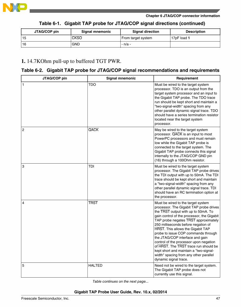
Table 6-1. Gigabit TAP probe for JTAG/COP signal directions (continued)
JTAG/COP pin Signal mnemonic Signal direction Description
15 CKSO From target system 17pF load 1
16 GND - n/a -
1. 14.7KOhm pull-up to buffered TGT PWR.
Table 6-2. Gigabit TAP probe for JTAG/COP signal recommendations and requirements
JTAG/COP pin Signal mnemonic Requirement
1 TDO Must be wired to the target systemprocessor. TDO is an output from thetarget system processor and an input tothe Gigabit TAP probe. The TDO tracerun should be kept short and maintain a"two-signal-width" spacing from anyother parallel dynamic signal trace. TDOshould have a series termination resistorlocated near the target systemprocessor.
2 QACK May be wired to the target systemprocessor. QACK is an input to mostPowerPC processors and must remainlow while the Gigabit TAP probe isconnected to the target system. TheGigabit TAP probe connects this signalinternally to the JTAG/COP GND pin(16) through a 100Ohm resistor.
3 TDI Must be wired to the target systemprocessor. The Gigabit TAP probe drivesthe TDI output with up to 50mA. The TDItrace should be kept short and maintaina "two-signal-width" spacing from anyother parallel dynamic signal trace. TDIshould have an RC termination option atthe processor.
4 TRST Must be wired to the target systemprocessor. The Gigabit TAP probe drivesthe TRST output with up to 50mA. Togain control of the processor, the GigabitTAP probe negates TRST approximately250 milliseconds before negation ofHRST. This allows the Gigabit TAPprobe to issue COP commands throughthe JTAG/COP interface and gaincontrol of the processor upon negationof HRST. The TRST trace run should bekept short and maintain a "two-signal-width" spacing from any other paralleldynamic signal trace.
5 HALTED Need not be wired to the target system.The Gigabit TAP probe does notcurrently use this signal.
Table continues on the next page...
Chapter 6 JTAG/COP connector information
Gigabit TAP Probe User Guide, Rev. 10.x, 02/2014
Freescale Semiconductor, Inc. 47
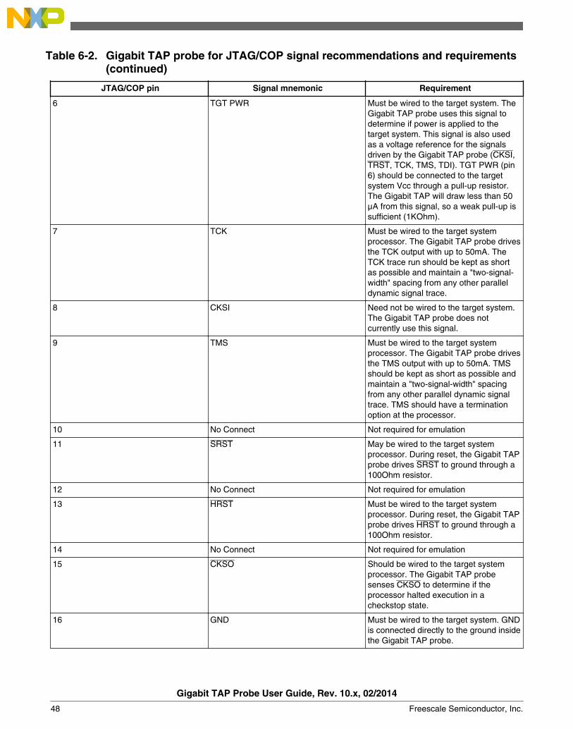
Table 6-2. Gigabit TAP probe for JTAG/COP signal recommendations and requirements(continued)
JTAG/COP pin Signal mnemonic Requirement
6 TGT PWR Must be wired to the target system. TheGigabit TAP probe uses this signal todetermine if power is applied to thetarget system. This signal is also usedas a voltage reference for the signalsdriven by the Gigabit TAP probe (CKSI,TRST, TCK, TMS, TDI). TGT PWR (pin6) should be connected to the targetsystem Vcc through a pull-up resistor.The Gigabit TAP will draw less than 50µA from this signal, so a weak pull-up issufficient (1KOhm).
7 TCK Must be wired to the target systemprocessor. The Gigabit TAP probe drivesthe TCK output with up to 50mA. TheTCK trace run should be kept as shortas possible and maintain a "two-signal-width" spacing from any other paralleldynamic signal trace.
8 CKSI Need not be wired to the target system.The Gigabit TAP probe does notcurrently use this signal.
9 TMS Must be wired to the target systemprocessor. The Gigabit TAP probe drivesthe TMS output with up to 50mA. TMSshould be kept as short as possible andmaintain a "two-signal-width" spacingfrom any other parallel dynamic signaltrace. TMS should have a terminationoption at the processor.
10 No Connect Not required for emulation
11 SRST May be wired to the target systemprocessor. During reset, the Gigabit TAPprobe drives SRST to ground through a100Ohm resistor.
12 No Connect Not required for emulation
13 HRST Must be wired to the target systemprocessor. During reset, the Gigabit TAPprobe drives HRST to ground through a100Ohm resistor.
14 No Connect Not required for emulation
15 CKSO Should be wired to the target systemprocessor. The Gigabit TAP probesenses CKSO to determine if theprocessor halted execution in acheckstop state.
16 GND Must be wired to the target system. GNDis connected directly to the ground insidethe Gigabit TAP probe.
Gigabit TAP Probe User Guide, Rev. 10.x, 02/2014
48 Freescale Semiconductor, Inc.

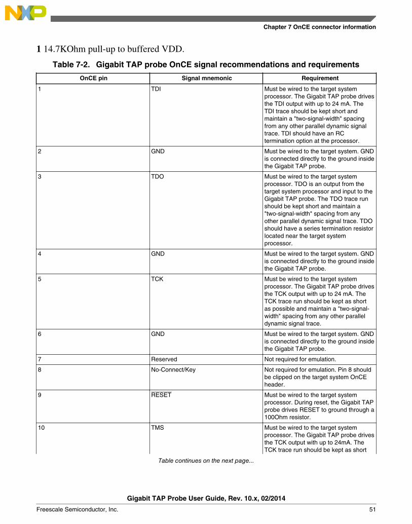
Chapter 7OnCE connector informationThe CodeWarrior Gigabit TAP OnCE probe has a 14-pin connector which automaticallysupports target system signal levels from 1.2V to 3.3V.
Figure 7-1 shows the pin assignments of the probe OnCE connector.
Table 7-1 lists OnCE signal names, direction, pin numbers, descriptions, and drivecapabilities for the probe OnCE connector.
Table 7-2 provides a general description of each OnCE signal and the operationalrequirements.
NOTEAll OnCE signals must meet accepted standards for OnCEsignal design. To ensure proper and stable operation betweenthe Gigabit TAP probe and the target system, the OnCE signalsmust meet the requirements listed in Table 7-2.
Gigabit TAP Probe User Guide, Rev. 10.x, 02/2014
Freescale Semiconductor, Inc. 49
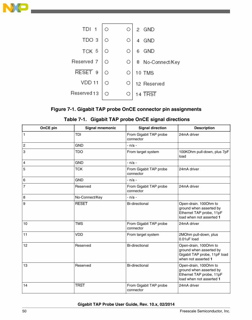
Figure 7-1. Gigabit TAP probe OnCE connector pin assignments
Table 7-1. Gigabit TAP probe OnCE signal directions
OnCE pin Signal mnemonic Signal direction Description
1 TDI From Gigabit TAP probeconnector
24mA driver
2 GND - n/a -
3 TDO From target system 100KOhm pull-down, plus 7pFload
4 GND - n/a -
5 TCK From Gigabit TAP probeconnector
24mA driver
6 GND - n/a -
7 Reserved From Gigabit TAP probeconnector
24mA driver
8 No-Connect/Key - n/a -
9 RESET Bi-directional Open-drain. 100Ohm toground when asserted byEthernet TAP probe, 11pFload when not asserted 1
10 TMS From Gigabit TAP probeconnector
24mA driver
11 VDD From target system 2MOhm pull-down, plus0.01uF load
12 Reserved Bi-directional Open-drain, 100Ohm toground when asserted byGigabit TAP probe, 11pF loadwhen not asserted 1
13 Reserved Bi-directional Open-drain, 100Ohm toground when asserted byEthernet TAP probe, 11pFload when not asserted 1
14 TRST From Gigabit TAP probeconnector
24mA driver
Gigabit TAP Probe User Guide, Rev. 10.x, 02/2014
50 Freescale Semiconductor, Inc.
1 14.7KOhm pull-up to buffered VDD.
Table 7-2. Gigabit TAP probe OnCE signal recommendations and requirements
OnCE pin Signal mnemonic Requirement
1 TDI Must be wired to the target systemprocessor. The Gigabit TAP probe drivesthe TDI output with up to 24 mA. TheTDI trace should be kept short andmaintain a "two-signal-width" spacingfrom any other parallel dynamic signaltrace. TDI should have an RCtermination option at the processor.
2 GND Must be wired to the target system. GNDis connected directly to the ground insidethe Gigabit TAP probe.
3 TDO Must be wired to the target systemprocessor. TDO is an output from thetarget system processor and input to theGigabit TAP probe. The TDO trace runshould be kept short and maintain a"two-signal-width" spacing from anyother parallel dynamic signal trace. TDOshould have a series termination resistorlocated near the target systemprocessor.
4 GND Must be wired to the target system. GNDis connected directly to the ground insidethe Gigabit TAP probe.
5 TCK Must be wired to the target systemprocessor. The Gigabit TAP probe drivesthe TCK output with up to 24 mA. TheTCK trace run should be kept as shortas possible and maintain a "two-signal-width" spacing from any other paralleldynamic signal trace.
6 GND Must be wired to the target system. GNDis connected directly to the ground insidethe Gigabit TAP probe.
7 Reserved Not required for emulation.
8 No-Connect/Key Not required for emulation. Pin 8 shouldbe clipped on the target system OnCEheader.
9 RESET Must be wired to the target systemprocessor. During reset, the Gigabit TAPprobe drives RESET to ground through a100Ohm resistor.
10 TMS Must be wired to the target systemprocessor. The Gigabit TAP probe drivesthe TCK output with up to 24mA. TheTCK trace run should be kept as short
Table continues on the next page...
Chapter 7 OnCE connector information
Gigabit TAP Probe User Guide, Rev. 10.x, 02/2014
Freescale Semiconductor, Inc. 51

Table 7-2. Gigabit TAP probe OnCE signal recommendations and requirements (continued)
OnCE pin Signal mnemonic Requirement
as possible and maintain a "two-signal-width" spacing from any other paralleldynamic signal trace.
11 VDD Must be wired to the target system. TheGigabit TAP probe uses this signal todetermine if power is applied to thetarget system. This signal is also usedas a voltage reference for the signalsdriven by the Gigabit TAP probe (TDI,TCK, TMS, RESET, and TRST).
12 Reserved Not required for emulation.
13 Reserved Not required for emulation.
14 TRST Must be wired to the target systemprocessor. The Gigabit TAP probe drivesthe TRST output with up to 24 mA. TheTRST trace run should be kept short andmaintain a "two-signal-width" spacingfrom any other parallel dynamic signaltrace.
Gigabit TAP Probe User Guide, Rev. 10.x, 02/2014
52 Freescale Semiconductor, Inc.
Chapter 8Aurora high speed trace daughtercard informationThis chapter provides information on the CodeWarrior Gigabit TAP Aurora/JTAG probe.It supports high speed serial trace and JTAG interfaces as specified by the Power.org™Standard for Physical Connection. The connection provides two lanes of high speed serialtrace, two lanes of high speed serial download capability, a standard JTAG connection,and from four to six vendor specific I/O signals troubleshooting information.
This chapter contains the following sections:
• General specifications• Mechanical specification
8.1 General specificationsThis section describes the general sepcifications.
8.1.1 Simplex operation
The probe can receive two lanes of high speed trace data from the SoC. Any combinationof lanes and speeds may be configured to support the bandwidth requirement of the SoC.An optional back channel may be used to support UFC (User Flow Control) between theprobe and the SoC as specified by the appropriate Power.Org and Nexus specifications.
Gigabit TAP Probe User Guide, Rev. 10.x, 02/2014
Freescale Semiconductor, Inc. 53
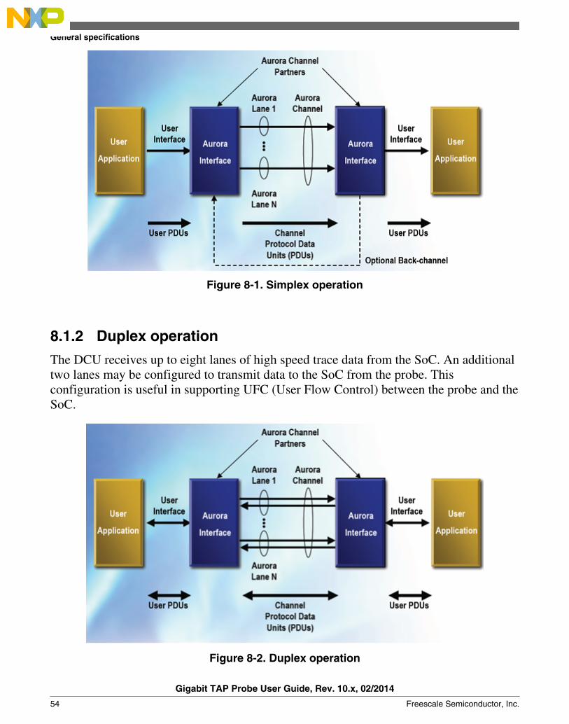
Figure 8-1. Simplex operation
8.1.2 Duplex operation
The DCU receives up to eight lanes of high speed trace data from the SoC. An additionaltwo lanes may be configured to transmit data to the SoC from the probe. Thisconfiguration is useful in supporting UFC (User Flow Control) between the probe and theSoC.
Figure 8-2. Duplex operation
General specifications
Gigabit TAP Probe User Guide, Rev. 10.x, 02/2014
54 Freescale Semiconductor, Inc.
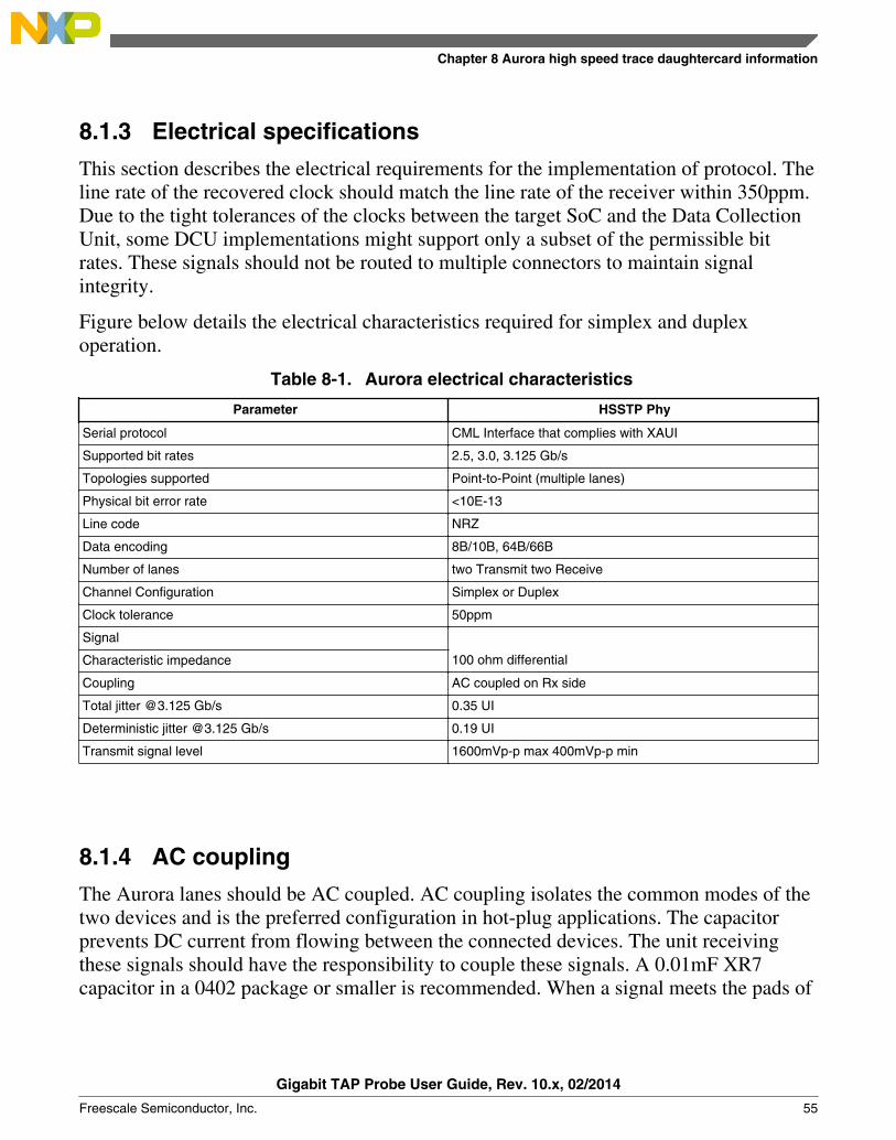
8.1.3 Electrical specifications
This section describes the electrical requirements for the implementation of protocol. Theline rate of the recovered clock should match the line rate of the receiver within 350ppm.Due to the tight tolerances of the clocks between the target SoC and the Data CollectionUnit, some DCU implementations might support only a subset of the permissible bitrates. These signals should not be routed to multiple connectors to maintain signalintegrity.
Figure below details the electrical characteristics required for simplex and duplexoperation.
Table 8-1. Aurora electrical characteristics
Parameter HSSTP Phy
Serial protocol CML Interface that complies with XAUI
Supported bit rates 2.5, 3.0, 3.125 Gb/s
Topologies supported Point-to-Point (multiple lanes)
Physical bit error rate <10E-13
Line code NRZ
Data encoding 8B/10B, 64B/66B
Number of lanes two Transmit two Receive
Channel Configuration Simplex or Duplex
Clock tolerance 50ppm
Signal
Characteristic impedance 100 ohm differential
Coupling AC coupled on Rx side
Total jitter @3.125 Gb/s 0.35 UI
Deterministic jitter @3.125 Gb/s 0.19 UI
Transmit signal level 1600mVp-p max 400mVp-p min
8.1.4 AC coupling
The Aurora lanes should be AC coupled. AC coupling isolates the common modes of thetwo devices and is the preferred configuration in hot-plug applications. The capacitorprevents DC current from flowing between the connected devices. The unit receivingthese signals should have the responsibility to couple these signals. A 0.01mF XR7capacitor in a 0402 package or smaller is recommended. When a signal meets the pads of
Chapter 8 Aurora high speed trace daughtercard information
Gigabit TAP Probe User Guide, Rev. 10.x, 02/2014
Freescale Semiconductor, Inc. 55
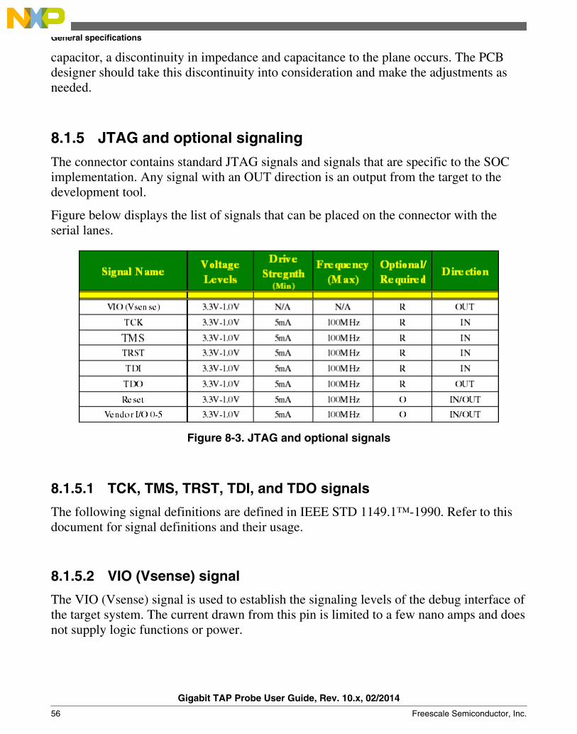
capacitor, a discontinuity in impedance and capacitance to the plane occurs. The PCBdesigner should take this discontinuity into consideration and make the adjustments asneeded.
8.1.5 JTAG and optional signaling
The connector contains standard JTAG signals and signals that are specific to the SOCimplementation. Any signal with an OUT direction is an output from the target to thedevelopment tool.
Figure below displays the list of signals that can be placed on the connector with theserial lanes.
Figure 8-3. JTAG and optional signals
8.1.5.1 TCK, TMS, TRST, TDI, and TDO signals
The following signal definitions are defined in IEEE STD 1149.1™-1990. Refer to thisdocument for signal definitions and their usage.
8.1.5.2 VIO (Vsense) signal
The VIO (Vsense) signal is used to establish the signaling levels of the debug interface ofthe target system. The current drawn from this pin is limited to a few nano amps and doesnot supply logic functions or power.
General specifications
Gigabit TAP Probe User Guide, Rev. 10.x, 02/2014
56 Freescale Semiconductor, Inc.

8.1.5.3 Reset signal
The Reset signal causes the target to enter into a defined reset state or signals theoccurrence of a reset on the target. The full intent of the Reset signal may be defineddifferently for each device so the device documentation should be referred to determinethe behavior of this signal. The tool and target should use an open-drain output driver forthis pin.
8.1.5.4 Vendor IO 0-5 signals
These signals are input and output SoC specific signals. The Gigabit TAP automaticallyconfigure these signals as input or output based on the type of SoC it is connecting to.These signals are not required by the standard for operation, but improve the controlbetween the test tool and SoC. For the definition of these signals, refer to the hardwarereference manual for specific SoC.
8.1.5.5 Recommended termination
It is recommended that the signals having Target value in the Location field as shown infigure are connected to pull-ups on the target to prevent floating signals when the tool isnot connected or powered on. The voltage to which the signals are pulled up is the I/Ovoltage of the target signals.
Table 8-2. JTAG and optional signals
Signal name Pull-up Series termination Location
VIO (sense) 1 KOhms Target
TCK 10 KOhms Target
TMS 10 KOhms Target
TRST 10 KOhms Target
TDI 10 KOhms Target
TDO 10 KOhms Test Tool
Reset 10 KOhms Target
Chapter 8 Aurora high speed trace daughtercard information
Gigabit TAP Probe User Guide, Rev. 10.x, 02/2014
Freescale Semiconductor, Inc. 57

8.2 Mechanical specificationThe Power.Org and Nexus specifications provide a wide range of connector and pinoutoptions. The sections below describe the connectors and pinouts currently supported bythe Gigabit TAP, but additional options may become available later. Contact yourFreescale FAE or Sales person to determine those that are currently supported with theGigabit TAP and recommended for your application.
8.2.1 Cables
Freescale currently supports two cables listed in the Table 8-3, but note that the 22-pincable must be purchased separately from Samtec.
Table 8-3. 70-pin and 22-pin duplex cables
70-pin duplex cable 22-pin duplex cable
Freescale Part Number CWH-GTT-ACBL-YE N/A
Samtec Part Number HDR-141762-02 HDR-141490-02
Pin Count 70 22
Target Transmit Lanes 8 2
Target Receive Lanes 4 2
Aurora Reference Clock Pins Yes No
Vendor I/O Pins 6 4
Cable Length 18" 18"
PCB Keepout Dimensions 1.786"x0.326" 1.030"x0.326"
Included with Gigabit TAP Yes No
All Aurora cables use a common 62-pin connector to attach to the Gigabit TAP's AuroraTrace socket. This socket is keyed so that the cable cannot be plugged in upside-down.
8.2.2 Connectors
The Power.org and Nexus specifications define both simplex and duplex variations of the70-pin connector, but the Gigabit TAP + Trace currently only has cables available for theduplex configuration. This pinout is shown in figure below.
Table 8-4. 70-pin Duplex Aurora Pinout - Samtec Part Number: ASP-135029-01
Latch GND GND Latch
1 TX0+ VIO (V sense) 2
3 TX0- TCK 4
Table continues on the next page...
Mechanical specification
Gigabit TAP Probe User Guide, Rev. 10.x, 02/2014
58 Freescale Semiconductor, Inc.

Table 8-4. 70-pin Duplex Aurora Pinout - Samtec Part Number: ASP-135029-01 (continued)
5 GND TMS 6
7 TX1+ TDI 8
9 TX1- TDO 1
11 GND TRST 12
13 RX0+ Vendor I/O 0 14
15 RX0- Vendor I/O 1 16
17 GND Vendor I/O 2 18
19 RX1+ Vendor I/O 3 20
21 RX1- /RESET 22
23 GND GND 24
25 TX2+ CLK+ 26
27 TX2- CLK- 28
29 GND GND 30
31 TX3+ Vendor I/O 4 32
33 TX3- Vendor I/O 5 34
35 GND GND 36
37 RX2+ N/C 38
39 RX2- N/C 40
41 GND GND 42
43 RX3+ N/C 44
45 RX3- N/C 46
47 GND GND 48
49 TX4+ N/C 50
51 TX4- N/C 52
53 GND GND 54
55 TX5+ N/C 56
57 TX5- N/C 58
59 GND GND 60
61 TX6+ N/C 62
63 TX6- N/C 64
65 GND GND 66
67 TX7+ N/C 68
69 TX7- N/C 70
Latch GND GND Latch
Chapter 8 Aurora high speed trace daughtercard information
Gigabit TAP Probe User Guide, Rev. 10.x, 02/2014
Freescale Semiconductor, Inc. 59

The Power.org and Nexus specifications define both simplex and duplex variations of the22-pin connector, but the Gigabit TAP + Trace currently only has cables available for theDuplex configuration. This pinout is shown in figure below.
Table 8-5. 22-pin Duplex Aurora Pinout - Samtec Part Number: ASP-137969-01
Latch GND GND Latch
1 TX0+ VIO (V sense) 2
3 TX0- TCK 4
5 GND TMS 6
7 TX1+ TDI 8
9 TX1- TDo 10
11 GND TRST 12
13 RX0+ Vendor I/O 0 14
15 RX0- Vendor I/O 1 16
17 GND Vendor I/O 2 18
19 RX1+ Vendor I/O 3 20
21 RX1- /RESET 22
Latch GND GND Latch
8.2.3 PCB design and routing consideration
Routing of the Aurora lane traces are extremely critical. Sharp corners and vias can makenarrow eye patterns that affect the performance of the Aurora lanes. To achievemaximum performance, it is critical that care be taken in routing the lanes and the JTAGsingle-ended signals. To achieve optimal JTAG interface, good performance layout androuting practices should be observed. When routing the JTAG signals on a target board, itis recommended that they should be routed directly to the SoC using minimal vias andhave a minimum of twice the distance to the plane spacing. These signals should have animpedance of 50ohm ±10%. If multiple components are attached to the JTAG scan chain,the performance of the bus must be considered. Additional loading may require a reducedJTAG bus speed for reliable operation or buffering of the TMS, TCK, and TDI signals toall the devices on the chain.
NOTEConsult the appropriate Xilinx documentation for Auroraspecific layout and routing.
Mechanical specification
Gigabit TAP Probe User Guide, Rev. 10.x, 02/2014
60 Freescale Semiconductor, Inc.
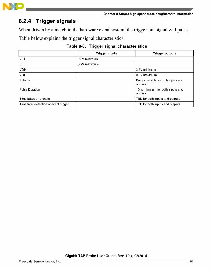
8.2.4 Trigger signals
When driven by a match in the hardware event system, the trigger-out signal will pulse.
Table below explains the trigger signal characteristics.
Table 8-6. Trigger signal characteristics
Trigger inputs Trigger outputs
VIH 2.3V minimum
VIL 0.9V maximum
VOH 2.3V minimum
VOL 0.6V maximum
Polarity Programmable for both inputs andoutputs
Pulse Duration 10ns minimum for both inputs andoutputs
Time between signals TBD for both inputs and outputs
Time from detection of event trigger TBD for both inputs and outputs
Chapter 8 Aurora high speed trace daughtercard information
Gigabit TAP Probe User Guide, Rev. 10.x, 02/2014
Freescale Semiconductor, Inc. 61

Mechanical specification
Gigabit TAP Probe User Guide, Rev. 10.x, 02/2014
62 Freescale Semiconductor, Inc.
Chapter 9Setting up standalone PC EthernetThis chapter covers installation of a direct TCP/IP Ethernet standalone connectionbetween a and the Gigabit TAP probe. Use it only if you do not want to connect yourprobe to an existing multi-user network.
You may decide to have a standalone network for:
• Target system access security• Immunity from network outages• Faster communication if main network has high-traffic• Simpler connection with fewer variables to cause problems
This chapter contains the following sections:
• System requirements• Tutorial: Standalone network for Ethernet setup• Installing and configuring TCP/IP software• Connecting Gigabit TAP probe to host computer• Configuring Gigabit TAP probe
CAUTIONThe Gigabit TAP probe contains components that are subject todamage from electrostatic discharge. Whenever you are using,handling, or transporting the Gigabit TAP probe, or connectingto or disconnecting from a target system, always use properanti-static protection measures, including static-free bench padsand grounded wrist straps.
9.1 System requirementsA typical standalone network configuration requires:
• A two-node network between a non-networked PC and the Gigabit TAP probe.
Gigabit TAP Probe User Guide, Rev. 10.x, 02/2014
Freescale Semiconductor, Inc. 63

• A networked PC with a second Ethernet Network Interface Card (NIC) connected tothe Gigabit TAP probe; Standalone TCP/IP network configuration shows thestandalone configuration.
Figure 9-1. Standalone TCP/IP network configuration• A PC with Microsoft® Windows operating system installed on it.
9.2 Tutorial: Standalone Network for Ethernet setupIf your PC is already configured for networking, skip the tutorial section and seeConfiguring Gigabit TAP probe section.
The steps required to set up a standalone network are covered in the following sections:
• Installing and configuring TCP/IP software• Creating Windows hosts file• Connecting Gigabit TAP probe to host computer
9.2.1 Installing and configuring TCP/IP software
Microsoft provides support for TCP/IP protocol with Windows. If your host PC does notalready have TCP/IP protocol installed, you need to add it.
If you are installing a second Ethernet adapter to dedicate to the Gigabit TAP probe, youneed to install a second instance of TCP/IP. In both instances, you bind the adapter to theTCP/IP protocol stack.
To install and configure TCP/IP, you need to have the following:
Tutorial: Standalone Network for Ethernet setup
Gigabit TAP Probe User Guide, Rev. 10.x, 02/2014
64 Freescale Semiconductor, Inc.
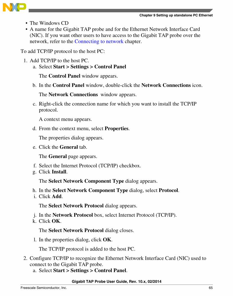
• The Windows CD• A name for the Gigabit TAP probe and for the Ethernet Network Interface Card
(NIC). If you want other users to have access to the Gigabit TAP probe over thenetwork, refer to the Connecting to network chapter.
To add TCP/IP protocol to the host PC:
1. Add TCP/IP to the host PC.a. Select Start > Settings > Control Panel
The Control Panel window appears.
b. In the Control Panel window, double-click the Network Connections icon.
The Network Connections window appears.
c. Right-click the connection name for which you want to install the TCP/IPprotocol.
A context menu appears.
d. From the context menu, select Properties.
The properties dialog appears.
e. Click the General tab.
The General page appears.
f. Select the Internet Protocol (TCP/IP) checkbox.g. Click Install.
The Select Network Component Type dialog appears.
h. In the Select Network Component Type dialog, select Protocol.i. Click Add.
The Select Network Protocol dialog appears.
j. In the Network Protocol box, select Internet Protocol (TCP/IP).k. Click OK.
The Select Network Protocol dialog closes.
l. In the properties dialog, click OK.
The TCP/IP protocol is added to the host PC.
2. Configure TCP/IP to recognize the Ethernet Network Interface Card (NIC) used toconnect to the Gigabit TAP probe.
a. Select Start > Settings > Control Panel.
Chapter 9 Setting up standalone PC Ethernet
Gigabit TAP Probe User Guide, Rev. 10.x, 02/2014
Freescale Semiconductor, Inc. 65
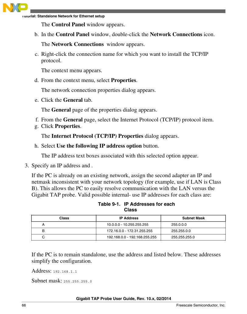
The Control Panel window appears.
b. In the Control Panel window, double-click the Network Connections icon.
The Network Connections window appears.
c. Right-click the connection name for which you want to install the TCP/IPprotocol.
The context menu appears.
d. From the context menu, select Properties.
The network connection properties dialog appears.
e. Click the General tab.
The General page of the properties dialog appears.
f. From the General page, select the Internet Protocol (TCP/IP) protocol item.g. Click Properties.
The Internet Protocol (TCP/IP) Properties dialog appears.
h. Select Use the following IP address option button.
The IP address text boxes associated with this selected option appear.
3. Specify an IP address and .
If the PC is already on an existing network, assign the second adapter an IP andnetmask inconsistent with your network topology (for example, use if LAN is ClassB). This allows the PC to easily resolve communication with the LAN versus theGigabit TAP probe. Valid possible internal- use IP addresses for each class are:
Table 9-1. IP Addresses for eachClass
Class IP Address Subnet Mask
A 10.0.0.0 - 10.255.255.255 255.0.0.0
B 172.16.0.0 - 172.31.255.255 255.255.0.0
C 192.168.0.0 - 192.168.255.255 255.255.255.0
If the PC is to remain standalone, use the address and listed below. These addressessimplify the configuration.
Address: 192.168.1.1
Subnet mask: 255.255.255.0
Tutorial: Standalone Network for Ethernet setup
Gigabit TAP Probe User Guide, Rev. 10.x, 02/2014
66 Freescale Semiconductor, Inc.
4. Confirm your settings, and close the Internet Protocol (TCP/IP) Propertieswindow.
5. When prompted, restart Windows.
If not prompted, restart Windows manually.
NOTEUnless you want to password protect access, click Cancelwhen asked for a network password.
9.2.2 Creating Windows hosts file
In the following procedure, you create a hosts database that identifies your PC host andthe Gigabit TAP probe. The hosts file associates IP addresses and host names of bothdevices.
A sample hosts file is installed in your Windows directory when you add the MicrosoftTCP/IP protocol. If your PC has previously been set up with network communication, ahosts database may already exist. Before creating a new hosts database, it is a good ideato make backup copies of any hosts file or sample hosts file.
To create a hosts database:
1. Go to the directory where the hosts file is located. Windows hosts files are located inthe %system root%\system32\drivers\etc directory.
NOTEIf you have trouble locating this file, use Windows Find tosearch for "hosts." If you have a dual-boot system, be sureto edit the hosts file appropriate to the operating systemunder which you are installing Gigabit TAP probe.
2. Make a backup copy of any existing hosts file.
Name the backup files something other than hosts, such as hosts.bak.
3. Use any text editor, open a new text file and name it hosts (without an extension) oropen the existing hosts file.
4. In the hosts file, add an entry for the Ethernet Network Interface Card (NIC) used bythe Gigabit TAP probe.
Use the IP address you assigned during TCP/IP configuration and assign the uniquename.
Chapter 9 Setting up standalone PC Ethernet
Gigabit TAP Probe User Guide, Rev. 10.x, 02/2014
Freescale Semiconductor, Inc. 67
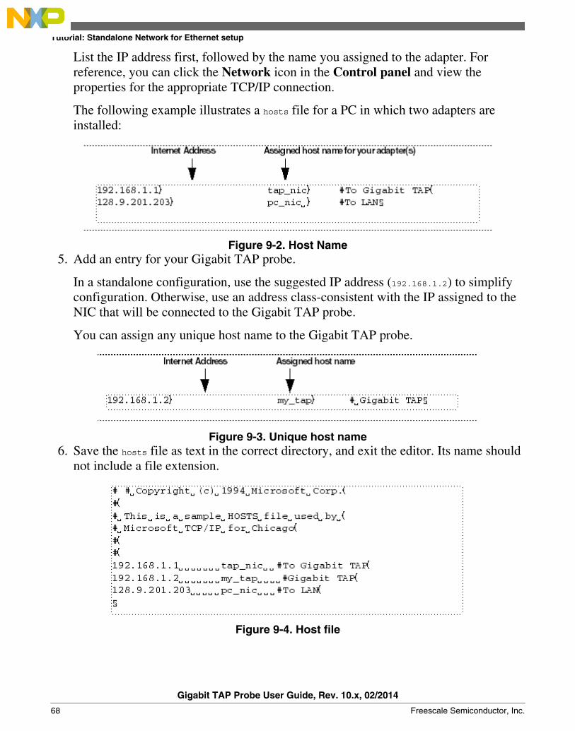
List the IP address first, followed by the name you assigned to the adapter. Forreference, you can click the Network icon in the Control panel and view theproperties for the appropriate TCP/IP connection.
The following example illustrates a hosts file for a PC in which two adapters areinstalled:
Figure 9-2. Host Name5. Add an entry for your Gigabit TAP probe.
In a standalone configuration, use the suggested IP address (192.168.1.2) to simplifyconfiguration. Otherwise, use an address class-consistent with the IP assigned to theNIC that will be connected to the Gigabit TAP probe.
You can assign any unique host name to the Gigabit TAP probe.
Figure 9-3. Unique host name6. Save the hosts file as text in the correct directory, and exit the editor. Its name should
not include a file extension.
Figure 9-4. Host file
Tutorial: Standalone Network for Ethernet setup
Gigabit TAP Probe User Guide, Rev. 10.x, 02/2014
68 Freescale Semiconductor, Inc.
9.2.3 Connecting Gigabit TAP probe to host computer
The Gigabit TAP probe has a built-in twisted pair interface that connects directly tonetworks that use the twisted pair (10/100/1000BaseT) cables. A twisted pair crossovercable has been provided to connect the RJ-45 connector of the Gigabit TAP probe to the installed in your PC.
9.3 Configuring the Gigabit TAP probeBefore you can use the to communicate with the Gigabit TAP probe, you must store theIP address and netmask in the Gigabit TAP probe's flash using the probe's internal setuputility.
NOTEFor more information on all the commands available from theGigabit TAP probe's internal setup utility, see Gigabit TAPprobe setup utility commands and variables section.
9.3.1 Starting setup utility
To access the internal of the Gigabit TAP probe, connect a terminal emulator (such asWindows® HyperTerminal) and configure it. For more information, see CustomizingGigabit TAP probe section.
9.3.2 Storing IP address and netmask in flash EPROM
When the core> prompt appears on the terminal, you can use the netparam command toconfigure the Gigabit TAP probe's network parameters.
To store the IP address and in flash EPROM:
1. Set the Gigabit TAP probe for static IP address mode using the following commandat the core> prompt:
netparam bootconfig static
2. Enter the Gigabit TAP probe's IP address and netmask at the core> prompt. Forexample:
netparam static_ip_address 192.168.1.2:255.255.0.0
Chapter 9 Setting up standalone PC Ethernet
Gigabit TAP Probe User Guide, Rev. 10.x, 02/2014
Freescale Semiconductor, Inc. 69

NOTEThe IP address you enter must match the IP address youspecified for the Gigabit TAP probe in the hosts file(192.168.1.2 is the suggested IP address). The netmask mustmatch the netmask you specified when you configured yourPC (255.255.0.0 is the suggested netmask).
3. Remove the USB cable from the port. It is not required for normal Ethernet TAPprobe operation.
Configuring the Gigabit TAP probe
Gigabit TAP Probe User Guide, Rev. 10.x, 02/2014
70 Freescale Semiconductor, Inc.

Chapter 10Gigabit TAP probe setup utility commandsThis chapter explains how to access the Gigabit TAP probe internal setup utility. Itdescribes all available setup utility commands and arguments.
This chapter contains the following sections:
• Connecting to Gigabit TAP probe setup utility• Gigabit TAP probe setup utility commands and variables
NOTEThe commands described in this chapter are for reference only.For detailed procedures on using these commands, seeapplicable chapter that covers the topic of interest.
10.1 Connecting to Gigabit TAP probe setup utilityThere are two methods for accessing the Gigabit TAP probe internal setup utility:
• Connect to the Gigabit TAP probe USB port. Use this method if the Gigabit TAPprobe is not connected to your network. For more information, see CustomizingGigabit TAP probe section.
• Telnet to the Gigabit TAP probe through an existing Ethernet connection.
Use this method if the Gigabit TAP probe is currently connected to your network.
is the Internet standard protocol for remote logins. Most TCP/IP networks provide atelnet program that you can use to login across the network to another machine. Notethat if you lose your Ethernet connection by improperly configuring the Gigabit TAPprobe from a telnet session, then you will have to connect to the serial port to re-establish network communications.
To connect to the setup utility using the telnet port:
1. Open a telnet session and connect to the Gigabit TAP probe.
Gigabit TAP Probe User Guide, Rev. 10.x, 02/2014
Freescale Semiconductor, Inc. 71
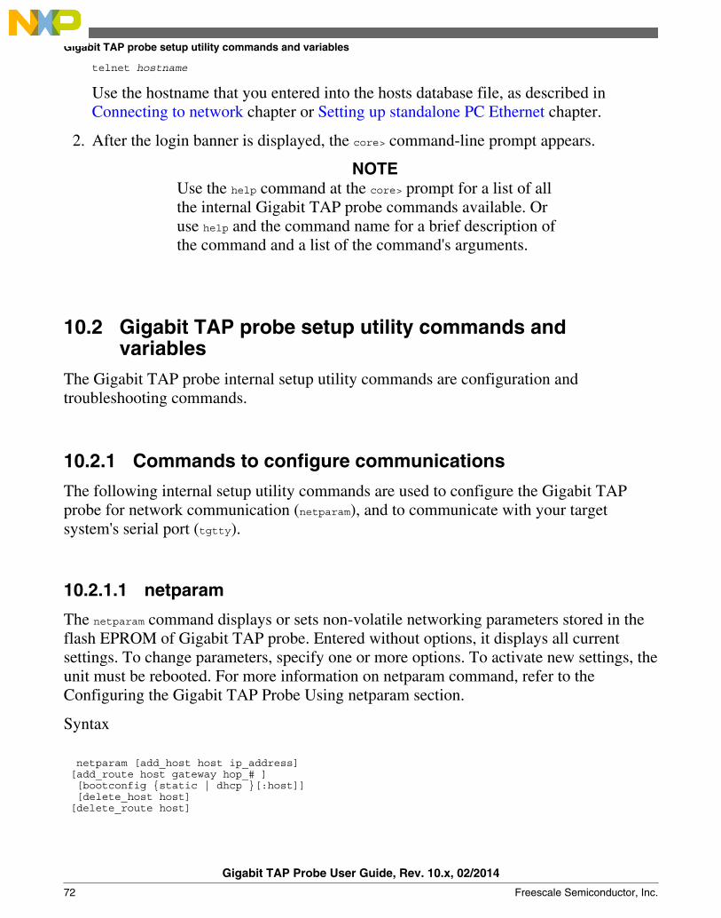
telnet hostname
Use the hostname that you entered into the hosts database file, as described inConnecting to network chapter or Setting up standalone PC Ethernet chapter.
2. After the login banner is displayed, the core> command-line prompt appears.
NOTEUse the help command at the core> prompt for a list of allthe internal Gigabit TAP probe commands available. Oruse help and the command name for a brief description ofthe command and a list of the command's arguments.
10.2 Gigabit TAP probe setup utility commands andvariables
The Gigabit TAP probe internal setup utility commands are configuration andtroubleshooting commands.
10.2.1 Commands to configure communications
The following internal setup utility commands are used to configure the Gigabit TAPprobe for network communication (netparam), and to communicate with your targetsystem's serial port (tgtty).
10.2.1.1 netparam
The netparam command displays or sets non-volatile networking parameters stored in theflash EPROM of Gigabit TAP probe. Entered without options, it displays all currentsettings. To change parameters, specify one or more options. To activate new settings, theunit must be rebooted. For more information on netparam command, refer to theConfiguring the Gigabit TAP Probe Using netparam section.
Syntax
netparam [add_host host ip_address] [add_route host gateway hop_# ] [bootconfig {static | dhcp }[:host]] [delete_host host] [delete_route host]
Gigabit TAP probe setup utility commands and variables
Gigabit TAP Probe User Guide, Rev. 10.x, 02/2014
72 Freescale Semiconductor, Inc.

[static_ip_address address[:mask]] [static_dns_server address]
Table 10-1. Netparam Parameters
Field Description
<null> Reports the current configuration
add_host host ip_address Adds a hostname-address pair to the static host table. Tableentries are automatically entered into the system on reset.host - Name to associate with the addressip_addressip_address - IP address to use for host,specified in dotted-decimal notation
add_route host gateway hop_# Adds a route to Gigabit TAP probe static route table. Tableentries are automatically entered into the system on reset. Ifthe specified parameters are invalid for the operating network,they are not stored. host - Destination IP address of host orhost network, specified in dotted-decimal notation. Default is avalid entry for host, and equivalent to 0.0.0.0. gateway -Gateway IP address for probe, specified in dotted-decimalnotation hop_# - Decimal number of gateway hops betweenGigabit TAP probe and destination host or network
bootconfig {static | dhcp }[:host] Sets the IP address resolution protocol. It determines the bootmethod of Gigabit TAP probe. Use bootconfig to connectto the network either by DHCP or by storing the IP address inthe flash EPROM of Gigabit TAP probe.
When using DHCP, you can specify the host name that youwould like the probe to try to register with a name serverwhen it acquires its network configuration.
The factory assigned host name is FSLXXYYZZ, whereXXYYZZ is the last three octets of the Gigabit MAC address,provided on a label on the bottom side of the probe. Forexample, if the probe's Gigabit MAC address is00:00:f6:00:77:31, the default host name will beFSL007731. static - Use IP address stored in Gigabit TAPprobe dhcp - Use the network DHCP protocol to resolve IPaddress, netmask, and default gateway (default) :host -Host name for the Gigabit TAP probe. If dhcp is specified, theprobe will attempt to register this host name with the DHCPserver. There should be no white space before :host. Theccs findcc search utility will report the host name of theprobe for both the dhcp and static options
delete_host host Deletes a hostname-address pair from the static host table.host - Destination IP address of host or host network
delete_route host Deletes a route from the static route table host - DestinationIP address of host or host network
static_ip_address address[:mask] Sets the Gigabit TAP probe IP address and optional netmaskaddress - IP address in dotted-decimal format (for example,128.8.1.1). When entering the IP address by itself (withoutalso entering the netmask), the Gigabit TAP probe uses thestandard netmask assigned to that IP address. mask -Netmask in dotted-decimal format (for example.,
Table continues on the next page...
Chapter 10 Gigabit TAP probe setup utility commands
Gigabit TAP Probe User Guide, Rev. 10.x, 02/2014
Freescale Semiconductor, Inc. 73

Table 10-1. Netparam Parameters (continued)
Field Description
255.255.0.0). If subnetting is required, you must store thenetmask by entering it on the same command line,immediately following the IP address.
static_dns_server address Sets the DNS server to use static bootconfig address - IPaddress in dotted-decimal format (e.g. 128.1.1). The DNSserver at this address will be used for domain name resolutionwhen bootconfig is set to static.
10.2.1.2 tgtty
The tgtty command configures the target system serial port settings.
Syntax
tgtty [default] [9600 | 19200 | 38400 | 57600 | 115200] [data8 | data5 | data6 | data7] [stop1 | stop2] [noparity|oddparity|evenparity|lowparity|highparity] [<rtscts | nortscts>] [noxon | xon] [echo | noecho]
Options
Options can be combined in one statement. Without options, the tgtty command displaysthe current settings.
The target system serial port's default settings are:
9600 data8 stop1 noparity nortscts echo
Table 10-2. Default Target Settings
Default Set the default target system serial settings
[9600 | 19200 | 38400 | 57600 | 115200] Choose a baud rate
[data8 | data5 | data6 | data7] Specify data bits
[stop1 | stop2] Specify stop bits
[noparity | oddparity | evenparity |lowparity| highparity]
Define parity
[<rtscts | nortscts>] Enable or disable hardware flow control
[noxon | xon] Enable or disable XON/XOFF flow control
Table continues on the next page...
Gigabit TAP probe setup utility commands and variables
Gigabit TAP Probe User Guide, Rev. 10.x, 02/2014
74 Freescale Semiconductor, Inc.

Table 10-2. Default Target Settings (continued)
Default Set the default target system serial settings
[echo | noecho] Enable or disable target system echo feature
10.2.2 Commands to troubleshoot communication
The following commands are used to troubleshoot problems connecting to your network.The procedures for troubleshooting communication are covered in Troubleshootingchapter.
NOTEIn this manual, commonly used options for these commands aredescribed.
10.2.2.1 arp
Use the arp command to edit the table by assigning hostnames to specific Ethernetaddresses. Without options, it displays the current arp table.
Syntax
arp [-s hostname ethernet_address | -d hostname]
Table 10-3. ARP - Options
Field Description
-s hostname ethernet_address Assign a hostname alias to an Ethernet address in the arptable
-d hostname Delete a hostname alias from the arp table
10.2.2.2 host
Use the host command to edit the host table by assigning hostnames to specific IP addresseswithout permanently storing the routing tables in the flash EPROM of the Gigabit TAPprobe. Without options, it displays the current host table.
Syntax
Chapter 10 Gigabit TAP probe setup utility commands
Gigabit TAP Probe User Guide, Rev. 10.x, 02/2014
Freescale Semiconductor, Inc. 75

host [add hostname ip_address | delete hostname ip_address]
Table 10-4. Host - Options
Field Description
add hostname ip_address Assign a hostname alias to an IP address in the host table.
delete hostname ip_address Delete a hostname alias from the host table.
10.2.2.3 netstat
Displays network information and statistics.
Syntax
netstat -a --inet | -i | -s | -r
Table 10-5. Netsat - Options
Field Description
-a --inet Display network connections
-i Display device status
-s Display protocol statistics
-r Display route table
10.2.2.4 ping
Use the ping command to verify that the Gigabit TAP probe is connected to your network.
Syntax
ping [-s size] [-c cnt][hostname | ip_address]
Table 10-6. Ping - Options
Field Description
hostname Use the hostname stored in Gigabit TAP probe host table(see the host command).
ip_address Use the IP address of the host you are trying to reach.
Table continues on the next page...
Gigabit TAP probe setup utility commands and variables
Gigabit TAP Probe User Guide, Rev. 10.x, 02/2014
76 Freescale Semiconductor, Inc.

Table 10-6. Ping - Options (continued)
Field Description
size The size, in bytes, to use for request packets.
cnt The number of packets to send.
10.2.2.5 route
Use the route command to test network routing without permanently storing the routingtables in the Gigabit TAP probe flash EPROM. Without options, it displays the currentroute table or default gateway.
Syntax
route [add destination gateway | delete destination]
Table 10-7. Route - Options
Field Description
add destination gateway Add a dynamic route to the route table.
delete destination Delete a dynamic route from the route table.
Chapter 10 Gigabit TAP probe setup utility commands
Gigabit TAP Probe User Guide, Rev. 10.x, 02/2014
Freescale Semiconductor, Inc. 77

Gigabit TAP probe setup utility commands and variables
Gigabit TAP Probe User Guide, Rev. 10.x, 02/2014
78 Freescale Semiconductor, Inc.

Chapter 11Network administrationThis chapter guides the network administrators in installing a Gigabit TAP probe. TheGigabit TAP probe is a Gigabit host device that may be configured for TCP/IP usingDHCP to acquire its IP configuration (the default method) or through a static IPconfiguration.
This chapter explains the following:
• Gigabit TAP probe network ports• Configuring Gigabit TAP probe using netparam• Using CCS to search for Gigabit TAP probes
11.1 Gigabit TAP probe network portsSoftware uses several network ports to communicate with a Gigabit TAP. In case, theGigabit TAP and host software are on the same network, you do not need to be aware ofthese ports. However, in case where a Gigabit TAP is located in a protected network, anadministrator will need to provide access to these ports if you want to connect to theGigabit TAP from another network. Figure below lists the ports used by the Gigabit TAPand a brief description of each port and describes various network ports of the GigabitTAP probe.
Table 11-1. Gigabit TAP network ports
Port Number Description
23 Telnet access to configuration console
1082 Telnet access to target serial port
1085 Used by CodeWarrior for trace collection
1086 Used by CodeWarrior for trace collection
1087 Used for firmware updates and by CodeWarrior to initialize the GigabitTAP
41474 Used by CodeWarrior to control the Gigabit TAP
53099 Used by CodeWarrior to check Gigabit TAP status
Gigabit TAP Probe User Guide, Rev. 10.x, 02/2014
Freescale Semiconductor, Inc. 79
11.2 Configuring Gigabit TAP probe using netparamUse the netparam command to select the network parameters:
• Address resolution protocol• Static address resolution data• Static routing tables
CAUTIONnetparam writes its settings into non-volatile flash memoryon the Gigabit TAP probe. Each time you enter a netparamcommand, wait for the core> prompt to re-appear beforeentering the next command.
11.2.1 Configuring dynamic IP Address
To configure a dynamic IP address:
1. Connect to the Gigabit TAP probe internal setup utility, as explained in Connectingto the Gigabit TAP Probe Setup Utility section.
2. At the core> prompt, use netparam to specify the protocol appropriate to your network:
netparam bootconfig dhcp[:hostname]
DHCP is the default setting. If you specify a hostname for the Gigabit TAP probe, theprobe will attempt to register the host name with the DHCP server, which may thenupdate any name servers on the network.
11.2.2 Configuring static IP Address
If you do not have a DHCP server on your network or you prefer to manually configureyour network settings, the Gigabit TAP probe is capable of storing its IP address andnetmask in flash memory. When bootconfig is set to static, the Gigabit TAP probe usesthis stored information to resolve its own IP and netmask requests.
Configuring Gigabit TAP probe using netparam
Gigabit TAP Probe User Guide, Rev. 10.x, 02/2014
80 Freescale Semiconductor, Inc.
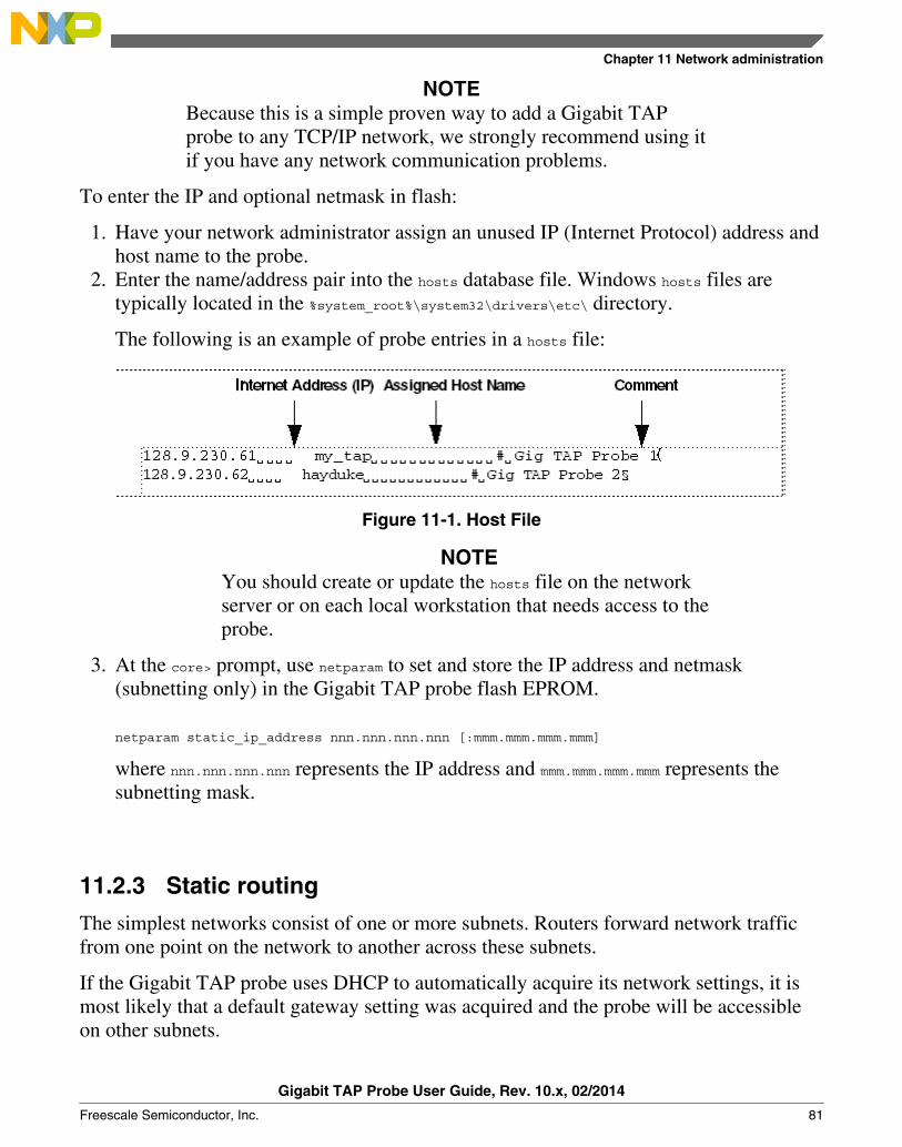
NOTEBecause this is a simple proven way to add a Gigabit TAPprobe to any TCP/IP network, we strongly recommend using itif you have any network communication problems.
To enter the IP and optional netmask in flash:
1. Have your network administrator assign an unused IP (Internet Protocol) address andhost name to the probe.
2. Enter the name/address pair into the hosts database file. Windows hosts files aretypically located in the %system_root%\system32\drivers\etc\ directory.
The following is an example of probe entries in a hosts file:
Figure 11-1. Host File
NOTEYou should create or update the hosts file on the networkserver or on each local workstation that needs access to theprobe.
3. At the core> prompt, use netparam to set and store the IP address and netmask(subnetting only) in the Gigabit TAP probe flash EPROM.
netparam static_ip_address nnn.nnn.nnn.nnn [:mmm.mmm.mmm.mmm]
where nnn.nnn.nnn.nnn represents the IP address and mmm.mmm.mmm.mmm represents thesubnetting mask.
11.2.3 Static routing
The simplest networks consist of one or more subnets. Routers forward network trafficfrom one point on the network to another across these subnets.
If the Gigabit TAP probe uses DHCP to automatically acquire its network settings, it ismost likely that a default gateway setting was acquired and the probe will be accessibleon other subnets.
Chapter 11 Network administration
Gigabit TAP Probe User Guide, Rev. 10.x, 02/2014
Freescale Semiconductor, Inc. 81
However, when using a static IP configuration or where the DHCP configuration isincomplete, you may have to provide additional routing information, including:
• Store a default gateway in flash memory• Load static routing tables into flash memory
11.2.3.1 Specify default gateway or static route table (optional)
If you are using a static IP configuration or your DHCP configuration does not specify adefault gateway, you can manually enter the IP address of the default gateway to use.This gateway must be accessible on your local subnet.
To specify a default gateway:
A default gateway entry must specify the IP address of the first gateway that the networktraffic from probe crosses. This gateway must be aware of the network's complete routetable. Use the following netparam syntax:
netparam add_route 0.0.0.0 gateway_ip 1
For gateway_ip, provide the IP address of the router or gateway in dot notation. The defaultvalue is 0.0.0.0.
11.2.4 Changing existing route entry
NOTEWhen entered in the Gigabit TAP probe, static routes are notupdated automatically. You must update these routes if changesin network topology affect the static routes.
Before entering static routes, make a map of all gateway paths between the Gigabit TAPprobe, as starting point, and each workstation that must have access to it.
To change an existing routing entry:
1. At the core> prompt, delete the existing routing entry:
netparam delete_route host_ip
2. Enter the new route as described above:
netparam add_route host_ipgateway_iphop_#
Configuring Gigabit TAP probe using netparam
Gigabit TAP Probe User Guide, Rev. 10.x, 02/2014
82 Freescale Semiconductor, Inc.
NOTEhost_ip can identify an individual workstation or a networkserving multiple hosts. The gateway_ip is the first gatewaythe probe traffic crosses when communicating with thedestination workstation. The hop_# is the decimal number ofgateways between the probe and the destinationworkstation.
11.2.5 Entering static routes
NOTEWhen entered in the Gigabit TAP probe, static routes are notupdated automatically. You must update these routes if changesin network topology affect the static routes.
Before entering static routes, make a map of all gateway paths between the Gigabit TAPprobe, as starting point, and each workstation must have access to it.
To enter a static route or default gateway:
1. At the core> prompt, use the netparam command to enter the first host/gateway pair:
netparam add_route host_ipgateway_iphop_#
Wait for the core> prompt between each netparam entry.
NOTEhost_ip can identify an individual host or a network servingmultiple hosts. The gateway_ip is the first gateway theGigabit TAP probe crosses when communicating with thedestination host. The hop_# is the decimal number ofgateways between the Gigabit TAP probe and thedestination host. The netparam command is described inGigabit TAP probe setup utility commands section.
2. Add routes until all destination hosts or networks are defined.3. When the core> prompt returns, reset the Gigabit TAP probe by cycling power, or by
entering the reset command.
Chapter 11 Network administration
Gigabit TAP Probe User Guide, Rev. 10.x, 02/2014
Freescale Semiconductor, Inc. 83
11.2.5.1 Static route example
Figure 11-2 shows three class "C" networks joined together by a single IP router, makingeach Gigabit TAP probe accessible from three workstations (elmer, tweety, and brutus).
No static routing information is required to make a Gigabit TAP probe accessible from aworkstation local to it on a network. For example, the Gigabit TAP probe goofy onnetwork 198.9.230.0 communicates directly with workstation elmer.
When static routing is used, a routing entry is required on a Gigabit TAP probe for eachworkstation on a non-local network that accesses it. The Gigabit TAP probe goofyrequires two entries, for workstation tweety on network 198.9.231.0 and workstationbrutus on network 198.9.232.0.
Each static route entry is made using a netparam command and consists of a networkaddress and a host address. The netparam commands for the static route entries for GigabitTAP probe goofy are:
netparam add_route 198.9.231.0 198.9.230.1 1
netparam add_route 198.9.232.0 198.9.230.1 1
Configuring Gigabit TAP probe using netparam
Gigabit TAP Probe User Guide, Rev. 10.x, 02/2014
84 Freescale Semiconductor, Inc.

Figure 11-2. Three Class C Networks Connected by a Single Router
Each of the three Gigabit TAP probe hosts must have a static route entry for each remoteworkstation that accesses it.
11.3 Using CCS to search for Gigabit TAP probesThe console provides a findcc command line utility which searches for all theCodeWarrior probes on the local subnet of each network interface of the host and lists theprobes' IP addresses, as well as other information. It uses mDNS multicast packets todiscover Gigabit TAP devices. Multicast packets are typically limited to the local subnetand typically are not routed or passed through VPNs.
If your Gigabit TAP probe acquires its IP address using DHCP, but is not able to registerits host name on the network, you will need the probe's IP address. To find the probe'saddress, perform the following steps:
1. Launch CCS and open the CCS Command window. The procedure is slightlydifferent on Windows and Linux/Solaris host machines.
• For Windows, run the command:
Chapter 11 Network administration
Gigabit TAP Probe User Guide, Rev. 10.x, 02/2014
Freescale Semiconductor, Inc. 85

CodeWarrior_Installation\ccs\bin\ccs.exe
This will launch CCS and add a CCS icon (see Figure 11-3) to your taskbar.Double-click that icon in the taskbar to open the Command window.
• For Linux/Solaris, run the command:
CodeWarrior_Installation/ccs/bin/ccs
This will launch CCS and open the Command window automatically.
Figure 11-3. CCS icon2. The command takes the following arguments when searching for Gigabit TAP
probes:
findcc gtaps [-quiet|-verbose]
11.3.1 Sample output
% findcc gtaps
gtap1 (192.168.0.3): Gigabit TAP
Aurora Nexus Daughter Card
LVDS PowerPC JTAG/COP Probe Tip
Boot Loader v1.0.0
Operating System v1.0.0
%
Using CCS to search for Gigabit TAP probes
Gigabit TAP Probe User Guide, Rev. 10.x, 02/2014
86 Freescale Semiconductor, Inc.
Chapter 12Gigabit TAP probe firmware (Core)This chapter explains the methods for reprogramming the core image stored in the flashEPROM of the Gigabit TAP probe. Before reprogramming the flash EPROM, make sureyou have already configured the Gigabit TAP probe network communication.
This chapter contains the following sections:
• Gigabit TAP probe internal software overview• Reprogramming Gigabit TAP probe firmware images
12.1 Gigabit TAP probe internal software overviewThe Gigabit TAP Boot Loader image performs hardware initialization and starts up theOperating System.
12.1.1 Boot loader
When the Gigabit TAP first powers up, it executes the Boot Loader. This occurs whilethe heartbeat LED is solid red. The Boot Loader is not generally visible to the user andshould rarely require reprogramming or updating. If an update is required, follow theinstructions in Reprogramming firmware through Gigabit port section.
12.1.2 Fallback boot loader
The Gigabit TAP Fallback Boot Loader image can be used to recover a probe if theprimary Boot Loader becomes corrupted. The procedure for enabling the Fallback BootLoader requires opening the case to access switches, and should only be performed afterconsulting with Freescale Technical Support.
Gigabit TAP Probe User Guide, Rev. 10.x, 02/2014
Freescale Semiconductor, Inc. 87
12.1.3 Operating System
The Gigabit TAP probe Operating System image provides tools for configuring andtesting network communication, for re-loading the probe software, and the underlyingsoftware framework required to work with the debugger.
When the Gigabit TAP probe finishes executing the Boot Loader, it loads the OperatingSystem. This is indicated by the core> prompt in the Gigabit TAP probe's setup utility,and by flashing a Orange or Green heartbeat LED. To reprogram the operating systemimage stored in the Gigabit TAP probe flash EPROM, see Reprogramming Gigabit TAPprobe firmware images section.
12.1.4 Shell software
The Gigabit TAP probe shell software is transparent to the user, and the application thattells the probe how to control the target system. It recognizes the specific target systemprocessor and debug port interface, and carries out the instructions of the debugger. Theshell software is not stored in flash, and therefore does not require reprogramming.
12.2 Reprogramming Gigabit TAP probe firmware imagesAt some point you may be required to reprogram the Gigabit TAP probe firmware imagesstored in its flash EPROM. Typically this occurs when you are installing an update toexisting software, and the release letter specifies a later version of probe Boot Loader orOperating System software. The firmware is distributed in two images:
• gtap_bl.gp contains the Boot Loader• gtap_os.gp contains the Operating System
A flash file loader (UPDATEGTAP) utility is included with the debugger software. UPDATEGTAPprovides the ability to reprogram the Gigabit TAP probe firmware images stored in itsflash EPROM.
12.2.1 Reprogramming firmware through Gigabit port
In order to use the following instructions, the Gigabit TAP probe communications mustalready be configured (see Connecting to network chapter or Setting up standalone PCEthernet chapter.)
Reprogramming Gigabit TAP probe firmware images
Gigabit TAP Probe User Guide, Rev. 10.x, 02/2014
88 Freescale Semiconductor, Inc.
To reprogram the firmware image:
1. Launch CCS and open the CCS command window. For information on launchingCCS, refer to the Using CCS to Search For Gigabit TAP Probes section.
2. In the CCS Command window, enter the command:
updategtap {hostname | ip_address}
3. As it executes, UPDATEGTAP reports its progress. When the process is complete,UPDATEGTAP reports:
All updates completed successfully.
CAUTIONDo nothing to disrupt operation while running theUPDATEGTAP command. The heartbeat LED will flash at afaster frequency while the update is in progress, and the probewill automatically reboot when the update is complete. Powerfailures, network disruptions, and Gigabit TAP probe resetsduring an update and can create a non-working state that mayrequire factory repair.
These procedures must be performed on each Gigabit TAP probe that you plan to usewith the current version of debugger.
Chapter 12 Gigabit TAP probe firmware (Core)
Gigabit TAP Probe User Guide, Rev. 10.x, 02/2014
Freescale Semiconductor, Inc. 89

Reprogramming Gigabit TAP probe firmware images
Gigabit TAP Probe User Guide, Rev. 10.x, 02/2014
90 Freescale Semiconductor, Inc.

Chapter 13TroubleshootingThis chapter provides Gigabit TAP probe troubleshooting information.
This chapter contains the following sections:
• Troubleshooting communications problems• Troubleshooting power problems• Troubleshooting overheating problems
13.1 Troubleshooting communications problemsThis section explains how to troubleshoot communication problems between thedebugger and the Gigabit TAP probe.
If the debugger is unable to communicate with the Gigabit TAP probe:
• Check the cable and connections between the network cable and the Gigabit TAPprobe.
The Gigabit TAP probe connects directly to networks that use twisted pair(10/100/1000BaseT) cables.
• Make sure communication was configured correctly for your network.• Make sure the Gigabit TAP probe is receiving power.
See Gigabit TAP probe status indicators section for a description of the status LEDs.
• Make sure the Gigabit TAP probe is running the operating system software.
For more information on loading the operating system software, see Gigabit TAPprobe firmware (Core) chapter.
• Use the communication troubleshooting utilities of Gigabit TAP probe to verify thatit is recognized on your network, or to help diagnose problems connecting to yournetwork.
Gigabit TAP Probe User Guide, Rev. 10.x, 02/2014
Freescale Semiconductor, Inc. 91

To troubleshoot communication, see Verify network communication section.
To list all the CodeWarrior probes on your local subnets, use the CCS findcc hostutility. see Using CCS to search for Gigabit TAP probes section.
• Make sure the debugger is set up correctly for Ethernet communication with theGigabit TAP probe.
If all the settings are correct and the debugger cannot communicate with the GigabitTAP probe, contact Customer Support for assistance.
13.1.1 Verify network communication
If you want to verify that Gigabit TAP is up and running on your network, enter the pingcommand at the core> prompt of the Gigabit TAP probe.
To verify network communication:
1. Connect to the Gigabit TAP probe internal setup utility, as explained in Connectingto Gigabit TAP probe setup utility section.
2. Verify communication by entering this command at the core> prompt:
ping ipaddress | hostname
For example, to ping a hostname, named my_tap at IP address 128.9.230.61, enter thecommand as follows:
ping 128.9.230.61
- or -
ping my_tap
NOTEWhen establishing communication, you will have to pingthe IP address that was used during the setup process, as theGigabit TAP probe may not automatically recognize thehostname. To ping a hostname, the Gigabit TAP probeinternal host table must first be updated.
Troubleshooting communications problems
Gigabit TAP Probe User Guide, Rev. 10.x, 02/2014
92 Freescale Semiconductor, Inc.

13.1.2 View network connections
If you want to check your network configuration and activity, use netstat command. Thiscommand displays all the network statistics on active connections such as their currentstatus, all hosts that are connected, and which programs are running. You can also seeinformation about the routing table and even get statistics on your network interfaces.
To run the netstat command:
1. Connect to the internal setup utility of Gigabit TAP probe.2. At the core> prompt, enter the netstat command using this syntax:
netstat -s
The output of this command will show you whether any data is being sent or receivedover the network. For description of the netstat options, see netstat section.
13.2 Troubleshooting power problemsIf the Gigabit TAP probe behaves erratically, check the connections to the external powersupply.
The LED labeled HEARTBEAT indicates whether the Gigabit TAP probe is receivingpower. If this LED is not lit, check the connections to the external power supply.
13.3 Troubleshooting overheating problemsThe following problems indicate the cause of overheating of Gigabit TAP probe:
• Excessive fan noise: The Gigabit TAP have cooling fans which keep criticalcomponents from overheating. These fans generally run quietly, but will run fasterand louder if the Gigabit TAP is getting too hot.
• Red heartbeat LED: The Gigabit TAP monitors the temperature of several keycomponents, and will change the color of the heartbeat LED to red if thesecomponents get close to overheating.
• Unexpected shutdown or reset: If the Gigabit TAP detects that components arereaching their maximum rated operating temperature, it will automatically go into anovertemperature shutdown. When this occurs, the Gigabit TAP will power off allcomponents (including LEDs, USB, Serial, and network), and run the fans atmaximum speed until the system cools off.
If you encounter any of the above problems, follow these steps to resolve your problem:
Chapter 13 Troubleshooting
Gigabit TAP Probe User Guide, Rev. 10.x, 02/2014
Freescale Semiconductor, Inc. 93
1. Check for air flow obstructions. The Gigabit TAP has air vents on both sides whichshould be kept clear of obstructions and dust. If any of these air vents are blocked,the Gigabit TAP will not be able to adequately cool itself.
2. Check the ambient temperature. The Gigabit TAP is designed to operate at ambienttemperatures up to 40 degrees Celcius. If the ambient temperature exceeds 40degrees Celcius, the Gigabit TAP may overheat.
NOTEBe careful not to position the Gigabit TAP near the heatexhaust of other hardware or equipment. Doing so, it maycause the Gigabit TAP to use air that is warmer than theambient room temperature.
3. Check that the fans are clean and spinning smoothly. Checking the fans will requireopening the Gigabit TAP case, and this should only be done after contactingtechnical support.
Troubleshooting overheating problems
Gigabit TAP Probe User Guide, Rev. 10.x, 02/2014
94 Freescale Semiconductor, Inc.
Index
(10/100/1000BaseT) 17
1000BaseT Ethernet link 10100BaseT 1010BaseT 10
A
AC/DC configurations 13adapters 12arp 75Aurora Nexus 23Aurora Nexus Connector 42Aurora Nexus daughtercard 10
C
cables 12CCS 85Class C 66CONFIG 19, 70Connecting to network 17Connecting to the Target System 23
D
DC cable 15DHCP 17
E
Electrical requirements 15electrostatic discharge (ESD) 14EPROM 69Ethernet Network Interface Card (NIC) 22, 69
F
findcc 86flexible probe tip extension 26
G
Gigabit TAP + Trace 9Gigabit TAP probe 9
H
Heartbeat LED 36HSSTP 55, 56, 60
J
JTAG/COP interface 10JTAG header 26JTAG Header 26JTAG probe 42
L
LED 37LED indicators 34
N
netmask 66, 69network address resolution 19
O
Operating Requirements 13Operating Temperature 16
P
PCB 60PC host 63ping 76Product Highlights 11
R
RJ-45 cable 18route 77routing protocols 19RS-232 communication protocol 40RUN/PAUSE 36
S
SERDES 60Serial Communication with the Gigabit TAP Probe19setup utility 69Standard Electrostatic Precautions 14Static routing 19Status Indicators 38Subnet mask 66
T
Target Power Requirements 13Target System Requirements 16
Index
Gigabit TAP Probe User Guide
Freescale Semiconductor, Inc. 95
TCP/IP network 17TCP/IP protocol 69TELNET 71Testing Network Communication 21tgtty 74
U
USB port 19
V
VendorIO 56Verifying Communication 21
X
XON/XOFF flow control 20
Index
Gigabit TAP Probe User Guide
96 Freescale Semiconductor, Inc.

How to Reach Us:
Home Page:freescale.com
Web Support:freescale.com/support
Information in this document is provided solely to enable system andsoftware implementers to use Freescale products. There are no expressor implied copyright licenses granted hereunder to design or fabricateany integrated circuits based on the information in this document.Freescale reserves the right to make changes without further notice toany products herein.
Freescale makes no warranty, representation, or guarantee regardingthe suitability of its products for any particular purpose, nor doesFreescale assume any liability arising out of the application or use ofany product or circuit, and specifically disclaims any and all liability,including without limitation consequential or incidental damages.“Typical” parameters that may be provided in Freescale data sheetsand/or specifications can and do vary in different applications, andactual performance may vary over time. All operating parameters,including “typicals,” must be validated for each customer application bycustomer's technical experts. Freescale does not convey any licenseunder its patent rights nor the rights of others. Freescale sells productspursuant to standard terms and conditions of sale, which can be foundat the following address: freescale.com/SalesTermsandConditions.
Freescale, the Freescale logo, and CodeWarrior are trademarks ofFreescale Semiconductor, Inc., Reg. U.S. Pat. & Tm. Off. All otherproduct or service names are the property of their respective owners.
© 2009–2016 Freescale Semiconductor, Inc.
Document Number GTAPUGRevision 10.x, 02/2014