Embed Size (px)
Citation preview
1
DOI: 10.1002/adma.201705048
Article type: Communication
Giant Thermal Expansion in 2D and 3D Cellular Materials
By Hanxing Zhu a,*, Tongxiang Fan b, Qing Peng c, d and Di Zhang b
a School of Engineering, Cardiff University, Cardiff, CF24 3AA, UK
b State Key Lab of Metal Matrix Composites, Shanghai Jiaotong University, Shanghai,
200240, China
c School of Power and Mechanical Engineering, Wuhan University, Wuhan 430072, China.
d Nuclear Engineering and Radiological Sciences, University of Michigan, Ann Arbor,
Michigan 48109, United States
* Corresponding author: H.X.Z. ([email protected])
When temperature increases, the volume of an object changes. This property was
quantified as the coefficient of thermal expansion only a few hundred years ago. Part
of the reason is that the change of volume due to the variation of temperature is in
general extremely small and imperceptible. Here we report abnormal giant linear
thermal expansions in different types of two-ingredient micro-structured hierarchical
and self-similar cellular materials. The cellular materials can be two-dimensional or
three-dimensional, and isotropic or anisotropic, with a positive or negative thermal
expansion due to the convex or/and concave shape in their representative volume
elements respectively. The magnitude of the thermal expansion coefficient could be
several times larger than the highest value reported in the literature. This study
suggests an innovative approach to develop temperature-sensitive functional
materials and devices.
brought to you by COREView metadata, citation and similar papers at core.ac.uk
provided by Online Research @ Cardiff
2
Most materials have a positive thermal expansion coefficient (PTEC) and they expand
isotropically when heated. The thermal expansion coefficient (TEC) of solid materials is
usually in the order of 63 10 1K for ceramics,
510 1K for metals, and 410 1K for
polymers[1, 2]. Very few unusual materials[3-7] have a negative thermal expansion coefficient
(NTEC) and their lattice dimensions shrink with heating. Large negative thermal expansion is
usually anisotropic[4-6], or even shrinking in one direction and expanding in another direction.
Although quite a large isotropic NTEC 31.2 10 1K has been found for a solid
polyacrylamide film[7], the magnitude of isotropic thermal expansion coefficient of solid
materials without pores is usually very limited[3, 8].
Many researchers[9-14] aim to find materials with a negative thermal expansion coefficient
because such materials are of great research interest and have important applications, e.g.
activators or sensors, due to the coupled thermal-mechanical behaviour[15]. It has been
recognized that the thermal expansion coefficients of one-phase or two-phase solid materials
that do not contain a pore phase are always very limited in magnitude, and that three-phase
materials[2, 16-18] containing a pore phase could have a much larger thermal expansion coefficient
than the one-phase or two-phase solid materials. Thus, people have designed some cellular
materials with an improved magnitude of NTEC[19-22]. Here we study different new types of
micro-structured two-ingredient hierarchical and self-similar 2D and 3D cellular materials that
can be not only isotropic (note that ‘isotropic’ means yx for 2D cellular materials and
zyx for 3D cellular materials) or anisotropic, but also have either a negative or a
positive linear thermal expansion coefficient with a magnitude significantly larger than any
reported value in the literature.
3
To enhance the magnitudes of thermal expansion coefficients, the 2D and 3D cellular
materials in this paper are made of two different solid ingredients A and B (Figures 1 and 2).
It is assumed that ingredient A is a ceramic with a Young’s modulus of 112 10AE
2/N m
and a thermal expansion coefficient of 63 10A 1K , and ingredient B is a polymer with a
Young’s modulus of 93 10BE
2/N m and a thermal expansion coefficient of
6200 10B 1K . Figures 1c, 1d and 1e show the geometrical structures of the periodic
representative volume elements (RVEs) of the first level two-ingredient 2D cellular materials
with isotropic NTEC, isotropic PTEC and anisotropic TEC, respectively. The two straight and
inclined struts are made of ingredient A, perpendicular to each other, and have rigid connection
in the middle. All the other struts in the RVEs of the first level (i.e. level-1) 2D cellular
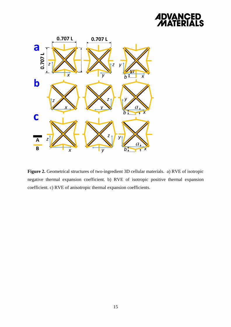
materials are made of ingredient B. Figure 2 shows the geometrical structures of the periodic
representative volume elements (RVEs) of the first level two-ingredient 3D cellular materials
with isotropic NTEC, isotropic PTEC and anisotropic TEC, respectively. The four straight and
inclined struts are made of ingredient A and have rigid connection in the middle. All the other
struts in the RVEs of the first level 3D cellular materials are made of ingredient B. When the
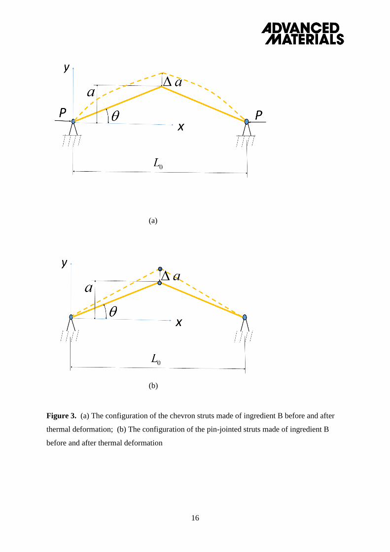
effect of thermal expansion is absent, the shape of all the non-straight struts in the RVEs of both
the first level 2D and 3D materials is assumed to be a chevron with a span of 1.0L and an
amplitude of a , as shown in Figure 3a. Moreover, all the dimensions in Figures 1-3, including
the x, y and z axes, are normalized by L . In addition, all the chevron struts are assumed to have
a uniform thickness t for 2D cellular materials or a uniform square cross-section of side t for
3D cellular materials. The chevron struts (Made of ingredient B) are assumed to be pin-
connected with the straight struts of the cross (made of ingredient A) in the middle.
4
When there is a temperature change T , the change of the amplitude a of the chevron
struts can be obtained from Equations (S1-3) and (S1-4) (see the Supporting Information), and
the magnitude of the isotropic negative (Figures 1c and 2a), or isotropic positive (Figures 1d
and 2b), or anisotropic (Figures 1e and 2c) linear thermal expansion coefficients of both the
first level 2D and 3D cellular materials can be obtained as 11 k , where
4102 BAB , and the linear thermal expansion magnification factor 1k is
defined as /11k and given as
T
ak
667.11 (1)
for the first level 2D cellular materials, and
T
ak
205.21 (2)
for the first level 3D cellular materials. In Equations (1) and (2), T is the thermal strain
of the chevron struts relative to the cross in the middle. The detailed derivation of a , 1 and
1k is given in the Supporting Information (S1.1).
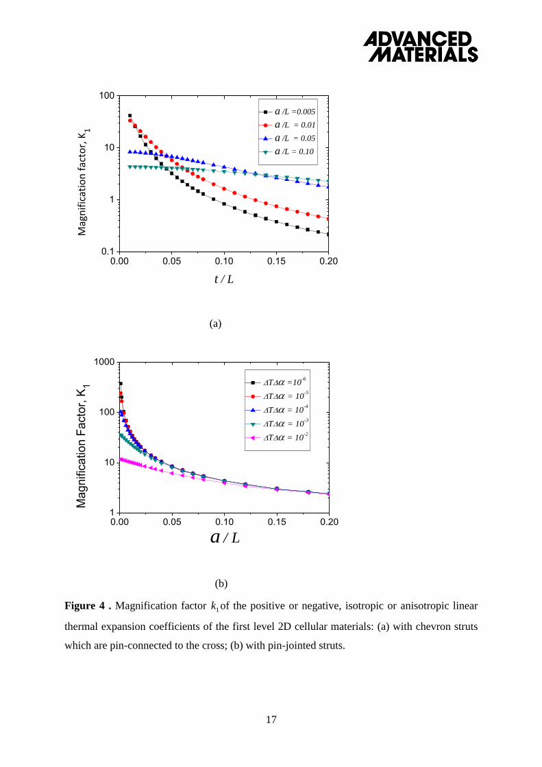
Figure 4a shows the effects of the dimensionless amplitude /a L and the aspect ratio
/t L on the magnification factor 1k of the positive or negative, isotropic or anisotropic linear
thermal expansion coefficients of the first level 2D cellular materials with chevron struts which
are pin-connected to the cross in the middle. It is noted that the values of 1k in Figure 4a
obtained from Equations (1), (2), (S1-3) and (S1-4) remain almost the same when
100005.0 T K. The results presented in Figure 4a are obtained from the small
deformation theory and a single Timoshenko beam element, and the combined effects of
thermal expansion, strut bending, transverse shearing and axial compression on the deformation
1K
5
of the chevron struts have all been considered. We also found that the transverse shear
deformation of the chevron struts has negligible effect on the values of 1k .
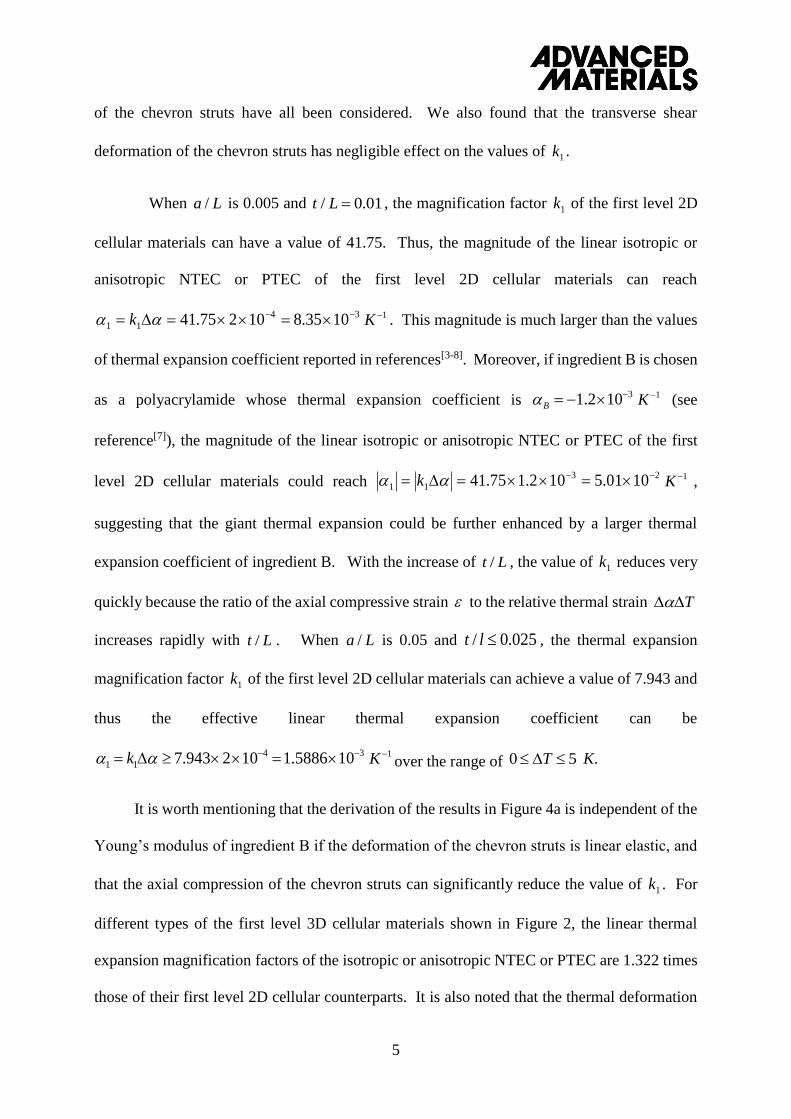
When /a L is 0.005 and / 0.01t L , the magnification factor 1k of the first level 2D
cellular materials can have a value of 41.75. Thus, the magnitude of the linear isotropic or
anisotropic NTEC or PTEC of the first level 2D cellular materials can reach
34
11 1035.810275.41 k 1K . This magnitude is much larger than the values
of thermal expansion coefficient reported in references[3-8]. Moreover, if ingredient B is chosen
as a polyacrylamide whose thermal expansion coefficient is 31.2 10B 1K (see
reference[7]), the magnitude of the linear isotropic or anisotropic NTEC or PTEC of the first
level 2D cellular materials could reach 23
11 1001.5102.175.41 k 1K ,
suggesting that the giant thermal expansion could be further enhanced by a larger thermal
expansion coefficient of ingredient B. With the increase of Lt / , the value of 1k reduces very
quickly because the ratio of the axial compressive strain to the relative thermal strain T
increases rapidly with Lt / . When /a L is 0.05 and 025.0/ lt , the thermal expansion
magnification factor 1k of the first level 2D cellular materials can achieve a value of 7.943 and
thus the effective linear thermal expansion coefficient can be
34
11 105886.1102943.7 k 1K over the range of 50 T K.
It is worth mentioning that the derivation of the results in Figure 4a is independent of the
Young’s modulus of ingredient B if the deformation of the chevron struts is linear elastic, and
that the axial compression of the chevron struts can significantly reduce the value of 1k . For
different types of the first level 3D cellular materials shown in Figure 2, the linear thermal
expansion magnification factors of the isotropic or anisotropic NTEC or PTEC are 1.322 times
those of their first level 2D cellular counterparts. It is also noted that the thermal deformation
6
of the chevron struts is in general a geometrical nonlinearity problem. To validate the accuracy
and applicability of the results in Figure 4a, we have performed finite deformation geometrical
nonlinearity analysis (see Supporting Information S1.2). The values of 1k obtained from the
geometrical nonlinearity analysis are almost the same as those presented in Figure 4a. This is
partly because even when 3102 T (i.e, 4102 1K and 10T K), the strain
in the solid chevron struts is still smaller than 0.2%. Moreover, we have also performed finite
element simulation to validate the theoretical results using the commercial finite element
software ABAQUS. Half a chevron strut is partitioned into 800 plane stress CPS4T elements
and the obtained results are shown in Tables S1 and S2 (in the Supporting Information) to
validate the theoretical results presented in Figures 4a and 4b. For the cases when the chevron
struts are pin-jointed with the cross, the FEM results in Table S1 show quite good agreement
with the theoretical results presented in Figure 4a although the FEM results indicate that the
larger the value of , the smaller the magnification factor 1k . For the cases when the
chevron struts are replaced by two pin-jointed struts (as shown in Fig. 3b), the FEM results in
Table S2 are identical to the theoretical results presented in Figure 4b. When the chevron struts
are rigidly connected instead of pin-jointed to the cross in the middle of the 2D or 3D cellular
materials, the values of /a L remain unchanged, the thermal expansion magnification factors
presented in Figure 4a are still valid when the value of Lt /2 (instead of Lt / ) are used to find
the corresponding 1k .
Now, if the chevron strut in Figure 3a is replaced by two pin-jointed struts as shown in
Figure 3b, the values of the thermal expansion magnification factor 1k of the first level 2D
cellular materials are obtained (see S1.3) and presented in Figure 4b. For the first level 2D
cellular materials when /a L is 0.001, the thermal expansion magnification factor 1k is 375 and
the linear CTE is 075.0102375 4
11 k 1K if 005.0T K ; and 1k becomes
T
7
102.3 and 0204.01023.102 4
11 k if 5.0T K. These magnitudes are
much larger than any reported thermal expansion coefficients in literature, including the results
in references[2, 20], which is the highest value reported to the best of our knowledge. It is worth
pointing out that the magnification factors of pin-jointed struts (Figure 4b) are sensitive to the
dimensionless amplitude and the temperature change T . On the other side, they are
entirely independent of the aspect ratio . When is 0.001 and 05.0/ Lt , the single
level 2D cellular materials still have a reasonable stiffness 3
1 102.1 E from Equation
(S2-5) . However, if is too small, the 2D cellular materials with pin-jointed struts may not
have a sufficient stiffness to support their self-weight and to enable the expected thermal
expansion function. In general, the larger the range of the relative thermal strain T (or
temperature change T ), the smaller is the thermal expansion magnification factor 1k . The
values of 1k of the first level 3D cellular materials shown in Figure 2 are 1.322 times those of
their first level 2D counterparts. Figure 4b shows that when /a L = 0.02 and T 0.5 K, 1k is
always larger than 20 for the first level 2D cellular materials and larger than 26.44 for first level
3D cellular materials. The upbound value of 1k depends on the specific stiffness, namely
stiffness-to-weigth ratio, of the cellular structures. In other words, the giant thermal expansion
of our proposed cellular material could be further improved by using materials with higher
specific stiffness and CTE as component B.
Structural hierarchy can not only enhance the mechanical properties of materials[23-27], but
may also enhance the magnitude of the linear thermal expansion coefficient of 2D and 3D
cellular materials. Both the two-ingredient 2D and 3D hierarchical materials are thus assumed
to be self-similar, as demonstrated in Figure 1. To enable the expected thermal expansion
function, the minimum mechanical stiffness of the cellular materials is assumed to be about
3100.1 nE (this is because the relative density of a hierarchical cellular material is
1K
/a L
/t L /a L
2/N m
/a L
2/N m
8
much lower than a normal solid material). For a two-level hierarchical 2D cellular material
with pin-jointed chevron struts (as shown in Figure 3a), if 045.0/ Lt and =0.01 (or
0.05), magnification factor of the linear thermal expansion coefficient can be obtained as
7.4791.6)( 22
12 kk (or 4.4903.7 2 ) when T 5 K. In this case, the stiffness of the
two-level hierarchical 2D cellular materials is about 31058.1 nE . If the
dimensionless amplitude 1.0/05.0 La and 1.0/045.0 Lt , the magnification factor of
the linear thermal expansion coefficient of a two-level hierarchical and self-similar 2D cellular
material shown in Figure 1 can easily achieve a value of 25.125.3)( 22
12 kk when T 5
K, which is significantly greater than that of its single level counterpart with the same /a L and
. It is noted that for 2D or 3D cellular materials with chevron struts, the magnification
factor of the linear thermal expansion coefficient strongly depends on the values of both /a L
and /t L ; in contrast, their mechanical stiffness is mainly dependent on the aspect ratio /t L
and entirely independent of the amplitude /a L .
We have also studied the case when the chevron struts in the hierarchical and self-similar
2D and 3D cellular materials are replaced by pin-jointed struts. Figure 4b and Table S2 (in the
Supporting Information) show that if 04.004.0 Lt and 05.005.0 La for a two-level
hierarchical and self-similar 2D cellular material, the magnification factor of the linear thermal
expansion coefficient can be obtained as 14.70375.8)( 22
12 kk when 5.0T K, or
55.64034.8)( 22
12 kk when 5T K. In this case, the mechanical stiffness of the
two-level hierarchical 2D cellular materials can be obtained from Equation (S2-6) and given as
39
32
22
2/322
2
10864.1103)05.041(
)05.004.08(
)4(
)8(
Bn
n
n EaL
taE
2/N m . If 1.01.0 Lt and
06.006.0 La , for a two-level hierarchical and self-similar 3D cellular material, the
magnification factor of the linear thermal expansion coefficient can be obtained as
/a L
2/N m
/t L
9
127.8602.7322.1)322.1( 222
12 kk , thus 0172.0102127.86 4
22 k
when 5.0T K, or 17.81815.6322.1)( 222
12 kk and
0162.010217.81 4
22 k when 5T K. In this case, the strain or deformation
of the two-level hierarchical and self-similar 3D cellular materials will be
%86.05.00172.02 T (or %1.850162.02 T ) although the thermal strain in
the struts is just 0.02% (or 0.2%). The mechanical stiffness of the two-level hierarchical and
self-similar 3D cellular materials can be obtained from Equation (S2-8) and given as
39
32
222
2/322
22
1016.1103)06.041(
)06.01.064.17(
)4(
)64.17(
Bn
n
n EaL
atE
2/N m . If 15.015.0 Lt
and 08.008.0 La , for a three-level hierarchical and self-similar 2D cellular materials, the
magnification factor of the linear thermal expansion coefficient can be obtained as
96.143241.5)( 33
13 kk (i.e., 0288.010296.143 4
33 k ) when 5T K.
In this case, the stiffness of the three-level hierarchical 2D cellular materials can be obtained
from Equation (S2-6) and given as
39
5.42
32
2/322
2
1021.1103)08.041(
)08.015.08(
)4(
)8(
Bn
n
n EaL
taE
2/N m . For three-level
hierarchical and self-similar 3D cellular materials, if 2.02.0 Lt and 1.01.0 La , the
magnification factor of the linear thermal expansion coefficients is obtained as
1.18128.4322.1)322.1( 333
13 kk (i.e., 0362.01021.181 4
33 k ) when
5T K, and the stiffness of the three-level hierarchical and self-similar 3D cellular materials
is given as 39
5.42
322
2/322
22
10883.0103)1.041(
)1.02.064.17(
)4(
)64.17(
Bn
n
n EaL
atE
2/N m .
Lakes[2, 20] has designed isotropic single–level 2D hexagonal honeycomb and 3D
tetrakaidecahedral open cell foam with curved struts made of two different ingredients. They
both could have a very large isotropic positive or negative thermal expansion coefficient given
1K
1K
1K
10
by
)(]1
)2/tan(2
1[)](
1
)2/tan(2
1[ 12
21
ft
l
t
l
hh
lRVE , where l and
t are the length and thickness of the curved struts, is the angle of the curved struts and
is the difference of the thermal expansion coefficients of the two ingredients[20]. When ,
the magnification factors of the cellular materials designed by Lakes[2, 20] are included in Fig.
4a for comparison. It is noted that should be smaller than 018.229 (i.e. 4 radians), otherwise
the curved struts will overlap, and thus the maximum possible value of )(f is smaller than
0.48. If the aspect ratio 01.0/ lt , the maximum possible magnification factor of the NTEC
or PNTEC of both the 2D and 3D cellular materials designed by Lakes[2, 20] can be obtained as
48)(1
f
t
lk RVE , thus 0096.010248 4
11 kRVE , which is
significantly smaller than some of our above reported results for the single-level 2D or
hierarchical self-similar 2D and 3D cellular materials in this paper (as can be seen, k can be
easily much larger than 50 in the materials designed in this paper). It is also noted that the
aspect ratio /t l should be in general larger than 0.01 in the 2D and 3D cellular materials
designed by Lakes[2, 20]. This is because the Young’s modulus is
SEL
tE 3
1 )(3.2 (3)
for hexagonal honeycombs[1, 20], and
SS ELt
LtEE
2
42
1)/(5014.01
)/(1608.0
09.11
76.0
(4)
for tetrakaidecahedral open cell foams[20, 28]. In the cellular materials designed by Lakes[2, 20],
if the two ingredients are chosen as a metal and a ceramic (with a Young’s modulus
112 10SE 2/N m ), the cellular materials may be sufficiently stiff, but would be in the
order of 510 1K and the resultant thermal expansion coefficient would still be very small
1K
11
compared to our results of the 2D or 3D cellular materials in this paper. If their two-ingredients
are a ceramic and a polymer and / 0.01t l , the Young’s modulus of the cellular materials will
be 36.9 10
2/N m for honeycombs and 4.82 2/N m for open-celled foams. Thus, the aspect
ratio /t l can’t be smaller than 0.01 , otherwise the single level cellular materials designed by
Lakes[2, 20] do not have a sufficient stiffness to support the self-weight and to enable the
expected function of thermal expansion.
In this report, it has been demonstrated that although structural hierarchy can enhance the
magnitude of the linear thermal expansion coefficient for cellular materials, it is impossible to
achieve an ‘unbounded’ value due to the limit of a required minimum mechanical stiffness. The
magnitude of the linear thermal expansion coefficient of an nth level hierarchical and self-
similar cellular materials is obtained as n
AB
n
n kk ))(()( 11 for 2D and
n
ABn kk )322.1()()322.1( 1
2
1 for 3D if the shape of the RVE is convex, and
n
AB
n
n kk ))(()( 11 for 2D and n
ABn kk )322.1()()322.1( 1
2
1
for 3D if the shape of the RVE is concave. The magnitude of the isotropic NTEC, isotropic
PTEC and anisotropic TEC of the cellular materials in this paper could achieve a value much
larger than 0.012 1K and significantly larger than the maximum possible value of CTE reported
in literature, e.g. the maximum possible result of the 2D and 3D cellular materials designed by
Lakes[2, 20]. The Young’s modulus of ingredient B has no effect on the results of nk and n ,
but strongly affects the stiffness of the cellular materials. The normal-auxeticity mechanical
phase transition has recently been found in graphene, an atomic-thick two-dimensional
hexagonal carbon[29]. The results in this paper could apply to multiscale metamaterials design[30]
spanning from macro- down to micro and nano scales and our study opens a new avenue to
developing more sensitive functional materials or devices. Although there might be some
12
technical challenges to manufacture the designed pin-jointed structures at the microscale, their
broad applications could be foreseen.
References
[1] L. J. Gibson, M. F. Ashby, Cellular Solids, Pergamon press, Oxford, 1997.
[2] R. Lakes J. Mater. Lett. 1996, 15, 475.
[3] T. A. Mary, J. S. O. Evans, T. Vogt, A.W. Sleight, Science 1996, 272, 90.
[4] A. L. Goodwin, M. Calleja, M. J. Conterio, M. T. Dove, J. S. O. Evans, D. A. Keen, Science
2008, 319, 794.
[5] X. G. Zheng, H. Kubozono, H. Yamada, K. Kato, Y. Ishiwata, C. N. Xu, Nat. Nanotech.
2008, 3, 724.
[6] D. Das, T. Jacobs, L. J. Barbour, Nat. Mater. 2010, 9, 36.
[7] X. Shen, C. Viney, E. R. Johnson, C. Wang, J. Q. Lu, Nat. Chemistry 2013, 5, 1035.
[8] A. W. Sleight, Annu. Rev. Mater. Sci. 1998, 8, 29.
[9] A. K. A. Pryde, K. D. Hammonds, M. T. Dover, V. Heine, J. D. Gales, M. C. Warren, J.
Phys.: Condens. Matter. 1996, 8, 10973.
[10] J. S. O. Evans, T. A. Mary, A. W. Sleight, J. Solid State Chem. 1998, 137, 148.
[11] A. E. Phillips, A. L. Goodwin, G. J. Halder, P. D. Southon, C. J. Kepert, Angew. Chem.
Int. Ed. 2008, 47, 1396.
[12] M. Azuma, W. Chen, H. Seki, M. Czapski, S. Olga, K. Oka, M. Mizumaki, T. Watanuki, N.
Ishimatsu, N. Kawamura, S. Ishiwata, M. G. Tucker, Y. Shimakawa, J. P. Attfield, Nat.
Commun. 2011, 2, 347.
[13] J. Chen, F. Wang, Q. Huang, L. Hu, X. Song, J. Deng, R. Yu, X. Xing, Scientific Reports
13
2013, 3, 2458.
[14] J. Chen, L. Hu, J. Deng, X. Xing, Chem. Soc. Rev. 2015, 44, 3522.
[15] J. A. Burg, R. H. Dauskerdt, Nat. Mater. 2016, 15, 974.
[16] J. Gribb, Nature 1968, 220, 576.
[17] R. A. Schapery, J. Compos. Mater. 1968, 2, 380.
[18] B. W. Rozen, Z. Hashin, Int. J. Eng. Sci. 1970, 8, 157.
[19] O. Sigmund, S. Torquato, Appl. Phys. Lett. 1996, 69, 3203.
[20] R. Lakes, Appl. Phys. Lett. 2007, 90, 221905.
[21] Q. Wang, J. A. Jackson, Q. Ge, J. B. Hopkins, C. M. Spadaccini, N. X. Fang, Phys. Rev.
Lett. 2016, 117, 175901.
[22] L. Wu, B. Li, J. Zhou, ACS Appl. Mater. Interfaces 2016, 8, 17721.
[23] R. Lakes, R. Nature 1993, 361, 511.
[24] B. Ji, H. Gao, J. Mech. Phys. Solids 2004, 52, 1963.
[25] H. X. Zhu, L. Yan, R. Zhang, X. M. Qiu, Acta Mater. 2012, 60, 4927.
[26] H. X. Zhu, Z. B. Wang, Z.B. Sci. Adv. Mater. 2013, 5, 677.
[27] X. Zheng, et al. Science 2014, 344, 1373.
[28] H. X. Zhu, J. F. Knott, N. J. Mills, J. Mech. Phys. Solids 1997, 45, 319.
[29] B. Deng, J. Hu, H. Zhu, S. Liu, L. Liu, Y. Shi, Q. Peng, 2D Mater. 2017, 4, 021020.
[30] X. Zheng, W. Smith, J. Jackson, B. Moran, H. Cui, D. Chen, J. Ye, N. Fang, N. Rogriguez,
T. Weisgraber, C. M. Spadaccini, Nat. Mater. 2016, 15, 1100.

14
Figures
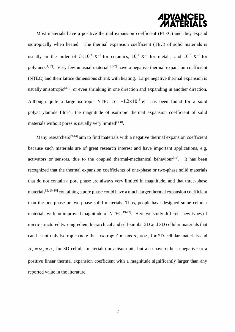
Figure 1. Geometrical structures of two-ingredient hierarchical 2D cellular materials. a)
overview of the second level 2D cellular material consisting of 5 5 RVEs with non-straight
struts made of the level-1 material shown in b. b) overview of the first level 2D cellular material
consisting of 5 5 identical RVEs shown in c (or d or e). c) RVE of isotropic negative thermal
expansion coefficient. d) REV of isotropic positive thermal expansion coefficient. e) REV of
anisotropic thermal expansion coefficients.
15
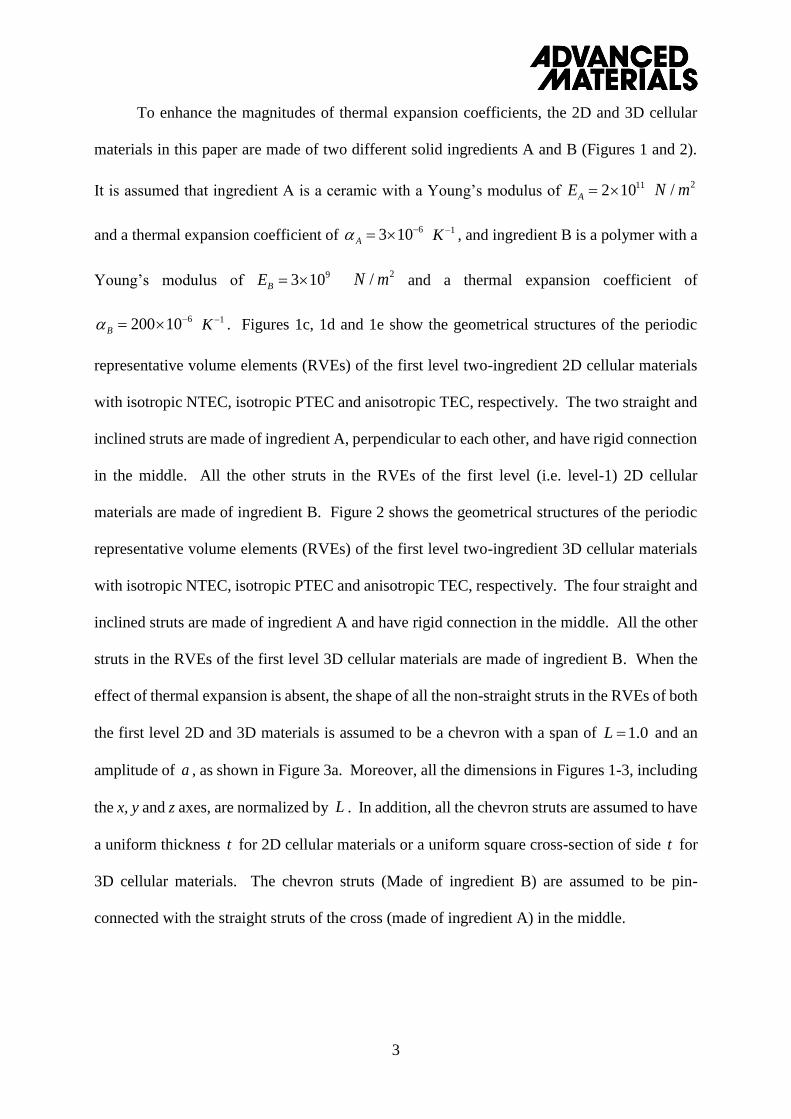
Figure 2. Geometrical structures of two-ingredient 3D cellular materials. a) RVE of isotropic
negative thermal expansion coefficient. b) RVE of isotropic positive thermal expansion
coefficient. c) RVE of anisotropic thermal expansion coefficients.
16
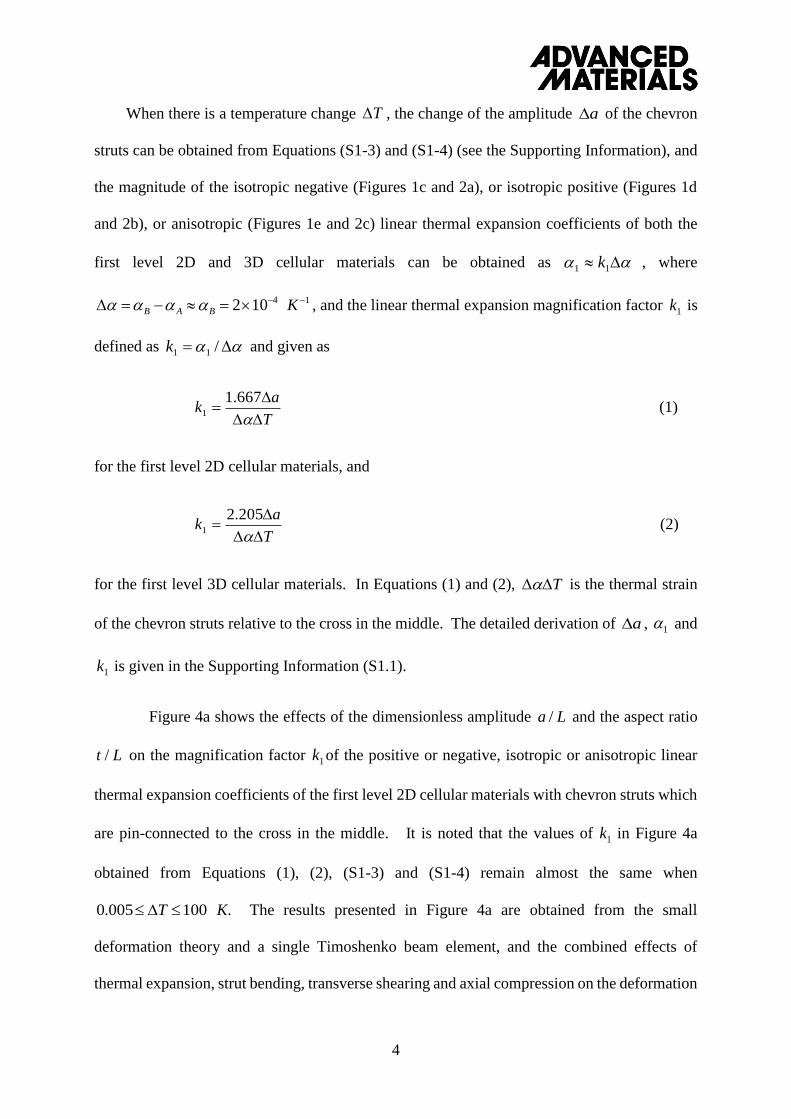
(a)
(b)
Figure 3. (a) The configuration of the chevron struts made of ingredient B before and after
thermal deformation; (b) The configuration of the pin-jointed struts made of ingredient B
before and after thermal deformation
17
0.00 0.05 0.10 0.15 0.200.1
1
10
100
Mag
nif
icat
ion
fac
tor,
K1
t / L
a /L =0.005
a /L = 0.01
a /L = 0.05
a /L = 0.10
(a)
0.00 0.05 0.10 0.15 0.201
10
100
1000
Mag
nific
atio
n F
acto
r, K
1
a / L
T =10-6
T= 10-5
T = 10-4
T= 10-3
T = 10-2
(b)
Figure 4 . Magnification factor 1k of the positive or negative, isotropic or anisotropic linear
thermal expansion coefficients of the first level 2D cellular materials: (a) with chevron struts
which are pin-connected to the cross; (b) with pin-jointed struts.
18
Supporting Information
DOI: 10.1002/adma.201705048
Giant Thermal Expansion in 2D and 3D Cellular Materials
By Hanxing Zhu a,*, Tongxiang Fan b, Qing Peng c, d and Di Zhang b
a School of Engineering, Cardiff University, Cardiff, CF24 3AA, UK
b State Key Lab of Metal Matrix Composites, Shanghai Jiaotong University, Shanghai,
200240, China
c School of Power and Mechanical Engineering, Wuhan University, Wuhan 430072, China.
d Nuclear Engineering and Radiological Sciences, University of Michigan, Ann Arbor,
Michigan 48109, United States
* Corresponding author: H.X.Z. ([email protected])
S1. Thermal Expansion in the first level cellular materials
All types of the 2D and 3D cellular materials shown in Figures 1 and 2 are assumed to be
made of two different solid ingredients A and B. Ingredient A is chosen as a ceramic with a
Young’s modulus of and a thermal expansion coefficient of
, and ingredient B is chosen as a polymer with a Young’s modulus of
and a thermal expansion coefficient of . All the non-straight struts are
assumed to have the same chevron shape with a span of and an amplitude of , and to
be pin-connected with the straight struts of the cross in the middle of the RVEs. In addition, all
the chevron struts are assumed to have the same uniform thickness for 2D cellular materials
or the same uniform square cross-section of side for 3D cellular materials. Moreover, all the
dimensions in Figures 1-3, including the x, y and z axes, are normalized by . It is noted that
the geometrical structure of ingredient B in Fig. 1c is similar to the 4-star auxetic honeycomb[31].
112 10AE 2/N m 63 10A
1K 93 10BE 2/N m
6200 10B 1K
1.0L a
t
t
L
19
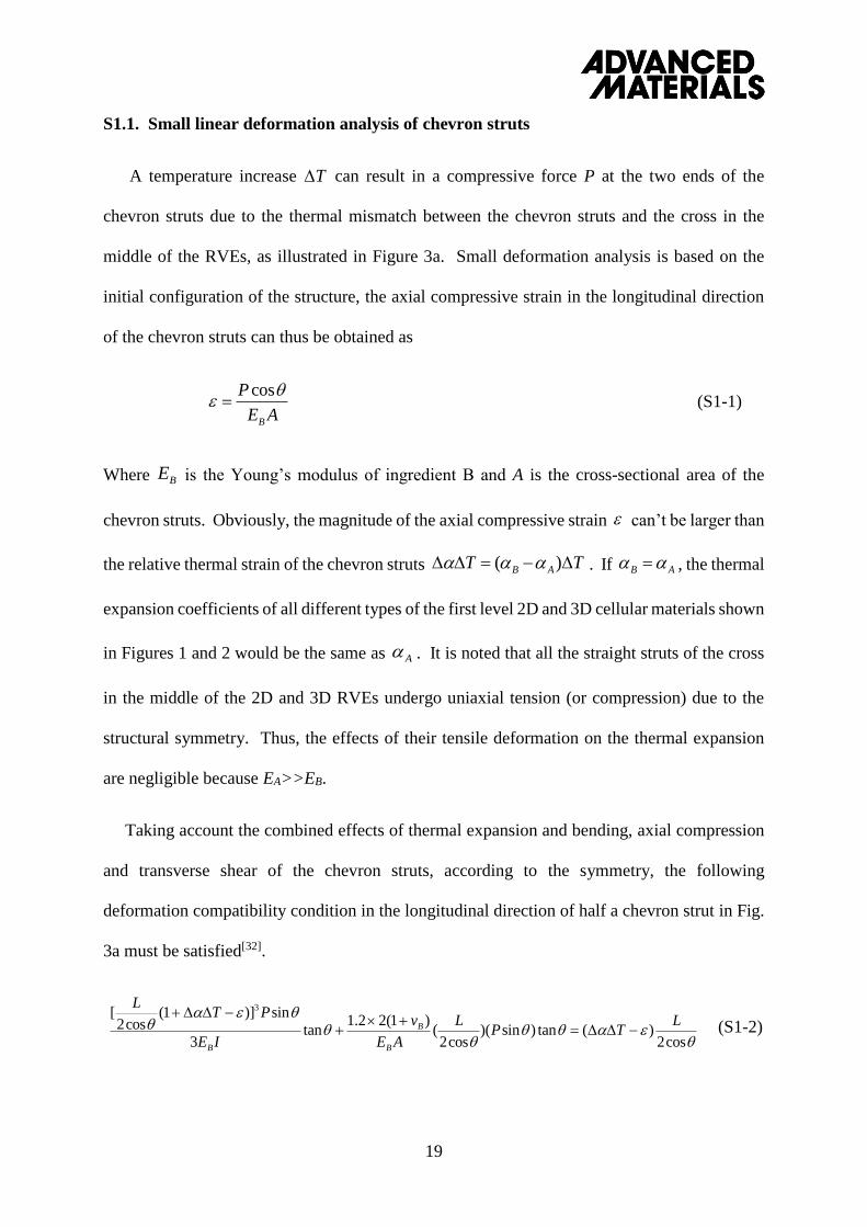
S1.1. Small linear deformation analysis of chevron struts
A temperature increase can result in a compressive force P at the two ends of the
chevron struts due to the thermal mismatch between the chevron struts and the cross in the
middle of the RVEs, as illustrated in Figure 3a. Small deformation analysis is based on the
initial configuration of the structure, the axial compressive strain in the longitudinal direction
of the chevron struts can thus be obtained as
(S1-1)
Where is the Young’s modulus of ingredient B and A is the cross-sectional area of the
chevron struts. Obviously, the magnitude of the axial compressive strain can’t be larger than
the relative thermal strain of the chevron struts . If , the thermal
expansion coefficients of all different types of the first level 2D and 3D cellular materials shown
in Figures 1 and 2 would be the same as . It is noted that all the straight struts of the cross
in the middle of the 2D and 3D RVEs undergo uniaxial tension (or compression) due to the
structural symmetry. Thus, the effects of their tensile deformation on the thermal expansion
are negligible because EA>>EB.
Taking account the combined effects of thermal expansion and bending, axial compression
and transverse shear of the chevron struts, according to the symmetry, the following
deformation compatibility condition in the longitudinal direction of half a chevron strut in Fig.
3a must be satisfied[32].
cos2
)(tan)sin)(cos2
()1(22.1
tan3
sin)]1(cos2
[ 3
LTP
L
AE
v
IE
PTL
B
B
B
(S1-2)
T
cos
B
P
E A
BE
( )B AT T B A
A
20
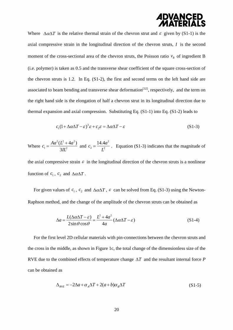
Where is the relative thermal strain of the chevron strut and given by (S1-1) is the
axial compressive strain in the longitudinal direction of the chevron struts, is the second
moment of the cross-sectional area of the chevron struts, the Poisson ratio of ingredient B
(i.e. polymer) is taken as 0.5 and the transverse shear coefficient of the square cross-section of
the chevron struts is 1.2. In Eq. (S1-2), the first and second terms on the left hand side are
associated to beam bending and transverse shear deformation[32], respectively, and the term on
the right hand side is the elongation of half a chevron strut in its longitudinal direction due to
thermal expansion and axial compression. Substituting Eq. (S1-1) into Eq. (S1-2) leads to
(S1-3)
Where and . Equation (S1-3) indicates that the magnitude of
the axial compressive strain in the longitudinal direction of the chevron struts is a nonlinear
function of , and .
For given values of , and , can be solved from Eq. (S1-3) using the Newton-
Raphson method, and the change of the amplitude of the chevron struts can be obtained as
(S1-4)
For the first level 2D cellular materials with pin-connections between the chevron struts and
the cross in the middle, as shown in Figure 1c, the total change of the dimensionless size of the
RVE due to the combined effects of temperature change and the resultant internal force P
can be obtained as
(S1-5)
T
I
Bv
3
1 2(1 )c T c T
2 2 2
1 2
( 4 )
3
Aa L ac
IL
2
2 2
14.4ac
L
1c 2c T
1c 2c T
2 24( )( )
2sin cos 4
L aL Ta T
a
T
2 2( )RVE A Ba T a b T
21
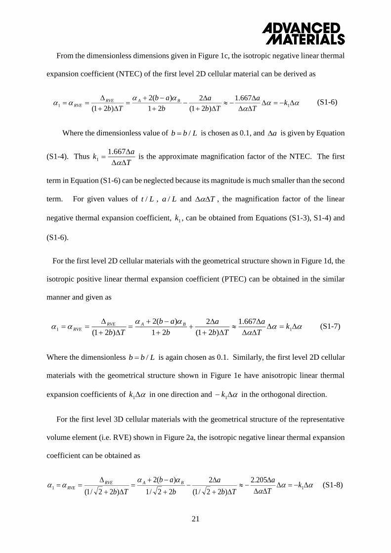
From the dimensionless dimensions given in Figure 1c, the isotropic negative linear thermal
expansion coefficient (NTEC) of the first level 2D cellular material can be derived as
11
667.1
)21(
2
21
)(2
)21(k
T
a
Tb
a
b
ab
Tb
BARVERVE
(S1-6)
Where the dimensionless value of is chosen as 0.1, and is given by Equation
(S1-4). Thus T
ak
667.11 is the approximate magnification factor of the NTEC. The first
term in Equation (S1-6) can be neglected because its magnitude is much smaller than the second
term. For given values of , and , the magnification factor of the linear
negative thermal expansion coefficient, 1k , can be obtained from Equations (S1-3), S1-4) and
(S1-6).
For the first level 2D cellular materials with the geometrical structure shown in Figure 1d, the
isotropic positive linear thermal expansion coefficient (PTEC) can be obtained in the similar
manner and given as
11
667.1
)21(
2
21
)(2
)21(k
T
a
Tb
a
b
ab
Tb
BARVERVE (S1-7)
Where the dimensionless is again chosen as 0.1. Similarly, the first level 2D cellular
materials with the geometrical structure shown in Figure 1e have anisotropic linear thermal
expansion coefficients of 1k in one direction and 1k in the orthogonal direction.
For the first level 3D cellular materials with the geometrical structure of the representative
volume element (i.e. RVE) shown in Figure 2a, the isotropic negative linear thermal expansion
coefficient can be obtained as
11
205.2
)22/1(
2
22/1
)(2
)22/1(k
T
a
Tb
a
b
ab
Tb
BARVERVE (S1-8)
/b b L a
/t L /a L T
/b b L
22
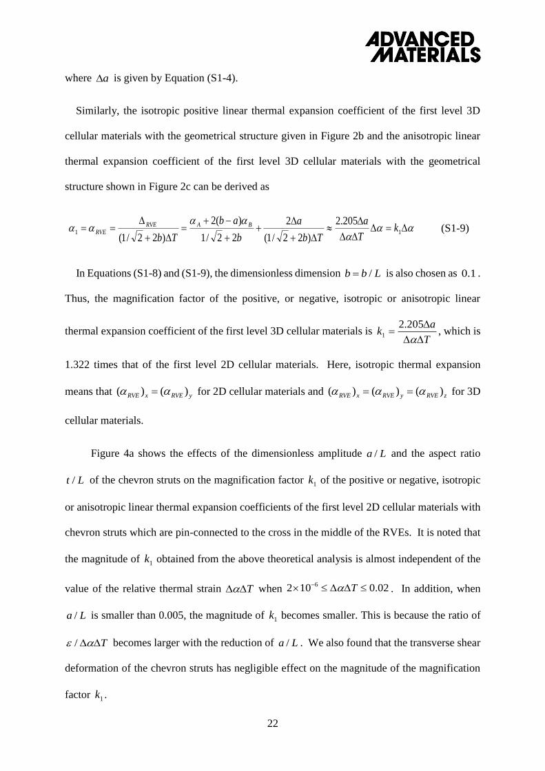
where is given by Equation (S1-4).
Similarly, the isotropic positive linear thermal expansion coefficient of the first level 3D
cellular materials with the geometrical structure given in Figure 2b and the anisotropic linear
thermal expansion coefficient of the first level 3D cellular materials with the geometrical
structure shown in Figure 2c can be derived as
11
205.2
)22/1(
2
22/1
)(2
)22/1(k
T
a
Tb
a
b
ab
Tb
BARVERVE (S1-9)
In Equations (S1-8) and (S1-9), the dimensionless dimension is also chosen as .
Thus, the magnification factor of the positive, or negative, isotropic or anisotropic linear
thermal expansion coefficient of the first level 3D cellular materials is T
ak
205.21 , which is
1.322 times that of the first level 2D cellular materials. Here, isotropic thermal expansion
means that for 2D cellular materials and for 3D
cellular materials.
Figure 4a shows the effects of the dimensionless amplitude and the aspect ratio
of the chevron struts on the magnification factor 1k of the positive or negative, isotropic
or anisotropic linear thermal expansion coefficients of the first level 2D cellular materials with
chevron struts which are pin-connected to the cross in the middle of the RVEs. It is noted that
the magnitude of 1k obtained from the above theoretical analysis is almost independent of the
value of the relative thermal strain when . In addition, when
is smaller than 0.005, the magnitude of 1k becomes smaller. This is because the ratio of
becomes larger with the reduction of . We also found that the transverse shear
deformation of the chevron struts has negligible effect on the magnitude of the magnification
factor 1k .
a
/b b L 0.1
( ) ( )RVE x RVE y ( ) ( ) ( )RVE x RVE y RVE z
/a L
/t L
T 62 10 0.02T
/a L
/ T /a L
23
Figure 4a shows that when is 0.005 and , the magnification factor 1k of the
first level 2D cellular materials is 41.75. The magnitudes of the linear isotropic or anisotropic
NTEC or PTEC of the first level 2D cellular materials can thus reach
34
11 1035.810275.41 k . This value is significantly larger than the
positive or negative thermal expansion coefficients reported in references3-8. Moreover, if the
ingredient B is chosen as a polyacrylamide material whose thermal expansion coefficient is
(see reference7), the magnitude of the linear isotropic or anisotropic NTEC
or PTEC of the first level 2D cellular materials could reach
23
11 1001.5102.175.41 k , suggesting that the giant thermal expansion
could be further improved by the thermal expansion coefficient of ingredient B.
It is noted that the derivation of the results in Figure 4a is independent of the Young’s
modulus of ingredient B as long as the deformation is linear elastic, as can be seen that is
absent in Equations (S1-3) and (S1-4). Although the transverse shear deformation of the
chevron struts has negligible effect on the magnitude of 1k , the axial compression can
significantly reduce the value of 1k . If without the effect of axial compression (i.e. if is zero
in Equation (S1-4)), the magnification factor of the linear isotropic or anisotropic NTEC or
PTEC of the first level 2D cellular materials would become )4
(667.1667.1 2
1a
La
T
ak
,
which is independent of the aspect ratio . In this case, 35.831 k if ; and
68.411 k if , being much larger than those presented in Figure 4a.
S1.2. Nonlinear finite deformation analysis of chevron struts
The analysis in S1.1 and the results shown in Figure 4a are based on the initial undeformed
configuration and obtained from the small deformation theory using a single Timoshenko beam
element[32]. However, the thermal deformation of the chevron struts is in general a geometrical
/a L / 0.01t L
1K
31.2 10B 1K
1K
BE
/t L / 0.005a L
/ 0.01a L
24
nonlinearity problem. The deformed configuration of half a chevron strut under thermal
expansion and the restraint force P acted at the pin-jointed end is shown in Figure S1. The
relationship between the bending curvature and the bending moment is given as [33, 34]
dsAE
PTPPy
ds
dIE
S
B
bB ]sin)cos1[(
0
(S1-10)
Where the left hand side is the bending stiffness times the bending curvature and the right
hand side is the bending moment. When , (see Figures
3a and S1), thus the angle of the chevron strut due to the combined effects of strut
bending, thermal expansion and axial compression can be determined as
(S1-11)
In the above equation, the strut is assumed to have a square cross-section of side t and
.
The angle due to transverse shear deformation of the strut is given as
(S1-12)
Where the Poisson ratio of the chevron material (i.e. a polymer) is chosen as 0.5.
The total angle of the deformed half chevron strut can thus be obtained as
(S1-13)
/ (2cos )S l L ( )2
b l
( )b s
0( ) [ (1 cos )sin ]
2
l s
bs
B B
P Ps T ds ds
E I E A
112 0
12[ (1 cos )sin ]
2
l s
sT ds ds
t
1 / cosB
P
E A
1
1.2 sin 2.4(1 )( ) sin 3.6 sinS
B B
P v Ps
G A E A
( ) ( ) ( )b Ss s s
25
For a given value of the relative thermal strain , the function can be determined
using the iterative method [33, 34] and the deformation compatibility condition:
(S1-14)
To solve the nonlinear function , the length of half the chevron strut
was divided into 100000 elements, the value of was initially chosen as and
as . Using the iterative method, the convergent solution of was very quickly obtained
from the following solution scheme [33, 34]. The first step is to obtain new values of
using Equations (S1-11), (S1-12) and (S1-13), and the initially given or the already obtained
values of and . The second step is to check with the deformation compatibility
condition (S1-14). In step 3, if the left hand side of Eq. (S1-14) is larger than the right hand
side, it suggests that the value of is too small, then increase the value of ; if the left hand
side of Eq. (S1-14) is smaller than the right hand side, it suggests that the value of is too
large, then reduce the value of . Step 4 is to check the new values of with the previous
values, if the largest difference is smaller than 610 , convergent solution of has been
obtained; otherwise repeat steps 1-4 using the updated values of and . Thus very
accurate solution of can be very quickly obtained for any given value of the relative
thermal strain , and the change of the amplitude of the chevron strut, , can be
obtained as
(S1-15)
It is noted that in the analysis of S1.1 and S1.2, the combined effects of thermal expansion,
bending, axial compression and transverse shear on the thermal deformation of the chevron
T ( )s
10(1 cos ) cos cos / 2
l
T ds l L
( )s / (2cos )l L
1 / 2T ( )s
( )s
( )s
1 ( )s
1 1
1
1 ( )s
( )s
1 ( )s
( )s
T a
10(1 cos )sin
l
a T ds a
26
struts are all considered. The thermal expansion magnification factor of the 2D and 3D cellular
materials can be obtained using the relevant equations given in section S1.1.
S1.3. Deformation analysis of pin-jointed struts
If the chevron strut in Figure 3a is replaced by two pin-jointed struts as shown in Figure 3b,
for a given value of the relative thermal expansion , the change of the amplitude in
Figure 3b can be obtained as
(S1-16)
and the values of the thermal expansion magnification factor 1k of the 2D cellular materials can
be obtained using the relevant equations given in section S1.1, and presented in Figure 4b for
2D cellular materials. For the first level 3D cellular materials with pin-jointed struts, the values
of the thermal expansion magnification factor are 1.322 times those of their 2D counterparts.
S1.4. Validation by finite element simulation
To verify the theoretical results given in Figures 4a and 4b for the first level 2D cellular
materials, we have performed finite element simulation using the commercial software
ABAQUS. Half a chevron strut is partitioned into 800 plane stress CPS4T elements and the
obtained results are shown in Tables S1 and S2 to validate the theoretical results of Figures 4a
and 4b. For the cases when the chevron struts are pin-jointed with the cross, the FEM results
in Table S1 show quite good agreement with theoretical results although the FEM results
indicate that the larger the value of , the smaller the magnification factor 1k . For the
cases when the chevron struts are replaced by two pin-jointed struts, the FEM results in Table
S2 are identical to the theoretical results.
T
2 2 2 2( / 4 )(1 ) / 4a L a T L a
T

27
S1.5. Thermal expansion coefficient of hierarchical and self-similar cellular materials
For the nth level hierarchical and self-similar 2D cellular materials shown in Figure 1, the
thermal expansion coefficient can be obtained as
n
AB
n
n kk ))(()( 11 (S1-17)
if the shape of the RVE is convex, and
n
AB
n
n kk ))(()( 11 (S1-18)
if the shape of the RVE is concave.
For the nth level hierarchical and self-similar 3D cellular materials, the thermal expansion
coefficient can be obtained as n
ABn kk )322.1()()322.1( 1
2
1 if the shape of the
RVE is convex, and n
ABn kk )322.1()()322.1( 1
2
1 if the shape of the RVE is
concave.
S2. The stiffness of 2D and 3D cellular materials
When a uniaxial tensile stress is applied to the RVEs of the first level 2D cellular
materials with chevron struts, as shown in Figures 1c, 1d and 1e, the concentrated force applied
at the vertex of the chevron strut on the left hand side or right hand side is
xx LbLF 2.1)2( , where . The chevron struts can be treated as pin-supported
beams with a span of L and the horizontal deformation of the RVEs can thus be approximated
as 3
43 6.0
48
2
tE
L
IE
FL
B
x
B
x
where
12
3tI . This is because bending of the chevron struts is the
dominant deformation mechanism. The horizontal strain can be derived as
. Thus the Young’s modulus of the first level
2D cellular materials is obtained as
x
0.1b L
3 3/ ( 2 ) / (1.2 ) / (2 )x x x x BL b L L E t
28
(S2-1)
For the nth level hierarchical and self-similar 2D cellular materials, the Young’s modulus
can be obtained in the similar manner, and given as
(S2-2)
Similarly, the Young’s modulus of the first level 3D cellular materials with pin-jointed
chevron struts can be obtained as
(S2-3)
For the nth level hierarchical and self-similar 3D cellular materials, the Young’s modulus
is obtained as
(S2-4)
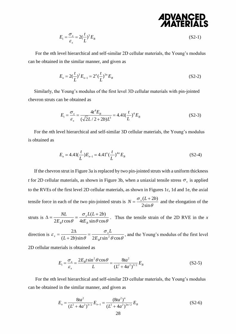
If the chevron strut in Figure 3a is replaced by two pin-jointed struts with a uniform thickness
t for 2D cellular materials, as shown in Figure 3b, when a uniaxial tensile stress is applied
to the RVEs of the first level 2D cellular materials, as shown in Figures 1c, 1d and 1e, the axial
tensile force in each of the two pin-jointed struts is
sin2
)2( bLN x and the elongation of the
struts is
cossin4
)2(
cos2 B
x
B tE
bLL
tE
NL . Thus the tensile strain of the 2D RVE in the x
direction is
cossin2sin)2(
22tE
L
bLB
xx
, and the Young’s modulus of the first level
2D cellular materials is obtained as
BB
x
x EaL
ta
L
tEE
2/322
22
1)4(
8cossin2
(S2-5)
For the nth level hierarchical and self-similar 2D cellular materials, the Young’s modulus
can be obtained in the similar manner, and given as
Bn
n
nn EaL
taE
aL
taE
2/322
2
12/322
2
)4(
)8(
)4(
8
(S2-6)
3
1 2( )xB
x
tE E
L
3 3
12( ) 2 ( )n n
n n B
t tE E E
L L
44
1 3
44.41( )
( 2 / 2 2 )
x BB
x
t E tE E
LL b L
4
14.41( ) 4.41 ( )n n
n n B
t tE E E
L L
x

29
Similarly, the Young’s modulus of the first level 3D cellular materials is obtained as
(S2-7)
where .
For the nth level hierarchical and self-similar 3D cellular materials, the Young’s modulus
can be obtained as
(S2-8)
References
[31] J.N. Grima, R. Gatt, A. Alderson, K.E. Evans, Molecular Simulation. 2005, 31, 925.
[32] J.M. Gere, S.P. Timoshenko, Mechanics of Materials, Cambridge University Press, 1985.
[33] H.X. Zhu, N.J. Mills, Int. J. Solids and Struct. 2000, 37, 1931.
[34] H.X. Zhu, N.J Mills, J.F. Knott, J. Mech. Phys. Solids 1997, 45, 1875.
2 2 2 2
1 2 2 3/22 2 3/2
17.64
( 4 )( / 4 ) ( 2 / 4 )
x BB
x
t a E t aE E
L aL a L b
0.1 0.1b L
2 2
2 2 3 /2
(17.64 )
( 4 )
n
n Bn
t aE E
L a
30
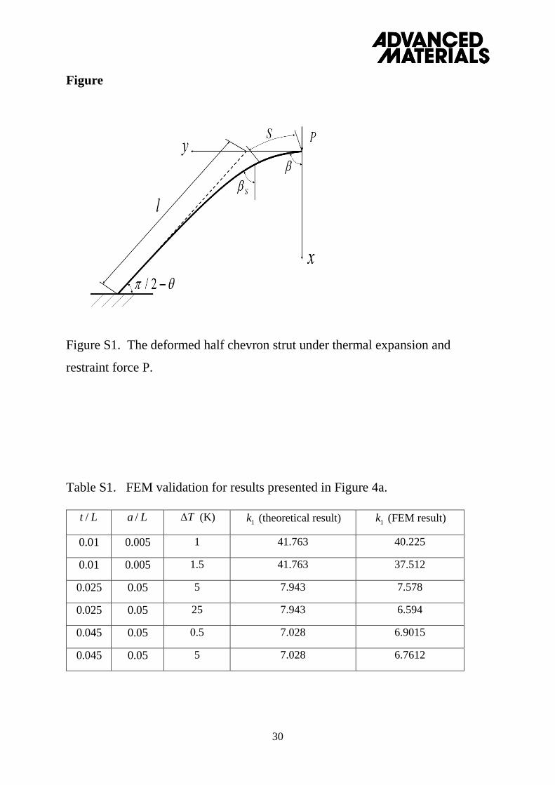
Figure
Figure S1. The deformed half chevron strut under thermal expansion and
restraint force P.
Table S1. FEM validation for results presented in Figure 4a.
Lt / La / T (K) 1k (theoretical result) 1k (FEM result)
01.0 005.0 1 41.763 40.225
01.0 005.0 1.5 41.763 37.512
025.0 05.0 5 7.943 7.578
025.0 05.0 25 7.943 6.594
045.0 05.0 0.5 7.028 6.9015
045.0 05.0 5 7.028 6.7612
31
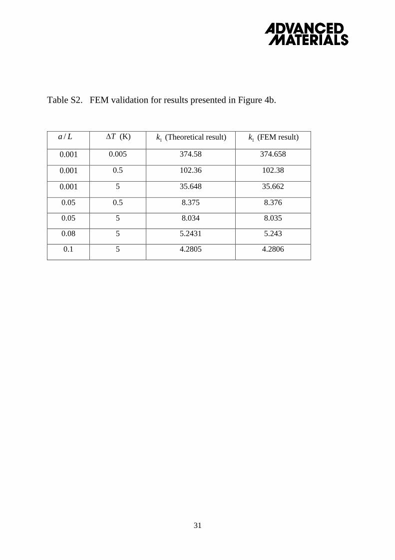
Table S2. FEM validation for results presented in Figure 4b.
La / T (K) 1k (Theoretical result) 1k (FEM result)
001.0 0.005 374.58 374.658
001.0 0.5 102.36 102.38
001.0 5 35.648 35.662
0.05 0.5 8.375 8.376
0.05 5 8.034 8.035
0.08 5 5.2431 5.243
0.1 5 4.2805 4.2806