Embed Size (px)
DESCRIPTION
DSA
Citation preview
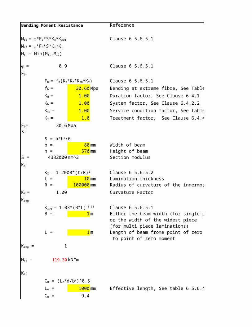
Bending Moment Resistance Reference
Clause 6.5.6.5.1
0.9 Clause 6.5.6.5.1
Clause 6.5.6.5.1
30.60 Mpa Bending at extreme fibre, See Table 6.3
1.00 Duration factor, See Clause 6.4.1
1.00 System factor, See Clause 6.4.2.2
1.00 Service condition factor, See table 6.4.2
1.0 Treatment factor, See Clause 6.4.4
30.6 MpaS:
b = 80 mm Width of beamh = 570 mm Height of beam
S = 4332000 mm^3 Section modulus
Clause 6.5.6.5.2t = 10 mm Lamination thicknessR = 100000 mm Radius of curvature of the innermost lamination
1.00 Curvature Factor
Clause 6.5.6.5.1B = 1 m Either the beam width (for single piece laminations)
or the width of the widest piece(for multi piece laminations)
L = 1 m Length of beam frome point of zero moment to point of zero moment
1
119.30 kN*m
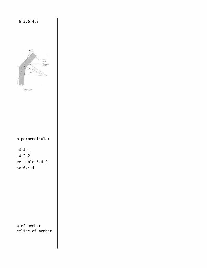
1000 mm Effective length, See table 6.5.6.4.3
9.4
Mr1 = j*Fb*S*Kx*Kzbg
Mr2 = j*Fb*S*Kx*Kl
Mr = Min(Mr1,Mr2)
j =
Fb:
Fb = fb(Kd*Kh*Ksb*Kt)
fb =
Kd =
Kh =
Ksb =
Kt =
Fb=
S = b*h2/6
KX:
KX = 1-2000*(t/R)2
KX =
Kzbg:
Kzbg = 1.03*(B*L)-0.18
Kzbg =
Mr1 =
KL:
CB = (Le*d/b2)^0.5
Le =
CB =

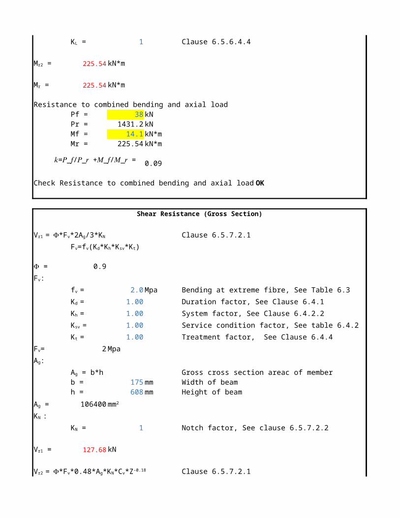
1 Clause 6.5.6.4.4
119.30 kN*m
119.30 kN*m
KL =
Mr2 =
Mr =

Shear Resistance (Gross Section)
Clause 6.5.7.2.1
0.9
2.0 Mpa Bending at extreme fibre, See Table 6.3
1.00 Duration factor, See Clause 6.4.1
1.00 System factor, See Clause 6.4.2.2
1.00 Service condition factor, See table 6.4.2
1.00 Treatment factor, See Clause 6.4.4
2 Mpa
Gross cross section areac of memberb = 315 mm Width of beamh = 540 mm Height of beam
170100
1 Notch factor, See clause 6.5.7.2.2
204.12 kN
Clause 6.5.7.2.1
3.69 Shear load coefficient, see clause 6.5.7.4 and table 6.5.7.4l = 32 m Length of beam
Z = 5.44 Beam volume
399.8 kN
399.752 kN
Vr1 = F*Fv*2Ag/3*KN
Fv=fv(Kd*Kh*Ksv*Kt)
F =
Fv:
fv =
Kd =
Kh =
Ksv =
Kt =
Fv=
Ag:
Ag = b*h
Ag = mm2
KN :
KN =
Vr1 =
Vr2 = F*Fv*0.48*Ag*KN*Cv*Z-0.18
Cv =
m3
Vr2 =
If Z > 2m3 then Vr = Vr1 else Vr =Vr2
Vr =
Bending Moment Resistance (Based on bending strength)
Section 8.2
Section 8.2
Section 8.2
Section 2.5
0.9 Clause 6.5.6.5.1
Clause 6.5.6.5.1
30.60 Mpa Bending at extreme fibre, See Table 6.3
1.00 Duration factor, See Clause 6.4.1
1.00 System factor, See Clause 6.4.2.2
1.00 Service condition factor, See table 6.4.2
1.0 Treatment factor, See Clause 6.4.4
30.6 MpaS:
b = 80 mm Width of beamh = 570 mm Height of beam
S = 4332000 mm^3 Section modulus
119.30328 kN*m
Clause 6.5.6.5.2t = 19 mm Lamination thickness, See table 8.2 page 374 wood design manualR = 100000 mm Radius of curvature of the innermost lamination
1.00 Curvature Factor
Clause 6.5.6.5.1B = 1 m Either the beam width (for single piece laminations)
or the width of the widest piece(for multi piece laminations)
L = 1 m Length of beam frome point of zero moment
to point of zero moment
1
1000 mm Effective length, See table 6.5.6.4.3
Mrb1 = M'r*KL*Kx*KM
Mrb2 = M'r*KZbg*KX*KM
Mrb = Min(Mrb1,Mrb2)
M'rb = f*Fb*S
f =
Fb:
Fb = fb(Kd*Kh*Ksb*Kt)
fb =
Kd =
Kh =
Ksb =
Kt =
Fb=
S = b*h2/6
M'rb =
KX:
KX = 1-2000*(t/R)2
KX =
Kzbg:
Kzbg = 1.03*(B*L)-0.18
Kzbg =
KL:
CB = (Le*d/b2)^0.5
Le =

9.4
1 Clause 6.5.6.4.4
Section 8.40.0436 radian
Location : Apex of curved
0.8946187
106.72 kN*m
106.72 kN*m
106.72 kN*m
CB =
KL =
KM:
KM = 1/(1+2.7*tan a) a =
KM =
Mrb1 =
Mrb2 =
Mrb =

COLUMN _POINT 4 TO 5Liner Section Column
Axial Resistance Parallel Clause 6.5.8To The Grain (Column Capacity)
Pr=phi*Fc*A*Kzcg*KcFc=fc(Kd*Kh*Ksc*Kt)Kzc=0.68(Z)^-0.13 < 1.0Kc=[1.0+(FcKzcgCc^3/35E05KseKt)]^-1
phi= 0.8Fc:
fc= 30.2 Mpa Table 6.3Ksc= 1.00 Service condition factor, See Table 6.4.2 Kt= 1.0 Treatment factor, See Table 5.4.3Kd= 1.0 Duration factor, See Clause 4.3.2.2Kh= 1.0 System factor, See Clause 6.4.3
Fc= 30.2 MpaA = 106400 mm^2
Kzc= see belowKc = see below
Pr = 1431.2 kN
Column Lengths
Weak Axis = Lx = 3000 mmStrong Axis = Ly = 6200 mm
Column Size
Weak Axis = dx = 175 mmStrong Axis = dy = 608 mm
Kzcg
Kzcg = 0.7Z = 0.65968 m3 Member volumn
Kc
Kc = 0.78 Clause 6.5.8.5E = 12400 Table 6.3 - Modulus of Elasticity
E05=0.87E = 10788 Mpa Table 5.3.1 A-DKse = 1.0 Table 6.4.2 service condition factorCc = 17.1
Cc<=50, slenderness is within limitation

Bending Moment Resistance Reference
Clause 6.5.6.5.1
0.9 Clause 6.5.6.5.1
Clause 6.5.6.5.1
25.60 Mpa Bending at extreme fibre, See Table 6.3
1.00 Duration factor, See Clause 6.4.1
1.00 System factor, See Clause 6.4.2.2
1.00 Service condition factor, See table 6.4.2
1.0 Treatment factor, See Clause 6.4.4
25.6 MpaS:
b = 175 mm Width of beamh = 608 mm Height of beam
S = 10781867 mm^3 Section modulus
Clause 6.5.6.5.2t = 19 mm Lamination thickness, see table 8.2 page 374R = 2800 mm Radius of curvature of the innermost lamination
0.91 Curvature Factor
Clause 6.5.6.5.1B = 0.175 m Either the beam width (for single piece
laminations) or the width of the widest piece(for multi piece laminations)
L = 6 m Length of beam frome point of zero moment to point of zero moment
1.00
225.54 kN*m
5760 mm Effective length, See table 6.5.6.4.3
10.7
Mr1 = j*Fb*S*Kx*Kzbg
Mr2 = j*Fb*S*Kx*Kl
Mr = Min(Mr1,Mr2)
j =
Fb:
Fb = fb(Kd*Kh*Ksb*Kt)
fb =
Kd =
Kh =
Ksb =
Kt =
Fb=
S = b*h2/6
KX:
KX = 1-2000*(t/R)2
KX =
Kzbg:
Kzbg = 1.03*(B*L)-0.18
Kzbg =
Mr1 =
KL:
CB = (Le*d/b2)^0.5
Le =
CB =

1 Clause 6.5.6.4.4
225.54 kN*m
225.54 kN*m
Resistance to combined bending and axial load Pf = 38 kNPr = 1431.2 kNMf = 14.1 kN*mMr = 225.54 kN*m
0.09
Check Resistance to combined bending and axial load : OK
Shear Resistance (Gross Section)
Clause 6.5.7.2.1
0.9
2.0 Mpa Bending at extreme fibre, See Table 6.3
1.00 Duration factor, See Clause 6.4.1
1.00 System factor, See Clause 6.4.2.2
1.00 Service condition factor, See table 6.4.2
1.00 Treatment factor, See Clause 6.4.4
2 Mpa
Gross cross section areac of memberb = 175 mm Width of beamh = 608 mm Height of beam
106400
1 Notch factor, See clause 6.5.7.2.2
127.68 kN
Clause 6.5.7.2.1
KL =
Mr2 =
Mr =
Vr1 = F*Fv*2Ag/3*KN
Fv=fv(Kd*Kh*Ksv*Kt)
F =
Fv:
fv =
Kd =
Kh =
Ksv =
Kt =
Fv=
Ag:
Ag = b*h
Ag = mm2
KN :
KN =
Vr1 =
Vr2 = F*Fv*0.48*Ag*KN*Cv*Z-0.18
𝑘=𝑃_𝑓/𝑃_𝑟 +𝑀_𝑓/𝑀_𝑟 =

3.69 Shear load coefficient, see clause 6.5.7.4 and table 6.5.7.4
l = 6200 mm Length of beam
Z = 0.66 Beam volume
365.6 kN
127.7 kN
10
0.08
Check shear Resistance : OK
Cv =
m3
Vr2 =
If Z > 2m3 then Vr = Vr1 else Vr =Vr2
Vr =
Vf =𝑘=𝑉_𝑓/𝑉_𝑟 =
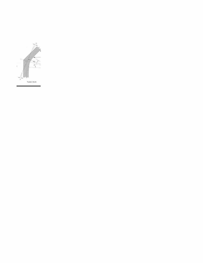
TURDOR ARCH @ POINT 4Bending Moment Resistance (Based on bending strength)
Section 8.2
Section 8.2
Section 8.2
Section 2.5
0.9 Clause 6.5.6.5.1
Clause 6.5.6.5.1
25.60 Mpa Bending at extreme fibre, See Table 6.3
1.00 Duration factor, See Clause 6.4.1
1.00 System factor, See Clause 6.4.2.2
1.00 Service condition factor, See table 6.4.2
1.0 Treatment factor, See Clause 6.4.4
25.6 MpaS:
b = 175 mm Width of beamh = 608 mm Height of beam
S = 10781867 mm^3 Section modulus
248.41421 kN*m
Clause 6.5.6.5.2t = 19 mm Lamination thickness, See table 8.2 page 374
wood design manualR = 2800 mm Radius of curvature of the innermost
0.91 lamination Curvature Factor
Clause 6.5.6.5.1B = 0.175 m Either the beam width (for single piece
laminations) or the width of the widest piece(for multi piece laminations)
L = 6 m Length of beam frome point of zero moment to point of zero moment
1
Mrb1 = M'r*KL*Kx*KM
Mrb2 = M'r*KZbg*KX*KM
Mrb = Min(Mrb1,Mrb2)
M'rb = f*Fb*S
f =
Fb:
Fb = fb(Kd*Kh*Ksb*Kt)
fb =
Kd =
Kh =
Ksb =
Kt =
Fb=
S = b*h2/6
M'rb =
KX:
KX = 1-2000*(t/R)2
KX =
Kzbg:
Kzbg = 1.03*(B*L)-0.18
Kzbg =
KL:
CB = (Le*d/b2)^0.5

5760 mm Effective length, See table 6.5.6.4.3
10.7
1 Clause 6.5.6.4.4
Section 8.40.5529889 radian
Location : Not apex of curved
1
225.54 kN*m
225.54 kN*m
225.54 kN*m
Bending Moment Resistance (Based on radial tension strength)
Clause 6.5.6.6.2
Clause 6.5.6.6.1
0.9 Clause 6.5.6.6.1
Clause 6.5.6.6.1
0.83 Mpa Specified strength intension perpendicular to grain, see table 6.3
1.00 Duration factor, See Clause 6.4.1
1.00 System factor, See Clause 6.4.2.2
1.00 Service condition factor, See table 6.4.2
1.0 Treatment factor, See Clause 6.4.4
0.83 Mpa
S:
b = 175 mm Width of beamh = 608 mm Height of beam
S = 10781867 mm^3 Section modulus
A = 106400 Maximum cross sectional area of memberR = 3104 mm Radius of curvature at centerline of member
0.9 rad Enclosed angle in radian Loading : Uniformly distributedMember : Double tapered curved
Le =
CB =
KL =
KM:
KM = 1/(1+2.7*tan a) a =
KM =
Mrb1 =
Mrb2 =
Mrb =
Mrt1= f*Ftp*S*KZtp*KR
Mrt2 = f*Ftp*2*A/3*R*KZtp
f =
Ftp:
Ftp = ftp(Kd*Kh*Kstp*Kt)
ftp =
Kd =
Kh =
Kstp =
Kt =
Ftp=
S = b*h2/6
KZtp:
mm2
b =

0.6995909
0.55 radianA = 0.16 Constants given in table 6.5.6.6.3B = 0.06 Constants given in table 6.5.6.6.3C = 0.11 Constants given in table 6.5.6.6.3
5.6826898Location : Not apex of curved
32.02 kN*m
115.06 kN*m
0.00 kN*m
Mr = 225.54 kN*m
Axial Resistance Parallel Clause 6.5.8To The Grain (Column Capacity)
Pr=phi*Fc*A*Kzcg*KcFc=fc(Kd*Kh*Ksc*Kt)Kzc=0.68(Z)^-0.13 < 1.0Kc=[1.0+(FcKzcgCc^3/35E05KseKt)]^-1
phi= 0.8Fc:
fc= 30.2 Mpa Table 6.3Ksc= 1.00 Table 6.4.2 service condition factorKt= 1.0 Table 5.4.3 treatment factorKd= 1.0 Duration factor see Clause 4.3.2.2Kh= 1.0 System factor see Clause 6.4.3
Fc= 30.2 MpaA = 84455 mm^2
Kzc= see belowKc = see below
Pr = 1162.7 kN
1162.7 kN Calculated with equivalent section
1225.9 kN Calculated with smaller section and Cc=1
Column Lengths
Weak Axis = Lx = 3000 mmStrong Axis = Ly = 6200 mm
KZtp =
KR: a =
KR = [A+B*(d/R)+C*(d/R)2]-1
KR =
Mrt1=
Mrt2 =
Mrt =
Column Size
Equivalent Smaller end Larger end
Weak Axis = dx = 175 mm 175 mm 175 mm
Strong Axis = dy = 482.6 mm 380 mm 608 mm
Kzcg
Kzcg = 0.7Z = 0.523621 m3 Member volumn
Kzcg = 0.8 For member with constant section
Z = 0.4123 m3 of smaller one
Kc
Kc = 0.77 Clause 6.5.8.5E = 12400 Table 6.3 - Modulus of Elasticity
0.87E = 10788 Table 5.3.1 A-DKse = 1.0 Table 6.4.2 service condition factorCc = 17.1
Cc<=50, slenderness is within limitation
Resistance to combined bending and axial load Pf = 38 kNPr = 1162.7 kNMf = 14.1 kN*mMr = 225.54 kN*m
0.10
Check Resistance to combined bending and axial load : OK
Shear Resistance (Gross Section)
Clause 6.5.7.2.1
0.9
2.0 Mpa Bending at extreme fibre, See Table 6.3
1.00 Duration factor, See Clause 6.4.1
1.00 System factor, See Clause 6.4.2.2
1.00 Service condition factor, See table 6.4.2
1.00 Treatment factor, See Clause 6.4.4
2 Mpa
Gross cross section areac of member
Vr1 = F*Fv*2Ag/3*KN
Fv=fv(Kd*Kh*Ksv*Kt)
F =
Fv:
fv =
Kd =
Kh =
Ksv =
Kt =
Fv=
Ag:
Ag = b*h
𝑘=𝑉_𝑓/𝑉_𝑟 =
𝑘=𝑃_𝑓/𝑃_𝑟 +𝑀_𝑓/𝑀_𝑟 =

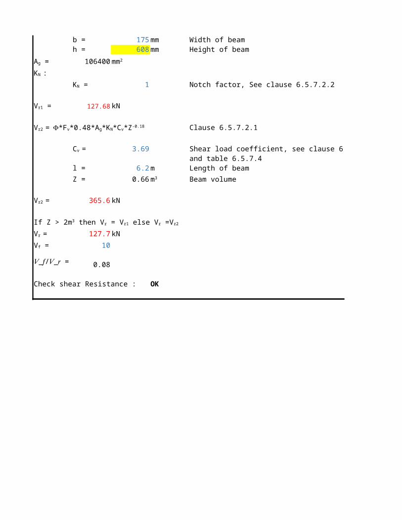
b = 175 mm Width of beamh = 608 mm Height of beam
106400
1 Notch factor, See clause 6.5.7.2.2
127.68 kN
Clause 6.5.7.2.1
3.69 Shear load coefficient, see clause 6.5.7.4 and table 6.5.7.4
l = 6.2 m Length of beam
Z = 0.66 Beam volume
365.6 kN
127.7 kN
10
0.08
Check shear Resistance : OK
Ag = mm2
KN :
KN =
Vr1 =
Vr2 = F*Fv*0.48*Ag*KN*Cv*Z-0.18
Cv =
m3
Vr2 =
If Z > 2m3 then Vr = Vr1 else Vr =Vr2
Vr =
Vf =𝑘=𝑉_𝑓/𝑉_𝑟 =

TURDOR ARCH @ POINT 3Bending Moment Resistance (Based on bending strength)
Section 8.2
Section 8.2
Section 8.2
Section 2.5
0.9 Clause 6.5.6.5.1
Clause 6.5.6.5.1
25.60 Mpa Bending at extreme fibre, See Table 6.3
1.00 Duration factor, See Clause 6.4.1
1.00 System factor, See Clause 6.4.2.2
1.00 Service condition factor, See table 6.4.2
1.0 Treatment factor, See Clause 6.4.4
25.6 MpaS:
b = 175 mm Width of beamh = 1192 mm Height of beam
S = 41441867 mm^3 Section modulus
954.82061 kN*m
Clause 6.5.6.5.2t = 19 mm Lamination thickness, See table 8.2 page 374
wood design manualR = 2800 mm Radius of curvature of the innermost
0.91 lamination Curvature Factor
Clause 6.5.6.5.1B = 0.175 m Either the beam width (for single piece
laminations) or the width of the widest piece(for multi piece laminations)
L = 6 m Length of beam frome point of zero moment to point of zero moment
1
Mrb1 = M'r*KL*Kx*KM
Mrb2 = M'r*KZbg*KX*KM
Mrb = Min(Mrb1,Mrb2)
M'rb = f*Fb*S
f =
Fb:
Fb = fb(Kd*Kh*Ksb*Kt)
fb =
Kd =
Kh =
Ksb =
Kt =
Fb=
S = b*h2/6
M'rb =
KX:
KX = 1-2000*(t/R)2
KX =
Kzbg:
Kzbg = 1.03*(B*L)-0.18
Kzbg =
KL:
CB = (Le*d/b2)^0.5

5760 mm Effective length, See table 6.5.6.4.3
15.0
1 Clause 6.5.6.4.4
Section 8.40.5529889 radian
Location : Apex of curved
0.3750223
325.10 kN*m
325.10 kN*m
325.10 kN*m
Bending Moment Resistance (Based on radial tension strength)
Clause 6.5.6.6.2
Clause 6.5.6.6.1
0.9 Clause 6.5.6.6.1
Clause 6.5.6.6.1
0.83 Mpa Specified strength intension perpendicular to grain, see table 6.3
1.00 Duration factor, See Clause 6.4.1
1.00 System factor, See Clause 6.4.2.2
1.00 Service condition factor, See table 6.4.2
1.0 Treatment factor, See Clause 6.4.4
0.83 Mpa
S:
b = 175 mm Width of beamh = 1192 mm Height of beam
S = 41441867 mm^3 Section modulus
A = 208600 Maximum cross sectional area of memberR = 3396 mm Radius of curvature at centerline of member
0.9 rad Enclosed angle in radian Loading : Uniformly distributedMember : Double tapered curved
Le =
CB =
KL =
KM:
KM = 1/(1+2.7*tan a) a =
KM =
Mrb1 =
Mrb2 =
Mrb =
Mrt1= f*Ftp*S*KZtp*KR
Mrt2 = f*Ftp*2*A/3*R*KZtp
f =
Ftp:
Ftp = ftp(Kd*Kh*Kstp*Kt)
ftp =
Kd =
Kh =
Kstp =
Kt =
Ftp=
S = b*h2/6
KZtp:
mm2
b =

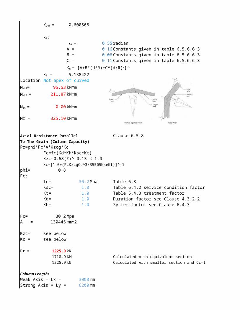
0.6005656
0.55 radianA = 0.16 Constants given in table 6.5.6.6.3B = 0.06 Constants given in table 6.5.6.6.3C = 0.11 Constants given in table 6.5.6.6.3
5.1384221Location : Not apex of curved
95.53 kN*m
211.87 kN*m
0.00 kN*m
Mr = 325.10 kN*m
Axial Resistance Parallel Clause 6.5.8To The Grain (Column Capacity)
Pr=phi*Fc*A*Kzcg*KcFc=fc(Kd*Kh*Ksc*Kt)Kzc=0.68(Z)^-0.13 < 1.0Kc=[1.0+(FcKzcgCc^3/35E05KseKt)]^-1
phi= 0.8Fc:
fc= 30.2 Mpa Table 6.3Ksc= 1.0 Table 6.4.2 service condition factorKt= 1.0 Table 5.4.3 treatment factorKd= 1.0 Duration factor see Clause 4.3.2.2Kh= 1.0 System factor see Clause 6.4.3
Fc= 30.2 MpaA = 130445 mm^2
Kzc= see belowKc = see below
Pr = 1225.9 kN
1718.9 kN Calculated with equivalent section
1225.9 kN Calculated with smaller section and Cc=1
Column Lengths
Weak Axis = Lx = 3000 mmStrong Axis = Ly = 6200 mm
KZtp =
KR: a =
KR = [A+B*(d/R)+C*(d/R)2]-1
KR =
Mrt1=
Mrt2 =
Mrt =

Column Size
Equivalent Smaller end Larger end
Weak Axis = dx = 175 mm 175 mm 175 mm
Strong Axis = dy = 745.4 mm 380 mm 1192 mm
Kzcg
Kzcg = 0.7Z = 0.808759 m3 Member volumn
Kzcg = 0.8 For member with constant section
Z = 0.4123 m3 of smaller one
Kc
Kc = 0.78 Clause 6.5.8.5E = 12400 Table 6.3 - Modulus of Elasticity
0.87E = 10788 Table 5.3.1 A-DKse = 1.0 Table 6.4.2 service condition factorCc = 17.1
Cc<=50, slenderness is within limitation
Resistance to combined bending and axial load Pf = 25.2 kNPr = 1225.9 kNMf = 32.1 kN*mMr = 325.10 kN*m
0.12
Check Resistance to combined bending and axial load : OK
Shear Resistance (Gross Section)
Clause 6.5.7.2.1
0.9
2.0 Mpa Bending at extreme fibre, See Table 6.3
1.00 Duration factor, See Clause 6.4.1
1.00 System factor, See Clause 6.4.2.2
1.00 Service condition factor, See table 6.4.2
1.00 Treatment factor, See Clause 6.4.4
2 Mpa
Gross cross section areac of member
Vr1 = F*Fv*2Ag/3*KN
Fv=fv(Kd*Kh*Ksv*Kt)
F =
Fv:
fv =
Kd =
Kh =
Ksv =
Kt =
Fv=
Ag:
Ag = b*h
𝑘=𝑉_𝑓/𝑉_𝑟 =
𝑘=𝑃_𝑓/𝑃_𝑟 +𝑀_𝑓/𝑀_𝑟 =
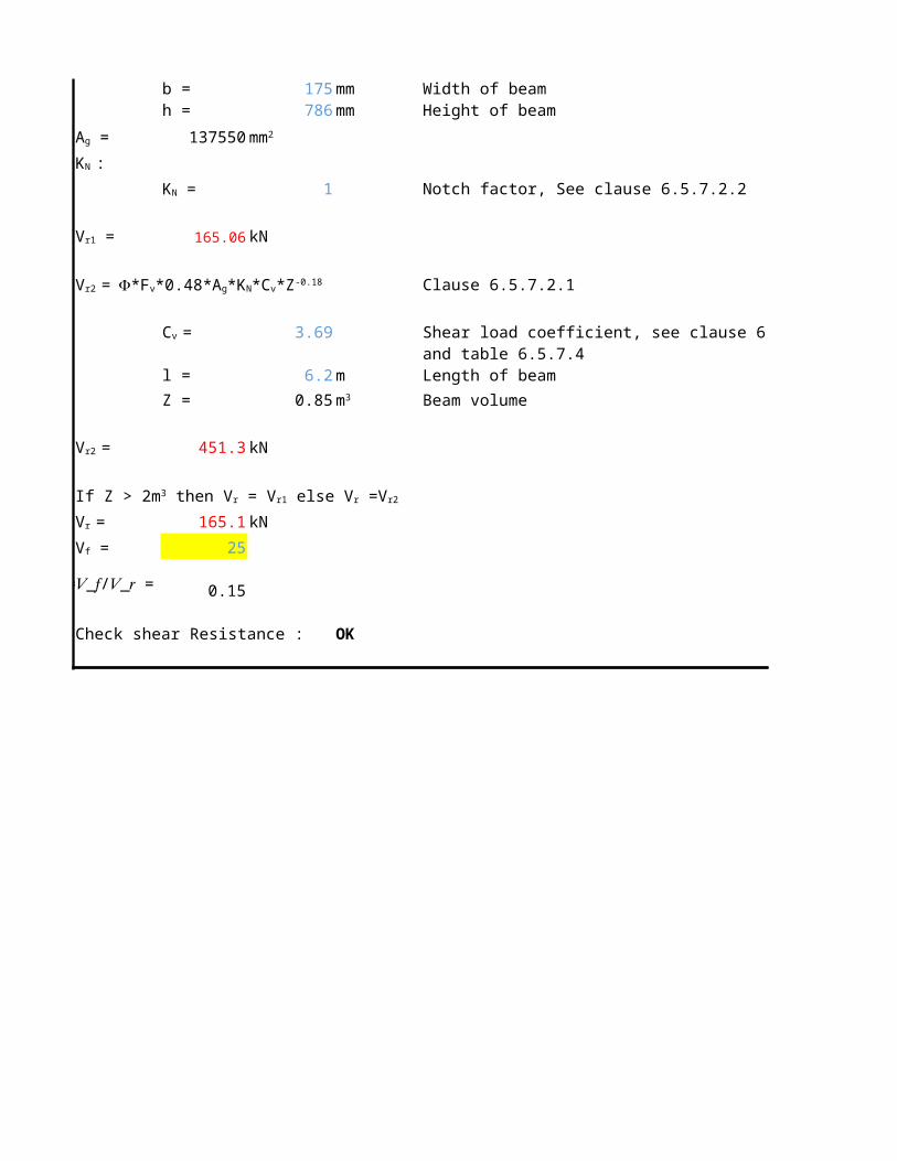
b = 175 mm Width of beamh = 786 mm Height of beam
137550
1 Notch factor, See clause 6.5.7.2.2
165.06 kN
Clause 6.5.7.2.1
3.69 Shear load coefficient, see clause 6.5.7.4 and table 6.5.7.4
l = 6.2 m Length of beam
Z = 0.85 Beam volume
451.3 kN
165.1 kN
25
0.15
Check shear Resistance : OK
Ag = mm2
KN :
KN =
Vr1 =
Vr2 = F*Fv*0.48*Ag*KN*Cv*Z-0.18
Cv =
m3
Vr2 =
If Z > 2m3 then Vr = Vr1 else Vr =Vr2
Vr =
Vf =𝑘=𝑉_𝑓/𝑉_𝑟 =
TURDOR ARCH @ POINT 2Bending Moment Resistance (Based on bending strength)
Section 8.2
Section 8.2
Section 8.2
Section 2.5
0.9 Clause 6.5.6.5.1
Clause 6.5.6.5.1
25.60 Mpa Bending at extreme fibre, See Table 6.3
1.00 Duration factor, See Clause 6.4.1
1.00 System factor, See Clause 6.4.2.2
1.00 Service condition factor, See table 6.4.2
1.0 Treatment factor, See Clause 6.4.4
25.6 MpaS:
b = 175 mm Width of beamh = 617 mm Height of beam
S = 11103429 mm^3 Section modulus
255.82301 kN*m
Clause 6.5.6.5.2t = 19 mm Lamination thickness, See table 8.2 page 374
wood design manualR = 2800 mm Radius of curvature of the innermost
0.91 lamination Curvature Factor
Clause 6.5.6.5.1B = 0.175 m Either the beam width (for single piece
laminations) or the width of the widest piece(for multi piece laminations)
L = 6 m Length of beam frome point of zero moment to point of zero moment
1
Mrb1 = M'r*KL*Kx*KM
Mrb2 = M'r*KZbg*KX*KM
Mrb = Min(Mrb1,Mrb2)
M'rb = f*Fb*S
f =
Fb:
Fb = fb(Kd*Kh*Ksb*Kt)
fb =
Kd =
Kh =
Ksb =
Kt =
Fb=
S = b*h2/6
M'rb =
KX:
KX = 1-2000*(t/R)2
KX =
Kzbg:
Kzbg = 1.03*(B*L)-0.18
Kzbg =
KL:
CB = (Le*d/b2)^0.5

5760 mm Effective length, See table 6.5.6.4.3
10.8
1 Clause 6.5.6.4.4
Section 8.40.5529889 radian
Location : Not apex of curved
1
232.26 kN*m
232.26 kN*m
232.26 kN*m
Bending Moment Resistance (Based on radial tension strength)
Clause 6.5.6.6.2
Clause 6.5.6.6.1
0.9 Clause 6.5.6.6.1
Clause 6.5.6.6.1
0.83 Mpa Specified strength intension perpendicular to grain, see table 6.3
1.00 Duration factor, See Clause 6.4.1
1.00 System factor, See Clause 6.4.2.2
1.00 Service condition factor, See table 6.4.2
1.0 Treatment factor, See Clause 6.4.4
0.83 Mpa
S:
b = 175 mm Width of beamh = 617 mm Height of beam
S = 11103429 mm^3 Section modulus
A = 107975 Maximum cross sectional area of memberR = 3108.5 mm Radius of curvature at centerline of member
0.9 rad Enclosed angle in radian Loading : Uniformly distributedMember : Double tapered curved
Le =
CB =
KL =
KM:
KM = 1/(1+2.7*tan a) a =
KM =
Mrb1 =
Mrb2 =
Mrb =
Mrt1= f*Ftp*S*KZtp*KR
Mrt2 = f*Ftp*2*A/3*R*KZtp
f =
Ftp:
Ftp = ftp(Kd*Kh*Kstp*Kt)
ftp =
Kd =
Kh =
Kstp =
Kt =
Ftp=
S = b*h2/6
KZtp:
mm2
b =
0.6973359
0.55 radianA = 0.16 Constants given in table 6.5.6.6.3B = 0.06 Constants given in table 6.5.6.6.3C = 0.11 Constants given in table 6.5.6.6.3
5.673984Location : Not apex of curved
32.82 kN*m
116.56 kN*m
0.00 kN*m
Mr = 232.26 kN*m
Axial Resistance Parallel Clause 6.5.8To The Grain (Column Capacity)
Pr=phi*Fc*A*Kzcg*KcFc=fc(Kd*Kh*Ksc*Kt)Kzc=0.68(Z)^-0.13 < 1.0Kc=[1.0+(FcKzcgCc^3/35E05KseKt)]^-1
phi= 0.8Fc:
fc= 30.2 Mpa Table 6.3Ksc= 1.00 Table 6.4.2 service condition factorKt= 1.0 Table 5.4.3 treatment factorKd= 1.0 Duration factor see Clause 4.3.2.2Kh= 1.0 System factor see Clause 6.4.3
Fc= 30.2 MpaA = 85163.75 mm^2
Kzc= see belowKc = see below
Pr = 1171.5 kN
1171.5 kN Calculated with equivalent section
1225.9 kN Calculated with smaller section and Cc=1
Column Lengths
Weak Axis = Lx = 3000 mmStrong Axis = Ly = 6200 mm
KZtp =
KR: a =
KR = [A+B*(d/R)+C*(d/R)2]-1
KR =
Mrt1=
Mrt2 =
Mrt =

Column Size
Equivalent Smaller end Larger end
Weak Axis = dx = 175 mm 175 mm 175 mm
Strong Axis = dy = 486.65 mm 380 mm 617 mm
Kzcg
Kzcg = 0.7Z = 0.5280153 m3 Member volumn
Kzcg = 0.8 For member with constant section
Z = 0.4123 m3 of smaller one
Kc
Kc = 0.77 Clause 6.5.8.5E = 12400 Table 6.3 - Modulus of Elasticity
0.87E = 10788 Table 5.3.1 A-DKse = 1.0 Table 6.4.2 service condition factorCc = 17.1
Cc<=50, slenderness is within limitation
Resistance to combined bending and axial load Pf = 17.1 kNPr = 1171.5 kNMf = 7.1 kN*mMr = 232.26 kN*m
0.05
Check Resistance to combined bending and axial load : OK
Shear Resistance (Gross Section)
Clause 6.5.7.2.1
0.9
2.0 Mpa Bending at extreme fibre, See Table 6.3
1.00 Duration factor, See Clause 6.4.1
1.00 System factor, See Clause 6.4.2.2
1.00 Service condition factor, See table 6.4.2
1.00 Treatment factor, See Clause 6.4.4
2 Mpa
Gross cross section areac of member
Vr1 = F*Fv*2Ag/3*KN
Fv=fv(Kd*Kh*Ksv*Kt)
F =
Fv:
fv =
Kd =
Kh =
Ksv =
Kt =
Fv=
Ag:
Ag = b*h
𝑘=𝑉_𝑓/𝑉_𝑟 =
𝑘=𝑃_𝑓/𝑃_𝑟 +𝑀_𝑓/𝑀_𝑟 =

b = 175 mm Width of beamh = 617 mm Height of beam
107975
1 Notch factor, See clause 6.5.7.2.2
129.57 kN
Clause 6.5.7.2.1
3.69 Shear load coefficient, see clause 6.5.7.4 and table 6.5.7.4
l = 6.2 m Length of beam
Z = 0.67 Beam volume
370.0 kN
129.6 kN
10.8
0.08
Check shear Resistance : OK
Ag = mm2
KN :
KN =
Vr1 =
Vr2 = F*Fv*0.48*Ag*KN*Cv*Z-0.18
Cv =
m3
Vr2 =
If Z > 2m3 then Vr = Vr1 else Vr =Vr2
Vr =
Vf =𝑘=𝑉_𝑓/𝑉_𝑟 =

TURDOR ARCH @ POINT 1Bending Moment Resistance (Based on bending strength)
Section 8.2
Section 8.2
Section 8.2
Section 2.5
0.9 Clause 6.5.6.5.1
Clause 6.5.6.5.1
25.60 Mpa Bending at extreme fibre, See Table 6.3
1.00 Duration factor, See Clause 6.4.1
1.00 System factor, See Clause 6.4.2.2
1.00 Service condition factor, See table 6.4.2
1.0 Treatment factor, See Clause 6.4.4
25.6 MpaS:
b = 175 mm Width of beamh = 498.5 mm Height of beam
S = 7247982 mm^3 Section modulus
166.99351 kN*m
Clause 6.5.6.5.2t = 19 mm Lamination thickness, See table 8.2 page 374
wood design manualR = 2800 mm Radius of curvature of the innermost
0.91 lamination Curvature Factor
Clause 6.5.6.5.1B = 0.175 m Either the beam width (for single piece
laminations) or the width of the widest piece(for multi piece laminations)
L = 6 m Length of beam frome point of zero moment to point of zero moment
1
Mrb1 = M'r*KL*Kx*KM
Mrb2 = M'r*KZbg*KX*KM
Mrb = Min(Mrb1,Mrb2)
M'rb = f*Fb*S
f =
Fb:
Fb = fb(Kd*Kh*Ksb*Kt)
fb =
Kd =
Kh =
Ksb =
Kt =
Fb=
S = b*h2/6
M'rb =
KX:
KX = 1-2000*(t/R)2
KX =
Kzbg:
Kzbg = 1.03*(B*L)-0.18
Kzbg =
KL:
CB = (Le*d/b2)^0.5

5760 mm Effective length, See table 6.5.6.4.3
9.7
1 Clause 6.5.6.4.4
Section 8.40.5529889 radian
Location : Not apex of curved
1
151.61 kN*m
151.61 kN*m
151.61 kN*m
Bending Moment Resistance (Based on radial tension strength)
Clause 6.5.6.6.2
Clause 6.5.6.6.1
0.9 Clause 6.5.6.6.1
Clause 6.5.6.6.1
0.83 Mpa Specified strength intension perpendicular to grain, see table 6.3
1.00 Duration factor, See Clause 6.4.1
1.00 System factor, See Clause 6.4.2.2
1.00 Service condition factor, See table 6.4.2
1.0 Treatment factor, See Clause 6.4.4
0.83 Mpa
S:
b = 175 mm Width of beamh = 498.5 mm Height of beam
S = 7247982 mm^3 Section modulus
A = 87237.5 Maximum cross sectional area of memberR = 3049.25 mm Radius of curvature at centerline of member
0.9 rad Enclosed angle in radian Loading : Uniformly distributedMember : Const Depth curved
Le =
CB =
KL =
KM:
KM = 1/(1+2.7*tan a) a =
KM =
Mrb1 =
Mrb2 =
Mrb =
Mrt1= f*Ftp*S*KZtp*KR
Mrt2 = f*Ftp*2*A/3*R*KZtp
f =
Ftp:
Ftp = ftp(Kd*Kh*Kstp*Kt)
ftp =
Kd =
Kh =
Kstp =
Kt =
Ftp=
S = b*h2/6
KZtp:
mm2
b =
0.5009343
0.55 radianA = 0.16 Constants given in table 6.5.6.6.3B = 0.06 Constants given in table 6.5.6.6.3C = 0.11 Constants given in table 6.5.6.6.3
5.7887489Location : Not apex of curved
15.70 kN*m
66.36 kN*m
0.00 kN*m
Mr = 151.61 kN*m
Axial Resistance Parallel Clause 6.5.8To The Grain (Column Capacity)
Pr=phi*Fc*A*Kzcg*KcFc=fc(Kd*Kh*Ksc*Kt)Kzc=0.68(Z)^-0.13 < 1.0Kc=[1.0+(FcKzcgCc^3/35E05KseKt)]^-1
phi= 0.8Fc:
fc= 30.2 Mpa Table 6.3Ksc= 1.00 Table 6.4.2 service condition factorKt= 1.0 Table 5.4.3 treatment factorKd= 1.0 Duration factor see Clause 4.3.2.2Kh= 1.0 System factor see Clause 6.4.3
Fc= 30.2 MpaA = 75831.875 mm^2
Kzc= see belowKc = see below
Pr = 1055.3 kN
1055.3 kN Calculated with equivalent section
1225.9 kN Calculated with smaller section and Cc=1
Column Lengths
Weak Axis = Lx = 3000 mmStrong Axis = Ly = 6200 mm
KZtp =
KR: a =
KR = [A+B*(d/R)+C*(d/R)2]-1
KR =
Mrt1=
Mrt2 =
Mrt =

Column Size
Equivalent Smaller end Larger end
Weak Axis = dx = 175 mm 175 mm 175 mm
Strong Axis = dy = 433.325 mm 380 mm 498.5 mm
Kzcg
Kzcg = 0.8Z = 0.4701576 m3 Member volumn
Kzcg = 0.8 For member with constant section
Z = 0.4123 m3 of smaller one
Kc
Kc = 0.77 Clause 6.5.8.5E = 12400 Table 6.3 - Modulus of Elasticity
0.87E = 10788 Table 5.3.1 A-DKse = 1.0 Table 6.4.2 service condition factorCc = 17.1
Cc<=50, slenderness is within limitation
Resistance to combined bending and axial load Pf = 13.1 kNPr = 1055.3 kNMf = 3.4 kN*mMr = 151.61 kN*m
0.03
Check Resistance to combined bending and axial load : OK
Shear Resistance (Gross Section)
Clause 6.5.7.2.1
0.9
2.0 Mpa Bending at extreme fibre, See Table 6.3
1.00 Duration factor, See Clause 6.4.1
1.00 System factor, See Clause 6.4.2.2
1.00 Service condition factor, See table 6.4.2
1.00 Treatment factor, See Clause 6.4.4
2 Mpa
Gross cross section areac of member
Vr1 = F*Fv*2Ag/3*KN
Fv=fv(Kd*Kh*Ksv*Kt)
F =
Fv:
fv =
Kd =
Kh =
Ksv =
Kt =
Fv=
Ag:
Ag = b*h
𝑘=𝑉_𝑓/𝑉_𝑟 =
𝑘=𝑃_𝑓/𝑃_𝑟 +𝑀_𝑓/𝑀_𝑟 =
b = 175 mm Width of beamh = 498.5 mm Height of beam
87237.5
1 Notch factor, See clause 6.5.7.2.2
104.69 kN
Clause 6.5.7.2.1
3.69 Shear load coefficient, see clause 6.5.7.4 and table 6.5.7.4
l = 6.2 m Length of beam
Z = 0.54 Beam volume
310.7 kN
104.7 kN
9
0.09
Check shear Resistance : OK
Ag = mm2
KN :
KN =
Vr1 =
Vr2 = F*Fv*0.48*Ag*KN*Cv*Z-0.18
Cv =
m3
Vr2 =
If Z > 2m3 then Vr = Vr1 else Vr =Vr2
Vr =
Vf =𝑘=𝑉_𝑓/𝑉_𝑟 =

TURDOR ARCH @ POINT 0Bending Moment Resistance (Based on bending strength)
Section 8.2
Section 8.2
Section 8.2
Section 2.5
0.9 Clause 6.5.6.5.1
Clause 6.5.6.5.1
25.60 Mpa Bending at extreme fibre, See Table 6.3
1.00 Duration factor, See Clause 6.4.1
1.00 System factor, See Clause 6.4.2.2
1.00 Service condition factor, See table 6.4.2
1.0 Treatment factor, See Clause 6.4.4
25.6 MpaS:
b = 175 mm Width of beamh = 380 mm Height of beam
S = 4211667 mm^3 Section modulus
97.0368 kN*m
Clause 6.5.6.5.2t = 19 mm Lamination thickness, See table 8.2 page 374
wood design manualR = 2800 mm Radius of curvature of the innermost
0.91 lamination Curvature Factor
Clause 6.5.6.5.1B = 0.175 m Either the beam width (for single piece
laminations) or the width of the widest piece(for multi piece laminations)
L = 6 m Length of beam frome point of zero moment to point of zero moment
1
Mrb1 = M'r*KL*Kx*KM
Mrb2 = M'r*KZbg*KX*KM
Mrb = Min(Mrb1,Mrb2)
M'rb = f*Fb*S
f =
Fb:
Fb = fb(Kd*Kh*Ksb*Kt)
fb =
Kd =
Kh =
Ksb =
Kt =
Fb=
S = b*h2/6
M'rb =
KX:
KX = 1-2000*(t/R)2
KX =
Kzbg:
Kzbg = 1.03*(B*L)-0.18
Kzbg =
KL:
CB = (Le*d/b2)^0.5
5760 mm Effective length, See table 6.5.6.4.3
8.5
1 Clause 6.5.6.4.4
Section 8.40.5529889 radian
Location : Not apex of curved
1
88.10 kN*m
88.10 kN*m
88.10 kN*m
Bending Moment Resistance (Based on radial tension strength)
Clause 6.5.6.6.2
Clause 6.5.6.6.1
0.9 Clause 6.5.6.6.1
Clause 6.5.6.6.1
0.83 Mpa Specified strength intension perpendicular to grain, see table 6.3
1.00 Duration factor, See Clause 6.4.1
1.00 System factor, See Clause 6.4.2.2
1.00 Service condition factor, See table 6.4.2
1.0 Treatment factor, See Clause 6.4.4
0.83 Mpa
S:
b = 175 mm Width of beamh = 380 mm Height of beam
S = 4211667 mm^3 Section modulus
A = 66500 Maximum cross sectional area of memberR = 2990 mm Radius of curvature at centerline of member
0.9 rad Enclosed angle in radian Loading : Uniformly distributedMember : Double tapered curved
Le =
CB =
KL =
KM:
KM = 1/(1+2.7*tan a) a =
KM =
Mrb1 =
Mrb2 =
Mrb =
Mrt1= f*Ftp*S*KZtp*KR
Mrt2 = f*Ftp*2*A/3*R*KZtp
f =
Ftp:
Ftp = ftp(Kd*Kh*Kstp*Kt)
ftp =
Kd =
Kh =
Kstp =
Kt =
Ftp=
S = b*h2/6
KZtp:
mm2
b =

0.7743161
0.55 radianA = 0.16 Constants given in table 6.5.6.6.3B = 0.06 Constants given in table 6.5.6.6.3C = 0.11 Constants given in table 6.5.6.6.3
5.9031134Location : Not apex of curved
14.38 kN*m
76.67 kN*m
0.00 kN*m
Mr = 88.10 kN*m
Axial Resistance Parallel Clause 6.5.8To The Grain (Column Capacity)
Pr=phi*Fc*A*Kzcg*KcFc=fc(Kd*Kh*Ksc*Kt)Kzc=0.68(Z)^-0.13 < 1.0Kc=[1.0+(FcKzcgCc^3/35E05KseKt)]^-1
phi= 0.8Fc:
fc= 30.2 Mpa Table 6.3Ksc= 1.00 Table 6.4.2 service condition factorKt= 1.0 Table 5.4.3 treatment factorKd= 1.0 Duration factor see Clause 4.3.2.2Kh= 1.0 System factor see Clause 6.4.3
Fc= 30.2 MpaA = 66500 mm^2
Kzc= see belowKc = see below
Pr = 937.6 kN
937.6 kN Calculated with equivalent section
1225.9 kN Calculated with smaller section and Cc=1
Column Lengths
Weak Axis = Lx = 3000 mmStrong Axis = Ly = 6200 mm
KZtp =
KR: a =
KR = [A+B*(d/R)+C*(d/R)2]-1
KR =
Mrt1=
Mrt2 =
Mrt =

Column Size
Equivalent Smaller end Larger end
Weak Axis = dx = 175 mm 175 mm 175 mm
Strong Axis = dy = 380 mm 380 mm 380 mm
Kzcg
Kzcg = 0.8Z = 0.4123 m3 Member volumn
Kzcg = 0.8 For member with constant section
Z = 0.4123 m3 of smaller one
Kc
Kc = 0.76 Clause 6.5.8.5E = 12400 Table 6.3 - Modulus of Elasticity
0.87E = 10788 Table 5.3.1 A-DKse = 1.0 Table 6.4.2 service condition factorCc = 17.1
Cc<=50, slenderness is within limitation
Resistance to combined bending and axial load Pf = 1.9 kNPr = 937.6 kNMf = 0 kN*mMr = 88.10 kN*m
0.00
Check Resistance to combined bending and axial load : OK
Shear Resistance (Gross Section)
Clause 6.5.7.2.1
0.9
2.0 Mpa Bending at extreme fibre, See Table 6.3
1.00 Duration factor, See Clause 6.4.1
1.00 System factor, See Clause 6.4.2.2
1.00 Service condition factor, See table 6.4.2
1.00 Treatment factor, See Clause 6.4.4
2 Mpa
Gross cross section areac of member
Vr1 = F*Fv*2Ag/3*KN
Fv=fv(Kd*Kh*Ksv*Kt)
F =
Fv:
fv =
Kd =
Kh =
Ksv =
Kt =
Fv=
Ag:
Ag = b*h
𝑘=𝑉_𝑓/𝑉_𝑟 =
𝑘=𝑃_𝑓/𝑃_𝑟 +𝑀_𝑓/𝑀_𝑟 =
b = 175 mm Width of beamh = 380 mm Height of beam
66500
1 Notch factor, See clause 6.5.7.2.2
79.80 kN
Clause 6.5.7.2.1
3.69 Shear load coefficient, see clause 6.5.7.4 and table 6.5.7.4
l = 6.2 m Length of beam
Z = 0.41 Beam volume
248.7 kN
79.8 kN
7.7
0.10
Check shear Resistance : OK
Ag = mm2
KN :
KN =
Vr1 =
Vr2 = F*Fv*0.48*Ag*KN*Cv*Z-0.18
Cv =
m3
Vr2 =
If Z > 2m3 then Vr = Vr1 else Vr =Vr2
Vr =
Vf =𝑘=𝑉_𝑓/𝑉_𝑟 =