Embed Size (px)
Citation preview
Water Technologies & Solutions technical paper
Find a contact near you by visiting www.suezwatertechnologies.com and clicking on “Contact Us.” *Trademark of SUEZ; may be registered in one or more countries. ©2017 SUEZ. All rights reserved. TP1041EN.docx Aug-13
getting to zero discharge: how to recycle that last bit of really bad wastewater Authors: Joe Bostjancic and Rodi Ludlum, Resource Conservation Company (RCC)
Note: SUEZ purchased RCC in 2005.
abstract
Designing a plant for maximum water recycle and reuse is not the mystery it once was. New and improved water treatment technologies allow plants to recycle vast quantities of wastewater that once went to sewers, rivers, deep wells, spray fields or percolation ponds. In addition, plants are now being designed from the ground up with water conservation in mind. However, no matter how carefully designed a plant may be, there are often a few remaining wastewater streams too saturated for conventional physical/chemical and membrane technology.
This paper will discuss various forms of evaporation, crystallization and spray drying to reduce these last difficult wastewaters to dry solids and in the process, squeeze out the last bit of clean water for maximum recycle and reuse. Specific case studies will be used to illustrate the wastewater recycling process and show how in some cases, valuable products as well as clean water may be recovered from the wastewater.
advantage of zero liquid discharge operation
Permitting a new industrial plant is often a long and tedious process. Designing a plant for zero wastewater discharge right from the start wins faster community acceptance and streamlines the permitting process. Recycling wastewater greatly decreases the amount of makeup water that must be purchased from the local utility and eliminates the local control and costs of sewer disposal. Wastewater recycling also allows a greater freedom in selecting a site for an industrial plant because there are fewer concerns about adequate water supply. In many cases, poor quality water can be used for make-up since it is upgraded in-house. For example, at several zero discharge sites, secondary sewage effluent or wastewater from other industrial sites is used as make-up.
a brief history of evaporation
Several things happened in the early 70’s to spur interest in evaporators for wastewater treatment. First was the imposition of clean water laws such as the National Pollution Discharge Elimination System (NPDES) and the implementation of similar “zero liquid discharge” regulations at the local level. These regulations justified research into treating highly saturated brine wastewaters such as cooling tower blowdown, which had previously been dumped into rivers. These wastewaters, saturated with calcium sulfate and silica, are difficult to evaporate because they are already at the scaling point. RCC (now SUEZ) researchers in the early 70’s developed a method of adding calcium sulfate “seeds” to the saturated wastewater to give the precipitating salts a place to adhere and remain in suspension (Figure 1).

Page 2 TP1041EN.docx
Figure 1: Seeded Slurry Process
Seeding alone is not enough to prevent scaling, however. Other system variables are: geometry of the equipment, temperature, pH, residence time, system volume, crystal size, crystal composition, crystal concentration, ratios and proportions of each mineral to other minerals, trace element presence, and evaporation rate. These and other factors will be discussed later in the paper.
vapor compression cycle
The amount of energy it takes to evaporate water was also a limiting factor in the early 70’s, especially with soaring energy prices after the oil embargo. Using steam as the energy source, it takes 1000 BTUs to evaporate a pound of water. Multiple effect evaporator systems increase this efficiency, but add capital cost in the form of additional evaporator bodies. Using electricity, or the vapor compression cycle, to evaporate water increases the efficiency 10 times, requiring only 100 BTUs to evaporate a pound of water. In other words, one evaporator body driven by a mechanical vapor compressor is equivalent to a 10-effect, or 10-body system driven by steam.
In the early 70’s, compressor suppliers adapted high-pressure, single-stage centrifugal gas compressors to operate on steam. This was another important factor in the growth of vapor compression evaporation. Properly protected from stray salts in the steam along with prudent design factors, vapor compressors have been successfully used with evaporators since the mid-70’s.
configuration, materials of construction
Boiling brines corroded low-cost aluminum in the first test evaporators. Titanium was finally selected as the most versatile in resisting attack from a broad array of constituents in the water. Using titanium material in the evaporator meant the condenser had to be a tube-and-shell design rather than flat plate, as tubes are easier to weld than plates, offer a smooth surface for brine flow and have better resistance to pressure.
vapor compression evaporator
The RCC Seeded Slurry Brine Evaporator, developed in the early 70’s, contains all the same basic elements today. A vapor compression evaporator diagram is shown in Figure 2. Wastewater enters a feed tank (not shown) where the pH is adjusted between 5.5 and 6.0. The acidified wastewater is pumped to a heat exchanger that raises its temperature to the boiling point. It then goes to a deaerator, which removes non-condensable gases such as carbon dioxide and oxygen.
Figure 2: Vapor Compression Evaporator System
Hot deaerated feed enters the evaporator sump, where it combines with the recirculating brine slurry. The slurry is pumped to the top of a bundle of two-inch heat transfer tubes, where it falls by gravity in a thin film down the inside of the tubes. As it falls, a small portion evaporates and the rest falls into the sump to be recirculated.
The vapor travels down the tubes with the brine, and is drawn up through mist eliminators on its way to the vapor compressor. Compressed vapor flows to
TP1041EN.docx Page 3
the outside of the heat transfer tubes, where its latent heat is given up to the cooler brine slurry falling inside. As the vapor gives up heat, it condenses as distilled water. The distillate is pumped back through the heat exchanger, where it gives up sensible heat to the incoming wastewater. A small amount of the brine slurry is continuously released from the evaporator to control density.
Typically 95% of the wastewater feed will be converted to distillate (<10 ppm [mg/L] TDS) for reuse in the plant. The remaining 5% is treated in a variety of ways which will be discussed in detail later in the paper.
waste steam evaporator
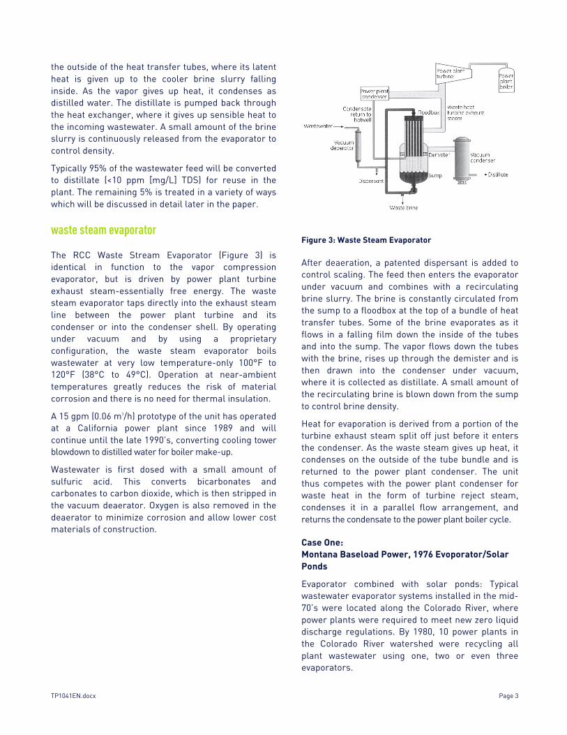
The RCC Waste Stream Evaporator (Figure 3) is identical in function to the vapor compression evaporator, but is driven by power plant turbine exhaust steam-essentially free energy. The waste steam evaporator taps directly into the exhaust steam line between the power plant turbine and its condenser or into the condenser shell. By operating under vacuum and by using a proprietary configuration, the waste steam evaporator boils wastewater at very low temperature-only 100°F to 120°F (38°C to 49°C). Operation at near-ambient temperatures greatly reduces the risk of material corrosion and there is no need for thermal insulation.
A 15 gpm (0.06 m3/h) prototype of the unit has operated at a California power plant since 1989 and will continue until the late 1990’s, converting cooling tower blowdown to distilled water for boiler make-up.
Wastewater is first dosed with a small amount of sulfuric acid. This converts bicarbonates and carbonates to carbon dioxide, which is then stripped in the vacuum deaerator. Oxygen is also removed in the deaerator to minimize corrosion and allow lower cost materials of construction.
Figure 3: Waste Steam Evaporator
After deaeration, a patented dispersant is added to control scaling. The feed then enters the evaporator under vacuum and combines with a recirculating brine slurry. The brine is constantly circulated from the sump to a floodbox at the top of a bundle of heat transfer tubes. Some of the brine evaporates as it flows in a falling film down the inside of the tubes and into the sump. The vapor flows down the tubes with the brine, rises up through the demister and is then drawn into the condenser under vacuum, where it is collected as distillate. A small amount of the recirculating brine is blown down from the sump to control brine density.
Heat for evaporation is derived from a portion of the turbine exhaust steam split off just before it enters the condenser. As the waste steam gives up heat, it condenses on the outside of the tube bundle and is returned to the power plant condenser. The unit thus competes with the power plant condenser for waste heat in the form of turbine reject steam, condenses it in a parallel flow arrangement, and returns the condensate to the power plant boiler cycle.
Case One: Montana Baseload Power, 1976 Evoporator/Solar Ponds
Evaporator combined with solar ponds: Typical wastewater evaporator systems installed in the mid-70’s were located along the Colorado River, where power plants were required to meet new zero liquid discharge regulations. By 1980, 10 power plants in the Colorado River watershed were recycling all plant wastewater using one, two or even three evaporators.

Page 4 TP1041EN.docx
One typical installation is a Montana baseload power plant, where two evaporators were installed in 1976 to recycle cooling tower blowdown. Feed chemistry is shown in Table I. About 350 gpm (1.3 m3/h) is treated at the plant. Distillate is used as boiler makeup, with the remaining concentrated brine sent to a series of solar evaporation ponds on site. Lined solar ponds were the only method of handling waste brine during the early years of zero discharge. Climate, terrain and the remote locations of the first zero discharge plants made solar ponds a sensible option.
Table 1: Feed Chemistry ppm (mg/L) as Ion, Montana Power Plan
Case Two: Florida Power, 1981 Evaporator/Spray dryer
Evaporator combined with a spray dryer: The first zero liquid discharge plant on the east coast has the wrong climate for solar ponds but a requirement for zero liquid discharge. Wastewater from cooling towers is collected in the ash pond system along with rain, coal pile runoff, landfill runoff and other plant wastes. The combined waste stream is sent to a lamella separator and filter to remove particles, then to a vapor compression evaporator at the rate of about 300 gpm (1.1 m3/h). The feed is relatively low in TDS at about 2500 ppm (mg/L). Distillate is reused as boiler make-up and cooling tower make-up.
Concentrated brine is sent to a spray dryer at the rate of about 2 to 4 gpm (0.01 to 0.02 m3/h) and reduced to solids for disposal at a landfill on site. Dry solids production averages about 20 tons per week. The spray dryer (Figure 4) consists of an atomizing wheel spinning at 16,800 rpm which sprays the concentrated slurry into a hot, gas-fired chamber. Water instantly evaporates from the droplets and the solids are drawn into a bag filters.
Case Three: Virginia Power, 1991 Evaporator/Crystallizer
Evaporator combined with a crystallizer: Another way to reduce concentrated brine to dry solids is to send it to a forced-circulation crystallizer, which may be driven by steam or mechanical vapor compression. SUEZ RO crystallizers have been used for decades in the food processing industry and to produce commodity chemicals. SUEZ crystallizers are now almost standard equipment at zero discharge sites, especially for plants lacking the land and the proper climate for solar ponds.
Designers of the Virginia zero discharge power plant chose to preconcentrate plant wastewater with electrodialysis reversal (EDR) and reverse osmosis (RO) before sending it to the evaporator at the rate of about 90 gpm. Four gpm of waste brine is then sent to the crystallizer (Figure 5).
Figure 5: Forced-Circulation Crystallizer Steam-Driven
Figure 4: Spray Dryer
TP1041EN.docx Page 5
Crystallizer operation: The crystallizer at the Virginia site is a forced-circulation evaporator driven by plant steam, but it may also be driven by a vapor compressor. Slurry from the evaporator is sent to the crystallizer sump and then to a flooded shell and tube heat exchanger. Because the tubes are flooded, the brine is under pressure and will not boil. This prevents scaling in the tubes. The brine enters the crystallizer vapor body at an angle, where it swirls in a vortex. A small amount of the brine evaporates and crystals form. Most of the brine is recirculated back to the heater; a small stream is sent to a filter press for final dewatering to a 20% moisture content. Filter cake from the press is discharged at the rate of about 365 pounds per hour.
Case Four: Polish Coal Mine, 1992 RO/Evaporator/Crystallizer
At the world’s first zero liquid discharge coal mine, nearly three million gallons per day of mine drainage is preconcentrated with reverse osmosis before is sent to two RCC Vapor Compression Evaporators at the rate of about 800 gpm (3 m3/h). Because of the high levels of sodium chloride in the mine drainage, (Table 2) Polish engineers also chose to recover commercial grade sodium chloride from the concentrated brine. This is sold at about US$100 per ton to help offset the cost of pollution control.
Table 2: Polish Coal Mine Feed to Evaporators
Sodium Chloride Crystallizer: Most crystallizers at zero liquid discharge sites produce a mixed salt that must be landfilled. But where it makes sense, specific salts may be recovered from the mixed salt slurry. This moves the concept of “zero liquid discharge” toward the ideal of “zero waste discharge.”
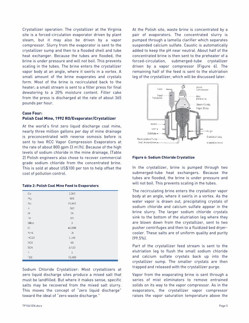
At the Polish site, waste brine is concentrated by a pair of evaporators. The concentrated slurry is pumped through a lamella clarifier which separates suspended calcium sulfate. Caustic is automatically added to keep the pH near neutral. About half of the concentrated brine is then sent to the preheater of a forced-circulation, submerged-tube crystallizer driven by a vapor compressor (Figure 6). The remaining half of the feed is sent to the elutriation leg of the crystallizer, which will be discussed later.
Figure 6: Sodium Chloride Crystallize
In the crystallizer, brine is pumped through two submerged-tube heat exchangers. Because the tubes are flooded, the brine is under pressure and will not boil. This prevents scaling in the tubes.
The recirculating brine enters the crystallizer vapor body at an angle, where it swirls in a vortex. As the water vapor is drawn out, precipitating crystals of sodium chloride and calcium sulfate appear in the brine slurry. The larger sodium chloride crystals sink to the bottom of the elutriation leg where they are blown down from the crystallizer, sent to two pusher centrifuges and then to a fluidized bed dryer-cooler. These salts are of uniform quality and purity (99.5%).
Part of the crystallizer feed stream is sent to the elutriation leg to flush the small sodium chloride and calcium sulfate crystals back up into the crystallizer sump. The smaller crystals are then trapped and released with the crystallizer purge.
Vapor from the evaporating brine is sent through a series of mist eliminators to remove entrained solids on its way to the vapor compressor. As in the evaporators, the crystallizer vapor compressor raises the vapor saturation temperature above the
Page 6 TP1041EN.docx
boiling point of the recirculating brine. The compressed steam is then introduced to the shell side of both heaters. Here it gives up its heat of vaporization (to heat the brine slurry inside the tubes) and condenses on the outside of the tube wall. The condensate is pumped back through the evaporator heat exchangers to be used in the nearby power and heat generating plant.
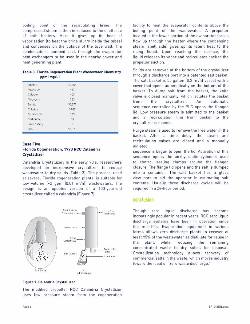
Table 3: Florida Cogeneration Plant Wastewater Chemistry ppm (mg/L)
Case Five: Florida Cogeneration, 1993 RCC Calandria Crystallizer
Calandria Crystallizer: In the early 90’s, researchers developed an inexpensive crystallizer to reduce wastewater to dry solids (Table 3). The process, used at several Florida cogeneration plants, is suitable for low volume (~2 gpm [0.01 m3/h]) wastewaters. The design is an updated version of a 100-year-old crystallizer called a calandria (Figure 7).
Figure 7: Calandria Crystallizer
The modified propeller RCC Calandria Crystallizer uses low pressure steam from the cogeneration
facility to heat the evaporator contents above the boiling point of the wastewater. A propeller located in the lower portion of the evaporator forces flow up through the heater where the condensing steam (shell side) gives up its latent heat to the rising liquid. Upon reaching the surface, the liquid releases its vapor and recirculates back to the propeller suction.
Solids are removed at the bottom of the crystallizer through a discharge port into a patented salt basket. The salt basket is 55 gallon (0.2 m3/h) vessel with a cover that opens automatically on the bottom of the basket. To dump salt from the basket, the knife valve is closed manually, which isolates the basket from the crystallizer. An automatic sequence controlled by the PLC opens the flanged lid. Low pressure steam is admitted to the basket and a recirculation line from basket to the crystallizer is opened.
Purge steam is used to remove the free water in the basket. After a time delay, the steam and recirculation valves are closed and a manually initiated sequence is begun to open the lid. Activation of this sequence opens the air/hydraulic cylinders used to control sealing clamps around the flanged closure. The flange lid opens and the salt is dumped into a container. The salt basket has a glass view port to aid the operator in estimating salt contents. Usually three discharge cycles will be required in a 24-hour period.
conclusion
Though zero liquid discharge has become increasingly popular in recent years, RCC zero liquid discharge systems have been in operation since the mid-70’s. Evaporation equipment in various forms allows zero discharge plants to recover at least 95% of the wastewater as distillate for reuse in the plant, while reducing the remaining concentrated waste to dry solids for disposal. Crystallization technology allows recovery of commercial salts in the waste, which moves industry toward the ideal of “zero waste discharge.”
TP1041EN.docx Page 7
references
1. A. Seigworth; R. Ludlum; E. Reahl, “Case Study: Integrating Membrane Processes with Evaporation to Achieve Economical Zero Liquid Discharge at the Doswell Combined Cycle Facility,” Desalination, 102 (1995), pp. 81-86.
2. J. Sikora; K. Szyndler; R. Ludlum, “Desalination Plant at Debiensko, Poland: Mine Drainage Treatment for Zero Liquid Discharge,” Paper presented at the International Water Conference, Pittsburgh, Pennsylvania, October, 1993.
3. C. Brew; C. Blackwell, “Ten Years of ‘Real Life’ Operational Experience of a Zero Discharge Power Plant in Florida,” Paper presented at Power Gen 91, Tampa, Florida, December, 1991.
4. L. Weimer; H. Dolf; D. Austin, “A Systems Engineering Approach to Vapor Recompression Evaporators,” Chemical Engineering Progress, November 1980, pp. 70-77.
5. J. Anderson, “Development History of the RCC Brine Concentrator for Concentrating Cooling-Tower Blowdown,” Paper presented at the American Society of Mechanical Engineers Winter Annual Meeting, New York, New York, December 5, 1976.