Embed Size (px)
Citation preview

Getting the Most Out of Right-Suite Universal 2018
Examples and Reference
Version 18.0
October 2017
Right-Suite Universal 2018 is composed of these modules:
Right-Draw® Right-Radiant®
Right-J® Right-F280™ Right-CommLoad® Right-N®
Right-Loop™
Right-D® Right-Duct™ Right-CommDuct™
Right-$™ Right-SolarDHW™
Right-HV™ Right-Proposal®
Right-2Line™ Right-Comm2Line™
Right-Consultant™
Wrightsoft Corporation 131 Hartwell Avenue
Lexington, MA USA 02421
800-225-8697 FAX 781-861-2058
www.wrightsoft.com


Right-Suite Universal 2018 incorporates the ACCA-approved software versions of
ACCA's procedures for residential and commercial load calculation and residential duct sizing.
Right-J® The Windows Version of
Air Conditioning Contractors of America’s Manual J, Residential Load Calculation
Seventh and Eighth (Version 2.00 March 2006) Editions
Air Conditioning Contractors of America
Right-N® The Windows Version of
Air Conditioning Contractors of America’s Manual N, Commercial Load Calculation
for Small Commercial Buildings Fifth Edition (February 2008)
Air Conditioning Contractors of America
Right-D® The Windows Version of
Air Conditioning Contractors of America’s Manual D, Residential Duct Sizing
Air Conditioning Contractors of America


Right-Suite Universal 2018 incorporates software versions of CSA’s procedures for residential load calculation and residential duct sizing.
Right-F280™ A strict implementation of
Determining the Required Capacity of Residential Space Heating and Cooling Appliances
CAN/CSA-F280-M90
CSA-F280-12
Right-Duct™
The Computer Version of HRAI's
Residential Air System Design

© Copyright 1985-2017 Wrightsoft Corporation.
All Rights Reserved.
This document may not be copied, transcribed, or transmitted and stored - either mechanically or electronically - whether in part or in whole, without the expressed written consent of Wrightsoft Corporation.
Disclaimer
Wrightsoft Corporation has carefully undertaken the task of preparing this manual and its accompanying electronic disk media, which have included the research and development efforts to evaluate the performance and effectiveness of this product.
However, Wrightsoft Corporation makes no warranties as to the contents of this manual and the accompanying electronic disk media other than what is specifically stated in the Limited Agreement and Limited Warranty which you, the licensee, have agreed to by your decision to use these products.
Wrightsoft Corporation further reserves the right to make changes to the specifications of the program and the contents of the manual without obligation to notify any person or organization of such changes.
Trademarks
Right-Suite Universal 2018, Right-J®, Right-F280™, Right-CommLoad®, Right-N®, Right-D®, Right-Duct™, Right-CommDuct™, Right-HV™, Right-Radiant®, Right-Draw®, Right-$™, Right-SolarDHW™, Right-Loop™, Right-Proposal®, Right-Consultant™, and Right-Contact™ are trademarks of Wrightsoft Corporation. Manual J, Manual D, and Manual N are trademarks of the Air Conditioning Contractors of America. IBM is a trademark of International Business Machines. Windows NT, Windows XP, Windows Vista and MS are trademarks of Microsoft Corporation.
Limited Agreement
You may install the PROGRAM on a single computer owned or controlled by you and make a reasonable number of back-up copies of the PROGRAM to protect against malfunction of or damage to the computer system or media on which the PROGRAM is used or stored. You may not otherwise use, copy or modify the PROGRAM, or merge the PROGRAM with any other PROGRAM. You may transfer the PROGRAM and license to another party if the other party agrees to accept the terms and conditions of this Agreement and, at the time of transfer, you transfer to such party or destroy all copies of the PROGRAM, whether in printed or machine-readable form (including the original and all modifications and portions of the PROGRAM contained or merged into other PROGRAMS). The PROGRAM is owned by Wrightsoft Corporation and is protected under U.S. copyright law and international treaty provisions. All copies of the PROGRAM made by you in accordance with this Agreement must contain Wrightsoft Corporation's copyright notices. Except as specifically provided in this License, all intellectual property rights in and to the PROGRAM are retained by Wrightsoft Corporation.
Limited Warranty
You may return the PROGRAM to Wrightsoft Corporation within 30 days from delivery if you are dissatisfied with the PROGRAM for any reason and Wrightsoft Corporation will refund your purchase price. Except for this right of return, the PROGRAM and the user documentation are licensed to you "as is," and Wrightsoft Corporation disclaims any and all warranties, expressed or implied, including without limitation any implied warranties of merchantability, fitness for particular purpose, title and non-infringement. In no event will Wrightsoft Corporation be liable for any incidental or consequential damages, including without limitation lost profits, arising out of the use of inability to use the PROGRAM or documentation. Some states do not allow (a) the exclusion of implied warranties or limitations on how long an implied warranty may last, and/or (b) the limitation or exclusion of liability for incidental or consequential damages, so the above limitations and exclusions may not apply to you.

Table of Contents
Table of Contents ............................................................... iii
Preface ........................................................................... xxiii
Introduction ................................................................................ 1 Right-Draw® vs Worksheets .............................................................................. 2
Right-J® & Right-D® Calculation Methods ........................................................ 2
Right-F280™ & Right-Duct™ Calculation Methods ........................................... 2
Right-N®, Right-CommLoad®, and Right-CommDuct™ Calculation Methods .. 3
Following the Examples ..................................................................................... 3
Residential Examples ......................................................................................... 3
Commercial Examples ....................................................................................... 4
Residential and Commercial Examples .............................................................. 4
RSU file names .................................................................................................. 5
AutoSave ............................................................................................................ 6
Inputs .................................................................................................................. 6
Hot keys ............................................................................................................. 7
Monitor Screen Resolution & Right-Draw® ........................................................ 8
Using the Reference Material ............................................................................. 8
Symbols & Conventions ..................................................................................... 8
Symbols used in this manual .............................................................................. 8
Example Files ..................................................................................................... 9
Things to Remember .......................................................................................... 9
1 Basic Building Description Using Right-Draw® .............. 11 How to start a new project file of your own (not an example) ........................... 12
Key Right-Draw® Components ......................................................................... 12
The HVAC Shapes™ Toolbox .......................................................................... 13
Sheet Navigator ............................................................................................... 14
Multizone Tree ................................................................................................. 15
Load Meter ....................................................................................................... 16
Bird's Eye Viewer ............................................................................................. 16
Building orientation .......................................................................................... 17
Overview of Right-Draw® operations ............................................................... 17
Property Sheets ............................................................................................... 17
Layers .............................................................................................................. 18
Sheets - How to enter multi-story buildings ..................................................... 19
How to add a room........................................................................................... 20
How to re-size a room ...................................................................................... 21
Moving a room ................................................................................................. 22
Automatic scrolling ........................................................................................... 23
Ceilings and floors ........................................................................................... 23
How to display the Property Sheet for a room ................................................. 24
Things to Remember ....................................................................................... 25
Part I - ACCA Residential Examples ........................................ 27
2 One Room Example: Step 1 - Describe the Building .... 29 One-Room Example Description ..................................................................... 30
Example Files for the One-Room Example ...................................................... 31
Step 1a - Start a New Project From a Template With Preset Values .............. 31
Step 1b - Add Rooms, Doors & Windows ........................................................ 32
Draw a room .................................................................................................... 33
Move a room .................................................................................................... 34
Resize a room .................................................................................................. 34
Name a room ................................................................................................... 35
Right-Draw® & the Right-J® Worksheet ........................................................... 35
Change orientation ........................................................................................... 36
Add doors ......................................................................................................... 37
Add windows .................................................................................................... 37
Property Sheets ................................................................................................ 38
Step 1c - Add Vaulted Ceilings & Special Floors (if needed) ........................... 39
Internal gains .................................................................................................... 39
Things to Remember ........................................................................................ 42
3 Room-by-room Example: Step 1 - Describe the Building45 A Room-by-Room Example .............................................................................. 46
Example Files for the Room-by-Room Example .............................................. 48
Step 1a - Start a New Project ........................................................................... 48
Run the project wizard ...................................................................................... 48
Verify/set project information ............................................................................ 49
Set the calculation methods ............................................................................. 53
Step 1b - Add Rooms, Doors & Windows ........................................................ 53
Change the scale ............................................................................................. 54
Change the orientation ..................................................................................... 54
Add rooms ........................................................................................................ 55
Add doors ......................................................................................................... 59
Add windows .................................................................................................... 60
Step 1c - Add Vaulted Ceilings & Special Floors (if needed) ........................... 64
Step 1d - Repeat Steps 1b & 1c for Each Level ............................................... 64
Sheets & Layers ............................................................................................... 64
Add rooms to the second story ......................................................................... 65
Add windows .................................................................................................... 66
Basement walls ................................................................................................ 67
Ceilings & Floors .............................................................................................. 72
Internal gains .................................................................................................... 72
Ventilation ......................................................................................................... 73
Things to Remember ........................................................................................ 74
4 Room-by-room Example: Step 2 - Select the Equipment75 How Does Multi-Zoning Work? ......................................................................... 76
How Are Multiple Systems Handled? ............................................................... 77
Step 2a - Assign Zoning ................................................................................... 77
Screens Linked to Zones ................................................................................. 80
Infiltration & zones ........................................................................................... 80
How do I decide which rooms to group together in a zone? ............................ 81
Step 2b - Assign Distribution Systems ............................................................. 81
HVAC equipment & zones ............................................................................... 81
Step 2c - Geothermal Loop .............................................................................. 81
Step 2d - Evaluate Equipment System Options ............................................... 81
Step 2e - Select the Final Equipment System ................................................. 81
Things to Remember ....................................................................................... 85
5 Room-by-room Example: Step 3 - Design the Distribution87 Design the distribution ..................................................................................... 88
Step 3a - Air Distribution via Ducts .................................................................. 88
Equipment AVF ................................................................................................ 89
External fan static pressure ............................................................................. 90
Add & move air outlets ..................................................................................... 90
Choose the duct layout .................................................................................... 92
Viewing the duct details ................................................................................... 94
Fittings ............................................................................................................. 95
Risers ............................................................................................................... 96
No air outlet rooms ........................................................................................... 96
Step 3b - Distribution With Radiant Panels ...................................................... 96
Add a radiant panel .......................................................................................... 96
Step 3c - Baseboards ...................................................................................... 98
Things to Remember ..................................................................................... 100
6 Room-by-room Example: Step 4 - Document the Project101 Step 4a - Complete the Job Quotation ........................................................... 102
Step 4b - Save the Project ............................................................................. 102
Step 4c - Generate Reports ........................................................................... 102

Print standard reports ..................................................................................... 102
Things to Remember ...................................................................................... 104
7 Flex Duct System Using Right-Draw .......................... 105 Example Files for This Chapter ...................................................................... 106
Summary of Steps .......................................................................................... 106
Step 1 - Enter the Building Description .......................................................... 106
Step 2 - Enter Equipment AVF & Static Pressure .......................................... 106
Step 3 - Select the Flex Duct Material ............................................................ 108
Step 4 - Position the Air Outlets ..................................................................... 110
Step 5 - Select the Duct System Layout ......................................................... 111
Step 6 - Adjust the Flex Duct Routing ............................................................ 111
Things to Remember ...................................................................................... 113
8 Multiple Level Building With All Trunks on One Level 115 Example Files for This Chapter ...................................................................... 116
Summary of Steps .......................................................................................... 116
Step 1 - Enter the Building Description .......................................................... 116
Step 2 - Enter Equipment AVF & Static Pressure Information ....................... 117
Step 3 - Relocate the Air Outlets .................................................................... 117
Step 4 - Select a One Level Trunk Duct System Layout ................................ 119
Step 5 - Relocate the Risers .......................................................................... 120
Things to Remember ...................................................................................... 122
9 Multizone Houses ....................................................... 123 Example Files for This Chapter ...................................................................... 124
Summary of Steps .......................................................................................... 124
Multizone Houses ........................................................................................... 124
What is a room? ............................................................................................. 124
What is a zone? .............................................................................................. 124
Select Zones & Rooms in the Right-J® Worksheet ........................................ 125
Balance Loads Among Zones ........................................................................ 125
Diversity for Multizone Projects ...................................................................... 125
What is diversity? ........................................................................................... 126
Multizone House Example ............................................................................. 126
Example house description ............................................................................ 127
Single zone starting point ............................................................................... 127
Central VAV system ....................................................................................... 128
Equipment in the zones ................................................................................. 128
Things to Remember ..................................................................................... 128
Part II - CSA Residential Examples ....................................... 131
10 One Room Example: Step 1-Describe the Building .. 133 One-Room Example Description ................................................................... 134
Vacation cabin floor plan ................................................................................ 134
Example Files for the One-Room Example .................................................... 134
Step 1a - Start a New Project From a Template with Preset Values ............. 135
Step 1b - Add Rooms, Doors, & Windows ..................................................... 135
Draw a room .................................................................................................. 135
Move a room .................................................................................................. 136
Resize a room ................................................................................................ 137
Name a room ................................................................................................. 138
Right-Draw® & the Right-F280™ Worksheet ................................................ 138
Add doors ....................................................................................................... 139
Add windows .................................................................................................. 140
Step 1c - Add Vaulted Ceilings & Special Floors if Needed ........................... 143
11 Room-by-room Example: Step 1-Describe the Building145 A Room-by-Room Example ........................................................................... 146
Example Files for the Room-by-Room Example ............................................ 147
Step 1a - Start a New Project From a Template With Preset Values ............ 148
Run the project wizard ................................................................................... 148
Verify/set project information ......................................................................... 149

Step 1b - Add Rooms, Doors, & Windows ..................................................... 153
Add rooms ...................................................................................................... 155
Add doors ....................................................................................................... 158
Add windows .................................................................................................. 159
Step 1c - Add Vaulted Ceilings & Special Floors (if needed) ......................... 162
Step 1d - Repeat Steps 1b & 1c for Each Level ............................................. 162
Sheets & layers .............................................................................................. 162
Add rooms to the basement ........................................................................... 166
Add windows .................................................................................................. 169
Adding vaulted ceilings & special floors (if needed) ....................................... 170
Things to Remember ...................................................................................... 170
12 Room-by-room Example: Step 2 - Select the Equipment171 How Does Multi-Zoning Work? ....................................................................... 172
How Are Multiple Systems Handled? ............................................................. 173
Step 2a - Assign Zoning ................................................................................. 173
Screens Linked to Zones ................................................................................ 176
How do I decide which rooms to group together in a zone? .......................... 177
Step 2b - Assign Distribution Systems ........................................................... 177
HVAC equipment & zones .............................................................................. 177
Step 2c - Geothermal Loop ............................................................................ 177
Step 2d - Evaluate Equipment System Options ............................................. 177
Step 2e - Select the Final Equipment System ................................................ 177
Things to Remember ...................................................................................... 181
13 Room-by-room Example: Step 3 - Design the Distribution ........................................................................................ 183
Design the distribution .................................................................................... 184
Step 3a - Air Distribution via Ducts ................................................................. 184
Equipment AVF .............................................................................................. 184
External fan static pressure ............................................................................ 185
Add & move registers ..................................................................................... 185
Choose the duct layout .................................................................................. 187
View the duct details ...................................................................................... 188
Fittings ........................................................................................................... 189
Multiple level ducts ......................................................................................... 190
Step 3b - Distribution with Radiant Panels ..................................................... 190
Add a radiant panel ........................................................................................ 190
Fine-Tune the Design .................................................................................... 192
Radiant panel construction number ............................................................... 192
Step 3c - Baseboards .................................................................................... 193
Things to Remember ..................................................................................... 195
14 Room-by-room Example: Step 4 - Document the Project ........................................................................................ 197
Step 4a - Complete the Job Quotation ........................................................... 198
Step 4b - Save the Project ............................................................................. 198
Step 4c - Generate Reports ........................................................................... 198
Standard reports ............................................................................................ 198
Things to Remember ..................................................................................... 200
Part III - Commercial Examples ............................................. 201
15 Single Zone Example: Step 1 - Describe the Building203 Example Files for this Chapter ....................................................................... 204
Entering a Simple Building ............................................................................. 204
Building Data for High Hat Store ..................................... 204 Step 1a - Start a new project ......................................................................... 205
Step 1b - Add spaces, doors, and windows ................................................... 205
Adding a room to the Drawing Area ............................................................... 205
Adding doors .................................................................................................. 207
Adding windows ............................................................................................. 208
Step 1c - Add internal gains ........................................................................... 211
Appliances ..................................................................................................... 211
Save your project ........................................................................................... 212
Things to Remember ...................................................................................... 212
16 Single Zone Example: Step 2 - Select the Equipment215 Step 2a - Assign zoning ................................................................................. 216
Step 2b - Specify equipment .......................................................................... 216
Equipment Loads ........................................................................................... 217
Equipment Selection ...................................................................................... 218
Fan cfm .......................................................................................................... 220
Things to Remember ...................................................................................... 221
17 Single Zone Example: Step 3 - Distribution .............. 223 Step 3 - Air Distribution via ducts ................................................................... 224
The Ducts Layer ............................................................................................. 224
Things to Remember ...................................................................................... 226
18 Single Zone Example: Step 4 - Document the Project227 Step 4a - Complete the job quotation ............................................................. 228
Step 4b - Save the Project ............................................................................. 228
Step 4c - Generate reports ............................................................................. 228
Things to Remember ...................................................................................... 230
19 Multi-Zone Example: Step 1 - Describe the Building 231 Example Files for this Chapter ....................................................................... 232
Entering a Multizone Building ......................................................................... 232
Building Data for Multizone Example ............................................................. 233
Step 1a - Start a new project .......................................................................... 234
Step 1b - Add spaces, doors, and windows ................................................... 234
Things to Remember ...................................................................................... 241
20 Multizone Example: Step 2 - Select the Equipment ... 243 Step 2a - Assign zoning ................................................................................. 244
Step 2b - Specify equipment .......................................................................... 246
21 Multizone Example: Step 3 - Distribution ................... 251

Step 3 - Air Distribution via ducts ................................................................... 252
The Ducts Layer ............................................................................................. 252
22 Multizone Example: Step 4 - Document the Project ... 255 Step 4a - Complete the job quotation ............................................................ 256
Step 4b - Save the Project ............................................................................. 256
Step 4c - Generate reports ............................................................................ 256
Part IV - Residential and Commercial Examples ................... 259
23 Two-line Drawings ...................................................... 261 What are the Two-Line Duct Modules? .......................................................... 262
Example Files for This Chapter ...................................................................... 262
Multiple Drawing Modes ................................................................................. 262
Tips for using two-line ducts .......................................................................... 264
How Do You Change the Color of Ducts? ..................................................... 264
How Do You Change Register Sizes? ........................................................... 265
How Do You Change Duct Fittings? .............................................................. 265
Or ................................................................................................................... 265
How Do You Specify Offsets in 2 Line Ducts? ............................................... 265
Things to Remember ..................................................................................... 266
24 High-velocity Duct Design ......................................... 267 Example Files for This Chapter ...................................................................... 268
Summary of Steps ......................................................................................... 268
Introduction .................................................................................................... 268
Overview ........................................................................................................ 269
Step 1- Describe the Building ........................................................................ 269
Step 2 - Select the Duct System Layout ........................................................ 271
Step 3 - Fine-Tune the Duct Design .............................................................. 271
Step 4 - Check the Bill of Materials Screen ................................................... 272
High-velocity Tips & Tricks ............................................................................. 272
How do I design two duct system types in one building? ............................... 272
How do I switch a zone from low to high-velocity or vice versa? ................... 272
How do I change duct system layout? ............................................................ 273
How do I make RSU automatically place supply outlets? .............................. 273
How do I adjust the trunk to building perimeter for automatic duct layouts? .. 273
How do I change trunk sizes calculated by RSU? .......................................... 273
How do I change supply outlet types? ............................................................ 273
How do I change trunk material, shape or height? ......................................... 273
How do I adjust the number of supply outlets per room automatically? ......... 274
How do I adjust the number of supply outlets manually? ............................... 274
How do I adjust sound attenuator length? ...................................................... 274
How do I enter orifice adjustment? ................................................................. 274
How do I curve the ducts? .............................................................................. 274
How do I check that the airflow is enough to supply the room design load? .. 275
How do I alter automatic part takeoffs? .......................................................... 275
Things to Remember ...................................................................................... 275
25 Design a Geothermal Loop System .......................... 277 Example Files for This Chapter ...................................................................... 278
Summary of Steps .......................................................................................... 278
Example Loop Design .................................................................................... 278
Step 1 - Select the Bin Data & Earth Temperature Cities .............................. 278
Step 2 - Select the Equipment ........................................................................ 279
Step 3 - Select the Loop/Equipment Configuration ........................................ 282
Step 4 - Select the Loop Characteristics ........................................................ 282
Loop Details Screen ....................................................................................... 285
Step 5 - Select the Circulating Pump ............................................................. 286
Pump Details Screen ...................................................................................... 288
Save Your Project .......................................................................................... 289
Things to Remember ...................................................................................... 289
26 Design Radiant Heating & Snow Melting Systems ... 291 Example Files for This Chapter ...................................................................... 292
What Does Right-Radiant® Do? .................................................................... 292
Summary of Steps for a Radiant Heating Design .......................................... 292
Before We Begin ............................................................................................ 293
Step 1 - Enter the Project Data, Building Description & Load Calculations ... 293
Step 2 - Select the Radiant Preferences ........................................................ 294
Step 3 - Draw the radiant loops & Refine the Panel Design .......................... 300
Draw the radiant loops ................................................................................... 300
Edit the radiant loops ..................................................................................... 304
Loop leaders .................................................................................................. 306
Allocation tips ................................................................................................. 307
Refine your panel design ............................................................................... 307
Step 4 - Review the manifolds ....................................................................... 308
Step 5 - Zoning .............................................................................................. 310
Step 6 - Design the Supply/Return and Near-Boiler Piping ........................... 312
The Radiant Heating Monitor ......................................................................... 315
Save the File & Print the Reports ................................................................... 315
Summary of Steps for a Snow Melting Panel Design .................................... 316
Step 1 - Enter Snow Melting Preferences ...................................................... 316
Step 2 - Enter the Design Temperature, Wind Speed & Snowfall Rate ......... 316
Step 3 - Draw the Snow Melt Loops and Refine the Panel Design ................ 317
Step 4 - Review Manifolds ............................................................................. 318
Step 5 - Design the Central System ............................................................... 318
Radiant Heating Quick Quote ........................................................................ 319
Things to Remember ..................................................................................... 320
27 Solar Hot Water Heater System Design with Right-SolarDHW™ .................................................................... 321
Example Files for This Chapter ...................................................................... 322
What Does Right-SolarDHW™ Do? .............................................................. 322
A Right-SolarDHW™ Example ...................................................................... 323
Weather location ............................................................................................ 323
Backup hot water heater ................................................................................ 326
Solar hot water heating system ...................................................................... 328
Solar Water Heater Library ............................................................................. 335
Completing the Solar Hot Water System ........................................................ 336
Bill of Materials ............................................................................................... 337
Add the Solar Collector, Tank, and Pump to the Bill of Materials ................... 338
Add the costs to 'Solar Controller type 1' and 'Solar Accessories kit 1' .......... 340
Things to Remember ...................................................................................... 340
28 Sales Presentations with Right-$™ ......................... 343 Example Files for This Chapter ...................................................................... 344
What Does Right-$™ Do? .............................................................................. 344
A Right-$™ Example ...................................................................................... 344
System Comparison ....................................................................................... 344
Interpret the Cost Comparison Screen ........................................................... 346
Investment Comparisons ................................................................................ 347
Things to Remember ...................................................................................... 349
29 System Builder .......................................................... 351 Example Files for This Chapter ...................................................................... 352
What does the System Builder do? ................................................................ 352
Entering a system ........................................................................................... 352
Equipment ...................................................................................................... 354
Accessories .................................................................................................... 356
Install .............................................................................................................. 360
Features ......................................................................................................... 360
Comparing multiple systems .......................................................................... 360
Operation ........................................................................................................ 361
Finance ........................................................................................................... 361
System Builder setup ..................................................................................... 362
Select Manufacturers ..................................................................................... 362
Select Units .................................................................................................... 363
Map User Parts .............................................................................................. 365
Map Accessories ............................................................................................ 365
Map Installation Parts .................................................................................... 368
Map Rebates .................................................................................................. 368
Manufacturers for Presentation ...................................................................... 369
30 Assemble Your Costs ................................................ 371 What is Right-Proposal®?.............................................................................. 372
How Right-Proposal® Works ......................................................................... 372
Add, Modify & Delete Categories & Parts in the Library ................................ 373
Add categories & Parts .................................................................................. 373
Modify categories & parts .............................................................................. 376
Delete categories & parts ............................................................................... 376
Assemblies ..................................................................................................... 377
Assemble Your Quote .................................................................................... 378
Parts Mapping Editor ..................................................................................... 380
Things to Remember ..................................................................................... 381
31 Generate the proposal ............................................... 383 What is Right-Proposal®................................................................................ 384
Right-Proposal® Examples ............................................................................ 384
Example 1 - Print a Proposal ......................................................................... 384
Example 2 - Modify a Proposal ...................................................................... 386
Example 3 - Proposal Document Reference .................................................. 391
Sections ......................................................................................................... 392
Data ............................................................................................................... 393
Other components ......................................................................................... 397
Text Formatting .............................................................................................. 403
Misc. features ................................................................................................. 405
Example 4 - Setup Right-Proposal® for your use .......................................... 406
Library ............................................................................................................ 406
Proposal ......................................................................................................... 411
Things to Remember ...................................................................................... 412
32 Right-Consultant™ ................................................... 413 Right-Consultant™ Screens ........................................................................... 414
Setup .............................................................................................................. 414
Customers ...................................................................................................... 419
Proposals ....................................................................................................... 420
Dashboard ...................................................................................................... 422
Scorecard ....................................................................................................... 423
Part V - Reference ................................................................. 425
33 Templates ................................................................. 427 What is a Right-Suite Universal 2015 Template? ........................................ 428
How to Create an RSU Template ................................................................... 428
What Information Belongs in a Template? ..................................................... 428
What is an RSU Default Template? ............................................................... 430
The Template Wizard ..................................................................................... 430
Things to Remember ...................................................................................... 431
34 Right-Suite Universal 2015 Library.......................... 433 What is the Right-Suite Universal 2015 Library? ......................................... 434
Displaying the Right-Suite Universal 2015 Library ....................................... 435
Wizard Mode .................................................................................................. 435
In Context - Radiant Panel Preferences ......................................................... 435
From anywhere- Radiant Panel Preferences ................................................. 435
Using the Right-Suite Universal 2015 Library .............................................. 435
35 Building Construction ................................................. 439 Constructions Library ..................................................................................... 440
The Summary View ........................................................................................ 440
The Details View ............................................................................................ 443
Construction Selector ..................................................................................... 445
Select from library .......................................................................................... 446

36 File Operations .......................................................... 447 Create a New Project ..................................................................................... 448
Create a New Template ................................................................................. 448
Copy a Project or Template ........................................................................... 449
Delete a Project or Template ......................................................................... 449
Move a Project or Template ........................................................................... 449
Rename a Project or Template ...................................................................... 449
Things to Remember ..................................................................................... 450
37 Overview of RSU ....................................................... 451 Navigator Bar ................................................................................................. 452
The Design Process ....................................................................................... 453
The Design Process Using the Navigator Bar ............................................... 453
The Design Process Without Using the Navigator Bar .................................. 454
RSU Components .......................................................................................... 457
Screens & Toolbars ....................................................................................... 460
Function Selection ......................................................................................... 466
Loads ............................................................................................................. 475
Manual J Seventh and Eighth Editions .......................................................... 475
How Templates Save Time ............................................................................ 476
Things to Remember ..................................................................................... 477
38 Using the Web Menus ............................................... 479 Presentation mode ......................................................................................... 480
Standard mode .............................................................................................. 481
Custom Web Menus ...................................................................................... 483
39 Using the Navigator Bar ............................................ 489 User type selector .......................................................................................... 491
Navigator Bar Buttons .................................................................................... 491
Design ............................................................................................................ 492
Sales .............................................................................................................. 493
Manage Sales ................................................................................................ 494
Setup .............................................................................................................. 495
Wizards .......................................................................................................... 496
Customizations ............................................................................................... 496
Key Right-Draw® Screen Components .......................................................... 497
The HVAC Shapes™ Toolbox ........................................................................ 498
40 Advanced Building Description ................................. 501 Drawing Property Sheet ................................................................................. 502
Right-Draw® Toolbar ..................................................................................... 505
Toggle Buttons ............................................................................................... 505
Show/Hide Zone ............................................................................................. 506
Catalog ........................................................................................................... 506
Toggle Sheet Tree .......................................................................................... 507
Toggle Grid ..................................................................................................... 507
View Snap Points ........................................................................................... 508
Toggle Ruler ................................................................................................... 508
Edit Points Button ........................................................................................... 508
Edit & Manage Drawing Objects .................................................................... 508
Group objects ................................................................................................. 508
Ungroup objects ............................................................................................. 509
Regroup objects ............................................................................................. 509
Align objects ................................................................................................... 509
Center objects ................................................................................................ 509
Space objects ................................................................................................. 509
Size objects .................................................................................................... 509
Arrange objects .............................................................................................. 510
Undo & Redo Buttons ..................................................................................... 510
Notation Buttons ............................................................................................. 510
Notation layer drawing objects ....................................................................... 510
Sheets and Layers ......................................................................................... 513
Adding sheets and layers ............................................................................... 513
Editing an existing Sheet or Layer ................................................................. 513
Deleting an existing Sheet or Layer ............................................................... 514
Lock layer ....................................................................................................... 514
AutoCAD layer ............................................................................................... 514
PDF layer ....................................................................................................... 516
Rotate objects ................................................................................................ 517
Zoom .............................................................................................................. 518
Special trunk drawing mode ........................................................................... 519
Drawing Controls ........................................................................................... 520
Automatic focus shift ...................................................................................... 520
Multiselect for grouped objects ...................................................................... 520
Repeat last selection ...................................................................................... 520
Duplicate building components ...................................................................... 520
Change the drawing scale ............................................................................. 521
Change the grid settings ................................................................................ 521
Two-line walls ................................................................................................ 522
Drawing Tips & Tricks .................................................................................... 523
Non-rectangular rooms .................................................................................. 523
Doors ............................................................................................................. 527
Door types ...................................................................................................... 527
Wall openings ................................................................................................ 527
Ducts .............................................................................................................. 528
Duct symbols & fittings ................................................................................... 528
Change shape & size of air outlets ................................................................ 528
Change duct notations ................................................................................... 528
Risers for supply & return .............................................................................. 528
Stud wall returns with autosizing .................................................................... 529
Overlapping & intersecting ducts ................................................................... 529
Using color to identify duct errors .................................................................. 530
Color status indicators .................................................................................... 531
Rooms with no air outlets ............................................................................... 532
Tips for working with ducts ............................................................................. 532
Things to Remember ...................................................................................... 532
Glossary.......................................................................... 533
RSU Files ........................................................................ 543 File naming conventions ................................................................................. 543
RSU files you should back up ........................................................................ 543
Windows Environment .................................................... 545
Index ............................................................................... 547
What is ACCA? ............................................................... 554
ACCA Information Request ............................................ 555

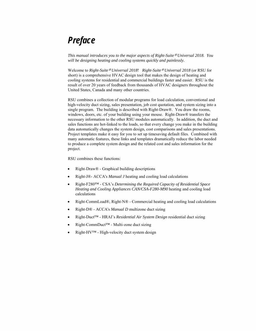
Preface
This manual introduces you to the major aspects of Right-Suite Universal 2018. You will be designing heating and cooling systems quickly and painlessly.
Welcome to Right-Suite Universal 2018! Right-Suite Universal 2018 (or RSU for short) is a comprehensive HVAC design tool that makes the design of heating and cooling systems for residential and commercial buildings faster and easier. RSU is the result of over 20 years of feedback from thousands of HVAC designers throughout the United States, Canada and many other countries.
RSU combines a collection of modular programs for load calculation, conventional and high-velocity duct sizing, sales presentation, job cost quotation, and system sizing into a single program. The building is described with Right-Draw®. You draw the rooms, windows, doors, etc. of your building using your mouse. Right-Draw® transfers the necessary information to the other RSU modules automatically. In addition, the duct and sales functions are hot-linked to the loads, so that every change you make in the building data automatically changes the system design, cost comparisons and sales presentations. Project templates make it easy for you to set up timesaving default files. Combined with many automatic features, these links and templates dramatically reduce the labor needed to produce a complete system design and the related cost and sales information for the project.
RSU combines these functions:
Right-Draw® - Graphical building descriptions
Right-J®- ACCA's Manual J heating and cooling load calculations
Right-F280™ - CSA’s Determining the Required Capacity of Residential Space Heating and Cooling Appliances CAN/CSA-F280-M90 heating and cooling load calculations
Right-CommLoad®, Right-N® - Commercial heating and cooling load calculations
Right-D® - ACCA's Manual D multizone duct sizing
Right-Duct™ - HRAI’s Residential Air System Design residential duct sizing
Right-CommDuct™ - Multi-zone duct sizing
Right-HV™ - High-velocity duct system design

Right-$™ - Equipment comparison and cost analysis
Right-SolarDHW™ - Solar hot water heating system design
Right-Loop™ - Geothermal loop design
Right-Radiant® - Radiant panel design
Right-Proposal® - Automated, custom designed sales proposals
Right-Consultant™ - Automated sales presentations and sales management
Right-Contact™ - Customer relationship management
The Examples and Reference provides examples of typical applications.
Consult the Quick Start Guide for installation and general instructions.
Consult the help system in the software for reference information on specific functions (Select Help from the main menu then make a selection).

Introduction
Introduction 2
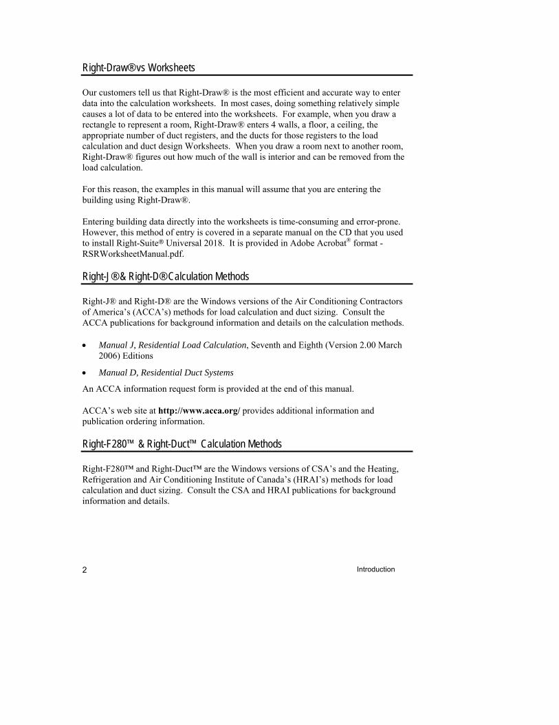
Right-Draw® vs Worksheets
Our customers tell us that Right-Draw® is the most efficient and accurate way to enter data into the calculation worksheets. In most cases, doing something relatively simple causes a lot of data to be entered into the worksheets. For example, when you draw a rectangle to represent a room, Right-Draw® enters 4 walls, a floor, a ceiling, the appropriate number of duct registers, and the ducts for those registers to the load calculation and duct design Worksheets. When you draw a room next to another room, Right-Draw® figures out how much of the wall is interior and can be removed from the load calculation.
For this reason, the examples in this manual will assume that you are entering the building using Right-Draw®.
Entering building data directly into the worksheets is time-consuming and error-prone. However, this method of entry is covered in a separate manual on the CD that you used to install Right-Suite Universal 2018. It is provided in Adobe Acrobat® format - RSRWorksheetManual.pdf.
Right-J® & Right-D® Calculation Methods
Right-J® and Right-D® are the Windows versions of the Air Conditioning Contractors of America’s (ACCA’s) methods for load calculation and duct sizing. Consult the ACCA publications for background information and details on the calculation methods.
Manual J, Residential Load Calculation, Seventh and Eighth (Version 2.00 March 2006) Editions
Manual D, Residential Duct Systems
An ACCA information request form is provided at the end of this manual.
ACCA’s web site at http://www.acca.org/ provides additional information and publication ordering information.
Right-F280™ & Right-Duct™ Calculation Methods
Right-F280™ and Right-Duct™ are the Windows versions of CSA’s and the Heating, Refrigeration and Air Conditioning Institute of Canada’s (HRAI’s) methods for load calculation and duct sizing. Consult the CSA and HRAI publications for background information and details.
Introduction 3
Determining the Required Capacity of Residential Space Heating and Cooling Appliances CAN/CSA-F280-M90 – CSA-F280-12 - Residential load calculation
Residential Air System Design - Residential duct design
HRAI’s web site at http://www.hrai.ca/ and CSA’s web site at http://www.csagroup.org provide additional information and publication ordering information.
Right-N®, Right-CommLoad®, and Right-CommDuct™ Calculation Methods
The Right-N® calculation procedure is an implementation of the Air Conditioning Contractors of America’s (ACCA’s) Manual N, Fifth Edition. Consult the ACCA publications for background information and details on the calculation methods.
Manual N, Commercial Load Calculation for Small Commercial Buildings, Fifth Edition (February 2008)
The Fifth Edition of Manual N is the Air Conditioning Contractors of America procedure for commercial heating and cooling load calculations for buildings three stories or less. This procedure uses the CLF/CLTD method for cooling load calculations. This procedure uses the CLF/CLTD method for cooling load calculations.
The Right-CommLoad® calculation procedure is an implementation of the CLTD method as presented in the ASHRAE 1989 Handbook of Fundamentals. Solar gain calculations are performed for the 21st of each selected calculation month and the actual site latitude and longitude, using procedures in chapter 31 (Fenestration) of the ASHRAE 2005 Handbook of Fundamentals. Ventilation requirement tables are taken from ASHRAE Standard 62.1-2007. The procedure for estimating the interaction between infiltration and ventilation is based on ACCA Manual N Fourth Edition. Weather data is from ASHRAE 2005 Handbook of Fundamentals (used by permission of ASHRAE), ACCA Manual N Fourth Edition, Canadian Standard CAN/CSA-F290-M90, and other sources.
The Right-CommDuct™ calculation procedure uses the ASHRAE duct fitting database, which was produced as a research project of the American Society of Heating, Refrigeration, and Air Conditioning Engineers (used by permission).
Following the Examples
Residential Examples
Examples are provided using both Manual J and CSA load calculation and duct design methods.
Introduction 4
One-room example ACCA - Chapter 2, CSA - Chapter 10 Provides detailed, step-by-step instructions to produce a one-room or block load. The emphasis in this example is on completing a project, start-to-finish, in the shortest amount of time. This allows you to 'get a feel' for the entire process without getting bogged down with a lot of details about the building.
Room-by-room example
ACCA - Chapters 3 - 6, CSA - Chapters 11 - 14 This 'real-world' example includes how to enter a typical building including a basement, interior walls, floors, and ceilings, multiple construction types, etc. You will use the basic techniques that you learned in the one-room example.
Zoning example Chapter 9 This example explains how to enter multi-zone buildings and how zoning affects the load and equipment selection.
Room-by-room duct design example
Chapter 5 This example describes how to design a sheet metal duct system using Right-Draw®.
Flex duct example Chapter 7 This example describes how to design a flex duct system using Right-Draw®.
Multi-level ducts with trunks on one level example
Chapter 8 This example describes how to keep all the trunks on one level with risers to the outlets on the other floors.
Commercial Examples
Single-zone example Chapters 15 - 18 This example provides detailed, step-by-step instructions to produce a one-zone or block load. The emphasis in this example is on completing a project, start-to-finish, in the shortest amount of time. This allows you to 'get a feel' for the entire process without getting bogged down with a lot of details about the building.
Multi-zone example Chapters 19 - 22 This 'real-world' example includes how to enter a typical building including a interior walls, floors, and ceilings, multiple construction types, internal gains, etc. You will use the basic techniques that you learned in the one-zone example.
Residential and Commercial Examples
Two-line duct Chapter 23
Introduction 5
example This example demonstrates using two-line ducts in your drawings.
High-velocity duct system example
Chapter 24 This example demonstrates how to design a high-velocity duct system using Right-Draw®.
Geothermal loop example
Chapter 25 This example demostrates using Right-Loop™ to calculate geothermal loop lengths.
Radiant heating example
Chapter 26 This example demonstrates how to design radiant heating systems using Right-Draw®.
Snow-melting example
Chapter 26 This example demonstrates how to design radiant snow-melting systems using Right-Draw®.
Solar hot water heating system example
Chapter 27 This example demonstrates how to use Right-SolarDHW™ to design a solar hot water heating system.
Operating cost comparison example
Chapter 28 This example demonstrates how to use Right-$™ to compare the operating costs of up to 4 different heating and cooling systems.
Job costing example Chapter 30 This example demonstrates how Right-Proposal® assembles a bill of materials for your project from your Right-Draw® building.
Sales proposal example
Chapter 31 This example shows you how to automatically generate a proposal that you can submit to your customer for approval using the data generated by Right-Suite Universal 2018.
Tracking your sales example
Chapter 32 This example shows you how you can use Right-Consultant™ to track your sales efforts using your Right-Suite Universal 2018 projects .
RSU file names
There are three file types that you will encounter when you open or save input information. Each uses a different file extension.
.RUD files are Right-Suite Universal 2018 project files specially created for use as demos. The examples in this manual use these demo files.
Introduction 6
.RUP files are project files that you create for each of your jobs. They contain all the information you enter (customer, building, system design information, etc.).
.RUT files are project files that contain standard startup information for the various types of jobs you do. They are stored in the Template directory with the .RUT file extension. See Chapter 33 for a complete discussion on templates.
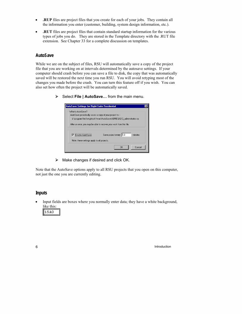
AutoSave
While we are on the subject of files, RSU will automatically save a copy of the project file that you are working on at intervals determined by the autosave settings. If your computer should crash before you can save a file to disk, the copy that was automatically saved will be restored the next time you run RSU. You will avoid retyping most of the changes you made before the crash. You can turn this feature off if you wish. You can also set how often the project will be automatically saved.
Select File | AutoSave… from the main menu.
Make changes if desired and click OK.
Note that the AutoSave options apply to all RSU projects that you open on this computer, not just the one you are currently editing.
Inputs
Input fields are boxes where you normally enter data; they have a white background, like this:
Introduction 7
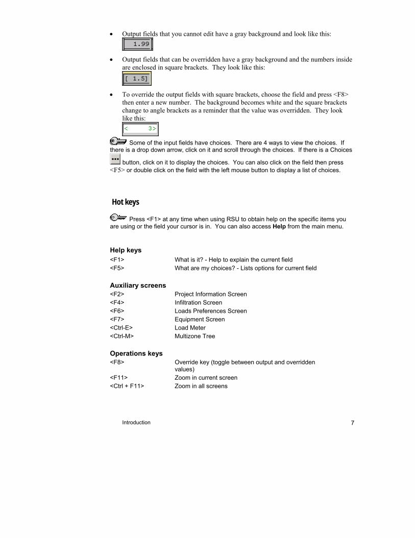
Output fields that you cannot edit have a gray background and look like this:
Output fields that can be overridden have a gray background and the numbers inside are enclosed in square brackets. They look like this:
To override the output fields with square brackets, choose the field and press <F8> then enter a new number. The background becomes white and the square brackets change to angle brackets as a reminder that the value was overridden. They look like this:
Some of the input fields have choices. There are 4 ways to view the choices. If
there is a drop down arrow, click on it and scroll through the choices. If there is a Choices
button, click on it to display the choices. You can also click on the field then press <F5> or double click on the field with the left mouse button to display a list of choices.
Hot keys
Press <F1> at any time when using RSU to obtain help on the specific items you are using or the field your cursor is in. You can also access Help from the main menu.
Help keys
<F1> What is it? - Help to explain the current field <F5> What are my choices? - Lists options for current field
Auxiliary screens
<F2> Project Information Screen <F4> Infiltration Screen <F6> Loads Preferences Screen <F7> Equipment Screen <Ctrl-E> Load Meter <Ctrl-M> Multizone Tree
Operations keys
<F8> Override key (toggle between output and overridden values)
<F11> Zoom in current screen <Ctrl + F11> Zoom in all screens
Introduction 8
<F12> Zoom out current screen <Ctrl + F12> Zoom out all screens <Ctrl-PageUp> Moves cursor to the top of a worksheet <Ctrl-PageDown> Moves cursor to the bottom of a worksheet <Ctrl-Left/Right> Moves cursor to the next room to the left/right in the Right-
J® or Right-F280™ Worksheet <Ctrl-Home> Moves cursor to the room farthest to the left in the Right-J®
or Right-F280™ Worksheet <Ctrl-End> Moves cursor to the room farthest to the right in the Right-
J® or Right-F280™ Worksheet
Monitor Screen Resolution & Right-Draw®
The screen images shown in these examples use a screen resolution of 1024 x 768. Your computer may be capable of displaying at higher resolutions, 1280 x 1024, for example. You should use the highest resolution that allows the maximum amount of drawing space with acceptable ‘readability’ of the text on the screen. The only way to determine the optimum screen resolution for your monitor is to try different resolutions. Start with the highest resolution available. Experiment with large and small font options. If you have to strain your eyes to read the screen, lower the resolution and try it again. You will probably have to settle on a compromise between viewing as much as possible on the drawing area and being able to read the rest of the screen.
Using the Reference Material
The last part of this manual contains reference material. Most of these chapters describe detailed aspects of Right-Suite Universal 2018 that you probably won't use on a daily basis, but that you might want to know about. You will get the most out of these chapters once you have a little experience with the basic operation of Right-Suite Universal 2018.
Symbols & Conventions
Symbols used in this manual
Key information for users.
Caution areas and potential sources of confusion.
Tips for expert users.
Brackets are used to identify keys on the keyboard, such as <Enter>
Introduction 9
Menu selections are identified in bold text and the '|' character is used to separate menu choices that appear in sequence, such as File | Open.
In the project examples, specific instructions for inputs to RSU are shown in this format (indented Arial font with an arrow bullet).
Text and numbers that you type are enclosed in single quotation marks, such as ‘Acme Air Conditioning Company’.
‘RSU’ is short for ‘Right-Suite Universal 2018’.
Example Files
RSU is distributed with a set of example demo files. These files have names like ‘MDEX3.rud’. Most of chapters of this manual are built around example files. To follow along, open the specified file and make the changes described in the text. When you are done, you can compare your work with the completed demo file that is also provided.
For simplicity and consistency, all the examples are based on the demo project files distributed with RSU. To follow along and duplicate the examples, use the File | Open | Demo... option from the main menu. Your screens and your results may be different if you use a registered or an OEM version.
Things to Remember
A 'Things to Remember' section similar to this is included at the end of each chapter.
Consult the appropriate publications for details on the load calculation methods and duct sizing procedures.
There is a demo file for each module. You can try out unlicensed modules by trying the examples in this manual or by viewing the demo files. To display a demo file, select File | Open | Demo... then select the desired demo file.
Press <F1> for help on items that are selected or choose Help from the main menu.
There are 4 ways to view a list of choices in the input fields: click on a drop down arrow, click on a Choices button, select a field then press <F5> or double click on a field.


1
Basic Building Description Using Right-Draw®
Read this chapter first. This chapter introduces the basic techniques that you will need to enter building descriptions with Right-Draw®. You will probably want to refer back to it often.
How to start a new project file of your own (not an example) ................................................................................ 12
Key Right-Draw® Screen Components ......................... 12
Overview of Right-Draw® operations ............................. 17
How to add a room ........................................................ 20
How to re-size a room ................................................... 21
Moving a room............................................................... 22
Automatic scrolling ........................................................ 23
Ceilings and floors ......................................................... 23
How to display the Property Sheet for a room ............... 24
Things to Remember ..................................................... 25
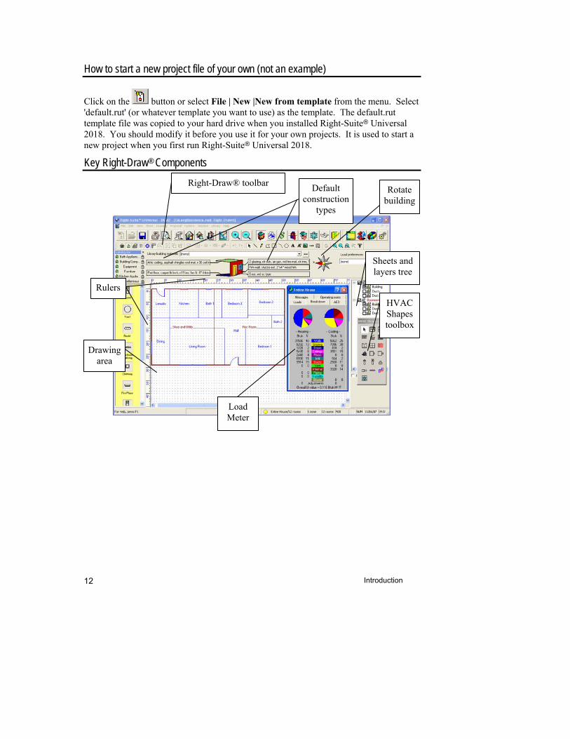
Introduction 12
How to start a new project file of your own (not an example)
Click on the button or select File | New |New from template from the menu. Select 'default.rut' (or whatever template you want to use) as the template. The default.rut template file was copied to your hard drive when you installed Right-Suite Universal 2018. You should modify it before you use it for your own projects. It is used to start a new project when you first run Right-Suite Universal 2018.
Key Right-Draw® Components
Right-Draw® toolbar
Rulers
Drawing area
Default construction
types
Sheets and layers tree
HVAC Shapes toolbox
Load Meter
Rotate building
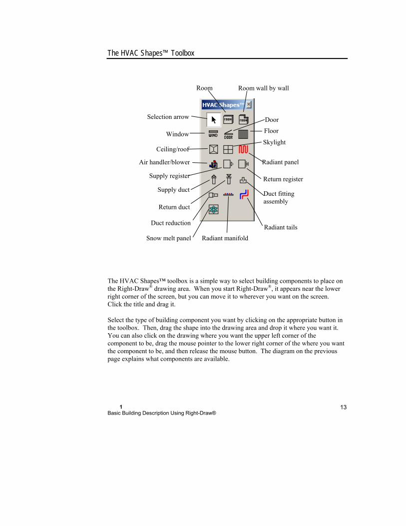
1 Basic Building Description Using Right-Draw®
13
The HVAC Shapes™ Toolbox
The HVAC Shapes™ toolbox is a simple way to select building components to place on the Right-Draw® drawing area. When you start Right-Draw®, it appears near the lower right corner of the screen, but you can move it to wherever you want on the screen. Click the title and drag it.
Select the type of building component you want by clicking on the appropriate button in the toolbox. Then, drag the shape into the drawing area and drop it where you want it. You can also click on the drawing where you want the upper left corner of the component to be, drag the mouse pointer to the lower right corner of the where you want the component to be, and then release the mouse button. The diagram on the previous page explains what components are available.
Selection arrow
Duct fitting assembly
Return duct
Supply register Return register
Skylight
Door
Supply duct
Ceiling/roof
Floor
Room
Air handler/blower
Window
Duct reduction
Radiant manifold
Radiant panel
Radiant tails
Snow melt panel
Room wall by wall

Introduction 14
If you forget what a shape is, just hold the mouse pointer over the tool. A reminder will soon appear below the mouse pointer.
The Catalog bar is not displayed at first. You may activate it by clicking on the button on the Right-Draw® toolbar. Use of the Catalog bar is an advanced feature and is discussed in Chapter 40.
Sheet Navigator
Sheet name (one per building story)
Layers
Click to expand orcompress tree
Check to showUncheck to hide
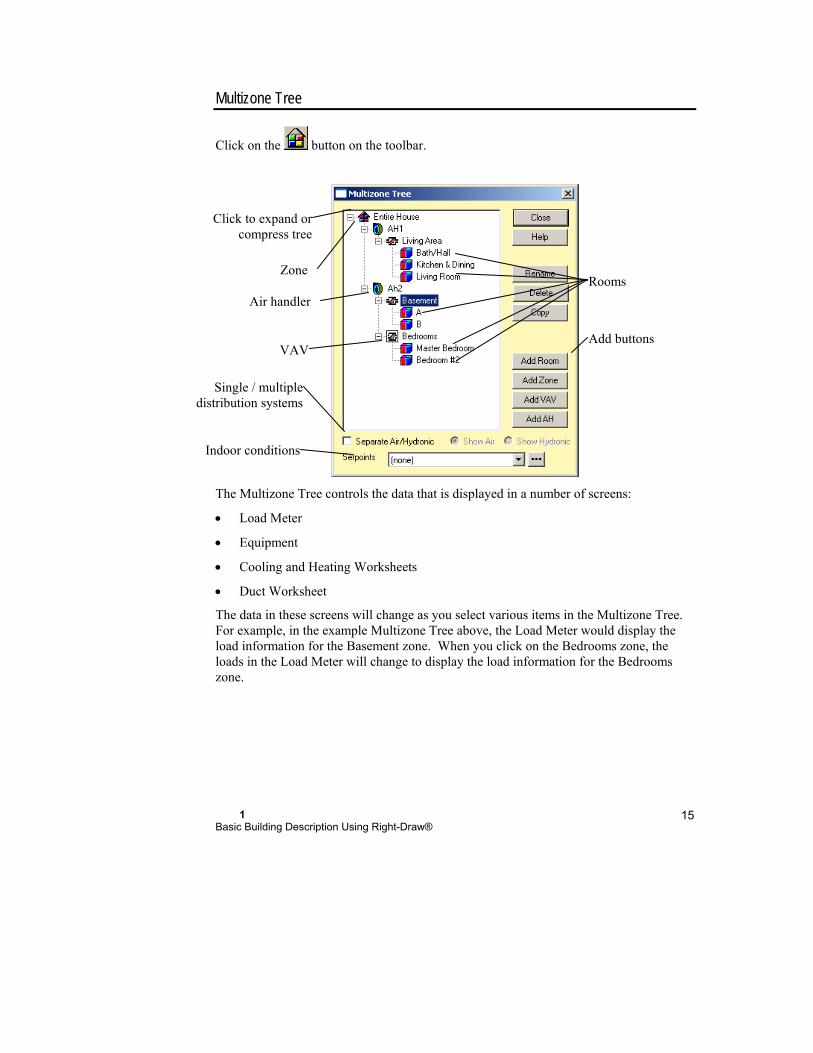
1 Basic Building Description Using Right-Draw®
15
Multizone Tree
Click on the button on the toolbar.
The Multizone Tree controls the data that is displayed in a number of screens:
Load Meter
Equipment
Cooling and Heating Worksheets
Duct Worksheet
The data in these screens will change as you select various items in the Multizone Tree. For example, in the example Multizone Tree above, the Load Meter would display the load information for the Basement zone. When you click on the Bedrooms zone, the loads in the Load Meter will change to display the load information for the Bedrooms zone.
Add buttons
Click to expand orcompress tree
VAV
Air handler
Rooms Zone
Single / multipledistribution systems
Indoor conditions
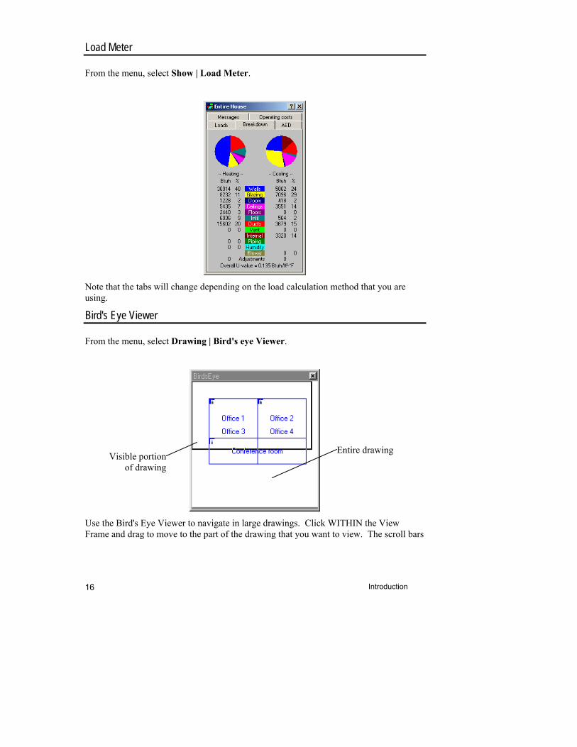
Introduction 16
Load Meter
From the menu, select Show | Load Meter.
Note that the tabs will change depending on the load calculation method that you are using.
Bird's Eye Viewer
From the menu, select Drawing | Bird's eye Viewer.
Use the Bird's Eye Viewer to navigate in large drawings. Click WITHIN the View Frame and drag to move to the part of the drawing that you want to view. The scroll bars
Visible portionof drawing
Entire drawing
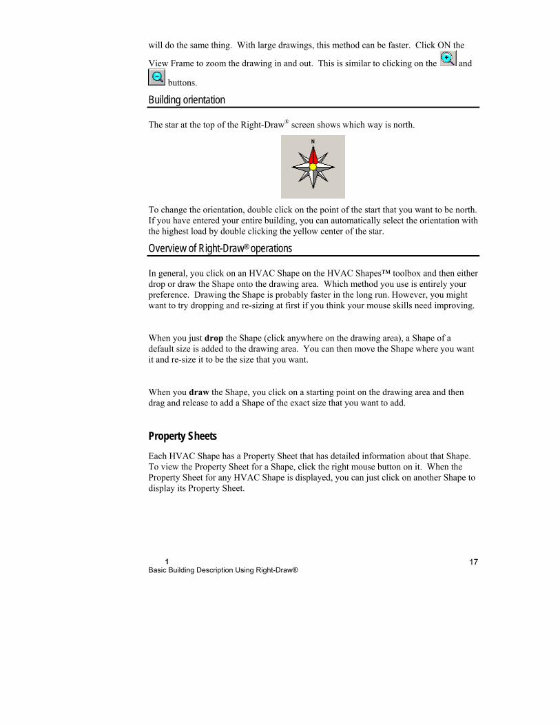
1 Basic Building Description Using Right-Draw®
17
will do the same thing. With large drawings, this method can be faster. Click ON the
View Frame to zoom the drawing in and out. This is similar to clicking on the and
buttons.
Building orientation
The star at the top of the Right-Draw® screen shows which way is north.
To change the orientation, double click on the point of the start that you want to be north. If you have entered your entire building, you can automatically select the orientation with the highest load by double clicking the yellow center of the star.
Overview of Right-Draw® operations
In general, you click on an HVAC Shape on the HVAC Shapes™ toolbox and then either drop or draw the Shape onto the drawing area. Which method you use is entirely your preference. Drawing the Shape is probably faster in the long run. However, you might want to try dropping and re-sizing at first if you think your mouse skills need improving.
When you just drop the Shape (click anywhere on the drawing area), a Shape of a default size is added to the drawing area. You can then move the Shape where you want it and re-size it to be the size that you want.
When you draw the Shape, you click on a starting point on the drawing area and then drag and release to add a Shape of the exact size that you want to add.
Property Sheets
Each HVAC Shape has a Property Sheet that has detailed information about that Shape. To view the Property Sheet for a Shape, click the right mouse button on it. When the Property Sheet for any HVAC Shape is displayed, you can just click on another Shape to display its Property Sheet.
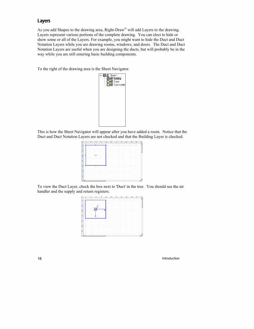
Introduction 18
Layers
As you add Shapes to the drawing area, Right-Draw® will add Layers to the drawing. Layers represent various portions of the complete drawing. You can elect to hide or show some or all of the Layers. For example, you might want to hide the Duct and Duct Notation Layers while you are drawing rooms, windows, and doors. The Duct and Duct Notation Layers are useful when you are designing the ducts, but will probably be in the way while you are still entering basic building components.
To the right of the drawing area is the Sheet Navigator.
This is how the Sheet Navigator will appear after you have added a room. Notice that the Duct and Duct Notation Layers are not checked and that the Building Layer is checked.
To view the Duct Layer, check the box next to 'Duct' in the tree. You should see the air handler and the supply and return registers.
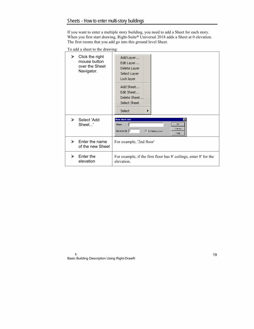
1 Basic Building Description Using Right-Draw®
19
Sheets - How to enter multi-story buildings
If you want to enter a multiple story building, you need to add a Sheet for each story. When you first start drawing, Right-Suite Universal 2018 adds a Sheet at 0 elevation. The first rooms that you add go into this ground level Sheet.
To add a sheet to the drawing:
Click the right mouse button over the Sheet Navigator.
Select 'Add Sheet...'
Enter the name of the new Sheet
For example, '2nd floor'
Enter the elevation
For example, if the first floor has 8' ceilings, enter 8' for the elevation.
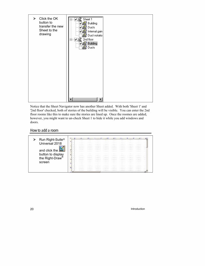
Introduction 20
Click the OK button to transfer the new Sheet to the drawing
Notice that the Sheet Navigator now has another Sheet added. With both 'Sheet 1' and '2nd floor' checked, both of stories of the building will be visible. You can enter the 2nd floor rooms like this to make sure the stories are lined up. Once the roomes are added, however, you might want to un-check Sheet 1 to hide it while you add windows and doors.
How to add a room
Run Right-Suite Universal 2018
and click the button to display the Right-Draw® screen
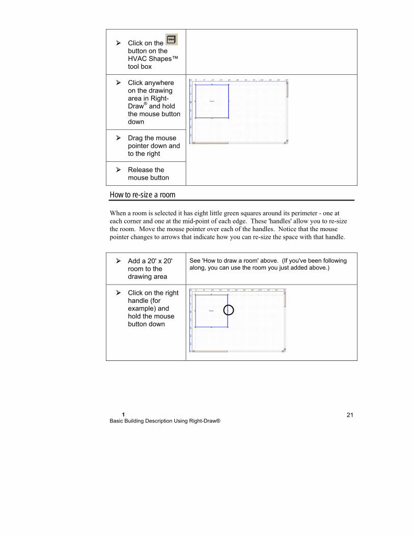
1 Basic Building Description Using Right-Draw®
21
Click on the button on the HVAC Shapes™ tool box
Click anywhere on the drawing area in Right-Draw® and hold the mouse button down
Drag the mouse pointer down and to the right
Release the mouse button
How to re-size a room
When a room is selected it has eight little green squares around its perimeter - one at each corner and one at the mid-point of each edge. These 'handles' allow you to re-size the room. Move the mouse pointer over each of the handles. Notice that the mouse pointer changes to arrows that indicate how you can re-size the space with that handle.
Add a 20' x 20' room to the drawing area
See 'How to draw a room' above. (If you've been following along, you can use the room you just added above.)
Click on the right handle (for example) and hold the mouse button down
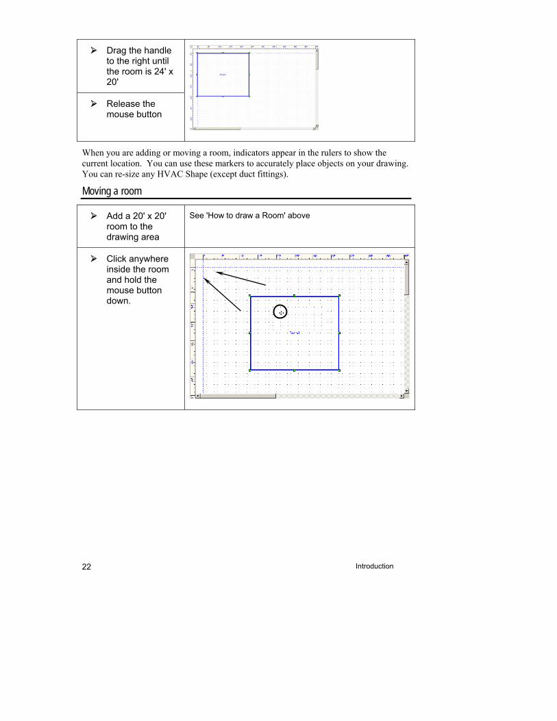
Introduction 22
Drag the handle to the right until the room is 24' x 20'
Release the mouse button
When you are adding or moving a room, indicators appear in the rulers to show the current location. You can use these markers to accurately place objects on your drawing. You can re-size any HVAC Shape (except duct fittings).
Moving a room
Add a 20' x 20' room to the drawing area
See 'How to draw a Room' above
Click anywhere inside the room and hold the mouse button down.
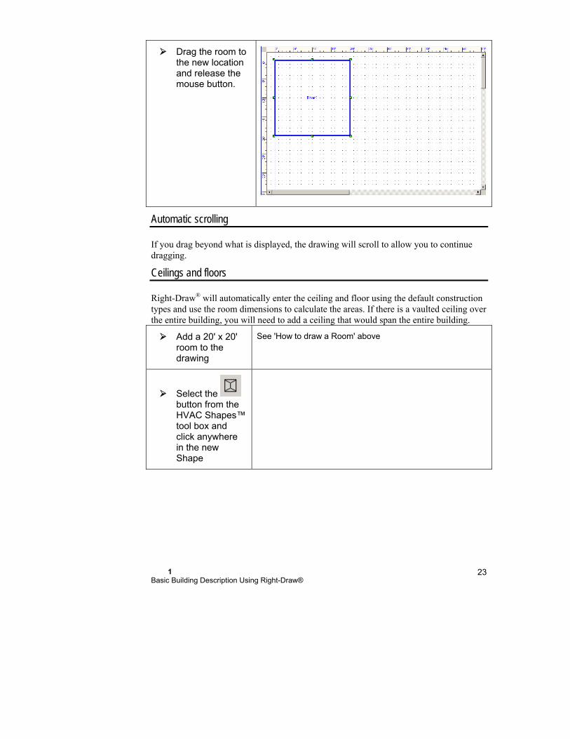
1 Basic Building Description Using Right-Draw®
23
Drag the room to the new location and release the mouse button.
Automatic scrolling
If you drag beyond what is displayed, the drawing will scroll to allow you to continue dragging.
Ceilings and floors
Right-Draw® will automatically enter the ceiling and floor using the default construction types and use the room dimensions to calculate the areas. If there is a vaulted ceiling over the entire building, you will need to add a ceiling that would span the entire building.
Add a 20' x 20' room to the drawing
See 'How to draw a Room' above
Select the button from the HVAC Shapes™ tool box and click anywhere in the new Shape
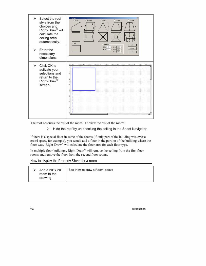
Introduction 24
Select the roof style from the choices and Right-Draw® will calculate the ceiling area automatically.
Enter the necessary dimensions
Click OK to activate your selections and return to the Right-Draw® screen
The roof obscures the rest of the room. To view the rest of the room:
Hide the roof by un-checking the ceiling in the Sheet Navigator.
If there is a special floor in some of the rooms (if only part of the building was over a crawl space, for example), you would add a floor in the portion of the building where the floor was. Right-Draw® will calculate the floor area for each floor type.
In multiple floor buildings, Right-Draw® will remove the ceiling from the first floor rooms and remove the floor from the second floor rooms.
How to display the Property Sheet for a room
Add a 20' x 20' room to the drawing
See 'How to draw a Room' above

1 Basic Building Description Using Right-Draw®
25
Move the mouse arrow over the room you just added and click on the right mouse button
There is a tab in the Property Sheet for each component of the room. Click on each tab to see details for each component.
Things to Remember
See the Advanced Building Description Using Right-Draw® chapter to handle special cases.

Part I - ACCA Residential Examples


2
One Room Example: Step 1 - Describe the Building
This chapter tells you how to use Right-Draw as a fast and efficient way to enter a building description into RSU. Right-Draw will also help you layout your equipment, ducts, air outlets and radiant panels.
This example is a one-room building. This simple building will teach you how to use the HVAC Shapes™.
One-Room Example Description ................................... 30
Step 1a - Start a New Project From a Template With Preset Values .......................................................... 31
Step 1b - Add Rooms, Doors & Windows ...................... 32
Step 1c - Add Vaulted Ceilings & Special Floors (if needed) ................................................................... 39
Things to Remember ..................................................... 42
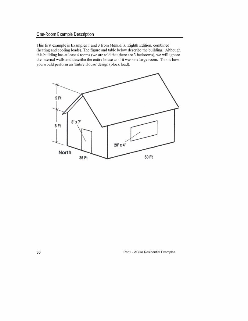
Part I - ACCA Residential Examples 30
One-Room Example Description
This first example is Examples 1 and 3 from Manual J, Eighth Edition, combined (heating and cooling loads). The figure and table below describe the building. Although this building has at least 4 rooms (we are told that there are 3 bedrooms), we will ignore the internal walls and describe the entire house as if it was one large room. This is how you would perform an 'Entire House' design (block load).

2 One Room Example: Step 1 - Describe the Building
31
Item Description
Weather location Santa Fe, New Mexico
Indoor conditions
Htg - 70oF with 20% RH humidification Clg - 75oF and dry coil (45% RH or less)
Winter humidification Yes, at 20% RH (evaporative)
Walls Wood 2"x4" frame walls with brick veneer, R-13 blanket insulation, R-2 board insulation and interior finish
Ceiling R-30 insulation above an 8ft ceiling, FHA vented attic, no radiant barrier and dark shingle roof
Windows Generic double pane, wood frame, fixed sash, clear glass window with drape half closed
Door Wood panel
Floor Passive slab floor on light, dry soil with 3ft (vertical) of R-5 edge insulation
Infiltration Average construction, no fire place
Ducts Radial duct system in attic, R-4 duct insulation, duct runs not sealed
Internal loads One refrigerator, one range with vented hood Bedrooms 3 Equipment Heat pump
Example Files for the One-Room Example
Demo or template file: Examples1and3Start.rud
Completed demo file for comparison: ExExamples1and3.rud
The examples will use the Demo mode of RSU. Your screens and your results may be different when you use the full version or an OEM version.
Step 1a - Start a New Project From a Template With Preset Values
Start RSU.
To open the demo file, select File | Open | Demo... from the main menu. Select ' Examples1and3Start.rud' and click Open (this file is located in C:\My Documents\Wrightsoft HVAC\Demo unless you installed these files in another directory).
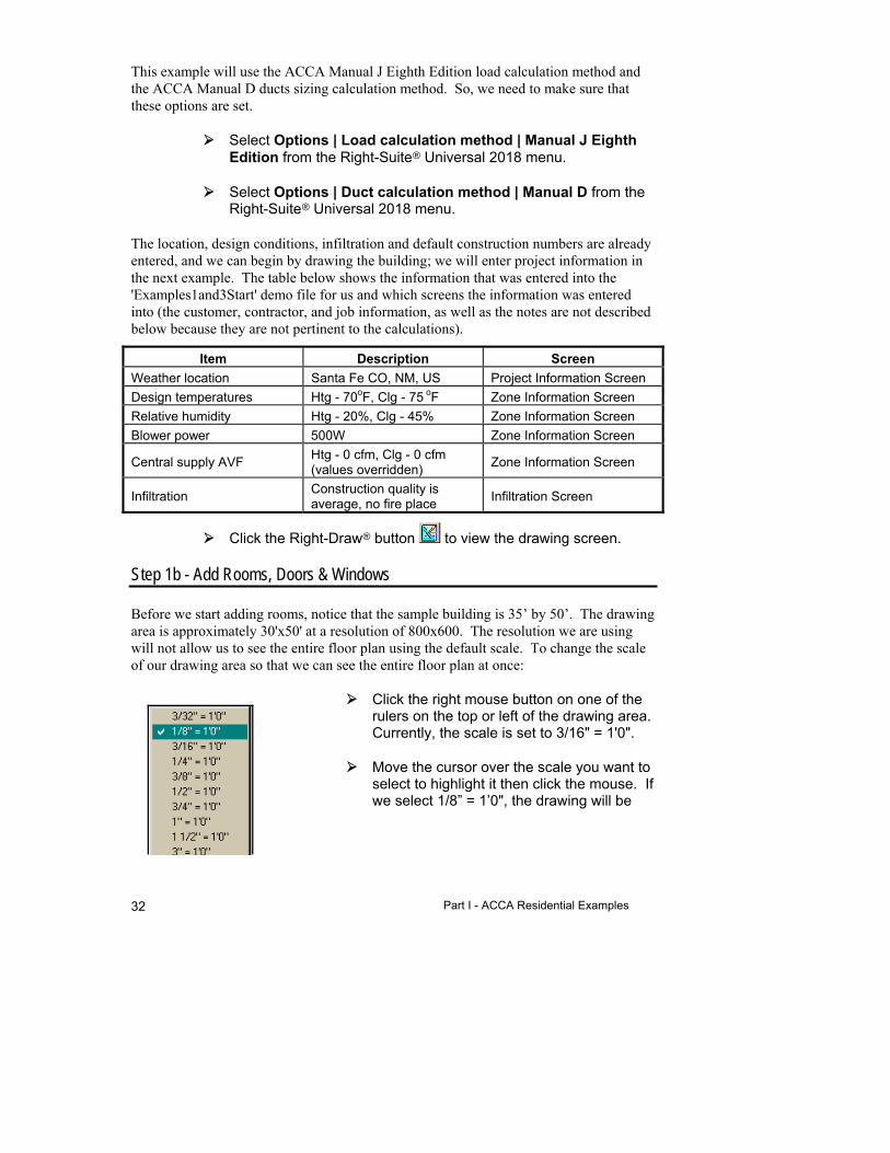
Part I - ACCA Residential Examples 32
This example will use the ACCA Manual J Eighth Edition load calculation method and the ACCA Manual D ducts sizing calculation method. So, we need to make sure that these options are set.
Select Options | Load calculation method | Manual J Eighth Edition from the Right-Suite Universal 2018 menu.
Select Options | Duct calculation method | Manual D from the Right-Suite Universal 2018 menu.
The location, design conditions, infiltration and default construction numbers are already entered, and we can begin by drawing the building; we will enter project information in the next example. The table below shows the information that was entered into the 'Examples1and3Start' demo file for us and which screens the information was entered into (the customer, contractor, and job information, as well as the notes are not described below because they are not pertinent to the calculations).
Item Description Screen
Weather location Santa Fe CO, NM, US Project Information Screen
Design temperatures Htg - 70oF, Clg - 75 oF Zone Information Screen
Relative humidity Htg - 20%, Clg - 45% Zone Information Screen
Blower power 500W Zone Information Screen
Central supply AVF Htg - 0 cfm, Clg - 0 cfm (values overridden)
Zone Information Screen
Infiltration Construction quality is average, no fire place
Infiltration Screen
Click the Right-Draw button to view the drawing screen.
Step 1b - Add Rooms, Doors & Windows
Before we start adding rooms, notice that the sample building is 35’ by 50’. The drawing area is approximately 30'x50' at a resolution of 800x600. The resolution we are using will not allow us to see the entire floor plan using the default scale. To change the scale of our drawing area so that we can see the entire floor plan at once:
Click the right mouse button on one of the rulers on the top or left of the drawing area. Currently, the scale is set to 3/16" = 1'0".
Move the cursor over the scale you want to select to highlight it then click the mouse. If we select 1/8” = 1’0", the drawing will be
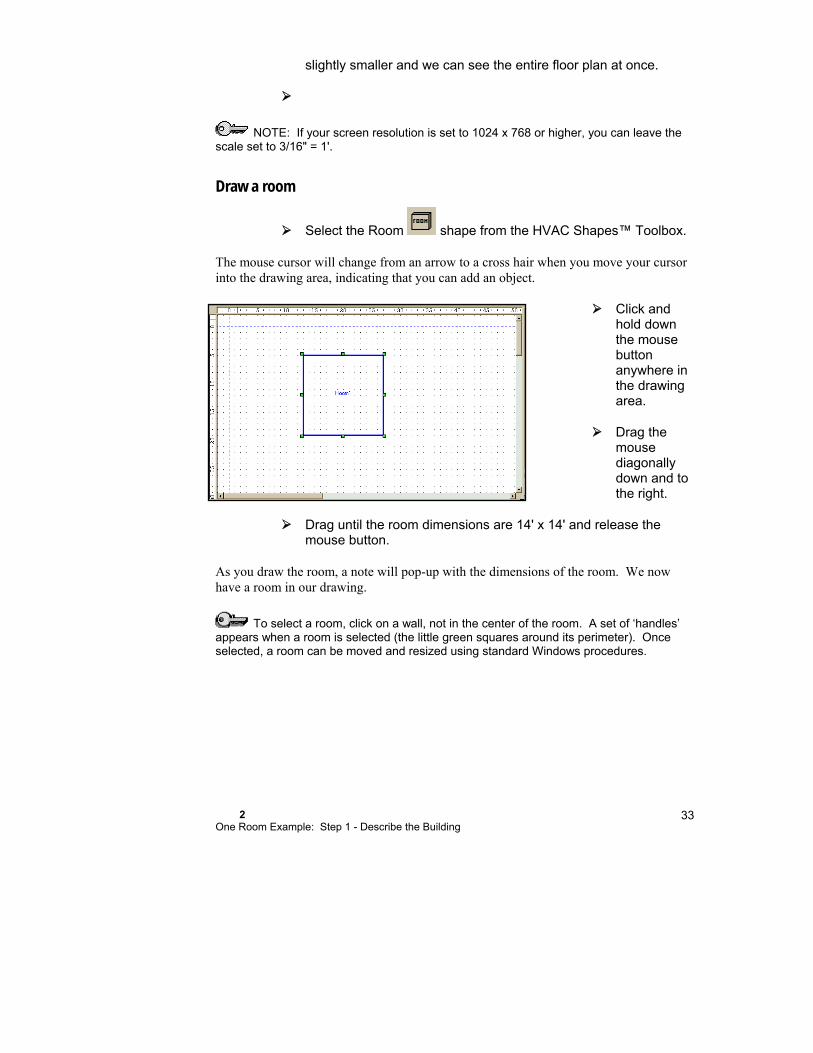
2 One Room Example: Step 1 - Describe the Building
33
slightly smaller and we can see the entire floor plan at once.
NOTE: If your screen resolution is set to 1024 x 768 or higher, you can leave the scale set to 3/16" = 1'.
Draw a room
Select the Room shape from the HVAC Shapes™ Toolbox.
The mouse cursor will change from an arrow to a cross hair when you move your cursor into the drawing area, indicating that you can add an object.
Click and hold down the mouse button anywhere in the drawing area.
Drag the mouse diagonally down and to the right.
Drag until the room dimensions are 14' x 14' and release the mouse button.
As you draw the room, a note will pop-up with the dimensions of the room. We now have a room in our drawing.
To select a room, click on a wall, not in the center of the room. A set of ‘handles’ appears when a room is selected (the little green squares around its perimeter). Once selected, a room can be moved and resized using standard Windows procedures.
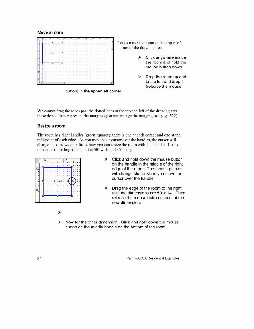
Part I - ACCA Residential Examples 34
Move a room
Let us move the room to the upper left corner of the drawing area.
Click anywhere inside the room and hold the mouse button down.
Drag the room up and to the left and drop it (release the mouse
button) in the upper left corner.
We cannot drag the room past the dotted lines at the top and left of the drawing area; these dotted lines represent the margins (you can change the margins, see page 522).
Resize a room
The room has eight handles (green squares); there is one at each corner and one at the mid-point of each edge. As you move your cursor over the handles, the cursor will change into arrows to indicate how you can resize the room with that handle. Let us make our room larger so that it is 50’ wide and 35’ long.
Click and hold down the mouse button on the handle in the middle of the right edge of the room. The mouse pointer will change shape when you move the cursor over the handle.
Drag the edge of the room to the right until the dimensions are 50' x 14'. Then, release the mouse button to accept the new dimension.
Now for the other dimension. Click and hold down the mouse button on the middle handle on the bottom of the room.

2 One Room Example: Step 1 - Describe the Building
35
Drag the bottom of the room down until the dimensions are 50' x 35'. Release the mouse button to accept the new dimension.
Use the edge handles to change one dimension at a time or use the corner handles to change both dimensions at once.
When you are adding an object or moving one, notice that indicators appear in the rulers to show the current location. You can use these markers to accurately place objects on your drawing.
You can also use the keyboard to move and resize rooms and other objects. With the room selected, use the arrow keys to move the entire room without changing its size and shape. If you hold the <Shift> key down while pressing the arrow keys, you can resize the room.
Name a room
Right-Draw names rooms as you add them (‘Room1,’ ‘Room2’ and so on), but you can change the name. We will change the name of the room we just added to ‘Santa Fe’.
Click to select the room (the green handles will appear) and just type the new name, ‘Santa Fe.’ Click anywhere in the drawing area to accept the name.
Right-Draw® & the Right-J® Worksheet
Right-Draw automatically fills out the Right-J® Worksheet as you draw a building. Let us take a quick detour and check the progress.
Click the Right-J® button on the Selector Toolbar.
Click the Right-J® Worksheet button on the Screen Toolbar.
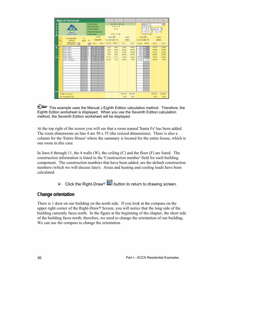
Part I - ACCA Residential Examples 36
This example uses the Manual J Eighth Edition calculation method. Therefore, the Eighth Editon worksheet is displayed. When you use the Seventh Edition calculation method, the Seventh Edition worksheet will be displayed.
At the top right of the screen you will see that a room named 'Santa Fe' has been added. The room dimensions on line 4 are 50 x 35 (the resized dimensions). There is also a column for the 'Entire House' where the summary is located for the entire house, which is one room in this case.
In lines 6 through 11, the 4 walls (W), the ceiling (C) and the floor (F) are listed. The construction information is listed in the 'Construction number' field for each building component. The construction numbers that have been added, are the default construction numbers (which we will discuss later). Areas and heating and cooling loads have been calculated.
Click the Right-Draw button to return to drawing screen.
Change orientation
There is 1 door on our building on the north side. If you look at the compass on the upper right corner of the Right-Draw Screen, you will notice that the long side of the building currently faces north. In the figure at the beginning of the chapter, the short side of the building faces north; therefore, we need to change the orientation of our building. We can use the compass to change the orientation.
2 One Room Example: Step 1 - Describe the Building
37
To change the orientation of the building, double click on the compass arrow that points NORTH in your drawing. In this case, double click on the arrow that currently points west.
The red point on the compass will change to point north.
To see the 'worst case' orientation for your building's load (highest cooling load), double click on the yellow center. RSU will move the NORTH compass point to show the orientation for the worst-case load (NOTE: This feature does not update as you draw so you have to double click the center whenever you want to see the worst case orientation).
Add doors
Select the Door shape from the HVAC Shapes™ Toolbox.
Click on the north wall 16' from the top and drag the mouse down until the door length is 3'. Release the mouse button.
A door will be added to that wall.
Add windows
There is only one window. Adding windows is just as easy as adding doors.
Click on the Window shape.
Click on the west wall 10' from the north wall.
Drag to the right until the window is 20' wide then release the mouse button.
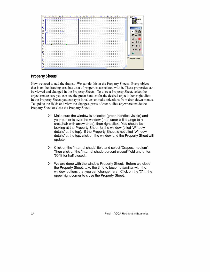
Part I - ACCA Residential Examples 38
Property Sheets
Now we need to add the drapes. We can do this in the Property Sheets. Every object that is on the drawing area has a set of properties associated with it. These properties can be viewed and changed in the Property Sheets. To view a Property Sheet, select the object (make sure you can see the green handles for the desired object) then right click. In the Property Sheets you can type in values or make selections from drop down menus. To update the fields and view the changes, press <Enter>, click anywhere inside the Property Sheet or close the Property Sheet.
Make sure the window is selected (green handles visible) and your cursor is over the window (the cursor will change to a crosshair with arrow ends), then right click. You should be looking at the Property Sheet for the window (titled 'Window details' at the top). If the Property Sheet is not titled 'Window details' at the top, click on the window and the Property Sheet will update.
Click on the 'Internal shade' field and select 'Drapes, medium'. Then click on the 'Internal shade percent closed' field and enter '50'% for half closed.
We are done with the window Property Sheet. Before we close the Property Sheet, take the time to become familiar with the window options that you can change here. Click on the 'X' in the upper right corner to close the Property Sheet.

2 One Room Example: Step 1 - Describe the Building
39
The default window height is entered automatically from the defaults in the Loads Preferences Screen. We will provide more detail about this powerful screen a little later.
Step 1c - Add Vaulted Ceilings & Special Floors (if needed)
Right-Draw will automatically enter a ceiling and floor for each room with the default construction numbers and use the room dimensions to calculate the areas. Add vaulted ceilings and special floors when needed. For this example, we do not need to add special floors or ceilings.
Special ceilings (Ceiling/roof shape) are used when you have vaulted or cathedral ceilings. You would also use special ceilings if your ceiling was not flat or if there are two ceiling types in one room. To add a special ceiling to a room or building, select the Ceiling shape then draw the ceiling over the portion of the room or building where the ceiling is needed. Select the ceiling type and enter the dimensions. Verify that the construction information is correct.
Special floors (Floor shape) are used when a room has more than one floor type (for example, if part of a room was over a crawl space). To add a special floor you would draw the floor in the portion of the room where the special floor was needed. Select the floor type and Right-Draw calculates the floor areas for both floor types.
Internal gains
There are 4 (3+1) people and one 'appliance' (one refrigerator, one range with vented hood) in this building. We need to enter this information into the room Property Sheet.

Part I - ACCA Residential Examples 40
Select the room (make sure the green handles are showing) and right click.
The room Property Sheet will appear. Notice that there are 4 tabs at the top. The room Property Sheet contains information about the room and its walls, ceiling and floor. Take a minute to click on each of the tabs to become familiar with the information found here.
Click on the Room tab and enter '4' in the 'Number of occupants' field and '1' in the 'Number of appliances' field.
You do not need to close the Property Sheet to change another construction's properties. Just select a different object in the drawing area and the Property Sheet will be updated for your selection.
See Manual J, Eighth Edition for a discussion of appliance loads and internal gains.
Now we need to enter the duct losses, which can also be set in the Loads Preferences Screen.
Click on either the 'Duct loss %' or 'Duct gain %' field (they are connected, you enter both loss and gain at the same time) and
click on the Choices button.
The 'Duct Loads' window will appear. Select the following for both Supply and Return ducts and click OK to close the window.
Field Selection
Duct location Vented attic
Roof material Asphalt shingles
Roof color Dark
Duct system Radial, perimeter outlets
Sealed Unsealed
Insulation R-value 4.0
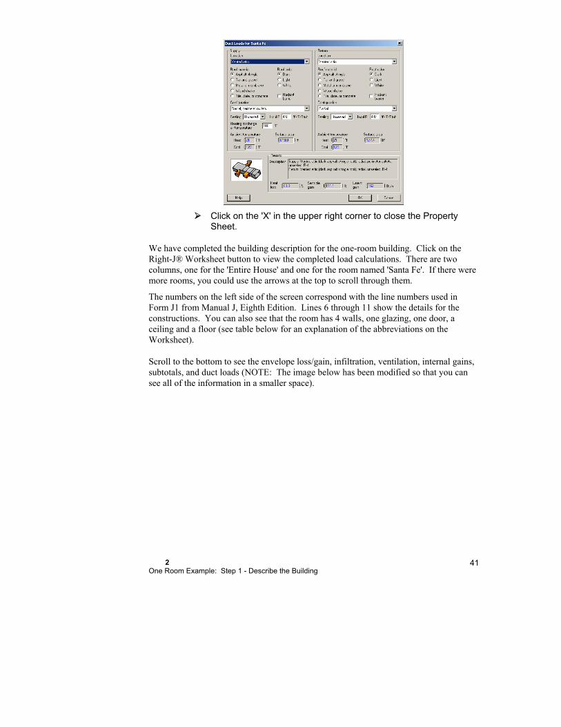
2 One Room Example: Step 1 - Describe the Building
41
Click on the 'X' in the upper right corner to close the Property Sheet.
We have completed the building description for the one-room building. Click on the Right-J® Worksheet button to view the completed load calculations. There are two columns, one for the 'Entire House' and one for the room named 'Santa Fe'. If there were more rooms, you could use the arrows at the top to scroll through them.
The numbers on the left side of the screen correspond with the line numbers used in Form J1 from Manual J, Eighth Edition. Lines 6 through 11 show the details for the constructions. You can also see that the room has 4 walls, one glazing, one door, a ceiling and a floor (see table below for an explanation of the abbreviations on the Worksheet).
Scroll to the bottom to see the envelope loss/gain, infiltration, ventilation, internal gains, subtotals, and duct loads (NOTE: The image below has been modified so that you can see all of the information in a smaller space).
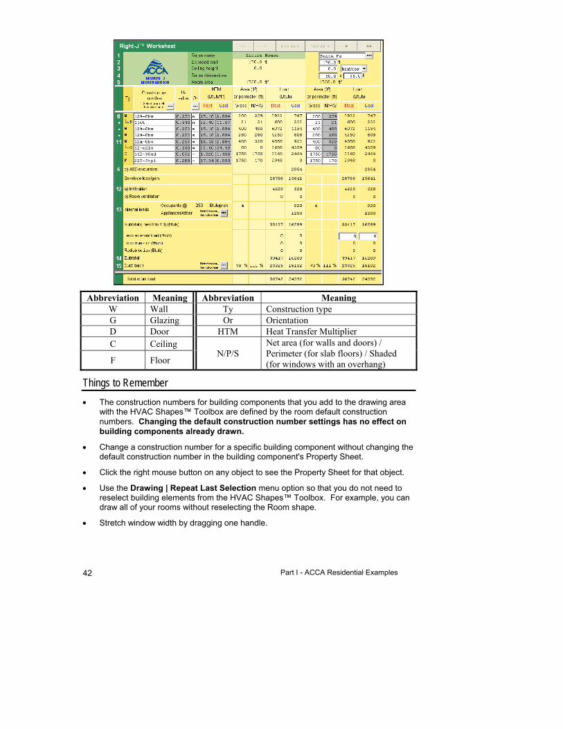
Part I - ACCA Residential Examples 42
Abbreviation Meaning Abbreviation Meaning W Wall Ty Construction type G Glazing Or Orientation D Door HTM Heat Transfer Multiplier C Ceiling
N/P/S Net area (for walls and doors) / Perimeter (for slab floors) / Shaded (for windows with an overhang) F Floor
Things to Remember
The construction numbers for building components that you add to the drawing area with the HVAC Shapes™ Toolbox are defined by the room default construction numbers. Changing the default construction number settings has no effect on building components already drawn.
Change a construction number for a specific building component without changing the default construction number in the building component's Property Sheet.
Click the right mouse button on any object to see the Property Sheet for that object.
Use the Drawing | Repeat Last Selection menu option so that you do not need to reselect building elements from the HVAC Shapes™ Toolbox. For example, you can draw all of your rooms without reselecting the Room shape.
Stretch window width by dragging one handle.

2 One Room Example: Step 1 - Describe the Building
43
Hold down the <Shift> key to select any number of similar objects (multiple selection). Then right-click to see the Property Sheet for the entire group. Common properties will be displayed; fields that are different will be blank. Change any property, and you will affect the entire group all at once. This is a quick way to change the construction number for all of the windows on a floor.
Use <Ctrl>-drag to copy any object. You can also use <Ctrl-C> (Edit | Copy) and <Ctrl-V> (Edit | Paste) to copy any object.
Right-Draw automatically adds a floor and a ceiling to each room using the default construction numbers. See the room Property Sheet for details.


3
Room-by-room Example: Step 1 - Describe the Building
This chapter tells you how to use Right-Draw as a fast and efficient way to enter a building description into RSU. Right-Draw will also help you layout your equipment, ducts, air outlets and radiant panels.
This example has many rooms on two levels. Here we will demonstrate the procedure for describing a more complex building in Right-Draw.
A Room-by-Room Example ........................................... 46
Step 1a - Start a New Project ........................................ 48
Step 1b - Add Rooms, Doors & Windows ...................... 53
Step 1c - Add Vaulted Ceilings & Special Floors (if needed) ................................................................... 64
Step 1d - Repeat Steps 1b & 1c for Each Level ............ 64
Things to Remember ..................................................... 74
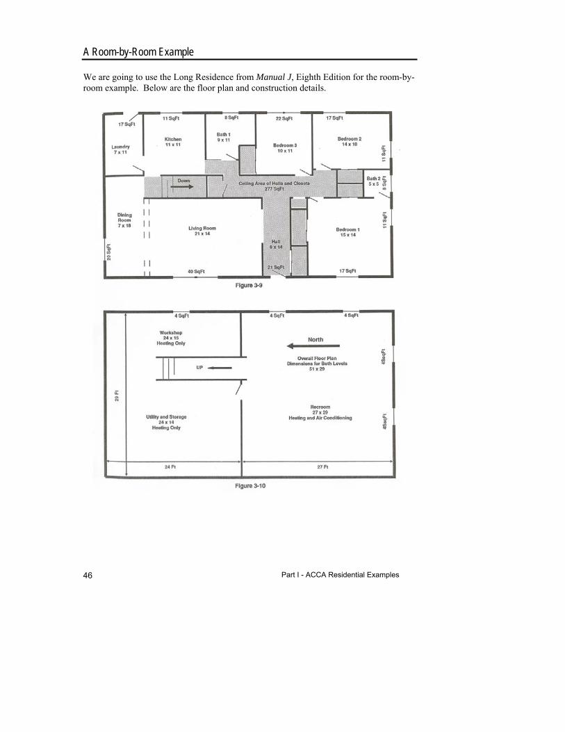
Part I - ACCA Residential Examples 46
A Room-by-Room Example
We are going to use the Long Residence from Manual J, Eighth Edition for the room-by-room example. Below are the floor plan and construction details.
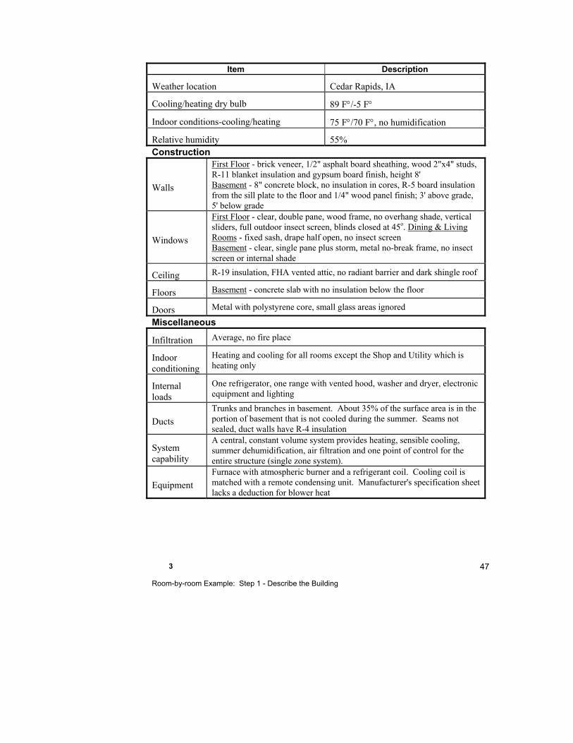
3 Room-by-room Example: Step 1 - Describe the Building
47
Item Description
Weather location Cedar Rapids, IA
Cooling/heating dry bulb 89 F/-5 F
Indoor conditions-cooling/heating 75 F/70 F, no humidification
Relative humidity 55% Construction
Walls
First Floor - brick veneer, 1/2" asphalt board sheathing, wood 2"x4" studs, R-11 blanket insulation and gypsum board finish, height 8' Basement - 8" concrete block, no insulation in cores, R-5 board insulation from the sill plate to the floor and 1/4" wood panel finish; 3' above grade, 5' below grade
Windows
First Floor - clear, double pane, wood frame, no overhang shade, vertical sliders, full outdoor insect screen, blinds closed at 45o. Dining & Living Rooms - fixed sash, drape half open, no insect screen Basement - clear, single pane plus storm, metal no-break frame, no insect screen or internal shade
Ceiling R-19 insulation, FHA vented attic, no radiant barrier and dark shingle roof
Floors Basement - concrete slab with no insulation below the floor
Doors Metal with polystyrene core, small glass areas ignored
Miscellaneous
Infiltration Average, no fire place
Indoor conditioning
Heating and cooling for all rooms except the Shop and Utility which is heating only
Internal loads
One refrigerator, one range with vented hood, washer and dryer, electronic equipment and lighting
Ducts
Trunks and branches in basement. About 35% of the surface area is in the portion of basement that is not cooled during the summer. Seams not sealed, duct walls have R-4 insulation
System capability
A central, constant volume system provides heating, sensible cooling, summer dehumidification, air filtration and one point of control for the entire structure (single zone system).
Equipment
Furnace with atmospheric burner and a refrigerant coil. Cooling coil is matched with a remote condensing unit. Manufacturer's specification sheet lacks a deduction for blower heat

Part I - ACCA Residential Examples 48
Example Files for the Room-by-Room Example
Demo file: LongResidenceStart.rud
Completed demo file for comparison: ExLongResidence.rud
The examples will use the Demo mode of RSU. Your screens and your results may be different when you use the full version or an OEM version.
Step 1a - Start a New Project
Start RSU.
To start the Demo file, select File | Open | Demo... then choose 'LongResidenceStart.rud'.
The first example was simple enough that we could just set the defaults and draw the building components. This example is a little more complex, so we will be learning how to allow for a variety of situations.
Run the project wizard
You can run the Project Wizard from the Show | Wizards menu, the Design section of the Navigator Bar, or the Sales section of the Navigator Bar (it's called the Sales Wizard in the Sales section).
Select Show | Wizards | Project wizard from the menu.
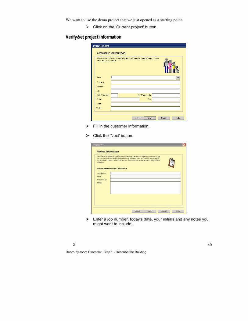
3 Room-by-room Example: Step 1 - Describe the Building
49
We want to use the demo project that we just opened as a starting point.
Click on the 'Current project' button.
Verify/set project information
Fill in the customer information.
Click the 'Next' button.
Enter a job number, today's date, your initials and any notes you might want to include.
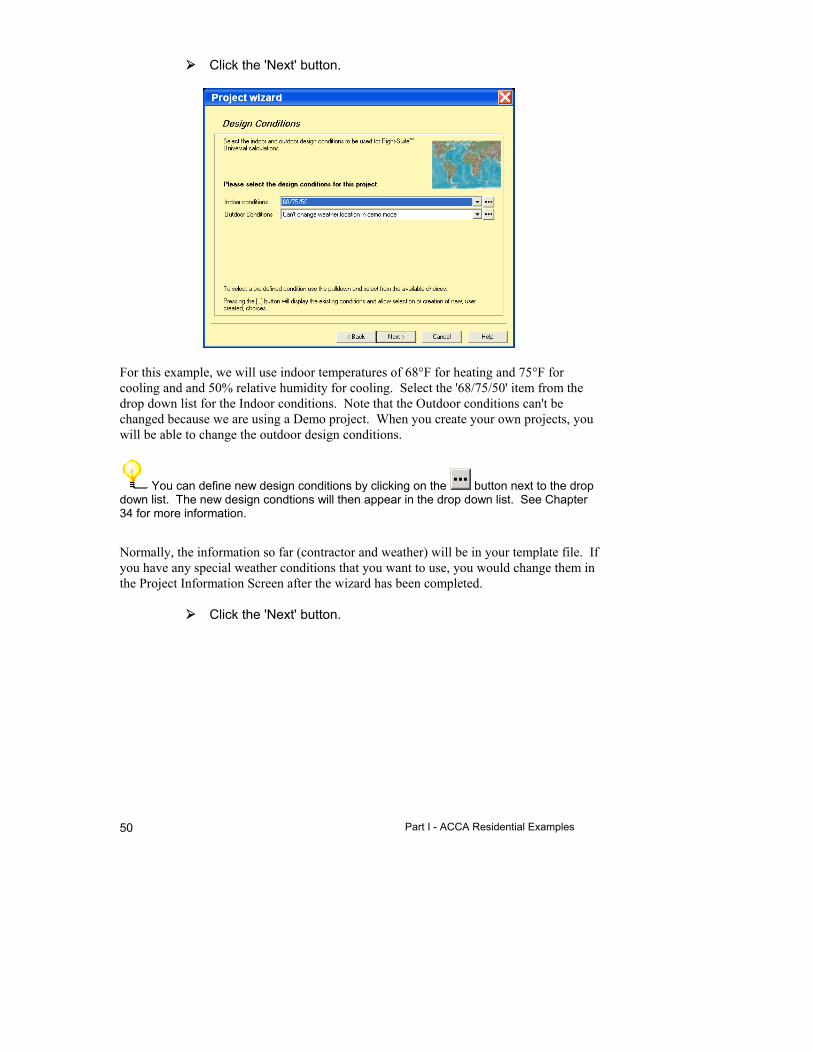
Part I - ACCA Residential Examples 50
Click the 'Next' button.
For this example, we will use indoor temperatures of 68°F for heating and 75°F for cooling and and 50% relative humidity for cooling. Select the '68/75/50' item from the drop down list for the Indoor conditions. Note that the Outdoor conditions can't be changed because we are using a Demo project. When you create your own projects, you will be able to change the outdoor design conditions.
You can define new design conditions by clicking on the button next to the drop down list. The new design condtions will then appear in the drop down list. See Chapter 34 for more information.
Normally, the information so far (contractor and weather) will be in your template file. If you have any special weather conditions that you want to use, you would change them in the Project Information Screen after the wizard has been completed.
Click the 'Next' button.

3 Room-by-room Example: Step 1 - Describe the Building
51
Select 'Long Residence Example' from the list of Building Types.
This building type has been preset to have 2 stories named First Floor and Basement with the appropriate elevations. When we start to draw our house, there will already be 2 levels created.
Select 'Long Residence Example' from the list of Construction Materials.
Construction materaials have been preset for the First Floor for this example.
Select 'Average' from the list of infiltration Tightness'
Leave the number of fireplaces at 0.
Click the 'Next' button
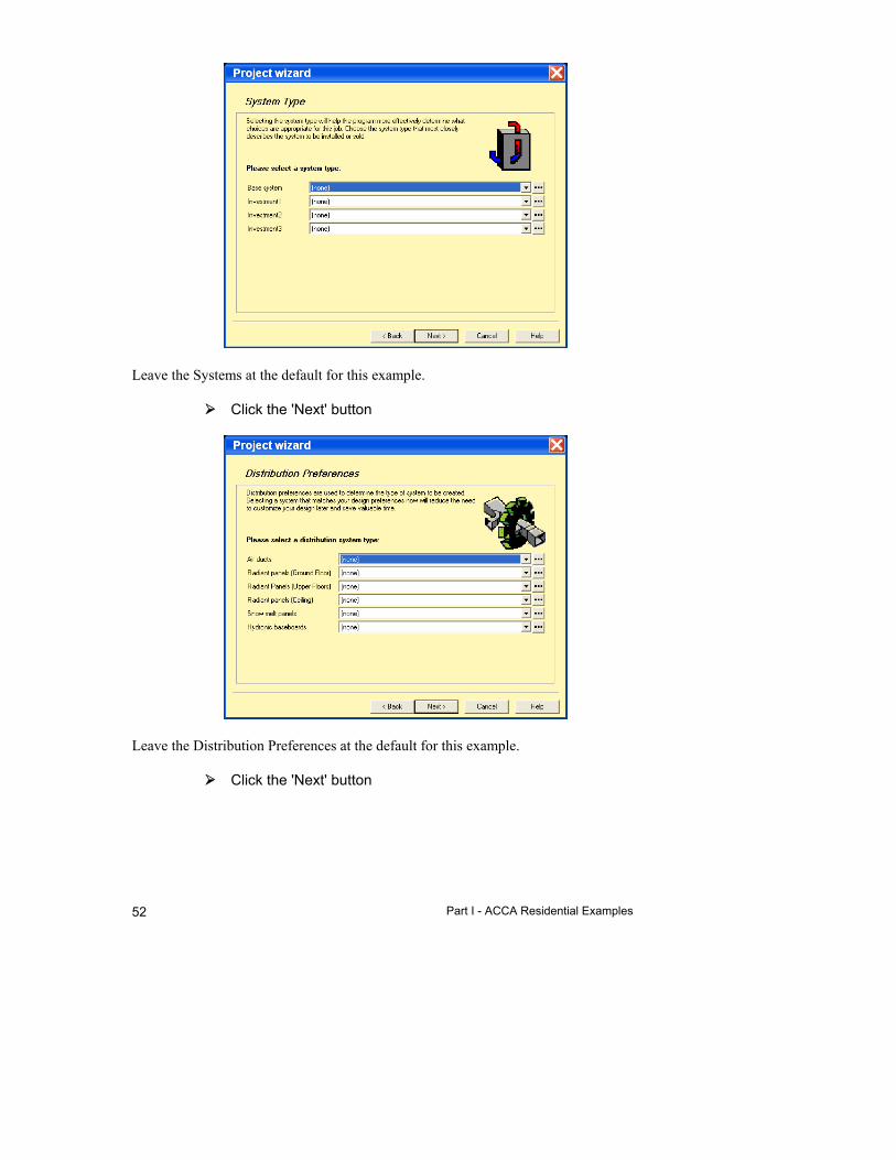
Part I - ACCA Residential Examples 52
Leave the Systems at the default for this example.
Click the 'Next' button
Leave the Distribution Preferences at the default for this example.
Click the 'Next' button

3 Room-by-room Example: Step 1 - Describe the Building
53
Select the 'ACCA1' report set from the drop down list.
Click the 'Next' button
Click the 'Finish' button.
When prompted for a project name, enter 'MyLongResidence'.
Set the calculation methods
This example will use the ACCA Manual J Eighth Edition load calculation method and the acca Manual D ducts sizing calculation method. So, we need to make sure that these options are set.
Select Options | Load calculation method | Manual J Eighth Edition from the Right-Suite Universal 2018 menu.
Select Options | Duct calculation method | Manual D from the Right-Suite Universal 2018 menu.
Step 1b - Add Rooms, Doors & Windows
Now, we can start drawing the building.
Click on the button to display the Right-Draw Screen.
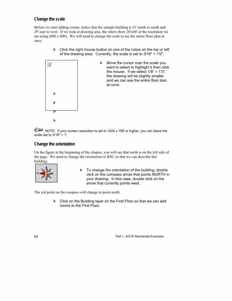
Part I - ACCA Residential Examples 54
Change the scale
Before we start adding rooms, notice that the sample building is 51' north to south and 29' east to west. If we look at drawing area, the rulers show 26'x46' at the resolution we are using (800 x 600). We will need to change the scale to see the entire floor plan at once.
Click the right mouse button on one of the rulers on the top or left of the drawing area. Currently, the scale is set to 3/16" = 1'0".
Move the cursor over the scale you want to select to highlight it then click the mouse. If we select 1/8” = 1’0", the drawing will be slightly smaller and we can see the entire floor plan at once.
NOTE: If your screen resolution is set to 1024 x 768 or higher, you can leave the scale set to 3/16" = 1'.
Change the orientation
On the figure at the beginning of the chapter, you will see that north is on the left side of the page. We need to change the orientation in RSU so that we can describe this building.
To change the orientation of the building, double click on the compass arrow that points NORTH in your drawing. In this case, double click on the arrow that currently points west.
The red point on the compass will change to point north.
Click on the Building layer on the First Floor so that we can add rooms to the First Floor.
The linked image cannot be displayed. The file may have been moved, renamed, or deleted. Verify that the link points to the correct file and location.
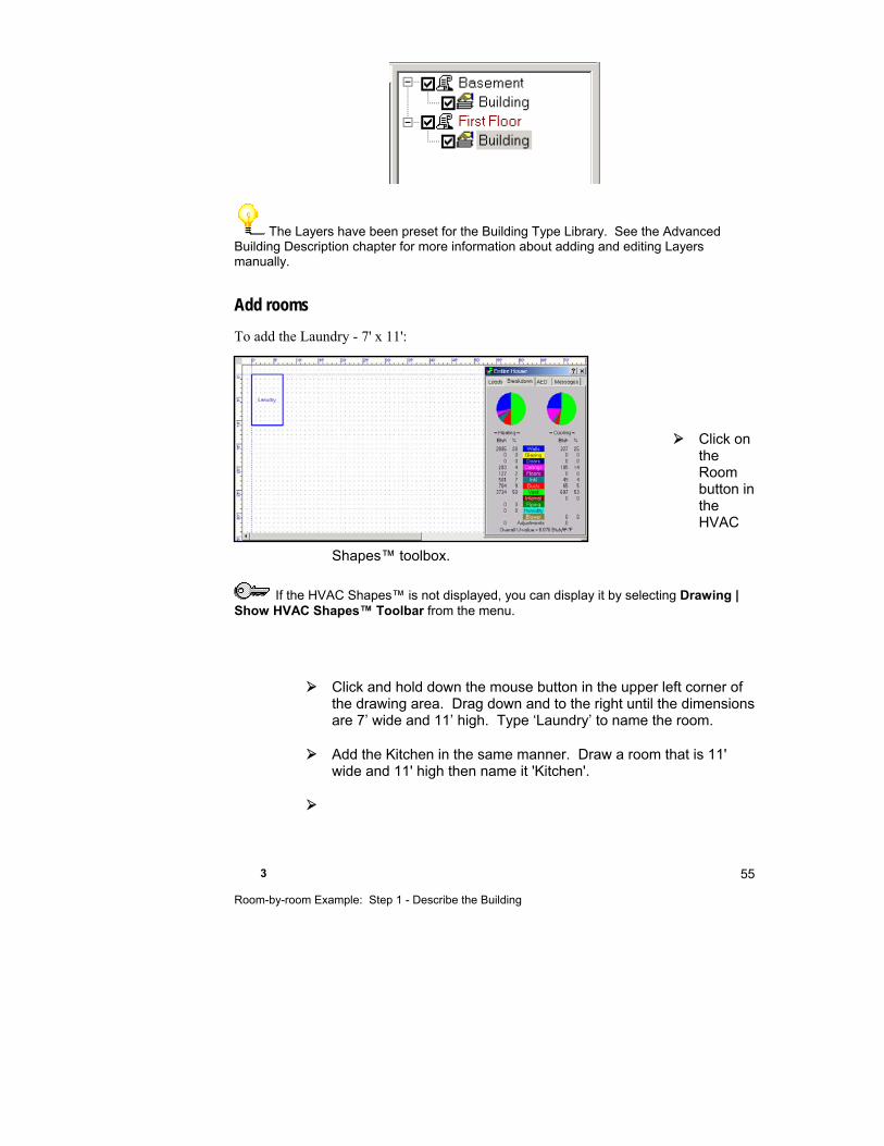
3 Room-by-room Example: Step 1 - Describe the Building
55
The Layers have been preset for the Building Type Library. See the Advanced Building Description chapter for more information about adding and editing Layers manually.
Add rooms
To add the Laundry - 7' x 11':
Click on the Room button in the HVAC
Shapes™ toolbox.
If the HVAC Shapes™ is not displayed, you can display it by selecting Drawing | Show HVAC Shapes™ Toolbar from the menu.
Click and hold down the mouse button in the upper left corner of the drawing area. Drag down and to the right until the dimensions are 7’ wide and 11’ high. Type ‘Laundry’ to name the room.
Add the Kitchen in the same manner. Draw a room that is 11' wide and 11' high then name it 'Kitchen'.

Part I - ACCA Residential Examples 56
Watch the Load Meter change as you draw. If the Load Meter is not displayed, you can display it by selecting Show | Right-J®| Load Meter from the menu.
The rooms that we are drawing will have the default values we set in the Loads Preferences Screen. Notice that Right-Draw knows that the common wall between the 2 rooms is an interior wall and has displayed it as a thin line. This wall is not included in the external wall calculations.
Draw Bath 1, Bedroom 3, Bedroom 2 and Dining Room (see floor plan on page 46 for the dimensions).
The linked image cannot be displayed. The file may have been moved, renamed, or deleted. Verify that the link points to the correct file and location.
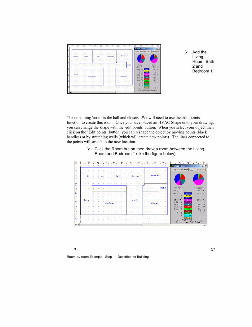
3 Room-by-room Example: Step 1 - Describe the Building
57
Add the Living Room, Bath 2 and Bedroom 1.
The remaining 'room' is the hall and closets. We will need to use the 'edit points' function to create this room. Once you have placed an HVAC Shape onto your drawing, you can change the shape with the 'edit points' button. When you select your object then click on the ‘Edit points’ button, you can reshape the object by moving points (black handles) or by stretching walls (which will create new points). The lines connected to the points will stretch to the new location.
Click the Room button then draw a room between the Living Room and Bedroom 1 (like the figure below).

Part I - ACCA Residential Examples 58
Click the Edit Points button.
The green handles that are around the perimeter of the room will turn to black squares ("points").
Stretch the room to fill the space. Drag corners and walls until the room fills the space.
Click the Edit Points button again when you are done
Zoom in if you are having a difficult time placing the points. Working with edit points is almost impossible if you turn the snap points off (see page 521). Also note that odd-shaped room dimensions are shown in the format 1'x237' (1' x the area) in the Right-J® Worksheet.
Your room should look like this:

3 Room-by-room Example: Step 1 - Describe the Building
59
Name the room 'Hall'.
To change the position of the room name, hold the Shift key down and drag the room name.
Add doors
There are 2 doors in our example: one in the Laundry on the east side of the house and one in the front on the west side.
Select the Door shape from the HVAC Shapes™ Toolbox. Click in the center of the outside wall of Hall A. The default width is 3', which is the width we need.
Now add the door to the Laundry use the figure on page 46 to determine the location. Click on the Door shape then click, hold the mouse button down and drag until the door is 3' wide.
The linked image cannot be displayed. The file may have been moved, renamed, or deleted. Verify that the link points to the correct file and location.
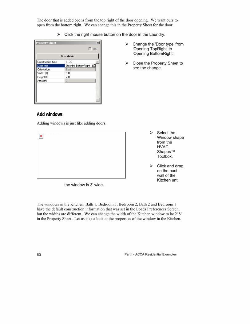
Part I - ACCA Residential Examples 60
The door that is added opens from the top right of the door opening. We want ours to open from the bottom right. We can change this in the Property Sheet for the door.
Click the right mouse button on the door in the Laundry.
Change the 'Door type' from 'Opening TopRight' to 'Opening BottomRight'.
Close the Property Sheet to see the change.
Add windows
Adding windows is just like adding doors.
Select the Window shape from the HVAC Shapes™ Toolbox.
Click and drag on the east wall of the Kitchen until
the window is 3' wide.
The windows in the Kitchen, Bath 1, Bedroom 3, Bedroom 2, Bath 2 and Bedroom 1 have the default construction information that was set in the Loads Preferences Screen, but the widths are different. We can change the width of the Kitchen window to be 2' 8" in the Property Sheet. Let us take a look at the properties of the window in the Kitchen.
The linked image cannot be displayed. The file may have been moved, renamed, or deleted. Verify that the link points to the correct file and location.
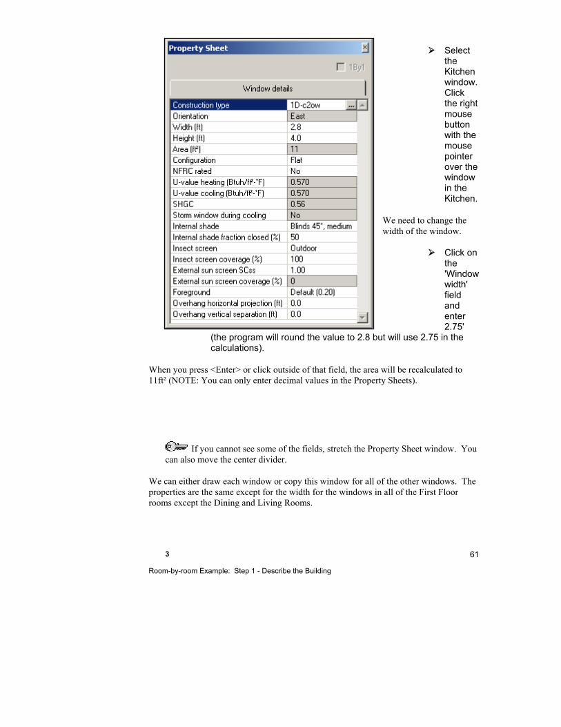
3 Room-by-room Example: Step 1 - Describe the Building
61
Select the Kitchen window. Click the right mouse button with the mouse pointer over the window in the Kitchen.
We need to change the width of the window.
Click on the 'Window width' field and enter 2.75'
(the program will round the value to 2.8 but will use 2.75 in the calculations).
When you press <Enter> or click outside of that field, the area will be recalculated to 11ft² (NOTE: You can only enter decimal values in the Property Sheets).
If you cannot see some of the fields, stretch the Property Sheet window. You can also move the center divider.
We can either draw each window or copy this window for all of the other windows. The properties are the same except for the width for the windows in all of the First Floor rooms except the Dining and Living Rooms.
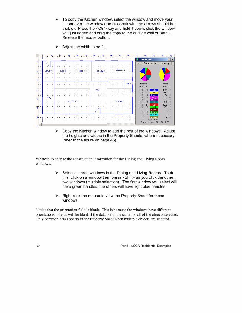
Part I - ACCA Residential Examples 62
To copy the Kitchen window, select the window and move your cursor over the window (the crosshair with the arrows should be visible). Press the <Ctrl> key and hold it down, click the window you just added and drag the copy to the outside wall of Bath 1. Release the mouse button.
Adjust the width to be 2'.
Copy the Kitchen window to add the rest of the windows. Adjust the heights and widths in the Property Sheets, where necessary (refer to the figure on page 46).
We need to change the construction information for the Dining and Living Room windows.
Select all three windows in the Dining and Living Rooms. To do this, click on a window then press <Shift> as you click the other two windows (multiple selection). The first window you select will have green handles; the others will have light blue handles.
Right click the mouse to view the Property Sheet for these windows.
Notice that the orientation field is blank. This is because the windows have different orientations. Fields will be blank if the data is not the same for all of the objects selected. Only common data appears in the Property Sheet when multiple objects are selected.

3 Room-by-room Example: Step 1 - Describe the Building
63
We want to change the construction to '1E-c2fw, wood frame, fixed sash, clear, 2 pane'. . Click on the 'Construction type' field.
Click on the 'Double' tab (for double pane). Select the following:
Section Selection
Type Fixed window
Frame material Wood
Storm pane None
Outer pane Clear
Inner pane Clear
Glass thickness
1/2"
Fill gas Air
With these selections, the MJ8 code in the Results section should be '1E-c2fw'.
Click OK to accept your choices.
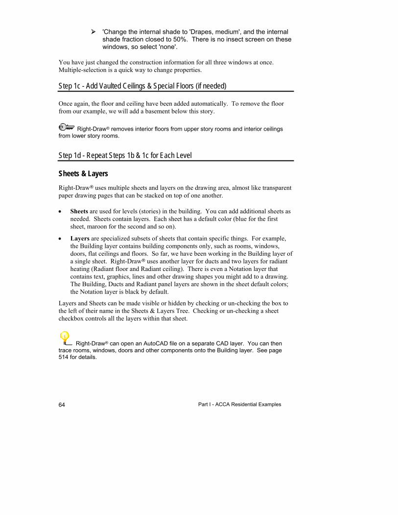
Part I - ACCA Residential Examples 64
'Change the internal shade to 'Drapes, medium', and the internal shade fraction closed to 50%. There is no insect screen on these windows, so select 'none'.
You have just changed the construction information for all three windows at once. Multiple-selection is a quick way to change properties.
Step 1c - Add Vaulted Ceilings & Special Floors (if needed)
Once again, the floor and ceiling have been added automatically. To remove the floor from our example, we will add a basement below this story.
Right-Draw removes interior floors from upper story rooms and interior ceilings from lower story rooms.
Step 1d - Repeat Steps 1b & 1c for Each Level
Sheets & Layers
Right-Draw uses multiple sheets and layers on the drawing area, almost like transparent paper drawing pages that can be stacked on top of one another.
Sheets are used for levels (stories) in the building. You can add additional sheets as needed. Sheets contain layers. Each sheet has a default color (blue for the first sheet, maroon for the second and so on).
Layers are specialized subsets of sheets that contain specific things. For example, the Building layer contains building components only, such as rooms, windows, doors, flat ceilings and floors. So far, we have been working in the Building layer of a single sheet. Right-Draw uses another layer for ducts and two layers for radiant heating (Radiant floor and Radiant ceiling). There is even a Notation layer that contains text, graphics, lines and other drawing shapes you might add to a drawing. The Building, Ducts and Radiant panel layers are shown in the sheet default colors; the Notation layer is black by default.
Layers and Sheets can be made visible or hidden by checking or un-checking the box to the left of their name in the Sheets & Layers Tree. Checking or un-checking a sheet checkbox controls all the layers within that sheet.
Right-Draw can open an AutoCAD file on a separate CAD layer. You can then trace rooms, windows, doors and other components onto the Building layer. See page 514 for details.
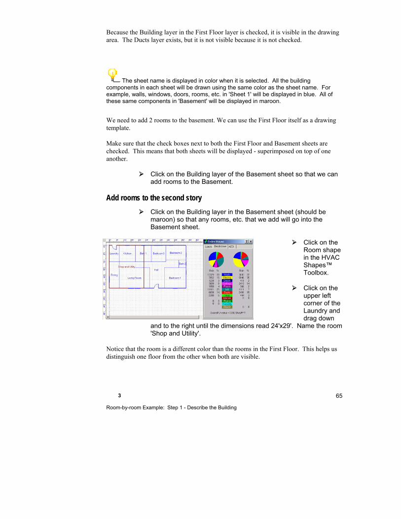
3 Room-by-room Example: Step 1 - Describe the Building
65
Because the Building layer in the First Floor layer is checked, it is visible in the drawing area. The Ducts layer exists, but it is not visible because it is not checked.
The sheet name is displayed in color when it is selected. All the building components in each sheet will be drawn using the same color as the sheet name. For example, walls, windows, doors, rooms, etc. in 'Sheet 1' will be displayed in blue. All of these same components in 'Basement' will be displayed in maroon.
We need to add 2 rooms to the basement. We can use the First Floor itself as a drawing template.
Make sure that the check boxes next to both the First Floor and Basement sheets are checked. This means that both sheets will be displayed - superimposed on top of one another.
Click on the Building layer of the Basement sheet so that we can add rooms to the Basement.
Add rooms to the second story
Click on the Building layer in the Basement sheet (should be maroon) so that any rooms, etc. that we add will go into the Basement sheet.
Click on the Room shape in the HVAC Shapes™ Toolbox.
Click on the upper left corner of the Laundry and drag down
and to the right until the dimensions read 24'x29'. Name the room 'Shop and Utility'.
Notice that the room is a different color than the rooms in the First Floor. This helps us distinguish one floor from the other when both are visible.
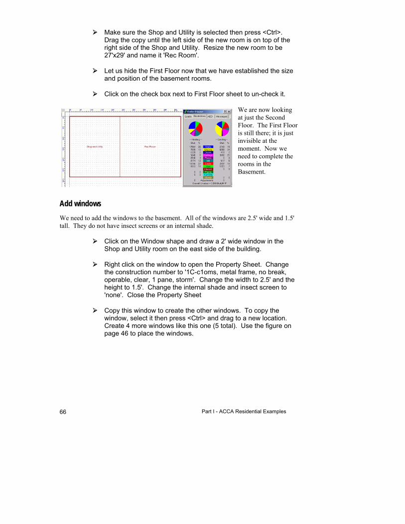
Part I - ACCA Residential Examples 66
Make sure the Shop and Utility is selected then press <Ctrl>. Drag the copy until the left side of the new room is on top of the right side of the Shop and Utility. Resize the new room to be 27'x29' and name it 'Rec Room'.
Let us hide the First Floor now that we have established the size and position of the basement rooms.
Click on the check box next to First Floor sheet to un-check it.
We are now looking at just the Second Floor. The First Floor is still there; it is just invisible at the moment. Now we need to complete the rooms in the Basement.
Add windows
We need to add the windows to the basement. All of the windows are 2.5' wide and 1.5' tall. They do not have insect screens or an internal shade.
Click on the Window shape and draw a 2' wide window in the Shop and Utility room on the east side of the building.
Right click on the window to open the Property Sheet. Change the construction number to '1C-c1oms, metal frame, no break, operable, clear, 1 pane, storm'. Change the width to 2.5' and the height to 1.5'. Change the internal shade and insect screen to 'none'. Close the Property Sheet
Copy this window to create the other windows. To copy the window, select it then press <Ctrl> and drag to a new location. Create 4 more windows like this one (5 total). Use the figure on page 46 to place the windows.
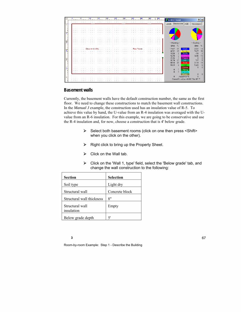
3 Room-by-room Example: Step 1 - Describe the Building
67
Basement walls
Currently, the basement walls have the default construction number, the same as the first floor. We need to change these constructions to match the basement wall constructions. In the Manual J example, the construction used has an insulation value of R-5. To achieve this value by hand, the U-value from an R-4 insulation was averaged with the U-value from an R-6 insulation. For this example, we are going to be conservative and use the R-4 insulation and, for now, choose a construction that is 4' below grade.
Select both basement rooms (click on one then press <Shift> when you click on the other).
Right click to bring up the Property Sheet.
Click on the Wall tab.
Click on the 'Wall 1, type' field, select the 'Below grade' tab, and change the wall construction to the following:
Section Selection
Soil type Light dry
Structural wall Concrete block
Structural wall thickness 8"
Structural wall insulation
Empty
Below grade depth 5'
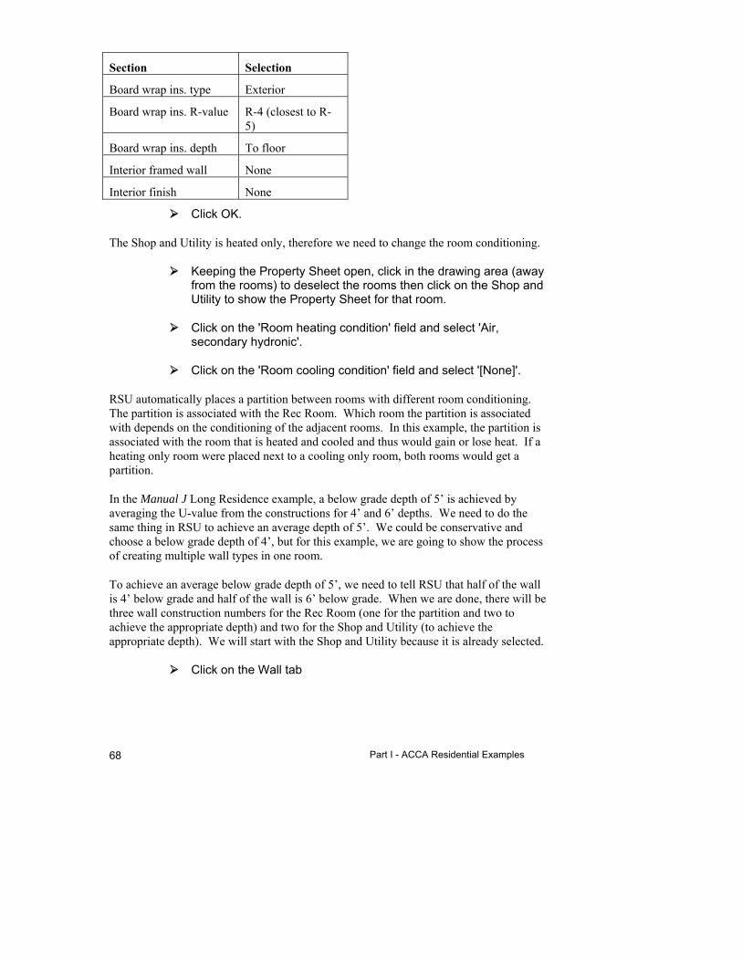
Part I - ACCA Residential Examples 68
Section Selection
Board wrap ins. type Exterior
Board wrap ins. R-value R-4 (closest to R-5)
Board wrap ins. depth To floor
Interior framed wall None
Interior finish None
Click OK.
The Shop and Utility is heated only, therefore we need to change the room conditioning.
Keeping the Property Sheet open, click in the drawing area (away from the rooms) to deselect the rooms then click on the Shop and Utility to show the Property Sheet for that room.
Click on the 'Room heating condition' field and select 'Air, secondary hydronic'.
Click on the 'Room cooling condition' field and select '[None]'.
RSU automatically places a partition between rooms with different room conditioning. The partition is associated with the Rec Room. Which room the partition is associated with depends on the conditioning of the adjacent rooms. In this example, the partition is associated with the room that is heated and cooled and thus would gain or lose heat. If a heating only room were placed next to a cooling only room, both rooms would get a partition.
In the Manual J Long Residence example, a below grade depth of 5’ is achieved by averaging the U-value from the constructions for 4’ and 6’ depths. We need to do the same thing in RSU to achieve an average depth of 5’. We could be conservative and choose a below grade depth of 4’, but for this example, we are going to show the process of creating multiple wall types in one room.
To achieve an average below grade depth of 5’, we need to tell RSU that half of the wall is 4’ below grade and half of the wall is 6’ below grade. When we are done, there will be three wall construction numbers for the Rec Room (one for the partition and two to achieve the appropriate depth) and two for the Shop and Utility (to achieve the appropriate depth). We will start with the Shop and Utility because it is already selected.
Click on the Wall tab

3 Room-by-room Example: Step 1 - Describe the Building
69
In the Wall tab, you will see that the wall type that is selected for the Wall 1, type has a below grade depth of 4' and the area is 616ft2. We will add the 6' below grade depth construction then adjust the areas.
Click on the 'Wall 2, type' field and select the same wall as before except with a 6' depth below grade - '15A-4sfoc-6, basement wall - block, open core, no framing or interior finish, R-4 foam board to floor, 6' below grade'. Click OK.
We have now added our 6' below grade construction. Let us add areas to that construction.
Click on the 'Wall 2, area' field to display the Wall Details window.
The Wall Details window is used to adjust the automatic wall area calculations. You only need to do this if there is more than one wall in a room. Enter the area adjustments as necessary. We need to adjust the areas of the north, east and west walls. Let us start with the north wall. The wall is 29' long and 8' high therefore, we want to add an area of 116ft2 (14.5' x 8'; half of the total 29' wall length because the other half will have the 4' depth).
Type '116' in the north 'Area adjustment' field.
The east and west walls will have the same area adjustment. We want an area of 96ft2 for the east and west walls (12' x 8'; half of the total 24' wall length because the other half will have the 4' depth).
Enter '96' for both the east and west walls then click OK.
We now need to subtract the area we just added to the 6' depth construction from the 4' depth construction so that our total area is correct.
Click on the 'Wall 1, area' field to display the Wall Details window for the 4' depth construction.
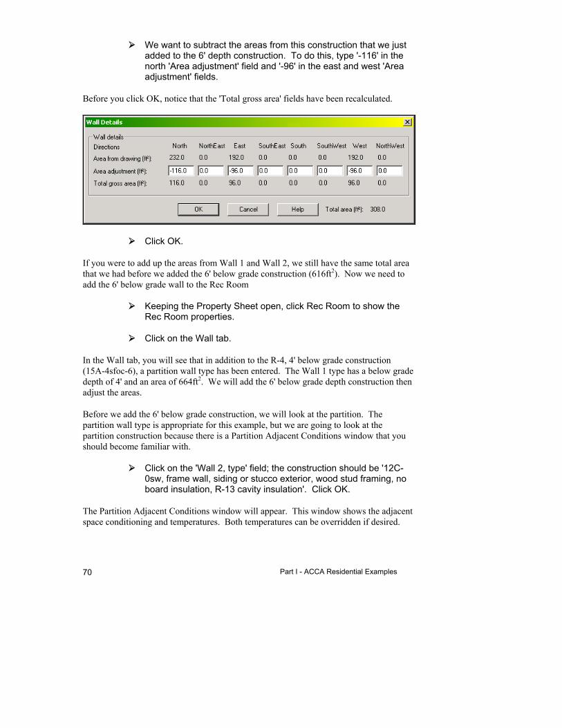
Part I - ACCA Residential Examples 70
We want to subtract the areas from this construction that we just added to the 6' depth construction. To do this, type '-116' in the north 'Area adjustment' field and '-96' in the east and west 'Area adjustment' fields.
Before you click OK, notice that the 'Total gross area' fields have been recalculated.
Click OK.
If you were to add up the areas from Wall 1 and Wall 2, we still have the same total area that we had before we added the 6' below grade construction (616ft2). Now we need to add the 6' below grade wall to the Rec Room
Keeping the Property Sheet open, click Rec Room to show the Rec Room properties.
Click on the Wall tab.
In the Wall tab, you will see that in addition to the R-4, 4' below grade construction (15A-4sfoc-6), a partition wall type has been entered. The Wall 1 type has a below grade depth of 4' and an area of 664ft2. We will add the 6' below grade depth construction then adjust the areas.
Before we add the 6' below grade construction, we will look at the partition. The partition wall type is appropriate for this example, but we are going to look at the partition construction because there is a Partition Adjacent Conditions window that you should become familiar with.
Click on the 'Wall 2, type' field; the construction should be '12C-0sw, frame wall, siding or stucco exterior, wood stud framing, no board insulation, R-13 cavity insulation'. Click OK.
The Partition Adjacent Conditions window will appear. This window shows the adjacent space conditioning and temperatures. Both temperatures can be overridden if desired.
3 Room-by-room Example: Step 1 - Describe the Building
71
The heating adjacent space temperature is from the setpoint of the adjacent zone if you have a multizone building or from the winter outdoor temperature. You will not need to override this value often because the outdoor heating temperature is conservative. The cooling adjacent space temperature is the default for a shaded exterior wall and is dependent on the partition construction. A heavier construction will yield a lower cooling adjacent space temperature. If you have the situation where the adjacent room temperature will be higher than the default value (for example, if the adjacent room is not cooled, in the sun and all of the windows are closed) then you can override the value. Both temperatures can be overridden.
We will leave these values, so click OK.
Next we need to add the 6' below grade construction.
Click on the 'Wall 3, type' field and select '15A-4sfoc-6, basement wall - block, open core, no framing or interior finish, R-4 foam board to floor, 6' below grade'. Click OK.
We have now added our 6' below grade construction. Let us add areas to that construction.
Click on the 'Wall 3, area' field to display the Wall Details window.
We need to adjust the areas of the south, east and west walls. Let us start with the south wall. The wall is 29' long and 8' high therefore, we want to add an area of 116ft2 (14.5' x 8'; half of the 29' wall length because the other half will have the 4' below grade construction).
Type '116' in the south 'Area adjustment' field.
The east and west walls will have the same area adjustment. We want an area of 108ft2 for the east and west walls (13.5' x 8'; half of the 27' wall length because the other half will have the 4' below grade construction).
Enter '108' for both the east and west walls then click OK.
We now need to subtract the area we just added to the 6' below grade construction from the 4' below grade construction so that our total area is correct.
Click on the 'Wall 1, area' field to display the Wall Details window for the 4' below grade construction.
We want to subtract the areas from this construction that we just added to the 6' below grade construction. To do this, type '-116'

Part I - ACCA Residential Examples 72
in the south 'Area adjustment' field and '-108' in the east and west 'Area adjustment' fields.
Click OK then click on the 'X' in the upper right corner to close the Property Sheet.
If you were to add up the areas from Wall 1 and Wall 3, we still have the same total exterior wall area that we had before we added the 6' below grade construction (664ft2).
Ceilings & Floors
If you had a vaulted ceiling or a special floor, you would add them now. We do not need to add special ceilings or floors to this building.
While we are discussing ceilings and floors, note that the internal floor from the first floor and the ceiling from the basement have been removed automatically by Right-Draw®. Because Right-Draw® knows the relative location of rooms and stories, we do not have to remove the internal ceilings or floors.
Internal gains
The Long Residence in Manual J, Eighth Edition shows that there are 2 people in the Living Room and 2 people in the Rec Room. With Right-Draw®, you can enter the occupant information into the Property Sheet for specific rooms. When you enter a number in the 'Number of occupants' field in the room Property Sheet, RSU multiplies that number with the default value located on the Loads Preferences Screen. In this case, we are using 230 Btuh/person for sensible and 200 Btuh/person for latent internal gain.
Select the Rec Room (make sure the green handles are showing) and right click.
Select the Room tab.
Click on the 'Number of occupants' field and enter '2'.
Now we need to add 2 people to the Living Room. We do not need to close the Property Sheet to do this.
Click on the First Floor sheet check box to display the first floor.
Select the Living Room (make sure the green handles are only around the Living Room).

3 Room-by-room Example: Step 1 - Describe the Building
73
The Property Sheet will update to show the Living Room properties. Click on the 'Number of occupants' field and enter '2'.
Now we need to add the appliance internal loads. Again, we will select the rooms we want to add the internal gains to and enter the values into the Property Sheets. We can add the internal gains for the lights in the Living Room while we still have the Property Sheet for the Living Room open. Since Manual J 8th Edition assumes 1200 Btuh per appliance set and we want to enter a different value for this room, we have overriden the Btuh per appliance set to '1' in the Load Preferences Screen. We can then enter the appliance loads in each room in Btuh directly.
Click on the 'Number of appliances' field and type '300'.
Remember that since we entered a value of '1' in the Loads Preferences Screen. RSU will multiply the value you enter into the Property Sheet by the value that is on the Loads Preferences Screen (or on the Right-J® Worksheet). Therefore, the total internal gain for the Living Room will be 300 x 1 = 300 Btuh.
Select the Laundry room. The Property Sheet will update to show the Laundry properties.
Enter '500' for the washer and dryer in the 'Number of appliances' field.
Repeat the same steps for the Kitchen (1,000 Btuh) and the Rec Room (600 Btuh).
Ventilation
Now that we have the building described, we should check the ventilation.
Click on the Zone Information button to display the Zone Information Screen.
In the Ventilation section there is a 'Central supply AVF' field that shows a value of 52 cfm. The system designer, for the example in Manual J, decided that this value was low enough to disregard. No mechanical ventilation was used.
This value differs from the 36 cfm value that is calculated for the Manual J example Version 1.1 February 2003 (from Worksheet E). This difference is due to changes in the infiltration calculations outlined in Addendum D, May 2004. This small difference would not affect the decision to disregard the ventilation.
Part I - ACCA Residential Examples 74
In RSU we can override this value and enter a value of '0' to indicate that no mechanical ventilation should be considered.
Click on the heating 'Central supply AVF' field and press <F8> to override the value.
Enter a value of '0'.
Repeat the same steps to enter a value of '0' for the cooling central supply AVF.
The exhaust AVF will also change to '0'.
We have completed describing our second example building. Take a moment to review the loads on the Load Meter, Right-J® Worksheet and the Zone Information Screen. Also check the Infiltration Screen summary.
You should save the project we have been working on.
Select File | Save from the menu.
Things to Remember
Use the Project Wizard to start a new project to quickly enter calculation assumptions and preferences.
To describe a multiple story building, put each story in its own sheet with different elevations. Right-Draw® will automatically remove interior floors and ceilings.
Right-Draw® will remove the area of interior walls, floors, and ceilings from the load calculation automatically.

4
Room-by-room Example: Step 2 - Select the Equipment
How Does Multi-Zoning Work? ...................................... 76
How Are Multiple Systems Handled? ............................ 77
Step 2a - Assign Zoning ................................................ 77
Step 2b - Assign Distribution Systems .......................... 81
Step 2c - Geothermal Loop ........................................... 81
Step 2d - Evaluate Equipment System Options ............. 81
Step 2e - Select the Final Equipment System ............... 81
Things to Remember ..................................................... 85
Part I - ACCA Residential Examples 76
This chapter continues where Chapter 3 leaves off. We will continue to use the file we created but the data that we will be entering for this chapter is not from the Manual J example. To begin, open the project that you created from Chapter 3.
Select File | Open | Project… from the main menu.
Select ‘MyLongResidence.rud' from the list of demo files and click OK.
How Does Multi-Zoning Work?
RSU helps you divide a house into multiple HVAC system zones, calculate loads for the zones, and size ducts for each zone. Your zone definitions are automatically linked to other RSU program components.
The process for zoning is easy. To add zones when the same equipment is supplying all zones:
1. Click the Multizone button in the Project Toolbar.
2. Click the first room you wish to assign to a zone, then click the Add Zone button and enter the name of the zone.
3. Drag-and-drop rooms into the new zone as required.
4. Repeat steps 2 and 3 until all the rooms have been assigned to their proper zone.
This process usually takes less than a couple of minutes, even for a large number of rooms.
Note: If each zone has a VAV box associated with it (used in commercial applications) you would click 'Add VAV' instead of 'Add Zone' above.
If each zone is to have its own equipment, you would follow the above instructions except click 'Add AH' (for add air handler) instead of 'Add Zone'. When you do this, a blower HVAC Shape will be added to the Right-Draw® drawing.
There can even be separate zoning if there is both an air and a hydronic distribution system.
It is important to note that as you enter a new zone name RSU will propagate all changes through the project and move ducts, etc. as required to suit the new zone configurations. Also note that equipment can either be in individual zones, or the equipment can be in the Entire House for central equipment in multiple zones.
4 Room-by-room Example: Step 2 - Select the Equipment
77
How Are Multiple Systems Handled?
You can evaluate as many as four HVAC system alternatives in Right-$™ for each HVAC unit in your design. For designs with a single central unit, Right-$™ can let you examine a total of four system options. For multizone designs with a separate unit serving each zone, there can be as many as four system alternatives for each zone. For example, a three-zone house will have a total of 12 systems to consider (3 zones x 4 systems), but you can only compare alternatives within a zone.
After you evaluate the system options in Right-$™, select one of the systems to function as the Current System. The Current System is linked to the other RSU functions for their calculations. Use the Options | Current System | (then choose Base System, Investment 1, Investment 2 or Investment 3) menu choice to specify the system to be used in the calculations and reports.
When you select Options | Current System from the main menu, that system option is selected for each zone. For example, if you have a three-zone project and you select ‘Investment 1’ for Current System, the equipment you have defined as Investment 1 in Right-$™ for each zone will become the current system for all other zones.
Step 2a - Assign Zoning
RSU’s Multizone Tree makes it easy to add and delete zones, air handlers, and VAV boxes and move rooms between them using either multiple HVAC units or a single central HVAC unit with proportional zone dampers.
There are 4 zones in the sample house served by a single unit. The Rec Room and Shop and Utility will each have their own zone, because they are conditioned differently. The 3 bedrooms and Bath 2 will be in one zone and the rest of the rooms on the first floor will be in a zone.
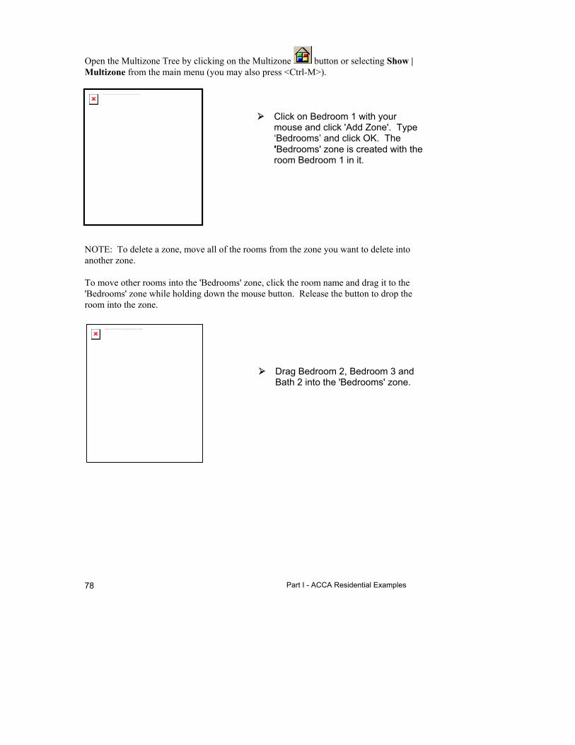
Part I - ACCA Residential Examples 78
Open the Multizone Tree by clicking on the Multizone button or selecting Show | Multizone from the main menu (you may also press <Ctrl-M>).
Click on Bedroom 1 with your mouse and click 'Add Zone'. Type ‘Bedrooms’ and click OK. The 'Bedrooms' zone is created with the room Bedroom 1 in it.
NOTE: To delete a zone, move all of the rooms from the zone you want to delete into another zone.
To move other rooms into the 'Bedrooms' zone, click the room name and drag it to the 'Bedrooms' zone while holding down the mouse button. Release the button to drop the room into the zone.
Drag Bedroom 2, Bedroom 3 and Bath 2 into the 'Bedrooms' zone.
The linked image cannot be displayed. The file may have been moved, renamed, or deleted. Verify that the link points to the correct file and location.
The linked image cannot be displayed. The file may have been moved, renamed, or deleted. Verify that the link points to the correct file and location.
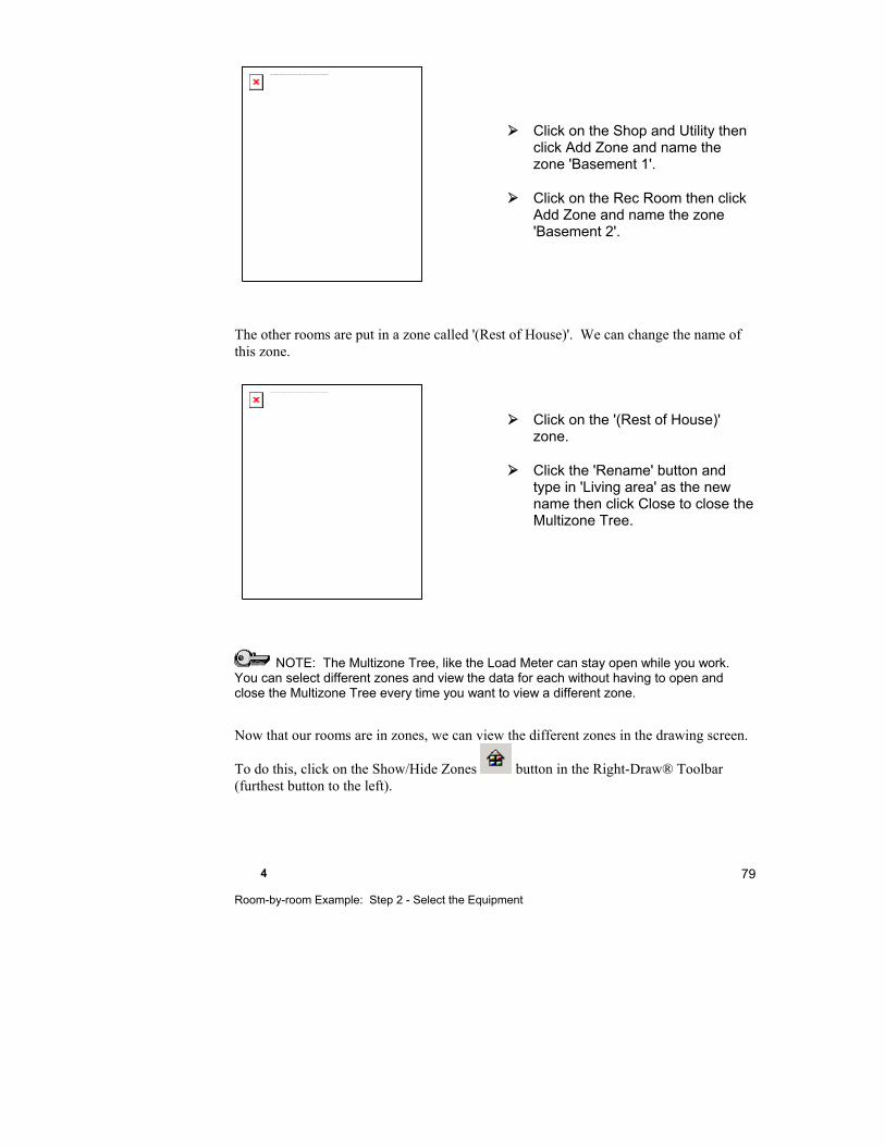
4 Room-by-room Example: Step 2 - Select the Equipment
79
Click on the Shop and Utility then click Add Zone and name the zone 'Basement 1'.
Click on the Rec Room then click Add Zone and name the zone 'Basement 2'.
The other rooms are put in a zone called '(Rest of House)'. We can change the name of this zone.
Click on the '(Rest of House)' zone.
Click the 'Rename' button and type in 'Living area' as the new name then click Close to close the Multizone Tree.
NOTE: The Multizone Tree, like the Load Meter can stay open while you work. You can select different zones and view the data for each without having to open and close the Multizone Tree every time you want to view a different zone.
Now that our rooms are in zones, we can view the different zones in the drawing screen.
To do this, click on the Show/Hide Zones button in the Right-Draw® Toolbar (furthest button to the left).
The linked image cannot be displayed. The file may have been moved, renamed, or deleted. Verify that the link points to the correct file and location.
The linked image cannot be displayed. The file may have been moved, renamed, or deleted. Verify that the link points to the correct file and location.
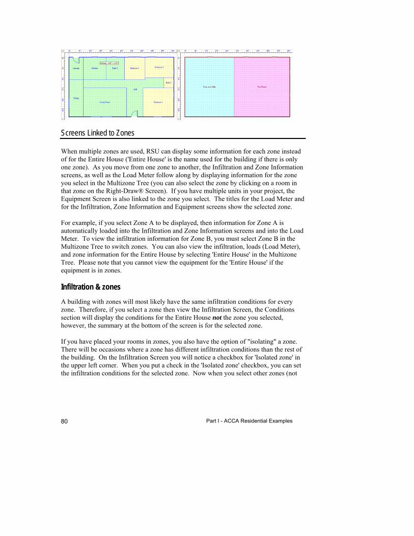
Part I - ACCA Residential Examples 80
Screens Linked to Zones
When multiple zones are used, RSU can display some information for each zone instead of for the Entire House ('Entire House' is the name used for the building if there is only one zone). As you move from one zone to another, the Infiltration and Zone Information screens, as well as the Load Meter follow along by displaying information for the zone you select in the Multizone Tree (you can also select the zone by clicking on a room in that zone on the Right-Draw® Screen). If you have multiple units in your project, the Equipment Screen is also linked to the zone you select. The titles for the Load Meter and for the Infiltration, Zone Information and Equipment screens show the selected zone.
For example, if you select Zone A to be displayed, then information for Zone A is automatically loaded into the Infiltration and Zone Information screens and into the Load Meter. To view the infiltration information for Zone B, you must select Zone B in the Multizone Tree to switch zones. You can also view the infiltration, loads (Load Meter), and zone information for the Entire House by selecting 'Entire House' in the Multizone Tree. Please note that you cannot view the equipment for the 'Entire House' if the equipment is in zones.
Infiltration & zones
A building with zones will most likely have the same infiltration conditions for every zone. Therefore, if you select a zone then view the Infiltration Screen, the Conditions section will display the conditions for the Entire House not the zone you selected, however, the summary at the bottom of the screen is for the selected zone.
If you have placed your rooms in zones, you also have the option of "isolating" a zone. There will be occasions where a zone has different infiltration conditions than the rest of the building. On the Infiltration Screen you will notice a checkbox for 'Isolated zone' in the upper left corner. When you put a check in the 'Isolated zone' checkbox, you can set the infiltration conditions for the selected zone. Now when you select other zones (not
4 Room-by-room Example: Step 2 - Select the Equipment
81
isolated), the conditions at the top of the screen will be for the 'Entire House', but will exclude the isolated zone.
How do I decide which rooms to group together in a zone?
Zones should consist of rooms that have similar loads and similar comfort control requirements. Experience will help you decide how to zone a house. It is usually a good idea to group rooms that have a similar solar exposure into one zone. Occupancy schedules and opportunities for cooling thermostat setup are also key considerations. Upper and lower floors are often separate zones.
Use the Multizone Tree to make “what-if” evaluations on your zoning scheme. You can quickly move rooms from one zone to another and instantly see the effects on loads, ducts and HVAC units.
See Chapter 9 for a complete discussion of zoning.
Step 2b - Assign Distribution Systems
HVAC equipment & zones
Your project might have a single zone or multiple zones. There can be a single unit that serves the entire house or multiple units that serve different zones or combinations of zones. Use the Multizone Tree Screen to design the zone and equipment plan for your project.
Step 2c - Geothermal Loop
If your project uses geothermal loops, now is the time to design them. See Chapter 25 for a detailed Right-Loop™ example.
Step 2d - Evaluate Equipment System Options
To determine the most practical equipment system, you may want to compare several system configurations. See Chapter 28 for a detailed Right-$™ example.
Step 2e - Select the Final Equipment System
Since the equipment is in the Entire House, we need to select 'Entire House' in the Multizone Tree in order to select equipment, otherwise, the Equipment button is grayed out and we are not allowed to select the equipment.
Open the Multizone Tree by clicking on the Multizone button.

Part I - ACCA Residential Examples 82
Select 'Entire House' and then click Close.
Click the Equipment button or press <F7> to display the Equipment Screen.
Here you can select your final heating and cooling equipment. We are using an air source heat pump with a gas furnace backup in our example.
The Equipment Screen is organized with several tabs across the top. By clicking on the desired tab, you can access choices and information.
System type tab
Select 'Split air source HP' for the cooling source.
Select 'Furnace' for the backup heating source type.
Select 'Natural gas' for the heating source fuel.
Select 'none' for the water-heating source.
Data tab
Click the Data tab to view or edit operating cost information.
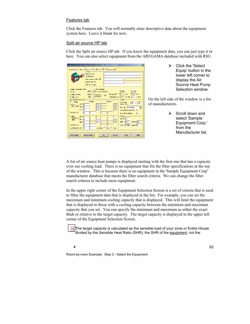
4 Room-by-room Example: Step 2 - Select the Equipment
83
Features tab
Click the Features tab. You will normally enter descriptive data about the equipment system here. Leave it blank for now.
Split air source HP tab
Click the Split air source HP tab. If you know the equipment data, you can just type it in here. You can also select equipment from the ARI/GAMA database included with RSU.
Click the 'Select Equip' button in the lower left corner to display the Air Source Heat Pump Selection window.
On the left side of the window is a list of manufacturers.
Scroll down and select 'Sample Equipment Corp.' from the Manufacturer list.
A list of air source heat pumps is displayed starting with the first one that has a capacity over our cooling load. There is no equipment that fits the filter specifications at the top of the window. This is because there is no equipment in the 'Sample Equipment Corp' manufacturer database that meets the filter search criteria. We can change the filter search criterea to include more equipment.
In the upper right corner of the Equipment Selection Screen is a set of criteria that is used to filter the equipment data that is displayed in the list. For example, you can set the maximum and minimum cooling capacity that is displayed. This will limit the equipment that is displayed to those with a cooling capacity between the minimum and maximum capacity that you set. You can specify the minimum and maximum as either the exact Btuh or relative to the target capacity. The target capacity is displayed in the upper left corner of the Equipment Selection Screen.
The target capacity is calculated as the sensible load of your zone or Entire House divided by the Sensible Heat Ratio (SHR); the SHR of the equipment, not the
The linked image cannot be displayed. The file may have been mov ed, renamed, or deleted. Verify that the link points to the correct file and location.

Part I - ACCA Residential Examples 84
building. This is generally 0.70, however, you should verify this by referring to the manufacturer's specification sheet for the equipment.
Let us expand the maximum capacity display range to 200% of the target capacity.
In the 'Filter' section enter '200', in the Max 'Capacity/ Load (%)' field.
The list of equipment now includes equipment up to 200% of the target capacity.
Click anywhere on the first line to select the equipment then click OK.
Gas furnace tab
Click the Gas furnace tab. If you know the equipment data, you can just type it in here. You can also select equipment from the ARI/GAMA database included with RSU.
Click the ‘Select Equip’ button to display the Gas Furnace Selection window.
Select 'Sample Equipment Corp' from the list of manufacturers on the left.
A list of gas furnaces will be displayed starting with the first one that has a capacity that is over our heating load.
Click anywhere on the first line to select the equipment then click OK.
Click OK again when you are done with the Equipment Screen.
4 Room-by-room Example: Step 2 - Select the Equipment
85
Whether you are going to continue to the next chapter or not, you should save the project file that we have been working on.
Select File | Save from the main menu or click on the Save button.
Things to Remember
Zoning in RSU is controlled from the Multizone Tree by simply dragging the rooms into the desired zones.
The data in the Infiltration, Equipment and Zone Information screens as well as in the Load Meter change depending on the active zone. The active zone is chosen in the Multizone Tree.
Equipment is selected from the Equipment Screen
You do not need to close the Multizone Tree while you work.

5
Room-by-room Example: Step 3 - Design the Distribution
Step 3a - Air Distribution via Ducts ................................ 88
Step 3b - Distribution With Radiant Panels.................... 96
Step 3c - Baseboards .................................................... 98
Things to Remember ................................................... 100
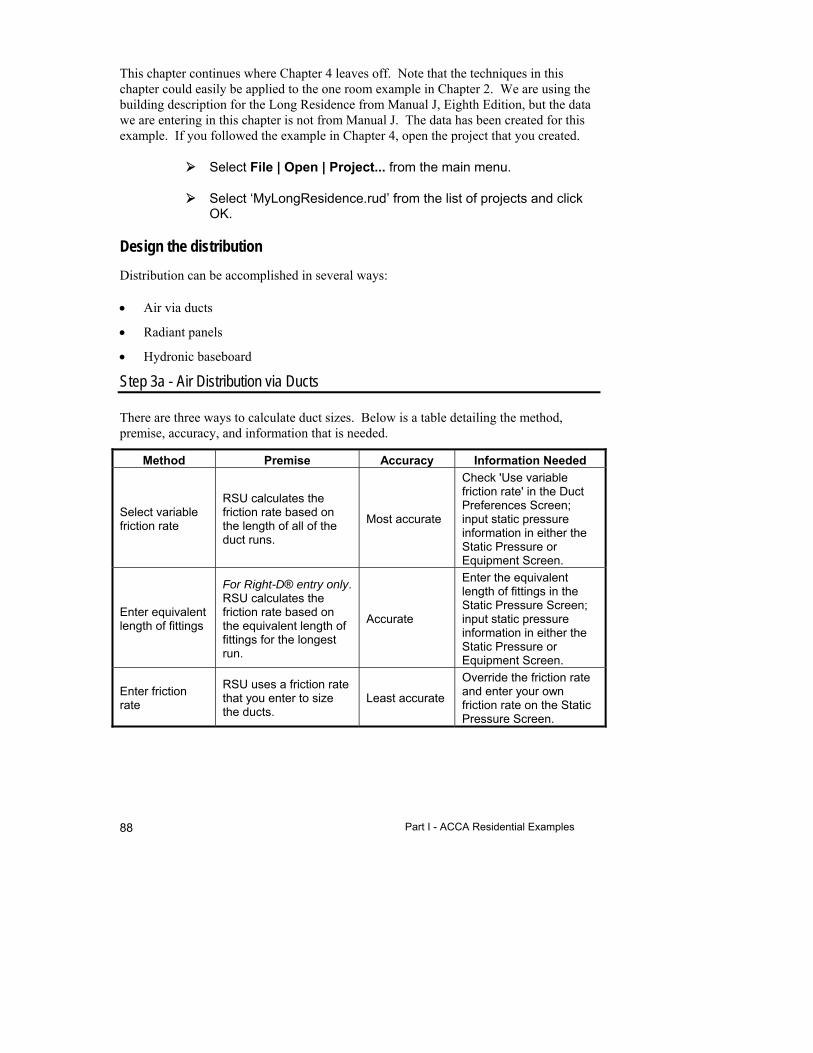
Part I - ACCA Residential Examples 88
This chapter continues where Chapter 4 leaves off. Note that the techniques in this chapter could easily be applied to the one room example in Chapter 2. We are using the building description for the Long Residence from Manual J, Eighth Edition, but the data we are entering in this chapter is not from Manual J. The data has been created for this example. If you followed the example in Chapter 4, open the project that you created.
Select File | Open | Project... from the main menu.
Select ‘MyLongResidence.rud’ from the list of projects and click OK.
Design the distribution
Distribution can be accomplished in several ways:
Air via ducts
Radiant panels
Hydronic baseboard
Step 3a - Air Distribution via Ducts
There are three ways to calculate duct sizes. Below is a table detailing the method, premise, accuracy, and information that is needed.
Method Premise Accuracy Information Needed
Select variable friction rate
RSU calculates the friction rate based on the length of all of the duct runs.
Most accurate
Check 'Use variable friction rate' in the Duct Preferences Screen; input static pressure information in either the Static Pressure or Equipment Screen.
Enter equivalent length of fittings
For Right-D® entry only. RSU calculates the friction rate based on the equivalent length of fittings for the longest run.
Accurate
Enter the equivalent length of fittings in the Static Pressure Screen; input static pressure information in either the Static Pressure or Equipment Screen.
Enter friction rate
RSU uses a friction rate that you enter to size the ducts.
Least accurate
Override the friction rate and enter your own friction rate on the Static Pressure Screen.
5 Room-by-room Example: Step 3 - Design the Distribution
89
For this example, we will enter the friction rate. We also need to enter the fan size and external fan static pressure according to the manufacturer's specifications before the duct sizes can be calculated.
Equipment AVF
Suppose that we looked up the equipment that we selected in our manufacturer's specification sheet and found that the rated fan size is 1,600 cfm. We need to override the design AVF in RSU because the current AVF is 1,283 cfm.
Click on Multizone button.
Select the 'Entire House' zone and click 'Close' to make the 'Entire House' zone the current zone.
Click on the Equipment button.
Click on the Air source HP tab and click on the cooling ‘Design AVF (cfm)’ field.
Press <F8> to override the value. Enter '1600' (but, press <Tab> - do not press <Enter> because we are not finished with this screen; also notice that both the heating and cooling AVF changed).
We will assume that our sample gas furnace is rated at 2,500 cfm. Again, we will need to override the design AVF. Typically, when a heat pump is used with backup heating equipment, the heating equipment that is satisfying the load at any one moment can be the heat pump, the backup equipment or both. The ducts should be designed for the maximum airflow at any one time. For our example, we will assume that either the heat pump or the furnace will be on one at a time, never together. Therefore, we will be sizing the ducts to the furnace fan size, which is 2,500 cfm.
Un-check the ‘Heating=Cooling’ option. This will allow us to set the heating and cooling AVF independently of one another.
Click on the heating 'Design AVF (cfm)' field and press the <F8> key.
Delete the current value and enter '2500'.
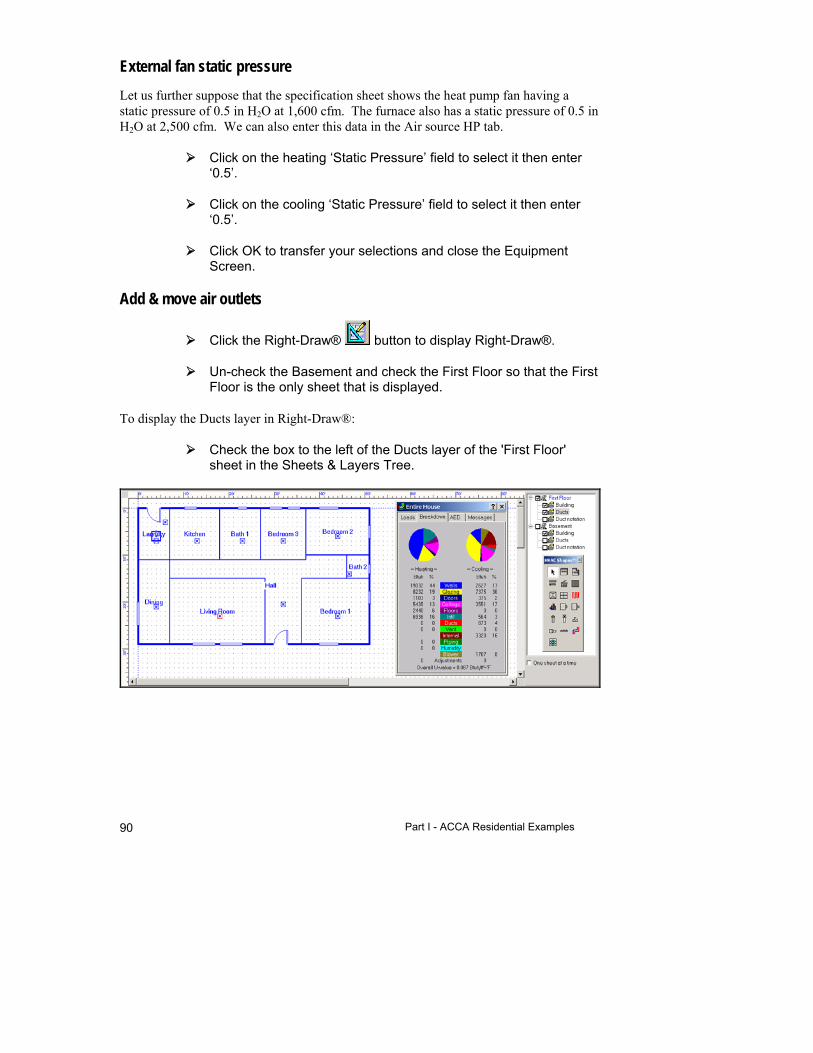
Part I - ACCA Residential Examples 90
External fan static pressure
Let us further suppose that the specification sheet shows the heat pump fan having a static pressure of 0.5 in H2O at 1,600 cfm. The furnace also has a static pressure of 0.5 in H2O at 2,500 cfm. We can also enter this data in the Air source HP tab.
Click on the heating ‘Static Pressure’ field to select it then enter ‘0.5’.
Click on the cooling ‘Static Pressure’ field to select it then enter ‘0.5’.
Click OK to transfer your selections and close the Equipment Screen.
Add & move air outlets
Click the Right-Draw® button to display Right-Draw®.
Un-check the Basement and check the First Floor so that the First Floor is the only sheet that is displayed.
To display the Ducts layer in Right-Draw®:
Check the box to the left of the Ducts layer of the 'First Floor' sheet in the Sheets & Layers Tree.

5 Room-by-room Example: Step 3 - Design the Distribution
91
You can lock the building layer so that you don't accidentally move rooms, windows, etc. while you are moving duct components. Click the right mouse button on the building layer in the Sheets and Layers screen and select 'Lock Layer'.
Supply Air outlet (register)
Return Air outlet (register)
Blower/unit
Riser
Right-Draw® added supply air outlets to each room, a return air outlet to the Laundry, and a blower to the Laundry. In Right-Draw® we can choose the duct layout and the duct system will be designed for us. The first-pass placement of the air outlets may or may not be the final position. You should review the placement and make adjustments. The air outlets are HVAC Shapes™ like rooms and doors. You can drag them wherever you want them. In this example, we will move them under the windows and doors. We can also relocate the return air outlet and the blower to be more centrally located.
Move the unit and the air outlets under the windows and doors. Your drawing should look like the figure below. Zoom in for more accurate placement of the air outlets.
Place a check next to the Basement layer in the Sheets & Layers Tree and un-check the First Floor.
Place a check in the Ducts layer in the Basement. Move the air outlets like the figure below.
Please note that the figures below have the snap points turned off for clarity. The snap points must be on to draw the ducts. See page 521 for a discussion of snap points.

Part I - ACCA Residential Examples 92
You can change the shape (round, square, or rectangular) and size of an air outlet in the Property Sheet.
Choose the duct layout
We can now select a duct system layout so that Right-Draw® can design the ducts.
Click on the First Floor layer. You should see both sheets now.
Click on the unit to select it then right click to view the Property Sheet for the unit
Select 'X-axis plenum' in the 'Duct system layout' field.

5 Room-by-room Example: Step 3 - Design the Distribution
93
Any ducts or registers that overlap are shown in red. Ducts that are outside of the building are shown in aqua. Ducts that are not connected are shown in a lighter version of the layer they are on (for example, if the layer is green, ducts that are not connected will be light green).
RSU provides a horizontal extended plenum duct design, sizes the ducts, and draws the duct system.
With any of the automatic design modes (selected in the unit Property Sheet), the trunks will be attached to the unit. In fact, if you move the unit, the trunks move with it.
The unit is automatically placed in the first room drawn. The first room we drew was on the First Floor therefore Right-Draw® would place the unit on the First Floor. We need to move the unit to the Basement. Because the trunks move with the unit, the trunks will also be placed in the basement, too.
If the unit Property Sheet is not still visible, select the unit then right click. We want to change the duct layout to 'User defined' so that we can fine-tune our design.
Select the 'Sheet' field and choose 'Basement' from the list of the available sheets that drop down. Close the Property Sheet. Close the Load Meter.
We have just moved the unit into the basement; the unit should be maroon like the rest of the basement ducts. Because the duct layout is user defined, we can move the ducts if necessary. To move or clear the ducts, the duct layout must be user defined.
If you need to move the ducts, just click on an air outlet and drag it to a new location. The ducts will move with the air outlets. If you are going to move any of the ducts or air outlets, it is recommended that you zoom in for clarity.
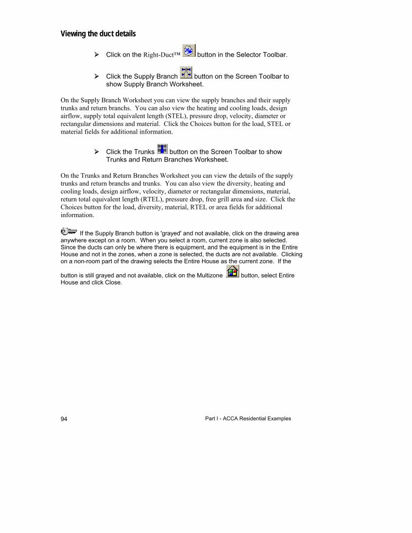
Part I - ACCA Residential Examples 94
Viewing the duct details
Click on the Right-Duct™ button in the Selector Toolbar.
Click the Supply Branch button on the Screen Toolbar to show Supply Branch Worksheet.
On the Supply Branch Worksheet you can view the supply branches and their supply trunks and return branchs. You can also view the heating and cooling loads, design airflow, supply total equivalent length (STEL), pressure drop, velocity, diameter or rectangular dimensions and material. Click the Choices button for the load, STEL or material fields for additional information.
Click the Trunks button on the Screen Toolbar to show Trunks and Return Branches Worksheet.
On the Trunks and Return Branches Worksheet you can view the details of the supply trunks and return branchs and trunks. You can also view the diversity, heating and cooling loads, design airflow, velocity, diameter or rectangular dimensions, material, return total equivalent length (RTEL), pressure drop, free grill area and size. Click the Choices button for the load, diversity, material, RTEL or area fields for additional information.
If the Supply Branch button is 'grayed' and not available, click on the drawing area anywhere except on a room. When you select a room, current zone is also selected. Since the ducts can only be where there is equipment, and the equipment is in the Entire House and not in the zones, when a zone is selected, the ducts are not available. Clicking on a non-room part of the drawing selects the Entire House as the current zone. If the
button is still grayed and not available, click on the Multizone button, select Entire House and click Close.
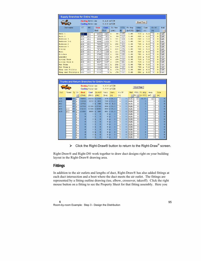
5 Room-by-room Example: Step 3 - Design the Distribution
95
Click the Right-Draw® button to return to the Right-Draw® screen.
Right-Draw® and Right-D® work together to draw duct designs right on your building layout in the Right-Draw® drawing area.
Fittings
In addition to the air outlets and lengths of duct, Right-Draw® has also added fittings at each duct intersection and a boot where the duct meets the air outlet. The fittings are represented by a fitting outline drawing (tee, elbow, crossover, takeoff). Click the right mouse button on a fitting to see the Property Sheet for that fitting assembly. Here you

Part I - ACCA Residential Examples 96
can change/add fittings to the assembly or in the case of vertical ducts, enter the vertical length of the duct. You can also define the risers here.
Risers
Right-Draw® will add risers where appropriate. If you select an x-axis or y-axis plenum design, the riser will leave the unit and supply or return the air from the other floors. If you select a one-level design, the riser is associated with the trunks and branches.
Supply risers are represented as a small square with an ‘X’. Return risers are indicated as a small square with a ‘/’ (half an ‘X’).
See Chapters 7, 8, and 24 for detailed duct design discussions.
No air outlet rooms
You are now able to have rooms with no registers like hallways, foyers stairwells, walk-in closets, etc. It is best to design no air outlet rooms before you draw the ducts. All you need to do is delete the air outlets you do not need. The loads will be reassigned to adjacent conditioned rooms and ducts will be sized accordingly. If you have the Duct notations layer checked in the Sheets & Layers Tree, the airflow will change on the screen. The Right-J® Worksheet displays where those loads were redistributed on the Redistribution line, above line 14; values are negative where air outlets have been removed and positive in the rooms that have been adjusted. The adjustment is also on the standard reports.
Click on the air outlet you want to remove.
Press the <Delete> key to delete the air outlet.
A pop-up box will appear asking if you are certain you want to delete the air outlet. Click Yes.
Step 3b - Distribution With Radiant Panels
Add a radiant panel
To demonstrate how a radiant panel would be added, we will add a radiant floor to the Living Room.
Select the First Floor sheet only.
Hide the Ducts layer for clarity.
The linked image cannot be displayed. The file may have been moved, renamed, or deleted. Verify that the link points to the correct file and location.

5 Room-by-room Example: Step 3 - Design the Distribution
97
Select the Radiant Panel shape from the HVAC Shapes™ Toolbox.
Click anywhere in the Living Room; the panel will fill the room. The shaded area indicates the location of the radiant panel.
Click on the entry points and drag them to the lower left of the Living Room.
Select the Radiant heating manifold shape from the HVAC Shapes™ Toolbox and add the manifold. Right-Draw® will add tails to connect the manifold to the entry points or you can add them manually.
Right-Radiant® adds a Radiant floor layer and designs the radiant panel.
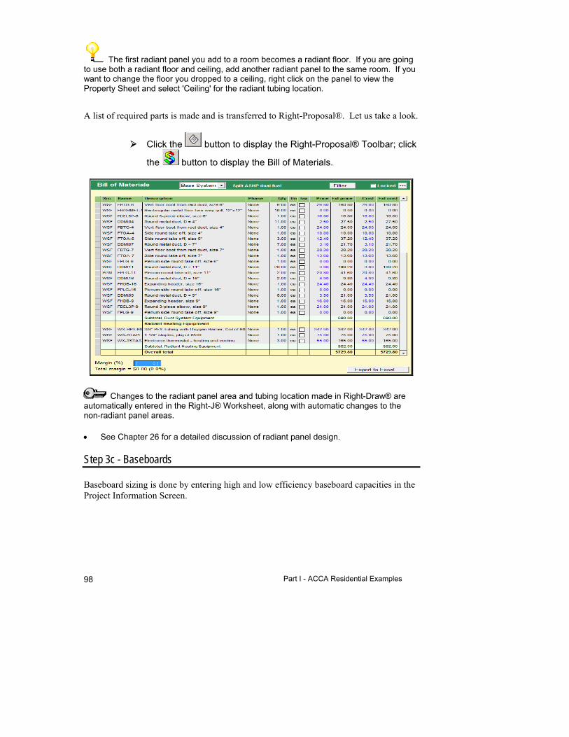
Part I - ACCA Residential Examples 98
The first radiant panel you add to a room becomes a radiant floor. If you are going to use both a radiant floor and ceiling, add another radiant panel to the same room. If you want to change the floor you dropped to a ceiling, right click on the panel to view the Property Sheet and select 'Ceiling' for the radiant tubing location.
A list of required parts is made and is transferred to Right-Proposal®. Let us take a look.
Click the button to display the Right-Proposal® Toolbar; click
the button to display the Bill of Materials.
Changes to the radiant panel area and tubing location made in Right-Draw® are automatically entered in the Right-J® Worksheet, along with automatic changes to the non-radiant panel areas.
See Chapter 26 for a detailed discussion of radiant panel design.
Step 3c - Baseboards
Baseboard sizing is done by entering high and low efficiency baseboard capacities in the Project Information Screen.

5 Room-by-room Example: Step 3 - Design the Distribution
99
Click the Project Information button in the Project Toolbar to display the Project Information Screen.
To view the Baseboard Data, use the scroll bar on the right to scroll to the bottom of the Project Information Screen.
If you enter the baseboard capacities here, RSU will calculate the feet of baseboard required for each room based on the room load and display the baseboard data on the last line of the Right-J® Worksheet (when there is no baseboard data, the last line on the Worksheet displays the air required).
Part I - ACCA Residential Examples 100
Things to Remember
Distribution is accomplished with air via ducts, radiant panels or hydronic baseboards.
Set the fan AVF and static pressure before laying out the duct system.
Right-Draw® will design a duct system automatically; just place your air outlets and choose the duct layout in the Property Sheet for the unit.
The duct information in Right-Draw® is used by Right-D® to size the ducts.
Right-Draw® will design radiant panel systems and transfer a list of required parts to Right-Proposal®.
Set the baseboard ratings in the Project Information Screen. Right-J® will calculate the feet of hydronic baseboard for each room and display the data on the last line of the Right-J® Worksheet (NOTE: If no baseboard values have been entered on the Project Information Screen, then the last line on the Worksheet displays the air required).
In Right-Suite Universal 2018 you can have rooms, like hallways and closets that do not have air outlets.
6
Room-by-room Example: Step 4 - Document the Project
Step 4a - Complete the Job Quotation ........................ 102
Step 4b - Save the Project .......................................... 102
Step 4c - Generate Reports ........................................ 102
Things to Remember ................................................... 104
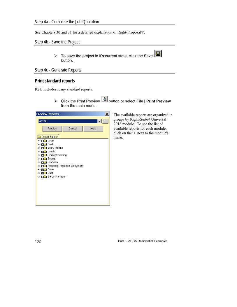
Part I - ACCA Residential Examples 102
Step 4a - Complete the Job Quotation
See Chapters 30 and 31 for a detailed explanation of Right-Proposal®.
Step 4b - Save the Project
To save the project in it’s current state, click the Save button.
Step 4c - Generate Reports
Print standard reports
RSU includes many standard reports.
Click the Print Preview button or select File | Print Preview from the main menu.
The available reports are organized in groups by Right-Suite Universal 2018 module. To see the list of available reports for each module, click on the '+' next to the module's name.
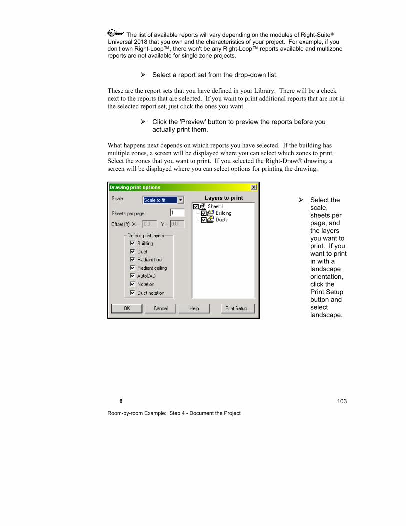
6 Room-by-room Example: Step 4 - Document the Project
103
The list of available reports will vary depending on the modules of Right-Suite Universal 2018 that you own and the characteristics of your project. For example, if you don't own Right-Loop™, there won't be any Right-Loop™ reports available and multizone reports are not available for single zone projects.
Select a report set from the drop-down list.
These are the report sets that you have defined in your Library. There will be a check next to the reports that are selected. If you want to print additional reports that are not in the selected report set, just click the ones you want.
Click the 'Preview' button to preview the reports before you actually print them.
What happens next depends on which reports you have selected. If the building has multiple zones, a screen will be displayed where you can select which zones to print. Select the zones that you want to print. If you selected the Right-Draw® drawing, a screen will be displayed where you can select options for printing the drawing.
Select the scale, sheets per page, and the layers you want to print. If you want to print in with a landscape orientation, click the Print Setup button and select landscape.

Part I - ACCA Residential Examples 104
The reports will be displayed on screen. You can zoom in and page through them for review.
You may want to print without previewing the reports. To do this just click on the Print button or select File | Print from the main menu. Previewing allows you to verify that the information is correct before printing. You can also zoom in or out and view multiple pages at once if you preview the reports.
Things to Remember
RSU provides a library of standard reports that comply with ACCA requirements.
7
Flex Duct System Using Right-Draw
The example in this chapter will demonstrate how to draw flex duct systems with Right-Draw®.
Summary of Steps ...................................................... 106
Step 1 - Enter the Building Description ........................ 106
Step 2 - Enter Equipment AVF & Static Pressure........ 106
Step 3 - Select the Flex Duct Material ......................... 108
Step 4 - Position the Air Outlets .................................. 110
Step 5 - Select the Duct System ................................. 111
Step 6 - Adjust the Flex Duct Routing ......................... 111
Things to Remember ................................................... 113
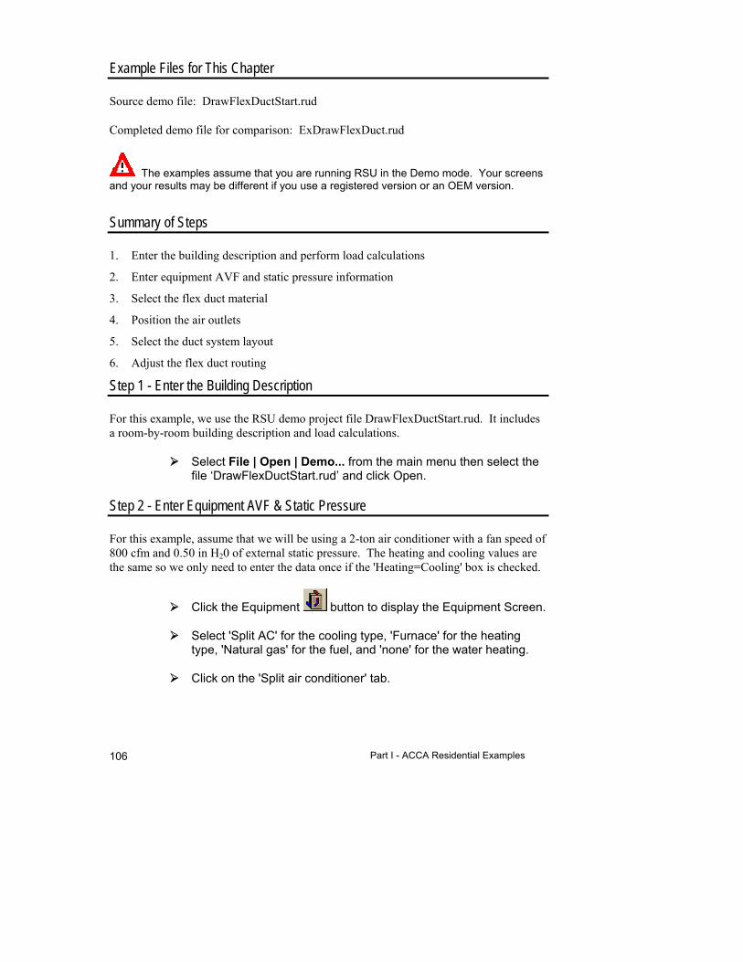
Part I - ACCA Residential Examples 106
Example Files for This Chapter
Source demo file: DrawFlexDuctStart.rud
Completed demo file for comparison: ExDrawFlexDuct.rud
The examples assume that you are running RSU in the Demo mode. Your screens and your results may be different if you use a registered version or an OEM version.
Summary of Steps
1. Enter the building description and perform load calculations
2. Enter equipment AVF and static pressure information
3. Select the flex duct material
4. Position the air outlets
5. Select the duct system layout
6. Adjust the flex duct routing
Step 1 - Enter the Building Description
For this example, we use the RSU demo project file DrawFlexDuctStart.rud. It includes a room-by-room building description and load calculations.
Select File | Open | Demo... from the main menu then select the file ‘DrawFlexDuctStart.rud’ and click Open.
Step 2 - Enter Equipment AVF & Static Pressure
For this example, assume that we will be using a 2-ton air conditioner with a fan speed of 800 cfm and 0.50 in H20 of external static pressure. The heating and cooling values are the same so we only need to enter the data once if the 'Heating=Cooling' box is checked.
Click the Equipment button to display the Equipment Screen.
Select 'Split AC' for the cooling type, 'Furnace' for the heating type, 'Natural gas' for the fuel, and 'none' for the water heating.
Click on the 'Split air conditioner' tab.
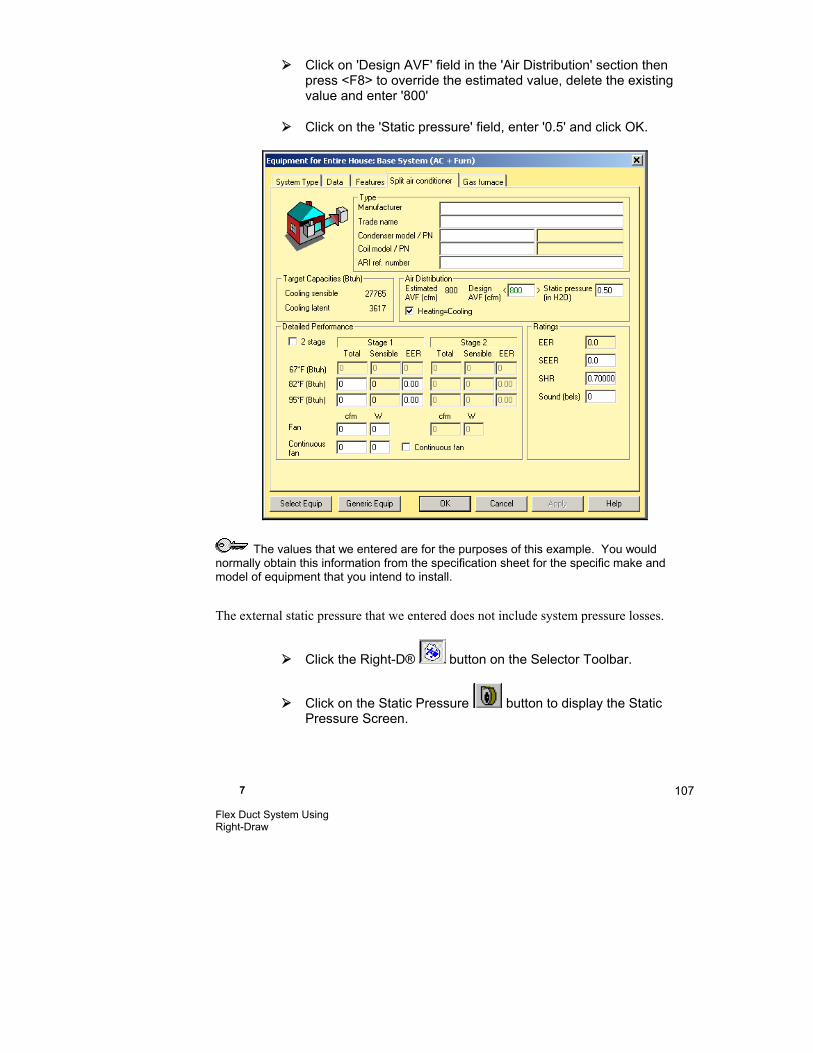
7 Flex Duct System Using Right-Draw
107
Click on 'Design AVF' field in the 'Air Distribution' section then press <F8> to override the estimated value, delete the existing value and enter '800'
Click on the 'Static pressure' field, enter '0.5' and click OK.
The values that we entered are for the purposes of this example. You would normally obtain this information from the specification sheet for the specific make and model of equipment that you intend to install.
The external static pressure that we entered does not include system pressure losses.
Click the Right-D® button on the Selector Toolbar.
Click on the Static Pressure button to display the Static Pressure Screen.
Part I - ACCA Residential Examples 108
Notice that the equipment external static pressure data has been transferred from the Equipment Screen to the 'External static pressure' fields. Static pressure losses due to various duct system components have been subtracted from the external static pressure that we entered in the Equipment Screen to calculate the available static pressure for our duct system. These losses were entered in the demo file; they are appropriate for this example so we will not be changing them.
Step 3 - Select the Flex Duct Material
To draw flex ducts, the duct material must be either round flexible metal (MetlFlx) or round flexible vinyl (VinlFlx). We want to use round flexible vinyl coated helix ducts for all supply branches and trunks. We also want to choose our junction box.
Open the Duct Preferences Screen by clicking on the Duct
Preferences button.
Select the supply branch ‘Duct material’ Choices button to view the available duct material choices. Choose 'VinlFlx' then click OK.
Select the supply trunk ‘Duct material’ Choices button. Choose 'VinlFlx' then click OK.
Scroll to the bottom of the screen. In the 'Trunk Junction Fittings' section click on the 'Return Rect branch' choices button. Select the return trunk junctions tab ('Ret TR junctions') then 10B and click OK.
All other values are appropriate for this example.
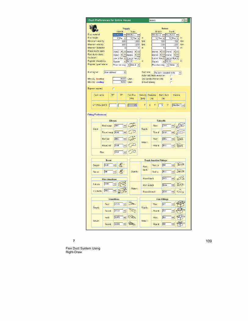
7 Flex Duct System Using Right-Draw
109
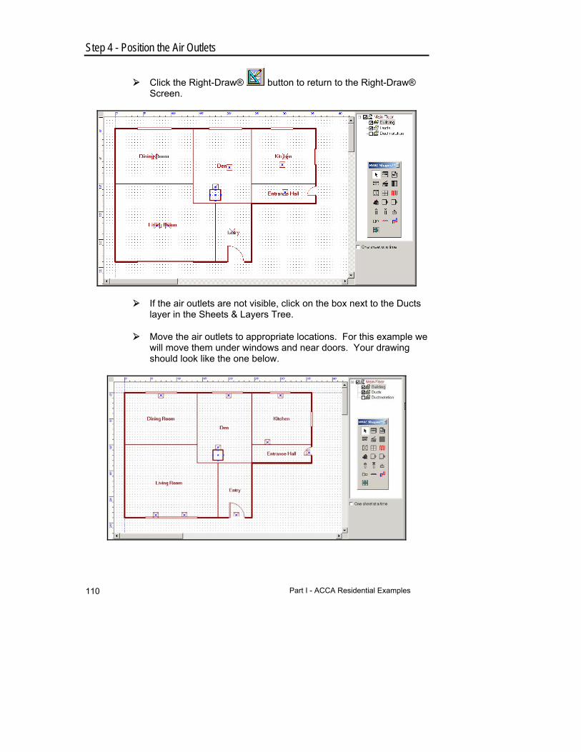
Part I - ACCA Residential Examples 110
Step 4 - Position the Air Outlets
Click the Right-Draw® button to return to the Right-Draw® Screen.
If the air outlets are not visible, click on the box next to the Ducts layer in the Sheets & Layers Tree.
Move the air outlets to appropriate locations. For this example we will move them under windows and near doors. Your drawing should look like the one below.

7 Flex Duct System Using Right-Draw
111
Step 5 - Select the Duct System Layout
The duct system for this example will have supply flex branches and trunks.
Click on the unit then right click to bring up the Property Sheet. Select 'X-axis plenum' for the duct layout and close the Property Sheet
A preliminary duct system will be drawn. The shortest possible route from the trunk to the air outlet has been used. Fittings and junction boxes have been added where needed. Notice that the flex ducts are represented by a squiggly line whereas the return duct is a dashed straight line (supply ducts are solid lines, return ducts are dashed).
Step 6 - Adjust the Flex Duct Routing
For this example we will reroute the supply branches so that they can be secured to the floor joists at inside walls. We will start with the supply branch in the Entry.
Select the unit and right click. Choose 'User defined' for the duct layout. This allows you to make modifications to the Right-Draw® duct layout.
Click on the branch duct in the Entry to select it.
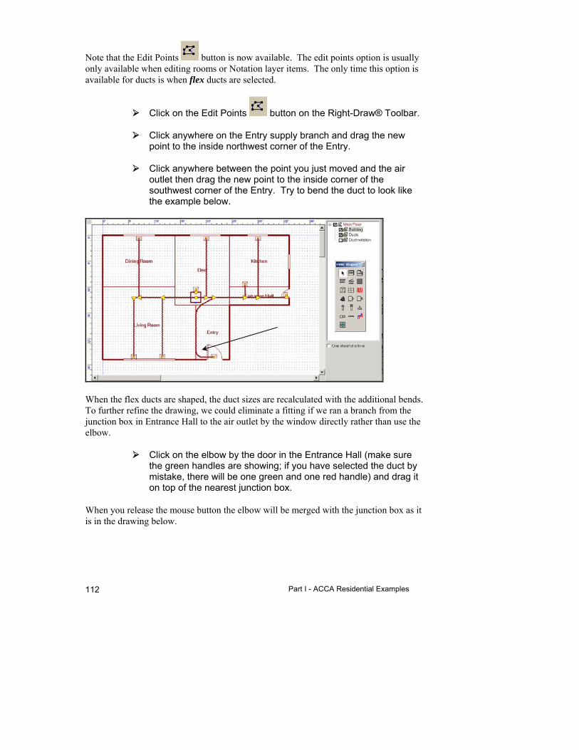
Part I - ACCA Residential Examples 112
Note that the Edit Points button is now available. The edit points option is usually only available when editing rooms or Notation layer items. The only time this option is available for ducts is when flex ducts are selected.
Click on the Edit Points button on the Right-Draw® Toolbar.
Click anywhere on the Entry supply branch and drag the new point to the inside northwest corner of the Entry.
Click anywhere between the point you just moved and the air outlet then drag the new point to the inside corner of the southwest corner of the Entry. Try to bend the duct to look like the example below.
When the flex ducts are shaped, the duct sizes are recalculated with the additional bends. To further refine the drawing, we could eliminate a fitting if we ran a branch from the junction box in Entrance Hall to the air outlet by the window directly rather than use the elbow.
Click on the elbow by the door in the Entrance Hall (make sure the green handles are showing; if you have selected the duct by mistake, there will be one green and one red handle) and drag it on top of the nearest junction box.
When you release the mouse button the elbow will be merged with the junction box as it is in the drawing below.
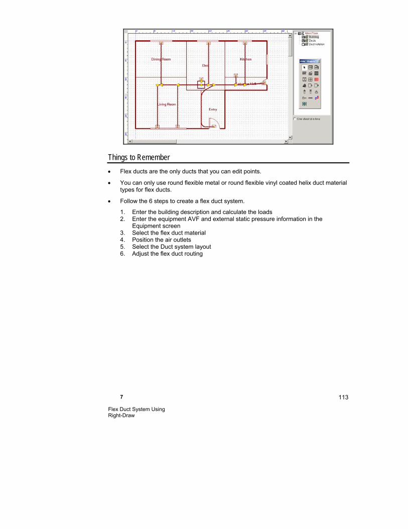
7 Flex Duct System Using Right-Draw
113
Things to Remember
Flex ducts are the only ducts that you can edit points.
You can only use round flexible metal or round flexible vinyl coated helix duct material types for flex ducts.
Follow the 6 steps to create a flex duct system.
1. Enter the building description and calculate the loads 2. Enter the equipment AVF and external static pressure information in the
Equipment screen 3. Select the flex duct material 4. Position the air outlets 5. Select the Duct system layout 6. Adjust the flex duct routing

8
Multiple Level Building With All Trunks on One Level
This chapter explains how to use Right-Draw® to design a duct system for a multiple level house, with all the trunks on one level. Risers will be used to connect the trunks in the basement to the upper floors.
Summary of Steps ....................................................... 116
Step 1 - Enter the Building Description ........................ 116
Step 2 - Enter Equipment AVF & Static Pressure Information ............................................................. 117
Step 3 - Relocate the Air Outlets ................................. 117
Step 4 - Select a One Level Trunk Duct System Layout .................................................................... 119
Step 5 - Relocate the Risers ....................................... 120
Things to Remember ................................................... 122
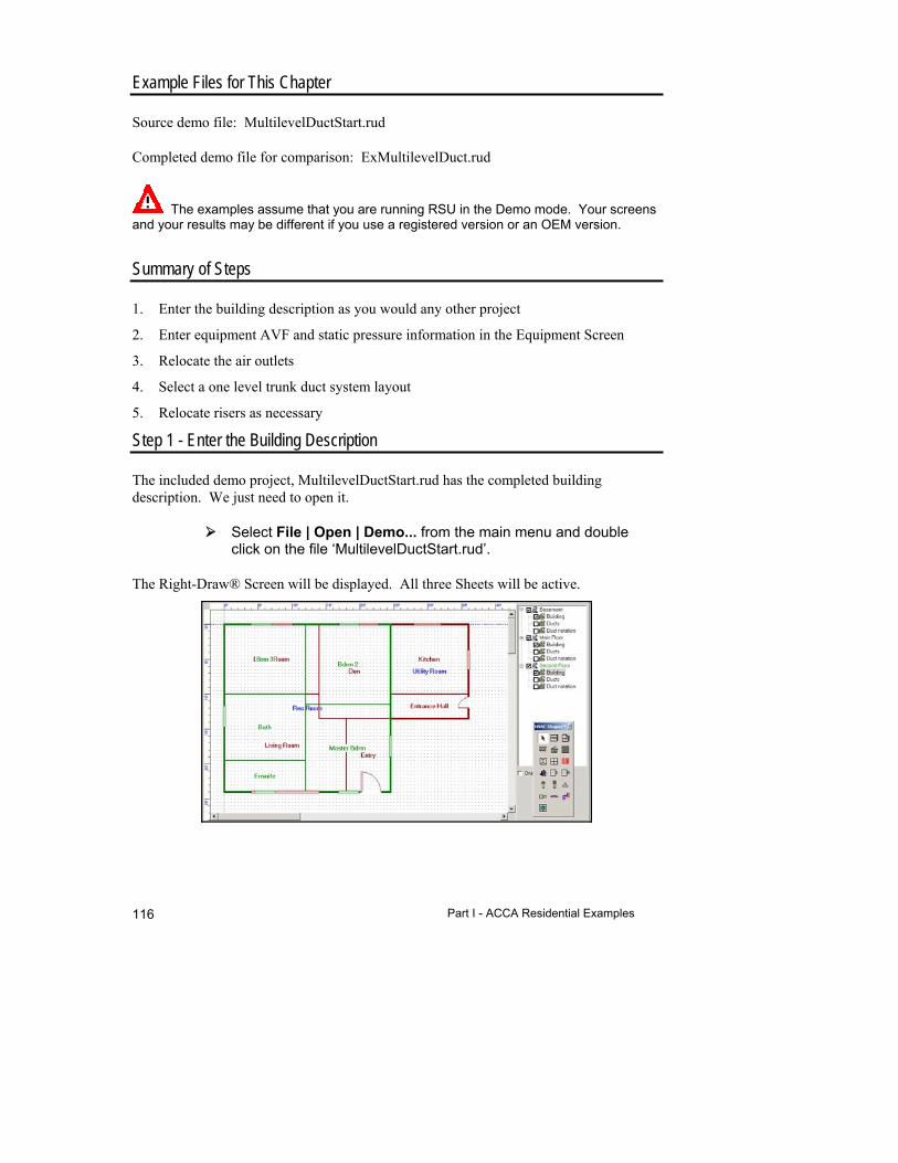
Part I - ACCA Residential Examples 116
Example Files for This Chapter
Source demo file: MultilevelDuctStart.rud
Completed demo file for comparison: ExMultilevelDuct.rud
The examples assume that you are running RSU in the Demo mode. Your screens and your results may be different if you use a registered version or an OEM version.
Summary of Steps
1. Enter the building description as you would any other project
2. Enter equipment AVF and static pressure information in the Equipment Screen
3. Relocate the air outlets
4. Select a one level trunk duct system layout
5. Relocate risers as necessary
Step 1 - Enter the Building Description
The included demo project, MultilevelDuctStart.rud has the completed building description. We just need to open it.
Select File | Open | Demo... from the main menu and double click on the file ‘MultilevelDuctStart.rud’.
The Right-Draw® Screen will be displayed. All three Sheets will be active.
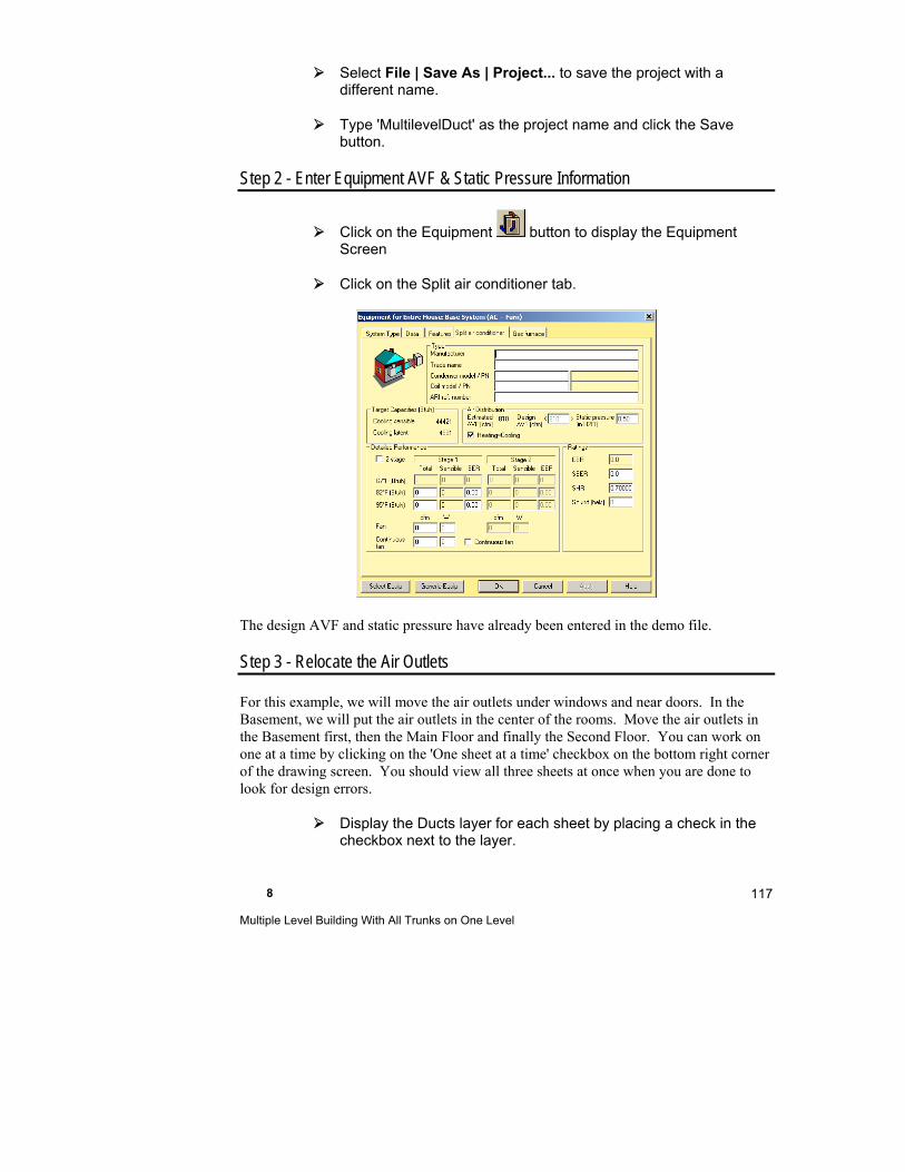
8 Multiple Level Building With All Trunks on One Level
117
Select File | Save As | Project... to save the project with a different name.
Type 'MultilevelDuct' as the project name and click the Save button.
Step 2 - Enter Equipment AVF & Static Pressure Information
Click on the Equipment button to display the Equipment Screen
Click on the Split air conditioner tab.
The design AVF and static pressure have already been entered in the demo file.
Step 3 - Relocate the Air Outlets
For this example, we will move the air outlets under windows and near doors. In the Basement, we will put the air outlets in the center of the rooms. Move the air outlets in the Basement first, then the Main Floor and finally the Second Floor. You can work on one at a time by clicking on the 'One sheet at a time' checkbox on the bottom right corner of the drawing screen. You should view all three sheets at once when you are done to look for design errors.
Display the Ducts layer for each sheet by placing a check in the checkbox next to the layer.

Part I - ACCA Residential Examples 118
Move the unit and air outlets so that your drawing looks like the drawings below.
Basement
Main Floor
Second Floor
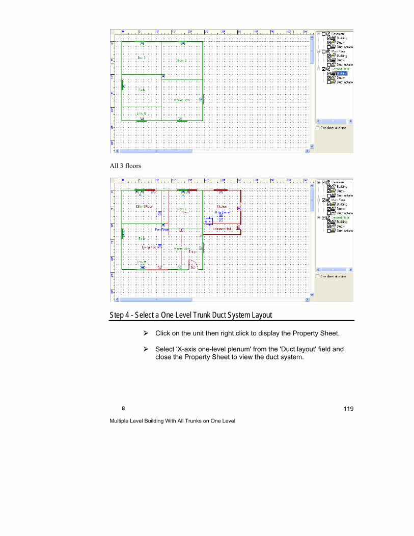
8 Multiple Level Building With All Trunks on One Level
119
All 3 floors
Step 4 - Select a One Level Trunk Duct System Layout
Click on the unit then right click to display the Property Sheet.
Select 'X-axis one-level plenum' from the 'Duct layout' field and close the Property Sheet to view the duct system.
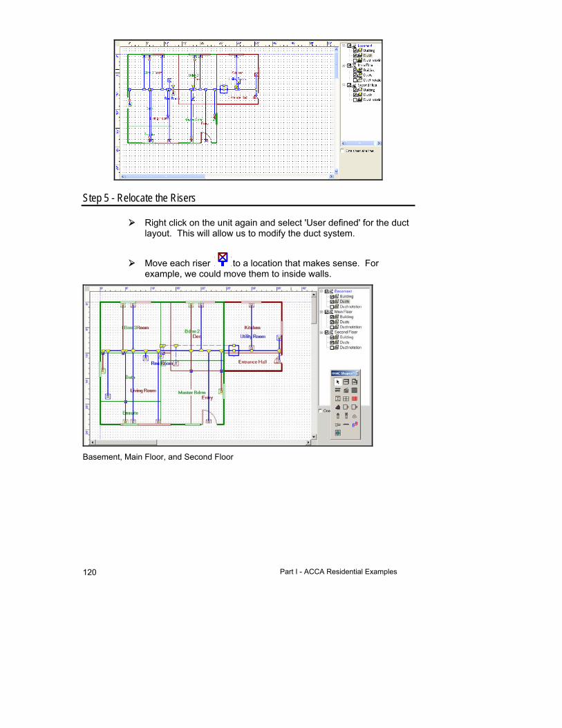
Part I - ACCA Residential Examples 120
Step 5 - Relocate the Risers
Right click on the unit again and select 'User defined' for the duct layout. This will allow us to modify the duct system.
Move each riser to a location that makes sense. For example, we could move them to inside walls.
Basement, Main Floor, and Second Floor
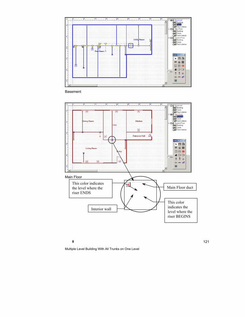
8 Multiple Level Building With All Trunks on One Level
121
Basement
Main Floor
The linked image cannot be displayed. The file may have been moved, renamed, or deleted. Verify that the link points to the correct file and location.
This color indicates the level where the riser ENDS
This color indicates the level where the riser BEGINS
Interior wall
Main Floor duct
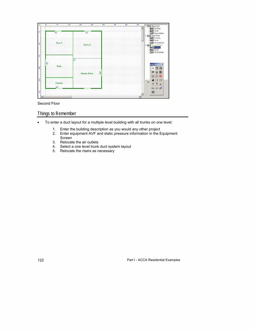
Part I - ACCA Residential Examples 122
Second Floor
Things to Remember
To enter a duct layout for a multiple level building with all trunks on one level:
1. Enter the building description as you would any other project 2. Enter equipment AVF and static pressure information in the Equipment
Screen 3. Relocate the air outlets 4. Select a one level trunk duct system layout 5. Relocate the risers as necessary

9
Multizone Houses
This chapter explains how to use RSU to design multizone HVAC systems.
Summary of Steps ............................................................. 124
Multizone Houses .............................................................. 124
Balance Loads Among Zones ........................................... 125
Diversity for Multizone Projects ......................................... 125
Multizone House Example ................................................. 126
Things to Remember ......................................................... 128
Part I - ACCA Residential Examples 124
Example Files for This Chapter
Source and completed demo file: MZone.rud
The examples assume that you are running RSU in the Demo mode. Your screens and your results may be different if you use a registered version or an OEM version.
Summary of Steps
1. Enter the building description as though the entire house is a single zone
2. In the Multizone Tree, create zones and assign each room to a zone
3. Define HVAC equipment, either multiple units or a single, central unit with zone dampers
Multizone Houses
To improve control of comfort conditions or reduce operating energy costs, houses are frequently divided into HVAC zones, each with its own thermostat. Zoning may also make it possible to use smaller HVAC systems by considering load diversity, or the fact that loads may not peak at the same time in each zone.
Typical residential zoning schemes place the living spaces and bedrooms in separate zones or create separate zones for each floor in a multi-story house.
What is a room?
In RSU, a room represents any building space for which you want to calculate loads. Rooms in your project generally correspond to rooms in the actual house design, but it is common to combine closets and similar minor areas to adjoining spaces. RSU will calculate loads, airflow and baseboard requirements for each room. If you only need a quick block load, you can treat the house as one large room.
What is a zone?
In RSU, a zone is a group of one or more rooms that have the same indoor conditions, that is, a single thermostat controls the heating and cooling equipment for one or more rooms. Each room in a zone uses the same heating and cooling thermostat setpoints.
9 Multizone Houses
125
Select Zones & Rooms in the Right-J® Worksheet
The Right-J® Worksheet displays building description inputs and load calculation results for each room you define. When you create zones and assign rooms with the Multizone Tree, the Right-J® Worksheet automatically groups the rooms together by zone and enables the prev zone and next zone buttons between the room selection buttons at the top of the Worksheet. You use the room selection buttons as in single zone cases, but the rooms are arranged by zone.
To view the data for the Entire House in the Right-J® Worksheet, click the prev zone button until the Entire House heading appears and the prev zone button is grayed out. Now, the zone control buttons allow you to move between zones (NOTE: The first room in each zone is also visible).
For each zone, display the rooms within it by clicking on the room selection buttons.
You can also use the Multizone Tree to select a zone for display in the Right-J® Worksheet. Highlight a zone or room name in the Multizone Tree and it becomes visible in the Worksheet. Notice that the Multizone Tree can be left open to allow quick project navigation.
Balance Loads Among Zones
After you have completed the load calculations and zone assignments, you should consider options for balancing loads among zones. Use the Multizone Tree to reassign rooms to zones and view the results in the Right-J® Worksheet or the Load Meter.
Use the Multizone Tree to make “what-if” evaluations on your zoning scheme. You can quickly move rooms from one zone to another and instantly see the effects on loads, ducts and HVAC equipment..
Diversity for Multizone Projects
When you are evaluating a multizone project, you must consider diversity with respect to cooling loads.
Part I - ACCA Residential Examples 126
What is diversity?
Diversity is the term used to describe the fact that the rooms in a house experience their peak cooling load at different times of the day and thus the entire house peak load may be less than the sum of the room peak loads. For example, a room with large east-facing windows will probably have a cooling load peak during the morning. A room with west-facing windows has little solar heat gain during the morning and a large gain during the afternoon when the east side of the building is in shade. Load diversity simply means that the total load for the two rooms at any particular time is less than the two peak loads added together
Manual J 8 recognizes diversity in the Average Load Procedure, which uses multi-hour averages for many calculation factors. For zones that do not benefit from diversity, Manual J 8 provides the Peak Load Procedure. The details of these two approaches are discussed in Chapter 1 of Manual J 8.
Adequate Exposure Diversity (AED) is determined according to Manual J Eighth Edition by calculating the glazing (fenestration) cooling loads between 8AM and 8PM. If the highest load during this period exceeds the average fenestration gain (AFG) by 30%, the AED Excursion (the amount over 30% over the AFG) is added to the zone or house load. You can see the results of the hourly fenestration loads and AED Excursion on the AED tab of the Load Meter.
In this example the peak fenestration gain occurs at around 4PM. However, since the peak fenestration gain is only 23.4% over the average fenestration gain, the house is considered to have AED. Therefore, the AED Excursion is 0, meaning that the average load can be used.
If there was more glass facing one direction, the peak fenestration gain might go over around 10,100 Btuh (30% over the average), the AED Excursion would be added to the house load.
Multizone House Example
The house shown below is a typical candidate for zoning. We will use Right-Suite Universal 2018 to evaluate three multizone approaches.
The linked image cannot be displayed. The file may have been moved, renamed, or deleted. Verify that the link points to the correct file and location.
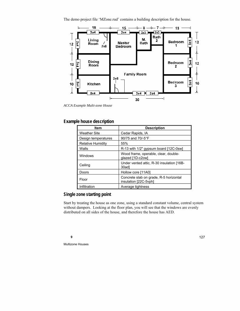
9 Multizone Houses
127
The demo project file ‘MZone.rud’ contains a building description for the house.
ACCA Example Multi-zone House
Example house description Item Description
Weather Site Cedar Rapids, IA
Design temperatures 90/75 and 70/-5°F
Relative Humidity 55%
Walls R-13 with 1/2" gypsum board [12C-0sw]
Windows Wood frame, operable, clear, double-glazed [1D-c2ow]
Ceiling Under vented attic, R-30 insulation [16B-30ad]
Doors Hollow core [11A0]
Floor Concrete slab on grade, R-5 horizontal insulation [22C-5vph]
Infiltration Average tightness
Single zone starting point
Start by treating the house as one zone, using a standard constant volume, central system without dampers. Looking at the floor plan, you will see that the windows are evenly distributed on all sides of the house, and therefore the house has AED.

Part I - ACCA Residential Examples 128
Central VAV system
Consider what happens if a variable air volume system is used instead of a constant volume system to split the house into two zones.
Diversity still applies as far as the HVAC equipment is concerned, because all exposures are of similar importance. The Entire House has AED and the total load on the equipment is calculated using the Average Load Procedure (ALP) method.
On the other hand, the two zones each have a primary orientation, so they do not have AED. RSR calculates the zone loads and air requirements by adding the AED Excursion to the ALP load. Right-D® will size the ducts using the larger peak load values. Because the entire house still has AED, the equipment and the main supply duct will be sized using the Average Load Procedure loads.
The latent load is not affected; it is the same as the latent load for the single zone case.
Equipment in the zones
The figure to the right shows the use of two units arranged to cool living or sleeping areas. This approach provides positive control by having separate thermostats and separate units but requires more total capacity than either the single zone approach or the central zone system.
Because the two units must each provide the peak for their own zone, the combined capacity is the sum of the two peaks, which is greater than the other approaches.
Add air handlers for each zone in the Multizone Tree Screen to evaluate this arrangement.
Things to Remember
To create a multizone design, first enter all building description and project information as you would for a single-zone design. Then assign each room to a zone, using the Multizone Tree.
The Multizone Tree is used to quickly create and delete zones and rooms, assign rooms to zones, and move rooms among zones.
Use the Multizone Tree to do “what-if” cases to optimize load balance.

9 Multizone Houses
129
For multizone projects, the Zone Information, Infiltration, Equipment, and other screens provide specific information for the currently selected zone.

Part II - CSA Residential Examples

10
One Room Example: Step 1-Describe the Building
This chapter shows you how to use Right-Draw® as a fast and efficient way to enter a building description into RSU. Right-Draw® will also help you layout your equipment, ducts, registers and radiant panels.
The first example will be a one-room building. This simple building will teach you how to use the HVAC Shapes™.
One-Room Example Description ................................. 134
Step 1a - Start a New Project From a Template with Preset Values ........................................................ 135
Step 1b - Add Rooms, Doors, & Windows ................... 135
Step 1c - Add Vaulted Ceilings & Special Floors if Needed .................................................................. 143
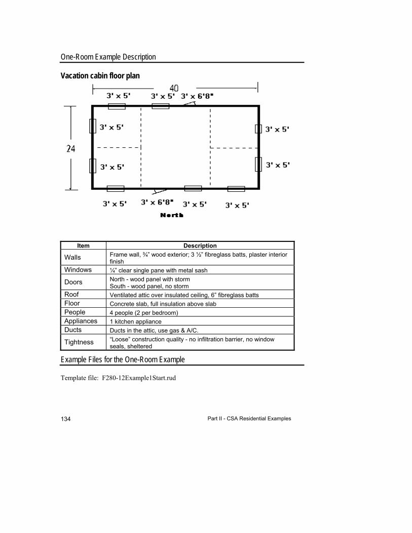
Part II - CSA Residential Examples 134
One-Room Example Description
Vacation cabin floor plan
Item Description
Walls Frame wall, ¾” wood exterior; 3 ½” fibreglass batts, plaster interior finish
Windows ¼” clear single pane with metal sash
Doors North - wood panel with storm South - wood panel, no storm
Roof Ventilated attic over insulated ceiling, 6” fibreglass batts Floor Concrete slab, full insulation above slab People 4 people (2 per bedroom) Appliances 1 kitchen appliance Ducts Ducts in the attic, use gas & A/C.
Tightness “Loose” construction quality - no infiltration barrier, no window seals, sheltered
Example Files for the One-Room Example
Template file: F280-12Example1Start.rud

10 One Room Example: Step 1-Describe the Building
135
Completed demo file for comparison: ExF280-12Example1.rud
The examples will use the Demo mode of RSU. Your screens and your results may be different when you use the full version or an OEM version.
Step 1a - Start a New Project From a Template with Preset Values
Start RSU.
Start a new project by selecting File | Open | Demo from the main menu. Select ‘F280-12Example1Start.rud’ from the list of demo projects and click Open.
Select Options | Load calculation method | CSA / CAN F280-12 [Right-F280™] from the menu.
Click on the button to display the drawing.
We are now looking at an empty drawing screen. Because we started with a template, the design conditions and infiltration information are already entered and we can begin by drawing the building.
Step 1b - Add Rooms, Doors, & Windows
Draw a room
Select the Room shape from the HVAC Shapes™ Toolbox.
Notice that the mouse cursor changes from an arrow to a cross hair, indicating that you are ready to add an object to the drawing area.
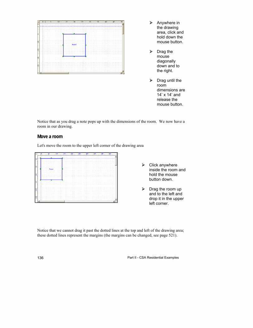
Part II - CSA Residential Examples 136
Anywhere in the drawing area, click and hold down the mouse button.
Drag the mouse diagonally down and to the right.
Drag until the room dimensions are 14’ x 14’ and release the mouse button.
Notice that as you drag a note pops up with the dimensions of the room. We now have a room in our drawing.
Move a room
Let's move the room to the upper left corner of the drawing area
Click anywhere inside the room and hold the mouse button down.
Drag the room up and to the left and drop it in the upper left corner.
Notice that we cannot drag it past the dotted lines at the top and left of the drawing area; these dotted lines represent the margins (the margins can be changed, see page 521).
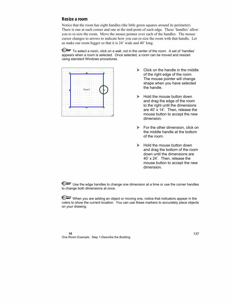
10 One Room Example: Step 1-Describe the Building
137
Resize a room Notice that the room has eight handles (the little green squares around its perimeter). There is one at each corner and one at the mid-point of each edge. These ‘handles’ allow you to re-size the room. Move the mouse pointer over each of the handles. The mouse cursor changes to arrows to indicate how you can re-size the room with that handle. Let us make our room bigger so that it is 24’ wide and 40’ long.
To select a room, click on a wall, not in the center of the room. A set of ‘handles’ appears when a room is selected. Once selected, a room can be moved and resized using standard Windows procedures.
Click on the handle in the middle of the right edge of the room. The mouse pointer will change shape when you have selected the handle.
Hold the mouse button down and drag the edge of the room to the right until the dimensions are 40’ x 14’. Then, release the mouse button to accept the new dimension.
For the other dimension, click on the middle handle at the bottom of the room.
Hold the mouse button down and drag the bottom of the room down until the dimensions are 40’ x 24’. Then, release the mouse button to accept the new dimension.
Use the edge handles to change one dimension at a time or use the corner handles to change both dimensions at once.
When you are adding an object or moving one, notice that indicators appear in the rulers to show the current location. You can use these markers to accurately place objects on your drawing.
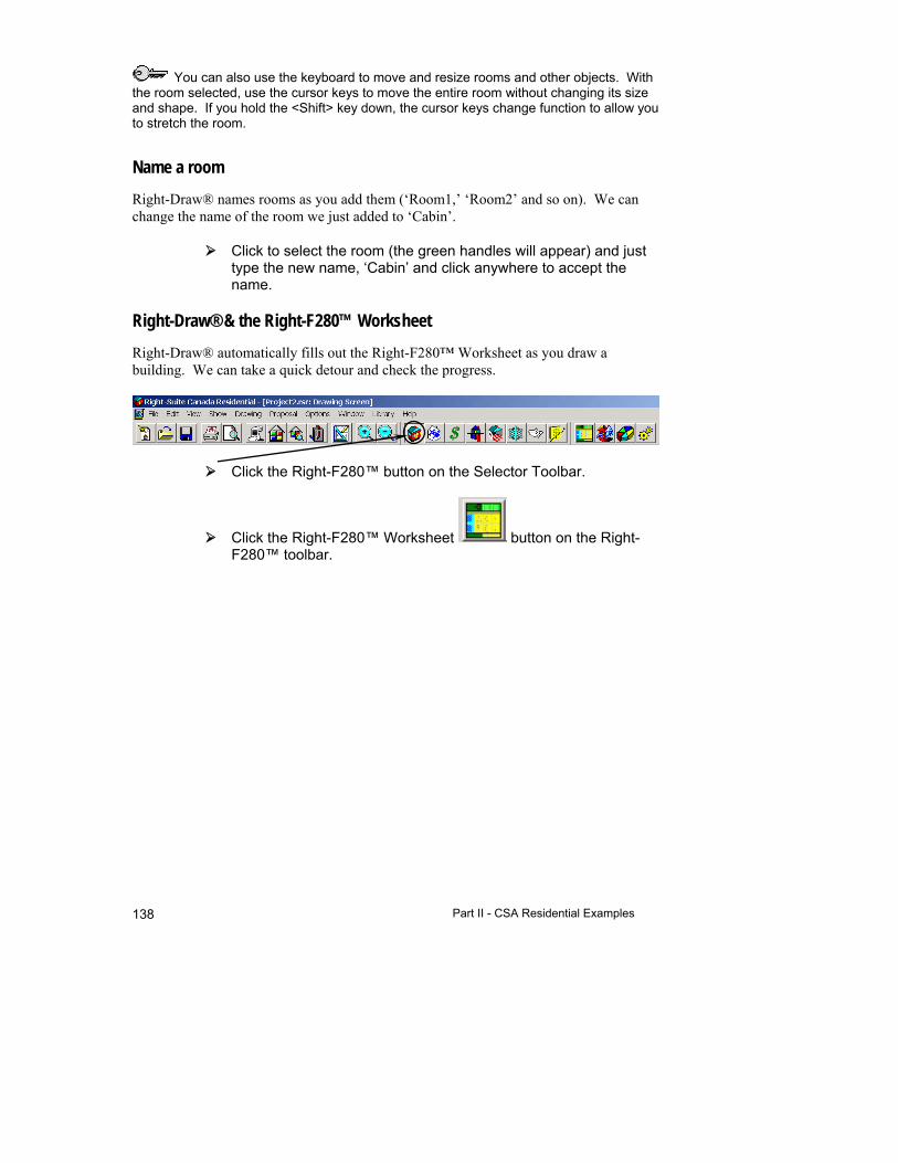
Part II - CSA Residential Examples 138
You can also use the keyboard to move and resize rooms and other objects. With the room selected, use the cursor keys to move the entire room without changing its size and shape. If you hold the <Shift> key down, the cursor keys change function to allow you to stretch the room.
Name a room
Right-Draw® names rooms as you add them (‘Room1,’ ‘Room2’ and so on). We can change the name of the room we just added to ‘Cabin’.
Click to select the room (the green handles will appear) and just type the new name, ‘Cabin’ and click anywhere to accept the name.
Right-Draw® & the Right-F280™ Worksheet
Right-Draw® automatically fills out the Right-F280™ Worksheet as you draw a building. We can take a quick detour and check the progress.
Click the Right-F280™ button on the Selector Toolbar.
Click the Right-F280™ Worksheet button on the Right-F280™ toolbar.
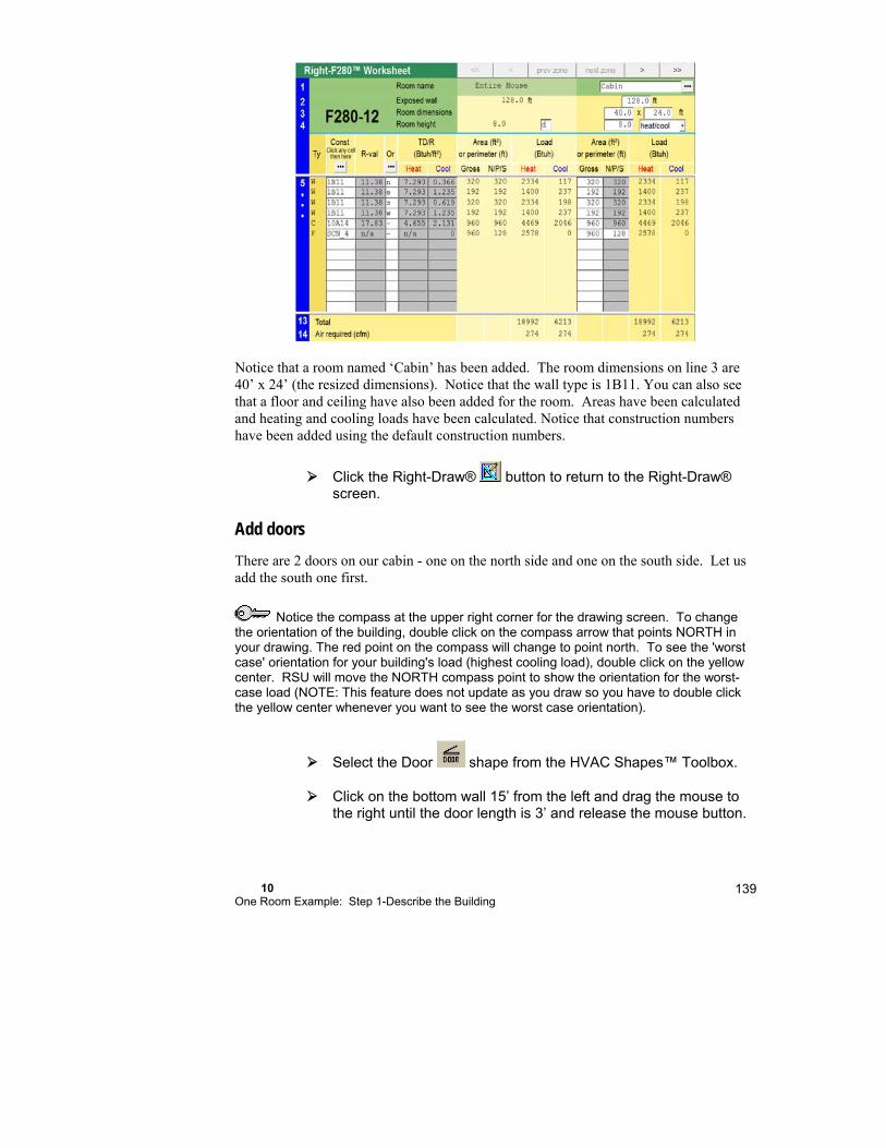
10 One Room Example: Step 1-Describe the Building
139
Notice that a room named ‘Cabin’ has been added. The room dimensions on line 3 are 40’ x 24’ (the resized dimensions). Notice that the wall type is 1B11. You can also see that a floor and ceiling have also been added for the room. Areas have been calculated and heating and cooling loads have been calculated. Notice that construction numbers have been added using the default construction numbers.
Click the Right-Draw® button to return to the Right-Draw® screen.
Add doors
There are 2 doors on our cabin - one on the north side and one on the south side. Let us add the south one first.
Notice the compass at the upper right corner for the drawing screen. To change the orientation of the building, double click on the compass arrow that points NORTH in your drawing. The red point on the compass will change to point north. To see the 'worst case' orientation for your building's load (highest cooling load), double click on the yellow center. RSU will move the NORTH compass point to show the orientation for the worst-case load (NOTE: This feature does not update as you draw so you have to double click the yellow center whenever you want to see the worst case orientation).
Select the Door shape from the HVAC Shapes™ Toolbox.
Click on the bottom wall 15’ from the left and drag the mouse to the right until the door length is 3’ and release the mouse button.

Part II - CSA Residential Examples 140
A door will be added to that wall. Now go ahead and add the north door to the top wall starting 22’ from the left using the same steps described above.
Add windows
We will start with the left-most window facing south. Adding windows is just as easy as adding doors.
Select the
Window shape.
Click on the bottom wall at 5’ from the west wall.
Drag to the right until the window is 3’ wide, and then release the mouse button.

10 One Room Example: Step 1-Describe the Building
141
The window height is entered from the defaults in the Loads preferences Screen. We will provide more detail about this powerful screen a little later.
Since all the windows are the same, we will add the other windows by copying the one we just added. Add the other 2 south windows starting 24’ and 32’ from the left.
To copy any HVAC shape, hold down the <Ctrl> key and click on the shape (in this case the window you just created). Hold the mouse button down and drag the mouse. Move the copied window until the left side starts at 24’. Use the ruler at the top to determine the location.
Repeat the same process for the other south window.
Add the 2 north-facing windows at 7’ and 16’ by copying the south windows. Then add the 2 east and 2 west windows starting at 5’ and 16’ from the top.
The linked image cannot be displayed. The file may have been moved, renamed, or deleted. Verify that the link points to the correct file and location.
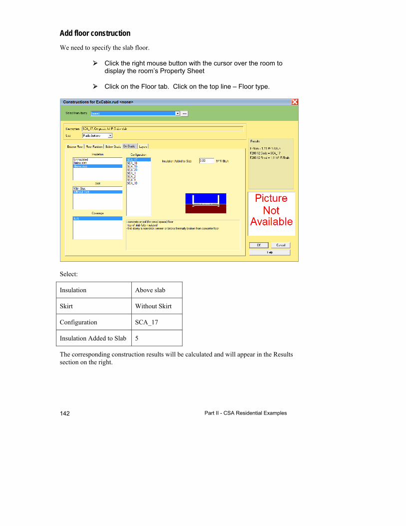
Part II - CSA Residential Examples 142
Add floor construction
We need to specify the slab floor.
Click the right mouse button with the cursor over the room to display the room’s Property Sheet
Click on the Floor tab. Click on the top line – Floor type.
Select:
Insulation Above slab
Skirt Without Skirt
Configuration SCA_17
Insulation Added to Slab 5
The corresponding construction results will be calculated and will appear in the Results section on the right.

10 One Room Example: Step 1-Describe the Building
143
Click on the OK button to accept your choices and transfer the results.
Step 1c - Add Vaulted Ceilings & Special Floors if Needed
Right-Draw® will automatically enter the ceiling and floor with the default construction numbers and use the room dimensions to calculate the areas. This is appropriate for our example.
If we had vaulted ceilings, we would need to add a special ceiling that would span the entire house. To add a vaulted ceiling you just draw the ceiling with the Ceiling HVAC Shape then select the roof style and Right-Draw® calculates the ceiling area automatically.
Special floors are used when a room has more than one floor type (for example, if part of a room was over a crawl space). To add a special floor you would draw the floor in the portion of the room where the special floor was needed. Select the floor type and Right-Draw® calculates the floor area for both floor types.
We do not need to add a special ceiling or floor because we only have one ceiling and one floor type, the floor is under the entire house, and the ceiling area is the same as the floor area. We have completed the building description for the vacation cabin. Click on the Right-F280™ Worksheet button to view the completed ‘Entire House’ load calculation.
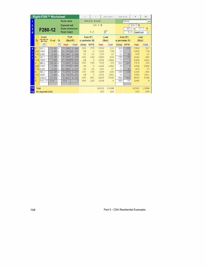
Part II - CSA Residential Examples 144
11
Room-by-room Example: Step 1-Describe the Building
This chapter shows you how to use Right-Draw® as a fast and efficient way to enter a building description into RSU. Right-Draw® will also help you layout your equipment, ducts, registers and radiant panels.
This example has many rooms on two levels. Here we will demonstrate the procedure for describing a more complex building in Right-Draw®.
A Room-by-Room Example ......................................... 146
Step 1a - Start a New Project From a Template With Preset Values ........................................................ 148
Step 1b - Add Rooms, Doors, & Windows ................... 153
Step 1c - Add Vaulted Ceilings & Special Floors (if needed) ................................................................. 162
Step 1d - Repeat Steps 1b & 1c for Each Level .......... 162
Things to Remember ................................................... 170

Part II - CSA Residential Examples 146
A Room-by-Room Example
In the second example, we are going to work with a two-bedroom house with a vented attic. There are 2 additional rooms on the second floor. Below are the floor plan and construction details.

11 Room-by-room Example: Step 1-Describe the Building
147
Item Description Weather location Bracebridge, Ontario
Winter inside design temperature 72 F
Winter outside design temperature -15 F
Summer inside design temperature 75 F
Summer outside design temperature 84 F
Soil condition Sandy
Construction Walls Main Floor – 2 x 4 wood-framed, metal siding, 3/8”
sheathing, drywall with R-11 fibreglass batt insulation; 8' ht.
Basement - 10" concrete block, internally covered with 2" Type 1 expanded polystyrene (R-7.5), to 2' below grade, drywall; 7' height 5' below grade
Windows Operable, wood frame, double pane, low-e, e = 0.2, argon filled, no storm, no shading
Ceiling 2 x 6 wood framed, vented attic, with R-11 insulation, drywall
Doors Solid wood, 1¾" thick with storm
Floors Basement - concrete, 5' below grade
Miscellaneous Occupancy 3
Internal gains Appliances in the kitchen
Ducts In conditioned spaces
Tightness Average
Wind exposure Sheltered
Example Files for the Room-by-Room Example
Demo file: F280-12Example2Start.rud
Completed demo file for comparison: ExF280-12Example2.rud
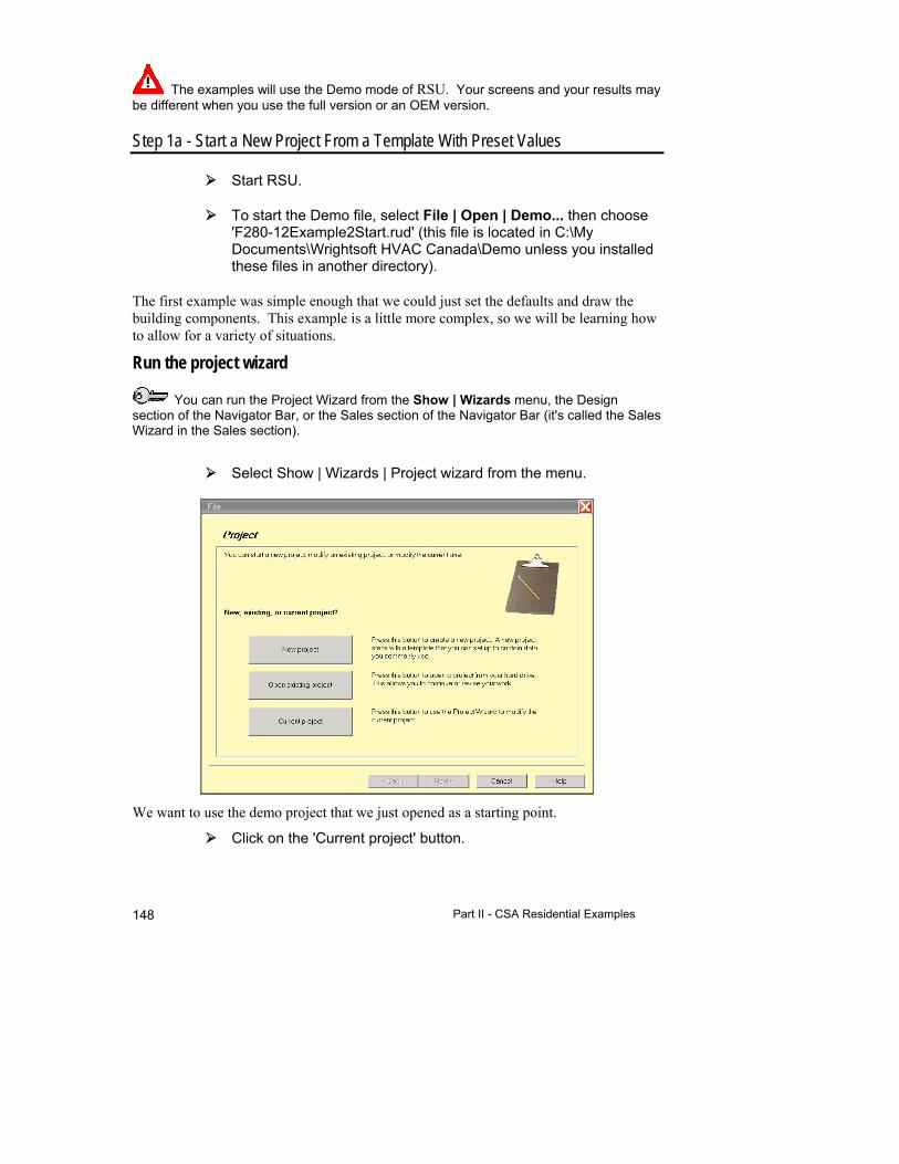
Part II - CSA Residential Examples 148
The examples will use the Demo mode of RSU. Your screens and your results may be different when you use the full version or an OEM version.
Step 1a - Start a New Project From a Template With Preset Values
Start RSU.
To start the Demo file, select File | Open | Demo... then choose 'F280-12Example2Start.rud' (this file is located in C:\My Documents\Wrightsoft HVAC Canada\Demo unless you installed these files in another directory).
The first example was simple enough that we could just set the defaults and draw the building components. This example is a little more complex, so we will be learning how to allow for a variety of situations.
Run the project wizard
You can run the Project Wizard from the Show | Wizards menu, the Design section of the Navigator Bar, or the Sales section of the Navigator Bar (it's called the Sales Wizard in the Sales section).
Select Show | Wizards | Project wizard from the menu.
We want to use the demo project that we just opened as a starting point.
Click on the 'Current project' button.
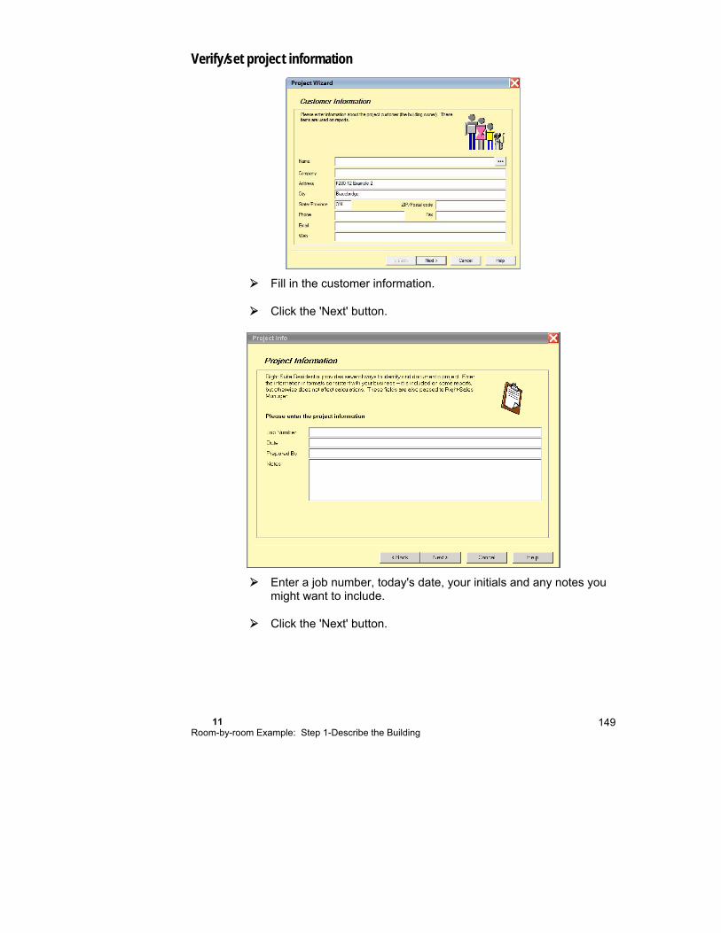
11 Room-by-room Example: Step 1-Describe the Building
149
Verify/set project information
Fill in the customer information.
Click the 'Next' button.
Enter a job number, today's date, your initials and any notes you might want to include.
Click the 'Next' button.
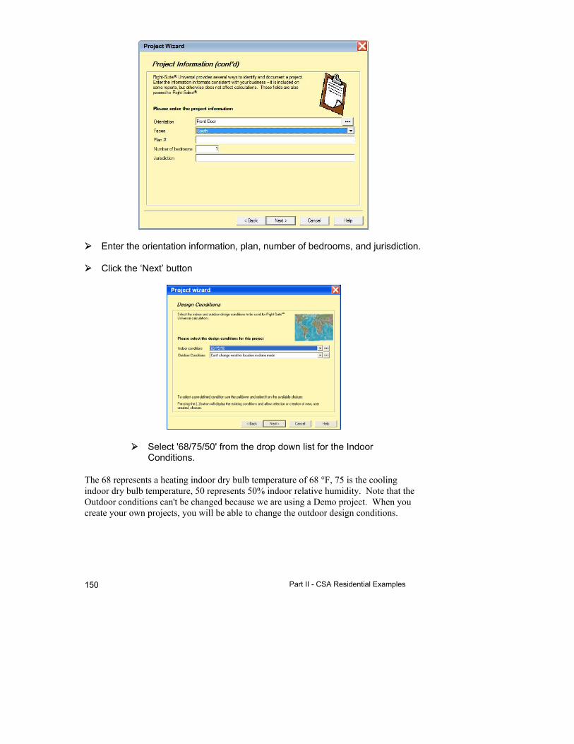
Part II - CSA Residential Examples 150
Enter the orientation information, plan, number of bedrooms, and jurisdiction.
Click the ‘Next’ button
Select '68/75/50' from the drop down list for the Indoor Conditions.
The 68 represents a heating indoor dry bulb temperature of 68 °F, 75 is the cooling indoor dry bulb temperature, 50 represents 50% indoor relative humidity. Note that the Outdoor conditions can't be changed because we are using a Demo project. When you create your own projects, you will be able to change the outdoor design conditions.
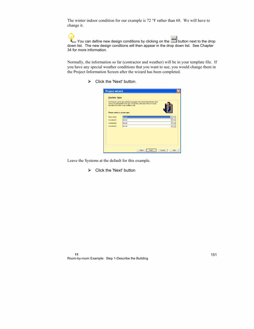
11 Room-by-room Example: Step 1-Describe the Building
151
The winter indoor condition for our example is 72 °F rather than 68. We will have to change it.
You can define new design conditions by clicking on the button next to the drop down list. The new design condtions will then appear in the drop down list. See Chapter 34 for more information.
Normally, the information so far (contractor and weather) will be in your template file. If you have any special weather conditions that you want to use, you would change them in the Project Information Screen after the wizard has been completed.
Click the 'Next' button.
Leave the Systems at the default for this example.
Click the 'Next' button
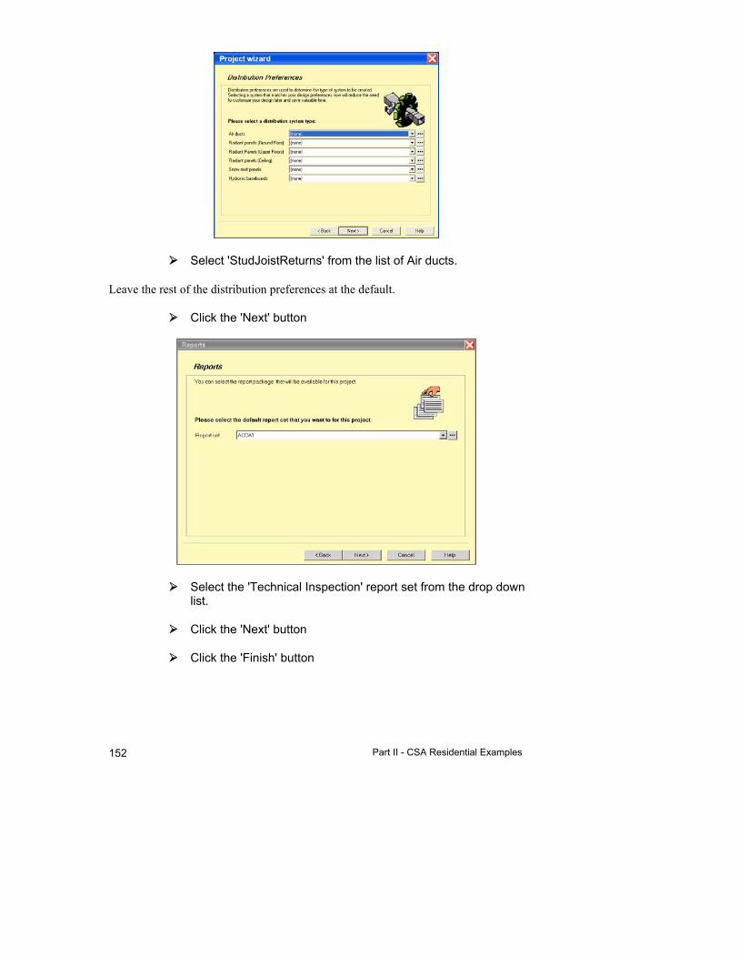
Part II - CSA Residential Examples 152
Select 'StudJoistReturns' from the list of Air ducts.
Leave the rest of the distribution preferences at the default.
Click the 'Next' button
Select the 'Technical Inspection' report set from the drop down list.
Click the 'Next' button
Click the 'Finish' button

11 Room-by-room Example: Step 1-Describe the Building
153
Enter 'Rdraw2' as the file name and click the 'Save' button to save your new project
Remember that we have to change the Winter inside design temperature.
Click on the button on the toolbar. You can also select Show | Zone Information from the menu.
Change the Heating Design Temperature to 72.
Click on the button on the toolbar to display the Right-Draw screen.
We are now looking at an empty Right-Draw® Screen. The first example was simple enough that we could just set the defaults and draw the building components. This example is a little more complex, so we will be learning how to allow for a variety of situations.
The example in this chapter uses I-P units. However, you may wish to use SI units. To change to SI units, select Options | Metric (SI) units from the menu.
Step 1b - Add Rooms, Doors, & Windows
Now we can start drawing the building.
Click on the button to display the Right-Draw® Screen.
Before we start adding rooms, notice that the sample building is 23’ north to south and 30’ east to west. If we look at the left ruler, we see that it goes to around 26’. The top ruler goes to around 46’. The resolution we are using (1024 x 768) will allow us to see the entire floor plan using the default scale. If this were not true, we would want to

Part II - CSA Residential Examples 154
change the scale of our drawing area so that we could see the entire floor plan at once. Let us take a moment to see how we would do this.
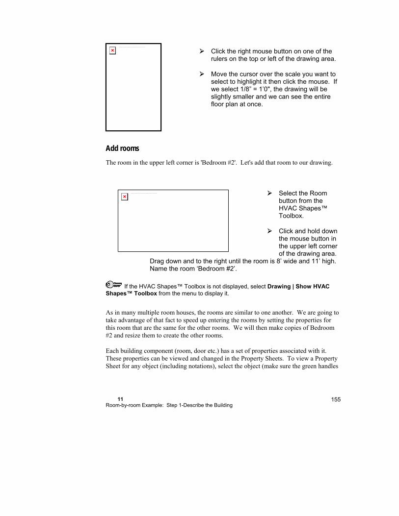
11 Room-by-room Example: Step 1-Describe the Building
155
Click the right mouse button on one of the rulers on the top or left of the drawing area.
Move the cursor over the scale you want to select to highlight it then click the mouse. If we select 1/8” = 1’0", the drawing will be slightly smaller and we can see the entire floor plan at once.
Add rooms
The room in the upper left corner is 'Bedroom #2'. Let's add that room to our drawing.
Select the Room button from the HVAC Shapes™ Toolbox.
Click and hold down the mouse button in the upper left corner of the drawing area.
Drag down and to the right until the room is 8’ wide and 11’ high. Name the room ‘Bedroom #2’.
If the HVAC Shapes™ Toolbox is not displayed, select Drawing | Show HVAC Shapes™ Toolbox from the menu to display it.
As in many multiple room houses, the rooms are similar to one another. We are going to take advantage of that fact to speed up entering the rooms by setting the properties for this room that are the same for the other rooms. We will then make copies of Bedroom #2 and resize them to create the other rooms.
Each building component (room, door etc.) has a set of properties associated with it. These properties can be viewed and changed in the Property Sheets. To view a Property Sheet for any object (including notations), select the object (make sure the green handles
The linked image cannot be displayed. The file may have been moved, renamed, or deleted. Verify that the link points to the correct file and location.
The linked image cannot be displayed. The file may have been moved, renamed, or deleted. Verify that the link points to the correct file and location.
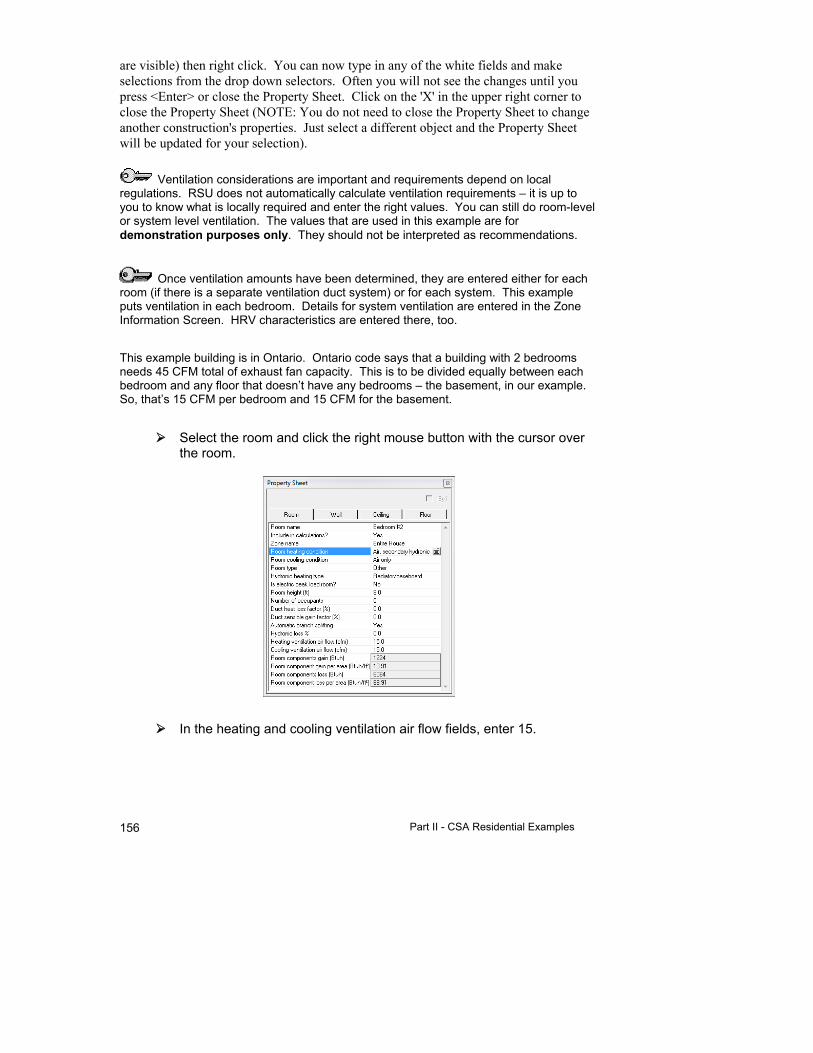
Part II - CSA Residential Examples 156
are visible) then right click. You can now type in any of the white fields and make selections from the drop down selectors. Often you will not see the changes until you press <Enter> or close the Property Sheet. Click on the 'X' in the upper right corner to close the Property Sheet (NOTE: You do not need to close the Property Sheet to change another construction's properties. Just select a different object and the Property Sheet will be updated for your selection).
Ventilation considerations are important and requirements depend on local regulations. RSU does not automatically calculate ventilation requirements – it is up to you to know what is locally required and enter the right values. You can still do room-level or system level ventilation. The values that are used in this example are for demonstration purposes only. They should not be interpreted as recommendations.
Once ventilation amounts have been determined, they are entered either for each room (if there is a separate ventilation duct system) or for each system. This example puts ventilation in each bedroom. Details for system ventilation are entered in the Zone Information Screen. HRV characteristics are entered there, too.
This example building is in Ontario. Ontario code says that a building with 2 bedrooms needs 45 CFM total of exhaust fan capacity. This is to be divided equally between each bedroom and any floor that doesn’t have any bedrooms – the basement, in our example. So, that’s 15 CFM per bedroom and 15 CFM for the basement.
Select the room and click the right mouse button with the cursor over the room.
In the heating and cooling ventilation air flow fields, enter 15.
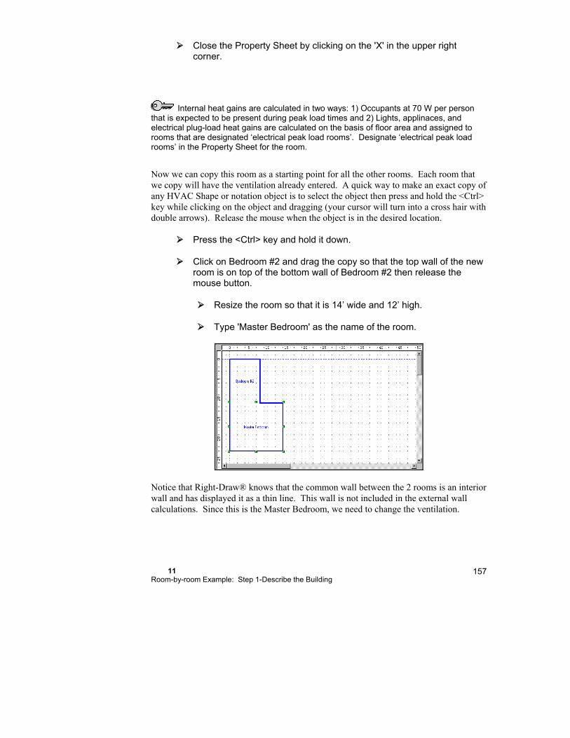
11 Room-by-room Example: Step 1-Describe the Building
157
Close the Property Sheet by clicking on the 'X' in the upper right corner.
Internal heat gains are calculated in two ways: 1) Occupants at 70 W per person that is expected to be present during peak load times and 2) Lights, applinaces, and electrical plug-load heat gains are calculated on the basis of floor area and assigned to rooms that are designated ‘electrical peak load rooms’. Designate ‘electrical peak load rooms’ in the Property Sheet for the room.
Now we can copy this room as a starting point for all the other rooms. Each room that we copy will have the ventilation already entered. A quick way to make an exact copy of any HVAC Shape or notation object is to select the object then press and hold the <Ctrl> key while clicking on the object and dragging (your cursor will turn into a cross hair with double arrows). Release the mouse when the object is in the desired location.
Press the <Ctrl> key and hold it down.
Click on Bedroom #2 and drag the copy so that the top wall of the new room is on top of the bottom wall of Bedroom #2 then release the mouse button.
Resize the room so that it is 14’ wide and 12’ high.
Type 'Master Bedroom' as the name of the room.
Notice that Right-Draw® knows that the common wall between the 2 rooms is an interior wall and has displayed it as a thin line. This wall is not included in the external wall calculations. Since this is the Master Bedroom, we need to change the ventilation.
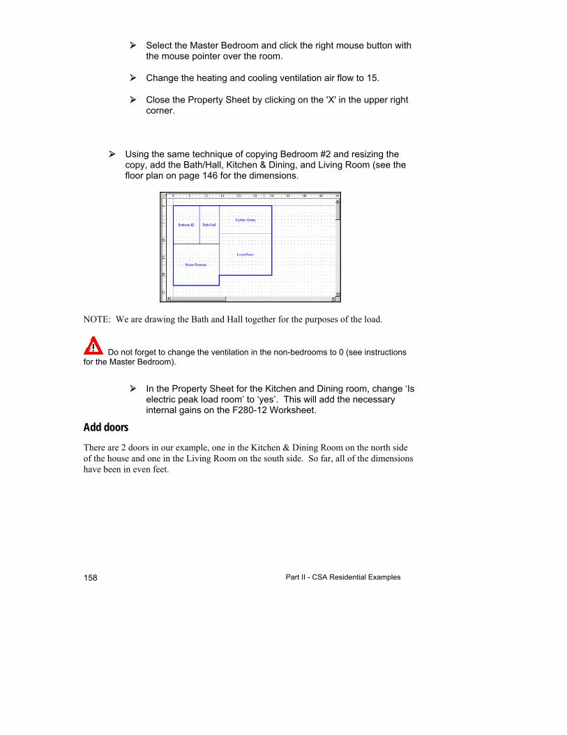
Part II - CSA Residential Examples 158
Select the Master Bedroom and click the right mouse button with the mouse pointer over the room.
Change the heating and cooling ventilation air flow to 15.
Close the Property Sheet by clicking on the 'X' in the upper right corner.
Using the same technique of copying Bedroom #2 and resizing the copy, add the Bath/Hall, Kitchen & Dining, and Living Room (see the floor plan on page 146 for the dimensions.
NOTE: We are drawing the Bath and Hall together for the purposes of the load.
Do not forget to change the ventilation in the non-bedrooms to 0 (see instructions for the Master Bedroom).
In the Property Sheet for the Kitchen and Dining room, change ‘Is electric peak load room’ to ‘yes’. This will add the necessary internal gains on the F280-12 Worksheet.
Add doors
There are 2 doors in our example, one in the Kitchen & Dining Room on the north side of the house and one in the Living Room on the south side. So far, all of the dimensions have been in even feet.

11 Room-by-room Example: Step 1-Describe the Building
159
Select the Door shape from the HVAC Shapes™ Toolbox. Click the south wall of the Living Room 1' to the right of where it meets the Master Bedroom. Drag along the wall to the right until the width is 3’ and release the mouse button.
Copy the door by pressing and holding the <Ctrl> key then clicking the door you just added and dragging the copy to the north outside wall of the Kitchen & Dining Room 1' from the Bath/Hall.
Add windows Adding windows is just like adding doors.
Select the Window shape from the HVAC Shapes™ Toolbox.
Click in the center of the west wall of Bedroom #2 and drag until the window is 4’ wide (NOTE: If you just click on a wall a window 3’ wide is drawn).
The linked image cannot be displayed. The file may have been moved, renamed, or deleted. Verify that the link points to the correct file and location.
The linked image cannot be displayed. The file may have been moved, renamed, or deleted. Verify that the link points to the correct file and location.
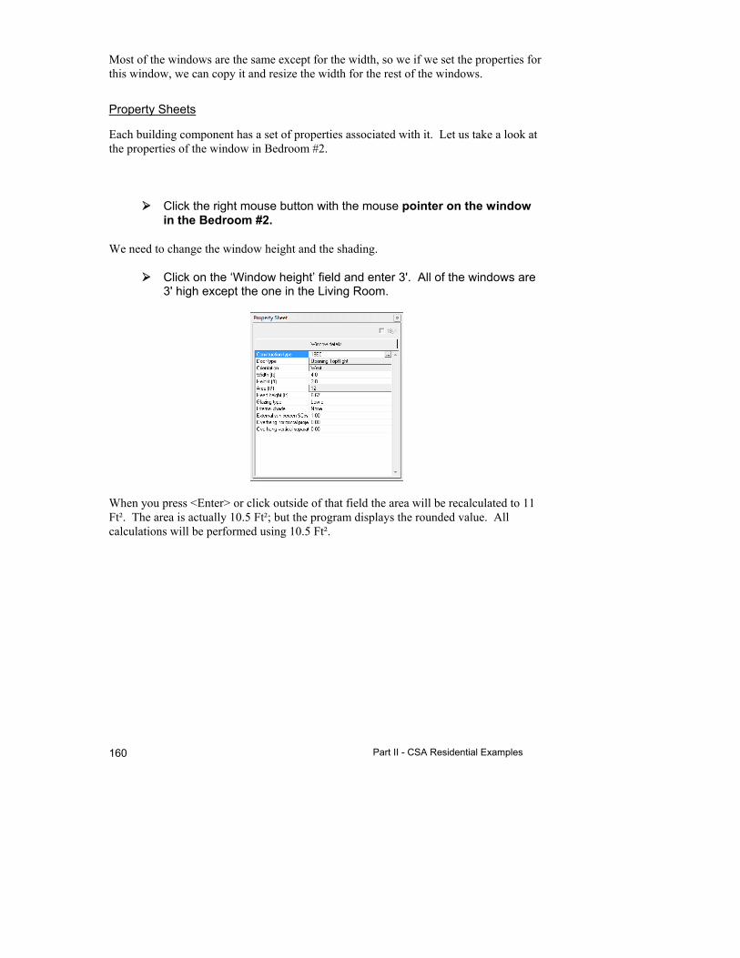
Part II - CSA Residential Examples 160
Most of the windows are the same except for the width, so we if we set the properties for this window, we can copy it and resize the width for the rest of the windows.
Property Sheets
Each building component has a set of properties associated with it. Let us take a look at the properties of the window in Bedroom #2.
Click the right mouse button with the mouse pointer on the window in the Bedroom #2.
We need to change the window height and the shading.
Click on the ‘Window height’ field and enter 3'. All of the windows are 3' high except the one in the Living Room.
When you press <Enter> or click outside of that field the area will be recalculated to 11 Ft². The area is actually 10.5 Ft²; but the program displays the rounded value. All calculations will be performed using 10.5 Ft².

11 Room-by-room Example: Step 1-Describe the Building
161
We also need to change the shading.
Click on the ‘Internal shade’ field and select ‘None’ from the list that drops down.
Click the ‘X’ in the upper right corner to close the Property Sheet.
Now copy this window for all of the other windows. The properties will be the same for all of the windows.
Press the <Ctrl> key and hold it down, click the window you just added and drag the copy to the outside wall of the Bath.
Resize the width to 3’
Add the rest of the windows using the same technique. Refer to the floor plan on page 146 for placement.
The linked image cannot be displayed. The file may have been moved, renamed, or deleted. Verify that the link points to the correct file and location.

Part II - CSA Residential Examples 162
When you add the window in the Living Room, you will have to change the height to 4'.
Click the right mouse button with the mouse pointer over the window in the Living Room.
Click on the 'Height' field and type 4. The area will be recalculated when you press <Enter> or close the Property Sheet.
Step 1c - Add Vaulted Ceilings & Special Floors (if needed)
Once again, the floor and ceiling have been added automatically. Since there is a conditioned basement below this storey, there is no floor in this storey.
Right-Draw® removes interior floors from upper storey rooms and interior ceilings from lower storey rooms.
To remove the floor from our example, we will add a basement below this storey.
Step 1d - Repeat Steps 1b & 1c for Each Level
Sheets & layers
Right-Draw® uses multiple sheets and layers on the drawing area, almost like transparent paper drawing pages that can be stacked on top of one another.
Sheets are used for levels (storeys) in the building. You can add additional sheets as needed. Sheets contain layers. Each sheet has a default color (blue for the first sheet, maroon for the second and so on).
Layers are specialized subsets of sheets that contain specific things. For example, the Building layer contains only building components such as rooms, windows, doors, flat ceilings and floors. So far, we have been working in the Building layer of a single sheet. Right-Draw® uses another layer for ducts and another layer for radiant heating. There is even a Notation layer that contains text, graphics, lines, and other drawing shapes you might add to a drawing. The Building, Ducts and Radiant panel layers are shown in the sheet default colors; the Notation layer is black by default.
We need to add a Sheet for the basement.
Click the right mouse button with the mouse pointer over the blank section of the Sheets and Layers Tree.
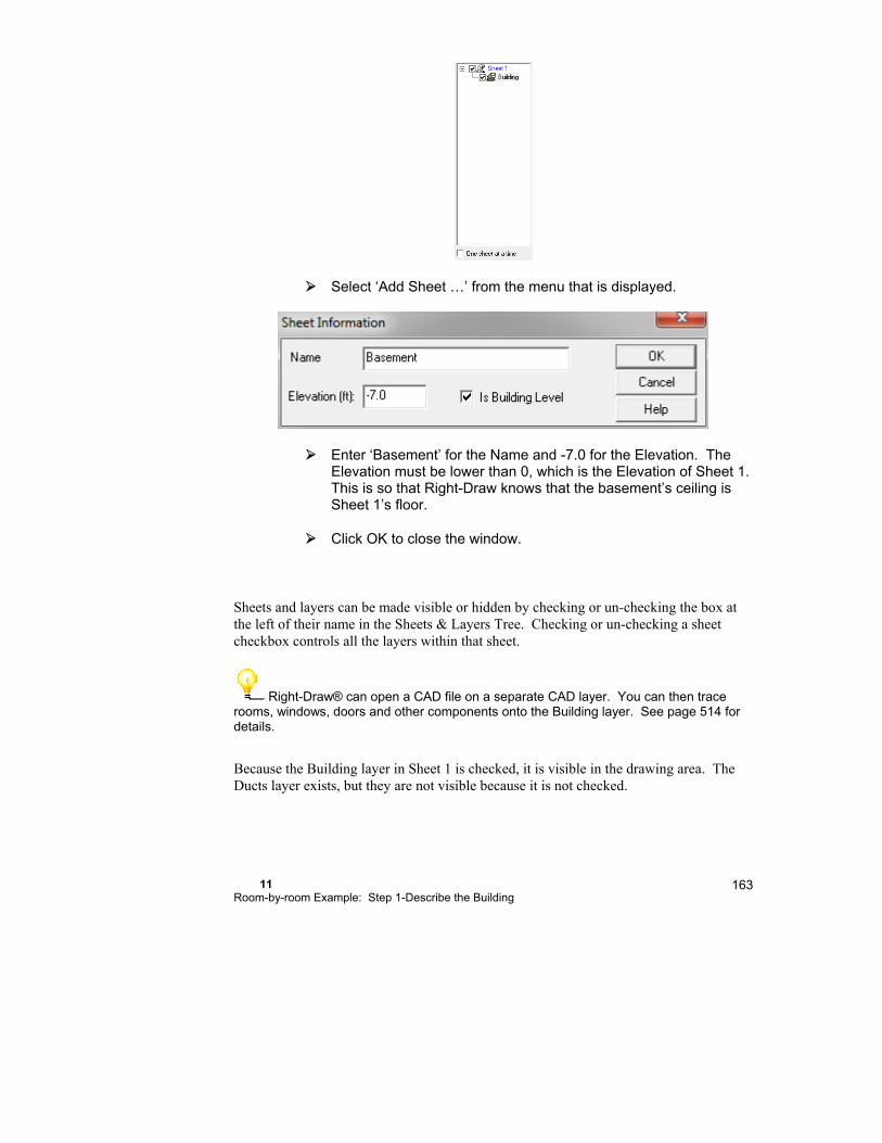
11 Room-by-room Example: Step 1-Describe the Building
163
Select ‘Add Sheet …’ from the menu that is displayed.
Enter ‘Basement’ for the Name and -7.0 for the Elevation. The Elevation must be lower than 0, which is the Elevation of Sheet 1. This is so that Right-Draw knows that the basement’s ceiling is Sheet 1’s floor.
Click OK to close the window.
Sheets and layers can be made visible or hidden by checking or un-checking the box at the left of their name in the Sheets & Layers Tree. Checking or un-checking a sheet checkbox controls all the layers within that sheet.
Right-Draw® can open a CAD file on a separate CAD layer. You can then trace rooms, windows, doors and other components onto the Building layer. See page 514 for details.
Because the Building layer in Sheet 1 is checked, it is visible in the drawing area. The Ducts layer exists, but they are not visible because it is not checked.
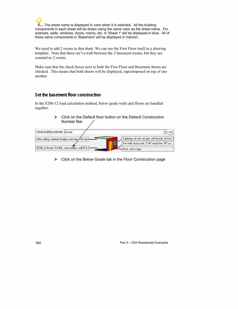
Part II - CSA Residential Examples 164
The sheet name is displayed in color when it is selected. All the building components in each sheet will be drawn using the same color as the sheet name. For example, walls, windows, doors, rooms, etc. in 'Sheet 1' will be displayed in blue. All of these same components in 'Basement' will be displayed in maroon.
We need to add 2 rooms to that sheet. We can use the First Floor itself as a drawing template. Note that there isn’t a wall between the 2 basement rooms, but they are counted as 2 rooms.
Make sure that the check boxes next to both the First Floor and Basement sheets are checked. This means that both sheets will be displayed, superimposed on top of one another.
Set the basement floor construction
In the F280-12 load calculation method, below grade walls and floors are handled together.
Click on the Default floor button on the Default Construction Number Bar.
Click on the Below Grade tab in the Floor Construction page

11 Room-by-room Example: Step 1-Describe the Building
165
Note that all calculations performed by BasementHLR.xls (provided by CSA for F280-12) are performed by RSU. So, that external spreadsheet is not needed. The same is true for the slab-on-grade spreadsheet, SlabOnGradeHLR.xls.
Make the following selections in this screen:
Construction Concrete Insulation Interior wall insulation Depth below grade 5 ft Configuration BCIN_4 Interior Wall Insulation 7.5 ft² ˚F/Btuh
This will calculate the necessary floor and below grade wall construction.
Click OK to apply the changes.
Now that we have made this selection for the floor construction, it will be the floor construction for whatever rooms we add in the basement.
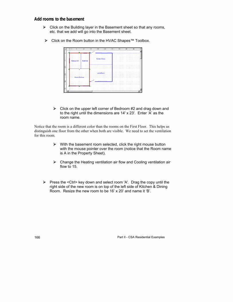
Part II - CSA Residential Examples 166
Add rooms to the basement
Click on the Building layer in the Basement sheet so that any rooms, etc. that we add will go into the Basement sheet.
Click on the Room button in the HVAC Shapes™ Toolbox.
Click on the upper left corner of Bedroom #2 and drag down and to the right until the dimensions are 14' x 23'. Enter ‘A’ as the room name.
Notice that the room is a different color than the rooms on the First Floor. This helps us distinguish one floor from the other when both are visible. We need to set the ventilation for this room.
With the basement room selected, click the right mouse button with the mouse pointer over the room (notice that the Room name is A in the Property Sheet).
Change the Heating ventilation air flow and Cooling ventilation air flow to 15.
Press the <Ctrl> key down and select room 'A'. Drag the copy until the right side of the new room is on top of the left side of Kitchen & Dining Room. Resize the new room to be 16’ x 20’ and name it ‘B’.
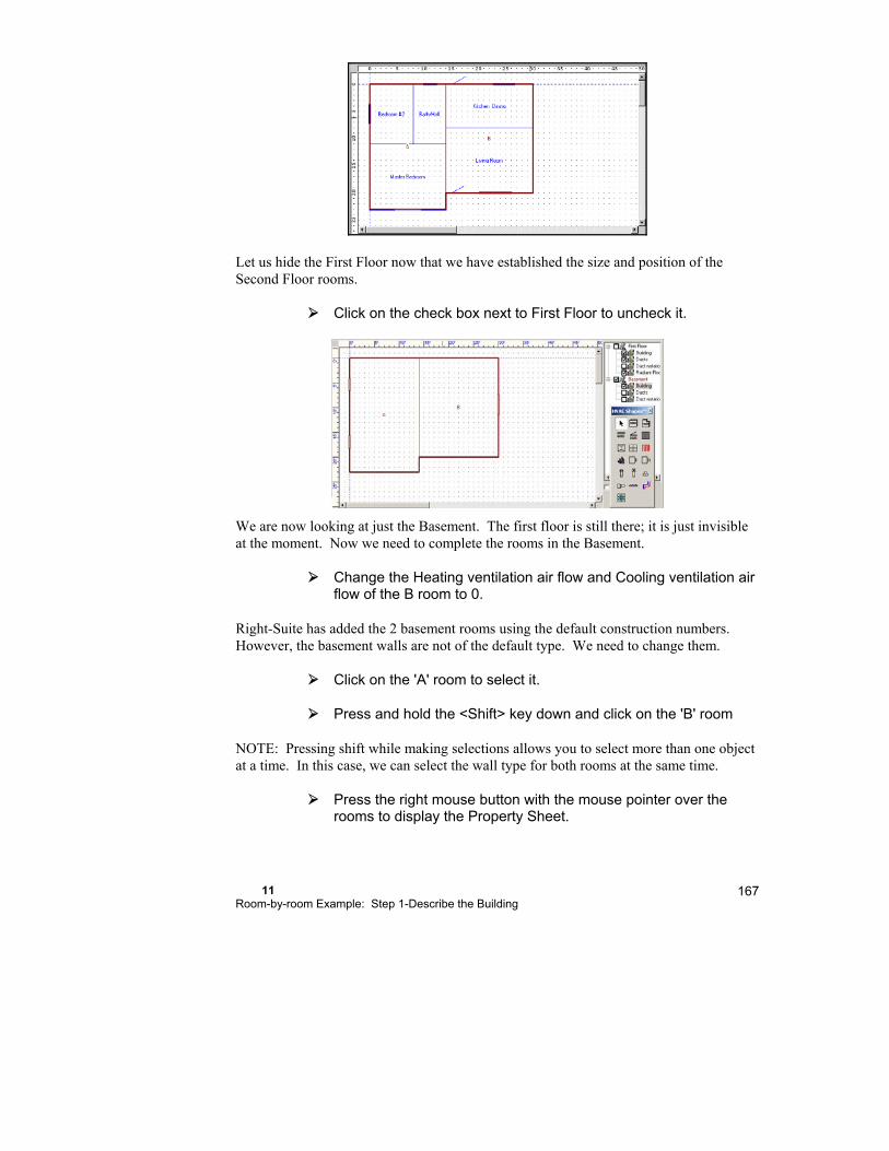
11 Room-by-room Example: Step 1-Describe the Building
167
Let us hide the First Floor now that we have established the size and position of the Second Floor rooms.
Click on the check box next to First Floor to uncheck it.
We are now looking at just the Basement. The first floor is still there; it is just invisible at the moment. Now we need to complete the rooms in the Basement.
Change the Heating ventilation air flow and Cooling ventilation air flow of the B room to 0.
Right-Suite has added the 2 basement rooms using the default construction numbers. However, the basement walls are not of the default type. We need to change them.
Click on the 'A' room to select it.
Press and hold the <Shift> key down and click on the 'B' room
NOTE: Pressing shift while making selections allows you to select more than one object at a time. In this case, we can select the wall type for both rooms at the same time.
Press the right mouse button with the mouse pointer over the rooms to display the Property Sheet.

Part II - CSA Residential Examples 168
Only the properties common to both rooms will be displayed. Notice that the room name is blank - properties that differ are not displayed.
Click on the 'Wall' tab and then on the value in the 'Wall 1, type' field. The available wall types will be displayed.
Select the Masonry tab
Select the following:
Section Selection
Exterior None
Exterior board insulation R-8
Sheathing None
Structural wall Sand and gravel block
Structural wall thickness 10"
Block insulation None
Interior framed wall 2 x 4 wood
Cavity insulation None
Interior finish 5/8" gypsum board
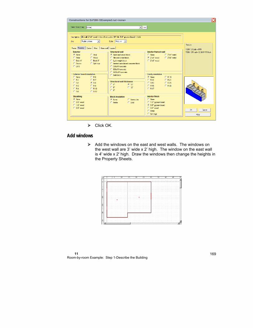
11 Room-by-room Example: Step 1-Describe the Building
169
Click OK.
Add windows
Add the windows on the east and west walls. The windows on the west wall are 3’ wide x 2’ high. The window on the east wall is 4' wide x 2' high. Draw the windows then change the heights in the Property Sheets.
Part II - CSA Residential Examples 170
Adding vaulted ceilings & special floors (if needed)
The ceiling has been removed automatically by Right-Draw® because it is under the first floor, and we do not need to add an additional floor. We have finished describing our second example building. Take a moment to review the loads on the Right-F280™ Worksheet.
If you are not going to continue with the next chapter, you should save the project we have been working on.
Select File | Save As | Project… from the main menu.
Type ‘Rdraw2’ as the project name and click Save.
Things to Remember
The construction numbers for building elements that you add to the drawing area with the HVAC Shapes™ Toolbox are defined by the room default construction numbers. Changing the default construction number settings has no effect on building elements already drawn.
Use the Drawing | Repeat Last Selection menu option so that you do not need to reselect building elements from the HVAC Shapes™ Toolbox. For example, you can draw all of your rooms with out reselecting the Room shape.
Stretch window width by dragging one handle.
Click the right mouse button on any object to see the Property Sheet for that object.
Hold down the <Shift> key to select any number of similar objects (multiple selections). Then right-click to see the Property Sheet for the entire group. Common properties will be displayed; fields that are different will be blank. Change any property, and you will affect the entire group all at once. This is a quick way to change the construction number for all of the windows on a floor.
Use <Ctrl>-drag to copy any object. You can also use <Ctrl-C> (Edit | Copy) and <Ctrl-V> (Edit | Paste) to copy any object.
Right-Draw® automatically adds a floor and a ceiling to each room using the default construction numbers. See the Property Sheet for the room.
To describe a multiple-storey building, put each storey in its own sheet with different elevations. Right-Draw® will automatically remove interior floors and ceilings.
12
Room-by-room Example: Step 2 - Select the Equipment
How Does Multi-Zoning Work? .................................... 172
How Are Multiple Systems Handled? .......................... 173
Step 2a - Assign Zoning .............................................. 173
Step 2b - Assign Distribution Systems ........................ 177
Step 2c - Geothermal Loop ......................................... 177
Step 2d - Evaluate Equipment System Options ........... 177
Step 2e - Select the Final Equipment System ............. 177
Part II - CSA Residential Examples 172
This chapter continues where Chapter 11 leaves off. If you followed the example in Chapter 11, open the project that you created.
Select File | Open | Project… from the main menu.
Select ‘Rdraw2.rup’ from the list of projects and click OK.
How Does Multi-Zoning Work?
RSU helps you divide a house into multiple HVAC system zones, calculate loads for the zones, and size ducts for each zone. Your zone definitions are automatically linked to other RSU program components.
The process for zoning is easy. To add zones when the same equipment is supplying all zones:
1. Click the Multizone button in the Project Toolbar.
2. Click the first room you wish to assign to a zone, then click the Add Zone button and enter the name of the zone.
3. Drag-and-drop rooms into the new zone as required.
4. Repeat steps 2 and 3 until all the rooms have been assigned to their proper zone.
This process usually takes less than a couple of minutes, even for a large number of rooms.
Note: If each zone has a VAV box associated with it (used in commercial applications) you would click 'Add VAV' instead of 'Add Zone' above.
If each zone is to have its own equipment, you would follow the above instructions except click 'Add AH' (for add air handler) instead of 'Add Zone'. When you do this a blower HVACShape will be added to the Right-Draw® drawing.
There can even be separate zoning if there is both an air and a hydronic distribution system.
It is important to note that as you enter a new zone name RSU will propagate all changes through the project and move ducts, etc as required to suit the new zone configurations. Also note that equipment can either be in individual zones or in the Entire House for central equipment in multiple zones.

12 Room-by-room Example: Step 2 - Select the Equipment
173
How Are Multiple Systems Handled?
You can evaluate as many as four HVAC system alternatives in Right-$™ for each HVAC unit in your design. For designs with a single central unit, Right-$™ can let you examine a total of four system options. For multi-zone designs with a separate unit serving each zone, there can be as many as four system alternatives for each zone. For example, a three-zone house will have a total of 12 systems to consider (3 zones x 4 systems), but you can only compare alternatives within a zone.
After you evaluate the system options in Right-$™, select one of the systems to function as the Current System. The Current System is linked to the other RSU functions for their calculations. Use the Options | Current System | (then choose Base System, Investment 1, Investment 2 or Investment 3) menu choice to specify the system to be used in the calculations and reports.
When you select Options | Current System from the main menu, that system option is selected for each zone. For example, if you have a three-zone project and you select ‘Investment 1’ for Current System, the equipment you have defined as Investment 1 in Right-$™ for each zone will become the current system for all other zones.
Step 2a - Assign Zoning
RSU’s Multizone Tree makes it easy to add and delete zones and move rooms between zones using either multiple HVAC units or a single central HVAC unit with proportional zone dampers.
There are 3 zones in the sample house. The 2 bedrooms will be in one zone, the 2 rooms in the basement will be in another zone and the rest of the rooms on the first floor will be in the third zone.
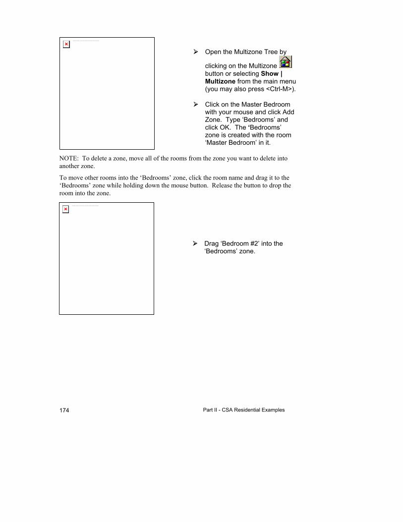
Part II - CSA Residential Examples 174
Open the Multizone Tree by
clicking on the Multizone button or selecting Show | Multizone from the main menu (you may also press <Ctrl-M>).
Click on the Master Bedroom with your mouse and click Add Zone. Type ‘Bedrooms’ and click OK. The ‘Bedrooms’ zone is created with the room ‘Master Bedroom’ in it.
NOTE: To delete a zone, move all of the rooms from the zone you want to delete into another zone.
To move other rooms into the ‘Bedrooms’ zone, click the room name and drag it to the ‘Bedrooms’ zone while holding down the mouse button. Release the button to drop the room into the zone.
Drag ‘Bedroom #2’ into the ‘Bedrooms’ zone.
The linked image cannot be displayed. The file may have been moved, renamed, or deleted. Verify that the link points to the correct file and location.
The linked image cannot be displayed. The file may have been moved, renamed, or deleted. Verify that the link points to the correct file and location.

12 Room-by-room Example: Step 2 - Select the Equipment
175
Add a zone titled 'Living Area' and place the Bath, Kitchen & Dining, and Living Room into that zone.
The other rooms are put in a zone called ‘(Rest of House)’. We can change the name of this zone.
Click on the ‘(Rest of House)’ zone.
Click the ‘Rename’ button and type in ‘Basement’ as the new name then click another room name. Finally, click Close to close the Multizone Tree.
NOTE: The Multizone Tree, like the Property Sheets can stay open while you work. You can select different zones and view the data for each without having to open and close the Multizone Tree every time you want to view a different zone.
The linked image cannot be displayed. The file may have been moved, renamed, or deleted. Verify that the link points to the correct file and location.
The linked image cannot be displayed. The file may have been moved, renamed, or deleted. Verify that the link points to the correct file and location.
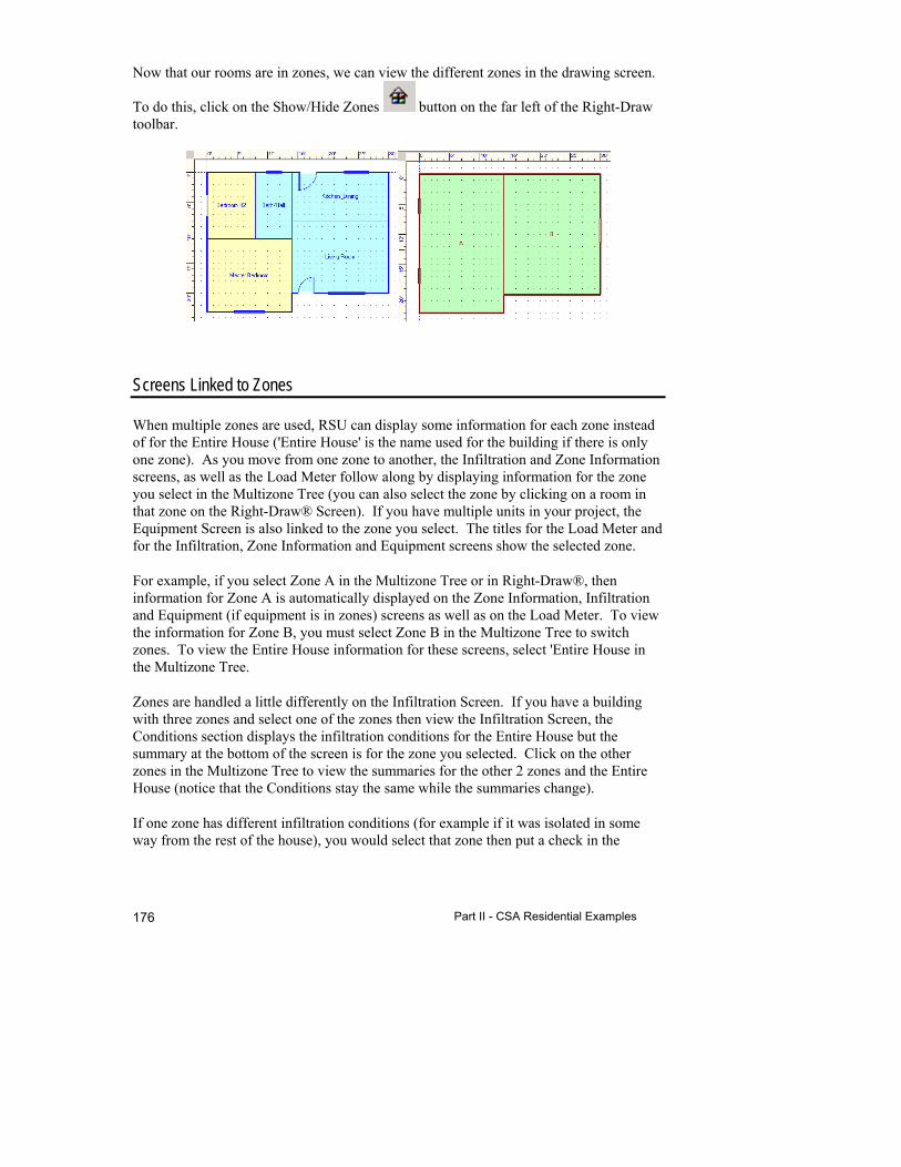
Part II - CSA Residential Examples 176
Now that our rooms are in zones, we can view the different zones in the drawing screen.
To do this, click on the Show/Hide Zones button on the far left of the Right-Draw toolbar.
Screens Linked to Zones
When multiple zones are used, RSU can display some information for each zone instead of for the Entire House ('Entire House' is the name used for the building if there is only one zone). As you move from one zone to another, the Infiltration and Zone Information screens, as well as the Load Meter follow along by displaying information for the zone you select in the Multizone Tree (you can also select the zone by clicking on a room in that zone on the Right-Draw® Screen). If you have multiple units in your project, the Equipment Screen is also linked to the zone you select. The titles for the Load Meter and for the Infiltration, Zone Information and Equipment screens show the selected zone.
For example, if you select Zone A in the Multizone Tree or in Right-Draw®, then information for Zone A is automatically displayed on the Zone Information, Infiltration and Equipment (if equipment is in zones) screens as well as on the Load Meter. To view the information for Zone B, you must select Zone B in the Multizone Tree to switch zones. To view the Entire House information for these screens, select 'Entire House in the Multizone Tree.
Zones are handled a little differently on the Infiltration Screen. If you have a building with three zones and select one of the zones then view the Infiltration Screen, the Conditions section displays the infiltration conditions for the Entire House but the summary at the bottom of the screen is for the zone you selected. Click on the other zones in the Multizone Tree to view the summaries for the other 2 zones and the Entire House (notice that the Conditions stay the same while the summaries change).
If one zone has different infiltration conditions (for example if it was isolated in some way from the rest of the house), you would select that zone then put a check in the
12 Room-by-room Example: Step 2 - Select the Equipment
177
'Isolated zone' checkbox at the top of the Conditions section of the Infiltration Screen. Now the infiltration conditions are unique to that zone (notice that the Conditions title has changed). The summary is still for the zone that is selected, but the conditions are unique to that zone. The other zones, if there is no check in their 'Isolated zone' checkboxes, will have the Entire House infiltration conditions.
How do I decide which rooms to group together in a zone?
Zones should consist of rooms that have similar loads and similar comfort control requirements. Experience will help you decide how to zone a house. It is usually a good idea to group rooms that have a similar solar exposure into one zone. Occupancy schedules and opportunities for cooling thermostat setup are also key considerations. Upper and lower floors are often separate zones.
Use the Multizone Tree to make “what-if” evaluations on your zoning scheme. You can quickly move rooms from one zone to another and instantly see the effects on loads, ducts and HVAC units.
Step 2b - Assign Distribution Systems
HVAC equipment & zones
Your project might have a single zone or multiple zones. There can be a single unit that serves the entire house or multiple units that serve different zones or combinations of zones. Use the Multizone Tree Screen to design the zone and equipment plan for your project.
Step 2c - Geothermal Loop
If your project uses geothermal loops, now is the time to design them. See Chapter 25 for a detailed Right-Loop™ example.
Step 2d - Evaluate Equipment System Options
To determine the most practical equipment system, you may want to compare several system configurations. See Chapter 28 for a detailed Right-$™ example.
Step 2e - Select the Final Equipment System
Since the equipment is in the Entire House, we need to select 'Entire House' in the Multizone Tree in order to select equipment, otherwise, the Equipment button is grayed out and we are not allowed to select the equipment.
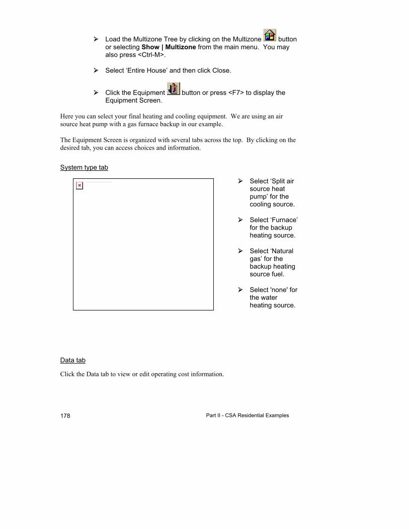
Part II - CSA Residential Examples 178
Load the Multizone Tree by clicking on the Multizone button or selecting Show | Multizone from the main menu. You may also press <Ctrl-M>.
Select ‘Entire House’ and then click Close.
Click the Equipment button or press <F7> to display the Equipment Screen.
Here you can select your final heating and cooling equipment. We are using an air source heat pump with a gas furnace backup in our example.
The Equipment Screen is organized with several tabs across the top. By clicking on the desired tab, you can access choices and information.
System type tab
Select ‘Split air source heat pump’ for the cooling source.
Select ‘Furnace’ for the backup heating source.
Select ‘Natural gas’ for the backup heating source fuel.
Select 'none' for the water heating source.
Data tab
Click the Data tab to view or edit operating cost information.
The linked image cannot be displayed. The file may have been moved, renamed, or deleted. Verify that the link points to the correct file and location.
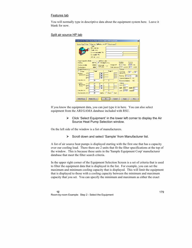
12 Room-by-room Example: Step 2 - Select the Equipment
179
Features tab
You will normally type in descriptive data about the equipment system here. Leave it blank for now.
Split air source HP tab
If you know the equipment data, you can just type it in here. You can also select equipment from the ARI/GAMA database included with RSU.
Click ‘Select Equipment’ in the lower left corner to display the Air Source Heat Pump Selection window.
On the left side of the window is a list of manufacturers.
Scroll down and select ‘Sample’ from Manufacturer list.
A list of air source heat pumps is displayed starting with the first one that has a capacity over our cooling load. There there are 2 units that fit the filter specifications at the top of the window. This is because these units in the 'Sample Equipment Corp' manufacturer database that meet the filter search criteria.
In the upper right corner of the Equipment Selection Screen is a set of criteria that is used to filter the equipment data that is displayed in the list. For example, you can set the maximum and minimum cooling capacity that is displayed. This will limit the equipment that is displayed to those with a cooling capacity between the minimum and maximum capacity that you set. You can specify the minimum and maximum as either the exact

Part II - CSA Residential Examples 180
Btuh or relative to the target capacity. The target capacity is displayed in the upper left corner of the Equipment Selection Screen.
The target capacity is calculated as the sensible load of your zone or Entire House divided by the Sensible Heat Ratio (SHR); the SHR of the equipment, not the
building. This is generally 0.70, however, you should verify this by referring to the manufacturer's specification sheet for the equipment.
For example, let us expand the maximum capacity display range to 200% of the target capacity.
In the 'Filter' section enter '200', in the Max 'Capacity/ Load (%)' field.
The list of equipment now includes equipment up to 200% of the target capacity.
Click anywhere on the first line to select the equipment then click OK.
Gas furnace tab
If you know the equipment data, you can just type it in here. You can also select equipment from the ARI/GAMA database included with RSU.
Click ‘Select Equipment’ to display the Gas Furnace Selection window.
Select 'Sample' from the list of manufacturers on the left.
A list of gas furnaces will be displayed starting with the first one that has a capacity that is over our heating load.
The linked image cannot be displayed. The file may have been mov ed, renamed, or deleted. Verify that the link points to the correct file and location.
12 Room-by-room Example: Step 2 - Select the Equipment
181
Click anywhere on the first line to select the equipment then click OK.
Click OK again when you are done with the Equipment Screen.
Whether you are going to continue to the next chapter or not, you should save the project file that we have been working on.
Select File | Save from the main menu or click on the Save button.
Things to Remember
Zoning in RSU is controlled from the Multizone Tree by simply dragging the rooms into the desired zones.
The data in the Zone Information, Infiltration, and Equipment Screens as well as in the Load Meter change depending on the active zone. The active zone is chosen in the Multizone Tree.
Equipment can be located in each zone or in the Entire House.
Equipment is selected from the Equipment Screen either by zone of for the Entire House depending on your selections in the Multizone Tree Screen.
You do not need to close the Multizone Tree while you work


13
Room-by-room Example: Step 3 - Design the Distribution
Step 3a - Air Distribution via Ducts .............................. 184
Step 3b - Distribution with Radiant Panels .................. 190
Step 3c - Baseboards .................................................. 193
Things to Remember ................................................... 195
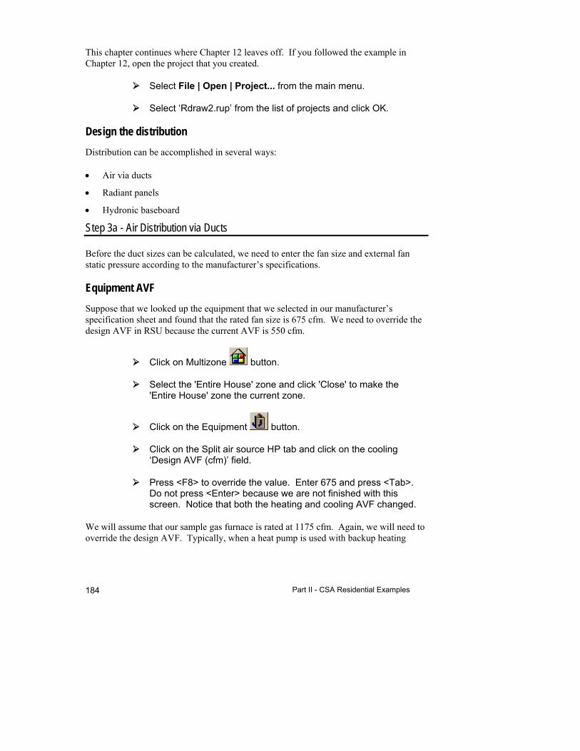
Part II - CSA Residential Examples 184
This chapter continues where Chapter 12 leaves off. If you followed the example in Chapter 12, open the project that you created.
Select File | Open | Project... from the main menu.
Select ‘Rdraw2.rup’ from the list of projects and click OK.
Design the distribution
Distribution can be accomplished in several ways:
Air via ducts
Radiant panels
Hydronic baseboard
Step 3a - Air Distribution via Ducts
Before the duct sizes can be calculated, we need to enter the fan size and external fan static pressure according to the manufacturer’s specifications.
Equipment AVF
Suppose that we looked up the equipment that we selected in our manufacturer’s specification sheet and found that the rated fan size is 675 cfm. We need to override the design AVF in RSU because the current AVF is 550 cfm.
Click on Multizone button.
Select the 'Entire House' zone and click 'Close' to make the 'Entire House' zone the current zone.
Click on the Equipment button.
Click on the Split air source HP tab and click on the cooling ‘Design AVF (cfm)’ field.
Press <F8> to override the value. Enter 675 and press <Tab>. Do not press <Enter> because we are not finished with this screen. Notice that both the heating and cooling AVF changed.
We will assume that our sample gas furnace is rated at 1175 cfm. Again, we will need to override the design AVF. Typically, when a heat pump is used with backup heating
13 Room-by-room Example: Step 3 - Design the Distribution
185
equipment, the heating equipment that is satisfying the load at any one moment can be the heat pump, the backup equipment or both. The ducts should be designed for the maximum airflow at any one time. For our example, we will assume that either the heat pump or the furnace will be on one at a time, never together. Therefore, we will be sizing the ducts to the furnace fan size 1175 cfm.
Un-check the ‘Heating=Cooling’ option. This will allow us to set the heating and cooling AVF independently of one another.
Click on the heating 'Design AVF (cfm)' field and press the <F8> key.
Delete the current value and enter 1175 and press <Tab>.
External fan static pressure
Let us further suppose that the specification sheet shows the heat pump fan having a static pressure of 0.5 in. H2O at 675 cfm. The furnace also has a static pressure of 0.5 in. H2O at 1175 cfm.
Click on the heating ‘Static Pressure’ field to select it then enter ‘0.5’.
Click on the cooling ‘Static Pressure’ field to select it then enter ‘0.5’.
Click OK to transfer your selections and close the Equipment Screen.
Add & move registers
Click the Right-Draw® button to display the Right-Draw® Screen.
To display the Ducts layer in Right-Draw®:
Check the box at the left of the 'First Floor' sheet and uncheck the box at the left of the 'Basement' sheet. This will display the First Floor only.
Check the box at the left of the Ducts layer of the ‘First Floor’ sheet in the Sheets and Layers Tree.

Part II - CSA Residential Examples 186
Right-Draw® added supply registers to each room, a return register and blower to Bedroom #2 (the blower is actually below Bedroom #2). In Right-Draw® we can choose the duct layout and the duct system will be designed for us. The first-pass placement of the registers may or may not be the final position. You should review the placement and make adjustments. The registers are HVAC Shapes™ like rooms and doors. You can drag them wherever you want them. In this example, we will move them under the windows and doors. We can also relocate the return register and the blower to be more centrally located.
Drag the unit and the registers into place so that your drawing looks like the drawings below.
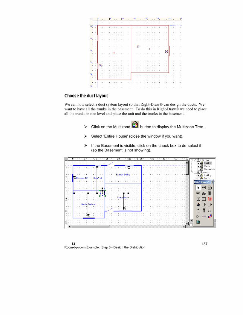
13 Room-by-room Example: Step 3 - Design the Distribution
187
Choose the duct layout
We can now select a duct system layout so that Right-Draw® can design the ducts. We want to have all the trunks in the basement. To do this in Right-Draw® we need to place all the trunks in one level and place the unit and the trunks in the basement.
Click on the Multizone button to display the Multizone Tree.
Select 'Entire House' (close the window if you want).
If the Basement is visible, click on the check box to de-select it (so the Basement is not showing).

Part II - CSA Residential Examples 188
Click on the unit to select it then right click to view the Property Sheet for the unit
Select 'X-axis one-level trunks' in the 'Duct system layout' field.
RSU provides a horizontal extended plenum duct design, sizes the ducts, and draws the duct system. In addition, this duct system layout will put all trunks on one level.
With any of the automatic design modes (selected in the unit Property Sheet), the trunks will be attached to the unit. In fact, if you move the unit, the trunks move with it.
The unit is placed on the first level that a room is drawn. The first room we drew was on the First Floor therefore Right-Draw® would place the unit on the First Floor. We need to move the unit to the Basement. Because the trunks move with the unit, the trunks will also be placed in the Basement, too.
Click the right mouse button with the mouse pointer on the unit (the unit is selected in the illustration below) to display the Property Sheet for it.
Select the General tab then click the 'Sheet' field. Select 'Basement' from the list of the available sheets that drop down. Close the Property Sheet.
View the duct details
Click on the Right-Duct™ button in the Selector Toolbar.
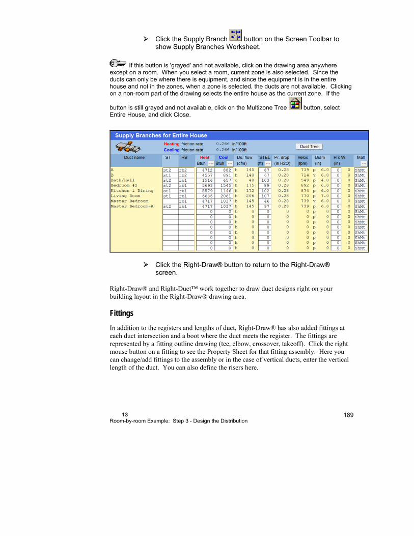
13 Room-by-room Example: Step 3 - Design the Distribution
189
Click the Supply Branch button on the Screen Toolbar to show Supply Branches Worksheet.
If this button is 'grayed' and not available, click on the drawing area anywhere except on a room. When you select a room, current zone is also selected. Since the ducts can only be where there is equipment, and since the equipment is in the entire house and not in the zones, when a zone is selected, the ducts are not available. Clicking on a non-room part of the drawing selects the entire house as the current zone. If the
button is still grayed and not available, click on the Multizone Tree button, select Entire House, and click Close.
Click the Right-Draw® button to return to the Right-Draw® screen.
Right-Draw® and Right-Duct™ work together to draw duct designs right on your building layout in the Right-Draw® drawing area.
Fittings
In addition to the registers and lengths of duct, Right-Draw® has also added fittings at each duct intersection and a boot where the duct meets the register. The fittings are represented by a fitting outline drawing (tee, elbow, crossover, takeoff). Click the right mouse button on a fitting to see the Property Sheet for that fitting assembly. Here you can change/add fittings to the assembly or in the case of vertical ducts, enter the vertical length of the duct. You can also define the risers here.
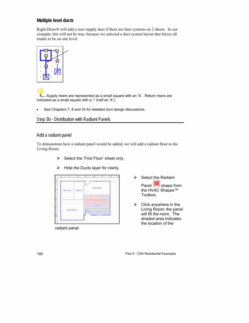
Part II - CSA Residential Examples 190
Multiple level ducts
Right-Draw® will add a riser supply duct if there are duct systems on 2 sheets. In our example, this will not be true, because we selected a duct system layout that forces all trunks to be on one level.
Supply risers are represented as a small square with an ‘X’. Return risers are indicated as a small square with a ‘/’ (half an ‘X’).
See Chapters 7, 8 and 24 for detailed duct design discussions.
Step 3b - Distribution with Radiant Panels
Add a radiant panel
To demonstrate how a radiant panel would be added, we will add a radiant floor to the Living Room.
Select the ‘First Floor’ sheet only.
Hide the Ducts layer for clarity.
Select the Radiant
Panel shape from the HVAC Shapes™ Toolbox.
Click anywhere in the Living Room; the panel will fill the room. The shaded area indicates the location of the
radiant panel.
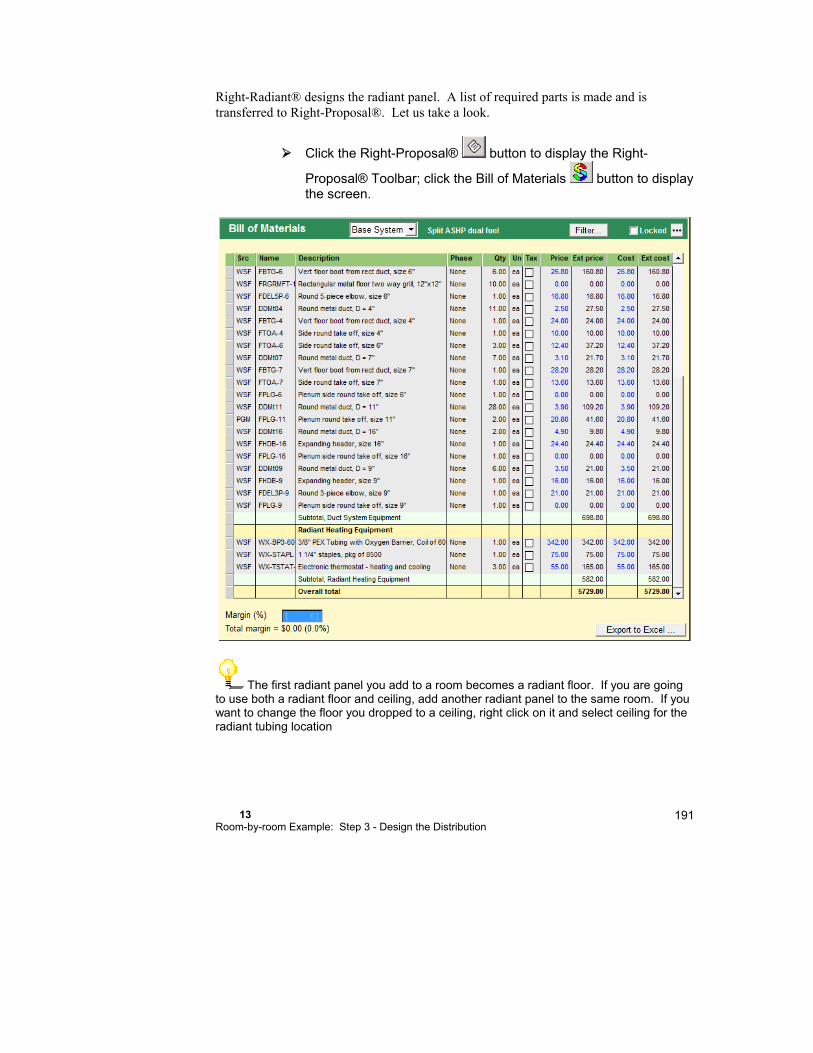
13 Room-by-room Example: Step 3 - Design the Distribution
191
Right-Radiant® designs the radiant panel. A list of required parts is made and is transferred to Right-Proposal®. Let us take a look.
Click the Right-Proposal® button to display the Right-
Proposal® Toolbar; click the Bill of Materials button to display the screen.
The first radiant panel you add to a room becomes a radiant floor. If you are going to use both a radiant floor and ceiling, add another radiant panel to the same room. If you want to change the floor you dropped to a ceiling, right click on it and select ceiling for the radiant tubing location

Part II - CSA Residential Examples 192
Fine-Tune the Design
This section describes the additional Right-Radiant® screens used to specify design details for fine-tuning the design. For detailed information about these additional screens, see Chapter 26.
Radiant panel construction number
You can select the radiant floor type for an individual panel in the Floor tab of the Room Property Sheet. Here is how.
Click the Right-Draw® button to return the Right-Draw® screen.
The radiant floor in the Living Room should still be selected.
Click in the Living Room a second time to select the room itself (the green handles will indicate whether the room or radiant panel is selected).
Click the right mouse button on the selected room to display the room Property Sheet.
Click on the Floor tab to display the floor properties.
Click on the ‘Radiant floor type’ field to display the 'What are my choices?' window for radiant floors.
Select type 41 on the left and 41B0 on the right then click OK.
The linked image cannot be displayed. The file may have been moved, renamed, or deleted. Verify that the link points to the correct file and location.

13 Room-by-room Example: Step 3 - Design the Distribution
193
If you need to change the additional back insulation R-value or view the total back insulation or total U-value, do so now. Click OK and close the Property Sheet.
You may need to modify the shape and size of the radiant panel for your particular situation. You can resize and move radiant floors and ceilings just like rooms by dragging the handles with the mouse. You can also use edit points on a radiant panel to change the shape.
Changes to the radiant panel area and location made in Right-Draw® are automatically entered in the Right-F280™ Worksheet, along with automatic changes to the non-radiant panel areas.
See Chapter 26 for a detailed discussion of radiant panel design.
Step 3c - Baseboards
Size baseboards by entering high and low efficiency baseboard capacities in the Project Information Screen.
Click the Project Information button in the Project Toolbar to display the Project Information Screen.
Use the scroll bar to go to the bottom of the Project Information Screen to view the Baseboard Data.

Part II - CSA Residential Examples 194
If you enter the baseboard capacities here, Right-F280™ will calculate the feet of baseboard required for each room based on the room load and display the baseboard data on line 14 on the Right-F280™ Worksheet.

13 Room-by-room Example: Step 3 - Design the Distribution
195
Things to Remember
Distribution is accomplished with air via ducts, radiant panels or hydronic baseboards.
Set the fan AVF and static pressure before laying out the duct system.
Right-Draw® will design a duct system automatically; just place your registers and choose the duct layout in the Property Sheet for the unit.
The duct information from Right-Draw® is used by Right-Duct™ to size the ducts.
Right-Draw® will design radiant panel systems and transfer a list of required parts to Right-Proposal®.
Set the baseboard ratings in the Project Information Screen. Right-F280™ will calculate the feet of hydronic baseboard for each room and displayed the data on line 14 of the Right-F280™ Worksheet (NOTE: If no baseboard values entered on the Project Information Screen, then line 14 displays the air required).


14
Room-by-room Example: Step 4 - Document the Project
Step 4a - Complete the Job Quotation ........................ 198
Step 4b - Save the Project .......................................... 198
Step 4c - Generate Reports ........................................ 198
Things to Remember ................................................... 200
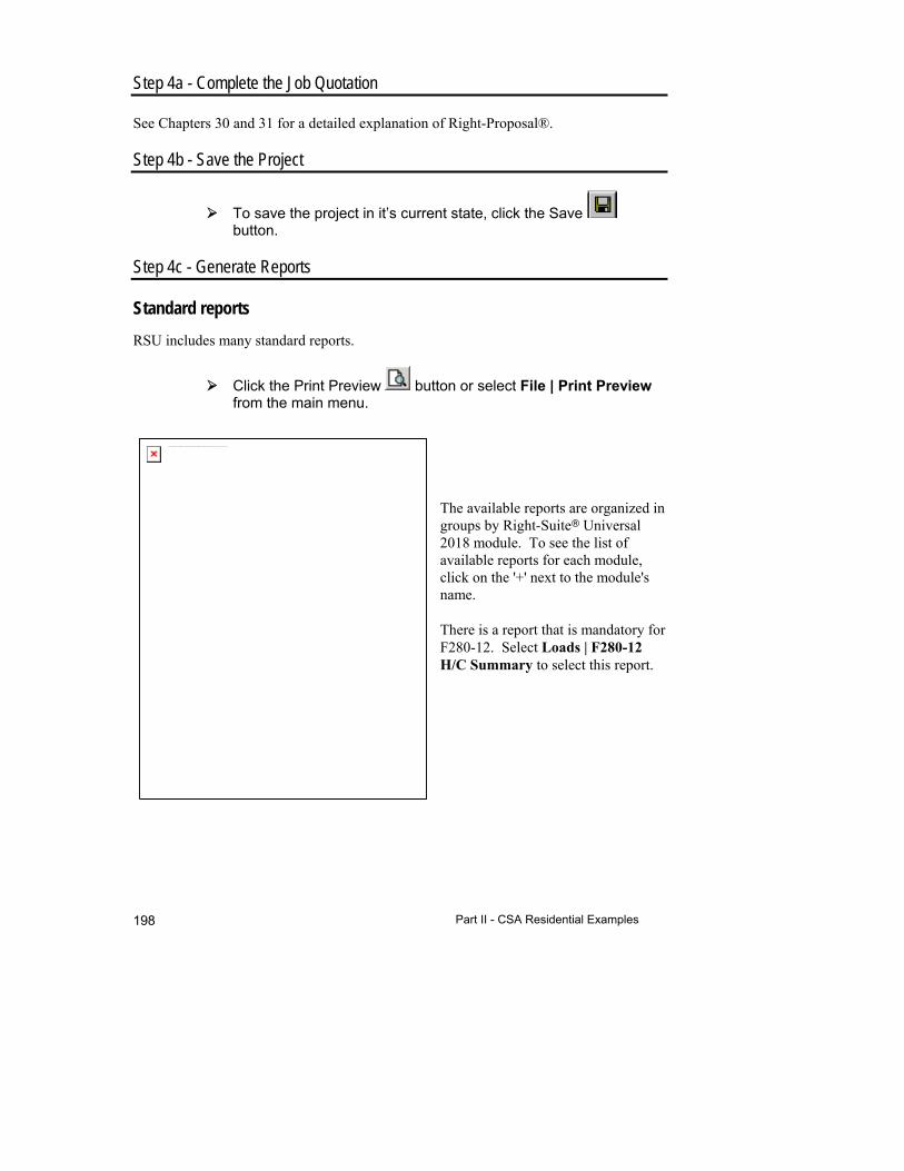
Part II - CSA Residential Examples 198
Step 4a - Complete the Job Quotation
See Chapters 30 and 31 for a detailed explanation of Right-Proposal®.
Step 4b - Save the Project
To save the project in it’s current state, click the Save button.
Step 4c - Generate Reports
Standard reports
RSU includes many standard reports.
Click the Print Preview button or select File | Print Preview from the main menu.
The available reports are organized in groups by Right-Suite Universal 2018 module. To see the list of available reports for each module, click on the '+' next to the module's name.
There is a report that is mandatory for F280-12. Select Loads | F280-12 H/C Summary to select this report.
The linked image cannot be displayed. The file may have been moved, renamed, or deleted. Verify that the link points to the correct file and location.
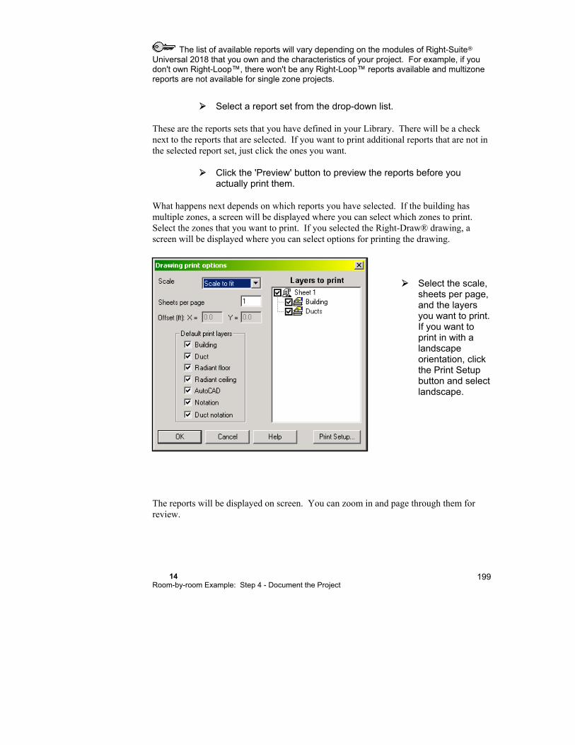
14 Room-by-room Example: Step 4 - Document the Project
199
The list of available reports will vary depending on the modules of Right-Suite Universal 2018 that you own and the characteristics of your project. For example, if you don't own Right-Loop™, there won't be any Right-Loop™ reports available and multizone reports are not available for single zone projects.
Select a report set from the drop-down list.
These are the reports sets that you have defined in your Library. There will be a check next to the reports that are selected. If you want to print additional reports that are not in the selected report set, just click the ones you want.
Click the 'Preview' button to preview the reports before you actually print them.
What happens next depends on which reports you have selected. If the building has multiple zones, a screen will be displayed where you can select which zones to print. Select the zones that you want to print. If you selected the Right-Draw® drawing, a screen will be displayed where you can select options for printing the drawing.
Select the scale, sheets per page, and the layers you want to print. If you want to print in with a landscape orientation, click the Print Setup button and select landscape.
The reports will be displayed on screen. You can zoom in and page through them for review.

Part II - CSA Residential Examples 200
You may want to print without previewing the reports. To do this just click on the Print button or select File | Print from the main menu. Previewing allows you to verify that the information is correct before printing. You can also zoom in or out and view multiple pages at once if you preview the reports.
Things to Remember
RSU provides a library of standard reports that you might find useful. Select ‘Inspection Report’ from the library of Report Packages.

Part III - Commercial Examples

15 Single Zone Example: Step 1 - Describe the Building
The next chapters will go through the steps necessary to design a project from start to finish. The first example will be a one-room building. This simple building will demonstrate the design procedure without the complexities of a real-life design. Once the overall procedure is introduced, we will proceed to the details of each step.
This chapter tells you how to use Right-Draw® as a fast and efficient way to enter a building description into Right-Suite Universal 2018. Right-Draw® will also help you layout your equipment, ducts, and registers.
Entering a Simple Building .......................................... 204
Step 1a - Start a new project ....................................... 205
Step 1b - Add spaces, doors, and windows ................. 205
Step 1c - Add internal gains ........................................ 211
Things to Remember ................................................... 212
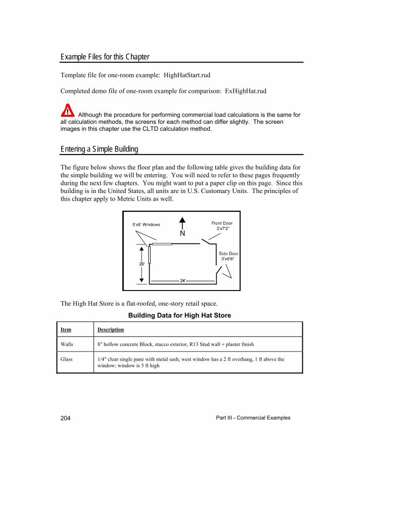
Part III - Commercial Examples 204
Example Files for this Chapter
Template file for one-room example: HighHatStart.rud
Completed demo file of one-room example for comparison: ExHighHat.rud
Although the procedure for performing commercial load calculations is the same for all calculation methods, the screens for each method can differ slightly. The screen images in this chapter use the CLTD calculation method.
Entering a Simple Building
The figure below shows the floor plan and the following table gives the building data for the simple building we will be entering. You will need to refer to these pages frequently during the next few chapters. You might want to put a paper clip on this page. Since this building is in the United States, all units are in U.S. Customary Units. The principles of this chapter apply to Metric Units as well.
The High Hat Store is a flat-roofed, one-story retail space.
Building Data for High Hat Store
Item Description
Walls 8" hollow concrete Block, stucco exterior, R13 Stud wall + plaster finish
Glass 1/4" clear single pane with metal sash; west window has a 2 ft overhang, 1 ft above the window; window is 5 ft high
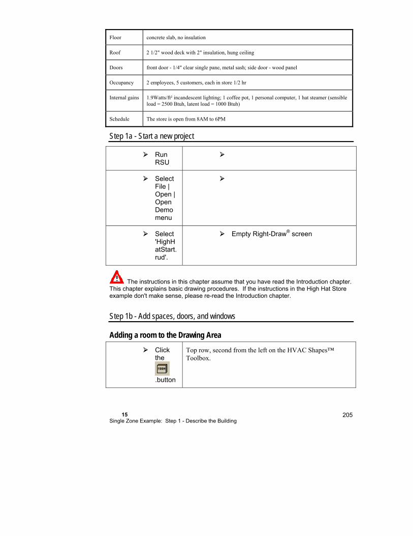
15 Single Zone Example: Step 1 - Describe the Building
205
Floor concrete slab, no insulation
Roof 2 1/2" wood deck with 2" insulation, hung ceiling
Doors front door - 1/4" clear single pane, metal sash; side door - wood panel
Occupancy 2 employees, 5 customers, each in store 1/2 hr
Internal gains 1.9Watts/ft² incandescent lighting; 1 coffee pot, 1 personal computer, 1 hat steamer (sensible load = 2500 Btuh, latent load = 1000 Btuh)
Schedule The store is open from 8AM to 6PM
Step 1a - Start a new project
Run RSU
Select File | Open | Open Demo menu
Select 'HighHatStart.rud'.
Empty Right-Draw® screen
The instructions in this chapter assume that you have read the Introduction chapter. This chapter explains basic drawing procedures. If the instructions in the High Hat Store example don't make sense, please re-read the Introduction chapter.
Step 1b - Add spaces, doors, and windows
Adding a room to the Drawing Area
Click the
.button
Top row, second from the left on the HVAC Shapes™ Toolbox.
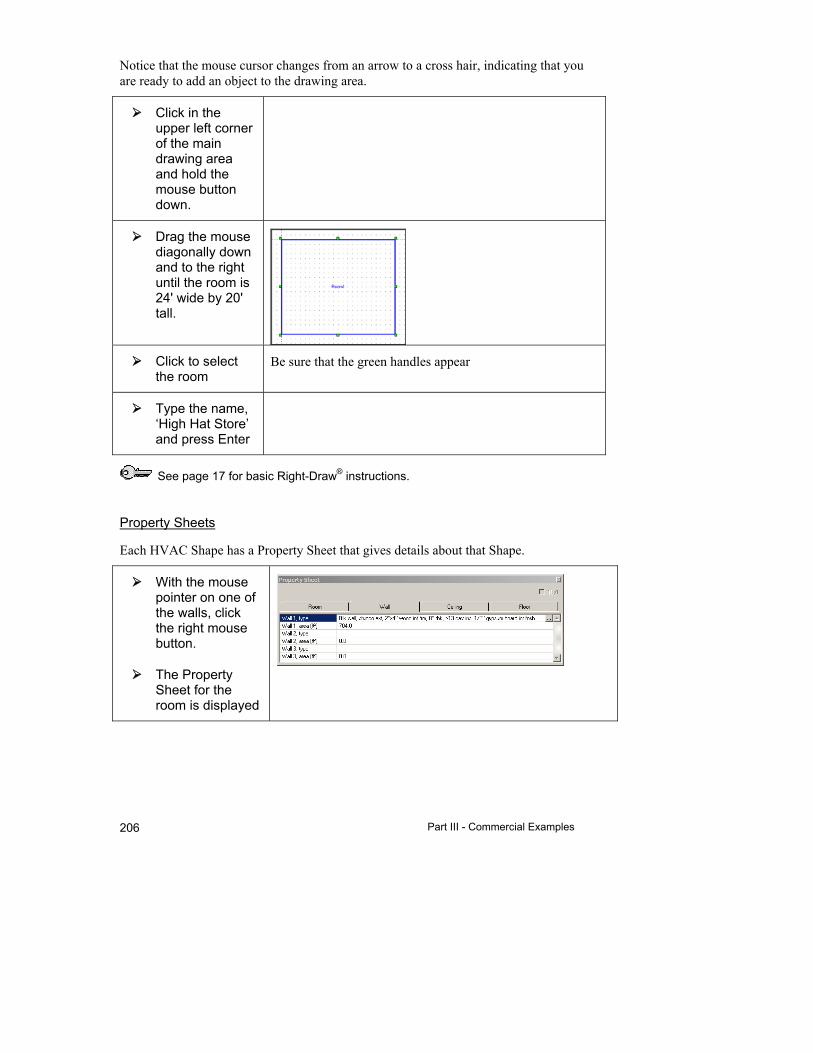
Part III - Commercial Examples 206
Notice that the mouse cursor changes from an arrow to a cross hair, indicating that you are ready to add an object to the drawing area.
Click in the upper left corner of the main drawing area and hold the mouse button down.
Drag the mouse diagonally down and to the right until the room is 24' wide by 20' tall.
Click to select the room
Be sure that the green handles appear
Type the name, ‘High Hat Store’ and press Enter
See page 17 for basic Right-Draw® instructions.
Property Sheets
Each HVAC Shape has a Property Sheet that gives details about that Shape.
With the mouse pointer on one of the walls, click the right mouse button.
The Property Sheet for the room is displayed

15 Single Zone Example: Step 1 - Describe the Building
207
Close the Property Sheet by clicking on the
in the upper right corner.
The Load Meter
As you make changes to the drawing, Right-CommLoad® calculates the load and displays the results in the Load Meter.
Select Show | Right-Comm Load™ | Load Meter.
Adding doors
There are 2 doors on our store - one in the north wall and one in the east wall. The north door is a glass door. Since we want to include solar gains for this door, we need to enter it as a window rather than as a door. Let's add the east door.
The top of the Right-Draw® is north, the bottom is south, etc.
Peak Loads
Loads at each hour for each month
Loads at each hour during Display month

Part III - Commercial Examples 208
Select the button. Top row, far right on the HVAC Shapes™ toolbox.
Click on the east wall (on the right side of the drawing) 15' from the top.
Use the rulers on the side as a guide.
Drag the mouse up until the door length is 3'.
Adding windows
Adding windows is just as easy as adding doors.
We'll start with the north door that we just skipped when we entered the doors.
Click on the button
Top row, 2nd from the right
Click on the north (top) wall at the 18' mark.
Drag to the right until the window is 3' wide.
Since this is a door and not a window, we need to modify the construction and window height.
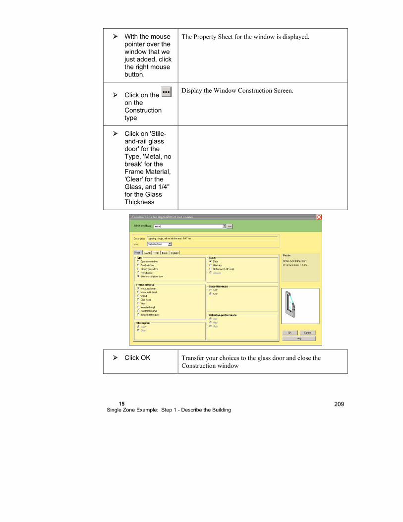
15 Single Zone Example: Step 1 - Describe the Building
209
With the mouse pointer over the window that we just added, click the right mouse button.
The Property Sheet for the window is displayed.
Click on the on the Construction type
Display the Window Construction Screen.
Click on 'Stile-and-rail glass door' for the Type, 'Metal, no break' for the Frame Material, 'Clear' for the Glass, and 1/4" for the Glass Thickness
Click OK Transfer your choices to the glass door and close the Construction window

Part III - Commercial Examples 210
On the third line of the Property Sheet, we can see that the height is set to 4.0', the default. We need to change this to 7'2" or 7.2'.
Click on the '4.0' on the 'Height' line, type 7.2, and press the Enter key.
The area on the fifth line will be recalculated using the width and the new height.
Now let's add the north window.
Click on the Window shape
top row, 2nd from the right
Click on the north wall 1' from the left.
Drag the mouse to the right until the length of the window is 8'.
Click on the window that we just added to display its Property Sheet.
If the Property Sheet is not displayed, click with the right mouse button on the window that we just added.
Change the Height to 5'.
Since the west window is the same as the one we just added, we will add the other window by copying the one we just added.

15 Single Zone Example: Step 1 - Describe the Building
211
Hold down the Ctrl key and click on the window you just created. Hold the mouse button down and drag the mouse so that the window starts at 9' on the west wall - use the ruler on the right to determine the location.
The copied window will rotate 90 degrees to fit on the west wall.
Since we have only one ceiling and one floor type, the floor is under the entire room, and the ceiling area is the same as the floor area, we don't need to add a ceiling or floor.
Step 1c - Add internal gains
Internal heat gains due to occupants, lights, appliances, etc. have been entered automatically according to the schedules that were pre-set in the 'HighHatStart' Demo project that we started with.
Appliances
Click the right mouse button on the room to display the Property Sheet.
In the Property Sheet, click on 'Select ...' for Int.gains for Appliances. Hint: scroll down.
Under 'Application' 3rd one down
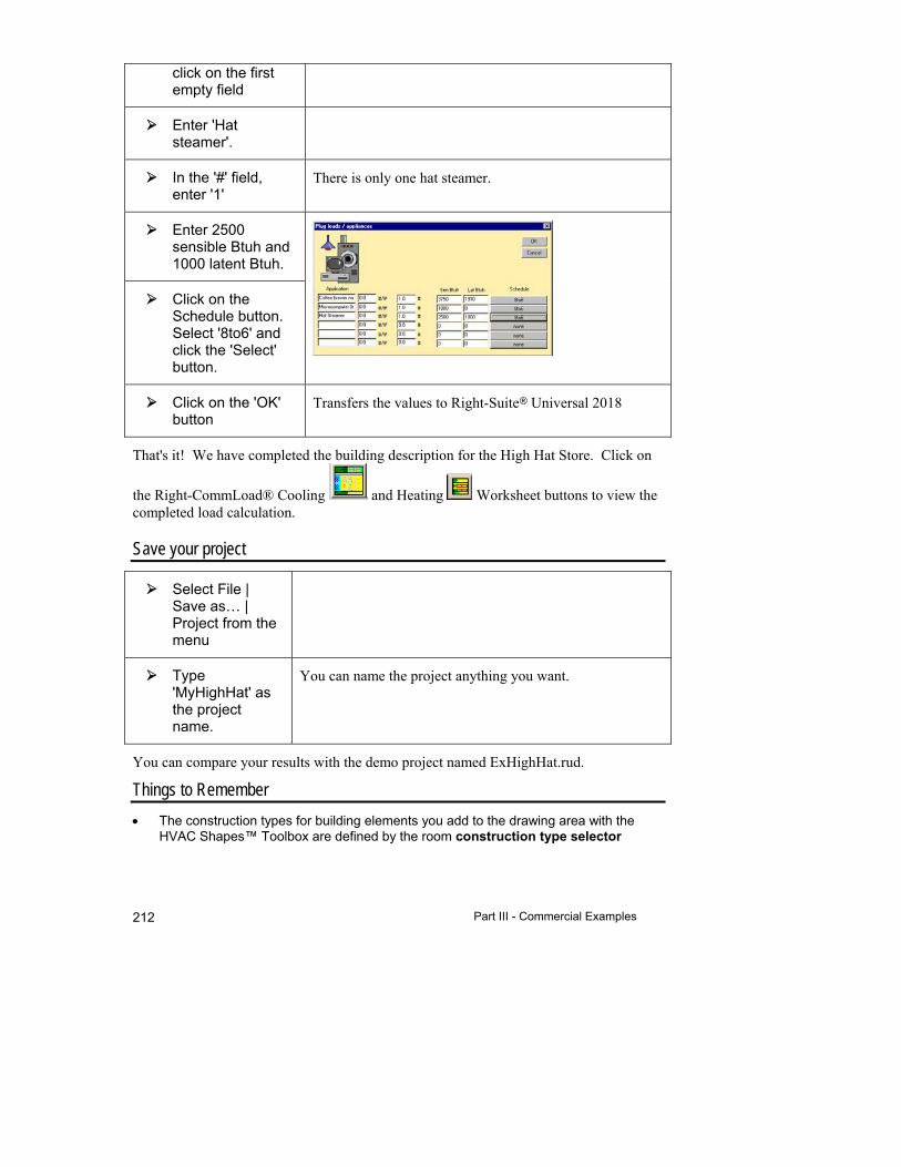
Part III - Commercial Examples 212
click on the first empty field
Enter 'Hat steamer'.
In the '#' field, enter '1'
There is only one hat steamer.
Enter 2500 sensible Btuh and 1000 latent Btuh.
Click on the Schedule button. Select '8to6' and click the 'Select' button.
Click on the 'OK' button
Transfers the values to Right-Suite Universal 2018
That's it! We have completed the building description for the High Hat Store. Click on
the Right-CommLoad® Cooling and Heating Worksheet buttons to view the completed load calculation.
Save your project
Select File | Save as… | Project from the menu
Type 'MyHighHat' as the project name.
You can name the project anything you want.
You can compare your results with the demo project named ExHighHat.rud.
Things to Remember
The construction types for building elements you add to the drawing area with the HVAC Shapes™ Toolbox are defined by the room construction type selector
15 Single Zone Example: Step 1 - Describe the Building
213
immediately above the drawing area. Changing the settings in the construction type selector has no effect on building elements already drawn.
Stretch wall or window width by dragging one handle.
Click the right-mouse button on any object to see the Property Sheet for that object.
Hold down the shift key and select any group of similar objects. Then right-click to see the common properties for the entire group. Change any property, and you’ll effect the entire group, all at once.
You can Ctrl-drag to copy any object. You can also use Ctrl-C (Edit | Copy) and Ctrl-V (Edit | Paste) to make multiple copies of any object.
Right-Draw® automatically adds a floor and a ceiling to each room using the default construction types. See the property sheet for the room.

16 Single Zone Example: Step 2 - Select the Equipment
In this chapter, we will design and select the equipment system for the single-zone High Hat Store example that we worked with in the last chapter.
Step 2a - Assign zoning .............................................. 216
Step 2b - Specify equipment ....................................... 216
Equipment Loads ........................................................ 217
Equipment Selection ................................................... 218
Fan cfm ....................................................................... 220
Things to Remember ................................................... 221
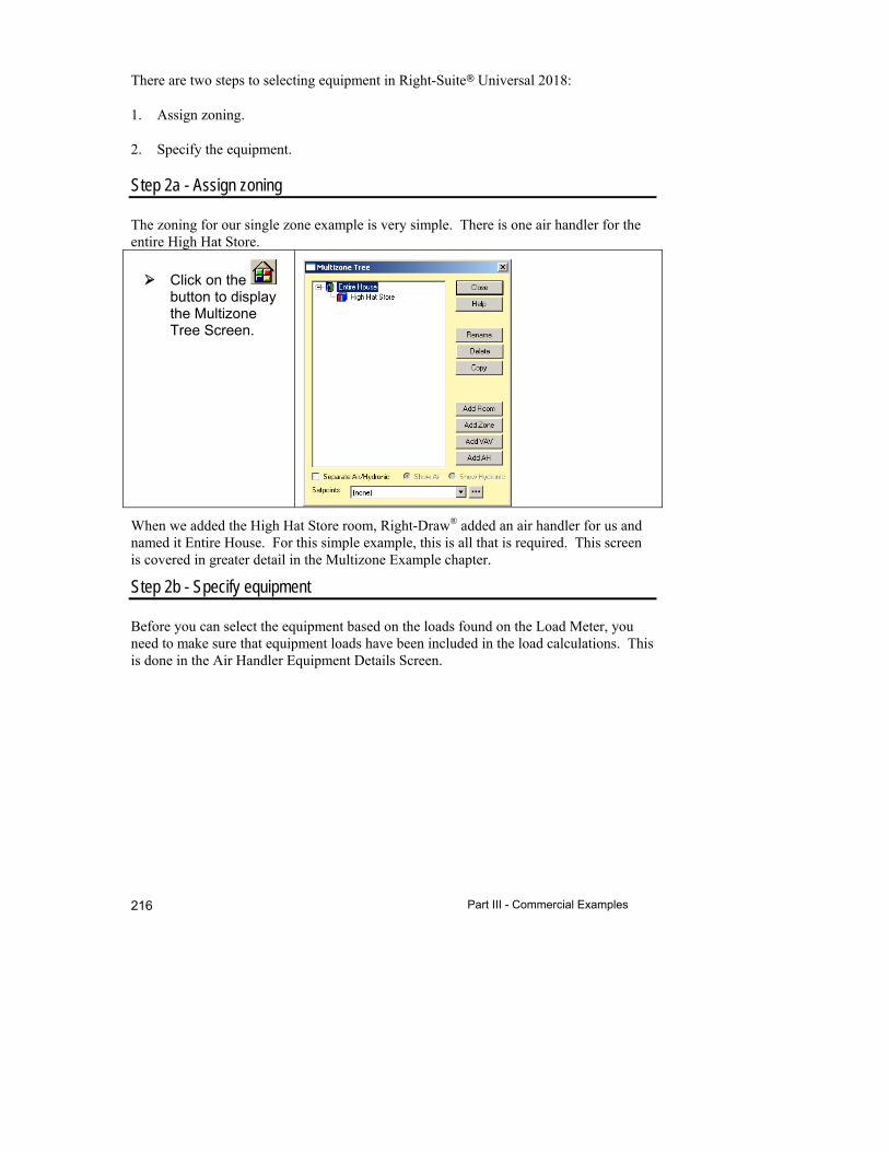
Part III - Commercial Examples 216
There are two steps to selecting equipment in Right-Suite Universal 2018:
1. Assign zoning.
2. Specify the equipment.
Step 2a - Assign zoning
The zoning for our single zone example is very simple. There is one air handler for the entire High Hat Store.
Click on the button to display the Multizone Tree Screen.
When we added the High Hat Store room, Right-Draw® added an air handler for us and named it Entire House. For this simple example, this is all that is required. This screen is covered in greater detail in the Multizone Example chapter.
Step 2b - Specify equipment
Before you can select the equipment based on the loads found on the Load Meter, you need to make sure that equipment loads have been included in the load calculations. This is done in the Air Handler Equipment Details Screen.
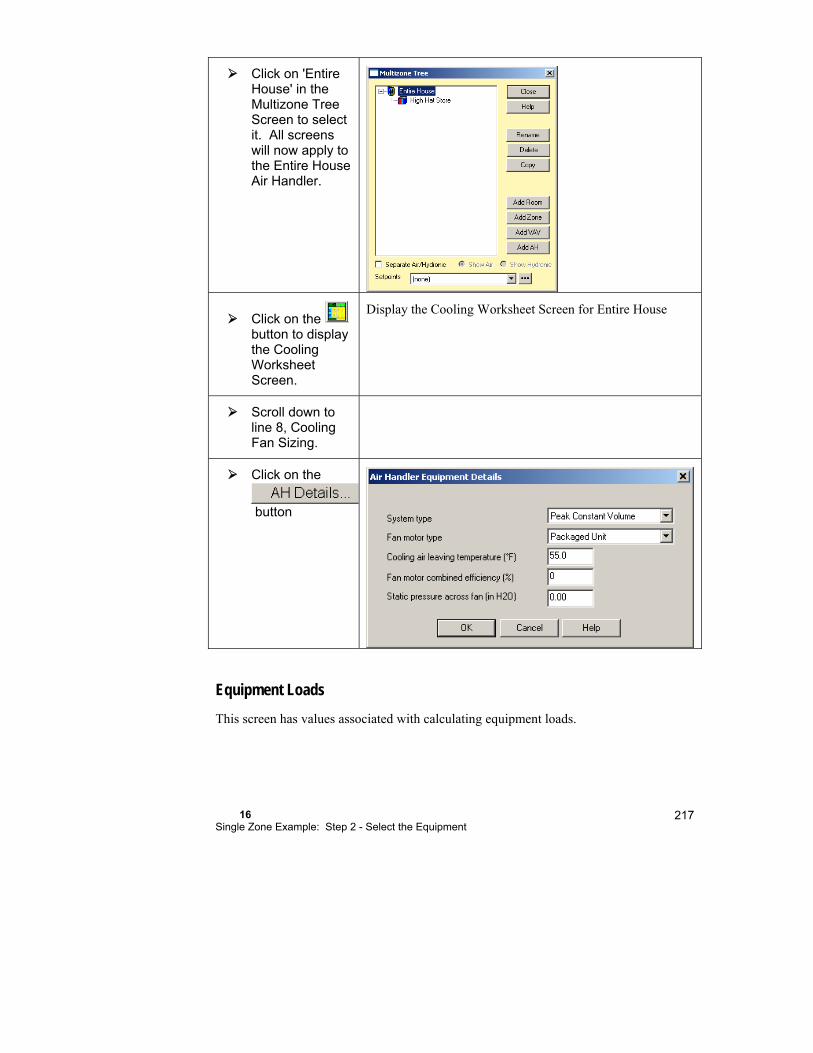
16 Single Zone Example: Step 2 - Select the Equipment
217
Click on 'Entire House' in the Multizone Tree Screen to select it. All screens will now apply to the Entire House Air Handler.
Click on the button to display the Cooling Worksheet Screen.
Display the Cooling Worksheet Screen for Entire House
Scroll down to line 8, Cooling Fan Sizing.
Click on the
button
Equipment Loads
This screen has values associated with calculating equipment loads.
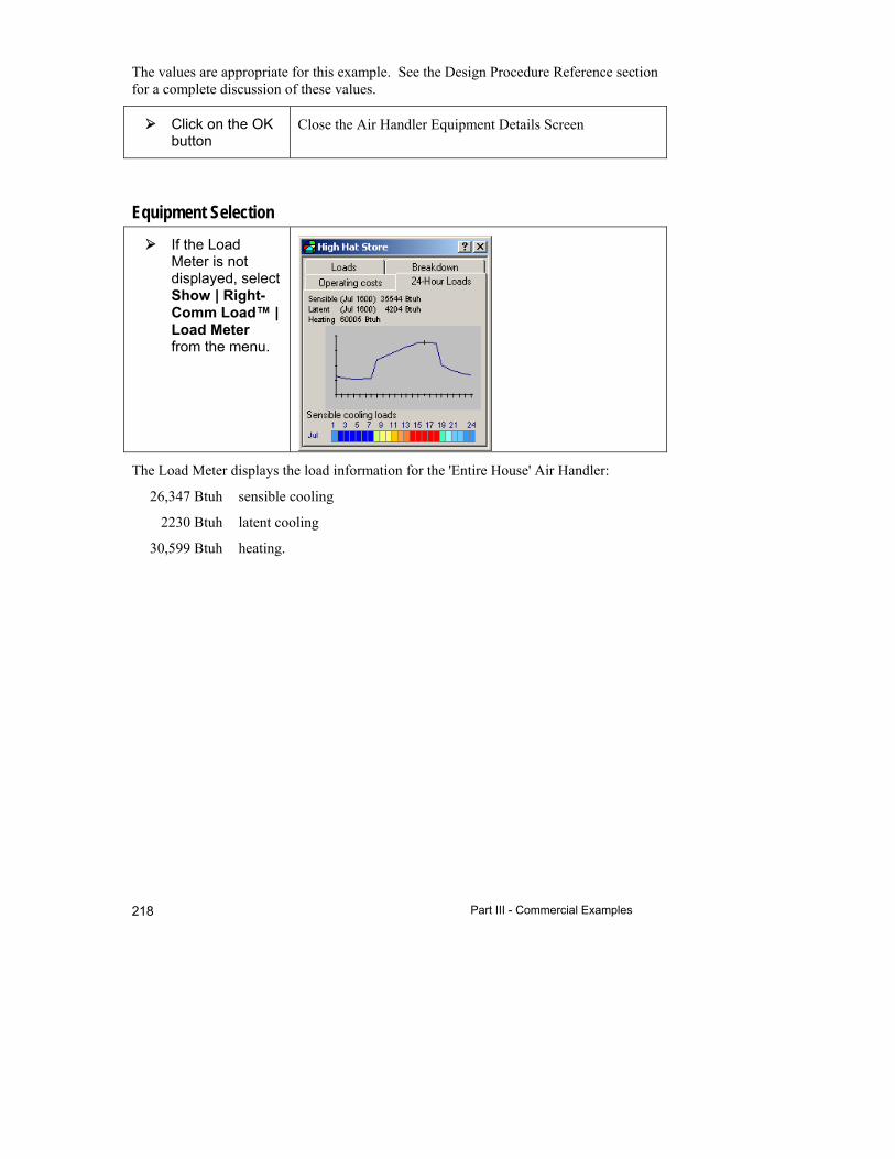
Part III - Commercial Examples 218
The values are appropriate for this example. See the Design Procedure Reference section for a complete discussion of these values.
Click on the OK button
Close the Air Handler Equipment Details Screen
Equipment Selection
If the Load Meter is not displayed, select Show | Right-Comm Load™ | Load Meter from the menu.
The Load Meter displays the load information for the 'Entire House' Air Handler:
26,347 Btuh sensible cooling
2230 Btuh latent cooling
30,599 Btuh heating.

16 Single Zone Example: Step 2 - Select the Equipment
219
Click on the button
Click on 'Split air source HP' for the Cooling type
Click on 'Furnace' and 'Natural gas' for the Supplemental heating
Select 'None' for the Water heating
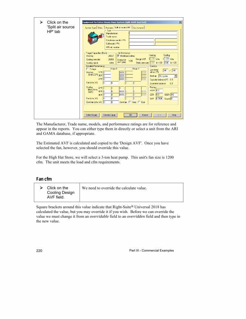
Part III - Commercial Examples 220
Click on the 'Split air source HP' tab
The Manufacturer, Trade name, models, and performance ratings are for reference and appear in the reports. You can either type them in directly or select a unit from the ARI and GAMA database, if appropriate.
The Estimated AVF is calculated and copied to the 'Design AVF'. Once you have selected the fan, however, you should override this value.
For the High Hat Store, we will select a 3-ton heat pump. This unit's fan size is 1200 cfm. The unit meets the load and cfm requirements.
Fan cfm
Click on the Cooling Design AVF field.
We need to override the calculate value.
Square brackets around this value indicate that Right-Suite Universal 2018 has calculated the value, but you may override it if you wish. Before we can override the value we must change it from an overridable field to an overridden field and then type in the new value.
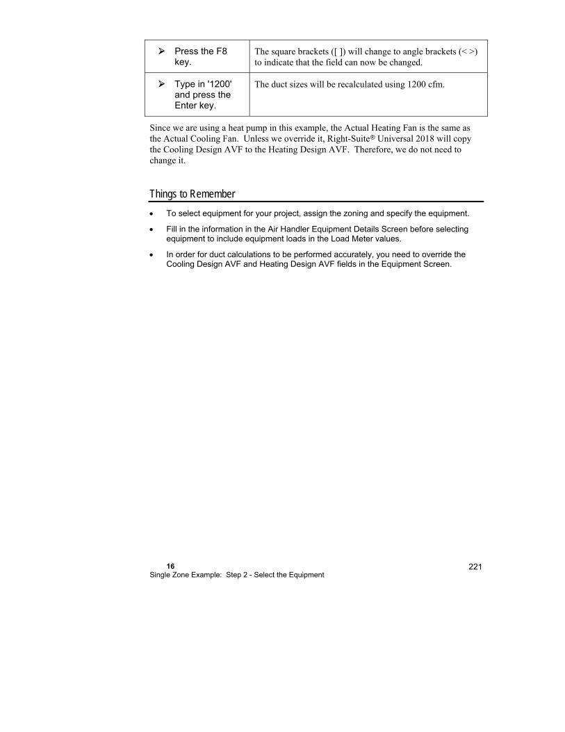
16 Single Zone Example: Step 2 - Select the Equipment
221
Press the F8 key.
The square brackets ([ ]) will change to angle brackets (< >) to indicate that the field can now be changed.
Type in '1200' and press the Enter key.
The duct sizes will be recalculated using 1200 cfm.
Since we are using a heat pump in this example, the Actual Heating Fan is the same as the Actual Cooling Fan. Unless we override it, Right-Suite Universal 2018 will copy the Cooling Design AVF to the Heating Design AVF. Therefore, we do not need to change it.
Things to Remember
To select equipment for your project, assign the zoning and specify the equipment.
Fill in the information in the Air Handler Equipment Details Screen before selecting equipment to include equipment loads in the Load Meter values.
In order for duct calculations to be performed accurately, you need to override the Cooling Design AVF and Heating Design AVF fields in the Equipment Screen.

17 Single Zone Example: Step 3 - Distribution
Step 3 - Air Distribution via ducts ................................ 224
The Ducts Layer .......................................................... 224
Things to Remember ................................................... 226
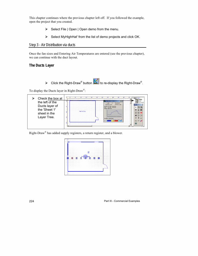
Part III - Commercial Examples 224
This chapter continues where the previous chapter left off. If you followed the example, open the project that you created.
Select File | Open | Open demo from the menu.
Select MyHighHat' from the list of demo projects and click OK.
Step 3 - Air Distribution via ducts
Once the fan sizes and Entering Air Temperatures are entered (see the previous chapter), we can continue with the duct layout.
The Ducts Layer
Click the Right-Draw® button to re-display the Right-Draw®.
To display the Ducts layer in Right-Draw®:
Check the box at the left of the Ducts layer of the 'Sheet 1' sheet in the Layer Tree.
Right-Draw® has added supply registers, a return register, and a blower.
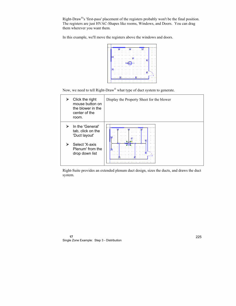
17 Single Zone Example: Step 3 - Distribution
225
Right-Draw®'s 'first-pass' placement of the registers probably won't be the final position. The registers are just HVAC-Shapes like rooms, Windows, and Doors. You can drag them wherever you want them.
In this example, we'll move the registers above the windows and doors.
Now, we need to tell Right-Draw® what type of duct system to generate.
Click the right mouse button on the blower in the center of the room.
Display the Property Sheet for the blower
In the 'General' tab, click on the 'Duct layout'
Select 'X-axis Plenum' from the drop down list
Right-Suite provides an extended plenum duct design, sizes the ducts, and draws the duct system.

Part III - Commercial Examples 226
Check the box at the left of the Ducts Notation layer of the 'Sheet 1' sheet in the Layer Tree.
Display the duct size calculation results.
Things to Remember
Set the fan CFM before laying out ducts.
Once Right-Draw® places the registers initially, you should re-position them to their final location.
The duct information in Right-Draw® is used by Right-CommDuct™ to size the ducts.
Right-Draw® adds fittings according to the preset defaults in the Duct Preferences Screen.

18 Single Zone Example: Step 4 - Document the Project
Step 4a - Complete the Job Quotation ........................ 228
Step 4b - Save the Project .......................................... 228
Step 4c - Generate Reports ........................................ 228
Things to Remember ................................................... 230

Part III - Commercial Examples 228
Step 4a - Complete the job quotation
When Right-CommDuct™ designed and sized the ducts, it transferred a parts list to Right-Proposal.
Click on the button to display the Right-Proposal Toolbar
and then click the button to display the Bill of Materials Screen.
Step 4b - Save the Project
We may save our project in its current state by clicking on the
button.
Step 4c - Generate reports
Right-Suite Universal 2018 includes many standard reports. As a quick example of how to print out a report, these instructions will help you to print out the Summary Report.

18 Single Zone Example: Step 4 - Document the Project
229
To access the list of Right-Suite Universal 2018’s reports, either
click the button or select File | Print from the menu.
A ‘Choose Report’ screen will pop-up. Click in the box next to the 'Load: Summary' report. Click 'Print' to print the report.
To un-check a report, click it again.
A 'Select Zones to Print' screen will pop up. Leave 'High Hat Store' selected and click OK to print.
With Right-Suite Universal 2018, you may also preview any of these reports in a Print Preview screen that will allow you to Zoom-In or Out, view multiple pages, or even print.

Part III - Commercial Examples 230
Things to Remember
Right-Suite Universal 2018 provides a library of standard reports.
You can either print the standard reports or preview them on the screen before printing them.

19 Multi-Zone Example: Step 1 - Describe the Building
In the High Hat example we focused on the process of designing a project in Right-Suite Universal 2018. We skipped some real-life details to give an overview of the process. In this chapter we will build on this overview and cover more of the details.
Example Files for this Chapter .................................... 232
Entering a Multizone Building ...................................... 232
Step 1a - Start a new project ....................................... 234
Step 1b - Add spaces, doors, and windows ................. 234
Things to Remember ................................................... 241

232
The steps are the same for this example as they were for the High Hat example.
Example Files for this Chapter
Template file for one-room example: MZExampleStart.rud
Completed demo file of multizone example for comparison: ExMZExample.rud
Although the procedure for performing commercial load calculations is the same for all calculation methods, the screens for each method can be differ slightly. The screen images in this chapter use the CLTD calculation method.
Entering a Multizone Building
The figure below shows the floor plan and the following table gives the building data for the multizone building we will be entering. You will need to refer to these pages frequently during the next few chapters. You might want to put a paper clip on this page. Since this building is in the United States, all units are in U.S. Customary Units. The principles of this chapter apply to Metric Units as well.
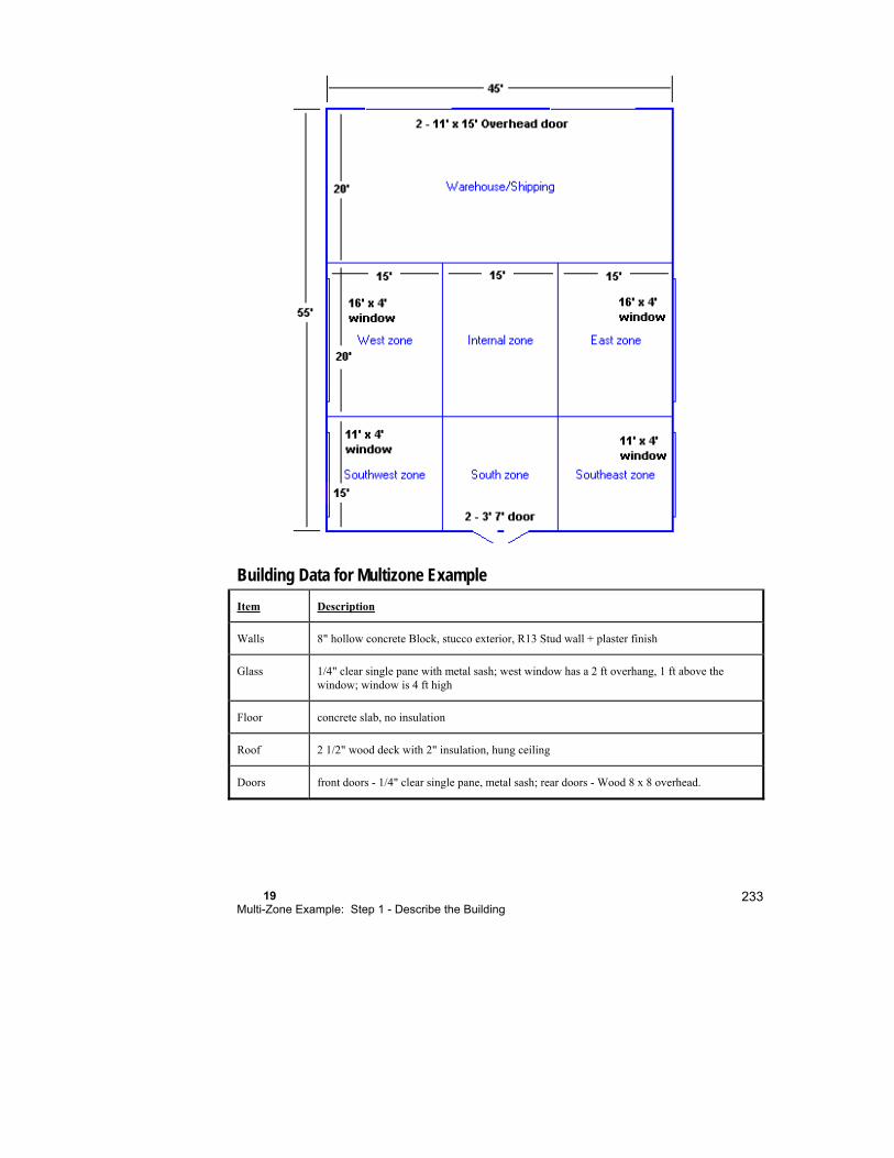
19 Multi-Zone Example: Step 1 - Describe the Building
233
Building Data for Multizone Example
Item Description
Walls 8" hollow concrete Block, stucco exterior, R13 Stud wall + plaster finish
Glass 1/4" clear single pane with metal sash; west window has a 2 ft overhang, 1 ft above the window; window is 4 ft high
Floor concrete slab, no insulation
Roof 2 1/2" wood deck with 2" insulation, hung ceiling
Doors front doors - 1/4" clear single pane, metal sash; rear doors - Wood 8 x 8 overhead.
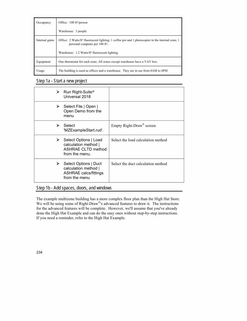
234
Occupancy Office: 100 ft²/person
Warehouse: 3 people
Internal gains Office: 2 Watts/ft² fluorescent lighting; 1 coffee pot and 1 photocopier in the internal zone, 1 personal computer per 100 ft²,
Warehouse: 1.2 Watts/ft² fluorescent lighting
Equipment One thermostat for each zone; All zones except warehouse have a VAV box.
Usage The building is used as offices and a warehouse. They are in use from 8AM to 6PM
Step 1a - Start a new project
Run Right-Suite Universal 2018
Select File | Open | Open Demo from the menu
Select 'MZExampleStart.rud'.
Empty Right-Draw® screen
Select Options | Load calculation method | ASHRAE CLTD method from the menu.
Select the load calculation method
Select Options | Duct calculation method | ASHRAE calcs/fittings from the menu
Select the duct calculation method
Step 1b - Add spaces, doors, and windows
The example multizone building has a more complex floor plan than the High Hat Store. We will be using some of Right-Draw®'s advanced features to draw it. The instructions for the advanced features will be complete. However, we'll assume that you've already done the High Hat Example and can do the easy ones without step-by-step instructions. If you need a reminder, refer to the High Hat Example.

19 Multi-Zone Example: Step 1 - Describe the Building
235
Click on the button until the left ruler shows at least 55 on the bottom.
Zoom in a little so that we can see the entire length of our building.
Add a 45' x 20' room and call it 'Whse/Shipping'.
Click the right mouse button over the room you just added.
Display the Property Sheet for the room.
Change the Scenario to 'Warehouse'.
The default Scenario has been set to 'Office'. Changing the Scenario to Warehouse will cause load calculations to use the values in the Warehouse Scenario for Internal Gains and Schedules.
Click on 'Int.gains from People', 'Select…'
Enter 3 under # on the first line. Click OK.
Change the number of people in the Warehouse to 3.
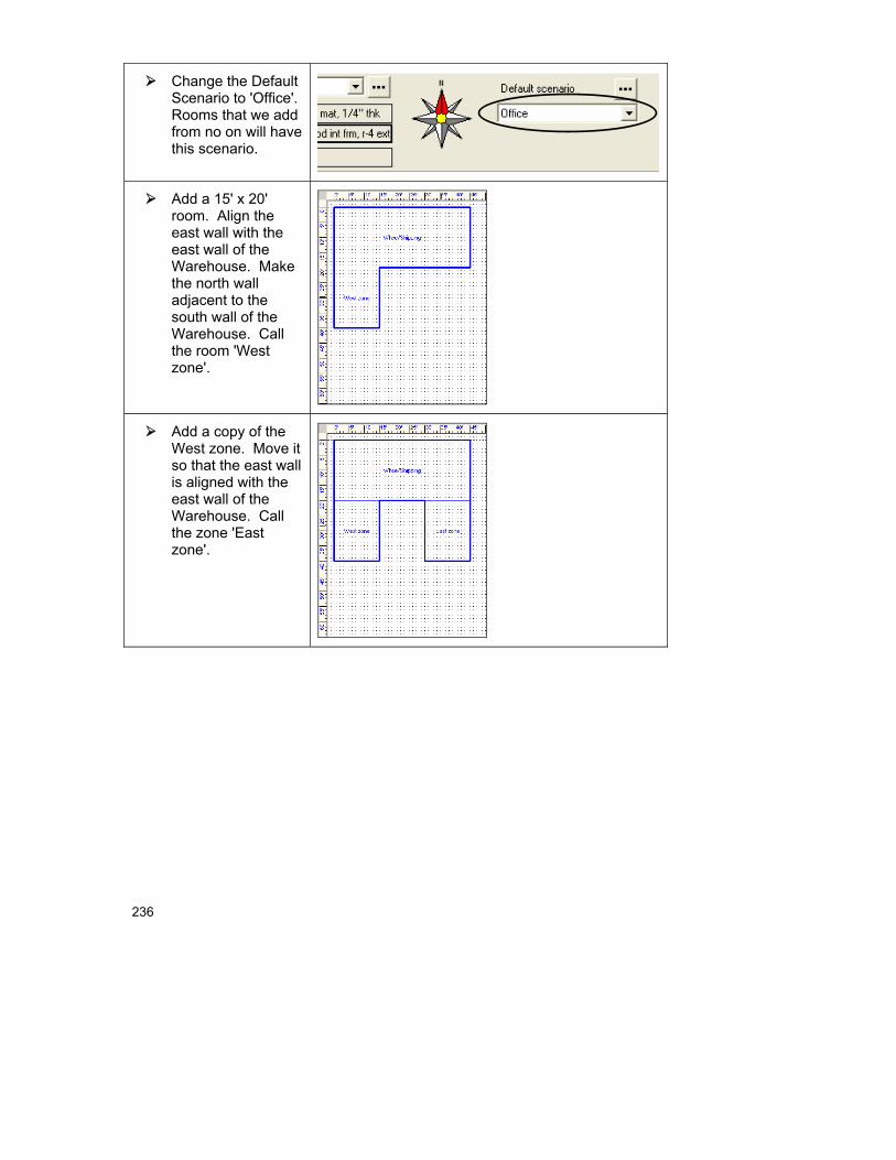
236
Change the Default Scenario to 'Office'. Rooms that we add from no on will have this scenario.
Add a 15' x 20' room. Align the east wall with the east wall of the Warehouse. Make the north wall adjacent to the south wall of the Warehouse. Call the room 'West zone'.
Add a copy of the West zone. Move it so that the east wall is aligned with the east wall of the Warehouse. Call the zone 'East zone'.

19 Multi-Zone Example: Step 1 - Describe the Building
237
Add another copy of the West zone. Place it between the West zone and East zone with the north wall adjacent to the south wall of the Warehouse. Call the room 'Internal zone'.
Note that since we copied the 'West zone', the internal gains due to people for the 'Internal zone' and 'East zone' will be the same as the 'West zone'.
Select the Internal zone and click the right mouse button on it to display its Property Sheet. Select 'Int. gains from appliances', 'Select…'
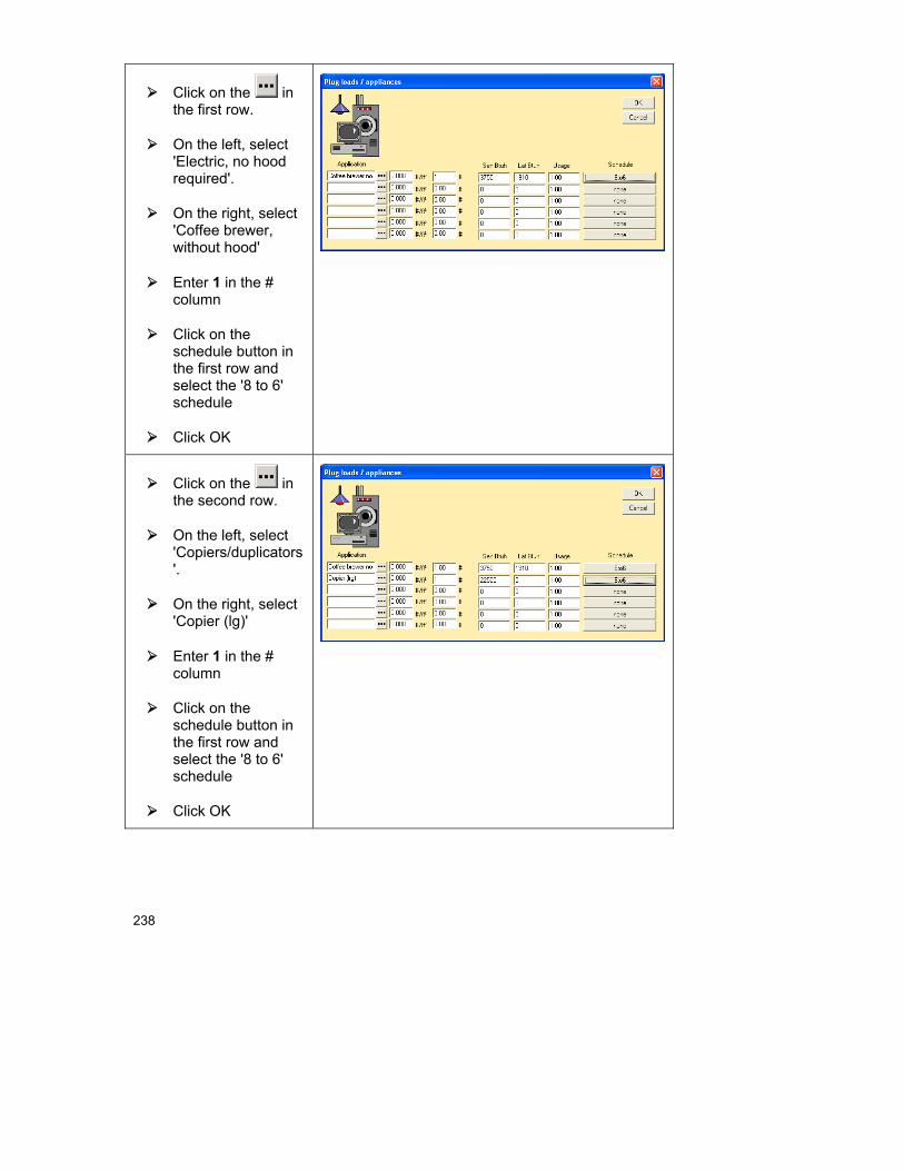
238
Click on the in the first row.
On the left, select 'Electric, no hood required'.
On the right, select 'Coffee brewer, without hood'
Enter 1 in the # column
Click on the schedule button in the first row and select the '8 to 6' schedule
Click OK
Click on the in the second row.
On the left, select 'Copiers/duplicators'.
On the right, select 'Copier (lg)'
Enter 1 in the # column
Click on the schedule button in the first row and select the '8 to 6' schedule
Click OK
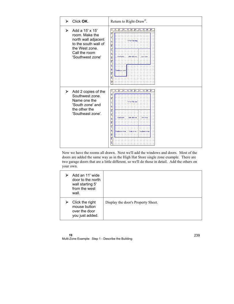
19 Multi-Zone Example: Step 1 - Describe the Building
239
Click OK. Return to Right-Draw®.
Add a 15' x 15' room. Make the north wall adjacent to the south wall of the West zone. Call the room 'Southwest zone'
Add 2 copies of the Southwest zone. Name one the 'South zone' and the other the 'Southeast zone'.
Now we have the rooms all drawn. Next we'll add the windows and doors. Most of the doors are added the same way as in the High Hat Store single zone example. There are two garage doors that are a little different, so we'll do those in detail. Add the others on your own.
Add an 11' wide door to the north wall starting 5' from the west wall.
Click the right mouse button over the door you just added.
Display the door's Property Sheet.
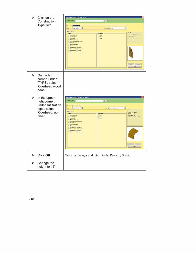
240
Click on the Construction Type field.
On the left corner, under 'TYPE', select 'Overhead wood panel.
In the upper right corner, under 'Infiltration type', select 'Overhead, no relief'
Click OK. Transfer changes and return to the Property Sheet.
Change the height to 15'
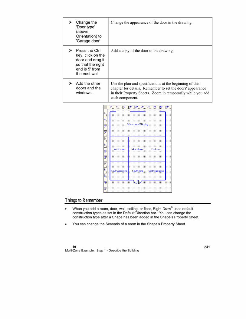
19 Multi-Zone Example: Step 1 - Describe the Building
241
Change the 'Door type' (above Orientation) to 'Garage door'
Change the appearance of the door in the drawing.
Press the Ctrl key, click on the door and drag it so that the right end is 5' from the east wall.
Add a copy of the door to the drawing.
Add the other doors and the windows.
Use the plan and specifications at the beginning of this chapter for details. Remember to set the doors' appearance in their Property Sheets. Zoom in temporarily while you add each component.
Things to Remember
When you add a room, door, wall, ceiling, or floor, Right-Draw® uses default construction types as set in the Default/Direction bar. You can change the construction type after a Shape has been added in the Shape's Property Sheet.
You can change the Scenario of a room in the Shape's Property Sheet.

242
You can change the appearance of a door on your drawing in the Door's Property Sheet.

20 Multizone Example: Step 2 - Select the Equipment
In this chapter, we will design and select the equipment system for the multizone example that we worked with in the last chapter.
Step 2a - Assign zoning .............................................. 244
Step 2b - Specify equipment ....................................... 246
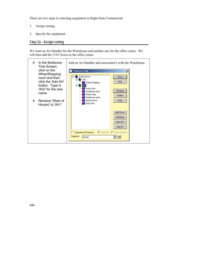
244
There are two steps to selecting equipment in Right-Suite Commercial:
1. Assign zoning.
2. Specify the equipment.
Step 2a - Assign zoning
We want an Air Handler for the Warehouse and another one for the office zones. We will then add the VAV boxes to the office zones.
In the Multizone Tree Screen, click on the Whse/Shipping' room and then click the 'Add AH' button. Type in 'Ah2' for the new name.
Rename '(Rest of House)' to 'Ah1'
Add an Air Handler and associated it with the Warehouse.
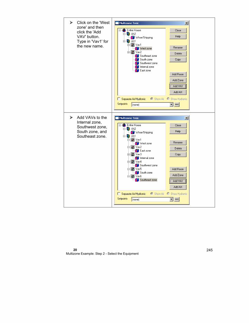
20 Multizone Example: Step 2 - Select the Equipment
245
Click on the 'West zone' and then click the 'Add VAV' button. Type in 'Vav1' for the new name.
Add VAVs to the Internal zone, Southwest zone, South zone, and Southeast zone.
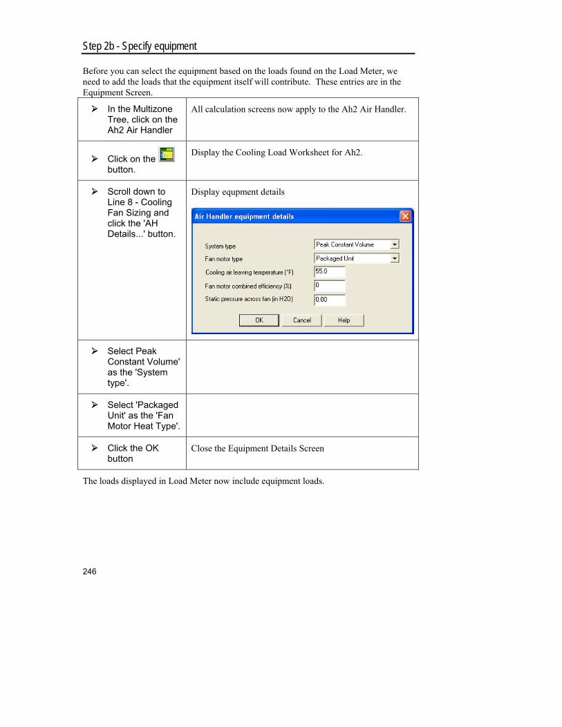
246
Step 2b - Specify equipment
Before you can select the equipment based on the loads found on the Load Meter, we need to add the loads that the equipment itself will contribute. These entries are in the Equipment Screen.
In the Multizone Tree, click on the Ah2 Air Handler
All calculation screens now apply to the Ah2 Air Handler.
Click on the button.
Display the Cooling Load Worksheet for Ah2.
Scroll down to Line 8 - Cooling Fan Sizing and click the 'AH Details...' button.
Display equpment details
Select Peak Constant Volume' as the 'System type'.
Select 'Packaged Unit' as the 'Fan Motor Heat Type'.
Click the OK button
Close the Equipment Details Screen
The loads displayed in Load Meter now include equipment loads.

20 Multizone Example: Step 2 - Select the Equipment
247
Now, we need to specify the size of the fan that we intend to use for this project. For this room, we will use a 4-ton A/C that has a 1600 cfm fan and a furnace that has a 153,600 Btuh output capacity and a 3000 cfm fan.
Select Ah2 in the Multizone Tree Screen
Click on the
Select 'Split AC' for the Cooling equipment type, 'Furnace' for the Heating equipment type, and 'Natural gas' for the Heating equipment fuel
Display the Equipment Screen for the Ah2 air handler.
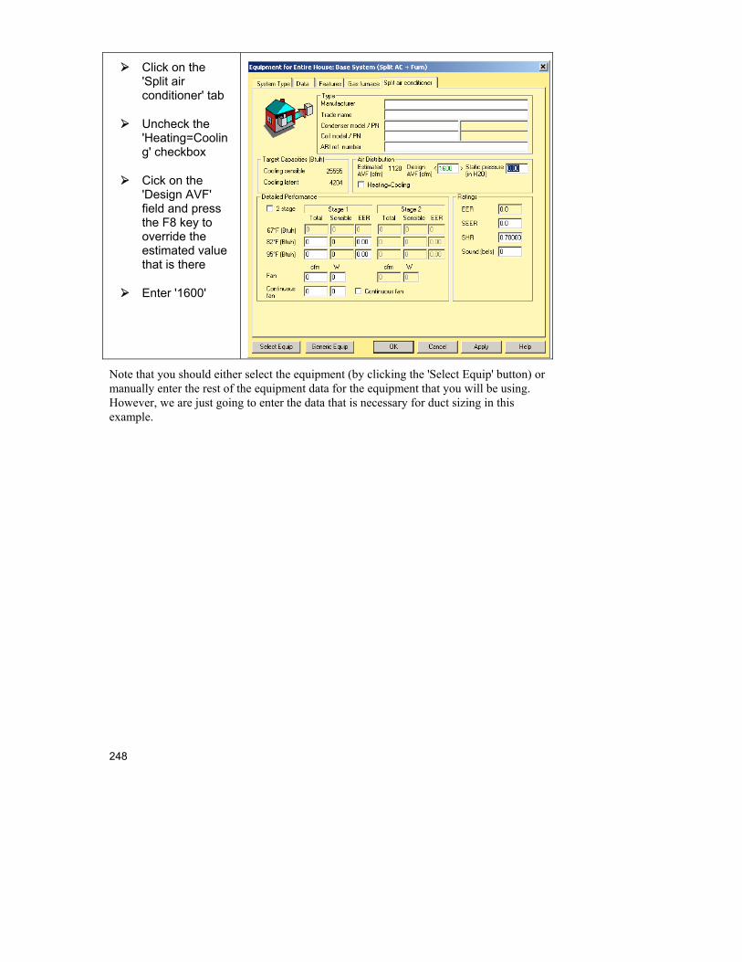
248
Click on the 'Split air conditioner' tab
Uncheck the 'Heating=Cooling' checkbox
Cick on the 'Design AVF' field and press the F8 key to override the estimated value that is there
Enter '1600'
Note that you should either select the equipment (by clicking the 'Select Equip' button) or manually enter the rest of the equipment data for the equipment that you will be using. However, we are just going to enter the data that is necessary for duct sizing in this example.
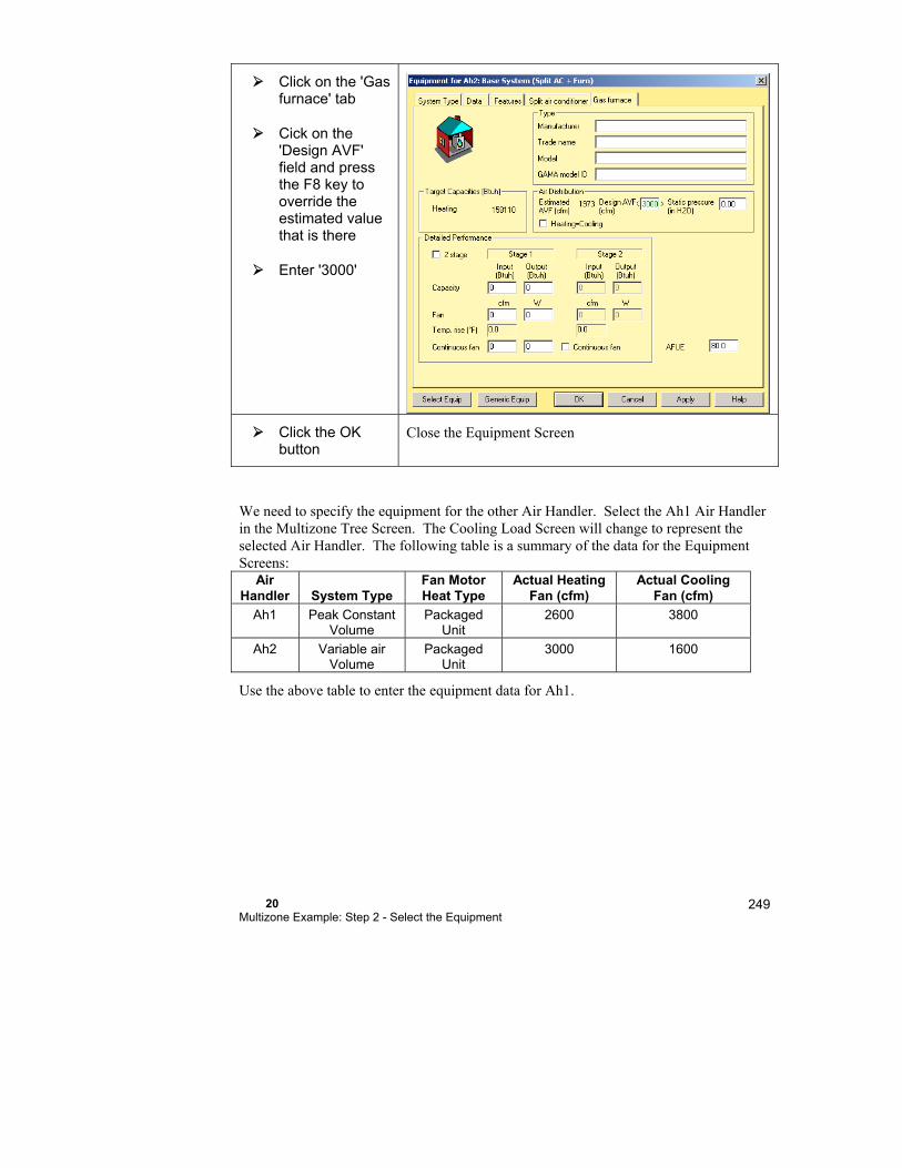
20 Multizone Example: Step 2 - Select the Equipment
249
Click on the 'Gas furnace' tab
Cick on the 'Design AVF' field and press the F8 key to override the estimated value that is there
Enter '3000'
Click the OK button
Close the Equipment Screen
We need to specify the equipment for the other Air Handler. Select the Ah1 Air Handler in the Multizone Tree Screen. The Cooling Load Screen will change to represent the selected Air Handler. The following table is a summary of the data for the Equipment Screens:
Air Handler
System Type
Fan Motor Heat Type
Actual Heating Fan (cfm)
Actual Cooling Fan (cfm)
Ah1 Peak Constant Volume
Packaged Unit
2600 3800
Ah2 Variable air Volume
Packaged Unit
3000 1600
Use the above table to enter the equipment data for Ah1.


21 Multizone Example: Step 3 - Distribution
In this chapter, we will design the duct system for the multizone example that we worked with in the last chapter.
The Ducts Layer .......................................................... 252

252
Step 3 - Air Distribution via ducts
Once the fan sizes are entered (see the previous chapter), we can continue with the duct layout.
The Ducts Layer
Click the Right-Draw® button
Re-display the Right-Draw® screen.
Click on the Ducts Layer in the Sheet Navigator
Display the Ducts layer in Right-Draw®.
Right-Draw® has created Air Handlers, a VAV boxes, and supply and return registers. Supply registers have 2 diagonal (like an 'X') and returns have one diagonal (like a '/').
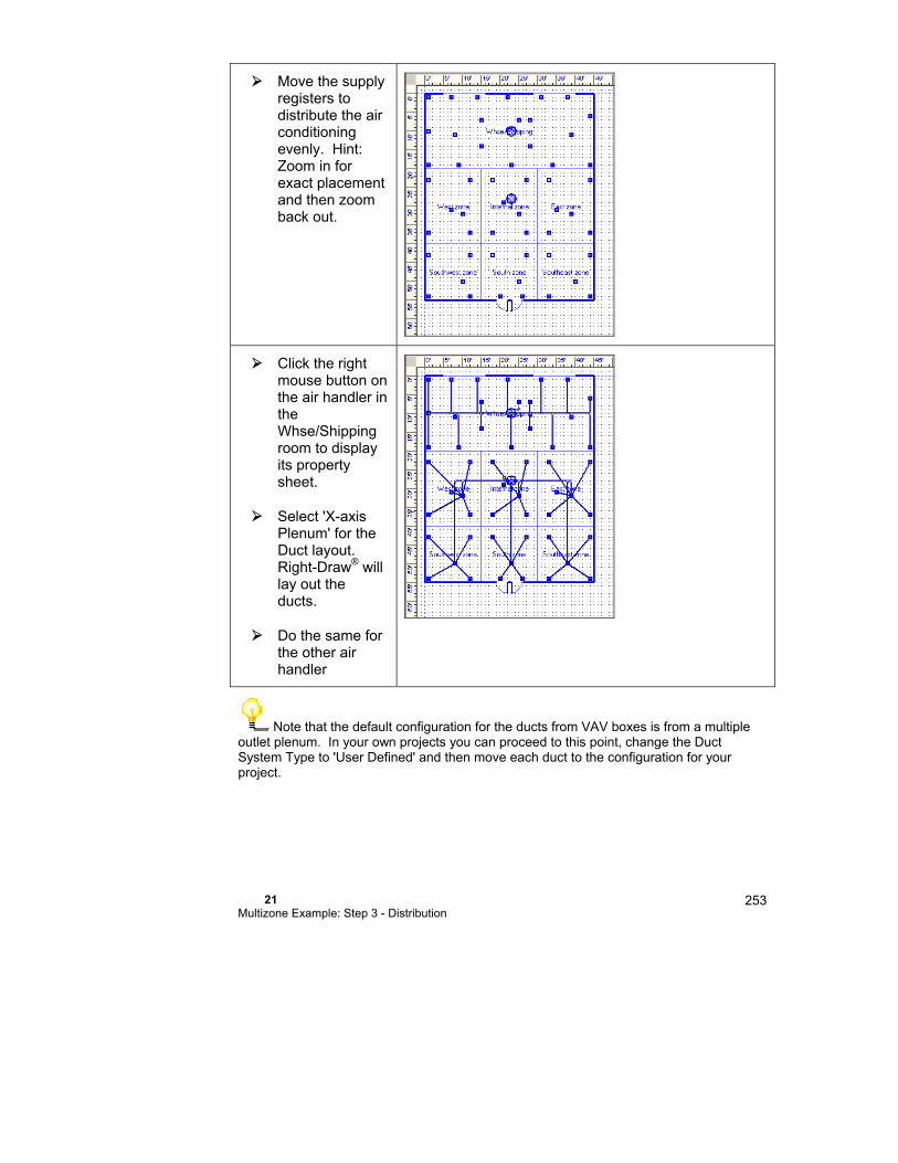
21 Multizone Example: Step 3 - Distribution
253
Move the supply registers to distribute the air conditioning evenly. Hint: Zoom in for exact placement and then zoom back out.
Click the right mouse button on the air handler in the Whse/Shipping room to display its property sheet.
Select 'X-axis Plenum' for the Duct layout. Right-Draw® will lay out the ducts.
Do the same for the other air handler
Note that the default configuration for the ducts from VAV boxes is from a multiple outlet plenum. In your own projects you can proceed to this point, change the Duct System Type to 'User Defined' and then move each duct to the configuration for your project.

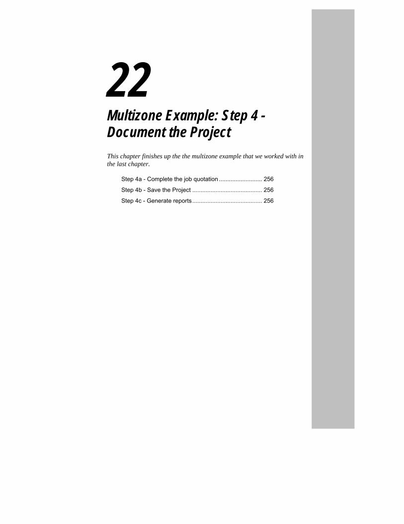
22 Multizone Example: Step 4 - Document the Project
This chapter finishes up the the multizone example that we worked with in the last chapter.
Step 4a - Complete the job quotation .......................... 256
Step 4b - Save the Project .......................................... 256
Step 4c - Generate reports .......................................... 256

256
Step 4a - Complete the job quotation
When Right-CommDuct™ designed and sized the ducts; it transferred a parts list to Right-Proposal.
Click on the button to display the Right-Proposal® toolbar
Click on the button to display the Bill of Materials.
Step 4b - Save the Project
We may save our project in its current state by clicking on the button.
Step 4c - Generate reports
Right-Suite Universal 2018 includes many standard reports. In this example, we'll print out a drawing.
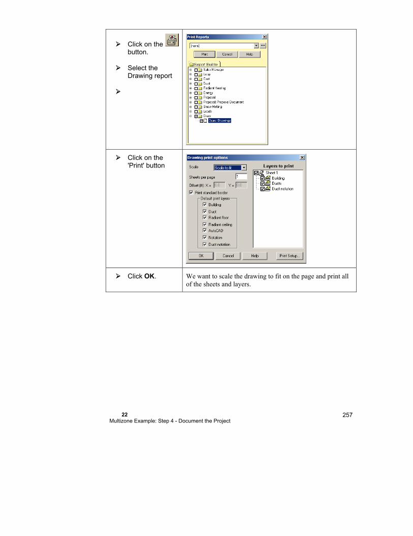
22 Multizone Example: Step 4 - Document the Project
257
Click on the button.
Select the Drawing report
Click on the 'Print' button
Click OK. We want to scale the drawing to fit on the page and print all of the sheets and layers.


Part IV - Residential and Commercial Examples


23
Two-line Drawings
This chapter explains how to use RSU to generate CAD quality 2-line drawings.
What are the Two-Line Duct Modules? ....................... 262
Multiple Drawing Modes .............................................. 262
Tips for using two-line ducts ........................................ 264
Things to Remember ................................................... 266
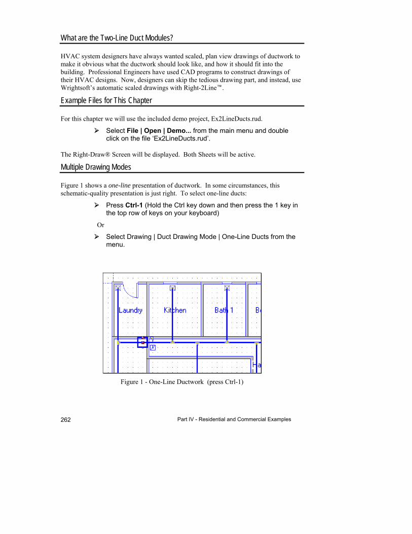
Part IV - Residential and Commercial Examples 262
Figure 1 - One-Line Ductwork (press Ctrl-1)
What are the Two-Line Duct Modules?
HVAC system designers have always wanted scaled, plan view drawings of ductwork to make it obvious what the ductwork should look like, and how it should fit into the building. Professional Engineers have used CAD programs to construct drawings of their HVAC designs. Now, designers can skip the tedious drawing part, and instead, use Wrightsoft’s automatic scaled drawings with Right-2Line.
Example Files for This Chapter
For this chapter we will use the included demo project, Ex2LineDucts.rud.
Select File | Open | Demo... from the main menu and double click on the file ‘Ex2LineDucts.rud’.
The Right-Draw® Screen will be displayed. Both Sheets will be active.
Multiple Drawing Modes
Figure 1 shows a one-line presentation of ductwork. In some circumstances, this schematic-quality presentation is just right. To select one-line ducts:
Press Ctrl-1 (Hold the Ctrl key down and then press the 1 key in the top row of keys on your keyboard)
Or
Select Drawing | Duct Drawing Mode | One-Line Ducts from the menu.

23 Two-line Drawings
263
Figure 2 – Two Line CAD Ducts (Ctrl-2)
The conversion to 2 lines is essentially instantaneous:
Press Ctrl-2
Or
Select Drawing | Duct Drawing Mode | Two-Line Ducts from the menu
Figure 2 shows the same duct section as two-line ductwork.
Each of the fittings in Figure 1 has been automatically redrawn as a top (plan) view of the individual fitting. The one-line fittings are shown as boots, but the two line fittings reveal that they are ID 4AD, round to rectangular 90-degree boot. The designer selected this fitting in the Duct Preferences Screen in the Fitting Preferences section. Wrightsoft® has designed matching CAD fittings for each of the fitting ID's in ACCA's Manual D, January 1995 Edition. This means that regardless of which fitting a designer may choose, RSU will automatically calculate the airflow and size of each fitting using ACCA’s duct fittings, look up the fitting drawing, and draw the scaled fitting in the correct orientation. These same fitting drawings are available to the designer as a printout, or as a new layer in an external CAD file, such as AutoCad’s DWG format or DXF.
The third duct drawing mode is frequently used to reduce visual clutter by combining two- line CAD drawings for trunks with one-line drawings for branch runs. Figure 4 shows the same ductwork as Figure 1 and Figure 2, but with two-line trunks with one-line branches. To obtain this display:
Press Ctrl-3
Or

Part IV - Residential and Commercial Examples 264
Select Drawing | Duct Drawing Mode | Mixed two-one line ducts
from the menu
Tips for using two-line ducts
There are no other tricks to convert between these three modes, and they are all essentially instantaneous.
There are, however, several tips that designers will appreciate for specific drawing details:
1. Changing the color of ducts
2. Changing register sizes
3. Changing duct fittings
4. Specifying offsets in rectangular ductwork
These topics follow as Question and Answers.
How Do You Change the Color of Ducts?
First, bring up the general Property Sheet for the drawing by right clicking in the area between the ruler and drawing, or by right clicking outside other objects.
Next, notice that you can change 2-line colors for Supply and Return ducts, by clicking on the right side of the color selector line. You will see a pull down color chart that allows you to select colors
Figure 4: 2-Line with 1-Line Branches
The linked image cannot be displayed. The file may have been moved, renamed, or deleted. Verify that the link points to the correct file and location.

23 Two-line Drawings
265
for supply and return, but will only apply in 2-line drawing mode. Note also that you can change the thickness of the drawing line to be medium, thick or thin.
How Do You Change Register Sizes?
First, right-click on the register you want to resize and right-click to view the property sheet. You can change the shape, and/or size by entering new values in the Property sheet.
How Do You Change Duct Fittings?
In either 1 line or 2-line duct drawing mode, select the fitting you would like to change by clicking on it. In one-line mode, this is really easy. The green handles are right on top of the fitting, and make it really obvious. Note that the selection box for 2 line fittings may not be in the most obvious place.
How Do You Specify Offsets in 2 Line Ducts?
Rectangular trunk runs frequently reduce size as branch runs take off from the trunk. The reduction from one trunk to the next can be offset to either side, or tapered on both sides. In general, designers keep the trunk height constant, and reduce trunk width as cfm decreases in the trunk. For example, in the Figure below,
The offset is to the right; that is, the child (downstream) trunk has its right side aligned with the parent (upstream) trunk. In the next Figure, the same trunk is aligned to the right for the 24x8 and 18x8 sections, and to the right for the 14x8 and 8x8 sections. The trunk duct's Property Sheet allows each trunk duct to be aligned to the upstream trunk section either to the left, the right, or the center.
The linked image cannot be displayed. The file may have been moved, renamed, or deleted. Verify that the link points to the correct file and location.
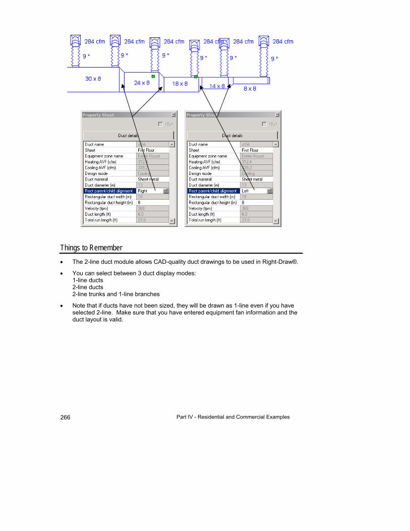
Part IV - Residential and Commercial Examples 266
Things to Remember
The 2-line duct module allows CAD-quality duct drawings to be used in Right-Draw®.
You can select between 3 duct display modes: 1-line ducts 2-line ducts 2-line trunks and 1-line branches
Note that if ducts have not been sized, they will be drawn as 1-line even if you have selected 2-line. Make sure that you have entered equipment fan information and the duct layout is valid.
24
High-velocity Duct Design
This chapter describes how to design a high-velocity duct system with Right-Draw®.
Summary of Steps ....................................................... 268
Overview ..................................................................... 269
Step 1- Describe the Building ...................................... 269
Step 2 - Select the Duct System Layout ...................... 271
Step 3 - Fine-Tune the Duct Design ............................ 271
Step 4 - Check the Bill of Materials Screen ................. 272
High-velocity Tips & Tricks .......................................... 272
Things to Remember ................................................... 275
Part IV - Residential and Commercial Examples 268
Example Files for This Chapter
Source demo file: DrawFlexDuctStart.rud
Completed demo file for comparison: ExHighVelocity.rud
The examples assume that you are running RSU in the Demo mode. Your screens and your results may be different if you use a registered version or an OEM version.
The example in this chapter is a residential example. However, a high-velocity duct system can be used with any of the available load calculation methods - residential or commercial.
Summary of Steps
1. Enter the building description and calculate the load.
2. Select the duct layout.
3. Fine-tune the duct design.
4. Check the Bill of Materials Screen
Introduction
High-velocity ducts or mini-ducts are based on the idea that fixed-size smaller diameter ducts can be used in place of conventional low velocity ducts now extensively used for residential heating and cooling. The fundamental principle of high-velocity systems is that the size of the supply branches and supply registers is fixed and is identical for all supply branches. To accommodate different loads in different parts of the house, the designer specifies more outlets to serve rooms with larger loads and a lesser number of air outlets for lower loads. These high-velocity systems are repetitive in nature because they use the same parts for each branch and trunk. High-velocity duct systems are appealing because they are easy to design and simple to install (most of the parts are the same).
The duct system design equations used here are based on 2” diameter supply branches, with high pressure plenums providing approximately the same pressure at the takeoff for all branch runs. Since the length of each run varies, there is a corresponding variation in airflow delivered, automatically computed by Right-HV™.

24 High-velocity Duct Design
269
In addition to fully automatic sizing calculations, Right-HV™ can automatically layout and design the entire duct system and generate a parts list in Right-Proposal®.
Because of their ability to fit into small spaces and their installation simplicity, high-velocity systems are becoming commonly used in existing buildings where duct chases or spaces are not easily obtained. High-velocity duct systems are a great tool for HVAC contractors who want to design systems quickly and easily.
Overview
Right-HV™ allows residential designs that are multizone or single zone. Multizone systems require one air handler per zone, because each high-velocity zone requires its own air handler. RSU allows any combination of high-velocity or low velocity zones in a single house. In either case, return systems are low velocity and use conventional components.
The first step to designing any duct system with RSU is to describe the building, preferably with Right-Draw®, and obtain the load for each room. The load is automatically calculated as the building is drawn.
Next, create the building, assign the zones and set each unit to high-velocity or low velocity. This establishes the design rules for the program, and enables duct preferences for each zone. You then select the duct layout in the Property Sheet for each unit or design the layout manually. Set preferences for system parameters, such as trunk layout pattern or trunk distance to exterior wall.
As designers change the drawing or inputs in the system, RSU immediately recalculates, including Right-Proposal®’s parts list. The automatic parts takeoff will select parts for the manufacturer selected.
Step 1- Describe the Building
In this example, we will start from an existing floor plan drawing, and complete a high-velocity duct system. Let us start by opening the demo file DrawFlexDuctStart.rud.
Select File | Open | Demo... from the main menu and select 'DrawFlexDuctStart.rud' then click Open.
Since this is a one-zone, one-floor example, we will not have to use zoning. Instructions for a zoned house will be very similar for each zone, once the house's zones have been assigned (see Chapter 9), and the main menu item Options | Equipment in Zones has been selected.
Drag the unit to the desired location; zoom out if you have to.
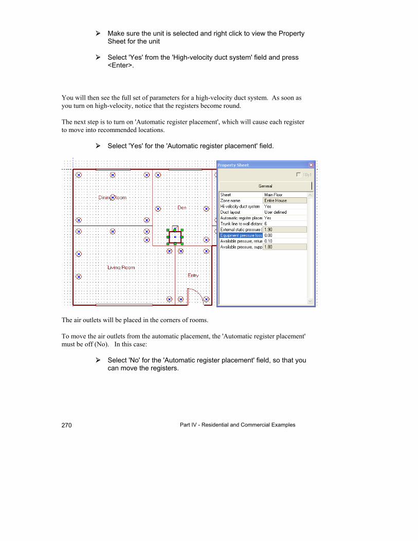
Part IV - Residential and Commercial Examples 270
Make sure the unit is selected and right click to view the Property Sheet for the unit
Select 'Yes' from the 'High-velocity duct system' field and press <Enter>.
You will then see the full set of parameters for a high-velocity duct system. As soon as you turn on high-velocity, notice that the registers become round.
The next step is to turn on 'Automatic register placement', which will cause each register to move into recommended locations.
Select 'Yes' for the 'Automatic register placement' field.
The air outlets will be placed in the corners of rooms.
To move the air outlets from the automatic placement, the 'Automatic register placement' must be off (No). In this case:
Select 'No' for the 'Automatic register placement' field, so that you can move the registers.
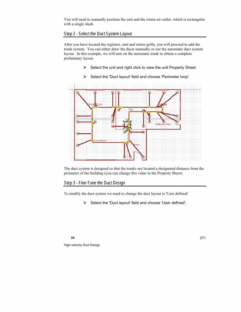
24 High-velocity Duct Design
271
You will need to manually position the unit and the return air outlet, which is rectangular with a single slash.
Step 2 - Select the Duct System Layout
After you have located the registers, unit and return grille, you will proceed to add the trunk system. You can either draw the ducts manually or use the automatic duct system layout. In this example, we will turn on the automatic trunk to obtain a complete preliminary layout
Select the unit and right click to view the unit Property Sheet.
Select the 'Duct layout' field and choose 'Perimeter loop'.
The duct system is designed so that the trunks are located a designated distance from the perimeter of the building (you can change this value in the Property Sheet).
Step 3 - Fine-Tune the Duct Design
To modify the duct system we need to change the duct layout to 'User defined'.
Select the 'Duct layout' field and choose 'User defined'.
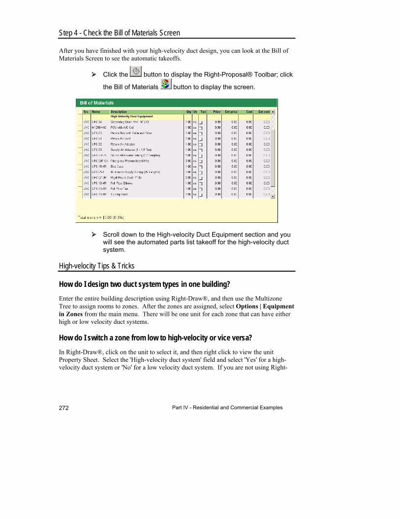
Part IV - Residential and Commercial Examples 272
Step 4 - Check the Bill of Materials Screen
After you have finished with your high-velocity duct design, you can look at the Bill of Materials Screen to see the automatic takeoffs.
Click the button to display the Right-Proposal® Toolbar; click
the Bill of Materials button to display the screen.
Scroll down to the High-velocity Duct Equipment section and you will see the automated parts list takeoff for the high-velocity duct system.
High-velocity Tips & Tricks
How do I design two duct system types in one building?
Enter the entire building description using Right-Draw®, and then use the Multizone Tree to assign rooms to zones. After the zones are assigned, select Options | Equipment in Zones from the main menu. There will be one unit for each zone that can have either high or low velocity duct systems.
How do I switch a zone from low to high-velocity or vice versa?
In Right-Draw®, click on the unit to select it, and then right click to view the unit Property Sheet. Select the 'High-velocity duct system' field and select 'Yes' for a high-velocity duct system or 'No' for a low velocity duct system. If you are not using Right-
24 High-velocity Duct Design
273
Draw®, you can select the zone in the Multizone Tree then click on the Equipment button. Place a check in the high-velocity checkbox to have a high-velocity duct system. Remove the check for a low velocity duct system.
How do I change duct system layout?
You can change the duct system layout in two places. If you are using Right-Draw®, select the unit, and then right click to view the Property Sheet for the unit. You can select the duct system layout there. If you are not using Right-Draw® or want to save
the duct system type in a template, click on the Duct Preferences button. Choose the duct system layout there (located in the upper left part of the screen).
How do I make RSU automatically place supply outlets?
To have RSU automatically place the supply air outlets in Right-Draw®, select the unit and right click to view the unit Property Sheet. Select 'Yes' in the 'Automatic register placement' field (NOTE: You must change this selection back to 'No' to modify the air outlet placement). You can also select automatic register placement in the Duct Preferences Screen.
How do I adjust the trunk to building perimeter for automatic duct layouts?
You can change the trunk line to wall distance in the unit Property Sheet.
How do I change trunk sizes calculated by RSU?
You can change the trunk sizes manually. Select the duct you want to resize and right click to view the Property Sheet for the duct. Set the ‘Automatic sizing’ field to ‘No’ and press <Enter>. Then you will be able to change the duct size manually
How do I change supply outlet types?
To change all of the supply air outlet types at once, select the type on the Duct Preferences Screen. You can select from round white or unfinished, sloped 15o or 25o, or rectangular.
You can change individual air outlets or several outlets at once by selecting the outlet (or outlets) then right clicking to view the Property Sheet for the outlet or outlets. Choose the supply outlet type in the 'Outlet type' field.
How do I change trunk material, shape or height?
To change the trunk material, shape or height, for all of the trunks at once, change the desired attribute on the Duct Preferences Screen.
Part IV - Residential and Commercial Examples 274
You can change the attributes individual trunks or several trunks at once by selecting the trunk (or trunks) then right clicking to view the Property Sheet for the trunk or trunks. Make your changes here.
How do I adjust the number of supply outlets per room automatically?
The number of supply outlet per room is automatically generated by RSU based on the maximum airflow per outlet value on the Duct Preferences Screen. If you change this value, the number of outlets generated in each ‘automatic branch splitting’ room will be affected.
How do I adjust the number of supply outlets manually?
To change the number of outlets in a particular room(s) just add outlets using the Supply Register shape in the HVAC Shapes™ Toolbox or delete outlets by selecting them and pressing <Delete>. If you add or delete a register, the 'Automatic branch splitting' field in the room Property Sheet will change from 'Yes' to 'No' and the number of outlets you want will be retained.
To switch room back to ‘Automatic branch splitting’, right click on the room to view the room Property Sheet and change the value of the ‘Automatic branch splitting’ field to 'Yes'.
How do I adjust sound attenuator length?
For each branch, the sound attenuator length will be calculated as minimum (desirable length, actual branch length). To see calculated attenuator length for a branch, select a branch and right click to view the branch Property Sheet. To adjust the sound attenuator length for all branches, type value in the 'Attenuator length' field on the Duct Preferences Screen.
How do I enter orifice adjustment?
You can enter an orifice adjustment in the Property Sheet for the supply branch or in the Supply Branches Worksheet (scroll to the right to see the Orifice column).
How do I curve the ducts?
The high-velocity branches are like flex ducts; you can bend the ducts using the edit points function. To add a curve to the a duct:
Select the duct.
Click the Edit Points button.
24 High-velocity Duct Design
275
Click anywhere along the duct and drag to create a bend.
Click the Edit Points button again when you are done.
How do I check that the airflow is enough to supply the room design load?
In Supply Branches Worksheet you can see both design heating and cooling airflow (cfm) per room and actual airflow that will be delivered to the room. If actual airflow is less than either heating or cooling design airflow, they will be displayed in red on the Supply Branches Worksheet. To modify the system so that the airflow is appropriate, you can add more outlets per room that needs the additional airflow or change branch length.
How do I alter automatic part takeoffs?
To following fields in Duct Preferences Screen will affect takeoffs
Supply duct insulation
Motor frequency
Configuration
High speed blower
Chilled water cooling
Use package or individual parts
Use high efficiency filter
Things to Remember
Most of the high-velocity settings can be changed in the unit Property Sheet or on the Duct Preferences Screen.
The 'Automatic register placement' field must be 'No' to modify the register placement; the 'Duct layout' field must be 'User defined' to modify the duct layout.
You can use the Edit Points button to add bends to high-velocity ducts.
Right-HV™ has automatic takeoffs to Right-Proposal® .

25
Design a Geothermal Loop System
This chapter explains how to design and size a geothermal heat exchange loop.
Example Files for This Chapter ................................... 278
Summary of Steps ....................................................... 278
Step 1 - Select the Bin Data & Earth Temperature Cities ..................................................................... 278
Step 2 - Select the Equipment ..................................... 279
Step 3 - Select the Loop/Equipment Configuration ...... 282
Step 4 - Select the Loop Characteristics ..................... 282
Step 5 - Select the Circulating Pump ........................... 286
Things to Remember ................................................... 289
Part IV - Residential and Commercial Examples 278
Example Files for This Chapter
Source demo file: ExACCA.rud
Completed demo file for comparison: ExACCA-L.rud
The examples assume that you are running RSU in the Demo mode. Your screens and your results may be different if you use a registered version or an OEM version.
Summary of Steps
There are five additional steps necessary to complete a geothermal loop design once the load calculation is complete.
You can either enter the building description in Right-J® to calculate the loads or enter the loads manually if you already know what they are.
1. Select the bin data and earth temperature cities
2. Select the ground-source heat pump equipment
3. Select the loop/equipment configuration
4. Select the loop characteristics
5. Select the circulating pump
Example Loop Design
We will use the included demo project, ExACCA.rud.
From the menu, select File | Open | Demo…
Select 'ExACCA.rud' from the list of demo project files
Select File | Save As | Project... and change the project file name to 'MyACCA-L'. Click Save.
We now have a project file named MyACCA-L.rud that is a copy of ExACCA.rud.
Step 1 - Select the Bin Data & Earth Temperature Cities
Go to the Project Information Screen. You will see that the bin data city is ‘Des Moines MAP, IA’ and the earth temperature city is ‘Des Moines’. Because we are working in
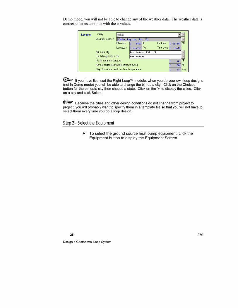
25 Design a Geothermal Loop System
279
Demo mode, you will not be able to change any of the weather data. The weather data is correct so let us continue with these values.
If you have licensed the Right-Loop™ module, when you do your own loop designs (not in Demo mode) you will be able to change the bin data city. Click on the Choices button for the bin data city then choose a state. Click on the '+' to display the cities. Click on a city and click Select.
Because the cities and other design conditions do not change from project to project, you will probably want to specify them in a template file so that you will not have to select them every time you do a loop design.
Step 2 - Select the Equipment
To select the ground source heat pump equipment, click the Equipment button to display the Equipment Screen.
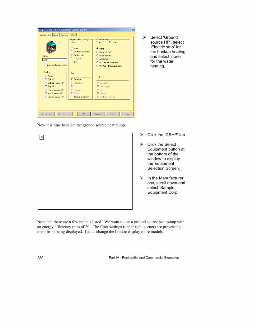
Part IV - Residential and Commercial Examples 280
Select ‘Ground source HP’, select ‘Electric strip’ for the backup heating and select ‘none’ for the water heating.
Now it is time to select the ground source heat pump.
Click the ‘GSHP’ tab
Click the Select Equipment button at the bottom of the window to display the Equipment Selection Screen.
In the Manufacturer box, scroll down and select ‘Sample Equipment Corp’.
Note that there are a few models listed. We want to use a ground source heat pump with an energy efficiency ratio of 20. The filter settings (upper right corner) are preventing them from being displayed. Let us change the limit to display more models.
The linked image cannot be displayed. The file may have been moved, renamed, or deleted. Verify that the link points to the correct file and location.
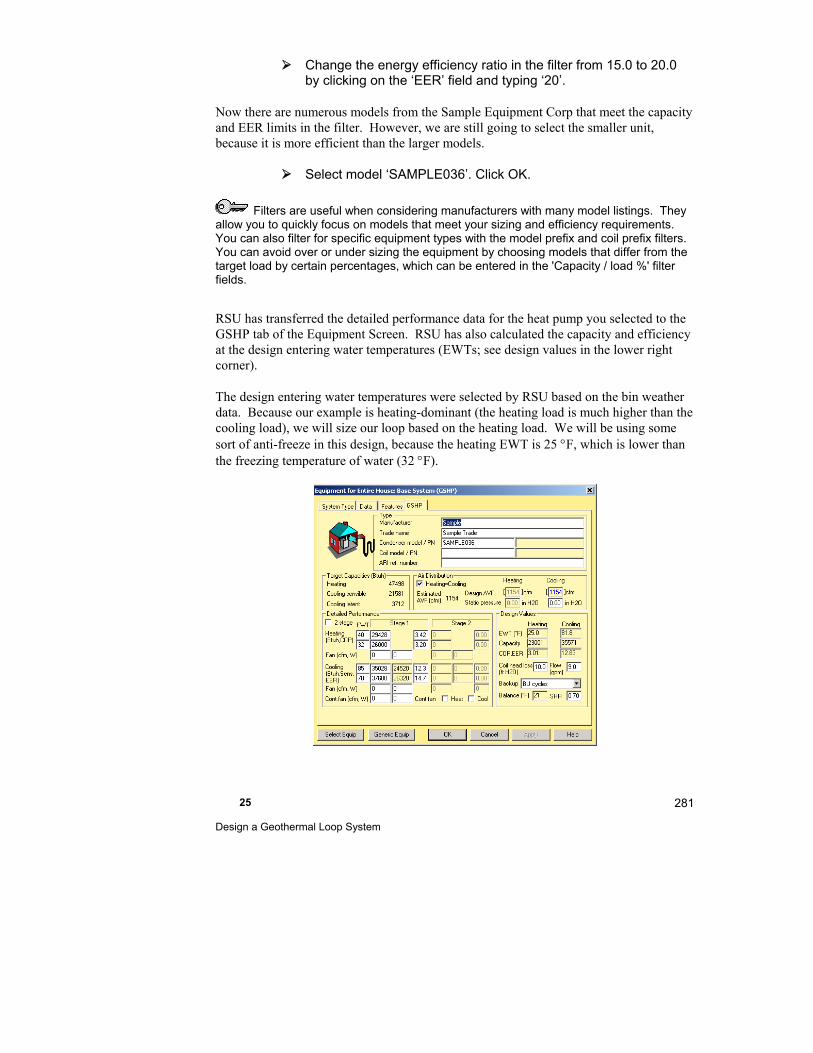
25 Design a Geothermal Loop System
281
Change the energy efficiency ratio in the filter from 15.0 to 20.0 by clicking on the ‘EER’ field and typing ‘20’.
Now there are numerous models from the Sample Equipment Corp that meet the capacity and EER limits in the filter. However, we are still going to select the smaller unit, because it is more efficient than the larger models.
Select model ‘SAMPLE036’. Click OK.
Filters are useful when considering manufacturers with many model listings. They allow you to quickly focus on models that meet your sizing and efficiency requirements. You can also filter for specific equipment types with the model prefix and coil prefix filters. You can avoid over or under sizing the equipment by choosing models that differ from the target load by certain percentages, which can be entered in the 'Capacity / load %' filter fields.
RSU has transferred the detailed performance data for the heat pump you selected to the GSHP tab of the Equipment Screen. RSU has also calculated the capacity and efficiency at the design entering water temperatures (EWTs; see design values in the lower right corner).
The design entering water temperatures were selected by RSU based on the bin weather data. Because our example is heating-dominant (the heating load is much higher than the cooling load), we will size our loop based on the heating load. We will be using some sort of anti-freeze in this design, because the heating EWT is 25 F, which is lower than the freezing temperature of water (32 F).
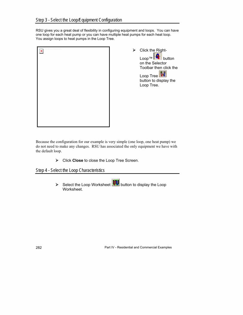
Part IV - Residential and Commercial Examples 282
Step 3 - Select the Loop/Equipment Configuration
RSU gives you a great deal of flexibility in configuring equipment and loops. You can have one loop for each heat pump or you can have multiple heat pumps for each heat loop. You assign loops to heat pumps in the Loop Tree.
Click the Right-
Loop™ button on the Selector Toolbar then click the
Loop Tree button to display the Loop Tree.
Because the configuration for our example is very simple (one loop, one heat pump) we do not need to make any changes. RSU has associated the only equipment we have with the default loop.
Click Close to close the Loop Tree Screen.
Step 4 - Select the Loop Characteristics
Select the Loop Worksheet button to display the Loop Worksheet.
The linked image cannot be displayed. The file may have been moved, renamed, or deleted. Verify that the link points to the correct file and location.

25 Design a Geothermal Loop System
283
RSU has all the information it needs to calculate the loop length. Using the default settings, the Loop Worksheet has already selected a loop length (Total pipe) and other design values. You can modify the loop design to meet the needs of this particular job.
Click on the configuration input Choices button.
Select the ‘Slinky’ tab (NOTE: The tabs on the bottom of the screen represent major configuration types).

Part IV - Residential and Commercial Examples 284
Select ’12, slinky-flat’ from the two slinky configurations that are shown and click OK.
RSU recalculates the loop length located on the lower right part of your screen, using this new configuration. Now we can enter any additional details for our loop design
Click on the pipe Choices button and select ‘PE SCHED 40, 3/4”’ and click OK.
Click the soil type Choices button and select ‘Saturated sand'.
Click the coolant Choices button, select ‘Propylene glycol’ and click OK.
Note that each change we make affects the loop length. You can experiment with these loop characteristics to fine-tune your loop design.
On the right side of the Loop Worksheet, we see that the slinky loop length is 6,322 ft and requires 242 ft of trench. Let us see how long a vertical configuration would be.
Click the configuration Choices button and click the ‘Vertical’ tab.
Choose configuration type ‘14, 2 pipe (single loop)’ and click OK.
Increase the pipe size to '2”'.
Whoops! RSU displays a dialog box telling us that our Reynolds number has fallen below the minimum necessary to maintain appropriate heat transfer. It has also given us five suggested solutions. Click OK.
The Reynolds number is calculated from all the factors that affect the flow of fluid in the pipe. A higher Reynolds number indicates more turbulence (swirling and mixing) in the flow inside the pipe. For geothermal loops, more turbulence means better heat transfer between the fluid in the pipe and the earth. Good practice calls for a Reynolds number of 2,500 or higher for geothermal loops.
Reduce the pipe size to '1 1/2”'.
The Reynolds number is now acceptable and the loop length has been calculated. The Loop Worksheet shows that the loop length has dropped to 607 ft. That would be a 304 ft bore hole, with one pipe up and one pipe down). Now let us see how a horizontal loop looks.
Click the configuration Choices button and click the ‘Horizontal’ tab.
25 Design a Geothermal Loop System
285
Choose ‘2, 2 pipe, 1 x 2’ and click OK.
Our loop length is now 1,542 ft with a 771 ft trench. Right-Loop™ has allowed us to make a quick survey of three configuration options. A summary of the total pipe lengths is shown below:
Configuration Loop Length
Slinky 6,322 ft
Vertical 607 ft
Horizontal 1,542 ft
For this example, leave the ground loop set to horizontal (2, 2 pipe (1 x 2)').
Loop Details Screen
We can use the Loop Details Screen to view the intermediate calculations and values that RSU used to calculate the loop length.
Click the Loop Details button to display the Loop Details Screen.
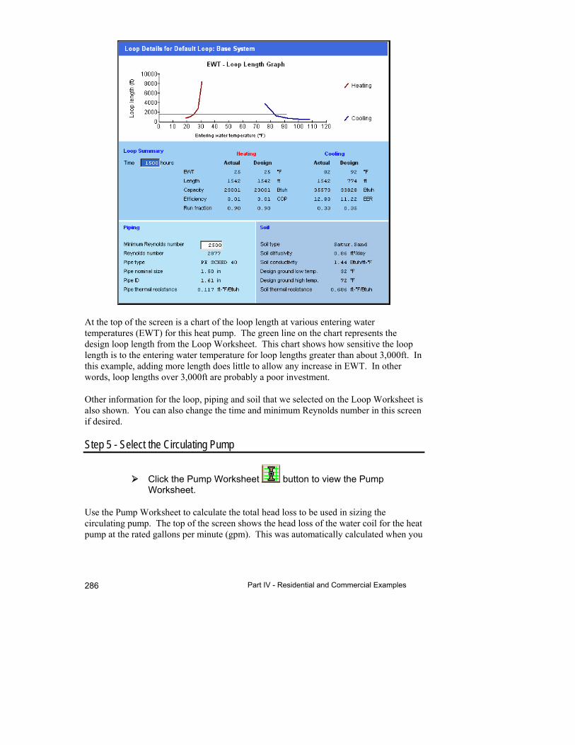
Part IV - Residential and Commercial Examples 286
At the top of the screen is a chart of the loop length at various entering water temperatures (EWT) for this heat pump. The green line on the chart represents the design loop length from the Loop Worksheet. This chart shows how sensitive the loop length is to the entering water temperature for loop lengths greater than about 3,000ft. In this example, adding more length does little to allow any increase in EWT. In other words, loop lengths over 3,000ft are probably a poor investment.
Other information for the loop, piping and soil that we selected on the Loop Worksheet is also shown. You can also change the time and minimum Reynolds number in this screen if desired.
Step 5 - Select the Circulating Pump
Click the Pump Worksheet button to view the Pump Worksheet.
Use the Pump Worksheet to calculate the total head loss to be used in sizing the circulating pump. The top of the screen shows the head loss of the water coil for the heat pump at the rated gallons per minute (gpm). This was automatically calculated when you
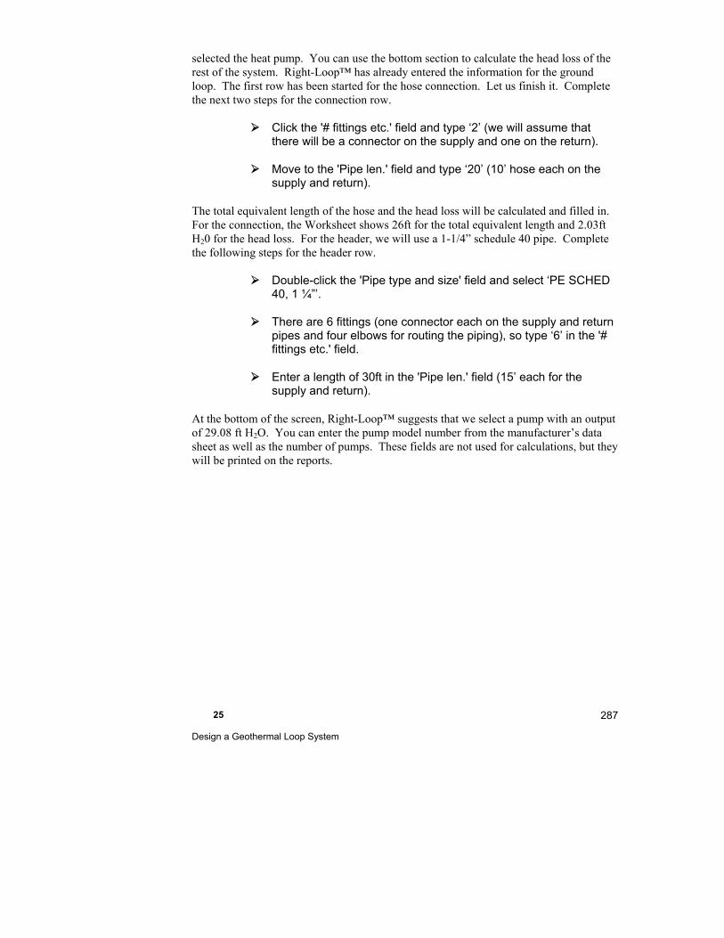
25 Design a Geothermal Loop System
287
selected the heat pump. You can use the bottom section to calculate the head loss of the rest of the system. Right-Loop™ has already entered the information for the ground loop. The first row has been started for the hose connection. Let us finish it. Complete the next two steps for the connection row.
Click the '# fittings etc.' field and type ‘2’ (we will assume that there will be a connector on the supply and one on the return).
Move to the 'Pipe len.' field and type ‘20’ (10’ hose each on the supply and return).
The total equivalent length of the hose and the head loss will be calculated and filled in. For the connection, the Worksheet shows 26ft for the total equivalent length and 2.03ft H20 for the head loss. For the header, we will use a 1-1/4” schedule 40 pipe. Complete the following steps for the header row.
Double-click the 'Pipe type and size' field and select ‘PE SCHED 40, 1 ¼”’.
There are 6 fittings (one connector each on the supply and return pipes and four elbows for routing the piping), so type ‘6’ in the '# fittings etc.' field.
Enter a length of 30ft in the 'Pipe len.' field (15’ each for the supply and return).
At the bottom of the screen, Right-Loop™ suggests that we select a pump with an output of 29.08 ft H2O. You can enter the pump model number from the manufacturer’s data sheet as well as the number of pumps. These fields are not used for calculations, but they will be printed on the reports.
Part IV - Residential and Commercial Examples 288
Pump Details Screen
Click the Pump Details button to display the Circulating Pump Details Screen
This screen shows the intermediate values used to calculate the total head loss displayed on the Pump Worksheet.
25 Design a Geothermal Loop System
289
Save Your Project
Select File | Save from the main menu to save your project or
click on the Save button.
You can compare your results with the completed ExACCA-L.rud file.
Things to Remember
Right-Loop™ allows you to quickly evaluate various heat exchange loop types and configurations.
You can select a pipe configuration by clicking on the configuration Choices button.
Right-Loop™ will calculate the volume of water and antifreeze for your loops.
When the Reynolds number in the loop falls below the minimum value (which you can change on the Loop Details Screen); you need to make changes that will increase the velocity of the fluid. RSU provides warnings and suggestions when the Reynolds number is too low.
The EWT Loop Length Graph shows the loop length for a given EWT; the design loop length from the Loop Worksheet is also shown.


26
Design Radiant Heating & Snow Melting Systems
This chapter explains how to design radiant loop heating and a snow melting systems.
Example Files for This Chapter ................................... 292
What Does Right-Radiant® Do?.................................. 292
Summary of Steps for a Radiant Heating Design ........ 292
Summary of Steps for a Snow Melting Panel Design .. 316
Things to Remember ................................................... 320
Part IV - Residential and Commercial Examples 292
Example Files for This Chapter
Source demo file: Example Load.rud
Completed demo file for comparison: Radiant Example.rud
The examples assume that you are running RSU in the Demo mode. Your screens and your results may be different if you use a registered version or an OEM version.
What Does Right-Radiant® Do?
Right-Radiant® helps you quickly and easily design radiant panel heating and snow melting panel systems. Like other RSU program components, Right-Radiant® is directly linked to building load information. You can describe the building and operating conditions, then calculate loads with either Right-J® or Right-Draw®. From that point, producing a radiant panel design requires little additional effort.
An accurate, room-by-room load calculation is a fundamental requirement for a successful radiant panel design.
After the loads are determined, all you need to do is indicate which rooms have radiant panels then enter the type and area of the each panel. Using Radiant Panel Property Sheets or the Radiant Heating Worksheet screens, you can fine-tune the design to meet any special requirements.
Right-Draw® offers some particular advantages when entering building descriptions for use with Right-Radiant®. Right-Draw® understands the relative positions of conditioned spaces and accounts for the heat transfer that occurs from the back of radiant panels into the other conditioned spaces. This cannot be done on the Worksheet alone. In addition, Right-Draw® easily handles complex radiant heating panel shapes.
Summary of Steps for a Radiant Heating Design
1. Enter the project data, building description and load information
2. Select the radiant preferences
3. Draw the radiant loops and refine the panel design
4. Review manifolds
5. Zoning
26 Design Radiant Heating & Snow Melting Systems
293
6. Design central system
Before We Begin
Before we begin designing a radiant heating system with Right-Radiant®, we should first become familiar with the terms used in this chapter.
Radiant panel - A heated surface used for heating a room or for snow melting. A room can have at most two radiant panels (one floor, one ceiling). A panel has one or more loops, which need not be identical.
Snow melting panel - A special case of radiant panel used outdoors to melt snow.
Loop - One continuous run of tubing, without branches, running from a manifold, through a radiant panel, and back to the manifold. Loop length includes panel tubing plus tails.
Tail - Although the tubing is continuous, the portion of the tubing that runs from the radiant panel to the manifold and from the manifold to the radiant panel is known as the tail. Total loop length includes the tail lengths.
Manifold - A collection point for a number of loops. A manifold has a supply side and a return side. All loops served by a manifold have the same supply temperature and the same pressure loss (balancing valves are used to achieve design flow rates in each loop). The return temperature can be calculated by determining the flow per loop, estimating the output per loop given the flow/temperature conditions, and calculating the temperature of the mixed loop returns. A manifold can serve more than one zone.
Open the 'Example Load.rud' file to follow along.
We will not be entering any information for this example. All of this information has already been entered. We will be dropping a radiant panel in the Right-Draw® screen just to see how it is done.
Step 1 - Enter the Project Data, Building Description & Load Calculations
The weather location is appropriate for this example. The building has been described in Right-Draw® and the loads have been calculated and summarized by Right-J® on the Right-J® Worksheet and at the bottom of the Zone Information Screen. The rooms have been organized into zones and the design conditions (Indoor Conditions on the Zone Information Screen) for each zone have been lowered to account for the comfort advantages of radiant heating (a 2-5 oF reduction is recommended by many designers).
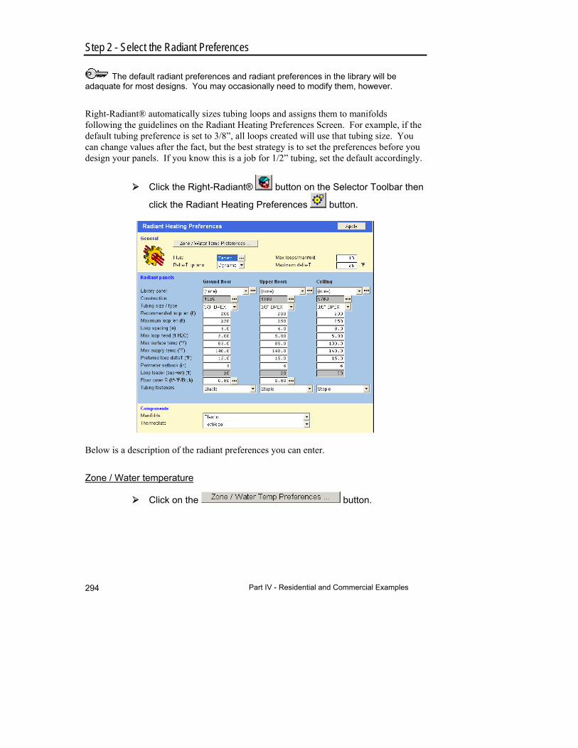
Part IV - Residential and Commercial Examples 294
Step 2 - Select the Radiant Preferences
The default radiant preferences and radiant preferences in the library will be adaquate for most designs. You may occasionally need to modify them, however.
Right-Radiant® automatically sizes tubing loops and assigns them to manifolds following the guidelines on the Radiant Heating Preferences Screen. For example, if the default tubing preference is set to 3/8”, all loops created will use that tubing size. You can change values after the fact, but the best strategy is to set the preferences before you design your panels. If you know this is a job for 1/2” tubing, set the default accordingly.
Click the Right-Radiant® button on the Selector Toolbar then
click the Radiant Heating Preferences button.
Below is a description of the radiant preferences you can enter.
Zone / Water temperature
Click on the button.
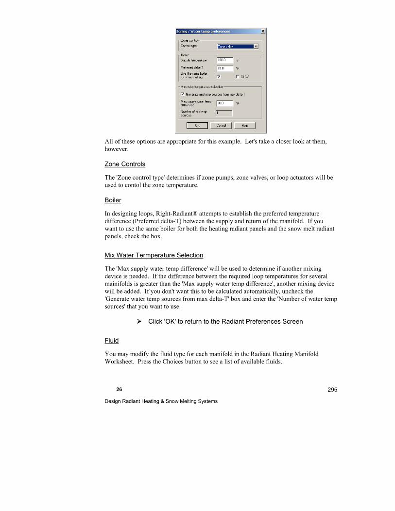
26 Design Radiant Heating & Snow Melting Systems
295
All of these options are appropriate for this example. Let's take a closer look at them, however.
Zone Controls
The 'Zone control type' determines if zone pumps, zone valves, or loop actuators will be used to contol the zone temperature.
Boiler
In designing loops, Right-Radiant® attempts to establish the preferred temperature difference (Preferred delta-T) between the supply and return of the manifold. If you want to use the same boiler for both the heating radiant panels and the snow melt radiant panels, check the box.
Mix Water Termperature Selection
The 'Max supply water temp difference' will be used to determine if another mixing device is needed. If the difference between the required loop temperatures for several mainifolds is greater than the 'Max supply water temp difference', another mixing device will be added. If you don't want this to be calculated automatically, uncheck the 'Generate water temp sources from max delta-T' box and enter the 'Number of water temp sources' that you want to use.
Click 'OK' to return to the Radiant Preferences Screen
Fluid
You may modify the fluid type for each manifold in the Radiant Heating Manifold Worksheet. Press the Choices button to see a list of available fluids.
Part IV - Residential and Commercial Examples 296
Delta-T Options
Delta-T – The temperature difference measured between the fluid supply and fluid return of a given loop or manifold.
Fixed Delta-T – Targets to maintain a constant loop delta-t resulting in higher average required fluid temperatures and higher flow.
Dynamic Delta-T – Targets to maintain an average required loop fluid temperature resulting in a wider delta-t and lower flow.
‘Delta-T’ is the temperature difference between the fluid supply and the fluid return of a given loop or manifold. In reality, ‘Delta-T’ is a result rather than an input due to heat transfer while fluid is circulated through the tubing. Depending on the speed of the water, construction method and the amount of heat transfer, the ‘Delta-T’ can vary greatly. However, since we are designing the system to perform adequately under peak design conditions, we have to use the ‘Delta-T’ a target input simply so that we can size the system correctly. This will also help ensure that the space meets the comfort requirements of the occupant. The program starts out by automatically calculating the average fluid temperature requirement for each radiant panel. Then, based on heat-load and depending on which ‘Delta-T’ option you select, the program then calculates the fluid supply temperature, flow and balancing requirements for each loop.
If selecting to use the fixed ‘Delta-T’ option, you simply specify a set delta-t for each panel (typically 10-20 degrees), and the fluid supply temperature is calculated by adding half the selected delta-t to the average fluid temperature. Example; if a room requires 100 degree average fluid temperature and your ‘Fixed’ delta-t is set to 10 degrees, the fluid supply temperature will be 105 degrees (100 + 10 divided by 2 = 105). When several loops from different rooms are connected to a manifold, the program uses the room with the highest average fluid temperature to calculate the required fluid supply for that manifold. In this case, all the lower demand loops connected to that manifold will receive a varying degree of higher than needed fluid supply temperature even if they don’t need it simply because they are connected to the same manifold. This does not typically impact the comfort or performance of those loops. If those rooms are on separate zones, the difference in requirement is simply controlled by allowing the thermostat to cycle a more frequently to control the room temperature. If the difference in requirement is too large (20-40 degrees), you may consider moving the lower demand loops to a different or own manifold with a lower fluid supply temperature assigned. Otherwise, the thermostat may cycle too much and in some cases the room may have difficulty maintaining a steady temperature.
If selecting to use the ‘Dynamic’ option, you now specify a ‘Target Delta-T’ (typically 10-20 degrees), and a ‘Max Delta-T’ (typically 20-40 degrees), the fluid supply temperature for the loop is again calculated by adding half the target delta-t to the average fluid temperature. Example; if a room requires 100
26 Design Radiant Heating & Snow Melting Systems
297
degree average fluid temperature and your ‘Target’ delta-t is set to 10 degrees, the fluid supply temperature will be 105 degrees (100 + 10 divided by 2 = 105). This is so far the same as using the ‘Fixed’ delta-t option. The difference comes into play when multiple loops with different average fluid temperatures are connected to the same manifold. In the ‘Dynamic’ mode, the program tries to maintain the average fluid temperature for each loop rather than maintaining the same delta-t. The program uses the loop with the highest average fluid temperature to calculate the required fluid supply for that manifold. All the loops on that manifold will now receive the same fluid supply temperature just as in the ‘Fixed’ delta-t scenario. In the ‘Dynamic’ mode, the program will try to match the required average fluid temperature for each loop by slowing down the flow and allowing a larger delta-t. In theory, this would mean that even if all the loops on the manifold have different requirements, they would all have the same run time since the fluid temperature for each loop would match the heat-load requirement. Example; let’s say you have two loops on the same manifold and one loop requires 100 degree average fluid temperature and the other 110 degrees. The program will use highest demand loop and the ‘Max Head’ setting to run the water as fast as it can to keep the tightest delta-t possible. In this case it may achieve a delta-t around 5 degrees. With that, the program now calculates the fluid supply temperature to be 112.5 degrees (110 + 5 divided by 2 = 112.5). With this established, to now be able to maintain the average fluid temp for the second loop (100), the program will calculate the delta-t for the second loop to be 25 degrees (112.5 – 100 * 2 = 25). Flow and balancing is then calculated based on this. If the delta-t for the second loop is beyond the ‘Max Delta-T’ setting the program will do one of two things, if ‘Show radiant loops’ is checked in the ‘Draw’ screen, the program will warn the designer that the condition for the loop is beyond preferred limits by turning the loop info text to be red in color. If the ‘Show radiant loops’ is unchecked, the program will move the affected loops to a different manifold that better matches the requirements.
In general, when using the ‘Dynamic’ delta-t option, the flow requirement is much lower allowing for a smaller circulator. However, allowing a wider a delta-t can have an impact on the temperature distribution across the floor. Be careful not to allow too wide of a delta-t in areas where bare-foot comfort is important.
Maximum loops/manifold
This is used to automatically generate manifolds when you are designing your radiant system manually - i.e. when the Drawing | Draw radiant loops options is not checked in the menu. When this option is checked, Right-Draw® will calculate the number of loops and manifolds necessary, without considering the value in this field.
Part IV - Residential and Commercial Examples 298
Maximum delta-T
This is the maximum difference in temperature between the entering and return fluid that is allowed for any loop. Right-Draw® will adjust the design so that this delta-T is never exceeded.
Radiant Panel Options
There are 3 sets of radiant panel preferences. There is one set for radiant panels on the ground floor, upper floors and ceilings. For each set, you can define:
Construction. Use the Choices button for a list of options. You may modify this for each loop in the Radiant Heating Loop Worksheet or in the property sheet for the panel in Right-Draw.
The construction that you select determines how the radiant loop is displayed in Right-Draw. If you select any , the loop will be laid out between joists. If you select any 'ThermalBoard' construction, the loop will indicate individual modular panels that are assembled to make up the entire loop. If you select one of the other, free form constructions, you can select more complex loop configurations in the radiant loop's Property Sheet.
Tube size and type. Select from the drop-down list. You may modify this for each loop in the Radiant Heating Loop Worksheet or in the property sheet for the panel in Right-Draw.
Recommended and maximum pipe length per loop.
Loop spacing for radiant floors and ceilings. You may modify this later for each loop to handle special situations.
You may modify the maximum surface temperature and supply fluid temperature for each loop.
Perimeter setback or the distance between the edge of the panel and the outside pipe.
Loop leader allowance is the total (supply and return) length of pipe needed to connect the radiant panel to the manifold. Normally, you don't need to enter a value here because these lengths are calculated automatically by Right-Draw. However, if you elect to not link Right-Draw® and Right-Radiant®, these values will be used.
The floor cover R-value represents the resistance of floor coverings (wood finish floor or carpet) and has a large effect on the heat output of a floor radiant panel. Set the R-value appropriately for the current job. You may enter a different value for each loop in the Radiant Heating Loop Worksheet.
To set the floor cover R-value, click on the Choices button next to that field.
26 Design Radiant Heating & Snow Melting Systems
299
Select the R-value or the floor covering type (Heavy carpet, R-0.80) and click OK.
Be sure that the values of floor cover R-value are realistic and accurately reflect what the homeowner plans to install.
You may select which tubing fasteners you would like to use.
You can predefine radiant panel preferences sets and store them in the Library. You can then select an entire set of preferences from the drop-down list at the top of this section. See the Library section in the appendix for details.
Components
You may select the manifolds and thermostats from the drop-down lists.
Apply button
In the upper right corner is the Apply button. When you press this button the radiant design will be recalculated using the current values in the Radiant Heating Preferences Screen.
The values listed below are applied immediately without pressing the Apply button:
Preferred and maximum delta-T
Maximum supply temperature
Maximum head
Loops/manifold
All component preferences
All zone and water temperature preferences
This powerful button should be used with care. Use this button only when you want to make changes to the entire radiant design.
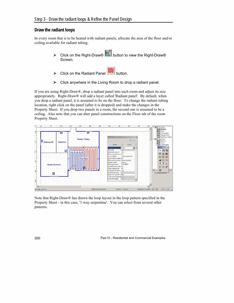
Part IV - Residential and Commercial Examples 300
Step 3 - Draw the radiant loops & Refine the Panel Design
Draw the radiant loops
In every room that is to be heated with radiant panels, allocate the area of the floor and/or ceiling available for radiant tubing.
Click on the Right-Draw® button to view the Right-Draw® Screen.
Click on the Radiant Panel button.
Click anywhere in the Living Room to drop a radiant panel.
If you are using Right-Draw®, drop a radiant panel into each room and adjust its size appropriately. Right-Draw® will add a layer called 'Radiant panel'. By default, when you drop a radiant panel, it is assumed to be on the floor. To change the radiant tubing location, right click on the panel (after it is dropped) and make the changes in the Property Sheet. If you drop two panels in a room, the second one is assumed to be a ceiling. Also note that you can alter panel constructions on the Floor tab of the room Property Sheet.
Note that Right-Draw® has drawn the loop layout in the loop pattern specified in the Property Sheet - in this case, '1-way serpentine'. You can select from several other patterns.
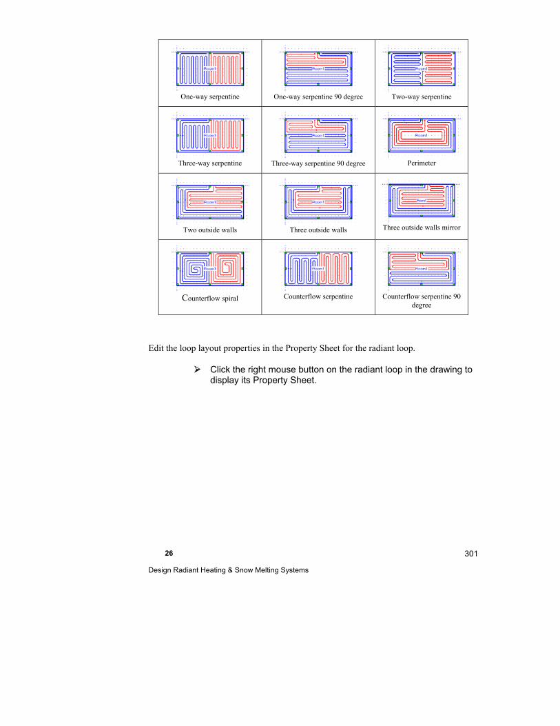
26 Design Radiant Heating & Snow Melting Systems
301
One-way serpentine
One-way serpentine 90 degree
Two-way serpentine
Three-way serpentine
Three-way serpentine 90 degree
Perimeter
Two outside walls
Three outside walls
Three outside walls mirror
Counterflow spiral
Counterflow serpentine
Counterflow serpentine 90
degree
Edit the loop layout properties in the Property Sheet for the radiant loop.
Click the right mouse button on the radiant loop in the drawing to display its Property Sheet.
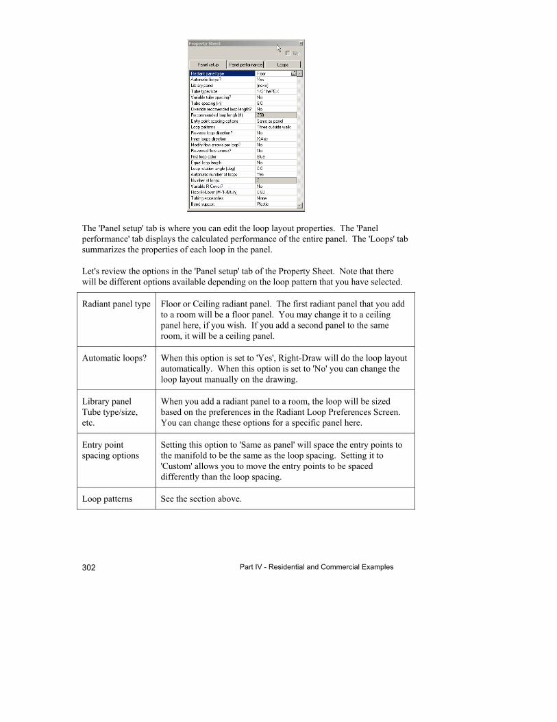
Part IV - Residential and Commercial Examples 302
The 'Panel setup' tab is where you can edit the loop layout properties. The 'Panel performance' tab displays the calculated performance of the entire panel. The 'Loops' tab summarizes the properties of each loop in the panel.
Let's review the options in the 'Panel setup' tab of the Property Sheet. Note that there will be different options available depending on the loop pattern that you have selected.
Radiant panel type Floor or Ceiling radiant panel. The first radiant panel that you add to a room will be a floor panel. You may change it to a ceiling panel here, if you wish. If you add a second panel to the same room, it will be a ceiling panel.
Automatic loops? When this option is set to 'Yes', Right-Draw will do the loop layout automatically. When this option is set to 'No' you can change the loop layout manually on the drawing.
Library panel Tube type/size, etc.
When you add a radiant panel to a room, the loop will be sized based on the preferences in the Radiant Loop Preferences Screen. You can change these options for a specific panel here.
Entry point spacing options
Setting this option to 'Same as panel' will space the entry points to the manifold to be the same as the loop spacing. Setting it to 'Custom' allows you to move the entry points to be spaced differently than the loop spacing.
Loop patterns See the section above.
26 Design Radiant Heating & Snow Melting Systems
303
Reversed flow arrows?
The radiant loops will display arrows showing the direction of flow. You can reverse the direction of flow by selecting 'Yes' here.
Inner loops direction
You can set whether you want the inner loops in the panel to run with the X-axis (horizontally), with the Y-axis (vertically), counterflow.
Modify flow arrows per loop? Reversed flow arrows?
First loop color In most cases, the colors that Right-Draw selects to display individual loops in the loop panel are adaquate. However, in some cases (i.e. when there is one loop in each panel), you may wish to change the colors. To do this, change the color of the first loop here.
Equal loop length When this option is set to 'No', the length of each loop will be approximately equal, but not exactly. This allows for simpler loop layouts and, therefore, easier installation. Setting this option to 'Yes' will result in loop lengths that are exactly equal.
Loop rotation angle
Right-Draw will draw the loops so that they are parallel to the long dimension of the room it is in. You can rotate the loops by entering a value here. For example, you might have a room that has walls that are not horzontal or vertical. You might have to rotate the loops to get them to be parallel to the walls.
Automatic number of loops and Number of loops
Set 'Automatic number of loops' to 'Yes' to let Right-Radiant® calculate the number loops that are required. To override the calculated number of loops, set the 'Automatic number of loops' to 'No' and enter the number of loops.
Variable R-Cover, Floor R-Cover, Tubing accessories, and Bend support
The selections that you made in the Radiant Preferences screen will appear here initially. However, you may change them, if you wish.
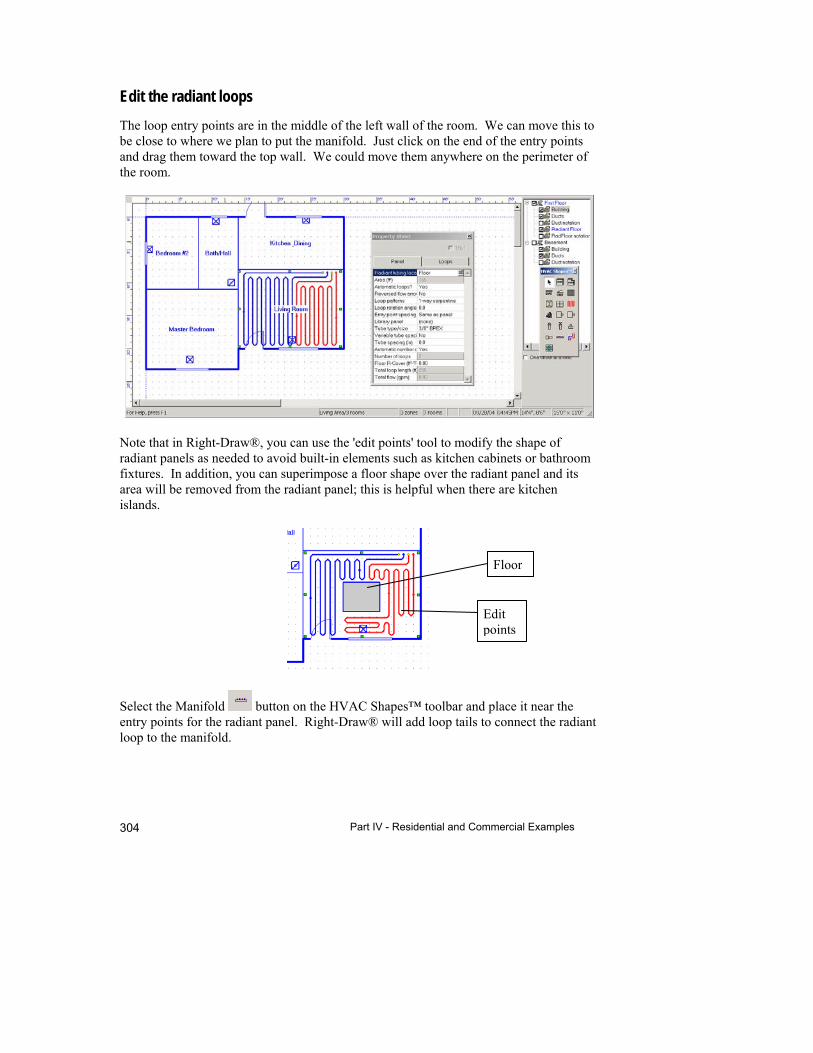
Part IV - Residential and Commercial Examples 304
Edit the radiant loops
The loop entry points are in the middle of the left wall of the room. We can move this to be close to where we plan to put the manifold. Just click on the end of the entry points and drag them toward the top wall. We could move them anywhere on the perimeter of the room.
Note that in Right-Draw®, you can use the 'edit points' tool to modify the shape of radiant panels as needed to avoid built-in elements such as kitchen cabinets or bathroom fixtures. In addition, you can superimpose a floor shape over the radiant panel and its area will be removed from the radiant panel; this is helpful when there are kitchen islands.
Select the Manifold button on the HVAC Shapes™ toolbar and place it near the entry points for the radiant panel. Right-Draw® will add loop tails to connect the radiant loop to the manifold.
Floor
Edit points
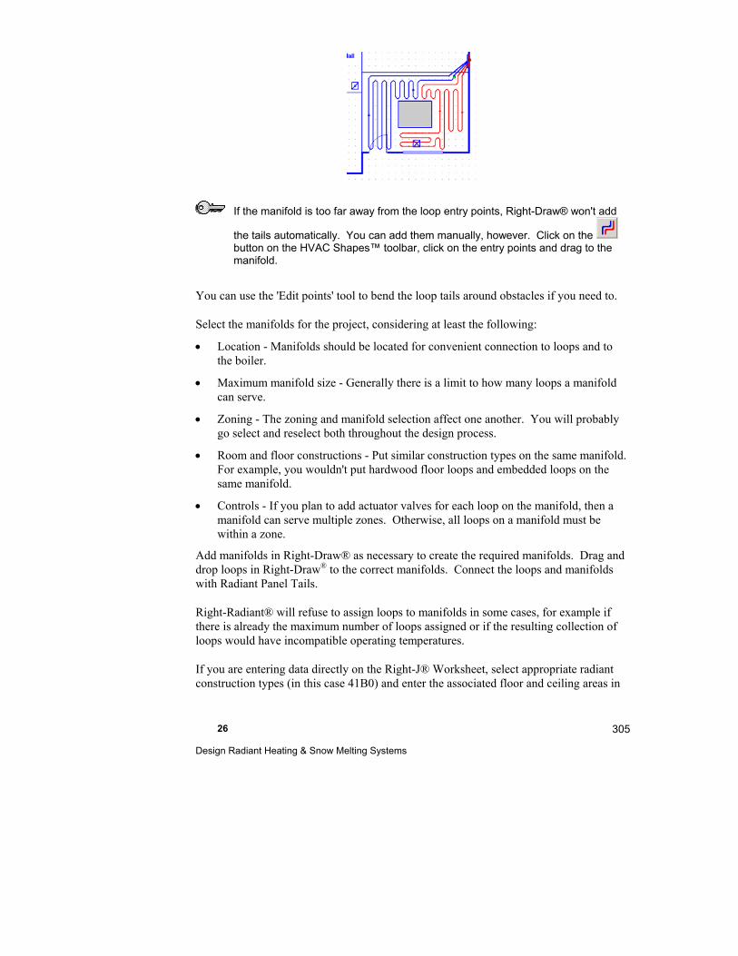
26 Design Radiant Heating & Snow Melting Systems
305
If the manifold is too far away from the loop entry points, Right-Draw® won't add
the tails automatically. You can add them manually, however. Click on the button on the HVAC Shapes™ toolbar, click on the entry points and drag to the manifold.
You can use the 'Edit points' tool to bend the loop tails around obstacles if you need to.
Select the manifolds for the project, considering at least the following:
Location - Manifolds should be located for convenient connection to loops and to the boiler.
Maximum manifold size - Generally there is a limit to how many loops a manifold can serve.
Zoning - The zoning and manifold selection affect one another. You will probably go select and reselect both throughout the design process.
Room and floor constructions - Put similar construction types on the same manifold. For example, you wouldn't put hardwood floor loops and embedded loops on the same manifold.
Controls - If you plan to add actuator valves for each loop on the manifold, then a manifold can serve multiple zones. Otherwise, all loops on a manifold must be within a zone.
Add manifolds in Right-Draw® as necessary to create the required manifolds. Drag and drop loops in Right-Draw® to the correct manifolds. Connect the loops and manifolds with Radiant Panel Tails.
Right-Radiant® will refuse to assign loops to manifolds in some cases, for example if there is already the maximum number of loops assigned or if the resulting collection of loops would have incompatible operating temperatures.
If you are entering data directly on the Right-J® Worksheet, select appropriate radiant construction types (in this case 41B0) and enter the associated floor and ceiling areas in
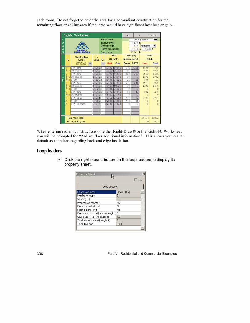
Part IV - Residential and Commercial Examples 306
each room. Do not forget to enter the area for a non-radiant construction for the remaining floor or ceiling area if that area would have significant heat loss or gain.
When entering radiant constructions on either Right-Draw® or the Right-J® Worksheet, you will be prompted for “Radiant floor additional information”. This allows you to alter default assumptions regarding back and edge insulation.
Loop leaders
Click the right mouse button on the loop leaders to display its property sheet.
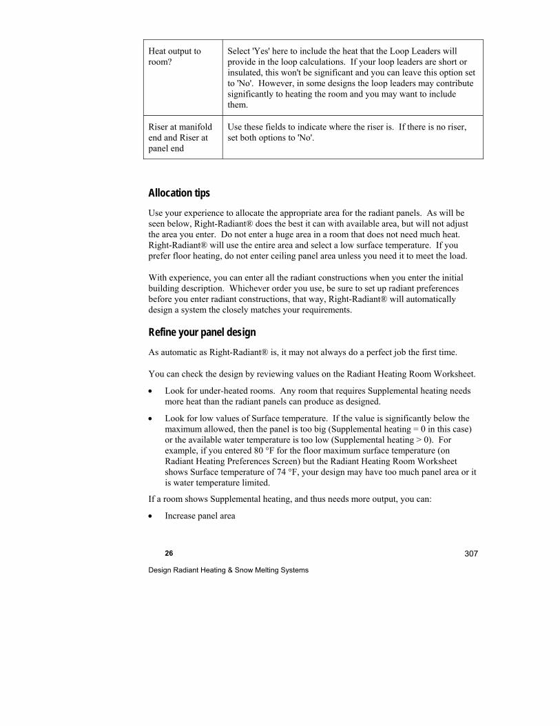
26 Design Radiant Heating & Snow Melting Systems
307
Heat output to room?
Select 'Yes' here to include the heat that the Loop Leaders will provide in the loop calculations. If your loop leaders are short or insulated, this won't be significant and you can leave this option set to 'No'. However, in some designs the loop leaders may contribute significantly to heating the room and you may want to include them.
Riser at manifold end and Riser at panel end
Use these fields to indicate where the riser is. If there is no riser, set both options to 'No'.
Allocation tips
Use your experience to allocate the appropriate area for the radiant panels. As will be seen below, Right-Radiant® does the best it can with available area, but will not adjust the area you enter. Do not enter a huge area in a room that does not need much heat. Right-Radiant® will use the entire area and select a low surface temperature. If you prefer floor heating, do not enter ceiling panel area unless you need it to meet the load.
With experience, you can enter all the radiant constructions when you enter the initial building description. Whichever order you use, be sure to set up radiant preferences before you enter radiant constructions, that way, Right-Radiant® will automatically design a system the closely matches your requirements.
Refine your panel design
As automatic as Right-Radiant® is, it may not always do a perfect job the first time.
You can check the design by reviewing values on the Radiant Heating Room Worksheet.
Look for under-heated rooms. Any room that requires Supplemental heating needs more heat than the radiant panels can produce as designed.
Look for low values of Surface temperature. If the value is significantly below the maximum allowed, then the panel is too big (Supplemental heating = 0 in this case) or the available water temperature is too low (Supplemental heating > 0). For example, if you entered 80 °F for the floor maximum surface temperature (on Radiant Heating Preferences Screen) but the Radiant Heating Room Worksheet shows Surface temperature of 74 °F, your design may have too much panel area or it is water temperature limited.
If a room shows Supplemental heating, and thus needs more output, you can:
Increase panel area
Part IV - Residential and Commercial Examples 308
Select a construction that has better thermal performance (for example, heat transfer plate constructions will produce more heat than will staple up constructions)
Add a ceiling panel in addition to a floor panel
Reduce cover R-value (on Radiant Heating Loop Worksheet)
Reduce tube spacing (on either the Room or the Loop Worksheet)
Increase the Maximum surface temperature (on the Loop Worksheet)
Increase the Supply temperature (on the Radiant Heating Preferences Screen)
If a room has no Supplemental heating and the surface temperature is significantly below the maximum, the panel may be too big, resulting in a design that is more expensive than needed. Your options include:
Accept the design as is
Reduce panel area
Increase tube spacing – it may be possible to meet the load with less tubing.
Select a lower performance (but perhaps cheaper) construction.
Step 4 - Review the manifolds
The manifold assignments can be reviewed on the System Navigator Tree.
Click on the button to display the System Navigator Tree.
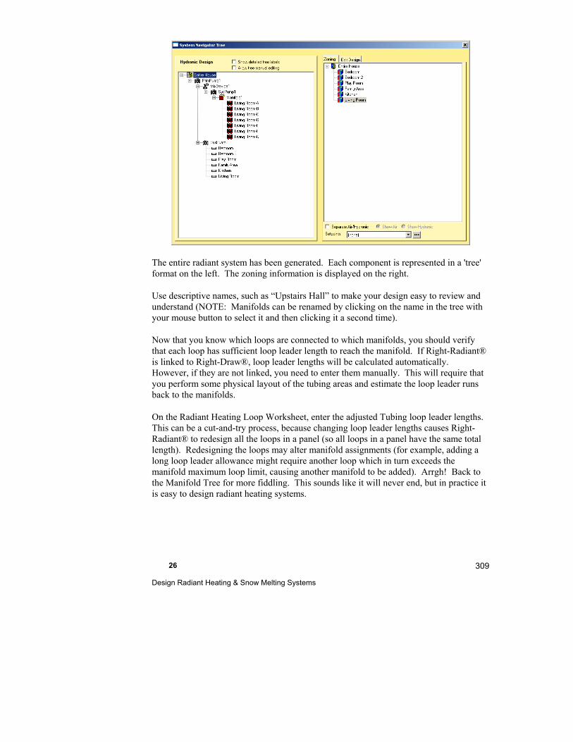
26 Design Radiant Heating & Snow Melting Systems
309
The entire radiant system has been generated. Each component is represented in a 'tree' format on the left. The zoning information is displayed on the right.
Use descriptive names, such as “Upstairs Hall” to make your design easy to review and understand (NOTE: Manifolds can be renamed by clicking on the name in the tree with your mouse button to select it and then clicking it a second time).
Now that you know which loops are connected to which manifolds, you should verify that each loop has sufficient loop leader length to reach the manifold. If Right-Radiant® is linked to Right-Draw®, loop leader lengths will be calculated automatically. However, if they are not linked, you need to enter them manually. This will require that you perform some physical layout of the tubing areas and estimate the loop leader runs back to the manifolds.
On the Radiant Heating Loop Worksheet, enter the adjusted Tubing loop leader lengths. This can be a cut-and-try process, because changing loop leader lengths causes Right-Radiant® to redesign all the loops in a panel (so all loops in a panel have the same total length). Redesigning the loops may alter manifold assignments (for example, adding a long loop leader allowance might require another loop which in turn exceeds the manifold maximum loop limit, causing another manifold to be added). Arrgh! Back to the Manifold Tree for more fiddling. This sounds like it will never end, but in practice it is easy to design radiant heating systems.
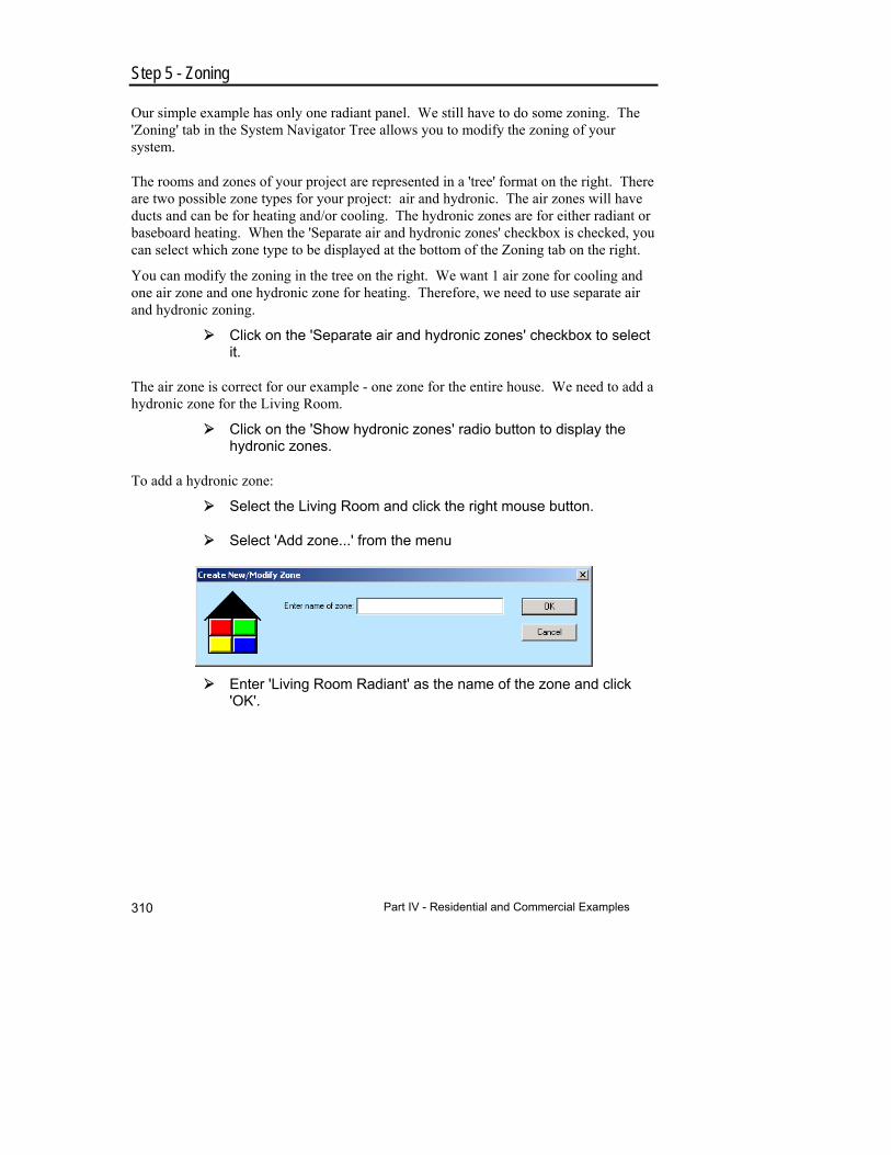
Part IV - Residential and Commercial Examples 310
Step 5 - Zoning
Our simple example has only one radiant panel. We still have to do some zoning. The 'Zoning' tab in the System Navigator Tree allows you to modify the zoning of your system.
The rooms and zones of your project are represented in a 'tree' format on the right. There are two possible zone types for your project: air and hydronic. The air zones will have ducts and can be for heating and/or cooling. The hydronic zones are for either radiant or baseboard heating. When the 'Separate air and hydronic zones' checkbox is checked, you can select which zone type to be displayed at the bottom of the Zoning tab on the right.
You can modify the zoning in the tree on the right. We want 1 air zone for cooling and one air zone and one hydronic zone for heating. Therefore, we need to use separate air and hydronic zoning.
Click on the 'Separate air and hydronic zones' checkbox to select it.
The air zone is correct for our example - one zone for the entire house. We need to add a hydronic zone for the Living Room.
Click on the 'Show hydronic zones' radio button to display the hydronic zones.
To add a hydronic zone:
Select the Living Room and click the right mouse button.
Select 'Add zone...' from the menu
Enter 'Living Room Radiant' as the name of the zone and click 'OK'.
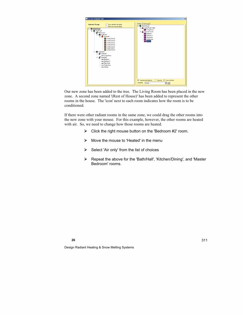
26 Design Radiant Heating & Snow Melting Systems
311
Our new zone has been added to the tree. The Living Room has been placed in the new zone. A second zone named '(Rest of House)' has been added to represent the other rooms in the house. The 'icon' next to each room indicates how the room is to be conditioned.
If there were other radiant rooms in the same zone, we could drag the other rooms into the new zone with your mouse. For this example, however, the other rooms are heated with air. So, we need to change how those rooms are heated.
Click the right mouse button on the 'Bedroom #2' room.
Move the mouse to 'Heated' in the menu
Select 'Air only' from the list of choices
Repeat the above for the 'Bath/Hall', 'Kitchen/Dining', and 'Master Bedroom' rooms.
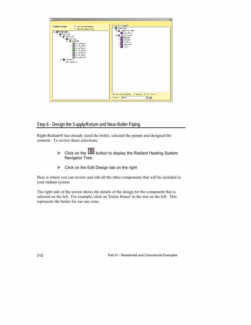
Part IV - Residential and Commercial Examples 312
Step 6 - Design the Supply/Return and Near-Boiler Piping
Right-Radiant® has already sized the boiler, selected the pumps and designed the controls. To review these selections:
Click on the button to display the Radiant Heating System Navigator Tree.
Click on the Edit Design tab on the right
Here is where you can review and edit all the other components that will be included in your radiant system.
The right side of the screen shows the details of the design for the component that is selected on the left. For example, click on 'Entire House' in the tree on the left. This represents the boiler for our one zone.
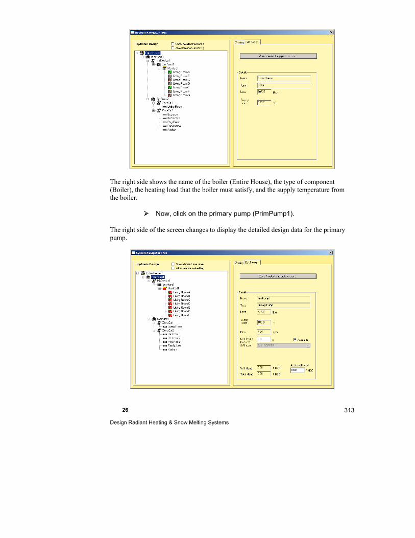
26 Design Radiant Heating & Snow Melting Systems
313
The right side shows the name of the boiler (Entire House), the type of component (Boiler), the heating load that the boiler must satisfy, and the supply temperature from the boiler.
Now, click on the primary pump (PrimPump1).
The right side of the screen changes to display the detailed design data for the primary pump.
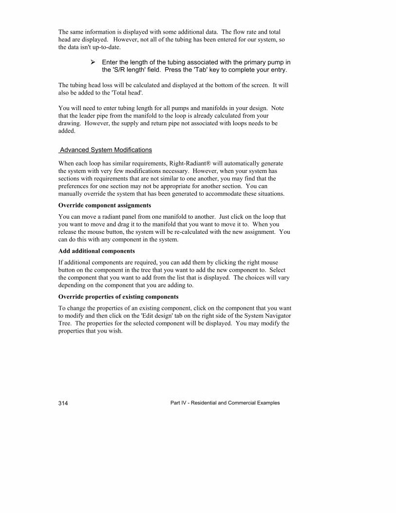
Part IV - Residential and Commercial Examples 314
The same information is displayed with some additional data. The flow rate and total head are displayed. However, not all of the tubing has been entered for our system, so the data isn't up-to-date.
Enter the length of the tubing associated with the primary pump in the 'S/R length' field. Press the 'Tab' key to complete your entry.
The tubing head loss will be calculated and displayed at the bottom of the screen. It will also be added to the 'Total head'.
You will need to enter tubing length for all pumps and manifolds in your design. Note that the leader pipe from the manifold to the loop is already calculated from your drawing. However, the supply and return pipe not associated with loops needs to be added.
Advanced System Modifications
When each loop has similar requirements, Right-Radiant® will automatically generate the system with very few modifications necessary. However, when your system has sections with requirements that are not similar to one another, you may find that the preferences for one section may not be appropriate for another section. You can manually override the system that has been generated to accommodate these situations.
Override component assignments
You can move a radiant panel from one manifold to another. Just click on the loop that you want to move and drag it to the manifold that you want to move it to. When you release the mouse button, the system will be re-calculated with the new assignment. You can do this with any component in the system.
Add additional components
If additional components are required, you can add them by clicking the right mouse button on the component in the tree that you want to add the new component to. Select the component that you want to add from the list that is displayed. The choices will vary depending on the component that you are adding to.
Override properties of existing components
To change the properties of an existing component, click on the component that you want to modify and then click on the 'Edit design' tab on the right side of the System Navigator Tree. The properties for the selected component will be displayed. You may modify the properties that you wish.
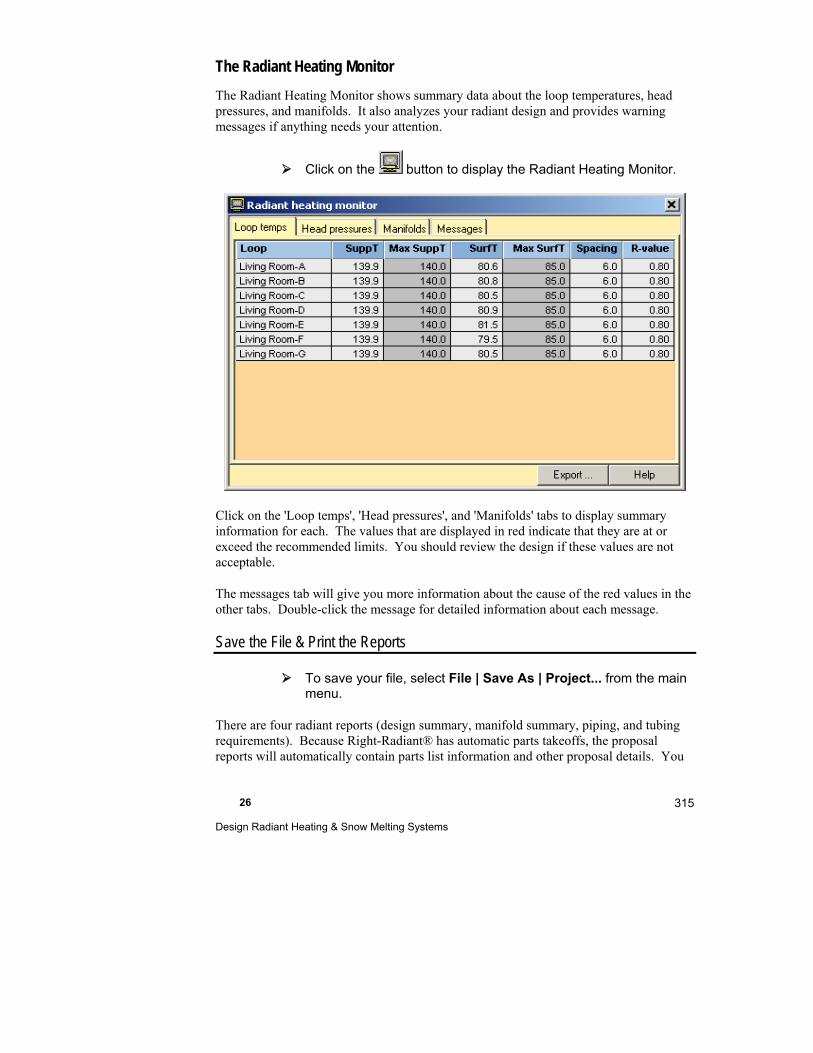
26 Design Radiant Heating & Snow Melting Systems
315
The Radiant Heating Monitor
The Radiant Heating Monitor shows summary data about the loop temperatures, head pressures, and manifolds. It also analyzes your radiant design and provides warning messages if anything needs your attention.
Click on the button to display the Radiant Heating Monitor.
Click on the 'Loop temps', 'Head pressures', and 'Manifolds' tabs to display summary information for each. The values that are displayed in red indicate that they are at or exceed the recommended limits. You should review the design if these values are not acceptable.
The messages tab will give you more information about the cause of the red values in the other tabs. Double-click the message for detailed information about each message.
Save the File & Print the Reports
To save your file, select File | Save As | Project... from the main menu.
There are four radiant reports (design summary, manifold summary, piping, and tubing requirements). Because Right-Radiant® has automatic parts takeoffs, the proposal reports will automatically contain parts list information and other proposal details. You

Part IV - Residential and Commercial Examples 316
may want to preview all 7 reports (four Right-Radiant® and three Right-Proposal®) to see what kinds of information are provided on the reports. Previewing reports will also help you catch errors you did not see on the screen. Make the corrections as necessary and then print the final reports. To preview and print these reports:
Select File | Print Preview from the main menu.
Select the reports from the Choose Reports window (click to select and click to deselect) then click OK.
Preview the reports and if there are no changes, click Print in the upper left corner.
Verify the printer settings and click OK.
Summary of Steps for a Snow Melting Panel Design
Designing a snow melting system is a lot like designing a radiant heating system.
To design a snow melting system, use almost the same steps:
1. Select the snow melt preferences
2. Enter the design temperature, wind speed, and snowfall rate
3. Draw the snow melt boundry and loops - refine the panel design
4. Review manifolds
5. Design central system
Step 1 - Enter Snow Melting Preferences
Enter the appropriate settings for the preferences. See Help | Snow Melting Overview for an explanation of the terms.
Step 2 - Enter the Design Temperature, Wind Speed & Snowfall Rate
Enter these values on the Snow Melting Worksheet. Access the worksheet by clicking
on the Snow Melting Worksheet button. Double click on the 'Snowfall rate' field and choose the rate appropriate for your conditions.
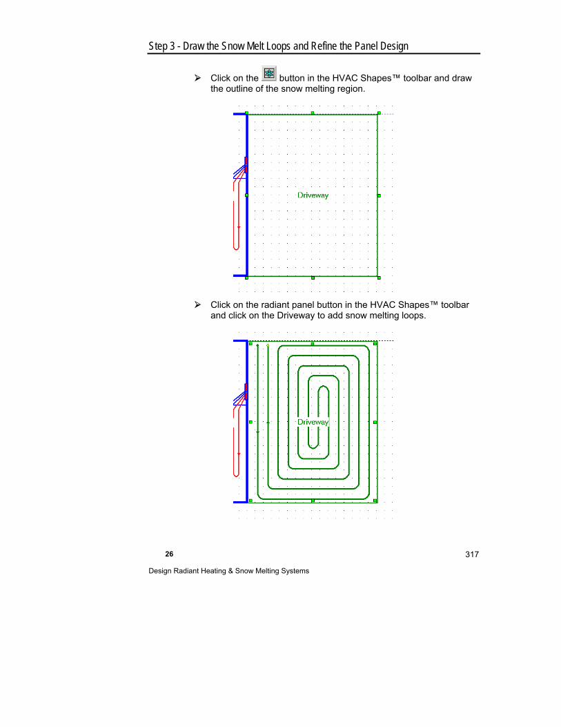
26 Design Radiant Heating & Snow Melting Systems
317
Step 3 - Draw the Snow Melt Loops and Refine the Panel Design
Click on the button in the HVAC Shapes™ toolbar and draw the outline of the snow melting region.
Click on the radiant panel button in the HVAC Shapes™ toolbar and click on the Driveway to add snow melting loops.

Part IV - Residential and Commercial Examples 318
Use the same techniques as we used to design radiant heating loops to add the manifold and tails, change the shape of the loop area, etc.
Select the manifolds for the project, considering at least the following:
Location - Manifolds should be located for convenient connection to loops and to the equipment.
Maximum manifold size - Generally there is a limit to how many loops a manifold can serve.
Add manifolds in Right-Draw® as necessary to create the required manifolds.
Right-Radiant® will refuse to assign loops to manifolds in some cases, for example if there is already the maximum number of loops assigned or if the resulting collection of loops would have incompatible operating temperatures.
Step 4 - Review Manifolds
The mainifold assignments can be reviewed on the Snow Melting Manifold Tree.
Click on the button to display the Snow Melting Manifold Worksheet.
Click on the 'Manifold Tree' button at the top of the screen to display the Manifold Tree.
Step 5 - Design the Central System
Using summary values, you can size the boiler, select pumps and design controls. To size the pumps:
Click on the button to display the Radiant System Navigator Tree.

26 Design Radiant Heating & Snow Melting Systems
319
Note that because we checked the 'Use the same boiler for snow melt' box in the 'Zoning/water temp preferences' screen, both the heating radiant panel and snow melt radiant panel use the same boiler. Also note that since the difference between the required temperatures for the heating radiant panel and snow melt radiant panel is greater than the setting in the 'Zoning / water temp preferences' screen, there are separate mixing valves for each.
The 'Show detailed tree labels' checkbox is checked to show the additional data in the tree.
Click on the 'Close' button to return to the Drawing Screen.
Radiant Heating Quick Quote
You can quickly estimate the cost of materials for a radiant design using the Quick Quote feature of Right-Radiant®. Quick Quote calculates the radiant loop length using summary and average information. It is completely separate from Right-Draw® and Right-J®.
Select Options | Radiant heating quick quote mode from the menu.
Click on the button to display the Radiant Quick Quote Screen.
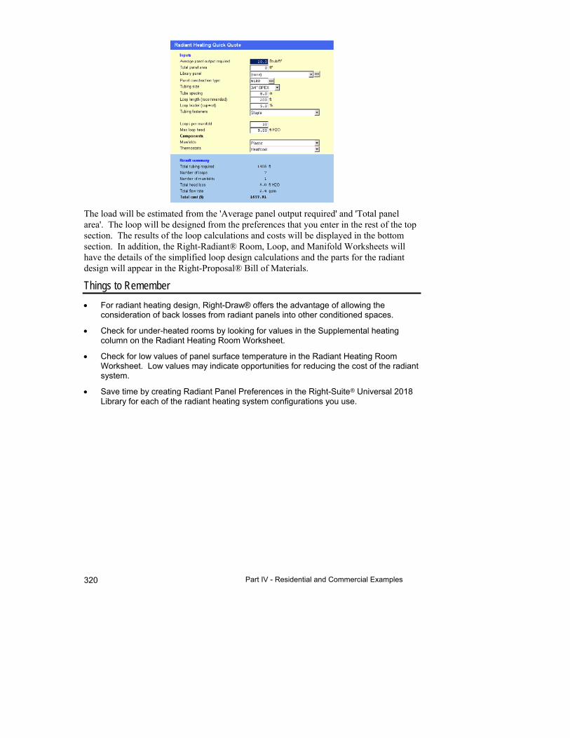
Part IV - Residential and Commercial Examples 320
The load will be estimated from the 'Average panel output required' and 'Total panel area'. The loop will be designed from the preferences that you enter in the rest of the top section. The results of the loop calculations and costs will be displayed in the bottom section. In addition, the Right-Radiant® Room, Loop, and Manifold Worksheets will have the details of the simplified loop design calculations and the parts for the radiant design will appear in the Right-Proposal® Bill of Materials.
Things to Remember
For radiant heating design, Right-Draw® offers the advantage of allowing the consideration of back losses from radiant panels into other conditioned spaces.
Check for under-heated rooms by looking for values in the Supplemental heating column on the Radiant Heating Room Worksheet.
Check for low values of panel surface temperature in the Radiant Heating Room Worksheet. Low values may indicate opportunities for reducing the cost of the radiant system.
Save time by creating Radiant Panel Preferences in the Right-Suite Universal 2018 Library for each of the radiant heating system configurations you use.

27
Solar Hot Water Heater System Design with Right-SolarDHW™
This chapter shows you how to design a solar hot water system.
Example Files for This Chapter ................................... 322
What Does Right-SolarDHW™ Do? ............................ 322
A Right-SolarDHW™ Example .................................... 323
Weather location ......................................................... 323
Backup hot water heater.............................................. 326
Solar collector.............................................................. 329
Solar Tank ................................................................... 331
Solar pump .................................................................. 334
Controller and Accessories.......................................... 335
Solar Water Heater Library .......................................... 335
Bill of Materials ............................................................ 337
Things to Remember ................................................... 340

Part IV - Residential and Commercial Examples 322
Example Files for This Chapter
Source demo file: SolarDHWStart.rud
Completed demo file for comparison: ExSolarDHW.rud
The examples assume that you are running RSU in the Demo mode. Your screens and your results may be different if you use a registered version or an OEM version.
What Does Right-SolarDHW™ Do?
Right-SolarDHW™ makes it possible to quickly design a solar hot water heating system based on the hot water requirements of the people in the house and the solar conditions of the house - the location, orientation of the solar panels, etc.
Solar hot water heating systems typically have a solar part and a backup part. When the sun is out, the solar part 'pre-heats' the water and stores it in a separate tank. This tank supplies the backup hot water heater with heated water and so it doesn't need to heat it. Hot water from the solar tank replaces the hot water in the backup water as the occupants use it. Cold water from the mains is added to the solar tank and heated by the collector. So, the solar system is 'inserted' between a standard hot water heater and the 'mains' water supply.
The solar part consists of:
A solar collector that is installed on the roof
A solar storage tank
A pump to circulate the water through the collector and the tank
A controller to activate the pump when necessary
Accessories - piping, etc. needed to complete the installation
The above configuration is typical for a retrofit installation. For new installations, there are other configurations available including a 'single tank' configuration. This configuration has a single tank that stores both the pre-heated water from the solar collector and water from the backup heat source.
As you add components to the solar hot water system, the corresponding part in the Right-Proposal® database will be added to the Bill of Materials. If there isn't a corresponding part, a part will be added with the model number only. You can then either add a part to the Right-Proposal® database or just enter the price, etc. manually into the Bill of Materials.

27 Solar Hot Water Heater System Design with Right-SolarDHW™
323
The controllers and accessories are handled a little differently than other components. There are a number of pre-defined 'generic' kit assemblies that you need to map specific parts in your Right-Proposal® database. You select one of these kits for your project. You can either map the parts of each kit ahead of time or just build each kit when you need it.
A Right-SolarDHW™ Example
Start by opening the demo project ‘SolarDHWStart.rud'.
Weather location
Right-SolarDHW™ needs to know details about the location of your project to determine when the sun can heat the water. We select the location in the Project Information Screen. You generally select the weather location when you first start a new project.
Select Show | Project Information from the menu
Scroll down to the 'Location' section
Click on the next to the Weather location.

Part IV - Residential and Commercial Examples 324
Note the circled button. When there is solar data available for the selected location, this button will be available. Many U.S. locations have solar data, but not all do. You should make sure that the location you select has solar data. If the one you have selected doesn't have solar data, select a similar location that does.
If your location doesn't have solar data, you can enter it manually in the Project Information Screen. You will probably want to include the data in the Weather Locations Libarary. You need to enter the Irradiation, Average DB, and Mains temperature in the Cooling Conditions grid of the monthly weather data.
Click on the Solar Data button
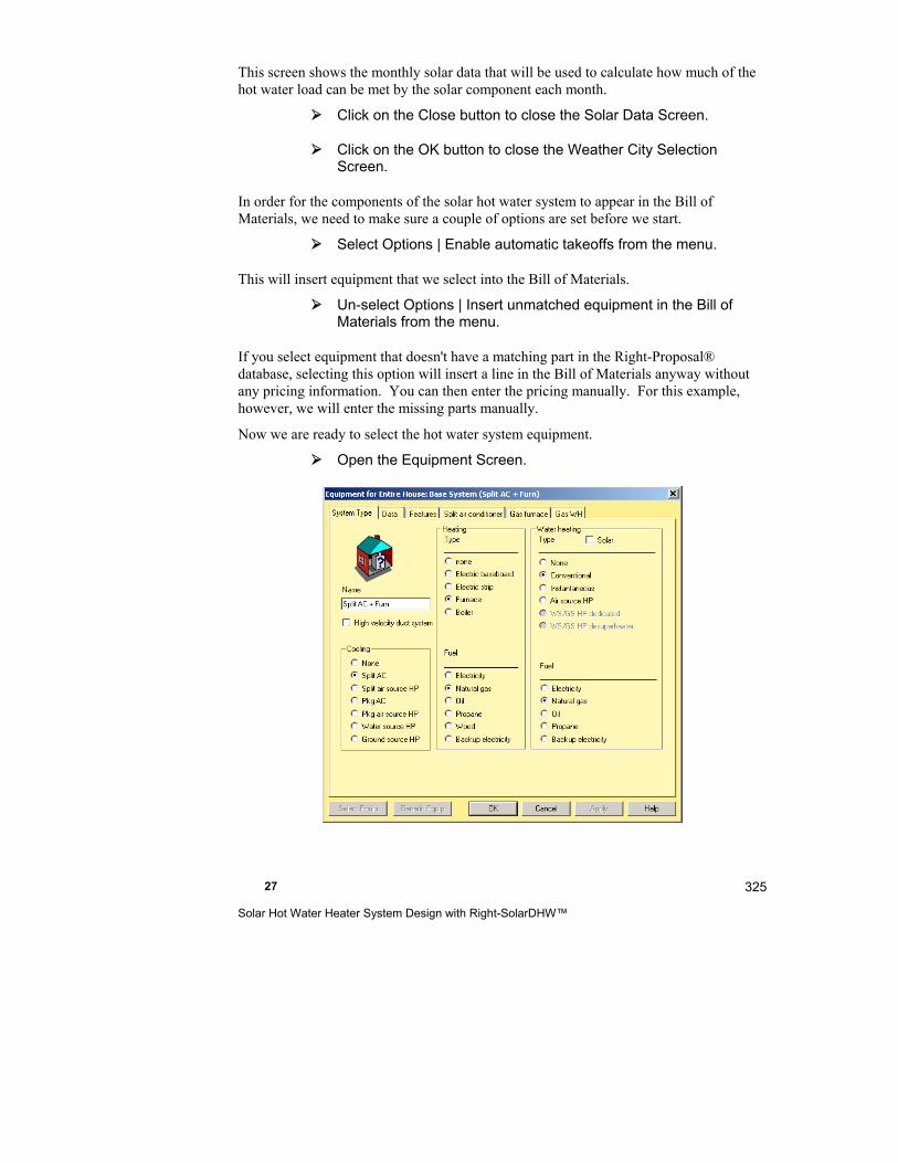
27 Solar Hot Water Heater System Design with Right-SolarDHW™
325
This screen shows the monthly solar data that will be used to calculate how much of the hot water load can be met by the solar component each month.
Click on the Close button to close the Solar Data Screen.
Click on the OK button to close the Weather City Selection Screen.
In order for the components of the solar hot water system to appear in the Bill of Materials, we need to make sure a couple of options are set before we start.
Select Options | Enable automatic takeoffs from the menu.
This will insert equipment that we select into the Bill of Materials.
Un-select Options | Insert unmatched equipment in the Bill of Materials from the menu.
If you select equipment that doesn't have a matching part in the Right-Proposal® database, selecting this option will insert a line in the Bill of Materials anyway without any pricing information. You can then enter the pricing manually. For this example, however, we will enter the missing parts manually.
Now we are ready to select the hot water system equipment.
Open the Equipment Screen.
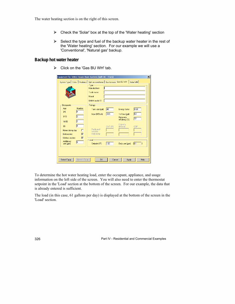
Part IV - Residential and Commercial Examples 326
The water heating section is on the right of this screen.
Check the 'Solar' box at the top of the 'Water heating' section
Select the type and fuel of the backup water heater in the rest of the 'Water heating' section. For our example we will use a 'Conventional', 'Natural gas' backup.
Backup hot water heater
Click on the 'Gas BU WH' tab.
To determine the hot water heating load, enter the occupant, appliance, and usage information on the left side of the screen. You will also need to enter the thermostat setpoint in the 'Load' section at the bottom of the screen. For our example, the data that is already entered is sufficient.
The load (in this case, 61 gallons per day) is displayed at the bottom of the screen in the 'Load' section.

27 Solar Hot Water Heater System Design with Right-SolarDHW™
327
Select the backup hot water heater
We can now select the specific backup hot water heater that we are going to use. Since there will be times when the sun won't be out, you should size the backup for the entire load - as if there wasn't going to be a solar part.
Click on the 'Select Equip' button in the lower left corner of the screen.
Select 'Sample' in the list of manufacturers on the left.
The list of hot water heaters is filtered to only show equipment that is close to the load that was calculated in the previous screen. The list is also filtered to only show hot water heaters of the type and fuel that we selected in the System Type tab.
Click on the hot water heater that you want to use (there is only one in our example) and then click the OK button to transfer the selected hot water heater.
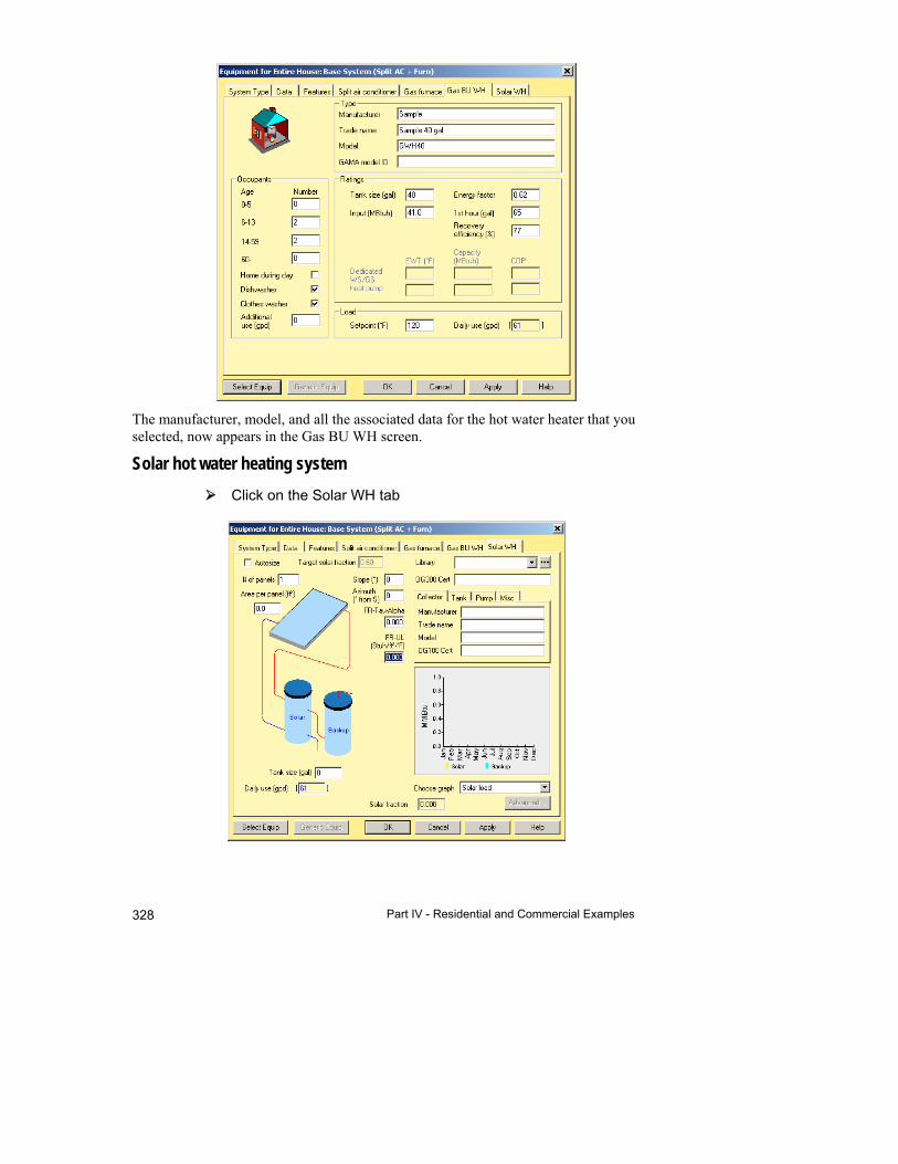
Part IV - Residential and Commercial Examples 328
The manufacturer, model, and all the associated data for the hot water heater that you selected, now appears in the Gas BU WH screen.
Solar hot water heating system
Click on the Solar WH tab
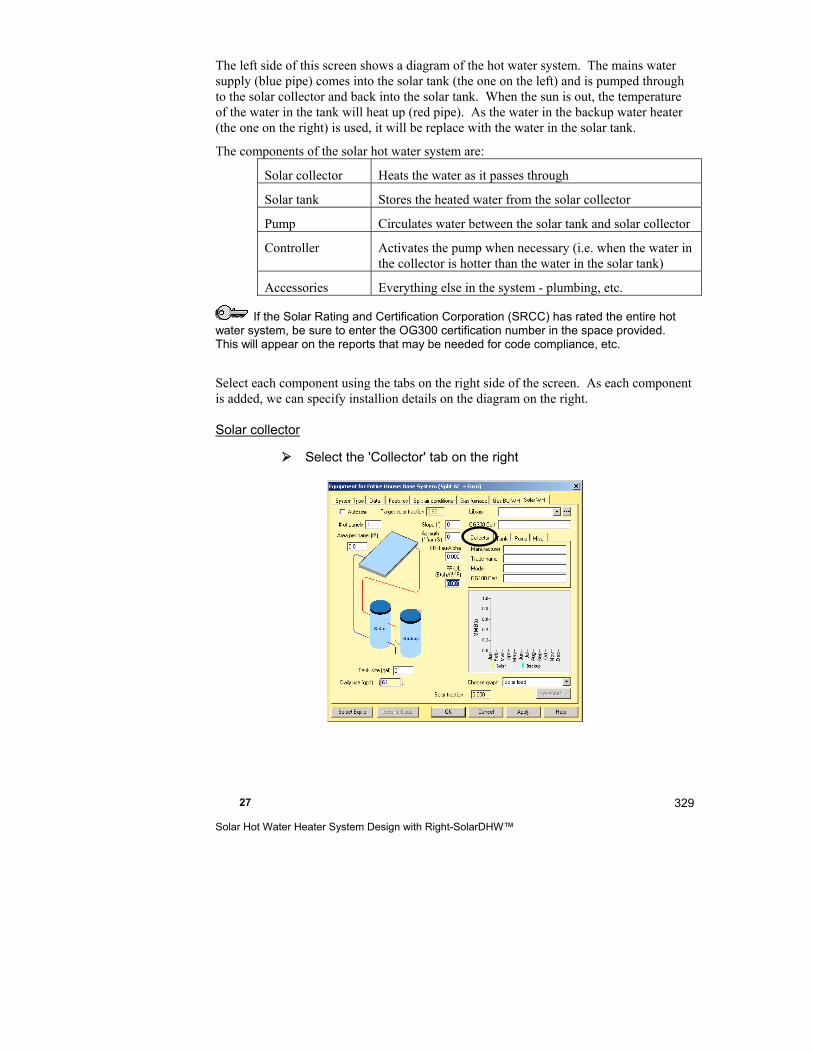
27 Solar Hot Water Heater System Design with Right-SolarDHW™
329
The left side of this screen shows a diagram of the hot water system. The mains water supply (blue pipe) comes into the solar tank (the one on the left) and is pumped through to the solar collector and back into the solar tank. When the sun is out, the temperature of the water in the tank will heat up (red pipe). As the water in the backup water heater (the one on the right) is used, it will be replace with the water in the solar tank.
The components of the solar hot water system are:
Solar collector Heats the water as it passes through
Solar tank Stores the heated water from the solar collector
Pump Circulates water between the solar tank and solar collector
Controller Activates the pump when necessary (i.e. when the water in the collector is hotter than the water in the solar tank)
Accessories Everything else in the system - plumbing, etc.
If the Solar Rating and Certification Corporation (SRCC) has rated the entire hot water system, be sure to enter the OG300 certification number in the space provided. This will appear on the reports that may be needed for code compliance, etc.
Select each component using the tabs on the right side of the screen. As each component is added, we can specify installion details on the diagram on the right.
Solar collector
Select the 'Collector' tab on the right

Part IV - Residential and Commercial Examples 330
Click the 'Select Equip' button in the lower left of the screen
Select 'Sample' for the manufacturer
The target area is a 'starting point' for selecting a collector. Just about any size collector can be used in any installation by using multiple collectors. Manipulate the values in the Filter section until the collector you want to use is shown.
Note that the solar collecctor in the list has a Gross Area that is less than the target area that we need for this project. We will need at least 2 of these particular collectors. We will select this collector and enter the number of collectors in the Equipment Screen.
FR-Tau-Alpha and FR-UL are values that are used to indicate the effectiveness of the solar collector. FR-Tau-Alpha is the collector's 'optical efficiency' - the higher the better. FR-UL is a measure of how much heat the collector loses (i.e. due to insulation, etc.) - the lower the better. FR-Tau-Alpha values are generally in the range of 0.3 (not very efficient) to 0.8 (very efficient). FR-UL values can be 2 or 3 (high losses) to 0.3 or 0.4 (low losses). In general, glazed collectors have a lower FR-Tau-Alpha than unglazed and a lower FR-UL than unglazed.
Click on the collector in the list and click on the OK button to transfer the selected collector.
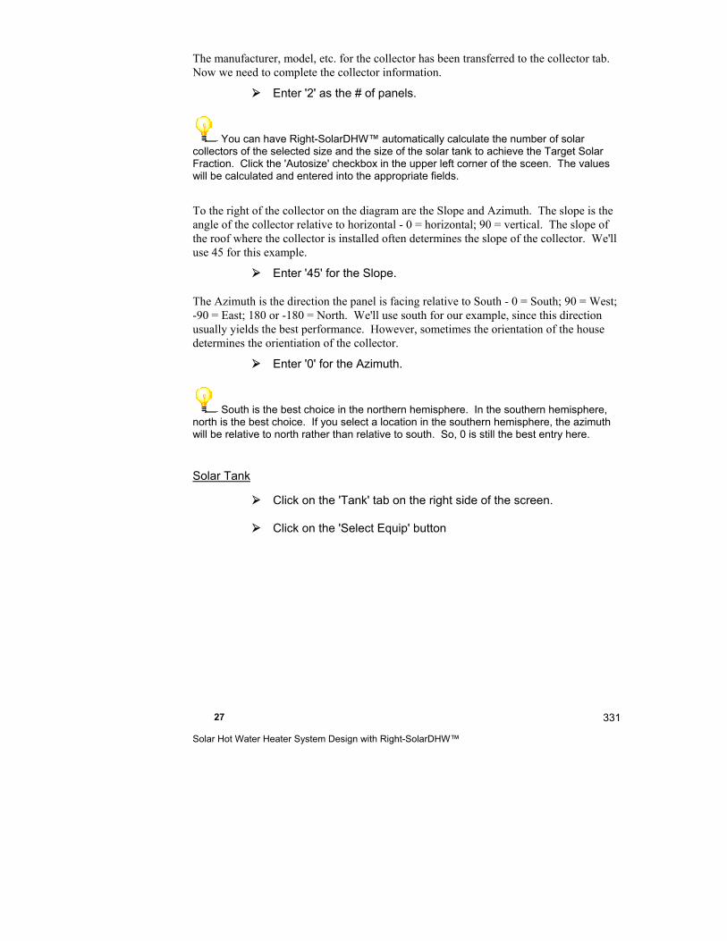
27 Solar Hot Water Heater System Design with Right-SolarDHW™
331
The manufacturer, model, etc. for the collector has been transferred to the collector tab. Now we need to complete the collector information.
Enter '2' as the # of panels.
You can have Right-SolarDHW™ automatically calculate the number of solar collectors of the selected size and the size of the solar tank to achieve the Target Solar Fraction. Click the 'Autosize' checkbox in the upper left corner of the sceen. The values will be calculated and entered into the appropriate fields.
To the right of the collector on the diagram are the Slope and Azimuth. The slope is the angle of the collector relative to horizontal - 0 = horizontal; 90 = vertical. The slope of the roof where the collector is installed often determines the slope of the collector. We'll use 45 for this example.
Enter '45' for the Slope.
The Azimuth is the direction the panel is facing relative to South - 0 = South; 90 = West; -90 = East; 180 or -180 = North. We'll use south for our example, since this direction usually yields the best performance. However, sometimes the orientation of the house determines the orientiation of the collector.
Enter '0' for the Azimuth.
South is the best choice in the northern hemisphere. In the southern hemisphere, north is the best choice. If you select a location in the southern hemisphere, the azimuth will be relative to north rather than relative to south. So, 0 is still the best entry here.
Solar Tank
Click on the 'Tank' tab on the right side of the screen.
Click on the 'Select Equip' button

Part IV - Residential and Commercial Examples 332
The capacity of the tank made by 'Sample' is greater than the 'Target capacity'. So, we will select it.
Typically the solar tank is sized at 1.5 to 2 gallons per ft² of solar collector area.
It isn't necessary to make selections from the database. You can just enter the data directly in the 'Solar WH' tab of the Equipment Screen.
Right-Suite Universal 2018 includes sample data only for solar tanks and solar pumps. If you want to select these items from the database, you will need to add them yourself via an Excel spreadsheet. See C:\Program Files\Wrightsoft HVAC\Data\Excel import\Sample Parts Template.xls for details on how to do this.
Select the tank and click the OK button to transfer it.

27 Solar Hot Water Heater System Design with Right-SolarDHW™
333
Note that the selecting the collector and tank is all that is necessary to calculate the solar fraction and solar load of the system. The graph on the right shows how much of the hot water heating load can be met with the solar system each month. The blue section represents the entire hot water heating load and the yellow section represents how much of that can be met with the solar system. Select the 'Solar fraction' graph from the drop down list to show the same information as fractions of the total load.
Click on the Advanced... button below the graph
This screen shows all the intermediate values for the monthly solar load and solar fraction calculations. In addition, the calculated tank UA is displayed in the upper left corner.
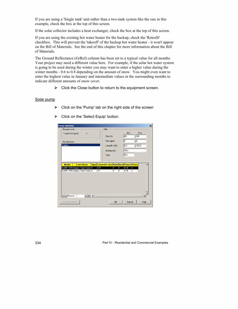
Part IV - Residential and Commercial Examples 334
If you are using a 'Single tank' unit rather than a two-tank system like the one in this example, check the box at the top of this screen.
If the solar collector includes a heat exchanger, check the box at the top of this screen.
If you are using the existing hot water heater for the backup, check the 'Retrofit' checkbox. This will prevent the 'takeoff' of the backup hot water heater - it won't appear on the Bill of Materials. See the end of this chapter for more information about the Bill of Materials.
The Ground Reflectance (GrRef) column has been set to a typical value for all months. Your project may need a different value here. For example, if the solar hot water system is going to be used during the winter you may want to enter a higher value during the winter months - 0.6 to 0.8 depending on the amount of snow. You might even want to enter the highest value in January and intemediate values in the surrounding months to indicate different amounts of snow cover.
Click the Close button to return to the equipment screen.
Solar pump
Click on the 'Pump' tab on the right side of the screen
Click on the 'Select Equip' button.

27 Solar Hot Water Heater System Design with Right-SolarDHW™
335
Select a pump that will meet the flow and head requirements of the collector and related piping. Generally, the flow will be in the range of 0.02 to 0.03 gpm per ft² of solar collector area.
Select the first pump and then click on the OK button to transfer it.
Controller and Accessories
Click on the 'Misc.' tab on the right side of the screen.
Select 'Controller type 1' from the Controller drop-down list.
Select 'Accessory kit 1' from the Accessories drop-down list.
Solar Water Heater Library
You can select solar hot water systems and save them into the Right-Suite Universal 2018 Library. When you do this, you can select an entire system from the drop-down list in the upper right corner of the 'Solar WH' tab. To enter systems into the library:

Part IV - Residential and Commercial Examples 336
Click on the button in the upper right corner of the 'Solar WH' tab
When you are not in the Equipment Screen, you can also select Library | Solar Water Heaters from the menu.
Click the 'New...' button to add a system. Give it a name and description. Click the 'Next' button and select the components of the system just like you just did for this example.
Completing the Solar Hot Water System
You have selected the entire solar hot water system.
Click on the OK button at the bottom of the screen to transfer the hot water system to your project.
The components of the hot water system that are in the Right-Proposal® databse will be added to the Bill of Materials. However, 'Controller type 1' and 'Accessory kit 1' haven't
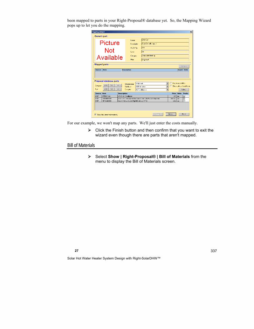
27 Solar Hot Water Heater System Design with Right-SolarDHW™
337
been mapped to parts in your Right-Proposal® database yet. So, the Mapping Wizard pops up to let you do the mapping.
For our example, we won't map any parts. We'll just enter the costs manually.
Click the Finish button and then confirm that you want to exit the wizard even though there are parts that aren't mapped.
Bill of Materials
Select Show | Right-Proposal® | Bill of Materials from the menu to display the Bill of Materials screen.
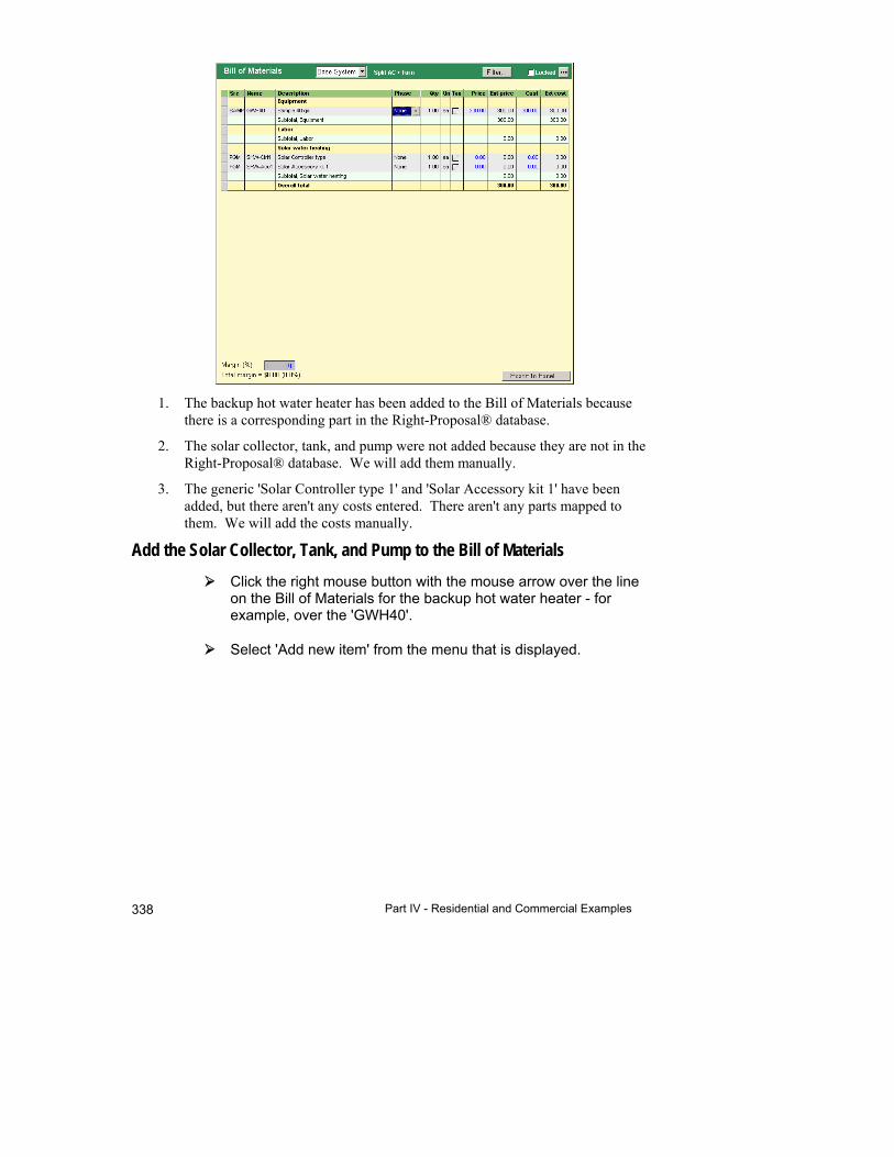
Part IV - Residential and Commercial Examples 338
1. The backup hot water heater has been added to the Bill of Materials because there is a corresponding part in the Right-Proposal® database.
2. The solar collector, tank, and pump were not added because they are not in the Right-Proposal® database. We will add them manually.
3. The generic 'Solar Controller type 1' and 'Solar Accessory kit 1' have been added, but there aren't any costs entered. There aren't any parts mapped to them. We will add the costs manually.
Add the Solar Collector, Tank, and Pump to the Bill of Materials
Click the right mouse button with the mouse arrow over the line on the Bill of Materials for the backup hot water heater - for example, over the 'GWH40'.
Select 'Add new item' from the menu that is displayed.

27 Solar Hot Water Heater System Design with Right-SolarDHW™
339
Fill this screen in with the information for the solar collector:
Name SC-UFL001
Description Sample solar collector
Cost $500.00
Price $600.00
Quantity 2
Click the OK button to transfer the added item to the Bill of Materials
Repeat these steps to add the solar tank and pump.

Part IV - Residential and Commercial Examples 340
To add hot water heaters, solar collectors, tanks, and pumps to the Right-Proposal® database, you need to add parts with the same manufacturer and part number via an Excel spreadsheet. See C:\Program Files\Wrightsoft HVAC\Data\Excel import\Sample Parts Template.xls for details on how to do this.
Add the costs to 'Solar Controller type 1' and 'Solar Accessories kit 1'
Click the right mouse button with the mouse pointer over the 'SHW-Ctrl1' in the Bill of Materials.
Select 'Edit item' from the menu that is displayed.
Enter the Cost and Price that you wish and click the OK button to transfer them to the Bill of Materials.
Repeat this step to add the costs to the 'Solar Accessories kit1'
If you enter parts and/or pricing into the Bill of Materials and then re-select equipment for the solar hot water system with automatic takeoffs turned on, your changes will be lost. To preserve your changes, un-select Options | Enable automatic takesoffs from the menu before re-selecting equpment.
That's it! You have selected the entire solar hot water system and added the various components to the Bill of Materials - ready for proposals and operating costs.
Things to Remember
Right-SolarDHW™ makes it easy to design and select a solar hot water system.
There are backup and solar components to the solar hot water system
The solar components incude a solar collector, tank, pump, controller, and accessories.
If there are corresponding parts in the Right-Proposal® database for the solar components, they will be added to the Bill of Materials automatically. If they are not, you can add them manually.
The controller and accessories are generic kits that you can map to actual parts in your Right-Proposal® database.
Right-$™ allows for the solar component when it calculates the fuel cost for water heating.

27 Solar Hot Water Heater System Design with Right-SolarDHW™
341


28
Sales Presentations with Right-$™
This chapter shows you how to analyze system and operating costs for as many as four systems. Graphical comparisons will help your customers understand their purchase options.
Example Files for This Chapter ................................... 344
What Does Right-$™ Do? ........................................... 344
A Right-$™ Example ................................................... 344
Things to Remember ........................................... 349
Part IV - Residential and Commercial Examples 344
Example Files for This Chapter
Source demo file: R$Examp.rud
Completed demo file for comparison: ExR$Exam.rud
The examples assume that you are running RSU in the Demo mode. Your screens and your results may be different if you use a registered version or an OEM version.
What Does Right-$™ Do?
Right-$™ makes it possible to quickly and conveniently compare the financial aspects of as many as four HVAC system alternatives. With Right-$™ your sales presentations will be easier to prepare and you will be able to provide information for decision making to your most demanding customers.
The comparisons consider initial costs, operating costs, interest rates and monthly payments. In addition to tables of annual costs and savings, Right-$™ also provides overall calculations of simple payback periods and return on investment. A variety of bar charts make the comparisons easy to understand by showing costs and savings for the alternatives side-by-side.
By taking future savings into account, your customers will understand why spending a little more up front will be a smart choice for them. Right-$™ helps create a win-win situation by giving your customers the confidence needed to make good decisions and by giving you the sale.
If you define standard system alternatives in an RSU template, the System Comparison Screen will automatically analyze the systems as soon as the loads are calculated.
A Right-$™ Example
System Comparison
Let us compare four air source heat pump systems.
Start by opening the demo project ‘R$Examp.rud'.
Open the Project Information Screen.
28 Sales Presentations with Right-$™
345
Because we are using RSU in Demo mode, we cannot edit weather data. You will see that the bin data city has been entered. Operating costs for heat pumps require the bin data city information for calculations. Leave the bin data city set to Fort Worth/Carswell AFB.
With a licensed version of RSU, you can edit the weather data cities by clicking the Choices button for the 'Weather location’ field. Select the country, state, and city and then click OK. For the bin data city, click the bin data city Choices button, and then make your selection. Click on the plus (+) sign to the left of a state to display a list of cities; click on a city and press Select.
To open the System Comparison Screen, click the Right-$™
button on the Selector Toolbar then click the System
Comparison button.
The Base System has been filled in with the equipment. For this example, however, we want to change the backup heating type to electric strip.
Click the system name button under the Base System.
Select 'Split air source HP' for the cooling type, then ‘Electric strip’ and 'Electricity' for the backup heating type and fuel. Make sure the water heating is 'none'.
Click on the Air source HP tab then click on the Select Equipment button.
Choose 'Sample Equipment Corp' for the manufacturer. In the Filter section, enter a minimum Capacity of 85% then enter '10.2' for the minimum and maximum SEER and press <Enter>. This will narrow your options making it easier for you to find and select the HPP056102-072 model. Click OK.
Click on the Data tab and enter '2900' in the Initial Costs section for Equipment ($).
Click OK because you have finished entering the data for the Base System.
You will see that the Base System is an air source heat pump with the 'Sample HPP056102-072' make and model. Also notice that the efficiency data has been entered.
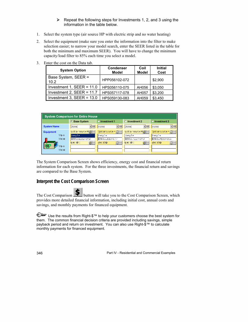
Part IV - Residential and Commercial Examples 346
Repeat the following steps for Investments 1, 2, and 3 using the information in the table below.
1. Select the system type (air source HP with electric strip and no water heating)
2. Select the equipment (make sure you enter the information into the filter to make selection easier; to narrow your model search, enter the SEER listed in the table for both the minimum and maximum SEER). You will have to change the minimum capacity/load filter to 85% each time you select a model.
3. Enter the cost on the Data tab.
System Option Condenser
Model Coil
Model Initial Cost
Base System, SEER = 10.2 HPP056102-072 $2,900
Investment 1, SEER = 11.0 HPS056110-075 AH056 $3,050 Investment 2, SEER = 11.7 HPS057117-078 AH057 $3,200 Investment 3, SEER = 13.0 HPS059130-083 AH059 $3,450
The System Comparison Screen shows efficiency, energy cost and financial return information for each system. For the three investments, the financial return and savings are compared to the Base System.
Interpret the Cost Comparison Screen
The Cost Comparison button will take you to the Cost Comparison Screen, which provides more detailed financial information, including initial cost, annual costs and savings, and monthly payments for financed equipment.
Use the results from Right-$™ to help your customers choose the best system for them. The common financial decision criteria are provided including savings, simple payback period and return on investment. You can also use Right-$™ to calculate monthly payments for financed equipment.
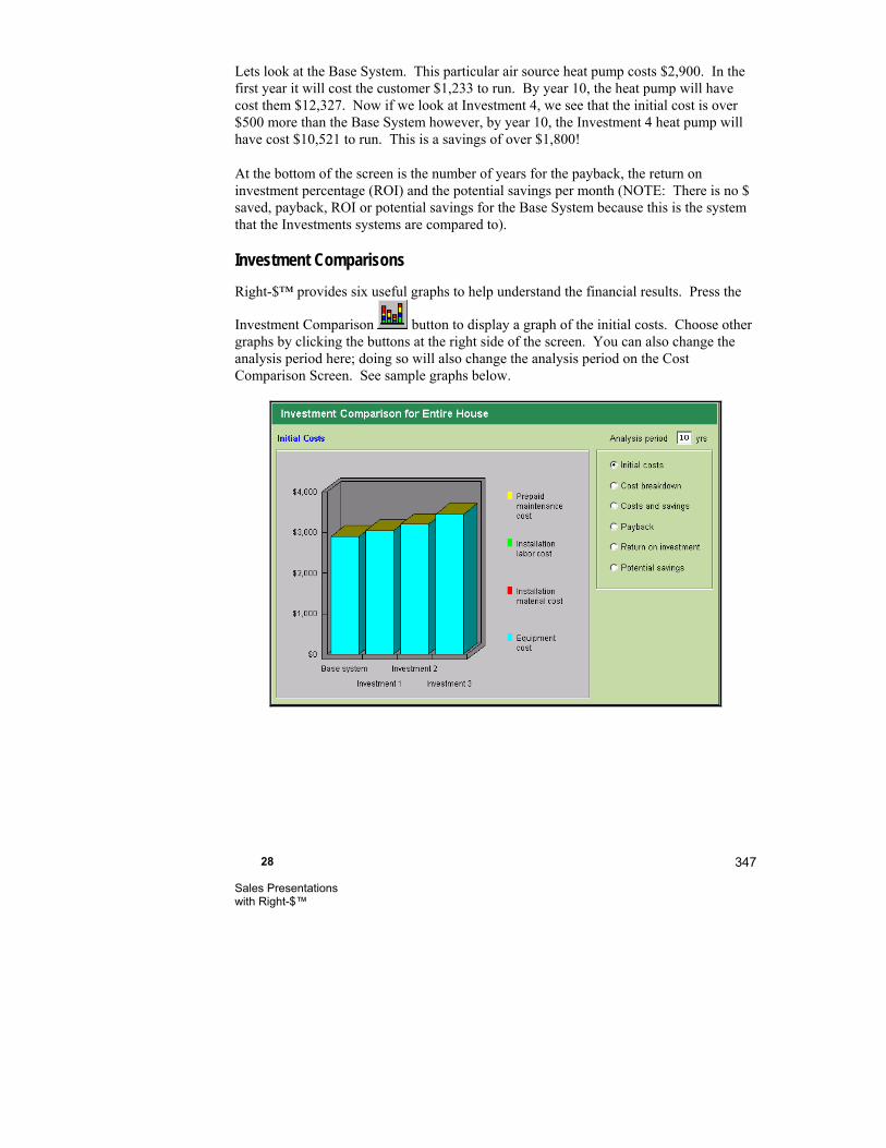
28 Sales Presentations with Right-$™
347
Lets look at the Base System. This particular air source heat pump costs $2,900. In the first year it will cost the customer $1,233 to run. By year 10, the heat pump will have cost them $12,327. Now if we look at Investment 4, we see that the initial cost is over $500 more than the Base System however, by year 10, the Investment 4 heat pump will have cost $10,521 to run. This is a savings of over $1,800!
At the bottom of the screen is the number of years for the payback, the return on investment percentage (ROI) and the potential savings per month (NOTE: There is no $ saved, payback, ROI or potential savings for the Base System because this is the system that the Investments systems are compared to).
Investment Comparisons
Right-$™ provides six useful graphs to help understand the financial results. Press the
Investment Comparison button to display a graph of the initial costs. Choose other graphs by clicking the buttons at the right side of the screen. You can also change the analysis period here; doing so will also change the analysis period on the Cost Comparison Screen. See sample graphs below.
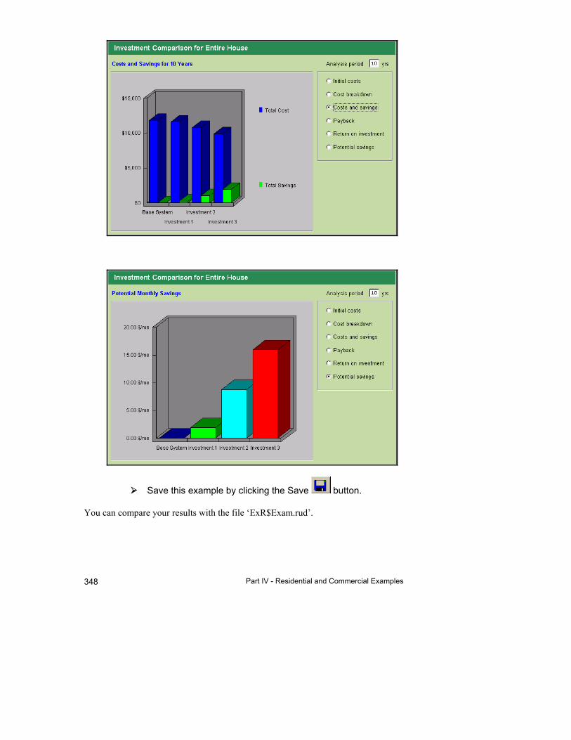
Part IV - Residential and Commercial Examples 348
Save this example by clicking the Save button.
You can compare your results with the file ‘ExR$Exam.rud’.
28 Sales Presentations with Right-$™
349
Things to Remember
Right-$™ makes it easy to compare operating and other costs for four systems.
Colorful bar charts provide quick graphical comparisons of Right-$™ results.
Right-$™ can also evaluate the cost of common water heating systems.
Define alternative system designs in a template to speed the process of defining and evaluating investment options for your customers.


29
System Builder
This chapter tells you how to select equipment systems and accessories based on your customers requirements.
Equipment ................................................................... 354
Accessories ................................................................. 356
Install ........................................................................... 360
Features ...................................................................... 360
Comparing multiple systems ....................................... 360
System Builder setup .................................................. 362
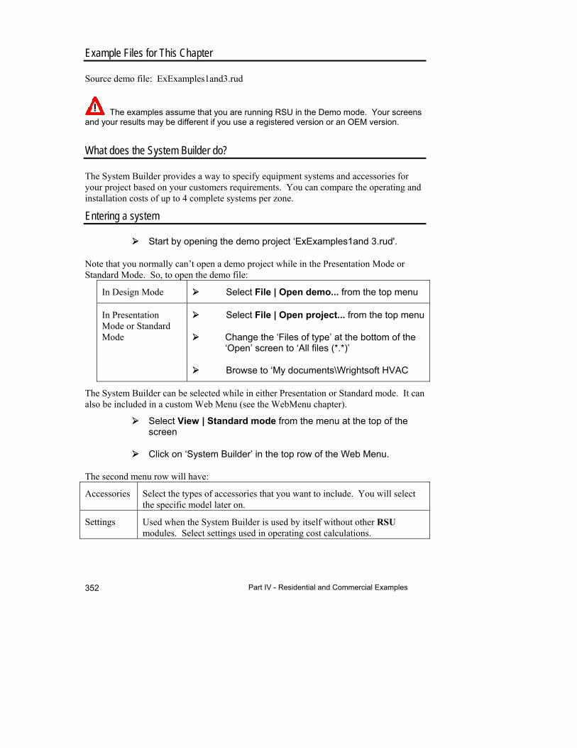
Part IV - Residential and Commercial Examples 352
Example Files for This Chapter
Source demo file: ExExamples1and3.rud
The examples assume that you are running RSU in the Demo mode. Your screens and your results may be different if you use a registered version or an OEM version.
What does the System Builder do?
The System Builder provides a way to specify equipment systems and accessories for your project based on your customers requirements. You can compare the operating and installation costs of up to 4 complete systems per zone.
Entering a system
Start by opening the demo project ‘ExExamples1and 3.rud'.
Note that you normally can’t open a demo project while in the Presentation Mode or Standard Mode. So, to open the demo file:
In Design Mode Select File | Open demo... from the top menu
In Presentation Mode or Standard Mode
Select File | Open project... from the top menu
Change the ‘Files of type’ at the bottom of the ‘Open’ screen to ‘All files (*.*)’
Browse to ‘My documents\Wrightsoft HVAC
The System Builder can be selected while in either Presentation or Standard mode. It can also be included in a custom Web Menu (see the WebMenu chapter).
Select View | Standard mode from the menu at the top of the screen
Click on ‘System Builder’ in the top row of the Web Menu.
The second menu row will have:
Accessories Select the types of accessories that you want to include. You will select the specific model later on.
Settings Used when the System Builder is used by itself without other RSU modules. Select settings used in operating cost calculations.
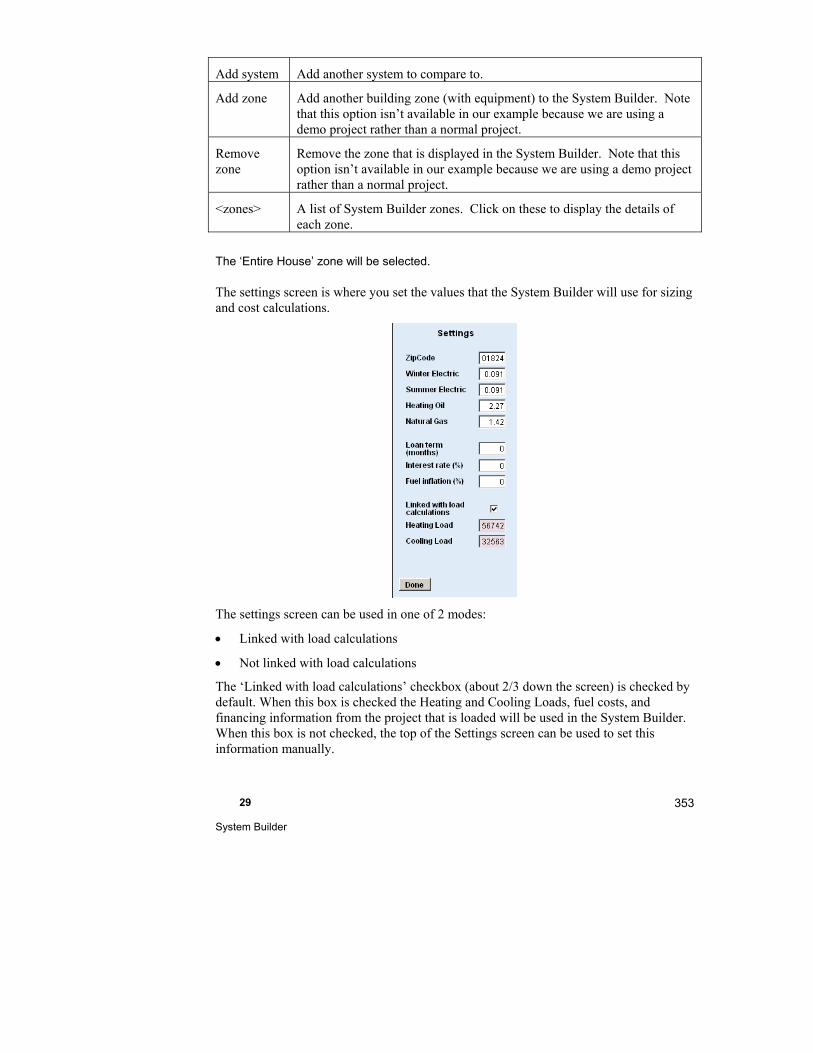
29 System Builder
353
Add system Add another system to compare to.
Add zone Add another building zone (with equipment) to the System Builder. Note that this option isn’t available in our example because we are using a demo project rather than a normal project.
Remove zone
Remove the zone that is displayed in the System Builder. Note that this option isn’t available in our example because we are using a demo project rather than a normal project.
<zones> A list of System Builder zones. Click on these to display the details of each zone.
The ‘Entire House’ zone will be selected.
The settings screen is where you set the values that the System Builder will use for sizing and cost calculations.
The settings screen can be used in one of 2 modes:
Linked with load calculations
Not linked with load calculations
The ‘Linked with load calculations’ checkbox (about 2/3 down the screen) is checked by default. When this box is checked the Heating and Cooling Loads, fuel costs, and financing information from the project that is loaded will be used in the System Builder. When this box is not checked, the top of the Settings screen can be used to set this information manually.

Part IV - Residential and Commercial Examples 354
When you use this screen not linked with load calculations, you should enter the zip code at the top first and then the loads. You can then change the zip code and the load calculations will be adjusted for the new zip code.
Click on the ‘Done’ button in the Settings box for now.
There is, yet another, menu below the Web Menu:
Equipment Shows the selected equipment
Install Shows the installation costs for the selected equipment
Features Shows the features of the selected equipment
Operation Shows the operating costs of the selected equipment
Finance Shows the financing costs of the selected equipment
Equipment
Most of the screen shows a summary of the (up to 4) systems. On the left is a box where you can select the specific equipment. Make selections from the top of the box to the bottom. As you make selections, the choices that are available in lower drop down lists will change to reflect previous selections.

29 System Builder
355
Select ‘AC and Gas Furnace’ from the drop down list for the System Type.
Select ‘Sample’ from the drop down list for the Manufacturer.
Select ‘ACS046’ (for example) from the drop down list for the Outdoor Family. Note that the list contains only AC’s available from the manufacturer, Sample.
Select ‘ACS046125’ (for example) from the drop down list for the Outdoor Unit Model. Note that only models of the family you selected are available in the list.
Select ‘AFUE90’ (for example) from the drop down list for the Indoor Unit Model.
Select ‘AFUE90-40H’ (for example) from the drop down list for the Indoor Unit Model.
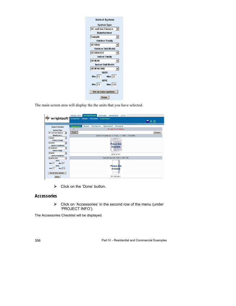
Part IV - Residential and Commercial Examples 356
The main screen area will display the the units that you have selected.
Click on the ‘Done’ button.
Accessories
Click on ‘Accessories’ in the second row of the menu (under ‘PROJECT INFO’).
The Accessories Checklist will be displayed.
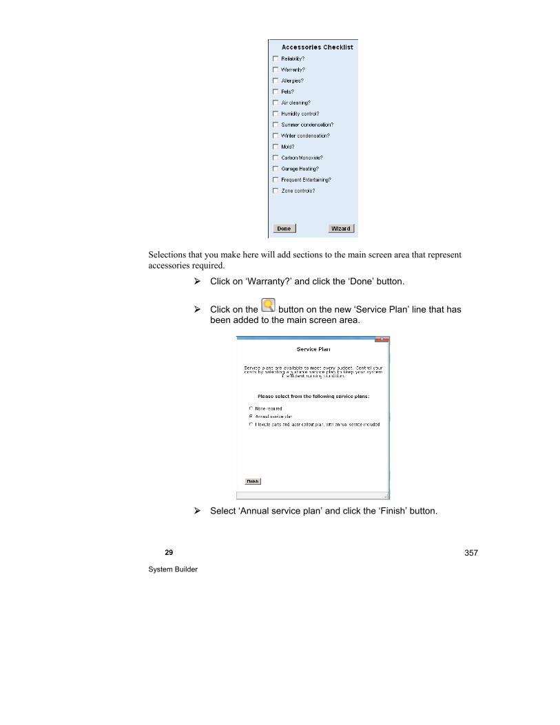
29 System Builder
357
Selections that you make here will add sections to the main screen area that represent accessories required.
Click on ‘Warranty?’ and click the ‘Done’ button.
Click on the button on the new ‘Service Plan’ line that has been added to the main screen area.
Select ‘Annual service plan’ and click the ‘Finish’ button.

Part IV - Residential and Commercial Examples 358
Click the button on the right of the Service Plan line.
In this screen, we can select the specific ‘part’ from the Right-Proposal® database to add. See page 373 for details about adding parts to the Right-Proposal® database.
Select ‘Sample’ as the Manufactuer
Select Warranty as the Part Category
The top grid is a list of all parts in the selected category for the selected manufacturer. The bottom grid is a list of parts that will be included in the system. We will select the two year warranty.
Click on the ‘Two year warranty’ line.
The two year warranty will appear in the bottom grid and will be added to the System Builder.
To delete the ‘Two year warranty’ from the bottom grid, click on the line in the bottom grid that you want to delete.
Click the ‘Finish’ button at the top to transfer your selections to the system.
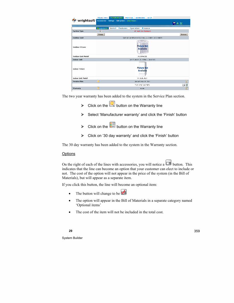
29 System Builder
359
The two year warranty has been added to the system in the Service Plan section.
Click on the button on the Warranty line
Select ‘Manufacturer warranty’ and click the ‘Finish’ button
Click on the button on the Warranty line
Click on ‘30 day warranty’ and click the ‘Finish’ button
The 30 day warranty has been added to the system in the Warranty section.
Options
On the right of each of the lines with accessories, you will notice a button. This indicates that the line can become an option that your customer can elect to include or not. The cost of the option will not appear in the price of the system (in the Bill of Materials), but will appear as a separate item.
If you click this button, the line will become an optional item:
The button will change to be
The option will appear in the Bill of Materials in a separate category named ‘Optional items’
The cost of the item will not be included in the total cost.
Part IV - Residential and Commercial Examples 360
Click the button again and the button will return to being a non-optional item:
The button will change to be
The option will appear in the Bill of Materials in the Accessories category.
The cost of the item will be included in the total cost.
Install
Click on ‘Install’ in the menu at the top of the System Builder.
The accessories are replaced by a list of sections associated with the installation of the system. You can add specific items in each category – labor, materials, etc. from the Right-Proposal® database. Add them the same way you added accessories above – click on the ‘List’ button and select the parts that you want to include.
Features
Click on ‘Features’ in the menu at the top of the System Builder.
The install items are replaced by a summary of the features of the equipment – the manufacturers, models, capacities, efficiencies, etc.
Comparing multiple systems
We have entered a complete system. The Operation and Finance sections are used to compare multiple systems. To add additional systems for comparison:
Click on ‘Add system’ in the second menu line
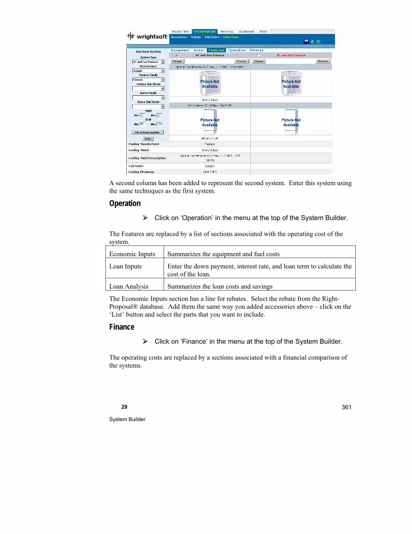
29 System Builder
361
A second column has been added to represent the second system. Enter this system using the same techniques as the first system.
Operation
Click on ‘Operation’ in the menu at the top of the System Builder.
The Features are replaced by a list of sections associated with the operating cost of the system.
Economic Inputs Summarizes the equipment and fuel costs
Loan Inputs Enter the down payment, interest rate, and loan term to calculate the cost of the loan.
Loan Analysis Summarizes the loan costs and savings
The Economic Inputs section has a line for rebates. Select the rebate from the Right-Proposal® database. Add them the same way you added accessories above – click on the ‘List’ button and select the parts that you want to include.
Finance
Click on ‘Finance’ in the menu at the top of the System Builder.
The operating costs are replaced by a sections associated with a financial comparison of the systems.
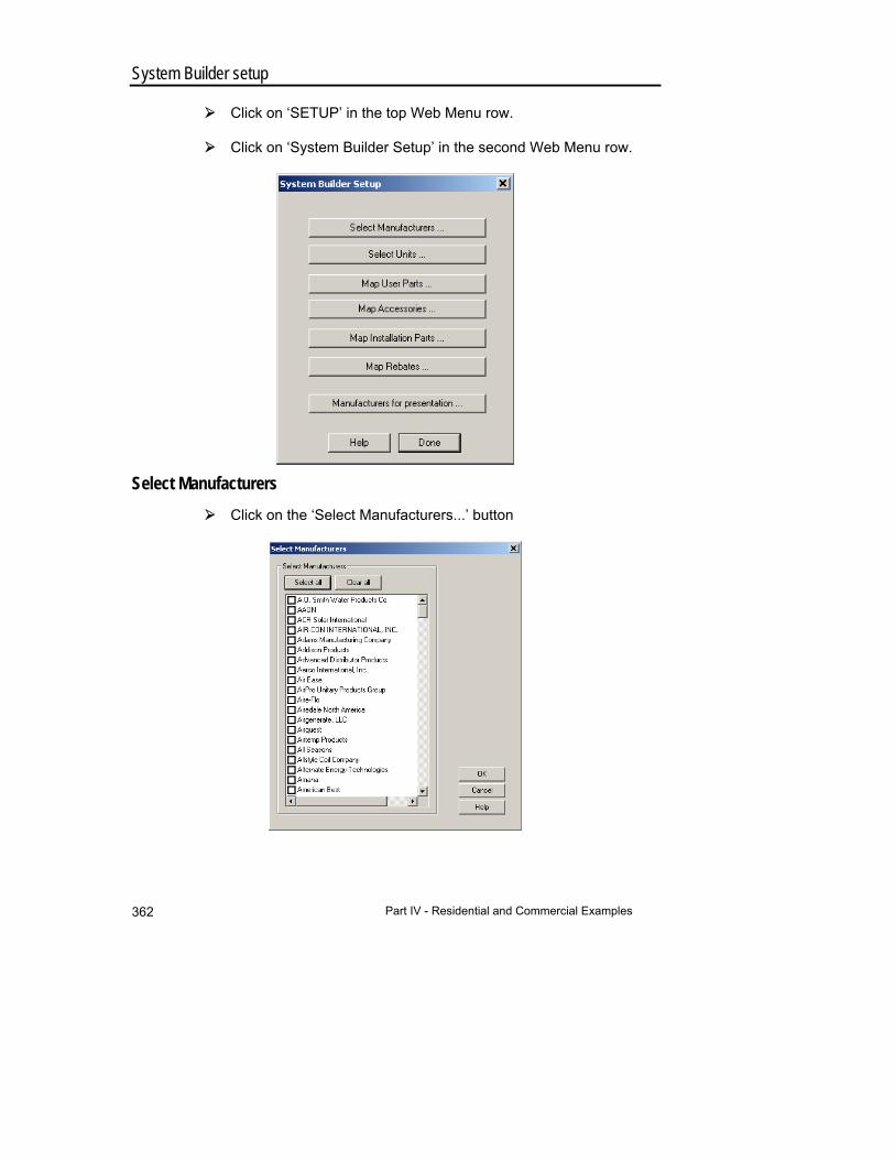
Part IV - Residential and Commercial Examples 362
System Builder setup
Click on ‘SETUP’ in the top Web Menu row.
Click on ‘System Builder Setup’ in the second Web Menu row.
Select Manufacturers
Click on the ‘Select Manufacturers...’ button

29 System Builder
363
If none of the manufacturers in this list are checked, all manufactueres will appear in any list of manufacturers. However, if you check specific manufacturers here, they will be the only ones available where ever there is a list of manufactueres – equipment, accessories, etc. This can make it easier to locate the manufacturer you are interested in during the presentation to your customer.
Click on the ‘Clear all’ button to uncheck all manufacturers
Click on the ‘Sample’ manufacturer (you’ll have to scroll down).
Click on the ‘OK’ button
Select Units
Click on the ‘Select Units...’ button in the System Builder Setup box.
You can filter what is available for selection by selected manufacturers to specific types and even specific units. Since Sample is the only manufacturer that we selected in the ‘Select Manufactuers’ screen, it is the only one listed here.
Click on the + to the left of Sample to expand it.

Part IV - Residential and Commercial Examples 364
Below Sample is a list of equipment categories and Right-Proposal® database categories.
Click on ‘Split AC’ in the list
The right side now shows a list of split AC’s manufactured by Sample. You can unchec k the ones you don’t want to be available and check the ones you want to be available. This will make it easier to make selections during the presentation to your customer.
Click the ‘Close’ button
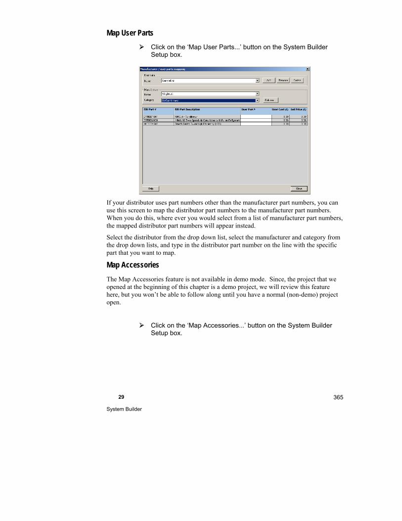
29 System Builder
365
Map User Parts
Click on the ‘Map User Parts...’ button on the System Builder Setup box.
If your distributor uses part numbers other than the manufacturer part numbers, you can use this screen to map the distributor part numbers to the manufacturer part numbers. When you do this, where ever you would select from a list of manufacturer part numbers, the mapped distributor part numbers will appear instead.
Select the distributor from the drop down list, select the manufacturer and category from the drop down lists, and type in the distributor part number on the line with the specific part that you want to map.
Map Accessories
The Map Accessories feature is not available in demo mode. Since, the project that we opened at the beginning of this chapter is a demo project, we will review this feature here, but you won’t be able to follow along until you have a normal (non-demo) project open.
Click on the ‘Map Accessories...’ button on the System Builder Setup box.
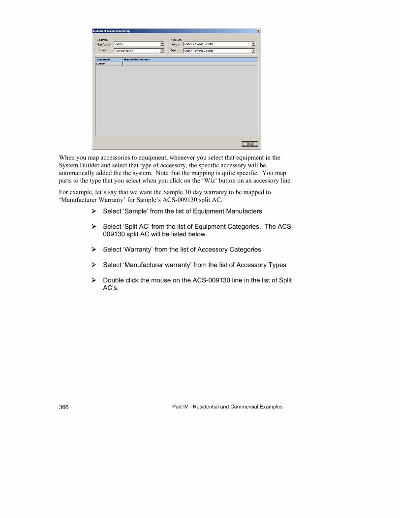
Part IV - Residential and Commercial Examples 366
When you map accessories to equipment, whenever you select that equipment in the System Builder and select that type of accessory, the specific accessory will be automatically added the the system. Note that the mapping is quite specific. You map parts to the type that you select when you click on the ‘Wiz’ button on an accessory line.
For example, let’s say that we want the Sample 30 day warranty to be mapped to ‘Manufacturer Warranty’ for Sample’s ACS-009130 split AC.
Select ‘Sample’ from the list of Equipment Manufacters
Select ‘Split AC’ from the list of Equipment Categories. The ACS-009130 split AC will be listed below.
Select ‘Warranty’ from the list of Accessory Categories
Select ‘Manufacturer warranty’ from the list of Accessory Types
Double click the mouse on the ACS-009130 line in the list of Split AC’s.
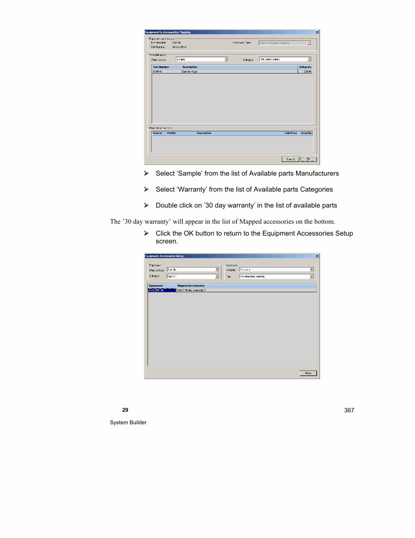
29 System Builder
367
Select ‘Sample’ from the list of Available parts Manufacturers
Select ‘Warranty’ from the list of Available parts Categories
Double click on ’30 day warranty’ in the list of available parts
The ’30 day warranty’ will appear in the list of Mapped accessories on the bottom.
Click the OK button to return to the Equipment Accessories Setup screen.
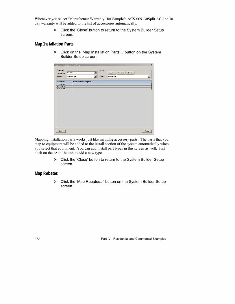
Part IV - Residential and Commercial Examples 368
Whenever you select ‘Manufactuer Warranty’ for Sample’s ACS-009130Split AC, the 30 day warranty will be added to the list of accessories automatically.
Click the ‘Close’ button to return to the System Builder Setup screen.
Map Installation Parts
Click on the ‘Map Installation Parts...’ button on the System Builder Setup screen.
Mapping installation parts works just like mapping accessory parts. The parts that you map to equipment will be added to the install section of the system automatically when you select that equipment. You can add install part types in this screen as well. Just click on the ‘Add’ button to add a new type.
Click the ‘Close’ button to return to the System Builder Setup screen.
Map Rebates
Click the ‘Map Rebates...’ button on the System Builder Setup screen.
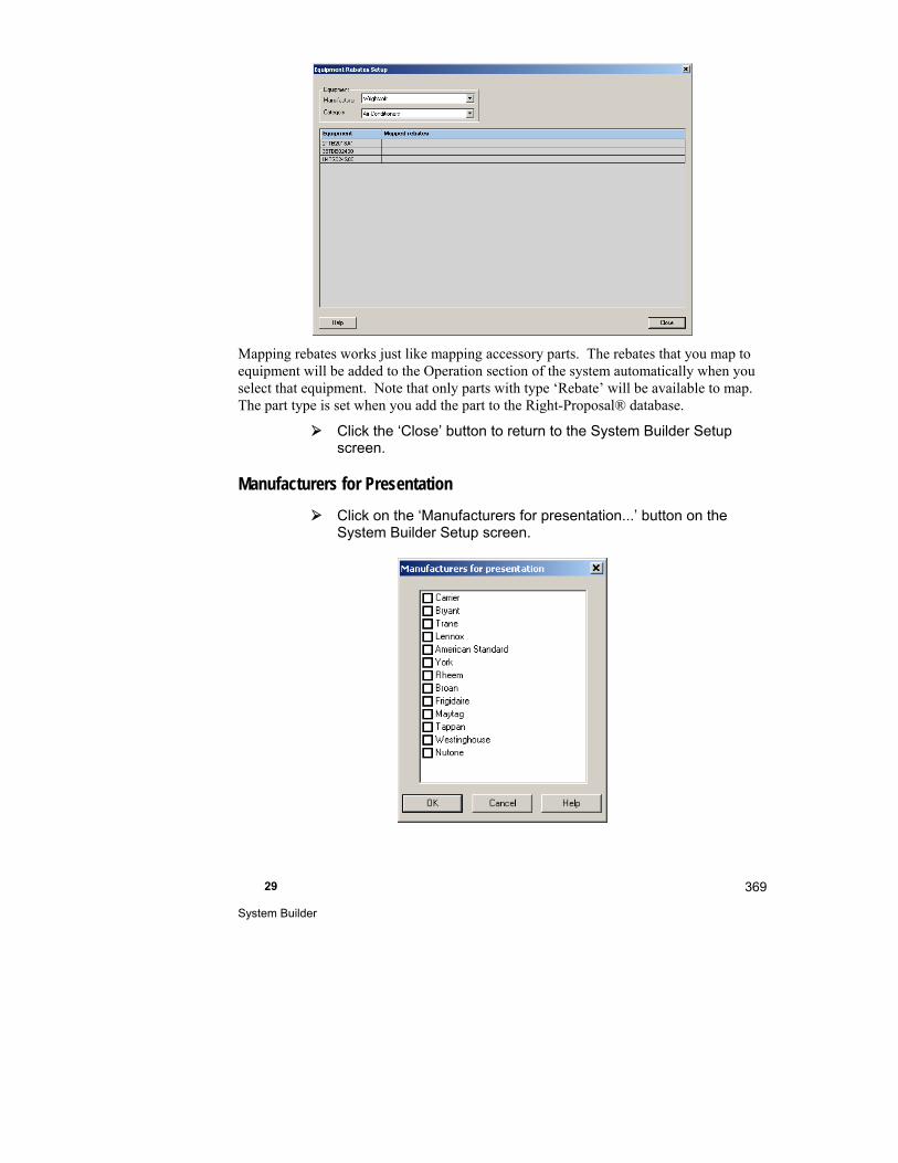
29 System Builder
369
Mapping rebates works just like mapping accessory parts. The rebates that you map to equipment will be added to the Operation section of the system automatically when you select that equipment. Note that only parts with type ‘Rebate’ will be available to map. The part type is set when you add the part to the Right-Proposal® database.
Click the ‘Close’ button to return to the System Builder Setup screen.
Manufacturers for Presentation
Click on the ‘Manufacturers for presentation...’ button on the System Builder Setup screen.

Part IV - Residential and Commercial Examples 370
In Presentation mode, the Manufacturer and Show Room Web Menu selections can be used to provide information about a specific manufacturer. In this screen, you can control which manufacturers are available in the second row menu.

30
Assemble Your Costs
This chapter tells you how to use your own library of cost items to quickly prepare detailed job cost quotes.
What is Right-Proposal®? ........................................... 372
How Right-Proposal® Works ....................................... 372
Add, Modify & Delete Categories & Parts in the Library .................................................................... 373
Assemblies .................................................................. 377
Assemble Your Quote ................................................. 378
Parts Mapping Editor ................................................... 380
Things to Remember ................................................... 381
Part IV - Residential and Commercial Examples 372
What is Right-Proposal®?
Right-Proposal® helps you quickly assemble cost quotes for your jobs. Using your own library of item costs, you can quickly select the appropriate items and create a printed proposal with detailed parts lists and costs.
The Proposal Information Screen lets you define an unlimited number of sections. Each section is the summary of a detailed list of items you selected from your cost data library. There are three default sections and three sections that are automatically generated (called automatic takeoffs) by RSU if you own the appropriate modules (see table below)
Default Sections RSU Generated Sections Module Needed
Equipment Duct System Equipment Right-D®
Labor High-velocity Duct Equipment Right-HV™
Overall Total Radiant Heating Equipment Right-Radiant®
How Right-Proposal® Works
RSU uses a Microsoft Access database to hold your own library of cost data. The database consists of a table of categories and a table of parts for each category. You can add and edit both the categories and parts to suit your specific needs.
The example database shipped with RSU contains a number of categories. You may wish to add other categories such as flat rate pricing, piping, wiring and subcontracted pieces.
Each part (cost item) in the database (Library) includes a description and pricing information. You can add, modify and delete parts in the Library from within RSU. No other programs are required to maintain the Library.
You will need to define the parts in your Library before using Right-Proposal®. You can add new items and modify descriptions and costs as you develop your library of parts.
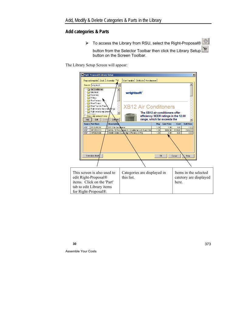
30 Assemble Your Costs
373
Add, Modify & Delete Categories & Parts in the Library
Add categories & Parts
To access the Library from RSU, select the Right-Proposal®
button from the Selector Toolbar then click the Library Setup button on the Screen Toolbar.
The Library Setup Screen will appear:
This screen is also used to edit Right-Proposal® items. Click on the 'Part' tab to edit Library items for Right-Proposal®.
Categories are displayed in this list.
Items in the selected catetory are displayed here.

Part IV - Residential and Commercial Examples 374
To add a new category:
Click the right mouse button on one of the existing categories and select 'Add category' from the menu that is displayed.
Type a description, discount, margin, and BTB (business-to-business) purchase tax for the new category. Click the OK button to add the new category.
To enter a new manufacturer, click on the 'Manufacturer' tab.
A new line will be added to the category list. When you add a category, you can enter discount and margin values for the category. When you add a part to this category, the part's discount and margin will be filled in based on the category discount and margin, but you can change these values for individual parts as necessary.
To add a part:
Select the category of the part you want to add from the list on the left. For this example, select the Wrightsoft duct fittings category from the list on the left to display all of the parts already entered into the Wrightsoft duct fittings category.

30 Assemble Your Costs
375
Click the Add button
In the screen that appears, type the manufacturer’s part number (TEST1), description (1" tubing to brass manifold connector), and the package count (1), click the 'Taxable' box to select it, and type a list price ($17.50) for the new item. Use the <Tab> key to move from field to field. You can also assign a 'Phase' to the part (there are pre-defined phases, but you can add your own, if you wish). The phase indicates the phase of the project where the part would be used. The Bill of Materials lists all of the parts used in
Part IV - Residential and Commercial Examples 376
the project. You can filter the list of parts to include only one phase. This allows you to see the costs of each phase of the job.
Notice that the other costs are entered for you. We will use the category discount and margin so you do not need to change them.
Click the 'Finish' button to add the item.
Modify categories & parts
To modify an existing category:
To change the description of a category, click the right mouse button on the category you want to change and select Edit from the menu that is displayed. For our example, use the Fittings category.
Type the new description (Radiant fittings). You can change the discount and margin in the same manner.
Click the 'OK' button to save your changes.
To modify an existing part:
Select a category (for example, the 'Wrightsoft duct fitting' category that we just added a part to) then click on the line in the list of the item that you want to change. Then, click on the Edit button (next to the Add button). We are going to change the TEST1 fitting that we just created.
The price has gone up on the TEST1 fitting so type $18.50 into the 'List price' field.
Click the 'OK' button to save your changes.
Delete categories & parts
To delete a part:
To delete a part, click anywhere on the line of the part that you want to delete and click on the Delete button.
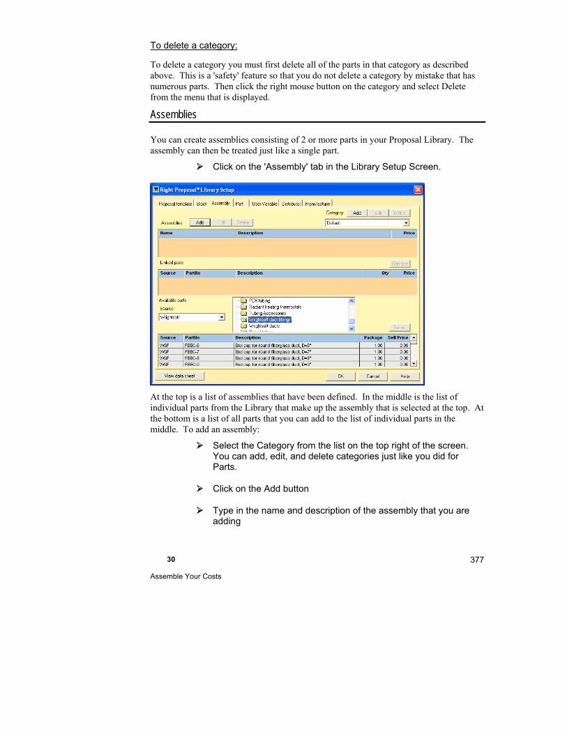
30 Assemble Your Costs
377
To delete a category:
To delete a category you must first delete all of the parts in that category as described above. This is a 'safety' feature so that you do not delete a category by mistake that has numerous parts. Then click the right mouse button on the category and select Delete from the menu that is displayed.
Assemblies
You can create assemblies consisting of 2 or more parts in your Proposal Library. The assembly can then be treated just like a single part.
Click on the 'Assembly' tab in the Library Setup Screen.
At the top is a list of assemblies that have been defined. In the middle is the list of individual parts from the Library that make up the assembly that is selected at the top. At the bottom is a list of all parts that you can add to the list of individual parts in the middle. To add an assembly:
Select the Category from the list on the top right of the screen. You can add, edit, and delete categories just like you did for Parts.
Click on the Add button
Type in the name and description of the assembly that you are adding
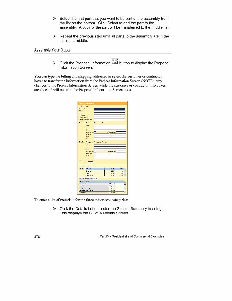
Part IV - Residential and Commercial Examples 378
Select the first part that you want to be part of the assembly from the list on the bottom. Click Select to add the part to the assembly. A copy of the part will be transferred to the middle list.
Repeat the previous step until all parts to the assembly are in the list in the middle.
Assemble Your Quote
Click the Proposal Information button to display the Proposal Information Screen.
You can type the billing and shipping addresses or select the customer or contractor boxes to transfer the information from the Project Information Screen (NOTE: Any changes to the Project Information Screen while the customer or contractor info boxes are checked will occur in the Proposal Information Screen, too).
To enter a list of materials for the three major cost categories:
Click the Details button under the Section Summary heading. This displays the Bill of Materials Screen.

30 Assemble Your Costs
379
To add fittings, for example, we'll add a 'Ducts' section and add our TEST1 fitting to the Bill of Materials. Click the right mouse button on any column on the same row as 'Overall total'.
A menu will be displayed. Select 'Add new section'. Enter 'Ducts' as the name of the new section and click OK to add the new section.
Click the right mouse button on the 'Ducts' heading. Select 'Add part from database'.
Select a category (Radiant Fittings) then a part (TEST1) and click on the Insert button.
You can select all of the items to go into the 'Ducts' Section now. Just keep choosing parts and clicking the Insert button. For now, we'll close this screen.
Click on the Close button to return to the Bill of Materials Screen.
You will see that the part that you selected is now listed in the Ducts Section on the Bill of Materials Screen.
If you do not like the default Bill of Materials section names, you can change them. Click on the section name in the Description field then type the new section name.
If you want to add a part that is not in the database, click the right mouse button in the section that you want to add the part to, then select 'Add new item' from the menu that pops up. An empty line will appear under the section name. Enter data for all of the applicable fields.
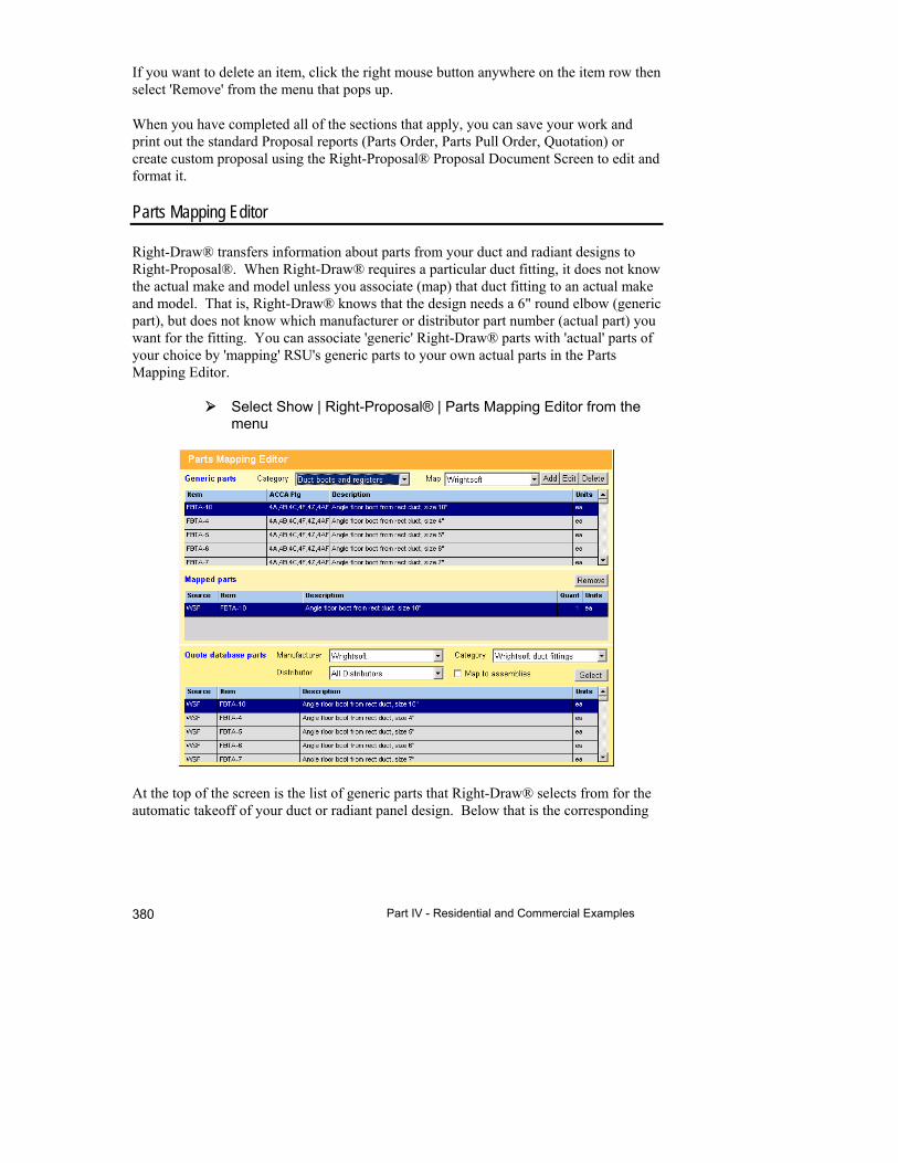
Part IV - Residential and Commercial Examples 380
If you want to delete an item, click the right mouse button anywhere on the item row then select 'Remove' from the menu that pops up.
When you have completed all of the sections that apply, you can save your work and print out the standard Proposal reports (Parts Order, Parts Pull Order, Quotation) or create custom proposal using the Right-Proposal® Proposal Document Screen to edit and format it.
Parts Mapping Editor
Right-Draw® transfers information about parts from your duct and radiant designs to Right-Proposal®. When Right-Draw® requires a particular duct fitting, it does not know the actual make and model unless you associate (map) that duct fitting to an actual make and model. That is, Right-Draw® knows that the design needs a 6" round elbow (generic part), but does not know which manufacturer or distributor part number (actual part) you want for the fitting. You can associate 'generic' Right-Draw® parts with 'actual' parts of your choice by 'mapping' RSU's generic parts to your own actual parts in the Parts Mapping Editor.
Select Show | Right-Proposal® | Parts Mapping Editor from the menu
At the top of the screen is the list of generic parts that Right-Draw® selects from for the automatic takeoff of your duct or radiant panel design. Below that is the corresponding
30 Assemble Your Costs
381
actual part(s) from your Proposal Library. When you select the generic part on the top, the middle list will change to show the actual part that is currently mapped to it.
To change the mapping for a generic part:
Start with the Generic Parts (on the top) and select a generic part category from the drop-down list.
Select the generic part item that you want to map from the list of items that appears.
On the 'Proposal Library parts' part of the screen (on the bottom), select the Manufacturer, Distributor and the Category. They all have drop-down lists.
Click on the actual part that you want to map to the generic part you just selected on the left and click the Select button.
The 'Mapped part' table in the middle will now contain two parts the old one and the one you just selected from the Available parts list.
Now you must remove the old 'Mapped part'. To do this, click on the old part (usually on top) and click the Remove button.
Map any generic part in this manner. To map an assembly rather than an individual part to the generic part, just check 'Map to assemblies' in the 'Proposal Library parts' section of the screen. The list will change from parts to assemblies. The Parts Mapping Editor is a quick way to connect your own Proposal Library to the generic parts in Right-Draw®.
Things to Remember
You must create your own custom library of parts and assemblies for use in Right-Proposal®.
RSU comes with a library of parts. Right-Duct™, Right-HV™ and Right-Radiant® have automatic takeoffs. This means that if you draw a duct system or radiant panel design with Right-Draw®, major parts (fittings, ducts etc) will automatically appear in the Proposal Screens.
You need to map generic parts from the automatic takeoffs to actual parts or assemblies from your Parts Library.
When you make changes to the Parts Library the changes apply to all projects, not just the project that you are working on.


31
Generate the proposal
This chapter describes how to create custom designed proposals to submit to your customers.
What is Right-Proposal® ............................................ 384
Example 1 - Print a Proposal ....................................... 384
Example 2 - Modify a Proposal .................................... 386
Example 3 - Proposal Document Reference ............... 391
Example 4 - Setup Right-Proposal® for your use ........ 406

Part IV - Residential and Commercial Examples 384
What is Right-Proposal®
Right-Proposal® helps you quickly generate professional in-home sales presentations with integrated project information, equipment, and costs.
The proposal is generated using the Proposal Document Screen. This screen is a word processor, so you can create professional proposals customized with your logo, etc. and formatted to your specifications. You can prepare proposal templates and save them for use in all of your projects. The information specific to each project will change automatically. You just select the template and print the proposal out.
Right-Proposal® Examples
This chapter has several examples that demonstrate generating proposals with Right-Proposal®.
1. Print a proposal - In this example, we will print a proposal using one of the proposal templates that is included with Right-Proposal®.
2. Modify a proposal - In this example, we will modify the proposal template that we used in the first example. Use this example as an introduction to the capabilities of the word processor.
3. Proposal document reference - In this example, we will introduce all of the capabilities of Right-Proposal®. Use this example to learn the advanced features of Right-Proposal®.
4. Setup Right-Proposal® for your use - In this section of the chapter we will prepare Right-Proposal® for your everyday use.
Example 1 - Print a Proposal
In this example, we will print a proposal using one of the proposal templates that is included with Right-Proposal®.
Select File | Open | Demo … from the menu.
Select 'ExExamples1and3.rud' from the list of demo projects.

31 Generate the proposal
385
Click on the Right-Proposal® button to display the Right-Proposal® toolbar.
Click on the Proposal Document button to display the Proposal Document Screen
This screen isn't very interesting yet - just a blank page. Notice, however, at the top there are 2 additional toolbars under the Right-Suite toolbar. The first toolbar has buttons used for editing the proposal document. The second toolbar has buttons used for formatting the text in your proposal. There is also a ruler that shows the left and right margins, tab stops, etc.
In the middle of the first toolbar, there is a drop down list of all of the proposal templates that are available. Select One page from the list.
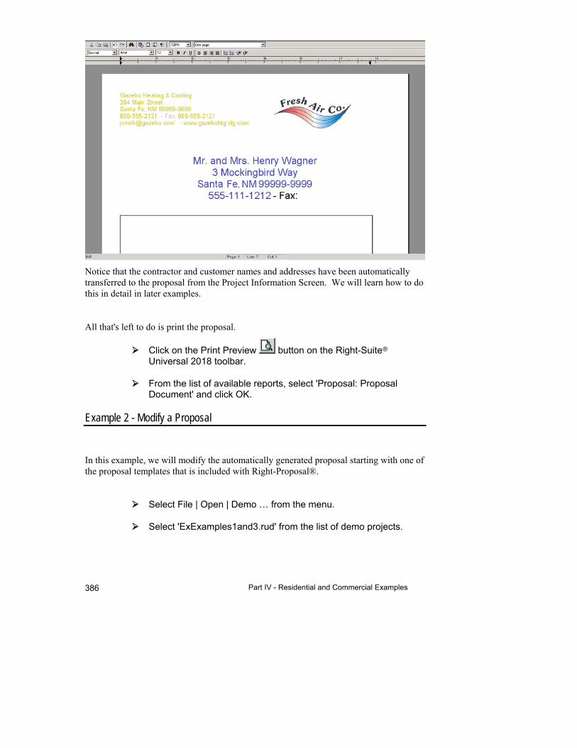
Part IV - Residential and Commercial Examples 386
Notice that the contractor and customer names and addresses have been automatically transferred to the proposal from the Project Information Screen. We will learn how to do this in detail in later examples.
All that's left to do is print the proposal.
Click on the Print Preview button on the Right-Suite Universal 2018 toolbar.
From the list of available reports, select 'Proposal: Proposal Document' and click OK.
Example 2 - Modify a Proposal
In this example, we will modify the automatically generated proposal starting with one of the proposal templates that is included with Right-Proposal®.
Select File | Open | Demo … from the menu.
Select 'ExExamples1and3.rud' from the list of demo projects.
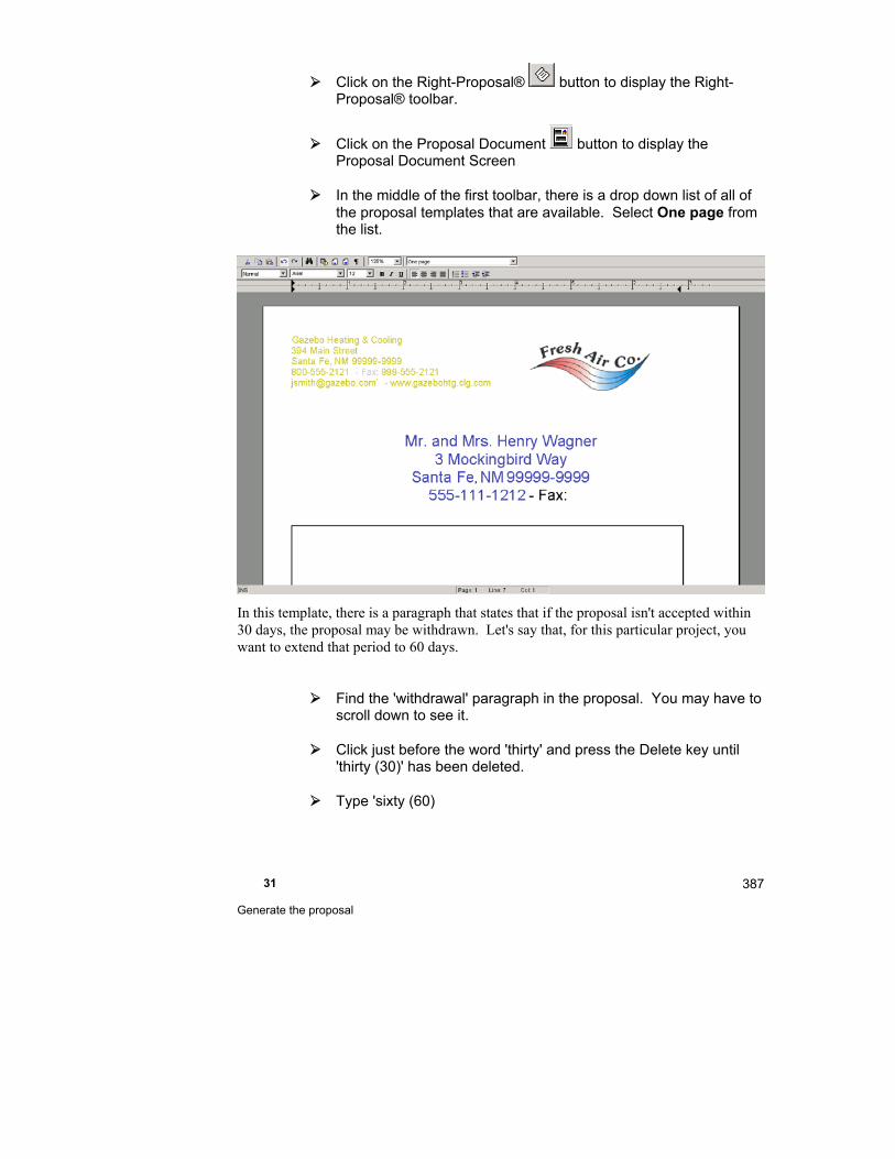
31 Generate the proposal
387
Click on the Right-Proposal® button to display the Right-Proposal® toolbar.
Click on the Proposal Document button to display the Proposal Document Screen
In the middle of the first toolbar, there is a drop down list of all of the proposal templates that are available. Select One page from the list.
In this template, there is a paragraph that states that if the proposal isn't accepted within 30 days, the proposal may be withdrawn. Let's say that, for this particular project, you want to extend that period to 60 days.
Find the 'withdrawal' paragraph in the proposal. You may have to scroll down to see it.
Click just before the word 'thirty' and press the Delete key until 'thirty (30)' has been deleted.
Type 'sixty (60)

Part IV - Residential and Commercial Examples 388
Note that you have just modified the proposal for THIS project only. The 'One page' Proposal Template has not changed. It still says 'thirty (30)'. When you save the project the changes that you have made to the proposal will be saved as well.
Now, let's change the font of the entire 'withdrawal' paragraph.
Click the mouse button to the left of the beginning of the paragraph and drag to the end of the paragraph. The entire paragraph should be selected.
Select 'Times New Roman' from the drop down list of fonts in the top toolbar. You should have this font in the list. If you don't, just select another font.
Now, let's get fancy. We'll add a shaded box around the customer name and address. The customer name and address are at the top of the page.
Click to the left of the customer name as if you were going to type something there.
Select Proposal | Insert | Drawing object | Rectangle from the menu.
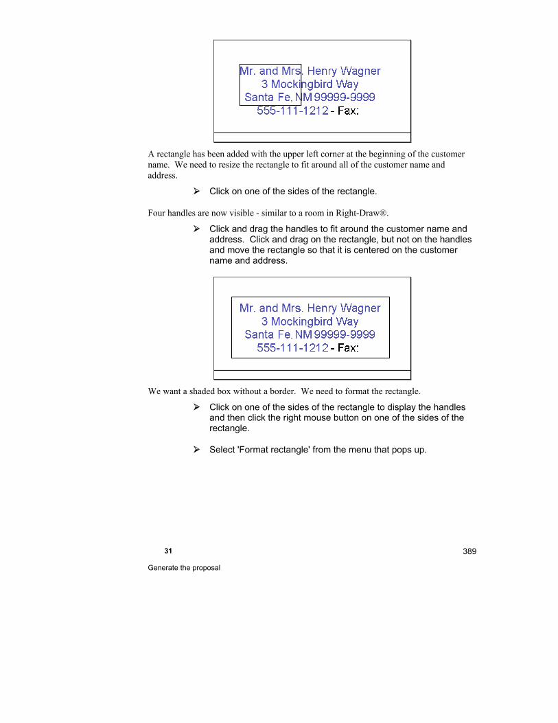
31 Generate the proposal
389
A rectangle has been added with the upper left corner at the beginning of the customer name. We need to resize the rectangle to fit around all of the customer name and address.
Click on one of the sides of the rectangle.
Four handles are now visible - similar to a room in Right-Draw®.
Click and drag the handles to fit around the customer name and address. Click and drag on the rectangle, but not on the handles and move the rectangle so that it is centered on the customer name and address.
We want a shaded box without a border. We need to format the rectangle.
Click on one of the sides of the rectangle to display the handles and then click the right mouse button on one of the sides of the rectangle.
Select 'Format rectangle' from the menu that pops up.

Part IV - Residential and Commercial Examples 390
Change the line thickness to 0 by typing a '0' at 'Line'.
This will remove the border.
Click on the 'Fill Color'.
Click on the gray box in the last row of colors and click the 'OK' button.
Click on the 'OK' button in the Rectangle Properties screen.
We now have a borderless, shaded box around the customer name and address.
We have made the following modifications to the 'One page' proposal template:
Changed the withdrawal period from 30 to 60 days
Changed the font of the withdrawal paragraph
Added a borderless, shaded box around the customer name and address
Let's save this modified proposal as a template so that we can use these modifications again. We'll still have the original 'One page' proposal template if we want to use as well.
Click the right mouse button on a blank portion of the proposal document.

31 Generate the proposal
391
Select 'Save all as Proposal template…' from the menu that pops up.
Change the 'Name' to 'One page enhanced'
Change the 'Description' to 'One page - 60 day withdrawal'
Click the 'Save' button to save the template
The description will help you remember how it is different from the 'One page' template. Notice that 'One page enhanced' has been added to the drop down list in the top proposal toolbar.
Example 3 - Proposal Document Reference
In this example, we will introduce everything that can possibly be added to a proposal. Consequently, the template that we will create will be more of a sampler than a usable proposal template.
We'll start out like the previous examples.
It is generally easier to design a proposal template when there is actual information to display.
Select File | Open | Demo … from the menu.
Select 'ExExamples1and3.rud' from the list of demo projects.
Click on the Right-Proposal® button to display the Right-Proposal® toolbar.
Click on the Proposal Document button to display the Proposal Document Screen
In this example, however, we will start with a blank page.
In the middle of the first toolbar, there is a drop down list of all of the proposal templates that are available. Select 'New Proposal Template' from the list.

Part IV - Residential and Commercial Examples 392
Note: The instructions below use the Right-Suite Universal 2018 menu to make selections. However, you can usually make the same selection by clicking the right mouse button at the location indicated. A menu will pop up with a list of options. You may use either method.
Sections
Page layout
Select Proposal | Options | Proposal page layout from the menu
In this screen you can set the page and header/footer margins.
Header and footer
The header and footer appear on every page of the proposal. You can add what you want in the header and footer just once and it will appear on every page. To edit the header and footer:
Select Proposal | Edit Header / Footer from the menu
You could put your company name and address with your logo in the header. The date and page number could go in the footer.
You can have the same header and footer on every page or a different header and/or footer on the first page. For example, if you didn't want the page number on the first page:
Add the page number to the footer (see below)
Select Proposal | Options | Separate first page footer from the menu

31 Generate the proposal
393
The first page will not have the page number in the footer. The rest of the pages will.
Data
Page numbers
To insert the page number:
Select Proposal | Insert | Page numbers | Page number from the menu
You will usually want the page number in the header or footer.
Right-Proposal® will insert the current page number into the proposal document.
Dates
To insert the date:
Select Proposal | Insert | Date and time… from the menu
Select the format of the date and/or time that you want and click the 'OK' button.
The current date and/or time will be inserted into the proposal document. If you open the same proposal tomorrow, it will have tomorrow's date.
Page break
You can just keep adding things to your proposal. When you fill up a page, it will continue to the next page automatically. You may want to force a page break before the end of the page. To do this:
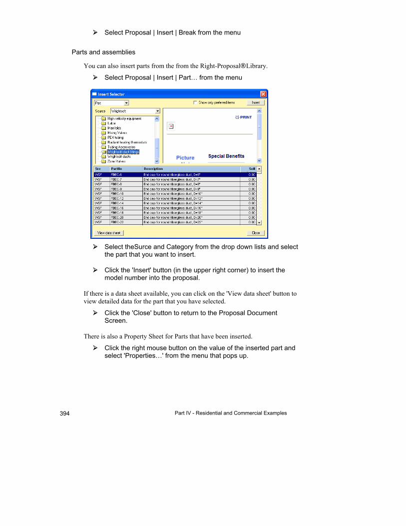
Part IV - Residential and Commercial Examples 394
Select Proposal | Insert | Break from the menu
Parts and assemblies
You can also insert parts from the from the Right-Proposal® Library.
Select Proposal | Insert | Part… from the menu
Select theSurce and Category from the drop down lists and select the part that you want to insert.
Click the 'Insert' button (in the upper right corner) to insert the model number into the proposal.
If there is a data sheet available, you can click on the 'View data sheet' button to view detailed data for the part that you have selected.
Click the 'Close' button to return to the Proposal Document Screen.
There is also a Property Sheet for Parts that have been inserted.
Click the right mouse button on the value of the inserted part and select 'Properties…' from the menu that pops up.
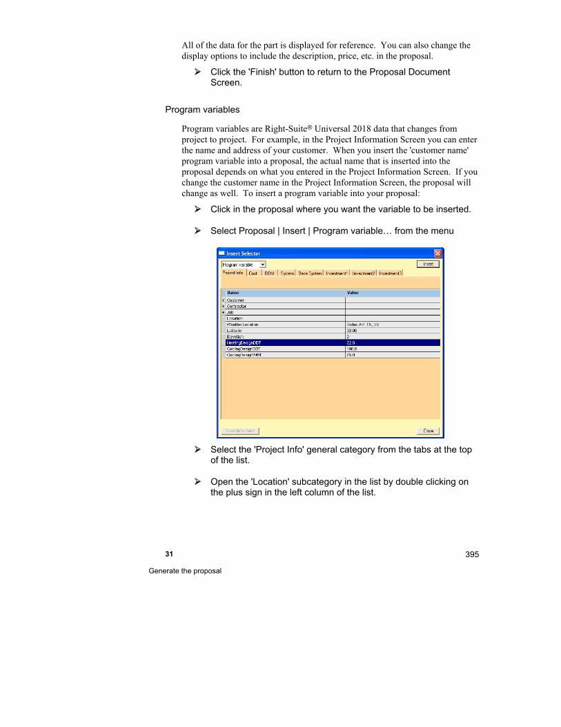
31 Generate the proposal
395
All of the data for the part is displayed for reference. You can also change the display options to include the description, price, etc. in the proposal.
Click the 'Finish' button to return to the Proposal Document Screen.
Program variables
Program variables are Right-Suite Universal 2018 data that changes from project to project. For example, in the Project Information Screen you can enter the name and address of your customer. When you insert the 'customer name' program variable into a proposal, the actual name that is inserted into the proposal depends on what you entered in the Project Information Screen. If you change the customer name in the Project Information Screen, the proposal will change as well. To insert a program variable into your proposal:
Click in the proposal where you want the variable to be inserted.
Select Proposal | Insert | Program variable… from the menu
Select the 'Project Info' general category from the tabs at the top of the list.
Open the 'Location' subcategory in the list by double clicking on the plus sign in the left column of the list.
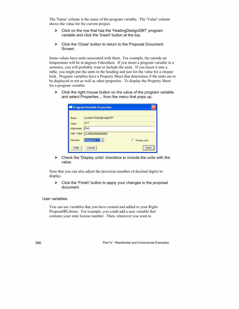
Part IV - Residential and Commercial Examples 396
The 'Name' column is the name of the program variable. The 'Value' column shows the value for the current project.
Click on the row that has the 'HeatingDesignDBT' program variable and click the 'Insert' button at the top.
Click the 'Close' button to return to the Proposal Document Screen.
Some values have units associated with them. For example, the outside air temperature will be in degrees Fahrenheit. If you insert a program variable in a sentence, you will probably want to include the units. If you insert it into a table, you might put the units in the heading and just list the value for a cleaner look. Program variables have a Property Sheet that determines if the units are to be displayed or not as well as other properties. To display the Property Sheet for a program variable:
Click the right mouse button on the value of the program variable and select Properties… from the menu that pops up.
Check the 'Display units' checkbox to include the units with the value.
Note that you can also adjust the precision (number of decimal digits) to display.
Click the 'Finish' button to apply your changes in the proposal document.
User variables
You can use variables that you have created and added to your Right-Proposal® Library. For example, you could add a user variable that contains your state license number. Then, whenever you want to
31 Generate the proposal
397
include your license number in a proposal you don't have to go look it up. To insert a user variable:
Select Proposal | Insert | User variable… from the menu.
Select the category from the drop down list.
Select the user variable that you want to add and click on the Insert button.
Click on the Close button to return to the Proposal Document Screen.
Other components
Blocks
A Block is a portion of a proposal that is saved for later use. A Block can include text, images, tables, text boxes, etc. A Block can contain anything that you can put in a proposal document. The formatting is part of the Block. So, you can just insert it into your proposal and it's ready to go. You can use Blocks that you have created and added to your Right-Proposal® Library. For example, you could add a Block that contains your standard warranty statement. Then, whenever you want to include the warranty statement in a proposal you don't have to go re-type it. To insert a Block:
Select Proposal | Insert | Block… from the menu.
Select the category from the drop down list.
Select the Block that you want to add and click on the 'Insert' button.
Click on the 'Close' button to return to the Proposal Document Screen.
Text Boxes
A Text Box is a rectangle with text in it. The rectangle can be resized and the text will stay within the rectangle. Use a Text Box to accent important text. For example, you could add a Text Box that contains your standard warranty statement. To insert a Text Box:
Select Proposal | Insert | Text box… from the menu. A text box will be added to the document.
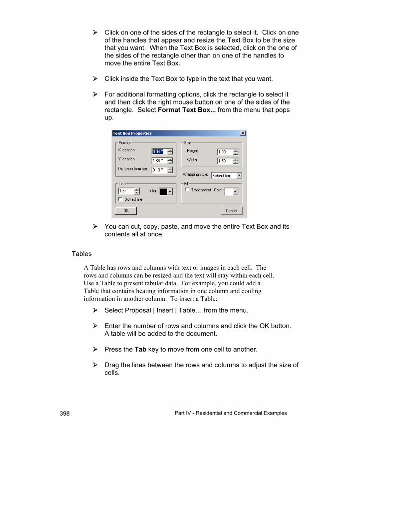
Part IV - Residential and Commercial Examples 398
Click on one of the sides of the rectangle to select it. Click on one of the handles that appear and resize the Text Box to be the size that you want. When the Text Box is selected, click on the one of the sides of the rectangle other than on one of the handles to move the entire Text Box.
Click inside the Text Box to type in the text that you want.
For additional formatting options, click the rectangle to select it and then click the right mouse button on one of the sides of the rectangle. Select Format Text Box... from the menu that pops up.
You can cut, copy, paste, and move the entire Text Box and its contents all at once.
Tables
A Table has rows and columns with text or images in each cell. The rows and columns can be resized and the text will stay within each cell. Use a Table to present tabular data. For example, you could add a Table that contains heating information in one column and cooling information in another column. To insert a Table:
Select Proposal | Insert | Table… from the menu.
Enter the number of rows and columns and click the OK button. A table will be added to the document.
Press the Tab key to move from one cell to another.
Drag the lines between the rows and columns to adjust the size of cells.
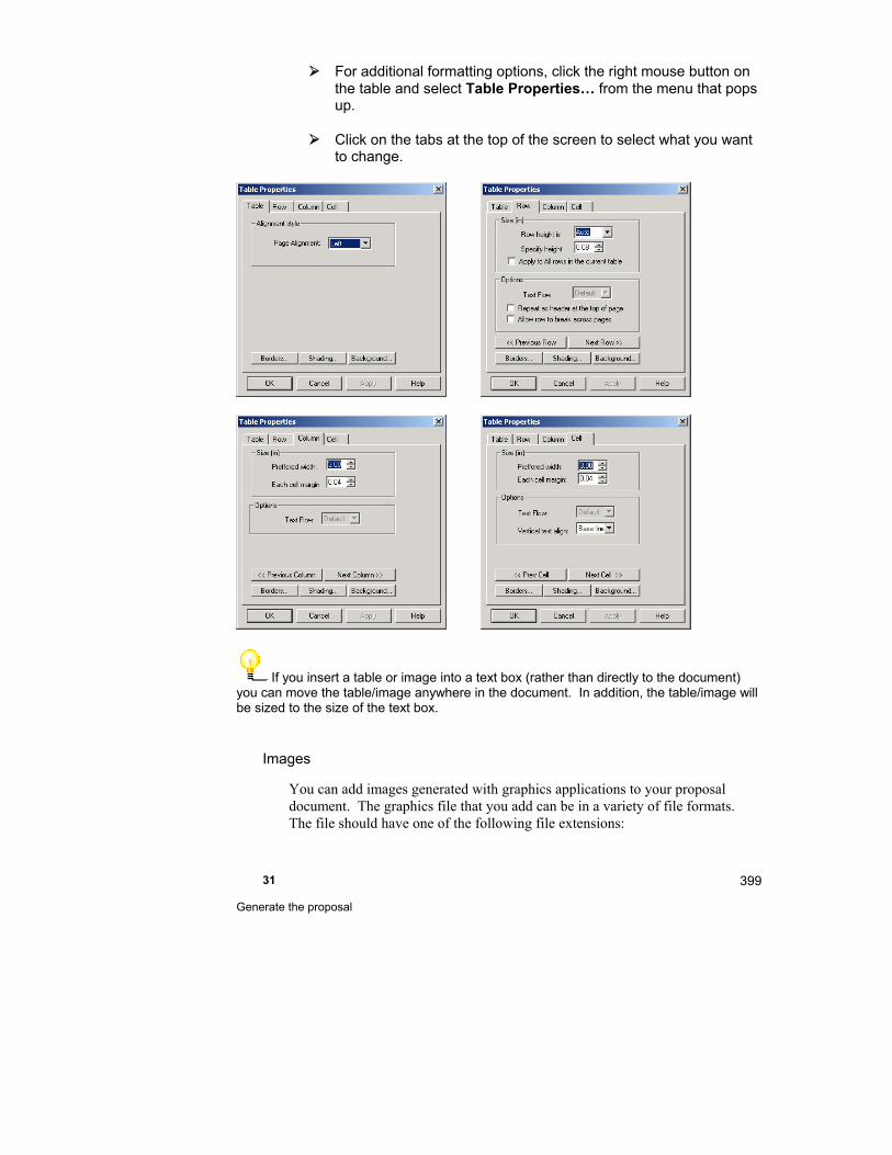
31 Generate the proposal
399
For additional formatting options, click the right mouse button on the table and select Table Properties… from the menu that pops up.
Click on the tabs at the top of the screen to select what you want to change.
If you insert a table or image into a text box (rather than directly to the document) you can move the table/image anywhere in the document. In addition, the table/image will be sized to the size of the text box.
Images
You can add images generated with graphics applications to your proposal document. The graphics file that you add can be in a variety of file formats. The file should have one of the following file extensions:

Part IV - Residential and Commercial Examples 400
.bmp
.jpg
.emf
.wmf
.png
The most common format that you will encounter is .bmp. Most graphics applications can generate files in this format, including Window Paint, which comes with Microsoft Windows. You could add your company logo to your proposal document. You can either link an image or embed an image in your proposal document. There are advantages and disadvantages to both methods. Link an image
When you link an image, you can modify the image using a graphics application. The image in the proposal document will be updated automatically. However, if you open the proposal document on another computer and the second computer doesn't have the image that you linked, the image will not be visible.
Embed an image When you embed an image in your proposal document, a copy of the image becomes a permanent part of the proposal document. Any changes you make to the original image will not be updated in the proposal document. However, when you open the proposal document on another computer, the image will always be visible.
To insert an Image:
Select Proposal | Insert | Picture from the menu. Select either Link Picture… or Embed Picture…
Select the graphics file that you want to insert.
For additional formatting options, click the right mouse button on the image and select Format Picture… from the menu that pops up.

31 Generate the proposal
401
Lines and rectangles
You can add lines and rectangles to your proposal document to accent or frame sections within it. To add a line:
Select Proposal | Insert | Drawing object | Line from the menu.
A line will be added to your proposal document. Click on the line to select it and drag one of the handles that appears until it is the size that you want.
To move the line, select it and then click anywhere on the line except on one of the handles. Drag the line where you want it.
For additional formatting options, select the line, click the right mouse button on it, and select Format Line… from the menu that pops up.
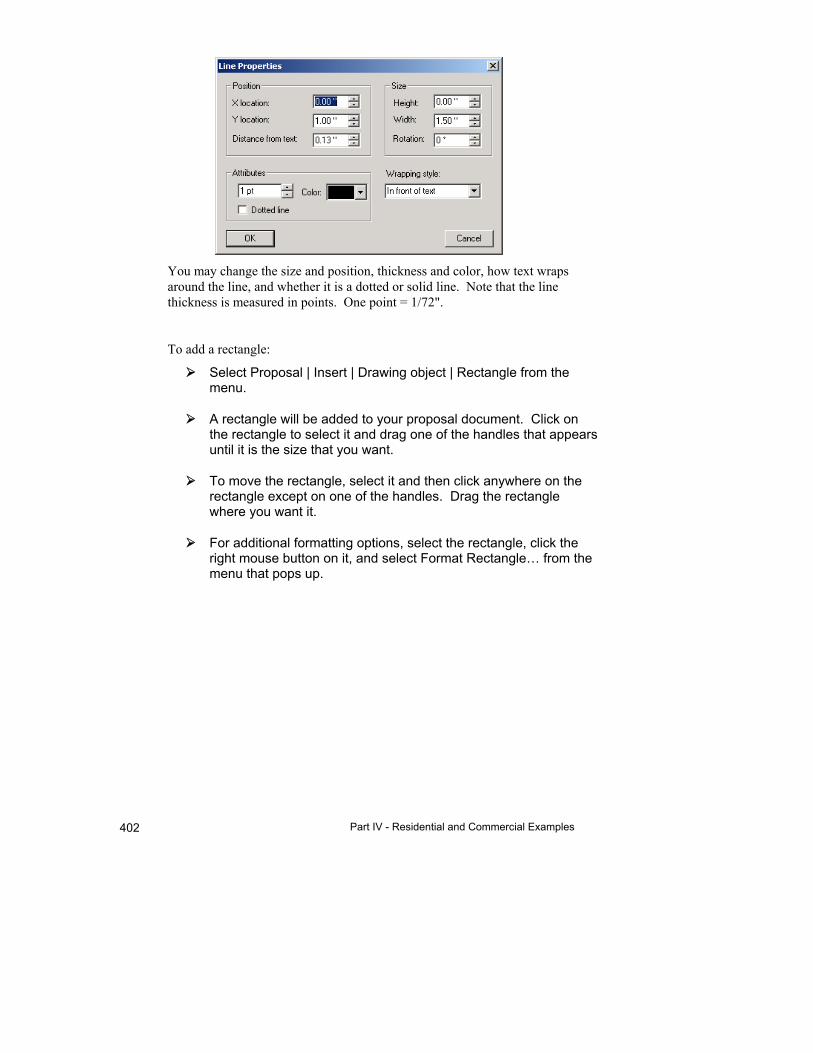
Part IV - Residential and Commercial Examples 402
You may change the size and position, thickness and color, how text wraps around the line, and whether it is a dotted or solid line. Note that the line thickness is measured in points. One point = 1/72".
To add a rectangle:
Select Proposal | Insert | Drawing object | Rectangle from the menu.
A rectangle will be added to your proposal document. Click on the rectangle to select it and drag one of the handles that appears until it is the size that you want.
To move the rectangle, select it and then click anywhere on the rectangle except on one of the handles. Drag the rectangle where you want it.
For additional formatting options, select the rectangle, click the right mouse button on it, and select Format Rectangle… from the menu that pops up.
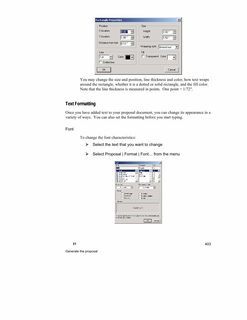
31 Generate the proposal
403
You may change the size and position, line thickness and color, how text wraps around the rectangle, whether it is a dotted or solid rectangle, and the fill color. Note that the line thickness is measured in points. One point = 1/72".
Text Formatting
Once you have added text to your proposal document, you can change its appearance in a variety of ways. You can also set the formatting before you start typing.
Font
To change the font characteristics:
Select the text that you want to change
Select Proposal | Format | Font… from the menu

Part IV - Residential and Commercial Examples 404
Paragraph
To change the characteristics of an entire paragraph:
Select the text that you want to change
Select Proposal | Format | Paragraph… from the menu
Bullets and numbering
You can add bullets to a list of key points in your proposal document. Like this:
Licensed and insured
30 day warranty
Free estimate
You can also number a list sequentially or in outline format. To add bullets or numbering:
Select the text that you want to change
Select Proposal | Format | Bullets and numbering… from the menu
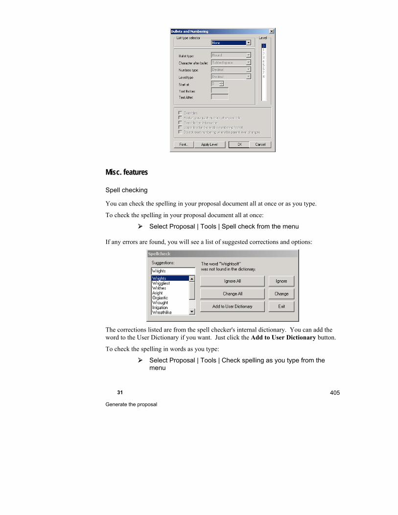
31 Generate the proposal
405
Misc. features
Spell checking
You can check the spelling in your proposal document all at once or as you type.
To check the spelling in your proposal document all at once:
Select Proposal | Tools | Spell check from the menu
If any errors are found, you will see a list of suggested corrections and options:
The corrections listed are from the spell checker's internal dictionary. You can add the word to the User Dictionary if you want. Just click the Add to User Dictionary button.
To check the spelling in words as you type:
Select Proposal | Tools | Check spelling as you type from the menu

Part IV - Residential and Commercial Examples 406
If any words are misspelled while you are typing into your proposal document, the misspelled word will have a squiggly line under it.
Click the right mouse button on the misspelled word and see a list of suggested corrections and options.
Export/import
You can export (write) a Right-Proposal® document to a file that can be opened by other applications. For example, you can export a Right-Proposal® document to Rich Text Format. Most word processing programs, like Microsoft Word or WordPad, can read this format. To export a proposal document:
Select Proposal | Export to from the menu
Select the format that you want to export to
Select the name and location of the file you want to export to
You can also import (read) a file generated with other applications into a Right-Proposal® document. To import a file:
Select Proposal | Import from from the menu
Select the format of the file that you want to import from
Select the name and location of the file you want to import
Example 4 - Setup Right-Proposal® for your use
In this example we will outline the procedure to set Right-Proposal® up for your use. The more thorough you are in this step, the more time you will save when you design your proposals.
Library
The first step is to fill out the Right-Proposal® Library with the information that you will
be using. To add to the Library, click on the Right-Proposal® button on the toolbar
selector and then click on the button.
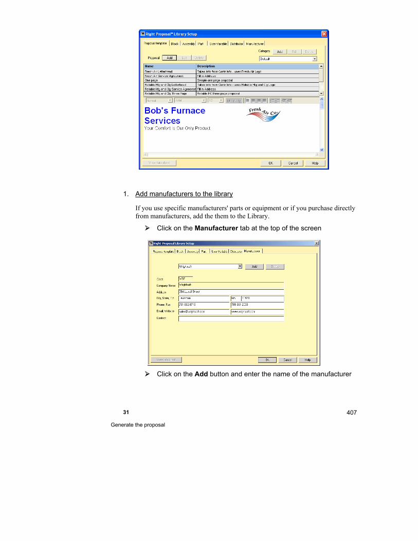
31 Generate the proposal
407
1. Add manufacturers to the library
If you use specific manufacturers' parts or equipment or if you purchase directly from manufacturers, add the them to the Library.
Click on the Manufacturer tab at the top of the screen
Click on the Add button and enter the name of the manufacturer
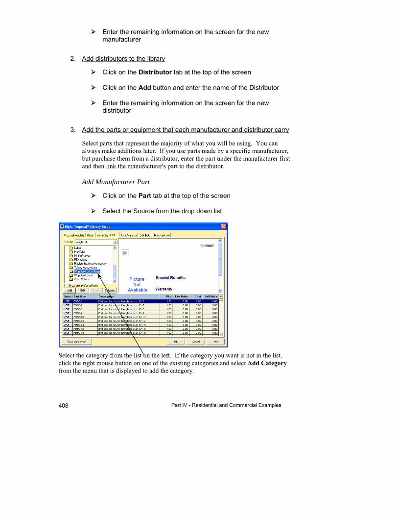
Part IV - Residential and Commercial Examples 408
Enter the remaining information on the screen for the new manufacturer
2. Add distributors to the library
Click on the Distributor tab at the top of the screen
Click on the Add button and enter the name of the Distributor
Enter the remaining information on the screen for the new distributor
3. Add the parts or equipment that each manufacturer and distributor carry
Select parts that represent the majority of what you will be using. You can always make additions later. If you use parts made by a specific manufacturer, but purchase them from a distributor, enter the part under the manufacturer first and then link the manufacturer's part to the distributor.
Add Manufacturer Part
Click on the Part tab at the top of the screen
Select the Source from the drop down list
Select the category from the list on the left. If the category you want is not in the list, click the right mouse button on one of the existing categories and select Add Category from the menu that is displayed to add the category.
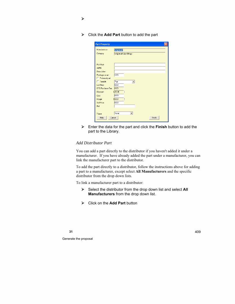
31 Generate the proposal
409
Click the Add Part button to add the part
Enter the data for the part and click the Finish button to add the part to the Library.
Add Distributor Part
You can add a part directly to the distributor if you haven't added it under a manufacturer. If you have already added the part under a manufacturer, you can link the manufacturer part to the distributor.
To add the part directly to a distributor, follow the instructions above for adding a part to a manufacturer, except select All Manufacturers and the specific distributor from the drop down lists.
To link a manufacturer part to a distributor:
Select the distributor from the drop down list and select All Manufacturers from the drop down list.
Click on the Add Part button
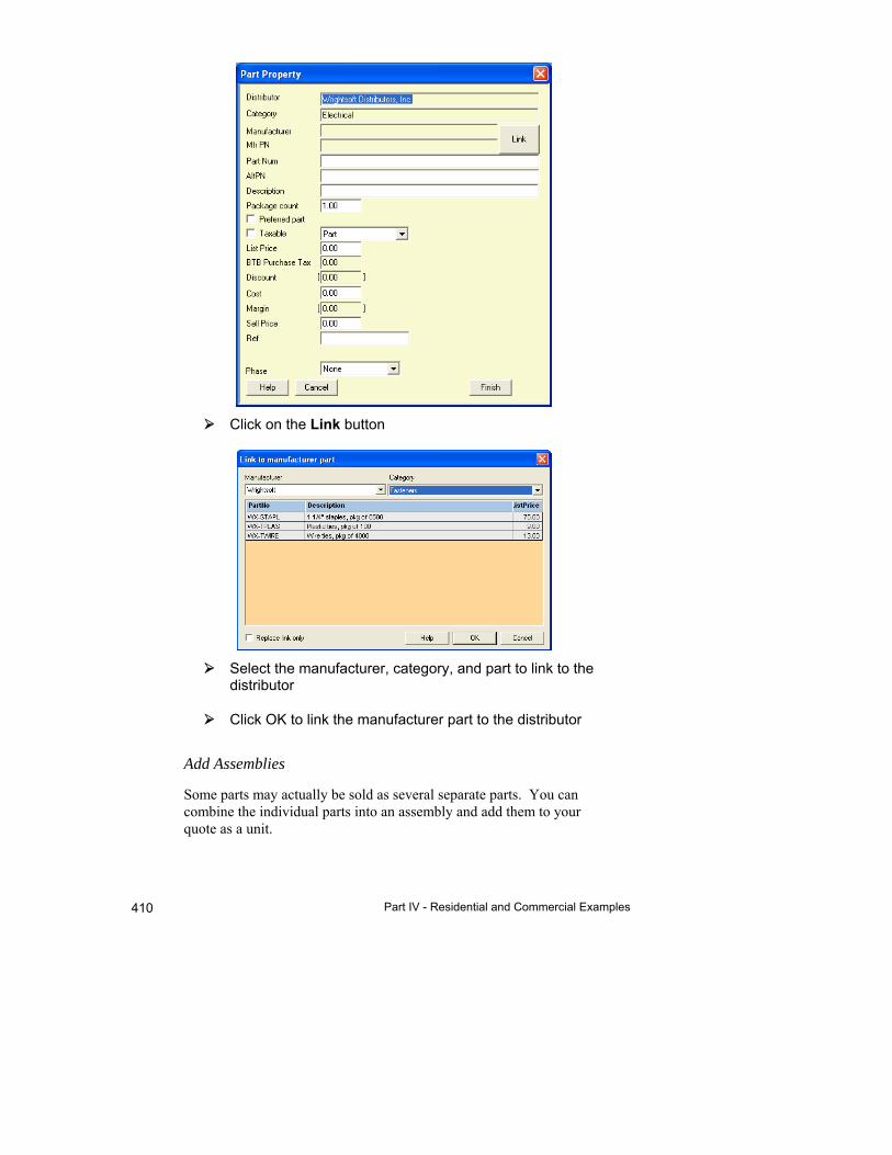
Part IV - Residential and Commercial Examples 410
Click on the Link button
Select the manufacturer, category, and part to link to the distributor
Click OK to link the manufacturer part to the distributor
Add Assemblies
Some parts may actually be sold as several separate parts. You can combine the individual parts into an assembly and add them to your quote as a unit.
31 Generate the proposal
411
See the previous chapter for detailed instructions.
4. Map the parts that you have entered to generic parts
When Right-Draw® generates a parts list during the automatic take off, the parts are generic - not associated with any manufacturer or distributor. You can associate (map) the parts that you have entered to the generic parts that Right-Draw® generates. Right-Proposal® will add your mapped parts to the Bill of Materials and Purchase Orders for the manufacturers or distributors that carry the mapped parts.
See the previous chapter for detailed instructions.
Proposal
You will probably want to use the proposals that you currently use with some modifications. You can use the Proposal Document's editing capabilities to design your new proposals. Adding, deleting, and moving things around until you're happy with it can be done quickly and easily. It is helpful, however, to take a few moments before you start to collect your thoughts about what you want before you start.
Blocks
Identify sections of your proposals that will be the same in all proposals. For example, you probably have a standard warranty that you use for all of your projects. You may also have standard payment terms. You can put these standard paragraphs in Blocks and insert them all at once in your proposals. So, you only have to type it out completely once.
See the previous example for detailed instructions.
User variables
User variables can be used for unformatted text that you can insert into your proposal by name. For example, you could add a User Variable with your license number. You can then add your license number to a proposal document without having to look it up.
Proposal Templates
Once you have designed your proposals, you can save them as templates in the Right-Proposal® Library. You can then generate a proposal by just selecting the template that you want to use.

Part IV - Residential and Commercial Examples 412
Things to Remember
To setup Right-Proposal® add manufacturers, distributors, parts, blocks, and user variables to the Right-Proposal® Library. Then map the parts that you added to the generic parts in Right-Proposal®.
You can use the Proposal Document word processor to add proposal templates to the Right-Proposal® Library. You can then generate a proposal for any project by just selecting the template.

32 Right-Consultant™
This chapter describes how to optimize your sales efforts with Right-Consultant™.
Setup ........................................................................... 414
Customers ................................................................... 419
Proposals .................................................................... 420
Dashboard ................................................................... 422
Scorecard .................................................................... 423

Part IV - Residential and Commercial Examples 414
Right-Consultant™ manager allows you keep track of your sales efforts and the status of your projects.
Right-Consultant™ Screens
Right-Consultant™ uses 4 main screens. There are also detail screens for each main screen. To display the Right-Consultant™ toolbar:
Click on the button in the Right-Suite Universal 2018 toolbar.
Setup
To display the Right-Consultant™ Setup Screen:
Click on the button in the Right-Consultant™ toolbar.
Or
Select Show | Right-Consultant™ | Setup from the Right-Suite Universal 2018 menu.
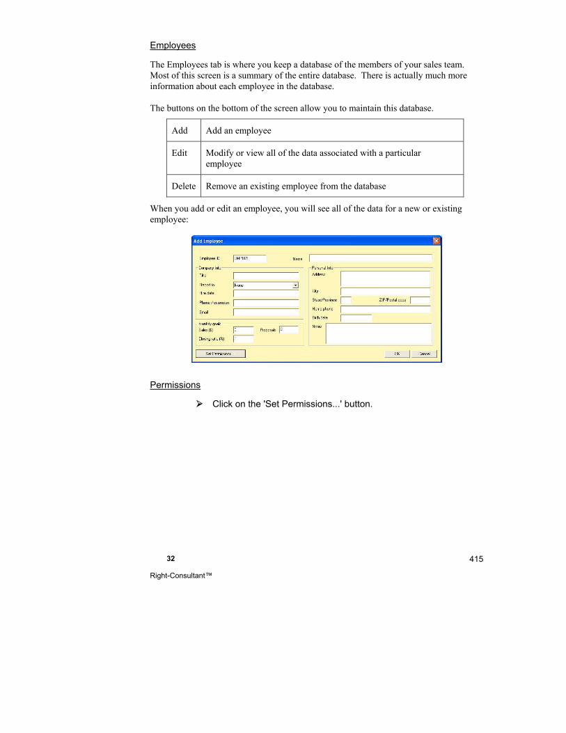
32 Right-Consultant™
415
Employees
The Employees tab is where you keep a database of the members of your sales team. Most of this screen is a summary of the entire database. There is actually much more information about each employee in the database.
The buttons on the bottom of the screen allow you to maintain this database.
Add Add an employee
Edit Modify or view all of the data associated with a particular employee
Delete Remove an existing employee from the database
When you add or edit an employee, you will see all of the data for a new or existing employee:
Permissions
Click on the 'Set Permissions...' button.

Part IV - Residential and Commercial Examples 416
You can determine what each employee can do in Right-Suite Universal 2018. Enter a login name and password for the new employee and then check what you want to allow this employee to do.
Make sure that the first employee that you enter login information for is yourself and that you give yourself 'Administrative functions' permission. This allows you to enter login information for other employees.
Once you have entered login information for an employee, all employees will need to have login information entered or they won't be able to run Right-Suite Universal 2018. When the program starts, it will ask for login information if ANY employee has login information in the employee database.
Preferences
Click on the ‘Preferences’ tab at the top
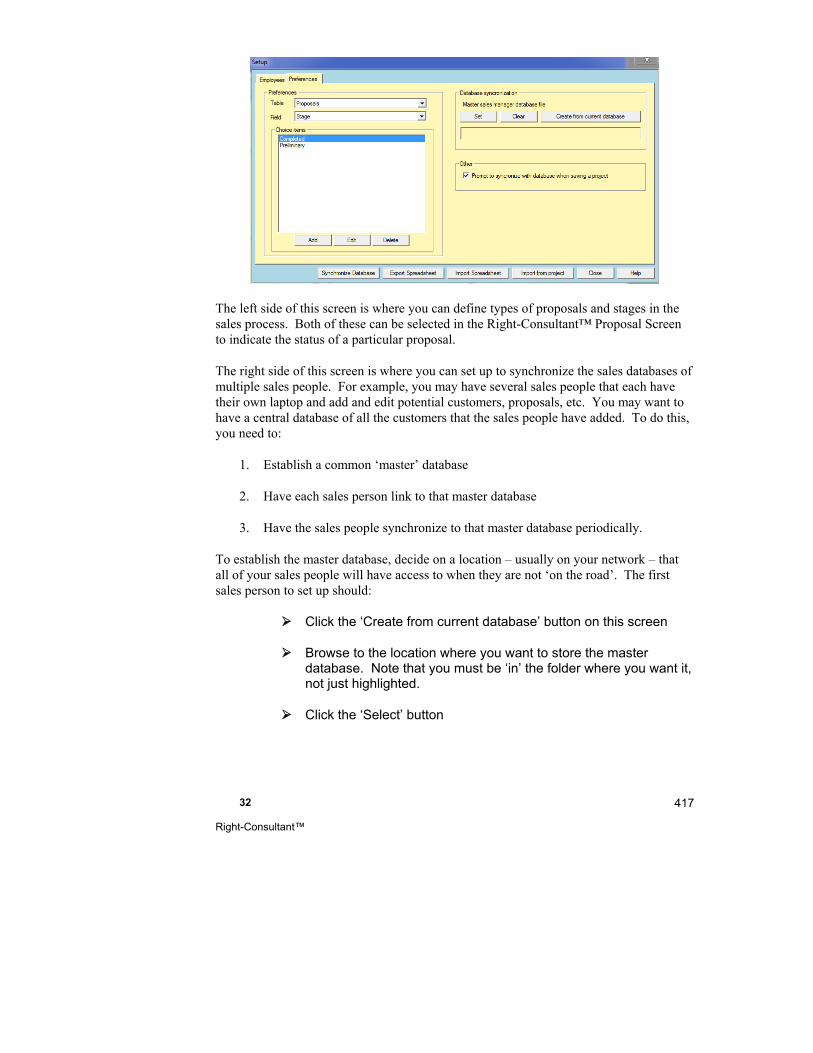
32 Right-Consultant™
417
The left side of this screen is where you can define types of proposals and stages in the sales process. Both of these can be selected in the Right-Consultant™ Proposal Screen to indicate the status of a particular proposal.
The right side of this screen is where you can set up to synchronize the sales databases of multiple sales people. For example, you may have several sales people that each have their own laptop and add and edit potential customers, proposals, etc. You may want to have a central database of all the customers that the sales people have added. To do this, you need to:
1. Establish a common ‘master’ database
2. Have each sales person link to that master database
3. Have the sales people synchronize to that master database periodically.
To establish the master database, decide on a location – usually on your network – that all of your sales people will have access to when they are not ‘on the road’. The first sales person to set up should:
Click the ‘Create from current database’ button on this screen
Browse to the location where you want to store the master database. Note that you must be ‘in’ the folder where you want it, not just highlighted.
Click the ‘Select’ button
Part IV - Residential and Commercial Examples 418
The sales person’s local sales database will be copied to the selected location and will become the master database.
Each of the other sales people should:
Click on the ‘Set’ button on this screen
Browse to the master database and select it
Click the ‘Open’ button
Click the ‘Synchronize Database’ button (at the bottom of this screen) to synchronize the local database with the master database.
Each sales person should then synchronize their database whenever they can. They can be synchronized in any order and at any time. New customers will be added to the master database, modified customers will be updated on the master database, and the master database will be copied to the sales person’s computer.
Importing Customers, Employees, and Proposals
If your have Right-Suite Universal 2018 projects that are not being managed by Right-Consultant™, you can import them into Right-Consultant™ easily.
Click on the Import button at the bottom of the Setup Screen.
Select the Right-Suite Universal 2018 project that you want to import.
If there is a customer name entered in the project that you are importing (in the Project Information Screen), the customer information will be added to the Right-Consultant™ customer database. Type in the additional customer information in the screen that is displayed. Click the OK button to proceed to the Employee Screen.
If the project you are importing has 'Prepared by' (in the Project Information Screen) filled in, an employee will be added to the Right-Consultant™ employee database. Type in the additional employee information in the screen that is displayed. Click on the OK button to proceed to the Proposal Screen.
If the project you are importing has a job number (in the Project Information Screen) filled in, a proposal will be added to the Right-Consultant™ proposals database. Type in the additional

32 Right-Consultant™
419
information in the screen that is displayed. Click on the OK button to complete the importing.
Customers
To display the Right-Consultant™ Customers Screen:
Click on the button in the Right-Consultant™ toolbar.
Or
Select Show | Right-Consultant™ | Customers from the Right-Suite Universal 2018 menu.
This is where you keep a database of all of your customers. Most of this screen is a summary of the entire database. There is actually much more information about each customer in the database.
The buttons on the bottom of the screen allow you to maintain this database.
Add Add a customer
Edit Modify or view all of the data associated with a particular customer
Delete Remove an existing customer from the database
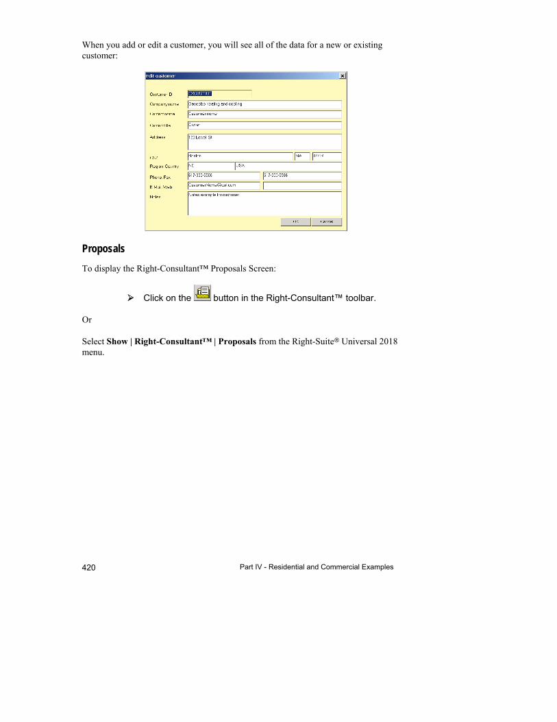
Part IV - Residential and Commercial Examples 420
When you add or edit a customer, you will see all of the data for a new or existing customer:
Proposals
To display the Right-Consultant™ Proposals Screen:
Click on the button in the Right-Consultant™ toolbar.
Or
Select Show | Right-Consultant™ | Proposals from the Right-Suite Universal 2018 menu.
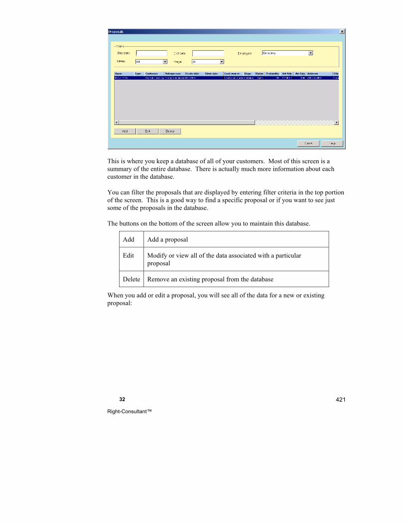
32 Right-Consultant™
421
This is where you keep a database of all of your customers. Most of this screen is a summary of the entire database. There is actually much more information about each customer in the database.
You can filter the proposals that are displayed by entering filter criteria in the top portion of the screen. This is a good way to find a specific proposal or if you want to see just some of the proposals in the database.
The buttons on the bottom of the screen allow you to maintain this database.
Add Add a proposal
Edit Modify or view all of the data associated with a particular proposal
Delete Remove an existing proposal from the database
When you add or edit a proposal, you will see all of the data for a new or existing proposal:

Part IV - Residential and Commercial Examples 422
Note that you can select the Type (in the Job section) and Stage (on the right) from drop down lists. The available Types and Stages will be from the Types and Stages databases that you added in the Setup Screen.
Dashboard
To display the Right-Consultant™ Dashboard:
Click on the button in the Right-Consultant™ toolbar.
Or
Select Show | Right-Consultant™ | Dashboard from the Right-Suite Universal 2018 menu.
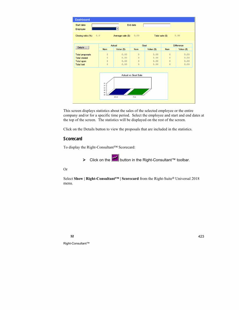
32 Right-Consultant™
423
This screen displays statistics about the sales of the selected employee or the entire company and/or for a specific time period. Select the employee and start and end dates at the top of the screen. The statistics will be displayed on the rest of the screen.
Click on the Details button to view the proposals that are included in the statistics.
Scorecard
To display the Right-Consultant™ Scorecard:
Click on the button in the Right-Consultant™ toolbar.
Or
Select Show | Right-Consultant™ | Scorecard from the Right-Suite Universal 2018 menu.
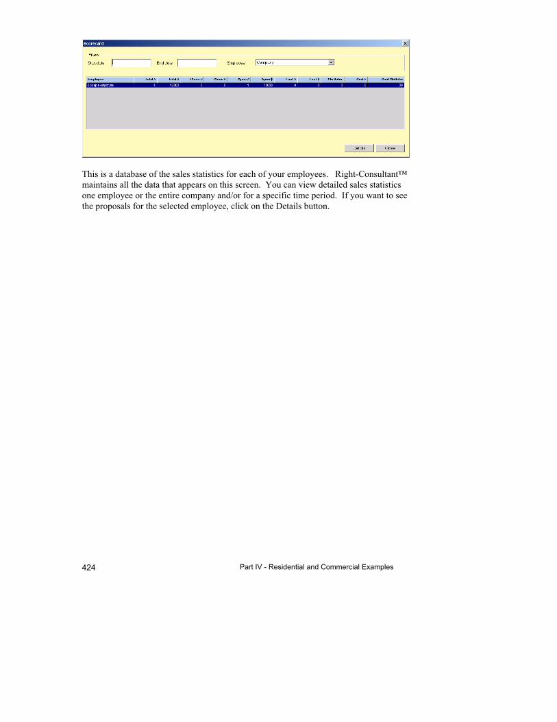
Part IV - Residential and Commercial Examples 424
This is a database of the sales statistics for each of your employees. Right-Consultant™ maintains all the data that appears on this screen. You can view detailed sales statistics one employee or the entire company and/or for a specific time period. If you want to see the proposals for the selected employee, click on the Details button.

Part V - Reference


33
Templates
This chapter describes how to use templates to simplify your work and save time.
What is a Right-Suite Universal 2018 Template? ...... 428
How to Create an RSU Template ................................ 428
What Information Belongs in a Template? .................. 428
What is an RSU Default Template? ............................. 430
The Template Wizard .................................................. 430
Things to Remember ................................................... 430
Part V - Reference 428
It is strongly recommended that you use a template as the starting point for every new project.
Templates allow you to shortcut most of the work required to set up a new project and complete a design. By using templates, you can reduce the time required to complete typical designs to just a few minutes. You also avoid inconsistent settings from one project to another.
What is a Right-Suite Universal 2018 Template?
A Right-Suite Universal 2018 template is just a project file that has been saved with an .rut filename extension. When you start a new project with an RSU template, a new project file is created with the information from the template file already entered. Templates are particularly effective for repeating common job types.
How to Create an RSU Template
The simplest way to create a template is to begin with a project file or template file similar to the one you want to create. Make any changes and save it as a template file with a new name.
For example, open the 'MDEX1.rud' demo file provided with RSU. Modify the file so that it contains the information you want in your template (NOTE: If you are working in Demo mode you will not be able to alter the customer name, contractor name or weather data).
Select File | Save As | Template… from the main menu and enter a name for the template. Notice that the 'Save as type' field at the bottom indicates that your template will be saved as an RSU template with the .rut file extension (NOTE: You cannot save templates in Demo mode).
What Information Belongs in a Template?
A template contains information that you want automatically included in a new project. For example, if all the builders you work with prefer flex ducts for branches and fiberglass ductboard for trunks, then specify that information in your template. If you work with different builders who have different preferences, you might create a template for each builder.
Think in terms of saving yourself keystrokes by cleverly anticipating project types that you do over and over. Below is a list of items you may wish to preset.

33 Templates
429
Project-wide data
Project Information Screen
Contractor name, address, phone
Weather data
Fuel data
Cost data
Zone Information Screen
Inside design conditions
Proposal Information
Billing address
Shipping address
Manufacturers for automatic takeoffs
Equipment Screen
System type
Data
Equipment filters
Right-Draw®
Default construction numbers
Catalogs
Set scale and grid settings Loads
Infiltration calculation method
Loads Preferences Screen
New room and glazing defaults
Internal gains
Duct loss and duct gain
Ducts
Duct Preferences Screen
Duct system layout
Material type
Velocity
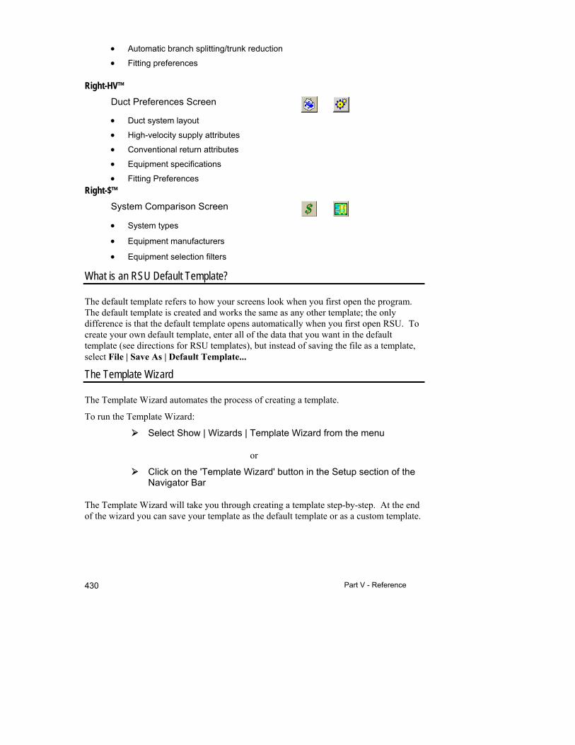
Part V - Reference 430
Automatic branch splitting/trunk reduction
Fitting preferences
Right-HV™
Duct Preferences Screen
Duct system layout
High-velocity supply attributes
Conventional return attributes
Equipment specifications
Fitting Preferences
Right-$™
System Comparison Screen
System types
Equipment manufacturers
Equipment selection filters
What is an RSU Default Template?
The default template refers to how your screens look when you first open the program. The default template is created and works the same as any other template; the only difference is that the default template opens automatically when you first open RSU. To create your own default template, enter all of the data that you want in the default template (see directions for RSU templates), but instead of saving the file as a template, select File | Save As | Default Template...
The Template Wizard
The Template Wizard automates the process of creating a template.
To run the Template Wizard:
Select Show | Wizards | Template Wizard from the menu
or
Click on the 'Template Wizard' button in the Setup section of the Navigator Bar
The Template Wizard will take you through creating a template step-by-step. At the end of the wizard you can save your template as the default template or as a custom template.

33 Templates
431
Things to Remember
Templates are essential to create designs quickly and to take full advantage of RSU.
Create templates for each of the major types of jobs you do.
Use descriptive file names for your templates.
Create a default template so that you are ready to enter project information as soon as you start RSU.
Use the Template Wizard to automate creating templates.


34
Right-Suite Universal 2018 Library
What is the Right-Suite Universal 2018 Library? ....... 434
Displaying the Right-Suite Universal 2018 Library ..... 435
Using the Right-Suite Universal 2018 Library ............ 435
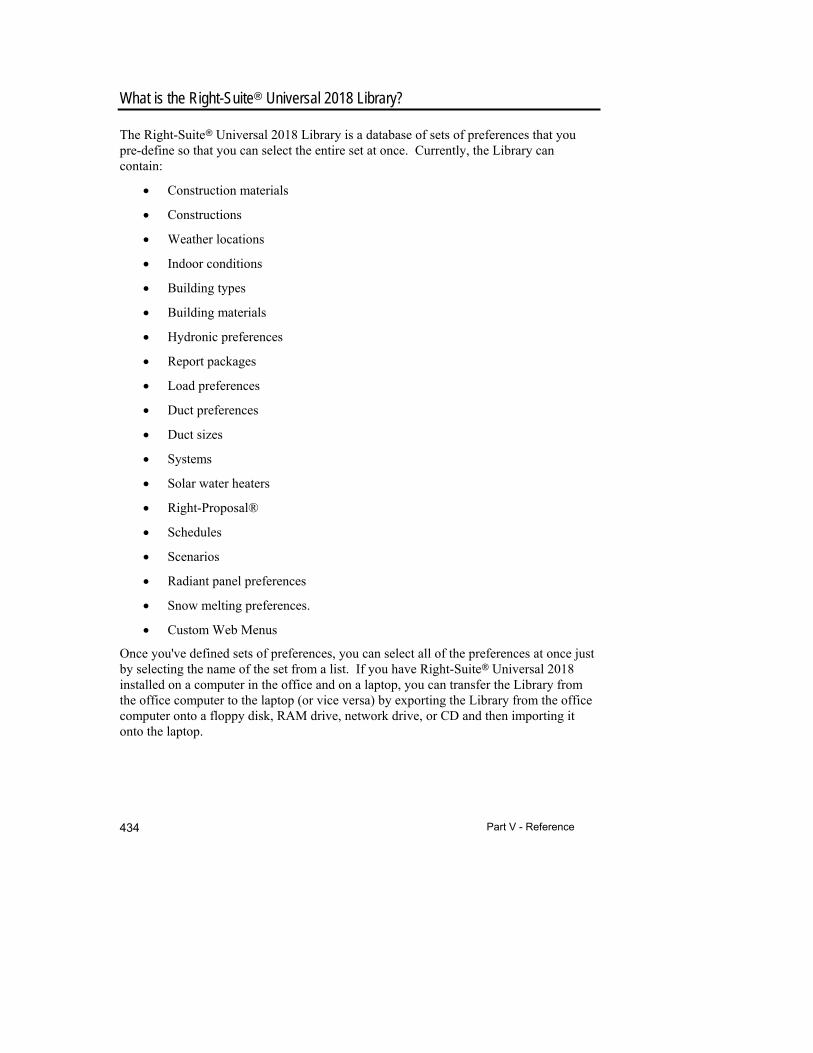
Part V - Reference 434
What is the Right-Suite Universal 2018 Library?
The Right-Suite Universal 2018 Library is a database of sets of preferences that you pre-define so that you can select the entire set at once. Currently, the Library can contain:
Construction materials
Constructions
Weather locations
Indoor conditions
Building types
Building materials
Hydronic preferences
Report packages
Load preferences
Duct preferences
Duct sizes
Systems
Solar water heaters
Right-Proposal®
Schedules
Scenarios
Radiant panel preferences
Snow melting preferences.
Custom Web Menus
Once you've defined sets of preferences, you can select all of the preferences at once just by selecting the name of the set from a list. If you have Right-Suite Universal 2018 installed on a computer in the office and on a laptop, you can transfer the Library from the office computer to the laptop (or vice versa) by exporting the Library from the office computer onto a floppy disk, RAM drive, network drive, or CD and then importing it onto the laptop.
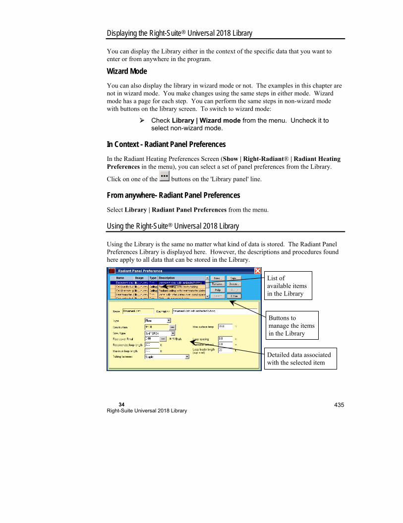
34 Right-Suite Universal 2018 Library
435
Displaying the Right-Suite Universal 2018 Library
You can display the Library either in the context of the specific data that you want to enter or from anywhere in the program.
Wizard Mode
You can also display the library in wizard mode or not. The examples in this chapter are not in wizard mode. You make changes using the same steps in either mode. Wizard mode has a page for each step. You can perform the same steps in non-wizard mode with buttons on the library screen. To switch to wizard mode:
Check Library | Wizard mode from the menu. Uncheck it to select non-wizard mode.
In Context - Radiant Panel Preferences
In the Radiant Heating Preferences Screen (Show | Right-Radiant® | Radiant Heating Preferences in the menu), you can select a set of panel preferences from the Library.
Click on one of the buttons on the 'Library panel' line.
From anywhere- Radiant Panel Preferences
Select Library | Radiant Panel Preferences from the menu.
Using the Right-Suite Universal 2018 Library
Using the Library is the same no matter what kind of data is stored. The Radiant Panel Preferences Library is displayed here. However, the descriptions and procedures found here apply to all data that can be stored in the Library.
List of available items in the Library
Buttons to manage the items in the Library
Detailed data associated with the selected item
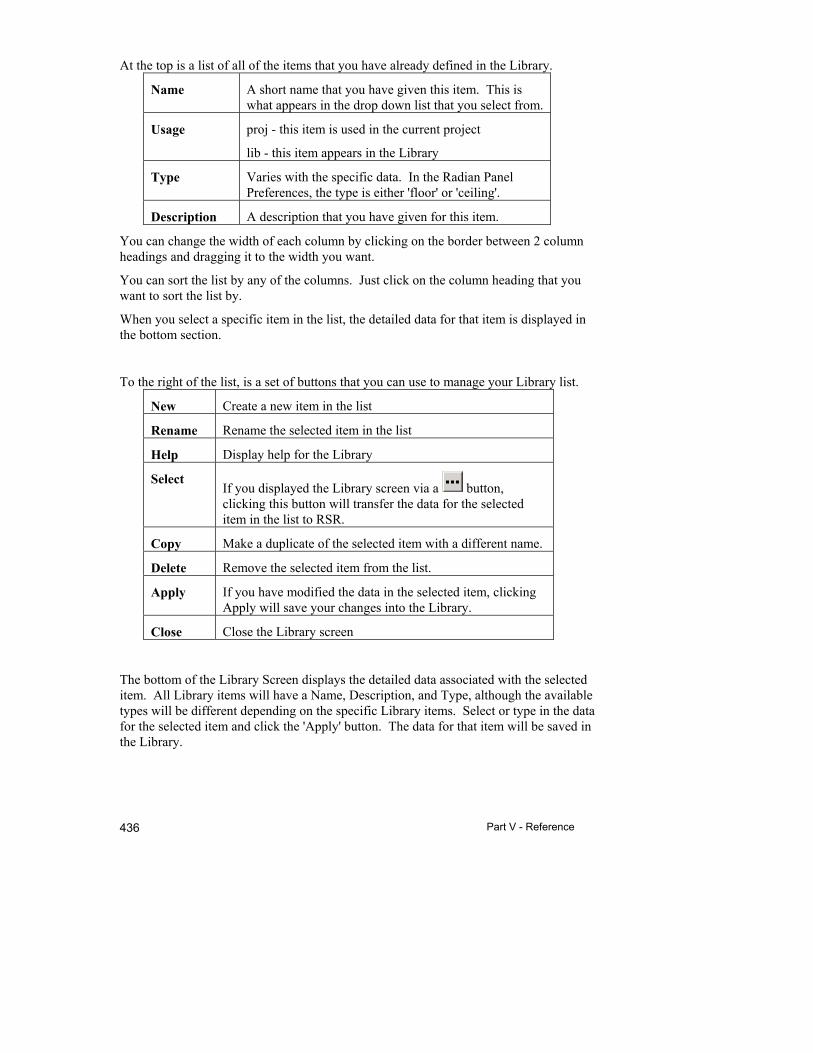
Part V - Reference 436
At the top is a list of all of the items that you have already defined in the Library.
Name A short name that you have given this item. This is what appears in the drop down list that you select from.
Usage proj - this item is used in the current project
lib - this item appears in the Library
Type Varies with the specific data. In the Radian Panel Preferences, the type is either 'floor' or 'ceiling'.
Description A description that you have given for this item.
You can change the width of each column by clicking on the border between 2 column headings and dragging it to the width you want.
You can sort the list by any of the columns. Just click on the column heading that you want to sort the list by.
When you select a specific item in the list, the detailed data for that item is displayed in the bottom section.
To the right of the list, is a set of buttons that you can use to manage your Library list.
New Create a new item in the list
Rename Rename the selected item in the list
Help Display help for the Library
Select If you displayed the Library screen via a button, clicking this button will transfer the data for the selected item in the list to RSR.
Copy Make a duplicate of the selected item with a different name.
Delete Remove the selected item from the list.
Apply If you have modified the data in the selected item, clicking Apply will save your changes into the Library.
Close Close the Library screen
The bottom of the Library Screen displays the detailed data associated with the selected item. All Library items will have a Name, Description, and Type, although the available types will be different depending on the specific Library items. Select or type in the data for the selected item and click the 'Apply' button. The data for that item will be saved in the Library.

34 Right-Suite Universal 2018 Library
437
Once you have saved this data, you can select all of the data at once by selecting the name, usually from a drop-down list, in Right-Suite Universal 2018. For example, you can select an entire set of Radiant Panel Preferences from the drop-down list on the 'Library panel' line in the Radiant Heating Preferences screen.

35
Building Construction
Constructions Library .................................................. 440
Construction Selector .................................................. 445

Part V - Reference 440
Constructions Library
The Constructions Library allows you to define building component constructions so that you can include them in your projects. The construction details of the building components of your project determine the heating and cooling load of your project. Any constructions that you define here can be used with any of the calculation methods in Right-Suite Universal 2018.
To display this screen:
Select Library | Constructions from the menu
All constructions in your library are shown.
There are 2 views of the Construction Library screen.
1. The Summary View - In this view, you can review a complete list of pre-defined constructions in your Library.
2. The Details View - You use this view to define the constructions in your Library.
The Summary View
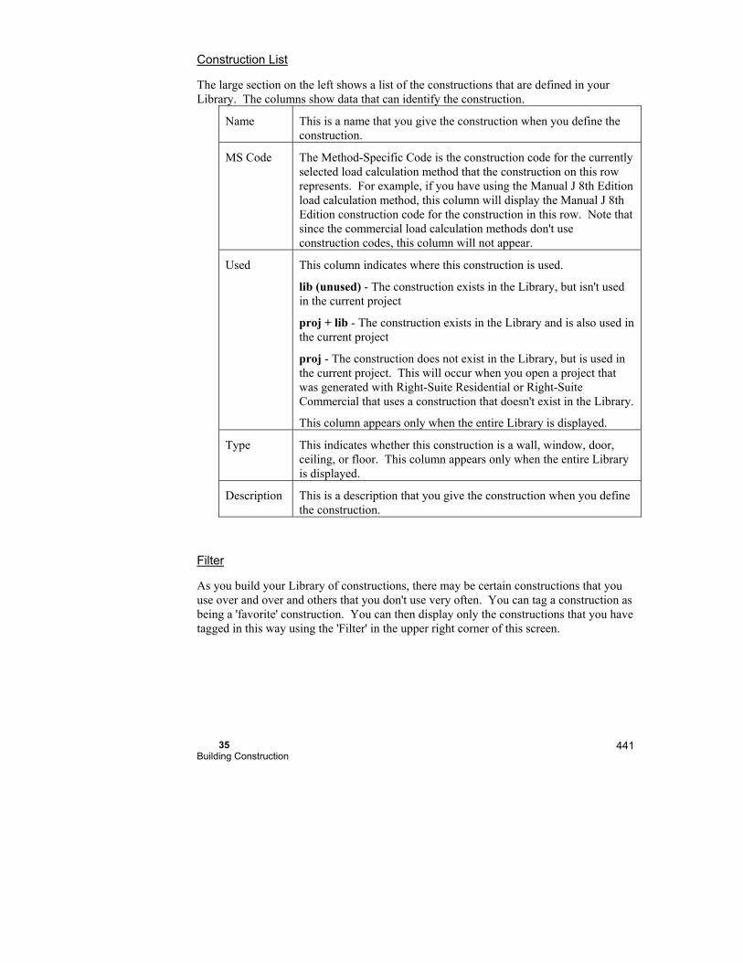
35 Building Construction
441
Construction List
The large section on the left shows a list of the constructions that are defined in your Library. The columns show data that can identify the construction.
Name This is a name that you give the construction when you define the construction.
MS Code The Method-Specific Code is the construction code for the currently selected load calculation method that the construction on this row represents. For example, if you have using the Manual J 8th Edition load calculation method, this column will display the Manual J 8th Edition construction code for the construction in this row. Note that since the commercial load calculation methods don't use construction codes, this column will not appear.
Used This column indicates where this construction is used.
lib (unused) - The construction exists in the Library, but isn't used in the current project
proj + lib - The construction exists in the Library and is also used in the current project
proj - The construction does not exist in the Library, but is used in the current project. This will occur when you open a project that was generated with Right-Suite Residential or Right-Suite Commercial that uses a construction that doesn't exist in the Library.
This column appears only when the entire Library is displayed.
Type This indicates whether this construction is a wall, window, door, ceiling, or floor. This column appears only when the entire Library is displayed.
Description This is a description that you give the construction when you define the construction.
Filter
As you build your Library of constructions, there may be certain constructions that you use over and over and others that you don't use very often. You can tag a construction as being a 'favorite' construction. You can then display only the constructions that you have tagged in this way using the 'Filter' in the upper right corner of this screen.
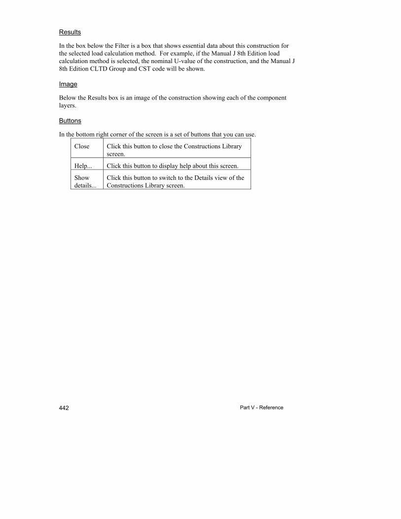
Part V - Reference 442
Results
In the box below the Filter is a box that shows essential data about this construction for the selected load calculation method. For example, if the Manual J 8th Edition load calculation method is selected, the nominal U-value of the construction, and the Manual J 8th Edition CLTD Group and CST code will be shown.
Image
Below the Results box is an image of the construction showing each of the component layers.
Buttons
In the bottom right corner of the screen is a set of buttons that you can use.
Close Click this button to close the Constructions Library screen.
Help... Click this button to display help about this screen.
Show details...
Click this button to switch to the Details view of the Constructions Library screen.
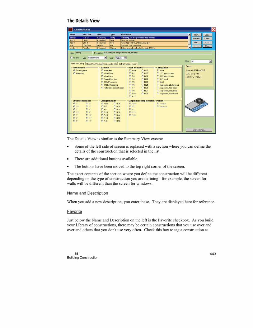
35 Building Construction
443
The Details View
The Details View is similar to the Summary View except:
Some of the left side of screen is replaced with a section where you can define the details of the construction that is selected in the list.
There are additional buttons available.
The buttons have been moved to the top right corner of the screen.
The exact contents of the section where you define the construction will be different depending on the type of construction you are defining - for example, the screen for walls will be different than the screen for windows.
Name and Description
When you add a new description, you enter these. They are displayed here for reference.
Favorite
Just below the Name and Description on the left is the Favorite checkbox. As you build your Library of constructions, there may be certain constructions that you use over and over and others that you don't use very often. Check this box to tag a construction as

Part V - Reference 444
being a 'favorite' construction. You can then display only the constructions that you have tagged in this way using the 'Filter' in the upper right corner of this screen.
Definition method (Use)
Next to the Favorite checkbox is a drop down list of methods you can use to define the selected construction.
Radio buttons
This method shows a series of tabs where you can define your construction by selecting individual characteristics of the construction from a list of choices.
Custom layers
The last tab in this section is one called 'Layers'. It shows a summary of the thermal characteristics of each layer in your construction. When you select the 'Custom layers' definition method, you can define the construction by adding and editing the lines in this summary directly.
Custom values
Use this tab to define custom constructions that are not covered by the list of choices available when using the Radio buttons definition method.
Color
If you are defining a wall or ceiling, you can select the color of the wall or ceiling here.
Infiltration type
If you are defining a door, you can select the infiltration type here. This is used to calculate door traffic infiltration when the CLTD or RTS commercial calculation methods are used.
Tabs
This is where you define the construction when the 'Radio buttons' definition method is used. The specific tabs will vary depending on the type of construction that you are defining - for example, the tabs for walls are different than for windows. Select the tab that represents the general category of the construction type that you are defining. Then make selections for each layer of your construction on that tab. For example, if you are defining a sloped roof, select the 'Sloped Roof/Ceiling' tab first, then the Roof material, Structure, etc. from the list of options for each layer on that tab. As you make selections, the data in the Results box and the image will change to reflect your selections.
The last tab on the right will always be the 'Layers' tab. This tab shows a summary of the thermal characteristics of each layer in your construction.
35 Building Construction
445
Buttons
In the top right corner of the screen is a set of buttons that you can use.
New Click this button to create a new construction.
Rename Click this button to change the name of the construction that is selected in the list
Help Displays help about this screen
Copy Click this button to create a new construction that is a copy of the construction that is selected in the list.
Delete Click this button to delete the selected construction.
Apply Once you have completed making changes to a construction, click this button to transfer your changes to the Library. The Construction Library screen will remain displayed so that you can continue to make changes.
Close Closes the Construction Library screen without selecting a construction.
In the bottom right corner of the screen is the 'Show Summary' button. Click this button to switch to the Summary View of the Constructions Library screen.
Construction Selector
To display this screen:
Click Default CST bar in Right-Draw
Click the Type field in the Property Sheet for the building component
Double click the CST field in any of the load worksheet screens
Only the appropriate constructions are displayed. For example, if you click on a wall CST field, only wall constructions are displayed.

Part V - Reference 446
Select from library
At the top of the screen, you can select a pre-defined construction from your Library. You define the constructions in the Construction Library screen. When you select a construction, the bottom of the screen will display the details of the construction that you selected.
You can use a construction without defining it in your Library. Select (none) in the list of pre-defined constructions. Then, just define a construction with the tabs in the bottom of the screen. Define the construction just like in the Construction Library Details screen.
Click the OK button to use the construction in your project.

36
File Operations
This chapter explains how to use the File menu to manage your project files and templates.
Create a New Project .................................................. 448
Create a New Template .............................................. 448
Copy a Project ............................................................. 449
Delete a Project ........................................................... 449
Move a Project ............................................................ 449
Rename a Project ........................................................ 449
Things to Remember ................................................... 450

Part V - Reference 448
RSU’s ability to store project files and templates allows you to conveniently store a wealth of information on your computer. As you use RSU, you will actually create a powerful library of specific project files and templates that let you shortcut most of the input process for new jobs.
To avoid confusion in the future as you accumulate a large collection of project and template files, use file names that describe the contents. Consider using codes to help sort your files. For example, file names beginning with ‘2S2Z’ might be used for two-story, two-zone houses.
Procedures for typical file management operations within RSU are described here. You can also accomplish each of these operations with the Windows Explorer.
You can access the Windows file management functions by right clicking on the name of any file after selecting File | New, File | Open, File | Save, or File | Save As.
Create a New Project
To create a new RSU project (.RUP extension) from a template:
Select File | New | New From Template... from the main menu. Then select a template as a starting point for your new project.
A project file will be opened with a temporary file name, ‘Project#.RUP’, where ‘#’ is a number.
When you save your project (using either File | Save | Project... or File | Save As | Project…), enter your own descriptive file name and click Save.
Create a New Template
A Right-Suite Universal 2018 template is a project file with an .RUT extension. To create a new template, start with a project.
Create a new project then enter your template data. Select File | Save As | Template… from the main menu. Type the template name and click Save.

36 File Operations
449
Copy a Project or Template
You can create a copy of a project or template file by using the Windows Explorer or by opening the project and saving it with a new file name.
Open the project or template you want to copy by selecting File | Open | Project... or Template... then select File | Save As | Project… or Template Type the name of the copy and click Save.
Delete a Project or Template
To delete a project or template:
Select File | Delete, choose the file then click Delete. Another window will appear to verify that you have selected the correct file. Click 'Yes' if the correct file is listed.
Move a Project or Template
You can move a project or template from one location on your hard drive to another location or to a floppy disk by using the Windows Explorer. Within RSU, you can move a file by opening the project or template, saving it to a new location, and then deleting the file from the original location.
Open the project you want to copy by selecting File | Open | Project...
Select File | Save As | Project… and type the name of the copy then click Save.
Now delete the original file as described above.
Rename a Project or Template
To rename a project in RSU:
Copy the project you want to rename, give the copy the new name, and delete the original.

Part V - Reference 450
Things to Remember
You can manage files using RSU’s File menu; Windows Explorer or Windows file management functions are accessed by right clicking on a file name in a File menu window (Save, Save As etc).

37
Overview of RSU
This chapter illustrates the design process with RSU.
1. Describe the building
2. Select the equipment
3. Design the distribution
4. Document the project

Part V - Reference 452
Navigator Bar
In the Design Mode, you can operate Right-Suite Universal 2018 using the Navigator Bar or not. The Navigator bar is along the left side of theRight-Suite Universal 2018 screen.
The Navigator Bar presents Right-Suite Universal 2018's functions, as buttons, in the order that you would use them, depending on what you want to do. For example, there are separate sets of buttons for:
Setting up Right-Suite Universal 2018 for use
Designing a project
Presenting a project proposal to your customer
Managing your sales
If you would rather not use the Navigator Bar, you can turn it off and use Right-Suite Universal 2018 screen-by-screen.
See the Navigator Bar chapter for further information on the Navigator Bar.
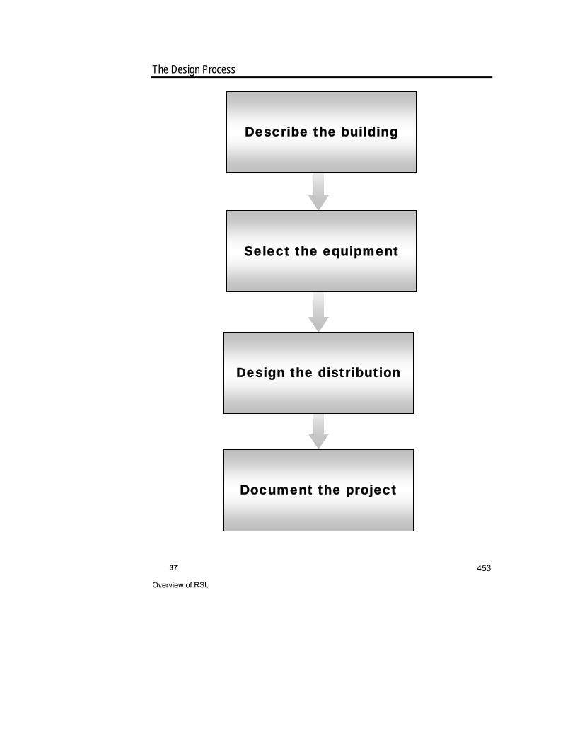
37 Overview of RSU
453
The Design Process
Describe the building
Select the equipment
Design the distribution
Document the project
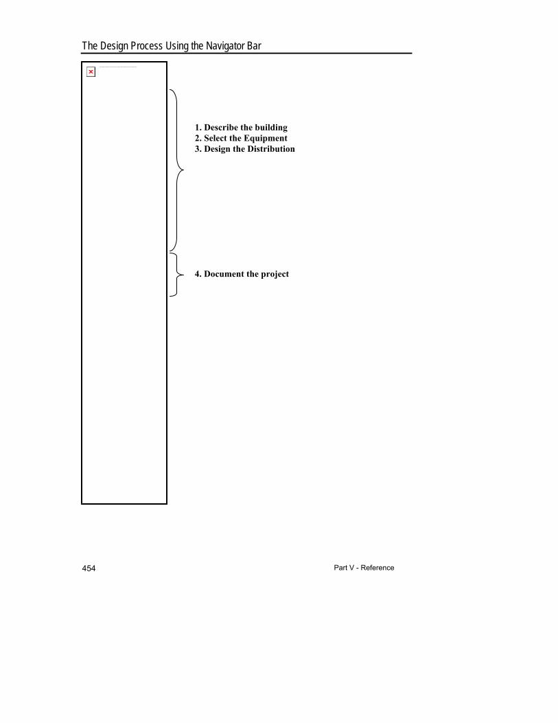
Part V - Reference 454
The Design Process Using the Navigator Bar
1. Describe the building 2. Select the Equipment 3. Design the Distribution
4. Document the project
The linked image cannot be displayed. The file may have been moved, renamed, or deleted. Verify that the link points to the correct file and location.
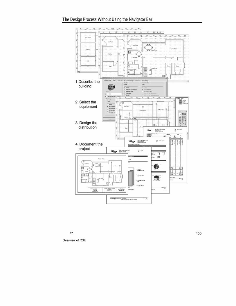
37 Overview of RSU
455
The Design Process Without Using the Navigator Bar
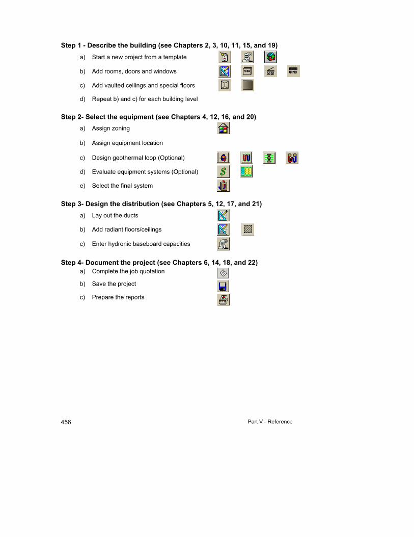
Part V - Reference 456
Step 1 - Describe the building (see Chapters 2, 3, 10, 11, 15, and 19)
a) Start a new project from a template
b) Add rooms, doors and windows
c) Add vaulted ceilings and special floors
d) Repeat b) and c) for each building level
Step 2- Select the equipment (see Chapters 4, 12, 16, and 20)
a) Assign zoning
b) Assign equipment location
c) Design geothermal loop (Optional)
d) Evaluate equipment systems (Optional)
e) Select the final system
Step 3- Design the distribution (see Chapters 5, 12, 17, and 21)
a) Lay out the ducts
b) Add radiant floors/ceilings
c) Enter hydronic baseboard capacities
Step 4- Document the project (see Chapters 6, 14, 18, and 22)
a) Complete the job quotation
b) Save the project
c) Prepare the reports
37 Overview of RSU
457
RSU Components
RSU combines these HVAC design and marketing functions.
Right-Consultant™ - Automated sales presentations and sales management Right-Draw® - Graphical building descriptions Right-J® - ACCA's Manual J heating and cooling load calculations, 7th and 8th (Version
2.00) Editions Right-F280™ - CSA’s Determining the Required Capacity of Residential Space Heating and
Cooling Appliances CAN/CSA-F280-M90 and CSA-F280-12 heating and cooling load calculations
Right-CommLoad® - Heating and cooling load calculations using the CLTD method as presented in the ASHRAE 1989 Handbook of Fundamentals.
Right-N® - ACCA's Manual N commercial load calculation for small commercial buildings, 5th Edition
Right-D® - ACCA's Manual D multizone duct sizing Right-Duct™ - HRAI’s Residential Air System Design residential duct sizing Right-CommDuct™ - Multi-zone duct sizing for commercial applications Right-HV™ - High-velocity duct system design Right-2Line Duct™ and Right-Comm2Line Duct™ - Add 2-line ducts to Right-Draw®
drawings Right-$™ - Energy analysis and sales software Right-Loop™ - Geothermal loop design Right-Radiant® - Radiant heating and snow melting panel design Right-SolarDHW™ - Solar hot water heater system design Right-Proposal® - Cost estimates and custom proposals
Right-Suite Universal 2018 relies on the ACCA Manual J, Seventh and Eighth (Version 2.00) Edition methods; ACCA Manual N Fifth Edition method; CSA’s Determining the Required Capacity of Residential Space Heating and Cooling Appliances CAN/CSA-F280-M90; and the ASHRAE 1989 and 2005 Handbook of Fundamentals to calculate heating and cooling loads. A load calculation forms the basis of all projects. The other RSU modules are hot-linked to the loads; the modules that require load information automatically use the loads from Right-J®, Right-F280™, or Right-CommLoad®. Changes in the building description and other inputs that affect the loads are also automatically reflected in the other modules.
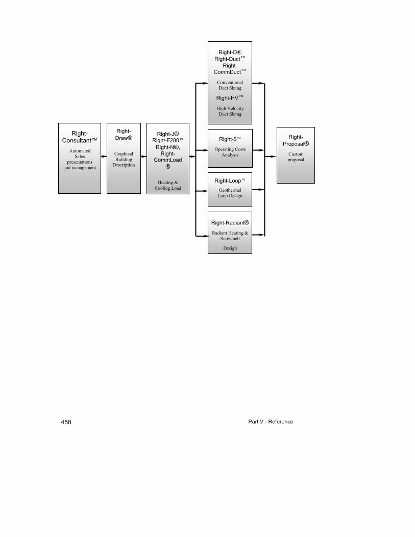
Part V - Reference 458
Right-J® Right-F280
Right-N®, Right-
CommLoad®
Heating &
Cooling Load
Right-Draw®
Graphical Building
Description
Right-D® Right-Duct
Right-CommDuct
Conventional Duct Sizing
Right-HV
High Velocity Duct Sizing
Right-$
Operating Costs Analysis
Right-Loop
Geothermal Loop Design
Right-Radiant®
Radiant Heating & Snowmelt
Design
Right-Proposal®
Custom proposal
Right-Consultant™
Automated Sales
presentations and management
37 Overview of RSU
459
Right-Consultant™ automates in-home sales presentations with PowerPoint, digital image, and video capabilities. Customizable Wizards take you and your customer through the design process including the customer questionnaire. Your customer's responses to the questionnaire select specific components that meet your customer needs. In addition, the Sales Manager allows you to manage the sales efforts of your entire sales team.
Right-Draw® provides a graphical method for entering the building description. You can draw the floor plan for a building using simple drag-and-drop rooms, doors and windows. The construction details are specified with convenient pop-up menus. If you own the Right-D® module (see below), Right-Draw® will even draw the duct system and let you make changes with the mouse.
Right-J®, Right-F280™, Right-CommLoad®, Right-N® are the core calculations of RSU. These modules compute the heating and cooling loads for a building. Load calculation data is entered automatically as you draw your building in Right-Draw®. If you wish, you can ‘unlink’ the load calculation modules from Right-Draw® and enter the building description into the Worksheets directly. As you enter the building description into the Right-Draw® drawing area or the load calculation Worksheets, the loads are computed automatically. The load calculation modules also compute the heating and cooling duct air flow (cfm) needed to supply each room.
Right-D®, Right-Duct™, and Right-CommDuct™ uses the room loads to size duct system trunks and branches. The duct calculation modules automatically modify the duct system whenever the load changes because they are connected to the loads in the load calculation modules. To complete the duct system design, you just need to add fan information and a few additional system details. You can preset most details and preferences in a project template so that there is very little to do to size the ducts, after the load is calculated.
Right-HV™ also uses the room loads to design and size high-velocity duct systems. Right-HV™ allows residential designs that are multizone or single zone. Just select the preferences, and then calculate the loads. The high-velocity ducts will be placed (in Right-Draw®) and the sizes will be calculated instantly.
Right-$™ is a sales presentation tool that compares four equipment systems side-by-side on your screen. Right-$™ is always connected to the building loads; changes that affect the loads can be seen in the Right-$™ analyses immediately. Right-$™ uses the ARI/GAMA electronic library of HVAC equipment that is distributed with RSU. Equipment listings can be preset in a project template to automatically select equipment based on filters that you define for capacity, efficiency, model prefix and other characteristics. When used this way, Right-$™ automatically develops the sales presentation as the building description is entered.
Right-Proposal® allows you to quickly generate professional in-home sales presentations with integrated project information, equipment, and costs. It produces a cost summary with an unlimited number of major cost categories (sections). Three of the categories are preset (equipment, labor and overall total), but you can change them to suit your needs. Duct system equipment, high-velocity duct equipment and radiant heating equipment categories are
Part V - Reference 460
automatically generated by RSU if you own those modules and have ducts or radiant panels in your design. Right-Proposal® produces a detailed list of cost items for each major cost category. The automatic takeoff (see glossary for a definition) features of Right-Radiant®, Right-HV™ and the duct design modules provide most of the necessary cost items. You can also add cost items from your own Proposal Library.
Right-Loop™ sizes geothermal loops based on the equipment and the heating and cooling loads. The loads that Right-J® calculates are hot-linked to the loads that Right-Loop™ uses to size the geothermal loop. Right-Loop™ also provides a worksheet to calculate the pump head and computes antifreeze volume for a wide range of conditions and antifreeze types.
Right-Radiant® assists with the design of radiant heating and snow melting panel systems. Right-Radiant® evaluates loop sizes for radiant panels in ceilings and floors and sizes piping and manifolds. Most of the radiant heating panel data is entered into Right-Radiant® automatically as you draw your building in Right-Draw®.
Right-SolarDHW™ assembles the various components of a solar hot water heating system. This includes the backup hot water heater, solar collector, solar tank, pump, controller, and accessories. You select the hot water heater from a database of GAMA hot water heaters and the solar collector from a database of SRCC rated collectors. Right-$™ includes the operating cost savings from the solar system.
Screens & Toolbars
RSU has convenient toolbars to provide quick access to key program features. Below is a list of the main buttons and toolbars.
Project Management Toolbar Report Toolbar Project Toolbar Right-Draw® Button Zoom Buttons Selector Toolbar Screen Toolbar - Changes depending on your selection with the Selector Toolbar.
There are several Screen Toolbars: Right-J®, Right-D®/Right-HV™, Right-$™, Right-Loop™, Radiant Heating, Snow Melting, Right-Proposal® and Right-Consultant™
You can specify which toolbars to display by selecting View | Toolbars... from the main menu. Choose the toolbars you want to display and the button size. Click Close when you are done. You can move and rearrange toolbars; place the mouse cursor on the gray border of a toolbar and drag-and-drop it to a new location.

37 Overview of RSU
461
The main buttons and toolbars relate to the overall project, including file handling, printing, screen zooming and the selection of functional areas such as project information, equipment and zone information.
The Selector Toolbar is used to select buttons for a module. Pressing a button in the Selector Toolbar automatically displays the Screen Toolbar specific to that module.
Right-Draw® has its own toolbar that is only displayed when the Right-Draw® screen is displayed (see Chapter 40). This toolbar is used to select drawing and editing options. Right-Draw® also has the HVAC Shapes™ Toolbox that is comprised of buttons that are used to add building components to your drawing.
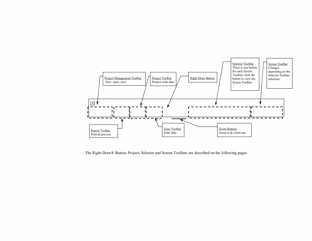
The Right-Draw® Button, Project, Selector and Screen Toolbars are described on the following pages.
The linked image cannot be displayed. The file may have been moved, renamed, or deleted. Verify that the link points to the correct file and location.
Project Management Toolbar New, open, save
Report Toolbar Print & preview
Project Toolbar Project-wide data
Right-Draw Button
Screen Toolbar Changes depending on the Selector Toolbar selection
Selector Toolbar There is one button for each Screen Toolbar; click the button to view the Screen Toolbar.
Zoom Buttons Zoom in & zoom out
Zone Toolbar Zone data

Project Management Screens
Project Information Screen Customer and contractor information,
notes, weather location, conditions, fuel, cost and baseboard data
Zone Information Screen Enter and view zone design
conditions and load summaries
Multizone Tree
Drag-and-drop zoning control
Equipment Screen
Information about the current equipment system in the project
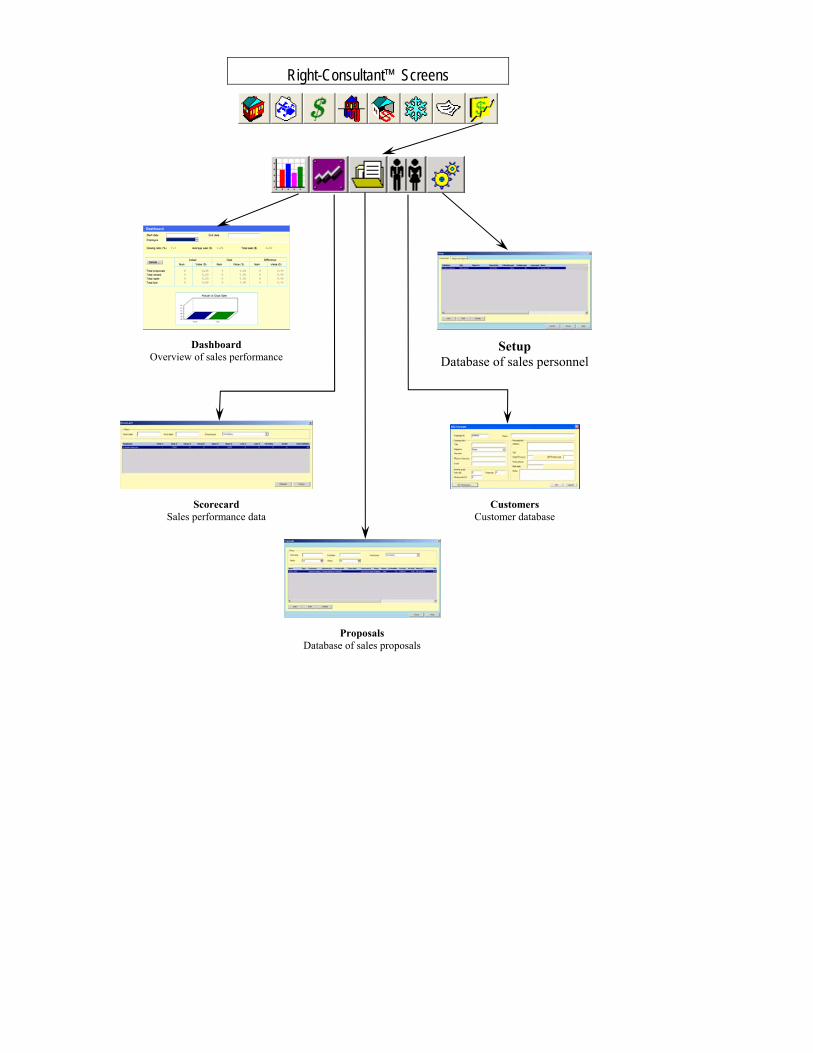
Right-Consultant™ Screens
Dashboard
Overview of sales performance Setup
Database of sales personnel
Scorecard
Sales performance data Customers
Customer database
Proposals Database of sales proposals
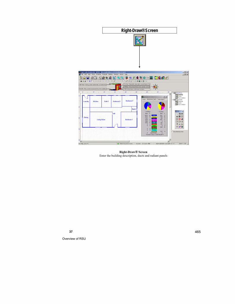
37 Overview of RSU
465
Right-Draw® Screen Enter the building description, ducts and radiant panels
Right-Draw® Screen
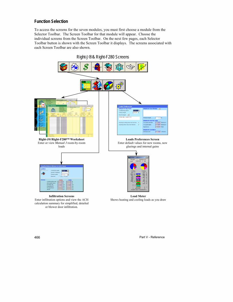
Part V - Reference 466
Function Selection
To access the screens for the seven modules, you must first choose a module from the Selector Toolbar. The Screen Toolbar for that module will appear. Choose the individual screens from the Screen Toolbar. On the next few pages, each Selector Toolbar button is shown with the Screen Toolbar it displays. The screens associated with each Screen Toolbar are also shown.
Right-J® & Right-F280 Screens
Right-J®/Right-F280™ Worksheet
Enter or view Manual J room-by-room loads
Loads Preferences Screen Enter default values for new rooms, new
glazings and internal gains
Infiltration Screens
Enter infiltration options and view the ACH calculation summary for simplified, detailed
or blower door infiltration.
Load Meter Shows heating and cooling loads as you draw
The linked image cannot be displayed. The file may have been moved, renamed, or deleted. Verify that the link points to the correct file and location.

37 Overview of RSU
467
Right-CommLoad® Screens
Display time of day Select the load day and hour to display
Scenario
Edit or define schedule scenarios
Right-J®/Right-F280™ Worksheet Enter or view heating and cooling room-
by-room loads
Manual N Infiltration Screen
Calculate simplified or blower door infiltration
Load Meter
Shows heating and cooling loads as you draw
Infiltration/Ventilation Screen
Enter infiltration and ventilation options and view the envelope and traffic summary.
The linked image cannot be displayed. The file may have been moved, renamed, or deleted. Verify that the link points to the correct file and location.
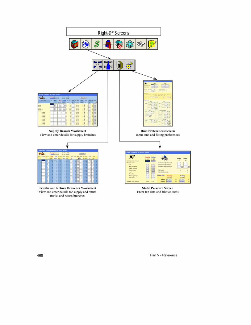
Part V - Reference 468
Right-D® Screens
Supply Branch Worksheet
View and enter details for supply branches Duct Preferences Screen
Input duct and fitting preferences
Trunks and Return Branches Worksheet View and enter details for supply and return
trunks and return branches
Static Pressure Screen Enter fan data and friction rates

37 Overview of RSU
469
Right-$™ Screens
System Comparison Screen Compare operating costs
Investment Comparison Screen Compare investment costs graphically
Cost Comparison Screen View a detailed comparison of costs, savings
and financing
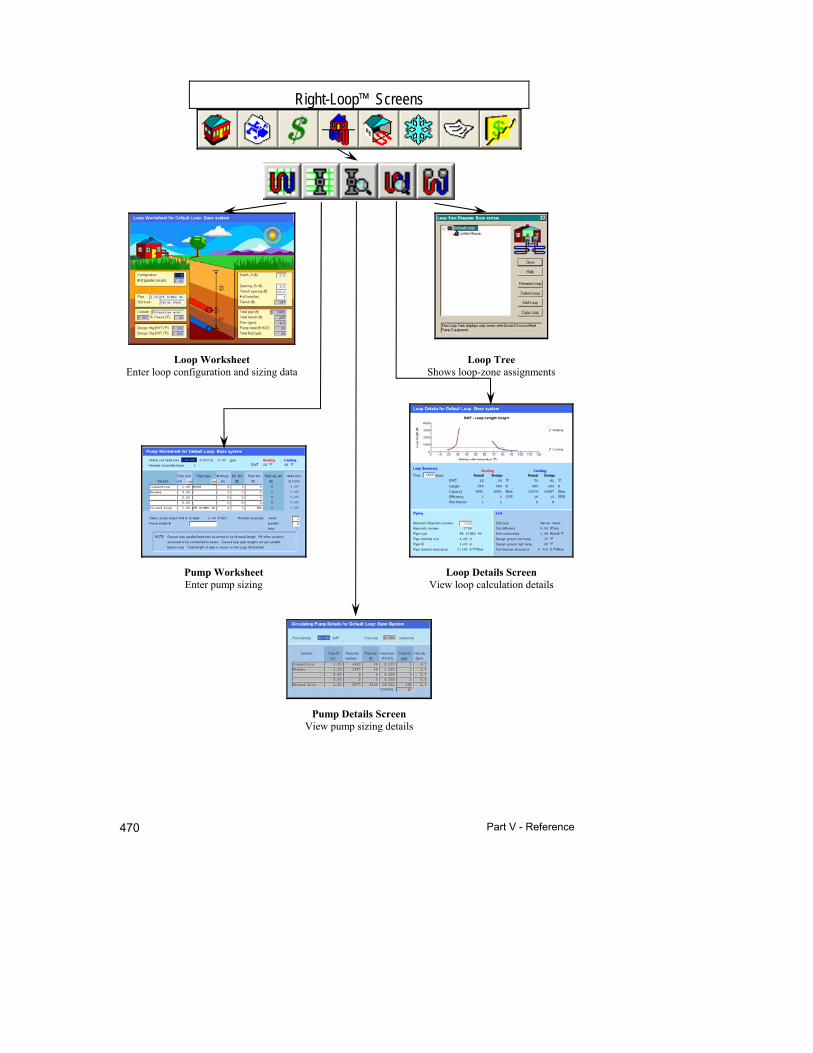
Part V - Reference 470
Right-Loop™ Screens
Loop Worksheet Enter loop configuration and sizing data
Loop Tree Shows loop-zone assignments
Pump Worksheet Enter pump sizing
Loop Details Screen View loop calculation details
Pump Details Screen View pump sizing details
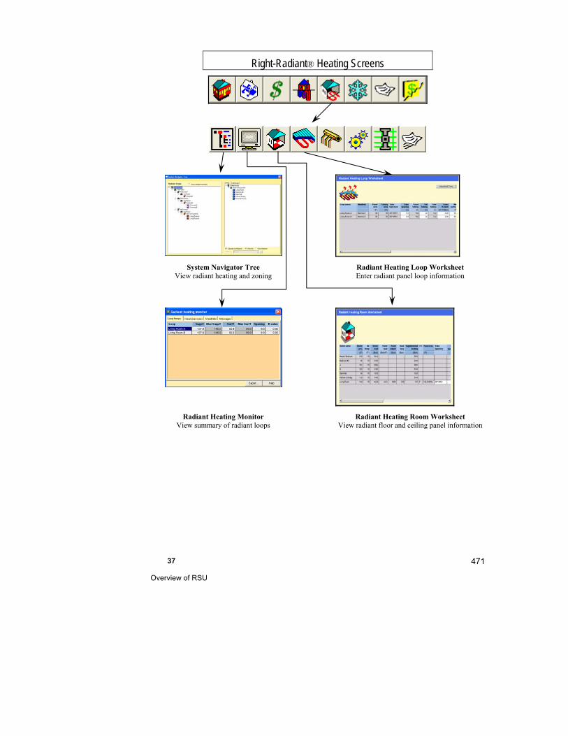
37 Overview of RSU
471
Right-Radiant® Heating Screens
System Navigator Tree
View radiant heating and zoning Radiant Heating Loop Worksheet
Enter radiant panel loop information
Radiant Heating Monitor
View summary of radiant loops Radiant Heating Room Worksheet
View radiant floor and ceiling panel information
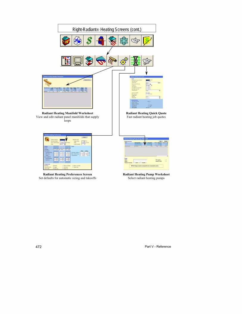
Part V - Reference 472
Right-Radiant® Heating Screens (cont.)
Radiant Heating Manifold Worksheet View and edit radiant panel manifolds that supply
loops
Radiant Heating Quick Quote Fast radiant heating job quotes
Radiant Heating Preferences Screen Set defaults for automatic sizing and takeoffs
Radiant Heating Pump Worksheet Select radiant heating pumps

37 Overview of RSU
473
Right-Radiant® Snow Melting Screens
Snow Melting Worksheet Enter snow melting panel information
Snow Melting Preferences Screen
Set defaults for automatic calculations
and takeoffs
Snow Melting Loop Worksheet Enter snow melting loop information
Snow Melting Manifold Worksheet View and edit snow melting manifolds that
supply loops

Part V - Reference 474
Right-Proposal® Screens
Proposal Document Screen View and edit proposal document
Proposal Information Screen View and edit ordering information and
section subtotals
Bill of Materials
View and edit list of parts to be used Library Setup
Add or edit items available for the job cost estimate
Purchase Order Screen
View and edit purchase orders to distributors and manufacturers
37 Overview of RSU
475
Loads
The loads can be found in 3 places: the Load Meter, the Zone Information Screen (for residential calculation methods) and the Worksheets. The Load Meter is what you will refer to as you draw; the Worksheet is where you will find the load details; the Zone Information Screen is where you will find the Load Summary for residential calculation methods. Any changes you make on the Right-Draw® Screen (if it is hot-linked) will affect the loads in all three places.
The Load Meter shows the total heating and cooling loads for the building and the total loads for walls, glazing, doors, ceilings, floors, infiltration, ducts, ventilation and hydronic piping. The Load Meter changes on screen as you draw. You can view the 'Entire House' load or if you are working on a multizone building, select the zone in the Multizone Tree to view the loads for that zone. You can view the Load Meter at any time; you do not need to close the Load Meter when you change screens. To resize the Load Meter, place your cursor over the bottom border and drag up or down.
The Worksheets show the loads broken down by construction number and room. For residential calculation methods, the Load Summary on the Zone Information Screen shows the latent loads and other 'Entire House' loads not shown in the Load Meter. This is also where you can view "the answer", the total heating and sensible and latent cooling loads.
Manual J Seventh and Eighth Editions
ACCA's Seventh and Eighth Edtions of Manual J are both in use. Right-Suite Universal 2018 can calculate loads using either method. In fact, you can switch between the two methods easily and compare the results instantly.
You will probably want to use one method or the other most of the time. For example, your local building inspectors may require a specific method. When you run RSR for the first time, you select which load calculation method you want to use. The method that you select will be used for all projects unless you change it manually. If you open a project that uses a different method than what RSR has been set for, RSR will give you the option of using that method or the method that you set RSR for. You can change the method at any time.
If you use Right-Draw® to enter your building, there is almost no difference between entering your building using the two methods. The only difference is that there will be different choices available. When you select construction types (either default or for specific components), duct losses, or load preferences the list of available options that you can select from will be appropriate for the calculation method that is currently in
Part V - Reference 476
effect. When you change calculation methods, RSR will convert the existing construction types to the new method. In some cases there may not be an equivalent type. RSR will notify you if any construction type cannot be converted exactly. You can then re-select that construction type using the choices available for the new calculation method.
If you use the Right-J® Worksheet to enter your building, the diffences are more noticable. The Right-J® Seventh Edition Worksheet looks different than the Right-J® Eighth Edition Worksheet. This is primarily due to the fact that in the Eighth Edition, each wall has an orientation and in the Seventh Editon they do not.
Seventh Edition Eighth Edition
6 non-oriented walls types 6 oriented window types 3 non-oriented door types 6 floor types 6 ceiling types
Unlimited number of oriented wall, window, and door types
Unlimited number of floor and ceiling types
How Templates Save Time
For more information on saving time with templates, see Chapter 33.
Templates are a starting point for new projects. They speed up the design process. In using RSU, you will find that there are assumptions and information you wish to use for each of your projects, such as load and duct preferences, weather data and contractor information. Instead of typing this information in every time you start a project, you can start a project with a template. Fill in the information unique to the project then save the file as an RSU project with a new name.
Templates are simply RSU projects that have been saved with an .RUT file extension. Instead of re-entering common data each time you start a new project, you can define a template that contains the information that is used in most projects. In fact, you can define several templates to handle the various types of jobs you typically do. For example, if you design many flex duct and sheet metal duct systems but never in the same project, you could create one template with the flex duct preferences (duct material, junction boxes, flex duct fittings etc.) and one for the sheet metal duct systems you design. Then when you want to design a flex duct system, you would open the flex duct template and all of the data in the template is entered into your project. Because the duct preferences are already entered, all you have to do is draw your building.

37 Overview of RSU
477
Templates are stored in a folder titled Template. Open a template by selecting either File | New from Template or File | Open | Template. Just open a template and describe your building; your preferences, contractor information and weather data will already be entered from the template (NOTE: The data is only transferred to NEW projects).
If you want to create a new template from scratch, you should:
Restart the program, enter the data that you want in the template, and then save the project as a template (File | Save As | Template...).
If you want to start a new template that is based on another template:
Select File | New from Template and choose the template you want to modify. Modify the template as desired.
To save the modified template with a new name, select File | Save As | Template... Save the modified template a different name than the original template.
You will now have both templates - the original template, which is unchanged, and the modified template that is based on the original template. See Chapter 33 for more details.
Things to Remember
Right-Suite® program components are hot-linked (see glossary), together so that heating and cooling loads and other information are passed from Right-Draw® to Right-J® and to the other modules that need loads. When you make changes to the building description and weather information, they are automatically used to update the calculations made throughout RSU. For example, if you add a large picture window to a room, RSU automatically recalculates the heating and cooling loads, increases the size of the duct system and reevaluates the annual operating costs.
RSU’s Selector Toolbar is used to display the module specific Screen Toolbars. Click on a button in the Selector Toolbar to choose the module and display the Screens Toolbar for that module. Then choose the individual screen you want to display from the Screen Toolbar.
Right-Draw® automates many parts of the building description process. This saves a lot of time and prevents many omission errors.
You can control nearly all of RSU from the toolbars. Use the Drawing and Options menus for special settings. Use the keyboard to enter numbers and text.
If you prefer to use keystrokes instead of the menus or buttons, nearly all of the menu options can be accessed using the keyboard shortcuts (view key strokes in the menus).

Part V - Reference 478
Templates are a powerful part of RSU. They substantially reduce the time and effort required to create new project files and complete a design.
Detailed information on using templates is provided in Chapter 33.
38
Using the Web Menus
This chapter describes navigating around the many screens in Right-Suite Universal 2018 using the Web Menus.
Presentation mode ...................................................... 480
Standard mode ............................................................ 481
Custom Web Menus .................................................... 483

Part V - Reference 480
You can operate Right-Suite Universal 2018 using the Web Menus.
The Web Menus are available when Right-Suite Universal 2018 is in any of the modes in the ‘View’ menu. However, Web Menus are normally off in ‘Design mode’.
Select ‘Design mode’, ‘Presentation mode’, or ‘Standard mode’ from the ‘View’ menu across the top of the screen.
Presentation Mode
Standard Mode
The Web Menus have two rows of menus. When you select an item in the top row, the available options in the second row will change. You can preview the options for each top row menu by moving the mouse pointer over the top row selection without clicking. When you select a menu option from the second row, the main screen will change to that selection. Some of the menus have a toolbar below the second menu row. This toolbar is used to control the main screen.
Presentation mode
Use this mode during your in-house presentation to your potential customer. You can click each menu from left to right for your presentation.
About Us
This menu displays an introduction to your company for your customer. See the Setup section in the ‘Standard mode’ for information about customizing this menu. Note that this option is not available while in demo mode.
Manufacturer
This menu displays an introduction to the equipment that you intend to provide for your customer. See the Setup section in the ‘Standard mode’ for information about customizing this menu. Note that this option is not available while in demo mode.
Show Room
38 Using the Web Menus
481
This is where you can display a presentation of showing the benefits and features of the equipment that you are proposing. See the setup section for more details. Note that this option is not available while in demo mode.
Project Info
You can use the Project Information screen to enter all of your potential customers contact information.
Questionnaire
Use this to determine you customer's needs by having them answer a series of questions. The questions are presented like wizards – a set of related question per screen. You can also select the specific screen from the second menu row. The selections that are entered here will affect the System Builder. Note that this option is not available while in demo mode.
System Builder
This section can be used to select the specific equipment that you are proposing to use in this project. See the System Builder chapter for more information.
Proposal
This displays the Right-Proposal™ Proposal Document screen. This is where you prepare the final document that you will submit to your customer. The second menu has options to start a Right-Suite Universal 2018 project and print other reports.
Testimonial
This menu displays testimonials from your existing customers for your customer to review. See the Setup section of the ‘Standard mode’ for information about customizing this button. Note that this option is not available while in demo mode.
Standard mode
Project Info
You can use the Project Information Screen to enter your customer’s name and address as well as other information about the project.
Presentation
You can review the ‘About us’ and ‘Testimonial’ portions of the presentation. See the ‘Setup’ section below for information about customizing these. Note that this option is not available while in demo mode.
Manufacturer
You can review the ‘Manufacturer’ portion of the presentation. See the ‘Setup’ section below for information about customizing this. Note that this option is not available while in demo mode.
Part V - Reference 482
System Builder
You can review and prepare the System Builder portion of the presentation. See the ‘Setup’ section below for information about customizing this.
Questionaire
You can review the ‘Questionaire’ portion of the presentation. Note that this option is not available while in demo mode.
Proposal
You can review and prepare the portions of the presentation. The Proposal Wizard can be used to start a new Right-Suite Universal 2018 project. Pricing, the proposal document, and the Bill of Materials are also available here.
Dashboard
This section has the screens associated with Right-Consultant™. See chapter 32 for additional information.
Setup
This is where you customize Right-Suite Universal 2018 and the presentation.
Customize Wizard
The Customize Wizard is used to customize Right-Suite Universal 2018. Each screen represents an element that can be customized. Make selections in each screen and click the Next button to proceed to the next screen. See page 496 for more information.
Template Wizard
Templates are special projects that have entries that don’t change from one project to another. Use this wizard to create templates. Make selections in each screen and click the Next button to proceed to the next screen. See Chapter 33 for a complete discussion on templates. Note that this option is not available while in demo mode.
Parts Library setup
This is where you set up the parts for Right-Proposal®. See Chapter 30 for more information.
System Builder setup
This is where you set up the System Builder. See the System Builder chapter for more information.
Sales Manager
This is where you set up Right-Consultant™. See chapter 32 for more information.
Database Import

38 Using the Web Menus
483
This is where you can import Excel spreadsheets (in the proper format) into the Right-Proposal® database and the equipment database.
Custom Web Menus
You can create customized Web Menus that contain any of the menus in ‘Design mode’. To create a custom Web Menu:
Switch to ‘Design mode’ – select View | Design mode in the Right-Suite Universal 2018 menus across the top of the screen.
Select Library | Custom Web Menus in the top menu.
Like other Library screens, there are three sections to this screen. The top left has a list of existing custom Web Menus. There are none in the list now. The bottom has the details of the selected Web Menu (since none are selected, this portion is blank). The top right is a set of buttons that are used to manage the list of Web Menus.
Let’s create a sample with just Loads and Duct screens.
Click the ‘New’ button to create a new Web Menu.
Enter ‘Loads and Ducts’ for the name of the Web Menu
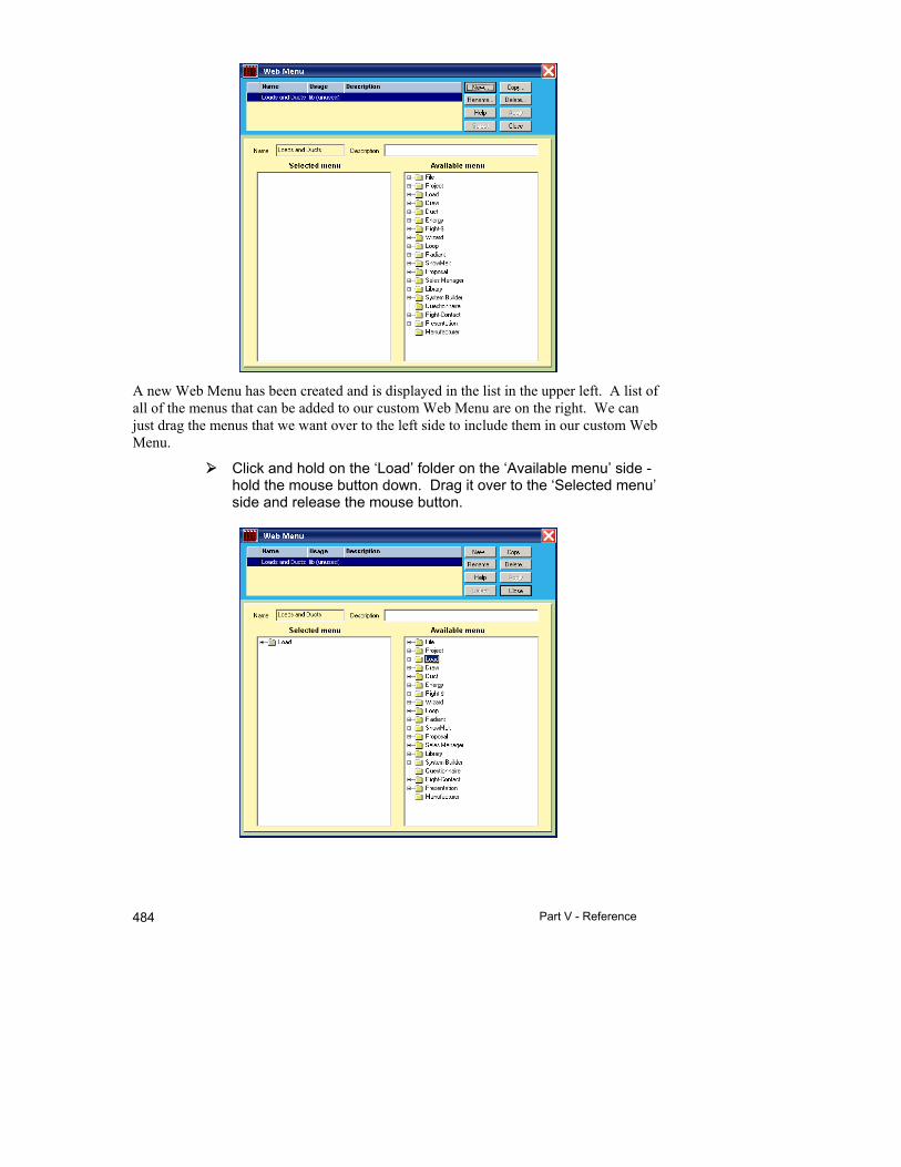
Part V - Reference 484
A new Web Menu has been created and is displayed in the list in the upper left. A list of all of the menus that can be added to our custom Web Menu are on the right. We can just drag the menus that we want over to the left side to include them in our custom Web Menu.
Click and hold on the ‘Load’ folder on the ‘Available menu’ side - hold the mouse button down. Drag it over to the ‘Selected menu’ side and release the mouse button.
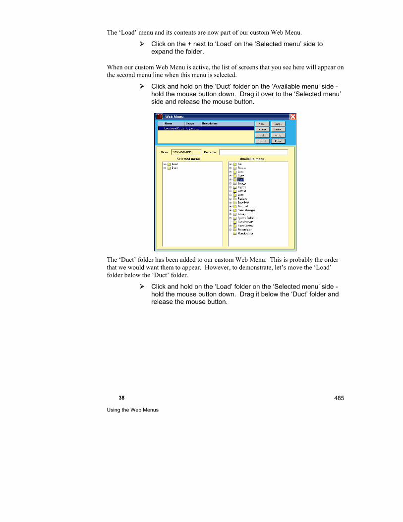
38 Using the Web Menus
485
The ‘Load’ menu and its contents are now part of our custom Web Menu.
Click on the + next to ‘Load’ on the ‘Selected menu’ side to expand the folder.
When our custom Web Menu is active, the list of screens that you see here will appear on the second menu line when this menu is selected.
Click and hold on the ‘Duct’ folder on the ‘Available menu’ side - hold the mouse button down. Drag it over to the ‘Selected menu’ side and release the mouse button.
The ‘Duct’ folder has been added to our custom Web Menu. This is probably the order that we would want them to appear. However, to demonstrate, let’s move the ‘Load’ folder below the ‘Duct’ folder.
Click and hold on the ‘Load’ folder on the ‘Selected menu’ side - hold the mouse button down. Drag it below the ‘Duct’ folder and release the mouse button.
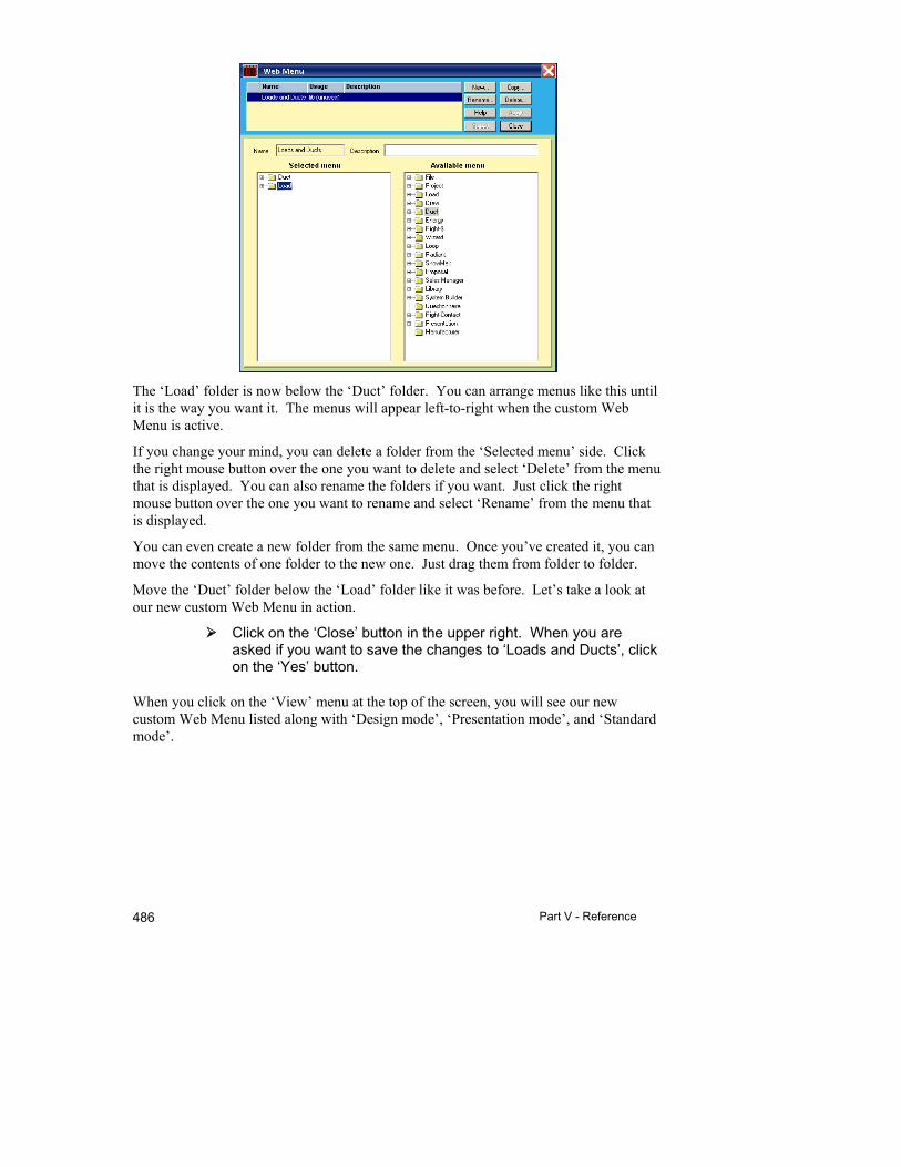
Part V - Reference 486
The ‘Load’ folder is now below the ‘Duct’ folder. You can arrange menus like this until it is the way you want it. The menus will appear left-to-right when the custom Web Menu is active.
If you change your mind, you can delete a folder from the ‘Selected menu’ side. Click the right mouse button over the one you want to delete and select ‘Delete’ from the menu that is displayed. You can also rename the folders if you want. Just click the right mouse button over the one you want to rename and select ‘Rename’ from the menu that is displayed.
You can even create a new folder from the same menu. Once you’ve created it, you can move the contents of one folder to the new one. Just drag them from folder to folder.
Move the ‘Duct’ folder below the ‘Load’ folder like it was before. Let’s take a look at our new custom Web Menu in action.
Click on the ‘Close’ button in the upper right. When you are asked if you want to save the changes to ‘Loads and Ducts’, click on the ‘Yes’ button.
When you click on the ‘View’ menu at the top of the screen, you will see our new custom Web Menu listed along with ‘Design mode’, ‘Presentation mode’, and ‘Standard mode’.
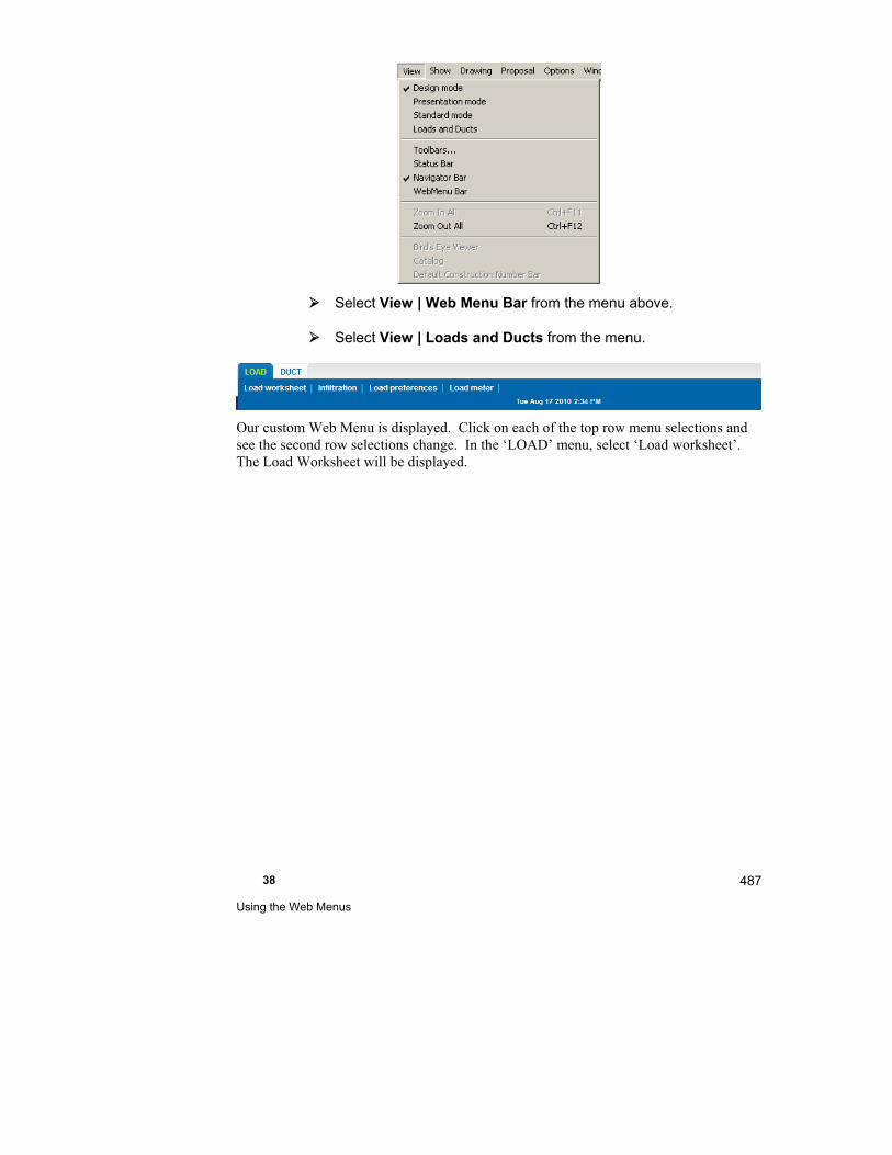
38 Using the Web Menus
487
Select View | Web Menu Bar from the menu above.
Select View | Loads and Ducts from the menu.
Our custom Web Menu is displayed. Click on each of the top row menu selections and see the second row selections change. In the ‘LOAD’ menu, select ‘Load worksheet’. The Load Worksheet will be displayed.

39
Using the Navigator Bar
This chapter describes the Navigator Bar as a fast and efficient way to navigate around the many screens in Right-Suite Universal 2018.
User type selector ....................................................... 491
Navigator Bar Buttons ................................................. 491
Wizards ....................................................................... 496
Customizations ............................................................ 496

Part V - Reference 490
You can operate Right-Suite Universal 2018 in ‘Design mode’ using the Navigator Bar or not. The Navigator bar is along the left side of the Right-Suite Universal 2018 screen.
The Navigator Bar presents Right-Suite Universal 2018's functions, as buttons, in the order that you would use them, depending on what you want to do. All of Right-Suite Universal 2018's features will be available via the menus at the top of the screen. The Navigator Bar will have just the features that you are interested in right now. For example, there are separate sets of buttons for:
Setting up Right-Suite Universal 2018 for use
Designing a project
Presenting a project proposal to your customer
Managing your sales
If you would rather not use the Navigator Bar, you can turn it off and use Right-Suite Universal 2018 screen-by-screen. Select each screen using the toolbar or the menu at the top of the screen.
There will be a checkmark next to the View | Navigator Bar menu item when the Navigator Bar is active.
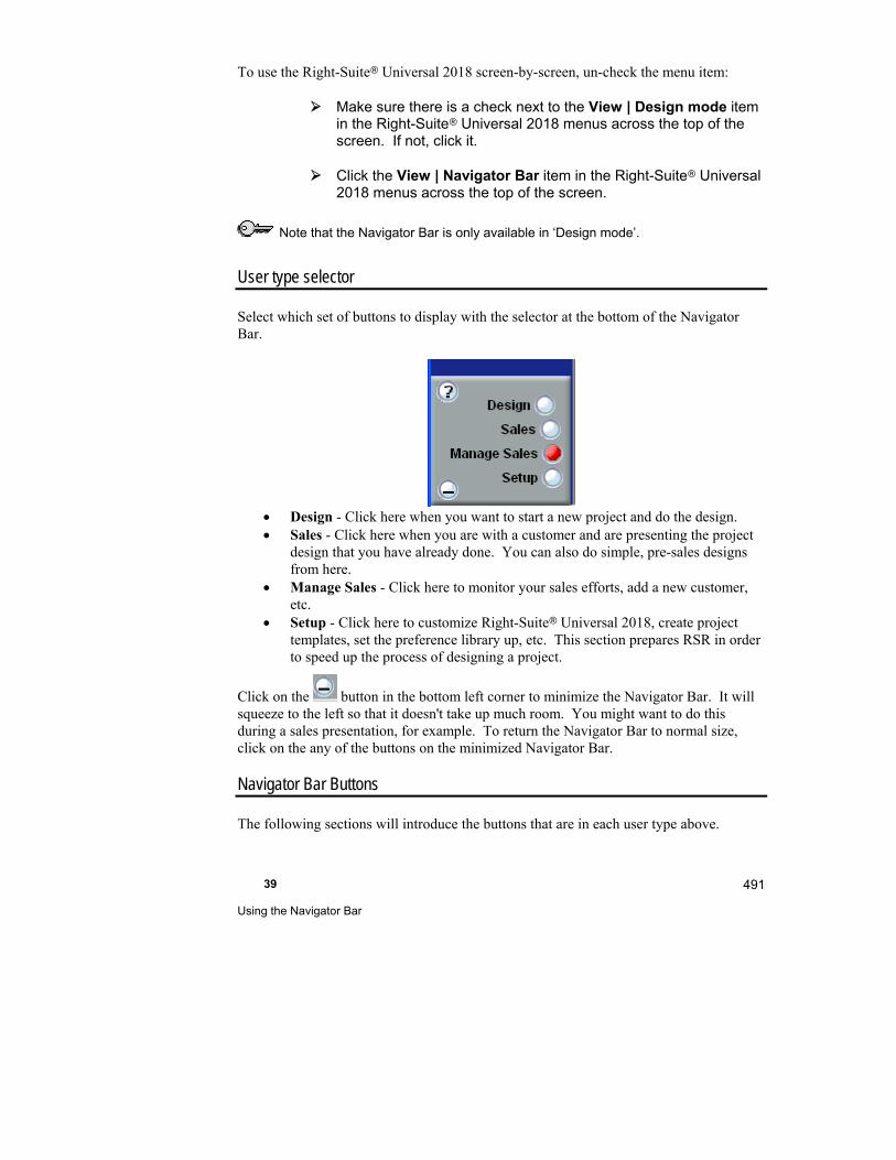
39 Using the Navigator Bar
491
To use the Right-Suite Universal 2018 screen-by-screen, un-check the menu item:
Make sure there is a check next to the View | Design mode item in the Right-Suite Universal 2018 menus across the top of the screen. If not, click it.
Click the View | Navigator Bar item in the Right-Suite Universal 2018 menus across the top of the screen.
Note that the Navigator Bar is only available in ‘Design mode’.
User type selector
Select which set of buttons to display with the selector at the bottom of the Navigator Bar.
Design - Click here when you want to start a new project and do the design. Sales - Click here when you are with a customer and are presenting the project
design that you have already done. You can also do simple, pre-sales designs from here.
Manage Sales - Click here to monitor your sales efforts, add a new customer, etc.
Setup - Click here to customize Right-Suite Universal 2018, create project templates, set the preference library up, etc. This section prepares RSR in order to speed up the process of designing a project.
Click on the button in the bottom left corner to minimize the Navigator Bar. It will squeeze to the left so that it doesn't take up much room. You might want to do this during a sales presentation, for example. To return the Navigator Bar to normal size, click on the any of the buttons on the minimized Navigator Bar.
Navigator Bar Buttons
The following sections will introduce the buttons that are in each user type above.

Part V - Reference 492
Design
Project Wizard
Create a new project using a step-by-step wizard.
Draw
Displays the Right-Draw® Screen so that you can draw the floorplan, duct system, radiant panels, etc. for your project. You can also display this screen by selecting Show | Drawing Screen from the top menu.
Multizone tree
Displays the Multizone Tree Screen so that you can zone your project.
Zone information
Displays the Zone Information Screen so that you can complete your load and veiw the results.
Load Meter
Displays the Load Meter so that you can see the breakdown of your loads.
Equipment
Enter equipment systems in the Right-$™ System Comparison Screen to compare lower operating costs of high efficiency equipment. You can also display this screen by selecting Show | Right-$™ | System Comparison from the top menu.
Duct, Radiant Heating, Snow Melting
Display screens so that you can design the duct system, radiant heating, and snow melting for your project.
Bill of Materials
Displays the Right-Proposal Bill of Materials Screen for review and modification to complete the project. You can also display this screen by selecting Show | Right-Proposal® | Bill of Materials from the top menu.
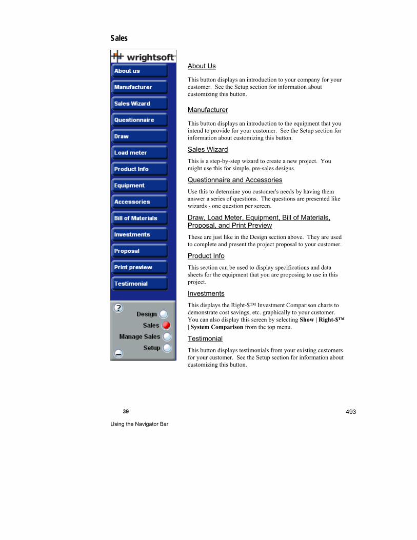
39 Using the Navigator Bar
493
Sales
About Us
This button displays an introduction to your company for your customer. See the Setup section for information about customizing this button.
Manufacturer
This button displays an introduction to the equipment that you intend to provide for your customer. See the Setup section for information about customizing this button.
Sales Wizard
This is a step-by-step wizard to create a new project. You might use this for simple, pre-sales designs.
Questionnaire and Accessories
Use this to determine you customer's needs by having them answer a series of questions. The questions are presented like wizards - one question per screen.
Draw, Load Meter, Equipment, Bill of Materials, Proposal, and Print Preview
These are just like in the Design section above. They are used to complete and present the project proposal to your customer.
Product Info
This section can be used to display specifications and data sheets for the equipment that you are proposing to use in this project.
Investments
This displays the Right-$™ Investment Comparison charts to demonstrate cost savings, etc. graphically to your customer. You can also display this screen by selecting Show | Right-$™ | System Comparison from the top menu.
Testimonial
This button displays testimonials from your existing customers for your customer. See the Setup section for information about customizing this button.
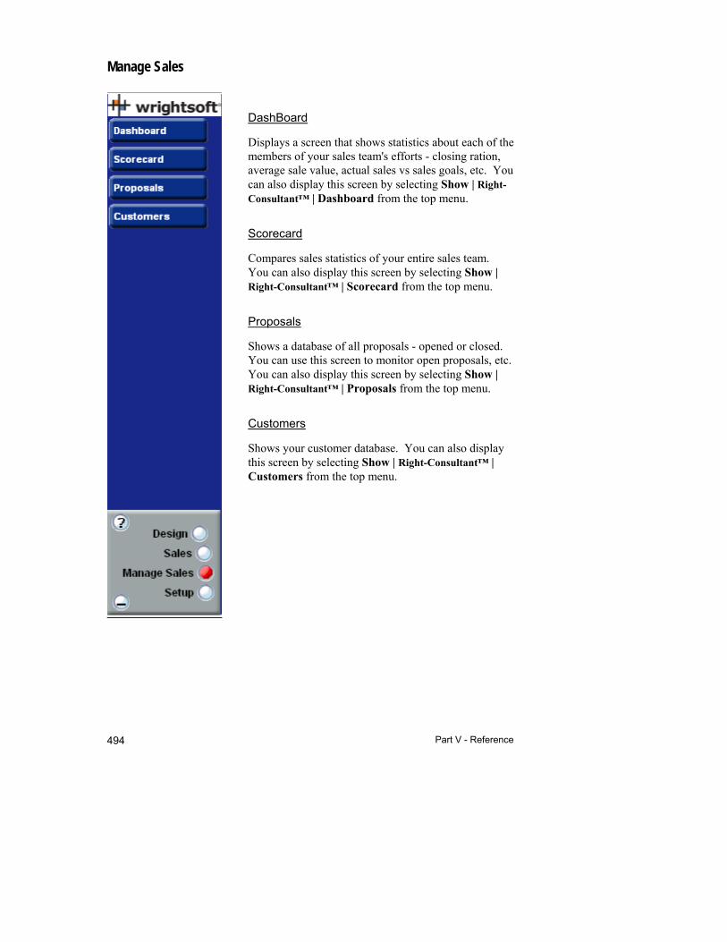
Part V - Reference 494
Manage Sales
DashBoard
Displays a screen that shows statistics about each of the members of your sales team's efforts - closing ration, average sale value, actual sales vs sales goals, etc. You can also display this screen by selecting Show | Right-Consultant™ | Dashboard from the top menu.
Scorecard
Compares sales statistics of your entire sales team. You can also display this screen by selecting Show | Right-Consultant™ | Scorecard from the top menu.
Proposals
Shows a database of all proposals - opened or closed. You can use this screen to monitor open proposals, etc. You can also display this screen by selecting Show | Right-Consultant™ | Proposals from the top menu.
Customers
Shows your customer database. You can also display this screen by selecting Show | Right-Consultant™ | Customers from the top menu.
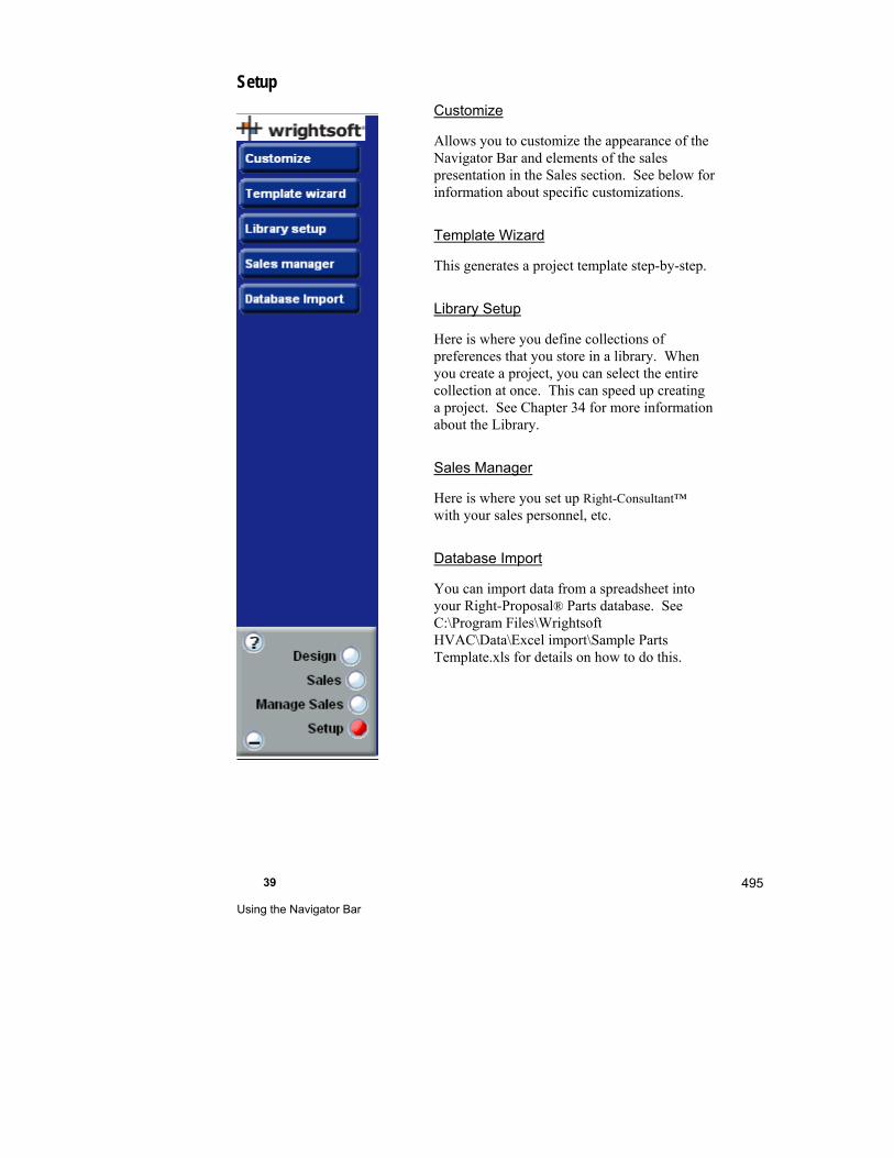
39 Using the Navigator Bar
495
Setup
Customize
Allows you to customize the appearance of the Navigator Bar and elements of the sales presentation in the Sales section. See below for information about specific customizations.
Template Wizard
This generates a project template step-by-step.
Library Setup
Here is where you define collections of preferences that you store in a library. When you create a project, you can select the entire collection at once. This can speed up creating a project. See Chapter 34 for more information about the Library.
Sales Manager
Here is where you set up Right-Consultant™ with your sales personnel, etc.
Database Import
You can import data from a spreadsheet into your Right-Proposal® Parts database. See C:\Program Files\Wrightsoft HVAC\Data\Excel import\Sample Parts Template.xls for details on how to do this.

Part V - Reference 496
Wizards
A lot of the buttons on the Navigator Bar request information in the form a wizard. A wizard requests one or a few bits of information at a time step-by-step. At each step there is a 'Back' and either a 'Next' button or a 'Finish' button. You can navigate through the wizard by providing the information to each page and then clicking on the 'Next' button.
The last page will have a 'Finish' button. Click on this button complete the wizard.
You can back track to a previous page by clicking on the 'Back' button until you get to the page that you want.
In addition, the Navigator Bar has a button for each step of the wizard, so you can jump directly to the page you want.
Be sure to click on the 'Finish' button on the 'Finish' page when you are done making changes.
Customizations
You can customize the appearance of the Navigator Bar and the presentation screens in the Sales section. See the 'Customize' button in the 'Setup' Section above.
1. Report Logo - You can replace the house logo at the top of the printed reports with your own company logo. The logo must be a bitmap image (with a file extension of .bmp) and in 256 color format. You can use a logo that you already have by browsing to it on your computer. You can also create a new one on this page.
2. Background page - When Right-Suite Universal 2018 is run, the first page shows the Wrightsoft® background page. This is just a web page that we have included with Right-Suite Universal 2018. You can replace this backround with your own web page if you want. Any file in HTML format can be used. You can also construct a background web page here by entering your company name and slogan and selecting a logo.
3. Skin chooser - The Navigator Bar is normally blue with 3-D blue and white buttons. You can change the overall appearance of the buttons here.
4. Company Presentation - This is where you can set what is displayed when you click on the 'About Us' button in the Sales section of the Navigator Bar. You can even change what the button says - 'About Fresh Air' (or your company name) instead of 'About Us' for example. What is displayed when you click this button can be almost any type of presentation. If you can view it on your computer, you can view it when you click on the 'About Us' button. It can be
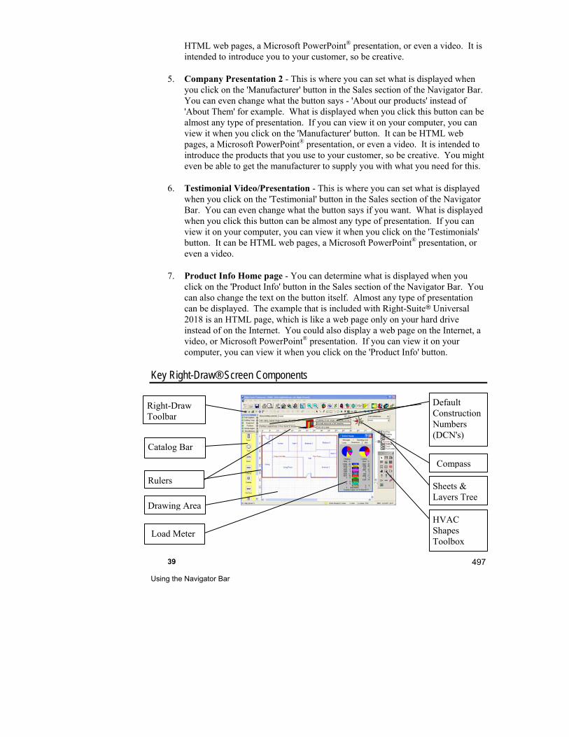
39 Using the Navigator Bar
497
HTML web pages, a Microsoft PowerPoint® presentation, or even a video. It is intended to introduce you to your customer, so be creative.
5. Company Presentation 2 - This is where you can set what is displayed when you click on the 'Manufacturer' button in the Sales section of the Navigator Bar. You can even change what the button says - 'About our products' instead of 'About Them' for example. What is displayed when you click this button can be almost any type of presentation. If you can view it on your computer, you can view it when you click on the 'Manufacturer' button. It can be HTML web pages, a Microsoft PowerPoint® presentation, or even a video. It is intended to introduce the products that you use to your customer, so be creative. You might even be able to get the manufacturer to supply you with what you need for this.
6. Testimonial Video/Presentation - This is where you can set what is displayed when you click on the 'Testimonial' button in the Sales section of the Navigator Bar. You can even change what the button says if you want. What is displayed when you click this button can be almost any type of presentation. If you can view it on your computer, you can view it when you click on the 'Testimonials' button. It can be HTML web pages, a Microsoft PowerPoint® presentation, or even a video.
7. Product Info Home page - You can determine what is displayed when you click on the 'Product Info' button in the Sales section of the Navigator Bar. You can also change the text on the button itself. Almost any type of presentation can be displayed. The example that is included with Right-Suite Universal 2018 is an HTML page, which is like a web page only on your hard drive instead of on the Internet. You could also display a web page on the Internet, a video, or Microsoft PowerPoint® presentation. If you can view it on your computer, you can view it when you click on the 'Product Info' button.
Key Right-Draw® Screen Components
Right-Draw Toolbar
Catalog Bar
Rulers
Drawing Area
Default Construction Numbers (DCN's)
Sheets & Layers Tree
HVAC Shapes Toolbox
Load Meter
Compass
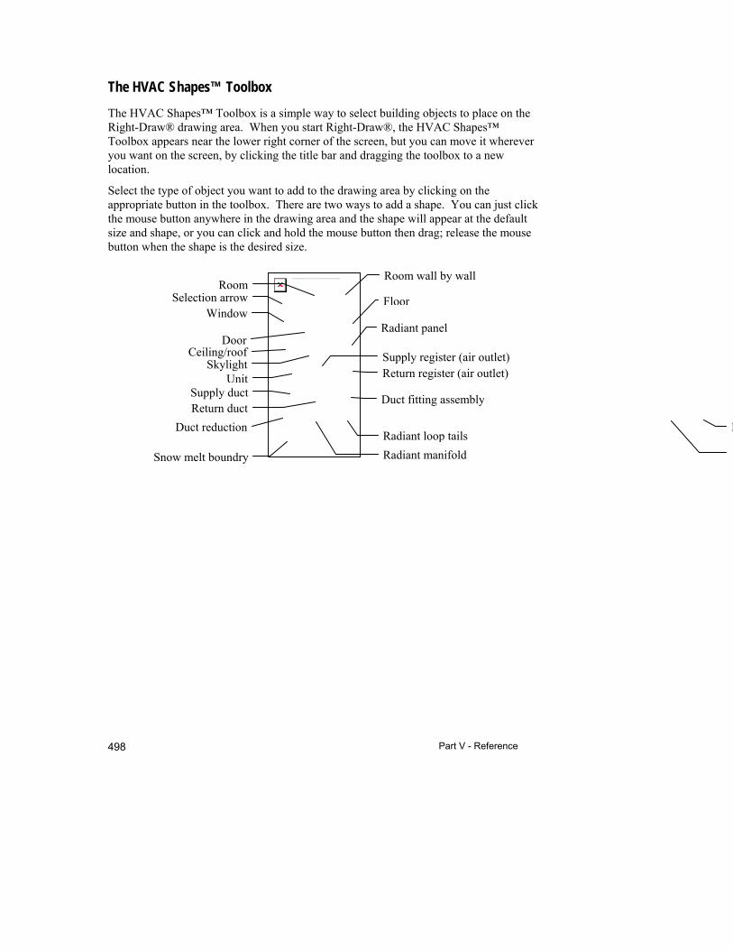
Part V - Reference 498
The linked image cannot be displayed. The file may have been moved, renamed, or deleted. Verify that the link points to the correct file and location.
The HVAC Shapes™ Toolbox
The HVAC Shapes™ Toolbox is a simple way to select building objects to place on the Right-Draw® drawing area. When you start Right-Draw®, the HVAC Shapes™ Toolbox appears near the lower right corner of the screen, but you can move it wherever you want on the screen, by clicking the title bar and dragging the toolbox to a new location.
Select the type of object you want to add to the drawing area by clicking on the appropriate button in the toolbox. There are two ways to add a shape. You can just click the mouse button anywhere in the drawing area and the shape will appear at the default size and shape, or you can click and hold the mouse button then drag; release the mouse button when the shape is the desired size.
Window
Duct fitting assembly Return duct
Return register (air outlet) Supply register (air outlet)
Skylight
Room
Duct reduction
Supply duct Unit
Radiant loop tails
Snow melt boundry
Room wall by wall
Ceiling/roof
Radiant panel
Floor
R
Door
Radiant manifold
Selection arrow

39 Using the Navigator Bar
499
If you forget what a shape or toolbar button is, hold the mouse pointer over the shape in the toolbox or the button on the toolbar. A reminder will soon appear below the mouse pointer.
You can view or not view many aspects of the drawing screen under View (catalog, bird's eye viewer, default construction number bar) or Drawing (HVAC Shapes™ Toolbox) in the main menu.
Use the bird's eye viewer (found under View | Bird's Eye Viewer) to view a building at a distance. You can move the bounding box (black outline) to change the focus of the building on the drawing area. Resize the bounding box to zoom in and out. Typically, the zoom buttons, located at the top of the screen, are more convenient for zooming. You can also use the scroll wheel on the mouse to zoom.

40
Advanced Building Description
This chapter introduces some advanced techniques that you can use in Right-Draw® to further speed up entering building descriptions and to handle special cases.
Drawing Property Sheet .............................................. 502
Notation layer drawing objects .................................... 510
Sheets and Layers ...................................................... 513
Rotate objects ............................................................. 517
Edit & Manage Drawing Objects .................................. 508
Drawing Tips & Tricks ................................................. 523
Things to Remember ................................................... 532
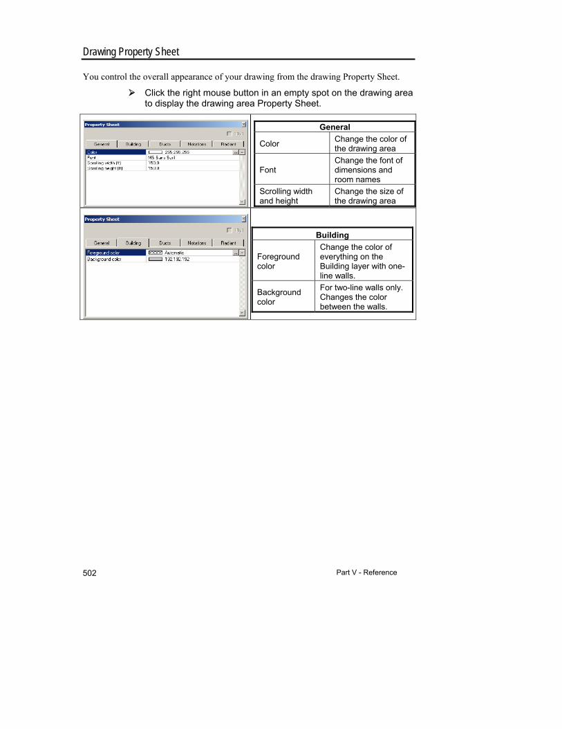
Part V - Reference 502
Drawing Property Sheet
You control the overall appearance of your drawing from the drawing Property Sheet.
Click the right mouse button in an empty spot on the drawing area to display the drawing area Property Sheet.
General
Color Change the color of the drawing area
Font Change the font of dimensions and room names
Scrolling width and height
Change the size of the drawing area
Building
Foreground color
Change the color of everything on the Building layer with one-line walls.
Background color
For two-line walls only. Changes the color between the walls.
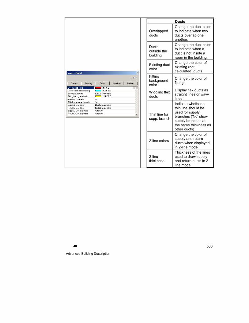
40 Advanced Building Description
503
Ducts
Overlapped ducts
Change the duct color to indicate when two ducts overlap one another.
Ducts outside the building
Change the duct color to indicate when a duct is not inside a room in the building.
Existing duct color
Change the color of existing (not calculated) ducts
Fitting background color
Change the color of fittings.
Wiggling flex ducts
Display flex ducts as straight lines or wavy lines
Thin line for supp. branch
Indicate whether a thin line should be used for supply branches ('No' show supply branches at the same thickness as other ducts)
2-line colors
Change the color of supply and return ducts when displayed in 2-line mode
2-line thickness
Thickness of the lines used to draw supply and return ducts in 2-line mode

Part V - Reference 504
Notations
Register contains
Change the air outlet information in the notations.
Duct contains Change what appears in the duct notations.
Fitting contains
Change what appears in the duct fitting notations
Display callout
Select whether a line is to be used to indicate which duct or air outlet the notation applies to.
Register arrows
Display arrows for registers indicating direction of air flow
Color Change the color of duct and air outlet notations.
Font Change the font of notations.
Notation layer color
Change the color of objects on the Notation layer (excluding text, duct and air outlet notations).
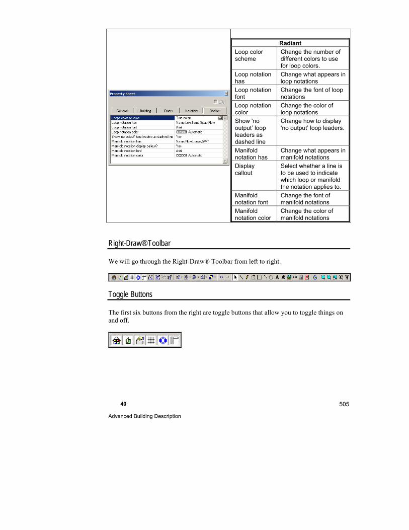
40 Advanced Building Description
505
Radiant
Loop color scheme
Change the number of different colors to use for loop colors.
Loop notation has
Change what appears in loop notations
Loop notation font
Change the font of loop notations
Loop notation color
Change the color of loop notations
Show ‘no output’ loop leaders as dashed line
Change how to display ‘no output’ loop leaders.
Manifold notation has
Change what appears in manifold notations
Display callout
Select whether a line is to be used to indicate which loop or manifold the notation applies to.
Manifold notation font
Change the font of manifold notations
Manifold notation color
Change the color of manifold notations
Right-Draw® Toolbar
We will go through the Right-Draw® Toolbar from left to right.
Toggle Buttons
The first six buttons from the right are toggle buttons that allow you to toggle things on and off.
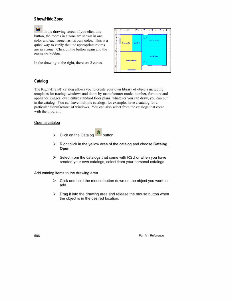
Part V - Reference 506
Show/Hide Zone
In the drawing screen if you click this button, the rooms in a zone are shown in one color and each zone has it's own color. This is a quick way to verify that the appropriate rooms are in a zone. Click on the button again and the zones are hidden.
In the drawing to the right, there are 2 zones.
Catalog
The Right-Draw® catalog allows you to create your own library of objects including templates for tracing, windows and doors by manufacturer model number, furniture and appliance images, even entire standard floor plans; whatever you can draw, you can put in the catalog. You can have multiple catalogs; for example, have a catalog for a particular manufacturer of windows. You can also select from the catalogs that come with the program.
Open a catalog
Click on the Catalog button.
Right click in the yellow area of the catalog and choose Catalog | Open.
Select from the catalogs that come with RSU or when you have created your own catalogs, select from your personal catalogs.
Add catalog items to the drawing area
Click and hold the mouse button down on the object you want to add.
Drag it into the drawing area and release the mouse button when the object is in the desired location.

40 Advanced Building Description
507
Catalog objects can be altered like HVAC Shapes™ or notation objects (sized, rotated, etc.) once they are on the drawing area. They also have properties. Right click on a catalog object that is on the drawing area to view the Property Sheet.
Add items to an existing catalog
Create an object to add to the catalog using either the notation tools or the HVAC Shapes™ (you can even save whole buildings complete with construction numbers as a catalog item).
Select the object or objects (if you have an object that is made up of multiple parts you should group the parts before placing it in the catalog).
Choose the catalog that you want to add your object to by clicking on the title (open the appropriate catalog now if it is not already open).
Press <Ctrl-C> to copy your selection onto the Windows clipboard. You can also select Edit | Copy from the main menu.
Click the right mouse button over the catalog area (yellow) and select ‘Paste’.
You can now name the object by double clicking on the name below the object. To create a new catalog, you would create the object as described above. Right click on a title bar and select New (the New Catalog should be visible). Copy and paste your item as described above. When you do this, the Save As window will appear (catalogs are saved with a .CAT file extension). This is when you name your new catalog and choose a directory location. We recommend that you save your catalogs with the catalogs that come with RSU so that it is easy to find them (C:\Program files\Wrightsoft HVAC\Data).
Toggle Sheet Tree
Typically the Toggle Sheet Tree button is selected and the Sheets & Layers Tree is visible. Click on this button again to hide the Sheets & Layers Tree.
Toggle Grid
Typically the Toggle Grid button is selected and the grid is visible. Click on this button again to hide the grid.
Part V - Reference 508
View Snap Points
Typically the View Snap Points button is selected and the snap points are visible. Snap points are very important when working with ducts. The snap points, like the snap to grid, allow you to connect things precisely, such as connecting a supply branch to a trunk. If you are having a difficult time working with the ducts or notations, zoom in. You will probably only ever turn the snap points off to view detailed drawings on the screen. The snap points do not show up on printouts.
Toggle Ruler
Typically the Toggle Ruler button is selected and the rulers are visible. You can turn off the rulers to allow more of the drawing area to be visible but drawing may become more difficult if you are used to drawing with the rulers on. Click on the button to toggle the rulers.
Edit Points Button
Use the Edit Points button to create odd-shaped rooms or to put bend in flex or high-velocity ducts. To change the shape of a room or a duct, select the room or duct then click on the Edit Points button. The green handles that show object selection will turn into black squares that are referred to as 'points'. Move the points as desired. To create a new point, click on a wall or a length of duct (a non-point area) and drag. To delete a point, hold the Ctrl key down and click on the point that you want to delete.
Edit & Manage Drawing Objects
There are a number of ways that you can manipulate objects relative to one another. In RSU you can group, align, center, space, size and arrange objects. The following buttons can also be used on HVAC Shapes™ as well as Notation layer objects.
Group objects
You can group 2 or more HVAC Shapes™ or Notation layer shapes together using the Group button. To select more than one object at a time, press <Shift> as you click on the objects then click the Group button. When you do this, you can move, resize, and delete, etc. them together as if they were one object. To a certain extent this happens automatically with windows and doors in a room. When you move a room, the windows and doors move with the room. However, when you resize the room, only the size of the room changes - the windows stay the same size. If you group the windows and doors with the room, when you resize the room, the windows and doors will be resized as well.
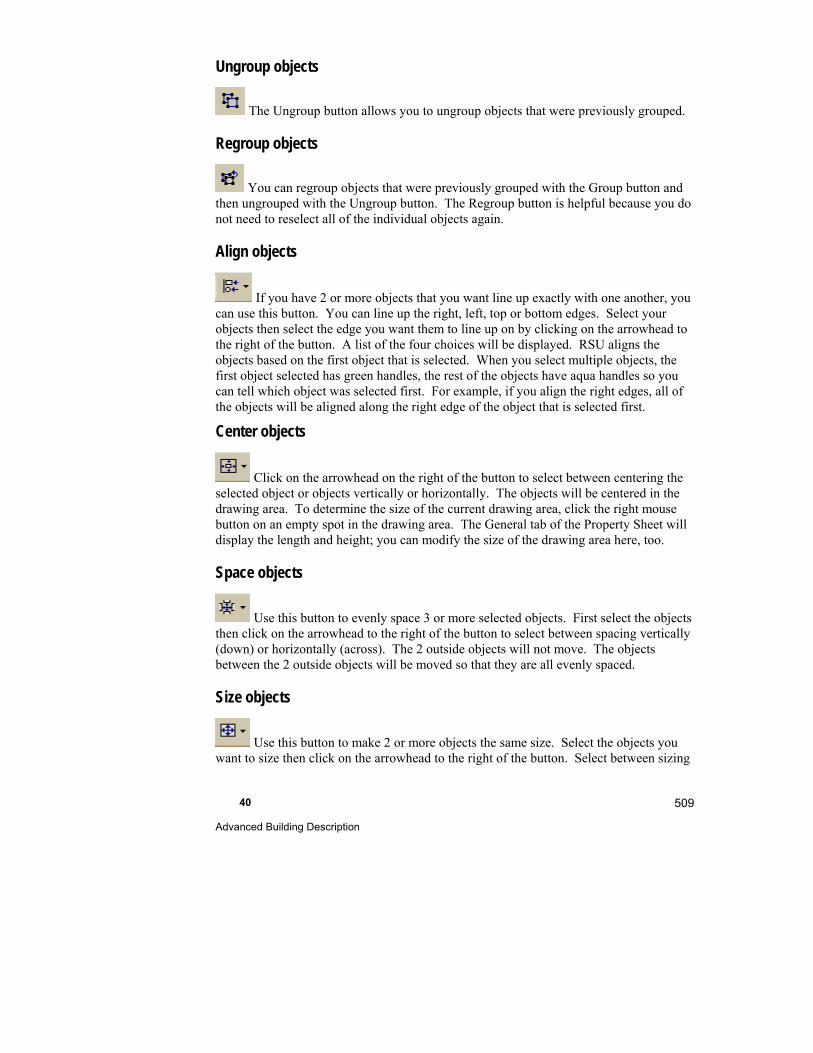
40 Advanced Building Description
509
Ungroup objects
The Ungroup button allows you to ungroup objects that were previously grouped.
Regroup objects
You can regroup objects that were previously grouped with the Group button and then ungrouped with the Ungroup button. The Regroup button is helpful because you do not need to reselect all of the individual objects again.
Align objects
If you have 2 or more objects that you want line up exactly with one another, you can use this button. You can line up the right, left, top or bottom edges. Select your objects then select the edge you want them to line up on by clicking on the arrowhead to the right of the button. A list of the four choices will be displayed. RSU aligns the objects based on the first object that is selected. When you select multiple objects, the first object selected has green handles, the rest of the objects have aqua handles so you can tell which object was selected first. For example, if you align the right edges, all of the objects will be aligned along the right edge of the object that is selected first.
Center objects
Click on the arrowhead on the right of the button to select between centering the selected object or objects vertically or horizontally. The objects will be centered in the drawing area. To determine the size of the current drawing area, click the right mouse button on an empty spot in the drawing area. The General tab of the Property Sheet will display the length and height; you can modify the size of the drawing area here, too.
Space objects
Use this button to evenly space 3 or more selected objects. First select the objects then click on the arrowhead to the right of the button to select between spacing vertically (down) or horizontally (across). The 2 outside objects will not move. The objects between the 2 outside objects will be moved so that they are all evenly spaced.
Size objects
Use this button to make 2 or more objects the same size. Select the objects you want to size then click on the arrowhead to the right of the button. Select between sizing
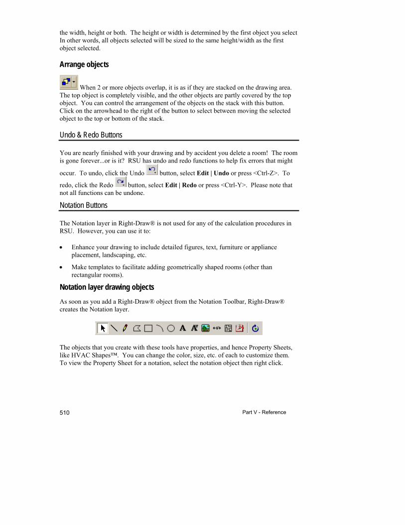
Part V - Reference 510
the width, height or both. The height or width is determined by the first object you select In other words, all objects selected will be sized to the same height/width as the first object selected.
Arrange objects
When 2 or more objects overlap, it is as if they are stacked on the drawing area. The top object is completely visible, and the other objects are partly covered by the top object. You can control the arrangement of the objects on the stack with this button. Click on the arrowhead to the right of the button to select between moving the selected object to the top or bottom of the stack.
Undo & Redo Buttons
You are nearly finished with your drawing and by accident you delete a room! The room is gone forever...or is it? RSU has undo and redo functions to help fix errors that might
occur. To undo, click the Undo button, select Edit | Undo or press <Ctrl-Z>. To
redo, click the Redo button, select Edit | Redo or press <Ctrl-Y>. Please note that not all functions can be undone.
Notation Buttons
The Notation layer in Right-Draw® is not used for any of the calculation procedures in RSU. However, you can use it to:
Enhance your drawing to include detailed figures, text, furniture or appliance placement, landscaping, etc.
Make templates to facilitate adding geometrically shaped rooms (other than rectangular rooms).
Notation layer drawing objects
As soon as you add a Right-Draw® object from the Notation Toolbar, Right-Draw® creates the Notation layer.
The objects that you create with these tools have properties, and hence Property Sheets, like HVAC Shapes™. You can change the color, size, etc. of each to customize them. To view the Property Sheet for a notation, select the notation object then right click.
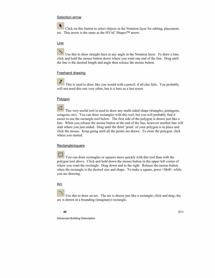
40 Advanced Building Description
511
Selection arrow
Click on this button to select objects in the Notation layer for editing, placement, etc. This arrow is the same as the HVAC Shapes™ arrow.
Line
Use this to draw straight lines at any angle in the Notation layer. To draw a line, click and hold the mouse button down where you want one end of the line. Drag until the line is the desired length and angle then release the mouse button.
Freehand drawing
This is used to draw like you would with a pencil, if all else fails. You probably will not need this one very often, but it is here as a last resort.
Polygon
This very useful tool is used to draw any multi-sided shape (triangles, pentagons, octagons, etc). You can draw rectangles with this tool, but you will probably find it easier to use the rectangle tool below. The first side of the polygon is drawn just like a line. When you release the mouse button at the end of the line, however another line will start where you just ended. Drag until the third ‘point’ of your polygon is in place and click the mouse. Keep going until all the points are drawn. To close the polygon, click where you started.
Rectangle/square
You can draw rectangles or squares more quickly with this tool than with the polygon tool above. Click and hold down the mouse button in the upper left corner of where you want the rectangle. Drag down and to the right. Release the mouse button when the rectangle is the desired size and shape. To make a square, press <Shift> while you are drawing.
Arc
Use this to draw an arc. The arc is drawn just like a rectangle; click and drag; the arc is drawn in a bounding (imaginary) rectangle.

Part V - Reference 512
Ellipse/circle
Use this to draw circular shapes. The circle or ellipse is drawn inside an imaginary rectangle and is drawn just like a rectangle. To make a circle, press <Shift> while you are drawing.
Text
You can add any text to your drawing with this tool. Once you have selected this tool, draw a rectangle to define an area for text and type your text. You can resize the rectangle once you know the exact size of the text by dragging the green handles.
Program variable text
You can add text from RSU to your drawing with this tool. Once you have selected this tool, draw a rectangle to define an area for text. Click the right mouse button to display the property sheet. Click on the ‘Variable name’ line at the top. From here you can select what program variable to include in your drawing. The actual text will change if you change it in RSU. For example, if you select the ‘JobNumber’ variable (in the ‘Project Info’ tab), whatever you have entered as the job number in the Project Information Screen. You can change the color of the text, the background color, the font of the text, etc. You can also resize the rectangle once you know the exact size of the text by dragging the green handles.
Graphic image
With this tool you can insert any graphic image (with the file extensions: .ICO, .BMP., or .DIB) into the Notation layer. Create bitmaps or other files to insert into your drawings; you could even create trees and other architectural details. To add a graphic image to your drawing, click the Graphic image button then click anywhere in the drawing area. The Bitmap Dialog box will pop-up. Click Load and select an image from your files. Click ‘Open’ then OK.
You will see a preview of the image you selected. Click OK to insert it into your drawing. At first the image will be the size it was when it was created. You can resize it, however, to be larger or smaller than the original by dragging the green handles. Press <Shift> as you are resizing the image to constrain the proportions.

40 Advanced Building Description
513
Dimension
You can add blue print dimensions to your drawing with this tool. Click on this button, click on the drawing where you want the dimension line to start, drag to where you want the dimension line to end. The dimension value will be calculated automatically and displayed between 2 arrows. You can move, stretch, etc. the dimension line just like any other Right-Draw® object. It behaves very much like a window. Click the right mouse button on the dimension line to change its properties.
Sheets and Layers
Adding sheets and layers
To add a Sheet or Layer:
Click the right mouse button anywhere in the Sheets and Layers Tree.
Select 'Add sheet' or 'Add layer' from the menu that is displayed
Enter the name of the Sheet or Layer and any other requested data
Click OK
Editing an existing Sheet or Layer
To edit an existing Sheet or Layer:
Click the right mouse button on the name of the Sheet or Layer that you want to edit in the Sheets and Layers Tree.
Select 'Edit sheet' or 'Edit layer' from the menu that is displayed
Edit the name of the Sheet or Layer and any other data
The linked image cannot be displayed. The file may have been moved, renamed, or deleted. Verify that the link points to the correct file and location.

Part V - Reference 514
Click OK
Deleting an existing Sheet or Layer
To delete an existing Sheet or Layer:
Click the right mouse button on the name of the sheet or Layer that you want to edit in the Sheets and Layers Tree.
Select 'Delete sheet' or 'Delete layer' from the menu that is displayed
Click OK to confirm that you want to delete the Sheet or Layer
Lock layer
At times it may be convenient to lock a layer of your drawing so that you do not mistakenly select objects on that layer. For example, once you have drawn the building components (rooms, windows, doors, etc.) and are ready to work on the duct design, you can 'Lock' the Building layer so that you can only select duct components and not building components. This can be a real time-saver if you are working on a complex multi-story building.
To lock a layer, select the layer you want to lock in the Sheets & Layers Tree and right click the mouse.
Select Lock layer from the menu. The name of the layer will turn gray to let you know it is locked.
To unlock a layer:
Select the layer and right click the mouse.
Select Unlock layer from the menu.
The name of the layer will return to its original color.
AutoCAD layer
This extremely powerful feature of Right-Draw® can speed up the process of entering a building description and eliminate takeoff errors. With this feature, you place a copy of a CAD drawing into its own layer in Right-Draw® and enter rooms, windows, doors, etc. into Right-Draw® by tracing the underlying drawing.
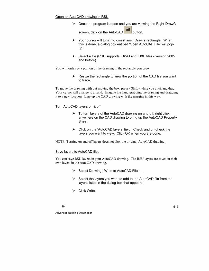
40 Advanced Building Description
515
Open an AutoCAD drawing in RSU
Once the program is open and you are viewing the Right-Draw®
screen, click on the AutoCAD button.
Your cursor will turn into crosshairs. Draw a rectangle. When this is done, a dialog box entitled ‘Open AutoCAD File’ will pop-up.
Select a file (RSU supports .DWG and .DXF files - version 2005 and before).
You will only see a portion of the drawing in the rectangle you drew.
Resize the rectangle to view the portion of the CAD file you want to trace.
To move the drawing with out moving the box, press <Shift> while you click and drag. Your cursor will change to a hand. Imagine the hand grabbing the drawing and dragging it to a new location. Line up the CAD drawing with the margins in this way.
Turn AutoCAD layers on & off
To turn layers of the AutoCAD drawing on and off, right click anywhere on the CAD drawing to bring up the AutoCAD Property Sheet.
Click on the ‘AutoCAD layers’ field. Check and un-check the layers you want to view. Click OK when you are done.
NOTE: Turning on and off layers does not alter the original AutoCAD drawing.
Save layers to AutoCAD files
You can save RSU layers in your AutoCAD drawing. The RSU layers are saved in their own layers in the AutoCAD drawing.
Select Drawing | Write to AutoCAD Files...
Select the layers you want to add to the AutoCAD file from the layers listed in the dialog box that appears.
Click Write.
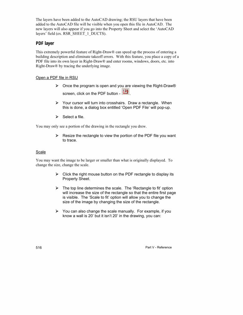
Part V - Reference 516
The layers have been added to the AutoCAD drawing; the RSU layers that have been added to the AutoCAD file will be visible when you open this file in AutoCAD. The new layers will also appear if you go into the Property Sheet and select the ‘AutoCAD layers’ field (ex. RSR_SHEET_1_DUCTS).
PDF layer
This extremely powerful feature of Right-Draw® can speed up the process of entering a building description and eliminate takeoff errors. With this feature, you place a copy of a PDF file into its own layer in Right-Draw® and enter rooms, windows, doors, etc. into Right-Draw® by tracing the underlying image.
Open a PDF file in RSU
Once the program is open and you are viewing the Right-Draw®
screen, click on the PDF button - .
Your cursor will turn into crosshairs. Draw a rectangle. When this is done, a dialog box entitled ‘Open PDF File’ will pop-up.
Select a file.
You may only see a portion of the drawing in the rectangle you drew.
Resize the rectangle to view the portion of the PDF file you want to trace.
Scale
You may want the image to be larger or smaller than what is originally displayed. To change the size, change the scale.
Click the right mouse button on the PDF rectangle to display its Property Sheet.
The top line determines the scale. The ‘Rectangle to fit’ option will increase the size of the rectangle so that the entire first page is visible. The ‘Scale to fit’ option will allow you to change the size of the image by changing the size of the rectangle.
You can also change the scale manually. For example, if you know a wall is 20’ but it isn’t 20’ in the drawing, you can:
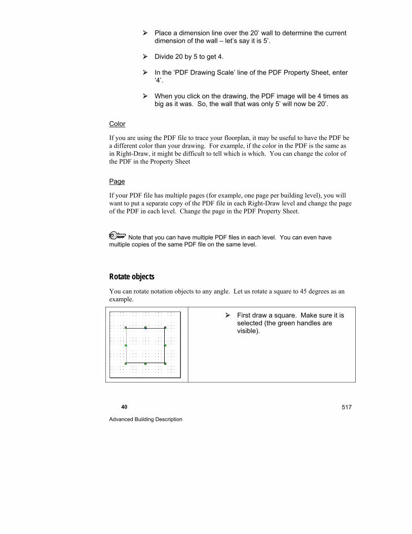
40 Advanced Building Description
517
Place a dimension line over the 20’ wall to determine the current dimension of the wall – let’s say it is 5’.
Divide 20 by 5 to get 4.
In the ‘PDF Drawing Scale’ line of the PDF Property Sheet, enter ‘4’.
When you click on the drawing, the PDF image will be 4 times as big as it was. So, the wall that was only 5’ will now be 20’.
Color
If you are using the PDF file to trace your floorplan, it may be useful to have the PDF be a different color than your drawing. For example, if the color in the PDF is the same as in Right-Draw, it might be difficult to tell which is which. You can change the color of the PDF in the Property Sheet
Page
If your PDF file has multiple pages (for example, one page per building level), you will want to put a separate copy of the PDF file in each Right-Draw level and change the page of the PDF in each level. Change the page in the PDF Property Sheet.
Note that you can have multiple PDF files in each level. You can even have multiple copies of the same PDF file on the same level.
Rotate objects
You can rotate notation objects to any angle. Let us rotate a square to 45 degrees as an example.
First draw a square. Make sure it is selected (the green handles are visible).
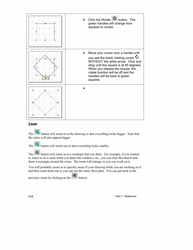
Part V - Reference 518
Click the Rotate button. The green handles will change from squares to circles.
Move your cursor over a handle until
you see the black rotating cursor WITHOUT the white arrow. Click and drag until the square is at 45 degrees. When you release the mouse, the rotate function will be off and the handles will be back to green squares.
Zoom
The button will zoom in to the drawing so that everything looks bigger. Note that the rulers will also appear bigger.
The button will zoom out so that everything looks smaller.
The button will zoom in to a rectangle that you draw. For example, if you wanted to zoom in on a room while you place the windows, etc., you can click this button and draw a rectangle around the room. The room will enlarge so you can work on it.
You will probably zoom in to specific areas of your drawing while you are working on it and then zoom back out so you can see the entire floor plan. You can get back to the
previous zoom by clicking on the button.
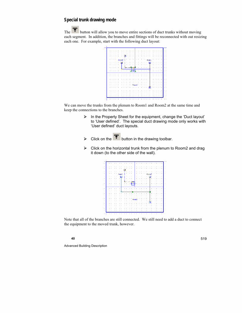
40 Advanced Building Description
519
Special trunk drawing mode
The button will allow you to move entire sections of duct trunks without moving each segment. In addition, the branches and fittings will be reconnected with out resizing each one. For example, start with the following duct layout:
We can move the trunks from the plenum to Room1 and Room2 at the same time and keep the connections to the branches.
In the Property Sheet for the equipment, change the ‘Duct layout’ to ‘User defined’. The special duct drawing mode only works with ‘User defined’ duct layouts.
Click on the button in the drawing toolbar.
Click on the horizontal trunk from the plenum to Room2 and drag it down (to the other side of the wall).
Note that all of the branches are still connected. We still need to add a duct to connect the equipment to the moved trunk, however.
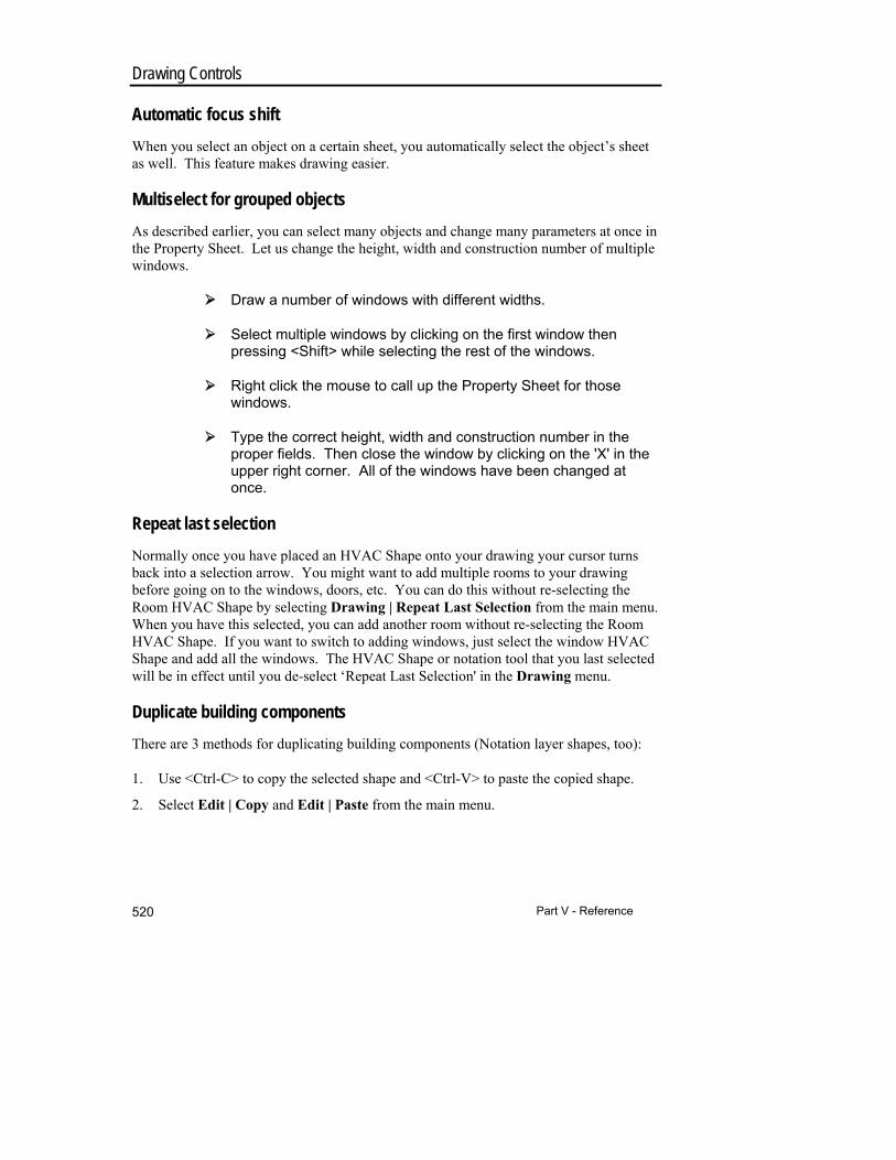
Part V - Reference 520
Drawing Controls
Automatic focus shift
When you select an object on a certain sheet, you automatically select the object’s sheet as well. This feature makes drawing easier.
Multiselect for grouped objects
As described earlier, you can select many objects and change many parameters at once in the Property Sheet. Let us change the height, width and construction number of multiple windows.
Draw a number of windows with different widths.
Select multiple windows by clicking on the first window then pressing <Shift> while selecting the rest of the windows.
Right click the mouse to call up the Property Sheet for those windows.
Type the correct height, width and construction number in the proper fields. Then close the window by clicking on the 'X' in the upper right corner. All of the windows have been changed at once.
Repeat last selection
Normally once you have placed an HVAC Shape onto your drawing your cursor turns back into a selection arrow. You might want to add multiple rooms to your drawing before going on to the windows, doors, etc. You can do this without re-selecting the Room HVAC Shape by selecting Drawing | Repeat Last Selection from the main menu. When you have this selected, you can add another room without re-selecting the Room HVAC Shape. If you want to switch to adding windows, just select the window HVAC Shape and add all the windows. The HVAC Shape or notation tool that you last selected will be in effect until you de-select ‘Repeat Last Selection' in the Drawing menu.
Duplicate building components
There are 3 methods for duplicating building components (Notation layer shapes, too):
1. Use <Ctrl-C> to copy the selected shape and <Ctrl-V> to paste the copied shape.
2. Select Edit | Copy and Edit | Paste from the main menu.
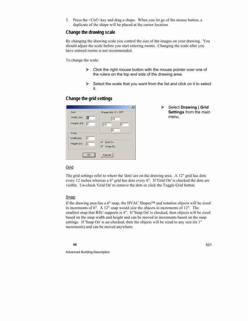
40 Advanced Building Description
521
3. Press the <Ctrl> key and drag a shape. When you let go of the mouse button, a duplicate of the shape will be placed at the cursor location.
Change the drawing scale
By changing the drawing scale you control the size of the images on your drawing. You should adjust the scale before you start entering rooms. Changing the scale after you have entered rooms is not recommended.
To change the scale:
Click the right mouse button with the mouse pointer over one of the rulers on the top and side of the drawing area.
Select the scale that you want from the list and click on it to select it.
Change the grid settings
Select Drawing | Grid Settings from the main menu.
Grid
The grid settings refer to where the 'dots' are on the drawing area. A 12" grid has dots every 12 inches whereas a 6" grid has dots every 6". If 'Grid On' is checked the dots are visible. Un-check 'Grid On' to remove the dots or click the Toggle Grid button.
Snap
If the drawing area has a 6" snap, the HVAC Shapes™ and notation objects will be sized in increments of 6". A 12" snap would size the objects in increments of 12". The smallest snap that RSU supports is 4". If 'Snap On' is checked, then objects will be sized based on the snap width and height and can be moved in increments based on the snap settings. If 'Snap On' is un-checked, then the objects will be sized to any size (in 1" increments) and can be moved anywhere.
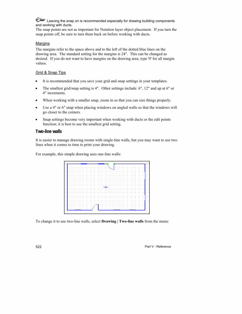
Part V - Reference 522
Leaving the snap on is recommended especially for drawing building components and working with ducts. The snap points are not as important for Notation layer object placement. If you turn the snap points off, be sure to turn them back on before working with ducts.
Margins
The margins refer to the space above and to the left of the dotted blue lines on the drawing area. The standard setting for the margins is 24". This can be changed as desired. If you do not want to have margins on the drawing area, type '0' for all margin values.
Grid & Snap Tips
It is recommended that you save your grid and snap settings in your templates.
The smallest grid/snap setting is 4". Other settings include: 6", 12" and up at 6" or 4" increments.
When working with a smaller snap, zoom in so that you can size things properly.
Use a 4" or 6" snap when placing windows on angled walls so that the windows will go closer to the corners.
Snap settings become very important when working with ducts or the edit points function; it is best to use the smallest grid setting.
Two-line walls
It is easier to manage drawing rooms with single-line walls, but you may want to use two lines when it comes to time to print your drawing.
For example, this simple drawing uses one-line walls:
To change it to use two-line walls, select Drawing | Two-line walls from the menu:
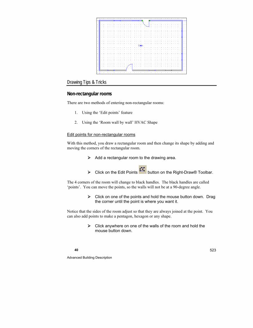
40 Advanced Building Description
523
Drawing Tips & Tricks
Non-rectangular rooms
There are two methods of entering non-rectangular rooms:
1. Using the ‘Edit points’ feature
2. Using the ‘Room wall by wall’ HVAC Shape
Edit points for non-rectangular rooms
With this method, you draw a rectangular room and then change its shape by adding and moving the corners of the rectangular room.
Add a rectangular room to the drawing area.
Click on the Edit Points button on the Right-Draw® Toolbar.
The 4 corners of the room will change to black handles. The black handles are called ‘points’. You can move the points, so the walls will not be at a 90-degree angle.
Click on one of the points and hold the mouse button down. Drag the corner until the point is where you want it.
Notice that the sides of the room adjust so that they are always joined at the point. You can also add points to make a pentagon, hexagon or any shape.
Click anywhere on one of the walls of the room and hold the mouse button down.
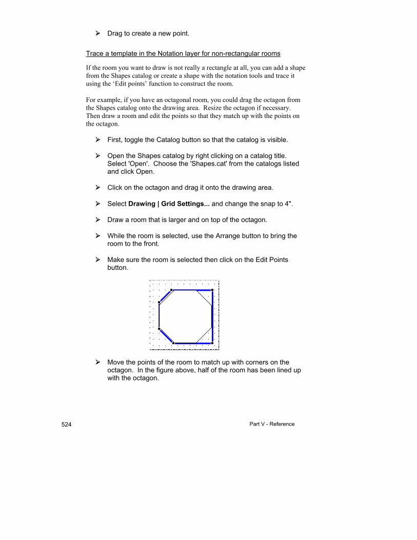
Part V - Reference 524
Drag to create a new point.
Trace a template in the Notation layer for non-rectangular rooms
If the room you want to draw is not really a rectangle at all, you can add a shape from the Shapes catalog or create a shape with the notation tools and trace it using the ‘Edit points’ function to construct the room.
For example, if you have an octagonal room, you could drag the octagon from the Shapes catalog onto the drawing area. Resize the octagon if necessary. Then draw a room and edit the points so that they match up with the points on the octagon.
First, toggle the Catalog button so that the catalog is visible.
Open the Shapes catalog by right clicking on a catalog title. Select 'Open'. Choose the 'Shapes.cat' from the catalogs listed and click Open.
Click on the octagon and drag it onto the drawing area.
Select Drawing | Grid Settings... and change the snap to 4".
Draw a room that is larger and on top of the octagon.
While the room is selected, use the Arrange button to bring the room to the front.
Make sure the room is selected then click on the Edit Points button.
Move the points of the room to match up with corners on the octagon. In the figure above, half of the room has been lined up with the octagon.
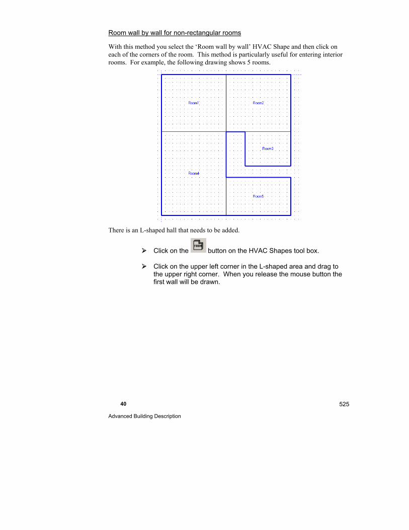
40 Advanced Building Description
525
Room wall by wall for non-rectangular rooms
With this method you select the ‘Room wall by wall’ HVAC Shape and then click on each of the corners of the room. This method is particularly useful for entering interior rooms. For example, the following drawing shows 5 rooms.
There is an L-shaped hall that needs to be added.
Click on the button on the HVAC Shapes tool box.
Click on the upper left corner in the L-shaped area and drag to the upper right corner. When you release the mouse button the first wall will be drawn.
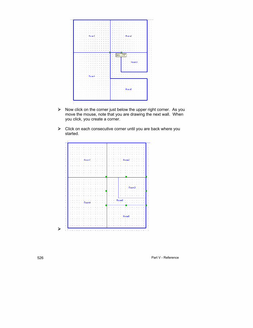
Part V - Reference 526
Now click on the corner just below the upper right corner. As you move the mouse, note that you are drawing the next wall. When you click, you create a corner.
Click on each consecutive corner until you are back where you started.

40 Advanced Building Description
527
Doors
Door types
RSU has many different kinds of doors for your drawings. In the door Property Sheet there is the option to change a door to a wall opening, sliding (opaque), double, or garage door.
To draw a sliding door, draw a door on the wall.
Right click on the door to bring up the Property Sheet.
Select sliding door from the list of Door type options. Click on the 'X' in the upper right corner to close the box and view the sliding door.
Sliding doors are opaque; to add a glass sliding door, add a window and select the appropriate window type.
You can also change the door opening orientation in the Property Sheet.
You can add internal doors with the Building components catalog. Please note that these objects are for cosmetic purposes only and are not used in the load calculations.
Wall openings
To add wall openings to your drawing, draw a door that is the same size as the wall opening you want and in the same location.
Right click on the door you just drew to view the Property Sheet.
Click on Door type to display the Door type options and select ‘Wall Opening’.
Close the Property Sheet or press <Enter> to view the opening (NOTE: Interior doors and openings have no effect on load calculations).
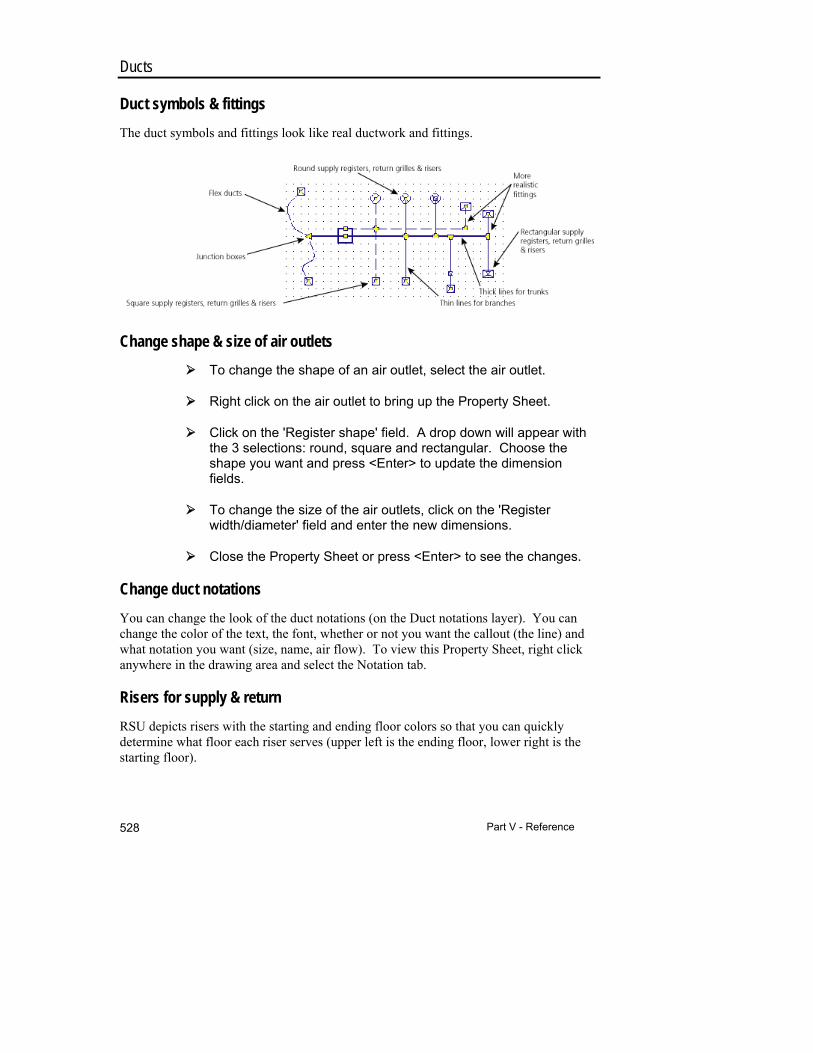
Part V - Reference 528
Ducts
Duct symbols & fittings
The duct symbols and fittings look like real ductwork and fittings.
Change shape & size of air outlets
To change the shape of an air outlet, select the air outlet.
Right click on the air outlet to bring up the Property Sheet.
Click on the 'Register shape' field. A drop down will appear with the 3 selections: round, square and rectangular. Choose the shape you want and press <Enter> to update the dimension fields.
To change the size of the air outlets, click on the 'Register width/diameter' field and enter the new dimensions.
Close the Property Sheet or press <Enter> to see the changes.
Change duct notations
You can change the look of the duct notations (on the Duct notations layer). You can change the color of the text, the font, whether or not you want the callout (the line) and what notation you want (size, name, air flow). To view this Property Sheet, right click anywhere in the drawing area and select the Notation tab.
Risers for supply & return
RSU depicts risers with the starting and ending floor colors so that you can quickly determine what floor each riser serves (upper left is the ending floor, lower right is the starting floor).
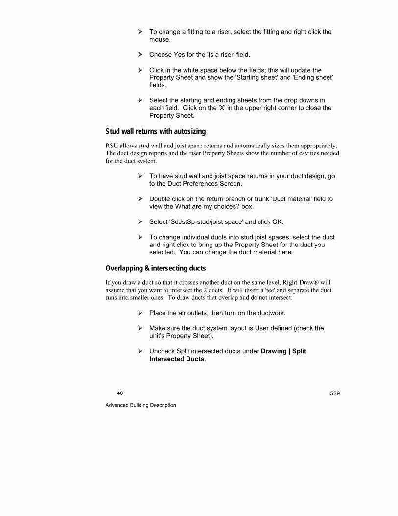
40 Advanced Building Description
529
To change a fitting to a riser, select the fitting and right click the mouse.
Choose Yes for the 'Is a riser' field.
Click in the white space below the fields; this will update the Property Sheet and show the 'Starting sheet' and 'Ending sheet' fields.
Select the starting and ending sheets from the drop downs in each field. Click on the 'X' in the upper right corner to close the Property Sheet.
Stud wall returns with autosizing
RSU allows stud wall and joist space returns and automatically sizes them appropriately. The duct design reports and the riser Property Sheets show the number of cavities needed for the duct system.
To have stud wall and joist space returns in your duct design, go to the Duct Preferences Screen.
Double click on the return branch or trunk 'Duct material' field to view the What are my choices? box.
Select 'SdJstSp-stud/joist space' and click OK.
To change individual ducts into stud joist spaces, select the duct and right click to bring up the Property Sheet for the duct you selected. You can change the duct material here.
Overlapping & intersecting ducts
If you draw a duct so that it crosses another duct on the same level, Right-Draw® will assume that you want to intersect the 2 ducts. It will insert a 'tee' and separate the duct runs into smaller ones. To draw ducts that overlap and do not intersect:
Place the air outlets, then turn on the ductwork.
Make sure the duct system layout is User defined (check the unit's Property Sheet).
Uncheck Split intersected ducts under Drawing | Split Intersected Ducts.
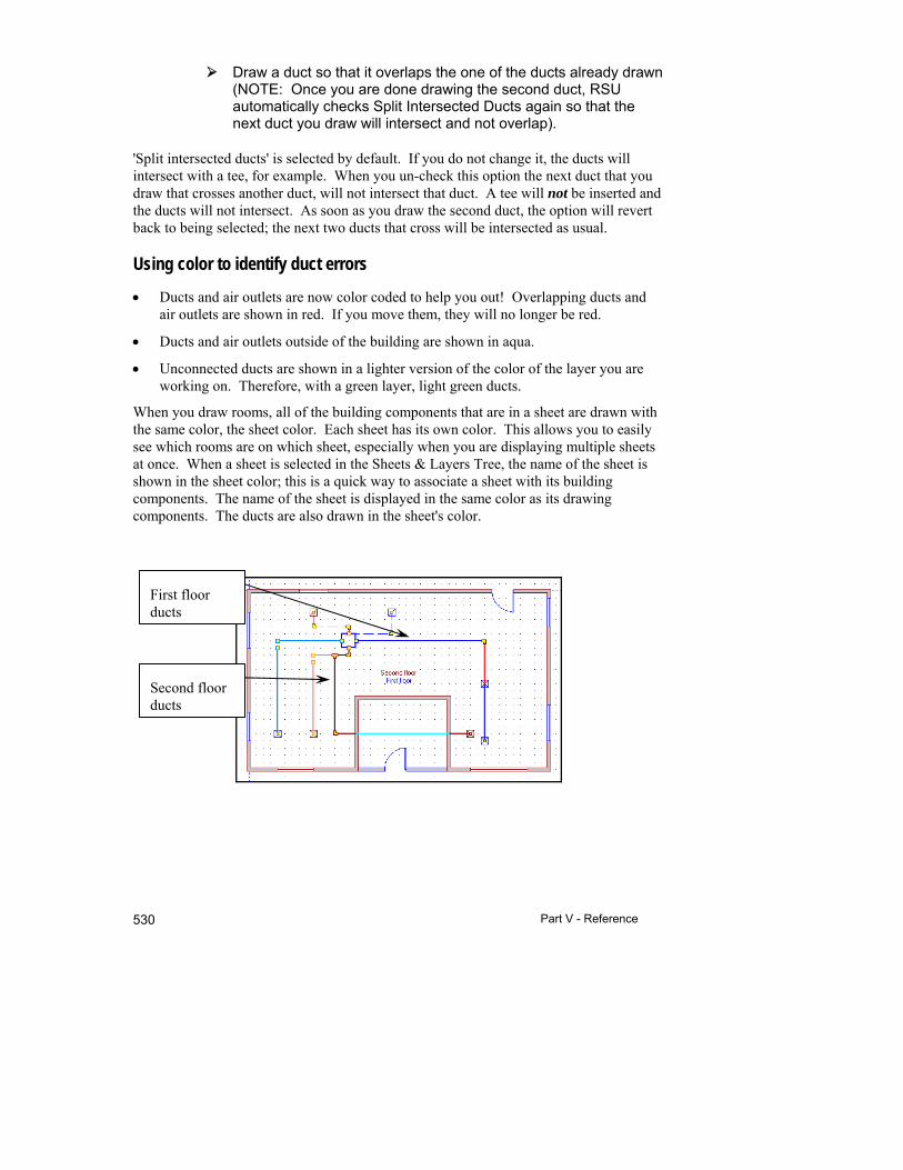
Part V - Reference 530
Draw a duct so that it overlaps the one of the ducts already drawn (NOTE: Once you are done drawing the second duct, RSU automatically checks Split Intersected Ducts again so that the next duct you draw will intersect and not overlap).
'Split intersected ducts' is selected by default. If you do not change it, the ducts will intersect with a tee, for example. When you un-check this option the next duct that you draw that crosses another duct, will not intersect that duct. A tee will not be inserted and the ducts will not intersect. As soon as you draw the second duct, the option will revert back to being selected; the next two ducts that cross will be intersected as usual.
Using color to identify duct errors
Ducts and air outlets are now color coded to help you out! Overlapping ducts and air outlets are shown in red. If you move them, they will no longer be red.
Ducts and air outlets outside of the building are shown in aqua.
Unconnected ducts are shown in a lighter version of the color of the layer you are working on. Therefore, with a green layer, light green ducts.
When you draw rooms, all of the building components that are in a sheet are drawn with the same color, the sheet color. Each sheet has its own color. This allows you to easily see which rooms are on which sheet, especially when you are displaying multiple sheets at once. When a sheet is selected in the Sheets & Layers Tree, the name of the sheet is shown in the sheet color; this is a quick way to associate a sheet with its building components. The name of the sheet is displayed in the same color as its drawing components. The ducts are also drawn in the sheet's color.
Second floor ducts
First floor ducts
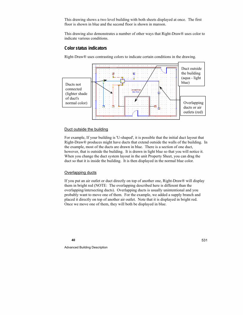
40 Advanced Building Description
531
This drawing shows a two level building with both sheets displayed at once. The first floor is shown in blue and the second floor is shown in maroon.
This drawing also demonstrates a number of other ways that Right-Draw® uses color to indicate various conditions.
Color status indicators
Right-Draw® uses contrasting colors to indicate certain conditions in the drawing.
Duct outside the building
For example, If your building is 'U-shaped', it is possible that the initial duct layout that Right-Draw® produces might have ducts that extend outside the walls of the building. In the example, most of the ducts are drawn in blue. There is a section of one duct, however, that is outside the building. It is drawn in light blue so that you will notice it. When you change the duct system layout in the unit Property Sheet, you can drag the duct so that it is inside the building. It is then displayed in the normal blue color.
Overlapping ducts
If you put an air outlet or duct directly on top of another one, Right-Draw® will display them in bright red (NOTE: The overlapping described here is different than the overlapping/intersecting ducts). Overlapping ducts is usually unintentional and you probably want to move one of them. For the example, we added a supply branch and placed it directly on top of another air outlet. Note that it is displayed in bright red. Once we move one of them, they will both be displayed in blue.
Duct outside the building (aqua - light blue)
Overlapping ducts or air outlets (red)
Ducts not connected (lighter shade of duct's normal color)
Part V - Reference 532
Ducts not connected
If you draw a duct and it is not connected to the ducts system on both ends, it is displayed a shade lighter of the same color than normal. In the example above, there are two ducts that are not connected, one on each floor of the building. One common error is to turn off the snap points; it is very difficult to line up ducts with the snap points off and many of the ducts will be unconnected.
Rooms with no air outlets
You are able to have rooms with no registers like hallways, foyers stairwells, walk-in closets, etc. It is best to design no air outlet rooms before you draw the ducts. All you need to do is delete the air outlets you do not need. The loads will be reassigned to adjacent conditioned rooms and ducts will be sized accordingly. If you have the Duct notations layer checked in the Sheets & Layers Tree, the airflow will change on the screen. The Right-J® Worksheet displays where those loads were redistributed on the Redistribution line, above line 14; values are negative where air outlets have been removed and positive in the rooms that have been adjusted. The adjustment is also on the standard reports.
Click on the air outlet you want to remove.
Press the <Delete> key to delete the air outlet.
A pop-up box will appear asking if you are certain you want to delete the air outlet. Click Yes.
Tips for working with ducts
We recommend that you become familiar with zooming in and out. When you are working with ducts, it is much easier to connect ducts if you are zoomed in. Zooming will be especially important when you are working with smaller snap settings.
Keep snap points on so that the ducts snap together.
Supply air outlets cannot be moved out of a room. If you want to remove an air outlet you must delete it.
Things to Remember
Notation layer objects can be altered like HVAC Shapes™; they also have properties that can be viewed by selecting the object then right clicking.
You can insert almost any graphic image onto the drawing area. You could even place your logo on the drawing!
Use the catalog objects to add the finishing touches to your drawings.

Glossary
A
Adequate Exposure Diversity (AED) - A cooling application has AED if the difference between the peak-hour fenestration gain for the entire conditioned space does not exceed the average fenestration gain for the same space by more than 30%.
AED see Adequate Exposure Diversity
AED Excursion - The difference between the peak-hour fenestration gain for the entire conditioned space and 130% of the average fenestration gain for the same space. This value is added to the ALP load calculation if the conditioned space does not have AED. In other words, this value is added to the ALP load calculation if the peak-hour fenestration gain for the entire conditioned space exceeds the average fenestration gain for the same space by more than 30%. If this difference is less than 30%, the ALP load calculation value is used.
ALP - see Average Load Procedure
Air change (AC) – The amount of outdoor air that is required to completely replace the air in a room or building with outdoor air, by air leakage (infiltration) and /or through an engineered ventilation system.
Air changes per hour (ACH or AC/hr) – The number of times per hour the total volume of indoor air contained in a room or building is replaced with outdoor air by infiltration or mechanical ventilation.
Air conditioner (AC) – An assembly of equipment for the simultaneous control of air temperature, relative humidity, purity and motion.
Air Conditioning & Refrigeration Institute (ARI) – A private-public sector research collaboration of the heating, ventilation, air-conditioning and refrigeration (HVAC/R) industry, with the mission to identify, prioritize, and undertake pre-competitive research that focuses on decreasing energy consumption, increasing indoor environmental quality and safeguarding the environment.
Air Conditioning Contractors of America (ACCA) – A nonprofit trade association of HVACR contractors (see The ACCA Connection at the end of this manual).
Part V - Reference 534
Airflow – The movement of air, usually within boundaries such as ducts.
Air outlet – A device or opening through which air is withdrawn from or discharged into a conditions space.
Air source heat pump (ASHP)
Air Volumetric Flow (AVF) – Refers to the air flow rate through an HVAC unit or duct system. Measured in cubic feet per minute (cfm) in inch-pound units and liters per second (l/s) in SI units.
Annual fuel consumption (AFC) – The amount of fuel used in one year.
Annual fuel utilization efficiency (AFUE) – An annual fuel efficiency rating similar to mileage ratings for cars. The higher the AFUE for a furnace, the more efficient the furnace. All furnace models are tested using U.S. Department of Energy procedures to assign their AFUE rating. The lowest allowable AFUE (as of 1992) is 78%.
Ambient air – The air surrounding an object (usually outdoor air or the air in an enclosure under study).
American Society of Heating, Refrigerating and Air-Conditioning Engineers (ASHRAE) – An international organization that is organized for the sole purpose of advancing the arts and sciences of heating, ventilation, air conditioning and refrigeration for the public's benefit through research, standards writing, continuing education and publications.
Available static pressure - the static pressure of air available for ducts sizing. The external static pressure is the static pressure that the unit provides at the output of the unit. There may be additional pressure losses in the system that will reduce the external static pressure to the available static pressure.
Average Load Procedure - The base Manual J Eighth Edition load calculation. Note that an AED Excursion may be added to this load if applicable. See AED Excursion for details.
B
Block – In the Right-Proposal® Library, a block is a copy of a section of a proposal including all formatting, text, tables, images, etc. Blocks differ from User Variables in that User Variables do not contain formatting.
Block cooling load – The largest cooling load that can occur when a number of rooms or zones are considered as a group.
Glossary 535
British thermal unit (Btu) – The amount of heat required to raise the temperature of one pound of water one degree Fahrenheit.
British thermal unit per hour (Btuh) – The hourly rate of heat flow, measured in Btu units.
Bypass duct – A duct that is connected to both the supply duct and return duct for the purpose of maintaining adequate flow through critical components when the system air flow is vigorously throttled by zone dampers.
C
Coefficient of performance (COP) – The ratio of the rate of net heat output to the total energy input expressed in consistent units and under designated rating conditions. The ratio of the refrigerating capacity to the work absorbed by the compressor per unit time.
Construction numbers – The codes used by ACCA for building component constructions.
Convective heat transfer coefficient (H) – The constant of proportionality relating the convective rate of heat transfer at a surface to the temperature difference across the air film on that surface.
Cooling (Clg) – The process for reducing the temperature of a space of system below a specified level.
Cooling load factor (CLF) – The ratio of the total cooling of a complete cycle for a specified period consisting of an on time and an off time to the steady-state cooling done over the same period at constant ambient conditions.
Cooling load temperature difference (CLTD) – Used to calculate the heat gain for walls, ceilings, floors and opaque doors. A CLTD represents the effective air temperature difference across the structural panel. This temperature difference accounts for the air-to-air temperature difference across the panel, the heating effect of the sun striking the outdoor surface of the panel and the thermal mass of the panel.
Cooling inside dry-bulb – The temperature used to set the thermostat during the cooling season.
Cubic feet per minute (cfm) – The volume of air that can be heated or cooled by heating or cooling equipment per minute.

Part V - Reference 536
D
Damper – A device used to vary the volume of air passing through an outlet, inlet, or duct; or generally through a confined cross section by varying the cross-sectional area.
Degree-day (DD) – The difference in temperature between the outdoor mean temperature over a 24-hour period, and the given base temperature of a building space.
Design airflow – The required airflow when the system is operating under assumed maximum conditions of design, including diversity.
Design conditions – The specified environmental conditions, such as temperature and humidity, required to be produced and maintained by a system.
Design temperature swing – The temperature rise allowed above the inside design temperature. Right-Suite Universal 2018 only accepts 3.0 or 4.5 °F.
Diversity – The effect referred to when using the block load as the design cooling load in residential multizone applications. This is possible because peak zone loads don’t usually occur at the same time. The block load is usually less than the sum of the peak zone loads.
Dry-bulb temperature – Air temperature measured by an ordinary thermometer when there is no solar heating effect or evaporative cooling effect.
Duct sizing – The calculation of dimensions of ducting for a given air distribution system.
E
Effective length – The design parameter for calculating the friction loss of a run. Effective Length, expressed in feet, is the sum of the actual length and the equivalent length.
Efficiency – The ratio of useful output energy of a piece of equipment to input energy.
Emittance (e) – The ratio of the radiant energy flux (Btuh/Sqft) emitted from a surface (thrown off to the surroundings) to the flux emitted from a black body (the maximum possible emittance) at the same temperature and subject to the same environment.
Glossary 537
Energy-efficiency ratio (EER) – The ratio of net cooling capacity in Btuh to the total rate of electric input in watts, under designated operating conditions.
Equipment sizing load – Also called design heating or cooling load.
Equivalent length – A method of expressing the friction loss of duct fittings by equating the fitting loss to straight duct friction loss.
Equivalent temperature difference (ETD) – See Cooling load temperature difference.
External static pressure - the static pressure of air that a unit provides at the output of the unit. There may be additional pressure losses in the system that will affect the available static pressure. The available static pressure is used in the duct sizing calculations.
F
Fahrenheit temperature (oF) – The temperature scale on which at standard atmospheric pressure, the boiling point of water is 212 oF and its freezing point is 32 oF; absolute zero is -459.69 oF.
Friction rate – The pressure loss that occurs between two points in a duct system.
G
Gallon (Gal) – U.S. gallon.
Gas Appliance Manufacturers Association – A national trade association whose members manufacture appliances, components and related products used in connection with space heating, water heating and commercial food service. In addition to gas-fired appliances, GAMA’s scope includes certain oil-fired and electrical appliances. GAMA’s principal purpose is to serve and represent its members and the industries, which they comprise.
Grains – A unit of measurement that refers to the weight of an object (there are 7,000 grains in a pound).
H
Heat flow (Q) – The passage of heat from one point to another or one space to another by one or more of the three modes (conduction, convection and radiation).
Part V - Reference 538
Heat transfer multiplier (HTM) – The amount of heat that flows through one square foot of a building component at a given temperature difference. HTM values differ for various wall constructions. Heating HTM’s for doors, walls, etc. are determined by multiplying the transmission coefficient (U) by the winter design temperature difference. Cooling HTM’s for doors, walls, etc. are determined by multiplying the transmission coefficient (U) by the summer equivalent temperature difference.
Heating (Htg) – The process of adding heat energy causing a rise in temperature, or a transfer of sensible heat into latent heat.
Heating design temperature difference (TD) – The winter indoor dry bulb temperature minus the winter outside dry bulb temperature.
Heating inside dry-bulb - The temperature used to set the thermostat during the heating season.
Heating load (HL) – The heating rate required to replace heat loss from the space being controlled.
Heating seasonal performance factor (HSPF) – The ratio of the total heat delivered over the heating seasons (not to exceed 12 months) to the total energy input over the heating season, in consistent units.
Heating, Ventilation & Air Conditioning (HVAC)
Heating, Ventilation, Air Conditioning & Refrigeration (HVACR)
Hour (hr) – One of the points on a timepiece marking off 12 or 24 successive intervals of 60 minutes, from midnight to noon and noon to midnight or from midnight to midnight.
Humidity ratio – The ratio of the mass of water vapor to the mass of dry air.
K
Kilowatt hour (kWh) – The energy unit used in marketing electrical power (the SI unit for energy is the joule (J))
L
Latent gain – The additional load caused by humidity reduction. Affected by the relative humidity.

Glossary 539
Latent heat – Energy (heat) associated with a change of state, as of liquid to vapor or vice versa, expressed as Btu/lb. In HVAC usage, the energy associated with the moisture in the air.
Latent infiltration Load – The heat gain or latent load from moisture brought in with the air leakage.
Latent ventilation Load – The latent gain caused by mechanical ventilation equipment.
Length (L) – A measure used as a unit to estimate dimensions.
Linear foot (LF) – A unit of length in the U.S. Customary and British Imperial systems equal to 12 inches (0.3048 meter).
Load calculation – Determines how much energy (Btu) is required to maintain cooling, heating, and ventilation.
M
Manual D – ACCA’s method for sizing residential ductwork. Right-Suite Universal 2018 is the computerized version of Manual D.
Manual J – ACCA’s method for residential load calculations. Right-Suite Universal 2018 is the computerized version of Manual J. ACCA released Addenda A, B, C, and D to Manual J Eighth Edition in May of 2004. These addenda are incorporated into Manual J Eighth Edition (Version 2.00) and Right-Suite Universal 2018.
Manual N - – ACCA’s method for small commercial load calculations. Right-Suite Universal 2018 is the computerized version of Manual N, Fifth Edition.
Multizone (or multiple zone) system (MZ) – For dwellings, a comfort-conditioning system designed to serve two or more rooms or areas having different or unsynchronized heating and cooling requirements. In some cases a zone is required to satisfy a special humidification, filtration or ventilation requirement. See Zone.
O
Outdoor air – The air outside a building or taken from outdoors and not previously circulated through the system.
Outside air – External air; atmosphere exterior to refrigerated or conditioned space; ambient, surrounding air.
Part V - Reference 540
P
Peak Fenestration Gain - The maximum hourly fenestration heat gain for a conditioned space.
PFG - see Peak Fenestration Gain
PLP - see Peak Load Procedure
Pound (lb) – A unit of weight equal to 16 ounces (453.592 grams.
R
R-value – Thermal resistance value of an insulator. Higher R-values mean better insulation and lower heat flow. R values are expressed in ft2. °F/Btuh.
Radiation gain – Heating increase due to the radiation effects from the sun. Surfaces transfer heat.
Rate-swing multiplier (RSM) – A correction factor used to modify sensible cooling loads to account for the effects of room temperature swing and equipment rating conditions.
Relative humidity – Approximately, the ratio of the density of the water vapor in the air to the saturation density of water vapor at the same temperature, expressed as a percentage.
S
Seasonal energy efficiency ratio (SEER) – The total cooling output of an air conditioner during its normal annual usage period for cooling, in Btuh, divided by the total electric energy input during the same period, in watt-hours.
Sensible gain – The increase in temperature where moisture is not involved.
Sensible heat ratio (SHR) – The ratio of the sensible heat to the sensible plus latent heat to be removed from a conditioned space.
Shading coefficient – The ratio of the admittance of a light, a glazing or a fenestration assembly (with or without internal shade) to the admittance of a single light of 1/8 inch, clear, double strength glass.
Glossary 541
Solar gain – Heat gain into a building from the solar radiation through glass of different types and interior shading. Also called “radiation gain”.
Static pressure – the force per unit area, perpendicular to the direction of flow in a duct.
T
Temperature difference – The variation between the inside and outside air temperature. For cooling temperature difference, solar gain data is considered.
Ton –A time-rate of cooling equal to 12,000 Btuh (approximately 3517 W).
Total latent load – The sum of the following latent loads: internal gains, ventilation, and infiltration.
Total sensible gain – The total of all sensible gains for a room, including internal gains, infiltration and duct gains.
Transmission coefficient (U-value) – The U-value combines the effect of the thermal resistance of the building components, such as a wall, ceiling, or roof, with the effects of convection at the inside and outside surfaces. U-values are expressed in Btuh/sq ft °F.
Transmission loss – Heating or cooling loss through a solid surface, such as a wall. (This differs from infiltration loss, which is the heating or cooling loss through the air.)
U
U-value (or U-Factor) – Combines the effect of the thermal resistance of the wall, ceiling/roof, or glass, and the effects of convection at the inside and outside surfaces. U values are expressed in Btuh/sq ft °F.
User Variable – In the Right-Proposal® Library, a User Variable is data that you define and can include in your Proposal Document by name. A User Variable differs from a Block in that a User Variable does not contain any formatting. The formatting in effect before the User Variable will be used.
V
Ventilation – Outdoor air that is introduced by HVAC equipment in a controlled manner.
Part V - Reference 542
W
Wet-bulb temperature – The temperature indicated by a wet-bulb psychrometer. It is a good indicator of the amount of moisture in the air. When the wet-bulb temperature is equal to the dry-bulb temperature, the relative humidity is 100%.
Z
Zone – An area in a building that is isolated by a full partition. A building can have several zones. You can adjust the temperature in one zone independently of the other zones. The number of zones in a house is equal to the number of thermostats in the house.
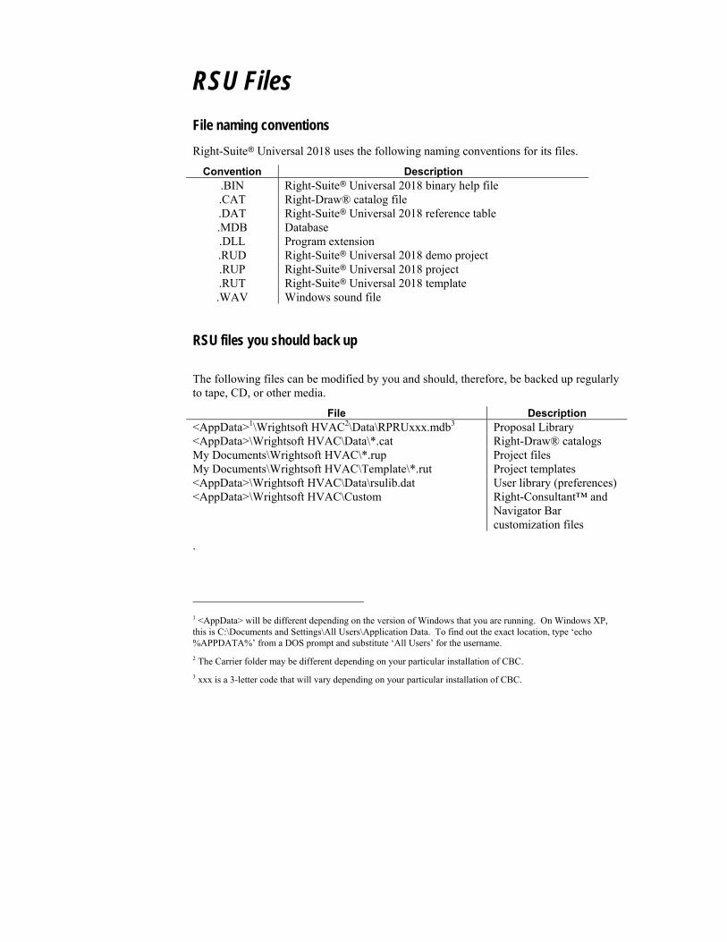
RSU Files
File naming conventions
Right-Suite Universal 2018 uses the following naming conventions for its files.
Convention Description .BIN Right-Suite Universal 2018 binary help file .CAT Right-Draw® catalog file .DAT Right-Suite Universal 2018 reference table .MDB Database .DLL Program extension .RUD Right-Suite Universal 2018 demo project .RUP Right-Suite Universal 2018 project .RUT Right-Suite Universal 2018 template .WAV Windows sound file
RSU files you should back up
The following files can be modified by you and should, therefore, be backed up regularly to tape, CD, or other media.
File Description <AppData>1\Wrightsoft HVAC2\Data\RPRUxxx.mdb3 Proposal Library <AppData>\Wrightsoft HVAC\Data\*.cat Right-Draw® catalogs My Documents\Wrightsoft HVAC\*.rup Project files My Documents\Wrightsoft HVAC\Template\*.rut Project templates <AppData>\Wrightsoft HVAC\Data\rsulib.dat User library (preferences) <AppData>\Wrightsoft HVAC\Custom Right-Consultant™ and
Navigator Bar customization files
.
1 <AppData> will be different depending on the version of Windows that you are running. On Windows XP, this is C:\Documents and Settings\All Users\Application Data. To find out the exact location, type ‘echo %APPDATA%’ from a DOS prompt and substitute ‘All Users’ for the username.
2 The Carrier folder may be different depending on your particular installation of CBC.
3 xxx is a 3-letter code that will vary depending on your particular installation of CBC.


Windows Environment
One benefit of Windows is that there is more than one way to accomplish any task. This appendix was included to provide you a reference to Windows conventions that are used in RSU.
<Alt-Access Key> - In the Windows environment, you may scroll through the main menu without using your mouse. Notice on the Windows main menu that every menu has one letter underlined. The underlined letter is the Access Key for that menu. In RSU, press <Alt> then press the <F> key to display the File menu options. Notice that each of the file menu options also has an Access Key. To choose and option from the File menu, just press the underlined letter next to the option. Once you have selected a main menu Access Key, you may scroll around with the arrow keys. Moving left to right will move the cursor between main menu items, moving up an down will move the cursor within a menu.
<Alt-Tab> - A major benefit of working in a Windows environment is that you can move from application to application without having to close out of either of the programs. One easy way to switch between programs is to use the <Alt-Tab> feature. While holding down <Alt>, press <Tab> once. A pop-up display will arise in the middle of your screen. The programs you have open are displayed in this box; there is a box around the program you are currently working in. With the <Alt>key still depressed, press <Tab>. This will move the box to another program. Press <Tab> until the program you want to display has the box around it then release the <Alt-Tab> keys.
Adjusting Window Size - In RSU, you may now have more than one screen open at a time. This allows you to make changes in one screen and view the effect of the changes on the other screens. However, to do this effectively you will have to resize some of the windows. Even if you Tile the arrangement (see description below) of the windows, you may still want to show more or less of certain screens.
To adjust the window size, place your cursor directly on the border of a window that you would like to resize. If you place your cursor on the vertical border, your cursor will look like the figure below. You may also rest your cursor on a horizontal bar to change the height of the window or in the corner of a window to adjust height and width simultaneously.
Cascade - Choose Window | Cascade from the main menu to stack the screens in a cascaded arrangement with the title bar of each window visible. To access any Window, simply click its title bar.

Part V - Reference 546
Restoring Windows - Anytime you have minimized, maximized or altered the size of a window and would like to “restore” the original shape and size, you may use this capability. Select Window | Restore to restore your window to its original size.
Size Grip - In the furthermost lower, right-hand corner of the RSU program window, you will notice some diagonal lines that fade into the corner. This is known as the size grip. Click and hold down the mouse button on the size grip. Drag upward and to the left. Notice how the size grip can be used to resize the window. The size grip is useful if you are running RSU with other programs at the same time.
Tile - Choose Window | Tile from the main menu to "Tile" the open windows. Selecting Tile will place any screens that you have open in a tiled arrangement so that they are all visible on your screen at once.

Index
A
ACCA ... xxiii, 2, 3, 104, 453, 531, 537, 552, 553
Adequate Exposure Diversity ................. 126
AED ........ See Adequate Exposure Diversity
Air outlets ...... 29, 45, 90, 96, 100, 106, 110, 116, 117, 524, 528
AutoCAD files .................................. 64, 511
AutoCAD layer ........................... See Layers
Automatic calculations ............................ 469
Automatic scrolling ................................... 23
AutoSave ..................................................... 6
B
Balancing .......................... 81, 125, 175, 289
Bill of Materials .............................. 318, 333
Bill of Materials Screen .......................... 374
Bin data ............................. See Weather data
Bird's eye viewer ..................................... 495
Bird's Eye Viewer ..................................... 16
Building orientation .................................. 36
Building orientation ...................... 17, 42, 54
Worst case ............................................ 37
Bypass duct ............................................. 533
C
CAD file .................................................. 162
Calculation Methods ................................... 3
Catalog ...... 14, 425, 495, 502, 523, 529, 541
Ceilings ............................................... 11, 23
Add ..................................... 39, 45, 64, 72
adding ................... 23, 143, 145, 160, 168
Special ceilings ............................. 39, 494
Vaulted ceilings .... 29, 39, 45, 64, 72, 452
Choices help .............................. 7, 108, 275
Color ........... 64, 65, 162, 498, 502, 507, 525
Duct .................................................... 499
Status indicators .......................... 526, 527
Construction ...................................... 63, 435
Construction numbers .. 36, 42, 43, 471, 503, 516, 533
Cost comparisons ............................ 342, 465
Custom Web Menus ................................ 479
D
Default construction numbers ...... 32, 39, 42, 425, 495
Demo mode ..................... 31, 275, 424, 541
Design conditions .................... 289, 425, 459
Design process ........................ 447, 452, 472
Dimension ............................................... 509
Distribution ..................................... 181, 221
Part V - Reference 548
ducts ................................... 182, 222, 248
Hydronic baseboards .......................... 191
Radiant panels .................................... 188
Diversity ................................................. 128
Definition ................................... 126, 534
Doors ........... 29, 32, 42, 45, 53, 59, 452, 523
adding ................................. 139, 157, 205
Drag and drop
Multizone Screen ............................... 172
drawing scale .......................................... 153
Duct design ..................................... 186, 187
Duct distribution ...... 75, 81, 87, 88, 96, 100, 107, 447, 452
Hydronic baseboards ...... 88, 98, 100, 452
Duct notation layer ...................... See Layers
Duct Preferences Screen 108, 425, 426, 464, 525
Duct sizing ............................. xxiii, 2, 9, 453
Duct system design .... 93, 111, 125, 455, See High-velocity ducts
Duct system layout ...92, 106, 111, 116, 117, 119, 122, 425, 426, 526
Special trunk drawing mode ............... 515
ducts in basement ................................... 185
Ducts Layer ......... 183, 222, 248, See Layers
E
Earth temperature city ....... See Weather data
Entering water temperature .... 277, 282, 294
Equipment AVF...................................... 182
Equipment cfm ......................................... 89
Equipment location
In zones .............................. 128, 265, 268
Equipment Screen .. 7, 80, 82, 129, 174, 176, 273, 275, 276, 277, 321
Equivalent length .................... 283, 534, 535
EWT ........... See Entering water temperature
Example
Flex duct ............................................. 105
Loop design ........................................ 274
Multizone ........................................... 123
Proposal ...................................... 367, 379
Room-by-room ............................. 46, 146
Template ............................................. 423
Whole house load ................................. 30
F
F1 See What is it? help
F2 See Project Information Screen
F4 See Infiltration Screen
F7 See Equipment Screen, See Equipment Screen
F8 See Override
Fan Static Pressure .................................. 183
File operations ........................................ 443
Fittings .......95, 283, 464, 494, 499, 524, 535
Flex duct ......................... 105, 106, 424, 472
Floors ........................................................ 23
Add ..................................... 39, 45, 64, 72
adding ................... 23, 143, 145, 160, 168
Special floors 29, 39, 45, 64, 72, 452, 494
Friction rate .................................. 464, 535
FR-Tau-Alpha ......................................... 326
FR-UL .................................................... 326
Index 549
G
Geothermal loop design ................. xxiv, 273
Grid settings ............................ 503, 517, 518
H
handle ...................................................... 137
Handle ......................................... 33, 34, 514
Help keys .................................................... 7
High-velocity ducts ......... 263, 264, 268, 271
Duct layout ......................... 267, 269, 271
Register placement ..... 266, 269, 270, 271
Hot keys ...................................................... 7
Hot water heater ...................................... 322
HRAI........................................................... 2
HVAC Shapes™ Toolbox 13, 37, 55, 59, 60, 65, 494
Copy ................................................... 517
Hydronic baseboard .... See Duct distribution
I
Infiltration ... 41, 85, 425, 471, 531, 537, 539
Infiltration Screen . 7, 80, 129, 174, 462, 463
Initial cost ............................................... 340
Install ........................................................ 31
Internal gains .............. 39, 47, 462, 463, 539
Internal Gains .................................. 134, 147
Investment comparisons .................. 343, 465
K
Key information .......................................... 8
L
Layers .... 18, 64, 90, 103, 197, 506, 526, See Sheets and Layers
AutoCAD ...................................... 64, 511
Duct notation ...................................... 525
Ducts ............................... 65, 90, 110, 117
Lock .................................................... 510
Notation 64, 112, 500, 506, 508, 517, 520, 529
PDF ..................................................... 512
Radiant panel .......................... 64, 97, 296
Library ............................ 295, 316, 429, 430
Library Setup Screen ............................... 369
Load calculation .. xxiii, 9, 41, 125, 288, 453, 523, 537
Block load ............................. 30, 124, 534
method ........................................ 2, 3, 471
Load Meter ... 7, 16, 56, 79, 80, 85, 125, 174, 462, 463, 471
Loads preferences ................. 7, 39, 425, 462
Loop characteristics ................ 274, 278, 280
Loop Details Screen ................ 281, 285, 466
Loop Worksheet .............. 278, 282, 285, 466
Loop/equipment configuration ....... 274, 278, 285, 466
M
Manifold, radiant ..................................... 300
Part V - Reference 550
Manifold, snow melting .......................... 314
Manual D ................... xxiii, 2, 453, 537, 552
Manual Jxxiii, 2, 40, 46, 126, 453, 471, 537, 552
Form J1 ................................................ 41
Manual N ............................ 3, 453, 537, 552
Move................................................... 11, 22
Multiple equipment systems ............. 77, 171
Multiple zones ....................... See Multizone
multi-story building
How to enter ......................................... 19
Multizone ... 76, 80, 103, 123, 124, 125, 126, 128, 170, 174, 197, 301, 459, 471, 534, 537
Multizone Tree . 7, 76, 77, 78, 79, 80, 81, 85, 94, 124, 125, 128, 171, 471
Multizone Tree Screen ............................. 15
N
Navigator Bar ................................. 448, 486
new project
How to start .................................... 11, 12
New project .. 29, 31, 48, 133, 135, 145, 148, 424, 444, 452, 472, 473, 474
Notation layer .............................. See Layers
O
Overlapping vs. intersecting ducts .......... 526
Override ................................ 7, 89, 107, 182
P
Parts Mapping Editor .............. 367, 376, 377
PDF files ................................................. 512
PDF layer ..................................... See Layers
Presentation mode ................................... 476
Project
Copy ................................................... 445
Delete ................................................. 445
Move .................................................. 445
New .................................................... 444
Rename ............................................... 445
Save .................................................... 102
Project Information Screen .... 7, 49, 98, 100, 149, 273, 275, 340, 374, 425, 459, 471
Property Sheet ..... 11, 24, 39, 42, 60, 62, 92, 100, 119, 158, 296, 498, 511, 516, 523, 525
Radiant Loop ...................................... 298
Property Sheets ......................................... 17
Proposal document
Blocks................................................. 407
Bullets and numbering ....................... 400
Dates .................................................. 389
Export/import ..................................... 402
Font ............................................ 384, 399
Header and footer ............................... 388
Images ................................................ 395
Images - embed .................................. 396
Images - link ....................................... 396
Lines and rectangles ................... 384, 397
Page layout ......................................... 388
Page numbers ..................................... 389
Paragraph format ................................ 400
Parts and assemblies ........................... 390
Program variables ............................... 391

Index 551
Proposal Templates ............................ 407
Spell checking .................................... 401
Tables ................................................. 394
Text boxes .......................................... 393
User variables ............................. 392, 407
Proposal Information Screen ........... 368, 374
Proposal Library ..................... 368, 456, 470
Assemblies .................................. 373, 406
Distributors ......................................... 404
Manufacturers ..................................... 403
Parts ............................ 369, 370, 372, 404
proposal template .................................... 386
Pump Details Screen ....................... 284, 466
Pump Worksheet ..................... 282, 284, 466
R
Radiant heating 64, 287, 288, 289, 316, 456, 467, 468
Radiant Heating Loop Worksheet .. 294, 304, 305, 467, 468
Radiant Heating Manifold Worksheet ... 291, 468
Radiant Heating Preferences Screen ...... 290, 295, 468
Radiant Heating Quick Quote ................. 315
Radiant Heating Room Worksheet . 303, 316, 467
Radiant Heating System Navigator Tree . 304
radiant panel
construction number ........................... 190
Radiant panel .... xxiv, 29, 45, 87, 88, 96, 98, 288, 303, 316, 376, 453, 456, 468
Add ....................................................... 96
Construction ....................................... 294
Definition ............................................ 289
Radiant panel layer ..................... See Layers
Radiant Panel Preferences ............... 294, 430
Repeat last selection .......................... 42, 516
Reports ............................................ 102, 452
Standard96, 102, 196, 283, 311, 376, 525, 528
Reports .................................................... 226
Reports .................................................... 252
re-size .................................................. 11, 21
Reynolds number ............................ 280, 285
Right-Consultant™ ................................. 409
Right-Draw®
Key Components .................................. 12
Overview ........................................ 11, 17
Right-Draw® and the Right-F280™ Worksheet ........................................... 138
Right-Draw® and the Right-J® Worksheet .............................................................. 35
Right-Draw® Shapes
copying ....................... 141, 154, 158, 208
Right-J® Worksheet .................................. 35
Right-Proposal® Library ........................ 402
riser ......................................................... 188
Risers .................. 91, 96, 115, 116, 120, 525
Roofs ............................................ See Floors
room
adding ................................................. 203
How to add ........................................... 20
How to move ........................................ 22
How to re-size ....................................... 21

Part V - Reference 552
Room .... 42, 64, 93, 452, 455, 462, 467, 471, 498
Add .............. 29, 32, 33, 45, 53, 55, 65, 77
adding ................................. 135, 154, 171
assign to zone ..................................... 171
Assign to zone ............ 77, 81, 85, 94, 502
Definition ........................................... 124
Move .................................................... 34
moving ............................................... 136
Name .................................................... 35
naming ............................................... 138
No air outlets .............................. 100, 528
Non-rectangular ................... 57, 506, 519
Property Sheet ...................................... 39
Resize ................................................... 34
Rotate ..................................... 497, 503, 513
RSU file names ....................................... 541
RSU file names ........................................... 5
S
Saving project files ................. 196, 226, 252
Scale ........................................... 32, 54, 517
Screen resolution ............................ 8, 33, 54
Sheet Navigator ........................................ 14
Sheets ....................................................... 19
Sheets & Layers Tree .. 64, 90, 96, 110, 503, 510, 526, 528
Sheets and Layers ................................... 161
Ducts layer ................................. 222, 248
Snow melting ........... 287, 288, 289, 456, 469
Snow Melting Loop Worksheet ........... 469
Snow Melting Manifold Tree ................. 314
Snow Melting Manifold Worksheet .... 469
Snow Melting Panel Design ................... 312
Snow Melting Preferences .............. 430, 469
Snow Melting Worksheet ....................... 312
Solar collector ......................................... 325
Solar controller and Accessories ............. 331
Solar hot water heating system ....... 317, 324
Solar pump .............................................. 330
Solar Rating and Certification Corporation ........................................................... 325
Solar Tank .............................................. 327
SRCC ..... See Solar Rating and Certification Corporation
Standard mode ........................................ 477
Static pressure
Available static pressure ..................... 106
Fan static pressure .......................... 89, 90
Static Pressure Screen .... 105, 106, 107, 115, 117, 464
Story ................................................. 64, 444
Supply Branch Worksheet ................... 464
System Builder ....................................... 347
System comparisons 340, 341, 342, 426, 465
T
Takeoff95, 98, 268, 311, 377, 425, 456, 468, 511, 512
template
default .................................................. 12
Templates ............................... 455, 474, 541
Create ......................................... 424, 444
Default ........................................ 423, 426
Drawing .............................. 502, 506, 520
Index 553
New from template ......... 29, 31, 444, 452
proposal ...................................... 381, 383
RSU . 6, 50, 151, 275, 340, 345, 423, 424, 472, 518, 541
Toolbars .................................. 381, 456, 462
Notation Toolbar ................................ 506
Project Toolbar ............... 76, 99, 458, 459
Right-Draw® .............................. 112, 520
Screen Toolbar .... 94, 369, 457, 458, 462, 473
Selector Toolbar ...... 35, 94, 98, 268, 278, 290, 341, 369, 457, 458, 462, 473
Trunk reductions ..................................... 426
Two-line walls ................................ 498, 518
V
VAV
Central VAV system ........................... 128
ventilation
basement ............................................. 164
master bedroom .................................. 156
room ................................................... 155
Ventilation ........................ 41, 471, 537, 539
W
Weather data .. 275, 289, 341, 424, 425, 459, 472, 473
Bin data ....................... 274, 275, 277, 341
Earth temperature city ................ 274, 275
Web Menus ............................................. 476
What is it? help ........................................... 7
Window
properties ............................................ 158
Windows
Add ........................................... 37, 60, 66
adding ......................... 140, 158, 167, 206
Property Sheet ...................................... 60
wizard ........ 48, 148, 431, 488, 489, 491, 492
Worksheet ...................................... 462, 463
Z
Zone ............................................ See Zoning
Zone Information Screen .... 80, 85, 129, 174, 289, 425
zoning
hydronic .............................................. 306
Zoning ................................. 77, 81, 171, 175
Definition ............................................ 124
Equipment ........................................... 128
zoom ........................................................ 495
Zoom in/out .. 7, 58, 104, 198, 227, 456, 458, 518, 528

Part V - Reference 554
The ACCA Connection
Right-J®, Right-D®, and Right-N® are recognized by ACCA as approved versions of the Manual J, Manual D, and Manual N calculation and sizing methods.
What is ACCA? The Air Conditioning Contractors of America (ACCA) is a nonprofit trade association of HVACR contractors with national headquarters located in Washington, DC. With over 4,100 members and more than 50 local chapters across the country, ACCA’s membership includes manufacturers of HVAC equipment, utilities, equipment wholesalers and distributors, vocational and technical schools and others.
ACCA represents and serves contractors who design, install, service and repair air conditioning, heating, refrigeration, humidification, dehumidification, air purification and ventilation systems. ACCA is dedicated to providing its members with the tools and information for managing quality in their business operations through numerous education programs, publications, and technical and management reference libraries.
In addition, ACCA vigorously promotes the interests and concerns of its members to the US Congress and federal agencies and encourages input and participation from members in the association’s goal to influence public policy to improve the HVACR business climate.
To receive more information on the Air Conditioning Contractors of America, please fill out the request form and fax or mail a copy to ACCA.
You can contact ACCA on the World Wide Web at www.acca.org
Air Conditioning Contractors of America 1712 New Hampshire Avenue, NW Washington, DC 20009 (202) 483-9370 fax (202) 265-9800

ACCA Information Request 555
ACCA Information Request Please send me information on:
ACCA Membership The Quality College
ACCA Publications Chapters in my area
EPIC Education Programs ACCA Annual Meetings
MIX Groups
Your Address
Name:
Title:
Company:
Address:
City:
State: Zip:
Phone:
Email:
General Information
Are you a current ACCA member? Yes No
Are you a HVACR contractor? Yes No
If yes, Commercial Government Industrial
Institutional Residential
Largest metropolitan area near you:
Fax to: (202) 265-9800 or Mail to: Air Conditioning Contractors of America 1712 New Hampshire Avenue, NW Washington, DC 20009


Other Software from Wrightsoft®
Right-Suite® Tools- This affordable software features a set of HVAC tools that allows you to get a fast answer for a variety of HVAC questions - including psychrometrics! Right-Suite® Tools combines these functions:
Right-Tools™ - loan, wire, pipe, and fan law calculator as well as other useful HVAC formulas and conversion factors.
Right-Psychrometrics™ - psychrometrics the easy way
For more information on these products and special offers from Wrightsoft®, call 800-225-8697
or visit our website at www.wrightsoft.com