Embed Size (px)
Citation preview
Getting Started with Automatic ToolpathingMay 2016
Mastercam® 2017 Mastercam ATP
Date: May 2016Copyright © 2016 CNC Software, Inc.— All rights reserved.Software: Mastercam 2017
TERMS OF USE Use of this document is subject to the Mastercam End User License Agreement. The Mastercam End User License Agreement can be found at: http://www.mastercam.com/companyinfo/legal/LicenseAgreement.aspx
Be sure you have the latest information!
Information might have been changed or added since this document was published. The latest version of this document is installed with Mastercam or can be obtained from your local Reseller. A ReadMe file (ReadMe.pdf)—installed with each release—includes the latest information about Mastercam features and enhancements.

iii
Contents
Introduction ....................................................................................................... 7
Tutorial Goals................................................................................................. 7
General Tutorial Requirements ....................................................................... 7
Files Included with this Tutorial .................................................................. 8
1. ATP Cabinet Overview.......................................................... 9 The ATP Workflow........................................................................................ 9
Assigning Toolpaths to Geometry .................................................................. 9
Exporting the Toolpaths................................................................................ 10
Generating a Level List ................................................................................. 10
Mapping Operations to Levels ..................................................................... 10
Run the Cutlist .............................................................................................. 10
Levels and Operations ................................................................................ 10
How ATP Processes Your Files ................................................................. 11
2. Preparing ATP - Cabinet Example....................................... 13
Exercise 1: Preparing the Interface ..................................................... 13Adding the McLink Icon ............................................................................... 13
Exercise 2: Opening the Part ............................................................... 15
Exercise 3: Creating the Operations .................................................... 16Creating the Outside Contour Operation ..................................................... 16
Creating the Outside Chamfer Operation .................................................... 19
Creating the Dado Operation ....................................................................... 20
Creating the Block Drilling Operation .......................................................... 22
Exercise 4: Exporting the Operations .................................................. 23
iv MASTERCAM 2017
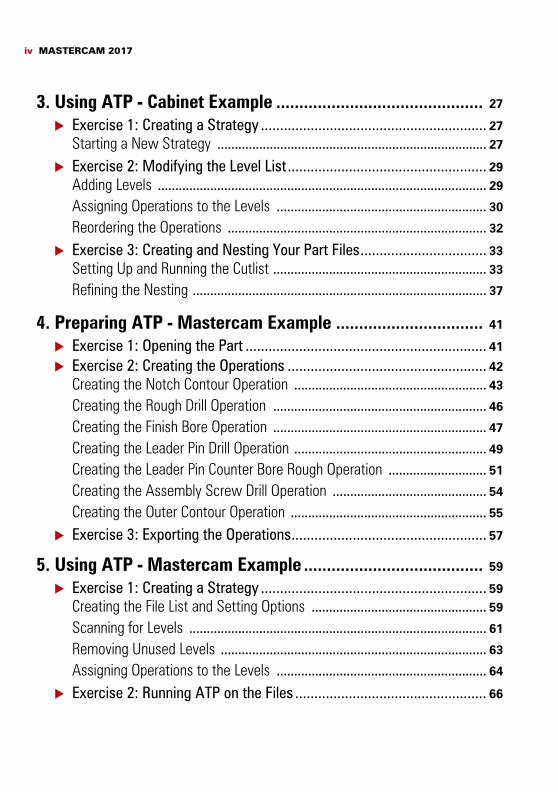
3. Using ATP - Cabinet Example ............................................. 27
Exercise 1: Creating a Strategy ........................................................... 27Starting a New Strategy ............................................................................. 27
Exercise 2: Modifying the Level List.................................................... 29Adding Levels .............................................................................................. 29
Assigning Operations to the Levels ............................................................ 30
Reordering the Operations .......................................................................... 32
Exercise 3: Creating and Nesting Your Part Files................................. 33Setting Up and Running the Cutlist ............................................................. 33
Refining the Nesting .................................................................................... 37
4. Preparing ATP - Mastercam Example ................................ 41
Exercise 1: Opening the Part ............................................................... 41
Exercise 2: Creating the Operations .................................................... 42Creating the Notch Contour Operation ....................................................... 43
Creating the Rough Drill Operation ............................................................. 46
Creating the Finish Bore Operation ............................................................. 47
Creating the Leader Pin Drill Operation ....................................................... 49
Creating the Leader Pin Counter Bore Rough Operation ............................ 51
Creating the Assembly Screw Drill Operation ............................................ 54
Creating the Outer Contour Operation ........................................................ 55
Exercise 3: Exporting the Operations................................................... 57
5. Using ATP - Mastercam Example ....................................... 59
Exercise 1: Creating a Strategy ........................................................... 59Creating the File List and Setting Options .................................................. 59
Scanning for Levels ..................................................................................... 61
Removing Unused Levels ............................................................................ 63
Assigning Operations to the Levels ............................................................ 64
Exercise 2: Running ATP on the Files .................................................. 66
v
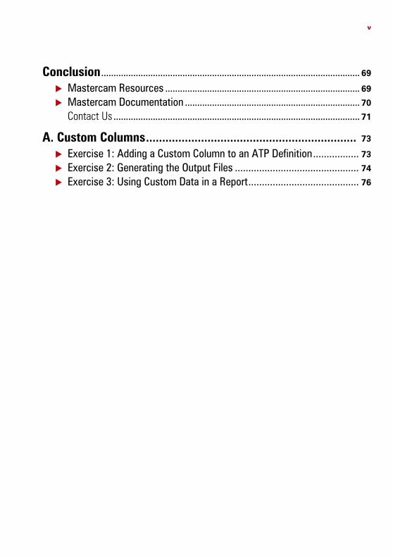
Conclusion ......................................................................................................... 69
Mastercam Resources ............................................................................... 69
Mastercam Documentation ....................................................................... 70
Contact Us .................................................................................................... 71
A. Custom Columns................................................................. 73
Exercise 1: Adding a Custom Column to an ATP Definition................. 73
Exercise 2: Generating the Output Files .............................................. 74
Exercise 3: Using Custom Data in a Report......................................... 76

vi MASTERCAM 2017

Introduction
Welcome to Getting Started with Automatic Toolpathing. Once Automatic Toolpa-thing (ATP) is setup, it automates Mastercam to create part files, NC files, nesting files, and report images with the click of a button. More specifically, ATP automates the process of assigning toolpaths to geometry for recurrent parts, such as in cabinet and closet making. It does this by linking operations to specific levels (layers) containing geometry, which creates a machining strategy. In this tutorial, you discover how to setup ATP and use it to process part files exported from your cabinet software.
Tutorial Goals Set up Mastercam 2017 for ATP. Create operation libraries for ATP. Configure ATP. Create ATP strategies. Run a cutlist.
This tutorial assumes that you are familiar with the basics of using Mastercam.
Estimated time to complete this tutorial: 4 hours
General Tutorial RequirementsAll Mastercam tutorials have the following general requirements:
You must be comfortable using the Windows® operating system. Each lesson in the tutorial builds on the mastery of preceding lesson’s skills.
We recommend that you complete them in order. Additional files may accompany a tutorial. Unless the tutorial provides specific
instructions on where to place these files, store them in a folder that can be accessed from the Mastercam workstation, either with the tutorial or in any location that you prefer.
You will need an internet connection to view videos that are referenced in the tutorials. All videos can be found on our YouTube channel: www.youtube.com/user/MastercamTechDocs.
8 MASTERCAM 2017 / Introduction
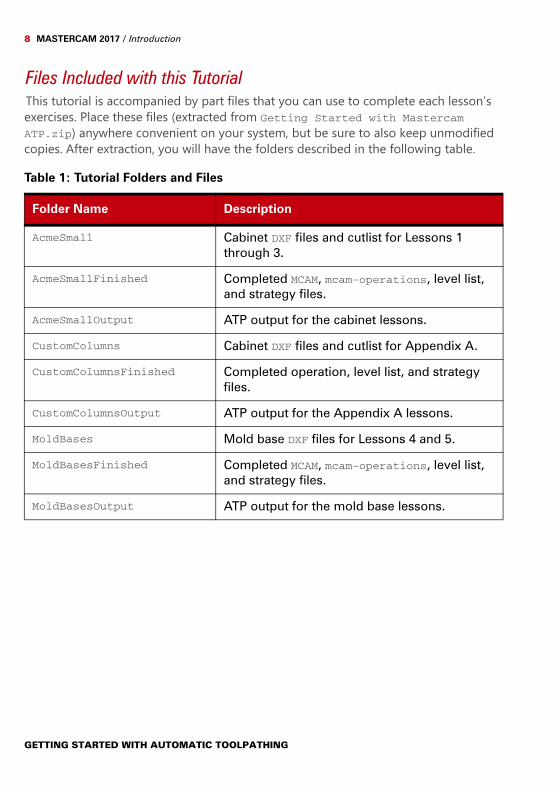
Files Included with this TutorialThis tutorial is accompanied by part files that you can use to complete each lesson’s exercises. Place these files (extracted from Getting Started with Mastercam ATP.zip) anywhere convenient on your system, but be sure to also keep unmodified copies. After extraction, you will have the folders described in the following table.
Table 1: Tutorial Folders and Files
Folder Name Description
AcmeSmall Cabinet DXF files and cutlist for Lessons 1 through 3.
AcmeSmallFinished Completed MCAM, mcam-operations, level list, and strategy files.
AcmeSmallOutput ATP output for the cabinet lessons.
CustomColumns Cabinet DXF files and cutlist for Appendix A.
CustomColumnsFinished Completed operation, level list, and strategy files.
CustomColumnsOutput ATP output for the Appendix A lessons.
MoldBases Mold base DXF files for Lessons 4 and 5.
MoldBasesFinished Completed MCAM, mcam-operations, level list, and strategy files.
MoldBasesOutput ATP output for the mold base lessons.
GETTING STARTED WITH AUTOMATIC TOOLPATHING
LESSON 11ATP Cabinet Overview
ATP automates the assignment of toolpaths to geometry for recurrent parts by linking operations to specific levels, each level containing geometry for a single type of oper-ation. ATP automatically scans all levels and programs for the geometry on each level with the toolpath types you have chosen.Once you setup ATP (create a strategy), you choose the cutlist to be processed. ATP automatically batch processes each part file using the chosen strategy. It then nests the toolpaths and posts the results to one or more NC files (depending on the number of sheets created). ATP sorts these files into folders by material name.ATP is especially useful in large projects with many pieces of geometry. With a modest amount of setup, you can save valuable time by letting the software automatically find, chain, and toolpath all the elements of a job.
The ATP WorkflowMost of the ATP workflow involves preparing your part’s operations and mapping them to the levels in the part files. After this one-time setup, running a cutlist to generate and nest your part files is a quick process. The following list is a summary of the complete workflow.
Assign toolpaths to geometry in the part files. Export the toolpaths as an operation library. Generate a level list from the part files. Map operations to levels. Run the cutlist.
Assigning Toolpaths to GeometryIn most cases, you start with the DXF file with the largest number of operations. This file usually contains all of the operations you need for all the other files in the job. You open this file in Mastercam and create operations just as you would for any other Mastercam part. However, you need only create one of each operation type. For example, if a job has several dado cuts that use the same operation type and tool, you only need to toolpath one of them.
10 MASTERCAM 2017 / ATP Cabinet Overview
NOTE: ATP supports the following toolpaths: Contour, Pocket, Drill, Block Drill, Engrave, Circle Mill, and Helix Bore.
Exporting the ToolpathsOnce you have created the operations needed to complete the job, you export the operations to a library. When you work with ATP, you load this library so that the oper-ations you created are available for mapping to levels. A single operation can be mapped to multiple levels in multiple part files.
Generating a Level ListJust as ATP needs to know about the operations it has to work with (stored in the exported operations library), it needs to know about the levels included in your job’s part files. ATP creates a level list for you and displays the results.
Mapping Operations to LevelsAfter creating your level list, you load the operations library, which makes the opera-tions available for mapping. Each level in the list has a drop-down menu from which you can choose the appropriate operation. You must map an operation to every level in the level list.
Run the CutlistYou complete the previous steps only once for each job type. After that, you can simply run the job’s cutlist to generate the files needed to cut the parts for the job, including nesting the parts on the sheet stock you define.
Levels and OperationsAs you can tell from the ATP workflow, levels and operations play a central role in automating Mastercam to create your final part files. Typically, you define the levels when creating your job’s files in your cabinet software. Each level must contain the
GETTING STARTED WITH AUTOMATIC TOOLPATHING
HOW ATP PROCESSES YOUR FILES 11
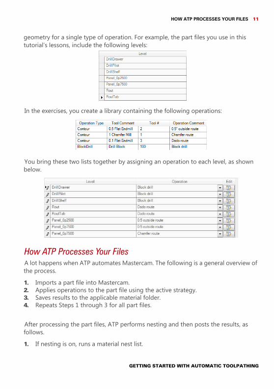
geometry for a single type of operation. For example, the part files you use in this tutorial’s lessons, include the following levels:
In the exercises, you create a library containing the following operations:
You bring these two lists together by assigning an operation to each level, as shown below.
How ATP Processes Your FilesA lot happens when ATP automates Mastercam. The following is a general overview of the process.1. Imports a part file into Mastercam.2. Applies operations to the part file using the active strategy.3. Saves results to the applicable material folder.4. Repeats Steps 1 through 3 for all part files.
After processing the part files, ATP performs nesting and then posts the results, as follows.1. If nesting is on, runs a material nest list.
GETTING STARTED WITH AUTOMATIC TOOLPATHING
12 MASTERCAM 2017 / ATP Cabinet Overview
2. Saves the nested sheet as a drawing to the applicable material folder.3. Posts NC code to the applicable material folder.4. Repeats Steps 1 through 3 for all nest lists.
GETTING STARTED WITH AUTOMATIC TOOLPATHING
LESSON 22Preparing ATP - Cabinet Example
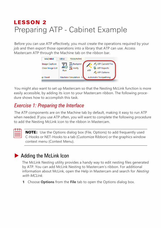
Before you can use ATP effectively, you must create the operations required by your job and then export those operations into a library that ATP can use. Access Mastercam ATP through the Machine tab on the ribbon bar.
You might also want to set up Mastercam so that the Nesting McLink function is more easily accessible, by adding its icon to your Mastercam ribbon. The following proce-dure shows how to accomplish this task.
Exercise 1: Preparing the InterfaceThe ATP components are on the Machine tab by default, making it easy to run ATP when needed. If you use ATP often, you will want to complete the following procedure to add the Nesting McLink icon to the ribbon in Mastercam.
NOTE: Use the Options dialog box (File, Options) to add frequently used C-Hooks or NET-Hooks to a tab (Customize Ribbon) or the graphics window context menu (Context Menu).
Adding the McLink IconThe McLink Nesting utility provides a handy way to edit nesting files generated by ATP. You can add McLink Nesting to Mastercam’s ribbon. For additional information about McLink, open the Help in Mastercam and search for Nesting with MCLink.1 Choose Options from the File tab to open the Options dialog box.
14 MASTERCAM 2017 / Preparing ATP - Cabinet Example
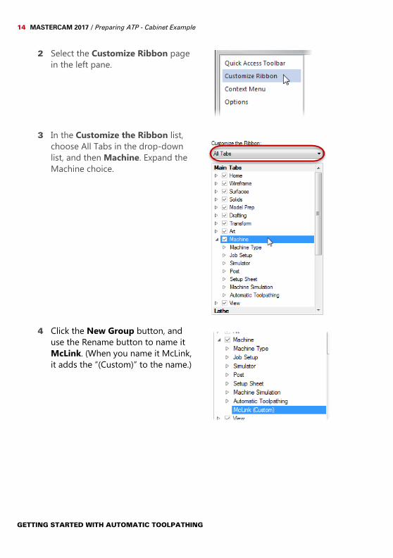
2 Select the Customize Ribbon page in the left pane.
3 In the Customize the Ribbon list, choose All Tabs in the drop-down list, and then Machine. Expand the Machine choice.
4 Click the New Group button, and use the Rename button to name it McLink. (When you name it McLink, it adds the “(Custom)” to the name.)
GETTING STARTED WITH AUTOMATIC TOOLPATHING
OPENING THE PART 15
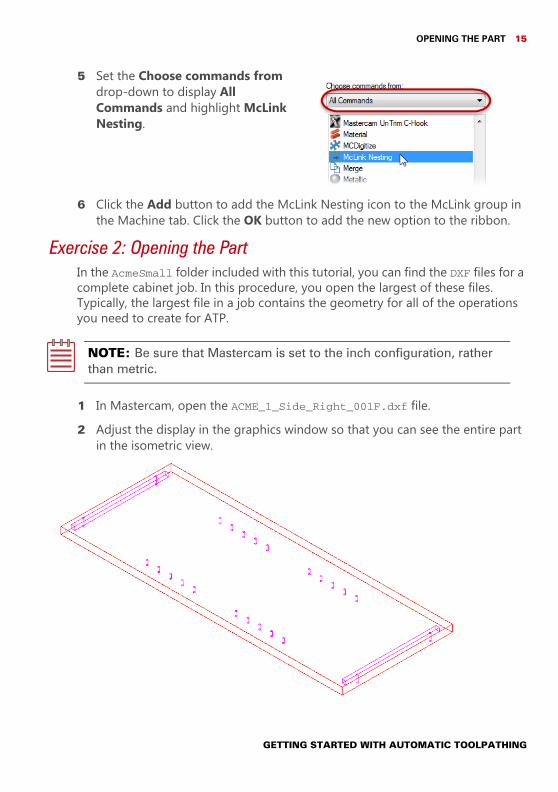
5 Set the Choose commands from drop-down to display All Commands and highlight McLink Nesting.
6 Click the Add button to add the McLink Nesting icon to the McLink group in the Machine tab. Click the OK button to add the new option to the ribbon.
Exercise 2: Opening the PartIn the AcmeSmall folder included with this tutorial, you can find the DXF files for a complete cabinet job. In this procedure, you open the largest of these files. Typically, the largest file in a job contains the geometry for all of the operations you need to create for ATP.
NOTE: Be sure that Mastercam is set to the inch configuration, rather than metric.
1 In Mastercam, open the ACME_1_Side_Right_001F.dxf file.2 Adjust the display in the graphics window so that you can see the entire part
in the isometric view.
GETTING STARTED WITH AUTOMATIC TOOLPATHING
16 MASTERCAM 2017 / Preparing ATP - Cabinet Example
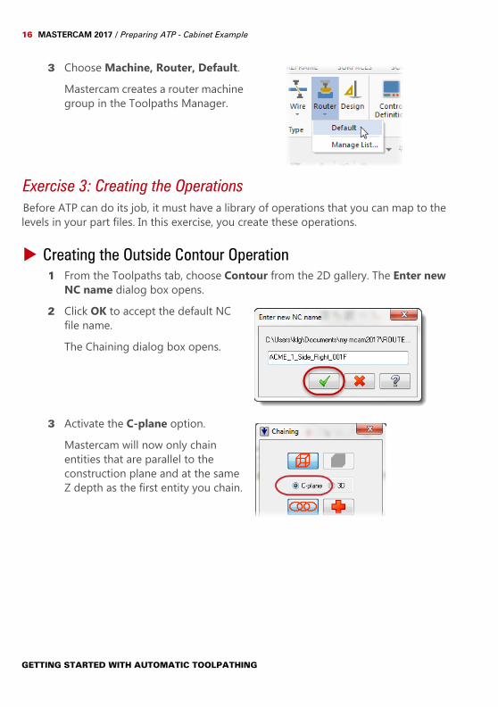
3 Choose Machine, Router, Default.Mastercam creates a router machine group in the Toolpaths Manager.
Exercise 3: Creating the OperationsBefore ATP can do its job, it must have a library of operations that you can map to the levels in your part files. In this exercise, you create these operations.
Creating the Outside Contour Operation1 From the Toolpaths tab, choose Contour from the 2D gallery. The Enter new
NC name dialog box opens.2 Click OK to accept the default NC
file name.The Chaining dialog box opens.
3 Activate the C-plane option.Mastercam will now only chain entities that are parallel to the construction plane and at the same Z depth as the first entity you chain.
GETTING STARTED WITH AUTOMATIC TOOLPATHING
CREATING THE OPERATIONS 17
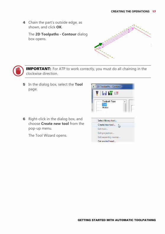
4 Chain the part’s outside edge, as shown, and click OK.The 2D Toolpaths - Contour dialog box opens.
IMPORTANT: For ATP to work correctly, you must do all chaining in the clockwise direction.
5 In the dialog box, select the Tool page.
6 Right-click in the dialog box, and choose Create new tool from the pop-up menu.The Tool Wizard opens.
GETTING STARTED WITH AUTOMATIC TOOLPATHING
18 MASTERCAM 2017 / Preparing ATP - Cabinet Example
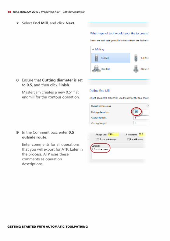
7 Select End Mill, and click Next.
8 Ensure that Cutting diameter is set to 0.5, and then click Finish.Mastercam creates a new 0.5” flat endmill for the contour operation.
9 In the Comment box, enter 0.5 outside route.Enter comments for all operations that you will export for ATP. Later in the process, ATP uses these comments as operation descriptions.
GETTING STARTED WITH AUTOMATIC TOOLPATHING
CREATING THE OPERATIONS 19
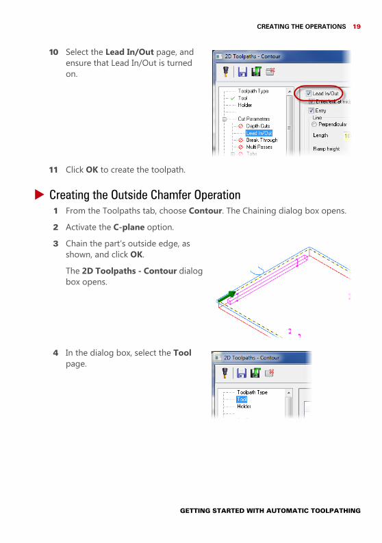
10 Select the Lead In/Out page, and ensure that Lead In/Out is turned on.
11 Click OK to create the toolpath.
Creating the Outside Chamfer Operation1 From the Toolpaths tab, choose Contour. The Chaining dialog box opens.2 Activate the C-plane option.3 Chain the part’s outside edge, as
shown, and click OK.The 2D Toolpaths - Contour dialog box opens.
4 In the dialog box, select the Tool page.
GETTING STARTED WITH AUTOMATIC TOOLPATHING
20 MASTERCAM 2017 / Preparing ATP - Cabinet Example
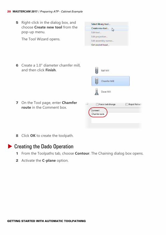
5 Right-click in the dialog box, and choose Create new tool from the pop-up menu.The Tool Wizard opens.
6 Create a 1.0” diameter chamfer mill, and then click Finish.
7 On the Tool page, enter Chamfer route in the Comment box.
8 Click OK to create the toolpath.
Creating the Dado Operation1 From the Toolpaths tab, choose Contour. The Chaining dialog box opens.2 Activate the C-plane option.
GETTING STARTED WITH AUTOMATIC TOOLPATHING
CREATING THE OPERATIONS 21
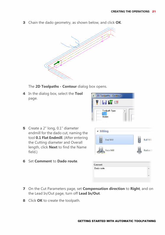
3 Chain the dado geometry, as shown below, and click OK.
The 2D Toolpaths - Contour dialog box opens.4 In the dialog box, select the Tool
page.
5 Create a 2” long, 0.1” diameter endmill for the dado cut, naming the tool 0.1 Flat Endmill. (After entering the Cutting diameter and Overall length, click Next to find the Name field.)
6 Set Comment to Dado route.
7 On the Cut Parameters page, set Compensation direction to Right, and on the Lead In/Out page, turn off Lead In/Out.
8 Click OK to create the toolpath.
GETTING STARTED WITH AUTOMATIC TOOLPATHING
22 MASTERCAM 2017 / Preparing ATP - Cabinet Example
NOTE: Although the part file contains two dados, you only need to tool-path one. When run, ATP will automatically find other matching dado operations.
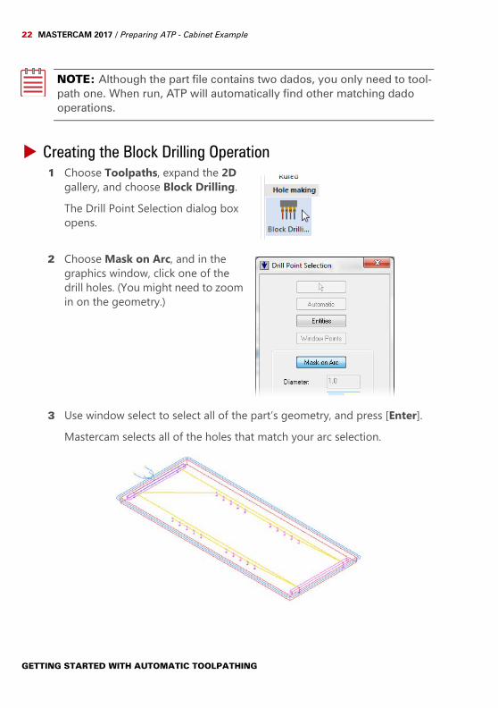
Creating the Block Drilling Operation1 Choose Toolpaths, expand the 2D
gallery, and choose Block Drilling. The Drill Point Selection dialog box opens.
2 Choose Mask on Arc, and in the graphics window, click one of the drill holes. (You might need to zoom in on the geometry.)
3 Use window select to select all of the part’s geometry, and press [Enter].Mastercam selects all of the holes that match your arc selection.
GETTING STARTED WITH AUTOMATIC TOOLPATHING
EXPORTING THE OPERATIONS 23
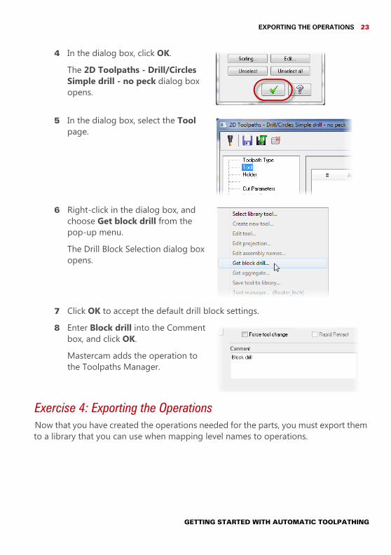
4 In the dialog box, click OK.The 2D Toolpaths - Drill/Circles Simple drill - no peck dialog box opens.
5 In the dialog box, select the Tool page.
6 Right-click in the dialog box, and choose Get block drill from the pop-up menu.The Drill Block Selection dialog box opens.
7 Click OK to accept the default drill block settings.8 Enter Block drill into the Comment
box, and click OK.Mastercam adds the operation to the Toolpaths Manager.
Exercise 4: Exporting the OperationsNow that you have created the operations needed for the parts, you must export them to a library that you can use when mapping level names to operations.
GETTING STARTED WITH AUTOMATIC TOOLPATHING
24 MASTERCAM 2017 / Preparing ATP - Cabinet Example
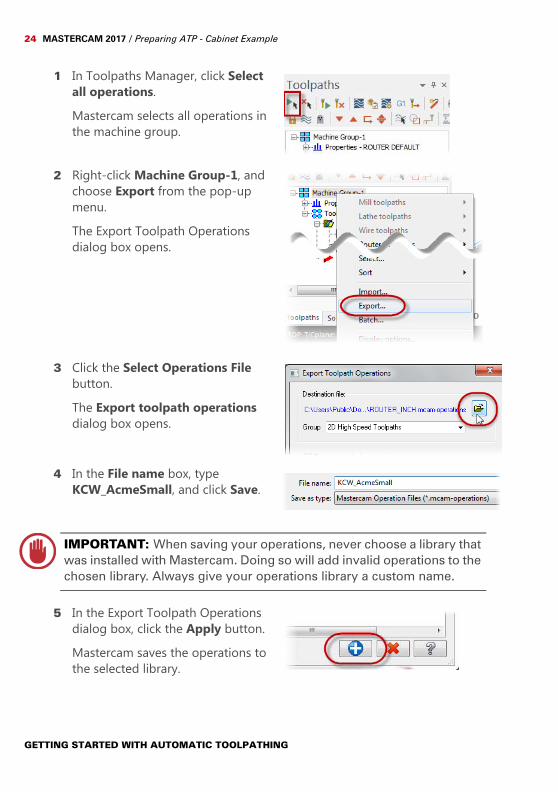
1 In Toolpaths Manager, click Select all operations.Mastercam selects all operations in the machine group.
2 Right-click Machine Group-1, and choose Export from the pop-up menu.The Export Toolpath Operations dialog box opens.
3 Click the Select Operations File button.The Export toolpath operations dialog box opens.
4 In the File name box, type KCW_AcmeSmall, and click Save.
IMPORTANT: When saving your operations, never choose a library that was installed with Mastercam. Doing so will add invalid operations to the chosen library. Always give your operations library a custom name.
5 In the Export Toolpath Operations dialog box, click the Apply button.Mastercam saves the operations to the selected library.
GETTING STARTED WITH AUTOMATIC TOOLPATHING
EXPORTING THE OPERATIONS 25
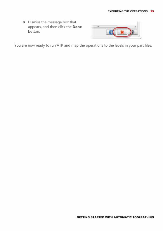
6 Dismiss the message box that appears, and then click the Done button.
You are now ready to run ATP and map the operations to the levels in your part files.
GETTING STARTED WITH AUTOMATIC TOOLPATHING

26 MASTERCAM 2017 / Preparing ATP - Cabinet Example
GETTING STARTED WITH AUTOMATIC TOOLPATHING
LESSON 33Using ATP - Cabinet Example
Once you have your operation library created, it is time to create a strategy for the job. This requires generating a level list (a list of all levels in the job’s part files) and assigning an operation to each level. When that is done, you can run your cutlist to create the job’s final files.
Exercise 1: Creating a StrategyTo create a strategy, you must start a new strategy file and generate a level list from the parts.
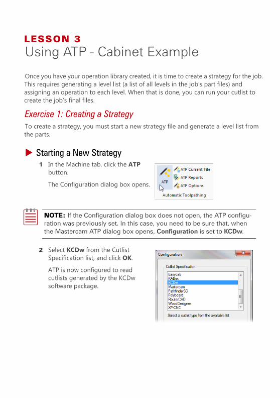
Starting a New Strategy1 In the Machine tab, click the ATP
button.The Configuration dialog box opens.
NOTE: If the Configuration dialog box does not open, the ATP configu-ration was previously set. In this case, you need to be sure that, when the Mastercam ATP dialog box opens, Configuration is set to KCDw.
2 Select KCDw from the Cutlist Specification list, and click OK.ATP is now configured to read cutlists generated by the KCDw software package.
28 MASTERCAM 2017 / Using ATP - Cabinet Example
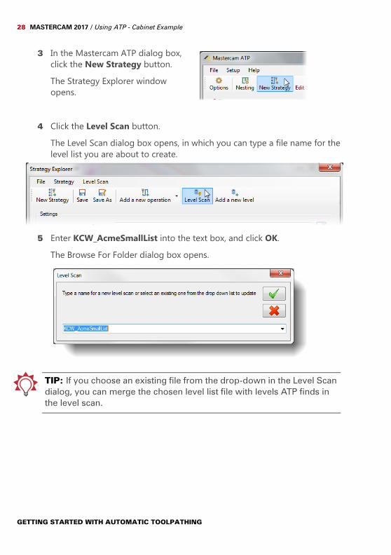
3 In the Mastercam ATP dialog box, click the New Strategy button.The Strategy Explorer window opens.
4 Click the Level Scan button.The Level Scan dialog box opens, in which you can type a file name for the level list you are about to create.
5 Enter KCW_AcmeSmallList into the text box, and click OK.The Browse For Folder dialog box opens.
TIP: If you choose an existing file from the drop-down in the Level Scan dialog, you can merge the chosen level list file with levels ATP finds in the level scan.
GETTING STARTED WITH AUTOMATIC TOOLPATHING
MODIFYING THE LEVEL LIST 29
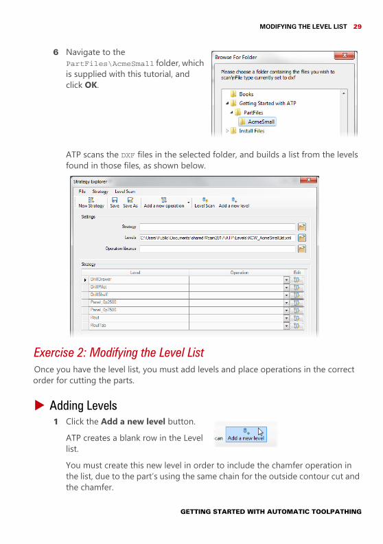
6 Navigate to the PartFiles\AcmeSmall folder, which is supplied with this tutorial, and click OK.
ATP scans the DXF files in the selected folder, and builds a list from the levels found in those files, as shown below.
Exercise 2: Modifying the Level ListOnce you have the level list, you must add levels and place operations in the correct order for cutting the parts.
Adding Levels1 Click the Add a new level button.
ATP creates a blank row in the Level list.You must create this new level in order to include the chamfer operation in the list, due to the part’s using the same chain for the outside contour cut and the chamfer.
GETTING STARTED WITH AUTOMATIC TOOLPATHING
30 MASTERCAM 2017 / Using ATP - Cabinet Example
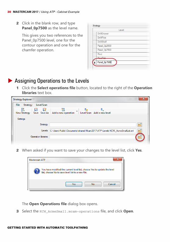
2 Click in the blank row, and type Panel_0p7500 as the level name.This gives you two references to the Panel_0p7500 level, one for the contour operation and one for the chamfer operation.
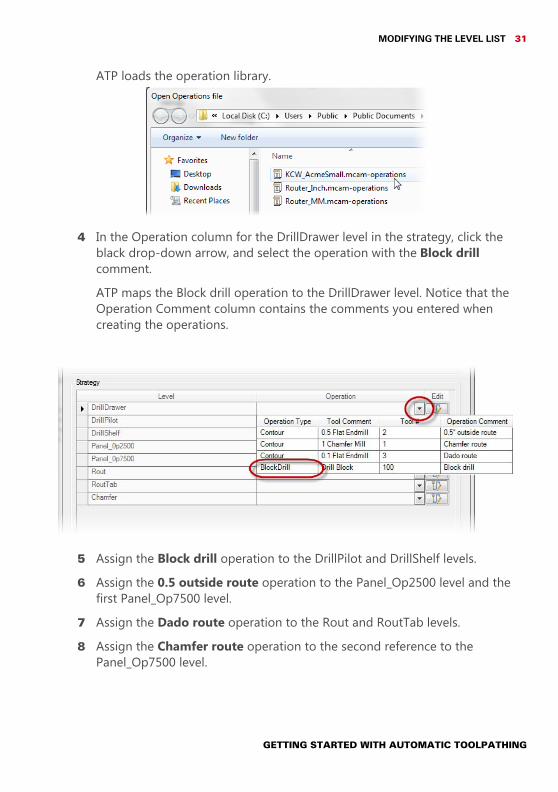
Assigning Operations to the Levels1 Click the Select operations file button, located to the right of the Operation
libraries text box.
2 When asked if you want to save your changes to the level list, click Yes.
The Open Operations file dialog box opens.3 Select the KCW_AcmeSmall.mcam-operations file, and click Open.
GETTING STARTED WITH AUTOMATIC TOOLPATHING
MODIFYING THE LEVEL LIST 31
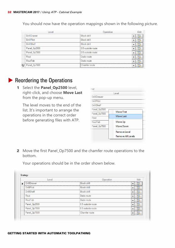
ATP loads the operation library.
4 In the Operation column for the DrillDrawer level in the strategy, click the black drop-down arrow, and select the operation with the Block drill comment.ATP maps the Block drill operation to the DrillDrawer level. Notice that the Operation Comment column contains the comments you entered when creating the operations.
5 Assign the Block drill operation to the DrillPilot and DrillShelf levels.6 Assign the 0.5 outside route operation to the Panel_Op2500 level and the
first Panel_Op7500 level.7 Assign the Dado route operation to the Rout and RoutTab levels.8 Assign the Chamfer route operation to the second reference to the
Panel_Op7500 level.
GETTING STARTED WITH AUTOMATIC TOOLPATHING
32 MASTERCAM 2017 / Using ATP - Cabinet Example
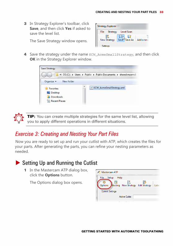
You should now have the operation mappings shown in the following picture.
Reordering the Operations1 Select the Panel_Op2500 level,
right-click, and choose Move Last from the pop-up menu.The level moves to the end of the list. It’s important to arrange the operations in the correct order before generating files with ATP.
2 Move the first Panel_Op7500 and the chamfer route operations to the bottom.Your operations should be in the order shown below.
GETTING STARTED WITH AUTOMATIC TOOLPATHING
CREATING AND NESTING YOUR PART FILES 33
3 In Strategy Explorer’s toolbar, click Save, and then click Yes if asked to save the level list.The Save Strategy window opens.
4 Save the strategy under the name KCW_AcmeSmallStrategy, and then click OK in the Strategy Explorer window.
TIP: You can create multiple strategies for the same level list, allowing you to apply different operations in different situations.
Exercise 3: Creating and Nesting Your Part FilesNow you are ready to set up and run your cutlist with ATP, which creates the files for your parts. After generating the parts, you can refine your nesting parameters as needed.
Setting Up and Running the Cutlist1 In the Mastercam ATP dialog box,
click the Options button.The Options dialog box opens.
GETTING STARTED WITH AUTOMATIC TOOLPATHING
34 MASTERCAM 2017 / Using ATP - Cabinet Example
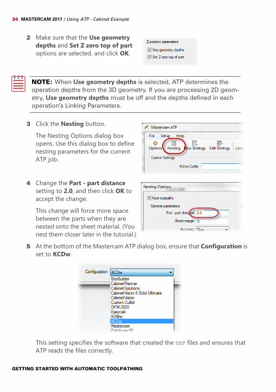
2 Make sure that the Use geometry depths and Set Z zero top of part options are selected, and click OK.
NOTE: When Use geometry depths is selected, ATP determines the operation depths from the 3D geometry. If you are processing 2D geom-etry, Use geometry depths must be off and the depths defined in each operation’s Linking Parameters.
3 Click the Nesting button.The Nesting Options dialog box opens. Use this dialog box to define nesting parameters for the current ATP job.
4 Change the Part - part distance setting to 2.0, and then click OK to accept the change.This change will force more space between the parts when they are nested onto the sheet material. (You nest them closer later in the tutorial.)
5 At the bottom of the Mastercam ATP dialog box, ensure that Configuration is set to KCDw.
This setting specifies the software that created the DXF files and ensures that ATP reads the files correctly.
GETTING STARTED WITH AUTOMATIC TOOLPATHING
CREATING AND NESTING YOUR PART FILES 35
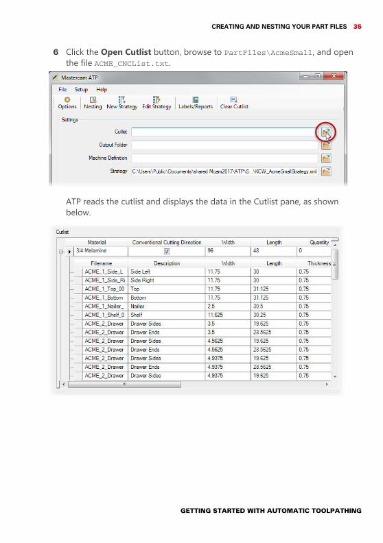
6 Click the Open Cutlist button, browse to PartFiles\AcmeSmall, and open the file ACME_CNCList.txt.
ATP reads the cutlist and displays the data in the Cutlist pane, as shown below.
GETTING STARTED WITH AUTOMATIC TOOLPATHING
36 MASTERCAM 2017 / Using ATP - Cabinet Example
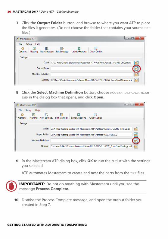
7 Click the Output Folder button, and browse to where you want ATP to place the files it generates. (Do not choose the folder that contains your source DXF files.)
8 Click the Select Machine Definition button, choose ROUTER DEFAULT.MCAM-RMD in the dialog box that opens, and click Open.
9 In the Mastercam ATP dialog box, click OK to run the cutlist with the settings you selected.ATP automates Mastercam to create and nest the parts from the DXF files.
IMPORTANT: Do not do anything with Mastercam until you see the message Process Complete.
10 Dismiss the Process Complete message, and open the output folder you created in Step 7.
GETTING STARTED WITH AUTOMATIC TOOLPATHING
CREATING AND NESTING YOUR PART FILES 37
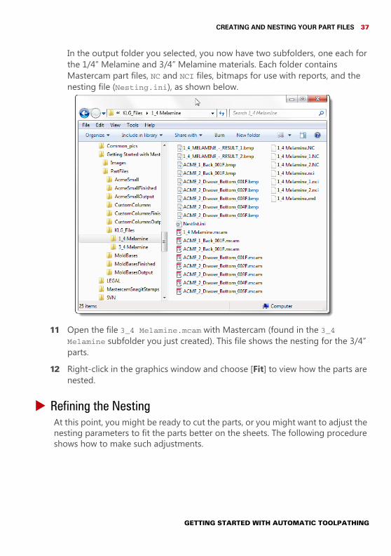
In the output folder you selected, you now have two subfolders, one each for the 1/4” Melamine and 3/4” Melamine materials. Each folder contains Mastercam part files, NC and NCI files, bitmaps for use with reports, and the nesting file (Nesting.ini), as shown below.
11 Open the file 3_4 Melamine.mcam with Mastercam (found in the 3_4 Melamine subfolder you just created). This file shows the nesting for the 3/4” parts.
12 Right-click in the graphics window and choose [Fit] to view how the parts are nested.
Refining the NestingAt this point, you might be ready to cut the parts, or you might want to adjust the nesting parameters to fit the parts better on the sheets. The following procedure shows how to make such adjustments.
GETTING STARTED WITH AUTOMATIC TOOLPATHING
38 MASTERCAM 2017 / Using ATP - Cabinet Example
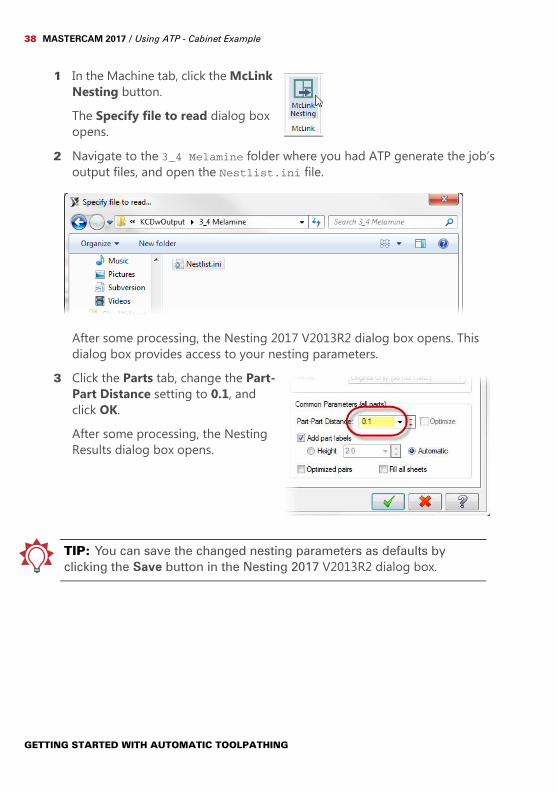
1 In the Machine tab, click the McLink Nesting button.The Specify file to read dialog box opens.
2 Navigate to the 3_4 Melamine folder where you had ATP generate the job’s output files, and open the Nestlist.ini file.
After some processing, the Nesting 2017 V2013R2 dialog box opens. This dialog box provides access to your nesting parameters.
3 Click the Parts tab, change the Part-Part Distance setting to 0.1, and click OK.After some processing, the Nesting Results dialog box opens.
TIP: You can save the changed nesting parameters as defaults by clicking the Save button in the Nesting 2017 V2013R2 dialog box.
GETTING STARTED WITH AUTOMATIC TOOLPATHING
CREATING AND NESTING YOUR PART FILES 39
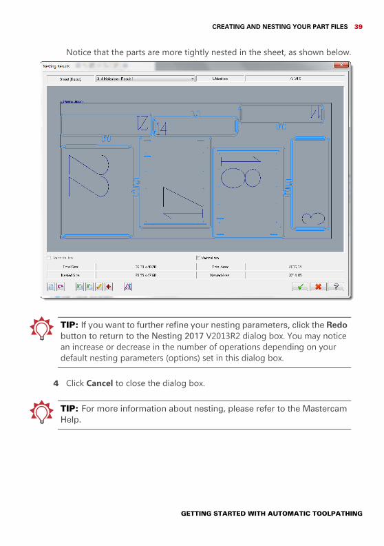
Notice that the parts are more tightly nested in the sheet, as shown below.
TIP: If you want to further refine your nesting parameters, click the Redo button to return to the Nesting 2017 V2013R2 dialog box. You may notice an increase or decrease in the number of operations depending on your default nesting parameters (options) set in this dialog box.
4 Click Cancel to close the dialog box.
TIP: For more information about nesting, please refer to the Mastercam Help.
GETTING STARTED WITH AUTOMATIC TOOLPATHING
40 MASTERCAM 2017 / Using ATP - Cabinet Example
GETTING STARTED WITH AUTOMATIC TOOLPATHING
LESSON 44Preparing ATP - Mastercam Example
When using ATP in the Mastercam configuration, you use a file list instead of a cutlist. As with the cabinet example, you must still create an operations library and map the operations to the levels in the files.
NOTE: This lesson assumes that you have set up ATP as described in the section Preparing the Interface on page 13.
Exercise 1: Opening the PartIn the MoldBases folder included with this tutorial, you can find the DXF files for this lesson. In this procedure, you open the largest of these files, because the largest file in a job typically contains the geometry for all of the operations you need to create for ATP.1 Start a new Mastercam session. Make sure you are using the inch
configuration.2 In Mastercam, open the 1.dxf file. (You may want to change the geometry’s
color to make it easier to see.)

42 MASTERCAM 2017 / Preparing ATP - Mastercam Example
The part should look like the following image.
3 From the Machine tab, choose Mill, Default.Mastercam creates a mill machine group in the Toolpaths Manager.
Exercise 2: Creating the OperationsThe mold bases project contains much more geometry than you will create operations for. To keep the example short, in this exercise, you create only the seven operations represented on the levels in the 1.dxf file.
GETTING STARTED WITH AUTOMATIC TOOLPATHING
CREATING THE OPERATIONS 43
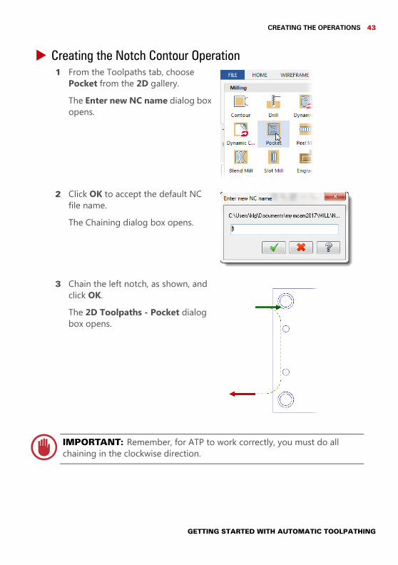
Creating the Notch Contour Operation1 From the Toolpaths tab, choose
Pocket from the 2D gallery. The Enter new NC name dialog box opens.
2 Click OK to accept the default NC file name.The Chaining dialog box opens.
3 Chain the left notch, as shown, and click OK.The 2D Toolpaths - Pocket dialog box opens.
IMPORTANT: Remember, for ATP to work correctly, you must do all chaining in the clockwise direction.
GETTING STARTED WITH AUTOMATIC TOOLPATHING
44 MASTERCAM 2017 / Preparing ATP - Mastercam Example
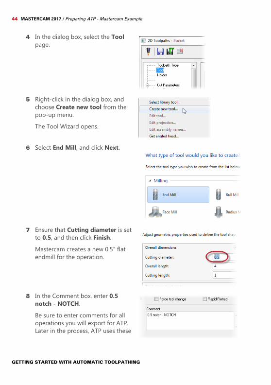
4 In the dialog box, select the Tool page.
5 Right-click in the dialog box, and choose Create new tool from the pop-up menu.The Tool Wizard opens.
6 Select End Mill, and click Next.
7 Ensure that Cutting diameter is set to 0.5, and then click Finish.Mastercam creates a new 0.5” flat endmill for the operation.
8 In the Comment box, enter 0.5 notch - NOTCH.Be sure to enter comments for all operations you will export for ATP. Later in the process, ATP uses these
GETTING STARTED WITH AUTOMATIC TOOLPATHING
CREATING THE OPERATIONS 45
comments as operation descriptions.
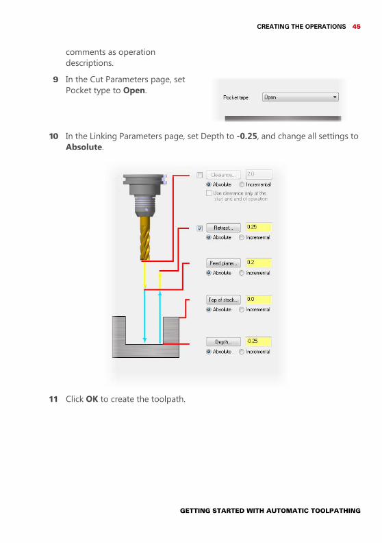
9 In the Cut Parameters page, set Pocket type to Open.
10 In the Linking Parameters page, set Depth to -0.25, and change all settings to Absolute.
11 Click OK to create the toolpath.
GETTING STARTED WITH AUTOMATIC TOOLPATHING

46 MASTERCAM 2017 / Preparing ATP - Mastercam Example
Creating the Rough Drill Operation1 From the Toolpaths tab, choose Drill
in the Hole making section of the 2D gallery. The Drill Point Selection dialog box opens.
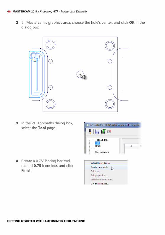
2 In Mastercam’s graphics area, choose the hole’s center, as shown, and click OK in the dialog box.
3 In the dialog box, select the Tool page.
GETTING STARTED WITH AUTOMATIC TOOLPATHING
CREATING THE OPERATIONS 47
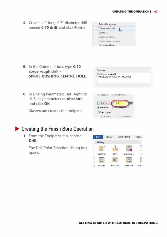
4 Create a 4” long, 0.7” diameter drill named 0.70 drill, and click Finish.
5 In the Comment box, type 0.70 sprue rough drill - SPRUE_BUSHING_CENTRE_HOLE.
6 In Linking Parameters, set Depth to-0.5, all parameters to Absolute, and click OK.Mastercam creates the toolpath.
Creating the Finish Bore Operation1 From the Toolpaths tab, choose
Drill. The Drill Point Selection dialog box opens.
GETTING STARTED WITH AUTOMATIC TOOLPATHING
48 MASTERCAM 2017 / Preparing ATP - Mastercam Example
2 In Mastercam’s graphics area, choose the hole’s center, and click OK in the dialog box.
3 In the 2D Toolpaths dialog box, select the Tool page.
4 Create a 0.75” boring bar tool named 0.75 bore bar, and click Finish.
GETTING STARTED WITH AUTOMATIC TOOLPATHING
CREATING THE OPERATIONS 49
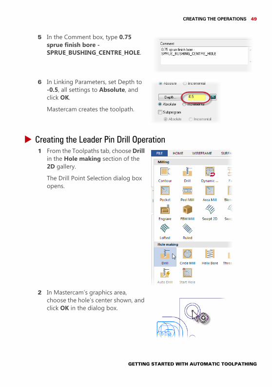
5 In the Comment box, type 0.75 sprue finish bore - SPRUE_BUSHING_CENTRE_HOLE.
6 In Linking Parameters, set Depth to-0.5, all settings to Absolute, and click OK.Mastercam creates the toolpath.
Creating the Leader Pin Drill Operation1 From the Toolpaths tab, choose Drill
in the Hole making section of the 2D gallery. The Drill Point Selection dialog box opens.
2 In Mastercam’s graphics area, choose the hole’s center shown, and click OK in the dialog box.
GETTING STARTED WITH AUTOMATIC TOOLPATHING
50 MASTERCAM 2017 / Preparing ATP - Mastercam Example
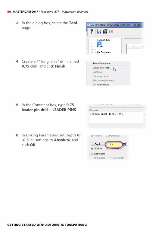
3 In the dialog box, select the Tool page.
4 Create a 4” long, 0.75” drill named 0.75 drill, and click Finish.
5 In the Comment box, type 0.75 leader pin drill - LEADER PINS.
6 In Linking Parameters, set Depth to-0.5, all settings to Absolute, and click OK.
GETTING STARTED WITH AUTOMATIC TOOLPATHING
CREATING THE OPERATIONS 51
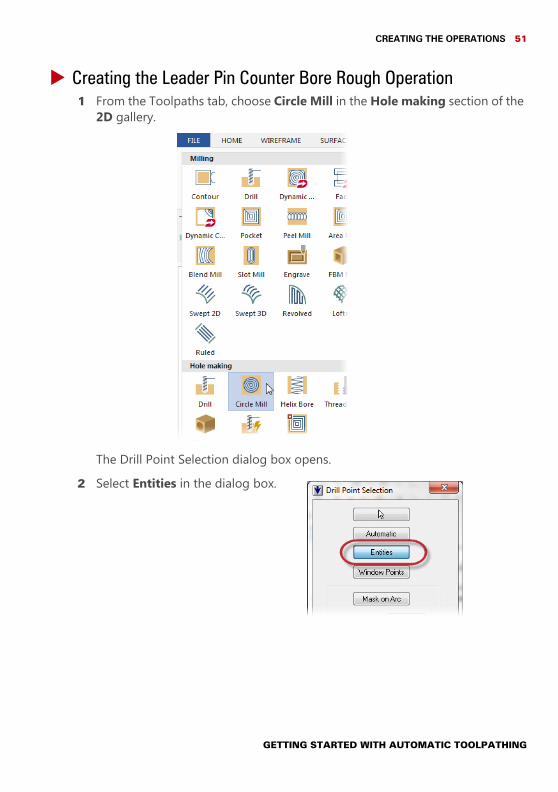
Creating the Leader Pin Counter Bore Rough Operation1 From the Toolpaths tab, choose Circle Mill in the Hole making section of the
2D gallery.
The Drill Point Selection dialog box opens. 2 Select Entities in the dialog box.
GETTING STARTED WITH AUTOMATIC TOOLPATHING
52 MASTERCAM 2017 / Preparing ATP - Mastercam Example
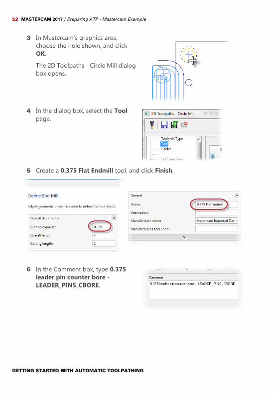
3 In Mastercam’s graphics area, choose the hole shown, and click OK.The 2D Toolpaths - Circle Mill dialog box opens.
4 In the dialog box, select the Tool page.
5 Create a 0.375 Flat Endmill tool, and click Finish.
6 In the Comment box, type 0.375 leader pin counter bore -LEADER_PINS_CBORE.
GETTING STARTED WITH AUTOMATIC TOOLPATHING
CREATING THE OPERATIONS 53
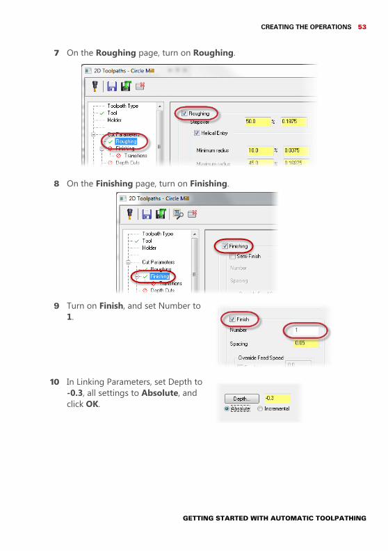
7 On the Roughing page, turn on Roughing.
8 On the Finishing page, turn on Finishing.
9 Turn on Finish, and set Number to 1.
10 In Linking Parameters, set Depth to-0.3, all settings to Absolute, and click OK.
GETTING STARTED WITH AUTOMATIC TOOLPATHING
54 MASTERCAM 2017 / Preparing ATP - Mastercam Example
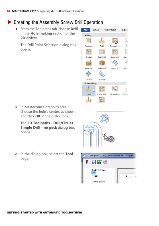
Creating the Assembly Screw Drill Operation1 From the Toolpaths tab, choose Drill
in the Hole making section of the 2D gallery.The Drill Point Selection dialog box opens.
2 In Mastercam’s graphics area, choose the hole’s center, as shown, and click OK in the dialog box.The 2D Toolpaths - Drill/Circles Simple Drill - no peck dialog box opens.
3 In the dialog box, select the Tool page.
GETTING STARTED WITH AUTOMATIC TOOLPATHING
CREATING THE OPERATIONS 55
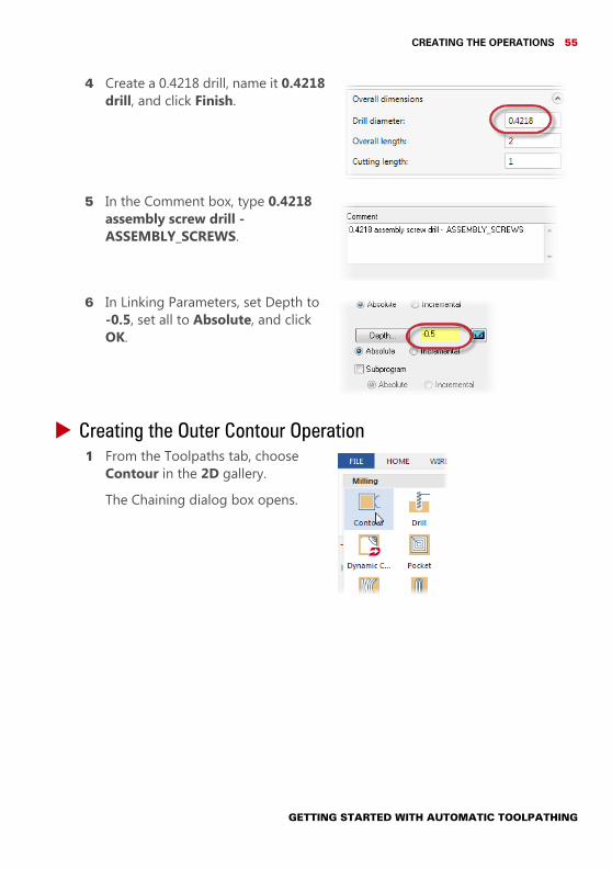
4 Create a 0.4218 drill, name it 0.4218 drill, and click Finish.
5 In the Comment box, type 0.4218 assembly screw drill - ASSEMBLY_SCREWS.
6 In Linking Parameters, set Depth to-0.5, set all to Absolute, and click OK.
Creating the Outer Contour Operation1 From the Toolpaths tab, choose
Contour in the 2D gallery.The Chaining dialog box opens.
GETTING STARTED WITH AUTOMATIC TOOLPATHING
56 MASTERCAM 2017 / Preparing ATP - Mastercam Example
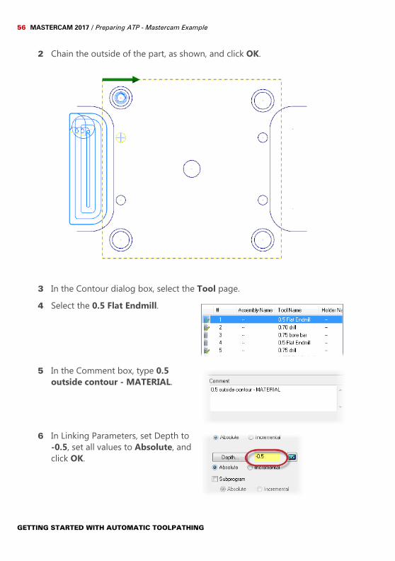
2 Chain the outside of the part, as shown, and click OK.
3 In the Contour dialog box, select the Tool page.4 Select the 0.5 Flat Endmill.
5 In the Comment box, type 0.5 outside contour - MATERIAL.
6 In Linking Parameters, set Depth to-0.5, set all values to Absolute, and click OK.
GETTING STARTED WITH AUTOMATIC TOOLPATHING
EXPORTING THE OPERATIONS 57
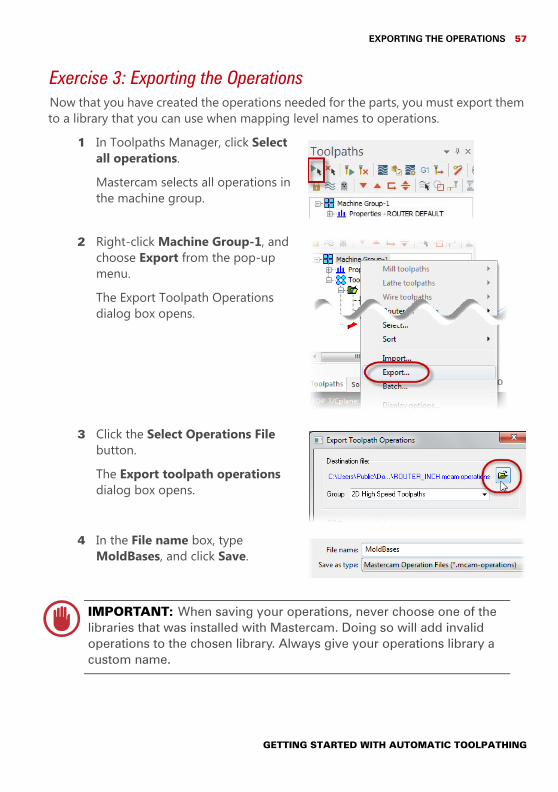
Exercise 3: Exporting the OperationsNow that you have created the operations needed for the parts, you must export them to a library that you can use when mapping level names to operations.
1 In Toolpaths Manager, click Select all operations.Mastercam selects all operations in the machine group.
2 Right-click Machine Group-1, and choose Export from the pop-up menu.The Export Toolpath Operations dialog box opens.
3 Click the Select Operations File button.The Export toolpath operations dialog box opens.
4 In the File name box, type MoldBases, and click Save.
IMPORTANT: When saving your operations, never choose one of the libraries that was installed with Mastercam. Doing so will add invalid operations to the chosen library. Always give your operations library a custom name.
GETTING STARTED WITH AUTOMATIC TOOLPATHING
58 MASTERCAM 2017 / Preparing ATP - Mastercam Example
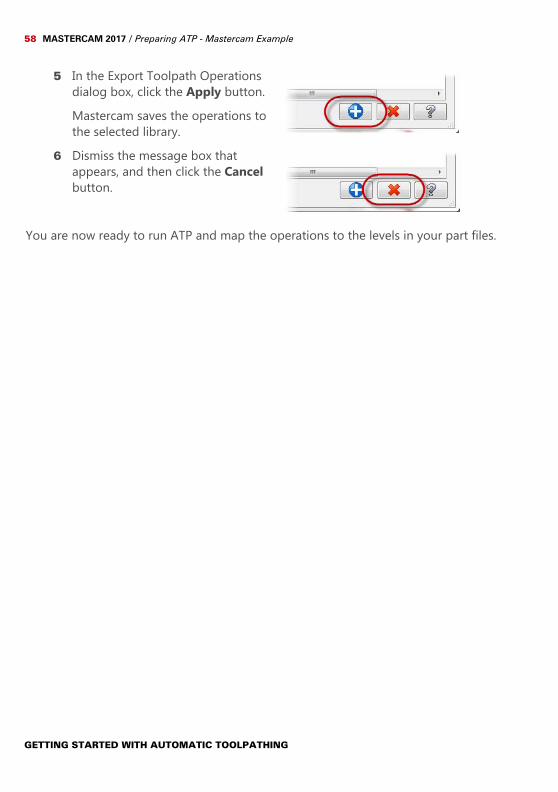
5 In the Export Toolpath Operations dialog box, click the Apply button.Mastercam saves the operations to the selected library.
6 Dismiss the message box that appears, and then click the Cancel button.
You are now ready to run ATP and map the operations to the levels in your part files.
GETTING STARTED WITH AUTOMATIC TOOLPATHING
LESSON 55Using ATP - Mastercam Example
In this lesson, you create an ATP strategy for generating the mold base project’s final files. This process is similar to what you did to create a cabinet strategy. In the Mastercam case, however, you set up a file list in place of a cutlist.
NOTE: This section assumes that you are continuing the tutorial from Lesson 4. If you are starting this section without completing Lesson 4, open the file 1.mcam included with this tutorial.
Exercise 1: Creating a StrategyTo create a strategy, you must tell ATP about the files to use, as well as set the appropriate options, and map operations to levels.
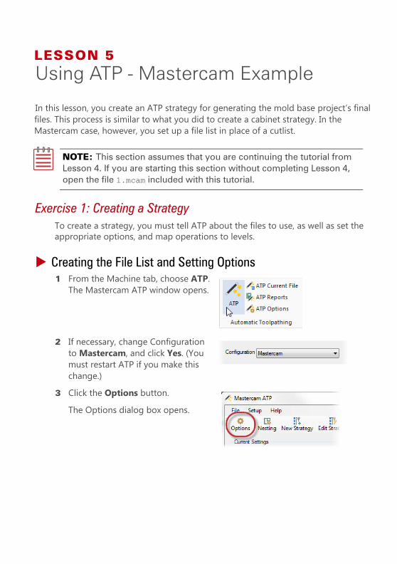
Creating the File List and Setting Options1 From the Machine tab, choose ATP.
The Mastercam ATP window opens.
2 If necessary, change Configuration to Mastercam, and click Yes. (You must restart ATP if you make this change.)
3 Click the Options button.The Options dialog box opens.
60 MASTERCAM 2017 / Using ATP - Mastercam Example
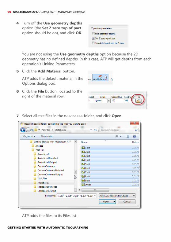
4 Turn off the Use geometry depths option (the Set Z zero top of part option should be on), and click OK.
You are not using the Use geometry depths option because the 2D geometry has no defined depths. In this case, ATP will get depths from each operation’s Linking Parameters.
5 Click the Add Material button.ATP adds the default material in the Options dialog box.
6 Click the File button, located to the right of the material row.
7 Select all DXF files in the MoldBases folder, and click Open.
ATP adds the files to its Files list.
GETTING STARTED WITH AUTOMATIC TOOLPATHING

CREATING A STRATEGY 61
8 Click the Nesting button.The Nesting Options dialog box opens.
9 Turn off the Nest toolpaths option, and click OK.The mold bases do not need nesting.
Scanning for Levels1 Click the New Strategy button.
The Strategy Explorer window opens.
2 Click the Level Scan button.The Level Scan window opens.
3 Enter MoldBasesLevels into the text box, and click OK.The Browse For Folder dialog box opens.
GETTING STARTED WITH AUTOMATIC TOOLPATHING
62 MASTERCAM 2017 / Using ATP - Mastercam Example
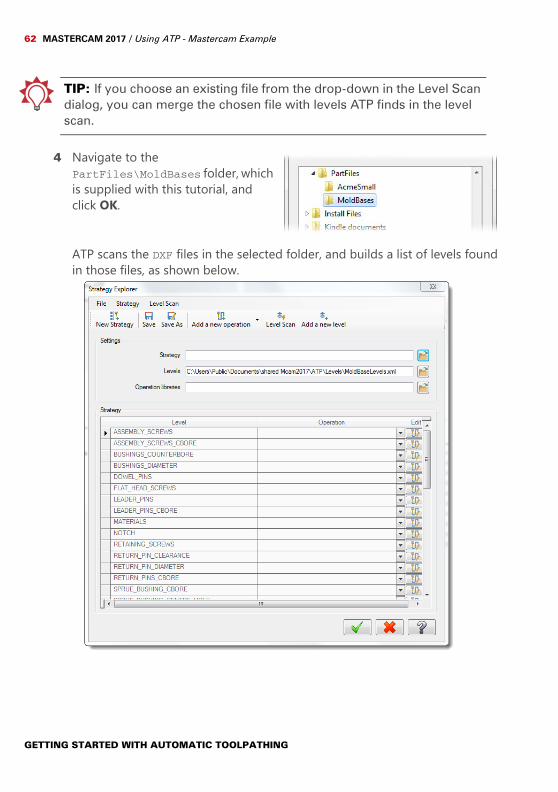
TIP: If you choose an existing file from the drop-down in the Level Scan dialog, you can merge the chosen file with levels ATP finds in the level scan.
4 Navigate to the PartFiles\MoldBases folder, which is supplied with this tutorial, and click OK.
ATP scans the DXF files in the selected folder, and builds a list of levels found in those files, as shown below.
GETTING STARTED WITH AUTOMATIC TOOLPATHING
CREATING A STRATEGY 63
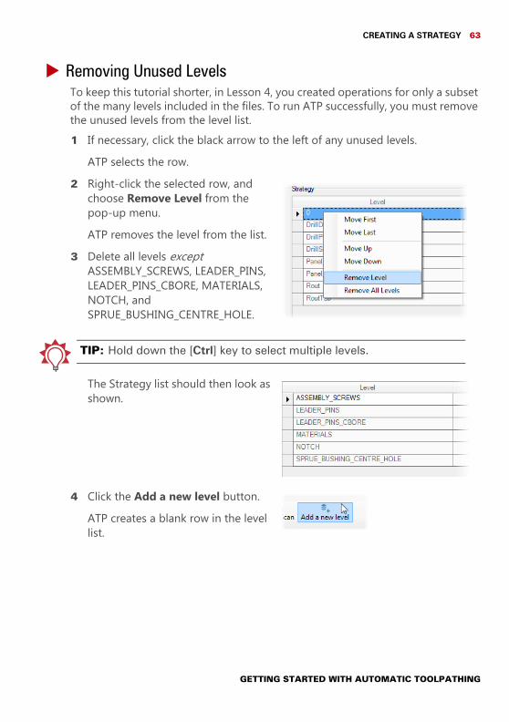
Removing Unused LevelsTo keep this tutorial shorter, in Lesson 4, you created operations for only a subset of the many levels included in the files. To run ATP successfully, you must remove the unused levels from the level list.1 If necessary, click the black arrow to the left of any unused levels.
ATP selects the row.2 Right-click the selected row, and
choose Remove Level from the pop-up menu.ATP removes the level from the list.
3 Delete all levels except ASSEMBLY_SCREWS, LEADER_PINS, LEADER_PINS_CBORE, MATERIALS, NOTCH, and SPRUE_BUSHING_CENTRE_HOLE.
TIP: Hold down the [Ctrl] key to select multiple levels.
The Strategy list should then look as shown.
4 Click the Add a new level button.ATP creates a blank row in the level list.
GETTING STARTED WITH AUTOMATIC TOOLPATHING
64 MASTERCAM 2017 / Using ATP - Mastercam Example
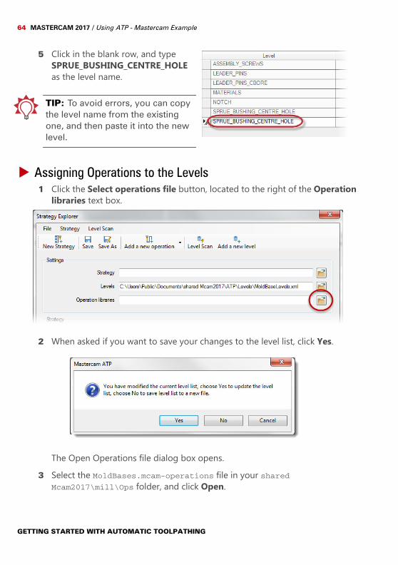
5 Click in the blank row, and type SPRUE_BUSHING_CENTRE_HOLE as the level name.
TIP: To avoid errors, you can copy the level name from the existing one, and then paste it into the new level.
Assigning Operations to the Levels1 Click the Select operations file button, located to the right of the Operation
libraries text box.
2 When asked if you want to save your changes to the level list, click Yes.
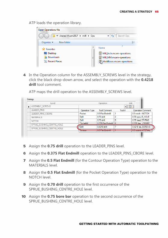
The Open Operations file dialog box opens.3 Select the MoldBases.mcam-operations file in your shared
Mcam2017\mill\Ops folder, and click Open.
GETTING STARTED WITH AUTOMATIC TOOLPATHING
CREATING A STRATEGY 65
ATP loads the operation library.
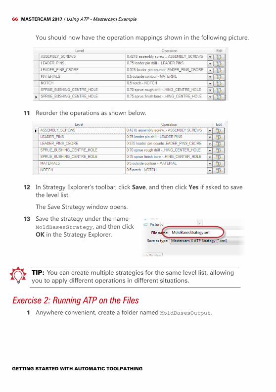
4 In the Operation column for the ASSEMBLY_SCREWS level in the strategy, click the black drop-down arrow, and select the operation with the 0.4218 drill tool comment.ATP maps the drill operation to the ASSEMBLY_SCREWS level.
5 Assign the 0.75 drill operation to the LEADER_PINS level.6 Assign the 0.375 Flat Endmill operation to the LEADER_PINS_CBORE level.7 Assign the 0.5 Flat Endmill (for the Contour Operation Type) operation to the
MATERIALS level.8 Assign the 0.5 Flat Endmill (for the Pocket Operation Type) operation to the
NOTCH level.9 Assign the 0.70 drill operation to the first occurrence of the
SPRUE_BUSHING_CENTRE_HOLE level.10 Assign the 0.75 bore bar operation to the second occurrence of the
SPRUE_BUSHING_CENTRE_HOLE level.
GETTING STARTED WITH AUTOMATIC TOOLPATHING
66 MASTERCAM 2017 / Using ATP - Mastercam Example
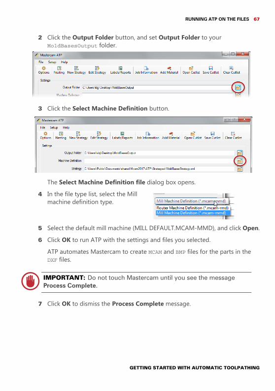
You should now have the operation mappings shown in the following picture.
11 Reorder the operations as shown below.
12 In Strategy Explorer’s toolbar, click Save, and then click Yes if asked to save the level list.The Save Strategy window opens.
13 Save the strategy under the name MoldBasesStrategy, and then click OK in the Strategy Explorer.
TIP: You can create multiple strategies for the same level list, allowing you to apply different operations in different situations.
Exercise 2: Running ATP on the Files1 Anywhere convenient, create a folder named MoldBasesOutput.
GETTING STARTED WITH AUTOMATIC TOOLPATHING
RUNNING ATP ON THE FILES 67
2 Click the Output Folder button, and set Output Folder to your MoldBasesOutput folder.
3 Click the Select Machine Definition button.
The Select Machine Definition file dialog box opens.4 In the file type list, select the Mill
machine definition type.
5 Select the default mill machine (MILL DEFAULT.MCAM-MMD), and click Open.6 Click OK to run ATP with the settings and files you selected.
ATP automates Mastercam to create MCAM and BMP files for the parts in the DXF files.
IMPORTANT: Do not touch Mastercam until you see the message Process Complete.
7 Click OK to dismiss the Process Complete message.
GETTING STARTED WITH AUTOMATIC TOOLPATHING
68 MASTERCAM 2017 / Using ATP - Mastercam Example
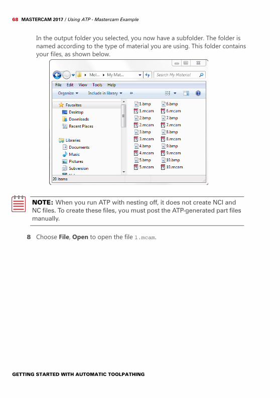
In the output folder you selected, you now have a subfolder. The folder is named according to the type of material you are using. This folder contains your files, as shown below.
NOTE: When you run ATP with nesting off, it does not create NCI and NC files. To create these files, you must post the ATP-generated part files manually.
8 Choose File, Open to open the file 1.mcam.
GETTING STARTED WITH AUTOMATIC TOOLPATHING

MASTERCAM RESOURCES 69
This file shows the toolpaths that ATP created for the part’s geometry.
9 Examine the other part files in the output folder to see how ATP applied toolpaths to the geometry.
ConclusionCongratulations! You have completed the Getting Started with Automatic Toolpathing tutorial. Now that you have mastered the skills in this tutorial, explore Mastercam’s other features and functions. You may be interested in other tutorials that we offer. The Mastercam tutorial series is in continual development, and we will add modules as we complete them.
Mastercam ResourcesEnhance your Mastercam experience by using the following resources:
Mastercam Help— Also, most dialog boxes, function panels, and ribbon bars feature a Help button that opens Mastercam Help directly to related information.
Mastercam Reseller—Your local Mastercam Reseller can help with most questions about Mastercam.
Technical Support—CNC Software’s Technical Support department (860-875-5006 or [email protected]) is open Monday through Friday from 8:00 a.m. to 5:30 p.m. USA Eastern Standard Time.
GETTING STARTED WITH AUTOMATIC TOOLPATHING
70 MASTERCAM 2017 / Using ATP - Mastercam Example
Mastercam Tutorials—CNC offers a series of tutorials to help registered users become familiar with basic Mastercam features and functions. The Mastercam tutorial series is in continual development, with new modules added as we complete them.
Mastercam University—CNC Software sponsors Mastercam University, an affordable online learning platform that gives you 24/7 access to Mastercam training materials. Take advantage of more than 180 videos to master your skills at your own pace and help prepare yourself for Mastercam Certification. For more information on Mastercam University, please contact your Authorized Mastercam Reseller, visit www.mastercamu.com, or email [email protected].
Online communities— You can find a wealth of information, including many videos, at www.mastercam.com. For tech tips and the latest Mastercam news, follow us on Facebook (www.facebook.com/mastercam), Twitter (www.twitter.com/mastercam), or Google+ (plus.google.com/+mastercam). Visit our YouTube channel to see Mastercam in action (www.youtube.com/user/MastercamCadCam)! Registered users can search for information or ask questions on the Mastercam Web forum, forum.mastercam.com, or use the knowledge base at kb.mastercam.com.
Mastercam DocumentationMastercam installs the following documents in the \Documentation folder of your Mastercam installation:
What’s New in Mastercam 2017 Mastercam 2017 Installation Guide Mastercam 2017 Administrator Guide Mastercam 2017 Transition Guide Mastercam 2017 Quick Reference Card Mastercam 2017 ReadMe
GETTING STARTED WITH AUTOMATIC TOOLPATHING
MASTERCAM DOCUMENTATION 71
Contact UsFor questions about this or other Mastercam documentation, contact the Technical Documentation department by email at [email protected].
For assistance with installing Mastercam, its HASP or NetHASP, or to obtain more information on using Mastercam, contact your local Mastercam Reseller. If your Reseller is unavailable, you can call CNC Technical Support Services Monday through Friday, 8:00 a.m.–5:30 p.m., USA Eastern Standard Time.When calling CNC Software for technical support, please follow these guidelines:
Be sure you have already tried to contact your Mastercam Reseller. Provide the serial number of your HASP or NetHASP. Be ready to describe the problem in detail. Write down what happened,
particularly if you cannot call immediately after the problem occurs. Be in front of your computer when you call. If possible, try to duplicate the problem before calling. Our Support Services
technician may require you to duplicate the problem while you are on the phone.
When you call, have ready a complete description of your hardware, including your operating system (OS), central processing unit (CPU), graphics card and settings, and memory.
You can also leave a message for CNC Support Services twenty-four hours a day, seven days a week via our email or website addresses. When sending email, please include:
The serial number of your HASP or NetHASP Telephone number and contact information where you can be reached Files required to reproduce an issue
TIP: This utility makes it easy to provide your Reseller or CNC Support Services with a file attachment that contains the information they need. For more information on using Zip2Go, please refer to Mastercam Help.
GETTING STARTED WITH AUTOMATIC TOOLPATHING
72 MASTERCAM 2017 / Using ATP - Mastercam Example
Important Contact Information
Address CNC Software, Inc.671 Old Post RoadTolland, Connecticut 06084-9970USA
Phone (860) 875-5006Fax (860) 872-1565FTP Address ftp://ftp.mastercam.comInternet Address http://www.mastercam.comEmail [email protected]
GETTING STARTED WITH AUTOMATIC TOOLPATHING
ADDING A CUSTOM COLUMN TO AN ATP DEFINITION 73
APPENDIX A1Custom Columns
There may be times when the cutlist you receive for a project has an extra field. Consider, for example, a KCDw case where your cutlist contains extra data that speci-fies an edge banding code. Because the KCDw definition installed with ATP does not expect this extra data, if you try to load the cutlist in ATP, you get an error.To solve this problem, you can add a custom column (or columns) to the cutlist speci-fication in the KCDw definition. The following exercises show how to do this for a KCDw project. The steps are similar for other ATP definitions.
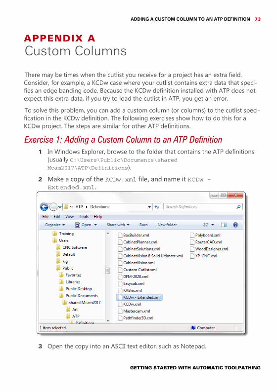
Exercise 1: Adding a Custom Column to an ATP Definition1 In Windows Explorer, browse to the folder that contains the ATP definitions
(usually C:\Users\Public\Documents\shared Mcam2017\ATP\Definitions).
2 Make a copy of the KCDw.xml file, and name it KCDw - Extended.xml.
3 Open the copy into an ASCII text editor, such as Notepad.
GETTING STARTED WITH AUTOMATIC TOOLPATHING
74 MASTERCAM 2017 / Custom Columns
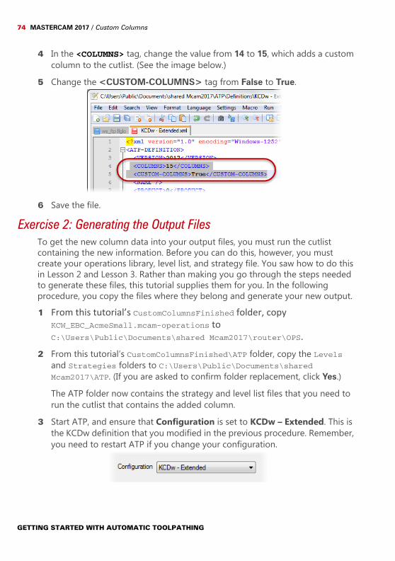
4 In the <COLUMNS> tag, change the value from 14 to 15, which adds a custom column to the cutlist. (See the image below.)
5 Change the <CUSTOM-COLUMNS> tag from False to True.
6 Save the file.
Exercise 2: Generating the Output FilesTo get the new column data into your output files, you must run the cutlist containing the new information. Before you can do this, however, you must create your operations library, level list, and strategy file. You saw how to do this in Lesson 2 and Lesson 3. Rather than making you go through the steps needed to generate these files, this tutorial supplies them for you. In the following procedure, you copy the files where they belong and generate your new output.1 From this tutorial’s CustomColumnsFinished folder, copy
KCW_EBC_AcmeSmall.mcam-operations to C:\Users\Public\Documents\shared Mcam2017\router\OPS.
2 From this tutorial’s CustomColumnsFinished\ATP folder, copy the Levels and Strategies folders to C:\Users\Public\Documents\shared Mcam2017\ATP. (If you are asked to confirm folder replacement, click Yes.)The ATP folder now contains the strategy and level list files that you need to run the cutlist that contains the added column.
3 Start ATP, and ensure that Configuration is set to KCDw – Extended. This is the KCDw definition that you modified in the previous procedure. Remember, you need to restart ATP if you change your configuration.
GETTING STARTED WITH AUTOMATIC TOOLPATHING
GENERATING THE OUTPUT FILES 75
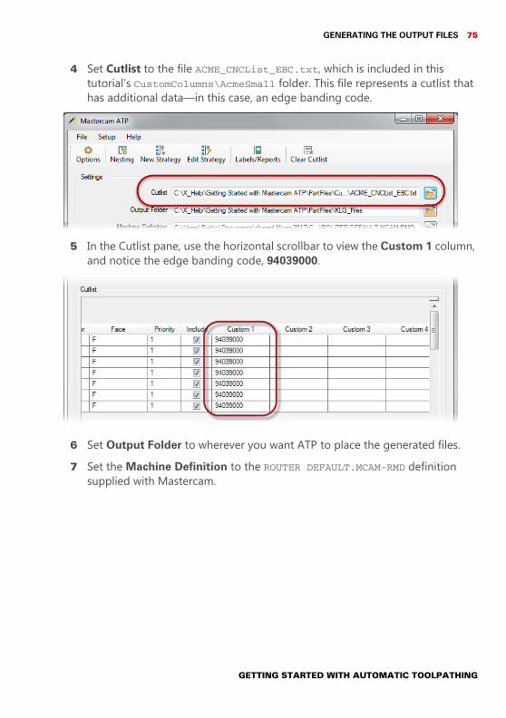
4 Set Cutlist to the file ACME_CNCList_EBC.txt, which is included in this tutorial’s CustomColumns\AcmeSmall folder. This file represents a cutlist that has additional data—in this case, an edge banding code.
5 In the Cutlist pane, use the horizontal scrollbar to view the Custom 1 column, and notice the edge banding code, 94039000.
6 Set Output Folder to wherever you want ATP to place the generated files.7 Set the Machine Definition to the ROUTER DEFAULT.MCAM-RMD definition
supplied with Mastercam.
GETTING STARTED WITH AUTOMATIC TOOLPATHING
76 MASTERCAM 2017 / Custom Columns
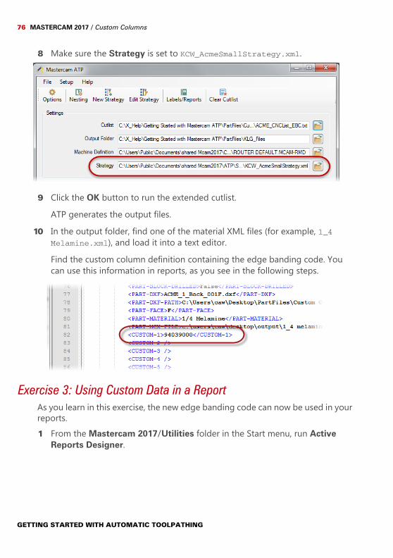
8 Make sure the Strategy is set to KCW_AcmeSmallStrategy.xml.
9 Click the OK button to run the extended cutlist.ATP generates the output files.
10 In the output folder, find one of the material XML files (for example, 1_4 Melamine.xml), and load it into a text editor.Find the custom column definition containing the edge banding code. You can use this information in reports, as you see in the following steps.
Exercise 3: Using Custom Data in a ReportAs you learn in this exercise, the new edge banding code can now be used in your reports.1 From the Mastercam 2017/Utilities folder in the Start menu, run Active
Reports Designer.
GETTING STARTED WITH AUTOMATIC TOOLPATHING
USING CUSTOM DATA IN A REPORT 77
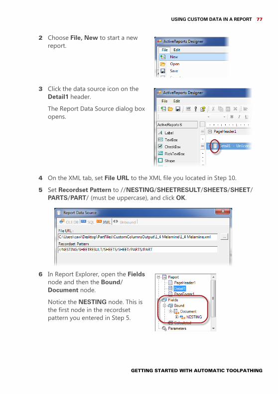
2 Choose File, New to start a new report.
3 Click the data source icon on the Detail1 header.The Report Data Source dialog box opens.
4 On the XML tab, set File URL to the XML file you located in Step 10.5 Set Recordset Pattern to //NESTING/SHEETRESULT/SHEETS/SHEET/
PARTS/PART/ (must be uppercase), and click OK.
6 In Report Explorer, open the Fields node and then the Bound/Document node.Notice the NESTING node. This is the first node in the recordset pattern you entered in Step 5.
GETTING STARTED WITH AUTOMATIC TOOLPATHING
78 MASTERCAM 2017 / Custom Columns
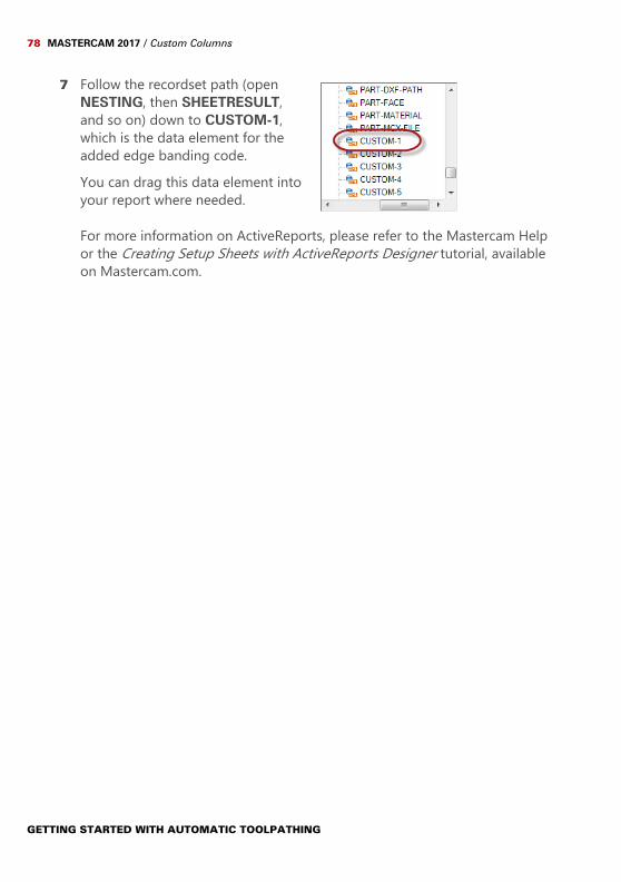
7 Follow the recordset path (open NESTING, then SHEETRESULT, and so on) down to CUSTOM-1, which is the data element for the added edge banding code.You can drag this data element into your report where needed.
For more information on ActiveReports, please refer to the Mastercam Help or the Creating Setup Sheets with ActiveReports Designer tutorial, available on Mastercam.com.
GETTING STARTED WITH AUTOMATIC TOOLPATHING

671 Old Post RoadTolland, CT 06084 USAwww.mastercam.com
Attention! Updates may be available. Go to Mastercam.com/Support for the latest downloads.