Embed Size (px)
Citation preview

Getting Started in Electronic Design Thomas C. Wilson, Jr. ● [email protected]
Instrument Laboratory ● School of Marine and Atmospheric Sciences Stony Brook University
1
UNOLS RVTEC 2016 La Jolla CA – v1.0

Unless otherwise noted:
Standard Disclaimers
• Mention of a company in this presentation does not constitute an official endorsement by the State of New York, the State University of New York, or the School of Marine and Atmospheric Sciences.
• The presenter has no ownership interest in any commercial entity mentioned.
• The presenter has never dated anyone connected to any mentioned company, nor is this ever likely. Neither have those folks plied him with baubles, nor trinkets, nor fancy food and drink.
Special RVTEC “No Chop-Busting” Disclaimers
Anyone who implies otherwise is asking for trouble.

SAFETY, SAFETY, SAFETY
TEST all designs through as wide a range of input conditions as possible.
USE CAUTION with high voltage and high power.
CONSIDER redundant dumb limit controls and other fail safe features.
NOT for human safety applications.
5:00

GALL’S LAW “A complex system that works is invariably found to have evolved from a simple system that worked.”
-John Gall (1925-2015) Pediatrician and author
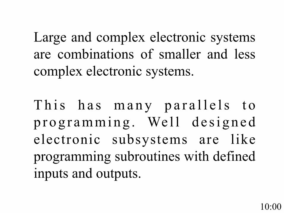
Large and complex electronic systems are combinations of smaller and less complex electronic systems. T h i s h a s m a n y p a r a l l e l s t o p r o g r a m m i n g . We l l d e s i g n e d electronic subsystems are like programming subroutines with defined inputs and outputs.
10:00

Electronic troubleshooting is like code debugging: work down from the total system to locate the specific subsystem that is malfunctioning. Electronic design is like code writing: design simple, robust, tested subsystems, then combine them to achieve a large and complex result.

GALL’S LAW (part 2)
“A complex system designed from scratch never works and cannot be patched up to make it work. You have to start over, beginning with a working simple system.”
15:00

BEGIN BY DOING – my first kit Phillips Electronics Engineer EE20 – circa 1966
20 projects including AM radio, audio amplifier, night light, etc. Pictorial diagrams with open holes placed over pegboard, spring contacts
fit through open holes, components fit between contacts.

BEGIN BY DOING – your first kit Oddwires ultimate kit with Arduino Uno and carrying case
$139.95 (I’d buy one for every tech in the fleet) 61 projects including servos, stepper motors, Bluetooth,
ultrasonic rangefinder, LED and LCD displays, etc.
http://www.oddwires.com/copy-of-the-ultimate-kit-with-arduino-uno/
20:00

OK – I built them all – now what?
Recognize the simple subsystems and put them together in new ways. Add to your toolbox of simple systems. Buy extra parts and make your more useful creations permanent: either with hand wired boards, homemade printed circuit boards, or commercial printed circuit boards.

Adding to your toolbox - Resources Forrest W. Mims III
Author of 60 books, over 7.5 million copies sold. Focus on ICs and discrete component designs. As responsible as anyone for my career. Buy his books (widely available): -Getting Started in Electronics -Engineer’s Notebook. -Whatever else looks interesting.
25:00

Instructive Vendors Lots of free information and tutorials
on how to use what they sell
Adafruit: www.adafruit.com
SparkFun: www.sparkfun.com
Make: www.makershed.com (also Make Magazine)
Jameco: www.Jameco.com (“Workshop” on their home page, also get on mailing list)
Oddwires: www.oddwires.com (see Arduino project ideas)
Instructables: www.instructables.com (just instruction)

Don’t be afraid of datasheets
Good when you need to go deep.
Typical or test circuits often do just what you
want!
SAVE A COPY of the datasheet of every active
component in your design.
30:00

Component Vendors Digi-Key: www.digikey.com The 900 pound gorilla of suppliers: online stock status, same day shipping on orders received by 8pm central time, links to the datasheet of everything the sell.
Mouser: www.mouser.com Good second source, quick ship, northeast US location.
Newark/Element 14: www.newark.com Once famous for having everything presuming you were willing to pay higher than list price, now just famous for having everything. Still publishes a paper catalog large enough to use as a weapon.

http://www.nytimes.com/2001/07/22/nyregion/the-tinkerer-s-last-stand-sold-for-pennies-on-the-streets-of-williamsburg.html?_r=0
Canal Street NYC – how I miss it!
35:00

Speciality and Surplus Vendors
Marlin P Jones - http://www.mpja.com/ (Bench power supplies)
Herbach and Rademan - http://www.herbach.com/
C and H Surplus - http://candhsurplus.com/
Electronic Goldmine - http://www.goldmine-elec-products.com/
All Electronics - http://www.allelectronics.com/
More vendors at: http://amasci.com/surplus/surpls.html

DIGITAL INPUT CIRCUIT PROTECTION Upper: use 1/6 of a 4049 series inverting buffer in a socket – way cheaper than a new processor!
Lower: D1, D2 = 1N4148, R1 = 1K. Diodes clamp input to within 0.6V of V+ and ground, resistor limits current.
40:00
Design and Document Build your own recipe book of useful circuits that work.
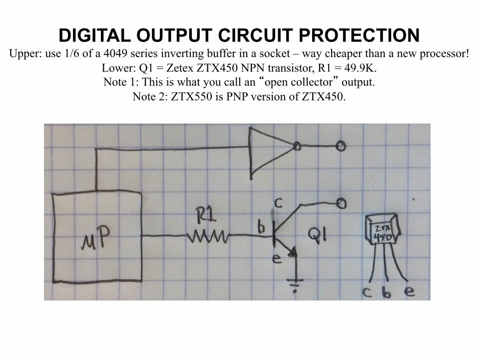
DIGITAL OUTPUT CIRCUIT PROTECTION Upper: use 1/6 of a 4049 series inverting buffer in a socket – way cheaper than a new processor!
Lower: Q1 = Zetex ZTX450 NPN transistor, R1 = 49.9K. Note 1: This is what you call an “open collector” output.
Note 2: ZTX550 is PNP version of ZTX450.
45:00
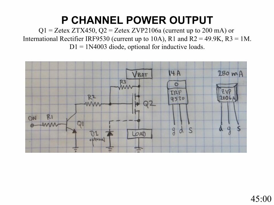
P CHANNEL POWER OUTPUT Q1 = Zetex ZTX450, Q2 = Zetex ZVP2106a (current up to 200 mA) or
International Rectifier IRF9530 (current up to 10A), R1 and R2 = 49.9K, R3 = 1M. D1 = 1N4003 diode, optional for inductive loads.

N CHANNEL POWER OUTPUT Q1 = Zetex ZVN2106 (current up to 300 mA) or
International Rectifier IRF530 (current up to 10A), R1 = 1M, R2 = 49.9K. D1 = 1N4003 diode, optional for inductive loads.

Put it All Together
LOW BATTERY SHUTOFF CIRCUIT
Theory of operation and circuit notes.
T.C. Wilson – 5 May 2015.
1. Regulator U2 provides a reference voltage of 5.0 volts. C1 provides stabil izat ion. Another reference such as a zener and resistor could be used but the LP2950 is small, has low idle current, and I have a drawer full of them.
Note: pinout
drawings!
50:00

2. U1 is a CMOS low power op amp that can drive output to the supply rails (important in this application). R1 and R2 form a voltage divider defining the setpoint for the shutoff. When pin 2 voltage is less then pin 3 voltage output pin 6 is driven low and turns on power MOSFET Q1 through R5. R6 provides additional pullup to turn off Q1. U1 pin 8 sets idle current iQ (higher iQ=higher bandwidth). Since bandwidth is not important in this application pin 8 is tied to V+ for minimum idle current of 10 uA. Overall idle current of the circuit in shutdown is 190 uA, if you care to reduce this you could probably set R1 + R2 = 1 Mohm instead of 100 Kohm.
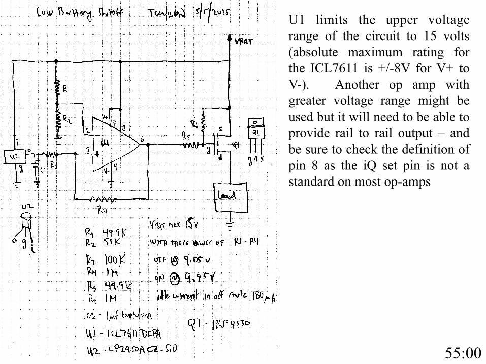
U1 limits the upper voltage range of the circuit to 15 volts (absolute maximum rating for the ICL7611 is +/-8V for V+ to V-). Another op amp with greater voltage range might be used but it will need to be able to provide rail to rail output – and be sure to check the definition of pin 8 as the iQ set pin is not a standard on most op-amps
55:00

3. R4 provides positive feedback = hysteresis to the circuit. When the circuit turns power on (voltage at pin 2 becomes higher than pin 3) pin 6 swings low and drives pin 3 even lower through R4, reinforcing the voltage difference between pins 2 and 3. Similarly, when the circuit turns power off (voltage at pin 2 becomes lower than pin 3) pin 6 swings high and drives pin 3 even higher through R4, again reinforcing the voltage difference between pins 2 and 3.
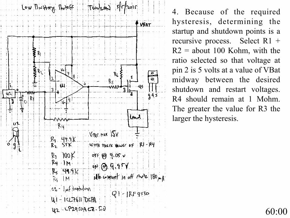
4. Because of the required hysteresis, determining the startup and shutdown points is a recursive process. Select R1 + R2 = about 100 Kohm, with the ratio selected so that voltage at pin 2 is 5 volts at a value of VBat midway between the desired shutdown and restart voltages. R4 should remain at 1 Mohm. The greater the value for R3 the larger the hysteresis.
60:00
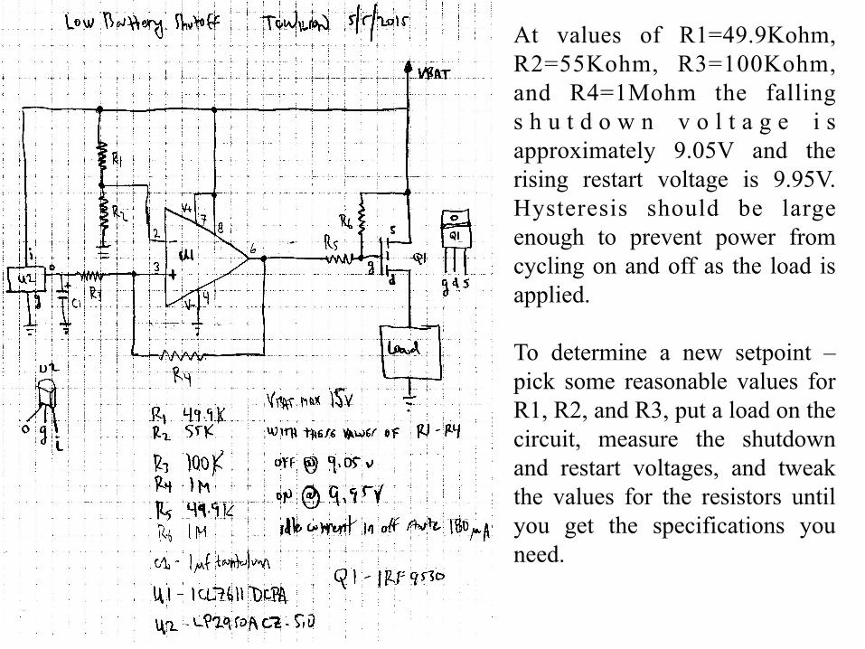
At values of R1=49.9Kohm, R2=55Kohm, R3=100Kohm, and R4=1Mohm the falling s h u t d o w n v o l t a g e i s approximately 9.05V and the rising restart voltage is 9.95V. Hysteresis should be large enough to prevent power from cycling on and off as the load is applied. To determine a new setpoint – pick some reasonable values for R1, R2, and R3, put a load on the circuit, measure the shutdown and restart voltages, and tweak the values for the resistors until you get the specifications you need.

DO YOU SEE THE SUBSYSTEMS?
Power switch
Voltage reference
Comparator with hysteresis
65:00

MAKING IT PERMANENT - HAND WIRED
Do not disrespect hand wiring. It’s not a prototype, it’s a one-off!
GPS logger Met buoy power control

MAKING IT PERMANENT - DESKTOP PCB
“Desktop PCB Fabrication” – RVTEC 2004 https://www.unols.org/sites/default/files/200411rvtap37.pdf
Only change – Mental Automation is mostly out of business, “not recommended for new design(ers)”. Try KiCAD http://kicad-pcb.org/
Challenger deep sea pump replacement timer board
70:00

MAKING IT PERMANENT - COMMERCIAL PCB
Beware of “free PCB design” software offered by a PCB vendor - usually traps you with that vendor.
Design around free drill sizes.
Output “Gerber” files, email to board maker with credit card.
Advanced Circuits - http://www.4pcb.com/ Best prices for small runs – 2 layers, $33 each, min qty 4.
Alberta Printed Circuits – http://www.apcircuits.com/ Best prices for medium runs (10+ pieces)
GPS/Argos drifter
SHOW AND TELL
1. Engineers Notebook – 1980 (first printing). 2. Engineer’s Notebook II – 1982 (first printing). 3. Getting Started in Electronics. 4. Make Ultimate Arduino Microcontroller Kit. Three PC boards – all TCW designs. 1. Hand wired board – GPS logger. 2. Hand wired board – Met buoy power control. 3. Desktop PC board – Challenger deep sea pump timer. 4. Commercial PC board – GPS/Argos drifter.
75:00

ACKNOWLEDGEMENTS To Forrest W. Mims III - for simple systems that work.
To my parents, who always found a few dollars to invest at Halley Electronics, Radio Shack, and Pagoda Hardware - and to the longsuffering employees of
Halley Electronics, Radio Shack, and Pagoda Hardware.
To teachers, mentors, students, and colleagues including Henry Harrison, David Lucyk, Bob Slavonik,
Trevor Young Alex Sneddon
and of course my shipmates at RVTEC.

QUESTIONS? I AM NOT AFRAID.

THANKS FOR LISTENING!
AFTERWARDS - GO BUILD STUFF!