Embed Size (px)
Citation preview
EUROPEAN COMMISSION
JOINT RESEARCH CENTRE
I NSTITUTE FOR SY S T E M S , I N F O R M A T I C S & S AFETY
State-of-the-Art report on:
The Automation and Integrationof Production Processes
in Shipbuilding
by:
Fivos ANDRITSOSand
Juan PEREZ-PRAT
for the:
DG Enterprise, unit E.6
Administrative arrangement:
14707-1998-12 A1CA ISP BE
June 2000

AIPS study Page 2 June 2000
Glossary2-D Two Dimensional3-D Three DimensionalAI Artificial IntelligenceANSI American National Standards InstituteCAD Computer Aided DesignCAE Computer Aided EngineeringCAP Computer Aided PlanningCE Concurrent EngineeringCEPS Competitive Engineering & Production in ShipbuildingCESA Committee of EU Shipbuilders' AssociationsCFD Computational Fluid DynamicsCgt Compensated Gross TonsCIM Computer Integrated ManufacturingCNC Computerised Numerical ControlCOREDES Committee of R&D in European ShipbuildingCSG Constructive Solid GeometryD Deliverable Item (plus reference number)D.xx Deliverable Item No xxDB Data BaseDG Directorate GeneralDIN Deutsches Institut für NormungDoF Degree(s) of FreedomDwt Dead weight tonsEC European CommissionECU European Currency UnitEDM Electronic Document (or Data) ManagementEEA European Economic AreaEI Environment InstituteEPD Electronic Product DefinitionERP Enterprise Resource PlanningESPRIT European Strategic Programme in Research in ITEU European UnionFCAW Flux Cored Arc WeldingFCW Flux Cored Wire (welding)FEA Finite Element AnalysisFP Framework Program (research)FSW Friction Stir WeldingG .. Giga: a billion units of ..Gt Gross tonsHMI Human-Machine Interface (same as MMI)HPCN High Performance Computing and NetworkingHTML Hyper-Text Machine LanguageHW HardwareICIMS Intelligent Control & Integrated Manufacturing SystemsICT Information and Communication ToolsIFR International Federation of RoboticsIGES Initial Graphics Exchange SpecificationIMO International Maritime OrganisationIPR Intellectual Property RightsISIC International Standard Industrial ClassificationISIS Institute for Systems, Informatics and SafetyISO International Standards OrganisationIT Information TechnologiesJRC Joint Research Centrek .. Kilo: a thousand units of ..LAN Local Area NetworkM .. Mega: a million units of ..

AIPS study Page 3 June 2000
M.xx Milestone No xxm.xx Month No xx from the start of the projectMAG Metal Active Gas (welding)MCAW Metal Core Arc WeldingMIG Metal Invert Gas (welding)MIF Maritime Industries ForumMMA Manual Metal Arc (welding)m-m Man-monthMRP Material Requirements PlanningMS MicrosoftNC Numerical ControlNFS Network File SystemNIST National (US) Institute for Standards and TechnologyNoE Network of ExcellenceNURBS Non-Uniform Rational B-SplinesOCR Optical Character RecognitionOO Object OrientedPDM Product Data ManagementPRODIS Product Development and Innovation in ShipbuildingQA Quality AssuranceQC Quality ControlR&D Research and DevelopmentRDB Relational Data BaseRIT Remote Inspection and Tele-operationROBMAR ROBotics for the MARitime IndustryROTIS Remotely Operated Tanker Inspection SystemROV Remotely Operated VehicleRTD Research & Technological DevelopmentSAW Submerged Arc WeldingSoA State of the ArtSS System SpecificationsSW SoftwareT .. Tera: a trillion units of ..TF-MSF Task Force “Maritime Systems of the Future”TPPS Technology of the Production Processes in ShipbuildingUSA United States of AmericaWAN Wide Area NetworkWP Work PackageWWW World Wide Web (Internet)

AIPS study Page 4 June 2000
Executive SummaryMaritime sector has been and will continue to be of strategic importance for Europe,due to the nature of its economy, topology, history and tradition [3]. Shipbuilding is akey maritime industry which has contributed significantly to Europe’s maritime pastand which is strategic for its maritime future. It is also a considerable source of em-ployment. In the global market economy of today, EU shipbuilding and other relatedindustries, in order to stay competitive, are faced with an urgent need for profoundchanges towards:
• The drastic reduction of the costs and lead times, imposed by the over-capacityin production and the consequent fierce international competition. This need hasbecome even more urgent from the recent events in the Southeast Asia andfrom the upcoming cease of all subsidies to the EU shipbuilding industry.
• The achievement of a sustainable shipbuilding process, part of a sustainable“quality shipping”.
• The assurance of the highest possible quality standards, necessary for a safeand environmentally friendly navigation.
The achievement of these goals requires drastic changes in almost every aspect ofthe planning, designing, building and maintaining the European commercial fleet.
As what shipbuilding is concerned, the most promising field for the improvement ofits overall efficiency is, according to the maritime industries Master Plan [3], [7], pro-duction (incl. design) technology. Novel technologies (like laser welding etc), theautomation and robotisation as well as the integration of the design and fabricationprocesses can lead to a much increased productivity and transform shipbuildingfrom labour intensive to a technology intensive sector.
JRC-ISIS has undertaken the study on “the Automation and Integration of Produc-tion Processes in Shipbuilding; State-of-the-art Report” (AIPS), in support to the ac-tivities of the DG “Enterprises”. The key objectives are:
• To identify the technologies in which investments are likely to be more produc-tive in increasing the competitiveness of the European shipyards.
• To identify the actions and measures that are more appropriate in order to en-hance the necessary R&D efforts.
• To identify sectors from which shipbuilding can profit in terms of technologytransfer and the actions that would help developing the necessary synergies.
Traditionally, shipbuilding has been identified with those operations and processesrelated with the transformation of sheet metal to steel hulls. These operations es-sentially consisted in marking and cutting the sheet metal prime material in ele-mentary building pieces the assembly of which, in various stages (panels, sub-blocks, blocks, sections), finally yielded the complete steel hull. Thus, three basicclasses of processes could be distinguished:
• Sheet (or profile) metal treatment processes• Fitting and assembling (nowadays mostly by welding)• Handling (moving and positioning the various blocks and sub-assemblies)
Maximising the efficiency of shipbuilding essentially meant:
• Assuring the most cost-effective acquisition of the necessary prime materialsand components,
• Optimising each one of the processes stated above and• Planning the whole sequence of operations in such a way so as to ensure a
seamless flow of material and an optimal utilisation of the available resources
Automation in shipbuilding has been applied almost exclusively in steel construction,in particular in cutting and welding. Nevertheless, especially in what concerns mostof the big European yards, the relative importance of the steel shaping and assem-bling has decreased substantially. Shipbuilding nowadays encompasses a range of
AIPS study Page 5 June 2000
processes and activities much broader than shaping and assembling sheet metalsteel. Activities, such as finishing and outfitting become increasingly important.
In what concerns steelwork, new cutting and welding technologies (i.e. laser weld-ing) look promising in assuring high quality even when large deck areas are con-structed from thin plates or sandwich panels. Their introduction nevertheless re-quires radical re-thinking of the whole steelwork chain.
The role of CAD/CAE has traditionally been that of enhancing the various phases ofthe design process and assuring shorter lead times to the planning and the start ofthe production activities. Nowadays, in view of the increasing complexity of the pro-duction operations and, consequently, the planning requirements and the stringentlead times to market, CAD/CAE tools are rapidly acquiring the role of the integratorbetween the ‘traditional’ design phases the planning and production processes.
The first parts of the steel production, that is marking, cutting, conditioning and as-sembling the steel plates and profiles into 2D blocks, are done today with very smallmanning and it is unlikely that any considerable gains are achieved through furtherresearch. On the contrary, the problems in welding of 3D block assemblies are quiteextensive, because the structures are complicated, and the repeatability of thestructures is very low. The production is more one-of-a-kind type than serial orsimilar. Although some shipyards have advanced robotized systems, the mechani-sation of welding processes seems more attractive than automation, due the con-siderably lower investment costs. The same holds true for the pre-erection anderection phases. The need for massive investments in novel “intelligent” systems forautomating such one-of-a-kind operations cannot be justified by the meagre gains interms of overall productivity. As the European shipyards tend to build more outfittingintensive ships, more effort and research in steelwork automation is not likely to beof high priority. Even where the automation technology exists, it is not necessarilyeconomical considering the high investment costs.
Steel construction apart, the degree of automation of the other processes is fromnon-existent to very limited. The major area for automation in the outfitting is thepipe workshop. High degree of prefabrication means that major part of pipes is be-ing manufactured in workshops. Bending of pipes and welding of flanges can beautomated with relatively small effort and this has been already done to some ex-tent. Good planning and efficient design – production integration is needed in orderto maximise pipe pre-fabrication.
In the other areas of outfitting automation is not an easy task, although the advan-tages to be derived could be significant. Standardisation and modularisation of shipsystems, integration and good planning rather than automation are regarded as theways to increase productivity in outfitting, possibly through subcontracted activities.
The main reason for which the largest part of shipbuilding processes are not yetautomated lies in the very nature of the shipbuilding operations coupled with the factthat the robotic market has been almost entirely dominated and tailored to the largevolume automotive and commodities industry. In fact:
1. Almost none of the shipbuilding operations are exactly repeatable; at best theyare similar. Many operations are performed only once or at most a very limitednumber of times.
2. Many of them, especially the assembly operations, involve very important pay-loads, in terms of mass, volume and cost. The accessibility can also be quitedifficult.
These two facts mark a clear cut with the robotics and automation technologies asapplied in the large production volume industries like automotive or commoditiesmanufacturing.
In such conditions (i.e. one-of-a-kind operations), the most important performancecriteria of a manipulating robotic system are the ease of path planning and the op-erational flexibility. Autonomy in the execution of certain tasks is a must for ensuringthe above stated characteristics.
AIPS study Page 6 June 2000
Integration of the right sensorial information in a supervisory control type schemecan permit the autonomous execution of many low-level tasks with two importantconsequences:
(a) The human operators of robotic manipulators could be concentrated in highlevel activities (such as planning and supervision) instead of performing lowlevel tasks (such as collision avoidance, precision positioning etc).
(b) “Small” variations in the work-pieces or in the working environment could bedealt without any need of reprogramming off-line automated or robotised facili-ties.
The low-level tasks that could be executed autonomously include:
• Obstacle avoidance;• Adapt to the execution of “similar”, not exactly repetitive operations;• Corrections for work-piece or workspace “inaccuracies”
Task autonomy cannot be achieved but through novel “intelligent” control schemesintegrating sensorial systems. It implies the use of data fusion, hard real time com-puting, autonomous mission execution etc., techniques that are far from being es-tablished in the environment of manufacturing or engineering industries (see nextparagraph) but are used extensively in some military, deep-sea, space and other"high tech" applications. Specially in heavy robotics, when manipulating large andheavy loads, new tracking techniques compensating or bypassing the inevitablemechanical inaccuracies are required for reliable precision positioning and handling.
An additional factor to consider is that most heavy robotics/handling installations inshipbuilding and other heavy industries are tailored made, often by the final userhimself. This prohibits the amortisation of the cost for the introduction of technolo-gies such as stated above. The already high development cost is further augmentedbecause of the inherent safety and reliability requirements implying extensive testingand validation procedures and the big and expensive experimental facilities neededfor the experimental demonstration, testing and validation procedures.
For all these reasons, at short term, the margin for improvements in productivitythrough R&D investments the robotisation / automation of the shipbuilding produc-tion processes is very small, especially at individual shipyard level. On the contrary,at long term, a strategic R&D plan should be formulated permitting the introductionof all the necessary technologies for the efficient robotisation / automation of theone-of-a-kind operations in shipbuilding and in other heavy industries.
Prior to construction, every vessel must be designed, the construction operationsmust be planned, the automated machines must be programmed and the timely de-livery of prime materials and equipment must be assured. These activities involvethe generation and manipulation of enormous amounts of information. The availabil-ity of potent information and communication tools has increased significantly theamount of information to be “managed”. Maintenance of consistent and updated in-formation as well as a seamless information flow across the shipbuilding activitiesare vital for the efficient realisation of each shipbuilding project. The extreme diver-sity, in terms of contents, users, use and forms, of the information necessary for thevarious design and production stages make this task quite a difficult one.
A particularity of the shipyards, in relation to other engineering industries, is the factthe it is quite seldom that the machines, assembly lines or workshops will have toproduce exactly the same work piece. Virtually every vessel constructed, even iffrom the same series, differs somewhat from each other.
An additional complication is that even when the nominal geometry of two or moreblocks are the same, due to thermal distortions, actual geometry may vary quite abit. Besides the particular assembling or machining problems this might cause, thisgives rise to a problem relative to the gradual deterioration of the model(s) of thevessel assemblies or sub-assemblies, relative to the actual situation. One way todeal with the problem is to perform extensive shrinkage calculations and update the
AIPS study Page 7 June 2000
CAD models with frequent measurements. Nevertheless, this is not always as sim-ple as it might seem.
Up till some years ago, the shipyards have been largely self sufficient in all disci-plines of shipbuilding. All the steel work, outfitting work and even the machiningwork has been made mainly by the yard’s own personnel. Occasional work subcon-tracting has been necessary to even out the peak loads, but this has been minorpart and done normally under shipyard’s supervision.
However, workload distribution among various disciplines can vary significantly indifferent ship types. The ever-increasing importance and complexity of the outfittingwork requires many specially trained personnel for limited periods of time whosehandling is, for the shipyard, difficult and not cost effective. Hence, most advancedshipyards have moved to using extensively subcontractors. These are not con-tracted only on a time base but also as suppliers capable of turnkey systems deliv-eries. Examples are that of the HVAC systems and the prefabricated cabins. Pro-duction of the cabins is happening at the factory, where it can be standardised inclose resemblance to a series production. This gives also possibilities for a certainlevel of automation.
Standardisation and modularisation of ship systems and subassemblies is seen to-day as the key to rationalise production, shift work out of the ship in the workshops,where it can be performed in a more comfortable and controlled environment.
Today, experts speak about “assembly” yards, where the shipyard has the sole roleof assembling the hull and perform selected parts of the outfitting. This developmentmakes the integration process much more difficult than it would have been in a casewhere everything was done inside the yard. On the other hand, successful comple-tion of ship project with extensive subcontracting sets new challenges for the stan-dardisation and integration of the processes.
The operational principle of the assembly yard sets special requirements to the inte-gration of processes. The design and production is not happening anymore in thelimited area inside the shipyard fences. Instead the work can be done far away fromthe yard even in other countries.
The shipyard is de-facto the coordinating body for all these activities. This meansefficient flow of vast amount of information in all its forms to all the users, as indi-cated in the paragraphs above. Even more important, the distributed and in a varietyof different formats information must be kept constantly concise and updated.
Most shipyards today are conscious that, at short-medium term, the best way to in-crease their productivity is trough an efficient production planning and a rationalisa-tion of all the production and design processes. They are also conscious that thesegoals cannot be achieved but through integration, making the maximum out of mod-ern information and communication tools.
In fact most large shipyards use large common databases; they have PCs andworkstations connected by LANs and have good Internet connections to many oftheir suppliers or subcontractors. Their CAD system is connected and can downloaddata to cutting machines and T-beam stations. Nevertheless, CAD/CAE tools arestill being seen mainly as design tools that, occasionally, provide data to CIM sys-tems, logistics, planning departments and subcontractors. Instead CAD/CAE toolsneed to be seen mainly as the integrating backbone of each shipbuilding project.Although some timid steps have been taken towards that direction, there is a lot tobe done yet.
Conclusions:
The shipping world is relatively conservative in technology thinking. The invest-ments, be it for ordering a ship or purchasing new production technology, are con-siderable and everybody tries to minimise the economical risks. However, the majorEU shipyards have taken up the challenge imposed by the modern global market

AIPS study Page 8 June 2000
economy and the particular shipbuilding market situation of today and are changingfast.
Very high level of automation as such is not of the highest priority in the develop-ment list of the shipyards. The nature of shipbuilding, which is one-of-a-type produc-tion with few series-production features, makes efficient and cost-effective automa-tion difficult. The diminishing portion of steel construction, which is technically theeasiest target for automation, makes investments on further automation even morequestionable.
Outfitting work is still at the beginning of the automation process. Here, it is the sub-contractors that are likely to develop new production technologies. Automation islikely to be developed for workshop or subcontracted activities.
At short-medium term, the major productivity gains in EU shipbuilding can beachieved through rationalisation of work phases, good planning and integrationrather than automation. The concepts of product model and process simulation canserve as a backbone for the integration of new construction strategies (standardisedcomponents, modular outfitting etc), of highly concurrent engineering and produc-tion, methods and of efficient supply chain management tools.
At long term, basic and long-term R&D should be encouraged in order to permit theintroduction of all the necessary technologies for the efficient robotisation / automa-tion of the one-of-a-kind operations in shipbuilding, construction and other heavy“one-of-a-kind” industries.
AIPS study Page 9 June 2000
ContentsGlossary .................................................................................................................2
Executive Summary................................................................................................4
Contents .................................................................................................................9
1 Introduction ...................................................................................................111.1 Origins of the AIPS study.....................................................................111.2 Scope of the AIPS study ......................................................................111.3 Implementation method .......................................................................121.4 Report structure...................................................................................13
2 Terms & definitions........................................................................................152.1 Robotics ..............................................................................................152.2 Automation / mechanisation.................................................................162.3 Computer Aided Design, Engineering and Manufacturing.....................18
3 Context .........................................................................................................203.1 Towards a competitive & sustainable shipbuilding................................203.2 Robotics & automation.........................................................................233.3 Integration tools ...................................................................................25
4 Shipbuilding process break-down ..................................................................304.1 Shipbuilding today ...............................................................................304.2 Production processes ..........................................................................314.3 Information processes..........................................................................32
5 Automation of the production processes ........................................................355.1 Marking, cutting & conditioning of the steel plates and profiles .............355.2 Fabrication of 2D blocks ......................................................................375.3 Fabrication of 3D blocks in workshop ...................................................385.4 Prefabrication of pipes, supports, modules etc .....................................395.5 Blasting and painting / coating .............................................................405.6 Transport & handling ...........................................................................415.7 Dimensional control & inspection .........................................................435.8 Welding processes in shipbuilding .......................................................445.9 Laser technologies for cutting and welding...........................................455.10 Automating one-of-a-kind processes....................................................47
6 Design, planning & logistics...........................................................................516.1 General considerations ........................................................................516.2 The importance of ship design .............................................................516.3 Ship design activities ...........................................................................516.4 Ship design software tools ...................................................................53
7 Integrating design, production & supply chain ................................................617.1 Integration of basic design with detail design........................................617.2 Integration of detail design with the production activities.......................627.3 Integration of production planning ........................................................627.4 Product model .....................................................................................627.5 Process simulation...............................................................................65
8 New technologies and R&D activities.............................................................678.1 General ...............................................................................................678.2 Study on the maritime RTD activities in the member states ..................678.3 Recent conferences on shipbuilding IT applications .............................688.4 Recent R&D projects relevant to AIPS .................................................718.5 Shipbuilding automation related R&D...................................................768.6 Integration related R&D .......................................................................768.7 The impact of novel production technologies........................................778.8 Conclusion and recommendations on AIPS related R&D......................77

AIPS study Page 10 June 2000
9 Competitiveness of EU shipbuilding...............................................................789.1 Effects of automation ...........................................................................789.2 Effects of integration ............................................................................789.3 Considerations on the competitiveness of the EU shipyards.................79
10 Conclusions...................................................................................................8010.1 Challenging environment .....................................................................8010.2 Low priority for further automation........................................................8010.3 High priority for integration...................................................................8010.4 Need for technology transfer and long-term R&D.................................81
Acknowledgement ................................................................................................82
References ...........................................................................................................83
Annexes ...............................................................................................................86
A.1 External subcontractors to the AIPS study .....................................................88
A.2 Shipyards and other organisations contacted.................................................91
A.3 COMPIT 2000 – programme .........................................................................93
A.4 The Dutch collaborative experience...............................................................97The Dutch Maritime Cluster ...........................................................................97General overview of the Dutch shipbuilding ...................................................97Priorities........................................................................................................98Software providers ........................................................................................98
A.5 The CESA working group on cooperation ......................................................99
AIPS study Page 11 June 2000
1 Introduction
1.1 Origins of the AIPS studyMaritime sector has been and will continue to be of strategic importance for Europe,due to the nature of its economy, topology, history and tradition [3]. Shipbuilding is akey maritime industry which has contributed significantly to Europe’s maritime pastand which is strategic for its maritime future. It is also a considerable source of em-ployment.
Nevertheless, in the global market economy of today, EU shipbuilding and other re-lated industries, in order to stay competitive, are faced with an urgent need for pro-found changes. The ultimate goals are:
• The drastic reduction of the costs and lead times, imposed by the over-capacityin production and the consequent fierce international competition. This need hasbecome even more urgent from the recent events in the Southeast Asia andfrom the upcoming cease of all subsidies to the EU shipbuilding industry.
• The achievement of a sustainable shipbuilding process, part of a sustainable“quality shipping”.
• The assurance of the highest possible quality standards, necessary for a safeand environmentally friendly navigation.
The enlargement of the Union with five new member states, some of which have aconsiderable shipbuilding industry, is another factor to be considered.
1.2 Scope of the AIPS studyThe purpose of the present state-of-the-art study is:
An overview of the technology of the production processes used in shipbuilding(TPPS), more in particular related to their automation and their integration, in view ofa competitive and sustainable European shipbuilding industry.
The key objectives of this report are:
• To identify the technologies in which investments are likely to be more produc-tive in increasing the competitiveness of the European shipyards.
• To identify the actions and measures that are more appropriate in order to en-hance the necessary R&D efforts.
• To identify sectors from which shipbuilding can profit in terms of TechnologyTransfer and the actions that would help developing the necessary synergies.
The study moves along two main lines:
1. State-of-the-art in shipbuilding technology2. State-of-the-art in related R&D
As requested in the invitation to tender, the report addresses all the activities relatedto the construction of the vessel as well as its main components (hull, propulsionetc). Some indicative topics on which the study focuses are:
• Computer Aided Design and Engineering• Computer Integrated Manufacturing• Automation and mechanisation of production• Integration of the shipbuilding processes• Heavy robotics & handling• Novel cutting and welding technologies• Component and system modularisation• Influence of novel vessel designs to shipbuilding• Employment issues• Environmental issues• Safety issues
AIPS study Page 12 June 2000
It encompasses all the EU countries plus some of the new member states and,wherever possible, provides information on US, Japan, Korea and China.
1.3 Implementation methodThe methodology with which the AIPS study has been conducted is summarised asfollows:
1. The current shipbuilding methods, techniques and practices were outlined2. A comprehensive, qualitative breakdown of shipbuilding (including design,
planning, management, etc.) has been performed.3. Out of the experience of the contributors to this study and consultations with
various relevant professional bodies a list of organisations and/or personsplaying a major role in at least one of the items (technologies, techniques, ac-tivities) above were identified, covering as completely as possible the above-mentioned breakdown structure.
4. Surveys of the organisations identified above were performed. They includedvisits on-site and/or interviews with relevant personnel. Although no unifiedquestionnaires or forms were compiled during or following these visits and/orinterviews, “survey guidelines” were issued. A list of the shipyards and otherorganisations surveyed is given in Annex A.2.
5. Following these surveys as well as other relevant literature and web searches,each AIPS contributor submitted a report on its pre-defined area of responsibil-ity (see [2]).
6. Finally, the results of the surveys were synthesised in a concise report (presentdocument) meeting the objectives of the study.
The surveys have covered the four distinct groups, which have been identified asthe main groups of players in shipbuilding technologies:
1. The ‘demand’ part: organisations performing, supervising or managing ship-building operations
2. The ‘supply’ part: industries and companies, suppliers of equipment, servicesand technology
3. The ‘regulatory’ part: IMO, classification societies, flag etc.4. The R&D part: laboratories, universities and other R&D performers working in
fields related to or of strong potential interest to shipbuilding
The approach and the method of survey for each of these target groups has beendistinct, reflecting their particularities.
Events (meetings, workshops etc.) related to shipbuilding or other related sectorshave been exploited as well as the structure and the events of the ROBMAR [6],CEPS [8], PRODIS [31] and other related networks. In particular, work done in theframe of the CEPS and PRODIS networks on the state-of-the-art in Engineering andProduction and on Product Development tools has not been duplicated but, whereapplicable, it has been included in the present study.
A particular mention should be made to the CESA Working Group on Co-operation(see Annex A.5), which allowed the participation of F.Andritsos at the meetings andvisits of the group and provided to the AIPS study all the material collected andcompiled by the group in a “Production Technologies Catalogue”.
As what R&D is concerned, the main source of information was the study by BMTand other partners on behalf of DG III (now DG ENTERPRISE) on the current EUmember states RTD activities with reference to shipbuilding (including marineequipment, shipping and marine resources), the final report [29] of which was issuedin February 2000. An additional source of information has been the direct experi-ence of many of the AIPS contributors on many relevant R&D projects.
It has been to our intention to co-operate closely with DG ENTERPRISE E.6, havingfrequent meetings, answering any particular demands as they are raised and re-directing the study in real-time, if required.
AIPS study Page 13 June 2000
The implementation of the AIPS study has been divided in four main tasks as fol-lows:
#1 Detailed work-plan for the study#2 Outline of the current shipbuilding methods, processes & practices#3 Outline of the current R&D effort for technologies associated with the automa-
tion and integration of key shipbuilding processes#4 Synthesis and conclusions
Following the AIPS proposal, the detailed plan for the AIPS study [2] had foreseenthe following activities:
(i) Perform a first, qualitative breakdown of shipbuilding.(ii) Identify the activities (or clusters of activities) that are of major interest for the
present study.(iii) Identify those organisations/persons that will give a major contribution to the
survey, possibly through contracts with JRC. Specify the contribution of eachcontributor / contractor.
(iv) Formulate the questionnaires for each of the ‘target’ types of the survey.(v) Perform the surveys(vi) Analyse the results and synthesise the conclusions in a concise document
Following the initial work done in the frame of task #1, we realised that, during thelast years, there have been a significant numbers of inquiries, surveys and statisticson shipbuilding. Most of these, either as results or as raw data, have been madeavailable to AIPS. So, further surveys through questionnaires or forms to be com-piled were judged unnecessary.
It has been decided, rather than just providing yet another compilation of tables andstatistics, to take advantage of the surveys as well as of the existing data, the expe-rience of the contributors to the AIPS study and the valuable contribution of relevantthematic networks and associations and try to analyse and answer directly the mainquestions at which the AIPS study aims at (as listed in section 1.2 above).
In performing the planning of the study care has been taken so as to cover:
• All regions of interest (i.e. EU regions, new member-states, etc)• All basic types of technology and equipment relative to shipbuilding (i.e. weld-
ing, cutting, handling, IT, etc)• All fields of R&D directly related to shipbuilding (i.e. new materials, laser weld-
ing, etc).• All activities related to shipbuilding operations (i.e. construction, planning, man-
agement etc)
1.4 Report structureEssentially, the object of the present study can be broken down to:
• The automation of each of the generic shipbuilding processes (including design,planning etc.);
• The integration, mainly through appropriate CAD/CAE tools of the design, plan-ning and production processes;
• The R&D relative to the core technologies relative to the automation of eachproduction / design process and to their integration.
The present state-of-the-art report is structured as follows:
The section 2 below gives a brief definition of the main terms used in the rest of thereport.
Section 3 deals with the context of the AIPS study. It intends to give an overview ofthe main generic arguments (shipbuilding processes, robotics & automation,CAD/CAM/CIM) of the present study in their context, trace the interrelations and de-lineate their potential as well as their limitations.

AIPS study Page 14 June 2000
Section 4 deals with the generic shipbuilding process. It presents the shipbuildingprocess breakdown structure as well as the information flow diagram. It presentssome typical shipyard layouts and tries to outline the inter-relations of the variousprocesses and production phases.
Section 5 deals with the state-of-the-art and/or best practices of each of the produc-tion processes as identified in section 4, in respect to their robotisation / automation.In particular, it tries to identify the owners and users of these state-of-the-art tech-nologies or techniques.
Section 6 deals with the state-of-the-art and/or best practices in design, productionplanning and logistics.
Section 7 deals with integration of the various production processes through the useof computerised tools. More in particular it addresses the issue of interfacing andintegrating the various CAD/CAE to the CIM and logistic tools as well as the produc-tion practices and procedures.
Section 8 deals with the current status, at European, national and, where possible,at international level of the R&D activities relative with the core technologies of theproduction and integration processes identified at the sections 5 to 7.
Section 9 analyses the effect of the automation of the production processes andtheir integration to the competitiveness of the EU yards vi-a-vis their Far Easterncounterparts.
Finally, section 10 attempts to draw some useful conclusions relative with the con-tractual aims o the AIPS study (see section 1.2 above). Namely: the identificationthe technologies in which investments are likely to be more productive in increasingthe competitiveness of the European shipyards, the actions and measures that aremore appropriate in order to enhance the necessary R&D efforts and the actionsthat would help developing eventual technology transfer.
AIPS study Page 15 June 2000
2 Terms & definitionsCare has been taken so that the terms and definitions used in the current report arein concordance with internationally accepted standards such as:
• International Standard Industrial Classification of All Economic Activities (ISIC):Details, as well as an index for all classified economic activities, can be found athttp://www.un.org/Depts/unsdold/class/isicmain.htm. When possible, revision 3compatible classification is used, otherwise revision 2.
• International Federation of Robotics (IFR)• International Organisation for Standardisation (ISO), http://www.iso.ch/
As the whole section 4 is dedicate to shipbuilding processes, including design andplanning activities, no specific shipbuilding terms will be defined here.
2.1 Robotics2.1.1 Industrial robots
According to ISO 8373, a Manipulating Industrial Robot is an automatically con-trolled, re-programmable, multipurpose manipulator, programmable in 3 or moreaxes, which may be either fixed in place or mobile, for use in industrial automationapplications.
Industrial Manipulating Robots are classified [10] by:
1. Industrial branches: according to International Standard Industrial Classification(ISIC), rev.3, some 24 industrial branches are specified. Among them there isno specific entry for Shipbuilding or Maritime Industry. Shipbuilding robots couldbe classified under one of the following categories:• Manufacture of other metal products, except machinery & equipment (No
28) or• Manufacture of other transport equipment
2. Application areas: 24 main areas (IFR classification). Among the, of special in-terest for the current report are:• Welding (No 160), further broken down in arc, spot, gas, laser welding (161
to 164) and others (169)• Special processes (No 190), further broken down in laser and water jet cut-
ting (191 and 192) and others (199)• Assembling (No 200), further broken down in mechanical attachment, in-
serting/mounting/cutting, bonding, soldering, handling for assembly opera-tions (201 to 205) and others (209)
3. Type of robot: the classification is done by:(a) Number of axes (3, 4, 5 or more)(b) Type of control:
• Sequence-controlled / playback point to point: Binary operation (i.e.start/stop), no programmed control of the trajectory in between
• Trajectory operated / continuous playback: 3 or more controlled axismotions specifying a time based trajectory
• Adaptive: robots provided with sensory1, adaptive2 or learning3 control• Tele-operated• Not classified
1 Motion or force is adjusted according the output of an external sensor2 Control system parameters are adjusted from conditions detected during the process3 When experience from previous cycles is used automatically to change the control pa-
rameters or algorithms
AIPS study Page 16 June 2000
(c) Mechanical Structure• Cartesian & gantry• SCARA: robot with 2 parallel rotary joints to provide compliance in a
plane• Articulated: robot with at least 3 articulated joints• Parallel: robot with concurrent prismatic or rotary joints• Spherical & cylindrical
The definition of the industrial robots, such as presented above, does not includethe concept of autonomous performance of even low-level tasks or operations. Thisconcept is fundamental for the robotisation of critical, one-of-a-kind operations suchas the ones found in typical shipbuilding environments. IFR envisages autonomyonly for the recently introduced category of service robots.
2.1.2 Service robots
There is no strict, internationally accepted definition for service robots, specially inwhat distinguishes them from manipulating industrial robots and other type ofequipment. According to a preliminary definition by IFR, service robot is a robotwhich operates semi or fully autonomously to perform services useful to the wellbeing of humans and equipment, excluding manufacturing operations. Often, but notalways, service robots are mobile.
According to the above definition, some manipulating industrial robots, when oper-ating in non-manufacturing environments, could be classified as “service robots”.Several robots, operating in a manufacturing environment but in non-repetitive op-erations and possessing some degree of autonomy, cannot be classified either asmanipulating industrial robots or as service robots.
2.2 Automation / mechanisationAccording the Webster dictionary “automation” is a coined word having no precise,generally accepted technical meaning but widely used to imply the concept, devel-opment or use of highly automatic machinery or control systems. Automation isgenerally accepted as the technology concerned with the application of complexmechanical, electronic or computer based systems in the operation and control ofproduction / manufacturing. It includes:
• Automatic machine tools for processing work-parts;• Automatic materials handling systems;• Automatic assembly machines;• Continuous-flow processes;• Feedback control systems;• Computer process control systems and• Computerised systems for data collection, planning and decision making to
support manufacturing activities
In what concern the metalworking industries and the shipyards in particular, auto-mated production systems can be classified in three basic types:
• Fixed automation: fixed sequence of processing operations (i.e. transfer lines)• Programmable automation: programmable sequence of processing operations
(i.e. NC machine tool)• Intelligent automation: Some degree of autonomy / self-adaptability
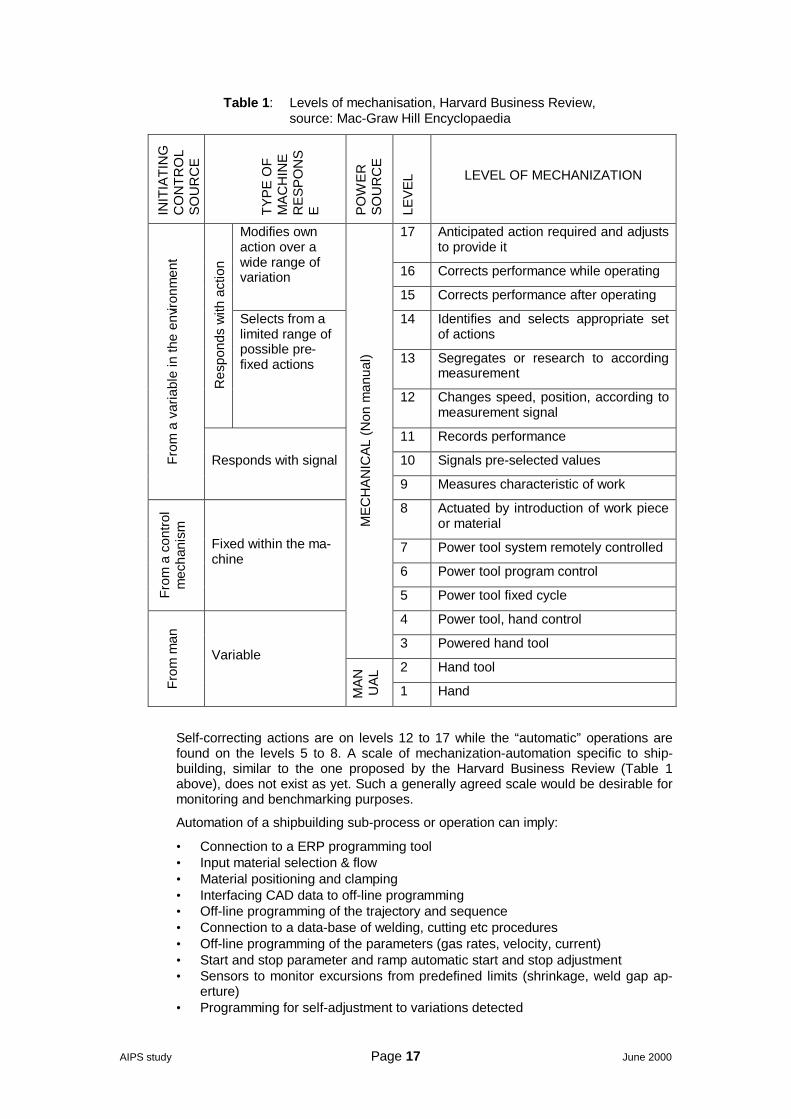
The Mac-Graw Hill Encyclopaedia quoted the Harvard Business Review proposal of17 levels of mechanisation according the power and control sources, as shown onTable 1 below.
AIPS study Page 17 June 2000
Table 1: Levels of mechanisation, Harvard Business Review,source: Mac-Graw Hill Encyclopaedia
INIT
IATI
NG
CO
NTR
OL
SO
UR
CE
TYP
E O
FM
AC
HIN
ER
ES
PO
NS
E PO
WE
RS
OU
RC
E
LEV
EL LEVEL OF MECHANIZATION
17 Anticipated action required and adjuststo provide it
16 Corrects performance while operating
Modifies ownaction over awide range ofvariation
15 Corrects performance after operating
14 Identifies and selects appropriate setof actions
13 Segregates or research to accordingmeasurement
Res
pond
s w
ith a
ctio
n
Selects from alimited range ofpossible pre-fixed actions
12 Changes speed, position, according tomeasurement signal
11 Records performance
10 Signals pre-selected valuesFrom
a v
aria
ble
in th
e en
viron
men
t
Responds with signal
9 Measures characteristic of work
8 Actuated by introduction of work pieceor material
7 Power tool system remotely controlled
6 Power tool program control
From
a c
ontro
lm
echa
nism
Fixed within the ma-chine
5 Power tool fixed cycle
4 Power tool, hand control
ME
CH
AN
ICA
L (N
on m
anua
l)
3 Powered hand tool
2 Hand tool
From
man
Variable
MA
NU
AL
1 Hand
Self-correcting actions are on levels 12 to 17 while the “automatic” operations arefound on the levels 5 to 8. A scale of mechanization-automation specific to ship-building, similar to the one proposed by the Harvard Business Review (Table 1above), does not exist as yet. Such a generally agreed scale would be desirable formonitoring and benchmarking purposes.
Automation of a shipbuilding sub-process or operation can imply:
• Connection to a ERP programming tool• Input material selection & flow• Material positioning and clamping• Interfacing CAD data to off-line programming• Off-line programming of the trajectory and sequence• Connection to a data-base of welding, cutting etc procedures• Off-line programming of the parameters (gas rates, velocity, current)• Start and stop parameter and ramp automatic start and stop adjustment• Sensors to monitor excursions from predefined limits (shrinkage, weld gap ap-
erture)• Programming for self-adjustment to variations detected
AIPS study Page 18 June 2000
• On line quality control (record of parameters, warning or inspection systems,marking)
• Tool exchange and cleaning automated systems• Cleaning and finishing as needed• Material output• Material output classification and routing
By the term “mechanisation” we refer to the assistance, which is provide to the op-erator, usually by servo-mechanical means, in order to alleviate him in the most te-dious parts of his job. Sometimes, this assistance can involve quite complicated andexpensive equipment as in the case of robot-assisted operations. The fundamentaldifference of mechanisation as compared to robotisation or automation lies in thefact that, although some auxiliary operations might be automated or robotised, theoperation as such is performed manually.
Typical examples of mechanisation are:
• Automatic feed of the electrode during a welding operation• Servo-assisted handling of the tubes, wires or the entire welding machine
through gantries, hanging pantographic mechanisms etc.
Often, the terms “semi-automated” and “mechanised” are used indiscriminately. Infact, there exist many overlaps in what in the use of terms like automation, mecha-nisation, semi-automation, robotisation, robot-assisted operations etc.
2.3 Computer Aided Design, Engineering and ManufacturingCAD (Computer-Aided Design) refers to the use of computer and digital technologyto support the preparation of engineering designs, typically limited to geometry only.
CAD / CAM (Computer-Aided Design / Computer-Aided Manufacturing) refers to theintegrated use of computer and digital technology to support the entire design-to-fabrication cycle of a product.
CAE (Computer-Aided Engineering) refers to the use of computer and digital tech-nology to support basic error checking, analysis, optimisation, manufacturability,etc., of a product design. Finite element analysis (FEA) is one example of CAE.
CE (Concurrent Engineering) refers to a systematic approach to creating a productdesign that considers all elements of the product life cycle from the conceptual de-sign to the disposal of a product, and in so doing defines the product, its manufac-turing processes, and all other required life cycle processes such as logistic support.Concurrent engineering means shortening the engineering process cycle introduc-ing parallel engineering processes instead of sequential processes.
CIM (Computer Integrated Manufacturing) refers to the use of computer and digitaltechnology to completely integrate all manufacturing process with engineering de-sign.
Communication Protocol refers to a defined communication format that containsthe control procedures required for the data transfer across the link interfaces, andto and from the user's application programs. A set of rules that specify how datacommunication is to take place over a network. governing the format, timing, se-quencing and error control of exchanged data.
EPD (Electronic Product Definition) refers to the concurrent creation, management,sharing, and reusing of electronic product information in a collaborative environmentthroughout a product's life cycle and across a distributed value chain.
EDM (Electronic Document Management) refers to a combination of automated andoperator-invoked processes that allow the capturing, storage, retrieval, display,routing and maintenance of information comprising electronically stored documents.
Extended Enterprise: The seamless integration of a group of companies and sup-pliers.

AIPS study Page 19 June 2000
IGES (Initial Graphics Exchange Specification) is an American standard for ex-changing CAD data, started by the American National Standards Institute (ANSI)back to 1979. The Current version is IGES 5.3. The next version will be IGES 6.0.
Parametric Modelling refers to a type of CAD model that relates the geometry ofdifferent elements of a product so that when one element is changed, the geometryof the rest of the product changes as well.
PDM (Product Data Management) refers to the management of all engineeringmanufacturing data for a product to control its entire development cycle.
Product Data refer to all engineering data necessary to define the geometry, thefunction, and the behaviour of an item over its entire life span, including logistic ele-ments for quality, reliability, maintainability, topology, relationship, tolerances, attrib-utes, and features necessary to define the item completely for the purpose of de-sign, analysis, manufacture, test, and inspection.
Product Model is a data model that contains the functions and physical character-istics of each unit of a product throughout its complete life cycle (from requirementsspecification to disposal).
STEP (Standard for the Exchange of Product Model Data - ISO standard 10303) isthe international data description standard which will provide a complete unambigu-ous, computer-interpretable definition of the physical and functional characteristicsof a product throughout its life cycle.
Virtual Prototyping is a software-based engineering discipline that entails model-ling a mechanical system, simulating and visualizing its 3D motion behaviour undernear real-world operating conditions, and refining / optimising the design through it-erative design studies.
VR (Virtual Reality) refers to a class of systems (hardware and software) made tobuild a high-end representation of reality.
AIPS study Page 20 June 2000
3 Context
3.1 Towards a competitive & sustainable shipbuilding3.1.1 The changing yard
The shipbuilding market is characterised by an over-capacity in production, mainlyin the sector of merchant vessels, which has caused dramatic price reductions (from15% to 30% over the 1998 prices) in particular for the steel intensive vessel typeswhich are fabricated in Korea (tankers, bulk-carriers, VLCCs, etc.). The actual ship-building capacity is around 21 Mgct while the newbuildings in 1999 accounted for16.4 Mcgt. This unbalance is bound to worsen during the next few years, [30].
The principal reason for the unbalance between shipbuilding offer and demand hasbeen the substantial increase of the Korean shipbuilding capacity, mainly during theperiod 1994-1996. As a result of the Korean expansion, all the major shipbuildingareas (Japan in particular) accused significant losses. In EU the situation of theshipbuilding sector is critical as the increased demand for luxury cruise vessels andthe weak Euro cannot but just compensate for the losses towards Korea.
The situation of the shipbuilding market has accelerated the trend of EU shipyardstowards building vessel types with high technical content and specialised know-how.Typical examples are the containerships, LNG, LPG and product tankers, dredgers,luxury cruise vessels and ferries.
Apart from the shift towards more complex types of vessels, we must note the in-creasing complexity of every vessel type because of:
• Increased performance requirements in every operational field: speed, safety,emissions, manning, comfort, cargo & passenger handling etc.
• More stringent environmental and safety regulations• Better design and building tools that allow better products even in conditions of
lower profit margin
Moving to more complicated ship types sets a totally different level of requirementsfor the shipyard and surrounding infrastructure. The focus is shifted from the puresteel construction towards extensive outfitting work. As the complexity of a vesselincreases the portion of the steel work diminishes significantly. In a modern passen-ger cruise vessel the outfitting work can represent up to 80% of the total work thesteel work being 20%. Material costs become also a dominant factor in ship pricing.
Another important change concerns the design activities (including planning andmanagement), which become increasingly important both in terms of volume andcost as well overall impact to the shipbuilding project. For a modern passengervessel, can easily represent over 10% of the total project cost [44].
The very short delivery times, imposed by the fierce competition and the rapidlyevolving market, emphasise even more the need for efficient design, planning andmanagement. Indeed, in many cases, the time from contract to delivery of even avery complicated vessel, such as a cruise liner, can be shorter than 30 months.
In the past, shipyards have been largely self sufficient in all disciplines of shipbuild-ing process. All the steel work, outfitting work and even the machining work hasbeen made mainly by the shipyard’s own personnel. Occasional work subcontract-ing has been necessary to even out the peak loads, but this has been minor partand done normally under shipyard’s supervision.
However, workloads can vary significantly across various disciplines in different shiptypes. Also the complexity of certain outfitting work requires a lot of highly skilledpersonnel for limited periods of time. From the shipyard’s point of view handling thisis difficult and not cost effective. Due to this reason most of the advanced shipyardshave moved towards the extensive use of subcontractors. These are more andmore requested to provide systems and turnkey deliveries.
AIPS study Page 21 June 2000
Today the experts speak about “assembly” yards, where the shipyard may assumethe sole role of assembling the hull and selected parts of the outfitting while a sig-nificant part of the added value is produced by external personnel. This develop-ment makes the automation and integration process much more difficult than itwould be in a case where everything is done at the yard.
Nowadays, successful completion of complicated ship (such as modern high-speedferries or big passenger vessels) in a concurrent engineering and production envi-ronment sets new challenges for the standardisation of components and integrationof the production processes.
3.1.2 The changing ship
There has been tremendous development in most kinds of ships since the earlyeighties. The size of ships has progressively increased as well as speed. Increasedsafety together with higher capacity and efficiency requirements have led to applica-tion of new design configurations and technology, at a rate never seen before in theshipbuilding world.
In terms of hull forms, the tendency has been towards higher capacity, which hasmeant bulkier ships, above and under waterline, towards higher block coefficient.Another clear tendency has been towards higher speeds especially in ferries, con-tainerships and high value cargoes. Average contract speed for ships above 1000 gthas increased by about one knot within the last 15 years. For some special shiptypes, such as container feeder ships, ro-ro ships and ferries the increase has beenseveral knots. At the same time also the main dimension ratios have changed re-markably, the length-beam ratio has decreased, in some cases even below 5 andthe beam-draught ratio has increased: for example for ro-ro passenger ferries from3,0-3,5 up to 4,5-5,0.
Up to the end of the 70’s the hull forms were typically defined by using hull form se-ries, such as Series 60, Taylor, BSRA and similar. Today these series are no moreused and, typically, hull form designs are based on reference vessel(s) or are de-fined and faired using CAD programs.
Cruise vessels have also developed rapidly during the last twenty years. The in-crease in vessel size is impressive. 85,000 gt has for a long time been the upperlimit of cruise vessel size. The first mega size cruise vessel was the 101,353 gt Car-nival Destiny delivered in 1996. The total number of such mega cruise vessels, builtor on order by the end of 1999, was 9.
Ro-ro’s and ro-ro passenger ferries have today two clearly different families:
• Conventional high displacement ferries with Froude number around 0,30 or be-low and
• High displacement fast ferries with Froude number clearly above 0,35, reachingtoday already 0,40 or even above
Catamaran designs and pods and water jet propulsion allow innovative designswaiving the constraints of the monohull-propeller limitations.
Increased competition, however, will always put the focus on the cost effectivenessof any investment. Any drastic innovation in the vessel design, structures or materi-als has inherent risks on long time performance (fatigue, corrosion, vibrations. etc).Efficient lifecycle analysis is required for the cost-analysis of any new configurationor solution.
The issue is to maximise the efficient revenue generating space at minimised in-vestment and running costs, taking into account system availability and environ-mental impacts. These items have to be clarified and their impact on the lifecycleeconomy of the vessel has to be calculated before any major decision can be made.
New products and innovations are introduced and completely new machinery andship configurations are developed for efficiency and economical reasons.
Considering cost efficiency we end up with four items:
AIPS study Page 22 June 2000
1. Space,2. Weight,3. Power4. Equipment (materials)
The efficient area and volume of the vessel compared with the total area and vol-ume is a good indication of revenue generating capability and costs. Weight is di-rectly related to building and fuel costs. Installed power onboard relates to the effi-ciency of hull, propulsion system and power generation. Equipment and materialsare cost related either directly or indirectly (through required man-hours).
3.1.3 Shipbuilding, fundamental sector of a sustainable EU shipping
The maritime sector has been and will continue to be of strategic importance forEurope, due to the nature of its economy, topology, history and tradition [3]. Ship-ping in particular has played a major role in almost every aspect of the European lifeand is, to a great extent, responsible for its present welfare. The EEA (EuropeanEconomic Area) ship owners controlled a fleet, which, in January 1998, represented190.6 M gt, corresponding to 38.5% of the world fleet.
The shipbuilding industry in Europe (EU plus Poland and Norway) is in third place,behind Japan and Korea, in terms of tonnage built and equalled Japan in first placeas far as order book is concerned (1998 data). Europe’s shipbuilding is world lead-ing in complex, high-tech ship constructions, particularly passenger ships (cruisersand ferries), containerships, LNG and LPG tankers, etc. European equipmentmanufacturers represent over 2,500 SMEs. During 1997, shipbuilding and relatedsuppliers employed a work force of about 200,000 persons, delivering merchantships and equipment with a value of around 17 G€.
Over the past couple of decades, European shipbuilding has declined dramaticallyin terms of orders, closures of yards and the consequent loss of skilled workers; in1976, shipbuilding an related industries employed some 500,000 workers. Europeanshipbuilding, as we know it, cannot survive such losses in its skill base.
Shipbuilding is a key maritime industry, which not only has contributed significantlyto Europe’s maritime past but also is strategic for its future. In the global marketeconomy of today, in order to stay competitive, shipbuilding industries are faced withan urgent need for profound changes. This need has become even more urgentfrom the recent events in the Southeast Asia and from the upcoming cease of allsubsidies. The enlargement of the Union with five new member states, some ofwhich have a considerable shipbuilding industry, is another factor to be considered.In the long run, European shipbuilding cannot assure its future but by:
• The achievement of a competitive and sustainable shipbuilding, integral part ofa sustainable shipping industry.
• The assurance of the highest possible quality standards, necessary for a safeand environmentally friendly navigation.
The achievement of these goals requires drastic changes in almost every aspect ofthe planning, designing, building and maintaining the European commercial fleet.Improvements are to be sought in every stage of the fabrication process, from theconceptual design to the procurement, production, outsourcing management, as-sembly, fitting, QA etc. Novel technologies (like laser welding etc), the automationand robotisation as well as the integration of the design and fabrication processescan lead to a much increased productivity and have the potential to transform ship-building from a labour intensive to a technology intensive sector.
A technology intensive, sustainable European shipbuilding sector is a fundamental,integrating part of a sustainable European shipping, which is, and will continue tobe, of strategic importance for the future of Europe.
AIPS study Page 23 June 2000
3.2 Robotics & automation3.2.1 The world market for industrial robots
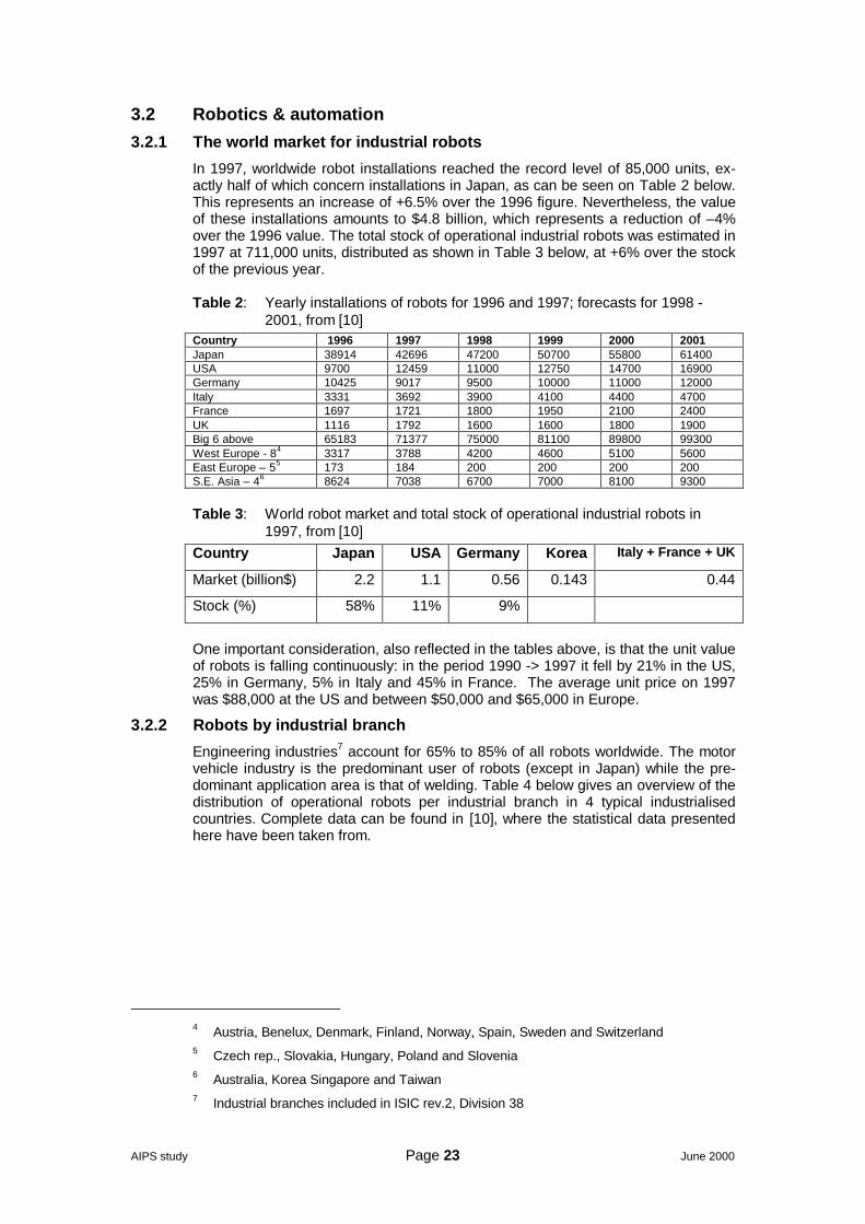
In 1997, worldwide robot installations reached the record level of 85,000 units, ex-actly half of which concern installations in Japan, as can be seen on Table 2 below.This represents an increase of +6.5% over the 1996 figure. Nevertheless, the valueof these installations amounts to $4.8 billion, which represents a reduction of –4%over the 1996 value. The total stock of operational industrial robots was estimated in1997 at 711,000 units, distributed as shown in Table 3 below, at +6% over the stockof the previous year.
Table 2: Yearly installations of robots for 1996 and 1997; forecasts for 1998 -2001, from [10]
Country 1996 1997 1998 1999 2000 2001Japan 38914 42696 47200 50700 55800 61400USA 9700 12459 11000 12750 14700 16900Germany 10425 9017 9500 10000 11000 12000Italy 3331 3692 3900 4100 4400 4700France 1697 1721 1800 1950 2100 2400UK 1116 1792 1600 1600 1800 1900Big 6 above 65183 71377 75000 81100 89800 99300West Europe - 84 3317 3788 4200 4600 5100 5600East Europe – 55 173 184 200 200 200 200S.E. Asia – 46 8624 7038 6700 7000 8100 9300
Table 3: World robot market and total stock of operational industrial robots in1997, from [10]
Country Japan USA Germany Korea Italy + France + UK
Market (billion$) 2.2 1.1 0.56 0.143 0.44
Stock (%) 58% 11% 9%
One important consideration, also reflected in the tables above, is that the unit valueof robots is falling continuously: in the period 1990 -> 1997 it fell by 21% in the US,25% in Germany, 5% in Italy and 45% in France. The average unit price on 1997was $88,000 at the US and between $50,000 and $65,000 in Europe.
3.2.2 Robots by industrial branch
Engineering industries7 account for 65% to 85% of all robots worldwide. The motorvehicle industry is the predominant user of robots (except in Japan) while the pre-dominant application area is that of welding. Table 4 below gives an overview of thedistribution of operational robots per industrial branch in 4 typical industrialisedcountries. Complete data can be found in [10], where the statistical data presentedhere have been taken from.
4 Austria, Benelux, Denmark, Finland, Norway, Spain, Sweden and Switzerland5 Czech rep., Slovakia, Hungary, Poland and Slovenia6 Australia, Korea Singapore and Taiwan7 Industrial branches included in ISIC rev.2, Division 38
AIPS study Page 24 June 2000
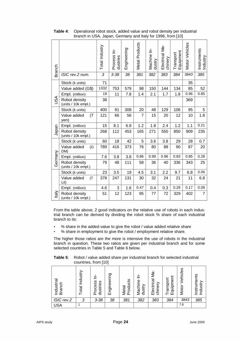
Table 4: Operational robot stock, added value and robot density per industrialbranch in USA, Japan, Germany and Italy for 1996, from [10]
Tota
l Ind
ustry
Pro
cess
In-
dust
ries
Eng
inee
ring
Met
al P
rodu
cts
Mac
hine
In-
dust
ry
Ele
ctric
al M
a-ch
iner
y
Tran
spor
tE
quip
men
t
Mot
or V
ehic
les
Inst
rum
ents
Indu
stry
Bra
nch
ISIC rev.2 num. 3 3-38 38 381 382 383 384 3843 385
Stock (k units) 71 35Value added (G$) 1332 753 579 98 150 144 134 85 52Empl. (million) 19 11 7.8 1.4 2.1 1.7 1.8 0.96 0.85
US
A Robot density(units / 10k empl.)
38 369
Stock (k units) 400 91 308 20 48 129 106 95 5Value added (Tyen)
121 66 56 7 15 20 12 10 1.8
Empl. (million) 15 8.1 6.8 1.2 1.8 2.4 1.2 1.1 0.21
Japa
n
Robot density(units / 10k empl.)
268 112 453 165 271 550 850 909 235
Stock (k units) 60 18 42 5 3.6 3.8 29 28 0.7Value added (GDM)
789 416 373 76 80 88 90 87 20
Empl. (million) 7.6 3.8 3.8 0.86 0.99 0.96 0.83 0.85 0.28
Ger
man
y
Robot density(units / 10k empl.)
79 48 111 58 36 40 336 343 25
Stock (k units) 23 3.5 19 4.5 3.1 2.2 9.7 6.8 0.06
Value added (TLit)
378 247 131 30 32 24 21 11 6.8
Empl. (million) 4.6 3 1.6 0.47 0.4 0.3 0.29 0.17 0.09
Italy Robot density
(units / 10k empl.)51 12 123 95 77 72 329 402 7
From the table above, 2 good indicators on the relative use of robots in each indus-trial branch can be derived by dividing the robot stock % share of each industrialbranch to its:
• % share in the added value to give the robot / value added relative share• % share in employment to give the robot / employment relative share.
The higher those ratios are the more is intensive the use of robots in the industrialbranch in question. These two ratios are given per industrial branch and for someselected countries in Table 5 and Table 6 below.
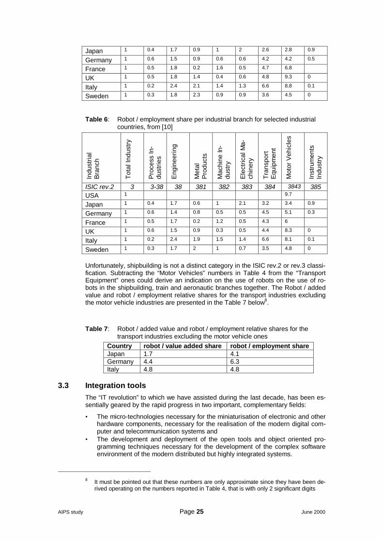
Table 5: Robot / value added share per industrial branch for selected industrialcountries, from [10]
Indu
stria
lB
ranc
h
Tota
l Ind
ustry
Pro
cess
In-
dust
ries
Eng
inee
ring
Met
alP
rodu
cts
Mac
hine
In-
dust
ry
Ele
ctric
al M
a-ch
iner
y
Tran
spor
tE
quip
men
t
Mot
or V
ehic
les
Inst
rum
ents
Indu
stry
ISIC rev.2 3 3-38 38 381 382 383 384 3843 385USA 1 7.8
AIPS study Page 25 June 2000
Japan 1 0.4 1.7 0.9 1 2 2.6 2.8 0.9
Germany 1 0.6 1.5 0.9 0.6 0.6 4.2 4.2 0.5
France 1 0.5 1.8 0.2 1.6 0.5 4.7 6.8
UK 1 0.5 1.8 1.4 0.4 0.6 4.8 9.3 0
Italy 1 0.2 2.4 2.1 1.4 1.3 6.6 8.8 0.1
Sweden 1 0.3 1.8 2.3 0.9 0.9 3.6 4.5 0
Table 6: Robot / employment share per industrial branch for selected industrialcountries, from [10]
Indu
stria
lB
ranc
h
Tota
l Ind
ustry
Pro
cess
In-
dust
ries
Eng
inee
ring
Met
alP
rodu
cts
Mac
hine
In-
dust
ry
Ele
ctric
al M
a-ch
iner
y
Tran
spor
tE
quip
men
t
Mot
or V
ehic
les
Inst
rum
ents
Indu
stry
ISIC rev.2 3 3-38 38 381 382 383 384 3843 385USA 1 9.7
Japan 1 0.4 1.7 0.6 1 2.1 3.2 3.4 0.9
Germany 1 0.6 1.4 0.8 0.5 0.5 4.5 5.1 0.3
France 1 0.5 1.7 0.2 1.2 0.5 4.3 6
UK 1 0.6 1.5 0.9 0.3 0.5 4.4 8.3 0
Italy 1 0.2 2.4 1.9 1.5 1.4 6.6 8.1 0.1
Sweden 1 0.3 1.7 2 1 0.7 3.5 4.8 0
Unfortunately, shipbuilding is not a distinct category in the ISIC rev.2 or rev.3 classi-fication. Subtracting the “Motor Vehicles” numbers in Table 4 from the “TransportEquipment” ones could derive an indication on the use of robots on the use of ro-bots in the shipbuilding, train and aeronautic branches together. The Robot / addedvalue and robot / employment relative shares for the transport industries excludingthe motor vehicle industries are presented in the Table 7 below8.
Table 7: Robot / added value and robot / employment relative shares for thetransport industries excluding the motor vehicle ones
Country robot / value added share robot / employment shareJapan 1.7 4.1Germany 4.4 6.3Italy 4.8 4.8
3.3 Integration toolsThe “IT revolution” to which we have assisted during the last decade, has been es-sentially geared by the rapid progress in two important, complementary fields:
• The micro-technologies necessary for the miniaturisation of electronic and otherhardware components, necessary for the realisation of the modern digital com-puter and telecommunication systems and
• The development and deployment of the open tools and object oriented pro-gramming techniques necessary for the development of the complex softwareenvironment of the modern distributed but highly integrated systems.
8 It must be pointed out that these numbers are only approximate since they have been de-
rived operating on the numbers reported in Table 4, that is with only 2 significant digits
AIPS study Page 26 June 2000
Especially during the last decade, digital computer technology penetrated almostevery single aspect of industrial activity. It alleviated humans from many tedious re-petitive jobs and provided the backbone for efficient and cost effective performanceof operations as diverse as document production to car assembling or high precisioncomponent manufacturing.
3.3.1 Computers: from calculations to communications and integration
There is no need to illustrate to anyone the rapid advances of the computer industryduring the last years. In many respects, the hardware potential available in a mod-ern laptop compute is superior to any medium-size computer of 10 years ago. In therecent years, the improvement of the average cost / performance ratio has beenhalved every one and half years. The considerable performance gains obtained inthe PC based platforms and the consequent move of many engineering applicationstowards Windows NT has further improved that figure.
Nevertheless, the most drastic change perhaps lies in the way computer systemsare perceived and used:
10 years ago a computer would typically be perceived as a tool for increasing theproductivity of a certain process, be it design (i.e. CAD/CAE systems) or production(robots or automation systems), mainly through its ability to perform fast calcula-tions.
10 years from now, a computer is likely to be perceived as an integration tool, com-ponent of a broad digital communication system rather like a process productivityenhancing tool.
Today, in what regards the use of computers, EU enterprises are still in the very be-ginning of a transformation process. The levers of this transformation are:
• The vast amount of technical and commercial information which are availablealmost in real-time through Internet.
• The new digital communication technologies (LANs, WANs, ISDSN, etc.), whichmake technically possible concurrent engineering, virtual enterprises, and othercollaborative forms of working, using cheap, public communication channels.
Important issues to be addressed are of commercial and regulatory aspect ratherthan technical. They mainly concern communication standards and data security.
3.3.2 Software development & programming techniques
Object Oriented Programming
Object Oriented Programming is the recent answer to the complexity of the softwareengineering processes. Although the concept of Object is not that new it was thelate evolution of languages like C++ and Java that gave to this technique the re-quired tools to apply it.
The concept of Object is based on the idea that this software unit comprises fromthe data and the routines that are used to process them. This way the degree of ac-cess to the data and the permission to alter them is controlled. This is referred asthe encapsulation property. Objects represent usually existing physical entities(sensor, mechanism) but also processes or message passing units. Objects canhave certain relations among them the most important is inheritance. An object canbe described to belong to a certain class of objects inheriting a structure and be-haviour from the original class. According to this relation a feature of one object canbe inherited to others once those are declared to belong to this group of objects.Other relations among objects can be constructed allowing different levels of inter-action. Objects can belong to a number of different groups inheriting thus the char-acteristics (coherently) of all these groups. This property is referred as polymor-phism.
Another basic advantage of the OOP is the possibility to recycle software code.Parts of the same software code in the form of objects can be used in different proj-ects exploiting similarities in the representation of an object. This is possible since
AIPS study Page 27 June 2000
each object can have the same interface and structure that characterises its behav-iour in different software packages.
UML
Unified Modelling Language (UML) is a semi-formal semantic meta-language usedmainly in OOP, to define the basic modelling concepts of object, class, association,etc. It includes formal well-formedness rules expressed as constraints in the ObjectConstraint Language (OCL). In addition it provides graphical notation for modellingconcepts with 8 different diagram types and 2 predefined domain extensions.
UML combined existing standards developed separately by researchers into aunique by the Object Management Group (OMG) in 1997. In this way UML evolvedinto a standard tool for analysis and design of object-oriented systems based onextensive experience and best practices. Currently is gaining rapid acceptance(training, tools, books) as a common language in software industry.
UML can be used in many different areas to capture domain-specific concepts andideas, reflecting the main characteristics of OOP that is :
• encapsulation• inheritance• polymorphism / genericity
In addition it offers the means for the description of a system as set of structurallycollaborating parts classes and instances.
UML offers the possibility to describe a number of different design views for a sys-tem with corresponding types of diagrams, namely:
• Requirements (use case diagrams)• Static structure (class diagrams): types of objects and their relationships• Dynamic behaviour (state machines): possible life histories of an object• Interactive behaviour (activity, sequence, and collaboration diagrams): flow of
control among objects to achieve system-level behaviour• Physical implementation structures (component and deployment diagrams):
software modules and deployment on physical nodes.
A number of visual tools based on UML have been developed automatically trans-lating the graphical structures into software frames. The author has then to fill up thecreated frame with the detailed code. This allows a more effective software con-struction since the generated structures reflect design choices not to be overwrittenin later stages of development.
3.3.3 CAD / CAE
A model is a representation of an object or a physical system. Models can be sym-bolic (i.e. a set of mathematical or logical equations), iconic (i.e. a map), logical (.e.flow chart) or geometric. Designers, engineers or analysts create and use models todefine somehow the process the physical realisation of any part, assembly or con-struction. In addition, models are used extensively to simulate, test or predict thebehaviour of objects or physical systems.
Computerised systems, mainly due to their interactive graphic capabilities, have be-come valuable tools for creating and manipulating geometric and other types ofmodels. Thus, they have contributed in enhancing significantly most of the designphases, leading at much better engineered products much faster. Modern CADpackages also provide interfaces towards CAM systems, thus contributing in the off-line programming of the automated production facilities.
A very important change happening these days concerns in the role that CAD toolsplay in modern industry: The role of CAD/CAE has traditionally been that of en-hancing the various phases of the design process and assuring shorter lead times tothe planning and the start of the production activities. Nowadays, in view of the in-creasing complexity of the production operations and, consequently, the planningrequirements and the stringent lead times to market, CAD/CAE tools are rapidly ac-

AIPS study Page 28 June 2000
quiring the role of the integrator between the ‘traditional’ design phases the planningand production processes.
The design, manufacture and support of a product involve an increasing number ofpartners each one of them requiring different, specialised data and information re-lated to the development of the given product. All of them need to be able to operateefficiently and for that it is vital the ability to share and exchange Product Data in atimely manner is critical. Geometry, which has traditionally been the object ofCAD/CAM, is only part of the information necessary for the realisation of a product,especially when a product life-cycle approach is considered. Recently, the potentialof the IT tools, combined with the new SW development environment, promises tomake possible the realisation of a Product Model providing a representation of allinformation associated with the complete product lifecycle including design, manu-facture, utilisation, maintenance, and disposal along with the necessary mecha-nisms and definitions to enable data to be exchanged among different computersystems and environments (see STEP).
In general, the capabilities of the CAD / CAE packages kept pace with the rapidlyevolving IT potential with two important trends:
• The move, even for demanding CFD applications, from mainframe platforms toworkstations and / or PCs.
• The move from proprietary operating systems towards standard UNIX and,mainly, Windows NT environment.
In what concerns the CAD market, on top of the above trends, we see an importantshift of the big software vendors towards new architectures, moving from 2D baseddrafting to complete 3D and Product Model representations. Some important CADpackages are currently being completely re-written at costs of several thousands ofman-years of development work.
The globalisation of the market economy combined with the IT context, as describedin the paragraphs above, has created two apparently conflicting trends in the marketof the CAD / CAM / CAE products:
• Further concentration of the big CAD / CAE vendors• Creation and development of many small, home/custom made, highly special-
ised products
Although there have been significant activities to define standards on CAD data ex-change, the interfacing of the various existing CAD programs remains a major bot-tleneck. Even if the big software houses usually provide ad-hoc translators towardseach other’s packages, passing data among applications is usually a matter of con-cern. The situation is much worse in smaller packages.
Nevertheless, this situation is bound to change. The great enabler in the uptake ofnew standards is the web. With the prevalence of the Internet within the working en-vironment we have the means to move and view data from anywhere to anywhere inthe world. With companies like Microsoft, who have recently made a strategic deci-sion to enter the engineering applications market, applying constant pressure toconform, we stand on the brink of a new generation of systems with new architec-tures built on the concept of integrated platforms.
In shipbuilding, CAD tools are used in every stage of the design process and, partly,in the early production processes. A good overview of the use of the CAD / CAEtools in shipbuilding is found in [25].
3.3.4 Standards
Models, even when representing the same physical object or system can be ex-tremely different from each other depending primarily on the use or the require-ments they are supposed to meet but also on the way they were conceived. This iseven more so for the computerised models that depend upon also upon the HW andSW platform on which they are visualised, on the particular modelling (CAD/CAE)program used or even on the programming habits of the CAD designer / operator.
AIPS study Page 29 June 2000
Flawless information exchange across different models / applications has alwaysbeen a major issue.
In the past decades, models used in engineering / industrial applications weremostly CAD, CAM or CAE models, that is mostly graphical representations of somephysical object or system. Consequently, the major issue has been that of ex-changing / sharing of graphical / geometric information among the various applica-tions. The IGES (Initial Graphics Exchange Specification) standard for exchangingCAD data, started ANSI back in 1979, was the most important response to tacklethis issue. Nevertheless, the interfacing of the various existing CAD programs andthe flawless exchange of geometric information still remains an important issue. Infact, the problem is so complicated, the requirements (and consequently the meth-ods and techniques used over the time) are so diverse that even the market forceshave been unable to impose a de-facto standard (like Microsoft in the office auto-mation applications).
Inevitably, the situation is bound to be much more complicated in what concerns thestandards on product models, where information is not only geometric but is sup-posed to describe all aspects of the product throughout its life-cycle.
STEP (Standard for the Exchange of Product model data - ISO standard 10303) isan international set of standards, still under development, which will be used to de-scribe a product in a neutral format over its complete life-cycle in a hardware-independent way. Several STEP application protocols, specifically oriented to shipdesign, production and operation, are in preparation. EMSA is the European Mari-time STEP Association. In USA the MariStep organisation is quite active, driven bythe military industry and IBM and a ProStep organisation. Japan has also a StepAssociation.
This series of ISO 10303 International Standards provides a representation of prod-uct information along with the necessary mechanisms and definitions to enableproduct data to be exchanged. The exchange is among different computer systemsand environments associated with the complete product life-cycle, including productdesign, manufacture, use, maintenance, and final disposition of the product.
The following are within the scope of ISO 10303:
1. The representation of product information, including components and assem-blies;
2. The exchange of product data, including storing, transferring, accessing, andarchiving.
Thus, STEP supports not only the exchange of product data, but also its represen-tation for e.g. archiving. The whole life-cycle of a product is in scope, including op-eration and maintenance.
AIPS study Page 30 June 2000
4 Shipbuilding process break-down
4.1 Shipbuilding todayTraditionally, shipbuilding has been identified with those operations and processesrelated with the transformation of sheet metal to steel hulls. These operations es-sentially consisted in marking and cutting the sheet metal prime material in ele-mentary building pieces the assembly of which, in various stages (panels, sub-blocks, blocks, sections), finally yielded the complete steel hull. Thus, three basicclasses of processes could be distinguished:
• Sheet (or beam) metal treatment processes (conditioning, marking, cutting,bending etc)
• Assembling (nowadays mostly welding)• Handling (moving and positioning the various blocks and sub-assemblies)
Maximising the efficiency of shipbuilding essentially meant:
• Assuring the most cost-effective acquisition of the necessary prime materialsand components,
• Optimising (in terms of cost and quality) each one of the processes statedabove and
• Planning the whole sequence of operations in such a way so as to ensure aseamless flow of material and an optimal utilisation of the available resources(labour, equipment, space and time)
Today, the relative importance (at least in terms of cost) of the steel shaping andassembling has decreased substantially. This is true especially for the big passen-ger and ferry vessels where EU shipbuilding still holds a considerable share of themarket. In fact, due to the ever-increasing requirements in terms of passengercomfort, safety in navigation and environmental concerns, modern passenger andferry vessels look more and more like huge navigating hotels or big industrial com-plexes. Shipbuilding nowadays encompasses a range of processes and activitiesmuch broader than shaping and assembling sheet metal steel. Less ‘traditional’shipbuilding activities, such as finishing and outfitting become increasingly impor-tant.
For a variety of reasons (also tackled in section 3 above), the traditional concept ofshipbuilding still prevails between in the European shipbuilding industry. Neverthe-less, there are concrete signs that this situation is beginning to change.
Another very important change happening these days is in the role that CAD toolsplay in shipbuilding: The role of CAD/CAE tools in shipbuilding has traditionally beenthat of enhancing the various phases of the design process and assuring shorterlead times to the planning and the start of the production activities. Nowadays, inview of the increasing complexity of the production operations and, consequently,the planning requirements and the stringent lead times to market, CAD / CAE toolsare rapidly acquiring the role of the integrator between the ‘traditional’ designphases the planning and production processes.
For all these reasons, design, be it basic or detailed, cannot be considered sepa-rately not only from production planning but also from most of the individual produc-tion processes. Nevertheless, for practical reasons, we distinguish the productionfrom the design & planning activities in terms of the different tools and technologiesapplied. While production deals with the handling and transformation material ob-jects, design and planning activities have mainly to do with the generation and han-dling of information. As such, for the purpose of the AIPS study, they are consideredas fundamental components of the integration process and the corresponding in-formation flow rather than parts of production process flow.
So, for the purpose of this study, we consider two types / classes of processes:
(a) The production processes, dealing with material objects and
AIPS study Page 31 June 2000
(b) The information processes, dealing with information
Each one of them being examined in its own context:
(1) The shipbuilding production process flow scheme, as seen in Figure 1(2) The information flow across the shipbuilding activities, as seen in Figure 2.
Although there exist significant variations according the type of vessel, the size andspecialization of each shipyard, these schemes, given in Figure 1 and Figure 2below give an adequate picture of the generic shipbuilding production processbreakdown structure and the corresponding information flow.
4.2 Production processesBy the term “production activities” or “production processes” we mean all the activi-ties that essentially consist in transforming (machining, assembling, handling, trans-porting etc) material objects. In what follows, the “generic shipbuilding” is brokendown to classes of processes hereafter referred as “production processes” or “proc-esses”. Although the meaning and the sequence of these processes can vary ac-cording to the type (i.e. tanker, container carrier, passenger ship) and size of thevessel as well as the particular methods and mentalities each individual yard, it canbe said that they represent quite well all but the very specialised constructions.
So, the generic shipbuilding production can essentially be broken down in the fol-lowing production processes:
P.1 Raw material reception & preparationP.2 Marking, cutting & conditioning of steel plates and profilesP.3 Fabrication of 2D blocks: welding of flat and shaped sub-assemblies (panels
and sub-blocks)P.4 Fabrication of 3D blocks in workshopP.5 Pre-erection: assembly of 3D blocks and subassemblies into erection unitsP.6 Prefabrication of pipes, supports, modules etcP.7 Pre-outfittingP.8 Blasting and painting/coatingP.9 Erection and outfitting in the dry-dock or slip-wayP.10 Outfitting (incl. piping, wiring, machinery etc.)P.11 Finishing & outfitting onboard of the floating vesselP.12 Commissioning & sea trials
The processes above are not necessarily sequential. Processes P.6 to P.8 in par-ticular, are performed at various stages of the shipbuilding schedule (see Figure 1below). In addition, there exist two processes that are performed in support to all ofthe processes stated above, throughout the shipbuilding activity:
P.13 Transport & handlingP.14 Dimensional control & inspection
Another important factor to consider is where each process takes place. In that re-spect, we can distinguish three classes of processes:
• Processes P.1 to P.7 are generally performed in a workshop with the possibilityof support for eventual production lines, semi or fully automated facilities etc.
• Processes P.9 to P.12 are performed out of the workshop, on the dry dock,slipway or in the floating vessel at the dockside.
• Processes P.8, P.13 and P.14 are performed either on the workshop or outside
In general, phases performed in the workshop tend to be much more efficient9 thanin dry-dock or in the floating vessel (see section 3.1.1). Consequently, there is atendency to perform as much of the outfitting, coating painting etc as early in theproduction schedule as possible.
9 According to [12], each man-hour of pre-outfitting is equivalent to 1.5-2.0 man-hours of
outfitting at the dock
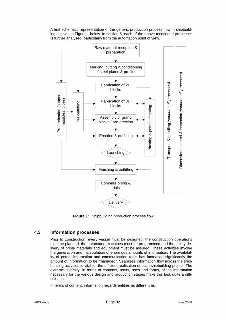
AIPS study Page 32 June 2000
A first schematic representation of the generic production process flow in shipbuild-ing is given in Figure 1 below. In section 5, each of the above mentioned processesis further analysed, particularly from the automation point of view.
Fabrication of 3Dblocks
Erection & outfitting
Commissioning &trials
Delivery
Marking, cutting & conditioningof steel plates & profiles
Tran
spor
t & h
andl
ing
(sup
ports
all
proc
esse
s)
Dim
ensi
onal
con
trol &
insp
ectio
n (s
uppo
rts a
ll pr
oces
ses)
Raw material reception &preparation
Fabrication of 2Dblocks
Assembly of grandblocks / pre-erection
Finishing & outfitting
Pre
-out
fittin
g
Pre
fabr
icat
ion
(sup
ports
,m
odul
es, p
ipes
)
Bla
stin
g &
pai
ntin
g/co
atin
gLaunching
Figure 1: Shipbuilding production process flow
4.3 Information processesPrior to construction, every vessel must be designed, the construction operationsmust be planned, the automated machines must be programmed and the timely de-livery of prime materials and equipment must be assured. These activities involvethe generation and manipulation of enormous amounts of information. The availabil-ity of potent information and communication tools has increased significantly theamount of information to be “managed”. Seamless information flow across the ship-building activities is vital for the efficient realisation of each shipbuilding project. Theextreme diversity, in terms of contents, users, uses and forms, of the informationnecessary for the various design and production stages make this task quite a diffi-cult one.
In terms of content, information regards entities as different as:
AIPS study Page 33 June 2000
• The vessel as a whole or in blocks, parts, equipment, tubing, circuitry etc• The yard layout, personnel, facilities and equipment• Procedures and know-how
The information users are:
• Engineers, naval architects and other specialists• Welders, automated machine operators and other craftsmen• The owner and the class• External subcontractors, equipment and service providers
Information (mostly but not always computerised) can be in a variety of forms:
• 3D models,• drawings,• specifications,• machine tool programming code,• work-schedules,• part lists,• plans and lay-outs,• inventories etc
In the following paragraphs we identify the main classes of information processes,hereafter referred as “information processes”, in the context of an information-flowscheme (Figure 2) in a generic shipbuilding process. By the term “information proc-esses” we mean all the activities that essentially consist in generating or processinginformation, essential for the subsequent realisation of one or more production pro-cesses as delineated in the section 4.2 above.
The main information processes involved in shipbuilding are:
I.1 Pre-designI.2 Basic designI.3 Detailed designI.4 Building proceduresI.5 Production design & planningI.6 Programming of automated facilitiesI.7 Warehouse controlI.8 Outsourcing controlI.9 Work planning & preparation
A schematic representation of the information flow in the context of the genericshipbuilding production can be seen in Figure 2 below. Fully contoured blocks de-note the main information processes, as listed above, while the dotted ones denotethe production processes, as delineated in the section 4.2 above.
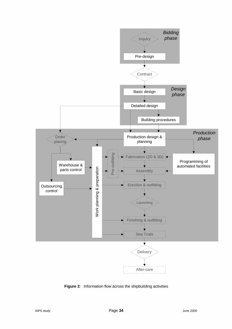
AIPS study Page 34 June 2000
Inquiry
Pre-design
Contract
Basic design
Detailed design
Building procedures
Fabrication (2D & 3D)
Assembly
Erection & outfitting
Finishing & outfitting
Launching
Sea Trials
Delivery
After-care
Warehouse &parts control
Production design &planning
Programming ofautomated facilities
Outsourcingcontrol
Designphase
Biddingphase
ProductionphaseOrder
placing
Wor
k pl
anni
ng &
pre
para
tion
Pre
-out
fittin
g
Figure 2: Information flow across the shipbuilding activities
AIPS study Page 35 June 2000
5 Automation of the production processesIn this section we will deal with the automation of each of the processes listed insection 4.2 above (see also Figure 1). The processes of major interest from theautomation point of view are the following:
P.2 Marking, cutting & conditioning of steel plates and profilesP.3 Fabrication of 2D blocks: welding of flat and shaped sub-assemblies (panels
and sub-blocks)P.4 Fabrication of 3D blocks in workshopP.6 Prefabrication of pipes, supports, modules etcP.8 Blasting and painting/coatingP.13 Transport & handlingP.14 Dimensional control & inspection
The state of automation / mechanisation of each one of these processes is outlinedin the following subsections. A considerable part of the information presented comesfrom [32], CEPS State-of-the-Art report on General Production Technology.
Apart from the processes listed above, particular attention is given to the new pro-duction technologies such as laser cutting and welding etc. The main reason for thatis the fact that most of these technologies cannot be conceived without a significantdegree of mechanisation / automation.
5.1 Marking, cutting & conditioning of the steel plates and profiles5.1.1 De-scaling / priming
Typically, yards are equipped with gantries with magnet or vacuum-beam to put thematerial on the charging conveyor.
Successive stations are:
• Roller conveyor• Preheating plant (gas or oil-heated )• Connection roller conveyor• De-scaling plant, equipped with SI centrifugal wheel with integrated grit recy-
cling plant• Connection roller conveyor• Priming plant, with spraying sensor system controlling paint film thickness, ex-
haust system with special self cleaning filter• Drying conveyor with exhaust system• Roller conveyor• Marking device• Discharging conveyor• Crane with magnet or vacuum-beam for transporting / storing the material
The plants are normally designed to handle plates as well as profiles. Special de-vices ensure that more than one profile at a time can pass through this line.
The trend today is to minimize the stock (and finance) and avoid local environmentissues by ordering the plates and profiles blasted and shop-primed and almost just-in-time (based on reliable supply from the steel mills).
5.1.2 Marking
The following methods are currently in use, usually as an attachment to the cuttingdevice:
• Powder marking• Inkjet marking• Plasma arc marking• Laser marking
AIPS study Page 36 June 2000
Marking in advanced shipbuilding includes
• Contract/construction number• Plate or part number allowing also traceability from heat /lot number of the plate,
lamination direction…• Position lines for fitting and welding• Lines for shaping in case of curved plates• Welding procedure(s) identification and sequence• Identification of the sub-assembly and block where the part or plate must be fit-
ted
5.1.3 Cutting
The following methods of cutting are in use nowadays for plate and profiles (includ-ing bulb profiles):
• Shears: used for straight cuts normally up to 3,000 mm (Nowadays mainly usedonly in the locksmith’s shops)
• Roller shears: Used for straight cuts normally up to 12,000 mm (nowadays be-ing replaced by thermal cutting machines)
• Water-jet cutting: due to its rather poor performance at the moment it is notwidely used
• Thermal cutting: basically we can distinguish:
• Oxy-Fuel cutting• Plasma-Cutting• Laser-Cutting• A combination of the above
Plasma cutting installations are gradually taking over. Underwater plate cutting sys-tems with dual pools (the heads are cutting in one of the pools while the other ispumped out for cleaning, plate conditioning and unloading) provides an automatedservice to any yard size.
A plate cutting system can be considered complete when it addresses all of thepoints below:
• Conveyor feed-in and facilities for unloading either plates and small pieces• Possibility to cut with the bevel for welding• Integrated marking (identification, part number and block, procedure welding
lines, marks for bending.• Tolerances, change of bevel on contour• Measurement system /integrated quality control/• Connection to the CAD system• Multiple torch for simultaneous cutting• Protection, insonorisation etc.
Some yards have multiple cutting lines; small yards can benefit of joint installationslike in the Nederland, where most cutting is concentrated on two specialised instal-lations, one of them is served just-in-time by the steel mill. The Dutch cutting organi-sations offer complementary services such digitisation of hard drawings, and gen-eration of CAD information, nesting etc.
5.1.4 Automation / mechanisation
Plate cutting has been one of the first processes to be automated in shipbuilding.Cutting systems are less complex than welding systems and numerical controlmechanized equipments have been used since 20 years ago and have been stead-ily improving since. Indeed, references on robotized shipyard plate cutting systemsare about ten times as numerous as welding systems. The TRIBON reference list of1999 (Table 8 below) gives an idea on the subject.
AIPS study Page 37 June 2000
Table 8: TRIBON robot installations, 1999
Plate cutting 47
Welding 6
Profile cutting 3
The data presented in this section mostly comes from the CEPS survey on generalproduction technology [32].
Mechanised surface treatment is implemented at most yards as well as in most ofthe subcontractors. Mechanised 2D cutting is also fully implemented. Robotized cut-ting is implemented at 50% of the yards.
Mechanised milling is implemented at 40-50% of the yards together with other edgepreparation methods.
Mechanised solutions have been developed and implemented also for the bendingand forming of plates in most of the yards.
A number of EU manufacturers offer complete production lines for surface treat-ment, marking and cutting operations.
The biggest challenge appears to be the assurance of the accuracy and the cutsurface quality adequate for the implementation, in the successive productionphases, of laser welding techniques.
5.2 Fabrication of 2D blocks5.2.1 Typical equipment
Basically a typical modern panel production line consists of:
• Roller bed with conveying means• Clamping (hydraulic, magnetic, vacuum) / tacking portal• Butt-welding gantry(s)• Panel turnover arrangement (in some cases)• Panel turning arrangement (90°) sometimes equipped with a thermal contour
cutting machine• Stiffener pallet• Mobile Grinding: device for the removal of primer / paint in way-off stiffeners• Mobile stiffener gantry• Fillet-welding gantry• Mobile web gantry• Web welding gantry• Lift–off transport station
Depending on the kind of panel, all possible outfitting–elements are installed as well.Before a panel leaves the shop, it must be ascertained that it is within allowable tol-erances and the outfitting–elements are in the right location. So, appropriate qualityassurance equipment, sometimes including automated optical measuring devices, isalso present.
5.2.2 Types of panel lines
The following types of panel lines are found in the shipyards:
Mini panel line, usable for one plate, working area under the portal(s) about 4x20m2
Normal flat panel line, for panels of 10x10 m2, 15x15 m2, 20x20 m2 or larger, de-pending on the size of ships, the yard is generally building
Double bottom line, usually following the configuration / sequence:
Station 1: Inner floor plates are placed and welded together
AIPS study Page 38 June 2000
Station 2: Floor plates are being put on the panel and weldedStation 3: Longitudinal floors are put in position and welded.Station 4: Tank heating pipes and other outfitting elements will be attached.Station 5: Already bended shell plates will be put on the floor grid and weldedStation 6: Lifted off the line onto special means of transport for moving to the ring
block section building area.
Curved panel line: There are various stations, sized for the largest anticipatedpanel. Each station is equipped with a large number of adjustable stanchions. Bymeans of the software the upper point of all the stanchions, if being connected,forms the shape of the curved panel in question. They usually follow the followingconfiguration:
Station 1: The already shaped plates will be put on them and welded together.Station 2: Frames will be put on the plate-field and welded by means of robots.Station 3: Secondary members are being put on the panel and welded as well.Station 4: As far as practicable outfitting elements will be put on the panelStation 5: Lift off the line on special means of transport for moving to the block-
building area.
Girder building line, consisting of:
• Crane with beam to put web and girder on the roller – conveyor• Press roller machine• Welding robots• Profile straightening machine• Discharging conveyor
With the aid of this line the optimum profiles are being produced tailor-made.
5.2.3 Automation / mechanisation
Automation (incl. robotisation) is rather well developed. More or less automatedlines are implemented in nearly 50% of the yards.
A number of EU manufacturers offer complete custom-built production lines, moreor less automated, using various configurations.
Efficient use of laser welding methods, in order to assure minimum thermal defor-mations, is still an open issue. There is a number of EC sponsored and nationalprojects on this argument with the active participation of some of the biggest EUshipyards (see section 5.8 below).
5.3 Fabrication of 3D blocks in workshop3D blocks complex structures consisting of flat panels, 2D sub blocks and curvedblocks. Assembly of these units is done, in most of the yards. Mechanised weldingis installed in some yards also for closed structures (i.e. electro-gas) while somemechanised solutions have been developed even for dock-area welding.
The building strategy for 3D blocks is designed so as to make the welding in bestpossible positions, but also maintains possibilities of efficient block outfitting.
Outfitting of 3D- blocks is important part of the modern shipbuilding philosophy.When properly planned, major part of the outfitting can be performed in the work-shop, where the working positions are optimal and material handling much easier.After erection of the hull the working conditions are much worse (usually top of thehead installations and the transportation of equipment and other materials muchmore difficult.
High degree of block outfitting means that the steel and outfitting work are parallelactivities and interact each other throughout the block assembly period. This setscertain limitations to the automation of block assembly and the practical solutionsare not very common today. Principally the same technical solutions as in 2D-blocks can be adapted, but the more complex shapes and the integration with theoutfitting limit considerably the practical possibilities.
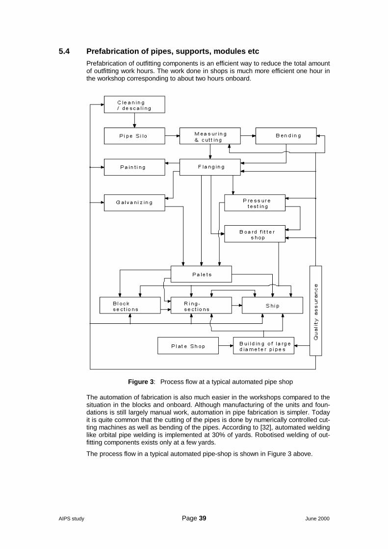
AIPS study Page 39 June 2000
5.4 Prefabrication of pipes, supports, modules etcPrefabrication of outfitting components is an efficient way to reduce the total amountof outfitting work hours. The work done in shops is much more efficient one hour inthe workshop corresponding to about two hours onboard.
Figure 3: Process flow at a typical automated pipe shop
The automation of fabrication is also much easier in the workshops compared to thesituation in the blocks and onboard. Although manufacturing of the units and foun-dations is still largely manual work, automation in pipe fabrication is simpler. Todayit is quite common that the cutting of the pipes is done by numerically controlled cut-ting machines as well as bending of the pipes. According to [32], automated weldinglike orbital pipe welding is implemented at 30% of yards. Robotised welding of out-fitting components exists only at a few yards.
The process flow in a typical automated pipe-shop is shown in Figure 3 above.
AIPS study Page 40 June 2000
5.5 Blasting and painting / coating5.5.1 Blasting
The aim of getting a clean surface (SAE 2,5 Quality - SIS 05590-1967 standard) bymeans of thorough blasting, can be achieved by various methods:
1. Sand and abrasive blasting is only allowed in closed and ventilated rooms. Notin open air!
2. Copper Slag or other mineral abrasive are only to be used for tanks within thesection.
3. Grain size of steel abrasive between 0,3-1,0 mm is used for general blasting.4. Cut wire or steel shot is used for mechanical shot-blasting.5. High-Pressure Water-Cleaning 300-2,500 bar pressure.6. Ice-Particles cleaning is being used only for special tasks.
The steel-blast-material is collected, sometimes under the working floor, is beingcleaned / separated and transported back to the silos for being used again.
The complete shop must be constantly “de-dusted“ of the dust by means of a veryeffective ventilation system. The free-blasting workers must wear breathing appa-ratus.
To reach the different level of a block-section normally a scaffolding system is in-stalled at the walls of the shop and being swung to the unit, for easy access.
In alternative to the classical methods, the “VACU-BLAST“ method consists of aunit, which works like a vacuum-cleaner and does not need any de-fuming / de-dusting or fresh air for the operator. This system has one handicap, the cleanedarea per hour is considerable less compared to any other method.
Shipyards tend to order the plates already blasted and shop primed. However manyyards have invested on installations to clean by blasting and paint block assembliesafter all welding (except erection) has been completed. This gives a better appear-ance and plate protection (shop-primer is destroyed by welding).
5.5.2 Coating / painting
After a thorough cleaning, the block-section is painted / coated in place or after be-ing transported to the coating-shop. As per paint specification, the different layer ofpaint will be applied, in accordance with the required curing time, by means of thepaint spraying method. The shop has to be adequately heated and ventilated.
As shown in Figure 1, page 32, a certain part of the painting / coating has to bedone on board as part of the finishing & outfitting process. As with every operationon the dockside, it is much less efficient and less healthy than in the shop. That iswhy shipyards tend to coat and paint as early as possible in the production process.Nevertheless, it is estimated that 20% to 40% of the surface of a modern vessel ispainted in the dock area.
The surface to be painted / coated in modern vessels has increased dramatically thelast years on almost all vessel types; in particular in those having a double hullstructure (150% more than the single hull). The total area to be painted in a typicaldouble-hull VLCC of 300,000 dwt is about 380,000 m2.
Painting / coating can be quite an unhealthy work. Painters represent, directly or in-directly (through subcontracting) an important part of the shipyard’s working force.According to [36], painters represent more than 20% of the working force of the Hi-tachi Zosen Ariake works, about the same as the welders.
5.5.3 Automation / mechanisation
Despite the increasing importance of blasting and, particularly, painting / coating ac-tivities as well as the increasing difficulties in finding painters, no substantial stepshave been taken towards the robotisation of these processes. The only significantrelevant work that we are aware of is that in [36] on a NC painting robot for ship-building, from the Hitachi Zosen Corporation.

AIPS study Page 41 June 2000
There are a number of RTD projects on robotics, which can be of potential interestfor future painting robot applications, like an IMS project on a snake robot, jointlydeveloped by US, Japan, EU and Korea and the OCTOPUS project on the vesseltopside cleaning.
5.6 Transport & handlingIn addition to the self-explanatory Figure 4 below, two more transport / handling de-vices need to be mentioned:
• The Dual Walking Beams (DWB) units are individual working machines, com-pletely self-contained. They are working in groups as per load-requirement andare operated by one operator. They are designed for a load of 100 t, 200 t and400 t per unit. The DWB units can move heavy loads over any reasonable firmand flat ground, without the need of tracks, rails or skids. Crushed gravel is ac-ceptable. They can overcome gaps between quay-wall and barge, cross rail-tracks and move up or down a slope of up to 4 degrees. The maximum load uptill now handled by a DWB-system was a complete submarine having a weightof 12,000 t and being transported from the construction-shed to the launchingsite.
• Air Cushions, as an example those distributed by Aero-Go, US. With the aid offluid film technology, aero-casters use compressed air or, occasionally, liquids,to actually float heavy loads on a thin fluid film. Individual units of a carrying ca-pacity starting from 0.9 t up to 400 t are available. Coupled together they alsocan handle even larger loads. The only disadvantage compared to the DWBsystem is that the floor-surface has to be of a much higher quality.
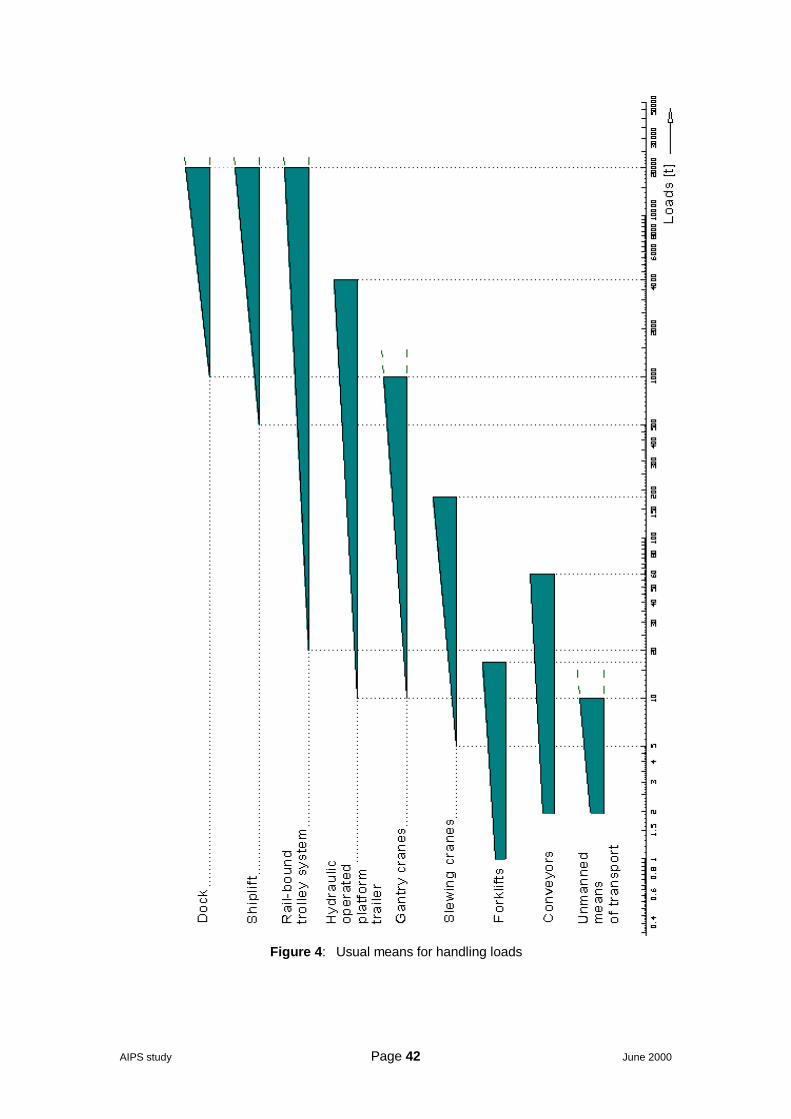
AIPS study Page 42 June 2000
Figure 4: Usual means for handling loads
AIPS study Page 43 June 2000
5.7 Dimensional control & inspectionAccording to [33], accuracy in production is seen as a main subject where QA/QCconcepts can lead to major reductions in production costs. Today's standard con-cerning accuracy in production seems to be on a good way but some important ar-eas for improvement have been identified.
3-D coordinate measurement techniques are in use at nearly all shipyards. Thosewho didn't introduce them up to now have these in test or development phases. Thelocal plan/actual data comparison is common on most yards. Those who are notable to do this at present are interested in doing so in the near future.
There is a high interest for R&D in this field. Most shipyards use the measurementresults not only for later process improvement but also in the actual ongoing pro-duction. The electronic data transfer is already introduced on half of the yards; allothers are highly interested in this technology.
5.7.1 Measuring techniques / devices
Tape measuring is the leading method in the various production stages from partsfabrication to subassemblies, including plates, curved plates and profiles, panelsand curved panels for nearly 2/3 of the yards.
For measuring sections, blocks and hull assembly less than half of the yards use 3-D co-ordinate measurement techniques, whereas the others use theodolite systems.Some use both systems parallel. Roughly 1/6 of the yards use these systems alsofor checking panel, curved panel and subassembly tolerance control.
Two yards use stationary photogrammetric measuring both for checking parts(plates) and panel accuracy.
For measuring the flatness the rotation laser is used on very few yards for subas-semblies and higher production stages.
The measuring frequency is handled quite differently, spot check or 100% - checkseem to be real alternatives, only very few yards have established a systematic ap-proach for the frequency of checks.
5.7.2 NDT methods
The standard manual NDT methods (x-ray, ultra sonic, dye penetration and mag-netic particle test) are implemented in every shipyard without exception. The techni-cal standards are sufficient and there is no interest for further development in thisfield.
However, interest is put on the development of automated testing and verificationprocedures as well as on online process monitoring systems for welding on station-ary plants. Automated test analysis systems are in use only in 1 out of 5 yards.Consequently, the interest for further RTD is rather high.
The use of light materials (aluminium, high-strength steel grades or thermo-mechanically treated steel), and the joining or welding combinations of above, intro-duce new challenges to prevent fatigue and corrosion failures, this requiring moreextensive control in welding and service inspection.
The introduction of lighter sandwich materials that may be joined by gluing or the in-troduction of laser welding will require the collection of testing experiences on flawdetection on new databases.
The corrosion monitoring of ships’ hulls in service where ultrasonic thickness meas-urement techniques are used, is still subject to new developments (.i.e. the reso-nance method proposed by DNV). Results from thickness measurements are inte-grated by the classification societies in a ship record from the construction throughoperation.
AIPS study Page 44 June 2000
5.7.3 Monitoring systems for QC (Shop floor monitoring etc)
Assembly and welding sequence plans are used in almost every shipyard. Thesame applies to production stage oriented welding standards.
Very few of the questioned shipyards have established any online process dataregistration system by now, but some activities can be seen in this field.
Manually prepared process data documentation is introduced on almost all yards,the remaining ones are testing whereas product related process data documentationthrough all production stages is used only on half of the yards, yet few others areinterested.
Product related accuracy documentation is already used by 2 yards out of 3. Thesame goes for the visualisation of measurement results for the workers on the shopfloor.
5.8 Welding processes in shipbuilding5.8.1 General
Welding is by far the most important technology applied in shipbuilding. The weightof the metal deposited by welding in a ship can easily be as much as 3 to 4% of thetotal steel weight, and the cost of the welding consumable per kg deposited can bemore than 10 times the cost of the same weight of steel. Hence, many processesare oriented to as narrow gaps as possible or even in achieving the weld throughthe fusion of base metal with a minimum deposition of new metal.
Although the deposition rate gives an idea of the capabilities of the basic process,the main cost parameter to consider is the velocity of the overall welding process (inm/s), which depends of the welding position, plate thickness, root size etc.
Table 9: Comparison of welding speed (m / min) for some welding methods,source: Messer IGM 1999
Steel thickness 4 mm 6 mm 8 mm 12 mmMIG / MAG 1.1 0.9 0.75 0.55Plasma 0.45 0.35 0.25 -Laser 20 15 1,2 1,2MIG = Metal Invert Gas MAG = Metal Active Gas
Table 10: Weld metal consumed between 1975 and 1996, source: ESAB 1999
Welding Method Western Europe U. S. A. Japan
MMA 18 % 22 % 16 %
MIG / MAGSolid Wire
68 % 52 % 53 %
FCW 8 % 20 % 25 %
SAW 6 % 6 % 6 %
Total weight in t 381,000 t 295,000 t 310,000 t
MMA= Manual Metal Arc MIG = Metal Invert Gas MAG = Metal Active GasFCW = Flux Cored Wire SAW = Submerged Arc Welding
5.8.2 The main types welding processes
The main welding processes applicable to shipbuilding today are:
Submerged arc welding (SAW) is limited to welds that can be positioned on a hori-zontal plane. Is used extensively for butt-welding of the plates for the fabrication ofthe flat panels. With copper backing (or ceramic or powder backing) steel plates up
AIPS study Page 45 June 2000
to 20 mm thickness can be welded in one pass from one side only. Multiple arc tan-dem-arc, series- arc (3 arc on one pass), magnetic clamping, and procedures usingmetal powder addition provides highly efficient mechanized systems for differentplate thickness. SAW tractors using movable tracks provide an effective automaticwelding that can be used also on assembly and erection stages (joining deck orbottom panels) and also on continuous fillet welds (using the beam as guide). SAWwelding is also widely used for automatic T section stations
FCAW (flux core arc welding) and MCAW (metal core arc welding) semi-automaticwire processes are now dominant in European shipbuilding and with variations ofdiameter size, core composition and gas (electrode classification and type) havesubstituted almost completely the stick electrode (MMA) on production, even manysubcontractors still use. Some highly automated yards may still use 20-30% ofmanual (stick) consumables. Solid wire (MAG) is also used as a low cost consum-able with acceptable quality.
Ceramic backing is widely used, to allow one pass welding not only on horizontalposition with sub-arc but also on semi-automatic MAG welding in any position atworkshop or on assembly or erection on dock. Savings in root grinding for the backpass and/or on the root pass, often eliminating the 180° turn of the block, haveproven cost reduction and worsens the potential advantages of robotization.
FCAW is used on mechanised station for fillet welding and robot stations. Somemechanised stations working on 10 m up panels can weld 4 reinforcements at atime from both sides (eight arcs). FCAW is used also on automated egg-cratewelding (4 arcs at a time in vertical position) on double bottom assemblies.
Friction stir welding (FSW) has been invented and patented by The Welding Institute(TWI). A wear resistant rotating tool is used to join sheet and plate materials such asaluminium, copper and lead. The welds are made below the melting point in thesolid phase. The excellent mechanical properties and low distortion are attributed tothe low heat input. Three Scandinavian companies now use the process for produc-tion of large aluminium panels made from aluminium extrusions. Research andcommercial FSW machines are now available and included complete installations toweld up to 16 m lengths. This technique is already being applied in the constructionof fast ferries and heli-decks.
5.8.3 Mechanised or semi-automated welding
In welding, the term semi-automatic is often used to design manual welding withwire feeders (MAG or FCAW), today representing more than half of the welding inmost yards. MAG or FCAW with high performance procedures ends with a heavygun carrying the power supply, the wire, the gas supply and, today, the fume extrac-tion hose. When working in a wide space, the lengths of the 3 or 4 connectinghouses makes the welding gun a heavy tool to work with. Support to the welder maybe from mobile suspending holders to gantries where the welding system is sus-pended and moved through the working area.
In shipbuilding there is also a frequent use of self propelled and guided tractors typi-cal on SAW on horizontal surfaces, and light mechanization devices (basically amotorised device running in all positions on a track that is attached to the plate bymagnets.
5.9 Laser technologies for cutting and weldingThe big attraction of laser technology to the manufacturing industry, specially wherethin plate products are extensively used, is due to the limited heat deposition / dis-persion during both laser-cutting and welding. Heat deposition causes thermal dis-tortion, which is an important source of re-working and low quality.
Although a big effort has been undertaken by equipment manufacturers, researchcentres (specially The Welding Institute, UK), gas companies, steel suppliers and, inshipbuilding, the classification societies and some pioneer yards, the introduction oflaser technologies in shipbuilding has been rather slow. This in spite of the consid-
AIPS study Page 46 June 2000
erable progress that has been made in other fields such as the precision, electronicsand on automotive industries.
The reasons for that lay mainly in the extensive overhauling of the whole steel pro-duction chain which the use of laser technologies imply as well as in the very tighttolerances and the consequent manufacturing, handling and positioning issues.
Some selected references on laser technologies cutting and welding in shipbuildingare listed from [37] to [43].
5.9.1 Actions promoting laser relevant to cutting and welding in EU
Laser cutting and welding is promoted through national programmes in UK andGermany. In Germany the Federal Ministry of Science and Technology, has fundedthe Laser 2000 programme with an annual budget of 35 M€ including education andtechnology transfer and support SME.
Laser manufacturers, gas suppliers and steel makers have developed new productsto make laser equipment more competitive and improve the limits of the currentequipment.
First applications of laser on shipyards are found in Germany (Meyer Werft), UK(Vosper), Italy (Fincantieri) and Denmark (Odense). The most interested yards arethe passenger and ferry builders, using thin plate with high planariity / qualityrequirements.
There is a number of EU projects on laser-technologies, including some shipbuildingapplications (see [29]), as well as a relevant thematic network (TRANSLAS).
5.9.2 Main types of lasers used for cutting and welding
CO2 lasers were first developed in USA in 1964. It can handle large power but can-not be transmitted through fibre optics. Delivering and focusing the laser beam tothe required require the use of delicate precision mirroring systems as well as themotion of either the work-piece or the whole laser head (or both).
It can be used for cutting ferritic steels (with oxygen at low pressure), stainlesssteels (with high pressure nitrogen), titanium and magnesium (with argon). It isused with helium or argon as protective gases during welding.
Thermal efficiency is up to 10% and maximum output is about 45 kW. Applicationsare around 85% on cutting, 14% on welding and 1% heat treatment.
Today, CO2 lasers can easily cut up to 20 mm of steel and weld up to 7 mm in asingle pass (applications up to 25 mm claimed).
Nd YAG (neodymium-yttrium aluminium garnet) were first developed in USA in 1964at the same time as CO2 lasers. They are less energy efficient, and have pro-gressed rather slowly. The optical energy produced by Nd YAG lasers, has a signifi-cant advantage when compared CO2 lasers in that it can passed through a fibre op-tic cable thus allowing far greater flexibility. The auxiliary protection gases, oxygennitrogen, helium or argon same as for CO2 lasers.
Thermal efficiency is up to 2.5% and maximum output, to date, is about 5 kW (3 kWpractically on industry).
Nd YAG lasers are used up to 70% in precision welding, 25% on cutting and drillingand 5% in marking.
The fibre optic transmission facility makes this laser flexibility ideal for 3D opera-tions. It is used quite extensively on the automotive industry (tailored blank welding)and aerospace.
Hybrid laser / plasma systems for cutting and combined laser / arc welding are inresearch application phase. Those pioneer shipyards that have already started us-ing laser installations are strongly interested in further R&D.
AIPS study Page 47 June 2000
5.9.3 The advantages and constraints of laser technology in shipbuilding
The main advantages derived from using of laser technology for cutting and/orwelding are:
• The same equipment can be used for cutting and for welding, (changing opticsand gas protection)
• Energy can be tightly focused (a 3 kW laser focused to within a 0.2 mm diame-ter spot generates a power density of 95 kW/mm2
• Low noise and fumes• High quality square edge cuts• Chamfer/bevel cutting dross free, low heat affected zone• Minimum distortion after cutting or welding• Flexible CNC environment, potential for 3D automation
The main constraints that the use of laser technologies imposes are:
• Investment recovery/ intensive use• Restrictions on low C, S, and Ph steels needed for welding. New or modified
cracking tests used.• Special planarity and thickness tolerances are needed. Mill stresses released
when cutting may produce deformations on the plates, over the laser focuslength tolerance.
• Acceptance by classification societies; concern on solidification cracking afterwelding, and on potential of local corrosion in some joints.
• Redesign of the weld configurations for laser welding (specially T welds)• Cuts must be often conditioned due to excessive sharpness.• Single pass butt-welding is limited (to 15 mm). Not competitive with the one-side
welding tandem or arc-series submerged-arc in butt-welding of plates.
Extensive testing on material properties welding 6 and 12 mm thickness with partici-pation of the Welding Institute UK and classification societies has been performed inthe last ten years. The laser welding database extent is considered not sufficient,while data on fatigue on service of laser welds is practically non-existent. Butt-welding with laser with more than a 0.5 mm gap requires filler metal (or tandem la-ser), this introduces another variable. Progress on laser hybrid welding processeswill be slow and may be promoted only for other specific applications and proce-dures where sufficient testing and guarantees can be provided. Applications on non-critical / structural parts of passenger ships, i.e. superstructures, can progress morequickly.
5.9.4 Automation issues
A laser facility, in contrast to other means of welding, has to be completely auto-mated. It cannot be manual, semi-automated or mechanically assisted. The auto-mation requirements, in particular of the laser welding processes, are one of themost important bottlenecks in the practical application of laser technologies in ship-building. The main issues are:
• Manufacturing accuracy (tolerances, planarity etc)• Precise delivery (position, speed and focus) of the CO2 beam; it implies either
the precise positioning of the pieces to be welded or the precise positioning ofthe whole CO2 laser equipment
• Avoidance or compensation of the thermal distortions during the laser weldingprocess
• Reliable operation; avoidance of expensive, off-line calibrations
5.10 Automating one-of-a-kind processesThe main reason for which the largest part of shipbuilding processes are not yetautomated lies in the very nature of the shipbuilding operations coupled with the factthat the robotic market has been almost entirely dominated and tailored to the largevolume automotive and commodities industry. In fact:

AIPS study Page 48 June 2000
1. Almost none of the shipbuilding operations are exactly repeatable; at best theyare similar. Many operations are performed only once or at most a very limitednumber of times.
2. Many of them, especially the assembly operations, involve very important pay-loads, in terms of mass, volume and cost.
As what robotics is concerned, these two facts are of fundamental importance. Theymark a clear cut with the robotics and automation technologies as applied in thelarge production volume industries like automotive or commodities manufacturing.For example, let us consider the automotive industry:
• Most of the operations are repeatable over many thousands of identical cyclesinvolving, most of the times, limited payloads;
• Planning and optimisation of even the most complex processes can beachieved not only through simulation but also through trial and error;
• Operations can be “taught” and the concept of repeatability (precision in re-peating a path under given conditions) is more important than accuracy as such.
• Accuracy is usually assured through very rigid mechanical parts and low pay-load to own weight ratios.
• There are no particular safety and reliability issues.
In the context of a typical shipyard (or, in fact, in many heavy industries or construc-tion sites) none of the above conditions is true. On the contrary:
• Operations are generally one-of-a-kind, that is almost no operation is identical toanother; at best they can be similar to each other.
• Planning and optimisation can usually be achieved only through simulation,• Payloads can be very important;• Teaching is impossible;• Usually, there exist important safety and reliability issues due to the important
masses and dimensions involved and to the very big capital cost of the equip-ment and the payload involved.
In such conditions (i.e. one-of-a-kind operations), the most important performancecriteria of a manipulating robotic system are the ease of path planning and/or theoperational flexibility. Autonomy in the execution of certain tasks is a must for en-suring the above stated characteristics.
Although some elements of low-level task autonomy are built in some widespreadapplications (i.e. the control of the electrode across a weld) heavy industry hasmade little profit from such technologies, especially in what concerns the field ofheavy robotics and handling applications. In fact, many such operations are stillperformed by "non intelligent" equipment such as heavy-duty transporters or ma-nipulators that are usually under the direct control of the human operator. The factthat in some cases (i.e. inaccessible or hazardous environment) the operator is as-sisted by a more or less sophisticated sensorial systems (i.e. tele-camera, proximitysensors, force sensing) does not remove him from the control and responsibility foreach of the low level tasks (see Figure 5 below). This lack of autonomy in perform-ing low-level tasks is an important source of low quality, errors and delays.
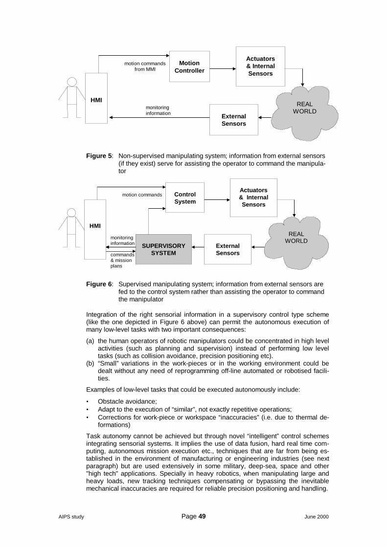
AIPS study Page 49 June 2000
HMI
Motion
Controller
Actuators & Internal Sensors
REAL WORLD
External Sensors
motion commands from MMI
monitoring information
Figure 5: Non-supervised manipulating system; information from external sensors(if they exist) serve for assisting the operator to command the manipula-tor
HMI
Control System
Actuators & Internal Sensors
SUPERVISORY
SYSTEM
REAL WORLD
External Sensors
motion commands
monitoring information
commands & mission plans
Figure 6: Supervised manipulating system; information from external sensors arefed to the control system rather than assisting the operator to commandthe manipulator
Integration of the right sensorial information in a supervisory control type scheme(like the one depicted in Figure 6 above) can permit the autonomous execution ofmany low-level tasks with two important consequences:
(a) the human operators of robotic manipulators could be concentrated in high levelactivities (such as planning and supervision) instead of performing low leveltasks (such as collision avoidance, precision positioning etc).
(b) “Small” variations in the work-pieces or in the working environment could bedealt without any need of reprogramming off-line automated or robotised facili-ties.
Examples of low-level tasks that could be executed autonomously include:
• Obstacle avoidance;• Adapt to the execution of “similar”, not exactly repetitive operations;• Corrections for work-piece or workspace “inaccuracies” (i.e. due to thermal de-
formations)
Task autonomy cannot be achieved but through novel “intelligent” control schemesintegrating sensorial systems. It implies the use of data fusion, hard real time com-puting, autonomous mission execution etc., techniques that are far from being es-tablished in the environment of manufacturing or engineering industries (see nextparagraph) but are used extensively in some military, deep-sea, space and other"high tech" applications. Specially in heavy robotics, when manipulating large andheavy loads, new tracking techniques compensating or bypassing the inevitablemechanical inaccuracies are required for reliable precision positioning and handling.

AIPS study Page 50 June 2000
It is noteworthy that, according to the IFR (International Federation of Robotics)classification [10], no such class of industrial manipulating robots is foreseen.Autonomy is only foreseen in the new category of “service robots”. According to apreliminary definition by IFR, service robot is a robot which operates semi or fullyautonomously to perform services useful to the well being of humans and equip-ment, excluding manufacturing operations.
An additional factor to consider is that most heavy robotics/handling installations inshipbuilding and other heavy industries are tailored made, often by the final userhimself. This prohibits the amortisation of the cost for the introduction of technolo-gies such as stated above. The already high development cost is further augmentedbecause of the inherent safety and reliability requirements implying extensive testingand validation procedures and the big and expensive experimental facilities neededfor the experimental demonstration, testing and validation procedures.
AIPS study Page 51 June 2000
6 Design, planning & logistics
6.1 General considerationsAn important part of the information reported in this section on the design tools isbased on reference [31], that is on SoA report of the PRODIS thematic network, is-sued on November 1999. Information on CIM and logistics is based on reference[35], that is on SoA report of CEPS on thematic area 10 on CIM & logistics in ship-building.
Another very concise document on modern ship design is the future of ship design,by DELTAMARIN Ltd, [44]. Several data, especially on the 3D and 4D productmodel, have been taken from this document.
By the term design activities we mean all these activities that generate the informa-tion necessary for the realisation of a shipbuilding project. In a somewhat more re-stricted interpretation, design is associated just with the product, that is the vesselitself; activities having to do with production scheduling, warehouse control etc arenot classified as design activities. In this report the term “design” will be used in itsbroad interpretation, encompassing production design and planning, scheduling etc.
6.2 The importance of ship designRecent evolution of the EU shipbuilding (see section 3.1 above), in parallel to thediminishing relative importance of steel working, have caused a significant increasein the volume, value and relative importance of the design activities. In fact, designactivities (including management) can easily reach over 10% of the cost of a mod-ern passenger vessel [44]. What is even more important is the fact that design ac-tivities have an important impact on many other costs like materials, subcontracting,production etc as well as on delivery time. The importance of design activities hasbeen recognised by the big EU yards, which invest considerable sums on enhancingand integrating their design activities.
In [44], DELTAMARIN Ltd has gathered and analysed more than 50 recently builtpassenger cruise ships of all sizes. Rather big, sometimes amazing, differenceshave been found in terms of space utilisation. Even if some of the differences canbe explained by different vessel characteristics, there appears to be no plausibleexplanation other than the differences in design quality and efficiency. Analysing thespace-weight relation of recently built cruise ships shows that the most efficient shiphas 40% more effective area per lightweight ton compared with the least efficient. Atypical difference is about 20%, which can already be considered to be high. Thevessel type and standard may has certainly an impact on these numbers, but other-wise it is difficult to find other explanations except efficiency in the design.
Hence, ship design efficiency is of vital importance to shipbuilding industry. In spiteof the considerable investments and the developments in the various design toolsand methods, there is still considerable room for improvement and substantial eco-nomic return potential.
6.3 Ship design activitiesWe can distinguish, according to its utilisation (i.e. the client for which the design ismade), in 3 main types of ship design:
• Pre-design (conceptual and contract design)• Basic design (including class design)• Detail design
As far as the approach and tools employed we can distinguish:
• CFD for the hydrodynamic calculations, usually aimed at the verification or op-timisation of the hull form and the propulsion
AIPS study Page 52 June 2000
• Classification rules for the verification of the vessel structure under the specificdesign loads and conditions
• FEA used for structural analysis, usually aimed at the verification or optimisationof the vessel structure under the specific design loads and conditions
• Surface modelling for fairing detail definition of the main hull surfaces• Solid modelling for the creation of part models• 3D ship product model
6.3.1 Pre-design
Under the term “pre-design” we include all the conceptual and the contractual de-sign activities. Pre-design is essentially based on the owner’s specific requirementsas well as on the applicable rules and regulations. It is of paramount importance forthe success and the profitability of the shipbuilding project, it makes extensive useof a wide range of tools and requires very experienced, high-level personnel. It in-volves the following activities:
(a) Selection of the general ship configuration, main dimensions and coefficients:This activity is usually based on the judgement, experience and creativity of thedesigner. Some artificial intelligence (AI) tools have been proposed recently but,for the time being, they have been of limited use. No particular breakthrough is tobe expected in this field.
(b) Preliminary design of the hull form: Although it makes extensive use of special-ised CAD packages, it is mainly based on the experience of the designer. Sometools have appear recently, which generate directly the hull form out of the princi-pal dimensions and coefficients.
(c) Still water hydrostatic calculations: This field is well known; it has been among thefirst computer based applications in shipbuilding.
(d) Still water hydrodynamic calculations: Although significant advances have beenmade in the field of CFD, mainly in what concern the numerical model preparation(pre-processing) and the visualisation of the results (post-processing), CFD hy-drodynamic calculations are reliable only in conjunction with basin model tests orwhen extensive tests and measurements exist for similar ships.
(e) Ship structural configuration: It involves the definition of the decks and bulkheadsas well as weight, volume and centre of gravity calculations. It is a rather well ad-dressed field with a number of PC-based software packages (mainly from classi-fication societies), which assist the designer to rapidly try and evaluate variousalternatives.
(f) Loading conditions and sea keeping analysis: Loading and sea keeping condi-tions are selected according to the rules and regulations for each particular ves-sel type. There exist a number of commercially available packages for the inves-tigation and analysis of the results.
(g) Main equipment data sheets and requirements: Most of the work involved here isstraight forward, based on experience as well as on applicable rules and regula-tions.
Although adequate computer tools are available for almost each of the above-mentioned activities, a lot is remains to be done regarding their utilisation in an inte-grated environment. The pressure exercised on the shipyards for shorter deliverytimes in conjunction with the increasing engineering work in an increasingly com-plex, concurrent environment, puts in first priority the integration of all these pre-design activities.
6.3.2 Basic design (contractual / class)
Basic design is based on pre-design activities, focused on the specific class ap-proval requirements and producing other necessary schemes and arrangements fordetail design. Part of the documentation has to be approved by the ship owner. It in-volves the following activities:
• Hull structure scantlings necessary for class approval: PC based software isusually provided by the class
• FEA structural model(s) for class approval.
AIPS study Page 53 June 2000
• Hull structure class drawings: Only a subset of detailed drawings is required.Necessary data can usually be obtained from the first steps of 3D ship productmodelling.
• Equipment data sheets: In most cases it involves just the use of spreadsheets• Piping, instrumentation and electrical diagrams: Relatively simple graphic edi-
tors (with some accounting capability) can handle the job. Recently, 3D shipproduct model is used so that the data entered to be consistent and availablefor the later detail design phase. The same holds true for the general arrange-ment drawings.
• Eventual updates and/or modifications necessary for class approval
In general, most tools used in basic design activities are well established and usedthroughout the range of the involved organisations. Communications and integration/ interfacing between pre, class and detail design activities are items in which thereis room for significant improvement.
Class design is an important part of basic design, focused on the specific class ap-proval requirements. Indeed, many classification societies offer, often for free, verycomprehensive software packages covering most needs for basic design. Recently,some of them have begun developing 3D ship product software packages [17] inwhich they plan to integrate, in a product life cycle approach, all the class relatedinformation about a vessel, from pre-design to periodic inspections, eventual modifi-cations and maintenance down to its decommissioning and scrapping.
6.3.3 Detail design
The main scope of the detailed design activities is production itself. In general, theamount of work involved (in terms of man-hours) is considerably higher than eitherpre or class design; it is generally performed by personnel of lower qualification.Detail design associated with the traditional steel part of shipbuilding is well coveredby a range of software products.
Detail design usually started only when pre-design had been completed and classdesign had been quite advanced. Shorter delivery times and increasing amount ofengineering work have created significant overlaps, which are only recently startedbeing managed by the introduction of concurrent engineering and other collabora-tive tools. The boundaries between the pre, class and detail design are fading as thelead time from contract to production and delivery become shorter and shorter.
Powerful, integrated CAD packages promising integrated concurrent engineeringand collaborative product commerce and resource planning solutions are still in de-velopment by the major CAD vendors.
6.4 Ship design software tools6.4.1 Hydrodynamics
Computational fluid dynamics (CFD) has entered commercial shipbuilding frommilitary and aerospace applications through academia, relevant RTD institutions andtowing tanks, which will continue to be the main producers and users of CFD codes.
The ultimate purpose of any CFD code is to provide the solution of the Navier-Stokes equations for time-dependant, 3D, laminar or turbulent flow around bodies ofarbitrary shape. This objective is far from reached, principally because of insufficientunderstanding of basic physical phenomena involved. In particular, the complexvortex flow near the stern of the ship cannot be adequately modelled.
Although CFD tools alone cannot predict the still water behaviour of a given hull withsufficient accuracy, they constitute valuable design tools, used in conjunction withtowing tank tests or for comparative analysis of various alternative forms.
Because of the great economic impact of the fuel consumption and the high impactof propeller induced vibration and noise on comfort, the area of resistance and pro-pulsion is the best-developed hydrodynamic area. Nevertheless, CFD tools alone
AIPS study Page 54 June 2000
are not capable of predicting the sea-keeping or manoeuvring characteristics of avessel, the local loads or the ship’s behaviour on extreme conditions.
Further development efforts are driven by the need for an increasingly fast and ac-curate early design rather than the need of more accurate and elaborate solutions.
6.4.2 Structural
The primary tool for the definition of the structure and scantlings is the ClassificationCodes. Otherwise, more or less standard FEA packages such as NASTRAN,ANSYS, ABAQUS and other, are used for the hull structural analysis. FEA tech-niques and methods are fairly standard and rather well developed. On the contrary,an important domain where significant progress has been made lately is that of preand post-processing. This is due to the significant increase of the graphics capabili-ties of both UNIX and PC based systems as well as to the new OOP techniques thatallow for the building of dedicated, user-friendly interfaces.
As in the hydrodynamic codes described in the previous section, further develop-ment efforts are driven by the need for an increasingly fast and accurate early de-sign and are likely to be focused in the following areas:
• Quick definition of an early FEA hull model based on a skeleton configuration ofthe main structure.
• Mesh parameterisation and re-use.• Integration of meshing with other phases of the basic and detail design.
Finally, due to the complexity of the FEA calculations and the consequent high levelof qualification required by the personnel, medium and small yards are not likely tobe using them but on exceptional occasions.
6.4.3 Thermal shrinkage prediction
Heat shrinkage is considered in the detail design process on almost all of the yards.Half of them define shrinkage values for all assembly stages separately and arethus able to attribute shrinkage to the actual cause and location. The others have todistribute shrinkage over the complete part. In addition to some ongoing develop-ment activities there is a strong interest in developing methods that allow attributingshrinkage values to the area where it occurs.
Calculation of shrinkage values is done either manually or automatically (in 1 out of3 yards). They are mostly based on empirical databases. There exist a definite in-terest for increased use of automatic calculations. The shrinkage calculation pro-grammes are either stand-alone solutions or integrated into the CAD packages.There is a very big interest for highly integrated solutions.
Numerical (FEA) methods for shrinkage calculation are not in widespread use.
6.4.4 Decision Support Systems
Intelligent constraint based programmes are in use at about 20-30% of the ship-yards and primarily in Europe. Applications include both assembly planning (productbreakdown), scheduling and capacity planning. Ongoing development is beingevaluated particularly in the USA and in Europe in connection with ESPRIT andEUREKA projects.
Simulation tools are used at about one third of the responding shipyards throughoutthe world. Applications relate to assembly planning, schedule and capacity planningas well as facility evaluations. In addition simulation of robot processes and applica-tions is increasingly practised. Further developments are in hand related to capacityplanning (bottle-necks) and robot simulation.
Virtual reality tools are currently not so widespread in Europe; more so elsewhere,particularly in USA, in the areas of internal design development and productionevaluation. They are more widespread (about 47%) in a wide spectrum of yardsparticularly for the discussions with owners. Development is particularly seen in re-lation to complex ship types such as passenger ships and especially naval vessels.
AIPS study Page 55 June 2000
As what further development is concerned, operational applications must increase inorder to optimise decision making with regard to engineering and production for shipprojects ensuring quick responses compatible with the new CAE potential. More inparticular:
At short term:
• Constraint based programming for assembly planning and production planning• Further development of steel production simulation
At long term:
• Extended use of virtual reality for internal applications such as design develop-ment and design for production
• Use of multi media in training
6.4.5 Process data & workshop control
DNC systems are in use universally for steel cutting facilities and 75% of yards haveDNC operated pipe bending. Outside of these areas, 50% of yards have other appli-cations including robots and more specialist machine applications. Development ofPDM (Process Data Management) applications is particularly focused on robotics.However, this area has not been fully developed yet. Further R&D is required togather and apply better process data and thereby ensure optimal process, automa-tion and quality solutions.
Development of workshop control systems is driven by automation but has notachieved the same level as PDM with only 60 % applied in steel cutting and 50 % inpipe fabrication. Decentralised control of robot cells exists and also coordinationbetween cells for detail scheduling etc is practised to some extent (< 40 %). Thesystems are not fully deployed yet, further integration and decentralisation is re-quired, including the human aspects, is under development. Particularly applicationsoutside the automated areas of shipbuilding i.e. main assembly, erection and outfit-ting are very limited and require further development. The extension of CIM in pro-duction beyond the basic requirements of current robot and automation applicationsis required. The solutions should seek optimal production utilisation, flexibility anduser interfaces.
The following R&D needs have been identified:
At short term:
• Development of planning data and tools linked to design systems with a view toreduction of lead time for production preparation and planning.
• Development of prototype fabrication cells using human oriented principles foroperation and work organisation.
• Development of daily workshop planning tools for steel and outfitting for ship-building based on intranet and focused on human centred interfaces and opera-tional organisation.
At long term:
• Real time process control• Productivity control methods
6.4.6 3D computer modelling
3D computer models are still mainly prepared to compensate the actual plastic de-sign models. Most of the models, modelling techniques, are specific for structural orpiping design.
Models of complete vessels with all disciplines included are still rare. 3D computermodelling technique is generally not used at the project design stage.
Ideally, 3D computer modelling technique should be applied in accordance with theactual design procedure, i.e. starting from the project design phase before the ship-building contract is even signed. The same model should then be extended into a
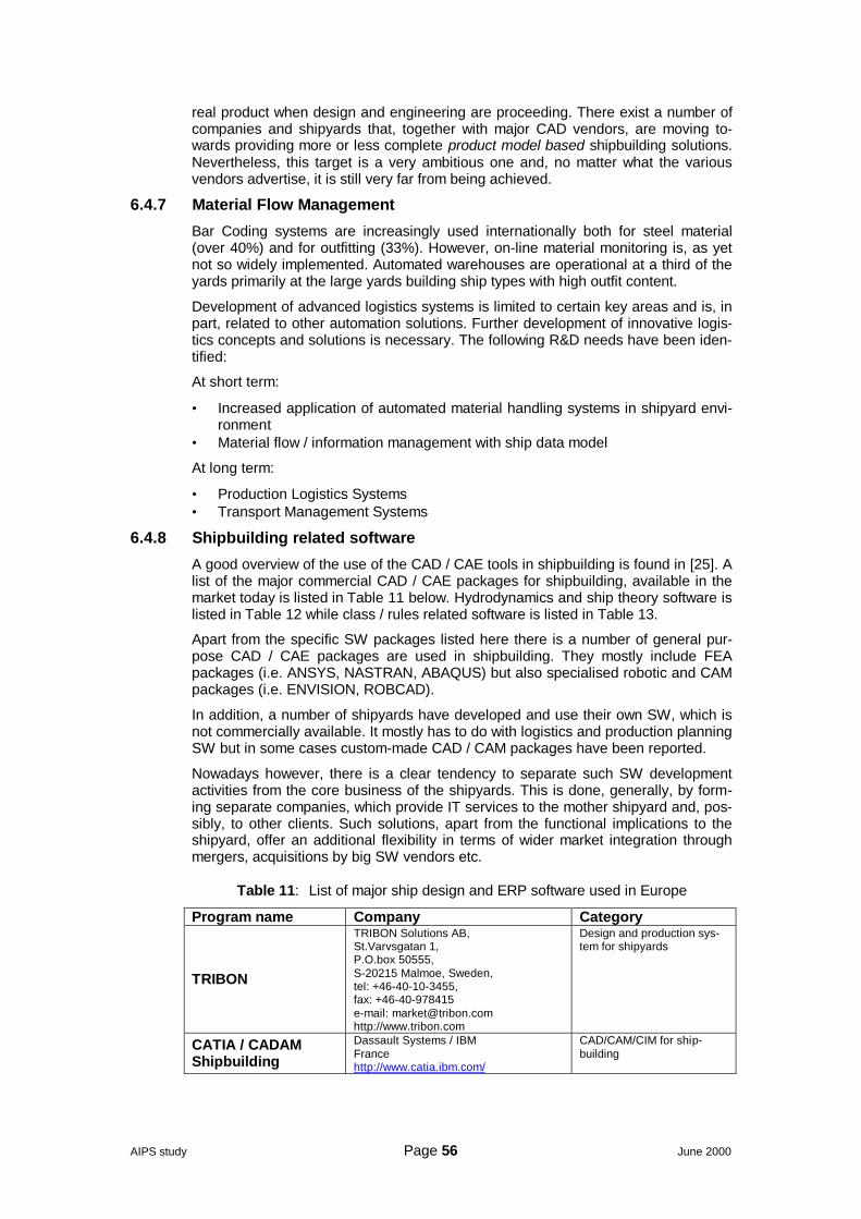
AIPS study Page 56 June 2000
real product when design and engineering are proceeding. There exist a number ofcompanies and shipyards that, together with major CAD vendors, are moving to-wards providing more or less complete product model based shipbuilding solutions.Nevertheless, this target is a very ambitious one and, no matter what the variousvendors advertise, it is still very far from being achieved.
6.4.7 Material Flow Management
Bar Coding systems are increasingly used internationally both for steel material(over 40%) and for outfitting (33%). However, on-line material monitoring is, as yetnot so widely implemented. Automated warehouses are operational at a third of theyards primarily at the large yards building ship types with high outfit content.
Development of advanced logistics systems is limited to certain key areas and is, inpart, related to other automation solutions. Further development of innovative logis-tics concepts and solutions is necessary. The following R&D needs have been iden-tified:
At short term:
• Increased application of automated material handling systems in shipyard envi-ronment
• Material flow / information management with ship data model
At long term:
• Production Logistics Systems• Transport Management Systems
6.4.8 Shipbuilding related software
A good overview of the use of the CAD / CAE tools in shipbuilding is found in [25]. Alist of the major commercial CAD / CAE packages for shipbuilding, available in themarket today is listed in Table 11 below. Hydrodynamics and ship theory software islisted in Table 12 while class / rules related software is listed in Table 13.
Apart from the specific SW packages listed here there is a number of general pur-pose CAD / CAE packages are used in shipbuilding. They mostly include FEApackages (i.e. ANSYS, NASTRAN, ABAQUS) but also specialised robotic and CAMpackages (i.e. ENVISION, ROBCAD).
In addition, a number of shipyards have developed and use their own SW, which isnot commercially available. It mostly has to do with logistics and production planningSW but in some cases custom-made CAD / CAM packages have been reported.
Nowadays however, there is a clear tendency to separate such SW developmentactivities from the core business of the shipyards. This is done, generally, by form-ing separate companies, which provide IT services to the mother shipyard and, pos-sibly, to other clients. Such solutions, apart from the functional implications to theshipyard, offer an additional flexibility in terms of wider market integration throughmergers, acquisitions by big SW vendors etc.
Table 11: List of major ship design and ERP software used in Europe
Program name Company Category
TRIBON
TRIBON Solutions AB,St.Varvsgatan 1,P.O.box 50555,S-20215 Malmoe, Sweden,tel: +46-40-10-3455,fax: +46-40-978415e-mail: [email protected]://www.tribon.com
Design and production sys-tem for shipyards
CATIA / CADAMShipbuilding
Dassault Systems / IBMFrancehttp://www.catia.ibm.com/
CAD/CAM/CIM for ship-building
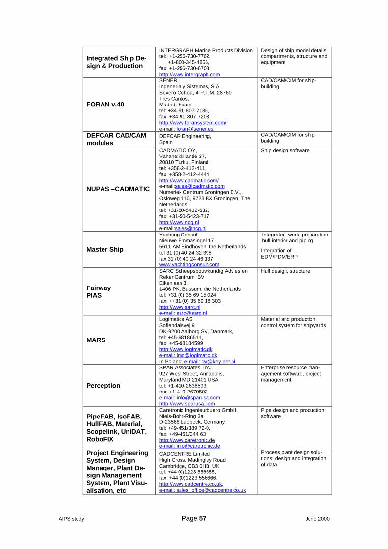
AIPS study Page 57 June 2000
Integrated Ship De-sign & Production
INTERGRAPH Marine Products Divisiontel: +1-256-730-7762, +1-800-345-4856,fax: +1-256-730-6708http://www.intergraph.com
Design of ship model details,compartments, structure andequipment
FORAN v.40
SENER,Ingeneria y Sistemas, S.A.Severo Ochoa, 4-P.T.M. 28760Tres Cantos,Madrid, Spaintel: +34-91-807-7185,fax: +34-91-807-7203http://www.foransystem.com/e-mail: [email protected]
CAD/CAM/CIM for ship-building
DEFCAR CAD/CAMmodules
DEFCAR Engineering,Spain
CAD/CAM/CIM for ship-building
NUPAS –CADMATIC
CADMATIC OY,Vahaheikkilantie 37,20810 Turku, Finland,tel: +358-2-412-411,fax: +358-2-412-4444http://www.cadmatic.com/e-mail:[email protected] Centrum Groningen B.V.,Osloweg 110, 9723 BX Groningen, TheNetherlands,tel: +31-50-5412-632,fax: +31-50-5423-717http://www.ncg.nle-mail:[email protected]
Ship design software
Master Ship
Yachting ConsultNieuwe Emmasingel 175611 AM Eindhoven, the Netherlandstel 31 (0) 40 24 32 395fax 31 (0) 40 24 46 137www.yachtingconsult.com
Integrated work preparationhull interior and piping
Integration ofEDM/PDM/ERP
FairwayPIAS
SARC Scheepsbouwkundig Advies enRekenCentrum BVEikenlaan 3,1406 PK, Bussum, the Netherlandstel: +31 (0) 35 69 15 024fax: ++31 (0) 35 69 18 303http://www.sarc.nle-mail: [email protected]
Hull design, structure
MARS
Logimatics ASSofiendalsvej 9DK-9200 Aalborg SV, Danmark,tel: +45-98186511,fax: +45-98184599http://www.logimatic.dke-mail: [email protected] Poland: e-mail: [email protected]
Material and productioncontrol system for shipyards
Perception
SPAR Associates, Inc.,927 West Street, Annapolis,Maryland MD 21401 USAtel: +1-410-2638593,fax: +1-410-2670503e-mail: [email protected]://www.sparusa.com
Enterprise resource man-agement software, projectmanagement
PipeFAB, IsoFAB,HullFAB, Material,Scopelink, UniDAT,RoboFIX
Caretronic Ingenieurbuero GmbHNiels-Bohr-Ring 3aD-23568 Luebeck, Germanytel: +49-451/389 72-0,fax: +49-451/344 63http://www.caretronic.dee-mail: [email protected]
Pipe design and productionsoftware
Project EngineeringSystem, DesignManager, Plant De-sign ManagementSystem, Plant Visu-alisation, etc
CADCENTRE LimitedHigh Cross, Madingley RoadCambridge, CB3 0HB, UKtel: +44 (0)1223 556655,fax: +44 (0)1223 556666,http://www.cadcentre.co.uk,e-mail: [email protected]
Process plant design solu-tions: design and integrationof data
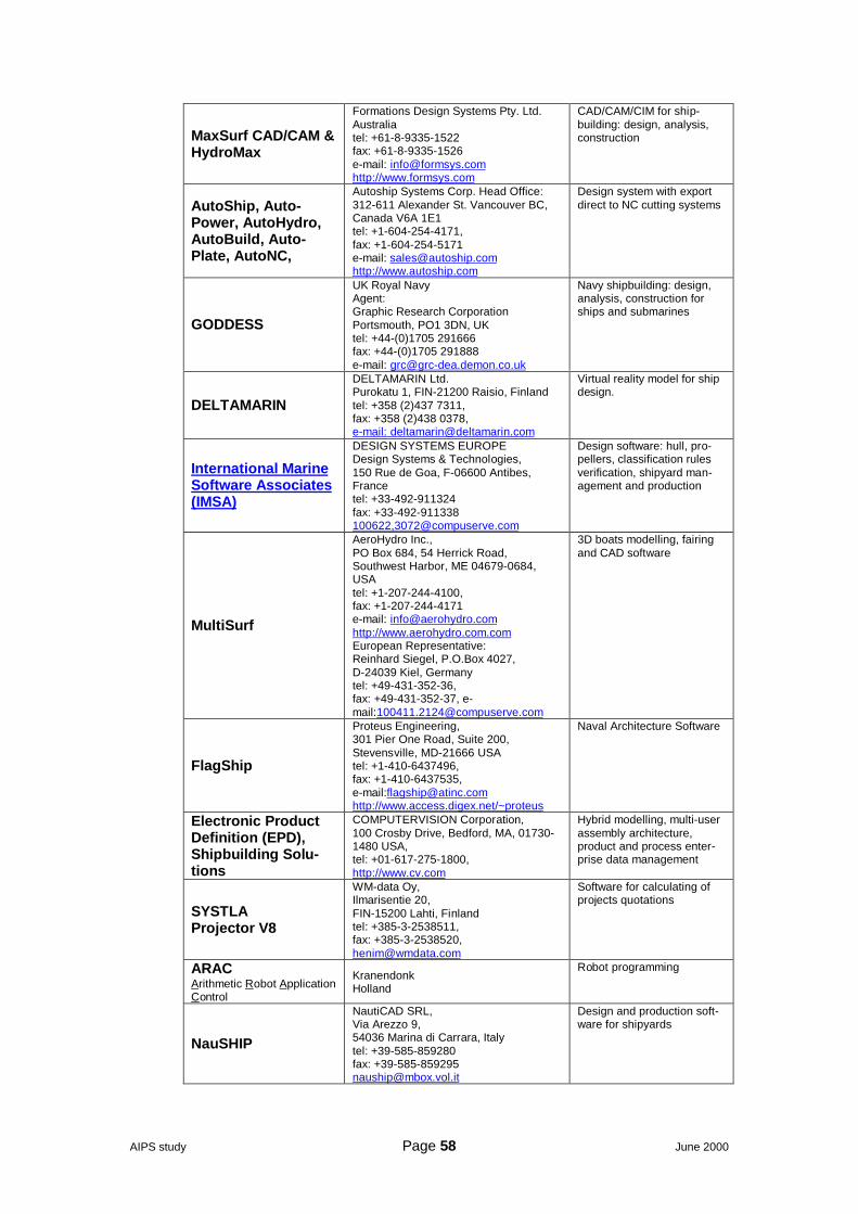
AIPS study Page 58 June 2000
MaxSurf CAD/CAM &HydroMax
Formations Design Systems Pty. Ltd.Australiatel: +61-8-9335-1522fax: +61-8-9335-1526e-mail: [email protected]://www.formsys.com
CAD/CAM/CIM for ship-building: design, analysis,construction
AutoShip, Auto-Power, AutoHydro,AutoBuild, Auto-Plate, AutoNC,
Autoship Systems Corp. Head Office:312-611 Alexander St. Vancouver BC,Canada V6A 1E1tel: +1-604-254-4171,fax: +1-604-254-5171e-mail: [email protected]://www.autoship.com
Design system with exportdirect to NC cutting systems
GODDESS
UK Royal NavyAgent:Graphic Research CorporationPortsmouth, PO1 3DN, UKtel: +44-(0)1705 291666fax: +44-(0)1705 291888e-mail: [email protected]
Navy shipbuilding: design,analysis, construction forships and submarines
DELTAMARIN
DELTAMARIN Ltd.Purokatu 1, FIN-21200 Raisio, Finlandtel: +358 (2)437 7311,fax: +358 (2)438 0378,e-mail: [email protected]
Virtual reality model for shipdesign.
International MarineSoftware Associates(IMSA)
DESIGN SYSTEMS EUROPEDesign Systems & Technologies,150 Rue de Goa, F-06600 Antibes,Francetel: +33-492-911324fax: +33-492-911338100622,[email protected]
Design software: hull, pro-pellers, classification rulesverification, shipyard man-agement and production
MultiSurf
AeroHydro Inc.,PO Box 684, 54 Herrick Road,Southwest Harbor, ME 04679-0684,USAtel: +1-207-244-4100,fax: +1-207-244-4171e-mail: [email protected]://www.aerohydro.com.comEuropean Representative:Reinhard Siegel, P.O.Box 4027,D-24039 Kiel, Germanytel: +49-431-352-36,fax: +49-431-352-37, e-mail:[email protected]
3D boats modelling, fairingand CAD software
FlagShip
Proteus Engineering,301 Pier One Road, Suite 200,Stevensville, MD-21666 USAtel: +1-410-6437496,fax: +1-410-6437535,e-mail:[email protected]://www.access.digex.net/~proteus
Naval Architecture Software
Electronic ProductDefinition (EPD),Shipbuilding Solu-tions
COMPUTERVISION Corporation,100 Crosby Drive, Bedford, MA, 01730-1480 USA,tel: +01-617-275-1800,http://www.cv.com
Hybrid modelling, multi-userassembly architecture,product and process enter-prise data management
SYSTLAProjector V8
WM-data Oy,Ilmarisentie 20,FIN-15200 Lahti, Finlandtel: +385-3-2538511,fax: +385-3-2538520,[email protected]
Software for calculating ofprojects quotations
ARACArithmetic Robot ApplicationControl
KranendonkHolland
Robot programming
NauSHIP
NautiCAD SRL,Via Arezzo 9,54036 Marina di Carrara, Italytel: +39-585-859280fax: [email protected]
Design and production soft-ware for shipyards
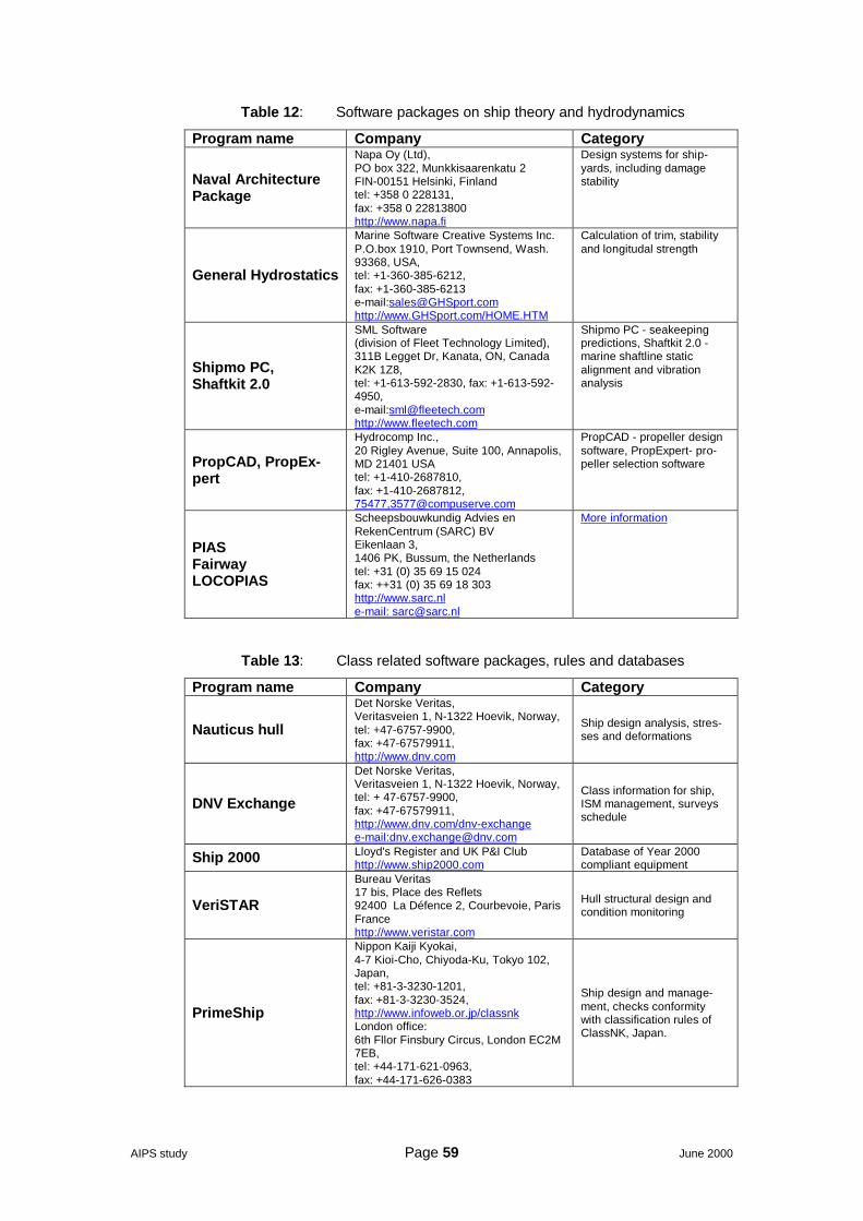
AIPS study Page 59 June 2000
Table 12: Software packages on ship theory and hydrodynamics
Program name Company Category
Naval ArchitecturePackage
Napa Oy (Ltd),PO box 322, Munkkisaarenkatu 2FIN-00151 Helsinki, Finlandtel: +358 0 228131,fax: +358 0 22813800http://www.napa.fi
Design systems for ship-yards, including damagestability
General Hydrostatics
Marine Software Creative Systems Inc.P.O.box 1910, Port Townsend, Wash.93368, USA,tel: +1-360-385-6212,fax: +1-360-385-6213e-mail:[email protected]://www.GHSport.com/HOME.HTM
Calculation of trim, stabilityand longitudal strength
Shipmo PC,Shaftkit 2.0
SML Software(division of Fleet Technology Limited),311B Legget Dr, Kanata, ON, CanadaK2K 1Z8,tel: +1-613-592-2830, fax: +1-613-592-4950,e-mail:[email protected]://www.fleetech.com
Shipmo PC - seakeepingpredictions, Shaftkit 2.0 -marine shaftline staticalignment and vibrationanalysis
PropCAD, PropEx-pert
Hydrocomp Inc.,20 Rigley Avenue, Suite 100, Annapolis,MD 21401 USAtel: +1-410-2687810,fax: +1-410-2687812,75477,[email protected]
PropCAD - propeller designsoftware, PropExpert- pro-peller selection software
PIASFairwayLOCOPIAS
Scheepsbouwkundig Advies enRekenCentrum (SARC) BVEikenlaan 3,1406 PK, Bussum, the Netherlandstel: +31 (0) 35 69 15 024fax: ++31 (0) 35 69 18 303http://www.sarc.nle-mail: [email protected]
More information
Table 13: Class related software packages, rules and databases
Program name Company Category
Nauticus hull
Det Norske Veritas,Veritasveien 1, N-1322 Hoevik, Norway,tel: +47-6757-9900,fax: +47-67579911,http://www.dnv.com
Ship design analysis, stres-ses and deformations
DNV Exchange
Det Norske Veritas,Veritasveien 1, N-1322 Hoevik, Norway,tel: + 47-6757-9900,fax: +47-67579911,http://www.dnv.com/dnv-exchangee-mail:[email protected]
Class information for ship,ISM management, surveysschedule
Ship 2000 Lloyd's Register and UK P&I Clubhttp://www.ship2000.com
Database of Year 2000compliant equipment
VeriSTAR
Bureau Veritas17 bis, Place des Reflets92400 La Défence 2, Courbevoie, ParisFrancehttp://www.veristar.com
Hull structural design andcondition monitoring
PrimeShip
Nippon Kaiji Kyokai,4-7 Kioi-Cho, Chiyoda-Ku, Tokyo 102,Japan,tel: +81-3-3230-1201,fax: +81-3-3230-3524,http://www.infoweb.or.jp/classnkLondon office:6th Fllor Finsbury Circus, London EC2M7EB,tel: +44-171-621-0963,fax: +44-171-626-0383
Ship design and manage-ment, checks conformitywith classification rules ofClassNK, Japan.
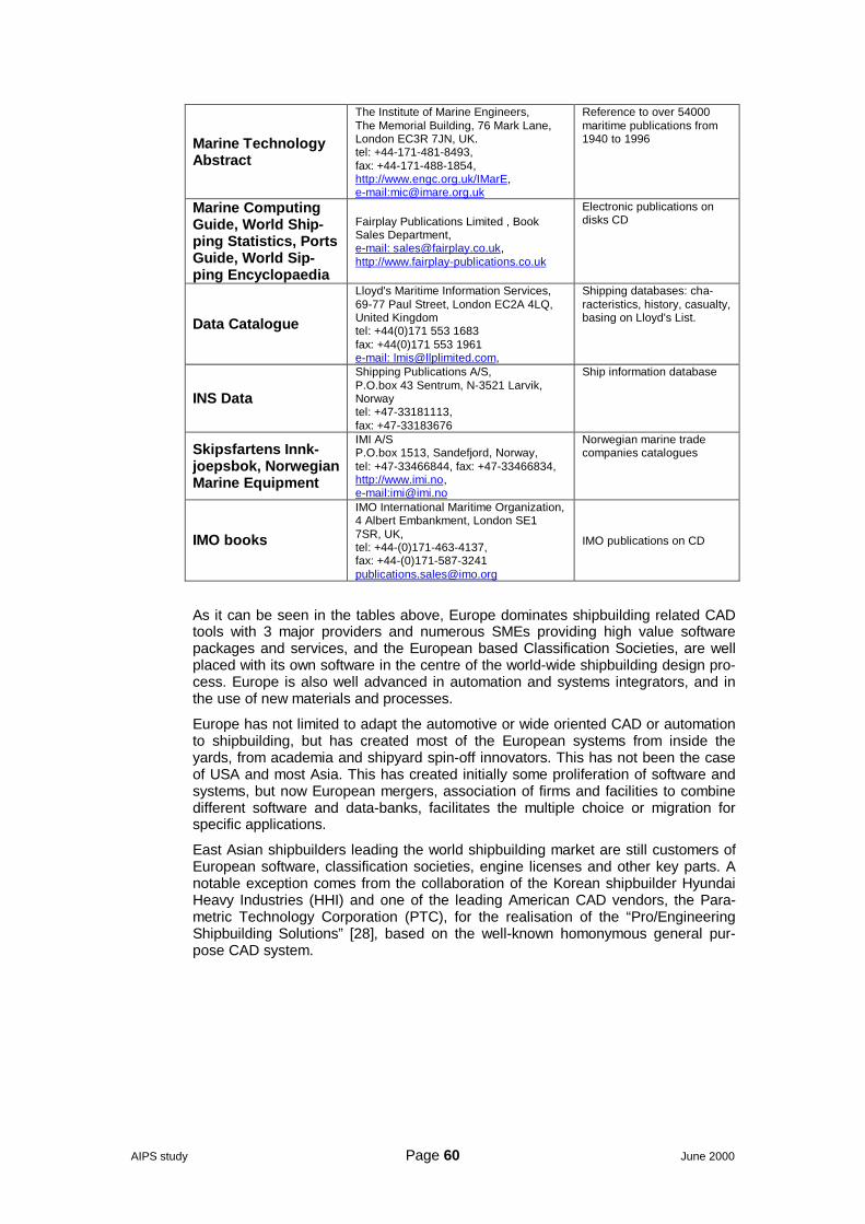
AIPS study Page 60 June 2000
Marine TechnologyAbstract
The Institute of Marine Engineers,The Memorial Building, 76 Mark Lane,London EC3R 7JN, UK.tel: +44-171-481-8493,fax: +44-171-488-1854,http://www.engc.org.uk/IMarE,e-mail:[email protected]
Reference to over 54000maritime publications from1940 to 1996
Marine ComputingGuide, World Ship-ping Statistics, PortsGuide, World Sip-ping Encyclopaedia
Fairplay Publications Limited , BookSales Department,e-mail: [email protected],http://www.fairplay-publications.co.uk
Electronic publications ondisks CD
Data Catalogue
Lloyd's Maritime Information Services,69-77 Paul Street, London EC2A 4LQ,United Kingdomtel: +44(0)171 553 1683fax: +44(0)171 553 1961e-mail: [email protected],
Shipping databases: cha-racteristics, history, casualty,basing on Lloyd's List.
INS Data
Shipping Publications A/S,P.O.box 43 Sentrum, N-3521 Larvik,Norwaytel: +47-33181113,fax: +47-33183676
Ship information database
Skipsfartens Innk-joepsbok, NorwegianMarine Equipment
IMI A/SP.O.box 1513, Sandefjord, Norway,tel: +47-33466844, fax: +47-33466834,http://www.imi.no,e-mail:[email protected]
Norwegian marine tradecompanies catalogues
IMO books
IMO International Maritime Organization,4 Albert Embankment, London SE17SR, UK,tel: +44-(0)171-463-4137,fax: +44-(0)[email protected]
IMO publications on CD
As it can be seen in the tables above, Europe dominates shipbuilding related CADtools with 3 major providers and numerous SMEs providing high value softwarepackages and services, and the European based Classification Societies, are wellplaced with its own software in the centre of the world-wide shipbuilding design pro-cess. Europe is also well advanced in automation and systems integrators, and inthe use of new materials and processes.
Europe has not limited to adapt the automotive or wide oriented CAD or automationto shipbuilding, but has created most of the European systems from inside theyards, from academia and shipyard spin-off innovators. This has not been the caseof USA and most Asia. This has created initially some proliferation of software andsystems, but now European mergers, association of firms and facilities to combinedifferent software and data-banks, facilitates the multiple choice or migration forspecific applications.
East Asian shipbuilders leading the world shipbuilding market are still customers ofEuropean software, classification societies, engine licenses and other key parts. Anotable exception comes from the collaboration of the Korean shipbuilder HyundaiHeavy Industries (HHI) and one of the leading American CAD vendors, the Para-metric Technology Corporation (PTC), for the realisation of the “Pro/EngineeringShipbuilding Solutions” [28], based on the well-known homonymous general pur-pose CAD system.
AIPS study Page 61 June 2000
7 Integrating design, production & supply chainIntegration of the shipbuilding processes essentially consists in assuring the flaw-less operation of the information flow between the various stages of the engineering,design, planning and production processes as shown in Figure 2. Some importantissues to be considered in this section are:
• Integration of basic design with detail design• Integration of detail design with production design & planning• Integration of detail design with the production activities (such as cutting, form-
ing & welding) and the programming of the automated facilities• Integration of production planning with the control of supplies & outsourcing
(sub-contracted services and equipment purchasing)
In an ideal situation, one could conceive a computer system implementing the com-plete flow-chart shown in Figure 2. In practice, it implies the integration (or just theinterfacing) of various specialised computer programmes (CAD, CAE, logistics, etc.)and, sometimes, manual procedures.
The concept of “assembly” yard is becoming reality with the major European ship-yards. In this scheme the shipyard is subcontracting major parts of the outfittingwork like total turnkeys of different ship spaces. These can be even engine rooms orlarge cabin areas or restaurants. In these areas everything, except the steel-work, isdone by subcontracting companies. This leaves only the coordination role to theshipyard.
This fact sets new requirements for design systems, material and project manage-ment systems. Efficient coordination is the key factor for successful new-building.
Actually, there are no general or specific tools and methods available, which couldbe used throughout the different design and engineering phases; even within eachphase many different systems are used, often without proper links and coordination.
There are generally several computer systems at shipyards and within the industryserving shipping companies and shipyards. They are, however, typically tailor-madesystems and they lack integration. Product data is spread out between differentsystems and companies without common product model; thus the data in eachsystem lives its own life. Coordination takes time and, in most cases, it is effectiveonly during the building and installation phase, sometimes leading to rather costlysolutions.
7.1 Integration of basic design with detail designIn the basic design all the major characteristics of the new-building such as room ar-rangements, system diagrams etc. are accurately defined. Specifications stateclearly, what to be included in the detail design. Today the individual designers pickthis information from the basic design drawings. The result is therefore dependingon carefulness and skills of each person reading the documents.
Today in some 3D design systems it is possible to create intelligent systemschemes, where the information on armatures, materials and identification data arestored into a database to be used in the detail phase. This way it is possible toeliminate major part of the human errors.
This all must be also linked to the procurement and handling of materials. It is acomplicated formula, because basic design needs equipment information, which isin the other hand needs purchase decisions. Procurement needs technical handlingand delivery times of material compared to the building philosophy dictate theschedules of purchases. Considering that the major part of the ship’s price consistsof materials bills, it is clear that this will be of major importance in the systems de-velopment of the future.
AIPS study Page 62 June 2000
7.2 Integration of detail design with the production activitiesThe integration of the design with the production tools is already today’s reality. 3Ddesign gives the possibility to have all kind of geometric or material data to be proc-essed for the production machinery. Typically today the plate cutting information,pipe length cutting and bending information is directly fed by wire to the productionunits.
7.3 Integration of production planningThe function of production planning is to make sure that all the conditions of suc-cessful ship manufacturing are fulfilled. This means, that there will be a buildingplace, sufficient human resources, tools, materials and manufacturing drawings inthe right place at the right time. This includes also the subcontractor coordination.
The shipyards have various production management systems in use today, but mostof them have deficiencies like subcontracting or project follow-up tools.
Coordination of material flow is one of the major tasks also in production planning.This starts already before the ship contract, when the decisions in the major shipequipment (like main engines) are done. This reflects to the production schedulingand that way to design schedules as well. The turnkey deliveries belong also to thiscategory as well. Especially the follow-up of subcontractors should be integratedvery tightly to shipyard’s own management systems.
The construction of a ship is a huge network of activities, where the dependenciesbetween different tasks are massive and complicated. However, this is a process,which in spite of the differences in ships remains largely the same from new-buildingto new-building. With good reason it is reasonable to think, that this can be de-scribed accurately enough in order to develop suitable software.
Virtual shipyard (simulation of the building process) can be the tool of the future forthe integration and management of the real shipyard. Similar tools are already usedin automotive industry. This shipyard model should be integrated together with aship product model, which contains all the ship- related information in the same da-tabase. These two combined should provide powerful tools to coordinate the net-work of suppliers, sub-contractors and shipyard resources.
7.4 Product modelIn today’s market situation shipyards as well as shipping companies are concen-trating on their core business and outsourcing most of the support functions. Thisserves reducing the costs and balancing the use of capacity in the fluctuating mar-ket. Extensive use of consultants, subcontractors and suppliers is a typical situationin shipbuilding.
The product definition becomes essential for the shipyard, ship-owner, class and thesubcontractors. Typical contract documents may initially be enough for the yard butwhen all the major systems and spaces on the ship are subcontracted proper andadequate definition of the ship at the earliest possible stage becomes of vital im-portance if not critical.
Coordination between the different parties must be fluent and efficient to keep theschedule and, of course, all parties should understand the final end product in thesame way, in accordance with the ship-owner’s original plan. This is, however, quitedifficult when several different parties are involved and the end product is not ex-actly as originally ordered.
To be able to serve the ship development process from the first idea up to the com-missioning and, why not, to its operation and decommissioning, a product model isrequired including all the necessary information for the complete shipbuilding proc-ess. It is self-understanding that time is an essential parameter to be included in themodel leading to a 4D product model.
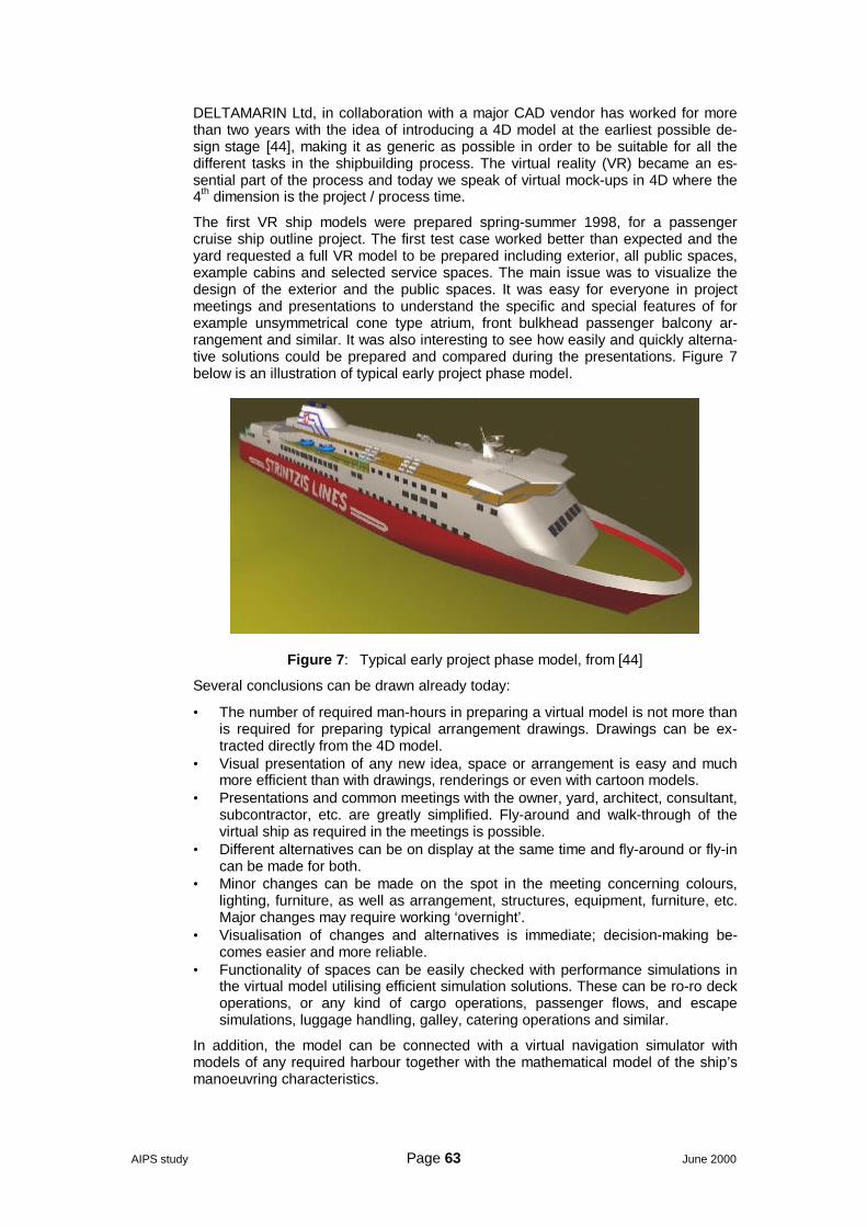
AIPS study Page 63 June 2000
DELTAMARIN Ltd, in collaboration with a major CAD vendor has worked for morethan two years with the idea of introducing a 4D model at the earliest possible de-sign stage [44], making it as generic as possible in order to be suitable for all thedifferent tasks in the shipbuilding process. The virtual reality (VR) became an es-sential part of the process and today we speak of virtual mock-ups in 4D where the4th dimension is the project / process time.
The first VR ship models were prepared spring-summer 1998, for a passengercruise ship outline project. The first test case worked better than expected and theyard requested a full VR model to be prepared including exterior, all public spaces,example cabins and selected service spaces. The main issue was to visualize thedesign of the exterior and the public spaces. It was easy for everyone in projectmeetings and presentations to understand the specific and special features of forexample unsymmetrical cone type atrium, front bulkhead passenger balcony ar-rangement and similar. It was also interesting to see how easily and quickly alterna-tive solutions could be prepared and compared during the presentations. Figure 7below is an illustration of typical early project phase model.
Figure 7: Typical early project phase model, from [44]
Several conclusions can be drawn already today:
• The number of required man-hours in preparing a virtual model is not more thanis required for preparing typical arrangement drawings. Drawings can be ex-tracted directly from the 4D model.
• Visual presentation of any new idea, space or arrangement is easy and muchmore efficient than with drawings, renderings or even with cartoon models.
• Presentations and common meetings with the owner, yard, architect, consultant,subcontractor, etc. are greatly simplified. Fly-around and walk-through of thevirtual ship as required in the meetings is possible.
• Different alternatives can be on display at the same time and fly-around or fly-incan be made for both.
• Minor changes can be made on the spot in the meeting concerning colours,lighting, furniture, as well as arrangement, structures, equipment, furniture, etc.Major changes may require working ‘overnight’.
• Visualisation of changes and alternatives is immediate; decision-making be-comes easier and more reliable.
• Functionality of spaces can be easily checked with performance simulations inthe virtual model utilising efficient simulation solutions. These can be ro-ro deckoperations, or any kind of cargo operations, passenger flows, and escapesimulations, luggage handling, galley, catering operations and similar.
In addition, the model can be connected with a virtual navigation simulator withmodels of any required harbour together with the mathematical model of the ship’smanoeuvring characteristics.
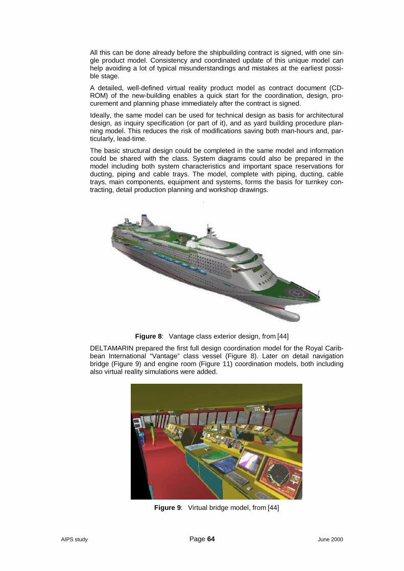
AIPS study Page 64 June 2000
All this can be done already before the shipbuilding contract is signed, with one sin-gle product model. Consistency and coordinated update of this unique model canhelp avoiding a lot of typical misunderstandings and mistakes at the earliest possi-ble stage.
A detailed, well-defined virtual reality product model as contract document (CD-ROM) of the new-building enables a quick start for the coordination, design, pro-curement and planning phase immediately after the contract is signed.
Ideally, the same model can be used for technical design as basis for architecturaldesign, as inquiry specification (or part of it), and as yard building procedure plan-ning model. This reduces the risk of modifications saving both man-hours and, par-ticularly, lead-time.
The basic structural design could be completed in the same model and informationcould be shared with the class. System diagrams could also be prepared in themodel including both system characteristics and important space reservations forducting, piping and cable trays. The model, complete with piping, ducting, cabletrays, main components, equipment and systems, forms the basis for turnkey con-tracting, detail production planning and workshop drawings.
Figure 8: Vantage class exterior design, from [44]
DELTAMARIN prepared the first full design coordination model for the Royal Carib-bean International “Vantage” class vessel (Figure 8). Later on detail navigationbridge (Figure 9) and engine room (Figure 11) coordination models, both includingalso virtual reality simulations were added.
Figure 9: Virtual bridge model, from [44]
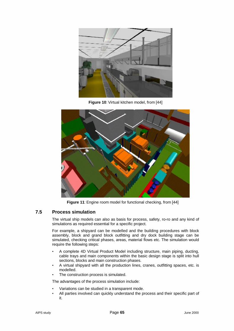
AIPS study Page 65 June 2000
Figure 10: Virtual kitchen model, from [44]
Figure 11: Engine room model for functional checking, from [44]
7.5 Process simulationThe virtual ship models can also as basis for process, safety, ro-ro and any kind ofsimulations as required essential for a specific project.
For example, a shipyard can be modelled and the building procedures with blockassembly, block and grand block outfitting and dry dock building stage can besimulated, checking critical phases, areas, material flows etc. The simulation wouldrequire the following steps:
• A complete 4D Virtual Product Model including structure, main piping, ducting,cable trays and main components within the basic design stage is split into hullsections, blocks and main construction phases.
• A virtual shipyard with all the production lines, cranes, outfitting spaces, etc. ismodelled.
• The construction process is simulated.
The advantages of the process simulation include:
• Variations can be studied in a transparent mode.• All parties involved can quickly understand the process and their specific part of
it.
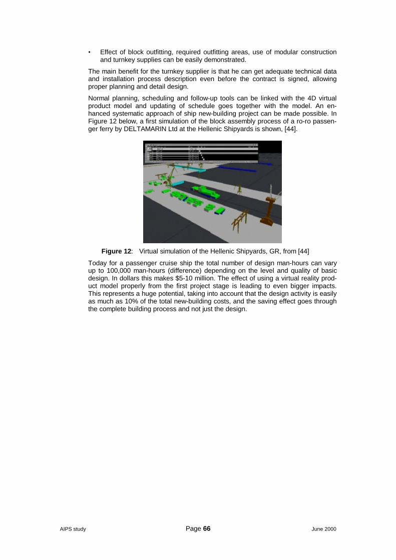
AIPS study Page 66 June 2000
• Effect of block outfitting, required outfitting areas, use of modular constructionand turnkey supplies can be easily demonstrated.
The main benefit for the turnkey supplier is that he can get adequate technical dataand installation process description even before the contract is signed, allowingproper planning and detail design.
Normal planning, scheduling and follow-up tools can be linked with the 4D virtualproduct model and updating of schedule goes together with the model. An en-hanced systematic approach of ship new-building project can be made possible. InFigure 12 below, a first simulation of the block assembly process of a ro-ro passen-ger ferry by DELTAMARIN Ltd at the Hellenic Shipyards is shown, [44].
Figure 12: Virtual simulation of the Hellenic Shipyards, GR, from [44]
Today for a passenger cruise ship the total number of design man-hours can varyup to 100,000 man-hours (difference) depending on the level and quality of basicdesign. In dollars this makes $5-10 million. The effect of using a virtual reality prod-uct model properly from the first project stage is leading to even bigger impacts.This represents a huge potential, taking into account that the design activity is easilyas much as 10% of the total new-building costs, and the saving effect goes throughthe complete building process and not just the design.
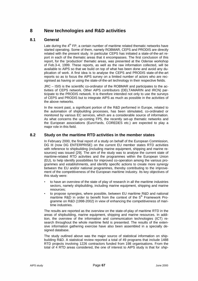
AIPS study Page 67 June 2000
8 New technologies and R&D activities
8.1 GeneralLate during the 4th FP, a certain number of maritime related thematic networks havestarted operating. Some of them, namely ROBMAR, CEPS and PRODIS are directlyrelated with the present study. In particular CEPS has initiated a state-of-the-art re-port in each of the thematic areas that it encompasses. The first conclusion of thisreport, for the ‘production’ thematic areas, was presented at the Odense workshopof Feb.3-4, 1999. These reports, as well as the raw information collected, will beavailable to AIPS so that we build on top of what has been done and avoid any du-plication of work. A first idea is to analyse the CEPS and PRODIS state-of-the-artreports so as to focus the AIPS survey on a limited number of actors who are rec-ognised as having or using the state-of-the-art technology in their respective fields.
JRC – ISIS is the scientific co-ordinator of the ROBMAR and participates to the ac-tivities of CEPS network. Other AIPS contributors (DELTAMARIN and IRCN) par-ticipate to the PRODIS network. It is therefore intended not only to use the surveysof CEPS and PRODIS but to integrate AIPS as much as possible in the activities ofthe above networks.
In the recent past, a significant portion of the R&D performed in Europe, related tothe automation of shipbuilding processes, has been stimulated, co-ordinated ormonitored by various EC services, which are a considerable source of information.As what concerns the up-coming FP5, the recently set-up thematic networks andthe European associations (EuroYards, COREDES etc.) are expected to play amajor role in this field.
8.2 Study on the maritime RTD activities in the member statesIn February 2000, the final report of a study on behalf of the European Commission,DG III (now DG ENTERPRISE) on the current EU member states RTD activitieswith reference to shipbuilding (including marine equipment, shipping and marine re-sources) was issued [29]. The aim of the study was to analyse the current state ofmaritime-related RTD activities and the programmes within the European Union(EU), to help identify possibilities for improved co-operation among the various pro-grammes and establishments, and identify specific actions to create more synergybetween the EU and/or national programmes, thereby contributing to the improve-ment of the competitiveness of the European maritime industry. Its key objectives ofthis study were:
• to have an overview of the state of play of research in all the maritime industriessectors, namely shipbuilding, including marine equipment, shipping and marineresources;
• to propose synergies, where possible, between EU maritime R&D and nationalmaritime R&D in order to benefit from the context of the 5th Framework Pro-gramme on R&D (1998-2002) in view of enhancing the competitiveness of mari-time industries.
The results are reported as the overview on the state-of-play of maritime RTD in theareas of shipbuilding, marine equipment, shipping and marine resources. In addi-tion, the overview of the information and communication technologies (ICT) re-search throughout the whole maritime field is presented. The results of the exten-sive information gathering exercise have also been assembled in a specially de-signed database.
The study outlined above was the major source of statistical information on ship-building R&D. A statistical review reported a total of 49 programs that include 1488RTD projects involving 1226 contractors funded from 198 organisations. From thetotal of 4 RTD areas considered, the one of interest to AIPS study is that for ship-
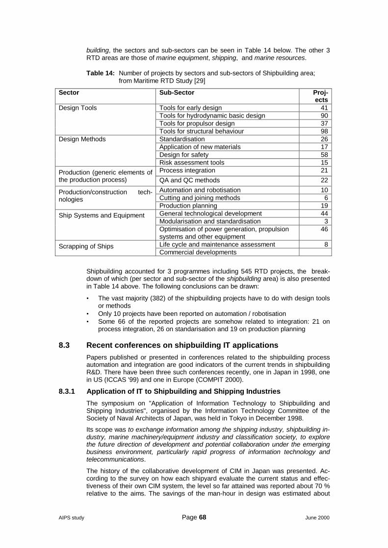
AIPS study Page 68 June 2000
building, the sectors and sub-sectors can be seen in Table 14 below. The other 3RTD areas are those of marine equipment, shipping, and marine resources.
Table 14: Number of projects by sectors and sub-sectors of Shipbuilding area;from Maritime RTD Study [29]
Sector Sub-Sector Proj-ects
Tools for early design 41Tools for hydrodynamic basic design 90Tools for propulsor design 37
Design Tools
Tools for structural behaviour 98Standardisation 26Application of new materials 17Design for safety 58
Design Methods
Risk assessment tools 15Process integration 21Production (generic elements of
the production process) QA and QC methods 22Automation and robotisation 10Cutting and joining methods 6
Production/construction tech-nologies
Production planning 19General technological development 44Modularisation and standardisation 3
Ship Systems and Equipment
Optimisation of power generation, propulsionsystems and other equipment
46
Life cycle and maintenance assessment 8Scrapping of ShipsCommercial developments
Shipbuilding accounted for 3 programmes including 545 RTD projects, the break-down of which (per sector and sub-sector of the shipbuilding area) is also presentedin Table 14 above. The following conclusions can be drawn:
• The vast majority (382) of the shipbuilding projects have to do with design toolsor methods
• Only 10 projects have been reported on automation / robotisation• Some 66 of the reported projects are somehow related to integration: 21 on
process integration, 26 on standarisation and 19 on production planning
8.3 Recent conferences on shipbuilding IT applicationsPapers published or presented in conferences related to the shipbuilding processautomation and integration are good indicators of the current trends in shipbuildingR&D. There have been three such conferences recently, one in Japan in 1998, onein US (ICCAS '99) and one in Europe (COMPIT 2000).
8.3.1 Application of IT to Shipbuilding and Shipping Industries
The symposium on "Application of Information Technology to Shipbuilding andShipping Industries", organised by the Information Technology Committee of theSociety of Naval Architects of Japan, was held in Tokyo in December 1998.
Its scope was to exchange information among the shipping industry, shipbuilding in-dustry, marine machinery/equipment industry and classification society, to explorethe future direction of development and potential collaboration under the emergingbusiness environment, particularly rapid progress of information technology andtelecommunications.
The history of the collaborative development of CIM in Japan was presented. Ac-cording to the survey on how each shipyard evaluate the current status and effec-tiveness of their own CIM system, the level so far attained was reported about 70 %relative to the aims. The savings of the man-hour in design was estimated about
AIPS study Page 69 June 2000
20%, and about 30% in construction as compared to 1989. It was pointed out thatamong many merits brought about by CIM application the greatest merit by CIM ap-plication seems to come from easier optimisation of production process, planning,etc. The papers most relevant to AIPS are presented below:
The State of Art of CIM for Shipbuilding in Shipyards in Japan, by Ken Ito (Mit-subishi Heavy Industries, Ltd) and Tomoyoshi Tanabe (Kawasaki Heavy Industries,Ltd);
Major Japanese shipbuilders have made co-operative work of establishing the con-cept of CIM for Shipbuilding and developing the framework of the CIM for these 10years. Each shipyard has developed own CIM step by step, applying the results ofthe projects. Overview of the history of the CIM projects is presented, and theevaluations of the CIM developed by each shipyard are made. Issues for the futureof the shipbuilding industries are discussed.
Overview of an Advanced CIM (ACIM) for Shipbuilding by Toshiyuki Amemiyaand Masahiro Sonda;
The ACIM project has been launched in 1997 with plan for three years under theauspice of Ship and Ocean Foundation. The aim of ACIM is to enhance the currentCIM system through the intensive usage of advancing information technology aswell as many assets obtained from previous CIM projects, and put the advancedCIM into practical use. In the ACIM project, we are trying to enable efficient andflexible collaborative engineering for shipbuilding on the basis of the knowledgesharing between multiple disciplines by developing practical product/process modeland promoting software integration environment that enables systems and engi-neers working together on the networks.
IT for Better Collaboration and Cooperation among Shipbuilding and MarineMachinery / Equipment Industries by Norio Hata and Hiroshi Tabuchi;
This paper introduces the outline of three industry wide projects on information ex-change among shipping, shipbuilding and marine machinery/ equipment companiesas well as a ship classification society. The first project named as "Senpaku (Ship)CALS project" consists a series of experiments for the purpose of establishing coretechnology for electronic exchange of technical information for realizing "sharing oftechnical information using computer network" especially among shipbuilders, shipowners and ship classification societies. The second and the third projects, namedas "Senpaku EC project" and "Zohaku (Shipyards and Marine parts suppliers) Webproject" respectively, extend their scope of information exchange to technical databetween shipbuilders and ship machinery/equipment suppliers. It is pointed out inthis paper that recent information technology widely popularized as well as rapidlyadvanced such like as PC and WWW seems to realize better collaboration and co-operation near future among those parties involved in the projects. For real success,however, it is noted that many efforts should also be paid in standardization of vari-ous data to be exchanged.
8.3.2 ICCAS '99
The 10th International Conference on Computer Applications in Shipbuilding (ICCAS'99) held in June 1999 by MIT Sea Grant College Program, Cambridge Massachu-setts, with the scope to: review the operational experience with existing computerapplications in the building of ships and offshore structures, and look towardemerging advances in information technologies that will become the basis for thenext generation of shipyard computer systems.
Recognising the importance of computers and computerisation in the shipbuildingindustry, this conference set out to review operational experience with existing com-puter applications in the building of ships and offshore structures. It also looked to-wards emerging advances in information technologies that will become the basis forthe next generation of shipyard computer systems. The subject matter of ICCAS '99covered a wide range of topics in computer applications to shipbuilding. Principaltopics included in the subject matter were:
AIPS study Page 70 June 2000
- Preliminary Design: Tendering, initial design, general arrangement, cost andwork estimation; 19 papers.
- Detailed and Production Design: Structure, hull form, hydrodynamic design,machinery, hull and outfitting designs, shell expansion, linkages with suppliersof parts or subassemblies; 3 papers.
- Assembly and Construction: Parts manufacture, prefabrication, assembly,erection, scrapping, shipyard robotics and shop automation, parts standardiza-tion, accuracy control, and assembly simulation; 13 papers.
- Inspection and Maintenance: Inspection standards, liability, surveys, life cyclemaintenance, parts and system reliability, documentation and commissioning.
- CAD/CAM/CIM Systems: Design, manufacturing, and maintenance systems;shipbuilding CIM, hull form representation, modelling methodology, GUI, intelli-gent systems, simulation based systems; 9 papers.
- Product Modelling: Product model technology, general product modellingsystem, object-oriented databases, STEP, EDI; 17 papers.
- Emerging Information Technology: Virtual reality, automated design and pro-duction systems, data and knowledge sharing, communications standards, up-dated object technologies, computer parallelism; 3 papers.
- Operation and Management: Shipyard operation, facilities and human re-sources, scheduling, production planning and optimisation, work and productionflow analysis, stock control, flexible production, organization, project manage-ment, concurrent engineering, virtual enterprise, remote production systems,block and building strategy; 15 papers.
- Information Technology Infrastructure: System architecture, information flowanalysis, inter- and intranet applications; 6 papers.
In all, 86 papers or addresses were given and over half of these had links to AIPStopics. Two important conclusions can be drawn from a first examination of thecomplete program of the conference:
• The very small number of papers on robotics and automation, themes under theAssembly and Construction topic.
• The important number of papers on product modelling, concurrent and collabo-rative engineering, standards, data exchange etc.
This is yet another indication of the importance of the integration of the various de-sign phases amongst them as well as with production, scheduling and planning ac-tivities.
8.3.3 COMPIT 2000
In March 2000 the conference entitled COMPIT2000 was held in Berlin. Many ofthe contributors to this conference come from academic institutions identified by thisstudy and all relevant papers are also included in the principal papers and authorslist in Annex A.3.
With its strong IT orientation, this conference represented a major focus for pre-senting the topics relevant to the AIPS theme and is seen as a key source of identi-fying the actors and state-of-the-art of the subject. Around 50 papers were deliv-ered, of which, over one third addressed issues concerning the automation of ship-building processes or integration of the building functions.
The principal topics included in the subject matter were:
• CAD / CAM / Robotics• CIM / CAP• IT standards/ Electronic data exchange/ Networking technology• Management Information Systems / Executive Information Systems• Artificial Intelligence• Management / Legal / Economical aspects of IT
AIPS study Page 71 June 2000
8.4 Recent R&D projects relevant to AIPS8.4.1 ROWER II
Welding operations on the edge of blocks and sections of a ship in the dry-dock orin the slipway during the final erection, especially as regards the interior of the ship,are carried out manually. The working conditions for the operators are uncomfort-able and the related costs are high.
The development of a mobile robotic welding system to automate this phase of theship construction would result in the following benefits:
• increase in the productivity by a factor of 3.6 by increasing the welder's arc timein confined spaces and the deposition rate
• reduction by 10% of the assembling lead time in the dry-dock/slipway, which isthe bottleneck of the ship production process, thus resulting in an increase ofthe throughput (and of market share)
• better quality of weld execution thanks to the automated process, with reductionfrom 20% to 10% of the defective welds to be reworked
• improvement in working conditions of the operators.
A realistic operating target would be to cover all the welds in the central part oflarge-medium size ships, characterised by a more uniform cell shape. The ROWERII project aims in developing a robotic welding system, at industrial prototype level,consisting of:
• a legged mobile platform, to position the welding equipment inside the cell• a platform mounted lightweight manipulator to perform fine positioning of the
welding torch• the welding equipment including power source, torch, wire feeder, etc• a vision system to accurately measure the workspace (weld location and
shape), prior to welding• a control console to program and supervise the system from outside the working
cell• a system to perform Quality Control (QC) of the weld from remote.
The proposed development is the second step of an on-going BRITE-Euram projectnamed ROWER and having scope limited to the welding of a single type of shipcells, those of the double bottom, and making use of a non optimal commercial ma-nipulator manufactured in Japan.
The ROWER II is a 3-year BRITE-EURAM project started at mid 1998. Its consor-tium includes the following partners:
- Tecnomare (Italy) - coordinator- Istituto de Automatica Industrial (Spain)- Lund University (Sweden)- Fincantieri (Italy)- Astilleros Españoles (Spain)- ENVC (Portugal)- Karlskronavarvet (Sweden).
8.4.2 SNAKE
Multi-Flexible Light Weight Robotic Manipulator (Snake Robot) for One-Of-A Kindand Small Batch Industries of the Future (SNAKE)
IMS (Intelligent Manufacturing Systems) project #99005
Innovative application of various technologies is needed to move shipbuilding andsimilar heavy industries producing one-of-a-kind or small batch products (discretemanufacturers) into a new era to meet changing national and global demands. Thisproject is one such effort which will accomplish flexible automation of building proc-esses in large and heavy structures such as ship sections, bridge elements etc. Anautomated, robotic system that can reach into long, narrow chambers with complex

AIPS study Page 72 June 2000
geometry and automatically perform costly and environmentally undesirable weld-ing, cleaning, and painting tasks is proposed.
More details can be found in: http://www.ims.org/index2.htm
8.4.3 FANTASTIC
Functional Design and optimisation of ship hull forms, project G3RD-CT-1999-00096.
Today's ship design processes still follow a "trial and error" methodology unsuitableto cope with this market's growing demand. Considering this as a critical limitation toshipyard's competitiveness, major players of the European shipbuilding communitycontribute their expertise so as to significantly improve their design approach. Fo-cusing on geometric modelling and hydrodynamic analysis as the two decisive com-ponents, a new "functional design" process will be introduced allowing the efficientgeneration, systematic variation, effective flow analysis and rational evaluation ofship hull forms. Aiming at hull form optimisation at both the early and the refined de-sign stage, innovative parametric modelling technique will be developed, estab-lished numerical simulation methods will be enhanced and existing optimisation pro-cedures will be supplied. An open and modular system integrating all necessarytools will be implemented and applied at model basins and shipyards.
This is a 36 month long GROWTH project, started early in 2000, coordinated byFINCANTIERI S.p.A. with the participation of CETENA S.p.A., BAZAN yards, NAPAOy, and other important EU companies and academia.
8.4.4 DOCKWELDER
DOCKWELDER is a recently submitted GROWTH project, coordinated by OdenseSteel Shipyard (DK) with the participation of FINCANTIERI (I), AMROSE and MIP(DK), APS (D) and CYBERNETIX (F).
The main objective of the project is to increase competitiveness in European ship-building by automating 30% of the welding tasks in the dock area and thus raisingthe productivity by 10%. In addition, the project aims to improve the working condi-tions, safety and health of the welders in the ship erection area.
The technical objectives are:
• Establishing an overview of welding automation aspects in the ship erectionarea,
• Develop a flexible manipulator for welding in closed ship hull structures anddemonstrate this in a shipbuilding environment,
• Develop and integrate a motion planning and control system,• Develop and integrate a process control system being able to manage the sig-
nificant welding gaps in the ship erection area.
The proposed concept is illustrated in Figure 13 and Figure 14 below.
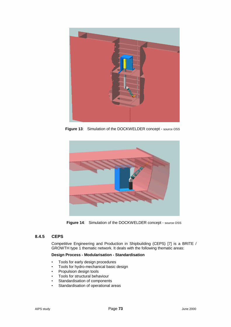
AIPS study Page 73 June 2000
Figure 13: Simulation of the DOCKWELDER concept - source OSS
Figure 14: Simulation of the DOCKWELDER concept - source OSS
8.4.5 CEPS
Competitive Engineering and Production in Shipbuilding (CEPS) [7] is a BRITE /GROWTH type 1 thematic network. It deals with the following thematic areas:
Design Process - Modularisation - Standardisation
• Tools for early design procedures• Tools for hydro-mechanical basic design• Propulsion design tools• Tools for structural behaviour• Standardisation of components• Standardisation of operational areas
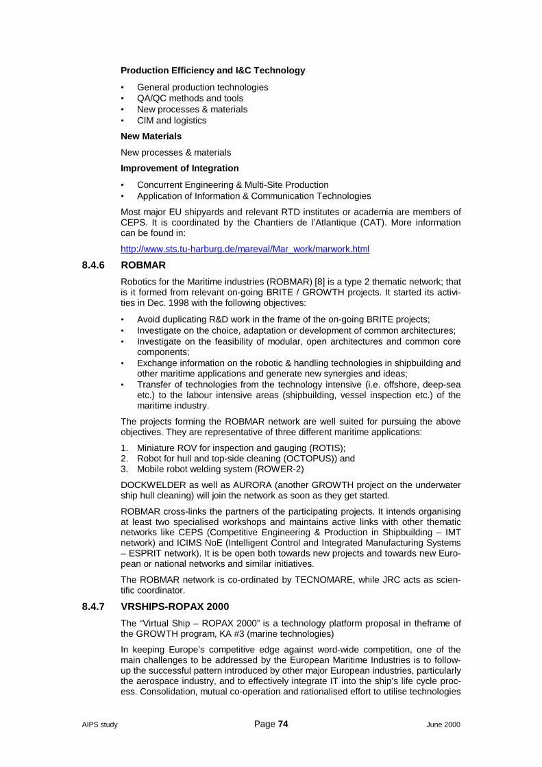
AIPS study Page 74 June 2000
Production Efficiency and I&C Technology
• General production technologies• QA/QC methods and tools• New processes & materials• CIM and logistics
New Materials
New processes & materials
Improvement of Integration
• Concurrent Engineering & Multi-Site Production• Application of Information & Communication Technologies
Most major EU shipyards and relevant RTD institutes or academia are members ofCEPS. It is coordinated by the Chantiers de l’Atlantique (CAT). More informationcan be found in:
http://www.sts.tu-harburg.de/mareval/Mar_work/marwork.html
8.4.6 ROBMAR
Robotics for the Maritime industries (ROBMAR) [8] is a type 2 thematic network; thatis it formed from relevant on-going BRITE / GROWTH projects. It started its activi-ties in Dec. 1998 with the following objectives:
• Avoid duplicating R&D work in the frame of the on-going BRITE projects;• Investigate on the choice, adaptation or development of common architectures;• Investigate on the feasibility of modular, open architectures and common core
components;• Exchange information on the robotic & handling technologies in shipbuilding and
other maritime applications and generate new synergies and ideas;• Transfer of technologies from the technology intensive (i.e. offshore, deep-sea
etc.) to the labour intensive areas (shipbuilding, vessel inspection etc.) of themaritime industry.
The projects forming the ROBMAR network are well suited for pursuing the aboveobjectives. They are representative of three different maritime applications:
1. Miniature ROV for inspection and gauging (ROTIS);2. Robot for hull and top-side cleaning (OCTOPUS)) and3. Mobile robot welding system (ROWER-2)
DOCKWELDER as well as AURORA (another GROWTH project on the underwatership hull cleaning) will join the network as soon as they get started.
ROBMAR cross-links the partners of the participating projects. It intends organisingat least two specialised workshops and maintains active links with other thematicnetworks like CEPS (Competitive Engineering & Production in Shipbuilding – IMTnetwork) and ICIMS NoE (Intelligent Control and Integrated Manufacturing Systems– ESPRIT network). It is be open both towards new projects and towards new Euro-pean or national networks and similar initiatives.
The ROBMAR network is co-ordinated by TECNOMARE, while JRC acts as scien-tific coordinator.
8.4.7 VRSHIPS-ROPAX 2000
The “Virtual Ship – ROPAX 2000” is a technology platform proposal in theframe ofthe GROWTH program, KA #3 (marine technologies)
In keeping Europe’s competitive edge against word-wide competition, one of themain challenges to be addressed by the European Maritime Industries is to follow-up the successful pattern introduced by other major European industries, particularlythe aerospace industry, and to effectively integrate IT into the ship’s life cycle proc-ess. Consolidation, mutual co-operation and rationalised effort to utilise technologies
AIPS study Page 75 June 2000
to their greatest effect can only strengthen European shipbuilding industry. TheVRSHIP-ROPAX 2000 focuses on integrating current effort dispersed throughoutEurope to provide a standardised platform upon which a variety of maritime indus-tries can function. It will eventually help European maritime industries to:
• Maintain and improve their position against word-wide competition by improvingtheir knowledge and
• Technological skills;• Combine competitiveness/profitability with safety and environmental protection;• Look at technology and innovation as the main way to survive in the global in-
ternational market.
The resulting platform is expected to provide short and medium term benefit toEuropean ship operators, regulatory bodies and shipbuilders and longer term bene-fits to the maritime industry as a whole through the embedding of high technology inthe very fabric of designing, building and operating the ships of the future. In par-ticular, the project aims to integrate and simulate critical technologies of ship sys-tems to ensure safe and reliable transportation of goods and people. Critical tech-nologies addressing development of areas such as powering and propulsion sys-tems, outfitting, internal arrangement, systems configuration, hull form design, hy-dromechanics and structural analyses are already receiving attention from acrossthe spectrum of the maritime industry. This necessitates that due attention is paidand concerted effort expended in the conception and development of an integratedplatform to allow for systematic integration, management and testing of the varioustechnologies to ensure overall design optimisation and product performance, whileaddressing all the life phases of the ship including design, production, operation anddisposal.
To achieve its aim VRSHIPS-ROPAX 2000 will employ state of the art methods fromvarious research areas to conduct the work. These include database meddler ar-chitecture, knowledge sharing initiatives, collaborative and virtual design environ-ments. This will require development of database systems, coordination and com-munication mechanisms and applications of standards such as STEP and CORBAto a large-scale engineering project. VRSHIPS-ROPAX 2000 will also address theneed to ensure ship safety, starting at an early stage in the design process. It will dothis by integrating design and simulation tools, which individually already have acertain predictive power into a much more potent whole, which, in addition, will en-able the visualisation of the consequences of design decisions. Though the virtualplatform will be generic the focus of the ship platform will be on a ROPAX, asawareness of safety problems in this area is at a high level after the Estonia andHerald of Free Enterprise tragedies. The VRSHIPS-ROPAX 2000 proposal relatesdirectly to two of the main points reflected in the EU’s Council Resolution of 22nd
December 1994 on the safety of roll-on/roll-off passenger ferries. It will enable intactand damage stability requirements to be more easily met by simulating a ship invarious sea conditions, and it will allow the simultaneous design of optimumevacuation routes and the evacuation procedures which utilise these routes.
Thus the project will deliver:
• An integrated virtual platform prototype system.• Software simulation tools and virtual models of the ship system.• An integrative architecture for critical ship technologies.• A virtual platform for real time and a ship platform for physical performance
evaluation.
The consortium consists of 48 partners from 12 countries, including 9 in industries,19 companies, 9 RTD establishments and 8 academia.
Understanding of the wide-ranging and central role of the project can be readily re-alised by reference to the thematic network SAFER EURORO Cluster (Appendix A)and the direct links with the Maritime Industry's R&D master plan explained therein.VRSHIPS-ROPAX 2000 is the integrative platform that "pools" together advancedtechnological tools to assess performance of a ship system from first principles and
AIPS study Page 76 June 2000
thus help amass experiential information and insight. It will provide not only a plat-form of ship system critical technologies but also a generic virtual platform for anyship type. The project supports the European maritime industries in:
• Maintaining adequate strategic control over technological developments in ship-building and shipping operation.
• Adapting and integrating new technological developments in other advancedbranches of the European industry, particularly aerospace and informationtechnology.
• Exploiting European ‘know-how’ and European maritime industry’s worldwideleadership in ship design and ship operation supporting services.
• Further improving the ship design and ship operation process by use of virtualmodelling tools, enabling the simulation of ship’s ‘life cycle’ from the initial con-ception, the design, production and finally operation under normal and extreme(emergency) conditions, with clear impact on ship’s economy, efficiency, safetyand protection of human lives and of physical environment.
As an example of the potential contribution from the project, the design of a 50 mGRP mine hunter can take 4,000 hours of conceptual design, 40,000 hours duringthe definition phase and 400,000 hours in the detail design phase. It could be ar-gued that savings of up to 1/3 in the definition phase and 1/4 or 1/5 in the detaileddesign phase. The final results would be of a better quality in any case, but just con-sidering the above 0.5 M€ could be easily saved in a project of this size.
8.5 Shipbuilding automation related R&DThe fact that only 10 projects reported for the shipyard automation / robotisation bythe maritime RTD study reflects essentially two things:
• The shipyards cannot finance nor can they be the driving force for long-termR&D on robotics or automation.
• The fact that, despite some notable (and very expensive) exceptions in some hi-tech applications (like space robotics), the relevant technologies are not yetmatures for promising any practical industrial application.
This is consistent also with the analysis of the papers presented at the major inter-national conferences relative to the AIPS study.
A notable exception to the above is OSS (Odense Steel Shipyard); it is the only EUshipyard that invests on long-term RTD concerning robotics for one-of-a-kind opera-tions. In fact, OSS has participated actively in many such projects like the most re-cent SNAKE and DOCKWELDER.
8.6 Integration related R&DThe number of European or national RTD projects as well as the number of paperspresented at the major AIPS relevant conferences, related to integration is quite im-portant. On top of that, there is an important RTD activity done by private companiesand major CAD vendors, which, due to the associated commercial interests, is pro-prietary and not sufficiently well documented.
We note that the areas that are covered better in terms of performed RTD are thoseof:
• Integrating ship design with production design and planning• Data exchange• Concurrent engineering• Virtual enterprise• Integrating the various ship design activities - standards
On the contrary, RTD on CIM and automated facilities programming integration isnot as well covered. This might reflect the fact that interfacing CAD data with CAMequipment is considered a rather consolidated straightforward procedure not need-ing any further R&D.
AIPS study Page 77 June 2000
8.7 The impact of novel production technologiesThere is a number of novel production technologies, which are either being intro-duced or are considered for future use by the major EU yards. They include mainly:
• Laser technologies for cutting and welding• New materials (aluminium, composite or sandwich)• New bonding techniques
These technologies alone cannot change significantly the shipbuilding industry.Nevertheless, the specialised facilities and know-how required for most of theseprocesses, combined with the introduction of new vessel concepts could, undercertain circumstances, act as a catalyst for the transformation of the EU yards to thevirtual shipyard and the network of technology intensive enterprises / suppliers oftomorrow.
The necessary circumstances quoted above have to do with the development anddeployment of the necessary tools, infrastructure and mentality for the integration ofthe design and production activities around the product model, in the context of thevirtual shipyard concept (see section 7).
8.8 Conclusion and recommendations on AIPS related R&DThe 3 major conferences during the last 3 years (Tokyo 98, ICCAS 99 and COMPIT2000) as well as the BMT maritime RTD study indicated a scarce RTD effort in ro-botics & automation. They indicated an important effort on integration issues like:product model, standards, concurrent engineering and data exchange. These factsconfirm:
• The importance of integration at short and medium term: Shipyards and otherplayers of the sector are conscious of this fact and are already investing in thisdirection.
• The reluctance of the shipyards and other maritime RTD institutions to finance(or be the driving force) for any long-term RTD activities on automation and ro-botics for one-of-a-kind processes.
Shipyards cannot invest, nor can they be the driving force in any long-term R&D ac-tivities on robotisation of one-of-a-kind processes, for the reasons that have beendiscussed in the previous sections. Nevertheless, in order for shipbuilding to be-come a technology intensive, rather than work intensive sector, tedious, unhealthyand dangerous work must inevitably be robotised. Such long-term R&D is thereforenecessary if shipbuilding is to become a technology intensive rather than a work-intensive industrial sector.
EC, along with national authorities and shipbuilder’s associations must find alterna-tive ways to encourage basic and long-term R&D and stimulate the technologytransfer from other high tech applications, in order to permit the introduction of allthe necessary technologies for the efficient robotisation / automation of the one-of-a-kind operations in shipbuilding, construction and other heavy “one-of-a-kind” indus-tries. Such ways may include:
• Network relevant R&D institutes, academia, shipyards, other one-of-a-kind in-dustries and automation equipment providers.
• Stimulate trans-sector activities regarding the application of autonomous roboticsystems (service robots operating in remote, dangerous or unhealthy environ-ments).
• Financing of basic and long-term R&D of industrial relevance, even without evi-dent economic returns.
AIPS study Page 78 June 2000
9 Competitiveness of EU shipbuildingEven if the effects of integration, process automation and robotisation on the pro-ductivity are not questionable, their effects on competitiveness are not as clear. Es-pecially in what concerns the competitiveness vis-à-vis their Far Eastern counter-parts the situation is as follows:
9.1 Effects of automationGiven that, as analysed in the above sections:
Further automation of the shipbuilding productive processes cannot have significanteconomic returns but at medium / long term,
• It involves considerable amount of basic R&D activities, which cannot be per-formed, financed or owned by individual shipyards
• Basic technologies and solutions from such rather basic R&D activities, arebound to proliferate much faster than the time needed to be implemented andgive tangible economic return.
• Even where process automation / mechanisation looks promising at short term(i.e. painting and coating), in the modern global economic and IT context, itcannot guarantee but a very brief competitive edge.
Investing in automation, in whatever form and however necessary it might be, can-not, by itself, improve the competitiveness of the EU shipbuilding industry nor can itsecure its present market niche.
It must be pointed out that, as soon as the basic automation technologies becomeavailable, Korean (and in the future also the Chinese) shipyards are in a much bet-ter position to implement these technologies than their EU counterparts. There aretwo basic reasons for that:
• The current market niche of the Far Eastern shipyards is much more suitable toautomation improvements than the EU market niche.
• Far Eastern shipyards follow quite closely the international R&D activities andalready have a lot of agreements with top EU shipyards and technology provid-ers.
Although it was not possible to visit, in the frame of the AIPS study, any Koreanshipyard, all the information we have point out that they have modern installationsand are keen and capable of applying any new promising technology.
9.2 Effects of integrationInvestments on integration are bound to affect the productivity of the shipyards in amuch more direct way than investments on automation of any single process. Undersome conditions, its effect on competitiveness can be quite significant for the indi-vidual yard as well as for the EU shipbuilding as a whole. More in particular:
• The erection of large cruise vessels, fast ferries etc, typical of what are still con-sidered to be EU market niches, are much more apt to profit from an integrated,concurrent engineering and production environment than tankers, bulk carriersetc.
• Although the required investment for introducing such an environment to a par-ticular shipyard is not as heavy (in fact much of the development cost is sharedand buffered through the big CAD vendors), its implementation requires radicalstructural, organisational and mentality changes. These changes cannot be im-plemented but gradually, they are heavily custom / application driven, they canbe quite long to implement and, if wrong decisions are taken at the beginning,they can be quite risky. As a consequence, applied pioneer solutions cannot becopied or transferred as easily and the effects of any successful innovative ap-plication are bound to have a longer lasting effect.
AIPS study Page 79 June 2000
Nevertheless, at medium / long term, production integration alone cannot assureany competitive edge over the Far Eastern shipyards nor can it secure the currentmarket niche. On the contrary, there are examples of Korean shipyards10 that havealready established partnerships with leading CAD vendors in order to further en-hance their productivity and competitiveness and penetrate some typical EU marketniches.
9.3 Considerations on the competitiveness of the EU shipyardsThe competitiveness of the EU shipyards, specially vis-à-vis their Far Eastern com-petitors, is a matter that goes far beyond the scope of the present study. Neverthe-less, we allow some considerations that can serve for further thoughts:
European shipbuilding cannot, in general, retain its actual market niches, even moreso it cannot gain the market sectors lost recently in favour of its Far-Eastern com-petitors just by technology or R&D investments, be it on automation or on designand integration.
Instead, following the experience of other sectors, EU shipbuilding must target on itsintegration in the context of a competitive and sustainable European shipping. Therecent developments in information and communication technologies make possiblea coherent product model type of approach, where a network of shipyards and otherrelated industries and enterprises respond collectively to the need for a producing,maintaining, adapting and decommissioning the fleet of vessels necessary to assurea sustainable European shipping.
Ship owners and ship operators must see these virtual shipyards or better virtualship-making industries (i.e. networks of specialised shipyards, equipment manufac-turers, repair yards, service providers etc) as a long-standing partners, much like theway the airlines see the big aircraft manufacturing consortia.
10 Hyundai Heavy Industries (HHI) Ulsan shipyard is in partnership with Parametric Tech-
nologies Corporation (PTC) to develop the complete next generation shipbuilding solution[28], an integrated shipbuilding environment
AIPS study Page 80 June 2000
10 Conclusions
10.1 Challenging environmentThe over-capacity in production, mainly in the sector of merchant vessels, hascaused dramatic price reductions (from 15% to 30% over the 1998 prices) in par-ticular for some vessel types (tankers, VLCCs, etc.). The situation of the shipbuild-ing market has accelerated the trend of EU shipyards towards building vessel typeswith high technical content and specialised know-how like containerships, LNG andLPG tankers, dredgers, luxury cruise vessels and ferries.
Increasing vessel complexity means significantly less steel work (sometimes lowerthan 20% of the total cost) and increasingly important design, planning and man-agement (it can represent over 10% of the cost of a modern passenger vessel). Thevery short delivery times, imposed by the fierce competition and the rapidly evolvingmarket, emphasise even more the need for efficient design, planning and manage-ment.
In the past, shipyards have been largely self sufficient in all disciplines of shipbuild-ing process. Nowadays however, workloads can vary significantly across variousdisciplines and the complexity of certain work requires a lot of highly skilled person-nel for limited periods of time. Due to this reason most of the advanced shipyardsuse extensively subcontractors and total turnkey deliveries suppliers, moving rapidlytowards the concept of “assembly” yard.
Nowadays, successful, in-time, completion of complicated ships (such as modernhigh-speed ferries or big passenger vessels) in a concurrent engineering and pro-duction environment sets new challenges for the standardisation and integration ofthe processes.
The shipping world is relatively conservative in technology thinking. The invest-ments, be it for ordering a ship or purchasing new production technology, are con-siderable and everybody tries to minimise the economical risks. However, the majorEU shipyards have taken up the challenge imposed by the modern global marketeconomy and the particular shipbuilding market situation and are changing fast.
10.2 Low priority for further automationVery high level of automation as such is not of the highest priority in the develop-ment list of the shipyards. The nature of shipbuilding, which is one-of-a-type produc-tion with few series-production features, makes efficient and cost-effective automa-tion difficult.
The first part of the steel production process (marking, cutting, 2D blocks etc) is al-ready quite well automated. The 3D block and grand-block assembly as well as thedockside erection are very difficult to be automated or robotised; robotic technologyis not yet mature to offer economically viable solutions.
The diminishing portion of steel construction, which is technically the easiest targetfor automation, makes investments on further automation of individual productionprocesses even more questionable.
Outfitting work is still at the beginning of the automation process. Here, it is the sub-contractors that are likely to develop new production technologies. Automation islikely to be developed for workshop or subcontracted activities.
10.3 High priority for integrationShip design efficiency is of vital importance to shipbuilding industry. In spite of theconsiderable investments and the developments in the various design tools andmethods, there is still considerable room for improvement and substantial economicreturn potential. Design activities (including production planning and management)not only constitute an important part of the total cost of the vessel project but also

AIPS study Page 81 June 2000
have a significant impact on the other costs (production, procurement, delivery timeetc).
At present, there exist a range of valid CAD, CAE, CAM, CIM and ERP tools alreadydeployed in the major EU yards. The major issue as what concerns the quality andefficiency of both the final product and the production (incl. design) process itselflays in the efficient cooperative engineering and production.
In brief: at short-medium term, the major productivity gains in EU shipbuilding canbe achieved through rationalisation of work phases, good planning and integrationrather than automation. The final target is a virtual yard, operating in a cooperative /concurrent engineering and production context together with a network of special-ised contactors, suppliers. The central concept for such a context is that of the 4Dproduct model.
10.4 Need for technology transfer and long-term R&DShipyards cannot invest, nor can they be the driving force in any long-term R&D ac-tivities on robotisation of one-of-a-kind processes, for the reasons that have beendiscussed in the previous sections. Nevertheless, in order for shipbuilding to be-come a technology intensive, rather than work intensive sector, tedious, unhealthyand dangerous work must inevitably be robotised.
EC, along with national authorities and shipbuilder’s associations must find ways toencourage basic and long-term R&D in order to permit the introduction of all thenecessary technologies for the efficient robotisation / automation of the one-of-a-kind operations in shipbuilding, construction and other heavy “one-of-a-kind” indus-tries.

AIPS study Page 82 June 2000
AcknowledgementThe authors wish to thank Lucio Sabbadini and Luciano Manzon of FINCANTIERI S.p.A. aswell as Michael Goldan of VNSI (Dutch shipbuilders association) for their useful comments.
They wish also to thank each of the members of the CESA working group on co-operation for useful discussions and information given as well as for the unique opportunityto participate to their fruitful meetings and visits to numerous EU shipyards.

AIPS study Page 83 June 2000
References[1] F. Andritsos, Tender for a Study on the Automation & Integration of Production
Processes in Shipbuilding – State-of-the-Art Report, Sept. 1998
[2] F. Andritsos, Planning for the State-of-the-Art report on the Automation & Inte-gration of Production Processes in Shipbuilding, April 1999
[3] “The Maritime Industry R&D Master Plan”, Task Force: Maritime Systems of theFuture, European Commission, DG III-F, Draft of 4 July 1996.
[4] John Bell, High-power lasers weld ship-shape structures, OLE, May 1996, p17.
[5] IRDAC Opinion - Towards the Framework Programme V, Industrial R&D Advi-sory Committee of the European Commission, Luxembourg, 14 June 1996.
[6] G.A. Bekey, Needs for Robotics in Emerging Applications: A ResearchAgenda, Report for IEEE/Robotics Industry Association, Oct. 1996.(http://www.sandia.gov.isrc/Bekey.paper.html)
[7] Competitive Engineering & Production in Shipbuilding (CEPS), BRITE – IMTtype 1 thematic network, area 3B, started Dec 1998.
[8] Robotics for the Maritime Industries (ROBMAR), BRITE – IMT type 2 thematicnetwork, area 3B, started Dec 1998.
[9] Proposal for a Counsil regulation on aid to shipbuilding, Brussels 26.7.95,COM(95) 410 final
[10] The International federation of Robotics, United Nations / Economic Commission forEurope, World Robotics 1998, Geneva, 1998
[11] Ken Ito, Takashi Yoshimura, Akio Iida, Masahiro Sonda, Realisation of CIM, basedon the Systematisation of the Production Department, Mitsubishi Heavy Indus-tries Ltd Technical Review, Vol.35 No.2 (June 1998)
[12] Richter, Cartsten, personal communication, Howaldtswerke Deutsche Werft,Nov.99, Kiel (D)
[13] Guus van der Bles, C. Dirkse, CONCOMSHIP - Integrated Shipbuilding by Con-current Engineering, Proceedings, COMPIT 2000, March 29 to April 2, 2000,Potsdam - Berlin (D)
[14] Manuel Ventura, J. Vitoria, Carlos Guedes Soares, Implementation of STEPTranslators Using the Ship Hull Product Model, Proceedings, COMPIT 2000,March 29 to April 2, 2000, Potsdam - Berlin (D)
[15] Marcus Bentin, Karsten Stenzel, STEP Interface between TRIBON andPOSEIDON, Proceedings, COMPIT 2000, March 29 to April 2, 2000, Potsdam -Berlin (D)
[16] Berend Bohlmann, IT Integration in Modern Design of Ships, Proceedings,COMPIT 2000, March 29 to April 2, 2000, Potsdam - Berlin (D)
[17] Morten Lovstad, Simon Holby Behrens-Nielsen, NAUTICUS - Knowledge Man-agement and Decision Support throughout the Ship's Life Cycle, Proceedings,COMPIT 2000, March 29 to April 2, 2000, Potsdam - Berlin (D)
[18] Fivos Andritsos, Integration and Robot Autonomy: Key Technologies for Com-petitive Shipbuilding, Proceedings, COMPIT 2000, March 29 to April 2, 2000,Potsdam - Berlin (D)
[19] Sjoerd Hengst, R.J.J.F. Takken, Robotising in the Dutch Shipbuilding Industry,Proceedings, COMPIT 2000, March 29 to April 2, 2000, Potsdam - Berlin (D)
[20] Bart Lamiroy, Radu Horaud,Tom Drummond, Ole Knudsen, Visually Guided Ro-bots for Ship Building, Proceedings, COMPIT 2000, March 29 to April 2, 2000,Potsdam - Berlin (D)
AIPS study Page 84 June 2000
[21] Markus Vincze, M. Ayromlou, M. Zillich, S. Galt, N. Hewer, O. Neckelmann, R. Wa-terman, A. Gasteratos, R. Martinotti, G. Sandini, C. Gramkow, S. Hoffgaard, O.Madsen, RobVision - Visually Guiding a Walking Robot through a Ship Struc-ture, Proceedings, COMPIT 2000, March 29 to April 2, 2000, Potsdam - Berlin (D)
[22] Markus Aarnio, New 3-D Tools Allow Early Project Stage Virtual Models andSimulations, Proceedings, COMPIT 2000, March 29 to April 2, 2000, Potsdam -Berlin (D)
[23] Aldo Zini, Attilio Rocca, Marco Raffa, Roberto Costa, The Integration of VirtualPrototyping in Ship Design, Proceedings, COMPIT 2000, March 29 to April 2,2000, Potsdam - Berlin (D)
[24] Ivan Oestvik, Dimitris Konovessis, Dracos Vassalos, A ship design blackboardsystem, Proceedings, COMPIT 2000, March 29 to April 2, 2000, Potsdam - Berlin(D)
[25] J.Torroja, F.Alonso, Developments in Computer Aided Ship Design and Produc-tion, The Royal Institution of Naval Architects, Discussion Paper W177(1999)
[26] CAD/CAM Magazine Online, The Guide to Integrated Design & Production,http://www.cadcam-magazine.co.uk/htm/main.html
[27] Maritime Industry Information Infrastructure, http://www.marinfo.net/entry.html
[28] Parametric Technologies Corporation, Pro/ENGINEERING Shipbuilding SolutionsWhite Paper, communication from PTC
[29] British Maritime Technology, Cliff Funnell Associates, the Institute of Shipping Eco-nomics and Logistics and Maritime Engineering and Technology for Transport Lo-gistics and Education, The Current Extent of Member States Maritime Researchand Technological Development (RTD) Activities, with reference to shipbuild-ing, including marine equipment, shipping and marine resources, EuropeanCommission, DG Enterprise, tender III/98/12, final report, Feb. 2000
[30] Commission Européenne, Deuxième Rapport de la Commission Européenne auConseil des Ministres sur la Situation de la Construction Navale dans leMonde, Bruxelles, 14.04.00
[31] Product Development and Innovation in Shipbuilding (PRODIS), BRITE – IMT type1 thematic network, area 3B, State-of-the-Art report, Nov 1999
[32] Competitive Engineering & Production in Shipbuilding (CEPS), State-of-the-Art re-port, Thematic area 7: General Production Technology, May 1999
[33] Competitive Engineering & Production in Shipbuilding (CEPS), State-of-the-Art re-port, Thematic area 8: QA / QC concepts & methods, May 1999
[34] Competitive Engineering & Production in Shipbuilding (CEPS), State-of-the-Art re-port, Thematic area 9: New processes & materials, May 1999
[35] Competitive Engineering & Production in Shipbuilding (CEPS), State-of-the-Art re-port, Thematic area 10: CIM & logistics in shipbuilding, May 1999
[36] Tatsuo Miyazaki, Yoshio Nakashima, Hiroshi Ookubo, Kenichi Hebaru, YasunoriNoborikawa, Kazuo Ootsuka, Kunio Miyawaki, Tsuneto Mori, Toshiaki Shinohara,Yukio Saito and Hidetoshi Matsumoto, NC Painting Robot for Shipbuilding, pro-ceedings ICCAS’99
[37] Laser welding in Ship Construction, Project summary report TWI, L-SHIP/PSG(95) 16 April 1995
[38] .Lloyds Register of Shipping, Guidelines for the Approval of CO2 Laser Welding,March 1997
[39] Welding Procedure Specification for Laser Beam Welding, BS EN ISO 9956-111996
[40] DIN 2310, Thermal cutting, parts 1 to 6

AIPS study Page 85 June 2000
[41] House DS, Hilton PA, TWI Members Report, A cutting Process Comparison, May1997
[42] Shiga C., Trends in steel for shipbuilding - the growing use of advanced steelIIW Shipbuilding Seminar Odense April 1996
[43] F Roland, Laser welding in shipbuilding, Convergent Energy Focal Spot SeminarOrlando, US, March 1998
[44] M.Kanerva, e.a., The future of ship design, DELTAMARIN Ltd, Raisio, Finland,1999
AIPS study Page 86 June 2000
List of FiguresFigure 1: Shipbuilding production process flow................................................................32
Figure 2: Information flow across the shipbuilding activities.............................................34
Figure 3: Process flow at a typical automated pipe shop .................................................39
Figure 4: Usual means for handling loads .......................................................................42
Figure 5: Non-supervised manipulating system; information from external sensors (if theyexist) serve for assisting the operator to command the manipulator..................49
Figure 6: Supervised manipulating system; information from external sensors are fed tothe control system rather than assisting the operator to command themanipulator......................................................................................................49
Figure 7: Typical early project phase model, from [44] ....................................................63
Figure 8: Vantage class exterior design, from [44]...........................................................64
Figure 9: Virtual bridge model, from [44] .........................................................................64
Figure 10: Virtual kitchen model, from [44] ........................................................................65
Figure 11: Engine room model for functional checking, from [44].......................................65
Figure 12: Virtual simulation of the Hellenic Shipyards, GR, from [44] ...............................66
Figure 13: Simulation of the DOCKWELDER concept - source OSS .................................73
Figure 14: Simulation of the DOCKWELDER concept - source OSS .................................73

AIPS study Page 87 June 2000
AnnexesA.1 External subcontractors to the AIPS study
A.2 Shipyards and other organisations contacted
A.3 COMPIT 2000 – programme
A.4 The Dutch collaborative experience
A.5 The CESA working group on cooperation
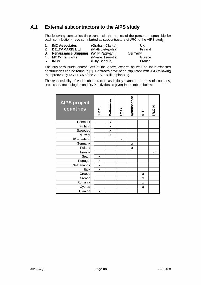
AIPS study Page 88 June 2000
A.1 External subcontractors to the AIPS study
The following companies (in parenthesis the names of the persons responsible foreach contribution) have contributed as subcontractors of JRC to the AIPS study:
1. IMC Associates (Graham Clarke) UK2. DELTAMARIN Ltd (Matti Lietepohja) Finland3. Renaissance Shipping (Willy Patzwahl) Germany4. MT Consultants (Marios Tseriotis) Greece5. IRCN (Guy Babaud) France
The business briefs and/or CVs of the above experts as well as their expectedcontributions can be found in [2]. Contracts have been stipulated with JRC followingthe aprooval by DG III.D.5 of the AIPS detailled planning.
The responsibility of each subcontractor, as initially planned, in terms of countries,processes, technologies and R&D activities, is given in the tables below:
J.R
.C.
Del
tam
arin
I.M.C
.
Ren
aiss
ance
M.T
.
I.R.C
.N.
Denmark xFinland x
Sweeded xNorway x
UK & Ireland xGermany x
Poland xFrance xSpain x
Portugal xNetherlands x
Italy xGreece xCroatia x
Romania xCyprus xUkraina x
AIPS projectcountries
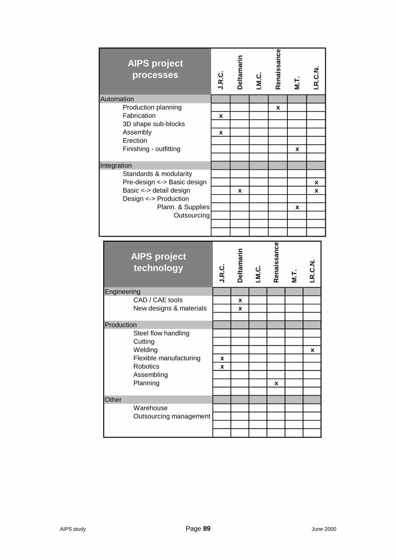
AIPS study Page 89 June 2000
J.R
.C.
Del
tam
arin
I.M.C
.
Ren
aiss
ance
M.T
.
I.R.C
.N.
AutomationProduction planning xFabrication x3D shape sub-blocksAssembly xErectionFinishing - outfitting x
IntegrationStandards & modularityPre-design <-> Basic design xBasic <-> detail design x xDesign <-> Production
Plann. & Supplies xOutsourcing
AIPS project processes
J.R
.C.
Del
tam
arin
I.M.C
.
Ren
aiss
ance
M.T
.
I.R.C
.N.
EngineeringCAD / CAE tools xNew designs & materials x
ProductionSteel flow handlingCuttingWelding xFlexible manufacturing xRobotics xAssemblingPlanning x
OtherWarehouseOutsourcing management
AIPS projecttechnology
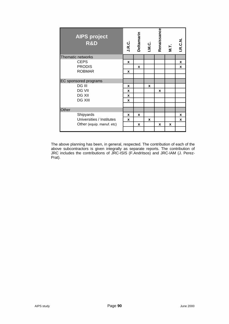
AIPS study Page 90 June 2000
J.R
.C.
Del
tam
arin
I.M.C
.
Ren
aiss
ance
M.T
.
I.R.C
.N.
Thematic networksCEPS x xPRODIS x xROBMAR x
EC sponsored programsDG III x xDG VII x xDG XII xDG XIII x
OtherShipyards x x xUniversities / Institutes x x xOther (equip. manuf. etc) x x x
AIPS projectR&D
The above planning has been, in general, respected. The contribution of each of theabove subcontractors is given integrally as separate reports. The contribution ofJRC includes the contributions of JRC-ISIS (F.Andritsos) and JRC-IAM (J. Perez-Prat).
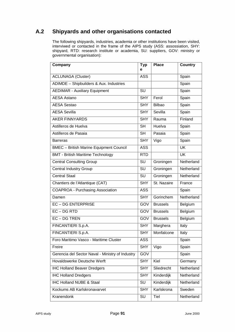
AIPS study Page 91 June 2000
A.2 Shipyards and other organisations contacted
The following shipyards, industries, academia or other institutions have been visited,interviwed or contacted in the frame of the AIPS study (ASS: assossiation, SHY:shipyard, RTD: research institute or academia, SU: suppliers, GOV: ministry orgovernmental organisation):
Company Type
Place Country
ACLUNAGA (Cluster) ASS Spain
ADIMDE – Shipbuilders & Aux. Industries Spain
AEDIMAR - Auxiliary Equipment SU Spain
AESA Astano SHY Ferol Spain
AESA Sestao SHY Bilbao Spain
AESA Sevilla SHY Sevilla Spain
AKER FINNYARDS SHY Rauma Finland
Astilleros de Huelva SH Huelva Spain
Astilleros de Pasaia SH Pasaia Spain
Barreras SHY Vigo Spain
BMEC – British Marine Equipment Council ASS UK
BMT - British Maritime Technology RTD UK
Central Consulting Group SU Groningen Netherland
Central Industry Group SU Groningen Netherland
Central Staal SU Groningen Netherland
Chantiers de l’Atlantique (CAT) SHY St. Nazaire France
COAPROA - Purchasing Association ASS Spain
Damen SHY Gorinchem Netherland
EC – DG ENTERPRISE GOV Brussels Belgium
EC – DG RTD GOV Brussels Belgium
EC – DG TREN GOV Brussels Belgium
FINCANTIERI S.p.A. SHY Marghera Italy
FINCANTIERI S.p.A. SHY Monfalcone Italy
Foro Maritimo Vasco - Maritime Cluster ASS Spain
Freire SHY Vigo Spain
Gerencia del Sector Naval - Ministry of Industry GOV Spain
Hovaldswerke Deutsche Werft SHY Kiel Germany
IHC Holland Beaver Dredgers SHY Sliedrecht Netherland
IHC Holland Dredgers SHY Kinderdijk Netherland
IHC Holland NUBE & Staal SU Kinderdijk Netherland
Kockums AB Karlskronavarvet SHY Karlskrona Sweden
Kranendonk SU Tiel Netherland
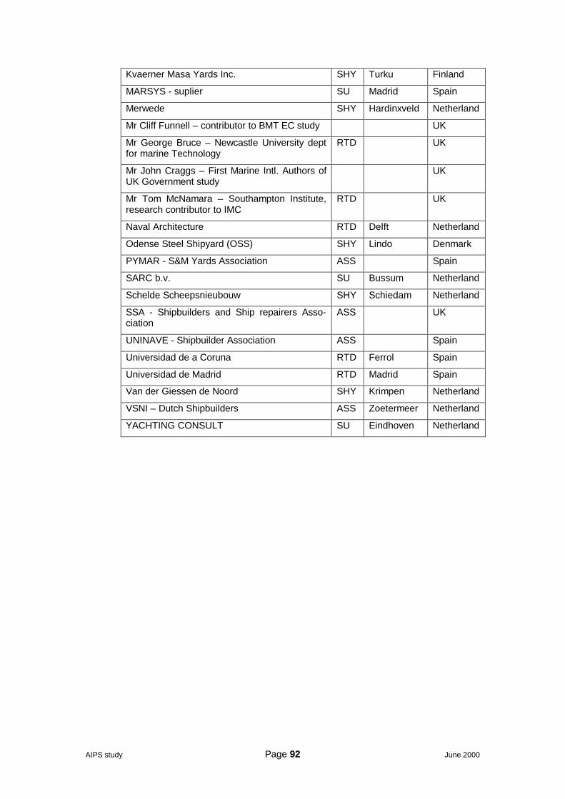
AIPS study Page 92 June 2000
Kvaerner Masa Yards Inc. SHY Turku Finland
MARSYS - suplier SU Madrid Spain
Merwede SHY Hardinxveld Netherland
Mr Cliff Funnell – contributor to BMT EC study UK
Mr George Bruce – Newcastle University deptfor marine Technology
RTD UK
Mr John Craggs – First Marine Intl. Authors ofUK Government study
UK
Mr Tom McNamara – Southampton Institute,research contributor to IMC
RTD UK
Naval Architecture RTD Delft Netherland
Odense Steel Shipyard (OSS) SHY Lindo Denmark
PYMAR - S&M Yards Association ASS Spain
SARC b.v. SU Bussum Netherland
Schelde Scheepsnieubouw SHY Schiedam Netherland
SSA - Shipbuilders and Ship repairers Asso-ciation
ASS UK
UNINAVE - Shipbuilder Association ASS Spain
Universidad de a Coruna RTD Ferrol Spain
Universidad de Madrid RTD Madrid Spain
Van der Giessen de Noord SHY Krimpen Netherland
VSNI – Dutch Shipbuilders ASS Zoetermeer Netherland
YACHTING CONSULT SU Eindhoven Netherland
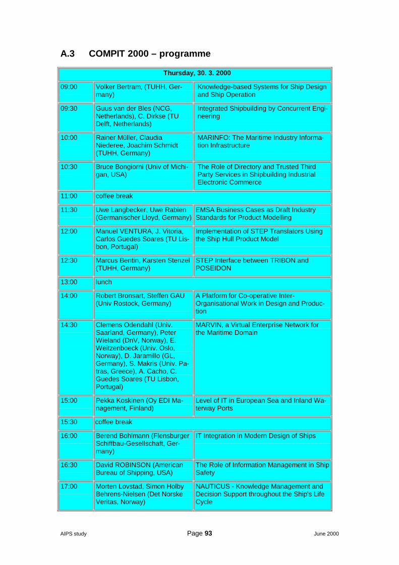
AIPS study Page 93 June 2000
A.3 COMPIT 2000 – programme
Thursday, 30. 3. 2000
09:00 Volker Bertram, (TUHH, Ger-many)
Knowledge-based Systems for Ship Designand Ship Operation
09:30 Guus van der Bles (NCG,Netherlands), C. Dirkse (TUDelft, Netherlands)
Integrated Shipbuilding by Concurrent Engi-neering
10:00 Rainer Müller, ClaudiaNiederee, Joachim Schmidt(TUHH, Germany)
MARINFO: The Maritime Industry Informa-tion Infrastructure
10:30 Bruce Bongiorni (Univ of Michi-gan, USA)
The Role of Directory and Trusted ThirdParty Services in Shipbuilding IndustrialElectronic Commerce
11:00 coffee break
11:30 Uwe Langbecker, Uwe Rabien(Germanischer Lloyd, Germany)
EMSA Business Cases as Draft IndustryStandards for Product Modelling
12:00 Manuel VENTURA, J. Vitoria,Carlos Guedes Soares (TU Lis-bon, Portugal)
Implementation of STEP Translators Usingthe Ship Hull Product Model
12:30 Marcus Bentin, Karsten Stenzel(TUHH, Germany)
STEP Interface between TRIBON andPOSEIDON
13:00 lunch
14:00 Robert Bronsart, Steffen GAU(Univ Rostock, Germany)
A Platform for Co-operative Inter-Organisational Work in Design and Produc-tion
14:30 Clemens Odendahl (Univ.Saarland, Germany), PeterWieland (DnV, Norway), E.Weitzenboeck (Univ. Oslo,Norway), D. Jaramillo (GL,Germany), S. Makris (Univ. Pa-tras, Greece), A. Cacho, C.Guedes Soares (TU Lisbon,Portugal)
MARVIN, a Virtual Enterprise Network forthe Maritime Domain
15:00 Pekka Koskinen (Oy EDI Ma-nagement, Finland)
Level of IT in European Sea and Inland Wa-terway Ports
15:30 coffee break
16:00 Berend Bohlmann (FlensburgerSchiffbau-Gesellschaft, Ger-many)
IT Integration in Modern Design of Ships
16:30 David ROBINSON (AmericanBureau of Shipping, USA)
The Role of Information Management in ShipSafety
17:00 Morten Lovstad, Simon HolbyBehrens-Nielsen (Det NorskeVeritas, Norway)
NAUTICUS - Knowledge Management andDecision Support throughout the Ship's LifeCycle
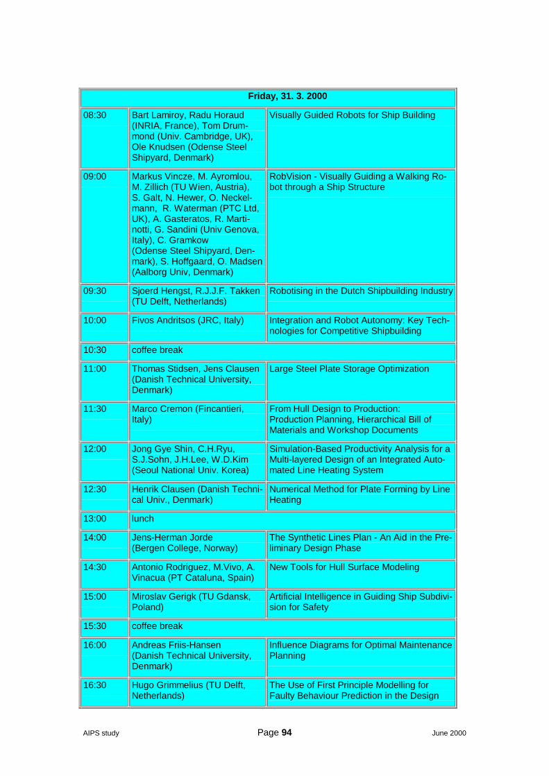
AIPS study Page 94 June 2000
Friday, 31. 3. 2000
08:30 Bart Lamiroy, Radu Horaud(INRIA, France), Tom Drum-mond (Univ. Cambridge, UK),Ole Knudsen (Odense SteelShipyard, Denmark)
Visually Guided Robots for Ship Building
09:00 Markus Vincze, M. Ayromlou,M. Zillich (TU Wien, Austria),S. Galt, N. Hewer, O. Neckel-mann, R. Waterman (PTC Ltd,UK), A. Gasteratos, R. Marti-notti, G. Sandini (Univ Genova,Italy), C. Gramkow(Odense Steel Shipyard, Den-mark), S. Hoffgaard, O. Madsen(Aalborg Univ, Denmark)
RobVision - Visually Guiding a Walking Ro-bot through a Ship Structure
09:30 Sjoerd Hengst, R.J.J.F. Takken(TU Delft, Netherlands)
Robotising in the Dutch Shipbuilding Industry
10:00 Fivos Andritsos (JRC, Italy) Integration and Robot Autonomy: Key Tech-nologies for Competitive Shipbuilding
10:30 coffee break
11:00 Thomas Stidsen, Jens Clausen(Danish Technical University,Denmark)
Large Steel Plate Storage Optimization
11:30 Marco Cremon (Fincantieri,Italy)
From Hull Design to Production:Production Planning, Hierarchical Bill ofMaterials and Workshop Documents
12:00 Jong Gye Shin, C.H.Ryu,S.J.Sohn, J.H.Lee, W.D.Kim(Seoul National Univ. Korea)
Simulation-Based Productivity Analysis for aMulti-layered Design of an Integrated Auto-mated Line Heating System
12:30 Henrik Clausen (Danish Techni-cal Univ., Denmark)
Numerical Method for Plate Forming by LineHeating
13:00 lunch
14:00 Jens-Herman Jorde(Bergen College, Norway)
The Synthetic Lines Plan - An Aid in the Pre-liminary Design Phase
14:30 Antonio Rodriguez, M.Vivo, A.Vinacua (PT Cataluna, Spain)
New Tools for Hull Surface Modeling
15:00 Miroslav Gerigk (TU Gdansk,Poland)
Artificial Intelligence in Guiding Ship Subdivi-sion for Safety
15:30 coffee break
16:00 Andreas Friis-Hansen(Danish Technical University,Denmark)
Influence Diagrams for Optimal MaintenancePlanning
16:30 Hugo Grimmelius (TU Delft,Netherlands)
The Use of First Principle Modelling forFaulty Behaviour Prediction in the Design
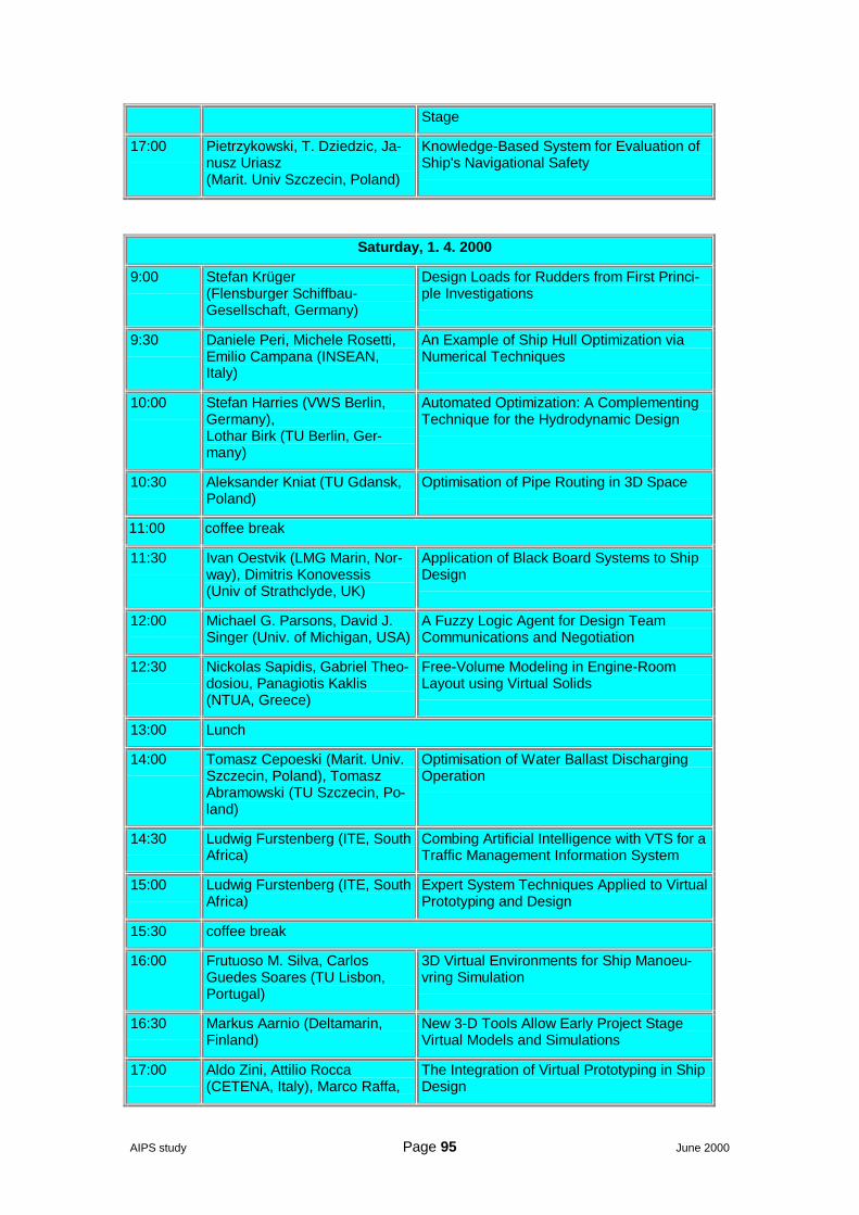
AIPS study Page 95 June 2000
Stage
17:00 Pietrzykowski, T. Dziedzic, Ja-nusz Uriasz(Marit. Univ Szczecin, Poland)
Knowledge-Based System for Evaluation ofShip's Navigational Safety
Saturday, 1. 4. 2000
9:00 Stefan Krüger(Flensburger Schiffbau-Gesellschaft, Germany)
Design Loads for Rudders from First Princi-ple Investigations
9:30 Daniele Peri, Michele Rosetti,Emilio Campana (INSEAN,Italy)
An Example of Ship Hull Optimization viaNumerical Techniques
10:00 Stefan Harries (VWS Berlin,Germany),Lothar Birk (TU Berlin, Ger-many)
Automated Optimization: A ComplementingTechnique for the Hydrodynamic Design
10:30 Aleksander Kniat (TU Gdansk,Poland)
Optimisation of Pipe Routing in 3D Space
11:00 coffee break
11:30 Ivan Oestvik (LMG Marin, Nor-way), Dimitris Konovessis(Univ of Strathclyde, UK)
Application of Black Board Systems to ShipDesign
12:00 Michael G. Parsons, David J.Singer (Univ. of Michigan, USA)
A Fuzzy Logic Agent for Design TeamCommunications and Negotiation
12:30 Nickolas Sapidis, Gabriel Theo-dosiou, Panagiotis Kaklis(NTUA, Greece)
Free-Volume Modeling in Engine-RoomLayout using Virtual Solids
13:00 Lunch
14:00 Tomasz Cepoeski (Marit. Univ.Szczecin, Poland), TomaszAbramowski (TU Szczecin, Po-land)
Optimisation of Water Ballast DischargingOperation
14:30 Ludwig Furstenberg (ITE, SouthAfrica)
Combing Artificial Intelligence with VTS for aTraffic Management Information System
15:00 Ludwig Furstenberg (ITE, SouthAfrica)
Expert System Techniques Applied to VirtualPrototyping and Design
15:30 coffee break
16:00 Frutuoso M. Silva, CarlosGuedes Soares (TU Lisbon,Portugal)
3D Virtual Environments for Ship Manoeu-vring Simulation
16:30 Markus Aarnio (Deltamarin,Finland)
New 3-D Tools Allow Early Project StageVirtual Models and Simulations
17:00 Aldo Zini, Attilio Rocca(CETENA, Italy), Marco Raffa,
The Integration of Virtual Prototyping in ShipDesign

AIPS study Page 96 June 2000
Roberto Costa(Fincantieri, Italy)
Sunday, 2. 4. 2000
9:00 Peter Beier (Univ Michigan,USA)
Web-Based Virtual Reality in Design andManufacturing Applications
10:00 Marco Barcellona (INSEAN,Italy), Volker Bertram (HSVA,Germany)
Virtual Reality Applications for CFD Post-processing
10:30 Ehsan Mesbahi (Univ Newcas-tle, UK),Volker Bertram (HSVA, Ger-many)
Empirical Design Formulae using ArtificialNeural Nets
11:00 coffee break
11:30 Kourosh Koushan (Marintek,Norway)
Prediction of Propeller Induced PressurePulses Using Artificial Neural Networks
12:00 Ehsan Mesbahi, Mehmet Atlar(Univ Newcastle, UK)
Artificial Neural Net Applications in Ship De-sign
13:00 lunch
AIPS study Page 97 June 2000
A.4 The Dutch collaborative experience
The Dutch Maritime ClusterDutch yards are in a strong maritime cluster, supported by a very active shipyardassociation (VNSI) promoting initiatives such as research on organization, logistics,and EDI platforms and IT applications.
The Dutch cluster has been described in a economic impact study published by theDelft University Press in separate volumes dedicated to shipbuilding industry, ma-rine equipment industry, The Royal Netherlands Navy, the Dutch seaport sector, theshipping sector and the offshore sector, fishing, services, maritime construction anddredging works, inland navigation, offshore, aquatic sports, suppliers, and all ship-building and auxiliary industries. Shipbuilding and auxiliary industries exported 46%of the production and representing less than 9% of the total turnover of the maritimecluster, but is understood as its cornerstone.
The maritime labour market was calculated in 1996 on more than 106,000 jobs, andtotal employment generated was estimated on 193,000. The number of seafarerswas expected to increase from 13,750 in 1996 to 18,600 in 2004 showing goodprospects extended to the rest of the cluster (i.e. shipbuilding)
Indirect value generated by the shipbuilding sector is estimated no less than 1.3times the size of the direct value added many in small companies. Offshore only,accounts 343 Dutch offshore companies all sizes from the multinationals to thesmall ones.
The NML (Nederland Maritiem Land) foundation represents the maritime cluster.
The VNSI association of Dutch yards has about 100 members:
• 20 on sea-going shipbuilding,• 15 in ship repair• The rest being bnuilders & repairers of coastal, work and inland ships
Around 40 yard sites appears regularly on the order-book and deliveries publishedby the Dutch magazine HSB International. Many yards sites are today in groups orholdings (IHC, DAMEN- see list)
General overview of the Dutch shipbuildingDutch yards are innovative in strategy, logistics and on the commercial and financialapproach. The yacht industry is considered at a close level to shipbuilding (mega-yachts up to 90 m and more may have more added value than 100 m cargo ves-sels).
Commercial shipbuilding self-limits to 140 m maximum length (the competitively isfavoured under this size) although some yards may built ships up to 250 m oflength.
Series are rare in the bigger sizes but some yards may combine one of a kind highvalue ships with standard low cost small standard dredgers or work-boats built intwo or tree modules (hull, propulsion machinery, and deck equipment) in own ac-count, ready for quick delivery.
The steel work moves between the heavy-duty equipment and structures of dredg-ers and the lighter inland or less than 140 m sea-going ships. Dredgers of all typesare the specialty of the Nederland shipbuilding
Nederland shipyards synergy with research centres (TNO and MARIN), the Univer-sity (Delft, side by side to TNO) and specialised industries and engineering (hydrau-lics, CAD and ERP suppliers) is worth to be taken as an example.
AIPS study Page 98 June 2000
PrioritiesDutch yards’ priorities were reported as:
Logistics: the ship type and the shipyard characteristics define the optimal con-struction strategy. The construction strategy is the main cost reduction option
Technology specialisation: the ships built have a higher added value on top of the“pure steel” and the yards competitively main enabler is to maintain the “numberone” on its specialty.
Research priority is on new types of ships and on increasing ship and equipment(dredging) performances.
Integration: Dutch yards give importance to integration they consider as part of thelogistics and what they translate as “engineering” (production strategy)
Software providersCAD
There are three major firms of CAD software in the Nederlands
• The CIG (Central Industry Group) NUPAS, associated with CADMATIC (Fin-land)
• Yachting Consult• SARC
Automation integration
Kranendonk ARAC software
ERP
Baan, a Dutch firm makes one of the best-known worldwide ERP software, but onlytwo yards in the Nederland uses it. Baan IV that is a general purpose software andneeds to be adapted to shipbuilding. One yard uses MARS, a ERP software forshipbuilding made by a smaller Danish provider.
As a consequence of the interest of the Dutch maritime industry, in EUROPORT2000 a special section for software with a special room for scheduled presentationswas included. See copy of the program of presentations attached.
Automation
Plate and profile cutting and marking is highly automated through two main con-tractors.
Welding automation is cautiously approached and does not appear to be a priority.The interviews with Kranendonk and TU Delft describe the automation approach ofthe Dutch automation integrator and of the Dutch yards (see separate report byPerez-Prat).
Nederland is accepted in the European shipbuilding as an example for clusteringand logistics on medium and small construction (up to 140 m)

AIPS study Page 99 June 2000
A.5 The CESA working group on cooperation
The CESA working group on cooperation consisted of representatives from:
• Fincantieri S.p.A. (Italy)• Aker Finnyards Oy (Finland)• Astilleros Españoles S.A. (Spain)• Chantiers de l'Atlantique - ALSTOM (France)• Estaleiros Navais de Viana do Castelo (Portougal)• Flensburger Schiffbau-Gesellschaft GmbH (Germany)• Howaldtswerke-Deutsche Werft AG (Germany)• Schelde Maritiem BV (The Nederlands)• Van der Giessen de Noord (The Nederlands)
These 9 shipyards decided to exchange visits, collect and compile information in astandardised way on the technological processes the layout and the equipment oftheir respective yards.
The work of the workgroup is an example of openness and collaboration between‘competing’ EU industries with the common of sharing knowledge and know-how onshipbuilding production technologies.
During each visit, usually of one full day, the participants were shown the completeyard, were given the opportunity to ask any question and take, through an officialphotographer, any picture desired.
The work of the workgroup has been documented in the “Production TechnologiesCatalogue”, in HTML format, on a CD, made available to every participant at theworkgroup.


