Embed Size (px)
Citation preview

Wood Floor Trusses areEnvironmentally Compatible.
FLOOR TRUSSES
Get more Quality, Flexibility and Labor Savings usingGet more Quality, Flexibility and Labor Savings using
Builders want solutions that help them stay on schedule and maintain quality construction and profits. Whencompared to traditional joist construction, manufactured wood floor truss systems are better, stronger, and can beinstalled faster. A manufactured truss is an engineered structural component assembled from wood members,metal connector plates and other mechanical fasteners. The truss members form a rigid structural framework andare assembled such that the members form triangles. Most builders are familiar with roof truss systems, but maynot realize the advantages of a manufactured floor truss system.
The benefits of manufactured wood truss floor systems are many. Floor trusses can span great distances, creatinglarger open spaces below unobstructed columns and partitions. Truss systems are quicker and easier to installthan traditional floor joists, and because they're manufactured in controlled environments, there's less chance ofwarping, shrinking, and twisting of lumber. Manufactured floor truss systems also save timber resources byreducing the amount of wood waste generated during construction.
FLOOR TRUSSESGet more Quality, Flexibility and Labor Savings usingGet more Quality, Flexibility and Labor Savings using
The component manufacturing process is simple and offers the professional builder plenty of time- and cost-saving resources along the way. Here's how it works:
House plans are sent by the builder to the wood floor truss manufacturer. There are hundreds of trussmanufacturers operating nationwide, but builders should research the quality and delivery costs before choosing avendor.
The building designer determines what loads need to be supported by the floor trusses. Then the truss designerdetermines how many trusses will be required, and their specific placement on the structure. The manufacturerthen builds the trusses, labels them for accurate installation, and ships them to the builder on the jobsite.
A detailed diagram with the placements of the trusses is sent along with the order to help the builder place thetrusses exactly where they should be installed.
Once the trusses are on the site, the builder can really start to see the benefits. The consistent size and height of themanufactured floor joist will mean easier sub-floor material installation, and the open web design allows for utilitiesto be run through in the floor system without drilling or cutting holes. These benefits will reduce the amount of timetrade contractors spend on site, speed up construction, and ultimately save the builder money. The technologyused in the design and manufacturing of floor trusses makes them a superior choice for builders looking tostreamline construction and provide a higher quality home to their customers.
2

32’
12’
12’ 6”
7’6”
Floor trusses are delivered to your site, ready forinstallation. No cutting or fitting is required. Strong,lightweight and rigid “System 42” Floor Trusses goup easily and quickly. Often without the use of acrane. Expensive steelworkers, welders or riggersare not required. Your crew can do it all.
Decking and ceiling materials are attached directlyto trusses without need for special hardware. Andbecause System 42 trusses can be spaced wider apart,less trusses are required resulting in less nails to drive.
Mechanicals are installed quickly through the open webs withoutnotching or furring. Electricians, A/C contractors and plumbers are off thejob quicker.
System 42 provides longer clear spans providing exceptional design flexibility. Forthis reason, plus their cost saving benefits during construction, more and morearchitects are specifying System 42 Floor Trusses than ever before.
FLOOR TRUSSES
The Benefits ofThe Benefits of
Floor truss are built with open chases for ductwork and have natural open spaces for plumbing and electrical wiring.Floor truss systems are sometimes called System 42's, because to build them manufacturers turn the 2x4's on theirside. This allows for shallow depths as well as a 3 1/2" nailing surface. Some floors are built from 2x3's, others from2x4's. Floor trusses can be manufactured with many different possible end conditions to accommodate differentinstallation needs; around raised walls, pocketed beams, headers around stairways, etc.
Is it OK to move a floor truss? Typical floor trusses are engineered to be spaced evenly, and the truss designdrawing verifies the required truss spacing. Occasionally the need will arise to shift one of the floor trusses fromwhere it was designed to be. When this happens, please contact the truss manufacturer to be sure it works. Slidinga floor truss even a few inches puts more load on the truss you're moving it away from, as shown in the drawingbelow.
Check with the truss manufacturer before shifting a truss !
BIf you shift it Then overstressed truss carries::
24" 3" 6.2% more load than designed for 27"on center 6" 12.5% 30""trusses 9" 18.7% 33""
16" 3" 9.3% more load than designed for 19"on center 6" 18.7% 22""
Fan Configuration Web Style
Two of the most common web patterns for floor trusses:
Warren Configuration Web Style
3www.alpineitw.com

FLOOR TRUSSESFraming withFraming with
Double truss
Header
Multiple ply floor trussesmay require special con-nection details betweenplys. Specialconnectors will bespecified on thedesign.
Stairwellopenings parallel totrusses in floor systemsdo not present a problem.By means of enclosed headersand beams or girders theseconditions can be handled with easeas illustrated.
Headerpocket
At stairwell openings perpendicular to floortrusses, additional posts or bearing wallsmay be required. All loads from stairs andsurrounding walls must be considered forcorrect floor truss design.
Trusses may be supported as top chordbearing or by hanger. Headers may be
supported by a hanger.
TrussHanger
4
Bottom chord bearing on a stud wall. Cantilever with an exterior wall on the end. Bottom chord bearing with shortcantilever and exterior wall.
Top chord bearing on stud wall. Floor truss designed to carry an interior header.Interior bearing on wall
Overhang on a floor truss used on a roof. Dropped cantilever foruse on exterior balconies.
Trimmable end conditionwith I-Joist insert.
Interior top chord bearing witha variable end height.
Top chord bearing witha variable end height.
Top chord bearing on stud wallwith variable end height.

39’3
”
17’
32’
These allowable spans are based on NDS 2005.Maximum deflection is limited by L/360 or L/480 under
1
live load. Basic Lumber Design Values are F =2000 psi(b)
F =1100 psi F =2000 psi E=1,800,000 psi Duration(t) (c)
Of Load = 1.00. Spacing of trusses are center-to-center(in inches).
Top Chord Dead Load = 10 psf. Bottom Chord DeadLoad = 5 psf. Center Line Chase = 24" max. Trussesmust be designed for any special loading, such asconcentrated loads. Other floor and roof loadingconditions and a variety of species and other lumbergrades are available.
Center Deflection Truss Depth Truss DepthSpacing Limit 12" 14" 16" 18" 20" 22" 12" 14" 16" 18" 20" 22"
16" o.c. L/360 22'2" 24'11" 26'10" 28'8" 30'4" 31'11" 19'0" 20'9" 22'4" 23'10" 25'3" 26'7"L/480 20'2" 22'7" 24'11" 27'2" 29'4" 31'5" 18'0" 20'2" 22"4' 23'10" 25'3" 26'7"
19.2" o.c. L/360 20'9" 22'8" 24'4" 26'0" 27'6" 29'0" 17'3" 18'9" 20'3" 21'7" 22'10" 24'1"L/480 18'11" 21'3" 23'6" 25'7" 27'6" 29'0" 16'11" 18'9" 20'3" 21'7" 22'10" 24'1"
24" o.c. L/360 18'5" 20'1" 21'7" 23'1" 24'5" 25'9" 15'2" 16'7" 17'10" 19'1" 20'2" 21'3"L/480 17'7" 19'9" 21'7" 23'1" 24'5" 25'9" 15'2" 16'7" 17'10" 19'1" 20'2" 21'3"
12" 14" 16" 18" 20" 22" 12" 14" 16" 18" 20" 22"
16" o.c. L/360 19'4" 21'4" 23'0" 24'6" 26'0" 27'4" 16'3" 17'9" 19'2" 20'5" 21'8" 22'9"L/480 17'7" 19'9" 21'10" 23'9" 25'8" 27'4" 15'9" 17'8" 19'2" 20'5" 21'8" 22'9"
19.2" o.c. L/360 17'9" 19'4" 20'10" 22'3" 23'7" 24'10" 14'9" 16'1" 17'4" 18'6" 19'7" 20'7"L/480 16'7" 18'7" 20'6" 22'3" 23'7" 24'10" 14'9" 16'1" 17'4" 18'6" 19'7" 20'7"
24" o.c. L/360 15'9" 17'2" 18'6" 19'9" 20'11" 22'0" 13'0" 14'2" 15'3" 16'4" 17'3" 18'2"L/480 15'4" 17'2" 18'6" 19'9" 20'11" 22'0" 13'0" 14'2" 15'3" 16'4" 17'3" 18'2"
12" 14" 16" 18" 20" 22" 12" 14" 16" 18" 20" 22"
16" o.c. L/360 16'11" 18'6" 19'11" 21'3" 22'6" 23'8" 14'1" 15'5" 16'7" 17'8" 18'9" 19'9"L/480 15'8" 17'7" 19'5" 21'2" 22'6" 23'8" 14'0" 15'5" 16'7" 17'8" 18'9" 19'9"
19.2" o.c. L/360 15'4" 16'9" 18'1" 19'3" 20'5" 21'6" 12'9" 13'11" 15'0" 16'0" 16'11" 17'10"L/480 14'9" 16'6" 18'1" 19'3" 20'5" 21'6" 12'9" 13'11" 15'0" 16'0" 16'11" 17'10"
24" o.c. L/360 13'8" 14'10" 16'0" 17'1" 18'1" 19'1" 11'3" 12'3" 13'3" 14'1" 14'11" 15'9"L/480 13'8" 14'10" 16'0" 17'1" 18'1" 19'1" 11'3" 12'3" 13'3" 14'1" 14'11" 15'9"
(1) Vibration Control -- Research by Virginia Tech indicates thatL/480 live load deflection criteria provides a high degree ofresistance to floor vibration (bounce). The building designer
desiring this benefit may choose to specify an L/480 live loaddeflection criteria to be used for the floor trusses.
40 PSF Live Load
55 PSF Total Load
85 PSF Live Load
100 PSF Total Load
60 PSF Live Load
75 PSF Total Load
40 PSF Live Load
55 PSF Total Load
85 PSF Live Load
100 PSF Total Load
60 PSF Live Load
75 PSF Total Load
4x2Lumber
3x2Lumber
3 / "1
2 2 / "1
2
1 / "1
2 1 / "1
2
FLOOR TRUSSES
Span Tables forSpan Tables for
5www.alpineitw.com

39’3
”
12’6”
22’3
”
Duct Openings For Fan Style Floor Trusses With 4x2 Chords & Webs
All Dimensions In Inches
DepthPan el
S izeA B C D E F G
10 60 41/2 41/4 11 41/2 16 4 7
11 60 51/4 51/4 12 51/2 15 5 8
117/8 60 73/4 63/4 10 61/4 14 51/2 83/4
12 60 61/4 61/4 14 6 20 5 9
13 60 71/4 71/4 12 7 181/2 6 10
14 60 81/4 81/4 17 7 22 6 11
15 60 91/4 81/2 15 8 25 6 12
16 60 101/4 91/2 14 9 27 6 13
18 60 121/4 101/2 141/2 101/2 26 7 15
20 60 14 111/2 141/2 12 26 8 17
22 60 16 121/2 15 13 30 8 19
24 60 18 131/2 16 14 32 8 21
26 60 19 141/2 18 15 34 8 23
30 60 22 16 20 17 32 10 24
36 60 25 171/2 22 191/2 36 10 24
Typical Duct Opening Sizes For 4x2 Fan Style Floor Trusses
All Dimensions In Inches
Duct Openings For Warren Style Low Joists
Depth BA C D E F
10
12
13
14
15
16
17
18
19
20
21
22
24
18
20
20
24
24
24
24
24
24
24
24
24
24
24
30
30
30
30
30
30
30
30
30
30
30
30
4x6
5x9
5x11
6x10
6x12
6x13
6x14
7x13
7x14
7x15
8x14
8x15
8x16
5
7
8
81/2
91/2
10
101/2
11
111/2
12
121/2
13
14
41/2
53/4
6
61/2
7
71/2
71/2
8
83/4
81/2
9
9
91/4
7
9
10
11
12
13
14
15
16
17
18
19
21
FLOOR TRUSSESFraming withFraming with
6 www.alpineitw.com
FLOOR TRUSSES
Typical Bearing / Heel Conditions forTypical Bearing / Heel Conditions for
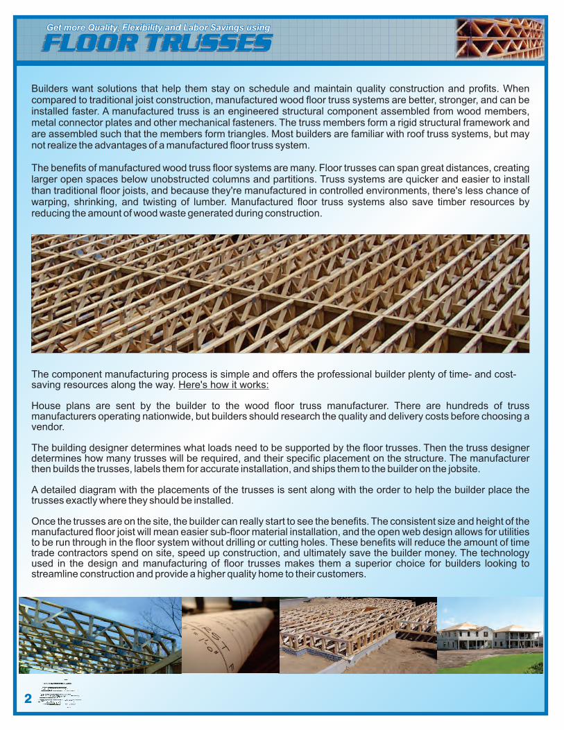
Common complaints about noise through ceilings in floortrusses include walking, moving furniture, and droppingobjects, all of which are considered impact sounds. Whenaddressing noise in floor systems, the Impact InsulationClass (IIC) rating is often the most critical value to consider.In general, IIC values for flooring are similar to their SoundTransmission Class (STS) values, so satisfying the coderequirement for one will typically work for the other, if notcome close.
A floor/ceiling's ability to limit sound transmission is not highly
dependent on the type of joist or truss to be used, but rather
the types of insulation, sheathing, flooring, and subflooring.
Most basic floor/ceiling construction materials like gypsum
board and hard surface flooring don't provide much IIC value.
The best methods for reducing impact noise, besides substantially increasing the floor systems mass, is to use
specialized acoustic products such as resilient channels and special acoustic underlayment's, as identified in
Figure-1.
Many of these measures are effective at reducing only certain types of noise and work in combination with the
other measures to create a complete soundproofing system. Batt insulation, for example, is effective for
absorbing airborne sounds, but does little or no good against structural/impact noise. While carpeting with a
fairly thick layer of padding beneath it is excellent at reducing impact noise, it is not effective against airborne
noise. For additional information regarding Sound Transmission in Wood Floor and Roof Trusses, refer to
SBCA report: .SRR No. 1601-03
Bracing is extremely IMPORTANT!! Every truss system needs adequate bracing. The purpose of most bracingis to ensure that the trusses and truss members remain straight and do not bow out of their plane. Inadequate,improper or incorrectly installed bracing can lead to collapses, failures and serious accidents. An engineeredbracing system will avoid these pitfalls and ensure the structural integrity of the truss system. Trusses need to bebraced during installation, which is called temporary bracing and they need permanent bracing which will remaininstalled for the life of the roof system.Temporary Bracing Guidelines: For metal plate connected wood truss systems, refer to BCSI-B7 for properinstallation bracing guidelines.
The provider of this document, nor any of its divisions or companies, does not warrant the recommendations and information contained herein as proper under all conditions andexpressly disclaims any responsibility for damages arising from the use, application, or reliance on the recommendations contained herein.
Sound Transmission through Floor Trusses
7
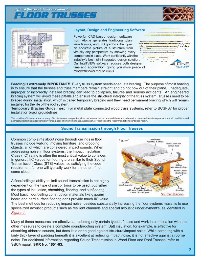
Powerful CAD-based design softwarefrom Alpine generates traditional planview layouts, and 3-D graphics that givean accurate picture of a structure fromvirtually any perspective by showing everycomponent in place. Work confidently with theindustry’s best fully integrated design solution.Our IntelliVIEW software reduces both designertime and aggravation, giving you more peace ofmind with fewer mouse clicks.
Layout, Design and Engineering Software
Figure-1
�Faster Construction / Saves Money
�Longer Clear Spans
�Hides Mechanicals
�Spaced 24” oc., multiple depths
�Cantilever and Balcony Built In
� 3.5 Width Surface to Glue and Nail to
�ColdAir Returns can be Eliminated
�Reduce Field Material Losses
�Pick-up Interior Point Loads
�Custom Designed for your project
�Commercial & ResidentialApplications
�Trim-able ends for concrete mis-pours
�No Humps in Floors
�Sound and Fire Ratings
�Angled Walls
FLOOR TRUSS SYSTEMSPerformance Facts usingPerformance Facts using
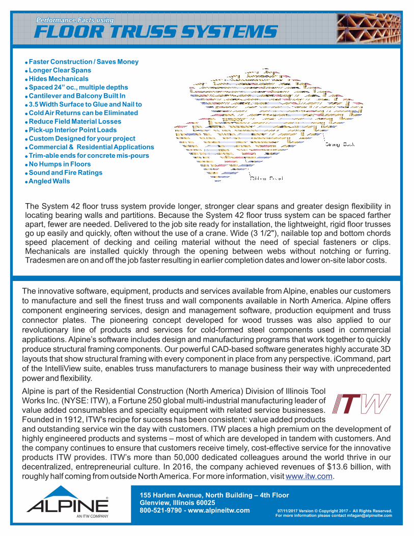
The System 42 floor truss system provide longer, stronger clear spans and greater design flexibility inlocating bearing walls and partitions. Because the System 42 floor truss system can be spaced fartherapart, fewer are needed. Delivered to the job site ready for installation, the lightweight, rigid floor trussesgo up easily and quickly, often without the use of a crane. Wide (3 1/2"), nailable top and bottom chordsspeed placement of decking and ceiling material without the need of special fasteners or clips.Mechanicals are installed quickly through the opening between webs without notching or furring.Tradesmen are on and off the job faster resulting in earlier completion dates and lower on-site labor costs.
The innovative software, equipment, products and services available from Alpine, enables our customersto manufacture and sell the finest truss and wall components available in North America. Alpine offerscomponent engineering services, design and management software, production equipment and trussconnector plates. The pioneering concept developed for wood trusses was also applied to ourrevolutionary line of products and services for cold-formed steel components used in commercialapplications. Alpine’s software includes design and manufacturing programs that work together to quicklyproduce structural framing components. Our powerful CAD-based software generates highly accurate 3Dlayouts that show structural framing with every component in place from any perspective. iCommand, partof the IntelliView suite, enables truss manufacturers to manage business their way with unprecedentedpower and flexibility.
155 Harlem Avenue, North Building – 4th FloorGlenview, Illinois 60025800-521-9790 - www.alpineitw.com 07/11/2017 Version © Copyright 2017 - All Rights Reserved.
For more information please contact [email protected]
Alpine is part of the Residential Construction (North America) Division of Illinois ToolWorks Inc. (NYSE: ITW), a Fortune 250 global multi-industrial manufacturing leader ofvalue added consumables and specialty equipment with related service businesses.Founded in 1912, ITW's recipe for success has been consistent: value added productsand outstanding service win the day with customers. ITW places a high premium on the development ofhighly engineered products and systems – most of which are developed in tandem with customers. Andthe company continues to ensure that customers receive timely, cost-effective service for the innovativeproducts ITW provides. ITW’s more than 50,000 dedicated colleagues around the world thrive in ourdecentralized, entrepreneurial culture. In 2016, the company achieved revenues of $13.6 billion, withroughly half coming from outside NorthAmerica. For more information, visit .www.itw.com