Embed Size (px)
Citation preview

Safety relays
425
Gesamtkatalog EN 2016_17_Stilvorlage LK FrutigerOT_2010 DE_GB.qxd 06.11.15 16:53 Seite 425

Safety controllers
Controllers for safety-related applications up to safety category 3 (EN 954-1) arecalled "safety controllers". Special test routines for hardware and software monitoring are implemented in the devices. Due to the certification of thehardware, operating system software and programming tools it is easy for the project engineer to get the approval for the machine.
16-bit SafetyController
Type Inputs /outputs
Description Draw-ingno.
Orderno.
24
SafetyController · 16 Bit · Programmable mobile controller type R 360 · for safetyapplications · SILcl 2 (IEC 62061) · PL d (EN ISO 13849-1) · 2 nd CAN interface for
gateway function according to SAE J 1939 · Configurable input / output functions ·Programming according to IEC 61131-3 · 24 inputs/outputs · 10...32 V DC
1 CR7506
40
SafetyController · 16 Bit · Programmable mobile controller type R 360 · for safetyapplications · SILcl 2 (IEC 62061) · PL d (EN ISO 13849-1) · 2 nd CAN interface for
gateway function according to SAE J 1939 · Configurable input / output functions ·Programming according to IEC 61131-3 · 40 inputs/outputs · 10...32 V DC
1 CR7021
80
SafetyController · 16 Bit · Programmable mobile controller type R 360 · for safetyapplications · SILcl 2 (IEC 62061) · PL d (EN ISO 13849-1) · 2 nd CAN interface for
gateway function according to SAE J 1939 · Configurable input / output functions ·Programming according to IEC 61131-3 · 80 inputs/outputs · 10...32 V DC
2 CR7201
Accessories and software
Type Description Orderno.
Programming software CODESYS · for configuration, programming and diagnosis of ifm controller systems · German version · incl. the DVD "Software, tools and documentation"
CP9006
Programming software CODESYS · for configuration, programming and diagnosis of ifm controller systems · English version · incl. the DVD "Software, tools and documentation"
CP9008
Connector AMP 55-pole · wirable · with contacts (Junior Power Timer) EC2013
System overview Page
16-bit SafetyController 426
Accessories and software 426 - 427
Scale drawings / drawing no. – CAD download: www.ifm.com 427
Safety technology
426Product selectors and further information can be found at: www.ifm.com
Gesamtkatalog EN 2016_17_Stilvorlage LK FrutigerOT_2010 DE_GB.qxd 06.11.15 16:53 Seite 426

Type Description Orderno.
Cable with connector · AMP 55-pole · wired · Cable length 1.2 m · Cores sealed individually · Core cross-section 1 mm2 EC2084
Cable with connector · AMP 55-pole · wired · Cable length 2.5 m · Cores sealed individually · Core cross-section 1 mm2 EC2097
Cable with connector · AMP 55-pole · wired · Cable length 1.2 m · Core cross-section 1 mm2 EC2086
Cable with connector · AMP 55-pole · wired · Cable length 2.5 m · Core cross-section 1 mm2 EC2046
Scale drawings / drawing no. – CAD download: www.ifm.com
1
153
43 LED
225
205,5
2680
1526
45°
2
153
43 LED
247
20
2680
1526
45°
Safety controllers
427
Gesamtkatalog EN 2016_17_Stilvorlage LK FrutigerOT_2010 DE_GB.qxd 06.11.15 16:53 Seite 427

AS-Interface Safety at Work
The sophisticated AS-i technology and the extended diagnostic possibilities providehigh reliability and machine uptime. "Safety at Work" is the extension of the AS-interface by safety-related components. Safety components up to the highest control category 4 to EN 954-1, SIL 3 to IEC 61508 and EN ISO 13849 - 1 / PL e can be connected to AS-i.
Safety at Work
Type Description Draw-ingno.
Orderno.
AS-i safety monitor · Basic version · 1-channel · Configuration and setup by configuration software ASIMON · Screw terminal · polyamide black · Complies with the requirements: ISO 13849-1: PL e · IEC 61508: SIL 3
1 AC001S
AS-i safety monitor · Basic version · 2-channel · Configuration and setup by configuration software ASIMON · Screw terminal · polyamide black · Complies with the requirements: ISO 13849-1: PL e · IEC 61508: SIL 3
1 AC002S
AS-i safety monitor · Extended functionality · 1-channel · Configuration and setup by configuration software ASIMON ·Screw terminal · polyamide black · Complies with the requirements: ISO 13849-1: PL e · IEC 61508: SIL 3
1 AC003S
AS-i safety monitor · Extended functionality · 2-channel · Configuration and setup by configuration software ASIMON ·Screw terminal · polyamide black · Complies with the requirements: ISO 13849-1: PL e · IEC 61508: SIL 3
1 AC004S
AS-i safety monitor · Extended functionality and integrated safe slave for triggering a safe AS-i output · 2-channel ·Configuration and setup by configuration software ASIMON V3.0 · Screw terminal · polyamide black · Complies with
the requirements: ISO 13849-1: category 4 · ISO 13849-1: PL e · IEC 61508: SIL 32 AC032S
AS-i safety monitor · 2 safe semi-conductor outputs · SIL 3 to EN 62061, IEC 61508 / SIL 3 and EN ISO 13849 - 1 / PL e ·Chip card to save the configuration data · Configuration and setup by configuration software ASIMON V3 G2 · USB 2.0
interface · Chip card and Combicon screw terminals supplied with the device · Screw terminal3 AC041S
Safe active AS-i module · Performance Level e to EN ISO 13849-1 et IEC 61508 / SIL 3 for the connection of mechanicalcontacts · Combicon connection · PA · Complies with the requirements: ISO 13849-1: category 4 · ISO 13849-1: PL e ·
IEC 61508: SIL 34 AC009S
Safe active AS-i output module · SIL 3 to EN 62061, IEC 61508 / SIL 3 and EN ISO 13849 - 1 / PL e · for the safe triggeringof actuators · Combicon connection · PA · Complies with the requirements: ISO 13849-1: PL e · IEC 61508: SIL 3
5 AC030S
Safe active AS-i module · Connection via M12x1 sockets or cage clamps · For connection of an electro-sensitive protectiveequipment (ESPE) type 4 to EN 61496-1 · PA 6 · Complies with the requirements: ISO 13849-1: category 4 · ISO 13849-1:
PL e · IEC 61508: SIL 36 AC007S
System overview Page
Safety at Work 428 - 430
Accessories Safety at Work 430
AS-i manuals 431
Scale drawings / drawing no. – CAD download: www.ifm.com 431 - 433
Safety technology
428Product selectors and further information can be found at: www.ifm.com
Gesamtkatalog EN 2016_17_Stilvorlage LK FrutigerOT_2010 DE_GB.qxd 06.11.15 16:53 Seite 428

Type Description Draw-ingno.
Orderno.
AS-i Safety at Work · Safe AS-i input module 2SI - 2LO · Addressing socket · Three orientations of the flat cable arepossible · Sockets M12 x 1 · PA / Piercing contacts: CuSn6 surface nickel and tin-plated · Complies with the requirements:
ISO 13849-1: category 4 · ISO 13849-1: PL e · IEC 62061: SILcl 37 AC505S
AS-i Safety at Work · Safe AS-i input module 4SI / 2DO T / 2LO · Addressing socket · Three orientations of the flat cableare possible · Sockets M12 x 1 · PA / Piercing contacts: CuSn6 surface nickel and tin-plated · Complies with the
requirements: ISO 13849-1: PL d · IEC 62061: SILcl 27 AC506S
Safe active AS-i ClassicLine module · IR addressing possible · Performance Level e to EN ISO 13849-1 for the connectionof mechanical contacts · Sockets M12 x 1 · PBT · Complies with the requirements: ISO 13849-1: category 4 · ISO 13849-1:
PL e · IEC 61508: SIL 38 AC006S
Illuminated E-STOP · front mounting · reset by turning · 2 NC contacts / 1 red LED · fool-proof E-STOP to EN ISO 13850 9 E7007S
Illuminated E-STOP with integrated AS-i connection · fool-proof E-STOP to EN ISO 13850 · Pull to reset · AS-i interface via AS-i flat cable IP 67 · PC GF20 · Complies with the requirements: ISO 13849-1: category 4 · ISO 13849-1: PL e ·
IEC 61508: SIL 310 AC010S
Key-release E-STOP with integrated AS-i connection · Connector M12 x 1 · AS-i interface via AS-i flat cable IP 67 · fool-proof E-STOP to EN ISO 13850 · Reset by key operation · PC GF20 · Complies with the requirements: ISO 13849-1: PL e ·
IEC 61508: SIL 311 AC011S
safe AS-i e-stop operating unit with integrated AS-i connection · AS-i interface via M12 x 1 connector · fool-proof E-STOP to EN ISO 13850 · Pull to reset · interchangeable button inserts
12 AC012S
Safe active AS-i ClassicLine module · AS-i version 2.1 · IR addressing possible · Control category 4 according to EN954-1 ·For the connection of fail-safe inductive sensors of the control category 4 · Sockets M12 x 1 · PBT · Complies with the
requirements: ISO 13849-1: category 4 · ISO 13849-1: PL e · IEC 61508: SIL 3– AC016S
AS-i safety PCB · Connection of mechanical contact and LED components · Certification to ISO 13849-1: PL e and IEC 61508 / SIL 3 · Complies with the requirements: · IEC 61508: SIL 3
13 AC015S
Fail-safe inductive sensor · M12 connector, Gold-plated contacts · PPE / diecast zinc · Complies with the requirements: ISO 13849-1: category 4 · ISO 13849-1: PL e · IEC 61508: SIL 3
14 GM504S
Fail-safe inductive sensor · M12 connector, Gold-plated contacts · PPE / diecast zinc · Complies with the requirements: ISO 13849-1: category 4 · ISO 13849-1: PL e · IEC 61508: SIL 3
14 GM505S
Fail-safe inductive sensor · M18 x 1 · M12 connector, Gold-plated contacts · high-grade stainless steel / PBT · Complies with the requirements: ISO 13849-1: category 4 · ISO 13849-1: PL e · IEC 61508: SIL 3
15 GG505S
Fail-safe inductive sensor · M30 x 1.5 · M12 connector, Gold-plated contacts · PEEK / high-grade stainless steel / O-ring:EPDM · Complies with the requirements: ISO 13849-1: category 4 · ISO 13849-1: PL e · IEC 61508: SIL 3
16 GI505S
Safety switch with guard locking · Normally closed principle · Rotatable actuating head made of metal · Mechanicalrelease on the front · Supply via AS-i / solenoid supply ext. from 24 V DC · M12 connector · thermoplastic reinforced
glass-fibre17 AC901S
Safety switch with guard locking · Normally open principle · Rotatable actuating head made of metal · Mechanical releaseon the front · Supply via AS-i / solenoid supply ext. from 24 V DC · M12 connector · thermoplastic reinforced glass-fibre
17 AC902S
Safety switch with guard locking · Normally closed principle · Rotatable actuating head made of metal · Mechanicalrelease on the front · Supply via AS-i / solenoid supply from AS-i · M12 connector · thermoplastic reinforced glass-fibre
18 AC903S
AS-Interface Safety at Work
429You can find scale drawings from page 431
Gesamtkatalog EN 2016_17_Stilvorlage LK FrutigerOT_2010 DE_GB.qxd 06.11.15 16:53 Seite 429

Type Description Draw-ingno.
Orderno.
Safety switch with guard locking · Normally open principle · Rotatable actuating head made of metal · Mechanical releaseon the front · Supply via AS-i / solenoid supply from AS-i · M12 connector · thermoplastic reinforced glass-fibre
18 AC904S
Accessories Safety at Work
Type Description Orderno.
AS-i Safety at Work · Programming software for AS-i safety monitor AC001S / AC002S / AC003S / AC004S / AC032S · Version 3.0 ·Configuration, set-up and diagnostics of the AS-i safety monitor
E7040S
Software ASIMON V3 G2 · Configuration, set-up and diagnostics of the AS-i safety monitor · AC041S E7050S
USB interface cable for the connection of the safety monitor AC041S to the PC · cable length 1.8 m · 1.8 m E7051S
Chip card to save the configuration data of the AS-i safety monitor AC041S · 256 K E7052S
Safe contact expander without delay · 2 independent channels · 4 contact blocks (NO) per channel · 1 feedback circuit (NC) perchannel · Mounting on DIN rail · Screw terminal
E7053S
Connection cable PC / AS-i safety monitor · Parameter setting cable PC / AS-i safety monitor · Western connector RJ 45 8 poles / D-Sub socket 9 poles · 2.5 m
E7001S
Connection cable AS-i safety monitor / AS-i safety monitor · Download cable AS-i safety monitor / AS-i safety monitor · Westernconnector RJ 45 8 poles · 0.3 m
E7002S
EMERGENCY STOP label IP66 4 languages D,GB,F,I · EMERGENCY STOP label 4 languages for a safe illuminated EMERGENCY STOPbutton with integrated AS-i interface AC010S / AC011S / AC012S · 50 x 50 mm
E7003S
EMERGENCY STOP protective collar · EMERGENCY STOP protective collar for safe E-STOP AC010S / AC011S / AC012S · Housingmaterials: PC GF20 RAL 1004
E7004S
bridging plug for safety modules · Housing materials: PUR E7005S
Adapter plug · straight · M20 - M12 · M12 connector · 0.07 m · Housing materials: polyamide E7006S
Safety technology
430Product selectors and further information can be found at: www.ifm.com
Gesamtkatalog EN 2016_17_Stilvorlage LK FrutigerOT_2010 DE_GB.qxd 06.11.15 16:53 Seite 430

AS-i manuals
Type Description Orderno.
ecolog asi system · AS-Interface Manual (German) AC0115
ecolog asi system · AS-Interface Manual (English) AC0116
Scale drawings / drawing no. – CAD download: www.ifm.com
1
120
35,5
45
104
LED
2
45
105,
9
120
35,5
102
82,6
91,2
3
LEDs
22,5114,5
108
99
1: Chip card, 2: service button, 3: Combicon connector with screwterminals, 4: Micro USB interface
4
105
35,5
25
108
LEDs
1
1: Addressing socket
5
2
105
35,5
25
108
1
1: Addressing socket, 2: LED
6
45,5
49,4
8011
1
AS-Interface Safety at Work
431
Gesamtkatalog EN 2016_17_Stilvorlage LK FrutigerOT_2010 DE_GB.qxd 06.11.15 16:53 Seite 431

Scale drawings / drawing no. – CAD download: www.ifm.com
7
45
103
40,2
44,7
25,8
8
90
LED
M12 x1
1 80
44
1: fixture infrared adapter
9
40
30
88
561238
1
10
58,5
66,5
UU
UU
93,5
5610
5
M12
x1
72
80
11
M12
x1
72
80
58,5
66,5
93,5
5610
5
12
5610
4
208
120 72
M12
x1
80
13
921 U U UU
44
32
9 10 10
14
40
M12
x1
4066
17
34
LED
4661
30 20
5,4
105,
4
6
8,5
33
Safety technology
432Product selectors and further information can be found at: www.ifm.com
Gesamtkatalog EN 2016_17_Stilvorlage LK FrutigerOT_2010 DE_GB.qxd 06.11.15 16:53 Seite 432
Scale drawings / drawing no. – CAD download: www.ifm.com
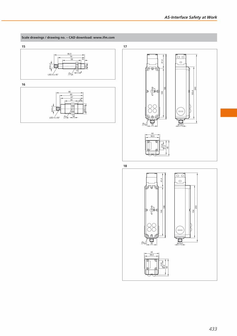
15
M18
x1
55 10
M12
x1
90,5
LED 8 x 45°
79
424
16
LED 4 x 90°
69
39
M30
x1,5
5
67
80
36
M12
x1
15
17
55
2514
419
041
,4
240
153,
4
M12x130
38,544
4641,4
18
55
2514
419
041
,4
203
154
M12x130
38,544
5046,4
AS-Interface Safety at Work
433
Gesamtkatalog EN 2016_17_Stilvorlage LK FrutigerOT_2010 DE_GB.qxd 06.11.15 16:53 Seite 433

Measuring andmonitoring fluids
Pressure, flow, temperature, level andvalve sensors for automation in the processindustries.
Multiple features
ifm process sensors can be used for control and measurementof the most important parameters of fluids – no matterwhether it is pressure, level, flow, temperature or valve position. The range of applications spans from simple monito-ring tasks and presence detection of media to accurate andhighly repeatable measurements.
The applied microprocessor technology allows for a selectionof key parameter settings. A four-digit alphanumeric displayand sealed pushbuttons allows local indication andadjustment of the parameters. This can be done with orwithout the media present, even before arrival on site.Output options include simple switched outputs, pulsed out-puts for metering systems, and current or voltage analogueoutputs. Most units also have the additional ability to transferanalogue values across IO-Link digitally, without any conver-sion losses.
As the sensors are mostly in direct contact with the medium,the design of the units and the selection of the materialswere driven by the high requirements in the applications.These include in particular resistance to pressure, vibration,shock, media and temperature as well as electromagneticcompatibility and a high ingress protection rating.
Multiple applications
The broad range of ifm fluid sensors can be used acrossmany different applications. The main areas of application aremachine building and mobile equipment, hygienic applica-tions (e.g. in the food and beverage industries) and industrialor chemical process plant.
An extensive range of process adapters and mounting acces-sories guarantees easy mechanical integration of the sensorsinto the application. Moreover, the units comply withrequired approvals such as EHEDG, 3A, FDA, KTW, ATEX andE1 for safe use in the application.
Regular examinations in production and high testrequirements at the development stage ensure a consistentlyhigh quality.
Process sensors
434Product selectors and further information can be found at: www.ifm.com
Gesamtkatalog EN 2016_17_Stilvorlage LK FrutigerOT_2010 DE_GB.qxd 06.11.15 16:53 Seite 434

Process sensors
435
Pressure sensors 436 - 470
Flow sensors / flow meters 472 - 505
Level sensors 506 - 528
Temperature sensors 530 - 562
Signal evaluation systems 564 - 569
Feedback systems for valves and valve actuators 570 - 583
Gesamtkatalog EN 2016_17_Stilvorlage LK FrutigerOT_2010 DE_GB.qxd 06.11.15 16:53 Seite 435

Sensors and transmitters with integrated control monitor
Units with special design for hygienic applications
Measuring principles with overload protection and a good long-term stability
Measuring range from -1…600 bar
Variable process connection and sealing technology via adapter
Pressure sensors
ifm offers a wide range of electronic pressure and vacuum sensors to meet therequirements of various industrial applications. The ceramic-capacitive measuringcell, tried and tested millions of times, is complemented by a stainless steel measu-ring cell with thin-film or thick-film wire strain gauges (series PK, PV, PT) and a piezoresistive measuring technique (for pneumatic applications).
All units have robust housings and do not require moving parts such as pistons orsprings. The result: the sensors are extremely shock and vibration resistant andoperate without any wear or maintenance.
The tried and tested ceramic-capacitive measuring principle is corrosion-resistantand long-term stable. In the long run this guarantees continuous accuracy of themeasured values. The sensors are resistant to dynamic pressure peaks andguarantee high overload resistance even in the case of extreme pressure peaksthat occur for example with fast closing valves.
Units with wire strain gauge in thin-film or thick-film technology on a stainless steelmeasuring cell are distinguished by their very compact and robust design. They canbe used in almost all industrial areas. The welded stainless steel measuring cellwithout any seals ensures a high degree of safety, in particular for applications withgas pressures of up to 600 bar as well as in air-conditioning and refrigerating tech-nology where aggressive coolants (freons) are used.
Local display:the clearly readableLED display showsthe current systempressure.
Pressuremeasurement in
pneumatic systems.
Process sensors
436Product selectors and further information can be found at: www.ifm.com
Gesamtkatalog EN 2016_17_Stilvorlage LK FrutigerOT_2010 DE_GB.qxd 06.11.15 16:53 Seite 436

System overview Page
Sensors with switching outputs and analogue outputs, display and IO-Link 438 - 440
Sensors with switching outputs and display with IO-Link 440 - 441
Electronic contact manometers with switching output and analogue output 441 - 442
PK sensors with mechanical setting and switching outputs 442 - 444
PP sensors for mobile and industrial applications with switching outputs, IO-Link 444
Sensors for pneumatic applications 445
PT sensors for industrial applications with analogue outputs 445 - 447
PT / PU sensors for mobile applications with analogue outputs 447 - 448
PA sensors with analogue outputs 448 - 450
Part seat monitoring 450
Sensors for hydrostatic level monitoring 450 - 451
Sensors for hydrostatic level monitoring ATEX category 1G/1D 451
Sensors with ATEX approval 3D 452
Sensors with ATEX approval 3D/3G 452
Full metal sensors for hygienic and wet areas with switching and analogue outputs, IO-Link 452 - 453
Full-metal high-temperature sensors up to 200 °C for hygienic and wet areas with switching output and analogue output, IO-Link 454
Electronic contact manometers for hygienic and wet areas with switching and analogue outputs 454 - 455
PF sensors for hygienic and wet areas with switching and analogue outputs 456
PL / PM sensors without display for hygienic and wet areas with analogue output 456 - 457
PE sensors with display with 2 switching outputs or switching and analogue output 457 - 458
Fixing components for pressure sensors 458
Accessories and software 458 - 459
Certificates 459 - 460
Adapters and accessories for adapters 460 - 461
Flange adapters 461 - 464
Wiring diagrams 464 - 465
Scale drawings / drawing no. – CAD download: www.ifm.com 465 - 470
Pressure sensors
437
Gesamtkatalog EN 2016_17_Stilvorlage LK FrutigerOT_2010 DE_GB.qxd 06.11.15 16:53 Seite 437

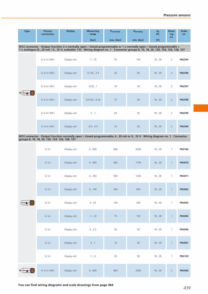
Sensors with switching outputs and analogue outputs, display and IO-Link
Type Processconnection
Display Measuringrange
[bar]
Poverload
max. [bar]
Pbursting
min. [bar]
UbDC
[V]
Draw-ingno.
Orderno.
M12 connector · Output function 2 x normally open / closed programmable or 1 x normally open / closed programmable + 1 x analogue (4...20 mA / 0...10 V; scaleable 1:5) · Wiring diagram no. 1 · Connector groups 8, 10, 18, 20, 120, 124, 126, 128, 157
G ¼ I Display unit 0...600 800 2500 18...30 1 PN2160
G ¼ I Display unit 0...400 800 1700 18...30 1 PN2070
G ¼ I Display unit 0...250 500 1200 18...30 1 PN2071
G ¼ I Display unit 0...100 300 650 18...30 1 PN2092
G ¼ I Display unit -1...25 150 350 18...30 1 PN2093
G ¼ I Display unit -1...10 75 150 18...30 1 PN2094
G ¼ I Display unit -0.125...2.5 20 50 18...30 1 PN2096
G ¼ I Display unit -0.05...1 10 30 18...30 1 PN2097
G ¼ I Display unit -0.0125...25 10 30 18...30 1 PN2098
G ¼ I Display unit -1...1 20 50 18...30 1 PN2099
G ¼ I Display unit -0.5...0.5 10 30 18...30 1 PN2169
G ¼ A / M5 I Display unit 0...600 800 2500 18...30 2 PN2560
G ¼ A / M5 I Display unit 0...400 800 1700 18...30 2 PN2570
G ¼ A / M5 I Display unit 0...250 500 1200 18...30 2 PN2571
G ¼ A / M5 I Display unit 0...100 300 650 18...30 2 PN2592
G ¼ A / M5 I Display unit -1...25 150 350 18...30 2 PN2593
Process sensors
438Product selectors and further information can be found at: www.ifm.com
Gesamtkatalog EN 2016_17_Stilvorlage LK FrutigerOT_2010 DE_GB.qxd 06.11.15 16:53 Seite 438
Type Processconnection
Display Measuringrange
[bar]
Poverload
max. [bar]
Pbursting
min. [bar]
UbDC
[V]
Draw-ingno.
Orderno.
M12 connector · Output function 2 x normally open / closed programmable or 1 x normally open / closed programmable + 1 x analogue (4...20 mA / 0...10 V; scaleable 1:5) · Wiring diagram no. 1 · Connector groups 8, 10, 18, 20, 120, 124, 126, 128, 157
G ¼ A / M5 I Display unit -1...10 75 150 18...30 2 PN2594
G ¼ A / M5 I Display unit -0.125...2.5 20 50 18...30 2 PN2596
G ¼ A / M5 I Display unit -0.05...1 10 30 18...30 2 PN2597
G ¼ A / M5 I Display unit -0.0125...0.25 10 30 18...30 2 PN2598
G ¼ A / M5 I Display unit -1...1 20 50 18...30 2 PN2599
G ¼ A / M5 I Display unit -0.5...0.5 10 30 18...30 2 PN2569
M12 connector · Output function normally open / closed programmable; 4...20 mA or 0...10 V · Wiring diagram no. 1 · Connectorgroups 8, 10, 18, 20, 120, 124, 126, 128, 157
G ¼ I Display unit 0...600 800 2500 18...30 1 PN3160
G ¼ I Display unit 0...400 800 1700 18...30 1 PN3070
G ¼ I Display unit 0...250 500 1200 18...30 1 PN3071
G ¼ I Display unit 0...100 300 650 18...30 1 PN3092
G ¼ I Display unit 0...25 150 350 18...30 1 PN3093
G ¼ I Display unit -1...10 75 150 18...30 1 PN3094
G ¼ I Display unit 0...2.5 20 50 18...30 1 PN3096
G ¼ I Display unit 0...1 10 30 18...30 1 PN3097
G ¼ I Display unit -1...0 20 50 18...30 1 PN3129
G ¼ A / M5 I Display unit 0...600 800 2500 18...30 2 PN3560
Pressure sensors
439You can find wiring diagrams and scale drawings from page 464
Gesamtkatalog EN 2016_17_Stilvorlage LK FrutigerOT_2010 DE_GB.qxd 06.11.15 16:53 Seite 439

Type Processconnection
Display Measuringrange
[bar]
Poverload
max. [bar]
Pbursting
min. [bar]
UbDC
[V]
Draw-ingno.
Orderno.
M12 connector · Output function normally open / closed programmable; 4...20 mA or 0...10 V · Wiring diagram no. 1 · Connectorgroups 8, 10, 18, 20, 120, 124, 126, 128, 157
G ¼ A / M5 I Display unit 0...400 800 1700 18...30 2 PN3570
G ¼ A / M5 I Display unit 0...250 500 1200 18...30 2 PN3571
G ¼ A / M5 I Display unit 0...100 300 650 18...30 2 PN3592
G ¼ A / M5 I Display unit 0...25 150 350 18...30 2 PN3593
G ¼ A / M5 I Display unit 0...10 75 150 18...30 2 PN3594
G ¼ A / M5 I Display unit 0...2.5 20 50 18...30 2 PN3596
G ¼ A / M5 I Display unit 0...1 10 30 18...30 2 PN3597
G ¼ A / M5 I Display unit -1...0 20 50 18...30 2 PN3529
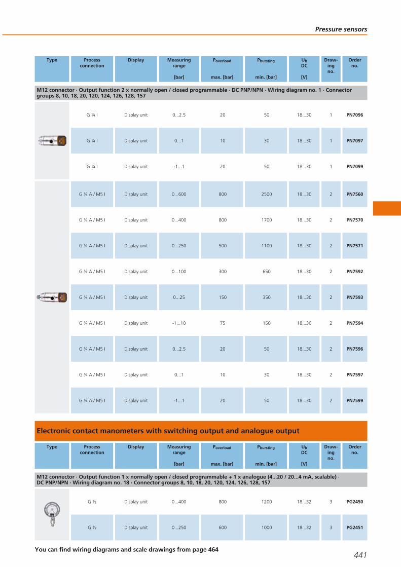
Sensors with switching outputs and display with IO-Link
Type Processconnection
Display Measuringrange
[bar]
Poverload
max. [bar]
Pbursting
min. [bar]
UbDC
[V]
Draw-ingno.
Orderno.
M12 connector · Output function 2 x normally open / closed programmable · DC PNP/NPN · Wiring diagram no. 1 · Connectorgroups 8, 10, 18, 20, 120, 124, 126, 128, 157
G ¼ I Display unit 0...600 800 2500 18...30 1 PN7160
G ¼ I Display unit 0...400 800 1700 18...30 1 PN7070
G ¼ I Display unit 0...250 500 1100 18...30 1 PN7071
G ¼ I Display unit 0...100 300 650 18...30 1 PN7092
G ¼ I Display unit 0...25 150 350 18...30 1 PN7093
G ¼ I Display unit -1...10 75 150 18...30 1 PN7094
Process sensors
440Product selectors and further information can be found at: www.ifm.com
Gesamtkatalog EN 2016_17_Stilvorlage LK FrutigerOT_2010 DE_GB.qxd 06.11.15 16:53 Seite 440
Type Processconnection
Display Measuringrange
[bar]
Poverload
max. [bar]
Pbursting
min. [bar]
UbDC
[V]
Draw-ingno.
Orderno.
M12 connector · Output function 2 x normally open / closed programmable · DC PNP/NPN · Wiring diagram no. 1 · Connectorgroups 8, 10, 18, 20, 120, 124, 126, 128, 157
G ¼ I Display unit 0...2.5 20 50 18...30 1 PN7096
G ¼ I Display unit 0...1 10 30 18...30 1 PN7097
G ¼ I Display unit -1...1 20 50 18...30 1 PN7099
G ¼ A / M5 I Display unit 0...600 800 2500 18...30 2 PN7560
G ¼ A / M5 I Display unit 0...400 800 1700 18...30 2 PN7570
G ¼ A / M5 I Display unit 0...250 500 1100 18...30 2 PN7571
G ¼ A / M5 I Display unit 0...100 300 650 18...30 2 PN7592
G ¼ A / M5 I Display unit 0...25 150 350 18...30 2 PN7593
G ¼ A / M5 I Display unit -1...10 75 150 18...30 2 PN7594
G ¼ A / M5 I Display unit 0...2.5 20 50 18...30 2 PN7596
G ¼ A / M5 I Display unit 0...1 10 30 18...30 2 PN7597
G ¼ A / M5 I Display unit -1...1 20 50 18...30 2 PN7599
Electronic contact manometers with switching output and analogue output
Type Processconnection
Display Measuringrange
[bar]
Poverload
max. [bar]
Pbursting
min. [bar]
UbDC
[V]
Draw-ingno.
Orderno.
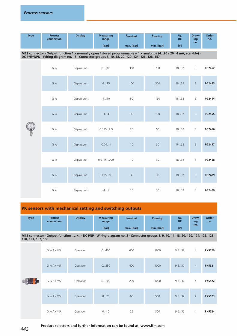
M12 connector · Output function 1 x normally open / closed programmable + 1 x analogue (4...20 / 20...4 mA, scalable) · DC PNP/NPN · Wiring diagram no. 18 · Connector groups 8, 10, 18, 20, 120, 124, 126, 128, 157
G ½ Display unit 0...400 800 1200 18...32 3 PG2450
G ½ Display unit 0...250 600 1000 18...32 3 PG2451
Pressure sensors
441You can find wiring diagrams and scale drawings from page 464
Gesamtkatalog EN 2016_17_Stilvorlage LK FrutigerOT_2010 DE_GB.qxd 06.11.15 16:53 Seite 441
Type Processconnection
Display Measuringrange
[bar]
Poverload
max. [bar]
Pbursting
min. [bar]
UbDC
[V]
Draw-ingno.
Orderno.
M12 connector · Output function 1 x normally open / closed programmable + 1 x analogue (4...20 / 20...4 mA, scalable) · DC PNP/NPN · Wiring diagram no. 18 · Connector groups 8, 10, 18, 20, 120, 124, 126, 128, 157
G ½ Display unit 0...100 300 700 18...32 3 PG2452
G ½ Display unit -1...25 100 300 18...32 3 PG2453
G ½ Display unit -1...10 50 150 18...32 3 PG2454
G ½ Display unit -1...4 30 100 18...32 3 PG2455
G ½ Display unit -0.125...2.5 20 50 18...32 3 PG2456
G ½ Display unit -0.05...1 10 30 18...32 3 PG2457
G ½ Display unit -0.0125...0.25 10 30 18...32 3 PG2458
G ½ Display unit -0.005...0.1 4 30 18...32 3 PG2489
G ½ Display unit -1...1 10 30 18...32 3 PG2409
PK sensors with mechanical setting and switching outputs
Type Processconnection
Display Measuringrange
[bar]
Poverload
max. [bar]
Pbursting
min. [bar]
UbDC
[V]
Draw-ingno.
Orderno.
M12 connector · Output function · DC PNP · Wiring diagram no. 2 · Connector groups 8, 9, 10, 11, 18, 20, 120, 124, 126, 128,130, 131, 157, 158
G ¼ A / M5 I Operation 0...400 600 1600 9.6...32 4 PK5520
G ¼ A / M5 I Operation 0...250 400 1000 9.6...32 4 PK5521
G ¼ A / M5 I Operation 0...100 200 1000 9.6...32 4 PK5522
G ¼ A / M5 I Operation 0...25 60 500 9.6...32 4 PK5523
G ¼ A / M5 I Operation 0...10 25 300 9.6...32 4 PK5524
Process sensors
442Product selectors and further information can be found at: www.ifm.com
Gesamtkatalog EN 2016_17_Stilvorlage LK FrutigerOT_2010 DE_GB.qxd 06.11.15 16:53 Seite 442

Type Processconnection
Display Measuringrange
[bar]
Poverload
max. [bar]
Pbursting
min. [bar]
UbDC
[V]
Draw-ingno.
Orderno.
M12 connector · Output function · DC PNP · Wiring diagram no. 3 · Connector groups 8, 9, 10, 11, 18, 20, 120, 124,126, 128, 130, 131, 157, 158
G ¼ A / M5 I Operation 0...400 600 1600 9.6...32 4 PK6520
G ¼ A / M5 I Operation 0...250 400 1000 9.6...32 4 PK6521
G ¼ A / M5 I Operation 0...100 200 1000 9.6...32 4 PK6522
G ¼ A / M5 I Operation 0...25 60 500 9.6...32 4 PK6523
G ¼ A / M5 I Operation 0...10 25 300 9.6...32 4 PK6524
M12 connector · Output function · DC PNP · Wiring diagram no. 4 · Connector groups 8, 9, 10, 11, 18, 20, 120, 124,126, 128, 130, 131, 157, 158
G ¼ A / M5 I Switching status 0...400 600 1600 9.6...32 4 PK7520
G ¼ A / M5 I Switching status 0...250 400 1000 9.6...32 4 PK7521
G ¼ A / M5 I Switching status 0...100 200 1000 9.6...32 4 PK7522
G ¼ A / M5 I Switching status 0...25 60 500 9.6...32 4 PK7523
G ¼ A / M5 I Switching status 0...10 25 300 9.6...32 4 PK7524
M12 connector · Output function · DC PNP · Wiring diagram no. 3 · Connector groups 8, 9, 10, 11, 18, 20, 120, 124,126, 128, 130, 131, 157, 158
R¼ A / M5 I Operation 0...100 200 1000 9.6...32 5 PK6732
R¼ A / M5 I Operation 0...10 25 300 9.6...32 5 PK6734
M12 connector · Output function · DC NPN · Wiring diagram no. 5 · Connector groups 8, 10, 18, 20, 120, 124, 126, 128,157
R¼ A / M5 I Operation 0...400 600 1600 9.6...32 5 PK8730
R¼ A / M5 I Operation 0...250 400 1000 9.6...32 5 PK8731
R¼ A / M5 I Operation 0...100 200 1000 9.6...32 5 PK8732
Pressure sensors
443You can find wiring diagrams and scale drawings from page 464
Gesamtkatalog EN 2016_17_Stilvorlage LK FrutigerOT_2010 DE_GB.qxd 06.11.15 16:53 Seite 443

Type Processconnection
Display Measuringrange
[bar]
Poverload
max. [bar]
Pbursting
min. [bar]
UbDC
[V]
Draw-ingno.
Orderno.
M12 connector · Output function · DC NPN · Wiring diagram no. 5 · Connector groups 8, 10, 18, 20, 120, 124, 126, 128,157
R¼ A / M5 I Operation 0...10 25 300 9.6...32 5 PK8734
PP sensors for mobile and industrial applications with switching outputs, IO-Link
Type Processconnection
Display Measuringrange
[bar]
Poverload
max. [bar]
Pbursting
min. [bar]
UbDC
[V]
Draw-ingno.
Orderno.
M12 connector · Output function 2 x normally open / closed programmable or 1 x normally open / closed programmable + 1 x normallyclosed (diagnostic function) · DC PNP · Wiring diagram no. 6 · Connector groups 8, 9, 10, 11, 18, 20, 120, 124, 126, 128, 130, 131, 157, 158
G ¼ A / M5 I Operation 0...400 600 1000 9.6...36 6 PP7550
G ¼ A / M5 I Operation 0...250 400 850 9.6...36 6 PP7551
G ¼ A / M5 I Operation 0...100 300 650 9.6...36 7 PP7552
G ¼ A / M5 I Operation 0...25 150 350 9.6...36 8 PP7553
G ¼ A / M5 I Operation -1...10 75 150 9.6...36 8 PP7554
G ¼ A / M5 I Operation 0...2.5 20 50 9.6...36 8 PP7556
M12 connector · Output function 2 x normally open / closed programmable or 1 x normally open / closed programmable + 1 x normallyclosed (diagnostic function) · DC NPN · Wiring diagram no. 6 · Connector groups 8, 9, 10, 11, 18, 20, 120, 124, 126, 128, 130, 131, 157, 158
G ¼ A / M5 I Operation 0...400 600 1000 9.6...36 6 PP0520
G ¼ A / M5 I Operation 0...250 400 850 9.6...36 6 PP0521
G ¼ A / M5 I Operation 0...100 300 650 9.6...36 7 PP0522
G ¼ A / M5 I Operation 0...25 150 350 9.6...36 8 PP0523
G ¼ A / M5 I Operation -1...10 75 150 9.6...36 8 PP0524
Process sensors
444Product selectors and further information can be found at: www.ifm.com
Gesamtkatalog EN 2016_17_Stilvorlage LK FrutigerOT_2010 DE_GB.qxd 06.11.15 16:53 Seite 444
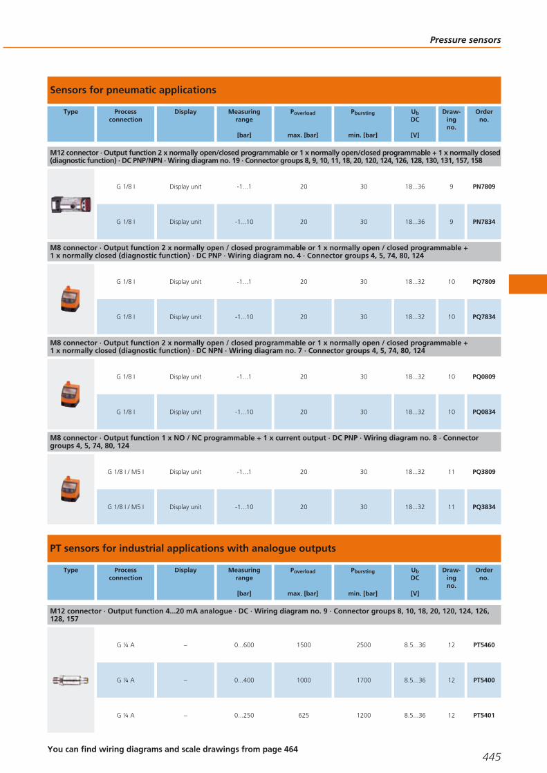
Sensors for pneumatic applications
Type Processconnection
Display Measuringrange
[bar]
Poverload
max. [bar]
Pbursting
min. [bar]
UbDC
[V]
Draw-ingno.
Orderno.
M12 connector · Output function 2 x normally open/closed programmable or 1 x normally open/closed programmable + 1 x normally closed(diagnostic function) · DC PNP/NPN · Wiring diagram no. 19 · Connector groups 8, 9, 10, 11, 18, 20, 120, 124, 126, 128, 130, 131, 157, 158
G 1/8 I Display unit -1...1 20 30 18...36 9 PN7809
G 1/8 I Display unit -1...10 20 30 18...36 9 PN7834
M8 connector · Output function 2 x normally open / closed programmable or 1 x normally open / closed programmable + 1 x normally closed (diagnostic function) · DC PNP · Wiring diagram no. 4 · Connector groups 4, 5, 74, 80, 124
G 1/8 I Display unit -1...1 20 30 18...32 10 PQ7809
G 1/8 I Display unit -1...10 20 30 18...32 10 PQ7834
M8 connector · Output function 2 x normally open / closed programmable or 1 x normally open / closed programmable + 1 x normally closed (diagnostic function) · DC NPN · Wiring diagram no. 7 · Connector groups 4, 5, 74, 80, 124
G 1/8 I Display unit -1...1 20 30 18...32 10 PQ0809
G 1/8 I Display unit -1...10 20 30 18...32 10 PQ0834
M8 connector · Output function 1 x NO / NC programmable + 1 x current output · DC PNP · Wiring diagram no. 8 · Connectorgroups 4, 5, 74, 80, 124
G 1/8 I / M5 I Display unit -1...1 20 30 18...32 11 PQ3809
G 1/8 I / M5 I Display unit -1...10 20 30 18...32 11 PQ3834
PT sensors for industrial applications with analogue outputs
Type Processconnection
Display Measuringrange
[bar]
Poverload
max. [bar]
Pbursting
min. [bar]
UbDC
[V]
Draw-ingno.
Orderno.
M12 connector · Output function 4...20 mA analogue · DC · Wiring diagram no. 9 · Connector groups 8, 10, 18, 20, 120, 124, 126,128, 157
G ¼ A – 0...600 1500 2500 8.5...36 12 PT5460
G ¼ A – 0...400 1000 1700 8.5...36 12 PT5400
G ¼ A – 0...250 625 1200 8.5...36 12 PT5401
Pressure sensors
445You can find wiring diagrams and scale drawings from page 464
Gesamtkatalog EN 2016_17_Stilvorlage LK FrutigerOT_2010 DE_GB.qxd 06.11.15 16:53 Seite 445

Type Processconnection
Display Measuringrange
[bar]
Poverload
max. [bar]
Pbursting
min. [bar]
UbDC
[V]
Draw-ingno.
Orderno.
M12 connector · Output function 4...20 mA analogue · DC · Wiring diagram no. 9 · Connector groups 8, 10, 18, 20, 120, 124, 126,128, 157
G ¼ A – 0...160 400 1100 8.5...36 12 PT5412
G ¼ A – 0...100 250 1000 8.5...36 12 PT5402
G ¼ A – 0...60 150 900 8.5...36 12 PT5423
G ¼ A – 0...40 100 800 8.5...36 12 PT5443
G ¼ A – 0...25 65 600 8.5...36 12 PT5403
G ¼ A – 0...16 40 450 8.5...36 12 PT5414
G ¼ A – 0...10 25 300 8.5...36 12 PT5404
G ¼ A – 0...6 15 200 8.5...36 12 PT5415
M12 connector · Output function 0...10 V analogue · DC · Wiring diagram no. 10 · Connector groups 8, 10, 18, 20, 120, 124, 126,128, 157
G ¼ A – 0...600 1500 2500 16...36 12 PU5460
G ¼ A – 0...400 1000 1700 16...36 12 PU5400
G ¼ A – 0...250 625 1200 16...36 12 PU5401
G ¼ A – 0...160 400 1100 16...36 12 PU5412
G ¼ A – 0...100 250 1000 16...36 12 PU5402
G ¼ A – 0...40 100 800 16...36 12 PU5443
G ¼ A – 0...60 150 900 16...36 12 PU5423
G ¼ A – 0...25 65 600 16...36 12 PU5403
Process sensors
446Product selectors and further information can be found at: www.ifm.com
Gesamtkatalog EN 2016_17_Stilvorlage LK FrutigerOT_2010 DE_GB.qxd 06.11.15 16:53 Seite 446

Type Processconnection
Display Measuringrange
[bar]
Poverload
max. [bar]
Pbursting
min. [bar]
UbDC
[V]
Draw-ingno.
Orderno.
M12 connector · Output function 0...10 V analogue · DC · Wiring diagram no. 10 · Connector groups 8, 10, 18, 20, 120, 124, 126,128, 157
G ¼ A – 0...16 40 450 16...36 12 PU5414
G ¼ A – 0...10 25 300 16...36 12 PU5404
G ¼ A – 0...6 15 200 16...36 12 PU5415
PT / PU sensors for mobile applications with analogue outputs
Type Processconnection
Display Measuringrange
[bar]
Poverload
max. [bar]
Pbursting
min. [bar]
UbDC
[V]
Draw-ingno.
Orderno.
M12 connector · Output function 4...20 mA analogue · DC · Wiring diagram no. 11 · Connector group 157
G ¼ A – 0...400 600 1600 8.5...36 13 PT3550
G ¼ A – 0...250 400 1000 8.5...36 13 PT3551
G ¼ A – 0...100 200 1000 8.5...36 13 PT3552
G ¼ A – 0...25 60 600 8.5...36 13 PT3553
G ¼ A – 0...10 25 300 8.5...36 13 PT3554
M12 connector · Output function 0...10 V analogue · DC · Wiring diagram no. 12 · Connector group 157
G ¼ A – 0...400 600 1600 16...36 13 PT9550
G ¼ A – 0...250 400 1000 16...36 13 PT9551
G ¼ A – 0...100 200 1000 16...36 13 PT9552
G ¼ A – 0...25 60 600 16...36 13 PT9553
G ¼ A – 0...10 25 300 16...36 13 PT9554
Pressure sensors
447You can find wiring diagrams and scale drawings from page 464
Gesamtkatalog EN 2016_17_Stilvorlage LK FrutigerOT_2010 DE_GB.qxd 06.11.15 16:53 Seite 447
Type Processconnection
Display Measuringrange
[bar]
Poverload
max. [bar]
Pbursting
min. [bar]
UbDC
[V]
Draw-ingno.
Orderno.
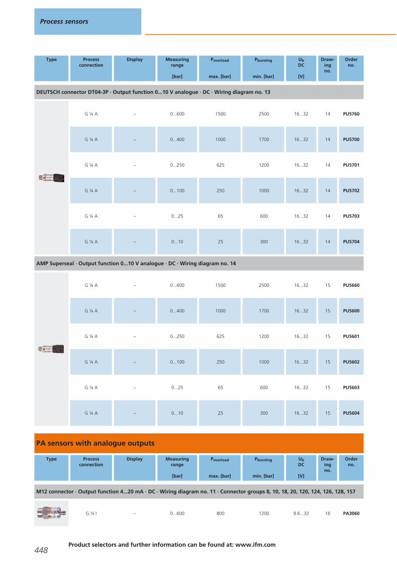
DEUTSCH connector DT04-3P · Output function 0...10 V analogue · DC · Wiring diagram no. 13
G ¼ A – 0...600 1500 2500 16...32 14 PU5760
G ¼ A – 0...400 1000 1700 16...32 14 PU5700
G ¼ A – 0...250 625 1200 16...32 14 PU5701
G ¼ A – 0...100 250 1000 16...32 14 PU5702
G ¼ A – 0...25 65 600 16...32 14 PU5703
G ¼ A – 0...10 25 300 16...32 14 PU5704
AMP Superseal · Output function 0...10 V analogue · DC · Wiring diagram no. 14
G ¼ A – 0...600 1500 2500 16...32 15 PU5660
G ¼ A – 0...400 1000 1700 16...32 15 PU5600
G ¼ A – 0...250 625 1200 16...32 15 PU5601
G ¼ A – 0...100 250 1000 16...32 15 PU5602
G ¼ A – 0...25 65 600 16...32 15 PU5603
G ¼ A – 0...10 25 300 16...32 15 PU5604
PA sensors with analogue outputs
Type Processconnection
Display Measuringrange
[bar]
Poverload
max. [bar]
Pbursting
min. [bar]
UbDC
[V]
Draw-ingno.
Orderno.
M12 connector · Output function 4...20 mA · DC · Wiring diagram no. 11 · Connector groups 8, 10, 18, 20, 120, 124, 126, 128, 157
G ¼ I – 0...600 800 1200 9.6...32 16 PA3060
Process sensors
448Product selectors and further information can be found at: www.ifm.com
Gesamtkatalog EN 2016_17_Stilvorlage LK FrutigerOT_2010 DE_GB.qxd 06.11.15 16:53 Seite 448

Type Processconnection
Display Measuringrange
[bar]
Poverload
max. [bar]
Pbursting
min. [bar]
UbDC
[V]
Draw-ingno.
Orderno.
M12 connector · Output function 4...20 mA · DC · Wiring diagram no. 11 · Connector groups 8, 10, 18, 20, 120, 124, 126, 128, 157
G ¼ I – 0...400 600 1000 9.6...32 17 PA3020
G ¼ I – 0...250 400 850 9.6...32 17 PA3021
G ¼ I – 0...100 300 650 9.6...32 18 PA3022
G ¼ I – 0...25 150 350 9.6...32 18 PA3023
G ¼ I – 0...10 75 150 9.6...32 18 PA3024
G ¼ I – 0...2.5 20 50 9.6...32 18 PA3026
G ¼ I – 0...1 10 30 9.6...32 18 PA3027
G ¼ I – 0...0.25 10 30 9.6...32 18 PA3028
G ¼ I – -1...0 10 30 9.6...32 18 PA3029
G ¼ A / M5 I – 0...250 400 850 9.6...32 19 PA3521
G ¼ A / M5 I – 0...100 300 650 9.6...32 19 PA3522
G ¼ A / M5 I – 0...25 150 350 9.6...32 19 PA3523
G ¼ A / M5 I – 0...10 75 150 9.6...32 19 PA3524
G ¼ A / M5 I – 0...2.5 20 50 9.6...32 19 PA3526
G ¼ A / M5 I – 0...0.25 10 30 9.6...32 19 PA3528
M12 connector · Output function 4...20 mA · DC · Wiring diagram no. 9 · Connector groups 8, 10, 18, 20, 120, 124, 126, 128, 157
G ¼ A / M5 I – 0...0.1 4 30 9.6...32 19 PA3589
Pressure sensors
449You can find wiring diagrams and scale drawings from page 464
Gesamtkatalog EN 2016_17_Stilvorlage LK FrutigerOT_2010 DE_GB.qxd 06.11.15 16:54 Seite 449
Type Processconnection
Display Measuringrange
[bar]
Poverload
max. [bar]
Pbursting
min. [bar]
UbDC
[V]
Draw-ingno.
Orderno.
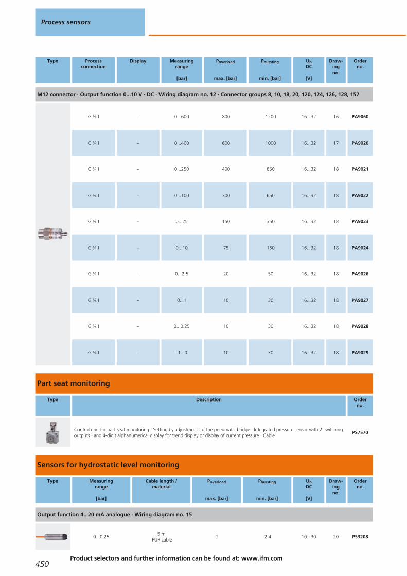
M12 connector · Output function 0...10 V · DC · Wiring diagram no. 12 · Connector groups 8, 10, 18, 20, 120, 124, 126, 128, 157
G ¼ I – 0...600 800 1200 16...32 16 PA9060
G ¼ I – 0...400 600 1000 16...32 17 PA9020
G ¼ I – 0...250 400 850 16...32 18 PA9021
G ¼ I – 0...100 300 650 16...32 18 PA9022
G ¼ I – 0...25 150 350 16...32 18 PA9023
G ¼ I – 0...10 75 150 16...32 18 PA9024
G ¼ I – 0...2.5 20 50 16...32 18 PA9026
G ¼ I – 0...1 10 30 16...32 18 PA9027
G ¼ I – 0...0.25 10 30 16...32 18 PA9028
G ¼ I – -1...0 10 30 16...32 18 PA9029
Part seat monitoring
Type Description Orderno.
Control unit for part seat monitoring · Setting by adjustment of the pneumatic bridge · Integrated pressure sensor with 2 switchingoutputs · and 4-digit alphanumerical display for trend display or display of current pressure · Cable
PS7570
Sensors for hydrostatic level monitoring
Type Measuringrange
[bar]
Cable length /material
Poverload
max. [bar]
Pbursting
min. [bar]
UbDC
[V]
Draw-ingno.
Orderno.
Output function 4...20 mA analogue · Wiring diagram no. 15
0...0.255 m
PUR cable2 2.4 10...30 20 PS3208
Process sensors
450Product selectors and further information can be found at: www.ifm.com
Gesamtkatalog EN 2016_17_Stilvorlage LK FrutigerOT_2010 DE_GB.qxd 06.11.15 16:54 Seite 450

Type Measuringrange
[bar]
Cable length /material
Poverload
max. [bar]
Pbursting
min. [bar]
UbDC
[V]
Draw-ingno.
Orderno.
Output function 4...20 mA analogue · Wiring diagram no. 15
0...0.610 m
PUR cable4 4.8 10...30 20 PS3407
0...0.615 m
PUR cable4 4.8 10...30 20 PS3427
0...0.630 m
PUR cable4 4.8 10...30 20 PS3607
0...115 m
PUR cable5 6 10...30 20 PS3417
0...130 m
PUR cable5 6 10...30 20 PS3617
Output function 4...20 mA analogue · Wiring diagram no. 16
0...0.255 m
FEP cable2 2.4 10...30 21 PS4208
0...0.610 m
FEP cable3 4 10...30 21 PS4407
· Wiring diagram no. 16
0...115 m
FEP cable5 6 10...30 21 PS4417
Sensors for hydrostatic level monitoring ATEX category 1G/1D
Type Measuringrange
[bar]
Cable length /material
Poverload
max. [bar]
Pbursting
min. [bar]
UbDC
[V]
Draw-ingno.
Orderno.
Output function 4...20 mA analogue · Wiring diagram no. 16
0...0.255 m
FEP cable2 2.4 10...30 21 PS308A
0...0.610 m
FEP cable4 4.8 10...30 21 PS307A
0...115 m
FEP cable5 6 10...30 21 PS317A
Pressure sensors
451You can find wiring diagrams and scale drawings from page 464
Gesamtkatalog EN 2016_17_Stilvorlage LK FrutigerOT_2010 DE_GB.qxd 06.11.15 16:54 Seite 451

Sensors with ATEX approval 3D
Type Processconnection
Display Measuringrange
[bar]
Poverload
max. [bar]
Pbursting
min. [bar]
UbDC
[V]
Draw-ingno.
Orderno.
M12 connector · Output function normally open / closed programmable; 4...20 mA or 0...10 V · DC PNP · Wiring diagram no. 17 ·Connector groups 154, 156
G ¼ I Display unit -1...10 75 150 18...36 22 PN004A
G ¼ I Display unit 0...2.5 20 50 18...36 22 PN006A
G ¼ I Display unit 0...1 10 30 18...36 22 PN007A
M12 connector · Output function 2 x normally open / closed programmable or 1 x normally open / closed programmable + 1 x normally closed (diagnostic function) · DC PNP/NPN · Wiring diagram no. 19 · Connector groups 154, 156
G ¼ I Display unit -1...10 75 150 18...36 22 PN014A
G ¼ I Display unit 0...2.5 20 50 18...36 22 PN016A
Sensors with ATEX approval 3D/3G
Type Processconnection
Display Measuringrange
[bar]
Poverload
max. [bar]
Pbursting
min. [bar]
UbDC
[V]
Draw-ingno.
Orderno.
M12 connector · Output function 1 x normally open / closed programmable + 1 x analogue (I / U, scaleable 1:4) · DC PNP/NPN ·Wiring diagram no. 18 · Connector groups 154, 156
Sealing cone G1male
Display unit -1...25 100 350 18...32 23 PI003A
Sealing cone G1male
Display unit -0.0124...0.25 10 30 18...32 23 PI008A
Sealing cone G1male
Display unit -1...1 10 30 18...32 23 PI009A
Full metal sensors for hygienic and wet areas with switching and analogue outputs, IO-Link
Type Processconnection
Display Measuringrange
[bar]
Poverload
max. [bar]
Pbursting
min. [bar]
UbDC
[V]
Draw-ingno.
Orderno.
M12 connector · Output function 1 x normally open / normally closed programmable + 1 x normally open / normally closed programm-able or 1 x analogue (4...20 / 20...4 mA, scalable) · Wiring diagram no. 20 · Connector groups 8, 10, 18, 20, 120, 124, 126, 128, 157
Aseptoflex Vario Display unit -1...25 100 350 20...32 24 PI2793
Process sensors
452Product selectors and further information can be found at: www.ifm.com
Gesamtkatalog EN 2016_17_Stilvorlage LK FrutigerOT_2010 DE_GB.qxd 06.11.15 16:54 Seite 452

Type Processconnection
Display Measuringrange
[bar]
Poverload
max. [bar]
Pbursting
min. [bar]
UbDC
[V]
Draw-ingno.
Orderno.
M12 connector · Output function 1 x normally open / normally closed programmable + 1 x normally open / normally closed programm-able or 1 x analogue (4...20 / 20...4 mA, scalable) · Wiring diagram no. 20 · Connector groups 8, 10, 18, 20, 120, 124, 126, 128, 157
Aseptoflex Vario Display unit -1...10 50 150 20...32 24 PI2794
Aseptoflex Vario Display unit -1...4 30 100 20...32 24 PI2795
Aseptoflex Vario Display unit -0.124...2.5 20 50 20...32 24 PI2796
Aseptoflex Vario Display unit -0.05...1 10 30 20...32 24 PI2797
Aseptoflex Vario Display unit -0.0124...0.25 10 30 20...32 24 PI2798
Aseptoflex Vario Display unit -0.005...0.1 4 30 20...32 24 PI2789
Aseptoflex Vario Display unit -1...1 10 30 20...32 24 PI2799
Sealing cone G1male
Display unit -1...25 100 350 20...32 25 PI2893*
Sealing cone G1male
Display unit -1...10 50 150 20...32 25 PI2894*
Sealing cone G1male
Display unit -1...4 30 100 20...32 25 PI2895*
Sealing cone G1male
Display unit -0.124...2.5 20 50 20...32 25 PI2896*
Sealing cone G1male
Display unit -0.05...1 10 30 20...32 25 PI2897*
Sealing cone G1male
Display unit -0.0124...0.25 10 30 20...32 25 PI2898*
Sealing cone G1male
Display unit -0.005...0.1 4 30 20...32 25 PI2889*
Sealing cone G1male
Display unit -1...1 10 30 20...32 25 PI2899*
* Attention: The unit must only be installed in a process connection for G1 sealing cone! The G1 male sealing cone of the unit is only suited for adapters with metal end stop!
Pressure sensors
453You can find wiring diagrams and scale drawings from page 464
Gesamtkatalog EN 2016_17_Stilvorlage LK FrutigerOT_2010 DE_GB.qxd 06.11.15 16:54 Seite 453

Full-metal high-temperature sensors up to 200 °C for hygienic and wet areas with switchingoutput and analogue output, IO-Link
Type Processconnection
Display Measuringrange
[bar]
Poverload
max. [bar]
Pbursting
min. [bar]
UbDC
[V]
Draw-ingno.
Orderno.
M12 connector · Output function 1 x normally open / normally closed programmable + 1 x normally open / normally closed programm-able or 1 x analogue (4...20 / 20...4 mA, scalable) · Wiring diagram no. 20 · Connector groups 8, 10, 18, 20, 120, 124, 126, 128, 157
Clamp DN 38 / 1½" Display unit -1...25 80 150 20...32 26 PI2203
Clamp DN 38 / 1½" Display unit -1...10 50 100 20...32 26 PI2204
Clamp DN 38 / 1½" Display unit -1...4 30 50 20...32 26 PI2205
Clamp DN 38 / 1½" Display unit -0.124...2.5 20 50 20...32 26 PI2206
Clamp DN 38 / 1½" Display unit -0.05...1 10 30 20...32 26 PI2207
Clamp DN 38 / 1½" Display unit -1...1 10 30 20...32 26 PI2209
Clamp DN 51 / 2" Display unit -1...25 80 150 20...32 27 PI2303
Clamp DN 51 / 2" Display unit -1...10 50 100 20...32 27 PI2304
Clamp DN 51 / 2" Display unit -1...4 30 50 20...32 27 PI2305
Clamp DN 51 / 2" Display unit -0.124...2.5 20 50 20...32 27 PI2306
Clamp DN 51 / 2" Display unit -0.05...1 10 30 20...32 27 PI2307
Clamp DN 51 / 2" Display unit -1...1 10 30 20...32 27 PI2309
Electronic contact manometers for hygienic and wet areas with switching and analogue outputs
Type Processconnection
Display Measuringrange
[bar]
Poverload
max. [bar]
Pbursting
min. [bar]
UbDC
[V]
Draw-ingno.
Orderno.
M12 connector · Output function 1 x normally open / closed programmable + 1 x analogue (4...20 / 20...4 mA, scalable) · DC PNP/NPN · Wiring diagram no. 18 · Connector groups 8, 10, 18, 20, 120, 124, 126, 128, 157
Aseptoflex Vario Display unit -1...25 100 350 18...32 28 PG2793
Process sensors
454Product selectors and further information can be found at: www.ifm.com
Gesamtkatalog EN 2016_17_Stilvorlage LK FrutigerOT_2010 DE_GB.qxd 06.11.15 16:54 Seite 454

Type Processconnection
Display Measuringrange
[bar]
Poverload
max. [bar]
Pbursting
min. [bar]
UbDC
[V]
Draw-ingno.
Orderno.
M12 connector · Output function 1 x normally open / closed programmable + 1 x analogue (4...20 / 20...4 mA, scalable) · DC PNP/NPN · Wiring diagram no. 18 · Connector groups 8, 10, 18, 20, 120, 124, 126, 128, 157
Aseptoflex Vario Display unit -1...10 50 150 18...32 28 PG2794
Aseptoflex Vario Display unit -1...4 30 100 18...32 28 PG2795
Aseptoflex Vario Display unit -1...1 10 30 18...32 28 PG2799
Aseptoflex Vario Display unit -0.124...2.5 20 50 18...32 28 PG2796
Aseptoflex Vario Display unit -0.05...1 10 30 18...32 28 PG2797
Aseptoflex Vario Display unit -0.0124...0.25 10 30 18...32 28 PG2798
Aseptoflex Vario Display unit -0.005...0.1 4 30 18...32 28 PG2789
Sealing cone G1male
Display unit -1...25 100 350 18...32 29 PG2893*
Sealing cone G1male
Display unit -1...10 50 150 18...32 29 PG2894*
Sealing cone G1male
Display unit -1...4 30 100 18...32 29 PG2895*
Sealing cone G1male
Display unit -0.124...2.5 20 50 18...32 29 PG2896*
Sealing cone G1male
Display unit -0.05...1 10 30 18...32 29 PG2897*
Sealing cone G1male
Display unit -0.0124...0.25 10 30 18...32 29 PG2898*
Sealing cone G1male
Display unit -1...1 10 30 18...32 29 PG2899*
Sealing cone G1male
Display unit -0.005...0.1 4 30 18...32 29 PG2889*
* Attention: The unit must only be installed in a process connection for G1 sealing cone! The G1 male sealing cone of the unit is only suited for adapters with metal end stop!
Pressure sensors
455You can find wiring diagrams and scale drawings from page 464
Gesamtkatalog EN 2016_17_Stilvorlage LK FrutigerOT_2010 DE_GB.qxd 06.11.15 16:54 Seite 455
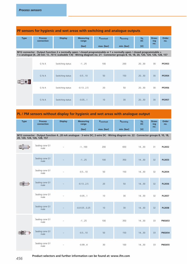
PF sensors for hygienic and wet areas with switching and analogue outputs
Type Processconnection
Display Measuringrange
[bar]
Poverload
max. [bar]
Pbursting
min. [bar]
UbDC
[V]
Draw-ingno.
Orderno.
M12 connector · Output function 2 x normally open / closed programmable or 1 x normally open / closed programmable + 1 x analogue (4...20 mA / 0...10 V; scaleable 1:4) · Wiring diagram no. 21 · Connector groups 8, 10, 18, 20, 120, 124, 126, 128, 157
G ¾ A Switching status -1...25 100 200 20...30 30 PF2953
G ¾ A Switching status -0.5...10 50 150 20...30 30 PF2954
G ¾ A Switching status -0.13...2.5 20 50 20...30 30 PF2956
G ¾ A Switching status -0.05...1 10 30 20...30 30 PF2957
PL / PM sensors without display for hygienic and wet areas with analogue output
Type Processconnection
Display Measuringrange
[bar]
Poverload
max. [bar]
Pbursting
min. [bar]
UbDC
[V]
Draw-ingno.
Orderno.
M12 connector · Output function 4...20 mA analogue · 3-wire DC; 2-wire DC · Wiring diagram no. 22 · Connector groups 8, 10, 18,20, 120, 124, 126, 128, 157
Sealing cone G1male
– -1...100 200 650 14...30 31 PL2652
Sealing cone G1male
– -1...25 100 350 14...30 32 PL2653
Sealing cone G1male
– -0.5...10 50 150 14...30 32 PL2654
Sealing cone G1male
– -0.13...2.5 20 50 14...30 32 PL2656
Sealing cone G1male
– -0.05...1 10 30 14...30 32 PL2657
Sealing cone G1male
– -0.0125...0.25 10 30 14...30 32 PL2658
Sealing cone G1male
– -1...25 100 350 14...30 33 PM2653
Sealing cone G1male
– -0.5...10 50 150 14...30 33 PM2654
Sealing cone G1male
– -0.99...4 30 100 14...30 33 PM2655
Process sensors
456Product selectors and further information can be found at: www.ifm.com
Gesamtkatalog EN 2016_17_Stilvorlage LK FrutigerOT_2010 DE_GB.qxd 06.11.15 16:54 Seite 456

Type Processconnection
Display Measuringrange
[bar]
Poverload
max. [bar]
Pbursting
min. [bar]
UbDC
[V]
Draw-ingno.
Orderno.
M12 connector · Output function 4...20 mA analogue · 3-wire DC; 2-wire DC · Wiring diagram no. 22 · Connector groups 8, 10, 18,20, 120, 124, 126, 128, 157
Sealing cone G1male
– -0.13...2.5 20 50 14...30 33 PM2656
Sealing cone G1male
– -0.05...1 10 30 14...30 33 PM2657
Sealing cone G1male
– -0.0125...0.25 10 30 14...30 33 PM2658
PE sensors with display with 2 switching outputs or switching and analogue output
Type Processconnection
Display Measuringrange
[bar]
Poverload
max. [bar]
Pbursting
min. [bar]
UbDC
[V]
Draw-ingno.
Orderno.
M12 connector · Output function 2 x normally open / closed programmable or 1 x normally open / closed programmable + 1 x normally closed (diagnostic function) · DC PNP/NPN · Wiring diagram no. 19 · Connector groups 8, 10, 18, 20, 120, 124, 126, 128, 157
G ¼ I Display unit 0...100 300 650 18...36 34 PE7002
G ¼ I Display unit 0...25 150 350 18...36 34 PE7003
G ¼ I Display unit -1...10 75 150 18...36 34 PE7004
G ¼ I Display unit 0...2.5 20 50 18...36 34 PE7006
G ¼ I Display unit -1...1 20 50 18...36 34 PE7009
M12 connector · Output function normally open / closed programmable; 4...20 mA or 0...10 V · DC PNP · Wiring diagram no. 17 ·Connector groups 8, 10, 18, 20, 120, 124, 126, 128, 157
G ¼ I Display unit 0...400 600 1000 18...36 35 PE3000
G ¼ I Display unit 0...250 400 850 18...36 34 PE3001
G ¼ I Display unit 0...100 300 650 18...36 34 PE3002
G ¼ I Display unit 0...25 150 350 18...36 34 PE3003
G ¼ I Display unit -1...10 75 150 18...36 34 PE3004
Pressure sensors
457You can find wiring diagrams and scale drawings from page 464
Gesamtkatalog EN 2016_17_Stilvorlage LK FrutigerOT_2010 DE_GB.qxd 06.11.15 16:54 Seite 457
Type Processconnection
Display Measuringrange
[bar]
Poverload
max. [bar]
Pbursting
min. [bar]
UbDC
[V]
Draw-ingno.
Orderno.
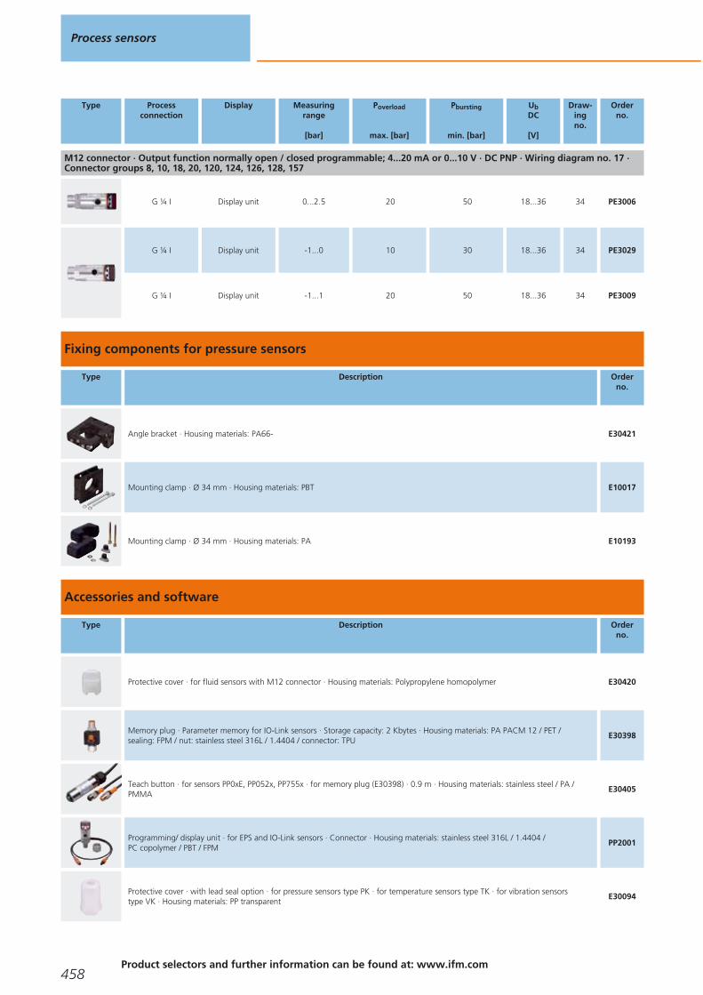
M12 connector · Output function normally open / closed programmable; 4...20 mA or 0...10 V · DC PNP · Wiring diagram no. 17 ·Connector groups 8, 10, 18, 20, 120, 124, 126, 128, 157
G ¼ I Display unit 0...2.5 20 50 18...36 34 PE3006
G ¼ I Display unit -1...0 10 30 18...36 34 PE3029
G ¼ I Display unit -1...1 20 50 18...36 34 PE3009
Fixing components for pressure sensors
Type Description Orderno.
Angle bracket · Housing materials: PA66- E30421
Mounting clamp · Ø 34 mm · Housing materials: PBT E10017
Mounting clamp · Ø 34 mm · Housing materials: PA E10193
Accessories and software
Type Description Orderno.
Protective cover · for fluid sensors with M12 connector · Housing materials: Polypropylene homopolymer E30420
Memory plug · Parameter memory for IO-Link sensors · Storage capacity: 2 Kbytes · Housing materials: PA PACM 12 / PET / sealing: FPM / nut: stainless steel 316L / 1.4404 / connector: TPU
E30398
Teach button · for sensors PP0xE, PP052x, PP755x · for memory plug (E30398) · 0.9 m · Housing materials: stainless steel / PA /PMMA
E30405
Programming/ display unit · for EPS and IO-Link sensors · Connector · Housing materials: stainless steel 316L / 1.4404 / PC copolymer / PBT / FPM
PP2001
Protective cover · with lead seal option · for pressure sensors type PK · for temperature sensors type TK · for vibration sensors type VK · Housing materials: PP transparent
E30094
Process sensors
458Product selectors and further information can be found at: www.ifm.com
Gesamtkatalog EN 2016_17_Stilvorlage LK FrutigerOT_2010 DE_GB.qxd 06.11.15 16:54 Seite 458

Type Description Orderno.
IO-Link interface · for parameter setting and analysis of units with max. 65 mA current consumption · Supported communicationprotocols: IO-Link (4800 and 38400 bits/s) EPS protocol (19200 bits/s) · for operation with FDT framework software "ifm Container“or software "LINERECORDER SENSOR"
E30396
USB IO-Link master · for parameter setting and analysis of units · Supported communication protocols: IO-Link (4.8, 38.4 and 230 Kbits/s) · for operation with FDT framework software "ifm Container“ or software "LINERECORDER SENSOR"
E30390
LINERECORDER SENSOR · Version 4.0.0 · Software for clear online and offline parameter setting of IO-Link sensors via USB adapter ·Use via USB connection cable (drivers are supplied): E30396 IO-Link interface or E30390 IO-Link master (note the respective datasheet) · IODD import and update from ifm's homepage · Reading of IODDs via storage media · Automatic sensor identification ·Graphic representation of the process values and history incl. export function · Documentation and archiving · Transferableparameter sets · Full memory plug support for IO-Link 1.1
QA0001
Syphon · G ¼ · Housing materials: steel E30140
Syphon · G ½ · Housing materials: steel E30141
Cable clamp fastener · for submersible pressure transmitter PS3 · Housing materials: steel / plastics E30399
Filter element · for submersible pressure transmitter PS3 · for fixing on the capillary tube E30400
Splitter box · with ventilation and terminal block · for submersible pressure transmitter PS3 · Housing materials: plastics E30401
Additional weight · for submersible pressure transmitter PS3 · Housing materials: stainless steel 316Ti / 1.4571 E30402
DIN rail clip · Housing materials: stainless steel E37340
Connector · QS-G 1/8-6 · with hexagonal socket 4 mm a/f · for tube with Ø 6 mm · Housing materials: steel / PBT / Brass / aluminium E30076
Connector · QS-G 1/8-8 · with hexagonal socket 5 mm a/f · for tube with Ø 8 mm · Housing materials: steel / PBT / Brass / aluminium E30077
Certificates
Description Orderno.
Factory calibration certificate for pressure sensors and flow sensors · Measurement points, pressure sensors: 6 measurement points in 20% steps of thefinal value of the measuring range (acc. to ISO 9001) · Measurement points, flow sensors: 3 or 4 measurement points, distances defined depending onthe measuring range (acc. to ISO 9001)
ZC0004
Pressure sensors
459You can find wiring diagrams and scale drawings from page 464
Gesamtkatalog EN 2016_17_Stilvorlage LK FrutigerOT_2010 DE_GB.qxd 06.11.15 16:54 Seite 459

Description Orderno.
DAkkS calibration certificate for pressure sensors · Number of measuring points: 11-point DAkkS calibration · Measurement points: in 10 % steps ofthe measuring range (according to directive DAkkS-DKD-R 6-1) · Minimum measurement uncertainty [bar]: 20 μbar...140 mbar (depending on thereference pressure)
ZC0005
Adapters and accessories for adapters
Type Description Orderno.
Adapter · R1/8 - R1/8 · rotatable · Housing materials: Brass nickel-plated E37350
T-pipe mounting set · G1/2 · with reducer G1/2 - G1/8, adapter R1/8 - R1/8 rotatable, seal G1/2 · Housing materials: Brass nickel-plated
E37360
Flange adapter · G ¼ · Hole spacing · 31.1 mm · Housing materials: sealing: NBR, acrylonitrile-butadiene-rubber / flange: aluminium / hollow screw: Brass
E30003
Adapter · G ¼ - G ½ · Housing materials: stainless steel / sealing: FPM E30000
Adapter · G ¼ A - G ¼ A · Housing materials: 1.4404 E30143
Adapter · G ¼ - M20 x 1.5 · Housing materials: stainless steel / FPM E30010
Adapter · G ¼ - G ½ · Housing materials: stainless steel / sealing: FPM E30050
Adapter · ¼" NPT - G ¼ · Housing materials: stainless steel 316Ti / 1.4571 E30058
Adapter · ¼" NPT - G ½ · Housing materials: stainless steel 316Ti / 1.4571 E30059
Adapter · G ¼ - DN16 · G¼ small flange DIN 28403 DN16 · Housing materials: stainless steel E30065
Flange adapter · G ¼ · for pressure sensors type PP7 / type PK · Housing materials: stainless steel / O-ring: NBR E30063
Adapter · G 1 - G ½ · Housing materials: stainless steel 316L / 1.4404 / sealing: FPM E30116
Process sensors
460Product selectors and further information can be found at: www.ifm.com
Gesamtkatalog EN 2016_17_Stilvorlage LK FrutigerOT_2010 DE_GB.qxd 06.11.15 16:54 Seite 460

Type Description Orderno.
Adapter · G ¼ - G ½ · Housing materials: stainless steel 316Ti / 1.4571 / sealing: FPM E30135
Damping screw · for pressure sensors with M5 internal thread E30057
O-ring · 24 x 2 · Housing materials: FKM FDA compliant E30123
Sealing ring · for Aseptoflex Vario adapter · Housing materials: PEEK FDA compliant E30124
Flange adapters
Type Description Orderno.
Clamp adapter · 1-1.5" · Aseptoflex Vario
Clamp adapter · Clamp · 1-1.5" · ISO 2852 · for units with Aseptoflex Vario adapter · Sealing by sealing ring · Housing materials:stainless steel 316L / 1.4435
E33201
Clamp adapter · with leakage port · Clamp · 1-1.5" · with sealing ring · ISO 2852 · for units with Aseptoflex Vario adapter · Housingmaterials: stainless steel 316L / 1.4435
E33208
Clamp adapter · Clamp · 1-1.5" · ISO 2852 · for units with Aseptoflex Vario adapter · Metal to metal seal · Housing materials:stainless steel 316L / 1.4435
E33701
Clamp adapter · 2" · Aseptoflex Vario
Clamp adapter · Clamp · 2" · ISO 2852 · for units with Aseptoflex Vario adapter · Sealing by sealing ring · Housing materials:stainless steel 316L / 1.4435
E33202
Aseptoflex Vario adapter · with leakage port · Clamp · 2" · with sealing ring · ISO 2852 · for units with Aseptoflex Vario adapter ·Housing materials: stainless steel 316L / 1.4435
E33209
Clamp adapter · Clamp · 2" · ISO 2852 · for units with Aseptoflex Vario adapter · Metal to metal seal · Housing materials: stainlesssteel 316L / 1.4435
E33702
Varivent Adapter · Type F, DN25 (1"), D = 50 · Aseptoflex Vario
Clamp adapter · Varivent Adapter · Varivent type F · DN25 (1"), D = 50 · for units with Aseptoflex Vario adapter · Sealing by sealingring · Housing materials: stainless steel 316L / 1.4435
E33221
Clamp adapter · Varivent Adapter · with leakage port · Varivent type F · DN25 (1"), D = 50 · for units with Aseptoflex Vario adapter ·Sealing by sealing ring · Housing materials: stainless steel 316L / 1.4435
E33228
Pressure sensors
461You can find wiring diagrams and scale drawings from page 464
Gesamtkatalog EN 2016_17_Stilvorlage LK FrutigerOT_2010 DE_GB.qxd 06.11.15 16:54 Seite 461

Type Description Orderno.
Varivent Adapter · Type F, DN25 (1"), D = 50 · Aseptoflex Vario
Clamp adapter · Varivent Adapter · Varivent type F · DN25 (1"), D = 50 · for units with Aseptoflex Vario adapter · Metal to metal seal · Housing materials: stainless steel 316L / 1.4435
E33721
Varivent Adapter · Type N, DN40...DN150 (1.5...6"), D = 68 · Aseptoflex Vario
Clamp adapter · Varivent Adapter · Varivent type N · DN40...DN150 (1.5...6"), D = 68 · for units with Aseptoflex Vario adapter ·Sealing by sealing ring · Housing materials: stainless steel 316L / 1.4435
E33222
Clamp adapter · Varivent Adapter · with leakage port · Varivent type N · DN40 (1.5"), D = 68 · for units with Aseptoflex Varioadapter · Sealing by sealing ring · Housing materials: stainless steel 316L / 1.4435
E33229
Clamp adapter · Varivent Adapter · Varivent type N · DN40...DN150 (1.5...6"), D = 68 · for units with Aseptoflex Vario adapter ·Metal to metal seal · Housing materials: stainless steel 316L / 1.4435
E33722
Hygienic pipe fitting · DN32 (1.25") · Aseptoflex Vario
Pipe fitting · Hygienic pipe fitting · Hygienic pipe fitting · DN32 (1.25") · DIN 11851 · for units with Aseptoflex Vario adapter ·Sealing by sealing ring · Housing materials: stainless steel 316L / 1.4435
E33211
Pipe fitting · Hygienic pipe fitting · Hygienic pipe fitting · DN32 (1.25") · DIN 11851 · for units with Aseptoflex Vario adapter · Metal to metal seal · Housing materials: stainless steel 316L / 1.4435
E33711
Hygienic pipe fitting · DN40 (1.5") · Aseptoflex Vario
Pipe fitting · Hygienic pipe fitting · Hygienic pipe fitting · DN40 (1.5") · DIN 11851 · for units with Aseptoflex Vario adapter · Sealing by sealing ring · Housing materials: stainless steel 316L / 1.4435
E33212
Pipe fitting · Hygienic pipe fitting · Hygienic pipe fitting · DN40 (1.5") · DIN 11851 · for units with Aseptoflex Vario adapter · Metal to metal seal · Housing materials: stainless steel 316L / 1.4435
E33712
Hygienic pipe fitting · DN50 (2") · Aseptoflex Vario
Pipe fitting · Hygienic pipe fitting · Hygienic pipe fitting · DN50 (2") · DIN 11851 · for units with Aseptoflex Vario adapter · Sealing by sealing ring · Housing materials: stainless steel 316L / 1.4435
E33213
Pipe fitting · Hygienic pipe fitting · Hygienic pipe fitting · DN50 (2") · DIN 11851 · for units with Aseptoflex Vario adapter · Metal to metal seal · Housing materials: stainless steel 316L / 1.4435
E33713
SMS pipe fitting · DN40 (1.5") · Aseptoflex Vario
Pipe fitting · SMS pipe fitting · DN40 (1.5") · SMS · for units with Aseptoflex Vario adapter · Metal to metal seal · Housing materials: stainless steel 316L / 1.4435
E33731
SMS pipe fitting · DN50 (2") · Aseptoflex Vario
Pipe fitting · SMS pipe fitting · DN50 (2") · SMS · for units with Aseptoflex Vario adapter · Metal to metal seal · Housing materials: stainless steel 316L / 1.4435
E33732
Process sensors
462 Product selectors and further information can be found at: www.ifm.com
Gesamtkatalog EN 2016_17_Stilvorlage LK FrutigerOT_2010 DE_GB.qxd 06.11.15 16:54 Seite 462

Type Description Orderno.
DRD adapter · D65 · Aseptoflex Vario
Flange adapter · DRD adapter · flange · DRD · D = 65 · for units with Aseptoflex Vario adapter · Sealing by sealing ring · Housing materials: stainless steel 316L / 1.4435
E33242
universal process adapter · Rd52 · Aseptoflex Vario
Pipe fitting · universal process adapter · for units with Aseptoflex Vario adapter · Sealing by sealing ring · Housing materials: stainless steel 316L / 1.4435
E33340
Welding adapter · D50 · Aseptoflex Vario
Welding adapter · Ø 50 mm · for units with Aseptoflex Vario adapter · Sealing by sealing ring · Housing materials: stainless steel 316L / 1.4435
E30122
Welding adapter · Ø 50 mm · with leakage port · for units with Aseptoflex Vario adapter · Sealing by sealing ring · Housing materials: stainless steel 316L / 1.4435
E30130
Aseptoflex Vario · Aseptoflex Vario
sealing plug · Aseptoflex Vario · Housing materials: adapter: stainless steel 316L / 1.4435 / sealing ring: FKM E30128
Clamp adapter · 1-1.5" · G 1
Clamp adapter · Clamp · 1-1.5" · ISO 2852 · for units with G 1 adaptation · Housing materials: stainless steel 316L / 1.4435 E33601
Hygienic pipe fitting · DN40 (1.5") · G 1
Pipe fitting · Hygienic pipe fitting · Hygienic pipe fitting · DN40 (1.5") · DIN 11851 · for units with G 1 adaptation · Housingmaterials: stainless steel 316L / 1.4435
E33612
Welding adapter · D50 · G 1
Welding adapter · G 1 - Ø 50 mm · Housing materials: stainless steel 316L / 1.4404 E30013
Welding adapter · G 1 - Ø 50 mm · Housing materials: stainless steel 316L / 1.4404 / O-ring: FKM / O-ring: EPDM E30072
G 1
sealing plug · G 1 · Housing materials: high-grade stainless steel E30070
Pressure sensors
463You can find wiring diagrams and scale drawings from page 464
Gesamtkatalog EN 2016_17_Stilvorlage LK FrutigerOT_2010 DE_GB.qxd 06.11.15 16:54 Seite 463

Type Description Orderno.
Welding adapter · D50 · G ¾
Welding adapter · G ¾ - Ø 50 mm · Housing materials: stainless steel 316L / 1.4404 E30009
G ¾
sealing plug · G ¾ · Housing materials: high-grade stainless steel E30071
Core colours
BK black
BN brown
BU blue
WH white
GY grey
GN green
Wiring diagrams
1
BN
WH
BK
BU
4
1
3
2 OUT2
L+
L
OUT1
2
L+
L
1
4
3
3
4
L
L+1
2
32:4:
4
2
L
L+
4
1
3Out 1Out 2
4:2:
5
L
L+
4:32:
4
2
1
6
4
1
3
2OUT2
L+
L
OUT1/Teach/Data
7
Out 2Out 1
4
L
L+
2
1
32:4:
8
L+
LOut 2Out 1
2:4: 3
4
2
1
9
L+BN1
WH2OUT
10
BN1
WH2
BU3
L+
L
OUT
11
L+
L
1
2
12
L+
L
1
3
2
13
A
C
B
OUT
L -
L +L +
14
1
2
3
OUT
L +
L -
15
BN
GY
WH
L+
L
16
1
BN
GN
L+
L
1: screen (connected to thehousing)
17
L+
L3 BU
4 BK
2 WH
1 BN
Process sensors
464Product selectors and further information can be found at: www.ifm.com
Gesamtkatalog EN 2016_17_Stilvorlage LK FrutigerOT_2010 DE_GB.qxd 06.11.15 16:54 Seite 464
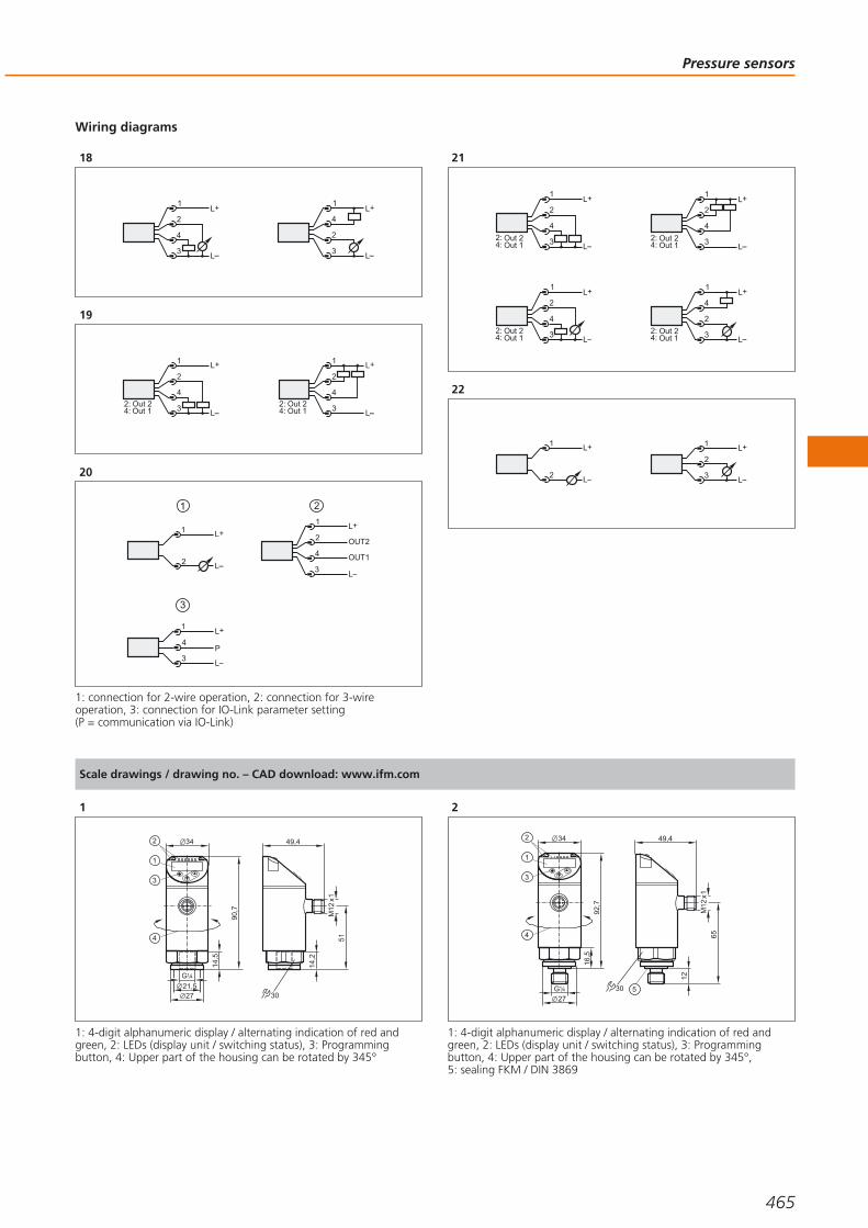
Wiring diagrams
18
4
1
3
2L+
L
2
1
3
4L+
L
19
Out 1Out 2
4
L
L+
2
1
34:2:
4
L
L+
2
1
3Out 1Out 2
4:2:
20
4
1
3
2
L+
L
OUT2
OUT1
2
L+
L
1
2
1
3
4
1
3P
L+
L
1: connection for 2-wire operation, 2: connection for 3-wireoperation, 3: connection for IO-Link parameter setting (P = communication via IO-Link)
21
4
L
L+
2
1
3Out 1Out 2
4:2:
4
L
L+
2
1
3Out 1Out 2
4:2:
4
1
3
2L+
LOut 1Out 2
4:2:
2
1
3
4L+
LOut 1Out 2
4:2:
22
L+
L
1
2
L+
L
1
3
2
Scale drawings / drawing no. – CAD download: www.ifm.com
1
34
90,7
1
2
21,5
14,5
51
G 41
27
49,4
M12
x1
30
3
4
14,2
1: 4-digit alphanumeric display / alternating indication of red andgreen, 2: LEDs (display unit / switching status), 3: Programmingbutton, 4: Upper part of the housing can be rotated by 345°
2
34
92,7
1
2
65
12
16,5
G 41
27
49,4
M12
x1
30
3
4
5
1: 4-digit alphanumeric display / alternating indication of red andgreen, 2: LEDs (display unit / switching status), 3: Programmingbutton, 4: Upper part of the housing can be rotated by 345°, 5: sealing FKM / DIN 3869
Pressure sensors
465
Gesamtkatalog EN 2016_17_Stilvorlage LK FrutigerOT_2010 DE_GB.qxd 06.11.15 16:54 Seite 465

Scale drawings / drawing no. – CAD download: www.ifm.com
3
3
169
22
100
2
1
24
75,5
57
M12
x1
G 21
1: Analogue display, 2: 4-digit alphanumeric display, 3: Touch button(programming button)
4
61,6
12
M12 x1
27
27
71,6
M5
7,5
G 411
5
60,6
13
R 41
M12 x127
27
70,6
M5
7,5
1
1: tightening torque 25 Nm
6
79,5
M12 x130
G14/
2
LED
65,5
30 12
M51
1: Pressure relief mechanism, No mechanical force must be exertedon the pressure relief mechanism., 2: sealing FPM / DIN 3869-14
7
79,5
M12 x130
30
12
G14/
M5
1
LED
65,5
1: sealing FPM / DIN 3869-14
8
79,5
M12 x130
42
65,5
30 12
G1/
M51
LED
1: ventilation, 2: sealing FPM / DIN 3869-14
9
1
2
10
178
20
34
34
35,620
15
4,5
5
6 86,6
52,3
M12
x1
3548,4
7 M4
28,5
28,5
1: ventilation connection M5; max. tightening torque 2.5 Nm, 2: main pressure connection G 1/8; tightening torque max. 8 Nm, 3: Programming button, 4: LEDs (display unit / switching status), 5: 4-digit alphanumeric display, 6: for mounting screw M4; max.tightening torque 2.5 Nm, 7: for mounting screw M4; max.tightening torque 2.5 Nm
Process sensors
466Product selectors and further information can be found at: www.ifm.com
Gesamtkatalog EN 2016_17_Stilvorlage LK FrutigerOT_2010 DE_GB.qxd 06.11.15 16:54 Seite 466

Scale drawings / drawing no. – CAD download: www.ifm.com
10
4,2
354,75
3220
4232
30
20,7
11,3
1: main pressure connection G 1/8; tightening torque max. 8 Nm,thread length max: 7.5 mm, 2: for mounting screw M4; max.tightening torque 2.5 Nm, 3: LEDs (display unit / switching status), 4: 4-digit alphanumeric display, 5: Programming button
11
4,2
354,75
3220
4232
30
20,7
11,3
1: Main pressure connection G 1/8; Tightening torque max. 8 Nm,insertion depth max. 7.5 mm, 2: Auxiliary pressure connection M5;Tightening torque max. 2.5 Nm, insertion depth max. 7.5 mm, 3: for mounting screw M4; max. tightening torque 2.5 Nm, 4: LEDs(display unit / switching status), 5: 4-digit alphanumeric display, 6: Programming button
12
12
65,9
51,6
M12 x118,9
G1 4/
19
1
1: FKM seal / DIN 3869-14
13
22
1
51,2
12
G1 4/
65,1
M12 x122
1: FKM seal / DIN 3869-14, tightening torque 25 Nm
14
71,5
51,4
12
G 41
19
1
19
21,825,4
1: sealing FKM / DIN 3869
15
51,9
7225,8
12
G 41
19
1
21,8
19
14,35
1: sealing FKM / DIN 3869
16
77,3
M12 x130
30
27
1,3
21,5
16,5
G 41
Pressure sensors
467
Gesamtkatalog EN 2016_17_Stilvorlage LK FrutigerOT_2010 DE_GB.qxd 06.11.15 16:54 Seite 467

Scale drawings / drawing no. – CAD download: www.ifm.com
17
75
M12 x130
30
27
1,3
21,5
14
G 41
1: Pressure relief mechanism, No mechanical force must be exertedon the pressure relief mechanism.
18
75
M12 x130
30
27
1,3
21,5
14
G 41
19
79,5
M12 x130
30
14
G14/
M5
1
1: sealing FPM / DIN 3869-14
20
100
27
21
27
147
22
9430
36
27
21,5
2 3
1
30
50,5
57,3
G
M12
x1
14
1 4/
39
1,3
1: 4-digit alphanumeric display, 2: LEDs (display unit / switchingstatus), 3: Programming button
23
G1
25,4
132
36
2 348
27
1
95,5
M12
x1
20°
50,539
36
1: 4-digit alphanumeric display, 2: LEDs, 3: Programming button
24
16,8
G1
64
M12
x1
105,
852
,8
50
34
1
2 3
15
24
1: 4-digit alphanumeric display, 2: LEDs, 3: Programming button
Process sensors
468Product selectors and further information can be found at: www.ifm.com
Gesamtkatalog EN 2016_17_Stilvorlage LK FrutigerOT_2010 DE_GB.qxd 06.11.15 16:54 Seite 468
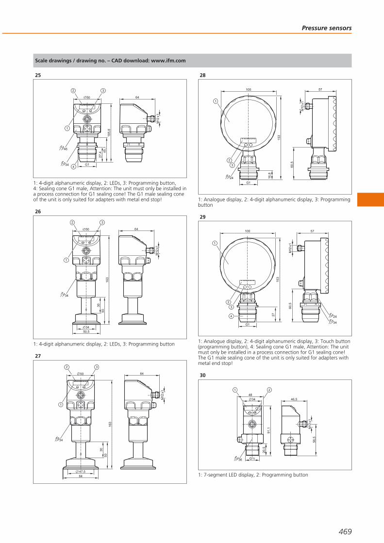
Scale drawings / drawing no. – CAD download: www.ifm.com
25
64
M12
x1
105,
645
,127
,450
34
46
1
2 3
G1
1: 4-digit alphanumeric display, 2: LEDs, 3: Programming button, 4: Sealing cone G1 male, Attention: The unit must only be installed ina process connection for G1 sealing cone! The G1 male sealing coneof the unit is only suited for adapters with metal end stop!
26
64
M12
x1
50
34
1
2 3
163
5030
50,534
1: 4-digit alphanumeric display, 2: LEDs, 3: Programming button
27
64
M12
x1
50
34
1
2 3
163
5030
64
47,5
28
24
3
153
16,8
100
2
1
57
60,5
M12
x1
G1
1: Analogue display, 2: 4-digit alphanumeric display, 3: Programmingbutton
29
24
34
3
153
27
100
2
1
G1
57
60,5
M12
x1
1: Analogue display, 2: 4-digit alphanumeric display, 3: Touch button(programming button), 4: Sealing cone G1 male, Attention: The unitmust only be installed in a process connection for G1 sealing cone!The G1 male sealing cone of the unit is only suited for adapters withmetal end stop!
30
91,1
34
20,5
G 4336
48
1 2
46,5
56,5
M12
x1
1: 7-segment LED display, 2: Programming button
Pressure sensors
469
Gesamtkatalog EN 2016_17_Stilvorlage LK FrutigerOT_2010 DE_GB.qxd 06.11.15 16:54 Seite 469

Scale drawings / drawing no. – CAD download: www.ifm.com
31
41 20°
1
34M12 x1
8127
G1
25,4
95,2
1: tightening torque 20 Nm
32
34M12 x1
48,5
85,3
27
G1
25,4
99,5
1
41 20°
1: tightening torque 20 Nm
33
41 20°1
117,
3
34M12 x1
131,
5
48
27
G1
25,4
1: tightening torque 20 Nm
34
91,5
34
27
1,3
21,5
2 3
1
30
48
57,3
G
M12
x1
14
1 4/
1: 4-digit alphanumeric display, 2: LEDs (display unit / switchingstatus), 3: Programming button
35
30
48
59,6
G
M12
x1
16,5
1 4/
94,1
34
27
1,3
21,5
2 3
1
1: 4-digit alphanumeric display, 2: LEDs (display unit / switchingstatus), 3: Programming button
Process sensors
470Product selectors and further information can be found at: www.ifm.com
Gesamtkatalog EN 2016_17_Stilvorlage LK FrutigerOT_2010 DE_GB.qxd 06.11.15 16:54 Seite 470

Pressure sensors
471
Gesamtkatalog EN 2016_17_Stilvorlage LK FrutigerOT_2010 DE_GB.qxd 06.11.15 16:54 Seite 471

For liquids and gases
Special versions for food applications and hazardous areas
Optional fittings for variable process connection
Flow monitoring also for aggressive media
Flow sensors
In almost all fields of process and plant engineering liquids or gases are used forcoolant and lubricant supply of machines and units, ventilation of installations andbuildings and the processing of products. In case of no flow of these mediaconsiderable damage and downtime may result. Thus it is very important to monitorthese media. In modern installations electronic flow monitors are used for thispurpose. They work without wear and tear and without mechanical components.This guarantees reliable monitoring even in case of difficult media over a longperiod.
Operating principle
Electronic flow sensors from ifm operate with different measurement techniques.They meet all requirements from a simple monitoring function to the exact detec-tion of flow quantities.
Harmonised operating menus ensure that operators who use different flow sensorscan quickly and precisely carry out settings on the sensors. Some flow sensorsfeature an integrated temperature monitor which makes an additional measuringpoint unnecessary. This enables to control processes in the optimum operatingstatus especially with regard to energy savings.
Analogue, binary and pulse outputs offer various possibilities to process themeasured data. Due to the flexible programming by means of pushbuttons theflow sensors can be adapted to different conditions. The sensors are mounted viaadapters.
Monitoring very smallflow rates: Flow moni-tor with flow adapter.
Optimisedconsumption ofcompressed air.
Process sensors
472
Gesamtkatalog EN 2016_17_Stilvorlage LK FrutigerOT_2010 DE_GB.qxd 06.11.15 16:54 Seite 472

Flow sensors / flow meters
473
System overview Page
Flow meters with integrated temperature measurement 475 - 476
Magnetic-inductive flow meters with integrated temperature measurement (sealing material FKM) 476 - 477
Magnetic-inductive flow meters with integrated temperature monitoring (sealing material EPDM) KTW / W270 approval 477 - 478
Magnetic-inductive flow meters (sealing material FKM) 478
Compact housings for adapters for flow monitoring 478 - 479
Compact housings can be configured for T-pieces for flow monitoring 479
Compact housings for adapters for flow monitoring, Hastelloy sensor tip 479
Compact housings for adapters for flow monitoring, titanium sensor tip 480
Compact designs for adapter with flow and temperature monitoring 480
Compact housings for adapters with ATEX approval group II, category 3D / 3G 480
Compact housings for adapters with Germanischer Lloyd (GL) approval 480
Compact housings for adapters for hygienic and wet areas 481
Mechatronic flow sensors for machine tools 481
Mechatronic flow sensors with display 481 - 482
Mechatronic flow sensors for liquids 482 - 483
Mechatronic flow sensors for high temperatures 483 - 484
Flow sensors for connection to control monitors, industrial applications 484
Flow sensors for connection to control monitors, industrial applications, titanium housing 484 - 485
Flow sensors for connection to control monitors for hygienic and wet areas 485
Flow sensors for connection to control monitors for aggressive media, ceramic housing 485 - 486
Flow sensors for connection to control monitors with ATEX approval 486
Flow sensors for connection to control monitors with ATEX approval, ceramic housing 487
Flow sensors for connection to control monitors with ATEX approval 2G 487
Air flow monitors 487
Compressed air meters 488
Compressed air meter for special gases 488
Ultrasonic flow meters for liquids (water, glycol solutions, oils) 489
Accessories for flow sensors and control monitors 489 - 491
Flange adapters for flow sensors 491 - 492
Accessories for airflow monitors 492
Accessories for flow meters 492 - 494
Grounding clamps for magnetic-inductive flow meters 494
Gesamtkatalog EN 2016_17_Stilvorlage LK FrutigerOT_2010 DE_GB.qxd 06.11.15 16:54 Seite 473

System overview Page
Wiring diagrams 494 - 495
Scale drawings / drawing no. – CAD download: www.ifm.com 495 - 505
Process sensors
474Product selectors and further information can be found at: www.ifm.com
Gesamtkatalog EN 2016_17_Stilvorlage LK FrutigerOT_2010 DE_GB.qxd 06.11.15 16:54 Seite 474

Flow meters with integrated temperature measurement
Type Processconnection
Measuringrange
[l/min]
Mediumtemperature
[°C]
Pressurerating
[bar]
Responsetime
[s]
Ub
[V]
Draw-ingno.
Orderno.
Output function OUT1: normally open / normally closed programmable or frequency or IO-Link OUT2: normally open / normallyclosed programmable or frequency · Wiring diagram no. 1 · Connector groups 8, 10, 18, 20, 120, 124, 126, 128, 157
G ½ 1...20 -10...90 12 < 1 18...30 1 SV4200
Rc ½ 1...20 -10...90 12 < 1 18...30 1 SV4500
G ½ 2...40 -10...90 12 < 1 18...30 1 SV5200
Rc ½ 2...40 -10...90 12 < 1 18...30 1 SV5500
G ¾ 5...100 -10...90 12 < 1 18...30 2 SV7200
Rc ¾ 5...100 -10...90 12 < 1 18...30 2 SV7500
Output function OUT1 = analogue signal temperature OUT2 = analogue signal flow · Wiring diagram no. 1 · Connector groups 8,10, 18, 20, 120, 124, 126, 128, 157
G ½ 1...20 -10...90 12 < 1 18...30 3 SV4204
Rc ½ 1...20 -10...90 12 < 1 18...30 3 SV4504
G ½ 2...40 -10...90 12 < 1 18...30 3 SV5204
Rc ½ 2...40 -10...90 12 < 1 18...30 3 SV5504
G ¾ 5...100 -10...90 12 < 1 18...30 4 SV7204
Rc ¾ 5...100 -10...90 12 < 1 18...30 4 SV7504
Output function analogue · Wiring diagram no. 2 · Connector groups 8, 10, 18, 20, 120, 124, 126, 128, 157
G ½ 0.5...10 -40...100 12 < 0.5 8...33 5 SV3050
G ½ 0.5...10 -40...100 12 < 0.5 8...33 5 SV3150
Flow sensors / flow meters
475You can find wiring diagrams and scale drawings from page 494
Gesamtkatalog EN 2016_17_Stilvorlage LK FrutigerOT_2010 DE_GB.qxd 06.11.15 16:54 Seite 475

Type Processconnection
Measuringrange
[l/min]
Mediumtemperature
[°C]
Pressurerating
[bar]
Responsetime
[s]
Ub
[V]
Draw-ingno.
Orderno.
Output function analogue · Wiring diagram no. 3 · Connector groups 8, 10, 18, 20, 120, 124, 126, 128, 157
G ½ 0.9...15 -40...100 12 < 0.5 8...33 6 SV4050
G ½ 0.9...15 -40...100 12 < 0.5 8...33 6 SV4150
G ¾ 1.8...32 -40...100 12 < 0.5 8...33 7 SV5050
G ¾ 1.8...32 -40...100 12 < 0.5 8...33 7 SV5150
G ¾ 3.5...50 -40...100 12 < 0.5 8...33 8 SV6050
G ¾ 3.5...50 -40...100 12 < 0.5 8...33 8 SV6150
G1 5.0...85 -40...100 12 < 0.5 8...33 9 SV7050
G1 5.0...85 -40...100 12 < 0.5 8...33 9 SV7150
G 1¼ 9...150 -40...100 12 < 0.5 8...33 10 SV8050
G 1¼ 9...150 -40...100 12 < 0.5 8...33 10 SV8150
Magnetic-inductive flow meters with integrated temperature measurement (sealing material FKM)
Type Processconnection
Measuringrange
[l/min]
Mediumtemperature
[°C]
Pressurerating
[bar]
Responsetime
[s]
Ub
[V]
Draw-ingno.
Orderno.
Output function OUT1: normally open / closed programmable or pulse OUT2: normally open / closed programmable or analogue(4...20 mA / 0...10 V, scaleable) · Wiring diagram no. 1 · Connector groups 8, 10, 18, 20, 120, 124, 126, 128, 157
G½ 0.10...25.00 -10...70 16 < 0.150 19...30 11 SM6000
G¾ 0.2...50.0 -10...70 16 < 0.150 19...30 12 SM7000
G1 0.2...100.0 -10...70 16 < 0.150 19...30 13 SM8000
Process sensors
476Product selectors and further information can be found at: www.ifm.com
Gesamtkatalog EN 2016_17_Stilvorlage LK FrutigerOT_2010 DE_GB.qxd 06.11.15 16:54 Seite 476
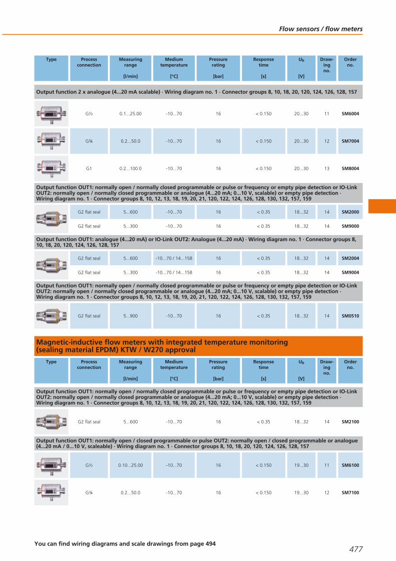
Type Processconnection
Measuringrange
[l/min]
Mediumtemperature
[°C]
Pressurerating
[bar]
Responsetime
[s]
Ub
[V]
Draw-ingno.
Orderno.
Output function 2 x analogue (4...20 mA scalable) · Wiring diagram no. 1 · Connector groups 8, 10, 18, 20, 120, 124, 126, 128, 157
G½ 0.1...25.00 -10...70 16 < 0.150 20...30 11 SM6004
G¾ 0.2...50.0 -10...70 16 < 0.150 20...30 12 SM7004
G1 0.2...100.0 -10...70 16 < 0.150 20...30 13 SM8004
Output function OUT1: normally open / normally closed programmable or pulse or frequency or empty pipe detection or IO-LinkOUT2: normally open / normally closed programmable or analogue (4...20 mA; 0...10 V, scalable) or empty pipe detection · Wiring diagram no. 1 · Connector groups 8, 10, 12, 13, 18, 19, 20, 21, 120, 122, 124, 126, 128, 130, 132, 157, 159
G2 flat seal 5...600 -10...70 16 < 0.35 18...32 14 SM2000
G2 flat seal 5...300 -10...70 16 < 0.35 18...32 14 SM9000
Output function OUT1: analogue (4...20 mA) or IO-Link OUT2: Analogue (4...20 mA) · Wiring diagram no. 1 · Connector groups 8,10, 18, 20, 120, 124, 126, 128, 157
G2 flat seal 5...600 -10...70 / 14...158 16 < 0.35 18...32 14 SM2004
G2 flat seal 5...300 -10...70 / 14...158 16 < 0.35 18...32 14 SM9004
Output function OUT1: normally open / normally closed programmable or pulse or frequency or empty pipe detection or IO-LinkOUT2: normally open / normally closed programmable or analogue (4...20 mA; 0...10 V, scalable) or empty pipe detection · Wiring diagram no. 1 · Connector groups 8, 10, 12, 13, 18, 19, 20, 21, 120, 122, 124, 126, 128, 130, 132, 157, 159
G2 flat seal 5...900 -10...70 16 < 0.35 18...32 14 SM0510
Magnetic-inductive flow meters with integrated temperature monitoring (sealing material EPDM) KTW / W270 approval
Type Processconnection
Measuringrange
[l/min]
Mediumtemperature
[°C]
Pressurerating
[bar]
Responsetime
[s]
Ub
[V]
Draw-ingno.
Orderno.
Output function OUT1: normally open / normally closed programmable or pulse or frequency or empty pipe detection or IO-LinkOUT2: normally open / normally closed programmable or analogue (4...20 mA; 0...10 V, scalable) or empty pipe detection · Wiring diagram no. 1 · Connector groups 8, 10, 12, 13, 18, 19, 20, 21, 120, 122, 124, 126, 128, 130, 132, 157, 159
G2 flat seal 5...600 -10...70 16 < 0.35 18...32 14 SM2100
Output function OUT1: normally open / closed programmable or pulse OUT2: normally open / closed programmable or analogue(4...20 mA / 0...10 V, scaleable) · Wiring diagram no. 1 · Connector groups 8, 10, 18, 20, 120, 124, 126, 128, 157
G½ 0.10...25.00 -10...70 16 < 0.150 19...30 11 SM6100
G¾ 0.2...50.0 -10...70 16 < 0.150 19...30 12 SM7100
Flow sensors / flow meters
477You can find wiring diagrams and scale drawings from page 494
Gesamtkatalog EN 2016_17_Stilvorlage LK FrutigerOT_2010 DE_GB.qxd 06.11.15 16:54 Seite 477

Type Processconnection
Measuringrange
[l/min]
Mediumtemperature
[°C]
Pressurerating
[bar]
Responsetime
[s]
Ub
[V]
Draw-ingno.
Orderno.
Output function OUT1: normally open / closed programmable or pulse OUT2: normally open / closed programmable or analogue(4...20 mA / 0...10 V, scaleable) · Wiring diagram no. 1 · Connector groups 8, 10, 18, 20, 120, 124, 126, 128, 157
G1 0.2...100.0 -10...70 16 < 0.150 19...30 13 SM8100
Output function OUT1: normally open / normally closed programmable or pulse or frequency or empty pipe detection or IO-LinkOUT2: normally open / normally closed programmable or analogue (4...20 mA; 0...10 V, scalable) or empty pipe detection · Wiring diagram no. 1 · Connector groups 8, 10, 12, 13, 18, 19, 20, 21, 120, 122, 124, 126, 128, 130, 132, 157, 159
G2 flat seal 5...300 -10...70 16 < 0.35 18...32 14 SM9100
Magnetic-inductive flow meters (sealing material FKM)
Type Processconnection
Measuringrange
[l/min]
Mediumtemperature
[°C]
Pressurerating
[bar]
Responsetime
[s]
Ub
[V]
Draw-ingno.
Orderno.
M12 connector · Output function 4...20 mA analogue · DC · Wiring diagram no. 4 · Connector groups 8, 10, 18, 20, 120, 124, 126,128, 157
G½ 0...25 -10...70 16 < 0.150 19...30 15 SM6050
G¾ 0...50 -10...70 16 < 0.150 19...30 16 SM7050
G1 0...100 -10...70 16 < 0.150 19...30 17 SM8050
Compact housings for adapters for flow monitoring
Type Setting rangeliquids / gases
[cm/s]
Materialsensor tip
Mediumtemperature
[°C]
Pressurerating
[bar]
Responsetime
[s]
Ub
[V]
Draw-ingno.
Orderno.
M12 connector · Wiring diagram no. 5 · Connector groups 8, 10, 18, 20, 120, 124, 126, 128, 157
3...300 / 200...3000 stainless steel 316L / 1.4404 -25...80 30 1...10 19...36 18 SI5000
M12 connector · Wiring diagram no. 6 · Connector groups 8, 10, 18, 20, 120, 124, 126, 128, 157
3...300 / 200...3000 stainless steel 316L / 1.4404 -25...80 300 1...10 18...36 19 SI5002
Process sensors
478Product selectors and further information can be found at: www.ifm.com
Gesamtkatalog EN 2016_17_Stilvorlage LK FrutigerOT_2010 DE_GB.qxd 06.11.15 16:54 Seite 478
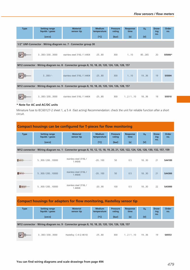
Type Setting rangeliquids / gases
[cm/s]
Materialsensor tip
Mediumtemperature
[°C]
Pressurerating
[bar]
Responsetime
[s]
Ub
[V]
Draw-ingno.
Orderno.
1/2" UNF-Connector · Wiring diagram no. 7 · Connector group 30
3...300 / 200...3000 stainless steel 316L / 1.4404 -25...80 300 1...10 85...265 20 SI5006*
M12 connector · Wiring diagram no. 8 · Connector groups 8, 10, 18, 20, 120, 124, 126, 128, 157
3...300 / - stainless steel 316L / 1.4404 -25...80 300 1...10 19...36 19 SI5004
M12 connector · Wiring diagram no. 9 · Connector groups 8, 10, 18, 20, 120, 124, 126, 128, 157
3...300 / 200...3000 stainless steel 316L / 1.4404 -25...80 300 1...2 / 1...10 18...36 19 SI5010
* Note for AC and AC/DC units
Miniature fuse to IEC60127-2 sheet 1, ≤ 5 A (fast acting) Recommendation: check the unit for reliable function after a shortcircuit.
Compact housings can be configured for T-pieces for flow monitoring
Type Setting rangeliquids / gases
[cm/s]
Materialsensor tip
Mediumtemperature
[°C]
Pressurerating
[bar]
Responsetime
[s]
Ub
[V]
Draw-ingno.
Orderno.
M12 connector · Wiring diagram no. 1 · Connector groups 8, 10, 12, 13, 18, 19, 20, 21, 120, 122, 124, 126, 128, 130, 132, 157, 159
5...300 / 200...10000stainless steel (316L /
1.4404)-20...100 50 0.5 18...30 21 SA4100
5...300 / 200...10000stainless steel (316L /
1.4404)-20...100 50 0.5 18...30 21 SA4300
5...300 / 200...10000stainless steel (316L /
1.4404)-20...90 100 0.5 18...30 22 SA5000
Compact housings for adapters for flow monitoring, Hastelloy sensor tip
Type Setting rangeliquids / gases
[cm/s]
Materialsensor tip
Mediumtemperature
[°C]
Pressurerating
[bar]
Responsetime
[s]
Ub
[V]
Draw-ingno.
Orderno.
M12 connector · Wiring diagram no. 9 · Connector groups 8, 10, 18, 20, 120, 124, 126, 128, 157
3...300 / 200...3000 Hastelloy C-4 (2.4610) -25...80 300 1...2 / 1...10 19...36 19 SI0553
Flow sensors / flow meters
479You can find wiring diagrams and scale drawings from page 494
Gesamtkatalog EN 2016_17_Stilvorlage LK FrutigerOT_2010 DE_GB.qxd 06.11.15 16:54 Seite 479
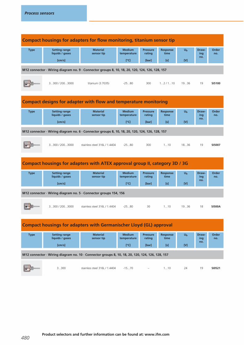
Compact housings for adapters for flow monitoring, titanium sensor tip
Type Setting rangeliquids / gases
[cm/s]
Materialsensor tip
Mediumtemperature
[°C]
Pressurerating
[bar]
Responsetime
[s]
Ub
[V]
Draw-ingno.
Orderno.
M12 connector · Wiring diagram no. 9 · Connector groups 8, 10, 18, 20, 120, 124, 126, 128, 157
3...300 / 200...3000 titanium (3.7035) -25...80 300 1...2 / 1...10 19...36 19 SI5100
Compact designs for adapter with flow and temperature monitoring
Type Setting rangeliquids / gases
[cm/s]
Materialsensor tip
Mediumtemperature
[°C]
Pressurerating
[bar]
Responsetime
[s]
Ub
[V]
Draw-ingno.
Orderno.
M12 connector · Wiring diagram no. 6 · Connector groups 8, 10, 18, 20, 120, 124, 126, 128, 157
3...300 / 200...3000 stainless steel 316L / 1.4404 -25...80 300 1...10 18...36 19 SI5007
Compact housings for adapters with ATEX approval group II, category 3D / 3G
Type Setting rangeliquids / gases
[cm/s]
Materialsensor tip
Mediumtemperature
[°C]
Pressurerating
[bar]
Responsetime
[s]
Ub
[V]
Draw-ingno.
Orderno.
M12 connector · Wiring diagram no. 5 · Connector groups 154, 156
3...300 / 200...3000 stainless steel 316L / 1.4404 -25...80 30 1...10 19...36 18 SI500A
Compact housings for adapters with Germanischer Lloyd (GL) approval
Type Setting rangeliquids / gases
[cm/s]
Materialsensor tip
Mediumtemperature
[°C]
Pressurerating
[bar]
Responsetime
[s]
Ub
[V]
Draw-ingno.
Orderno.
M12 connector · Wiring diagram no. 10 · Connector groups 8, 10, 18, 20, 120, 124, 126, 128, 157
3...300 stainless steel 316L / 1.4404 -15...70 – 1...10 24 19 SI0521
Process sensors
480Product selectors and further information can be found at: www.ifm.com
Gesamtkatalog EN 2016_17_Stilvorlage LK FrutigerOT_2010 DE_GB.qxd 06.11.15 16:54 Seite 480
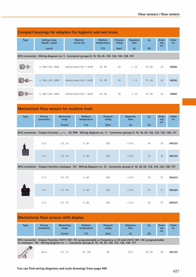
Compact housings for adapters for hygienic and wet areas
Type Setting rangeliquids / gases
[cm/s]
Materialsensor tip
Mediumtemperature
[°C]
Pressurerating
[bar]
Responsetime
[s]
Ub
[V]
Draw-ingno.
Orderno.
M12 connector · Wiring diagram no. 5 · Connector groups 8, 10, 18, 20, 120, 124, 126, 128, 157
3...300 / 200...3000 stainless steel 316L / 1.4435 -25...95 30 1...10 19...36 23 SI6600
3...300 / 200...3000 stainless steel 316L / 1.4435 -25...95 30 1...10 19...36 24 SI6700
3...300 / 200...3000 stainless steel 316L / 1.4435 -25...95 30 1...10 19...36 25 SI6800
Mechatronic flow sensors for machine tools
Type Processconnection
Measuringrange
[l/min]
Mediumtemperature
[°C]
Pressurerating
[bar]
Responsetime
[s]
Ub
[V]
Draw-ingno.
Orderno.
M12 connector · Output function · DC PNP · Wiring diagram no. 11 · Connector groups 8, 10, 18, 20, 120, 124, 126, 128, 157
G ½ 0.3...25 0...60 200 < 0.01 24 26 SBU323
G ½ 0.3...50 0...60 200 < 0.01 24 26 SBU324
M12 connector · Output function analogue · DC · Wiring diagram no. 12 · Connector groups 8, 10, 18, 20, 120, 124, 126, 128, 157
G ½ 0.3...25 0...60 200 < 0.01 24 27 SBU623
G ½ 0.3...50 0...60 200 < 0.01 24 27 SBU624
G ½ 0.3...75 0...60 200 < 0.01 24 27 SBU625
Mechatronic flow sensors with display
Type Processconnection
Measuringrange
[l/min]
Mediumtemperature
[°C]
Pressurerating
[bar]
Responsetime
[s]
Ub
[V]
Draw-ingno.
Orderno.
M12 connector · Output function OUT1: NO / NC programmable or frequency or IO-Link OUT2: NO / NC programmable or analogue · DC · Wiring diagram no. 1 · Connector groups 8, 10, 18, 20, 120, 124, 126, 128, 157
Rp ¾ 0.3...15 -10...100 40 0.01 18...30 28 SBY232
Flow sensors / flow meters
481You can find wiring diagrams and scale drawings from page 494
Gesamtkatalog EN 2016_17_Stilvorlage LK FrutigerOT_2010 DE_GB.qxd 06.11.15 16:54 Seite 481

Type Processconnection
Measuringrange
[l/min]
Mediumtemperature
[°C]
Pressurerating
[bar]
Responsetime
[s]
Ub
[V]
Draw-ingno.
Orderno.
M12 connector · Output function OUT1: NO / NC programmable or frequency or IO-Link OUT2: NO / NC programmable or analogue · DC · Wiring diagram no. 1 · Connector groups 8, 10, 18, 20, 120, 124, 126, 128, 157
Rp ¾ 0.5...25 -10...100 40 0.01 18...30 28 SBY233
Rp ¾ 1...50 -10...100 40 0.01 18...30 28 SBY234
Rp 1 2...100 -10...100 25 0.01 18...30 29 SBY246
Rp 1½ 4...200 -10...100 25 0.01 18...30 30 SBY257
G 1/2 0.3...15 -10...100 40 0.01 18...30 31 SBG232
G 1/2 0.5...25 -10...100 40 0.01 18...30 31 SBG233
G 1/2 1...50 -10...100 40 0.01 18...30 31 SBG234
G 3/4 2...100 -10...100 25 0.01 18...30 32 SBG246
G 1¼ 4...200 -10...100 25 0.01 18...30 33 SBG257
Mechatronic flow sensors for liquids
Type Processconnection
Measuringrange
[l/min]
Mediumtemperature
[°C]
Pressurerating
[bar]
Responsetime
[s]
Ub
[V]
Draw-ingno.
Orderno.
M12 connector · Output function · DC PNP · Wiring diagram no. 13 · Connector groups 8, 10, 18, 20, 120, 124, 126, 128, 157
Rp ¾ 1...15 0...85 40 < 0.01 24 34 SBY332
Rp ½ 2...20 0...85 80 < 0.01 24 35 SBY323
Rp ¾ 1...25 0...85 40 < 0.01 24 34 SBY333
Rp ¾ 2...50 0...85 40 < 0.01 24 34 SBY334
Process sensors
482Product selectors and further information can be found at: www.ifm.com
Gesamtkatalog EN 2016_17_Stilvorlage LK FrutigerOT_2010 DE_GB.qxd 06.11.15 16:54 Seite 482

Type Processconnection
Measuringrange
[l/min]
Mediumtemperature
[°C]
Pressurerating
[bar]
Responsetime
[s]
Ub
[V]
Draw-ingno.
Orderno.
M12 connector · Output function · DC PNP · Wiring diagram no. 13 · Connector groups 8, 10, 18, 20, 120, 124, 126, 128, 157
Rp 1 5...100 0...85 25 < 0.01 24 36 SBY346
Rp 1½ 20...200 0...85 25 < 0.01 24 37 SBY357
G ½ 1...15 0...85 40 < 0.01 24 38 SBG332
G ½ 1...25 0...85 40 < 0.01 24 38 SBG333
G ½ 2...50 0...85 40 < 0.01 24 38 SBG334
G ¾ 5...100 0...85 25 < 0.01 24 39 SBG346
G 1¼ 20...200 0...85 25 < 0.01 24 40 SBG357
Mechatronic flow sensors for high temperatures
Type Processconnection
Measuringrange
[l/min]
Mediumtemperature
[°C]
Pressurerating
[bar]
Responsetime
[s]
Ub
[V]
Draw-ingno.
Orderno.
M12 connector · Output function analogue · DC · Wiring diagram no. 12 · Connector groups 8, 10, 18, 20, 120, 124, 126, 128, 157
Rp ¾ 1...25 -10...100 40 < 0.01 18...32 41 SBY433
Rp ¾ 2...50 -10...100 40 < 0.01 18...32 41 SBY434
Rp 1 4...100 -10...100 25 < 0.01 18...32 42 SBY446
Rp 1½ 8...200 -10...100 25 < 0.01 18...32 43 SBY457
Cable with connector 0.3 m · Output function analogue · DC · Wiring diagram no. 12 · Connector groups 8, 10, 18, 20, 120, 124,126, 128, 157
Rp ¾ 0.3...25 10...180 15 < 0.01 24 44 SBT633
Rp ¾ 0.3...50 10...180 15 < 0.01 24 44 SBT634
Flow sensors / flow meters
483You can find wiring diagrams and scale drawings from page 494
Gesamtkatalog EN 2016_17_Stilvorlage LK FrutigerOT_2010 DE_GB.qxd 06.11.15 16:54 Seite 483

Type Processconnection
Measuringrange
[l/min]
Mediumtemperature
[°C]
Pressurerating
[bar]
Responsetime
[s]
Ub
[V]
Draw-ingno.
Orderno.
Cable with connector 0.3 m · Output function analogue · DC · Wiring diagram no. 12 · Connector groups 8, 10, 18, 20, 120, 124,126, 128, 157
G ¾ 0.3...25 10...180 15 < 0.01 24 45 SBM613
Flow sensors for connection to control monitors, industrial applications
Type Setting rangeliquids / gases
[cm/s]
Greatestsensitivity
[cm/s]
Mediumtemperature
[°C]
Responsetime
[s]
Max. T0gradient
[K/min]
Pressurerating
[bar]
Draw-ingno.
Orderno.
M12 connector · Wiring diagram no. 14 · Connector groups 12, 13, 19, 21, 122, 126, 128, 132, 159
3...300 / 200...3000 3...60 / 200...800 -25...80 1...10 30 30 46 SF6200
3...300 / 200...3000 3...60 / 200...800 -25...80 1...10 30 30 47 SF6201
M12 connector · Wiring diagram no. 14 · Connector groups 122, 126, 128, 132, 159
3...300 / 200...3000 3...60 / 200...800 -25...80 1...10 300 300 48 SF5200
3...300 / 200...3000 3...60 / 200...800 -25...80 1...10 300 30 49 SF5201
Cable 6 m · Wiring diagram no. 15
3...300 / 200...3000 3...60 / 200...800 -25...80 1...10 300 300 50 SF5350
3...300 / 200...3000 3...60 / 200...800 0...120 / 0...100 1...10 300 300 50 SF5300
Flow sensors for connection to control monitors, industrial applications, titanium housing
Type Setting rangeliquids / gases
[cm/s]
Greatestsensitivity
[cm/s]
Mediumtemperature
[°C]
Responsetime
[s]
Max. T0gradient
[K/min]
Pressurerating
[bar]
Draw-ingno.
Orderno.
Cable 6 m · Wiring diagram no. 15
3...300 / 200...3000 3...60 / 200...800 0...120 / 0...100 1...10 300 100 50 SF5800
M12 connector · Wiring diagram no. 14 · Connector groups 122, 126, 128, 132, 159
3...300 / 200...3000 3...60 / 200...800 -25...80 1...10 300 100 48 SF5700
Process sensors
484Product selectors and further information can be found at: www.ifm.com
Gesamtkatalog EN 2016_17_Stilvorlage LK FrutigerOT_2010 DE_GB.qxd 06.11.15 16:54 Seite 484

Type Setting rangeliquids / gases
[cm/s]
Greatestsensitivity
[cm/s]
Mediumtemperature
[°C]
Responsetime
[s]
Max. T0gradient
[K/min]
Pressurerating
[bar]
Draw-ingno.
Orderno.
M12 connector · Wiring diagram no. 14 · Connector groups 122, 126, 128, 132, 159
3...300 / 200...3000 3...60 / 200...800 -25...80 1...10 300 100 51 SF5701
3...300 / 200...3000 3...60 / 200...800 -25...80 1...10 300 100 52 SF5702
3...300 / 200...3000 3...60 / 200...800 -25...80 1...10 300 100 53 SF5703
3...300 / 200...3000 3...60 / 200...800 -25...80 1...10 300 100 54 SF5704
Flow sensors for connection to control monitors for hygienic and wet areas
Type Setting rangeliquids / gases
[cm/s]
Greatestsensitivity
[cm/s]
Mediumtemperature
[°C]
Responsetime
[s]
Max. T0gradient
[K/min]
Pressurerating
[bar]
Draw-ingno.
Orderno.
Cable 6 m · Wiring diagram no. 15
3...300 / 200...2000 3...60 / 200...800 0...120 / 0...100 1...10 15 30 – SF0516
Flow sensors for connection to control monitors for aggressive media, ceramic housing
Type Setting rangeliquids / gases
[cm/s]
Greatestsensitivity
[cm/s]
Mediumtemperature
[°C]
Responsetime
[s]
Max. T0gradient
[K/min]
Pressurerating
[bar]
Draw-ingno.
Orderno.
M12 connector · Wiring diagram no. 14 · Connector groups 12, 13, 19, 21, 122, 126, 128, 132, 159
3...60 / - 3...40 / - 5...70 2...20 7 30 55 SF2405
3...60 / - 3...40 / - 5...70 2...20 7 30 56 SF3405
Cable 6 m · Wiring diagram no. 15
3...60 / - 3...40 / - 5...70 2...20 7 30 57 SF2410
3...60 / - 3...40 / - 5...70 2...20 7 30 58 SF3410
Flow sensors / flow meters
485You can find wiring diagrams and scale drawings from page 494
Gesamtkatalog EN 2016_17_Stilvorlage LK FrutigerOT_2010 DE_GB.qxd 06.11.15 16:54 Seite 485

Type Setting rangeliquids / gases
[cm/s]
Greatestsensitivity
[cm/s]
Mediumtemperature
[°C]
Responsetime
[s]
Max. T0gradient
[K/min]
Pressurerating
[bar]
Draw-ingno.
Orderno.
Cable 16 m · Wiring diagram no. 15
3...60 3...40 5...70 2...20 7 30 57 SF0540
Flow sensors for connection to control monitors with ATEX approval
Type Setting rangeliquids / gases
[cm/s]
Greatestsensitivity
[cm/s]
Mediumtemperature
[°C]
Responsetime
[s]
Max. T0gradient
[K/min]
Pressurerating
[bar]
Draw-ingno.
Orderno.
Cable 6 m · Wiring diagram no. 16
3...300 / 200...2000 3...60 / 200...800 -20...60 1...10 15 300 59 SF111A
3...300 / 200...2000 3...60 / 200...800 -20...60 1...10 15 300 60 SF211A
3...300 / 200...2000 3...60 / 200...800 -20...60 1...10 15 300 61 SF311A
3...300 / 200...2000 3...60 / 200...800 -20...70 1...10 15 30 62 SF121A
3...300 / 200...2000 3...60 / 200...800 -20...70 1...10 15 30 63 SF221A
3...300 / 200...2000 3...60 / 200...800 -20...70 1...10 15 30 64 SF321A
M12 connector · Wiring diagram no. 17 · Connector group 155
3...300 / 200...2000 3...60 / 200...800 -20...70 1...10 15 30 65 SF120A
3...300 / 200...2000 3...60 / 200...800 -20...70 1...10 15 30 66 SF220A
3...300 / 200...2000 3...60 / 200...800 -20...70 1...10 15 30 67 SF320A
3...300 / 200...3000 3...60 / 200...800 -20...70 1...10 15 30 46 SF620A
Process sensors
486Product selectors and further information can be found at: www.ifm.com
Gesamtkatalog EN 2016_17_Stilvorlage LK FrutigerOT_2010 DE_GB.qxd 06.11.15 16:55 Seite 486

Flow sensors for connection to control monitors with ATEX approval, ceramic housing
Type Setting rangeliquids / gases
[cm/s]
Greatestsensitivity
[cm/s]
Mediumtemperature
[°C]
Responsetime
[s]
Max. T0gradient
[K/min]
Pressurerating
[bar]
Draw-ingno.
Orderno.
Cable 6 m · Wiring diagram no. 16
3...60 / - 3...40 / - 5...70 2...20 7 30 57 SF223A
3...60 / - 3...40 / - 5...70 2...20 7 30 58 SF323A
Flow sensors for connection to control monitors with ATEX approval 2G
Type Setting rangeliquids / gases
[cm/s]
Greatestsensitivity
[cm/s]
Mediumtemperature
[°C]
Responsetime
[s]
Max. T0gradient
[K/min]
Pressurerating
[bar]
Draw-ingno.
Orderno.
Cable 6 m · Wiring diagram no. 18
3...300 / 100...15000 3...100 / 100...7500 -20...70 1...10 30 30 68 SP321A
Air flow monitors
Type Setting rangeliquids / gases
[cm/s]
Greatestsensitivity
[cm/s]
Mediumtemperature
[°C]
Responsetime
[s]
Ub / tolerance
[V] / [%]
Draw-ingno.
Orderno.
Cable 2 m · Wiring diagram no. 19
100...1000 100...400 -10...50 3...60 80...250 AC 69 SL0101*
Cable 2 m · Wiring diagram no. 20
100...1000 100...400 -10...50 3...60 24 AC 69 SL0201*
Cable 2 m · Wiring diagram no. 21
100...1000 100...400 -10...50 3...60 24 DC ± 25 % 69 SL5101
* Note for AC and AC/DC units
Miniature fuse to IEC60127-2 sheet 1, ≤ 5 A (fast acting) Recommendation: check the unit for reliable function after a shortcircuit.
Flow sensors / flow meters
487You can find wiring diagrams and scale drawings from page 494
Gesamtkatalog EN 2016_17_Stilvorlage LK FrutigerOT_2010 DE_GB.qxd 06.11.15 16:55 Seite 487

Compressed air meters
Type Processconnection
Setting range
[Nm3/h]
Pressure rating
[bar]
Response time
[s]
Ub
[V]
Draw-ingno.
Orderno.
Output function OUT1: normally open / closed programmable or pulse OUT2: normally open / closed programmable or analogue(4...20 mA scaleable) · Wiring diagram no. 22 · Connector groups 8, 10, 18, 20, 120, 124, 126, 128, 157
G ¼ (DN8) 0.12...15.00 16 < 0.1 18...30 70 SD5000
R½ (DN15) 0.6...75.0 16 < 0.1 18...30 71 SD6000
G ½ (DN15) 0.6...75 16 < 0.1 18...30 72 SD6050
R1 (DN25) 1.8...225.0 16 < 0.1 18...30 73 SD8000
R1½ (DN40) 3.5...410.0 16 < 0.1 18...30 74 SD9000
R2 (DN50) 5...700 16 < 0.1 18...30 75 SD2000
Output function OUT1: normally open / closed programmable or pulse OUT2: normally open / closed programmable or analogue(4...20 mA scaleable) · Wiring diagram no. 1 · Connector groups 8, 10, 18, 20, 120, 124, 126, 128, 157
G 1 I 18…2110 16 < 0.1 18...30 76 SD0523
Compressed air meter for special gases
Type Processconnection
Setting range
[Nm3/h]
Mediumtemperature
[°C]
Pressurerating
[bar]
Responsetime
[s]
Ub
[V]
Draw-ingno.
Orderno.
Output function OUT1: normally open / closed programmable or pulse OUT2: normally open / closed programmable or analogue(4...20 mA scaleable) · Wiring diagram no. 25 · Connector groups 8, 10, 18, 20, 120, 124, 126, 128, 157
G ¼ (DN8)N2: 0.04...15.00 / Ar: 0.08...24.04 / CO2: 0.04...14.36
0...60 16 < 0.1 18...30 70 SD5100
R½ (DN15)Ar: 0.39 (0.4)...118.2 / CO2: 0.24 (0.2)...71.7 /
N2: 0.24 (0.2)...73.0 0...60 16 < 0.1 18...30 77 SD6100
Process sensors
488Product selectors and further information can be found at: www.ifm.com
Gesamtkatalog EN 2016_17_Stilvorlage LK FrutigerOT_2010 DE_GB.qxd 06.11.15 16:55 Seite 488

Ultrasonic flow meters for liquids (water, glycol solutions, oils)
Type Processconnection
Measuringrange
[l/min]
Mediumtemperature
[°C]
Pressurerating
[bar]
Responsetime
[s]
Ub
[V]
Draw-ingno.
Orderno.
Output function 2 x normally open / closed programmable · Wiring diagram no. 6 · Connector groups 8, 10, 18, 20, 120, 124, 126,128, 157
G¾ 0.1...50.0 -10...80 16 < 0.250 19...30 78 SU7200
G1 0.2...100.0 -10...80 16 < 0.250 19...30 79 SU8200
Output function OUT1: normally open / closed programmable or pulse OUT2: normally open / closed programmable or analogue(4...20 mA / 0...10 V, scaleable) · Wiring diagram no. 23 · Connector groups 8, 10, 18, 20, 120, 124, 126, 128, 157
G¾ 0.1...50.0 -10...80 16 < 0.250 19...30 78 SU7000
G1 0.2...100.0 -10...80 16 < 0.250 19...30 79 SU8000
G1¼ 0.4...200.0 -10...80 16 < 0.250 19...30 80 SU9000
Output function 2 x analogue (4...20 mA scalable) · Wiring diagram no. 24 · Connector groups 8, 10, 18, 20, 120, 124, 126, 128, 157
G1¼ 0.0...200.0 -10...80 16 < 0.250 19...30 80 SU9004
Accessories for flow sensors and control monitors
Type Description Orderno.
T-piece · R½ - M26 x 1.5 - R½ · for sensors and adapters with process connection M26 x 1.5 · Flow rate: 0...10 l/min · Housing materials: stainless steel 316L / 1.4404
E40136
Progressive ring T-piece DIN 2353 · QL 18-18-18 · for sensors and adapters with process connection M26 x 1.5 · Recommendation:precision steel pipes 18 x 1.5 to DIN 2391/ISO 3304 · Housing materials: stainless steel 316Ti / 1.4571
E40078
Progressive ring T-piece DIN 2353 · QL 22-18-22 · for sensors and adapters with process connection M26 x 1.5 · Recommendation:precision steel pipes 22 x 1.5 to DIN 2391/ISO 3304 · Housing materials: stainless steel 316Ti / 1.4571
E40079
Progressive ring T-piece DIN 2353 · QL 28-18-28 · for sensors and adapters with process connection M26 x 1.5 · Recommendation:precision steel pipes 28 x 1.5 to DIN 2391/ISO 3304 · Housing materials: brass
E40083
Adapter block · D10 / G ¼ · for flow sensors type SID, SF5 · Optimised for the following volumetric flow quantities (factory settingwith water): · 0.2...2 l/min (SI1xxx) 0.2...3 l/min (SI5xxx) · Housing materials: stainless steel 316L / 1.4404
E40161
Flow sensors / flow meters
489You can find wiring diagrams and scale drawings from page 494
Gesamtkatalog EN 2016_17_Stilvorlage LK FrutigerOT_2010 DE_GB.qxd 06.11.15 16:55 Seite 489

Type Description Orderno.
Adapter block · D16 / G ½ · for flow sensors type SID, SF5 · Optimised for the following volumetric flow quantities (factory settingwith water): · 0.5...5 l/min (SI1xxx) 0.5...7 l/min (SI5xxx) · Housing materials: stainless steel 316L / 1.4404
E40162
Adapter · M18 x 1.5 - G ½ · Insertion depth of the probe of SID, SFD, TN: · 21 mm · Housing materials: titanium E40114
Adapter · M18 x 1.5 - G ¼ · Insertion depth of the probe of SID, SFD, TN: · 13.5 mm · Housing materials: titanium E40115
Adapter · M18 x 1.5 - L18 · for mounting in T-pieces · Insertion depth of the probe of SID, SFD, TN: · 28.5 mm · Housing materials:nut: stainless steel 316Ti / 1.4571 / adapter: stainless steel 316L / 1.4404 / O-ring: FKM 16 x 1.5 gr 70° Shore A
E40104
Adapter · M18 x 1.5 - M12 x 1 · Insertion depth of the probe of SID, SFD, TN: · 13.5 mm · Housing materials: stainless steel 316L / 1.4404
E40101
Adapter · M18 x 1.5 - M12 x 1 · Insertion depth of the probe of SID, SFD, TN: · 13.5 mm · Housing materials: brass E40100
Adapter · M18 x 1.5 - ¼" NPT · Insertion depth of the probe of SID, SFD, TN: · 13.9 mm · Housing materials: stainless steel 316L / 1.4404
E40106
Adapter · M18 x 1.5 - G ¼ · Insertion depth of the probe of SID, SFD, TN: · 13.5 mm · Housing materials: stainless steel 316L / 1.4404
E40099
Adapter · M18 x 1.5 - G ¼ · Insertion depth of the probe of SID, SFD, TN: · 13.5 mm · Housing materials: brass E40098
Adapter · M18 x 1.5 - G ½ · Insertion depth of the probe of SID, SFD, TN: · 21 mm · Housing materials: stainless steel 316L / 1.4404
E40096
Adapter · M18 x 1.5 - G ½ · Insertion depth of the probe of SID, SFD, TN: · 21 mm · Housing materials: brass E40097
Mounting adapter · M18 x 1.5 - Ø 23 mm · Insertion depth of the probe of SID, SFD, TN: · 21 mm · Housing materials: PE-100 E40138
Welding adapter · M18 x 1.5 - Ø 24 mm · Insertion depth of the probe of SID, SFD, TN: · 15 mm · Housing materials: stainless steel 316L / 1.4404
E40124
Welding adapter · Welding adapter · for compressed air meter type SD · Housing materials: stainless steel 316L / 1.4404 E40195
Flow adapter (for low flow rates) · M12 x 1 - G 1/8 · for flow sensors and compact flow monitors with adapter · Housing materials: stainless steel 316L / 1.4404
E40129
Process sensors
490Product selectors and further information can be found at: www.ifm.com
Gesamtkatalog EN 2016_17_Stilvorlage LK FrutigerOT_2010 DE_GB.qxd 06.11.15 16:55 Seite 490

Type Description Orderno.
Combicon connector · with cage clamps 4 poles · Housing materials: current carrying parts: copper alloy tin-plated E40171
Protective cover · for flow sensors type SI5xxx, SI6xxx, SR59xx · Housing materials: PP uncoloured E40203
Flange adapters for flow sensors
Type Description Orderno.
Mounting plate · Housing materials: stainless steel 316L / 1.4404 E40249
Clamp adapter · Clamp · 1-1.5" · ISO 2852 · for units with Aseptoflex Vario adapter · Sealing by sealing ring · Housing materials: stainless steel 316L / 1.4435
E33201
Clamp adapter · Clamp · 2" · ISO 2852 · for units with Aseptoflex Vario adapter · Sealing by sealing ring · Housing materials: stainless steel 316L / 1.4435
E33202
Clamp adapter · Clamp · 1-1.5" · ISO 2852 · for units with Aseptoflex Vario adapter · Metal to metal seal · Housing materials: stainless steel 316L / 1.4435
E33701
Clamp adapter · Clamp · 2" · ISO 2852 · for units with Aseptoflex Vario adapter · Metal to metal seal · Housing materials: stainless steel 316L / 1.4435
E33702
Pipe fitting · Hygienic pipe fitting · Hygienic pipe fitting · DN32 (1.25") · DIN 11851 · for units with Aseptoflex Vario adapter ·Sealing by sealing ring · Housing materials: stainless steel 316L / 1.4435
E33211
Pipe fitting · Hygienic pipe fitting · Hygienic pipe fitting · DN40 (1.5") · DIN 11851 · for units with Aseptoflex Vario adapter · Sealing by sealing ring · Housing materials: stainless steel 316L / 1.4435
E33212
Pipe fitting · Hygienic pipe fitting · Hygienic pipe fitting · DN50 (2") · DIN 11851 · for units with Aseptoflex Vario adapter · Sealing by sealing ring · Housing materials: stainless steel 316L / 1.4435
E33213
Pipe fitting · Hygienic pipe fitting · Hygienic pipe fitting · DN32 (1.25") · DIN 11851 · for units with Aseptoflex Vario adapter · Metal to metal seal · Housing materials: stainless steel 316L / 1.4435
E33711
Pipe fitting · Hygienic pipe fitting · Hygienic pipe fitting · DN40 (1.5") · DIN 11851 · for units with Aseptoflex Vario adapter · Metal to metal seal · Housing materials: stainless steel 316L / 1.4435
E33712
Pipe fitting · Hygienic pipe fitting · Hygienic pipe fitting · DN50 (2") · DIN 11851 · for units with Aseptoflex Vario adapter · Metal to metal seal · Housing materials: stainless steel 316L / 1.4435
E33713
Flow sensors / flow meters
491You can find wiring diagrams and scale drawings from page 494
Gesamtkatalog EN 2016_17_Stilvorlage LK FrutigerOT_2010 DE_GB.qxd 06.11.15 16:55 Seite 491

Type Description Orderno.
Clamp adapter · Varivent Adapter · Varivent type F · DN25 (1"), D = 50 · for units with Aseptoflex Vario adapter · Sealing by sealing ring · Housing materials: stainless steel 316L / 1.4435
E33221
Clamp adapter · Varivent Adapter · Varivent type N · DN40...DN150 (1.5...6"), D = 68 · for units with Aseptoflex Vario adapter ·Sealing by sealing ring · Housing materials: stainless steel 316L / 1.4435
E33222
Clamp adapter · Varivent Adapter · Varivent type F · DN25 (1"), D = 50 · for units with Aseptoflex Vario adapter · Metal to metal seal · Housing materials: stainless steel 316L / 1.4435
E33721
Clamp adapter · Varivent Adapter · Varivent type N · DN40...DN150 (1.5...6"), D = 68 · for units with Aseptoflex Vario adapter ·Metal to metal seal · Housing materials: stainless steel 316L / 1.4435
E33722
Pipe fitting · SMS pipe fitting · DN40 (1.5") · SMS · for units with Aseptoflex Vario adapter · Metal to metal seal · Housing materials: stainless steel 316L / 1.4435
E33731
Pipe fitting · SMS pipe fitting · DN50 (2") · SMS · for units with Aseptoflex Vario adapter · Metal to metal seal · Housing materials: stainless steel 316L / 1.4435
E33732
Flange adapter · DRD adapter · flange · DRD · D = 65 · for units with Aseptoflex Vario adapter · Sealing by sealing ring · Housing materials: stainless steel 316L / 1.4435
E33242
Welding adapter · Ø 50 mm · for units with Aseptoflex Vario adapter · Sealing by sealing ring · Housing materials: stainless steel 316L / 1.4435
E30122
Accessories for airflow monitors
Type Description Orderno.
Mounting clamp · Ø 23 mm · for air flow monitor SLG · Housing materials: PBT E40048
Accessories for flow meters
Type Description Orderno.
Adapter · G ½ - R ½ · for flow monitor type SM6 · flat seal · Housing materials: stainless steel 316Ti / 1.4571 E40199
Adapter · G ½ - G ¾ · for flow monitor type SM6 · flat seal · Housing materials: stainless steel 316L / 1.4404 E40189
Adapter · G ¾ - R ½ · for flow monitor type SM7 / SU7 · Housing materials: stainless steel 316L / 1.4404 E40178
Process sensors
492Product selectors and further information can be found at: www.ifm.com
Gesamtkatalog EN 2016_17_Stilvorlage LK FrutigerOT_2010 DE_GB.qxd 06.11.15 16:55 Seite 492

Type Description Orderno.
Adapter · G 1 - R ½ · for flow monitor type SM8 / SU8 · Housing materials: stainless steel 316L / 1.4404 E40179
Adapter · G 1 - R ¾ · for flow monitor type SM8 / SU8 · Housing materials: stainless steel 316L / 1.4404 E40180
Adapter · G ¾ I - R½ · for flow monitor type SM7 / SU7 · Housing materials: Brass E40151
Adapter · G 1 - R¾ · for flow monitor type SM8 / SU8 · Housing materials: Brass E40153
Adapter · G 1¼ - R 1 · for flow monitor type SU9 · Housing materials: stainless steel 316L / 1.4404 E40205
Adapter · G ½ - G ½ · for flow monitor type SM6 · Housing materials: stainless steel 316L / 1.4404 E40213
Adapter · G ¾ - G ½ · for flow monitor type SM7 / SU7 · Housing materials: stainless steel 316L / 1.4404 E40214
Adapter · G 1 - G ¾ · for flow monitor type SM8 / SU8 · Housing materials: stainless steel 316L / 1.4404 E40215
Adapter · G ¾ - G ¾ · for flow monitor type SM7 / SU7 · Housing materials: stainless steel 316L / 1.4404 E40216
Adapter · G 1 - G 1 · for flow monitor type SM8 / SU8 · Housing materials: stainless steel 316L / 1.4404 E40217
Adapter · Victaulic · for flow sensors type SM2, SM9 · Housing materials: stainless steel 316Ti / 1.4571 E40227
Adapter · 2" NPT · for flow sensors type SM2, SM9 · Housing materials: stainless steel 316Ti / 1.4571 E40228
Adapter · 1½" NPT · for flow sensors type SM2, SM9 · Housing materials: stainless steel 316Ti / 1.4571 E40229
Adapter · G 1½ · for flow sensors type SM2, SM9 · Housing materials: stainless steel 316Ti / 1.4571 E40230
Adapter · R 2" A · for flow sensors type SM2, SM9 · Housing materials: stainless steel 316Ti / 1.4571 E40231
Flow sensors / flow meters
493You can find wiring diagrams and scale drawings from page 494
Gesamtkatalog EN 2016_17_Stilvorlage LK FrutigerOT_2010 DE_GB.qxd 06.11.15 16:55 Seite 493

Type Description Orderno.
Flange adapter · Flange adapter · Adapter · rotatable · for type SM2, SM9 · Housing materials: flange: stainless steel / adapter: stainless steel 316Ti / 1.4571 / O-ring: EPDM
E40240
Regulating valve · G ½ - G ½ · Housing materials: Brass nickel-plated / EPDM E40250
Regulating valve · G ¾ - G ¾ · Housing materials: Brass nickel-plated / EPDM E40251
Grounding clamps for magnetic-inductive flow meters
Type Description Orderno.
Grounding clamp · Housing materials: stainless steel 316L / 1.4404 E40234
Core colours
BK black
BN brown
BU blue
WH white
GY grey
Wiring diagrams
1
BN
WH
BK
BU
4
1
3
2 OUT2
L+
L
OUT1
2
L+BN1
WH2OUT
3
OUT
BN
WH
BK
BU
T1
T2
L+1
2
4
3
OUT: Analogue output, T1 / T2: Pt1000: -
4
BN1
WH2
BU3
L+
L
OUT
5
L+
L
1
4
3
6
2
L
L+
4
1
3Out 1Out 2
4:2:
7
1
4
2
5
L1
N
Out
8
L+
L3
2
1
9
P
L+1
4
3
2
L
P = programming wire (forremote adjustment)
10
L
L+
3
2
4
1
S2 S1
11
L+
L
BN1
4 BK
3 BU
12
L+
L
1 BN
2 WH
3 BU
13
3
L+
L
1
4
14
2 WH
1 BN
4 BK
3 BU
5 GY
15
BU
BK
BN
WH
GY
Process sensors
494Product selectors and further information can be found at: www.ifm.com
Gesamtkatalog EN 2016_17_Stilvorlage LK FrutigerOT_2010 DE_GB.qxd 06.11.15 16:55 Seite 494
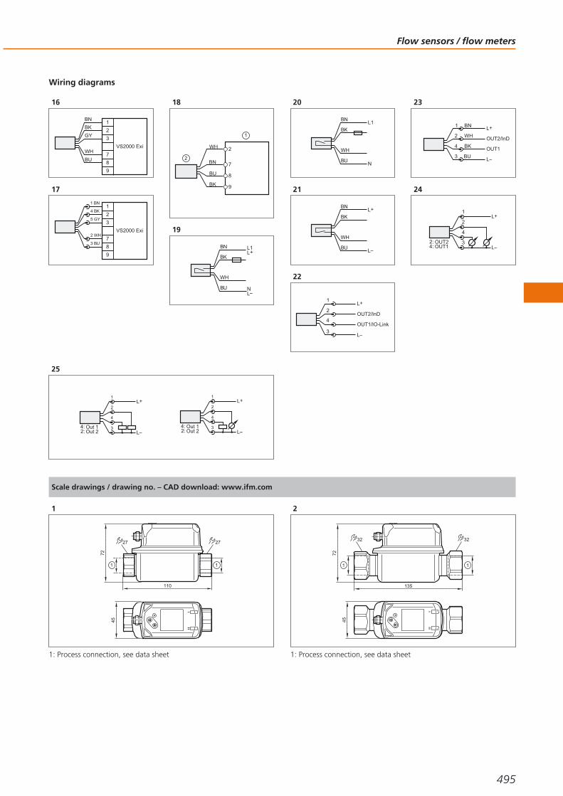
Wiring diagrams
16
BN
WH
BK
BU
1
2
3
7
8
9
GY
VS2000 Exi
17
1
2
3
7
8
9
VS2000 Exi
1 BN
2 WH
4 BK
3 BU
5 GY
18
2
7
8
9BK
BU
BN
WH
19
BN
WH
BU
BK
L1
N
L+
L
20
BN
WH
BU
BKL1
N
21
BN
WH
BU
BKL+
L
22
3
1
4
2
23
4
1
3
2 OUT2/InD
L+
L
BN
BU
OUT1
WH
BK
24
L+
LOUT1OUT2
4:2:
4
2
1
3
25
L+
LOut 2Out 1
2:4: 3
4
2
1
L
L+
Out 2Out 1
2:4: 3
4
2
1
Scale drawings / drawing no. – CAD download: www.ifm.com
1
110
72
45
1
2727
1
1: Process connection, see data sheet
2
135
72
45
1
3232
1
1: Process connection, see data sheet
Flow sensors / flow meters
495
Gesamtkatalog EN 2016_17_Stilvorlage LK FrutigerOT_2010 DE_GB.qxd 06.11.15 16:55 Seite 495
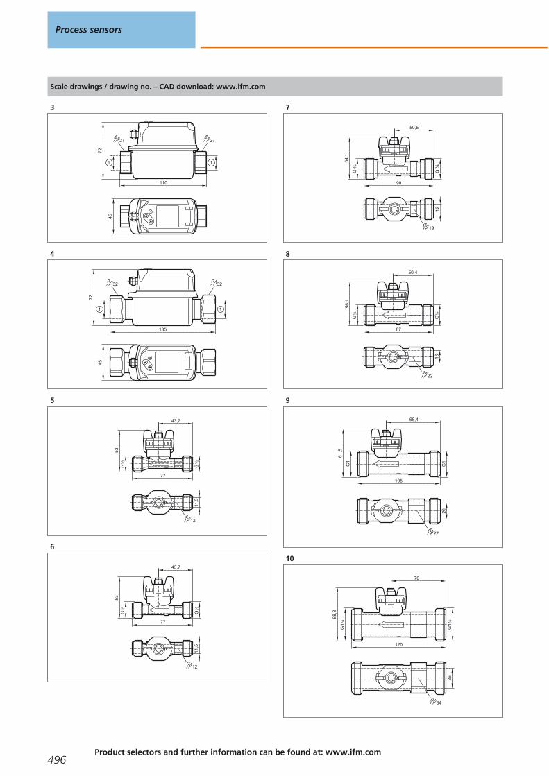
Scale drawings / drawing no. – CAD download: www.ifm.com
3
110
72
45
1
2727
1
4
135
72
45
1
3232
1
5
43,7
77
G2
1
G2
1
53
11,5
12
6
43,7
77
G2
1
G2
1
53
11,5
12
7
50,5
90
54,1
19
G ¾
G ¾
12
8
50,4
87
G4
3
G4
3
56,1
16
22
9
68,4
105
G1
G1
61,5
20
27
10
70
120
68,3
26
34
G1
41
G1
41
Process sensors
496Product selectors and further information can be found at: www.ifm.com
Gesamtkatalog EN 2016_17_Stilvorlage LK FrutigerOT_2010 DE_GB.qxd 06.11.15 16:55 Seite 496

Scale drawings / drawing no. – CAD download: www.ifm.com
11
12
G½
G½
11073
M12 x1
16
M12 x1
54
12
G4
3
G4
3
11073
M12 x1
19
M12 x1
54
15
13
G1
G1
11073
M12 x1
19
M12 x1
54
15
14
M12x1 G2
60
103
G2
113
117
200
40
15
12
G½
G½
110
73
M12 x1
16
M12 x1
54
16
G4
3
G4
3
11073
M12 x1
19
M12 x1
54
15
Flow sensors / flow meters
497
Gesamtkatalog EN 2016_17_Stilvorlage LK FrutigerOT_2010 DE_GB.qxd 06.11.15 16:55 Seite 497

Scale drawings / drawing no. – CAD download: www.ifm.com
17
G1
G1
11073
M12 x1
19
M12 x1
54
15
18
22
1 2
3
113
60 65
14
7,7
45
50
27
63
M12
x1
1: LED display, 2: setting pushbutton, 3: tightening torque 25 Nm
19
22
1 2
113
60 65
14
8,2
45
50
27
63
M12
x1
3
1: LED display, 2: setting pushbutton, 3: tightening torque 25 Nm
20
22
1 2
113
60 65
14
8,2
45
50
27
63
" 20
UN
F 2
A2
1
3
1: LED display, 2: setting pushbutton, 3: tightening torque 25 Nm
21
40
48
M12
x1
34
3
2
1
4
8110
L
8
22
40
48
M12
x1
34
3
2
1
4
8145
15
8
22
23
M12
x1
34
7,7
50
20
15
24
7111
9
27
63
1: LED display, 2: setting pushbutton, 3: G1/Aseptoflex Vario thread
Process sensors
498Product selectors and further information can be found at: www.ifm.com
Gesamtkatalog EN 2016_17_Stilvorlage LK FrutigerOT_2010 DE_GB.qxd 06.11.15 16:55 Seite 498
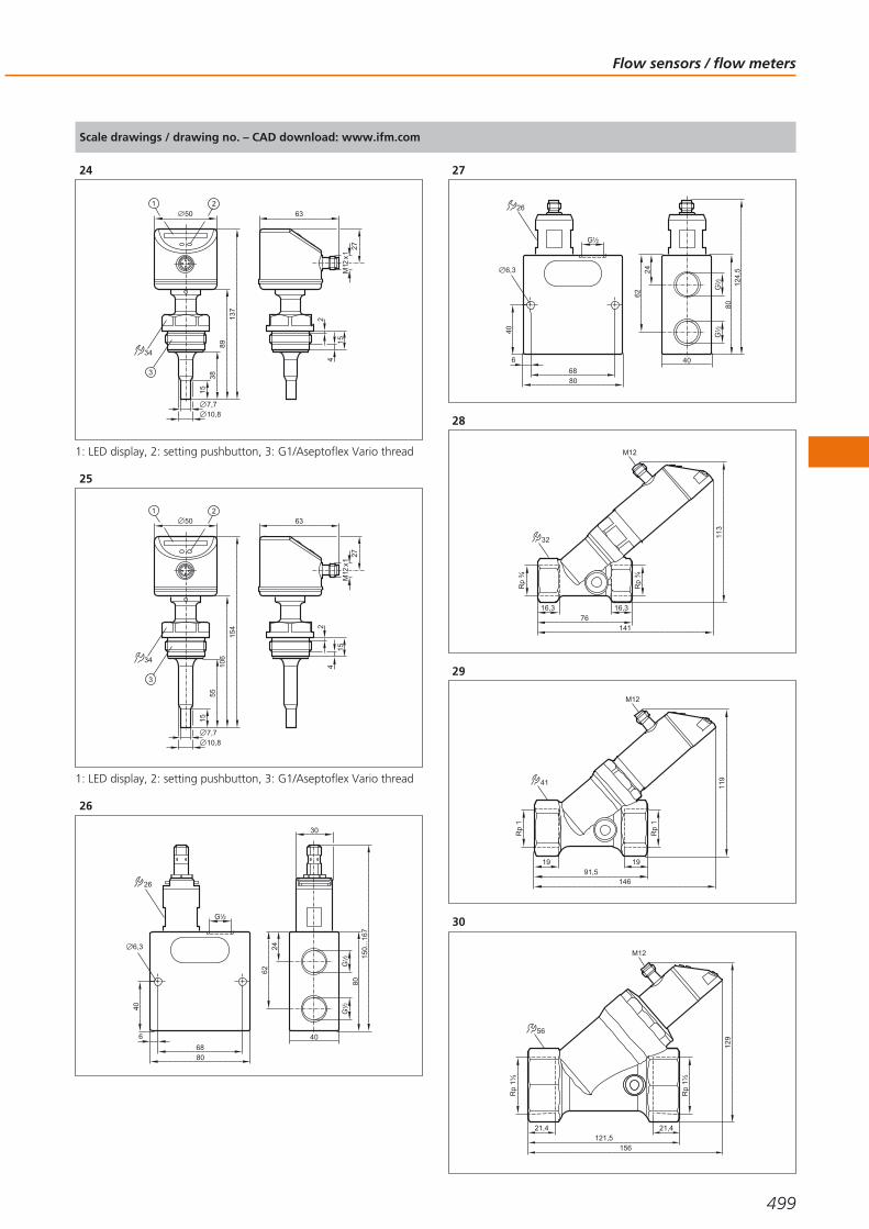
Scale drawings / drawing no. – CAD download: www.ifm.com
24
M12
x1
34
7,710,8
5038
15
24
15
8913
7
27
63
1: LED display, 2: setting pushbutton, 3: G1/Aseptoflex Vario thread
25
M12
x1
34
7,710,8
50
55
15
24
15
106
154
27
63
1: LED display, 2: setting pushbutton, 3: G1/Aseptoflex Vario thread
26
30
G2
1G
21
80
6224
150.
..167
40
G 21
8068
6
40
6,3
26
27
G 21
8068
6
40
6,3
26
G2
1G
21
80
6224
124,
5
40
28
Rp
¾
113
76141
16,3 16,3
Rp
¾
32
M12
29
Rp
1
19 1991,5
146
119
Rp
1
41
M12
30
Rp
1½
129
21,4 21,4121,5
156
Rp
1½
56
M12
Flow sensors / flow meters
499
Gesamtkatalog EN 2016_17_Stilvorlage LK FrutigerOT_2010 DE_GB.qxd 06.11.15 16:55 Seite 499

Scale drawings / drawing no. – CAD download: www.ifm.com
31
G ½
G ½
113
88147
18 18
32
M12
32
G ¾
G ¾
18103,5
152
18
11941
M12
33
G 1
¼
G 1
¼
129
22133,5
162
22
56
M12
34
113...123,576,5
32 97...
105,
5
1313
Rp
43
Rp
43
35
102.
..109
66,513 18 13
113...123,5
27
Rp
21
Rp
21
36
17 17
42
120...12991,5
106.
..112
Rp
1
Rp
1
37
56
137...146,5121,5
121.
..127
,5
Rp
12
1
Rp
12
1
20 20
38
119...129,588,5
32
97...
105,
5
18
G2
1
G2
1
18
Process sensors
500Product selectors and further information can be found at: www.ifm.com
Gesamtkatalog EN 2016_17_Stilvorlage LK FrutigerOT_2010 DE_GB.qxd 06.11.15 16:55 Seite 500
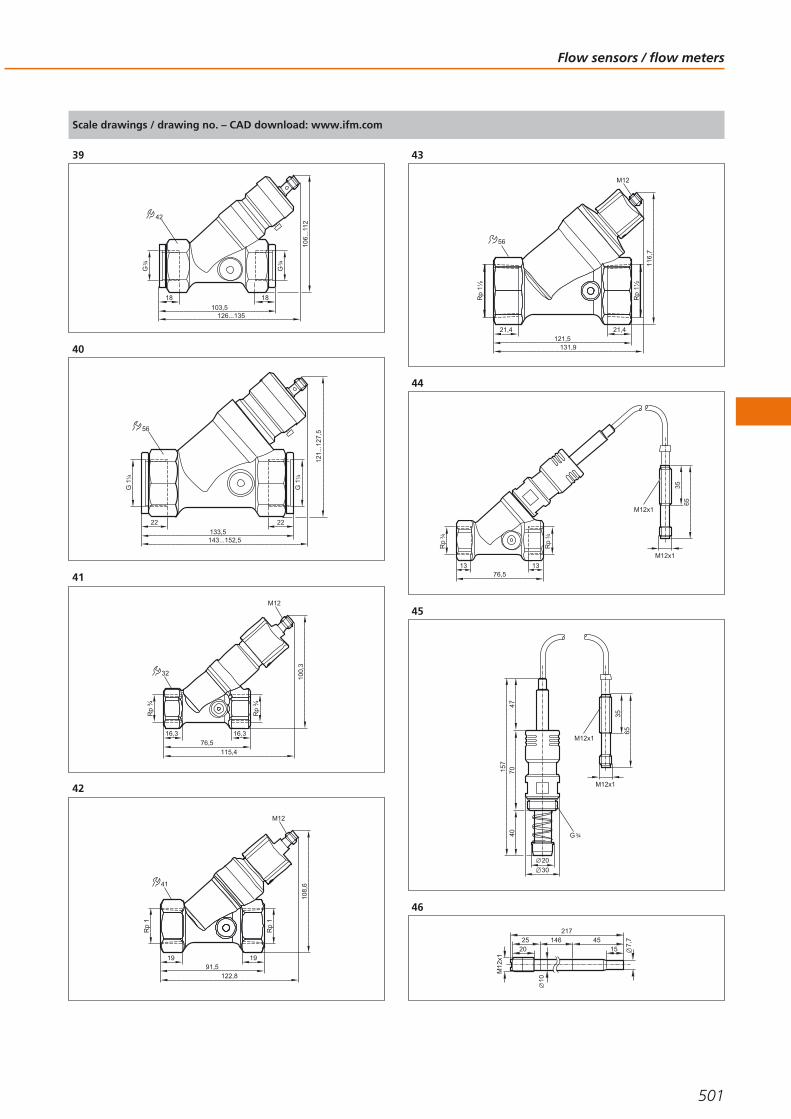
Scale drawings / drawing no. – CAD download: www.ifm.com
39
18
42
126...135103,5
106.
..112
G4
3
18
G4
3
40
56
143...152,5133,5
121.
..127
,5
G 1
41
22
G 1
41
22
41
M12
Rp
¾
Rp
¾
16,3 16,3
76,5115,4
100,
3
32
42
108
,6
91,5
Rp
1
Rp
1
19 19
122,8
41
M12
43
116,
7
21,4121,5
131,9
M12
Rp
1½
Rp
1½
21,4
56
44
3565
M12x1
M12x1
1376,5
13
Rp
43
Rp
43
4535
65
M12x1
M12x1
20
4070
4715
7
30
G 43
46
7,745
15
M12
x1
217
10
2025 146
Flow sensors / flow meters
501
Gesamtkatalog EN 2016_17_Stilvorlage LK FrutigerOT_2010 DE_GB.qxd 06.11.15 16:55 Seite 501

Scale drawings / drawing no. – CAD download: www.ifm.com
47
7,745
15
M12
x1
132
10
26
48
M12
x1
8272
22
14
8,2
44
19 1
1: internal thread M18 x 1.5
49
M12
x1
9282
22
14
7,7
55
19 1
8,2 15
internal thread M18 x 1.5
50
8672
22
14
8,2
44
19 1
1: internal thread M18 x 1.5
51
10263
4515
14
M12
x1
2211
8,2
10
1: internal thread M18 x 1.5
52
13293
4515
14
M12
x1
2211
8,2
10
1: internal thread M18 x 1.5
53
182143
4515
14
M12
x1
2211
8,2
10
1: internal thread M18 x 1.5
54
282243
4515
14
M12
x1
2211
8,2
10
1: internal thread M18 x 1.5
55
8,6
M12
x1
52
122713
17
G4
1
1
1: tightening torque max. 8 Nm
56
M12
x1
G2
1
15,54515
72
15
8,6
27
1
1: tightening torque max. 30 Nm
57
52
8,6
12
2713
G4
1
17 1
1: tightening torque max. 8 Nm
58
G2
1
15,54515
76,5
15
8,6
1
27
1: tightening torque max. 30 Nm
Process sensors
502Product selectors and further information can be found at: www.ifm.com
Gesamtkatalog EN 2016_17_Stilvorlage LK FrutigerOT_2010 DE_GB.qxd 06.11.15 16:55 Seite 502

Scale drawings / drawing no. – CAD download: www.ifm.com
59
17
55
122713
8,2
M12
x160
17
55
122713
8,2
G4
1
61
G2
1
124515
75
8,2
27
62
17
55
122713
M12
x17,
7
63
17
55
122713
7,7
G4
1
64
124515
75
27
G2
1
7,7
65
M12
x1
M12
x1
7,7
52
122713
17
66
M12
x1
7,7
52
122713
17
G4
1
67
M12
x1
124515
75
7,7
27
G2
1
68
G2
1
9515 45
20
27
7,7
69
140133
113
3223
2 LED
pot.2 LED
70
182,3
21,3
M12
x1
100111
74,5
G1
4 /
45
1 2
G1
4 /
60 20
31
3
1: 4-digit alphanumeric display, 2: Programming buttons, 3: hole for M5 fixing screw
Flow sensors / flow meters
503
Gesamtkatalog EN 2016_17_Stilvorlage LK FrutigerOT_2010 DE_GB.qxd 06.11.15 16:55 Seite 503

Scale drawings / drawing no. – CAD download: www.ifm.com
71
45
80,4
100111
M12
x1
R2
1
14
160 40300
21,3
1: 4-digit alphanumeric display, 2: Programming buttons
72
G 21
45
80,4
100111
M12
x1
1: 4-digit alphanumeric display, 2: Programming buttons
73
475375
27,3
33,7
R 1
M12
x1
100111
88,5
45
1 2
1: 4-digit alphanumeric display, 2: Programming buttons
74
39
R11
2
275475
42
100111
M12
x1
120
45
1 2
1: 4-digit alphanumeric display, 2: Programming buttons
75
133
45
1 2
54
R2 51
100111
M12
x1
275475
1: 4-digit alphanumeric display, 2: Programming buttons
76
111,5
96,5
451
2
3
6252,8
12
100
M12
x1
36
1: Programming buttons, 2: 4-digit alphanumeric display, 3: LEDs
77
R
210300
16,1
21,3
M12
x1
100111
76,8
45
1 2
1: 4-digit alphanumeric display, 2: Programming buttons
78
19
G4
3
G4
3
11096
100
80,5
M12
x1
installation length with pipe adapter E40151 / E40154: 185 mm
Process sensors
504Product selectors and further information can be found at: www.ifm.com
Gesamtkatalog EN 2016_17_Stilvorlage LK FrutigerOT_2010 DE_GB.qxd 06.11.15 16:55 Seite 504
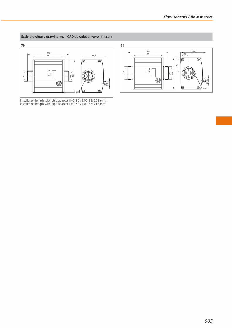
Scale drawings / drawing no. – CAD download: www.ifm.com
79
24
80,5
M12
x1
13096
100
G1
G1
installation length with pipe adapter E40152 / E40155: 205 mm,installation length with pipe adapter E40153 / E40156: 215 mm
80
80,5
M12
x1
26
48
13096
100
G1
41
G1
41
30,3
Flow sensors / flow meters
505
Gesamtkatalog EN 2016_17_Stilvorlage LK FrutigerOT_2010 DE_GB.qxd 06.11.15 16:55 Seite 505

Guided wave radar, capacitive and hydrostatic level sensors
Designed for common industrial and process fluids
No moving parts means high reliability and long service life
Outputs for continuous or point level measurement
Integrated LED display for local indication
Level sensors
ifm offers a range of level sensing technologies to suit a wide variety of level moni-toring applications. From monitoring simple automatic filling system and overflowprevention sensors to continuous process control ifm level sensors can give an effective solution to your application requirements.
Advantages of electronic sensors
Level monitoring systems that rely on mechanical movement are prone to erraticbehaviour and failure. Simple wear and tear or the build-up of deposits can causemechanical devices to stick or break apart. Electronic sensors from ifm have nomoving parts and evaluate level using either guided wave radar, capacitance orhydrostatic pressure. This makes ifm’s sensors especially robust and reliable.
Other advantages of electronic sensors are the local indication of the level and theeasy setting of output function, such as the switch point.
Measurement principles
Continuous level sensors from ifm use one of four different physicalmeasuring principles: For capacitive measurement the probe and the tank form anelectrical capacitor. The capacitance changes with the level and is converted into alevel measurement by a microprocessor. For hydrostatic level measurement ameasuring cell detects the hydrostatic pressure of the medium. Here the pressurechange is a measure for the level. The efector gwr level sensor operates on theprinciple of guided wave radar. Electromagnetic pulses are transmitted by the sen-sor head and guided along the probe. When the microwave pulse hits the mediumto be detected, it is reflected and the elapsed time is evaluated by the sensor.
Point levels can be set on many of the units using any of the three technologiesabove. The LM family adds a fourth; impedance spectroscopy is used to generatereliable switch points while ignoring foam and product residue sticking to theprobe.
Point level switchesmake direct contactwith the medium tobe monitored.
For special applica-tions: Level sensor
mounted in the top ofa tank.
Process sensors
506Product selectors and further information can be found at: www.ifm.com
Gesamtkatalog EN 2016_17_Stilvorlage LK FrutigerOT_2010 DE_GB.qxd 06.11.15 16:55 Seite 506

System overview Page
Electronic level sensors for oils and coolants, approval to the German Federal Water Act (WHG), section 19 508
Electronic level sensors for oils and coolants 508 - 509
Point level sensors for oils and coolants, approval to the German Federal Water Act (WHG), section 19 509
Point level sensors for oils and lubricants 510
Point level sensors for oils and coolants, approval to the German Federal Water Act (WHG), section 19 510
Point level sensors for hygienic areas, approval to the German Federal Water Act WHG section 19 511
Variable level sensors, guided wave radar, hygienic areas 511
Variable level sensors, guided wave radar, industrial applications 511 - 512
Compact sensors for level and temperature monitoring 512
Compact sensors for level and leakage monitoring 513
Sensors for hydrostatic level monitoring 513 - 514
Sensors for hydrostatic level monitoring ATEX category 1G/1D 514
Sensors for hydrostatic level monitoring in hygienic and wet areas 514 - 516
Accessories for level sensors LK, LT, LL, LI 516 - 517
Parameter-setting system 517 - 518
Certificates 518
Accessories for level sensors LM 518 - 519
Accessories 3A 519 - 520
Accessories for level sensors LR 520
LR probes for standard applications 520 - 521
LR probes for hygienic areas 521
LR coaxial pipes 522 - 523
Hygienic adapters 523
Accessories for level sensors PA, PG, PI, PN, PS, PY 524
Wiring diagrams 524 - 525
Scale drawings / drawing no. – CAD download: www.ifm.com 525 - 528
Level sensors
507
Gesamtkatalog EN 2016_17_Stilvorlage LK FrutigerOT_2010 DE_GB.qxd 06.11.15 16:55 Seite 507
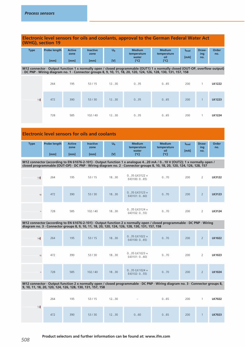
Electronic level sensors for oils and coolants, approval to the German Federal Water Act(WHG), section 19
Type Probe length
[mm]
Activezone
[mm]
Inactivezone
[mm]
Ub
[V]
Mediumtemperature
water[°C]
Mediumtemperature
oil[°C]
Iload
[mA]
Draw-ingno.
Orderno.
M12 connector · Output function 1 x normally open / closed programmable (OUT1) 1 x normally closed (OUT-OP, overflow output)· DC PNP · Wiring diagram no. 1 · Connector groups 8, 9, 10, 11, 18, 20, 120, 124, 126, 128, 130, 131, 157, 158
264 195 53 / 15 12...30 0...35 0...65 200 1 LK1222
472 390 53 / 30 12...30 0...35 0...65 200 1 LK1223
728 585 102 / 40 12...30 0...35 0...65 200 1 LK1224
Electronic level sensors for oils and coolants
Type Probe length
[mm]
Activezone
[mm]
Inactivezone
[mm]
Ub
[V]
Mediumtemperature
water[°C]
Mediumtemperature
oil[°C]
Iload
[mA]
Draw-ingno.
Orderno.
M12 connector (according to EN 61076-2-101) · Output function 1 x analogue 4...20 mA / 0...10 V (OUT2); 1 x normally open / closed programmable (OUT-OP) · DC PNP · Wiring diagram no. 2 · Connector groups 8, 10, 18, 20, 120, 124, 126, 128, 157
264 195 53 / 15 18...300...35 (LK3122 +E43100: 0...65)
0...70 200 2 LK3122
472 390 53 / 30 18...300...35 (LK3123 +E43101: 0...60)
0...70 200 2 LK3123
728 585 102 / 40 18...300...35 (LK3124 +E43102: 0...55)
0...70 200 2 LK3124
M12 connector (according to EN 61076-2-101) · Output function 2 x normally open / closed programmable · DC PNP · Wiring diagram no. 3 · Connector groups 8, 9, 10, 11, 18, 20, 120, 124, 126, 128, 130, 131, 157, 158
264 195 53 / 15 18...300...35 (LK1022 +E43100: 0...65)
0...70 200 2 LK1022
472 390 53 / 30 18...300...35 (LK1023 +E43101: 0...60)
0...70 200 2 LK1023
728 585 102 / 40 18...300...35 (LK1024 +E43102: 0...55)
0...70 200 2 LK1024
M12 connector · Output function 2 x normally open / closed programmable · DC PNP · Wiring diagram no. 3 · Connector groups 8,9, 10, 11, 18, 20, 120, 124, 126, 128, 130, 131, 157, 158
264 195 53 / 15 12...30 – 0...65 200 1 LK7022
472 390 53 / 30 12...30 0...60 0...65 200 1 LK7023
Process sensors
508Product selectors and further information can be found at: www.ifm.com
Gesamtkatalog EN 2016_17_Stilvorlage LK FrutigerOT_2010 DE_GB.qxd 06.11.15 16:55 Seite 508

Type Probe length
[mm]
Activezone
[mm]
Inactivezone
[mm]
Ub
[V]
Mediumtemperature
water[°C]
Mediumtemperature
oil[°C]
Iload
[mA]
Draw-ingno.
Orderno.
M12 connector · Output function 2 x normally open / closed programmable · DC PNP · Wiring diagram no. 3 · Connector groups 8,9, 10, 11, 18, 20, 120, 124, 126, 128, 130, 131, 157, 158
728 585 102 / 40 12...30 0...55 0...65 200 1 LK7024
M12 connector (according to EN 61076-2-101) · Output function 3 x normally open / closed programmable (OUT1...OUT3); 1 x normally open / closed programmable (OUT-OP) · DC PNP · Wiring diagram no. 4 · Connector groups 16, 17
264 195 53 / 15 18...300...35 (LK8122 +E43100: 0...65)
0...70 200 3 LK8122
472 390 53 / 30 18...300...35 (LK8123 +E43101: 0...60)
0...70 200 3 LK8123
728 585 102 / 40 18...300...35 (LK8124 +E43102: 0...55)
0...70 200 3 LK8124
Point level sensors for oils and coolants, approval to the German Federal Water Act (WHG), section 19
Type Probe length
[mm]
Output Ub
[V]
Mediumtemperature
water[°C]
Mediumtemperature
oil[°C]
Iload
[mA]
Draw-ingno.
Orderno.
M12 connector · Output function · DC PNP · Wiring diagram no. 5 · Connector groups 8, 10, 11, 18, 20, 120, 124, 126, 128,130, 157, 158
132 Normally closed 10...36 0...35 0...65 200 4 LI2141
273 Normally closed 10...36 0...35 0...65 200 4 LI2142
481 Normally closed 10...36 0...35 0...65 200 4 LI2143
132 Normally closed 10...36 0...35 0...65 200 4 LI2241
273 Normally closed 10...36 0...35 0...65 200 4 LI2242
481 Normally closed 10...36 0...35 0...65 200 4 LI2243
Level sensors
509You can find wiring diagrams and scale drawings from page 524
Gesamtkatalog EN 2016_17_Stilvorlage LK FrutigerOT_2010 DE_GB.qxd 06.11.15 16:55 Seite 509

Point level sensors for oils and lubricants
Type Probe length
[mm]
Output Ub
[V]
Mediumtemperature
water[°C]
Mediumtemperature
oil[°C]
Iload
[mA]
Draw-ingno.
Orderno.
M12 connector · Output function · DC PNP · Wiring diagram no. 5 · Connector groups 8, 10, 11, 18, 20, 120, 124, 126,128, 130, 157, 158
132normally open /
closed programmable10...36
0...35 (LI5141 +E43103: 0...65)
0...65 200 4 LI5141
273normally open /
closed programmable10...36
0...35 (LI5142 +E43100: 0...65)
0...65 200 4 LI5142
481normally open /
closed programmable10...36
0...35 (LI5143 +E43101: 0...60)
0...65 200 4 LI5143
737normally open /
closed programmable10...36
0...35 (LI5144 +E43102: 0...55)
0...65 200 4 LI5144
Point level sensors for oils and coolants, approval to the German Federal Water Act (WHG), section 19
Type Processconnection
Output Ub
[V]
Mediumtemperature
water[°C]
Mediumtemperature
oil[°C]
Iload
[mA]
Draw-ingno.
Orderno.
M12 connector · Output function 1 x NO / 1 x NC (WHG) · DC PNP · Wiring diagram no. 6 · Connector groups 8, 9, 10, 11, 18, 20,120, 124, 126, 128, 130, 131, 157, 158
G ½ A1 x NO / 1 x NC
(WHG) PNP18...30 -40...85 / (0...85) -40...100 / (0...100) 100 5 LMT191
G ½ A1 x NO / 1 x NC
(WHG) PNP18...30 -25...85 / (0...85) -25...100 / (0...100) 100 6 LMT192
G ½ A1 x NO / 1 x NC
(WHG) PNP18...30 -25...85 / (0...85) -25...100 / (0...100) 100 7 LMT194
G ½ A1 x NO / 1 x NC
(WHG) PNP18...30 -25...85 / (0...85) -25...100 / (0...100) 100 8 LMT195
G ¾ A1 x NO / 1 x NC
(WHG) PNP18...30 -25...85 / (0...85) -25...100 / (0...100) 100 9 LMT292
G 1 A1 x NO / 1 x NC
(WHG) PNP18...30 -25...85 / (0...85) -25...100 / (0...100) 100 10 LMT392
Process sensors
510Product selectors and further information can be found at: www.ifm.com
Gesamtkatalog EN 2016_17_Stilvorlage LK FrutigerOT_2010 DE_GB.qxd 06.11.15 16:55 Seite 510

Point level sensors for hygienic areas, approval to the German Federal Water Act (WHG) section 19
Type Processconnection
Output Ub
[V]
Mediumtemperature
water[°C]
Mediumtemperature
oil[°C]
Iload
[mA]
Draw-ingno.
Orderno.
M12 connector · Output function 2 x normally open / closed programmable · DC PNP/NPN · Wiring diagram no. 7 · Connectorgroups 8, 9, 10, 11, 18, 20, 120, 124, 126, 128, 130, 131, 157, 158
G ½ A2 x normally open /
closed programmablePNP/NPN
18...30 -40...85 -40...100 100 5 LMT100
G ½ A2 x normally open /
closed programmablePNP/NPN
18...30 -20...85 -20...100 100 6 LMT102
G ½ A2 x normally open /
closed progr. PNP/NPN18...30 -20...85 -20...100 100 7 LMT104
G ½ A2 x normally open /
closed progr. PNP/NPN18...30 -20...85 -20...100 100 8 LMT105
G ½ A2 x normally open /
closed progr. PNP/NPN18...30 -40...85 -40...100 100 5 LMT110
G ½ A2 x normally open /
closed progr. PNP/NPN18...30 -40...85 -40...100 100 5 LMT121
G ¾ A2 x normally open /
closed programmablePNP/NPN
18...30 -20...85 -20...100 100 9 LMT202
G 1 A2 x normally open /
closed programmablePNP/NPN
18...30 -20...85 -20...100 100 10 LMT302
Variable level sensors, guided wave radar, hygienic areas
Type Processconnection
Probe length
[mm]
Activezone
[mm]
Inactive zone
[mm]
Ub
[V]
Mediumtemperature
[°C]
Iload
[mA]
Draw-ingno.
Orderno.
M12 connector (according to EN 61076-2-101) · Output function OUT1: normally open / closed programmable / IO-Link OUT2: normally open / closed programmable or analogue (4...20 mA scaleable, invertable) · DC PNP/NPN · Wiring diagram no. 7 · Connector groups 8, 10, 18, 20, 120, 124, 126, 128, 157
Aseptoflex Vario 150...2000 L-40 30 / 10 18...30 -40...150 150 11 LR2750
Variable level sensors, guided wave radar, industrial applications
Type Processconnection
Probe length
[mm]
Activezone
[mm]
Inactive zone
[mm]
Ub
[V]
Mediumtemperature
[°C]
Iload
[mA]
Draw-ingno.
Orderno.
M12 connector (according to EN 61076-2-101) · Output function OUT1: normally open / closed programmable / IO-Link OUT2: normally open / closed programmable or analogue (4...20 mA scaleable, invertable) · DC PNP/NPN · Wiring diagram no. 7 · Connector groups 8, 10, 18, 20, 120, 124, 126, 128, 157
G ¾ A 150...2000 L-40 / (L-60) 30 / 10 (30) 18...30 -20...100 150 12 LR2050
Level sensors
511You can find wiring diagrams and scale drawings from page 524
Gesamtkatalog EN 2016_17_Stilvorlage LK FrutigerOT_2010 DE_GB.qxd 06.11.15 16:55 Seite 511
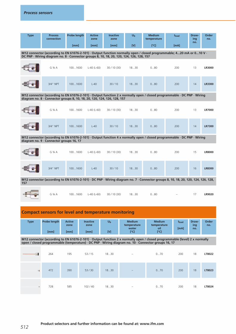
Type Processconnection
Probe length
[mm]
Activezone
[mm]
Inactive zone
[mm]
Ub
[V]
Mediumtemperature
[°C]
Iload
[mA]
Draw-ingno.
Orderno.
M12 connector (according to EN 61076-2-101) · Output function normally open / closed programmable; 4...20 mA or 0...10 V · DC PNP · Wiring diagram no. 8 · Connector groups 8, 10, 18, 20, 120, 124, 126, 128, 157
G ¾ A 100...1600 L-40 (L-60) 30 / 10 (30) 18...30 0...80 200 13 LR3000
3/4" NPT 100...1600 L-40 30 / 10 18...30 0...80 200 14 LR3300
M12 connector (according to EN 61076-2-101) · Output function 2 x normally open / closed programmable · DC PNP · Wiring diagram no. 8 · Connector groups 8, 10, 18, 20, 120, 124, 126, 128, 157
G ¾ A 100...1600 L-40 (L-60) 30 / 10 (30) 18...30 0...80 200 13 LR7000
3/4" NPT 100...1600 L-40 30 / 10 18...30 0...80 200 14 LR7300
M12 connector (according to EN 61076-2-101) · Output function 4 x normally open / closed programmable · DC PNP · Wiring diagram no. 9 · Connector groups 16, 17
G ¾ A 100...1600 L-40 (L-60) 30 / 10 (30) 18...30 0...80 200 15 LR8000
3/4" NPT 100...1600 L-40 30 / 10 18...30 0...80 200 16 LR8300
M12 connector (according to EN 61076-2-101) · DC PNP · Wiring diagram no. 7 · Connector groups 8, 10, 18, 20, 120, 124, 126, 128,157
G ¾ A 100...1600 L-40 (L-60) 30 / 10 (30) 18...30 0...80 – 17 LR9020
Compact sensors for level and temperature monitoring
Type Probe length
[mm]
Activezone
[mm]
Inactivezone
[mm]
Ub
[V]
Mediumtemperature
water[°C]
Mediumtemperature
oil[°C]
Iload
[mA]
Draw-ingno.
Orderno.
M12 connector (according to EN 61076-2-101) · Output function 2 x normally open / closed programmable (level) 2 x normallyopen / closed programmable (temperature) · DC PNP · Wiring diagram no. 10 · Connector groups 16, 17
264 195 53 / 15 18...30 – 0...70 200 18 LT8022
472 390 53 / 30 18...30 – 0...70 200 18 LT8023
728 585 102 / 40 18...30 – 0...70 200 18 LT8024
Process sensors
512Product selectors and further information can be found at: www.ifm.com
Gesamtkatalog EN 2016_17_Stilvorlage LK FrutigerOT_2010 DE_GB.qxd 06.11.15 16:55 Seite 512

Compact sensors for level and leakage monitoring
Type Probe length
[mm]
Activezone
[mm]
Inactivezone
[mm]
Ub
[V]
Mediumtemperature
water[°C]
Mediumtemperature
oil[°C]
Iload
[mA]
Draw-ingno.
Orderno.
M12 connector (according to EN 61076-2-101) · Output function 4 x normally open / closed programmable · DC PNP · Wiring diagram no. 11 · Connector groups 16, 17
264 195 53 / 15 18...300...35 (LL8022 +E43100: 0...65)
0...70 200 18 LL8022
472 390 53 / 30 18...300...35 (LL8023 +E43101: 0...60)
0...70 200 18 LL8023
728 585 102 / 40 18...300...35 (LL8024 +E43102: 0...55)
0...70 200 18 LL8024
Sensors for hydrostatic level monitoring
Type Measuringrange
[bar]
Cable length /material
Poverload
max. [bar]
Pbursting
min. [bar]
UbDC
[V]
Draw-ingno.
Orderno.
Output function 4...20 mA analogue · Wiring diagram no. 12
0...0.255 m
PUR cable2 2.4 10...30 19 PS3208
0...0.610 m
PUR cable4 4.8 10...30 19 PS3407
0...0.615 m
PUR cable4 4.8 10...30 19 PS3427
0...115 m
PUR cable5 6 10...30 19 PS3417
0...0.630 m
PUR cable4 4.8 10...30 19 PS3607
0...130 m
PUR cable5 6 10...30 19 PS3617
Output function 4...20 mA analogue · Wiring diagram no. 13
0...0.255 m
FEP cable2 2.4 10...30 20 PS4208
0...0.610 m
FEP cable3 4 10...30 20 PS4407
Level sensors
513You can find wiring diagrams and scale drawings from page 524
Gesamtkatalog EN 2016_17_Stilvorlage LK FrutigerOT_2010 DE_GB.qxd 06.11.15 16:55 Seite 513

Type Measuringrange
[bar]
Cable length /material
Poverload
max. [bar]
Pbursting
min. [bar]
UbDC
[V]
Draw-ingno.
Orderno.
· Wiring diagram no. 13
0...115 m
FEP cable5 6 10...30 20 PS4417
Output function 4...20 mA · Wiring diagram no. 14 · Connector groups 8, 10, 18, 20, 120, 124, 126, 128, 157
0...0.25 M12 connector 10 30 9.6...32 21 PA3028
0...0.25 M12 connector 10 30 9.6...32 22 PA3528
Output function 4...20 mA · Wiring diagram no. 15 · Connector groups 8, 10, 18, 20, 120, 124, 126, 128, 157
0...0.1 M12 connector 4 30 9.6...32 22 PA3589
Sensors for hydrostatic level monitoring ATEX category 1G/1D
Type Measuringrange
[bar]
Cable length /material
Poverload
max. [bar]
Pbursting
min. [bar]
UbDC
[V]
Draw-ingno.
Orderno.
Output function 4...20 mA analogue · Wiring diagram no. 13
0...0.255 m
FEP cable2 2.4 10...30 20 PS308A
0...0.610 m
FEP cable4 4.8 10...30 20 PS307A
0...115 m
FEP cable5 6 10...30 20 PS317A
Sensors for hydrostatic level monitoring in hygienic and wet areas
Type Processconnection
Display Measuringrange
[bar]
Poverload
max. [bar]
Pbursting
min. [bar]
UbDC
[V]
Draw-ingno.
Orderno.
M12 connector · Output function 1 x normally open / normally closed programmable + 1 x normally open / normally closed programm-able or 1 x analogue (4...20 / 20...4 mA, scalable) · Wiring diagram no. 16 · Connector groups 8, 10, 18, 20, 120, 124, 126, 128, 157
Aseptoflex Vario Display unit -0.005...0.1 4 30 20...32 23 PI2789
Aseptoflex Vario Display unit -0.0124...0.25 10 30 20...32 23 PI2798
Process sensors
514Product selectors and further information can be found at: www.ifm.com
Gesamtkatalog EN 2016_17_Stilvorlage LK FrutigerOT_2010 DE_GB.qxd 06.11.15 16:55 Seite 514

Type Processconnection
Display Measuringrange
[bar]
Poverload
max. [bar]
Pbursting
min. [bar]
UbDC
[V]
Draw-ingno.
Orderno.
M12 connector · Output function 1 x normally open / normally closed programmable + 1 x normally open / normally closed programm-able or 1 x analogue (4...20 / 20...4 mA, scalable) · Wiring diagram no. 16 · Connector groups 8, 10, 18, 20, 120, 124, 126, 128, 157
Aseptoflex Vario Display unit -1...1 10 30 20...32 23 PI2799
Aseptoflex Vario Display unit -0.05...1 10 30 20...32 23 PI2797
Aseptoflex Vario Display unit -0.124...2.5 20 50 20...32 23 PI2796
Sealing cone G1male
Display unit -0.005...0.1 4 30 20...32 24 PI2889*
Sealing cone G1male
Display unit -0.124...2.5 20 50 20...32 24 PI2896*
Sealing cone G1male
Display unit -0.05...1 10 30 20...32 24 PI2897*
Sealing cone G1male
Display unit -0.0124...0.25 10 30 20...32 24 PI2898*
Sealing cone G1male
Display unit -1...1 10 30 20...32 24 PI2899*
Clamp DN 38 / 1½" Display unit -0.124...2.5 20 50 20...32 25 PI2206
Clamp DN 38 / 1½" Display unit -0.05...1 10 30 20...32 25 PI2207
Clamp DN 38 / 1½" Display unit -1...1 10 30 20...32 25 PI2209
M12 connector · Output function 1 x normally open / closed programmable + 1 x analogue (4...20 / 20...4 mA, scalable) · Wiringdiagram no. 17 · Connector groups 8, 10, 18, 20, 120, 124, 126, 128, 157
Aseptoflex Vario Display unit -0.005...0.1 4 30 18...32 26 PG2789
Aseptoflex Vario Display unit -0.0124...0.25 10 30 18...32 26 PG2798
Aseptoflex Vario Display unit -0.05...1 10 30 18...32 26 PG2797
Aseptoflex Vario Display unit -1...1 10 30 18...32 26 PG2799
Aseptoflex Vario Display unit -0.124...2.5 20 50 18...32 26 PG2796
Level sensors
515You can find wiring diagrams and scale drawings from page 524
Gesamtkatalog EN 2016_17_Stilvorlage LK FrutigerOT_2010 DE_GB.qxd 06.11.15 16:55 Seite 515

Type Processconnection
Display Measuringrange
[bar]
Poverload
max. [bar]
Pbursting
min. [bar]
UbDC
[V]
Draw-ingno.
Orderno.
M12 connector · Output function 1 x normally open / closed programmable + 1 x analogue (4...20 / 20...4 mA, scalable) · Wiringdiagram no. 17 · Connector groups 8, 10, 18, 20, 120, 124, 126, 128, 157
Sealing cone G1male
Display unit -0.124...2.5 20 50 18...32 27 PG2896*
Sealing cone G1male
Display unit -0.05...1 10 30 18...32 27 PG2897*
Sealing cone G1male
Display unit -0.0124...0.25 10 30 18...32 27 PG2898*
Sealing cone G1male
Display unit -1...1 10 30 18...32 27 PG2899*
Sealing cone G1male
Display unit -0.005...0.1 4 30 18...32 27 PG2889*
* Attention: The unit must only be installed in a process connection for G1 sealing cone! The G1 male sealing cone of the unit is only suited for adapters with metal end stop!
Accessories for level sensors LK, LT, LL, LI
Type Description Orderno.
Flange plate · 54-52X52 D16 · for capacitive level sensors LK, LI, LT, LL · Housing materials: flange: aluminium anodised / nut: stainless steel / Spacer: Brass / rubber ring: FPM / sealing: Tesnit
E43007
Flange plate · 65-80 D16 · for capacitive level sensors LK, LI, LT, LL · Housing materials: flange: aluminium anodised / nut: stainless steel / Spacer: Brass / rubber ring: FPM
E43006
Flange plate · 73-90 D16 · for capacitive level sensors LK, LI, LT, LL · according to DIN 24557 · Housing materials: aluminiumanodised / nut: stainless steel / Spacer: Brass / rubber ring: FPM / sealing: NBR
E43001
Mounting adapter · G ¾ D16 · D16 · for capacitive level sensors LK, LI, LT, LL · Housing materials: flange: stainless steel / nut: stainless steel / Spacer: Brass / rubber ring: FPM / sealing: Tesnit
E43003
Mounting adapter · G ¾ D16 · D16 · for capacitive level sensors LI · Housing materials: Brass nickel-plated / TPE / sealing: FKM E43019
Mounting adapter · G ¾ D22 · D22 · for climatic tube LK / LI · Housing materials: stainless steel / NBR / Tesnit / Brass E43008
Mounting adapter · ¾" NPT D16 · D16 · for capacitive level sensors LK, LI, LT, LL · Housing materials: flange: stainless steel / nut: stainless steel / Spacer: Brass / rubber ring: FPM
E43012
Mounting adapter · ¾" NPT D22 · D22 · for climatic tube LK / LI · Housing materials: stainless steel / NBR / Brass E43014
Process sensors
516Product selectors and further information can be found at: www.ifm.com
Gesamtkatalog EN 2016_17_Stilvorlage LK FrutigerOT_2010 DE_GB.qxd 06.11.15 16:55 Seite 516

Type Description Orderno.
Mounting adapter · G 1 D16 · D16 · for capacitive level sensors LK, LI, LT, LL · Housing materials: flange: stainless steel / nut: stainless steel / Spacer: Brass / rubber ring: FPM / sealing: Tesnit
E43004
Mounting adapter · G 1 D22 · D22 · for climatic tube LK / LI · Housing materials: stainless steel / NBR / Tesnit / Brass E43009
Mounting adapter · 1" NPT D16 · D16 · for capacitive level sensors LK, LI, LT, LL · Housing materials: flange: stainless steel / nut: stainless steel / Spacer: Brass / rubber ring: FPM
E43013
Climatic tube · Length: 132 mm · for capacitive level sensors LK, LI · Housing materials: PPH / NBR E43103
Climatic tube · Length: 264 mm · for capacitive level sensors LK, LI · Housing materials: PPH / NBR E43100
Climatic tube · Length: 472 mm · for capacitive level sensors LK, LI · Housing materials: PPH / NBR E43101
Climatic tube · Length: 728 mm · for capacitive level sensors LK, LI · Housing materials: PPH / NBR E43102
Mounting clamp · Ø 16 mm · for capacitive level sensors LK, LI, LT, LL · Housing materials: PP E43000
Mounting set · Ø 16 mm · for capacitive level sensors LK, LI, LT, LL · Housing materials: PP / Metal parts: steel galvanised E43016
Welding adapter · Ø 50 D16 · D16 · for capacitive level sensors LK, LI, LT, LL · Housing materials: flange: stainless steel / nut: stainless steel / Spacer: Brass / rubber ring: FPM
E43002
Protective cover · for LK / LL / LR / LT sensors · Housing materials: PP E43910
Parameter-setting system
Type Description Orderno.
IO-Link interface · for parameter setting and analysis of units with max. 65 mA current consumption · Supported communicationprotocols: IO-Link (4800 and 38400 bits/s) EPS protocol (19200 bits/s) · for operation with FDT framework software "ifm Container“or software "LINERECORDER SENSOR"
E30396
ifm Container · FDT frame software · for parameter setting and analysis of units with DTM specification · e.g. ifm sensors with EPSprogramming interface, · sensors with IO-Link
E30110
Level sensors
517You can find wiring diagrams and scale drawings from page 524
Gesamtkatalog EN 2016_17_Stilvorlage LK FrutigerOT_2010 DE_GB.qxd 06.11.15 16:55 Seite 517
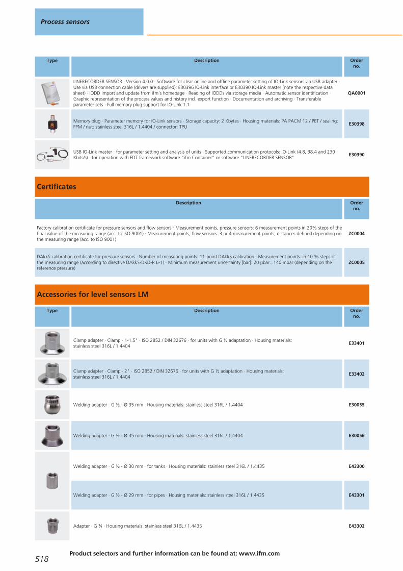
Type Description Orderno.
LINERECORDER SENSOR · Version 4.0.0 · Software for clear online and offline parameter setting of IO-Link sensors via USB adapter ·Use via USB connection cable (drivers are supplied): E30396 IO-Link interface or E30390 IO-Link master (note the respective datasheet) · IODD import and update from ifm's homepage · Reading of IODDs via storage media · Automatic sensor identification ·Graphic representation of the process values and history incl. export function · Documentation and archiving · Transferableparameter sets · Full memory plug support for IO-Link 1.1
QA0001
Memory plug · Parameter memory for IO-Link sensors · Storage capacity: 2 Kbytes · Housing materials: PA PACM 12 / PET / sealing:FPM / nut: stainless steel 316L / 1.4404 / connector: TPU
E30398
USB IO-Link master · for parameter setting and analysis of units · Supported communication protocols: IO-Link (4.8, 38.4 and 230Kbits/s) · for operation with FDT framework software "ifm Container“ or software "LINERECORDER SENSOR"
E30390
Certificates
Description Orderno.
Factory calibration certificate for pressure sensors and flow sensors · Measurement points, pressure sensors: 6 measurement points in 20% steps of thefinal value of the measuring range (acc. to ISO 9001) · Measurement points, flow sensors: 3 or 4 measurement points, distances defined depending onthe measuring range (acc. to ISO 9001)
ZC0004
DAkkS calibration certificate for pressure sensors · Number of measuring points: 11-point DAkkS calibration · Measurement points: in 10 % steps ofthe measuring range (according to directive DAkkS-DKD-R 6-1) · Minimum measurement uncertainty [bar]: 20 μbar...140 mbar (depending on thereference pressure)
ZC0005
Accessories for level sensors LM
Type Description Orderno.
Clamp adapter · Clamp · 1-1.5" · ISO 2852 / DIN 32676 · for units with G ½ adaptation · Housing materials: stainless steel 316L / 1.4404
E33401
Clamp adapter · Clamp · 2" · ISO 2852 / DIN 32676 · for units with G ½ adaptation · Housing materials: stainless steel 316L / 1.4404
E33402
Welding adapter · G ½ - Ø 35 mm · Housing materials: stainless steel 316L / 1.4404 E30055
Welding adapter · G ½ - Ø 45 mm · Housing materials: stainless steel 316L / 1.4404 E30056
Welding adapter · G ½ - Ø 30 mm · for tanks · Housing materials: stainless steel 316L / 1.4435 E43300
Welding adapter · G ½ - Ø 29 mm · for pipes · Housing materials: stainless steel 316L / 1.4435 E43301
Adapter · G ¾ · Housing materials: stainless steel 316L / 1.4435 E43302
Process sensors
518Product selectors and further information can be found at: www.ifm.com
Gesamtkatalog EN 2016_17_Stilvorlage LK FrutigerOT_2010 DE_GB.qxd 06.11.15 16:55 Seite 518

Type Description Orderno.
Adapter · G 1 · Housing materials: stainless steel 316L / 1.4435 E43303
Adapter · ¾" NPT · Housing materials: stainless steel 316L / 1.4404 E43313
Pipe fitting · G ½ · Hygienic pipe fitting · DN25 (1") · DIN 11851 · Housing materials: stainless steel 316L / 1.4435 E43304
Pipe fitting · G ½ · Hygienic pipe fitting · DN40 (1.5") · DIN 11851 · Housing materials: stainless steel 316L / 1.4435 E43305
Clamp adapter · G ½ · Varivent type F · DN25 (1"), D = 50 · Housing materials: stainless steel 316L / 1.4435 E43306
Clamp adapter · G ½ · Varivent type N · DN40...DN150 (1.5...6"), D = 68 · Housing materials: stainless steel 316L / 1.4435 E43307
Welding mandrel · G ½ · carries away heat during welding · Housing materials: brass E43314
Accessories 3A
Type Description Orderno.
Pipe fitting · SMS pipe fitting · DN25 · SMS · for units with G ½ adaptation · Housing materials: stainless steel 316L / 1.4404 E33430
sealing plug · G ½ · Housing materials: stainless steel 316L / 1.4435 E43308
Welding adapter · G ½ - Ø 30 mm · for tanks · with leakage port · with leakage port · Housing materials: stainless steel 316L / 1.4435
E43309
Welding adapter · G ½ - Ø 29 mm · for pipes · with leakage port · with leakage port · Housing materials: stainless steel 316L / 1.4435
E43310
Welding adapter · G ½ · with leakage port · Housing materials: stainless steel 316L / 1.4404 E43315
Clamp adapter · G ½ · with leakage port · Clamp · 1-1.5" · ISO 2852 / DIN 32676 · with leakage port · Housing materials: stainless steel 316L / 1.4435
E43311
Level sensors
519You can find wiring diagrams and scale drawings from page 524
Gesamtkatalog EN 2016_17_Stilvorlage LK FrutigerOT_2010 DE_GB.qxd 06.11.15 16:55 Seite 519

Type Description Orderno.
Clamp adapter · G ½ · with leakage port · Clamp · 2" · ISO 2852 / DIN 32676 · with leakage port · Housing materials: stainless steel 316L / 1.4435
E43312
Accessories for level sensors LR
Type Description Orderno.
Flange plate · 65-80 / G ¾ · for level sensors LR · Housing materials: flange: stainless steel E43202
Flange plate · 73-90 / G ¾ · for level sensors LR · according to DIN 24557 · Housing materials: flange: stainless steel / sealing: NBR
E43201
Flange plate · 73-90 / ¾" NPT · for level sensors LR · according to DIN 24557 · Housing materials: flange: stainless steel / sealing: NBR
E43206
LR probes for standard applications
Type Description Orderno.
Probe · Probe length: 150 mm · for level sensors LR · Housing materials: stainless steel 316L / 1.4404 E43225
Probe · Probe length: 210 mm · for level sensors LR · Housing materials: stainless steel E43351
Probe · Probe length: 240 mm · for level sensors LR · Housing materials: stainless steel 316L / 1.4404 E43203
Probe · Probe length: 265 mm · for level sensors LR · Housing materials: stainless steel E43352
Probe · Probe length: 300 mm · for level sensors LR · Housing materials: stainless steel 316L / 1.4404 E43226
Probe · Probe length: 450 mm · for level sensors LR · Housing materials: stainless steel 316L / 1.4404 E43204
Probe · Probe length: 500 mm · for level sensors LR · Housing materials: stainless steel 316L / 1.4404 E43227
Probe · Probe length: 700 mm · for level sensors LR · Housing materials: stainless steel 316L / 1.4404 E43205
Process sensors
520Product selectors and further information can be found at: www.ifm.com
Gesamtkatalog EN 2016_17_Stilvorlage LK FrutigerOT_2010 DE_GB.qxd 06.11.15 16:55 Seite 520

Type Description Orderno.
Probe · Probe length: 1000 mm · for level sensors LR · Housing materials: stainless steel 316L / 1.4404 E43207
Probe · Probe length: 1200 mm · for level sensors LR · Housing materials: stainless steel 316L / 1.4404 E43208
Probe · Probe length: 1400 mm · for level sensors LR · Housing materials: stainless steel 316L / 1.4404 E43209
Probe · Probe length: 1600 mm · for level sensors LR · Housing materials: stainless steel 316L / 1.4404 E43210
Probe · Probe length: 2000 mm · for level sensors LR205X · Housing materials: stainless steel E43353
LR probes for hygienic areas
Type Description Orderno.
Probe · Probe length: 150 mm · hygienic, for LR level sensors · hygienic systems · Housing materials: stainless steel E43345
Probe · Probe length: 300 mm · hygienic, for LR level sensors · hygienic systems · Housing materials: stainless steel E43346
Probe · Probe length: 500 mm · hygienic, for LR level sensors · hygienic systems · Housing materials: stainless steel E43340
Probe · Probe length: 700 mm · hygienic, for LR level sensors · hygienic systems · Housing materials: stainless steel E43347
Probe · Probe length: 1000 mm · hygienic, for LR level sensors · hygienic systems · Housing materials: stainless steel E43341
Probe · Probe length: 1500 mm · hygienic, for LR level sensors · hygienic systems · Housing materials: stainless steel E43348
Probe · Probe length: 2000 mm · hygienic, for LR level sensors · hygienic systems · Housing materials: stainless steel E43342
Level sensors
521You can find wiring diagrams and scale drawings from page 524
Gesamtkatalog EN 2016_17_Stilvorlage LK FrutigerOT_2010 DE_GB.qxd 06.11.15 16:55 Seite 521
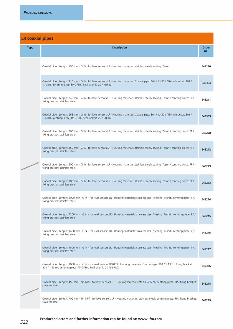
LR coaxial pipes
Type Description Orderno.
Coaxial pipe · Length: 150 mm · G ¾ · for level sensors LR · Housing materials: stainless steel / sealing: Tesnit E43230
Coaxial pipe · Length: 210 mm · G ¾ · for level sensors LR · Housing materials: Coaxial pipe: 304 / 1.4301 / fixing bracket: 301 /1.4310 / centring piece: PP GF30 / Seal: aramid 20 / NBR80:
E43354
Coaxial pipe · Length: 240 mm · G ¾ · for level sensors LR · Housing materials: stainless steel / sealing: Tesnit / centring piece: PP /fixing bracket: stainless steel
E43211
Coaxial pipe · Length: 265 mm · G ¾ · for level sensors LR · Housing materials: Coaxial pipe: 304 / 1.4301 / fixing bracket: 301 /1.4310 / centring piece: PP GF30 / Seal: aramid 20 / NBR80:
E43355
Coaxial pipe · Length: 300 mm · G ¾ · for level sensors LR · Housing materials: stainless steel / sealing: Tesnit / centring piece: PP /fixing bracket: stainless steel
E43228
Coaxial pipe · Length: 450 mm · G ¾ · for level sensors LR · Housing materials: stainless steel / sealing: Tesnit / centring piece: PP /fixing bracket: stainless steel
E43212
Coaxial pipe · Length: 500 mm · G ¾ · for level sensors LR · Housing materials: stainless steel / sealing: Tesnit / centring piece: PP /fixing bracket: stainless steel
E43229
Coaxial pipe · Length: 700 mm · G ¾ · for level sensors LR · Housing materials: stainless steel / sealing: Tesnit / centring piece: PP /fixing bracket: stainless steel
E43213
Coaxial pipe · Length: 1000 mm · G ¾ · for level sensors LR · Housing materials: stainless steel / sealing: Tesnit / centring piece: PP /fixing bracket: stainless steel
E43214
Coaxial pipe · Length: 1200 mm · G ¾ · for level sensors LR · Housing materials: stainless steel / sealing: Tesnit / centring piece: PP /fixing bracket: stainless steel
E43215
Coaxial pipe · Length: 1400 mm · G ¾ · for level sensors LR · Housing materials: stainless steel / sealing: Tesnit / centring piece: PP /fixing bracket: stainless steel
E43216
Coaxial pipe · Length: 1600 mm · G ¾ · for level sensors LR · Housing materials: stainless steel / sealing: Tesnit / centring piece: PP /fixing bracket: stainless steel
E43217
Coaxial pipe · Length: 2000 mm · G ¾ · for level sensors LR205X · Housing materials: Coaxial pipe: 304 / 1.4301 / fixing bracket:301 / 1.4310 / centring piece: PP GF30 / Seal: aramid 20 / NBR80:
E43356
Coaxial pipe · Length: 450 mm · ¾" NPT · for level sensors LR · Housing materials: stainless steel / centring piece: PP / fixing bracket:stainless steel
E43218
Coaxial pipe · Length: 700 mm · ¾" NPT · for level sensors LR · Housing materials: stainless steel / centring piece: PP / fixing bracket:stainless steel
E43219
Process sensors
522Product selectors and further information can be found at: www.ifm.com
Gesamtkatalog EN 2016_17_Stilvorlage LK FrutigerOT_2010 DE_GB.qxd 06.11.15 16:55 Seite 522

Type Description Orderno.
Coaxial pipe · Length: 1000 mm · ¾" NPT · for level sensors LR · Housing materials: stainless steel / centring piece: PP / fixingbracket: stainless steel
E43220
Coaxial pipe · Length: 1200 mm · ¾" NPT · for level sensors LR · Housing materials: stainless steel / centring piece: PP / fixingbracket: stainless steel
E43223
Coaxial pipe · Length: 1400 mm · ¾" NPT · for level sensors LR · Housing materials: stainless steel / centring piece: PP / fixingbracket: stainless steel
E43224
Coaxial pipe · Length: 1600 mm · ¾" NPT · for level sensors LR · Housing materials: stainless steel / centring piece: PP / fixingbracket: stainless steel
E43221
Coaxial pipe · Length: 700 mm · G ¾ · for level sensors LR · Housing materials: stainless steel / sealing: Tesnit / centring piece: PP /fixing bracket: stainless steel
E43333
Coaxial pipe · Length: 1200 mm · G ¾ · for level sensors LR · Housing materials: stainless steel / sealing: Tesnit / centring piece: PP /fixing bracket: stainless steel
E43334
Hygienic adapters
Type Description Orderno.
Welding adapter · Ø 50 mm · for units with Aseptoflex Vario adapter · Sealing by sealing ring · Housing materials: stainless steel316L / 1.4435
E30122
Pipe fitting · Hygienic pipe fitting · Hygienic pipe fitting · DN40 (1.5") · DIN 11851 · for units with Aseptoflex Vario adapter · Sealing by sealing ring · Housing materials: stainless steel 316L / 1.4435
E33212
Level sensors
523You can find wiring diagrams and scale drawings from page 524
Accessories for level sensors PA, PG, PI, PN, PS, PY
Type Description Orderno.
Cable clamp fastener · for submersible pressure transmitter PS3 · Housing materials: steel / plastics E30399
Filter element · for submersible pressure transmitter PS3 · for fixing on the capillary tube E30400
Splitter box · with ventilation and terminal block · for submersible pressure transmitter PS3 · Housing materials: plastics E30401
Additional weight · for submersible pressure transmitter PS3 · Housing materials: stainless steel 316Ti / 1.4571 E30402
Gesamtkatalog EN 2016_17_Stilvorlage LK FrutigerOT_2010 DE_GB.qxd 06.11.15 16:55 Seite 523

Core colours
BK black
BN brown
BU blue
WH white
GY grey
GN green
Wiring diagrams
1
L
L+
3 BU
4 BK
2 WH
1 BN
Out-OPOut 1
2:4:
2
L+
L3 BU
4 BK
2 WH
1 BN
Out-OPOut 2
4:2:
3
2
L
L+
4
1
3Out 1Out 2
4:2:
4
Out-OP / Out 4
3
4
2
5
6
Out 1
Out 3
L+1
n.c.7
Out 2
L
5
L+
L
1
4
3
6
BN
WH
BK
BU
4
1
3
2 OUT-OP
L+
L
OUT1
7
BN
WH
BK
BU
4
1
3
2 OUT2
L+
L
OUT1
8
3
1
4
2
9
1
2
4
6
3
5
L+
L
Out 1 / IO-Link
Out 2
Out 4
Out 3
10
Out 4
3
4
2
5
6
Out 1
Out 3
L+1
n.c.7
Out 2
L
11
Out-OP
3
4
2
5
6
Out 1
Out 3
L+1
n.c.7
Out 2
L
12
BN
GY
WH
L+
L
13
1
BN
GN
L+
L
1: screen (connected to thehousing)
14
L+
L
1
2
15
L+BN1
WH2OUT
Process sensors
524
Pipe fitting · Hygienic pipe fitting · Hygienic pipe fitting · DN50 (2") · DIN 11851 · for units with Aseptoflex Vario adapter · Sealing by sealing ring · Housing materials: stainless steel 316L / 1.4435
E33213
Pipe fitting · Hygienic pipe fitting · Hygienic pipe fitting · DN40 (1.5") · DIN 11851 · for units with Aseptoflex Vario adapter · Metal to metal seal · Housing materials: stainless steel 316L / 1.4435
E33712
Pipe fitting · Hygienic pipe fitting · Hygienic pipe fitting · DN50 (2") · DIN 11851 · for units with Aseptoflex Vario adapter · Metal to metal seal · Housing materials: stainless steel 316L / 1.4435
E33713
Clamp adapter · Clamp · 1-1.5" · ISO 2852 · for units with Aseptoflex Vario adapter · Sealing by sealing ring · Housing materials:stainless steel 316L / 1.4435
E33201
Clamp adapter · Clamp · 1-1.5" · ISO 2852 · for units with Aseptoflex Vario adapter · Metal to metal seal · Housing materials:stainless steel 316L / 1.4435
E33701
Type Description Orderno.
Gesamtkatalog EN 2016_17_Stilvorlage LK FrutigerOT_2010 DE_GB.qxd 06.11.15 16:55 Seite 524
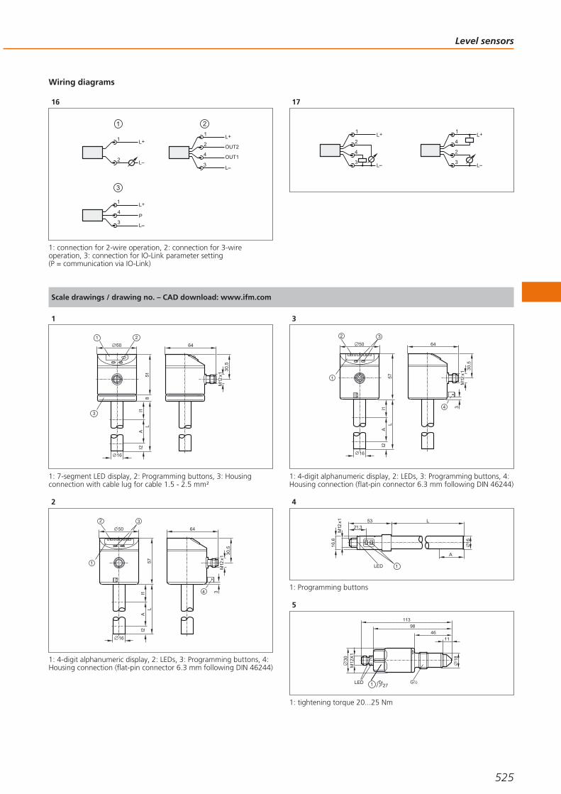
Wiring diagrams
16
4
1
3
2
L+
L
OUT2
OUT1
2
L+
L
1
2
1
3
4
1
3P
L+
L
1: connection for 2-wire operation, 2: connection for 3-wireoperation, 3: connection for IO-Link parameter setting (P = communication via IO-Link)
17
4
1
3
2L+
L
2
1
3
4L+
L
Scale drawings / drawing no. – CAD download: www.ifm.com
1
I1L
16
50
518
AI2
1 2
3
30,5
64
M12
x1
1: 7-segment LED display, 2: Programming buttons, 3: Housingconnection with cable lug for cable 1.5 - 2.5 mm²
2
30,5
64
M12
x1
4 3I1L
16
50
57A
I2
32
1
1: 4-digit alphanumeric display, 2: LEDs, 3: Programming buttons, 4:Housing connection (flat-pin connector 6.3 mm following DIN 46244)
3
30,5
64
M12
x1
4 3I1L
16
50
57A
I2
32
1
1: 4-digit alphanumeric display, 2: LEDs, 3: Programming buttons, 4:Housing connection (flat-pin connector 6.3 mm following DIN 46244)
4
L
16
53
M12
x1
LED
21,3
1
16,6
A
1: Programming buttons
5
1830
G 21LED
113
98
46
11
M12
X1
27
1: tightening torque 20...25 Nm
Level sensors
525
Gesamtkatalog EN 2016_17_Stilvorlage LK FrutigerOT_2010 DE_GB.qxd 06.11.15 16:55 Seite 525

Scale drawings / drawing no. – CAD download: www.ifm.com
6
30M
12x1
38
140
125
73,5
12
27
LED G 21
1: tightening torque 20...25 Nm
7
30
255
240
187
14
170,5
153
G 21
27
LED
M12
X1
1: tightening torque 20...25 Nm
8
30 14
G 21
27
LED
M12
X1
355
340
287
270,5
253
1: tightening torque 20...25 Nm
9
M12
X1
127
112
5428
30
31,6
12
32
G 43LED
27
1: tightening torque 35 Nm
10
140,5
125,567,5
38
M12
X1
12 29
3627
30
LED G1
1: tightening torque 35 Nm
11
M6
M12
x1
34
G1
27
64
38
50
53
105
88
1
2
3
I1
L
AI2
12,5
8
8
12
I1L
AI2
11
50
53
10895
1
2
3
68
M12
x1
34
G3/4
27
64
3833,5
13
M12
x130
63
G 43
86
32
I1L
50
57A
I2
32
7887
1
12
1: 4-digit alphanumeric display, 2: LEDs (display unit / switchingstatus), 3: Programming buttons, 4: sealing, A: Active range, I1 / I2: Inactive ranges
Process sensors
526Product selectors and further information can be found at: www.ifm.com
Gesamtkatalog EN 2016_17_Stilvorlage LK FrutigerOT_2010 DE_GB.qxd 06.11.15 16:55 Seite 526

Scale drawings / drawing no. – CAD download: www.ifm.com
14
I1
L
AI2
5057
3
2
6787
30
63
M12
x1
"NPT
8
43
6
32
1: 4-digit alphanumeric display, 2: LEDs (display unit / switchingstatus), 3: Programming buttons, A: Active range, I1 / I2: Inactiveranges
15
M12
x130
63
G 43
86
32
I1L
50
57A
I2
32
7887
1
12
1: 4-digit alphanumeric display, 2: LEDs (display unit / switchingstatus), 3: Programming buttons, 4: sealing, A: Active range, I1 / I2: Inactive ranges
16
I1
L
AI2
50
57
3
2
6787
30
63
M12
x1
"NPT
8
43
6
32
17
M12
x1 17,5
63
G 43
86
32
I1L
44A
I2
50
6574
12
18
30,5
64
M12
x1
5
4 3I1L
16
50
57A
I2
32
1
1: 4-digit alphanumeric display, 2: LEDs, 3: Programming buttons, 4: Housing connection (flat-pin connector 6.3 mm following DIN 46244), 5: Position of the temperature measuring element
19
100
27
20
27
147
21
75
M12 x130
30
27
1,3
21,5
14
G 41
Level sensors
527
Gesamtkatalog EN 2016_17_Stilvorlage LK FrutigerOT_2010 DE_GB.qxd 06.11.15 16:55 Seite 527

Scale drawings / drawing no. – CAD download: www.ifm.com
22
79,5
M12 x130
30
14
G14/
M5
1
1: sealing FPM / DIN 3869-14
23
16,8
G1
64
M12
x1
105,
852
,8
50
34
1
2 3
15
24
1: 4-digit alphanumeric display, 2: LEDs, 3: Programming button
24
64
M12
x1
105,
645
,127
,4
50
34
46
1
2 3
G1
1: 4-digit alphanumeric display, 2: LEDs, 3: Programming button, 4: Sealing cone G1 male, Attention: The unit must only be installed ina process connection for G1 sealing cone! The G1 male sealing coneof the unit is only suited for adapters with metal end stop!
25
64
M12
x1
50
34
1
2 3
163
5030
50,534
1: 4-digit alphanumeric display, 2: LEDs, 3: Programming button
26
24
3
153
16,8
100
2
1
57
60,5
M12
x1
G1
1: Analogue display, 2: 4-digit alphanumeric display, 3: Programmingbutton
27
24
34
3
153
27
100
2
1
G1
57
60,5
M12
x1
1: Analogue display, 2: 4-digit alphanumeric display, 3: Touch button(programming button), 4: Sealing cone G1 male, Attention: The unitmust only be installed in a process connection for G1 sealing cone!The G1 male sealing cone of the unit is only suited for adapters withmetal end stop!
Process sensors
528Product selectors and further information can be found at: www.ifm.com
Gesamtkatalog EN 2016_17_Stilvorlage LK FrutigerOT_2010 DE_GB.qxd 06.11.15 16:55 Seite 528

Level sensors
529
Gesamtkatalog EN 2016_17_Stilvorlage LK FrutigerOT_2010 DE_GB.qxd 06.11.15 16:55 Seite 529

Temperature sensors in contact with themedium for industrial and hygienic applications
Modular concept – tailored to every application
Various fittings availablefor process connections
Robust mechanics with high vibration and shock resistance
Non-contact infrared temperaturesensors for hot objects
Temperature sensors
ifm offers a very wide range of temperature monitoring products to suit the needsof many industries. One end of the range offers simple probes based on Pt100 orPt1000 resistive elements. At the top end we have a diverse redundant transmitterdesign which is warranted to stay within tolerance for 5 years or raise an alarm if itdrifts – ideal for those critical or difficult to reach installations.
What makes an ifm probe different?
The key to a good temperature probe is the balance between being responsive tochanging temperatures and being robust enough to cope with an ever changingenvironment. ifm uses flexible, temperature-resistant and extremely stable polyami-de film as a carrier of the SMD Pt100 components in place of circuit boards. Thisallows us to position the sensing element right up to the probe wall, making for avery fast response.
From sensor to system
ifm provides a selection of options for customers requiring temperature monitoring.The simplest systems are the all-in-one temperature transmitters which can be supp-lied for both industrial and hygienic applications. Others prefer the flexibility ofsourcing the probe and monitor separately and then combining them on site in oneof several ways. This gives the widest range of probe shapes and sizes for specificapplications. The evaluation can be achieved locally with a simple head transmitter,type TP, or by using a more feature-laden monitor like the TR which has its owndisplay. The top end solution is the TAD transmitter. It uses two independent tem-perature monitoring technologies which are then internally cross-checked by themicroprocessor. If ever they stop agreeing with each other’s measurement then thetransmitter will raise an alarm to alert the customer that he can no longer be 100 %certain of that measure and some action should be taken. ifm offers a 5 year war-ranty on that peace of mind.
Indirect temperature measurement
In most cases the infrared temperature measurement is used where temperaturescan only be measured indirectly, that means without contact. The reason for thiscan for example be a high temperature of the object. The sensors detect the infra-red radiation emitted by the objects and convert them into an output signal.
Local display of thecurrent temperature.
Essential: Tempera-ture monitoring in air
conditioning.
Process sensors
530Product selectors and further information can be found at: www.ifm.com
Gesamtkatalog EN 2016_17_Stilvorlage LK FrutigerOT_2010 DE_GB.qxd 06.11.15 16:55 Seite 530

System overview Page
Compact temperature sensors 532
Compact temperature sensors with display, IO-Link 532
Control monitors for temperature sensors 532
Control monitors for temperature sensors, IO-Link 533
Modular temperature transmitters 533
Pt1000 probe sensors for industrial applications 533 - 534
Pt100 probe sensors for industrial applications 534 - 535
Screw-in sensors for industrial applications 535
Cable sensors for industrial applications 535 - 536
Cable sensors with bolt-on sensor for industrial applications 537
Screw-in sensor with ATEX approval 3D/3G 537
Cable sensors for ATEX applications 3D/3G 537
Cable sensors with bolt-on sensors for ATEX 3D / 3G applications 537
IO-Link temperature transmitters 538 - 539
Probe sensors for hygienic and wet areas 539
Sensors with process connection for hygienic and wet areas 539 - 540
Temperature transmitters for hygienic and wet areas 540 - 541
Self-monitoring temperature transmitters for hygienic and wet areas, IO-Link 542
Temperature transmitter with display for hygienic and wet areas, IO-Link 542 - 545
Infrared temperature sensors 545 - 546
Accessories for temperature sensors TN / TR 546
Accessories for infrared temperature sensors 546 - 547
Accessories and software 547
Certificates 547 - 548
Thermowells for temperature sensors 548 - 550
Adapters 550 - 552
Hygienic adapters 552 - 556
Wiring diagrams 556 - 557
Scale drawings / drawing no. – CAD download: www.ifm.com 557 - 562
Temperature sensors
531
Gesamtkatalog EN 2016_17_Stilvorlage LK FrutigerOT_2010 DE_GB.qxd 06.11.15 16:55 Seite 531

Compact temperature sensors
Type Measuringrange
[°C / °F]
Processconnection
Installationlength
[mm]
Ub
[V]
Dynamic responseT05 / T09
[s]
Drawingno.
Orderno.
M12 connector · Output function · DC PNP · Wiring diagram no. 1 · Connector groups 8, 9, 10, 11, 18, 20, 120, 124,126, 128, 130, 131, 157, 158
-25...140 / -13...284 G ¼ A 39 9.6...32 1 / 3 1 TK6130
M12 connector · Output function · DC PNP · Wiring diagram no. 2 · Connector groups 8, 9, 10, 11, 18, 20, 120, 124,126, 128, 130, 131, 157, 158
-25...140 / -13...284 G ¼ A 39 9.6...32 1 / 3 1 TK7130
M12 connector · Output function 1 x normally open / 1 x normally closed · DC PNP · Wiring diagram no. 2 · Connector groups 8, 9,10, 11, 18, 20, 120, 124, 126, 128, 130, 131, 157, 158
-25...140 / -13...284 G ½ A 267 9.6...32 1 / 3 2 TK7480
Compact temperature sensors with display, IO-Link
Type Measuringrange
[°C / °F]
Processconnection
Installationlength
[mm]
Ub
[V]
Dynamic responseT05 / T09
[s]
Drawingno.
Orderno.
M12 connector · Output function 1 x normally open / closed programmable + 1 x analogue (4...20 mA / 0...10 V, scalable) · DCPNP/NPN · Wiring diagram no. 3 · Connector groups 8, 10, 18, 20, 120, 124, 126, 128, 157
-50...150 / -58...302 M18 x 1.5 45 18...32 1 / 3 ** 3 TN2511
M12 connector · Output function 2 x normally open / closed programmable · DC PNP/NPN · Wiring diagram no. 3 · Connectorgroups 8, 10, 18, 20, 120, 124, 126, 128, 157
-50...150 / -58...302 M18 x 1.5 45 18...32 1 / 3 3 TN7511
Control monitors for temperature sensors
Type Measuringrange
[°C]
Processconnection
Display Ub
[V]
Currentconsumption
[mA]
Iload
[mA]
Drawingno.
Orderno.
M12 connector · Output function 4 x normally open / closed programmable · DC PNP · Wiring diagram no. 6 · Connector groups 16,17
-40...150 G ½ A Display unit 18...28 90 500 4 TR8430
Process sensors
532Product selectors and further information can be found at: www.ifm.com
Gesamtkatalog EN 2016_17_Stilvorlage LK FrutigerOT_2010 DE_GB.qxd 06.11.15 16:55 Seite 532

Control monitors for temperature sensors, IO-Link
Type Measuringrange
[°C]
Processconnection
Display Ub
[V]
Currentconsumption
[mA]
Iload
[mA]
Drawingno.
Orderno.
M12 connector · Output function 1 x normally open / closed programmable + 1 x analogue (4...20 mA / 0...10 V, scalable) · DCPNP/NPN · Wiring diagram no. 3 · Connector groups 8, 10, 18, 20, 120, 124, 126, 128, 157
-100...600 / -148...1112
G ½ A Display unit 18...32 50 250 5 TR2439
M12 connector · Output function 2 x normally open / closed programmable · DC PNP/NPN · Wiring diagram no. 3 · Connectorgroups 8, 10, 18, 20, 120, 124, 126, 128, 157
-100...600 / -148...1112
G ½ A Display unit 18...32 50 250 5 TR7439
Modular temperature transmitters
Type Factorysetting
[°C / °F]
Processconnection
Ub
[V]
Ambienttemperature
[°C]
Measuring element Drawingno.
Orderno.
M12 connector · Output function 4...20 mA analogue · DC · Wiring diagram no. 7 · Connector groups 8, 10, 18, 20, 120, 124, 126,128, 157
-50...300 / - M12 20...32 -25...70for Pt100 and Pt1000 measuring elements
6 TP3232
0...100 / - M12 20...32 -25...70for Pt100 and Pt1000 measuring elements
6 TP3237
-50...150 / - M12 20...32 -25...70for Pt100 and Pt1000 measuring elements
6 TP3231
-18...149 / 0...300 M12 20...32 -25...70for Pt100 and Pt1000 measuring elements
6 TP3233
M12 connector · Output function 0...10 V analogue · DC · Wiring diagram no. 8 · Connector groups 8, 10, 18, 20, 120, 124, 126, 128,157
0...100 / - M12 18...32 -25...70for Pt100 and Pt1000 measuring elements
6 TP9237
Pt1000 probe sensors for industrial applications
Type Measuringrange
[°C]
Diameter
[mm]
Installationlength
[mm]
Sensorelement
Dynamic responseT05 / T09
[s]
Drawingno.
Orderno.
M12 connector · high-grade stainless steel · Wiring diagram no. 4
-40...150 10 160 1 x Pt 1000 1 / 3 7 TT1050
-40...150 10 260 1 x Pt 1000 1 / 3 7 TT2050
Temperature sensors
533You can find wiring diagrams and scale drawings from page 556
Gesamtkatalog EN 2016_17_Stilvorlage LK FrutigerOT_2010 DE_GB.qxd 06.11.15 16:56 Seite 533

Type Measuringrange
[°C]
Diameter
[mm]
Installationlength
[mm]
Sensorelement
Dynamic responseT05 / T09
[s]
Drawingno.
Orderno.
M12 connector · high-grade stainless steel · Wiring diagram no. 4
-40...150 10 360 1 x Pt 1000 1 / 3 7 TT3050
-40...150 10 560 1 x Pt 1000 1 / 3 7 TT5050
Pt100 probe sensors for industrial applications
Type Measuringrange
[°C]
Diameter
[mm]
Installationlength
[mm]
Sensorelement
Dynamic responseT05 / T09
[s]
Drawingno.
Orderno.
M12 connector · high-grade stainless steel · Connector groups 8, 10, 18, 20, 120, 124, 126, 128, 157
-40...150 6 70 1 x Pt 100 1 / 3 8 TT7281
-40...150 6 100 1 x Pt 100 1 / 3 8 TT0281
-40...150 6 150 1 x Pt 100 1 / 3 8 TT1281
-40...150 6 250 1 x Pt 100 1 / 3 8 TT2281
-40...150 6 300 1 x Pt 100 1 / 3 8 TT6281
-40...150 6 350 1 x Pt 100 1 / 3 8 TT3281
-40...150 6 50 1 x Pt 100 1 / 3 8 TT9281
-40...150 10 160 1 x Pt 100 1 / 3 7 TT1081
-40...150 10 260 1 x Pt 100 1 / 3 7 TT2081
-40...150 10 360 1 x Pt 100 1 / 3 7 TT3081
-40...150 10 560 1 x Pt 100 1 / 3 7 TT5081
-40...125 8.2 60 1 x Pt 100 1 / 3 9 TM9950
Process sensors
534Product selectors and further information can be found at: www.ifm.com
Gesamtkatalog EN 2016_17_Stilvorlage LK FrutigerOT_2010 DE_GB.qxd 06.11.15 16:56 Seite 534

Type Measuringrange
[°C]
Diameter
[mm]
Installationlength
[mm]
Sensorelement
Dynamic responseT05 / T09
[s]
Drawingno.
Orderno.
M12 connector · titanium · Connector groups 8, 10, 18, 20, 120, 124, 126, 128, 157
-40...125 8.2 60 1 x Pt 100 1 / 3 9 TM9900
Screw-in sensors for industrial applications
Type Measuringrange
[°C]
Processconnection
Installationlength
[mm]
Sensorelement
Dynamic responseT05 / T09
[s]
Drawingno.
Orderno.
M12 connector · high-grade stainless steel · Connector groups 8, 10, 18, 20, 120, 124, 126, 128, 157
-40...150 G ¼ 25 1 x Pt 100 1 / 3 10 TM4101
-40...150 G ¼ 25 1 x Pt 1000 1 / 3 10 TM5101
-40...150 G ½ 50 1 x Pt 100 1 / 3 11 TM4411
-40...150 G ½ 50 1 x Pt 1000 1 / 3 11 TM5411
-40...150 G ½ 100 1 x Pt 100 1 / 3 11 TM4431
-40...150 G ½ 150 1 x Pt 100 1 / 3 11 TM4441
-40...150 G ½ 250 1 x Pt 100 1 / 3 11 TM4461
Cable sensors for industrial applications
Type Measuringrange
[°C]
Diameter
[mm]
Cablematerial
Sensorelement
Dynamic responseT05 / T09
[s]
Drawingno.
Orderno.
Cable 4 m · high-grade stainless steel
-30...180 M5 silicone cable 1 x Pt 100 3 / 8 12 TS4759
Cable with connector 0.15 m · high-grade stainless steel · Connector groups 8, 10, 18, 20, 120, 124, 126, 128, 157
-50...250 Ø 6 mm PTFE cable 1 x Pt 1000 11 / 37 13 TS9256
Temperature sensors
535You can find wiring diagrams and scale drawings from page 556
Gesamtkatalog EN 2016_17_Stilvorlage LK FrutigerOT_2010 DE_GB.qxd 06.11.15 16:56 Seite 535

Type Measuringrange
[°C]
Diameter
[mm]
Cablematerial
Sensorelement
Dynamic responseT05 / T09
[s]
Drawingno.
Orderno.
Cable with connector 2 m · high-grade stainless steel · Connector groups 8, 10, 18, 20, 120, 124, 126, 128, 157
-40...90 Ø 6 mm / L = 45 mm PUR cable 1 x Pt 100 3 / 10 14 TS2289
-40...90 Ø 10 mm PUR cable 1 x Pt 100 6 / 25 15 TS2089
-50...250 Ø 6 mm PTFE cable 1 x Pt 100 11 / 37 13 TS2256
-50...250 Ø 10 mm PTFE cable 1 x Pt 100 12 / 39 16 TS2056
-30...90 M5 / L = 25.7 PUR cable 1 x Pt 100 3 / 8 17 TS2789
-40...90 M6 / L = 26 PUR cable 1 x Pt 100 3 / 9 18 TS2689
-30...180 M5 / L = 25.7 silicone cable 1 x Pt 100 3 / 8 19 TS2759
-30...180 M6 silicone cable 1 x Pt 100 3 / 8 20 TS2659
Cable with connector 2.5 m · high-grade stainless steel · Connector groups 8, 10, 18, 20, 120, 124, 126, 128, 157
-40...90 Ø 6 mm / L = 45 mm PUR cable 1 x Pt 100 3 / 10 14 TS9289
Cable with connector 5 m · high-grade stainless steel · Connector groups 8, 10, 18, 20, 120, 124, 126, 128, 157
-40...90 Ø 10 mm PUR cable 1 x Pt 100 6 / 25 15 TS5089
-40...90 Ø 6 mm / L = 45 mm PUR cable 1 x Pt 100 3 / 10 14 TS5289
Cable with connector 10 m · high-grade stainless steel · Connector groups 8, 10, 18, 20, 120, 124, 126, 128, 157
-30...180 M5 / L = 25.7 silicone cable 1 x Pt 100 3 / 8 19 TS0759
Process sensors
536Product selectors and further information can be found at: www.ifm.com
Gesamtkatalog EN 2016_17_Stilvorlage LK FrutigerOT_2010 DE_GB.qxd 06.11.15 16:56 Seite 536

Cable sensors with bolt-on sensor for industrial applications
Type Measuringrange
[°C]
Diameter
[mm]
Cablematerial
Sensorelement
Dynamic responseT05 / T09
[s]
Drawingno.
Orderno.
Cable with connector 2 m · stainless steel · Connector groups 8, 10, 18, 20, 120, 124, 126, 128, 157
-40...90 12 PUR cable 1 x Pt 100 9 / 15 21 TS2229
Cable 2 m · stainless steel
-40...90 12 PUR cable 1 x Pt 100 12 / 39 22 TS2239
Screw-in sensor with ATEX approval 3D/3G
Type Measuringrange
[°C]
Diameter
[mm]
Cablematerial
Sensorelement
Dynamic responseT05 / T09
[s]
Drawingno.
Orderno.
Cable 2 m · high-grade stainless steel · DC
-20...115 M5 silicone cable 1 x Pt 100 8 / 20 23 TS285A
Cable sensors for ATEX applications 3D/3G
Type Measuringrange
[°C]
Diameter
[mm]
Cablematerial
Sensorelement
Dynamic responseT05 / T09
[s]
Drawingno.
Orderno.
Cable 3 m · high-grade stainless steel
-20...80 Ø 5/6 mm / L = 40 silicone cable 1 x Pt 100 4 / 10 24 TS325A
Cable sensors with bolt-on sensors for ATEX 3D / 3G applications
Type Measuringrange
[°C]
Diameter
[mm]
Cablematerial
Sensorelement
Dynamic responseT05 / T09
[s]
Drawingno.
Orderno.
Cable 5 m · high-grade stainless steel
-20...80 10 silicone cable 1 x Pt 100 13 / 39 25 TS522A
-20...80 18 silicone cable 1 x Pt 1000 18 / 42 26 TS502A
Temperature sensors
537You can find wiring diagrams and scale drawings from page 556
Gesamtkatalog EN 2016_17_Stilvorlage LK FrutigerOT_2010 DE_GB.qxd 06.11.15 16:56 Seite 537

IO-Link temperature transmitters
Type Factorysetting
[°C / °F]
Processconnection
Installationlength
[mm]
Ub
[V]
Dynamic responseT05 / T09
[s]
Drawingno.
Orderno.
M12 connector · high-grade stainless steel · DC · Connector groups 8, 10, 18, 20, 120, 124, 126, 128, 157
-50...150 / - G ½ 30 18...32 1 / 3 27 TA2405
-50...150 / - G ½ 50 18...32 1 / 3 27 TA2415
0...100 / - G ½ 50 18...32 1 / 3 28 TA2417
-50...150 / - G ½ 100 18...32 1 / 3 27 TA2435
0...100 / - G ½ 100 18...32 1 / 3 28 TA2437
-50...150 / - G ½ 150 18...32 1 / 3 27 TA2445
0...100 / - G ½ 150 18...32 1 / 3 28 TA2447
-50...150 / - G ¼ 25 18...32 1 / 3 29 TA2105
-50...150 / - G ¼ 50 18...32 1 / 3 29 TA2115
-50...150 / - G ¼ 100 18...32 1 / 3 29 TA2135
-50...150 / - G ¼ 150 18...32 1 / 3 29 TA2145
0...300- / ½" NPT 30 18...32 1 / 3 30 TA2303
0...300- / ½" NPT 50 18...32 1 / 3 30 TA2313
0...300- / ½" NPT 100 18...32 1 / 3 30 TA2333
0...300- / ½" NPT 150 18...32 1 / 3 30 TA2343
Process sensors
538Product selectors and further information can be found at: www.ifm.com
Gesamtkatalog EN 2016_17_Stilvorlage LK FrutigerOT_2010 DE_GB.qxd 06.11.15 16:56 Seite 538

Type Factorysetting
[°C / °F]
Processconnection
Installationlength
[mm]
Ub
[V]
Dynamic responseT05 / T09
[s]
Drawingno.
Orderno.
M12 connector · high-grade stainless steel · DC · Connector groups 8, 10, 18, 20, 120, 124, 126, 128, 157
0...300- / ¼" NPT 25 18...32 1 / 3 31 TA2603
0...300- / ¼" NPT 50 18...32 1 / 3 31 TA2613
0...300- / ¼" NPT 100 18...32 1 / 3 31 TA2633
0...300- / ¼" NPT 150 18...32 1 / 3 31 TA2643
Probe sensors for hygienic and wet areas
Type Measuringrange
[°C]
Diameter
[mm]
Installationlength
[mm]
Sensorelement
Dynamic responseT05 / T09
[s]
Drawingno.
Orderno.
M12 connector · high-grade stainless steel · Connector groups 8, 10, 18, 20, 120, 124, 126, 128, 157
-40...150 6 50 1 x Pt 100 1 / 3 8 TT9291
-40...150 6 100 1 x Pt 100 1 / 3 8 TT0291
-40...150 6 150 1 x Pt 100 1 / 3 8 TT1291
-40...150 6 250 1 x Pt 100 1 / 3 8 TT2291
-40...150 6 350 1 x Pt 100 1 / 3 8 TT3291
Sensors with process connection for hygienic and wet areas
Type Measuringrange
[°C]
Processconnection
Installationlength
[mm]
Sensorelement
Dynamic responseT05 / T09
[s]
Drawingno.
Orderno.
M12 connector · high-grade stainless steel · Connector groups 8, 10, 18, 20, 120, 124, 126, 128, 157
-40...150Clamp 1-1.5"
ISO 285230 1 x Pt 100 1 / 3 32 TM4801
-40...150Clamp 1-1.5"
ISO 285250 1 x Pt 100 1 / 3 32 TM4811
Temperature sensors
539You can find wiring diagrams and scale drawings from page 556
Gesamtkatalog EN 2016_17_Stilvorlage LK FrutigerOT_2010 DE_GB.qxd 06.11.15 16:56 Seite 539

Type Measuringrange
[°C]
Processconnection
Installationlength
[mm]
Sensorelement
Dynamic responseT05 / T09
[s]
Drawingno.
Orderno.
M12 connector · high-grade stainless steel · Connector groups 8, 10, 18, 20, 120, 124, 126, 128, 157
-40...150Clamp 1-1.5"
ISO 2852100 1 x Pt 100 1 / 3 32 TM4831
-40...150Clamp 1-1.5"
ISO 2852150 1 x Pt 100 1 / 3 32 TM4841
-40...150 Clamp 2" 30 1 x Pt 100 1 / 3 33 TM4901
-40...150 Clamp 2" 50 1 x Pt 100 1 / 3 33 TM4911
-40...150 Clamp 2" 100 1 x Pt 100 1 / 3 33 TM4931
-40...150 Clamp 2" 150 1 x Pt 100 1 / 3 33 TM4941
-40...150G½
with sealing cone20 1 x Pt 100 1 / 3 34 TM4591
-40...150G½
with sealing cone30 1 x Pt 100 1 / 3 34 TM4501
-40...150G½
with sealing cone50 1 x Pt 100 1 / 3 34 TM4511
-40...150G½
with sealing cone100 1 x Pt 100 1 / 3 34 TM4531
-40...150G½
with sealing cone150 1 x Pt 100 1 / 3 34 TM4541
-50...140G½
with sealing cone– 1 x Pt 100 10 / 40 35 TM4599
Temperature transmitters for hygienic and wet areas
Type Measuringrange
[°C / °F]
Processconnection
Installationlength
[mm]
Ub
[V]
Dynamic responseT05 / T09
[s]
Drawingno.
Orderno.
M12 connector · high-grade stainless steel · DC · Connector groups 120, 124, 126
-50...200 / -3/4" clamp (ISO 2852)
25 18...32 < 0.5 / < 2.0 36 TA2002
-50...200 / -3/4" clamp (ISO 2852)
60 18...32 < 0.5 / < 2.0 36 TA2012
Process sensors
540 Product selectors and further information can be found at: www.ifm.com
Gesamtkatalog EN 2016_17_Stilvorlage LK FrutigerOT_2010 DE_GB.qxd 06.11.15 16:56 Seite 540

Type Measuringrange
[°C / °F]
Processconnection
Installationlength
[mm]
Ub
[V]
Dynamic responseT05 / T09
[s]
Drawingno.
Orderno.
M12 connector · high-grade stainless steel · DC · Connector groups 120, 124, 126
-50...200 / -1.5" clamp (ISO 2852)
30 18...32 < 0.5 / < 2 37 TA2802
-50...200 / -1.5" clamp (ISO 2852)
50 18...32 < 0.5 / < 2 37 TA2812
-50...200 / -1.5" clamp (ISO 2852)
100 18...32 < 0.5 / < 2 37 TA2832
-50...200 / -1.5" clamp (ISO 2852)
150 18...32 < 0.5 / < 2 37 TA2842
-50...200 / -G½
with sealing cone30 18...32 < 0.5 / < 2 38 TA2502
-50...200 / -G½
with sealing cone50 18...32 < 0.5 / < 2 38 TA2512
-50...200 / -G½
with sealing cone100 18...32 < 0.5 / < 2 38 TA2532
-50...200 / -G½
with sealing cone150 18...32 < 0.5 / < 2 38 TA2542
M12 connector · high-grade stainless steel · DC · Connector group --
0...100 / -G½
with sealing cone– 18...32 10 / 40 39 TA3597
M12 connector · high-grade stainless steel · DC · Connector groups 120, 124, 126
-50...200 / - Ø 6 mm 50 18...32 < 0.5 / < 2 40 TA2212
-50...200 / - Ø 6 mm 100 18...32 < 0.5 / < 2 40 TA2232
-50...200 / - Ø 6 mm 150 18...32 < 0.5 / < 2 40 TA2242
Temperature sensors
541You can find wiring diagrams and scale drawings from page 556
Gesamtkatalog EN 2016_17_Stilvorlage LK FrutigerOT_2010 DE_GB.qxd 06.11.15 16:56 Seite 541
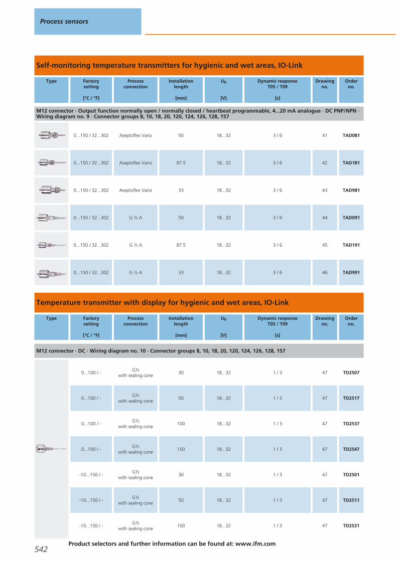
Self-monitoring temperature transmitters for hygienic and wet areas, IO-Link
Type Factorysetting
[°C / °F]
Processconnection
Installationlength
[mm]
Ub
[V]
Dynamic responseT05 / T09
[s]
Drawingno.
Orderno.
M12 connector · Output function normally open / normally closed / heartbeat programmable, 4...20 mA analogue · DC PNP/NPN ·Wiring diagram no. 9 · Connector groups 8, 10, 18, 20, 120, 124, 126, 128, 157
0...150 / 32...302 Aseptoflex Vario 50 18...32 3 / 6 41 TAD081
0...150 / 32...302 Aseptoflex Vario 87.5 18...32 3 / 6 42 TAD181
0...150 / 32...302 Aseptoflex Vario 33 18...32 3 / 6 43 TAD981
0...150 / 32...302 G ½ A 50 18...32 3 / 6 44 TAD091
0...150 / 32...302 G ½ A 87.5 18...32 3 / 6 45 TAD191
0...150 / 32...302 G ½ A 33 18...32 3 / 6 46 TAD991
Temperature transmitter with display for hygienic and wet areas, IO-Link
Type Factorysetting
[°C / °F]
Processconnection
Installationlength
[mm]
Ub
[V]
Dynamic responseT05 / T09
[s]
Drawingno.
Orderno.
M12 connector · DC · Wiring diagram no. 10 · Connector groups 8, 10, 18, 20, 120, 124, 126, 128, 157
0...100 / -G½
with sealing cone30 18...32 1 / 3 47 TD2507
0...100 / -G½
with sealing cone50 18...32 1 / 3 47 TD2517
0...100 / -G½
with sealing cone100 18...32 1 / 3 47 TD2537
0...100 / -G½
with sealing cone150 18...32 1 / 3 47 TD2547
-10...150 / -G½
with sealing cone30 18...32 1 / 3 47 TD2501
-10...150 / -G½
with sealing cone50 18...32 1 / 3 47 TD2511
-10...150 / -G½
with sealing cone100 18...32 1 / 3 47 TD2531
Process sensors
542Product selectors and further information can be found at: www.ifm.com
Gesamtkatalog EN 2016_17_Stilvorlage LK FrutigerOT_2010 DE_GB.qxd 06.11.15 16:56 Seite 542

Type Factorysetting
[°C / °F]
Processconnection
Installationlength
[mm]
Ub
[V]
Dynamic responseT05 / T09
[s]
Drawingno.
Orderno.
M12 connector · DC · Wiring diagram no. 10 · Connector groups 8, 10, 18, 20, 120, 124, 126, 128, 157
-10...150 / -G½
with sealing cone150 18...32 1 / 3 47 TD2541
0...100 / -1.5" clamp (ISO 2852)
30 18...32 1 / 3 48 TD2807
0...100 / -1.5" clamp (ISO 2852)
50 18...32 1 / 3 48 TD2817
0...100 / -1.5" clamp (ISO 2852)
100 18...32 1 / 3 48 TD2837
0...100 / -1.5" clamp (ISO 2852)
150 18...32 1 / 3 48 TD2847
-10...150 / -1.5" clamp (ISO 2852)
30 18...32 1 / 3 48 TD2801
-10...150 / -1.5" clamp (ISO 2852)
50 18...32 1 / 3 48 TD2811
-10...150 / -1.5" clamp (ISO 2852)
100 18...32 1 / 3 48 TD2831
-10...150 / -1.5" clamp (ISO 2852)
150 18...32 1 / 3 48 TD2841
0...300- / 1.5" clamp (ISO 2852)
30 18...32 1 / 3 48 TD2803
0...300- / 1.5" clamp (ISO 2852)
50 18...32 1 / 3 48 TD2813
0...300- / 1.5" clamp (ISO 2852)
100 18...32 1 / 3 48 TD2833
0...300- / 1.5" clamp (ISO 2852)
150 18...32 1 / 3 48 TD2843
0...100 / -2" clamp
(ISO 2852)30 18...32 1 / 3 49 TD2907
0...100 / -2" clamp
(ISO 2852)50 18...32 1 / 3 49 TD2917
0...100 / -2" clamp
(ISO 2852)100 18...32 1 / 3 49 TD2937
0...100 / -2" clamp
(ISO 2852)150 18...32 1 / 3 49 TD2947
Temperature sensors
543You can find wiring diagrams and scale drawings from page 556
Gesamtkatalog EN 2016_17_Stilvorlage LK FrutigerOT_2010 DE_GB.qxd 06.11.15 16:56 Seite 543

Type Factorysetting
[°C / °F]
Processconnection
Installationlength
[mm]
Ub
[V]
Dynamic responseT05 / T09
[s]
Drawingno.
Orderno.
M12 connector · DC · Wiring diagram no. 10 · Connector groups 8, 10, 18, 20, 120, 124, 126, 128, 157
-10...150 / -2" clamp
(ISO 2852)30 18...32 1 / 3 49 TD2901
-10...150 / -2" clamp
(ISO 2852)50 18...32 1 / 3 49 TD2911
-10...150 / -2" clamp
(ISO 2852)100 18...32 1 / 3 49 TD2931
-10...150 / -2" clamp
(ISO 2852)150 18...32 1 / 3 49 TD2941
0...300- / 2" clamp
(ISO 2852)30 18...32 1 / 3 49 TD2903
0...300- / 2" clamp
(ISO 2852)50 18...32 1 / 3 49 TD2913
0...300- / 2" clamp
(ISO 2852)100 18...32 1 / 3 49 TD2933
0...300- / 2" clamp
(ISO 2852)150 18...32 1 / 3 49 TD2943
0...100 / - Ø 6 mm 50 18...32 1 / 3 50 TD2217
0...100 / - Ø 6 mm 100 18...32 1 / 3 50 TD2237
0...100 / - Ø 6 mm 150 18...32 1 / 3 50 TD2247
0...100 / - Ø 6 mm 250 18...32 1 / 3 50 TD2267
-10...150 / - Ø 6 mm 50 18...32 1 / 3 50 TD2211
-10...150 / - Ø 6 mm 100 18...32 1 / 3 50 TD2231
-10...150 / - Ø 6 mm 150 18...32 1 / 3 50 TD2241
-10...150 / - Ø 6 mm 250 18...32 1 / 3 50 TD2261
-10...150 / - Ø 6 mm 200 18...32 1 / 3 50 TD2251
Process sensors
544Product selectors and further information can be found at: www.ifm.com
Gesamtkatalog EN 2016_17_Stilvorlage LK FrutigerOT_2010 DE_GB.qxd 06.11.15 16:56 Seite 544

Type Factorysetting
[°C / °F]
Processconnection
Installationlength
[mm]
Ub
[V]
Dynamic responseT05 / T09
[s]
Drawingno.
Orderno.
M12 connector · DC · Wiring diagram no. 10 · Connector groups 8, 10, 18, 20, 120, 124, 126, 128, 157
0...300- / Ø 6 mm 200 18...32 1 / 3 50 TD2253
0...100 / - Ø 6 mm 200 18...32 1 / 3 50 TD2257
-10...150 / - Ø 6 mm 300 18...32 1 / 3 50 TD2271
0...300- / Ø 6 mm 300 18...32 1 / 3 50 TD2273
0...100 / - Ø 6 mm 300 18...32 1 / 3 50 TD2277
-10...150 / - Ø 6 mm 350 18...32 1 / 3 50 TD2291
0...300- / Ø 6 mm 350 18...32 1 / 3 50 TD2293
0...100 / - Ø 6 mm 350 18...32 1 / 3 50 TD2297
Infrared temperature sensors
Type Temperaturerange
[°C]
Wave lengthrange
[μm]
Materiallens
Responsetime
[ms]
Drawingno.
Orderno.
M12 connector · Output function · Switching output, Analogue output · DC PNP · Wiring diagram no. 5 · Connectorgroup --
0...999.5 8...14Infrared transparent crystal lens with
anti-reflex coating< 100 51 TW2000
250...1600 1.0…1.7 tempered optical glass < 2 52 TW2001
500...2500 0.78…1.06 tempered optical glass < 2 52 TW2002
300...1600 1.0…1.7 tempered optical glass < 2 53 TW2011
M12 connector · Output function · 2 switching outputs · DC PNP · Wiring diagram no. 5 · Connector group --
50...500 8...14Infrared transparent crystal lens with
anti-reflex coating< 100 54 TW7000
Temperature sensors
545You can find wiring diagrams and scale drawings from page 556
Gesamtkatalog EN 2016_17_Stilvorlage LK FrutigerOT_2010 DE_GB.qxd 06.11.15 16:56 Seite 545

Type Temperaturerange
[°C]
Wave lengthrange
[μm]
Materiallens
Responsetime
[ms]
Drawingno.
Orderno.
M12 connector · Output function · 2 switching outputs · DC PNP · Wiring diagram no. 5 · Connector group --
250...1250 1.0...1.7 tempered optical glass ≤ 2 55 TW7001
350...1350 1.0...1.7 tempered optical glass ≤ 2 56 TW7011
Accessories for temperature sensors TN / TR
Type Description Orderno.
Angle bracket · Housing materials: PA66- E30421
Mounting clamp · Ø 34 mm · Housing materials: PBT E10017
Mounting clamp · Ø 34 mm · Housing materials: PA E10193
Mounting device 2 way · for fluid sensors · Housing materials: POM E30078
Mounting device 3 way · for fluid sensors · Housing materials: POM E30079
Protective cover · for fluid sensors with M12 connector · Housing materials: polyurethane E30006
Accessories for infrared temperature sensors
Type Description Orderno.
Measuring head · for infrared temperature sensors TWxx11, M30 design · Housing materials: AlMg3 black anodised / 303 / 1.4305 / lock nuts: 304 / 1.4301 / O-ring: FPM
E35060
Fibre optics with stainless steel sheathing · straight · Connection to infrared temperature sensors TWxx11 · ¼"-36UNS-2A · Housing materials: stainless steel, Fibre optic: Quartz/Quartz fibre (VIS/IR)
E35061
Fibre optics with stainless steel sheathing · straight · Connection to infrared temperature sensors TWxx11 · ¼"-36UNS-2A · Housing materials: stainless steel, Fibre optic: Quartz/Quartz fibre (VIS/IR)
E35062
Process sensors
546Product selectors and further information can be found at: www.ifm.com
Gesamtkatalog EN 2016_17_Stilvorlage LK FrutigerOT_2010 DE_GB.qxd 06.11.15 16:56 Seite 546
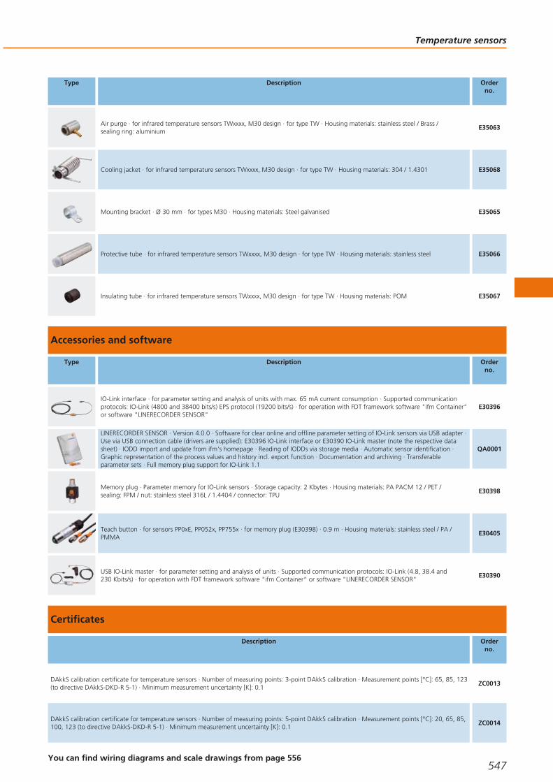
Type Description Orderno.
Air purge · for infrared temperature sensors TWxxxx, M30 design · for type TW · Housing materials: stainless steel / Brass / sealing ring: aluminium
E35063
Cooling jacket · for infrared temperature sensors TWxxxx, M30 design · for type TW · Housing materials: 304 / 1.4301 E35068
Mounting bracket · Ø 30 mm · for types M30 · Housing materials: Steel galvanised E35065
Protective tube · for infrared temperature sensors TWxxxx, M30 design · for type TW · Housing materials: stainless steel E35066
Insulating tube · for infrared temperature sensors TWxxxx, M30 design · for type TW · Housing materials: POM E35067
Accessories and software
Type Description Orderno.
IO-Link interface · for parameter setting and analysis of units with max. 65 mA current consumption · Supported communicationprotocols: IO-Link (4800 and 38400 bits/s) EPS protocol (19200 bits/s) · for operation with FDT framework software "ifm Container“or software "LINERECORDER SENSOR"
E30396
LINERECORDER SENSOR · Version 4.0.0 · Software for clear online and offline parameter setting of IO-Link sensors via USB adapter ·Use via USB connection cable (drivers are supplied): E30396 IO-Link interface or E30390 IO-Link master (note the respective datasheet) · IODD import and update from ifm's homepage · Reading of IODDs via storage media · Automatic sensor identification ·Graphic representation of the process values and history incl. export function · Documentation and archiving · Transferableparameter sets · Full memory plug support for IO-Link 1.1
QA0001
Memory plug · Parameter memory for IO-Link sensors · Storage capacity: 2 Kbytes · Housing materials: PA PACM 12 / PET / sealing: FPM / nut: stainless steel 316L / 1.4404 / connector: TPU
E30398
Teach button · for sensors PP0xE, PP052x, PP755x · for memory plug (E30398) · 0.9 m · Housing materials: stainless steel / PA /PMMA
E30405
USB IO-Link master · for parameter setting and analysis of units · Supported communication protocols: IO-Link (4.8, 38.4 and 230 Kbits/s) · for operation with FDT framework software "ifm Container“ or software "LINERECORDER SENSOR"
E30390
Certificates
Description Orderno.
DAkkS calibration certificate for temperature sensors · Number of measuring points: 3-point DAkkS calibration · Measurement points [°C]: 65, 85, 123(to directive DAkkS-DKD-R 5-1) · Minimum measurement uncertainty [K]: 0.1
ZC0013
DAkkS calibration certificate for temperature sensors · Number of measuring points: 5-point DAkkS calibration · Measurement points [°C]: 20, 65, 85,100, 123 (to directive DAkkS-DKD-R 5-1) · Minimum measurement uncertainty [K]: 0.1
ZC0014
Temperature sensors
547You can find wiring diagrams and scale drawings from page 556
Gesamtkatalog EN 2016_17_Stilvorlage LK FrutigerOT_2010 DE_GB.qxd 06.11.15 16:56 Seite 547

Description Orderno.
DAkkS calibration certificate for temperature sensors · Number of measuring points: n-point DAkkS calibration · Measurement points [°C]: number andpositions as requested by the customer, maximum 4 points in the range from -20...150 °C (to directive DAkkS-DKD-R 5-1) · Minimum measurementuncertainty [K]: 0.1
ZC0015
Factory calibration certificate for temperature sensors · Number of measuring points: 3-point factory calibration · Measurement points [°C]: 65, 85,123 (to ISO 9001) · Minimum measurement uncertainty [K]: 0.1
ZC0016
Factory calibration certificate for temperature sensors · Number of measuring points: 5-point factory calibration · Measurement points [°C]: 20, 65, 85,100, 123 (to ISO 9001) · Minimum measurement uncertainty [K]: 0.1
ZC0017
Factory calibration certificate for temperature sensors · Number of measuring points: n-point factory calibration · Measurement points [°C]: number and positions as requested by the customer, maximum 4 points in the range from -20...150 °C (to ISO 9001) · Minimum measurementuncertainty [K]: 0.1
ZC0018
Factory calibration sheet for first delivery of infrared temperature sensors · TW2000 / TW2001 / TW2002 / TW2011 · Minimum measurementuncertainty [K]: ± 4
ZC0061
Thermowells for temperature sensors
Type Description Orderno.
Welding thermowell · Ø 35 mm · Probe length: 126.5 mm · for type TA343x, TAA431, TAD191 · Housing materials: stainless steel 316L / 1.4404
E30403
Thermowell for temperature sensors · G ½ · Probe length: 53 mm · for type TA34xx, TAA431, TAD191 · Housing materials: stainless steel 316L / 1.4404
E30393
Thermowell for temperature sensors · G ½ - ½" NPT · Probe length: 69 mm · for type TA34xx, TAA4xx · Housing materials: stainless steel 316L / 1.4404
E30397
Thermowell for temperature sensors · Ø 10 mm - G ½ · Probe length: 82 mm · Housing materials: stainless steel 316L / 1.4404 E35010
Thermowell for temperature sensors · Ø 10 mm - G ½ · Probe length: 182 mm · Housing materials: stainless steel 316L / 1.4404 E35020
Thermowell for temperature sensors · Ø 10 mm - G ½ · Probe length: 282 mm · Housing materials: stainless steel 316L / 1.4404 E35030
Thermowell for temperature sensors · Ø 10 mm - G ½ · Probe length: 482 mm · Housing materials: stainless steel 316L / 1.4404 E35050
Thermowell for temperature sensors · Ø 6 mm · Installation length EL: 74 mm · for temperature sensors with installation length EL = 100 mm · Housing materials: stainless steel 316L / 1.4404
E37210
Thermowell for temperature sensors · Ø 6 mm · Installation length EL: 94 mm · for temperature sensors with installation length EL = 100 mm · Housing materials: stainless steel 316L / 1.4404
E37211
Process sensors
548 Product selectors and further information can be found at: www.ifm.com
Gesamtkatalog EN 2016_17_Stilvorlage LK FrutigerOT_2010 DE_GB.qxd 06.11.15 16:56 Seite 548

Type Description Orderno.
Thermowell for temperature sensors · Ø 6 mm · Installation length EL: 125 mm · for temperature sensors with installation length EL = 150 mm · Housing materials: stainless steel 316L / 1.4404
E37220
Thermowell for temperature sensors · Ø 6 mm · Installation length EL: 144 mm · for temperature sensors with installation length EL = 150 mm · Housing materials: stainless steel 316L / 1.4404
E37221
Thermowell for temperature sensors · Ø 6 mm · Installation length EL: 201 mm · for temperature sensors with installation length EL = 300 mm · Housing materials: stainless steel 316L / 1.4404
E37230
Thermowell for temperature sensors · Ø 6 mm · Installation length EL: 277 mm · for temperature sensors with installation length EL = 350 mm · Housing materials: stainless steel 316L / 1.4404
E37250
Thermowell for temperature sensors · Ø 6 mm · Installation length EL: 64 mm · for temperature sensors with installation length EL = 100 mm · Housing materials: stainless steel 316L / 1.4404
E37810
Thermowell for temperature sensors · Ø 6 mm · Installation length EL: 115 mm · for temperature sensors with installation length EL = 150 mm · Housing materials: stainless steel 316L / 1.4404
E37820
Thermowell for temperature sensors · Ø 6 mm · Installation length EL: 191 mm · for temperature sensors with installation length EL = 300 mm · Housing materials: stainless steel 316L / 1.4404
E37830
Thermowell for temperature sensors · Ø 6 mm · Installation length EL: 267 mm · for temperature sensors with installation length EL = 350 mm · Housing materials: stainless steel 316L / 1.4404
E37850
Thermowell for temperature sensors · Ø 6 mm · Installation length EL: 64 mm · for temperature sensors with installation length EL = 100 mm · Housing materials: stainless steel 316L / 1.4404
E37910
Thermowell for temperature sensors · Ø 6 mm · Installation length EL: 115 mm · for temperature sensors with installation length EL = 150 mm · Housing materials: stainless steel 316L / 1.4404
E37920
Thermowell for temperature sensors · Ø 6 mm · Installation length EL: 191 mm · for temperature sensors with installation length EL = 300 mm · Housing materials: stainless steel 316L / 1.4404
E37930
Thermowell for temperature sensors · Ø 6 mm · Installation length EL: 267 mm · for temperature sensors with installation length EL = 350 mm · Housing materials: stainless steel 316L / 1.4404
E37950
Thermowell for temperature sensors · Ø 6 mm · Installation length EL: 33 mm · for temperature sensors with installation length EL = 50 mm · Housing materials: stainless steel 316Ti / 1.4571
E37603
Thermowell for temperature sensors · Ø 6 mm · Installation length EL: 83 mm · for temperature sensors with installation length EL = 100 mm · Housing materials: stainless steel 316Ti / 1.4571
E37613
Thermowell for temperature sensors · Ø 6 mm · Installation length EL: 128 mm · for temperature sensors with installation length EL = 150 mm · Housing materials: stainless steel 316Ti / 1.4571
E37623
Thermowell for temperature sensors · Ø 6 mm · Installation length EL: 233 mm · for temperature sensors with installation length EL = 250 mm · Housing materials: stainless steel 316Ti / 1.4571
E37643
Temperature sensors
549You can find wiring diagrams and scale drawings from page 556
Gesamtkatalog EN 2016_17_Stilvorlage LK FrutigerOT_2010 DE_GB.qxd 06.11.15 16:56 Seite 549

Type Description Orderno.
Thermowell for temperature sensors · Ø 6 mm · Installation length EL: 333 mm · for temperature sensors with installation length EL = 350 mm · Housing materials: stainless steel 316Ti / 1.4571
E37663
Thermowell for temperature sensors · Ø 6 mm · Installation length EL: 68 mm · for temperature sensors with installation length EL = 100 mm · Housing materials: stainless steel 316L / 1.4404
E37511
Thermowell for temperature sensors · Ø 6 mm · Installation length EL: 118 mm · for temperature sensors with installation length EL = 150 mm · Housing materials: stainless steel 316L / 1.4404
E37521
Thermowell for temperature sensors · Ø 6 mm · Installation length EL: 27 mm · for temperature sensors with installation length EL = 50 mm · Housing materials: stainless steel 316L / 1.4404
E37600
Thermowell for temperature sensors · Ø 6 mm · Installation length EL: 74 mm · for temperature sensors with installation length EL = 100 mm · Housing materials: stainless steel 316L / 1.4404
E37610
Thermowell for temperature sensors · Ø 6 mm · Installation length EL: 124 mm · for temperature sensors with installation length EL = 150 mm · Housing materials: stainless steel 316L / 1.4404
E37620
Thermowell for temperature sensors · Ø 6 mm · Installation length EL: 224 mm · for temperature sensors with installation length EL = 250 mm · Housing materials: stainless steel 316L / 1.4404
E37640
Welding thermowell for temperature sensors · Ø 6 mm · Installation length EL: 49 mm · for temperature sensors with installationlength EL = 50 mm · Housing materials: stainless steel 316L / 1.4404
E37411
Welding thermowell for temperature sensors · Ø 6 mm · Installation length EL: 99 mm · for temperature sensors with installationlength EL = 100 mm · Housing materials: stainless steel 316L / 1.4404
E37421
Welding thermowell for temperature sensors · Ø 6 mm · Installation length EL: 149 mm · for temperature sensors with installationlength EL = 150 mm · Housing materials: stainless steel 316L / 1.4404
E37431
Welding thermowell for temperature sensors · Ø 6 mm · Installation length EL: 191 mm · for temperature sensors with installationlength EL = 300 mm · Housing materials: stainless steel 316L / 1.4404
E37430
Welding thermowell for temperature sensors · Ø 6 mm · Installation length EL: 267 mm · for temperature sensors with installationlength EL = 350 mm · Housing materials: stainless steel 316L / 1.4404
E37450
Adapters
Type Description Orderno.
Thread cover · Ø 24 mm - G ½ · Ø 24 mm · to cover the G½ thread for installation in hygienic areas · for type TR · Housing materials: stainless steel
E30091
Mounting set · for direct connection of temperature sensors TT to control monitors TR · Housing materials: stainless steel E30017
Process sensors
550Product selectors and further information can be found at: www.ifm.com
Gesamtkatalog EN 2016_17_Stilvorlage LK FrutigerOT_2010 DE_GB.qxd 06.11.15 16:56 Seite 550

Type Description Orderno.
Clamp fitting · Ø 6/8/10 mm - G ½ · for temperature sensors · Housing materials: stainless steel / FPM E30018
Clamp fitting · Ø 6/8/10 mm - ½" NPT · for temperature sensors · Housing materials: stainless steel / FPM E30025
Mounting adapter · M18 x 1.5 - Ø 23 mm · PVC adapter to be glued into the pipe · Insertion depth of the probe of SID, SFD, TN: · 21 mm · Housing materials: PVC
E40148
Sealing ring · for G ½ sealing cone · Housing materials: sealing ring on sensor side: FKM / sealing ring on process side: PEEK E43911
Adapter · M18 x 1.5 - G ½ · Housing materials: stainless steel 316L / 1.4404 / O-ring: FPM (fitted) E30073
Clamp adapter · Ø 6 mm - G ½ · no dead space · Housing materials: stainless steel 316L / 1.4404 / rubber ring: PEEK E30144
Welding adapter · M18 x 1.5 - Ø 24 mm · Insertion depth of the probe of SID, SFD, TN: · 15 mm · Housing materials: stainless steel 316L / 1.4404
E40124
Welding adapter · Ø 24.7 mm · for temperature sensors Ø 6 mm · Clamp fitting · Housing materials: stainless steel 316L / 1.4404 E30108
Welding adapter · Ø 25 mm · for temperature sensors Ø 6 mm · Clamp fitting · Housing materials: stainless steel 316L / 1.4404 /rubber ring: PEEK
E30407
Progressive ring fitting for temperature sensors · Ø 10 mm - G ½ · Housing materials: stainless steel 316Ti / 1.4571 E30016
Progressive ring fitting for temperature sensors · Ø 10 mm - ½" NPT · Housing materials: stainless steel 316Ti / 1.4571 E30024
Progressive ring fitting for temperature sensors · Ø 6 mm - G ½ · Housing materials: stainless steel 316Ti / 1.4571 E30047
Progressive ring fitting for temperature sensors · Ø 6 mm - ¼" NPT · Housing materials: stainless steel 316Ti / 1.4571 E30049
Progressive ring fitting for temperature sensors · Ø 6 mm - G ¼ · Housing materials: stainless steel 316Ti / 1.4571 E33431
Adapter · M18 x 1.5 - G ½ · Insertion depth of the probe of SID, SFD, TN: · 21 mm · Housing materials: titanium E40114
Temperature sensors
551You can find wiring diagrams and scale drawings from page 556
Gesamtkatalog EN 2016_17_Stilvorlage LK FrutigerOT_2010 DE_GB.qxd 06.11.15 16:56 Seite 551

Type Description Orderno.
Adapter · M18 x 1.5 - M12 x 1 · Insertion depth of the probe of SID, SFD, TN: · 13.5 mm · Housing materials: titanium E40128
Adapter · M18 x 1.5 - L18 · for mounting in T-pieces · Insertion depth of the probe of SID, SFD, TN: · 28.5 mm · Housing materials: nut: stainless steel 316Ti / 1.4571 / adapter: stainless steel 316L / 1.4404 / O-ring: FKM 16 x 1.5 gr 70° Shore A
E40104
Adapter · M18 x 1.5 - M12 x 1 · Insertion depth of the probe of SID, SFD, TN: · 13.5 mm · Housing materials: stainless steel 316L / 1.4404
E40101
Adapter · M18 x 1.5 - M12 x 1 · Insertion depth of the probe of SID, SFD, TN: · 13.5 mm · Housing materials: brass E40100
Adapter · M18 x 1.5 - G ¼ · Insertion depth of the probe of SID, SFD, TN: · 13.5 mm · Housing materials:stainless steel 316L / 1.4404
E40099
Adapter · M18 x 1.5 - G ¼ · Insertion depth of the probe of SID, SFD, TN: · 13.5 mm · Housing materials: brass E40098
Adapter · M18 x 1.5 - G ½ · Insertion depth of the probe of SID, SFD, TN: · 21 mm · Housing materials: stainless steel 316L / 1.4404 E40096
Adapter · M18 x 1.5 - G ½ · Insertion depth of the probe of SID, SFD, TN: · 21 mm · Housing materials: brass E40097
Adapter · M18 x 1.5 - ½" NPT · Insertion depth of the probe of SID, SFD, TN: · 23 mm · Housing materials: stainless steel 316L / 1.4404
E40107
Adapter · M18 x 1.5 - G ½ · Housing materials: stainless steel 316L / 1.4404 / O-ring: FPM (fitted) E30073
Protective cover · with lead seal option · for pressure sensors type PK · for temperature sensors type TK · for vibration sensors type VK · Housing materials: PP transparent
E30094
Hygienic adapters
Type Description Orderno.
Clamp adapter · 1-1.5" · Aseptoflex Vario
Clamp adapter · Clamp · 1-1.5" · ISO 2852 · for units with Aseptoflex Vario adapter · Sealing by sealing ring · Housing materials: stainless steel 316L / 1.4435
E33201
Process sensors
552Product selectors and further information can be found at: www.ifm.com
Gesamtkatalog EN 2016_17_Stilvorlage LK FrutigerOT_2010 DE_GB.qxd 06.11.15 16:56 Seite 552

Type Description Orderno.
Clamp adapter · 2" · Aseptoflex Vario
Clamp adapter · Clamp · 2" · ISO 2852 · for units with Aseptoflex Vario adapter · Sealing by sealing ring · Housing materials:stainless steel 316L / 1.4435
E33202
Clamp adapter · 1-1.5" · Aseptoflex Vario
Clamp adapter · Clamp · 1-1.5" · ISO 2852 · for units with Aseptoflex Vario adapter · Metal to metal seal · Housing materials:stainless steel 316L / 1.4435
E33701
Clamp adapter · 2" · Aseptoflex Vario
Clamp adapter · Clamp · 2" · ISO 2852 · for units with Aseptoflex Vario adapter · Metal to metal seal · Housing materials: stainless steel 316L / 1.4435
E33702
Hygienic pipe fitting · DN40 (1.5") · Aseptoflex Vario
Pipe fitting · Hygienic pipe fitting · Hygienic pipe fitting · DN40 (1.5") · DIN 11851 · for units with Aseptoflex Vario adapter · Sealing by sealing ring · Housing materials: stainless steel 316L / 1.4435
E33212
Hygienic pipe fitting · DN50 (2") · Aseptoflex Vario
Pipe fitting · Hygienic pipe fitting · Hygienic pipe fitting · DN50 (2") · DIN 11851 · for units with Aseptoflex Vario adapter · Sealing by sealing ring · Housing materials: stainless steel 316L / 1.4435
E33213
Hygienic pipe fitting · DN40 (1.5") · Aseptoflex Vario
Pipe fitting · Hygienic pipe fitting · Hygienic pipe fitting · DN40 (1.5") · DIN 11851 · for units with Aseptoflex Vario adapter · Metal to metal seal · Housing materials: stainless steel 316L / 1.4435
E33712
Hygienic pipe fitting · DN50 (2") · Aseptoflex Vario
Pipe fitting · Hygienic pipe fitting · Hygienic pipe fitting · DN50 (2") · DIN 11851 · for units with Aseptoflex Vario adapter · Metal to metal seal · Housing materials: stainless steel 316L / 1.4435
E33713
Varivent Adapter · Type N, DN40...DN150 (1.5...6"), D = 68 · Aseptoflex Vario
Clamp adapter · Varivent Adapter · Varivent type N · DN40...DN150 (1.5...6"), D = 68 · for units with Aseptoflex Vario adapter ·Sealing by sealing ring · Housing materials: stainless steel 316L / 1.4435
E33222
Clamp adapter · Varivent Adapter · Varivent type N · DN40...DN150 (1.5...6"), D = 68 · for units with Aseptoflex Vario adapter ·Metal to metal seal · Housing materials: stainless steel 316L / 1.4435
E33722
SMS pipe fitting · DN40 (1.5") · Aseptoflex Vario
Pipe fitting · SMS pipe fitting · DN40 (1.5") · SMS · for units with Aseptoflex Vario adapter · Metal to metal seal · Housing materials:stainless steel 316L / 1.4435
E33731
Temperature sensors
553You can find wiring diagrams and scale drawings from page 556
Gesamtkatalog EN 2016_17_Stilvorlage LK FrutigerOT_2010 DE_GB.qxd 06.11.15 16:56 Seite 553
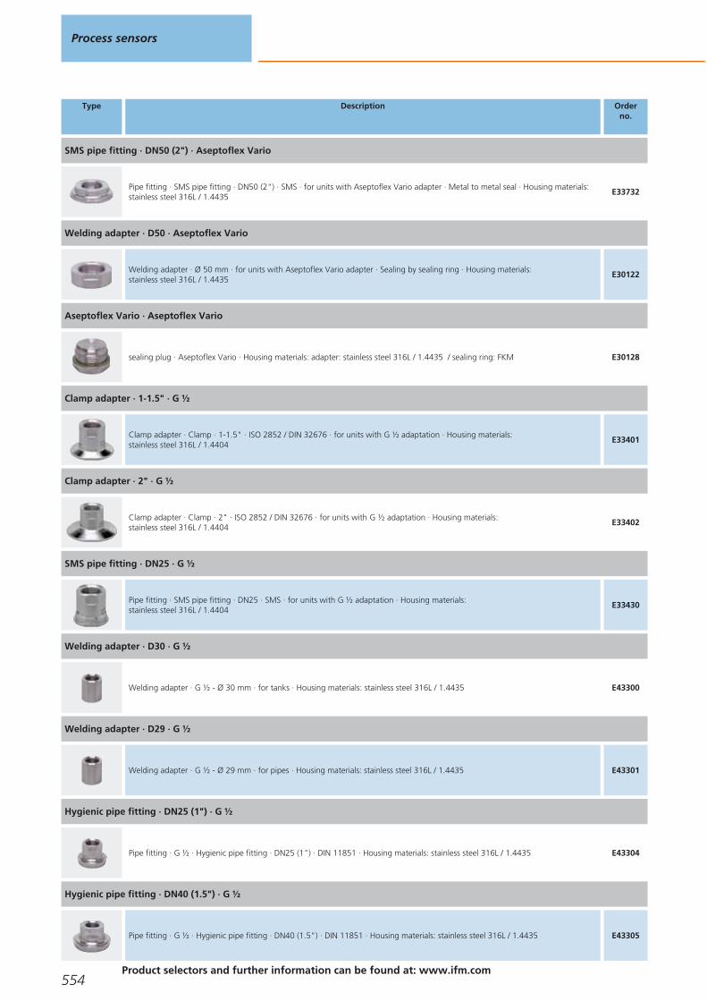
Type Description Orderno.
SMS pipe fitting · DN50 (2") · Aseptoflex Vario
Pipe fitting · SMS pipe fitting · DN50 (2") · SMS · for units with Aseptoflex Vario adapter · Metal to metal seal · Housing materials:stainless steel 316L / 1.4435
E33732
Welding adapter · D50 · Aseptoflex Vario
Welding adapter · Ø 50 mm · for units with Aseptoflex Vario adapter · Sealing by sealing ring · Housing materials: stainless steel 316L / 1.4435
E30122
Aseptoflex Vario · Aseptoflex Vario
sealing plug · Aseptoflex Vario · Housing materials: adapter: stainless steel 316L / 1.4435 / sealing ring: FKM E30128
Clamp adapter · 1-1.5" · G ½
Clamp adapter · Clamp · 1-1.5" · ISO 2852 / DIN 32676 · for units with G ½ adaptation · Housing materials: stainless steel 316L / 1.4404
E33401
Clamp adapter · 2" · G ½
Clamp adapter · Clamp · 2" · ISO 2852 / DIN 32676 · for units with G ½ adaptation · Housing materials: stainless steel 316L / 1.4404
E33402
SMS pipe fitting · DN25 · G ½
Pipe fitting · SMS pipe fitting · DN25 · SMS · for units with G ½ adaptation · Housing materials: stainless steel 316L / 1.4404
E33430
Welding adapter · D30 · G ½
Welding adapter · G ½ - Ø 30 mm · for tanks · Housing materials: stainless steel 316L / 1.4435 E43300
Welding adapter · D29 · G ½
Welding adapter · G ½ - Ø 29 mm · for pipes · Housing materials: stainless steel 316L / 1.4435 E43301
Hygienic pipe fitting · DN25 (1") · G ½
Pipe fitting · G ½ · Hygienic pipe fitting · DN25 (1") · DIN 11851 · Housing materials: stainless steel 316L / 1.4435 E43304
Hygienic pipe fitting · DN40 (1.5") · G ½
Pipe fitting · G ½ · Hygienic pipe fitting · DN40 (1.5") · DIN 11851 · Housing materials: stainless steel 316L / 1.4435 E43305
Process sensors
554Product selectors and further information can be found at: www.ifm.com
Gesamtkatalog EN 2016_17_Stilvorlage LK FrutigerOT_2010 DE_GB.qxd 06.11.15 16:56 Seite 554

Type Description Orderno.
Varivent Adapter · Type F, DN25 (1"), D = 50 · G ½
Clamp adapter · G ½ · Varivent type F · DN25 (1"), D = 50 · Housing materials: stainless steel 316L / 1.4435 E43306
Varivent Adapter · Type N, DN40...DN150 (1.5...6"), D = 68 · G ½
Clamp adapter · G ½ · Varivent type N · DN40...DN150 (1.5...6"), D = 68 · Housing materials: stainless steel 316L / 1.4435 E43307
sealing plug · G ½
sealing plug · G ½ · Housing materials: stainless steel 316L / 1.4435 E43308
Welding adapter ball · D35 · G ½
Welding adapter · G ½ - Ø 35 mm · Housing materials: stainless steel 316L / 1.4404 E30055
Welding adapter collar · D45 · G ½
Welding adapter · G ½ - Ø 45 mm · Housing materials: stainless steel 316L / 1.4404 E30056
Welding adapter · D30 · G ½
Welding adapter · G ½ - Ø 30 mm · for tanks · with leakage port · with leakage port · Housing materials: stainless steel 316L / 1.4435
E43309
Welding adapter · D29 · G ½
Welding adapter · G ½ - Ø 29 mm · for pipes · with leakage port · with leakage port · Housing materials: stainless steel 316L / 1.4435
E43310
Clamp adapter · 1-1.5" · G ½
Clamp adapter · G ½ · with leakage port · Clamp · 1-1.5" · ISO 2852 / DIN 32676 · with leakage port · Housing materials: stainless steel 316L / 1.4435
E43311
Clamp adapter · 2" · G ½
Clamp adapter · G ½ · with leakage port · Clamp · 2" · ISO 2852 / DIN 32676 · with leakage port · Housing materials: stainless steel 316L / 1.4435
E43312
Welding mandrel · G ½ · carries away heat during welding · Housing materials: brass E43314
Temperature sensors
555You can find wiring diagrams and scale drawings from page 556
Gesamtkatalog EN 2016_17_Stilvorlage LK FrutigerOT_2010 DE_GB.qxd 06.11.15 16:56 Seite 555

Type Description Orderno.
Welding adapter collar · D45 · G ½
Welding adapter · G ½ · with leakage port · Housing materials: stainless steel 316L / 1.4404 E43315
Welding adapter · D50 · G ½
Welding adapter · G ½ · long design for deeper installation · long design for deeper installation · Housing materials: stainless steel 316L / 1.4435
E43319
Core colours
BK black
BN brown
BU blue
WH white
GY grey
Wiring diagrams
1
4
L
L+1
2
32:4:
2
2
L
L+
4
1
3Out 1Out 2
4:2:
3
BN
WH
BK
BU
4
1
3
2 OUT2
L+
L
OUT1
4
1
2
3
4
5
L+
L
2
5
1
4
3
OUT1
OUT2
Test Input
screen
BN
WH
GY
BK
BU
6
TR 8430
L+
L
n.c.
Out 4
Out 1
Out 2
1
2
4
6
7
3
Out 35
3 (n.c.)
1 (n.c.)
4
2
7
4
1
3
2
L+
L
L
IO-Link1
2
3
4
1
2
3
4
1
2
3
4
B
B
TP
1: Two-wire sensor, 2: Four-wire sensor, 3: Operation as 2-wiretemperature transmitter, 4: Operation as 3-wire unit, IO-Linkcommunication possible, B: link
8
4
1
3
2
L+
L
IO-Link
1
2
3
4
1
2
1
2
3
4
B
B
TP
2: Two-wire sensor, 2: Four-wire sensor, B: link
9
BN
WH
BK
BU
4
1
3
2 OUT2
L+
L
OUT1
L+BN1
WH2OUT
Process sensors
556Product selectors and further information can be found at: www.ifm.com
Gesamtkatalog EN 2016_17_Stilvorlage LK FrutigerOT_2010 DE_GB.qxd 06.11.15 16:56 Seite 556

Wiring diagrams
10
L+
L3
1
4
2IO-Link
L+
L
1
2
Scale drawings / drawing no. – CAD download: www.ifm.com
1
39
M12 x127
27
96,5
25
8,2
G 41
87
2
267
M12 x127
27
327
G 21
8
255
3
34
140
4
3
1445
2
1
100
48
M12
x1
30
6
22
1: LEDs (display unit / switching status), 2: 4-digit alphanumericdisplay / alternating indication of red and green, 3: Programmingbuttons, 4: Upper part of the housing can be rotated by 345°
4
93
34
16,5
G 21
2 3
1
30
48
60M
12x1
4
1: 4-digit alphanumeric display, 2: LEDs, 3: Programming button, 4: connector for temperature sensor (M12 x 1)
5
64
48
M12
x1
34
104
3
16,5
2
1
30
1: LEDs (display unit / switching status), 2: 4-digit alphanumericdisplay / alternating indication of red and green, 3: Programmingbuttons
6
18M12x1
M12x1
25
LED
22 52
2
1: connection for voltage supply and output signals, 2: connectionfor temperature sensor
Temperature sensors
557
Gesamtkatalog EN 2016_17_Stilvorlage LK FrutigerOT_2010 DE_GB.qxd 06.11.15 16:56 Seite 557
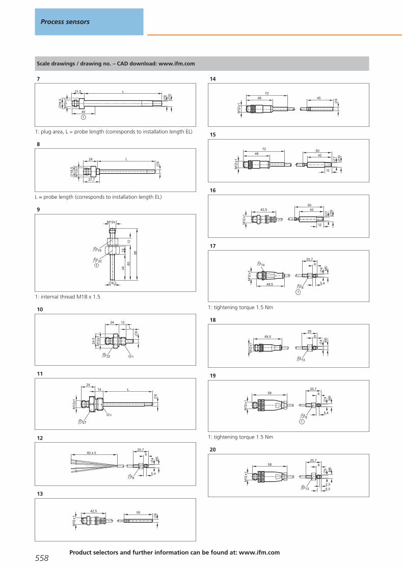
Scale drawings / drawing no. – CAD download: www.ifm.com
7
8
L
10
M12
x1
21,5
18,5
40
1
1: plug area, L = probe length (corresponds to installation length EL)
8
M12
x118
,5
24 L
27,7
6
L = probe length (corresponds to installation length EL)
9
90
60
22
14
8,2
44
12
M12x1
19
1
1: internal thread M18 x 1.5
10
6
24 12
L
24,5
M12
x1
22 G 41
11
M12
x1
24
L
6
14
G 21
27
12
80 ± 525,7
5,4
M54
8
8
13
M12
x1
42,5 50 6
14
M12
x1
64572
48
15
M12
x1
7248
50
12
107
42
16
50
12
107
42
M12
x1
42,5
17
25,7
5,4
M54
8
8
M12
x1
49,5
14
1: tightening torque 1.5 Nm
18
13
M12
x1
49,5
26
8
4 M6
19
M12
x1
5825,7
5,4
M54
8
8
1: tightening torque 1.5 Nm
20
M12
x1
5825,7
2,5
M65
8
13 6,5
Process sensors
558Product selectors and further information can be found at: www.ifm.com
Gesamtkatalog EN 2016_17_Stilvorlage LK FrutigerOT_2010 DE_GB.qxd 06.11.15 16:56 Seite 558

Scale drawings / drawing no. – CAD download: www.ifm.com
21
M12
x1
49,5
14 35
6,5
51
12
17
8,7
1,8
22
34
6,5
47
12,5
17
8,7
2,7
23
40 ± 10
13
8
26
M8
24
30 56
40
25
42
6,5
10
12
103
26
4818
11 18
18
103
27
6
M12
x118
,7
15,9 48 14
27LED G ½
EL
28
6
M12
x118
,7
15,9 48 14
26LED G ½
EL
29
6
M12
x118
,7
15,9 48
19
13
G ¼LED
EL
30
6
M12
x118
,715,9 48
75,7
LED 26 ½" NPT
EL
31
6
M12
x118
,7
15,9 48
71
19 ¼" NPTLED
EL
32
6
L2410
M12
x1
1
1: 1.5" clamp (ISO 2852), L = probe length (corresponds toinstallation length EL)
33
6
L24
64
10
M12
x1
L = probe length (corresponds to installation length EL)
Temperature sensors
559
Gesamtkatalog EN 2016_17_Stilvorlage LK FrutigerOT_2010 DE_GB.qxd 06.11.15 16:56 Seite 559

Scale drawings / drawing no. – CAD download: www.ifm.com
34
6
34 L
24,5
M12
x1
22
61,6
G 21
L = probe length (corresponds to installation length EL)
35
M12
x1
G½
18 10
22
68
3822 8
36
6
M12
x118
,7
15,9 50,4 EL
LED 2 x 180° 1
3/4" clamp (ISO 2852)
37
6
M12
x118
,7
LED 2 x 180°
15,9
47,5 EL
1
38
6
M12
x118
,7
LED 2 x 180°
15,9 47,5 35,4 EL
22 G ½
39
M12
x1
46 8 38
G½
102
18 10
22
40
6
M12
x118
,7
LED 2 x 180°
15,9 47,5 EL
41
M12
x1
50,4
103159
15
173,5
50
8 10
34 G1
42
M12
x1
50,4
140,5196,5
15
211
87,5
8 10
34 G1
43M
12x1
50,4
86142
15
156,5
33
8 10
34 G1
44
M12
x1
50,4
27
8
G 21
15
1050
194123,5
85,5
45
M12
x1
50,4
27
8
G 21
15
10
87,5123
161
231,5
Process sensors
560Product selectors and further information can be found at: www.ifm.com
Gesamtkatalog EN 2016_17_Stilvorlage LK FrutigerOT_2010 DE_GB.qxd 06.11.15 16:56 Seite 560

Scale drawings / drawing no. – CAD download: www.ifm.com
46
M12
x1
50,4
106,5
27
3368,5
8
G 21
15
10
177
47M
12x1
50
27
EL
48
63
99,5
G½
6
EL = Installation length
48
1
50
EL
4869
,4 M12
x127
63
6
1: 1.5" clamp (ISO 2852), EL = Installation length
49
50
EL
4869
,4 M12
x127
63
1
6
1: 2" clamp (ISO 2852), EL = Installation length
50
50
48
M12
x127
63
6
EL
EL = Installation length
51
28
61,5 91
M30
x1,5
183,5
M12
x1
536 21 3
°F °C
1: LEDs (display unit / switching status), 2: 7-segment LED display(4 digits), 3: Programming buttons
52
28
86 91
M30
x1,5
207,7
M12
x1
536 21 3
°F °C
1: LEDs (display unit / switching status), 2: 7-segment LED display (4 digits), 3: Programming buttons
Temperature sensors
561
Gesamtkatalog EN 2016_17_Stilvorlage LK FrutigerOT_2010 DE_GB.qxd 06.11.15 16:56 Seite 561

Scale drawings / drawing no. – CAD download: www.ifm.com
53
28
55 91
M30
x1,5
¼"-
36U
NS
-2A
181,5
M12
x1
536 21 3
°F °C
¼"-
36U
NS
-2A
4558,56
M30
x1,5
536
317
1: LEDs (display unit / switching status), 2: 7-segment LED display (4 digits), 3: Programming buttons
54
21
28
51 75,5
M30
x1,5
155
M12
x1
536 3
1: Programming buttons, 2: 7-segment LED display
55
21
28
85,5 75,5
M30
x1,5
189
M12
x1
536 3
1: LEDs (switching status), 2: 7-segment LED display (2 digits), 3: Programming buttons
56
28
54,5 75,5
M30
x1,5
¼"-
36U
NS
-2A
163
M12
x1
536 21 3
1: LEDs (switching status), 2: 7-segment LED display (2 digits), 3: Programming buttons
Process sensors
562Product selectors and further information can be found at: www.ifm.com
Gesamtkatalog EN 2016_17_Stilvorlage LK FrutigerOT_2010 DE_GB.qxd 06.11.15 16:56 Seite 562

Temperature sensors
563
Gesamtkatalog EN 2016_17_Stilvorlage LK FrutigerOT_2010 DE_GB.qxd 06.11.15 16:56 Seite 563
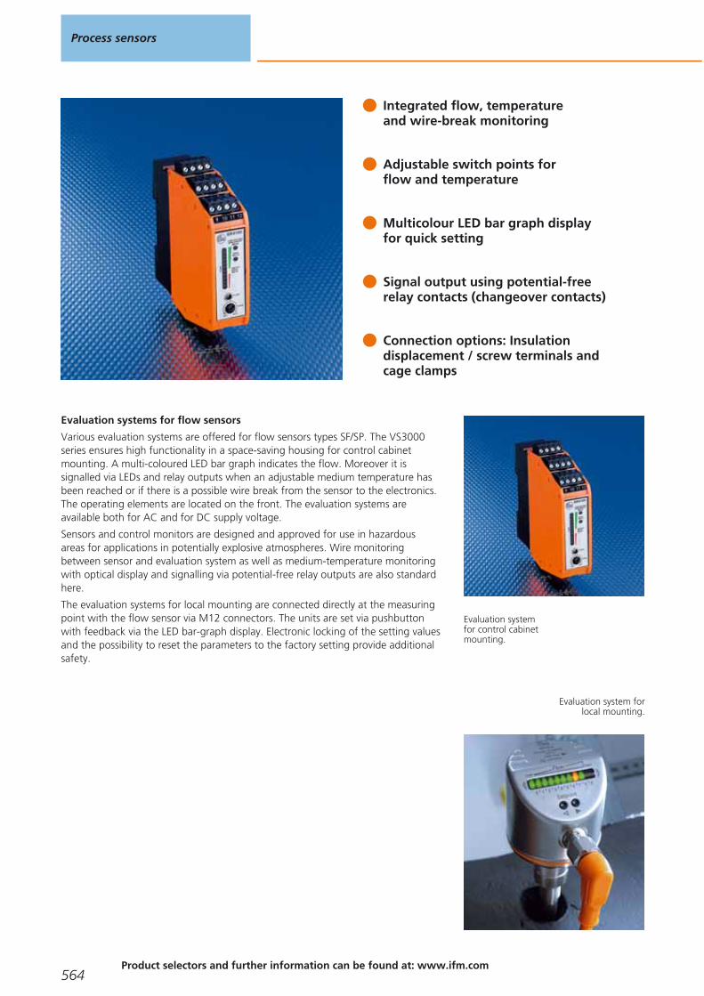
Integrated flow, temperature and wire-break monitoring
Adjustable switch points for flow and temperature
Multicolour LED bar graph display for quick setting
Signal output using potential-free relay contacts (changeover contacts)
Connection options: Insulation displacement / screw terminals and cage clamps
Evaluation systems for flow sensors
Various evaluation systems are offered for flow sensors types SF/SP. The VS3000series ensures high functionality in a space-saving housing for control cabinetmounting. A multi-coloured LED bar graph indicates the flow. Moreover it issignalled via LEDs and relay outputs when an adjustable medium temperature hasbeen reached or if there is a possible wire break from the sensor to the electronics.The operating elements are located on the front. The evaluation systems areavailable both for AC and for DC supply voltage.
Sensors and control monitors are designed and approved for use in hazardous areas for applications in potentially explosive atmospheres. Wire monitoringbetween sensor and evaluation system as well as medium-temperature monitoringwith optical display and signalling via potential-free relay outputs are also standardhere.
The evaluation systems for local mounting are connected directly at the measuringpoint with the flow sensor via M12 connectors. The units are set via pushbuttonwith feedback via the LED bar-graph display. Electronic locking of the setting valuesand the possibility to reset the parameters to the factory setting provide additionalsafety.
Evaluation systemfor control cabinetmounting.
Evaluation system forlocal mounting.
Process sensors
564Product selectors and further information can be found at: www.ifm.com
Gesamtkatalog EN 2016_17_Stilvorlage LK FrutigerOT_2010 DE_GB.qxd 06.11.15 16:56 Seite 564

System overview Page
Control monitors for industrial applications 566
Control monitors with ATEX approval 566 - 567
Control monitors with ATEX approval 2G 567
Accessories 567
Wiring diagrams 567 - 568
Scale drawings / drawing no. – CAD download: www.ifm.com 569
Signal evaluation systems
565
Gesamtkatalog EN 2016_17_Stilvorlage LK FrutigerOT_2010 DE_GB.qxd 06.11.15 16:56 Seite 565

Control monitors for industrial applications
Type Ub /Tolerance
[V] / [%]
Currentconsumpt.
[mA]
Powerconsumpt.
[VA]
Power-ondelaytime[s]
Outputwhen flow is
present
Outputwhen
temperature is exceeded
Outputin case of
wire break
Draw-ingno.
Orderno.
Combicon connector · Wiring diagram no. 3
90...240 AC /-5 /+10
– 4 10...80 relay energised relay energised relay de-energised 1 SN0150*
Combicon connector · Wiring diagram no. 4
90...240 AC /-5 /+10
– 4 10...80 relay energised – relay de-energised 1 SN0151*
Combicon connector · Wiring diagram no. 5
24 DC / +10 / -20
90 – 10...80 relay energised relay energised relay de-energised 1 SR0150*
Combicon connector · Wiring diagram no. 6
24 DC / +10 / -10
90 – 10...80 relay energised – relay de-energised 1 SR0153*
M12 connector · Wiring diagram no. 1 · Connector groups 8, 10, 18, 20, 120, 124, 126, 128, 157
19...36 DC 70 – 10no / nc
programmable– – 2 SR5900
1/2" UNF-Connector · Wiring diagram no. 2 · Connector group 30
85...265 AC /-5 / +10
– < 3.5 10no / nc
programmable– – 3 SR5906*
* Note for AC and AC/DC units
Miniature fuse to IEC60127-2 sheet 1, ≤ 5 A (fast acting) Recommendation: check the unit for reliable function after a shortcircuit.
Control monitors with ATEX approval
Type Ub /Tolerance
[V] / [%]
Currentconsumpt.
[mA]
Powerconsumpt.
[VA]
Power-ondelaytime[s]
Outputwhen flow is
present
Outputwhen
temperature is exceeded
Outputin case of
wire break
Draw-ingno.
Orderno.
15 terminals...2.5 mm²
230 AC / ± 10
– 5 30 relay energised – relay de-energised 4 SN2301*
110 AC / ± 10
– 5 30 relay energised – relay de-energised 4 SN2302*
Process sensors
566Product selectors and further information can be found at: www.ifm.com
Gesamtkatalog EN 2016_17_Stilvorlage LK FrutigerOT_2010 DE_GB.qxd 06.11.15 16:56 Seite 566
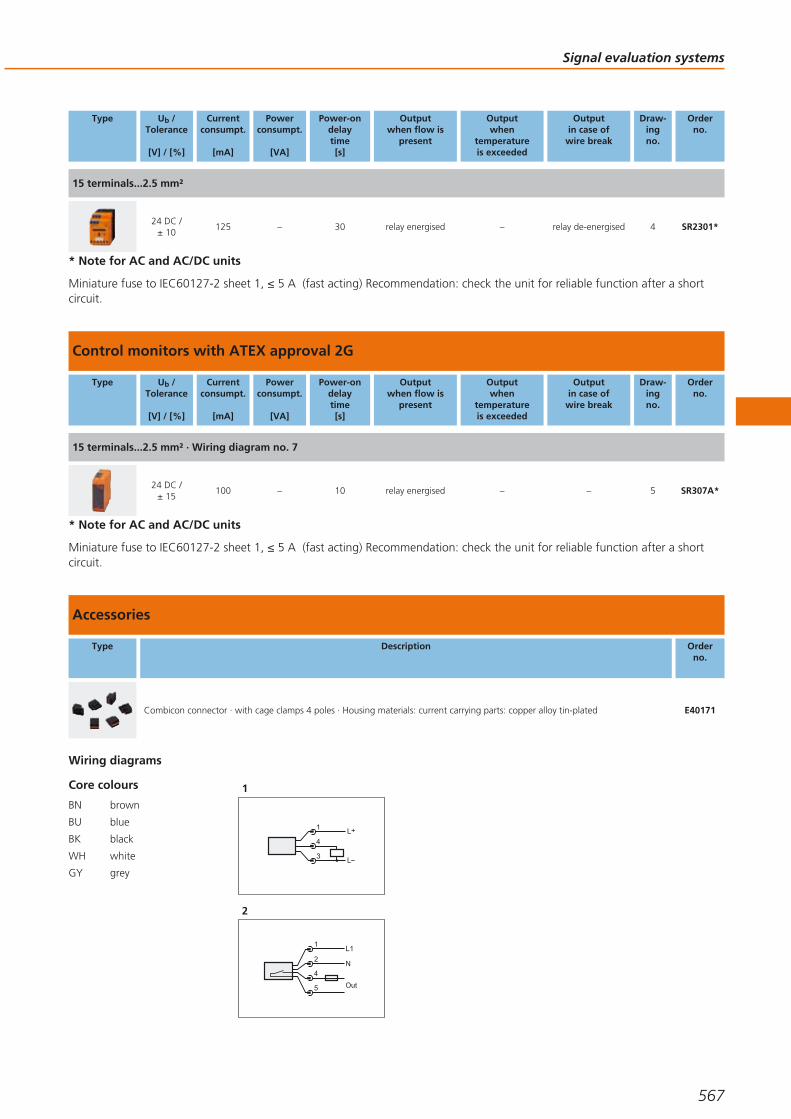
Type Ub /Tolerance
[V] / [%]
Currentconsumpt.
[mA]
Powerconsumpt.
[VA]
Power-ondelaytime[s]
Outputwhen flow is
present
Outputwhen
temperature is exceeded
Outputin case of
wire break
Draw-ingno.
Orderno.
15 terminals...2.5 mm²
24 DC / ± 10
125 – 30 relay energised – relay de-energised 4 SR2301*
* Note for AC and AC/DC units
Miniature fuse to IEC60127-2 sheet 1, ≤ 5 A (fast acting) Recommendation: check the unit for reliable function after a shortcircuit.
Control monitors with ATEX approval 2G
Type Ub /Tolerance
[V] / [%]
Currentconsumpt.
[mA]
Powerconsumpt.
[VA]
Power-ondelaytime[s]
Outputwhen flow is
present
Outputwhen
temperature is exceeded
Outputin case of
wire break
Draw-ingno.
Orderno.
15 terminals...2.5 mm² · Wiring diagram no. 7
24 DC / ± 15
100 – 10 relay energised – – 5 SR307A*
* Note for AC and AC/DC units
Miniature fuse to IEC60127-2 sheet 1, ≤ 5 A (fast acting) Recommendation: check the unit for reliable function after a shortcircuit.
Accessories
Type Description Orderno.
Combicon connector · with cage clamps 4 poles · Housing materials: current carrying parts: copper alloy tin-plated E40171
Core colours
BN brown
BU blue
BK black
WH white
GY grey
Wiring diagrams
1
L+
L
1
4
3
2
1
4
2
5
L1
N
Out
Signal evaluation systems
567
Gesamtkatalog EN 2016_17_Stilvorlage LK FrutigerOT_2010 DE_GB.qxd 06.11.15 16:56 Seite 567

Wiring diagrams
3
ACL
N
12
11
10
9
8
7
6
5
4
2
1
19
18
17
5
4
1
3
2
GY
BK
BN
BU
WH
20
21
22
23
24
1
2
35
4
1: Flow monitoring, 2: Wire break monitoring, 3: Temperaturemonitoring, 4: Power-on delay time, 5: Selection liquid / gas
4
ACL
N
12
11
10
9
8
7
6
5
4
2
1
19
18
17
5
4
1
3
2
GY
BK
BN
BU
WH
20
21
22
23
24
1
2
35
4
1: Flow monitoring, 2: Wire break monitoring, 3: Temperaturemonitoring, 4: Power-on delay time, 5: Selection liquid / gas, Note:miniature fuse to IEC60127-2 sheet 1,, ≤ 5 A (fast acting)
5
12
11
10
9
8
7
6
5
4
2
1
19
18
17
5
4
1
3
2
GY
BK
BN
BU
WH
20
21
22
23
24
1
2
35
4
DCL+L
1: Flow monitoring, 2: Wire break monitoring, 3: Temperaturemonitoring, 4: Power-on delay time, 5: Selection liquid / gas
6
DCL+L
12
11
10
9
8
7
6
5
4
2
1
19
18
17
5
4
1
3
2
GY
BK
BN
BU
WH
20
21
22
23
24
1
2
35
4
1: Flow monitoring, 2: Wire break monitoring, 3: Temperaturemonitoring, 4: Power-on delay time, 5: Selection liquid / gas, Note:miniature fuse to IEC60127-2 sheet 1,, ≤ 5 A (fast acting)
7
22
23
24
28
29
30
31
3234
35
36
2
7
8
9BK
BU
BN
WH
1
2
3
L
L+
1: Flow monitoring, 2: Fault monitoring, 3: Temperature monitoring,Note: miniature fuse to IEC60127-2 sheet 1,, ≤ 5 A (fast acting),Place the fuse outside the hazardous area.
Process sensors
568Product selectors and further information can be found at: www.ifm.com
Gesamtkatalog EN 2016_17_Stilvorlage LK FrutigerOT_2010 DE_GB.qxd 06.11.15 16:56 Seite 568

Scale drawings / drawing no. – CAD download: www.ifm.com
1
103,5
35,5
25
100
2
1
LEDs
LEDs
1 2 3 4
5 6 7 8
9 10 11 12
21 22 23 24
17 18 19 20
1: Potentiometer (switch point flow), 2: Potentiometer (switch pointtemperature)
2
27
64
M12
x1
4
1 2
835248
50
19,7
3
1: LED display, 2: setting pushbutton, 3: connection for voltagesupply and output signals, 4: connection for flow sensor
3
27
64
4
1 2
835248
50
19,7
3
" 20
UN
F 2
A2
1
1: LED display, 2: setting pushbutton, 3: connection for voltagesupply and output signals, 4: connection for flow sensor
4
45
78
1 2
19 20 21
13 14 15 16 17 18
3
97 8
+
120
35,5
1
1: Mounting on DIN rail
5
107113,6
35,2
104,
5
LEDs
1: LED display, 2: setting pushbuttons
Signal evaluation systems
569
Gesamtkatalog EN 2016_17_Stilvorlage LK FrutigerOT_2010 DE_GB.qxd 06.11.15 16:56 Seite 569

Dual inductive feedback sensors for pneumatic actuators and valves
Designed for simple fit to common actuators based on VDI / VDE 3845
AS-i versions for even simpler and neater wiring
Compact, weatherproof and low maintenance
Mounting sets available for manual valves and non-standard actuators
Valve sensors
Butterfly and ball valves in a variety of specifications are common across a broadspectrum of industrial processes. A large proportion of these have been automatedwith the addition of a pneumatic actuator to drive the valve between its open and closed positions. Feedback can then be added to confirm that the valve has achieved its desired position. This often takes the form of a rotating cam arrange-ment with a couple of microswitches or small inductive sensors mounted inside aplastic switch box. Such switch boxes can be difficult to set up, suffer from ingressand the cams can sometimes slip under normal plant vibration.
Operating principle
In 1992 ifm electronic released our first alternative to this old and failure pronedesign. The IND dual sensor is essentially a pair of inductive sensors, operating atdifferent frequencies so as not to interfere with each other, combined into a customdesign housing which mechanically matches the top works on standard pneumaticactuators. The dual sensor fits neatly onto the actuator’s existing M5 holes. A plastictarget “puck” is then fitted onto the slotted actuator shaft, again using the existingthreaded hole. The puck has two metal targets spaced 90 degrees apart which arepicked up by either the OPEN sensor or the CLOSED sensor.
Advantages
This simple construction addresses all the shortcomings of the switchbox solution.It is weatherproof surviving heavy rain, ice and strong sunshine. It is low profileallowing valve / actuator packages to fit where a switchbox would not. This alsomeans that feedback can be fitted to even small manually operated valves. It is lowweight so will not fail even if pumps are causing pipe vibration. It allows for backwiring a local solenoid through the common multi-pin connector, saving on wiringand cable tray costs.
Feedback: Positionmonitoring of
both pneumaticallyactuated and manual
valves is needed forplant control.
Process sensors
570Product selectors and further information can be found at: www.ifm.com
Gesamtkatalog EN 2016_17_Stilvorlage LK FrutigerOT_2010 DE_GB.qxd 06.11.15 16:56 Seite 570

System overview Page
Sensors for industrial applications 572 - 573
Sensors for industrial applications, AS-i system 573
Sensors with ATEX approval 1G / 2G and 1D 574
Sensors with ATEX approval 3D and / or 3G 575
Sensors for rising stem valves 575 - 576
Sensors for rising stem valves, AS-i system 576
Added value packages with Bürkert solenoid valve 576
Added value packages with Norgren Herion solenoid valve 576
Switching cams for sensors with quarter-turn actuators 577 - 578
Accessories for quarter-turn actuator sensors 578 - 579
Accessories for rising stem valve sensors 579
Wiring diagrams 580 - 581
Scale drawings / drawing no. – CAD download: www.ifm.com 581 - 583
Feedback systems for valvesand valve actuators
571
Gesamtkatalog EN 2016_17_Stilvorlage LK FrutigerOT_2010 DE_GB.qxd 06.11.15 16:56 Seite 571

Sensors for industrial applications
Type Dimensions
[mm]
Sensingrange
[mm]
Material Ub
[V]
Protection fAC / DC
[Hz]
IloadAC / DC
[mA]
Draw-ingno.
Orderno.
Cable 2 m · Output function · AC/DC · Wiring diagram no. 1
40 x 26 x 40 4 nf PBT 20...250 IP 67 25 / 50 250 / 100 1 IN0110*
Cable 2 m · Output function · DC PNP · Wiring diagram no. 2
40 x 26 x 26 4 nf PBT 10...36 IP 67 1300 250 2 IN5251
Cable 6 m · Output function · DC PNP · Wiring diagram no. 2
40 x 26 x 26 4 nf PC (polycarbonate) 10...36 IP 67 1300 250 2 IN5304
Cable 10 m · Output function · DC PNP · Wiring diagram no. 2
40 x 26 x 26 4 nf PBT 10...36 IP 67 1300 250 2 IN5323
M12 connector · Output function · DC PNP/NPN · Wiring diagram no. 13 · Connector groups 8, 10, 18, 20, 120, 124,126, 128, 157
40 x 26 x 26 4 nf PBT 10...36 IP 67 1300 250 3 IN5224
M12 connector · Output function · DC PNP/NPN · Wiring diagram no. 3 · Connector groups 8, 10, 18, 20, 120, 124, 126,128, 157
40 x 26 x 47 4 nf PBT 10...36 IP 67 250 250 4 IN5331
M12 connector · Output function · DC PNP · Wiring diagram no. 4 · Connector groups 8, 9, 10, 11, 18, 20, 120, 124,126, 128, 130, 131, 157, 158
40 x 26 x 26 4 nf PBT 10...36 IP 67 1300 250 3 IN5225
40 x 26 x 47 4 nf PBT 10...36 IP 67 1300 250 4 IN5327
M18 connector · Output function · DC PNP · Wiring diagram no. 4 · Connector group 24
40 x 26 x 26 4 nf PBT 10...36 IP 67 1300 250 5 IN5285
Process sensors
572Product selectors and further information can be found at: www.ifm.com
Gesamtkatalog EN 2016_17_Stilvorlage LK FrutigerOT_2010 DE_GB.qxd 06.11.15 16:56 Seite 572
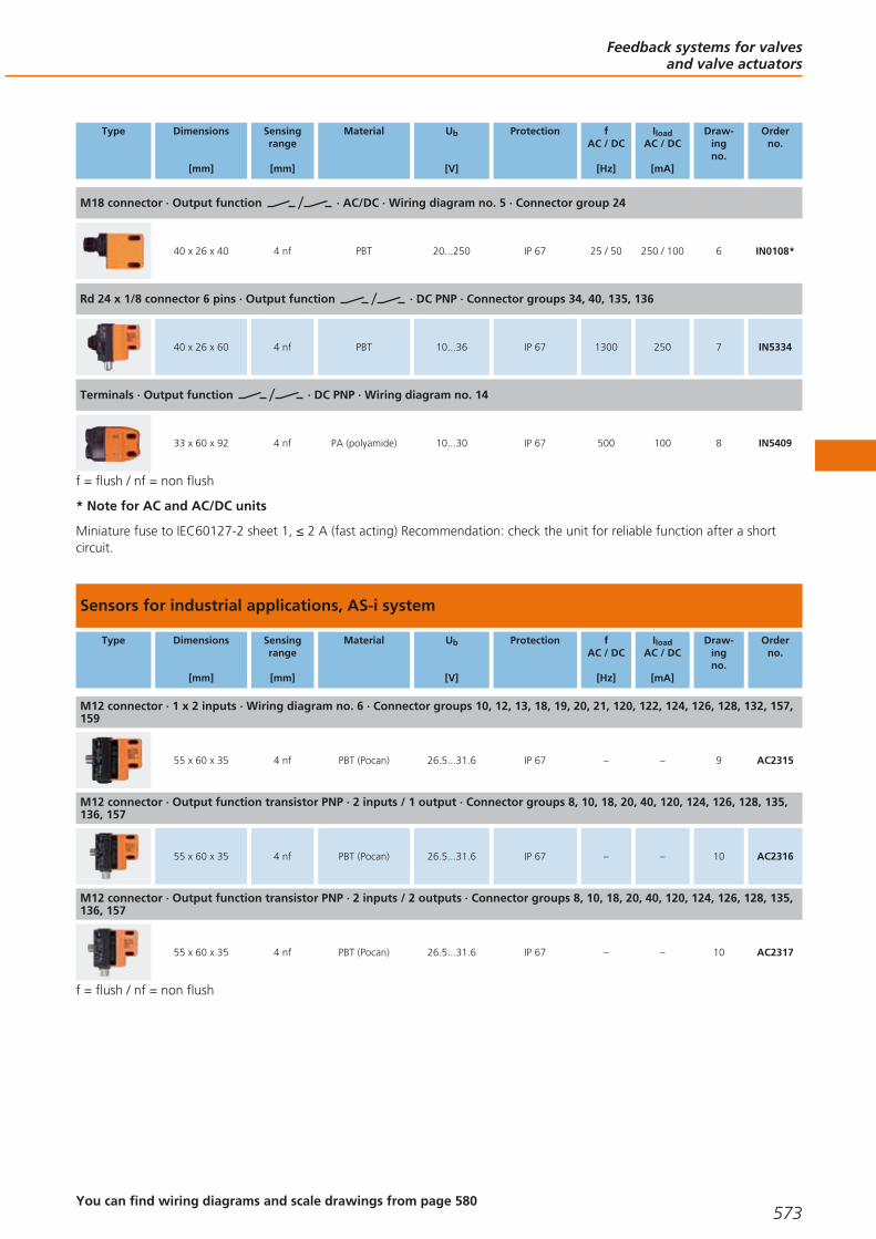
Type Dimensions
[mm]
Sensingrange
[mm]
Material Ub
[V]
Protection fAC / DC
[Hz]
IloadAC / DC
[mA]
Draw-ingno.
Orderno.
M18 connector · Output function · AC/DC · Wiring diagram no. 5 · Connector group 24
40 x 26 x 40 4 nf PBT 20...250 IP 67 25 / 50 250 / 100 6 IN0108*
Rd 24 x 1/8 connector 6 pins · Output function · DC PNP · Connector groups 34, 40, 135, 136
40 x 26 x 60 4 nf PBT 10...36 IP 67 1300 250 7 IN5334
Terminals · Output function · DC PNP · Wiring diagram no. 14
33 x 60 x 92 4 nf PA (polyamide) 10...30 IP 67 500 100 8 IN5409
f = flush / nf = non flush
* Note for AC and AC/DC units
Miniature fuse to IEC60127-2 sheet 1, ≤ 2 A (fast acting) Recommendation: check the unit for reliable function after a short circuit.
Sensors for industrial applications, AS-i system
Type Dimensions
[mm]
Sensingrange
[mm]
Material Ub
[V]
Protection fAC / DC
[Hz]
IloadAC / DC
[mA]
Draw-ingno.
Orderno.
M12 connector · 1 x 2 inputs · Wiring diagram no. 6 · Connector groups 10, 12, 13, 18, 19, 20, 21, 120, 122, 124, 126, 128, 132, 157,159
55 x 60 x 35 4 nf PBT (Pocan) 26.5...31.6 IP 67 – – 9 AC2315
M12 connector · Output function transistor PNP · 2 inputs / 1 output · Connector groups 8, 10, 18, 20, 40, 120, 124, 126, 128, 135,136, 157
55 x 60 x 35 4 nf PBT (Pocan) 26.5...31.6 IP 67 – – 10 AC2316
M12 connector · Output function transistor PNP · 2 inputs / 2 outputs · Connector groups 8, 10, 18, 20, 40, 120, 124, 126, 128, 135,136, 157
55 x 60 x 35 4 nf PBT (Pocan) 26.5...31.6 IP 67 – – 10 AC2317
f = flush / nf = non flush
Feedback systems for valvesand valve actuators
573You can find wiring diagrams and scale drawings from page 580
Gesamtkatalog EN 2016_17_Stilvorlage LK FrutigerOT_2010 DE_GB.qxd 06.11.15 16:56 Seite 573

Sensors with ATEX approval 1G / 2G and 1D
Type Dimensions
[mm]
Sensingrange
[mm]
Material Unom.at 1 KΩ
[V]
Ub
[V]
Internalcapacit.
[nF]
Internalinductance
[μH]
f
[Hz]
Draw-ingno.
Orderno.
Cable 2 m · Output function 2 x normally closed · Connection to certified intrinsically safe circuits with the max. values U = 15 V / I = 50 mA / P = 120 mW · Wiring diagram no. 7
40 x 26 x 26 4 nf PBT 8.2 DC 7.5...15 DC 140 130 1800 2 NN5009
Cable 10 m · Output function 2 x normally closed · Connection to certified intrinsically safe circuits with the max. values U = 15 V /I = 50 mA / P = 120 mW · Wiring diagram no. 7
40 x 26 x 26 4 nf PBT 8.2 DC 7.5...15 DC 140 140 1800 2 NN5011
M12 connector · Output function 2 x normally closed · Connection to certified intrinsically safe circuits with the max. values U = 15 V / I = 50 mA / P = 120 mW · Wiring diagram no. 8 · Connector group 153
40 x 26 x 26 4 nf PBT 8.2 DC 7.5...15 DC 140 130 1800 11 NN5008
M18 connector · Output function 2 x normally closed · Connection to certified intrinsically safe circuits with the max. values U = 15 V / I = 50 mA / P = 120 mW · Wiring diagram no. 9 · Connector group 24
40 x 26 x 26 4 nf PBT 8.2 DC 7.5...15 DC 140 130 1800 5 NN5013
Rd 24 x 1/8 connector 6 pins · Output function 2 x normally closed · Connection to certified intrinsically safe circuits with the max.values U = 15 V / I = 50 mA / P = 120 mW · Connector groups 34, 56, 64, 107, 108, 109, 110, 111, 112, 137, 152
40 x 26 x 60 4 nf PBT 8.2 DC – 150 150 250 7 N95001
40 x 26 x 60 4 nf PBT 8.2 DC – 100 150 1300 7 N95002
Terminals · Output function 2 x normally closed · Connection to certified intrinsically safe circuits with the max. values U = 15 V / I = 50 mA / P = 120 mW · Wiring diagram no. 15
33 x 60 x 92 4 nf PA (polyamide) 8.2 DC 7.5...15 DC – – 500 8 NN504A
Terminals · Output function 2 x normally closed · Connection to certified intrinsically safe circuits with the max. values U = 15 V / I = 50 mA / P = 120 mW · Wiring diagram no. 16 · Connector group --
33 x 60 x 92 4 nf PA (polyamide) 8.2 DC 7.5...15 DC – – 500 12 NN505A
f = flush / nf = non flush
Process sensors
574Product selectors and further information can be found at: www.ifm.com
Gesamtkatalog EN 2016_17_Stilvorlage LK FrutigerOT_2010 DE_GB.qxd 06.11.15 16:56 Seite 574

Sensors with ATEX approval 3D and / or 3G
Type Dimensions
[mm]
Sensingrange
[mm]
Material Ub
[V]
Protection fAC / DC
[Hz]
IloadAC / DC
[mA]
Draw-ingno.
Orderno.
Cable 2 m · Output function · DC PNP · Wiring diagram no. 2
40 x 26 x 26 4 nf PBT (Pocan) 10...30 IP 67 1300 100 2 IN508A
M12 connector · Output function transistor PNP · 2 inputs / 2 outputs · Connector groups 154, 156
55 x 60 x 35 4 nf PBT (Pocan) 26.5...31.6 IP 5x – – 10 AC317A
M12 connector · Output function transistor PNP · 2 inputs / 1 output · Connector groups 154, 156
55 x 60 x 35 4 nf PBT (Pocan) 26.5...31.6 IP 5x – – 10 AC316A
55 x 60 x 35 4 PBT (Pocan) 26.5...31.6 IP 67 – – 13 AC326A
M12 connector · 1 x 2 inputs · Wiring diagram no. 6 · Connector groups 154, 156
55 x 60 x 35 4 nf PBT (Pocan) 26.5...31.6 IP 5x – – 9 AC315A
M12 connector · Output function · DC PNP · Wiring diagram no. 4 · Connector groups 154, 156
40 x 26 x 47 4 PBT 10...30 IP 67 1300 100 14 IN507A
40 x 26 x 47 4 nf PBT (Pocan) 10...30 IP 67 1300 100 4 IN509A
f = flush / nf = non flush
Sensors for rising stem valves
Type Dimensions
[mm]
Sensingrange
[mm]
Material Ub
[V]
Protection fAC / DC
[Hz]
IloadAC / DC
[mA]
Draw-ingno.
Orderno.
Cable 2 m · Output function 1...5 V analogue · DC · Wiring diagram no. 10
67.5 x 43 x 110 – PA 18...36 IP 65 / IP 67 – – 15 IX5002
Cable 2 m · Output function 3 x normally open · DC PNP · Wiring diagram no. 11
67.5 x 43 x 110 – PA 18...36 IP 65 / IP 67 – 100 16 IX5006
Feedback systems for valvesand valve actuators
575You can find wiring diagrams and scale drawings from page 580
Gesamtkatalog EN 2016_17_Stilvorlage LK FrutigerOT_2010 DE_GB.qxd 06.11.15 16:57 Seite 575

Type Dimensions
[mm]
Sensingrange
[mm]
Material Ub
[V]
Protection fAC / DC
[Hz]
IloadAC / DC
[mA]
Draw-ingno.
Orderno.
Cable with connector 0.3 m · Output function 3 x normally open · DC PNP · Wiring diagram no. 12 · Connector groups 122, 126,128, 132, 159
65 x 52 x 110 – PA 18...36 IP 65 / IP 67 – 100 17 IX5010
65 x 43 x 110 0.2 PA 18...36 IP 65 / IP 67 – 100 18 ZZ0214
Sensors for rising stem valves, AS-i system
Type Dimensions
[mm]
Sensingrange
[mm]
Material Ub
[V]
Protection fAC / DC
[Hz]
IloadAC / DC
[mA]
Draw-ingno.
Orderno.
Cable with connector 0.15 m · AS-i · Wiring diagram no. 6 · Connector groups 10, 12, 13, 18, 19, 20, 21, 120, 122, 124, 126, 128, 132,157, 159
65 x 52 x 110 – PA 26.5...31.6 IP 65 / IP 67 – – 17 IX5030
Added value packages with Bürkert solenoid valve
Type Description Orderno.
Added value package AS-i for pneumatic quarter-turn actuators · A/B slave · Shaft height 20 mm · Hole spacing 80 mm · Connector
AC0017
Added value package AS-i for pneumatic quarter-turn actuators · A/B slave · Shaft height 30 mm · Hole spacing 80 mm · Connector
AC0019
Added value package AS-i for pneumatic quarter-turn actuators · A/B slave · Shaft height 30 mm · Hole spacing 130 mm ·Connector
AC0020
Added value packages with Norgren Herion solenoid valve
Type Description Orderno.
Added value package AS-i for pneumatic quarter-turn actuators · A/B slave · Shaft height 20 mm · Hole spacing 80 mm · Connector
AC0021
Added value package AS-i for pneumatic quarter-turn actuators · A/B slave · Shaft height 30 mm · Hole spacing 80 mm · Connector
AC0022
Added value package AS-i for pneumatic quarter-turn actuators · A/B slave · Shaft height 30 mm · Hole spacing 130 mm ·Connector
AC0023
Process sensors
576Product selectors and further information can be found at: www.ifm.com
Gesamtkatalog EN 2016_17_Stilvorlage LK FrutigerOT_2010 DE_GB.qxd 06.11.15 16:57 Seite 576

Switching cams for sensors with quarter-turn actuators
Type Description Orderno.
Target puck · Ø 53 mm · The upper damping level is 360° continuously adjustable · Housing materials: Target puck: PVC / screws:high-grade stainless steel
E10661
Target puck · Ø 53 mm · 6 possible switching flag positions · with drain holes · Housing materials: Target puck: PA 6 / screws: high-grade stainless steel
E17105
Target puck · Ø 53 mm · Housing materials: Target puck: PBT / screws: high-grade stainless steel E17118
Target puck · Ø 53 mm · 8 possible switching flag positions · with drain holes · Housing materials: Target puck: PA 6 / screws: high-grade stainless steel
E17294
Target puck · Ø 53 mm · 3 possible switching flag positions · Housing materials: Target puck: PA 6 black / screws: V2A E17320
Target puck · Ø 53 mm · 8 possible switching flag positions · Housing materials: Target puck: PA 6 black / screws: V2A E17321
Target puck · Ø 53 mm · Housing colour: blue · 8 possible switching flag positions · Housing materials: Target puck: PA 6 blue /screws: V2A
E17322
Target puck · Ø 53 mm · Housing colour: red · 8 possible switching flag positions · Housing materials: Target puck: PA 6 / screws:V2A
E17323
Target puck · Ø 55 mm · Inverted function · Housing materials: Target puck: PVC / screws: high-grade stainless steel / Metal ring:stainless steel
E17205
Target puck · Ø 59 mm · for Neles actuator type B1CU 6/20E · Housing materials: Target puck: POM E11278
Target puck · Ø 65 mm · Housing materials: Target puck: PVC / screws: high-grade stainless steel E17148
Target puck · Ø 65 mm · Housing colour: black · 8 possible switching flag positions · Housing materials: Target puck: PA 6 / screws:V2A
E17324
Target puck · Ø 65 mm · Housing colour: blue · 8 possible switching flag positions · Housing materials: Target puck: PA 6 / screws:V2A
E17325
Target puck · Ø 65 mm · Housing colour: red · 8 possible switching flag positions · Housing materials: Target puck: PA 6 / screws:V2A
E17326
Feedback systems for valvesand valve actuators
577You can find wiring diagrams and scale drawings from page 580
Gesamtkatalog EN 2016_17_Stilvorlage LK FrutigerOT_2010 DE_GB.qxd 06.11.15 16:57 Seite 577

Type Description Orderno.
Target puck · Ø 65 mm · Housing materials: Target puck: PA 6 / screws: V2A E17327
Target puck · Ø 102 mm · Housing materials: Target puck: PA 6 / screws: V2A E17328
Target puck · Ø 102 mm · Housing colour: black · 8 possible switching flag positions · Housing materials: Target puck: PA 6 / screws:V2A
E17329
Target puck · Ø 102 mm · Housing colour: blue · 8 possible switching flag positions · Housing materials: Target puck: PA 6 / screws:V2A
E17330
Target puck · Ø 102 mm · Housing colour: red · 8 possible switching flag positions · Housing materials: Target puck: PA 6 / screws:V2A
E17331
direction indicator black · 12 x 4.8 · For target puck · Housing materials: POM E17295
direction indicator yellow · 12 x 4.8 · For target puck · Housing materials: POM E17296
Accessories for quarter-turn actuator sensors
Type Description Orderno.
Spacer · 10 mm · for compensation between target pucks and dual sensor IND · Housing materials: PBT E10579
Spacer · 3 mm · for compensation between target pucks and dual sensor IND · Housing materials: PBT E10584
Spacer · 5 mm · for compensation between target pucks and dual sensor IND · Housing materials: PBT E10585
Cable gland · M20 x 1.5 · Housing materials: PA 6.6 E12208
Protective cap · M20 x 1.5 · Housing materials: PA 6.6 E12209
Plug for covering the oblong holes · Housing materials: EPDM E12212
Process sensors
578Product selectors and further information can be found at: www.ifm.com
Gesamtkatalog EN 2016_17_Stilvorlage LK FrutigerOT_2010 DE_GB.qxd 06.11.15 16:57 Seite 578

Type Description Orderno.
reinforcement bracket · for type IND · Housing materials: stainless steel 316Ti / 1.4571 E11310
protective housing · Accessory for valve sensors · for type IND · Housing materials: stainless steel E11984
Mounting kit · MS-MEC-KU-RA--F04A · for ball valve Mecafrance ISO5211/F04 DN25 PN40 · Detection of the "ON/OFF" position by means of the IND dual sensor
E10597
Mounting kit for limit position feedback · tyco 792E-100 · for Keystone actuators E11243
Accessories for rising stem valve sensors
Type Description Orderno.
Mounting adapter · for Kieselmann seat valves · accessory for IX5010, IX5030 · Housing materials: adapter: PA / target: stainless steel 316L / 1.4404
E12123
Mounting adapter · for Alfa Laval valves · accessory for IX5010, IX5030 · Housing materials: adapter: PA / target: stainless steel 316L / 1.4404
E11900
Mounting adapter · for Südmo valves · accessory for IX5010, IX5030 · Housing materials: adapter: PA / target: stainless steel 316L / 1.4404
E11989
Mounting adapter · for Georg Fischer diaphragm valve Diastar with mounting kit M12 · accessory for IX5010, IX5030 · Housing materials: adapter: POM / target: stainless steel
E12009
Mounting adapter · for Georg Fischer diaphragm valve Diastar with mounting kit M16 · accessory for IX5010, IX5030 · Housing materials: adapter: POM / target: stainless steel
E12010
Mounting adapter · for Bardiani valves · accessory for IX5010, IX5030 · Housing materials: adapter: PA / target: stainless steel 316L / 1.4404
E12170
Mounting adapter · IX / Ø 30 mm · for Gemü actuators with mounting kit · accessory for IX5010, IX5030 · Housing materials:adapter: POM / target: stainless steel
E12042
Mounting adapter · IX / Ø 45 mm · for Gemü actuators with mounting kit · accessory for IX5010, IX5030 · Housing materials:adapter: POM / target: stainless steel
E12043
Feedback systems for valvesand valve actuators
579You can find wiring diagrams and scale drawings from page 580
Gesamtkatalog EN 2016_17_Stilvorlage LK FrutigerOT_2010 DE_GB.qxd 06.11.15 16:57 Seite 579

Core colours
BN brown
BU blue
BK black
WH white
GY grey
Wiring diagrams
1
BN
BU
L+L1
LN
WHL+L1
BK
LNBU:
BK: A1A2
2
L
L+
BK
WH
BN
BUWH:BK: A1
A2
3
L
L+
L+
L
2 WH
1 BN
4 BK
3 BU
4
L
L+
3 BU
2 WH
4 BK
1 BN
2:4: A1
A2
5
L+L1
LNL+L1
LN
1
2
4
3A1A2
1+42+3
6
AS-i+1
3 AS-i
7
Out 1BK
BU
WH
BNL+ 1
L+ 2
Out 21
1: connection to NAMUR-amplifier
8
Out 1
3 BU
2 WH
4 BK
1 BNL+ 1
L+ 2
Out 2
1
1: connection to NAMUR-amplifier
9
Out 2
4 BK
2 BU
3 WH
1 BNL+ 1
L+ 2
Out 1
1
1: connection to NAMUR-amplifier
10
BN
BK
BU
L+
L
11
GY
WH
BK
BN
BU L
L+
12
L+
L
1
5
4
2
3
13
L
L+
L+
L
2:1: A1
A2
2 WH
1 BN
4 BK
3 BUL
L+
L+
L
3:4: A1
A2
2 WH
1 BN
4 BK
3 BU
NPNPNP
14
L
L+
2
4
1
34:2:
A2A1
6
7
8
5IN +
IN -
OUT +
OUT -
1: solenoid valve
15
2
1
6
7
8
5Ex-i IN +
EX-i IN -
EX-i OUT +
EX-i OUT -
L+ 2 (51)
A2 (52)
4
3
L+ 1 (41)
A1 (42)
Process sensors
580Product selectors and further information can be found at: www.ifm.com
Gesamtkatalog EN 2016_17_Stilvorlage LK FrutigerOT_2010 DE_GB.qxd 06.11.15 16:57 Seite 580
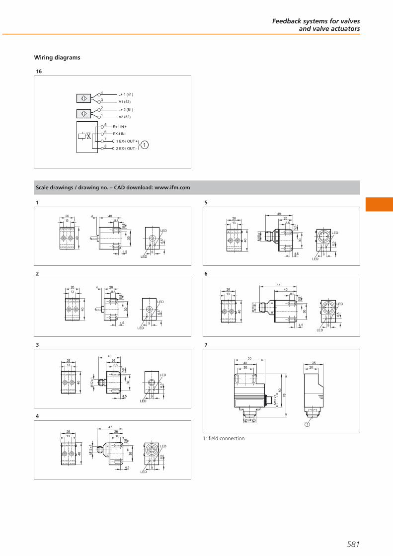
Wiring diagrams
16
6
7
8
5Ex-i IN +
EX-i IN -
1 EX-i OUT +
2 EX-i OUT -
2
1
L+ 2 (51)
A2 (52)
4
3
L+ 1 (41)
A1 (42)
Scale drawings / drawing no. – CAD download: www.ifm.com
1
40
2613
9
LED
A1
A2 6,5
LED
8,54 40
4,5
5,5
30
2
40
2613
9
LED
A1
A2 6,5
LED
8,54 26
4,5
5,5
30
3
40
2613
M12
x1
8,526
4,5
5,5
30
40
9
LED
A1
A2 6,5
LED
4
40
2613
9LED
A1
A2 6,5
LED
8,526
4,5
5,5
30
47
M12
x1
5
40
2613
9
LED
A1
A2 6,5
LED
8,526
4,5
5,5
30
49
M18
x1
6
40
26
13
9
LED
A1
A2 6,5
LED
8,540
4,5
5,5
30M18
x1
67
7
M12
x1
4055
60
Rd24x1 8
78
30 2635
1
1: field connection
Feedback systems for valvesand valve actuators
581
Gesamtkatalog EN 2016_17_Stilvorlage LK FrutigerOT_2010 DE_GB.qxd 06.11.15 16:57 Seite 581
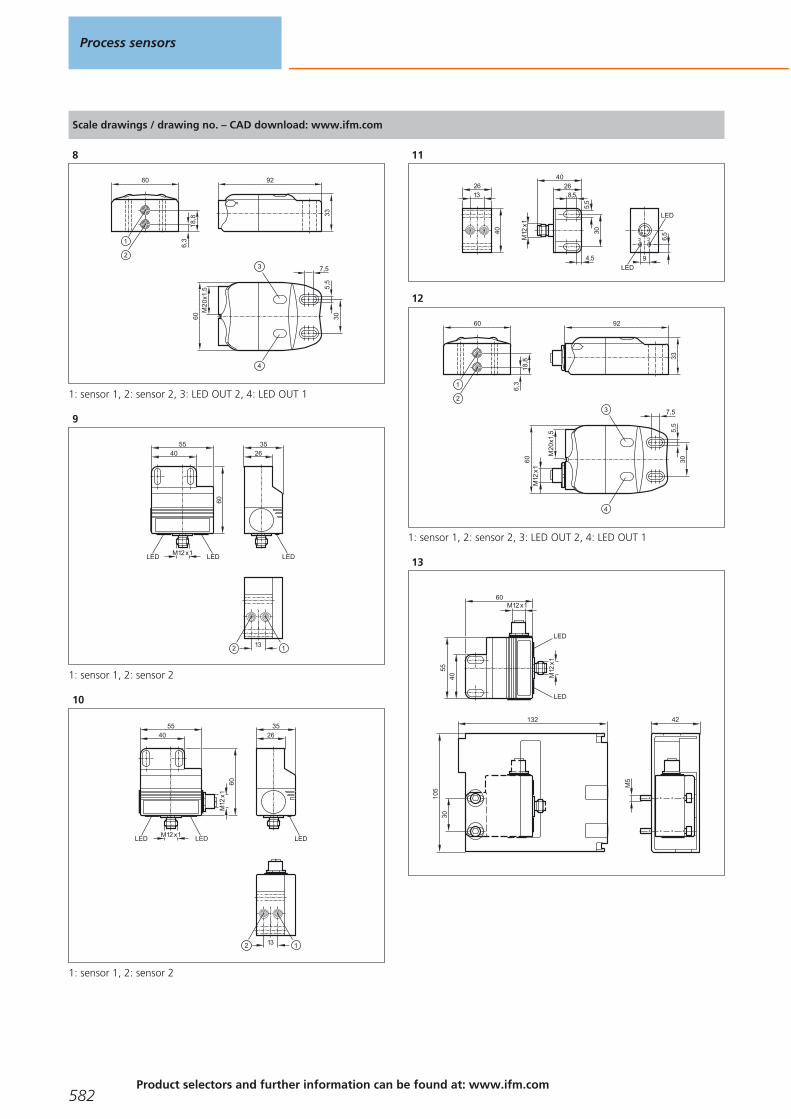
Scale drawings / drawing no. – CAD download: www.ifm.com
8
33
926,
318
,8
60
7,5
5,5
3060M
20
x1,5
1: sensor 1, 2: sensor 2, 3: LED OUT 2, 4: LED OUT 1
9
2635
LEDM12 x1
4055
LEDLED
60
1312
1: sensor 1, 2: sensor 2
10
2635
LEDM12 x1
M12
x1
4055
LEDLED
60
13 12
1: sensor 1, 2: sensor 2
11
40
2613
9
LED
A1
A2 6,5
LED
M12
x1
8,526
4,5
5,5
30
40
12
6,3
18,8
60
7,5
5,5
3060
M2
0x1
,5
M12
x1
33
92
1: sensor 1, 2: sensor 2, 3: LED OUT 2, 4: LED OUT 1
13M
12x1
M12 x1
4055
LED
LED
60
132
105
30
42
M5
Process sensors
582Product selectors and further information can be found at: www.ifm.com
Gesamtkatalog EN 2016_17_Stilvorlage LK FrutigerOT_2010 DE_GB.qxd 06.11.15 16:57 Seite 582

Scale drawings / drawing no. – CAD download: www.ifm.com
14
3050,7
106 34,65,5
8,5 1
M12
x18,5
26
4,5
5,5
30
47
1: protective housing
15
66,
225
99,6
110
1480
87,5
2634,838
43
LED
67,5
1: Max. spindle stroke, 2: Measuring range, 3: Initial value of themeasuring range (zero point)
16
67,5
2634,838
6,2
6
25
14
3
43
3 LED 4
88,6
8099,6
110
1: Max. spindle stroke, 2: Measuring distance, 3: Initial value of themeasuring range (zero point), 4: Programming buttons
17
52
3 LED 4
65
110
99,6
26
80
34,8
38
6,2
4,5
26,5 15
,5
3
4,3
88,6
1: Max. spindle stroke, 2: Measuring distance, 3: Initial value of themeasuring range (zero point), 4: Programming buttons
18
2
2530
,6
1419
10
24
65
83,5
110
99,6
26
80 88,6
34,838
6,2
4,5
26,5 15
,51
46,5
88
27
1: Valve sensor IX5010, 2: Mounting adapter E11900
Feedback systems for valvesand valve actuators
583
Gesamtkatalog EN 2016_17_Stilvorlage LK FrutigerOT_2010 DE_GB.qxd 06.11.15 16:57 Seite 583

Safe, easy, cost-optimised
Reduced cost: Reduced wiring complexityfor faster installation and fewer errorsources.
Bus system AS-Interface
AS-Interface (AS-i = actuator sensor interface) is a manufactu-rer-independent standard for the connection of actuators andsensors of the first field level. It is the only wiring systemaccepted worldwide. With more than 20 million slaves installedAS-i has been tried and tested as a low-cost feeder for allcommon fieldbuses for many years.
The product range includes AS-i components for differentareas from packaging and conveying via silo applications,machine tools, robotics and automation to the food industryand mobile vehicles.
Safe
The sophisticated AS-i technology and the extended diagnosticpossibilities provide high reliability and machine uptime.
“Safety at Work” is the extension of the AS-interface bysafety-related components. Safety components up to SIL 3 toIEC 61508 and EN ISO 13849 - 1 / PL e can be connected toAS-i.
Easy
Due to the standardised system, the low wiring complexityand the quick connection technology, AS-i enables simple“Plug & Play”. The reduction of terminals leads to reduceddocumentation.
Data and energy are jointly transmitted via a two-wire cable.The reverse polarity protected insulation displacementtechnology helps avoid errors. The modularity and the treestructure smoothly fit to the way the plant is put together.
Cost-optimised
It’s the end result that matters: Wiring complexity, documen-tation and set-up times are significantly reduced. The decentralisation of the AS-i participants leads to smallerand less expensive control cabinets. Simple diagnosis and aclear system design result in high machine uptime and avoiddowntimes.
Industrial communication
584Product selectors and further information can be found at: www.ifm.com
Gesamtkatalog EN 2016_17_Stilvorlage LK FrutigerOT_2010 DE_GB.qxd 06.11.15 16:57 Seite 584

Industrial communication
585
AS-Interface controllers / gateways 586 - 590
AS-Interface power supplies / earth fault monitors 592 - 593
AS-Interface I/O modules 594 - 613
AS-Interface AirBoxes for pneumatics 614 - 617
AS-Interface sensors 618 - 620
AS-Interface devices for valves and valve actuators 622 - 624
AS-Interface expansion 626 - 627
AS-Interface Safety at Work 628 - 634
Gesamtkatalog EN 2016_17_Stilvorlage LK FrutigerOT_2010 DE_GB.qxd 06.11.15 16:57 Seite 585

AS-Interface controllers / gateways
AS-i controller and gateways have AS-i master functionality and are thus an elementary part of AS-i networks. These components are usually in a control cabinet and ensure data communication. A wide product range provides suitabilityfor different applications. An integrated CODESYS-programmable PLC allows thatthe AS-i controllers can also be used as supplementary or independent controlsystem.
Controllers, gateways and software
Type Numberof
AS-i masters
Description Draw-ingno.
Orderno.
1AS-i DP controller E · AS-i PLC with Profibus-DP interface · Full master functions · Graphic display ·
Housing materials: aluminium / steel sheet galvanised1 AC1365
2AS-i DP controller E · AS-i PLC with Profibus-DP interface · Full master functions · Graphic display ·
Housing materials: aluminium / steel sheet galvanised1 AC1366
1AS-i controller E · AS-i controller freely programmable · Profibus DP interface · Ethernet programming
interface · Full master functions · Graphic display · Housing materials: aluminium / steel sheetgalvanised
1 AC1355
2AS-i controller E · AS-i controller freely programmable · Profibus DP interface · Ethernet programming
interface · Full master functions · Graphic display · Housing materials: aluminium / steel sheetgalvanised
1 AC1356
1AS-i Ethernet / IP Controller E · Full master functions · Graphic display · Housing materials: aluminium /
steel sheet galvanised2 AC1327
2AS-i Ethernet / IP Controller E · Full master functions · Graphic display · Housing materials: aluminium /
steel sheet galvanised2 AC1337
1AS-i DeviceNet controller E · AS-i controller with DeviceNet interface · Full master functions · Graphic
display · Housing materials: aluminium / steel sheet galvanised3 AC1318
2AS-i DeviceNet controller E · AS-i controller with DeviceNet interface · Full master functions · Graphic
display · Housing materials: aluminium / steel sheet galvanised3 AC1324
1AS-i CANopen Controller E · AS-i controller with CANopen interface · Full master functions · Graphic
display · Housing materials: aluminium / steel sheet galvanised4 AC1331
System overview Page
Controllers, gateways and software 586 - 587
Controllers / Gateways 587 - 588
AS-i manuals 588
Scale drawings / drawing no. – CAD download: www.ifm.com 588 - 590
Industrial communication
586Product selectors and further information can be found at: www.ifm.com
Gesamtkatalog EN 2016_17_Stilvorlage LK FrutigerOT_2010 DE_GB.qxd 06.11.15 16:57 Seite 586

Type Numberof
AS-i masters
Description Draw-ingno.
Orderno.
2AS-i CANopen Controller E · AS-i controller with CANopen interface · Full master functions · Graphic
display · Housing materials: aluminium / steel sheet galvanised5 AC1332
1AS-i controller E · AS-i controller freely programmable · Full master functions · Graphic display ·
Ethernet programming interface · Housing materials: aluminium / steel sheet galvanised6 AC1357
2AS-i controller E · AS-i controller freely programmable · Full master functions · Graphic display ·
Ethernet programming interface · Housing materials: aluminium / steel sheet galvanised7 AC1358
–CODESYS for Automation Alliance · Software CD for controller E Version 2.3 in several languages ·Single user licence · Compatible operating systems: Win2000 (32 bits), WinXP (32/64 bits), WinVista
(32/64 bits), Win7 (32/64 bits)– AC0340
Controllers / Gateways
Type Numberof
AS-i masters
Description Draw-ingno.
Orderno.
1SmartLink DP · AS-i gateway / Profibus DP · Full master functions · Graphic display · Housing
materials: aluminium / steel sheet galvanised8 AC1375
2AS-i DP gateway · Full master functions · Graphic display · Profibus DP interface · Housing materials:
aluminium / steel sheet galvanised1 AC1376
1
AS-i Profinet gateway · AS-i master · Ethernet configuration interface with dynamic web interface forconfiguration and diagnosis including remote maintenance · Profinet RT device class B · LCD colourdisplay · Device supply either via 24 V or AS-i (AS-i bus 1) · Housing materials: aluminium powder-
coated / steel sheet galvanised / Makrolon
9 AC1401
2
AS-i Profinet gateway · AS-i master · Ethernet configuration interface with dynamic web interface forconfiguration and diagnosis including remote maintenance · Profinet RT device class B · LCD colourdisplay · Device supply either via 24 V or AS-i (AS-i bus 1) · Housing materials: aluminium powder-
coated / steel sheet galvanised / Makrolon
9 AC1402
1
AS-i Profibus gateway · AS-i master · Ethernet configuration interface with dynamic web interface forconfiguration and diagnosis including remote maintenance · Profibus DP (DPV0 + DPV1) · LCD colour
display · Device supply either via 24 V or AS-i (AS-i bus 1) · Housing materials: aluminium powder-coated / steel sheet galvanised / Makrolon
10 AC1411
2
AS-i Profibus gateway · AS-i master · Ethernet configuration interface with dynamic web interface forconfiguration and diagnosis including remote maintenance · Profibus DP (DPV0 + DPV1) · LCD colour
display · Device supply either via 24 V or AS-i (AS-i bus 1) · Housing materials: aluminium powder-coated / steel sheet galvanised / Makrolon
10 AC1412
1
AS-i EtherNet/IP gateway · AS-i master · Ethernet configuration interface with dynamic web interfacefor configuration and diagnosis including remote maintenance · LCD colour display · Device supply
either via 24 V or AS-i (AS-i bus 1) · Housing materials: aluminium powder-coated / steel sheetgalvanised / Makrolon
9 AC1421
AS-Interfacecontrollers / gateways
587You can find scale drawings from page 588
Gesamtkatalog EN 2016_17_Stilvorlage LK FrutigerOT_2010 DE_GB.qxd 06.11.15 16:57 Seite 587

Type Numberof
AS-i masters
Description Draw-ingno.
Orderno.
2
AS-i EtherNet/IP gateway · AS-i master · Ethernet configuration interface with dynamic web interfacefor configuration and diagnosis including remote maintenance · LCD colour display · Device supply
either via 24 V or AS-i (AS-i bus 1) · Housing materials: aluminium powder-coated / steel sheetgalvanised / Makrolon
9 AC1422
– AS-i data decoupling module · Combicon connection · Housing materials: Makrolon 11 AC1250
AS-i manuals
Type Description Orderno.
ecolog asi system · AS-Interface Manual (German) AC0115
ecolog asi system · AS-Interface Manual (English) AC0116
Scale drawings / drawing no. – CAD download: www.ifm.com
1
4
10797
86
124
131
LED
62
LED
2
4
10797
86
124
131
LED
62
LED
3
1
2
4
10797
86
124
131
62
1: LED, 2: DeviceNet interface
Industrial communication
588 Product selectors and further information can be found at: www.ifm.com
Gesamtkatalog EN 2016_17_Stilvorlage LK FrutigerOT_2010 DE_GB.qxd 06.11.15 16:57 Seite 588

Scale drawings / drawing no. – CAD download: www.ifm.com
4
1
2
3
86
124
131
LEDs
62
4
10797
LEDs
4
5
1
2
3
86
124
131
LEDs
62
4
10797
LEDs
4
6
86
124
131
LED
62
4
10797
7
1
2
3
86
124
131
LED
62
4
10797
1: display, 2: control keys, 3: Ethernet interface
8
85
124
138
LED
62
4
6857
9
106,293
135,
512
8,2
AS-Interfacecontrollers / gateways
589
Gesamtkatalog EN 2016_17_Stilvorlage LK FrutigerOT_2010 DE_GB.qxd 06.11.15 16:57 Seite 589

Scale drawings / drawing no. – CAD download: www.ifm.com
10
106,293
135,
512
8,2
Sub-D (9-pole)
11
128,
2
45 62,865,5
Industrial communication
590Product selectors and further information can be found at: www.ifm.com
Gesamtkatalog EN 2016_17_Stilvorlage LK FrutigerOT_2010 DE_GB.qxd 06.11.15 16:57 Seite 590

AS-Interfacecontrollers / gateways
591
Gesamtkatalog EN 2016_17_Stilvorlage LK FrutigerOT_2010 DE_GB.qxd 06.11.15 16:57 Seite 591

AS-Interface power supplies / earth fault monitors
AS-i needs special AS-i power supplies for the communication and the voltage sup-ply of the AS-i modules and the connected inputs and outputs (partly). They supplyan unearthed voltage that is in particular suitable for communication insensitive tointerference, in particular in industrial environments. By means of earth fault moni-tors the installation can be monitored for earthing problems.
AS-i power supplies
Type OutputcurrentAS-i [A]
Description Draw-ingno.
Orderno.
2.8Power supply · AS-i power supply 115/230 V AC · Integrated data decoupling ·
NEC Class II Power Source · steel sheet1 AC1256
4Power supply · DC convertor 24 V DC for AS-i system voltage · Integrated data decoupling ·
steel sheet2 AC1257
4 Power supply · AS-i power supply 115/230 V AC · Integrated data decoupling · steel sheet 1 AC1254
8 Power supply · AS-i power supply 115/230 V AC · Integrated data decoupling · steel sheet 3 AC1258
8Power supply · Three-phase AS-i power supply 380...480 V AC · Integrated data decoupling ·
steel sheet4 AC1253
Insulation monitors
Type Description Draw-ingno.
Orderno.
AS-i insulation monitor · Detection of asymmetric insulation faults · Screw terminal 5 AC2211
AS-i insulation monitor · Detection of symmetric and asymmetric insulation faults · Screw terminal 5 AC2212
System overview Page
AS-i power supplies 592
Insulation monitors 592
Scale drawings / drawing no. – CAD download: www.ifm.com 593
Industrial communication
592Product selectors and further information can be found at: www.ifm.com
Gesamtkatalog EN 2016_17_Stilvorlage LK FrutigerOT_2010 DE_GB.qxd 06.11.15 16:57 Seite 592
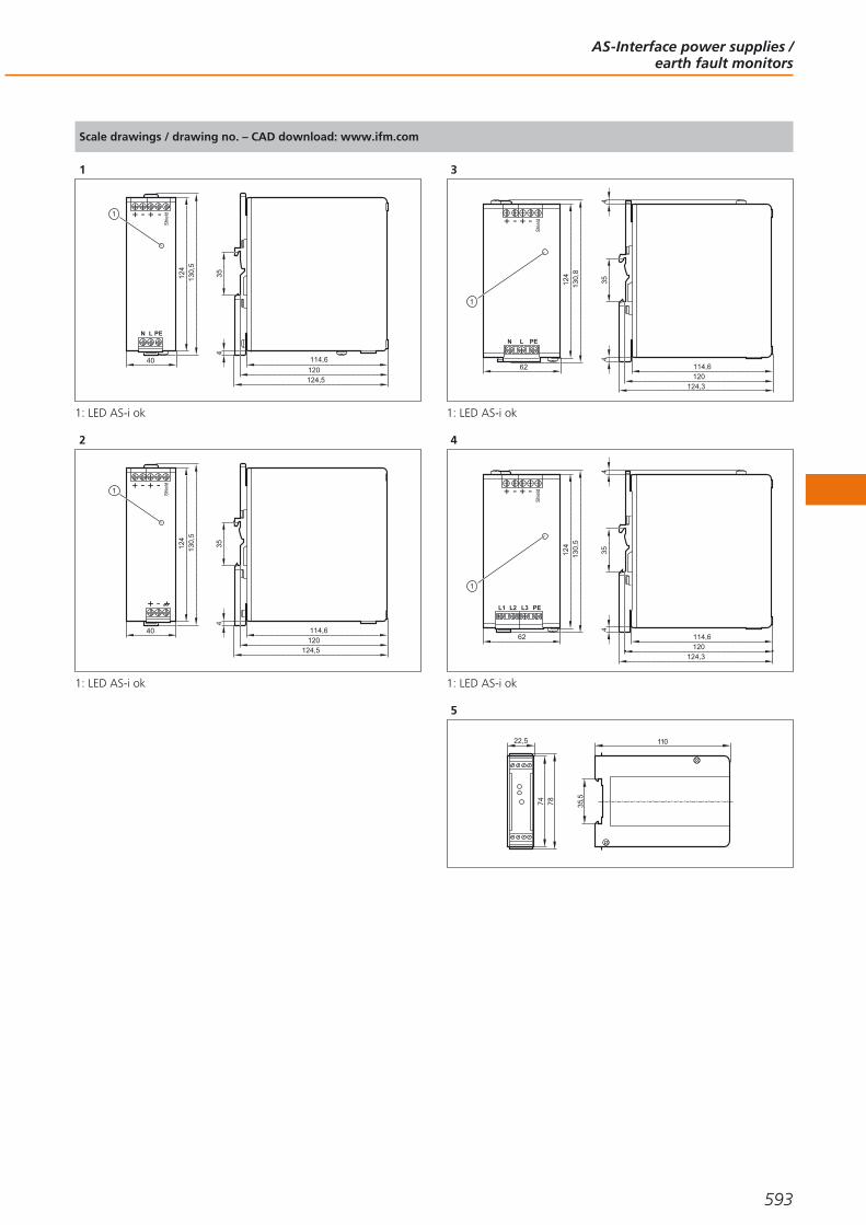
Scale drawings / drawing no. – CAD download: www.ifm.com
1
+ +- -
N L PE
Shie
ld
40
124
1
130,
5
114,6
354
120124,5
1: LED AS-i ok
2
+ +-
+ -
-
40
124
1
130,
5
Shie
ld
120114,6
354
124,5
1: LED AS-i ok
3
+
N L PE
62
124
130,
8
+ - -
1
Shie
ld
114,6
354
4
124,3120
1: LED AS-i ok
4
+
L1 L2 L3 PE
62
124
130,
5
+ - -
1
Shie
ld
114,6
354
4
124,3120
1: LED AS-i ok
5
74
22,5
78
110
35,5
AS-Interface power supplies /earth fault monitors
593
Gesamtkatalog EN 2016_17_Stilvorlage LK FrutigerOT_2010 DE_GB.qxd 06.11.15 16:57 Seite 593
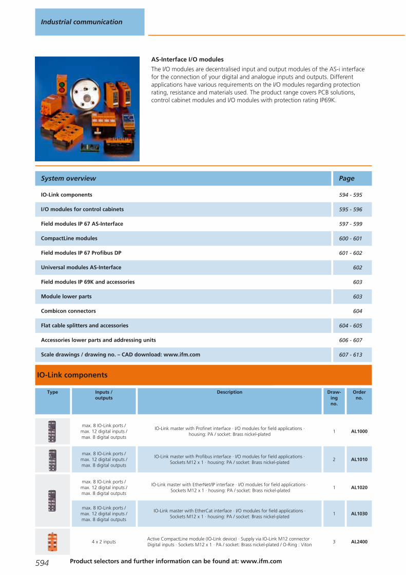
AS-Interface I/O modules
The I/O modules are decentralised input and output modules of the AS-i interfacefor the connection of your digital and analogue inputs and outputs. Different applications have various requirements on the I/O modules regarding protectionrating, resistance and materials used. The product range covers PCB solutions, control cabinet modules and I/O modules with protection rating IP69K.
Type Inputs /outputs
Description Draw-ingno.
Orderno.
max. 8 IO-Link ports / max. 12 digital inputs / max. 8 digital outputs
IO-Link master with Profinet interface · I/O modules for field applications · housing: PA / socket: Brass nickel-plated
1 AL1000
max. 8 IO-Link ports / max. 12 digital inputs / max. 8 digital outputs
IO-Link master with Profibus interface · I/O modules for field applications · Sockets M12 x 1 · housing: PA / socket: Brass nickel-plated
2 AL1010
max. 8 IO-Link ports / max. 12 digital inputs / max. 8 digital outputs
IO-Link master with EtherNet/IP interface · I/O modules for field applications ·Sockets M12 x 1 · housing: PA / socket: Brass nickel-plated
1 AL1020
max. 8 IO-Link ports / max. 12 digital inputs / max. 8 digital outputs
IO-Link master with EtherCat interface · I/O modules for field applications · Sockets M12 x 1 · housing: PA / socket: Brass nickel-plated
1 AL1030
4 x 2 inputsActive CompactLine module (IO-Link device) · Supply via IO-Link M12 connector · Digital inputs · Sockets M12 x 1 · PA / socket: Brass nickel-plated / O-Ring : Viton
3 AL2400
System overview Page
IO-Link components 594 - 595
I/O modules for control cabinets 595 - 596
Field modules IP 67 AS-Interface 597 - 599
CompactLine modules 600 - 601
Field modules IP 67 Profibus DP 601 - 602
Universal modules AS-Interface 602
Field modules IP 69K and accessories 603
Module lower parts 603
Combicon connectors 604
Flat cable splitters and accessories 604 - 605
Accessories lower parts and addressing units 606 - 607
Scale drawings / drawing no. – CAD download: www.ifm.com 607 - 613
Industrial communication
594 Product selectors and further information can be found at: www.ifm.com
IO-Link components
Gesamtkatalog EN 2016_17_Stilvorlage LK FrutigerOT_2010 DE_GB.qxd 06.11.15 16:57 Seite 594

Type Inputs /outputs
Description Draw-ingno.
Orderno.
8 x 2 inputsActive CompactLine module (IO-Link device) · Supply via IO-Link M12 connector · Digital inputs · Sockets M12 x 1 · PA / socket: Brass nickel-plated / O-Ring : Viton
4 AL2401
8 IO-Link ports / 10 digital inputs /
2 digital inputs or outputs
I/O modules for use in the control cabinet · IO-Link master 8 ports A and B variable ·LineRecorder Agent embedded · 2 Ethernet ports with integrated switch · Additionalbinary inputs and outputs can be configured · Housing for DIN rail mounting · Screw
terminal · housing: polyamide
5 AY1000
8 IO-Link ports / 10 digital inputs /
2 digital inputs or outputs
I/O modules for use in the control cabinet · IO-Link master 8 ports A and B variable ·LineRecorder Agent embedded · 2 Ethernet ports with integrated switch · Additionalbinary inputs and outputs can be configured · Housing for DIN rail mounting · Screw
terminal · housing: polyamide
5 AY1020
I/O modules for control cabinets
Type Inputs /outputs
Description Draw-ingno.
Orderno.
4 inputsActive AS-i module · String mounting possible · Addressing socket · Version 2.1 with
extended addressing mode · Digital inputs · Combicon connection · PA6 AC2250
4 inputsActive AS-i module · String mounting possible · Addressing socket · Input supply from
external PELV voltage source · Version 2.1 with extended addressing mode · Digital inputs· Combicon connection · PA
6 AC2254
4 outputsActive AS-i module · String mounting possible · Addressing socket · Version 2.1 ·
Digital outputs · Combicon connection · PA6 AC2252
4 inputs / 2 outputs / relayActive AS-i module · String mounting possible · Addressing socket · Version 2.1 with
extended addressing mode · Digital inputs · Combicon connection · PA6 AC2256
4 inputs / 2 outputs / relayActive AS-i module · String mounting possible · Addressing socket · Input supply from
external PELV voltage source · Version 2.1 with extended addressing mode · Digital inputsand outputs · Combicon connection · PA
6 AC2255
4 inputs / 3 outputsActive AS-i module · String mounting possible · Addressing socket · Version 2.1 withextended addressing mode · Digital inputs and outputs · Combicon connection · PA
6 AC2264
4 inputs / 4 outputsActive AS-i module · String mounting possible · Addressing socket · Version 2.1 ·
Digital inputs and outputs · Combicon connection · PA6 AC2251
4 inputs / 4 outputsActive AS-i module · String mounting possible · Addressing socket · External sensor supply
PELV · Version 2.1 · Digital inputs and outputs · Combicon connection · PA6 AC2257
4 inputs / 4 outputsActive AS-i module · String mounting possible · Addressing socket · External sensor supplyPELV · Version 3.0 with extended addressing mode · Only for operation with AS-i masters
with the profile M4 · Digital inputs and outputs · Combicon connection · PA7 AC2267
4 inputs 4...20 mAActive AS-i module · AS-i profile S-7.3 · 4 analogue inputs 4...20 mA · Supply either fromAS-i or an external 24 V source · For the connection of 2-wire, 3-wire or 4-wire sensors ·
Combicon connector for sensor connection · PA 6.66 AC2216
4 inputs 0...10 VActive AS-i module · AS-i profile S-7.3 · 4 analogue inputs 0...10 V · For the connection of
2-wire, 3-wire or 4-wire sensors · Combicon connector for sensor connection · PA 6.66 AC2217
AS-Interface I/O modules
595You can find scale drawings from page 607
Gesamtkatalog EN 2016_17_Stilvorlage LK FrutigerOT_2010 DE_GB.qxd 06.11.15 16:57 Seite 595

Type Inputs /outputs
Description Draw-ingno.
Orderno.
4 outputs 0...20 mAActive AS-i module · AS-i profile S-7.3 · 4 analogue outputs 0...20 mA · For theconnection of 2-wire actuators or 4-wire actuators with separate 24 V supply ·
Combicon connector for actuator connection · PA 6.66 AC2218
4 outputs 0...10 VActive AS-i module · AS-i profile S-7.3 · 4 analogue outputs 0...10 V · For the connectionof 2-wire actuators or 4-wire actuators with separate 24 V supply · Combicon connector
for actuator connection · PA 6.66 AC2219
4 inputs Pt100Active AS-i module · 4 analogue inputs temperature Pt100 · AS-i profile S-7.3 ·
Combicon connection · PBT6 AC2220
4 inputs / 4 outputs / relayActive AS-i module · String mounting possible · Addressing socket · Version 2.1 ·
Combicon connection · PA 6.68 AC2258
4 inputs / 4 outputs / relayActive AS-i module · String mounting possible · Addressing socket · Input supply from
external PELV voltage source · Version 2.1 · Combicon connection · PA 6.68 AC2259
4 inputs / 4 outputsActive AS-i module · PCB size 105 x 45 x 17 mm · Wire length 0.2 m ·
Digital inputs and outputs9 AC2709
4 inputs / 3 outputsActive AS-i module · AS-i slave with extended addressing mode ·
PCB size 105 x 45 x 17 mm · Wire length 0.2 m · Digital inputs and outputs9 AC2739
2 inputs / 1 LED output Active AS-i module · Only suited for mechanical contacts · Wire length 0.1 m 10 AC2729
3 inputs / 3 outputs Active AS-i module · AS-i version 2.1 with extended addressing mode 11 AC2731
4 inputs / 4 outputsActive AS-i module · AS-i slave with extended addressing mode · Only for operation with
AS-i masters with the profile M4 · 12 x 0.2 m · housing: PC potted12 AC2750
4 inputs / 3 outputsActive AS-i module · AS-i slave with extended addressing mode · 11 x 0.2 m ·
housing: PC potted13 AC2751
4 inputs / 4 outputsActive AS-i module · AS-i slave with extended addressing mode · Only for operation with
AS-i masters with the profile M4 · housing: PC potted14 AC2752
4 inputs / 3 outputs Active AS-i module · AS-i slave with extended addressing mode · housing: PC potted 15 AC2753
4 inputs / 4 outputsActive AS-i module · String mounting possible · Version 3.0 with extended addressingmode · Only for operation with AS-i masters with the profile M4 · plastics / PC GF20
16 AC3200
4 inputs / 4 outputsActive AS-i module · String mounting possible · Version 3.0 with extended addressingmode · Only for operation with AS-i masters with the profile M4 · plastics / PC GF20
16 AC3201
4 inputs / 4 outputsActive AS-i module · String mounting possible · Addressing socket · Version 3.0 with
extended addressing mode · Only for operation with AS-i masters with the profile M4 ·plastics / PC GF20
17 AC3220
4 inputs / 4 outputsActive AS-i module · String mounting possible · Addressing socket · Version 3.0 with
extended addressing mode · Only for operation with AS-i masters with the profile M4 ·plastics / PC GF20
17 AC3221
Industrial communication
596 Product selectors and further information can be found at: www.ifm.com
Gesamtkatalog EN 2016_17_Stilvorlage LK FrutigerOT_2010 DE_GB.qxd 06.11.15 16:57 Seite 596

Field modules IP 67 AS-Interface
Type Inputs /outputs
Description Draw-ingno.
Orderno.
4-way splitter boxClassicLine splitter box module · Three orientations of the flat cable are possible · AS-i and
AUX splitter box for the connection of intelligent sensors/actuators · Sockets M12 x 1 · PA / Piercing contacts: CuSn6 surface nickel and tin-plated
18 AC5200
4 inputsActive ClassicLine module · Addressing socket · Three orientations of the flat cable arepossible · Digital inputs · Sockets M12 x 1 · PA / Piercing contacts: CuSn6 surface nickel
and tin-plated18 AC5205
4 inputsActive ClassicLine module · Version 2.11 and 3.0 with extended addressing mode ·Addressing socket · Three orientations of the flat cable are possible · Digital inputs ·
Sockets M12 x 1 · PA / Piercing contacts: CuSn6 surface nickel and tin-plated18 AC5215
4 analogue inputs 4...20 mAActive ClassicLine module · 4 analogue inputs 4...20 mA · For the connection of 2-wire
and 3-wire sensors · Three orientations of the flat cable are possible · PA / Piercingcontacts: CuSn6 surface nickel and tin-plated
18 AC5216
3 outputsActive ClassicLine module · Version 2.11 and 3.0 with extended addressing mode ·
Addressing socket · Three orientations of the flat cable are possible · Digital outputs ·Sockets M12 x 1 · PA / Piercing contacts: CuSn6 surface nickel and tin-plated
18 AC5203
4 outputsActive ClassicLine module · Addressing socket · Three orientations of the flat cable are
possible · Digital outputs · Sockets M12 x 1 · PA / Piercing contacts: CuSn6 surface nickeland tin-plated
18 AC5208
4 outputsActive ClassicLine module · Addressing socket · Three orientations of the flat cable arepossible · Digital outputs 2 A · Sockets M12 x 1 · PA / Piercing contacts: CuSn6 surface
nickel and tin-plated18 AC5213
2 outputs / 2 inputsActive ClassicLine module · Version 2.11 and 3.0 with extended addressing mode ·
Addressing socket · Three orientations of the flat cable are possible · Digital outputs andinputs · Sockets M12 x 1 · PA / Piercing contacts: CuSn6 surface nickel and tin-plated
18 AC5214
2 inputs / 2 outputsActive ClassicLine module · Addressing socket · Three orientations of the flat cable arepossible · Digital inputs and outputs (2 A) · Sockets M12 x 1 · PA / Piercing contacts:
CuSn6 surface nickel and tin-plated18 AC5211
2 outputs / 2 inputs
Active ClassicLine module · Version 2.11 and 3.0 with extended addressing mode ·Addressing socket · Three orientations of the flat cable are possible · Outputs supplied
from AS-i · Digital outputs and inputs · Sockets M12 x 1 · PA / Piercing contacts: CuSn6surface nickel and tin-plated
18 AC5224
4 inputs / 3 outputsActive ClassicLine module · Version 2.11 and 3.0 with extended addressing mode ·
Addressing socket · Three orientations of the flat cable are possible · inputs externallysupplied · Sockets M12 x 1 · PA / Piercing contacts: CuSn6 surface nickel and tin-plated
19 AC5292
AS-Interface I/O modules
597You can find scale drawings from page 607
Gesamtkatalog EN 2016_17_Stilvorlage LK FrutigerOT_2010 DE_GB.qxd 06.11.15 16:57 Seite 597
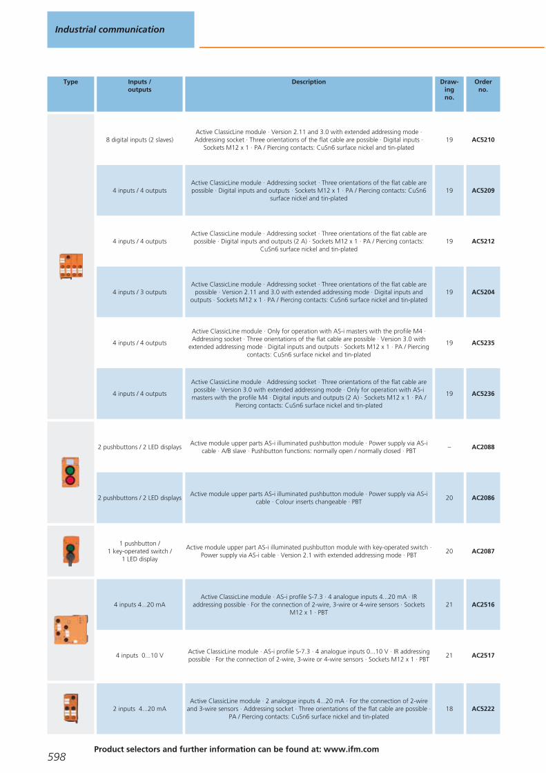
Type Inputs /outputs
Description Draw-ingno.
Orderno.
8 digital inputs (2 slaves)Active ClassicLine module · Version 2.11 and 3.0 with extended addressing mode ·Addressing socket · Three orientations of the flat cable are possible · Digital inputs ·
Sockets M12 x 1 · PA / Piercing contacts: CuSn6 surface nickel and tin-plated19 AC5210
4 inputs / 4 outputsActive ClassicLine module · Addressing socket · Three orientations of the flat cable arepossible · Digital inputs and outputs · Sockets M12 x 1 · PA / Piercing contacts: CuSn6
surface nickel and tin-plated19 AC5209
4 inputs / 4 outputsActive ClassicLine module · Addressing socket · Three orientations of the flat cable arepossible · Digital inputs and outputs (2 A) · Sockets M12 x 1 · PA / Piercing contacts:
CuSn6 surface nickel and tin-plated19 AC5212
4 inputs / 3 outputsActive ClassicLine module · Addressing socket · Three orientations of the flat cable are
possible · Version 2.11 and 3.0 with extended addressing mode · Digital inputs andoutputs · Sockets M12 x 1 · PA / Piercing contacts: CuSn6 surface nickel and tin-plated
19 AC5204
4 inputs / 4 outputs
Active ClassicLine module · Only for operation with AS-i masters with the profile M4 ·Addressing socket · Three orientations of the flat cable are possible · Version 3.0 with
extended addressing mode · Digital inputs and outputs · Sockets M12 x 1 · PA / Piercingcontacts: CuSn6 surface nickel and tin-plated
19 AC5235
4 inputs / 4 outputs
Active ClassicLine module · Addressing socket · Three orientations of the flat cable arepossible · Version 3.0 with extended addressing mode · Only for operation with AS-i
masters with the profile M4 · Digital inputs and outputs (2 A) · Sockets M12 x 1 · PA /Piercing contacts: CuSn6 surface nickel and tin-plated
19 AC5236
2 pushbuttons / 2 LED displaysActive module upper parts AS-i illuminated pushbutton module · Power supply via AS-i
cable · A/B slave · Pushbutton functions: normally open / normally closed · PBT– AC2088
2 pushbuttons / 2 LED displaysActive module upper parts AS-i illuminated pushbutton module · Power supply via AS-i
cable · Colour inserts changeable · PBT20 AC2086
1 pushbutton / 1 key-operated switch /
1 LED display
Active module upper part AS-i illuminated pushbutton module with key-operated switch ·Power supply via AS-i cable · Version 2.1 with extended addressing mode · PBT
20 AC2087
4 inputs 4...20 mAActive ClassicLine module · AS-i profile S-7.3 · 4 analogue inputs 4...20 mA · IR
addressing possible · For the connection of 2-wire, 3-wire or 4-wire sensors · Sockets M12 x 1 · PBT
21 AC2516
4 inputs 0...10 VActive ClassicLine module · AS-i profile S-7.3 · 4 analogue inputs 0...10 V · IR addressingpossible · For the connection of 2-wire, 3-wire or 4-wire sensors · Sockets M12 x 1 · PBT
21 AC2517
2 inputs 4...20 mAActive ClassicLine module · 2 analogue inputs 4...20 mA · For the connection of 2-wire
and 3-wire sensors · Addressing socket · Three orientations of the flat cable are possible ·PA / Piercing contacts: CuSn6 surface nickel and tin-plated
18 AC5222
Industrial communication
598Product selectors and further information can be found at: www.ifm.com
Gesamtkatalog EN 2016_17_Stilvorlage LK FrutigerOT_2010 DE_GB.qxd 06.11.15 16:57 Seite 598

Type Inputs /outputs
Description Draw-ingno.
Orderno.
2 inputs 4...20 mAActive ClassicLine module · 2 analogue inputs 4...20 mA · For the connection of 2-wire
and 4-wire sensors · Electrical isolation · Addressing socket · Three orientations of the flatcable are possible · PA / Piercing contacts: CuSn6 surface nickel and tin-plated
18 AC5223
2 IO-Link ports
Active ClassicLine module · 2 IO-Link ports · For the connection of IO-Link sensors andactuators, binary sensors and binary actuators · Addressing socket · Three orientations ofthe flat cable are possible · Only for operation with AS-i masters with the profile M4 · PA /
Piercing contacts: CuSn6 surface nickel and tin-plated
18 AC5225
4 analogue inputs 4...20 mAActive ClassicLine module · 4 analogue inputs 4...20 mA · For the connection of 2-wire,
3-wire or 4-wire sensors · Electrical isolation · Three orientations of the flat cable arepossible · PA / Piercing contacts: CuSn6 surface nickel and tin-plated
18 AC5226
2 digital inputs / 1 analogue input / 1 analogue output
Active ClassicLine module · Only for operation with AS-i masters with the profile M4 ·Electrical isolation · Three orientations of the flat cable are possible · Sockets M12 x 1 ·
PA / Piercing contacts: CuSn6 surface nickel and tin-plated18 AC5230
4 inputs
Active ClassicLine module · Addressing socket · Three orientations of the flat cable arepossible · ATEX approval · Group II, category 3D · Only in conjunction with impact
protection housing E7000A or equivalent protection · Sockets M12 x 1 · PA / Piercingcontacts: CuSn6 surface nickel and tin-plated
18 AC505A
4 inputs
Active ClassicLine module · Version 2.11 and 3.0 with extended addressing mode ·Addressing socket · Three orientations of the flat cable are possible · ATEX approval ·
Group II, category 3D · Only in conjunction with impact protection housing E7000A orequivalent protection · Sockets M12 x 1 · PA / Piercing contacts: CuSn6 surface nickel
and tin-plated
18 AC515A
4 outputs
Active ClassicLine module · Addressing socket · Three orientations of the flat cable arepossible · ATEX approval · Group II, category 3D · Only in conjunction with impact
protection housing E7000A or equivalent protection · Sockets M12 x 1 · PA / Piercingcontacts: CuSn6 surface nickel and tin-plated
18 AC508A
2 inputs / 2 outputs
Active ClassicLine module · Addressing socket · Three orientations of the flat cable arepossible · ATEX approval · Group II, category 3D · Only in conjunction with impact
protection housing E7000A or equivalent protection · Digital inputs and outputs (2 A) ·Sockets M12 x 1 · PA / Piercing contacts: CuSn6 surface nickel and tin-plated
18 AC507A
2 outputs / 2 inputs
Active ClassicLine module · Version 2.11 and 3.0 with extended addressing mode ·Addressing socket · Three orientations of the flat cable are possible · ATEX approval ·
Group II, category 3D · Only in conjunction with impact protection housing E7000A orequivalent protection · Sockets M12 x 1 · PA / Piercing contacts: CuSn6 surface nickel
and tin-plated
18 AC514A
2 inputs 4...20 mA
Active AS-i module · 2 analogue inputs 4...20 mA · For the connection of 2-wire and 3-wire sensors · Addressing socket · Three orientations of the flat cable are possible · ATEX
approval · Group II, category 3D · Only in conjunction with impact protection housingE7000A or equivalent protection · PA / Piercing contacts: CuSn6 surface nickel
and tin-plated
18 AC522A
4 inputs / 4 outputs
Active ClassicLine module · Only for operation with AS-i masters with the profile M4 ·Addressing socket · Three orientations of the flat cable are possible · Version 3.0 with
extended addressing mode · ATEX approval · Group II, category 3D · Only in conjunctionwith impact protection housing E7000A or equivalent protection · Sockets M12 x 1 · PA /
Piercing contacts: CuSn6 surface nickel and tin-plated
19 AC535A
AS-Interface I/O modules
599You can find scale drawings from page 607
Gesamtkatalog EN 2016_17_Stilvorlage LK FrutigerOT_2010 DE_GB.qxd 06.11.15 16:57 Seite 599
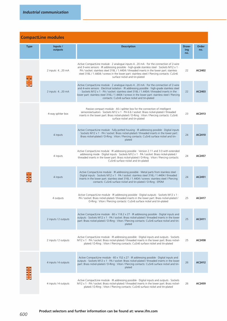
CompactLine modules
Type Inputs /outputs
Description Draw-ingno.
Orderno.
2 inputs 4...20 mA
Active CompactLine module · 2 analogue inputs 4...20 mA · For the connection of 2-wireand 3-wire sensors · IR addressing possible · high-grade stainless steel · Sockets M12 x 1 ·
PA / socket: stainless steel 316L / 1.4404 / threaded inserts in the lower part: stainlesssteel 316L / 1.4404 / screws in the lower part: stainless steel / Piercing contacts: CuSn6
surface nickel and tin-plated
22 AC2402
2 inputs 4...20 mA
Active CompactLine module · 2 analogue inputs 4...20 mA · For the connection of 2-wireand 4-wire sensors · Electrical isolation · IR addressing possible · high-grade stainless steel
· Sockets M12 x 1 · PA / socket: stainless steel 316L / 1.4404 / threaded inserts in thelower part: stainless steel 316L / 1.4404 / screws in the lower part: stainless steel / Piercing
contacts: CuSn6 surface nickel and tin-plated
22 AC2403
4-way splitter box
Passive compact module · AS-i splitter box for the connection of intelligentsensors/actuators · Sockets M12 x 1 · PA 6.6 / socket: Brass nickel-plated / threaded
inserts in the lower part: Brass nickel-plated / O-Ring : Viton / Piercing contacts: CuSn6surface nickel and tin-plated
23 AC2413
4 inputs
Active CompactLine module · fully potted housing · IR addressing possible · Digital inputs· Sockets M12 x 1 · PA / socket: Brass nickel-plated / threaded inserts in the lower part:
Brass nickel-plated / O-Ring : Viton / Piercing contacts: CuSn6 surface nickel and tin-plated
24 AC2410
4 inputs
Active CompactLine module · IR addressing possible · Version 2.11 and 3.0 with extendedaddressing mode · Digital inputs · Sockets M12 x 1 · PA / socket: Brass nickel-plated /
threaded inserts in the lower part: Brass nickel-plated / O-Ring : Viton / Piercing contacts:CuSn6 surface nickel and tin-plated
24 AC2457
4 inputs
Active CompactLine module · IR addressing possible · Metal parts from stainless steel ·Digital inputs · Sockets M12 x 1 · PA / socket: stainless steel 316L / 1.4404 / threadedinserts in the lower part: stainless steel 316L / 1.4404 / screws: stainless steel / Piercing
contacts: CuSn6 surface nickel and tin-plated / O-Ring : EPDM
24 AC2451
4 outputsActive CompactLine module · IR addressing possible · Digital outputs · Sockets M12 x 1 ·PA / socket: Brass nickel-plated / threaded inserts in the lower part: Brass nickel-plated /
O-Ring : Viton / Piercing contacts: CuSn6 surface nickel and tin-plated25 AC2417
2 inputs / 2 outputs
Active CompactLine module · 60 x 118.2 x 27 · IR addressing possible · Digital inputs andoutputs · Sockets M12 x 1 · PA / socket: Brass nickel-plated / threaded inserts in the lowerpart: Brass nickel-plated / O-Ring : Viton / Piercing contacts: CuSn6 surface nickel and tin-
plated
25 AC2411
2 inputs / 2 outputsActive CompactLine module · IR addressing possible · Digital inputs and outputs · SocketsM12 x 1 · PA / socket: Brass nickel-plated / threaded inserts in the lower part: Brass nickel-
plated / O-Ring : Viton / Piercing contacts: CuSn6 surface nickel and tin-plated25 AC2458
4 inputs / 4 outputs
Active CompactLine module · 60 x 152 x 27 · IR addressing possible · Digital inputs andoutputs · Sockets M12 x 1 · PA / socket: Brass nickel-plated / threaded inserts in the lowerpart: Brass nickel-plated / O-Ring : Viton / Piercing contacts: CuSn6 surface nickel and tin-
plated
26 AC2412
4 inputs / 4 outputsActive CompactLine module · IR addressing possible · Digital inputs and outputs · SocketsM12 x 1 · PA / socket: Brass nickel-plated / threaded inserts in the lower part: Brass nickel-
plated / O-Ring : Viton / Piercing contacts: CuSn6 surface nickel and tin-plated26 AC2459
Industrial communication
600Product selectors and further information can be found at: www.ifm.com
Gesamtkatalog EN 2016_17_Stilvorlage LK FrutigerOT_2010 DE_GB.qxd 06.11.15 16:57 Seite 600

Type Inputs /outputs
Description Draw-ingno.
Orderno.
4 inputs / 4 outputs
Active CompactLine module · IR addressing possible · External sensor supply PELV · Digitalinputs and outputs · Sockets M12 x 1 · PA / socket: Brass nickel-plated / threaded insertsin the lower part: Brass nickel-plated / O-Ring : Viton / Piercing contacts: CuSn6 surface
nickel and tin-plated
26 AC2466
4 inputs / 4 outputs
Active CompactLine module · IR addressing possible · Metal parts from stainless steel ·Digital inputs and outputs · Sockets M12 x 1 · PA / socket: stainless steel 316L / 1.4404 /threaded inserts in the lower part: stainless steel 316L / 1.4404 / screws: stainless steel /
Piercing contacts: CuSn6 surface nickel and tin-plated / O-Ring : EPDM
26 AC2452
4 inputs / 4 outputs
Active CompactLine module · IR addressing possible · Version 3.0 with extendedaddressing mode · Only for operation with AS-i masters with the profile M4 · Digital
inputs and outputs · Sockets M12 x 1 · PA / socket: Brass nickel-plated / threaded insertsin the lower part: Brass nickel-plated / O-Ring : Viton / Piercing contacts: CuSn6 surface
nickel and tin-plated
26 AC2471
4 inputsActive CompactLine module · AS-i connection via M12 connector · Digital inputs ·
Sockets M12 x 1 · PA / socket: Brass nickel-plated / O-Ring : Viton27 AC2464
4 inputs / 4 outputsActive CompactLine module · AS-i and AUX connection via M12 connector · Digital inputs
and outputs · Sockets M12 x 1 · PA / socket: Brass nickel-plated / O-Ring : Viton28 AC2465
2 outputs / 2 inputsCompact M8 AS-i module · 90.5 x 30 x 23.5 · Digital inputs and outputs supplied via AS-i
· AS-i connection via M12 connector · Version 2.11 and 3.0 with extended addressingmode · M8 ecolink interface · Sockets M8 x 1 · PBT
29 AC2482
4 inputsCompact M8 AS-i module · 90.5 x 30 x 23.5 · Digital inputs · AS-i connection via M12
connector · Version 2.11 and 3.0 with extended addressing mode · M8 ecolink interface ·Sockets M8 x 1 · PBT
29 AC2484
8 inputsCompact M8 AS-i module · 134.5 x 30 x 23.5 · Digital inputs · AS-i connection via M12connector · Version 3.0 with extended addressing mode · M8 ecolink interface · Only for
operation with AS-i masters with the profile M4 · Sockets M8 x 1 · PBT30 AC2488
Field modules IP 67 Profibus DP
Type Inputs /outputs
Description Draw-ingno.
Orderno.
4 IO-Link ports / 4 digital inputs
I/O modules for field applications · Profibus DP interface · Sockets M12 x 1 · housing: PA 6 / potting compound: PU / Contact pins: Brass gold-plated
31 AC2625
8 inputsI/O modules for field applications · Profibus DP interface · Sockets M12 x 1 ·
housing: PA 6 / potting compound: PU / Contact pins: Brass gold-plated31 AC2630
AS-Interface I/O modules
601You can find scale drawings from page 607
Gesamtkatalog EN 2016_17_Stilvorlage LK FrutigerOT_2010 DE_GB.qxd 06.11.15 16:57 Seite 601

Type Inputs /outputs
Description Draw-ingno.
Orderno.
4 inputs / 4 outputsI/O modules for field applications · Profibus DP interface · Sockets M12 x 1 ·
housing: PA 6 / potting compound: PU / Contact pins: Brass gold-plated31 AC2631
4 inputs Pt100I/O modules for field applications · Profibus DP interface · Sockets M12 x 1 ·
housing: PA 6 / potting compound: PU / Contact pins: Brass gold-plated31 AC2634
4 analogue inputs 0/4...20 mA
I/O modules for field applications · Profibus DP interface · Sockets M12 x 1 · housing: PA 6 / potting compound: PU / Contact pins: Brass gold-plated
31 AC2636
4 analogue outputs 0/4...20 mA
I/O modules for field applications · Profibus DP interface · Sockets M12 x 1 · housing: PA 6 / potting compound: PU / Contact pins: Brass gold-plated
31 AC2637
4 analogue inputs -10...0 V / 10 V
I/O modules for field applications · Profibus DP interface · Sockets M12 x 1 · housing: PA 6 / potting compound: PU / Contact pins: Brass gold-plated
31 AC2638
Universal modules AS-Interface
Type Inputs /outputs
Description Draw-ingno.
Orderno.
4 inputsActive module upper part AS-universal module · Digital inputs ·
Connection via cage clamps · PBT / stainless steel32 AC2032
4 inputs / 4 outputsActive module upper part AS-universal module · Digital inputs and outputs ·
Connection via cage clamps · PBT / stainless steel33 AC2035
2 inputs 4...20 mAActive AS-i module IP 65 · 2 analogue inputs 4...20 mA · AS-i profile S-7.3 · For theconnection of 2-wire, 3-wire or 4-wire sensors · Connection via cage clamps · PBT
34 AC2616
2 inputs 0...10 VActive AS-i module IP 65 · 2 analogue inputs 0...10 V · AS-i profile S-7.3 · For theconnection of 2-wire, 3-wire or 4-wire sensors · Connection via cage clamps · PBT
34 AC2617
2 outputs 0...20 mAActive AS-i module IP 65 · 2 analogue outputs 0...20 mA · AS-i profile S-7.3 · For the
connection of 2-wire actuators or 4-wire actuators with separate 24 V supply ·Connection via cage clamps · PBT
34 AC2618
2 outputs 0...10 VActive AS-i module IP 65 · 2 analogue outputs 0...10 V · AS-i profile S-7.3 · For the
connection of 2-wire actuators or 4-wire actuators with separate 24 V supply ·Connection via cage clamps · PBT
34 AC2619
4 inputs Pt100Active AS-i module IP 65 · 4 analogue inputs temperature Pt100 · AS-i profile S-7.3 ·
Connection via cage clamps · PBT33 AC2620
Industrial communication
602Product selectors and further information can be found at: www.ifm.com
Gesamtkatalog EN 2016_17_Stilvorlage LK FrutigerOT_2010 DE_GB.qxd 06.11.15 16:57 Seite 602
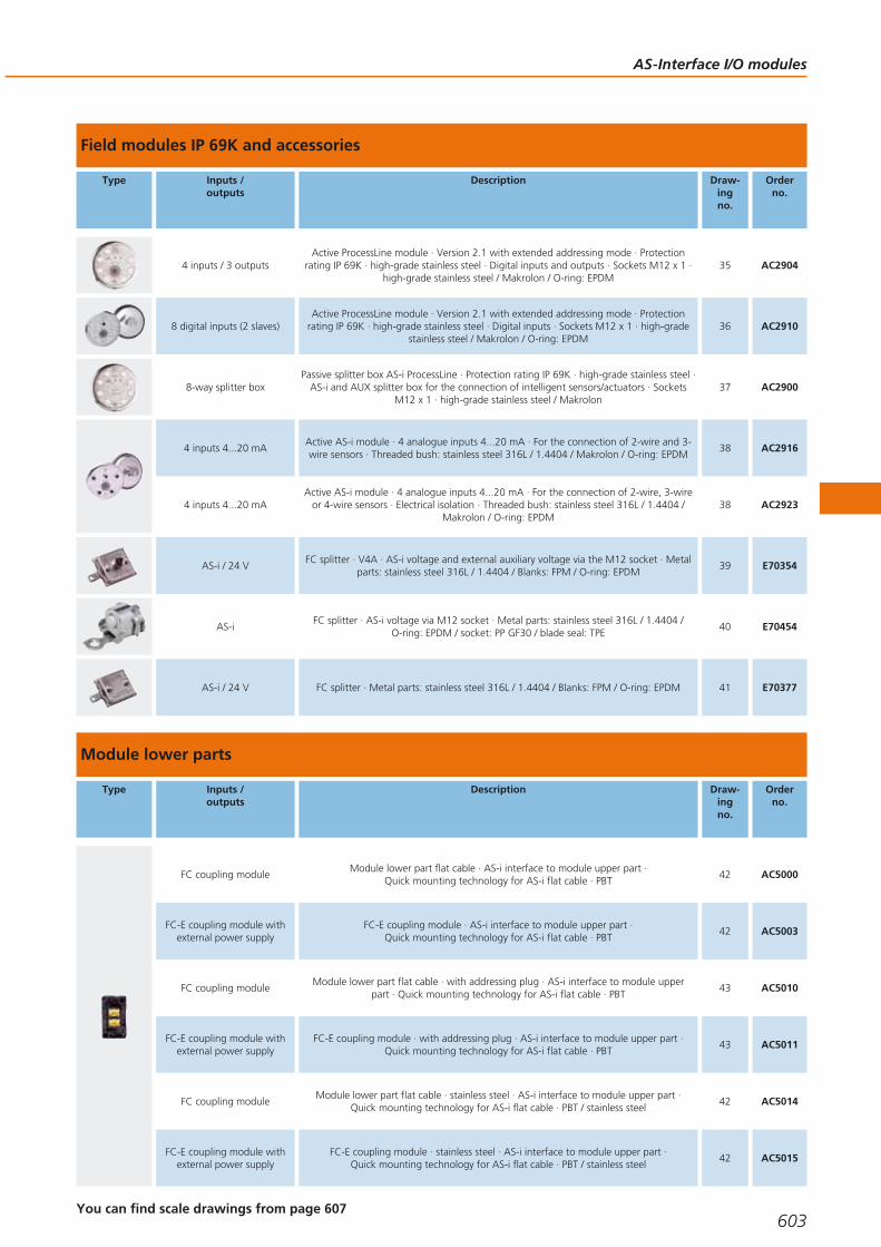
Field modules IP 69K and accessories
Type Inputs /outputs
Description Draw-ingno.
Orderno.
4 inputs / 3 outputsActive ProcessLine module · Version 2.1 with extended addressing mode · Protection
rating IP 69K · high-grade stainless steel · Digital inputs and outputs · Sockets M12 x 1 ·high-grade stainless steel / Makrolon / O-ring: EPDM
35 AC2904
8 digital inputs (2 slaves)Active ProcessLine module · Version 2.1 with extended addressing mode · Protection
rating IP 69K · high-grade stainless steel · Digital inputs · Sockets M12 x 1 · high-gradestainless steel / Makrolon / O-ring: EPDM
36 AC2910
8-way splitter boxPassive splitter box AS-i ProcessLine · Protection rating IP 69K · high-grade stainless steel ·
AS-i and AUX splitter box for the connection of intelligent sensors/actuators · SocketsM12 x 1 · high-grade stainless steel / Makrolon
37 AC2900
4 inputs 4...20 mAActive AS-i module · 4 analogue inputs 4...20 mA · For the connection of 2-wire and 3-wire sensors · Threaded bush: stainless steel 316L / 1.4404 / Makrolon / O-ring: EPDM
38 AC2916
4 inputs 4...20 mAActive AS-i module · 4 analogue inputs 4...20 mA · For the connection of 2-wire, 3-wire
or 4-wire sensors · Electrical isolation · Threaded bush: stainless steel 316L / 1.4404 /Makrolon / O-ring: EPDM
38 AC2923
AS-i / 24 VFC splitter · V4A · AS-i voltage and external auxiliary voltage via the M12 socket · Metal
parts: stainless steel 316L / 1.4404 / Blanks: FPM / O-ring: EPDM39 E70354
AS-iFC splitter · AS-i voltage via M12 socket · Metal parts: stainless steel 316L / 1.4404 /
O-ring: EPDM / socket: PP GF30 / blade seal: TPE40 E70454
AS-i / 24 V FC splitter · Metal parts: stainless steel 316L / 1.4404 / Blanks: FPM / O-ring: EPDM 41 E70377
Module lower parts
Type Inputs /outputs
Description Draw-ingno.
Orderno.
FC coupling moduleModule lower part flat cable · AS-i interface to module upper part ·
Quick mounting technology for AS-i flat cable · PBT42 AC5000
FC-E coupling module withexternal power supply
FC-E coupling module · AS-i interface to module upper part · Quick mounting technology for AS-i flat cable · PBT
42 AC5003
FC coupling moduleModule lower part flat cable · with addressing plug · AS-i interface to module upper
part · Quick mounting technology for AS-i flat cable · PBT43 AC5010
FC-E coupling module withexternal power supply
FC-E coupling module · with addressing plug · AS-i interface to module upper part · Quick mounting technology for AS-i flat cable · PBT
43 AC5011
FC coupling moduleModule lower part flat cable · stainless steel · AS-i interface to module upper part ·
Quick mounting technology for AS-i flat cable · PBT / stainless steel42 AC5014
FC-E coupling module withexternal power supply
FC-E coupling module · stainless steel · AS-i interface to module upper part · Quick mounting technology for AS-i flat cable · PBT / stainless steel
42 AC5015
AS-Interface I/O modules
603You can find scale drawings from page 607
Gesamtkatalog EN 2016_17_Stilvorlage LK FrutigerOT_2010 DE_GB.qxd 06.11.15 16:57 Seite 603

Combicon connectors
Type Description Orderno.
Combicon connector · with screw terminals 4-pole · Housing materials: current carrying parts: copper alloy tin-plated E70230
Combicon connector · with screw terminals 4-pole · Housing materials: current carrying parts: copper alloy tin-plated E70231
Combicon connector · with cage clamps 4 poles · Housing materials: current carrying parts: copper alloy tin-plated E70232
Combicon connector · with cage clamps 4 poles · Housing materials: current carrying parts: copper alloy tin-plated E70233
Combicon connector · with insulation displacement terminals 4-pole (0.75...1 mm2) · Housing materials: current carrying parts:copper alloy tin-plated
E70236
Flat cable splitters and accessories
Type Description Orderno.
PAAS M12 · AS-i and external voltage via M12 socket · Sockets M12 x 1 · Housing materials: PA 6.6 / socket housing: stainless steel 316L / 1.4404 / screws: stainless steel 316L / 1.4404 / O-Ring : NBR
E70188
PAAS splitter box · Distribution of the AS-i voltage or the external 24 V supply · Housing materials: PA / screws: stainless steel 316L / 1.4404 / sealing: NBR
E70200
FC splitter · Distribution of the AS-i voltage or the external 24 V supply · Housing materials: PA 6 GF35 Grivory E70381
FC splitter · high-grade stainless steel · ATEX approval · Group II, category 3D/3G · AS-i voltage and external auxiliary voltage via the M12 socket · Housing materials: Metal parts: stainless steel 316L / 1.4404 / Blanks: FPM / O-ring: EPDM
E7354A
FC splitter · ATEX approval · Group II, category 3D/3G · Distribution of the AS-i voltage or the external 24 V supply · Housingmaterials: Metal parts: stainless steel 316L / 1.4404 / Blanks: FPM / O-ring: EPDM
E7377A
FC insulation displacement connector · Socket M12 - AS-i flat cable · Housing materials: PA 6-GF-FR / Brass nickel-plated AC5005
FC insulation displacement connector · Socket M12 - AS-i flat cable · Housing materials: sealing: NBR / housing: PA / O-ring: FPM /screws: stainless steel / nut: stainless steel / Contact pins: bronze gold-plated
E70271
FC insulation displacement connector · Socket M12 - AS-i flat cable · Housing materials: PA E70096
Industrial communication
604Product selectors and further information can be found at: www.ifm.com
Gesamtkatalog EN 2016_17_Stilvorlage LK FrutigerOT_2010 DE_GB.qxd 06.11.15 16:57 Seite 604

Type Description Orderno.
FC insulation displacement connector · Distribution of the AS-i voltage and the external 24 V supply to M12 socket · 1 m · Housing materials: housing: PA 6 GF35 Grivory / Socket: PUR
E70481
FC insulation displacement connector · Distribution of the AS-i voltage to M12 socket · 0.6 m · Housing materials: housing: PA66 - GF25
E70483
FC insulation displacement connector · Transition from flat cable to round cable · Cable length 2 m · 2 m · Housing materials: PA 6 GF35 Grivory / round cable: PUR / core insulation: PVC
E70498
FC insulation displacement connector · Transition from flat cable to round cable · Cable length 5 m · 5 m · Housing materials: PA 6 GF35 Grivory / round cable: PUR / core insulation: PVC
E70499
Flat cable insulation displacement connector E79995
FC insulation displacement connector · straight / angled E79998
Splitter box · 8 way · Cable · 25 m · Housing materials: high-grade stainless steel E11847
Y splitter · M12 plug - 2 M8 sockets · Free from halogen · Free from silicone · Gold-plated contacts · Housing materials: PUR E10802
Y splitter · M12 plug - 2 M12 sockets · Free from halogen · Free from silicone · Gold-plated contacts · Housing materials: PUR E10803
Protective cap · M8 · for CompactM8 modules · Housing materials: ULTRAMID black E73005
Protective cap · M12 · for M12 sockets of ClassicLine modules, CompactLine modules and AirBoxes · Housing materials: PA black E73004
Protective cap · M12 · for M12 socket to cover the unused inputs and outputs on the module; for unused inputs of splitter boxes ·for ProcessLine modules · Housing materials: PVC
E70297
Connector for analogue modules · for AC5222, AC5223, AC2516, AC2566 · Housing materials: PVC E75222
AS-Interface I/O modules
605You can find scale drawings from page 607
Gesamtkatalog EN 2016_17_Stilvorlage LK FrutigerOT_2010 DE_GB.qxd 06.11.15 16:57 Seite 605
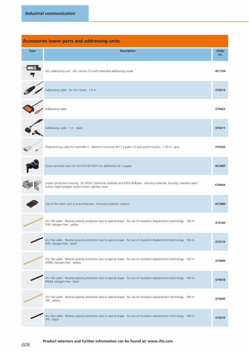
Accessories lower parts and addressing units
Type Description Orderno.
AS-i addressing unit · AS-i version 3.0 with extended addressing mode AC1154
Addressing cable · for AS-i slaves · 1.6 m E70213
Addressing cable E70423
Addressing cable · 1 m · black E70211
Programming cable for controller E · Western connector RJ11 6 poles / D-Sub socket 9 poles · 1.55 m · grey E70320
Screw terminal insert for AC5101/AC5031 for additional 24 V supply AC5007
impact protection housing · for ATEX ClassicLine modules and ATEX AirBoxes · Housing materials: housing: stainless steel / button head hexagon socket screw: stainless steel
E7000A
Use of the lower part as branching box · Housing materials: plastics AC3000
AS-i flat cable · Reverse polarity protection due to special shape · for use of insulation displacement technology · 100 m · PUR, halogen-free · yellow
E74100
AS-i flat cable · Reverse polarity protection due to special shape · for use of insulation displacement technology · 100 m · PUR, halogen-free · black
E74110
AS-i flat cable · Reverse polarity protection due to special shape · for use of insulation displacement technology · 100 m · EPDM, halogen-free · yellow
E74000
AS-i flat cable · Reverse polarity protection due to special shape · for use of insulation displacement technology · 100 m · EPDM, halogen-free · black
E74010
AS-i flat cable · Reverse polarity protection due to special shape · for use of insulation displacement technology · 100 m · TPE · yellow
E74200
AS-i flat cable · Reverse polarity protection due to special shape · for use of insulation displacement technology · 100 m · TPE · black
E74210
Industrial communication
606Product selectors and further information can be found at: www.ifm.com
Gesamtkatalog EN 2016_17_Stilvorlage LK FrutigerOT_2010 DE_GB.qxd 06.11.15 16:57 Seite 606

Type Description Orderno.
AS-i flat cable · Reverse polarity protection due to special shape · for the food industry · for use of insulation displacementtechnology · 100 m · TPE-PVC compound · yellow
E74300
AS-i flat cable · Reverse polarity protection due to special shape · for the food industry · for use of insulation displacementtechnology · 100 m · TPE-PVC compound · black
E74310
JOKARI flat cable stripping tool E70062
Flat cable blank · Length: 60 mm · to cover the unused cable entry · for FC splitter E70354 · Housing materials: silicone rubber blue E70299
Flat cable blank · Length: 60 mm · to cover the unused cable entry · for CompactLine modules (AC24xx), ClassicLine modules(AC52xx) or AirBoxes (AC52xx) · Housing materials: EPDM black
E70399
Heat-shrink cap · for sealing the flat cable ends · Housing materials: plastics E70113
Flat cable seal · Housing materials: ULTRAMID / sealing: NBR E70413
Cable clip for fixing the AS-i flat cable · for AC4000 / AC4002 · Housing materials: PA 6.6 E70067
Torque wrench E70390
Scale drawings / drawing no. – CAD download: www.ifm.com
1
20
30,5
1,5
M12
x1
LEDs
6030
198,
518
5
212
8,56
2
20
30,5
M12
x1
LEDs
6030
198,
518
5
212
8,56 1,5
AS-Interface I/O modules
607
Gesamtkatalog EN 2016_17_Stilvorlage LK FrutigerOT_2010 DE_GB.qxd 06.11.15 16:57 Seite 607

Scale drawings / drawing no. – CAD download: www.ifm.com
32327
54,
5
M12x1
M12x1
X1.0
4,7
107
118,
2
28,539
7,5
60
X1.1
X1.2 X1.3
4
23274,
710
715
2
28,5
397,5
60
54,
5
M12x1
M12x1X1.0 X1.1
X1.2 X1.3
X1.4 X1.5
X1.6 X1.7
5
45,2
105,
3
1
LEDs
2
113,6
35,5
1: Ethernet interface, 2: screw terminals
6
105
35,5
25
114
LEDs
1
1: Addressing socket
7
2
105
35,5
25
108
1
1: Addressing socket, 2: LED
8
105
35,5
50
114
100
1
2
1: LED, 2: Addressing socket
9
45
105
Industrial communication
608Product selectors and further information can be found at: www.ifm.com
Gesamtkatalog EN 2016_17_Stilvorlage LK FrutigerOT_2010 DE_GB.qxd 06.11.15 16:57 Seite 608

Scale drawings / drawing no. – CAD download: www.ifm.com
10
921 U U UU
44
32
9 10 10
11
40,
5
65,5
A+
A-
I3I2
I1I+
I-O
1O2
O3
12
12 76,6
31,1
13
12 76,6
31,1
14
12 76,6
31,1
15
12 76,6
31,1
16
25,4
95,4
129,
3
1
LED
LED
3
2
59,3
71
4
35,5
1: Plug with cage clamp connection, 2: label, 3: Addressing socket, 4: DIN rail adapter
17
10825,4
9312
3,2
1
LED
LED
3
2
4
35,5
1: Plug with cage clamp connection, 2: label, 3: Addressing socket, 4: Mounting on DIN rail
18
45
103
40,2
44,7
25,8
19
AS-Interface I/O modules
609
Gesamtkatalog EN 2016_17_Stilvorlage LK FrutigerOT_2010 DE_GB.qxd 06.11.15 16:57 Seite 609

Scale drawings / drawing no. – CAD download: www.ifm.com
20
4530
80
21
44
83
90
LEDM12x1
22
21
23274,
710
7
118,
2
54,
528,539
7,5
60
M12x1
23
1 3
42
23274,
710
7
118,
2
54,
5
28,539
7,5
60
M12x1
24
1 2
43
23274,
710
711
8,2
54,
5
28,539
7,5
60
M12x1
25
2327
54,
5
M12x1
1 2
43
4,7
107
118,
2
28,539
7,5
60
Industrial communication
610Product selectors and further information can be found at: www.ifm.com
Gesamtkatalog EN 2016_17_Stilvorlage LK FrutigerOT_2010 DE_GB.qxd 06.11.15 16:57 Seite 610
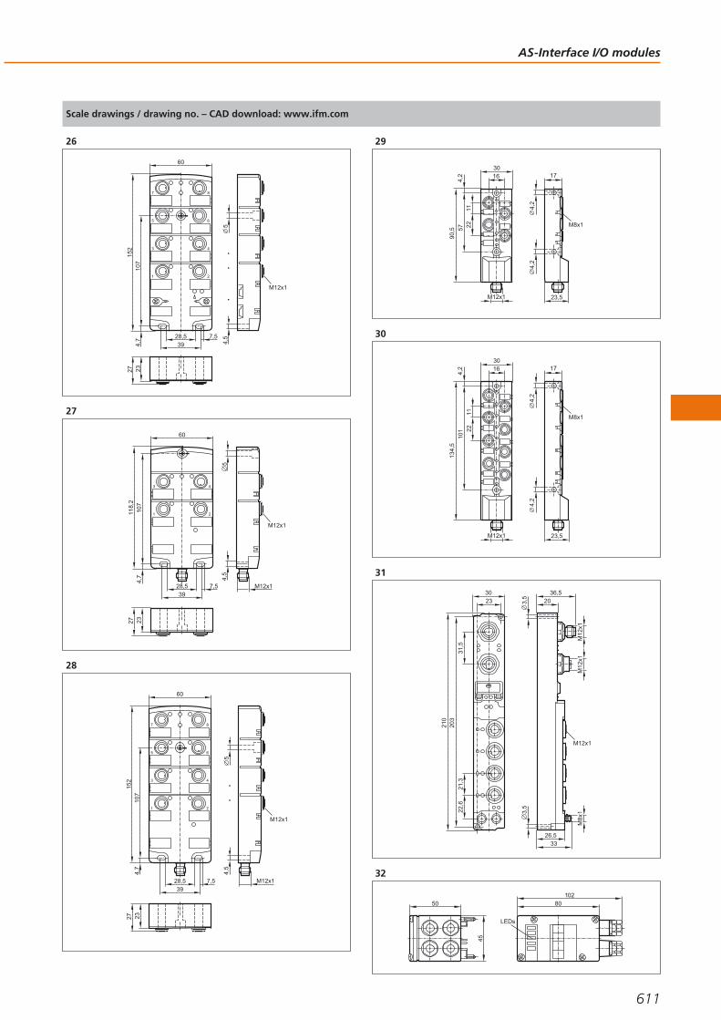
Scale drawings / drawing no. – CAD download: www.ifm.com
262327
1 2
4
6
8
3
5
7
4,7
107
152
28,539
7,5
60
54,
5
M12x1
27
2327
54,
5
M12x1
1 2
43
4,7
107
118,
2
28,539
7,5
60
M12x1
28
2327
1 2
4
6
8
3
5
7
4,7
107
152
28,539
7,5
60
54,
5
M12x1
M12x1
29
M8x1
17
23,5
4,2
4,2
30
90,5 57
4,2 16
1122
M12x1
30
M8x1
17
23,5M12x14,
24,
2
3016
134,
5
101
4,2
1122
31
210
203
3023
31,5
21,3
22,6
M12
x1M
12x1
M8x
1
M12x1
36,520
26,533
3,5
3,5
32
45
50
LEDs
80102
AS-Interface I/O modules
611
Gesamtkatalog EN 2016_17_Stilvorlage LK FrutigerOT_2010 DE_GB.qxd 06.11.15 16:57 Seite 611

Scale drawings / drawing no. – CAD download: www.ifm.com
33
91
50
71
LED
80102
34
91
50
71
LED
80102
35
M12
x1
43,6
80137,3 36
64,9
8,2
2
18
M12 x1 LED
36
M12
x1
43,6
80137,3 36
64,9
8,2
2
18
M12 x1 LED
37
M12
x1
43,6
80137,3 36
64,9
8,2
2
18
M12 x1
38
M12
x1
43,6
80137,3 36
64,9
8,2
2
18
M12 x1 LED
39
M12 x1
58 68
40,4
10
4,5
5,5
33,5
40
44,6
24,4
19,6
22
6
41
58 68
41
10
4,5
5,5
30,1
42
80
206
35
66
31
9,65,3
45
7 7
77
Industrial communication
612Product selectors and further information can be found at: www.ifm.com
Gesamtkatalog EN 2016_17_Stilvorlage LK FrutigerOT_2010 DE_GB.qxd 06.11.15 16:57 Seite 612

Scale drawings / drawing no. – CAD download: www.ifm.com
43
80
206
35
66
31
9,65,3
45
7 7
77
1
1: Addressing socket
AS-Interface I/O modules
613
Gesamtkatalog EN 2016_17_Stilvorlage LK FrutigerOT_2010 DE_GB.qxd 06.11.15 16:57 Seite 613
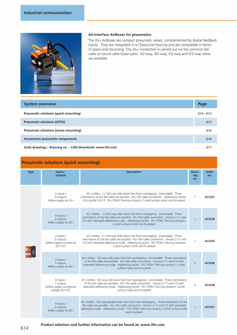
AS-Interface AirBoxes for pneumatics
The AS-i AirBoxes are compact pneumatic valves, complemented by digital feedbackinputs. They are integrated in a ClassicLine housing and are compatible in terms of space and mounting. The AS-i connection is carried out via the common flatcable or round cable lower parts. 3/2-way, 4/2-way, 5/2-way and 5/3-way valves are available.
Pneumatic solutions (quick mounting)
Type Inputs /outputs
Description Draw-ingno.
Orderno.
2 inputs / 2 outputs;
AirBox supply via AS-i
AS-i AirBox · 2 x 3/2-way slide valves free from overlapping · monostable · Threeorientations of the flat cable are possible · AS-i flat cable connection · Addressing socket ·
AS-i profile S-3.F.F · PA / POM / Piercing contacts: CuSn6 surface nickel and tin-plated1 AC5227
4 inputs / 2 outputs;
AirBox supply via AS-i
AS-i AirBox · 2 x 3/2-way slide valves free from overlapping · monostable · Threeorientations of the flat cable are possible · AS-i flat cable connection · Version 2.11 and3.0 with extended addressing mode · Addressing socket · PA / POM / Piercing contacts:
CuSn6 surface nickel and tin-plated
1 AC5228
4 inputs / 2 outputs;
AirBox supply via external 24 V DC
AS-i AirBox · 2 x 3/2-way slide valves free from overlapping · monostable · Threeorientations of the flat cable are possible · AS-i flat cable connection · Version 2.11 and3.0 with extended addressing mode · Addressing socket · PA / POM / Piercing contacts:
CuSn6 surface nickel and tin-plated
1 AC5243
4 inputs / 1 output ;
AirBox supply via AS-i
AS-i AirBox · 5/2-way slide valve free from overlapping · monostable · Three orientationsof the flat cable are possible · AS-i flat cable connection · Version 2.11 and 3.0 with
extended addressing mode · Addressing socket · PA / POM / Piercing contacts: CuSn6surface nickel and tin-plated
2 AC5246
4 inputs / 1 output;
AirBox supply via externalvoltage 24 V DC
AS-i AirBox · 5/2-way slide valve free from overlapping · monostable · Three orientationsof the flat cable are possible · AS-i flat cable connection · Version 2.11 and 3.0 with
extended addressing mode · Addressing socket · PA / POM / Piercing contacts: CuSn6surface nickel and tin-plated
2 AC5249
4 inputs / 2 outputs;
AirBox supply via AS-i
AS-i AirBox · 5/2-way bistable slide valve free from overlapping · Three orientations of theflat cable are possible · AS-i flat cable connection · Version 2.11 and 3.0 with extended
addressing mode · Addressing socket · PA / POM / Piercing contacts: CuSn6 surface nickeland tin-plated
1 AC5251
System overview Page
Pneumatic solutions (quick mounting) 614 - 615
Pneumatic solutions (ATEX) 615
Pneumatic solutions (screw mounting) 616
Accessories pneumatic components 616
Scale drawings / drawing no. – CAD download: www.ifm.com 617
Industrial communication
614Product selectors and further information can be found at: www.ifm.com
Gesamtkatalog EN 2016_17_Stilvorlage LK FrutigerOT_2010 DE_GB.qxd 06.11.15 16:57 Seite 614
Type Inputs /outputs
Description Draw-ingno.
Orderno.
4 inputs / 2 outputs;
AirBox supply via external 24 V DC
AS-i AirBox · 5/2-way bistable slide valve free from overlapping · Three orientations of theflat cable are possible · AS-i flat cable connection · Version 2.11 and 3.0 with extended
addressing mode · Addressing socket · PA / POM / Piercing contacts: CuSn6 surface nickeland tin-plated
1 AC5253
4 inputs / 2 outputs;
AirBox supply via AS-i
AS-i AirBox · 5/3-way slide valve free from overlapping · closed · Three orientations of theflat cable are possible · AS-i flat cable connection · Version 2.11 and 3.0 with extended
addressing mode · Addressing socket · PA / POM / Piercing contacts: CuSn6 surface nickeland tin-plated
1 AC5270
4 inputs / 2 outputs;
AirBox supply via external 24 V DC
AS-i AirBox · 5/3-way slide valve free from overlapping · closed · Three orientations of theflat cable are possible · AS-i flat cable connection · Addressing socket · Version 2.11 and3.0 with extended addressing mode · PA / POM / Piercing contacts: CuSn6 surface nickel
and tin-plated
1 AC5271
Pneumatic solutions (ATEX)
Type Inputs /outputs
Description Draw-ingno.
Orderno.
4 inputs / 2 outputs;
AirBox supply via AS-i
AS-i AirBox · 2 x 3/2-way slide valves free from overlapping · monostable · Threeorientations of the flat cable are possible · Digital inputs · Addressing socket · AS-i profile
S-7.F.F · Versions 2.11 and 3.0 · ATEX approval · Group II, category 3D · Only inconjunction with impact protection housing E7000A or equivalent protection · PA / POM /
Piercing contacts: CuSn6 surface nickel and tin-plated
1 AC542A
4 inputs / 2 outputs;
AirBox supply via AS-i
AS-i AirBox · 2 x 3/2-way slide valves free from overlapping · Three orientations of the flatcable are possible · AS-i flat cable connection · Version 2.11 and 3.0 with extended
addressing mode · Addressing socket · ATEX approval · Group II, category 3D · Only inconjunction with impact protection housing E7000A or equivalent protection · PA / POM /
Piercing contacts: CuSn6 surface nickel and tin-plated
1 AC528A
4 inputs / 1 output ;
AirBox supply via AS-i
AS-i AirBox · 5/2-way slide valve free from overlapping · monostable · Three orientationsof the flat cable are possible · AS-i flat cable connection · Version 2.11 and 3.0 with
extended addressing mode · Addressing socket · ATEX approval · Group II, category 3D ·Only in conjunction with impact protection housing E7000A or equivalent protection · PA
/ POM / Piercing contacts: CuSn6 surface nickel and tin-plated
2 AC546A
2 inputs / 1 output;
AirBox supply via AS-i
AS-i AirBox · 5/2-way slide valve free from overlapping · monostable · Three orientationsof the flat cable are possible · Digital inputs · Addressing socket · AS-i profile S-3.F.F ·ATEX approval · Group II, category 3D · Only in conjunction with impact protection
housing E7000A or equivalent protection · PA / POM / Piercing contacts: CuSn6 surfacenickel and tin-plated
1 AC246A
4 inputs / 2 outputs;
AirBox supply via AS-i
AS-i AirBox · 5/2-way bistable slide valve free from overlapping · Three orientations of theflat cable are possible · AS-i flat cable connection · Version 2.11 and 3.0 with extendedaddressing mode · Addressing socket · ATEX approval · Group II, category 3D · Only in
conjunction with impact protection housing E7000A or equivalent protection · PA / POM /Piercing contacts: CuSn6 surface nickel and tin-plated
1 AC551A
4 inputs / 2 outputs;
AirBox supply via AS-i
AS-i AirBox · 5/3-way slide valve free from overlapping · closed · Three orientations of theflat cable are possible · AS-i flat cable connection · Version 2.11 and 3.0 with extendedaddressing mode · Addressing socket · ATEX approval · Group II, category 3D · Only in
conjunction with impact protection housing E7000A or equivalent protection · PA / POM /Piercing contacts: CuSn6 surface nickel and tin-plated
1 AC570A
AS-InterfaceAirBoxes for pneumatics
615You can find scale drawings from page 617
Gesamtkatalog EN 2016_17_Stilvorlage LK FrutigerOT_2010 DE_GB.qxd 06.11.15 16:57 Seite 615

Pneumatic solutions (screw mounting)
Type Inputs /outputs
Description Draw-ingno.
Orderno.
2 x 2 inputs / 2 outputs
AS-i AirBox · Connection to the pneumatic system by tube fittings · Manual override bypressing/releasing or pressing/turning/locking · 2 x 2 digital inputs · 2 pneumatic outputs ·
Sockets M12 x 1 · housing: PBT / Metal parts: stainless steel / sealing: Viton3 AC2055
2 inputs / 1 output NO/NC
selectable (monostable)
AS-i AirBox · Connection to the pneumatic system by tube fittings · 1 x 2 or 2 x 1 digitalinputs · 1 pneumatic output (NO/NC selectable) · Sockets M12 x 1 · housing: PBT / Metal
parts: stainless steel / sealing: Viton4 AC2057
Accessories pneumatic components
Type Description Orderno.
Silencer · Housing materials: connection piece: PP / filter: PE E75232
Push-in T-fitting · Housing materials: housing: Nickel-plated brass / PA66 / tooth lock washer: stainless steel E75227
Push-in L-fitting · Housing materials: housing: PA66 / release ring: polyoxymethylene / tooth lock washer: stainless steel / form ring:acrylonitrile butadiene caoutchouc
E75228
Push-in L-fitting · Diameter reduction from Ø8 mm to Ø6 mm · Housing materials: housing: Nickel-plated brass / PA66 / tooth lockwasher: stainless steel
E75229
Sealing plug for AirBox · Housing materials: housing: PA66 E75231
Industrial communication
616Product selectors and further information can be found at: www.ifm.com
Gesamtkatalog EN 2016_17_Stilvorlage LK FrutigerOT_2010 DE_GB.qxd 06.11.15 16:57 Seite 616

Scale drawings / drawing no. – CAD download: www.ifm.com
1
2
4
0
1
0
1
91
108
85
1 50
40
2
1 50
40
2
4
0
1
91
108
85
3
44 46
8012 15
M12x1
45
LED8 mm
4
M12 x1
45
LED8 mm
4 mm
5
50 52
80
AS-InterfaceAirBoxes for pneumatics
617
Gesamtkatalog EN 2016_17_Stilvorlage LK FrutigerOT_2010 DE_GB.qxd 06.11.15 16:57 Seite 617

AS-Interface sensors
The bus connection is already integrated in the intelligent AS-i sensors. So they can be directly connected to the yellow cable. In addition to the pure sensor information, further diagnostic data are available via the AS-interface, which can be transmitted and evaluated at a low cost.
AS-i sensors
Type Description Draw-ingno.
Orderno.
Inductive sensor · M12 x 1 · Sensing range 4 mm · Gold-plated contacts · Connector, Gold-plated contacts · stainless steel / active face: LCP uncoloured
1 IFC247
Inductive sensor · M12 x 1 · Sensing range 7 mm · Gold-plated contacts · Connector, Gold-plated contacts · stainless steel / active face: LCP uncoloured
2 IFC248
Inductive sensor · M18 x 1 · Sensing range 8 mm · Gold-plated contacts · Connector, Gold-plated contacts · threaded sleeve: stainless steel / active face: LCP uncoloured / lock nuts: Brass
3 IGC234
Inductive sensor · M18 x 1 · Sensing range 12 mm · Gold-plated contacts · Connector, Gold-plated contacts · threaded sleeve: stainless steel / active face: LCP uncoloured / lock nuts: Brass
4 IGC235
Inductive sensor · M30 x 1.5 · Sensing range 14 mm · Gold-plated contacts · Connector, Gold-plated contacts · stainless steel / active face: LCP uncoloured
5 IIC220
Inductive sensor · M30 x 1.5 · Sensing range 22 mm · Gold-plated contacts · Connector, Gold-plated contacts · stainless steel / active face: LCP uncoloured
6 IIC221
Inductive sensor · Sensing range 15 mm · 5 positions of the sensing face selectable · Connector, rotatable, locking · PBT / PPE
7 IM5118
Temperature transmitter · Analogue value (16 bit value incl. sign) · AS-i profile S-7.3 · Max. medium temperature · 150°C /302°F (max. 40 min.) · Connector, Gold-plated contacts · stainless steel 316L / 1.4404 / stainless steel / stainless steel / PA
8 TAA131
Temperature transmitter · Analogue value (16 bit value incl. sign) · AS-i profile S-7.3 · Max. medium temperature · 150°C /302°F (max. 40 min.) · Connector, Gold-plated contacts · stainless steel 316L / 1.4404 / stainless steel / stainless steel / PA
9 TAA431
System overview Page
AS-i sensors 618 - 619
Scale drawings / drawing no. – CAD download: www.ifm.com 619 - 620
Industrial communication
618Product selectors and further information can be found at: www.ifm.com
Gesamtkatalog EN 2016_17_Stilvorlage LK FrutigerOT_2010 DE_GB.qxd 06.11.15 16:57 Seite 618

Type Description Draw-ingno.
Orderno.
Read/write head · With integrated AS-i slave profile 7.4 · M12 connector · rotatable · PA 10 DTA100
Read head · with integrated AS-i slave profile 7.3 · M12 connector · rotatable · PA 10 DTA101
Read/write head · With integrated AS-i slave profile 7.4 · M12 connector · 5 positions of the sensing face selectable ·rotatable, locking · PA
7 DTA200
Read head · with integrated AS-i slave profile 7.3 · M12 connector · 5 positions of the sensing face selectable · rotatable, locking · PA
7 DTA201
Read/write head · With integrated AS-i slave profile 7.4 · M12 connector · rotatable · housing: PPE / Metal parts: diecast zinc / brass nickel-plated
11 DTA300
Read head · with integrated AS-i slave profile 7.3 · M12 connector · rotatable · housing: PPE / Metal parts: diecast zinc /brass nickel-plated
11 DTA301
Scale drawings / drawing no. – CAD download: www.ifm.com
1
4940
M12
x1
174
M12
x1
LED 4 x 90°
60
2
4935
M12
x1
174
M12
x1
LED 4 x 90°
60
5
3
M18
x1
M12
x1
4047
60
LED 4 x 90°4
24
49
4
M18
x1
30 10
M12
x1
47
60
LED 4 x 90°
49
424
5
49
43
M30
x1,5
5
47
60
M12
x1
LED 4 x 90° 36
6
49
28
M30
x1,5
5
47
60
M12
x1
LED 4 x 90°
15
36
7
40
66
40
54
M12
x130
30 2
2
1
46
46
5,5
5,5
29,5
1: LED yellow, 2: LED green
AS-Interface sensors
619
Gesamtkatalog EN 2016_17_Stilvorlage LK FrutigerOT_2010 DE_GB.qxd 06.11.15 16:57 Seite 619
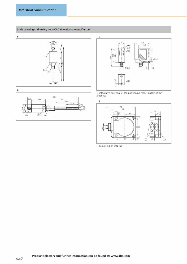
Scale drawings / drawing no. – CAD download: www.ifm.com
8
5360
8,2
M12x130
27
14,9
127,
9
13,5
G 41
LED
9
G 21
52,8 123
8,2
10
M12
x130
27
18,3
14,7
47,5
190,5
LED
87,5
10
4,8
2
41,2
4,517
55,7
17
4,2
M12 x1
24
55,3
70,4
LED
2
1
5,5
53,4
1: integrated antenna, 2: tag positioning mark (middle of theantenna)
11
92
80
40
7,565
65
5,59,3
M12
x1
112
40
LED171
20
1: Mounting on DIN rail
Industrial communication
620Product selectors and further information can be found at: www.ifm.com
Gesamtkatalog EN 2016_17_Stilvorlage LK FrutigerOT_2010 DE_GB.qxd 06.11.15 16:57 Seite 620

AS-Interface sensors
621
Gesamtkatalog EN 2016_17_Stilvorlage LK FrutigerOT_2010 DE_GB.qxd 06.11.15 16:57 Seite 621

AS-Interface devices for valves and valve actuators
The valve controls for pneumatic quarter-turn actuators can be directly mounted tomost quarter-turn actuators by means of the standardised mechanical interface.They contain two inductive sensors for position feedback, one or two outputs forthe control of the pilot valve, and an AS-i slave.
Sensors with ATEX approval 3D and / or 3G
Type Dimensions
[mm]
Sensingrange
[mm]
Material Ub
[V]
Protection fAC / DC
[Hz]
IloadAC / DC
[mA]
Draw-ingno.
Orderno.
M12 connector · Output function transistor PNP · 2 inputs / 2 outputs · Connector groups 154, 156
55 x 60 x 35 4 PBT 26.5...31.6 IP 5x – – 1 AC327A
M12 connector · Output function transistor PNP · 2 inputs / 1 output · Connector groups 154, 156
55 x 60 x 35 4 PBT 26.5...31.6 IP 5x – – 1 AC336A
Sensors for industrial applications, AS-i system
Type Dimensions
[mm]
Sensingrange
[mm]
Material Ub
[V]
Protection fAC / DC
[Hz]
IloadAC / DC
[mA]
Draw-ingno.
Orderno.
M12 connector · Output function transistor PNP · 2 inputs / 1 output · Connector group --
55 x 60 x 35 4 nf PBT (Pocan) 26.5...31.6 IP 67 – – 2 AC2310
System overview Page
Sensors with ATEX approval 3D and / or 3G 622
Sensors for industrial applications, AS-i system 622 - 623
Wiring diagrams 623
Scale drawings / drawing no. – CAD download: www.ifm.com 623 - 624
Industrial communication
622Product selectors and further information can be found at: www.ifm.com
Gesamtkatalog EN 2016_17_Stilvorlage LK FrutigerOT_2010 DE_GB.qxd 06.11.15 16:57 Seite 622
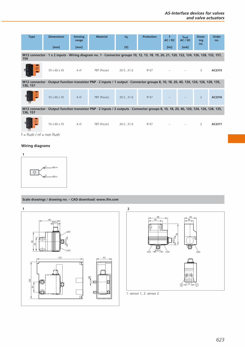
Type Dimensions
[mm]
Sensingrange
[mm]
Material Ub
[V]
Protection fAC / DC
[Hz]
IloadAC / DC
[mA]
Draw-ingno.
Orderno.
M12 connector · 1 x 2 inputs · Wiring diagram no. 1 · Connector groups 10, 12, 13, 18, 19, 20, 21, 120, 122, 124, 126, 128, 132, 157,159
55 x 60 x 35 4 nf PBT (Pocan) 26.5...31.6 IP 67 – – 3 AC2315
M12 connector · Output function transistor PNP · 2 inputs / 1 output · Connector groups 8, 10, 18, 20, 40, 120, 124, 126, 128, 135,136, 157
55 x 60 x 35 4 nf PBT (Pocan) 26.5...31.6 IP 67 – – 2 AC2316
M12 connector · Output function transistor PNP · 2 inputs / 2 outputs · Connector groups 8, 10, 18, 20, 40, 120, 124, 126, 128, 135,136, 157
55 x 60 x 35 4 nf PBT (Pocan) 26.5...31.6 IP 67 – – 2 AC2317
f = flush / nf = non flush
Wiring diagrams
1
AS-i+1
3 AS-i
Scale drawings / drawing no. – CAD download: www.ifm.com
1
M12
x1
M12 x1
4055
LED
LED
60
132
105
30
42
M5
2
2635
LEDM12 x1
M12
x1
4055
LEDLED
60
13 12
1: sensor 1, 2: sensor 2
AS-Interface devices for valvesand valve actuators
623
Gesamtkatalog EN 2016_17_Stilvorlage LK FrutigerOT_2010 DE_GB.qxd 06.11.15 16:57 Seite 623
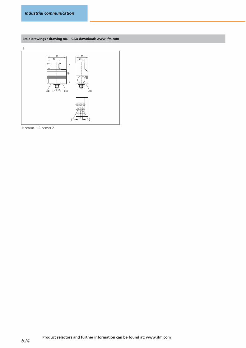
Scale drawings / drawing no. – CAD download: www.ifm.com
3
2635
LEDM12 x1
4055
LEDLED
60
1312
1: sensor 1, 2: sensor 2
Industrial communication
624Product selectors and further information can be found at: www.ifm.com
Gesamtkatalog EN 2016_17_Stilvorlage LK FrutigerOT_2010 DE_GB.qxd 06.11.15 16:57 Seite 624

AS-Interface devices for valvesand valve actuators
625
Gesamtkatalog EN 2016_17_Stilvorlage LK FrutigerOT_2010 DE_GB.qxd 06.11.15 16:57 Seite 625

AS-Interface expansion
There are different ways to extend the AS-i cable. The specified one hundred metrescan be extended up to 1000 metres in extreme cases.
AS-i repeaters
Type Description Draw-ingno.
Orderno.
AS-i repeater · Extension of the AS-i network by another 100 m · One additional AS-i power supply necessary · Combicon connection · PA 6.6
– AC2225
Passive AS-i bus termination · Extension of the cable to a maximum of 200 m without additional repeater · Improvement of the signal quality · Monitoring of the supply voltage by means of LEDs
1 AC1147
eASI-Tester · Local diagnosis of the AS-i network · Creation of test reports for AS-i networks · User-friendly diagnosis and evaluation via the connected PC
2 AC1145
AS-i tuner diagnostic module · Extension of the cable to a maximum of 200 m without additional repeater · Monitoring of the message quality · Display of critical states by "traffic light" LEDs · PBT
3 AC1146
Scale drawings / drawing no. – CAD download: www.ifm.com
1
M12
x1
46
20
2 LED
2
2991
138
System overview Page
AS-i repeaters 626
Scale drawings / drawing no. – CAD download: www.ifm.com 626 - 627
Industrial communication
626Product selectors and further information can be found at: www.ifm.com
Gesamtkatalog EN 2016_17_Stilvorlage LK FrutigerOT_2010 DE_GB.qxd 06.11.15 16:57 Seite 626

Scale drawings / drawing no. – CAD download: www.ifm.com
3
44
83
90
M12 x1
LED
1 2
1: tune button, 2: mode selector
AS-Interface expansion
627
Gesamtkatalog EN 2016_17_Stilvorlage LK FrutigerOT_2010 DE_GB.qxd 06.11.15 16:57 Seite 627
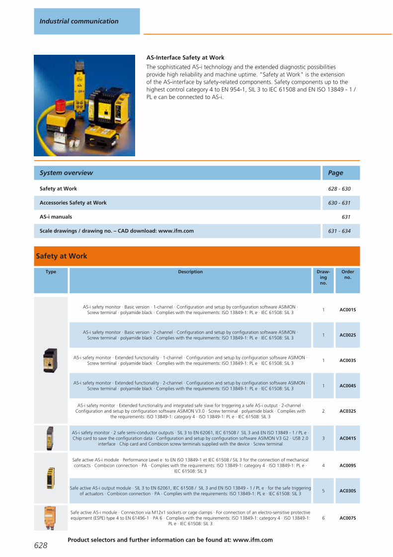
AS-Interface Safety at Work
The sophisticated AS-i technology and the extended diagnostic possibilities provide high reliability and machine uptime. "Safety at Work" is the extension of the AS-interface by safety-related components. Safety components up to the highest control category 4 to EN 954-1, SIL 3 to IEC 61508 and EN ISO 13849 - 1 /PL e can be connected to AS-i.
Safety at Work
Type Description Draw-ingno.
Orderno.
AS-i safety monitor · Basic version · 1-channel · Configuration and setup by configuration software ASIMON · Screw terminal · polyamide black · Complies with the requirements: ISO 13849-1: PL e · IEC 61508: SIL 3
1 AC001S
AS-i safety monitor · Basic version · 2-channel · Configuration and setup by configuration software ASIMON · Screw terminal · polyamide black · Complies with the requirements: ISO 13849-1: PL e · IEC 61508: SIL 3
1 AC002S
AS-i safety monitor · Extended functionality · 1-channel · Configuration and setup by configuration software ASIMON ·Screw terminal · polyamide black · Complies with the requirements: ISO 13849-1: PL e · IEC 61508: SIL 3
1 AC003S
AS-i safety monitor · Extended functionality · 2-channel · Configuration and setup by configuration software ASIMON ·Screw terminal · polyamide black · Complies with the requirements: ISO 13849-1: PL e · IEC 61508: SIL 3
1 AC004S
AS-i safety monitor · Extended functionality and integrated safe slave for triggering a safe AS-i output · 2-channel ·Configuration and setup by configuration software ASIMON V3.0 · Screw terminal · polyamide black · Complies with
the requirements: ISO 13849-1: category 4 · ISO 13849-1: PL e · IEC 61508: SIL 32 AC032S
AS-i safety monitor · 2 safe semi-conductor outputs · SIL 3 to EN 62061, IEC 61508 / SIL 3 and EN ISO 13849 - 1 / PL e ·Chip card to save the configuration data · Configuration and setup by configuration software ASIMON V3 G2 · USB 2.0
interface · Chip card and Combicon screw terminals supplied with the device · Screw terminal3 AC041S
Safe active AS-i module · Performance Level e to EN ISO 13849-1 et IEC 61508 / SIL 3 for the connection of mechanicalcontacts · Combicon connection · PA · Complies with the requirements: ISO 13849-1: category 4 · ISO 13849-1: PL e ·
IEC 61508: SIL 34 AC009S
Safe active AS-i output module · SIL 3 to EN 62061, IEC 61508 / SIL 3 and EN ISO 13849 - 1 / PL e · for the safe triggeringof actuators · Combicon connection · PA · Complies with the requirements: ISO 13849-1: PL e · IEC 61508: SIL 3
5 AC030S
Safe active AS-i module · Connection via M12x1 sockets or cage clamps · For connection of an electro-sensitive protectiveequipment (ESPE) type 4 to EN 61496-1 · PA 6 · Complies with the requirements: ISO 13849-1: category 4 · ISO 13849-1:
PL e · IEC 61508: SIL 36 AC007S
System overview Page
Safety at Work 628 - 630
Accessories Safety at Work 630 - 631
AS-i manuals 631
Scale drawings / drawing no. – CAD download: www.ifm.com 631 - 634
Industrial communication
628Product selectors and further information can be found at: www.ifm.com
Gesamtkatalog EN 2016_17_Stilvorlage LK FrutigerOT_2010 DE_GB.qxd 06.11.15 16:57 Seite 628

Type Description Draw-ingno.
Orderno.
AS-i Safety at Work · Safe AS-i input module 2SI - 2LO · Addressing socket · Three orientations of the flat cable arepossible · Sockets M12 x 1 · PA / Piercing contacts: CuSn6 surface nickel and tin-plated · Complies with the requirements:
ISO 13849-1: category 4 · ISO 13849-1: PL e · IEC 62061: SILcl 37 AC505S
AS-i Safety at Work · Safe AS-i input module 4SI / 2DO T / 2LO · Addressing socket · Three orientations of the flat cableare possible · Sockets M12 x 1 · PA / Piercing contacts: CuSn6 surface nickel and tin-plated · Complies with the
requirements: ISO 13849-1: PL d · IEC 62061: SILcl 27 AC506S
Safe active AS-i ClassicLine module · IR addressing possible · Performance Level e to EN ISO 13849-1 for the connectionof mechanical contacts · Sockets M12 x 1 · PBT · Complies with the requirements: ISO 13849-1: category 4 · ISO 13849-1:
PL e · IEC 61508: SIL 38 AC006S
Illuminated E-STOP · front mounting · reset by turning · 2 NC contacts / 1 red LED · fool-proof E-STOP to EN ISO 13850 9 E7007S
Illuminated E-STOP with integrated AS-i connection · fool-proof E-STOP to EN ISO 13850 · Pull to reset · AS-i interface via AS-i flat cable IP 67 · PC GF20 · Complies with the requirements: ISO 13849-1: category 4 · ISO 13849-1: PL e ·
IEC 61508: SIL 310 AC010S
Key-release E-STOP with integrated AS-i connection · Connector M12 x 1 · AS-i interface via AS-i flat cable IP 67 · fool-proof E-STOP to EN ISO 13850 · Reset by key operation · PC GF20 · Complies with the requirements: ISO 13849-1:
PL e · IEC 61508: SIL 311 AC011S
safe AS-i e-stop operating unit with integrated AS-i connection · AS-i interface via M12 x 1 connector · fool-proof E-STOP to EN ISO 13850 · Pull to reset · interchangeable button inserts
12 AC012S
Safe active AS-i ClassicLine module · AS-i version 2.1 · IR addressing possible · Control category 4 according to EN954-1 ·For the connection of fail-safe inductive sensors of the control category 4 · Sockets M12 x 1 · PBT · Complies with the
requirements: ISO 13849-1: category 4 · ISO 13849-1: PL e · IEC 61508: SIL 3– AC016S
AS-i safety PCB · Connection of mechanical contact and LED components · Certification to ISO 13849-1: PL e and IEC 61508 / SIL 3 · Complies with the requirements: · IEC 61508: SIL 3
13 AC015S
Fail-safe inductive sensor · M12 connector, Gold-plated contacts · PPE / diecast zinc · Complies with the requirements: ISO 13849-1: category 4 · ISO 13849-1: PL e · IEC 61508: SIL 3
14 GM504S
Fail-safe inductive sensor · M12 connector, Gold-plated contacts · PPE / diecast zinc · Complies with the requirements: ISO 13849-1: category 4 · ISO 13849-1: PL e · IEC 61508: SIL 3
14 GM505S
Fail-safe inductive sensor · M18 x 1 · M12 connector, Gold-plated contacts · high-grade stainless steel / PBT · Complies with the requirements: ISO 13849-1: category 4 · ISO 13849-1: PL e · IEC 61508: SIL 3
15 GG505S
Fail-safe inductive sensor · M30 x 1.5 · M12 connector, Gold-plated contacts · PEEK / high-grade stainless steel / O-ring: EPDM · Complies with the requirements: ISO 13849-1: category 4 · ISO 13849-1: PL e · IEC 61508: SIL 3
16 GI505S
Safety switch with guard locking · Normally closed principle · Rotatable actuating head made of metal · Mechanicalrelease on the front · Supply via AS-i / solenoid supply ext. from 24 V DC · M12 connector · thermoplastic reinforced
glass-fibre17 AC901S
Safety switch with guard locking · Normally open principle · Rotatable actuating head made of metal · Mechanical releaseon the front · Supply via AS-i / solenoid supply ext. from 24 V DC · M12 connector · thermoplastic reinforced glass-fibre
17 AC902S
Safety switch with guard locking · Normally closed principle · Rotatable actuating head made of metal · Mechanicalrelease on the front · Supply via AS-i / solenoid supply from AS-i · M12 connector · thermoplastic reinforced glass-fibre
18 AC903S
AS-Interface Safety at Work
629You can find scale drawings from page 631
Gesamtkatalog EN 2016_17_Stilvorlage LK FrutigerOT_2010 DE_GB.qxd 06.11.15 16:57 Seite 629

Type Description Draw-ingno.
Orderno.
Safety switch with guard locking · Normally open principle · Rotatable actuating head made of metal · Mechanical releaseon the front · Supply via AS-i / solenoid supply from AS-i · M12 connector · thermoplastic reinforced glass-fibre
18 AC904S
Accessories Safety at Work
Type Description Orderno.
AS-i Safety at Work · Programming software for AS-i safety monitor AC001S / AC002S / AC003S / AC004S / AC032S · Version 3.0 · Configuration, set-up and diagnostics of the AS-i safety monitor
E7040S
Software ASIMON V3 G2 · Configuration, set-up and diagnostics of the AS-i safety monitor · AC041S E7050S
USB interface cable for the connection of the safety monitor AC041S to the PC · cable length 1.8 m · 1.8 m E7051S
Chip card to save the configuration data of the AS-i safety monitor AC041S · 256 K E7052S
Safe contact expander without delay · 2 independent channels · 4 contact blocks (NO) per channel · 1 feedback circuit (NC) per channel · Mounting on DIN rail · Screw terminal
E7053S
Connection cable PC / AS-i safety monitor · Parameter setting cable PC / AS-i safety monitor · Western connector RJ 45 8 poles / D-Sub socket 9 poles · 2.5 m
E7001S
Connection cable AS-i safety monitor / AS-i safety monitor · Download cable AS-i safety monitor / AS-i safety monitor · Western connector RJ 45 8 poles · 0.3 m
E7002S
EMERGENCY STOP label IP66 4 languages D,GB,F,I · EMERGENCY STOP label 4 languages for a safe illuminated EMERGENCY STOPbutton with integrated AS-i interface AC010S / AC011S / AC012S · 50 x 50 mm
E7003S
EMERGENCY STOP protective collar · EMERGENCY STOP protective collar for safe E-STOP AC010S / AC011S / AC012S · Housing materials: PC GF20 RAL 1004
E7004S
bridging plug for safety modules · Housing materials: PUR E7005S
Adapter plug · straight · M20 - M12 · M12 connector · 0.07 m · Housing materials: polyamide E7006S
Bolt for safety guards · for heavy doors · For right or left hinged doors without escape release · No additional door handle required ·screw mounting onto common aluminium profiles and machine panels · Housing materials: diecast aluminium yellow
E7901S
Industrial communication
630Product selectors and further information can be found at: www.ifm.com
Gesamtkatalog EN 2016_17_Stilvorlage LK FrutigerOT_2010 DE_GB.qxd 06.11.15 16:57 Seite 630
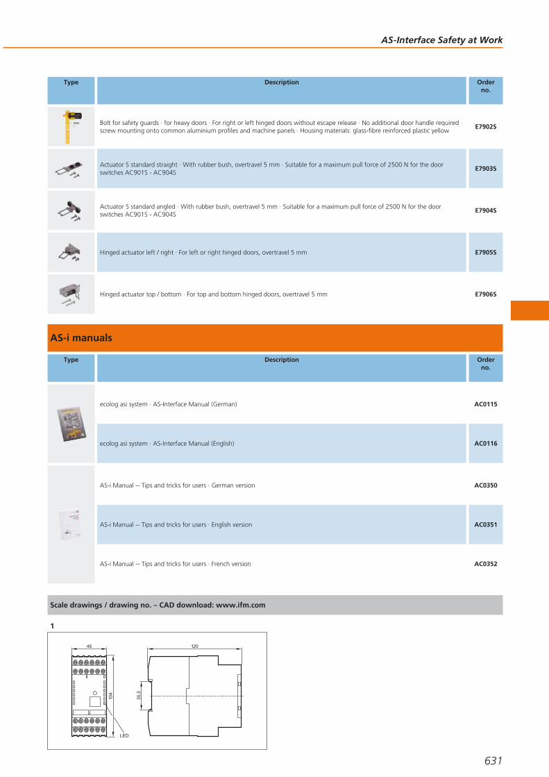
Type Description Orderno.
Bolt for safety guards · for heavy doors · For right or left hinged doors without escape release · No additional door handle required ·screw mounting onto common aluminium profiles and machine panels · Housing materials: glass-fibre reinforced plastic yellow
E7902S
Actuator S standard straight · With rubber bush, overtravel 5 mm · Suitable for a maximum pull force of 2500 N for the doorswitches AC901S - AC904S
E7903S
Actuator S standard angled · With rubber bush, overtravel 5 mm · Suitable for a maximum pull force of 2500 N for the doorswitches AC901S - AC904S
E7904S
Hinged actuator left / right · For left or right hinged doors, overtravel 5 mm E7905S
Hinged actuator top / bottom · For top and bottom hinged doors, overtravel 5 mm E7906S
AS-i manuals
Type Description Orderno.
ecolog asi system · AS-Interface Manual (German) AC0115
ecolog asi system · AS-Interface Manual (English) AC0116
AS-i Manual -- Tips and tricks for users · German version AC0350
AS-i Manual -- Tips and tricks for users · English version AC0351
AS-i Manual -- Tips and tricks for users · French version AC0352
Scale drawings / drawing no. – CAD download: www.ifm.com
1
120
35,5
45
104
LED
AS-Interface Safety at Work
631
Gesamtkatalog EN 2016_17_Stilvorlage LK FrutigerOT_2010 DE_GB.qxd 06.11.15 16:57 Seite 631

Scale drawings / drawing no. – CAD download: www.ifm.com
2
45
105,
9
12035
,5
102
82,6
91,2
3
LEDs
22,5114,5
108
99
1: Chip card, 2: service button, 3: Combicon connector with screwterminals, 4: Micro USB interface
4
105
35,5
25
108
LEDs
1
1: Addressing socket
5
2
105
35,5
25
108
1
1: Addressing socket, 2: LED
6
45,5
49,4
8011
1
7
45
103
40,2
44,7
25,8
8
90
LED
M12 x1
1 80
44
1: fixture infrared adapter
9
40
30
88
561238
1
Industrial communication
632Product selectors and further information can be found at: www.ifm.com
Gesamtkatalog EN 2016_17_Stilvorlage LK FrutigerOT_2010 DE_GB.qxd 06.11.15 16:57 Seite 632

Scale drawings / drawing no. – CAD download: www.ifm.com
10
58,5
66,5
UU
UU
93,5
5610
5
M12
x1
72
80
11
M12
x1
72
80
58,5
66,5
93,5
5610
5
12
5610
4
208
120 72
M12
x1
80
13
921 U U UU
44
32
9 10 10
14
40
M12
x1
4066
17
34
LED
4661
30 20
5,4
105,
4
6
8,5
33
15
M18
x1
55 10
M12
x1
90,5
LED 8 x 45°
79
424
16
LED 4 x 90°
69
39
M30
x1,5
5
67
80
36
M12
x1
15
AS-Interface Safety at Work
633
Gesamtkatalog EN 2016_17_Stilvorlage LK FrutigerOT_2010 DE_GB.qxd 06.11.15 16:57 Seite 633
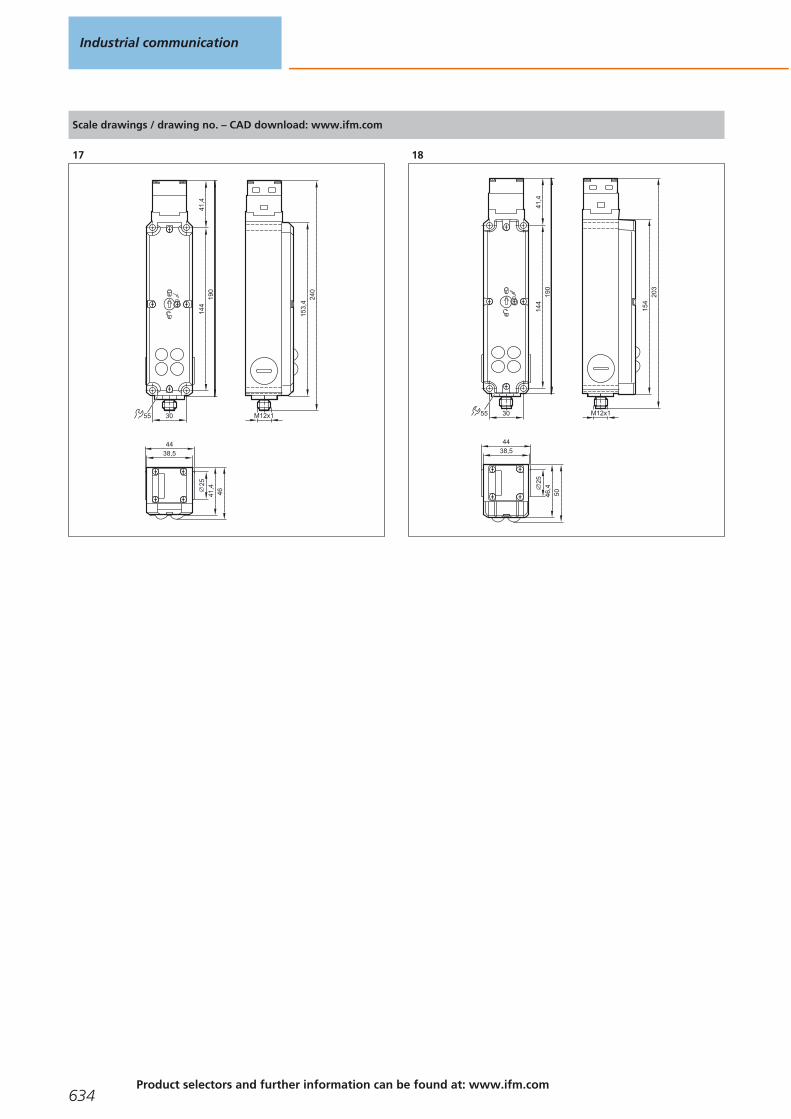
Scale drawings / drawing no. – CAD download: www.ifm.com
17
55
2514
419
041
,4
240
153,
4
M12x130
38,544
4641,4
18
55
2514
419
041
,4
203
154
M12x130
38,544
5046,4
Industrial communication
634Product selectors and further information can be found at: www.ifm.com
Gesamtkatalog EN 2016_17_Stilvorlage LK FrutigerOT_2010 DE_GB.qxd 06.11.15 16:57 Seite 634

AS-Interface Safety at Work
635
Gesamtkatalog EN 2016_17_Stilvorlage LK FrutigerOT_2010 DE_GB.qxd 06.11.15 16:57 Seite 635

For more transparency in the system
Multicode reader type O2I – the compactall-rounder for optical identification tasks.
Multicode readers
ifm multicode readers handle not only the ECC200 DataMatrix code, but also many more 2D and 1D codes. Codereading is not dependent on the orientation of the code tothe sensor. The industrially compatible mounting and wiringtechnology as well as the standardised process interfacesenable easy and quick integration into the industrial controlsystem.
There is a wide range of applications for multicode readers inindustry – from product tracking and production control toproduct identification. They are used for the automotive andfood industries, conveying, the production of solar installa-tions as well as machine tools and print machines.
RF identification systems
ifm offers different RFID systems using different frequencies,ranges, interfaces and data volumes.
LF 125 kHz system with AS-Interface
ifm supplies the first RFID system for AS-Interface worldwide.Up to 31 read / write heads can be connected to one AS-imaster. Antenna, electronics and AS-Interface are integratedin a compact housing.
LF 125 kHz / HF 13.56 MHz system with different field-bus interfaces
The RFID evaluation units DTE10x with integrated fieldbusinterfaces and web server is widely used in production tomark tools, for quality assurance, to monitor productionsteps, in conveying and in automation technology.
The antenna concept guarantees easy and quick connectionof the LF and HF RFID antennas to the evaluation unit bymeans of M12 connectors and standardised connectioncables of up to 20 metres.
You will find an overview of all connection cables in the chapter "Connection technology".
RFID compact unit suitable for mobile use
The robust RFID compact unit with CANopen interface hasbeen developed for identification tasks in agricultural machines, municipal vehicles and construction machines.
UHF system with Ethernet
As components of the UHF system platform, the read / writeunits DTE800 and DTE900 are compliant with the UHF bandsin Europe and the USA respectively. The data transmissionand parameter setting are carried out via Ethernet. The ultralow and low range antennas achieve selectivities of a fewcentimetres. The mid range antenna is chosen for applicationsin the near / far field with reading ranges of up to 2 m. Thewide range antenna attains reading ranges of up to 10 m.
Identification systems
636Product selectors and further information can be found at: www.ifm.com
Gesamtkatalog EN 2016_17_Stilvorlage LK FrutigerOT_2010 DE_GB.qxd 06.11.15 16:57 Seite 636
Identification systems
637
RFID 125 kHz 638 - 643
RFID 13.56 MHz 644 - 649
RFID UHF 650 - 653
1D/2D code readers 654 - 660
Gesamtkatalog EN 2016_17_Stilvorlage LK FrutigerOT_2010 DE_GB.qxd 06.11.15 16:57 Seite 637

RFID 125 kHz
RFID systems based on 125 kHz for production and conveying technology, identification of workpiece carriers and products.
- System DTS 125 with AS-Interface
- System DTE 100 with Profibus DP
- System DTE 101 with Profinet
- System DTE 102 with Ethernet/IP
RFID system 125 kHz with AS-Interface
Type Dimensions
[mm]
Travel speedread / write
[m/s]
Processinterface
Draw-ingno.
Orderno.
M12 connector · Connector groups 8, 10, 18, 20, 120, 124, 126, 128, 157
55 x 24 x 41 read: ≤ 0.5 (distance to the ID tag 15 mm) write: only static AS-i 1 DTA100
55 x 24 x 41 read: ≤ 0.5 (distance to the ID tag 15 mm) AS-i 1 DTA101
40 x 40 x 54 read: ≤ 0.5 (distance to the ID tag 30 mm) write: only static AS-i 2 DTA200
System overview Page
RFID system 125 kHz with AS-Interface 638 - 639
ID tags 125 kHz for system DTS 125 639
Handheld readers for system DTS 125 640
Fixing components 640
DTE 101 RFID system with ProfiNet 640
DTE102 RFID system with EtherNet/IP 641
DTE 100 RFID system with Profibus DP 641
DTE104 RFID system with Ethernet TCP/IP 641
RFID antennas 125 kHz for system DTE100, DTE101, DTE102, DTE104 641
RFID tags 125 kHz for antenna ANT512 641
Accessories DTE100 642
Connection technology 642
Scale drawings / drawing no. – CAD download: www.ifm.com 642 - 643
Identification systems
638Product selectors and further information can be found at: www.ifm.com
Gesamtkatalog EN 2016_17_Stilvorlage LK FrutigerOT_2010 DE_GB.qxd 06.11.15 16:57 Seite 638

Type Dimensions
[mm]
Travel speedread / write
[m/s]
Processinterface
Draw-ingno.
Orderno.
M12 connector · Connector groups 8, 10, 18, 20, 120, 124, 126, 128, 157
40 x 40 x 54 read: ≤ 0.5 (distance to the ID tag 30 mm) AS-i 2 DTA201
92 x 80 x 40 read: ≤ 0.5 (distance to the ID tag 40 mm) write: only static AS-i 3 DTA300
92 x 80 x 40 read: ≤ 0.5 (distance to the ID tag 40 mm) AS-i 3 DTA301
ID tags 125 kHz for system DTS 125
Type Description Orderno.
ID tag · ID-TAG/M5x16.5/01 · M5 x 16.5 mm · Screw mounting · Housing materials: PA black (RAL 9005) E80301
ID tag · ID-TAG/TRIANGLE HOUSING/01 · with ID tag E80301 · Housing materials: PBT orange (RAL 2003) / PA black (RAL 9005) E80302
ID tag · ID-TAG/M18x1/01 · M18 x 1 · Screw mounting · in metal · Housing materials: threaded sleeve: PBT orange E80311
ID tag · ID-TAG/D12x2/01 · Ø 12 x 2 mm · Housing materials: PPS black E80312
ID tag · ID-TAG/D20x2.15/01 · Ø 20 x 2.15 mm · Housing materials: polycarbonate black E80317
ID tag · ID-TAG/D30x2.15/01 · Ø 30 x 2.15 mm · Housing materials: polycarbonate black E80318
ID tag · ID-TAG/D50x2.2/01 · Ø 50 x 2.2 mm · Housing materials: polycarbonate black E80319
ID tag · ID-TAG/D26x4/01 · Ø 26 x 4 mm · Housing materials: PA High Temperature E80322
ID tag · ID-TAG/ISO-Card/01 · 54 x 86 x 1 mm · Housing materials: PVC white E80320
RFID 125 kHz
639You can find scale drawings from page 642
Gesamtkatalog EN 2016_17_Stilvorlage LK FrutigerOT_2010 DE_GB.qxd 06.11.15 16:57 Seite 639

Handheld readers for system DTS 125
Type Description Orderno.
RFID Handheld Reader USB · suitable for use in PCs or notebooks · 125 kHz · 1.8 m · Housing materials: PS E80321
RFID Handheld Reader CF Card · suitable for use in handheld PCs, pocket PCs or PDAs with CompactFlash interface · 125 kHz E80323
RFID Handheld Reader RS-232 · suitable for use in PCs or notebooks · 125 kHz · Housing materials: PS E80324
Fixing components
Type Description Orderno.
Angle bracket · Housing materials: stainless steel E80304
Mounting set · Clamp mounting · aluminium profile · for type OC · Housing materials: fixture: stainless steel 316Ti / 1.4571 / clamp: diecast zinc / Cube: diecast zinc
E20901
Mounting bracket · with integrated snap-on rail · for type IDC · Housing materials: stainless steel E10730
Mounting set · Clamp mounting · aluminium profile · for type OC · Housing materials: fixture: stainless steel 316Ti / 1.4571 / clamp: diecast zinc / Cube: diecast zinc
E20901
Dovetail clamp · for type DTS, O4, O5 · Housing materials: AlMgSi0.5 E21088
DTE 101 RFID system with ProfiNet
Type Description Draw-ingno.
Orderno.
Type DTE1 · M12 connector
RFID evaluation unit · for up to 4 read/write heads type ANT41x/ANT51x · Housing materials: Upper part: PA Grivory GV-5H orange / Upper part: TPE / lower part: GD-AlSi12
4 DTE101
Identification systems
640 Product selectors and further information can be found at: www.ifm.com
Gesamtkatalog EN 2016_17_Stilvorlage LK FrutigerOT_2010 DE_GB.qxd 06.11.15 16:57 Seite 640

DTE102 RFID system with EtherNet/IP
Type Description Draw-ingno.
Orderno.
Type DTE1 · M12 connector
RFID evaluation unit · for up to 4 read/write heads type ANT41x/ANT51x · Housing materials: Upper part: PA Grivory GV-5H orange / Upper part: TPE / lower part: GD-AlSi12
4 DTE102
DTE 100 RFID system with Profibus DP
Type Description Draw-ingno.
Orderno.
Type DTE1 · M12 connector
RFID evaluation unit · for up to 4 read/write heads type ANT41x/ANT51x · Housing materials: Upper part: PA Grivory GV-5H orange / Upper part: TPE / lower part: GD-AlSi12
5 DTE100
DTE104 RFID system with Ethernet TCP/IP
Type Description Draw-ingno.
Orderno.
Type DTE1 · M12 connector
RFID evaluation unit · for up to 4 read/write heads type ANT41x/ANT51x · Housing materials: Upper part: PA Grivory GV-5H orange / Upper part: TPE / lower part: GD-AlSi12
4 DTE104
RFID antennas 125 kHz for system DTE100, DTE101, DTE102, DTE104
Type Description Draw-ingno.
Orderno.
Read/write head · M12 connector · 5 positions of the sensing face selectable · Housing materials: housing: PA / Metal parts: stainless steel
2 ANT512
RFID tags 125 kHz for antenna ANT512
Type Description Orderno.
ID tag · ID-TAG/30X2.5/05 - 256 bit · Ø 30 x 2.5 mm · Housing materials: PA 6 black E80360
ID tag · ID-TAG/30X2.5/05 - 2048 bit · Ø 30 x 2.5 mm · Housing materials: PA 6 black E80361
RFID 125 kHz
641You can find scale drawings from page 642
Gesamtkatalog EN 2016_17_Stilvorlage LK FrutigerOT_2010 DE_GB.qxd 06.11.15 16:58 Seite 641

Accessories DTE100
Type Description Orderno.
Terminating resistor plug · straight · Free from silicone · Free from halogen · Gold-plated contacts · Housing materials: PUR E12315
Jumper · straight / straight · Free from halogen · Gold-plated contacts · 10 m · Housing materials: PUR E12317
Cable plug · straight · Free from halogen · Gold-plated contacts · M12 connector · 10 m · Housing materials: PUR E12319
Socket · straight · Free from halogen · Gold-plated contacts · M12 connector · 10 m · Housing materials: PUR E12321
Connection technology
Type Description Orderno.
Jumper · straight / straight · Ethernet · Cross-over patch cable · 2 m · Housing materials: PUR / PC E11898
Jumper · straight / straight · Ethernet · Patch cable · 2 m · Housing materials: PUR / PC E12090
Jumper · straight / straight · Ethernet · Cross-over patch cable · 10 m · Housing materials: PUR / PC E12204
Jumper · straight / straight · Ethernet · Cross-over patch cable · 20 m · Housing materials: PUR / PC E12205
Scale drawings / drawing no. – CAD download: www.ifm.com
1
4,8
2
41,2
4,517
55,7
17
4,2
M12 x1
24
55,3
70,4
LED
2
1
5,5
53,4
1: integrated antenna, 2: tag positioning mark (middle of the antenna)
2
40
66
40
54
M12
x130
30 2
2
1
46
46
5,5
5,5
29,5
1: LED yellow, 2: LED green
Identification systems
642
Gesamtkatalog EN 2016_17_Stilvorlage LK FrutigerOT_2010 DE_GB.qxd 06.11.15 16:58 Seite 642

Scale drawings / drawing no. – CAD download: www.ifm.com
3
92
80
40
7,565
65
5,59,3
M12
x1
112
40
LED171
20
1: Mounting on DIN rail
4
M12
x1
M12x1
85
75 32,246,2
115
43,557
,5M4
5
M12
x1
M12x1
85
75 32,246,2
115
43,557
,5M4
RFID 125 kHz
643
Gesamtkatalog EN 2016_17_Stilvorlage LK FrutigerOT_2010 DE_GB.qxd 06.11.15 16:58 Seite 643

RFID 13.56 MHz
Flexible system for production, assembly and handling technology. Ensures fast data transmission and supports the ISO 15693 standard.
- DTE100 system with Profibus DP
- DTE101 system with Profinet
- DTE102 system with EtherNet/IP
- DTE104 system with EtherNetTCP/IP
DTE 100 RFID system with Profibus DP
Type Description Draw-ingno.
Orderno.
Type DTE1 · M12 connector
RFID evaluation unit · for up to 4 read/write heads type ANT41x/ANT51x · Housing materials: Upper part: PA Grivory GV-5H orange / Upper part: TPE / lower part: GD-AlSi12
1 DTE100
DTE 101 RFID system with ProfiNet
Type Description Draw-ingno.
Orderno.
Type DTE1 · M12 connector
RFID evaluation unit · for up to 4 read/write heads type ANT41x/ANT51x · Housing materials: Upper part: PA Grivory GV-5H orange / Upper part: TPE / lower part: GD-AlSi12
2 DTE101
System overview Page
DTE 100 RFID system with Profibus DP 644
DTE 101 RFID system with ProfiNet 644
DTE102 RFID system with EtherNet/IP 645
DTE104 RFID system with Ethernet TCP/IP 645
RFID antennas 13.56 MHz for system DTE100, DTE101, DTE102, DTE104 645
RFID systems DTM424, DTM425, DTM434, DTM435 for mobile machines 646
RFID tags 13.56 MHz for antennasANT513, ANT410, ANT411, ANT430, ANT431, DTM424, DTM425, DTM434, DTM435 646
Accessories DTE100 647
Accessories DTM 647
Connection technology 647 - 648
Scale drawings / drawing no. – CAD download: www.ifm.com 648 - 649
Identification systems
644 Product selectors and further information can be found at: www.ifm.com
Gesamtkatalog EN 2016_17_Stilvorlage LK FrutigerOT_2010 DE_GB.qxd 06.11.15 16:58 Seite 644

DTE102 RFID system with EtherNet/IP
Type Description Draw-ingno.
Orderno.
Type DTE1 · M12 connector
RFID evaluation unit · for up to 4 read/write heads type ANT41x/ANT51x · Housing materials: Upper part: PA Grivory GV-5H orange / Upper part: TPE / lower part: GD-AlSi12
2 DTE102
DTE104 RFID system with Ethernet TCP/IP
Type Description Draw-ingno.
Orderno.
Type DTE1 · M12 connector
RFID evaluation unit · for up to 4 read/write heads type ANT41x/ANT51x · Housing materials: Upper part: PA Grivory GV-5H orange / Upper part: TPE / lower part: GD-AlSi12
2 DTE104
RFID antennas 13.56 MHz for system DTE100, DTE101, DTE102, DTE104
Type Description Draw-ingno.
Orderno.
Read/write head · M12 connector · Housing materials: housing: stainless steel / Top: PPS 3 ANT410
Read/write head · M12 connector · Housing materials: housing: stainless steel / Top: PPS 4 ANT411
Read/write head · M12 connector · Housing materials: housing: stainless steel / Top: PPS 5 ANT430
Read/write head · M12 connector · Housing materials: housing: stainless steel / Top: PPS 6 ANT431
Read/write head · M12 connector · 5 positions of the sensing face selectable · Housing materials: housing: PA / Metal parts: stainless steel
7 ANT513
RFID 13.56 MHz
645You can find scale drawings from page 648
Gesamtkatalog EN 2016_17_Stilvorlage LK FrutigerOT_2010 DE_GB.qxd 06.11.15 16:58 Seite 645
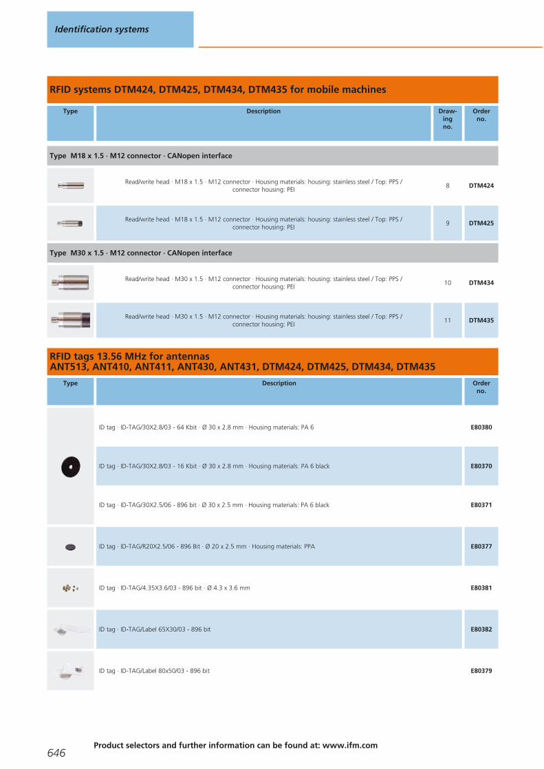
RFID systems DTM424, DTM425, DTM434, DTM435 for mobile machines
Type Description Draw-ingno.
Orderno.
Type M18 x 1.5 · M12 connector · CANopen interface
Read/write head · M18 x 1.5 · M12 connector · Housing materials: housing: stainless steel / Top: PPS / connector housing: PEI
8 DTM424
Read/write head · M18 x 1.5 · M12 connector · Housing materials: housing: stainless steel / Top: PPS / connector housing: PEI
9 DTM425
Type M30 x 1.5 · M12 connector · CANopen interface
Read/write head · M30 x 1.5 · M12 connector · Housing materials: housing: stainless steel / Top: PPS / connector housing: PEI
10 DTM434
Read/write head · M30 x 1.5 · M12 connector · Housing materials: housing: stainless steel / Top: PPS / connector housing: PEI
11 DTM435
RFID tags 13.56 MHz for antennas ANT513, ANT410, ANT411, ANT430, ANT431, DTM424, DTM425, DTM434, DTM435
Type Description Orderno.
ID tag · ID-TAG/30X2.8/03 - 64 Kbit · Ø 30 x 2.8 mm · Housing materials: PA 6 E80380
ID tag · ID-TAG/30X2.8/03 - 16 Kbit · Ø 30 x 2.8 mm · Housing materials: PA 6 black E80370
ID tag · ID-TAG/30X2.5/06 - 896 bit · Ø 30 x 2.5 mm · Housing materials: PA 6 black E80371
ID tag · ID-TAG/R20X2.5/06 - 896 Bit · Ø 20 x 2.5 mm · Housing materials: PPA E80377
ID tag · ID-TAG/4.35X3.6/03 - 896 bit · Ø 4.3 x 3.6 mm E80381
ID tag · ID-TAG/Label 65X30/03 - 896 bit E80382
ID tag · ID-TAG/Label 80x50/03 - 896 bit E80379
Identification systems
646Product selectors and further information can be found at: www.ifm.com
Gesamtkatalog EN 2016_17_Stilvorlage LK FrutigerOT_2010 DE_GB.qxd 06.11.15 16:58 Seite 646

Accessories DTE100
Type Description Orderno.
Terminating resistor plug · straight · Free from silicone · Free from halogen · Gold-plated contacts · Housing materials: PUR E12315
Jumper · straight / straight · Free from halogen · Gold-plated contacts · 10 m · Housing materials: PUR E12317
Cable plug · straight · Free from halogen · Gold-plated contacts · M12 connector · 10 m · Housing materials: PUR E12319
Socket · straight · Free from halogen · Gold-plated contacts · M12 connector · 10 m · Housing materials: PUR E12321
Accessories DTM
Type Description Orderno.
BasicDisplay XL · 4.3" colour display · 6 freely programmable backlit function keys · Navigation key for cursor function · CAN interface · Programming according to IEC 61131-3 · 8...32 V DC
CR0452
Socket · straight · Free from silicone · Free from halogen · Gold-plated contacts · For applications in particularly harsh environments ·M12 connector · 2 m · Housing materials: housing: TPU orange / sealing: FKM
EVM036
Socket · straight · Free from silicone · Free from halogen · Gold-plated contacts · For applications in particularly harsh environments ·M12 connector · 10 m · Housing materials: housing: TPU orange / sealing: FKM
EVM038
Socket · angled · Free from silicone · Free from halogen · Gold-plated contacts · M12 connector with integrated CAN terminatingresistor (120 ohm) · 5 m · Housing materials: housing: TPU black / sealing: FKM
EVC492
Jumper · angled / angled · Free from silicone · Free from halogen · Gold-plated contacts · 5 m · Housing materials: housing connector: TPU orange / housing socket: TPU black transparent / sealing: FKM
EVC039
Jumper · angled / straight · Free from silicone · Free from halogen · Gold-plated contacts · 5 m · Housing materials: housing: TPU orange / sealing: FKM
EVC069
Connection technology
Type Description Orderno.
Jumper · straight / straight · Ethernet · Cross-over patch cable · 2 m · Housing materials: PUR / PC E11898
RFID 13.56 MHz
647You can find scale drawings from page 648
Gesamtkatalog EN 2016_17_Stilvorlage LK FrutigerOT_2010 DE_GB.qxd 06.11.15 16:58 Seite 647

Type Description Orderno.
Jumper · straight / straight · Ethernet · Patch cable · 2 m · Housing materials: PUR / PC E12090
Jumper · straight / straight · Ethernet · Cross-over patch cable · 10 m · Housing materials: PUR / PC E12204
Jumper · straight / straight · Ethernet · Cross-over patch cable · 20 m · Housing materials: PUR / PC E12205
Scale drawings / drawing no. – CAD download: www.ifm.com
1
M12
x1
M12x1
85
75 32,246,2
115
43,557
,5M4
2
M12
x1
M12x1
85
75 32,246,2
115
43,557
,5M4
3
5970
49
M12
x1
174
M12
x1
1
LED 2x 180°
4
45
M12
x1
174
5
M12
x1
5970
LED 2x 180°
5
39
29
M30
x1,5
37
50
M12
x1
LED 5 36
1,5
6
39
18M
30x1
,537
50
M12
x1
LED 5
15
36
7
40
66
40
54
M12
x130
30 2
2
1
46
46
5,5
5,5
29,5
1: LED yellow, 2: LED green
Identification systems
648Product selectors and further information can be found at: www.ifm.com
Gesamtkatalog EN 2016_17_Stilvorlage LK FrutigerOT_2010 DE_GB.qxd 06.11.15 16:58 Seite 648
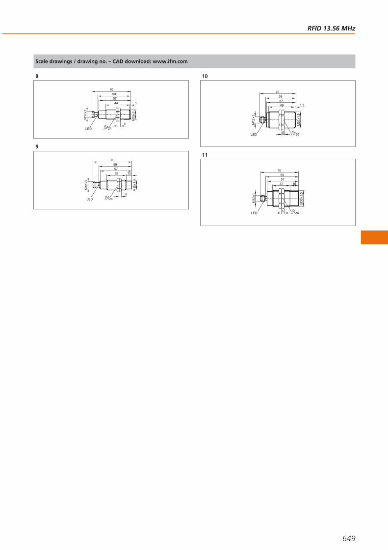
Scale drawings / drawing no. – CAD download: www.ifm.com
8M
12x1
4457
70
LED
59
24
4
1
M18
x1,5
9
M12
x1
3557
70
LED
59
10
24
4
M18
x1,5
10
59
49
M30
x1,5
57
70
M12
x1
LED
1,5
5 36
11
59
32
M30
x1,5
57
70
15
M12
x1
LED 5 36
RFID 13.56 MHz
649
Gesamtkatalog EN 2016_17_Stilvorlage LK FrutigerOT_2010 DE_GB.qxd 06.11.15 16:58 Seite 649

RFID UHF
The system is optimised for applications in production control, asset management,material flow control, track & trace and supply chain management:
- System DTE 800 for EU/ETSI
- System DTE 810 with Ethernet/IP
- System DTE 900 for US/FCC
- System DTE 910 with Ethernet/IP
RFID UHF readers
Type Dimensions
[mm]
Operatingfrequency
[MHz]
Trans-missionpower
[mW ERP]
Numberof antenna
inputs
Processinterface
Output Draw-ingno.
Orderno.
M12 connector · Connector groups 8, 10, 18, 20, 120, 124, 126, 128, 157
233.5 x 270 x 68865-868
(ETSI) 2000 4 Ethernet TCP/IP – 1 DTE800
233.5 x 270 x 68902...928
(FCC) 2000 4 Ethernet TCP/IP – 1 DTE900
233.5 x 270 x 68865-868
(ETSI) 2000 4 EtherNet/IP – 1 DTE810
233.5 x 270 x 68902...928
(FCC)2000 4 EtherNet/IP – 1 DTE910
M12 connector · Connector group --
– 865-868 (ETSI) 266 – Ethernet TCP/IP – 2 DTE820
System overview Page
RFID UHF readers 650
RFID UHF antennas 651
ID tags UHF 651
Accessories for UHF systems 652
Scale drawings / drawing no. – CAD download: www.ifm.com 652 - 653
Identification systems
650Product selectors and further information can be found at: www.ifm.com
Gesamtkatalog EN 2016_17_Stilvorlage LK FrutigerOT_2010 DE_GB.qxd 06.11.15 16:58 Seite 650

RFID UHF antennas
Type Dimensions
[mm]
Operatingfrequency
[MHz]
Antennagain
[cBic]
Max.input power
[mW]
Protection Draw-ingno.
Orderno.
TNC socket
63 x 28 x 90 865...928 -30 1000 IP 67 3 ANT805
63 x 28 x 90 865...870 -15 500 IP 67 3 ANT810
126 x 37 x 156 865...928-12 (866 MHz) /-10 (915 MHz)
– IP 67 4 ANT815
126 x 37 x 156 865...870 2.5 – IP 67 4 ANT820
271 x 270 x 42 865...870 8.5 – IP 65 5 ANT830
63 x 28 x 90902...928
(FCC)-15 500 IP 67 3 ANT910
271 x 270 x 42902...928
(FCC)8.3 – IP 65 5 ANT930
ID tags UHF
Type Description Orderno.
ID tag · ID-TAG/D50x3.3/04 · Ø 50 x 3.3 mm · Housing materials: PA 6 E80350
ID tag · ID-TAG/D55x13/04 · Ø 55 x 13 mm · Housing materials: PA 6 E80351
ID tag · ID-TAG/R30X10/04 · Ø 30 x 10 mm · Housing materials: PU black E80353
ID tag · ID-TAG/R40X10/04 · 40 x 32 x 8 mm · Housing materials: nylon black E80354
RFID UHF
651You can find scale drawings from page 652
Gesamtkatalog EN 2016_17_Stilvorlage LK FrutigerOT_2010 DE_GB.qxd 06.11.15 16:58 Seite 651
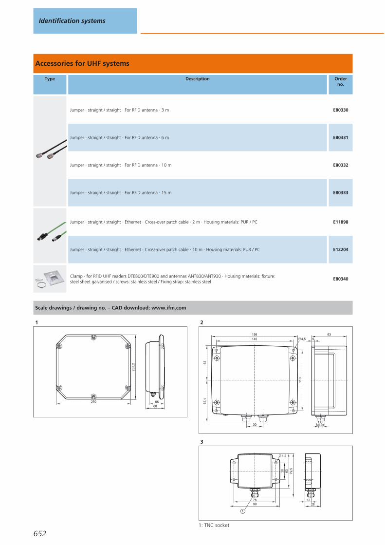
Accessories for UHF systems
Type Description Orderno.
Jumper · straight / straight · For RFID antenna · 3 m E80330
Jumper · straight / straight · For RFID antenna · 6 m E80331
Jumper · straight / straight · For RFID antenna · 10 m E80332
Jumper · straight / straight · For RFID antenna · 15 m E80333
Jumper · straight / straight · Ethernet · Cross-over patch cable · 2 m · Housing materials: PUR / PC E11898
Jumper · straight / straight · Ethernet · Cross-over patch cable · 10 m · Housing materials: PUR / PC E12204
Clamp · for RFID UHF readers DTE800/DTE900 and antennas ANT830/ANT930 · Housing materials: fixture: steel sheet galvanised / screws: stainless steel / Fixing strap: stainless steel
E80340
Scale drawings / drawing no. – CAD download: www.ifm.com
1
68270 55
233,
2
2
5
63
M12x1
110
6375
,1
140
156
30
4,5
3
90
30 63 79,5
1228
76
4,2
1: TNC socket
Identification systems
652
Gesamtkatalog EN 2016_17_Stilvorlage LK FrutigerOT_2010 DE_GB.qxd 06.11.15 16:58 Seite 652

Scale drawings / drawing no. – CAD download: www.ifm.com
4
156138
126
80
3715
148
4,2
1: TNC socket
5
27
14
2
271
236
12
29
10
0
10025 75
1: TNC socket
RFID UHF
653
Gesamtkatalog EN 2016_17_Stilvorlage LK FrutigerOT_2010 DE_GB.qxd 06.11.15 16:58 Seite 653

1D/2D code readers
Photoelectric multicode reader for 1D bar codes and 2D codes.Versions with infrared light and red light as well as different field of view sizes are available.
Multicode reader
Type Dimensions
[mm]
Max.field of
view size[mm]
Typeof light
LED
Motion speedint. / ext. lighting
[m/s]
Processinterface
Draw-ingno.
Orderno.
Multicode Reader · M12 plug, 8 poles · M12 socket, 4 poles · Connector groups 16, 17
60 x 42 x 53.5 64 x 48 red light 3 / 5Ethernet TCP/IP,
EtherNet/IP, RS-2321 O2I100
60 x 42 x 53.5 132 x 94 red light 3 / 5Ethernet TCP/IP,
EtherNet/IP, RS-2321 O2I102
60 x 42 x 59 400 x 300 red light 3 / 5Ethernet TCP/IP,
EtherNet/IP, RS-2322 O2I104
60 x 42 x 53.5 64 x 48 infrared 3 / 5Ethernet TCP/IP,
EtherNet/IP, RS-2321 O2I101
60 x 42 x 53.5 132 x 94 infrared 3 / 5Ethernet TCP/IP,
EtherNet/IP, RS-2321 O2I103
System overview Page
Multicode reader 654 - 655
Multicode reader with text recognition 655
Illumination units 656
Software 656
Panel PC for Multicode Reader 657
Fixing components 657 - 658
Protective panes and diffusers 658
Connection technology 658
Wiring diagrams 659
Scale drawings / drawing no. – CAD download: www.ifm.com 659 - 660
Identification systems
654Product selectors and further information can be found at: www.ifm.com
Gesamtkatalog EN 2016_17_Stilvorlage LK FrutigerOT_2010 DE_GB.qxd 06.11.15 16:58 Seite 654

Type Dimensions
[mm]
Max.field of
view size[mm]
Typeof light
LED
Motion speedint. / ext. lighting
[m/s]
Processinterface
Draw-ingno.
Orderno.
Multicode Reader · M12 plug, 8 poles · M12 socket, 4 poles · Connector groups 16, 17
60 x 42 x 59 400 x 300 infrared 3 / 5Ethernet TCP/IP,
EtherNet/IP, RS-2322 O2I105
60 x 42 x 53.5 64 x 48 red light 3 / 5Ethernet TCP/IP,
EtherNet/IP, RS-2321 O2I300
60 x 42 x 53.5 132 x 94 red light 3 / 5Ethernet TCP/IP,
EtherNet/IP, RS-2321 O2I302
60 x 42 x 59 400 x 300 red light 3 / 5Ethernet TCP/IP,
EtherNet/IP, RS-2322 O2I304
60 x 42 x 53.5 64 x 48 infrared 3 / 5Ethernet TCP/IP,
EtherNet/IP, RS-2321 O2I301
60 x 42 x 53.5 132 x 94 infrared 3 / 5Ethernet TCP/IP,
EtherNet/IP, RS-2321 O2I303
60 x 42 x 59 400 x 300 infrared 3 / 5Ethernet TCP/IP,
EtherNet/IP, RS-2322 O2I305
Multicode reader with text recognition
Type Dimensions
[mm]
Max.field of
view size[mm]
Typeof light
LED
Motion speedint. / ext. lighting
[m/s]
Processinterface
Draw-ingno.
Orderno.
Multicode Reader · M12 plug, 8 poles · M12 socket, 4 poles · Connector groups 16, 17
60 x 42 x 53.5 – red light 3 / 5 Ethernet 1 O2I350
60 x 42 x 53.5 – red light 3 / 5 Ethernet 1 O2I352
60 x 42 x 59 – red light 3 / 5 Ethernet 2 O2I354
60 x 42 x 53.5 – infrared 3 / 5 Ethernet 1 O2I351
60 x 42 x 53.5 – infrared 3 / 5 Ethernet 1 O2I353
60 x 42 x 59 – infrared 3 / 5 Ethernet 2 O2I355
1D/2D code readers
655You can find wiring diagrams and scale drawings from page 659
Gesamtkatalog EN 2016_17_Stilvorlage LK FrutigerOT_2010 DE_GB.qxd 06.11.15 16:58 Seite 655

Illumination units
Type Dimensions
[mm]
Typeof light
Activeilluminated
area[mm]
I0normal light
intensity[mA]
I0high lightintensity
[mA]
Trigger Draw-ingno.
Orderno.
M12 connector · metal · DC · Wiring diagram no. 1 · Connector groups 8, 10, 18, 20, 120, 124, 126, 128, 157
42 x 42 x 31 Red – 180 90External; 24 V PNP to
IEC61131-13 O2D909
42 x 42 x 32.2 Red – 180 90External; 24 V PNP to
IEC61131-14 O2D913
PUR cable with M12 connector 0.3 m · metal · DC · Wiring diagram no. 1 · Connector groups 8, 10, 18, 20, 120, 124, 126, 128, 157
Ø 122 / L = 20.5 Infrared – 800 1400 external; 24 V PNP 5 O2D917
116 x 13 x 18 Infrared – 185 325 external; 24 V PNP 6 O2D922
200 x 13 x 18 Infrared – 415 640 external; 24 V PNP 7 O2D925
Software
Type Description Number ofconnections
Orderno.
Operating software · O2I · for multicode reader · Create and manage application-specific configurationsMonitor mode for set-up and service Service reports for statistical evaluations
– E2I200
Multicode reader OPC server · Software · German/English 25 E2I210
Multicode reader OPC server · Software · German/English 50 E2I211
Multicode reader OPC server · Software · German/English 75 E2I212
Multicode reader OPC server · Software · German/English 100 E2I213
Identification systems
656Product selectors and further information can be found at: www.ifm.com
Gesamtkatalog EN 2016_17_Stilvorlage LK FrutigerOT_2010 DE_GB.qxd 06.11.15 16:58 Seite 656

Panel PC for Multicode Reader
Type Description Orderno.
Touch Panel PC · 12.1" colour display · Intel Atom CPU 1.6 GHz · 2 GByte RAM · Windows Embedded Standard 7 SP1 (32 bits) E2D400
Fixing components
Type Description Orderno.
Mounting set · O2D, O2M, O2I, O2V · Clamp mounting · rod mounting Ø 12 mm · Housing materials: fixture: stainless steel / clamp: stainless steel
E2D110
Mounting set · O2D, O2M, O2I, O2V · Clamp mounting · rod mounting Ø 14 mm · Housing materials: fixture: stainless steel / clamp: stainless steel
E2D112
Mounting set · Bar light · Clamp mounting · Housing materials: Mounting bracket: stainless steel / clamp: high-grade stainless steel
E2D114
Mounting set · Bar light · Clamp mounting · for 4 bar lights 10x75 mm · Housing materials: Mounting bracket: stainless steel /clamp: high-grade stainless steel
E2D116
Mounting set · Ring light · Clamp mounting · Housing materials: Mounting bracket: stainless steel / clamp: high-grade stainless steel E2D201
clamp · Ø 12 mm; M10 · Free-standing M10 · Housing materials: clamp: stainless steel E20946
clamp · Ø 12 mm · rod mounting Ø 12 mm · Housing materials: clamp: stainless steel E21110
clamp · Ø 14 mm; M12 · free-standing M12 · Housing materials: clamp: stainless steel E20948
clamp · Ø 14 mm · rod mounting Ø 14 mm · Housing materials: clamp: stainless steel E21109
mounting rod · Ø 12 · Length: 200 mm · straight · Housing materials: stainless steel 316Ti / 1.4571 E21112
mounting rod · Ø 12 · Length: 300 mm · straight · Housing materials: stainless steel 316Ti / 1.4571 E21113
mounting rod · Ø 12 / M10 · Length: 130 mm · straight · Housing materials: stainless steel 316Ti / 1.4571 E20938
1D/2D code readers
657You can find wiring diagrams and scale drawings from page 659
Gesamtkatalog EN 2016_17_Stilvorlage LK FrutigerOT_2010 DE_GB.qxd 06.11.15 16:58 Seite 657

Type Description Orderno.
mounting rod · Ø 12 / M10 · Length: 200 mm · angled · Housing materials: stainless steel 316Ti / 1.4571 E20940
mounting rod · Ø 14 / M12 · Length: 130 mm · straight · Housing materials: stainless steel 316Ti / 1.4571 E20939
mounting rod · Ø 14 / M12 · Length: 200 mm · angled · Housing materials: stainless steel 316Ti / 1.4571 E20941
Connection piece · Ø 20 mm · for the connection of two clamps with Ø 20 mm · Housing materials: stainless steel 316L / 1.4404 E21076
Protective panes and diffusers
Type Description Orderno.
Plastic diffuser · O2D / O2I · Housing materials: housing: diecast zinc black / lens: PMMA E21165
Plastic protective pane for the food industry · O2D / O2I · Housing materials: housing: diecast zinc black / lens: PMMA E21166
Glass protective pane · O2D / O2I · Housing materials: housing: diecast zinc black / lens: float glass E21168
Laser protection pane plastic · O2D / O2I · Housing materials: housing: diecast zinc black / lens: PMMA / filter: polycarbonate E21169
Connection technology
Type Description Orderno.
Jumper · straight / straight · Ethernet · Cross-over patch cable · 2 m · Housing materials: PUR / PC E11898
Jumper · straight / straight · Ethernet · Patch cable · 2 m · Housing materials: PUR / PC E12090
Jumper · straight / straight · Ethernet · Cross-over patch cable · 10 m · Housing materials: PUR / PC E12204
Jumper · straight / straight · Ethernet · Cross-over patch cable · 20 m · Housing materials: PUR / PC E12205
Identification systems
658Product selectors and further information can be found at: www.ifm.com
Gesamtkatalog EN 2016_17_Stilvorlage LK FrutigerOT_2010 DE_GB.qxd 06.11.15 16:58 Seite 658

Wiring diagrams
1
L+
L
1
4
2
3
1: Trigger, 2: Operating mode"high light intensity"
Scale drawings / drawing no. – CAD download: www.ifm.com
1
M12x1
2
19
M12x1
53,5
4,8
20,5
44,2
19,7
33
1
45
24,5
42
57
8060
21
9,5
7
3
1: display, 2: Focus adjustment screw, 3: Centre of the lens axes
2
M12x1
2
19
M12x1
59
4,8
20,5
49,5
25,2
38,5
1
45
24,5
42
57
8060
21
9,5
7
3
1: display, 2: Focus adjustment screw, 3: Centre of the lens axes
3
31
4,3
14
30
LED
24M12 x1
54
LED
42
4
32,2
4,3
14
30
LED
24M12 x1
54
LED
42
5
80
LED
3035 M4x6
60
20,5
122
6
13
1
116
5030
155
111,
6
18
4M4
3,2
3 LED
1D/2D code readers
659
Gesamtkatalog EN 2016_17_Stilvorlage LK FrutigerOT_2010 DE_GB.qxd 06.11.15 16:58 Seite 659
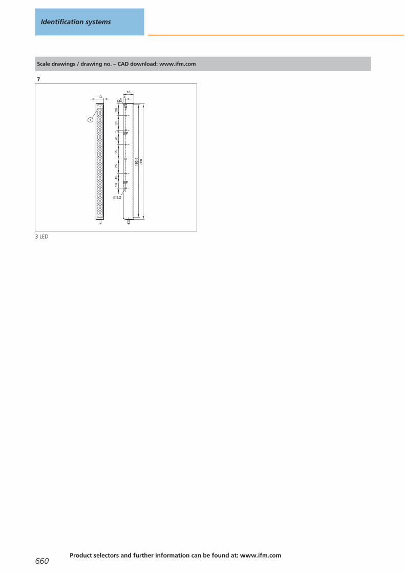
Scale drawings / drawing no. – CAD download: www.ifm.com
7
13
1
200
2025
205
25
195,
6
18
4M4
2510
15
3,2
3 LED
Identification systems
660Product selectors and further information can be found at: www.ifm.com
Gesamtkatalog EN 2016_17_Stilvorlage LK FrutigerOT_2010 DE_GB.qxd 06.11.15 16:58 Seite 660

1D/2D code readers
661
Gesamtkatalog EN 2016_17_Stilvorlage LK FrutigerOT_2010 DE_GB.qxd 06.11.15 16:58 Seite 661
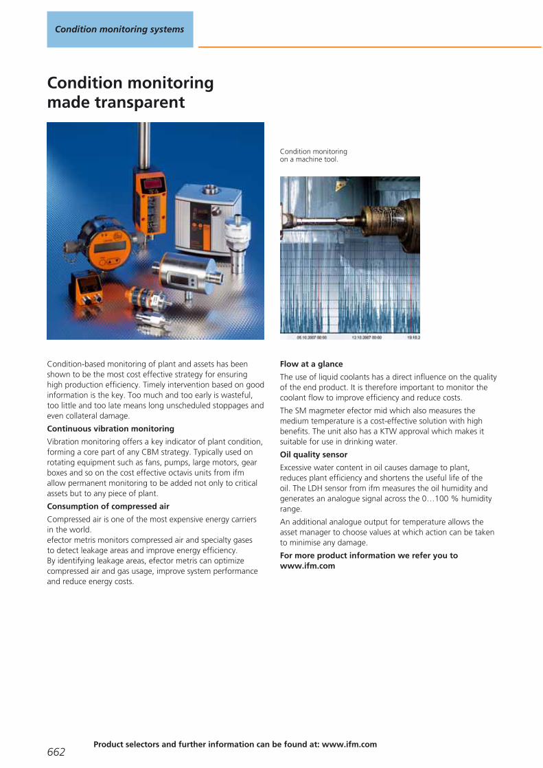
Condition monitoringmade transparent
Condition monitoringon a machine tool.
Condition-based monitoring of plant and assets has beenshown to be the most cost effective strategy for ensuringhigh production efficiency. Timely intervention based on goodinformation is the key. Too much and too early is wasteful,too little and too late means long unscheduled stoppages andeven collateral damage.
Continuous vibration monitoring
Vibration monitoring offers a key indicator of plant condition,forming a core part of any CBM strategy. Typically used onrotating equipment such as fans, pumps, large motors, gearboxes and so on the cost effective octavis units from ifmallow permanent monitoring to be added not only to criticalassets but to any piece of plant.
Consumption of compressed air
Compressed air is one of the most expensive energy carriersin the world.efector metris monitors compressed air and specialty gasesto detect leakage areas and improve energy efficiency.By identifying leakage areas, efector metris can optimizecompressed air and gas usage, improve system performanceand reduce energy costs.
Flow at a glance
The use of liquid coolants has a direct influence on the qualityof the end product. It is therefore important to monitor thecoolant flow to improve efficiency and reduce costs.
The SM magmeter efector mid which also measures themedium temperature is a cost-effective solution with highbenefits. The unit also has a KTW approval which makes itsuitable for use in drinking water.
Oil quality sensor
Excessive water content in oil causes damage to plant,reduces plant efficiency and shortens the useful life of theoil. The LDH sensor from ifm measures the oil humidity andgenerates an analogue signal across the 0…100 % humidityrange.
An additional analogue output for temperature allows theasset manager to choose values at which action can be takento minimise any damage.
For more product information we refer you towww.ifm.com
Condition monitoring systems
662Product selectors and further information can be found at: www.ifm.com
Gesamtkatalog EN 2016_17_Stilvorlage LK FrutigerOT_2010 DE_GB.qxd 06.11.15 16:58 Seite 662
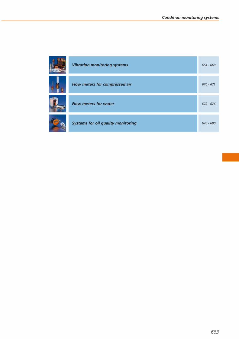
Condition monitoring systems
663
Vibration monitoring systems 664 - 669
Flow meters for compressed air 670 - 671
Flow meters for water 672 - 676
Systems for oil quality monitoring 678 - 680
Gesamtkatalog EN 2016_17_Stilvorlage LK FrutigerOT_2010 DE_GB.qxd 06.11.15 16:58 Seite 663

Vibration monitoring systems
efector octavis is a simple to implement vibration monitoring system which detectsvibration data and automatically determines the machine diagnosis directly on themachine.
The machine condition is forwarded to the PLC or to SCADA systems.
It fulfils the main requirements for modern machine monitoring: compatibility,modularity, and transferable configuration.
Vibration sensors for vibration monitoring of machines and plants to ISO 10816 type VK
Type Description Draw-ingno.
Orderno.
Vibration monitor to DIN ISO 10816 · Measuring range RMS: 0...25 mm/s · Switching output NC DC PNP and analogueoutput 4...20 mA · 2 Inputs / outputs total · Measuring range 0...25 RMS mm/s · Frequency range 10...1000 Hz · Ambient
temperature -30...125 °C · M12 connector · Operating voltage 18...32 V DC · IP 671 VKV021
Vibration monitor to DIN ISO 10816 · Measuring range RMS: 0...50 mm/s · Switching output NC DC PNP and analogueoutput 4...20 mA · 2 Inputs / outputs total · Measuring range 0...50 RMS mm/s · Frequency range 10...1000 Hz · Ambient
temperature -30...125 °C · M12 connector · Operating voltage 18...32 V DC · IP 671 VKV022
System overview Page
Vibration sensors for vibration monitoring of machines and plants to ISO 10816 type VK 664
Accessories VK 665
Vibration transmitters for vibration monitoring of machines and plants to ISO 10816 type VT 665
Vibration transmitter with ATEX approval 3D/3G 665
Compact vibration sensors type VN 665
Accessories VN 665 - 666
Diagnostic electronics – control cabinet modules for vibration diagnosis type VSE 666
Accessories VSE 666
Connection cables VSE 666 - 667
Vibration sensors for connection to external diagnostic electronics VSE – type VSA / VSP 667
Accessories VSA 667
Scale drawings / drawing no. – CAD download: www.ifm.com 668 - 669
Condition monitoring systems
664Product selectors and further information can be found at: www.ifm.com
Gesamtkatalog EN 2016_17_Stilvorlage LK FrutigerOT_2010 DE_GB.qxd 06.11.15 16:58 Seite 664
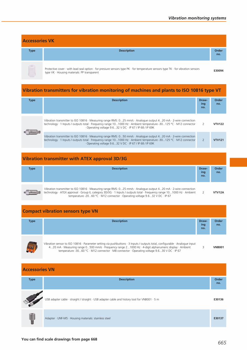
Accessories VK
Type Description Orderno.
Protective cover · with lead seal option · for pressure sensors type PK · for temperature sensors type TK · for vibration sensors type VK · Housing materials: PP transparent
E30094
Vibration transmitters for vibration monitoring of machines and plants to ISO 10816 type VT
Type Description Draw-ingno.
Orderno.
Vibration transmitter to ISO 10816 · Measuring range RMS: 0...25 mm/s · Analogue output 4...20 mA · 2-wire connectiontechnology · 1 Inputs / outputs total · Frequency range 10...1000 Hz · Ambient temperature -30...125 °C · M12 connector
· Operating voltage 9.6...32 V DC · IP 67 / IP 68 / IP 69K2 VTV122
Vibration transmitter to ISO 10816 · Measuring range RMS: 0...50 mm/s · Analogue output 4...20 mA · 2-wire connectiontechnology · 1 Inputs / outputs total · Frequency range 10...1000 Hz · Ambient temperature -30...125 °C · M12 connector
· Operating voltage 9.6...32 V DC · IP 67 / IP 68 / IP 69K2 VTV121
Vibration transmitter with ATEX approval 3D/3G
Type Description Draw-ingno.
Orderno.
Vibration transmitter to ISO 10816 · Measuring range RMS: 0...25 mm/s · Analogue output 4...20 mA · 2-wire connectiontechnology · ATEX approval · Group II, category 3D/3G · 1 Inputs / outputs total · Frequency range 10...1000 Hz · Ambient
temperature -20...60 °C · M12 connector · Operating voltage 9.6...32 V DC · IP 672 VTV12A
Compact vibration sensors type VN
Type Description Draw-ingno.
Orderno.
Vibration sensor to ISO 10816 · Parameter setting via pushbuttons · 3 Inputs / outputs total, configurable · Analogue input4...20 mA · Measuring range 0...500 mm/s · Frequency range 2...1000 Hz · 4-digit alphanumeric display · Ambient
temperature -30...60 °C · M12 connector · M8 connector · Operating voltage 9.6...30 V DC · IP 673 VNB001
Accessories VN
Type Description Orderno.
USB adapter cable · straight / straight · USB adapter cable and history tool for VNB001 · 5 m E30136
Adapter · UNF-M5 · Housing materials: stainless steel E30137
Vibration monitoring systems
665You can find scale drawings from page 668
Gesamtkatalog EN 2016_17_Stilvorlage LK FrutigerOT_2010 DE_GB.qxd 06.11.15 16:58 Seite 665

Type Description Orderno.
Power supply · 2 m · Housing materials: PPE E30080
Diagnostic electronics – control cabinet modules for vibration diagnosis type VSE
Type Description Draw-ingno.
Orderno.
Diagnostics electronics for vibration sensors type VSA / VSP · Mounting on DIN rail · 4 sensor inputs 0...10 mA or IEPE ·TCP/IP Ethernet interface · Frequency-selective machine monitoring of up to 4 measuring points · Integrated historymemory with real-time clock · Counter function · 6 Inputs / outputs total, configurable · Analogue input 0...10 mA /
IEPE · Ambient temperature 0...70 °C · Operating voltage 24 V DC ± 20 % · IP 20
4 VSE002
Diagnostic electronics for vibration sensors · Mounting on DIN rail · Integrated history memory with real-time clock ·Counter function · TCP/IP Ethernet interface · Active wire break detection and self-test (only MEMS) of the connectedacceleration sensors · Parameter setting via PC software VES004 · 16 Inputs / outputs total, configurable · Ambient
temperature 0...70 °C · Operating voltage 24 V DC ± 20 % · IP 20
5 VSE100
Accessories VSE
Type Description Number ofconnections
Orderno.
Parametriersoftware für VSExxx und VNBxxx – VES004
octavis OPC server · Software · German/English 25 VOS001
octavis OPC server · Software · German/English 50 VOS002
octavis OPC server · Software · German/English 75 VOS003
octavis OPC server · Software · German/English 100 VOS004
octavis OPC server · Software · German/English 1000 VOS005
Connection cables VSE
Type Description Orderno.
Jumper · straight / straight · Ethernet · Cross-over patch cable · 5 m · Housing materials: PUR E30112
Condition monitoring systems
666 Product selectors and further information can be found at: www.ifm.com
Gesamtkatalog EN 2016_17_Stilvorlage LK FrutigerOT_2010 DE_GB.qxd 06.11.15 16:58 Seite 666

Type Description Orderno.
Jumper · straight / straight · Ethernet · Cross-over patch cable · 2 m · Housing materials: PUR EC2080
Vibration sensors for connection to external diagnostic electronics VSE – type VSA / VSP
Type Description Draw-ingno.
Orderno.
Accelerometer · for connection to external diagnostic electronics type VSE · Measuring range ± 25 g · Frequency range0...6000 Hz · Ambient temperature -30...125 °C · M12 connector · Operating voltage 7.2...10.8 V DC · IP 68 / IP 69K
6 VSA001
Accelerometer · for connection to external diagnostic electronics type VSE · Measuring range ± 3.3 g · Frequency range0...1000 Hz · Ambient temperature -30...125 °C · M12 connector · Operating voltage 9 V DC · IP 68 / IP 69K
6 VSA101
Accelerometer · for connection to external diagnostic electronics type VSE · Measuring range ± 250 g · Frequency range0...6000 Hz · Ambient temperature -30...125 °C · M12 connector · Operating voltage 9 V DC · IP 68 / IP 69K
6 VSA201
Accelerometer · for connection to external diagnostic electronics type VSE · Measuring range ± 25 g · Frequency range0...10000 Hz · Ambient temperature -30...85 °C · PUR cable with M12 connector, 0.8 m · Operating voltage 9 V DC ·
IP 677 VSA002
Accelerometer · for connection to external diagnostic electronics type VSE · Measuring range ± 25 g · Frequency range0...10000 Hz · Ambient temperature -30...85 °C · PUR cable, 6 m · Operating voltage 9 V DC · IP 67
7 VSA006
Accelerometer · for connection to external diagnostic electronics type VSE · Measuring range ± 25 g · Frequency range0...10000 Hz · Ambient temperature -30...100 °C · PUR cable, 3 m · Operating voltage 9 V DC · IP 67
8 VSA004
Accelerometer · for connection to external diagnostic electronics type VSE · Measuring range ± 25 g · Frequency range0...10000 Hz · Ambient temperature -30...100 °C · PUR cable, 10 m · Operating voltage 9 V DC · IP 67
8 VSA005
Accelerometer · for connection to external diagnostic electronics type VSE · Measuring range ± 50 g · Frequency range2...10000 ± 5% Hz · Ambient temperature -55...125 °C · M12 connector · Operating voltage 10...12 V DC · IP 67
9 VSP001
Accelerometer · ATEX approval · Group II, category 1D · Group II, category 1G · For connection to VSExxx type externaldiagnostic electronics via safety barrier · Measuring range ± 80 g · Frequency range 2...10000 Hz · Ambient temperature -
55...90 °C · PUR cable, 10 m · Operating voltage 10...12 V DC · IP 6810 VSP01A
Accelerometer · ATEX approval · group 1, M1 · For connection to VSExxx type external diagnostic electronics via safetybarrier · Measuring range ± 80 g · Frequency range 2...10000 Hz · Ambient temperature -55...90 °C · PUR cable, 10 m ·
Operating voltage 10...12 V DC · IP 6810 VSP02A
Accessories VSA
Type Description Orderno.
conical washer · Ø 8.4 / 15 mm · for vibration sensors VSA001, VSA101, VSA201 · Housing materials: stainless steel 316Ti / 1.4571 E30115
Adapter · M8-M8 · for vibration sensors VSA001, VSA101, VSA201 · Electrical isolation · Housing materials: PEEK E30132
Vibration monitoring systems
667You can find scale drawings from page 668
Gesamtkatalog EN 2016_17_Stilvorlage LK FrutigerOT_2010 DE_GB.qxd 06.11.15 16:58 Seite 667

Scale drawings / drawing no. – CAD download: www.ifm.com
1
63,7
11
M12 x127
27
73,1
M81
1: tightening torque 15 Nm
2
M12 x1
22
63,2
5
2
1/4''-28 UNF
22
5
14 15,9
16,8
1: Threaded adapter 1/4"-28 UNF / M8 x 1.25 mm, 2: Threadedadapter 1/4"-28 UNF, tightening torque 8 Nm
3
M12
x1
5162,4
14
65,3
36
20M5
37,6
5
10
4
5,3
M8
x1
4
103,4
35,5
25,4
100
1
LEDs
1: Ethernet interface
5
50
114
LEDs
2
1
105
35,5
1: Ethernet interface, 2: Combicon plug with screw terminals(optional)
6
18,5
M8
x1,2
5
M12
x117
5324
178
1
1: conical angle = 90°
7
13
M16
x1,5
142218
5
8
18
11,5
13,5
L
5,5
9
M12 x1
18,9
46,5
35,7
5
1/4''-28 UNF
19
Condition monitoring systems
668Product selectors and further information can be found at: www.ifm.com
Gesamtkatalog EN 2016_17_Stilvorlage LK FrutigerOT_2010 DE_GB.qxd 06.11.15 16:58 Seite 668

Scale drawings / drawing no. – CAD download: www.ifm.com
10
23,5
64,725
,5
47,5
37
305
M8x1,25
Vibration monitoring systems
669
Gesamtkatalog EN 2016_17_Stilvorlage LK FrutigerOT_2010 DE_GB.qxd 06.11.15 16:58 Seite 669

Flow meters for compressed air
efector metris is used to measure the consumption of compressed air. The highmeasurement dynamics in conjunction with high measurement accuracy and a fastresponse time result in an application range from leakage detection to operationalmeasurement of consumption. Many possibilities of supplying the values measuredfor current and temperature allow almost universal coupling to process or controlsystems.
Compressed air meters
Type Processconnection
Setting range
[Nm3/h]
Pressure rating
[bar]
Response time
[s]
Ub
[V]
Draw-ingno.
Orderno.
Output function OUT1: normally open / closed programmable or pulse OUT2: normally open / closed programmable or analogue(4...20 mA scaleable) · Wiring diagram no. 1 · Connector groups 8, 10, 18, 20, 120, 124, 126, 128, 157
G ¼ (DN8) 0.12...15.00 16 < 0.1 18...30 1 SD5000
R½ (DN15) 0.6...75.0 16 < 0.1 18...30 2 SD6000
G ½ (DN15) 0.6...75 16 < 0.1 18...30 3 SD6050
R1 (DN25) 1.8...225.0 16 < 0.1 18...30 4 SD8000
R1½ (DN40) 3.5...410.0 16 < 0.1 18...30 5 SD9000
R2 (DN50) 5...700 16 < 0.1 18...30 6 SD2000
Output function OUT1: normally open / closed programmable or pulse OUT2: normally open / closed programmable or analogue(4...20 mA scaleable) · Wiring diagram no. 2 · Connector groups 8, 10, 18, 20, 120, 124, 126, 128, 157
G 1 I 18…2110 16 < 0.1 18...30 7 SD0523
System overview Page
Compressed air meters 670
Wiring diagrams 671
Scale drawings / drawing no. – CAD download: www.ifm.com 671
Condition monitoring systems
670Product selectors and further information can be found at: www.ifm.com
Gesamtkatalog EN 2016_17_Stilvorlage LK FrutigerOT_2010 DE_GB.qxd 06.11.15 16:58 Seite 670
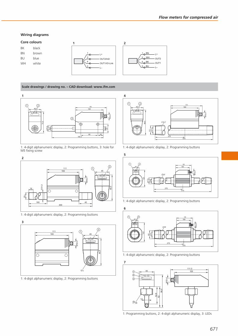
Core colours
BK black
BN brown
BU blue
WH white
Wiring diagrams
1
3
1
4
2
2
BN
WH
BK
BU
4
1
3
2 OUT2
L+
L
OUT1
Scale drawings / drawing no. – CAD download: www.ifm.com
1
182,3
21,3
M12
x1100
111
74,5
G1
4 /
45
1 2G
14 /
60 20
31
3
1: 4-digit alphanumeric display, 2: Programming buttons, 3: hole forM5 fixing screw
2
45
80,4
100111
M12
x1
R2
1
14
160 40300
21,3
1: 4-digit alphanumeric display, 2: Programming buttons
3
G 21
45
80,4
100111
M12
x1
1: 4-digit alphanumeric display, 2: Programming buttons
4
475375
27,3
33,7
R 1
M12
x1
100111
88,5
45
1 2
1: 4-digit alphanumeric display, 2: Programming buttons
5
39
R11
2
275475
42
100111
M12
x1
120
45
1 2
1: 4-digit alphanumeric display, 2: Programming buttons
6
133
45
1 2
54
R2 51
100111
M12
x1
275475
1: 4-digit alphanumeric display, 2: Programming buttons
7
111,5
96,5
451
2
3
6252,8
12
100
M12
x1
36
1: Programming buttons, 2: 4-digit alphanumeric display, 3: LEDs
Flow meters for compressed air
671
Gesamtkatalog EN 2016_17_Stilvorlage LK FrutigerOT_2010 DE_GB.qxd 06.11.15 16:58 Seite 671

Flow meters for water
Efforts to reduce water consumption presuppose knowledge of the currentconsumption. Measuring systems such as magnetic-inductive or ultrasound flowmeters can also be used for applications in drinking water circuits due to their com-pact design. The use in drinking water supply is ensured by the use of approvedmaterials. Many possibilities of supplying the values measured for current and tem-perature allow almost universal coupling to process or control systems.
Magnetic-inductive flow meters with integrated temperature monitoring (sealing material EPDM) KTW / W270 approval
Type Processconnection
Measuringrange
[l/min]
Mediumtemperature
[°C]
Pressurerating
[bar]
Responsetime
[s]
Ub
[V]
Draw-ingno.
Orderno.
Output function OUT1: normally open / normally closed programmable or pulse or frequency or empty pipe detection or IO-LinkOUT2: normally open / normally closed programmable or analogue (4...20 mA; 0...10 V, scalable) or empty pipe detection · Wiring diagram no. 1 · Connector groups 8, 10, 12, 13, 18, 19, 20, 21, 120, 122, 124, 126, 128, 130, 132, 157, 159
G2 flat seal 8...600 -10...70 16 < 0.35 18...32 1 SM2100
Output function OUT1: normally open / closed programmable or pulse OUT2: normally open / closed programmable or analogue(4...20 mA / 0...10 V, scaleable) · Wiring diagram no. 1 · Connector groups 8, 10, 18, 20, 120, 124, 126, 128, 157
G½ 0.25...25.00 -10...70 16 < 0.150 19...30 2 SM6100
G¾ 0.5...50.0 -10...70 16 < 0.150 19...30 3 SM7100
G1 0.7...100.0 -10...70 16 < 0.150 19...30 4 SM8100
Output function OUT1: normally open / normally closed programmable or pulse or frequency or empty pipe detection or IO-LinkOUT2: normally open / normally closed programmable or analogue (4...20 mA; 0...10 V, scalable) or empty pipe detection · Wiring diagram no. 1 · Connector groups 8, 10, 12, 13, 18, 19, 20, 21, 120, 122, 124, 126, 128, 130, 132, 157, 159
G2 flat seal 6.5...300 -10...70 16 < 0.35 18...32 1 SM9100
System overview Page
Magnetic-inductive flow meters with integrated temperature monitoring (sealing material EPDM) KTW / W270 approval 672
Ultrasonic flow meters for liquids (water, glycol solutions, oils) 673
Accessories for flow meters 673 - 675
Grounding clamps for magnetic-inductive flow meters 675
Wiring diagrams 675
Scale drawings / drawing no. – CAD download: www.ifm.com 676
Condition monitoring systems
672Product selectors and further information can be found at: www.ifm.com
Gesamtkatalog EN 2016_17_Stilvorlage LK FrutigerOT_2010 DE_GB.qxd 06.11.15 16:58 Seite 672

Ultrasonic flow meters for liquids (water, glycol solutions, oils)
Type Processconnection
Measuringrange
[l/min]
Mediumtemperature
[°C]
Pressurerating
[bar]
Responsetime
[s]
Ub
[V]
Draw-ingno.
Orderno.
Output function 2 x normally open / closed programmable · Wiring diagram no. 2 · Connector groups 8, 10, 18, 20, 120, 124, 126,128, 157
G¾ 0.1...50.0 -10...80 16 < 0.250 19...30 5 SU7200
G1 0.2...100.0 -10...80 16 < 0.250 19...30 6 SU8200
Output function OUT1: normally open / closed programmable or pulse OUT2: normally open / closed programmable or analogue(4...20 mA / 0...10 V, scaleable) · Wiring diagram no. 3 · Connector groups 8, 10, 18, 20, 120, 124, 126, 128, 157
G¾ 0.1...50.0 -10...80 16 < 0.250 19...30 5 SU7000
G1 0.2...100.0 -10...80 16 < 0.250 19...30 6 SU8000
G1¼ 0.4...200.0 -10...80 16 < 0.250 19...30 7 SU9000
Output function 2 x analogue (4...20 mA scalable) · Wiring diagram no. 4 · Connector groups 8, 10, 18, 20, 120, 124, 126, 128, 157
G1¼ 0.0...200.0 -10...80 16 < 0.250 19...30 7 SU9004
Accessories for flow meters
Type Description Orderno.
Adapter · G ½ - R ½ · for flow monitor type SM6 · flat seal · Housing materials: stainless steel 316Ti / 1.4571 E40199
Adapter · G ½ - G ¾ · for flow monitor type SM6 · flat seal · Housing materials: stainless steel 316L / 1.4404 E40189
Adapter · G ¾ - R ½ · for flow monitor type SM7 / SU7 · Housing materials: stainless steel 316L / 1.4404 E40178
Adapter · G 1 - R ½ · for flow monitor type SM8 / SU8 · Housing materials: stainless steel 316L / 1.4404 E40179
Adapter · G 1 - R ¾ · for flow monitor type SM8 / SU8 · Housing materials: stainless steel 316L / 1.4404 E40180
Flow meters for water
673You can find wiring diagrams and scale drawings from page 675
Gesamtkatalog EN 2016_17_Stilvorlage LK FrutigerOT_2010 DE_GB.qxd 06.11.15 16:58 Seite 673
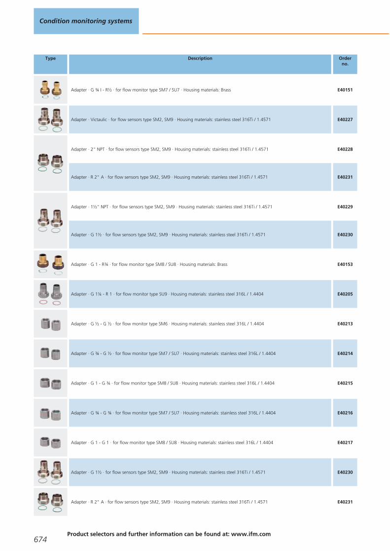
Type Description Orderno.
Adapter · G ¾ I - R½ · for flow monitor type SM7 / SU7 · Housing materials: Brass E40151
Adapter · Victaulic · for flow sensors type SM2, SM9 · Housing materials: stainless steel 316Ti / 1.4571 E40227
Adapter · 2" NPT · for flow sensors type SM2, SM9 · Housing materials: stainless steel 316Ti / 1.4571 E40228
Adapter · R 2" A · for flow sensors type SM2, SM9 · Housing materials: stainless steel 316Ti / 1.4571 E40231
Adapter · 1½" NPT · for flow sensors type SM2, SM9 · Housing materials: stainless steel 316Ti / 1.4571 E40229
Adapter · G 1½ · for flow sensors type SM2, SM9 · Housing materials: stainless steel 316Ti / 1.4571 E40230
Adapter · G 1 - R¾ · for flow monitor type SM8 / SU8 · Housing materials: Brass E40153
Adapter · G 1¼ - R 1 · for flow monitor type SU9 · Housing materials: stainless steel 316L / 1.4404 E40205
Adapter · G ½ - G ½ · for flow monitor type SM6 · Housing materials: stainless steel 316L / 1.4404 E40213
Adapter · G ¾ - G ½ · for flow monitor type SM7 / SU7 · Housing materials: stainless steel 316L / 1.4404 E40214
Adapter · G 1 - G ¾ · for flow monitor type SM8 / SU8 · Housing materials: stainless steel 316L / 1.4404 E40215
Adapter · G ¾ - G ¾ · for flow monitor type SM7 / SU7 · Housing materials: stainless steel 316L / 1.4404 E40216
Adapter · G 1 - G 1 · for flow monitor type SM8 / SU8 · Housing materials: stainless steel 316L / 1.4404 E40217
Adapter · G 1½ · for flow sensors type SM2, SM9 · Housing materials: stainless steel 316Ti / 1.4571 E40230
Adapter · R 2" A · for flow sensors type SM2, SM9 · Housing materials: stainless steel 316Ti / 1.4571 E40231
Condition monitoring systems
674Product selectors and further information can be found at: www.ifm.com
Gesamtkatalog EN 2016_17_Stilvorlage LK FrutigerOT_2010 DE_GB.qxd 06.11.15 16:58 Seite 674

Type Description Orderno.
Flange adapter · Adapter · rotatable · for type SM2, SM9 · Housing materials: flange: stainless steel / adapter:stainless steel 316Ti / 1.4571 / O-ring: EPDM
E40240
Grounding clamps for magnetic-inductive flow meters
Type Description Orderno.
Grounding clamp · Housing materials: stainless steel 316L / 1.4404 E40234
Core colours
BK black
BN brown
BU blue
WH white
Wiring diagrams
1
BN
WH
BK
BU
4
1
3
2 OUT2
L+
L
OUT1
2
2
L
L+
4
1
3Out 1Out 2
4:2:
3
4
1
3
2 OUT2/InD
L+
L
BN
BU
OUT1
WH
BK
4
L+
LOUT1OUT2
4:2:
4
2
1
3
Flow meters for water
675
Gesamtkatalog EN 2016_17_Stilvorlage LK FrutigerOT_2010 DE_GB.qxd 06.11.15 16:58 Seite 675
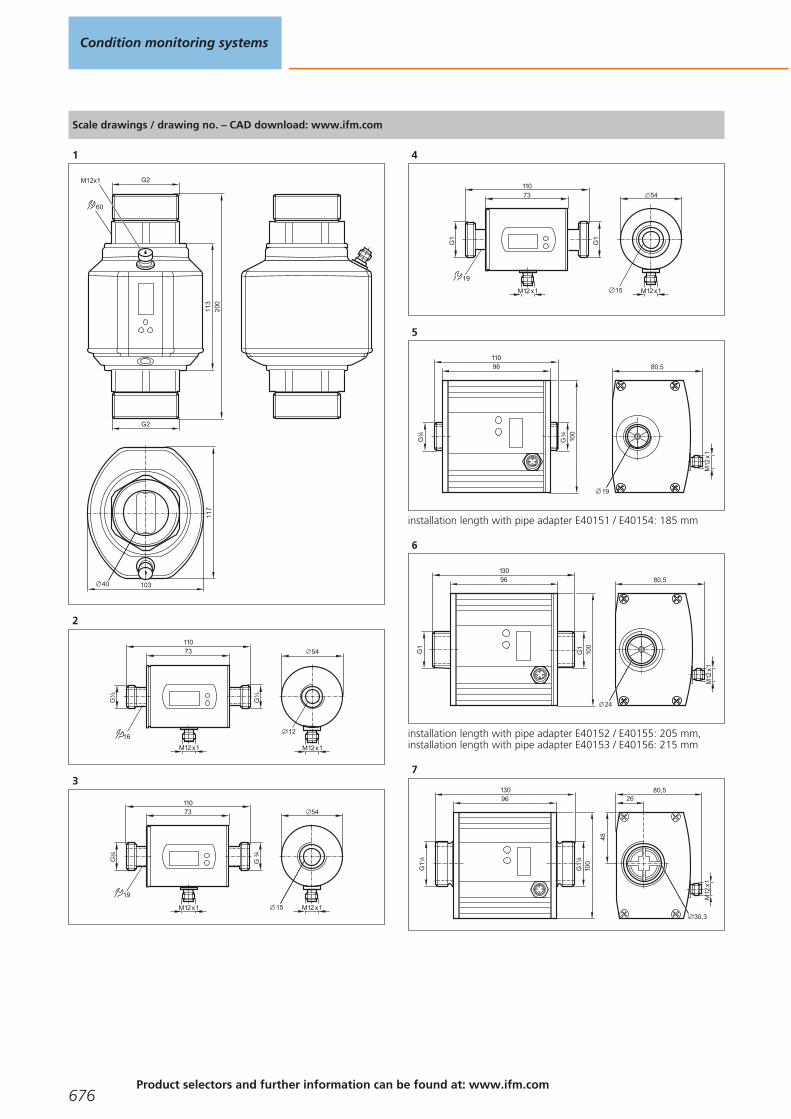
Scale drawings / drawing no. – CAD download: www.ifm.com
1
M12x1 G2
60
103
G2
113
117
200
40
2
12
G½
G½
11073
M12 x1
16
M12 x1
54
3
G4
3
G4
3
11073
M12 x1
19
M12 x1
54
15
4
G1
G1
11073
M12 x1
19
M12 x1
54
15
5
19
G4
3
G4
3
11096
100
80,5
M12
x1
installation length with pipe adapter E40151 / E40154: 185 mm
6
24
80,5
M12
x1
13096
100
G1
G1
installation length with pipe adapter E40152 / E40155: 205 mm,installation length with pipe adapter E40153 / E40156: 215 mm
7
80,5
M12
x1
26
48
13096
100
G1
41
G1
41
30,3
Condition monitoring systems
676Product selectors and further information can be found at: www.ifm.com
Gesamtkatalog EN 2016_17_Stilvorlage LK FrutigerOT_2010 DE_GB.qxd 06.11.15 16:58 Seite 676

Flow meters for water
677
Gesamtkatalog EN 2016_17_Stilvorlage LK FrutigerOT_2010 DE_GB.qxd 06.11.15 16:58 Seite 677

Systems for oil quality monitoring
For an early detection of too high a water content in lubricants and oils it is usefulto continuously monitor the relative moisture in the media using a sensor.The sensor measures the relative moisture in the oil in the range of 0...100 % bymeans of a capacitive measuring element. Besides the relative moisture the sensoralso provides the medium temperature as an analogue signal.LDP100 monitors the degree of cleanliness or the level of contamination in fluids.Compatible media are mineral oils, ester oils and biodegradable oils.The calibration is made in accordance with ISO 11943.The purity classes are indicated on the LCD display and provided via analogue out-put and CAN bus
Oil particle sensor
Type Processconnection
Pressurerating
[bar]
Protection Mediumtemperature
oil[°C]
Ambienttemperature
[°C]
Draw-ingno.
Orderno.
M12 connector · Output function 4...20 mA (can be configured); digital alarm output · Wiring diagram no. 1 · Connector groups 14,15, 16, 17
Minimess M16 x 2
420 IP 67 -10...80 -10...60 1 LDP100
Oil moisture sensor
Type Processconnection
Pressurerating
[bar]
Protection Mediumtemperature
oil[°C]
Ambienttemperature
[°C]
Draw-ingno.
Orderno.
M12 connector · Output function 4...20 mA analogue · Wiring diagram no. 2 · Connector groups 15, 16, 17
G ¾ 50 IP 67 -20...100 -20...85 2 LDH100
System overview Page
Oil particle sensor 678
Oil moisture sensor 678
Accessories for LDP oil particle monitor 679
Accessories for oil moisture sensor LDH 679
Wiring diagrams 679
Scale drawings / drawing no. – CAD download: www.ifm.com 680
Condition monitoring systems
678Product selectors and further information can be found at: www.ifm.com
Gesamtkatalog EN 2016_17_Stilvorlage LK FrutigerOT_2010 DE_GB.qxd 06.11.15 16:58 Seite 678

Accessories for LDP oil particle monitor
Type Description Orderno.
Screw couplings with cover plate · Blende 0.18 mm · Housing materials: socket housing: steel / surface characteristics: zinc/nickel grey / sealing: NBR
E43330
Screw couplings with cover plate · Blende 0.3 mm · Housing materials: socket housing: steel / surface characteristics: zinc/nickel grey / sealing: NBR
E43331
Jumper · straight / straight · CAN adapter cable: M12 plug, 5-pole / M12 socket, 8-pole · Gold-plated contacts · 0.15 m · Housing materials: PUR
E43332
BasicDisplay · 2.8" colour display · 5 freely programmable backlit function keys · Navigation key for cursor function · CAN interface · Programming according to IEC 61131-3 · 8...32 V DC
CR0451
Accessories for oil moisture sensor LDH
Type Description Orderno.
Adapter block · D33 / G ¾ · for oil moisture sensor LDH100 · Housing materials: aluminium E43400
Wiring diagrams
1
screen
L+
L
Out 1
Out 2
1
8
7
6
3
4
5
2
In
CANH
GND 1
CANL
In: Switching input (low level activates measuring cycle), Out 1:Analogue output, Out 2: Switching output, GND 1: Signal groundOut 1
2
screen
L+
L
Out 1
Out 2
1
8
7
6
3
4
5
2
n.c.
n.c.
n.c.
n.c.
Systems foroil quality monitoring
679
Gesamtkatalog EN 2016_17_Stilvorlage LK FrutigerOT_2010 DE_GB.qxd 06.11.15 16:58 Seite 679

Scale drawings / drawing no. – CAD download: www.ifm.com
1
23,551,5
78
140,3
89
M12x1
2 x LED
1
2
M16x2
1: Programming buttons, 2: display
2
32
42M
12x1
21,6
5444 43
14
G4
3
Condition monitoring systems
680Product selectors and further information can be found at: www.ifm.com
Gesamtkatalog EN 2016_17_Stilvorlage LK FrutigerOT_2010 DE_GB.qxd 06.11.15 16:58 Seite 680

Systems foroil quality monitoring
681
Gesamtkatalog EN 2016_17_Stilvorlage LK FrutigerOT_2010 DE_GB.qxd 06.11.15 16:58 Seite 681

For mobile applications
Extreme shock and vibration: Reliablefunction of the sensitive electronics mustbe guaranteed under harsh operatingconditions as well.
Control technology for mobile applications
Life today cannot be imagined without electronics in modernmotor vehicles and mobile machines. Many necessary andconvenient functions could not be implemented without electronic support. In contrast to electronics in consumergoods and “normal” industrial applications such as packagingmachines and conveyors the requirements for componentsfor mobile applications are much higher.
Electronic requirements
The components need to be carefully selected, mainlybecause of the extreme mechanical stress caused by impactsand shocks and the use at extreme operating temperatures.The direct influence of dirt, humidity and water often cannotbe excluded in field applications. Therefore a high protectionrating and a special selection of the materials are required forthe devices.
In addition to mechanical and environmental influences,electrical interference affecting the whole system as well asindividual devices, have to be taken into account. A widesupply voltage range and well-adapted protective measuresensure safe operation of the devices even in case of largevoltage fluctuations by the battery / generator system. Strongconducted or radiated interference must not influence thefunction either.
For device networking the CAN bus has become the success-ful standard in the last few years. Whereas for the highvolume production of passenger cars special, optimised andwell-adapted protocols are used, the CANopen protocol hasbecome indispensable in mobile machines. Manufacturer andindustry-specific protocols, such as diagnostic engine dataaccording to SAE J 1939, can be coupled to the machineprocess via gateways.
Systems formobile machines
682Product selectors and further information can be found at: www.ifm.com
Gesamtkatalog EN 2016_17_Stilvorlage LK FrutigerOT_2010 DE_GB.qxd 06.11.15 16:58 Seite 682

Systems formobile machines
683
Basic control systems 684 - 689
Mobile controllers 690 - 696
I/O modules 698 - 703
Dialogue modules / displays 704 - 707
Cameras 708 - 712
Diagnostic and service units 714 - 716
Signal converters 718 - 719
Sensors 720 - 735
Gesamtkatalog EN 2016_17_Stilvorlage LK FrutigerOT_2010 DE_GB.qxd 06.11.15 16:58 Seite 683

Basic control systems
The ecomatmobile Basic control system has a modular design, is easy to install andto operate and is cost-optimised.
Besides pure control functions it provides solutions for wiring and protection.
In addition, a graphical visualisation module ensures the indication of system messa-ges and simple display instruments.
BasicController
Type Inputs / outputstotal
Inputs Outputs Interfaces Draw-ingno.
Orderno.
Configurable input / output functions, Programming according to IEC 61131-3
20
12 x Digital4 x analogue (U/I)
4 x frequency4 x Resistor
8 x Digital8 x PWM
2 x CAN 1 CR0401
24
12 x Digital4 x analogue (U/I)
4 x frequency4 x Resistor
12 x Digital2 x PWM-I10 x PWM
2 x CAN 2 CR0403
16
8 x Digital4 x analogue (U/I)
4 x frequency4 x Resistor
8 x Digital8 x PWM-I8 x PWM
4 x H bridge
2 x CAN 3 CR0411
14
8 x Digital4 x analogue (U/I)
4 x frequency4 x Resistor
6 x Relay 2 x CAN 4 CR0431
System overview Page
BasicController 684
Starter set ecomatmobile Basic 685
BasicRelay 685
BasicDisplay 685
BasicDisplay XL 685
Accessories for the mini control system Basic 685 - 688
Scale drawings / drawing no. – CAD download: www.ifm.com 688 - 689
Systems for mobile machines
684Product selectors and further information can be found at: www.ifm.com
Gesamtkatalog EN 2016_17_Stilvorlage LK FrutigerOT_2010 DE_GB.qxd 06.11.15 16:58 Seite 684
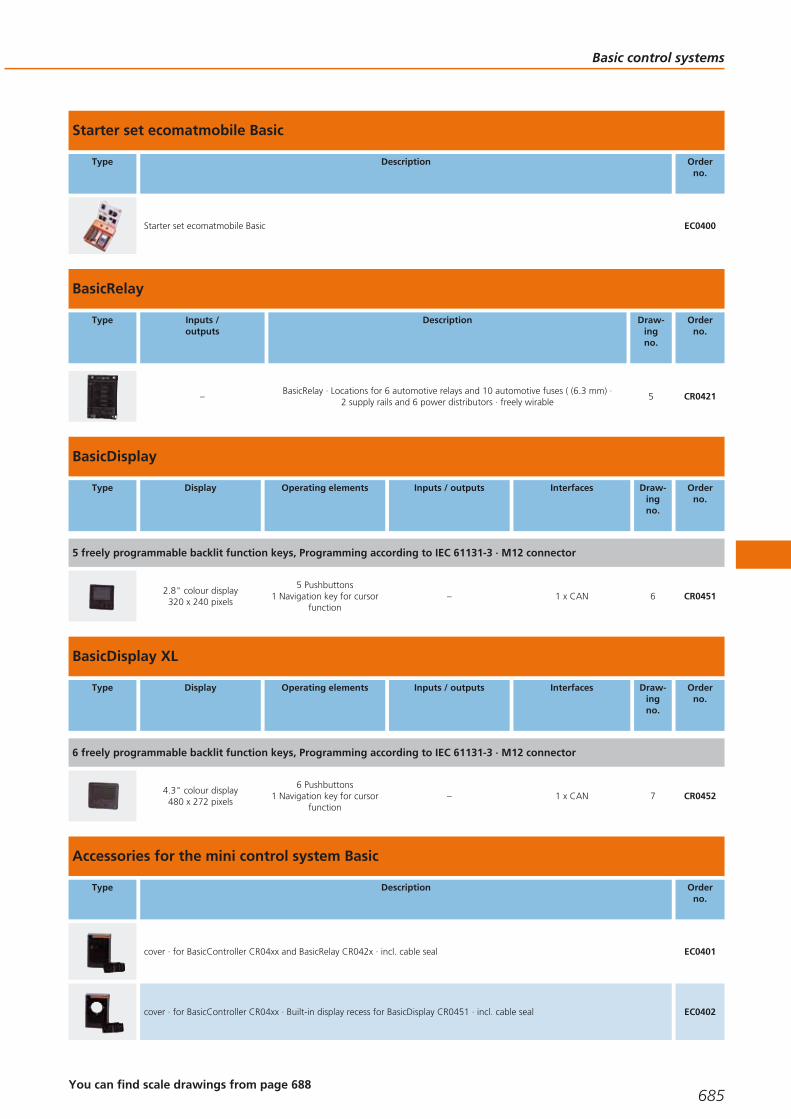
Starter set ecomatmobile Basic
Type Description Orderno.
Starter set ecomatmobile Basic EC0400
BasicRelay
Type Inputs /outputs
Description Draw-ingno.
Orderno.
–BasicRelay · Locations for 6 automotive relays and 10 automotive fuses ( (6.3 mm) ·
2 supply rails and 6 power distributors · freely wirable5 CR0421
BasicDisplay
Type Display Operating elements Inputs / outputs Interfaces Draw-ingno.
Orderno.
5 freely programmable backlit function keys, Programming according to IEC 61131-3 · M12 connector
2.8" colour display320 x 240 pixels
5 Pushbuttons1 Navigation key for cursor
function– 1 x CAN 6 CR0451
BasicDisplay XL
Type Display Operating elements Inputs / outputs Interfaces Draw-ingno.
Orderno.
6 freely programmable backlit function keys, Programming according to IEC 61131-3 · M12 connector
4.3" colour display480 x 272 pixels
6 Pushbuttons1 Navigation key for cursor
function– 1 x CAN 7 CR0452
Accessories for the mini control system Basic
Type Description Orderno.
cover · for BasicController CR04xx and BasicRelay CR042x · incl. cable seal EC0401
cover · for BasicController CR04xx · Built-in display recess for BasicDisplay CR0451 · incl. cable seal EC0402
Basic control systems
685You can find scale drawings from page 688
Gesamtkatalog EN 2016_17_Stilvorlage LK FrutigerOT_2010 DE_GB.qxd 06.11.15 16:58 Seite 685

Type Description Orderno.
Mounting frame · for BasicDisplay CR0451 · panel · Housing materials: stainless steel EC0403
Mounting frame · for BasicDisplay XL CR0452 · panel · Housing materials: stainless steel EC0404
RAM mount set · Ball size 1" (B) · e.g. for BasicDisplay · for use as a desktop unit · Housing materials: Mounting arm: aluminiumblack anodised / Mounting plate: aluminium black anodised / ball: rubber / Display carrier: plastics black
EC0405
RAM mount set · Ball size 1" (B) · e.g. for BasicDisplay XL · for use as a desktop unit · Housing materials: Mounting arm: aluminiumblack anodised / Mounting plate: aluminium black anodised / ball: rubber / Display carrier: plastics black
EC0406
Display carrier · RAM mount system · Ball size 1" (B) · e.g. for BasicDisplay · for use as a desktop unit · Housing materials: plastics black
EC0407
Display carrier · RAM mount system · Ball size 1" (B) · e.g. for BasicDisplay XL · for use as a desktop unit · Housing materials: plastics black
EC0408
Mounting plate · RAM mount system · Ball size 1" (B) · e.g. for BasicDisplay or BasicDisplay XL · for use as a desktop unit · Housing materials: Mounting plate: aluminium black anodised / ball: rubber
EC0409
Mounting arm · 95 mm · RAM mount system · Ball size 1" (B) · e.g. for BasicDisplay or BasicDisplay XL · for use as a desktop unit ·Housing materials: Mounting arm: aluminium black anodised
EC0410
Socket · angled · Free from silicone · Free from halogen · Gold-plated contacts · M12 connector with integrated CAN terminatingresistor (120 ohm) · 5 m · Housing materials: housing: TPU black / sealing: FKM
EVC492
Jumper · wired · for 2 BasicControllers CR04xx · CAN interface · Power supply · 0.5 m EC0451
Jumper · wired · for 1 BasicController CR04xx and 1 BasicDisplay CR045x · CAN interface · Power supply · M12 connector · 0.1 m EC0452
Jumper · wired · for 2 BasicControllers CR04xx and 1 BasicDisplay CR045x · CAN interface · Power supply · M12 connector · 0.5 m EC0453
Jumper · wired · for 1 BasicController CR04xx and 1 BasicDisplay CR045x · CAN interface · Power supply · M12 connector · 5 m EC0454
Jumper · wired · for 1 BasicController CR04xx and 1 BasicDisplay CR045x · CAN interface · Power supply · M12 connector · 10 m EC0458
Jumper · wired · for 2 BasicControllers CR04xx and 1 BasicDisplay CR045x · CAN interface · Power supply · M12 connector · 5 m EC0455
Systems for mobile machines
686Product selectors and further information can be found at: www.ifm.com
Gesamtkatalog EN 2016_17_Stilvorlage LK FrutigerOT_2010 DE_GB.qxd 06.11.15 16:58 Seite 686

Type Description Orderno.
Contacts and contact housings · for BasicController CR04xx · wirable · utilising all connections to a BasicController EC0456
Set of contacts · for BasicRelay CR0421 · wirable · utilising all connections to a BasicRelay EC0457
Standard timer contact housing · for BasicController CR04xx · CAN1 and supply P/N1 · Coding · wirable · Housing materials: PA white
EC0460
Standard timer contact housing · for BasicController CR04xx · CAN2 N2 · Coding · wirable · Housing materials: PA white EC0461
Standard timer contact housing · for BasicController CR04xx · Inputs A/B/C · Coding · wirable · Housing materials: PA grey EC0462
Standard timer contact housing · for BasicController CR04xx · Outputs D/E/F · Coding · wirable · Housing materials: PA white EC0463
Standard timer contact · for standard timer contact housing · 0.2...0.5 mm2 / Ø 1.0...1.6 mm · Housing materials: tin-plated EC0459
Standard timer contact · for standard timer contact housing · 0.5...1.0 mm2 / Ø 1.4...2.3 mm · Housing materials: tin-plated EC0468
Standard timer contact · for standard timer contact housing · 1.0...2.5 mm2 / Ø 2.1...3.1 mm · Housing materials: tin-plated EC0469
Standard power timer contact · for standard timer contact housing · 1.25...2.5 mm2 / Ø 2.1...3.1 mm · Housing materials: tin-plated EC0470
Contacts and contact housings · for BasicController relay CR0431 · wirable · utilising all connections to a BasicController relay EC0464
Connecting material for power supply · for BasicController relay CR0431 · wirable EC0465
Set of relais and fuses for 12 V DC systems · for BasicController relay CR0431 EC0466
Set of relais and fuses for 24 V DC systems · for BasicController relay CR0431 EC0467
CANfox · CAN/RS232-USB interface · Programming and diagnosis of CAN systems · 5 V DC (via USB interface) EC2112
Basic control systems
687You can find scale drawings from page 688
Gesamtkatalog EN 2016_17_Stilvorlage LK FrutigerOT_2010 DE_GB.qxd 06.11.15 16:58 Seite 687

Type Description Orderno.
Adapter cable · for CAN interface CANfox · CAN adapter: DIN connector, 6 poles / M12 connector, 5 poles · RS-232 adapter: DIN connector, 6 poles / Sub-D plug, 9 poles · Cable length 1 m
EC2113
Set of programming cables · for CAN interface CANfox · Cable BasicController: DIN connector, 6-pole / standard timer contacthousing, 6-pole · Cable BasicDisplay: DIN connector, 6-pole / M12 socket, 5-pole · CAN interface · Voltage supply via individual wires with end ferrules · Cable length 1 m
EC2114
Programming software CODESYS · for configuration, programming and diagnosis of ifm controller systems · German version · incl. the DVD "Software, tools and documentation"
CP9006
Programming software CODESYS · for configuration, programming and diagnosis of ifm controller systems · English version · incl. the DVD "Software, tools and documentation"
CP9008
Scale drawings / drawing no. – CAD download: www.ifm.com
1
18
A B C D E F
N2
P/N1
25,5
127
163
145
12,58,5
6,5
10,5
79,7112
LED
8,5
2
18
A B C D E F
N2
P/N1
25,5
127
163
145
12,58,5
6,5
10,5
79,7112
LED
8,5
3
18
A B C D E F
N2
P/N1
25,5
127
163
145
12,58,5
6,5
10,5
79,7112
LED
8,5
4
1825,5
127
163
145
12,58,5
6,5
10,5
79,71128,
5
46,1
Systems for mobile machines
688Product selectors and further information can be found at: www.ifm.com
Gesamtkatalog EN 2016_17_Stilvorlage LK FrutigerOT_2010 DE_GB.qxd 06.11.15 16:58 Seite 688

Scale drawings / drawing no. – CAD download: www.ifm.com
5
1825,5
127
163
145
12,58,5
6,5
10,5
79,7112
26,563,58,
5
6
LED
M12
x1M
52x1
,5
1,511,2
87,5 31,3 558,6
87,5
44,2
35,2
12,3
7
LED
M12
x1M
52x1
,5
124,596,8
5510
9,5
41,3
15,6 5,433,6
11 1,5
Basic control systems
689
Gesamtkatalog EN 2016_17_Stilvorlage LK FrutigerOT_2010 DE_GB.qxd 06.11.15 16:58 Seite 689

Mobile controllers
The platform of the ecomatmobile control system: the powerful controller family.Free programmability and the variety of configuration options enable use in a widerange of different applications.
16-bit ClassicController
Type Inputs / outputstotal
Inputs Outputs Interfaces Draw-ingno.
Orderno.
Configurable input / output functions, Programming according to IEC 61131-3
2424 x Digital
8 x analogue (U/I)8 x frequency
8 x Digital8 x PWM-I8 x PWM
2 x CAN1 x RS-232
1 CR0505
4040 x Digital
8 x analogue (U/I)8 x frequency
24 x Digital8 x PWM-I12 x PWM
2 x H bridge
2 x CAN1 x RS-232
1 CR0020
System overview Page
16-bit ClassicController 690
16-bit ExtendedController 691
16-bit SmartController 691
SmartController 32 bits 691
16-bit SafetyController 691
SafetyController 32 bits 692
32-bit ClassicController 692
32-bit ExtendedController 692
CabinetController for use in control cabinets 693
Accessories and software 693
Connection technology for control systems 693 - 695
Scale drawings / drawing no. – CAD download: www.ifm.com 695 - 696
Systems for mobile machines
690Product selectors and further information can be found at: www.ifm.com
Gesamtkatalog EN 2016_17_Stilvorlage LK FrutigerOT_2010 DE_GB.qxd 06.11.15 16:58 Seite 690
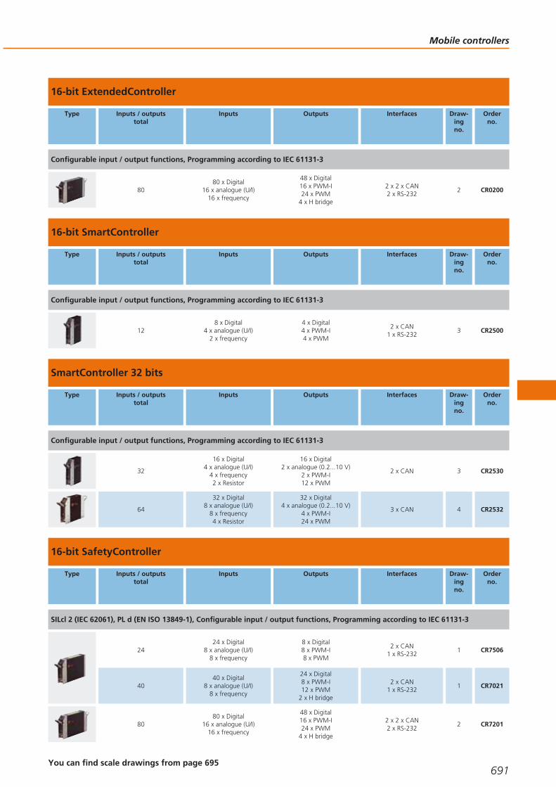
16-bit ExtendedController
Type Inputs / outputstotal
Inputs Outputs Interfaces Draw-ingno.
Orderno.
Configurable input / output functions, Programming according to IEC 61131-3
8080 x Digital
16 x analogue (U/I)16 x frequency
48 x Digital16 x PWM-I24 x PWM
4 x H bridge
2 x 2 x CAN2 x RS-232
2 CR0200
16-bit SmartController
Type Inputs / outputstotal
Inputs Outputs Interfaces Draw-ingno.
Orderno.
Configurable input / output functions, Programming according to IEC 61131-3
128 x Digital
4 x analogue (U/I)2 x frequency
4 x Digital4 x PWM-I4 x PWM
2 x CAN1 x RS-232
3 CR2500
SmartController 32 bits
Type Inputs / outputstotal
Inputs Outputs Interfaces Draw-ingno.
Orderno.
Configurable input / output functions, Programming according to IEC 61131-3
32
16 x Digital4 x analogue (U/I)
4 x frequency2 x Resistor
16 x Digital2 x analogue (0.2...10 V)
2 x PWM-I12 x PWM
2 x CAN 3 CR2530
64
32 x Digital8 x analogue (U/I)
8 x frequency4 x Resistor
32 x Digital4 x analogue (0.2...10 V)
4 x PWM-I24 x PWM
3 x CAN 4 CR2532
16-bit SafetyController
Type Inputs / outputstotal
Inputs Outputs Interfaces Draw-ingno.
Orderno.
SILcl 2 (IEC 62061), PL d (EN ISO 13849-1), Configurable input / output functions, Programming according to IEC 61131-3
2424 x Digital
8 x analogue (U/I)8 x frequency
8 x Digital8 x PWM-I8 x PWM
2 x CAN1 x RS-232
1 CR7506
4040 x Digital
8 x analogue (U/I)8 x frequency
24 x Digital8 x PWM-I12 x PWM
2 x H bridge
2 x CAN1 x RS-232
1 CR7021
8080 x Digital
16 x analogue (U/I)16 x frequency
48 x Digital16 x PWM-I24 x PWM
4 x H bridge
2 x 2 x CAN2 x RS-232
2 CR7201
Mobile controllers
691You can find scale drawings from page 695
Gesamtkatalog EN 2016_17_Stilvorlage LK FrutigerOT_2010 DE_GB.qxd 06.11.15 16:58 Seite 691
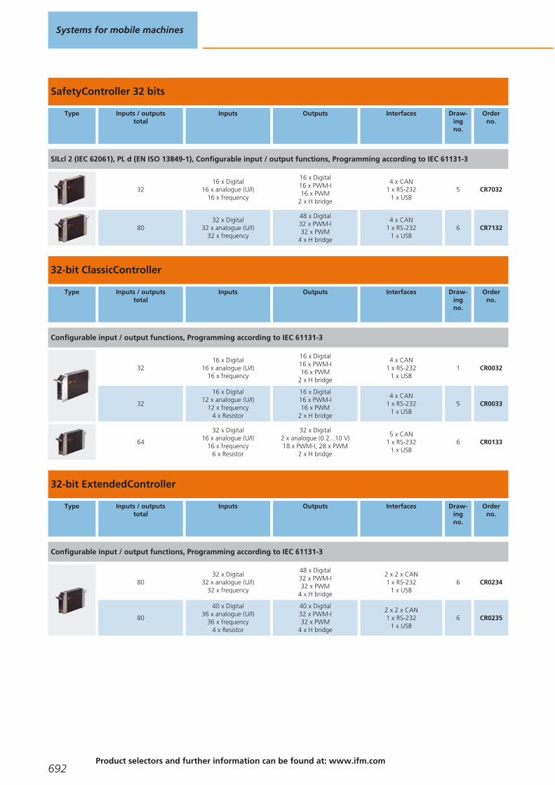
SafetyController 32 bits
Type Inputs / outputstotal
Inputs Outputs Interfaces Draw-ingno.
Orderno.
SILcl 2 (IEC 62061), PL d (EN ISO 13849-1), Configurable input / output functions, Programming according to IEC 61131-3
3216 x Digital
16 x analogue (U/I)16 x frequency
16 x Digital16 x PWM-I16 x PWM
2 x H bridge
4 x CAN1 x RS-232
1 x USB5 CR7032
8032 x Digital
32 x analogue (U/I)32 x frequency
48 x Digital32 x PWM-I32 x PWM
4 x H bridge
4 x CAN1 x RS-232
1 x USB6 CR7132
32-bit ClassicController
Type Inputs / outputstotal
Inputs Outputs Interfaces Draw-ingno.
Orderno.
Configurable input / output functions, Programming according to IEC 61131-3
3216 x Digital
16 x analogue (U/I)16 x frequency
16 x Digital16 x PWM-I16 x PWM
2 x H bridge
4 x CAN1 x RS-232
1 x USB1 CR0032
32
16 x Digital12 x analogue (U/I)
12 x frequency4 x Resistor
16 x Digital16 x PWM-I16 x PWM
2 x H bridge
4 x CAN1 x RS-232
1 x USB5 CR0033
64
32 x Digital16 x analogue (U/I)
16 x frequency6 x Resistor
32 x Digital2 x analogue (0.2...10 V)18 x PWM-I, 28 x PWM
2 x H bridge
5 x CAN1 x RS-232
1 x USB6 CR0133
32-bit ExtendedController
Type Inputs / outputstotal
Inputs Outputs Interfaces Draw-ingno.
Orderno.
Configurable input / output functions, Programming according to IEC 61131-3
8032 x Digital
32 x analogue (U/I)32 x frequency
48 x Digital32 x PWM-I32 x PWM
4 x H bridge
2 x 2 x CAN1 x RS-232
1 x USB6 CR0234
80
40 x Digital36 x analogue (U/I)
36 x frequency4 x Resistor
40 x Digital32 x PWM-I32 x PWM
4 x H bridge
2 x 2 x CAN1 x RS-232
1 x USB6 CR0235
Systems for mobile machines
692Product selectors and further information can be found at: www.ifm.com
Gesamtkatalog EN 2016_17_Stilvorlage LK FrutigerOT_2010 DE_GB.qxd 06.11.15 16:58 Seite 692

CabinetController for use in control cabinets
Type Inputs / outputstotal
Inputs Outputs Interfaces Draw-ingno.
Orderno.
Configurable input / output functions, Programming according to IEC 61131-3
4224 x Digital
8 x analogue (U/I)4 x frequency
18 x Digital4 x PWM10 x Relay
1 x CAN1 x RS-232
7 CR0301
3624 x Digital
8 x analogue (U/I)4 x frequency
12 x Digital4 x PWM
1 x CAN1 x RS-232
8 CR0302
4224 x Digital
8 x analogue (U/I)4 x frequency
18 x Digital8 x PWM
6 x PNP 10 A
2 x CAN1 x RS-232
9 CR0303
Accessories and software
Type Description Orderno.
Programming software CODESYS · for configuration, programming and diagnosis of ifm controller systems · German version · incl. the DVD "Software, tools and documentation"
CP9006
Programming software CODESYS · for configuration, programming and diagnosis of ifm controller systems · English version · incl. the DVD "Software, tools and documentation"
CP9008
Starter set ecomat R 360 Smart Controller · consisting of: · controller CR2500 · I/O simulator box incl. connection cable andconnectors · plug-in power supply · DVD with programming software CODESYS · project examples and manuals
EC2074
Connection technology for control systems
Type Description Orderno.
Connector AMP 55-pole · wirable · with contacts (Junior Power Timer) EC2013
Cable with connector · AMP 55-pole · wired · Cable length 1.2 m · Cores sealed individually · Core cross-section 1 mm2 EC2084
Cable with connector · AMP 55-pole · wired · Cable length 2.5 m · Cores sealed individually · Core cross-section 1 mm2 EC2097
Cable with connector · AMP 55-pole · wired · Cable length 1.2 m · Core cross-section 1 mm2 EC2086
Cable with connector · AMP 55-pole · wired · Cable length 2.5 m · Core cross-section 1 mm2 EC2046
Mobile controllers
693You can find scale drawings from page 695
Gesamtkatalog EN 2016_17_Stilvorlage LK FrutigerOT_2010 DE_GB.qxd 06.11.15 16:58 Seite 693

Type Description Orderno.
Cable with connector · AMP 6-pole · wired · fully wired · Cable length 1.2 m · Core cross-section 1 mm2 EC1520
Cable with connector · AMP 10-pole · wired · fully wired · Cable length 1.2 m · Core cross-section 1 mm2 EC1521
Cable with connector · AMP 14-pole · wired · fully wired · Cable length 1.2 m · Core cross-section 1 mm2 EC1522
Cable with connector · AMP 18-pole · wired · fully wired · Cable length 1.2 m · Core cross-section 1 mm2 EC1523
Cable with connector · AMP 18-pole · wired · partially wired · for input signals · Cable length 1.2 m · Core cross-section 1 mm2 EC1524
Cable with connector · AMP 18-pole · wired · fully wired · Cable length 2.5 m · Core cross-section 1 mm2 EC1533
Plug set for CabinetModule CR2012 / CR2014 · wirable · consisting of: · AMP Crimp housing 1 x 6 pins, 2 x 18 pins incl. Crimpcontacts (Junior Power Timer)
EC2053
Plug set for CabinetController CR0301 / CR0302 · wirable · consisting of: · AMP Crimp housing 1 x 6 pins, 2 x 10 pins, 3 x 18 pinsincl. Crimp contacts (Junior Power Timer)
EC2075
Plug set for CabinetModule CR201x · wirable · consisting of: · AMP Crimp housing 1 x 6 pins, 2 x 14 pins, 2 x 18 pins incl. Crimpcontacts (Junior Power Timer)
EC2089
Plug set · wirable · consisting of: · AMP Crimp housing 2 x 6 pins, 2 x 10 pins, 3 x 18 pins incl. Crimp contacts (Junior Power Timer) EC2090
RS-232 Programming adapter · with gender changer for pin-socket conversion EC2076
programming cable · cable length 2 m interface 9-pole D-SUB (female) · AMP 6-pole · Test input (AMP connector, pin 5) connected to VBB via link
EC2091
programming cable · e.g. for ClassicController CR0032 or ExtendedController CR0232 · wired EC2096
Load-Dump-Module · 12 V DC EC2015
Load-Dump-Module · 24 V DC EC2016
Systems for mobile machines
694Product selectors and further information can be found at: www.ifm.com
Gesamtkatalog EN 2016_17_Stilvorlage LK FrutigerOT_2010 DE_GB.qxd 06.11.15 16:58 Seite 694

Type Description Orderno.
Spring terminal box · e.g. for starter set EC2032
Serial interface cable · 2 x 9-pole D-SUB (female) · 1:1 · e.g. for PC communication, configuration or uploads of firmware updates ·Cable length 2 m · e.g. for process and dialogue monitors PDM360
EC2063
Scale drawings / drawing no. – CAD download: www.ifm.com
115
3
43 LED
225
205,5
2680
1526
45°
2
153
43 LED
247
20
2680
1526
45°
3
153
43 LED
132
205,5
2680
1526
45°
Mobile controllers
695
Gesamtkatalog EN 2016_17_Stilvorlage LK FrutigerOT_2010 DE_GB.qxd 06.11.15 16:58 Seite 695
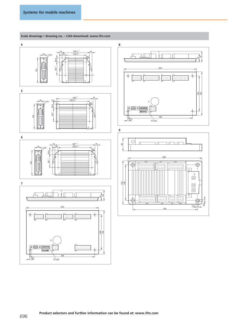
Scale drawings / drawing no. – CAD download: www.ifm.com
4
153
43169,5 ± 1
128,5 ± 12025
,580
± 1
1515
45°LED
5
153
43LED
226 ± 1
200,5 ± 15,5
25,5
80 ±
1
15
45°
6
153
43LED
247 ± 1
206,5 ± 120
25,5
80±
1
1515
45°
7
2533
223
134
108
1984,5
10 LED
8
2533
223
134
108
1984,5
10 LED
9
X10 X11
X20 X21
198
226
133
108
39
5,8
7,8
X12
P/N1N2
Systems for mobile machines
696Product selectors and further information can be found at: www.ifm.com
Gesamtkatalog EN 2016_17_Stilvorlage LK FrutigerOT_2010 DE_GB.qxd 06.11.15 16:58 Seite 696

Mobile controllers
697
Gesamtkatalog EN 2016_17_Stilvorlage LK FrutigerOT_2010 DE_GB.qxd 06.11.15 16:58 Seite 697

I/O modules
Decentralised I/O modules for use in CANopen bus systems. Considerably reducedwiring, they are mounted where the signals are generated.The flexible configuration of the inputs and outputs enables universal use and reduces the costs for stockholding.
CompactModules metal
Type Inputs / outputstotal
Inputs Outputs Interfaces Draw-ingno.
Orderno.
CAN parameters adjustable via coding switch, Configurable input / output functions · M12 connector
8 –8 x Digital4 x PWM-I4 x PWM
1 x CAN 1 CR2031
168 x Digital
4 x analogue (U/I)8 x Digital4 x PWM
1 x CAN 2 CR2032
128 x Digital
4 x analogue (U/I)4 x Digital4 x PWM
1 x CAN 3 CR2033
CompactModules
Type Inputs / outputstotal
Inputs Outputs Interfaces Draw-ingno.
Orderno.
Configurable output functions · M12 connector
8 –8 x Digital8 x PWM
1 x CAN 4 CR2011
System overview Page
CompactModules metal 698
CompactModules 698 - 699
SmartModules 699
CabinetModules 699
KeypadModules 699
Accessories for I/O modules 700 - 702
Scale drawings / drawing no. – CAD download: www.ifm.com 702 - 703
Systems for mobile machines
698Product selectors and further information can be found at: www.ifm.com
Gesamtkatalog EN 2016_17_Stilvorlage LK FrutigerOT_2010 DE_GB.qxd 06.11.15 16:58 Seite 698

Type Inputs / outputstotal
Inputs Outputs Interfaces Draw-ingno.
Orderno.
Configurable input / output functions · M12 connector
84 x Digital
4 x analogue (0...10 V)4 x Digital4 x PWM
1 x CAN 4 CR2013
SmartModules
Type Inputs / outputstotal
Inputs Outputs Interfaces Draw-ingno.
Orderno.
Configurable input / output functions · 55-pole connec.
12 4 x Digital8 x Digital8 x PWM-I8 x PWM
1 x CAN 5 CR2512
128 x Digital
4 x analogue (U/I)4 x Digital4 x PWM
1 x CAN 5 CR2513
3015 x Digital
4 x analogue (U/I)
15 x Digital3 x PWM
4 x PNP 10 A4 x H bridge
1 x CAN 6 CR2520
CabinetModules
Type Inputs / outputstotal
Inputs Outputs Interfaces Draw-ingno.
Orderno.
CAN parameters adjustable via coding switch, Configurable input / output functions · Connector
1616 x Digital
4 x analogue (0...10 V)4 x Digital2 x PWM
1 x CAN 7 CR2012
1616 x Digital
4 x analogue (0...5 V)4 x Digital2 x PWM
1 x CAN 7 CR2014
3216 x Digital
4 x analogue (U/I)4 x frequency
16 x Digital4 x PWM
1 x CAN 8 CR2016
KeypadModules
Type Display Operating elements Inputs / outputs Interfaces Draw-ingno.
Orderno.
Programming according to IEC 61131-3 · cage clamps
2 x LED bar graph (10-digit)12 x LEDs
12 Pushbuttons4 arrow keys
– 1 x CAN 9 CR1500
I/O modules
699You can find scale drawings from page 702
Gesamtkatalog EN 2016_17_Stilvorlage LK FrutigerOT_2010 DE_GB.qxd 06.11.15 16:58 Seite 699
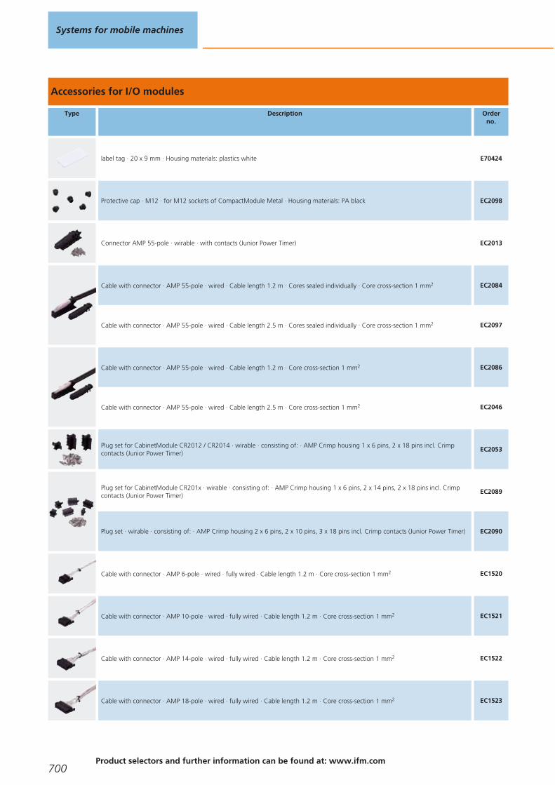
Accessories for I/O modules
Type Description Orderno.
label tag · 20 x 9 mm · Housing materials: plastics white E70424
Protective cap · M12 · for M12 sockets of CompactModule Metal · Housing materials: PA black EC2098
Connector AMP 55-pole · wirable · with contacts (Junior Power Timer) EC2013
Cable with connector · AMP 55-pole · wired · Cable length 1.2 m · Cores sealed individually · Core cross-section 1 mm2 EC2084
Cable with connector · AMP 55-pole · wired · Cable length 2.5 m · Cores sealed individually · Core cross-section 1 mm2 EC2097
Cable with connector · AMP 55-pole · wired · Cable length 1.2 m · Core cross-section 1 mm2 EC2086
Cable with connector · AMP 55-pole · wired · Cable length 2.5 m · Core cross-section 1 mm2 EC2046
Plug set for CabinetModule CR2012 / CR2014 · wirable · consisting of: · AMP Crimp housing 1 x 6 pins, 2 x 18 pins incl. Crimpcontacts (Junior Power Timer)
EC2053
Plug set for CabinetModule CR201x · wirable · consisting of: · AMP Crimp housing 1 x 6 pins, 2 x 14 pins, 2 x 18 pins incl. Crimpcontacts (Junior Power Timer)
EC2089
Plug set · wirable · consisting of: · AMP Crimp housing 2 x 6 pins, 2 x 10 pins, 3 x 18 pins incl. Crimp contacts (Junior Power Timer) EC2090
Cable with connector · AMP 6-pole · wired · fully wired · Cable length 1.2 m · Core cross-section 1 mm2 EC1520
Cable with connector · AMP 10-pole · wired · fully wired · Cable length 1.2 m · Core cross-section 1 mm2 EC1521
Cable with connector · AMP 14-pole · wired · fully wired · Cable length 1.2 m · Core cross-section 1 mm2 EC1522
Cable with connector · AMP 18-pole · wired · fully wired · Cable length 1.2 m · Core cross-section 1 mm2 EC1523
Systems for mobile machines
700Product selectors and further information can be found at: www.ifm.com
Gesamtkatalog EN 2016_17_Stilvorlage LK FrutigerOT_2010 DE_GB.qxd 06.11.15 16:58 Seite 700
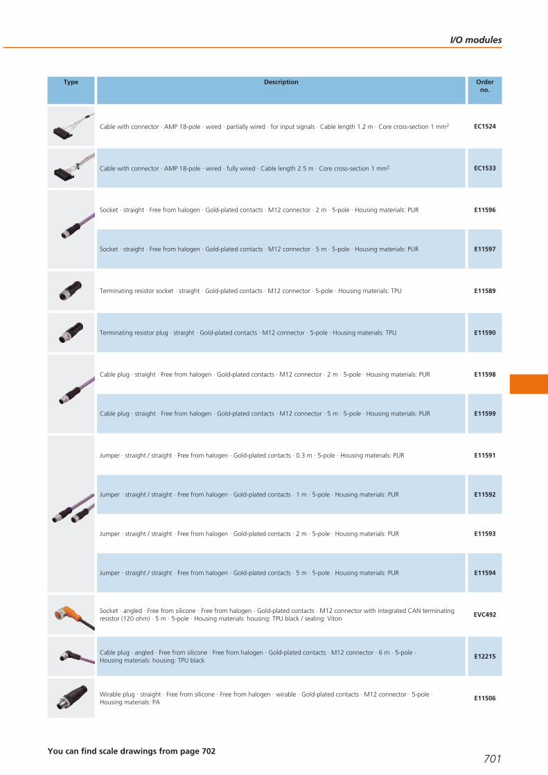
Type Description Orderno.
Cable with connector · AMP 18-pole · wired · partially wired · for input signals · Cable length 1.2 m · Core cross-section 1 mm2 EC1524
Cable with connector · AMP 18-pole · wired · fully wired · Cable length 2.5 m · Core cross-section 1 mm2 EC1533
Socket · straight · Free from halogen · Gold-plated contacts · M12 connector · 2 m · 5-pole · Housing materials: PUR E11596
Socket · straight · Free from halogen · Gold-plated contacts · M12 connector · 5 m · 5-pole · Housing materials: PUR E11597
Terminating resistor socket · straight · Gold-plated contacts · M12 connector · 5-pole · Housing materials: TPU E11589
Terminating resistor plug · straight · Gold-plated contacts · M12 connector · 5-pole · Housing materials: TPU E11590
Cable plug · straight · Free from halogen · Gold-plated contacts · M12 connector · 2 m · 5-pole · Housing materials: PUR E11598
Cable plug · straight · Free from halogen · Gold-plated contacts · M12 connector · 5 m · 5-pole · Housing materials: PUR E11599
Jumper · straight / straight · Free from halogen · Gold-plated contacts · 0.3 m · 5-pole · Housing materials: PUR E11591
Jumper · straight / straight · Free from halogen · Gold-plated contacts · 1 m · 5-pole · Housing materials: PUR E11592
Jumper · straight / straight · Free from halogen · Gold-plated contacts · 2 m · 5-pole · Housing materials: PUR E11593
Jumper · straight / straight · Free from halogen · Gold-plated contacts · 5 m · 5-pole · Housing materials: PUR E11594
Socket · angled · Free from silicone · Free from halogen · Gold-plated contacts · M12 connector with integrated CAN terminatingresistor (120 ohm) · 5 m · 5-pole · Housing materials: housing: TPU black / sealing: Viton
EVC492
Cable plug · angled · Free from silicone · Free from halogen · Gold-plated contacts · M12 connector · 6 m · 5-pole · Housing materials: housing: TPU black
E12215
Wirable plug · straight · Free from silicone · Free from halogen · wirable · Gold-plated contacts · M12 connector · 5-pole · Housing materials: PA
E11506
I/O modules
701You can find scale drawings from page 702
Gesamtkatalog EN 2016_17_Stilvorlage LK FrutigerOT_2010 DE_GB.qxd 06.11.15 16:58 Seite 701

Type Description Orderno.
Wirable socket · straight · Free from silicone · Free from halogen · wirable · Gold-plated contacts · M12 connector · 5-pole · Housing materials: PA
E11511
Wirable plug · straight · Free from silicone · Free from halogen · wirable · Gold-plated contacts · M12 connector · 4-pole · Housing materials: PA
E11504
Wirable plug · angled · Free from silicone · Free from halogen · wirable · Gold-plated contacts · M12 connector · 4-pole · Housing materials: PA
E11505
Wirable plug · angled · Free from silicone · Free from halogen · wirable · Gold-plated contacts · M12 connector · 5-pole · Housing materials: PA
E11860
Wirable plug · angled · Free from silicone · Free from halogen · wirable · Gold-plated contacts · M12 connector · 5-pole · Housing materials: PA
E11507
Load-Dump-Module · 12 V DC EC2015
Load-Dump-Module · 24 V DC EC2016
Plug for Danfoss PWM valves · wirable · terminals EC2056
Plug for Danfoss PWM valves · M12 connector EC2088
Adapter cable for CAN devices with M12 connector (5 pole) · e.g. CANmem, CANremote or inclination sensors EC2062
Scale drawings / drawing no. – CAD download: www.ifm.com
1
69
2339
LED M12 x1
9 52
6
227205
5 5
77
PWR
DIA
1357
2468
CA
N in
CA
N o
ut
2
69
2339
LED M12 x1
9 52
6
227205
5 5
77
PWR
DIA
1357
2468
CA
N in
CA
N o
ut
Systems for mobile machines
702Product selectors and further information can be found at: www.ifm.com
Gesamtkatalog EN 2016_17_Stilvorlage LK FrutigerOT_2010 DE_GB.qxd 06.11.15 16:59 Seite 702

Scale drawings / drawing no. – CAD download: www.ifm.com
3
69
2339
LED M12 x1
9 526
227205
5 5
77
PWR
DIA
1357
2468
CA
N in
CA
N o
ut
4
1 2
4
6
8
3
5
7
18224,
710
715
2
54,
5
28,539
7,5
60
M12x1
PWR
DIA
5
153
43 LED
132
205,5
2680
1526
45°
6
153
43LED
226 ± 1
200,5 ± 15,5
25,5
80 ±
1
15
45°
7
163
6342,3
18 LED
142,34,5
29±1
13
8
X10 X11
P/N1 X20 X21
161
181
105
8230
5,8
7,8
9
32
90
190
I/O modules
703
Gesamtkatalog EN 2016_17_Stilvorlage LK FrutigerOT_2010 DE_GB.qxd 06.11.15 16:59 Seite 703

Dialogue modules / displays
Displays with graphics capabilities, free programming to IEC 61131 and variousinterfaces are features of the dialogue modules.The convenient user interface for service and machine handling – the dialoguemodules of the ecomatmobile control system.
PDM360 smart with 2.5" monochrome display
Type Display Operating elements Inputs / outputs Interfaces Draw-ingno.
Orderno.
12 freely programmable backlit function keys, Programming according to IEC 61131-3 · M12 connector
2.5" monochrome display128 x 64 pixels
12 Pushbuttons –1 x CAN
1 x RS-2321 CR1070
2.5" monochrome display128 x 64 pixels
12 Pushbuttons4 x digital in
4 x digital out1 x CAN
1 x RS-2321 CR1071
PDM360 NG with 7" display
Type Display Operating elements Inputs / outputs Interfaces Draw-ingno.
Orderno.
Real-time clock, 8 freely programmable backlit function keys, Programming according to IEC 61131-3 · M12 connector
7" colour display800 x 480 pixels
8 Pushbuttons
1 x digital in1 x analogue in1 x digital out
2 x Video (CVBS)1 x Buzzer
4 x CAN1 x Ethernet
2 x USB2 CR1083
7" colour display800 x 480 pixels
8 Pushbuttons
1 x digital in1 x analogue in1 x digital out
1 x BuzzerReal-time clock
4 x CAN1 x Ethernet
2 x USB2 CR1087
System overview Page
PDM360 smart with 2.5" monochrome display 704
PDM360 NG with 7" display 704 - 705
PDM360 NG with 12" Display 705
Accessories for displays 705 - 706
Connection technology for displays 707
Scale drawings / drawing no. – CAD download: www.ifm.com 707
Systems for mobile machines
704Product selectors and further information can be found at: www.ifm.com
Gesamtkatalog EN 2016_17_Stilvorlage LK FrutigerOT_2010 DE_GB.qxd 06.11.15 16:59 Seite 704

Type Display Operating elements Inputs / outputs Interfaces Draw-ingno.
Orderno.
Real-time clock, 9 freely programmable backlit function keys, Programming according to IEC 61131-3 · M12 connector
7" colour display800 x 480 pixels
9 Pushbuttons1 Encoder with pushbutton
1 x digital in1 x analogue in1 x digital out
1 x BuzzerReal-time clock
4 x CAN1 x Ethernet
2 x USB3 CR1080
7" colour display800 x 480 pixels
9 Pushbuttons1 Navigation key with
pushbutton
1 x digital in1 x analogue in1 x digital out
1 x BuzzerReal-time clock
4 x CAN1 x Ethernet
2 x USB4 CR1081
7" colour display800 x 480 pixels
9 Pushbuttons1 Navigation key with
pushbutton1 Touch screen
1 x digital in1 x analogue in1 x digital out
2 x Video (CVBS)1 x Buzzer
4 x CAN1 x Ethernet
2 x USB4 CR1082
7" colour display800 x 480 pixels
9 Pushbuttons1 Encoder with pushbutton
1 x digital in1 x analogue in1 x digital out
2 x Video (CVBS)1 x Buzzer
4 x CAN1 x Ethernet
2 x USB3 CR1084
7" colour display800 x 480 pixels
9 Pushbuttons1 Navigation key with
pushbutton
1 x digital in1 x analogue in1 x digital out
2 x Video (CVBS)1 x Buzzer
4 x CAN1 x Ethernet
2 x USB4 CR1085
PDM360 NG with 12" Display
Type Display Operating elements Inputs / outputs Interfaces Draw-ingno.
Orderno.
Real-time clock, Programming according to IEC 61131-3 · M12 connector
12" colour display1024 x 768 pixels
13 Pushbuttons1 Navigation key with
pushbutton
1 x digital in1 x analogue in1 x digital out
2 x Video (CVBS)1 x Buzzer
4 x CAN1 x Ethernet
2 x USB5 CR1200
12" colour display1024 x 768 pixels
13 Pushbuttons1 Navigation key with
pushbutton1 Touch screen
1 x digital in1 x analogue in1 x digital out
2 x Video (CVBS)1 x Buzzer
4 x CAN1 x Ethernet
2 x USB5 CR1201
Accessories for displays
Type Description Orderno.
Snap in set · e.g. for process and dialogue monitors PDM360, PDM360 compact or PDM360 smart · for panel mounting · consisting of: · 4 plastic springs
EC1452
Fixing set · e.g. for process and dialogue monitors PDM360, PDM360 compact or PDM360 smart · for control cabinet mounting ·consisting of: · 4 mounting brackets, 4 cylinder screws
EC1453
Mounting plate · RAM mount system · Ball size 1.5" (C) · e.g. for process and dialogue monitors PDM360 NG, PDM360, PDM360 compact or PDM360 smart · for use as a desktop unit
EC1410
Dialogue modules / displays
705You can find scale drawings from page 707
Gesamtkatalog EN 2016_17_Stilvorlage LK FrutigerOT_2010 DE_GB.qxd 06.11.15 16:59 Seite 705

Type Description Orderno.
Mounting arm short · 90 mm · RAM mount system · Ball size 1.5" (C) · e.g. for process and dialogue monitors PDM360 NG,PDM360, PDM360 compact or PDM360 smart · for use as a desktop unit
EC1411
Mounting arm standard · 144 mm · RAM mount system · Ball size 1.5" (C) · e.g. for process and dialogue monitors PDM360 NG,PDM360, PDM360 compact or PDM360 smart · for use as a desktop unit
EC1412
Mounting arm long · 231 mm · RAM mount system · Ball size 1.5" (C) · e.g. for process and dialogue monitors PDM360 NG,PDM360, PDM360 compact or PDM360 smart · for use as a desktop unit
EC1413
RAM mount set 1 · 144 mm · RAM mount system · Ball size 1.5" (C) · e.g. for process and dialogue monitors PDM360 NG, PDM360, PDM360 compact or PDM360 smart · for use as a desktop unit
EC1414
Seal and vibration absorber · for process and dialogue modules PDM360 smart, PDM360 compact EC1450
Mounting frame and vibration absorber · for process and dialogue modules PDM360 NG · panel · Housing materials: steel sheet EC2110
Seal and vibration absorber · for process and dialogue modules PDM360 NG · panel · Housing materials: TPE black EC2115
Load-Dump-Module · 12 V DC EC2015
Load-Dump-Module · 24 V DC EC2016
plug-in power supply · with interchangeable mains plugs (EU/UK/USA/AUS) · Output 24 V DC / 1000 mA EC2059
Mounting frame and vibration absorber · for process and dialogue modules PDM360 NG · panel · Housing materials: steel sheet EC2110
Seal and vibration absorber · for process and dialogue modules PDM360 NG · panel · Housing materials: TPE black EC2115
Installation kit · for process and dialogue modules PDM360 NG-12 · panel · Housing materials: steel sheet EC2117
Systems for mobile machines
706Product selectors and further information can be found at: www.ifm.com
Gesamtkatalog EN 2016_17_Stilvorlage LK FrutigerOT_2010 DE_GB.qxd 06.11.15 16:59 Seite 706
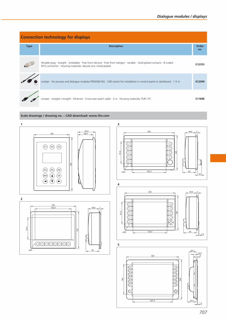
Connection technology for displays
Type Description Orderno.
Wirable plug · straight · shieldable · Free from silicone · Free from halogen · wirable · Gold-plated contacts · B-coded · M12 connector · Housing materials: diecast zinc nickel-plated
E12355
Jumper · for process and dialogue modules PDM360 NG · USB socket for installation in control panel or dashboard · 1.5 m EC2099
Jumper · straight / straight · Ethernet · Cross-over patch cable · 2 m · Housing materials: PUR / PC E11898
Scale drawings / drawing no. – CAD download: www.ifm.com
1
46,453,4
109
165
F2 F3F1
F5 F6F4
okesc
2
192
152,4
157
55
746,6
LED
91,5
3
225
152,4
91,4
146
5518
746,6
LED
4
225
152,4
91,4
146
55
746,6
LED2,5
5
52,61,5
814,9
42,7
324
245
247,4
185
Dialogue modules / displays
707
Gesamtkatalog EN 2016_17_Stilvorlage LK FrutigerOT_2010 DE_GB.qxd 06.11.15 16:59 Seite 707

Cameras
Displays with graphics capabilities, free programming to IEC 61131 and variousinterfaces are features of the dialogue modules.The convenient user interface for service and machine handling – the dialoguemodules of the ecomatmobile control system.
3D sensors for mobile machines
Type Image resolution Angle of aperture
[°]
Additionalfunctions
Interfaces Draw-ingno.
Orderno.
M12 connector
64 x 16 pixels 70 x 23Angle of aperture 70° x 23°
(horizontal x vertical)Video signal
analogue1 O3M150
64 x 16 pixels 70 x 23 CAN outputVideo signal
analogue1 O3M151
Accessories
Type Description Orderno.
IR illumination unit · Device interfaces: MCI · Angle of aperture 70° x 23° (horizontal x vertical) · IR illumination unit for the operationof O3M15x and O3M25x · Connector · Housing materials: diecast aluminium
O3M950
System overview Page
3D sensors for mobile machines 708
Accessories 708 - 709
Connection cables for industrial imaging 709
Camera systems for PDM360 color and PDM360 NG 710
Connection technology for displays 710
Accessories 710 - 711
Camera systems for PDM360 color and PDM360 NG 711
Connection technology for displays 711
Scale drawings / drawing no. – CAD download: www.ifm.com 712
Systems for mobile machines
708Product selectors and further information can be found at: www.ifm.com
Gesamtkatalog EN 2016_17_Stilvorlage LK FrutigerOT_2010 DE_GB.qxd 06.11.15 16:59 Seite 708
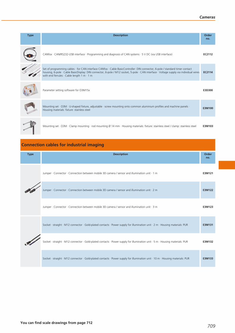
Type Description Orderno.
CANfox · CAN/RS232-USB interface · Programming and diagnosis of CAN systems · 5 V DC (via USB interface) EC2112
Set of programming cables · for CAN interface CANfox · Cable BasicController: DIN connector, 6-pole / standard timer contacthousing, 6-pole · Cable BasicDisplay: DIN connector, 6-pole / M12 socket, 5-pole · CAN interface · Voltage supply via individual wireswith end ferrules · Cable length 1 m · 1 m
EC2114
Parameter setting software for O3M15x E3D300
Mounting set · O3M · U-shaped fixture, adjustable · screw mounting onto common aluminium profiles and machine panels ·Housing materials: fixture: stainless steel
E3M100
Mounting set · O3M · Clamp mounting · rod mounting Ø 14 mm · Housing materials: fixture: stainless steel / clamp: stainless steel E3M103
Connection cables for industrial imaging
Type Description Orderno.
Jumper · Connector · Connection between mobile 3D camera / sensor and illumination unit · 1 m E3M121
Jumper · Connector · Connection between mobile 3D camera / sensor and illumination unit · 2 m E3M122
Jumper · Connector · Connection between mobile 3D camera / sensor and illumination unit · 3 m E3M123
Socket · straight · M12 connector · Gold-plated contacts · Power supply for illumination unit · 2 m · Housing materials: PUR E3M131
Socket · straight · M12 connector · Gold-plated contacts · Power supply for illumination unit · 5 m · Housing materials: PUR E3M132
Socket · straight · M12 connector · Gold-plated contacts · Power supply for illumination unit · 10 m · Housing materials: PUR E3M133
Cameras
709You can find scale drawings from page 712
Gesamtkatalog EN 2016_17_Stilvorlage LK FrutigerOT_2010 DE_GB.qxd 06.11.15 16:59 Seite 709

Camera systems for PDM360 color and PDM360 NG
Type Image resolution Angle of aperture
[°]
Additionalfunctions
Interfaces Draw-ingno.
Orderno.
M16 connector
720 x 480 78 lens heatingVideo signal
analogue2 O2M200
720 x 480 78Integrated mirror function
lens heatingVideo signal
analogue2 O2M201
720 x 480 115 lens heatingVideo signal
analogue2 O2M202
720 x 480 115Integrated mirror function
lens heatingVideo signal
analogue2 O2M203
Connection technology for displays
Type Description Orderno.
Adapter cable · straight / straight · M16 - M12 · Gold-plated contacts · Free from silicone · 0.6 m · Housing materials: housing: PUR / sealing: EPDM
E2M200
Adapter cable · straight / straight · Y adapter cable M12 plug / 2 x M16 socket · Gold-plated contacts · Free from silicone · 0.95 m · Housing materials: housing: PUR / sealing: EPDM
E2M201
Jumper · straight / straight · M16 - M16 · Gold-plated contacts · Free from silicone · 5 m · Housing materials: housing: PUR / sealing: EPDM
E2M203
Jumper · straight / straight · M16 - M16 · Gold-plated contacts · Free from silicone · 16 m · Housing materials: housing: PUR / sealing: EPDM
E2M205
Jumper · straight / straight · M16 - M16 · Gold-plated contacts · Free from silicone · 21 m · Housing materials: housing: PUR / sealing: EPDM
E2M206
Accessories
Type Description Orderno.
protective housing · O2M2 · Housing materials: housing: 1.4301 E2M212
Mounting bracket · O2M2 · Housing materials: housing: ABS reinforced glass-fibre / PC / PA E2M211
Systems for mobile machines
710Product selectors and further information can be found at: www.ifm.com
Gesamtkatalog EN 2016_17_Stilvorlage LK FrutigerOT_2010 DE_GB.qxd 06.11.15 16:59 Seite 710
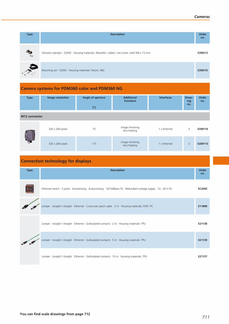
Type Description Orderno.
Vibration damper · O2M2 · Housing materials: Absorber: rubber / set screw: steel M6 x 15 mm E2M213
Mounting set · O2M2 · Housing materials: fixture: ABS E2M210
Camera systems for PDM360 color and PDM360 NG
Type Image resolution Angle of aperture
[°]
Additionalfunctions
Interfaces Draw-ingno.
Orderno.
M12 connector
320 x 240 pixels 75image mirroring
lens heating1 x Ethernet 3 O2M110
320 x 240 pixels 115image mirroring
lens heating1 x Ethernet 3 O2M113
Connection technology for displays
Type Description Orderno.
Ethernet switch · 5 ports · Autosensing · Autocrossing · 10/100Base-TX · Redundant voltage supply · 10...30 V DC EC2095
Jumper · straight / straight · Ethernet · Cross-over patch cable · 2 m · Housing materials: PUR / PC E11898
Jumper · straight / straight · Ethernet · Gold-plated contacts · 2 m · Housing materials: TPU E21138
Jumper · straight / straight · Ethernet · Gold-plated contacts · 5 m · Housing materials: TPU E21139
Jumper · straight / straight · Ethernet · Gold-plated contacts · 10 m · Housing materials: TPU E21137
Cameras
711You can find scale drawings from page 712
Gesamtkatalog EN 2016_17_Stilvorlage LK FrutigerOT_2010 DE_GB.qxd 06.11.15 16:59 Seite 711
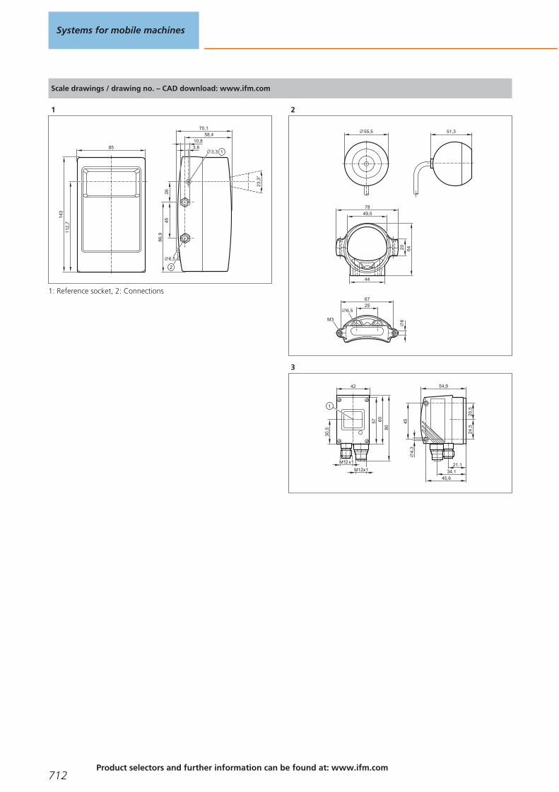
Scale drawings / drawing no. – CAD download: www.ifm.com
1
23
,3°
85
143
112,
7
70,158,4
10,8
45
6,5
2686
,91
2
3,33,8
1: Reference socket, 2: Connections
2
55,5 51,3
6,52567
M3
44
7849,5
64206
3
54,9
45
45,6
21,1
34,1
4,3
42
57
80
M12 x1
M12x1
60
20,5
24,5
30,5
1
Systems for mobile machines
712Product selectors and further information can be found at: www.ifm.com
Gesamtkatalog EN 2016_17_Stilvorlage LK FrutigerOT_2010 DE_GB.qxd 06.11.15 16:59 Seite 712

Cameras
713
Gesamtkatalog EN 2016_17_Stilvorlage LK FrutigerOT_2010 DE_GB.qxd 06.11.15 16:59 Seite 713
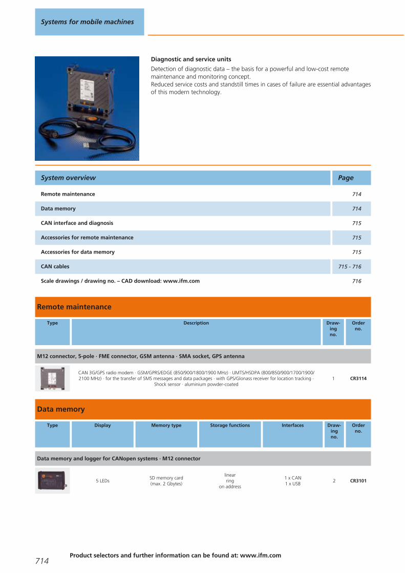
Diagnostic and service units
Detection of diagnostic data – the basis for a powerful and low-cost remote maintenance and monitoring concept.Reduced service costs and standstill times in cases of failure are essential advantagesof this modern technology.
Remote maintenance
Type Description Draw-ingno.
Orderno.
M12 connector, 5-pole · FME connector, GSM antenna · SMA socket, GPS antenna
CAN 3G/GPS radio modem · GSM/GPRS/EDGE (850/900/1800/1900 MHz) · UMTS/HSDPA (800/850/900/1700/1900/2100 MHz) · for the transfer of SMS messages and data packages · with GPS/Glonass receiver for location tracking ·
Shock sensor · aluminium powder-coated1 CR3114
Data memory
Type Display Memory type Storage functions Interfaces Draw-ingno.
Orderno.
Data memory and logger for CANopen systems · M12 connector
5 LEDsSD memory card(max. 2 Gbytes)
linearring
on address
1 x CAN1 x USB
2 CR3101
System overview Page
Remote maintenance 714
Data memory 714
CAN interface and diagnosis 715
Accessories for remote maintenance 715
Accessories for data memory 715
CAN cables 715 - 716
Scale drawings / drawing no. – CAD download: www.ifm.com 716
Systems for mobile machines
714Product selectors and further information can be found at: www.ifm.com
Gesamtkatalog EN 2016_17_Stilvorlage LK FrutigerOT_2010 DE_GB.qxd 06.11.15 16:59 Seite 714

CAN interface and diagnosis
Type Description Draw-ingno.
Orderno.
CANfox · CAN/RS232-USB interface · Programming and diagnosis of CAN systems · 5 V DC (via USB interface) 3 EC2112
Adapter cable · for CAN interface CANfox · CAN adapter: DIN connector, 6 poles / M12 connector, 5 poles · RS-232adapter: DIN connector, 6 poles / Sub-D plug, 9 poles · Cable length 1 m
4 EC2113
Accessories for remote maintenance
Type Description Orderno.
CANremote GSM planar aerial · GSM 850/900/1800/1900 · UMTS 1920...2170 MHz · Cable length 3 m · FME socket (GSM) · flat design for mounting on all plain surfaces
EC2092
CANremote GPS planar aerial · with integrated amplifier · Cable length 3 m · SMA aerial connector · flat design for mounting on all plain surfaces
EC2093
GSM/GPS combined antenna · GSM 850/900/1800/1900 · UMTS 1920...2170 MHz · with integrated amplifier · Cable length 3 m ·FME socket (GSM) · SMA plug (GPS) · flat design for mounting on all plain surfaces · e.g. for CANremote CR3108, CR3110 orCR3112 · thread M16 x 1.5
EC2116
Accessories for data memory
Type Description Orderno.
SD memory card · 2 GByte · for mobile applications EC1021
CAN cables
Type Description Orderno.
Adapter cable · 9-pole D-SUB (female) · 5-pole socket; M12 · 2-pole cable for power supply with bare ends · integrated CANterminal resistor (120 Ω) switchable
EC2050
Adapter cable for CAN devices with M12 connector (5 pole) · e.g. CANmem, CANremote or inclination sensors EC2062
CAN communication cable · cable length 2 m interface 9-pole D-SUB (female) · cable ends with lugs EC2034
Diagnostic andservice units
715You can find scale drawings from page 716
Gesamtkatalog EN 2016_17_Stilvorlage LK FrutigerOT_2010 DE_GB.qxd 06.11.15 16:59 Seite 715

Type Description Orderno.
Serial interface cable · 2 x 9-pole D-SUB (female) · 1:1 · e.g. for PC communication, configuration or uploads of firmware updates ·Cable length 2 m · e.g. for process and dialogue monitors PDM360
EC2063
USB connection cable · type A to type Mini B · for PC communication, configuration and uploads of firmware updates · cable length 1.8 m · e.g. for CANmem
EC2058
Wirable socket · straight · Free from silicone · Free from halogen · wirable · Gold-plated contacts · M12 connector · 5-pole · Housing materials: PA
E11511
Scale drawings / drawing no. – CAD download: www.ifm.com
1
42
111,
5
1
109126
107
120,
5
32 4
1: LEDs, 2: SMA socket, GPS antenna, 3: FME connector, GSMantenna, 4: M12 connector, 5-pole
2
M12
x1
117,5
130
5 LED
35
85
CARD ERRORCARD ACCESS
ONERROR
CAN
5
2
41
3
1: CANopen interface, 2: protective cover, 3: USB, type Mini-B(socket), 4: SD/MMC slot, 5: PCMCIA slot
3
130076
4
1000
1000
1: CAN adapter, 2: RS-232 adapter
Systems for mobile machines
716Product selectors and further information can be found at: www.ifm.com
Gesamtkatalog EN 2016_17_Stilvorlage LK FrutigerOT_2010 DE_GB.qxd 06.11.15 16:59 Seite 716

Diagnostic andservice units
717
Gesamtkatalog EN 2016_17_Stilvorlage LK FrutigerOT_2010 DE_GB.qxd 06.11.15 16:59 Seite 717

Signal converters
The solution provider for special applications. Signal converter to adapt sensor andactuator signals to the inputs and outputs of the controller or CANopen modules.
Converters and PWM modules
Type Description Draw-ingno.
Orderno.
PWM / analogue module · PCB · Input 24 V DC PWM signal · Output 0...5 V DC 1 CR3001
PWM / analogue module · PCB · Input 24 V DC PWM signal · Output 0...10 V DC 1 CR3002
PWM / analogue module · Housing · Input 24 V DC PWM signal · Output 0...5 V DC 2 CR3003
PWM / analogue module · Housing · Input 24 V DC PWM signal · Output 0...10 V DC 2 CR3004
DC/DC converter · Input 18...36 V DC · Output 10 V DC 3 EC2025
Module for current measurement with ecomat R 360 controller 4 EC2049
Scale drawings / drawing no. – CAD download: www.ifm.com
1
42,5
49
3024,5
3,2
2
42,5
54
3424,5
3,2
15
System overview Page
Converters and PWM modules 718
Scale drawings / drawing no. – CAD download: www.ifm.com 718 - 719
Systems for mobile machines
718Product selectors and further information can be found at: www.ifm.com
Gesamtkatalog EN 2016_17_Stilvorlage LK FrutigerOT_2010 DE_GB.qxd 06.11.15 16:59 Seite 718
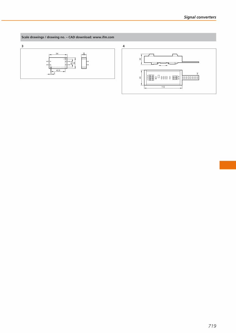
Scale drawings / drawing no. – CAD download: www.ifm.com
3
42,5
54
3424,5
3
15
4
3245
112
123
54
Signal converters
719
Gesamtkatalog EN 2016_17_Stilvorlage LK FrutigerOT_2010 DE_GB.qxd 06.11.15 16:59 Seite 719

Sensors
From CAN-bus compatible or analogue inclination sensors to inductive proximityswitches and pressure sensors for mobile applications.The sensors of the ecomatmobile system are reliable even under the extreme conditions of use in a mobile machine.
Absolute multiturn-encoders (CANopen) for mobile applications
Type Resolution Ub
[V]
f
[kHz]
Iload
[mA]
Shaft
[mm]
Ambienttemperature
[°C]
Cableentry
Draw-ingno.
Orderno.
M12 connector · Output function CANopen interface · Connector group 159
24 bits 10...30 – – 10 -40...85 axial 1 RM9000
System overview Page
Absolute multiturn-encoders (CANopen) for mobile applications 720
RFID system 13.56 MHz 721
CAN inclination sensors 721
Inclination sensors 721
Tilt sensors 722
Inductive sensors for mobile applications 722 - 724
Full metal sensors for industrial applications 724 - 725
Sensors for mobile applications 725
Electronic pressure sensors for mobile applications 725 - 728
Accessories for sensors for mobile applications 728
Connection technology for sensors for mobile use 728 - 731
Wiring diagrams 731 - 732
Scale drawings / drawing no. – CAD download: www.ifm.com 732 - 735
Systems for mobile machines
720Product selectors and further information can be found at: www.ifm.com
Gesamtkatalog EN 2016_17_Stilvorlage LK FrutigerOT_2010 DE_GB.qxd 06.11.15 16:59 Seite 720
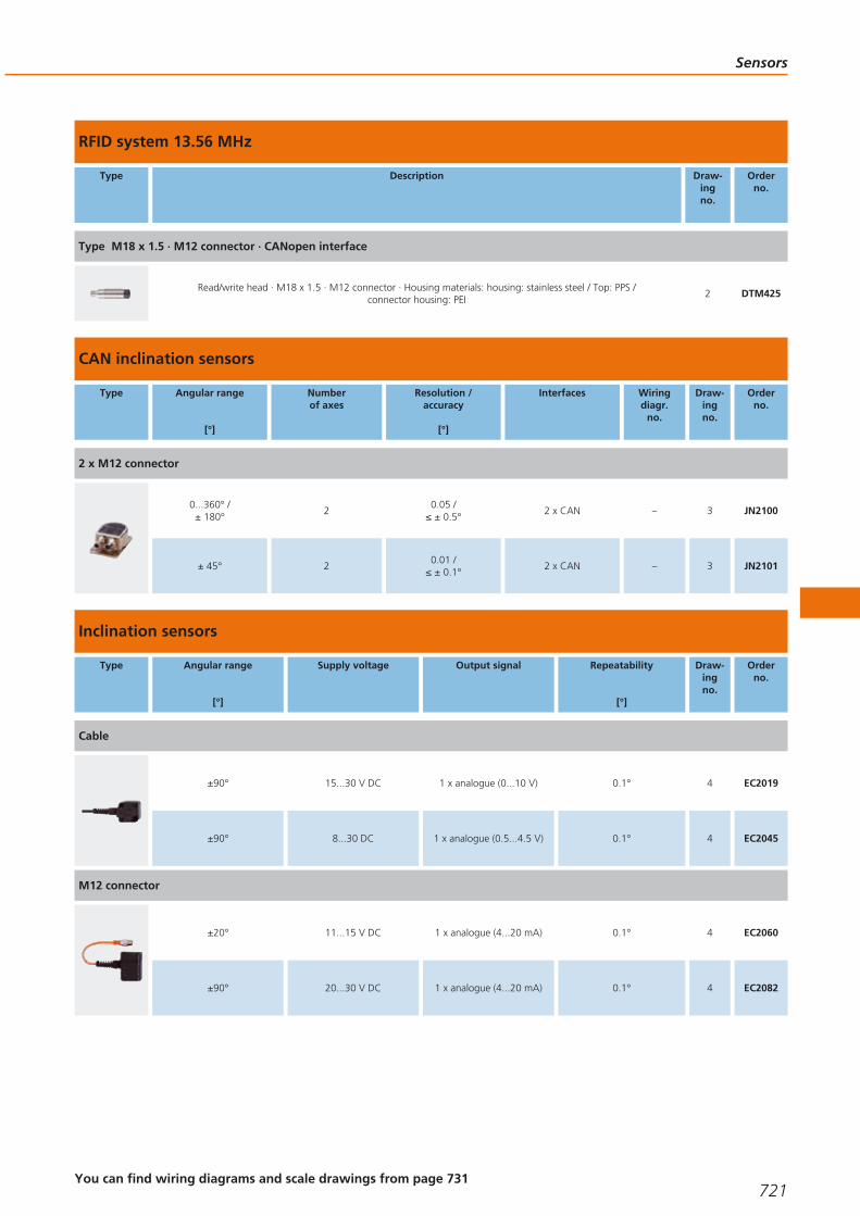
RFID system 13.56 MHz
Type Description Draw-ingno.
Orderno.
Type M18 x 1.5 · M12 connector · CANopen interface
Read/write head · M18 x 1.5 · M12 connector · Housing materials: housing: stainless steel / Top: PPS / connector housing: PEI
2 DTM425
CAN inclination sensors
Type Angular range
[°]
Numberof axes
Resolution /accuracy
[°]
Interfaces Wiringdiagr.
no.
Draw-ingno.
Orderno.
2 x M12 connector
0...360° / ± 180°
20.05 /
≤ ± 0.5°2 x CAN – 3 JN2100
± 45° 20.01 /
≤ ± 0.1°2 x CAN – 3 JN2101
Inclination sensors
Type Angular range
[°]
Supply voltage Output signal Repeatability
[°]
Draw-ingno.
Orderno.
Cable
±90° 15...30 V DC 1 x analogue (0...10 V) 0.1° 4 EC2019
±90° 8...30 DC 1 x analogue (0.5...4.5 V) 0.1° 4 EC2045
M12 connector
±20° 11...15 V DC 1 x analogue (4...20 mA) 0.1° 4 EC2060
±90° 20...30 V DC 1 x analogue (4...20 mA) 0.1° 4 EC2082
Sensors
721You can find wiring diagrams and scale drawings from page 731
Gesamtkatalog EN 2016_17_Stilvorlage LK FrutigerOT_2010 DE_GB.qxd 06.11.15 16:59 Seite 721

Tilt sensors
Type Angular range
[°]
Supply voltage Output signal Repeatability
[°]
Draw-ingno.
Orderno.
Cable
2.5...5.5° 10...30 V DC 1 x Digital 0.2° 5 EC2061
Inductive sensors for mobile applications
Type Dimensions
[mm]
Sensingrange
[mm]
Material Ub
[V]
Protection f
[Hz]
Iload
[mA]
Draw-ingno.
Orderno.
Cable 3 m · Output function · DC PNP · Wiring diagram no. 1
40 x 12 x 26 4 nf PBT 10...36 IP 67 70 – 6 IN5281
Cable 3 m · Output function · DC PNP · Wiring diagram no. 2
40 x 12 x 26 4 nf PBT 10...36 IP 67 70 – 6 IN5282
Cable 6 m · Output function · DC PNP · Wiring diagram no. 3
M12 / L = 79 4 f stainless steel 10...60 IP 67 / IP 69K 400 200 7 IFM209
M12 / L = 79 7 nf High-grade st. steel 10...60 IP 67 / IP 69K 300 200 8 IFM210
M18 / L = 81 8 f stainless steel 10...60 IP 67 / IP 69K 200 200 9 IGM206
M18 / L = 81 12 nf stainless steel 10...60 IP 67 / IP 69K 200 200 10 IGM207
M30 / L = 81 12 f stainless steel 10...60 IP 67 / IP 69K 100 200 11 IIM210
M30 / L = 81 22 nf stainless steel 10...60 IP 67 / IP 69K 100 200 12 IIM211
Cable 6 m · Output function · 3-wire DC PNP; 2-wire DC PNP/NPN · Wiring diagram no. 14
M12 / L = 79 4 f stainless steel 10...36 IP 67 / IP 69K 400 100 7 IFM207
Systems for mobile machines
722Product selectors and further information can be found at: www.ifm.com
Gesamtkatalog EN 2016_17_Stilvorlage LK FrutigerOT_2010 DE_GB.qxd 06.11.15 16:59 Seite 722
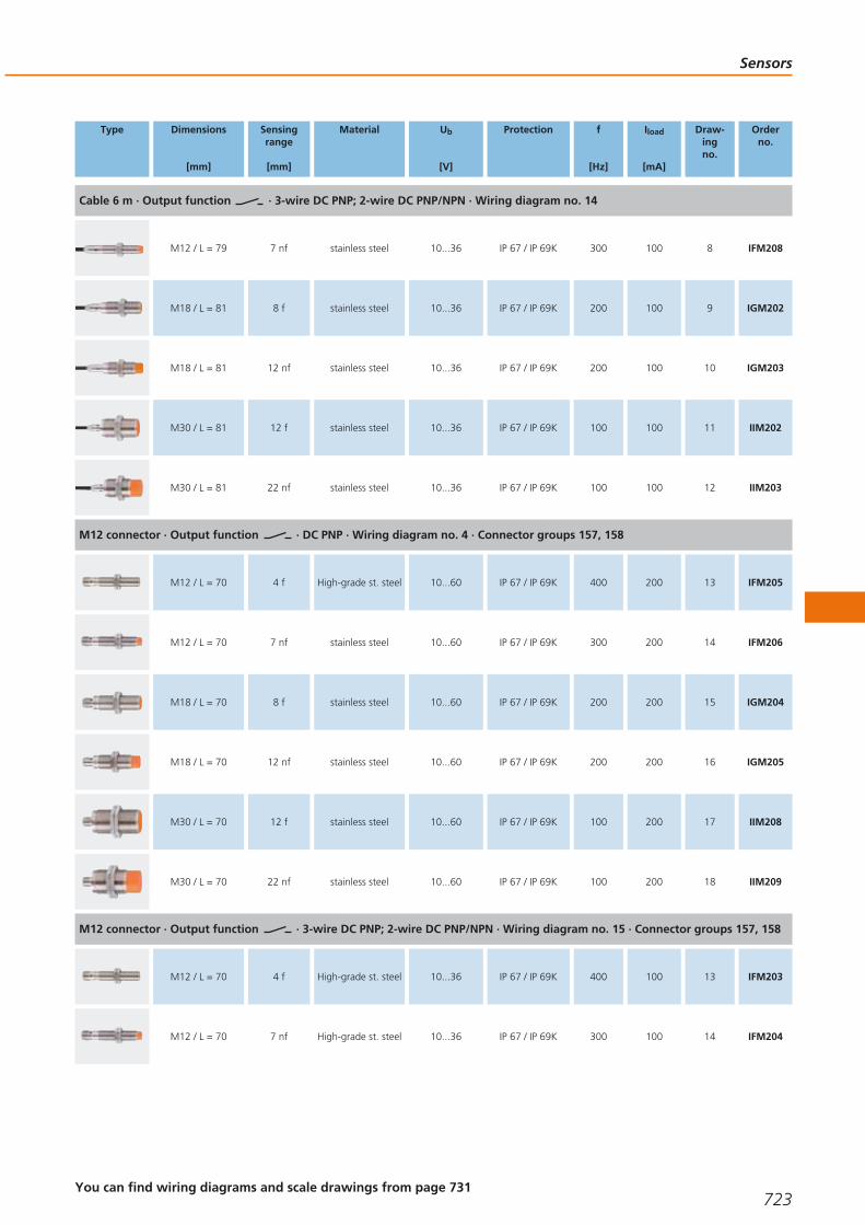
Type Dimensions
[mm]
Sensingrange
[mm]
Material Ub
[V]
Protection f
[Hz]
Iload
[mA]
Draw-ingno.
Orderno.
Cable 6 m · Output function · 3-wire DC PNP; 2-wire DC PNP/NPN · Wiring diagram no. 14
M12 / L = 79 7 nf stainless steel 10...36 IP 67 / IP 69K 300 100 8 IFM208
M18 / L = 81 8 f stainless steel 10...36 IP 67 / IP 69K 200 100 9 IGM202
M18 / L = 81 12 nf stainless steel 10...36 IP 67 / IP 69K 200 100 10 IGM203
M30 / L = 81 12 f stainless steel 10...36 IP 67 / IP 69K 100 100 11 IIM202
M30 / L = 81 22 nf stainless steel 10...36 IP 67 / IP 69K 100 100 12 IIM203
M12 connector · Output function · DC PNP · Wiring diagram no. 4 · Connector groups 157, 158
M12 / L = 70 4 f High-grade st. steel 10...60 IP 67 / IP 69K 400 200 13 IFM205
M12 / L = 70 7 nf stainless steel 10...60 IP 67 / IP 69K 300 200 14 IFM206
M18 / L = 70 8 f stainless steel 10...60 IP 67 / IP 69K 200 200 15 IGM204
M18 / L = 70 12 nf stainless steel 10...60 IP 67 / IP 69K 200 200 16 IGM205
M30 / L = 70 12 f stainless steel 10...60 IP 67 / IP 69K 100 200 17 IIM208
M30 / L = 70 22 nf stainless steel 10...60 IP 67 / IP 69K 100 200 18 IIM209
M12 connector · Output function · 3-wire DC PNP; 2-wire DC PNP/NPN · Wiring diagram no. 15 · Connector groups 157, 158
M12 / L = 70 4 f High-grade st. steel 10...36 IP 67 / IP 69K 400 100 13 IFM203
M12 / L = 70 7 nf High-grade st. steel 10...36 IP 67 / IP 69K 300 100 14 IFM204
Sensors
723You can find wiring diagrams and scale drawings from page 731
Gesamtkatalog EN 2016_17_Stilvorlage LK FrutigerOT_2010 DE_GB.qxd 06.11.15 16:59 Seite 723

Type Dimensions
[mm]
Sensingrange
[mm]
Material Ub
[V]
Protection f
[Hz]
Iload
[mA]
Draw-ingno.
Orderno.
M12 connector · Output function · 3-wire DC PNP; 2-wire DC PNP/NPN · Wiring diagram no. 15 · Connector groups 157, 158
M18 / L = 70 8 f stainless steel 10...36 IP 67 / IP 69K 200 100 15 IGM200
M18 / L = 70 12 nf stainless steel 10...36 IP 67 / IP 69K 200 100 16 IGM201
M30 / L = 70 12 f stainless steel 10...36 IP 67 / IP 69K 100 100 17 IIM200
M30 / L = 70 22 nf stainless steel 10...36 IP 67 / IP 69K 100 100 18 IIM201
f = flush / nf = non flush
Full metal sensors for industrial applications
Type Dimensions
[mm]
Sensingrange
[mm]
Material Ub
[V]
Protection f
[Hz]
Iload
[mA]
Draw-ingno.
Orderno.
M12 connector · Output function · DC PNP · Wiring diagram no. 4 · Connector groups 8, 10, 11, 18, 20, 120, 124, 126, 128,130, 157, 158
M12 / L = 93 1.8 f High-grade st. steel 10...36IP 65 / IP 68 /
IP 69K1000 200 19 MFH200
M12 connector · Output function · DC NPN · Wiring diagram no. 5 · Connector groups 8, 10, 18, 20, 120, 124, 126, 128, 157
M12 / L = 93 1.8 f High-grade st. steel 10...36IP 65 / IP 68 /
IP 69K1000 200 19 MFH201
M12 connector · Output function · DC PNP · Wiring diagram no. 4 · Connector groups 8, 10, 11, 18, 20, 120, 124, 126, 128,130, 157, 158
M12 / L = 60 1.8 f High-grade st. steel 10...36IP 65 / IP 68 /
IP 69K1000 200 20 MFH202
M12 connector · Output function · DC NPN · Wiring diagram no. 5 · Connector groups 8, 10, 18, 20, 120, 124, 126, 128, 157
M12 / L = 60 1.8 f High-grade st. steel 10...36IP 65 / IP 68 /
IP 69K1000 200 20 MFH203
M12 connector · Output function · DC PNP · Wiring diagram no. 6 · Connector groups 8, 10, 18, 20, 120, 124, 126, 128, 157
M12 / L = 60 1.8 f High-grade st. steel 10...36IP 65 / IP 68 /
IP 69K1000 200 20 MFH204
Systems for mobile machines
724Product selectors and further information can be found at: www.ifm.com
Gesamtkatalog EN 2016_17_Stilvorlage LK FrutigerOT_2010 DE_GB.qxd 06.11.15 16:59 Seite 724

Type Dimensions
[mm]
Sensingrange
[mm]
Material Ub
[V]
Protection f
[Hz]
Iload
[mA]
Draw-ingno.
Orderno.
M12 connector · Output function · DC PNP · Wiring diagram no. 4 · Connector groups 8, 10, 11, 18, 20, 120, 124, 126, 128,130, 157, 158
special design 2 f High-grade st. steel 10...36IP 65 / IP 68 /
IP 69K1000 200 21 M9H200
f = flush / nf = non flush
Sensors for mobile applications
Type Dimensions
[mm]
Sensingrange
[mm]
Material Ub
[V]
Protection f
[Hz]
Iload
[mA]
Draw-ingno.
Orderno.
M12 connector · Output function · DC PNP · Wiring diagram no. 4 · Connector groups 8, 10, 11, 18, 20, 120, 124, 126, 128,130, 157, 158
M12 / L = 60 60 stainless steel 10...30 IP 67 5000 200 22 MF5004
Cable with connector 0.15 m · Output function · DC PNP · Wiring diagram no. 4 · Connector groups 1, 2, 3, 72, 78, 120, 122
40 x 12 x 26 60 PBT 10...30 IP 67 – 200 23 MN5200
Electronic pressure sensors for mobile applications
Type Processconnection
Display Measuringrange
[bar]
Poverload
max. [bar]
Pbursting
min. [bar]
UbDC
[V]
Draw-ingno.
Orderno.
AMP Superseal · Output function 0...10 V analogue · Wiring diagram no. 7
G ¼ A – 0...400 1000 1700 16...32 24 PU5600
G ¼ A – 0...250 625 1200 16...32 24 PU5601
G ¼ A – 0...100 250 1000 16...32 24 PU5602
G ¼ A – 0...25 65 600 16...32 24 PU5603
G ¼ A – 0...10 25 300 16...32 24 PU5604
G ¼ A – 0...600 1500 2500 16...32 24 PU5660
Sensors
725You can find wiring diagrams and scale drawings from page 731
Gesamtkatalog EN 2016_17_Stilvorlage LK FrutigerOT_2010 DE_GB.qxd 06.11.15 16:59 Seite 725

Type Processconnection
Display Measuringrange
[bar]
Poverload
max. [bar]
Pbursting
min. [bar]
UbDC
[V]
Draw-ingno.
Orderno.
DEUTSCH connector DT04-3P · Output function 0...10 V analogue · Wiring diagram no. 8
G ¼ A – 0...400 1000 1700 16...32 25 PU5700
G ¼ A – 0...250 625 1200 16...32 25 PU5701
G ¼ A – 0...100 250 1000 16...32 25 PU5702
G ¼ A – 0...25 65 600 16...32 25 PU5703
G ¼ A – 0...10 25 300 16...32 25 PU5704
G ¼ A – 0...600 1500 2500 16...32 25 PU5760
AMP Superseal · Output function 4...20 mA analogue · Wiring diagram no. 9
G ¼ A – 0...400 1000 1700 8...32 24 PT5600
G ¼ A – 0...250 625 1200 8...32 24 PT5601
G ¼ A – 0...100 250 1000 8...32 24 PT5602
G ¼ A – 0...25 65 600 8...32 24 PT5603
G ¼ A – 0...10 25 300 8...32 24 PT5604
G ¼ A – 0...600 1500 2500 8...32 24 PT5660
DEUTSCH connector DT04-3P · Output function 4...20 mA analogue · Wiring diagram no. 10
G ¼ A – 0...400 1000 1700 8...32 25 PT5700
G ¼ A – 0...250 625 1200 8...32 25 PT5701
G ¼ A – 0...100 250 1000 8...32 25 PT5702
Systems for mobile machines
726Product selectors and further information can be found at: www.ifm.com
Gesamtkatalog EN 2016_17_Stilvorlage LK FrutigerOT_2010 DE_GB.qxd 06.11.15 16:59 Seite 726

Type Processconnection
Display Measuringrange
[bar]
Poverload
max. [bar]
Pbursting
min. [bar]
UbDC
[V]
Draw-ingno.
Orderno.
DEUTSCH connector DT04-3P · Output function 4...20 mA analogue · Wiring diagram no. 10
G ¼ A – 0...25 65 600 8...32 25 PT5703
G ¼ A – 0...10 25 300 8...32 25 PT5704
G ¼ A – 0...600 1500 2500 8...32 25 PT5760
M12 connector · Output function 2 x normally open / closed programmable or 1 x normally open / closed programmable + 1 x normally closed (diagnostic function) · Wiring diagram no. 11 · Connector groups 157, 158
G ¼ A / M5 I Operation 0...400 600 1000 9.6...36 26 PP000E
G ¼ A / M5 I Operation 0...250 400 850 9.6...36 26 PP001E
G ¼ A / M5 I Operation 0...100 300 650 9.6...36 27 PP002E
G ¼ A / M5 I Operation 0...25 150 350 9.6...36 28 PP003E
G ¼ A / M5 I Operation -1...10 75 150 9.6...36 28 PP004E
M12 connector · Output function 4...20 mA analogue · Wiring diagram no. 12 · Connector group 157
G ¼ A – 0...400 600 1600 8.5...36 29 PT3550
G ¼ A – 0...250 400 1000 8.5...36 29 PT3551
G ¼ A – 0...100 200 1000 8.5...36 29 PT3552
G ¼ A – 0...25 60 600 8.5...36 29 PT3553
G ¼ A – 0...10 25 300 8.5...36 29 PT3554
G ¼ A – 0...600 9600 2400 8.5...36 29 PT3560
M12 connector · Output function 0...10 V analogue · Wiring diagram no. 13 · Connector group 157
G ¼ A – 0...400 600 1600 16...36 29 PT9550
Sensors
727You can find wiring diagrams and scale drawings from page 731
Gesamtkatalog EN 2016_17_Stilvorlage LK FrutigerOT_2010 DE_GB.qxd 06.11.15 16:59 Seite 727

Type Processconnection
Display Measuringrange
[bar]
Poverload
max. [bar]
Pbursting
min. [bar]
UbDC
[V]
Draw-ingno.
Orderno.
M12 connector · Output function 0...10 V analogue · Wiring diagram no. 13 · Connector group 157
G ¼ A – 0...250 400 1000 16...36 29 PT9551
G ¼ A – 0...100 200 1000 16...36 29 PT9552
G ¼ A – 0...25 60 600 16...36 29 PT9553
G ¼ A – 0...10 25 300 16...36 29 PT9554
Accessories for sensors for mobile applications
Type Description Orderno.
Programming/ display unit · for EPS and IO-Link sensors · Connector · Housing materials: stainless steel 316L / 1.4404 / PC copolymer / PBT / FPM
PP2001
Mounting clamp · Ø 12 mm · with end stop · for type M12 · Housing materials: PC E11047
Mounting clamp · Ø 18 mm · with end stop · for type M18 · Housing materials: PC E11048
Mounting clamp · Ø 30 mm · with end stop · for type M30 · Housing materials: PC E11049
Angle bracket · for type M12 · Housing materials: stainless steel E10735
Angle bracket · for type M18 · Housing materials: stainless steel E10736
Angle bracket · for type M30 · Housing materials: stainless steel E10737
Connection technology for sensors for mobile use
Type Description Orderno.
Jumper · straight / straight · Free from silicone · Free from halogen · Gold-plated contacts · 0.3 m · Housing materials: housing: TPUorange / sealing: FKM
EVC010
Systems for mobile machines
728 Product selectors and further information can be found at: www.ifm.com
Gesamtkatalog EN 2016_17_Stilvorlage LK FrutigerOT_2010 DE_GB.qxd 06.11.15 16:59 Seite 728

Type Description Orderno.
Jumper · straight / straight · Free from silicone · Free from halogen · Gold-plated contacts · 1 m · Housing materials: housing: TPU orange / sealing: FKM
EVC012
Socket · angled · Free from silicone · Free from halogen · Gold-plated contacts · M12 connector · 2 m · Housing materials: housing: TPU orange / sealing: FKM
EVC004
Socket · angled · Free from silicone · Free from halogen · Gold-plated contacts · M12 connector · 5 m · Housing materials: housing: TPU orange / sealing: FKM
EVC005
Socket · angled · Free from silicone · Free from halogen · Gold-plated contacts · M12 connector · 10 m · Housing materials: housing: TPU orange / sealing: FKM
EVC006
Socket · straight · Free from silicone · Free from halogen · Gold-plated contacts · M12 connector · 2 m · Housing materials: housing: TPU orange / sealing: FKM
EVC001
Socket · straight · Free from silicone · Free from halogen · Gold-plated contacts · M12 connector · 5 m · Housing materials: housing: TPU orange / sealing: FKM
EVC002
Socket · straight · Free from silicone · Free from halogen · Gold-plated contacts · M12 connector · 10 m · Housing materials:housing: TPU orange / sealing: FKM
EVC003
Socket · straight · Free from silicone · Free from halogen · Gold-plated contacts · M12 connector · 2 m · Housing materials: housing: TPU orange / sealing: FKM
EVC526
Socket · straight · Free from silicone · Free from halogen · Gold-plated contacts · M12 connector · 5 m · Housing materials: housing: TPU orange / sealing: FKM
EVC527
Socket · straight · Free from silicone · Free from halogen · Gold-plated contacts · M12 connector · 10 m · Housing materials:housing: TPU orange / sealing: FKM
EVC528
Socket · angled · Free from silicone · Free from halogen · Gold-plated contacts · M12 connector · 2 m · Housing materials: housing: TPU orange / sealing: FKM
EVC529
Socket · angled · Free from silicone · Free from halogen · Gold-plated contacts · M12 connector · 5 m · Housing materials: housing: TPU orange / sealing: FKM
EVC530
Socket · angled · Free from silicone · Free from halogen · Gold-plated contacts · M12 connector · 10 m · Housing materials: housing: TPU orange / sealing: FKM
EVC531
Socket · straight · Free from silicone · Free from halogen · Gold-plated contacts · M12 connector · 2 m · Housing materials: housing: TPU orange / sealing: FKM
EVC532
Socket · straight · Free from silicone · Free from halogen · Gold-plated contacts · M12 connector · 5 m · Housing materials: housing: TPU orange / sealing: FKM
EVC533
Socket · straight · Free from silicone · Free from halogen · Gold-plated contacts · M12 connector · 10 m · Housing materials:housing: TPU orange / sealing: FKM
EVC534
Sensors
729You can find wiring diagrams and scale drawings from page 731
Gesamtkatalog EN 2016_17_Stilvorlage LK FrutigerOT_2010 DE_GB.qxd 06.11.15 16:59 Seite 729

Type Description Orderno.
Socket · angled · Free from silicone · Free from halogen · Gold-plated contacts · M12 connector · 2 m · Housing materials: housing: TPU orange / sealing: FKM
EVC535
Socket · angled · Free from silicone · Free from halogen · Gold-plated contacts · M12 connector · 5 m · Housing materials: housing: TPU orange / sealing: FKM
EVC536
Socket · angled · Free from silicone · Free from halogen · Gold-plated contacts · M12 connector · 10 m · Housing materials: housing: TPU orange / sealing: FKM
EVC537
Socket · straight · Free from silicone · Free from halogen · Gold-plated contacts · M12 connector · 2 m · Housing materials: housing: TPU orange / sealing: FKM
EVC538
Socket · straight · Free from silicone · Free from halogen · Gold-plated contacts · M12 connector · 5 m · Housing materials: housing: TPU orange / sealing: FKM
EVC539
Socket · straight · Free from silicone · Free from halogen · Gold-plated contacts · M12 connector · 10 m · Housing materials:housing: TPU orange / sealing: FKM
EVC540
Socket · angled · Free from silicone · Free from halogen · Gold-plated contacts · M12 connector · 2 m · Housing materials: housing: TPU orange / sealing: FKM
EVC541
Socket · angled · Free from silicone · Free from halogen · Gold-plated contacts · M12 connector · 5 m · Housing materials: housing: TPU orange / sealing: FKM
EVC542
Socket · angled · Free from silicone · Free from halogen · Gold-plated contacts · M12 connector · 10 m · Housing materials: housing: TPU orange / sealing: FKM
EVC543
Socket · straight · Free from silicone · Free from halogen · Gold-plated contacts · M12 connector · 2 m · Housing materials: housing: TPU orange / sealing: FKM
EVC544
Socket · straight · Free from silicone · Free from halogen · Gold-plated contacts · M12 connector · 5 m · Housing materials: housing: TPU orange / sealing: FKM
EVC545
Socket · straight · Free from silicone · Free from halogen · Gold-plated contacts · M12 connector · 10 m · Housing materials:housing: TPU orange / sealing: FKM
EVC546
Socket · angled · Free from silicone · Free from halogen · Gold-plated contacts · M12 connector · 2 m · Housing materials: housing: TPU orange / sealing: FKM
EVC547
Socket · angled · Free from silicone · Free from halogen · Gold-plated contacts · M12 connector · 5 m · Housing materials: housing: TPU orange / sealing: FKM
EVC548
Socket · angled · Free from silicone · Free from halogen · Gold-plated contacts · M12 connector · 10 m · Housing materials: housing: TPU orange / sealing: FKM
EVC549
Socket · straight · Free from halogen · Gold-plated contacts · M12 connector · 2 m · Housing materials: PUR E11596
Systems for mobile machines
730
Gesamtkatalog EN 2016_17_Stilvorlage LK FrutigerOT_2010 DE_GB.qxd 06.11.15 16:59 Seite 730

Type Description Orderno.
Socket · straight · Free from halogen · Gold-plated contacts · M12 connector · 5 m · Housing materials: PUR E11597
Terminating resistor socket · straight · Gold-plated contacts · M12 connector · Housing materials: TPU E11589
Terminating resistor plug · straight · Gold-plated contacts · M12 connector · Housing materials: TPU E11590
Cable plug · straight · Free from halogen · Gold-plated contacts · M12 connector · 2 m · Housing materials: PUR E11598
Cable plug · straight · Free from halogen · Gold-plated contacts · M12 connector · 5 m · Housing materials: PUR E11599
Jumper · straight / straight · Free from halogen · Gold-plated contacts · 0.3 m · Housing materials: PUR E11591
Jumper · straight / straight · Free from halogen · Gold-plated contacts · 1 m · Housing materials: PUR E11592
Jumper · straight / straight · Free from halogen · Gold-plated contacts · 2 m · Housing materials: PUR E11593
Jumper · straight / straight · Free from halogen · Gold-plated contacts · 5 m · Housing materials: PUR E11594
Socket · angled · Free from silicone · Free from halogen · Gold-plated contacts · M12 connector with integrated CAN terminatingresistor (120 ohm) · 5 m · Housing materials: housing: TPU black / sealing: FKM
EVC492
Cable plug · angled · Free from silicone · Free from halogen · Gold-plated contacts · M12 connector · 6 m · Housing materials:housing: TPU black
E12215
Core colours
BN brown
BU blue
BK black
Wiring diagrams
1
BN
BU L
L+
2
BN
BU L
L+
3
BN
BK
BU
L+
L
4
L+
L
1
4
3
5
L+
L
1
4
3
6
L+
L
1
2
3
7
1
2
3
OUT
L +
L -
Sensors
731
Gesamtkatalog EN 2016_17_Stilvorlage LK FrutigerOT_2010 DE_GB.qxd 06.11.15 16:59 Seite 731

Wiring diagrams
8
A
C
B
OUT
L -
L +L +
9
1
3L +
OUT
10
A
BOUT
+L
11
4
1
3
2OUT2
L+
L
OUT1/Teach/Data
12
L+
L
1
2
13
L+
L
1
3
2
14
L+
L
BN
BK
BU
L+
L
BN
BK
15
L+
L
1
4
L+
L
1
4
3
Scale drawings / drawing no. – CAD download: www.ifm.com
1
36,53024
LED
2023 36 9
100
4
4
10
57
M12
x1
2
M12
x1
3557
70
LED
59
10
24
4
M18
x1,5
3
364,
5
9075
224560
5,3
4
5241
4124
537
5,2
5
6,2
81
20
2,75
5,25
8,25
12,75
Systems for mobile machines
732Product selectors and further information can be found at: www.ifm.com
Gesamtkatalog EN 2016_17_Stilvorlage LK FrutigerOT_2010 DE_GB.qxd 06.11.15 16:59 Seite 732

Scale drawings / drawing no. – CAD download: www.ifm.com
640
6
12
LED
4
2613
32
3,2 4
5
LED
3,2
18
1610
1
1: threaded insert M3, depth 5.8 mm, max. tightening torque 1.2 Nm (screw fixing class 8.8) when brass insert in contact withcounterpart.
7
5,4
7962
53
M12
x1
LED 4 x 90° 17
4
8
5,4
796248
LED 4 x 90° 17
4
M12
x1
5
9
64
LED 4 x 90° 24
81
5750
M18
x1
4
10
64
LED 4 x 90° 24
81
5740
M18
x1
4
10
11
36
53
M30
x1,5
57
5
5
64
LED 4 x 90°
81
12
36
38
M30
x1,5
1557
5
5
64
LED 4 x 90°
81
13
5950
M12
x1
17
4
M12
x1
LED
70
14
45
M12
x1
174
5
M12
x1
5970
LED
15
M18
x1
M12
x1
5057
7059
424LED 4 x 90°
16
M18
x1
M12
x1
4057
70
LED 4 x 90°
59
10
424
17
59
53
M30
x1,5
57
70
M12
x1
LED 4 x 90° 536
Sensors
733
Gesamtkatalog EN 2016_17_Stilvorlage LK FrutigerOT_2010 DE_GB.qxd 06.11.15 16:59 Seite 733

Scale drawings / drawing no. – CAD download: www.ifm.com
18
LED 4 x 90°
59
38
M30
x1,5
5
57
70
36
M12
x1
15
19
M12
x1
M12
x1
10
18
9,74
57,8
7,8
17
93
20
M12
x1
10
1527,8
417
M12
x1
9,7
7,8
60
21
11 10,5
53
15,5
LED
19
11,2
M12
x1
M14
x1,5
27,5
22
4940
M12
x1
174
M12
x1
LED 4 x 90°
60
23
1610
1
4020
12
LED
4
2613
32
3,2 45
LED
3,2
18
1: threaded insert M3, depth 5.8 mm, max. tightening torque 1.2 Nm (screw fixing class 8.8) when brass insert in contact withcounterpart.
24
51,9
72
25,8
12
G 41
19
1
21,8
19
14,35
1: sealing FKM / DIN 3869
25
71,5
51,4
12
G 41
19
1
19
21,825,4
1: sealing FKM / DIN 3869
26
79,5
M12 x130
G14/
2
LED
65,5
30 12
M51
1: Pressure relief mechanism, No mechanical force must be exertedon the pressure relief mechanism., 2: sealing FPM / DIN 3869-14
27
79,5
M12 x130
30
12
G14/
M5
1
LED
65,5
1: sealing FPM / DIN 3869-14
Systems for mobile machines
734Product selectors and further information can be found at: www.ifm.com
Gesamtkatalog EN 2016_17_Stilvorlage LK FrutigerOT_2010 DE_GB.qxd 06.11.15 16:59 Seite 734

Scale drawings / drawing no. – CAD download: www.ifm.com
28
79,5
M12 x130
42
65,5
30 12
G1/
M51
LED
1: ventilation, 2: sealing FPM / DIN 3869-14
29
22
1
51,2
12
G1 4/
65,1
M12 x122
1: FKM seal / DIN 3869-14, tightening torque 25 Nm
Sensors
735
Gesamtkatalog EN 2016_17_Stilvorlage LK FrutigerOT_2010 DE_GB.qxd 06.11.15 16:59 Seite 735

Quickly and safely connected
Maximum operational reliability due to thenew vibration protection with end stop.
Connection technology
With a wide variety of different sensor designs ifm electronicoffers a wide range of high quality connectors. The choice oftypes covers common M8, M12, M18 types through to valveplugs. The “ecolink” connectors (order no. EVxxxx) offeradditional quality features.
ecolink – a new dimension in connection technology
The innovative design incorporating a mechanical end stopensures that the O-ring is always correctly compressed and so permanently maintains its sealing function. The connectorremains securely positioned on the unit even in case of extremevibration and impacts. The use of a transparent black housingensures that even in bright lighting conditions the LEDs areclearly visible.
For industrial applications
High-quality materials suited to the requirements in industrialenvironments. Largely resistant to oils, greases and coolants.
For hygienic and wet areas
PVC housing and cable, gold-plated contacts and high-gradestainless steel nuts are the optimum choice for long life.
For hazardous areas
Connection technology for ATEX categories 1D, 2D, 3D and1G, 3G. With the EC type examination certificate for compo-nents from DEKRA EXAM the connection technology meetsthe strictest requirements.
For welding applications
Halogen-free PUR cables prevent burning-in of weld spatter;teflon-coated coupling nuts prevent weld spatter sticking. Thecables are also suited for drag chains and torsionalmovements.
For sensors in robust applications
The saw tooth contoured vibration protection secures againststrong shocks and vibrations. The high protection rating, widetemperature range and high-quality housing materials (high-grade stainless steel, TPU) ensure permanent safe connectionin harsh environments.
Connection technology
736Product selectors and further information can be found at: www.ifm.com
Gesamtkatalog EN 2016_17_Stilvorlage LK FrutigerOT_2010 DE_GB.qxd 06.11.15 16:59 Seite 736

Connection technology
737
Sockets 738 - 765
Plugs 766 - 770
Jumper cables 772 - 804
Splitter boxes 806 - 824
Y-splitters 826 - 828
Gesamtkatalog EN 2016_17_Stilvorlage LK FrutigerOT_2010 DE_GB.qxd 06.11.15 16:59 Seite 737

Sockets
Sockets are mainly used for the connection of sensors. High-quality socket contactsand materials ensure reliable electrical connections. In addition to a wide range of standard products ifm also offers versions withoutsilicone and halogen, versions for hygienic areas, for applications in contact withcoolants and lubricants, as well as for welding applications.
M8 sockets for industrial applications
Type Cable Wirespecification
Materialhousing /
nut
U
[V]
Ta
[°C]
Pro-tection
LEDs Draw-ingno.
Orderno.
Group 1 · Socket M8, 3-pole, 3-wire · Wiring diagram no. 1
2 m blackPUR cable 3 x 0.25 mm2, Ø 3.7 mm
TPU /Brass
50 AC60 DC
-25...90IP 65 / IP 67 /IP 68 / IP 69K
– 1 EVC141
System overview Page
M8 sockets for industrial applications 738 - 740
M12 sockets for industrial applications 740 - 743
M12 sockets for industrial applications with screen 743 - 745
M16 sockets for industrial applications 745
M18 sockets for industrial applications 746
M23 sockets for industrial applications 746 - 747
1/2" sockets for industrial applications 747 - 748
7/8" sockets for industrial applications 748
DIN sockets for industrial applications 748
RD24 sockets for industrial applications 748 - 749
Connectors weld slag resistant 749 - 750
M12 cable sockets for hygienic and wet areas with screen 750 - 752
Connectors for hygienic and wet areas 752 - 755
Connectors for hazardous areas 756 - 757
Connectors for robust applications 757 - 758
Wiring diagrams 759 - 760
Scale drawings / drawing no. – CAD download: www.ifm.com 760 - 765
Connection technology
738Product selectors and further information can be found at: www.ifm.com
Gesamtkatalog EN 2016_17_Stilvorlage LK FrutigerOT_2010 DE_GB.qxd 06.11.15 16:59 Seite 738
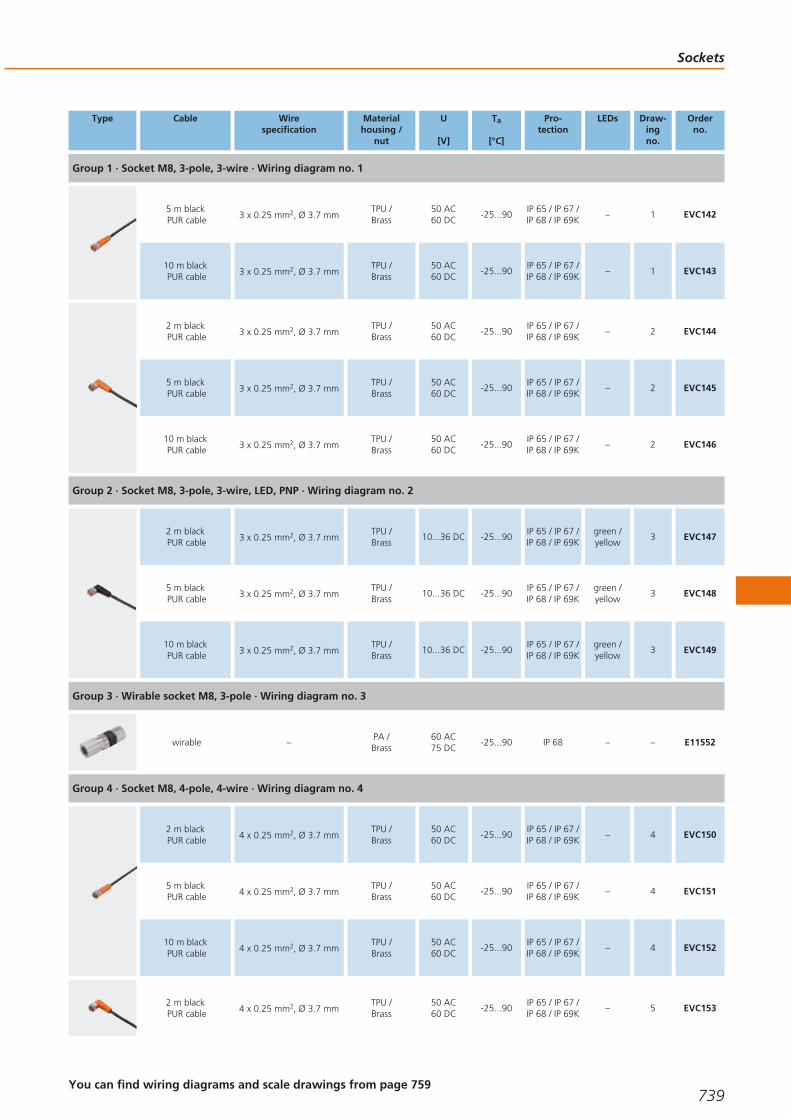
Type Cable Wirespecification
Materialhousing /
nut
U
[V]
Ta
[°C]
Pro-tection
LEDs Draw-ingno.
Orderno.
Group 1 · Socket M8, 3-pole, 3-wire · Wiring diagram no. 1
5 m blackPUR cable 3 x 0.25 mm2, Ø 3.7 mm
TPU /Brass
50 AC60 DC
-25...90IP 65 / IP 67 /IP 68 / IP 69K
– 1 EVC142
10 m blackPUR cable 3 x 0.25 mm2, Ø 3.7 mm
TPU /Brass
50 AC60 DC
-25...90IP 65 / IP 67 /IP 68 / IP 69K
– 1 EVC143
2 m blackPUR cable 3 x 0.25 mm2, Ø 3.7 mm
TPU /Brass
50 AC60 DC
-25...90IP 65 / IP 67 /IP 68 / IP 69K
– 2 EVC144
5 m blackPUR cable 3 x 0.25 mm2, Ø 3.7 mm
TPU /Brass
50 AC60 DC
-25...90IP 65 / IP 67 /IP 68 / IP 69K
– 2 EVC145
10 m blackPUR cable 3 x 0.25 mm2, Ø 3.7 mm
TPU /Brass
50 AC60 DC
-25...90IP 65 / IP 67 /IP 68 / IP 69K
– 2 EVC146
Group 2 · Socket M8, 3-pole, 3-wire, LED, PNP · Wiring diagram no. 2
2 m blackPUR cable 3 x 0.25 mm2, Ø 3.7 mm
TPU /Brass
10...36 DC -25...90IP 65 / IP 67 /IP 68 / IP 69K
green /yellow
3 EVC147
5 m blackPUR cable 3 x 0.25 mm2, Ø 3.7 mm
TPU /Brass
10...36 DC -25...90IP 65 / IP 67 /IP 68 / IP 69K
green /yellow
3 EVC148
10 m blackPUR cable 3 x 0.25 mm2, Ø 3.7 mm
TPU /Brass
10...36 DC -25...90IP 65 / IP 67 /IP 68 / IP 69K
green /yellow
3 EVC149
Group 3 · Wirable socket M8, 3-pole · Wiring diagram no. 3
wirable –PA /Brass
60 AC75 DC
-25...90 IP 68 – – E11552
Group 4 · Socket M8, 4-pole, 4-wire · Wiring diagram no. 4
2 m blackPUR cable 4 x 0.25 mm2, Ø 3.7 mm
TPU /Brass
50 AC60 DC
-25...90IP 65 / IP 67 /IP 68 / IP 69K
– 4 EVC150
5 m blackPUR cable 4 x 0.25 mm2, Ø 3.7 mm
TPU /Brass
50 AC60 DC
-25...90IP 65 / IP 67 /IP 68 / IP 69K
– 4 EVC151
10 m blackPUR cable 4 x 0.25 mm2, Ø 3.7 mm
TPU /Brass
50 AC60 DC
-25...90IP 65 / IP 67 /IP 68 / IP 69K
– 4 EVC152
2 m blackPUR cable 4 x 0.25 mm2, Ø 3.7 mm
TPU /Brass
50 AC60 DC
-25...90IP 65 / IP 67 /IP 68 / IP 69K
– 5 EVC153
Sockets
739You can find wiring diagrams and scale drawings from page 759
Gesamtkatalog EN 2016_17_Stilvorlage LK FrutigerOT_2010 DE_GB.qxd 06.11.15 16:59 Seite 739

Type Cable Wirespecification
Materialhousing /
nut
U
[V]
Ta
[°C]
Pro-tection
LEDs Draw-ingno.
Orderno.
Group 4 · Socket M8, 4-pole, 4-wire · Wiring diagram no. 4
5 m blackPUR cable 4 x 0.25 mm2, Ø 3.7 mm
TPU /Brass
50 AC60 DC
-25...90IP 65 / IP 67 /IP 68 / IP 69K
– 5 EVC154
10 m blackPUR cable 4 x 0.25 mm2, Ø 3.7 mm
TPU /Brass
50 AC60 DC
-25...90IP 65 / IP 67 /IP 68 / IP 69K
– 5 EVC155
Group 5 · Wirable socket M8, 4-pole · Wiring diagram no. 5
wirable –PA /Brass
60 AC75 DC
-25...90 IP 68 – – E11553
M12 sockets for industrial applications
Type Cable Wirespecification
Materialhousing /
nut
U
[V]
Ta
[°C]
Pro-tection
LEDs Draw-ingno.
Orderno.
Group 6 · Socket M12, 5-pole, 2-wire · Wiring diagram no. 6
2 m blackPUR cable 2 x 0.34 mm2, Ø 4.9 mm
TPU /Brass
250 AC300 DC
-25...90IP 65 / IP 67 /IP 68 / IP 69K
– 6 EVC164
5 m blackPUR cable 2 x 0.34 mm2, Ø 4.9 mm
TPU /Brass
250 AC300 DC
-25...90IP 65 / IP 67 /IP 68 / IP 69K
– 6 EVC165
10 m blackPUR cable 2 x 0.34 mm2, Ø 4.9 mm
TPU /Brass
250 AC300 DC
-25...90IP 65 / IP 67 /IP 68 / IP 69K
– 6 EVC166
2 m blackPUR cable 2 x 0.34 mm2, Ø 4.9 mm
TPU /Brass
250 AC300 DC
-25...90IP 65 / IP 67 /IP 68 / IP 69K
– 7 EVC161
5 m blackPUR cable 2 x 0.34 mm2, Ø 4.9 mm
TPU /Brass
250 AC300 DC
-25...90IP 65 / IP 67 /IP 68 / IP 69K
– 7 EVC162
10 m blackPUR cable 2 x 0.34 mm2, Ø 4.9 mm
TPU /Brass
250 AC300 DC
-25...90IP 65 / IP 67 /IP 68 / IP 69K
– 7 EVC163
Group 7 · socket M12, 2-pole + PE, 3-wire · Wiring diagram no. 7
2 m orangePVC cable
3 x AWG 22 (3 x0.34 mm2), Ø 5 mm
TPU /Brass
250 AC300 DC
-25...90 IP 67 – 8 E10865
5 m orangePVC cable
3 x AWG 22 (3 x0.34 mm2), Ø 5 mm
TPU /Brass
250 AC300 DC
-25...90 IP 67 – 8 E10866
2 m orangePVC cable
3 x AWG 22 (3 x0.34 mm2), Ø 5 mm
TPU /Brass
250 AC300 DC
-25...90 IP 67 – 9 E10867
Connection technology
740 Product selectors and further information can be found at: www.ifm.com
Gesamtkatalog EN 2016_17_Stilvorlage LK FrutigerOT_2010 DE_GB.qxd 06.11.15 16:59 Seite 740

Type Cable Wirespecification
Materialhousing /
nut
U
[V]
Ta
[°C]
Pro-tection
LEDs Draw-ingno.
Orderno.
Group 7 · socket M12, 2-pole + PE, 3-wire · Wiring diagram no. 7
5 m orangePVC cable
3 x AWG 22 (3 x0.34 mm2), Ø 5 mm
TPU /Brass
250 AC300 DC
-25...90 IP 67 – 9 E10868
Group 8 · Wirable socket M12, 4-pole · Wiring diagram no. 5
wirable ...0.75 mm2 (Ø 4...6 mm)PA /Brass
250 AC/DC -25...85 IP 68 – 10 E11509
wirable ...0.75 mm2 (Ø 4...6 mm)PA /Brass
250 AC/DC -25...85 IP 68 – 11 E11508
Group 9 · Wirable socket M12, 4-pole, LED, PNP · Wiring diagram no. 8
wirable ...0.75 mm2 (Ø 4...6 mm)PA /Brass
10...30 DC -25...85 IP 68green /yellow
12 E11510
wirable ...0.75 mm2 (Ø 4...6 mm) PA 10...30 DC -40...85 IP 67green /yellow
11 E10136
Group 10 · Socket M12, 5/4-pole, 4-wire · Wiring diagram no. 4
2 m blackPUR cable 4 x 0.34 mm2, Ø 4.9 mm
TPU /Brass
250 AC300 DC
-25...90IP 65 / IP 67 /IP 68 / IP 69K
– 6 EVC004
5 m blackPUR cable 4 x 0.34 mm2, Ø 4.9 mm
TPU /Brass
250 AC300 DC
-25...90IP 65 / IP 67 /IP 68 / IP 69K
– 6 EVC005
10 m blackPUR cable 4 x 0.34 mm2, Ø 4.9 mm
TPU /Brass
250 AC300 DC
-25...90IP 65 / IP 67 /IP 68 / IP 69K
– 6 EVC006
2 m blackPUR cable 4 x 0.34 mm2, Ø 4.9 mm
TPU /Brass
250 AC300 DC
-25...90IP 65 / IP 67 /IP 68 / IP 69K
– 7 EVC001
5 m blackPUR cable 4 x 0.34 mm2, Ø 4.9 mm
TPU /Brass
250 AC300 DC
-25...90IP 65 / IP 67 /IP 68 / IP 69K
– 7 EVC002
10 m blackPUR cable 4 x 0.34 mm2, Ø 4.9 mm
TPU /Brass
250 AC300 DC
-25...90IP 65 / IP 67 /IP 68 / IP 69K
– 7 EVC003
Group 11 · Socket M12, 5/4-pole, 4-wire, LED, PNP · Wiring diagram no. 9
2 m blackPUR cable 4 x 0.34 mm2, Ø 4.9 mm
TPU /Brass
10...36 DC -25...90IP 65 / IP 67 /IP 68 / IP 69K
green /2 x yellow
13 EVC007
5 m blackPUR cable 4 x 0.34 mm2, Ø 4.9 mm
TPU /Brass
10...36 DC -25...90IP 65 / IP 67 /IP 68 / IP 69K
green /2 x yellow
13 EVC008
Sockets
741You can find wiring diagrams and scale drawings from page 759
Gesamtkatalog EN 2016_17_Stilvorlage LK FrutigerOT_2010 DE_GB.qxd 06.11.15 16:59 Seite 741

Type Cable Wirespecification
Materialhousing /
nut
U
[V]
Ta
[°C]
Pro-tection
LEDs Draw-ingno.
Orderno.
Group 11 · Socket M12, 5/4-pole, 4-wire, LED, PNP · Wiring diagram no. 9
10 m blackPUR cable 4 x 0.34 mm2, Ø 4.9 mm
TPU /Brass
10...36 DC -25...90IP 65 / IP 67 /IP 68 / IP 69K
green /2 x yellow
13 EVC009
Group 12 · Wirable socket M12, 5-pole · Wiring diagram no. 10
wirable ...0.75 mm2 (Ø 4...6 mm)PA /Brass
125 AC/DC -25...85 IP 68 – 14 E11512
wirable ...0.75 mm2 (Ø 4...6 mm)PA /Brass
125 AC/DC -25...85 IP 68 – 15 E11511
Group 13 · Socket M12, 5-pole, 5-wire · Wiring diagram no. 11
2 m blackPUR cable 5 x 0.34 mm2, Ø 4.9 mm
TPU /Brass
60 AC60 DC
-25...90IP 65 / IP 67 /IP 68 / IP 69K
– 6 EVC073
5 m blackPUR cable 5 x 0.34 mm2, Ø 4.9 mm
TPU /Brass
60 AC60 DC
-25...90IP 65 / IP 67 /IP 68 / IP 69K
– 6 EVC074
10 m blackPUR cable 5 x 0.34 mm2, Ø 4.9 mm
TPU /Brass
60 AC60 DC
-25...90IP 65 / IP 67 /IP 68 / IP 69K
– 6 EVC075
2 m blackPUR cable 5 x 0.34 mm2, Ø 4.9 mm
TPU /Brass
60 AC60 DC
-25...90IP 65 / IP 67 /IP 68 / IP 69K
– 7 EVC070
5 m blackPUR cable 5 x 0.34 mm2, Ø 4.9 mm
TPU /Brass
60 AC60 DC
-25...90IP 65 / IP 67 /IP 68 / IP 69K
– 7 EVC071
10 m blackPUR cable 5 x 0.34 mm2, Ø 4.9 mm
TPU /Brass
60 AC60 DC
-25...90IP 65 / IP 67 /IP 68 / IP 69K
– 7 EVC072
Group 14 · Socket M12, 8-pole, 6-wire · Wiring diagram no. 12
5 m blackPUR cable 6 x 0.34 mm2, Ø 6 mm
TPU /diecast zinc
60 AC/DC -25...85 IP 68 – 16 E10976
10 m blackPUR cable 6 x 0.34 mm2, Ø 6 mm
TPU /diecast zinc
60 AC/DC -25...85 IP 68 – 16 E10977
Group 15 · socket M12, 8-pole, 7-wire + screen · Wiring diagram no. 13
2 m blackPUR cable 7 x 0.25 mm2 + screen
TPU /diecast zinc
60 AC/DC -25...85 IP 67 – 16 E20738
5 m blackPUR cable 7 x 0.25 mm2 + screen
TPU /diecast zinc
60 AC/DC -25...85 IP 67 – 17 E20838
Connection technology
742Product selectors and further information can be found at: www.ifm.com
Gesamtkatalog EN 2016_17_Stilvorlage LK FrutigerOT_2010 DE_GB.qxd 06.11.15 16:59 Seite 742
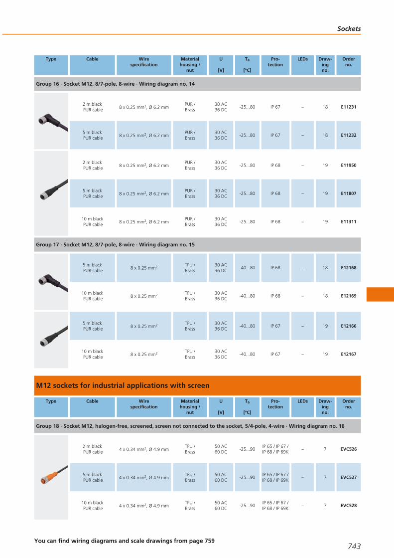
Type Cable Wirespecification
Materialhousing /
nut
U
[V]
Ta
[°C]
Pro-tection
LEDs Draw-ingno.
Orderno.
Group 16 · Socket M12, 8/7-pole, 8-wire · Wiring diagram no. 14
2 m blackPUR cable 8 x 0.25 mm2, Ø 6.2 mm
PUR /Brass
30 AC36 DC
-25...80 IP 67 – 18 E11231
5 m blackPUR cable 8 x 0.25 mm2, Ø 6.2 mm
PUR /Brass
30 AC36 DC
-25...80 IP 67 – 18 E11232
2 m blackPUR cable 8 x 0.25 mm2, Ø 6.2 mm
PUR /Brass
30 AC36 DC
-25...80 IP 68 – 19 E11950
5 m blackPUR cable 8 x 0.25 mm2, Ø 6.2 mm
PUR /Brass
30 AC36 DC
-25...80 IP 68 – 19 E11807
10 m blackPUR cable 8 x 0.25 mm2, Ø 6.2 mm
PUR /Brass
30 AC36 DC
-25...80 IP 68 – 19 E11311
Group 17 · Socket M12, 8/7-pole, 8-wire · Wiring diagram no. 15
5 m blackPUR cable 8 x 0.25 mm2 TPU /
Brass30 AC36 DC
-40...80 IP 68 – 18 E12168
10 m blackPUR cable 8 x 0.25 mm2 TPU /
Brass30 AC36 DC
-40...80 IP 68 – 18 E12169
5 m blackPUR cable 8 x 0.25 mm2 TPU /
Brass30 AC36 DC
-40...80 IP 67 – 19 E12166
10 m blackPUR cable 8 x 0.25 mm2 TPU /
Brass30 AC36 DC
-40...80 IP 67 – 19 E12167
M12 sockets for industrial applications with screen
Type Cable Wirespecification
Materialhousing /
nut
U
[V]
Ta
[°C]
Pro-tection
LEDs Draw-ingno.
Orderno.
Group 18 · Socket M12, halogen-free, screened, screen not connected to the socket, 5/4-pole, 4-wire · Wiring diagram no. 16
2 m blackPUR cable 4 x 0.34 mm2, Ø 4.9 mm
TPU /Brass
50 AC60 DC
-25...90IP 65 / IP 67 /IP 68 / IP 69K
– 7 EVC526
5 m blackPUR cable 4 x 0.34 mm2, Ø 4.9 mm
TPU /Brass
50 AC60 DC
-25...90IP 65 / IP 67 /IP 68 / IP 69K
– 7 EVC527
10 m blackPUR cable 4 x 0.34 mm2, Ø 4.9 mm
TPU /Brass
50 AC60 DC
-25...90IP 65 / IP 67 /IP 68 / IP 69K
– 7 EVC528
Sockets
743You can find wiring diagrams and scale drawings from page 759
Gesamtkatalog EN 2016_17_Stilvorlage LK FrutigerOT_2010 DE_GB.qxd 06.11.15 16:59 Seite 743

Type Cable Wirespecification
Materialhousing /
nut
U
[V]
Ta
[°C]
Pro-tection
LEDs Draw-ingno.
Orderno.
Group 18 · Socket M12, halogen-free, screened, screen not connected to the socket, 5/4-pole, 4-wire · Wiring diagram no. 16
2 m blackPUR cable 4 x 0.34 mm2, Ø 4.9 mm
TPU /Brass
50 AC60 DC
-25...90IP 65 / IP 67 /IP 68 / IP 69K
– 6 EVC529
5 m blackPUR cable 4 x 0.34 mm2, Ø 4.9 mm
TPU /Brass
50 AC60 DC
-25...90IP 65 / IP 67 /IP 68 / IP 69K
– 6 EVC530
10 m blackPUR cable 4 x 0.34 mm2, Ø 4.9 mm
TPU /Brass
50 AC60 DC
-25...90IP 65 / IP 67 /IP 68 / IP 69K
– 6 EVC531
Group 19 · Socket M12, halogen-free, screened, screen not connected to the socket, 5-pole, 5-wire · Wiring diagram no. 17
2 m blackPUR cable 5 x 0.25 mm2, Ø 4.9 mm
TPU /Brass
30 AC36 DC
-25...90IP 65 / IP 67 /IP 68 / IP 69K
– 7 EVC532
5 m blackPUR cable 5 x 0.25 mm2, Ø 4.9 mm
TPU /Brass
30 AC36 DC
-25...90IP 65 / IP 67 /IP 68 / IP 69K
– 7 EVC533
10 m blackPUR cable 5 x 0.25 mm2, Ø 4.9 mm
TPU /Brass
30 AC36 DC
-25...90IP 65 / IP 67 /IP 68 / IP 69K
– 7 EVC534
2 m blackPUR cable 5 x 0.25 mm2, Ø 4.9 mm
TPU /Brass
30 AC36 DC
-25...90IP 65 / IP 67 /IP 68 / IP 69K
– 6 EVC535
5 m blackPUR cable 5 x 0.25 mm2, Ø 4.9 mm
TPU /Brass
30 AC36 DC
-25...90IP 65 / IP 67 /IP 68 / IP 69K
– 6 EVC536
10 m blackPUR cable 5 x 0.25 mm2, Ø 4.9 mm
TPU /Brass
30 AC36 DC
-25...90IP 65 / IP 67 /IP 68 / IP 69K
– 6 EVC537
Group 20 · Socket M12, halogen-free, screened, screen connected to the socket, 5/4-pole, 4-wire · Wiring diagram no. 18
2 m blackPUR cable 4 x 0.34 mm2, Ø 4.9 mm
TPU /Brass
50 AC60 DC
-25...90 IP 65 / IP 67 – 7 EVC538
5 m blackPUR cable 4 x 0.34 mm2, Ø 4.9 mm
TPU /Brass
50 AC60 DC
-25...90 IP 65 / IP 67 – 7 EVC539
10 m blackPUR cable 4 x 0.34 mm2, Ø 4.9 mm
TPU /Brass
50 AC60 DC
-25...90 IP 65 / IP 67 – 7 EVC540
2 m blackPUR cable 4 x 0.34 mm2, Ø 4.9 mm
TPU /Brass
50 AC60 DC
-25...90 IP 65 / IP 67 – 6 EVC541
5 m blackPUR cable 4 x 0.34 mm2, Ø 4.9 mm
TPU /Brass
50 AC60 DC
-25...90 IP 65 / IP 67 – 6 EVC542
Connection technology
744Product selectors and further information can be found at: www.ifm.com
Gesamtkatalog EN 2016_17_Stilvorlage LK FrutigerOT_2010 DE_GB.qxd 06.11.15 16:59 Seite 744
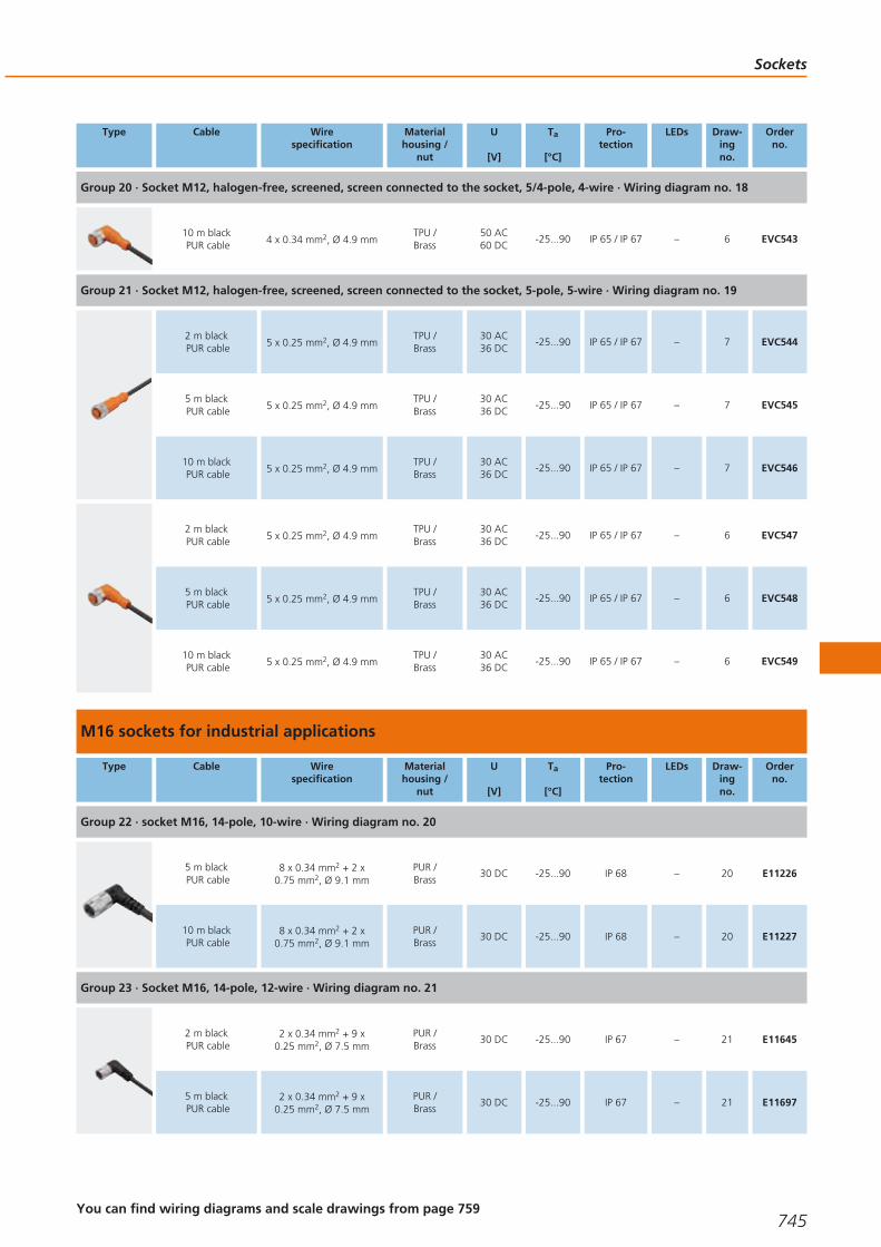
Type Cable Wirespecification
Materialhousing /
nut
U
[V]
Ta
[°C]
Pro-tection
LEDs Draw-ingno.
Orderno.
Group 20 · Socket M12, halogen-free, screened, screen connected to the socket, 5/4-pole, 4-wire · Wiring diagram no. 18
10 m blackPUR cable 4 x 0.34 mm2, Ø 4.9 mm
TPU /Brass
50 AC60 DC
-25...90 IP 65 / IP 67 – 6 EVC543
Group 21 · Socket M12, halogen-free, screened, screen connected to the socket, 5-pole, 5-wire · Wiring diagram no. 19
2 m blackPUR cable 5 x 0.25 mm2, Ø 4.9 mm
TPU /Brass
30 AC36 DC
-25...90 IP 65 / IP 67 – 7 EVC544
5 m blackPUR cable 5 x 0.25 mm2, Ø 4.9 mm
TPU /Brass
30 AC36 DC
-25...90 IP 65 / IP 67 – 7 EVC545
10 m blackPUR cable 5 x 0.25 mm2, Ø 4.9 mm
TPU /Brass
30 AC36 DC
-25...90 IP 65 / IP 67 – 7 EVC546
2 m blackPUR cable 5 x 0.25 mm2, Ø 4.9 mm
TPU /Brass
30 AC36 DC
-25...90 IP 65 / IP 67 – 6 EVC547
5 m blackPUR cable 5 x 0.25 mm2, Ø 4.9 mm
TPU /Brass
30 AC36 DC
-25...90 IP 65 / IP 67 – 6 EVC548
10 m blackPUR cable 5 x 0.25 mm2, Ø 4.9 mm
TPU /Brass
30 AC36 DC
-25...90 IP 65 / IP 67 – 6 EVC549
M16 sockets for industrial applications
Type Cable Wirespecification
Materialhousing /
nut
U
[V]
Ta
[°C]
Pro-tection
LEDs Draw-ingno.
Orderno.
Group 22 · socket M16, 14-pole, 10-wire · Wiring diagram no. 20
5 m blackPUR cable
8 x 0.34 mm2 + 2 x0.75 mm2, Ø 9.1 mm
PUR /Brass
30 DC -25...90 IP 68 – 20 E11226
10 m blackPUR cable
8 x 0.34 mm2 + 2 x0.75 mm2, Ø 9.1 mm
PUR /Brass
30 DC -25...90 IP 68 – 20 E11227
Group 23 · Socket M16, 14-pole, 12-wire · Wiring diagram no. 21
2 m blackPUR cable
2 x 0.34 mm2 + 9 x0.25 mm2, Ø 7.5 mm
PUR /Brass
30 DC -25...90 IP 67 – 21 E11645
5 m blackPUR cable
2 x 0.34 mm2 + 9 x0.25 mm2, Ø 7.5 mm
PUR /Brass
30 DC -25...90 IP 67 – 21 E11697
Sockets
745You can find wiring diagrams and scale drawings from page 759
Gesamtkatalog EN 2016_17_Stilvorlage LK FrutigerOT_2010 DE_GB.qxd 06.11.15 17:00 Seite 745

M18 sockets for industrial applications
Type Cable Wirespecification
Materialhousing /
nut
U
[V]
Ta
[°C]
Pro-tection
LEDs Draw-ingno.
Orderno.
Group 24 · Wirable socket M18, 4-pole · Wiring diagram no. 5
wirable ...0.75 mm2
(Ø 6...8 mm)PA
20...250AC/DC
-40...85 IP 65 – 22 E10013
wirable ...0.75 mm2
(Ø 6...8 mm)PA /
ULTRAMID20...250AC/DC
-40...85 IP 65 – 23 E10137
M23 sockets for industrial applications
Type Cable Wirespecification
Materialhousing /
nut
U
[V]
Ta
[°C]
Pro-tection
LEDs Draw-ingno.
Orderno.
Group 25 · Socket M23, 12-pole, 12-wire · Wiring diagram no. 22
5 m blackPUR cable
8 x 0.5 mm2 + 3 x1.0 mm2, Ø 9.3 mm
PUR /Brass
63 AC/DC -25...80 IP 67 – 24 E11739
10 m blackPUR cable
8 x 0.5 mm2 + 3 x1.0 mm2, Ø 9.3 mm
PUR /Brass
63 AC/DC -25...80 IP 67 – 24 E11740
15 m blackPUR cable
8 x 0.5 mm2 + 3 x1.0 mm2, Ø 9.3 mm
PUR /Brass
63 AC/DC -25...80 IP 67 – 24 E11741
5 m blackPUR cable
8 x 0.5 mm2 + 3 x1.0 mm2, Ø 9.3 mm
PUR /Brass
63 AC/DC -25...80 IP 67 – 25 E11736
10 m blackPUR cable
8 x 0.5 mm2 + 3 x1.0 mm2, Ø 9.3 mm
PUR /Brass
63 AC/DC -25...80 IP 67 – 25 E11737
15 m blackPUR cable
8 x 0.5 mm2 + 3 x1.0 mm2, Ø 9.3 mm
PUR /Brass
63 AC/DC -25...80 IP 67 – 25 E11738
Group 26 · Wirable M23 socket, 12 poles
wirable ...1 mm2 (Ø 10...14 mm) Brass 10...30 DC -25...90 IP 65 – 26 E10448
wirable ...1 mm2 (Ø 10...14 mm) Brass 10...30 DC -25...90 IP 65 – 27 E10447
Group 27 · Socket M23, 19-pole, 19-wire · Wiring diagram no. 28
5 m blackPUR cable
16 x 0.5 mm2 + 3 x1.0 mm2, Ø 11.6 mm
PUR /Brass
63 AC/DC -25...80 IP 67 – 28 E11745
Connection technology
746Product selectors and further information can be found at: www.ifm.com
Gesamtkatalog EN 2016_17_Stilvorlage LK FrutigerOT_2010 DE_GB.qxd 06.11.15 17:00 Seite 746

Type Cable Wirespecification
Materialhousing /
nut
U
[V]
Ta
[°C]
Pro-tection
LEDs Draw-ingno.
Orderno.
Group 27 · Socket M23, 19-pole, 19-wire · Wiring diagram no. 28
10 m blackPUR cable
16 x 0.5 mm2 + 3 x1.0 mm2, Ø 11.6 mm
PUR /Brass
63 AC/DC -25...80 IP 67 – 28 E11746
15 m blackPUR cable
16 x 0.5 mm2 + 3 x1.0 mm2, Ø 11.6 mm
PUR /Brass
63 AC/DC -25...80 IP 67 – 28 E11747
5 m blackPUR cable
16 x 0.5 mm2 + 3 x1.0 mm2, Ø 11.6 mm
PUR /Brass
63 AC/DC -25...80 IP 67 – 29 E11742
10 m blackPUR cable
16 x 0.5 mm2 + 3 x1.0 mm2, Ø 11.6 mm
PUR /Brass
63 AC/DC -25...80 IP 67 – 29 E11743
15 m blackPUR cable
16 x 0.5 mm2 + 3 x1.0 mm2, Ø 11.6 mm
PUR /Brass
63 AC/DC -25...80 IP 67 – 29 E11744
Group 28 · Wirable socket M23, 19-pole
wirable ...1 mm2 (Ø 10...14 mm) Brass 10...30 DC -25...90 IP 65 – – E10887
wirable ...1 mm2 (Ø 10...14 mm) Brass 10...30 DC -25...90 IP 65 – – E10886
1/2" sockets for industrial applications
Type Cable Wirespecification
Materialhousing /
nut
U
[V]
Ta
[°C]
Pro-tection
LEDs Draw-ingno.
Orderno.
Group 29 · socket 1/2", 2-pole + PE, 3-wire · Wiring diagram no. 23
2 m yellowPVC cable
3 x AWG 22, Ø 5.2 mmTPU /Brass
250 AC300 DC
-25...90 IP 67 – 30 E10190
5 m yellowPVC cable
3 x AWG 22, Ø 5.2 mmTPU /Brass
250 AC300 DC
-25...90 IP 67 – 31 E10200
2 m yellowPVC cable
3 x AWG 22, Ø 5.2 mmTPU /Brass
250 AC300 DC
-25...90 IP 67 – 32 E10189
5 m yellowPVC cable
3 x AWG 22, Ø 5.2 mmTPU /Brass
250 AC300 DC
-25...90 IP 67 – 33 E10191
10 m yellowPVC cable
3 x AWG 22, Ø 5.2 mmTPU /Brass
250 AC300 DC
-25...90 IP 67 – 31 E10261
Sockets
747You can find wiring diagrams and scale drawings from page 759
Gesamtkatalog EN 2016_17_Stilvorlage LK FrutigerOT_2010 DE_GB.qxd 06.11.15 17:00 Seite 747
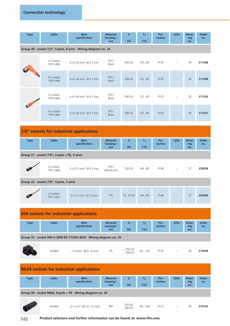
Type Cable Wirespecification
Materialhousing /
nut
U
[V]
Ta
[°C]
Pro-tection
LEDs Draw-ingno.
Orderno.
Group 30 · socket 1/2", 5-pole, 4-wire · Wiring diagram no. 24
5 m blackPUR cable 4 x 0.34 mm2, Ø 4.7 mm
TPU /Brass
300 AC -25...90 IP 67 – 34 E11248
10 m blackPUR cable 4 x 0.34 mm2, Ø 4.7 mm
TPU /Brass
300 AC -25...90 IP 67 – 34 E11249
5 m blackPUR cable 4 x 0.34 mm2, Ø 4.7 mm
TPU /Brass
300 AC -25...90 IP 67 – 35 E11250
10 m blackPUR cable 4 x 0.34 mm2, Ø 4.7 mm
TPU /Brass
300 AC -25...90 IP 67 – 36 E11251
7/8" sockets for industrial applications
Type Cable Wirespecification
Materialhousing /
nut
U
[V]
Ta
[°C]
Pro-tection
LEDs Draw-ingno.
Orderno.
Group 31 · socket 7/8", 2-pole + PE, 3-wire
2 m blackPVC cable 3 x 0.75 mm2, Ø 5.2 mm
TPU /diecast zinc
250 AC -40...80 IP 68 – 37 E20428
Group 32 · socket 7/8", 3-pole, 3-wire
2 m blackPVC cable 3 x 0.5 mm2, Ø 5.4 mm TPU 10...30 DC -40...80 IP 68 – 37 E20430
DIN sockets for industrial applications
Type Cable Wirespecification
Materialhousing /
nut
U
[V]
Ta
[°C]
Pro-tection
LEDs Draw-ingno.
Orderno.
Group 33 · socket DIN A (DIN EN 175301-803) · Wiring diagram no. 25
wirable ...1.5 mm2 (Ø 6...8 mm) PA...250 AC...300 DC
-40...125 IP 65 – 38 E10058
RD24 sockets for industrial applications
Type Cable Wirespecification
Materialhousing /
nut
U
[V]
Ta
[°C]
Pro-tection
LEDs Draw-ingno.
Orderno.
Group 34 · socket Rd24, 6-pole + PE · Wiring diagram no. 26
wirable ...2.5 mm2 (Ø 10...12 mm) PBT250 AC300 DC
-40...100 IP 67 – 39 E70142
Connection technology
748 Product selectors and further information can be found at: www.ifm.com
Gesamtkatalog EN 2016_17_Stilvorlage LK FrutigerOT_2010 DE_GB.qxd 06.11.15 17:00 Seite 748

Type Cable Wirespecification
Materialhousing /
nut
U
[V]
Ta
[°C]
Pro-tection
LEDs Draw-ingno.
Orderno.
Group 34 · socket Rd24, 6-pole + PE · Wiring diagram no. 26
wirable ...2.5 mm2 (Ø 6...8 mm)PBT /PA
250 AC300 DC
-40...100 IP 67 – 40 E11043
Connectors weld slag resistant
Type Cable Wirespecification
Materialhousing /
nut
U
[V]
Ta
[°C]
Pro-tection
LEDs Draw-ingno.
Orderno.
Group 114 · Socket M12, 5/4-pole, 4-wire · Wiring diagram no. 4
2 m greyPUR cable 4 x 0.34 mm2, Ø 4.9 mm
TPU /Brass
250 AC300 DC
-25...90IP 65 / IP 67 /IP 68 / IP 69K
– 6 EVW004
5 m greyPUR cable 4 x 0.34 mm2, Ø 4.9 mm
TPU /Brass
250 AC300 DC
-25...90IP 65 / IP 67 /IP 68 / IP 69K
– 6 EVW005
10 m greyPUR cable 4 x 0.34 mm2, Ø 4.9 mm
TPU /Brass
250 AC300 DC
-25...90IP 65 / IP 67 /IP 68 / IP 69K
– 6 EVW006
2 m greyPUR cable 4 x 0.34 mm2, Ø 4.9 mm
TPU /Brass
250 AC300 DC
-25...90IP 65 / IP 67 /IP 68 / IP 69K
– 7 EVW001
5 m greyPUR cable 4 x 0.34 mm2, Ø 4.9 mm
TPU /Brass
250 AC300 DC
-25...90IP 65 / IP 67 /IP 68 / IP 69K
– 7 EVW002
10 m greyPUR cable 4 x 0.34 mm2, Ø 4.9 mm
TPU /Brass
250 AC300 DC
-25...90IP 65 / IP 67 /IP 68 / IP 69K
– 7 EVW003
Group 115 · Socket M12, 5/4-pole, 4-wire, LED, PNP · Wiring diagram no. 9
2 m greyPUR cable 4 x 0.34 mm2, Ø 4.9 mm
TPU /Brass
10...36 DC -25...90IP 65 / IP 67 /IP 68 / IP 69K
green /2 x yellow
13 EVW007
5 m greyPUR cable 4 x 0.34 mm2, Ø 4.9 mm
TPU /Brass
10...36 DC -25...90IP 65 / IP 67 /IP 68 / IP 69K
green /2 x yellow
13 EVW008
10 m greyPUR cable 4 x 0.34 mm2, Ø 4.9 mm
TPU /Brass
10...36 DC -25...90IP 65 / IP 67 /IP 68 / IP 69K
green /2 x yellow
13 EVW009
Group 116 · Socket M12, 5/4-pole, 5-wire · Wiring diagram no. 11
2 m greyPUR cable 5 x 0.34 mm2, Ø 5.1 mm
TPU /Brass
60 AC60 DC
-25...90IP 65 / IP 67 /IP 68 / IP 69K
– 6 EVW013
5 m greyPUR cable 5 x 0.34 mm2, Ø 5.1 mm
TPU /Brass
60 AC60 DC
-25...90IP 65 / IP 67 /IP 68 / IP 69K
– 6 EVW014
Sockets
749You can find wiring diagrams and scale drawings from page 759
Gesamtkatalog EN 2016_17_Stilvorlage LK FrutigerOT_2010 DE_GB.qxd 06.11.15 17:00 Seite 749

Type Cable Wirespecification
Materialhousing /
nut
U
[V]
Ta
[°C]
Pro-tection
LEDs Draw-ingno.
Orderno.
Group 116 · Socket M12, 5/4-pole, 5-wire · Wiring diagram no. 11
10 m greyPUR cable 5 x 0.34 mm2, Ø 5.1 mm
TPU /Brass
60 AC60 DC
-25...90IP 65 / IP 67 /IP 68 / IP 69K
– 6 EVW015
Group 117 · Socket M12, 5/4-pole, 5-wire · Wiring diagram no. 11
2 m greyPUR cable 5 x 0.34 mm2, Ø 5.1 mm
TPU /Brass
60 AC60 DC
-25...90IP 65 / IP 67 /IP 68 / IP 69K
– 7 EVW010
5 m greyPUR cable 5 x 0.34 mm2, Ø 5.1 mm
TPU /Brass
60 AC60 DC
-25...90IP 65 / IP 67 /IP 68 / IP 69K
– 7 EVW011
10 m greyPUR cable 5 x 0.34 mm2, Ø 5.1 mm
TPU /Brass
60 AC60 DC
-25...90IP 65 / IP 67 /IP 68 / IP 69K
– 7 EVW012
M12 cable sockets for hygienic and wet areas with screen
Type Cable Wirespecification
Materialhousing /
nut
U
[V]
Ta
[°C]
Pro-tection
LEDs Draw-ingno.
Orderno.
Group 120 · Socket M12, screened, screen not connected to the socket, 5/4-pole, 4-wire · Wiring diagram no. 16
2 m orangePVC cable 4 x 0.34 mm2, Ø 5.2 mm
PVC /stainless steel316L / 1.4404
50 AC60 DC
-25...100IP 65 / IP 67 /IP 68 / IP 69K
– 41 EVT381
5 m orangePVC cable 4 x 0.34 mm2, Ø 5.2 mm
PVC /stainless steel316L / 1.4404
50 AC60 DC
-25...100IP 65 / IP 67 /IP 68 / IP 69K
– 41 EVT382
10 m orangePVC cable 4 x 0.34 mm2, Ø 5.2 mm
PVC /stainless steel316L / 1.4404
50 AC60 DC
-25...100IP 65 / IP 67 /IP 68 / IP 69K
– 41 EVT383
25 m orangePVC cable 4 x 0.34 mm2, Ø 5.2 mm
PVC /stainless steel316L / 1.4404
50 AC60 DC
-25...100IP 65 / IP 67 /IP 68 / IP 69K
– 41 EVT384
2 m orangePVC cable 4 x 0.34 mm2, Ø 5.2 mm
PVC /stainless steel316L / 1.4404
50 AC60 DC
-25...100IP 65 / IP 67 /IP 68 / IP 69K
– 43 EVT385
5 m orangePVC cable 4 x 0.34 mm2, Ø 5.2 mm
PVC /stainless steel316L / 1.4404
50 AC60 DC
-25...100IP 65 / IP 67 /IP 68 / IP 69K
– 43 EVT386
10 m orangePVC cable 4 x 0.34 mm2, Ø 5.2 mm
PVC /stainless steel316L / 1.4404
50 AC60 DC
-25...100IP 65 / IP 67 /IP 68 / IP 69K
– 43 EVT387
25 m orangePVC cable 4 x 0.34 mm2, Ø 5.2 mm
PVC /stainless steel316L / 1.4404
50 AC60 DC
-25...100IP 65 / IP 67 /IP 68 / IP 69K
– 43 EVT388
Connection technology
750 Product selectors and further information can be found at: www.ifm.com
Gesamtkatalog EN 2016_17_Stilvorlage LK FrutigerOT_2010 DE_GB.qxd 06.11.15 17:00 Seite 750

Type Cable Wirespecification
Materialhousing /
nut
U
[V]
Ta
[°C]
Pro-tection
LEDs Draw-ingno.
Orderno.
Group 122 · Socket M12, screened, screen not connected to the socket, 5-pole, 5-wire · Wiring diagram no. 17
2 m orangePVC cable 5 x 0.25 mm2, Ø 5.2 mm
PVC /stainless steel316L / 1.4404
30 AC36 DC
-25...100IP 65 / IP 67 /IP 68 / IP 69K
– 41 EVT389
5 m orangePVC cable 5 x 0.25 mm2, Ø 5.2 mm
PVC /stainless steel316L / 1.4404
30 AC36 DC
-25...100IP 65 / IP 67 /IP 68 / IP 69K
– 41 EVT390
10 m orangePVC cable 5 x 0.25 mm2, Ø 5.2 mm
PVC /stainless steel316L / 1.4404
30 AC36 DC
-25...100IP 65 / IP 67 /IP 68 / IP 69K
– 41 EVT391
25 m orangePVC cable 5 x 0.25 mm2, Ø 5.2 mm
PVC /stainless steel316L / 1.4404
30 AC36 DC
-25...100IP 65 / IP 67 /IP 68 / IP 69K
– 41 EVT392
2 m orangePVC cable 5 x 0.25 mm2, Ø 5.2 mm
PVC /stainless steel316L / 1.4404
30 AC36 DC
-25...100IP 65 / IP 67 /IP 68 / IP 69K
– 43 EVT393
5 m orangePVC cable 5 x 0.25 mm2, Ø 5.2 mm
PVC /stainless steel316L / 1.4404
30 AC36 DC
-25...100IP 65 / IP 67 /IP 68 / IP 69K
– 43 EVT394
10 m orangePVC cable 5 x 0.25 mm2, Ø 5.2 mm
PVC /stainless steel316L / 1.4404
30 AC36 DC
-25...100IP 65 / IP 67 /IP 68 / IP 69K
– 43 EVT395
25 m orangePVC cable 5 x 0.25 mm2, Ø 5.2 mm
PVC /stainless steel316L / 1.4404
30 AC36 DC
-25...100IP 65 / IP 67 /IP 68 / IP 69K
– 43 EVT396
Group 124 · Socket M12, screened, screen connected to the socket, 5/4-pole, 4-wire · Wiring diagram no. 18
2 m orangePVC cable 4 x 0.34 mm2, Ø 5.2 mm
PVC /stainless steel316L / 1.4404
50 AC60 DC
-25...100IP 65 / IP 67 /IP 68 / IP 69K
– 41 EVT397
5 m orangePVC cable 4 x 0.34 mm2, Ø 5.2 mm
PVC /stainless steel316L / 1.4404
50 AC60 DC
-25...100IP 65 / IP 67 /IP 68 / IP 69K
– 41 EVT398
10 m orangePVC cable 4 x 0.34 mm2, Ø 5.2 mm
PVC /stainless steel316L / 1.4404
50 AC60 DC
-25...100IP 65 / IP 67 /IP 68 / IP 69K
– 41 EVT399
25 m orangePVC cable 4 x 0.34 mm2, Ø 5.2 mm
PVC /stainless steel316L / 1.4404
50 AC60 DC
-25...100IP 65 / IP 67 /IP 68 / IP 69K
– 41 EVT400
2 m orangePVC cable 4 x 0.34 mm2, Ø 5.2 mm
PVC /stainless steel316L / 1.4404
50 AC60 DC
-25...100IP 65 / IP 67 /IP 68 / IP 69K
– 43 EVT401
5 m orangePVC cable 4 x 0.34 mm2, Ø 5.2 mm
PVC /stainless steel316L / 1.4404
50 AC60 DC
-25...100IP 65 / IP 67 /IP 68 / IP 69K
– 43 EVT402
10 m orangePVC cable 4 x 0.34 mm2, Ø 5.2 mm
PVC /stainless steel316L / 1.4404
50 AC60 DC
-25...100IP 65 / IP 67 /IP 68 / IP 69K
– 43 EVT403
Sockets
751You can find wiring diagrams and scale drawings from page 759
Gesamtkatalog EN 2016_17_Stilvorlage LK FrutigerOT_2010 DE_GB.qxd 06.11.15 17:00 Seite 751
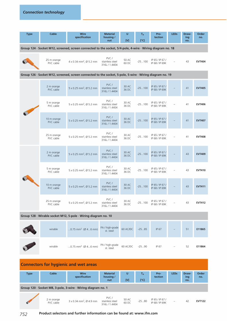
Type Cable Wirespecification
Materialhousing /
nut
U
[V]
Ta
[°C]
Pro-tection
LEDs Draw-ingno.
Orderno.
Group 124 · Socket M12, screened, screen connected to the socket, 5/4-pole, 4-wire · Wiring diagram no. 18
25 m orangePVC cable 4 x 0.34 mm2, Ø 5.2 mm
PVC /stainless steel316L / 1.4404
50 AC60 DC
-25...100IP 65 / IP 67 /IP 68 / IP 69K
– 43 EVT404
Group 126 · Socket M12, screened, screen connected to the socket, 5-pole, 5-wire · Wiring diagram no. 19
2 m orangePVC cable 5 x 0.25 mm2, Ø 5.2 mm
PVC /stainless steel316L / 1.4404
30 AC36 DC
-25...100IP 65 / IP 67 /IP 68 / IP 69K
– 41 EVT405
5 m orangePVC cable 5 x 0.25 mm2, Ø 5.2 mm
PVC /stainless steel316L / 1.4404
30 AC36 DC
-25...100IP 65 / IP 67 /IP 68 / IP 69K
– 41 EVT406
10 m orangePVC cable 5 x 0.25 mm2, Ø 5.2 mm
PVC /stainless steel316L / 1.4404
30 AC36 DC
-25...100IP 65 / IP 67 /IP 68 / IP 69K
– 41 EVT407
25 m orangePVC cable 5 x 0.25 mm2, Ø 5.2 mm
PVC /stainless steel316L / 1.4404
30 AC36 DC
-25...100IP 65 / IP 67 /IP 68 / IP 69K
– 41 EVT408
2 m orangePVC cable 5 x 0.25 mm2, Ø 5.2 mm
PVC /stainless steel316L / 1.4404
30 AC36 DC
-25...100IP 65 / IP 67 /IP 68 / IP 69K
– 43 EVT409
5 m orangePVC cable 5 x 0.25 mm2, Ø 5.2 mm
PVC /stainless steel316L / 1.4404
30 AC36 DC
-25...100IP 65 / IP 67 /IP 68 / IP 69K
– 43 EVT410
10 m orangePVC cable 5 x 0.25 mm2, Ø 5.2 mm
PVC /stainless steel316L / 1.4404
30 AC36 DC
-25...100IP 65 / IP 67 /IP 68 / IP 69K
– 43 EVT411
25 m orangePVC cable 5 x 0.25 mm2, Ø 5.2 mm
PVC /stainless steel316L / 1.4404
30 AC36 DC
-25...100IP 65 / IP 67 /IP 68 / IP 69K
– 43 EVT412
Group 128 · Wirable socket M12, 5-pole · Wiring diagram no. 10
wirable ...0.75 mm2 (Ø 4...6 mm)PA / high-grade
st. steel60 AC/DC -25...85 IP 67 – 51 E11865
wirable ...0.75 mm2 (Ø 4...6 mm)PA / high-grade
st. steel60 AC/DC -25...90 IP 67 – 52 E11864
Connectors for hygienic and wet areas
Type Cable Wirespecification
Materialhousing /
nut
U
[V]
Ta
[°C]
Pro-tection
LEDs Draw-ingno.
Orderno.
Group 120 · Socket M8, 3-pole, 3-wire · Wiring diagram no. 1
2 m orangePVC cable 3 x 0.34 mm2, Ø 4.9 mm
PVC /stainless steel316L / 1.4404
50 AC60 DC
-25...80IP 65 / IP 67 /IP 68 / IP 69K
– 42 EVT122
Connection technology
752 Product selectors and further information can be found at: www.ifm.com
Gesamtkatalog EN 2016_17_Stilvorlage LK FrutigerOT_2010 DE_GB.qxd 06.11.15 17:00 Seite 752
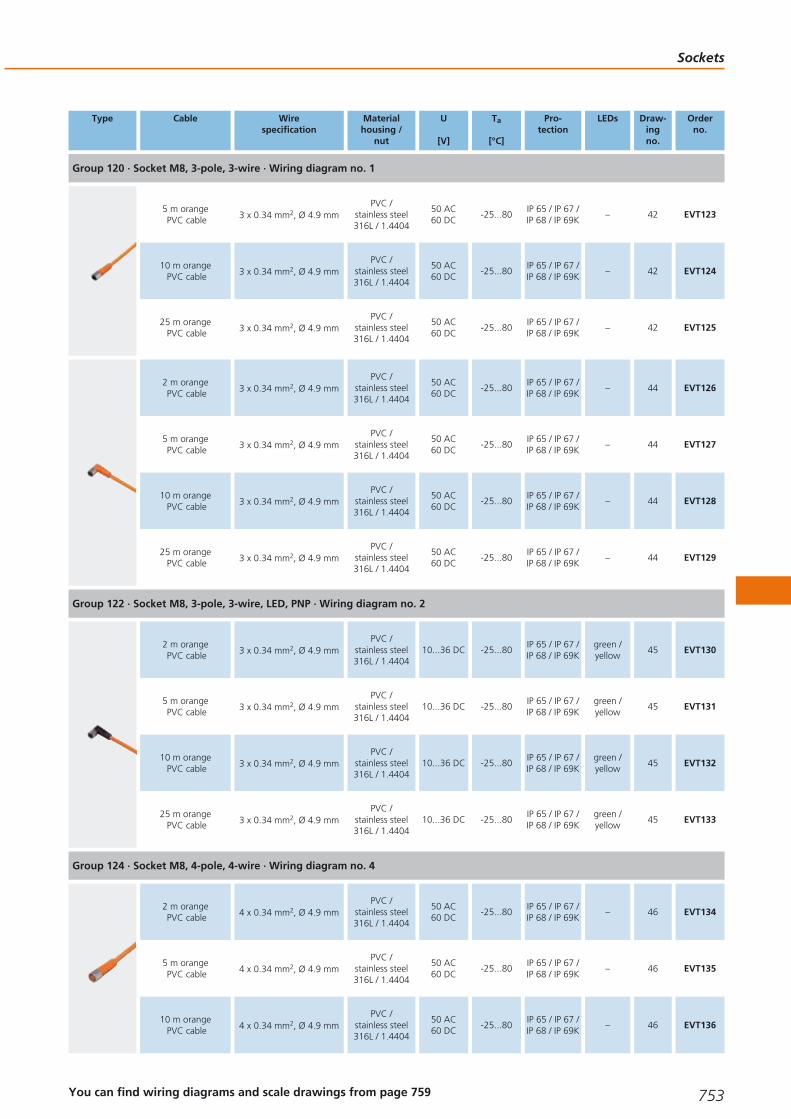
Type Cable Wirespecification
Materialhousing /
nut
U
[V]
Ta
[°C]
Pro-tection
LEDs Draw-ingno.
Orderno.
Group 120 · Socket M8, 3-pole, 3-wire · Wiring diagram no. 1
5 m orangePVC cable 3 x 0.34 mm2, Ø 4.9 mm
PVC /stainless steel316L / 1.4404
50 AC60 DC
-25...80IP 65 / IP 67 /IP 68 / IP 69K
– 42 EVT123
10 m orangePVC cable 3 x 0.34 mm2, Ø 4.9 mm
PVC /stainless steel316L / 1.4404
50 AC60 DC
-25...80IP 65 / IP 67 /IP 68 / IP 69K
– 42 EVT124
25 m orangePVC cable 3 x 0.34 mm2, Ø 4.9 mm
PVC /stainless steel316L / 1.4404
50 AC60 DC
-25...80IP 65 / IP 67 /IP 68 / IP 69K
– 42 EVT125
2 m orangePVC cable 3 x 0.34 mm2, Ø 4.9 mm
PVC /stainless steel316L / 1.4404
50 AC60 DC
-25...80IP 65 / IP 67 /IP 68 / IP 69K
– 44 EVT126
5 m orangePVC cable 3 x 0.34 mm2, Ø 4.9 mm
PVC /stainless steel316L / 1.4404
50 AC60 DC
-25...80IP 65 / IP 67 /IP 68 / IP 69K
– 44 EVT127
10 m orangePVC cable 3 x 0.34 mm2, Ø 4.9 mm
PVC /stainless steel316L / 1.4404
50 AC60 DC
-25...80IP 65 / IP 67 /IP 68 / IP 69K
– 44 EVT128
25 m orangePVC cable 3 x 0.34 mm2, Ø 4.9 mm
PVC /stainless steel316L / 1.4404
50 AC60 DC
-25...80IP 65 / IP 67 /IP 68 / IP 69K
– 44 EVT129
Group 122 · Socket M8, 3-pole, 3-wire, LED, PNP · Wiring diagram no. 2
2 m orangePVC cable 3 x 0.34 mm2, Ø 4.9 mm
PVC /stainless steel316L / 1.4404
10...36 DC -25...80IP 65 / IP 67 /IP 68 / IP 69K
green /yellow
45 EVT130
5 m orangePVC cable 3 x 0.34 mm2, Ø 4.9 mm
PVC /stainless steel316L / 1.4404
10...36 DC -25...80IP 65 / IP 67 /IP 68 / IP 69K
green /yellow
45 EVT131
10 m orangePVC cable 3 x 0.34 mm2, Ø 4.9 mm
PVC /stainless steel316L / 1.4404
10...36 DC -25...80IP 65 / IP 67 /IP 68 / IP 69K
green /yellow
45 EVT132
25 m orangePVC cable 3 x 0.34 mm2, Ø 4.9 mm
PVC /stainless steel316L / 1.4404
10...36 DC -25...80IP 65 / IP 67 /IP 68 / IP 69K
green /yellow
45 EVT133
Group 124 · Socket M8, 4-pole, 4-wire · Wiring diagram no. 4
2 m orangePVC cable 4 x 0.34 mm2, Ø 4.9 mm
PVC /stainless steel316L / 1.4404
50 AC60 DC
-25...80IP 65 / IP 67 /IP 68 / IP 69K
– 46 EVT134
5 m orangePVC cable 4 x 0.34 mm2, Ø 4.9 mm
PVC /stainless steel316L / 1.4404
50 AC60 DC
-25...80IP 65 / IP 67 /IP 68 / IP 69K
– 46 EVT135
10 m orangePVC cable 4 x 0.34 mm2, Ø 4.9 mm
PVC /stainless steel316L / 1.4404
50 AC60 DC
-25...80IP 65 / IP 67 /IP 68 / IP 69K
– 46 EVT136
Sockets
753You can find wiring diagrams and scale drawings from page 759
Gesamtkatalog EN 2016_17_Stilvorlage LK FrutigerOT_2010 DE_GB.qxd 06.11.15 17:00 Seite 753

Type Cable Wirespecification
Materialhousing /
nut
U
[V]
Ta
[°C]
Pro-tection
LEDs Draw-ingno.
Orderno.
Group 124 · Socket M8, 4-pole, 4-wire · Wiring diagram no. 4
25 m orangePVC cable 4 x 0.34 mm2, Ø 4.9 mm
PVC /stainless steel316L / 1.4404
50 AC60 DC
-25...80IP 65 / IP 67 /IP 68 / IP 69K
– 46 EVT137
2 m orangePVC cable 4 x 0.34 mm2, Ø 4.9 mm
PVC /stainless steel316L / 1.4404
50 AC60 DC
-25...80IP 65 / IP 67 /IP 68 / IP 69K
– 47 EVT138
5 m orangePVC cable 4 x 0.34 mm2, Ø 4.9 mm
PVC /stainless steel316L / 1.4404
50 AC60 DC
-25...80IP 65 / IP 67 /IP 68 / IP 69K
– 47 EVT139
10 m orangePVC cable 4 x 0.34 mm2, Ø 4.9 mm
PVC /stainless steel316L / 1.4404
50 AC60 DC
-25...80IP 65 / IP 67 /IP 68 / IP 69K
– 47 EVT140
25 m orangePVC cable 4 x 0.34 mm2, Ø 4.9 mm
PVC /stainless steel316L / 1.4404
50 AC60 DC
-25...80IP 65 / IP 67 /IP 68 / IP 69K
– 47 EVT141
Group 126 · Socket M12, 5/4-pole, 4-wire · Wiring diagram no. 4
2 m orangePVC cable 4 x 0.34 mm2, Ø 4.9 mm
PVC /stainless steel316L / 1.4404
250 AC300 DC
-25...100IP 65 / IP 67 /IP 68 / IP 69K
– 43 EVT067
5 m orangePVC cable 4 x 0.34 mm2, Ø 4.9 mm
PVC /stainless steel316L / 1.4404
250 AC300 DC
-25...100IP 65 / IP 67 /IP 68 / IP 69K
– 43 EVT004
10 m orangePVC cable 4 x 0.34 mm2, Ø 4.9 mm
PVC /stainless steel316L / 1.4404
250 AC300 DC
-25...100IP 65 / IP 67 /IP 68 / IP 69K
– 43 EVT005
25 m orangePVC cable 4 x 0.34 mm2, Ø 4.9 mm
PVC /stainless steel316L / 1.4404
250 AC300 DC
-25...100IP 65 / IP 67 /IP 68 / IP 69K
– 43 EVT006
2 m orangePVC cable 4 x 0.34 mm2, Ø 4.9 mm
PVC /stainless steel316L / 1.4404
250 AC300 DC
-25...100IP 65 / IP 67 /IP 68 / IP 69K
– 41 EVT064
5 m orangePVC cable 4 x 0.34 mm2, Ø 4.9 mm
PVC /stainless steel316L / 1.4404
250 AC300 DC
-25...100IP 65 / IP 67 /IP 68 / IP 69K
– 41 EVT001
10 m orangePVC cable 4 x 0.34 mm2, Ø 4.9 mm
PVC /stainless steel316L / 1.4404
250 AC300 DC
-25...100IP 65 / IP 67 /IP 68 / IP 69K
– 41 EVT002
25 m orangePVC cable 4 x 0.34 mm2, Ø 4.9 mm
PVC /stainless steel316L / 1.4404
250 AC300 DC
-25...100IP 65 / IP 67 /IP 68 / IP 69K
– 41 EVT003
Group 128 · Wirable socket M12, 4-pole · Wiring diagram no. 5
wirable ...0.75 mm2 (Ø 4...6 mm)PA / high-grade
st. steel240 AC/DC -25...85 IP 67 – 48 E11862
Connection technology
754Product selectors and further information can be found at: www.ifm.com
Gesamtkatalog EN 2016_17_Stilvorlage LK FrutigerOT_2010 DE_GB.qxd 06.11.15 17:00 Seite 754

Type Cable Wirespecification
Materialhousing /
nut
U
[V]
Ta
[°C]
Pro-tection
LEDs Draw-ingno.
Orderno.
Group 128 · Wirable socket M12, 4-pole · Wiring diagram no. 5
wirable ...0.75 mm2 (Ø 4...6 mm)PA / high-grade
st. steel240 AC/DC -25...90 IP 67 – 49 E11861
Group 130 · Socket M12, 5/4-pole, 4-wire, LED, PNP · Wiring diagram no. 9
2 m orangePVC cable 4 x 0.34 mm2, Ø 4.9 mm
PVC /stainless steel316L / 1.4404
10...36 DC -25...100IP 65 / IP 67 /IP 68 / IP 69K
green /2 x yellow
50 EVT069
5 m orangePVC cable 4 x 0.34 mm2, Ø 4.9 mm
PVC /stainless steel316L / 1.4404
10...36 DC -25...100IP 65 / IP 67 /IP 68 / IP 69K
green /2 x yellow
50 EVT007
10 m orangePVC cable 4 x 0.34 mm2, Ø 4.9 mm
PVC /stainless steel316L / 1.4404
10...36 DC -25...100IP 65 / IP 67 /IP 68 / IP 69K
green /2 x yellow
50 EVT008
25 m orangePVC cable 4 x 0.34 mm2, Ø 4.9 mm
PVC /stainless steel316L / 1.4404
10...36 DC -25...100IP 65 / IP 67 /IP 68 / IP 69K
green /2 x yellow
50 EVT009
Group 131 · Wirable socket M12, 5/4-pole, LED, PNP · Wiring diagram no. 27
wirable ...0.75 mm2 (Ø 4...6 mm)PBT / high-grade
st. steel10...30 DC -25...85 IP 67 / IP 69K
green /yellow
53 E11863
Group 132 · Socket M12, 5-pole, 5-wire · Wiring diagram no. 11
5 m orangePVC cable 5 x 0.34 mm2, Ø 5.1 mm
PVC /stainless steel316L / 1.4404
60 AC60 DC
-25...100IP 65 / IP 67 /IP 68 / IP 69K
– 43 EVT013
10 m orangePVC cable 5 x 0.34 mm2, Ø 5.1 mm
PVC /stainless steel316L / 1.4404
60 AC60 DC
-25...100IP 65 / IP 67 /IP 68 / IP 69K
– 43 EVT014
25 m orangePVC cable 5 x 0.34 mm2, Ø 5.1 mm
PVC /stainless steel316L / 1.4404
60 AC60 DC
-25...100IP 65 / IP 67 /IP 68 / IP 69K
– 43 EVT015
5 m orangePVC cable 5 x 0.34 mm2, Ø 5.1 mm
PVC /stainless steel316L / 1.4404
60 AC60 DC
-25...100IP 65 / IP 67 /IP 68 / IP 69K
– 41 EVT010
10 m orangePVC cable 5 x 0.34 mm2, Ø 5.1 mm
PVC /stainless steel316L / 1.4404
60 AC60 DC
-25...100IP 65 / IP 67 /IP 68 / IP 69K
– 41 EVT011
25 m orangePVC cable 5 x 0.34 mm2, Ø 5.1 mm
PVC /stainless steel316L / 1.4404
60 AC60 DC
-25...100IP 65 / IP 67 /IP 68 / IP 69K
– 41 EVT012
Sockets
755You can find wiring diagrams and scale drawings from page 759
Gesamtkatalog EN 2016_17_Stilvorlage LK FrutigerOT_2010 DE_GB.qxd 06.11.15 17:00 Seite 755
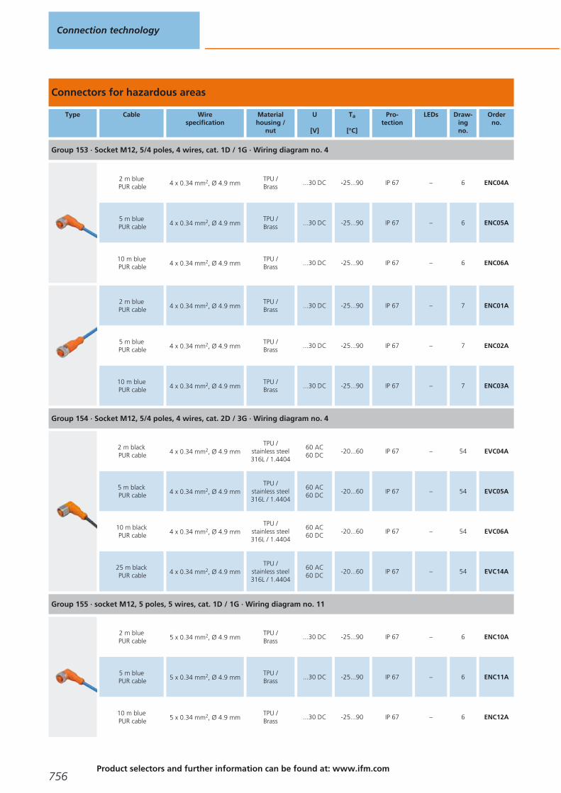
Connectors for hazardous areas
Type Cable Wirespecification
Materialhousing /
nut
U
[V]
Ta
[°C]
Pro-tection
LEDs Draw-ingno.
Orderno.
Group 153 · Socket M12, 5/4 poles, 4 wires, cat. 1D / 1G · Wiring diagram no. 4
2 m bluePUR cable 4 x 0.34 mm2, Ø 4.9 mm
TPU /Brass
...30 DC -25...90 IP 67 – 6 ENC04A
5 m bluePUR cable 4 x 0.34 mm2, Ø 4.9 mm
TPU /Brass
...30 DC -25...90 IP 67 – 6 ENC05A
10 m bluePUR cable 4 x 0.34 mm2, Ø 4.9 mm
TPU /Brass
...30 DC -25...90 IP 67 – 6 ENC06A
2 m bluePUR cable 4 x 0.34 mm2, Ø 4.9 mm
TPU /Brass
...30 DC -25...90 IP 67 – 7 ENC01A
5 m bluePUR cable 4 x 0.34 mm2, Ø 4.9 mm
TPU /Brass
...30 DC -25...90 IP 67 – 7 ENC02A
10 m bluePUR cable 4 x 0.34 mm2, Ø 4.9 mm
TPU /Brass
...30 DC -25...90 IP 67 – 7 ENC03A
Group 154 · Socket M12, 5/4 poles, 4 wires, cat. 2D / 3G · Wiring diagram no. 4
2 m blackPUR cable 4 x 0.34 mm2, Ø 4.9 mm
TPU /stainless steel316L / 1.4404
60 AC60 DC
-20...60 IP 67 – 54 EVC04A
5 m blackPUR cable 4 x 0.34 mm2, Ø 4.9 mm
TPU /stainless steel316L / 1.4404
60 AC60 DC
-20...60 IP 67 – 54 EVC05A
10 m blackPUR cable 4 x 0.34 mm2, Ø 4.9 mm
TPU /stainless steel316L / 1.4404
60 AC60 DC
-20...60 IP 67 – 54 EVC06A
25 m blackPUR cable 4 x 0.34 mm2, Ø 4.9 mm
TPU /stainless steel316L / 1.4404
60 AC60 DC
-20...60 IP 67 – 54 EVC14A
Group 155 · socket M12, 5 poles, 5 wires, cat. 1D / 1G · Wiring diagram no. 11
2 m bluePUR cable 5 x 0.34 mm2, Ø 4.9 mm
TPU /Brass
...30 DC -25...90 IP 67 – 6 ENC10A
5 m bluePUR cable 5 x 0.34 mm2, Ø 4.9 mm
TPU /Brass
...30 DC -25...90 IP 67 – 6 ENC11A
10 m bluePUR cable 5 x 0.34 mm2, Ø 4.9 mm
TPU /Brass
...30 DC -25...90 IP 67 – 6 ENC12A
Connection technology
756Product selectors and further information can be found at: www.ifm.com
Gesamtkatalog EN 2016_17_Stilvorlage LK FrutigerOT_2010 DE_GB.qxd 06.11.15 17:00 Seite 756

Type Cable Wirespecification
Materialhousing /
nut
U
[V]
Ta
[°C]
Pro-tection
LEDs Draw-ingno.
Orderno.
Group 155 · socket M12, 5 poles, 5 wires, cat. 1D / 1G · Wiring diagram no. 11
25 m bluePUR cable 5 x 0.34 mm2, Ø 4.9 mm
TPU /Brass
...30 DC -25...90 IP 67 – 6 ENC13A
50 m bluePUR cable 5 x 0.34 mm2, Ø 4.9 mm
TPU /Brass
...30 DC -25...90 IP 67 – 6 ENC14A
2 m bluePUR cable 5 x 0.34 mm2, Ø 4.9 mm
TPU /Brass
...30 DC -25...90 IP 67 – 7 ENC07A
5 m bluePUR cable 5 x 0.34 mm2, Ø 4.9 mm
TPU /Brass
...30 DC -25...90 IP 67 – 7 ENC08A
10 m bluePUR cable 5 x 0.34 mm2, Ø 4.9 mm
TPU /Brass
...30 DC -25...90 IP 67 – 7 ENC09A
Connectors for robust applications
Type Cable Wirespecification
Materialhousing /
nut
U
[V]
Ta
[°C]
Pro-tection
LEDs Draw-ingno.
Orderno.
Group 157 · Socket M12, 5/4-pole, 4-wire · Wiring diagram no. 4
2 m blackPUR cable 4 x 0.34 mm2, Ø 4.9 mm
TPU /stainless steel316L / 1.4404
250 AC300 DC
-40...90IP 65 / IP 67 /IP 68 / IP 69K
– 54 EVM004
5 m blackPUR cable 4 x 0.34 mm2, Ø 4.9 mm
TPU /stainless steel316L / 1.4404
250 AC300 DC
-40...90IP 65 / IP 67 /IP 68 / IP 69K
– 54 EVM005
10 m blackPUR cable 4 x 0.34 mm2, Ø 4.9 mm
TPU /stainless steel316L / 1.4404
250 AC300 DC
-40...90IP 65 / IP 67 /IP 68 / IP 69K
– 54 EVM006
25 m blackPUR cable 4 x 0.34 mm2, Ø 4.9 mm
TPU /stainless steel316L / 1.4404
250 AC300 DC
-40...90IP 65 / IP 67 /IP 68 / IP 69K
– 54 EVM012
50 m blackPUR cable 4 x 0.34 mm2, Ø 4.9 mm
TPU /stainless steel316L / 1.4404
250 AC300 DC
-40...90IP 65 / IP 67 /IP 68 / IP 69K
– 54 EVM010
2 m blackPUR cable 4 x 0.34 mm2, Ø 4.9 mm
TPU /stainless steel316L / 1.4404
250 AC300 DC
-40...90IP 65 / IP 67 /IP 68 / IP 69K
– 55 EVM001
5 m blackPUR cable 4 x 0.34 mm2, Ø 4.9 mm
TPU /stainless steel316L / 1.4404
250 AC300 DC
-40...90IP 65 / IP 67 /IP 68 / IP 69K
– 55 EVM002
10 m blackPUR cable 4 x 0.34 mm2, Ø 4.9 mm
TPU /stainless steel316L / 1.4404
250 AC300 DC
-40...90IP 65 / IP 67 /IP 68 / IP 69K
– 55 EVM003
Sockets
757You can find wiring diagrams and scale drawings from page 759
Gesamtkatalog EN 2016_17_Stilvorlage LK FrutigerOT_2010 DE_GB.qxd 06.11.15 17:00 Seite 757

Type Cable Wirespecification
Materialhousing /
nut
U
[V]
Ta
[°C]
Pro-tection
LEDs Draw-ingno.
Orderno.
Group 157 · Socket M12, 5/4-pole, 4-wire · Wiring diagram no. 4
25 m blackPUR cable 4 x 0.34 mm2, Ø 4.9 mm
TPU /stainless steel316L / 1.4404
250 AC300 DC
-40...90IP 65 / IP 67 /IP 68 / IP 69K
– 55 EVM014
Group 158 · Socket M12, 5/4-pole, 4-wire, LED, PNP · Wiring diagram no. 9
2 m blackPUR cable 4 x 0.34 mm2, Ø 4.9 mm
TPU /stainless steel316L / 1.4404
10...36 DC -40...90IP 65 / IP 67 /IP 68 / IP 69K
green /2 x yellow
56 EVM007
5 m blackPUR cable 4 x 0.34 mm2, Ø 4.9 mm
TPU /stainless steel316L / 1.4404
10...36 DC -40...90IP 65 / IP 67 /IP 68 / IP 69K
green /2 x yellow
56 EVM008
10 m blackPUR cable 4 x 0.34 mm2, Ø 4.9 mm
TPU /stainless steel316L / 1.4404
10...36 DC -40...90IP 65 / IP 67 /IP 68 / IP 69K
green /2 x yellow
56 EVM009
Group 159 · Socket M12, 5-pole, 5-wire · Wiring diagram no. 11
2 m blackPUR cable 5 x 0.34 mm2, Ø 4.9 mm
TPU /stainless steel316L / 1.4404
50 AC60 DC
-40...90IP 65 / IP 67 /IP 68 / IP 69K
– 54 EVM039
5 m blackPUR cable 5 x 0.34 mm2, Ø 4.9 mm
TPU /stainless steel316L / 1.4404
50 AC60 DC
-40...90IP 65 / IP 67 /IP 68 / IP 69K
– 54 EVM040
10 m blackPUR cable 5 x 0.34 mm2, Ø 4.9 mm
TPU /stainless steel316L / 1.4404
50 AC60 DC
-40...90IP 65 / IP 67 /IP 68 / IP 69K
– 54 EVM041
2 m blackPUR cable 5 x 0.34 mm2, Ø 4.9 mm
TPU /stainless steel316L / 1.4404
60 AC60 DC
-40...90IP 65 / IP 67 /IP 68 / IP 69K
– 55 EVM036
5 m blackPUR cable 5 x 0.34 mm2, Ø 4.9 mm
TPU /stainless steel316L / 1.4404
60 AC60 DC
-40...90IP 65 / IP 67 /IP 68 / IP 69K
– 55 EVM037
10 m blackPUR cable 5 x 0.34 mm2, Ø 4.9 mm
TPU /stainless steel316L / 1.4404
60 AC60 DC
-40...90IP 65 / IP 67 /IP 68 / IP 69K
– 55 EVM038
2 m blackPUR cable 5 x 0.34 mm2, Ø 4.9 mm
TPU /stainless steel316L / 1.4404
50 AC60 DC
-40...90IP 65 / IP 67 /IP 68 / IP 69K
– 54 EVM039
5 m blackPUR cable 5 x 0.34 mm2, Ø 4.9 mm
TPU /stainless steel316L / 1.4404
50 AC60 DC
-40...90IP 65 / IP 67 /IP 68 / IP 69K
– 54 EVM040
10 m blackPUR cable 5 x 0.34 mm2, Ø 4.9 mm
TPU /stainless steel316L / 1.4404
50 AC60 DC
-40...90IP 65 / IP 67 /IP 68 / IP 69K
– 54 EVM041
Connection technology
758Product selectors and further information can be found at: www.ifm.com
Gesamtkatalog EN 2016_17_Stilvorlage LK FrutigerOT_2010 DE_GB.qxd 06.11.15 17:00 Seite 758

Core colours
BK black
BN brown
BU blue
WH white
GN/YE green/yellow
GY grey
GN green
YE yellow
PK pink
screen Screen
OG orange
VT lilac
RD red
RD/BK red/black
RD/WH red/white
Wiring diagrams
1
1
3
BN
BU
4 BK
2
1
3
L+
4
L
YE GN
BN
BU
BK out
3
1
3
4
4
1
2
3
4
BN
WH
BU
BK
5
1
2
3
4
6
1
4
WH
BK
7
1
2
3
GN/YE
BK
BU
8
L+
L
out
out
1
3
4
YE GN
2
9
out
out
L+
L
1
3
4
YE GN
BN
BU
BK
2 WH
YE
10
1
2
3
4
5
11
1
2
3
4
5
BN
WH
BU
BK
GY
12
1
2
3
4
5
WH
GN
YE
GY
BN
7 BU
6: not used
13
4
5
6
7
8
2
3
1
YE
GY
PK
BU
screen
BN
GN
WH
14
4
5
6
7
8
2
3
1
BK
GY
PK
VT
OG
WH
BU
BN
Colours to DIN EN 60947-5-6
15
1
2
3
4
WH
BN
GN
YE
5 GY
6 PK
7 BU
8 RD
16
1
2
3
4
BN
WH
BU
BK
screen
17
1
2
3
4
BN
WH
BU
BK
screen
5 GY
18
1
2
3
4
BN
WH
BU
BK
screen
19
1
2
3
4
BN
WH
BU
BK
5 GY
screen
20
J
L
N
O
P
C
E
A
GN
BU
GN/BN
RD/BU
WH
WH/GN
GY/PK
BN
S
T
GY
YE
21
G
J
L
N
O
C
E
A
PK
GN
BU
RD/BU
VT
GY/PK
BK
BN
P
S
T
WH
GY
YE
22
4
5
6
7
8
2
3
1
GY
GY/PK
RD/BU
WH/GN
BN/GN
GN
YE
WH
9
10
11
12
BU
BN
YE/GN
23
1
2
3
GN
RD/BK
RD/WH
24
1
2
4
5
BK
BU
BN
WH
Sockets
759
Gesamtkatalog EN 2016_17_Stilvorlage LK FrutigerOT_2010 DE_GB.qxd 06.11.15 17:00 Seite 759

Wiring diagrams
25
1
2
3
26
4
5
6
2
3
1
27
L+
L
1
3
4
YE GN
BN
BU
BK
2 WH
28
4
5
6
7
8
2
3
1
RD/BU
GN
BU
GY/PK
WH/GN
RD
GY
VT
9
10
11
12
WH/YE
WH/GY
BK
GN/YE
13
14
15
YE/BN
BN/GN
WH
16
17
18
19
YE
PK
GY/BN
BN
Scale drawings / drawing no. – CAD download: www.ifm.com
1
9
10 31
M8x1 1
4
3
2
9
10 19
M8x1 25,5
1
4
3
3
9
10 19
M8x1 25,5
LED1
4
3
4
9
10 31
M8x1
4
3
2
1
5
9
10 19
M8x1 25,5
4
3
2
1
6
15,5
M12x1 36,5
26,5
14 3
1 2
4
5
Connection technology
760
Gesamtkatalog EN 2016_17_Stilvorlage LK FrutigerOT_2010 DE_GB.qxd 06.11.15 17:00 Seite 760

Scale drawings / drawing no. – CAD download: www.ifm.com
7
15,5
M12x1 45
14
3
1 2
4
5
8
15
M12 x1
39
27
10,5
3
1
2
9
15
M12 x1
10,5
433
1
2
10
20
M12 x1
30
35,4
19
3
1 2
4
11
18
M12 x1
46
3
1 2
4
12
18
M12 x1
30
35
18
2 LED
3
1 2
4
13
15,5
M12x1 36,5
26,5
143 LED 3
1 2
4
5
14
35
18
20
M12 x1
30
3
1 2
4
5
15
20
M12 x1
46
3
1 2
4
5
16
13Ø14,5
43,9M12x1
4
1 2
65
378
17
43
15
M12 x1
4
1 2
65
378
18
15
38
M12 x1
28
10,5
4
1 2
65
378
Sockets
761
Gesamtkatalog EN 2016_17_Stilvorlage LK FrutigerOT_2010 DE_GB.qxd 06.11.15 17:00 Seite 761

Scale drawings / drawing no. – CAD download: www.ifm.com
19
4315
M12 x1
4
1 2
65
378
20
20
M16 x1
47
45
AM
NCO
PE
LUTJS
RG
21
4520
M16x1
49
AM
NCO
PE
LUTJS
RG
22
25
M18 x1
36
21
43
21
3
1 4
2
23
25
M18 x1
56
3
1 4
2
24
51
70
26
M 23 x1
9 81127
6511
1023
4
25
26
M 23 x1
859 81
127
6511
1023
4
26
49
20
26
M 23 x1
1
23
411
567
8910 12
27
20
58
26
M 23 x1
51
24
1
23
411
567
8910 12
28
51
70
26
M 23 x1
1234
56 7
89
101112
13
14
15
16
17
1819
29
26
M 23 x1
851
234
56 7
89
101112
13
14
15
16
17
1819
30
26
1/2" 20UNF
14,5
38,5
3
1
2
Connection technology
762Product selectors and further information can be found at: www.ifm.com
Gesamtkatalog EN 2016_17_Stilvorlage LK FrutigerOT_2010 DE_GB.qxd 06.11.15 17:00 Seite 762

Scale drawings / drawing no. – CAD download: www.ifm.com
31
27
10,5
1539
G 21
3
1
2
32
14,5 42,5
1/2" 20UNF
3
1
2
33
42
10,5
15
G 21
3
1
2
34
26
1/2" 20UNF
14,5
38,5
32
5 1
4
35
14,5 42,5
1/2" 20UNF3
2
5 1
4
36
42
10,5
15
"-20UNF213
2
5 1
4
37
49,9G 87
Ø26
2
1
3
38
2918
42
M322
282
21
3
39
29
Rd 24
71
4
1 6
352
40
29
Rd 24
38,5
20
59
26
4
1 6
352
41
15,5
45
14
M12 x1
3
1 2
4
5
42
9
31
M8x1
10
1
4
3
Sockets
763
Gesamtkatalog EN 2016_17_Stilvorlage LK FrutigerOT_2010 DE_GB.qxd 06.11.15 17:00 Seite 763

Scale drawings / drawing no. – CAD download: www.ifm.com
43
15,5
M12x1 36,5
26,5
14 3
1 2
4
5
44
9
19
25,5
M8x1
10
1
4
3
45
9
19
25,5
LED
M8x1
10
1
4
3
46
9
31
M8x1
10
4
3
2
1
47
9
19
25,5
M8x1
10
4
3
2
1
48
36
18
13
M12 x1
3820
3
1 2
4
49
20
M12 x 1 1813
54
3
1 2
4
50
15,5
M12x1 36,5
26,5
14LED 3
1 2
4
5
51
36
18
13
M12 x1
3820
3
1 2
4
5
52
20
M12 x 1 1813
54
3
1 2
4
5
53
36
18
13
M12 x1
3820
LED3
1 2
4
5
54
15,5
M12x1 36,5
26,5
14 3
1 2
4
5
Connection technology
764Product selectors and further information can be found at: www.ifm.com
Gesamtkatalog EN 2016_17_Stilvorlage LK FrutigerOT_2010 DE_GB.qxd 06.11.15 17:00 Seite 764

Scale drawings / drawing no. – CAD download: www.ifm.com
55
15,5
M12x1 45
14
3
1 2
4
5
56
3 LED
15,5
M12x1 36,5
26,5
14 3
1 2
4
5
Sockets
765
Gesamtkatalog EN 2016_17_Stilvorlage LK FrutigerOT_2010 DE_GB.qxd 06.11.15 17:00 Seite 765

Plugs
Plugs are mainly used for the connection to splitter boxes and modules. High-qualitypin contacts and materials ensure reliable electrical connections. In addition to a wide range of standard products ifm also offers versions withoutsilicone and halogen, versions for hygienic areas, for applications in contact withcoolants and lubricants, as well as for welding applications.
M8 cable plugs for industrial applications
Type Cable Wirespecification
Materialhousing /
nut
U
[V]
Ta
[°C]
Pro-tection
LEDs Draw-ingno.
Orderno.
Group 35 · Wirable plug M8, 3-pole · Wiring diagram no. 1
wirable –PA /Brass
60 AC75 DC
-25...90 IP 68 – – E11550
Group 36 · Wirable plug M8, 4-pole · Wiring diagram no. 2
wirable –PA /Brass
60 AC75 DC
-25...90 IP 68 – – E11551
M12 cable plugs for industrial applications
Type Cable Wirespecification
Materialhousing /
nut
U
[V]
Ta
[°C]
Pro-tection
LEDs Draw-ingno.
Orderno.
Group 37 · Cable plug M12, 4-pole, 4-wire · Wiring diagram no. 3
2 m blackPUR cable 4 x 0.34 mm2, Ø 4.9 mm
TPU /Brass
250 AC300 DC
-25...90IP 65 / IP 67 /IP 68 / IP 69K
– 1 EVC079
5 m blackPUR cable 4 x 0.34 mm2, Ø 4.9 mm
TPU /Brass
250 AC300 DC
-25...90IP 65 / IP 67 /IP 68 / IP 69K
– 1 EVC080
System overview Page
M8 cable plugs for industrial applications 766
M12 cable plugs for industrial applications 766 - 767
Connectors for hygienic and wet areas 767 - 768
Wiring diagrams 768
Scale drawings / drawing no. – CAD download: www.ifm.com 769 - 770
Connection technology
766Product selectors and further information can be found at: www.ifm.com
Gesamtkatalog EN 2016_17_Stilvorlage LK FrutigerOT_2010 DE_GB.qxd 06.11.15 17:00 Seite 766
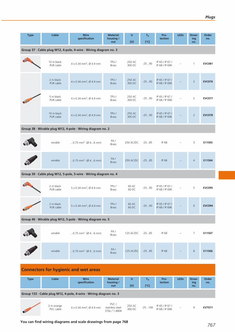
Type Cable Wirespecification
Materialhousing /
nut
U
[V]
Ta
[°C]
Pro-tection
LEDs Draw-ingno.
Orderno.
Group 37 · Cable plug M12, 4-pole, 4-wire · Wiring diagram no. 3
10 m blackPUR cable 4 x 0.34 mm2, Ø 4.9 mm
TPU /Brass
250 AC300 DC
-25...90IP 65 / IP 67 /IP 68 / IP 69K
– 1 EVC081
2 m blackPUR cable 4 x 0.34 mm2, Ø 4.9 mm
TPU /Brass
250 AC300 DC
-25...90IP 65 / IP 67 /IP 68 / IP 69K
– 2 EVC076
5 m blackPUR cable 4 x 0.34 mm2, Ø 4.9 mm
TPU /Brass
250 AC300 DC
-25...90IP 65 / IP 67 /IP 68 / IP 69K
– 2 EVC077
10 m blackPUR cable 4 x 0.34 mm2, Ø 4.9 mm
TPU /Brass
250 AC300 DC
-25...90IP 65 / IP 67 /IP 68 / IP 69K
– 2 EVC078
Group 38 · Wirable plug M12, 4-pole · Wiring diagram no. 2
wirable ...0.75 mm2 (Ø 4...6 mm)PA /Brass
250 AC/DC -25...85 IP 68 – 3 E11505
wirable ...0.75 mm2 (Ø 4...6 mm)PA /Brass
250 AC/DC -25...85 IP 68 – 4 E11504
Group 39 · Cable plug M12, 5-pole, 5-wire · Wiring diagram no. 4
2 m blackPUR cable 5 x 0.34 mm2, Ø 4.9 mm
TPU /Brass
60 AC60 DC
-25...90IP 65 / IP 67 /IP 68 / IP 69K
– 5 EVC095
2 m blackPUR cable 5 x 0.34 mm2, Ø 4.9 mm
TPU /Brass
60 AC60 DC
-25...90IP 65 / IP 67 /IP 68 / IP 69K
– 6 EVC094
Group 40 · Wirable plug M12, 5-pole · Wiring diagram no. 5
wirable ...0.75 mm2 (Ø 4...6 mm)PA /Brass
125 AC/DC -25...85 IP 68 – 7 E11507
wirable ...0.75 mm2 (Ø 4...6 mm)PA /Brass
125 AC/DC -25...85 IP 68 – 8 E11506
Connectors for hygienic and wet areas
Type Cable Wirespecification
Materialhousing /
nut
U
[V]
Ta
[°C]
Pro-tection
LEDs Draw-ingno.
Orderno.
Group 133 · Cable plug M12, 4-pole, 4-wire · Wiring diagram no. 3
2 m orangePVC cable 4 x 0.34 mm2, Ø 4.9 mm
PVC /stainless steel316L / 1.4404
250 AC300 DC
-25...100IP 65 / IP 67 /IP 68 / IP 69K
– 9 EVT071
Plugs
767You can find wiring diagrams and scale drawings from page 768
Gesamtkatalog EN 2016_17_Stilvorlage LK FrutigerOT_2010 DE_GB.qxd 06.11.15 17:00 Seite 767

Type Cable Wirespecification
Materialhousing /
nut
U
[V]
Ta
[°C]
Pro-tection
LEDs Draw-ingno.
Orderno.
Group 133 · Cable plug M12, 4-pole, 4-wire · Wiring diagram no. 3
5 m orangePVC cable 4 x 0.34 mm2, Ø 4.9 mm
PVC /stainless steel316L / 1.4404
250 AC300 DC
-25...100IP 65 / IP 67 /IP 68 / IP 69K
– 9 EVT072
10 m orangePVC cable 4 x 0.34 mm2, Ø 4.9 mm
PVC /stainless steel316L / 1.4404
250 AC300 DC
-25...100IP 65 / IP 67 /IP 68 / IP 69K
– 9 EVT073
Group 134 · Wirable plug M12, 4-pole · Wiring diagram no. 2
wirable ...0.75 mm2 (Ø 4...6 mm)PA / high-grade
st. steel240 AC/DC -25...85 IP 67 – 10 E11858
wirable ...0.75 mm2 (Ø 4...6 mm)PA / high-grade
st. steel250 AC/DC -25...85 IP 67 – 11 E11857
Group 135 · Cable plug M12, 5-pole, 5-wire · Wiring diagram no. 4
2 m orangePVC cable 5 x 0.34 mm2, Ø 5.1 mm
PVC /stainless steel316L / 1.4404
60 AC60 DC
-25...100IP 65 / IP 67 /IP 68 / IP 69K
– 12 EVT074
Group 136 · Wirable plug M12, 5-pole · Wiring diagram no. 5
wirable ...0.75 mm2 (Ø 4...6 mm)PA / high-grade
st. steel60 AC/DC -25...85 IP 67 – 13 E11860
wirable ...0.75 mm2 (Ø 4...6 mm)PA / high-grade
st. steel125 AC/DC -25...85 IP 67 – 14 E11859
Core colours
BK black
BN brown
BU blue
WH white
GY grey
Wiring diagrams
1
1
3
4
2
1
2
3
4
3
1
2
3
4
BN
WH
BU
BK
4
1 BN
2 WH
3 BU
4 BK
5 GY
5
1
2
3
4
5
Connection technology
768Product selectors and further information can be found at: www.ifm.com
Gesamtkatalog EN 2016_17_Stilvorlage LK FrutigerOT_2010 DE_GB.qxd 06.11.15 17:00 Seite 768

Scale drawings / drawing no. – CAD download: www.ifm.com
1
15,5
M12x1
36,5
30,5
1443
2 1
2
15,5
M12x1 49,5
14
43
2 1
3
42
18
15
20
M12 x1
31
43
2 1
4
5220
M12 x1
43
2 1
5
15,5
M12x1
36,5
30,5
14 4
2 1
3
5
6
15,5
M12x1 49,5
14
4
2 1
3
5
7
42
18
15
20
M12 x1
31
4
2 1
3
5
8
5220
M12 x14
2 1
3
5
9
15,5
49
14
M12 x1
43
2 1
10
40
13
M12 x1
3820
18 43
2 1
11
20
M12 x 1 13
60
18
43
2 1
12
15,5
M12x1 36,5
30,5
14 4
2 1
3
5
Plugs
769
Gesamtkatalog EN 2016_17_Stilvorlage LK FrutigerOT_2010 DE_GB.qxd 06.11.15 17:00 Seite 769

Scale drawings / drawing no. – CAD download: www.ifm.com
13
40
13
M12 x1
3820
18 4
2 1
3
5
14
20
M12 x 1 13
60
18
4
2 1
3
5
Connection technology
770Product selectors and further information can be found at: www.ifm.com
Gesamtkatalog EN 2016_17_Stilvorlage LK FrutigerOT_2010 DE_GB.qxd 06.11.15 17:00 Seite 770

Plugs
771
Gesamtkatalog EN 2016_17_Stilvorlage LK FrutigerOT_2010 DE_GB.qxd 06.11.15 17:00 Seite 771

Jumper cables
Connection cables feature a plug and a socket. They are used for the connection ofsensors to splitter boxes and modules. High-quality contacts and materials ensure reliable electrical connections. In addition to a wide range of standard products ifm also offers versions withoutsilicone and halogen, versions for hygienic areas, for applications in contact withcoolants and lubricants, as well as for welding applications.
M8 – M8 jumpers for industrial applications
Type Cable Wirespecification
Materialhousing /
nut
U
[V]
Ta
[°C]
Pro-tection
LEDs Draw-ingno.
Orderno.
Group 41 · Jumper , plug: M8, 3-pole, socket: M8, 3-pole, 3-wire · Wiring diagram no. 1
0.3 m blackPUR cable 3 x 0.25 mm2, Ø 3.7 mm
TPU /Brass
50 AC60 DC
-25...90IP 65 / IP 67 /IP 68 / IP 69K
– 1 EVC275
0.6 m blackPUR cable 3 x 0.25 mm2, Ø 3.7 mm
TPU /Brass
50 AC60 DC
-25...90IP 65 / IP 67 /IP 68 / IP 69K
– 1 EVC276
1 m blackPUR cable 3 x 0.25 mm2, Ø 3.7 mm
TPU /Brass
50 AC60 DC
-25...90IP 65 / IP 67 /IP 68 / IP 69K
– 1 EVC277
2 m blackPUR cable 3 x 0.25 mm2, Ø 3.7 mm
TPU /Brass
50 AC60 DC
-25...90IP 65 / IP 67 /IP 68 / IP 69K
– 1 EVC278
System overview Page
M8 – M8 jumpers for industrial applications 772 - 775
M8 socket – M12 plug jumpers for industrial applications 776 - 778
M8 plug - M12 socket jumpers for industrial applications 778 - 780
M12 – M12 jumpers for industrial applications 780 - 784
Valve - plug jumpers for industrial applications 785 - 786
Jumpers weld slag resistant 787 - 788
Jumpers for hygienic and wet areas 788 - 794
Jumpers for hygienic and wet areas 794 - 798
Jumpers for hazardous areas 798
Wiring diagrams 799
Scale drawings / drawing no. – CAD download: www.ifm.com 799 - 804
Connection technology
772Product selectors and further information can be found at: www.ifm.com
Gesamtkatalog EN 2016_17_Stilvorlage LK FrutigerOT_2010 DE_GB.qxd 06.11.15 17:00 Seite 772
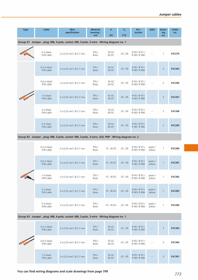
Type Cable Wirespecification
Materialhousing /
nut
U
[V]
Ta
[°C]
Pro-tection
LEDs Draw-ingno.
Orderno.
Group 41 · Jumper , plug: M8, 3-pole, socket: M8, 3-pole, 3-wire · Wiring diagram no. 1
5 m blackPUR cable 3 x 0.25 mm2, Ø 3.7 mm
TPU /Brass
50 AC60 DC
-25...90IP 65 / IP 67 /IP 68 / IP 69K
– 1 EVC279
0.3 m blackPUR cable 3 x 0.25 mm2, Ø 3.7 mm
TPU /Brass
50 AC60 DC
-25...90IP 65 / IP 67 /IP 68 / IP 69K
– 2 EVC265
0.6 m blackPUR cable 3 x 0.25 mm2, Ø 3.7 mm
TPU /Brass
50 AC60 DC
-25...90IP 65 / IP 67 /IP 68 / IP 69K
– 2 EVC266
1 m blackPUR cable 3 x 0.25 mm2, Ø 3.7 mm
TPU /Brass
50 AC60 DC
-25...90IP 65 / IP 67 /IP 68 / IP 69K
– 2 EVC267
2 m blackPUR cable 3 x 0.25 mm2, Ø 3.7 mm
TPU /Brass
50 AC60 DC
-25...90IP 65 / IP 67 /IP 68 / IP 69K
– 2 EVC268
5 m blackPUR cable 3 x 0.25 mm2, Ø 3.7 mm
TPU /Brass
50 AC60 DC
-25...90IP 65 / IP 67 /IP 68 / IP 69K
– 2 EVC269
Group 42 · Jumper , plug: M8, 3-pole, socket: M8, 3-pole, 3-wire, LED, PNP · Wiring diagram no. 2
0.3 m blackPUR cable 3 x 0.25 mm2, Ø 3.7 mm
TPU /Brass
10...36 DC -25...90IP 65 / IP 67 /IP 68 / IP 69K
green /yellow
1 EVC280
0.6 m blackPUR cable 3 x 0.25 mm2, Ø 3.7 mm
TPU /Brass
10...36 DC -25...90IP 65 / IP 67 /IP 68 / IP 69K
green /yellow
1 EVC281
1 m blackPUR cable 3 x 0.25 mm2, Ø 3.7 mm
TPU /Brass
10...36 DC -25...90IP 65 / IP 67 /IP 68 / IP 69K
green /yellow
1 EVC282
2 m blackPUR cable 3 x 0.25 mm2, Ø 3.7 mm
TPU /Brass
10...36 DC -25...90IP 65 / IP 67 /IP 68 / IP 69K
green /yellow
1 EVC283
5 m blackPUR cable 3 x 0.25 mm2, Ø 3.7 mm
TPU /Brass
10...36 DC -25...90IP 65 / IP 67 /IP 68 / IP 69K
green /yellow
1 EVC284
Group 43 · Jumper , plug: M8, 4-pole, socket: M8, 3-pole, 3-wire · Wiring diagram no. 1
0.3 m blackPUR cable 3 x 0.25 mm2, Ø 3.7 mm
TPU /Brass
50 AC60 DC
-25...90IP 65 / IP 67 /IP 68 / IP 69K
– 3 EVC305
0.6 m blackPUR cable 3 x 0.25 mm2, Ø 3.7 mm
TPU /Brass
50 AC60 DC
-25...90IP 65 / IP 67 /IP 68 / IP 69K
– 3 EVC306
1 m blackPUR cable 3 x 0.25 mm2, Ø 3.7 mm
TPU /Brass
50 AC60 DC
-25...90IP 65 / IP 67 /IP 68 / IP 69K
– 3 EVC307
Jumper cables
773You can find wiring diagrams and scale drawings from page 799
Gesamtkatalog EN 2016_17_Stilvorlage LK FrutigerOT_2010 DE_GB.qxd 06.11.15 17:00 Seite 773

Type Cable Wirespecification
Materialhousing /
nut
U
[V]
Ta
[°C]
Pro-tection
LEDs Draw-ingno.
Orderno.
Group 43 · Jumper , plug: M8, 4-pole, socket: M8, 3-pole, 3-wire · Wiring diagram no. 1
2 m blackPUR cable 3 x 0.25 mm2, Ø 3.7 mm
TPU /Brass
50 AC60 DC
-25...90IP 65 / IP 67 /IP 68 / IP 69K
– 3 EVC308
5 m blackPUR cable 3 x 0.25 mm2, Ø 3.7 mm
TPU /Brass
50 AC60 DC
-25...90IP 65 / IP 67 /IP 68 / IP 69K
– 3 EVC309
0.3 m blackPUR cable 3 x 0.25 mm2, Ø 3.7 mm
TPU /Brass
50 AC60 DC
-25...90IP 65 / IP 67 /IP 68 / IP 69K
– 4 EVC315
0.6 m blackPUR cable 3 x 0.25 mm2, Ø 3.7 mm
TPU /Brass
50 AC60 DC
-25...90IP 65 / IP 67 /IP 68 / IP 69K
– 4 EVC316
1 m blackPUR cable 3 x 0.25 mm2, Ø 3.7 mm
TPU /Brass
50 AC60 DC
-25...90IP 65 / IP 67 /IP 68 / IP 69K
– 4 EVC317
2 m blackPUR cable 3 x 0.25 mm2, Ø 3.7 mm
TPU /Brass
50 AC60 DC
-25...90IP 65 / IP 67 /IP 68 / IP 69K
– 4 EVC318
5 m blackPUR cable 3 x 0.25 mm2, Ø 3.7 mm
TPU /Brass
50 AC60 DC
-25...90IP 65 / IP 67 /IP 68 / IP 69K
– 4 EVC319
Group 44 · Jumper , plug: M8, 3-pole, socket: M8, 4-pole, 3-wire · Wiring diagram no. 1
0.3 m blackPUR cable 3 x 0.25 mm2, Ø 3.7 mm
TPU /Brass
50 AC60 DC
-25...90IP 65 / IP 67 /IP 68 / IP 69K
– 5 EVC260
0.6 m blackPUR cable 3 x 0.25 mm2, Ø 3.7 mm
TPU /Brass
50 AC60 DC
-25...90IP 65 / IP 67 /IP 68 / IP 69K
– 5 EVC261
1 m blackPUR cable 3 x 0.25 mm2, Ø 3.7 mm
TPU /Brass
50 AC60 DC
-25...90IP 65 / IP 67 /IP 68 / IP 69K
– 5 EVC262
2 m blackPUR cable 3 x 0.25 mm2, Ø 3.7 mm
TPU /Brass
50 AC60 DC
-25...90IP 65 / IP 67 /IP 68 / IP 69K
– 5 EVC263
5 m blackPUR cable 3 x 0.25 mm2, Ø 3.7 mm
TPU /Brass
50 AC60 DC
-25...90IP 65 / IP 67 /IP 68 / IP 69K
– 5 EVC264
0.3 m blackPUR cable 3 x 0.25 mm2, Ø 3.7 mm
TPU /Brass
50 AC60 DC
-25...90IP 65 / IP 67 /IP 68 / IP 69K
– 6 EVC270
0.6 m blackPUR cable 3 x 0.25 mm2, Ø 3.7 mm
TPU /Brass
50 AC60 DC
-25...90IP 65 / IP 67 /IP 68 / IP 69K
– 6 EVC271
1 m blackPUR cable 3 x 0.25 mm2, Ø 3.7 mm
TPU /Brass
50 AC60 DC
-25...90IP 65 / IP 67 /IP 68 / IP 69K
– 6 EVC272
Connection technology
774 Product selectors and further information can be found at: www.ifm.com
Gesamtkatalog EN 2016_17_Stilvorlage LK FrutigerOT_2010 DE_GB.qxd 06.11.15 17:00 Seite 774

Type Cable Wirespecification
Materialhousing /
nut
U
[V]
Ta
[°C]
Pro-tection
LEDs Draw-ingno.
Orderno.
Group 44 · Jumper , plug: M8, 3-pole, socket: M8, 4-pole, 3-wire · Wiring diagram no. 1
2 m blackPUR cable 3 x 0.25 mm2, Ø 3.7 mm
TPU /Brass
50 AC60 DC
-25...90IP 65 / IP 67 /IP 68 / IP 69K
– 6 EVC273
5 m blackPUR cable 3 x 0.25 mm2, Ø 3.7 mm
TPU /Brass
50 AC60 DC
-25...90IP 65 / IP 67 /IP 68 / IP 69K
– 6 EVC274
Group 45 · Jumper , plug: M8, 4-pole, socket: M8, 4-pole, 4-wire · Wiring diagram no. 3
0.3 m blackPUR cable 4 x 0.25 mm2, Ø 3.7 mm
TPU /Brass
50 AC60 DC
-25...90IP 65 / IP 67 /IP 68 / IP 69K
– 7 EVC300
0.6 m blackPUR cable 4 x 0.25 mm2, Ø 3.7 mm
TPU /Brass
50 AC60 DC
-25...90IP 65 / IP 67 /IP 68 / IP 69K
– 7 EVC301
1 m blackPUR cable 4 x 0.25 mm2, Ø 3.7 mm
TPU /Brass
50 AC60 DC
-25...90IP 65 / IP 67 /IP 68 / IP 69K
– 7 EVC302
2 m blackPUR cable 4 x 0.25 mm2, Ø 3.7 mm
TPU /Brass
50 AC60 DC
-25...90IP 65 / IP 67 /IP 68 / IP 69K
– 7 EVC303
5 m blackPUR cable 4 x 0.25 mm2, Ø 3.7 mm
TPU /Brass
50 AC60 DC
-25...90IP 65 / IP 67 /IP 68 / IP 69K
– 7 EVC304
0.3 m blackPUR cable 4 x 0.25 mm2, Ø 3.7 mm
TPU /Brass
50 AC60 DC
-25...90IP 65 / IP 67 /IP 68 / IP 69K
– 8 EVC310
0.6 m blackPUR cable 4 x 0.25 mm2, Ø 3.7 mm
TPU /Brass
50 AC60 DC
-25...90IP 65 / IP 67 /IP 68 / IP 69K
– 8 EVC311
1 m blackPUR cable 4 x 0.25 mm2, Ø 3.7 mm
TPU /Brass
50 AC60 DC
-25...90IP 65 / IP 67 /IP 68 / IP 69K
– 8 EVC312
2 m blackPUR cable 4 x 0.25 mm2, Ø 3.7 mm
TPU /Brass
50 AC60 DC
-25...90IP 65 / IP 67 /IP 68 / IP 69K
– 8 EVC313
5 m blackPUR cable 4 x 0.25 mm2, Ø 3.7 mm
TPU /Brass
50 AC60 DC
-25...90IP 65 / IP 67 /IP 68 / IP 69K
– 8 EVC314
Jumper cables
775You can find wiring diagrams and scale drawings from page 799
Gesamtkatalog EN 2016_17_Stilvorlage LK FrutigerOT_2010 DE_GB.qxd 06.11.15 17:00 Seite 775
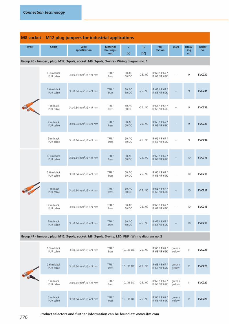
M8 socket – M12 plug jumpers for industrial applications
Type Cable Wirespecification
Materialhousing /
nut
U
[V]
Ta
[°C]
Pro-tection
LEDs Draw-ingno.
Orderno.
Group 46 · Jumper , plug: M12, 3-pole, socket: M8, 3-pole, 3-wire · Wiring diagram no. 1
0.3 m blackPUR cable 3 x 0.34 mm2, Ø 4.9 mm
TPU /Brass
50 AC60 DC
-25...90IP 65 / IP 67 /IP 68 / IP 69K
– 9 EVC230
0.6 m blackPUR cable 3 x 0.34 mm2, Ø 4.9 mm
TPU /Brass
50 AC60 DC
-25...90IP 65 / IP 67 /IP 68 / IP 69K
– 9 EVC231
1 m blackPUR cable 3 x 0.34 mm2, Ø 4.9 mm
TPU /Brass
50 AC60 DC
-25...90IP 65 / IP 67 /IP 68 / IP 69K
– 9 EVC232
2 m blackPUR cable 3 x 0.34 mm2, Ø 4.9 mm
TPU /Brass
50 AC60 DC
-25...90IP 65 / IP 67 /IP 68 / IP 69K
– 9 EVC233
5 m blackPUR cable 3 x 0.34 mm2, Ø 4.9 mm
TPU /Brass
50 AC60 DC
-25...90IP 65 / IP 67 /IP 68 / IP 69K
– 9 EVC234
0.3 m blackPUR cable 3 x 0.34 mm2, Ø 4.9 mm
TPU /Brass
50 AC60 DC
-25...90IP 65 / IP 67 /IP 68 / IP 69K
– 10 EVC215
0.6 m blackPUR cable 3 x 0.34 mm2, Ø 4.9 mm
TPU /Brass
50 AC60 DC
-25...90IP 65 / IP 67 /IP 68 / IP 69K
– 10 EVC216
1 m blackPUR cable 3 x 0.34 mm2, Ø 4.9 mm
TPU /Brass
50 AC60 DC
-25...90IP 65 / IP 67 /IP 68 / IP 69K
– 10 EVC217
2 m blackPUR cable 3 x 0.34 mm2, Ø 4.9 mm
TPU /Brass
50 AC60 DC
-25...90IP 65 / IP 67 /IP 68 / IP 69K
– 10 EVC218
5 m blackPUR cable 3 x 0.34 mm2, Ø 4.9 mm
TPU /Brass
50 AC60 DC
-25...90IP 65 / IP 67 /IP 68 / IP 69K
– 10 EVC219
Group 47 · Jumper , plug: M12, 3-pole, socket: M8, 3-pole, 3-wire, LED, PNP · Wiring diagram no. 2
0.3 m blackPUR cable 3 x 0.34 mm2, Ø 4.9 mm
TPU /Brass
10...36 DC -25...90IP 65 / IP 67 /IP 68 / IP 69K
green /yellow
11 EVC225
0.6 m blackPUR cable 3 x 0.34 mm2, Ø 4.9 mm
TPU /Brass
10...36 DC -25...90IP 65 / IP 67 /IP 68 / IP 69K
green /yellow
11 EVC226
1 m blackPUR cable 3 x 0.34 mm2, Ø 4.9 mm
TPU /Brass
10...36 DC -25...90IP 65 / IP 67 /IP 68 / IP 69K
green /yellow
11 EVC227
2 m blackPUR cable 3 x 0.34 mm2, Ø 4.9 mm
TPU /Brass
10...36 DC -25...90IP 65 / IP 67 /IP 68 / IP 69K
green /yellow
11 EVC228
Connection technology
776Product selectors and further information can be found at: www.ifm.com
Gesamtkatalog EN 2016_17_Stilvorlage LK FrutigerOT_2010 DE_GB.qxd 06.11.15 17:00 Seite 776
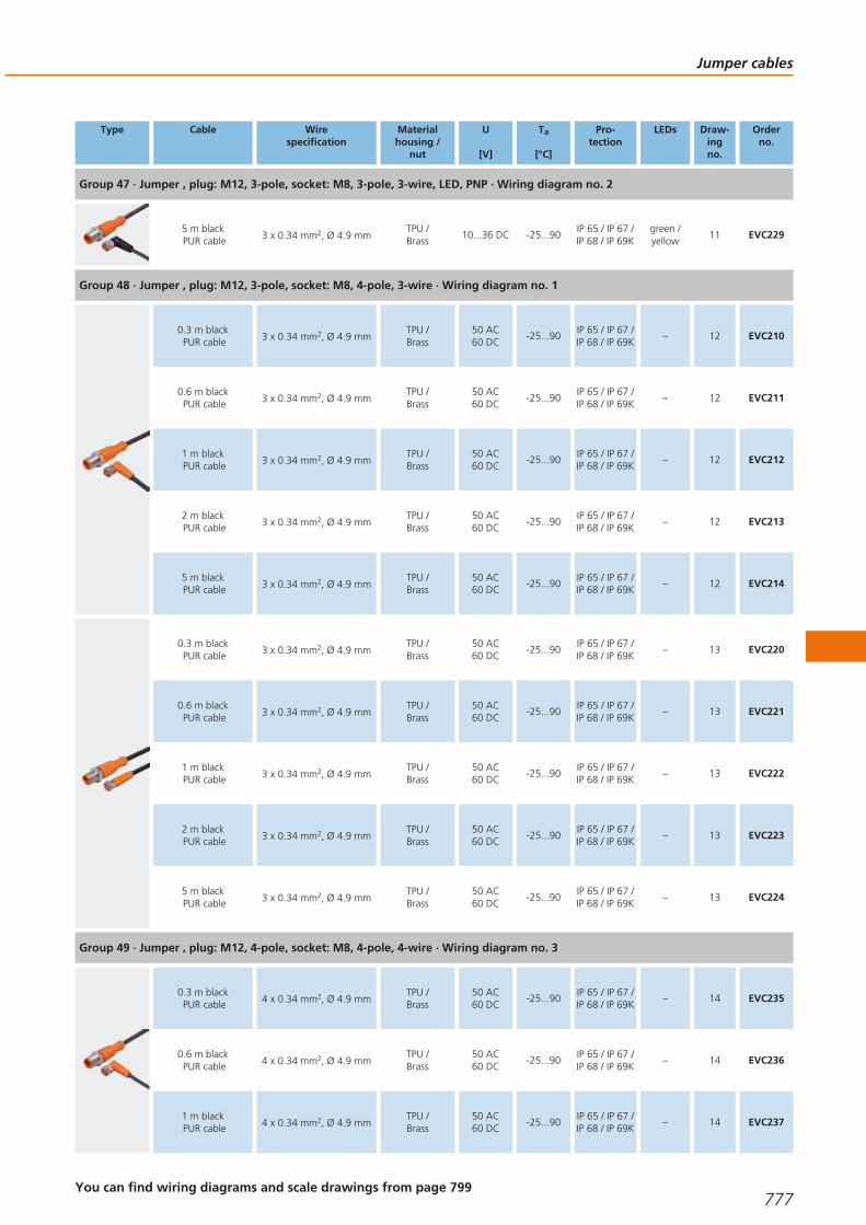
Type Cable Wirespecification
Materialhousing /
nut
U
[V]
Ta
[°C]
Pro-tection
LEDs Draw-ingno.
Orderno.
Group 47 · Jumper , plug: M12, 3-pole, socket: M8, 3-pole, 3-wire, LED, PNP · Wiring diagram no. 2
5 m blackPUR cable 3 x 0.34 mm2, Ø 4.9 mm
TPU /Brass
10...36 DC -25...90IP 65 / IP 67 /IP 68 / IP 69K
green /yellow
11 EVC229
Group 48 · Jumper , plug: M12, 3-pole, socket: M8, 4-pole, 3-wire · Wiring diagram no. 1
0.3 m blackPUR cable 3 x 0.34 mm2, Ø 4.9 mm
TPU /Brass
50 AC60 DC
-25...90IP 65 / IP 67 /IP 68 / IP 69K
– 12 EVC210
0.6 m blackPUR cable 3 x 0.34 mm2, Ø 4.9 mm
TPU /Brass
50 AC60 DC
-25...90IP 65 / IP 67 /IP 68 / IP 69K
– 12 EVC211
1 m blackPUR cable 3 x 0.34 mm2, Ø 4.9 mm
TPU /Brass
50 AC60 DC
-25...90IP 65 / IP 67 /IP 68 / IP 69K
– 12 EVC212
2 m blackPUR cable 3 x 0.34 mm2, Ø 4.9 mm
TPU /Brass
50 AC60 DC
-25...90IP 65 / IP 67 /IP 68 / IP 69K
– 12 EVC213
5 m blackPUR cable 3 x 0.34 mm2, Ø 4.9 mm
TPU /Brass
50 AC60 DC
-25...90IP 65 / IP 67 /IP 68 / IP 69K
– 12 EVC214
0.3 m blackPUR cable 3 x 0.34 mm2, Ø 4.9 mm
TPU /Brass
50 AC60 DC
-25...90IP 65 / IP 67 /IP 68 / IP 69K
– 13 EVC220
0.6 m blackPUR cable 3 x 0.34 mm2, Ø 4.9 mm
TPU /Brass
50 AC60 DC
-25...90IP 65 / IP 67 /IP 68 / IP 69K
– 13 EVC221
1 m blackPUR cable 3 x 0.34 mm2, Ø 4.9 mm
TPU /Brass
50 AC60 DC
-25...90IP 65 / IP 67 /IP 68 / IP 69K
– 13 EVC222
2 m blackPUR cable 3 x 0.34 mm2, Ø 4.9 mm
TPU /Brass
50 AC60 DC
-25...90IP 65 / IP 67 /IP 68 / IP 69K
– 13 EVC223
5 m blackPUR cable 3 x 0.34 mm2, Ø 4.9 mm
TPU /Brass
50 AC60 DC
-25...90IP 65 / IP 67 /IP 68 / IP 69K
– 13 EVC224
Group 49 · Jumper , plug: M12, 4-pole, socket: M8, 4-pole, 4-wire · Wiring diagram no. 3
0.3 m blackPUR cable 4 x 0.34 mm2, Ø 4.9 mm
TPU /Brass
50 AC60 DC
-25...90IP 65 / IP 67 /IP 68 / IP 69K
– 14 EVC235
0.6 m blackPUR cable 4 x 0.34 mm2, Ø 4.9 mm
TPU /Brass
50 AC60 DC
-25...90IP 65 / IP 67 /IP 68 / IP 69K
– 14 EVC236
1 m blackPUR cable 4 x 0.34 mm2, Ø 4.9 mm
TPU /Brass
50 AC60 DC
-25...90IP 65 / IP 67 /IP 68 / IP 69K
– 14 EVC237
Jumper cables
777You can find wiring diagrams and scale drawings from page 799
Gesamtkatalog EN 2016_17_Stilvorlage LK FrutigerOT_2010 DE_GB.qxd 06.11.15 17:01 Seite 777

Type Cable Wirespecification
Materialhousing /
nut
U
[V]
Ta
[°C]
Pro-tection
LEDs Draw-ingno.
Orderno.
Group 49 · Jumper , plug: M12, 4-pole, socket: M8, 4-pole, 4-wire · Wiring diagram no. 3
2 m blackPUR cable 4 x 0.34 mm2, Ø 4.9 mm
TPU /Brass
50 AC60 DC
-25...90IP 65 / IP 67 /IP 68 / IP 69K
– 14 EVC238
5 m blackPUR cable 4 x 0.34 mm2, Ø 4.9 mm
TPU /Brass
50 AC60 DC
-25...90IP 65 / IP 67 /IP 68 / IP 69K
– 14 EVC239
0.3 m blackPUR cable 4 x 0.34 mm2, Ø 4.9 mm
TPU /Brass
50 AC60 DC
-25...90IP 65 / IP 67 /IP 68 / IP 69K
– 15 EVC240
0.6 m blackPUR cable 4 x 0.34 mm2, Ø 4.9 mm
TPU /Brass
50 AC60 DC
-25...90IP 65 / IP 67 /IP 68 / IP 69K
– 15 EVC241
1 m blackPUR cable 4 x 0.34 mm2, Ø 4.9 mm
TPU /Brass
50 AC60 DC
-25...90IP 65 / IP 67 /IP 68 / IP 69K
– 15 EVC242
2 m blackPUR cable 4 x 0.34 mm2, Ø 4.9 mm
TPU /Brass
50 AC60 DC
-25...90IP 65 / IP 67 /IP 68 / IP 69K
– 15 EVC243
5 m blackPUR cable 4 x 0.34 mm2, Ø 4.9 mm
TPU /Brass
50 AC60 DC
-25...90IP 65 / IP 67 /IP 68 / IP 69K
– 15 EVC244
M8 plug - M12 socket jumpers for industrial applications
Type Cable Wirespecification
Materialhousing /
nut
U
[V]
Ta
[°C]
Pro-tection
LEDs Draw-ingno.
Orderno.
Group 50 · Jumper , plug: M8, 3-pole, socket: M12, 5/4-pole, 3-wire · Wiring diagram no. 1
0.3 m blackPUR cable 3 x 0.34 mm2, Ø 4.9 mm
TPU /Brass
50 AC60 DC
-25...90IP 65 / IP 67 /IP 68 / IP 69K
– 16 EVC245
0.6 m blackPUR cable 3 x 0.34 mm2, Ø 4.9 mm
TPU /Brass
50 AC60 DC
-25...90IP 65 / IP 67 /IP 68 / IP 69K
– 16 EVC246
1 m blackPUR cable 3 x 0.34 mm2, Ø 4.9 mm
TPU /Brass
50 AC60 DC
-25...90IP 65 / IP 67 /IP 68 / IP 69K
– 16 EVC247
2 m blackPUR cable 3 x 0.34 mm2, Ø 4.9 mm
TPU /Brass
50 AC60 DC
-25...90IP 65 / IP 67 /IP 68 / IP 69K
– 16 EVC248
5 m blackPUR cable 3 x 0.34 mm2, Ø 4.9 mm
TPU /Brass
50 AC60 DC
-25...90IP 65 / IP 67 /IP 68 / IP 69K
– 16 EVC249
Connection technology
778Product selectors and further information can be found at: www.ifm.com
Gesamtkatalog EN 2016_17_Stilvorlage LK FrutigerOT_2010 DE_GB.qxd 06.11.15 17:01 Seite 778

Type Cable Wirespecification
Materialhousing /
nut
U
[V]
Ta
[°C]
Pro-tection
LEDs Draw-ingno.
Orderno.
Group 51 · Jumper , plug: M8, 3-pole, socket: M12, 5-pole, 3-wire · Wiring diagram no. 1
0.3 m blackPUR cable 3 x 0.34 mm2, Ø 4.9 mm
TPU /Brass
50 AC60 DC
-25...90IP 65 / IP 67 /IP 68 / IP 69K
– 17 EVC255
0.6 m blackPUR cable 3 x 0.34 mm2, Ø 4.9 mm
TPU /Brass
50 AC60 DC
-25...90IP 65 / IP 67 /IP 68 / IP 69K
– 17 EVC256
1 m blackPUR cable 3 x 0.34 mm2, Ø 4.9 mm
TPU /Brass
50 AC60 DC
-25...90IP 65 / IP 67 /IP 68 / IP 69K
– 17 EVC257
2 m blackPUR cable 3 x 0.34 mm2, Ø 4.9 mm
TPU /Brass
50 AC60 DC
-25...90IP 65 / IP 67 /IP 68 / IP 69K
– 17 EVC258
5 m blackPUR cable 3 x 0.34 mm2, Ø 4.9 mm
TPU /Brass
50 AC60 DC
-25...90IP 65 / IP 67 /IP 68 / IP 69K
– 17 EVC259
Group 52 · Jumper , plug: M8, 3-pole, socket: M12, 5-pole, 3-wire, LED, PNP · Wiring diagram no. 2
0.3 m blackPUR cable 3 x 0.34 mm2, Ø 4.9 mm
TPU /Brass
10...36 DC -25...90IP 65 / IP 67 /IP 68 / IP 69K
green /yellow
18 EVC250
0.6 m blackPUR cable 3 x 0.34 mm2, Ø 4.9 mm
TPU /Brass
10...36 DC -25...90IP 65 / IP 67 /IP 68 / IP 69K
green /yellow
18 EVC251
1 m blackPUR cable 3 x 0.34 mm2, Ø 4.9 mm
TPU /Brass
10...36 DC -25...90IP 65 / IP 67 /IP 68 / IP 69K
green /yellow
18 EVC252
2 m blackPUR cable 3 x 0.34 mm2, Ø 4.9 mm
TPU /Brass
10...36 DC -25...90IP 65 / IP 67 /IP 68 / IP 69K
green /yellow
18 EVC253
5 m blackPUR cable 3 x 0.34 mm2, Ø 4.9 mm
TPU /Brass
10...36 DC -25...90IP 65 / IP 67 /IP 68 / IP 69K
green /yellow
18 EVC254
Group 53 · Jumper , plug: M8, 4-pole, socket: M12, 5-pole, 4-wire · Wiring diagram no. 3
0.3 m blackPUR cable 4 x 0.34 mm2, Ø 4.9 mm
TPU /Brass
50 AC60 DC
-25...90IP 65 / IP 67 /IP 68 / IP 69K
– 19 EVC285
0.6 m blackPUR cable 4 x 0.34 mm2, Ø 4.9 mm
TPU /Brass
50 AC60 DC
-25...90IP 65 / IP 67 /IP 68 / IP 69K
– 19 EVC286
1 m blackPUR cable 4 x 0.34 mm2, Ø 4.9 mm
TPU /Brass
50 AC60 DC
-25...90IP 65 / IP 67 /IP 68 / IP 69K
– 19 EVC287
2 m blackPUR cable 4 x 0.34 mm2, Ø 4.9 mm
TPU /Brass
50 AC60 DC
-25...90IP 65 / IP 67 /IP 68 / IP 69K
– 19 EVC288
Jumper cables
779You can find wiring diagrams and scale drawings from page 799
Gesamtkatalog EN 2016_17_Stilvorlage LK FrutigerOT_2010 DE_GB.qxd 06.11.15 17:01 Seite 779

Type Cable Wirespecification
Materialhousing /
nut
U
[V]
Ta
[°C]
Pro-tection
LEDs Draw-ingno.
Orderno.
Group 53 · Jumper , plug: M8, 4-pole, socket: M12, 5-pole, 4-wire · Wiring diagram no. 3
5 m blackPUR cable 4 x 0.34 mm2, Ø 4.9 mm
TPU /Brass
50 AC60 DC
-25...90IP 65 / IP 67 /IP 68 / IP 69K
– 19 EVC289
Group 54 · Jumper , plug: M8, 4-pole, socket: M12, 5/4-pole, 4-wire · Wiring diagram no. 3
0.3 m blackPUR cable 4 x 0.34 mm2, Ø 4.9 mm
TPU /Brass
50 AC60 DC
-25...90IP 65 / IP 67 /IP 68 / IP 69K
– 20 EVC295
0.6 m blackPUR cable 4 x 0.34 mm2, Ø 4.9 mm
TPU /Brass
50 AC60 DC
-25...90IP 65 / IP 67 /IP 68 / IP 69K
– 20 EVC296
1 m blackPUR cable 4 x 0.34 mm2, Ø 4.9 mm
TPU /Brass
50 AC60 DC
-25...90IP 65 / IP 67 /IP 68 / IP 69K
– 20 EVC297
2 m blackPUR cable 4 x 0.34 mm2, Ø 4.9 mm
TPU /Brass
50 AC60 DC
-25...90IP 65 / IP 67 /IP 68 / IP 69K
– 20 EVC298
5 m blackPUR cable 4 x 0.34 mm2, Ø 4.9 mm
TPU /Brass
50 AC60 DC
-25...90IP 65 / IP 67 /IP 68 / IP 69K
– 20 EVC299
Group 55 · Jumper , plug: M8, 4-pole, socket: M12, 5-pole, 4-wire, LED, PNP · Wiring diagram no. 4
0.3 m blackPUR cable 4 x 0.34 mm2, Ø 4.9 mm
TPU /Brass
10...36 DC -25...90IP 65 / IP 67 /IP 68 / IP 69K
green /2 x yellow
21 EVC290
0.6 m blackPUR cable 4 x 0.34 mm2, Ø 4.9 mm
TPU /Brass
10...36 DC -25...90IP 65 / IP 67 /IP 68 / IP 69K
green /2 x yellow
21 EVC291
1 m blackPUR cable 4 x 0.34 mm2, Ø 4.9 mm
TPU /Brass
10...36 DC -25...90IP 65 / IP 67 /IP 68 / IP 69K
green /2 x yellow
21 EVC292
2 m blackPUR cable 4 x 0.34 mm2, Ø 4.9 mm
TPU /Brass
10...36 DC -25...90IP 65 / IP 67 /IP 68 / IP 69K
green /2 x yellow
21 EVC293
5 m blackPUR cable 4 x 0.34 mm2, Ø 4.9 mm
TPU /Brass
10...36 DC -25...90IP 65 / IP 67 /IP 68 / IP 69K
green /2 x yellow
21 EVC294
M12 – M12 jumpers for industrial applications
Type Cable Wirespecification
Materialhousing /
nut
U
[V]
Ta
[°C]
Pro-tection
LEDs Draw-ingno.
Orderno.
Group 56 · Jumper , plug: M12, 3-pole, socket: M12, 5-pole, 3-wire · Wiring diagram no. 1
0.3 m blackPUR cable 3 x 0.34 mm2, Ø 4.9 mm
TPU /Brass
250 AC300 DC
-25...90IP 65 / IP 67 /IP 68 / IP 69K
– 22 EVC045
Connection technology
780Product selectors and further information can be found at: www.ifm.com
Gesamtkatalog EN 2016_17_Stilvorlage LK FrutigerOT_2010 DE_GB.qxd 06.11.15 17:01 Seite 780

Type Cable Wirespecification
Materialhousing /
nut
U
[V]
Ta
[°C]
Pro-tection
LEDs Draw-ingno.
Orderno.
Group 56 · Jumper , plug: M12, 3-pole, socket: M12, 5-pole, 3-wire · Wiring diagram no. 1
0.6 m blackPUR cable 3 x 0.34 mm2, Ø 4.9 mm
TPU /Brass
250 AC300 DC
-25...90IP 65 / IP 67 /IP 68 / IP 69K
– 22 EVC046
1 m blackPUR cable 3 x 0.34 mm2, Ø 4.9 mm
TPU /Brass
250 AC300 DC
-25...90IP 65 / IP 67 /IP 68 / IP 69K
– 22 EVC047
2 m blackPUR cable 3 x 0.34 mm2, Ø 4.9 mm
TPU /Brass
250 AC300 DC
-25...90IP 65 / IP 67 /IP 68 / IP 69K
– 22 EVC048
5 m blackPUR cable 3 x 0.34 mm2, Ø 4.9 mm
TPU /Brass
250 AC300 DC
-25...90IP 65 / IP 67 /IP 68 / IP 69K
– 22 EVC049
0.3 m blackPUR cable 3 x 0.34 mm2, Ø 4.9 mm
TPU /Brass
250 AC300 DC
-25...90IP 65 / IP 67 /IP 68 / IP 69K
– 23 EVC040
0.6 m blackPUR cable 3 x 0.34 mm2, Ø 4.9 mm
TPU /Brass
250 AC300 DC
-25...90IP 65 / IP 67 /IP 68 / IP 69K
– 23 EVC041
1 m blackPUR cable 3 x 0.34 mm2, Ø 4.9 mm
TPU /Brass
250 AC300 DC
-25...90IP 65 / IP 67 /IP 68 / IP 69K
– 23 EVC042
2 m blackPUR cable 3 x 0.34 mm2, Ø 4.9 mm
TPU /Brass
250 AC300 DC
-25...90IP 65 / IP 67 /IP 68 / IP 69K
– 23 EVC043
5 m blackPUR cable 3 x 0.34 mm2, Ø 4.9 mm
TPU /Brass
250 AC300 DC
-25...90IP 65 / IP 67 /IP 68 / IP 69K
– 23 EVC044
Group 58 · Jumper , plug: M12, 3-pole, socket: M12, 5-pole, 3-wire, LED, PNP · Wiring diagram no. 2
0.3 m blackPUR cable 3 x 0.34 mm2, Ø 4.9 mm
TPU /Brass
10...36 DC -25...90IP 65 / IP 67 /IP 68 / IP 69K
green /yellow
24 EVC050
0.6 m blackPUR cable 3 x 0.34 mm2, Ø 4.9 mm
TPU /Brass
10...36 DC -25...90IP 65 / IP 67 /IP 68 / IP 69K
green /yellow
24 EVC051
1 m blackPUR cable 3 x 0.34 mm2, Ø 4.9 mm
TPU /Brass
10...36 DC -25...90IP 65 / IP 67 /IP 68 / IP 69K
green /yellow
24 EVC052
2 m blackPUR cable 3 x 0.34 mm2, Ø 4.9 mm
TPU /Brass
10...36 DC -25...90IP 65 / IP 67 /IP 68 / IP 69K
green /yellow
24 EVC053
5 m blackPUR cable 3 x 0.34 mm2, Ø 4.9 mm
TPU /Brass
10...36 DC -25...90IP 65 / IP 67 /IP 68 / IP 69K
green /yellow
24 EVC054
Jumper cables
781You can find wiring diagrams and scale drawings from page 799
Gesamtkatalog EN 2016_17_Stilvorlage LK FrutigerOT_2010 DE_GB.qxd 06.11.15 17:01 Seite 781
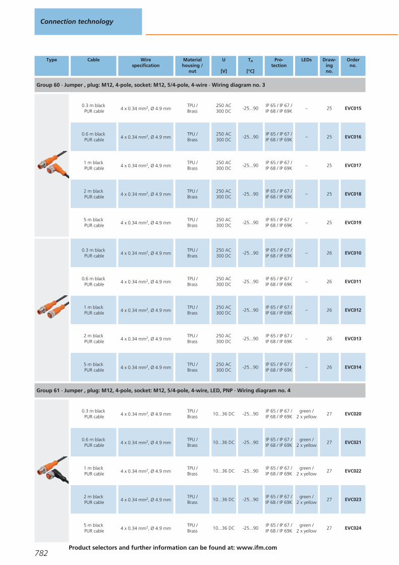
Type Cable Wirespecification
Materialhousing /
nut
U
[V]
Ta
[°C]
Pro-tection
LEDs Draw-ingno.
Orderno.
Group 60 · Jumper , plug: M12, 4-pole, socket: M12, 5/4-pole, 4-wire · Wiring diagram no. 3
0.3 m blackPUR cable 4 x 0.34 mm2, Ø 4.9 mm
TPU /Brass
250 AC300 DC
-25...90IP 65 / IP 67 /IP 68 / IP 69K
– 25 EVC015
0.6 m blackPUR cable 4 x 0.34 mm2, Ø 4.9 mm
TPU /Brass
250 AC300 DC
-25...90IP 65 / IP 67 /IP 68 / IP 69K
– 25 EVC016
1 m blackPUR cable 4 x 0.34 mm2, Ø 4.9 mm
TPU /Brass
250 AC300 DC
-25...90IP 65 / IP 67 /IP 68 / IP 69K
– 25 EVC017
2 m blackPUR cable 4 x 0.34 mm2, Ø 4.9 mm
TPU /Brass
250 AC300 DC
-25...90IP 65 / IP 67 /IP 68 / IP 69K
– 25 EVC018
5 m blackPUR cable 4 x 0.34 mm2, Ø 4.9 mm
TPU /Brass
250 AC300 DC
-25...90IP 65 / IP 67 /IP 68 / IP 69K
– 25 EVC019
0.3 m blackPUR cable 4 x 0.34 mm2, Ø 4.9 mm
TPU /Brass
250 AC300 DC
-25...90IP 65 / IP 67 /IP 68 / IP 69K
– 26 EVC010
0.6 m blackPUR cable 4 x 0.34 mm2, Ø 4.9 mm
TPU /Brass
250 AC300 DC
-25...90IP 65 / IP 67 /IP 68 / IP 69K
– 26 EVC011
1 m blackPUR cable 4 x 0.34 mm2, Ø 4.9 mm
TPU /Brass
250 AC300 DC
-25...90IP 65 / IP 67 /IP 68 / IP 69K
– 26 EVC012
2 m blackPUR cable 4 x 0.34 mm2, Ø 4.9 mm
TPU /Brass
250 AC300 DC
-25...90IP 65 / IP 67 /IP 68 / IP 69K
– 26 EVC013
5 m blackPUR cable 4 x 0.34 mm2, Ø 4.9 mm
TPU /Brass
250 AC300 DC
-25...90IP 65 / IP 67 /IP 68 / IP 69K
– 26 EVC014
Group 61 · Jumper , plug: M12, 4-pole, socket: M12, 5/4-pole, 4-wire, LED, PNP · Wiring diagram no. 4
0.3 m blackPUR cable 4 x 0.34 mm2, Ø 4.9 mm
TPU /Brass
10...36 DC -25...90IP 65 / IP 67 /IP 68 / IP 69K
green /2 x yellow
27 EVC020
0.6 m blackPUR cable 4 x 0.34 mm2, Ø 4.9 mm
TPU /Brass
10...36 DC -25...90IP 65 / IP 67 /IP 68 / IP 69K
green /2 x yellow
27 EVC021
1 m blackPUR cable 4 x 0.34 mm2, Ø 4.9 mm
TPU /Brass
10...36 DC -25...90IP 65 / IP 67 /IP 68 / IP 69K
green /2 x yellow
27 EVC022
2 m blackPUR cable 4 x 0.34 mm2, Ø 4.9 mm
TPU /Brass
10...36 DC -25...90IP 65 / IP 67 /IP 68 / IP 69K
green /2 x yellow
27 EVC023
5 m blackPUR cable 4 x 0.34 mm2, Ø 4.9 mm
TPU /Brass
10...36 DC -25...90IP 65 / IP 67 /IP 68 / IP 69K
green /2 x yellow
27 EVC024
Connection technology
782Product selectors and further information can be found at: www.ifm.com
Gesamtkatalog EN 2016_17_Stilvorlage LK FrutigerOT_2010 DE_GB.qxd 06.11.15 17:01 Seite 782

Type Cable Wirespecification
Materialhousing /
nut
U
[V]
Ta
[°C]
Pro-tection
LEDs Draw-ingno.
Orderno.
Group 62 · Jumper , plug: M12, 4-pole, socket: M12, 5/4-pole, 4-wire · Wiring diagram no. 3
0.3 m blackPUR cable 4 x 0.34 mm2, Ø 4.9 mm
TPU /Brass
250 AC300 DC
-25...90IP 65 / IP 67 /IP 68 / IP 69K
– 28 EVC025
0.6 m blackPUR cable 4 x 0.34 mm2, Ø 4.9 mm
TPU /Brass
250 AC300 DC
-25...90IP 65 / IP 67 /IP 68 / IP 69K
– 28 EVC026
1 m blackPUR cable 4 x 0.34 mm2, Ø 4.9 mm
TPU /Brass
250 AC300 DC
-25...90IP 65 / IP 67 /IP 68 / IP 69K
– 28 EVC027
2 m blackPUR cable 4 x 0.34 mm2, Ø 4.9 mm
TPU /Brass
250 AC300 DC
-25...90IP 65 / IP 67 /IP 68 / IP 69K
– 28 EVC028
5 m blackPUR cable 4 x 0.34 mm2, Ø 4.9 mm
TPU /Brass
250 AC300 DC
-25...90IP 65 / IP 67 /IP 68 / IP 69K
– 28 EVC029
0.3 m blackPUR cable 4 x 0.34 mm2, Ø 4.9 mm
TPU /Brass
250 AC300 DC
-25...90IP 65 / IP 67 /IP 68 / IP 69K
– 29 EVC030
0.6 m blackPUR cable 4 x 0.34 mm2, Ø 4.9 mm
TPU /Brass
250 AC300 DC
-25...90IP 65 / IP 67 /IP 68 / IP 69K
– 29 EVC031
1 m blackPUR cable 4 x 0.34 mm2, Ø 4.9 mm
TPU /Brass
250 AC300 DC
-25...90IP 65 / IP 67 /IP 68 / IP 69K
– 29 EVC032
2 m blackPUR cable 4 x 0.34 mm2, Ø 4.9 mm
TPU /Brass
250 AC300 DC
-25...90IP 65 / IP 67 /IP 68 / IP 69K
– 29 EVC033
5 m blackPUR cable 4 x 0.34 mm2, Ø 4.9 mm
TPU /Brass
250 AC300 DC
-25...90IP 65 / IP 67 /IP 68 / IP 69K
– 29 EVC034
Group 63 · Jumper , plug: M12, 4-pole, socket: M12, 5/4-pole, 4-wire, LED, PNP · Wiring diagram no. 4
0.3 m blackPUR cable 4 x 0.34 mm2, Ø 4.9 mm
TPU /Brass
10...36 DC -25...90IP 65 / IP 67 /IP 68 / IP 69K
green /2 x yellow
30 EVC035
0.6 m blackPUR cable 4 x 0.34 mm2, Ø 4.9 mm
TPU /Brass
10...36 DC -25...90IP 65 / IP 67 /IP 68 / IP 69K
green /2 x yellow
30 EVC036
1 m blackPUR cable 4 x 0.34 mm2, Ø 4.9 mm
TPU /Brass
10...36 DC -25...90IP 65 / IP 67 /IP 68 / IP 69K
green /2 x yellow
30 EVC037
2 m blackPUR cable 4 x 0.34 mm2, Ø 4.9 mm
TPU /Brass
10...36 DC -25...90IP 65 / IP 67 /IP 68 / IP 69K
green /2 x yellow
30 EVC038
5 m blackPUR cable 4 x 0.34 mm2, Ø 4.9 mm
TPU /Brass
10...36 DC -25...90IP 65 / IP 67 /IP 68 / IP 69K
green /2 x yellow
30 EVC039
Jumper cables
783You can find wiring diagrams and scale drawings from page 799
Gesamtkatalog EN 2016_17_Stilvorlage LK FrutigerOT_2010 DE_GB.qxd 06.11.15 17:01 Seite 783

Type Cable Wirespecification
Materialhousing /
nut
U
[V]
Ta
[°C]
Pro-tection
LEDs Draw-ingno.
Orderno.
Group 64 · Jumper , plug: M12, 5-pole, socket: M12, 5-pole, 5-wire · Wiring diagram no. 5
0.3 m blackPUR cable 5 x 0.34 mm2, Ø 4.9 mm
TPU /Brass
60 AC60 DC
-25...90IP 65 / IP 67 /IP 68 / IP 69K
– 31 EVC060
0.6 m blackPUR cable 5 x 0.34 mm2, Ø 4.9 mm
TPU /Brass
60 AC60 DC
-25...90IP 65 / IP 67 /IP 68 / IP 69K
– 31 EVC061
1 m blackPUR cable 5 x 0.34 mm2, Ø 4.9 mm
TPU /Brass
60 AC60 DC
-25...90IP 65 / IP 67 /IP 68 / IP 69K
– 31 EVC062
2 m blackPUR cable 5 x 0.34 mm2, Ø 4.9 mm
TPU /Brass
60 AC60 DC
-25...90IP 65 / IP 67 /IP 68 / IP 69K
– 31 EVC063
5 m blackPUR cable 5 x 0.34 mm2, Ø 4.9 mm
TPU /Brass
60 AC60 DC
-25...90IP 65 / IP 67 /IP 68 / IP 69K
– 31 EVC064
0.3 m blackPUR cable 5 x 0.34 mm2, Ø 4.9 mm
TPU /Brass
60 AC60 DC
-25...90IP 65 / IP 67 /IP 68 / IP 69K
– 32 EVC055
0.6 m blackPUR cable 5 x 0.34 mm2, Ø 4.9 mm
TPU /Brass
60 AC60 DC
-25...90IP 65 / IP 67 /IP 68 / IP 69K
– 32 EVC056
1 m blackPUR cable 5 x 0.34 mm2, Ø 4.9 mm
TPU /Brass
60 AC60 DC
-25...90IP 65 / IP 67 /IP 68 / IP 69K
– 32 EVC057
2 m blackPUR cable 5 x 0.34 mm2, Ø 4.9 mm
TPU /Brass
60 AC60 DC
-25...90IP 65 / IP 67 /IP 68 / IP 69K
– 32 EVC058
5 m blackPUR cable 5 x 0.34 mm2, Ø 4.9 mm
TPU /Brass
60 AC60 DC
-25...90IP 65 / IP 67 /IP 68 / IP 69K
– 32 EVC059
0.3 m blackPUR cable 5 x 0.34 mm2, Ø 4.9 mm
TPU /Brass
60 AC60 DC
-25...90IP 65 / IP 67 /IP 68 / IP 69K
– 33 EVC065
0.6 m blackPUR cable 5 x 0.34 mm2, Ø 4.9 mm
TPU /Brass
60 AC60 DC
-25...90IP 65 / IP 67 /IP 68 / IP 69K
– 33 EVC066
1 m blackPUR cable 5 x 0.34 mm2, Ø 4.9 mm
TPU /Brass
60 AC60 DC
-25...90IP 65 / IP 67 /IP 68 / IP 69K
– 33 EVC067
2 m blackPUR cable 5 x 0.34 mm2, Ø 4.9 mm
TPU /Brass
60 AC60 DC
-25...90IP 65 / IP 67 /IP 68 / IP 69K
– 33 EVC068
5 m blackPUR cable 5 x 0.34 mm2, Ø 4.9 mm
TPU /Brass
60 AC60 DC
-25...90IP 65 / IP 67 /IP 68 / IP 69K
– 33 EVC069
Connection technology
784Product selectors and further information can be found at: www.ifm.com
Gesamtkatalog EN 2016_17_Stilvorlage LK FrutigerOT_2010 DE_GB.qxd 06.11.15 17:01 Seite 784

Valve - plug jumpers for industrial applications
Type Cable Wirespecification
Materialhousing /
nut
U
[V]
Ta
[°C]
Pro-tection
LEDs Draw-ingno.
Orderno.
Group 65 · Jumper , plug: M12, 3-pole, valve plug: Housing A, 4-pole, 3-wire, LED · Wiring diagram no. 6
0.3 m blackPUR cable 3 x 0.5 mm2, Ø 5 mm
PUR /Brass
24 AC/DC -25...80 IP 67 yellow 34 E11416
0.6 m blackPUR cable 3 x 0.5 mm2, Ø 5 mm
PUR /Brass
24 AC/DC -25...80 IP 67 yellow 34 E11417
1 m blackPUR cable 3 x 0.5 mm2, Ø 5 mm
PUR /Brass
24 AC/DC -25...80 IP 67 yellow 34 E11418
2 m blackPUR cable 3 x 0.5 mm2, Ø 5 mm
PUR /Brass
24 AC/DC -25...80 IP 67 yellow 34 E11419
5 m blackPUR cable 3 x 0.5 mm2, Ø 5 mm
PUR /Brass
24 AC/DC -25...80 IP 67 yellow 34 E11420
Group 66 · Jumper , plug: M12, 3-pole, valve plug: Housing B, 3-pole, 3-wire, LED · Wiring diagram no. 7
0.3 m blackPUR cable 3 x 0.5 mm2, Ø 5 mm
PUR /Brass
24 AC/DC -25...80 IP 67 yellow 35 E11421
0.6 m blackPUR cable 3 x 0.5 mm2, Ø 5 mm
PUR /Brass
24 AC/DC -25...80 IP 67 yellow 35 E11422
1 m blackPUR cable 3 x 0.5 mm2, Ø 5 mm
PUR /Brass
24 AC/DC -25...80 IP 67 yellow 35 E11423
2 m blackPUR cable 3 x 0.5 mm2, Ø 5 mm
PUR /Brass
24 AC/DC -25...80 IP 67 yellow 35 E11424
5 m blackPUR cable 3 x 0.5 mm2, Ø 5 mm
PUR /Brass
24 AC/DC -25...80 IP 67 yellow 35 E11425
Group 67 · Jumper , plug: M12, 3-pole, valve plug: Housing B (industrial standard), 3-pole, 3-wire, LED · Wiring diagram no. 7
0.3 m blackPUR cable 3 x 0.5 mm2, Ø 5 mm
PUR /Brass
24 AC/DC -25...80 IP 67 yellow 36 E11431
0.6 m blackPUR cable 3 x 0.5 mm2, Ø 5 mm
PUR /Brass
24 AC/DC -25...80 IP 67 yellow 36 E11432
1 m blackPUR cable 3 x 0.5 mm2, Ø 5 mm
PUR /Brass
24 AC/DC -25...80 IP 67 yellow 36 E11433
Jumper cables
785You can find wiring diagrams and scale drawings from page 799
Gesamtkatalog EN 2016_17_Stilvorlage LK FrutigerOT_2010 DE_GB.qxd 06.11.15 17:01 Seite 785
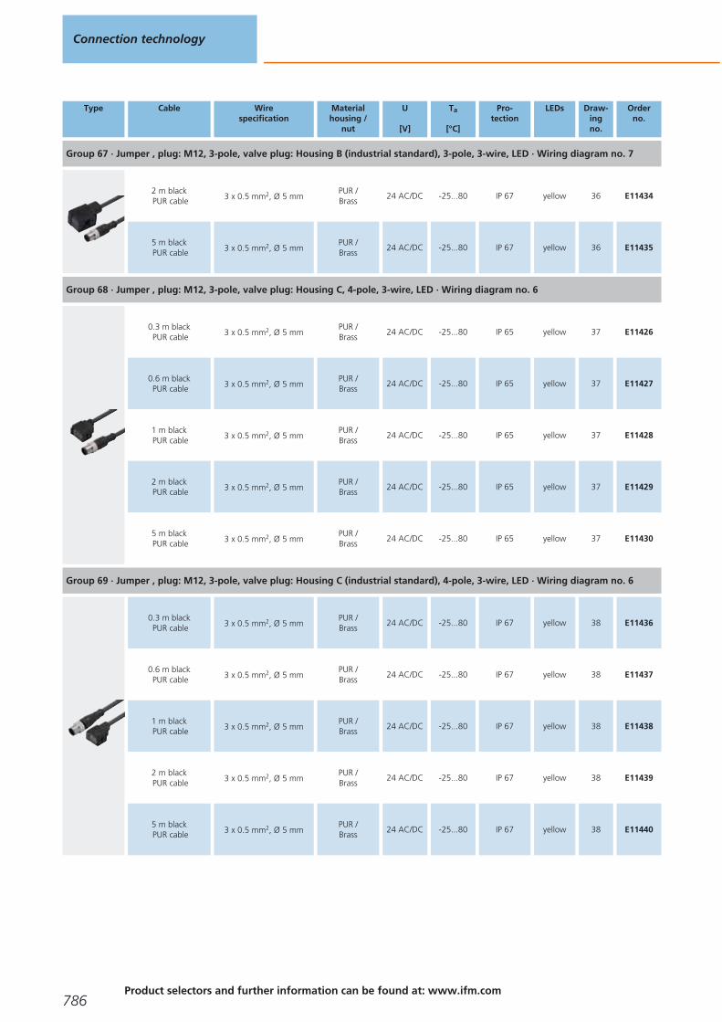
Type Cable Wirespecification
Materialhousing /
nut
U
[V]
Ta
[°C]
Pro-tection
LEDs Draw-ingno.
Orderno.
Group 67 · Jumper , plug: M12, 3-pole, valve plug: Housing B (industrial standard), 3-pole, 3-wire, LED · Wiring diagram no. 7
2 m blackPUR cable 3 x 0.5 mm2, Ø 5 mm
PUR /Brass
24 AC/DC -25...80 IP 67 yellow 36 E11434
5 m blackPUR cable 3 x 0.5 mm2, Ø 5 mm
PUR /Brass
24 AC/DC -25...80 IP 67 yellow 36 E11435
Group 68 · Jumper , plug: M12, 3-pole, valve plug: Housing C, 4-pole, 3-wire, LED · Wiring diagram no. 6
0.3 m blackPUR cable 3 x 0.5 mm2, Ø 5 mm
PUR /Brass
24 AC/DC -25...80 IP 65 yellow 37 E11426
0.6 m blackPUR cable 3 x 0.5 mm2, Ø 5 mm
PUR /Brass
24 AC/DC -25...80 IP 65 yellow 37 E11427
1 m blackPUR cable 3 x 0.5 mm2, Ø 5 mm
PUR /Brass
24 AC/DC -25...80 IP 65 yellow 37 E11428
2 m blackPUR cable 3 x 0.5 mm2, Ø 5 mm
PUR /Brass
24 AC/DC -25...80 IP 65 yellow 37 E11429
5 m blackPUR cable 3 x 0.5 mm2, Ø 5 mm
PUR /Brass
24 AC/DC -25...80 IP 65 yellow 37 E11430
Group 69 · Jumper , plug: M12, 3-pole, valve plug: Housing C (industrial standard), 4-pole, 3-wire, LED · Wiring diagram no. 6
0.3 m blackPUR cable 3 x 0.5 mm2, Ø 5 mm
PUR /Brass
24 AC/DC -25...80 IP 67 yellow 38 E11436
0.6 m blackPUR cable 3 x 0.5 mm2, Ø 5 mm
PUR /Brass
24 AC/DC -25...80 IP 67 yellow 38 E11437
1 m blackPUR cable 3 x 0.5 mm2, Ø 5 mm
PUR /Brass
24 AC/DC -25...80 IP 67 yellow 38 E11438
2 m blackPUR cable 3 x 0.5 mm2, Ø 5 mm
PUR /Brass
24 AC/DC -25...80 IP 67 yellow 38 E11439
5 m blackPUR cable 3 x 0.5 mm2, Ø 5 mm
PUR /Brass
24 AC/DC -25...80 IP 67 yellow 38 E11440
Connection technology
786Product selectors and further information can be found at: www.ifm.com
Gesamtkatalog EN 2016_17_Stilvorlage LK FrutigerOT_2010 DE_GB.qxd 06.11.15 17:01 Seite 786
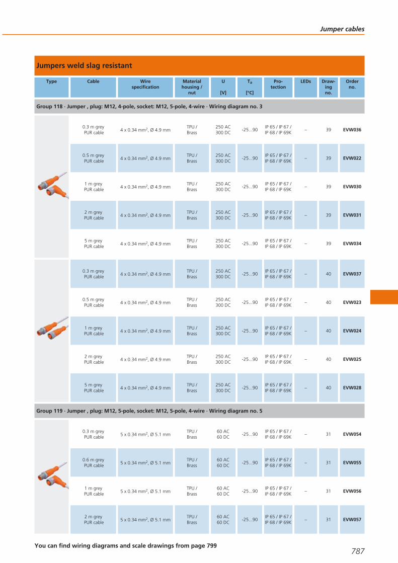
Jumpers weld slag resistant
Type Cable Wirespecification
Materialhousing /
nut
U
[V]
Ta
[°C]
Pro-tection
LEDs Draw-ingno.
Orderno.
Group 118 · Jumper , plug: M12, 4-pole, socket: M12, 5-pole, 4-wire · Wiring diagram no. 3
0.3 m greyPUR cable 4 x 0.34 mm2, Ø 4.9 mm
TPU /Brass
250 AC300 DC
-25...90IP 65 / IP 67 /IP 68 / IP 69K
– 39 EVW036
0.5 m greyPUR cable 4 x 0.34 mm2, Ø 4.9 mm
TPU /Brass
250 AC300 DC
-25...90IP 65 / IP 67 /IP 68 / IP 69K
– 39 EVW022
1 m greyPUR cable 4 x 0.34 mm2, Ø 4.9 mm
TPU /Brass
250 AC300 DC
-25...90IP 65 / IP 67 /IP 68 / IP 69K
– 39 EVW030
2 m greyPUR cable 4 x 0.34 mm2, Ø 4.9 mm
TPU /Brass
250 AC300 DC
-25...90IP 65 / IP 67 /IP 68 / IP 69K
– 39 EVW031
5 m greyPUR cable 4 x 0.34 mm2, Ø 4.9 mm
TPU /Brass
250 AC300 DC
-25...90IP 65 / IP 67 /IP 68 / IP 69K
– 39 EVW034
0.3 m greyPUR cable 4 x 0.34 mm2, Ø 4.9 mm
TPU /Brass
250 AC300 DC
-25...90IP 65 / IP 67 /IP 68 / IP 69K
– 40 EVW037
0.5 m greyPUR cable 4 x 0.34 mm2, Ø 4.9 mm
TPU /Brass
250 AC300 DC
-25...90IP 65 / IP 67 /IP 68 / IP 69K
– 40 EVW023
1 m greyPUR cable 4 x 0.34 mm2, Ø 4.9 mm
TPU /Brass
250 AC300 DC
-25...90IP 65 / IP 67 /IP 68 / IP 69K
– 40 EVW024
2 m greyPUR cable 4 x 0.34 mm2, Ø 4.9 mm
TPU /Brass
250 AC300 DC
-25...90IP 65 / IP 67 /IP 68 / IP 69K
– 40 EVW025
5 m greyPUR cable 4 x 0.34 mm2, Ø 4.9 mm
TPU /Brass
250 AC300 DC
-25...90IP 65 / IP 67 /IP 68 / IP 69K
– 40 EVW028
Group 119 · Jumper , plug: M12, 5-pole, socket: M12, 5-pole, 4-wire · Wiring diagram no. 5
0.3 m greyPUR cable 5 x 0.34 mm2, Ø 5.1 mm
TPU /Brass
60 AC60 DC
-25...90IP 65 / IP 67 /IP 68 / IP 69K
– 31 EVW054
0.6 m greyPUR cable 5 x 0.34 mm2, Ø 5.1 mm
TPU /Brass
60 AC60 DC
-25...90IP 65 / IP 67 /IP 68 / IP 69K
– 31 EVW055
1 m greyPUR cable 5 x 0.34 mm2, Ø 5.1 mm
TPU /Brass
60 AC60 DC
-25...90IP 65 / IP 67 /IP 68 / IP 69K
– 31 EVW056
2 m greyPUR cable 5 x 0.34 mm2, Ø 5.1 mm
TPU /Brass
60 AC60 DC
-25...90IP 65 / IP 67 /IP 68 / IP 69K
– 31 EVW057
Jumper cables
787You can find wiring diagrams and scale drawings from page 799
Gesamtkatalog EN 2016_17_Stilvorlage LK FrutigerOT_2010 DE_GB.qxd 06.11.15 17:01 Seite 787

Type Cable Wirespecification
Materialhousing /
nut
U
[V]
Ta
[°C]
Pro-tection
LEDs Draw-ingno.
Orderno.
Group 119 · Jumper , plug: M12, 5-pole, socket: M12, 5-pole, 4-wire · Wiring diagram no. 5
5 m greyPUR cable 5 x 0.34 mm2, Ø 5.1 mm
TPU /Brass
60 AC60 DC
-25...90IP 65 / IP 67 /IP 68 / IP 69K
– 31 EVW058
10 m greyPUR cable 5 x 0.34 mm2, Ø 5.1 mm
TPU /Brass
60 AC60 DC
-25...90IP 65 / IP 67 /IP 68 / IP 69K
– 31 EVW059
0.3 m greyPUR cable 5 x 0.34 mm2, Ø 5.1 mm
TPU /Brass
60 AC60 DC
-25...90IP 65 / IP 67 /IP 68 / IP 69K
– 32 EVW048
0.6 m greyPUR cable 5 x 0.34 mm2, Ø 5.1 mm
TPU /Brass
60 AC60 DC
-25...90IP 65 / IP 67 /IP 68 / IP 69K
– 32 EVW049
1 m greyPUR cable 5 x 0.34 mm2, Ø 5.1 mm
TPU /Brass
60 AC60 DC
-25...90IP 65 / IP 67 /IP 68 / IP 69K
– 32 EVW050
2 m greyPUR cable 5 x 0.34 mm2, Ø 5.1 mm
TPU /Brass
60 AC60 DC
-25...90IP 65 / IP 67 /IP 68 / IP 69K
– 32 EVW051
5 m greyPUR cable 5 x 0.34 mm2, Ø 5.1 mm
TPU /Brass
60 AC60 DC
-25...90IP 65 / IP 67 /IP 68 / IP 69K
– 32 EVW052
10 m greyPUR cable 5 x 0.34 mm2, Ø 5.1 mm
TPU /Brass
60 AC60 DC
-25...90IP 65 / IP 67 /IP 68 / IP 69K
– 32 EVW053
Jumpers for hygienic and wet areas
Type Cable Wirespecification
Materialhousing /
nut
U
[V]
Ta
[°C]
Pro-tection
LEDs Draw-ingno.
Orderno.
Group 137 · Jumper , plug: M8, 3-pole, socket: M8, 3-pole, 3-wire · Wiring diagram no. 1
0.3 m orangePVC cable 3 x 0.34 mm2, Ø 4.9 mm
PVC /stainless steel316L / 1.4404
50 AC60 DC
-25...80IP 65 / IP 67 /IP 68 / IP 69K
– 41 EVT142
0.6 m orangePVC cable 3 x 0.34 mm2, Ø 4.9 mm
PVC /stainless steel316L / 1.4404
50 AC60 DC
-25...80IP 65 / IP 67 /IP 68 / IP 69K
– 41 EVT143
1 m orangePVC cable 3 x 0.34 mm2, Ø 4.9 mm
PVC /stainless steel316L / 1.4404
50 AC60 DC
-25...80IP 65 / IP 67 /IP 68 / IP 69K
– 41 EVT144
2 m orangePVC cable 3 x 0.34 mm2, Ø 4.9 mm
PVC /stainless steel316L / 1.4404
50 AC60 DC
-25...80IP 65 / IP 67 /IP 68 / IP 69K
– 41 EVT145
5 m orangePVC cable 3 x 0.34 mm2, Ø 4.9 mm
PVC /stainless steel316L / 1.4404
50 AC60 DC
-25...80IP 65 / IP 67 /IP 68 / IP 69K
– 41 EVT146
Connection technology
788Product selectors and further information can be found at: www.ifm.com
Gesamtkatalog EN 2016_17_Stilvorlage LK FrutigerOT_2010 DE_GB.qxd 06.11.15 17:01 Seite 788

Type Cable Wirespecification
Materialhousing /
nut
U
[V]
Ta
[°C]
Pro-tection
LEDs Draw-ingno.
Orderno.
Group 137 · Jumper , plug: M8, 3-pole, socket: M8, 3-pole, 3-wire · Wiring diagram no. 1
10 m orangePVC cable 3 x 0.34 mm2, Ø 4.9 mm
PVC /stainless steel316L / 1.4404
50 AC60 DC
-25...80IP 65 / IP 67 /IP 68 / IP 69K
– 41 EVT147
0.3 m orangePVC cable 3 x 0.34 mm2, Ø 4.9 mm
PVC /stainless steel316L / 1.4404
50 AC60 DC
-25...80IP 65 / IP 67 /IP 68 / IP 69K
– 42 EVT148
0.6 m orangePVC cable 3 x 0.34 mm2, Ø 4.9 mm
PVC /stainless steel316L / 1.4404
50 AC60 DC
-25...80IP 65 / IP 67 /IP 68 / IP 69K
– 42 EVT149
1 m orangePVC cable 3 x 0.34 mm2, Ø 4.9 mm
PVC /stainless steel316L / 1.4404
50 AC60 DC
-25...80IP 65 / IP 67 /IP 68 / IP 69K
– 42 EVT150
2 m orangePVC cable 3 x 0.34 mm2, Ø 4.9 mm
PVC /stainless steel316L / 1.4404
50 AC60 DC
-25...80IP 65 / IP 67 /IP 68 / IP 69K
– 42 EVT151
5 m orangePVC cable 3 x 0.34 mm2, Ø 4.9 mm
PVC /stainless steel316L / 1.4404
50 AC60 DC
-25...80IP 65 / IP 67 /IP 68 / IP 69K
– 42 EVT152
10 m orangePVC cable 3 x 0.34 mm2, Ø 4.9 mm
PVC /stainless steel316L / 1.4404
50 AC60 DC
-25...80IP 65 / IP 67 /IP 68 / IP 69K
– 42 EVT153
Group 139 · Jumper , plug: M8, 3-pole, socket: M8, 3-pole, 3-wire, LED, PNP · Wiring diagram no. 2
0.3 m orangePVC cable 3 x 0.34 mm2, Ø 4.9 mm
PVC /stainless steel316L / 1.4404
10...36 DC -25...80IP 65 / IP 67 /IP 68 / IP 69K
green /yellow
43 EVT154
0.6 m orangePVC cable 3 x 0.34 mm2, Ø 4.9 mm
PVC /stainless steel316L / 1.4404
10...36 DC -25...80IP 65 / IP 67 /IP 68 / IP 69K
green /yellow
43 EVT155
1 m orangePVC cable 3 x 0.34 mm2, Ø 4.9 mm
PVC /stainless steel316L / 1.4404
10...36 DC -25...80IP 65 / IP 67 /IP 68 / IP 69K
green /yellow
43 EVT156
2 m orangePVC cable 3 x 0.34 mm2, Ø 4.9 mm
PVC /stainless steel316L / 1.4404
10...36 DC -25...80IP 65 / IP 67 /IP 68 / IP 69K
green /yellow
43 EVT157
5 m orangePVC cable 3 x 0.34 mm2, Ø 4.9 mm
PVC /stainless steel316L / 1.4404
10...36 DC -25...80IP 65 / IP 67 /IP 68 / IP 69K
green /yellow
43 EVT158
10 m orangePVC cable 3 x 0.34 mm2, Ø 4.9 mm
PVC /stainless steel316L / 1.4404
10...36 DC -25...80IP 65 / IP 67 /IP 68 / IP 69K
green /yellow
43 EVT159
Group 141 · Jumper , plug: M8, 3-pole, socket: M8, 3-pole, 3-wire · Wiring diagram no. 1
0.3 m orangePVC cable 3 x 0.34 mm2, Ø 4.9 mm
PVC /stainless steel316L / 1.4404
50 AC60 DC
-25...80IP 65 / IP 67 /IP 68 / IP 69K
– 44 EVT160
Jumper cables
789You can find wiring diagrams and scale drawings from page 799
Gesamtkatalog EN 2016_17_Stilvorlage LK FrutigerOT_2010 DE_GB.qxd 06.11.15 17:01 Seite 789

Type Cable Wirespecification
Materialhousing /
nut
U
[V]
Ta
[°C]
Pro-tection
LEDs Draw-ingno.
Orderno.
Group 141 · Jumper , plug: M8, 3-pole, socket: M8, 3-pole, 3-wire · Wiring diagram no. 1
0.6 m orangePVC cable 3 x 0.34 mm2, Ø 4.9 mm
PVC /stainless steel316L / 1.4404
50 AC60 DC
-25...80IP 65 / IP 67 /IP 68 / IP 69K
– 44 EVT161
1 m orangePVC cable 3 x 0.34 mm2, Ø 4.9 mm
PVC /stainless steel316L / 1.4404
50 AC60 DC
-25...80IP 65 / IP 67 /IP 68 / IP 69K
– 44 EVT162
2 m orangePVC cable 3 x 0.34 mm2, Ø 4.9 mm
PVC /stainless steel316L / 1.4404
50 AC60 DC
-25...80IP 65 / IP 67 /IP 68 / IP 69K
– 44 EVT163
5 m orangePVC cable 3 x 0.34 mm2, Ø 4.9 mm
PVC /stainless steel316L / 1.4404
50 AC60 DC
-25...80IP 65 / IP 67 /IP 68 / IP 69K
– 44 EVT164
10 m orangePVC cable 3 x 0.34 mm2, Ø 4.9 mm
PVC /stainless steel316L / 1.4404
50 AC60 DC
-25...80IP 65 / IP 67 /IP 68 / IP 69K
– 44 EVT165
0.3 m orangePVC cable 3 x 0.34 mm2, Ø 4.9 mm
PVC /stainless steel316L / 1.4404
50 AC60 DC
-25...80IP 65 / IP 67 /IP 68 / IP 69K
– 45 EVT166
0.6 m orangePVC cable 3 x 0.34 mm2, Ø 4.9 mm
PVC /stainless steel316L / 1.4404
50 AC60 DC
-25...80IP 65 / IP 67 /IP 68 / IP 69K
– 45 EVT167
1 m orangePVC cable 3 x 0.34 mm2, Ø 4.9 mm
PVC /stainless steel316L / 1.4404
50 AC60 DC
-25...80IP 65 / IP 67 /IP 68 / IP 69K
– 45 EVT168
2 m orangePVC cable 3 x 0.34 mm2, Ø 4.9 mm
PVC /stainless steel316L / 1.4404
50 AC60 DC
-25...80IP 65 / IP 67 /IP 68 / IP 69K
– 45 EVT169
5 m orangePVC cable 3 x 0.34 mm2, Ø 4.9 mm
PVC /stainless steel316L / 1.4404
50 AC60 DC
-25...80IP 65 / IP 67 /IP 68 / IP 69K
– 45 EVT170
10 m orangePVC cable 3 x 0.34 mm2, Ø 4.9 mm
PVC /stainless steel316L / 1.4404
50 AC60 DC
-25...80IP 65 / IP 67 /IP 68 / IP 69K
– 45 EVT171
Group 142 · Jumper , plug: M8, 3-pole, socket: M8, 3-pole, 3-wire, LED, PNP · Wiring diagram no. 2
0.3 m orangePVC cable 3 x 0.34 mm2, Ø 4.9 mm
PVC /stainless steel316L / 1.4404
10...36 DC -25...80IP 65 / IP 67 /IP 68 / IP 69K
green /yellow
46 EVT172
0.6 m orangePVC cable 3 x 0.34 mm2, Ø 4.9 mm
PVC /stainless steel316L / 1.4404
10...36 DC -25...80IP 65 / IP 67 /IP 68 / IP 69K
green /yellow
46 EVT173
1 m orangePVC cable 3 x 0.34 mm2, Ø 4.9 mm
PVC /stainless steel316L / 1.4404
10...36 DC -25...80IP 65 / IP 67 /IP 68 / IP 69K
green /yellow
46 EVT174
2 m orangePVC cable 3 x 0.34 mm2, Ø 4.9 mm
PVC /stainless steel316L / 1.4404
10...36 DC -25...80IP 65 / IP 67 /IP 68 / IP 69K
green /yellow
46 EVT175
Connection technology
790Product selectors and further information can be found at: www.ifm.com
Gesamtkatalog EN 2016_17_Stilvorlage LK FrutigerOT_2010 DE_GB.qxd 06.11.15 17:01 Seite 790

Type Cable Wirespecification
Materialhousing /
nut
U
[V]
Ta
[°C]
Pro-tection
LEDs Draw-ingno.
Orderno.
Group 142 · Jumper , plug: M8, 3-pole, socket: M8, 3-pole, 3-wire, LED, PNP · Wiring diagram no. 2
5 m orangePVC cable 3 x 0.34 mm2, Ø 4.9 mm
PVC /stainless steel316L / 1.4404
10...36 DC -25...80IP 65 / IP 67 /IP 68 / IP 69K
green /yellow
46 EVT176
10 m orangePVC cable 3 x 0.34 mm2, Ø 4.9 mm
PVC /stainless steel316L / 1.4404
10...36 DC -25...80IP 65 / IP 67 /IP 68 / IP 69K
green /yellow
46 EVT177
Group 143 · Jumper , plug: M8, 3-pole, socket: M8, 4-pole, 3-wire · Wiring diagram no. 1
0.3 m orangePVC cable 3 x 0.34 mm2, Ø 4.9 mm
PVC /stainless steel316L / 1.4404
50 AC60 DC
-25...80IP 65 / IP 67 /IP 68 / IP 69K
– 47 EVT279
0.6 m orangePVC cable 3 x 0.34 mm2, Ø 4.9 mm
PVC /stainless steel316L / 1.4404
50 AC60 DC
-25...80IP 65 / IP 67 /IP 68 / IP 69K
– 47 EVT280
1 m orangePVC cable 3 x 0.34 mm2, Ø 4.9 mm
PVC /stainless steel316L / 1.4404
50 AC60 DC
-25...80IP 65 / IP 67 /IP 68 / IP 69K
– 47 EVT281
2 m orangePVC cable 3 x 0.34 mm2, Ø 4.9 mm
PVC /stainless steel316L / 1.4404
50 AC60 DC
-25...80IP 65 / IP 67 /IP 68 / IP 69K
– 47 EVT203
5 m orangePVC cable 3 x 0.34 mm2, Ø 4.9 mm
PVC /stainless steel316L / 1.4404
50 AC60 DC
-25...80IP 65 / IP 67 /IP 68 / IP 69K
– 47 EVT204
0.3 m orangePVC cable 3 x 0.34 mm2, Ø 4.9 mm
PVC /stainless steel316L / 1.4404
50 AC60 DC
-25...80IP 65 / IP 67 /IP 68 / IP 69K
– 48 EVT283
0.6 m orangePVC cable 3 x 0.34 mm2, Ø 4.9 mm
PVC /stainless steel316L / 1.4404
50 AC60 DC
-25...80IP 65 / IP 67 /IP 68 / IP 69K
– 48 EVT284
1 m orangePVC cable 3 x 0.34 mm2, Ø 4.9 mm
PVC /stainless steel316L / 1.4404
50 AC60 DC
-25...80IP 65 / IP 67 /IP 68 / IP 69K
– 48 EVT285
2 m orangePVC cable 3 x 0.34 mm2, Ø 4.9 mm
PVC /stainless steel316L / 1.4404
50 AC60 DC
-25...80IP 65 / IP 67 /IP 68 / IP 69K
– 48 EVT211
5 m orangePVC cable 3 x 0.34 mm2, Ø 4.9 mm
PVC /stainless steel316L / 1.4404
50 AC60 DC
-25...80IP 65 / IP 67 /IP 68 / IP 69K
– 48 EVT286
Group 144 · Jumper , plug: M8, 3-pole, socket: M12, 5-pole, 3-wire · Wiring diagram no. 1
0.3 m orangePVC cable 3 x 0.34 mm2, Ø 4.9 mm
PVC /stainless steel316L / 1.4404
50 AC60 DC
-25...80IP 65 / IP 67 /IP 68 / IP 69K
– 49 EVT260
0.6 m orangePVC cable 3 x 0.34 mm2, Ø 4.9 mm
PVC /stainless steel316L / 1.4404
50 AC60 DC
-25...80IP 65 / IP 67 /IP 68 / IP 69K
– 49 EVT261
Jumper cables
791You can find wiring diagrams and scale drawings from page 799
Gesamtkatalog EN 2016_17_Stilvorlage LK FrutigerOT_2010 DE_GB.qxd 06.11.15 17:01 Seite 791

Type Cable Wirespecification
Materialhousing /
nut
U
[V]
Ta
[°C]
Pro-tection
LEDs Draw-ingno.
Orderno.
Group 144 · Jumper , plug: M8, 3-pole, socket: M12, 5-pole, 3-wire · Wiring diagram no. 1
1 m orangePVC cable 3 x 0.34 mm2, Ø 4.9 mm
PVC /stainless steel316L / 1.4404
50 AC60 DC
-25...80IP 65 / IP 67 /IP 68 / IP 69K
– 49 EVT262
2 m orangePVC cable 3 x 0.34 mm2, Ø 4.9 mm
PVC /stainless steel316L / 1.4404
50 AC60 DC
-25...80IP 65 / IP 67 /IP 68 / IP 69K
– 49 EVT263
0.3 m orangePVC cable 3 x 0.34 mm2, Ø 4.9 mm
PVC /stainless steel316L / 1.4404
50 AC60 DC
-25...80IP 65 / IP 67 /IP 68 / IP 69K
– 50 EVT265
0.6 m orangePVC cable 3 x 0.34 mm2, Ø 4.9 mm
PVC /stainless steel316L / 1.4404
50 AC60 DC
-25...80IP 65 / IP 67 /IP 68 / IP 69K
– 50 EVT266
1 m orangePVC cable 3 x 0.34 mm2, Ø 4.9 mm
PVC /stainless steel316L / 1.4404
50 AC60 DC
-25...80IP 65 / IP 67 /IP 68 / IP 69K
– 50 EVT267
2 m orangePVC cable 3 x 0.34 mm2, Ø 4.9 mm
PVC /stainless steel316L / 1.4404
50 AC60 DC
-25...80IP 65 / IP 67 /IP 68 / IP 69K
– 50 EVT268
5 m orangePVC cable 3 x 0.34 mm2, Ø 4.9 mm
PVC /stainless steel316L / 1.4404
50 AC60 DC
-25...80IP 65 / IP 67 /IP 68 / IP 69K
– 50 EVT269
Group 145 · Jumper , plug: M8, 4-pole, socket: M8, 4-pole, 4-wire · Wiring diagram no. 3
0.3 m orangePVC cable 4 x 0.34 mm2, Ø 4.9 mm
PVC /stainless steel316L / 1.4404
50 AC60 DC
-25...80IP 65 / IP 67 /IP 68 / IP 69K
– 51 EVT178
0.6 m orangePVC cable 4 x 0.34 mm2, Ø 4.9 mm
PVC /stainless steel316L / 1.4404
50 AC60 DC
-25...80IP 65 / IP 67 /IP 68 / IP 69K
– 51 EVT179
1 m orangePVC cable 4 x 0.34 mm2, Ø 4.9 mm
PVC /stainless steel316L / 1.4404
50 AC60 DC
-25...80IP 65 / IP 67 /IP 68 / IP 69K
– 51 EVT180
2 m orangePVC cable 4 x 0.34 mm2, Ø 4.9 mm
PVC /stainless steel316L / 1.4404
50 AC60 DC
-25...80IP 65 / IP 67 /IP 68 / IP 69K
– 51 EVT181
5 m orangePVC cable 4 x 0.34 mm2, Ø 4.9 mm
PVC /stainless steel316L / 1.4404
50 AC60 DC
-25...80IP 65 / IP 67 /IP 68 / IP 69K
– 51 EVT182
10 m orangePVC cable 4 x 0.34 mm2, Ø 4.9 mm
PVC /stainless steel316L / 1.4404
50 AC60 DC
-25...80IP 65 / IP 67 /IP 68 / IP 69K
– 51 EVT183
0.3 m orangePVC cable 4 x 0.34 mm2, Ø 4.9 mm
PVC /stainless steel316L / 1.4404
50 AC60 DC
-25...80IP 65 / IP 67 /IP 68 / IP 69K
– 52 EVT184
0.6 m orangePVC cable 4 x 0.34 mm2, Ø 4.9 mm
PVC /stainless steel316L / 1.4404
50 AC60 DC
-25...80IP 65 / IP 67 /IP 68 / IP 69K
– 52 EVT185
Connection technology
792 Product selectors and further information can be found at: www.ifm.com
Gesamtkatalog EN 2016_17_Stilvorlage LK FrutigerOT_2010 DE_GB.qxd 06.11.15 17:01 Seite 792

Type Cable Wirespecification
Materialhousing /
nut
U
[V]
Ta
[°C]
Pro-tection
LEDs Draw-ingno.
Orderno.
Group 145 · Jumper , plug: M8, 4-pole, socket: M8, 4-pole, 4-wire · Wiring diagram no. 3
1 m orangePVC cable 4 x 0.34 mm2, Ø 4.9 mm
PVC /stainless steel316L / 1.4404
50 AC60 DC
-25...80IP 65 / IP 67 /IP 68 / IP 69K
– 52 EVT186
2 m orangePVC cable 4 x 0.34 mm2, Ø 4.9 mm
PVC /stainless steel316L / 1.4404
50 AC60 DC
-25...80IP 65 / IP 67 /IP 68 / IP 69K
– 52 EVT187
5 m orangePVC cable 4 x 0.34 mm2, Ø 4.9 mm
PVC /stainless steel316L / 1.4404
50 AC60 DC
-25...80IP 65 / IP 67 /IP 68 / IP 69K
– 52 EVT188
10 m orangePVC cable 4 x 0.34 mm2, Ø 4.9 mm
PVC /stainless steel316L / 1.4404
50 AC60 DC
-25...80IP 65 / IP 67 /IP 68 / IP 69K
– 52 EVT189
0.3 m orangePVC cable 4 x 0.34 mm2, Ø 4.9 mm
PVC /stainless steel316L / 1.4404
50 AC60 DC
-25...80IP 65 / IP 67 /IP 68 / IP 69K
– 53 EVT190
0.6 m orangePVC cable 4 x 0.34 mm2, Ø 4.9 mm
PVC /stainless steel316L / 1.4404
50 AC60 DC
-25...80IP 65 / IP 67 /IP 68 / IP 69K
– 53 EVT191
1 m orangePVC cable 4 x 0.34 mm2, Ø 4.9 mm
PVC /stainless steel316L / 1.4404
50 AC60 DC
-25...80IP 65 / IP 67 /IP 68 / IP 69K
– 53 EVT192
2 m orangePVC cable 4 x 0.34 mm2, Ø 4.9 mm
PVC /stainless steel316L / 1.4404
50 AC60 DC
-25...80IP 65 / IP 67 /IP 68 / IP 69K
– 53 EVT193
5 m orangePVC cable 4 x 0.34 mm2, Ø 4.9 mm
PVC /stainless steel316L / 1.4404
50 AC60 DC
-25...80IP 65 / IP 67 /IP 68 / IP 69K
– 53 EVT194
10 m orangePVC cable 4 x 0.34 mm2, Ø 4.9 mm
PVC /stainless steel316L / 1.4404
50 AC60 DC
-25...80IP 65 / IP 67 /IP 68 / IP 69K
– 53 EVT195
0.3 m orangePVC cable 4 x 0.34 mm2, Ø 4.9 mm
PVC /stainless steel316L / 1.4404
50 AC60 DC
-25...80IP 65 / IP 67 /IP 68 / IP 69K
– 54 EVT196
0.6 m orangePVC cable 4 x 0.34 mm2, Ø 4.9 mm
PVC /stainless steel316L / 1.4404
50 AC60 DC
-25...80IP 65 / IP 67 /IP 68 / IP 69K
– 54 EVT197
1 m orangePVC cable 4 x 0.34 mm2, Ø 4.9 mm
PVC /stainless steel316L / 1.4404
50 AC60 DC
-25...80IP 65 / IP 67 /IP 68 / IP 69K
– 54 EVT198
2 m orangePVC cable 4 x 0.34 mm2, Ø 4.9 mm
PVC /stainless steel316L / 1.4404
50 AC60 DC
-25...80IP 65 / IP 67 /IP 68 / IP 69K
– 54 EVT199
5 m orangePVC cable 4 x 0.34 mm2, Ø 4.9 mm
PVC /stainless steel316L / 1.4404
50 AC60 DC
-25...80IP 65 / IP 67 /IP 68 / IP 69K
– 54 EVT200
Jumper cables
793You can find wiring diagrams and scale drawings from page 799
Gesamtkatalog EN 2016_17_Stilvorlage LK FrutigerOT_2010 DE_GB.qxd 06.11.15 17:01 Seite 793

Type Cable Wirespecification
Materialhousing /
nut
U
[V]
Ta
[°C]
Pro-tection
LEDs Draw-ingno.
Orderno.
Group 145 · Jumper , plug: M8, 4-pole, socket: M8, 4-pole, 4-wire · Wiring diagram no. 3
10 m orangePVC cable 4 x 0.34 mm2, Ø 4.9 mm
PVC /stainless steel316L / 1.4404
50 AC60 DC
-25...80IP 65 / IP 67 /IP 68 / IP 69K
– 54 EVT201
Jumpers for hygienic and wet areas
Type Cable Wirespecification
Materialhousing /
nut
U
[V]
Ta
[°C]
Pro-tection
LEDs Draw-ingno.
Orderno.
Group 146 · Jumper , plug: M12, 3-pole, socket: M8, 3-pole, 3-wire · Wiring diagram no. 1
0.3 m orangePVC cable 3 x 0.34 mm2, Ø 4.9 mm
PVC /stainless steel316L / 1.4404
50 AC60 DC
-25...80IP 65 / IP 67 /IP 68 / IP 69K
– 55 EVT236
0.6 m orangePVC cable 3 x 0.34 mm2, Ø 4.9 mm
PVC /stainless steel316L / 1.4404
50 AC60 DC
-25...80IP 65 / IP 67 /IP 68 / IP 69K
– 55 EVT237
1 m orangePVC cable 3 x 0.34 mm2, Ø 4.9 mm
PVC /stainless steel316L / 1.4404
50 AC60 DC
-25...80IP 65 / IP 67 /IP 68 / IP 69K
– 55 EVT238
2 m orangePVC cable 3 x 0.34 mm2, Ø 4.9 mm
PVC /stainless steel316L / 1.4404
50 AC60 DC
-25...80IP 65 / IP 67 /IP 68 / IP 69K
– 55 EVT239
5 m orangePVC cable 3 x 0.34 mm2, Ø 4.9 mm
PVC /stainless steel316L / 1.4404
50 AC60 DC
-25...80IP 65 / IP 67 /IP 68 / IP 69K
– 55 EVT240
0.3 m orangePVC cable 3 x 0.34 mm2, Ø 4.9 mm
PVC /stainless steel316L / 1.4404
50 AC60 DC
-25...80IP 65 / IP 67 /IP 68 / IP 69K
– 56 EVT242
0.6 m orangePVC cable 3 x 0.34 mm2, Ø 4.9 mm
PVC /stainless steel316L / 1.4404
50 AC60 DC
-25...80IP 65 / IP 67 /IP 68 / IP 69K
– 56 EVT243
1 m orangePVC cable 3 x 0.34 mm2, Ø 4.9 mm
PVC /stainless steel316L / 1.4404
50 AC60 DC
-25...80IP 65 / IP 67 /IP 68 / IP 69K
– 56 EVT244
2 m orangePVC cable 3 x 0.34 mm2, Ø 4.9 mm
PVC /stainless steel316L / 1.4404
50 AC60 DC
-25...80IP 65 / IP 67 /IP 68 / IP 69K
– 56 EVT245
5 m orangePVC cable 3 x 0.34 mm2, Ø 4.9 mm
PVC /stainless steel316L / 1.4404
50 AC60 DC
-25...80IP 65 / IP 67 /IP 68 / IP 69K
– 56 EVT246
Group 147 · Jumper , plug: M12, 3-pole, socket: M12, 5/4/3-pole, 3-wire · Wiring diagram no. 1
0.3 m orangePVC cable 3 x 0.34 mm2, Ø 4.9 mm
PVC /stainless steel316L / 1.4404
250 AC300 DC
-25...100IP 65 / IP 67 /IP 68 / IP 69K
– 57 EVT028
Connection technology
794Product selectors and further information can be found at: www.ifm.com
Gesamtkatalog EN 2016_17_Stilvorlage LK FrutigerOT_2010 DE_GB.qxd 06.11.15 17:01 Seite 794

Type Cable Wirespecification
Materialhousing /
nut
U
[V]
Ta
[°C]
Pro-tection
LEDs Draw-ingno.
Orderno.
Group 147 · Jumper , plug: M12, 3-pole, socket: M12, 5/4/3-pole, 3-wire · Wiring diagram no. 1
0.6 m orangePVC cable 3 x 0.34 mm2, Ø 4.9 mm
PVC /stainless steel316L / 1.4404
250 AC300 DC
-25...100IP 65 / IP 67 /IP 68 / IP 69K
– 57 EVT029
1 m orangePVC cable 3 x 0.34 mm2, Ø 4.9 mm
PVC /stainless steel316L / 1.4404
250 AC300 DC
-25...100IP 65 / IP 67 /IP 68 / IP 69K
– 57 EVT030
2 m orangePVC cable 3 x 0.34 mm2, Ø 4.9 mm
PVC /stainless steel316L / 1.4404
250 AC300 DC
-25...100IP 65 / IP 67 /IP 68 / IP 69K
– 57 EVT031
5 m orangePVC cable 3 x 0.34 mm2, Ø 4.9 mm
PVC /stainless steel316L / 1.4404
250 AC300 DC
-25...100IP 65 / IP 67 /IP 68 / IP 69K
– 57 EVT032
10 m orangePVC cable 3 x 0.34 mm2, Ø 4.9 mm
PVC /stainless steel316L / 1.4404
250 AC300 DC
-25...100IP 65 / IP 67 /IP 68 / IP 69K
– 57 EVT033
0.3 m orangePVC cable 3 x 0.34 mm2, Ø 4.9 mm
PVC /stainless steel316L / 1.4404
250 AC300 DC
-25...100IP 65 / IP 67 /IP 68 / IP 69K
– 58 EVT022
0.6 m orangePVC cable 3 x 0.34 mm2, Ø 4.9 mm
PVC /stainless steel316L / 1.4404
250 AC300 DC
-25...100IP 65 / IP 67 /IP 68 / IP 69K
– 58 EVT023
1 m orangePVC cable 3 x 0.34 mm2, Ø 4.9 mm
PVC /stainless steel316L / 1.4404
250 AC300 DC
-25...100IP 65 / IP 67 /IP 68 / IP 69K
– 58 EVT024
2 m orangePVC cable 3 x 0.34 mm2, Ø 4.9 mm
PVC /stainless steel316L / 1.4404
250 AC300 DC
-25...100IP 65 / IP 67 /IP 68 / IP 69K
– 58 EVT025
5 m orangePVC cable 3 x 0.34 mm2, Ø 4.9 mm
PVC /stainless steel316L / 1.4404
250 AC300 DC
-25...100IP 65 / IP 67 /IP 68 / IP 69K
– 58 EVT026
10 m orangePVC cable 3 x 0.34 mm2, Ø 4.9 mm
PVC /stainless steel316L / 1.4404
250 AC300 DC
-25...100IP 65 / IP 67 /IP 68 / IP 69K
– 58 EVT027
Group 148 · Jumper , plug: M12, 3-pole, socket: M12, 5/4/3-pole, 3-wire, LED, PNP · Wiring diagram no. 2
0.3 m orangePVC cable 3 x 0.34 mm2, Ø 4.9 mm
PVC /stainless steel316L / 1.4404
10...36 DC -25...100IP 65 / IP 67 /IP 68 / IP 69K
green /yellow
59 EVT034
0.6 m orangePVC cable 3 x 0.34 mm2, Ø 4.9 mm
PVC /stainless steel316L / 1.4404
10...36 DC -25...100IP 65 / IP 67 /IP 68 / IP 69K
green /yellow
59 EVT035
1 m orangePVC cable 3 x 0.34 mm2, Ø 4.9 mm
PVC /stainless steel316L / 1.4404
10...36 DC -25...100IP 65 / IP 67 /IP 68 / IP 69K
green /yellow
59 EVT036
2 m orangePVC cable 3 x 0.34 mm2, Ø 4.9 mm
PVC /stainless steel316L / 1.4404
10...36 DC -25...100IP 65 / IP 67 /IP 68 / IP 69K
green /yellow
59 EVT037
Jumper cables
795You can find wiring diagrams and scale drawings from page 799
Gesamtkatalog EN 2016_17_Stilvorlage LK FrutigerOT_2010 DE_GB.qxd 06.11.15 17:01 Seite 795

Type Cable Wirespecification
Materialhousing /
nut
U
[V]
Ta
[°C]
Pro-tection
LEDs Draw-ingno.
Orderno.
Group 148 · Jumper , plug: M12, 3-pole, socket: M12, 5/4/3-pole, 3-wire, LED, PNP · Wiring diagram no. 2
5 m orangePVC cable 3 x 0.34 mm2, Ø 4.9 mm
PVC /stainless steel316L / 1.4404
10...36 DC -25...100IP 65 / IP 67 /IP 68 / IP 69K
green /yellow
59 EVT038
10 m orangePVC cable 3 x 0.34 mm2, Ø 4.9 mm
PVC /stainless steel316L / 1.4404
10...36 DC -25...100IP 65 / IP 67 /IP 68 / IP 69K
green /yellow
59 EVT039
Group 149 · Jumper , plug: M12, 4-pole, socket: M8, 4-pole, 4-wire · Wiring diagram no. 3
0.3 m orangePVC cable 4 x 0.34 mm2, Ø 4.9 mm
PVC /stainless steel316L / 1.4404
50 AC60 DC
-25...80IP 65 / IP 67 /IP 68 / IP 69K
– 60 EVT248
0.6 m orangePVC cable 4 x 0.34 mm2, Ø 4.9 mm
PVC /stainless steel316L / 1.4404
50 AC60 DC
-25...80IP 65 / IP 67 /IP 68 / IP 69K
– 60 EVT249
1 m orangePVC cable 4 x 0.34 mm2, Ø 4.9 mm
PVC /stainless steel316L / 1.4404
50 AC60 DC
-25...80IP 65 / IP 67 /IP 68 / IP 69K
– 60 EVT250
5 m orangePVC cable 4 x 0.34 mm2, Ø 4.9 mm
PVC /stainless steel316L / 1.4404
50 AC60 DC
-25...80IP 65 / IP 67 /IP 68 / IP 69K
– 60 EVT251
0.3 m orangePVC cable 4 x 0.34 mm2, Ø 4.9 mm
PVC /stainless steel316L / 1.4404
50 AC60 DC
-25...80IP 65 / IP 67 /IP 68 / IP 69K
– 61 EVT253
0.6 m orangePVC cable 4 x 0.34 mm2, Ø 4.9 mm
PVC /stainless steel316L / 1.4404
50 AC60 DC
-25...80IP 65 / IP 67 /IP 68 / IP 69K
– 61 EVT254
1 m orangePVC cable 4 x 0.34 mm2, Ø 4.9 mm
PVC /stainless steel316L / 1.4404
50 AC60 DC
-25...80IP 65 / IP 67 /IP 68 / IP 69K
– 61 EVT255
2 m orangePVC cable 4 x 0.34 mm2, Ø 4.9 mm
PVC /stainless steel316L / 1.4404
50 AC60 DC
-25...80IP 65 / IP 67 /IP 68 / IP 69K
– 61 EVT256
5 m orangePVC cable 4 x 0.34 mm2, Ø 4.9 mm
PVC /stainless steel316L / 1.4404
50 AC60 DC
-25...80IP 65 / IP 67 /IP 68 / IP 69K
– 61 EVT257
Group 150 · Jumper , plug: M12, 4-pole, socket: M12, 5/4-pole, 4-wire · Wiring diagram no. 3
0.3 m orangePVC cable 4 x 0.34 mm2, Ø 4.9 mm
PVC /stainless steel316L / 1.4404
250 AC300 DC
-25...100IP 65 / IP 67 /IP 68 / IP 69K
– 62 EVT046
0.6 m orangePVC cable 4 x 0.34 mm2, Ø 4.9 mm
PVC /stainless steel316L / 1.4404
250 AC300 DC
-25...100IP 65 / IP 67 /IP 68 / IP 69K
– 62 EVT047
1 m orangePVC cable 4 x 0.34 mm2, Ø 4.9 mm
PVC /stainless steel316L / 1.4404
250 AC300 DC
-25...100IP 65 / IP 67 /IP 68 / IP 69K
– 62 EVT048
Connection technology
796Product selectors and further information can be found at: www.ifm.com
Gesamtkatalog EN 2016_17_Stilvorlage LK FrutigerOT_2010 DE_GB.qxd 06.11.15 17:01 Seite 796
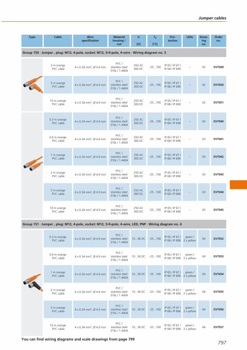
Type Cable Wirespecification
Materialhousing /
nut
U
[V]
Ta
[°C]
Pro-tection
LEDs Draw-ingno.
Orderno.
Group 150 · Jumper , plug: M12, 4-pole, socket: M12, 5/4-pole, 4-wire · Wiring diagram no. 3
2 m orangePVC cable 4 x 0.34 mm2, Ø 4.9 mm
PVC /stainless steel316L / 1.4404
250 AC300 DC
-25...100IP 65 / IP 67 /IP 68 / IP 69K
– 62 EVT049
5 m orangePVC cable 4 x 0.34 mm2, Ø 4.9 mm
PVC /stainless steel316L / 1.4404
250 AC300 DC
-25...100IP 65 / IP 67 /IP 68 / IP 69K
– 62 EVT050
10 m orangePVC cable 4 x 0.34 mm2, Ø 4.9 mm
PVC /stainless steel316L / 1.4404
250 AC300 DC
-25...100IP 65 / IP 67 /IP 68 / IP 69K
– 62 EVT051
0.3 m orangePVC cable 4 x 0.34 mm2, Ø 4.9 mm
PVC /stainless steel316L / 1.4404
250 AC300 DC
-25...100IP 65 / IP 67 /IP 68 / IP 69K
– 63 EVT040
0.6 m orangePVC cable 4 x 0.34 mm2, Ø 4.9 mm
PVC /stainless steel316L / 1.4404
250 AC300 DC
-25...100IP 65 / IP 67 /IP 68 / IP 69K
– 63 EVT041
1 m orangePVC cable 4 x 0.34 mm2, Ø 4.9 mm
PVC /stainless steel316L / 1.4404
250 AC300 DC
-25...100IP 65 / IP 67 /IP 68 / IP 69K
– 63 EVT042
2 m orangePVC cable 4 x 0.34 mm2, Ø 4.9 mm
PVC /stainless steel316L / 1.4404
250 AC300 DC
-25...100IP 65 / IP 67 /IP 68 / IP 69K
– 63 EVT043
5 m orangePVC cable 4 x 0.34 mm2, Ø 4.9 mm
PVC /stainless steel316L / 1.4404
250 AC300 DC
-25...100IP 65 / IP 67 /IP 68 / IP 69K
– 63 EVT044
10 m orangePVC cable 4 x 0.34 mm2, Ø 4.9 mm
PVC /stainless steel316L / 1.4404
250 AC300 DC
-25...100IP 65 / IP 67 /IP 68 / IP 69K
– 63 EVT045
Group 151 · Jumper , plug: M12, 4-pole, socket: M12, 5/4-pole, 4-wire, LED, PNP · Wiring diagram no. 4
0.3 m orangePVC cable 4 x 0.34 mm2, Ø 4.9 mm
PVC /stainless steel316L / 1.4404
10...36 DC -25...100IP 65 / IP 67 /IP 68 / IP 69K
green /2 x yellow
64 EVT052
0.6 m orangePVC cable 4 x 0.34 mm2, Ø 4.9 mm
PVC /stainless steel316L / 1.4404
10...36 DC -25...100IP 65 / IP 67 /IP 68 / IP 69K
green /2 x yellow
64 EVT053
1 m orangePVC cable 4 x 0.34 mm2, Ø 4.9 mm
PVC /stainless steel316L / 1.4404
10...36 DC -25...100IP 65 / IP 67 /IP 68 / IP 69K
green /2 x yellow
64 EVT054
2 m orangePVC cable 4 x 0.34 mm2, Ø 4.9 mm
PVC /stainless steel316L / 1.4404
10...36 DC -25...100IP 65 / IP 67 /IP 68 / IP 69K
green /2 x yellow
64 EVT055
5 m orangePVC cable 4 x 0.34 mm2, Ø 4.9 mm
PVC /stainless steel316L / 1.4404
10...36 DC -25...100IP 65 / IP 67 /IP 68 / IP 69K
green /2 x yellow
64 EVT056
10 m orangePVC cable 4 x 0.34 mm2, Ø 4.9 mm
PVC /stainless steel316L / 1.4404
10...36 DC -25...100IP 65 / IP 67 /IP 68 / IP 69K
green /2 x yellow
64 EVT057
Jumper cables
797You can find wiring diagrams and scale drawings from page 799
Gesamtkatalog EN 2016_17_Stilvorlage LK FrutigerOT_2010 DE_GB.qxd 06.11.15 17:01 Seite 797

Type Cable Wirespecification
Materialhousing /
nut
U
[V]
Ta
[°C]
Pro-tection
LEDs Draw-ingno.
Orderno.
Group 152 · Jumper , plug: M12, 5-pole, socket: M12, 5-pole, 5-wire · Wiring diagram no. 5
0.3 m orangePVC cable 5 x 0.34 mm2, Ø 5.1 mm
PVC /stainless steel316L / 1.4404
60 AC60 DC
-25...100IP 65 / IP 67 /IP 68 / IP 69K
– 65 EVT058
0.6 m orangePVC cable 5 x 0.34 mm2, Ø 5.1 mm
PVC /stainless steel316L / 1.4404
60 AC60 DC
-25...100IP 65 / IP 67 /IP 68 / IP 69K
– 65 EVT059
1 m orangePVC cable 5 x 0.34 mm2, Ø 5.1 mm
PVC /stainless steel316L / 1.4404
60 AC60 DC
-25...100IP 65 / IP 67 /IP 68 / IP 69K
– 65 EVT060
2 m orangePVC cable 5 x 0.34 mm2, Ø 5.1 mm
PVC /stainless steel316L / 1.4404
60 AC60 DC
-25...100IP 65 / IP 67 /IP 68 / IP 69K
– 65 EVT061
5 m orangePVC cable 5 x 0.34 mm2, Ø 5.1 mm
PVC /stainless steel316L / 1.4404
60 AC60 DC
-25...100IP 65 / IP 67 /IP 68 / IP 69K
– 65 EVT062
10 m orangePVC cable 5 x 0.34 mm2, Ø 5.1 mm
PVC /stainless steel316L / 1.4404
60 AC60 DC
-25...100IP 65 / IP 67 /IP 68 / IP 69K
– 65 EVT063
Jumpers for hazardous areas
Type Cable Wirespecification
Materialhousing /
nut
U
[V]
Ta
[°C]
Pro-tection
LEDs Draw-ingno.
Orderno.
Group 156 · Jumper , plug: M12, 4-pole, socket: M12, 5/4-pole, 4-wire · Wiring diagram no. 3
0.3 m blackPUR cable 4 x 0.34 mm2, Ø 4.9 mm
TPU /stainless steel316L / 1.4404
60 AC60 DC
-20...60 IP 67 – 66 EVC09A
0.6 m blackPUR cable 4 x 0.34 mm2, Ø 4.9 mm
TPU /stainless steel316L / 1.4404
60 AC60 DC
-20...60 IP 67 – 66 EVC10A
1 m blackPUR cable 4 x 0.34 mm2, Ø 4.9 mm
TPU /stainless steel316L / 1.4404
60 AC60 DC
-20...60 IP 67 – 66 EVC11A
2 m blackPUR cable 4 x 0.34 mm2, Ø 4.9 mm
TPU /stainless steel316L / 1.4404
60 AC60 DC
-20...60 IP 67 – 66 EVC07A
5 m blackPUR cable 4 x 0.34 mm2, Ø 4.9 mm
TPU /stainless steel316L / 1.4404
60 AC60 DC
-20...60 IP 67 – 66 EVC12A
10 m blackPUR cable 4 x 0.34 mm2, Ø 4.9 mm
TPU /stainless steel316L / 1.4404
60 AC60 DC
-20...60 IP 67 – 66 EVC13A
Connection technology
798Product selectors and further information can be found at: www.ifm.com
Gesamtkatalog EN 2016_17_Stilvorlage LK FrutigerOT_2010 DE_GB.qxd 06.11.15 17:01 Seite 798
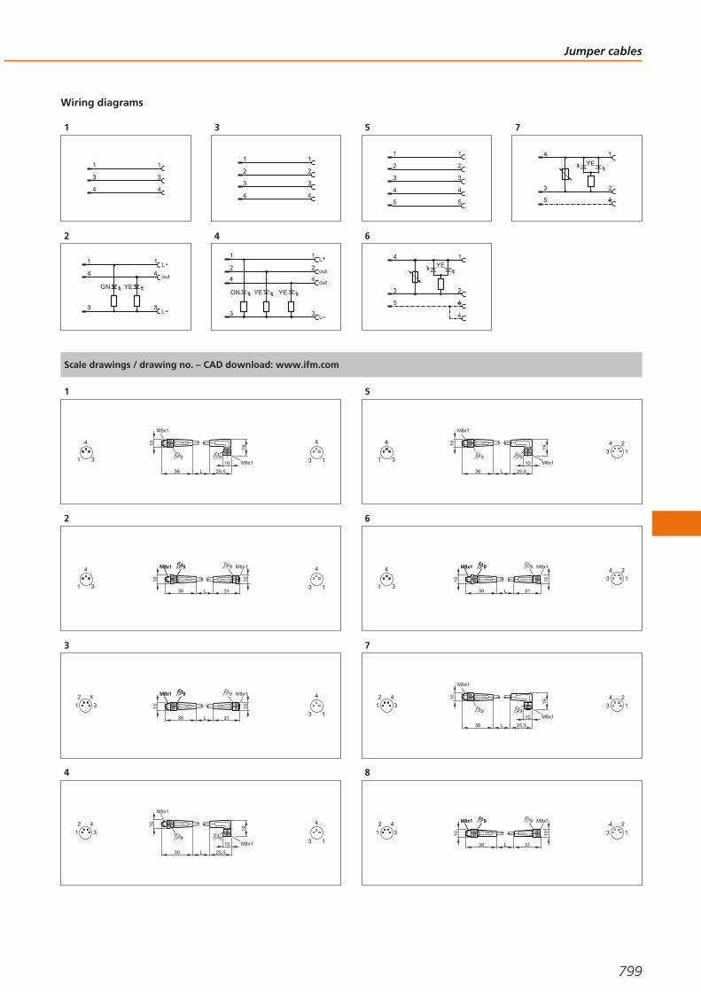
Wiring diagrams
1
1
3
4
1
3
4
2
1
3
L+
4
L
YEGN
1
3
4 out
3
1
2
3
1
2
3
4 4
4
out
out
L+
L
1
3
4
GN YE
2
1
3
4
2
YE
5
1
2
3
4
1
2
3
4
5 5
6
1
2
YE4
3
5
7
1
2
4
3
5
YE
Scale drawings / drawing no. – CAD download: www.ifm.com
1
M8x1
9M8x1
1010
10
25,536 L
9
19
3
4
1 1
4
3
2
9M8x1 9M8x1 9 M8x1
1010 10
3136 L3
4
1 1
4
3
3
9M8x1 9M8x1 9 M8x1
1010 10
3136 L
2
1
4
3
1
4
3
4
M8x1
9M8x1
1010
10
25,536 L
9
19
2
1
4
3
1
4
3
5
M8x1
9M8x1
1010
10
25,536 L
9
19
3
4
1
4
3
2
1
6
9M8x1 9M8x1 9 M8x1
1010 10
3136 L3
4
1
4
3
2
1
7
M8x1
9M8x1
1010
10
25,536 L
9
19
2
1
4
34
3
2
1
8
9M8x1 9M8x1 9 M8x1
1010 10
3136 L
2
1
4
34
3
2
1
Jumper cables
799
Gesamtkatalog EN 2016_17_Stilvorlage LK FrutigerOT_2010 DE_GB.qxd 06.11.15 17:01 Seite 799
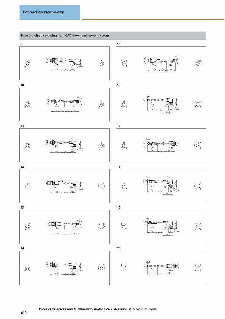
Scale drawings / drawing no. – CAD download: www.ifm.com
9
M8x110
25,5L
9
19
49,5
14
M12
x1
4
1
3 1
4
3
10
L
9
49,5
14
M12
x1
M8x1
10
31
4
1
3 1
4
3
11
M8x110
25,5L
9
19
LED
49,5
14
M12
x1
4
1
3 1
4
3
12
M8x110
25,5L
9
19
49,5
14
M12
x1
4
1
3
4
3
2
1
13
L
9
49,5
14
M12
x1
M8x1
10
31
4
1
3
4
3
2
1
14
M8x110
25,5L
9
19
49,5
14
M12
x1
43
2 1 4
3
2
1
15
L
9
49,5
14
M12
x1
M8x1
10
31
43
2 1 4
3
2
1
16
M12x1
26,5
14
36,5
15,5
M8x1
9
1010
36 L3
4
1 3
1 2
4
17
45
M8x1
9
1010
36 L
14
M12
x1
3
4
1 3
1 2
4
5
18
M12x1
26,5
14
36,5
15,5
M8x1
9
1010
36 L
LED
3
4
1 3
1 2
4
5
19
M12x1
26,5
14
36,5
15,5
M8x1
9
1010
36 L
2
1
4
3
3
1 2
4
5
20
45
M8x1
9
1010
36 L
14
M12
x12
1
4
33
1 2
4
Connection technology
800Product selectors and further information can be found at: www.ifm.com
Gesamtkatalog EN 2016_17_Stilvorlage LK FrutigerOT_2010 DE_GB.qxd 06.11.15 17:01 Seite 800

Scale drawings / drawing no. – CAD download: www.ifm.com
21
M12x1
26,5
14
36,5
15,5
M8x1
9
1010
36 L
LED
2
1
4
3
3
1 2
4
5
22
49,5
14
L
15,5
M12x1
M12x1
26,5
14
36,5
15,5
4
1
3 3
1 2
4
5
23
49,5
14
15,5
M12x1
45
14
L
15,5
M12x1
4
1
3 3
1 2
4
5
24
49,5
14
L
15,5
M12x1
M12x1
26,5
14
36,5
15,5
LED
4
1
3 3
1 2
4
5
25
49,5
14
L
15,5
M12x1
M12x1
26,5
14
36,5
15,5
43
2 1
3
1 2
4
26
49,5
14
15,5
M12x1
45
14
L
15,5
M12x1
43
2 1
3
1 2
4
27
49,5
14
L
15,5
M12x1
M12x1
26,5
14
36,5
15,5
LED
43
2 1
3
1 2
4
28
15,5
M12x1
45
14
L
M12x1
30,5
14
36,5
15,5
43
2 1
3
1 2
4
29
L
M12x1
26,5
14
36,5
15,5M12x1
30,5
14
36,5
15,543
2 1
3
1 2
4
30
L
M12x1
26,5
14
36,515,5
LED
M12x1
30,5
14
36,5
15,5
43
2 1
3
1 2
4
31
49,5
14
L
15,5
M12x1
M12x1
26,5
14
36,5
15,54
2 1
3
5
3
1 2
4
5
32
49,5
14
15,5
M12x1
45
14
L
15,5
M12x1
4
2 1
3
5
3
1 2
4
5
Jumper cables
801
Gesamtkatalog EN 2016_17_Stilvorlage LK FrutigerOT_2010 DE_GB.qxd 06.11.15 17:01 Seite 801
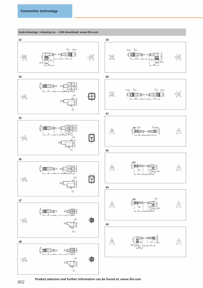
Scale drawings / drawing no. – CAD download: www.ifm.com
33
15,5
M12x1
45
14
L
M12x1
30,5
14
36,5
15,5
4
2 1
3
5
3
1 2
4
5
34
L 17,5 29,5
29,5
M12
x1
47
LED
M 3
28,5
435 2 1
35
LED
M 3
28,5
L 17,5 31,5
9
2410
M12
x1
47
435
1 2
36
LED
M 3
28,5
L 17,5 31,5
24
M12
x1
47
435
1 2
37
L 12 20
18
M12
x1
47
LED
M 2,5
21,5
435 12
38
M 3
L 12 20
18
M12
x1
47
LED
21,5
435 12
39
49,5
14
L
15,5
M12x1
M12x1
26,5
14
36,5
15,5
43
2 1
3
1 2
4
5
40
49,5
14
15,5
M12x1
45
14
L
15,5
M12x1
43
2 1
3
1 2
4
5
41
M8x1 9M8x1 9 M8x1
10 10
3136 L3
4
1 1
4
3
42
M8x1M8x1
10
36 L
19
99M8x1
25,5
103
4
1 1
4
3
43
M8x1M8x1
10
36 L
19
LED
99M8x1
25,5
103
4
1 1
4
3
44
9 M8x1
10
31L
25
9
M8x1
25,5
103
4
1 1
4
3
Connection technology
802Product selectors and further information can be found at: www.ifm.com
Gesamtkatalog EN 2016_17_Stilvorlage LK FrutigerOT_2010 DE_GB.qxd 06.11.15 17:01 Seite 802
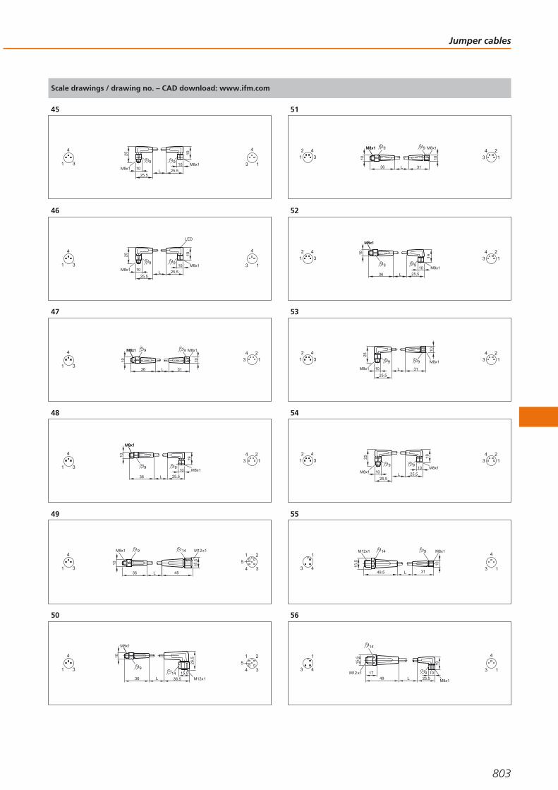
Scale drawings / drawing no. – CAD download: www.ifm.com
45
L
25
9
M8x1
25,5
10
19
9M8x1
25,5
103
4
1 1
4
3
46
L
25
9
M8x1
25,5
10
19
LED
9M8x1
25,5
103
4
1 1
4
3
47
M8x1 9M8x1 9 M8x1
10 10
3136 L3
4
1
4
3
2
1
48
M8x1M8x1
10
36 L
19
99M8x1
25,5
103
4
1
4
3
2
1
49
9M8x1
10
14
45L36
15,5
M12 x1
3
4
1 3
1 2
4
5
50
M8x1
10
36 L
915,5
M12x136,5
26,5
143
4
1 3
1 2
4
5
51
M8x1 9M8x1 9 M8x1
10 10
3136 L
2
1
4
34
3
2
1
52
M8x1M8x1
10
36 L
19
99M8x1
25,5
10
2
1
4
34
3
2
1
53
9 M8x1
10
31L
259
M8x1
25,5
10
2
1
4
34
3
2
1
54
L
25
9
M8x1
25,5
10
19
9M8x1
25,5
10
2
1
4
34
3
2
1
55
9 M8x1
10
31L
15,5
49,5
14M12x1
4
1
3 1
4
3
56
L4917 9
19
25,5M8x1
10
15,5
14
M12 x14
1
3 1
4
3
Jumper cables
803
Gesamtkatalog EN 2016_17_Stilvorlage LK FrutigerOT_2010 DE_GB.qxd 06.11.15 17:01 Seite 803

Scale drawings / drawing no. – CAD download: www.ifm.com
57
L49
14
15,5
M12 x1
M12x136,5
15,5
26,5
144
1
3 3
1
4
58
L
15,5
M12 x1
49
14
45
15,5
M12 x1 14
4
1
3 3
1
4
59
L49
14
15,5
M12 x1
M12x136,5
15,5
26,5
14
LED
4
1
3 3
1
4
60
9 M8x1
10
31L
15,5
49,5
14M12x1
43
2 1 4
3
2
1
61
L4917 9
19
25,5M8x1
10
15,5
14
M12 x143
2 1 4
3
2
1
62
L49
14
15,5
M12 x1
M12x136,5
15,5
26,5
1443
2 1
3
1 2
4
63
L
15,5
M12 x1
49
14
45
15,5
M12 x1 14
43
2 1
3
1 2
4
64
L49
14
15,5
M12 x1
M12x136,5
15,5
26,5
14
LED
43
2 1
3
1 2
4
65
L
15,5
M12 x1
49
14
45
15,5
M12 x1 14
4
2 1
3
5
3
1 2
4
5
66
31
14
15,5
26,5
14
15,5
36,5 36,5
M12x1 M12x1
L
43
2 1
3
1 2
4
Connection technology
804Product selectors and further information can be found at: www.ifm.com
Gesamtkatalog EN 2016_17_Stilvorlage LK FrutigerOT_2010 DE_GB.qxd 06.11.15 17:02 Seite 804

Jumper cables
805
Gesamtkatalog EN 2016_17_Stilvorlage LK FrutigerOT_2010 DE_GB.qxd 06.11.15 17:02 Seite 805

Splitter boxes
Splitter boxes enable the connection of several sensors and the transmission of thecorresponding signals and supply voltages via a multi-wire cable. This considerably reduces installation and wiring complexity. In addition to splitter boxes with potted cable, versions with central connector arealso available.
Splitter boxes for industrial applications
Type Cable Wirespecification
Materialhousing /
nut
U
[V]
Ta
[°C]
Pro-tection
LEDs Draw-ingno.
Orderno.
Group 70 · M12 splitter box for 1 signal · Wiring diagram no. 1
5 m blackPUR cable 4 x 0.25 mm2, Ø 5 mm
TPU /Brass
10...55 DC -25...80 IP 67 – 1 E10437
Group 71 · splitter box M8, 3-pole, LED · Wiring diagram no. 18
5 m blackPUR cable
4 x 0.34 mm2 + 2 x0.75 mm2, Ø 6.4 mm
PBT-GF 20 10...30 DC -25...80IP 65 / IP 67 /
IP 68green /
4 x yellow2 EBC048
10 m blackPUR cable
4 x 0.34 mm2 + 2 x0.75 mm2, Ø 6.4 mm
PBT-GF 20 10...30 DC -25...80IP 65 / IP 67 /
IP 68green /
4 x yellow2 EBC049
Group 72 · splitter box M8, 3-pole, LED · Wiring diagram no. 19
M12 connector – PBT-GF 20 10...30 DC -25...80 IP 67 / IP 68green /
4 x yellow3 EBC050
Group 73 · splitter box M8, 4-pole, LED · Wiring diagram no. 20
5 m blackPUR cable
8 x 0.34 mm2 + 2 x0.75 mm2, Ø 7.4 mm
PBT-GF 20 10...30 DC -25...80IP 65 / IP 67 /
IP 68green /
8 x yellow4 EBC051
10 m blackPUR cable
8 x 0.34 mm2 + 2 x0.75 mm2, Ø 7.4 mm
PBT-GF 20 10...30 DC -25...80IP 65 / IP 67 /
IP 68green /
8 x yellow4 EBC052
System overview Page
Splitter boxes for industrial applications 806 - 812
Splitter boxes for hygienic and wet areas 812
Wiring diagrams 812 - 818
Scale drawings / drawing no. – CAD download: www.ifm.com 818 - 824
Connection technology
806Product selectors and further information can be found at: www.ifm.com
Gesamtkatalog EN 2016_17_Stilvorlage LK FrutigerOT_2010 DE_GB.qxd 06.11.15 17:02 Seite 806

Type Cable Wirespecification
Materialhousing /
nut
U
[V]
Ta
[°C]
Pro-tection
LEDs Draw-ingno.
Orderno.
Group 74 · splitter box M8, 4-pole, LED · Wiring diagram no. 21
M16 connector – PBT-GF 20 10...30 DC -25...80 IP 67 / IP 68green /
8 x yellow5 EBC053
Group 75 · splitter box M8, 3-pole, LED · Wiring diagram no. 22
5 m blackPUR cable
8 x 0.34 mm2 + 2 x0.75 mm2, Ø 7.4 mm
PBT-GF 20 10...30 DC -25...80IP 65 / IP 67 /
IP 68green /
8 x yellow6 EBC054
10 m blackPUR cable
8 x 0.34 mm2 + 2 x0.75 mm2, Ø 9.1 mm
PBT-GF 20 10...30 DC -25...80IP 65 / IP 67 /
IP 68green /
8 x yellow6 EBC055
Group 76 · splitter box M8, 4-pole, LED · Wiring diagram no. 23
5 m blackPUR cable
16 x 0.34 mm2 + 2 x0.75 mm2, Ø 8.5 mm
PBT-GF 20 10...30 DC -25...80IP 65 / IP 67 /
IP 68green /
16 x yellow7 EBC056
10 m blackPUR cable
16 x 0.34 mm2 + 2 x0.75 mm2, Ø 8.5 mm
PBT-GF 20 10...30 DC -25...80IP 65 / IP 67 /
IP 68green /
16 x yellow7 EBC057
Group 77 · splitter box M8, 3-pole, LED · Wiring diagram no. 24
5 m blackPUR cable
4 x 0.34 mm2 + 2 x0.75 mm2, Ø 6.4 mm
PBT-GF 20 10...30 DC -25...80IP 65 / IP 67 /
IP 68green /
4 x yellow2 EBC058
10 m blackPUR cable
4 x 0.34 mm2 + 2 x0.75 mm2, Ø 6.4 mm
PBT-GF 20 10...30 DC -25...80IP 65 / IP 67 /
IP 68green /
4 x yellow2 EBC059
Group 78 · splitter box M8, 3-pole, LED · Wiring diagram no. 25
M12 connector – PBT-GF 20 10...30 DC -25...80IP 65 / IP 67 /
IP 68green /
4 x yellow3 EBC060
Group 79 · splitter box M8, 4-pole, LED · Wiring diagram no. 26
5 m blackPUR cable
8 x 0.34 mm2 + 2 x0.75 mm2, Ø 7.4 mm
PBT-GF 20 10...30 DC -20...80IP 65 / IP 67 /
IP 68green /
8 x yellow4 EBC061
10 m blackPUR cable
8 x 0.34 mm2 + 2 x0.75 mm2, Ø 7.4 mm
PBT-GF 20 10...30 DC -20...80IP 65 / IP 67 /
IP 68green /
8 x yellow4 EBC062
Group 80 · splitter box M8, 4-pole, LED · Wiring diagram no. 27
M16 connector – PBT-GF 20 10...30 DC -25...80 IP 67 / IP 68green /
8 x yellow5 EBC063
Splitter boxes
807You can find wiring diagrams and scale drawings from page 812
Gesamtkatalog EN 2016_17_Stilvorlage LK FrutigerOT_2010 DE_GB.qxd 06.11.15 17:02 Seite 807
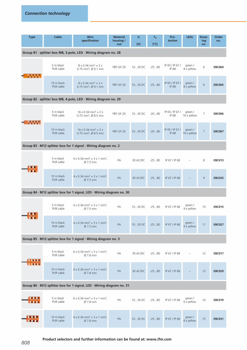
Type Cable Wirespecification
Materialhousing /
nut
U
[V]
Ta
[°C]
Pro-tection
LEDs Draw-ingno.
Orderno.
Group 81 · splitter box M8, 3-pole, LED · Wiring diagram no. 28
5 m blackPUR cable
8 x 0.34 mm2 + 2 x0.75 mm2, Ø 9.1 mm
PBT-GF 20 10...30 DC -25...80IP 65 / IP 67 /
IP 68green /
8 x yellow6 EBC064
10 m blackPUR cable
8 x 0.34 mm2 + 2 x0.75 mm2, Ø 9.1 mm
PBT-GF 20 10...30 DC -25...80IP 65 / IP 67 /
IP 68green /
8 x yellow6 EBC065
Group 82 · splitter box M8, 4-pole, LED · Wiring diagram no. 29
5 m blackPUR cable
16 x 0.34 mm2 + 2 x0.75 mm2, Ø 8.5 mm
PBT-GF 20 10...30 DC -20...80IP 65 / IP 67 /
IP 68green /
16 x yellow7 EBC066
10 m blackPUR cable
16 x 0.34 mm2 + 2 x0.75 mm2, Ø 8.5 mm
PBT-GF 20 10...30 DC -20...80IP 65 / IP 67 /
IP 68green /
16 x yellow7 EBC067
Group 83 · M12 splitter box for 1 signal · Wiring diagram no. 2
5 m blackPUR cable
4 x 0.34 mm2 + 3 x 1 mm2,Ø 7.5 mm
PA 30 AC/DC -25...80 IP 67 / IP 68 – 8 EBC013
10 m blackPUR cable
4 x 0.34 mm2 + 3 x 1 mm2,Ø 7.5 mm
PA 30 AC/DC -25...80 IP 67 / IP 68 – 9 EBC025
Group 84 · M12 splitter box for 1 signal, LED · Wiring diagram no. 30
5 m blackPUR cable
4 x 0.34 mm2 + 3 x 1 mm2,Ø 7.5 mm
PA 10...30 DC -25...80 IP 67 / IP 68green /
4 x yellow10 EBC015
10 m blackPUR cable
4 x 0.34 mm2 + 3 x 1 mm2,Ø 7.5 mm
PA 10...30 DC -25...80 IP 67 / IP 68green /
4 x yellow11 EBC027
Group 85 · M12 splitter box for 1 signal · Wiring diagram no. 3
5 m blackPUR cable
6 x 0.34 mm2 + 3 x 1 mm2,Ø 7.8 mm
PA 30 AC/DC -25...80 IP 67 / IP 68 – 12 EBC017
10 m blackPUR cable
6 x 0.34 mm2 + 3 x 1 mm2,Ø 7.8 mm
PA 30 AC/DC -25...80 IP 67 / IP 68 – 13 EBC029
Group 86 · M12 splitter box for 1 signal, LED · Wiring diagram no. 31
5 m blackPUR cable
6 x 0.34 mm2 + 3 x 1 mm2,Ø 7.8 mm
PA 10...30 DC -25...80 IP 67 / IP 68green /
6 x yellow14 EBC019
10 m blackPUR cable
6 x 0.34 mm2 + 3 x 1 mm2,Ø 7.8 mm
PA 10...30 DC -25...80 IP 67 / IP 68green /
6 x yellow15 EBC031
Connection technology
808Product selectors and further information can be found at: www.ifm.com
Gesamtkatalog EN 2016_17_Stilvorlage LK FrutigerOT_2010 DE_GB.qxd 06.11.15 17:02 Seite 808
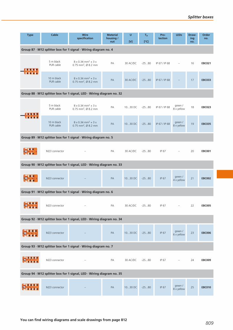
Type Cable Wirespecification
Materialhousing /
nut
U
[V]
Ta
[°C]
Pro-tection
LEDs Draw-ingno.
Orderno.
Group 87 · M12 splitter box for 1 signal · Wiring diagram no. 4
5 m blackPUR cable
8 x 0.34 mm2 + 3 x0.75 mm2, Ø 8.2 mm
PA 30 AC/DC -25...80 IP 67 / IP 68 – 16 EBC021
10 m blackPUR cable
8 x 0.34 mm2 + 3 x0.75 mm2, Ø 8.2 mm
PA 30 AC/DC -25...80 IP 67 / IP 68 – 17 EBC033
Group 88 · M12 splitter box for 1 signal, LED · Wiring diagram no. 32
5 m blackPUR cable
8 x 0.34 mm2 + 3 x0.75 mm2, Ø 8.2 mm
PA 10...30 DC -25...80 IP 67 / IP 68green /
8 x yellow18 EBC023
10 m blackPUR cable
8 x 0.34 mm2 + 3 x0.75 mm2, Ø 8.2 mm
PA 10...30 DC -25...80 IP 67 / IP 68green /
8 x yellow19 EBC035
Group 89 · M12 splitter box for 1 signal · Wiring diagram no. 5
M23 connector – PA 30 AC/DC -25...80 IP 67 – 20 EBC001
Group 90 · M12 splitter box for 1 signal, LED · Wiring diagram no. 33
M23 connector – PA 10...30 DC -25...80 IP 67green /
4 x yellow21 EBC002
Group 91 · M12 splitter box for 1 signal · Wiring diagram no. 6
M23 connector – PA 30 AC/DC -25...80 IP 67 – 22 EBC005
Group 92 · M12 splitter box for 1 signal, LED · Wiring diagram no. 34
M23 connector – PA 10...30 DC -25...80 IP 67green /
6 x yellow23 EBC006
Group 93 · M12 splitter box for 1 signal · Wiring diagram no. 7
M23 connector – PA 30 AC/DC -25...80 IP 67 – 24 EBC009
Group 94 · M12 splitter box for 1 signal, LED · Wiring diagram no. 35
M23 connector – PA 10...30 DC -25...80 IP 67green /
8 x yellow25 EBC010
Splitter boxes
809You can find wiring diagrams and scale drawings from page 812
Gesamtkatalog EN 2016_17_Stilvorlage LK FrutigerOT_2010 DE_GB.qxd 06.11.15 17:02 Seite 809

Type Cable Wirespecification
Materialhousing /
nut
U
[V]
Ta
[°C]
Pro-tection
LEDs Draw-ingno.
Orderno.
Group 95 · M12 splitter box for 2 signals · Wiring diagram no. 8
5 m blackPUR cable
8 x 0.34 mm2 + 3 x1.0 mm2, Ø 8.2 mm
PA 30 AC/DC -25...80 IP 67 / IP 68 – 8 EBC014
10 m blackPUR cable
8 x 0.34 mm2 + 3 x1.0 mm2, Ø 8.2 mm
PA 30 AC/DC -25...80 IP 67 / IP 68 – 9 EBC026
Group 96 · M12 splitter box for 2 signals, LED · Wiring diagram no. 36
5 m blackPUR cable
8 x 0.34 mm2 + 3 x1.0 mm2, Ø 8.2 mm
PA 10...30 DC -25...80 IP 67 / IP 68green /
8 x yellow26 EBC016
10 m blackPUR cable
8 x 0.34 mm2 + 3 x1.0 mm2, Ø 8.2 mm
PA 10...30 DC -25...80 IP 67 / IP 68green /
8 x yellow27 EBC028
Group 97 · M12 splitter box for 2 signals · Wiring diagram no. 37
5 m blackPUR cable
12 x 0.34 mm2 + 3 x1.0 mm2, Ø 8.8 mm
PA 30 AC/DC -25...80 IP 67 / IP 68 – 12 EBC018
10 m blackPUR cable
12 x 0.34 mm2 + 3 x1.0 mm2, Ø 8.8 mm
PA 30 AC/DC -25...80 IP 67 / IP 68 – 13 EBC030
Group 98 · M12 splitter box for 2 signals, LED · Wiring diagram no. 38
5 m blackPUR cable
12 x 0.34 mm2 + 3 x1.0 mm2, Ø 8.8 mm
PA 10...30 DC -25...80 IP 67 / IP 68green /
12 x yellow28 EBC020
10 m blackPUR cable
12 x 0.34 mm2 + 3 x1.0 mm2, Ø 8.8 mm
PA 10...30 DC -25...80 IP 67 / IP 68green /
12 x yellow29 EBC032
Group 99 · M12 splitter box for 2 signals · Wiring diagram no. 39
5 m blackPUR cable
16 x 0.34 mm2 + 3 x0.75 mm2, Ø 9.7 mm
PA 30 AC/DC -25...80 IP 67 / IP 68 – 16 EBC022
10 m blackPUR cable
16 x 0.34 mm2 + 3 x0.75 mm2, Ø 9.7 mm
PA 30 AC/DC -25...80 IP 67 / IP 68 – 17 EBC034
Group 100 · M12 splitter box for 2 signals, LED · Wiring diagram no. 40
5 m blackPUR cable
16 x 0.34 mm2 + 3 x1.0 mm2, Ø 9.7 mm
PA 10...30 DC -25...80 IP 67 / IP 68green /
16 x yellow30 EBC024
10 m blackPUR cable
16 x 0.34 mm2 + 3 x1.0 mm2, Ø 9.7 mm
PA 10...30 DC -25...80 IP 67 / IP 68green /
16 x yellow31 EBC036
Connection technology
810Product selectors and further information can be found at: www.ifm.com
Gesamtkatalog EN 2016_17_Stilvorlage LK FrutigerOT_2010 DE_GB.qxd 06.11.15 17:02 Seite 810
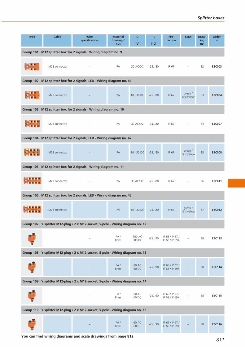
Type Cable Wirespecification
Materialhousing /
nut
U
[V]
Ta
[°C]
Pro-tection
LEDs Draw-ingno.
Orderno.
Group 101 · M12 splitter box for 2 signals · Wiring diagram no. 9
M23 connector – PA 30 AC/DC -25...80 IP 67 – 32 EBC003
Group 102 · M12 splitter box for 2 signals, LED · Wiring diagram no. 41
M23 connector – PA 10...30 DC -25...80 IP 67green /
8 x yellow33 EBC004
Group 103 · M12 splitter box for 2 signals · Wiring diagram no. 10
M23 connector – PA 30 AC/DC -25...80 IP 67 – 34 EBC007
Group 104 · M12 splitter box for 2 signals, LED · Wiring diagram no. 42
M23 connector – PA 10...30 DC -25...80 IP 67green /
12 x yellow35 EBC008
Group 105 · M12 splitter box for 2 signals · Wiring diagram no. 11
M23 connector – PA 30 AC/DC -25...80 IP 67 – 36 EBC011
Group 106 · M12 splitter box for 2 signals, LED · Wiring diagram no. 43
M23 connector – PA 10...30 DC -25...80 IP 67green /
16 x yellow37 EBC012
Group 107 · Y splitter M12-plug / 2 x M12-socket, 5-pole · Wiring diagram no. 12
–PA /Brass
250 AC300 DC
-25...90IP 65 / IP 67 /IP 68 / IP 69K
– 38 EBC113
Group 108 · Y splitter M12-plug / 2 x M12-socket, 5-pole · Wiring diagram no. 13
–PA /Brass
60 AC60 DC
-25...90IP 65 / IP 67 /IP 68 / IP 69K
– 38 EBC114
Group 109 · Y splitter M12-plug / 2 x M12-socket, 5-pole · Wiring diagram no. 14
–PA /Brass
60 AC60 DC
-25...90IP 65 / IP 67 /IP 68 / IP 69K
– 38 EBC115
Group 110 · Y splitter M12-plug / 2 x M12-socket, 5-pole · Wiring diagram no. 15
–PA /Brass
60 AC60 DC
-25...90IP 65 / IP 67 /IP 68 / IP 69K
– 38 EBC116
Splitter boxes
811You can find wiring diagrams and scale drawings from page 812
Gesamtkatalog EN 2016_17_Stilvorlage LK FrutigerOT_2010 DE_GB.qxd 06.11.15 17:02 Seite 811

Type Cable Wirespecification
Materialhousing /
nut
U
[V]
Ta
[°C]
Pro-tection
LEDs Draw-ingno.
Orderno.
Group 111 · Y splitter M12-plug / 2 x M12-socket, 5-pole · Wiring diagram no. 16
–PA /Brass
60 AC60 DC
-25...90IP 65 / IP 67 /IP 68 / IP 69K
– 38 EBC117
Group 112 · Y splitter M12-plug / 2 x M12-socket, 5-pole · Wiring diagram no. 17
–PA /Brass
60 AC60 DC
-25...90IP 65 / IP 67 /IP 68 / IP 69K
– 38 EBC118
Splitter boxes for hygienic and wet areas
Type Cable Wirespecification
Materialhousing /
nut
U
[V]
Ta
[°C]
Pro-tection
LEDs Draw-ingno.
Orderno.
Group 113 · splitter box M12, LED · Wiring diagram no. 40
10 m blackPUR / PVC cable
3 x 0.75 mm2 + 16 x0.34 mm2, Ø 11 mm
high-gradestainless steel
10...36 DC -5...70 IP 69Kgreen /
16 x yellow39 E11775
Core colours
BK black
BN brown
BU blue
WH white
GN green
GY grey
YE yellow
PK pink
RD red
VT lilac
GN/YE green/yellow
Wiring diagrams
1
BN
BU
BK
WH
1 (1...2)
3 (1...2)
4 (1)
4 (2)
2
WH
GN
YE
GY
BU
GN/YE
BN
4 (1)
4 (2)
4 (3)
4 (4)
3 (1...4)
5 (1...4)
1 (1...4)
3
WH
GN
YE
GY
BU
GN/YE
BN
4 (1)
4 (2)
4 (3)
4 (4)
3 (1...6)
5 (1...6)
1 (1...6)
PK
RD
4 (5)
4 (6)
4
WH
GN
YE
GY
BU
GN/YE
BN
4 (1)
4 (2)
4 (3)
4 (4)
3 (1...8)
5 (1...8)
1 (1...8)
PK
RD
4 (5)
4 (6)
BK
VT
4 (7)
4 (8)
5
12
1
2
3
4
9
10
11 1 (1...4)
3 (1...4)
5 (1...4)
4 (1)
4 (2)
4 (3)
4 (4)
6
12
1
2
3
4
9
10
11 1 (1...6)
3 (1...6)
5 (1...6)
4 (1)
4 (2)
4 (3)
4 (4)
5
6
4 (5)
4 (6)
7
12
1
2
3
4
9
10
11 1 (1...8)
3 (1...8)
5 (1...8)
4 (1)
4 (2)
4 (3)
4 (4)
5
6
4 (5)
4 (6)
7
8
4 (7)
4 (8)
8
GY/PK
RD/BU
WH/GN
BN/GN
WH
BU
GN/YE
BN
2 (1)
2 (2)
2 (3)
2 (4)
4 (1)
3 (1...4)
5 (1...4)
1 (1...4)
GN
YE
GY
4 (2)
4 (3)
4 (4)
Connection technology
812Product selectors and further information can be found at: www.ifm.com
Gesamtkatalog EN 2016_17_Stilvorlage LK FrutigerOT_2010 DE_GB.qxd 06.11.15 17:02 Seite 812

Wiring diagrams
9
15
7
5
4
16
6
12
19
4 (1)
2 (1)
4 (2)
2 (2)
4 (3)
3 (1...4)
5 (1...4)
1 (1...4)
8
3
14
2 (3)
4 (4)
2 (4)
+
-
10
19 1 (1...6)
6 3 (1...6)
15 4 (1)
12 5 (1...6)
7 2 (1)
5 4 (2)
4 2 (2)
16 4 (3)
8 2 (3)
3 4 (4)
14 2 (4)
17 4 (5)
9 2 (5)
2 4 (6)
13 2 (6)
1119 1 (1...8)
6 3 (1...8)
15 4 (1)
12 5 (1...8)
7 2 (1)
5 4 (2)
4 2 (2)
16 4 (3)
8 2 (3)
3 4 (4)
14 2 (4)
17 4 (5)
9 2 (5)
2 4 (6)
13 2 (6)
11 4 (7)
10 2 (7)
1 4 (8)
18 2 (8)
12
4
1 1
3
4
3
2
B
A
1
3
4
C
131 1
33
55
B
A
2
4
2
1
3
5
4
2
4
C
14
1 1
3
5
3
5
44
B
A
1
3
5
4
2
C
151 1
2
3
2
3
4
B
A
1
2
3
4
5
5
4
5
C
16
1 1
3
5
3
5
22
B
A
1
3
5
2
4
C
17
5
1 1
3
5
4
3
4
B
A
1
3
4
5
C
18
BN
WH
GN
GN
1 (1...4)
3 (1...4)
4 (1)
4 (2)
4 (3)
4 (4)
YE
YE
GY
+
-BU
19
5
1
7
GN
2
1 (1...4)
3 (1...4)
4 (1)
4 (2)
4 (3)
4 (4)
YE
3
4
+
-
Splitter boxes
813
Gesamtkatalog EN 2016_17_Stilvorlage LK FrutigerOT_2010 DE_GB.qxd 06.11.15 17:02 Seite 813

Wiring diagrams
20
BN
WH
GN
GY/PK
1 (1...4)
3 (1...4)
4 (1)
2 (1)
4 (2)
2 (2)
YE
GN
RD/BU
4 (3)
2 (3)
YE
WH/GN
4 (4)
2 (4)
GY
BN/GN
+
-BU
21
A
P
L
GN
E
1 (1...4)
3 (1...4)
4 (1)
2 (1)
4 (2)
2 (2)
YE
J
O
4 (3)
2 (3)
T
C
4 (4)
2 (4)
S
N
+
-
22
BN
WH
GN
GN
1 (1...8)
3 (1...8)
4 (1)
4 (2)
4 (3)
4 (4)
YE
YE
GY
4 (5)
4 (6)
PK
RD
4 (7)
4 (8)
BK
VT
+
-BU
23
BN
WH
GN
GY/PK
1 (1...8)
4 (1)
2 (1)
4 (2)
2 (2)
YE
GN
RD/BU
4 (3)
2 (3)
YE
WH/GN
4 (4)
2 (4)
GY
BN/GN
+
-BU 3 (1...8)
4 (5)
2 (5)
PK
WH/YE
4 (6)
2 (6)
RD
YE/BN
4 (7)
2 (7)
BK
WH/GY
4 (8)
2 (8)
VT
GY/BN
24
BN
WH
GN
GN
3 (1...4)
1 (1...4)
4 (1)
4 (2)
4 (3)
4 (4)
YE
YE
GY
+
BU
25
5
1
7
GN
2
3 (1...4)
1 (1...4)
4 (1)
4 (2)
4 (3)
4 (4)
YE
3
4
+
Connection technology
814Product selectors and further information can be found at: www.ifm.com
Gesamtkatalog EN 2016_17_Stilvorlage LK FrutigerOT_2010 DE_GB.qxd 06.11.15 17:02 Seite 814

Wiring diagrams
26
BN
WH
GN
GY/PK
3 (1...4)
1 (1...4)
4 (1)
2 (1)
4 (2)
2 (2)
YE
GN
RD/BU
4 (3)
2 (3)
YE
WH/GN
4 (4)
2 (4)
GY
BN/GN
+
BU
27
A
P
L
GN
E
3 (1...4)
1 (1...4)
4 (1)
2 (1)
4 (2)
2 (2)
YE
J
O
4 (3)
2 (3)
T
C
4 (4)
2 (4)
S
N
+
28
BN
WH
GN
GN
3 (1...8)
1 (1...8)
4 (1)
4 (2)
4 (3)
4 (4)
YE
YE
GY
4 (5)
4 (6)
PK
RD
4 (7)
4 (8)
BK
VT
+
BU
29
BN
WH
GN
GY/PK
3 (1...8)
4 (1)
2 (1)
4 (2)
2 (2)
YE
GN
RD/BU
4 (3)
2 (3)
YE
WH/GN
4 (4)
2 (4)
GY
BN/GN
+
BU
1 (1...8)
4 (5)
2 (5)
PK
WH/YE
4 (6)
2 (6)
RD
YE/BN
4 (7)
2 (7)
BK
WH/GY
4 (8)
2 (8)
VT
GY/BN
30
BN
WH
GN/YE
GN
GN
1 (1...4)
5 (1...4)
4 (1)
4 (2)
4 (3)
4 (4)
YE
YE
GY
+
BU 3 (1...4)-
L
L
31
BN
WH
GN/YE
GN
GN
1 (1...6)
5 (1...6)
4 (1)
4 (2)
4 (3)
4 (4)
YE
YE
GY
4 (5)
4 (6)
PK
RD
+
-BU 3 (1...6)
Splitter boxes
815
Gesamtkatalog EN 2016_17_Stilvorlage LK FrutigerOT_2010 DE_GB.qxd 06.11.15 17:02 Seite 815

Wiring diagrams
32
WH
GN
GN
1 (1...8)
3 (1...8)
4 (1)
4 (2)
4 (3)
4 (4)
YE
YE
GY
+
- BU
BN
4 (5)
4 (6)
PK
RD
4 (7)
4 (8)
BK
VT
5 (1...8)GN/YE
33
1
GN
2
1 (1...4)
3 (1...4)
4 (1)
4 (2)
4 (3)
4 (4)
YE
3
4
+
-
-
10
9
11
5 (1...4)12
34
1
GN
2
1 (1...6)
3 (1...6)
4 (1)
4 (2)
4 (3)
4 (4)
YE
3
4
+
-
-
10
9
11
4 (5)
4 (6)
5
6
5 (1...6)12
35
1
GN
2
1 (1...8)
3 (1...8)
4 (1)
4 (2)
4 (3)
4 (4)
YE
3
4
+
-
-
10
9
11
4 (5)
4 (6)
5
6
4 (7)
4 (8)
7
8
5 (1...8)12
36
BN
WH
GN/YE
GN
GY/PK
1 (1...4)
5 (1...4)
4 (1)
2 (1)
4 (2)
2 (2)
YE
GN
RD/BU
4 (3)
2 (3)
YE
WH/GN
4 (4)
2 (4)
GY
BN/GN
+
-BU 3 (1...4)
37
GY/PK
RD/BU
WH/GN
BN/GN
WH
BU
GN/YE
BN
2 (1)
2 (2)
2 (3)
2 (4)
4 (1)
3 (1...6)
5 (1...6)
1 (1...6)
WH/YE
YE/BN
2 (5)
2 (6)
GN
YE
GY
PK
RD
4 (2)
4 (3)
4 (4)
4 (5)
4 (6)
Connection technology
816Product selectors and further information can be found at: www.ifm.com
Gesamtkatalog EN 2016_17_Stilvorlage LK FrutigerOT_2010 DE_GB.qxd 06.11.15 17:02 Seite 816

Wiring diagrams
38
GN
1 (1...8)
5 (1...8)
4 (1)
2 (1)
4 (2)
2 (2)
YE
4 (3)
2 (3)
4 (4)
2 (4)
+
-3 (1...8)
4 (5)
2 (5)
PK
WH/YE
4 (6)
2 (6)
RD
YE/BN
BN
WH
GN/YE
GY/PK
GN
RD/BU
YE
WH/GN
GY
BN/GN
BU
39
GY/PK
RD/BU
WH/GN
BN/GN
WH
BU
GN/YE
BN
2 (1)
2 (2)
2 (3)
2 (4)
4 (1)
3 (1...8)
5 (1...8)
1 (1...8)
WH/YE
YE/BN
2 (5)
2 (6)
WH/GY
GY/BN
2 (7)
2 (8)
GN
YE
GY
PK
RD
4 (2)
4 (3)
4 (4)
4 (5)
4 (6)
BK
VT
4 (7)
4 (8)
40
GN
1 (1...8)
5 (1...8)
4 (1)
2 (1)
4 (2)
2 (2)
YE
4 (3)
2 (3)
4 (4)
2 (4)
+
-3 (1...8)
4 (5)
2 (5)
4 (6)
2 (6)
4 (7)
2 (7)
4 (8)
2 (8)
PK
WH/YE
RD
YE/BN
BK
WH/GY
VT
GY/BN
BN
WH
GN/YE
GY/PK
GN
RD/BU
YE
WH/GN
GY
BN/GN
BU
41
19
15
12
GN
7
1 (1...4)
5 (1...4)
4 (1)
2 (1)
4 (2)
2 (2)
YE
5
4
4 (3)
2 (3)
16
8
4 (4)
2 (4)
3
14
+
-6 3 (1...4)
Splitter boxes
817
Gesamtkatalog EN 2016_17_Stilvorlage LK FrutigerOT_2010 DE_GB.qxd 06.11.15 17:02 Seite 817

Wiring diagrams
42
19
15
12
GN
7
1 (1...6)
5 (1...6)
4 (1)
2 (1)
4 (2)
2 (2)
YE
5
4
4 (3)
2 (3)
16
8
4 (4)
2 (4)
3
14
+
-6 3 (1...6)
4 (5)
2 (5)
17
9
4 (6)
2 (6)
2
13
43
19
15
12
GN
7
1 (1...8)
5 (1...8)
4 (1)
2 (1)
4 (2)
2 (2)
YE
5
4
4 (3)
2 (3)
16
8
4 (4)
2 (4)
3
14
+
-6 3 (1...8)
4 (5)
2 (5)
17
9
4 (6)
2 (6)
2
13
4 (7)
2 (7)
11
10
4 (8)
2 (8)
1
18
Scale drawings / drawing no. – CAD download: www.ifm.com
1
10,423,5
17
53
6,5
1630
,542
3
1 2
4
2
M8x1
17
20
4,5
4,5
30
85,5
574,
3 16
1122
1
4
3
3
M12x1
17
23,7
4,5
4,5
3016
85,4
574,
3
M8x1
1122
6
2 1
45
738
1
4
3
4
M8x1
17
20
4,5
4,5
30
85,5
574,
3 16
1122
4
3
2
1
5
M8x1
M16x1
17
27
4,5
4,5
3016
90,4
5711
224,
3
AMNCO
PE
LU
TJSR
G
4
3
2
1
Connection technology
818Product selectors and further information can be found at: www.ifm.com
Gesamtkatalog EN 2016_17_Stilvorlage LK FrutigerOT_2010 DE_GB.qxd 06.11.15 17:02 Seite 818

Scale drawings / drawing no. – CAD download: www.ifm.com
6
M8x1
17
20
4,5
4,5
30
16
129,
5 101
4,3
1122
1
4
3
7
M8x1
17
20
4,5
4,5
30
16
129,
5 101
4,3
1122
4
3
2
1
8
1 2
43
18
4,7
7382
22
54,
5
3339
54
M12x132,7
27
3
1 2
4
5
9
1 2
43
18224,
773
118,
234
55
4,5
28,539
7,5
60
M12x1
3
1 2
4
5
10
1 2
43
18
4,7
7382
22
54,
5
3339
54
M12x132,7
27
3
1 2
4
5
11
1 2
43
PWR
18224,
773
118,
234
55
4,5
28,539
7,5
60
M12x1
3
1 2
4
5
12
1 2
43
65
18
4,7
7310
0
22
54,
5
3339
54
M12x132,7
27
3
1 2
4
5
13
1 2
4
6
3
5
18224,
773
125
34
55
4,5
28,539
7,5
60
M12x1
3
1 2
4
5
Splitter boxes
819
Gesamtkatalog EN 2016_17_Stilvorlage LK FrutigerOT_2010 DE_GB.qxd 06.11.15 17:02 Seite 819

Scale drawings / drawing no. – CAD download: www.ifm.com
14
1 2
43
18
4,7
7310
0
22
54,
5
3339
54
M12x132,7
27
65
3
1 2
4
5
15
1 2
4
6
3
5
PWR
18224,
773
125
34
55
4,5
28,539
7,5
60
M12x1
3
1 2
4
5
16
1 2
43
18
4,7
7312
7
22
54,
5
3339
54
M12x1
5
32,7
2734
6
8
5
7
3
1 2
4
5
17
1 2
4
6
8
3
5
7
18224,
773
152
34
55
4,5
28,539
7,5
60
M12x1 3
1 2
4
5
18
1 2
43
18
4,7
7312
7
22
54,
5
3339
54
M12x1
5
32,7
2734
6
8
5
7
3
1 2
4
5
19
1 2
4
6
8
3
5
7
PWR
18224,
773
152
34
55
4,5
28,539
7,5
60
M12x1 3
1 2
4
5
Connection technology
820Product selectors and further information can be found at: www.ifm.com
Gesamtkatalog EN 2016_17_Stilvorlage LK FrutigerOT_2010 DE_GB.qxd 06.11.15 17:02 Seite 820
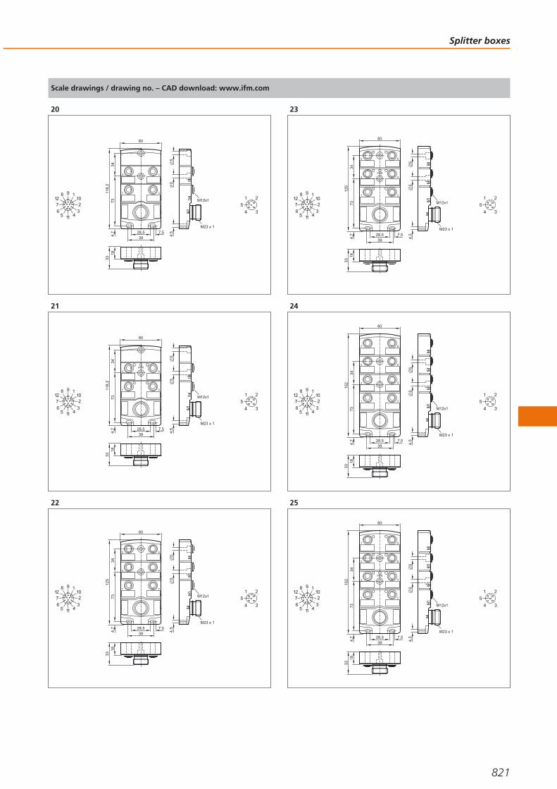
Scale drawings / drawing no. – CAD download: www.ifm.com
20
1 2
43
1833
4,7
7311
8,2
34
55
4,528,5
397,5
60
M23 x 1
M12x1
98 11276
5 11
102
34
3
1 2
4
5
21
1 2
43
PWR
1833
4,7
7311
8,2
34
55
4,528,5
397,5
60
M23 x 1
M12x1
98 11276
5 11
102
34
3
1 2
4
5
22
1 2
4
6
3
5
1833
4,7
7312
534
55
4,528,5
397,5
60
M23 x 1
M12x1
98 11276
5 11
102
34
3
1 2
4
5
23
1 2
4
6
3
5
PWR
1833
4,7
7312
534
55
4,528,5
397,5
60
M23 x 1
M12x1
98 11276
5 11
102
34
3
1 2
4
5
24
1 2
4
6
8
3
5
7
1833
4,7
7315
234
55
4,528,5
397,5
60
M23 x 1
M12x1
98 11276
5 11
102
34
3
1 2
4
5
25
1 2
4
6
8
3
5
7
PWR
1833
4,7
7315
234
55
4,528,5
397,5
60
M23 x 1
M12x1
98 11276
5 11
102
34
3
1 2
4
5
Splitter boxes
821
Gesamtkatalog EN 2016_17_Stilvorlage LK FrutigerOT_2010 DE_GB.qxd 06.11.15 17:02 Seite 821

Scale drawings / drawing no. – CAD download: www.ifm.com
26
1 2
43
18
4,7
7382
22
54,
5
3339
54
M12x132,7
27
3
1 2
4
5
27
1 2
43
PWRB
A
B
A
B
A
B
A
18224,
773
118,
234
55
4,5
28,539
7,5
60
M12x1
3
1 2
4
5
28
1 2
43
18
4,7
7310
0
22
54,
5
3339
54
M12x132,7
27
65
3
1 2
4
5
29
1 2
4
6
3
5
PWRB
A
B
A
B
A
B
A
B
A
B
A
18224,
773
125
34
55
4,5
28,539
7,5
60
M12x1
3
1 2
4
5
30
1 2
43
18
4,7
7312
7
22
54,
5
3339
54
M12x1
5
32,7
2734
6
8
5
7
3
1 2
4
5
31
1 2
4
6
8
3
5
7
PWRB
A
B
A
B
A
B
A
B
A
B
A
B
A
B
A
18224,
773
152
34
55
4,5
28,539
7,5
60
M12x1 3
1 2
4
5
32
1 2
43
1833
4,7
7311
8,2
34
55
4,528,5
397,5
60
M23 x 1
M12x11
23
4567
8
910
11 12
13
14
15
16
17
1819
3
1 2
4
5
Connection technology
822Product selectors and further information can be found at: www.ifm.com
Gesamtkatalog EN 2016_17_Stilvorlage LK FrutigerOT_2010 DE_GB.qxd 06.11.15 17:02 Seite 822

Scale drawings / drawing no. – CAD download: www.ifm.com
33
1 2
43
PWRB
A
B
A
B
A
B
A
1833
4,7
7311
8,2
34
55
4,528,5
397,5
60
M23 x 1
M12x11
23
4567
8
910
11 12
13
14
15
16
17
1819
3
1 2
4
5
34
1 2
4
6
3
5
1833
4,7
7312
534
55
4,528,5
397,5
60
M23 x 1
M12x1
123
4567
8
910
11 12
13
14
15
16
17
1819
3
1 2
4
5
35
1 2
4
6
3
5
PWRB
A
B
A
B
A
B
A
B
A
B
A
1833
4,7
7312
534
55
4,528,5
397,5
60
M23 x 1
M12x1
123
4567
8
910
11 12
13
14
15
16
17
1819
3
1 2
4
5
36
1 2
4
6
8
3
5
7
1833
4,7
7315
234
55
4,528,5
397,5
60
M23 x 1
M12x1
123
4567
8
910
11 12
13
14
15
16
17
1819
3
1 2
4
5
37
1 2
4
6
8
3
5
7
PWRB
A
B
A
B
A
B
A
B
A
B
A
B
A
B
A
1833
4,7
7315
234
55
4,528,5
397,5
60
M23 x 1
M12x1
123
4567
8
910
11 12
13
14
15
16
17
1819
3
1 2
4
5
38
M12x1
48,716
389
21
M12x1
C
B
A
4,3 M12x1
14
4
2 1
3
5
3
1 2
4
5
Splitter boxes
823
Gesamtkatalog EN 2016_17_Stilvorlage LK FrutigerOT_2010 DE_GB.qxd 06.11.15 17:02 Seite 823

Scale drawings / drawing no. – CAD download: www.ifm.com
39
2
3472
36
64,9
8,2
18
137,
3
M12 x1
LED
3
1 2
4
5
Connection technology
824Product selectors and further information can be found at: www.ifm.com
Gesamtkatalog EN 2016_17_Stilvorlage LK FrutigerOT_2010 DE_GB.qxd 06.11.15 17:02 Seite 824

Splitter boxes
825
Gesamtkatalog EN 2016_17_Stilvorlage LK FrutigerOT_2010 DE_GB.qxd 06.11.15 17:02 Seite 825
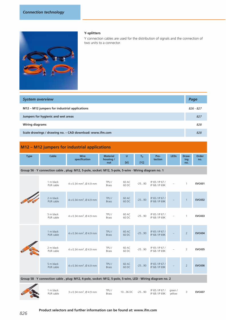
Y-splitters
Y connection cables are used for the distribution of signals and the connection oftwo units to a connector.
M12 – M12 jumpers for industrial applications
Type Cable Wirespecification
Materialhousing /
nut
U
[V]
Ta
[°C]
Pro-tection
LEDs Draw-ingno.
Orderno.
Group 56 · Y connection cable , plug: M12, 5-pole, socket: M12, 5-pole, 5-wire · Wiring diagram no. 1
1 m blackPUR cable 4 x 0.34 mm2, Ø 4.9 mm
TPU /Brass
60 AC60 DC
-25...90IP 65 / IP 67 /IP 68 / IP 69K
– 1 EVC431
2 m blackPUR cable 4 x 0.34 mm2, Ø 4.9 mm
TPU /Brass
60 AC60 DC
-25...90IP 65 / IP 67 /IP 68 / IP 69K
– 1 EVC432
5 m blackPUR cable 4 x 0.34 mm2, Ø 4.9 mm
TPU /Brass
60 AC60 DC
-25...90IP 65 / IP 67 /IP 68 / IP 69K
– 1 EVC433
1 m blackPUR cable 4 x 0.34 mm2, Ø 4.9 mm
TPU /Brass
60 AC60 DC
-25...90IP 65 / IP 67 /IP 68 / IP 69K
– 2 EVC434
2 m blackPUR cable 4 x 0.34 mm2, Ø 4.9 mm
TPU /Brass
60 AC60 DC
-25...90IP 65 / IP 67 /IP 68 / IP 69K
– 2 EVC435
5 m blackPUR cable 4 x 0.34 mm2, Ø 4.9 mm
TPU /Brass
60 AC60 DC
-25...90IP 65 / IP 67 /IP 68 / IP 69K
– 2 EVC436
Group 58 · Y connection cable , plug: M12, 4-pole, socket: M12, 5-pole, 5-wire, LED · Wiring diagram no. 2
1 m blackPUR cable 3 x 0.34 mm2, Ø 4.9 mm
TPU /Brass
10...36 DC -25...90IP 65 / IP 67 /IP 68 / IP 69K
green /yellow
3 EVC437
System overview Page
M12 – M12 jumpers for industrial applications 826 - 827
Jumpers for hygienic and wet areas 827
Wiring diagrams 828
Scale drawings / drawing no. – CAD download: www.ifm.com 828
Connection technology
826Product selectors and further information can be found at: www.ifm.com
Gesamtkatalog EN 2016_17_Stilvorlage LK FrutigerOT_2010 DE_GB.qxd 06.11.15 17:02 Seite 826
Type Cable Wirespecification
Materialhousing /
nut
U
[V]
Ta
[°C]
Pro-tection
LEDs Draw-ingno.
Orderno.
Group 58 · Y connection cable , plug: M12, 4-pole, socket: M12, 5-pole, 5-wire, LED · Wiring diagram no. 2
2 m blackPUR cable 3 x 0.34 mm2, Ø 4.9 mm
TPU /Brass
10...36 DC -25...90IP 65 / IP 67 /IP 68 / IP 69K
green /yellow
3 EVC438
5 m blackPUR cable 3 x 0.34 mm2, Ø 4.9 mm
TPU /Brass
10...36 DC -25...90IP 65 / IP 67 /IP 68 / IP 69K
green /yellow
3 EVC439
Jumpers for hygienic and wet areas
Type Cable Wirespecification
Materialhousing /
nut
U
[V]
Ta
[°C]
Pro-tection
LEDs Draw-ingno.
Orderno.
Group 137 · Y connection cable , plug: M12, 5-pole, socket: M12, 5-pole, 5-wire · Wiring diagram no. 1
1 m orangePVC cable 4 x 0.34 mm2, Ø 4.9 mm
PVC /stainless steel316L / 1.4404
60 AC60 DC
-25...100IP 65 / IP 67 /IP 68 / IP 69K
– 4 EVT329
2 m orangePVC cable 4 x 0.34 mm2, Ø 4.9 mm
PVC /stainless steel316L / 1.4404
60 AC60 DC
-25...100IP 65 / IP 67 /IP 68 / IP 69K
– 4 EVT330
5 m orangePVC cable 4 x 0.34 mm2, Ø 4.9 mm
PVC /stainless steel316L / 1.4404
60 AC60 DC
-25...100IP 65 / IP 67 /IP 68 / IP 69K
– 4 EVT331
1 m orangePVC cable 4 x 0.34 mm2, Ø 4.9 mm
PVC /stainless steel316L / 1.4404
60 AC60 DC
-25...100IP 65 / IP 67 /IP 68 / IP 69K
– 5 EVT332
2 m orangePVC cable 4 x 0.34 mm2, Ø 4.9 mm
PVC /stainless steel316L / 1.4404
60 AC60 DC
-25...100IP 65 / IP 67 /IP 68 / IP 69K
– 5 EVT333
5 m orangePVC cable 4 x 0.34 mm2, Ø 4.9 mm
PVC /stainless steel316L / 1.4404
60 AC60 DC
-25...100IP 65 / IP 67 /IP 68 / IP 69K
– 5 EVT334
Group 139 · Y connection cable , plug: M12, 4-pole, socket: M12, 5-pole, 5-wire, LED, PNP · Wiring diagram no. 2
1 m orangePVC cable 3 x 0.34 mm2, Ø 4.9 mm
PVC /stainless steel316L / 1.4404
10...36 DC -25...100IP 65 / IP 67 /IP 68 / IP 69K
green /yellow
6 EVT335
2 m orangePVC cable 3 x 0.34 mm2, Ø 4.9 mm
PVC /stainless steel316L / 1.4404
10...36 DC -25...100IP 65 / IP 67 /IP 68 / IP 69K
green /yellow
6 EVT336
5 m orangePVC cable 3 x 0.34 mm2, Ø 4.9 mm
PVC /stainless steel316L / 1.4404
10...36 DC -25...100IP 65 / IP 67 /IP 68 / IP 69K
green /yellow
6 EVT337
Y-splitters
827You can find wiring diagrams and scale drawings from page 828
Gesamtkatalog EN 2016_17_Stilvorlage LK FrutigerOT_2010 DE_GB.qxd 06.11.15 17:02 Seite 827

Wiring diagrams
1
1 1
3
5
3
5
44
B
A
1
3
5
4
2
C
2
-
+1 1
3
4
3
4
B
A
1
3
4
2
C
L
L
out
GN
YE
GN
YE
out
Scale drawings / drawing no. – CAD download: www.ifm.com
1
L50
17
M12
x115
14
45
15,5
M12x1
14
B A
C
4,2
4
2 1
3
5
3
1 2
4
5
2
L50
17
M12
x115
14
36,5
26,5
14
15,5 M12x1
B A
C
4,2
4
2 1
3
5
3
1 2
4
5
3
L50
17
M12
x115
14
36,5
26,5
14
15,5 M12x1
LEDB A
C
4,2
43
2 1
3
1 2
4
5
4
L50
17
M12
x115
15,5
45
14
M12 x1
14
B A
C
4
2 1
3
5
3
1 2
4
5
5
L5017
M12
x115
36,5
15,5
26,5
14M12x1
14
B A
C
4
2 1
3
5
3
1 2
4
5
6
L5017
M12
x115
36,5
15,5
26,5
14M12x1
14
LEDB A
C
43
2 1
3
1 2
4
5
Connection technology
828Product selectors and further information can be found at: www.ifm.com
Gesamtkatalog EN 2016_17_Stilvorlage LK FrutigerOT_2010 DE_GB.qxd 06.11.15 17:02 Seite 828

Y-splitters
829
Gesamtkatalog EN 2016_17_Stilvorlage LK FrutigerOT_2010 DE_GB.qxd 06.11.15 17:02 Seite 829
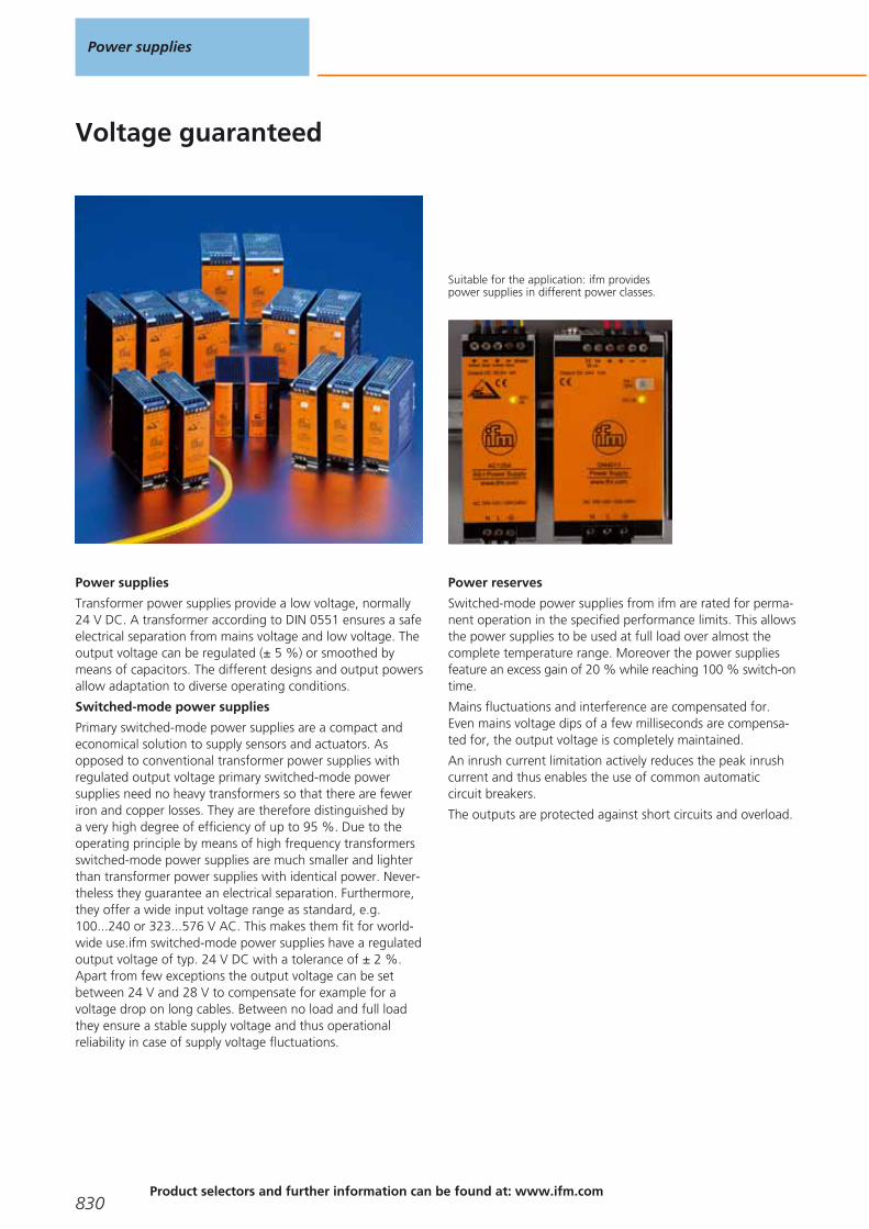
Voltage guaranteed
Suitable for the application: ifm providespower supplies in different power classes.
Power supplies
Transformer power supplies provide a low voltage, normally24 V DC. A transformer according to DIN 0551 ensures a safeelectrical separation from mains voltage and low voltage. Theoutput voltage can be regulated (± 5 %) or smoothed bymeans of capacitors. The different designs and output powersallow adaptation to diverse operating conditions.
Switched-mode power supplies
Primary switched-mode power supplies are a compact andeconomical solution to supply sensors and actuators. Asopposed to conventional transformer power supplies withregulated output voltage primary switched-mode power supplies need no heavy transformers so that there are feweriron and copper losses. They are therefore distinguished by a very high degree of efficiency of up to 95 %. Due to theoperating principle by means of high frequency transformersswitched-mode power supplies are much smaller and lighterthan transformer power supplies with identical power. Never-theless they guarantee an electrical separation. Furthermore,they offer a wide input voltage range as standard, e.g.100...240 or 323...576 V AC. This makes them fit for world-wide use.ifm switched-mode power supplies have a regulatedoutput voltage of typ. 24 V DC with a tolerance of ± 2 %.Apart from few exceptions the output voltage can be set between 24 V and 28 V to compensate for example for a voltage drop on long cables. Between no load and full loadthey ensure a stable supply voltage and thus operational reliability in case of supply voltage fluctuations.
Power reserves
Switched-mode power supplies from ifm are rated for perma-nent operation in the specified performance limits. This allowsthe power supplies to be used at full load over almost thecomplete temperature range. Moreover the power suppliesfeature an excess gain of 20 % while reaching 100 % switch-ontime.
Mains fluctuations and interference are compensated for.Even mains voltage dips of a few milliseconds are compensa-ted for, the output voltage is completely maintained.
An inrush current limitation actively reduces the peak inrushcurrent and thus enables the use of common automatic circuit breakers.
The outputs are protected against short circuits and overload.
Power supplies
830Product selectors and further information can be found at: www.ifm.com
Gesamtkatalog EN 2016_17_Stilvorlage LK FrutigerOT_2010 DE_GB.qxd 06.11.15 17:02 Seite 830

Power supplies
831
24 V DC power supplies 832 - 836
AS-i power supplies 838 - 840
Gesamtkatalog EN 2016_17_Stilvorlage LK FrutigerOT_2010 DE_GB.qxd 06.11.15 17:02 Seite 831
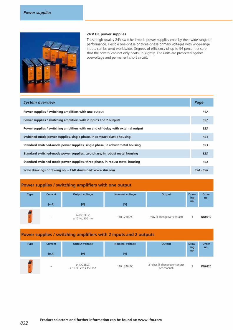
24 V DC power supplies
These high-quality 24V switched-mode power supplies excel by their wide range ofperformance. Flexible one-phase or three-phase primary voltages with wide-rangeinputs can be used worldwide. Degrees of efficiency of up to 94 percent ensurethat the control cabinet only heats up slightly. The units are protected against overvoltage and permanent short circuit.
Power supplies / switching amplifiers with one output
Type Current
[mA]
Output voltage
[V]
Nominal voltage
[V]
Output Draw-ingno.
Orderno.
–24 DC SELV,
± 10 %, 300 mA110...240 AC relay (1 changeover contact) 1 DN0210
Power supplies / switching amplifiers with 2 inputs and 2 outputs
Type Current
[mA]
Output voltage
[V]
Nominal voltage
[V]
Output Draw-ingno.
Orderno.
–24 DC SELV,
± 10 %, 2 x ≤ 150 mA110...240 AC
2 relays (1 changeover contactper channel)
2 DN0220
System overview Page
Power supplies / switching amplifiers with one output 832
Power supplies / switching amplifiers with 2 inputs and 2 outputs 832
Power supplies / switching amplifiers with on and off delay with external output 833
Switched-mode power supplies, single phase, in compact plastic housing 833
Standard switched-mode power supplies, single phase, in robust metal housing 833
Standard switched-mode power supplies, two-phase, in robust metal housing 833
Standard switched-mode power supplies, three-phase, in robust metal housing 834
Scale drawings / drawing no. – CAD download: www.ifm.com 834 - 836
Power supplies
832Product selectors and further information can be found at: www.ifm.com
Gesamtkatalog EN 2016_17_Stilvorlage LK FrutigerOT_2010 DE_GB.qxd 06.11.15 17:02 Seite 832

Power supplies / switching amplifiers with on and off delay with external output
Type Current
[mA]
Output voltage
[V]
Nominal voltage
[V]
Output Draw-ingno.
Orderno.
max. 40 24 DC ±5% 230 AC (50...60 Hz) / 24 DC relay (1 changeover contact) 3 DT0001
Switched-mode power supplies, single phase, in compact plastic housing
Type Current
[A]
Output voltage
[V]
Nominal voltage
[V]
Mainsbuffering time
[ms]
Efficiencytyp.
[%]
Draw-ingno.
Orderno.
1.25 24...28 115 / 230 AC 120 (230 V AC; 24 V DC; 1.25 A) 84 4 DN1030
2.5 24...28 115 / 230 AC 90 (230 V AC; 24 V DC; 2.5 A) 88 4 DN1031
4.1 24...28 DC (±2%) 115 / 230 AC > 40 (230 V AC; 24 V DC / 4.1 A) 90 5 DN1022
Standard switched-mode power supplies, single phase, in robust metal housing
Type Current
[A]
Output voltage
[V]
Nominal voltage
[V]
Mainsbuffering time
[ms]
Efficiencytyp.
[%]
Draw-ingno.
Orderno.
3.3 24...28 DC 115 / 230 AC30 (120 V AC; 60 Hz) / 128 (230 V AC; 50 Hz)
88 6 DN4011
5 24...28 DC 115 / 230 AC80 (120 V AC; 60 Hz) / 78 (230 V AC; 50 Hz)
89.4 6 DN4012
10 24...28 DC 115 / 230 AC46 (120 V AC; 60 Hz) / 47 (230 V AC; 50 Hz)
91 7 DN4013
20 24...28 DC 115 / 230 AC26 (120 V AC; 60 Hz) / 26 (230 V AC; 50 Hz)
92.7 8 DN4014
Standard switched-mode power supplies, two-phase, in robust metal housing
Type Current
[A]
Output voltage
[V]
Nominal voltage
[V]
Mainsbuffering time
[ms]
Efficiencytyp.
[%]
Draw-ingno.
Orderno.
5 24...28 DC 2 x 400 AC27 (400 V AC; 50 Hz) / 48 (480 V AC; 60 Hz)
90.4 9 DN4032
24 V DC power supplies
833You can find scale drawings from page 834
Gesamtkatalog EN 2016_17_Stilvorlage LK FrutigerOT_2010 DE_GB.qxd 06.11.15 17:02 Seite 833

Standard switched-mode power supplies, three-phase, in robust metal housing
Type Current
[A]
Output voltage
[V]
Nominal voltage
[V]
Mainsbuffering time
[ms]
Efficiencytyp.
[%]
Draw-ingno.
Orderno.
10 24...28 DC 3 x 400 AC34 (400 V AC; 50 Hz) / 54 (480 V AC; 60 Hz)
92.8 10 DN4033
20 24...28 DC 3 x 400 AC22 (400 V AC; 50 Hz) / 22 (480 V AC; 60 Hz)
95 11 DN4034
40 24...28 DC (±2%) 3 x 400...500 AC > 15 92.5 12 DN2035
30 24...28 DC (±2%) 3 x 400...500 AC > 10 93 13 DN2036
Scale drawings / drawing no. – CAD download: www.ifm.com
1
25,4 109,1
93
LED s
3
2
4
35,5
112,
6
1
1: plug-in screw terminals, 2: label, 3: potentiometer, 4: Mounting onDIN rail
2
25,4 109,1
93
LED s
3
2
4
35,5
112,
6
1
1: plug-in screw terminals, 2: label, 3: potentiometer, 4: Mounting onDIN rail
3
55
75
1 2 3 4 5 6 7 8
9 10 11 12 13 14 15 16
110
35,5
1
1: Mounting on DIN rail
4
45 100
90
LED
1: potentiometer
5
35,5
10773
75 83
LED
pot.
1
1: jumper "single/parallel operation"
Power supplies
834Product selectors and further information can be found at: www.ifm.com
Gesamtkatalog EN 2016_17_Stilvorlage LK FrutigerOT_2010 DE_GB.qxd 06.11.15 17:02 Seite 834
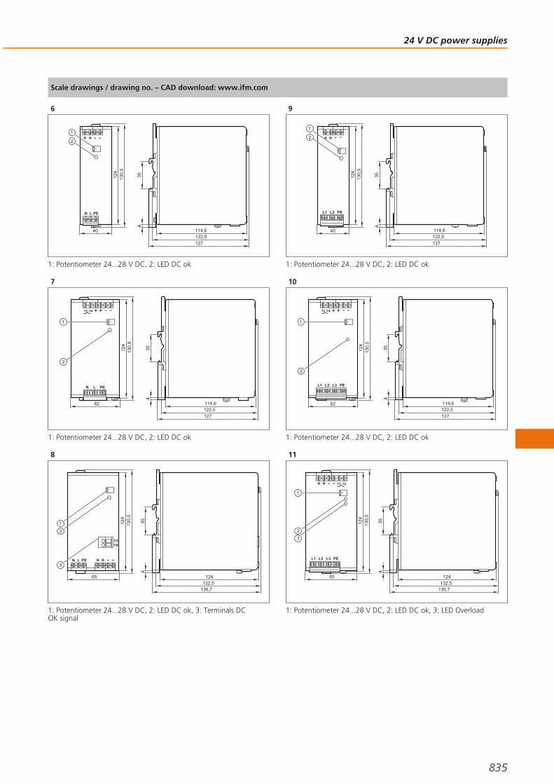
Scale drawings / drawing no. – CAD download: www.ifm.com
6
+ + - -
N L PE
40
124
2
1
130,
5
127
114,6
354
122,5
1: Potentiometer 24...28 V DC, 2: LED DC ok
7
N L PE
62
124
130,
8
+ + - -13 14
2
1
114,6
354
127122,5
1: Potentiometer 24...28 V DC, 2: LED DC ok
8
N L PE
65
124
2
1 130,
5
+ + - -
1314
3
124
354
136,7132,5
1: Potentiometer 24...28 V DC, 2: LED DC ok, 3: Terminals DC OK signal
9
+ + - -
L1 L2 PE
40
124
2
1
130,
5
114,6
354
127122,5
1: Potentiometer 24...28 V DC, 2: LED DC ok
10
L1 L2 L3 PE
62
124
130,
5
+ + - -13 14
2
1
114,6
354
127122,5
1: Potentiometer 24...28 V DC, 2: LED DC ok
11
L1 L2 L3 PE
65
124
130,
5
+ + - - 13 14
2
1
3
354
124
136,7132,5
1: Potentiometer 24...28 V DC, 2: LED DC ok, 3: LED Overload
24 V DC power supplies
835
Gesamtkatalog EN 2016_17_Stilvorlage LK FrutigerOT_2010 DE_GB.qxd 06.11.15 17:02 Seite 835
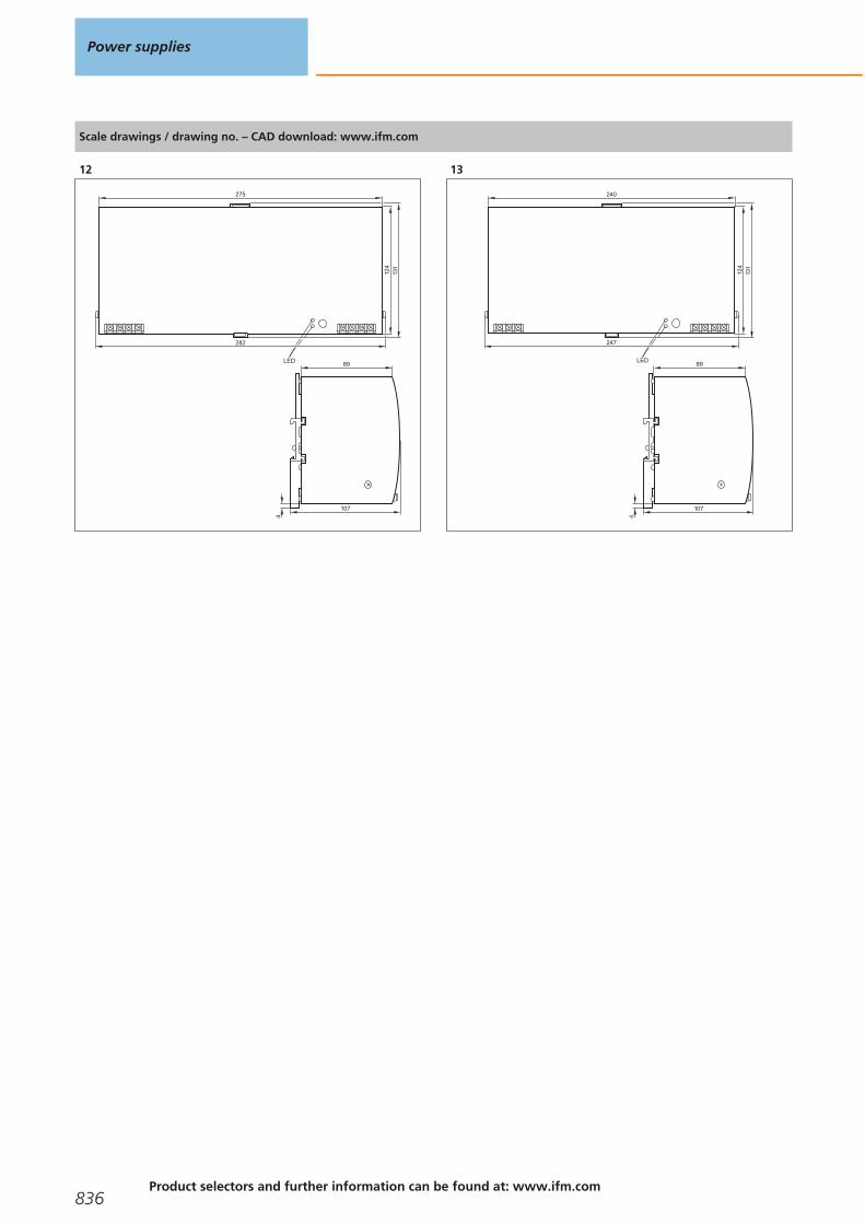
Scale drawings / drawing no. – CAD download: www.ifm.com
12
89
4
107
124
275
131
282
LED
13
89
4
107
124
240
131
LED
247
Power supplies
836Product selectors and further information can be found at: www.ifm.com
Gesamtkatalog EN 2016_17_Stilvorlage LK FrutigerOT_2010 DE_GB.qxd 06.11.15 17:02 Seite 836

24 V DC power supplies
837
Gesamtkatalog EN 2016_17_Stilvorlage LK FrutigerOT_2010 DE_GB.qxd 06.11.15 17:02 Seite 837

AS-i power supplies
All AS-i power supplies are primary switched-mode power supplies with a highdegree of efficiency. The robust DIN rail housing can be easily integrated in largecontrol cabinets as well as in local boxes. The primary voltage range stretches from24 V DC via 230 V AC up to 400 V AC three-phase and can consequently be adaptedto the local conditions.
AS-i switched-mode power supplies, single phase, in robust metal housing
Type Current
[A]
Output voltage
[V]
Nominal voltage
[V]
Mainsbuffering time
[ms]
Efficiencytyp.
[%]
Draw-ingno.
Orderno.
2.8 30.5 DC 115 / 230 AC98 (120 V AC; 60 Hz) / 96 (230 V AC; 50 Hz)
86.9 1 AC1256
4 30.5 DC 115 / 230 AC70 (120 V AC; 60 Hz) / 70 (230 V AC; 50 Hz)
88 1 AC1254
8 30.5 DC 115 / 230 AC44 (120 V AC; 60 Hz) / 42 (230 V AC; 50 Hz)
89.4 2 AC1258
AS-i switched-mode power supplies, single phase, in compact plastic housing
Type Current
[A]
Output voltage
[V]
Nominal voltage
[V]
Mainsbuffering time
[ms]
Efficiencytyp.
[%]
Draw-ingno.
Orderno.
0.95 29.5...31.6 DC 100...240 AC 120 (230 V AC) 86 3 AC1220
1.9 29.5...31.6 DC 100...240 AC 90 (230 V AC) 88 3 AC1221
System overview Page
AS-i switched-mode power supplies, single phase, in robust metal housing 838
AS-i switched-mode power supplies, single phase, in compact plastic housing 838
AS-i switched-mode power supplies, three phase, in robust metal housing 839
DC / DC converter (24 V / AS-i), in robust metal housing 839
Scale drawings / drawing no. – CAD download: www.ifm.com 839 - 840
Power supplies
838Product selectors and further information can be found at: www.ifm.com
Gesamtkatalog EN 2016_17_Stilvorlage LK FrutigerOT_2010 DE_GB.qxd 06.11.15 17:02 Seite 838

AS-i switched-mode power supplies, three phase, in robust metal housing
Type Current
[A]
Output voltage
[V]
Nominal voltage
[V]
Mainsbuffering time
[ms]
Efficiencytyp.
[%]
Draw-ingno.
Orderno.
8 30.5 DC 3 x 400 AC34 (400 V AC; 50 Hz) / 53 (480 V AC; 60 Hz)
92 4 AC1253
DC / DC converter (24 V / AS-i), in robust metal housing
Type Current
[A]
Output voltage
[V]
Nominal voltage
[V]
Mainsbuffering time
[ms]
Efficiencytyp.
[%]
Draw-ingno.
Orderno.
4 30.5 DC 24 DC 6 (24 V DC) 90.5 5 AC1257
Scale drawings / drawing no. – CAD download: www.ifm.com
1
+ +- -
N L PE
Shie
ld
40
124
1
130,
5
114,6
354
120124,5
1: LED AS-i ok
2
+
N L PE
62
124
130,
8
+ - -
1
Shie
ld
114,6
354
4
124,3120
1: LED AS-i ok
3
45 100
90
LED
4
+
L1 L2 L3 PE
62
124
130,
5
+ - -
1
Shie
ld
114,6
354
4
124,3120
1: LED AS-i ok
AS-i power supplies
839
Gesamtkatalog EN 2016_17_Stilvorlage LK FrutigerOT_2010 DE_GB.qxd 06.11.15 17:02 Seite 839

Scale drawings / drawing no. – CAD download: www.ifm.com
5
+ +-
+ -
-
40
124
1
130,
5
Shie
ld
120114,6
354
124,5
1: LED AS-i ok
Power supplies
840Product selectors and further information can be found at: www.ifm.com
Gesamtkatalog EN 2016_17_Stilvorlage LK FrutigerOT_2010 DE_GB.qxd 06.11.15 17:02 Seite 840

AS-i power supplies
841
Gesamtkatalog EN 2016_17_Stilvorlage LK FrutigerOT_2010 DE_GB.qxd 06.11.15 17:02 Seite 841

AlgeriaSarl AMS Algérie - AutomatismesMotorisation & ServicesLotissement C, lot n°190 BDraria - 16000 ALGERTel. +213 (0)5 59 43 45 22Tel. +213 (0) 23 26 41 45Fax +213 (0)23 26 42 58contact@amsalgérie.comwww.amsalgerie.com
Argentinaifm electronic s.r.l.Lola Mora 42110º piso, oficina 31107 - Puerto MaderoCiudad Aut. Buenos AiresTel./Fax +54 (011) 5353-3436Interior del país: [email protected]/ar
Australiaifm efector pty ltd.PO Box 479Suite 3, 745 Springvale RoadMulgrave VIC 3170Tel. 1300 365 088Fax 1300 365 [email protected]/au
Austriaifm electronic gmbhWienerbergstraße 41Gebäude E1120 ViennaTel. +43 / 1 / 617 45 00Fax +43 / 1 / 617 45 00 [email protected]/at
BangladeshSensotec Automation and Control5, New Eskaton RoadGhausnagar,RamnaDhaka 1000 BangladeshTel. +880 171 154 689 [email protected]
Belarusifm electronicELTICON Trade House Ltd.2A Ostroshitskaya st.220125 Minsk, BelarusTel.: +375-17-286-4649Fax: +375-17-289-6169E-mail: [email protected]
MilkGroup LLC.220015 Minsk, BelarusPonomarenko str., 35A, office 517Tel./Fax: +375 17 207 29 34E-mail: [email protected]
FilFar Technology LLC Zapadnaya str., 13, office 519 220036 Minsk, BelarusTel.: +375 (44) 540-40-40E-mail: [email protected]
Belgium and Luxembourgifm electronic n.v./s.a.Zuiderlaan 91 - B61731 ZellikTel. +32 2 481 0220Fax +32 2 463 [email protected]/be
BoliviaBAVARIA S.R.L. Álvaro Baptista VargasZona Calacoto Alto, Urb. Morocollo - Santos PariamoC. Mario Diaz de medina (26-A), n° 32La PazTel. 00-591-2-279 269 1Mobile 00-591-720-47 442PoBox N°[email protected]
Brazilifm electronic Ltda.Rua Eleonora Cintra, 140Jardim Analia Franco03337-000 Sāo PauloTel. +55-11-2672-1730Fax [email protected]/br
Bulgariaifm electronic eood1202 Sofiaul. Klokotnica No 2ABusiness Centre IVELfl.4, office 17Tel. +359 2 807 59 69Fax +359 2 807 59 [email protected]
Canadaifm efector Canada Inc.2233 Argentia Road, Suite 104Mississauga, ON L5N 2X7Tel. 855-436-2262Fax [email protected]/ca
Chileifm electronic SpAPresidente Eduardo Frei Montalva6199, Oficina 5032Comuna de ConchalíRegión MetropolitanaTel.: [email protected]
Chinaifm electronic (Shanghai) Co., LtdBuilding 15, No. 1000, Zhangheng Road, Pu Dong District.201203 Shanghai, P.R.China Tel. +86 21 3813 4800Fax +86 21 5027 8669400 National Service Hotline: 400 880 6651Involving: Contact quotation, Productdelivery, Technical support, [email protected]/cn
ifm electronic (HK) LtdUnit 2106, 21/F,Tower 2, MetroplazaNo. 223 Hing Fong Road,Kwai Chung, N.T., Hong Kong. [email protected]/hk
ifm electronic (Taiwan) Limited9F.-6, No.12, Fuxing 4th Rd., CianjhenDistrict, Kaohsiung City,Postal Code 806, Taiwan, R.O.C.Tel. +886-7-335-7778Fax [email protected]/tw
ColumbiaSENSOMATIC Y CIA LTDA.Calle 1 C 25a - 50Bogotá D.C.Tel. +57 313 430 2264Tel. +57 1 407 96 [email protected]
Costa RicaGen Bus S.ASanta Rosa, Sto. Domingo, Heredia.Bodegas Del Sol, Bodega n° 22Tel. + (506) 25 60 39 58Tel. + (506) 22 62 39 27 Fax + (506) 22 62 16 74
Croatiaifm electronic gmbhWienerbergstr. 41Gebäude E1120 WienTel. +43 / 1 / 617 45 00Fax +43 / 1 / 617 45 00 [email protected]/hr
Czech Republicifm electronic, spol. s r.o.U Křížku 571252 43 PragueTel. +420 267 990 211Fax +420 267 750 [email protected]/cz
Denmarkifm electronic a/sRingager 4A2605 BrøndbyTel. +45 70 20 11 [email protected]/dk
Dominican RepublicWECH AUTOCONTROLES S. A.Ave. Romulo Betancourt 2158 Edificio WechUrb. RenacimientoSanto DomingoTel. + 1 809-531-0550Fax + 1 [email protected]
EcuadorINSELEC CIA. LTDA.Av. de los AruposE1-202 y Pan. Norte- Km 5 ½QuitoTel. +593 2 28074- 76 - 78Fax +593 2 [email protected]
EgyptEgyptian Establishment forElectromechanical SuppliesMr. Ahmed Gouda27 Al-Salam StreetAl Arezona, Al Haram RoadGiza 12111, CairoTel. +20 / 2 / 586 49 49Fax +20 / 2 / 586 49 49Mobile +20 10 10 61 [email protected]
El SalvadorProvinterProlongación Boulevard Constitución,Residencial la Gloria,Block C-3 pje. 2-C, N*1 Mejicanos,San Salvador, El SalvadorTel. + (503) [email protected]
EstoniaPesmel Estonia LTDSegu 476505 SaueTel. +372 674 73 30Fax +372 674 73 [email protected]
Finlandifm electronic oyVaakatie 5 00440 Helsinki Tel. +358 (0)75 329 5000Fax +358 (0)75 329 [email protected]/fi
ifm – worldwideaddresses
842Product selectors and further information can be found at: www.ifm.com
Gesamtkatalog EN 2016_17_Stilvorlage LK FrutigerOT_2010 DE_GB.qxd 06.11.15 17:02 Seite 842
Franceifm electronicSiège :Savoie Technolac BP22673374 Le Bourget du LacAgence commerciale :Immeuble Uranus1-3 rue Jean Richepin93192 NOISY LE GRAND CEDEXTel. 0820 22 30 01Fax 0820 22 22 [email protected]/fr
Germanyifm electronic gmbhFriedrichstr. 145128 EssenTel. +49 201 24 22 0Fax +49 201 24 22 12 [email protected]/de
Greeceifm electronic monoprosopi E.P.E.27, Andrea Papandreou Street15125 AmaroussiTel. +30 210 61 800 90Fax +30 210 61 994 [email protected]/gr
GuatemalaIngenieros Civiles ElectromecánicosAsociados, S.A. (IASA)20 Calle 25-55 Zona 12 Empresarial El Cortijo III Bodega n° 907, Guatemala CityTel. [email protected]
HondurasR y D INDUSTRIALBo. Paz Barahona11 Ave. 14 y 15 CalleS.O. #142San Pedro SulaTel. +(504) 2550-3703Tel. +(504) [email protected]
Hungaryifm electronic kft.Szent Imre út 59. I.em.H-9028 GyőrTel. +36-96 / 518-397Fax +36-96 / [email protected]/hu
Indiaifm electronic India Private LimitedPlot No. P-39/1MIDC Gokul ShirgaonKolhapur – 416234Maharashtra StateTel. +91 / 231 / 267 27 70Fax +91 / 231 / 267 23 [email protected]/in
IndonesiaPT Indoserako SejahteraJl. P. Jayakarta 121 No. 5910730 Jakarta PusatTel. +62 / 21 6 24 8923Fax +62 / 21 6 24 [email protected]
Irelandifm electronic (Ireland) Ltd.No. 7, The CourtyardKilcarbery Business ParkNew Nangor RoadClondalkinDublin 22Tel. +353 / 1 / 461 32 00 Fax +353 / 1 / 457 38 [email protected]/ie
IsraelAstragal Ltd.3, Hashikma Str.Azur 58001P.O. Box 99Azur 58190Tel. +972 / 3 / 5 59 16 60Fax +972 / 3 / 5 59 23 [email protected]
Italyifm electronicCentro Direzionale ColleoniPalazzo Andromeda 2Via Paracelso n. 1820864 Agrate Brianza (MB)Tel. +39 (0)39-6899982Fax +39 (0)[email protected]/it
Japanefector co. ltd.18F WBG Marive-west2-6-1 Nakase, Mihama-kuChiba-shi, Chiba [email protected]/jp
JordanAl Mashreqan Trading SuppliesP.O.Box.85105411185 SwaifiehAmmanTel. +962 6 581 8841Fax +962 6 581 [email protected]
Koreaifm electronic Ltd.Hyundai Liberty House 201Dokseodang-ro Yongsan-Gu 04420 SeoulTel. +82 2-790-5610Fax +82 [email protected]/kr
KuwaitKana Controls 2nd Floor Khalid Fauzan BuildingBuilding No. 1670Street No. 7, Block No. 1Al-Rai Industrial Area, P.O. Box - 25593,13116 SafatTel. +965-24741537Fax [email protected]
LatviaEC SystemsKatlakalna Str. 4A1073 RigaTel. +371 724 1231Fax +371 724 [email protected]
LebanonMiddle East Development Co. SAL(MEDEVCO)Medevco Building Jeita Main Road Jeita - Kesrouan, LebanonMail address :P.O.Box 67 Jounieh LebanonTel. +961-9-233550 Fax [email protected]
LithuaniaElinta UABTerminalo g. 3, Biruliškių k., Karmėlavos sen.LT-54469 Kauno raj. (Kauno LEZ)Tel. +370 37 351 999Fax +370 37 452 [email protected]
Malaysia & Singaporeifm electronic Pte. LtdMalaysian Branch OfficeNo. 9F – 2A, 9th Floor,Tower 4 @ PFCC, Jalan Puteri 1/2,Bandar Puteri Puchong,47100 Puchong, SelangorTel. + 603 8066 9853Fax + 603 8066 [email protected]/my
Singapore Branch Office25, International Business Park #03-26/29 German Center 609916 Singapore Tel. +6565628661 Fax [email protected]/sg
Mexicoifm efector S. de R.L. de C.V.Ave. Arq. Pedro Ramírez Vázquez 200-4Planta Baja, Col. Valle Oriente.San Pedro Garza García, N.L. 66269Tel. +52-81-8040-3535Fax [email protected]/mx
MoroccoSOFIMED137, Boulevard Moulay Ismaïl - Roches Noires20290 - CasablancaTel. +212 522 240 101Fax +212 522 240 100www.sofimed.ma
Namibiaifm electronic (pty) Ltd1 Basement Office,Decor House25 Dr. W. Kulz Street Windhoek NamibiaTel. +264 61 300984 / 300998 Fax +264 61 300910Fax to email +264 88 651 [email protected]/na
Netherlandsifm electronic b.v.Deventerweg 1 E3843 GA HarderwijkTel. +31 / 341 438 438Fax +31 / 341 438 [email protected]/nl
New Zealandifm efector pty ltd.Unit 13, 930 Great South RoadPenrose, AucklandTel. +64 / 95 79 69 91Fax +64 / 95 79 92 [email protected]/nz
NigeriaAutomated Process Ltd3rd Floor, 32 Lagos Abeokuta ExpresswayNear Cement Bus StopDopemu, AgegeLagos StateTel. + 234 / 01 / 4729 967Fax + 234 /01 / 4925 [email protected]
NorwaySiv.Ing. J.F.Knudtzen ASBillingstadsletta 971396 BillingstadPostboks 1601378 NesbruTel. +47 / 66 98 33 50Fax +47 / 66 98 09 55 [email protected]
ifm – worldwideaddresses
843
Gesamtkatalog EN 2016_17_Stilvorlage LK FrutigerOT_2010 DE_GB.qxd 06.11.15 17:02 Seite 843

ifm – worldwideaddresses
844Product selectors and further information can be found at: www.ifm.com
OmanTechnical Engineering Company LLC.P.O. Box 59 Madinat Al Sultan QaboosPostal Code 115Tel. +968 24503593Fax +968 [email protected]
PanamaJDA IngenieríaDirección: Edificio Diamante 3, 3A,Villa De Las Fuentes 1.Ciudad de Panamá. Tel: (507) 399-8200/ [email protected]
Perudekatec s.a.c.Los Calderos 188Urb. Vulcano, AteLimaTel. +511 / 348 0293Tel. +511 / 348 0458Tel. +511 / 348 2269Fax +511 / 349 [email protected]
PhilippinesGram Industrial, Inc.Bldg. 9 Don Mariano Lim Industrial Complex,Alabang Zapote Road corner Concha Cruz Drive,Brgy. Almanza 1 Las Piñas CityTel. 632-8502218 / 8508496Fax 632-8077173 / [email protected]
Polandifm electronic Sp.z o.o.ul. Węglowa 7PL 40-105 KatowiceTel. +48 32 70 56 454Tel. +48 32 70 56 480Fax +48 32 70 56 [email protected]/pl
Portugalifm electronic s.a.Parque Tecnológico S. Félix da MarinhaAvenida Manuel Violas, 4764410-137 São Félix da MarinhaTel. +351 22 37 17 108Fax +351 22 37 17 [email protected]/pt
QatarAdvanced Fluid Power L.L.CP.O. Box 201382Barwa Village Al WakraBuilding No 1Doha-Qatar Tel. +974-40164275Fax [email protected]
Romaniaifm electronic s.r.l.Mihai Viteazu Str. Nr. 1Selimbar, Sibiu557260Tel. 0040 269 224550Fax 0040 269 [email protected]
Russiaifm electronicIbragimova, 31, k.50office 808105318 MoscowTel. +7 (495) 921-44-14Fax +7 (495) [email protected]/ru
Saudi ArabiaNoor Al-Shomoe for Electric & MaintenanceKing Khalid Street, Cross 5P.O. Box 2571Al-Khobar 31952Kingdom of Saudi ArabiaTel. +9 663 864 49 58Fax +9 663 894 63 [email protected]
Bariq Al Emdadat Trading EstablishmentP.O. Box 27001, Riyadh 11653Kingdom of Saudi ArabiaContact: Abdul Aziz Mohamed EliasTel. +966 11 4728782Fax +966 11 4725576Mobile 00966 53 [email protected]
Singaporeifm electronic Pte. Ltd.25, International Business Park #03-26/29 German Center 609916 Singapore Tel. +6565628661 Fax [email protected]/sg
Slovakiaifm electronic spol. s.r.o.Rybnicna 40831 06 BratislavaTel. +421 / 2 / 44 87 23 29Fax +421 / 2 / 44 64 60 [email protected]/sk
South Africaifm electronic (pty) Ltd112 Sovereign Drive, Route 21 Corporate Park Centurion 0157 Postnet Suite 279Private Bag X8Elardus Park0047National: 0861 IFM RSA (436 772) International: +27 12 450 0400Fax +27 12 450 0412 [email protected]/za
Spainifm electronic s.l.Parc Mas BlauEdificio Inbisac/ Garrotxa 6-808820 El Prat de LlobregatTel. 0034 93 479 30 80Fax 0034 93 479 30 [email protected]/es
Sri LankaIsaro Automation Systems Ltd.First Floor,400 Galle Road,Rawathawatta.MoratuwaTel. +94 114 216 784Fax + 94 11 2644 [email protected]
Swedenifm electronic abDrakegatan 641250 GothenburgTel. växel 031-750 23 00Fax 031-750 23 [email protected]/se
Switzerlandifm electronic agAltgraben 274624 HärkingenTel. 0800 88 80 33Fax 0800 88 80 [email protected]/ch
ThailandSCM ALLIANZE CO., LTD.700/19-24Phaholyothin RoadSamsennai PhayataiBangkok 10400Tel. +66 02 615 [email protected]
TunesiaTECHNOPRESTGP1 – Km 5,5 Rte de Sousse –Z.I 2013 Ben ArousTel. +216 71 389 203Fax + 216 71 389 [email protected]
Turkeyifm electronic Elektrikli ve Elektronik Aletlerİth.İhr.Paz.Tic.Ltd.Şti. Merkez Mah. Nadide Sok. Anıttepe Sitesi No:28 34381 Şişli / İstanbulTel. +90 / 212 / 210 5080Fax +90 / 212 / 221 [email protected]/tr
Ukraineifm electronicMariny Raskovoj 1102660 KievTel. +380 44 501 8543Fax +380 44 501 [email protected]/ua
United Arab EmiratesAl Injazat Technical Services Est.P.O. Box 42895Al Qubaisi bldg floor 0 flat # 4Liwa street corner of corniche road,Abu DhabiTel. +971-2-6585400Fax +971-2-6585401Mobil [email protected]
United Kingdomifm electronic Ltd.efector HouseKingsway Business ParkOldfield RoadHamptonMiddlesex TW12 2HDTel. +44 / 20 / 8213 0000Fax +44 / 20 / 8213 [email protected]/uk
USAifm efector, inc.1100 Atwater Dr.Malvern, PA 19355Tel. +1-800-441-8246Fax +1-800-329-0436 [email protected]/us
VenezuelaPetrobornas, C.A.C.C. Plaza Aeropuerto,Galería piso 1, Local P1-B03, Calle Neverí, Unare,Puerto Ordaz 8050, Estado BolívarTel. + 58 286 [email protected]
VietnamThe Representative Office of ifm electronic gmbh in Ho Chi Minh City7A-7th Floor,#467 Dien Bien Phu Street,Ward 25, Binh Thanh District,Ho Chi Minh City 700000Tel. +84-8-35125177 Fax [email protected]
Gesamtkatalog EN 2016_17_Stilvorlage LK FrutigerOT_2010 DE_GB.qxd 12.11.15 11:15 Seite 844

ifm – worldwideaddresses
845
Gesamtkatalog EN 2016_17_Stilvorlage LK FrutigerOT_2010 DE_GB.qxd 06.11.15 17:02 Seite 845

AUTOMATIONBOOK
AU
TOM
ATI
ON
BO
OK
201
6/2
017
Titel Gesamtk. Montage 16 GB 16.12.15 15:56 Seite 1