Embed Size (px)
Citation preview
GEOTHERMAL TRAINING PROGRAMME Reports 2013 Orkustofnun, Grensasvegur 9, Number 28 IS-108 Reykjavik, Iceland
659
GEOTHERMAL WELL DESIGN
Abdirasak Omar Moumin Ministry of Energy and Natural Resources
P.O. Box 10010 Djibouti
DJIBOUTI [email protected]
ABSTRACT
This report describes the geothermal well design for the future 4 wells in the Lava Lake area in Fiale Caldera in Djibouti. Various geophysical studies in the framework of different projects have confirmed the presence of a magmatic heat source potentially useful for the production of geothermal energy. The present work includes: the casing design, the wellhead pressure estimate, and cementing of the casings to prevent contamination of fresh water and maintain well integrity during exploitation. An Excel based programme was developed for the casing design. Also, the Viking engineering programme calculated the reduced collapse resistance and assisted the Excel programme. The criteria for the casing design were as follows: preliminary selection based on burst and collapse pressure, selection based on tension, and finally the biaxial correction. Since the reservoir pressures and temperatures of Wells AA, AB, AC and AD are not known, the reservoir pressure and temperature of Well Asal 5 were used to design the 4 wells and it is expected that the same casing string design will be used.
1. INTRODUCTION The formation pressures, geology, hole depth, formation temperature and other factors are important for the final selection of casing grades and weights of a geothermal well. The casing design process consists of selecting the casing sizes, weight, grades and setting depths. This is done by calculating the burst, collapse, and axial loads affecting the casing during drilling of the well and also while the well is in production. Other factors such as corrosion must also be taken into account. The casing design is of utmost importance for the success of the well. The cost of the casing constitutes a considerable part of the total cost of the well, approximately 20%. The first wells, in total six (Asal 1, 2, 3, 4, 5 and 6), were drilled in 1975 and 1987/1988 in the Lake Asal area to depths of 1316-2105 m, with temperatures up to 350°C (Elmi, 2005). Asal 5 will be used as a reference for designing the new wells AA, AB, AC and AD. The hydrostatic pressure profile for Asal 5 can be seen in APPENDIX III. The lithology from Asal 5 is better than what was expected for the Lava Lake in Fiale area. Asal 5 was drilled in the Inner Rift, about 1 km west of Lava Lake. The drilling of Well Asal 5 started on 7th January 1988 and finished on March 3, 1988. The final depth is 2,105 m and the temperature at the bottom is 350°C. It is unproductive and penetrates both cold and hot formations. In March 1988, Dr. Kristjan Saemundsson made a geological survey in the Asal Field, where he indicated that Well Asal 5 was not correctly sited, as it would be about 700-1000 m from the
Abdirasak Omar 660 Report 28
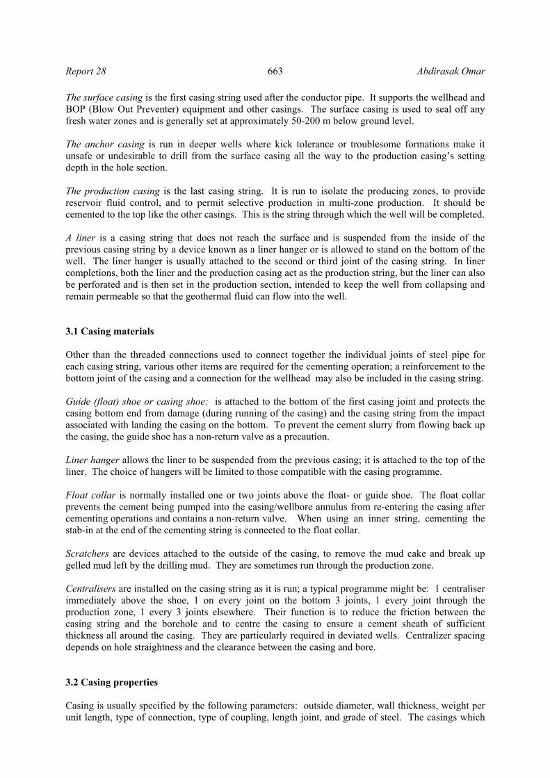
geothermal upflow zone (Saemundsson, 1988). In June 1988, a resistivity survey using the TEM method (Transient Electromagnetics) was carried out in the "Inner Rift" (Árnason et al., 1988). The survey indicated the existence of an upflow zone of geothermal fluid under the Lava Lake, as had been predicted by Saemundsson (1988). These results show this area to be most promising for siting future exploratory wells. 2. WELL SITE GEOLOGY The well design shall be based on a geological prognosis comprised of the expected stratigraphy and lithology. Geological conditions and fresh water aquifers are important factors for selecting the number of casing strings, casing setting depths and to select optimum drilling targets. Wells AA, AB, AC, and AD will be sited in the Fiale area (Figure 1), specifically north of the Lava Lake about 70 km west of Djibouti city. The project area is estimated to be 2.5 km2. The sector is favoured because of its impressive faulting, massive magma deposition and active steam fumaroles on the surface. The Asal rift zone is dominated by very recent volcanic rocks and is characterized by a diverging plate boundary and continuous microseismic earthquakes. The last volcanic eruption took place in1978 at Ardoukoba, southeast of Lake Asal. From 1975 to 1988 studies of the area were conducted. They proved that there is a heat source (350°C) in the area and that the fluids are highly saline (Virkir-Orkint, 1990). The Asal area is between Ghoubbet El Kharab and Lake Asal. The Fiale area is the southeast part of the Inner Rift. The Lava Lake is a circular depression in the centre of the Fiale area (REI, 2008). Djibouti is located where three major extensional structures, the Red sea, the East African Rift and the Gulf of Aden, meet and form the Afar Depression (Varet, 1973; Stieltjies, 1976).
FIGURE 1: Map of Fiale area (REI, 2008)

Report 28 661 Abdirasak Omar
The area could be impermeable. Significant fractures and faults are under the Lava Lake and it is a geological anomaly that should be protected. Therefore, the wells will not be drilled directly above the Lava Lake. To cut major faults, the technique of directional drilling will be used. The tectonic map is important for siting the wells and for targeting the faults. 2.1 Lithological logs As already mentioned, the lithology of Well Asal 5 is expected to be similar to that of the new drilling site. The Italian company Aquater (Aquater, 1989) made lithological studies of Well Asal 5 and, in doing so, collected cuttings every 5 m. The cuttings were studied using a binocular microscope. Thin sections of the cuttings were collected every 10 m or when necessary every 5 m. The thin sections were studied using a polarizing microscope. The stratigraphic series was reconstructed and the hydrothermal alteration paragenesis was studied. The lithological sequence is quite monotonous, and most of the encountered rock type can be classified in the following units: ferrobasalt, olivine basalt, tuff, trachy-basalt, dark trachyte, sand or slit, and claystone (Figure 2). 2.2 Alteration zones
The hydrothermal mineral assemblages presented in Well Asal 5 indicate high-temperature geothermal activity. Six hydrothermal alteration zones were established based on the progressive alteration of the rock (Figure 3). These zones are as follows (Khaireh, 1989): unaltered zone; smectite zone (this zone indicates a temperature range of up to 200°C); mixed layer clay zone (this zone is found at a
FIGURE 2: Lithological sequence expected for the Lava Lake in the Fiale area
FIGURE 3: Alteration zones for the Lava Lake in the Fiale area
Abdirasak Omar 662 Report 28
temperature range of about 200-230°C); chlorite zone (the zone measures a temperature range of about 230-240°C); chlorite-epidote zone (this zone falls in the temperature range of 230-280°C); and chlorite-actinolite zone (this zone is correlated with temperatures exceeding 280°C). 2.3 Temperature profiles
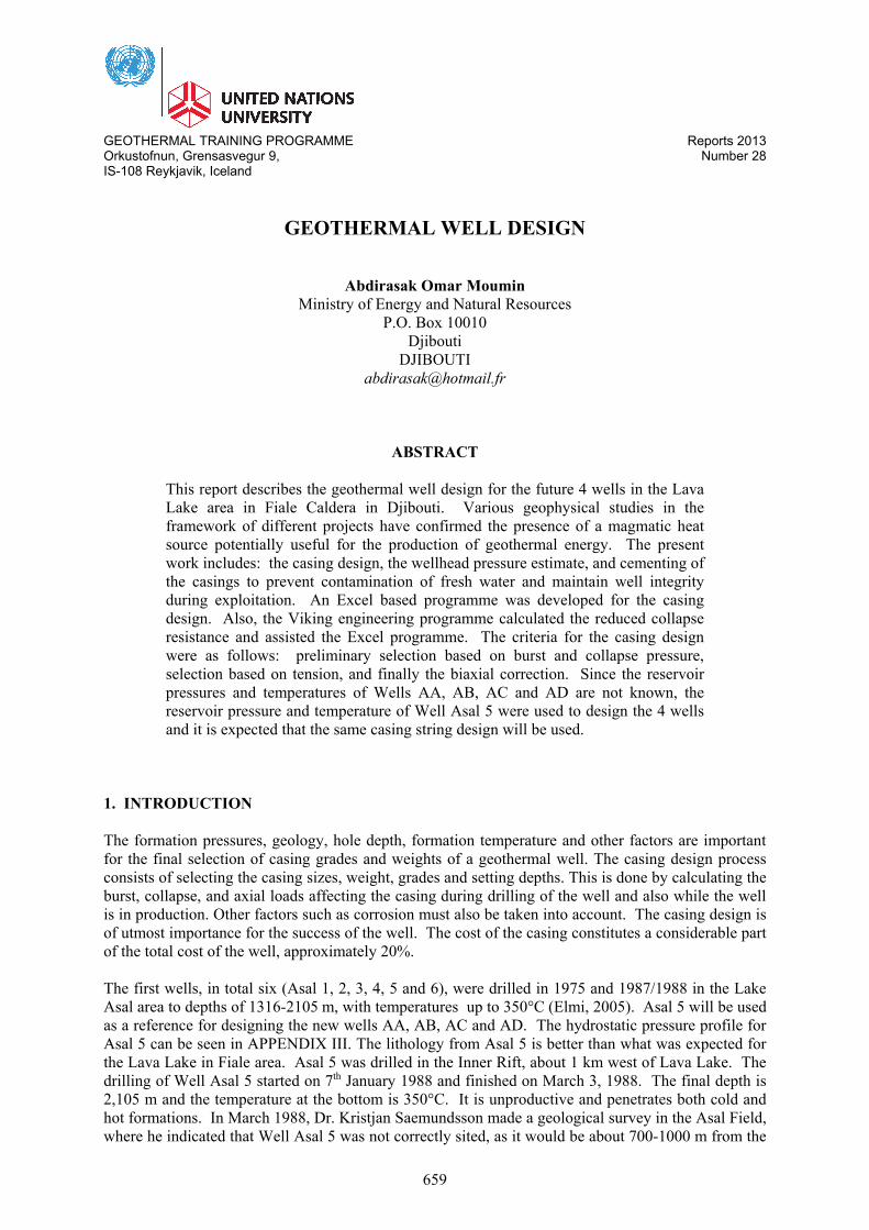
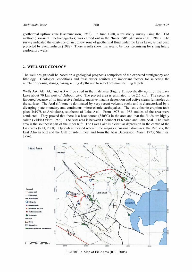
Well Asal 5 showed a sharp increase in temperature below 200 m b.s.l., with a maximum of about 180°C at 500 m. Between 500 and 1000 m depth, the rocks drastically cooled down with temperatures as low as 60-70°C. After 1000 m depth, the temperature increased rapidly, reaching more than 350°C at 2100 m (Figure 4). The significant inversion on the temperature profile of Well Asal 5 might be explained by the superficial underground flow toward Lake Asal which goes deeper in this well (Jalludin, 2010). For wellhead design purposes, the temperature in the part that penetrates the cold formations was reversed and a maximum temperature of 312°C at 2050 m was assumed (Figure 5). If, during drilling, temperatures exceed this temperature according to cutting samples and temperature readings, drilling should be halted and a flow test conducted. 3. CASING DESIGN The well design defines the desired final status of the well. Geothermal well designs and drilling practices are similar worldwide (Hossein-Pourazad, 2005). The casing design is the same, whether the well is drilled vertically or directionally. Casings are designed to accomplish two different tasks. The first is to allow safe drilling of the well and to resist any force or conditions that are imposed upon it during drilling, without sustaining significant damage. The second is to meet the well’s objectives without requiring a workover during the well’s lifetime. Therefore, the main functions of the casing in any well are: to maintain hole integrity, to prevent contamination of near fresh water zones, to provide a suitable connection for the wellhead equipment and a hole of known diameters and depth to facilitate the running of test and completion equipment, to provide a conduit for well production, and to optimize well cost. Since pressure varies along each section of the hole, different casing sizes are employed; this arrangement gives a final tapered shape to the finished well. It is possible to run a casing string having the same outside diameters but with different thickness or strength properties. Thus, a heavy or high grade casing could be run along the section of the hole containing high pressures, or near the surface where tensile stresses are high. Multiple intervals of casing are successively placed within previous casings in geothermal wells. The typical casings used are: The conductor pipe is the first casing to be put in place, and is often installed before the rig is mobilized. The conductor pipe can be excavated for or it can be driven with a hammer. It has the largest diameter and it is generally set at approximately 1-10 m below ground level. The conductor casing is used to seal off unconsolidated formations at shallow depths to prevent cave-ins.
FIGURE 4: Temperature profile of Well Asal 5
FIGURE 5: Expected temperature profile in the new wells
0
500
1000
1500
2000
2500
0 100 200 300 400
Dep
th (
m)
T (°C)
0
500
1000
1500
2000
2500
0 100 200 300 400
Dep
th (
m)
T (°C)
Report 28 663 Abdirasak Omar
The surface casing is the first casing string used after the conductor pipe. It supports the wellhead and BOP (Blow Out Preventer) equipment and other casings. The surface casing is used to seal off any fresh water zones and is generally set at approximately 50-200 m below ground level. The anchor casing is run in deeper wells where kick tolerance or troublesome formations make it unsafe or undesirable to drill from the surface casing all the way to the production casing’s setting depth in the hole section. The production casing is the last casing string. It is run to isolate the producing zones, to provide reservoir fluid control, and to permit selective production in multi-zone production. It should be cemented to the top like the other casings. This is the string through which the well will be completed. A liner is a casing string that does not reach the surface and is suspended from the inside of the previous casing string by a device known as a liner hanger or is allowed to stand on the bottom of the well. The liner hanger is usually attached to the second or third joint of the casing string. In liner completions, both the liner and the production casing act as the production string, but the liner can also be perforated and is then set in the production section, intended to keep the well from collapsing and remain permeable so that the geothermal fluid can flow into the well. 3.1 Casing materials
Other than the threaded connections used to connect together the individual joints of steel pipe for each casing string, various other items are required for the cementing operation; a reinforcement to the bottom joint of the casing and a connection for the wellhead may also be included in the casing string. Guide (float) shoe or casing shoe: is attached to the bottom of the first casing joint and protects the casing bottom end from damage (during running of the casing) and the casing string from the impact associated with landing the casing on the bottom. To prevent the cement slurry from flowing back up the casing, the guide shoe has a non-return valve as a precaution. Liner hanger allows the liner to be suspended from the previous casing; it is attached to the top of the liner. The choice of hangers will be limited to those compatible with the casing programme. Float collar is normally installed one or two joints above the float- or guide shoe. The float collar prevents the cement being pumped into the casing/wellbore annulus from re-entering the casing after cementing operations and contains a non-return valve. When using an inner string, cementing the stab-in at the end of the cementing string is connected to the float collar. Scratchers are devices attached to the outside of the casing, to remove the mud cake and break up gelled mud left by the drilling mud. They are sometimes run through the production zone. Centralisers are installed on the casing string as it is run; a typical programme might be: 1 centraliser immediately above the shoe, 1 on every joint on the bottom 3 joints, 1 every joint through the production zone, 1 every 3 joints elsewhere. Their function is to reduce the friction between the casing string and the borehole and to centre the casing to ensure a cement sheath of sufficient thickness all around the casing. They are particularly required in deviated wells. Centralizer spacing depends on hole straightness and the clearance between the casing and bore. 3.2 Casing properties Casing is usually specified by the following parameters: outside diameter, wall thickness, weight per unit length, type of connection, type of coupling, length joint, and grade of steel. The casings which

Abdirasak Omar 664 Report 28
are most used have been standardised by the American Petroleum Institute (API). Appendix I lists the API specifications, standards and bulletins referred to in this report. 3.2.1 Casing size
The size of the casing refers to the outside diameter (O.D.) of the main body of the tubular (not the connector). Casing sizes vary from 4.5" to 36" diameter. Tubulars with an O.D. of less than 4.5" are called tubing. API recommended dimensions of drift mandrels, which are used to determine the pipes inner roundness, are as follows: the drift diameter (Table 1) is the maximum size of a drill bit that can safely be run through the casing. 3.2.2 Joint length
The length of a joint of casing has been standardised and classified by the API (Table 2). The precise length of each joint has to be measured. The length is measured from the top of the connector to a reference point on the pin at the other end of the casing joint. Casing is run most often in Range 3 lengths to reduce the number of connections in the string. Since casing is made up of single joints, Range 3 lengths can be handled easily by most rigs. 3.2.3 Casing weight The weight per foot of the casing is representative of the wall thickness of the pipe. There are, for instance, three different weights of 20" casing; see the Drilling data handbook (Gabolde and Nguyen, 2006). 3.2.4 Connections The casing is fabricated in joints and is delivered to the rig. The casing joints are joined together by threaded connections. They exist in a wide variety of threaded connections. In the API standard 5B, the connection between the joints is carried out by coupling; it (coupling or casing collar) is threaded internally (female) and is installed on one end of each joint before it is delivered to the rig. Contrary to coupling, the casing joints are threaded externally at either end. The standard types of API threaded and coupled connections are:
Short thread connection (STC); Long thread connection (LTC); and Buttress thread connection (BTC).
3.2.5 Casing grade
API defines the characteristics of various steels and assigns letters to identify those grades (the chemical composition of the material); the number refers to the minimum yield strength of the material, e.g. N-80 casing has the minimum yield strength of 80000 psi and K-55 has the minimum yield strength of 55000 psi; refer to API specification 5CT for complete definitions. Table 3 shows the different grades of steel classified by API. Certain manufacturers produce non-API materials.
TABLE 1: Drift mandrels
Casing diameter (in)
Mandrel length Mandrel diameter (in) (mm) (in) (mm)
< 9 5/8 6 152 ID-1/8 ID-3.18 9 5/8 to 13 5/8 12 305 ID-5/32 ID-3.97 13 3/8 and larger 12 305 ID-3/16 ID-4.76
ID: Inside diameter
TABLE 2: Length range of a casing joint - API
Range Length Average length
(feet) (m) (feet) (m) 1 16-25 4.9-7.6 22 6.7 2 25-34 7.6-10.4 31 9.45 3 Over 34 Over 10.4 42 12.8

Report 28 665 Abdirasak Omar
Both seamless and welded tubulars are used as casing although seamless casing is the most common type of casing and usually only H and J grades are welded.
TABLE 3: Tensile requirements for casing and tubing
Grades
Properties
H40 J55 K55 N80 L80 C90 C95 T95 P110
Grades color codes 1 black 1 green 2 green 1 red 1 red
1 brown1 purple 1 brown 1silver 1white
Min. yield strength Bar 2760 3790 3790 5520 5520 6210 6550 6550 7580 Psi 40000 55000 55000 80000 80000 90000 95000 95000 110000
Max. yield strength Bar 5520 5520 5520 7580 6550 7240 7580 7580 9650 Psi 80000 80000 80000 110000 95000 105000 110000 110000 140000
Min. ultimate tensile strength
Bar 4140 5170 6550 6890 6550 6890 7240 7240 8620 Psi 60000 75000 95000 100000 95000 100000 105000 105000 125000
3.3 Safety factor
The exact values of loadings are difficult to determine; the safety factor is used to allow and to ensure that the rated performance of the casing is always greater than any expected load. Safety factors are arbitrary figures that have evolved with experience. Each operating company uses its own values for safety factors for specific situations. The minimum acceptable casing design factors (NZS, 1991) are:
Internal yield (burst) design factors 1.5 -1.8; Collapse design factors 1.2; Tensile design factors 1.5 – 1.8; and Compressive factor 1.2.
3.4 Casing design criteria Generally, the casing design process involves three distinct steps: The selection of the casing sizes and setting depths; the definition of the operational scenarios which will result in burst, collapse and axial loads being applied to the casing; and the calculation of the magnitude of these loads and selection of an appropriate weight and grade of casing. The load inside any particular string will differ from those inside the other strings. Each string of casing must be carefully designed to withstand the anticipated loads to which it will be exposed during installation, when drilling the next hole section, and when producing from the well. Radial loads (burst and collapse) and axial (tensile and compressive) loads to which the casing will be exposed during the lifetime of the well will dictate the depth of the casing shoe. The casing design should be calculated using the true vertical depth. The majority of the equations used in this section have been extracted from Baker Hughes INTEQ (1995), BG Group (2001), and Heriot-Watt University (2010). 3.4.1 Collapse
Collapse pressure originates from the column of mud used during drilling and the column of cement used to cement the casing in place. The collapse load at any point along the casing can be calculated from:
P P P (1)
where P = Collapse pressure;
Abdirasak Omar 666 Report 28
P = External pressure due to mud or cement; and P = Internal pressure due to mud, water or cement. Before designing each casing string, it is important to define the hypotheses to be considered:
- While running casing and designing for the collapse pressure, the internal pressure is zero (Pi=0) because the surface, anchor and production casings are assumed to be empty (full evacuation).
- At the surface we assume that the collapse pressure is zero (P 0= Pe). - At the shoe of each casing string, the maximum collapse pressure is calculated. The collapse
pressure increases with depth, going from zero at surface to the maximum value at the shoe. The equation for the collapse pressure while running the casing generally is as follows:
At surface P 0 (2)
At shoe P P ρ g CSD
where P = Collapse pressure; P = External pressure (due to drilling mud or other drilling fluid); g = Force of gravity; CSD = Casing setting depth; and ρ = Density of drilling mud. In metric units, the collapse pressure is given by:
P ρ 0.0981 CSD (3)
where P = Collapse pressure (bar); CSD = Casing setting depth (m); and ρ = Density of current drilling mud (kg/l). while in imperial units, the collapse pressure is given by:
P ρ 0.052 CSD (4)
where Pc = Collapse Pressure (psi); CSD = Casing Setting Depth (feet); ρ = Density of current drilling mud (ppg). After running the casing and when designing for the collapse pressure, the column of cement imposes the external pressure, and the casing is assumed to be full of water. The density of fluid inside the casing is equal to 1 kg/l, hence:
P ρ cement g CSD (5) P ρ fluid inside the casing g CSD (6) At shoe P ρ cement ρ fluid inside the casing g CSD (7) At surface P = 0
The collapse pressure due to the mud column (Pi = 0, inside casing totally empty) is higher than the collapse pressure due to the cement column (P # 0, casing full of displacement fluid); that is why the collapse pressure due to the mud column is used for the design of the collapse resistance. Then the design factor, discussed in Section 3.3, is added.

Report 28 667 Abdirasak Omar
3.4.2 Burst The burst pressure design must ensure that the pressure inside the casing does not exceed the casing burst pressure limit. The top section of each casing string and wellhead shall be designed to resist the pressure and temperature conditions. The pressures at the surface and at the casing shoe are calculated by the equation defined below:
P P P (8)
When designing for the burst pressure, to optimize the casing’s resistance, it is assumed that at the surface the internal pressure is due to the hydrostatic pressure minus the weight of the gas. The external pressure is assumed to be Pe= 0. Burst at surface:
P 0 (9)
P P NHTD ρ 0.0981 P (10)
The hydrostatic pressure is given by the following equation:
P NHTD ρ 0.0981 (11)
where P = Burst pressure at surface (bar); P = Internal pressure at surface (bar); P = External pressure at surface (bar); P = Hydrostatic pressure at NHTD (bar); ρ = Density of saturated liquid;
ρ = Gas density at NHTD; and NHTD = Next hole total depth (m). For more details, see Section 6 where the hydrostatic pressure is calculated for every 50 m. Burst at shoe:
P CSD 0.105 (12)
The gradient of salt water is 0.105 bar/m or 0.465 psi/ft.
P P ρ L 0.0981 L ρ 0.0981 (13)
P = P P (14)
where P = Burst pressure at shoe (bar); P = Internal pressure at shoe (bar); P = External pressure at shoe (bar); P = Applied pressure pumping (bar); ρ = Cement slurry density (kg/l); ρ = Density of displacement fluid (kg/l);
L = Height of cement column inside casing (m); and L = Height of water column inside casing (m).
3.4.3 Axial loads: tension load The axial load that may be exerted on the casing string is the tension and compression that occur under the following conditions (Figure 6): the tension is due to the weight of the casing and the cooling of the well, and the compressive loads are due to thermal expansion during heating-up of the well.

Abdirasak Omar 668 Report 28
Casings are mostly in tension except for conductor pipes. Tension loads are determined by: the forces due to the buoyed weight, the bending force in deviated wells, the shock load and the force due to pressure testing. The design factor for all axial tensile and compressive loading shall not be less than 1.2 (NZS, 1991). If the yield strength of casing is exceeded during running and cementing of the casing, then casing failure is likely. Calculation of buoyed weight: The weight of casing in air is given by:
where W = Nominal unit weight of casing (lb/ft); and
W = Weight air (lb). Therefore, the buoyant weight of casing is given by:
W W BF (16)
BF Buoyancy factor 1ρρ
(17)
where ρ = Steel density (7.85 kg/l); ρ = Density of fluid (fluid displacement or mud or cement) (kg/l); and W = Buoyant weight (lb). Hence
Buoyancy force W 1 BF (18) Calculation of buoyed weight in different liquids (inside and annular): Here, the buoyant weight is determined by using the buoyancy factor from the following equation:
BF1 1
1 (19)
where ID = Inside diameter (in); OD = Outside diameter (in); ρ = Density of fluid inside casing (kg/l); and ρ = Density of fluid outside casing (kg/l). When the cement is inside the casing, the tensile force at the surface from the casing weight (buoyant weight) is at its maximum value and the minimum value of the tensile force at the surface from the casing weight is attained when the entire volume of cement is displaced outside the casing. Bending force: Bending force arises if casing is run in deviated wells or in wells with severe dogleg. In the deviated wells, the bends must be considered. The bending force can be computed from the following:
B 63 W OD θ (20)
where OD = Outside diameter (in); θ = Dogleg severity, degrees/100 ft;
FIGURE 6: Casing loads
W W CSD (15)

Report 28 669 Abdirasak Omar
W = Nominal unit weight of casing (lb/ft); and B = Bending force (lb). Shock loads: The casing string experiences shock loads when it is decelerated or accelerated while setting or unsetting the casing slips. The shock load is given by:
Shock load 3200 W (21)
To recap,the preliminary casing selection is based on burst and collapse, and the safety factor in tension during pressure testing must be more than 1.5 – 1.8; it is given by the relationship below. The casing should be tested to the maximum pressure for which it has been designed.
SafetyFactor in tension
Yield StrengthTotal Tensile loads
(22)
Totaltensileloads Shock load Force due to pressuretesting (23)
Force duetopressure testingπ4
ID testing pressure (24)
where Testing pressure = 60% dependsonthecompanyinvolved Burstpressure. Axial loading applied to the liner: The perforated liner in the production section of the well is not cemented and is not supported or constrained. Therefore, the extreme compressive stress, due to the thermal expansion and bending forces concerning the perforated liner, is given by:
F L W g
1A
OD eL
(25)
where Fec = Extreme compressive stress (N); L = Length of the liner (m); W = Nominal weight of casing (kg/m); g = Acceleration due to gravity (m s-2); A = Cross-section area of pipe (m2); OD = Outside diameter (m); e = Eccentricity (actual hole diameter minus OD) (m); and L = Net moment of inertia of the pipe section, allowing for perforation (kg m2). After the well has been completed, the tensile axial load in the top section of the casing, below the wellhead, applied by the fluid in the well is:
Fπ4P ID (26)
where F = Lifting force due to wellhead pressure (N); P = Maximum wellhead pressure (Pa); and ID = Inside diameter of production casing (m2). 3.4.4 Axial loads: compression The compressive loads due to thermal expansion during heating-up of the well when the casing is constrained both longitudinally and laterally by cement is:
F C T T A (27)
where F = Compressive loads (N);

Abdirasak Omar 670 Report 28
C =E a, thermal stress constant for casing steel (MPa/°C); T = Maximum expected temperature (°C ; T = Neutral temperature (temperature at time cement is set (°C); A = Cross-section area of pipe (m2); E = Modulus of elasticity; and a = Coefficient of linear thermal expansion. Casing string design shall allow for the changes in casing properties at elevated temperatures, as shown in Table 4. The modulus of elasticity can be assumed to be constant over the temperature range; the value is 200 10 MPa. The coefficient of linear, thermal expansion should be taken as 12 × 10-6/°C. Normally the coefficient of linear, thermal expansion is not constant, particularly at low temperature and pressures, and must be determined by reference to the steam tables. Therefore, the thermal stress constant for casing steel is: Ct = 2.4 MPa/°C.
TABLE 4: Temperature effects (NZS) on casing properties (K-55)
Temperature (°C) 20 (°C) 100 (°C) 200 (°C) 300 (°C)
API yield strength 1 0.95 0.95 0.95 Tensile strength 1 0.97 1.02 1.07 Modulus of elasticity 208 208 200 192
3.4.5 API rated capacity of casing
The API bulletin 5C3 defines four formulas for calculating the collapse resistance of casings (Rabia, 1987). The API collapse formulas predict acceptable minimum collapse values, not average values. They are determined by yield strength of axial stress (see Section 3.6.5) and OD/t. They are given by the following equations: The theoretical elastic collapse pressure, Pc, may be determined from the following equation in imperial units:
P
46.978 10
1 (28)
where Pc = Elastic pressure (psi); OD = Outside diameter (in); and
t = Wall thickness (in).
And in metric units:
P
3.304 10
1 (29)
The elastic collapse pressure equation (Equation 28) is applicable where the following relationship is satisfied:
ODt
2
3 (30)
where
A 2.8762 0.10679 10 Y 0.21301 10 Y 0.53132 10 Y (31)
B 0.026233 0.50609 10 (32)
Report 28 671 Abdirasak Omar
and Y = Minimum yield strength of the casing (psi). The transition collapse pressure (Pt) is given by:
P Y
CD (33)
where C and D are constants given by the following relationship:
C46.95 10
Y
(34)
D
CBA
(35)
Equation 33 is applicable if:
Y A C
E Y B DODt
2
3 (36)
where
E 465.93 0.030867Y 0.10483 10 Y 0.36989 10 Y (37)
The plastic collapse pressure may be calculated from the following equation:
P Y
AB E (38)
Equation 38 is applicable if the following relationship is verified:
A 2 8 B
/A 2
2 B
ODt
Y A C
E Y B D (39)
The yield strength collapse pressure, Py, is calculated by:
P 2Y1
(40)
The range of OD/t is:
ODt
A 2 B/
A 2
2 B (41)
3.4.6 Biaxial loads The radial stress is often negligible compared to the axial and tangential stresses. The manufacturer provides the collapse resistance for casing under zero axial load. Under field conditions, this is never the case. Considering the axial stress, the new yield strength is given by:

Abdirasak Omar 672 Report 28
Y 1 0.75
SY
0.5SY
Y (42)
where Y = Yield strength considering axial stress, psi or MPa; Y = Minimum yield strength of the casing, psi or MPa; and S = Axial stress, psi or MPa.
S
Axial load IbCross section area in
(43)
The result from Equation 42 will be used for calculating burst and collapse (see above). The minimum burst resistance of the casing is calculated by using Barlow’s equation:
P 0.875
2 Y t
OD (44)
And the minimum collapse resistance is calculated by the following steps:
a) Calculate the axial stress (S ) at the section of casing under consideration; b) Determine (Equation 42) the yield strength considering the axial stress, ; c) Calculate the ratio OD/t; d) Using Equations 31, 32, 34, 35 and 37, calculate the constants A, B, C, D and E and determine
the range for which OD/t is applicable (Equations 30, 36, 39 and 41); and e) Determine the appropriate equation for calculating the reduced collapse resistance from OD/t.
Viking Engineering, LG, has developed an Excel based programme to calculate collapse resistance. The input data are: OD, pipe weight per foot, grade, the yield strength considering the axial stress ( ), and t (thickness). The output of the programme is A, B, C, D, F (in the programme, C=F and D = G), and the collapse resistance. 3.4.7 Triaxial loads In the most critical case, one needs to take into consideration triaxial stress analysis. To calculate it, the radial, tangential, and axial stresses need to be calculated. Often, the triaxial stress analysis is not used but, in reality, the casing string is submitted to triaxial loading. In the casing design of wells AA, AB, AC and AD, we do not consider the triaxial stress analysis. 4. CASING DESIGN PROGRAMME FOR WELLS AA, AB, AC, AD In this part, the casing design for wells Asal A, Asal B, Asal C and Asal D are presented. To do this, an Excel based programme was used as well as the Viking Engineering programme, which was used to calculate the reduced collapse resistance. Step 1: Preliminary selection of weight and grade, based on burst and collapse pressure The program calculates the burst pressure at the shoe and at the surface, as well as the collapse pressure at the shoe and at the surface for each casing string. The input data for the programme is namely the casing setting depth, the mud programme, the hydrostatic pressure, the temperature and the gas density. Step 2: Selection based on tension After step 1, the burst and collapse requirements are known, and the weight and grade of the casing are selected. Therefore, the tension can be calculated. The input data for the programme is the specifications of the casing string given by the manufacturer. The programme determines the total
Report 28 673 Abdirasak Omar
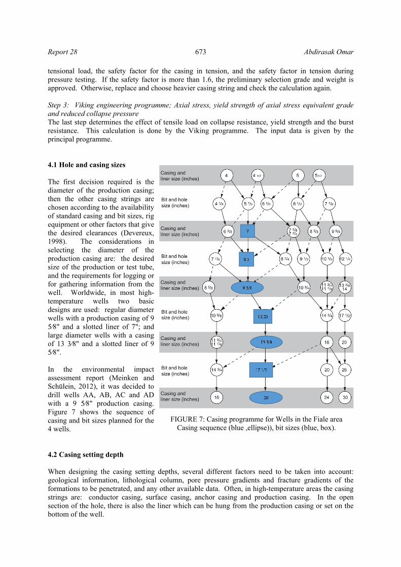
tensional load, the safety factor for the casing in tension, and the safety factor in tension during pressure testing. If the safety factor is more than 1.6, the preliminary selection grade and weight is approved. Otherwise, replace and choose heavier casing string and check the calculation again. Step 3: Viking engineering programme; Axial stress, yield strength of axial stress equivalent grade and reduced collapse pressure The last step determines the effect of tensile load on collapse resistance, yield strength and the burst resistance. This calculation is done by the Viking programme. The input data is given by the principal programme. 4.1 Hole and casing sizes The first decision required is the diameter of the production casing; then the other casing strings are chosen according to the availability of standard casing and bit sizes, rig equipment or other factors that give the desired clearances (Devereux, 1998). The considerations in selecting the diameter of the production casing are: the desired size of the production or test tube, and the requirements for logging or for gathering information from the well. Worldwide, in most high-temperature wells two basic designs are used: regular diameter wells with a production casing of 9 5⁄8" and a slotted liner of 7"; and large diameter wells with a casing of 13 3⁄8" and a slotted liner of 9 5⁄8". In the environmental impact assessment report (Meinken and Schülein, 2012), it was decided to drill wells AA, AB, AC and AD with a 9 5⁄8" production casing. Figure 7 shows the sequence of casing and bit sizes planned for the 4 wells. 4.2 Casing setting depth When designing the casing setting depths, several different factors need to be taken into account: geological information, lithological column, pore pressure gradients and fracture gradients of the formations to be penetrated, and any other available data. Often, in high-temperature areas the casing strings are: conductor casing, surface casing, anchor casing and production casing. In the open section of the hole, there is also the liner which can be hung from the production casing or set on the bottom of the well.
FIGURE 7: Casing programme for Wells in the Fiale area Casing sequence (blue ,ellipse)), bit sizes (blue, box).
Abdirasak Omar 674 Report 28
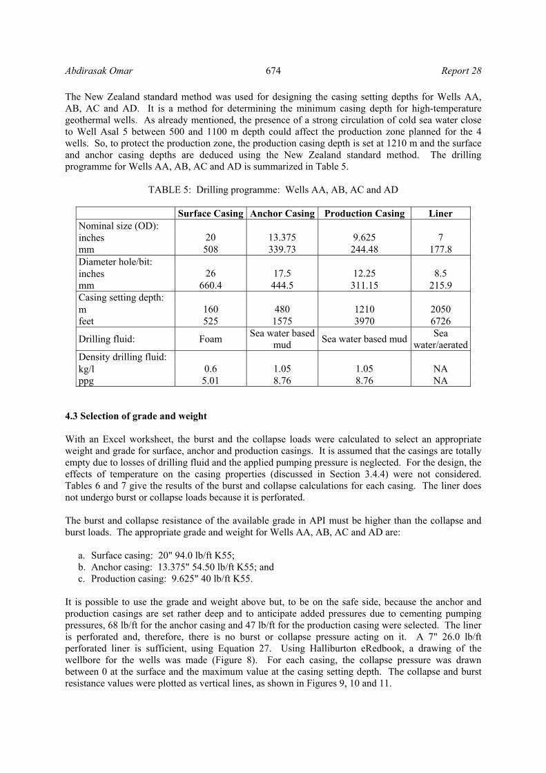
The New Zealand standard method was used for designing the casing setting depths for Wells AA, AB, AC and AD. It is a method for determining the minimum casing depth for high-temperature geothermal wells. As already mentioned, the presence of a strong circulation of cold sea water close to Well Asal 5 between 500 and 1100 m depth could affect the production zone planned for the 4 wells. So, to protect the production zone, the production casing depth is set at 1210 m and the surface and anchor casing depths are deduced using the New Zealand standard method. The drilling programme for Wells AA, AB, AC and AD is summarized in Table 5.
TABLE 5: Drilling programme: Wells AA, AB, AC and AD
Surface Casing Anchor Casing Production Casing Liner Nominal size (OD):
20
13.375
9.625
7 inches mm 508 339.73 244.48 177.8 Diameter hole/bit:
26
17.5
12.25
8.5 inches mm 660.4 444.5 311.15 215.9 Casing setting depth:
160
480
1210
2050 m feet 525 1575 3970 6726
Drilling fluid: Foam Sea water based
mud Sea water based mud
Sea water/aerated
Density drilling fluid: 0.6
1.05
1.05
NA kg/l
ppg 5.01 8.76 8.76 NA
4.3 Selection of grade and weight With an Excel worksheet, the burst and the collapse loads were calculated to select an appropriate weight and grade for surface, anchor and production casings. It is assumed that the casings are totally empty due to losses of drilling fluid and the applied pumping pressure is neglected. For the design, the effects of temperature on the casing properties (discussed in Section 3.4.4) were not considered. Tables 6 and 7 give the results of the burst and collapse calculations for each casing. The liner does not undergo burst or collapse loads because it is perforated. The burst and collapse resistance of the available grade in API must be higher than the collapse and burst loads. The appropriate grade and weight for Wells AA, AB, AC and AD are:
a. Surface casing: 20" 94.0 lb/ft K55; b. Anchor casing: 13.375" 54.50 lb/ft K55; and c. Production casing: 9.625" 40 lb/ft K55.
It is possible to use the grade and weight above but, to be on the safe side, because the anchor and production casings are set rather deep and to anticipate added pressures due to cementing pumping pressures, 68 lb/ft for the anchor casing and 47 lb/ft for the production casing were selected. The liner is perforated and, therefore, there is no burst or collapse pressure acting on it. A 7" 26.0 lb/ft perforated liner is sufficient, using Equation 27. Using Halliburton eRedbook, a drawing of the wellbore for the wells was made (Figure 8). For each casing, the collapse pressure was drawn between 0 at the surface and the maximum value at the casing setting depth. The collapse and burst resistance values were plotted as vertical lines, as shown in Figures 9, 10 and 11.

Report 28 675 Abdirasak Omar
TABLE 6: Results of burst pressure calculations for each casing
Surface casing CSD 160.00 m 524.93 ft Next hole total depth 480.00 m 1574.80 ft Height of cement column inside casing 76.57 m 251.20 ft Height of water column inside casing 83.43 m 273.73 ft Density of current drilling mud 0.60 kg/l 5.01 ppg Density of displacement fluid 1.00 kg/l 8.35 ppg Density of cement (class G) 1.90 kg/l 15.86 ppg Gas density at NHTD 0.0005 kg/l 0.00442 ppg Gradient of salt-saturation 0.105 bar/m 0.465 psi/mForce of gravity 0.0981 Applied pumping pressure 14.13 bar 204.89 psi Hydrostatic pressure at NHTD 29.00 bar 420.62 psi Burst at surface 28.98 bar 420.25 psi Burst at surface by safety factor 1.5 43.46 bar 630.38 psi Pe at surface 0 bar 0 psi Pi at surface 28.98 bar 420.25 psi Burst at shoe 19.78 bar 286.92 psi Burst at shoe by safety factor 29.67 bar 430.39 psi Pe at shoe 16.80 bar 243.67 psi Pi at shoe 36.58 bar 530.59 psi Calculation of height of water and cement inside the casing Capacity of cylinder 20" 202.70 l/m Capacity of surface casing 20" 32432 l 32.43 m3 Volume of slurry 38800 l 38.80 m3 60% freshwater 23280 l 23.28 m3 40% cement (class G) 15520 l 15.52 m3 Anchor casing CSD 480 m 1574.80 ft Next hole total depth 1210 m 3969.82 ft Height of cement column inside casing 218.33 m 716.31 ft Height of water column inside casing 261.67 m 858.49 ft Density of current drilling mud 1.05 kg/l 8.76 ppg Gas density at NHTD 0.005 kg/l 0.04173 ppg Applied pumping pressure 42.38 bar 614.67 psi Hydrostatic pressure at NHTD 92.00 bar 1334.37 psi Burst at surface 91.41 bar 1325.76 psi Burst at surface by safety factor 1.5 137.11 bar 1988.64 psi Pe at surface 0.00 bar 0.00 psi Pi at surface 91.41 bar 1325.76 psi Burst at shoe 58.34 bar 846.22 psi Burst at shoe by safety factor 87.52 bar 1269.33 psi Pe at shoe 50.40 bar 731.00 psi Pi at shoe 108.74 bar 1577.22 psi Calculated height of water and cement inside the casing Capacity of cylinder 13.375" 90.64 l/m Capacity of anchor casing 13.375" 43507.20 l 43.51 m3 Volume of slurry 49474.00 l 49.47 m3 60% freshwater 29684.40 l 29.68 m3 40% cement (class G) 19789.60 l 19.79 m3
Abdirasak Omar 676 Report 28
TABLE 6 cont.: Results of burst pressure calculations for each casing
Production casing CSD 1210 m 3969.82 ft Next hole total depth 2050 m 6725.72 ft Height of cement column inside casing 454.16 m 1490.04 ft Height of water column inside casing 755.84 m 2479.78 ft Density of current drilling mud 1.05 kg/l 8.76 ppg Gas density at NHTD 0.0565 kg/l 0.47150 ppg Applied pumping pressure 106.83 bar 1549.48 psi Hydrostatic pressure at NHTD 158.20 bar 2294.55 psi Burst at surface 146.84 bar 2129.75 psi Burst at surface by safety factor 1.5 220.26 bar 3194.62 psi Pe at surface 0 bar 0 psi Pi at surface 146.84 bar 2129.75 psi Burst at shoe 138.58 bar 2009.96 psi Burst at shoe by safety factor 207.87 bar 3014.94 psi Pe at shoe 127.05 bar 1842.73 psi Pi at shoe 265.63 bar 3852.70 psi Calculated height of water and cement inside the casing Capacity of cylinder 9.625" 46.94 l/m Capacity of anchor casing 9.625" 56797.40 l 56.80 m3 Volume of slurry 53296.00 l 53.30 m3 60% freshwater 31977.60 l 31.98 m3 40% cement (class G) 21318.40 l 21.32 m3
TABLE 7: Results of collapse pressure calculations for each casing
Surface casing Collapse pressure during running of the casing Collapse at surface 0 bar 0 psi Collapse at shoe 9.42 bar 136.59 psi Collapse at shoe by safety factor 1.2 11.30 bar 163.91 psi Pe at shoe 9.42 bar 136.59 psi Pi at shoe 0 bar 0 psi Collapse pressure after running the casing Collapse at surface 0 bar 0 psi Collapse at shoe 14.13 bar 204.89 psi Collapse at shoe by safety factor 1.2 16.95 bar 245.87 psi Pe at shoe 29.82 bar 432.54 psi Pi at shoe 15.70 bar 227.65 psi Anchor casing Collapse pressure during running of the casing Collapse at surface 0 bar 0 psi Collapse at shoe 49.44 bar 717.11 psi Collapse at shoe by safety factor 1.2 59.33 bar 860.54 psi Pe at shoe 49.44 bar 717.11 psi Pi at shoe 0 bar 0 psi Collapse pressure after running the casing Collapse at surface 0 bar 0 psi Collapse at shoe 42.38 bar 614.67 psi Collapse at shoe by safety factor 1.2 50.86 bar 737.60 psi Pe at shoe 89.47 bar 1297.63 psi Pi at shoe 47.09 bar 682.96 psi

Report 28 677 Abdirasak Omar
TABLE 7 cont.: Results of collapse pressure calculations for each casing
Production casing Collapse pressure during running the casing Collapse at surface 0 bar 0 psi Collapse at shoe 124.64 bar 1807.72 psi Collapse at shoe by safety factor 1.2 149.56 bar 2169.27 psi Pe at shoe 124.64 bar 1807.72 psi Pi at shoe 0 bar 0 psi Collapse pressure after running the casing Collapse at surface 0 bar 0 psi Collapse at shoe 106.83 bar 1549.48 psi Collapse at shoe by safety factor 1.2 128.20 bar 1859.37 psi Pe at shoe 225.53 bar 3271.11 psi Pi at shoe 118.70 bar 1721.64 psi
For hydrostatic pressure at each section see Section 6, Table 10
FIGURE 8 : Wellbore schematic, Fiale area

Abdirasak Omar 678 Report 28
FIGURE 9: 20" casing design
FIGURE 10: 13⅜" casing design
FIGURE 11: 9⅝" casing design
0
20
40
60
80
100
120
140
160
180
0 20 40 60 80 100 120 140 160D
epth
(m
)
Pressure (bar)
Burst pressure Collapse/mud
Collapse/cement K55 94.0 lb/ft, collapse resistance
K55 94.0 lb/ft, internal yield pressure
050
100150200250300350400450500550
0 50 100 150 200 250
Dep
th (
m)
Pressure (bar)
Burst pressure Collapse/mud
Collapse/cement K55 68 lb/ft, collapse resistance
K55 68.0 lb/ft, internal yield pressure
0100200300400500600700800900
1000110012001300
0 50 100 150 200 250 300 350
Dep
th (
m)
Pressure (bar)
Burst pressure Collapse/mud
Collapse/cement K55 47.0 lb/ft, collapse resistance
K55 47.0 lb/ft, internal yield pressure

Report 28 679 Abdirasak Omar
4.4 Casing design in deviated Wells AA, AB, AC and AD From the sections above, the general method for casing design was applied to directional wells by simply converting the measured depth (MD) to true vertical depth. The collapse, burst and tension criteria were then applied and the appropriate casing grades were selected. Finally, in the deviated sections of the well, the vertical lengths of selected grades were converted to the measured depth (MD) lengths by simply dividing the vertical depth by cos(angle of deviation) (see Appendix II, which shows the well trajectories). Basic design data: Kick off point for Wells AA, AB, AC and AD = 480 m; Deviation angle = 30°; TVD = 2050 m; and Measured depth (MD) = 2250 m. The selection of grade and weight provides the basis for checking for tension. The tensile loads are to be included in the design of the casings string. In Table 8, the total tensile load and the safety factor for each section were determined to assure that the safety factor for the tension loads was equal or above 1.5 – 1.8. The entire volume of cement is outside the casing and the casing inside is full of displacement fluid. When the casing is cemented, the effects of shock loading disappear; therefore, a safety factor of 1.4 in tension in the production section could be tolerated. Table 9 shows the compressive loads on the casing due to thermal expansion during heat-up.
TABLE 8: Tensile loads
Selected grade and weight
Max. buoyant weight in 1000 daN
Bending force in
1000 daN
Shock load in
1000 daN
Lifting force due to wellhead
pressure in 1000 daN
Force due to pressure testing in 1000 daN
Total tensile load in
1000 daN
Safety factor
Surface casing 20" 94.0 lb/ft K55
19.2 133.8 161.3 314.1 2.1
Anchor casing 13.375" 68.0 lb/ft K55
41.6 96.8 36.4 125.84 300.2 1.6
Production casing 9.625" 47.0 lb/ft K55
72.5 31.71 66.9 68.8 239.9 1.4
TABLE 9: Compressive loads due to thermal expansion during heating-up
Surface casing Anchor casing Production casing
Compressive loads in 1000 daN 156 352 508 Biaxial correction is resolved using an equation from the Viking Engineering programme (Appendix IV) for reducing the collapse rating in the presence of axial tension. The collapse resistance of the casing in the presence of axial stress is calculated by reducing the yield strength in accordance to the axial stress, giving: Surface casing: 20 " 94.0 lb/ft K55 Axial stress = 1599.5 psi Reduced yield strength due to axial stress: 54.2 ksi Reduced collapse pressure: 520 psi Anchor casing: 13.375 " 54.50 lb/ft K55 Axial stress = 4804.4 psi Reduced yield strength due to axial stress: 52.4 ksi

Abdirasak Omar 680 Report 28
Reduced collapse pressure: 1900 psi Production casing: 9.625 " 40 lb/ft K55 Axial stress = 11096 psi Reduced yield strength due to axial stress: 48.6ksi Reduced collapse pressure: 3600 psi. 5. CEMENTING PROCESS In this section, the cement job for each casing will be calculated. The casings of Wells AA, AB, AC, and AD will be cemented in place with a single-stage cementing operation with a cementing head (single-stage cementing), which is the most common type of cementing operation when there is no loss of circulation (Bett, 2010). Other common cementing methods in geothermal wells can be used such as multiple-stage and inner-string cementing. The single-stage procedure follows the following steps (Figure 12):
a. Installation of the cementing head; b. Cleaning out the mud in the annulus; c. Release wiper plug, to clean the inside of the casing and to maintain the spacer front; d. Pump spacer into the casing; e. Pump cement; f. Release shut-off plug; and g. Stop the displacement process when the plug reaches the float collar.
FIGURE 12: Single-stage cementing operation

Report 28 681 Abdirasak Omar
5.1 Cementing calculations for Asal Wells AA, AB, AC and AD All casings are fully cemented back to the surface. For each casing, the total slurry volume is the sum of four volumes: slurry volume between the casing and the open hole, slurry volume left inside the casing below the float collar, slurry volume in the rathole, and slurry volume in the annulus between the casing and the previous casing (Figure 12). The duration of the operation can be calculated using a displacement rate of 24 l/s and a mixing and pumping rate of 20 l/s (Thórhallsson, 2013). Conductor casing, 30" V = Volume of an annular space between open hole (28") and conductor casing: Slurry 0.4 m3 Plus 60% excess 0.64 m3 Surface casing: 20" 94.0 lb/ft K55 Casing 20" 94.0 lb/ft K55 Capacity 185.32 l/m Displacement 202.68 l/m CSD 160 m
Open hole 26" Capacity 342.5 l/m Depth of open hole 156 m
Previous casing 30" Capacity 456 l/m Previous CSD 2 m
Rathole Depth of rathole 2 m Capacity 342.5 l/m
a. Slurry volume between casing and hole: V1 = Depth of open hole × (Capacity of open hole (26") - Casing displacement (20")) = 22 m3. Assume gauge hole, add 60% excess in open hole, V1 = 35 m3.
b. Slurry volume in the rathole: V2 = Depth of rathole × Capacity of open hole (26") = 0.7 m3. Assume gauge hole, add 60% excess in open hole, V2 = 1.1 m3.
c. Slurry volume below the float collar, shoe track: V3 = Depth of shoe track (10 m) × Casing capacity (20") = 1.85 m3.
d. Slurry volume between casing: V4 = Depth of previous casing × (Casing capacity 26" - Casing displacement 20")) = 0.51 m3.
The total cement required for the surface casing is 38.8 m3. The duration of the cementing operation is given by:
DurationSlurryvolume
Pumpingandmixing rateDisplacement volumeDisplacement rate
Contigency 1hr (44)
The displacement volume is the slurry volume inside the casing between the cementing head and the float collar. Therefore, the displacement volume is calculated from the volumetric capacity of the casing and the depth of the float collar in the casing (volumetric capacity of casing × depth of float collar).
e. Displacement volume = (150+12 (depth landing joint)) × 185.32 l/m = 30.02 m3. f. Duration of operation = 113 minutes.
Anchor casing: 13.375" 54.50 lb/ft K55

Abdirasak Omar 682 Report 28
Casing 13.375" 68.0 lb/ft K55 Capacity 78.1 l/m Displacement 90.65 l/m CSD 480 m
Open hole 17.5" Capacity 155.2 l/m Depth of open hole 318 m
Previous casing 20" Capacity 185.32 l/m Displacement 202.68 l/m Previous CSD 160 m
Rathole Depth of rathole 2 m Capacity 155.2 l/m
a. Slurry volume between casing and open hole:
V1 = Depth of open hole × (Capacity open hole (17.5") - Casing displacement (13.375")) = 21 m3. Assume gauge hole, add 60% excess in open hole, V1 = 33 m3.
b. Slurry volume in the rathole: V2 = Depth of rathole × Capacity of open hole (17.5") = 0.3 m3. Assume gauge hole, add 60% excess in open hole, V2 = 0.5 m3.
c. Slurry volume below the float collar, shoe track: V3 = Depth of shoe track (10 m) × Casing capacity (13.375") = 0.78 m3.
d. Slurry volume between casing: V4 = Depth of previous casing × (Casing capacity 20" - Casing displacement 13.375")) = 15.15 m3. The total cement required for the anchor casing is 49.5 .
e. Displacement volume = (470+12 (depth landing joint)) × 78.1 l/m = 37.64 m3. f. Duration of operation = 127 minutes.
Production casing 9.625" 47 lb/ft K55 Casing 9.625" 68.0 lb/ft K55 Capacity 38.19 l/m Displacement 46.94 l/m CSD (=length) 1290 m
Open hole 12.25" Capacity 76.04 l/m Depth of open hole 808 m
Previous casing 13.375" Capacity 78.1 l/m Displacement 90.65 l/m Previous CSD 480 m
Rathole Depth of rathole 2 m Capacity 76.04 l/m
a. Slurry volume between casing and open hole:
V1 = Depth of open hole × (capacity of open hole (12.25") - casing displacement (9.625")) = 24 m3. Assume gauge hole, add 60% excess in open hole, V1 = 38 m3.
b. Slurry volume in the rathole: V2 = Depth of rathole × capacity of open hole (12.25") = 0.15 m3. Assume gauge hole, add 60% excess in open hole, V2 = 0.24 m3.
c. Slurry volume below the float collar, shoe track: V3 = Depth of shoe track (10 m) × casing capacity (9.625") = 0.4 m3.
d. Slurry volume between casing: V4 = Depth of previous casing × (casing capacity 13.375" - casing displacement 9.625")) = 15 m3. The total cement required for production casing is 53 m3.
e. Displacement volume = (1280+12 (depth landing joint)) × 38.19 l/m = 49 m3. f. Duration of operation = 139 minutes.
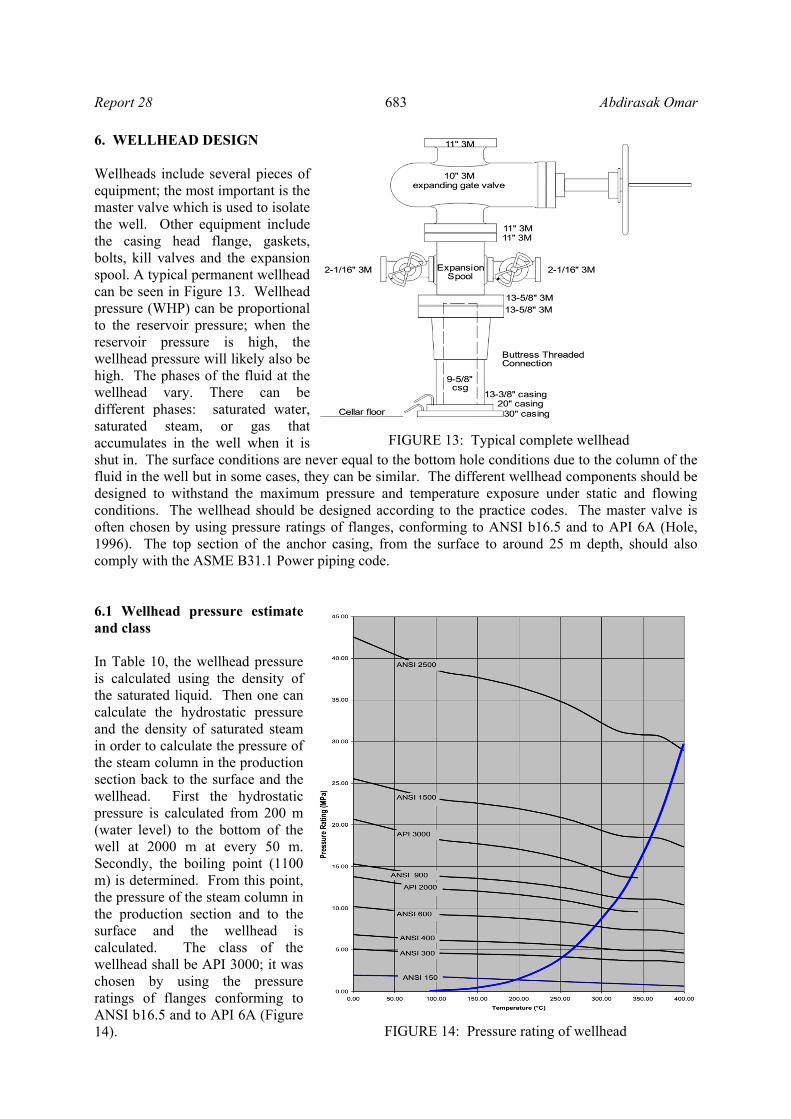
Report 28 683 Abdirasak Omar
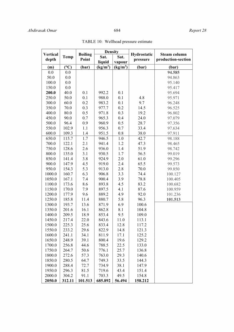
6. WELLHEAD DESIGN Wellheads include several pieces of equipment; the most important is the master valve which is used to isolate the well. Other equipment include the casing head flange, gaskets, bolts, kill valves and the expansion spool. A typical permanent wellhead can be seen in Figure 13. Wellhead pressure (WHP) can be proportional to the reservoir pressure; when the reservoir pressure is high, the wellhead pressure will likely also be high. The phases of the fluid at the wellhead vary. There can be different phases: saturated water, saturated steam, or gas that accumulates in the well when it is shut in. The surface conditions are never equal to the bottom hole conditions due to the column of the fluid in the well but in some cases, they can be similar. The different wellhead components should be designed to withstand the maximum pressure and temperature exposure under static and flowing conditions. The wellhead should be designed according to the practice codes. The master valve is often chosen by using pressure ratings of flanges, conforming to ANSI b16.5 and to API 6A (Hole, 1996). The top section of the anchor casing, from the surface to around 25 m depth, should also comply with the ASME B31.1 Power piping code. 6.1 Wellhead pressure estimate and class In Table 10, the wellhead pressure is calculated using the density of the saturated liquid. Then one can calculate the hydrostatic pressure and the density of saturated steam in order to calculate the pressure of the steam column in the production section back to the surface and the wellhead. First the hydrostatic pressure is calculated from 200 m (water level) to the bottom of the well at 2000 m at every 50 m. Secondly, the boiling point (1100 m) is determined. From this point, the pressure of the steam column in the production section and to the surface and the wellhead is calculated. The class of the wellhead shall be API 3000; it was chosen by using the pressure ratings of flanges conforming to ANSI b16.5 and to API 6A (Figure 14).
FIGURE 13: Typical complete wellhead
FIGURE 14: Pressure rating of wellhead
Abdirasak Omar 684 Report 28
TABLE 10: Wellhead pressure estimate
Vertical depth
Temp Boiling Point
Density Hydrostatic
pressure Steam column
production-section Sat.
liquid Sat.
vapour(m) (°C) (bar) (kg/m3) (kg/m3) (bar) (bar) 0.0 0.0 94.585
50.0 0.0 94.863 100.0 0.0 95.140 150.0 0.0 95.417 200.0 40.0 0.1 992.2 0.1 95.694 250.0 50.0 0.1 988.0 0.1 4.8 95.971 300.0 60.0 0.2 983.2 0.1 9.7 96.248 350.0 70.0 0.3 977.7 0.2 14.5 96.525 400.0 80.0 0.5 971.8 0.3 19.2 96.802 450.0 90.0 0.7 965.3 0.4 24.0 97.079 500.0 96.4 0.9 960.9 0.5 28.7 97.356 550.0 102.9 1.1 956.3 0.7 33.4 97.634 600.0 109.3 1.4 951.5 0.8 38.0 97.911 650.0 115.7 1.7 946.5 1.0 42.7 98.188 700.0 122.1 2.1 941.4 1.2 47.3 98.465 750.0 128.6 2.6 936.0 1.4 51.9 98.742 800.0 135.0 3.1 930.5 1.7 56.5 99.019 850.0 141.4 3.8 924.9 2.0 61.0 99.296 900.0 147.9 4.5 919.0 2.4 65.5 99.573 950.0 154.3 5.3 913.0 2.8 70.0 99.850
1000.0 160.7 6.3 906.8 3.3 74.4 100.127 1050.0 167.1 7.4 900.4 3.9 78.8 100.405 1100.0 173.6 8.6 893.8 4.5 83.2 100.682 1150.0 170.0 7.9 897.5 4.1 87.6 100.959 1200.0 177.9 9.6 889.2 4.9 92.0 101.236 1250.0 185.8 11.4 880.7 5.8 96.3 101.513 1300.0 193.7 13.6 871.9 6.9 100.6 1350.0 201.6 16.1 862.8 8.1 104.8 1400.0 209.5 18.9 853.4 9.5 109.0 1450.0 217.4 22.0 843.6 11.0 113.1 1500.0 225.3 25.6 833.4 12.8 117.2 1550.0 233.2 29.6 822.9 14.8 121.3 1600.0 241.1 34.1 811.9 17.1 125.2 1650.0 248.9 39.1 800.4 19.6 129.2 1700.0 256.8 44.6 788.5 22.5 133.0 1750.0 264.7 50.6 776.1 25.7 136.8 1800.0 272.6 57.3 763.0 29.3 140.6 1850.0 280.5 64.7 749.3 33.5 144.3 1900.0 288.4 72.7 734.9 38.1 147.9 1950.0 296.3 81.5 719.6 43.4 151.4 2000.0 304.2 91.1 703.3 49.5 154.8 2050.0 312.11 101.513 685.892 56.494 158.212

Report 28 685 Abdirasak Omar
7. CONCLUSIONS The casing programme is vital to the success and safety of the well drilling process and to the integrity and life of the well. The design of Wells AA, AB, AC and AD was oversized to avoid any risk. After drilling the first well, the first useful geotechnical data for the new drilling site will be available; then the design of the other three wells can be optimized.
Generally, drilling can be done with foam or mud. The choice of drilling fluid will depend on the geology and the surrounding terrain. In the Fiale area, it is most likely that the drilling fluid used will consist of seawater based drilling mud. But in the production section, using aerated drilling should be considered because of possible low permeability.
AKNOWLEDGEMENTS
I would first like to thank my supervisor, Arnar Bjarki Árnason, for teaching me to be more independent throughout this project. I also would like to thank my teachers at UNU-GTP. I especially want to thank Mr. Ingimar Gudni Haraldsson, Ms. Málfrídur Ómarsdóttir, Mr. Markús A. G. Wilde and Ms. Thórhildur Ísberg, all of whom dedicated their time to me during my stay in Iceland. Finally, I express my sincere gratefulness to the now retired director, Dr. Ingvar Birgir Fridleifsson, and the new director, Mr. Lúdvík S. Georgsson.
REFERENCES
Aquater, 1989: Asal 5 well report - final report. Aquater, Italy, 64 pp. Árnason, K., Björnsson, G., Flóvenz, Ó.G., Haraldsson, E.H., 1988: Geothermal resistivity survey in the Asal rift, volume 1: Main text. Orkustofnun, Reykjavík, OS-88031/JHD-05, prepared for the UND-OPS and ISERST, 48 pp. Baker Hughes INTEQ, 1995: Drilling engineering workbook. A distributed learning course. Baker Hughes INTEQ Inc., 410 pp. Bett, E.K., 2010: Geothermal well cementing, materials and placement techniques. Report 10 in: Geothermal training in Iceland 2010. UNU-GTP, Iceland, 99-130. BG Group, 2001: Well engineering and production operations management system – Casing design manual. B.G. Group, document number WSD CD 01, 51 pp. Devereux, S., 1998: Practical well planning and drilling. Pennwell, Oklahoma, OK, United States 524 pp. Elmi, H.D., 2005: Analysis of geothermal well test data from the Asal rift area, Republic of Djibouti. Report 6 in: Geothermal training in Iceland 2005. UNU-GTP, Iceland, 39-59. Gabolde G., and Nguyen, J.P., 2006: Drilling data handbook (8th edition). Institut Française du Petrole Publications, Paris, 552 pp. Heriot-Watt University, 2010: Drilling engineering. Heriot-Watt University, Department of petroleum engineering, 539 pp.
Abdirasak Omar 686 Report 28
Hole, H.M., 1996: Geothermal Energy New Zealand, Ltd. Seminar on Geothermal Drilling Engineering, Jakarta, Indonesia, Seminar handbook. Hossein-Pourazad, H., 2005: High-temperature geothermal well design. Report 9 in: Geothermal training in Iceland 2005. UNU-GTP, Iceland, 111-123. Jalludin, M., 2010: State of knowledge of the geothermal provinces of the Republic of Djibouti. Paper presented at “Short Course V on Exploration for Geothermal Resources” organized by UNU-GTP, KenGen and GDC, Lake Naivasha, Kenya, 14 pp. Khaireh, A.E., 1989: Borehole geology of well Asal-5, Asal geothermal field, Djibouti. UNU-GTP, Iceland, report 6, 31 pp. Meinken, W., and Schülein, S., 2012: Geothermal resources evaluation project Djibouti, environmental and social impacts. Fichtner GmbH and Co., final report, 14 pp. NZS, 1991: Code of practice for deep geothermal wells. Standards New Zealand, NZS 2403:1991, 96 pp. Rabia, H., 1987: Fundamentals of casing design, vol. 1. Graham & Trotham, London, United Kingdom, 285 pp. REI, 2008: Drilling and testing of geothermal exploration wells in the Asal area, Djibouti: Environmental management plan. Reykjavik Energy Invest, report REI-2008/Assal 1, 58 pp. Saemundsson, K., 1988: Djibouti geothermal project. Analysis of geological data pertaining to geothermal exploration of Asal rift. United Nations Development Programme, 18 pp. Stiltjes, L., 1976: Research for a geothermal field in a zone of oceanic spreading: Examples of the Asal Rift. Proceedings of the 2nd UN Symposium on the Development and Use of Geothermal Resources, San Francisco, CA, United States, 1, 613-623. Thórhallsson, S., 2013: Geothermal drilling technology. UNU-GTP, Iceland, unpublished lecture notes. Varet, J., 1978: Geology of central and southern Afar (Ethiopia and Djibouti Republic). Centre Natonal de la Recherche Scientifique, Paris, France, 124 pp. Virkir-Orkint, 1990: Djibouti, geothermal scaling and corrosion study. Virkir-Orkint, Reykjavík, report, 109 pp.
APPENDIX I: API specifications, standards and bulletins
API SPEC 5CT, “Specification for casing a tubing”: Covers seamless and welded casing and tubing, couplings, pup joints and connectors in all grades. Processes of manufacture, chemical and mechanical property requirements, methods of test and dimensions are included. API STD 5B, “Specification for threading, gauging, and thread inspection for casing, tubing, and line pipe threads”: Covers dimensional requirements on threads and thread gauges, stipulations on gauging practice, gauge specifications and certifications, as well as instruments and methods for the inspection of threads of round-thread casing and tubing, buttress thread casing, and extreme-line casing and drill pipe.

Report 28 687 Abdirasak Omar
API RP 5A5, “Recommended practice for filed inspection of new casing, tubing and plain-end drill pipe”: Provides a uniform method of inspecting tubular goods. API RP 5B1, “Recommended practice for thread inspection on casing, tubing and line pipe”: The purpose of this recommended practice is to provide guidance and instructions on the correct use of thread inspection techniques and equipment. API RP 5C1, “Recommended practice for care and use of casing and tubing”: Covers use, transportation, storage, handling, and reconditioning of casing and tubing. API RP5C5, “Recommended practice for evaluation procedures for casing and tubing connections”: Describes tests to be performed to determine the galling tendency, sealing performance and structural integrity of tubular connections. API BULL 5A2, “Bulletin on thread compounds”: Provides material requirements and performance tests for two grades of thread compound for use on oil-field tubular goods.
API BULL 5C2, “Bulletin on performance properties of casing and tubing”: Covers collapsing pressures, internal yield pressures and joint strengths of casing and tubing and minimum yield load for drill pipe. API BULL 5C3, “Bulletin on formulas and calculations for casing, tubing, drill pipe and line pipe properties”: Provides formulas used in the calculations of various pipe properties, also background information regarding their development and use. API BULL 5C4, “Bulletin on round thread casing joint strength with combined internal pressure and bending.” Provides joint strength of round thread casing when subject to combined bending and internal pressure.
APPENDIX II: Calculated hole trajectories for Wells AA, AB, AC and AD Dogleg severity: 2.5 degrees/30 ft., Deviation angle 30 degrees
MD (m)
Inclination(°)
TVD (m)
Displacement (m)
0 0 0 0 30 0 30 0 60 0 60 0 90 0 90 0
120 0 120 0 150 0 150 0 160 0 160 0 180 0 180 0 210 0 210 0 240 0 240 0 270 0 270 0 300 0 300 0 330 0 330 0 360 0 360 0 390 0 390 0 420 0 420 0 450 0 450 0 480 0 480 0

Abdirasak Omar 688 Report 28
MD (m)
Inclination(°)
TVD (m)
Displacement (m)
510 2.5 510.0 0.7 540 5 539.9 2.6 570 7.5 569.8 5.9 600 10 599.4 10.4 630 12.5 628.8 16.3 660 15 658.0 23.4 690 17.5 686.8 31.8 720 20 715.2 41.5 750 22.5 743.1 52.3 780 25 770.6 64.4 810 27.5 797.5 77.7 840 30 823.8 92.1 870 30 849.8 107.1 900 30 875.8 122.1 930 30 901.7 137.1 960 30 927.7 152.1 990 30 953.7 167.1
1020 30 979.7 182.1 1050 30 1005.7 197.1 1080 30 1031.6 212.1 1110 30 1057.6 227.1 1140 30 1083.6 242.1 1170 30 1109.6 257.1 1200 30 1135.6 272.1 1230 30 1161.6 287.1 1260 30 1187.5 302.1 1290 30 1213.5 317.1 1320 30 1239.5 332.1 1350 30 1265.5 347.1 1380 30 1291.5 362.1 1410 30 1317.4 377.1 1440 30 1343.4 392.1 1470 30 1369.4 407.1 1500 30 1395.4 422.1 1530 30 1421.4 437.1 1560 30 1447.3 452.1 1590 30 1473.3 467.1 1620 30 1499.3 482.1 1650 30 1525.3 497.1 1680 30 1551.3 512.1 1710 30 1577.2 527.1 1740 30 1603.2 542.1 1770 30 1629.2 557.1 1800 30 1655.2 572.1 1830 30 1681.2 587.1 1860 30 1707.1 602.1 1890 30 1733.1 617.1 1920 30 1759.1 632.1 1950 30 1785.1 647.1 1980 30 1811.1 662.1 2010 30 1837.1 677.1 2040 30 1863.0 692.1

Report 28 689 Abdirasak Omar
APPENDIX III: Hydrostatic pressure in Well Asal 5
0
500
1000
1500
2000
2500
0 50 100 150 200
Dep
th (
m)
Pressure (bar)
MD (m)
Inclination(°)
TVD (m)
Displacement (m)
2070 30 1889.0 707.1 2100 30 1915.0 722.1 2130 30 1941.0 737.1 2160 30 1967.0 752.1 2190 30 1992.9 767.1 2220 30 2018.9 782.1 2250 30 2050 797.1

Abdirasak Omar 690 Report 28
APPENDIX IV: Reduced collapse resistance, production casing
API Collapse Input D (in) 9,625 Pipe Outside Diameter Weight (lbf/ft) 47 Pipe Weight Per Foot Grade K55 Pipe Grade Yield Strength (ksi) 48,6 Pipe Yield Strength Wall (in) 0,472 Pipe Wall Thickness Nominal ID (in) 8,681 Nominal Inside Diameter
Collapse Resistance (psi) 3600 Calculated Collapse Rating
Collapse Calculations D/t 20,39 A 2,970661 B 0,050525 C 995,6239 F 2,011316 G 0,034209 Yield Strength Collapse (psi) 4480 Collapse Ratings Based on D/t D/t 15,44 Plastic Collapse (psi) 3570 Collapse Ratings Based on D/t D/t 25,89 Transition Collapse (psi) 3090 Collapse Ratings Based on D/t D/t 39,53 Elastic Collapse (psi) 6130 Collapse Ratings Based on D/t This calculator calculates API collapse resistance for a specific pipe.