Embed Size (px)
Citation preview
GEOTHERMAL RESERVOIR MANAGEMENT TECHNOLOGY AND PROBLEM AREAS
Pierre Ungemach
GEOPRODUCTION CONSULTANTS (GPC)
Paris Nord 2, 14, rue de la Perdrix, Lot 109, B.P. 50030 95946 ROISSY CDG CEDEX, FRANCE
E-mail: [email protected]
ABSTRACT This paper focuses on the technology and problem areas related to the management
of low enthalpy geothermal reservoirs dedicated to direct uses, chiefly space and district heating.
Accordingly it reviews the headings, deemed the most sensitive, itemised below: - well drilling and completion - well restoration and workover - production and injection technology - corrosion and scaling thermochemical shortcomings - risk assessment - sustainable reservoir development. The latter, indeed a key issue, is illustrated by the reservoir simulation of two 50 year
projected development scenarios in view of investigating well longevities and reservoir life.
1. INTRODUCTION Once a geothermal resource has been identified and the reservoir assessed, leading to
a conceptual model of the geothermal system, reservoir development and relevant management issues come into play.
In the broad sense, reservoir management is an extension of reservoir engineering. Whereas the latter addresses key issues such as heat in place, reservoir performance, well deliverabilities, heat recovery, water injection and reservoir life, reservoir management aims at optimised exploitation strategies in compliance with technical feasibility, economic viability and environmental safety requirements.
Reservoir management involves also resource management, a matter raising growing interest in the perspective of sustainable development of alternative, preferably renewable, energy sources as highlighted by the debate on Global Warming/Climatic Changes and recommendations of the recent World Environmental Summits (Kyoto Protocol) reducing greenhouse gas emissions.
The foregoing arise the crucial question on whether geothermal heat is a renewable energy source. It is not, at human time scale, for the simple reason that the heat is abstracted from the reservoir via convection and resupplied by conduction.
Hence longevity of heat mining should be sought through properly balanced production schedules and designed water injection strategies in order to achieve sustainability, a concept defined in practical terms as the ability of a heat mining scheme to secure production over very long times [1]. This is indeed a challenging accomplishment, in which reservoir/resource management takes an important share.
It requires an integrated approach of the most sensitive problems areas encountered during early reservoir development stages to be performed, alongside a thorough analysis of
1
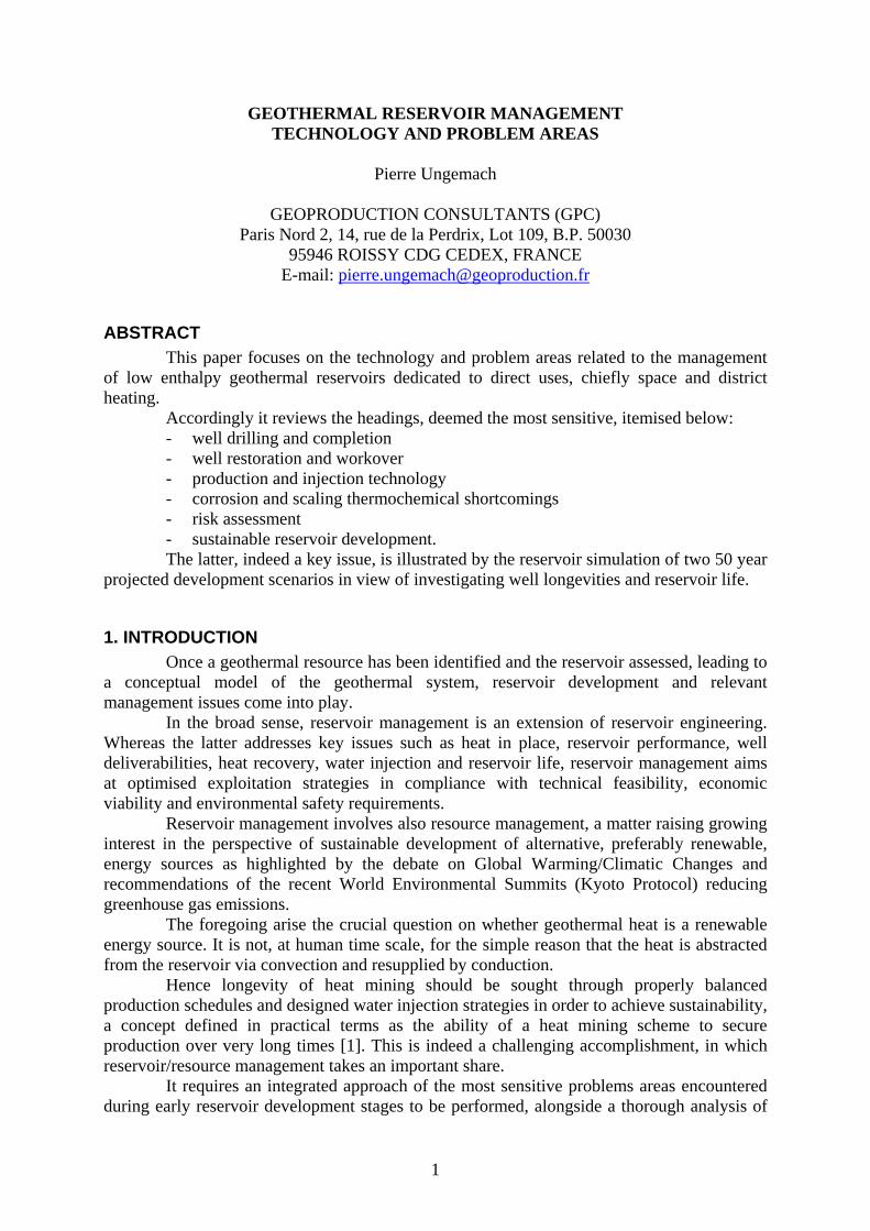
related exploitation risks. Those should ultimately allow to assess, in the light of sustainability i.e. long term issues, the relevance of several candidate development scenarios ad associated mining schemes, implemented via adequate reservoir simulation codes, according to the rationale sketched in fig. 1 flowchart.
Accordingly, the problems addressing sensitive headings such as (i) well drilling and completion, (ii) maintenance and workover, (iii) production/injection technologies, (iv) thermochemical (corrosion/scaling) shortcomings, (v) risk assessments and system lifetimes will be reviewed through case studies and records borrowed chiefly to the low enthalpy Paris Basin reservoir, exploited since the early 1970s for the supply of geothermal heat from district heating doublets.
The survey which benefits from a considerable field expertise, will be concluded by the simulation, over a seventy five year life, of prospective geothermal district heating development scenarios and selected production/injection well arrays.
The reservoir and exploitation features are highlighted in a second paper [2 ].
DEVELOPMENT/MANAGEMENT
STRATEGY
SUSTAINABILITY
EXTERNALITIES
OFFERRecoverable
Heat
DEMANDExisting/potential
heat loads
RISKASSESSMENT
ECONOMIC/FINANCIAL/
INSTITUTIONAL/ENVIRONMENTAL
Non TechnicalObstacles
ECONOMICSRESERVOIR/SYSTEM LIFE
RESERVOIRENGINEERING
PRODUCTIONTECHNOLOGY
Figure 1: Reservoir management diagram
2. WELL DRILLING AND COMPLETION
2.1 General Owing to depths and flowrates targeted at ca. 1500/2000 m and 200/250 m3/h
respectively, geothermal drilling technology/machinery and attached services in low enthalpy environments conform to oil and gas drilling standards, thus requiring a heavy duty (150/250 t hook load) rig force.
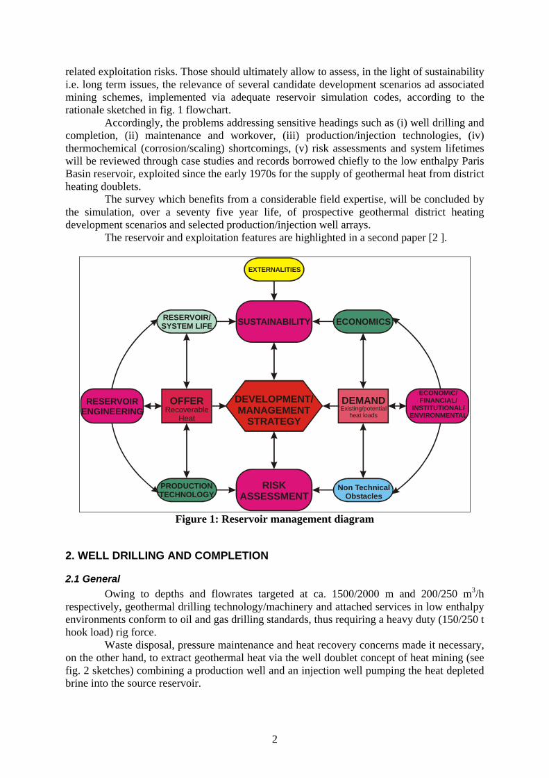
Waste disposal, pressure maintenance and heat recovery concerns made it necessary, on the other hand, to extract geothermal heat via the well doublet concept of heat mining (see fig. 2 sketches) combining a production well and an injection well pumping the heat depleted brine into the source reservoir.
2
Here, the consolidated nature of the carbonate host rocks did not require any completion whatsoever, the wells being produced and injected in openhole.
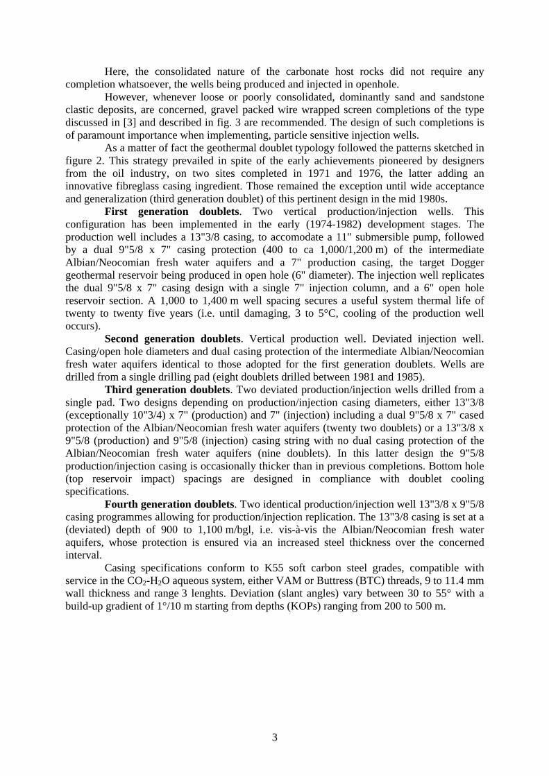
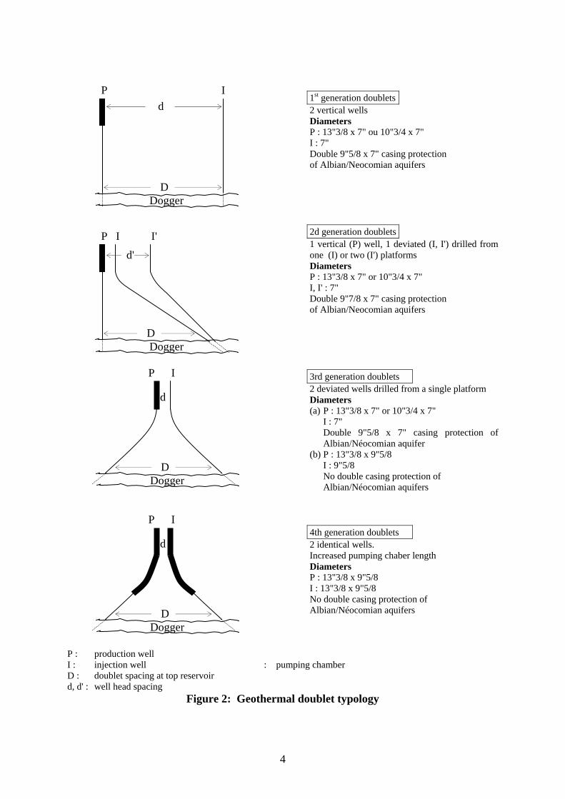
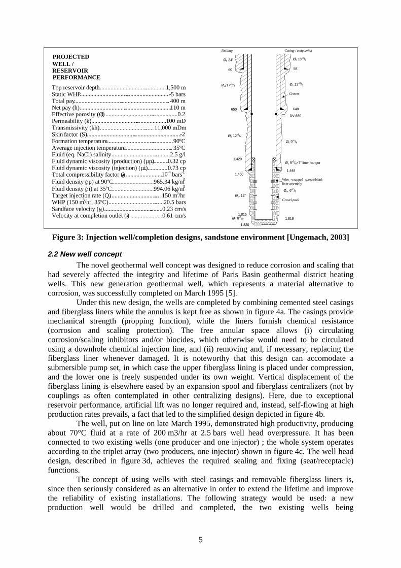
However, whenever loose or poorly consolidated, dominantly sand and sandstone clastic deposits, are concerned, gravel packed wire wrapped screen completions of the type discussed in [3] and described in fig. 3 are recommended. The design of such completions is of paramount importance when implementing, particle sensitive injection wells.
As a matter of fact the geothermal doublet typology followed the patterns sketched in figure 2. This strategy prevailed in spite of the early achievements pioneered by designers from the oil industry, on two sites completed in 1971 and 1976, the latter adding an innovative fibreglass casing ingredient. Those remained the exception until wide acceptance and generalization (third generation doublet) of this pertinent design in the mid 1980s.
First generation doublets. Two vertical production/injection wells. This configuration has been implemented in the early (1974-1982) development stages. The production well includes a 13"3/8 casing, to accomodate a 11" submersible pump, followed by a dual 9"5/8 x 7" casing protection (400 to ca 1,000/1,200 m) of the intermediate Albian/Neocomian fresh water aquifers and a 7" production casing, the target Dogger geothermal reservoir being produced in open hole (6" diameter). The injection well replicates the dual 9"5/8 x 7" casing design with a single 7" injection column, and a 6" open hole reservoir section. A 1,000 to 1,400 m well spacing secures a useful system thermal life of twenty to twenty five years (i.e. until damaging, 3 to 5°C, cooling of the production well occurs).
Second generation doublets. Vertical production well. Deviated injection well. Casing/open hole diameters and dual casing protection of the intermediate Albian/Neocomian fresh water aquifers identical to those adopted for the first generation doublets. Wells are drilled from a single drilling pad (eight doublets drilled between 1981 and 1985).
Third generation doublets. Two deviated production/injection wells drilled from a single pad. Two designs depending on production/injection casing diameters, either 13"3/8 (exceptionally 10"3/4) x 7" (production) and 7" (injection) including a dual 9"5/8 x 7" cased protection of the Albian/Neocomian fresh water aquifers (twenty two doublets) or a 13"3/8 x 9"5/8 (production) and 9"5/8 (injection) casing string with no dual casing protection of the Albian/Neocomian fresh water aquifers (nine doublets). In this latter design the 9"5/8 production/injection casing is occasionally thicker than in previous completions. Bottom hole (top reservoir impact) spacings are designed in compliance with doublet cooling specifications.
Fourth generation doublets. Two identical production/injection well 13"3/8 x 9"5/8 casing programmes allowing for production/injection replication. The 13"3/8 casing is set at a (deviated) depth of 900 to 1,100 m/bgl, i.e. vis-à-vis the Albian/Neocomian fresh water aquifers, whose protection is ensured via an increased steel thickness over the concerned interval.
Casing specifications conform to K55 soft carbon steel grades, compatible with service in the CO2-H2O aqueous system, either VAM or Buttress (BTC) threads, 9 to 11.4 mm wall thickness and range 3 lenghts. Deviation (slant angles) vary between 30 to 55° with a build-up gradient of 1°/10 m starting from depths (KOPs) ranging from 200 to 500 m.
3
Dogger
P I
d'
D
I'
Dogger
P I
d
D
Dogger
P I
d
D
Dogger
P I d
D
1st generation doublets 2 vertical wells Diameters P : 13"3/8 x 7" ou 10"3/4 x 7" I : 7" Double 9"5/8 x 7" casing protection of Albian/Neocomian aquifers 2d generation doublets 1 vertical (P) well, 1 deviated (I, I') drilled from one (I) or two (I') platforms Diameters P : 13"3/8 x 7" or 10"3/4 x 7" I, I' : 7" Double 9"7/8 x 7" casing protection of Albian/Neocomian aquifers 3rd generation doublets 2 deviated wells drilled from a single platform Diameters (a) P : 13"3/8 x 7" or 10"3/4 x 7" I : 7" Double 9"5/8 x 7" casing protection of
Albian/Néocomian aquifer (b) P : 13"3/8 x 9"5/8 I : 9"5/8 No double casing protection of Albian/Néocomian aquifers 4th generation doublets 2 identical wells. Increased pumping chaber length Diameters P : 13"3/8 x 9"5/8 I : 13"3/8 x 9"5/8 No double casing protection of Albian/Néocomian aquifers
P : production well I : injection well z : pumping chamber D : doublet spacing at top reservoir d, d' : well head spacing
Figure 2: Geothermal doublet typology
4
60
650
1,420
1,450
1,815
1,820
1,816
1,448
648
DV 660
58
Ød 24”
Ød 17”1/2
Ød 12”1/4
Øur 12”
Øc 18”5/8
Øc 13”3/8
Øc 9”5/8
Øc 9”5/8×7” liner hanger
Øsc 6”5/8
Ød 8”1/2
Drilling Casing / completion
Cement
Gravel pack
Wire wrapped screen/blankliner assembly
WELL / PROJECTED
RESERVOIR PERFORMANCE
Figure 3: Injection well/completion designs, sandstone environment [Ungemach, 2003]
2.2 New well concept The novel geothermal well concept was designed to reduce corrosion and scaling that
had severely affected the integrity and lifetime of Paris Basin geothermal district heating wells. This new generation geothermal well, which represents a material alternative to corrosion, was successfully completed on March 1995 [5].
Under this new design, the wells are completed by combining cemented steel casings and fiberglass liners while the annulus is kept free as shown in figure 4a. The casings provide mechanical strength (propping function), while the liners furnish chemical resistance (corrosion and scaling protection). The free annular space allows (i) circulating corrosion/scaling inhibitors and/or biocides, which otherwise would need to be circulated using a downhole chemical injection line, and (ii) removing and, if necessary, replacing the fiberglass liner whenever damaged. It is noteworthy that this design can accomodate a submersible pump set, in which case the upper fiberglass lining is placed under compression, and the lower one is freely suspended under its own weight. Vertical displacement of the fiberglass lining is elsewhere eased by an expansion spool and fiberglass centralizers (not by couplings as often contemplated in other centralizing designs). Here, due to exceptional reservoir performance, artificial lift was no longer required and, instead, self-flowing at high production rates prevails, a fact that led to the simplified design depicted in figure 4b.
The well, put on line on late March 1995, demonstrated high productivity, producing about 70°C fluid at a rate of 200 m3/hr at 2.5 bars well head overpressure. It has been connected to two existing wells (one producer and one injector) ; the whole system operates according to the triplet array (two producers, one injector) shown in figure 4c. The well head design, described in figure 3d, achieves the required sealing and fixing (seat/receptacle) functions.
The concept of using wells with steel casings and removable fiberglass liners is, since then seriously considered as an alternative in order to extend the lifetime and improve the reliability of existing installations. The following strategy would be used: a new production well would be drilled and completed, the two existing wells being
Top reservoir depth .................... .......... ................ ...............................
1,500 m . .............................-5 barsStatic WHP
Total pay .................................... ........................... ................. ............
... 400 m . .................... ...........
) ..
...................... .......110 mNet pay (h)
0.2. .................Effective porosit (ØyPermeability (k
e ..) ...............................
100 mD. ........ ... ....... ...............................
... ...... 11,000 mDmTran missivity (kh)s
Skin
factor (S)
2 .............. ................ .............. .................Formation temperature
.. .............. ...............
.- 90ºC. ................
Average injection temperatur
e .................................. 35ºC Fluid (eq. NaCl) salinity ................................ ..........2.5 g/l Fluid dynamic viscosity (production) (µpFluid dynamic viscosity (injection) (µ
) ............0.32 cp i) ................
.........................0.73 cp
Total compressibility factor (tc) 10-4 bars-1
Fluid density ( ρ p) at 90ºC ............................ 965.34 kg/m3
Fluid density ( ρ i) at 35ºC ............................. 9 4 06 kg/m39) ...............................
.. ..
Target injection rate (Q .. .............................
150 m3/hr WHP (150 m 3 /hr, 35ºC)
)....
............................... ....2
.. ........ 0.5 bars 0.23 cm/sv sfSandface velocity ( 0.61 cm/sVelocity at completion outlet (vc ) ......................
5
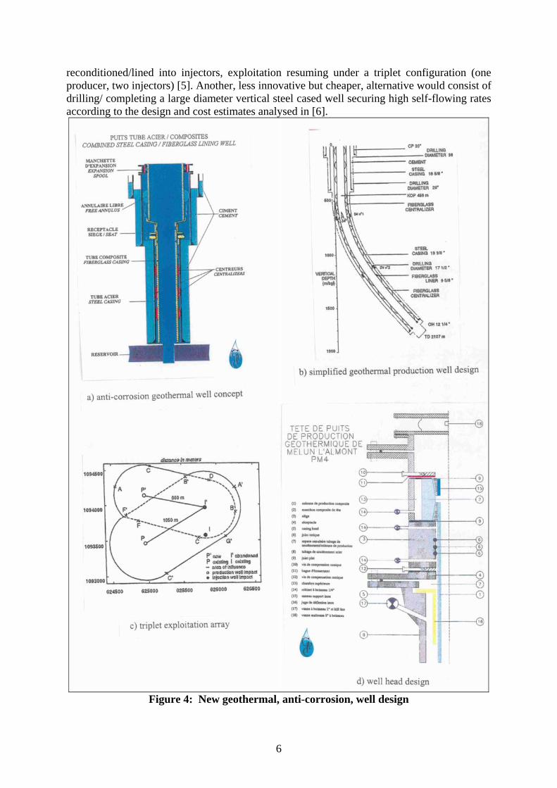
reconditioned/lined into injectors, exploitation resuming under a triplet configuration (one producer, two injectors) [5]. Another, less innovative but cheaper, alternative would consist of drilling/ completing a large diameter vertical steel cased well securing high self-flowing rates according to the design and cost estimates analysed in [6].
Figure 4: New geothermal, anti-corrosion, well design
6
3. WELL MAINTENANCE AND WORKOVER As far as well heavy duty repair is concerned, two major issues ought to be
emphasized in the areas of well clean up and waste processing, respectively:
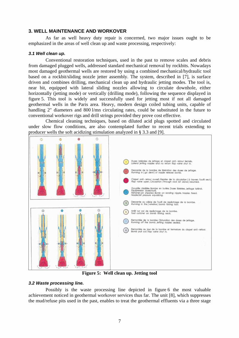
3.1 Well clean up. Conventional restoration techniques, used in the past to remove scales and debris
from damaged plugged wells, addressed standard mechanical removal by rockbits. Nowadays most damaged geothermal wells are restored by using a combined mechanical/hydraulic tool based on a rockbit/sliding nozzle jetter assembly. The system, described in [7], is surface driven and combines drilling, mechanical clean up and hydraulic jetting modes. The tool is, near bit, equipped with lateral sliding nozzles allowing to circulate downhole, either horizontally (jetting mode) or vertically (drilling mode), following the sequence displayed in figure 5. This tool is widely and successfully used for jetting most if not all damaged geothermal wells in the Paris area. Heavy, modern design coiled tubing units, capable of handling 2" diameters and 800 l/mn circulating rates, could be substituted in the future to conventional workover rigs and drill strings provided they prove cost effective.
Chemical cleaning techniques, based on diluted acid plugs spotted and circulated under slow flow conditions, are also contemplated further to recent trials extending to producer wells the soft acidizing stimulation analyzed in § 3.3 and [9].
Figure 5: Well clean up. Jetting tool
3.2 Waste processing line. Possibly is the waste processing line depicted in figure 6 the most valuable
achievement noticed in geothermal workover services thus far. The unit [8], which suppresses the mud/refuse pits used in the past, enables to treat the geothermal effluents via a three stage
7
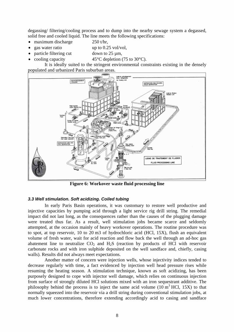
degassing/ filtering/cooling process and to dump into the nearby sewage system a degassed, solid free and cooled liquid. The line meets the following specifications: • maximum discharge 250 t/hr, • gas water ratio up to 0.25 vol/vol, • particle filtering cut down to 25 µm, • cooling capacity 45°C depletion (75 to 30°C).
It is ideally suited to the stringent environmental constraints existing in the densely populated and urbanized Paris suburban areas.
Figure 6: Workover waste fluid processing line
3.3 Well stimulation. Soft acidizing. Coiled tubing In early Paris Basin operations, it was customary to restore well productive and
injective capacities by pumping acid through a light service rig drill string. The remedial impact did not last long, as the consequences rather than the causes of the plugging damage were treated thus far. As a result, well stimulation jobs became scarce and seldomly attempted, at the occasion mainly of heavy workover operations. The routine procedure was to spot, at top reservoir, 10 to 20 m3 of hydrochloric acid (HCl, 15X), flush an equivalent volume of fresh water, wait for acid reaction and flow back the well through an ad-hoc gas abatement line to neutralize CO2 and H2S (reaction by products of HCl with reservoir carbonate rocks and with iron sulphide deposited on the well sandface and, chiefly, casing walls). Results did not always meet expectations.
Another matter of concern were injection wells, whose injectivity indices tended to decrease regularly with time, a fact evidenced by injection well head pressure rises while resuming the heating season. A stimulation technique, known as soft acidizing, has been purposely designed to cope with injector well damage, which relies on continuous injection from surface of strongly diluted HCl solutions mixed with an iron sequestrant additive. The philosophy behind the process is to inject the same acid volume (10 m3 HCl, 15X) to that normally squeezed into the reservoir via a drill string during conventional stimulation jobs, at much lower concentrations, therefore extending accordingly acid to casing and sandface
8
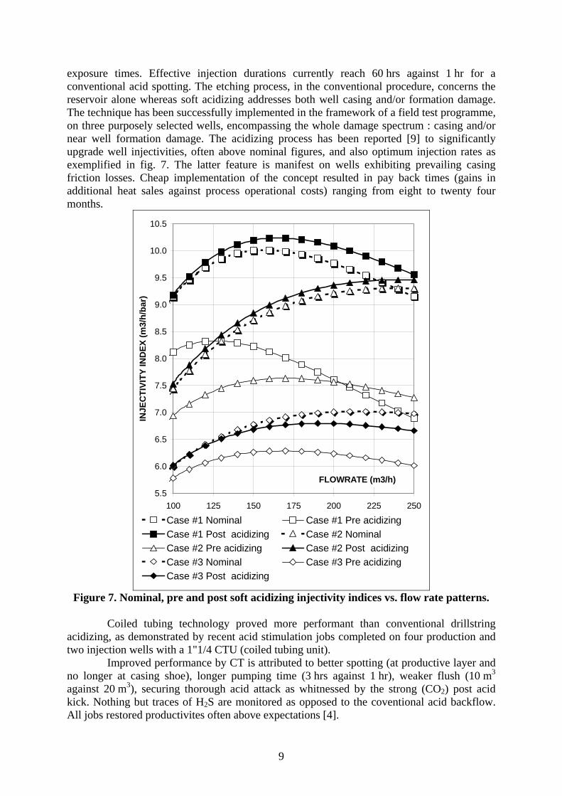
exposure times. Effective injection durations currently reach 60 hrs against 1 hr for a conventional acid spotting. The etching process, in the conventional procedure, concerns the reservoir alone whereas soft acidizing addresses both well casing and/or formation damage. The technique has been successfully implemented in the framework of a field test programme, on three purposely selected wells, encompassing the whole damage spectrum : casing and/or near well formation damage. The acidizing process has been reported [9] to significantly upgrade well injectivities, often above nominal figures, and also optimum injection rates as exemplified in fig. 7. The latter feature is manifest on wells exhibiting prevailing casing friction losses. Cheap implementation of the concept resulted in pay back times (gains in additional heat sales against process operational costs) ranging from eight to twenty four months.
5.5
6.0
6.5
7.0
7.5
8.0
8.5
9.0
9.5
10.0
10.5
100 125 150 175 200 225 250
FLOWRATE (m3/h)
INJE
CTI
VITY
IND
EX (m
3/h/
bar)
Case #1 Nominal Case #1 Pre acidizingCase #1 Post acidizing Case #2 NominalCase #2 Pre acidizing Case #2 Post acidizingCase #3 Nominal Case #3 Pre acidizingCase #3 Post acidizing
Figure 7. Nominal, pre and post soft acidizing injectivity indices vs. flow rate patterns.
Coiled tubing technology proved more performant than conventional drillstring
acidizing, as demonstrated by recent acid stimulation jobs completed on four production and two injection wells with a 1"1/4 CTU (coiled tubing unit).
Improved performance by CT is attributed to better spotting (at productive layer and no longer at casing shoe), longer pumping time (3 hrs against 1 hr), weaker flush (10 m3 against 20 m3), securing thorough acid attack as whitnessed by the strong (CO2) post acid kick. Nothing but traces of H2S are monitored as opposed to the coventional acid backflow. All jobs restored productivites often above expectations [4].
9
On injection wells the field procedure differs from the one implemented on the production well in that both the casing walls and the reservoir are treated sequentially and that there is no backflow episode. In fact the experimented protocol achieves both the objectives of soft acidizing and standard (openhole) reservoir stimulation.
3.4 Tracer leak off tests [10] Detection of casing leaks is a major concern in well maintenance and control of
casing integrities. It is usually performed by means of casing calliper logs and packer leak off tests. Those imply that the production equipments, such as submersible pump sets and downhole chemical injection lines, have been previously removed.
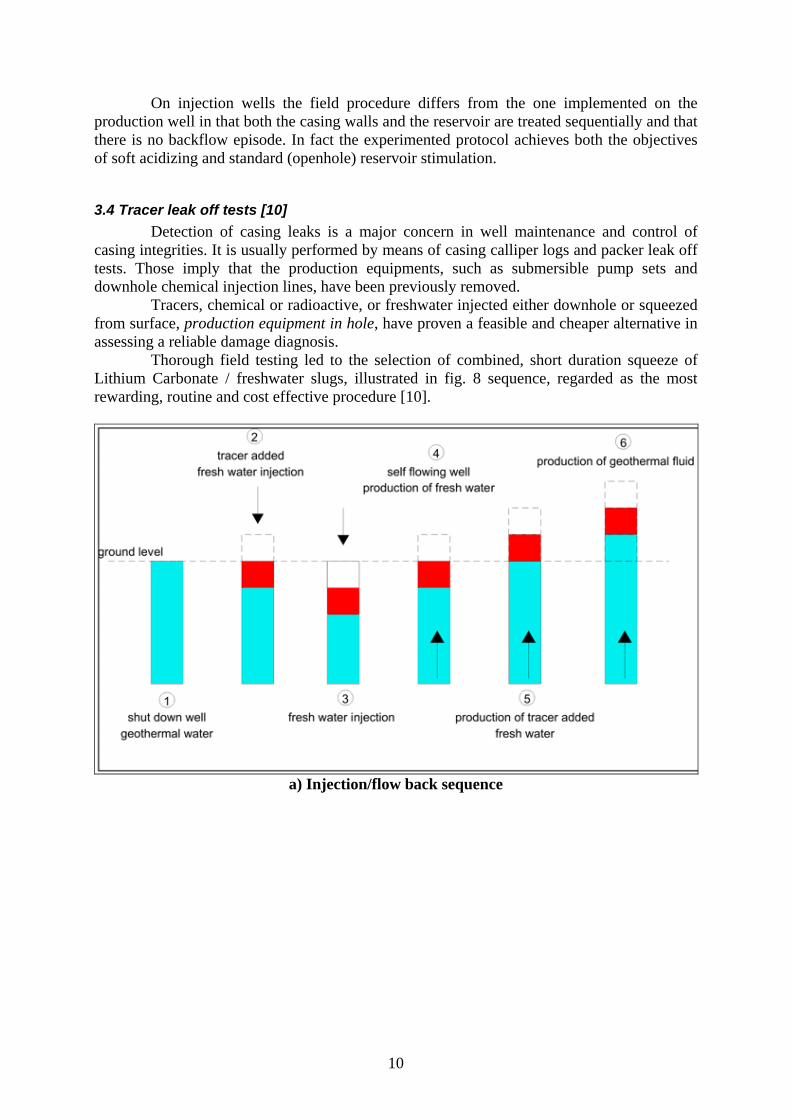
Tracers, chemical or radioactive, or freshwater injected either downhole or squeezed from surface, production equipment in hole, have proven a feasible and cheaper alternative in assessing a reliable damage diagnosis.
Thorough field testing led to the selection of combined, short duration squeeze of Lithium Carbonate / freshwater slugs, illustrated in fig. 8 sequence, regarded as the most rewarding, routine and cost effective procedure [10].
a) Injection/flow back sequence
10
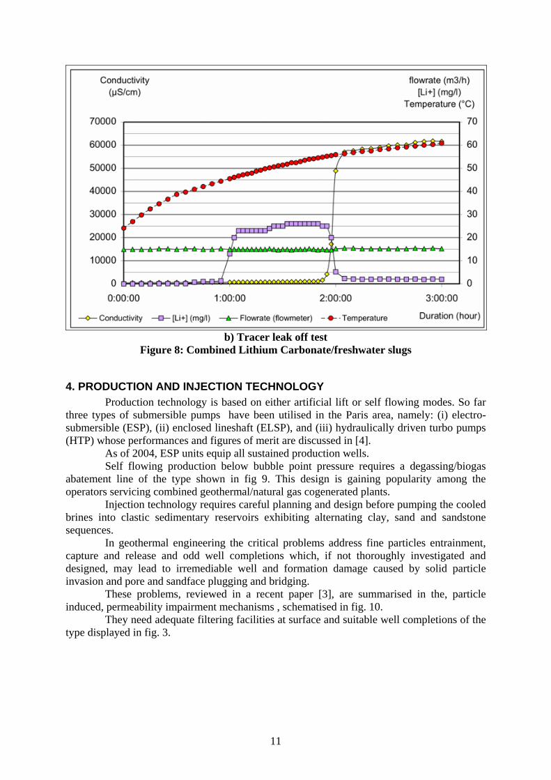
b) Tracer leak off test Figure 8: Combined Lithium Carbonate/freshwater slugs
4. PRODUCTION AND INJECTION TECHNOLOGY Production technology is based on either artificial lift or self flowing modes. So far
three types of submersible pumps have been utilised in the Paris area, namely: (i) electro-submersible (ESP), (ii) enclosed lineshaft (ELSP), and (iii) hydraulically driven turbo pumps (HTP) whose performances and figures of merit are discussed in [4].
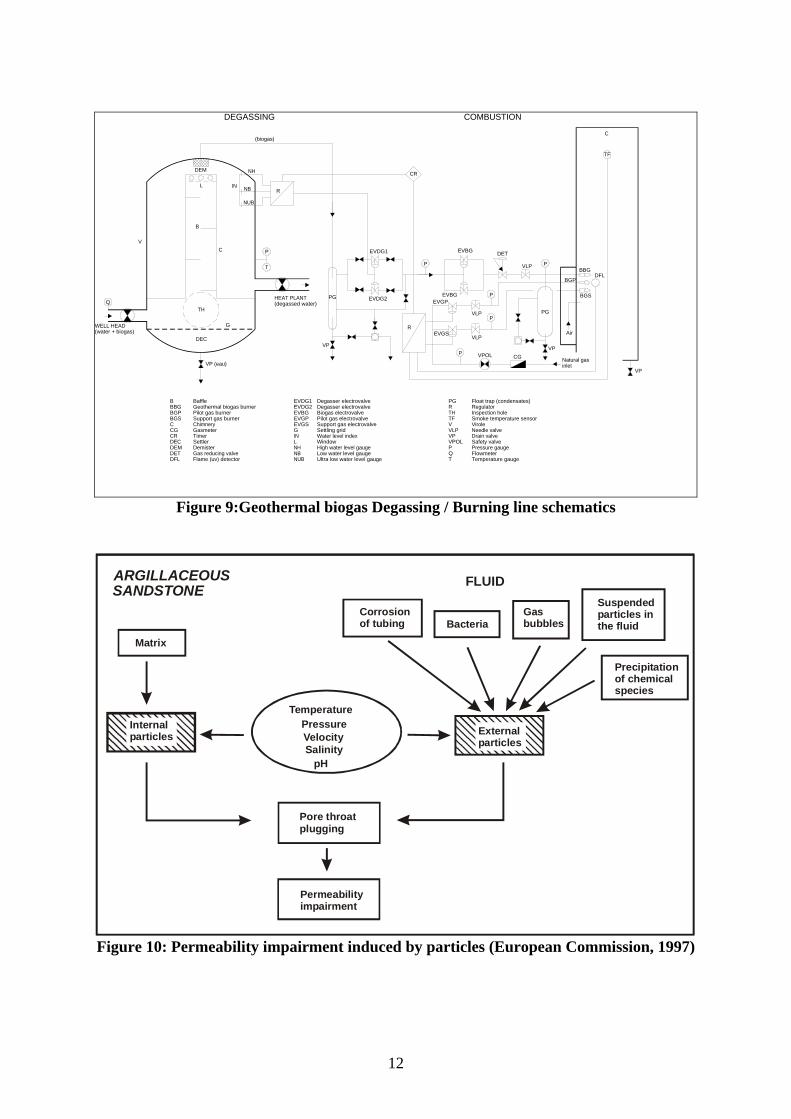
As of 2004, ESP units equip all sustained production wells. Self flowing production below bubble point pressure requires a degassing/biogas
abatement line of the type shown in fig 9. This design is gaining popularity among the operators servicing combined geothermal/natural gas cogenerated plants.
Injection technology requires careful planning and design before pumping the cooled brines into clastic sedimentary reservoirs exhibiting alternating clay, sand and sandstone sequences.
In geothermal engineering the critical problems address fine particles entrainment, capture and release and odd well completions which, if not thoroughly investigated and designed, may lead to irremediable well and formation damage caused by solid particle invasion and pore and sandface plugging and bridging.
These problems, reviewed in a recent paper [3], are summarised in the, particle induced, permeability impairment mechanisms , schematised in fig. 10.
They need adequate filtering facilities at surface and suitable well completions of the type displayed in fig. 3.
11
DEM
L
B
CV
QTH
P
DEC
VP (eau)
NH
NB
NUB
R
T
G
COMBUSTIONDEGASSING
(biogas)
BBBGBGPBGSCCGCRDECDEMDETDFL
BaffleGeothermal biogas burnerPilot gas burnerSupport gas burnerChimneryGasmeterTimerSettlerDemisterGas reducing valveFlame (uv) detector
EVDG1EVDG2EVBGEVGPEVGSGINLNHNBNUB
Degasser electrovalveDegasser electrovalveBiogas electrovalvePilot gas electrovalveSupport gas electrovalveSettling gridWater level indexWindowHigh water level gaugeLow water level gaugeUltra low water level gauge
PGRTHTFVVLPVP
PQT
Float trap (condensates)RegulatorInspection holeSmoke temperature sensorViroleNeedle valveDrain valve
Pressure gaugeFlowmeterTemperature gauge
IN
VPOL Safety valve
PG
EVDG1
EVDG2
EVBG
EVBGEVGP
EVGSVLP
VLP
P
P
P
P
P
TF
DET
VPOL CG
PG
VP VP
DFLBBG
BGS
BGP
Air
Natural gasinlet
VP
C
R
CR
VLP
WELL HEAD(water + biogas)
HEAT PLANT(degassed water)
Figure 9:Geothermal biogas Degassing / Burning line schematics
Permeabilityimpairment
ARGILLACEOUS SANDSTONE
Matrix
Corrosion of tubing Bacteria
Gasbubbles
Suspendedparticles inthe fluid
Precipitation of chemical species
External particles
TemperaturePressureVelocitySalinityApH
Internalparticles
Pore throatplugging
FLUID
Figure 10: Permeability impairment induced by particles (European Commission, 1997)
12
5. CORROSION AND SCALING. DOWNHOLE CHEMICAL INHIBITION PROCEDURES
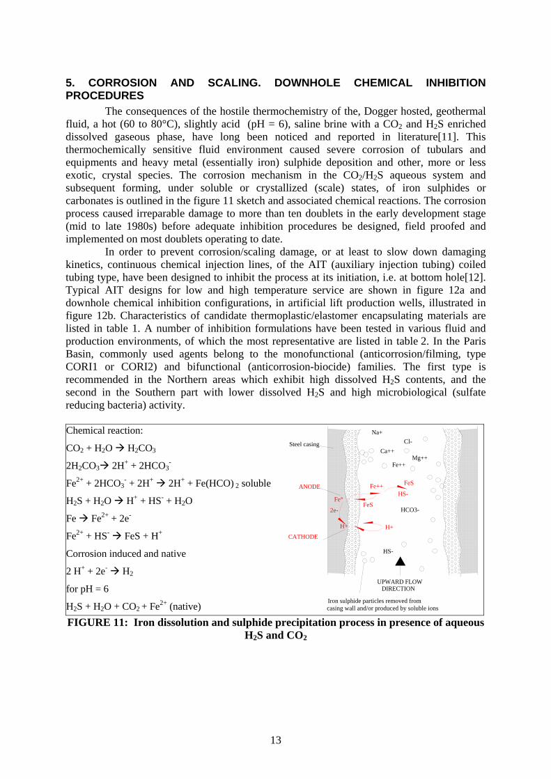
The consequences of the hostile thermochemistry of the, Dogger hosted, geothermal fluid, a hot (60 to 80°C), slightly acid (pH = 6), saline brine with a CO2 and H2S enriched dissolved gaseous phase, have long been noticed and reported in literature[11]. This thermochemically sensitive fluid environment caused severe corrosion of tubulars and equipments and heavy metal (essentially iron) sulphide deposition and other, more or less exotic, crystal species. The corrosion mechanism in the CO2/H2S aqueous system and subsequent forming, under soluble or crystallized (scale) states, of iron sulphides or carbonates is outlined in the figure 11 sketch and associated chemical reactions. The corrosion process caused irreparable damage to more than ten doublets in the early development stage (mid to late 1980s) before adequate inhibition procedures be designed, field proofed and implemented on most doublets operating to date.
In order to prevent corrosion/scaling damage, or at least to slow down damaging kinetics, continuous chemical injection lines, of the AIT (auxiliary injection tubing) coiled tubing type, have been designed to inhibit the process at its initiation, i.e. at bottom hole[12]. Typical AIT designs for low and high temperature service are shown in figure 12a and downhole chemical inhibition configurations, in artificial lift production wells, illustrated in figure 12b. Characteristics of candidate thermoplastic/elastomer encapsulating materials are listed in table 1. A number of inhibition formulations have been tested in various fluid and production environments, of which the most representative are listed in table 2. In the Paris Basin, commonly used agents belong to the monofunctional (anticorrosion/filming, type CORI1 or CORI2) and bifunctional (anticorrosion-biocide) families. The first type is recommended in the Northern areas which exhibit high dissolved H2S contents, and the second in the Southern part with lower dissolved H2S and high microbiological (sulfate reducing bacteria) activity.
Chemical reaction:
CO2 + H2O H2CO3
2H2CO3 2H+ + 2HCO3-
Fe2+ + 2HCO3- + 2H+ 2H+ + Fe(HCO) 2 soluble
H2S + H2O H+ + HS- + H2O
Fe Fe2+ + 2e-
Fe2+ + HS- FeS + H+
Corrosion induced and native
2 H+ + 2e- H2
for pH = 6
H2S + H2O + CO2 + Fe2+ (native)
Na+Cl-
Ca++Mg++
Fe++
UPWARD FLOWDIRECTION
Iron sulphide particles removed fromcasing wall and/or produced by soluble ions
HS-
HCO3-
Steel casing
H+
Fe°
FeS
HS-
FeS2e-
H+
ANODE
CATHODE
Fe++
FIGURE 11: Iron dissolution and sulphide precipitation process in presence of aqueous
H2S and CO2
13
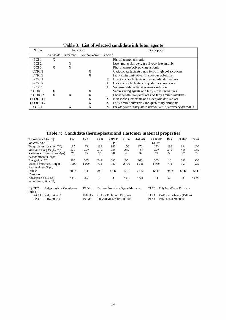
Table 3: List of selected candidate inhibitor agents Name Function Description Antiscale Dispersant Anticorrosion Biocide SCI 1 X Phosphonate non ionic SCI 2 X Low molecular weight polyacrylate anionic SCI 3 X X Phosphonate/polyacrylate anionic CORI 1 X Cationic surfactants ; non ionic in glycol solutions CORI 2 X Fatty amin derivatives in aqueous solutions BIOC 1 X Non ionic surfactants and aldehydic derivatives BIOC 2 X Cationic surfactants and quaternary ammonia BIOC 3 X Superior aldehydes in aqueous solution SCORI 1 X X Sequestering agents and fatty amin derivatives SCORI 2 X X X Phosphonate, polyacrylate and fatty amin derivatives CORBIO 1 X X Non ionic surfactants and aldehydic derivatives CORBIO 2 X X Fatty amin derivatives and quaternary ammonia SCB 1 X X X Polyacrylates, fatty amin derivatives, quarternary ammonia
Table 4: Candidate thermoplastic and elastomer material properties Type de matériau (*) PPC PA 11 PA 6 EPDM/ PVDF HALAR PA 6/PP/ PPS TPFE TPFA Material type PP EPDM Temp. de service max. (°C) 105 95 120 140 150 170 120 196 204 260 Max. operating temp. (°F) 220 220 250 280 300 340 250 350 400 500 Résistance à la traction (Mpa) 25 55 35 28 46 50 43 90 22 28 Tensile strength (Mpa) Elongation (%) 300 300 240 600 80 200 300 10 300 300 Module d'élasticité (Mpa) 1 200 1 000 760 347 2 700 1 700 1 980 750 655 625 Flex modulus (Mpa) Dureté 60 D 72 D 40 R 50 D 77 D 75 D 65 D 70 D 60 D 55 D Hardness Absorption d'eau (%) < 0.1 2.5 5 2 < 0.1 < 0.1 < 1 2.1 0 < 0.03 Water absorption (%) (*) PPC : Polypropylene Copolymer EPDM : Etylene Propylene Dyene Monomer TPFE : PolyTetraFluoroEthylene (Teflon) PA 11 : Polyamide 11 HALAR : Chloro Tri Fluoro Ethylene TPFA : PerFluoro Alkoxy (Teflon) PA 6 : Polyamide 6 PVDF : PolyVinyle Dyene Fluoride PPS : PolyPhenyl Sulphone
14
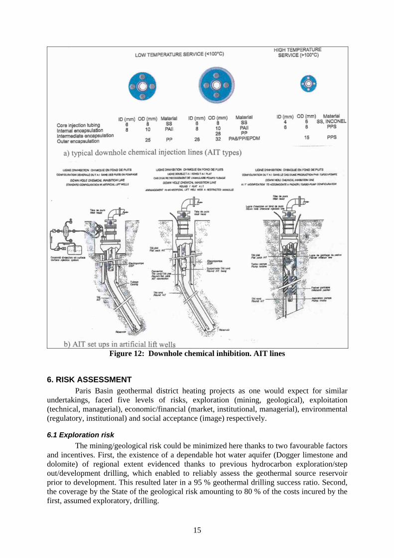
Figure 12: Downhole chemical inhibition. AIT lines
6. RISK ASSESSMENT Paris Basin geothermal district heating projects as one would expect for similar
undertakings, faced five levels of risks, exploration (mining, geological), exploitation (technical, managerial), economic/financial (market, institutional, managerial), environmental (regulatory, institutional) and social acceptance (image) respectively.
6.1 Exploration risk The mining/geological risk could be minimized here thanks to two favourable factors
and incentives. First, the existence of a dependable hot water aquifer (Dogger limestone and dolomite) of regional extent evidenced thanks to previous hydrocarbon exploration/step out/development drilling, which enabled to reliably assess the geothermal source reservoir prior to development. This resulted later in a 95 % geothermal drilling success ratio. Second, the coverage by the State of the geological risk amounting to 80 % of the costs incured by the first, assumed exploratory, drilling.
15
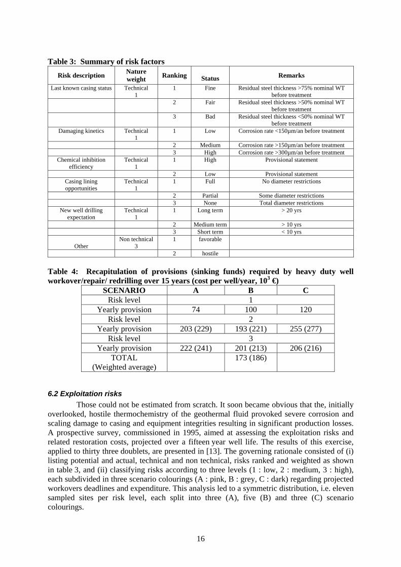
Table 3: Summary of risk factors
Risk description Nature weight Ranking Status Remarks
Last known casing status Technical 1
1 Fine Residual steel thickness >75% nominal WT before treatment
2 Fair Residual steel thickness >50% nominal WT before treatment
3 Bad Residual steel thickness <50% nominal WT before treatment
Damaging kinetics Technical 1
1 Low Corrosion rate <150µm/an before treatment
2 Medium Corrosion rate >150µm/an before treatment 3 High Corrosion rate >300µm/an before treatment
Chemical inhibition efficiency
Technical 1
1 High Provisional statement
2 Low Provisional statement Casing lining opportunities
Technical 1
1 Full No diameter restrictions
2 Partial Some diameter restrictions 3 None Total diameter restrictions
New well drilling expectation
Technical 1
1 Long term > 20 yrs
2 Medium term > 10 yrs 3 Short term < 10 yrs
Other Non technical
3 1 favorable
2 hostile Table 4: Recapitulation of provisions (sinking funds) required by heavy duty well workover/repair/ redrilling over 15 years (cost per well/year, 103 €)
SCENARIO A B C Risk level 1
Yearly provision 74 100 120 Risk level 2
Yearly provision 203 (229) 193 (221) 255 (277) Risk level 3
Yearly provision 222 (241) 201 (213) 206 (216) TOTAL
(Weighted average) 173 (186)
6.2 Exploitation risks Those could not be estimated from scratch. It soon became obvious that the, initially
overlooked, hostile thermochemistry of the geothermal fluid provoked severe corrosion and scaling damage to casing and equipment integrities resulting in significant production losses. A prospective survey, commissioned in 1995, aimed at assessing the exploitation risks and related restoration costs, projected over a fifteen year well life. The results of this exercise, applied to thirty three doublets, are presented in [13]. The governing rationale consisted of (i) listing potential and actual, technical and non technical, risks ranked and weighted as shown in table 3, and (ii) classifying risks according to three levels (1 : low, 2 : medium, 3 : high), each subdivided in three scenario colourings (A : pink, B : grey, C : dark) regarding projected workovers deadlines and expenditure. This analysis led to a symmetric distribution, i.e. eleven sampled sites per risk level, each split into three (A), five (B) and three (C) scenario colourings.
16
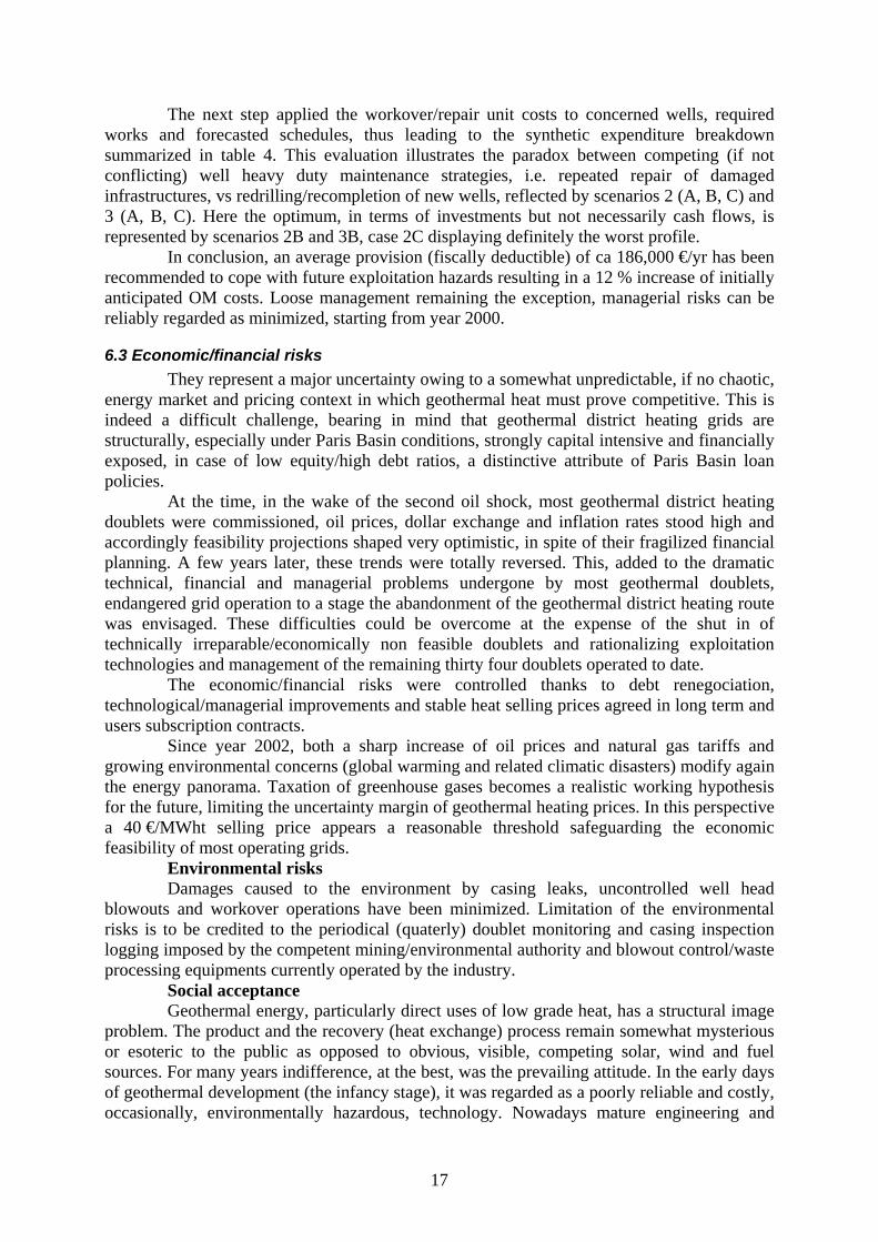
The next step applied the workover/repair unit costs to concerned wells, required works and forecasted schedules, thus leading to the synthetic expenditure breakdown summarized in table 4. This evaluation illustrates the paradox between competing (if not conflicting) well heavy duty maintenance strategies, i.e. repeated repair of damaged infrastructures, vs redrilling/recompletion of new wells, reflected by scenarios 2 (A, B, C) and 3 (A, B, C). Here the optimum, in terms of investments but not necessarily cash flows, is represented by scenarios 2B and 3B, case 2C displaying definitely the worst profile.
In conclusion, an average provision (fiscally deductible) of ca 186,000 €/yr has been recommended to cope with future exploitation hazards resulting in a 12 % increase of initially anticipated OM costs. Loose management remaining the exception, managerial risks can be reliably regarded as minimized, starting from year 2000.
6.3 Economic/financial risks They represent a major uncertainty owing to a somewhat unpredictable, if no chaotic,
energy market and pricing context in which geothermal heat must prove competitive. This is indeed a difficult challenge, bearing in mind that geothermal district heating grids are structurally, especially under Paris Basin conditions, strongly capital intensive and financially exposed, in case of low equity/high debt ratios, a distinctive attribute of Paris Basin loan policies.
At the time, in the wake of the second oil shock, most geothermal district heating doublets were commissioned, oil prices, dollar exchange and inflation rates stood high and accordingly feasibility projections shaped very optimistic, in spite of their fragilized financial planning. A few years later, these trends were totally reversed. This, added to the dramatic technical, financial and managerial problems undergone by most geothermal doublets, endangered grid operation to a stage the abandonment of the geothermal district heating route was envisaged. These difficulties could be overcome at the expense of the shut in of technically irreparable/economically non feasible doublets and rationalizing exploitation technologies and management of the remaining thirty four doublets operated to date.
The economic/financial risks were controlled thanks to debt renegociation, technological/managerial improvements and stable heat selling prices agreed in long term and users subscription contracts.
Since year 2002, both a sharp increase of oil prices and natural gas tariffs and growing environmental concerns (global warming and related climatic disasters) modify again the energy panorama. Taxation of greenhouse gases becomes a realistic working hypothesis for the future, limiting the uncertainty margin of geothermal heating prices. In this perspective a 40 €/MWht selling price appears a reasonable threshold safeguarding the economic feasibility of most operating grids.
Environmental risks Damages caused to the environment by casing leaks, uncontrolled well head
blowouts and workover operations have been minimized. Limitation of the environmental risks is to be credited to the periodical (quaterly) doublet monitoring and casing inspection logging imposed by the competent mining/environmental authority and blowout control/waste processing equipments currently operated by the industry.
Social acceptance Geothermal energy, particularly direct uses of low grade heat, has a structural image
problem. The product and the recovery (heat exchange) process remain somewhat mysterious or esoteric to the public as opposed to obvious, visible, competing solar, wind and fuel sources. For many years indifference, at the best, was the prevailing attitude. In the early days of geothermal development (the infancy stage), it was regarded as a poorly reliable and costly, occasionally, environmentally hazardous, technology. Nowadays mature engineering and
17
management and growing environmental (clean air) concerns have gained wider acceptance by the public of the geothermal district heating alternative. Still, image building efforts need to be persued to popularize the technology.
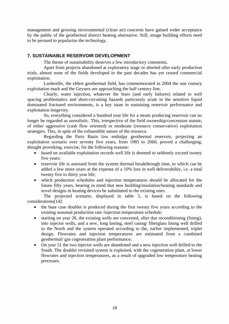
7. SUSTAINABLE RESERVOIR DEVELOPMENT The theme of sustainability deserves a few introductory comments. Apart from projects abandoned at exploratory stage or aborted after early production
trials, almost none of the fields developed in the past decades has yet ceased commercial exploitation.
Larderello, the eldest geothermal field, has commemorated in 2004 the one century exploitation mark and the Geysers are approaching the half century line.
Clearly, water injection, whatever the fears (and early failures) related to well spacing problematics and short-circuiting hazards particuraly acute in the sensitive liquid dominated fractured environments, is a key issue in sustaining reservoir performance and exploitation longevity.
So, everything considered a hundred year life for a steam producing reservoir can no longer be regarded as unrealistic. This, irrespective of the field ownership/concession statute, of either aggressive (cash flow oriented) or moderate (resource conservative) exploitation strategies. This, in spite of the exhaustible nature of the resource.
Regarding the Paris Basin low enthalpy geothermal reservoir, projecting an exploitation scenario over seventy five years, from 1985 to 2060, proved a challenging, thought provoking, exercise, for the following reasons:
• based on available exploitation records well life is deemed to seldomly exceed twenty five years;
• reservoir life is assessed from the system thermal breakthrough time, to which can be added a few more years at the expense of a 10% loss in well deliverability, i.e. a total twenty five to thirty year life;
• which production schedules and injection temperatures should be allocated for the future fifty years, bearing in mind that new building/insulation/heating standards and novel designs in heating devices be substituted to the existing ones.
The projected scenario, displayed in table 5, is based on the following considerations[14]:
• the base case doublet is produced during the first twenty five years according to the existing seasonal production rate /injection temperature schedule;
• starting on year 26, the existing wells are converted, after due reconditioning (lining), into injector wells, and a new, long lasting, steel casing/ fiberglass lining well drilled to the North and the system operated according to the, earlier implemented, triplet design. Flowrates and injection temperatures are estimated from a combined geothermal/ gas cogeneration plant performance;
• On year 51 the two injector wells are abandoned and a new injection well drilled to the South. The doublet revisited system is exploited, with the cogeneration plant, at lower flowrates and injection temperatures, as a result of upgraded low temperature heating processes.
18
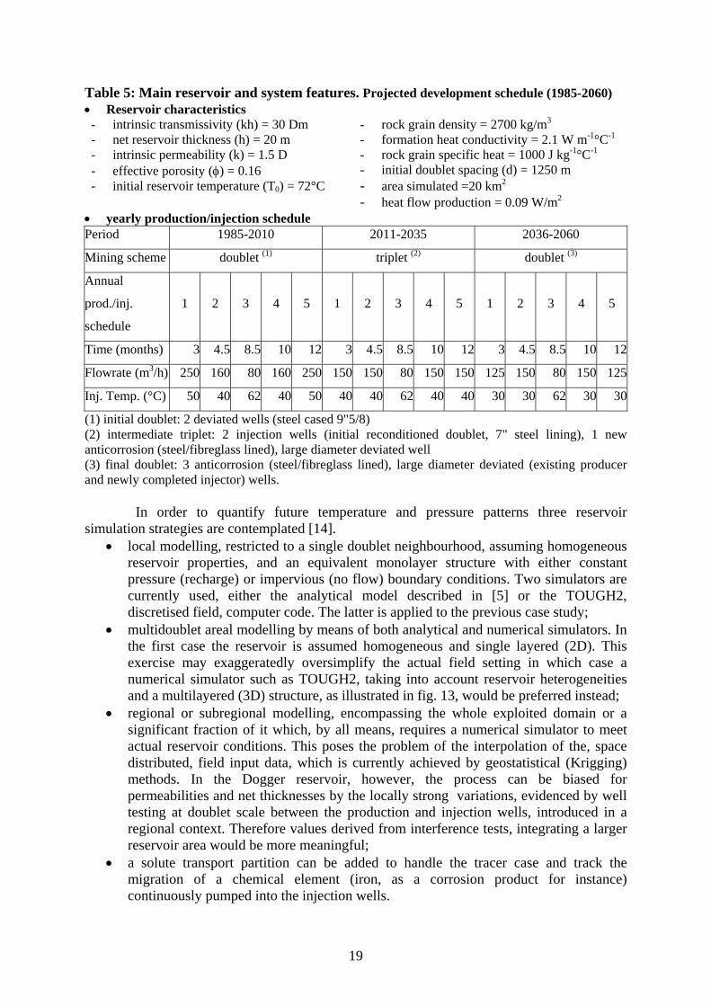
Table 5: Main reservoir and system features. Projected development schedule (1985-2060) • Reservoir characteristics - intrinsic transmissivity (kh) = 30 Dm - net reservoir thickness (h) = 20 m - intrinsic permeability (k) = 1.5 D - effective porosity (φ) = 0.16 - initial reservoir temperature (T0) = 72°C
- rock grain density = 2700 kg/m3 - formation heat conductivity = 2.1 W m-1°C-1 - rock grain specific heat = 1000 J kg-1°C-1 - initial doublet spacing (d) = 1250 m - area simulated =20 km2 - heat flow production = 0.09 W/m2
• yearly production/injection schedule Period 1985-2010 2011-2035 2036-2060
Mining scheme doublet (1) triplet (2) doublet (3)
Annual
prod./inj.
schedule
1 2 3 4 5 1 2 3 4 5 1 2 3 4 5
Time (months) 3 4.5 8.5 10 12 3 4.5 8.5 10 12 3 4.5 8.5 10 12
Flowrate (m3/h) 250 160 80 160 250 150 150 80 150 150 125 150 80 150 125
Inj. Temp. (°C) 50 40 62 40 50 40 40 62 40 40 30 30 62 30 30
(1) initial doublet: 2 deviated wells (steel cased 9"5/8) (2) intermediate triplet: 2 injection wells (initial reconditioned doublet, 7" steel lining), 1 new anticorrosion (steel/fibreglass lined), large diameter deviated well (3) final doublet: 3 anticorrosion (steel/fibreglass lined), large diameter deviated (existing producer and newly completed injector) wells.
In order to quantify future temperature and pressure patterns three reservoir
simulation strategies are contemplated [14]. • local modelling, restricted to a single doublet neighbourhood, assuming homogeneous
reservoir properties, and an equivalent monolayer structure with either constant pressure (recharge) or impervious (no flow) boundary conditions. Two simulators are currently used, either the analytical model described in [5] or the TOUGH2, discretised field, computer code. The latter is applied to the previous case study;
• multidoublet areal modelling by means of both analytical and numerical simulators. In the first case the reservoir is assumed homogeneous and single layered (2D). This exercise may exaggeratedly oversimplify the actual field setting in which case a numerical simulator such as TOUGH2, taking into account reservoir heterogeneities and a multilayered (3D) structure, as illustrated in fig. 13, would be preferred instead;
• regional or subregional modelling, encompassing the whole exploited domain or a significant fraction of it which, by all means, requires a numerical simulator to meet actual reservoir conditions. This poses the problem of the interpolation of the, space distributed, field input data, which is currently achieved by geostatistical (Krigging) methods. In the Dogger reservoir, however, the process can be biased for permeabilities and net thicknesses by the locally strong variations, evidenced by well testing at doublet scale between the production and injection wells, introduced in a regional context. Therefore values derived from interference tests, integrating a larger reservoir area would be more meaningful;
• a solute transport partition can be added to handle the tracer case and track the migration of a chemical element (iron, as a corrosion product for instance) continuously pumped into the injection wells.
19
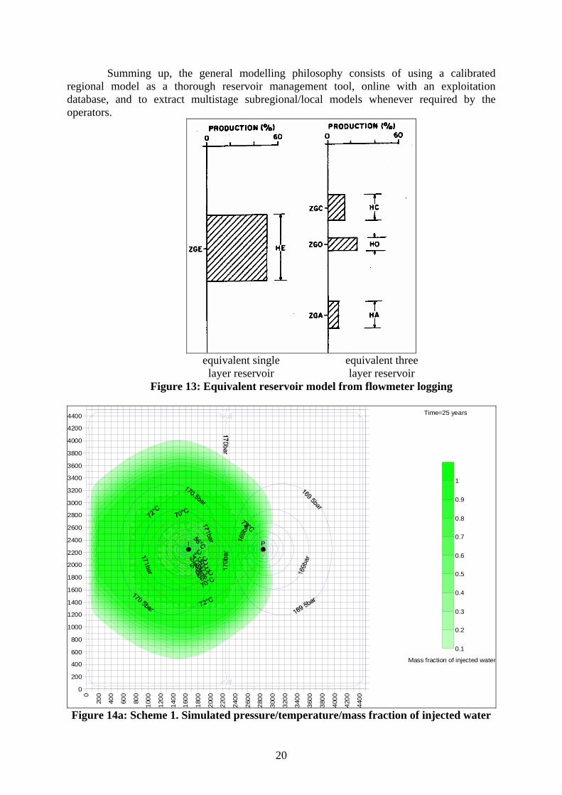
Summing up, the general modelling philosophy consists of using a calibrated regional model as a thorough reservoir management tool, online with an exploitation database, and to extract multistage subregional/local models whenever required by the operators.
equivalent single equivalent three layer reservoir layer reservoir
Figure 13: Equivalent reservoir model from flowmeter logging
0
200
400
600
800
1000
1200
1400
1600
1800
2000
2200
2400
2600
2800
3000
3200
3400
3600
3800
4000
4200
4400
0
200
400
600
800
1000
1200
1400
1600
1800
2000
2200
2400
2600
2800
3000
3200
3400
3600
3800
4000
4200
4400
PI
0.1
0.2
0.3
0.4
0.5
0.6
0.7
0.8
0.9
1
Time=25 years
Mass fraction of injected water
Figure 14a: Scheme 1. Simulated pressure/temperature/mass fraction of injected water
20
0
200
400
600
800
1000
1200
1400
1600
1800
2000
2200
2400
2600
2800
3000
3200
3400
3600
3800
4000
4200
4400
0
200
400
600
800
1000
1200
1400
1600
1800
2000
2200
2400
2600
2800
3000
3200
3400
3600
3800
4000
4200
4400
P
I I
0.1
0.2
0.3
0.4
0.5
0.6
0.7
0.8
0.9
1
Time=50 years
Mass fraction of injected water
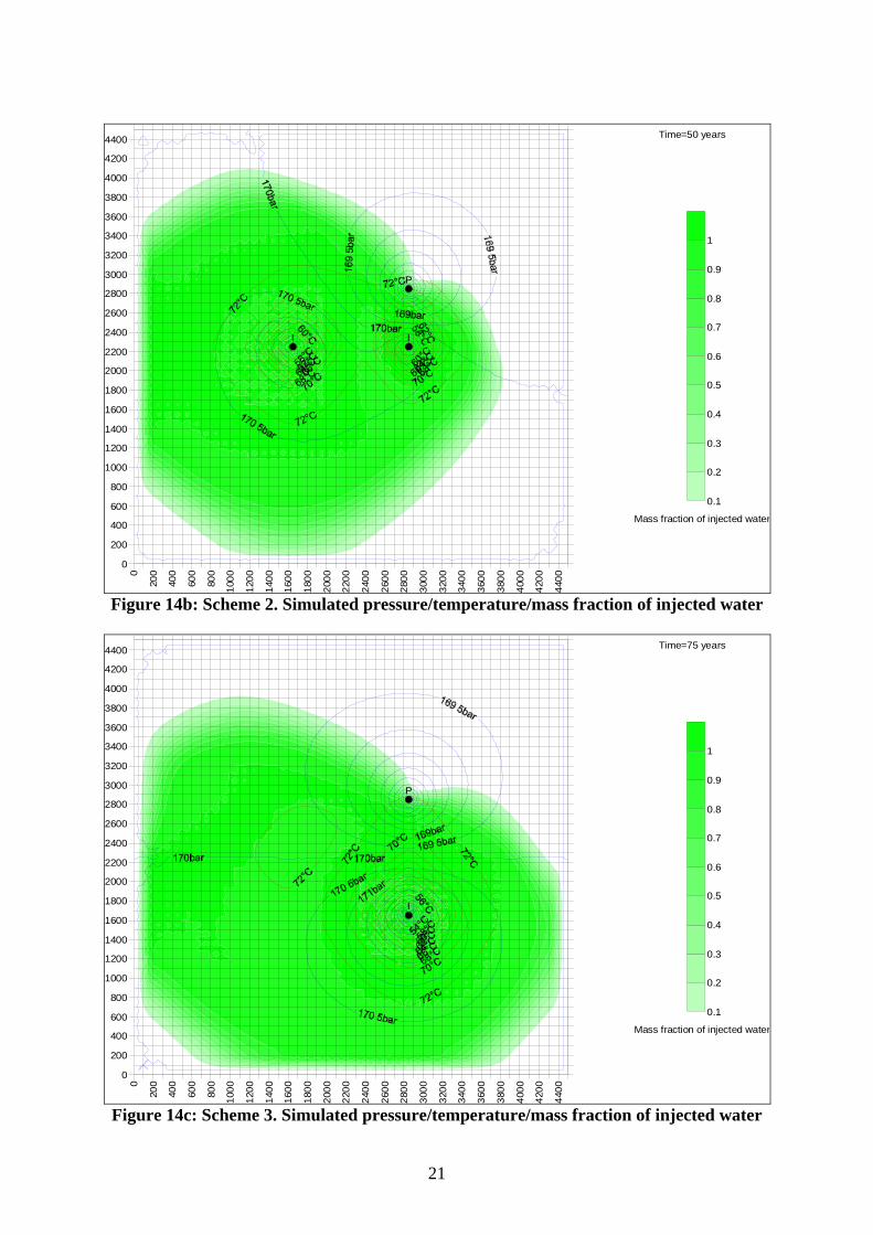
Figure 14b: Scheme 2. Simulated pressure/temperature/mass fraction of injected water
0
200
400
600
800
1000
1200
1400
1600
1800
2000
2200
2400
2600
2800
3000
3200
3400
3600
3800
4000
4200
4400
0
200
400
600
800
1000
1200
1400
1600
1800
2000
2200
2400
2600
2800
3000
3200
3400
3600
3800
4000
4200
4400
P
I
0.1
0.2
0.3
0.4
0.5
0.6
0.7
0.8
0.9
1
Time=75 years
Mass fraction of injected water
Figure 14c: Scheme 3. Simulated pressure/temperature/mass fraction of injected water
21
66.00
67.00
68.00
69.00
70.00
71.00
72.00
0 10 20 30 40 50 60 70
Time, years
T, °C
80
constant pressure boundaryclosed reservoir
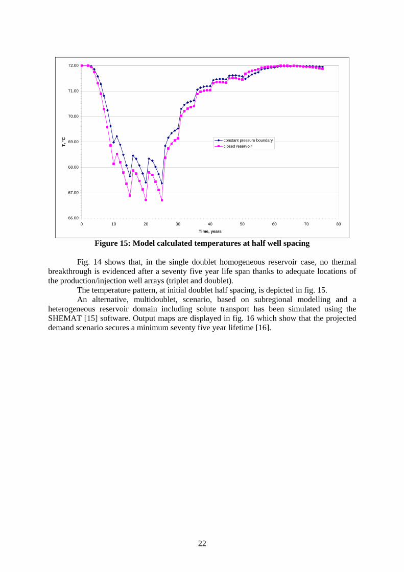
Figure 15: Model calculated temperatures at half well spacing
Fig. 14 shows that, in the single doublet homogeneous reservoir case, no thermal
breakthrough is evidenced after a seventy five year life span thanks to adequate locations of the production/injection well arrays (triplet and doublet).
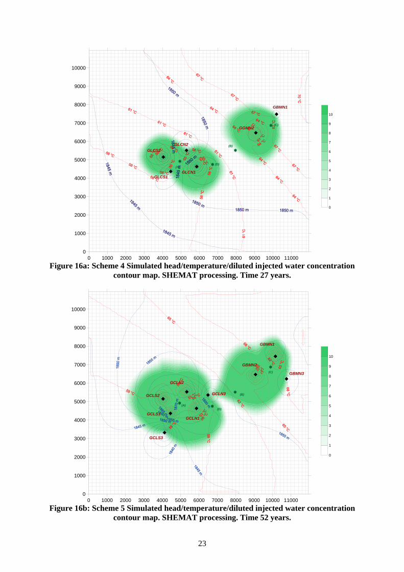
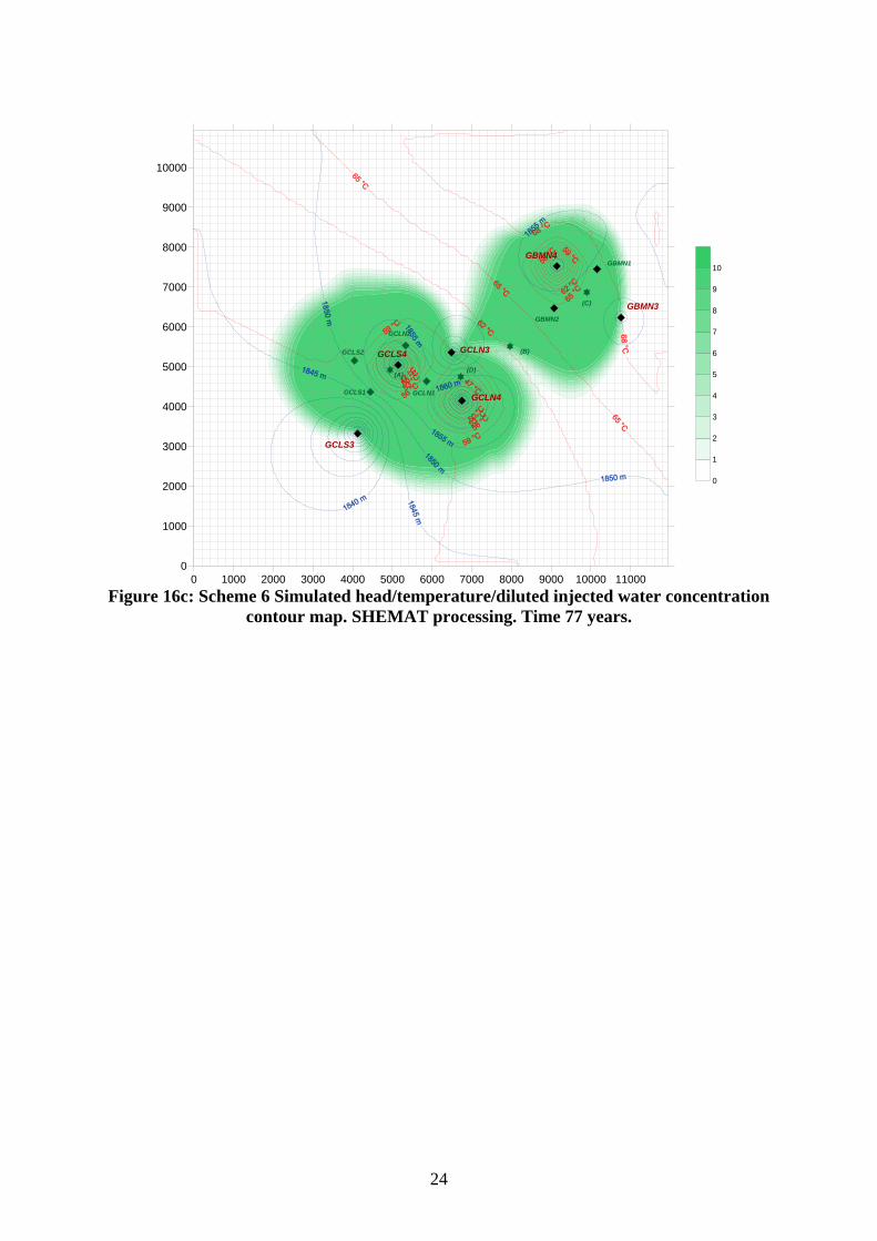
The temperature pattern, at initial doublet half spacing, is depicted in fig. 15. An alternative, multidoublet, scenario, based on subregional modelling and a
heterogeneous reservoir domain including solute transport has been simulated using the SHEMAT [15] software. Output maps are displayed in fig. 16 which show that the projected demand scenario secures a minimum seventy five year lifetime [16].
22
0 1000 2000 3000 4000 5000 6000 7000 8000 9000 10000 110000
1000
2000
3000
4000
5000
6000
7000
8000
9000
10000
GLCS1
GLCS2
GLCN1
GLCN2
GBMN1
GGMN2
(A)
(B)
(C)
(D)
0
1
2
3
4
5
6
7
8
9
10
Figure 16a: Scheme 4 Simulated head/temperature/diluted injected water concentration
contour map. SHEMAT processing. Time 27 years.
0 1000 2000 3000 4000 5000 6000 7000 8000 9000 10000 110000
1000
2000
3000
4000
5000
6000
7000
8000
9000
10000
GCLS3
GCLS1
GCLS2
GCLN1
GCLN2
GCLN3
GBMN1
GBMN2
GBMN3
0
1
2
3
4
5
6
7
8
9
10
(A)
(B)
(C)
(D)
Figure 16b: Scheme 5 Simulated head/temperature/diluted injected water concentration
contour map. SHEMAT processing. Time 52 years.
23
0 1000 2000 3000 4000 5000 6000 7000 8000 9000 10000 110000
1000
2000
3000
4000
5000
6000
7000
8000
9000
10000
GCLS1
GCLS2
GCLN1
GCLN2
GBMN1
GBMN2
(A)
(B)
(C)
(D)
0
1
2
3
4
5
6
7
8
9
10
GCLS3
GCLN3
GBMN3
GCLS4
GCLN4
GBMN4
Figure 16c: Scheme 6 Simulated head/temperature/diluted injected water concentration
contour map. SHEMAT processing. Time 77 years.
24
8. CONCLUSIONS Owing to the exhaustible nature of geothermal resources, sustainable heat mining is
of utmost importance in designing and implementing relevant exploitation strategies aimed at reconciling users’ demands with reservoir longevity concerns.
The latter require (i) dependable reservoir properties, (ii) reliable heat extraction technologies, and (iii) appropriate databases and reservoir simulation tools.
These issues were illustrated on a case study, borrowed to the well documented Paris Basin district heating scheme, which benefits from a thirty year exploitation record with thirty four ongoing district heating well doublets.
The review addressed a carbonate reservoir of regional extent, hosting a thermochemically hostile fluid, a hot saline brine including a CO2/H2S enriched solution gas phase, making injection of the heat depleted brine into the source reservoir an environmental prerequisite.
Clearly, corrosion/scaling, initially overlooked, shortcomings and water injection proved the most sensitive problem areas, an attribute, as a matter of fact, shared by most geothermal reservoirs worldwide, would they be hosted either by low or high enthalpy, fractured or not, sedimentary – consolidated – carbonate and loose clastic or volcanic rock environments.
These could be overcome thanks to adequate remedial/preventing – well workover, downhole chemical inhibition – and design – new anticorrosion well concept, doublet modelling – strategies which, alongside risk assessment surveys, played a dominant role in upgrading reservoir performance/well deliverabilities thus securing exploitation longevity.
The foregoing were concluded by two sustainable development scenarios addressing (i) an isolated well doublet, and (ii) a multiwell doublet configurations.
Simulation results proved both consistent with initially contemplated expectations as no thermal breakthrough whatsoever was noticed.
As already confirmed by the geothermal exploitation record scored worldwide, lifetimes nearing one hundred years should not be any longer regarded as utopia, whatever the scepticism once disclosed by conventional energy planners.
25
REFERENCES
1. Rybach, L. and Eugster, W. J. (2002). Sustainability Aspects of Geothermal Heat Pumps. 27th Workshop on Geothermal Reservoir Engineering, Stanford University, Stanford, CA, January 28-30, 2002, Conference Proceedings.
2. Ungemach, P. (2004). Carbonate Geothermal Reservoir Management and Use in France. Paper presented at the IGD 2004 Poland on “Low Enthalpy Geothermal Resources. Exploitation and Development”, Zakopane, 13-17 September 2004.
3. Ungemach, P. (2003). Reinjection of Cooled Geothermal Brines into Sandstone Reservoirs. In Geothermics, vol. 32, pp. 743-761
4. Ungemach, P. (2001). Insight into Geothermal Reservoir Management. European Summer School on Geothermal Energy Applications.. Oradea, Romania, April 26-May 5, 2001. Text Book (Rosca, M. ed.), pp. 43-76.
5. Ungemach, P. (1998). A State of the Art Review of Successful Geothermal Technologies Implemented at European Level. Geoproduction Consultants (GPC) Int. Report no: 98285.
6. Geoproduction Consultants – GPC (2000): Restoration of an Abandoned Geothermal District Heating Well Doublet. A Case Study. GPC internal report AVV-PU-0038.
7. Geoproduction Consultants –GPC (1996): Sliding Nozzle Jetting Tool. Company Brochure, 8 pages.
8. Geoproduction Consultants – GPC (1996): Workover Waste Fluid Processing Line. Company Brochure, 8 pages.
9. Ventre, A. V. and Ungemach, P. (1998): Soft Acidizing of Damaged Geothermal Injection Wells – Discussion of Results Achieved in the Paris Basin. Paper presented at the 23rd Workshop on Geothermal Reservoir Engineering, Stanford University, Standford, CA,. 26-28 January 1998, Proceedings pp. 33-43.
10. Ungemach, P., Ventre, A. V. and Nicolaon, S. (2002). Tracer Leak Off Tests and Means of Checking Well Integrity. Application to Paris Basin Geothermal Production Wells. 27th Workshop on Geothermal Reservoir Engineering, Stanford University, Stanford, CA, January 28-30, 2002, SGP-TR-71.
11. P. Ungemach (1997): Chemical Treatment of Low Temperature Geofluids. Paper presented at the International Course on District Heating Schemes. Cesme, Turkey, 19-25 October 1997. Proceedings pp. 10-1 to 10-14
12. Geoproduction Consultants – GPC (1998): Downhole Injection / Control Lines. Company Brochure, 12p.
13. Ungemach, P and Ventre, A. V. (1997): Economic, Legal and Institutional Insight into Geothermal District Heating Paper presented at the International Course on District Heating Schemes, Cesme, Turkey, 19-25 October, 1997. Proceedings pp. 23-1 to 23-20.
14. Ungemach, P. and Antics M. (2003). Insight into Modern Geothermal Reservoir Management Practice. International Geothermal Days Turkey, Seferinhisar, Turkey, June 2003.
15. Clauser, C. Ed (2003). Numerical Simulation of Reactive Flow in Hot Aquifers. SHEMAT and Processing SHEMAT. Springer Publ. Co. Berlin.
16. Ungemach, P. Antics, M. and Papachistou, M. (2004). Sustainable Geothermal Reservoir Management. Paper no. 0517 submitted for presentation at the World Geothermal Congress, 2005.
26