Embed Size (px)
Citation preview
GEOTECHNICAL STUDY (PART I OF II) GULF SHORELINE STABILIZATION PROJECT
ROCKEFELLER REFUGE CAMERON PARISH, LOUISIANA
SHINER MOSELEY AND ASSOCIATES, INC. CORPUS CHRISTI, TEXAS

Report No. 0602-1316 Part I of II August 13, 2002 Shiner Moseley and Associates, Inc. 555 N. Carancahua, Suite 1650 Corpus Christi, Texas 78478 Attention: Mr. Dan Heilman, P.E.
Geotechnical Study (Part I of II) Gulf Shoreline Stabilization Project
Rockefeller Refuge Cameron Parish, Louisiana
Introduction
Fugro South, Inc. is pleased to present this first report of our geotechnical study for the above-
referenced project. Mr. Dan Heilman, P.E., with Shiner Moseley and Associates, Inc. (SMA),
requested this study during a telephone conversation with Mr. David W. Duhon of Fugro South,
Inc., on March 20, 2002. Mr. Neil McLellan, P.E., with SMA, authorized this study verbally and via
memorandum e-mailed to Mr. Duhon on May 29, 2002. We performed this study in general
accordance with our Proposal No. 0602-1316, dated March 25, 2002.
This first report is being issued at the request of the client to aid with the conceptual designs of
various shoreline stabilization structures. The major design concept included and discussed in this
report is allowable soil bearing capacity, followed by construction considerations. Upon
determination by others of the stabilization concepts deemed most likely feasible, we will be
supplied with the selected design alternatives in order to perform our consolidation and settlement
analyses. The results of our analyses will then be presented in a subsequent report.
Project Description. We understand that due to extensive coastal erosion over the past several
years, the Louisiana Department of Natural Resources, along with the Rockefeller Wildlife Refuge,
is planning to construct a shoreline stabilization structure from Joseph’s Bayou westward about
10 miles to the west boundary of the Rockefeller Refuge along the existing shoreline. The project
site is essentially located in the southeast corner of Cameron Parish, Louisiana, which is bordered
to the south by the Gulf of Mexico. A Site Vicinity Map is provided on Plate 1 of this report. The
stabilization project may consist of, but not be limited to, constructing a rock breakwater or
installing Geotubes. SMA has requested that Fugro South, Inc. provide geotechnical
recommendations to aid in the beach stabilization project.
Report No. 0602-1316 Part I of II
-2-
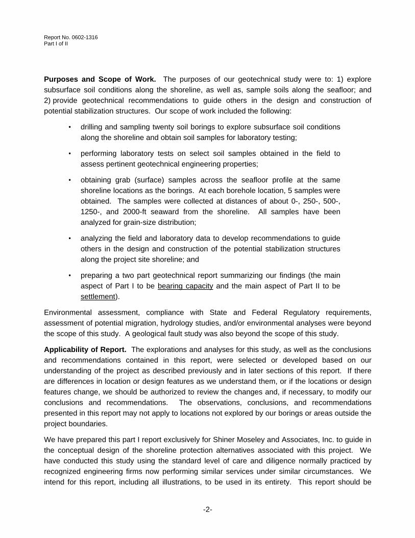
Purposes and Scope of Work. The purposes of our geotechnical study were to: 1) explore
subsurface soil conditions along the shoreline, as well as, sample soils along the seafloor; and
2) provide geotechnical recommendations to guide others in the design and construction of
potential stabilization structures. Our scope of work included the following:
• drilling and sampling twenty soil borings to explore subsurface soil conditions
along the shoreline and obtain soil samples for laboratory testing;
• performing laboratory tests on select soil samples obtained in the field to
assess pertinent geotechnical engineering properties;
• obtaining grab (surface) samples across the seafloor profile at the same
shoreline locations as the borings. At each borehole location, 5 samples were
obtained. The samples were collected at distances of about 0-, 250-, 500-,
1250-, and 2000-ft seaward from the shoreline. All samples have been
analyzed for grain-size distribution;
• analyzing the field and laboratory data to develop recommendations to guide
others in the design and construction of the potential stabilization structures
along the project site shoreline; and
• preparing a two part geotechnical report summarizing our findings (the main
aspect of Part I to be bearing capacity and the main aspect of Part II to be
settlement).
Environmental assessment, compliance with State and Federal Regulatory requirements,
assessment of potential migration, hydrology studies, and/or environmental analyses were beyond
the scope of this study. A geological fault study was also beyond the scope of this study.
Applicability of Report. The explorations and analyses for this study, as well as the conclusions
and recommendations contained in this report, were selected or developed based on our
understanding of the project as described previously and in later sections of this report. If there
are differences in location or design features as we understand them, or if the locations or design
features change, we should be authorized to review the changes and, if necessary, to modify our
conclusions and recommendations. The observations, conclusions, and recommendations
presented in this report may not apply to locations not explored by our borings or areas outside the
project boundaries.
We have prepared this part I report exclusively for Shiner Moseley and Associates, Inc. to guide in
the conceptual design of the shoreline protection alternatives associated with this project. We
have conducted this study using the standard level of care and diligence normally practiced by
recognized engineering firms now performing similar services under similar circumstances. We
intend for this report, including all illustrations, to be used in its entirety. This report should be

Report No. 0602-1316 Part I of II
-3-
made available to prospective contractors for information only and not as a warranty of subsurface
conditions.
Field Exploration
Our field activities are discussed in this section. We have included discussions relative to drilling &
sampling methods for borings, sampling methods for seafloor grab samples, water depth
observations, and borehole sealing.
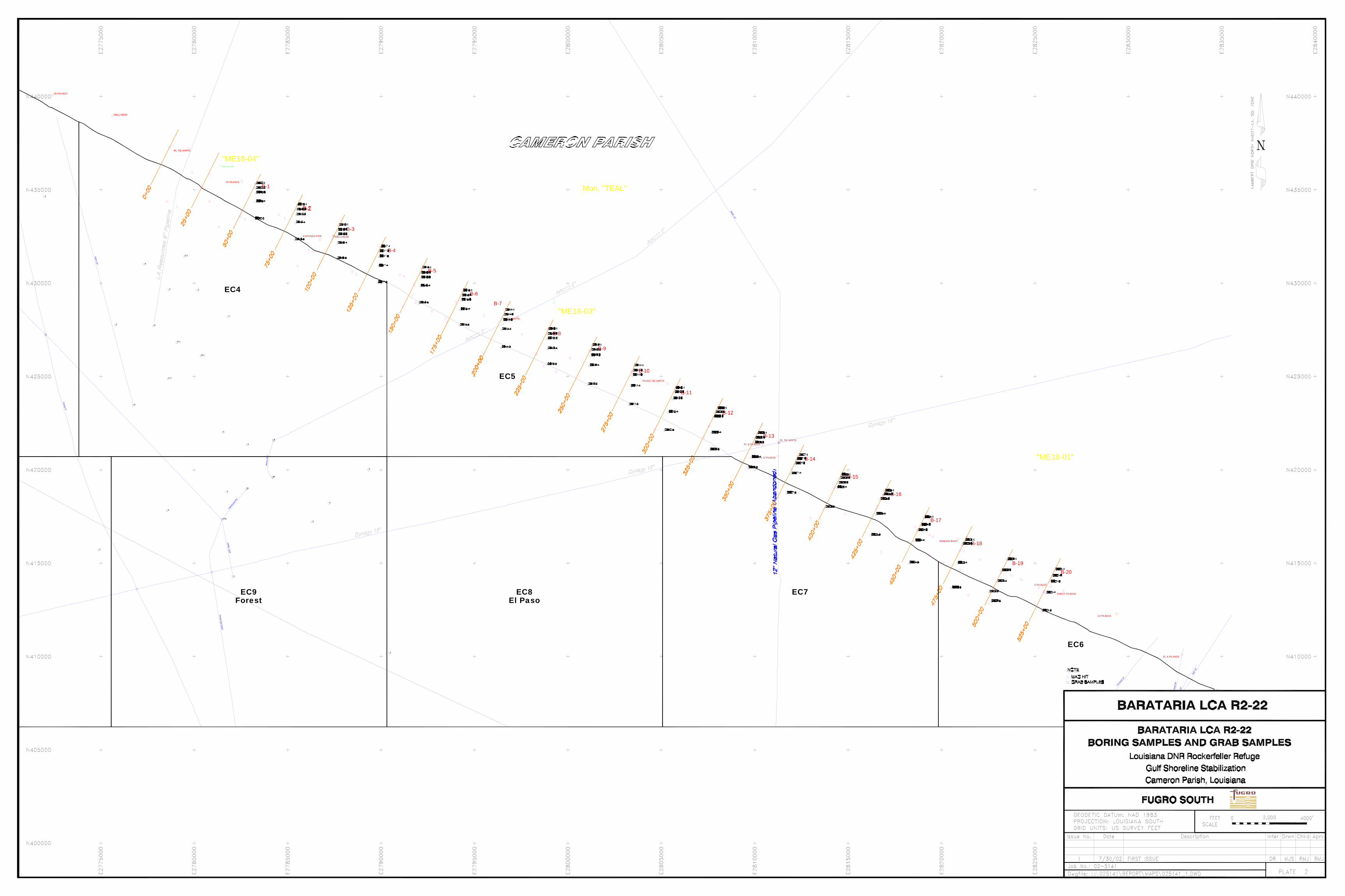
General. Fugro South, Inc. explored subsurface soil conditions at the project site between the
dates of June 17, 2002 and July 11, 2002 by drilling and sampling 20 exploratory soil borings and
obtaining 100 seafloor samples. The locations of the borings and grab samples are shown on the
Plan of Borings on Plate 2 of this report. Borings B-1, B-4, B-6, B-8, B-10, B-12, B-14, B-16, and
B-19 were drilled to a penetration of approximately 50 ft below existing shoreline grade. Borings
B-2, B-5, B-7, B-9, B-11, B-13, B-15, B-17, and B-20 were drilled to a penetration of approximately
25 ft below shoreline grade. Borings B-3 and B-18 were drilled to a depth of about 100 ft below
shoreline grade. It should be noted that the spacing between borings is approximately 2,500 ft.
Representatives of John E. Chance Land Surveyors staked the borehole locations requested by
SMA prior to our arrival onsite. Locations that could not be accessed were offset and the final
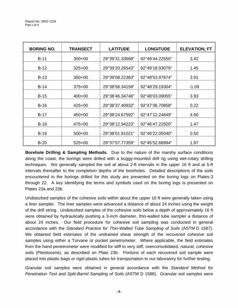
boring coordinates and elevations are provided in the following table. The coordinates and water-
depth readings at the time of sampling for the seafloor grab-samples are provided on Plate 2 at
the end of this report. The vertical datum is NAVD88.
BORING NO. TRANSECT LATITUDE LONGITUDE ELEVATION, FT
B-1 50+00 29°41’16.36193” 92°54’00.78323” 0.35
B-2 75+00 29°41’05.12261” 92°53’35.46969” 1.25
B-3 100+00 29°40’54.78499” 92°53’09.82675” -0.20
B-4 125+00 29°40’43.45767” 92°52’44.56051” -0.30
B-5 150+00 29°40’33.10483” 92°52’18.88296” 3.18
B-6 175+00 29°40’20.99154” 92°51’54.00504” 0.58
B-7 200+00 29°40’10.50906” 92°51’28.44306” 0.73
B-8 225+00 29°40’00.83905” 92°51’02.16568” 0.48
B-9 250+00 29°39’53.23203” 92°50’35.10695” 3.82
B-10 275+00 29°39’41.91963” 92°50’09.58169” -0.43
Report No. 0602-1316 Part I of II
-4-
BORING NO. TRANSECT LATITUDE LONGITUDE ELEVATION, FT
B-11 300+00 29°39’31.33668” 92°49’44.22550” 3.42
B-12 325+00 29°39’20.26543” 92°49’18.93079” 1.45
B-13 350+00 29°39’08.22383” 92°48’53.97874” 3.91
B-14 375+00 29°38’56.34158” 92°48’29.19304” -1.09
B-15 400+00 29°38’46.34746” 92°48’03.09055” 3.93
B-16 425+00 29°38’37.40932” 92°47’36.70858” 0.22
B-17 450+00 29°38’24.67592” 92°47’12.24649” 4.60
B-18 475+00 29°38’12.94223” 92°46’47.22920” 1.47
B-19 500+00 29°38’01.91021” 92°46’22.05040” 0.50
B-20 525+00 29°37’57.77359” 92°45’52.68994” 1.97
Borehole Drilling & Sampling Methods. Due to the nature of the marshy surface conditions
along the coast, the borings were drilled with a buggy-mounted drill rig using wet-rotary drilling
techniques. We generally sampled the soil at about 2-ft intervals in the upper 16 ft and at 5-ft
intervals thereafter to the completion depths of the boreholes. Detailed descriptions of the soils
encountered in the borings drilled for this study are presented on the boring logs on Plates 3
through 22. A key identifying the terms and symbols used on the boring logs is presented on
Plates 23a and 23b.
Undisturbed samples of the cohesive soils within about the upper 16 ft were generally taken using
a liner sampler. The liner samples were advanced a distance of about 24 inches using the weight
of the drill string. Undisturbed samples of the cohesive soils below a depth of approximately 16 ft
were obtained by hydraulically pushing a 3-inch diameter, thin-walled tube sampler a distance of
about 24 inches. Our field procedure for cohesive soil sampling was conducted in general
accordance with the Standard Practice for Thin-Walled Tube Sampling of Soils (ASTM D 1587).
We obtained field estimates of the undrained shear strength of the recovered cohesive soil
samples using either a Torvane or pocket penetrometer. Where applicable, the field estimates
from the hand penetrometer were modified for stiff to very stiff, overconsolidated, natural, cohesive
soils (Pleistocene), as described on Plate 23b. Portions of each recovered soil sample were
placed into plastic bags or rigid plastic tubes for transportation to our laboratory for further testing.
Granular soil samples were obtained in general accordance with the Standard Method for
Penetration Test and Split-Barrel Sampling of Soils (ASTM D 1586). Granular soil samples were

Report No. 0602-1316 Part I of II
-5-
obtained using the Standard Penetration Test (SPT) as described on Plate 23b. Our geotechnical
technician recorded the hammer blows for each sampling interval. The SPT N-value described on
Plate 23b is recorded on the boring logs. The soil samples obtained from the split-barrel sampler
were visually classified and placed in plastic bags for transportation to our laboratory.
Seafloor Grab Sampling. At each borehole location along the beach, 5 seafloor grab samples
were obtained in a perpendicular direction seaward from the shoreline. The samples were
collected at distances of about 0-, 250-, 500-, 1250-, and 2000-ft. Each sample was analyzed for
grain-size distribution. The coordinates and water-depth readings at the time of sampling for the
seafloor grab-samples are provided on Plate 2 at the end of this report.
Water Depth Observations. As stated earlier, borings along the shoreline were drilled with a
buggy-mounted drill rig using wet-rotary drilling methods. Due to the low surface elevation of the
coastline and the fact that wet-rotary drilling methods had to be utilized for sampling, water depth
readings within the exploratory boreholes could not be obtained. However, we were able to
measure the water depth at each seafloor grab-sample location. The water level was measured
from the water surface to the existing mudline. We have provided a discussion relating to the
water depths measured during our sampling operations later in the General Site Conditions section
of this report.
Borehole Sealing. Each boring was sealed with cement-bentonite grout from the bottom up using
a tremie pipe upon completion. When the grout returned to the surface, we removed the tremie
pipe and topped off the boreholes by pouring grout from the surface. Our field procedure for
borehole completion was conducted in general accordance with the regulations of the Louisiana
Department of Transportation and Development (LADOTD), the Office of Public Works (OPW),
and the Department of Environmental Quality (DEQ).
Laboratory Testing
The laboratory-testing program for this study was directed primarily toward evaluating the
classification properties and undrained shear strength of the coastal subsurface soils along the
area of Louisiana shoreline previously discussed. We also measured the compressibility
characteristics of the subsurface soils by performing eleven (11) incrementally-loaded
consolidation tests on selected samples. Particle size analyses or grain size curves developed
from our sieve analyses on select samples of fine material recovered during our drilling activities
are presented on Plates A-1 through A-10 in Appendix A of this report. Grain size curves
developed from our sieve analyses performed on each seafloor grab-sample are presented on
Plates B-1 through B-20 in Appendix B of this report (five (5) grain size distribution curves are
presented on each plate). Our laboratory tests were performed in general accordance with the
appropriate standards as tabulated at the end of this section.
Report No. 0602-1316 Part I of II
-6-
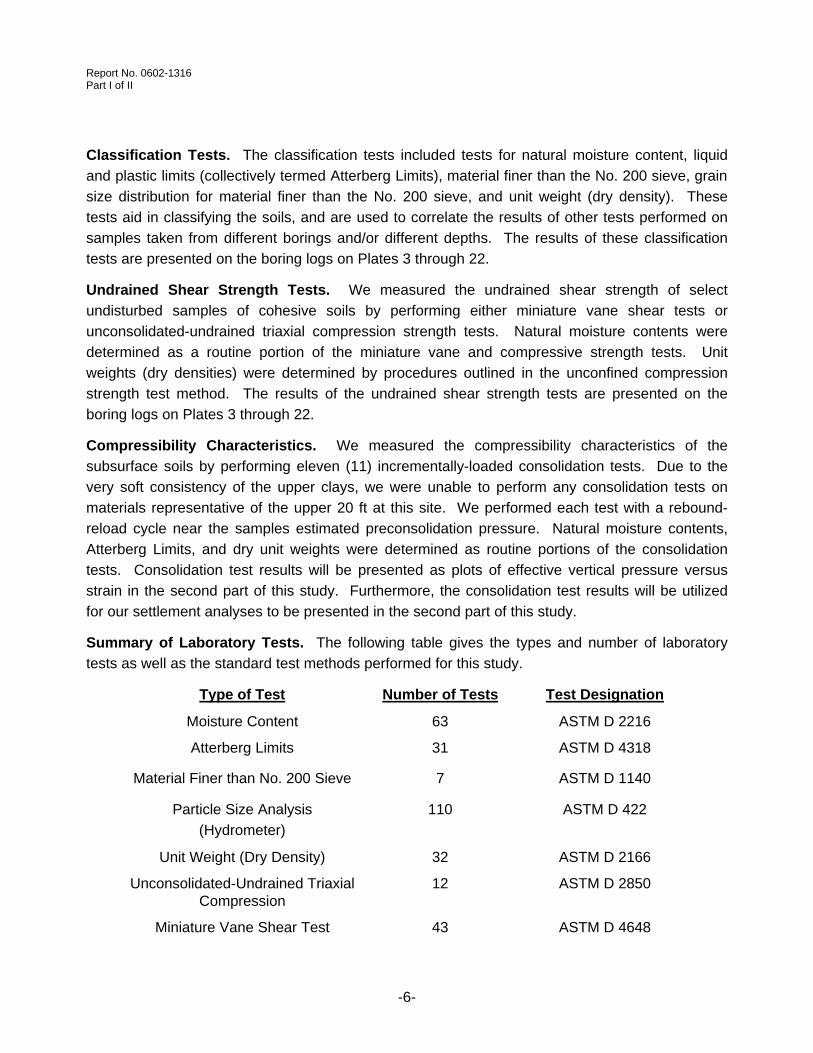
Classification Tests. The classification tests included tests for natural moisture content, liquid
and plastic limits (collectively termed Atterberg Limits), material finer than the No. 200 sieve, grain
size distribution for material finer than the No. 200 sieve, and unit weight (dry density). These
tests aid in classifying the soils, and are used to correlate the results of other tests performed on
samples taken from different borings and/or different depths. The results of these classification
tests are presented on the boring logs on Plates 3 through 22.
Undrained Shear Strength Tests. We measured the undrained shear strength of select
undisturbed samples of cohesive soils by performing either miniature vane shear tests or
unconsolidated-undrained triaxial compression strength tests. Natural moisture contents were
determined as a routine portion of the miniature vane and compressive strength tests. Unit
weights (dry densities) were determined by procedures outlined in the unconfined compression
strength test method. The results of the undrained shear strength tests are presented on the
boring logs on Plates 3 through 22.
Compressibility Characteristics. We measured the compressibility characteristics of the
subsurface soils by performing eleven (11) incrementally-loaded consolidation tests. Due to the
very soft consistency of the upper clays, we were unable to perform any consolidation tests on
materials representative of the upper 20 ft at this site. We performed each test with a rebound-
reload cycle near the samples estimated preconsolidation pressure. Natural moisture contents,
Atterberg Limits, and dry unit weights were determined as routine portions of the consolidation
tests. Consolidation test results will be presented as plots of effective vertical pressure versus
strain in the second part of this study. Furthermore, the consolidation test results will be utilized
for our settlement analyses to be presented in the second part of this study.
Summary of Laboratory Tests. The following table gives the types and number of laboratory
tests as well as the standard test methods performed for this study.
Type of Test Number of Tests Test Designation
Moisture Content 63 ASTM D 2216
Atterberg Limits 31 ASTM D 4318
Material Finer than No. 200 Sieve 7 ASTM D 1140
Particle Size Analysis
(Hydrometer)
110 ASTM D 422
Unit Weight (Dry Density) 32 ASTM D 2166
Unconsolidated-Undrained Triaxial Compression
12 ASTM D 2850
Miniature Vane Shear Test 43 ASTM D 4648

Report No. 0602-1316 Part I of II
-7-
Type of Test Number of Tests Test Designation
Incremental Consolidation Test 11 ASTM D 2435
General Site Conditions
The interpreted site and subsurface conditions based upon our field exploration and laboratory
testing are discussed in this section. This section also includes a discussion of the water depth
conditions encountered along the shoreline during our field exploration activities.
Site Description. The project site is generally composed of the southern portion of
Rockefeller Refuge located in Cameron Parish, Louisiana from Joseph’s Bayou westward along
the beach approximately 10 miles to the western boundary of the refuge. Surface conditions along
the coast essentially consist of very soft, highly organic topsoil and easily erodible shell fragments,
which compose the beach and grassy marshland. See Plate 2 for an aerial view of the project
site.
General Subsurface Conditions. We evaluated subsurface conditions along the shoreline by
reviewing the logs of our soil borings and evaluating the results of laboratory tests presented on
the boring logs. Generally, the subsurface soil conditions encountered in our soil borings consist
of approximately 0 to 5 ft of shell and shell fragments composing the surface of the beach
underlain by 35 to 40 ft of Recent clay deposits overlying natural clay of Pleistocene age
encountered to a depth of at least 100 ft below the existing shoreline, the maximum depth
explored for this study. A Generalized Subsurface Profile is provided on Plate 24. The following
table provides a general summary of the subsurface conditions encountered during this study.
Stratum Soil Description Average Depth
I Shell with Shell Fragments Beach Surface, 0 to 5 ft
II CLAY (Recent) 5 ft to about 40 ft
III CLAY with Silt and Sand
(Pleistocene)
40 ft to at least 100 ft
Stratum I consists of shell and fragmented shell that was observed in the borings performed on the
beach from the beach surface to an average depth of about 5 ft below grade. Tests performed on
selected samples indicate materials finer than the No. 200 sieve range from about 1 to 6 percent.
The measured blow counts (N-values) from the Standard Penetration Test range from 5 to 13
blows per foot in this stratum. These blow counts indicate a loose to medium-dense consistency.
Borings that were offset off the beach surface do not show the Stratum I material.
The measured undrained shear strength of the Stratum II Recent cohesive soils typically ranges
from approximately 80 psf (very soft) to 450 psf (soft). Undrained shear strengths as low as 60 psf

Report No. 0602-1316 Part I of II
-8-
were measured on several samples. Furthermore, it should be noted that relatively high values of
water content and Atterberg Limits (Liquid Limit, Plastic Limit, and Plasticity Index) indicated in the
Stratum II soils to a penetration of about 35 ft below shoreline grade are likely a result of organics
within the recovered soil samples. The water content of the upper clay soils is very close to its
Liquid Limit, which means that the upper clays have a consistency of a thick drilling mud.
The measured undrained shear strength in the Stratum III Pleistocene cohesive soils generally
ranges from approximately 1000 psf (stiff) to 2,000 psf (very stiff). Appreciable amounts of silt and
sand were encountered throughout Stratum III intermixed with the predominantly clay material.
It should be noted that we have reviewed existing soil data from previous Fugro South, Inc. reports
0600-1340 (Northwest Route Access Road, Pecos Prospect, Pecan Island Field) and 0600-1373
(Well and Bridge Locations, Pecos Upthrown Project, Pecan Island, Louisiana), which were in the
same general area of this project in South Louisiana to the east in Vermilion Parish. Subsurface
conditions are such that the approximate depth, classification, and consistency of the upper clay
soils are similar to the conditions discovered for this project. Additional information relating to the
subsurface conditions encountered in the borings drilled for this project is presented on the boring
logs on Plates 3 through 22 at the end of this report. A key identifying the terms and symbols
used on the boring logs is presented on Plates 23a and 23b.
Approximate Seafloor Water Depth. As previously indicated, we measured the water depth from
the water surface to the mudline at each of our seafloor grab-sample locations. The water depth
observations indicated that the water level at or near the shoreline, corresponding to the first
seafloor sample obtained nearest the coast at each boring location, was approximately 5 ft at the
time of sampling. This is due to the fact that there is not a gradual slope starting at grade and
progressing to a lower depth into the gulf. At the shoreline along the beach, there is a vertical
drop of about 5 ft starting at the coast then gradually deepening with distance away from the
shore. Generally, progressing in a southerly direction the recorded water depths increase to an
approximate depth of 11 ft at the final grab-sample locations, which are located about 2000 ft
seaward of the shore. The depth readings corresponding to each grab-sample location are
presented on the Plan of Borings on Plate 2. It should be noted that the reported water levels are
approximate and do not consider any variations in depth associated with tidal fluctuations and/or
the variability of the mudline (seafloor) across the site.
Variations in Subsurface Conditions. Our interpretations of soil and water depth conditions, as
described in this report, are based on data obtained from our field observations, seafloor sampling,
soil borings, and laboratory tests. It is possible that undisclosed variations in soil or water depth conditions, the lateral extent and depth of the various strata, especially the Stratum I shell, and the position of the mudline exist across the site. Please note that the borings were
spread about 2,500 ft apart, therefore, localized variations between boring locations are likely. We
recommend careful observations be performed during any construction to verify our
Report No. 0602-1316 Part I of II
-9-
interpretations. The information regarding subsurface conditions presented in this report should be
made available to prospective contractors for information only, and not as a warranty of
subsurface and/or water depth conditions.
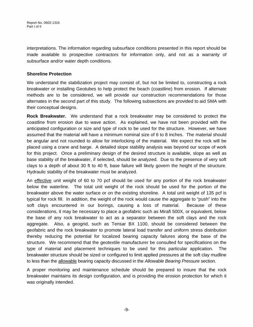
Shoreline Protection
We understand the stabilization project may consist of, but not be limited to, constructing a rock breakwater or installing Geotubes to help protect the beach (coastline) from erosion. If alternate methods are to be considered, we will provide our construction recommendations for those alternates in the second part of this study. The following subsections are provided to aid SMA with their conceptual designs.
Rock Breakwater. We understand that a rock breakwater may be considered to protect the coastline from erosion due to wave action. As explained, we have not been provided with the anticipated configuration or size and type of rock to be used for the structure. However, we have assumed that the material will have a minimum nominal size of 6 to 8 inches. The material should be angular and not rounded to allow for interlocking of the material. We expect the rock will be placed using a crane and barge. A detailed slope stability analysis was beyond our scope of work for this project. Once a preliminary design of the desired structure is available, slope as well as base stability of the breakwater, if selected, should be analyzed. Due to the presence of very soft clays to a depth of about 30 ft to 40 ft, base failure will likely govern the height of the structure. Hydraulic stability of the breakwater must be analyzed.
An effective unit weight of 60 to 70 pcf should be used for any portion of the rock breakwater below the waterline. The total unit weight of the rock should be used for the portion of the breakwater above the water surface or on the existing shoreline. A total unit weight of 135 pcf is typical for rock fill. In addition, the weight of the rock would cause the aggregate to “push” into the soft clays encountered in our borings, causing a loss of material. Because of these considerations, it may be necessary to place a geofabric such as Mirafi 500X, or equivalent, below the base of any rock breakwater to act as a separator between the soft clays and the rock aggregate. Also, a geogrid, such as Tensar BX 1100, should be considered between the geofabric and the rock breakwater to promote lateral load transfer and uniform stress distribution thereby reducing the potential for localized bearing capacity failures along the base of the structure. We recommend that the geotextile manufacturer be consulted for specifications on the type of material and placement techniques to be used for this particular application. The breakwater structure should be sized or configured to limit applied pressures at the soft clay mudline to less than the allowable bearing capacity discussed in the Allowable Bearing Pressure section.
A proper monitoring and maintenance schedule should be prepared to insure that the rock breakwater maintains its design configuration, and is providing the erosion protection for which it was originally intended.

Report No. 0602-1316 Part I of II
-10-
Geotubes. Geotubes are relatively large diameter cylindrical synthetic tubes that can be filled with dredge materials. The geotubes will act as a stable shoreline protection system protecting the shoreline from erosion.
The geotubes should be sized or configured to limit applied pressures at the soft clay mudline to less than the allowable bearing capacity discussed in the following section.
Allowable Bearing Pressure. The allowable bearing capacity depends primarily on the undrained shear strength of the foundation soils. We recommend an average allowable bearing pressure of 250 psf be utilized for the design of shoreline protection structures placed on land that bear in the upper Recent natural, clay soil deposits encountered in our exploratory borings. The allowable bearing pressure reported above includes a factor of safety of 2 with respect to shear failure of the foundation soils. However, for this application, and due to the fact that a localized failure of the protection structures on the shore may not be considered catastrophic, a lower value (1.5) may be acceptable for design. Due to the fact that mudline soils in the Gulf may possess lower localized values of undrained shear strength, the allowable bearing capacity utilized for the design of structures placed in the water should be verified through further exploration. We anticipate that at localized areas along the shore and along the seafloor, the allowable bearing capacity may be 30 percent lower than the average value reported above.
Settlement. Estimation of settlement for the very soft clays encountered at this site will be
difficult. In addition, consolidation tests could not be performed on the very soft clay samples
generally representative of the upper 20 ft of material. Therefore, our settlement estimates will be
based on judgment, past experience, and the consolidation settlement analyses. Results of these
analyses will be presented in the second part of this study once we have been provided with the
size and configuration of the breakwater. Due to the presence of very soft clays to a considerable
depth, very large consolidation and creep settlement over a long period of time should be expected
at this site. Differential settlement along and across the breakwater is also likely due to variations
in the strength and compressibility of the upper clays.
Construction Considerations
The following sections provide additional comments relative to lateral soil displacement due to
material placement, construction equipment, construction sequence, a field test section, and
construction monitoring.
Lateral Soil Displacement. The upper soils encountered in the exploratory borings consisted primarily of very soft clays. These clays extend from the existing shoreline (mudline) to a depth of about 40 ft. It is possible that a lateral soil displacement (mudwave) could be created in these upper soils when soil or rock is dropped on them. It is difficult to determine the magnitude of a lateral soil displacement. The lateral extent of the displacement will depend on the height from which the construction material is dropped. Reducing the height from which the materials are dropped into the water will help to reduce the extent of lateral displacement. In our opinion, it

Report No. 0602-1316 Part I of II
-11-
would be prudent to gently place the rock on the prepared subgrade (after the geofabric and geogrid are installed) as opposed to dropping the rock.
Construction Equipment. Any construction equipment used on the beach should be carefully
selected and should impart very low bearing pressure on the subgrade soils. Remolding of the
soils and continued operation of the construction equipment may further reduce the bearing
capacity of the soils. Construction equipment may sink in the very soft clays at this site unless it is
supported by mats or other properly prepared subgrade. It should be noted that the allowable
bearing capacity given in this report is an average across the site and localized areas have as
much as 30 percent lower bearing capacity.
Construction Sequence. We recommend that the sequence of the breakwater construction be
such that the entire breakwater is constructed in relatively uniform lifts. Significant (more that
about 0.5 ft) differences in height during construction should be avoided to reduce the potential for
slope/base failures.
Field Test Section. We strongly recommend that consideration be given to constructing a field
test section. The very soft clays at this site are prone to create a mudwave, which will be very
difficult to contain or remediate. Construction of a test section will give valuable information on
whether the breakwater can be constructed to its intended height, settlement and creep of the
soils, and will aid in developing construction sequence and techniques.
Construction Monitoring. We recommend that a geotechnical engineer, or qualified
representative, be present on-site to observe the construction of shoreline protection structures.
On-site observations may aid in recognizing and reconciling any unanticipated soil or groundwater
condition and to check that design recommendations are appropriate and properly implemented
during construction. During the construction phases, we can provide construction surveillance to:
(1) observe compliance with the design concepts, specifications, and recommendations; and (2)
observe subsurface conditions during construction.
* * *
Report No. 0602-1316 Part I of II
-12-
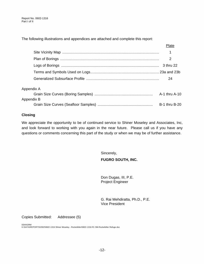
The following illustrations and appendices are attached and complete this report:
Plate
Site Vicinity Map ............................................................................................. 1
Plan of Borings ............................................................................................... 2
Logs of Borings .............................................................................................. 3 thru 22
Terms and Symbols Used on Logs.................................................................. 23a and 23b
Generalized Subsurface Profile ...................................................................... 24
Appendix A
Grain Size Curves (Boring Samples) ........................................................ A-1 thru A-10
Appendix B
Grain Size Curves (Seafloor Samples) ..................................................... B-1 thru B-20
Closing
We appreciate the opportunity to be of continued service to Shiner Moseley and Associates, Inc,
and look forward to working with you again in the near future. Please call us if you have any
questions or comments concerning this part of the study or when we may be of further assistance.
Sincerely,
FUGRO SOUTH, INC.
Don Dugas, III, P.E. Project Engineer
G. Rai Mehdiratta, Ph.D., P.E. Vice President Copies Submitted: Addressee (5) DDIII\GRM K:\DATA\REPORTS\2002\0602-1316 Shiner Moseley - Rockefeller\0602-1316 R1 SM-Rockefeller Refuge.doc

Report No. 0602-1316
PLATE 1
Reference: Louisiana Atlas & Gazetteer, 1st Edition, DeLorme, 1998.
SITE VICINITY MAP Not-to-Scale
Joseph’s Bayou
Mon. "TEAL"
"ME18-04"
"ME18-01"
1
A
E-1
1
D-1
C-1
B-1
1
1
4
4
2 4
1
1
1
1
1
4
2
3
1
STR
A
1
1
1
1
1
4*
1
Col
-Gul
f 16"
Petro
Corp
P/L"
Am
oco
P/L
"
Koch 10"
LA R
esou
rces
10"
Texas Gas 12&
3"
Forest 4"
Col-G
ulf 1
2"
Linder (2)3"
NG
PL 12"
TGP
12"
EC8El Paso
EC9Forest
EC4
EC5
EC7
EC6
EC18
"ME18-03"WITNESS
WITNESS
"PONTOON 2 AZ MK"
20 PILINGS
WELLHEAD
29 PILINGS
EXPOSED PIPE WELLHEAD
PL & PILINGS
PL & PILINGS
SUNKEN BOAT
6 PILINGS
SHEET PILINGS
13 PILINGS
PL & PILINGS
PL TIE W/RTK
PILING TIE W/RTK
PL TIE W/RTK
PL TIE W/RTK
B-1
B-3
B-20
B-4
B-5
B-6
B-7
B-8
B-9
B-10
B-11
B-12
B-13
B-14
B-15
B-16
B-17
B-18
B-19

50.0
108
111
74
30
27
CLAY, very soft, gray- organics 0' to 25'
- firm below 18'
- soft below 28'
- stiff to very stiff, brownish-yellow below 43'
- stiff below 48'
43
94
115
105
59
48
45
23
67
60
36
DATE: June 19, 2002
TOTAL DEPTH: 50.0'
CAVED DEPTH: Not Applicable
DRY AUGER: Not Applicable
WET ROTARY: 0' to 50'
BACKFILL: Cement-Bentonite Grout
LOGGER: J. PHIPPS
LOG OF BORING NO. B-1
29deg 41' 16.36193"N 92deg 54' 00.78323"W 29deg 41' 16.36193"N 92deg 54' 00.78323"W
SURFACE EL.: .35'
GULF SHORELINE STABILIZATION PROJECTROCKEFELLER REFUGE
CAMERON PARISH, LOUISIANA
LOCATION: See Plate 2COORDINATES:
PLATE 3
10
20
30
40
50
NOTES:1. Terms and symbols defined on Plate 23a and 23b.
LIQ
UID
LIM
IT
Triaxial
UN
IT D
RY
WT
,P
CF
PA
SS
ING
NO
.20
0 S
IEV
E, %
KIPS PER SQ FT
SY
MB
OL
Penetrometer Unconfined
PLA
ST
ICLI
MIT Miniature Vane
PLA
ST
ICIT
YIN
DE
X (
PI)
Torvane
STRATUM DESCRIPTION
WA
TE
RC
ON
TE
NT
, %
ST
RA
TU
MD
EP
TH
, F
T
0.5 1.0 1.5 2.0 2.5
C:\C
DB
UR
N~
1\LA
KE
CH
~1\
0602
-131
6.G
PJ
F
UG
RO
_SO
(LA
B D
AT
A)
8
/13/
2002
BL
OW
S P
ER
FO
OT
SA
MP
LES
WA
TE
R L
EV
EL
DE
PT
H,
FT
SHEAR STRENGTHCLASSIFICATION
Field Vane
Report No. 0602-1316
WA
TE
RC
ON
TE
NT
, %
ST
RA
TU
MD
EP
TH
, F
T
0.5 1.0 1.5 2.0 2.5
C:\C
DB
UR
N~
1\LA
KE
CH
~1\
0602
-131
6.G
PJ
F
UG
RO
_SO
(LA
B D
AT
A)
8
/13/
2002
BL
OW
S P
ER
FO
OT
SA
MP
LES
WA
TE
R L
EV
EL
DE
PT
H,
FT
SHEAR STRENGTHCLASSIFICATION
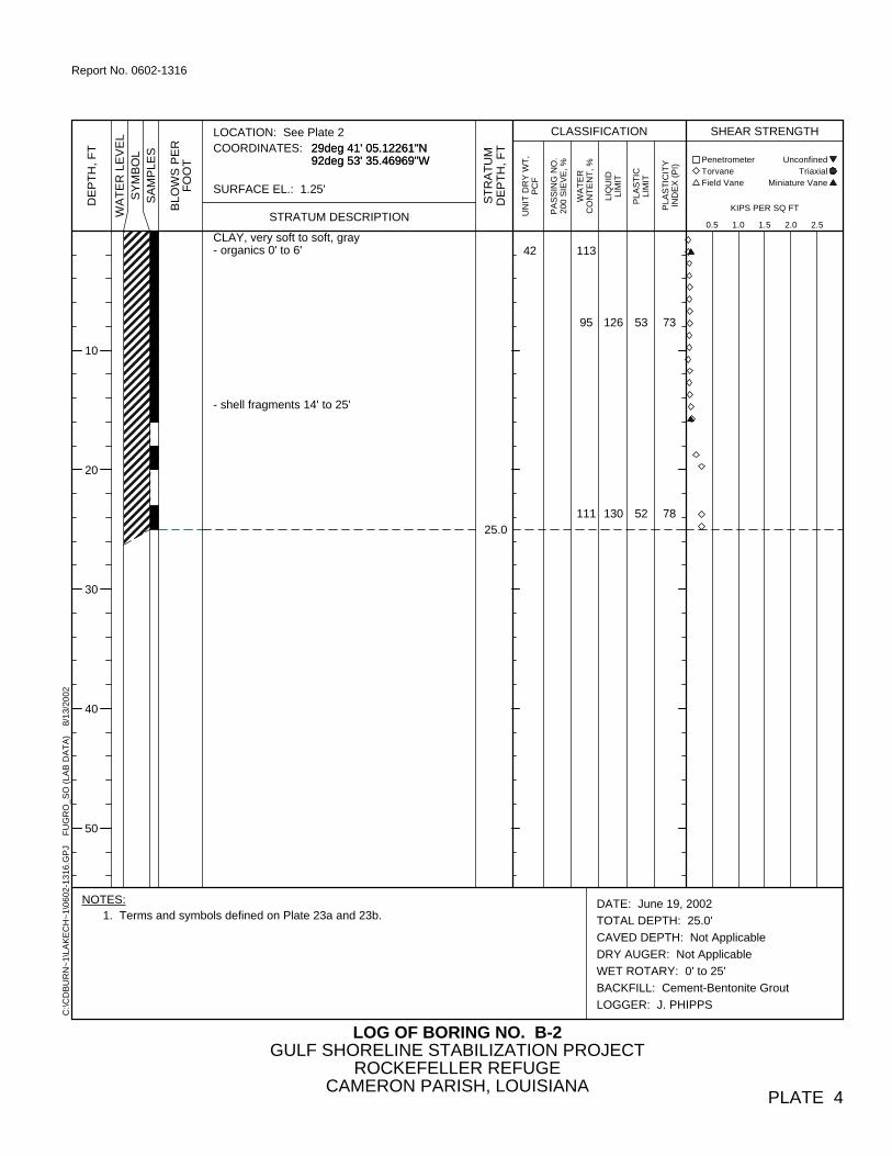
CLAY, very soft to soft, gray- organics 0' to 6'
- shell fragments 14' to 25'
42
25.0
113
95
111
126
130
53
52
73
78
DATE: June 19, 2002
TOTAL DEPTH: 25.0'
CAVED DEPTH: Not Applicable
DRY AUGER: Not Applicable
WET ROTARY: 0' to 25'
BACKFILL: Cement-Bentonite Grout
LOGGER: J. PHIPPS
LOG OF BORING NO. B-2
29deg 41' 05.12261"N 92deg 53' 35.46969"W 29deg 41' 05.12261"N 92deg 53' 35.46969"W
SURFACE EL.: 1.25'
GULF SHORELINE STABILIZATION PROJECTROCKEFELLER REFUGE
CAMERON PARISH, LOUISIANA
LOCATION: See Plate 2COORDINATES:
PLATE 4
10
20
30
40
50
NOTES:1. Terms and symbols defined on Plate 23a and 23b.
LIQ
UID
LIM
IT
Triaxial
UN
IT D
RY
WT
,P
CF
PA
SS
ING
NO
.20
0 S
IEV
E, %
KIPS PER SQ FT
SY
MB
OL
Penetrometer Unconfined
PLA
ST
ICLI
MIT Miniature Vane
PLA
ST
ICIT
YIN
DE
X (
PI)
Torvane
STRATUM DESCRIPTION
Field Vane
Report No. 0602-1316
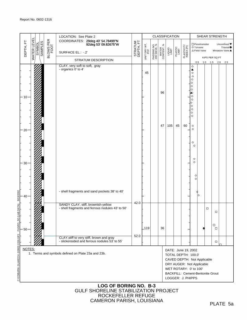
CLAY, very soft to soft, gray- organics 0' to 4'
- shell fragments and sand pockets 38' to 40'
SANDY CLAY, stiff, brownish-yellow- shell fragments and ferrous nodules 43' to 50'
CLAY,stiff to very stiff, brown and gray- slickensided and ferrous nodules 53' to 55'
45
119
42.0
52.0
96
47
36
105 45 60
DATE: June 19, 2002
TOTAL DEPTH: 100.0'
CAVED DEPTH: Not Applicable
DRY AUGER: Not Applicable
WET ROTARY: 0' to 100'
BACKFILL: Cement-Bentonite Grout
LOGGER: J. PHIPPS
LOG OF BORING NO. B-3
29deg 40' 54.78499"N 92deg 53' 09.82675"W 29deg 40' 54.78499"N 92deg 53' 09.82675"W
SURFACE EL.: -.2'
GULF SHORELINE STABILIZATION PROJECTROCKEFELLER REFUGE
CAMERON PARISH, LOUISIANA
LOCATION: See Plate 2COORDINATES:
PLATE 5a
10
20
30
40
50
NOTES:1. Terms and symbols defined on Plate 23a and 23b.
LIQ
UID
LIM
IT
Triaxial
UN
IT D
RY
WT
,P
CF
PA
SS
ING
NO
.20
0 S
IEV
E, %
KIPS PER SQ FT
SY
MB
OL
Penetrometer Unconfined
PLA
ST
ICLI
MIT Miniature Vane
PLA
ST
ICIT
YIN
DE
X (
PI)
Torvane
STRATUM DESCRIPTION
WA
TE
RC
ON
TE
NT
, %
ST
RA
TU
MD
EP
TH
, F
T
0.5 1.0 1.5 2.0 2.5
C:\C
DB
UR
N~
1\LA
KE
CH
~1\
0602
-131
6.G
PJ
F
UG
RO
_SO
(LA
B D
AT
A)
8
/13/
2002
BL
OW
S P
ER
FO
OT
SA
MP
LES
WA
TE
R L
EV
EL
DE
PT
H,
FT
SHEAR STRENGTHCLASSIFICATION
Field Vane
Report No. 0602-1316

CLAY, stiff to very stiff, yellowish-red and brownSANDY CLAY, firm, brown- shell fragments and ferrous nodules 58' to 65'
CLAY, firm to stiff, yellowish-red and brown- sand partings 68' to 70'
68
57.0
67.0
100.0
9961
76 34 42
DATE: June 19, 2002
TOTAL DEPTH: 100.0'
CAVED DEPTH: Not Applicable
DRY AUGER: Not Applicable
WET ROTARY: 0' to 100'
BACKFILL: Cement-Bentonite Grout
LOGGER: J. PHIPPS
LOG OF BORING NO. B-3
29deg 40' 54.78499"N 92deg 53' 09.82675"W 29deg 40' 54.78499"N 92deg 53' 09.82675"W
SURFACE EL.: -.2'
GULF SHORELINE STABILIZATION PROJECTROCKEFELLER REFUGE
CAMERON PARISH, LOUISIANA
LOCATION: See Plate 2COORDINATES:
PLATE 5b
60
70
80
90
100
NOTES:1. Terms and symbols defined on Plate 23a and 23b.
LIQ
UID
LIM
IT
Triaxial
UN
IT D
RY
WT
,P
CF
PA
SS
ING
NO
.20
0 S
IEV
E, %
KIPS PER SQ FT
SY
MB
OL
Penetrometer Unconfined
PLA
ST
ICLI
MIT Miniature Vane
PLA
ST
ICIT
YIN
DE
X (
PI)
Torvane
STRATUM DESCRIPTION
WA
TE
RC
ON
TE
NT
, %
ST
RA
TU
MD
EP
TH
, F
T
0.5 1.0 1.5 2.0 2.5
C:\C
DB
UR
N~
1\LA
KE
CH
~1\
0602
-131
6.G
PJ
F
UG
RO
_SO
(LA
B D
AT
A)
8
/13/
2002
BL
OW
S P
ER
FO
OT
SA
MP
LES
WA
TE
R L
EV
EL
DE
PT
H,
FT
SHEAR STRENGTHCLASSIFICATION
Field Vane
Report No. 0602-1316

148
114
57
26
27
16
122
87
41
DATE: June 21, 2002
TOTAL DEPTH: 50.0'
CAVED DEPTH: Not Applicable
DRY AUGER: Not Applicable
WET ROTARY: 0' to 50'
BACKFILL: Cement-Bentonite Grout
LOGGER: J. PHIPPS
LOG OF BORING NO. B-4
29deg 40' 43.45767"N 92deg 52' 44.56051"W 29deg 40' 43.45767"N 92deg 52' 44.56051"W
SURFACE EL.: -.3'
GULF SHORELINE STABILIZATION PROJECTROCKEFELLER REFUGE
CAMERON PARISH, LOUISIANA
LOCATION: See Plate 2COORDINATES:
PLATE 6
10
20
30
40
50
NOTES:1. Terms and symbols defined on Plate 23a and 23b.
LIQ
UID
LIM
IT
Triaxial
UN
IT D
RY
WT
,P
CF
CLAY, very soft to soft, gray- organics 0' to 6'
- stiff, brownish-yellow below 42'- calcareous nodules 43' to 45'- shell fragments 43' to 50'
- sand pockets below 48'
36
49
50.0
128
105
94
29
PA
SS
ING
NO
.20
0 S
IEV
E, %
KIPS PER SQ FT
SY
MB
OL
Penetrometer Unconfined
PLA
ST
ICLI
MIT Miniature Vane
PLA
ST
ICIT
YIN
DE
X (
PI)
Torvane
STRATUM DESCRIPTION
WA
TE
RC
ON
TE
NT
, %
ST
RA
TU
MD
EP
TH
, F
T
0.5 1.0 1.5 2.0 2.5
C:\C
DB
UR
N~
1\LA
KE
CH
~1\
0602
-131
6.G
PJ
F
UG
RO
_SO
(LA
B D
AT
A)
8
/13/
2002
BL
OW
S P
ER
FO
OT
SA
MP
LES
WA
TE
R L
EV
EL
DE
PT
H,
FT
SHEAR STRENGTHCLASSIFICATION
Field Vane
Report No. 0602-1316

SHELL, loose, light brown
CLAY, very soft to soft, gray- organics 0' to 4'
2
86
4.0
25.0
136
87
8
7
99 30 69
DATE: June 21, 2002
TOTAL DEPTH: 25.0'
CAVED DEPTH: Not Applicable
DRY AUGER: Not Applicable
WET ROTARY: 0' to 25'
BACKFILL: Cement-Bentonite Grout
LOGGER: J. PHIPPS
LOG OF BORING NO. B-5
29deg 40' 33.10483"N 92deg 52' 18.88296"W 29deg 40' 33.10483"N 92deg 52' 18.88296"W
SURFACE EL.: 3.18'
GULF SHORELINE STABILIZATION PROJECTROCKEFELLER REFUGE
CAMERON PARISH, LOUISIANA
LOCATION: See Plate 2COORDINATES:
PLATE 7
10
20
30
40
50
NOTES:1. Terms and symbols defined on Plate 23a and 23b.
LIQ
UID
LIM
IT
Triaxial
UN
IT D
RY
WT
,P
CF
PA
SS
ING
NO
.20
0 S
IEV
E, %
KIPS PER SQ FT
SY
MB
OL
Penetrometer Unconfined
PLA
ST
ICLI
MIT Miniature Vane
PLA
ST
ICIT
YIN
DE
X (
PI)
Torvane
STRATUM DESCRIPTION
WA
TE
RC
ON
TE
NT
, %
ST
RA
TU
MD
EP
TH
, F
T
0.5 1.0 1.5 2.0 2.5
C:\C
DB
UR
N~
1\LA
KE
CH
~1\
0602
-131
6.G
PJ
F
UG
RO
_SO
(LA
B D
AT
A)
8
/13/
2002
BL
OW
S P
ER
FO
OT
SA
MP
LES
WA
TE
R L
EV
EL
DE
PT
H,
FT
SHEAR STRENGTHCLASSIFICATION
Field Vane
Report No. 0602-1316

109
57
42
26
67
31
DATE: June 21, 2002
TOTAL DEPTH: 50.0'
CAVED DEPTH: Not Applicable
DRY AUGER: Not Applicable
WET ROTARY: 0' to 50'
BACKFILL: Cement-Bentonite Grout
LOGGER: J. PHIPPS
LOG OF BORING NO. B-6
29deg 40' 20.99154"N 92deg 51' 54.00504"W 29deg 40' 20.99154"N 92deg 51' 54.00504"W
SURFACE EL.: .58'
CLAY, very soft to soft, gray- organics 0' to 10'
- stiff, greenish-gray and brown below 32'- slickensided and sand partings 33' to 35'
- brown and gray below 38'- calcareous nodules 38' to 40'
- shell below 43'
37
119
50.0
114
148
33
34
GULF SHORELINE STABILIZATION PROJECTROCKEFELLER REFUGE
CAMERON PARISH, LOUISIANA
LOCATION: See Plate 2COORDINATES:
PLATE 8
10
20
30
40
50
NOTES:1. Terms and symbols defined on Plate 23a and 23b.
LIQ
UID
LIM
IT
Triaxial
UN
IT D
RY
WT
,P
CF
PA
SS
ING
NO
.20
0 S
IEV
E, %
KIPS PER SQ FT
SY
MB
OL
Penetrometer Unconfined
PLA
ST
ICLI
MIT Miniature Vane
PLA
ST
ICIT
YIN
DE
X (
PI)
Torvane
STRATUM DESCRIPTION
WA
TE
RC
ON
TE
NT
, %
ST
RA
TU
MD
EP
TH
, F
T
0.5 1.0 1.5 2.0 2.5
C:\C
DB
UR
N~
1\LA
KE
CH
~1\
0602
-131
6.G
PJ
F
UG
RO
_SO
(LA
B D
AT
A)
8
/13/
2002
BL
OW
S P
ER
FO
OT
SA
MP
LES
WA
TE
R L
EV
EL
DE
PT
H,
FT
SHEAR STRENGTHCLASSIFICATION
Field Vane
Report No. 0602-1316

SHELL, loose, brown
CLAY, very soft to soft, gray- organics 4' to 10'
3
41
4.0
25.0
109
114
103
10
6
115
105
49
19
66
86
DATE: June 21, 2002
TOTAL DEPTH: 25.0'
CAVED DEPTH: Not Applicable
DRY AUGER: Not Applicable
WET ROTARY: 0' to 25'
BACKFILL: Cement-Bentonite Grout
LOGGER: J. PHIPPS
LOG OF BORING NO. B-7
29deg 40' 10.50906"N 92deg 51' 28.44306"W 29deg 40' 10.50906"N 92deg 51' 28.44306"W
SURFACE EL.: .73'
GULF SHORELINE STABILIZATION PROJECTROCKEFELLER REFUGE
CAMERON PARISH, LOUISIANA
LOCATION: See Plate 2COORDINATES:
PLATE 9
10
20
30
40
50
NOTES:1. Terms and symbols defined on Plate 23a and 23b.
LIQ
UID
LIM
IT
Triaxial
UN
IT D
RY
WT
,P
CF
PA
SS
ING
NO
.20
0 S
IEV
E, %
KIPS PER SQ FT
SY
MB
OL
Penetrometer Unconfined
PLA
ST
ICLI
MIT Miniature Vane
PLA
ST
ICIT
YIN
DE
X (
PI)
Torvane
STRATUM DESCRIPTION
WA
TE
RC
ON
TE
NT
, %
ST
RA
TU
MD
EP
TH
, F
T
0.5 1.0 1.5 2.0 2.5
C:\C
DB
UR
N~
1\LA
KE
CH
~1\
0602
-131
6.G
PJ
F
UG
RO
_SO
(LA
B D
AT
A)
8
/13/
2002
BL
OW
S P
ER
FO
OT
SA
MP
LES
WA
TE
R L
EV
EL
DE
PT
H,
FT
SHEAR STRENGTHCLASSIFICATION
Field Vane
Report No. 0602-1316

CLAY, very soft to soft, gray- organics 0' to 11'
SANDY CLAY, stiff, gray
CLAY, firm to stiff, brownish-yellow and gray- calcareous nodules below 48'
44
99
42.0
48.0
50.0
100
25
32
126
56
26
15
100
41
DATE: June 21, 2002
TOTAL DEPTH: 50.0'
CAVED DEPTH: Not Applicable
DRY AUGER: Not Applicable
WET ROTARY: 0' to 50'
BACKFILL: Cement-Bentonite Grout
LOGGER: J. PHIPPS
LOG OF BORING NO. B-8
29deg 40' 00.8305"N 92deg 51' 02.16568"W 29deg 40' 00.8305"N 92deg 51' 02.16568"W
SURFACE EL.: .48'
GULF SHORELINE STABILIZATION PROJECTROCKEFELLER REFUGE
CAMERON PARISH, LOUISIANA
LOCATION: See Plate 2COORDINATES:
PLATE 10
10
20
30
40
50
NOTES:1. Terms and symbols defined on Plate 23a and 23b.
LIQ
UID
LIM
IT
Triaxial
UN
IT D
RY
WT
,P
CF
PA
SS
ING
NO
.20
0 S
IEV
E, %
KIPS PER SQ FT
SY
MB
OL
Penetrometer Unconfined
PLA
ST
ICLI
MIT Miniature Vane
PLA
ST
ICIT
YIN
DE
X (
PI)
Torvane
STRATUM DESCRIPTION
WA
TE
RC
ON
TE
NT
, %
ST
RA
TU
MD
EP
TH
, F
T
0.5 1.0 1.5 2.0 2.5
C:\C
DB
UR
N~
1\LA
KE
CH
~1\
0602
-131
6.G
PJ
F
UG
RO
_SO
(LA
B D
AT
A)
8
/13/
2002
BL
OW
S P
ER
FO
OT
SA
MP
LES
WA
TE
R L
EV
EL
DE
PT
H,
FT
SHEAR STRENGTHCLASSIFICATION
Field Vane
Report No. 0602-1316
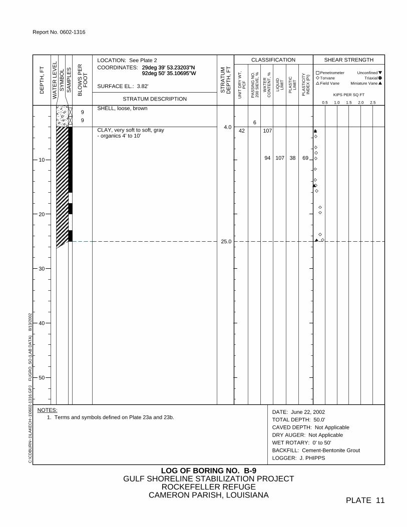
SHELL, loose, brown
CLAY, very soft to soft, gray- organics 4' to 10'
6
424.0
25.0
107
94
9
9
107 38 69
DATE: June 22, 2002
TOTAL DEPTH: 50.0'
CAVED DEPTH: Not Applicable
DRY AUGER: Not Applicable
WET ROTARY: 0' to 50'
BACKFILL: Cement-Bentonite Grout
LOGGER: J. PHIPPS
LOG OF BORING NO. B-9
29deg 39' 53.23203"N 92deg 50' 35.10695"W 29deg 39' 53.23203"N 92deg 50' 35.10695"W
SURFACE EL.: 3.82'
GULF SHORELINE STABILIZATION PROJECTROCKEFELLER REFUGE
CAMERON PARISH, LOUISIANA
LOCATION: See Plate 2COORDINATES:
PLATE 11
10
20
30
40
50
NOTES:1. Terms and symbols defined on Plate 23a and 23b.
LIQ
UID
LIM
IT
Triaxial
UN
IT D
RY
WT
,P
CF
PA
SS
ING
NO
.20
0 S
IEV
E, %
KIPS PER SQ FT
SY
MB
OL
Penetrometer Unconfined
PLA
ST
ICLI
MIT Miniature Vane
PLA
ST
ICIT
YIN
DE
X (
PI)
Torvane
STRATUM DESCRIPTION
WA
TE
RC
ON
TE
NT
, %
ST
RA
TU
MD
EP
TH
, F
T
0.5 1.0 1.5 2.0 2.5
C:\C
DB
UR
N~
1\LA
KE
CH
~1\
0602
-131
6.G
PJ
F
UG
RO
_SO
(LA
B D
AT
A)
8
/13/
2002
BL
OW
S P
ER
FO
OT
SA
MP
LES
WA
TE
R L
EV
EL
DE
PT
H,
FT
SHEAR STRENGTHCLASSIFICATION
Field Vane
Report No. 0602-1316

CLAY, very soft to soft, gray- shell fragments 0' to 2'- organics 0' to 8'
- shell fragments 38' to 40'
SANDY CLAY, stiff, greenish-gray
- gray and brown below 48'- sand pockets below 48'
32
101
42.0
50.0
102
84
22
93 63 30
DATE: June 22, 2002
TOTAL DEPTH: 50.0'
CAVED DEPTH: Not Applicable
DRY AUGER: Not Applicable
WET ROTARY: 0' to 50'
BACKFILL: Cement-Bentonite Grout
LOGGER: J. PHIPPS
LOG OF BORING NO. B-10
29deg 39' 41.91963"N 92deg 50' 09.58169"W 29deg 39' 41.91963"N 92deg 50' 09.58169"W
SURFACE EL.: -.43'
GULF SHORELINE STABILIZATION PROJECTROCKEFELLER REFUGE
CAMERON PARISH, LOUISIANA
LOCATION: See Plate 2COORDINATES:
PLATE 12
10
20
30
40
50
NOTES:1. Terms and symbols defined on Plate 23a and 23b.
LIQ
UID
LIM
IT
Triaxial
UN
IT D
RY
WT
,P
CF
PA
SS
ING
NO
.20
0 S
IEV
E, %
KIPS PER SQ FT
SY
MB
OL
Penetrometer Unconfined
PLA
ST
ICLI
MIT Miniature Vane
PLA
ST
ICIT
YIN
DE
X (
PI)
Torvane
STRATUM DESCRIPTION
WA
TE
RC
ON
TE
NT
, %
ST
RA
TU
MD
EP
TH
, F
T
0.5 1.0 1.5 2.0 2.5
C:\C
DB
UR
N~
1\LA
KE
CH
~1\
0602
-131
6.G
PJ
F
UG
RO
_SO
(LA
B D
AT
A)
8
/13/
2002
BL
OW
S P
ER
FO
OT
SA
MP
LES
WA
TE
R L
EV
EL
DE
PT
H,
FT
SHEAR STRENGTHCLASSIFICATION
Field Vane
Report No. 0602-1316
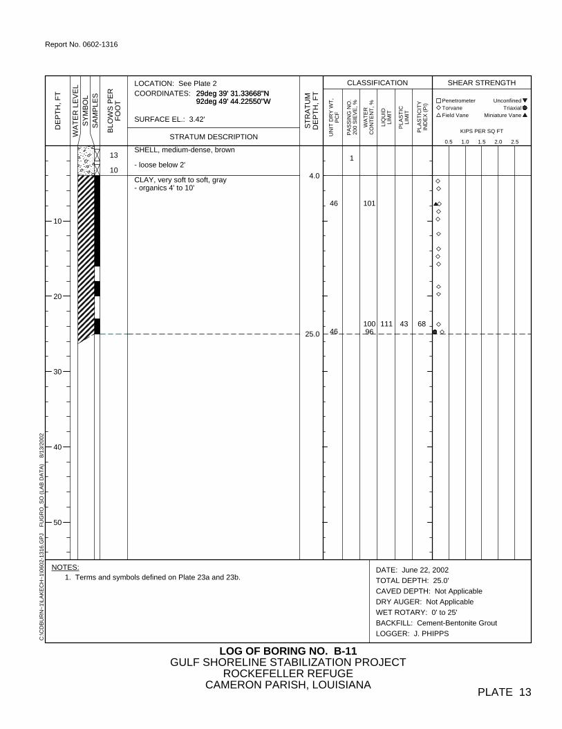
SHELL, medium-dense, brown
- loose below 2'
CLAY, very soft to soft, gray- organics 4' to 10'
1
46
46
4.0
25.0
101
10096
13
10
111 43 68
DATE: June 22, 2002
TOTAL DEPTH: 25.0'
CAVED DEPTH: Not Applicable
DRY AUGER: Not Applicable
WET ROTARY: 0' to 25'
BACKFILL: Cement-Bentonite Grout
LOGGER: J. PHIPPS
LOG OF BORING NO. B-11
29deg 39' 31.33668"N 92deg 49' 44.22550"W 29deg 39' 31.33668"N 92deg 49' 44.22550"W
SURFACE EL.: 3.42'
GULF SHORELINE STABILIZATION PROJECTROCKEFELLER REFUGE
CAMERON PARISH, LOUISIANA
LOCATION: See Plate 2COORDINATES:
PLATE 13
10
20
30
40
50
NOTES:1. Terms and symbols defined on Plate 23a and 23b.
LIQ
UID
LIM
IT
Triaxial
UN
IT D
RY
WT
,P
CF
PA
SS
ING
NO
.20
0 S
IEV
E, %
KIPS PER SQ FT
SY
MB
OL
Penetrometer Unconfined
PLA
ST
ICLI
MIT Miniature Vane
PLA
ST
ICIT
YIN
DE
X (
PI)
Torvane
STRATUM DESCRIPTION
WA
TE
RC
ON
TE
NT
, %
ST
RA
TU
MD
EP
TH
, F
T
0.5 1.0 1.5 2.0 2.5
C:\C
DB
UR
N~
1\LA
KE
CH
~1\
0602
-131
6.G
PJ
F
UG
RO
_SO
(LA
B D
AT
A)
8
/13/
2002
BL
OW
S P
ER
FO
OT
SA
MP
LES
WA
TE
R L
EV
EL
DE
PT
H,
FT
SHEAR STRENGTHCLASSIFICATION
Field Vane
Report No. 0602-1316

CLAY, very soft to soft, gray- organics 0' to 8'
- stiff to very stiff, brown and gray below 42'- slickensided 43' to 50'- calcareous nodules, 43' to 45'
44
44
50.0
99
104
109113
104
110
41
44
63
66
DATE: June 23, 2002
TOTAL DEPTH: 50.0'
CAVED DEPTH: Not Applicable
DRY AUGER: Not Applicable
WET ROTARY: 0' to 50'
BACKFILL: Cement-Bentonite Grout
LOGGER: J. PHIPPS
LOG OF BORING NO. B-12
29deg 39' 20.26543"N 92deg 49' 18.93079"W 29deg 39' 20.26543"N 92deg 49' 18.93079"W
SURFACE EL.: 1.45'
GULF SHORELINE STABILIZATION PROJECTROCKEFELLER REFUGE
CAMERON PARISH, LOUISIANA
LOCATION: See Plate 2COORDINATES:
PLATE 14
10
20
30
40
50
NOTES:1. Terms and symbols defined on Plate 23a and 23b.
LIQ
UID
LIM
IT
Triaxial
UN
IT D
RY
WT
,P
CF
PA
SS
ING
NO
.20
0 S
IEV
E, %
KIPS PER SQ FT
SY
MB
OL
Penetrometer Unconfined
PLA
ST
ICLI
MIT Miniature Vane
PLA
ST
ICIT
YIN
DE
X (
PI)
Torvane
STRATUM DESCRIPTION
WA
TE
RC
ON
TE
NT
, %
ST
RA
TU
MD
EP
TH
, F
T
0.5 1.0 1.5 2.0 2.5
C:\C
DB
UR
N~
1\LA
KE
CH
~1\
0602
-131
6.G
PJ
F
UG
RO
_SO
(LA
B D
AT
A)
8
/13/
2002
BL
OW
S P
ER
FO
OT
SA
MP
LES
WA
TE
R L
EV
EL
DE
PT
H,
FT
SHEAR STRENGTHCLASSIFICATION
Field Vane
Report No. 0602-1316
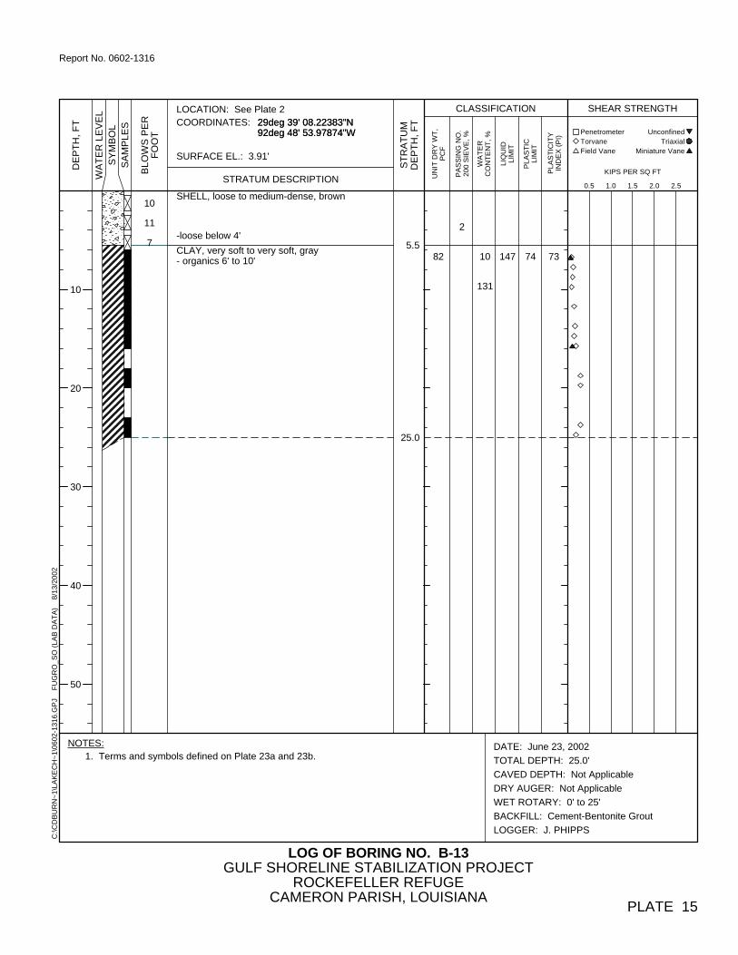
SHELL, loose to medium-dense, brown
-loose below 4'
CLAY, very soft to very soft, gray- organics 6' to 10'
2
825.5
25.0
10
131
10
11
7
147 74 73
DATE: June 23, 2002
TOTAL DEPTH: 25.0'
CAVED DEPTH: Not Applicable
DRY AUGER: Not Applicable
WET ROTARY: 0' to 25'
BACKFILL: Cement-Bentonite Grout
LOGGER: J. PHIPPS
LOG OF BORING NO. B-13
29deg 39' 08.22383"N 92deg 48' 53.97874"W 29deg 39' 08.22383"N 92deg 48' 53.97874"W
SURFACE EL.: 3.91'
GULF SHORELINE STABILIZATION PROJECTROCKEFELLER REFUGE
CAMERON PARISH, LOUISIANA
LOCATION: See Plate 2COORDINATES:
PLATE 15
10
20
30
40
50
NOTES:1. Terms and symbols defined on Plate 23a and 23b.
LIQ
UID
LIM
IT
Triaxial
UN
IT D
RY
WT
,P
CF
PA
SS
ING
NO
.20
0 S
IEV
E, %
KIPS PER SQ FT
SY
MB
OL
Penetrometer Unconfined
PLA
ST
ICLI
MIT Miniature Vane
PLA
ST
ICIT
YIN
DE
X (
PI)
Torvane
STRATUM DESCRIPTION
WA
TE
RC
ON
TE
NT
, %
ST
RA
TU
MD
EP
TH
, F
T
0.5 1.0 1.5 2.0 2.5
C:\C
DB
UR
N~
1\LA
KE
CH
~1\
0602
-131
6.G
PJ
F
UG
RO
_SO
(LA
B D
AT
A)
8
/13/
2002
BL
OW
S P
ER
FO
OT
SA
MP
LES
WA
TE
R L
EV
EL
DE
PT
H,
FT
SHEAR STRENGTHCLASSIFICATION
Field Vane
Report No. 0602-1316
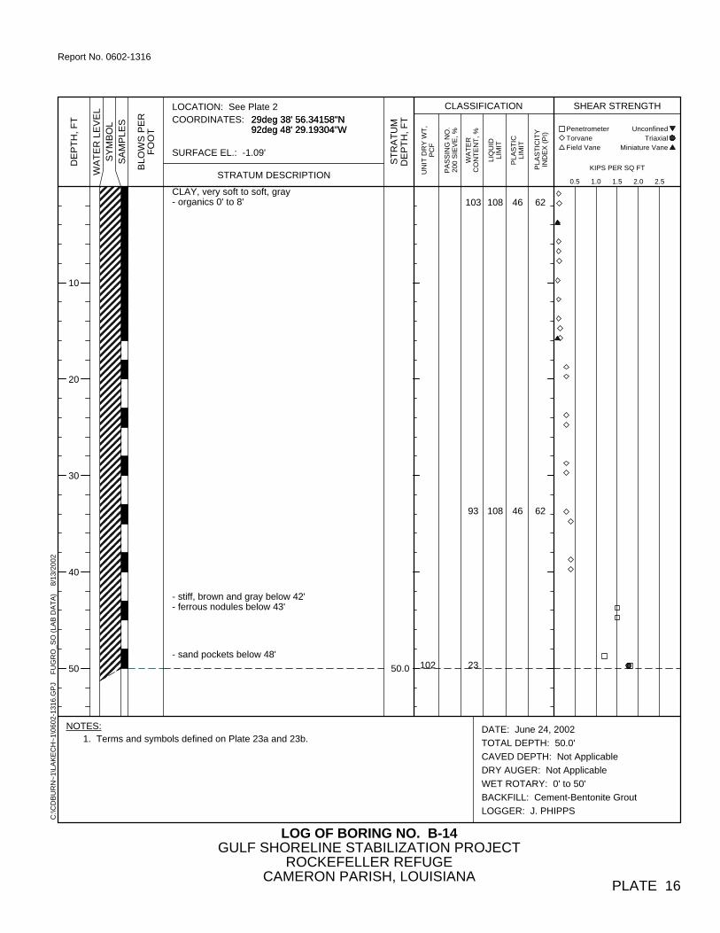
CLAY, very soft to soft, gray- organics 0' to 8'
- stiff, brown and gray below 42'- ferrous nodules below 43'
- sand pockets below 48'10250.0
103
93
23
108
108
46
46
62
62
DATE: June 24, 2002
TOTAL DEPTH: 50.0'
CAVED DEPTH: Not Applicable
DRY AUGER: Not Applicable
WET ROTARY: 0' to 50'
BACKFILL: Cement-Bentonite Grout
LOGGER: J. PHIPPS
LOG OF BORING NO. B-14
29deg 38' 56.34158"N 92deg 48' 29.19304"W 29deg 38' 56.34158"N 92deg 48' 29.19304"W
SURFACE EL.: -1.09'
GULF SHORELINE STABILIZATION PROJECTROCKEFELLER REFUGE
CAMERON PARISH, LOUISIANA
LOCATION: See Plate 2COORDINATES:
PLATE 16
10
20
30
40
50
NOTES:1. Terms and symbols defined on Plate 23a and 23b.
LIQ
UID
LIM
IT
Triaxial
UN
IT D
RY
WT
,P
CF
PA
SS
ING
NO
.20
0 S
IEV
E, %
KIPS PER SQ FT
SY
MB
OL
Penetrometer Unconfined
PLA
ST
ICLI
MIT Miniature Vane
PLA
ST
ICIT
YIN
DE
X (
PI)
Torvane
STRATUM DESCRIPTION
WA
TE
RC
ON
TE
NT
, %
ST
RA
TU
MD
EP
TH
, F
T
0.5 1.0 1.5 2.0 2.5
C:\C
DB
UR
N~
1\LA
KE
CH
~1\
0602
-131
6.G
PJ
F
UG
RO
_SO
(LA
B D
AT
A)
8
/13/
2002
BL
OW
S P
ER
FO
OT
SA
MP
LES
WA
TE
R L
EV
EL
DE
PT
H,
FT
SHEAR STRENGTHCLASSIFICATION
Field Vane
Report No. 0602-1316
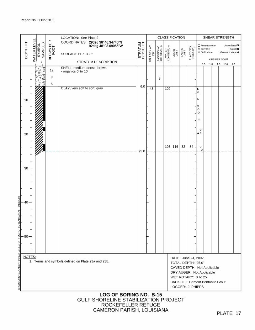
SHELL, medium-dense, brown- organics 0' to 10'
CLAY, very soft to soft, gray
3
436.0
25.0
102
103
12
9
5
116 32 84
DATE: June 24, 2002
TOTAL DEPTH: 25.0'
CAVED DEPTH: Not Applicable
DRY AUGER: Not Applicable
WET ROTARY: 0' to 25'
BACKFILL: Cement-Bentonite Grout
LOGGER: J. PHIPPS
LOG OF BORING NO. B-15
29deg 38' 46.34746"N 92deg 48' 03.09055"W 29deg 38' 46.34746"N 92deg 48' 03.09055"W
SURFACE EL.: 3.93'
GULF SHORELINE STABILIZATION PROJECTROCKEFELLER REFUGE
CAMERON PARISH, LOUISIANA
LOCATION: See Plate 2COORDINATES:
PLATE 17
10
20
30
40
50
NOTES:1. Terms and symbols defined on Plate 23a and 23b.
LIQ
UID
LIM
IT
Triaxial
UN
IT D
RY
WT
,P
CF
PA
SS
ING
NO
.20
0 S
IEV
E, %
KIPS PER SQ FT
SY
MB
OL
Penetrometer Unconfined
PLA
ST
ICLI
MIT Miniature Vane
PLA
ST
ICIT
YIN
DE
X (
PI)
Torvane
STRATUM DESCRIPTION
WA
TE
RC
ON
TE
NT
, %
ST
RA
TU
MD
EP
TH
, F
T
0.5 1.0 1.5 2.0 2.5
C:\C
DB
UR
N~
1\LA
KE
CH
~1\
0602
-131
6.G
PJ
F
UG
RO
_SO
(LA
B D
AT
A)
8
/13/
2002
BL
OW
S P
ER
FO
OT
SA
MP
LES
WA
TE
R L
EV
EL
DE
PT
H,
FT
SHEAR STRENGTHCLASSIFICATION
Field Vane
Report No. 0602-1316

DATE: June 24, 2002
TOTAL DEPTH: 50.0'
CAVED DEPTH: Not Applicable
DRY AUGER: Not Applicable
WET ROTARY: 0' to 50'
BACKFILL: Cement-Bentonite Grout
LOGGER: J. PHIPPS
LOG OF BORING NO. B-16
29deg 38' 37.40932"N 92deg 47' 36.70858"W 29deg 38' 37.40932"N 92deg 47' 36.70858"W
SURFACE EL.: .22'
GULF SHORELINE STABILIZATION PROJECTROCKEFELLER REFUGE
CAMERON PARISH, LOUISIANA
LOCATION: See Plate 2COORDINATES:
PLATE 18
10
20
30
40
50
NOTES:1. Terms and symbols defined on Plate 23a and 23b.
CLAY, very soft to soft, gray- organics 0' to10'
- stiff to very stiff, brownish-yellow and graybelow 42'
- slickensided and ferrous nodules 43' to 45'
- shell fragments below 48'
42
100
50.0
100
114
93
24
131
105
51
41
80
64
LIQ
UID
LIM
IT
Triaxial
UN
IT D
RY
WT
,P
CF
PA
SS
ING
NO
.20
0 S
IEV
E, %
KIPS PER SQ FT
SY
MB
OL
Penetrometer Unconfined
PLA
ST
ICLI
MIT Miniature Vane
PLA
ST
ICIT
YIN
DE
X (
PI)
Torvane
STRATUM DESCRIPTION
WA
TE
RC
ON
TE
NT
, %
ST
RA
TU
MD
EP
TH
, F
T
0.5 1.0 1.5 2.0 2.5
C:\C
DB
UR
N~
1\LA
KE
CH
~1\
0602
-131
6.G
PJ
F
UG
RO
_SO
(LA
B D
AT
A)
8
/13/
2002
BL
OW
S P
ER
FO
OT
SA
MP
LES
WA
TE
R L
EV
EL
DE
PT
H,
FT
SHEAR STRENGTHCLASSIFICATION
Field Vane
Report No. 0602-1316

SHELL, medium-dense, brown- organics 0' to 10'- loose below 2'
CLAY, very soft, gray
- sand pockets 18' to 20'
3
29
4.0
25.0
165
99
12
9
76 34 42
DATE: June 26, 2002
TOTAL DEPTH: 25.0'
CAVED DEPTH: Not Applicable
DRY AUGER: Not Applicable
WET ROTARY: 0' to 25'
BACKFILL: Cement-Bentonite Grout
LOGGER: J. PHIPPS
LOG OF BORING NO. B-17
29deg 38' 24.67592"N 92deg 47' 12.24649"W 29deg 38' 24.67592"N 92deg 47' 12.24649"W
SURFACE EL.: 4.6'
GULF SHORELINE STABILIZATION PROJECTROCKEFELLER REFUGE
CAMERON PARISH, LOUISIANA
LOCATION: See Plate 2COORDINATES:
PLATE 19
10
20
30
40
50
NOTES:1. Terms and symbols defined on Plate 23a and 23b.
LIQ
UID
LIM
IT
Triaxial
UN
IT D
RY
WT
,P
CF
PA
SS
ING
NO
.20
0 S
IEV
E, %
KIPS PER SQ FT
SY
MB
OL
Penetrometer Unconfined
PLA
ST
ICLI
MIT Miniature Vane
PLA
ST
ICIT
YIN
DE
X (
PI)
Torvane
STRATUM DESCRIPTION
WA
TE
RC
ON
TE
NT
, %
ST
RA
TU
MD
EP
TH
, F
T
0.5 1.0 1.5 2.0 2.5
C:\C
DB
UR
N~
1\LA
KE
CH
~1\
0602
-131
6.G
PJ
F
UG
RO
_SO
(LA
B D
AT
A)
8
/13/
2002
BL
OW
S P
ER
FO
OT
SA
MP
LES
WA
TE
R L
EV
EL
DE
PT
H,
FT
SHEAR STRENGTHCLASSIFICATION
Field Vane
Report No. 0602-1316

150
116
34
CLAY, very soft to soft, gray- organics 0' to 4'
- stiff, brownish-yellow and gray below 42'- slickensided 43' to 45'
- ferrous nodules and calcareous nodules 48' to50'
- shell 53' to 60'
41
95
169 78 91
DATE: June 26, 2002
TOTAL DEPTH: 100.0'
CAVED DEPTH: Not Applicable
DRY AUGER: Not Applicable
WET ROTARY: 0' to 100'
BACKFILL: Cement-Bentonite Grout
LOGGER: J. PHIPPS
LOG OF BORING NO. B-18
29deg 38' 12.94223"N 92deg 46' 47.22920"W 29deg 38' 12.94223"N 92deg 46' 47.22920"W
SURFACE EL.: 1.47'
GULF SHORELINE STABILIZATION PROJECTROCKEFELLER REFUGE
CAMERON PARISH, LOUISIANA
LOCATION: See Plate 2COORDINATES:
PLATE 20a
10
20
30
40
50
NOTES:1. Terms and symbols defined on Plate 23a and 23b.
LIQ
UID
LIM
IT
Triaxial
UN
IT D
RY
WT
,P
CF
PA
SS
ING
NO
.20
0 S
IEV
E, %
KIPS PER SQ FT
SY
MB
OL
Penetrometer Unconfined
PLA
ST
ICLI
MIT Miniature Vane
PLA
ST
ICIT
YIN
DE
X (
PI)
Torvane
STRATUM DESCRIPTION
WA
TE
RC
ON
TE
NT
, %
ST
RA
TU
MD
EP
TH
, F
T
0.5 1.0 1.5 2.0 2.5
C:\C
DB
UR
N~
1\LA
KE
CH
~1\
0602
-131
6.G
PJ
F
UG
RO
_SO
(LA
B D
AT
A)
8
/13/
2002
BL
OW
S P
ER
FO
OT
SA
MP
LES
WA
TE
R L
EV
EL
DE
PT
H,
FT
SHEAR STRENGTHCLASSIFICATION
Field Vane
Report No. 0602-1316

62.0
72.0
78.0
92.0
100.0
28
CLAY, firm, brownish-yellow and gray
SANDY CLAY, firm, gray- ferrous nodules 63' to 65'
- dark gray and gray below 68'- organics 68' to 70'
CLAY, firm, gray- silt partings 73' to 75'
SILTY CLAY, firm to stiff, brown- silt pockets 78' to 90'
- soft to firm below 83'
CLAY, stiff, gray
- firm below 98'
101
DATE: June 26, 2002
TOTAL DEPTH: 100.0'
CAVED DEPTH: Not Applicable
DRY AUGER: Not Applicable
WET ROTARY: 0' to 100'
BACKFILL: Cement-Bentonite Grout
LOGGER: J. PHIPPS
LOG OF BORING NO. B-18
29deg 38' 12.94223"N 92deg 46' 47.22920"W 29deg 38' 12.94223"N 92deg 46' 47.22920"W
SURFACE EL.: 1.47'
GULF SHORELINE STABILIZATION PROJECTROCKEFELLER REFUGE
CAMERON PARISH, LOUISIANA
LOCATION: See Plate 2COORDINATES:
PLATE 20b
60
70
80
90
100
NOTES:1. Terms and symbols defined on Plate 23a and 23b.
LIQ
UID
LIM
IT
Triaxial
UN
IT D
RY
WT
,P
CF
PA
SS
ING
NO
.20
0 S
IEV
E, %
KIPS PER SQ FT
SY
MB
OL
Penetrometer Unconfined
PLA
ST
ICLI
MIT Miniature Vane
PLA
ST
ICIT
YIN
DE
X (
PI)
Torvane
STRATUM DESCRIPTION
WA
TE
RC
ON
TE
NT
, %
ST
RA
TU
MD
EP
TH
, F
T
0.5 1.0 1.5 2.0 2.5
C:\C
DB
UR
N~
1\LA
KE
CH
~1\
0602
-131
6.G
PJ
F
UG
RO
_SO
(LA
B D
AT
A)
8
/13/
2002
BL
OW
S P
ER
FO
OT
SA
MP
LES
WA
TE
R L
EV
EL
DE
PT
H,
FT
SHEAR STRENGTHCLASSIFICATION
Field Vane
Report No. 0602-1316

CLAY, very soft to soft, gray- organics 0' to 6'
- sand partings 33' to 40'
- firm to stiff, greenish-gray and gray below 42'- sand pockets and ferrous nodules 43' to 45'
SANDY CLAY, stiff, brown- sand pockets below 48'
46
47.0
50.0
105
93 102 45 57
DATE: June 26, 2002
TOTAL DEPTH: 50.0'
CAVED DEPTH: Not Applicable
DRY AUGER: Not Applicable
WET ROTARY: 0' to 50'
BACKFILL: Cement-Bentonite Grout
LOGGER: J. PHIPPS
LOG OF BORING NO. B-19
29deg 38' 01.91021"N 92deg 46' 22.02040"W 29deg 38' 01.91021"N 92deg 46' 22.02040"W
SURFACE EL.: .5'
GULF SHORELINE STABILIZATION PROJECTROCKEFELLER REFUGE
CAMERON PARISH, LOUISIANA
LOCATION: See Plate 2COORDINATES:
PLATE 21
10
20
30
40
50
NOTES:1. Terms and symbols defined on Plate 23a and 23b.
LIQ
UID
LIM
IT
Triaxial
UN
IT D
RY
WT
,P
CF
PA
SS
ING
NO
.20
0 S
IEV
E, %
KIPS PER SQ FT
SY
MB
OL
Penetrometer Unconfined
PLA
ST
ICLI
MIT Miniature Vane
PLA
ST
ICIT
YIN
DE
X (
PI)
Torvane
STRATUM DESCRIPTION
WA
TE
RC
ON
TE
NT
, %
ST
RA
TU
MD
EP
TH
, F
T
0.5 1.0 1.5 2.0 2.5
C:\C
DB
UR
N~
1\LA
KE
CH
~1\
0602
-131
6.G
PJ
F
UG
RO
_SO
(LA
B D
AT
A)
8
/13/
2002
BL
OW
S P
ER
FO
OT
SA
MP
LES
WA
TE
R L
EV
EL
DE
PT
H,
FT
SHEAR STRENGTHCLASSIFICATION
Field Vane
Report No. 0602-1316
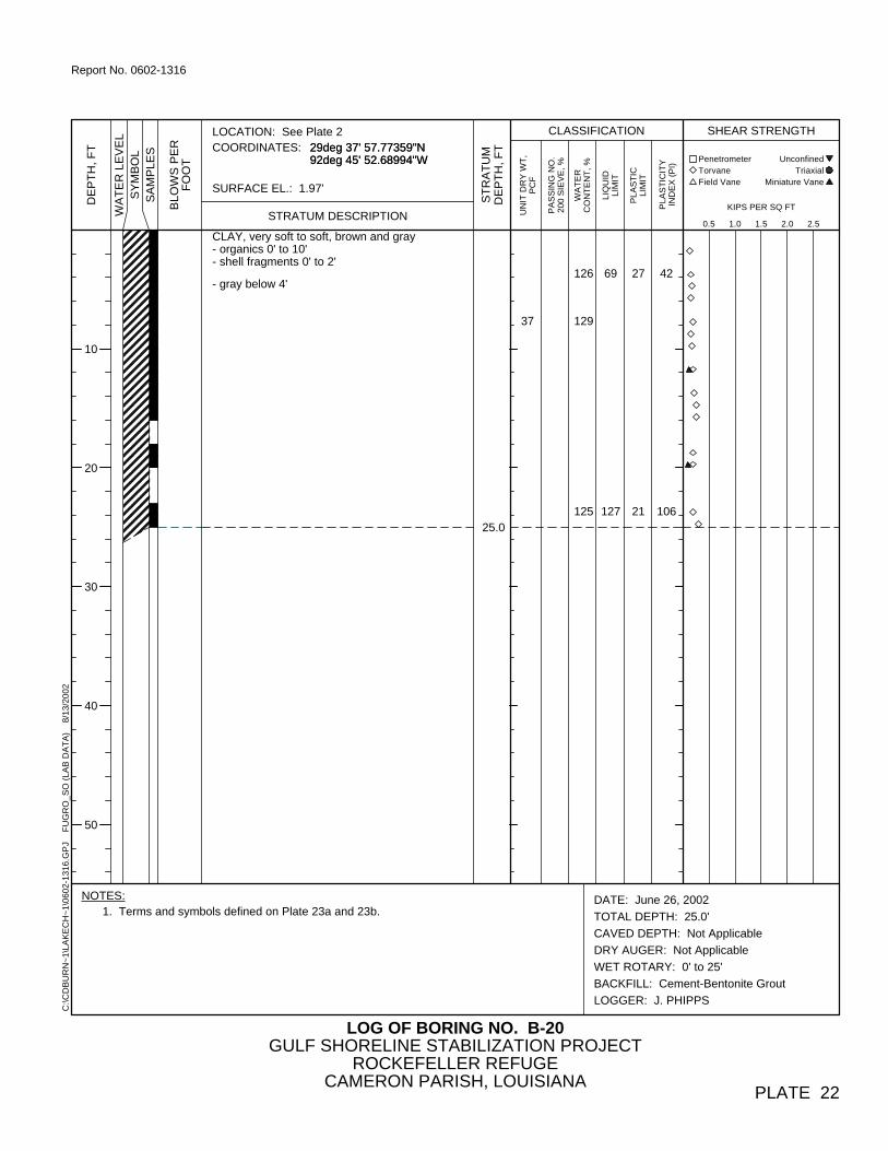
CLAY, very soft to soft, brown and gray- organics 0' to 10'- shell fragments 0' to 2'
- gray below 4'
37
25.0
126
129
125
69
127
27
21
42
106
DATE: June 26, 2002
TOTAL DEPTH: 25.0'
CAVED DEPTH: Not Applicable
DRY AUGER: Not Applicable
WET ROTARY: 0' to 25'
BACKFILL: Cement-Bentonite Grout
LOGGER: J. PHIPPS
LOG OF BORING NO. B-20
29deg 37' 57.77359"N 92deg 45' 52.68994"W 29deg 37' 57.77359"N 92deg 45' 52.68994"W
SURFACE EL.: 1.97'
GULF SHORELINE STABILIZATION PROJECTROCKEFELLER REFUGE
CAMERON PARISH, LOUISIANA
LOCATION: See Plate 2COORDINATES:
PLATE 22
10
20
30
40
50
NOTES:1. Terms and symbols defined on Plate 23a and 23b.
LIQ
UID
LIM
IT
Triaxial
UN
IT D
RY
WT
,P
CF
PA
SS
ING
NO
.20
0 S
IEV
E, %
KIPS PER SQ FT
SY
MB
OL
Penetrometer Unconfined
PLA
ST
ICLI
MIT Miniature Vane
PLA
ST
ICIT
YIN
DE
X (
PI)
Torvane
STRATUM DESCRIPTION
WA
TE
RC
ON
TE
NT
, %
ST
RA
TU
MD
EP
TH
, F
T
0.5 1.0 1.5 2.0 2.5
C:\C
DB
UR
N~
1\LA
KE
CH
~1\
0602
-131
6.G
PJ
F
UG
RO
_SO
(LA
B D
AT
A)
8
/13/
2002
BL
OW
S P
ER
FO
OT
SA
MP
LES
WA
TE
R L
EV
EL
DE
PT
H,
FT
SHEAR STRENGTHCLASSIFICATION
Field Vane
Report No. 0602-1316

PLATE 23a
Report No. 0602-1316
SAMPLER TYPES
NoRecovery
(1 of 2)
3"
CoarseSilt
Medium
SOIL GRAIN SIZE
Thin-walledTube
PartialRecoveryw/ Tube
Gravel
ClayCoarse
SOIL STRUCTURE
Having planes of weakness that appear slick and glossy.Containing shrinkage or relief cracks, often filled with fine sand or silt; usually more or less vertical.Inclusion of material of different texture that is smaller than the diameter of the sample.Inclusion less than 1/8 inch thick extending through the sample.Inclusion 1/8 inch to 3 inches thick extending through the sample.Inclusion greater than 3 inches thick extending through the sample.Soil sample composed of alternating partings or seams of different soil type.Soil sample composed of alternating layers of different soil type.Soil sample composed of pockets of different soil type and layered or laminated structure is not evident.Having appreciable quantities of carbonate.Having more than 50% carbonate content.
152 0.0024.7676.2 19.1
4
(mm)0.074
Boulders Cobbles
SOIL TYPES
ClayeySilt
Fine
Split-
SANDY ORSILTY CLAYS TOCLAYEY SILTS
ORGANIC SILTS ORCLAYEY SILTS
SANDY CLA
YS
Fine
U.S. Standard Sieve
Peat orHighlyOrganic
SiltySand
ClayeySand
Sand
SiltyClay
Silt
SandyClay
Concrete
SandySilt
Asphalt
Clay
10
Piston
6" 200
Auger
3/4"Gravel
2.00
40
0.420
Debris orMixedFill
barrel
Geoprobe
Sand
SOIL CLASSIFICATIONTERMS AND SYMBOLS USED ON BORING LOGS
Pitcher
RockCore
SlickensidedFissuredPocketPartingSeamLayerLaminatedInterlayeredIntermixedCalcareousCarbonate
PLASTICITY CHART
0
60
10
20
30
PLA
ST
ICIT
Y I
ND
EX
40
LIQUID LIMIT100
ORGANICCLAYS
A-LINE
50
0 10 20 30 40 50 8070
U-LIN
E
SILTY CLAYS
CLAYS
CLAYS
SILTS
60 90

Report No. 0602-1316
PLATE 23b(2 of 2)SOIL CLASSIFICATION
TERMS AND SYMBOLS USED ON BORING LOGS
25 blows drove sampler 12 inches, after initial 6 inches of seating.50 blows drove sampler 7 inches, after initial 6 inches of seating.50 blows drove sampler 3 inches during initial 6-inch seating interval.
< 0.250.25 to 0.500.50 to 1.001.00 to 2.002.00 to 4.00
> 4.00
Term
Our experience has shown that the hand penetrometer generally overestimates the in-situ undrained shear strength of over consolidated
Pleistocene Gulf Coast clays. These strengths are partially controlled by the presence of macroscopic soil defects such as slickensides, which
generally do not influence smaller scale tests like the hand penetrometer. Based on our experience, we have adjusted these field estimates of the
undrained shear strength of natural, overconsolidated Pleistocene Gulf Coast soils by multiplying the measured penetrometer reading by a factor of
0.6. These adjusted strength estimates are recorded in the "Shear Strength" column on the boring logs. Except as described in the text, we have
not adjusted estimates of the undrained shear strength for projects located outside of the Pleistocene Gulf Coast formations.
Information on each boring log is a compilation of subsurface conditions and soil or rock classifications obtained from the field as well as from
laboratory testing of samples. Strata have been interpreted by commonly accepted procedures. The stratum lines on the logs may be transitional
and approximate in nature. Water level measurements refer only to those observed at the time and places indicated, and can vary with time,
geologic condition, or construction activity.
Blows Per Foot (SPT)(approximate)
STRENGTH OF COHESIVE SOILS
SPLIT-BARREL SAMPLER DRIVING RECORD
NOTE: To avoid damage to sampling tools, driving is limited to 50 blows during or after seating interval.
2550/7"Ref/3"
DescriptiveTerm **Blows Per Foot (SPT)
Blows Per Foot
UndrainedShear Strength, ksf
*RelativeDensity, %
Description
STANDARD PENETRATION TEST (SPT)
Very LooseLooseMedium DenseDenseVery Dense
HAND PENETROMETER CORRECTION
A 2-in.-OD, 1-3/8-ID split spoon sampler is driven 1.5 ft into undisturbed soil with a 140-pound hammer free falling 30 in. After thesampler is seated 6 in. into undisturbed soil, the number of blows required to drive the sampler the last 12 in. is the StandardPenetration Resistance or "N" value, which is recorded as blows per foot as described below.
< 1515 to 3535 to 6565 to 85
> 85
0 to 45 to 10
11 to 3031 to 50
> 50
0 to 22 to 44 to 8
8 to 1616 to 32
> 32
DENSITY OF GRANULAR SOILS
Very SoftSoftFirmStiffVery StiffHard*Estimated from sampler driving record.
**Requires correction for depth, groundwater level, and grain size.
SHEAR STRENGTH TEST METHOD
U - Unconfined Q = Unconsolidated - Undrained Triaxial
P = Pocket Penetrometer T = Torvane V = Miniature Vane F = Field Vane
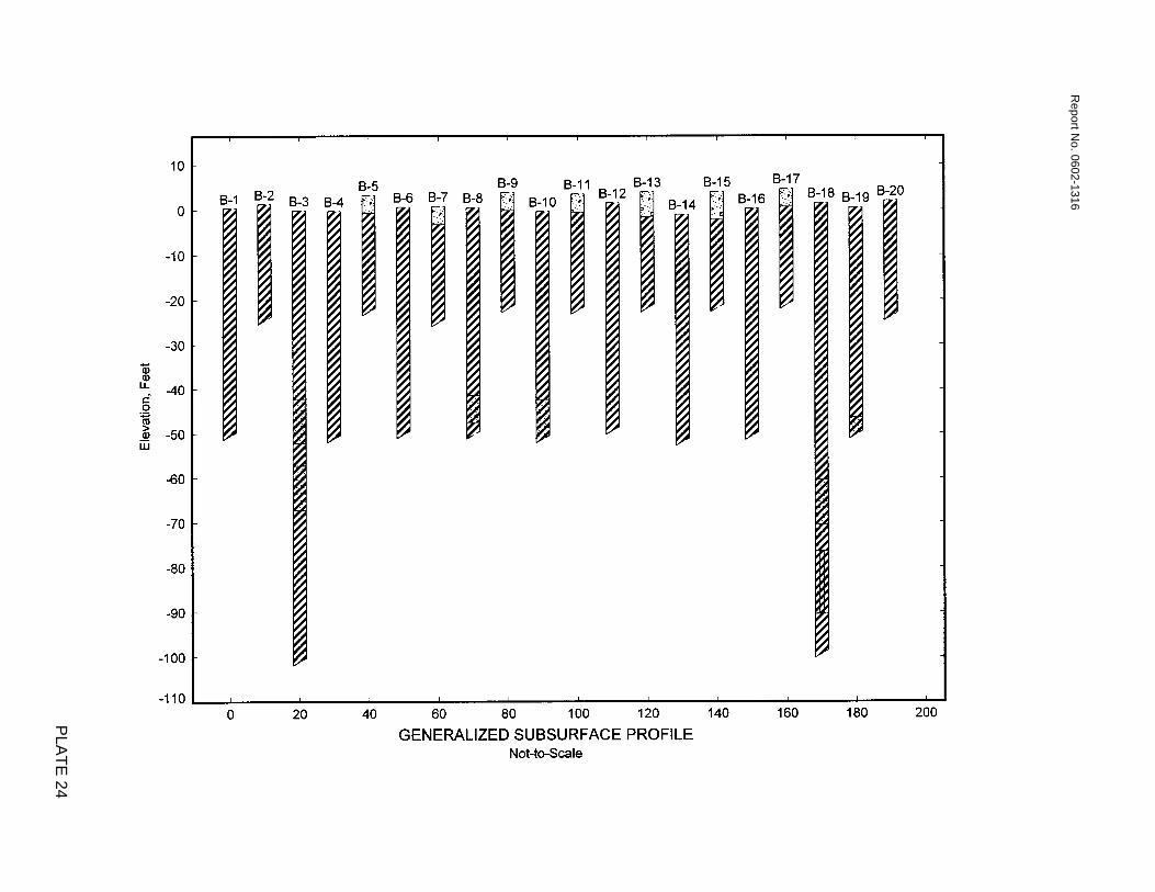
Report N
o. 0602-1316
PLA
TE
24

APPENDIX A

0.0010.010.1110100
Coarse
DEPTH, FT
Fine
3
Medium Fine
GRAVEL
SANDSILT or CLAY
20 40
U. S. STANDARD SIEVE
Coarse
1.5 3/40
20
40
60
80
100
PE
RC
EN
T F
INE
R B
Y W
EIG
HT
100
CLAY
Report N
o. 0602-1316
PE
RC
EN
T C
OA
RS
ER
BY
WE
IGH
T
GRAIN SIZE IN MILLIMETERS
0
20
40
60
80
100
NUMBERSHYDROMETER
3/8 10ANALYSIS
200
SYMBOL BORING
PLA
TE
A-1
GRAIN SIZE CURVE
4
U.S. STANDARD SIEVE
29.0
SIZES IN INCHES
CLASSIFICATION
B-3

0.0010.010.1110100
Coarse
DEPTH, FT
Fine
3
Medium Fine
GRAVEL
SANDSILT or CLAY
20 40
U. S. STANDARD SIEVE
Coarse
1.5 3/40
20
40
60
80
100
PE
RC
EN
T F
INE
R B
Y W
EIG
HT
100
CLAY
Report N
o. 0602-1316
PE
RC
EN
T C
OA
RS
ER
BY
WE
IGH
T
GRAIN SIZE IN MILLIMETERS
0
20
40
60
80
100
NUMBERSHYDROMETER
3/8 10ANALYSIS
200
SYMBOL BORING
PLA
TE
A-2
GRAIN SIZE CURVE
4
U.S. STANDARD SIEVE
8.0
SIZES IN INCHES
CLASSIFICATION
B-4
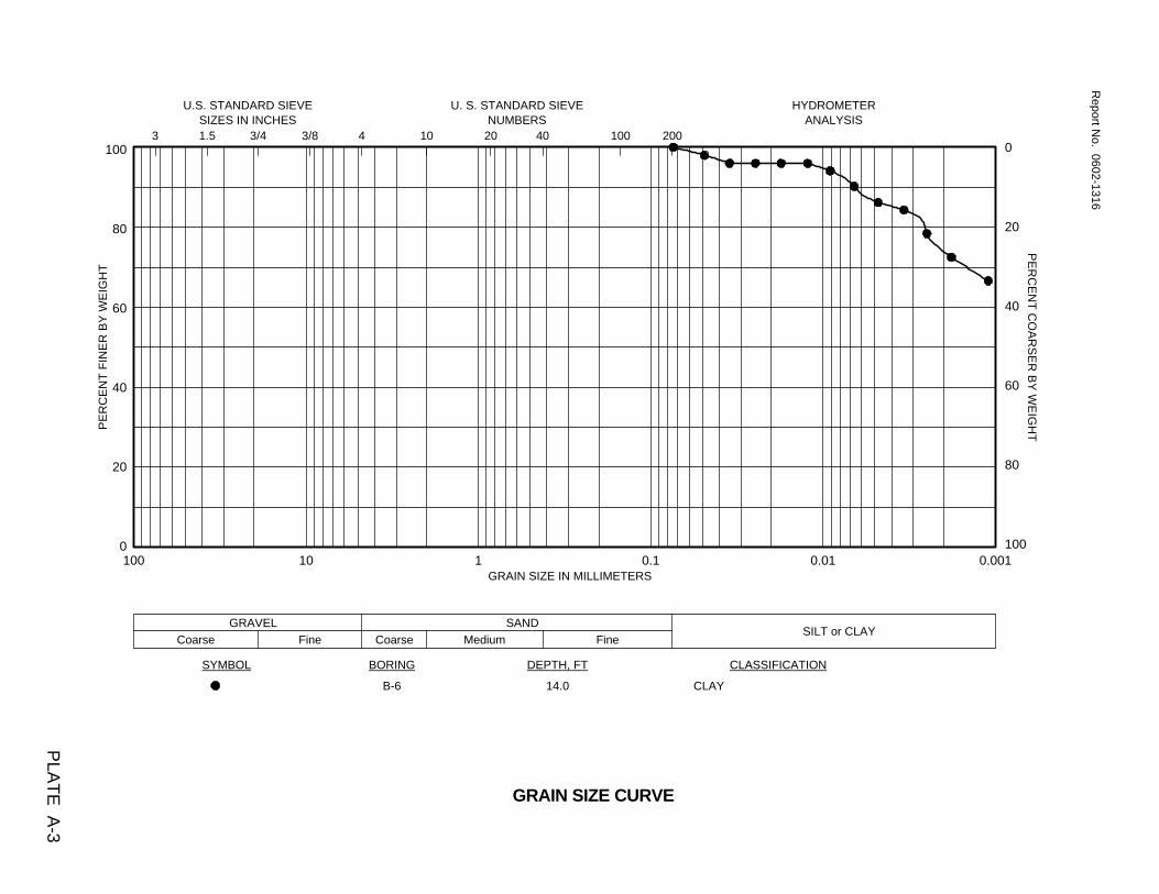
0.0010.010.1110100
Coarse
DEPTH, FT
Fine
3
Medium Fine
GRAVEL
SANDSILT or CLAY
20 40
U. S. STANDARD SIEVE
Coarse
1.5 3/40
20
40
60
80
100
PE
RC
EN
T F
INE
R B
Y W
EIG
HT
100
CLAY
Report N
o. 0602-1316
PE
RC
EN
T C
OA
RS
ER
BY
WE
IGH
T
GRAIN SIZE IN MILLIMETERS
0
20
40
60
80
100
NUMBERSHYDROMETER
3/8 10ANALYSIS
200
SYMBOL BORING
PLA
TE
A-3
GRAIN SIZE CURVE
4
U.S. STANDARD SIEVE
14.0
SIZES IN INCHES
CLASSIFICATION
B-6

0.0010.010.1110100
Coarse
DEPTH, FT
Fine
3
Medium Fine
GRAVEL
SANDSILT or CLAY
20 40
U. S. STANDARD SIEVE
Coarse
1.5 3/40
20
40
60
80
100
PE
RC
EN
T F
INE
R B
Y W
EIG
HT
100
CLAY
Report N
o. 0602-1316
PE
RC
EN
T C
OA
RS
ER
BY
WE
IGH
T
GRAIN SIZE IN MILLIMETERS
0
20
40
60
80
100
NUMBERSHYDROMETER
3/8 10ANALYSIS
200
SYMBOL BORING
PLA
TE
A-4
GRAIN SIZE CURVE
4
U.S. STANDARD SIEVE
13.0
SIZES IN INCHES
CLASSIFICATION
B-8

0.0010.010.1110100
Coarse
DEPTH, FT
Fine
3
Medium Fine
GRAVEL
SANDSILT or CLAY
20 40
U. S. STANDARD SIEVE
Coarse
1.5 3/40
20
40
60
80
100
PE
RC
EN
T F
INE
R B
Y W
EIG
HT
100
CLAY
Report N
o. 0602-1316
PE
RC
EN
T C
OA
RS
ER
BY
WE
IGH
T
GRAIN SIZE IN MILLIMETERS
0
20
40
60
80
100
NUMBERSHYDROMETER
3/8 10ANALYSIS
200
SYMBOL BORING
PLA
TE
A-5
GRAIN SIZE CURVE
4
U.S. STANDARD SIEVE
14.0
SIZES IN INCHES
CLASSIFICATION
B-10

0.0010.010.1110100
Coarse
DEPTH, FT
Fine
3
Medium Fine
GRAVEL
SANDSILT or CLAY
20 40
U. S. STANDARD SIEVE
Coarse
1.5 3/40
20
40
60
80
100
PE
RC
EN
T F
INE
R B
Y W
EIG
HT
100
CLAY
Report N
o. 0602-1316
PE
RC
EN
T C
OA
RS
ER
BY
WE
IGH
T
GRAIN SIZE IN MILLIMETERS
0
20
40
60
80
100
NUMBERSHYDROMETER
3/8 10ANALYSIS
200
SYMBOL BORING
PLA
TE
A-6
GRAIN SIZE CURVE
4
U.S. STANDARD SIEVE
14.0
SIZES IN INCHES
CLASSIFICATION
B-12

0.0010.010.1110100
Coarse
DEPTH, FT
Fine
3
Medium Fine
GRAVEL
SANDSILT or CLAY
20 40
U. S. STANDARD SIEVE
Coarse
1.5 3/40
20
40
60
80
100
PE
RC
EN
T F
INE
R B
Y W
EIG
HT
100
CLAY
Report N
o. 0602-1316
PE
RC
EN
T C
OA
RS
ER
BY
WE
IGH
T
GRAIN SIZE IN MILLIMETERS
0
20
40
60
80
100
NUMBERSHYDROMETER
3/8 10ANALYSIS
200
SYMBOL BORING
PLA
TE
A-7
GRAIN SIZE CURVE
4
U.S. STANDARD SIEVE
10.0
SIZES IN INCHES
CLASSIFICATION
B-14

0.0010.010.1110100
Coarse
DEPTH, FT
Fine
3
Medium Fine
GRAVEL
SANDSILT or CLAY
20 40
U. S. STANDARD SIEVE
Coarse
1.5 3/40
20
40
60
80
100
PE
RC
EN
T F
INE
R B
Y W
EIG
HT
100
CLAY
Report N
o. 0602-1316
PE
RC
EN
T C
OA
RS
ER
BY
WE
IGH
T
GRAIN SIZE IN MILLIMETERS
0
20
40
60
80
100
NUMBERSHYDROMETER
3/8 10ANALYSIS
200
SYMBOL BORING
PLA
TE
A-8
GRAIN SIZE CURVE
4
U.S. STANDARD SIEVE
16.0
SIZES IN INCHES
CLASSIFICATION
B-16
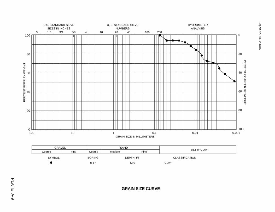
0.0010.010.1110100
Coarse
DEPTH, FT
Fine
3
Medium Fine
GRAVEL
SANDSILT or CLAY
20 40
U. S. STANDARD SIEVE
Coarse
1.5 3/40
20
40
60
80
100
PE
RC
EN
T F
INE
R B
Y W
EIG
HT
100
CLAY
Report N
o. 0602-1316
PE
RC
EN
T C
OA
RS
ER
BY
WE
IGH
T
GRAIN SIZE IN MILLIMETERS
0
20
40
60
80
100
NUMBERSHYDROMETER
3/8 10ANALYSIS
200
SYMBOL BORING
PLA
TE
A-9
GRAIN SIZE CURVE
4
U.S. STANDARD SIEVE
12.0
SIZES IN INCHES
CLASSIFICATION
B-17

0.0010.010.1110100
Coarse
DEPTH, FT
Fine
3
Medium Fine
GRAVEL
SANDSILT or CLAY
20 40
U. S. STANDARD SIEVE
Coarse
1.5 3/40
20
40
60
80
100
PE
RC
EN
T F
INE
R B
Y W
EIG
HT
100
CLAY
Report N
o. 0602-1316
PE
RC
EN
T C
OA
RS
ER
BY
WE
IGH
T
GRAIN SIZE IN MILLIMETERS
0
20
40
60
80
100
NUMBERSHYDROMETER
3/8 10ANALYSIS
200
SYMBOL BORING
PLA
TE
A-10
GRAIN SIZE CURVE
4
U.S. STANDARD SIEVE
10.0
SIZES IN INCHES
CLASSIFICATION
B-20
APPENDIX B
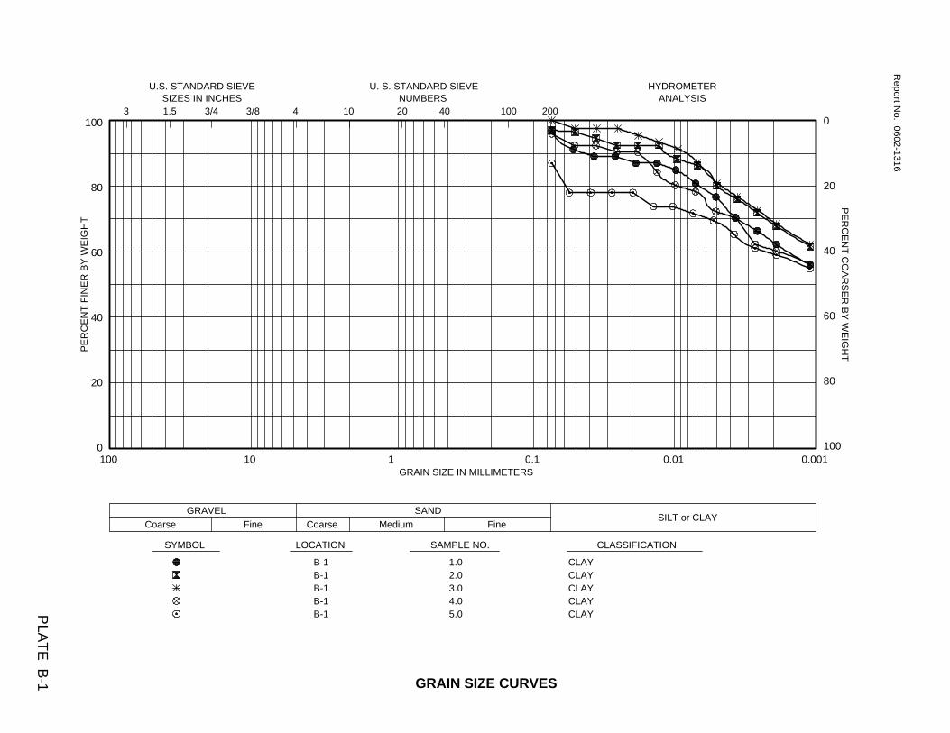
0.0010.010.1110100
Coarse
0
20
40
60
80
100
NUMBERSHYDROMETER
3/8 10ANALYSIS
200
CLASSIFICATION
3
Medium Fine
1.02.03.04.05.0
4
U.S. STANDARD SIEVESIZES IN INCHES
Fine
Report N
o. 0602-1316
PLA
TE
B-1
PE
RC
EN
T C
OA
RS
ER
BY
WE
IGH
T
GRAIN SIZE IN MILLIMETERS
GRAVEL
SYMBOL LOCATION
B-1B-1B-1B-1B-1
SAMPLE NO.
SANDSILT or CLAY
20 40
U. S. STANDARD SIEVE
Coarse
1.5 3/40
20
40
60
80
100
PE
RC
EN
T F
INE
R B
Y W
EIG
HT
100
CLAYCLAYCLAYCLAYCLAY
GRAIN SIZE CURVES

0.0010.010.1110100
Coarse
0
20
40
60
80
100
NUMBERSHYDROMETER
3/8 10ANALYSIS
200
CLASSIFICATION
3
Medium Fine
1.02.03.04.05.0
4
U.S. STANDARD SIEVESIZES IN INCHES
Fine
Report N
o. 0602-1316
PLA
TE
B-2
PE
RC
EN
T C
OA
RS
ER
BY
WE
IGH
T
GRAIN SIZE IN MILLIMETERS
GRAVEL
SYMBOL LOCATION
B-2B-2B-2B-2B-2
SAMPLE NO.
SANDSILT or CLAY
20 40
U. S. STANDARD SIEVE
Coarse
1.5 3/40
20
40
60
80
100
PE
RC
EN
T F
INE
R B
Y W
EIG
HT
100
CLAYCLAYCLAYCLAYCLAY
GRAIN SIZE CURVES

0.0010.010.1110100
Coarse
SAMPLE NO.
Fine
3
Medium Fine
GRAVEL
SANDSILT or CLAY
20 40
U. S. STANDARD SIEVE
Coarse
1.5 3/40
20
40
60
80
100
PE
RC
EN
T F
INE
R B
Y W
EIG
HT
100
CLAYCLAYCLAYCLAYCLAY
Report N
o. 0602-1316
PE
RC
EN
T C
OA
RS
ER
BY
WE
IGH
T
GRAIN SIZE IN MILLIMETERS
0
20
40
60
80
100
NUMBERSHYDROMETER
3/8 10ANALYSIS
200
SYMBOL LOCATION
PLA
TE
B-3
GRAIN SIZE CURVE
4
U.S. STANDARD SIEVE
1.02.03.04.05.0
SIZES IN INCHES
CLASSIFICATION
B-3B-3B-3B-3B-3
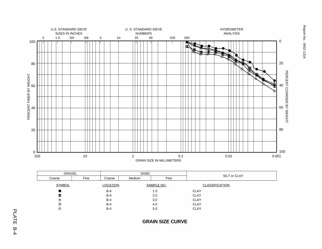
0.0010.010.1110100
Coarse
SAMPLE NO.
Fine
3
Medium Fine
GRAVEL
SANDSILT or CLAY
20 40
U. S. STANDARD SIEVE
Coarse
1.5 3/40
20
40
60
80
100
PE
RC
EN
T F
INE
R B
Y W
EIG
HT
100
CLAYCLAYCLAYCLAYCLAY
Report N
o. 0602-1316
PE
RC
EN
T C
OA
RS
ER
BY
WE
IGH
T
GRAIN SIZE IN MILLIMETERS
0
20
40
60
80
100
NUMBERSHYDROMETER
3/8 10ANALYSIS
200
SYMBOL LOCATION
PLA
TE
B-4
GRAIN SIZE CURVE
4
U.S. STANDARD SIEVE
1.02.03.04.05.0
SIZES IN INCHES
CLASSIFICATION
B-4B-4B-4B-4B-4

0.0010.010.1110100
Coarse
SAMPLE NO.
Fine
3
Medium Fine
GRAVEL
SANDSILT or CLAY
20 40
U. S. STANDARD SIEVE
Coarse
1.5 3/40
20
40
60
80
100
PE
RC
EN
T F
INE
R B
Y W
EIG
HT
100
CLAYCLAYCLAYCLAYCLAY
Report N
o. 0602-1316
PE
RC
EN
T C
OA
RS
ER
BY
WE
IGH
T
GRAIN SIZE IN MILLIMETERS
0
20
40
60
80
100
NUMBERSHYDROMETER
3/8 10ANALYSIS
200
SYMBOL LOCATION
PLA
TE
B-5
GRAIN SIZE CURVE
4
U.S. STANDARD SIEVE
1.02.03.04.05.0
SIZES IN INCHES
CLASSIFICATION
B-5B-5B-5B-5B-5

0.0010.010.1110100
Coarse
SAMPLE NO.
Fine
3
Medium Fine
GRAVEL
SANDSILT or CLAY
20 40
U. S. STANDARD SIEVE
Coarse
1.5 3/40
20
40
60
80
100
PE
RC
EN
T F
INE
R B
Y W
EIG
HT
100
CLAYCLAYCLAYCLAYCLAY
Report N
o. 0602-1316
PE
RC
EN
T C
OA
RS
ER
BY
WE
IGH
T
GRAIN SIZE IN MILLIMETERS
0
20
40
60
80
100
NUMBERSHYDROMETER
3/8 10ANALYSIS
200
SYMBOL LOCATION
PLA
TE
B-6
GRAIN SIZE CURVE
4
U.S. STANDARD SIEVE
1.02.03.04.05.0
SIZES IN INCHES
CLASSIFICATION
B-6B-6B-6B-6B-6

0.0010.010.1110100
Coarse
SAMPLE NO.
Fine
3
Medium Fine
GRAVEL
SANDSILT or CLAY
20 40
U. S. STANDARD SIEVE
Coarse
1.5 3/40
20
40
60
80
100
PE
RC
EN
T F
INE
R B
Y W
EIG
HT
100
CLAYCLAYCLAYCLAYCLAY
Report N
o. 0602-1316
PE
RC
EN
T C
OA
RS
ER
BY
WE
IGH
T
GRAIN SIZE IN MILLIMETERS
0
20
40
60
80
100
NUMBERSHYDROMETER
3/8 10ANALYSIS
200
SYMBOL LOCATION
PLA
TE
B-7
GRAIN SIZE CURVE
4
U.S. STANDARD SIEVE
1.02.03.04.05.0
SIZES IN INCHES
CLASSIFICATION
B-7B-7B-7B-7B-7

0.0010.010.1110100
Coarse
SAMPLE NO.
Fine
3
Medium Fine
GRAVEL
SANDSILT or CLAY
20 40
U. S. STANDARD SIEVE
Coarse
1.5 3/40
20
40
60
80
100
PE
RC
EN
T F
INE
R B
Y W
EIG
HT
100
CLAYCLAYCLAYCLAYCLAY
Report N
o. 0602-1316
PE
RC
EN
T C
OA
RS
ER
BY
WE
IGH
T
GRAIN SIZE IN MILLIMETERS
0
20
40
60
80
100
NUMBERSHYDROMETER
3/8 10ANALYSIS
200
SYMBOL LOCATION
PLA
TE
B-8
GRAIN SIZE CURVE
4
U.S. STANDARD SIEVE
1.02.03.04.05.0
SIZES IN INCHES
CLASSIFICATION
B-8B-8B-8B-8B-8

0.0010.010.1110100
Coarse
SAMPLE NO.
Fine
3
Medium Fine
GRAVEL
SANDSILT or CLAY
20 40
U. S. STANDARD SIEVE
Coarse
1.5 3/40
20
40
60
80
100
PE
RC
EN
T F
INE
R B
Y W
EIG
HT
100
CLAYCLAYCLAYCLAYCLAY
Report N
o. 0602-1316
PE
RC
EN
T C
OA
RS
ER
BY
WE
IGH
T
GRAIN SIZE IN MILLIMETERS
0
20
40
60
80
100
NUMBERSHYDROMETER
3/8 10ANALYSIS
200
SYMBOL LOCATION
PLA
TE
B-9
GRAIN SIZE CURVE
4
U.S. STANDARD SIEVE
1.02.03.04.05.0
SIZES IN INCHES
CLASSIFICATION
B-9B-9B-9B-9B-9

0.0010.010.1110100
Coarse
SAMPLE NO.
Fine
3
Medium Fine
GRAVEL
SANDSILT or CLAY
20 40
U. S. STANDARD SIEVE
Coarse
1.5 3/40
20
40
60
80
100
PE
RC
EN
T F
INE
R B
Y W
EIG
HT
100
CLAYCLAYCLAYCLAYCLAY
Report N
o. 0602-1316
PE
RC
EN
T C
OA
RS
ER
BY
WE
IGH
T
GRAIN SIZE IN MILLIMETERS
0
20
40
60
80
100
NUMBERSHYDROMETER
3/8 10ANALYSIS
200
SYMBOL LOCATION
PLA
TE
B-10
GRAIN SIZE CURVE
4
U.S. STANDARD SIEVE
1.02.03.04.05.0
SIZES IN INCHES
CLASSIFICATION
B-10B-10B-10B-10B-10

0.0010.010.1110100
Coarse
SAMPLE NO.
Fine
3
Medium Fine
GRAVEL
SANDSILT or CLAY
20 40
U. S. STANDARD SIEVE
Coarse
1.5 3/40
20
40
60
80
100
PE
RC
EN
T F
INE
R B
Y W
EIG
HT
100
CLAYCLAYCLAYCLAYCLAY
Report N
o. 0602-1316
PE
RC
EN
T C
OA
RS
ER
BY
WE
IGH
T
GRAIN SIZE IN MILLIMETERS
0
20
40
60
80
100
NUMBERSHYDROMETER
3/8 10ANALYSIS
200
SYMBOL LOCATION
PLA
TE
B-11
GRAIN SIZE CURVE
4
U.S. STANDARD SIEVE
1.02.03.04.05.0
SIZES IN INCHES
CLASSIFICATION
B-11B-11B-11B-11B-11

0.0010.010.1110100
Coarse
SAMPLE NO.
Fine
3
Medium Fine
GRAVEL
SANDSILT or CLAY
20 40
U. S. STANDARD SIEVE
Coarse
1.5 3/40
20
40
60
80
100
PE
RC
EN
T F
INE
R B
Y W
EIG
HT
100
CLAYCLAYCLAYCLAYCLAY
Report N
o. 0602-1316
PE
RC
EN
T C
OA
RS
ER
BY
WE
IGH
T
GRAIN SIZE IN MILLIMETERS
0
20
40
60
80
100
NUMBERSHYDROMETER
3/8 10ANALYSIS
200
SYMBOL LOCATION
PLA
TE
B-12
GRAIN SIZE CURVE
4
U.S. STANDARD SIEVE
1.02.03.04.05.0
SIZES IN INCHES
CLASSIFICATION
B-12B-12B-12B-12B-12

0.0010.010.1110100
Coarse
SAMPLE NO.
Fine
3
Medium Fine
GRAVEL
SANDSILT or CLAY
20 40
U. S. STANDARD SIEVE
Coarse
1.5 3/40
20
40
60
80
100
PE
RC
EN
T F
INE
R B
Y W
EIG
HT
100
CLAYCLAYCLAYCLAYCLAY
Report N
o. 0602-1316
PE
RC
EN
T C
OA
RS
ER
BY
WE
IGH
T
GRAIN SIZE IN MILLIMETERS
0
20
40
60
80
100
NUMBERSHYDROMETER
3/8 10ANALYSIS
200
SYMBOL LOCATION
PLA
TE
B-13
GRAIN SIZE CURVE
4
U.S. STANDARD SIEVE
1.02.03.04.05.0
SIZES IN INCHES
CLASSIFICATION
B-13B-13B-13B-13B-13

0.0010.010.1110100
Coarse
SAMPLE NO.
Fine
3
Medium Fine
GRAVEL
SANDSILT or CLAY
20 40
U. S. STANDARD SIEVE
Coarse
1.5 3/40
20
40
60
80
100
PE
RC
EN
T F
INE
R B
Y W
EIG
HT
100
CLAYCLAYCLAYCLAYCLAY
Report N
o. 0602-1316
PE
RC
EN
T C
OA
RS
ER
BY
WE
IGH
T
GRAIN SIZE IN MILLIMETERS
0
20
40
60
80
100
NUMBERSHYDROMETER
3/8 10ANALYSIS
200
SYMBOL LOCATION
PLA
TE
B-14
GRAIN SIZE CURVE
4
U.S. STANDARD SIEVE
1.02.03.04.05.0
SIZES IN INCHES
CLASSIFICATION
B-14B-14B-14B-14B-14
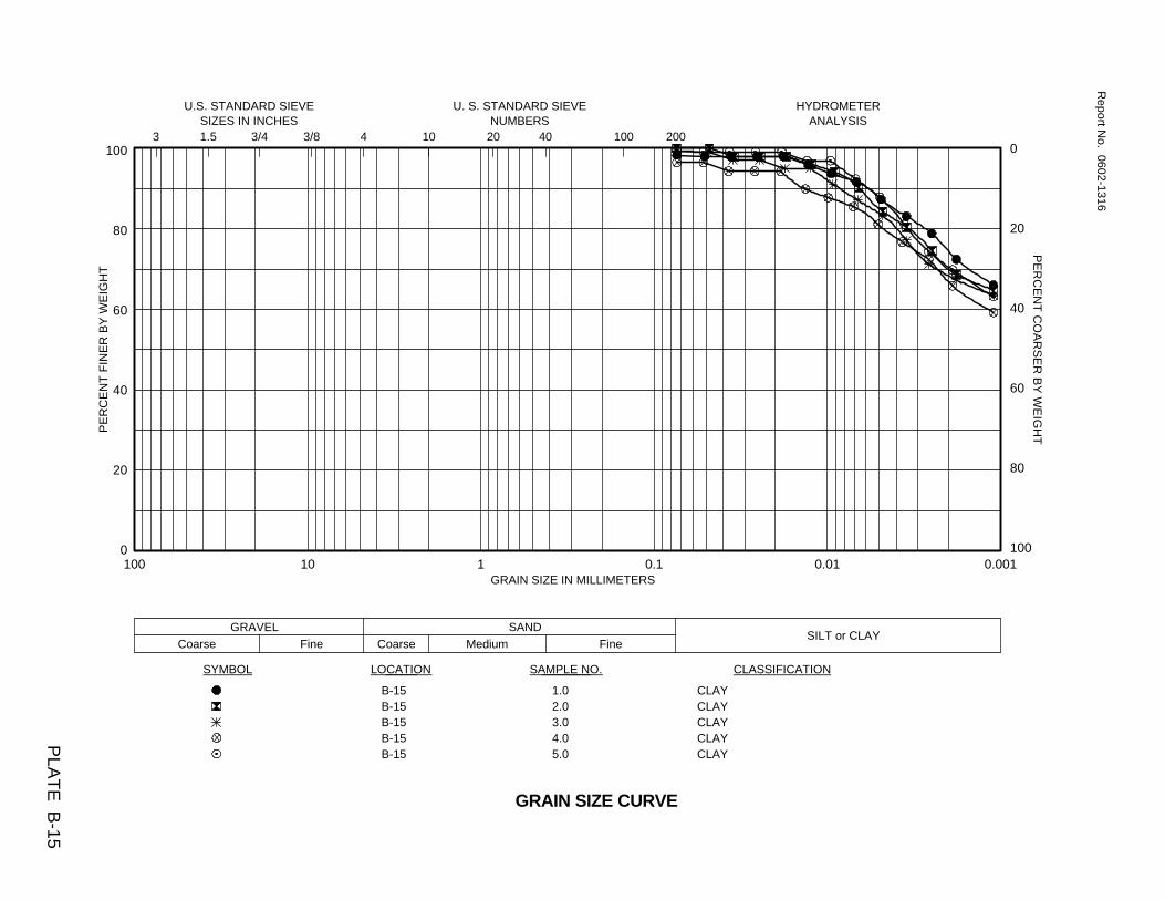
0.0010.010.1110100
Coarse
SAMPLE NO.
Fine
3
Medium Fine
GRAVEL
SANDSILT or CLAY
20 40
U. S. STANDARD SIEVE
Coarse
1.5 3/40
20
40
60
80
100
PE
RC
EN
T F
INE
R B
Y W
EIG
HT
100
CLAYCLAYCLAYCLAYCLAY
Report N
o. 0602-1316
PE
RC
EN
T C
OA
RS
ER
BY
WE
IGH
T
GRAIN SIZE IN MILLIMETERS
0
20
40
60
80
100
NUMBERSHYDROMETER
3/8 10ANALYSIS
200
SYMBOL LOCATION
PLA
TE
B-15
GRAIN SIZE CURVE
4
U.S. STANDARD SIEVE
1.02.03.04.05.0
SIZES IN INCHES
CLASSIFICATION
B-15B-15B-15B-15B-15

0.0010.010.1110100
Coarse
SAMPLE NO.
Fine
3
Medium Fine
GRAVEL
SANDSILT or CLAY
20 40
U. S. STANDARD SIEVE
Coarse
1.5 3/40
20
40
60
80
100
PE
RC
EN
T F
INE
R B
Y W
EIG
HT
100
CLAYCLAYCLAYCLAYCLAY
Report N
o. 0602-1316
PE
RC
EN
T C
OA
RS
ER
BY
WE
IGH
T
GRAIN SIZE IN MILLIMETERS
0
20
40
60
80
100
NUMBERSHYDROMETER
3/8 10ANALYSIS
200
SYMBOL LOCATION
PLA
TE
B-16
GRAIN SIZE CURVE
4
U.S. STANDARD SIEVE
1.02.03.04.05.0
SIZES IN INCHES
CLASSIFICATION
B-16B-16B-16B-16B-16
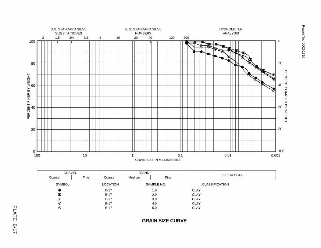
0.0010.010.1110100
Coarse
SAMPLE NO.
Fine
3
Medium Fine
GRAVEL
SANDSILT or CLAY
20 40
U. S. STANDARD SIEVE
Coarse
1.5 3/40
20
40
60
80
100
PE
RC
EN
T F
INE
R B
Y W
EIG
HT
100
CLAYCLAYCLAYCLAYCLAY
Report N
o. 0602-1316
PE
RC
EN
T C
OA
RS
ER
BY
WE
IGH
T
GRAIN SIZE IN MILLIMETERS
0
20
40
60
80
100
NUMBERSHYDROMETER
3/8 10ANALYSIS
200
SYMBOL LOCATION
PLA
TE
B-17
GRAIN SIZE CURVE
4
U.S. STANDARD SIEVE
1.02.03.04.05.0
SIZES IN INCHES
CLASSIFICATION
B-17B-17B-17B-17B-17

0.0010.010.1110100
Coarse
SAMPLE NO.
Fine
3
Medium Fine
GRAVEL
SANDSILT or CLAY
20 40
U. S. STANDARD SIEVE
Coarse
1.5 3/40
20
40
60
80
100
PE
RC
EN
T F
INE
R B
Y W
EIG
HT
100
CLAYCLAYCLAYCLAYCLAY
Report N
o. 0602-1316
PE
RC
EN
T C
OA
RS
ER
BY
WE
IGH
T
GRAIN SIZE IN MILLIMETERS
0
20
40
60
80
100
NUMBERSHYDROMETER
3/8 10ANALYSIS
200
SYMBOL LOCATION
PLA
TE
B-18
GRAIN SIZE CURVE
4
U.S. STANDARD SIEVE
1.02.03.04.05.0
SIZES IN INCHES
CLASSIFICATION
B-18B-18B-18B-18B-18
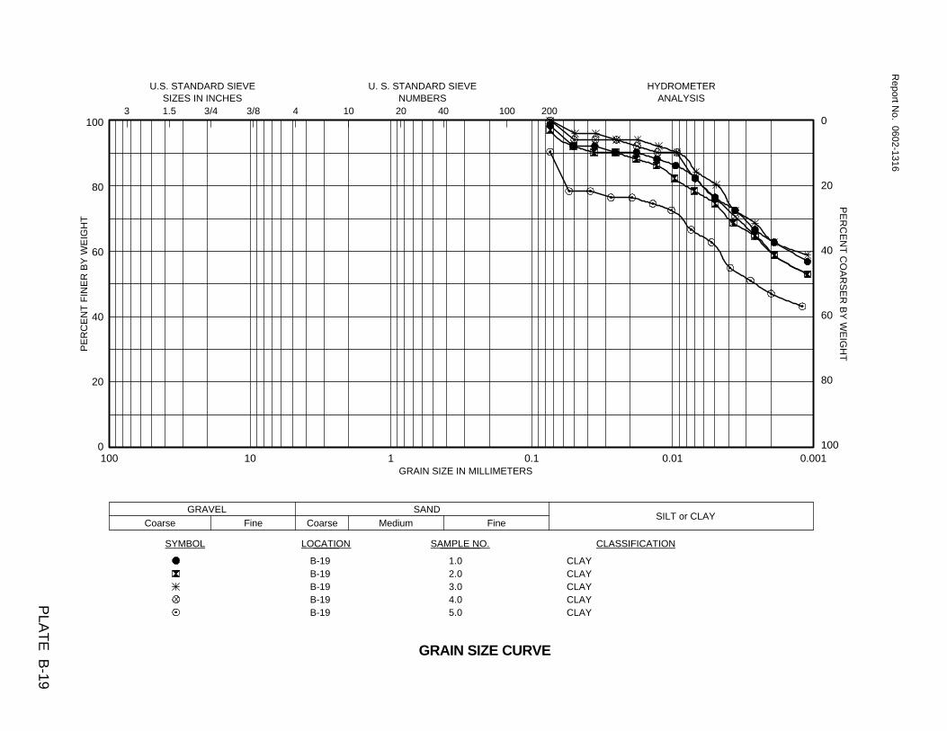
0.0010.010.1110100
Coarse
SAMPLE NO.
Fine
3
Medium Fine
GRAVEL
SANDSILT or CLAY
20 40
U. S. STANDARD SIEVE
Coarse
1.5 3/40
20
40
60
80
100
PE
RC
EN
T F
INE
R B
Y W
EIG
HT
100
CLAYCLAYCLAYCLAYCLAY
Report N
o. 0602-1316
PE
RC
EN
T C
OA
RS
ER
BY
WE
IGH
T
GRAIN SIZE IN MILLIMETERS
0
20
40
60
80
100
NUMBERSHYDROMETER
3/8 10ANALYSIS
200
SYMBOL LOCATION
PLA
TE
B-19
GRAIN SIZE CURVE
4
U.S. STANDARD SIEVE
1.02.03.04.05.0
SIZES IN INCHES
CLASSIFICATION
B-19B-19B-19B-19B-19
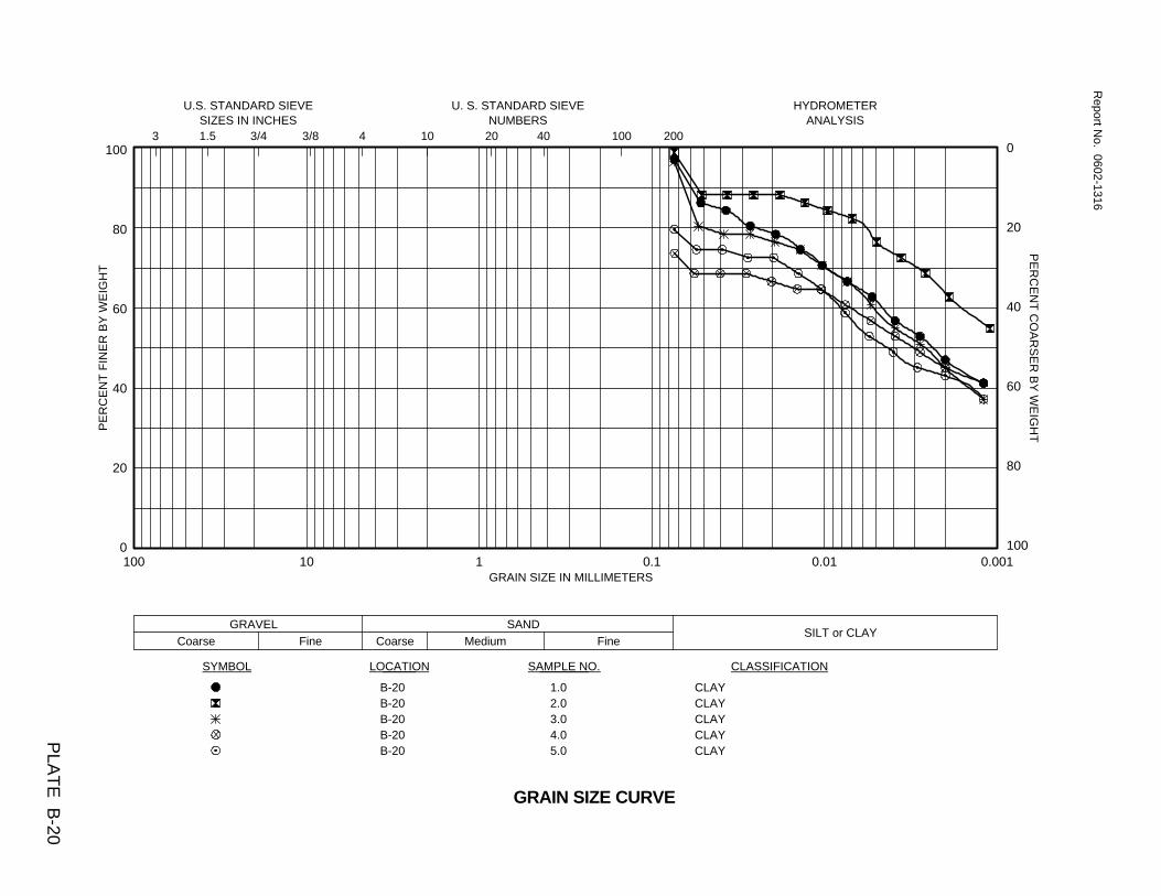
0.0010.010.1110100
Coarse
SAMPLE NO.
Fine
3
Medium Fine
GRAVEL
SANDSILT or CLAY
20 40
U. S. STANDARD SIEVE
Coarse
1.5 3/40
20
40
60
80
100
PE
RC
EN
T F
INE
R B
Y W
EIG
HT
100
CLAYCLAYCLAYCLAYCLAY
Report N
o. 0602-1316
PE
RC
EN
T C
OA
RS
ER
BY
WE
IGH
T
GRAIN SIZE IN MILLIMETERS
0
20
40
60
80
100
NUMBERSHYDROMETER
3/8 10ANALYSIS
200
SYMBOL LOCATION
PLA
TE
B-20
GRAIN SIZE CURVE
4
U.S. STANDARD SIEVE
1.02.03.04.05.0
SIZES IN INCHES
CLASSIFICATION
B-20B-20B-20B-20B-20