Embed Size (px)
Citation preview

5170 Mark Dabling Blvd | Colorado Springs, Colorado 80918 | Telephone: 719-528-8300 Fax: 719-528-5362
GEOTECHNICAL INVESTIGATION FLYWHEEL OFFICE DEVELOPMENT
SOUTHEAST OF EMBRAER HEIGHTS AND CRESTERRA PARKWAY
COLORADO SPRINGS, COLORADO
Prepared For:
COLARELLI CONTRUCTION 111 South Tejon Street, Suite 112
Colorado Springs, Colorado 80903
Project No. CS19327-125
November 10, 2020

COLLARELLI CONSTRUCTION FLYWHEEL OFFICE DEVELOPMENT CTL | T PROJECT NO. CS19327-125
TABLE OF CONTENTS
SCOPE ................................................................................................................. 1
SUMMARY OF CONCLUSIONS .......................................................................... 1
SITE CONDITIONS .............................................................................................. 2
PROPOSED CONSTRUCTION ............................................................................ 2
INVESTIGATION .................................................................................................. 3
SUBSURFACE CONDITIONS .............................................................................. 4
Fill .............................................................................................................. 4
Natural Sand .............................................................................................. 4
Groundwater .............................................................................................. 5
Seismicity ................................................................................................... 5
SITE DEVELOPMENT .......................................................................................... 5
Excavation .................................................................................................. 5
Sub-Excavation .......................................................................................... 6
Fill Placement ............................................................................................. 6
FOUNDATIONS .................................................................................................... 7
Spread Footings ......................................................................................... 7
BELOW-GRADE CONSTRUCTION ..................................................................... 8
FLOOR SYSTEMS AND SLABS-ON-GRADE ...................................................... 8
PAVEMENTS ...................................................................................................... 11
CONCRETE ........................................................................................................ 12
SURFACE DRAINAGE ....................................................................................... 13
CONSTRUCTION OBSERVATIONS .................................................................. 14
GEOTECHNICAL RISK ...................................................................................... 14
LIMITATIONS ..................................................................................................... 15
FIG. 1 – LOCATION OF EXPLORATORY BORINGS
FIG. 2 – SUMMARY LOGS OF EXPLORATORY BORINGS
FIG. 3 THROUGH 5 – GRADATION TEST RESULTS
TABLE 1 –SUMMARY OF LABORATORY TESTING

COLARELLI CONSTRUCTION 1
FLYWHEEL COMMERCIAL DEVELOPMENT CTL | T PROJECT NO. CS19327-125
SCOPE
This report presents the results of our Geotechnical Investigation for the pro-
posed Flywheel Commercial Office Building to be constructed southeast of the
intersection of Embraer Heights and Cresterra Parkway in Colorado Springs, Colora-
do. The purpose of our investigation was to evaluate subsurface conditions at the site
in order to develop geotechnical design and construction criteria for the proposed
office building. This report summarizes the results of our field and laboratory investi-
gations, and presents our design and construction recommendations for foundations,
floor systems, and pavement section alternatives, as well as surface and subsurface
drainage precautions. We believe the investigation was completed in accordance
with our proposal (CTL|T Proposal No. CS-20-0144) dated September 23, 2020.
Evaluation of the property for the possible presence of potentially hazardous materi-
als (environmental site assessment) was not included in the scope of this investiga-
tion.
The report was prepared based on conditions encountered in our exploratory
borings, results of laboratory tests, engineering analyses, and our experience. The
design criteria presented in the report were based on our understanding of the
planned construction. If changes occur, we should review the revised plans to deter-
mine their effect on our recommendations. The following section summarizes the
report. More detailed descriptions of subsurface conditions, as well as our design and
construction recommendations, are presented in the report.
SUMMARY OF CONCLUSIONS
1. The natural, near-surface soils encountered in our exploratory borings drilled within the proposed building footprint generally consisted of slightly silty to silty sand to the maximum depths explored of 30 feet. We encountered about 6 feet of fill at the ground surface in one of the five boring locations.

COLARELLI CONSTRUCTION 2
FLYWHEEL COMMERCIAL DEVELOPMENT CTL | T PROJECT NO. CS19327-125
2. Groundwater was not encountered in the borings during the drilling op-erations. The borings were again found to be dry when checked one day following the completion of our drilling. A more detailed discussion of groundwater is presented in the report.
3. We believe the proposed building can be constructed with a spread footing foundation constructed on the existing natural soils or densely compacted fill.
4. We judge the risk of poor slab-on-grade floor performance to be low where they are supported by the granular natural soils or densely com-pacted granular fill. Floor slab preparation details are presented in the report.
5. We believe the proposed parking areas can be paved with 3 inches of asphalt concrete over 6 inches of aggregate base course. For entranc-es and main drive lanes, the asphalt thickness should be increased to 4-inches. Alternative pavement sections are included in the report.
6. Overall surface drainage should provide for the rapid removal of runoff away from the proposed building and off pavement areas.
SITE CONDITIONS
The project site is situated on a vacant parcel of land located at the Peak In-
novation Park located southeast of the intersection of Embraer Heights and Cresterra
Parkway, in eastern Colorado Springs, Colorado. The general vicinity of the property
is presented in Fig. 1. The ground surface over most of the site is comparatively flat.
The northern and western 100 to 200 feet of the site slope gently downward toward
the adjacent streets. Vegetation consist of weeds, and native grasses. The general
vicinity surrounding the property is currently undeveloped and vacant. Embraer
Heights is located adjacent to the north, and Crestarra Parkway is located adjacent to
the west of the site.
PROPOSED CONSTRUCTION
Preliminary development plans available at the time of our investigation indi-
cate the proposed office building will consist of 50,000 square feet. The structure is
COLARELLI CONSTRUCTION 3
FLYWHEEL COMMERCIAL DEVELOPMENT CTL | T PROJECT NO. CS19327-125
planned as a single-story building with exterior construction consisting of site cast,
tilt-up concrete panels. We understand slab-on-grade floors are planned throughout
the building with no below grade areas. Based on the proposed use, we anticipate
some racking and forklift traffic within the building. A loading dock may be included in
the construction. Parking lots and drive lanes are planned around the perimeter of
the building. We expect minimal cuts and fills at the site to establish a building pad
elevation.
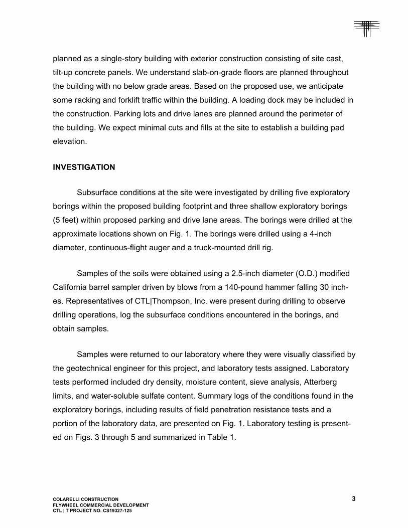
INVESTIGATION
Subsurface conditions at the site were investigated by drilling five exploratory
borings within the proposed building footprint and three shallow exploratory borings
(5 feet) within proposed parking and drive lane areas. The borings were drilled at the
approximate locations shown on Fig. 1. The borings were drilled using a 4-inch
diameter, continuous-flight auger and a truck-mounted drill rig.
Samples of the soils were obtained using a 2.5-inch diameter (O.D.) modified
California barrel sampler driven by blows from a 140-pound hammer falling 30 inch-
es. Representatives of CTL|Thompson, Inc. were present during drilling to observe
drilling operations, log the subsurface conditions encountered in the borings, and
obtain samples.
Samples were returned to our laboratory where they were visually classified by
the geotechnical engineer for this project, and laboratory tests assigned. Laboratory
tests performed included dry density, moisture content, sieve analysis, Atterberg
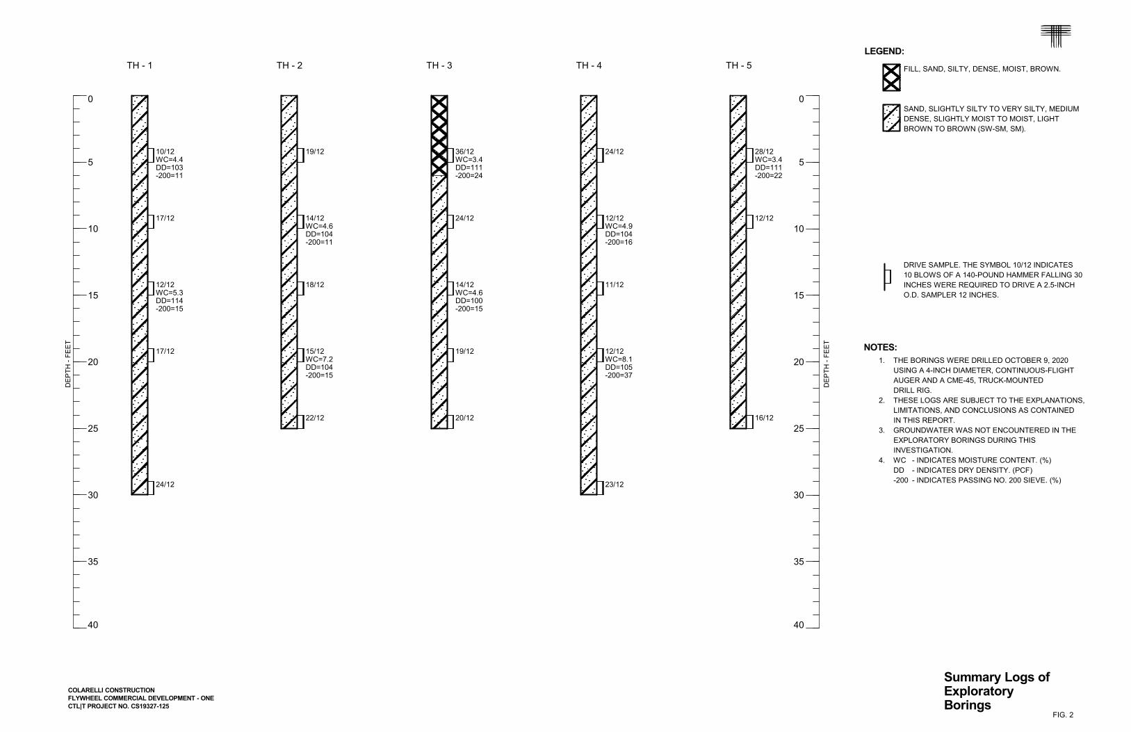
limits, and water-soluble sulfate content. Summary logs of the conditions found in the
exploratory borings, including results of field penetration resistance tests and a
portion of the laboratory data, are presented on Fig. 1. Laboratory testing is present-
ed on Figs. 3 through 5 and summarized in Table 1.

COLARELLI CONSTRUCTION 4
FLYWHEEL COMMERCIAL DEVELOPMENT CTL | T PROJECT NO. CS19327-125
SUBSURFACE CONDITIONS
The near-surface soils encountered in our exploratory borings drilled within the
proposed building footprint generally consisted of silty sand fill and natural, slightly
silty to silty sand to the maximum depths explored. Groundwater was not encoun-
tered at the time of drilling. When water level measurements were conducted one day
following the completion of the drilling, the borings were again found to be dry. The
pertinent engineering characteristics of the soils encountered are discussed in the
following paragraphs.
Fill
We encountered up to 6 feet of fill in one boring (TH-3) located in the south-
west corner of the proposed building footprint. The fill materials classified as silty
sand and were dense based on field penetration resistance testing suggesting they
were likely placed under controlled conditions. The fill was likely placed during previ-
ous rough grading of the site. Records of the fill placement were not available to us
for review at the time of this investigation.
A sample of the fill tested contained 24 percent of silt and clay-sized particles
(passing the No. 200 sieve). Test results and our experience indicate the sand fill
materials are typically non-expansive or exhibit low swell potential when wetted.
Natural Sand
Natural granular materials were encountered at the ground surface or overlain
by fill materials and extended to the maximum depths explored of up to 30 feet. The
granular materials were medium dense based on field penetration resistance testing
and consisted of slightly silty to silty sand. Samples tested in our laboratory contained
9 to 37 percent silt and clay-sized particles (passing the No. 200 sieve). Based on
experience, we anticipate the granular materials are non-expansive or exhibit slight
expansion when wetted under estimated overburden pressures.

COLARELLI CONSTRUCTION 5
FLYWHEEL COMMERCIAL DEVELOPMENT CTL | T PROJECT NO. CS19327-125
Groundwater
At the time of drilling, groundwater was not encountered in the borings drilled
to depths of up to 30 feet. When checked one day following the completion of the
drilling operations, the borings were again found to be dry. Our holes were drilled at
the end of the summer season and beginning of the fall season when groundwater
levels tend to be at or near their seasonal lows. We expect levels may rise during the
summer months in response to precipitation and irrigation.
Seismicity
The soil is not expected to respond unusually to seismic activity. Based on the
2015 International Building Code (IBC), we judge the site classifies as Site Class D
(stiff soil profile).
SITE DEVELOPMENT
No grading plans were available at the time of our investigation. Based on the
existing topography, the site appears to have been rough graded and we expect new
cuts and fills on the order of 5 feet or less will be necessary to establish a building
pad elevation and achieve desired grades across most of the site. Documentation
was not available regarding the existing fill materials encountered at the site; there-
fore, we must consider them to be of suspect quality and recommend it be recon-
structed within the structure footprint. The following sections discuss site develop-
ment in more detail.
Excavation
We believe the soils can be excavated with conventional, heavy-duty excava-
tion equipment. Based on our investigation and Occupational Safety and Health
Administration (OSHA) standards, we believe the on-site surficial soils classify as
Type C materials. OSHA requires Type C materials be braced or laid back to a

COLARELLI CONSTRUCTION 6
FLYWHEEL COMMERCIAL DEVELOPMENT CTL | T PROJECT NO. CS19327-125
maximum slope inclination of 1.5:1 (horizontal to vertical) for dry conditions. If
groundwater conditions change and becomes more shallow, the granular materials
may “flow” into the excavation. Excavation slopes specified by OSHA are dependent
upon the types of soil and groundwater conditions encountered. The contractor’s
“competent person” should identify the soils encountered in the excavations and refer
to OSHA standards to determine appropriate slopes.
Sub-Excavation
We encountered up to 6 feet of suspect quality fill materials in one boring (TH-
3) located in the southwest portion of the proposed building footprint. The fill materi-
als should not be relied upon to support new construction without documentation of
its placement. We recommend the fill material be excavated to a depth that exposes
the natural, underlying granular soils and be re-placed as moisture conditioned and
densely placed sub-excavation backfill. Excavation of the fill should extend at least 5
feet laterally beyond the exterior sides of the proposed foundations.
Fill Placement
The soils found at this site are suitable to re-use as fill material provided vege-
tation, topsoil, debris and other deleterious materials are substantially removed. If
imported fill is necessary, it should ideally consist of granular material with 100
percent passing the 2-inch sieve and containing less than 30 percent passing the No.
200 sieve. The import soil should exhibit low plasticity with a Liquid Limit less than 30
and a Plasticity Index less than 10. A sample of the import material should be submit-
ted to our office for testing before transporting to the site.
Before fill placement, vegetation, topsoil, asphalt, and other deleterious mate-
rial should be removed. Areas to receive fill should be deeply scarified, moisture
conditioned to within 2 percent of optimum moisture content and compacted to at
COLARELLI CONSTRUCTION 7
FLYWHEEL COMMERCIAL DEVELOPMENT CTL | T PROJECT NO. CS19327-125
least 95 percent of maximum modified Proctor dry density (ASTM D1557), for on-site
granular soils.
The properties of the fill will affect the performance of foundations and slabs-
on-grade. Granular fill placed below-footings and slabs should be moisture condi-
tioned to within 2 percent of optimum moisture content and compacted in thin lifts to
at least 95 percent of maximum modified Proctor dry density (ASTM D 1557).
We recommend utility trench backfill be moisture conditioned and compacted
as stated above. The placement and compaction of backfill should be observed and
tested by a representative of our firm during construction.
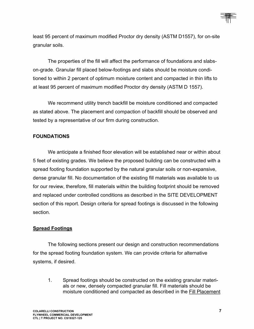
FOUNDATIONS
We anticipate a finished floor elevation will be established near or within about
5 feet of existing grades. We believe the proposed building can be constructed with a
spread footing foundation supported by the natural granular soils or non-expansive,
dense granular fill. No documentation of the existing fill materials was available to us
for our review, therefore, fill materials within the building footprint should be removed
and replaced under controlled conditions as described in the SITE DEVELOPMENT
section of this report. Design criteria for spread footings is discussed in the following
section.
Spread Footings
The following sections present our design and construction recommendations
for the spread footing foundation system. We can provide criteria for alternative
systems, if desired.
1. Spread footings should be constructed on the existing granular materi-als or new, densely compacted granular fill. Fill materials should be moisture conditioned and compacted as described in the Fill Placement

COLARELLI CONSTRUCTION 8
FLYWHEEL COMMERCIAL DEVELOPMENT CTL | T PROJECT NO. CS19327-125
section of this report. Soils loosened during excavation, pockets of loose material, or areas containing undocumented fills should be re-moved and densely replaced as previously discussed prior to placing concrete.
2. Spread footings should be designed for a maximum allowable soil pres-sure of 3,000 psf.
3. We recommend footings beneath continuous foundation walls be at least 16 inches wide. Footings beneath isolated column pads should be at least 24 inches square. Larger footing sizes will likely be required to accommodate the anticipated foundation loads.
4. We recommend designs consider total settlement of 1-inch and differ-ential settlement of 1/2-inch.
5. Continuous foundation walls should be reinforced, top and bottom, to span local anomalies in the subsoils. We recommend the reinforcement required to simply span an unsupported distance of at least 8 feet.
6. Exterior footings must be protected from frost action with a soil cover of at least 30 inches; typical for this area.
7. A representative of our firm should observe the completed foundation excavations to confirm the exposed conditions are similar to those en-countered in our exploratory borings. The placement and compaction of below-footing fill should be observed and tested by a representative of our firm during construction.
BELOW-GRADE CONSTRUCTION
We are not aware of any proposed habitable, below-grade construction. If
plans should change to include below-grade construction, we should be contacted to
provide recommendations for foundation wall lateral earth pressures and subsurface
drains.
FLOOR SYSTEMS AND SLABS-ON-GRADE
We anticipate a slab-on-grade floor is preferred within the proposed building.
We believe a low risk of poor slab performance will exist for a floor slab underlain by
non-expansive granular materials. Expansive materials and undocumented fills

COLARELLI CONSTRUCTION 9
FLYWHEEL COMMERCIAL DEVELOPMENT CTL | T PROJECT NO. CS19327-125
encountered in foundation excavations should be removed and replaced as dis-
cussed under the SITE DEVELOPMENT section of this report. The slab-on-grade
subgrade in lightly loaded areas (50 psf or less) should be scarified to a depth of 8
inches, moisture conditioned to within 2 percent of optimum moisture content and
compacted to at least 95 percent of maximum modified Proctor maximum dry density
(ASTM D 1557).
We understand some portions of the slab-on-grade floors located in the build-
ing may be designed for pressures greater than 50 psf. Some areas may experience
loading influenced by racking and forklift traffic. We recommend the subgrade below
the heavily loaded areas consist of at least 2 feet of dense granular fill. The fill should
consist of the on-site granular soils, moisture conditioned to within 2 percent of
optimum, and compacted to at least 95 percent of maximum modified Proctor dry
density. Slabs-on-grade supported by this dense fill material can be designed con-
sidering a modulus of subgrade reaction of 250 pci.
Shallow building foundations will likely settle relative to lightly loaded slab-on-
grade floors. We estimate this relative movement between footing foundations and
floor slabs could be on the order of 1 inch. The settlement can cause cosmetic
cracking of drywall. We recommend the slab-on-grade floors be separated from
exterior walls and interior bearing members with joints that allow for free vertical
movement of the slab. Slip-joints in slab-bearing partitions should allow for at least 1-
1/2 inches of free vertical movement. If the “float” is provided at the tops of partitions,
the connection between interior, slab-supported partitions and exterior, foundation-
supported walls should be detailed to allow differential movement. These architectur-
al connections are critical to help reduce cosmetic damage when foundations and
floor slabs move relative to each other. We have seen instances where these archi-
tectural connections were not designed and constructed properly and resulted in
moderate cosmetic damage, even though the movement experienced was well within
the anticipated range. The architect should pay special attention to these issues and
detail the connections accordingly.

COLARELLI CONSTRUCTION 10
FLYWHEEL COMMERCIAL DEVELOPMENT CTL | T PROJECT NO. CS19327-125
The 2015 International Building Code (IBC) requires a vapor retarder be
placed between base course or the subgrade soils and the concrete slab-on-grade
floor, unless the designer of the floor (structural engineer) waives this requirement.
The merits of installing a vapor retarder below the floor slab depend on the sensitivity
of floor coverings and building use to moisture. A properly installed vapor retarder (10
mil minimum) is more beneficial below concrete slab-on-grade floors where floor
coverings, painted floor surfaces or products stored on the floor will be sensitive to
moisture. The vapor retarder is most effective when concrete is placed directly on top
of it, rather than placing a sand or gravel leveling course between the vapor retarder
and the floor slab. The placement of concrete on the vapor retarder may increase the
risk of shrinkage cracking and curling. Use of concrete with reduced shrinkage
characteristics including minimized water content, maximized coarse aggregate
content, and reasonably low slump will reduce the risk of shrinkage cracking and
curling. Considerations and recommendations for the installation of vapor retarders
below concrete slabs are outlined in Section 3.2.3 of the 2006 report of the American
Concrete Institute (ACI) Committee 302, “Guide for Concrete Floor and Slab Con-
struction (ACI 302.R-96)”.
All parties must realize that even small movements of the floor slab (less than
1-inch) can damage comparatively brittle floor treatments such as ceramic or stone
tile that might be used in restrooms, or impact movement sensitive medical equip-
ment. If some movement of the slab is not acceptable, a structurally supported floor
with an air space between the floor and the subgrade soils is recommended. The air
space required by building codes depends on the materials used to construct the
floor. The structural floor is supported by the foundation system. There are design
and construction issues associated with structural floors, such as ventilation and
increased lateral loads that must be considered.
COLARELLI CONSTRUCTION 11
FLYWHEEL COMMERCIAL DEVELOPMENT CTL | T PROJECT NO. CS19327-125
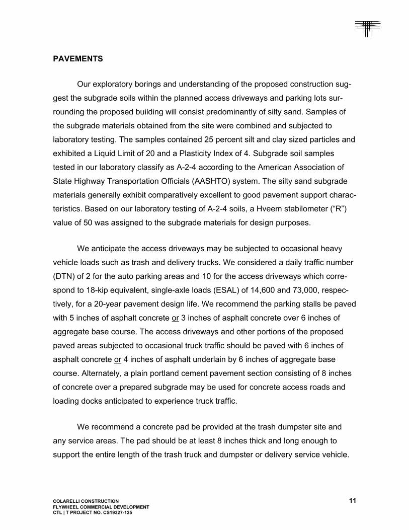
PAVEMENTS
Our exploratory borings and understanding of the proposed construction sug-
gest the subgrade soils within the planned access driveways and parking lots sur-
rounding the proposed building will consist predominantly of silty sand. Samples of
the subgrade materials obtained from the site were combined and subjected to
laboratory testing. The samples contained 25 percent silt and clay sized particles and
exhibited a Liquid Limit of 20 and a Plasticity Index of 4. Subgrade soil samples
tested in our laboratory classify as A-2-4 according to the American Association of
State Highway Transportation Officials (AASHTO) system. The silty sand subgrade
materials generally exhibit comparatively excellent to good pavement support charac-
teristics. Based on our laboratory testing of A-2-4 soils, a Hveem stabilometer (“R”)
value of 50 was assigned to the subgrade materials for design purposes.
We anticipate the access driveways may be subjected to occasional heavy
vehicle loads such as trash and delivery trucks. We considered a daily traffic number
(DTN) of 2 for the auto parking areas and 10 for the access driveways which corre-
spond to 18-kip equivalent, single-axle loads (ESAL) of 14,600 and 73,000, respec-
tively, for a 20-year pavement design life. We recommend the parking stalls be paved
with 5 inches of asphalt concrete or 3 inches of asphalt concrete over 6 inches of
aggregate base course. The access driveways and other portions of the proposed
paved areas subjected to occasional truck traffic should be paved with 6 inches of
asphalt concrete or 4 inches of asphalt underlain by 6 inches of aggregate base
course. Alternately, a plain portland cement pavement section consisting of 8 inches
of concrete over a prepared subgrade may be used for concrete access roads and
loading docks anticipated to experience truck traffic.
We recommend a concrete pad be provided at the trash dumpster site and
any service areas. The pad should be at least 8 inches thick and long enough to
support the entire length of the trash truck and dumpster or delivery service vehicle.

COLARELLI CONSTRUCTION 12
FLYWHEEL COMMERCIAL DEVELOPMENT CTL | T PROJECT NO. CS19327-125
Joints between concrete and asphalt pavements should be sealed with a flexible
compound.
Our design considers pavement construction will be completed in accordance
with the City of Colorado Springs “Standard Specifications” and the Pikes Peak
Region Asphalt Paving Specifications. Our calculations are based on regionally
accepted structural coefficients of locally available materials. The specifications
contain requirements for the pavement materials (asphalt, base course, and con-
crete) as well as the construction practices used (compaction, materials sampling,
and proof-rolling). Of particular importance are those recommendations directed
toward subgrade and base course compaction and proof-rolling. During proof-rolling,
particular attention should be directed toward the areas of confined backfill compac-
tion. Areas that pump excessively should be stabilized prior to pavement construc-
tion. A representative of our office should be present at the site during placement of
fill and construction of pavements to perform density testing.
CONCRETE
Concrete in contact with soils can be subject to sulfate attack. We measured
water-soluble sulfate concentrations in one sample from this site. Based on laborato-
ry testing and our experience, concentrations were measured at less than 0.1 per-
cent, typical of the materials encountered at the site. Sulfate concentrations less than
0.1 percent indicate Class 0 exposure to sulfate attack for concrete in contact with
the subsoils, according to ACI 201.2R-01 as published in the 2008 ACI Manual of
Concrete Practice. For this level of sulfate concentration, the American Concrete
Institute (ACI) indicates Type I cement can be used for concrete in contact with the
subsoils. In our experience, superficial damage may occur to the exposed surfaces of
highly permeable concrete, even though sulfate levels are relatively low. To control
this risk and to resist freeze-thaw deterioration, the water-to-cementitious material
ratio should not exceed 0.50 for concrete in contact with soils that are likely to stay
COLARELLI CONSTRUCTION 13
FLYWHEEL COMMERCIAL DEVELOPMENT CTL | T PROJECT NO. CS19327-125
moist due to surface drainage or high water tables. Concrete subjected to freeze-
thaw cycles should be air entrained.
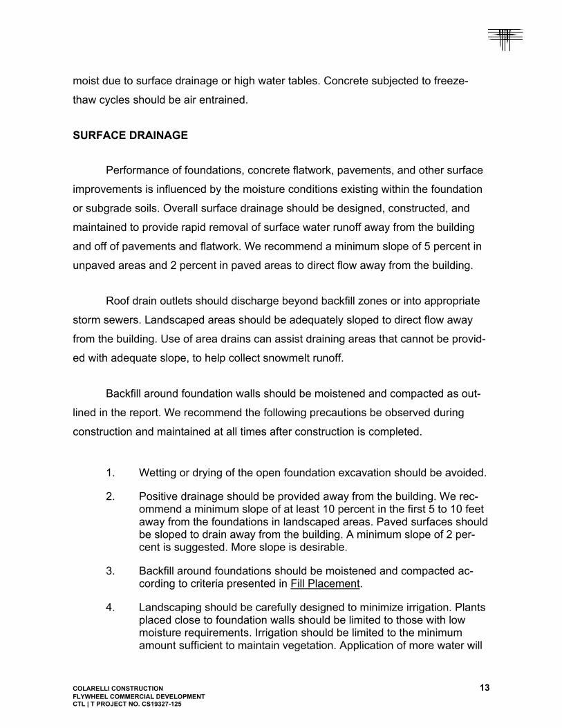
SURFACE DRAINAGE
Performance of foundations, concrete flatwork, pavements, and other surface
improvements is influenced by the moisture conditions existing within the foundation
or subgrade soils. Overall surface drainage should be designed, constructed, and
maintained to provide rapid removal of surface water runoff away from the building
and off of pavements and flatwork. We recommend a minimum slope of 5 percent in
unpaved areas and 2 percent in paved areas to direct flow away from the building.
Roof drain outlets should discharge beyond backfill zones or into appropriate
storm sewers. Landscaped areas should be adequately sloped to direct flow away
from the building. Use of area drains can assist draining areas that cannot be provid-
ed with adequate slope, to help collect snowmelt runoff.
Backfill around foundation walls should be moistened and compacted as out-
lined in the report. We recommend the following precautions be observed during
construction and maintained at all times after construction is completed.
1. Wetting or drying of the open foundation excavation should be avoided.
2. Positive drainage should be provided away from the building. We rec-ommend a minimum slope of at least 10 percent in the first 5 to 10 feet away from the foundations in landscaped areas. Paved surfaces should be sloped to drain away from the building. A minimum slope of 2 per-cent is suggested. More slope is desirable.
3. Backfill around foundations should be moistened and compacted ac-cording to criteria presented in Fill Placement.
4. Landscaping should be carefully designed to minimize irrigation. Plants placed close to foundation walls should be limited to those with low moisture requirements. Irrigation should be limited to the minimum amount sufficient to maintain vegetation. Application of more water will
COLARELLI CONSTRUCTION 14
FLYWHEEL COMMERCIAL DEVELOPMENT CTL | T PROJECT NO. CS19327-125
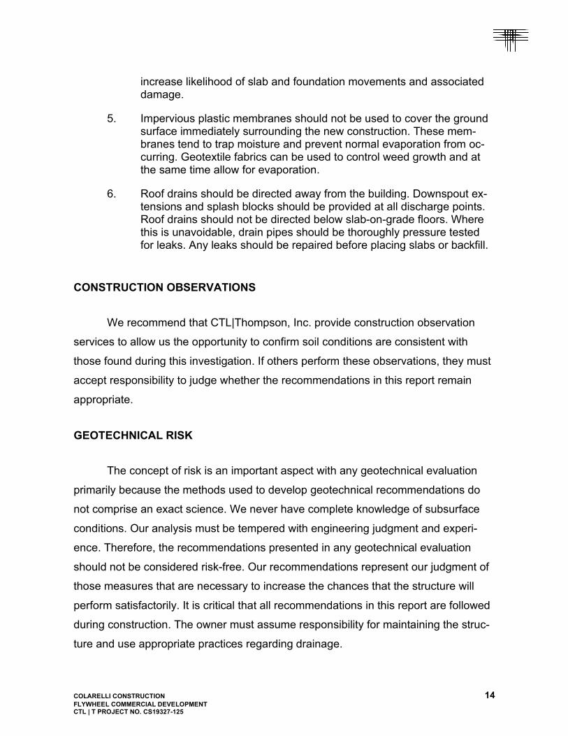
increase likelihood of slab and foundation movements and associated damage.
5. Impervious plastic membranes should not be used to cover the ground surface immediately surrounding the new construction. These mem-branes tend to trap moisture and prevent normal evaporation from oc-curring. Geotextile fabrics can be used to control weed growth and at the same time allow for evaporation.
6. Roof drains should be directed away from the building. Downspout ex-tensions and splash blocks should be provided at all discharge points. Roof drains should not be directed below slab-on-grade floors. Where this is unavoidable, drain pipes should be thoroughly pressure tested for leaks. Any leaks should be repaired before placing slabs or backfill.
CONSTRUCTION OBSERVATIONS
We recommend that CTL|Thompson, Inc. provide construction observation
services to allow us the opportunity to confirm soil conditions are consistent with
those found during this investigation. If others perform these observations, they must
accept responsibility to judge whether the recommendations in this report remain
appropriate.
GEOTECHNICAL RISK
The concept of risk is an important aspect with any geotechnical evaluation
primarily because the methods used to develop geotechnical recommendations do
not comprise an exact science. We never have complete knowledge of subsurface
conditions. Our analysis must be tempered with engineering judgment and experi-
ence. Therefore, the recommendations presented in any geotechnical evaluation
should not be considered risk-free. Our recommendations represent our judgment of
those measures that are necessary to increase the chances that the structure will
perform satisfactorily. It is critical that all recommendations in this report are followed
during construction. The owner must assume responsibility for maintaining the struc-
ture and use appropriate practices regarding drainage.

COLARELLI CONSTRUCTION 15
FLYWHEEL COMMERCIAL DEVELOPMENT CTL | T PROJECT NO. CS19327-125
LIMITATIONS
This report has been prepared for the exclusive use of Colarelli Construction
for the purpose of providing geotechnical design and construction criteria for the
50,000 square foot Flywheel Commercial Building. The information, conclusions, and
recommendations presented herein are based upon consideration of many factors
including, but not limited to, the type of structure proposed, the geologic setting, and
the subsurface conditions encountered. The conclusions and recommendations
contained in the report are not valid for use by others. Standards of practice continu-
ously evolve in the area of geotechnical engineering. The recommendations provided
are appropriate for about three years. If the project is not constructed within about
three years, we should be contacted to determine if we should update this report.
Our borings locations were chosen by the client, and we believe the borings
were reasonably spaced to obtain a reasonably accurate picture of foundation condi-
tions below the proposed building area. The data are representative of conditions
encountered only at the exact boring locations. Variations in the subsurface condi-
tions not indicated by our borings are possible. Representatives of our firm should
periodically visit the site to during construction to perform observation and testing
services.
We believe this investigation was conducted in a manner consistent with that
level of skill and care normally used by geotechnical engineers practicing under
similar conditions. No warranty, express or implied, is made.


TH
-1
TH
-2
TH
-4
TH
-3
TH
-5
S-2
S-3
S-1
FIG
. 1
Lo
catio
n o
fE
xplo
rato
ryB
orin
gs
06
0'N
OT
E:
BA
SE
DR
AW
ING
WA
S P
RO
VID
ED
BY
CO
LAR
ELLI
CO
NS
TR
UC
TIO
N D
RA
WIN
G B
Y IN
TE
RG
RO
UP
AR
CH
ITE
CT
S(D
AT
ED
AU
GU
ST
12, 2020).
LO
CA
TIO
N O
F P
RO
PO
SE
D B
UILD
ING
FO
OT
PR
INT
.
PR
OJE
CT
BO
UN
DA
RY
AP
PR
OX
IMA
TE
LO
CA
TIO
N O
F S
UB
GR
AD
E S
AM
PLE
.S
-1
AP
PR
OX
IMA
TE
LO
CA
TIO
N O
F E
XP
LOR
AT
OR
YB
OR
ING
.
LE
GE
ND
:
TH
-1
VIC
INIT
Y M
AP
(NO
T T
O S
CA
LE)
SC
AL
E: 1" =
60
'
30'
CO
LA
RE
LL
I CO
NS
TR
UC
TIO
NF
LY
WH
EE
L C
OM
ME
RC
IAL
DE
VE
LO
PM
EN
T - O
NE
CT
L|T
PR
OJE
CT
NO
. CS
193
27.0
00-125 E
MB
RA
ER
HE
IGH
TS
CRESTERRA PARKWAY
SIT
E
MILT
ON
E P
RO
BY
PK
WY
POWERS BLVD
EM
BR
AE
R H
TS
CRESTERRA
PK
WY
0
5
10
15
20
25
30
35
40
0
5
10
15
20
25
30
35
40
LEGEND:
FILL, SAND, SILTY, DENSE, MOIST, BROWN.
FIG. 2
DE
PT
H -
FE
ET
COLARELLI CONSTRUCTIONFLYWHEEL COMMERCIAL DEVELOPMENT - ONECTL|T PROJECT NO. CS19327-125
SAND, SLIGHTLY SILTY TO VERY SILTY, MEDIUMDENSE, SLIGHTLY MOIST TO MOIST, LIGHTBROWN TO BROWN (SW-SM, SM).
NOTES:
Summary Logs ofExploratoryBorings
DE
PT
H -
FE
ET
DRIVE SAMPLE. THE SYMBOL 10/12 INDICATES10 BLOWS OF A 140-POUND HAMMER FALLING 30INCHES WERE REQUIRED TO DRIVE A 2.5-INCHO.D. SAMPLER 12 INCHES.
10/12WC=4.4DD=103-200=11
17/12
12/12WC=5.3DD=114-200=15
17/12
24/12
TH - 1
19/12
14/12WC=4.6DD=104-200=11
18/12
15/12WC=7.2DD=104-200=15
22/12
TH - 2
36/12WC=3.4DD=111-200=24
24/12
14/12WC=4.6DD=100-200=15
19/12
20/12
TH - 3
24/12
12/12WC=4.9DD=104-200=16
11/12
12/12WC=8.1DD=105-200=37
23/12
TH - 4
28/12WC=3.4DD=111-200=22
12/12
16/12
TH - 5
1. THE BORINGS WERE DRILLED OCTOBER 9, 2020 USING A 4-INCH DIAMETER, CONTINUOUS-FLIGHT AUGER AND A CME-45, TRUCK-MOUNTED DRILL RIG.2. THESE LOGS ARE SUBJECT TO THE EXPLANATIONS, LIMITATIONS, AND CONCLUSIONS AS CONTAINED IN THIS REPORT.3. GROUNDWATER WAS NOT ENCOUNTERED IN THE EXPLORATORY BORINGS DURING THIS INVESTIGATION.4. WC - INDICATES MOISTURE CONTENT. (%) DD - INDICATES DRY DENSITY. (PCF) -200 - INDICATES PASSING NO. 200 SIEVE. (%)

Sample of SAND, SLIGHTLY SILTY (SW-SM) GRAVEL 0 % SAND 89 %From TH - 1 AT 4 FEET SILT & CLAY 11 % LIQUID LIMIT %
PLASTICITY INDEX %
Sample of SAND, SLIGHTLY SILTY (SW-SM) GRAVEL 0 % SAND 89 %From TH - 2 AT 9 FEET SILT & CLAY 11 % LIQUID LIMIT %
PLASTICITY INDEX %
COLARELLI CONSTRUCTION
FLYWHEEL COMMERCIAL DEVELOPMENT - ONE
CTL|T PROJECT NO. CS19327-125
FIG. 3
GradationTest Results
0.002
15 MIN.
.005
60 MIN.
.009
19 MIN.
.019
4 MIN.
.037
1 MIN.
.074
*200
.149
*100
.297
*50
0.42
*40
.590
*30
1.19
*16
2.0
*10
2.38
*8
4.76
*4
9.52
3/8"
19.1
3/4"
36.1
1½"
76.2
3"
127
5"
152
6"
200
8"
.001
45 MIN.
0
10
20
30
40
50
60
70
80
90
100
CLAY (PLASTIC) TO SILT (NON-PLASTIC)SANDS
FINE MEDIUM COARSE
GRAVEL
FINE COARSE COBBLES
DIAMETER OF PARTICLE IN MILLIMETERS
25 HR. 7 HR.
HYDROMETER ANALYSIS SIEVE ANALYSIS
TIME READINGS U.S. STANDARD SERIES CLEAR SQUARE OPENINGS
PE
RC
EN
T P
AS
SIN
G
0
10
20
30
50
60
70
80
90
100
PE
RC
EN
T R
ET
AIN
ED
40
0.002
15 MIN.
.005
60 MIN.
.009
19 MIN.
.019
4 MIN.
.037
1 MIN.
.074
*200
.149
*100
.297
*50
0.42
*40
.590
*30
1.19
*16
2.0
*10
2.38
*8
4.76
*4
9.52
3/8"
19.1
3/4"
36.1
1½"
76.2
3"
127
5"
152
6"
200
8"
.001
45 MIN.
0
10
20
30
40
50
60
70
80
90
100
CLAY (PLASTIC) TO SILT (NON-PLASTIC)SANDS
FINE MEDIUM COARS
GRAVEL
FINE COARSE COBBLES
DIAMETER OF PARTICLE IN MILLIMETERS
25 HR. 7 HR.
HYDROMETER ANALYSIS SIEVE ANALYSIS
TIME READINGS U.S. STANDARD SERIES CLEAR SQUARE OPENINGS
PE
RC
EN
T P
AS
SIN
G
PE
RC
EN
T R
ET
AIN
ED
0
10
20
30
40
50
60
70
80
90
100

Sample of FILL, SAND, SILTY GRAVEL 0 % SAND 76 %From TH - 3 AT 4 FEET SILT & CLAY 24 % LIQUID LIMIT %
PLASTICITY INDEX %
Sample of SAND, SILTY (SM) GRAVEL 0 % SAND 84 %From TH - 4 AT 9 FEET SILT & CLAY 16 % LIQUID LIMIT %
PLASTICITY INDEX %
COLARELLI CONSTRUCTION
FLYWHEEL COMMERCIAL DEVELOPMENT - ONE
CTL|T PROJECT NO. CS19327-125
FIG. 4
GradationTest Results
0.002
15 MIN.
.005
60 MIN.
.009
19 MIN.
.019
4 MIN.
.037
1 MIN.
.074
*200
.149
*100
.297
*50
0.42
*40
.590
*30
1.19
*16
2.0
*10
2.38
*8
4.76
*4
9.52
3/8"
19.1
3/4"
36.1
1½"
76.2
3"
127
5"
152
6"
200
8"
.001
45 MIN.
0
10
20
30
40
50
60
70
80
90
100
CLAY (PLASTIC) TO SILT (NON-PLASTIC)SANDS
FINE MEDIUM COARSE
GRAVEL
FINE COARSE COBBLES
DIAMETER OF PARTICLE IN MILLIMETERS
25 HR. 7 HR.
HYDROMETER ANALYSIS SIEVE ANALYSIS
TIME READINGS U.S. STANDARD SERIES CLEAR SQUARE OPENINGS
PE
RC
EN
T P
AS
SIN
G
0
10
20
30
50
60
70
80
90
100
PE
RC
EN
T R
ET
AIN
ED
40
0.002
15 MIN.
.005
60 MIN.
.009
19 MIN.
.019
4 MIN.
.037
1 MIN.
.074
*200
.149
*100
.297
*50
0.42
*40
.590
*30
1.19
*16
2.0
*10
2.38
*8
4.76
*4
9.52
3/8"
19.1
3/4"
36.1
1½"
76.2
3"
127
5"
152
6"
200
8"
.001
45 MIN.
0
10
20
30
40
50
60
70
80
90
100
CLAY (PLASTIC) TO SILT (NON-PLASTIC)SANDS
FINE MEDIUM COARS
GRAVEL
FINE COARSE COBBLES
DIAMETER OF PARTICLE IN MILLIMETERS
25 HR. 7 HR.
HYDROMETER ANALYSIS SIEVE ANALYSIS
TIME READINGS U.S. STANDARD SERIES CLEAR SQUARE OPENINGS
PE
RC
EN
T P
AS
SIN
G
PE
RC
EN
T R
ET
AIN
ED
0
10
20
30
40
50
60
70
80
90
100
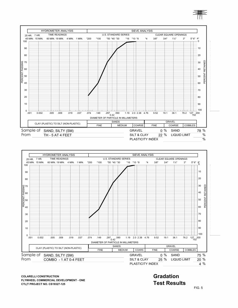
Sample of SAND, SILTY (SM) GRAVEL 0 % SAND 78 %From TH - 5 AT 4 FEET SILT & CLAY 22 % LIQUID LIMIT %
PLASTICITY INDEX %
Sample of SAND, SILTY (SM) GRAVEL 0 % SAND 75 %From COMBO - 1 AT 0-4 FEET SILT & CLAY 25 % LIQUID LIMIT 20 %
PLASTICITY INDEX 4 %
COLARELLI CONSTRUCTION
FLYWHEEL COMMERCIAL DEVELOPMENT - ONE
CTL|T PROJECT NO. CS19327-125
FIG. 5
GradationTest Results
0.002
15 MIN.
.005
60 MIN.
.009
19 MIN.
.019
4 MIN.
.037
1 MIN.
.074
*200
.149
*100
.297
*50
0.42
*40
.590
*30
1.19
*16
2.0
*10
2.38
*8
4.76
*4
9.52
3/8"
19.1
3/4"
36.1
1½"
76.2
3"
127
5"
152
6"
200
8"
.001
45 MIN.
0
10
20
30
40
50
60
70
80
90
100
CLAY (PLASTIC) TO SILT (NON-PLASTIC)SANDS
FINE MEDIUM COARSE
GRAVEL
FINE COARSE COBBLES
DIAMETER OF PARTICLE IN MILLIMETERS
25 HR. 7 HR.
HYDROMETER ANALYSIS SIEVE ANALYSIS
TIME READINGS U.S. STANDARD SERIES CLEAR SQUARE OPENINGS
PE
RC
EN
T P
AS
SIN
G
0
10
20
30
50
60
70
80
90
100
PE
RC
EN
T R
ET
AIN
ED
40
0.002
15 MIN.
.005
60 MIN.
.009
19 MIN.
.019
4 MIN.
.037
1 MIN.
.074
*200
.149
*100
.297
*50
0.42
*40
.590
*30
1.19
*16
2.0
*10
2.38
*8
4.76
*4
9.52
3/8"
19.1
3/4"
36.1
1½"
76.2
3"
127
5"
152
6"
200
8"
.001
45 MIN.
0
10
20
30
40
50
60
70
80
90
100
CLAY (PLASTIC) TO SILT (NON-PLASTIC)SANDS
FINE MEDIUM COARS
GRAVEL
FINE COARSE COBBLES
DIAMETER OF PARTICLE IN MILLIMETERS
25 HR. 7 HR.
HYDROMETER ANALYSIS SIEVE ANALYSIS
TIME READINGS U.S. STANDARD SERIES CLEAR SQUARE OPENINGS
PE
RC
EN
T P
AS
SIN
G
PE
RC
EN
T R
ET
AIN
ED
0
10
20
30
40
50
60
70
80
90
100
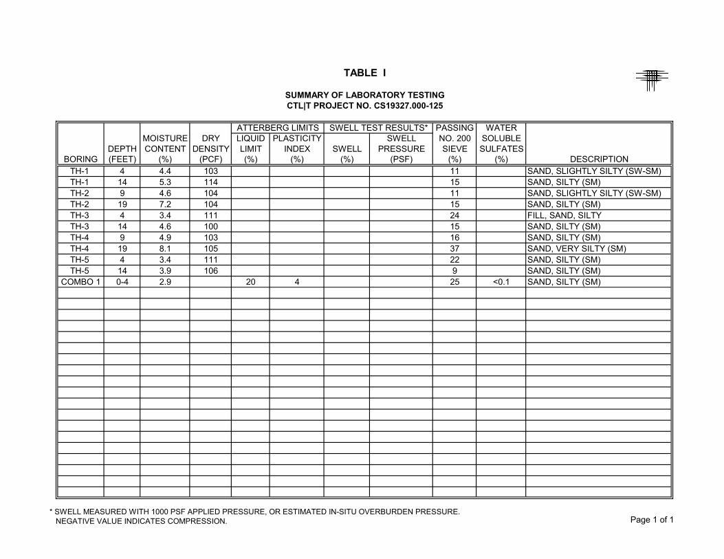
PASSING WATERMOISTURE DRY LIQUID PLASTICITY SWELL NO. 200 SOLUBLE
DEPTH CONTENT DENSITY LIMIT INDEX SWELL PRESSURE SIEVE SULFATESBORING (FEET) (%) (PCF) (%) (%) (%) (PSF) (%) (%) DESCRIPTION
TH-1 4 4.4 103 11 SAND, SLIGHTLY SILTY (SW-SM)TH-1 14 5.3 114 15 SAND, SILTY (SM)TH-2 9 4.6 104 11 SAND, SLIGHTLY SILTY (SW-SM)TH-2 19 7.2 104 15 SAND, SILTY (SM)TH-3 4 3.4 111 24 FILL, SAND, SILTYTH-3 14 4.6 100 15 SAND, SILTY (SM)TH-4 9 4.9 103 16 SAND, SILTY (SM)TH-4 19 8.1 105 37 SAND, VERY SILTY (SM)TH-5 4 3.4 111 22 SAND, SILTY (SM)TH-5 14 3.9 106 9 SAND, SILTY (SM)
COMBO 1 0-4 2.9 20 4 25 <0.1 SAND, SILTY (SM)
SWELL TEST RESULTS*
TABLE I
SUMMARY OF LABORATORY TESTINGCTL|T PROJECT NO. CS19327.000-125
ATTERBERG LIMITS
* SWELL MEASURED WITH 1000 PSF APPLIED PRESSURE, OR ESTIMATED IN-SITU OVERBURDEN PRESSURE. NEGATIVE VALUE INDICATES COMPRESSION. Page 1 of 1