Embed Size (px)
Citation preview
20/03/2018
1
foundations/footings Part 2
Geotechnical (GEO) and Structural design of footing pad
Last lecture has been presented: Role of foundations for structures safety and integrity. Ultimate
(ULS) and serviceability limit states (SLS) as defined in the Eurocode 7. Basic and frequently used principles for ULS STR.
Basic types of foundations, spread foundations. Definitions of contact pressure sz as design parameter of loading,
and soil strength Rzd as a parameter of the soil resistance. Influence of pad and soil stiffness to shape of sz alongside the
contact area of footing. Simplified imagination sz shape as result of simultaneous action of
M+N (N+e).
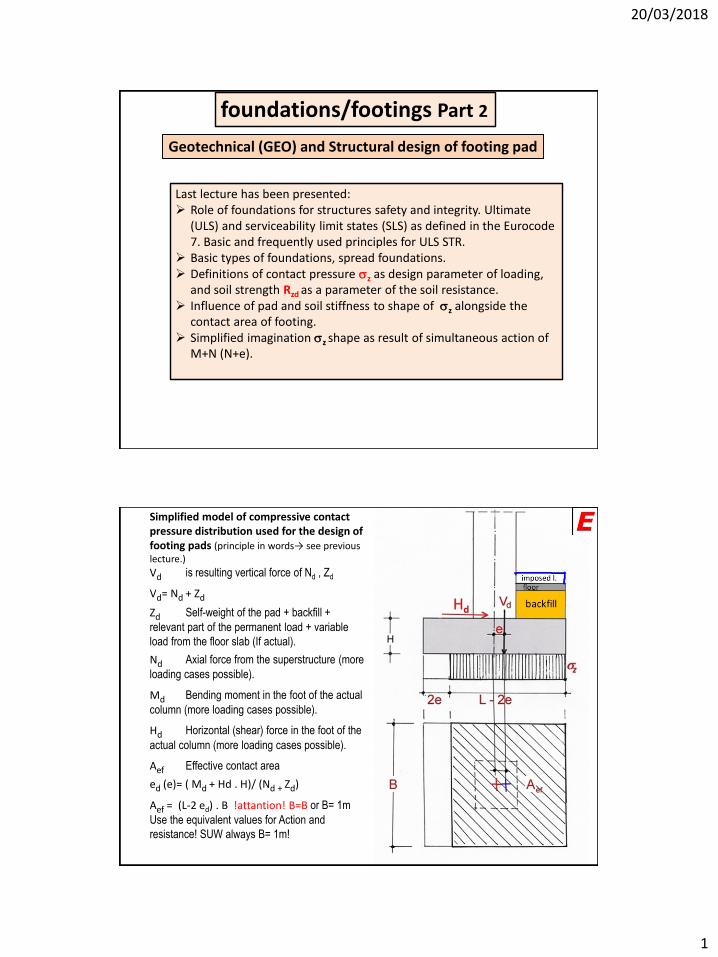
Simplified model of compressive contact pressure distribution used for the design of footing pads (principle in words→ see previous lecture.)
Vd is resulting vertical force of Nd , Zd
Vd= Nd + Zd
Zd Self-weight of the pad + backfill +
relevant part of the permanent load + variable
load from the floor slab (If actual).
Nd Axial force from the superstructure (more
loading cases possible).
Md Bending moment in the foot of the actual
column (more loading cases possible).
Hd Horizontal (shear) force in the foot of the
actual column (more loading cases possible).
Aef Effective contact area
ed (e)= ( Md + Hd . H)/ (Nd + Zd)
Aef = (L-2 ed) . B !attantion! B=B or B= 1m
Use the equivalent values for Action and
resistance! SUW always B= 1m!
20/03/2018
2
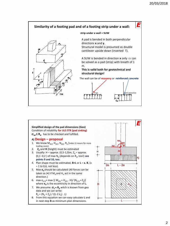
Similarity of a footing pad and of a footing strip under a wall:
A pad is bended in both perpendicular directions x and y.Structural model is presumed as double cantilever upside down (inverted T).
A SUW is bended in direction x only can be solved as a pad (strip) with breath of 1 m.This is valid both for geotechnical and structural design!
The wall can be of masonry or reinforced concrete
strip under a wall = SUW
Simplified design of the pad dimensions (Geo)Condition of reliability for ULS STR (pad sinking)
szd ≤ Rd has to be checked and fulfilled.
A) Design – proposal1. We know Md(i), Hd(i), Nd(i), Rd [index (i) means for more
loading cases].
2. Zd and H (height) must be estimated3. Usually: H = approx. (0,5-1,0)m, Zd = approx.
(0,1 -0,2 ) of max Nd (depends on Rd, too!) see points 9 and 10, too.
4. Plan shape must be estimated, B=L or L = x. B, (x = 1 to 0,6, not less).
5. Max ed should be calculated (All forces can be
taken as (+) if Md and Hd act in the same direction.)
6. max ed (i)= max [( Md(i) + Hd(i) . H)/ (Nd (i) + Zd)] where ed is the eccentricity in direction of L.
7. We presume sz = Rd witch is known from geo data and we can write: Rd = (Nd + Zd) / ((L-2 ed) . L)
8. From this equation we can easy calculate L and in next step B as minimum plan dimensions.
20/03/2018
3
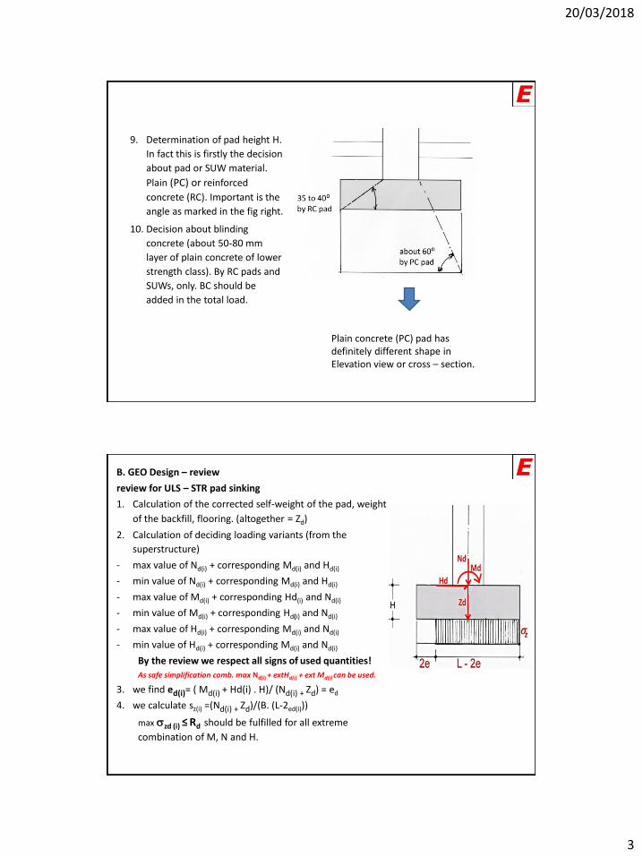
9. Determination of pad height H.
In fact this is firstly the decision
about pad or SUW material.
Plain (PC) or reinforced
concrete (RC). Important is the
angle as marked in the fig right.
10. Decision about blinding
concrete (about 50-80 mm
layer of plain concrete of lower
strength class). By RC pads and
SUWs, only. BC should be
added in the total load.
Plain concrete (PC) pad has definitely different shape in Elevation view or cross – section.
B. GEO Design – review
review for ULS – STR pad sinking
1. Calculation of the corrected self-weight of the pad, weight
of the backfill, flooring. (altogether = Zd)
2. Calculation of deciding loading variants (from the
superstructure)
- max value of Nd(i) + corresponding Md(i) and Hd(i)
- min value of Nd(i) + corresponding Md(i) and Hd(i)
- max value of Md(i) + corresponding Hd(i) and Nd(i)
- min value of Md(i) + corresponding Hd(i) and Nd(i)
- max value of Hd(i) + corresponding Md(i) and Nd(i)
- min value of Hd(i) + corresponding Md(i) and Nd(i)
By the review we respect all signs of used quantities!
As safe simplification comb. max Nd(i) + extHd(i) + ext Md(i) can be used.
3. we find ed(i)= ( Md(i) + Hd(i) . H)/ (Nd(i) + Zd) = ed
4. we calculate sz(i) =(Nd(i) + Zd)/(B. (L-2ed(i)))
max szd (i) ≤ Rd should be fulfilled for all extreme
combination of M, N and H.

20/03/2018
4
Stability of a pad ULS EQUA pad should not overturn and move horizontally. There are some common rules:if max ed(i) ≤ 1/6 L, stability is OK and no other check is necessaryif max ed(i) ≥ 1/6 L and ≤ 1/3 L,
Stability against overturning (ULS EQU) must be verified separately by the condition:Mstb ≥ Mdst
Mstb=[L/2 (Z’d + N’d)] . gstb
gstb = 0,9 (depends on NA), Z’d without backfill,N’d without variable loadMdst=max [H . Hd(i) + Md(i)]
Don’t forget the influence of favourableand unfavourable load action and equal values of coefficients gg and gq.
Stability against horizontal movement (ULS EQI)must be verified separately by the condition:Hstb ≥ Hdst
Hdst= Hd(i)
Hstb= N’d . tgf (extremely simplified)tgf is angle of the soil’s internal friction
Another controls
Design of a pad and SUW as a structure
First of all should be mentioned, that a part of contact
pressure sz is responsible for pad stressing, only! Hold true:
effective (upward) pressure pz = sz - qz, (sometimes will
be marked as pd) e.g. Pad „floats“ in the soil.
where qz = Zd/(B . L) (without imposed load on the 1st floor)
Has been observed that this clear fact is frequently ignored and contact/ground pressure is used, perhaps for greater simplicity and safety.
20/03/2018
5
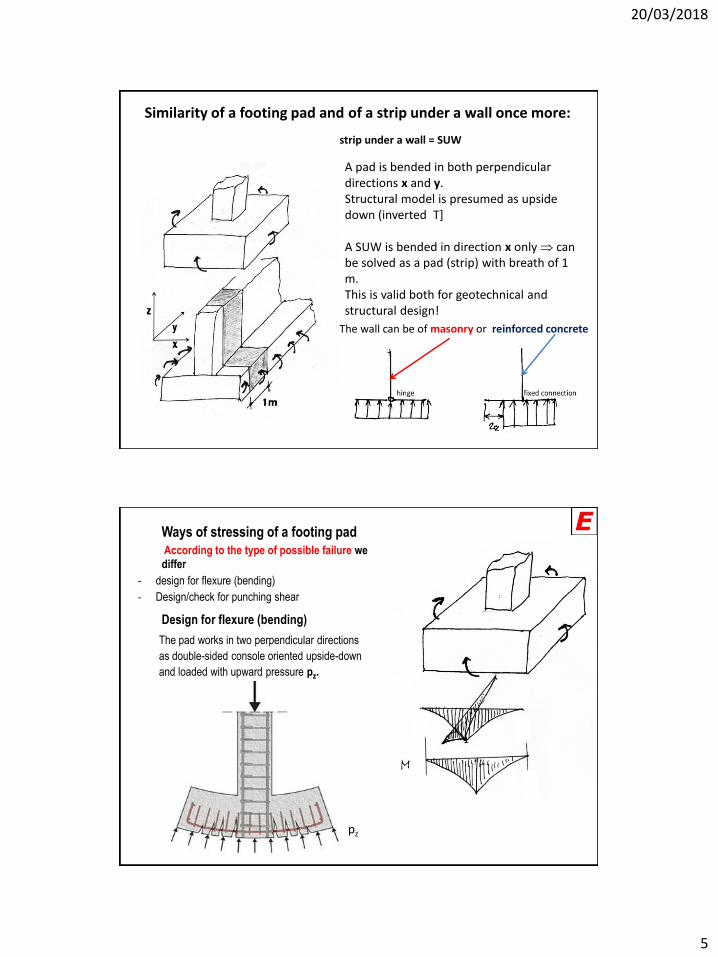
Similarity of a footing pad and of a strip under a wall once more:
A pad is bended in both perpendicular directions x and y.Structural model is presumed as upside down (inverted T]
A SUW is bended in direction x only can be solved as a pad (strip) with breath of 1 m.This is valid both for geotechnical and structural design!
The wall can be of masonry or reinforced concrete
strip under a wall = SUW
Ways of stressing of a footing pad
According to the type of possible failure we differ
- design for flexure (bending)
- Design/check for punching shear
Design for flexure (bending)
The pad works in two perpendicular directions
as double-sided console oriented upside-down
and loaded with upward pressure pz.
pz
20/03/2018
6
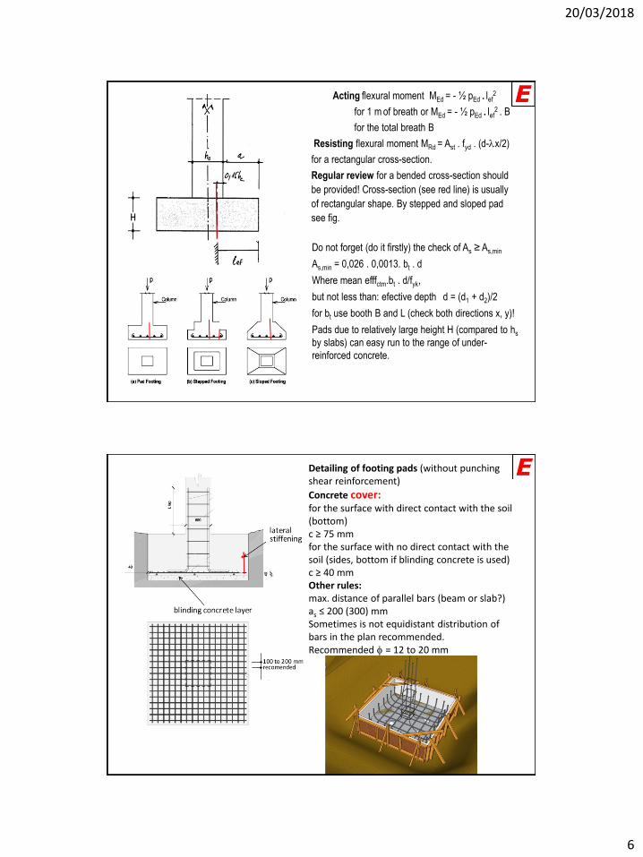
Acting flexural moment MEd = - ½ pEd . lef2
for 1 m of breath or MEd = - ½ pEd . lef2 . B
for the total breath B
Resisting flexural moment MRd = Ast . fyd . (d-lx/2)
for a rectangular cross-section.
Regular review for a bended cross-section should
be provided! Cross-section (see red line) is usually
of rectangular shape. By stepped and sloped pad
see fig.
Do not forget (do it firstly) the check of As ≥ As,min
As,min = 0,026 . 0,0013. bt . d
Where mean efffctm.bt . d/fyk,
but not less than: efective depth d = (d1 + d2)/2
for bt use booth B and L (check both directions x, y)!
Pads due to relatively large height H (compared to hs
by slabs) can easy run to the range of under-
reinforced concrete.
Detailing of footing pads (without punching shear reinforcement)
Concrete cover:for the surface with direct contact with the soil (bottom)c ≥ 75 mmfor the surface with no direct contact with the soil (sides, bottom if blinding concrete is used) c ≥ 40 mmOther rules:max. distance of parallel bars (beam or slab?)as ≤ 200 (300) mmSometimes is not equidistant distribution of bars in the plan recommended.Recommended f = 12 to 20 mm

20/03/2018
7
Videos to footing pad
• Video:1, 2, 3, 4
Anchoring of bars at the end of a pad. It is relatively complicated, based on strut and tie model.Original theory is based on the elastic presumption of pd distribution. There is no reason why not to keep the previous model of design with constant uniform distribution of pd of a part of contact area (Aef).
Let us to modify it. In the EN1992-1-1 can be seen:
Modification

20/03/2018
8
where:
R is the resultant of upward pressure within distance x
ze is the external lever arm, i.e. distance between R and the vertical force NEd. Can be assumed e
= 0,15b.
NEd is the vertical force corresponding to total ground pressure between sections A and B
zi is the internal lever arm, i.e. distance between the reinforcement and the horizontal force Fc, zi
may be taken as 0,9d.
Fc is the compressive force corresponding to maximum tensile force Fs,max
For straight bars without end anchorage the minimum value of X is the most critical. As a simplification
xmin = h/2 may be assumed. For other types of anchorage, higher values of X may be more critical.

20/03/2018
9
Influence of the wall type (RC/masonry) is valid both for the geo and structural design.In both cases is strip under a wall designed as 1 m breath section. In the geo part is designed the breath of the strip in the direction „x“ perpendicularly to wall.In the structural design part is designed reinforcement in the same direction.
For the main reinforcement with sectional area As/m
bars f 10 to 16 mm are used. For distributive
reinforcement bars f 8 to 12 mm as well. Should be
fulfilled As,dist ≥ 0,2 AS.
In the case of RC wall, reinforcement for wall strip connection should be used.
Similarity of a footing pad and of a SUW once more / detailing:
Main RFCMT Distributive RFCMT
In special cases, if large opening (e.g. doors) in a wall exists, additional stress occurs and additional reinforcement in longitudinal direction (y) should be applied.
Special stress of SUW

20/03/2018
10
In calculated reinforcement must be in an effective position in cross-section! By bended members it is the part of cross-section in tension (0,25 h).
Plain and slightly reinforced concrete foundations
What is it the “plain” and “slightly-reinforced” concrete?Concrete with As = 0 is plain. (Concerns effective zone.)Concrete with As < As,min is slightly-reinforced.
As,min = 0,026 .fctm.bt . d/fyk, but not less than: 0,0013. bt . dWhere d = (d1 + d2)/2(for bt in calculations use booth B and L (dimensions of a footing in directions x, y)!
Axially loaded strip and pad footings may be designed and constructed as plain concrete provided that acc. to EC2:
0,85 hf/a ≥ (3pd/ftd,pl)0,5
Where:hf is the foundation deptha is the projection from the column face (see figure)pd is the design value of the upward
pressure (in the EC2 is mistakenly given ground pressure)fctd,pl is the design value of the concrete tensile
strengthfctd,pl = act . fctd, where act is given in the N.A. act= 0,6 in
the CS.As a simplification the relation hf /a =2 may be used.
Plain concrete is suitable for little loaded footings, especially for strips under a masonry wall. In such cases is the breath of the strip usually in the range 50 to 80 cm.

20/03/2018
11