Embed Size (px)
Citation preview
Geotechnical Evaluation Support for Design of New Gas Compressor Foundation
Crockett Cogeneration Natural Gas Power Plant Crockett, California
Prepared for: Crockett Cogeneration
Prepared by: AMEC, Oakland, California
December 2011
Project 11162010
AMEC Environment & Infrastructure 2101 Webster Street, 12th Floor Oakland, California 94612-3066 USA Tel (510) 663-4100 Fax (510) 663-4141 amec.com
December 6, 2011
Project OD1116201.000
Mr. Carlos Sanchez Consolidated Asset Management Services Representing Crockett Cogeneration, Ltd. 34759 Lencioni Ave. Bakersfield, California 93308 Subject: Geotechnical Evaluation
New Gas Compressor Foundation Crockett Cogeneration Natural Gas Power Plant Crockett, California
Dear Mr. Sanchez:
AMEC Geomatrix, Inc. (AMEC) is pleased to submit this geotechnical evaluation report for a new natural gas compressor foundation design at the Crockett Cogeneration Natural Gas Power Plant in Crockett, California. This report was developed in accordance with our proposal dated October 13, 2011 and Purchase Order Number 2011511, dated October 13, 2011. Our evaluation included compiling and reviewing existing data, performing a site reconnaissance, performing engineering evaluations and analyses, developing geotechnical recommendations for the design and construction of the foundation elements, and preparing this report.
If you have any questions about this report, please do not hesitate to call any of the undersigned. It has been a pleasure working with you and we look forward to working with you on other future phases of the project.
Sincerely yours, AMEC Geomatrix, Inc.
Justin D. Phalen, PE, GE Project Engineer
Marc J. Ryan, PE, GE Principal Engineer
JPD/MJR/LU \\Oad-fs1\doc_safe\16000s\162010\3000\Final Crockett Cogen Rpt\1 txt, cvrs\Crockett Cogen Cvrltr.doc
Enclosures:
\\Oad-fs1\doc_safe\16000s\162010\3000\Final Crockett Cogen Rpt\1 txt, cvrs\Crockett Cogen Txt.docx i
TABLE OF CONTENTS
Page 1.0 INTRODUCTION ............................................................................................................ 1
1.1 PURPOSE AND SCOPE ........................................................................................... 1 1.2 REPORT ORGANIZATION ........................................................................................ 1
2.0 PROJECT DESCRIPTION.............................................................................................. 2
3.0 DATA REVIEW AND SITE RECONNAISSANCE ........................................................... 2 3.1 DATA REVIEW ....................................................................................................... 2 3.2 SITE RECONNAISSANCE ........................................................................................ 3
4.0 SITE AND SUBSURFACE CONDITIONS ...................................................................... 3 4.1 GEOLOGIC SETTING .............................................................................................. 3 4.2 SEISMICITY ........................................................................................................... 4 4.3 LOCAL DEVELOPMENT HISTORY ............................................................................ 5 4.4 EXISTING SURFACE AND SUBSURFACE CONDITIONS............................................... 5
4.4.1 Existing Surface Conditions .................................................................... 5 4.4.2 Subsurface Conditions ............................................................................ 6 4.4.3 Groundwater Conditions .......................................................................... 7
4.5 GEOLOGIC HAZARDS ............................................................................................. 7 4.5.1 Surface Fault Rupture ............................................................................. 7 4.5.2 Liquefaction ............................................................................................. 7 4.5.3 Site Instability/Landsliding ....................................................................... 8 4.5.4 Soil Swelling or Shrinkage Potential ........................................................ 9
5.0 DISCUSSIONS AND PRELIMINARY GEOTECHNICAL RECOMMENDATIONS ......... 9 5.1 EQUIPMENT FOUNDATION...................................................................................... 9 5.2 SEISMIC DESIGN PARAMETERS ........................................................................... 10 5.3 EARTHWORK ....................................................................................................... 11
5.3.1 Site Preparation ..................................................................................... 11 5.3.2 Excavation Conditions and Ground Support ......................................... 11 5.3.3 Dewatering Requirements ..................................................................... 13 5.3.4 Subgrade Preparation / Protection of Exposed Foundation Surfaces ... 14
5.3.4.1 Subgrade Preparation for Bearing Scenario “A” ........................ 14 5.3.4.2 Subgrade Preparation for Bearing Scenario “B” ........................ 14 5.3.4.3 Subgrade Preparation for Bearing Scenario “C” ........................ 15
5.3.5 Fill Materials and Compaction Criteria .................................................. 15 5.3.5.1 Select Fill ................................................................................... 15 5.3.5.2 Crushed Rock ............................................................................ 16 5.3.5.3 Aggregate Base ......................................................................... 16 5.3.5.4 Controlled Density Fill ................................................................ 16
5.3.6 Drainage and Erosion Control ............................................................... 17 5.4 CONDITIONS DURING CONSTRUCTION ................................................................. 17
6.0 BASIS OF RECOMMENDATIONS ............................................................................... 17
7.0 REFERENCES ............................................................................................................. 17
TABLE OF CONTENTS (Continued)
\\Oad-fs1\doc_safe\16000s\162010\3000\Final Crockett Cogen Rpt\1 txt, cvrs\Crockett Cogen Txt.docx ii
FIGURES
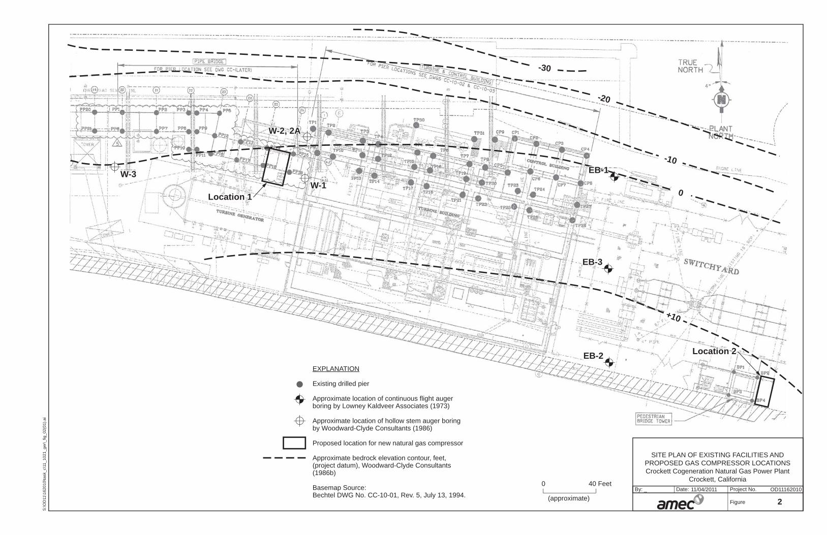
Figure 1 Site Location Map Figure 2 Site Plan and Proposed Locations for New Gas Compressor
APPENDICES
Appendix A Logs of Borings from Woodward, Clyde & Associates (1986b) and Lowney-Kaldveer Associates (1956)
Appendix B Photos of Proposed Locations taken October 19, 2011
\\Oad-fs1\doc_safe\16000s\162010\3000\Final Crockett Cogen Rpt\1 txt, cvrs\Crockett Cogen Txt.docx 1
GEOTECHNICAL EVALUATION New Gas Compressor Foundation
Crockett Cogeneration Natural Gas Power Plant Crockett, California
1.0 INTRODUCTION
This report presents the results of the geotechnical evaluation that AMEC performed to
support the design of a proposed new gas compressor at the Crockett Cogeneration Natural
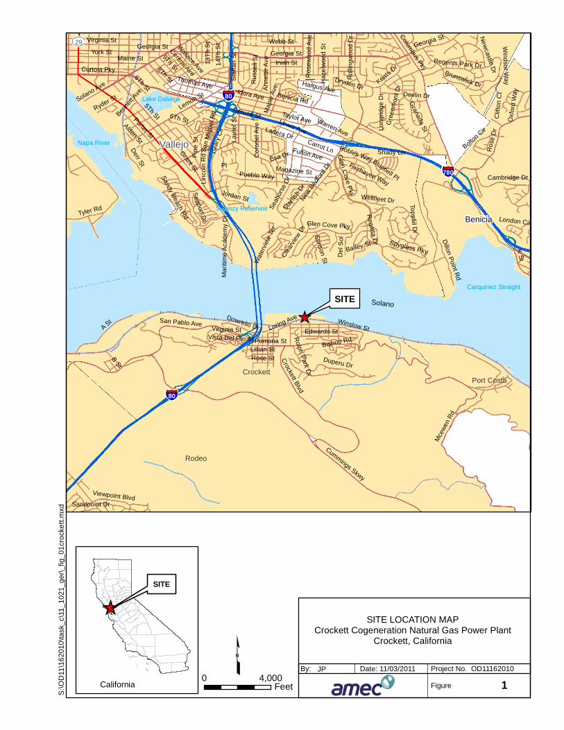
Gas Power Plant (CCNGPP) in Crockett, California. The location of the project is shown on the
Site Location Map (Figure 1).
1.1 PURPOSE AND SCOPE
The purpose of this study was to provide a geotechnical evaluation for two specific locations at
the site and provide geotechnical engineering recommendations for the foundation design of
the proposed equipment. The following information, recommendations, and schematic design
criteria are presented in this report:
• Summary of previous geotechnical and geologic studies performed at the site;
• Description of subsurface soil and groundwater conditions encountered in the logs of the borings performed by others;
• Description of site terrain, site history, geology, site seismicity, and geologic hazards;
• Site classification in accordance with ASCE 7-05 to be used for seismic design; and,
• Preliminary discussion of primary geotechnical considerations and preliminary design recommendations.
Our scope of services to accomplish the above-stated purposes was outlined in our proposal
dated October 13, 2011.
1.2 REPORT ORGANIZATION
A brief project description is presented in Section 2.0. Section 3.0 discusses the previous
geotechnical and geologic studies performed at the site. A general description of the site
conditions is provided in Section 4.0. Section 5.0 discusses the key geotechnical
considerations associated with the project and provides geotechnical recommendations for
preliminary design of the equipment foundation elements. Section 6.0 describes the basis for
our recommendations and Section 7.0 includes a list of references.
\\Oad-fs1\doc_safe\16000s\162010\3000\Final Crockett Cogen Rpt\1 txt, cvrs\Crockett Cogen Txt.docx 2
This report includes two appendixes. A summary of the existing data reviewed is included in
Appendix A. Appendix B contains photographs taken during a site visit to the CCNGPP on
October 19, 2011.
2.0 PROJECT DESCRIPTION
It is our understanding that the CCNGPP is considering an equipment upgrade that will feature
a new natural gas compressor and skid weighing up to 65,000-lbs with plan dimensions of
about 8 feet by 18 feet. Two locations are being considered for the placement of the
compressor and skid (Figure 2); both are in relatively congested areas containing existing
plant facilities. Location 1 is an area near the center of the plant currently surfaced with
concrete slabs with nearby structural mats, spread footings, piers, and grade beams for the
support of the adjacent facilities. Location 2 is at the far eastern edge of the plant, adjacent to
a three-story steel-framed pedestrian bridge tower. It is currently surfaced with asphaltic
concrete and occupied by a pipe and tool storage shed.
The project will consist of preparing one of the two selected sites by moving, or removing
existing facilities in the proposed footprint, demolishing existing surface features (concrete slab
or asphaltic concrete), installing the selected foundation elements, and installing the gas
compressor skid at grade. This geotechnical evaluation report was prepared to support the
design of the foundation elements for the new compressor.
3.0 DATA REVIEW AND SITE RECONNAISSANCE
The preliminary evaluation performed for the proposed equipment upgrade consisted of a
detailed review of existing geotechnical/geologic reports prepared for the existing facilities and
a cursory site reconnaissance to examine existing conditions at the ground surface.
3.1 DATA REVIEW
AMEC reviewed existing geologic and geotechnical information provided by Crockett
Cogeneration that was issued primarily for the design of the existing plant facilities. The
following sources contained information pertinent to our evaluation of the geotechnical
conditions:
• Geofon, Inc. (1991) Geotechnical Investigation, Proposed Aqueous Ammonia Storage Tanks, C&H Cogeneration Project, Crockett, California
• Woodward-Clyde Consultants (1986a) Preliminary Geotechnical Engineering and Seismic Exposure Study, Crocker Cogeneration Project
• Woodward-Clyde Consultants (1986b) Supplementary Geotechnical Studies – Western Portion of Crockett Cogeneration Plant
• Woodward-Clyde Consultants (1984) Preliminary Geotechnical Engineering Seismic Exposure Study, Crocker Cogeneration Project
\\Oad-fs1\doc_safe\16000s\162010\3000\Final Crockett Cogen Rpt\1 txt, cvrs\Crockett Cogen Txt.docx 3
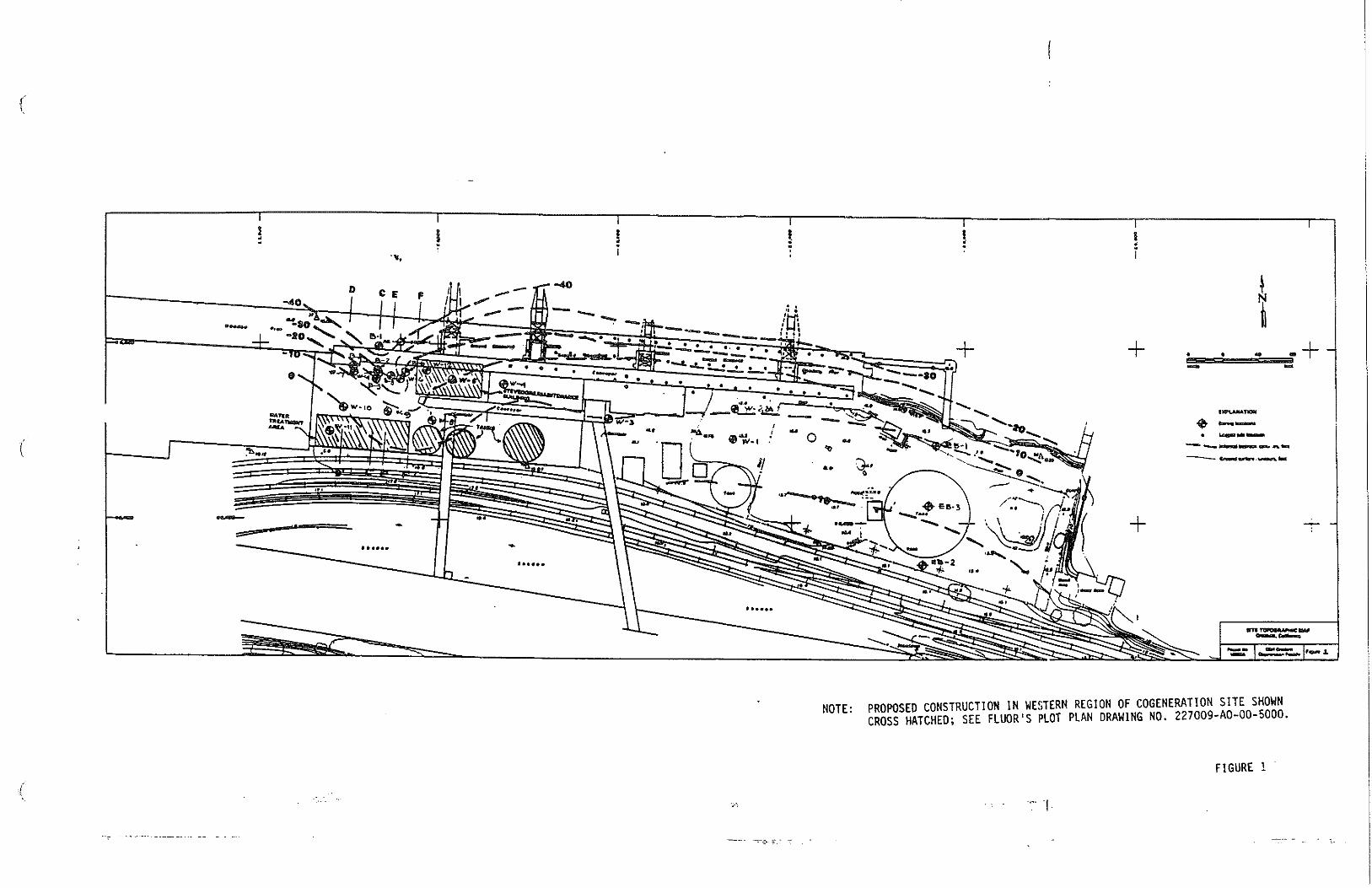
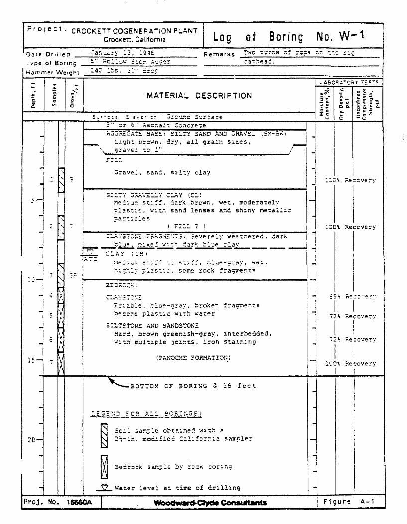
A total of seven (7) auger borings have been drilled at the plant site in the general vicinity of
the two proposed locations, as shown on Figure 2. Logs of these seven borings are presented
in Appendix A. Six of the borings were advanced through undocumented fill and into
underlying bedrock. Section 4.4 includes a discussion of the subsurface stratigraphy in more
detail. Samples collected from the exploratory borings were tested in the laboratory for
moisture content, unit weight, and undrained shear strength Woodward-Clyde Consultants
(1986a, 1986b).
3.2 SITE RECONNAISSANCE
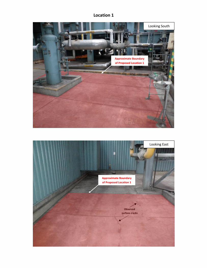
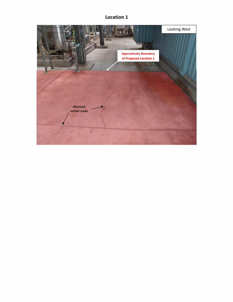
On October 19, 2011 AMEC representative, Mr. Justin Phalen, met with Mr. David Poling,
Operation and Maintenance Manager for the CCNGPP, and observed conditions at the two
proposed locations for the new gas compressor. These observations were generally intended
to evaluate the geotechnical performance of the existing site facilities and to note whether
there were any obvious signs of foundation distress that may have been a result of long-term
movements (e.g., noticeable cracks or offsets in concrete slabs that may indicate settlement or
heave). In both proposed locations, there were no immediately clear signs of distress to
existing foundation elements, indicating that the facilities have been performing well (from a
geotechnical standpoint) since construction in 1994. Individual hairline cracks (approximately 1
to 2 mm wide) were noted running through the middle of three of the concrete slabs at
Location 1. However, there was no vertical offset associated with the cracks, and it was
unclear whether or not they was associated with differential settlement of the slab or with
thermal expansion/contraction of the concrete. Photos taken during the site reconnaissance
are included in Appendix B.
4.0 SITE AND SUBSURFACE CONDITIONS
This section summarizes the overall site and subsurface conditions at the CCNGPP site.
Sections 4.1 and 4.2 describe the general geologic and seismic setting, respectively. The local
development history of the site is described in Section 4.3. Site-specific descriptions of existing
site, subsurface, and groundwater conditions are provided in Section 4.4. Geologic hazards
are discussed in Section 4.5.
4.1 GEOLOGIC SETTING
The CCNGPP is located at the water’s edge on the south shore of the Carquinez Strait near
where the strait drains into the northeast end of San Pablo/San Francisco Bay (Figure 1). The
bay occupies a broad, shallow depression that developed in response to minor crustal
extension between the San Andreas fault on the west and Hayward fault on the east. The San
Francisco Bay depression appears to be a pull-apart basin that has been slowly subsiding
during late Quaternary time (the past 700,000 years) and perhaps longer. The basin and
associated waterways are predominantly filled with late Quaternary alluvial, fluvial, and
estuarine deposits, overlying older basement rocks.
\\Oad-fs1\doc_safe\16000s\162010\3000\Final Crockett Cogen Rpt\1 txt, cvrs\Crockett Cogen Txt.docx 4
The oldest rocks in the San Francisco Bay area are Jurassic to Cretaceous (195 to 65 millions
of years [Ma] before present) marine sedimentary rocks and associated igneous and
metamorphic rocks of the Franciscan Complex. The Franciscan Complex is predominantly
graywacke (sandstone) and interbedded shale, with lesser amounts of submarine basalt
(greenstone), chert, serpentinite, and rare high-pressure metamorphic rocks known collectively
as blueschist. The local bedrock at the CCNGPP is comprised of the sedimentary Great Valley
Complex formed during the Cretaceous period (146 to 65 Ma), (Graymer et al., 2006). Great
Valley bedrock is described as interbedded layers of sandstone, siltstone, claystone and
shale. The siltstone and claystone units have the potential to be particularly dispersive, friable,
and prone to slaking when exposed to water. Outcrops of Great Valley are observed in the
vicinity along the shoreline on the upslope side of the Union Pacific Railroad tracks where the
rock was cut for the railroad alignment.
Younger alluvial deposits (locally known as Bay Mud) of Holocene age (less than 11,000 years
old) overlie the older bedrock at some areas, particularly below the water level elevation at the
edge of the old shoreline. These deposits are soft to medium stiff and are historically very
compressible.
4.2 SEISMICITY
Based on the record of historical earthquakes and its position astride the North
American-Pacific plate boundary, the San Francisco Bay region is considered to be one of the
more seismically active regions of the world. During the past 200 years, faults within this plate
boundary zone have produced numerous small-magnitude and at least fifteen moderate to
large (i.e., M > 6) earthquakes affecting the Bay Area (Toppozada et al., 1981; Ellsworth,
1990; Bakun, 1999). The U.S. Geological Survey (USGS) 2007 Working Group on California
Earthquake Probabilities (WGCEP, 2008) estimated an approximately 67 percent probability
that at least one major moment magnitude earthquake (MW ≥ 6.7) would occur in the San Francisco Bay Area before 2037.
Many active faults within the Bay Area contribute to this aggregate probability, and several
may have significance with regard to potential earthquake ground shaking at the CCNGPP.
Major active faults near the project site include the Concord-Green Valley, Hayward and San
Andreas faults, situated, respectively, approximately 6.3 miles [10.2 km] east, 8.8 miles [14.2
km] southwest, and 26.7 miles [42.9 km] west-southwest of the site (Jennings and Bryant,
2010). The WGCEP (2008) estimated a 31 percent probability of a MW 6.7 or larger
earthquake on the northern Hayward fault, the closer of the fault’s segments to the site. The
WGCEP (2008) estimated a 21 percent probability of a MW 6.7 or larger earthquake on the
San Andreas fault during that same period. Several moderate-magnitude, nineteenth and early
twentieth century events on the Hayward and San Andreas faults produced Modified Mercalli
Intensity (MMI) VII to VIII effects in the site vicinity (Toppozada et al., 1981; Toppozada and
\\Oad-fs1\doc_safe\16000s\162010\3000\Final Crockett Cogen Rpt\1 txt, cvrs\Crockett Cogen Txt.docx 5
Parke, 1982a, 1982b), including the magnitude 6.9 event on the southern Hayward fault in
October 1868 and the magnitude 8 (MW 7.8) San Francisco earthquake in April 1906 (Bakun,
1999). The 1989 MW 6.9 Loma Prieta earthquake produced MMI effects of VI-VII in the general
site vicinity (Plafker and Galloway, 1989).
Other faults mapped in the vicinity of the CCNGPP include the Franklin and Pinole faults.
4.3 LOCAL DEVELOPMENT HISTORY
Review of historic Sanborn Fire Insurance Maps for Crockett, California indicates that the
CCNGPP property has been through a series of development and redevelopment stages since
the latter part of the 19th century (Sanborn 1899, 1906, 1913, 1924, 1929, 1945). The earliest
maps from 1899 show that the majority of the existing plot had already been created from fill,
most likely generated from the railroad cut immediately to the south. The land was primarily
used as a warehouse lot for the Pacific Coast Grain Warehouse Company and subsequently
owned and operated by Western Grain and Sugar Product Company, and then by California
and Hawaiian Sugar Refining Corporation. The September 1906 map shows little improvement
since 1899 and does not mention any damage to the facility resulting from the Mw 7.8 San
Francisco Earthquake of April 1906. By 1913, three 60-foot diameter steel storage tanks were
installed near the eastern edge of the property. By 1929, nearly the entire plot was used for
sugar processing and storage and remained in this capacity for most of the 20th century.
Construction of the current natural gas plant facilities commenced in 1994 with the plant
becoming fully operational in 1996.
4.4 EXISTING SURFACE AND SUBSURFACE CONDITIONS
As mentioned in Section 4.1, the CCNGPP is located at the water’s edge on the south shore of
the Carquinez Strait near where the strait drains into the northeast end of San Pablo/San
Francisco Bay. The facility is bordered by the Union Pacific railroad and Loring Avenue to the
south, the C&H Sugar Factory to the west, and the waters of the Carquinez Strait to the north
and east. The following sections describe existing surface and subsurface conditions at the
plant and, specifically, at the two proposed gas compressor locations.
4.4.1 Existing Surface Conditions
The CCNGPP occupies the eastern end of a large marine fill constructed for the Bulk Raw
Sugar Wharf in the late 1800’s. The plant is roughly rectangular in shape with maximum plan
dimensions of approximately 150 feet by 900 feet. The surface is primarily covered with
concrete slabs and mats for the support of existing facilities, asphaltic concrete in areas that
are used as walkways and for supporting minor transient loads, and areas of crushed rock to
protect exposed grades. The site is relatively level within the plant boundaries with minor
grading to facilitate surface drainage. Based on the original plant drawings, existing surface
elevations in the vicinity of the site range between about +10 to +13 feet (project datum).
\\Oad-fs1\doc_safe\16000s\162010\3000\Final Crockett Cogen Rpt\1 txt, cvrs\Crockett Cogen Txt.docx 6
The existing site facilities and structures are supported on various configurations of large
diameter (2.5 to 4 feet) cast-in-place drilled piers with connecting grade beams between 2 and
6 ½ feet deep, shallow spread footings, and structural mats up to 6 feet thick.
The proposed Location 1 is in a congested area between the main turbine generator to the
south and a steel structure that houses boiler feed pumps to the north (Figure 2). The roughly
16-feet by 24-feet of workable area is surfaced with a reinforced concrete slab about 8-inches
thick and is flanked on the east and west by two 2½ foot diameter drilled piers approximately
30 deep that are supporting an overhead pipe bridge. There exists a natural gas filter with
footing plan dimensions of about 5½ by 5½ feet within the footprint of proposed Location 1 that
is planned to be moved a few feet east to accommodate the new gas compressor.
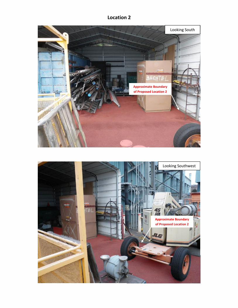
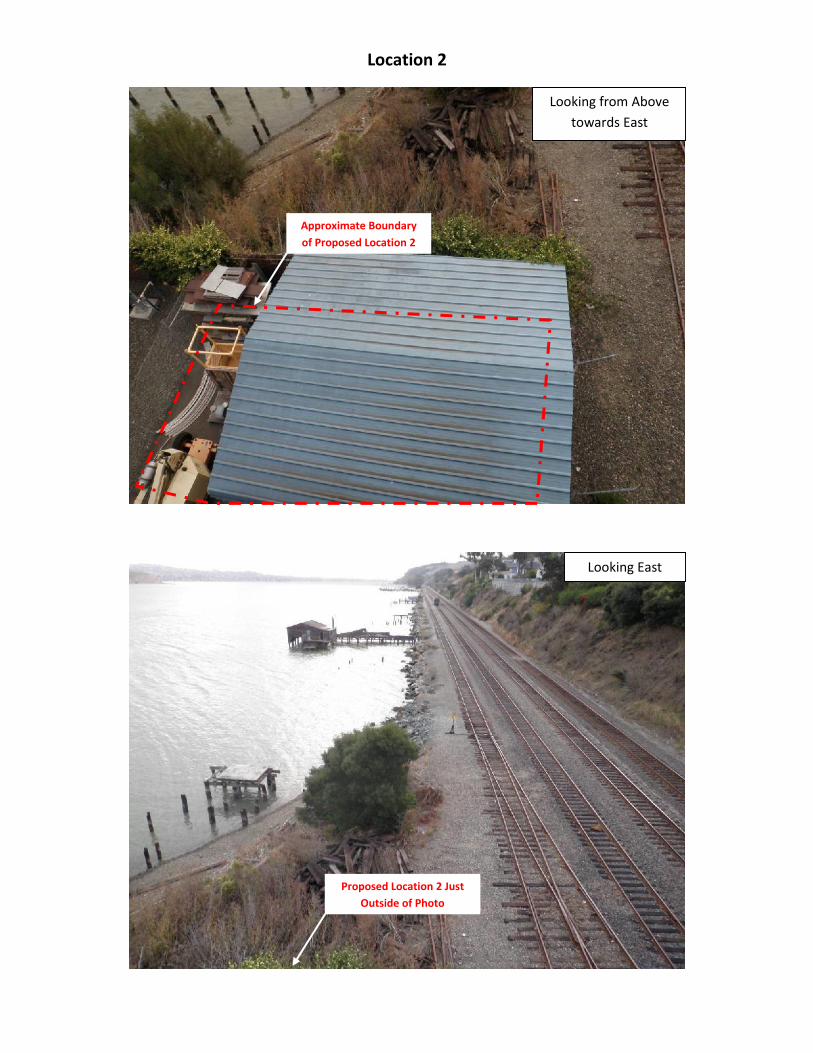
The proposed Location 2 is at the far eastern edge of the plant immediately east of a three-
story steel-framed pedestrian bridge tower. The tower is founded on four 2½ foot diameter
drilled piers approximately 30 feet deep. The roughly 22-feet by 35-feet of workable area is
surfaced with asphaltic concrete and occupied by a pipe and tool storage shed.
4.4.2 Subsurface Conditions
Our understanding of the subsurface conditions is based on review of the available
geotechnical borings logs described in Section 3.1. No additional investigation work was
performed for this project. The site stratigraphy generally consists of old (pre-1900)
undocumented marine fill overlying normally consolidated soft to medium stiff marine
sediments (Bay Mud) overlying bedrock of the Great Valley Complex. It is postulated that the
materials used to create the marine fill were predominantly borrowed from the spoils
generated from the shoreline excavation cut for the adjacent railroad. Based on available
boring data, the fill consists of a variable mix of gravel, sand and clay with most samples
collected from the fill being characterized as “gravelly clay” and “clayey sand and gravel.” The
fill is generally described as loose to dense and soft to medium stiff. In the vicinity of
Location 1, the fill is expected to be about 6 to 8 feet thick. In the vicinity of Location 2, the fill
is expected to be about 3 to 5 feet thick.
The Bay Mud in the vicinity of the CCNGPP is described from the borings as being
predominantly medium stiff with localized areas of softer and stiffer pockets. Bay Mud is
typically characterized as being particularly clayey, highly plastic, and highly compressible.
Being that the existing site fills have been compressing the native marine sediments for over
100 years, it is likely that the Bay Mud is in a more favorably consolidated state than if it were
undisturbed. In the vicinity of Location 1, the Bay Mud is expected to be about 2 to 7 feet thick,
becoming thicker from south to north. Less than two feet of Bay Mud is expected in vicinity of
Location 2.
\\Oad-fs1\doc_safe\16000s\162010\3000\Final Crockett Cogen Rpt\1 txt, cvrs\Crockett Cogen Txt.docx 7
Great Valley bedrock is exposed at the southern end of the site in the cut for the railroad, and
generally dips moderately to the north through the middle of the CCNGPP where it then dips
quickly off into the channel of the Carquinez Straight. Figure 2 shows top of bedrock elevation
contours interpreted by Woodward Clyde Consultants (1986b) based on borings drilled at the
site. Depth to bedrock from the top of the concrete slab at Location 1 is expected to be about 7
to 15 feet, becoming deeper from south to north. Depth to bedrock from the top of the
asphaltic concrete at Location 2 is expected to be about 3 to 5 feet.
Because of the age of the fill materials it is possible that they contain constituents of concern
(particularly heavy metals) known to be hazardous. According to the documents provided to
AMEC for the review of existing site conditions, there exists no current study to specifically
address soil contamination concerns. Field exploration and other evaluations that are
commonly used to assess the presence of substances that may be of an environmental
concern were beyond the scope of this study.
4.4.3 Groundwater Conditions
Groundwater was encountered at fairly consistent depths of about 6 to 8 feet (elevation +4 to
+6 ft) in all existing borings in the vicinity of the two proposed locations. Fluctuations in local
groundwater levels are expected to be tidally influenced and directly related to the free water
elevation in the Carquinez Strait.
4.5 GEOLOGIC HAZARDS
Potential geologic/geotechnical hazards assessed for the site include surface fault rupture,
liquefaction and related phenomena, site slope stability, and swelling or shrinking soils. The
assessment of these potential hazards is presented in this section. Discussion of site
classification related to seismic analysis and design of the proposed facility is presented in
Section 5.2.
4.5.1 Surface Fault Rupture
No active or potentially-active faults have been identified in the immediate vicinity of the
CCNGPP according to the California Geological Society (Jennings and Bryant, 2010). The site
is located approximately 6.3 miles west of the fault rupture zone established along the
Concord-Green Valley fault. Additionally, observations of the site and surrounding areas do
not indicate the presence of geologic conditions, geomorphic features or lineaments
suggestive of active or inactive faults crossing the project site. Based on this information, we
judge that the potential for surface fault rupture at the new CCNGPP is negligible.
4.5.2 Liquefaction
Liquefaction is a soil behavior phenomenon in which a soil loses a substantial amount of
strength due to high excess pore-water pressure generated by strong earthquake ground
shaking. Recently-deposited (i.e., within about the past 11,000 years) and relatively
\\Oad-fs1\doc_safe\16000s\162010\3000\Final Crockett Cogen Rpt\1 txt, cvrs\Crockett Cogen Txt.docx 8
unconsolidated soils and artificial fills located below the ground water surface are considered
susceptible to liquefaction (Youd and Perkins, 1978). Typically, the soils that are most
susceptible to liquefaction include relatively clean, loose, uniformly graded sand, silty sand,
and non-plastic silt deposits (e.g., National Research Council, 1985).
As discussed previously in this report, the geotechnical data gathered during previous
investigations indicate that the fill soils at the CCNGPP are predominantly loose to dense
clayey gravels, clayey sands, and gravelley clays most likely sourced from bedrock excavated
for the adjacent railroad alignment. Predominantly clayey soils typically are not considered to
be susceptible to earthquake-induced liquefaction. Predominantly granular soils, such as sand
and gravels with low fines contents, do comprise some zones of the undocumented fill in the
vicinity of Location 1. However, most of these zones are above the groundwater table and are
therefore not considered to be susceptible to liquefaction. There does exist the possibility of
more granular soils existing below the groundwater table that may generate unacceptable
levels of excess pore pressure as a result ground shaking from design-level earthquakes.
These soils are more commonly found closer to the existing wharf as the fill slopes down into
the channel.
We note that no evidence of liquefaction and/or related effects was reported for the CCNGPP
site or vicinity for the great 1906 San Francisco earthquake (Lawson, 1908; Youd and Hoose,
1978), nor for the 1989 Loma Prieta Earthquake (Tinsley and others, 1998). However, short of
a performing current and thorough geotechnical investigation study, the potential for
liquefaction cannot be eliminated. USGS indicates that the areas in the vicinity of the
CCNGPP that are largely comprised of fill materials have a very high liquefaction susceptibility
(Witter et al., 2006). Therefore, we are of the opinion that the hazard due to potential soil
liquefaction at the proposed CCNGPP site is low to very high, depending on soil and rock
conditions in the immediate vicinity of the facility in question. Location 1, in this case, has a
much higher potential for liquefaction than Location 2, primarily due to the thicker fill section
that is potentially below the ground water table. Location 2 has a much thinner fill section,
which is not anticipated to be below the groundwater table.
4.5.3 Site Instability/Landsliding
Lateral spreading, which is the lateral displacement of surficial soils, is usually associated with
the liquefaction of underlying soils. Because the potential liquefaction hazard at the site is
judged to be low to very high, and a significant portion of the CCNGPP is built on an
undocumented fill that is sloped into the adjacent waterway, we expect that the potential for
lateral spreading to occur also is low to very high.
\\Oad-fs1\doc_safe\16000s\162010\3000\Final Crockett Cogen Rpt\1 txt, cvrs\Crockett Cogen Txt.docx 9
4.5.4 Soil Swelling or Shrinkage Potential
The surficial fill clayey soils and Bay Mud are likely critically expansive, and are prone to
significant volume change (shrinkage and swelling) with seasonal fluctuations in soil moisture.
Such shrink/swell behavior can damage shallow foundation elements, such as footings and
slabs-on-grade, which are supported by these soils, if not properly designed. Measures to
mitigate for soil expansion are discussed in Section 5.3.
5.0 DISCUSSIONS AND PRELIMINARY GEOTECHNICAL RECOMMENDATIONS
Based on the results of our evaluation, it is our opinion that both Locations 1 and 2 are suitable
for the proposed natural gas compressor and skid, provided proper foundation support is
provided. Based on discussions with the owner’s representative, the preferred foundation
alternative is a shallow structural mat (rather than any type of deep foundation system, such
as drilled piers, micropiles, etc.). We are of the opinion that the proposed natural gas
compressor and skid can be supported on a structural mat foundation that bears on
undisturbed competent native rock or a thickened section of Select Fill on existing fill. The
recommendations presented below are considered appropriate for a shallow foundation design
given the variable soil conditions at the site.
The key geotechnical issues for design and construction of the proposed foundation are the
excavation support that will be required to excavate to the design depth, groundwater
considerations during construction, mitigation of expansive soils, effect of new loads on
existing adjacent foundation elements, seismic considerations, and groundwater
considerations during and after construction. These issues are discussed in more detail in the
following sections.
5.1 EQUIPMENT FOUNDATION
The proposed natural gas compressor and skid can be supported on a structural mat
foundation that will have one of three different bearing scenarios: A) bearing directly on native,
undisturbed bedrock (Location 2), B) bearing on a pad of Select Fill that is supported by
undisturbed bedrock (Location 2), or C) bearing on a thickened section of Select Fill on top of
undocumented fill/Bay Mud (Location 1). Recommendations for associated earthwork
associated with the three scenarios mat foundation are presented in Section 5.3. A mat
foundation subgrade prepared in accordance with the requirements described in Section 5.3.4
can be designed with the geotechnical parameters provided below.
A mat foundation constructed in accordance with the recommendations provided in
Section 5.3.4 will have an allowable net bearing capacity as shown below:
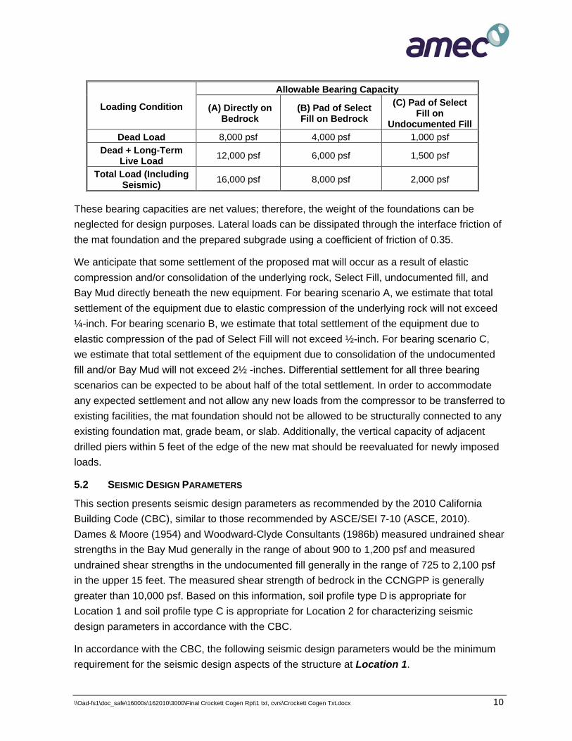
\\Oad-fs1\doc_safe\16000s\162010\3000\Final Crockett Cogen Rpt\1 txt, cvrs\Crockett Cogen Txt.docx 10
Loading Condition
Allowable Bearing Capacity
(A) Directly on Bedrock
(B) Pad of Select Fill on Bedrock
(C) Pad of Select Fill on
Undocumented Fill Dead Load 8,000 psf 4,000 psf 1,000 psf
Dead + Long-Term Live Load 12,000 psf 6,000 psf 1,500 psf
Total Load (Including Seismic) 16,000 psf 8,000 psf 2,000 psf
These bearing capacities are net values; therefore, the weight of the foundations can be
neglected for design purposes. Lateral loads can be dissipated through the interface friction of
the mat foundation and the prepared subgrade using a coefficient of friction of 0.35.
We anticipate that some settlement of the proposed mat will occur as a result of elastic
compression and/or consolidation of the underlying rock, Select Fill, undocumented fill, and
Bay Mud directly beneath the new equipment. For bearing scenario A, we estimate that total
settlement of the equipment due to elastic compression of the underlying rock will not exceed
¼-inch. For bearing scenario B, we estimate that total settlement of the equipment due to
elastic compression of the pad of Select Fill will not exceed ½-inch. For bearing scenario C,
we estimate that total settlement of the equipment due to consolidation of the undocumented
fill and/or Bay Mud will not exceed 2½ -inches. Differential settlement for all three bearing
scenarios can be expected to be about half of the total settlement. In order to accommodate
any expected settlement and not allow any new loads from the compressor to be transferred to
existing facilities, the mat foundation should not be allowed to be structurally connected to any
existing foundation mat, grade beam, or slab. Additionally, the vertical capacity of adjacent
drilled piers within 5 feet of the edge of the new mat should be reevaluated for newly imposed
loads.
5.2 SEISMIC DESIGN PARAMETERS
This section presents seismic design parameters as recommended by the 2010 California
Building Code (CBC), similar to those recommended by ASCE/SEI 7-10 (ASCE, 2010).
Dames & Moore (1954) and Woodward-Clyde Consultants (1986b) measured undrained shear
strengths in the Bay Mud generally in the range of about 900 to 1,200 psf and measured
undrained shear strengths in the undocumented fill generally in the range of 725 to 2,100 psf
in the upper 15 feet. The measured shear strength of bedrock in the CCNGPP is generally
greater than 10,000 psf. Based on this information, soil profile type D is appropriate for
Location 1 and soil profile type C is appropriate for Location 2 for characterizing seismic
design parameters in accordance with the CBC.
In accordance with the CBC, the following seismic design parameters would be the minimum
requirement for the seismic design aspects of the structure at Location 1.
\\Oad-fs1\doc_safe\16000s\162010\3000\Final Crockett Cogen Rpt\1 txt, cvrs\Crockett Cogen Txt.docx 11
• Soil Profile Type (site class): D “Stiff Soil”
• Site Risk Category: IV
• Seismic Design Category: D
• MCE Mapped Short Period Acceleration: SMS = 1.50g
• MCE Mapped Long Period (T=1 second) Acceleration: SM1 = 0.90g
• MCE Design Short Period Spectral Response Acceleration: SDS = 1.00g
• MCE Design Long Period (T=1 sec) Spectral Response Acceleration: SD1 = 0.60g
In accordance with the CBC, the following seismic design parameters would be the minimum
requirement for the seismic design aspects of the structure at Location 2.
• Soil Profile Type (site class): C “Very Dense Soil and Soft Rock”
• Site Risk Category: IV
• Seismic Design Category: D
• MCE Mapped Short Period Acceleration: SMS = 1.50g
• MCE Mapped Long Period (T=1 second) Acceleration: SM1 = 0.78g
• MCE Design Short Period Spectral Response Acceleration: SDS = 1.00g
• MCE Design Long Period (T=1 sec) Spectral Response Acceleration: SD1 = 0.52g
5.3 EARTHWORK
This section generally describes the work necessary to prepare Location 1 and Location 2 for
construction of the new natural gas compressor and skid foundation. Excavation conditions,
groundwater conditions, and backfilling associated with subgrade preparation are discussed.
Procedures that should be followed to protect the soils exposed in excavations are also
discussed.
5.3.1 Site Preparation
Any existing facilities within the footprint of the selected location should be removed and/or
relocated. Concrete slabs or asphaltic concrete should be saw-cut to at least the dimensions
of the proposed mat and should be completely broken up and removed. Any below-ground
utilities within the mat footprint should be identified and planned to be relocated.
5.3.2 Excavation Conditions and Ground Support
Excavations of the site soils should be possible with conventional small to mid-size heavy
earth moving equipment (e.g., backhoes, bobcats). AMEC recommends that the contractor be
required to exercise extreme caution when excavating the final two feet of the foundation
areas. Excavation equipment that can disturb the structure subgrades (e.g., backhoes with
buckets having large claws to loosen the earth) should be avoided when excavating to final
subgrade. The exposed foundation area surfaces of the planned structures also must be
\\Oad-fs1\doc_safe\16000s\162010\3000\Final Crockett Cogen Rpt\1 txt, cvrs\Crockett Cogen Txt.docx 12
protected as described in Section 5.3.4, Subgrade Preparation / Protection of Exposed
Foundation Surfaces.
As indicated in Section 4.4.2, Location 1 is expected to have about 6 to 8 feet of
undocumented fill over 2 to 7 feet of Bay Mud. If Location 1 is selected, it is recommended that
at least 5 feet of fill be excavated and replaced with Select Fill (Section 5.3.5) under the
footprint of the proposed mat foundation. Location 2 is expected to have about 3 to 5 feet of
undocumented fill or Bay Mud over bedrock. If Location 2 is selected, it is recommended that
the fill and Bay Mud be excavated to undisturbed bedrock and replaced with Select Fill
(Section 5.3.5) under the footprint of the proposed mat foundation.
The methods required to maintain stable conditions in excavations and temporary slopes
during construction will depend on the nature of the material exposed in the excavation, the
construction schedule, and the contractor’s operation and equipment, among other factors.
Because of the relatively confined working space at Location 1, excavations with inclined side
slopes will not likely be used during construction. Location 2 may have enough room to
facilitate sloped excavations on one or two sides. Vertical cuts will require appropriate
measures to support the adjacent ground and nearby existing facilities. Construction costs
associated with ground support measures are sometimes underestimated when
project-specific requirements are not identified. Excavations having vertical sidewalls deeper
than 3 feet will require effective means to adequately support the ground and to protect
workers. Excavations shallower than 3 feet may require support depending on the location of
the excavation relative to the existing facilities, the anticipated soil conditions, and/or the
contractor’s activities in the vicinity of the excavation. Adequate protection of workers in
excavations must be provided by the contractor at all times during construction. Anywhere that
excavations are made, unexpected caving of trench and excavation walls could occur at any
time or place, regardless of the depth of the excavation or trench.
If inclined side slopes are to be used (portions of Location 2, perhaps) temporary excavation
slopes in site soils should conform to CAL-OSHA requirements. Flatter side slopes may be
required (and should be anticipated) if the contractor intends to stockpile materials and/or use
heavy equipment adjacent to the cut. Flatter slopes also may be necessary if localized
instability is observed during construction.
The ground support system should be installed without leaving nearby improvements
unsupported. Installation and removal of the support measures must not affect nearby
structures/facilities. The support measures should be left in place if their removal might cause:
(1) the excavation bottom or adjacent ground to become disturbed, (2) the excavation wall to
collapse, and/or (3) damage a nearby structure or facility or the newly-completed structure. If
pressure-treated wood is used, it should be left in place and cut off about 2 feet below the
ground surface. Wood that is subject to rotting should not be used.
\\Oad-fs1\doc_safe\16000s\162010\3000\Final Crockett Cogen Rpt\1 txt, cvrs\Crockett Cogen Txt.docx 13
Existing structures, foundations, and improvements adjacent to the required excavations may
require underpinning during construction. AMEC recommends that the contractor be
responsible for the evaluation of underpinning and ground support requirements and for the
design of all underpinning and ground support measures. The contractor also should be
required to submit underpinning and excavation plans for review prior to construction.
Project specifications should place full responsibility on the contractor for the planning, design,
construction, maintenance, and removal of the ground support measures required for worker
protection and the prevention of ground movement/settlement that may damage nearby
facilities/structures, underground utilities, and other improvements. Ground support measures
and temporary cut slopes used in construction should conform to all state and federal safety
regulations and requirements. To help mitigate ground movement/settlement, stockpiling earth
and other construction materials near open excavations should be avoided. In no case should
stockpiling occur closer to excavations than federal or state regulatory agencies allow.
Structures, pipelines, and any other improvement that may be subject to distress/damage
during construction should be periodically monitored and/or surveyed. If movement is
detected, measures should be undertaken immediately to prevent additional movement and
damage. The contractor should be made responsible for the repair of all damage that results
from the new construction.
Precautions should be taken to limit access to the excavations by people and equipment.
Workers entering excavations should be protected from raveling and sloughing soils; safety
railings should be installed around the excavations.
5.3.3 Dewatering Requirements
Groundwater is not expected in excavations shallower than about elevation +6 feet. If possible,
excavations should be made in the drier months (i.e., June through September) to minimize
difficulties associated with higher groundwater levels that may occur during the winter rainy
season and rain/surface water inflows. For excavations that extend below groundwater, a
sump system will likely be required to control groundwater and to prevent the bottom of the
excavation from heaving or becoming quick.
The contractor should be made responsible for the design, construction, operation,
maintenance, and removal of any system that is implemented to control the inflow of surface
water and groundwater. The system should be designed to prevent migration and pumping of
soil fines with discharge water. The contractor must plan the dewatering and excavations
carefully so that stable and dry excavations are maintained continuously throughout
construction. The dewatering design proposed by the contractor should be presented in an
excavation dewatering plan.
\\Oad-fs1\doc_safe\16000s\162010\3000\Final Crockett Cogen Rpt\1 txt, cvrs\Crockett Cogen Txt.docx 14
Disposal of water from construction dewatering must also be planned carefully. Because of
regulatory requirements, discharging pumped groundwater directly into nearby drainages or
storm drain systems may require permits from the regulatory agencies having jurisdiction over
the project. Groundwater should be tested prior to disposal for substances that are of an
environmental concern. If encountered during construction, this water will require special
handling. Options that the contractor may use for disposal of pumped groundwater should be
identified and evaluated during design.
5.3.4 Subgrade Preparation / Protection of Exposed Foundation Surfaces
The subgrade soils exposed in the excavation should be protected from erosion, air or water
slaking, and changes in moisture content that could cause expansion, shrinkage, and/or
degradation of the exposed surface. The subgrade should be prepared as soon as possible
after excavation.
If work is done during the winter rainy season in exposed areas (i.e, Location 2), AMEC
recommends that a minimum 4-inch thick pad of controlled density fill (CDF) be poured on the
excavated subgrade as quickly as possible (i.e., within 24 hours) after the foundation area is
exposed in the final cut surface. Before the CDF pad is prepared, the exposed soil surface
should be clean and dry. Under no circumstances should groundwater, rainfall, surface runoff,
or construction water be allowed to pond on the exposed or unprotected soil surfaces. If left
unprotected, the subgrade soils could degrade quickly; their properties will change under the
action of earthmoving equipment, worker activities, and wetting or drying caused by the
elements.
5.3.4.1 Subgrade Preparation for Bearing Scenario “A”
We recommend that the subgrade in areas excavated to bedrock with the mat foundation
bearing directly on bedrock be prepared as follows:
1. The final exposed excavation subgrade surface should be undisturbed, leveled, and moisture conditioned
2. If the final excavation surface is anticipated to be open for more than 24 hours, or exposed to wet weather conditions, a 4-inch thick pad of CDF should be placed in the excavation bottom.
5.3.4.2 Subgrade Preparation for Bearing Scenario “B”
We recommend that the subgrade in areas excavated to bedrock with the mat foundation
bearing on a pad of Select Fill prepared as follows:
1. The final exposed excavation subgrade surface should be undisturbed, leveled, and moisture conditioned
2. If the final excavation surface is anticipated to be open for more than 24 hours, or exposed to wet weather conditions, a 4-inch thick pad of CDF should be placed in the excavation bottom.
\\Oad-fs1\doc_safe\16000s\162010\3000\Final Crockett Cogen Rpt\1 txt, cvrs\Crockett Cogen Txt.docx 15
3. Select Fill or CDF should be placed to bring the area to the finished subgrade elevation.
5.3.4.3 Subgrade Preparation for Bearing Scenario “C”
To provide a uniform bearing surface for the mat foundation in the undocumented fill area, we
recommend that the subgrade in this area be prepared as follows:
1. The final exposed excavated subgrade surface should be leveled, moisture conditioned, and compacted to 90 percent relative compaction using standard walk-behind compaction equipment.
2. A non-woven geotextile filter fabric (Mirafi 140NC or equivalent) should be placed on the exposed subgrade surface. Adjacent sections of filter fabric should be overlapped. Filter fabric at the edges should extend up the sidewalls of the excavation.
3. Crushed Rock described in Section 5.3.5 should be placed at least one foot thick over the entire excavation subgrade.
4. The non-woven geotextile filter fabric should be wrapped over the top of the Crushed Rock so that it overlaps and fully encapsulates the crushed rock.
5. Select Fill and/or CDF should be placed over the filter fabric and used to bring the area to the finished subgrade elevation.
5.3.5 Fill Materials and Compaction Criteria
It is anticipated that the following fill types will be used during construction of the project:
• Select Fill
• Crushed Rock
• Aggregate Base
• Controlled Density Fill (CDF)
These fill types and associated compaction criteria are discussed in more detail below. It
should be noted that when relative compaction is discussed in the text, it is based on the
maximum dry density and optimum moisture content of the subject material as determined by
ASTM Method D 1557 (latest edition). When the relative density is discussed in the text, it is
based on ASTM Methods D 4253 and D 4254 (latest edition). Compaction operations should
be performed using mechanical means only; compaction by jetting or flooding is not
recommended.
5.3.5.1 Select Fill
Select fill can be used to backfill the excavations under the mat foundation subgrade. Select
Fill should have a maximum plasticity index of 15 and a percentage passing the No. 200 sieve
between 5 and 50, and organic content less than 3 percent by volume. The requirement that at
least 5 percent pass the No. 200 sieve precludes the use of cohesionless sand as Select Fill. It
is anticipated that some of the excavated soils will be suitable for use as Select fill. Select Fill
\\Oad-fs1\doc_safe\16000s\162010\3000\Final Crockett Cogen Rpt\1 txt, cvrs\Crockett Cogen Txt.docx 16
should contain no rocks larger than 3 inches in the greatest dimension or more than 15
percent larger than 2 inches. Select Fill should be blended and uniformly moisture conditioned
to 1 to 3 percent above optimum moisture compacted to at least 95 percent relative
compaction. Select Fill should be placed on a firm, unyielding surface in horizontal lifts not
exceeding 8 inches in uncompacted thickness.
5.3.5.2 Crushed Rock
Crushed Rock should be an imported material that consists of durable rock and gravel that is
free of deleterious material and free from slaking or decomposition under the action of
alternate wetting and drying. We recommend that this material be used to provide support if
the excavation is in unstable ground (i.e., Location 1), and be used directly beneath the mat
foundation as a moisture break. If placed on soft, saturated, or unstable ground, this material
should be underlain and wrapped by a filter fabric selected to prevent the migration of fines
into the gravel. Crushed Rock should have a durability index of not less than 40 and should
meet the gradation requirements that 90 to 100 percent of the particles pass the ¾-inch sieve
and not more than 2 percent pass the No. 200 sieve. Crushed Rock should be uniformly
moistened and compacted with at least three passes of approved vibratory compaction
equipment, to a relative density of at least 75 percent, or to at least 90 percent relative
compaction, whichever results in the highest density. The material should be placed in
horizontal lifts that do not exceed 8 inches before being compacted.
5.3.5.3 Aggregate Base
Imported Aggregate Base material may be used in lieu of, or in conjunction with, Select Fill as
backfill of the excavation. This material should meet the requirements in the Caltrans Standard
Specifications (most recent edition), Section 26, Class 2 Aggregate Base (¾-inch maximum
particle size). Aggregate Base should be uniformly moisture conditioned to a moisture content
of 1 to 3 percent above optimum and compacted to at least 95 percent relative compaction.
The material should be placed in horizontal lifts that do not exceed 8 inches before being
compacted.
5.3.5.4 Controlled Density Fill
Controlled Density Fill (CDF) may be used in lieu of, or in conjunction with, Select Fill as
backfill of the excavation. CDF is also recommended to protect the exposed excavation
surface if it is anticipated to be open for more than 24 hours. CDF is also termed “Slurry
Cement Backfill” in Section 19 of the Caltrans Standard Specifications (most recent edition).
CDF consists of a fluid, workable mixture of aggregate, Portland cement, fly ash, and water
and should meet the gradation requirements listed in the Caltrans Standard Specifications.
\\Oad-fs1\doc_safe\16000s\162010\3000\Final Crockett Cogen Rpt\1 txt, cvrs\Crockett Cogen Txt.docx 17
5.3.6 Drainage and Erosion Control
Proper site drainage is important for the long-term performance of the new equipment
foundation. Final grades and pavements should be sloped to direct surface water away from
the foundation. Collected water should be directed toward suitable discharge facilities.
Ponding of surface water should not be allowed anywhere on the site.
5.4 CONDITIONS DURING CONSTRUCTION
An AMEC representative should observe earthwork and foundation construction to confirm
that subsurface conditions encountered during construction are comparable to those used for
developing the recommendations presented in this report. Unanticipated subsurface
conditions, which cannot be disclosed fully by exploratory borings and test pits, commonly are
encountered and frequently require additional expenditures to attain a properly constructed
project. Some contingency funding is recommended in case conditions encountered during
construction require additional exploration, testing, or design modifications.
6.0 BASIS OF RECOMMENDATIONS
The evaluations made in this report are based on the assumption that soil conditions at the
site do not deviate appreciably from those described herein, and are disclosed in the
exploratory borings. In the performance of our professional services, AMEC, its employees,
and its agents comply with the standards of care and skill ordinarily exercised by members of
our profession practicing in the same or similar localities. No warranty, either express or
implied, is made or intended in connection with the work performed by us, or by the proposal
for consulting or other services or by the furnishing of oral or written reports or findings. We
are responsible for the evaluations contained in this report, which are based on data related
only to the specific project and location discussed herein. In the event conclusions based on
these data are made by others, such conclusions are not our responsibility unless we have
been given an opportunity to review and concur in writing with such conclusions.
7.0 REFERENCES
American Society of Civil Engineers (ASCE), 2010, “Minimum Design Loads for Buildings and Other Structures,” ASCE/SEI 7-10, 650p.
Bakun, W.H., 1999, Seismic activity of the San Francisco Bay region: Bulletin of the Seismological Society of America, v.89, no.3, pp.764-784.
California Building Standards Commission (CBSC), 2010, California Building Code.
California Department of Transportation (Caltrans), 2010, Standard Specifications, State of California; Business, Transportation and Housing Agency, Department of Transportation.
Ellsworth, W.L., 1990, Earthquake history, 1769-1989, UinU Wallace, R.E. (ed.), The San Andreas fault system, California: U.S. Geological Survey Professional Paper 1515, pp. 153-187.
\\Oad-fs1\doc_safe\16000s\162010\3000\Final Crockett Cogen Rpt\1 txt, cvrs\Crockett Cogen Txt.docx 18
Geofon, Inc., 1991, Geotechnical Investigation, Proposed Aqueous Ammonia Storage Tanks, C&H Cogeneration Project, Crockett, California
Graymer, R.W., Moring, B.C., Saucedo, G.J., Wentworth, C.M., Brabb, E.E., and Knudsen, K.L., (2006) Geologic Map of the San Francisco Bay Region, published by USGS, Scale 1:275,000.
Jennings, C.W., and Bryant, W.A., 2010, California Geological Society 150th Anniversary Fault Activity Map of California, California Geologic Data Map Serioes, Map No. 6.
Lawson, A.C., 1908, The California earthquake of April 18, 1906; report of the California State Earthquake Investigation Commission: Carnegie Institute, Washington, D.C., Publication 87, v.1 and atlas, 451 p.
National Research Council, 1985, Liquefaction of Soils During Earthquakes, Committee on Earthquake Engineering, Commission on Engineering and Technical Systems, National Academy Press, Washington D.C., 240 p.
Plafker, G., and Galloway, J.P., 1989, Lessons learned from the Loma Prieta, California earthquake of October 17, 1989: U.S. Geological Survey Circular 1045, 48 p.
Sanborn Perris Map Co., 1899, Fire Insurance Map for Crockett, Including Port Costa-Selby, Valona and Rodeo, Contra Costa County, California, Sheet 4, October.
Sanborn Map Co., 1906, Fire Insurance Map for Crockett, Including Port Costa-Selby, Valona and Rodeo, Contra Costa County, California, Sheet 4, September.
Sanborn Map Co., 1913, Fire Insurance Map for Crockett, Including Port Costa and Valona, Contra Costa County, California, Sheet 3, September.
Sanborn Map Co., 1924, Fire Insurance Map for Crockett, Including Valona, Port Costa and Tormey, Contra Costa County, California, Sheet 1, September.
Sanborn Map Co., 1929, Fire Insurance Map for Crockett, Including Valona, Port Costa and Tormey, Contra Costa County, California, Sheet 2, March.
Sanborn Map Co., 1945, Fire Insurance Map for Crockett, Including Carquinez, Port Costa and Tormey, Contra Costa County, California, Rev. 4Sheet 2, October.
Tinsley, J.C., III, Egan, J.A., Kayen, R.E., Bennett, M.J., Kropp, A., and Holzer, T.L., 1998 Maps and descriptions of liquefaction and associated effects: in Holzer, T.L. (ed.), The Loma Prieta, California, Earthquake of October 17, 1989, Liquefaction: U.S. Geological Survey Professional Paper 1551-B, Appendix A, pp. B287-B314.
Toppozada, T.R., and Parke, D.L., 1982a, Area damaged by the 1868 Hayward earthquake and recurrence of damaging earthquakes near Hayward: Proceedings of the Conference on Earthquake Hazards in the Eastern San Francisco Bay Area: California Division of Mines and Geology Special Publication 62, pp. 321-328.
Toppozada, T.R., and Parke, D.L., 1982b, Areas damaged by California earthquakes, 1900-1949: Annual Technical Report - Fiscal Year 1981-1982, California Division of Mines and Geology, Open File Report 82-17, 65 p.
\\Oad-fs1\doc_safe\16000s\162010\3000\Final Crockett Cogen Rpt\1 txt, cvrs\Crockett Cogen Txt.docx 19
Toppozada, T.R., Real, C.R., and Parke, D.L., 1981, Preparation of isoseismal maps and summaries of reported effects for pre-1900 California earthquakes: Annual Technical Report - Fiscal Year 1980-1981, California Division of Mines and Geology, Open File Report 81-11 SAC, 182 p.
Witter, R.C., Knudsen, K.L., Sowers, J.M., Wentworth, C.M., Koehler, R.D., and Randolph, C.E., 2006, Maps of Quaternary Deposits and Liquefaction Susceptibility in the Central San Francisco Bay Region, USGS Open File Report 06-1037, Scale 1:200,000.
Woodward-Clyde Consultants, 1986a, Preliminary Geotechnical Engineering and Seismic Exposure Study, Crocker Cogeneration Project, Crockett, California.
Woodward-Clyde Consultants, 1986b, Supplementary Geotechnical Studies – Western Portion of Crockett Cogeneration Plant, Crockett, California.
Woodward-Clyde Consultants, 1984, Preliminary Geotechnical Engineering Seismic Exposure Study, Crocker Cogeneration Project, Crockett, California.
Working Group on California Earthquake Probabilities (WGCEP), 2008, “The Uniform California Earthquake Rupture Forecast, Version 2, (UCERF 2)” USGS Open File Report 2007-1437, CGS Special Report 203, SCEC Contribution #1138.
Youd, T.L., and Hoose, S.N., 1978, Historic ground failures in Northern California triggered by earthquakes: U.S. Geological Survey, Professional Paper 993, 177 p.
Youd, T.L., and Perkins, D.M., 1978, Mapping of liquefaction induced ground failure potential: Journal of the Geotechnical Engineering Division, American Society of Civil Engineers, v.104, no.4, pp. 433-446.
FIGURES
[_
SITE
Vallejo
Benicia
Crockett
Rodeo
Port Costa
Benicia Rd5Th St
Cummings Skwy
Georgia St
A St
Magazine St
Pomona St
Curtola Pky
Lemon St
San Pablo Ave
Ros
e D
r
Colum
bus Pky
Porter St
York St
Mce
wen
Rd
Grant St
Maine St
Map
le A
ve
Solano Ave
K S
tWebb St
Pueblo Way
Crockett B
lvd
Virginia St
Lewis Ave
Duperu Dr
Rega
tta Dr
Tyler Rd
Idora Ave
Winslow St
Dillon P
oint Rd
Jordan St
La
ur e
l St
Ro
llin
gw
oo
d D
r
Fulton Ave
Loring Ave
Vista Del Rio St
Dowrelio Dr
Wallace Ave
Ste
ffan
St
Brunswick DrKeats Dr
6Th St
Edwards St
Hargus Ave
Glen C
ove Pky
14T
h S
t
Pin
e S
tWellfleet Dr
Devlin Dr
Derr S
t
An
nett
e A
v e
Lin
coln
Rd
Irwin St
Cambridge Dr
Viewpoint Blvd
13T
h S
t
9Th St
Carrot Ln
Star
fish
Dr
Robles Way
Ma
r itim
e A
cad
em
y D
r
Co
ron
el A
ve
Granada S
t
Thomas Ave
Ryder St
Shady Ln
Ru
ssel
l St
Seaport D
r
Central Ave
Warren Ave
B St
Lillian St
Rolph P
ark Dr
Ladera Dr
De
l Sol
Taylor Ave Gre
enm
ont D
r
Ro
sew
oo
d A
ve
Sea
hors
e D
r
Bishop Rd
Dryden Dr
Fairhaven Way
New
Bed
ford
Dr
Rose St
Spyglass Pky
Oxf
ord
Way
Ha
zelw
ood
St
Cle
arvi
ew D
r
New
castle Dr
San
Mig
uel R
d
Lo
ng
ri dg
e D
r
Bolton C
ir
Topsa
i l Dr
Win
dso
r Wa
y
Bluebell PlSandy B
each Rd
8Th St
Pl
Regents Park Dr
Bailey St
Wat
ervi
ew T
er
Sandpoint Dr
Spruce St
London Cir
Alden St
Stinson S
t
Esa Dr
Clif
ton
Ct
Gar
y C
ir
Benne
tt Ave
Virginia St
Georgia St
Glen Cove Pky
6Th St
Georgia St
§̈¦80
§̈¦780
§̈¦80
UV29
Carquinez StraightCarquinez Straight
Napa RiverNapa River
Lake DalwigkLake Dalwigk
Swanzy ReservoirSwanzy Reservoir
Solano
Date: 11/03/2011
1
SITE LOCATION MAPCrockett Cogeneration Natural Gas Power Plant
Crockett, California
JP OD11162010
S:\
OD
11\1
62
01
0\t
ask
_c\
11_
10
21
_g
er\
_fig
_0
1cr
ock
ett
.mxd
[_
SITE
California0 4,000
Feet
£ By: Project No.
Figure
+10
0
-10
-20
-30
S:\O
D11
\162
010\
task
_c\1
1_10
21_g
er\_
fig_0
2(01
).ai
SITE PLAN OF EXISTING FACILITIES AND PROPOSED GAS COMPRESSOR LOCATIONSCrockett Cogeneration Natural Gas Power Plant
Crockett, California
_ 11/04/2011 OD11162010
2
W-3W-3W-3W-1W-1W-1
EB-1EB-1EB-1
EB-3EB-3EB-3
EB-2EB-2EB-2 Location 2Location 2Location 2
W-2, 2AW-2, 2AW-2, 2A
EXPLANATION
Existing drilled pier
Approximate location of continuous flight auger boring by Lowney Kaldveer Associates (1973)
Approximate location of hollow stem auger boring by Woodward-Clyde Consultants (1986)
Proposed location for new natural gas compressor
Approximate bedrock elevation contour, feet, (project datum), Woodward-Clyde Consultants (1986b)
Basemap Source:Bechtel DWG No. CC-10-01, Rev. 5, July 13, 1994.
Location 1Location 1Location 1
0 40 Feet
(approximate)
By: Date: Project No.
Figure
APPENDIX A
Logs of Borings from Woodward, Clyde & Associates (1986b) and Lowney-Kaldveer Associates (1956)
APPENDIX B
Photos of Proposed Locations taken October 19, 2011
Location 1
Approximate Boundaryof Proposed Location 1
Approximate Boundaryof Proposed Location 1
Observedsurface cracks
Looking South
Looking East
Location 1
Approximate Boundaryof Proposed Location 1
Observedsurface cracks
Looking West
Location 2
Approximate Boundaryof Proposed Location 2
Approximate Boundaryof Proposed Location 2
Looking South
Looking Southwest
Location 2
Approximate Boundaryof Proposed Location 2
Proposed Location 2 JustOutside of Photo
Looking from Abovetowards East
Looking East


![Influence of geotechnical factors on gas flow …undergroundcoal.com.au/outburst/pdfs/gas flow[1]-UK.pdf · Influence of geotechnical factors on gas flow experienced in a UK longwall](https://img.pdfslide.us/doc/110x75/5ba30dff09d3f26f6e8d14f8/inuence-of-geotechnical-factors-on-gas-ow-flow1-ukpdf-inuence-of.jpg)