Embed Size (px)
Citation preview
2016 Geotechnical Manual
Page 1 of 23
CHAPTER THREE
GEOTECHNICAL INVESTIGATION AND
SAMPLING
3.0 GENERAL All Geotechnical work performed by an approved consultant for the State of Indiana or Local Agencies, such as any Indiana local municipalities and/or county government involving the use of State or Federal funds, shall meet the requirements as described herein. All the dimensions of the equipment shall meet the requirements of AASHTO, ASTM and/or Indiana Test Methods (ITM) s unless otherwise specified herein. All work performed by the licensed Geotechnical Engineer for state and local agencies under these requirements shall consist of making a complete foundation investigation for the adequate design and construction of bridges, roadways and any other associated structures. A complete foundation investigation shall consist of an adequate program of field sampling, laboratory testing and engineering analysis and evaluation, with the results presented in report form. The investigation shall be performed in compliance with the procedures outlined in this document and generally accepted principles of sound engineering practice. The investigation shall be under the general supervision and subject to the approval of the Manager, Office of Geotechnical Services of the Indiana Department of Transportation. Unless otherwise subsequently noted, later references to as approved or directed will imply as approved or directed by the INDOT Manager Office of Geotechnical Services. 3.1 GEOTECHNICAL SURVEY The geotechnical survey is defined as the investigation of subsurface conditions along new or existing highway alignments, as required for the adequate design and construction of bridges, roads and other necessary structures. This investigation may be preliminary such as a corridor study or it may be more specific such as the more frequently performed geotechnical surveys of roads, bridges, retaining structures, landslides, etc. The survey details will depend upon the requirements of the individual project, except for resurfacing existing pavement and minor maintenance; a Geotechnical Survey will be performed on all projects. 3.2 PURPOSE OF GEOTECHNICAL SURVEY The purpose of the geotechnical survey is to identify the existing conditions of the in-situ soils, rock types and ground water in respect to the project requirements. It will also include the chemical and physical properties of the soils and rock so as to better enable the engineers to design the most uniform, stable and cost-effective road or bridge foundations. The survey will also be used to locate construction material for building embankments along roadways. 3.3 OFFICE STUDIES Indiana is exceptionally fortunate to have State organizations which have published geological, agricultural, and water surveys for many years. These publications provide a wealth of information for nearly every part of the State. Therefore, prior to initiating the field work for any project, a review of this literature, as well as previous studies done for and by INDOT, should be undertaken. This literature survey should be followed by an examination of any available boring logs and well drilling records, as well as any other available information.
2016 Geotechnical Manual
Page 2 of 23
Also, this information gathering could include a review of aerial photography; USDA/SCS reports; topographic, pedologic, bedrock surface, geologic, INDOT Data Bank, and quaternary deposits maps; and other pertinent studies which have been completed for and near the project site. The initial steps for conducting a geotechnical survey are done in the office, prior to going into the field. First, the project is classified e.g. as an overlay, rubbilization, reconstruction, new construction, bridge rehabilitation, bridge replacement, or landslide, etc. This will provide an indication of the extent and complexity of the required geotechnical report. A review of currently available information needs to be performed.
3.3.1 PRELIMINARY PLANS
The proposed route and grade are a part of the preliminary plans. By review of these plans and the available literature, a Geotechnical Engineer can identify many of the conditions that could potentially cause problems. These may include the extent of fill, cut, peat/marl deposits, landslides, sinkholes, and abandoned mines, etc. 3.3.2 MAPS Any available maps will be useful in determining the extent to which construction will influence or be influenced by the physical site conditions. Listed below are types of maps that may prove useful.
� Quaternary Geologic Map of Indiana. � 1o x 2o Regional Geologic Maps. � 7 1/2 Minute Topo Quadrangle Maps. � Topograph of the Bedrock Surface. � Thickness of Unconsolidated Deposits. � Soil Conservative Service County Soil Survey Map. � JTRP A-P Soil Survey. � Map for Seismic Design Specification. � Area Maps For Mines
These maps can be used as guides in planning the Geotechnical Investigation and defining areas of concern for the site reconnaissance. Additional maps of different types are available through the Geological Survey in Bloomington, Indiana. 3.3.3 PREVIOUS WORK
Studies and construction plans completed for the existing or nearby projects can be useful in identifying the problem areas. In particular, previous investigations and construction records that give a history of the roadway and bridge are useful in planning the investigation. The INDOT Office of Geotechnical Services maintains many geotechnical reports from previous projects. This includes preliminary plans, boring logs, test results, field observations, and correspondence relating to the project. Because of limited space, occasionally older files are eliminated, so not all projects are available. Proper use of previous geotechnical data can sometimes reduce geotechnical work in some project areas. It can help define soil types and pinpoint the areas of typical geotechnical problems even before the first on-site field investigation.
2016 Geotechnical Manual
Page 3 of 23
3.3.4 AERIAL PHOTOGRAPHY
The first step in any site investigation should be an examination of the area geography. Easy and quick resources for investigating are the various interactive map sites on the internet. Some examples include, but not limited to the following sites: http://maps.google.com http://maps.yahoo.com http://earth.goggle.com Internet maps are more current than the photographs provided by the USD/SCS in their county soil maps, and the internet maps are set up to be maneuverable to more closely observe features of the site which are pertinent to the geotechnical investigation. 3.3.5 MAINTENANCE INPUT It is important to get past performance, history, frequency and type of rehabilitation from the maintenance engineer. This information can be found during the preliminary field check. Sometimes it is noteworthy to ask questions about the maintenance history from the local INDOT or county transportation workers to obtain more details about past problems. 3.3.6 ENVIRONMENTAL CONCERNS
Any available environmental information which could impact the Geotechnical design, should be reviewed. The Pre-Engineering and Environment Division of INDOT performs environmental assessment reports on all state projects. Included is the possible presence of old underground storage tanks, hazardous or toxic spills, etc.
3.4 FIELD RECONNAISSANCE The Geotechnical Engineer shall attend the preliminary field check and establish the boring locations, rig type requirements, accessibility and record any existing problems such as pavement distresses, slope failures or any other problems within the project limits. During the field check, the Engineer should inquire about any details related to bridges, culverts, retaining structures and time restraints as well as local ordinances about any construction activities. Environmental concerns should also be reviewed at this time.
3.5 LOCATIONS AND DEPTHS OF BORINGS Locations and depths of soil borings are very important for the Geotechnical investigation of the proposed structure. It should provide the maximum possible information about the subsurface conditions for the design of the structure. The location and the depths of soil borings depend upon the existing topography, type of the structure as well as shape, size and anticipated loads. The following are the guidelines for soil boring locations and depths for various kinds of structures. For additional guidance AASHTO section10.4.2 as well as current FHWA and NHI manuals should be considered. The following series of guidelines are presented to enable the geologist, geotechnical engineer or others to prepare a subsurface drilling and coring program. However engineering judgment should also be used to determine the subsurface profile based on known or mapped geology, and regional geotechnical experience which could include the knowledge of karst areas, mines, rock elevation extremes and boulder rich glacial sluice ways to name a few.
2016 Geotechnical Manual
Page 4 of 23
3.5.1 BRIDGE STRUCTURES
3.5.1.1 LOCATION OF BORINGS The site Designer shall furnish plans of structure for which borings are to be made. Generally, the plans shall consist of road plan and profile sheets, a situation plan showing the location of substructure elements and cross-sections of the structure’s approaches. The plan and profile sheets will have included on them the maximum high water elevation and the stream bed elevation. In general, there shall be a boring made within 10 feet of each pier and end bent with the borings alternating right and left of the center line of the structures. Twin structures shall be considered as separate structures. For substructure units over 100 feet in width, a minimum of two borings per pier should be performed. Additional borings may be required as described in the following sections, or as directed by the Engineer. In the case of skewed structures, the borings should be located at the extreme end of the end bents to better determine any subsurface variation at the maximum end limits of such proposed structure. When the prescribed boring program does not reveal adequate information to define various strata, additional borings may be required. 3.5.1.2 DEPTH OF BORINGS
Borings shall be drilled to a minimum depth of 90 feet below ground elevation, unless bedrock is encountered at a shallower depth. However, if high pile loads are proposed, deeper borings may be required. Engineering judgment shall be used to determine these additional boring depths. The first boring performed should be at an interior pier. In the case of stream crossings, the boring depth shall penetrate a minimum of 15 feet below the maximum actual scour depth or to a depth below the maximum actual scour depth sufficient to carry the pile loads with the scourable overburden materials removed, whichever is greater. The latter depth shall extend 10 feet below the anticipated pile tip elevations. Engineering judgment shall be required to establish the pile tip elevations required to carry the pile loads and should be handled on an individual basis for each structure. Specific guidelines for the final depth of boring in soil and in bedrock are outlined below.
3.5.1.3 BORINGS IN SOIL Borings in any soil shall penetrate to the specified depth and penetrate a minimum of four consecutive split spoon samples into material having a standard penetration blow count (N) of fifteen (15) or greater. If this minimum penetration of fifteen (15) blows per foot material has not been obtained at the proposed boring termination depth, the boring shall be extended until this requirement is met or the project geotechnical engineer should be contacted for further guidance. When ground water is encountered, water or other drilling fluids should be added to the hole to maintain the water level in the hole at or above the ground water level to aid in avoiding a quick condition when granular soils are encountered. This precaution will keep the sand from coming up in to the casing. The ball check valve in the split-spoon sampler should not be removed, and washing through the spoon will not be permitted.
2016 Geotechnical Manual
Page 5 of 23
3.5.1.4 BORING THROUGH ROCK
When rock is encountered in the boring, rock coring will be required in each boring. Rock coring should not begin until auger refusal is obtained. When auger refusal as specified below is not achieved within 10 feet of encountering bedrock, the project geotechnical engineer should be contacted for guidance. Auger refusal shall be defined as auger penetration of less than 6 inches under 500 psi of auger-feed down pressure for a period not less than 10 minutes. Rock coring should not begin or end in weathered shale, weathered limestone, etc., unless absolutely necessary. Coring and sampling shall not be terminated in coal seams or voids. Recovery and Rock Quality Designation (RQD) shall be calculated and recorded before transporting core samples from boring locations.
If rock is encountered in the course of conducting borings for a structure a minimum length of coring of 10 feet into rock will be required at each substructure with a minimum recovery of 75% and a minimum RQD of 50%. If these values are not achieved an additional 5 feet of coring shall be completed. This coring shall be conducted in 5 foot “runs”. 10 foot “runs” will only be allowed in special cases and shall be pre-approved by the Office of Geotechnical Services. If the project is in an area in which it is known that geologic conditions will not allow the above criteria to be met engineering judgment must be applied. A sounding shall be performed at the opposite end from the boring made for each pier and/or each bent. These soundings shall be terminated in sound rock after achieving auger refusal. If there are layers of soft materials or voids in the cored rock, or there are other geological uncertainties, a minimum length of 10 feet o f rock core shall be taken from each boring and sounding at each substructure.
3.5.2 SEWERS, PIPES AND CULVERTS
3.5.2.1 TRENCHLESS PIPE INSTALLATION A minimum of two borings per 150 ft of trenchless pipe shall be obtained. The depth of the boring shall be a minimum of 5 feet or twice the pipe diameter below the invert elevation whichever is deeper. The sampling shall be continuous. Where groundwater is encountered, consideration shall be given to installing an observation well. Where rock is encountered within the required boring depths a five (5) foot rock core shall be obtained. 3.5.2.2 STORM SEWERS
Borings shall be located over proposed sewer at points of maximum invert depths with a maximum spacing of 500 feet. A minimum of two split spoon samples shall penetrate below the invert elevation. When rock is encountered, coring shall be performed and a minimum 5 foot core shall be obtained. In areas that are inaccessible to machine drilling, hand auger soundings shall be performed to delineate the soils. 3.5.2.3 SMALL CULVERTS (LESS THAN 4 FEET DIAMETER) A minimum of one sounding shall be made at each end of the pipe within the existing ditch, creek or steam channel to determine the depth of any soft soils to be removed. The depth of soundings shall extend a minimum of one pipe diameter below the proposed flow line, or into firm material. Additionally, DCP tests shall be performed at each end of the proposed culvert to a depth of 5 feet with blows recorded per each six inch increment.
2016 Geotechnical Manual
Page 6 of 23
3.5.2.4 LARGE CULVERTS (GREATER THAN 4 FEET DIAMETER)
For all drainage structures 4 feet or wider, the minimum number of borings and soundings required depends on the structure length as summarized below: Drainage structures less than 150 feet in length will require a minimum of one (1) boring
near the maximum proposed fill height. The depth of the borings should be a minimum of twice the structure width below the invert elevation or twice the fill height whichever is deeper. If rock is encountered within the proposed depth of excavation, coring shall be performed. A minimum of one 5 foot core shall be taken for each structure. In areas that are inaccessible to machine drilling, hand auger soundings shall be performed to delineate the soils.
Drainage structures greater than or equal to 150 feet in length will require one (1) boring near
each outside shoulder at the proposed maximum fill height. The depth of the borings should be a minimum of twice the drainage structure width below the invert elevation or twice the fill height whichever is deeper. If rock is encountered within the proposed depth of excavation, coring shall be performed. A minimum of one 5 foot core shall be taken for each structure. In areas that are inaccessible to machine drilling, hand auger soundings shall be performed to delineate the soils.
In the event the proposed drainage structure crosses an existing ditch, creek, or stream channel,
the boring criteria above should be followed and an additional boring shall be located in the existing channel. If the additional boring is inaccessible to machine drilling a minimum of one (1) DCP test shall be performed at that location to a depth of 5 feet. Blow counts shall be recorded for each 6 inch increment.
3.5.2.5 PLATE ARCHES ON FOOTINGS
Often large structures are proposed which are not considered to be bridges by the INDOT Division of Design. An example of these structures is structural plate arches on footings (bottomless). Borings should be located under the footing within the existing channel along the entire length of the structures, at intervals not exceeding 100 feet and at the ends. The borings should alternate from one side to the other. Soundings should be performed between the borings and at the ends within the existing and the proposed channel. The depth of the borings should be a minimum of twice the structure width below the invert elevation or twice the fill height whichever is deeper. If the proposed channel borings are inaccessible to machine drilling DCP tests shall be performed at those locations to a depth of 5 feet. Blow counts shall be recorded for each 6 inch increment. 3.5.2.6 CULVERTS ON FOOTINGS Box culverts on spread footings (bottomless) are another example of large structures not considered to be bridges. For box culverts wider than 10 feet, the minimum depth of the boring shall be 30 feet below the invert of the proposed foundation. Borings shall penetrate to the specified depth and penetrate a minimum of four consecutive split spoon samples into material having a standard penetration blow count (N) of fifteen (15) or greater. If this minimum penetration of fifteen (15) blows per foot material has not been obtained at the proposed boring termination depth, the boring shall be extended until this requirement is met or the project geotechnical engineer should be contacted for further guidance. If rock is encountered within the planned depth of investigation a minimum of one 5 foot rock core should be taken for each structure. RQD and recovery percentages should be as described in Section 3.5.1.4.
2016 Geotechnical Manual
Page 7 of 23
3.5.3 RETAINING STRUCTURES
Wall type, location and limits are often not delineated well enough at the early stage of planning and development of the project. Therefore, preliminary engineering report, plans, visual inspection and discussions with designers should be employed to develop a scope of subsurface investigation for retaining structures.
3.5.3.1 CANTILEVER RETAINING WALLS Borings should be located at the proposed extremities and along the proposed alignment of retaining structures as closely as possible. Boring spacing along the alignment shall be no more than 100 feet for walls less than 20 feet high and no more than 50 feet for proposed wall heights greater than 20 feet. Each proposed wall shall have a minimum of 2 borings completed along the proposed alignment. Back borings shall be completed at a distance of 1 – 1.5 times the proposed wall height behind the proposed alignment and at a spacing of 100 feet along the alignment. The depths of borings shall be a minimum of twice the height of the wall. Borings shall penetrate to the specified depth and penetrate a minimum of two consecutive split spoon samples into material having a standard penetration blow count (N) of fifteen (15) or greater. If this minimum penetration of fifteen (15) blows per foot material has not been obtained at the proposed boring termination depth, the boring shall be extended until this requirement is met or the project geotechnical engineer should be contacted for further guidance. Where rock is encountered in the planned depth of investigation, a minimum of one 5 foot rock core shall be taken for every 150 feet of wall length with a minimum of 2 cored boreholes for each wall. Non-cored borings shall be terminated after achieving auger refusal and competent rock profile developed. 3.5.3.2 ANCHORED WALLS
Borings should be located at the proposed extremities and along the proposed alignment of retaining structures as closely as possible. Boring spacing along the alignment shall be no more than 100 feet for walls less than 20 feet high and no more than 50 for proposed wall heights greater than 20 feet. Each proposed wall shall have a minimum of 2 borings completed along the proposed alignment. Back borings shall be completed at a distance of 1.0–1.5 times the proposed wall height behind the proposed alignment and at a distance of 100 feet along the alignment. Front borings shall be completed in front of the proposed wall at a distance of 0.75 -1.0 times the proposed height and at a spacing of 100 feet along the proposed alignment. The depths of borings shall be a minimum of twice the height of the wall. Borings shall penetrate to the specified depth and penetrate a minimum of two consecutive split spoon samples into material having a standard penetration blow count (N) of fifteen (15) or greater. If this minimum penetration of fifteen (15) blows per foot material has not been obtained at the proposed boring termination depth, the boring shall be extended until this requirement is met or the project geotechnical engineer should be contacted for further guidance. Where rock is encountered in the planned depth of investigation, a minimum of two 5 foot rock cores shall be taken for every 150 feet of wall length with a minimum of 2 cored boreholes for each wall. 10 feet of rock cores shall also be obtained from back borings for anchor design. Non-cored borings shall be terminated after achieving auger refusal and competent rock profile developed.
2016 Geotechnical Manual
Page 8 of 23
3.5.3.3 MSE WALLS Borings should be located at the proposed extremities and along the proposed alignment of retaining structures as closely as possible. Boring spacing along the alignment shall be no more than 100 feet for walls less than 20 feet high and no more than 50 feet for proposed wall heights greater than 20 feet. Each proposed wall shall have a minimum of 2 borings completed along the proposed alignment. Back borings shall be completed at a distance behind the proposed wall of 1.0–1.5 times the proposed wall height and at a spacing of 100 feet along the alignment. The depths of borings shall be a minimum of twice the height. Borings shall penetrate to the specified depth and penetrate a minimum of two consecutive split spoon samples into material having a standard penetration blow count (N) of fifteen (15) or greater. If this minimum penetration of fifteen (15) blows per foot material has not been obtained at the proposed boring termination depth, the boring shall be extended until this requirement is met or the project geotechnical engineer should be contacted for further guidance. Where rock is encountered in the planned depth of investigation, a minimum of one 5 foot rock core shall be taken for every 150 feet of wall length with a minimum of 2 cored boreholes for each wall. Non-cored borings shall be terminated after achieving auger refusal and competent rock profile developed.
3.5.4 ROADWAY IMPROVEMENT In general, borings for roadway improvements shall be dictated by the topography, geological conditions, visible soil conditions, and other design considerations. Borings should be located at the maximum cut or fill along the cross sections for new horizontal alignments. The borings should be spaced at 300 foot to 500 foot intervals for each two lane roadway and drilled to a minimum depth of 10 feet below the proposed grade. In the instance of divided highways each bound should be considered as a separate roadway when boring locations are considered. Engineering judgment should be used in sections of roadway where deeper subsurface investigation may be warranted. Sufficient borings in widening areas should be planned to cover proportionately the total widening area with respect to total project length/area.
3.5.4.1 CUT SECTIONS For cut sections where the proposed depth of cut is greater than 15 feet borings shall be spaced not more than 200 feet along the length of the proposed cut. Borings shall be located at the point of maximum cut and shall penetrate to a depth of 10 feet below the proposed grade line. Borings shall not stop in soft, very loose or unsuitable soils but should be extended a minimum o f 3 feet into firm material, unless otherwise approved. If rock is encountered below the proposed subgrade elevation, the borings on the centerline shall extend at least 5 feet into the rock. Cut section borings made in the ditch line shall extend 2 feet below the proposed flow line or 10 feet below the proposed finished grade line, whichever is deeper. Core borings made in rock back slopes shall be to a minimum depth of 2 feet below the proposed grade. Soundings made to determine the limits of rock shall be discontinued at the rock surface or four feet below proposed grade line, whichever depth is encountered first, or as otherwise approved.
2016 Geotechnical Manual
Page 9 of 23
3.5.4.2 FILL SECTIONS
Borings shall be located in areas of maximum fill at a spacing not greater than 400 feet for the fills less than 20 feet for two lane highways. Borings shall be located at a spacing not greater than 200 ft for fill heights greater than 20 feet unless otherwise approved. Roadway borings in fill sections shall penetrate to a depth of 10 feet or to a depth 2 times the height of proposed embankment, whichever is greater. Where fills cross stream flood plains, old lake beds, ponds, or other areas of suspected compressible or low-strength foundation soils, the borings shall penetrate to a minimum depth equal to the fill height into the firm ground regardless of fill height. Borings shall not be terminated in soft, very loose or unsuitable soils but should be extended into firm material with the last two SPT N values greater than 10. If rock is encountered in p r o p o s e d fill sections, the borings shall be discontinued at auger refusal or the proposed depth as determined above (whichever is shallower). One core boring shall be made 5 feet into the rock to establish its quality.
3.5.4.3 SPECIAL CASES Side Hill Cut Sections: A series of not less than two borings shall be conducted at each prescribed station such that a geologic cross section can be created. One boring shall be located at the maximum up-hill extent of the proposed cut and shall penetrate to a minimum depth of 10 feet below the proposed final grade. A second boring shall be located at the proposed ditch line and shall penetrate to the minimum depth described above. If the width of the proposed cut is greater than 100 feet from ditch line to ditch line a third boring shall be conducted. The third boring shall be located in the proposed ditch line opposite the first ditch line boring. The depth shall be as described in Sections 3.5.4.1 and 3.5.4.2. Side Hill Cut To Fill Section: When one side of centerline is in cut and other side is in fill borings shall be located in such way to capture the subsurface conditions of the cut section, the fill section and the ground water conditions. Boring depths shall be as described in Sections 3.5.4.1 and 3.5.4.2 with the additional requirement that the vertical overlap between the two borings shall be a minimum of 10 feet. Side Hill Fill Section On Unstable Slope: When embankment fill is to be placed on slopes where instability is predicted, a series of not less than 3 borings shall be conducted such that a geologic cross section can be created. Locate a boring at the toe of downhill side and other at intersection of the 1:1 slope from edge of pavement with ground line .The boring should be terminated twice the height of the fill or into rock. A rock core of 5 feet shall be taken. A third boring shall be performed at toe of the uphill slope to complete stratigraphy. All these three borings shall overlap vertically.
3.5.4.4 PAVEMENT REHABILITATION/FULL DEPTH RECLAMATION Ground Penetrating Radar (GPR) and Falling Weight Deflectometer (FWD) testing shall be performed prior to the proposal of boring locations. The anomalies discovered by these tests shall be delineated and boring and ground water monitoring shall be planned. If the GPR and FWD testing is to be completed by INDOT a request shall be submitted to the Office of Research by filling out the on-line form found at: FIND LINK GPR is a valuable tool for reducing the number of borings for a project by segmenting the project on the basis of similar subsurface features or anomalies identified prior to subsurface investigation. GPR may also be used to investigate the internal composition of many pavement layers and soils. Results from the condition and GPR surveys could be used to prepare plan for FWD testing. Boring plans will be prepared with condition survey, GPR and FWD testing to ensure that all the areas with different physical features and characteristics have been investigated.
2016 Geotechnical Manual
Page 10 of 23
Borings shall be placed at approximately 600 to 800 foot intervals, alternate from left to right lanes and in the case of divided highways, in the driving lanes alternating left to right sides. Borings shall extend to a minimum depth of three continuous split samples below the proposed subgrade material. Split spoon samples shall be taken recording various thicknesses of pavement and sub base material. In the event of soft, (N < 6), organic or unsuitable soils, the INDOT Office of Geotechnical Services should be contacted for additional instruction. Additional borings shall be competed for the purposes of obtaining 24 and 48 hour water readings. These borings shall be placed in at-grade and cut sections at a minimum frequency of 2 per mile and shall penetrate to a depth of 10 feet below the proposed grade. Measures shall be taken to insure that the borehole remains open to the full depth for the required monitoring period. This may require the temporary placement of slotted PVC pipe or similar measures.
3.5.5 HIGH MAST TOWER LIGHTS
High mast tower lights require a soil investigation at each location. These borings shall be drilled to a minimum depth of 25 feet with an N value of fifteen (15) blows or greater for the last 15 feet of the boring. If these criteria are not met drilling must continue until 15 continuous feet of greater than 15 blow material has been encountered. I f t h e above criteria cannot be met within a reasonable depth or rock is encountered within the required depth the project geotechnical engineer should be contacted and engineering judgment will be made as to the extent of additional drilling.
3.5.6 TRAFFIC-SIGNAL CANTILEVER STRUCTURE Traffic-signal cantilever structures require a soils investigation at each intersection to be signalized. These borings shall be drilled to a minimum depth of 25 feet with an N value of 15 blows or greater for the last 15 feet of the boring. If these criteria are not met drilling must continue until 15 continuous feet of greater than 15 blow material has been encountered. In case soil c o n d i t i o n s a r e not encountered as noted above or rock is encountered within the required depth of invest igat ion the project geotechnical engineer should be contacted and engineering judgment will be made as to the extent of additional drilling.
3.5.7 TRAFFIC SIGNS & LIGHT POLE FOUNDATIONS
Traffic sign or light pole foundations require a soils investigation at or near each proposed foundation. If multiple foundations are proposed within approximately 75 feet of each other, such as at a small to moderate sized intersection, one exploration point for the foundation group is adequate if conditions are relatively uniform. If more variable site conditions are anticipated, one boring near each foundation should be obtained. These borings shall be drilled to a minimum depth of 20 feet or 5 feet below the anticipated bottom of the foundation, whichever is greater. Only a site review is required if the new structures are to be founded in new or existing embankments known to be constructed of sands, b borrow or select backfill and compacted in accordance with 203 of the INDOT Standard Specifications.
3.5.8 CABLE BARRIER SYSTEMS
Cable barrier systems require soil investigations for barrier termination anchor points. A minimum of one boring should be completed at each proposed termination anchor point. These boring shall be drilled to a minimum depth of 25 feet with an N value of 15 blows or greater for the last 15 feet of the boring. If these criteria are not met drilling must continue until 15 continuous feet of greater than 15 blow material has been encountered. In case soil is not encountered as mentioned above or rock is encountered within the required depth the project geotechnical engineer should be contacted and engineering judgment will be made as to the extent of additional drilling.
2016 Geotechnical Manual
Page 11 of 23
3.5.9 SPECIAL GEOLOGIC CONDITIONS
3.5.9.1 PEAT, MARL OR ORGANIC DEPOSITS
Natural peat bogs often consist of a layer of peat or a combination of organic and mineral deposits overlying stable soils. While the upper layers may vary markedly in composition and exhibit a range of physical properties, they are entirely unsuitable as subgrade for highways. These materials must be dealt with in such a manner that they do not cause detrimental settlement or perhaps failure of the embankments or roads built upon them. Careful attention must be taken when determining the extent of organic and marl deposits. Borings should be completed on both sides of the roadway at a maximum spacing of 50 feet and shall extend a minimum of 10 feet into firm material. Firm material shall be defined as mineral soils with an N value of 10 blows or greater. Split Spoon samples shall be taken continuously for the entire length of the boring and the complete sample shall be logged. The boring pattern at the lateral limits of these deposits shall be such that the limit can be determined with an accuracy of less than 10 feet.
3.5.9.2 LANDSLIDES Landslides are most prevalent in the un-glaciated southern half of Indiana. Causes vary, but most are caused by weak soil and rock in the upper strata and variability in groundwater conditions. Landslides should not be confused with simple fill failures (which are easier to repair) or with embankment erosion problems which result in sloughing of fill materials. Landslides are “gravity transported” downward sliding or falling of soil and rock mixtures which have become loosened or detached, with movement being along a plane. The landslide area will have obvious scarps and toe bulges and if the slide has been a slow, continuous movement, trees growing in the slide will be bent to compensate for the movement of their base. Quick movement can occur and is obvious by the destruction caused by the falling materials. Borings should be located so that geologic cross sections of the landslide can be constructed. The cross section shall include borings above the scarp line, within the failure and beyond the toe bulge of the failure. Cross sectional borings shall be completed at a maximum spacing of 100 feet perpendicular to the direction of failure. All borings shall extend to bedrock and auger refusal shall be achieved. Split Spoon samples shall be taken at 2.5 foot intervals for the entire length of the boring to auger refusal unless otherwise specified. A minimum of one 5 foot rock core shall be completed in critical borings to be determined by the geotechnical engineer. 3.5.9.3 MINE SUBSIDENCE
Underground mining occurs mainly in western and southwestern Indiana and has a long tradition. There are many undocumented individual sites mined out prior to remediation where subsidence may occur. The presence of underground mines is reflected in local areas of depression or settlement of the ground surface which can occur gradually or in a very short period of time. The Indiana Department of Natural Resources (IDNR) and the Indiana Geological Survey (IGS), working with the state’s mining industry, have developed maps of the known surface and underground mine locations. Mine locations are always to be considered during the planning phase of any new construction. Undocumented mine locations and possible mine subsidence represent a definite risk. Mine subsidence issues are handled on an individual basis because of the site specific conditions affecting each mine Because they are familiar with their own areas, it is up to the INDOT district personnel to inform the necessary contact person with the OGS and IDNR when any subsidence problems are observed.
2016 Geotechnical Manual
Page 12 of 23
The scope of investigation should be determined on a case by case basis, and the boring layout should be similar to the peat investigation pattern to help minimize the number of borings to draw the required profile.
3.5.9.4 KARST Like mine subsidence, sinkholes can be insidious. They can appear suddenly or develop slowly. Sometimes pavement, especially concrete, can hide a developing sinkhole until the road surface breaks from lack of subsurface support and a major problem can develop very rapidly. Unfortunately, there are no maps of developing sinkholes except for old topographic maps, which may show depressions, or known sinkholes which were plugged and covered up prior to construction. As with potential mine subsidence locations, karst areas should always be considered during the planning phase of any new construction. A careful site investigation must be conducted in karst areas to spot any potential settlement areas followed by a Geotechnical investigation. The Geotechnical investigation should establish the depth to bedrock, the extent of the cavity and the drainage pattern of the subsurface water. The scope of Geotechnical investigation should be determined on a case by case basis, and the boring layout should be similar to the peat or mine subsidence investigation patterns. Geophysical techniques can be very helpful in targeting and refining the boring program proposed to investigate karst areas. 3.5.9.5 LANDFILLS
A landfill is a man-made feature which generally provides unsuitable material for the roadway substructure. INDOT policy is to suspend all geotechnical drilling and report the condition to INDOT Office of Environmental Services. All applicable OSHAA safety precautions and procedures should be followed in the completion of the geotechnical investigation. The limits and depth of the landfill shall be determined to facilitate remediation recommendations in a manner similar to the delineation of peat and marl deposits. 3.5.9.6 BUILDINGS Each project is drilled on an individual basis depending upon the areas architectural design. Commonly (but not limited to) Geotechnical soil borings are placed at areas of maximum stress and extend a minimum of 15 feet into stiff soil. 3.5.9.7 WETLANDS AND DETENTION PONDS
Wetlands and swampy areas usually fall under the peat/organic category although not all wetlands contain peat, they could have a sand or silt bottom. The boring pattern should be based on a case by case basis. The boring should be extended to a minimum of 15 feet into firm material. Firm material shall be defined as mineral soils with an N value of 10 blows or greater. Wetlands are protected under established federal guidelines. Before any investigation is started, all appropriate permits and a list of all work restrictions must be obtained from the Indiana Department of Natural Resources through INDOT’s Office of Environmental Services.
2016 Geotechnical Manual
Page 13 of 23
In General studies required for detention ponds and wetlands are site specific. Therefore, it is difficult to generalize requirements for investigation of such sites. For very preliminary studies, the best sources are USDA/SCS soil survey publications.
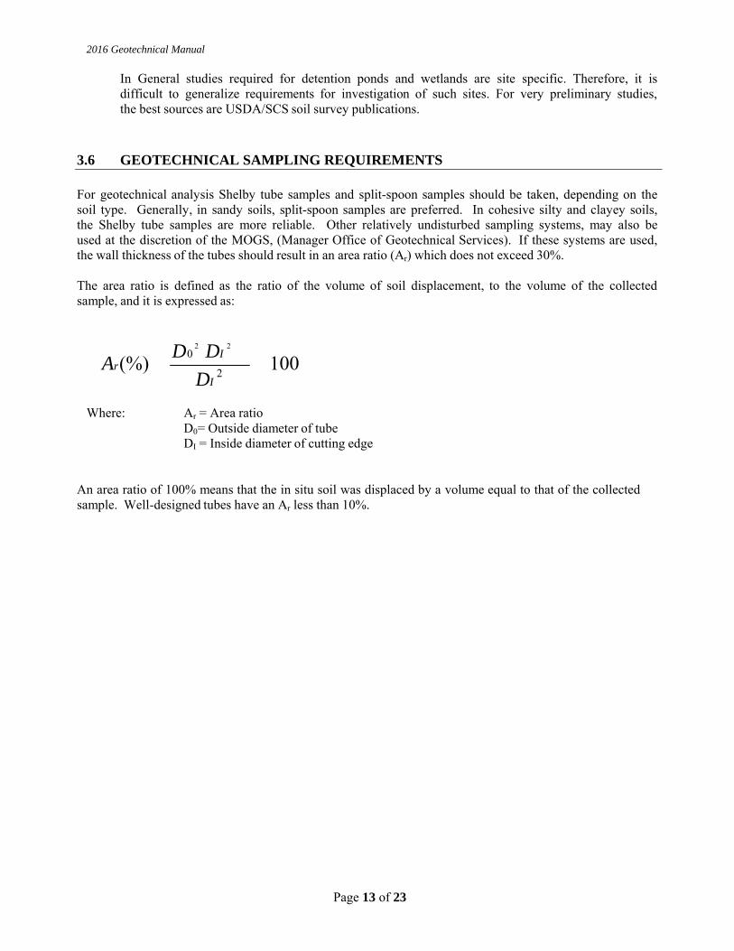
3.6 GEOTECHNICAL SAMPLING REQUIREMENTS For geotechnical analysis Shelby tube samples and split-spoon samples should be taken, depending on the soil type. Generally, in sandy soils, split-spoon samples are preferred. In cohesive silty and clayey soils, the Shelby tube samples are more reliable. Other relatively undisturbed sampling systems, may also be used at the discretion of the MOGS, (Manager Office of Geotechnical Services). If these systems are used, the wall thickness of the tubes should result in an area ratio (Ar) which does not exceed 30%. The area ratio is defined as the ratio of the volume of soil displacement, to the volume of the collected sample, and it is expressed as:
Ar (%) � D0 2
�DI 2
2
�100 DI
Where: Ar = Area ratio D0= Outside diameter of tube DI = Inside diameter of cutting edge
An area ratio of 100% means that the in situ soil was displaced by a volume equal to that of the collected sample. Well-designed tubes have an Ar less than 10%.
2016 Geotechnical Manual
Page 14 of 23
3.6.1 SPLIT SPOON SAMPLES
Generally, all borings requiring samples will be taken with a split-spoon sampler to obtain the data for the Standard Penetration Test, or SPT. The samples are taken at 2.5 foot intervals for the upper 10 feet and at 5 foot intervals thereafter unless otherwise specified or requested. The sampler shall be the standard 2 inch O.D. and 1 ½ inch I.D., driven with a 140 lb. hammer, dropped 30 inch. The number of “blows” required of the hammer to drive the split spoon 1 ½ feet, in 6 inch intervals, shall be recorded. The penetration resistance, called the N-value, shall be defined in AASHTO T-206 Standards and shall be the total of the last two intervals, or 1 foot of the 1 ½ feet drive. Two jar samples, each approximately 6 inches long shall be obtained from each split spoon sample for laboratory examination and/or testing. When required for subgrade or peat investigation, a full 18”SPT sample shall be taken and stored in jars. Sample would be designated as top, middle, and bottom. Keeping the samples as intact as possible, they are to be seated in clean glass jars to prevent loss of moisture, properly marked with the project number, boring number, sample number, blow count and field identification number. As soon as possible after drilling, the samples should be delivered to the laboratory for tests.
3.6.2 SHELBY TUBES Undisturbed samples, if required by the engineer, shall be obtained by pressing a thin-walled tube into the soil with a slow, continuous push. The Shelby Tube shall measure 2 to 3 inches O.D. and the length shall be as recommended in Table 1 of AASHTO T-207 or longer to avoid overfilling of the tube during sampling. The standard lengths for INDOT are: 30 to 36 inches. A recovery of 50% or greater is required unless otherwise approved by the Manager, Office of Geotechnical Services. Immediately upon retrieval, the tubes are to be trimmed and cleaned of excess soil on the ends, sealed with approved air-tight expanders and/or sealing wax on both ends. A suitable filler shall be added to the void at the top of the Shelby Tube to prevent movement of the sample within the tube. Both ends shall be covered with plastic caps, then tape should be applied in such a manner as to seal the open bolt holes and the lip of the cap. Samples shall be kept in a vertical position with the top up during transporting and storage. Samples shall not be jarred or shaken, and shall always be protected from temperature extremes, especially freezing. Each tube shall be properly tagged inside and out with all the pertinent information; project and designation number, road, boring, station and offset, line, depths, recovery percentage and date. It shall be delivered promptly to the laboratory for testing.
3.6.3 ROCK CORES
This involves using a drill rig to core through hard rock, which cannot be augured through. Core barrels, double or triple-tucked, with diamond core bits, of "NX", "NWG", or "NWPAM" (2 inch) sizes are suggested to obtain an approximate core size of 2 inches. The core barrel shall be 5 feet long with an inside diameter of 2 inches to obtain the minimum size core, unless otherwise approved by the MOGS. Longer barrels can be used, but the maximum allowable run is 5 feet. Wire-line coring shall only be permitted in special cases and should be preapproved by the MOGS.
If shale or any other non-durable sedimentary rocks are encountered, the core samples shall be wrapped tightly in a moisture-proof wrapping such as aluminum foil or plastic wrap to prevent drying of samples. Cores shall be measured to determine % recovery and RQD and placed in core boxes with labels
2016 Geotechnical Manual
Page 15 of 23
Indicating “top”, “bottom” and depths. The core box shall be labeled with Des #, Station, line, offset, Boring #, Depths of coring, RQD and % recovery.
3.6.4 BAG SAMPLES
3.6.4.1 RESILIENT MODULUS (MR) Bag samples for Resilient Modulus (MR) testing shall be obtained for each project, usually from the most predominant and critical soil found during the drilling. In addition to the bag sample a 24 inch long Shelby Tube sample shall also be collected for each MR test to be performed. When Rubblization, Full Depth Reclamation or other rehabilitation technique is recommended a minimum of one MR bag sample shall be obtained for every 10 borings performed or one per mile if boring spacing is greater than 600 feet. The sample shall consist of soil collected from auger cuttings taken below the pavement and sub-base material. The sampling procedure shall be as described below:
A continuous flight auger shall be used to penetrate the existing pavement and pavement sub-base
material to a depth approximately 4-6 inches below the top of the subgrade
The flight auger shall then be extracted from the borehole
The borehole shall be inspected and cleaned to insure no sub-base material will interfere with or contaminate sampling
A 24 inch long Shelby Tube sample shall be collected from the borehole
Upon completion of the Shelby Tube sampling the flight auger shall be reintroduced to the borehole and advanced to a depth of approximately 4-5 feet
Approximately 25 pounds of auger cuttings shall be collected for the bag sample, care shall be taken so that aggregate base material does not contaminate soil cuttings
An Unconfined Compression test shall be performed at 1% strain rate on two evenly spaced samples among those 10 borings. The results of Unconfined Compression tests performed at 1% strain relate well with MR at 95 % compaction. If the results of grain size and sieve analyses indicate that there is little variability in the soils within the project the number of MR tests may be reduced. For projects where Widening or New Alignment is proposed sampling frequency shall be as noted above. Samples shall be collected as described below:
A continuous flight auger shall be used to penetrate topsoil to a depth of approximately 1.5 feet
The flight auger shall then be extracted from the borehole
A 24 inch long Shelby Tube sample shall be collected from the borehole
Upon completion of the Shelby Tube sampling the flight auger shall be reintroduced to the borehole and advanced to a depth of approximately 4-5 feet
Approximately 25 pounds of auger cuttings shall be collected for the bag sample
Two (2) jar samples shall be included with each bag sample to be tested for in-situ moisture. All bags shall be properly tagged, inside and out, with tags showing the project number, road, sample number, station and offset, date, and field identification number and delivered to the lab in a timely manner. Soil classification tests are also assigned for each MR bag sample/ unconfined test at 1 % strain.
2016 Geotechnical Manual
Page 16 of 23
3.6.4.2 MOISTURE AND DENSITY TEST
A small bag sample, 24 lbs (11.0kg), is required for all cohesive soil types found during a subgrade investigation. The sample shall be taken from directly under the pavement/subbase strata, from the auger cuttings. A jar sample for moisture testing is not necessary if a split spoon sample was taken. All bags should be properly tagged on the outside as with the normal size MR bag sample and delivered to the lab in a timely manner.
3.6.4.3 SUBGRADE SAMPLING The horizontal and vertical variation in subsurface soil types, moisture, densities, strength, ground water elevations and rock location should all be considered when performing subgrade investigations. Pavement maintenance history, county soils map, GPR, and Falling Weight Deflectometer data are all helpful in developing a thorough subgrade investigation. The purpose of a subgrade investigation is to define the depth, thickness, and location of major soil and rock strata that may reduce the pavement service life and to determine the need for any foundation improvement and strengthening that may be required. The guidelines for drilling and sampling for subgrade investigation are as follows. When the top of the subgrade soil is reached, split spoon samples shall be taken and logged. Borings shall evaluate the upper approximate 4.5 feet of the proposed subgrade. Borings shall penetrate to a depth that allows for three continuous split spoon samples to be collected below the pavement sub-base. In the first split spoon sample if the N value is less than or equal to 10 blows, and the soil is cohesive, a 24 inch long Shelby Tube sample shall be taken beside the split spoon sample within the same pavement core hole. If a Shelby tube sample is required, it shall have a minimum recovery of fifty percent. If this is not obtained from the first tube, a second tube will be required as described previously depending on the soil encountered, so that a combined total of not less than 1 6 inches of undisturbed sample is obtained. If the N value is greater than 10 no Shelby tube sample shall be required and the boring shall be extended to the bottom of the first split spoon depth and the procedure repeated. If the N value is less than six in either the second or third split spoon samples and the soil is cohesive a Shelby tube sample is required at the corresponding depth. Again, a fifty-percent minimum recovery is required. If the N value on the third split spoon is six or greater the boring is to be terminated at this point. The investigation program may include Dynamic Cone Penetration (DCP) and Cone Penetrometer (CPT) testing. DCP and CPT test shall be performed in accordance with ITM 509 and ASTM D 5778. DCP tests shall be performed after removing pavement and sub-base material and blow counts shall be recorded for each 6 inch increment. DCP tests shall penetrate to a depth of 5 feet. If rock or hard strata are encountered, DCP test should be moved 2 feet away and restarted. CPT soundings shall penetrate to a minimum depth of 10 feet. Water level determination is prudent to roadway and other structure. Boring/sounding shall be drilled and a 48 hour water level record shall be provided in geotechnical report. Frequency, depth and other considerations shall be as described in Section 3.5.4.4. All the pavement rehabilitation projects including overlay design, full depth reclamation (FDR), crack seat, break and seat and rubblization shall have water level information.
2016 Geotechnical Manual
Page 17 of 23
3.6.4.4 TOPSOIL SAMPLING Top soil is described as soil that facilitates grass growth and is defined in Section 629 of the Recurring Special Provisions. Top soil consists of organic material, silt, sand, clay, gravel, and chemical elements such as potassium and phosphorus. The top soil thickness shall also be determined during the geotechnical investigation. Soils shall be sampled from the upper most strata of the boring/sounding. Sampling and testing shall be performed within the proposed construction limits and shall be representative of the surface soils within that area. Split spoon sampling shall be based on AASHTO T 206 in borings. The entire off road borings shall have organic soils identification. If drilling is not feasible bag samples shall be recovered and hand auger testing shall be completed in accordance with AASHTO T 203. The bag sample shall be a minimum of 1.0 lbs (0.45 kg). Sampling and testing shall be completed for all new road, bridge, box culverts, ditches, landslides, etc… projects which require a growth layer for grass germination. Engineering judgment shall be used to determine the location of sampling unless specified below. Frequency shall be as follows:
Descriptions Testing Frequency
New Road / Reconstruction one test / 5 Acres
Bridge /Pipe Culvert one test / each quadrant
Samples shall be logged, placed in zip lock bags and labeled appropriately. Labels shall include project ID (either Des number or Contract number), sample location and depth. Finally, topsoil thickness shall be determined by either machine or hand auger sounding.
3.6.5 PITS
In areas such as gullies, ravines or in streambeds, where it is not feasible to place a drill rig and information from a hand auger is inadequate, pits are dug to establish bedrock elevations and overburden depths. Usually a series of 10 sq. foot pits, in an acceptable pattern as per the requirements of the project, are dug by hand to confirm expected data. This method of data collection is limited to sites where shallow bedrock is known or expected, usually within a 3 foot depth. G e n e r a l l y no samples are taken although a representative bag or jar sample for grain size analysis and moisture tests may be requested.
3.6.6 HAND AUGERS Hand Augers are limited to soft cohesive soils and are preformed in areas where standard penetration tests are not possible or necessary. They are used to obtain a profile of the existing strata, sometimes with samples. There are five types of hand augers; 1) the sample hand auger is a minimum of 1 ½ inch diameter, 2) the 1 inch retraction piston sampler, 3) a peat sampler, 4) hand guide power hand auger and 5) a 3 inch diameter post hole type auger. Hand augers shall not exceed 6 inch per increment of advancement, and are performed in accordance with AASHTO T-203. If samples are obtained, they shall be placed in jars, sealed and labeled appropriately.
2016 Geotechnical Manual
Page 18 of 23
3.6.7 PAVEMENT CORES/SUBBASE
Pavement cores shall be obtained from existing pavement when an analysis or test of the core is requested by the Pavement Design Engineer. This core shall be 3 inches in diameter and 8 inches to 9 inches in length and properly labeled. If testing of the core is not required, then other methods of drilling through the pavement are acceptable. A detailed log with full description of material type and thicknesses should be written for each pavement core. Once the pavement core has been extracted, the boring shall be extended through the subbase to the subgrade. Subbase material should be carefully logged; however no sample should be taken for testing unless otherwise specified by the geotechnical engineer.
3.7 CONE PENETRATION TESTING (CPT) The Cone Penetrometer Test consists of pushing an instrumented Penetrometer into the ground while continuously recording sleeve friction, cone resistance and pore pressure in accordance with ASTM D 5778. Shear wave velocities can also be measured at user defined depths. Cone penetration testing can be performed in conjunction with SPT borings for all investigation types covered under Section 3.5 of this document based on the engineering judgment of the geotechnical engineer and approval of the MOGS.
3.8 DYNAMIC CONE PENETROMETER (DCP) This test shall be performed in accordance with ITM 509. DCP test of driving a steel rod with 60º steel cone at one end into the soil by dropping a sliding hammer from a standard height (22.6 inches). The soils strength is determined by counting blows for every six inches of penetration. The length of the bottom steel rods shall be 60 inches. Rods may be fabricated into different combinations of lengths for ease of use, however no length shall be less than 24 inches. A disposable cone is highly recommended for easier extraction of the of the rods at the completion of the test. DCP strengths should be based on the following table:
Blows per 6” Consistency/Density
0 to 3 soft
4 to 6 medium stiff
7 to 12 stiff
Over 13 very stiff
3.9 GEOPHYSICS Geophysical testing is becoming an increasingly important tool for geotechnical engineers and geologists in the performance of subsurface investigations. There are multiple tests including Ground Penetrating Radar, Soil Resistivity, and Seismic Reflection/Refraction which can be employed to aid subsurface profiling. The
2016 Geotechnical Manual
Page 19 of 23
appropriate test for the anticipated ground conditions and the intent of investigation should be determined on a project by project basis.
3.10 PERFORMANCE OF FIELD WORK ON PRIVATE PROPERTY
3.10.1 ENTRY PERMISSION
When the State of Indiana’s employees and representatives must enter and work on private property, they are required to follow Indiana Code 8-23-7-26-,27,28, which took effect on July 1st, 2008. The usual information about the project and its impact on the property owner/tenant should start the letter, along with an explanation of the type work, a timetable to expect entry and an estimate how many days the work will take should be given, but a notice of survey (NOS) letter is required by law to include the following:
1. Include both the occupant and the recorded owner of the property in the notification process. 2. A description of the aggrieved party’s right to compensation for damages. 3. The procedure the aggrieved party must follow to obtain the compensation. 4. The name, address and telephone number of an individual or office where property owners may
direct questions about the investigation. (This would be the geotechnical consultant’s information.)
5. The name, address and telephone number of an individual or office where property owners questions about the rights and procedures for damage compensation may be directed. (This would be the project area’s INDOT District Office, to the attention of the district’s Real Estate Manager.)
6. A copy of the Indiana Code 8-23-7-26, 27, 28 should be included with the letter. This will assist property owners with immediate answers to many of their questions.
After the field work is finished, Form IC-662 is to be immediately completed for crop damages. (Property damages are handled by the district in a different manner and are not claimed on Form IC- 662.) All Form IC-662 claims are to be promptly directed to the appropriate District Real Estate Manager since a timetable of sixty (60) days for reimbursement of an agreed upon compensation is established in the code.
3.10.2 CROP DAMAGE CLAIMS INCURRED ON PRIVATE PROPERTY
Crop damage claims are to e reported on Indiana Form IC 662. The forms should be filled out completely and accurately, with a sketch (length and width) of the damaged crop areas, the location where the damages occurred on the property in reference to a known point, and type crop planted. Acreage can be easily converted once the square footage of damages is determined by using the following website: http://www.metric-conversions.org/area/square-feet-to-acres.htm
After the forms are filled out, send immediately to the project location’s District Real Estate Manager for review and payment. An example of a completed form as well as a blank IC 662 is in the Appendix. It is also the sole responsibility of INDOT and the Consultant Geotechnical Engineer, acting as a representative of the Indiana Department of Transportation or Local Public Agency, to compensate the property owners for any damage incurred to their property because of the Geotechnical Investigation.
2016 Geotechnical Manual
Page 20 of 23
Damage compensation including crop damage should be handled as outlined in the aforementioned Indiana Code, by completing Indiana form I. C. 662 as accurately as possible then transmitting the information to the INDOT District Development office of the project area. Compensation of the damages will be handled by the district personnel. If the property owner is not satisfied with the compensation as determined by INDOT, the County Agricultural Agent will be asked to assist. (Appendix 3.1, I.C. 662.) Compensation for the damages of local agency projects will be handled by the Design consultant and local government.
3.11 EQUIPMENT
All drilling rigs which take split spoon samples shall be equipped with yearly calibrated automatic hammers. Calibration records for each rig’s hammer must be available for INDOT inspection upon request. Pile driving analyzers are the method commonly used for calibration of SPT hammers. Catheads shall not be used for sampling on INDOT projects. Only approved equipment shall be mobilized to the project sites as determined by a pre-drilling field check. If it is deemed necessary to change or add rigs during the process of drilling the project due to unforeseen circumstances at the site, the mobilization of the additional rig must be approved by the Office of Geotechnical Services prior to the move if additional payment for Mobilization is to be requested.
3.12 UTILITIES Buried utilities must be located prior to the start of all geotechnical investigations. Most Indiana companies subscribe to the “Indiana 811” network at 1-800-382-5544. Companies which are not members, in most cases municipal utilities, need to be contacted individually. Failure to contact these companies could result in injury or death to geotechnical drill crew members and the public and/or a loss of utility services. Before contacting the utility companies to locate their buried lines, it is helpful if all soil test boring locations are marked in a distinctive manner (laths, flags, paint, etc.) in order to expedite the process. If the roadwork involves extensive roadwork over several blocks or miles, it is recommended that a meeting be planned, onsite, with the utilities locators so that no boring locations are missed. If a meeting is not feasible, maps of the project with the soil test locations clearly marked (to be given to the locators) are an excellent alternative. Overhead utilities, although in plain sight, are sometimes forgotten. Drilling crews with high mast rigs should work within the guidelines established by the affected utilities and it is recommended that “insulators” or “boots” be placed on the wires to protect the workers. If it is imperative that data be obtained from directly under power lines, then an alternative to drilling with a high mast rig must be used such as a tripod, hand auger, pit, etc. Consider all overhead lines to be alive and dangerous. Older, urbanized areas can have abandoned utility lines or tanks, which could be encountered during drilling. Getting information about these lines prior to drilling from the utilities and street departments could help prevent “anxious” moments if one is accidentally hit. All utility hits should be treated as active lines, and follow the safety guidelines set down for such an emergency, until the utility company can confirm the abandoned line as such.
2016 Geotechnical Manual
Page 21 of 23
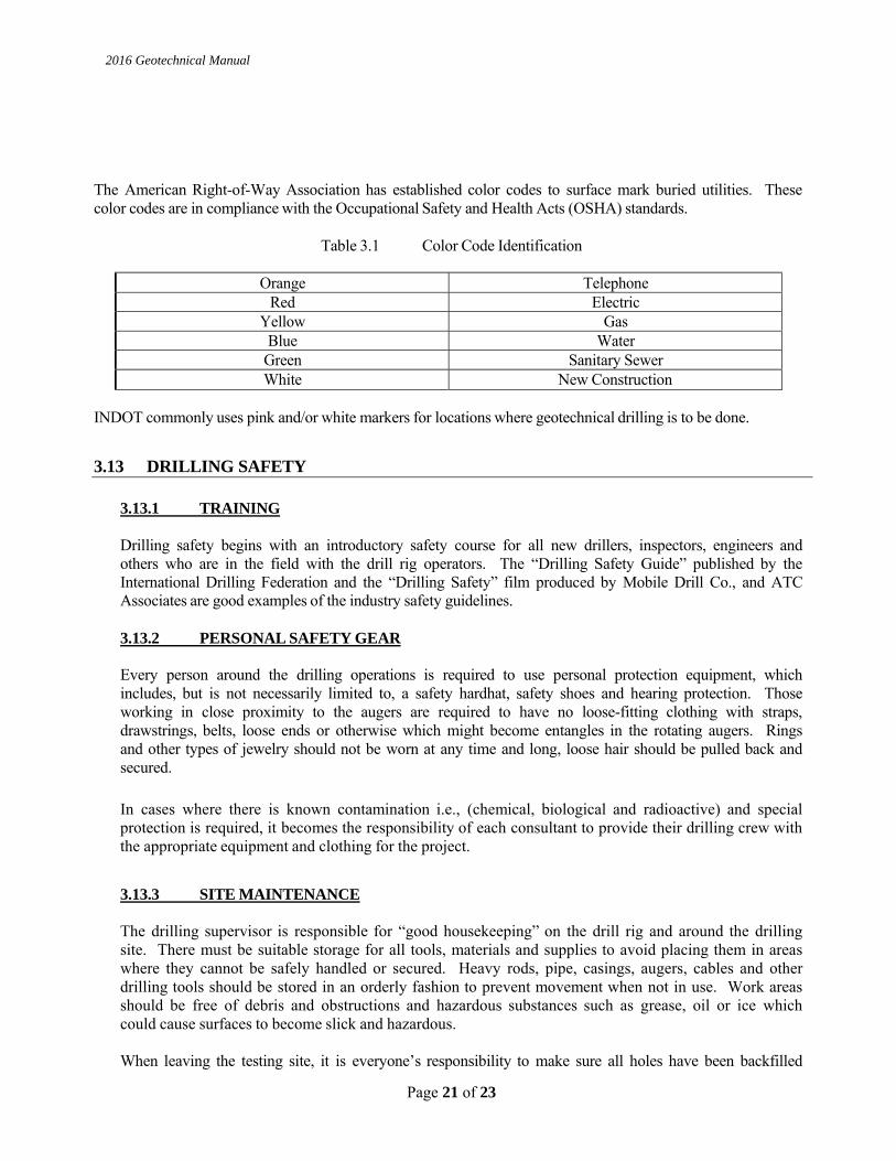
The American Right-of-Way Association has established color codes to surface mark buried utilities. These color codes are in compliance with the Occupational Safety and Health Acts (OSHA) standards.
Table 3.1 Color Code Identification
Orange Telephone Red Electric
Yellow Gas Blue Water
Green Sanitary Sewer White New Construction
INDOT commonly uses pink and/or white markers for locations where geotechnical drilling is to be done.
3.13 DRILLING SAFETY
3.13.1 TRAINING Drilling safety begins with an introductory safety course for all new drillers, inspectors, engineers and others who are in the field with the drill rig operators. The “Drilling Safety Guide” published by the International Drilling Federation and the “Drilling Safety” film produced by Mobile Drill Co., and ATC Associates are good examples of the industry safety guidelines.
3.13.2 PERSONAL SAFETY GEAR
Every person around the drilling operations is required to use personal protection equipment, which includes, but is not necessarily limited to, a safety hardhat, safety shoes and hearing protection. Those working in close proximity to the augers are required to have no loose-fitting clothing with straps, drawstrings, belts, loose ends or otherwise which might become entangles in the rotating augers. Rings and other types of jewelry should not be worn at any time and long, loose hair should be pulled back and secured. In cases where there is known contamination i.e., (chemical, biological and radioactive) and special protection is required, it becomes the responsibility of each consultant to provide their drilling crew with the appropriate equipment and clothing for the project.
3.13.3 SITE MAINTENANCE
The drilling supervisor is responsible for “good housekeeping” on the drill rig and around the drilling site. There must be suitable storage for all tools, materials and supplies to avoid placing them in areas where they cannot be safely handled or secured. Heavy rods, pipe, casings, augers, cables and other drilling tools should be stored in an orderly fashion to prevent movement when not in use. Work areas should be free of debris and obstructions and hazardous substances such as grease, oil or ice which could cause surfaces to become slick and hazardous. When leaving the testing site, it is everyone’s responsibility to make sure all holes have been backfilled
2016 Geotechnical Manual
Page 22 of 23
properly, dirt mounds scattered and sod replaced if necessary. All debris should be removed and the drill site returned to the condition it that was in before drilling operations began. If possible, a follow-up inspection to inspect and correct any settlement of the test holes should be done.
3.13.4 TRAFFIC CONTROL This work shall consist of providing traffic control services in accordance with the INDOT Worksite Traffic Control Manual, when traffic flow must be restricted in order to conduct drilling or coring operations.
3.14 NATURAL AND MANMADE HAZARDS
3.14.1 RIVERS AND STREAMS Drilling on a river requires a barge set-up if it is not possible to access through the existing bridge deck. The drilling needs to be done at a time when flash floods are not likely and should never be done in flood conditions. Drillers should be equipped with life vests or personal floatation devices while working on the water and, because icy conditions could develop quickly, it is not advisable to work on a barge in the winter cold.
3.14.2 UTILITY LINES
Always have buried utility lines located before drilling at the “Indiana 811” number 1-800-382-5544. See section 3.11 for more information.
3.14.3 TOXIC OR HAZARDOUS AREAS Most projects have an environmental assessment prior to any geotechnical survey which identifies hazardous areas. If a site previously thought to be “clean” is found to be hazardous, then the INDOT Office of Environmental Services should be immediately notified and all drilling operations ceased until guidance from the regulatory agency has been provided.
3.14.4 NATURAL GAS POCKETS
In Indiana, naturally occurring gas pockets have been opened up several times by standard geotechnical drilling methods over the years. Due to the volatility of the trapped gas, which can escape at high pressures, immediate action must be taken to make the situation as safe as possible for all involved at the drill site as well as the public safety concerns. Actions to be taken if a trapped natural gas pocket (not piped gas) is opened during drilling operations:
1. Immediately shutdown of all equipment being used on order to prevent electrical sparks
from igniting the gas and all on-site workers move away from the equipment. 2. All traffic must be stopped and or rerouted away from the scene. Local emergency
personnel should be contacted about the situation. 3. Contact the Indiana Department of Natural Resources Division of Oil and Gas Assistant
Director (office: 317-232-4055, directly: 317-232-6961) and IDNR will then contact their field personnel about the situation and send someone to the site to assist.

2016 Geotechnical Manual
Page 23 of 23
4. As per directions from the IDNR personnel on site, observe the pressure and amount of gas being expelled and determine when the situation is safe enough to close up and abandon the hole.