Embed Size (px)
Citation preview
Holdrege & Kull Nevada City • Truckee • Chico • Jackson • Angels Camp www.HoldregeandKull.com
GEOTECHNICAL ENGINEERING REPORT for ROUGH AND READY FIRE STATION 14506 Rough and Ready Highway Assessor’s Parcel Number 52-270-19 Nevada County, California Prepared for: Bruce Ivy Construction 143A Spring Hill Drive Grass Valley, California 95945 Prepared by: Holdrege & Kull 792 Searls Avenue Nevada City, California 95959
Project No. 3738-01 August 26, 2009
Project No. 3738-01 Geotechnical Engineering Report for Rough and Ready Fire Station August 26, 2009 Page iii
Holdrege & Kull
TABLE OF CONTENTS
1 INTRODUCTION...............................................................................................1 1.1 SITE DESCRIPTION ...............................................................................1 1.2 PROPOSED IMPROVEMENTS ..............................................................1 1.3 PURPOSE ...............................................................................................1 1.4 SCOPE OF SERVICES ...........................................................................1
2 SITE INVESTIGATION .....................................................................................2 2.1 LITERATURE REVIEW ...........................................................................2
2.1.1 Soil Survey....................................................................................2 2.1.2 Geologic Setting............................................................................3
2.2 FIELD INVESTIGATION..........................................................................3 2.2.1 Surface Conditions........................................................................3 2.2.2 Subsurface Soil Conditions...........................................................4 2.2.3 Groundwater Conditions ...............................................................5
3 LABORATORY TESTING .................................................................................5 Table 3.1 - Summary of Moisture/Density and Direct Shear Testing ................6
4 CONCLUSIONS................................................................................................6
5 RECOMMENDATIONS.....................................................................................7 5.1 GRADING................................................................................................7
5.1.1 Clearing and Grubbing..................................................................7 5.1.2 Existing Fill....................................................................................8 5.1.3 Cut Slope Grading ........................................................................9 5.1.4 Soil Preparation for Fill Placement................................................9 5.1.5 Fill Placement .............................................................................10 5.1.6 Differential Fill Depth...................................................................11 5.1.7 Fill Slope Grading .......................................................................12 5.1.8 Erosion Controls .........................................................................12 5.1.9 Underground Utility Trenches .....................................................13 5.1.10 Construction Dewatering.............................................................14 5.1.11 Soil Corrosion Potential ..............................................................15 5.1.12 Surface Water Drainage .............................................................15 5.1.13 Grading Plan Review and Construction Monitoring.....................16
5.2 STRUCTURAL IMPROVEMENT DESIGN CRITERIA...........................16 5.2.1 Seismic Design Criteria...............................................................16
Project No. 3738-01 Geotechnical Engineering Report for Rough and Ready Fire Station August 26, 2009 Page iv
Holdrege & Kull
5.2.1.1 - 2007 Seismic Design Parameters.................................17 5.2.2 Foundations ................................................................................17 5.2.3 Slab-on-Grade Floor Systems.....................................................19 5.2.4 Retaining Wall Design Criteria ....................................................21
Table 5.2.4.1 - Equivalent Fluid Unit Weights .............................22 5.2.5 Pavement Design........................................................................23
Table 5.2.5.1 - Recommended Pavement Sections....................24
6 LIMITATIONS..................................................................................................26 FIGURES Figure 1 Topographic Vicinity Map Figure 2 Exploratory Trench Location Map APPENDICES Appendix A Proposal Appendix B Important Information About Your Geotechnical Engineering Report
(included with permission of ASFE, Copyright 2004) Appendix C Exploratory Trench Logs Appendix D Laboratory Test Data
Project No. 3738-01 Geotechnical Engineering Report for Rough and Ready Fire Station August 26, 2009 Page 1
Holdrege & Kull
1 INTRODUCTION
At the request of Bruce Ivy Construction, Holdrege & Kull (H&K) performed a geotechnical investigation at 14506 Rough and Ready Highway in the community of Rough and Ready, California. The geotechnical investigation was performed in general accordance with our November 4, 2008 proposal for the project, a copy of which is included as Appendix A of this report. For your review, Appendix B contains a document prepared by ASFE entitled Important Information About Your Geotechnical Engineering Report, which summarizes the general limitations, responsibilities, and use of geotechnical reports.
1.1 SITE DESCRIPTION
The property is located on the north side of Rough and Ready Highway across from the Rough and Ready Store. The property is bordered by a private gravel drive to the east, Rough and Ready Highway to the south, and rural residential property to the west and north. At the time of our investigation, the site contained an existing structure with a brick façade.
1.2 PROPOSED IMPROVEMENTS
A multi-story structure utilizing wood frame and concrete masonry unit construction is currently proposed for the site. Associated improvements will include concrete and asphalt paved driveways and parking areas, retaining structures, concrete walkways, underground utilities, drainage improvements, and landscaping.
1.3 PURPOSE
We performed a surface reconnaissance and subsurface geotechnical investigation at the site, collected soil samples for laboratory testing, and performed engineering calculations to provide grading and drainage recommendations, foundation and retaining wall design criteria, slab-on-grade recommendations, and pavement design for the proposed improvements.
1.4 SCOPE OF SERVICES
To prepare this report, we performed the following scope of services:
We performed a site investigation, including a literature review and a limited subsurface investigation.
Project No. 3738-01 Geotechnical Engineering Report for Rough and Ready Fire Station August 26, 2009 Page 2
Holdrege & Kull
We collected relatively undisturbed soil samples and bulk soil samples from selected exploratory trenches.
We performed laboratory tests on select soil samples obtained during our subsurface investigation to determine their engineering material properties.
Based on observations made during our subsurface investigation and the results of laboratory testing, we performed engineering calculations to provide geotechnical engineering recommendations for earthwork and structural improvements.
Our scope of services did not include a groundwater flow analysis nor an evaluation of the site for the presence of hazardous materials, historic mining features, asbestiform minerals, mold, or corrosive subsurface conditions.
2 SITE INVESTIGATION
We performed a site investigation to characterize the existing surface conditions and shallow subsurface soil/rock conditions. Our site investigation included a literature review and field investigation as described below.
2.1 LITERATURE REVIEW
We performed a limited review of geologic literature pertaining to the project site. The following sections summarize our findings.
2.1.1 Soil Survey
As part of our study, we reviewed the Soil Survey of Nevada County, California, prepared by the USDA Soil Conservation Service (1993). The soil survey indicated that the site is located in an area containing the Trabuco Rock outcrop complex soil type.
The soil survey describes the Trabuco Rock outcrop complex as having low permeability, medium to rapid runoff, and a high hazard of erosion. A typical profile of the Trabuco soil series consists of a 10-inch thick surface layer of reddish brown loam and heavy loam. The surface layer is underlain by reddish brown, dark red, and yellowish red clay and clay loam to an approximate depth of 67 inches below the ground surface (bgs). The soil is underlain by weathered granitic rock.
Project No. 3738-01 Geotechnical Engineering Report for Rough and Ready Fire Station August 26, 2009 Page 3
Holdrege & Kull
2.1.2 Geologic Setting
We reviewed the 1:250,000-scale Geologic Map of the Chico Quadrangle, California (California Department of Conservation, Division of Division of Mines and Geology, 1992), and the 1:24,000-scale Geologic Map of the Grass Valley - Colfax Area (A. Tuminas, 1983). The geologic maps indicated that the site geology generally consists of Jurrasic-aged rocks of the Pilot Peak Plutonic Complex. The Pilot Peak Plutonic Complex consists of unmetamorphosed olivine gabbro and pyroxene-hornblende diorite.
We reviewed California Geological Survey Open File Report 96-08, Probabilistic Seismic Hazard Assessment for the State of California, and the 2002 update entitled California Fault Parameters. The documents indicate the property is located within the Foothills Fault System. The Foothills Fault System is designated as a Type C fault zone, with low seismicity and a low rate of recurrence. The 1997 edition of California Geological Survey Special Publication 43, Fault Rupture Hazard Zones in California, describes active faults and fault zones (activity within 11,000 years), as part of the Alquist-Priolo Earthquake Fault Zoning Act. The map and document indicate the site is not located within an Alquist-Priolo active fault zone.
2.2 FIELD INVESTIGATION
We performed our field investigation on August 4, 2009. During our field investigation, we observed the local topography and surface conditions and performed a limited subsurface investigation. The following sections summarize surface and subsurface conditions observed during our field investigation.
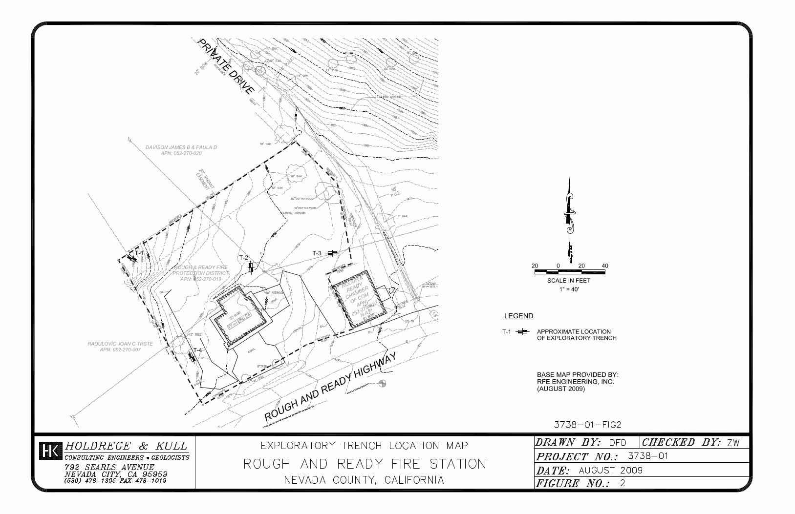
Our subsurface investigation included the excavation of 4 exploratory trenches across the project site. We excavated to depths ranging between approximately 6 and 10 feet below the ground surface (bgs) using a Kubota KX-121 excavator equipped with an 18-inch bucket. We obtained samples using a hand-actuated slide sampler and shovel. A project geologist from our firm logged the soil conditions revealed in the exploratory trenches and collected relatively undisturbed and bulk soil samples for laboratory testing. Figure 2 shows the approximate exploratory trench locations.
2.2.1 Surface Conditions
At the time of our investigation, the site contained an existing structure surrounded by areas of asphaltic pavement, gravel roads, and concrete slabs. The site sloped
Project No. 3738-01 Geotechnical Engineering Report for Rough and Ready Fire Station August 26, 2009 Page 4
Holdrege & Kull
gently to moderately to the south at gradients ranging from 5 percent to 15 percent. Site elevations ranged from 1876 feet above mean sea level (MSL) at the southeastern property corner to 1894 at the northwestern property corner.
We observed an area of apparent fill in the eastern portion of the site, north of the Rough and Ready Chamber of Commerce building. We estimate a maximum fill depth of 3 feet in this area.
Vegetation on the site included a redwood tree near the existing structure and a few scattered oak trees in unimproved portions of the site.
2.2.2 Subsurface Soil Conditions
The soil conditions described in the following paragraphs are generalized, based on our observations of soil revealed in our 4 exploratory trenches. More detailed information can be found in the trench logs in Appendix C.
Trench T-1 was excavated near the northwestern property corner. The trench exposed dry, dense, brown silty sand with abundant angular gravel and cobble-sized rock fragments from the ground surface to an approximate depth of 1.7 feet bgs. The silty sand was underlain by severely weathered rock that excavated as silty sand with gravel. Trench T-1 was terminated at refusal on severely weathered rock at an approximate depth of 5.7 feet bgs.
Trench T-2 was excavated near the northeastern corner of the existing structure. Trench T-2 exposed dry, dense, grayish brown silty sand with gravel and cobble-sized rock fragments from the ground surface to an approximate depth of 2.1 feet bgs. The silty sand was underlain by very severely weathered rock that excavated as silty sand with gravel to an approximate depth of 5.6 feet bgs. The very severely weathered rock was underlain by completely weathered rock. The trench was terminated at an approximate depth of 10 feet in completely weathered rock.
Trench T-3 was excavated in the eastern portion of the property in the area of apparent existing fill. Trench T-3 exposed fill consisting of dry, dense, brown silty sand with gravel and cobble-sized rock fragments from the ground surface to an approximate depth of 2 feet bgs. The fill was underlain by dry, dense, grayish brown silty sand with gravel and cobble-sized rock fragments to an approximate depth of 3.4 feet bgs. The silty sand was underlain by dark brown silty sand that was damp and loose to medium dense to an approximate depth of 5.5 feet bgs. The dark brown silty sand was underlain by mottled yellowish brown and brown clayey sand that was damp and loose to medium dense to an approximate depth of
Project No. 3738-01 Geotechnical Engineering Report for Rough and Ready Fire Station August 26, 2009 Page 5
Holdrege & Kull
7.4 feet bgs. The clayey sand was underlain by completely weathered rock. The trench was terminated at an approximate depth of 9.8 feet bgs in completely weathered rock.
Trench T-4 was excavated in the southwestern portion of the property. Trench T-4 exposed very severely to severely weathered rock that excavated as silty sand with friable gravel and cobble-sized rock fragments that was dry and dense. The trench was terminated at very slow excavation rates in severely weathered rock at an approximate depth of 7.8 feet bgs.
2.2.3 Groundwater Conditions
Our observations of groundwater conditions were made during the dry season. Although we did not observe groundwater in our exploratory trenches, our experience has shown that seepage may be encountered in excavations which reveal the soil/weathered rock transition, particularly during or after the rainy season.
3 LABORATORY TESTING
We performed laboratory tests on selected soil samples collected from our exploratory trenches to determine their engineering material properties. These engineering material properties were used to develop geotechnical engineering design recommendations for earthwork and structural improvements. We performed the following laboratory tests:
Moisture Content, (ASTM D2216), Density (unit weight), (ASTM D2937), Direct Shear Strength (ASTM D3080), Expansion Index (ASTM 4829), Resistance Value (ASTM D2844), Minimum Soil Resistivity (California DOT Test 643), Sulfate (California DOT Test 417) and Chloride (California DOT Test 422).
Table 3.1 summarizes moisture/density and direct shear test results. Appendix D presents graphical direct shear, expansion index, corrosivity and R-value test results.
Project No. 3738-01 Geotechnical Engineering Report for Rough and Ready Fire Station August 26, 2009 Page 6
Holdrege & Kull
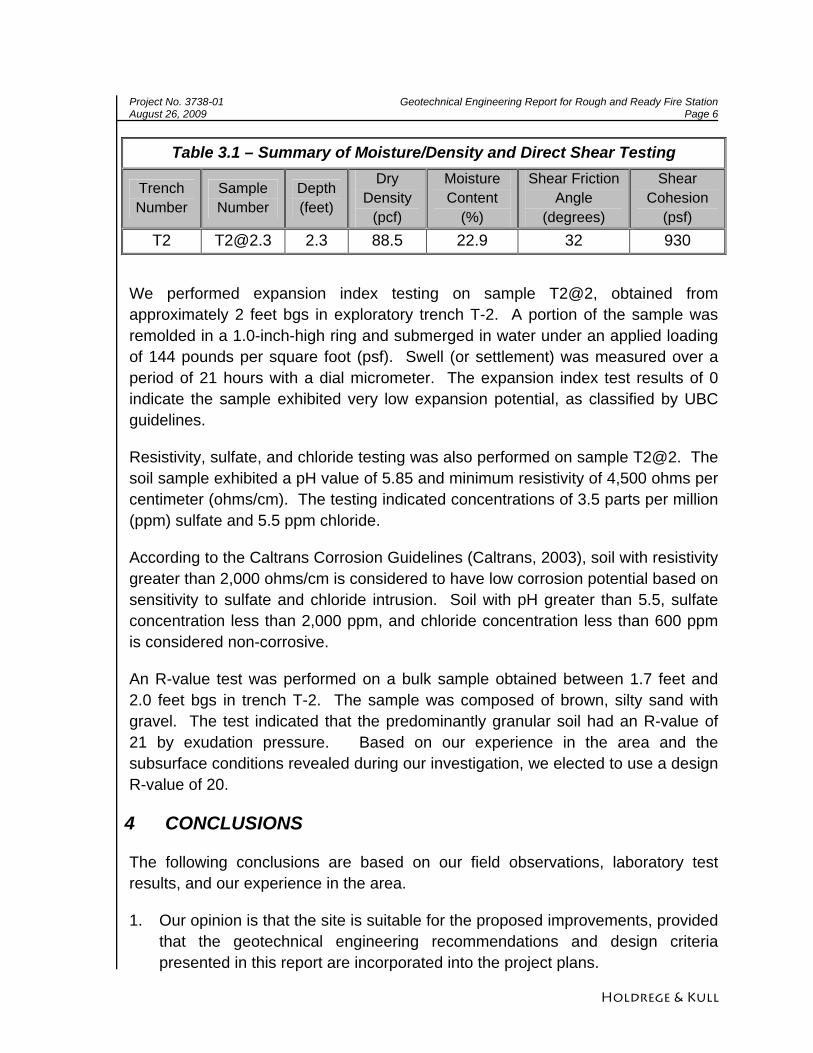
Table 3.1 – Summary of Moisture/Density and Direct Shear Testing
Trench Number
Sample Number
Depth (feet)
Dry Density
(pcf)
Moisture Content
(%)
Shear Friction Angle
(degrees)
Shear Cohesion
(psf) T2 [email protected] 2.3 88.5 22.9 32 930
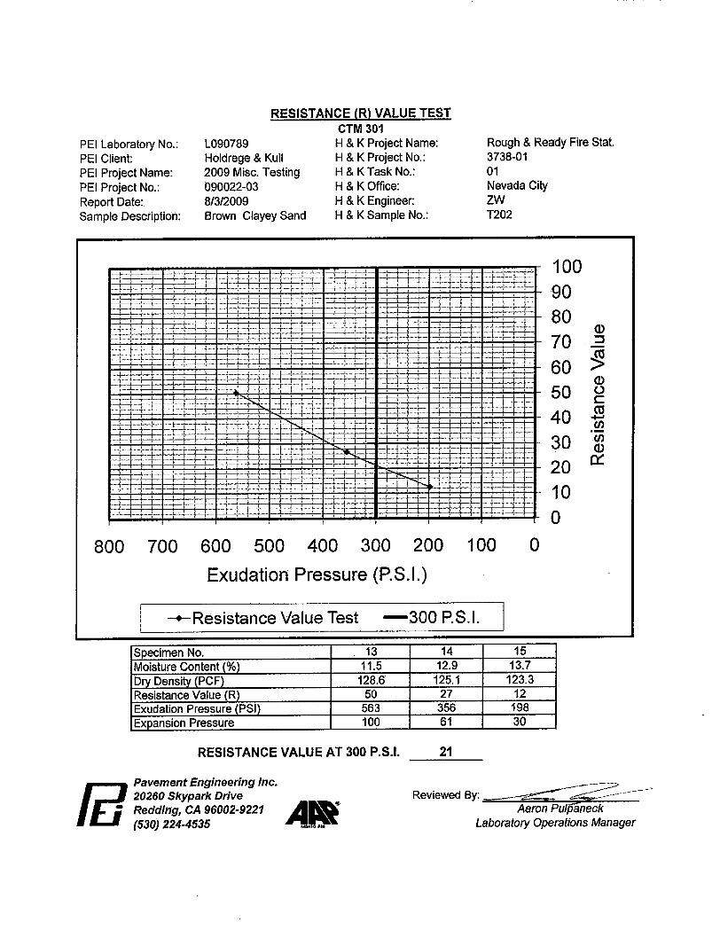
We performed expansion index testing on sample T2@2, obtained from approximately 2 feet bgs in exploratory trench T-2. A portion of the sample was remolded in a 1.0-inch-high ring and submerged in water under an applied loading of 144 pounds per square foot (psf). Swell (or settlement) was measured over a period of 21 hours with a dial micrometer. The expansion index test results of 0 indicate the sample exhibited very low expansion potential, as classified by UBC guidelines.
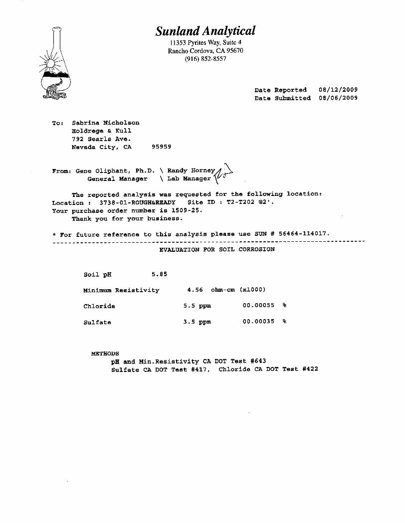
Resistivity, sulfate, and chloride testing was also performed on sample T2@2. The soil sample exhibited a pH value of 5.85 and minimum resistivity of 4,500 ohms per centimeter (ohms/cm). The testing indicated concentrations of 3.5 parts per million (ppm) sulfate and 5.5 ppm chloride.
According to the Caltrans Corrosion Guidelines (Caltrans, 2003), soil with resistivity greater than 2,000 ohms/cm is considered to have low corrosion potential based on sensitivity to sulfate and chloride intrusion. Soil with pH greater than 5.5, sulfate concentration less than 2,000 ppm, and chloride concentration less than 600 ppm is considered non-corrosive.
An R-value test was performed on a bulk sample obtained between 1.7 feet and 2.0 feet bgs in trench T-2. The sample was composed of brown, silty sand with gravel. The test indicated that the predominantly granular soil had an R-value of 21 by exudation pressure. Based on our experience in the area and the subsurface conditions revealed during our investigation, we elected to use a design R-value of 20.
4 CONCLUSIONS
The following conclusions are based on our field observations, laboratory test results, and our experience in the area.
1. Our opinion is that the site is suitable for the proposed improvements, provided that the geotechnical engineering recommendations and design criteria presented in this report are incorporated into the project plans.
Project No. 3738-01 Geotechnical Engineering Report for Rough and Ready Fire Station August 26, 2009 Page 7
Holdrege & Kull
2. Based on our site observations, the geology of the region, and our experience in the area, our opinion is that the risk of seismically induced hazards such as slope instability, liquefaction, and surface rupture are remote at the project site.
3. We encountered existing fill to an approximate depth of 2 feet bgs in exploratory trench T-3. The existing fill, should not be relied upon to support proposed parking area pavement without mitigation. We provide recom-mendations for existing fill and fill placement in Sections 5.1.2 and 5.1.5, respectively.
4. Although we did not observe shallow groundwater or seepage during our field investigation, areas of seepage may be encountered during grading onsite, particularly during the rainy season and/or in excavations which reveal the surface soil/weathered rock contact. Preliminary recommendations regarding subsurface drainage/construction dewatering are presented in this report.
5. Prior to grading and construction, we should be retained to review the proposed grading plan and structural improvements to confirm our recommendations.
5 RECOMMENDATIONS
The following geotechnical engineering recommendations are based on our understanding of the project as currently proposed, our field observations, the results of our laboratory testing program, engineering analysis, and our experience in the area.
5.1 GRADING
The following sections present our grading recommendations. The grading recommendations address clearing and grubbing, soil preparation, cut slope grading, fill placement, fill slope grading, erosion control, subsurface drainage, surface water drainage, construction dewatering, underground utility trenches, soil corrosion potential, plan review, and construction monitoring.
5.1.1 Clearing and Grubbing
The areas to be graded should be cleared and grubbed to remove vegetation and other deleterious materials as described below.
1. Strip and remove debris from clearing operations and the top 1 to 2 inches of soil containing shallow vegetation, roots and other deleterious materials. The organic topsoil can be stockpiled onsite and used in landscape areas but is not
Project No. 3738-01 Geotechnical Engineering Report for Rough and Ready Fire Station August 26, 2009 Page 8
Holdrege & Kull
suitable for use as fill. The project geotechnical engineer should approve any proposed use of the spoil generated from stripping prior to placement.
2. Overexcavate any relatively loose debris and soil that is encountered in our exploratory trenches or any other onsite excavations to underlying, competent material. Possible excavations include exploratory trenches excavated by others, mantles or soil test pits, holes resulting from tree stump or boulder removal, and mining relics.
3. Loose, untested fill encountered during site development shall be overexcavated to competent native soil or weathered rock a minimum of 5 feet beyond the areas of proposed improvements.
4. Overexcavate any encountered leach lines, abandoned sewer, water, and fuel lines, and loose soil in abandoned subsurface utility line trenches within the proposed improvement areas to underlying competent soil, as determined by a representative of H&K.
5. Remove rocks greater than 8 inches in greatest dimension (oversized rock) from native soil by scarifying to a depth of 12 inches below finish grade in areas to support pavement, slabs-on-grade or other flatwork. Oversized rock may be used in landscape areas, rock landscape walls, or removed from the site. Oversized rock can be stockpiled onsite and used to construct fills, but must be placed at or near the bottom of deep fills, if proposed, and must be placed in windrows to avoid nesting. No oversized rock should be placed in the upper 3 feet of any structural fill. The project geotechnical engineer should approve the use of oversized rock prior to constructing fill.
6. Fine grained, potentially expansive soil, as determined by H&K, that is encountered during grading should be mixed with granular soil, or overexcavated and stockpiled for removal from the project site or for later use in landscape areas. A typical mixing ratio for granular to expansive soil is 4 to 1. The actual mixing ratio should be determined by H&K.
7. Vegetation, deleterious materials, structural debris, and oversized rocks not used in landscape areas, drainage channels, or other non-structural uses should be removed from the site.
5.1.2 Existing Fill
One of our concerns regarding the project site is the presence of existing untested fill beneath the proposed parking area in the eastern portion of the site. Loose fill beneath pavement may contribute to future differential settlement-induced distress.
Project No. 3738-01 Geotechnical Engineering Report for Rough and Ready Fire Station August 26, 2009 Page 9
Holdrege & Kull
Our opinion is that the existing fill should not be relied upon to support the proposed improvements without mitigation. Relatively loose fill, within and a minimum of 5 feet beyond the proposed pavement, shall be overexcavated and stockpiled onsite. The depth of the overexcavation should extend through all loose soil to competent native soil or rock. The fill shall be replaced and compacted using the recommendations presented in the Fill Placement section of this report.
5.1.3 Cut Slope Grading
Based on our understanding of the project at this time, we anticipate that permanent cut slopes up to 12 feet in height will be created during grading of the proposed improvements. In general, permanent cut slopes should not be steeper than 1½:1, horizontal to vertical (H:V). Steeper cut slopes may be feasible, depending on the soil/rock conditions encountered and should be reviewed on a case-by-case basis. The upper two feet of all cut slopes should be graded to an approximate 2:1, H:V, slope to reduce sloughing and erosion of looser surface soil.
Temporary cut slopes may be constructed to facilitate retaining wall construction. We anticipate that subsurface conditions will be favorable for construction of temporary cut slopes no steeper than ½:1, H:V, for a maximum height of approximately 8 feet. To reduce the likelihood of sloughing or failure, temporary cut slopes should not remain over the winter.
A representative of H&K must observe temporary cut slopes steeper than 1½:1, H:V, during grading to confirm the soil and rock conditions encountered. We recommend that personnel not be allowed between the cut slope and the proposed retaining structure, form work, grading equipment, or parked vehicles during construction, unless the stability of the slope has been reviewed by H&K or the slope has been confirmed to meet OSHA excavation standards.
5.1.4 Soil Preparation for Fill Placement
Where fill placement is proposed, the surface soil exposed by site clearing and grubbing should be prepared as described below.
1. The surface soil should be scarified to a minimum depth of 12 inches below the existing ground surface, or to resistant rock, whichever is shallower. Following scarification, the soil should be uniformly moisture conditioned to within approximately 3 percentage points of the ASTM D1557 optimum moisture content.
Project No. 3738-01 Geotechnical Engineering Report for Rough and Ready Fire Station August 26, 2009 Page 10
Holdrege & Kull
2. The scarified and moisture conditioned soil should then be compacted to achieve a minimum relative compaction of 90 percent based on ASTM D1557 maximum dry density. The moisture content, density, and relative percent compaction should be verified by a representative of H&K. The earthwork contractor should assist our representative by excavating test pads with onsite earth moving equipment.
3. Where fill placement is proposed on native slopes steeper than approximately 5:1, H:V, a base key and routine benches must be provided. Unless otherwise recommended by the project geotechnical engineer, the base key should be excavated at the toe of the fill a minimum of 2 feet into competent stratum, as determined by a representative of H&K during construction observation. The bottom of the base key should be sloped slightly into the hillside at an approximate gradient of 5 percent or greater.
4. The fill must be benched into existing side slopes as fill placement progresses. Benching must extend through loose surface soil into firm material, and at intervals such that no loose surface soil is beneath the fill. As a minimum, a horizontal bench should be excavated every 5 vertical feet or as determined by a representative of H&K.
5.1.5 Fill Placement
Soil fill placement proposed for the project should incorporate the following recommendations:
1. Soil used for fill should consist of uncontaminated, predominantly granular, non-expansive native soil or approved import soil. If encountered, rock used in fill should be broken into pieces no larger than 8 inches in diameter. Rocks larger than 8 inches are considered oversized material and should be stockpiled for offhaul or later use in landscape areas and drainage channels. If approved by the project geotechnical engineer, oversized rock may be placed at or near the bottom of deep fills. Oversized rock must be placed in windrows to avoid nesting and to facilitate the placement of compacted fill. No oversized rock should be placed in the upper 3 feet of any structural fill. The project geotechnical engineer should approve the use of oversized rock prior to constructing fill.
2. Import soil should be predominantly granular, non-expansive and free of deleterious material. Import material that is proposed for use onsite should be submitted to H&K for approval and possible laboratory testing at least 72 hours prior to transport to the site.
Project No. 3738-01 Geotechnical Engineering Report for Rough and Ready Fire Station August 26, 2009 Page 11
Holdrege & Kull
3. Cohesive, predominantly fine grained, or potentially expansive soil encountered during grading should be stockpiled for removal, mixed as directed by H&K, or used in landscape areas.
As an option, cohesive fine grained, or potentially expansive soil can often be placed in the deeper portions of proposed fill (e.g., depths greater than 3 feet below subgrade in building footprints). However, this option would have to be evaluated on a case-by-case basis with consideration of the fill depth and proposed loading.
4. Soil used to construct fill should be uniformly moisture conditioned to within approximately 3 percentage points of the ASTM D1557 optimum moisture content. Wet soil may need to be air dried or mixed with drier material to facilitate placement and compaction, particularly during or following the wet season.
5. Fill should be constructed by placing uniformly moisture conditioned soil in maximum 8-inch-thick loose, horizontal lifts (layers) prior to compacting.
6. All fill should be compacted to a minimum relative compaction of 90 percent of the ASTM D1557 maximum dry density. The upper 12 inches of fill in paved areas, beneath proposed slabs-on-grade, and within the proposed building footprint should be compacted to a minimum of 95 percent relative compaction.
The moisture content, density and relative percent compaction of fill should be confirmed by a representative of H&K during construction.
5.1.6 Differential Fill Depth
Although we understand that the proposed fire station will be founded on cut native soil, we present the following general recommendations in the event the current grading plan is modified. These recommendations are intended to reduce the magnitude of differential settlement-induced structural distress associated with variable fill depth beneath structures.
1. Site grading should be performed so that cut-fill transition lines do not occur directly beneath any structures. The cut portion of the cut-fill building pads, if proposed, should be scarified to a minimum depth of 8 inches, and recompacted to 95 percent relative compaction.
2. Differential fill depths beneath structures should not exceed 5 feet. For example, if the maximum fill depth is 8 feet across a building pad, the minimum fill depth beneath that pad should not be less than 3 feet. If a cut-fill building
Project No. 3738-01 Geotechnical Engineering Report for Rough and Ready Fire Station August 26, 2009 Page 12
Holdrege & Kull
pad is used in this example, the cut portion would need to be overexcavated 3 feet and rebuilt with compacted fill.
5.1.7 Fill Slope Grading
Based on our understanding of the project, we do not anticipate that fill slopes will be created as part of the proposed improvements. However, we provide the following recommendations in case the grading plans are modified. In general, permanent fill slopes created onsite should be no steeper than 2:1, H:V. H&K should review fill slope configurations greater than approximately 6 feet in height, if proposed, prior to fill placement. Compaction and fill slope grading must be confirmed by H&K in the field.
Steeper fill slopes may be feasible with the use of geotextile reinforcement and/or rock facing. We can provide reinforced or buttressed fill slope design for the project, if requested.
Fill should be placed in horizontal lifts to the lines and grades shown on the project plans. Slopes should be constructed by overbuilding the slope face and then cutting it back to the design slope gradient. Fill slopes should not be constructed or extended horizontally by placing soil on an existing slope face and/or compacted by track walking.
5.1.8 Erosion Controls
Graded portions of the site should be seeded as soon as possible to allow vegetation to become established prior to and during the rainy season. In addition, grading that results in greater than one acre of soil disturbance or in sensitive areas may require the preparation of a site-specific storm water pollution prevention plan. As a minimum, the following controls should be installed prior to and during grading to reduce erosion.
1. Prior to commencement of site work, fiber rolls should be installed down slope of the proposed area of disturbance to reduce migration of sediment from the site. Fiber rolls on slopes are intended to reduce sediment discharge from disturbed areas, reduce the velocity of water flow, and aid in the overall revegetation of slopes. The fiber rolls should remain in place until construction activity is complete and vegetation becomes established.
2. All soil exposed in permanent slope faces should be hydroseeded or hand seeded/strawed with an appropriate seed mixture compatible with the soil and
Project No. 3738-01 Geotechnical Engineering Report for Rough and Ready Fire Station August 26, 2009 Page 13
Holdrege & Kull
climate conditions of the site as recommended by the local Resource Conservation District.
3. Following seeding, jute netting or erosion control blankets should be placed and secured over the slopes steeper than 2:1, H.V.
4. Surface water drainage ditches should be established as necessary to intercept and redirect concentrated surface water away from cut and fill slope faces. Under no circumstances should concentrated surface water be directed over slope faces. The intercepted water should be discharged into natural drainage courses or into other collection and disposal structures.
5.1.9 Underground Utility Trenches
Underground utility trenches should be excavated and backfilled as described below.
1. Based on subsurface conditions observed in our exploratory trenches, we anticipate that conventional equipment can be utilized to excavate utility trenches.
2. The California Occupational Safety and Health Administration (OSHA) requires all utility trenches deeper than 4 feet bgs be shored with bracing equipment prior to being entered by any individuals, whether or not they are associated with the project.
3. We anticipate that shallow subsurface seepage may be encountered, particularly if utility trenches are excavated during the winter, spring, or early summer. The earthwork contractor may need to employ dewatering methods as discussed in the Construction Dewatering section on page 14 to excavate, place and compact the trench backfill materials.
4. Trench backfill used within the bedding and shading zones should consist of ¾-inch minus crushed rock, granular material with a sand equivalent greater than 30, or similar material approved by the project engineer.
5. Soil used as trench backfill should consist of non-expansive soil with a plasticity index (PI) less than or equal to 15 and should not contain rocks greater than 3 inches in greatest dimension unless otherwise approved by the geotechnical engineer.
6. Where utility trenches will intersect perimeter footings or pass within the proposed building footprint, we recommend that a low permeability backfill plug be placed to reduce water migration and infiltration. In general, a low
Project No. 3738-01 Geotechnical Engineering Report for Rough and Ready Fire Station August 26, 2009 Page 14
Holdrege & Kull
permeability, predominantly fine-grained soil backfill, sand-cement slurry, or other approved material should be placed within five feet of the building exterior.
6. Trench backfill should be constructed by placing uniformly moisture conditioned soil in maximum 12-inch-thick loose lifts prior to compacting.
7. Trench backfill should be compacted to a minimum relative compaction of 90 percent of the ASTM D1557 maximum dry density. In areas of proposed pavement or concrete flatwork, the upper 12 inches of backfill should be compacted to a minimum relative compaction of 95 percent of the ASTM D1557 maximum dry density. Jetting is not an acceptable method of compacting trench backfill or bedding sand.
8. The loose lift thickness, moisture, density and relative compaction of the trench backfill soil should be observed by a representative of H&K during placement.
9. Construction quality assurance tests should be performed at a frequency determined by the project geotechnical engineer. Where trench backfill is placed at depths greater than approximately 4 feet, or where potentially unstable sidewall conditions exist, shoring may need to be provided by the contractor to facilitate compaction testing. If shoring is not provided or unsafe conditions are encountered, full time observation will likely be required to confirm compactive effort.
5.1.10 Construction Dewatering
Seepage may be encountered during grading, particularly in deeper excavations made during site preparation. The earthwork contractor should be prepared to dewater excavations if seepage is encountered during grading. Seepage may be encountered if grading is performed during or immediately after the rainy season. In addition, perched groundwater may be encountered on low permeability soil or weathered rock layers even during the summer months.
If subsurface seepage or groundwater conditions are encountered which prevent or restrict fill placement or construction of the proposed improvements, subdrains may be necessary. If groundwater or saturated soil conditions are encountered during grading, we should be retained to observe the conditions and provide site specific subsurface drainage recommendations. The following typical measures can be employed to mitigate the presence of seepage in excavations.
Project No. 3738-01 Geotechnical Engineering Report for Rough and Ready Fire Station August 26, 2009 Page 15
Holdrege & Kull
1. We anticipate that dewatering of utility trenches can be performed by constructing sumps to depths below the trench bottom and removing the water with sump pumps.
2. Additional sump excavations and pumps should be added as necessary to keep the excavation bottom free of standing water and relatively dry when placing and compacting the trench backfill material.
3. If groundwater enters the trench faster than it can be removed by the dewatering system, the underlying compacted soil may become unstable while compacting successive soil lifts. If this occurs, the unstable soil may need to be removed and replaced with free draining open graded drain rock. If drain rock is used, it should meet or exceed the following gradation specifications: 100 percent passing the ¾-inch sieve, 95 to 100 percent passing the ½-inch sieve, 70 to 100 percent passing the ⅜-inch sieve, 0 to 55 percent passing the No. 4 sieve, 0 to 10 percent passing the No. 8 sieve, and 0 to 3 percent passing the No. 200 sieve. Other approved backfill materials can again be used after placing the drain rock to an elevation that is higher than the groundwater.
5.1.11 Soil Corrosion Potential
Index testing of the soil in an effort to evaluate corrosion potential was performed as a part of our soil evaluation. The soil sample exhibited a pH value of 5.85 and minimum resistivity values of 4,500 ohms per centimeter (ohms/cm). The sample indicated concentrations of 3.5 parts per million (ppm) sulfate and 5.5 ppm chloride, respectively.
According to the Caltrans Corrosion Guidelines (Caltrans, 2003), soil with resistivity greater than 2,000 ohms/cm is considered to have low corrosion potential based on sensitivity to sulfate and chloride intrusion. Soil with pH greater than 5.5, sulfate concentration less than 2,000 ppm and chloride concentration less than 600 ppm is considered non-corrosive.
5.1.12 Surface Water Drainage
Proper surface water drainage is important to the successful development of the project. We recommend the following measures to help mitigate surface water drainage problems:
1. Slope final grades in structural areas so that surface water drains away from building pad finish subgrade at a minimum 2 percent slope for a minimum
Project No. 3738-01 Geotechnical Engineering Report for Rough and Ready Fire Station August 26, 2009 Page 16
Holdrege & Kull
distance of 10 feet. For structures utilizing slab-on-grade interior floor systems we recommend increasing the slope to 4 percent.
2. To reduce surface water infiltration, compact and slope all soil placed adjacent to building foundations such that water is not allowed to pond. Backfill should be free of deleterious materials.
3. Direct downspouts to positive drainage or a closed collector pipe that discharges flow to positive drainage.
4. Construct V-ditches at the top of cut and fill slopes where necessary to reduce concentrated surface water flow over slope faces. Typically, V-ditches should be 3 feet wide and at least 6 inches deep. Surface water collected in V-ditches should be directed away and downslope from proposed building pads and driveways into a drainage channel.
5.1.13 Grading Plan Review and Construction Monitoring
Construction quality assurance includes review of plans and specifications and performing construction monitoring as described below.
1. H&K should be retained to review the final grading plans prior to construction to confirm our understanding of the project at the time of our investigation, to determine whether our recommendations have been implemented, and to provide additional and/or modified recommendations, if necessary.
2. H&K should be retained to perform construction quality assurance (CQA) monitoring of all earthwork grading performed by the contractor to determine whether our recommendations have been implemented, and if necessary, provide additional and/or modified recommendations.
5.2 STRUCTURAL IMPROVEMENT DESIGN CRITERIA
The following sections present our structural improvement design criteria and recommendations. The recommendations address foundations, seismic parameters, concrete slabs-on-grade, retaining walls and pavement design.
5.2.1 Seismic Design Criteria
Our classification of on-site soil conditions is based on field observations and laboratory tests. The on-site soil primarily consists of granular soil composed of silty sand, with gravel and cobble-sized rock fragments. Based on the presence of predominantly granular soil and variably weathered rock at relatively shallow depths, we classified the on-site soil as (SM) for design purposes.
Project No. 3738-01 Geotechnical Engineering Report for Rough and Ready Fire Station August 26, 2009 Page 17
Holdrege & Kull
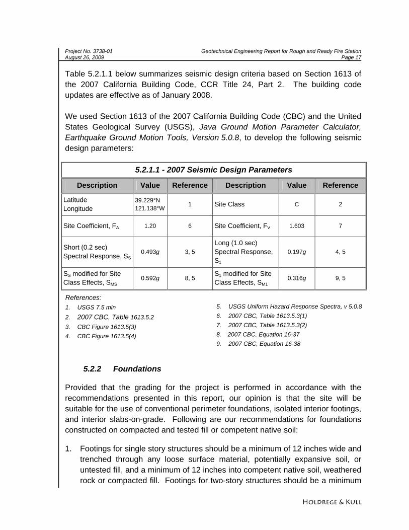
Table 5.2.1.1 below summarizes seismic design criteria based on Section 1613 of the 2007 California Building Code, CCR Title 24, Part 2. The building code updates are effective as of January 2008. We used Section 1613 of the 2007 California Building Code (CBC) and the United States Geological Survey (USGS), Java Ground Motion Parameter Calculator, Earthquake Ground Motion Tools, Version 5.0.8, to develop the following seismic design parameters:
5.2.1.1 - 2007 Seismic Design Parameters
Description Value Reference Description Value Reference
Latitude Longitude
39.229°N 121.138°W
1 Site Class C 2
Site Coefficient, FA 1.20 6 Site Coefficient, FV 1.603 7
Short (0.2 sec) Spectral Response, SS
0.493g 3, 5 Long (1.0 sec) Spectral Response, S1
0.197g 4, 5
SS modified for Site Class Effects, SMS
0.592g 8, 5 S1 modified for Site Class Effects, SM1
0.316g 9, 5
References: 1. USGS 7.5 min 2. 2007 CBC, Table 1613.5.2 3. CBC Figure 1613.5(3) 4. CBC Figure 1613.5(4)
5. USGS Uniform Hazard Response Spectra, v 5.0.8 6. 2007 CBC, Table 1613.5.3(1) 7. 2007 CBC, Table 1613.5.3(2) 8. 2007 CBC, Equation 16-37 9. 2007 CBC, Equation 16-38
5.2.2 Foundations
Provided that the grading for the project is performed in accordance with the recommendations presented in this report, our opinion is that the site will be suitable for the use of conventional perimeter foundations, isolated interior footings, and interior slabs-on-grade. Following are our recommendations for foundations constructed on compacted and tested fill or competent native soil:
1. Footings for single story structures should be a minimum of 12 inches wide and trenched through any loose surface material, potentially expansive soil, or untested fill, and a minimum of 12 inches into competent native soil, weathered rock or compacted fill. Footings for two-story structures should be a minimum
Project No. 3738-01 Geotechnical Engineering Report for Rough and Ready Fire Station August 26, 2009 Page 18
Holdrege & Kull
of 15 inches wide and trenched a minimum of 18 inches into competent native soil, weathered rock or compacted fill. If clay is encountered at the base of footing excavations, the footing should be deepened through the clay lens into underlying granular material or weathered rock, as determined in the field by H&K.
2. The base of the footing excavation should be approximately level. On sloping sites, it will be necessary to step the base of the footing excavation as necessary to maintain a slope of less than 10 percent at the base of the footing.
3. Footing trenches should be cleaned of all loose soil and construction debris prior to placing concrete. A representative from H&K should observe the footing excavations prior to concrete placement.
4. As a minimum, the footings should be designed with two No. 4 rebar reinforcement, one near the top of the footing and one near the bottom. A minimum of 3 inches of concrete coverage should surround the bars.
5. In general, structures constructed adjacent to descending slopes should employ a minimum setback of either 1/3 the height of the slope, or 40 feet, whichever is less. The setback for ascending slopes is either 1/2 the slope height or 15 feet, whichever is less. Where footings are proposed within these code-based setbacks, the project geotechnical engineer should review the proposed slope configuration and provide revised setback recommendations, if appropriate.
6. Footing excavations should be saturated prior to placing concrete to reduce the risk of problems caused by wicking of moisture from curing concrete. However, concrete should not be placed through standing water in the footing excavations.
7. In an effort to reduce the likelihood of settlement-induced distress to the proposed structures, we recommend that strip and isolated footings with a minimum embedment depth of 12 inches in competent soil be sized for an allowable bearing capacity of 3000 psf for dead plus live loads. This value can be increased by 300 psf for each additional foot of embedment up to a limiting value of 3600 psf. Allowable bearing may be increased by 33 percent for additional transient loading, such as wind or seismic loads.
8. A triangularly-distributed lateral resistance (passive soil resistance) of 300d psf, where d is footing depth, may be used for footings. This value may be increased by 33 percent for wind and seismic. As an alternate to the passive
Project No. 3738-01 Geotechnical Engineering Report for Rough and Ready Fire Station August 26, 2009 Page 19
Holdrege & Kull
soil resistance described above, a coefficient of friction for resistance to sliding of 0.35 may be used.
9. Total settlement of individual foundations will vary depending on the plan dimensions of the foundation and actual structural loading. Based on anticipated foundation dimensions and loads, we estimate that total post-construction settlement of footings designed and constructed in accordance with our recommendations will be on the order of one-half inch. Differential settlement between similarly loaded, adjacent footings is expected to be less than one-quarter inch, provided footings are founded on similar materials (e.g., all on structural fill, native soil or rock). Differential settlement between adjacent footings founded on dissimilar materials (e.g., one footing on soil and an adjacent footing on rock) may approach the maximum anticipated total settlement. Settlement of foundations is expected to occur rapidly and should be essentially complete shortly after initial application of loads.
5.2.3 Slab-on-Grade Floor Systems
H&K understands that interior concrete slab-on-grade floors are proposed for use with a perimeter concrete foundation. The project structural engineer should design slabs-on-grade with regard to the anticipated loading. This section presents general construction recommendations for interior concrete slab-on-grades. We also present recommendations for concrete slabs used for onsite roadways and parking areas in Section 5.2.5 of this report. Project specific slab-on-grade design should be based on the anticipated loading and serviceability criteria.
1. In general, slabs-on-grade supporting conventional interior live loads should be a minimum of 4 inches thick and utilize concrete with a minimum 28-day compressive strength of 3,000 psi. The design slab thickness should be based on loading and serviceability. A thickened concrete slab section will be required in service and loading bays intended to routinely support emergency vehicle loads.
2. Based on conversations with the project civil engineer, we understand that the project structural engineer will design the interior concrete slabs for the fire station.
3. The soil around the structure should be sloped away from the proposed slab subgrade a minimum of 4 percent for a distance of 10 feet. A representative from H&K should observe pad and subgrade elevations prior to the placement of forms.
Project No. 3738-01 Geotechnical Engineering Report for Rough and Ready Fire Station August 26, 2009 Page 20
Holdrege & Kull
4. In general, minimum slab reinforcement consists of No. 3 grade 60 rebar on 24-inch centers or flat sheets of 6x6, W4.0xW4.0 welded wire mesh (WWM). The design slab reinforcement should be based on loading and serviceability. For areas subjected to routine, heavy vehicle loads, we recommend that the minimum steel reinforcement be increased to No. 4 grade 60 rebar on 24-inch centers, unless otherwise recommended by the project structural engineer. H&K does not recommend using rolls of WWM because vertically centered placement of rolled mesh within the slab is difficult to achieve. All rebar and sheets of WWM should be placed in the center of the slab and supported on concrete "dobies". We do not recommend "hooking and pulling" of steel during concrete placement.
5. Prior to placing the vapor retarder and concrete, slab subgrade soil must be moisture conditioned to between 75 and 90 percent saturation to a depth of 24 inches. Moisture conditioning should be performed for a minimum of 24 hours prior to concrete placement. Clayey soil may take up to 72 hours to reach this required degree of saturation. If the soil is not moisture conditioned prior to placing concrete, moisture may be wicked out of the concrete, possibly contributing to shrinkage cracks. Additionally, our opinion is that moisture conditioning the soil prior to placing concrete will reduce the likelihood of soil swell or heave following construction at locations where fine grained, potentially expansive soil is encountered. To facilitate slab-on-grade construction, the slab subgrade soil may be moisture conditioned after rock placement. Following moisture conditioning, the vapor retarder should be placed.
6. Slabs should be underlain by at least 4 inches of washed rock. The rock should be uniformly graded so that 100% passes the 1-inch sieve, with 0% to 5% passing the No. 4 sieve. Following rock placement, the subgrade soil should be moisture conditioned as described above. The rock should then be overlain by a vapor retarder at least 15 mils thick. All penetrations through the vapor retarder should be taped or sealed to reduce vapor transmission. Laps in the vapor retarder should be taped. If requested, H&K can observe the vapor retarder prior to concrete placement to confirm that penetrations and laps have been sealed.
7. Regardless of the type of vapor retarder used, moisture can wick up through a concrete slab. Excessive moisture transmission through a slab can cause adhesion loss, warping and peeling of resilient floor coverings, deterioration of adhesive, seam separation, formation of air pockets, mineral deposition beneath flooring, odor and fungi growth. Slabs can be tested for water
Project No. 3738-01 Geotechnical Engineering Report for Rough and Ready Fire Station August 26, 2009 Page 21
Holdrege & Kull
transmissivity in areas that are moisture sensitive. Commercial sealants, entrained air, fly ash and a reduced water to cement ratio can be incorporated into the concrete to reduce slab permeability. H&K’s general recommendations are not intended to complete eliminate vapor transmission through the slab. The slab designer should determine whether an admixture or other method of vapor retardant is appropriate for the slab based on its proposed use.
8. Expansion joints should be provided between the slab and perimeter footings. Control joints should bisect the length and width of the slab at intervals specified by the American Concrete Institute (ACI) or Portland Concrete Association (PCA).
9. Exterior sidewalks utilizing slabs-on-grade may be placed directly on compacted fill without the use of a baserock section. For exterior slabs, the native soil should be ripped, moisture conditioned and recompacted to an 8-inch depth per the grading recommendations presented in this report. The vapor retarder may be omitted in areas that do not have moisture sensitive floor coverings (i.e., exterior parking areas).
10. All deleterious material must be removed prior to placing concrete.
11. H&K recommends that concrete have a water/cement ratio no greater than 0.45. Pozzolans or other additives may be added to increase workability, at the discretion of the slab designer.
12. Concrete slabs should be moisture cured for at least seven days after placement. Excessive curling of the slab may occur if moisture conditioning is not performed. This is especially critical for slabs that are cast during the warm summer months.
13. Concrete slabs impart a relatively small load on the subgrade (approximately 50 psf). Therefore, some vertical movement should be anticipated from possible soil expansion or differential loading.
5.2.4 Retaining Wall Design Criteria
The following active and passive pressures are for retaining walls in cut native soil or backfilled with granular onsite soil. If import soil is used, a representative from our firm should be retained to observe and test the soil to determine its strength properties. The pressures exerted against retaining walls may be assumed to be equal to a fluid of equivalent unit weight.
Table 5.2.4.1 presents equivalent fluid unit weights for cut native soil and onsite fill compacted per the grading recommendations presented in this report. For
Project No. 3738-01 Geotechnical Engineering Report for Rough and Ready Fire Station August 26, 2009 Page 22
Holdrege & Kull
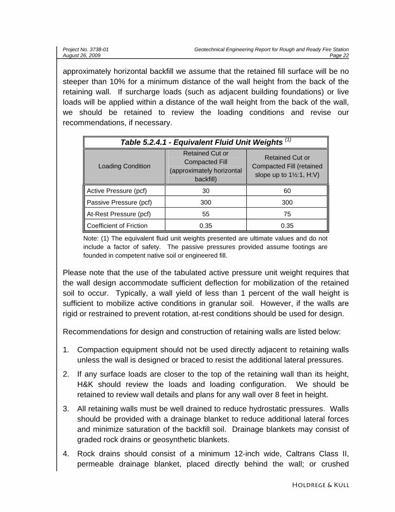
approximately horizontal backfill we assume that the retained fill surface will be no steeper than 10% for a minimum distance of the wall height from the back of the retaining wall. If surcharge loads (such as adjacent building foundations) or live loads will be applied within a distance of the wall height from the back of the wall, we should be retained to review the loading conditions and revise our recommendations, if necessary.
Table 5.2.4.1 - Equivalent Fluid Unit Weights (1)
Loading Condition
Retained Cut or Compacted Fill
(approximately horizontal backfill)
Retained Cut or Compacted Fill (retained slope up to 1½:1, H:V)
Active Pressure (pcf) 30 60
Passive Pressure (pcf) 300 300
At-Rest Pressure (pcf) 55 75
Coefficient of Friction 0.35 0.35
Note: (1) The equivalent fluid unit weights presented are ultimate values and do not include a factor of safety. The passive pressures provided assume footings are founded in competent native soil or engineered fill.
Please note that the use of the tabulated active pressure unit weight requires that the wall design accommodate sufficient deflection for mobilization of the retained soil to occur. Typically, a wall yield of less than 1 percent of the wall height is sufficient to mobilize active conditions in granular soil. However, if the walls are rigid or restrained to prevent rotation, at-rest conditions should be used for design.
Recommendations for design and construction of retaining walls are listed below:
1. Compaction equipment should not be used directly adjacent to retaining walls unless the wall is designed or braced to resist the additional lateral pressures.
2. If any surface loads are closer to the top of the retaining wall than its height, H&K should review the loads and loading configuration. We should be retained to review wall details and plans for any wall over 8 feet in height.
3. All retaining walls must be well drained to reduce hydrostatic pressures. Walls should be provided with a drainage blanket to reduce additional lateral forces and minimize saturation of the backfill soil. Drainage blankets may consist of graded rock drains or geosynthetic blankets.
4. Rock drains should consist of a minimum 12-inch wide, Caltrans Class II, permeable drainage blanket, placed directly behind the wall; or crushed
Project No. 3738-01 Geotechnical Engineering Report for Rough and Ready Fire Station August 26, 2009 Page 23
Holdrege & Kull
washed rock enveloped in a non-woven geotextile filter fabric such as Amoco 4546™ or equivalent. Drains should have a minimum 4-inch diameter, perforated, schedule 40, PVC pipe placed at the base of the wall, inside the drainrock, with the perforations placed down. The PVC pipe should be sloped so that water is directed away from the wall by gravity. A geosynthetic drainage blanket such as Enkadrain™ or equivalent may be substituted for the rock drain, provided the collected water is channeled away from the wall. If a geosynthetic blanket is used, backfill must be compacted carefully so that equipment or soil does not tear or crush the drainage blanket.
5. Adequate drainage and waterproofing for retaining walls associated with finished interior spaces are essential to reduce the likelihood of seepage and vapor transmission into the living space. We recommend that an appropriate waterproofing sealant be applied to the exterior surface of such retaining walls. A waterproofing consultant may be contacted to further review seepage and vapor transmission.
6. Additional lateral loading on retaining structures due to seismic accelerations may be considered at the designer’s option. For an earthquake producing a design horizontal acceleration of 0.2g, we recommend that the resulting additional lateral force applied to unrestrained (cantilevered) retaining structures with drained level backfill onsite be estimated as Pae=9H2 pounds, where H is the height of the wall in feet. The additional seismic force may be assumed to be applied at a height of 0.6H above the base of the wall. This seismic loading is for a drained, level backfill condition only; H&K should be consulted for values of seismic loading due to non-level or non-drained backfill conditions. The use of reduced factors of safety is often appropriate when reviewing overturning and sliding resistance during seismic events.
5.2.5 Pavement Design
We understand that asphalt concrete and Portland cement concrete (PCC) pavement are proposed onsite. We recommend PCC pavement have a minimum thickness of 6 inches with #3 rebar on 24 inch centers. The PCC pavement should be underlain by a minimum of 6 inches of baserock compacted to a minimum of 95 percent per ASTM D 1557.
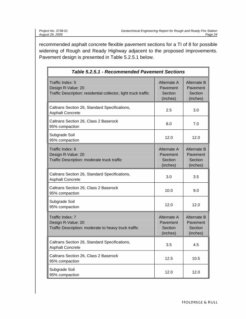
The following recommended asphalt concrete flexible pavement sections are based on a design R-value of 20 and preliminary traffic indices (TIs) of 5, 6, and 7. The TIs are being considered on a preliminary basis to facilitate planning of the proposed onsite roadways and parking areas. We have also included
Project No. 3738-01 Geotechnical Engineering Report for Rough and Ready Fire Station August 26, 2009 Page 24
Holdrege & Kull
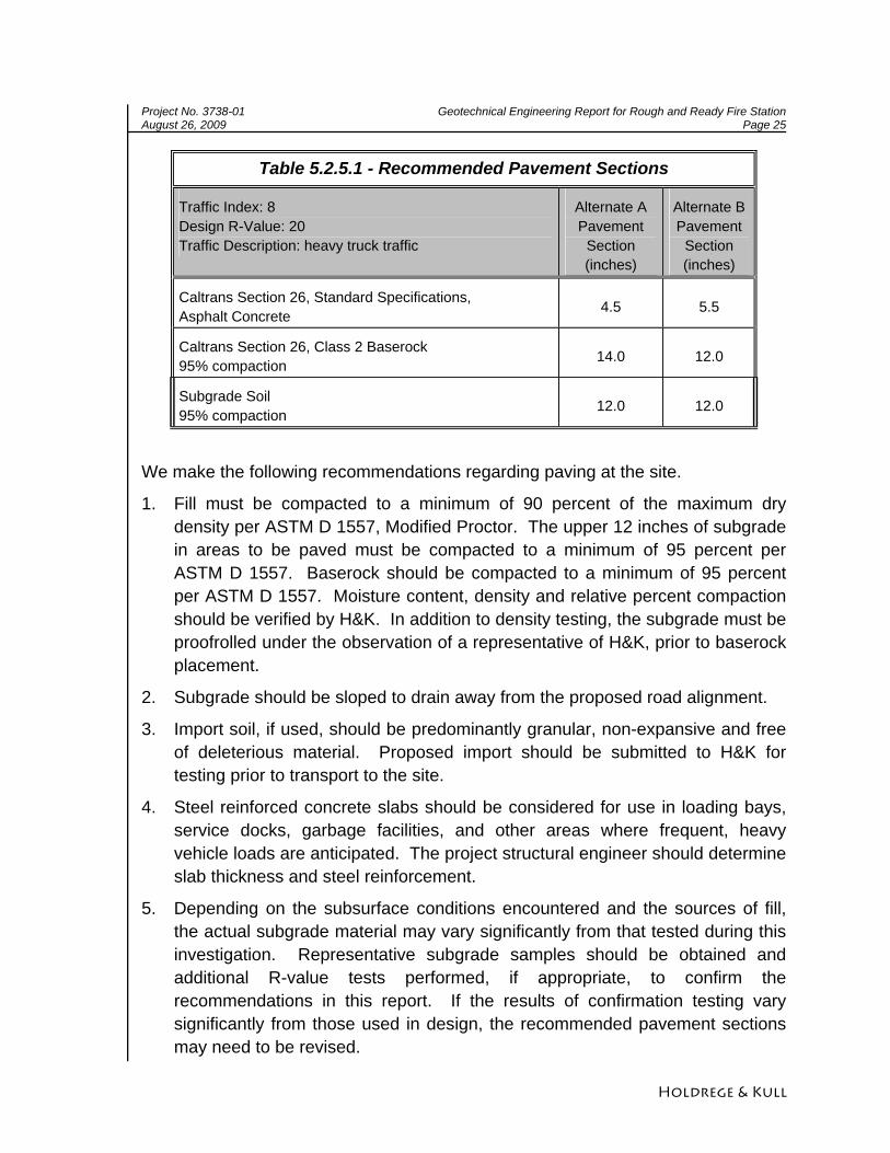
recommended asphalt concrete flexible pavement sections for a TI of 8 for possible widening of Rough and Ready Highway adjacent to the proposed improvements. Pavement design is presented in Table 5.2.5.1 below.
Table 5.2.5.1 - Recommended Pavement Sections
Traffic Index: 5 Design R-Value: 20 Traffic Description: residential collector, light truck traffic
Alternate A Pavement
Section (inches)
Alternate B Pavement
Section (inches)
Caltrans Section 26, Standard Specifications, Asphalt Concrete 2.5 3.0
Caltrans Section 26, Class 2 Baserock 95% compaction 8.0 7.0
Subgrade Soil 95% compaction 12.0 12.0
Traffic Index: 6 Design R-Value: 20 Traffic Description: moderate truck traffic
Alternate A Pavement
Section (inches)
Alternate B Pavement
Section (inches)
Caltrans Section 26, Standard Specifications, Asphalt Concrete 3.0 3.5
Caltrans Section 26, Class 2 Baserock 95% compaction 10.0 9.0
Subgrade Soil 95% compaction 12.0 12.0
Traffic Index: 7 Design R-Value: 20 Traffic Description: moderate to heavy truck traffic
Alternate A Pavement
Section (inches)
Alternate B Pavement
Section (inches)
Caltrans Section 26, Standard Specifications, Asphalt Concrete 3.5 4.5
Caltrans Section 26, Class 2 Baserock 95% compaction 12.5 10.5
Subgrade Soil 95% compaction 12.0 12.0
Project No. 3738-01 Geotechnical Engineering Report for Rough and Ready Fire Station August 26, 2009 Page 25
Holdrege & Kull
Table 5.2.5.1 - Recommended Pavement Sections
Traffic Index: 8 Design R-Value: 20 Traffic Description: heavy truck traffic
Alternate A Pavement
Section (inches)
Alternate B Pavement
Section (inches)
Caltrans Section 26, Standard Specifications, Asphalt Concrete 4.5 5.5
Caltrans Section 26, Class 2 Baserock 95% compaction 14.0 12.0
Subgrade Soil 95% compaction 12.0 12.0
We make the following recommendations regarding paving at the site.
1. Fill must be compacted to a minimum of 90 percent of the maximum dry density per ASTM D 1557, Modified Proctor. The upper 12 inches of subgrade in areas to be paved must be compacted to a minimum of 95 percent per ASTM D 1557. Baserock should be compacted to a minimum of 95 percent per ASTM D 1557. Moisture content, density and relative percent compaction should be verified by H&K. In addition to density testing, the subgrade must be proofrolled under the observation of a representative of H&K, prior to baserock placement.
2. Subgrade should be sloped to drain away from the proposed road alignment.
3. Import soil, if used, should be predominantly granular, non-expansive and free of deleterious material. Proposed import should be submitted to H&K for testing prior to transport to the site.
4. Steel reinforced concrete slabs should be considered for use in loading bays, service docks, garbage facilities, and other areas where frequent, heavy vehicle loads are anticipated. The project structural engineer should determine slab thickness and steel reinforcement.
5. Depending on the subsurface conditions encountered and the sources of fill, the actual subgrade material may vary significantly from that tested during this investigation. Representative subgrade samples should be obtained and additional R-value tests performed, if appropriate, to confirm the recommendations in this report. If the results of confirmation testing vary significantly from those used in design, the recommended pavement sections may need to be revised.
Project No. 3738-01 Geotechnical Engineering Report for Rough and Ready Fire Station August 26, 2009 Page 26
Holdrege & Kull
6 LIMITATIONS
The following limitations apply to the findings, conclusions and recommendations presented in this report:
1. Our professional services were performed consistent with the generally accepted geotechnical engineering principles and practices employed in northern California. No warranty is expressed or implied.
2. These services were performed consistent with our agreement with our client. We are not responsible for the impacts of any changes in environmental standards, practices, or regulations subsequent to performance of our services. We do not warrant the accuracy of information supplied by others, or the use of segregated portions of this report. This report is solely for the use of our client unless noted otherwise. Any reliance on this report by a third party is at the party's sole risk.
3. If changes are made to the nature or design of the project as described in this report, then the conclusions and recommendations presented in this report should be considered invalid. Only our firm can determine the validity of the conclusions and recommendations presented in this report. Therefore, we should be retained to review all project changes and prepare written responses with regards to their impacts on our conclusions and recommendations. However, we may require additional fieldwork and laboratory testing to develop any modifications to our recommendations. Costs to review project changes and perform additional fieldwork and laboratory testing necessary to modify our recommendations are beyond the scope of services presented in this report. Any additional work will be performed only after receipt of an approved scope of services, budget, and written authorization to proceed.
4. The analyses, conclusions and recommendations presented in this report are based on site conditions as they existed at the time we performed our surface and subsurface field investigations. We have assumed that the subsurface soil and groundwater conditions encountered at the location of our exploratory trenches are generally representative of the subsurface conditions throughout the entire project site. However, the actual subsurface conditions at locations between and beyond our exploratory trenches may differ. Therefore, if the subsurface conditions encountered during construction are different than those described in this report, then we should be notified immediately so that we can review these differences and, if necessary, modify our recommendations.
5. The elevation or depth to groundwater underlying the project site may differ with time and location.
Project No. 3738-01 Geotechnical Engineering Report for Rough and Ready Fire Station August 26, 2009 Page 27
Holdrege & Kull
6. The project site map shows approximate exploratory trench locations as determined by pacing distances from identifiable site features. Therefore, the trench locations should not be relied upon as being exact nor located with surveying methods.
7. Our geotechnical investigation scope of services did not include evaluating the project site for the presence of historic mining operations or hazardous materials. Although we did not observe evidence of historic mining activity or hazardous materials within the proposed building area at the time of our field investigation, all project personnel should be careful and take the necessary precautions should hazardous materials be encountered during construction. Possible historic mining excavation not detected during our investigation may impact the proposed improvements.
8. The findings of this report are valid as of the present date. However, changes in the conditions of the property can occur with the passage of time. The changes may be due to natural processes or to the works of man, on the project site or adjacent properties. In addition, changes in applicable or appropriate standards can occur, whether they result from legislation or the broadening of knowledge. Therefore, the recommendations presented in this report should not be relied upon after a period of two years from the issue date without our review.
FIGURES Figure 1 Topographic Vicinity Map Figure 2 Exploratory Trench Location Map
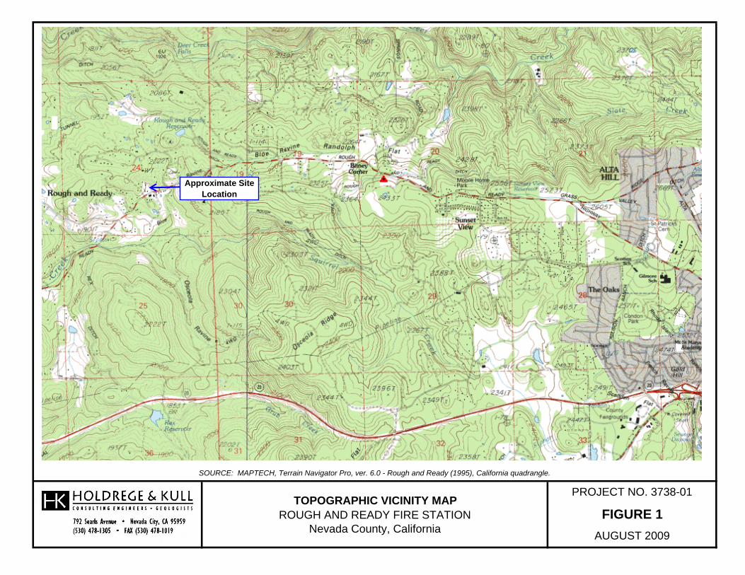
SOURCE: MAPTECH, Terrain Navigator Pro, ver. 6.0 - Rough and Ready (1995), California quadrangle.
PROJECT NO. 3738-01
FIGURE 1AUGUST 2009
TOPOGRAPHIC VICINITY MAPROUGH AND READY FIRE STATION
Nevada County, California
Approximate Site Location
APPENDIX A PROPOSAL
Proposal No. PN08343 November 4, 2008 Bruce Ivy Bruce Ivy Construction 143A Spring Hill Drive Grass Valley, CA 95945 Reference: Rough and Ready Fire Station APN 52-270-019
Nevada County, California
Subject: Proposal to Provide Geotechnical Engineering Services
Dear Mr. Ivy:
At your request, we prepared this proposal to provide geotechnical engineering services for the proposed Fire House improvements at 14506 Rough and Ready Highway in Nevada County, California. The purpose of our services will be to evaluate subsurface soil conditions for construction of a proposed fire station. As currently proposed, the multi-story structure will utilize wood frame and concrete masonry unit construction. Associated improvements will include concrete and asphalt paved driveways and parking areas, retaining structures, concrete walkways, underground utilities, drainage improvements, and landscaping. To prepare this proposal, we reviewed preliminary plans provided by RFE Engineering, Inc., and visited the project site. We propose to perform a design-level geotechnical investigation in general accordance with the 2007 California Building Code (CBC). SCOPE OF SERVICES Based on our understanding of the project, we propose the following scope of services. Geotechnical Investigation Holdrege & Kull (H&K) will perform a map and literature review of published documents pertinent to the project site including geologic maps and soil survey maps. We will perform a shallow subsurface investigation to characterize the soil, rock and groundwater conditions encountered at the site to the maximum depths explored. We will advance 4 to 6 exploratory trenches near the area of proposed improvements using a track-mounted mini-excavator. The trenches will be excavated to a maximum anticipated depth of 10 feet, or to refusal if shallower. For the purposes of this proposal, we have assumed that H&K will provide excavator services.
Rough and Ready Fire Station Proposal to Provide Geotechnical Engineering Services November 4, 2008 Page 2
Holdrege & Kull
An engineer or geologist from our firm will log soil conditions observed and collect relatively undisturbed and bulk soil samples from the exploratory trenches. Collection of soil samples and the sample intervals will depend upon the soil conditions encountered. The soil samples will be labeled, sealed, and transported to our laboratory where selected samples will be tested to determine their engineering material properties. If groundwater is encountered, the depth to groundwater below the existing ground surface will be measured. Prior to our field investigation, we will obtain underground service alert (USA) clearance for the site. USA coverage may not include existing on-site utilities. If requested, we can retain a private utility locating service to supplement the USA clearance to reduce the risk of encountering unmarked utilities on the site.
Laboratory Testing
H&K will perform laboratory tests on selected soil samples to determine their engineering material properties. All laboratory tests will be performed using American Society for Testing and Materials (ASTM), and Caltrans methods as guidelines. The soil characterization tests may include:
D2166, Unconfined Compression Shear Strength D2216, Moisture Content D2487, Unified Soil Classification System D2488, Soil Description Visual Manual Method D2844, Resistance Value (R-Value) (if requested) D2937, Density D3080, Direct Shear Strength D4318, Atterberg Limits (if appropriate) D4829, Expansion Index (if appropriate) Caltrans Method C 634, Resistivity Caltrans Method 417 and 422, Sulfate and Chloride
The actual tests performed may vary, depending on the subsurface conditions encountered. Data Analysis and Engineering Design Following the completion of laboratory testing, data will be analyzed and engineering calculations will be performed to develop geotechnical design recommendations for earthwork and structural improvements. The geotechnical engineering design recommendations will address the following:
Rough and Ready Fire Station Proposal to Provide Geotechnical Engineering Services November 4, 2008 Page 3
Holdrege & Kull
Earthwork Improvements
1. Site clearing and soil subgrade preparation. 2. Fill moisture conditioning and compaction. 3. Utility trench excavation and backfill. 4. Erosion control. 5. Surface water drainage. 6. Expansive soil mitigation (if present). Structural Improvements 1. Shallow foundation design criteria, including allowable bearing pressure. 2. Retaining wall design criteria. 3. Concrete slabs-on-grade. 4. Construction recommendations for exterior slabs-on-grade, including
exterior walkways and patios. 5. Conclusions regarding geologic hazards at the site. 6. Estimated total and differential settlement. 7. Seismic (earthquake shaking) design parameters. 8. Asphalt pavement sections, if requested.
Report Preparation
We will prepare a design-level geotechnical engineering report that will present our findings, conclusions, and recommendations. The report will include descriptions of site conditions, our field investigation, laboratory testing, and geotechnical engineering design recommendations for the proposed earthwork and structural improvements. The report will also include a site plan showing the approximate locations of the exploratory trenches, proposed structures, and property boundaries. The report appendices will present the exploratory trench logs and laboratory test data. ASSUMPTIONS AND CLIENT RESPONSIBILITIES The proposed scope of services is based on the following assumptions:
The client will provide H&K with authorization to access the site and physical access to trench locations. Although every attempt will be made to reduce the impacts of exploratory equipment, the client understands that some landscaping and unmarked underground utilities may be damaged by exploratory equipment.
AGREEMENT FOR GEOTECHNICAL ENGINEERING SERVICES (SF 04/08) PN08343 T&C RANDR FIRE HOUSE.DOC Page 1 of 3
AGREEMENT FOR GEOTECHNICAL ENGINEERING SERVICES THIS AGREEMENT, effective as of this 4th day of November 2008, is by and between Bruce Ivy Construction (“Client”) and Holdrege & Kull Consulting Engineers and Geologists (“Engineer”). The Project is described in Engineer’s attached PROPOSAL PN08343, dated November 4, 2008, which is hereby incorporated into and made a part of this Agreement. Engineer will perform Services under this Agreement as an independent contractor.
1. Level of Service. Engineer offers different levels of geotechnical engineering Services to suit the desires and needs of different clients. Although the possibility of error can never be eliminated, more detailed and extensive Services yield more information and reduce the probability of error, but at increased cost. Client must determine the level of Services adequate for its purposes. Client has reviewed the PROPOSAL and has determined that it does not need or want a greater level of Services than that being provided.
2. Standard of Care. Subject to the limitations inherent in the agreed scope of services outlined in the PROPOSAL as to the degree of care, the amount of time and expenses to be incurred, and subject to any other limitations contained in this Agreement, Engineer may perform its Services consistent with that level of care and skill ordinarily exercised by other professional engineers practicing in the same locale and under similar circumstances at the time the Services are performed. No warranty, express or implied, is included or intended by this Agreement. The recommendations are considered preliminary in nature and are based on opinions that are considered preliminary in nature; therefore, Engineer should be retained during grading and construction to confirm and verify or modify the findings. If Client does not so retain Engineer, then Engineer will not be liable for the accuracy of the preliminary opinions or recommendations.
3. Payments to Engineer. Client will pay Engineer’s invoices within 30 days following the invoice date, along with a late payment charge at the rate of 1½% per month after that date. Engineer may, at its sole option, suspend or terminate this Agreement if Client does not make payments when due. Unless otherwise agreed in writing, Engineer will bill its Services on a time-and-materials basis using its current schedule of fees and costs. Limitations stated in the PROPOSAL on the amount to be billed are estimates only, and are not an agreement by Engineer that it will complete the Services for the estimated amount. Client will reimburse Engineer for any costs, including legal fees, associated with the collection of past due unpaid amounts.
4. Certifications. Client agrees not to require that Engineer execute any certification with regard to Services performed or Work tested and/or observed under this Agreement unless: 1) Engineer believes that it has performed sufficient Services to provide a sufficient basis to issue the certification; 2) Engineer believes that the Services performed or Work tested and/or observed meet the criteria of the certification; and 3) Engineer has reviewed and approved in writing the exact form of such certification prior to execution of this Agreement. Any certification by Engineer is limited to an expression of professional opinion based upon the Services performed by Engineer, and does not constitute a warranty or guaranty, either express or implied.
5. Site Access. Client agrees to provide access and/or obtain permission for Engineer to enter upon all property as necessary to perform the Services. Engineer will exercise reasonable care to reduce damage, but Client recognizes that Engineer’s operations and investigative equipment may unavoidably alter or affect the Project site. The cost of repairing such damage will be borne by Client and is not included in the fee unless otherwise stated in the PROPOSAL.
6. Relevant Information. Client will provide Engineer with all information Client has, or can reasonably obtain, concerning the Project site, including subsurface conditions and the location of subsurface or hidden pipes, utilities or structures. Engineer will endeavor to avoid damage to such pipes, utilities and structures, but is not responsible for any damage to such items not properly identified in the information provided to it by Client. Engineer may reasonably rely on the accuracy and completeness of any information supplied by Client, without independently verifying its accuracy. Prior to the commencement of Services, Client will notify Engineer of any known potential health or safety hazard existing on or near the Project site, with particular reference to Hazardous Materials or conditions.
7. Construction Observation and Testing. If Engineer’s scope of services outlined in the PROPOSAL includes observation and/or testing during the course of construction, Engineer will rely on Client or Client’s representative for timely notification of changes to the construction schedule, so that Engineer can schedule site visits for testing and observation accordingly. Based on information obtained during such visits and on such observations, Engineer may inform Client of the progress of the geotechnical aspects of the construction work (“Work”). Client understands that Engineer may not be on site continuously; and, unless expressly agreed otherwise, Engineer will not observe all of the
SERVICES AGREEMENT FOR PN08343
AGREEMENT FOR GEOTECHNICAL ENGINEERING SERVICES (SF 04/08) PN08343 T&C RANDR FIRE HOUSE.DOC Page 2 of 3
Work. Engineer does not, and cannot, warrant or guarantee that the Work performed by Contractor meets the requirements of Engineer’s geotechnical recommendations or the plans and specifications for such Work; nor can Engineer be responsible for Contractor’s failure to perform the Work in accordance with the plans, specifications or the recommendations. Engineer will not supervise, direct or have control over the Work nor will Engineer have authority over or responsibility for the means, methods, techniques, sequences or procedures selected by Contractor for the Work; for safety precautions and programs incident to the Work; nor for any failure of Contractor to comply with Laws and Regulations applicable to Contractor furnishing and performing the Work.
8. Hazardous Materials. The term Hazardous Materials means any toxic substances, chemicals, radioactivity, pollutants or other materials, in whatever form or state, known or suspected to impair the environment in any way whatsoever, including but are not limited to, those substances defined, designated or listed in any federal, state or local law, regulation or ordinance concerning hazardous wastes, toxic substances or pollution. Engineer’s Services under this Agreement are limited to geotechnical engineering and Engineer has no responsibility to locate, identify, evaluate, treat or otherwise address Hazardous Materials. Client is solely responsible for notifying all appropriate federal, state, municipal or other governmental agencies and potentially affected public of the existence of any Hazardous Materials located at the Project site during performance of this Agreement. If hazardous materials are discovered at the Project site, Engineer can terminate this Agreement.
9. Subsurface Structures. Client agrees to correctly designate on plans to be furnished to Engineer, the location of all subsurface structures, such as pipes, tanks, cables and utilities within the property lines of the Project Site(s), and be responsible for any damage inadvertently caused by Engineer to any such structure or utility not so designated. Engineer is not liable to Client for any losses, damages or claims arising from damage to subterranean structures or utilities that were not correctly shown on plans furnished by Client to Engineer.
10. Limitation of Remedies. The total cumulative liability of Engineer and its subcontractors, employees and agents to Client arising from Services under this Agreement, will not exceed the gross compensation received by Engineer under this Agreement or $50,000, whichever is greater. This limitation applies to all lawsuits, claims or actions that allege errors or omissions by Engineer, whether alleged in tort, contract, or under any other legal theory. Upon Client’s written request, Engineer and Client may agree to increase the limitation to a greater amount in exchange for an increase in Engineer’s fee. Neither Engineer nor Client will be liable to the other for any special, consequential, incidental or penal losses or damages. Further, both Client and Engineer waive any right to sue, or otherwise make any claim against any of the other party’s officers, directors, shareholders or employees, past or present, as individuals.
11. Insurance. Engineer will maintain policies of general liability, automobile liability, workers compensation and professional liability insurance throughout the duration of this Agreement. Client will maintain property insurance sufficient to protect any property in which it has an insurable interest. Engineer and Client each waive any claims against each other for damage to property covered, or that should have been covered by property insurance required by this paragraph, including subrogated claims. Upon request, Engineer and Client will each provide the other with a certificate(s) of insurance evidencing the insurance required by this section.
12. Indemnification of Client. Subject to the provisions and limitations of this Agreement and all otherwise applicable statutes of limitations and repose, Engineer agrees to indemnify and hold harmless Client (including its shareholders, officers, directors and employees) from and against any and all claims, suits, liabilities, damages, expenses (including without limitation reasonable attorney’s fees and defense costs) or other losses, to the extent caused by Engineer’s negligent performance of its Services under this Agreement.
13. Indemnification of Engineer. Client will indemnify and hold harmless Engineer (including its shareholders, officers, directors and employees) from and against any and all claims, suits, liabilities, damages, expenses (including without limitation reasonable attorney’s fees and costs of defense) or other losses, to the extent caused by the negligence of Client, its employees, agents and contractors. In addition, except to the extent caused by Engineer’s sole negligence, Client expressly agrees to defend, indemnify and hold harmless Engineer from and against any and all Losses arising from or related to the existence, disposal, release, discharge, treatment or transportation of Hazardous Materials, or the exposure of any person to Hazardous Materials, or the degradation of the environment due to the presence, discharge, disposal, release of or exposure to Hazardous Material.
14. No Personal Liability. Client expressly waives that right to sue, or otherwise make any claim against, any of the Engineer’s officers or employees, past or present, as individuals, for any cause.
15. Consequential Damages. Neither Client nor Engineer will be liable to the other for any special, consequential, incidental or penal losses or damages including but not limited to losses, damages or claims related to the unavailability of property or facilities, shutdowns or service interruptions, loss of use, profits, revenue, or inventory, or for use charges, cost of capital, or claims of the other party and/or its customers.
16. Mediation. Engineer and Client agree to mediate any dispute regarding this Agreement or its performance as a precondition to instituting any legal action against the other, each party sharing equally the mediation fees and costs.

APPENDIX B IMPORTANT INFORMATION ABOUT YOUR GEOTECHNICAL ENGINEERING REPORT (Included with permission of ASFE, Copyright 2004)
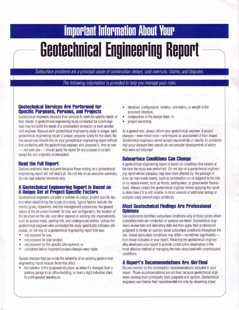
APPENDIX C EXPLORATORY TRENCH LOGS
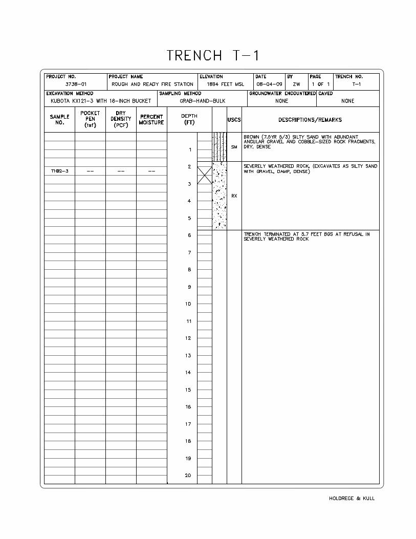
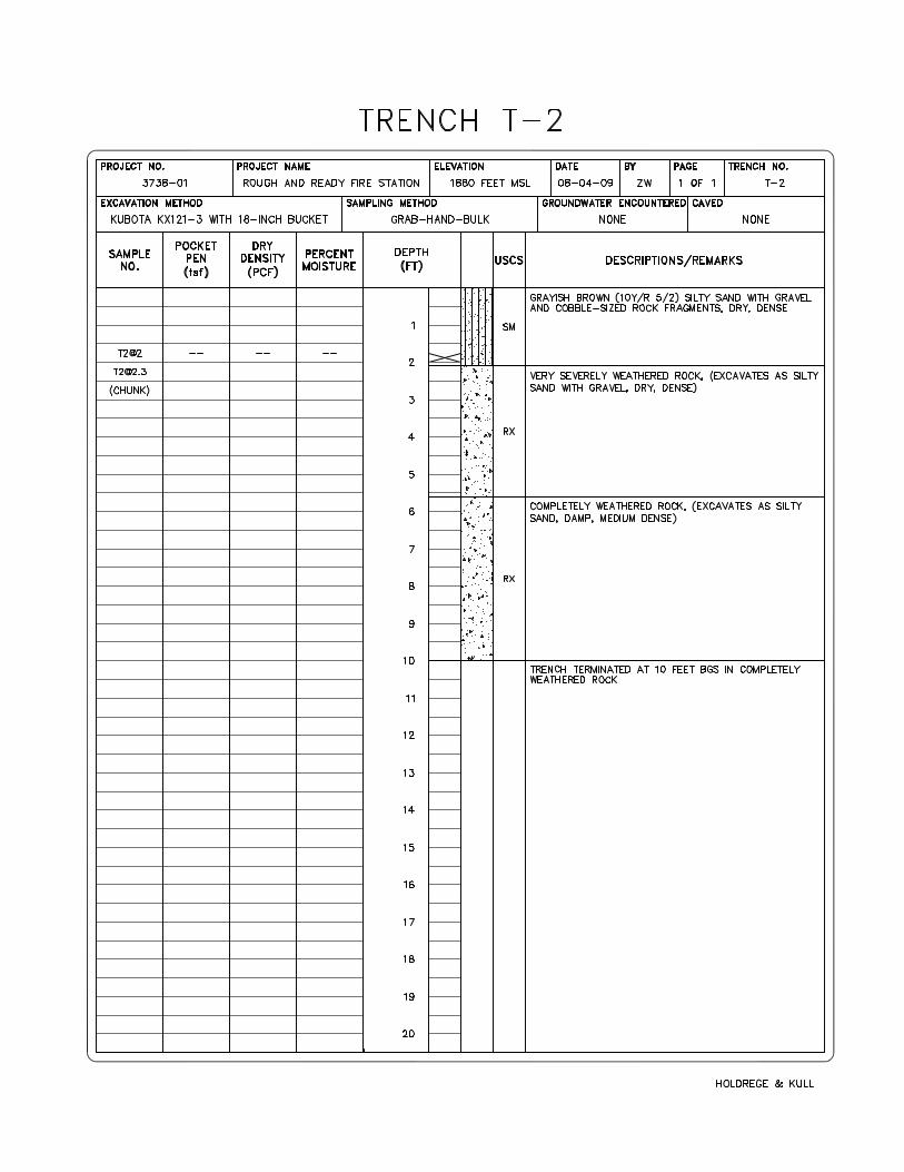
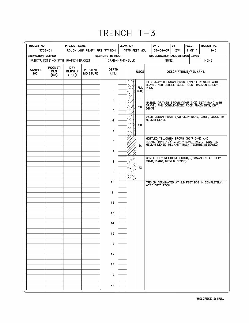
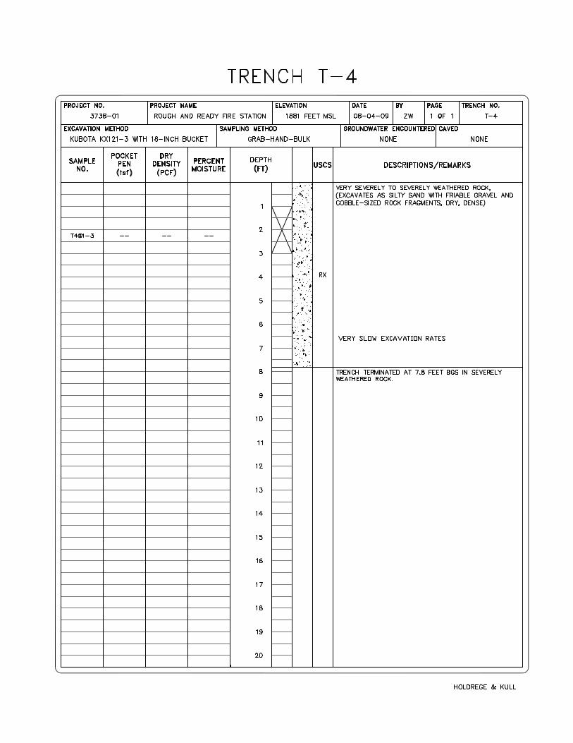
APPENDIX D LABORATORY TEST DATA
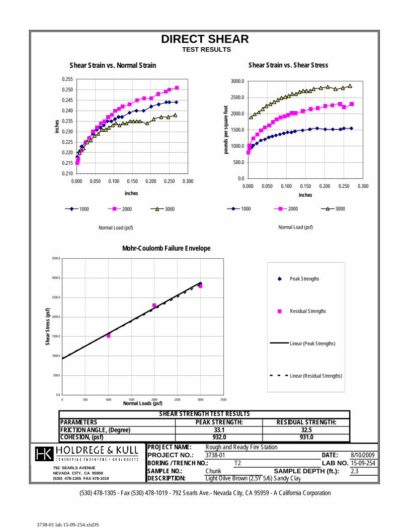
PARAMETERS
COHESION, (psf)PROJECT NAME: Rough and Ready Fire StationPROJECT NO.: DATE: 8/10/2009BORING / TRENCH NO.: LAB NO.:15-09-254SAMPLE NO.: 2.3DESCRIPTION:
(530) 478-1305 - Fax (530) 478-1019 - 792 Searls Ave.- Nevada City, CA 95959 - A California Corporation
T2SAMPLE DEPTH (ft.):Chunk
Light Oilve Brown (2.5Y 5/6) Sandy Clay
3738-01
SHEAR STRENGTH TEST RESULTS
931.033.1932.0
PEAK STRENGTH: RESIDUAL STRENGTH:32.5
DIRECT SHEAR TEST RESULTS
FRICTION ANGLE, (Degree)
792 SEARLS AVENUENEVADA CITY, CA 95959(530) 478-1305 FAX 478-1019
Shear Strain vs. Normal Strain
0.210
0.215
0.220
0.225
0.230
0.235
0.240
0.245
0.250
0.255
0.000 0.050 0.100 0.150 0.200 0.250 0.300
inches
inch
es
1000 2000 3000
Shear Strain vs. Shear Stress
0.0
500.0
1000.0
1500.0
2000.0
2500.0
3000.0
0.000 0.050 0.100 0.150 0.200 0.250 0.300inches
poun
ds p
er sq
uare
foot
1000 2000 3000
Mohr-Coulomb Failure Envelope
0.0
500.0
1000.0
1500.0
2000.0
2500.0
3000.0
3500.0
0 500 1000 1500 2000 2500 3000 3500Normal Loads (psf)
Shea
r Stre
ss (p
sf)
Peak Strengths
Residual Strengths
Linear (Peak Strengths)
Linear (Residual Strengths)
Normal Load (psf) Normal Load (psf)
3738-01 lab 15-09-254.xlsDS
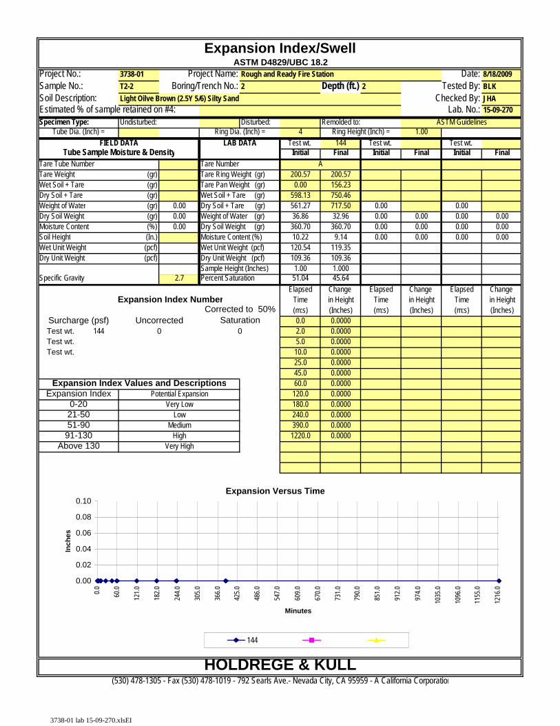
Project No.: 3738-01 Date: 8/18/2009Sample No.: T2-2 Depth (ft.) 2 Tested By: BLKSoil Description: Checked By: JHA
Lab. No.: 15-09-270Specimen Type: Undisturbed: Disturbed: Remolded to:
4 1.00Test wt. 144 Test wt. Test wt.
Initial Final Initial Final Initial FinalTare Tube Number Tare NumberTare Weight (gr) Tare Ring Weight (gr) 200.57 200.57Wet Soil + Tare (gr) Tare Pan Weight (gr) 0.00 156.23Dry Soil + Tare (gr) Wet Soil + Tare (gr) 598.13 750.46Weight of Water (gr) 0.00 Dry Soil + Tare (gr) 561.27 717.50 0.00 0.00Dry Soil Weight (gr) 0.00 Weight of Water (gr) 36.86 32.96 0.00 0.00 0.00 0.00Moisture Content (%) 0.00 Dry Soil Weight (gr) 360.70 360.70 0.00 0.00 0.00 0.00
(In.) Moisture Content (%) 10.22 9.14 0.00 0.00 0.00 0.00Wet Unit Weight (pcf) Wet Unit Weight (pcf) 120.54 119.35 Dry Unit Weight (pcf) Dry Unit Weight (pcf) 109.36 109.36
Sample Height (Inches) 1.00 1.000 2.7 Percent Saturation 51.04 45.64
Elapsed Change Elapsed Change Elapsed Change Time in Height Time in Height Time in Height(m:s) (Inches) (m:s) (Inches) (m:s) (Inches)0.0 0.0000
Test wt. 144 2.0 0.0000Test wt. 5.0 0.0000Test wt. 10.0 0.0000
25.0 0.000045.0 0.000060.0 0.0000
120.0 0.0000180.0 0.0000240.0 0.0000390.0 0.00001220.0 0.0000
Specific Gravity
Light Oilve Brown (2.5Y 5/6) Silty Sand
Tube Dia. (Inch) = Ring Dia. (Inch) = Ring Height (Inch) =
Soil Height
Estimated % of sample retained on #4:
UncorrectedCorrected to 50%
SaturationSurcharge (psf)
ASTM Guidelines
FIELD DATA LAB DATATube Sample Moisture & Density
Expansion Index Number
A
Expansion Index/SwellASTM D4829/UBC 18.2
Project Name:Boring/Trench No.: 2
Rough and Ready Fire Station
HighVery HighAbove 130
91-130
Expansion IndexExpansion Index Values and Descriptions
Very LowPotential Expansion
Low51-9021-500-20
(530) 478-1305 - Fax (530) 478-1019 - 792 Searls Ave.- Nevada City, CA 95959 - A California Corporation
0 0
HOLDREGE & KULL
Medium
Expansion Versus Time
0.00
0.02
0.04
0.06
0.08
0.10
0.0 60.0
121.0
182.0
244.0
305.0
366.0
425.0
486.0
547.0
609.0
670.0
731.0
790.0
851.0
912.0
974.0
1035
.0
1096
.0
1155
.0
1216
.0
Minutes
Inch
es
144
3738-01 lab 15-09-270.xlsEI