Embed Size (px)
Citation preview
Geotechnical Engineering and Materials Testing
GEOTECHNICAL ENGINEERING AND PAVEMENT DESIGN REPORT EAST 144th AVENUE WIDENING AND IMPROVEMENTS EAST 144th AVENUE BETWEEN YORK STREET & COLORADO BLVD THORNTON, COLORADO
PREPARED FOR: Drexel Barrell & Co.
1800 38th Street
Boulder, CO 80301
PREPARED BY: Cole Garner Geotechnical 1070 W. 124th Avenue, Suite 300 Westminster, Colorado 80234 Andrew J, Garner, P.E. [email protected] 303.996.2999
CGG Project No. 18.22.099 June 20, 2018
Geotechnical Engineering and Materials Testing
Cole Garner Geotechnical 1070 W. 124th Ave, Ste. 300
Westminster, CO 80234 303.996.2999
June 20, 2018 Drexel, Barrell & Co. 1800 38th Street Boulder, CO 80301 Attn: Mr. Garrett Lingreen, P.E. [email protected] 303.442.4338 Re: Geotechnical Engineering and Pavement Thickness Design Report
144th Avenue Widening and Improvements East 144th Avenue between York Street & Colorado Boulevard
Thornton, Co1orado CGG Project No. 18.22.099 Cole Garner Geotechnical (CGG) has completed geotechnical engineering investigation for improvements to approximately 5,250 lineal feet portion of East 144th Avenue east of York Street and west of Colorado Boulevard in Thornton, Colorado. These services were performed in general accordance with our proposal number P18.22.081, dated March 13, 2018. This geotechnical summary should be used in conjunction with the entire report for design and/or construction purposes. It should be recognized that specific details were not included or fully developed in this section, and the report must be read in its entirety for a comprehensive understanding of the items contained herein. The section titled General Comments should be read for an understanding of the report limitations.
x Subsurface Conditions: The following summarizes the conditions encountered in our borings for this study. Other specific information regarding the lithology encountered is noted on the Boring Logs. x Existing Pavement Materials: Cores of the existing asphalt concrete materials were completed at
Boring Nos. 1, 4, 6, 9, and 11. Existing asphalt concrete (AC) thicknesses ranged from about 12 to 14 inches between York St. and Madison St., and about 5 to 6 inches between Madison St. and Colorado Blvd.
x Existing Man-made Fill: Existing man-made fill (likely related to existing roadway and utility construction) was encountered in several of our borings and extended to depths ranging from about 3-½ feet to 10 feet below the existing roadway surface. The fill was variable, but was primarily comprised of sandy lean clay with lenses of clayey sand, claystone fragments and gravel.
x Native Soils: Native soils encountered underlying the fill soil consisted of predominantly sandy lean clay and clayey sand. Silty sand was observed in Boring No. 11.
x Sedimentary Sandstone and Claystone Bedrock: Claystone and sandstone bedrock was encountered just below the ground surface in Boring No. 3 and underlying the native soils at a depth of about 8 feet below the ground surface in Boring Nos. 1, 9, and 11.
x Groundwater: Groundwater was not encountered during drilling. The borings were backfilled upon completion of drilling for safety reasons.
Pavement Design Report East 144th Avenue Improvements – Thornton, Colorado
CGG Project No: 18.22.099
Cole Garner Geotechnical Page ii Geotechnical Engineering and Materials Testing
x Expansive Soils and Bedrock: As discussed, approximately 3-½ to 10 feet of existing fill was encountered
in our borings for this current study. This fill was likely placed during development of the existing roadway and utilities. However, the clay fill soils exhibited low to high expansive potential in their current condition and the claystone bedrock encountered at the site exhibited moderate expansive potential when subjected to wetting in our laboratory. Even low expansive materials may heave upon additional wetting, potentially resulting in pavement distress and other movement causing common cosmetic distress such as edge cracking, uneven curb and gutter, etc. We believe that some heave-related distress should be anticipated during the design life of the pavement. In our opinion, there is not a reasonable method to eliminate this risk, but we have provided recommendations that we believe will limit distress to the magnitudes normally acceptable in the region. In order to reduce the potential for movement and distress of the proposed improvements, we recommend that subgrade preparation along the proposed alignment include subexcavation, moisture-conditioning, and recompaction of the existing soils to a minimum depth of 3 feet below pavement subgrade elevation, as per the Standards. Other design and construction recommendations for the proposed pavements are outlined below.
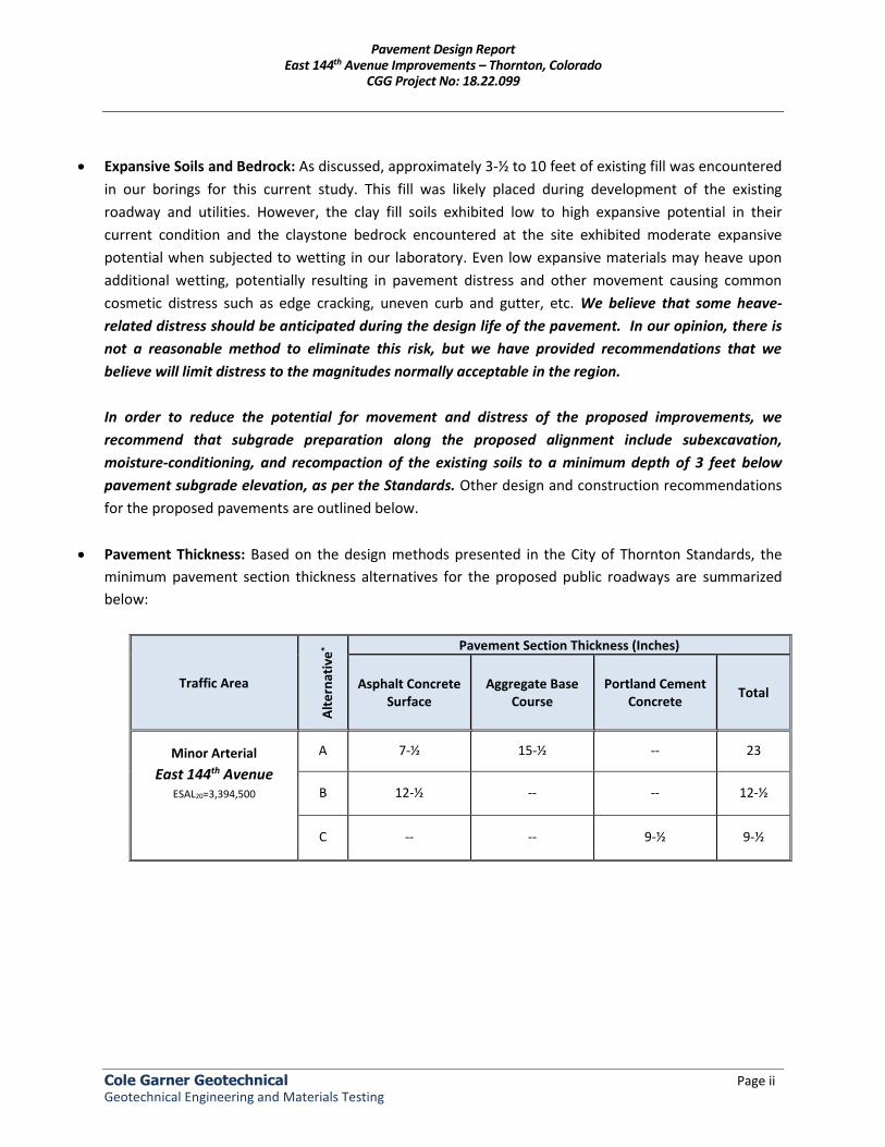
x Pavement Thickness: Based on the design methods presented in the City of Thornton Standards, the minimum pavement section thickness alternatives for the proposed public roadways are summarized below:
Traffic Area
Alt
ern
ativ
e*
Pavement Section Thickness (Inches)
Asphalt Concrete Surface
Aggregate Base Course
Portland Cement Concrete
Total
Minor Arterial
East 144th Avenue
ESAL20=3,394,500
A 7-½ 15-½ -- 23
B 12-½ -- -- 12-½
C -- -- 9-½ 9-½
Pavement Design Report East 144th Avenue Improvements – Thornton, Colorado
CGG Project No: 18.22.099
Cole Garner Geotechnical Page iii Geotechnical Engineering and Materials Testing
Details regarding design methods and other recommendations are included in the report. Please do not hesitate to contact us if you have any questions concerning this report or any of our testing, inspection, design and consulting services. Sincerely, Cole Garner Geotechnical
Patrick Maloney, G.I.T. Andrew J. Garner, P.E. Staff Geologist/Project Manager Principal, COO Copies to: Addressee (1 PDF copy)
06/20/18
Pavement Design Report East 144th Avenue Improvements – Thornton, Colorado
CGG Project No: 18.22.099
Cole Garner Geotechnical Page iv Geotechnical Engineering and Materials Testing
TABLE OF CONTENTS Page No. Letter of Transmittal .............................................................................................................................. iii INTRODUCTION ...................................................................................................................................... 1 PROJECT INFORMATION ........................................................................................................................ 1
Project Description ........................................................................................................................... 1 Site Information and Conditions ...................................................................................................... 2
SITE EXPLORATION PROCEDURES .......................................................................................................... 2 Field Exploration ............................................................................................................................... 2 Laboratory Testing ............................................................................................................................ 3
SUBSURFACE CONDITIONS..................................................................................................................... 3 Geology ............................................................................................................................................. 3 Typical Subsurface Profile ................................................................................................................ 4 Groundwater Conditions .................................................................................................................. 4 Laboratory Test Results ................................................................................................................... 5
RECOMMENDATIONS FOR DESIGN AND CONSTRUCTION .................................................................... 5 Geotechnical Considerations ............................................................................................................ 5 Pavement Design and Construction ................................................................................................. 5
Expansive Subgrade Mitigation ................................................................................................. 6 Subgrade Soil Support ................................................................................................................ 6 Design Traffic Values .................................................................................................................. 7 Recommended Pavement Sections ........................................................................................... 7 Pavement Rehabilitation ........................................................................................................... 8 Subsurface Drainage ................................................................................................................ 10 Subgrade Preparation .............................................................................................................. 10 Pavement Materials ................................................................................................................. 10
Earthwork ....................................................................................................................................... 11 General Considerations............................................................................................................ 11 Demolition and Site Preparation ............................................................................................. 12 Fill Materials ............................................................................................................................. 12 Fill Placement and Compaction ............................................................................................... 12 Excavations .............................................................................................................................. 13
Additional Recommendations ........................................................................................................ 13 Concrete Corrosion Protection ................................................................................................ 13 Drainage and Landscaping ....................................................................................................... 13
GENERAL COMMENTS .......................................................................................................................... 14 APPENDIX A: VICINITY MAP, BORING LOCATION DIAGRAM, LOGS OF BORINGS
APPENDIX B: LABORATORY TEST RESULTS, SOIL SUBGRADE AND ESAL DIAGRAM
APPENDIX C: GENERAL NOTES
APPENDIX D: PAVEMENT DESIGN CALCULATIONS, PAVEMENT SECTION ALTERNATIVES DIAGRAM
Geotechnical Engineering and Materials Testing
Cole Garner Geotechnical 1070 W. 124th Ave, Ste. 300
Westminster, CO 80234 303.996.2999
Geotechnical Engineering and Pavement Thickness Design Report East 144th Avenue Widening and Improvements East 144th Avenue between York Street and Colorado Boulevard Thornton, Colorado CGG Project No. 18.22.099 June 20, 2018 INTRODUCTION
This report contains the results of our geotechnical engineering exploration for improvements to a portion East 144th Avenue in Thornton, Colorado. The purpose of these services is to provide information and geotechnical engineering recommendations relative to:
x Subsurface soil and bedrock conditions x Groundwater conditions x Pavement structural sections x Earthwork x Drainage
The recommendations contained in this report are based upon the results of field and laboratory testing, engineering analyses, our experience with similar soil conditions and structures, and current City of Thornton Standards and Specifications for the Design and Construction of Public and Private Improvements (herein referred to as the Standards). PROJECT INFORMATION Project Description: We understand that the City of Thornton desires to widen and improve East 144th Avenue between the York Street and Colorado Boulevard to Major Arterial standards. Currently, this section of East 144th Avenue includes one lane of travel in the east- and westbound directions along with a left turn lane at York Street, a left and right turn lane at Elizabeth Court, a left and right turn lane at Detroit Street, and a left and right turn lane at Madison Street. The left turn lanes transition into an unused center lane between the RTD Right-Of-Way (ROW) and Madison Street. We understand that all widening is to occur within the existing ROW, if possible, but that the exact locations of widening to accommodate the new typical cross-section is still in the conceptual stages at this time. The planned improvements, although conceptual at the moment, will include the addition of one travel lane in each direction (Minor Arterial: 4 travel lanes total), center left turn lanes at some intersecting streets, and a bike-lane in each direction.

Pavement Design Report East 144th Avenue Improvements – Thornton, Colorado
CGG Project No: 18.22.099
Cole Garner Geotechnical Page 2 Geotechnical Engineering and Materials Testing
New drainage may be constructed in areas where widening alters or interferes with existing drainage facilities (swales). The existing pavements are to be rehabilitated with a mill and overlay and new curb and gutter is planned along the alignment, where needed. We presume the roadway widening will included flexible pavement sections construction in accordance with the City of Thornton Development Standards. If our assumptions above are not accurate, or if you have additional useful information, please inform us as soon as possible. Site Information and Conditions: As discussed, at the time of our exploration, the roadway alignments consisted of one lane of travel in the east and westbound directions along with right and left turn lanes in areas and an unused center lane between the RTD ROW and Madison Street. Existing pavement conditions and thicknesses varied along the alignment. Swales were present in the shoulders in unimproved areas. Curb and gutter leading to landscaping and a sidewalk was present on the southern side of the road for approximately 1,900 feet between Detroit Street and Madison Street adjacent to the Fallbrook Farms subdivision. Elevation drops gradually to the west, ranging from about 5,250 to 5,170 feet between Colorado Blvd. and York St., according to USGS mapping. SITE EXPLORATION PROCEDURES
The scope of the services performed for this project included site reconnaissance by a field engineer, a subsurface exploration program, laboratory testing and engineering analysis. Field Exploration: Our scope of services included geotechnical exploration of the subsurface materials at eleven (11) locations along the existing alignment. These exploratory test borings were drilled on either side of East 144th Avenue at approximately 500 feet centers for pavement design in accordance with the referenced Standards. Asphalt concrete (AC) cores and aggregate base course (ABC) measurements were performed at five (5) select locations for existing pavement condition assessments along the alignment. The borings were advanced to depths ranging from approximately 5 to 10 feet below the existing roadway surface in accordance with City of Thornton requirements. Please refer to the attached Boring Location Diagram in Appendix A for specific boring locations. Borings were advanced with a truck-mounted drilling rig utilizing 4-inch diameter, solid stem auger. A lithologic log of each boring was recorded by our field personnel during the drilling operations. At selected intervals, samples of the subsurface materials were obtained by driving standard split-spoon or modified California barrel samplers. Penetration resistance measurements were obtained by driving the sample barrel into the subsurface materials with a 140-pound automatic hammer falling 30 inches. The penetration resistance value is a useful index to the consistency, relative density or hardness of the materials encountered.
Pavement Design Report East 144th Avenue Improvements – Thornton, Colorado
CGG Project No: 18.22.099
Cole Garner Geotechnical Page 3 Geotechnical Engineering and Materials Testing
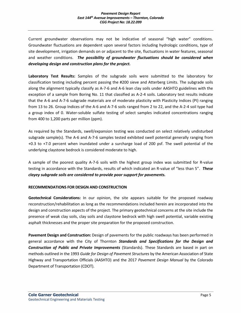
Groundwater measurements were obtained in the borings during exploration and then the borings were backfilled immediately thereafter for safety considerations. Where the borings were performed in existing pavements, they were backfilled with non-shrink grout mixed with sand and the pavement was patched with non-shrink grout or temporary cold-mix asphalt, according to the required Standards. Laboratory Testing: Samples retrieved during the field exploration were returned to the laboratory for observation by the project geotechnical engineer, and were visually-manually classified in general accordance with the Unified Soil Classification System described in Appendix C. Bedrock is described according the notes on Bedrock Classification. At that time, an applicable laboratory-testing program was formulated to determine engineering properties of the subsurface materials. Following the completion of the laboratory testing, the field descriptions were confirmed or modified as necessary, and Boring Logs were prepared. These logs are presented in Appendix A. Laboratory test results are presented in Appendix B. These results were used for the geotechnical engineering analyses and the development of foundation and earthwork recommendations. Laboratory tests were performed in general accordance with the applicable local or other accepted standards. Selected soil and bedrock samples were tested for the following engineering properties:
x Water content x Dry density x Swell/Consolidation potential x R-value
x Grain size x Plasticity Index x Water-soluble sulfates
SUBSURFACE CONDITIONS Geology: Surficial geologic conditions at the site, as mapped by the U.S. Geological Survey (USGS) (1Trimble & Machette, 1979), consist of Colluvium of Upper Holocene Age. This material is described as unconsolidated materials deposited on slopes by gravity and sheetwash that is generally variable with a thickness over 1.5 meters. Bedrock underlying the surface units consists of the upper transition member of the Dawson and Arapahoe Formations (TKda) of Paleocene and Upper Cretaceous Age. This unit is described as arkosic sandstone, siltstone, claystone, and/or minor amounts of conglomerate. Where the formation underlies the Denver Formation it is called the Arapahoe Formation. The formation is noted as being as much as 610 meters in thickness.
1 Trimble, Donald E., Machette, Michael N., Geologic Map of the Greater Denver Area, Front Range Urban Corridor, Colorado, United
States Geological Survey, Miscellaneous Investigations Series, Map I-856-H.
Pavement Design Report East 144th Avenue Improvements – Thornton, Colorado
CGG Project No: 18.22.099
Cole Garner Geotechnical Page 4 Geotechnical Engineering and Materials Testing
Due to the relatively flat nature of this section of 144th Avenue, risk due to geologic hazards at the site are anticipated to be low. Seismic activity in the area is anticipated to be low, and the alignment should be relatively stable from a structural standpoint. With proper site grading erosional problems at the site should be reduced. Mapping completed by the Colorado Geological Survey (2Hart, 1972) indicates the site is located in an area of "High to Very High Swell Potential." Potentially expansive materials mapped in this area include bedrock, weathered bedrock, and colluvium (surficial units).
Typical Subsurface Profile: The following summarizes the conditions encountered in our borings for this study. Other specific information regarding the lithology encountered is noted on the Boring Logs. x Existing Pavement Materials: Cores of the existing asphalt concrete materials were completed at
Boring Nos. 1, 4, 6, 9, and 11. Existing asphalt concrete (AC) thicknesses ranged from about 12 to 14 inches between York St. and Madison St., and about 5 to 6 inches between Madison St. and Colorado Blvd.
x Existing Man-made Fill: Existing man-made fill (likely related to existing roadway and utility construction) was encountered in several of our borings and extended to depths ranging from about 3-½ feet to 10 feet below the existing roadway surface. The fill was variable, but was primarily comprised of sandy lean clay with lenses of clayey sand, claystone fragments and gravel.
x Native Soils: Native soils encountered underlying the fill soil consisted of predominantly sandy lean clay and clayey sand. Silty sand was observed in Boring No. 11.
x Sedimentary Sandstone and Claystone Bedrock: Claystone and sandstone bedrock was encountered just below the ground surface in Boring No. 3 and underlying the native soils at a depth of about 8 feet below the ground surface in Boring Nos. 1, 9, and 11.
Groundwater Conditions: Groundwater was not encountered during drilling. The borings were backfilled upon completion of drilling for safety reasons. Based upon review of U.S. Geological Survey Maps, (3Hillier, et al, 1979), regional groundwater beneath the project area is expected to be encountered in the Arapahoe Aquifer at depths generally greater than 20 feet and commonly more than 100 feet below the existing ground surface.
2 Hart, Stephen S., 1972, Potentially Swelling Soil and Rock in the Front Range Urban Corridor, Colorado, Colorado Geological Survey,
Sheet 1 of 4. 1 Hillier, Donald E.; and Schneider, Paul A., Jr., 1979, Depth to Water Table (1976-1977) in the Boulder-Fort Collins-Greeley Area, Front
Range Urban Corridor, Colorado, United States Geological Survey, Map I-855-I.
Pavement Design Report East 144th Avenue Improvements – Thornton, Colorado
CGG Project No: 18.22.099
Cole Garner Geotechnical Page 5 Geotechnical Engineering and Materials Testing
Current groundwater observations may not be indicative of seasonal “high water” conditions. Groundwater fluctuations are dependent upon several factors including hydrologic conditions, type of site development, irrigation demands on or adjacent to the site, fluctuations in water features, seasonal and weather conditions. The possibility of groundwater fluctuations should be considered when developing design and construction plans for the project.
Laboratory Test Results: Samples of the subgrade soils were submitted to the laboratory for classification testing including percent passing the #200 sieve and Atterberg Limits. The subgrade soils along the alignment typically classify as A-7-6 and A-6 lean clay soils under AASHTO guidelines with the exception of a sample from Boring No. 11 that classified as A-2-4 soils. Laboratory test results indicate that the A-6 and A-7-6 subgrade materials are of moderate plasticity with Plasticity Indices (PI) ranging from 13 to 26. Group Indices of the A-6 and A-7-6 soils ranged from 2 to 22, and the A-2-4 soil type had a group index of 0. Water-soluble sulfate testing of select samples indicated concentrations ranging from 400 to 1,200 parts per million (ppm). As required by the Standards, swell/expansion testing was conducted on select relatively undisturbed subgrade sample(s). The A-6 and A-7-6 samples tested exhibited swell potential generally ranging from +0.3 to +7.0 percent when inundated under a surcharge load of 200 psf. The swell potential of the underlying claystone bedrock is considered moderate to high. A sample of the poorest quality A-7-6 soils with the highest group index was submitted for R-value testing in accordance with the Standards, results of which indicated an R-value of “less than 5”. These clayey subgrade soils are considered to provide poor support for pavements. RECOMMENDATIONS FOR DESIGN AND CONSTRUCTION Geotechnical Considerations: In our opinion, the site appears suitable for the proposed roadway reconstruction/rehabilitation as long as the recommendations included herein are incorporated into the design and construction aspects of the project. The primary geotechnical concerns at the site include the presence of weak clay soils, clay soils and claystone bedrock with high swell potential, variable existing asphalt thicknesses and the proper site preparation for the proposed construction. Pavement Design and Construction: Design of pavements for the public roadways has been performed in general accordance with the City of Thornton Standards and Specifications for the Design and Construction of Public and Private Improvements (Standards). These Standards are based in part on methods outlined in the 1993 Guide for Design of Pavement Structures by the American Association of State Highway and Transportation Officials (AASHTO) and the 2017 Pavement Design Manual by the Colorado Department of Transportation (CDOT).
Pavement Design Report East 144th Avenue Improvements – Thornton, Colorado
CGG Project No: 18.22.099
Cole Garner Geotechnical Page 6 Geotechnical Engineering and Materials Testing
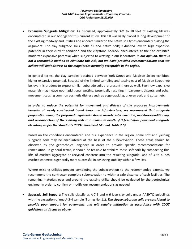
x Expansive Subgrade Mitigation: As discussed, approximately 3-½ to 10 feet of existing fill was encountered in our borings for this current study. This fill was likely placed during development of the existing roadway and utilities and appears similar to the native soil types encountered along the alignment. The clay subgrade soils (both fill and native soils) exhibited low to high expansive potential in their current condition and the claystone bedrock encountered at the site exhibited moderate expansive potential when subjected to wetting in our laboratory. In our opinion, there is not a reasonable method to eliminate this risk, but we have provided recommendations that we believe will limit distress to the magnitudes normally acceptable in the region.
In general terms, the clay samples obtained between York Street and Madison Street exhibited higher expansive potential. Because of the limited sampling and testing east of Madison Street, we believe it is prudent to expect similar subgrade soils are present there as well. Even low expansive materials may heave upon additional wetting, potentially resulting in pavement distress and other movement causing common cosmetic distress such as edge cracking, uneven curb and gutter, etc. In order to reduce the potential for movement and distress of the proposed improvements beneath all newly constructed travel lanes and infrastructure, we recommend that subgrade preparation along the proposed alignments should include subexcavation, moisture-conditioning, and recompaction of the existing soils to a minimum depth of 3 feet below pavement subgrade elevation, as per the Standards (CDOT Pavement Manual, Table 2.5). Based on the conditions encountered and our experience in the region, some soft and yielding subgrade soils may be encountered at the base of the subexcavation. These areas should be observed by the geotechnical engineer in order to provide specific recommendations for remediation. In general terms, it should be feasible to stabilize these soft soils by compacting thin lifts of crushed aggregate or recycled concrete into the resulting subgrade. Use of 3 to 4-inch crushed concrete is generally more successful in achieving stability within a few lifts. Where existing utilities prevent completing the subexcavation to the recommended extents, we recommend the contractor complete subexcavation to within a safe distance of such facilities. The remaining materials over and around the existing utility should be evaluated by the geotechnical engineer in order to confirm or modify our recommendations as needed.
x Subgrade Soli Support: The soils classify as A-7-6 and A-6 lean clay soils under AASHTO guidelines with the exception of one A-2-4 sample (Boring No. 11). The clayey subgrade soils are considered to provide poor support for pavements and will require mitigation in accordance with CDOT guidelines as discussed above.
Pavement Design Report East 144th Avenue Improvements – Thornton, Colorado
CGG Project No: 18.22.099
Cole Garner Geotechnical Page 7 Geotechnical Engineering and Materials Testing
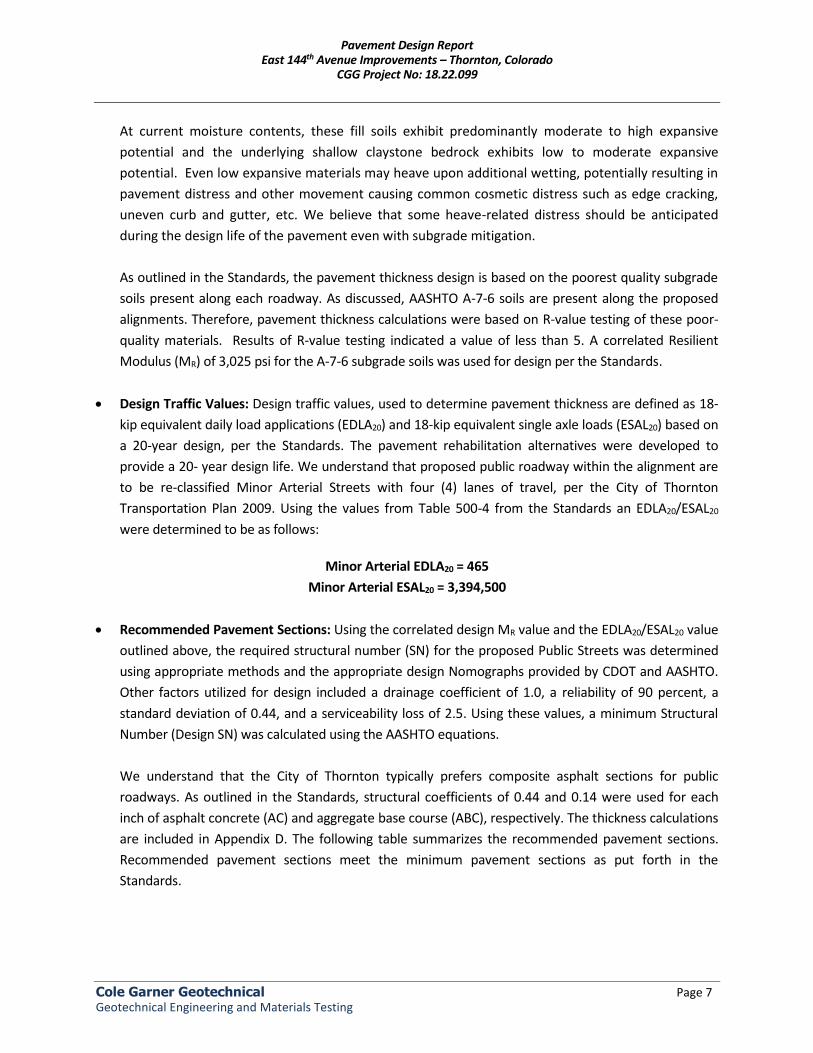
At current moisture contents, these fill soils exhibit predominantly moderate to high expansive potential and the underlying shallow claystone bedrock exhibits low to moderate expansive potential. Even low expansive materials may heave upon additional wetting, potentially resulting in pavement distress and other movement causing common cosmetic distress such as edge cracking, uneven curb and gutter, etc. We believe that some heave-related distress should be anticipated during the design life of the pavement even with subgrade mitigation. As outlined in the Standards, the pavement thickness design is based on the poorest quality subgrade soils present along each roadway. As discussed, AASHTO A-7-6 soils are present along the proposed alignments. Therefore, pavement thickness calculations were based on R-value testing of these poor-quality materials. Results of R-value testing indicated a value of less than 5. A correlated Resilient Modulus (MR) of 3,025 psi for the A-7-6 subgrade soils was used for design per the Standards.
x Design Traffic Values: Design traffic values, used to determine pavement thickness are defined as 18-kip equivalent daily load applications (EDLA20) and 18-kip equivalent single axle loads (ESAL20) based on a 20-year design, per the Standards. The pavement rehabilitation alternatives were developed to provide a 20- year design life. We understand that proposed public roadway within the alignment are to be re-classified Minor Arterial Streets with four (4) lanes of travel, per the City of Thornton Transportation Plan 2009. Using the values from Table 500-4 from the Standards an EDLA20/ESAL20 were determined to be as follows:
Minor Arterial EDLA20 = 465
Minor Arterial ESAL20 = 3,394,500
x Recommended Pavement Sections: Using the correlated design MR value and the EDLA20/ESAL20 value
outlined above, the required structural number (SN) for the proposed Public Streets was determined using appropriate methods and the appropriate design Nomographs provided by CDOT and AASHTO. Other factors utilized for design included a drainage coefficient of 1.0, a reliability of 90 percent, a standard deviation of 0.44, and a serviceability loss of 2.5. Using these values, a minimum Structural Number (Design SN) was calculated using the AASHTO equations. We understand that the City of Thornton typically prefers composite asphalt sections for public roadways. As outlined in the Standards, structural coefficients of 0.44 and 0.14 were used for each inch of asphalt concrete (AC) and aggregate base course (ABC), respectively. The thickness calculations are included in Appendix D. The following table summarizes the recommended pavement sections. Recommended pavement sections meet the minimum pavement sections as put forth in the Standards.
Pavement Design Report East 144th Avenue Improvements – Thornton, Colorado
CGG Project No: 18.22.099
Cole Garner Geotechnical Page 8 Geotechnical Engineering and Materials Testing
Traffic Area Alt.
Pavement Section Thickness (Inches)
Asphalt Concrete Surface
Aggregate Base Course
Portland Cement Concrete
Total
Minor Arterial
East 144th Avenue
ESAL20=3,394,500
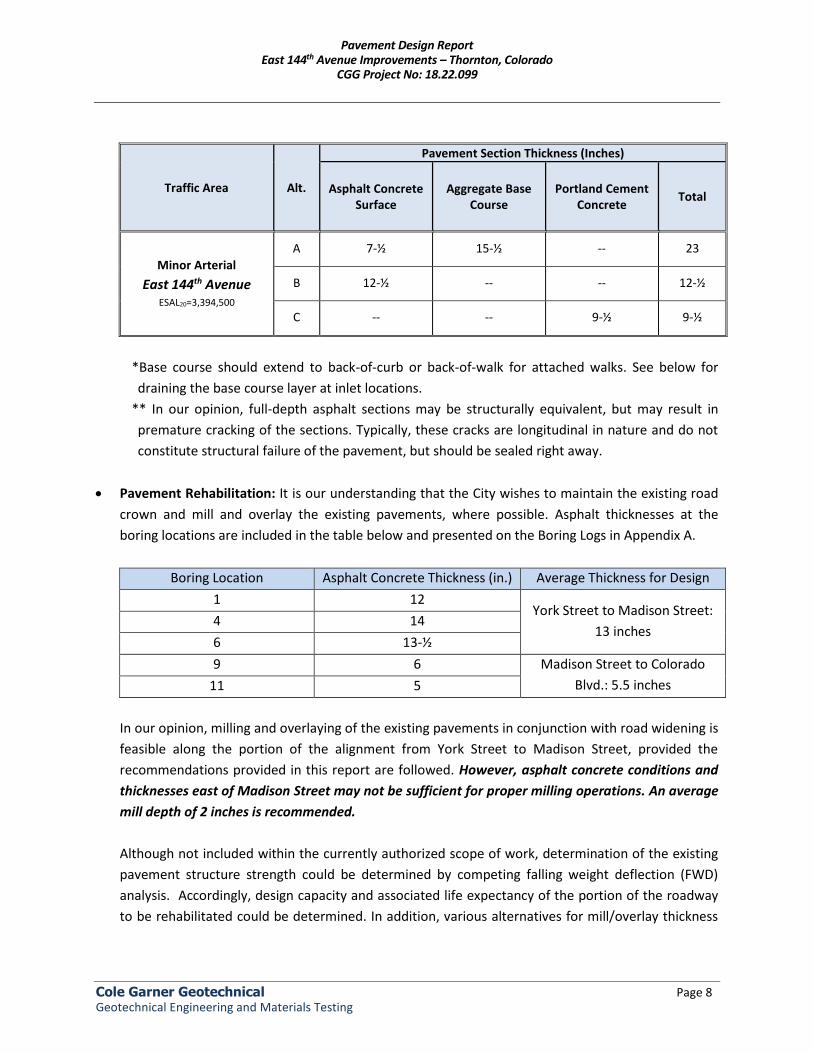
A 7-½ 15-½ -- 23
B 12-½ -- -- 12-½
C -- -- 9-½ 9-½
*Base course should extend to back-of-curb or back-of-walk for attached walks. See below for draining the base course layer at inlet locations.
** In our opinion, full-depth asphalt sections may be structurally equivalent, but may result in premature cracking of the sections. Typically, these cracks are longitudinal in nature and do not constitute structural failure of the pavement, but should be sealed right away.
x Pavement Rehabilitation: It is our understanding that the City wishes to maintain the existing road
crown and mill and overlay the existing pavements, where possible. Asphalt thicknesses at the boring locations are included in the table below and presented on the Boring Logs in Appendix A.
Boring Location Asphalt Concrete Thickness (in.) Average Thickness for Design
1 12 York Street to Madison Street:
13 inches 4 14 6 13-½ 9 6 Madison Street to Colorado
Blvd.: 5.5 inches 11 5 In our opinion, milling and overlaying of the existing pavements in conjunction with road widening is feasible along the portion of the alignment from York Street to Madison Street, provided the recommendations provided in this report are followed. However, asphalt concrete conditions and thicknesses east of Madison Street may not be sufficient for proper milling operations. An average mill depth of 2 inches is recommended. Although not included within the currently authorized scope of work, determination of the existing pavement structure strength could be determined by competing falling weight deflection (FWD) analysis. Accordingly, design capacity and associated life expectancy of the portion of the roadway to be rehabilitated could be determined. In addition, various alternatives for mill/overlay thickness
Pavement Design Report East 144th Avenue Improvements – Thornton, Colorado
CGG Project No: 18.22.099
Cole Garner Geotechnical Page 9 Geotechnical Engineering and Materials Testing
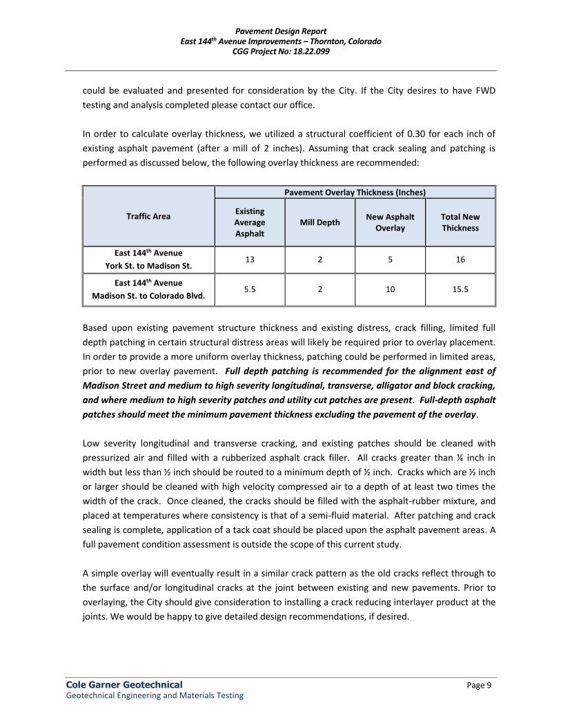
could be evaluated and presented for consideration by the City. If the City desires to have FWD testing and analysis completed please contact our office. In order to calculate overlay thickness, we utilized a structural coefficient of 0.30 for each inch of existing asphalt pavement (after a mill of 2 inches). Assuming that crack sealing and patching is performed as discussed below, the following overlay thickness are recommended:
Traffic Area
Pavement Overlay Thickness (Inches)
Existing Average Asphalt
Mill Depth New Asphalt
Overlay Total New Thickness
East 144th Avenue
York St. to Madison St. 13 2 5 16
East 144th Avenue
Madison St. to Colorado Blvd. 5.5 2 10 15.5
Based upon existing pavement structure thickness and existing distress, crack filling, limited full depth patching in certain structural distress areas will likely be required prior to overlay placement. In order to provide a more uniform overlay thickness, patching could be performed in limited areas, prior to new overlay pavement. Full depth patching is recommended for the alignment east of Madison Street and medium to high severity longitudinal, transverse, alligator and block cracking, and where medium to high severity patches and utility cut patches are present. Full-depth asphalt patches should meet the minimum pavement thickness excluding the pavement of the overlay. Low severity longitudinal and transverse cracking, and existing patches should be cleaned with pressurized air and filled with a rubberized asphalt crack filler. All cracks greater than ¼ inch in width but less than ½ inch should be routed to a minimum depth of ½ inch. Cracks which are ½ inch or larger should be cleaned with high velocity compressed air to a depth of at least two times the width of the crack. Once cleaned, the cracks should be filled with the asphalt-rubber mixture, and placed at temperatures where consistency is that of a semi-fluid material. After patching and crack sealing is complete, application of a tack coat should be placed upon the asphalt pavement areas. A full pavement condition assessment is outside the scope of this current study. A simple overlay will eventually result in a similar crack pattern as the old cracks reflect through to the surface and/or longitudinal cracks at the joint between existing and new pavements. Prior to overlaying, the City should give consideration to installing a crack reducing interlayer product at the joints. We would be happy to give detailed design recommendations, if desired.
Pavement Design Report East 144th Avenue Improvements – Thornton, Colorado
CGG Project No: 18.22.099
Cole Garner Geotechnical Page 10 Geotechnical Engineering and Materials Testing
x Subsurface Drainage: In our experience, surface water (from precipitation and irrigation) tends to collect behind curbs, attached sidewalks, etc. and this water infiltrates the subsurface over time. This water, if allowed to pond adjacent to roadways for extended periods, can cause:
x minor swell of the clayey pavement subgrade soils, which has been known to cause cracking
approximately 1 to 3 feet from the edge of curb and gutter (commonly known as edge cracking) and
x softening of the subgrade soils, particularly in areas of the roads that are lowest in elevation. These soft subgrade soils commonly cause localized alligator cracking and structural failure.
In our experience, the use of composite sections (HMA over ABC) often reduce the potential for these subgrade issues, however, in those areas that are lowest in elevation (particularly where storm sewer inlets are located) this subsurface water may collect and pool within the base course. To reduce the potential for this water to build up and cause structural failure, we recommend that all storm inlets be perforated just below the base of the aggregate base course layer. These perforations should be 2-inch diameter holes, spaced two feet on-center on the front face and uphill sides of each inlet. Holes should be drilled at an angle similar to the standard Type-R inlet details. The holes should be protected from intrusion of fines by a filter fabric or gravel-filled “rock sock” prior to backfilling the inlet and placement of the base course layer.
x Subgrade Preparation: Over-excavated fill, scarified subgrade, and pavement subgrade soils should be placed and compacted in horizontal lifts, using equipment and procedures that will produce recommended moisture contents and densities throughout the lift, as described in the Earthwork section below.
All pavement areas should be rough graded and then thoroughly proof rolled with a loaded tandem axle dump truck, water truck, or other heavy equipment approved by the observing engineer within 24 hours prior to paving. Particular attention should be paid to high traffic areas that were rutted and disturbed earlier and to areas where backfilled trenches are located. Areas where unsuitable conditions are located should be repaired by removing and replacing the materials with properly compacted engineered fills or additional base course. At a minimum, all subgrade soils should be scarified, moisture conditioned, and recompacted just prior to paving.
x Pavement Materials: Materials and construction of pavements for the project should be in accordance with the requirements and specifications of the City of Thornton. Materials should be submitted to the City of Thornton for approval prior to use on the site.
Pavement Design Report East 144th Avenue Improvements – Thornton, Colorado
CGG Project No: 18.22.099
Cole Garner Geotechnical Page 11 Geotechnical Engineering and Materials Testing
Aggregate base course should consist of a blend of sand and gravel that meets strict specifications for quality and gradation with a minimum R-value of 78. Use of materials meeting CDOT Class aggregate base specifications is required. Aggregate base course should be placed in lifts not exceeding 6 inches and compacted to a minimum of 95 percent modified Proctor density (AASHTO T180/ASTM D1557). Moisture should be uniformly added as necessary during compaction to obtain moisture content within 1 percent of optimum moisture content. Asphalt concrete should be composed of a mixture of aggregate, filler and additives (if required) and approved bituminous material. Asphalt concrete should be obtained from City of Thornton approved mix designs stating the Hveem properties, optimum asphalt content, job mix formula (JMF), and recommended mixing and placing temperatures. Aggregate used in asphalt concrete should meet a particular gradation. Asphalt concrete should consist of Grading SX for the top lift and Grading S or SG for the lower lifts, as outlined in the Standards. Mix designs should be submitted prior to construction to verify their adequacy. The asphalt mix should be designed for 100 gyratory design revolutions and the binder grade should conform with PG 64-22, per CDOT specifications. Asphalt material should be placed in maximum 3-inch lifts and compacted within a range of 92 to 96 percent of the theoretical maximum (Rice) density (AASHTO T209). Portland cement concrete (PCC) pavements, if used, should be obtained from an approved mix design conforming to CDOT Class P specifications. Concrete should be deposited by truck mixers or agitators and placed a maximum of 90 minutes from the time the water is added to the mix. Longitudinal and transverse joints should be provided as needed in concrete pavements for expansion/contraction and isolation. The location and extent of joints should be based upon the final pavement geometry. Sawed joints should be cut within 24 hours of concrete placement and should be a minimum depth of 25 percent of slab thickness plus 1/4 inch. All joints should be sealed to prevent entry of foreign material and doweled where necessary for load transfer. Where dowels cannot be used at joints accessible to wheel loads, pavement thickness should be increased by 25 percent at the joints and tapered to regular thickness in 5 feet.
Earthwork:
x General Considerations: The following presents recommendations for site preparation, excavation,
subgrade preparation and placement of engineered fills on the project.
All earthwork on the project should be observed and evaluated by CGG. The evaluation of earthwork should include observation and testing of engineered fills, subgrade preparation, foundation bearing soils and other geotechnical conditions exposed during the construction of the project.
Pavement Design Report East 144th Avenue Improvements – Thornton, Colorado
CGG Project No: 18.22.099
Cole Garner Geotechnical Page 12 Geotechnical Engineering and Materials Testing
x Demolition and Site Preparation: Strip and remove vegetation, existing foundations and pavements, any unsuitable existing fills, or any other deleterious materials from the site. Stripped materials consisting of vegetation and organic materials should be wasted from the site or used to revegetate landscaped areas or exposed slopes after completion of grading operations. Asphalt or concrete materials removed as part of site reclamation may be re-used on the site. We recommend that these materials be crushed to a maximum size of 4 to 6 inches and used to stabilize any soft soils that may be encountered. Based on the conditions encountered and our experience in the region, some soft and yielding subgrade soils may be encountered at the base of the subexcavation. These areas should be observed by the geotechnical engineer in order to provide specific recommendations for remediation. In general terms, it should be feasible to stabilize these soft soils by compacting thin lifts of crushed aggregate or recycled concrete into the resulting subgrade. Use of 3 to 4-inch crushed concrete is generally more successful in achieving stability within a few lifts. Where existing utilities prevent completing the subexcavation to the recommended extents, we recommend the contractor complete subexcavation to within a safe distance of such facilities. The remaining materials over and around the existing utility should be evaluated by the geotechnical engineer in order to confirm or modify our recommendations as needed.
x Fill Materials: On-site soils may be used for general site grading. Imported fill materials, if needed,
should be similar to the on-site soils, and in general, should conform to the following requirements:
Percent finer by weight Gradation (ASTM C136) 2" ........................................................................................................................................................ 100 No. 4 Sieve ..................................................................................................................................... 30-100 No. 40 Sieve ..................................................................................................................................... 10-60 No. 200 Sieve ....................................................................................................................... 65 maximum
Liquid Limit .................................................................................................................... 40 maximum Plasticity Index .............................................................................................................. 20 maximum
x Fill Placement and Compaction: Engineered fill should be placed and compacted in horizontal lifts,
using equipment and procedures that will produce recommended moisture contents and densities throughout the lift. Engineered fills should be placed and compacted according to the recommendations in the following table:
Pavement Design Report East 144th Avenue Improvements – Thornton, Colorado
CGG Project No: 18.22.099
Cole Garner Geotechnical Page 13 Geotechnical Engineering and Materials Testing
Observation and compaction testing should be performed by a qualified Geotechnical Engineer during subgrade preparation, backfill and other earthwork operations. Should the results of the in-place density tests indicate the specified moisture or compaction limits have not been met, the area represented by the test should be reworked and retested as required until the specified moisture and compaction requirements are achieved.
x Excavations: Caving soils and groundwater are present at the site. The individual contractor(s)
should be made responsible for designing and constructing stable, temporary excavations, as required, in order to maintain stability of both the excavation sides and bottom. All excavations should be sloped or shored in the interest of safety following local and federal regulations, including current OSHA excavation and trench safety standards.
As a safety measure, it is recommended that all vehicles and soil piles be kept to a minimum lateral distance from the crest of the slope equal to no less than the slope height. The exposed slope face should be protected against the elements.
Additional Recommendations:
x Concrete Corrosion Protection: Water soluble sulfate testing indicates sulfate concentration ranging from about 400 to 1,200 parts per million (ppm). ACI rates the measured concentrations as being a moderate risk of concrete sulfate attack. Therefore, Type II Portland cement, or equivalent, should be used for concrete on and below grade. Project concrete should be designed for moderate risk of attack in accordance with the provisions of the ACI Design Manual, Section 318, Chapter 4.
x Drainage and Landscaping: All grades should be adjusted to provide positive drainage away from the roadways during construction. Ponding of water on the subgrade should be avoided where possible. After roadway construction is completed, it is imperative that backfill placed against the back of the curb be moisture conditioned and well compacted. Grades should be established that direct surface water away from or onto pavements and these grades should be maintained throughout the life of the development. Water permitted to pond near or adjacent to the perimeter of the roadway (either during or post-construction) can result in excessive distress.
Criteria Recommended values Lift thickness 8 inches or less in loose thickness, depending on equipment
Moisture content range
Pavement Subgrade (onsite clays): Optimum to +2% percent above optimum Non-plastic sands/ABC: -2% percent below to +2% percent above optimum
Compaction
Pavement Subgrade (onsite clays): 95 percent minimum standard Proctor dry density (AASHTO T99) Non-plastic sands/ABC: 95 percent minimum modified Proctor dry density (AASHTO T180)
Pavement Design Report East 144th Avenue Improvements – Thornton, Colorado
CGG Project No: 18.22.099
Cole Garner Geotechnical Page 14 Geotechnical Engineering and Materials Testing
Landscaping irrigation adjacent to the roadways should be limited to only the amount needed to establish vegetation and sustain growth. Irrigation systems should be reviewed frequently to fix leaks and minimize over-spray.
GENERAL COMMENTS AND LIMITATIONS CGG should be retained to review the final design plans and specifications so comments can be made regarding interpretation and implementation of our geotechnical recommendations in the design and specifications. CGG should also be retained to provide testing and observation during the over-excavation, subgrade preparation, and other construction phases of the project. The analysis and recommendations presented in this report are based upon the data obtained from the borings performed at the indicated locations and from other information discussed in this report. This report does not reflect variations that may occur between borings, across the site, or due to the modifying effects of weather. The nature and extent of such variations may not become evident until during or after construction. If variations appear, we should be immediately notified so that further evaluation and supplemental recommendations can be provided. The scope of services for this project does not include, either specifically or by implication, any environmental or biological (e.g., mold, fungi, bacteria) assessment of the site or identification or prevention of pollutants, hazardous materials or conditions. If the owner is concerned about the potential for such contamination or pollution, other studies should be undertaken. This report has been prepared for the exclusive use of our client for specific application to the project discussed and has been prepared in accordance with generally accepted geotechnical engineering practices. No warranties, express or implied, are intended or made. Site safety, excavation support, and dewatering requirements are the responsibility of others. In the event that changes are planned in the nature, design, or location of the project as outlined in this report, the conclusions and recommendations contained in this report shall not be considered valid unless CGG reviews the changes, and either verifies or modifies the conclusions of this report in writing.

Cole Garner Geotechnical Page 1 Geotechnical Engineering and Materials Testing
APPENDIX A
VICINITY MAP BORING LOCATION DIAGRAM
LOGS OF BORINGS
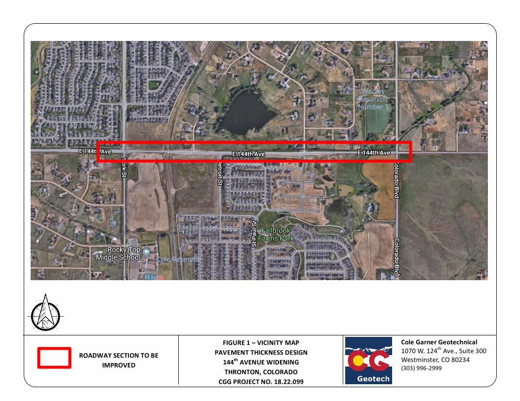
FIGURE1–VICINITYMAPPAVEMENTTHICKNESSDESIGN
144thAVENUEWIDENINGTHRONTON,COLORADO
CGGPROJECTNO.18.22.099
ROADWAYSECTIONTOBEIMPROVED
ColeGarnerGeotechnical1070W.124thAve.,Suite300Westminster,CO80234(303)996-2999
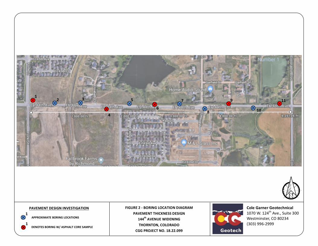
APPROXIMATEBORINGLOCATIONS
ColeGarnerGeotechnical1070W.124thAve.,Suite300Westminster,CO80234(303)996-2999
1
1DENOTESBORINGW/ASPHALTCORESAMPLE
PAVEMENTDESIGNINVESTIGATION
FIGURE2-BORINGLOCATIONDIAGRAMPAVEMENTTHICKNESSDESIGN
144thAVENUEWIDENINGTHORNTON,COLORADO
CGGPROJECTNO.18.22.099
1
2
113
4
5
6
7
8
9
10

15 / 12
14 / 12
21 / 12
110
108
108
+0.9/200
+4.1/200
17.5
19.5
20.7
100
100
100
ASPHALT CONCRETE, approximately 12"
FILL - LEAN CLAY with SAND, brown, calcareous, moist, stiff
SANDY LEAN CLAY, brown, moist
CLAYSTONE BEDROCK, grey, iron-stained, moist, weathered
Approximate bottom of borehole at 10.0 feet.
1
5.5
8
10
CB
CB
CB
CL
CL
-
DRILLING METHOD CME-55 / Solid Stem Auger
DATE STARTED 5/11/18
GROUND WATER LEVELS:
SURFACE CONDITIONS Approximately 12 inches of asphalt pavementDRILLING CONTRACTOR Vine Laboratories
COMPLETED 5/11/18
LOGGED BY KF CHECKED BY AG
HAMMER TYPE Automatic
PROPOSED ELEV.Not Provided
DURING DRILLING None
AFTER DRILLING Backfilled - 5/11/18
GROUND SURFACE ELEV.
GR
APH
ICLO
G
DEP
TH(ft
)
0.0
2.5
5.0
7.5
10.0
PEN
ETR
ATIO
Nbl
ows/
in
DR
Y U
NIT
WT.
(pcf
)
SWEL
L-C
ON
SOL
/SU
RC
HAR
GE
LOAD
, %ps
f
MO
ISTU
RE
CO
NTE
NT
(%)
REC
OVE
RY
%
MATERIAL DESCRIPTION
SAM
PLE
TYPE
USC
S SY
MBO
L
PAGE 1 OF 1BORING NUMBER 1
CLIENT Drexel Barrell
PROJECT NUMBER 18.22.099
PROJECT NAME East 144th Avenue Widening Project
PROJECT LOCATION East 144th Avenue between York St. and Colorado Blvd.
GEO
TEC
H B
H C
OLU
MN
S - G
INT
STD
US
LAB.
GD
T - 6
/20/
18 1
6:09
- C
:\USE
RS\
PU
BLIC
\DO
CU
MEN
TS\B
ENTL
EY\G
INT\
PRO
JEC
TS G
EO 2
018\
18.2
2.09
9 D
REX
EL B
ARR
ELL
- 144
TH A
VE W
IDEN
ING
.GPJ
Cole Garner Geotechnical1070 W. 124th Avenue, Suite 300Westminster, CO 80234Telephone: 303.996.2999
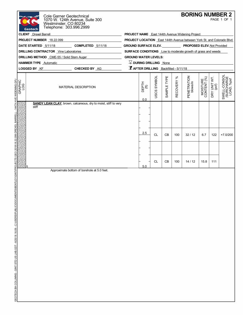
32 / 12
14 / 12
122
111
+7.0/2006.7
15.8
100
100
SANDY LEAN CLAY, brown, calcareous, dry to moist, stiff to verystiff
Approximate bottom of borehole at 5.0 feet.5
CB
CB
CL
CL
DRILLING METHOD CME-55 / Solid Stem Auger
DATE STARTED 5/11/18
GROUND WATER LEVELS:
SURFACE CONDITIONS Low to moderate growth of grass and weedsDRILLING CONTRACTOR Vine Laboratories
COMPLETED 5/11/18
LOGGED BY KF CHECKED BY AG
HAMMER TYPE Automatic
PROPOSED ELEV.Not Provided
DURING DRILLING None
AFTER DRILLING Backfilled - 5/11/18
GROUND SURFACE ELEV.
GR
APH
ICLO
G
DEP
TH(ft
)
0.0
2.5
5.0
PEN
ETR
ATIO
Nbl
ows/
in
DR
Y U
NIT
WT.
(pcf
)
SWEL
L-C
ON
SOL
/SU
RC
HAR
GE
LOAD
, %ps
f
MO
ISTU
RE
CO
NTE
NT
(%)
REC
OVE
RY
%
MATERIAL DESCRIPTION
SAM
PLE
TYPE
USC
S SY
MBO
L
PAGE 1 OF 1BORING NUMBER 2
CLIENT Drexel Barrell
PROJECT NUMBER 18.22.099
PROJECT NAME East 144th Avenue Widening Project
PROJECT LOCATION East 144th Avenue between York St. and Colorado Blvd.
GEO
TEC
H B
H C
OLU
MN
S - G
INT
STD
US
LAB.
GD
T - 6
/20/
18 1
6:09
- C
:\USE
RS\
PU
BLIC
\DO
CU
MEN
TS\B
ENTL
EY\G
INT\
PRO
JEC
TS G
EO 2
018\
18.2
2.09
9 D
REX
EL B
ARR
ELL
- 144
TH A
VE W
IDEN
ING
.GPJ
Cole Garner Geotechnical1070 W. 124th Avenue, Suite 300Westminster, CO 80234Telephone: 303.996.2999
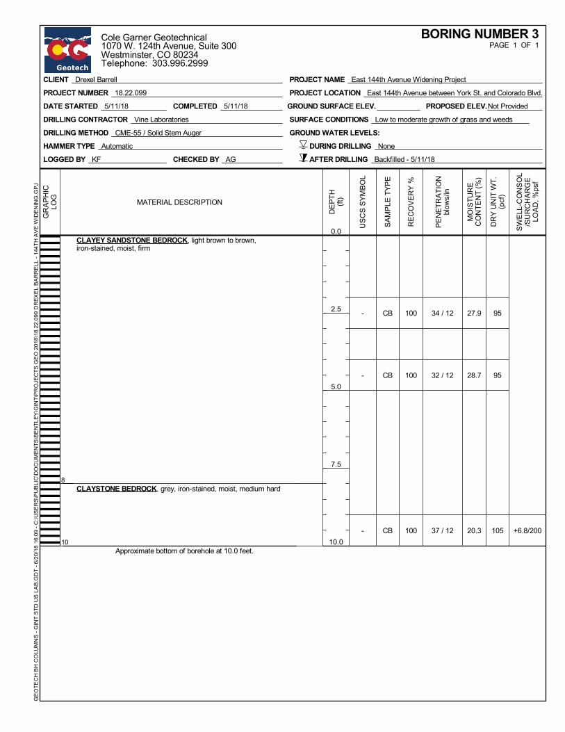
34 / 12
32 / 12
37 / 12
95
95
105 +6.8/200
27.9
28.7
20.3
100
100
100
CLAYEY SANDSTONE BEDROCK, light brown to brown,iron-stained, moist, firm
CLAYSTONE BEDROCK, grey, iron-stained, moist, medium hard
Approximate bottom of borehole at 10.0 feet.
8
10
CB
CB
CB
-
-
-
DRILLING METHOD CME-55 / Solid Stem Auger
DATE STARTED 5/11/18
GROUND WATER LEVELS:
SURFACE CONDITIONS Low to moderate growth of grass and weedsDRILLING CONTRACTOR Vine Laboratories
COMPLETED 5/11/18
LOGGED BY KF CHECKED BY AG
HAMMER TYPE Automatic
PROPOSED ELEV.Not Provided
DURING DRILLING None
AFTER DRILLING Backfilled - 5/11/18
GROUND SURFACE ELEV.
GR
APH
ICLO
G
DEP
TH(ft
)
0.0
2.5
5.0
7.5
10.0
PEN
ETR
ATIO
Nbl
ows/
in
DR
Y U
NIT
WT.
(pcf
)
SWEL
L-C
ON
SOL
/SU
RC
HAR
GE
LOAD
, %ps
f
MO
ISTU
RE
CO
NTE
NT
(%)
REC
OVE
RY
%
MATERIAL DESCRIPTION
SAM
PLE
TYPE
USC
S SY
MBO
L
PAGE 1 OF 1BORING NUMBER 3
CLIENT Drexel Barrell
PROJECT NUMBER 18.22.099
PROJECT NAME East 144th Avenue Widening Project
PROJECT LOCATION East 144th Avenue between York St. and Colorado Blvd.
GEO
TEC
H B
H C
OLU
MN
S - G
INT
STD
US
LAB.
GD
T - 6
/20/
18 1
6:09
- C
:\USE
RS\
PU
BLIC
\DO
CU
MEN
TS\B
ENTL
EY\G
INT\
PRO
JEC
TS G
EO 2
018\
18.2
2.09
9 D
REX
EL B
ARR
ELL
- 144
TH A
VE W
IDEN
ING
.GPJ
Cole Garner Geotechnical1070 W. 124th Avenue, Suite 300Westminster, CO 80234Telephone: 303.996.2999

8 / 12
4 / 12
100
100 +1.3/200
20.6
21.6
100
100
ASPHALT CONCRETE, approximately 14"
FILL - CLAYEY SAND to SANDY LEAN CLAY, brown to darkbrown, iron-stained, calcareous, moist, soft to medium stiff
Approximate bottom of borehole at 5.0 feet.
1.2
5
CB
CB
SC
SC/CL
DRILLING METHOD CME-55 / Solid Stem Auger
DATE STARTED 5/11/18
GROUND WATER LEVELS:
SURFACE CONDITIONS Approximately 14 inches of asphalt pavementDRILLING CONTRACTOR Vine Laboratories
COMPLETED 5/11/18
LOGGED BY KF CHECKED BY AG
HAMMER TYPE Automatic
PROPOSED ELEV.Not Provided
DURING DRILLING None
AFTER DRILLING Backfilled - 5/11/18
GROUND SURFACE ELEV.
GR
APH
ICLO
G
DEP
TH(ft
)
0.0
2.5
5.0
PEN
ETR
ATIO
Nbl
ows/
in
DR
Y U
NIT
WT.
(pcf
)
SWEL
L-C
ON
SOL
/SU
RC
HAR
GE
LOAD
, %ps
f
MO
ISTU
RE
CO
NTE
NT
(%)
REC
OVE
RY
%
MATERIAL DESCRIPTION
SAM
PLE
TYPE
USC
S SY
MBO
L
PAGE 1 OF 1BORING NUMBER 4
CLIENT Drexel Barrell
PROJECT NUMBER 18.22.099
PROJECT NAME East 144th Avenue Widening Project
PROJECT LOCATION East 144th Avenue between York St. and Colorado Blvd.
GEO
TEC
H B
H C
OLU
MN
S - G
INT
STD
US
LAB.
GD
T - 6
/20/
18 1
6:09
- C
:\USE
RS\
PU
BLIC
\DO
CU
MEN
TS\B
ENTL
EY\G
INT\
PRO
JEC
TS G
EO 2
018\
18.2
2.09
9 D
REX
EL B
ARR
ELL
- 144
TH A
VE W
IDEN
ING
.GPJ
Cole Garner Geotechnical1070 W. 124th Avenue, Suite 300Westminster, CO 80234Telephone: 303.996.2999
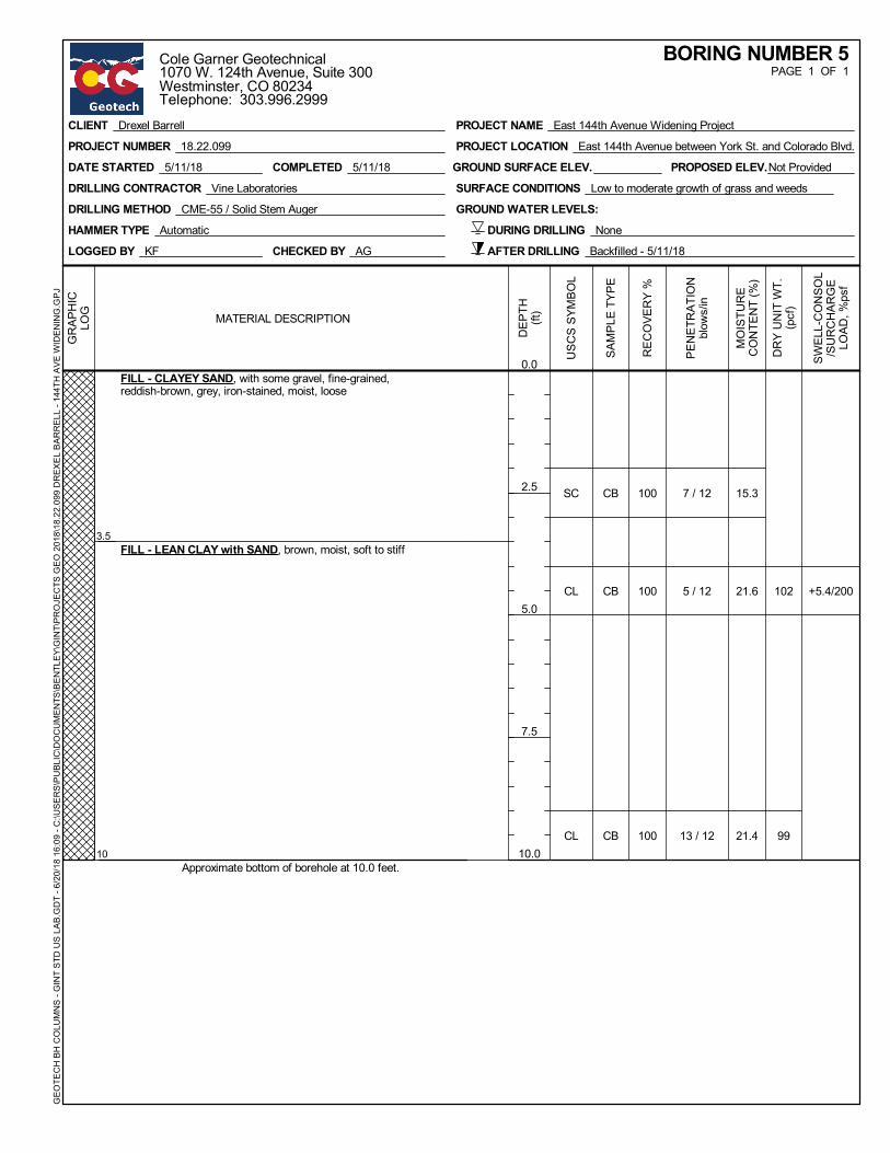
7 / 12
5 / 12
13 / 12
102
99
+5.4/200
15.3
21.6
21.4
100
100
100
FILL - CLAYEY SAND, with some gravel, fine-grained,reddish-brown, grey, iron-stained, moist, loose
FILL - LEAN CLAY with SAND, brown, moist, soft to stiff
Approximate bottom of borehole at 10.0 feet.
3.5
10
CB
CB
CB
SC
CL
CL
DRILLING METHOD CME-55 / Solid Stem Auger
DATE STARTED 5/11/18
GROUND WATER LEVELS:
SURFACE CONDITIONS Low to moderate growth of grass and weedsDRILLING CONTRACTOR Vine Laboratories
COMPLETED 5/11/18
LOGGED BY KF CHECKED BY AG
HAMMER TYPE Automatic
PROPOSED ELEV.Not Provided
DURING DRILLING None
AFTER DRILLING Backfilled - 5/11/18
GROUND SURFACE ELEV.
GR
APH
ICLO
G
DEP
TH(ft
)
0.0
2.5
5.0
7.5
10.0
PEN
ETR
ATIO
Nbl
ows/
in
DR
Y U
NIT
WT.
(pcf
)
SWEL
L-C
ON
SOL
/SU
RC
HAR
GE
LOAD
, %ps
f
MO
ISTU
RE
CO
NTE
NT
(%)
REC
OVE
RY
%
MATERIAL DESCRIPTION
SAM
PLE
TYPE
USC
S SY
MBO
L
PAGE 1 OF 1BORING NUMBER 5
CLIENT Drexel Barrell
PROJECT NUMBER 18.22.099
PROJECT NAME East 144th Avenue Widening Project
PROJECT LOCATION East 144th Avenue between York St. and Colorado Blvd.
GEO
TEC
H B
H C
OLU
MN
S - G
INT
STD
US
LAB.
GD
T - 6
/20/
18 1
6:09
- C
:\USE
RS\
PU
BLIC
\DO
CU
MEN
TS\B
ENTL
EY\G
INT\
PRO
JEC
TS G
EO 2
018\
18.2
2.09
9 D
REX
EL B
ARR
ELL
- 144
TH A
VE W
IDEN
ING
.GPJ
Cole Garner Geotechnical1070 W. 124th Avenue, Suite 300Westminster, CO 80234Telephone: 303.996.2999
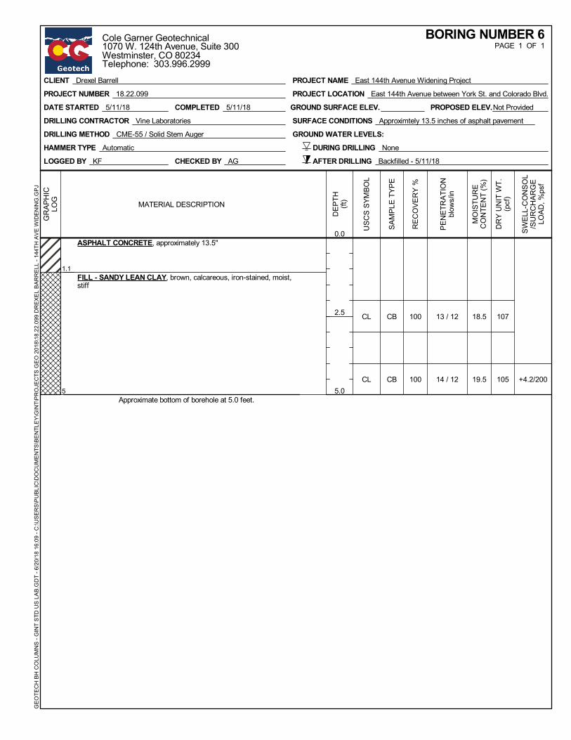
13 / 12
14 / 12
107
105 +4.2/200
18.5
19.5
100
100
ASPHALT CONCRETE, approximately 13.5"
FILL - SANDY LEAN CLAY, brown, calcareous, iron-stained, moist,stiff
Approximate bottom of borehole at 5.0 feet.
1.1
5
CB
CB
CL
CL
DRILLING METHOD CME-55 / Solid Stem Auger
DATE STARTED 5/11/18
GROUND WATER LEVELS:
SURFACE CONDITIONS Approximtely 13.5 inches of asphalt pavementDRILLING CONTRACTOR Vine Laboratories
COMPLETED 5/11/18
LOGGED BY KF CHECKED BY AG
HAMMER TYPE Automatic
PROPOSED ELEV.Not Provided
DURING DRILLING None
AFTER DRILLING Backfilled - 5/11/18
GROUND SURFACE ELEV.
GR
APH
ICLO
G
DEP
TH(ft
)
0.0
2.5
5.0
PEN
ETR
ATIO
Nbl
ows/
in
DR
Y U
NIT
WT.
(pcf
)
SWEL
L-C
ON
SOL
/SU
RC
HAR
GE
LOAD
, %ps
f
MO
ISTU
RE
CO
NTE
NT
(%)
REC
OVE
RY
%
MATERIAL DESCRIPTION
SAM
PLE
TYPE
USC
S SY
MBO
L
PAGE 1 OF 1BORING NUMBER 6
CLIENT Drexel Barrell
PROJECT NUMBER 18.22.099
PROJECT NAME East 144th Avenue Widening Project
PROJECT LOCATION East 144th Avenue between York St. and Colorado Blvd.
GEO
TEC
H B
H C
OLU
MN
S - G
INT
STD
US
LAB.
GD
T - 6
/20/
18 1
6:09
- C
:\USE
RS\
PU
BLIC
\DO
CU
MEN
TS\B
ENTL
EY\G
INT\
PRO
JEC
TS G
EO 2
018\
18.2
2.09
9 D
REX
EL B
ARR
ELL
- 144
TH A
VE W
IDEN
ING
.GPJ
Cole Garner Geotechnical1070 W. 124th Avenue, Suite 300Westminster, CO 80234Telephone: 303.996.2999
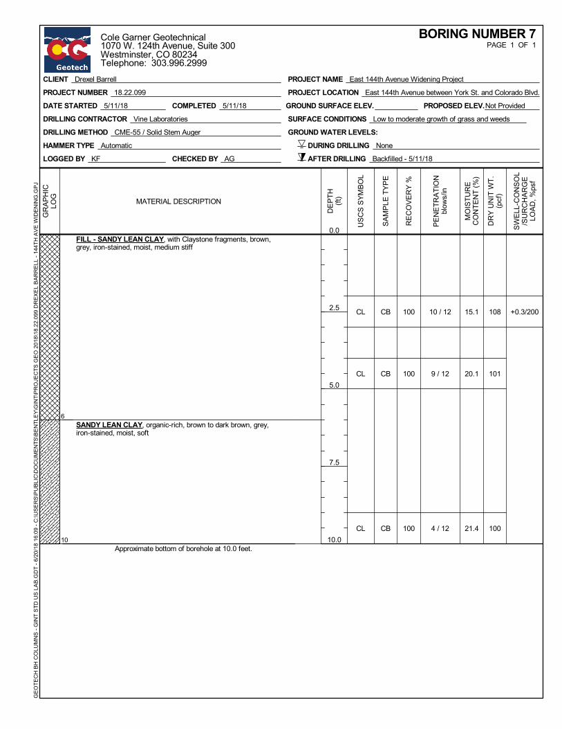
10 / 12
9 / 12
4 / 12
108
101
100
+0.3/20015.1
20.1
21.4
100
100
100
FILL - SANDY LEAN CLAY, with Claystone fragments, brown,grey, iron-stained, moist, medium stiff
SANDY LEAN CLAY, organic-rich, brown to dark brown, grey,iron-stained, moist, soft
Approximate bottom of borehole at 10.0 feet.
6
10
CB
CB
CB
CL
CL
CL
DRILLING METHOD CME-55 / Solid Stem Auger
DATE STARTED 5/11/18
GROUND WATER LEVELS:
SURFACE CONDITIONS Low to moderate growth of grass and weedsDRILLING CONTRACTOR Vine Laboratories
COMPLETED 5/11/18
LOGGED BY KF CHECKED BY AG
HAMMER TYPE Automatic
PROPOSED ELEV.Not Provided
DURING DRILLING None
AFTER DRILLING Backfilled - 5/11/18
GROUND SURFACE ELEV.
GR
APH
ICLO
G
DEP
TH(ft
)
0.0
2.5
5.0
7.5
10.0
PEN
ETR
ATIO
Nbl
ows/
in
DR
Y U
NIT
WT.
(pcf
)
SWEL
L-C
ON
SOL
/SU
RC
HAR
GE
LOAD
, %ps
f
MO
ISTU
RE
CO
NTE
NT
(%)
REC
OVE
RY
%
MATERIAL DESCRIPTION
SAM
PLE
TYPE
USC
S SY
MBO
L
PAGE 1 OF 1BORING NUMBER 7
CLIENT Drexel Barrell
PROJECT NUMBER 18.22.099
PROJECT NAME East 144th Avenue Widening Project
PROJECT LOCATION East 144th Avenue between York St. and Colorado Blvd.
GEO
TEC
H B
H C
OLU
MN
S - G
INT
STD
US
LAB.
GD
T - 6
/20/
18 1
6:09
- C
:\USE
RS\
PU
BLIC
\DO
CU
MEN
TS\B
ENTL
EY\G
INT\
PRO
JEC
TS G
EO 2
018\
18.2
2.09
9 D
REX
EL B
ARR
ELL
- 144
TH A
VE W
IDEN
ING
.GPJ
Cole Garner Geotechnical1070 W. 124th Avenue, Suite 300Westminster, CO 80234Telephone: 303.996.2999
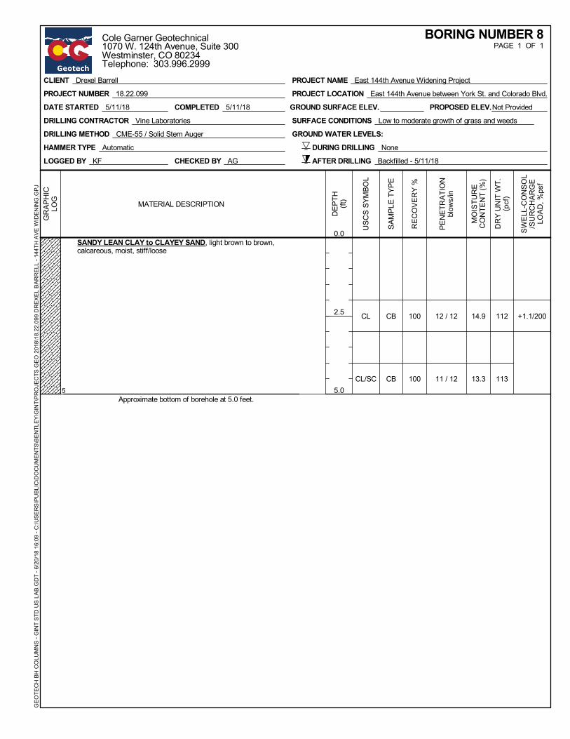
12 / 12
11 / 12
112
113
+1.1/20014.9
13.3
100
100
SANDY LEAN CLAY to CLAYEY SAND, light brown to brown,calcareous, moist, stiff/loose
Approximate bottom of borehole at 5.0 feet.5
CB
CB
CL
CL/SC
DRILLING METHOD CME-55 / Solid Stem Auger
DATE STARTED 5/11/18
GROUND WATER LEVELS:
SURFACE CONDITIONS Low to moderate growth of grass and weedsDRILLING CONTRACTOR Vine Laboratories
COMPLETED 5/11/18
LOGGED BY KF CHECKED BY AG
HAMMER TYPE Automatic
PROPOSED ELEV.Not Provided
DURING DRILLING None
AFTER DRILLING Backfilled - 5/11/18
GROUND SURFACE ELEV.
GR
APH
ICLO
G
DEP
TH(ft
)
0.0
2.5
5.0
PEN
ETR
ATIO
Nbl
ows/
in
DR
Y U
NIT
WT.
(pcf
)
SWEL
L-C
ON
SOL
/SU
RC
HAR
GE
LOAD
, %ps
f
MO
ISTU
RE
CO
NTE
NT
(%)
REC
OVE
RY
%
MATERIAL DESCRIPTION
SAM
PLE
TYPE
USC
S SY
MBO
L
PAGE 1 OF 1BORING NUMBER 8
CLIENT Drexel Barrell
PROJECT NUMBER 18.22.099
PROJECT NAME East 144th Avenue Widening Project
PROJECT LOCATION East 144th Avenue between York St. and Colorado Blvd.
GEO
TEC
H B
H C
OLU
MN
S - G
INT
STD
US
LAB.
GD
T - 6
/20/
18 1
6:09
- C
:\USE
RS\
PU
BLIC
\DO
CU
MEN
TS\B
ENTL
EY\G
INT\
PRO
JEC
TS G
EO 2
018\
18.2
2.09
9 D
REX
EL B
ARR
ELL
- 144
TH A
VE W
IDEN
ING
.GPJ
Cole Garner Geotechnical1070 W. 124th Avenue, Suite 300Westminster, CO 80234Telephone: 303.996.2999

10 / 12
16 / 12
41 / 12
105
97
107
+0.5/20018.8
25.2
20.0
100
100
100
ASPHALT CONCRETE, approximately 6"
SANDY LEAN CLAY, light brown to brown, grey, iron-stained,calcareous, moist, medium stiff to stiff
CLAYEY SANDSTONE BEDROCK, brown, grey, moist, mediumhard
Approximate bottom of borehole at 10.0 feet.
0.5
8
10
CB
CB
CB
CL
CL
-
DRILLING METHOD CME-55 / Solid Stem Auger
DATE STARTED 5/11/18
GROUND WATER LEVELS:
SURFACE CONDITIONS Approximately 6 inches of asphalt pavementDRILLING CONTRACTOR Vine Laboratories
COMPLETED 5/11/18
LOGGED BY KF CHECKED BY AG
HAMMER TYPE Automatic
PROPOSED ELEV.Not Provided
DURING DRILLING None
AFTER DRILLING Backfilled - 5/11/18
GROUND SURFACE ELEV.
GR
APH
ICLO
G
DEP
TH(ft
)
0.0
2.5
5.0
7.5
10.0
PEN
ETR
ATIO
Nbl
ows/
in
DR
Y U
NIT
WT.
(pcf
)
SWEL
L-C
ON
SOL
/SU
RC
HAR
GE
LOAD
, %ps
f
MO
ISTU
RE
CO
NTE
NT
(%)
REC
OVE
RY
%
MATERIAL DESCRIPTION
SAM
PLE
TYPE
USC
S SY
MBO
L
PAGE 1 OF 1BORING NUMBER 9
CLIENT Drexel Barrell
PROJECT NUMBER 18.22.099
PROJECT NAME East 144th Avenue Widening Project
PROJECT LOCATION East 144th Avenue between York St. and Colorado Blvd.
GEO
TEC
H B
H C
OLU
MN
S - G
INT
STD
US
LAB.
GD
T - 6
/20/
18 1
6:09
- C
:\USE
RS\
PU
BLIC
\DO
CU
MEN
TS\B
ENTL
EY\G
INT\
PRO
JEC
TS G
EO 2
018\
18.2
2.09
9 D
REX
EL B
ARR
ELL
- 144
TH A
VE W
IDEN
ING
.GPJ
Cole Garner Geotechnical1070 W. 124th Avenue, Suite 300Westminster, CO 80234Telephone: 303.996.2999

9 / 12
9 / 12 9724.6
100
100
SANDY LEAN CLAY, brown, grey, iron-stained, calcareous, moist,medium stiff
Approximate bottom of borehole at 5.0 feet.5
CB
CB
CL
CL
DRILLING METHOD CME-55 / Solid Stem Auger
DATE STARTED 5/11/18
GROUND WATER LEVELS:
SURFACE CONDITIONS Low to moderate growth of grass and weedsDRILLING CONTRACTOR Vine Laboratories
COMPLETED 5/11/18
LOGGED BY KF CHECKED BY AG
HAMMER TYPE Automatic
PROPOSED ELEV.Not Provided
DURING DRILLING None
AFTER DRILLING Backfilled - 5/11/18
GROUND SURFACE ELEV.
GR
APH
ICLO
G
DEP
TH(ft
)
0.0
2.5
5.0
PEN
ETR
ATIO
Nbl
ows/
in
DR
Y U
NIT
WT.
(pcf
)
SWEL
L-C
ON
SOL
/SU
RC
HAR
GE
LOAD
, %ps
f
MO
ISTU
RE
CO
NTE
NT
(%)
REC
OVE
RY
%
MATERIAL DESCRIPTION
SAM
PLE
TYPE
USC
S SY
MBO
L
PAGE 1 OF 1BORING NUMBER 10
CLIENT Drexel Barrell
PROJECT NUMBER 18.22.099
PROJECT NAME East 144th Avenue Widening Project
PROJECT LOCATION East 144th Avenue between York St. and Colorado Blvd.
GEO
TEC
H B
H C
OLU
MN
S - G
INT
STD
US
LAB.
GD
T - 6
/20/
18 1
6:09
- C
:\USE
RS\
PU
BLIC
\DO
CU
MEN
TS\B
ENTL
EY\G
INT\
PRO
JEC
TS G
EO 2
018\
18.2
2.09
9 D
REX
EL B
ARR
ELL
- 144
TH A
VE W
IDEN
ING
.GPJ
Cole Garner Geotechnical1070 W. 124th Avenue, Suite 300Westminster, CO 80234Telephone: 303.996.2999
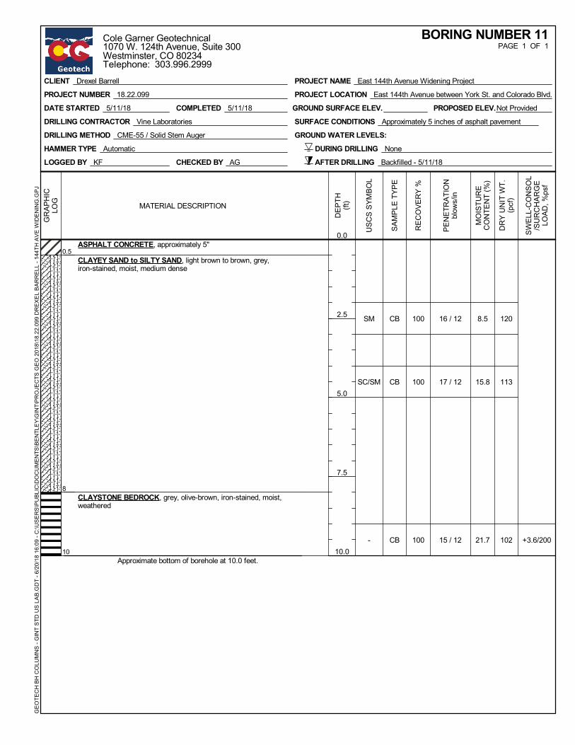
16 / 12
17 / 12
15 / 12
120
113
102 +3.6/200
8.5
15.8
21.7
100
100
100
ASPHALT CONCRETE, approximately 5"
CLAYEY SAND to SILTY SAND, light brown to brown, grey,iron-stained, moist, medium dense
CLAYSTONE BEDROCK, grey, olive-brown, iron-stained, moist,weathered
Approximate bottom of borehole at 10.0 feet.
0.5
8
10
CB
CB
CB
SM
SC/SM
-
DRILLING METHOD CME-55 / Solid Stem Auger
DATE STARTED 5/11/18
GROUND WATER LEVELS:
SURFACE CONDITIONS Approximately 5 inches of asphalt pavementDRILLING CONTRACTOR Vine Laboratories
COMPLETED 5/11/18
LOGGED BY KF CHECKED BY AG
HAMMER TYPE Automatic
PROPOSED ELEV.Not Provided
DURING DRILLING None
AFTER DRILLING Backfilled - 5/11/18
GROUND SURFACE ELEV.
GR
APH
ICLO
G
DEP
TH(ft
)
0.0
2.5
5.0
7.5
10.0
PEN
ETR
ATIO
Nbl
ows/
in
DR
Y U
NIT
WT.
(pcf
)
SWEL
L-C
ON
SOL
/SU
RC
HAR
GE
LOAD
, %ps
f
MO
ISTU
RE
CO
NTE
NT
(%)
REC
OVE
RY
%
MATERIAL DESCRIPTION
SAM
PLE
TYPE
USC
S SY
MBO
L
PAGE 1 OF 1BORING NUMBER 11
CLIENT Drexel Barrell
PROJECT NUMBER 18.22.099
PROJECT NAME East 144th Avenue Widening Project
PROJECT LOCATION East 144th Avenue between York St. and Colorado Blvd.
GEO
TEC
H B
H C
OLU
MN
S - G
INT
STD
US
LAB.
GD
T - 6
/20/
18 1
6:09
- C
:\USE
RS\
PU
BLIC
\DO
CU
MEN
TS\B
ENTL
EY\G
INT\
PRO
JEC
TS G
EO 2
018\
18.2
2.09
9 D
REX
EL B
ARR
ELL
- 144
TH A
VE W
IDEN
ING
.GPJ
Cole Garner Geotechnical1070 W. 124th Avenue, Suite 300Westminster, CO 80234Telephone: 303.996.2999

Cole Garner Geotechnical Page 1 Geotechnical Engineering and Materials Testing
APPENDIX B
LABORATORY TEST RESULTS SOIL SUBGRADE AND ESAL DIAGRAM

-10
-8
-6
-4
-2
0
2
4
6
8
10
0.1 1 10 100
CO
NSO
LID
ATIO
N(-)
%
SW
ELL(
+)
APPLIED PRESSURE, ksf
SWELL/CONSOLIDATION TEST
102 22
Date: 5/23/18Date: 5/23/18Note: Water Added to Sample at 200 psf.
CLIENT Drexel Barrell
PROJECT NUMBER 18.22.099
PROJECT NAME East 144th Avenue Widening Project
PROJECT LOCATION East 144th Avenue between York St. and Colorado Blvd.
BOREHOLE DEPTH1 2.0 FILL - LEAN CLAY with SAND
Classification MC%
CO
NSO
L S
TRAI
N -
GIN
T ST
D U
S LA
B.G
DT
- 6/1
8/18
12:
57 -
C:\U
SER
S\P
UBL
IC\D
OC
UM
ENTS
\BEN
TLEY
\GIN
T\PR
OJE
CTS
GEO
201
8\18
.22.
099
DR
EXEL
BAR
REL
L - 1
44TH
AVE
WID
ENIN
G.G
PJCole Garner Geotechnical1070 W. 124th Avenue, Suite 300Westminster, CO 80234Telephone: 303.996.2999
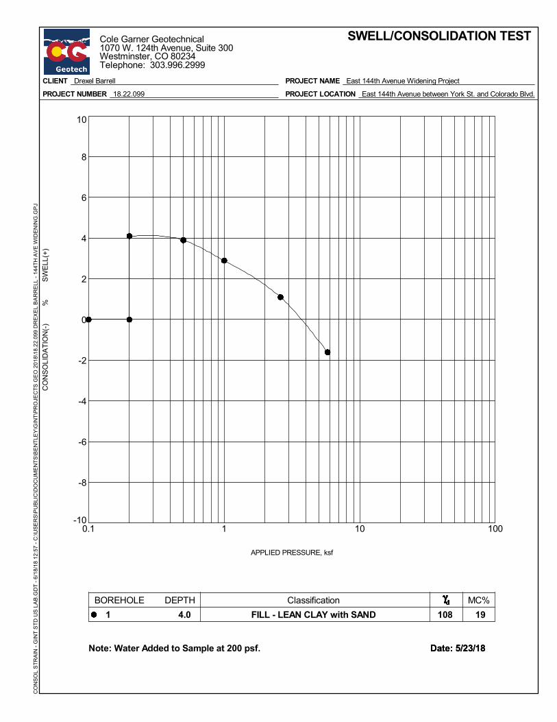
-10
-8
-6
-4
-2
0
2
4
6
8
10
0.1 1 10 100
CO
NSO
LID
ATIO
N(-)
%
SW
ELL(
+)
APPLIED PRESSURE, ksf
SWELL/CONSOLIDATION TEST
108 19
Date: 5/23/18Date: 5/23/18Note: Water Added to Sample at 200 psf.
CLIENT Drexel Barrell
PROJECT NUMBER 18.22.099
PROJECT NAME East 144th Avenue Widening Project
PROJECT LOCATION East 144th Avenue between York St. and Colorado Blvd.
BOREHOLE DEPTH1 4.0 FILL - LEAN CLAY with SAND
Classification MC%
CO
NSO
L S
TRAI
N -
GIN
T ST
D U
S LA
B.G
DT
- 6/1
8/18
12:
57 -
C:\U
SER
S\P
UBL
IC\D
OC
UM
ENTS
\BEN
TLEY
\GIN
T\PR
OJE
CTS
GEO
201
8\18
.22.
099
DR
EXEL
BAR
REL
L - 1
44TH
AVE
WID
ENIN
G.G
PJCole Garner Geotechnical1070 W. 124th Avenue, Suite 300Westminster, CO 80234Telephone: 303.996.2999

-10
-8
-6
-4
-2
0
2
4
6
8
10
0.1 1 10 100
CO
NSO
LID
ATIO
N(-)
%
SW
ELL(
+)
APPLIED PRESSURE, ksf
SWELL/CONSOLIDATION TEST
122 7
Date: 5/22/18Date: 5/22/18Note: Water Added to Sample at 200 psf.
CLIENT Drexel Barrell
PROJECT NUMBER 18.22.099
PROJECT NAME East 144th Avenue Widening Project
PROJECT LOCATION East 144th Avenue between York St. and Colorado Blvd.
BOREHOLE DEPTH2 2.0 SANDY LEAN CLAY
Classification MC%
CO
NSO
L S
TRAI
N -
GIN
T ST
D U
S LA
B.G
DT
- 6/1
8/18
12:
57 -
C:\U
SER
S\P
UBL
IC\D
OC
UM
ENTS
\BEN
TLEY
\GIN
T\PR
OJE
CTS
GEO
201
8\18
.22.
099
DR
EXEL
BAR
REL
L - 1
44TH
AVE
WID
ENIN
G.G
PJCole Garner Geotechnical1070 W. 124th Avenue, Suite 300Westminster, CO 80234Telephone: 303.996.2999

-10
-8
-6
-4
-2
0
2
4
6
8
10
0.1 1 10 100
CO
NSO
LID
ATIO
N(-)
%
SW
ELL(
+)
APPLIED PRESSURE, ksf
SWELL/CONSOLIDATION TEST
105 20
Date: 5/22/18Date: 5/22/18Note: Water Added to Sample at 200 psf.
CLIENT Drexel Barrell
PROJECT NUMBER 18.22.099
PROJECT NAME East 144th Avenue Widening Project
PROJECT LOCATION East 144th Avenue between York St. and Colorado Blvd.
BOREHOLE DEPTH3 9.0 CLAYSTONE BEDROCK
Classification MC%
CO
NSO
L S
TRAI
N -
GIN
T ST
D U
S LA
B.G
DT
- 6/1
8/18
12:
57 -
C:\U
SER
S\P
UBL
IC\D
OC
UM
ENTS
\BEN
TLEY
\GIN
T\PR
OJE
CTS
GEO
201
8\18
.22.
099
DR
EXEL
BAR
REL
L - 1
44TH
AVE
WID
ENIN
G.G
PJCole Garner Geotechnical1070 W. 124th Avenue, Suite 300Westminster, CO 80234Telephone: 303.996.2999
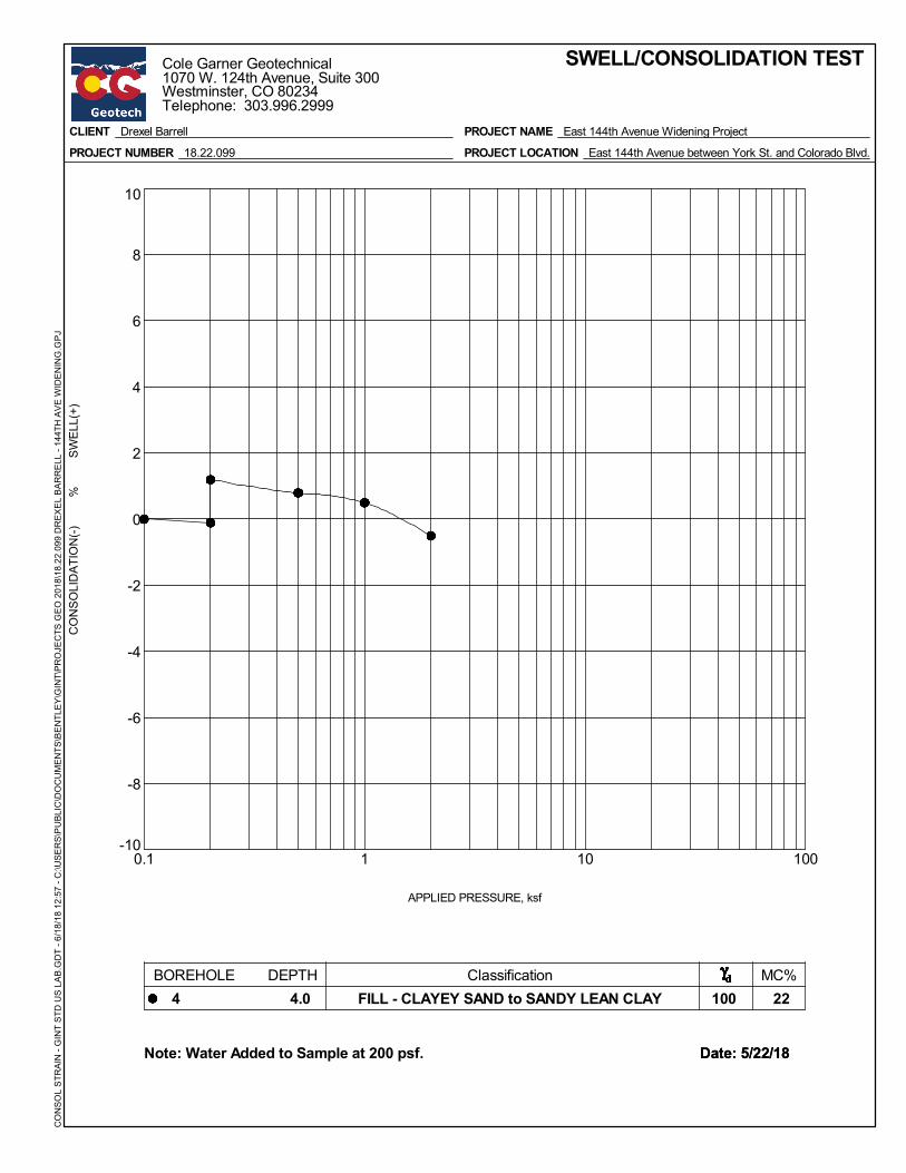
-10
-8
-6
-4
-2
0
2
4
6
8
10
0.1 1 10 100
CO
NSO
LID
ATIO
N(-)
%
SW
ELL(
+)
APPLIED PRESSURE, ksf
SWELL/CONSOLIDATION TEST
100 22
Date: 5/22/18Date: 5/22/18Note: Water Added to Sample at 200 psf.
CLIENT Drexel Barrell
PROJECT NUMBER 18.22.099
PROJECT NAME East 144th Avenue Widening Project
PROJECT LOCATION East 144th Avenue between York St. and Colorado Blvd.
BOREHOLE DEPTH4 4.0 FILL - CLAYEY SAND to SANDY LEAN CLAY
Classification MC%
CO
NSO
L S
TRAI
N -
GIN
T ST
D U
S LA
B.G
DT
- 6/1
8/18
12:
57 -
C:\U
SER
S\P
UBL
IC\D
OC
UM
ENTS
\BEN
TLEY
\GIN
T\PR
OJE
CTS
GEO
201
8\18
.22.
099
DR
EXEL
BAR
REL
L - 1
44TH
AVE
WID
ENIN
G.G
PJCole Garner Geotechnical1070 W. 124th Avenue, Suite 300Westminster, CO 80234Telephone: 303.996.2999
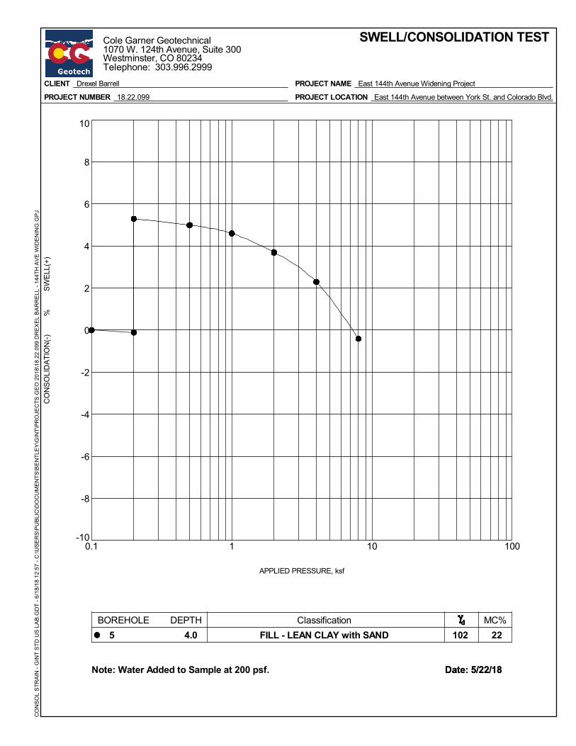
-10
-8
-6
-4
-2
0
2
4
6
8
10
0.1 1 10 100
CO
NSO
LID
ATIO
N(-)
%
SW
ELL(
+)
APPLIED PRESSURE, ksf
SWELL/CONSOLIDATION TEST
102 22
Date: 5/22/18Date: 5/22/18Note: Water Added to Sample at 200 psf.
CLIENT Drexel Barrell
PROJECT NUMBER 18.22.099
PROJECT NAME East 144th Avenue Widening Project
PROJECT LOCATION East 144th Avenue between York St. and Colorado Blvd.
BOREHOLE DEPTH5 4.0 FILL - LEAN CLAY with SAND
Classification MC%
CO
NSO
L S
TRAI
N -
GIN
T ST
D U
S LA
B.G
DT
- 6/1
8/18
12:
57 -
C:\U
SER
S\P
UBL
IC\D
OC
UM
ENTS
\BEN
TLEY
\GIN
T\PR
OJE
CTS
GEO
201
8\18
.22.
099
DR
EXEL
BAR
REL
L - 1
44TH
AVE
WID
ENIN
G.G
PJCole Garner Geotechnical1070 W. 124th Avenue, Suite 300Westminster, CO 80234Telephone: 303.996.2999
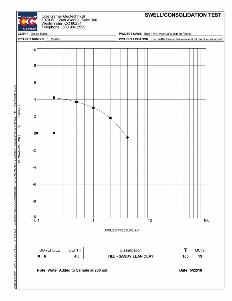
-10
-8
-6
-4
-2
0
2
4
6
8
10
0.1 1 10 100
CO
NSO
LID
ATIO
N(-)
%
SW
ELL(
+)
APPLIED PRESSURE, ksf
SWELL/CONSOLIDATION TEST
105 19
Date: 5/22/18Date: 5/22/18Note: Water Added to Sample at 200 psf.
CLIENT Drexel Barrell
PROJECT NUMBER 18.22.099
PROJECT NAME East 144th Avenue Widening Project
PROJECT LOCATION East 144th Avenue between York St. and Colorado Blvd.
BOREHOLE DEPTH6 4.0 FILL - SANDY LEAN CLAY
Classification MC%
CO
NSO
L S
TRAI
N -
GIN
T ST
D U
S LA
B.G
DT
- 6/1
8/18
12:
57 -
C:\U
SER
S\P
UBL
IC\D
OC
UM
ENTS
\BEN
TLEY
\GIN
T\PR
OJE
CTS
GEO
201
8\18
.22.
099
DR
EXEL
BAR
REL
L - 1
44TH
AVE
WID
ENIN
G.G
PJCole Garner Geotechnical1070 W. 124th Avenue, Suite 300Westminster, CO 80234Telephone: 303.996.2999

-10
-8
-6
-4
-2
0
2
4
6
8
10
0.1 1 10 100
CO
NSO
LID
ATIO
N(-)
%
SW
ELL(
+)
APPLIED PRESSURE, ksf
SWELL/CONSOLIDATION TEST
108 15
Date: 5/22/18Date: 5/22/18Note: Water Added to Sample at 200 psf.
CLIENT Drexel Barrell
PROJECT NUMBER 18.22.099
PROJECT NAME East 144th Avenue Widening Project
PROJECT LOCATION East 144th Avenue between York St. and Colorado Blvd.
BOREHOLE DEPTH7 2.0 FILL - SANDY LEAN CLAY
Classification MC%
CO
NSO
L S
TRAI
N -
GIN
T ST
D U
S LA
B.G
DT
- 6/1
8/18
12:
57 -
C:\U
SER
S\P
UBL
IC\D
OC
UM
ENTS
\BEN
TLEY
\GIN
T\PR
OJE
CTS
GEO
201
8\18
.22.
099
DR
EXEL
BAR
REL
L - 1
44TH
AVE
WID
ENIN
G.G
PJCole Garner Geotechnical1070 W. 124th Avenue, Suite 300Westminster, CO 80234Telephone: 303.996.2999
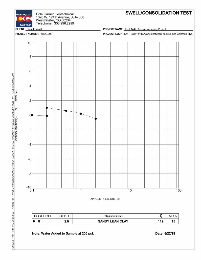
-10
-8
-6
-4
-2
0
2
4
6
8
10
0.1 1 10 100
CO
NSO
LID
ATIO
N(-)
%
SW
ELL(
+)
APPLIED PRESSURE, ksf
SWELL/CONSOLIDATION TEST
112 15
Date: 5/22/18Date: 5/22/18Note: Water Added to Sample at 200 psf.
CLIENT Drexel Barrell
PROJECT NUMBER 18.22.099
PROJECT NAME East 144th Avenue Widening Project
PROJECT LOCATION East 144th Avenue between York St. and Colorado Blvd.
BOREHOLE DEPTH8 2.0 SANDY LEAN CLAY
Classification MC%
CO
NSO
L S
TRAI
N -
GIN
T ST
D U
S LA
B.G
DT
- 6/1
8/18
12:
57 -
C:\U
SER
S\P
UBL
IC\D
OC
UM
ENTS
\BEN
TLEY
\GIN
T\PR
OJE
CTS
GEO
201
8\18
.22.
099
DR
EXEL
BAR
REL
L - 1
44TH
AVE
WID
ENIN
G.G
PJCole Garner Geotechnical1070 W. 124th Avenue, Suite 300Westminster, CO 80234Telephone: 303.996.2999
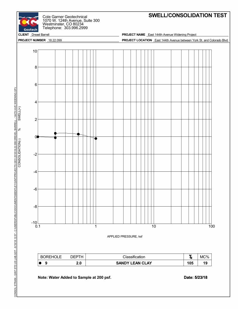
-10
-8
-6
-4
-2
0
2
4
6
8
10
0.1 1 10 100
CO
NSO
LID
ATIO
N(-)
%
SW
ELL(
+)
APPLIED PRESSURE, ksf
SWELL/CONSOLIDATION TEST
105 19
Date: 5/23/18Date: 5/23/18Note: Water Added to Sample at 200 psf.
CLIENT Drexel Barrell
PROJECT NUMBER 18.22.099
PROJECT NAME East 144th Avenue Widening Project
PROJECT LOCATION East 144th Avenue between York St. and Colorado Blvd.
BOREHOLE DEPTH9 2.0 SANDY LEAN CLAY
Classification MC%
CO
NSO
L S
TRAI
N -
GIN
T ST
D U
S LA
B.G
DT
- 6/1
8/18
12:
57 -
C:\U
SER
S\P
UBL
IC\D
OC
UM
ENTS
\BEN
TLEY
\GIN
T\PR
OJE
CTS
GEO
201
8\18
.22.
099
DR
EXEL
BAR
REL
L - 1
44TH
AVE
WID
ENIN
G.G
PJCole Garner Geotechnical1070 W. 124th Avenue, Suite 300Westminster, CO 80234Telephone: 303.996.2999

-10
-8
-6
-4
-2
0
2
4
6
8
10
0.1 1 10 100
CO
NSO
LID
ATIO
N(-)
%
SW
ELL(
+)
APPLIED PRESSURE, ksf
SWELL/CONSOLIDATION TEST
102 22
Date: 5/23/18Date: 5/23/18Note: Water Added to Sample at 200 psf.
CLIENT Drexel Barrell
PROJECT NUMBER 18.22.099
PROJECT NAME East 144th Avenue Widening Project
PROJECT LOCATION East 144th Avenue between York St. and Colorado Blvd.
BOREHOLE DEPTH11 9.0 CLAYSTONE BEDROCK
Classification MC%
CO
NSO
L S
TRAI
N -
GIN
T ST
D U
S LA
B.G
DT
- 6/1
8/18
12:
57 -
C:\U
SER
S\P
UBL
IC\D
OC
UM
ENTS
\BEN
TLEY
\GIN
T\PR
OJE
CTS
GEO
201
8\18
.22.
099
DR
EXEL
BAR
REL
L - 1
44TH
AVE
WID
ENIN
G.G
PJCole Garner Geotechnical1070 W. 124th Avenue, Suite 300Westminster, CO 80234Telephone: 303.996.2999
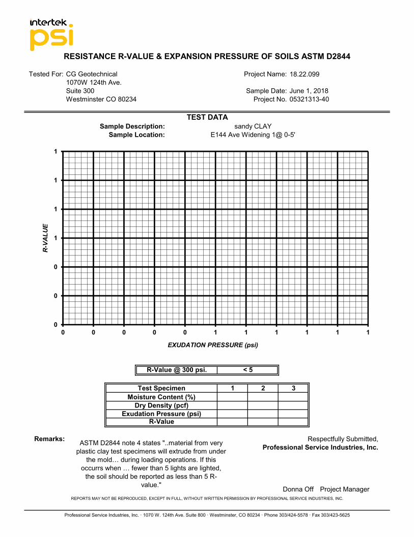
Sample Description:Sample Location:
Respectfully Submitted,Professional Service Industries, Inc.
REPORTS MAY NOT BE REPRODUCED, EXCEPT IN FULL, WITHOUT WRITTEN PERMISSION BY PROFESSIONAL SERVICE INDUSTRIES, INC.
Professional Service Industries, Inc. · 1070 W. 124th Ave. Suite 800 · Westminster, CO 80234 · Phone 303/424-5578 · Fax 303/423-5625
sandy CLAYE144 Ave Widening 1@ 0-5'
Project Manager
Sample Date: June 1, 2018Westminster CO 80234 Project No. 05321313-40
Remarks: ASTM D2844 note 4 states "..material from very plastic clay test specimens will extrude from under
the mold… during loading operations. If this occurrs when … fewer than 5 lights are lighted,
the soil should be reported as less than 5 R-value."
RESISTANCE R-VALUE & EXPANSION PRESSURE OF SOILS ASTM D2844
Tested For: CG Geotechnical Project Name: 18.22.099
R-Value @ 300 psi.
1070W 124th Ave.
TEST DATA
Suite 300
3#DIV/0!
< 5
Moisture Content (%)
Exudation Pressure (psi)#DIV/0!Dry Density (pcf)
Sample Location:
R-Value
1 2#DIV/0!#DIV/0!
Test Specimen
Donna Off
#DIV/0!#DIV/0!
0
0
0
1
1
1
1
0 0 0 0 0 1 1 1 1 1 1
R-V
ALU
E
EXUDATION PRESSURE (psi)
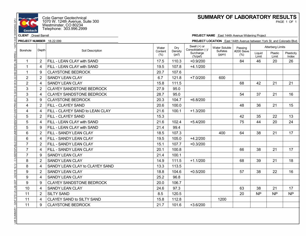
1 2 FILL - LEAN CLAY with SAND 17.5 110.3 +0.9/200 84 46 20 261 4 FILL - LEAN CLAY with SAND 19.5 107.8 +4.1/2001 9 CLAYSTONE BEDROCK 20.7 107.62 2 SANDY LEAN CLAY 6.7 121.8 +7.0/200 6002 4 SANDY LEAN CLAY 15.8 111.5 68 42 21 213 2 CLAYEY SANDSTONE BEDROCK 27.9 95.03 4 CLAYEY SANDSTONE BEDROCK 28.7 95.0 54 37 21 163 9 CLAYSTONE BEDROCK 20.3 104.7 +6.8/2004 2 FILL - CLAYEY SAND 20.6 100.0 48 36 21 154 4 FILL - CLAYEY SAND to LEAN CLAY 21.6 100.1 +1.3/2005 2 FILL - CLAYEY SAND 15.3 42 35 22 135 4 FILL - LEAN CLAY with SAND 21.6 102.4 +5.4/200 75 44 20 245 9 FILL - LEAN CLAY with SAND 21.4 99.46 2 FILL - SANDY LEAN CLAY 18.5 107.3 400 64 38 21 176 4 FILL - SANDY LEAN CLAY 19.5 105.0 +4.2/2007 2 FILL - SANDY LEAN CLAY 15.1 107.7 +0.3/2007 4 FILL - SANDY LEAN CLAY 20.1 100.8 66 38 21 177 9 SANDY LEAN CLAY 21.4 100.18 2 SANDY LEAN CLAY 14.9 111.5 +1.1/200 68 39 21 188 4 SANDY LEAN CLAY to CLAYEY SAND 13.3 113.59 2 SANDY LEAN CLAY 18.8 104.6 +0.5/200 57 38 22 169 4 SANDY LEAN CLAY 25.2 96.89 9 CLAYEY SANDSTONE BEDROCK 20.0 106.710 4 SANDY LEAN CLAY 24.6 97.3 63 38 21 1711 2 SILTY SAND 8.5 120.5 20 NP NP NP11 4 CLAYEY SAND to SILTY SAND 15.8 112.8 120011 9 CLAYSTONE BEDROCK 21.7 101.6 +3.6/200
WaterContent
(%)
PAGE 1 OF 1
LiquidLimit
Atterberg LimitsSwell (+) orConsolidation (-)/
Surcharge(%/psf)
DryDensity
(pcf)
Passing#200 Sieve
(%)
Water SolubleSulfates(ppm)
SUMMARY OF LABORATORY RESULTS
Soil DescriptionPlasticLimit
PlasticityIndex
Borehole Depth
CLIENT Drexel Barrell
PROJECT NUMBER 18.22.099
PROJECT NAME East 144th Avenue Widening Project
PROJECT LOCATION East 144th Avenue between York St. and Colorado Blvd.
LAB
SUM
MAR
Y - G
INT
STD
US
LAB.
GD
T - 6
/20/
18 1
6:12
- C
:\USE
RS\
PU
BLIC
\DO
CU
MEN
TS\B
ENTL
EY\G
INT\
PRO
JEC
TS G
EO 2
018\
18.2
2.09
9 D
REX
EL B
ARR
ELL
- 144
TH A
VE W
IDEN
ING
.GPJ
Cole Garner Geotechnical1070 W. 124th Avenue, Suite 300Westminster, CO 80234Telephone: 303.996.2999
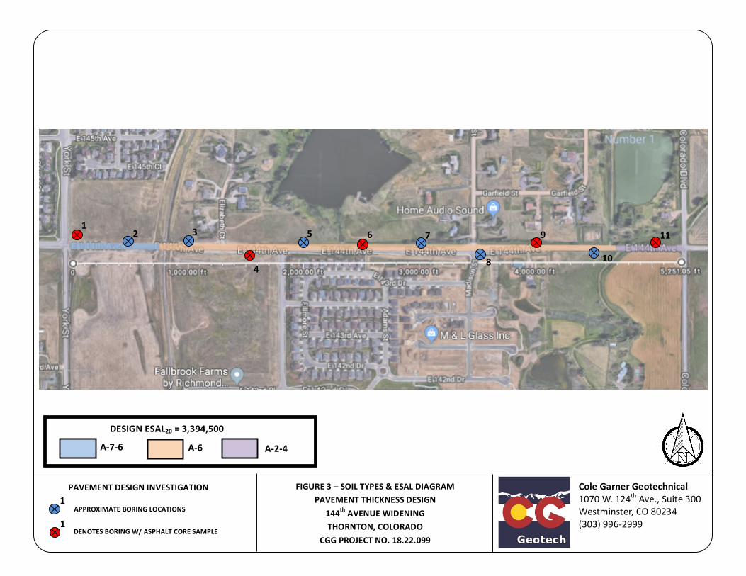
APPROXIMATEBORINGLOCATIONS
ColeGarnerGeotechnical1070W.124thAve.,Suite300Westminster,CO80234(303)996-2999
1
1DENOTESBORINGW/ASPHALTCORESAMPLE
PAVEMENTDESIGNINVESTIGATION
FIGURE3–SOILTYPES&ESALDIAGRAMPAVEMENTTHICKNESSDESIGN
144thAVENUEWIDENINGTHORNTON,COLORADO
CGGPROJECTNO.18.22.099
12
113
4
5
6 7
8
9
10
DESIGNESAL20=3,394,500
A-7-6 A-6 A-2-4

Cole Garner Geotechnical Page 1 Geotechnical Engineering and Materials Testing
APPENDIX C
GENERAL NOTES
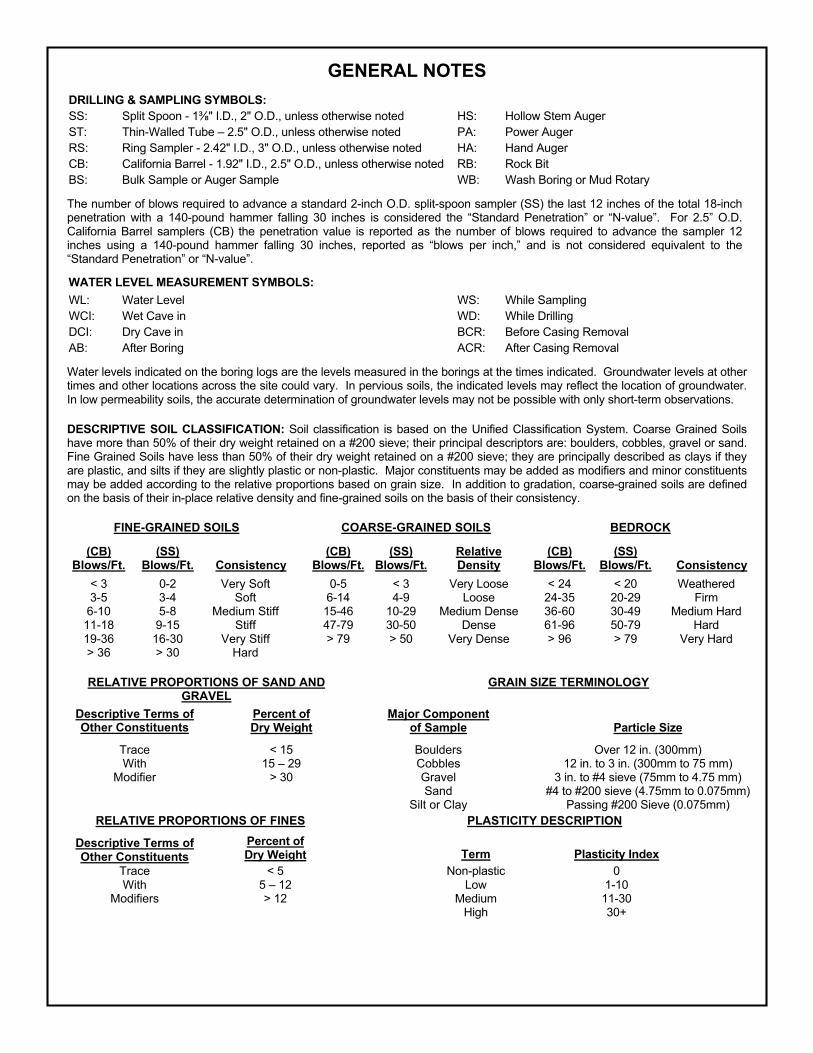
GENERAL NOTES DRILLING & SAMPLING SYMBOLS: SS: Split Spoon - 1!" I.D., 2" O.D., unless otherwise noted HS: Hollow Stem Auger ST: Thin-Walled Tube – 2.5" O.D., unless otherwise noted PA: Power Auger RS: Ring Sampler - 2.42" I.D., 3" O.D., unless otherwise noted HA: Hand Auger CB: California Barrel - 1.92" I.D., 2.5" O.D., unless otherwise noted RB: Rock Bit BS: Bulk Sample or Auger Sample WB: Wash Boring or Mud Rotary
The number of blows required to advance a standard 2-inch O.D. split-spoon sampler (SS) the last 12 inches of the total 18-inch penetration with a 140-pound hammer falling 30 inches is considered the “Standard Penetration” or “N-value”. For 2.5” O.D. California Barrel samplers (CB) the penetration value is reported as the number of blows required to advance the sampler 12 inches using a 140-pound hammer falling 30 inches, reported as “blows per inch,” and is not considered equivalent to the “Standard Penetration” or “N-value”.
WATER LEVEL MEASUREMENT SYMBOLS: WL: Water Level WS: While Sampling WCI: Wet Cave in WD: While Drilling DCI: Dry Cave in BCR: Before Casing Removal AB: After Boring ACR: After Casing Removal
Water levels indicated on the boring logs are the levels measured in the borings at the times indicated. Groundwater levels at other times and other locations across the site could vary. In pervious soils, the indicated levels may reflect the location of groundwater. In low permeability soils, the accurate determination of groundwater levels may not be possible with only short-term observations.
DESCRIPTIVE SOIL CLASSIFICATION: Soil classification is based on the Unified Classification System. Coarse Grained Soils have more than 50% of their dry weight retained on a #200 sieve; their principal descriptors are: boulders, cobbles, gravel or sand. Fine Grained Soils have less than 50% of their dry weight retained on a #200 sieve; they are principally described as clays if they are plastic, and silts if they are slightly plastic or non-plastic. Major constituents may be added as modifiers and minor constituents may be added according to the relative proportions based on grain size. In addition to gradation, coarse-grained soils are defined on the basis of their in-place relative density and fine-grained soils on the basis of their consistency.
FINE-GRAINED SOILS COARSE-GRAINED SOILS BEDROCK
(CB) Blows/Ft.
(SS) Blows/Ft.
Consistency
(CB) Blows/Ft.
(SS) Blows/Ft.
Relative Density
(CB) Blows/Ft.
(SS) Blows/Ft.
Consistency
< 3 0-2 Very Soft 0-5 < 3 Very Loose < 24 < 20 Weathered 3-5 3-4 Soft 6-14 4-9 Loose 24-35 20-29 Firm
6-10 5-8 Medium Stiff 15-46 10-29 Medium Dense 36-60 30-49 Medium Hard 11-18 9-15 Stiff 47-79 30-50 Dense 61-96 50-79 Hard 19-36 16-30 Very Stiff > 79 > 50 Very Dense > 96 > 79 Very Hard > 36 > 30 Hard
RELATIVE PROPORTIONS OF SAND AND GRAVEL
GRAIN SIZE TERMINOLOGY
Descriptive Terms of Other Constituents
Percent of Dry Weight
Major Component of Sample
Particle Size
Trace < 15 Boulders Over 12 in. (300mm) With 15 – 29 Cobbles 12 in. to 3 in. (300mm to 75 mm)
Modifier > 30 Gravel 3 in. to #4 sieve (75mm to 4.75 mm)
Sand
Silt or Clay #4 to #200 sieve (4.75mm to 0.075mm)
Passing #200 Sieve (0.075mm) RELATIVE PROPORTIONS OF FINES PLASTICITY DESCRIPTION
Descriptive Terms of Other Constituents
Percent of Dry Weight
Term Plasticity Index
Trace With
Modifiers
< 5 5 – 12 > 12
Non-plastic
Low Medium
High
0 1-10 11-30 30+
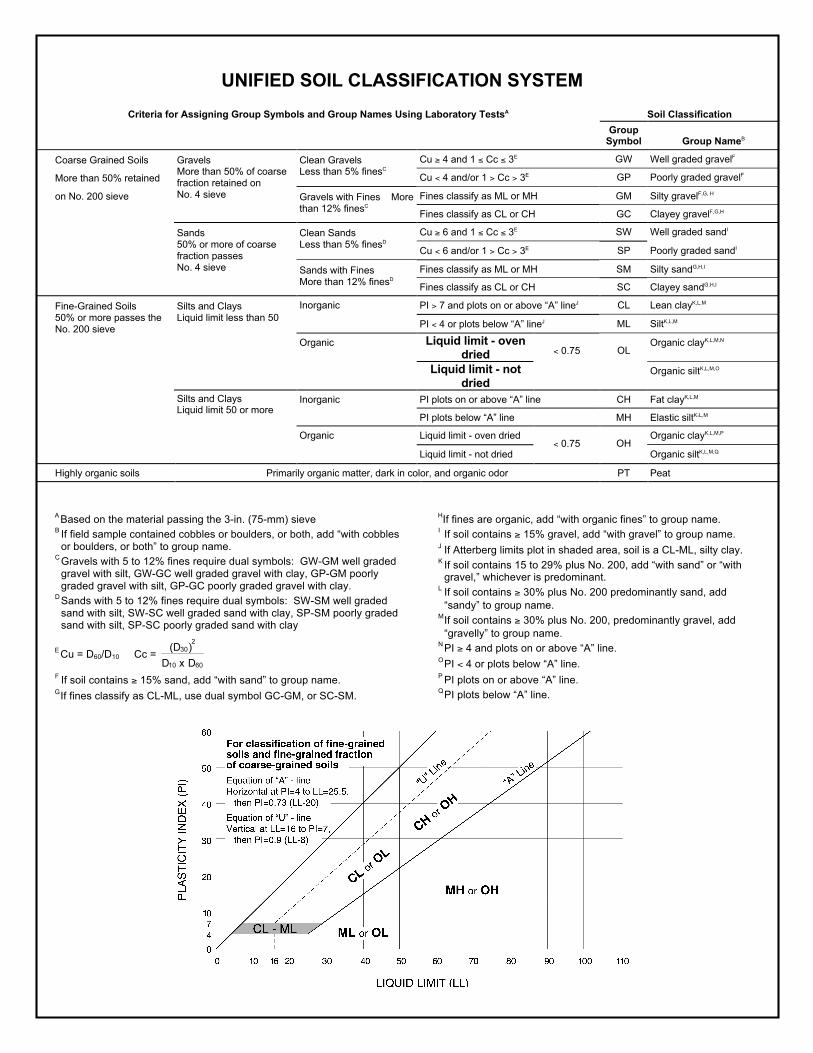
UNIFIED SOIL CLASSIFICATION SYSTEM Criteria for Assigning Group Symbols and Group Names Using Laboratory TestsA Soil Classification
Group Symbol
Group NameB
Cu ! 4 and 1 " Cc " 3E GW Well graded gravelF Clean Gravels Less than 5% finesC Cu < 4 and/or 1 > Cc > 3E GP Poorly graded gravelF
Fines classify as ML or MH GM Silty gravelF,G, H
Coarse Grained Soils
More than 50% retained
on No. 200 sieve
Gravels More than 50% of coarse fraction retained on No. 4 sieve Gravels with Fines More
than 12% finesC Fines classify as CL or CH GC Clayey gravelF,G,H
Cu ! 6 and 1 " Cc " 3E SW Well graded sandI Clean Sands Less than 5% finesD Cu < 6 and/or 1 > Cc > 3E SP Poorly graded sandI
Fines classify as ML or MH SM Silty sandG,H,I
Sands 50% or more of coarse fraction passes No. 4 sieve Sands with Fines
More than 12% finesD Fines classify as CL or CH SC Clayey sandG,H,I
PI > 7 and plots on or above “A” lineJ CL Lean clayK,L,M Silts and Clays Liquid limit less than 50
Inorganic
PI < 4 or plots below “A” lineJ ML SiltK,L,M
Liquid limit - oven dried
Organic clayK,L,M,N
Fine-Grained Soils 50% or more passes the No. 200 sieve
Organic
Liquid limit - not dried
< 0.75 OL
Organic siltK,L,M,O
Inorganic PI plots on or above “A” line CH Fat clayK,L,M
Silts and Clays Liquid limit 50 or more
PI plots below “A” line MH Elastic siltK,L,M
Liquid limit - oven dried Organic clayK,L,M,P Organic
Liquid limit - not dried < 0.75 OH
Organic siltK,L,M,Q
Highly organic soils Primarily organic matter, dark in color, and organic odor PT Peat
A Based on the material passing the 3-in. (75-mm) sieve B If field sample contained cobbles or boulders, or both, add “with cobbles
or boulders, or both” to group name. C Gravels with 5 to 12% fines require dual symbols: GW-GM well graded
gravel with silt, GW-GC well graded gravel with clay, GP-GM poorly graded gravel with silt, GP-GC poorly graded gravel with clay.
D Sands with 5 to 12% fines require dual symbols: SW-SM well graded sand with silt, SW-SC well graded sand with clay, SP-SM poorly graded sand with silt, SP-SC poorly graded sand with clay
E Cu = D60/D10 Cc =
F If soil contains ! 15% sand, add “with sand” to group name. G If fines classify as CL-ML, use dual symbol GC-GM, or SC-SM.
HIf fines are organic, add “with organic fines” to group name. I If soil contains ! 15% gravel, add “with gravel” to group name. J If Atterberg limits plot in shaded area, soil is a CL-ML, silty clay. K If soil contains 15 to 29% plus No. 200, add “with sand” or “with
gravel,” whichever is predominant. L If soil contains ! 30% plus No. 200 predominantly sand, add
“sandy” to group name. M If soil contains ! 30% plus No. 200, predominantly gravel, add
“gravelly” to group name. N PI ! 4 and plots on or above “A” line. O PI < 4 or plots below “A” line. P PI plots on or above “A” line. Q PI plots below “A” line.
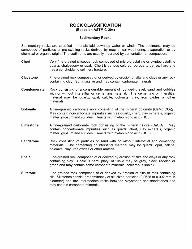
ROCK CLASSIFICATION (Based on ASTM C-294)
Sedimentary Rocks
Sedimentary rocks are stratified materials laid down by water or wind. The sediments may be composed of particles or pre-existing rocks derived by mechanical weathering, evaporation or by chemical or organic origin. The sediments are usually indurated by cementation or compaction.
Chert Very fine-grained siliceous rock composed of micro-crystalline or cyrptocrystalline
quartz, chalcedony or opal. Chert is various colored, porous to dense, hard and has a conchoidal to splintery fracture.
Claystone Fine-grained rock composed of or derived by erosion of silts and clays or any rock
containing clay. Soft massive and may contain carbonate minerals. Conglomerate Rock consisting of a considerable amount of rounded gravel, sand and cobbles
with or without interstitial or cementing material. The cementing or interstitial material may be quartz, opal, calcite, dolomite, clay, iron oxides or other materials.
Dolomite A fine-grained carbonate rock consisting of the mineral dolomite [CaMg(CO3)2].
May contain noncarbonate impurities such as quartz, chert, clay minerals, organic matter, gypsum and sulfides. Reacts with hydrochloric acid (HCL).
Limestone A fine-grained carbonate rock consisting of the mineral calcite (CaCO3). May
contain noncarbonate impurities such as quartz, chert, clay minerals, organic matter, gypsum and sulfides. Reacts with hydrochloric acid (HCL).
Sandstone Rock consisting of particles of sand with or without interstitial and cementing
materials. The cementing or interstitial material may be quartz, opal, calcite, dolomite, clay, iron oxides or other material.
Shale Fine-grained rock composed of or derived by erosion of silts and clays or any rock
containing clay. Shale is hard, platy, of fissile may be gray, black, reddish or green and may contain some carbonate minerals (calcareous shale).
Siltstone Fine grained rock composed of or derived by erosion of silts or rock containing
silt. Siltstones consist predominantly of silt sized particles (0.0625 to 0.002 mm in diameter) and are intermediate rocks between claystones and sandstones and may contain carbonate minerals.
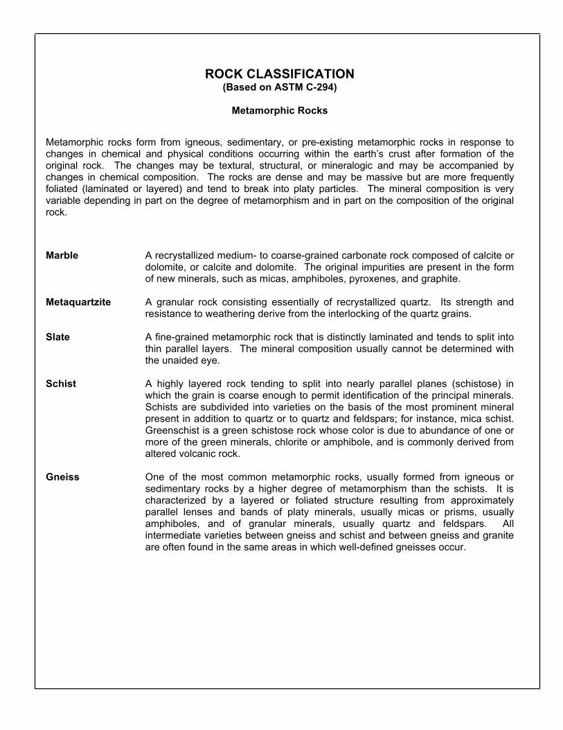
ROCK CLASSIFICATION (Based on ASTM C-294)
Metamorphic Rocks
Metamorphic rocks form from igneous, sedimentary, or pre-existing metamorphic rocks in response to changes in chemical and physical conditions occurring within the earth’s crust after formation of the original rock. The changes may be textural, structural, or mineralogic and may be accompanied by changes in chemical composition. The rocks are dense and may be massive but are more frequently foliated (laminated or layered) and tend to break into platy particles. The mineral composition is very variable depending in part on the degree of metamorphism and in part on the composition of the original rock.
Marble A recrystallized medium- to coarse-grained carbonate rock composed of calcite or
dolomite, or calcite and dolomite. The original impurities are present in the form of new minerals, such as micas, amphiboles, pyroxenes, and graphite.
Metaquartzite A granular rock consisting essentially of recrystallized quartz. Its strength and
resistance to weathering derive from the interlocking of the quartz grains. Slate A fine-grained metamorphic rock that is distinctly laminated and tends to split into
thin parallel layers. The mineral composition usually cannot be determined with the unaided eye.
Schist A highly layered rock tending to split into nearly parallel planes (schistose) in
which the grain is coarse enough to permit identification of the principal minerals. Schists are subdivided into varieties on the basis of the most prominent mineral present in addition to quartz or to quartz and feldspars; for instance, mica schist. Greenschist is a green schistose rock whose color is due to abundance of one or more of the green minerals, chlorite or amphibole, and is commonly derived from altered volcanic rock.
Gneiss One of the most common metamorphic rocks, usually formed from igneous or
sedimentary rocks by a higher degree of metamorphism than the schists. It is characterized by a layered or foliated structure resulting from approximately parallel lenses and bands of platy minerals, usually micas or prisms, usually amphiboles, and of granular minerals, usually quartz and feldspars. All intermediate varieties between gneiss and schist and between gneiss and granite are often found in the same areas in which well-defined gneisses occur.
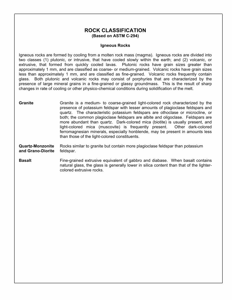
ROCK CLASSIFICATION (Based on ASTM C-294)
Igneous Rocks
Igneous rocks are formed by cooling from a molten rock mass (magma). Igneous rocks are divided into two classes (1) plutonic, or intrusive, that have cooled slowly within the earth; and (2) volcanic, or extrusive, that formed from quickly cooled lavas. Plutonic rocks have grain sizes greater than approximately 1 mm, and are classified as coarse- or medium-grained. Volcanic rocks have grain sizes less than approximately 1 mm, and are classified as fine-grained. Volcanic rocks frequently contain glass. Both plutonic and volcanic rocks may consist of porphyries that are characterized by the presence of large mineral grains in a fine-grained or glassy groundmass. This is the result of sharp changes in rate of cooling or other physico-chemical conditions during solidification of the melt. Granite Granite is a medium- to coarse-grained light-colored rock characterized by the
presence of potassium feldspar with lesser amounts of plagioclase feldspars and quartz. The characteristic potassium feldspars are othoclase or microcline, or both; the common plagioclase feldspars are albite and oligoclase. Feldspars are more abundant than quartz. Dark-colored mica (biotite) is usually present, and light-colored mica (muscovite) is frequently present. Other dark-colored ferromagnesian minerals, especially honblende, may be present in amounts less than those of the light-colored constituents.
Quartz-Monzonite Rocks similar to granite but contain more plagioclase feldspar than potassium and Grano-Diorite feldspar. Basalt Fine-grained extrusive equivalent of gabbro and diabase. When basalt contains
natural glass, the glass is generally lower in silica content than that of the lighter-colored extrusive rocks.
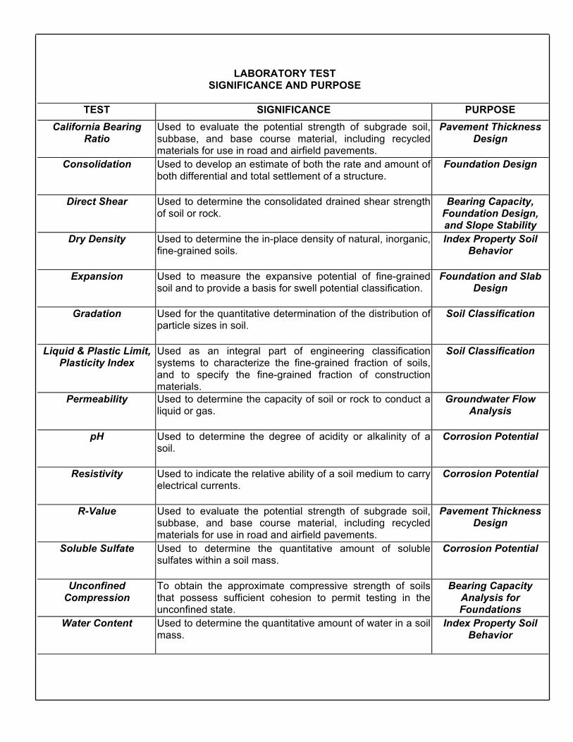
LABORATORY TEST SIGNIFICANCE AND PURPOSE
TEST SIGNIFICANCE PURPOSE
California Bearing Ratio
Used to evaluate the potential strength of subgrade soil, subbase, and base course material, including recycled materials for use in road and airfield pavements.
Pavement Thickness Design
Consolidation Used to develop an estimate of both the rate and amount of both differential and total settlement of a structure.
Foundation Design
Direct Shear Used to determine the consolidated drained shear strength of soil or rock.
Bearing Capacity, Foundation Design, and Slope Stability
Dry Density Used to determine the in-place density of natural, inorganic, fine-grained soils.
Index Property Soil Behavior
Expansion Used to measure the expansive potential of fine-grained soil and to provide a basis for swell potential classification.
Foundation and Slab Design
Gradation Used for the quantitative determination of the distribution of particle sizes in soil.
Soil Classification
Liquid & Plastic Limit, Plasticity Index
Used as an integral part of engineering classification systems to characterize the fine-grained fraction of soils, and to specify the fine-grained fraction of construction materials.
Soil Classification
Permeability Used to determine the capacity of soil or rock to conduct a liquid or gas.
Groundwater Flow Analysis
pH Used to determine the degree of acidity or alkalinity of a soil.
Corrosion Potential
Resistivity Used to indicate the relative ability of a soil medium to carry electrical currents.
Corrosion Potential
R-Value Used to evaluate the potential strength of subgrade soil, subbase, and base course material, including recycled materials for use in road and airfield pavements.
Pavement Thickness Design
Soluble Sulfate Used to determine the quantitative amount of soluble sulfates within a soil mass.
Corrosion Potential
Unconfined Compression
To obtain the approximate compressive strength of soils that possess sufficient cohesion to permit testing in the unconfined state.
Bearing Capacity Analysis for Foundations
Water Content Used to determine the quantitative amount of water in a soil mass.
Index Property Soil Behavior
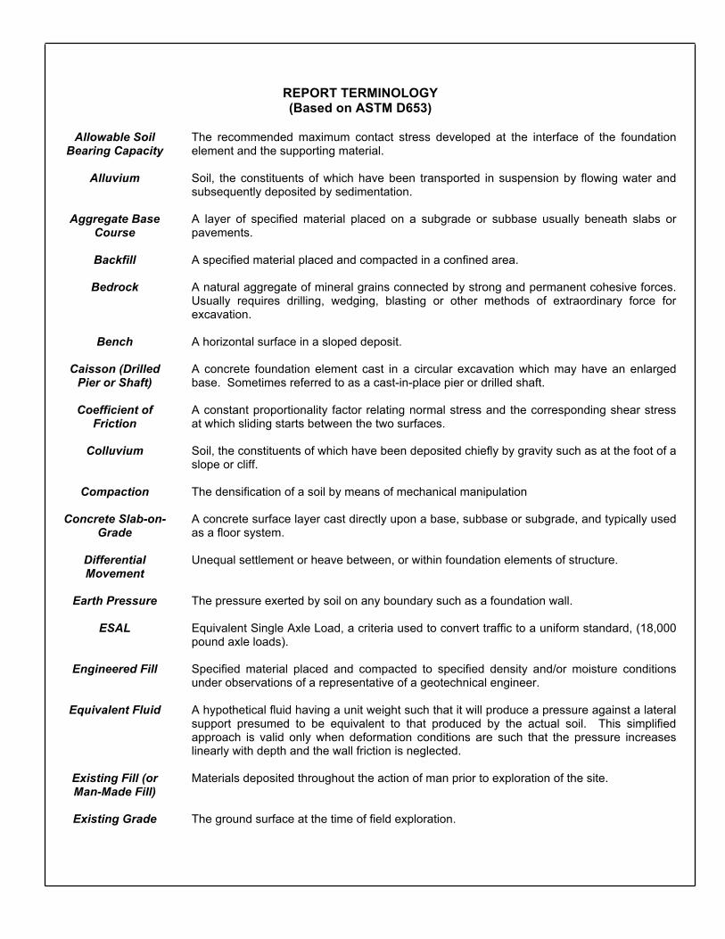
REPORT TERMINOLOGY (Based on ASTM D653)
Allowable Soil
Bearing Capacity The recommended maximum contact stress developed at the interface of the foundation
element and the supporting material.
Alluvium Soil, the constituents of which have been transported in suspension by flowing water and subsequently deposited by sedimentation.
Aggregate Base Course
A layer of specified material placed on a subgrade or subbase usually beneath slabs or pavements.
Backfill A specified material placed and compacted in a confined area.
Bedrock A natural aggregate of mineral grains connected by strong and permanent cohesive forces. Usually requires drilling, wedging, blasting or other methods of extraordinary force for excavation.
Bench A horizontal surface in a sloped deposit.
Caisson (Drilled Pier or Shaft)
A concrete foundation element cast in a circular excavation which may have an enlarged base. Sometimes referred to as a cast-in-place pier or drilled shaft.
Coefficient of Friction
A constant proportionality factor relating normal stress and the corresponding shear stress at which sliding starts between the two surfaces.
Colluvium Soil, the constituents of which have been deposited chiefly by gravity such as at the foot of a slope or cliff.
Compaction The densification of a soil by means of mechanical manipulation
Concrete Slab-on-Grade
A concrete surface layer cast directly upon a base, subbase or subgrade, and typically used as a floor system.
Differential Movement
Unequal settlement or heave between, or within foundation elements of structure.
Earth Pressure The pressure exerted by soil on any boundary such as a foundation wall.
ESAL Equivalent Single Axle Load, a criteria used to convert traffic to a uniform standard, (18,000 pound axle loads).
Engineered Fill Specified material placed and compacted to specified density and/or moisture conditions under observations of a representative of a geotechnical engineer.
Equivalent Fluid A hypothetical fluid having a unit weight such that it will produce a pressure against a lateral support presumed to be equivalent to that produced by the actual soil. This simplified approach is valid only when deformation conditions are such that the pressure increases linearly with depth and the wall friction is neglected.
Existing Fill (or Man-Made Fill)
Materials deposited throughout the action of man prior to exploration of the site.
Existing Grade The ground surface at the time of field exploration.
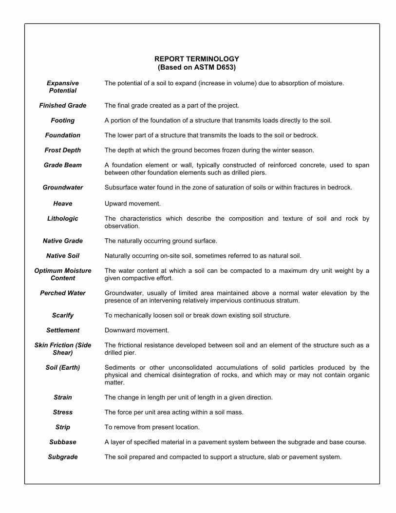
REPORT TERMINOLOGY (Based on ASTM D653)
Expansive Potential
The potential of a soil to expand (increase in volume) due to absorption of moisture.
Finished Grade The final grade created as a part of the project.
Footing A portion of the foundation of a structure that transmits loads directly to the soil.
Foundation The lower part of a structure that transmits the loads to the soil or bedrock.
Frost Depth The depth at which the ground becomes frozen during the winter season.
Grade Beam A foundation element or wall, typically constructed of reinforced concrete, used to span between other foundation elements such as drilled piers.
Groundwater Subsurface water found in the zone of saturation of soils or within fractures in bedrock.
Heave Upward movement.
Lithologic The characteristics which describe the composition and texture of soil and rock by observation.
Native Grade The naturally occurring ground surface.
Native Soil Naturally occurring on-site soil, sometimes referred to as natural soil.
Optimum Moisture Content
The water content at which a soil can be compacted to a maximum dry unit weight by a given compactive effort.
Perched Water Groundwater, usually of limited area maintained above a normal water elevation by the presence of an intervening relatively impervious continuous stratum.
Scarify To mechanically loosen soil or break down existing soil structure.
Settlement Downward movement.
Skin Friction (Side Shear)
The frictional resistance developed between soil and an element of the structure such as a drilled pier.
Soil (Earth) Sediments or other unconsolidated accumulations of solid particles produced by the physical and chemical disintegration of rocks, and which may or may not contain organic matter.
Strain The change in length per unit of length in a given direction.
Stress The force per unit area acting within a soil mass.
Strip To remove from present location.
Subbase A layer of specified material in a pavement system between the subgrade and base course.
Subgrade The soil prepared and compacted to support a structure, slab or pavement system.
Cole Garner Geotechnical Page 2 Geotechnical Engineering and Materials Testing
APPENDIX D
PAVEMENT DESIGN CALCULATIONS PAVEMENT SECTION ALTERNATIVES DIAGRAM
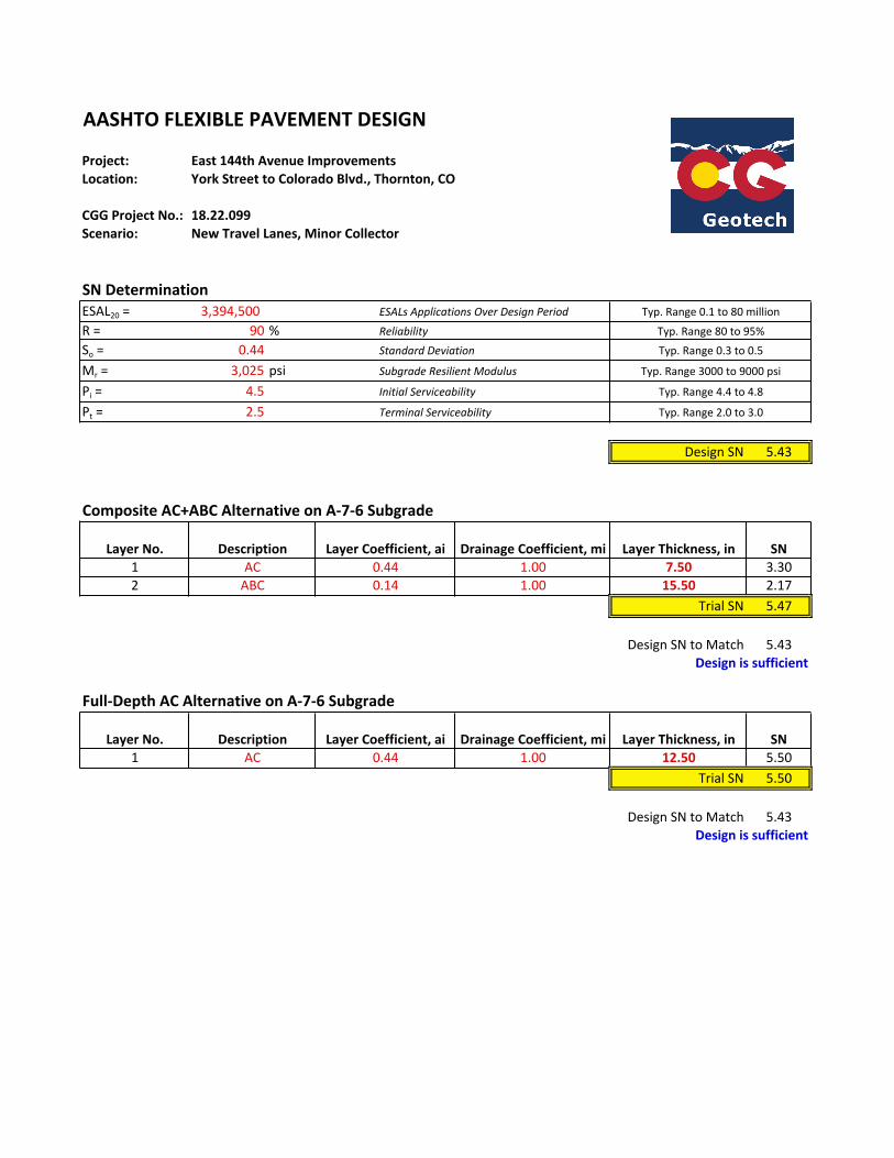
Project:Location:
CGGProjectNo.:Scenario:
SNDeterminationESAL20= 3,394,500R= 90 %So= 0.44Mr= 3,025 psiPi= 4.5Pt= 2.5
DesignSN 5.43
1 7.50 3.302 15.50 2.17
TrialSN 5.47
DesignSNtoMatch 5.43
1 12.50 5.50TrialSN 5.50
DesignSNtoMatch 5.43
TerminalServiceability
AASHTOFLEXIBLEPAVEMENTDESIGN
1.00
DrainageCoefficient,mi
East144thAvenueImprovementsYorkStreettoColoradoBlvd.,Thornton,CO
NewTravelLanes,MinorCollector18.22.099
ESALsApplicationsOverDesignPeriodReliabilityStandardDeviation
1.00
SNAC 0.44 1.00
Typ.Range2.0to3.0
Full-DepthACAlternativeonA-7-6Subgrade
InitialServiceability
CompositeAC+ABCAlternativeonA-7-6Subgrade
LayerNo. Description SNLayerCoefficient,ai DrainageCoefficient,mi LayerThickness,in
LayerThickness,in
Designissufficient
0.440.14
Description LayerCoefficient,ai
Typ.Range0.1to80million
Typ.Range80to95%Typ.Range0.3to0.5
Typ.Range3000to9000psi
Typ.Range4.4to4.8
LayerNo.
SubgradeResilientModulus
Designissufficient
ACABC
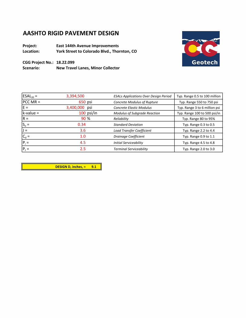
Project:Location:
CGGProjectNo.:Scenario:
ESAL20= 3,394,500 Typ.Range0.5to100million
PCCMR= 650 psi Typ.Range550to750psiE= 3,400,000 psi Typ.Range3to6millionpsik-value= 100 psi/in Typ.Range100to500psi/inR= 90 % Typ.Range80to95%So= 0.34 Typ.Range0.3to0.5
J= 3.6 Typ.Range2.2to4.4Cd= 1.0 Typ.Range0.9to1.1
Pi= 4.5 Typ.Range4.5to4.8
Pt= 2.5 Typ.Range2.0to3.0
DESIGND,inches,= 9.1
DrainageCoefficient
InitialServiceability
TerminalServiceability
NewTravelLanes,MinorCollector
ESALsApplicationsOverDesignPeriodConcreteModulusofRuptureConcreteElasticModulusModulusofSubgradeReactionReliability
AASHTORIGIDPAVEMENTDESIGN
East144thAvenueImprovementsYorkStreettoColoradoBlvd.,Thornton,CO
18.22.099
StandardDeviationLoadTransferCoefficient
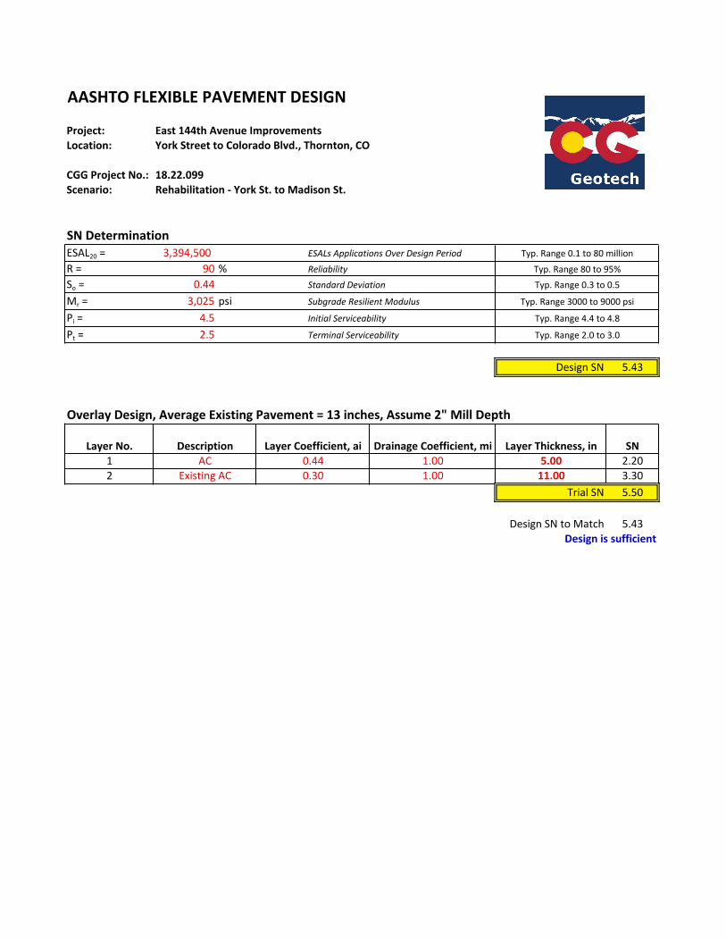
Project:Location:
CGGProjectNo.:Scenario:
SNDeterminationESAL20= 3,394,500R= 90 %So= 0.44Mr= 3,025 psiPi= 4.5Pt= 2.5
DesignSN 5.43
OverlayDesign,AverageExistingPavement=13inches,Assume2"MillDepth
1 5.00 2.202 11.00 3.30
TrialSN 5.50
DesignSNtoMatch 5.43Designissufficient
SNAC 0.44 1.00
ExistingAC 0.30 1.00
InitialServiceability Typ.Range4.4to4.8
TerminalServiceability Typ.Range2.0to3.0
LayerNo. Description LayerCoefficient,ai DrainageCoefficient,mi LayerThickness,in
Typ.Range0.1to80million
Reliability Typ.Range80to95%StandardDeviation Typ.Range0.3to0.5
SubgradeResilientModulus Typ.Range3000to9000psi
AASHTOFLEXIBLEPAVEMENTDESIGN
East144thAvenueImprovementsYorkStreettoColoradoBlvd.,Thornton,CO
18.22.099Rehabilitation-YorkSt.toMadisonSt.
ESALsApplicationsOverDesignPeriod
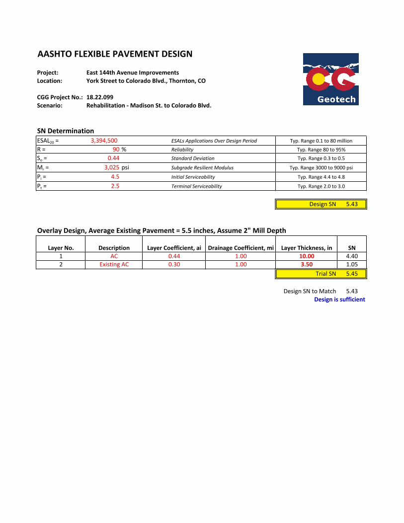
Project:Location:
CGGProjectNo.:Scenario:
SNDeterminationESAL20= 3,394,500R= 90 %So= 0.44Mr= 3,025 psiPi= 4.5Pt= 2.5
DesignSN 5.43
1 10.00 4.402 3.50 1.05
TrialSN 5.45
DesignSNtoMatch 5.43
OverlayDesign,AverageExistingPavement=5.5inches,Assume2"MillDepth
Designissufficient
AC 0.44 1.00ExistingAC 0.30 1.00
InitialServiceability Typ.Range4.4to4.8
TerminalServiceability Typ.Range2.0to3.0
LayerNo. Description LayerCoefficient,ai DrainageCoefficient,mi LayerThickness,in SN
Typ.Range0.1to80million
Reliability Typ.Range80to95%StandardDeviation Typ.Range0.3to0.5
SubgradeResilientModulus Typ.Range3000to9000psi
AASHTOFLEXIBLEPAVEMENTDESIGN
East144thAvenueImprovementsYorkStreettoColoradoBlvd.,Thornton,CO
18.22.099Rehabilitation-MadisonSt.toColoradoBlvd.
ESALsApplicationsOverDesignPeriod

APPROXIMATEBORINGLOCATIONS
ColeGarnerGeotechnical
1070W.124thAve.,Suite300Westminster,CO80234(303)996-2999
1
1DENOTESBORINGW/ASPHALTCORESAMPLE
PAVEMENTDESIGNINVESTIGATION
FIGURE4–PAVEMENTALTERNATIVESDIAGRAM
PAVEMENTTHICKNESSDESIGN
144thAVENUEWIDENING
THORNTON,COLORADO
CGGPROJECTNO.18.22.099
12
113
4
5
6 7
8
9
10