Embed Size (px)
Citation preview
YARDUOUSE PTY LTD
GEOTECHNICAL AND SALINITY ASSESSMENT REPORT
7 LUXFORD ROAD, MOUNT DRUITT, NSW
Report E23648.G02 26 February 2018
Report Distribution
Geotechnical and Salinity Assessment Report
7 Luxford Road, Mount Druitt, NSW
EI Report No. E23648.G02
Date: 26 February 2018
Copies Recipient
1 Soft Copy (PDF – Secured, issued by email)
Mr. Alex Volfneuk
Yarduouse Pty Ltd
PO Box 572
BONDI JUNCTION NSW 1755
1 Original (Saved to Digital Archives) EI Australia
Suite 6.01, 55 Miller Street
PYRMONT NSW 2009
Author: Technical Reviewer:
Stephen Kim
Geotechnical Engineer
Joseph Chaghouri
Senior Geotechnical Engineer
Revision Details Date Amended By
Draft 24 January 2018
Original 26 February 2018
© EI Australia 2017
This report is protected by copyright law and may only be reproduced, in electronic or hard copy format, if it is copied and distributed in full and with
prior written permission by EI.
Geotechnical and Salinity Assessment 7 Luxford Road, Mount Druitt, NSW P a g e | i Report No. E23648.G02, 26 February 2018
CONTENTS
1 INTRODUCTION .......................................................................................................................................... 1
1.1 BACKGROUND ........................................................................................................................................... 1
1.2 PROPOSED DEVELOPMENT ........................................................................................................................ 1
1.3 ASSESSMENT OBJECTIVES ........................................................................................................................ 1
1.4 SCOPE OF WORKS .................................................................................................................................... 2
1.5 INVESTIGATION CONSTRAINTS ................................................................................................................... 2
2 SITE DESCRIPTION .................................................................................................................................... 3
2.1 SITE DESCRIPTION AND IDENTIFICATION ..................................................................................................... 3
2.2 LOCAL LAND USE ...................................................................................................................................... 3
2.3 REGIONAL SETTING ................................................................................................................................... 3
3 INVESTIGATION RESULTS ........................................................................................................................ 4
3.1 STRATIGRAPHY ......................................................................................................................................... 4
3.2 GROUNDWATER OBSERVATIONS ................................................................................................................ 4
3.3 TEST RESULTS .......................................................................................................................................... 5
4 RECOMMENDATIONS ................................................................................................................................ 6
4.1 GEOTECHNICAL ISSUES ............................................................................................................................. 6
4.2 DILAPIDATION SURVEYS ............................................................................................................................ 6
4.3 EXCAVATION METHODOLOGY AND VIBRATION MONITORING ........................................................................ 6
4.4 GROUNDWATER CONSIDERATIONS ............................................................................................................. 7
4.5 EXCAVATION RETENTION ........................................................................................................................... 7
4.6 FOUNDATIONS ......................................................................................................................................... 10
4.7 LOWEST BASEMENT FLOOR SLAB ............................................................................................................ 10
4.8 SALINITY ................................................................................................................................................. 10
5 RECOMMENDATIONS FOR FURTHER GEOTECHNICAL SERVICES ................................................... 11
6 STATEMENT OF LIMITATIONS ................................................................................................................ 12
7 REFERENCES ........................................................................................................................................... 13
8 ABBREVIATIONS ...................................................................................................................................... 13
TABLES
Table 2-1 Summary of Site Information ............................................................................................................... 3
Table 2-2 Summary of Local Land Use ............................................................................................................... 3
Table 2-3 Topographic and Geological Information ............................................................................................. 3
Table 3-1 Summary of Subsurface Conditions .................................................................................................... 4
Table 3-2 Summary of Soil Laboratory Test Results ........................................................................................... 5
Table 4-1 Preliminary Geotechnical Design Parameters ..................................................................................... 9

Geotechnical and Salinity Assessment 7 Luxford Road, Mount Druitt, NSW P a g e | ii Report No. E23648.G02, 26 February 2018
FIGURES
1 Site Locality Plan 2 Borehole Location Plan
APPENDICES A Borehole Logs and Explanatory Notes B Laboratory Certificates C Important Information
Geotechnical and Salinity Assessment 7 Luxford Road, Mount Druitt, NSW P a g e | 1 Report No. E23648.G02, 26 February 2018
1 INTRODUCTION
1.1 BACKGROUND
At the request of Yarduouse Pty Ltd (the Client), EI Australia (EI) has carried out a Geotechnical and Salinity
Assessment (GSA) for the proposed development at 7 Luxford Road, Mount Druitt, NSW (the Site).
This GSA report has been prepared to provide advice and recommendations to assist in the preparation of
preliminary designs for the proposed development. The assessment has been carried out in accordance with the
agreed scope of works outlined in EI’s proposal referenced P15158.1, dated 7 November 2017.
1.2 PROPOSED DEVELOPMENT
To assist us with the preparation of this GSA report, the Client has supplied EI with:
Architectural drawings prepared by Tony Owen Partners, Project No. 988, Drawing Nos. A090 Rev A, A091,
A100, A500, A101, A501, A102, A103, A503, A104, A504, A200, A200, A201, A202, A203, A204, A205 and
A300, Revision A, November 2017);
Survey Plan prepared by T Grabara & Associates, Reference No: 3529, dated 27 June 2008. The datum in
the drawings is in Australian Height Datum (AHD). All levels henceforth referenced in this report are in AHD.
Based on the provided documents, EI understands that the proposed development involves the demolition of the
existing site structures and the construction of nine storey residential development overlying a two-level
basement. The lower basement level is proposed to have a Finished Floor Level (FFL) of RL 53.0m. A Bulk
Excavation Level (BEL) of RL 52.8m is assumed to allow for the construction of the basement slab. To achieve
the BEL, an excavation depth of about 6.0m to 7.2m below existing ground level (BEGL). Locally deeper
excavations may be required for steps, service trenches, crane pads and lift overrun pits.
1.3 ASSESSMENT OBJECTIVES
The objective of the GSA was to assess site surface and subsurface conditions at four borehole locations and to
provide preliminary geotechnical advice and recommendations addressing the following:
Dilapidation Surveys;
Excavation methodology;
Groundwater considerations;
Excavation support requirements;
Building foundation options, including preliminary design parameters;
Exposure classification for piles in accordance with AS 2159-2009;
Management of aggressive and saline soil conditions, if required;
Ground floor slab; and
The requirement for additional geotechnical works.
Geotechnical and Salinity Assessment 7 Luxford Road, Mount Druitt, NSW P a g e | 2 Report No. E23648.G02, 26 February 2018
1.4 SCOPE OF WORKS
The scope of works for the GSA included:
Preparation of a Work Health and Safety Plan;
Review of relevant geological maps for the project area;
Site walkover inspection by a Geotechnical Engineer to assess topographical features and site conditions;
Electro-magnetic scanning of proposed borehole locations for buried conductive services using a licensed
service locator with reference to Dial Before You Dig (DBYD) plans;
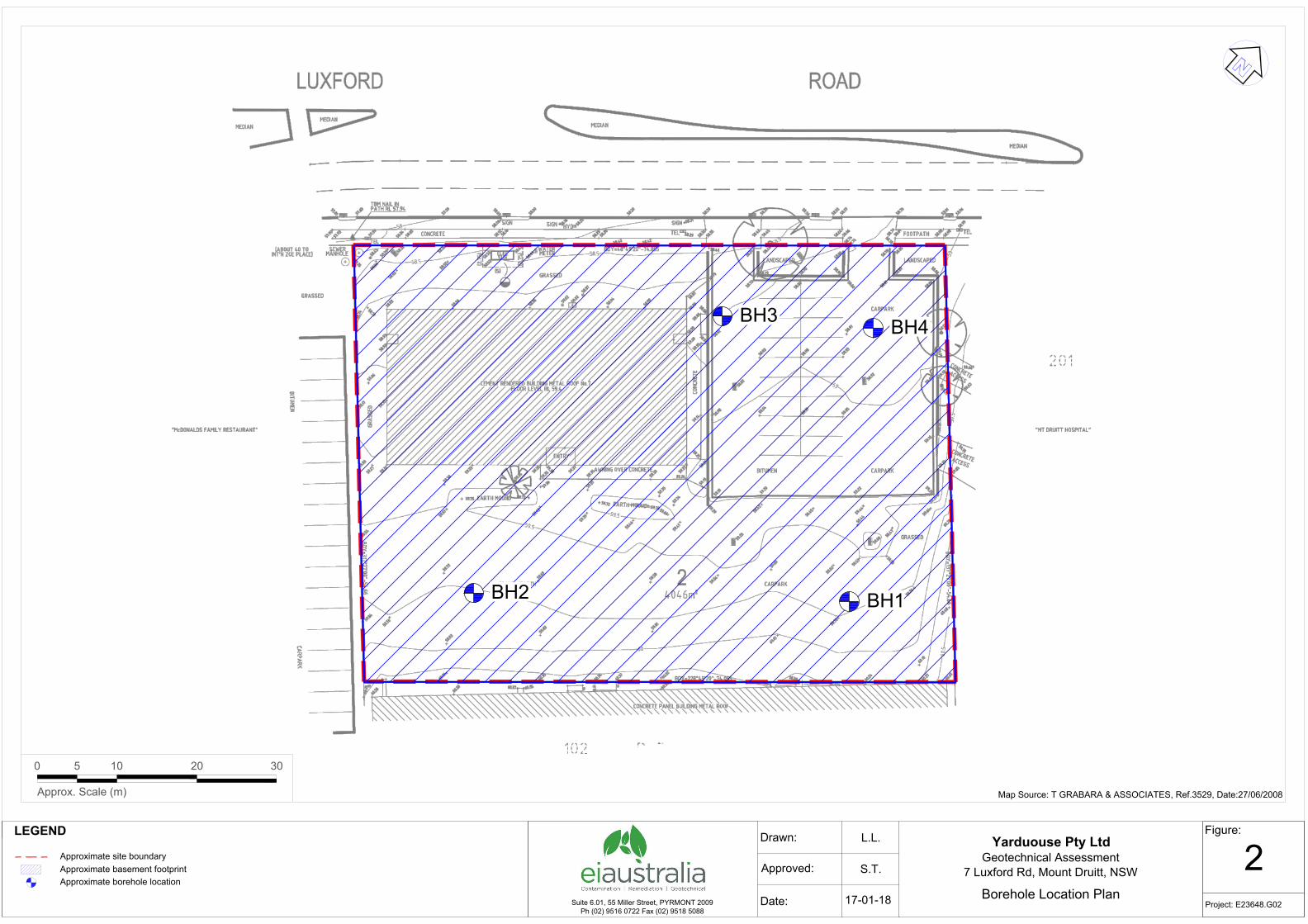
Auger drilling of four boreholes (BH1 to BH4), by a track-mounted drill rig using solid flight augers equipped
with a ‘Tungsten-Carbide’ (T-C) bit. BH1, BH2, BH3, and BH4 were drilled to depths of about 6.2m (RL
53.7m), 6.3m (RL 53.5m), 8.1m (RL 50.7m) and 8.1m (RL 50.7m) respectively. The approximate surface
levels shown on the borehole logs were approximated from spot levels shown on the supplied survey plan.
Approximate borehole locations are shown on Figure 2;
Standard Penetration Testing (SPT) was carried out during auger drilling of the boreholes to assess soil
strength/relative densities. These were augmented, where possible, by hand penetrometer readings on
cohesive soil samples collected in the SPT split tube sampler. Soil samples were sent to Macquarie
Geotechnical Pty Ltd (Macquarie) and SGS Sydney Pty Ltd (SGS), which are National Australian Testing
Authority (NATA) accredited laboratories, for testing and storage.
The strength of the shale bedrock in the augered sections of the boreholes was assessed by observation of
the auger penetration resistance using a T-C drill bit, examination of the recovered rock cuttings, and
moisture content test results. It should be noted that rock strengths assessed from augered boreholes are
approximate and strength variances can be expected.
Measurements of groundwater seepage/levels, where possible, in the augered sections of the boreholes
during and shortly after completion of auger drilling;
Preparation of this GSA report.
An EI Geotechnical Engineer was present on site to set out the borehole locations, direct the testing and
sampling, log the subsurface conditions and record groundwater levels.
1.5 INVESTIGATION CONSTRAINTS
The GSA was limited by the intent of the investigation. The discussions and advice presented in this report are
intended to assist in the preparation of preliminary designs for the proposed development. Further geotechnical
investigations should be completed prior to final design. Further geotechnical inspections should also be carried
out during construction to confirm the subsurface conditions across the site.
Geotechnical and Salinity Assessment 7 Luxford Road, Mount Druitt, NSW P a g e | 3 Report No. E23648.G02, 26 February 2018
2 SITE DESCRIPTION
2.1 SITE DESCRIPTION AND IDENTIFICATION
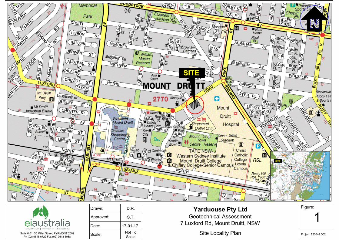
The site identification details and associated information are presented in Table 2-1 below while the site locality is
shown on Figure 1.
Table 2-1 Summary of Site Information
Information Detail
Street Address 7 Luxford Road, Mount Druitt, NSW
Lot and Deposited Plan (DP) Identification
Lot 2 DP 251863
Local Government Authority Blacktown Council
Site Description The Lot 2 of proposed site was occupied by an abandoned single-storey brick commercial building to the northwest and paved carpark on northeast of the site boundary. A concrete drive way/ pathway was located on the south-eastern portion of the site and provided access to Luxford Road. The remaining areas were covered with overgrown grass.
Site Area The site area is approximately 4046m2 (based on the provided drawings).
2.2 LOCAL LAND USE
The site is situated within an area of mixed use. Current uses on surrounding land are described in Table 2-2
below.
Table 2-2 Summary of Local Land Use
Direction Relative to Site Land Use Description
North Luxford Road, a six-lane asphaltic-concrete paved road.
East A two-lane concrete paved internal road followed by a two-storey building, setback of about
15m from the eastern site boundary;
South A single storey commercial building, abutting the southern site boundary;
West A bitumen car park followed by a commercial restaurant, setback about 20m from the
western site boundary.
2.3 REGIONAL SETTING
The site topography and geological information for the locality is summarised in Table 2-3 below.
Table 2-3 Topographic and Geological Information
Attribute Description
Topography The site ground topography falls towards the north-west at an angle of about 5°. The site levels vary from
an RL of about 58.3 at the north-western portion, to RL 60.7 towards the south-eastern corner.
Regional
Geology
Information on regional sub-surface conditions, referenced from the Department of Mineral and Energy
Geological Map Penrith 1:100,000 Geological Series Sheet 9030 (DMR 1991) indicates the site is underlain
by Bringelly Shale. Bringelly Shale generally comprises of shale, carbonaceous claystone, claystone,
laminite, fine to medium grained lithic sandstone, rare coal and tuff.
Geotechnical and Salinity Assessment 7 Luxford Road, Mount Druitt, NSW P a g e | 4 Report No. E23648.G02, 26 February 2018
3 INVESTIGATION RESULTS
3.1 STRATIGRAPHY
For the development of a site-specific geotechnical model, the observed stratigraphy during the GSA has been grouped into four geotechnical units. A summary of the subsurface conditions across the site, interpreted from the assessment results, are presented in Table 3-1 below. More detailed descriptions of subsurface conditions at each borehole location are available on the borehole logs presented in Appendix A. The details of the method of soil and rock classification, explanatory notes and abbreviations adopted on the borehole logs are also presented in Appendix A.
Table 3-1 Summary of Subsurface Conditions
Unit Material 2
Depth to top of Unit
(m BEGL) 1
Approximate RL of top of Unit
(m) 1
Observed Thickness
(m)
Material Description 2 Comments
1 Fill/ Topsoil Surface 59.9 to 58.8 0.3 to 0.5 Mixed Fill
Topsoil consisting of clay with sand,
gravel, and rootlets was encountered in
BH1.
Fill consisting of gravelly sand with rootlets
and trace clay was encountered in BH2.
Asphalt of 100mm thickness overlying
sandy fill was encountered in BH3 and
BH4.
The fill/topsoil is assessed to be variably
compacted based on our observations
during drilling.
2 Residual Soil 0.3 to 0.5 59.5 to 58.3 1.4 to 2.5 Silty CLAY
Generally stiff to hard, high plasticity silty
clay.
From 1.7 to 4.5m depth below existing
ground level grading into extremely
weathered material.
SPT N values ranged from 4 to >18
hammer bounced.
Hand penetrometer readings on the SPT
samples ranged from 120 to 490kPa;
3
Very Low to
Low Strength
Shale
1.8 to 3.0 58.0 to 55.8 2.0 to 3.7 SHALE
Distinctly weathered, very low to low
strength shale, with extremely weathered
bands.
4
Low to
Medium
Strength
Shale
5.0 to 6.0 54.3 to 52.8 0.2 to 3.1 SHALE Distinctly weathered, low to medium
strength shale.
1 Approximate depth and level at the time of our assessment. Depths and levels may vary across the site. 2 For more detailed descriptions of the subsurface conditions, reference should be made to the borehole logs attached to Appendix A.
3.2 GROUNDWATER OBSERVATIONS
Groundwater seepage was observed during auger drilling of BH3 and BH4 during auger drilling at a depth of
about 3.7 and 6.3m (RL 55.1m and RL 52.5) respectively. Following completion of fieldwork, the standing
groundwater level was measured in the open boreholes of BH1, BH2 and BH4 at depths of about 5.1m (RL of
about 54.8m), 4.6m (RL of about 55.2m) and 3.5m (RL of about 55.3m), respectively. No long term groundwater
monitoring was carried out.
Geotechnical and Salinity Assessment 7 Luxford Road, Mount Druitt, NSW P a g e | 5 Report No. E23648.G02, 26 February 2018
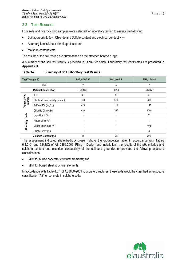
3.3 TEST RESULTS
Four soils and five rock chip samples were selected for laboratory testing to assess the following:
Soil aggressivity (pH, Chloride and Sulfate content and electrical conductivity);
Atterberg Limits/Linear shrinkage tests; and
Moisture content tests.
The results of the soil testing are summarised on the attached borehole logs.
A summary of the soil test results is provided in Table 3-2 below. Laboratory test certificates are presented in
Appendix B.
Table 3-2 Summary of Soil Laboratory Test Results
Test/ Sample ID BH2_0.50-0.95 BH3_6.0-6.2 BH4_1.5-1.95
Unit 2 4 2
Material Description Silty Clay SHALE Silty Clay
Ag
gre
ssiv
ity/
Sal
init
y
pH 4.7 8.4 6.1
Electrical Conductivity (μS/cm) 760 640 860
Sulfate SO4 (mg/kg) 420 110 140
Chloride Cl (mg/kg) 630 390 1200
Att
erb
erg
Lim
its
Liquid Limit (%) - - 52
Plastic Limit (%) - - 17
Linear Shrinkage (%) - - 10.5
Plastic index (%) - - 35
Moisture Content (%) 15 6.8 20.6
The assessment indicated shale bedrock present above the groundwater table. In accordance with Tables
6.4.2(C) and 6.5.2(C) of AS 2159:2009 ‘Piling – Design and Installation’, the results of the pH, chloride and
sulphate content and electrical conductivity of the soil and groundwater provided the following exposure
classifications:
‘Mild’ for buried concrete structural elements; and
‘Mild’ for buried steel structural elements.
In accordance with Table 4.8.1 of AS3600-2009 ‘Concrete Structures’ these soils would be classified as exposure
classification ‘A2’ for concrete in sulphate soils.
Geotechnical and Salinity Assessment 7 Luxford Road, Mount Druitt, NSW P a g e | 6 Report No. E23648.G02, 26 February 2018
4 RECOMMENDATIONS
4.1 GEOTECHNICAL ISSUES
Based on the results of the assessment, we consider the following to be the main geotechnical issues for the
proposed development:
Basement excavation and retention to limit lateral deflections and ground loss as a result of excavations,
resulting in damage to adjacent structures; and
Foundation design for building loads;
4.2 DILAPIDATION SURVEYS
Prior to construction, we recommend that detailed dilapidation surveys be carried out on all structures and
infrastructures surrounding the site. The reports would provide a record of existing conditions prior to
commencement of the work. A copy of each report should be provided to the adjoining property owner who
should be asked to confirm that it represents a fair assessment of existing conditions. The reports should be
carefully reviewed prior to construction.
4.3 EXCAVATION METHODOLOGY AND VIBRATION MONITORING
4.3.1 Preliminary Excavation Assessment
Prior to any excavation commencing, we recommend that reference be made to the WorkCover Excavation Work
Code of Practice – July 2015.
In order to achieve the bulk excavation level of RL 52.8m, excavation depths of up to about 6.0m to 7.2m BEGL is
expected. It is presumed that the proposed development will therefore extend through all Units described in Table
3-1 above.
Units 1, 2, and 3 can be readily excavated by buckets of medium to large hydraulic excavators, with some ripping.
Unit 3 may require a high capacity and heavy bulldozer of at least D9 or similar for effective production The use of
a smaller size bulldozer may result in lower productivity, and this should be allowed for. Alternatively, rock saws,
ripping hooks or rotary grinders could be used, though productivity would be lower and equipment wear
increased, and this should be allowed for. Such equipment would also be required for detailed excavation, such
as footings or services on the rock, and for trimming of faces. Final trimming of faces may also be completed
using a grinder attachment rather than a rock breaker in order to assist in limiting vibrations. The use of rotary
grinders generally generates dust and this may be supressed by spraying with water.
If rock breakers are to be used, vibration monitoring must be carried out and further advice must be sought from
the geotechnical engineer.
Groundwater seepage monitoring should be carried out during bulk excavation prior to finalising the design of a
pump out facility. Outlets into the stormwater system will require Council approval.
4.3.2 Excavation Monitoring
Consideration should be made to the impact of the proposed development upon neighbouring structures,
roadways and services. Basement excavation retention systems should be designed so as to limit lateral
deflections.
Contractors should also consider the following limits associated with carrying out excavation and construction
activities:
Limit lateral deflection of temporary or permanent retaining structures; and
Limit vertical settlements of ground surface at common property boundaries and services easement.
Monitoring of deflections of retaining structures and surface settlements should be carried out by a registered
surveyor at agreed points along the excavation boundaries and along existing building foundations/ services/
Geotechnical and Salinity Assessment 7 Luxford Road, Mount Druitt, NSW P a g e | 7 Report No. E23648.G02, 26 February 2018
pavements and other structures located within or near the zone of influence of the excavation. Owners of existing
services adjacent to the site should be consulted to assess appropriate deflection limits for their infrastructure.
Measurements should be taken:
Prior to commencement of excavations;
Immediately after installation of any temporary or permanent retaining structures;
Immediately after the excavation has reached a depth of 1.5 m, and each 1.5 m depth increment thereafter;
Immediately after the excavation has reached bulk excavation level; and
Immediately after backfilling behind retaining structures.
4.4 GROUNDWATER CONSIDERATIONS
Groundwater seepage was observed in borehole BH3 and BH4 during auger drilling at a depth of about 3.7 and
6.3m (RL 55.1m and RL 52.5m). The standing water level was observed in boreholes (BH1, BH2 and BH4) after
completion, at a depth of about 5.1m (RL of about 54.8m), 4.6m (RL of about 55.2m) and 3.5m (RL of about
55.3m) respectively, which are above the assumed BEL RL of 52.8m.
Experience shows that due to the expected low permeability of the bedrock profile, any groundwater inflows
following rainfall into the excavation should not have an adverse impact on the proposed development or on the
neighbouring sites. We expect that groundwater inflows into the excavation will occur along the soil/rock interface
and through any defects within the shale bedrock (such as jointing, and bending planes, etc.), particularly during
and following a period of rain. The initial flows into the excavation may be locally high, but would be expected to
decrease with time as the bedding seams
We expect that any seepage that does occur should be able to be controlled by a conventional sump and pump
system. We recommend that a sump-and-pump system be used both during construction and for permanent
groundwater control below the basement floor slab.
We recommend that monitoring of seepage be implemented during the excavation works to confirm the capacity
of the drainage system.
In the long term, drainage should be provided behind all basement retaining walls, around the perimeter of the
basement and below the basement slab. The completed excavation should also be inspected by the hydraulic
engineer to confirm that adequate drainage has been allowed for. Drainage should be connected to the sump-
and-pump system and discharging into the stormwater system. The permanent groundwater control system
should take into account any possible soluble substances in the groundwater which may dictate whether or not
groundwater can be pumped into the stormwater system.
The design of drainage and pump systems should take the above issues into account along with careful ongoing
inspections and maintenance programs.
4.5 EXCAVATION RETENTION
4.5.1 Support Systems
As the proposed basement extends to the site boundaries, EI considers that temporary batters are not feasible for
this site. In addition, unsupported vertical cuts of the soil and weathered rock profile of less than low strength are
not recommended for this site as these carry the risk of potential slump failure especially after a period of wet
weather. Slumping of the material may result in injury to personnel and/or damage to nearby
structures/infrastructures and equipment.
A suitable retention system, such anchored/propped soldier pile wall with concrete infill panels installed below
bulk excavation level is recommended for the support of the excavation. Anchors/props and shotcrete must be
installed progressively as excavation proceeds. The use of a more rigid system (such as a semi-contiguous or
contiguous pile wall) is recommended adjacent to neighbouring buildings/infrastructures, so as to reduce the
lateral movements and the risk of potential damage. The piles must be installed to below BEL.
Geotechnical and Salinity Assessment 7 Luxford Road, Mount Druitt, NSW P a g e | 8 Report No. E23648.G02, 26 February 2018
Bored piers may be used for this site. However, suitably sized piling rigs with rock augers and coring buckets will
be required for drilling through the shale bedrock. The proposed pile locations should take into account the
presence of any neighbouring anchors and/or the presence of buried services. Further advice should be sought
from prospective piling contractors who should be provided with a copy of this report. Working platforms may also
be required.
4.5.2 Design Parameters
The following parameters may be used for static design of temporary and permanent retaining walls at the subject
site:
For progressively anchored or propped walls where minor movements can be tolerated (provided there are
no buried movement sensitive services), we recommend the use of a trapezoidal earth pressure distribution
of 5H kPa for soil and weathered shale bedrock (Unit 1 to 3), where H is the retained height in meters. These
pressures should be assumed to be uniform over the central 50% of the support system, tapering to nil at top
and bottom;
For progressively anchored or propped walls which support areas which are highly sensitive to movement
(such as areas where movement sensitive structures or infrastructures or buried services are located in close
proximity), we recommend the use of a trapezoidal earth pressure distribution of 8H kPa for soil and
weathered shale bedrock (Unit 1 to 3), where ‘H’ is the retained height in meters. These pressures should be
assumed to be uniform over the central 50% of the support system, tapering to nil at top and bottom;
For the shale of low strength or better, a nominal uniform pressure of 10kPa should be allowed in the design
to support small wedges of rock that may occur. However, in addition the shoring wall design should either
be checked and designed to accommodate a wedge formed by a joint inclined at 45° intersecting the
excavation face at the base of the cut or at least the piles be designed for such a wedge and the excavation
carried out with close geotechnical supervision in order that additional anchors could be installed if
unfavourable defects are exposed.
If a steeply dipping defect plane is found to daylight towards the excavation, higher earth pressure
distributions, such as 10H kPa may be required, where ‘H’ is the depth from the surface to where the joint
daylights in the excavation, in metres.
All surcharge loading affecting the walls (including from construction equipment, construction loads, adjacent
high level footings, etc.) should be adopted in the retaining wall design as an additional surcharge using an
‘at rest’ earth pressure coefficient, ko, of 0.53;
The retaining walls should be designed as drained and measures are to be taken to provide complete and
permanent drainage behind the walls. Strip drains protected with a non-woven geotextile fabric should be
used behind the shotcrete infill panels for soldier pile walls or inserted between gaps in contiguous piles.
Alternatively, for the contiguous pile walls, weepholes comprising 20mm diameter PVC pipes grouted into
holes or gaps between adjacent piles at 1.2m centres (horizontal and vertical), may be used. The embedded
end of the pipes must, however, be wrapped with a non-woven geotextile fabric (such as Bidim A34) to act
as a filter against subsoil erosion;
For piles embedded into Unit 4 or better, the allowable lateral toe resistance value outlined in Table 4-1
below may be adopted;
If temporary anchors extend beyond the site boundaries, then permission from the neighbouring properties
would need to be obtained prior to installation. Also, the presence of neighbouring basements (if any) or
services and their levels must be confirmed prior to finalising anchor design. If the anchors in soils are to be
installed using wash drilling techniques, impact of ‘construction’ movements caused by anchor installation or
associated ground loss on adjoining structures and/or infrastructures should be considered. Alternatively, the
anchors should be drilled using dry spiral auger techniques within soils, with holes being cased with a PVC
pipe as soon as rock is encountered.
Geotechnical and Salinity Assessment 7 Luxford Road, Mount Druitt, NSW P a g e | 9 Report No. E23648.G02, 26 February 2018
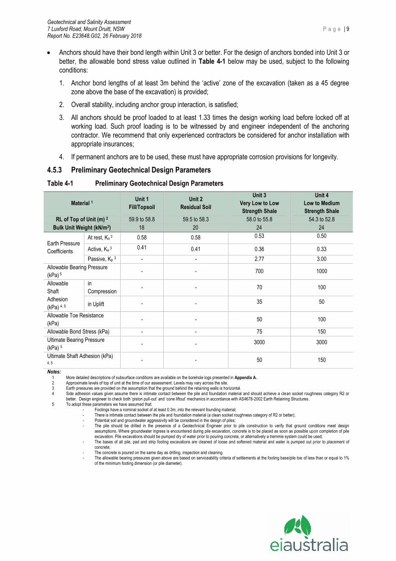
Anchors should have their bond length within Unit 3 or better. For the design of anchors bonded into Unit 3 or
better, the allowable bond stress value outlined in Table 4-1 below may be used, subject to the following
conditions:
1. Anchor bond lengths of at least 3m behind the ‘active’ zone of the excavation (taken as a 45 degree
zone above the base of the excavation) is provided;
2. Overall stability, including anchor group interaction, is satisfied;
3. All anchors should be proof loaded to at least 1.33 times the design working load before locked off at
working load. Such proof loading is to be witnessed by and engineer independent of the anchoring
contractor. We recommend that only experienced contractors be considered for anchor installation with
appropriate insurances;
4. If permanent anchors are to be used, these must have appropriate corrosion provisions for longevity.
4.5.3 Preliminary Geotechnical Design Parameters
Table 4-1 Preliminary Geotechnical Design Parameters
Material 1 Unit 1
Fill/Topsoil
Unit 2
Residual Soil
Unit 3
Very Low to Low
Strength Shale
Unit 4
Low to Medium
Strength Shale
RL of Top of Unit (m) 2 59.9 to 58.8 59.5 to 58.3 58.0 to 55.8 54.3 to 52.8
Bulk Unit Weight (kN/m3) 18 20 24 24
Earth Pressure
Coefficients
At rest, Ko 3 0.58 0.58 0.53 0.50
Active, Ka 3 0.41 0.41 0.36 0.33
Passive, Kp 3 - - 2.77 3.00
Allowable Bearing Pressure
(kPa) 5
- - 700 1000
Allowable
Shaft
Adhesion
(kPa) 4, 5
in
Compression - - 70 100
in Uplift - - 35 50
Allowable Toe Resistance
(kPa) - - 50 100
Allowable Bond Stress (kPa) - - 75 150
Ultimate Bearing Pressure
(kPa) 5 - - 3000 3000
Ultimate Shaft Adhesion (kPa) 4, 5
- - 50 150
Notes: 1 More detailed descriptions of subsurface conditions are available on the borehole logs presented in Appendix A. 2 Approximate levels of top of unit at the time of our assessment. Levels may vary across the site. 3 Earth pressures are provided on the assumption that the ground behind the retaining walls is horizontal. 4 Side adhesion values given assume there is intimate contact between the pile and foundation material and should achieve a clean socket roughness category R2 or
better. Design engineer to check both ‘piston pull-out’ and ‘cone liftout’ mechanics in accordance with AS4678-2002 Earth Retaining Structures. 5 To adopt these parameters we have assumed that:
- Footings have a nominal socket of at least 0.3m, into the relevant founding material; - There is intimate contact between the pile and foundation material (a clean socket roughness category of R2 or better); - Potential soil and groundwater aggressivity will be considered in the design of piles; - The pile should be drilled in the presence of a Geotechnical Engineer prior to pile construction to verify that ground conditions meet design
assumptions. Where groundwater ingress is encountered during pile excavation, concrete is to be placed as soon as possible upon completion of pile excavation. Pile excavations should be pumped dry of water prior to pouring concrete, or alternatively a tremmie system could be used;
- The bases of all pile, pad and strip footing excavations are cleaned of loose and softened material and water is pumped out prior to placement of concrete;
- The concrete is poured on the same day as drilling, inspection and cleaning. - The allowable bearing pressures given above are based on serviceability criteria of settlements at the footing base/pile toe of less than or equal to 1%
of the minimum footing dimension (or pile diameter).

Geotechnical and Salinity Assessment 7 Luxford Road, Mount Druitt, NSW P a g e | 10 Report No. E23648.G02, 26 February 2018
4.6 FOUNDATIONS
Following excavation to BEL of RL about 52.8m, we expect Unit 4 shale bedrock to be exposed. It is
recommended that all footings for the building be founded within shale bedrock of similar strength to provide
uniform support and reduce the potential for differential settlements.
Strip/pad footings and/or bored piles founded within Unit 4 quality shale may be designed with an maximum
allowable bearing pressure of 1000 kPa.
Geotechnical inspections of foundations by a geotechnical engineer to determine that the required socket
material has been achieved and founding material has been reached and determine any variations that may
occur between the boreholes and inspected locations are recommended.
Should higher bearing pressures be required, an additional geotechnical investigation should be carried out,
preferably following demolition, involving cored boreholes drilled to a minimum of 3m below final bulk excavation
levels to determine the depth and quality of bedrock to ascertain our assumptions and optimize the bearing
pressures.
Design of piles should consider the aggressivity of the soil and groundwater in accordance with Sections 6.4 and
6.5 of AS2159-2009.
4.7 LOWEST BASEMENT FLOOR SLAB
Following the removal of all loose and softened materials, we recommend that underfloor drainage be provided
and should comprise a strong, durable, single sized washed aggregate such as ‘blue metal gravel’. Concrete
pavements should be designed with an effective shear transmission at all joints by way of either dowelled or
keyed joints. The basement floor slab should be isolated from columns. The completed excavation should be
inspected by the hydraulic engineer to confirm the extent of the drainage required.
In addition, a system of sub-soil drains comprising a durable single sized aggregate with perforated drains/pipes
leading to sumps should be provided.
Permission may need to be obtained from the NSW Department of Primary Industries (DPI) and possibly Council
for any permanent discharge of seepage into the drainage system. Given the subsurface conditions, we expect
that seepage volumes would be low and within the DPI limits. However, if permission for discharge is not
obtained, the basement may need to be designed as a tanked basement.
4.8 SALINITY
Analyses of the electrical conductivity of the Unit 2 residual clay were assessed with reference to the Western
Sydney Regional Organisation of Council’s (WSROC) publication ‘Western Sydney Salinity Code of Practice’
(March 2003), and DPI guidelines on the investigation and management of salinity (2002) as part of the Local
Government Salinity Initiative for the NSW State Salinity Strategy. The results indicate the soils to be moderately
saline.
Approaches to limit the impact of moderately saline and mildly aggressive soils on proposed buried structures
could include:
Adopting chemically resistant concrete;
Increasing the concrete strength;
Increasing cover to steel reinforcing;
Adopt good vibration and curing techniques during concrete placement;
Limiting surface water in-flows;
Maintaining good surface and subsurface drainage; and
Including vapour-proof barriers.
Geotechnical and Salinity Assessment 7 Luxford Road, Mount Druitt, NSW P a g e | 11 Report No. E23648.G02, 26 February 2018
5 RECOMMENDATIONS FOR FURTHER GEOTECHNICAL SERVICES
Below is a summary of the previously recommended additional work that needs to be carried out:
Dilapidation surveys;
Additional investigation in the form of deep cored boreholes for bearing pressure optimisation (if required);
Design of working platforms (if required) for construction plant by an experienced and qualified geotechnical
engineer;
Classification of all excavated material transported off site;
Witnessing installation and proof-testing of anchors;
Geotechnical inspections of foundations; and
Ongoing monitoring of groundwater inflows into the bulk excavation;
Geotechnical and Salinity Assessment 7 Luxford Road, Mount Druitt, NSW P a g e | 12 Report No. E23648.G02, 26 February 2018
6 STATEMENT OF LIMITATIONS
This report has been prepared for the exclusive use of Yarduouse Pty Ltd who is the only intended beneficiary of
EI’s work. The scope of the assessment carried out for the purpose of this report is limited to those agreed with
Yarduouse Pty Ltd
No other party should rely on the document without the prior written consent of EI, and EI undertakes no duty, or
accepts any responsibility or liability, to any third party who purports to rely upon this document without EI's
approval.
EI has used a degree of care and skill ordinarily exercised in similar investigations by reputable members of the
geotechnical industry in Australia as at the date of this document. No other warranty, expressed or implied, is
made or intended. Each section of this report must be read in conjunction with the whole of this report, including
its appendices and attachments.
The conclusions presented in this report are based on a limited assessment of conditions, with specific sampling
and test locations chosen to be as representative as possible under the given circumstances.
EI's professional opinions are reasonable and based on its professional judgment, experience, training and
results from analytical data. EI may also have relied upon information provided by the Client and other third
parties to prepare this document, some of which may not have been verified by EI.
EI's professional opinions contained in this document are subject to modification if additional information is
obtained through further assessment, observations, or validation testing and analysis during construction. In
some cases, further testing and analysis may be required, which may result in a further report with different
conclusions.
We draw your attention to the document “Important Information”, which is included in Appendix C of this report.
The statements presented in this document are intended to advise you of what your realistic expectations of this
report should be. The document is not intended to reduce the level of responsibility accepted by EI, but rather to
ensure that all parties who may rely on this report are aware of the responsibilities each assumes in so doing.
Should you have any queries regarding this report, please do not hesitate to contact EI.
Geotechnical and Salinity Assessment 7 Luxford Road, Mount Druitt, NSW P a g e | 13 Report No. E23648.G02, 26 February 2018
7 REFERENCES
AS1170.4:2007, Structural Design Actions, Part 4: Earthquake Actions in Australia, Standards Australia.
AS1726:1993, Geotechnical Site Investigations, Standards Australia.
AS2159:2009, Piling – Design and Installation, Standards Australia.
AS3600:2009, Concrete Structures, Standards Australia
Excavation Work Code of Practice – July 2015 – WorkCover NSW,
NSW Department of Finance and Service, Spatial Information Viewer, maps.six.nsw.gov.au.
NSW Department of Mineral Resources (1983) Sydney 1:100,000 Geological Series Sheet 9130 (Edition 1).
Geological Survey of New South Wales, Department of Mineral Resources.
8 ABBREVIATIONS
AHD Australian Height Datum AS Australian Standard BEL Bulk Excavation Level BEGL Below Existing Ground Level BH Borehole DBYD Dial Before You Dig DP Deposited Plan EI EI Australia GSA Geotechnical and Salinity Assessment NATA National Association of Testing Authorities, Australia RL Reduced Level SPT Standard Penetration Test
T-C Tungsten-Carbide UCS Unconfined Compressive Strength
Geotechnical and Salinity Assessment 7 Luxford Road, Mount Druitt, NSW Report No. E23648.G02, 26 February 2018
FIGURES
Approved:
Scale:
Date:
Drawn:
17-01-17
Not To
Scale
D.R.
S.T.
1
Project: E23648.G02
Figure:
Suite 6.01, 55 Miller Street, PYRMONT 2009
Ph (02) 9516 0722 Fax (02) 9518 5088
SITE
Yarduouse Pty Ltd
Geotechnical Assessment
7 Luxford Rd, Mount Druitt, NSW
Site Locality Plan
SITE
0 5
Approx. Scale (m)
10 20 30
BH3
BH4
BH1
BH2
Map Source: T GRABARA & ASSOCIATES, Ref.3529, Date:27/06/2008
17-01-18
L.L.
2S.T.
Figure:
Suite 6.01, 55 Miller Street, PYRMONT 2009
Ph (02) 9516 0722 Fax (02) 9518 5088
Yarduouse Pty Ltd
Geotechnical Assessment
7 Luxford Rd, Mount Druitt, NSW
Borehole Location Plan
Approved:
Date:
Drawn:
Project: E23648.G02
Approximate basement footprint
Approximate site boundary
Approximate borehole location
LEGEND
Geotechnical and Salinity Assessment 7 Luxford Road, Mount Druitt, NSW Report No. E23648.G02, 26 February 2018
APPENDIX A
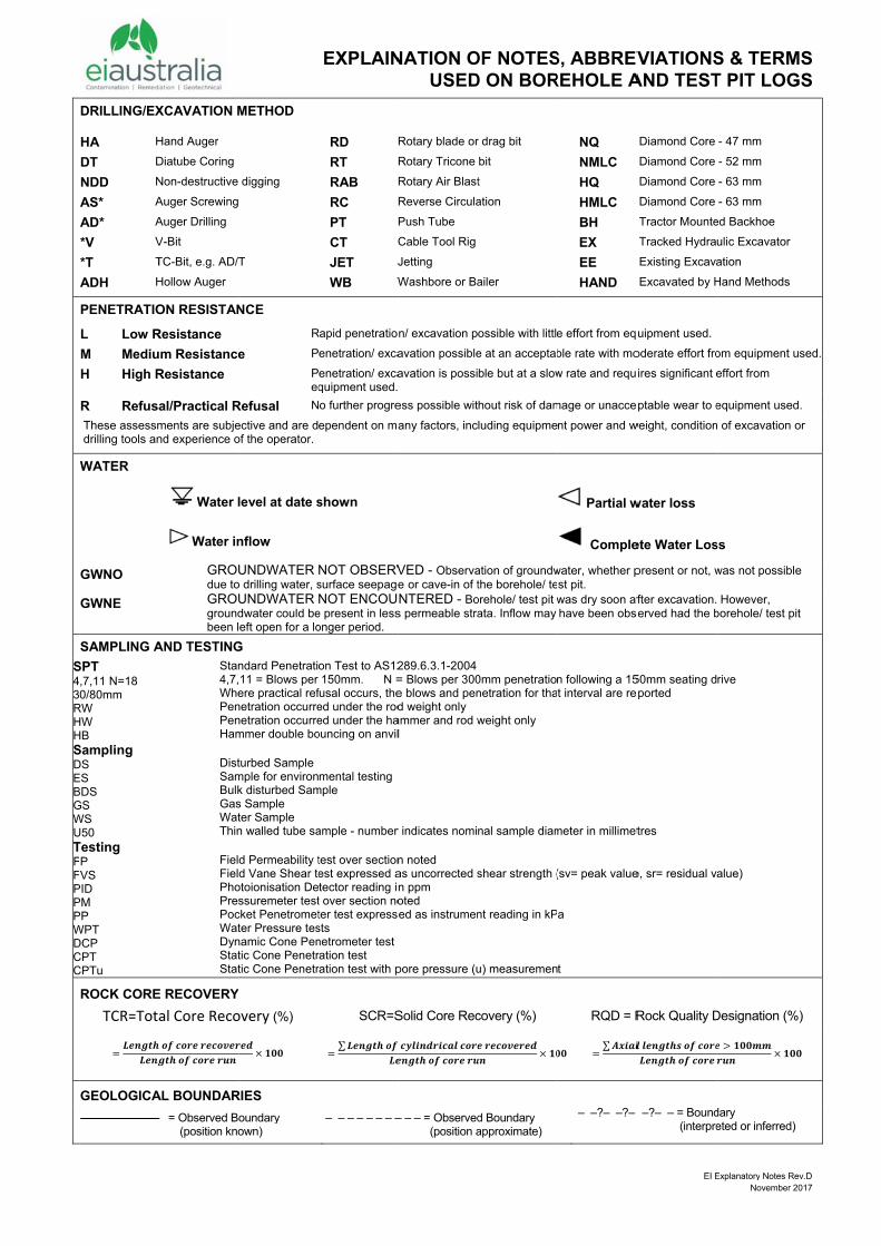
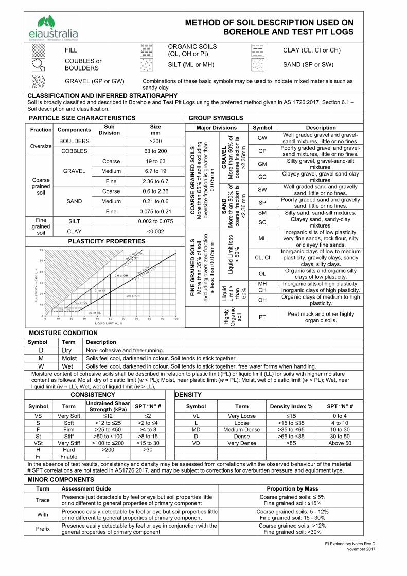
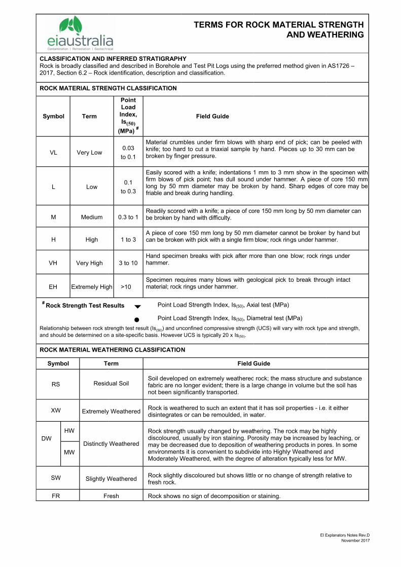
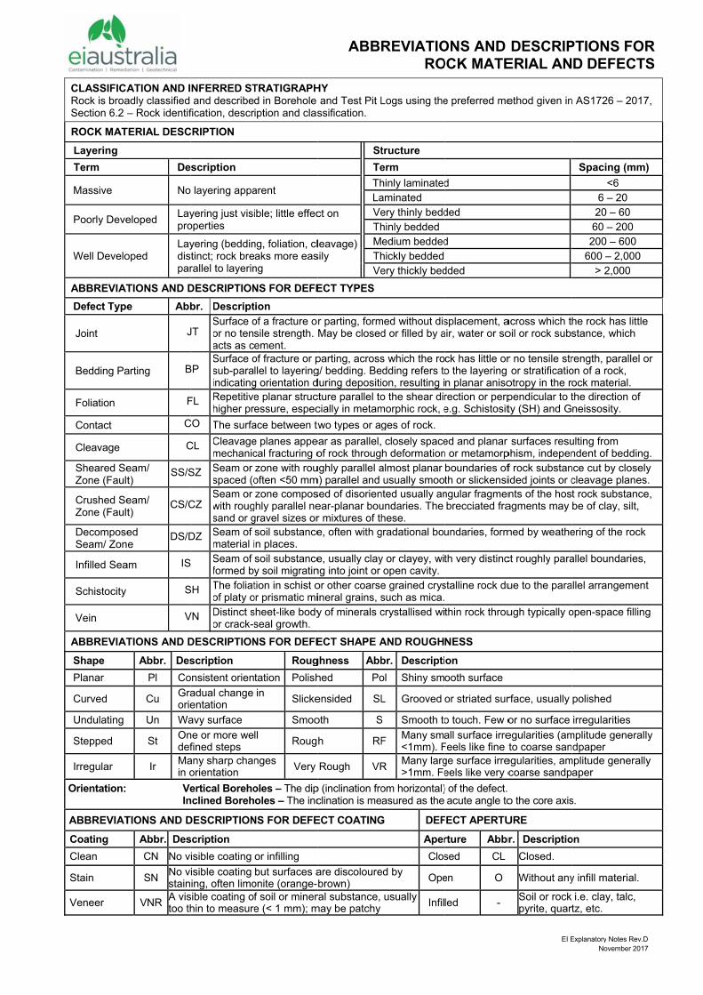
BOREHOLE LOGS AND EXPLANATORY NOTES
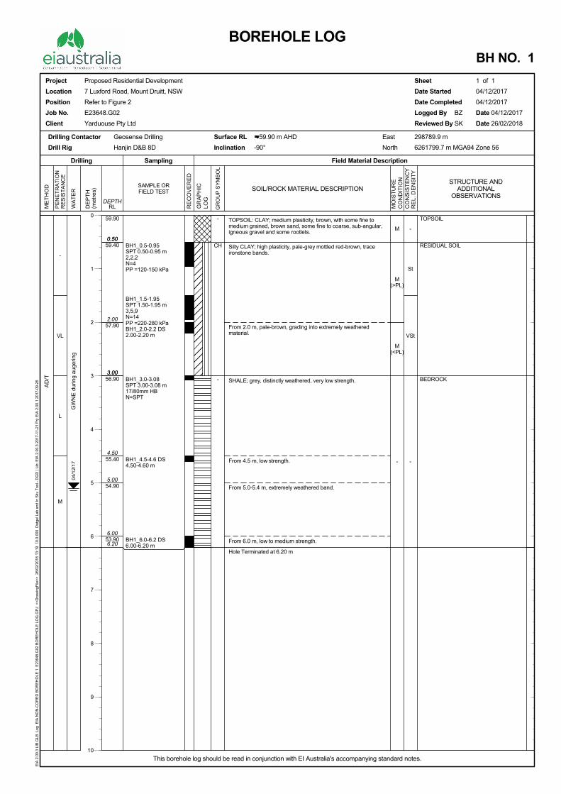
TOPSOIL: CLAY; medium plasticity, brown, with some fine tomedium grained, brown sand, some fine to coarse, sub-angular,igneous gravel and some rootlets.
Silty CLAY; high plasticity, pale-grey mottled red-brown, traceironstone bands.
From 2.0 m, pale-brown, grading into extremely weatheredmaterial.
SHALE; grey, distinctly weathered, very low strength.
From 4.5 m, low strength.
From 5.0-5.4 m, extremely weathered band.
From 6.0 m, low to medium strength.
Hole Terminated at 6.20 m
-
St
VSt
-
0.50
3.00
6.20
59.90
59.40
57.90
56.90
55.40
54.90
53.90
-
VL
L
M
AD
/T
0.50
2.00
3.00
4.50
5.00
6.00
M
M(>PL)
M(<PL)
-
BH1_0.5-0.95SPT 0.50-0.95 m2,2,2N=4PP =120-150 kPa
BH1_1.5-1.95SPT 1.50-1.95 m3,5,9N=14PP =220-280 kPaBH1_2.0-2.2 DS2.00-2.20 m
BH1_3.0-3.08SPT 3.00-3.08 m17/80mm HBN=SPT
BH1_4.5-4.6 DS4.50-4.60 m
BH1_6.0-6.2 DS6.00-6.20 m
-
CH
-
GW
NE
dur
ing
auge
ring
04/1
2/17
TOPSOIL
RESIDUAL SOIL
BEDROCK
SOIL/ROCK MATERIAL DESCRIPTION
PE
NE
TR
AT
ION
RE
SIS
TA
NC
E
RE
CO
VE
RE
D
ME
TH
OD
Field Material DescriptionSamplingDrilling
WA
TE
R
RLDEPTH
MO
IST
UR
EC
ON
DIT
ION
GR
AP
HIC
LOG
SAMPLE ORFIELD TEST
GR
OU
P S
YM
BO
L
CO
NS
IST
EN
CY
RE
L. D
EN
SIT
Y
DE
PT
H(m
etre
s)
Project
Location
Position
Job No.
Client
Proposed Residential Development
7 Luxford Road, Mount Druitt, NSW
Refer to Figure 2
E23648.G02
Yarduouse Pty Ltd
Drilling Contactor
Drill Rig
Geosense Drilling
Hanjin D&B 8D
Surface RL 59.90 m AHD
Inclination -90°
Sheet 1 of 1
Date Started 04/12/2017
Date Completed 04/12/2017
Logged By BZ Date 04/12/2017
Reviewed By SK Date 26/02/2018
BOREHOLE LOGBH NO. 1
East 298789.9 m
North 6261799.7 m MGA94 Zone 56
This borehole log should be read in conjunction with EI Australia's accompanying standard notes.
EIA
2.0
0.3
LIB
.GLB
Log
EIA
NO
N-C
OR
ED
BO
RE
HO
LE 1
E23
648.
G02
BO
RE
HO
LE L
OG
.GP
J <
<D
raw
ingF
ile>
> 2
6/02
/201
8 13
:19
10.
0.00
0 D
atge
l Lab
and
In S
itu T
ool -
DG
D |
Lib:
EIA
2.0
0.3
2017
-11-
21 P
rj: E
IA 2
.00.
1 20
17-0
9-26
STRUCTURE ANDADDITIONAL
OBSERVATIONS
0
1
2
3
4
5
6
7
8
9
10
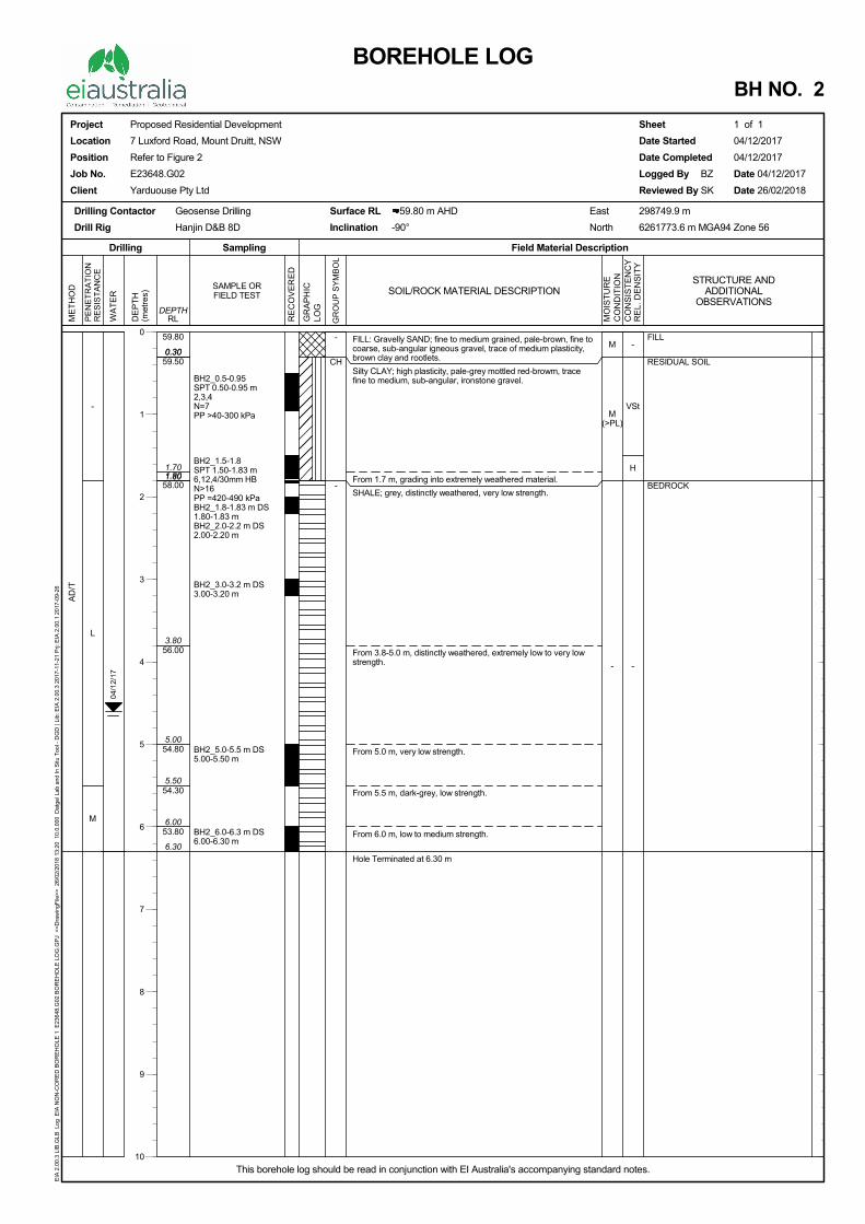
FILL: Gravelly SAND; fine to medium grained, pale-brown, fine tocoarse, sub-angular igneous gravel, trace of medium plasticity,brown clay and rootlets.
Silty CLAY; high plasticity, pale-grey mottled red-browm, tracefine to medium, sub-angular, ironstone gravel.
From 1.7 m, grading into extremely weathered material.
SHALE; grey, distinctly weathered, very low strength.
From 3.8-5.0 m, distinctly weathered, extremely low to very lowstrength.
From 5.0 m, very low strength.
From 5.5 m, dark-grey, low strength.
From 6.0 m, low to medium strength.
Hole Terminated at 6.30 m
-
VSt
H
-
0.30
1.80
6.30
59.80
59.50
58.00
56.00
54.80
54.30
53.80
-
L
M
AD
/T
0.30
1.701.80
3.80
5.00
5.50
6.00
M
M(>PL)
-
BH2_0.5-0.95SPT 0.50-0.95 m2,3,4N=7PP >40-300 kPa
BH2_1.5-1.8SPT 1.50-1.83 m6,12,4/30mm HBN>16PP =420-490 kPaBH2_1.8-1.83 m DS1.80-1.83 mBH2_2.0-2.2 m DS2.00-2.20 m
BH2_3.0-3.2 m DS3.00-3.20 m
BH2_5.0-5.5 m DS5.00-5.50 m
BH2_6.0-6.3 m DS6.00-6.30 m
-
CH
-
04/1
2/17
FILL
RESIDUAL SOIL
BEDROCK
SOIL/ROCK MATERIAL DESCRIPTION
PE
NE
TR
AT
ION
RE
SIS
TA
NC
E
RE
CO
VE
RE
D
ME
TH
OD
Field Material DescriptionSamplingDrilling
WA
TE
R
RLDEPTH
MO
IST
UR
EC
ON
DIT
ION
GR
AP
HIC
LOG
SAMPLE ORFIELD TEST
GR
OU
P S
YM
BO
L
CO
NS
IST
EN
CY
RE
L. D
EN
SIT
Y
DE
PT
H(m
etre
s)
Project
Location
Position
Job No.
Client
Proposed Residential Development
7 Luxford Road, Mount Druitt, NSW
Refer to Figure 2
E23648.G02
Yarduouse Pty Ltd
Drilling Contactor
Drill Rig
Geosense Drilling
Hanjin D&B 8D
Surface RL 59.80 m AHD
Inclination -90°
Sheet 1 of 1
Date Started 04/12/2017
Date Completed 04/12/2017
Logged By BZ Date 04/12/2017
Reviewed By SK Date 26/02/2018
BOREHOLE LOGBH NO. 2
East 298749.9 m
North 6261773.6 m MGA94 Zone 56
This borehole log should be read in conjunction with EI Australia's accompanying standard notes.
EIA
2.0
0.3
LIB
.GLB
Log
EIA
NO
N-C
OR
ED
BO
RE
HO
LE 1
E23
648.
G02
BO
RE
HO
LE L
OG
.GP
J <
<D
raw
ingF
ile>
> 2
6/02
/201
8 13
:20
10.
0.00
0 D
atge
l Lab
and
In S
itu T
ool -
DG
D |
Lib:
EIA
2.0
0.3
2017
-11-
21 P
rj: E
IA 2
.00.
1 20
17-0
9-26
STRUCTURE ANDADDITIONAL
OBSERVATIONS
0
1
2
3
4
5
6
7
8
9
10
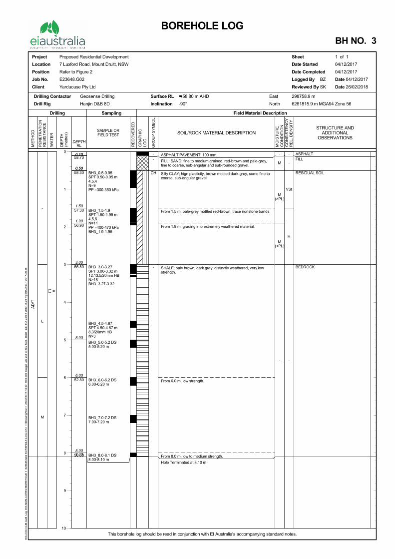
ASPHALT PAVEMENT: 100 mm.
FILL: SAND; fine to medium grained, red-brown and pale-grey,fine to coarse, sub-angular and sub-rounded gravel.
Silty CLAY; hign plasticity, brown mottled dark-grey, some fine tocoarse, sub-angular gravel.
From 1.5 m, pale-grey mottled red-brown, trace ironstone bands.
From 1.9 m, grading into extremely weathered material.
SHALE; pale brown, dark grey, distinctly weathered, very lowstrength.
From 6.0 m, low strength.
From 8.0 m, low to medium strength.
Hole Terminated at 8.10 m
-
-
VSt
H
-
0.10
0.50
5.00
8.10
58.70
58.30
57.30
56.90
55.80
52.80
50.80
-
L
M
AD
/T
0.10
0.50
1.50
1.90
3.00
6.00
8.00
-
M
M(>PL)
M(<PL)
-
BH3_0.5-0.95SPT 0.50-0.95 m4,5,4N=9PP =300-350 kPa
BH3_1.5-1.9SPT 1.50-1.95 m4,5,6N=11PP =400-470 kPaBH3_1.9-1.95
BH3_3.0-3.27SPT 3.00-3.32 m12,13,5/20mm HBN>18BH3_3.27-3.32
BH3_4.5-4.67SPT 4.50-4.67 m8,3/20mm HBN>3
BH3_5.0-5.2 DS5.00-5.20 m
BH3_6.0-6.2 DS6.00-6.20 m
BH3_7.0-7.2 DS7.00-7.20 m
BH3_8.0-8.1 DS8.00-8.10 m
--
CH
-
ASPHALTFILL
RESIDUAL SOIL
BEDROCK
SOIL/ROCK MATERIAL DESCRIPTION
PE
NE
TR
AT
ION
RE
SIS
TA
NC
E
RE
CO
VE
RE
D
ME
TH
OD
Field Material DescriptionSamplingDrilling
WA
TE
R
RLDEPTH
MO
IST
UR
EC
ON
DIT
ION
GR
AP
HIC
LOG
SAMPLE ORFIELD TEST
GR
OU
P S
YM
BO
L
CO
NS
IST
EN
CY
RE
L. D
EN
SIT
Y
DE
PT
H(m
etre
s)
Project
Location
Position
Job No.
Client
Proposed Residential Development
7 Luxford Road, Mount Druitt, NSW
Refer to Figure 2
E23648.G02
Yarduouse Pty Ltd
Drilling Contactor
Drill Rig
Geosense Drilling
Hanjin D&B 8D
Surface RL 58.80 m AHD
Inclination -90°
Sheet 1 of 1
Date Started 04/12/2017
Date Completed 04/12/2017
Logged By BZ Date 04/12/2017
Reviewed By SK Date 26/02/2018
BOREHOLE LOGBH NO. 3
East 298758.9 m
North 6261815.9 m MGA94 Zone 56
This borehole log should be read in conjunction with EI Australia's accompanying standard notes.
EIA
2.0
0.3
LIB
.GLB
Log
EIA
NO
N-C
OR
ED
BO
RE
HO
LE 1
E23
648.
G02
BO
RE
HO
LE L
OG
.GP
J <
<D
raw
ingF
ile>
> 2
6/02
/201
8 13
:20
10.
0.00
0 D
atge
l Lab
and
In S
itu T
ool -
DG
D |
Lib:
EIA
2.0
0.3
2017
-11-
21 P
rj: E
IA 2
.00.
1 20
17-0
9-26
STRUCTURE ANDADDITIONAL
OBSERVATIONS
0
1
2
3
4
5
6
7
8
9
10
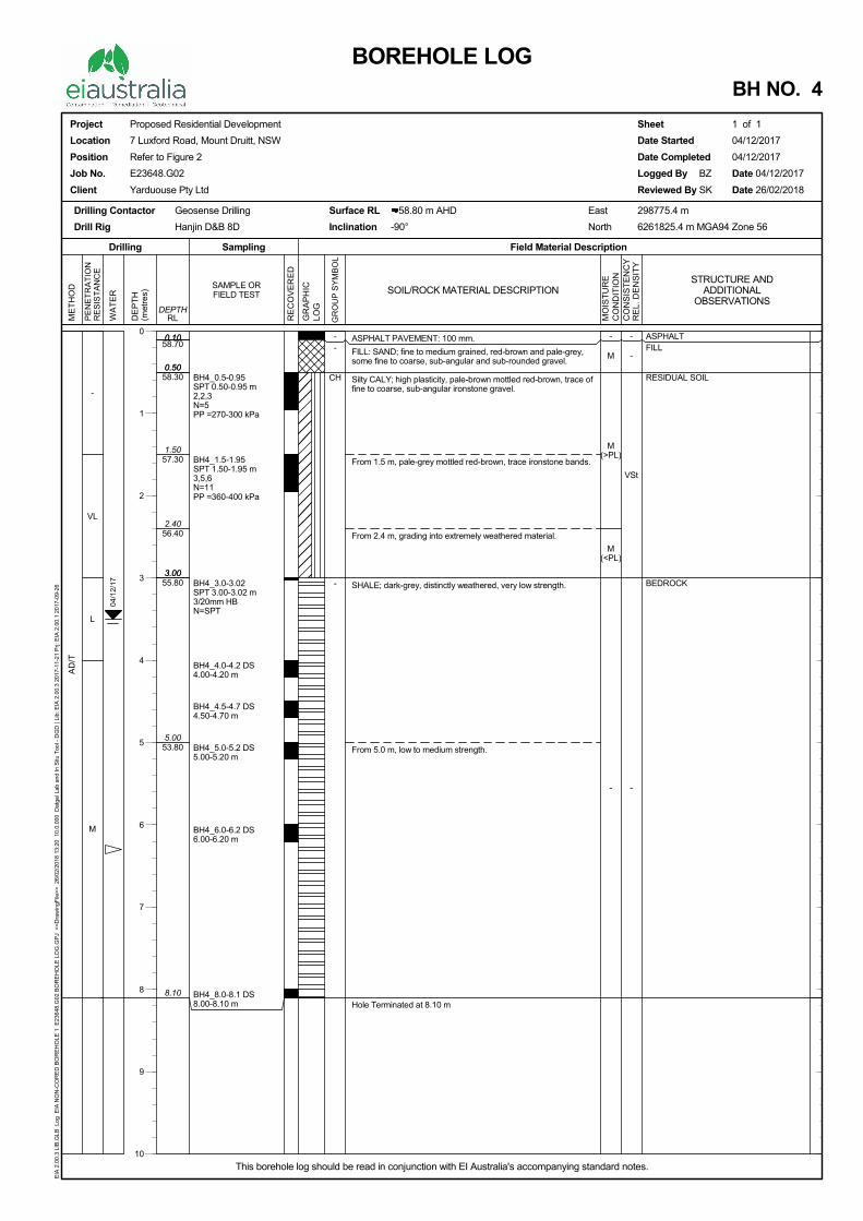
ASPHALT PAVEMENT: 100 mm.
FILL: SAND; fine to medium grained, red-brown and pale-grey,some fine to coarse, sub-angular and sub-rounded gravel.
Silty CALY; high plasticity, pale-brown mottled red-brown, trace offine to coarse, sub-angular ironstone gravel.
From 1.5 m, pale-grey mottled red-brown, trace ironstone bands.
From 2.4 m, grading into extremely weathered material.
SHALE; dark-grey, distinctly weathered, very low strength.
From 5.0 m, low to medium strength.
Hole Terminated at 8.10 m
-
-
VSt
-
0.10
0.50
3.00
8.10
58.70
58.30
57.30
56.40
55.80
53.80
-
VL
L
M
AD
/T
0.10
0.50
1.50
2.40
3.00
5.00
-
M
M(>PL)
M(<PL)
-
BH4_0.5-0.95SPT 0.50-0.95 m2,2,3N=5PP =270-300 kPa
BH4_1.5-1.95SPT 1.50-1.95 m3,5,6N=11PP =360-400 kPa
BH4_3.0-3.02SPT 3.00-3.02 m3/20mm HBN=SPT
BH4_4.0-4.2 DS4.00-4.20 m
BH4_4.5-4.7 DS4.50-4.70 m
BH4_5.0-5.2 DS5.00-5.20 m
BH4_6.0-6.2 DS6.00-6.20 m
BH4_8.0-8.1 DS8.00-8.10 m
--
CH
-
04/1
2/17
ASPHALTFILL
RESIDUAL SOIL
BEDROCK
SOIL/ROCK MATERIAL DESCRIPTION
PE
NE
TR
AT
ION
RE
SIS
TA
NC
E
RE
CO
VE
RE
D
ME
TH
OD
Field Material DescriptionSamplingDrilling
WA
TE
R
RLDEPTH
MO
IST
UR
EC
ON
DIT
ION
GR
AP
HIC
LOG
SAMPLE ORFIELD TEST
GR
OU
P S
YM
BO
L
CO
NS
IST
EN
CY
RE
L. D
EN
SIT
Y
DE
PT
H(m
etre
s)
Project
Location
Position
Job No.
Client
Proposed Residential Development
7 Luxford Road, Mount Druitt, NSW
Refer to Figure 2
E23648.G02
Yarduouse Pty Ltd
Drilling Contactor
Drill Rig
Geosense Drilling
Hanjin D&B 8D
Surface RL 58.80 m AHD
Inclination -90°
Sheet 1 of 1
Date Started 04/12/2017
Date Completed 04/12/2017
Logged By BZ Date 04/12/2017
Reviewed By SK Date 26/02/2018
BOREHOLE LOGBH NO. 4
East 298775.4 m
North 6261825.4 m MGA94 Zone 56
This borehole log should be read in conjunction with EI Australia's accompanying standard notes.
EIA
2.0
0.3
LIB
.GLB
Log
EIA
NO
N-C
OR
ED
BO
RE
HO
LE 1
E23
648.
G02
BO
RE
HO
LE L
OG
.GP
J <
<D
raw
ingF
ile>
> 2
6/02
/201
8 13
:20
10.
0.00
0 D
atge
l Lab
and
In S
itu T
ool -
DG
D |
Lib:
EIA
2.0
0.3
2017
-11-
21 P
rj: E
IA 2
.00.
1 20
17-0
9-26
STRUCTURE ANDADDITIONAL
OBSERVATIONS
0
1
2
3
4
5
6
7
8
9
10
S43RHHSDEBGWUTFFPPPWDCC
DRILLING/EX
HA H
DT D
NDD N
AS* A
AD* A
*V V
*T T
ADH H
PENETRATIO
L Low R
M Mediu
H High R
R Refusa
These assessmdrilling tools an
WATER
GWNO
GWNE
SAMPLING A
SPT ,7,11 N=18 0/80mm
RW HW HB Sampling DS ES BDS GS WS U50 Testing
P VS
PID PM PP WPT DCP CPT CPTu
ROCK CORE
TCR=Tota
GEOLOGICA
XCAVATION M
Hand Auger
Diatube Coring
Non-destructive
Auger Screwing
Auger Drilling
V-Bit
TC-Bit, e.g. AD/T
Hollow Auger
ON RESISTAN
Resistance
m Resistance
Resistance
al/Practical R
ments are subjend experience o
Water l
Water in
GROUdue toGROUgroundbeen l
AND TESTINGStan4,7,WhePenPenHam DistSamBulkGasWatThin FielFielPhoPresPocWatDynStatStat
E RECOVERY
al Core Reco
AL BOUNDAR
= Observed Bo(position kno
METHOD
digging
T
NCE
R
e P
Peq
Refusal N
ective and are dof the operator.
level at date s
nflow
UNDWATER o drilling water, sUNDWATER dwater could beeft open for a lo
G ndard Penetrati11 = Blows per ere practical ref
netration occurrenetration occurremmer double bo
turbed Sample mple for environk disturbed Sams Sample ter Sample n walled tube sa
d Permeability td Vane Shear te
otoionisation Dessuremeter test
cket Penetrometter Pressure tes
namic Cone Pentic Cone Penetrtic Cone Penetr
Y
overy (%)
RIES
oundary own)
EXPLAIN
RD R
RT R
RAB R
RC R
PT P
CT C
JET J
WB W
Rapid penetratio
enetration/ exca
enetration/ excaquipment used.
o further progre
ependent on ma
shown
NOT OBSERVsurface seepageNOT ENCOU
e present in lessonger period.
on Test to AS12150mm. N =
fusal occurs, theed under the roded under the haouncing on anvil
mental testingmple
ample - number
test over sectionest expressed atector reading int over section noter test expresssts netrometer testration test ration test with p
SCR=S
∑
– – – – – – – –
NATION OUSED
Rotary blade or
Rotary Tricone
Rotary Air Blast
Reverse Circula
Push Tube
Cable Tool Rig
Jetting
Washbore or Ba
n/ excavation p
avation possible
avation is possi
ess possible wit
any factors, inc
VED - Observae or cave-in of tNTERED - Bo
s permeable stra
289.6.3.1-2004= Blows per 300e blows and pend weight only
ammer and rod wl
r indicates nomi
n noted as uncorrected sn ppm oted ed as instrumen
pore pressure (u
Solid Core Rec
– – – = Observed(position a
OF NOTESD ON BOR
r drag bit
bit
t
ation
ailer
ossible with little
e at an acceptab
ble but at a slow
hout risk of dam
luding equipme
ation of groundwthe borehole/ te
orehole/ test pit wata. Inflow may
0mm penetrationetration for tha
weight only
nal sample diam
shear strength (
nt reading in kP
u) measuremen
covery (%)
d Boundary approximate)
S, ABBREVREHOLE A
NQ
NMLC
HQ
HMLC
BH
EX
EE
HAND
e effort from eq
ble rate with mo
w rate and requ
mage or unacce
nt power and w
Partial w
Comple
water, whether pst pit.was dry soon afhave been obse
n following a 15t interval are re
meter in millimet
(sv= peak value
a
t
RQD = R
∑
– –?– –?–
EI E
VIATIONSAND TEST
Diamond Core
Diamond Core
Diamond Core
Diamond Core
Tractor Mounte
Tracked Hydra
Existing Excava
Excavated by H
uipment used.
oderate effort fro
ires significant e
ptable wear to e
weight, condition
water loss
ete Water Los
present or not, w
fter excavation.served had the b
50mm seating deported
tres
e, sr= residual v
Rock Quality D
–?– – = Bound(interpre
Explanatory Notes ReNovember 2
S & TERMT PIT LOG
- 47 mm
- 52 mm
- 63 mm
- 63 mm
ed Backhoe
ulic Excavator
ation
Hand Methods
om equipment u
effort from
equipment used
n of excavation o
ss
was not possible
However, borehole/ test pi
rive
alue)
Designation (%
dary eted or inferred)
ev.D 2017
MS GS
used.
d.
or
e
it
%)
CLASoil Soil
Mocoliq
PA
Fra
Ov
Cogr
Fgr
MO
Sym
Sym
VS
SVHF
In th# SP
MIN
T
T
P
FIL
COBO
GR
ASSIFICATIOis broadly classdescription and
oisture content oontent as followsuid limit (w ≈ LL
ARTICLE SIZE
action Compo
versize BOUL
COB
oarse rained soil
GRA
SA
Fine rained soil
SI
CL
PL
OISTURE CON
mbol Term
D Dry M MoisW Wet
C
mbol Term
VS Very SS SoftF FirmSt Stiff
VSt Very SH HardFr Friablhe absence of tePT correlations
NOR COMPO
Term Asse
Trace Preseor no
With Preseor no
Prefix Presegene
LL
OUBLES or ULDERS
RAVEL (GP or
ON AND INFEsified and descrd classification.
of cohesive soils: Moist, dry of pL), Wet, wet of li
E CHARACTE
onents Su
Divis
LDERS
BLES
AVEL
Coa
Med
Fi
AND
Coa
Med
Fi
LT
LAY
LASTICITY P
NDITION
m Descriptio
Non- cohe
st Soils feel c
Soils feel c
CONSISTENC
m Undrained
StrengthSoft ≤12t >12 to
m >25 tof >50 to
Stiff >100 tod >20le - est results, consare not stated i
NENTS
essment Guide
ence just detecto different to gen
ence easily deteo different to gen
ence easily deteeral properties o
GW) Cosa
RRED STRATribed in Borehol
ls shall be descplastic limit (w <iquid limit (w > L
ERISTICS ub sion
6
arse 1
dium 6
ne 2.
arse 0.
dium 0.
ne 0.0
0.00
ROPERTIES
on
esive and free-ru
cool, darkened
cool, darkened
CY d Shear h (kPa)
SPT
2 ≤ ≤25 >2 t ≤50 >4 ≤100 >8 t ≤200 >15
00 >3
sistency and den AS1726:2017
e
table by feel or neral properties
ectable by feel oneral properties
ectable by feel of primary compo
ORGA(OL, O
SILT (
ombinations of tandy clay
TIGRAPHY le and Test Pit L
ribed in relation< PL); Moist, neaLL),
Size mm
>200
3 to 200
19 to 63
6.7 to 19
36 to 6.7
6 to 2.36
21 to 0.6
75 to 0.21
02 to 0.075
<0.002
unning.
in colour. Soil te
in colour. Soil te
DEN
“N” #
≤2 to ≤4 to 8 o 15 to 30 30 nsity may be as
7, and may be s
eye but soil proof primary com
or eye but soil pof primary com
or eye in conjunonent
METHOD
ANIC SOILS OH or Pt)
(ML or MH)
these basic sym
Logs using the p
n to plastic limit ar plastic limit (w
GROUP SY
Major Div
CO
AR
SE
GR
AIN
ED
SO
ILS
M
ore
than
65%
of s
oil e
xclu
ding
ov
ersi
ze fr
actio
n is
gre
ater
than
0.
075m
m
FIN
E G
RA
INE
D S
OIL
S
Mor
e th
an 3
5% o
f soi
l ex
clud
ing
over
size
d fr
actio
n is
less
than
0.0
75m
m
ends to stick tog
ends to stick tog
NSITY
Symbol
VL L
MD D
VD
ssessed from coubject to correc
operties little mponent
properties little mponent
nction with the
OF SOIL BOREHO
mbols may be us
preferred metho
(PL) or liquid limw ≈ PL); Moist,
YMBOLS
visions Sy
GR
AV
EL
M
ore
than
50%
of
coar
se f
ract
ion
is
>2.
36m
m
SA
ND
M
ore
than
50%
of
coar
se f
ract
ion
is
<2.
36 m
m
Liqu
id L
imit
less
<
50%
C
Liqu
id
Lim
it >
th
an
50%
Hig
hly
Org
ani
c so
il
gether.
gether, free wat
Term
Very LooseLoose
Medium DenseDense
Very Dense
orrelations with ctions for overbu
C
DESCRIPTOLE AND T
CLA
SAN
sed to indicate m
od given in AS 1
mit (LL) for soils wet of plastic lim
ymbol
GW Well sand
GP Poorlysand
GM Silt
GC Claye
SW Well
s
SP Poorly
sSM Silty
SC C
ML Inorgvery
CL, CI Inorgaplast
OL Orga
MH InorgCH Inorga
OH Organ
PT Pe
er forms when h
Density In
≤15>15 to
e >35 to >65 to
>85
the observed beurden pressure a
Proportion
Coarse grainedFine grained
Coarse grained Fine grained s
Coarse grainedFine grained
EI E
TION USETEST PIT
AY (CL, CI or C
ND (SP or SW
mixed materials
1726:2017, Sec
s with higher momit (w < PL); W
Descriptiograded gravel a
d mixtures, little y graded gravel
d mixtures, little ty gravel, grave
mixtures.ey gravel, grave
mixtures.l graded sand asand, little or noy graded sand asand, little or noy sand, sand-sil
Clayey sand, sanmixtures.
ganic silts of lowfine sands, rocor clayey fine s
anic clays of lowticity, gravelly c
clays, silty clanic silts and oclays of low pla
ganic silts of higanic clays of hignic clays of med
plasticity
eat muck and othorganic soi
handling.
ndex % SP
5 ≤35 ≤65 1≤85 3
5 A
ehaviour of the and equipment
n by Mass
ed soils: ≤ 5% soil: ≤15%
soils: 5 - 12% soil: 15 - 30%
d soils: >12% soil: >30%
Explanatory Notes ReNovember 2
ED ON LOGS
CH)
W)
s such as
ction 6.1 –
oisture et, near
on and gravel-or no fines. l and gravel-or no fines. l-sand-silt . el-sand-clay . nd gravelly o fines. and gravelly o fines. t mixtures. ndy-clay . w plasticity, k flour, silty sands. w to medium lays, sandy ays. rganic silty
asticity. gh plasticity. gh plasticity. dium to high .
her highly ls.
PT “N” #
0 to 4 4 to 10
10 to 30 30 to 50
Above 50
material. type.
ev.D 2017
CLASSIFICARock is broa2017, Sectio
ROCK MATE
Symbol
VL
L
M
H
VH
EH E
# Rock Stre
Relationship band should be
ROCK MAT
Symbol
RS
XW
DW
HW
MW
SW
FR
ATION AND INadly classified on 6.2 – Rock
ERIAL STREN
Term
Very Low
Low
Medium
High
Very High
Extremely Hig
ength Test Re
between rock ste determined on
ERIAL WEAT
Te
Resid
Extremely
W
Distinctly
W
Slightly W
Fr
NFERRED STand describedidentification,
NGTH CLASS
Point Load Index, Is(50)
(MPa) #
0.03
to 0.1
0.1
to 0.3
0.3 to 1
1 to 3
3 to 10
h >10
esults
● rength test resu
n a site-specific
THERING CLA
erm
ual Soil
y Weathered
Weathered
Weathered
resh
TRATIGRAPHd in Boreholedescription an
SIFICATION
Material crumknife; too harbroken by fing
Easily scoredfirm blows oflong by 50 mfriable and bre
Readily scorebe broken by
A piece of cocan be broken
Hand specimhammer.
Specimen reqmaterial; rock
Point Loa
Point Loa
ult (Is(50)) and unbasis. However
ASSIFICATION
Soil developefabric are nonot been sig
Rock is weatdisintegrates
Rock strengtdiscoloured,may be decrenvironmentModerately W
Rock slightlyfresh rock.
Rock shows
TERM
HY and Test Pit Lnd classificatio
Field Gu
mbles under fird to cut a triager pressure.
d with a knife;f pick point; hamm diametereak during han
ed with a knifehand with diffi
ore 150 mm lon with pick with
en breaks wit
quires many bk rings under h
ad Strength In
ad Strength In
nconfined compr UCS is typical
N
ed on extremeo longer evidennificantly trans
thered to suchs or can be rem
th usually chausually by iro
reased due tots it is conveniWeathered, w
y discoloured b
no sign of de
S FOR RO
Logs using theon.
uide
rm blows withaxial sample b
indentations as dull soundmay be brokendling.
; a piece of coiculty.
ng by 50 mmh a single firm
h pick after m
blows with geoammer.
ndex, Is(50), Ax
ndex, Is(50), Dia
ressive strengthly 20 x Is(50).
Field G
ely weatherednt; there is a lasported.
h an extent thamoulded, in w
nged by weaton staining. Po
deposition ofient to subdiviith the degree
but shows little
composition o
OCK MATA
e preferred me
h sharp end oby hand. Piec
1 mm to 3 mmunder hamm
en by hand. S
ore 150 mm lo
diameter cannblow; rock ring
ore than one
ological pick t
ial test (MPa)
ametral test (M
h (UCS) will vary
Guide
rock; the masarge change in
at it has soil prwater.
hering. The roorosity may beweathering prde into Highly
e of alteration t
e or no chang
or staining.
EI E
TERIAL STAND WEA
ethod given in
of pick; can beces up to 30 m
m show in themer. A piece o
Sharp edges
ong by 50 mm
not be brokengs under ham
blow; rock rin
to break throu
MPa)
ry with rock type
ss structure an volume but
roperties - i.e.
ock may be hige increased byroducts in pory Weathered atypically less f
e of strength r
Explanatory Notes ReNovember 2
TRENGTHATHERING
AS1726 –
e peeled withmm can be
e specimen wiof core 150 mof core may b
diameter can
by hand but mer.
gs under
ugh intact
e and strength,
nd substancethe soil has
. it either
ghly y leaching, or es. In some
and for MW.
relative to
ev.D 2017
H G
ithmm
be
CLASSIFICARock is broaSection 6.2 –
ROCK MAT
Layering
Term
Massive
Poorly Deve
Well Develo
ABBREVIAT
Defect Type
Joint
Bedding Pa
Foliation
Contact
Cleavage
Sheared SeZone (Fault
Crushed SeZone (Fault
DecomposeSeam/ Zon
Infilled Sea
Schistocity
Vein
ABBREVIAT
Shape
Planar
Curved
Undulating
Stepped
Irregular
Orientation:
ABBREVIAT
Coating
Clean
Stain
Veneer
ATION AND Iadly classified – Rock identif
TERIAL DESC
De
No
eloped Laypro
oped Laydispar
TIONS AND D
e Abb
J
arting B
F
C
C
eam/ t)
SS/S
eam/ t)
CS/C
ed e
DS/D
am IS
S
V
TIONS AND D
Abbr. Des
Pl Co
Cu Graorie
Un Wa
St Ondef
Ir Main o
VeIn
TIONS AND D
Abbr. Des
CN No v
SN No vstain
VNR A vistoo th
NFERRED STand describe
fication, descr
CRIPTION
scription
layering appa
yering just visoperties
yering (beddintinct; rock brerallel to layerin
DESCRIPTION
br. Descript
JT Surface oor no tenacts as c
BP Surface osub-paraindicating
FL Repetitivehigher pr
CO The surfa
CL Cleavagemechanic
SZ Seam or spaced (o
CZ Seam or with rougsand or g
DZ Seam of material i
Seam of formed b
SH The foliatof platy o
VN Distinct sor crack-s
DESCRIPTION
scription
onsistent orien
adual change entation
avy surface
ne or more wefined steps any sharp chanorientation
ertical Borehonclined Boreh
DESCRIPTION
scription
isible coating
isible coating ing, often limo
sible coating ohin to measure
TRATIGRAPHd in Boreholeiption and clas
arent
ible; little effec
ng, foliation, claks more eas
ng
NS FOR DEFE
tion
of a fracture osile strength. ement. of fracture or pllel to layeringg orientation de planar strucessure, espec
ace between tw
e planes appecal fracturing ozone with rouoften <50 mmzone compos
ghly parallel negravel sizes orsoil substancein places. soil substancey soil migratintion in schist o
or prismatic misheet-like bodyseal growth.
NS FOR DEFE
Roug
tation Polish
in Slicke
Smoo
ll Roug
nges Very
oles – The dipoles – The inc
NS FOR DEFE
or infilling
but surfaces aonite (orange-f soil or minere (< 1 mm); m
ABB
HY and Test Pit L
ssification.
St
Te
ThLa
ct on VeTh
leavage) sily
MThVe
ECT TYPES
r parting, formMay be closed
parting, acrossg/ bedding. Beduring depositicture parallel tocially in metam
wo types or a
ear as parallel,of rock throug
ughly parallel am) parallel and sed of disorienear-planar bour mixtures of the, often with g
e, usually clayng into joint or or other coarseineral grains, sy of minerals c
ECT SHAPE A
ghness Abb
hed Po
ensided SL
oth S
h RF
Rough VR
p (inclination froclination is me
ECT COATING
are discolourebrown)
ral substance, may be patchy
REVIATIORO
Logs using the
tructure
erm
hinly laminatedaminated ery thinly beddhinly beddededium beddedhickly beddedery thickly bed
med without disd or filled by a
s which the roedding refers toion, resulting io the shear dirmorphic rock, e
ges of rock.
closely spaceh deformation
almost planarusually smoo
nted usually anundaries. The hese.
gradational bou
y or clayey, witopen cavity.e grained cryssuch as mica.crystallised wi
AND ROUGH
br. Descripti
ol Shiny sm
L Grooved
S Smooth to
F Many sma<1mm). F
R Many larg>1mm. Fe
om horizontal)asured as the
G DEF
Aper
Clos
ed by Ope
usually Infil
ONS AND OCK MATE
e preferred me
d
ded
d
dded
splacement, aair, water or so
ck has little oro the layering n planar anisorection or perpe.g. Schistosit
ed and planar n or metamorpboundaries ofth or slickensingular fragmenbrecciated fra
undaries, form
th very distinc
stalline rock du
thin rock throu
NESS
on
ooth surface
or striated sur
o touch. Few o
all surface irreFeels like fine tge surface irreeels like very c
) of the defect. acute angle to
FECT APERTU
rture Abbr
sed CL
en O
led -
EI E
DESCRIPERIAL AN
ethod given in
across which toil or rock subs
r no tensile stror stratificatio
otropy in the ropendicular to tty (SH) and G
surfaces resuphism, indepenf rock substanided joints or cnts of the hosagments may
med by weathe
ct roughly para
ue to the para
ugh typically o
rface, usually
or no surface
egularities (amto coarse san
egularities, amcoarse sandp
o the core axis
URE
r. Descriptio
Closed.
Without any
Soil or rock pyrite, quart
Explanatory Notes ReNovember 2
PTIONS FOD DEFEC
n AS1726 – 20
Spacing (m
<6 6 – 20
20 – 6060 – 200200 – 600
600 – 2,000> 2,000
he rock has litstance, which
rength, paralleon of a rock, ock material.the direction oneissosity.
ulting from ndent of beddnce cut by closcleavage plant rock substanbe of clay, silt
ering of the ro
allel boundarie
allel arrangeme
open-space fill
polished
irregularities
mplitude generdpaper
mplitude generaaper
s.
on
y infill material
i.e. clay, talc,tz, etc.
ev.D 2017
OR CTS
017,
mm)
0 0
ttle
el or
of
ing. sely es.
nce, t,
ck
es,
ent
ling
rally
ally
l.

Geotechnical and Salinity Assessment 7 Luxford Road, Mount Druitt, NSW Report No. E23648.G02, 26 February 2018
APPENDIX B
LABORATORY CERTIFICATES
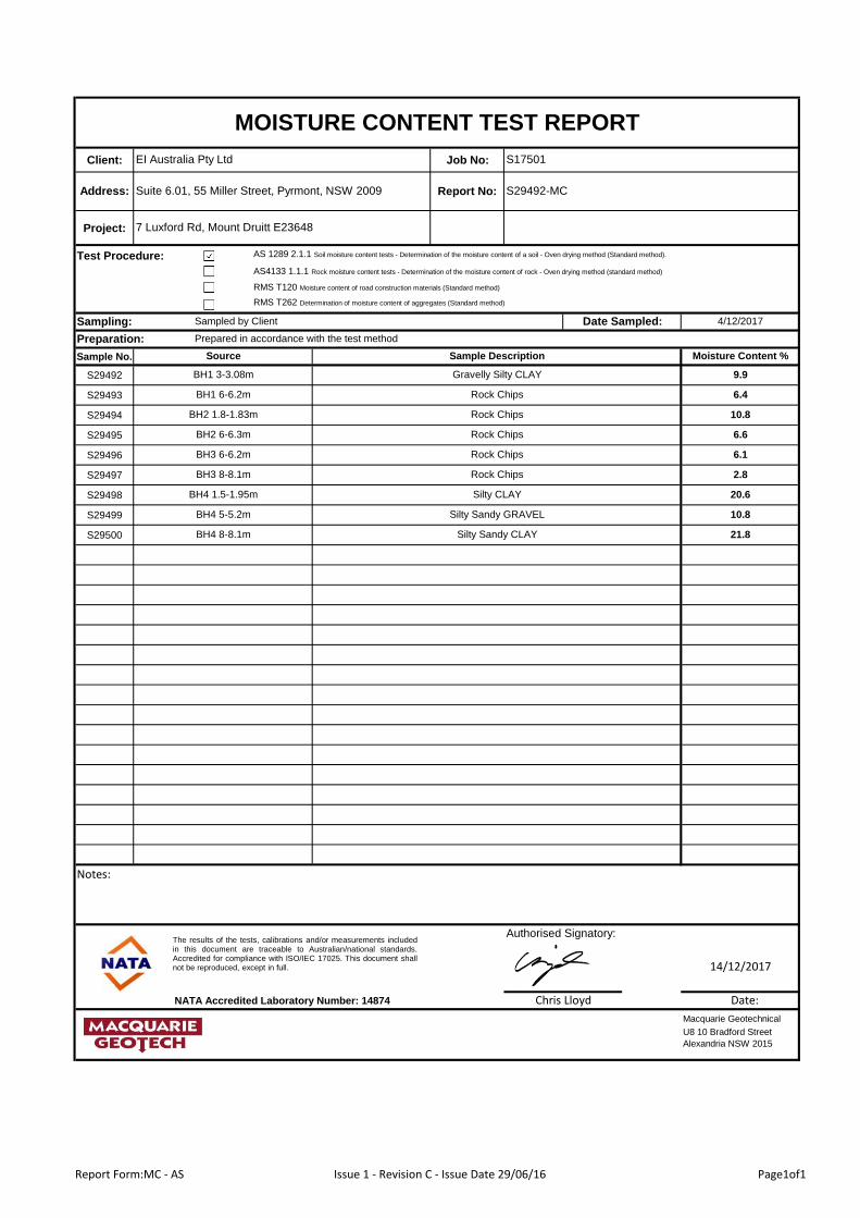
Client: Job No:
Project:
Test Procedure:
RMS T262 Determination of moisture content of aggregates (Standard method)
Sampling:
Sample No.
S29492
S29493
S29494
S29495
S29496
S29497
S29498
S29499
S29500
Authorised Signatory:
NATA Accredited Laboratory Number: 14874
EI Australia Pty Ltd S17501
MOISTURE CONTENT TEST REPORT
Preparation:
S29492-MCSuite 6.01, 55 Miller Street, Pyrmont, NSW 2009Address:
4/12/2017Date Sampled:
7 Luxford Rd, Mount Druitt E23648
Report No:
AS 1289 2.1.1 Soil moisture content tests - Determination of the moisture content of a soil - Oven drying method (Standard method).
AS4133 1.1.1 Rock moisture content tests - Determination of the moisture content of rock - Oven drying method (standard method)
RMS T120 Moisture content of road construction materials (Standard method)
Sampled by Client
Chris Lloyd
U8 10 Bradford Street
Alexandria NSW 2015
Macquarie Geotechnical
Date:
14/12/2017
Prepared in accordance with the test method
BH1 3-3.08m Gravelly Silty CLAY 9.9
BH1 6-6.2m Rock Chips 6.4
Source Sample Description Moisture Content %
BH3 6-6.2m Rock Chips 6.1
BH3 8-8.1m Rock Chips 2.8
BH2 1.8-1.83m Rock Chips 10.8
BH2 6-6.3m Rock Chips 6.6
BH4 8-8.1m Silty Sandy CLAY 21.8
BH4 1.5-1.95m Silty CLAY 20.6
BH4 5-5.2m Silty Sandy GRAVEL 10.8
Notes:
The results of the tests, calibrations and/or measurements includedin this document are traceable to Australian/national standards.Accredited for compliance with ISO/IEC 17025. This document shallnot be reproduced, except in full.
Report Form:MC - AS Issue 1 - Revision C - Issue Date 29/06/16 Page1of1
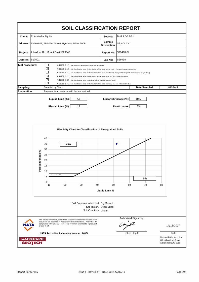
Client: Source:
Project: Report No:
Job No: Lab No:
Test Procedure: AS1289 2.1.1
AS1289 3.1.1
AS1289 3.1.2 Soil classification tests - Determination of the liquid limit if a soil - One point Casagrande method (subsidiary method)
AS1289 3.2.1
AS1289 3.3.1
AS1289 3.4.1
Sampling:
Liquid Limit (%): 52 Linear Shrinkage (%): 10.5
Plastic Limit (%): 17 Plastic Index: 35
Field Moisture Content (%): -
Soil Preparation Method:
Soil History:
NATA Accredited Laboratory Number: 14874
EI Australia Pty Ltd BH4 1.5-1.95m
SOIL CLASSIFICATION REPORT
Preparation:
Silty CLAYSuite 6.01, 55 Miller Street, Pyrmont, NSW 2009Address:
Soil classification tests - Determination of the linear shrinkage of a soil - Standard method
S29498-PI
S29498
4/12/2017Date Sampled:
Soil classification tests - Determination of the plastic limit of a soil - Standard method
S17501
Soil moisture content tests (Oven drying method)
Authorised Signatory:
Sampled by Client
7 Luxford Rd, Mount Druitt E23648
Sample
Description:
Soil classification tests - Determination of the liquid limit of a soil - Four point casagrande method
Prepared in accordance with the test method
Chris Lloyd
Soil classification tests - Calculation of the plasticity Index of a soil
Oven Dried
Soil Condition:
Dry Sieved
Linear
U8 10 Bradford Street
Alexandria NSW 2015
Macquarie Geotechnical
Date:
14/12/2017
The results of the tests, calibrations and/or measurements included in thisdocument are traceable to Australian/national standards. Accredited forcompliance with ISO/IEC 17025. This document shall not be reproduced,except in full.
Inorganic Silts and Clays
0
5
10
15
20
25
30
35
40
10 20 30 40 50 60 70 80
Pla
sti
cit
y I
nd
ex %
Liquid Limit %
Plasticity Chart for Classification of Fine-grained Soils
Clay
Silt
Report Form:PI LS Issue 1 - Revision F - Issue Date 22/02/17 Page1of1
Accreditation No. 2562
Date Reported
Contact
SGS Alexandria Environmental
Unit 16, 33 Maddox St
Alexandria NSW 2015
Huong Crawford
+61 2 8594 0400
+61 2 8594 0499
3
SGS Reference
Facsimile
Telephone
Address
Manager
Laboratory
E23648.G02
E23648.G02 - 7 Luxford Rd, Mount Druitt
(Not specified)
61 2 95160722
SUITE 6.01
55 MILLER STREET
PYRMONT NSW 2009
EI AUSTRALIA
Bryan Zheng
Samples
Order Number
Project
Facsimile
Telephone
Address
Client
CLIENT DETAILS LABORATORY DETAILS
12/12/2017
ANALYTICAL REPORT
SE173380 R0
Date Received 5/12/2017
COMMENTS
Accredited for compliance with ISO/IEC 17025 - Testing. NATA accredited laboratory 2562(4354).
Dong Liang
Metals/Inorganics Team Leader
Huong Crawford
Production Manager
SIGNATORIES
Member of the SGS Group
www.sgs.com.aut +61 2 8594 0400
f +61 2 8594 0499
Australia
Australia
Alexandria NSW 2015
Alexandria NSW 2015
Unit 16 33 Maddox St
PO Box 6432 Bourke Rd BC
Environment, Health and SafetySGS Australia Pty Ltd
ABN 44 000 964 278
Page 1 of 612/12/2017

SE173380 R0ANALYTICAL RESULTS
pH in soil (1:5) [AN101] Tested: 8/12/2017
BH4_1.5-1.95 BH2_0.5-0.95 BH3_6.0-6.2
SOIL SOIL SOIL
- - -
4/12/2017 4/12/2017 4/12/2017
SE173380.001 SE173380.002 SE173380.003
pH pH Units - 6.1 4.7 8.4
UOMPARAMETER LOR
Page 2 of 612/12/2017

SE173380 R0ANALYTICAL RESULTS
Conductivity and TDS by Calculation - Soil [AN106] Tested: 8/12/2017
BH4_1.5-1.95 BH2_0.5-0.95 BH3_6.0-6.2
SOIL SOIL SOIL
- - -
4/12/2017 4/12/2017 4/12/2017
SE173380.001 SE173380.002 SE173380.003
Conductivity of Extract (1:5 dry sample basis) µS/cm 1 860 760 640
UOMPARAMETER LOR
Page 3 of 612/12/2017

SE173380 R0ANALYTICAL RESULTS
Soluble Anions (1:5) in Soil by Ion Chromatography [AN245] Tested: 6/12/2017
BH4_1.5-1.95 BH2_0.5-0.95 BH3_6.0-6.2
SOIL SOIL SOIL
- - -
4/12/2017 4/12/2017 4/12/2017
SE173380.001 SE173380.002 SE173380.003
Chloride mg/kg 0.25 1200 630 390
Sulfate mg/kg 5 140 420 110
UOMPARAMETER LOR
Page 4 of 612/12/2017

SE173380 R0ANALYTICAL RESULTS
Moisture Content [AN002] Tested: 11/12/2017
BH4_1.5-1.95 BH2_0.5-0.95 BH3_6.0-6.2
SOIL SOIL SOIL
- - -
4/12/2017 4/12/2017 4/12/2017
SE173380.001 SE173380.002 SE173380.003
% Moisture %w/w 0.5 16 15 6.8
UOMPARAMETER LOR
Page 5 of 612/12/2017
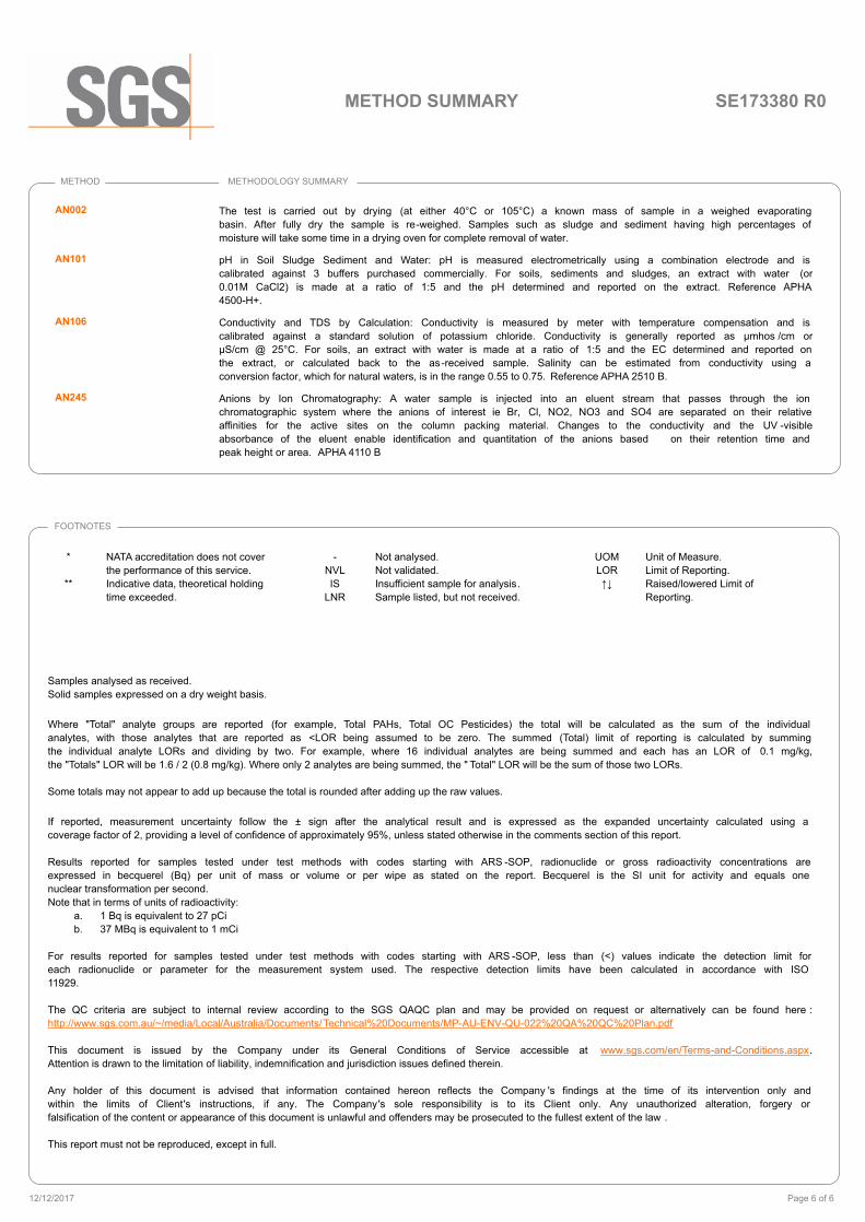
SE173380 R0METHOD SUMMARY
METHOD METHODOLOGY SUMMARY
The test is carried out by drying (at either 40°C or 105°C) a known mass of sample in a weighed evaporating
basin. After fully dry the sample is re-weighed. Samples such as sludge and sediment having high percentages of
moisture will take some time in a drying oven for complete removal of water.
AN002
pH in Soil Sludge Sediment and Water: pH is measured electrometrically using a combination electrode and is
calibrated against 3 buffers purchased commercially. For soils, sediments and sludges, an extract with water (or
0.01M CaCl2) is made at a ratio of 1:5 and the pH determined and reported on the extract. Reference APHA
4500-H+.
AN101
Conductivity and TDS by Calculation: Conductivity is measured by meter with temperature compensation and is
calibrated against a standard solution of potassium chloride. Conductivity is generally reported as µmhos /cm or
µS/cm @ 25°C. For soils, an extract with water is made at a ratio of 1:5 and the EC determined and reported on
the extract, or calculated back to the as-received sample. Salinity can be estimated from conductivity using a
conversion factor, which for natural waters, is in the range 0.55 to 0.75. Reference APHA 2510 B.
AN106
Anions by Ion Chromatography: A water sample is injected into an eluent stream that passes through the ion
chromatographic system where the anions of interest ie Br, Cl, NO2, NO3 and SO4 are separated on their relative
affinities for the active sites on the column packing material. Changes to the conductivity and the UV -visible
absorbance of the eluent enable identification and quantitation of the anions based on their retention time and
peak height or area. APHA 4110 B
AN245
FOOTNOTES
*
**
NATA accreditation does not cover
the performance of this service.
Indicative data, theoretical holding
time exceeded.
-
NVL
IS
LNR
Not analysed.
Not validated.
Insufficient sample for analysis.
Sample listed, but not received.
Samples analysed as received.
Solid samples expressed on a dry weight basis.
Where "Total" analyte groups are reported (for example, Total PAHs, Total OC Pesticides) the total will be calculated as the sum of the individual
analytes, with those analytes that are reported as <LOR being assumed to be zero. The summed (Total) limit of reporting is calculated by summing
the individual analyte LORs and dividing by two. For example, where 16 individual analytes are being summed and each has an LOR of 0.1 mg/kg,
the "Totals" LOR will be 1.6 / 2 (0.8 mg/kg). Where only 2 analytes are being summed, the " Total" LOR will be the sum of those two LORs.
Some totals may not appear to add up because the total is rounded after adding up the raw values.
If reported, measurement uncertainty follow the ± sign after the analytical result and is expressed as the expanded uncertainty calculated using a
coverage factor of 2, providing a level of confidence of approximately 95%, unless stated otherwise in the comments section of this report.
Results reported for samples tested under test methods with codes starting with ARS -SOP, radionuclide or gross radioactivity concentrations are
expressed in becquerel (Bq) per unit of mass or volume or per wipe as stated on the report. Becquerel is the SI unit for activity and equals one
nuclear transformation per second.
Note that in terms of units of radioactivity:
a. 1 Bq is equivalent to 27 pCi
b. 37 MBq is equivalent to 1 mCi
For results reported for samples tested under test methods with codes starting with ARS -SOP, less than (<) values indicate the detection limit for
each radionuclide or parameter for the measurement system used. The respective detection limits have been calculated in accordance with ISO
11929.
The QC criteria are subject to internal review according to the SGS QAQC plan and may be provided on request or alternatively can be found here :
http://www.sgs.com.au/~/media/Local/Australia/Documents/Technical%20Documents/MP-AU-ENV-QU-022%20QA%20QC%20Plan.pdf
This document is issued by the Company under its General Conditions of Service accessible at www.sgs.com/en/Terms-and-Conditions.aspx.
Attention is drawn to the limitation of liability, indemnification and jurisdiction issues defined therein.
Any holder of this document is advised that information contained hereon reflects the Company 's findings at the time of its intervention only and
within the limits of Client's instructions, if any. The Company's sole responsibility is to its Client only. Any unauthorized alteration, forgery or
falsification of the content or appearance of this document is unlawful and offenders may be prosecuted to the fullest extent of the law .
This report must not be reproduced, except in full.
UOM
LOR
↑↓
Unit of Measure.
Limit of Reporting.
Raised/lowered Limit of
Reporting.
Page 6 of 612/12/2017
Geotechnical and Salinity Assessment 7 Luxford Road, Mount Druitt, NSW Report No. E23648.G02, 26 February 2018
APPENDIX C
IMPORTANT INFORMATION
Important Information
Rev.7, January 2016
SCOPE OF SERVICES
The geotechnical report (“the report”) has been prepared in accordance with the scope of services as set out in the contract, or as otherwise agreed, between the Client And EI Australia (“EI”). The scope of work may have been limited by a range of factors such as time, budget, access and/or site disturbance constraints.
RELIANCE ON DATA
EI has relied on data provided by the Client and other individuals and organizations, to prepare the report. Such data may include surveys, analyses, designs, maps and plans. EI has not verified the accuracy or completeness of the data except as stated in the report. To the extent that the statements, opinions, facts, information, conclusions and/or recommendations (“conclusions”) are based in whole or part on the data, EI will not be liable in relation to incorrect conclusions should any data, information or condition be incorrect or have been concealed, withheld, misrepresented or otherwise not fully disclosed to EI.
GEOTECHNICAL ENGINEERING
Geotechnical engineering is based extensively on judgment and opinion. It is far less exact than other engineering disciplines. Geotechnical engineering reports are prepared for a specific client, for a specific project and to meet specific needs, and may not be adequate for other clients or other purposes (e.g. a report prepared for a consulting civil engineer may not be adequate for a construction contractor). The report should not be used for other than its intended purpose without seeking additional geotechnical advice. Also, unless further geotechnical advice is obtained, the report cannot be used where the nature and/or details of the proposed development are changed.
LIMITATIONS OF SITE INVESTIGATION
The investigation programme undertaken is a professional estimate of the scope of investigation required to provide a general profile of subsurface conditions. The data derived from the site investigation programme and subsequent laboratory testing are extrapolated across the site to form an inferred geological model, and an engineering opinion is rendered about overall subsurface conditions and their likely behaviour with regard to the proposed development. Despite investigation, the actual conditions at the site might differ from those inferred to exist, since no subsurface exploration program, no matter how comprehensive, can reveal all subsurface details and anomalies. The engineering logs are the subjective interpretation of subsurface conditions at a particular location and time, made by trained personnel. The actual interface between materials may be more gradual or abrupt than a report indicates.
SUBSURFACE CONDITIONS ARE TIME DEPENDENT
Subsurface conditions can be modified by changing natural forces or man-made influences. The report is based on conditions that existed at the time of subsurface exploration. Construction operations adjacent to the site, and natural events such as floods, or ground water fluctuations, may also affect subsurface conditions, and thus the continuing adequacy of a geotechnical report. EI should be kept appraised of any such events, and should be consulted to determine if any additional tests are necessary.
VERIFICATION OF SITE CONDITIONS
Where ground conditions encountered at the site differ significantly from those anticipated in the report, either due to natural variability of subsurface conditions or construction activities, it is a condition of the report that EI be notified of any variations and be provided with an opportunity to review the recommendations of this report. Recognition of change of soil and rock conditions requires experience and it is recommended that a suitably experienced geotechnical engineer be engaged to visit the site with sufficient frequency to detect if conditions have changed significantly.
REPRODUCTION OF REPORTS
This report is the subject of copyright and shall not be reproduced either totally or in part without the express permission of this Company. Where information from the accompanying report is to be included in contract documents or engineering specification for the project, the entire report should be included in order to minimize the likelihood of misinterpretation from logs.
REPORT FOR BENEFIT OF CLIENT
The report has been prepared for the benefit of the Client and no other party. EI assumes no responsibility and will not be liable to any other person or organisation for or in relation to any matter dealt with or conclusions expressed in the report, or for any loss or damage suffered by any other person or organisation arising from matters dealt with or conclusions expressed in the report (including without limitation matters arising from any negligent act or omission of EI or for any loss or damage suffered by any other party relying upon the matters dealt with or conclusions expressed in the report). Other parties should not rely upon the report or the accuracy or completeness of any conclusions and should make their own inquiries and obtain independent advice in relation to such matters.
OTHER LIMITATIONS
EI will not be liable to update or revise the report to take into account any events or emergent circumstances or fact occurring or becoming apparent after the date of the report.