Embed Size (px)
Citation preview

Geoscience
consulting
GEOLOGICAL AND GEOTECHNICAL REPORT
ON THE AZURE WINDOW, GOZO:
ROCK ASSESSMENT AND RECOMMENDATIONS
ON PRESERVATION AND CONSERVATION
Prepared by
Geoscience
consulting
On behalf of
MINISTRY FOR SUSTAINABLE DEVELOPMENT,
THE ENVIRONMENT AND CLIMATE CHANGE
Casa Leoni, Santa Venera
Malta
JULY 2013
Geoscience Consulting
Consultant: Dr Peter Gatt MSc(R'dg), PhD(Dunelm), FGS
T: +356 79603783 E: [email protected]

Geoscience
consulting
Report Reference:
Geoscience Consulting, 2013. Geological and geotechnical report on the Azure Window,
Gozo: Rock assessment and recommendations for preservation and conservation. Report
prepared for the Ministry for Sustainable Development, the Environment and Climate
Change (Ref: MG 22/2005), Malta.
This report is based on conditions at site during field work sessions and is produced for the
benefit of the client only. No responsibility can be accepted by Geoscience Consulting and its
consultants for any consequences which may arise from parties who may act upon the
contents and recommendations in this report.
July 2013
Copyright
The copyright of this report rests with the author. No quotation or data from it should be published without the
author’s prior written consent and any information derived from it should be acknowledged.
Geoscience Consulting
E-mail: [email protected]
© Peter A. Gatt, 2013
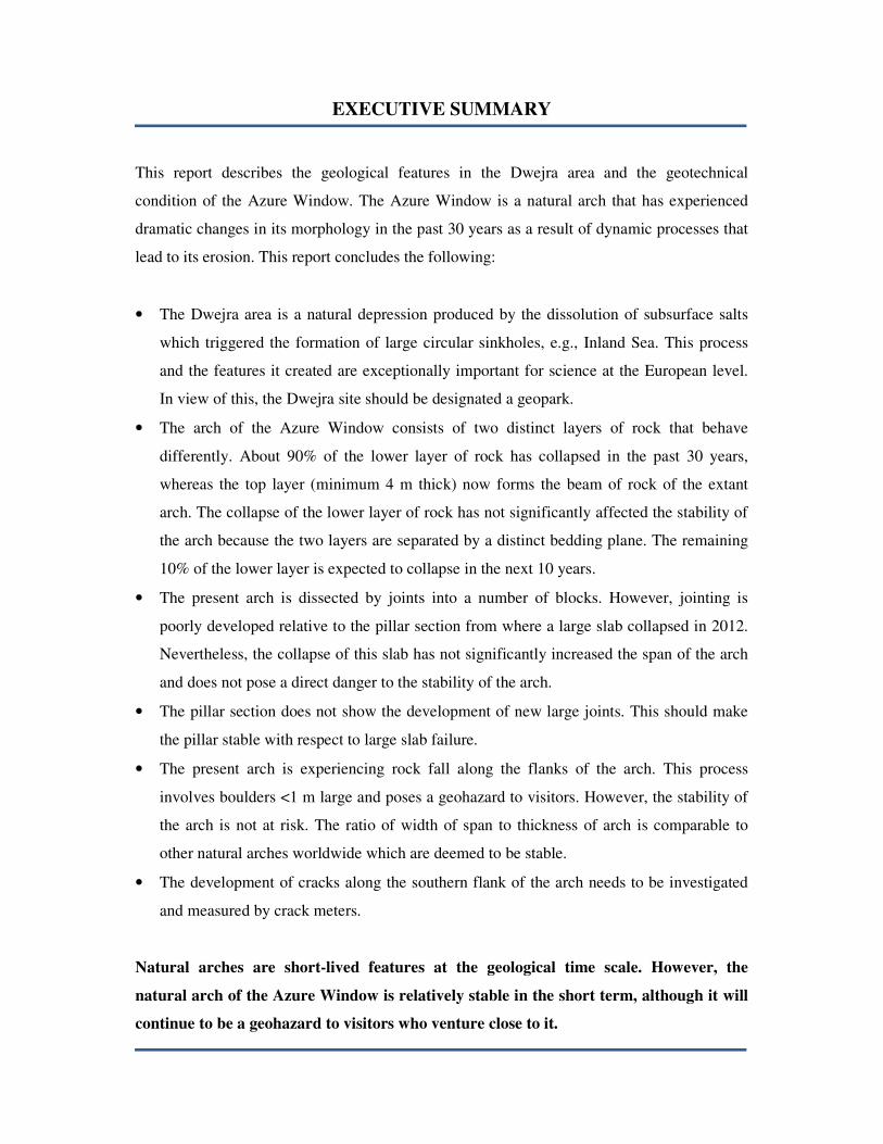
EXECUTIVE SUMMARY
This report describes the geological features in the Dwejra area and the geotechnical
condition of the Azure Window. The Azure Window is a natural arch that has experienced
dramatic changes in its morphology in the past 30 years as a result of dynamic processes that
lead to its erosion. This report concludes the following:
• The Dwejra area is a natural depression produced by the dissolution of subsurface salts
which triggered the formation of large circular sinkholes, e.g., Inland Sea. This process
and the features it created are exceptionally important for science at the European level.
In view of this, the Dwejra site should be designated a geopark.
• The arch of the Azure Window consists of two distinct layers of rock that behave
differently. About 90% of the lower layer of rock has collapsed in the past 30 years,
whereas the top layer (minimum 4 m thick) now forms the beam of rock of the extant
arch. The collapse of the lower layer of rock has not significantly affected the stability of
the arch because the two layers are separated by a distinct bedding plane. The remaining
10% of the lower layer is expected to collapse in the next 10 years.
• The present arch is dissected by joints into a number of blocks. However, jointing is
poorly developed relative to the pillar section from where a large slab collapsed in 2012.
Nevertheless, the collapse of this slab has not significantly increased the span of the arch
and does not pose a direct danger to the stability of the arch.
• The pillar section does not show the development of new large joints. This should make
the pillar stable with respect to large slab failure.
• The present arch is experiencing rock fall along the flanks of the arch. This process
involves boulders <1 m large and poses a geohazard to visitors. However, the stability of
the arch is not at risk. The ratio of width of span to thickness of arch is comparable to
other natural arches worldwide which are deemed to be stable.
• The development of cracks along the southern flank of the arch needs to be investigated
and measured by crack meters.
Natural arches are short-lived features at the geological time scale. However, the
natural arch of the Azure Window is relatively stable in the short term, although it will
continue to be a geohazard to visitors who venture close to it.

1
Contents
1. INTRODUCTION ......................................................................................................... 3
1.01 Location .................................................................................................................. 3
1.02 Objectives ............................................................................................................... 4
1.03 Definitions .............................................................................................................. 5
1.04 Dataset .................................................................................................................... 6
2. GEOLOGICAL ASSESSMENT .................................................................................... 7
2.01 Regional geology .................................................................................................... 7
2.02 Stratigraphy ............................................................................................................ 9
2.03 Structural geology ................................................................................................. 12
3. GEOTECHNICAL ASSESSMENT ............................................................................. 15
3.01 Geomorphology and lifecycle of arch .................................................................... 15
3.02 Rock mechanics .................................................................................................... 17
4. GEOMECHANICAL STABILITY OF AZURE WINDOW......................................... 18
4.01 The width of span and thickness of the unsupported arch: ..................................... 18
4.02 Jointing ................................................................................................................. 21
4.03 Stability of pillar ................................................................................................... 22
4.04 Modelling of failure process .................................................................................. 23
4.05 Geohazards ........................................................................................................... 24
5. HERITAGE STATUS .................................................................................................. 25
6. CONCLUSIONS ......................................................................................................... 26
7. RECOMMENDATIONS ............................................................................................. 27
8. REFERENCES ............................................................................................................ 28
Geological and geotechnical report on the Azure Window, Gozo Geoscience consulting
2
List of figures
Figure 1. Map of Maltese Islands showing location of natural arches (blue circles) including the Azure Window in western
Gozo. Location of deep well Madonna taz-Zejt (MTZ well) shown by black circle.................................................................. 4
Figure 2. Right: Special Area of Conservation Natura 2000 marked by blue line (source: MEPA); Left: Dwejra Point
headland comprising the Azure Window arch and pillar elements. The southern side is of high scenic value and a tourist
attraction viewed from the panorama point. ............................................................................................................................... 6
Figure 3. A. Structural features of the Dwejra Depression shown on a satellite photograph. Six large sinkholes are identified,
although three remain relatively intact: a. Inland Sea sinkhole, b. Berwin Sinkhole, c. Dwejra Bay Sinkhole. White arrow
points to Azure Window; B. 3D Lidar-based photograph shows the main sinkholes around the Azure Window including the
Blue Hole; C. Diagram showing process of sinkhole formation by the dissolution of subsurface evaporite. ............................ 8
Figure 4. Site stratigraphy of the Dwejra Point. Top: Uninterpreted photograph showing dimensions; Bottom: interpreted
section showing facies in Members A and B (see Figure 5). Joints A and B (white lines) penetrate all beds of Member B. .. 10
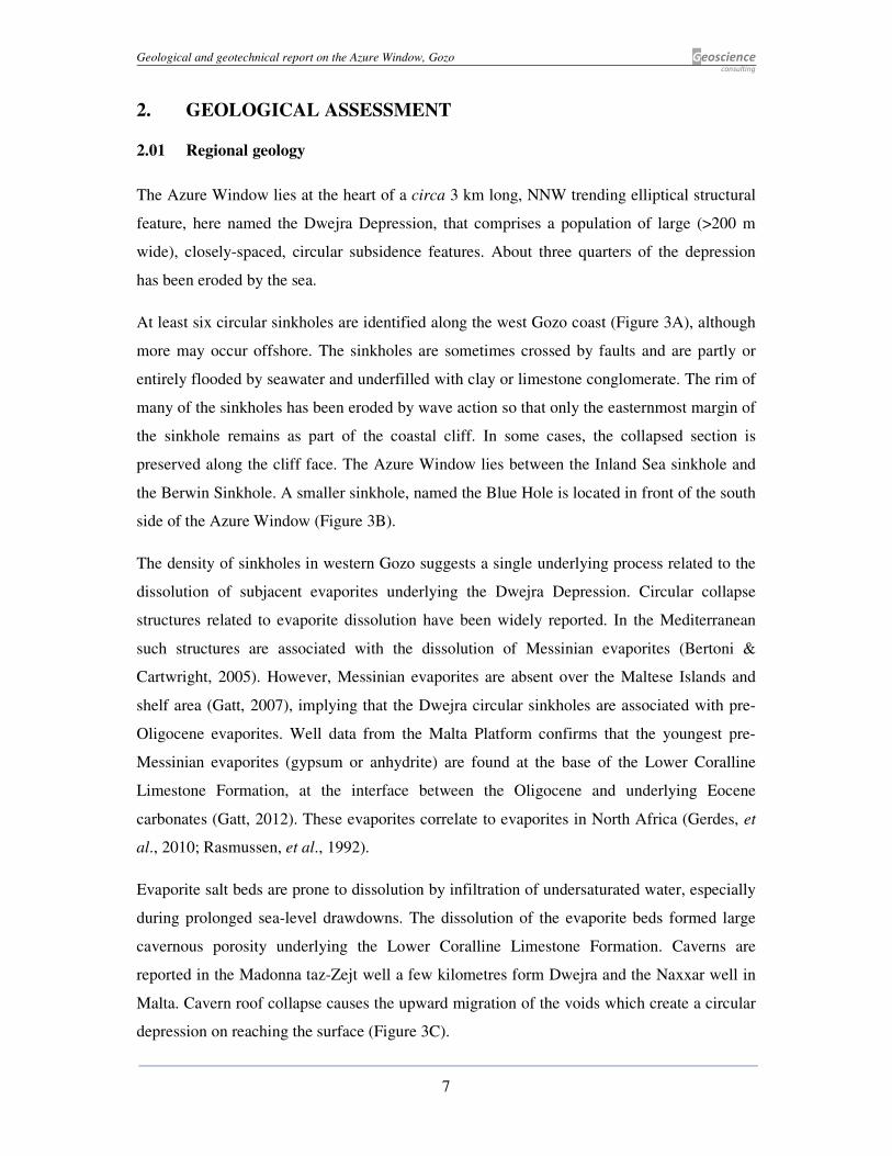
Figure 5. The lithology of Member B is partly exposed at the Azure Window and entirely exposed around the Blue Hole
sinkhole close to sea-level. The lithology of Member A facies is inaccessible at the Azure Window but is accessible in the
Inland Sea Sinkhole and is dominated by Coralline Red Algae. .............................................................................................. 11
Figure 6. Facies B-5 overlain by the intensely weathered hybrid facies (H) that passes further up to the Globigerina
Limestone Formation. The open joints B and C in facies B-5 cross each other. ...................................................................... 11
Figure 7. Surface lithology of Dwejra Point. ........................................................................................................................... 12
Figure 8. Top: The Inland Sea monocline dipping southwest. The more ductile Member B rocks deform without the
formation of faults (white lines). Inset map shows dip directions around the Inland Sea sinkhole; Bottom: lithology dipping
south from Azure Window to Blue Hole. Eroded outlier of Member B rocks preserved as a stack next to the Blue Hole. ..... 13
Figure 9. Map showing structural and geomorphological elements in Dwejra Point Headland. Only surface features affecting
Member B rocks are shown. .................................................................................................................................................... 13
Figure 10. Western edge of Dwejra Point. Photograph A: Open joints B and C within facies B-5; Photograph B: Non-
systematic, fresh fractures in Area X. The fractures do not follow jointing pattern and are irregular, whereas joints follow
geometrical patterns. ................................................................................................................................................................ 14
Figure 11. Model of slab failure and lifecycle of a natural arch. The model is based on the west coast of Gozo where these
features are observed: 1. Inland Sea arch consisting of a small arch developed along a major joint; 2. Azure Window arch; 3.
Fungus Rock in Dwejra where the bridge to the mainland had collapsed in the past leaving a stack. ..................................... 16
Figure 12. Evolution of Azure Window natural arch over 32 years. Right: model of void increase related to facies. ............. 16
Figure 13. Geotechinal parametres and discontinuity formation in Members A and B rock. Bold vertical lines represent
hypothetical well developed jointing whereas dotted vertical lines represent poorly developed vertical joints. ...................... 18
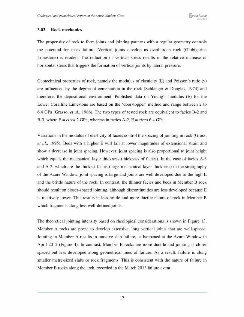
Figure 14. a. Photograph of the southern side of the Azure Window taken in 1981 prior to the failure of facies B-2 and B-3;
b. North-facing side of Azure Window showing potential slab failure of blocks 1c, 2 and 3 (shaded yellow) c. Red shading
shows recent failed blocks (1a & 1b); d. stratigraphy of the arch section observed near the Blue Hole area. Note the abrupt
hardground surface that forms a discontinuity surface with the overlying facies B-5. The dashed white line shows the area of
likely failure. ............................................................................................................................................................................ 19
Figure 15. Landscape Arch, Utah, USA. The minimum thickness (H) of the Arch approaches that of the Azure Window,
although the span is approximately 4 times greater. ................................................................................................................ 20
Figure 16. Photograph showing area of recent rockfall (red ring) along the middle part of the north-facing part of the arch.
The failure of slab 1a (dotted red line) may have relaxed stress along the arch and weakened the arch by reducing horizontal
stress along joints, resulting in failure. Similar failure occurred along the south-facing side that was recorded in the media of
March 2013. ............................................................................................................................................................................. 22
Figure 17. A: Geometry of natural arches in Europe; B. Stages in the development of the Azure Window arch. The first stage
is represented by the ‘window’ type of configuration as seen at Wied il-Mielah (Gozo) about 3.7 km from the Azure
Window. Slab failure along the sides of the void as happened in April 2012 has resulted in an asymmetrical archway which
may develop into a symmetrical arch (stage 4). ....................................................................................................................... 23
Figure 18. Geohazard map showing areas of potential failure. Inset shows warning signs located close to Azure Window.
Past extent of arch is based on colonial age maps. ................................................................................................................... 24
List of Tables
Table 1. Ratio of arch thickness to width of span of some of the largest natural arches in the world compared to the Azure
Window. .................................................................................................................................................................................. 20
Table 2. Blocks that have failed or may fail along the arch area.............................................................................................. 21
Geological and geotechnical report on the Azure Window, Gozo Geoscience consulting
3
1. INTRODUCTION
Geoscience Consulting have been commissioned by the Ministry for Sustainable
Development, the Environment and Climate Change to write this report on the condition of a
scenic natural arch at Dwejra, Gozo, known as the Azure Window. Apprehension on the
safety of the Azure Window heightened after the collapse of a large slab of limestone
reported in the media on April 2012, followed by rock fall in March 2013. This geological
and geotechnical report on the natural arch is intended to assess the danger posed by rock
failure to tourists as well as recommending possible interventions to increase the longevity of
the arch based on detailed geomechanical study.
There are several natural arches in the Maltese Islands, although only the Azure Window
(and Dwejra) is listed as a tentative candidate for UNESCO world heritage sites status.
Moreover, the scenic southern side of the Azure Window has been the setting for epic fantasy
films produced by major film studios Warner Brothers (1981) and HBO (2011) and has
become an important tourist attraction that generates income for the local economy.
This report contains the geological and geotechnical assessment of the natural arch based on
site visits in June 2013. It also includes the description of the regional geology with new
insights and discoveries on the spectacular processes and features affecting the area around
the Azure Window. The recommendations made and opinions expressed in this report are
based on ground conditions at site.
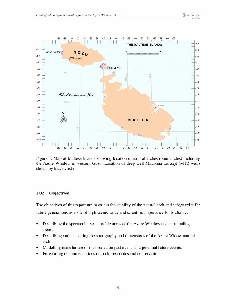
1.01 Location
The Azure Window is a natural arch, <30 m high, located along a headland named Dwejra
Point (36° 3’12.95”N, 14° 11’17.88”E) in Gozo Island on the western end of the Maltese
Islands. It is one of the 26 natural arches in the Maltese Islands (Figure 1), with the highest
number found in Comino Island (12 arches). The closest natural arches are found at the
Inland Sea, Fungus Rock and at Wied il-Mielah. The Azure Window and surrounding area is
protected under the Special Area of Conservation, Natura 2000 (Figure 2).
Geological and geotechnical report on the Azure Window, Gozo Geoscience consulting
4
Figure 1. Map of Maltese Islands showing location of natural arches (blue circles) including
the Azure Window in western Gozo. Location of deep well Madonna taz-Zejt (MTZ well)
shown by black circle.
1.02 Objectives
The objectives of this report are to assess the stability of the natural arch and safeguard it for
future generations as a site of high scenic value and scientific importance for Malta by:
• Describing the spectacular structural features of the Azure Window and surrounding
areas.
• Describing and measuring the stratigraphy and dimensions of the Azure Widow natural
arch.
• Modelling mass failure of rock based on past events and potential future events.
• Forwarding recommendations on rock mechanics and conservation.
Geological and geotechnical report on the Azure Window, Gozo Geoscience consulting
5
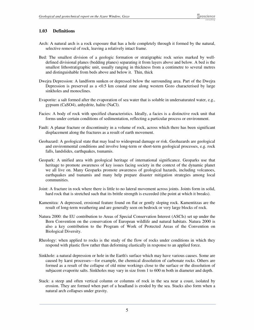
1.03 Definitions
Arch: A natural arch is a rock exposure that has a hole completely through it formed by the natural,
selective removal of rock, leaving a relatively intact frame.
Bed: The smallest division of a geologic formation or stratigraphic rock series marked by well-
defined divisional planes (bedding planes) separating it from layers above and below. A bed is the
smallest lithostratigraphic unit, usually ranging in thickness from a centimetre to several metres
and distinguishable from beds above and below it. Thin, thick
Dwejra Depression: A landform sunken or depressed below the surrounding area. Part of the Dwejra
Depression is preserved as a <0.5 km coastal zone along western Gozo characterised by large
sinkholes and monoclines.
Evaporite: a salt formed after the evaporation of sea water that is soluble in undersaturated water, e.g.,
gypsum (CaSO4), anhydrite, halite (NaCl).
Facies: A body of rock with specified characteristics. Ideally, a facies is a distinctive rock unit that
forms under certain conditions of sedimentation, reflecting a particular process or environment.
Fault: A planar fracture or discontinuity in a volume of rock, across which there has been significant
displacement along the fractures as a result of earth movement.
Geohazard: A geological state that may lead to widespread damage or risk. Geohazards are geological
and environmental conditions and involve long-term or short-term geological processes, e.g. rock
falls, landslides, earthquakes, tsunamis.
Geopark: A unified area with geological heritage of international significance. Geoparks use that
heritage to promote awareness of key issues facing society in the context of the dynamic planet
we all live on. Many Geoparks promote awareness of geological hazards, including volcanoes,
earthquakes and tsunamis and many help prepare disaster mitigation strategies among local
communities.
Joint: A fracture in rock where there is little to no lateral movement across joints. Joints form in solid,
hard rock that is stretched such that its brittle strength is exceeded (the point at which it breaks).
Kamenitza: A depressed, erosional feature found on flat or gently sloping rock. Kamentitzas are the
result of long-term weathering and are generally seen on bedrock or very large blocks of rock.
Natura 2000: the EU contribution to Areas of Special Conservation Interest (ASCIs) set up under the
Bern Convention on the conservation of European wildlife and natural habitats. Natura 2000 is
also a key contribution to the Program of Work of Protected Areas of the Convention on
Biological Diversity.
Rheology: when applied to rocks is the study of the flow of rocks under conditions in which they
respond with plastic flow rather than deforming elastically in response to an applied force.
Sinkhole: a natural depression or hole in the Earth's surface which may have various causes. Some are
caused by karst processes—for example, the chemical dissolution of carbonate rocks. Others are
formed as a result of the collapse of old mine workings close to the surface or the dissolution of
subjacent evaporite salts. Sinkholes may vary in size from 1 to 600 m both in diameter and depth.
Stack: a steep and often vertical column or columns of rock in the sea near a coast, isolated by
erosion. They are formed when part of a headland is eroded by the sea. Stacks also form when a
natural arch collapses under gravity.

Geological and geotechnical report on the Azure Window, Gozo Geoscience consulting
6
1.04 Dataset
The Azure Window stratigraphy was logged, sampled, and photographed from land and sea
during field work sessions held in June 2013. Where the stratigraphy is inaccessible at the
Azure Window, nearby areas with correlative stratigraphy exposed along a gorge was logged
(Figure 2). Other sources of data include the 8 km deep Madonna taz-Zejt exploratory well
(MTZ well) spudded just outside the region (Figure 1).
Figure 2. Right: Special Area of Conservation Natura 2000 marked by blue line (source:
MEPA); Left: Dwejra Point headland comprising the Azure Window arch and pillar elements.
The southern side is of high scenic value and a tourist attraction viewed from the panorama
point.
Geological and geotechnical report on the Azure Window, Gozo Geoscience consulting
7
2. GEOLOGICAL ASSESSMENT
2.01 Regional geology
The Azure Window lies at the heart of a circa 3 km long, NNW trending elliptical structural
feature, here named the Dwejra Depression, that comprises a population of large (>200 m
wide), closely-spaced, circular subsidence features. About three quarters of the depression
has been eroded by the sea.
At least six circular sinkholes are identified along the west Gozo coast (Figure 3A), although
more may occur offshore. The sinkholes are sometimes crossed by faults and are partly or
entirely flooded by seawater and underfilled with clay or limestone conglomerate. The rim of
many of the sinkholes has been eroded by wave action so that only the easternmost margin of
the sinkhole remains as part of the coastal cliff. In some cases, the collapsed section is
preserved along the cliff face. The Azure Window lies between the Inland Sea sinkhole and
the Berwin Sinkhole. A smaller sinkhole, named the Blue Hole is located in front of the south
side of the Azure Window (Figure 3B).
The density of sinkholes in western Gozo suggests a single underlying process related to the
dissolution of subjacent evaporites underlying the Dwejra Depression. Circular collapse
structures related to evaporite dissolution have been widely reported. In the Mediterranean
such structures are associated with the dissolution of Messinian evaporites (Bertoni &
Cartwright, 2005). However, Messinian evaporites are absent over the Maltese Islands and
shelf area (Gatt, 2007), implying that the Dwejra circular sinkholes are associated with pre-
Oligocene evaporites. Well data from the Malta Platform confirms that the youngest pre-
Messinian evaporites (gypsum or anhydrite) are found at the base of the Lower Coralline
Limestone Formation, at the interface between the Oligocene and underlying Eocene
carbonates (Gatt, 2012). These evaporites correlate to evaporites in North Africa (Gerdes, et
al., 2010; Rasmussen, et al., 1992).
Evaporite salt beds are prone to dissolution by infiltration of undersaturated water, especially
during prolonged sea-level drawdowns. The dissolution of the evaporite beds formed large
cavernous porosity underlying the Lower Coralline Limestone Formation. Caverns are
reported in the Madonna taz-Zejt well a few kilometres form Dwejra and the Naxxar well in
Malta. Cavern roof collapse causes the upward migration of the voids which create a circular
depression on reaching the surface (Figure 3C).

Geological and geotechnical report on the Azure Window, Gozo Geoscience consulting
8
Figure 3. A. Structural features of the Dwejra Depression shown on a satellite photograph.
Six large sinkholes are identified, although three remain relatively intact: a. Inland Sea
sinkhole, b. Berwin Sinkhole, c. Dwejra Bay Sinkhole. White arrow points to Azure Window;
B. 3D Lidar-based photograph shows the main sinkholes around the Azure Window
including the Blue Hole; C. Diagram showing process of sinkhole formation by the
dissolution of subsurface evaporite.

Geological and geotechnical report on the Azure Window, Gozo Geoscience consulting
9
2.02 Stratigraphy
The Azure Window is found entirely within the top part of the Lower Coralline Limestone
Formation (Oligocene) of the Maltese Islands. The limestone is well bedded and well jointed
and is sub-divided into four members by Pedley (1978). The vertical limestone lithology
varies significantly and results in differential erosion (Figure 4) and different rheological
behaviour when the rock is subjected to stress and tension. Limestone texture classification is
based on Dunham (1962) and the stratigraphy is divided into two Members that comprise the
arch and base section, respectively (Figure 5):
• Member B: About 7 m of horizontal to cross-bedded packstone to grainstone beds
(facies B-2 and B-3) overlain by >4 m of packstone to wackestone limestone (facies
B-5). Facies B-5 comprises the entire arch section of the Azure Window and is
equivalent to the Mara Member (Pedley, 1978) whereas facies B-2 and B-3 is
equivalent to the Xlendi Member.
• Member A: About 20 m of horizontal beds that constitutes the pillar and base of the
Azure Window (equivalent to the Attard Member). Sediments are dominated by
coralline red algae.
The base of Member B consists of thinly bedded white limestone (facies B-1) which forms a
groove-like depression around the Azure Window as a result of differential erosion of this
weak rock. The overlying facies B-2 is horizontally bedded and passes to cross-bedded B-3
facies, terminating in a hardground formed by corrasion of a well-cemented surface. Both
facies consist of large benthic foraminifera and sediments are interpreted as deposited in a
high-energy shoal environment with migrating sand waves (Davies, 1976).
Facies B-2 and B-3 are missing along most of the arch segment where they form small
abutments. This facies has a high level of intergranular porosity which makes it less compact
than the overlying facies 5 and the underlying Member A.
The upper part of Member B (facies B-5) forms most of the unsupported arch and comprises
frequent Scutella subrotunda fragments (Figure 7), whole tests and echinoid spines. Facies B-
5 consists of pavements of dense echinoid fragments that alternate with thick beds dominated
by micrite. An upper 1 m thick bed forms a hybrid facies between the overlying Globigerina
Limestone and facies B-5 and is distinguished by its light orange tint relative to the
underlying white sediments (Figure 6). The hybrid bed is mostly micritic with sporadic

Geological and geotechnical report on the Azure Window, Gozo Geoscience consulting
10
accumulation of large Scutellid tests. It is intensely weathered and has retreated to over a part
of the arch area. In some areas large solution pools (kamenitzas) occur.
Member A is dominated by calcareous coralline red algae, especially facies A-2. The
calcareous algae occur in different morphologies ranging from pebble-sized rhodoliths to
coarse-grained algal debris. The depositional environment was >30 m deep where moderate
current activity winnowed some of the fines and allowed rhodoliths to be occasionally
overturned. The slow growth of rhodoliths implies slow sedimentation which allows for
calcite cement to develop. In contrast, facies A-4 consists of fine-grained, thinly-bedded
sediments.
Figure 4. Site stratigraphy of the Dwejra Point. Top: Uninterpreted photograph showing
dimensions; Bottom: interpreted section showing facies in Members A and B (see Figure 5).
Joints A and B (white lines) penetrate all beds of Member B.
Geological and geotechnical report on the Azure Window, Gozo Geoscience consulting
11
Figure 5. The lithology of Member B is partly exposed at the Azure Window and entirely
exposed around the Blue Hole sinkhole close to sea-level. The lithology of Member A facies
is inaccessible at the Azure Window but is accessible in the Inland Sea Sinkhole and is
dominated by Coralline Red Algae.
Figure 6. Facies B-5 overlain by the intensely weathered hybrid facies (H) that passes further
up to the Globigerina Limestone Formation. The open joints B and C in facies B-5 cross each
other.

Geological and geotechnical report on the Azure Window, Gozo Geoscience consulting
12
Figure 7. Surface lithology of Dwejra Point.
2.03 Structural geology
The structural geology of the Dwejra Depression is controlled by circular sinkhole collapse
features and faulting. Faults adjacent to Dwejra Point bound the headland which juts out from
the rim of the Inland Sea Sinkhole. This rim forms a monocline dipping in a southwestern
direction in the direction of the Blue Hole sinkhole along the southern side of the Azure
Window (Figure 8). The structural elements imply significant rock deformation around the
Azure Window. The monoclines were affected by post-depositional faults with throws of a
few metres, which radiate from the Inland Sea Sinkhole. Faults dip towards downsagged part.
Most faults developed in Member A rocks whereas Member B sediments deformed over the
faulted areas (Figure 8), which is consistent with the different rheology of the two Members.

Geological and geotechnical report on the Azure Window, Gozo Geoscience consulting
13
Figure 8. Top: The Inland Sea monocline dipping southwest. The more ductile Member B
rocks deform without the formation of faults (white lines). Inset map shows dip directions
around the Inland Sea sinkhole; Bottom: lithology dipping south from Azure Window to Blue
Hole. Eroded outlier of Member B rocks preserved as a stack next to the Blue Hole.
Figure 9. Map showing structural and geomorphological elements in Dwejra Point Headland.
Only surface features affecting Member B rocks are shown.
Geological and geotechnical report on the Azure Window, Gozo Geoscience consulting
14
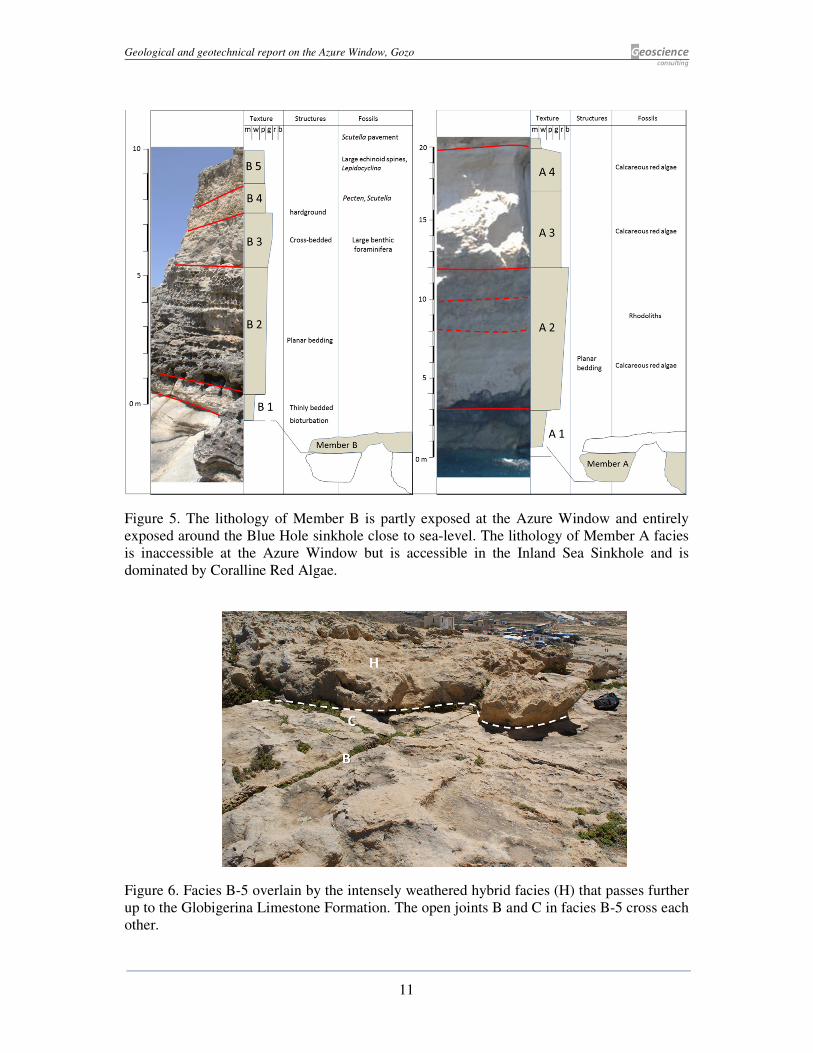
The structural elements of the Azure Window headland, namely faulting, have controlled the
overall shape of the headland whereas jointing has controlled the configuration of the
headland. Surface joints in Member B rocks are not entirely systematic, although two sets of
joints have developed in NNW and WSW direction. Both these patterns reflect lateral stress
along the headland in westerly and N-S directions.
Figure 9 only shows the main joints, some of which, e.g., joints B and C are open at their
termination (Figure 10A), although most of the remaining joints are closed. Jointing is mostly
systematic following geometrical patterns, although some joints are curved. An area of recent
fractures (Area X in Figure 9) has developed in the southeast part of the arch (Figure 10). The
fractures are extensional and non-systematic unlike the surrounding joint network. These
fractures represent recent extension in the direction of the cliff face.
Figure 10. Western edge of Dwejra Point. Photograph A: Open joints B and C within facies
B-5; Photograph B: Non-systematic, fresh fractures in Area X. The fractures do not follow
jointing pattern and are irregular, whereas joints follow geometrical patterns.

Geological and geotechnical report on the Azure Window, Gozo Geoscience consulting
15
3. GEOTECHNICAL ASSESSMENT
The stability and integrity of the Azure Window depends on external influences such as
geomorphological processes as well as the intrinsic rock mechanical properties.
3.01 Geomorphology and lifecycle of arch
Surface erosion is controlled by chemical dissolution of limestone that has stripped all the
Globigerina Limestone along the Dwejra Point headland and has partly removed the hybrid
sediments.
The sea cliffs along western Gozo are the result of mechanical erosion caused by slab failure.
The process begins with the erosion of a notch by wave action at sea-level. The lateral tensile
stresses in the rock free-face produce vertical joints. Eventually, the vertical joint will begin
to open until a point is reached when the mass of the slab exceeds the support afforded by the
area of contact between the slab and the underlying main rock mass. Slab failure will occur
by toppling (Figure 11). As the cliff face retreats, a submarine abrasion platform develops.
The circular subsidence sinkholes along coastal areas are prone to breaching by slab failure
that produces tunnels eroded by sea waves. The Dwejra Depression sinkholes show different
stages of the breaching process related to the lifecycle of a coastal natural arch (Figure 11).
The process is controlled by the development of jointing and sea wave erosion.
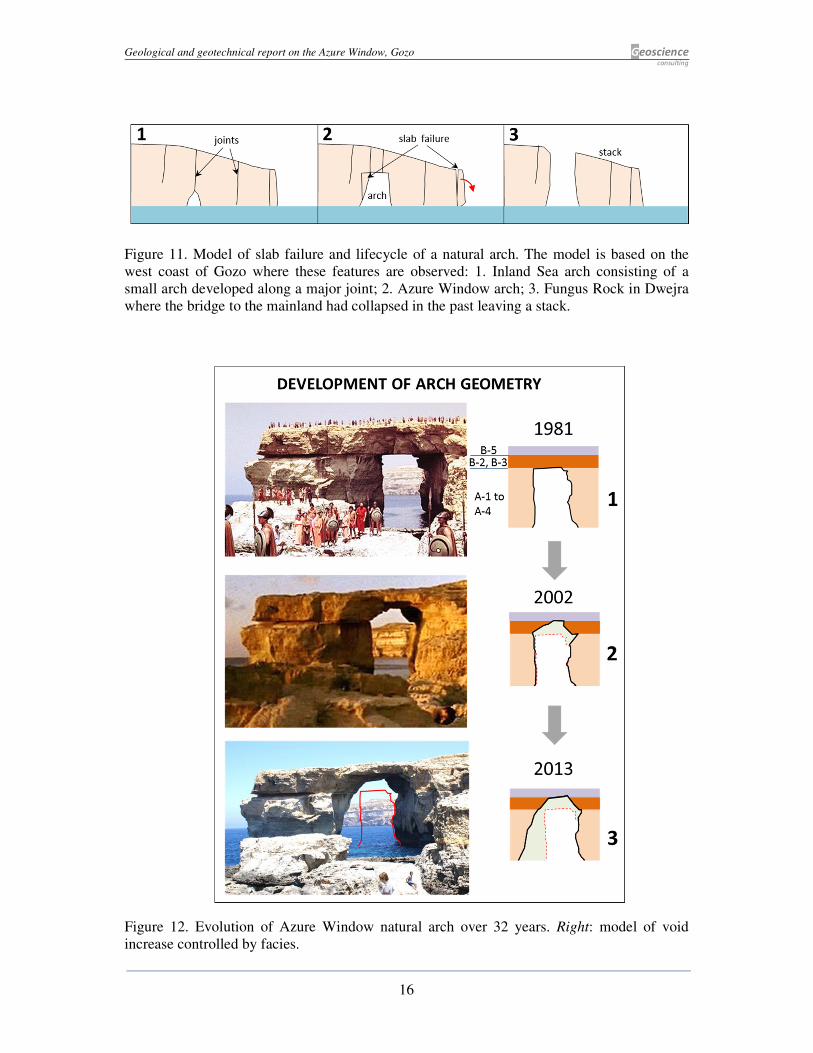
The Azure Window is midway along this process controlled by slab failure. It developed as a
result of sea wave deflection towards the Dwejra Point headland which resulted in greater
erosion along a weak spot within the headland. Erosion along joints produced a void that
became larger by slab failure. Since 1981, the volume of the void under the arch has doubled
as a result of rockfall and slab failure (Figure 12). The contrasting rheology of Member A and
Member B rocks resulted in a different response to geomorphological processes. Slab failure
is accelerated in Member A rocks prone to mass failure that resulted in its retreat, whereas
Member B rocks was left hanging forming the arch segment.
Geological and geotechnical report on the Azure Window, Gozo Geoscience consulting
16
Figure 11. Model of slab failure and lifecycle of a natural arch. The model is based on the
west coast of Gozo where these features are observed: 1. Inland Sea arch consisting of a
small arch developed along a major joint; 2. Azure Window arch; 3. Fungus Rock in Dwejra
where the bridge to the mainland had collapsed in the past leaving a stack.
Figure 12. Evolution of Azure Window natural arch over 32 years. Right: model of void
increase controlled by facies.
Geological and geotechnical report on the Azure Window, Gozo Geoscience consulting
17
3.02 Rock mechanics
The propensity of rock to form joints and jointing patterns with a regular geometry controls
the potential for mass failure. Vertical joints develop as overburden rock (Globigerina
Limestone) is eroded. The reduction of vertical stress results in the relative increase of
horizontal stress that triggers the formation of vertical joints by lateral pressure.
Geotechnical properties of rock, namely the modulus of elasticity (E) and Poisson’s ratio (ν)
are influenced by the degree of cementation in the rock (Schlanger & Douglas, 1974) and
therefore, the depositional environment. Published data on Young’s modulus (E) for the
Lower Coralline Limestone are based on the ‘doorstopper’ method and range between 2 to
6.4 GPa (Grasso, et al., 1986). The two types of tested rock are equivalent to facies B-2 and
B-3, where E = circa 2 GPa, whereas in facies A-2, E = circa 6.4 GPa.
Variations in the modulus of elasticity of facies control the spacing of jointing in rock (Gross,
et al., 1995). Beds with a higher E will fail at lower magnitudes of extensional strain and
show a decrease in joint spacing. However, joint spacing is also proportional to joint height
which equals the mechanical layer thickness (thickness of facies). In the case of facies A-3
and A-2, which are the thickest facies (large mechanical layer thickness) in the stratigraphy
of the Azure Window, joint spacing is large and joints are well developed due to the high E
and the brittle nature of the rock. In contrast, the thinner facies and beds in Member B rock
should result on closer-spaced jointing, although discontinuities are less developed because E
is relatively lower. This results in less brittle and more ductile nature of rock in Member B
which fragments along less well-defined joints.
The theoretical jointing intensity based on rheological considerations is shown in Figure 13.
Member A rocks are prone to develop extensive, long vertical joints that are well-spaced.
Jointing in Member A results in massive slab failure, as happened at the Azure Window in
April 2012 (Figure 4). In contrast, Member B rocks are more ductile and jointing is closer
spaced but less developed along geometrical lines of failure. As a result, failure is along
smaller metre-sized slabs or rock fragments. This is consistent with the nature of failure in
Member B rocks along the arch, recorded in the March 2013 failure event.

Geological and geotechnical report on the Azure Window, Gozo Geoscience consulting
18
Figure 13. Geotechinal parametres and discontinuity formation in Members A and B rock.
Bold vertical lines represent hypothetical well developed jointing whereas dotted vertical
lines represent poorly developed vertical joints.
4. GEOMECHANICAL STABILITY OF AZURE WINDOW
There are few published studies on the stability of natural arches worldwide. In view of this,
three fundamental mechanical factors are deemed to control the stability of the Azure
Window: (1) the width of the span and thickness of the unsupported arch, (2) the intensity of
jointing that sub-divides the arch into blocky rock masses, where individual blocks may be
prone to failure and (3) the stability of the pillar.
4.01 The width of span and thickness of the unsupported arch:
The span of a natural arch (b) should be proportional to tensile stress that can lead to failure
of the arch whereas the thickness (H) of the arch is related to resistance to the tensile stress
(Figure 4). The permissible maximum b and minimum H depends on the type of rock that
constitutes the arch, with weaker rock showing lower permissible values. The range of b and
H varies considerably throughout the world. The span of the 14 largest natural arches in the
world exceeds 60 m (Natural Arch and Bridge Society) with the largest span of arch in
limestone found at the ‘Fairy Bridge’ in Guangxi Province in China (121 m wide). The span
of the Azure Window arch is comparatively small, circa 25 m wide. Moreover, parts of the
arch are supported by abutments (cantilevers of rock) which decrease the span of the arch.
The abutments consist of facies B-3 and B-2. These facies are more prone to jointing and
tensile stress relative to facies B-5 (Blocks 2 and 3 in Figure 14c). Originally, they formed a
beam of rock with a configuration similar to the present Wied il-Mielah Window in northern
Gozo (Figure 12, Figure 14a, b). The beam of rock began to detach itself from the overlying
Geological and geotechnical report on the Azure Window, Gozo Geoscience consulting
19
facies B-5, separated by an abrupt and well-defined horizontal hardground surface that acts as
a discontinuity surface (Figure 14d). Consequently, movement or failure of the facies B-3
blocks was independent of the overlying facies B-5. The remaining beam formed of facies B-
5 constitutes the present arch.
Figure 14. a. Photograph of the southern side of the Azure Window taken in 1981 prior to the
failure of facies B-2 and B-3; b. North-facing side of Azure Window showing potential slab
failure of blocks 1c, 2 and 3 (shaded yellow) c. Red shading shows recent failed blocks (1a &
1b); d. stratigraphy of the arch section observed near the Blue Hole area. Note the abrupt
hardground surface that forms a discontinuity surface with the overlying facies B-5. The
dashed white line shows the area of likely failure.
The minimum thickness for a natural arch to be stable should be related to the span of the
beam. The minimum thickness of the beam consisting of facies B-5 at the Azure Window is
circa 4 m whereas the maximum span of the arch is 25 m. The ratio of minimum arch
thickness to width of span is 1:6. Comparative studies of minimum arch thickness to width of
span are shown in Table 1. Natural arches with a ratio H:b of 1:6 or larger have an arch
thickness (H) of >10 m, which exceeds that of the Azure Window. However, the lithology of
the arch is an important consideration and the arch with the greatest ratio (1:25), Landscape
Arch (Figure 15) has a thickness (H) comparable to that of the Azure Window. Nevertheless,
this arch has been declared unsafe.

Geological and geotechnical report on the Azure Window, Gozo Geoscience consulting
20
Figure 15. Landscape Arch, Utah, USA. The minimum thickness (H) of the Arch approaches
that of the Azure Window, although the span is approximately 4 times greater.
Name and location of natural arch Ratio
H:b
Thickness of
arch (approx.)
(H)
Width of span
of natural arch
(b)
Landscape Arch, Utah, USA 1:25 4 m 88 m
Jiangzhou Immortal Bridge, Guangxi Prov., China 1:7 14 m 103 m
Rainbow Bridge, Utah, USA 1:6 12 m 71 m
Azure Window, Malta 1:6 4 m (min.) 25 m
Aloba Arch, Chad 1:5 15 m 76 m
Table 1. Ratio of arch thickness to width of span of some of the largest natural arches in the
world compared to the Azure Window.
The theoretical maximum thickness of rock with overburden, threatened by collapse under a
natural arch with irregularly jointed rock over a specified span is considered to be a parabola
of height (v) determined by:
Equation 1…….(Terzaghi) v = 0.25 to 0.35 (b + h)
Where b is width and h is the height of void.
In the case of the Azure Window, the maximum thickness (v) calculated by Equation 1 is 6.5
m to 9.1 m (Figure 14c), which is greater than the minimum thickness (H) of the arch. The
absence of overburden reduces load on the arch and makes it more stable. However,
engineering formulas tend to oversimplify the complexity of natural rock.

Geological and geotechnical report on the Azure Window, Gozo Geoscience consulting
21
4.02 Jointing
Joints subdivide the arch into blocks that may fail separately. Closed joints along Member B
facies do not pose immediate danger of failure. However, where blocks daylight along the
edge of the headland, joints become open and may pose some concern because friction
between blocks is nil (Figure 9 and Figure 10). A number of past and potential rock failures
are assessed are tabulated in Table 2. The location of blocks is shown in Figure 14c.
Block
number facies Date Assessment
1a A-2,
3, 4
Failed:
April
2012
Although massive in size, failure has not significantly increased the
span of the unsupported arch and poses minor direct danger to the
integrity of the arch.
1b B-5
Failed:
March
2013
The collapse of rock along the arch may be related to changed
stress regime following the collapse of block 1a and does not pose
a threat to the integrity of the arch.
1c A-
2,3,4
Potential
failure
Large block that may fail. Width of block is unknown, but block
appears to be the result of exfoliation of the pillar. Its failure is not
likely to affect arch.
2 B-2
& 3
Potential
failure
Block is an abutment beneath the overlying arch. Failure may
effect stability of overlying arch in that area
3 B-3 Potential
failure
Block is an abutment. The block is ‘hanging’ from facies B-5
(arch) and its collapse should lessen the load along the arch
Table 2. Blocks that have failed or may fail along the arch area.
Joints half way along the arch have acted as failure surfaces responsible for recent unreported
rock fall on the north-facing (Figure 16) and south-facing parts of the arch reported in March
2013.
Area X along the south facing part of the headland has already lost most of its abutments
during unrecorded past events. The nature of the fractures in this area needs to be assessed
and growth of these fractures needs to be measured over a number of months.

Geological and geotechnical report on the Azure Window, Gozo Geoscience consulting
22
Figure 16. Photograph showing area of recent rockfall (red ring) along the middle part of the
north-facing part of the arch. The failure of slab 1a (dotted red line) may have relaxed stress
along the arch and weakened the arch by reducing horizontal stress along joints, resulting in
failure. Similar failure occurred along the south-facing side that was recorded in the media of
March 2013.
4.03 Stability of pillar
The pillar has experienced mass failure of a large triangular slab in April 2012. The failure
did not increase span width of the arch which remains stable. However, the release of this
slab has reduced the mass of the pillar. Failure of slabs on the south facies part of the pillar is
unlikely in the near future since there are no clearly defined tension cracks or joints, although
joints and blocks that can potentially fail occur on the north-facing part of the pillar (Figure
14b). The condition of the base of the pillar which is being undercut by sea waves remains
unknown.
The listing of the pillar (a precursor to toppling) can have a significant effect on the arch by
changing the level of horizontal stress. If the pillar lists eastwards (landwards), horizontal
stress is increased and unless buckling limit is not exceeded, the arch is strengthened.
However, if the pillar lists seaward, the horizontal stress on the arch is reduced. The collapse
of the large slab (block 1a) may have reduced stress on the eastward side of the pillar which
may have resulted in its slight rotation westward. Significantly, the reduction of horizontal
stress resulted in the rockfall along the arch a year later in March 2013 along the southern
side and unrecorded failure along the northern side (Figure 16).
Geological and geotechnical report on the Azure Window, Gozo Geoscience consulting
23
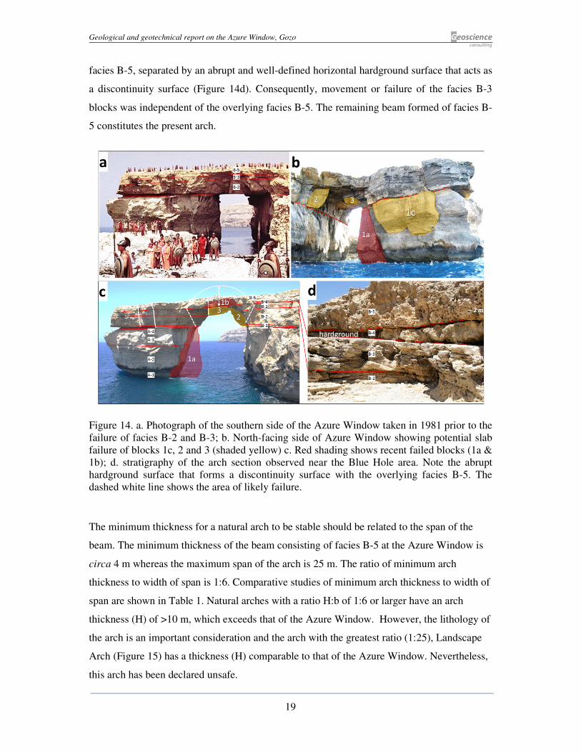
4.04 Modelling of failure process
Mass failure around the Azure Window is not random, but follows processes associated
jointing pattern and natural arch development along the coast. Many well-known European
arches have developed a hyperbola-shaped void which is symmetrical (Figure 17A). The arch
is a structurally sound configuration and is more stable than the rectangular-shaped ‘window’
type of configuration, although short-lived in geological time. Some natural arches may
develop in stages, beginning as a rectangular ‘window shape’ as in the case of the original
Azure Window and the present Wied il-Mielah Window, Gozo, and by time develop into an
arched shape void. The Azure Window seems to be following this progressive development:
The slab failure of April 2012 changed part of the rectangular void configuration into one
resembling an arch, although asymmetrical (Figure 17B). It is not clear if future failure may
affect the landward part of the arch to produce a symmetrical archway.
Figure 17. A: Geometry of natural arches in Europe; B. Stages in the development of the
Azure Window arch. The first stage is represented by the ‘window’ type of configuration as
seen at Wied il-Mielah (Gozo) about 3.7 km from the Azure Window. Slab failure along the
sides of the void as happened in April 2012 has resulted in an asymmetrical archway which
may develop into a symmetrical arch (stage 4).
Geological and geotechnical report on the Azure Window, Gozo Geoscience consulting
24
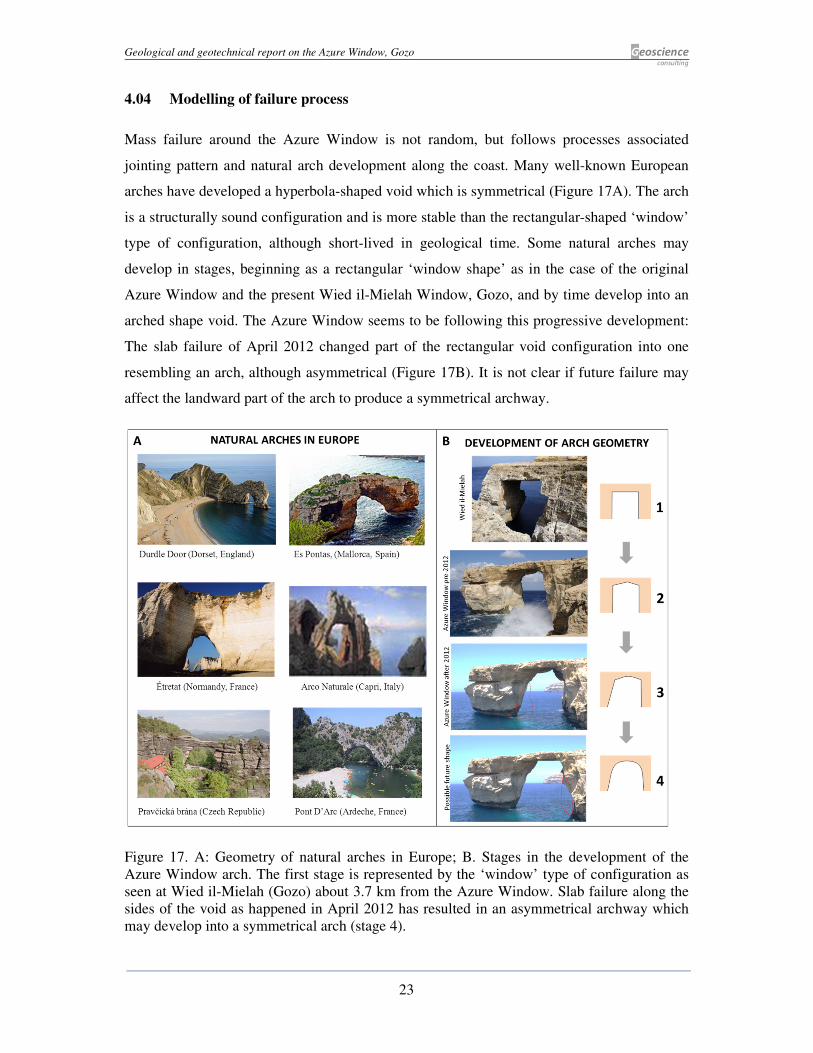
4.05 Geohazards
Natural arches are short-lived geological features and the arch section of the Azure Window
will inevitably collapse and the pillar section will become a stack. Dangers related to rock fall
are shown in Figure 18. The larger danger is from the failure of blocks 2 and 3 that act as
abutments and from rock fall along the sides of the arch. Rock fall along the northern side of
the headland is imminent. Area X along the southern side of the arch may eventually fail
depending on the nature of surface fractures that are developing. Signage informing visitors
of the danger is found leading to the arch.
Figure 18. Geohazard map showing areas of potential failure. Inset shows warning signs
located close to Azure Window. Past extent of arch is based on colonial age maps.
Geological and geotechnical report on the Azure Window, Gozo Geoscience consulting
25
5. HERITAGE STATUS
The Azure Window and the surrounding sinkholes are exceptional geological features within
the European context for the following reasons:
• The size of the sinkholes exceed 200 m diameter. Their mode of formation is related
to evaporite dissolution which is less common than limestone dissolution features.
Areas showing similar sinkhole features in Europe are found in Ripon, North
Yorkshire, England, although the sizes of the sinkholes are smaller and sinkholes are
located far away from each other.
• The concentration of sinkholes juxtaposed to each other makes the Dwejra area
exceptional at European level.
• The Azure Window not only has aesthetic value but is a dynamic feature that is of
interest to science. The changing morphology of the arch over the past 30 years is of
scientific importance.
Despite the exceptional nature of the geological features, the display of information on the
features and the processes responsible for their formation is scant or absent in the Dwejra
area. As a result, visitors cannot appreciate the scientific importance of Dwejra area. The
information that needs to be displayed should focus on:
• Sinkhole formation in the Dwejra Depression.
• Stratigraphy of the site with reference to fossils and depositional environments.
• The formation of the Azure Widow and its evolution in the past 30 years.
The above points and the information in this report should be the basis for reviving Malta’s
application to have the Dwejra area and the Azure Window included in the UNESCO World
Heritage site list.
The present level of protection afforded by the Natura 2000 designation is more concerned
with wildlife protection may not give sufficient importance and conservation status to
geological features described in this report. In view of the exceptional geological features at
Dwejra, the area should be declared a geopark. A geopark is a unified area with geological
heritage of international significance.

Geological and geotechnical report on the Azure Window, Gozo Geoscience consulting
26
6. CONCLUSIONS
Arch section:
• The Azure Window consists of two successive groups of rock: The Member A comprises
the pillar section topped by Member B which forms the arch section.
• The arch section (Member B) comprises two successive layers of rock (lower: facies B-
2/3; and upper: facies 5). There is minimum connection between the two layers.
Effectively they are two separate beams of rock that span the archway.
• The upper beam (facies B-5) remains relatively unaffected by the collapse of sections of
the lower beam (facies 5).
• In the past 30 years about 90% of the lower rock has collapsed leaving the upper beam of
rock as the intact arch. Abutments of the lower rock remain and these are prone to failure.
• The extant arch is prone to rock fall along the edges where blocks daylight. This process
is on-going but does not affect the stability of the arch.
• The present ratio of arch thickness to width of span is 1:6. This is comparable to the same
ratio in a number of natural arches found worldwide which are deemed as stable features.
• Fresh cracks along the southern side of the arch (Area X) need to be monitored.
Pillar section:
• Member A is prone to large joints that may result in slab failure whereas in Member B
joints are more closely spaced and less developed. As a result, Member B fails by rock
fall consisting of labs <1 m large.
• Large boulder collapsed by slab failure in April 2012. The event did not increase the span
of the arch and had little direct effect on the stability of the arch. A large slab may fail
along the northern side of the headland, although this is not a direct danger to the arch.
Overall assessment:
The Azure Window is evolving from rectangular ‘window’ morphology to an archway
following the common process in natural arches. It is expected that future rock failure along
the arch will be piecemeal by the failure of metre to pebble-sized rock rather than
instantaneous collapse of the arch. The Azure Window natural arch is relatively stable and
will continue to remain so for a number of years. However, rock fall will persist.
Geological and geotechnical report on the Azure Window, Gozo Geoscience consulting
27
7. RECOMMENDATIONS
The following recommendations on possible interventions are based on the above
conclusions:
• Installation of crack meters: Extension at specific points along on the surface of arch
needs to be monitored. Cracks in Area X and joints B and C (Figure 9, Figure 10) should
be monitored by crack meters and measurements taken on a monthly basis. The cracks in
Area X are atypical to other discontinuities along the arch and heir nature needs to be
assessed by monitoring.
• Installation of large rock bolts: Rock bolts intended to secure the entire arch are not
recommendable. The thickness of the arch is less than the area likely to be affected by
failure (Equation 1 in page 20) so that there is insufficient stable rock for rock bolts to
adhere to in order to support the arch.
• Installation of small rock bolts: <1 m sized blocks at the edge of the arch prone to rock
fall (Figure 18) can be bolted. However, the precarious location of these blocks and the
installation of machinery over the arch make this type of intervention dangerous.
• Geohazard warning: Navigation and swimming under and around the Azure Window
should remain prohibited due to rock fall geohazard.
• UNESCO heritage status: The Dwejra and Azure Window area should be re-considered,
in light of new findings in this report, as a candidate for listing as a UNESCO world
heritage site.
• Geopark status: The Dwejra and Azure Window area should be declared a geopark,
thereby protecting the geological features of the area. Information on the geological
features and processes that formed them should be displayed on boards in public view in
the vicinity of the relevant features.

Geological and geotechnical report on the Azure Window, Gozo Geoscience consulting
28
8. REFERENCES
Bertoni, C. & Cartwright, J. A., 2005. 3D seismic analysis of circular evaporite dissolution
structures, Eastern Mediterranean. Volume 162, pp. 909-926.
Davies, C., 1976. Accretion sets in the Lower Coralline Limestone of the Maltese Islands.
Journal of Sedimentary Petrology, Volume 46(2), pp. 414-417.
Dunham, R. J., 1962. Classification of carbonate rocks according to depositional texture. In:
W. E. Ham, ed. Classification of Carbonate Rocks. : Memoirs of the American Association
of Petroleum Geologists, 1, pp. 108-121.
Gatt, P., 2007. Controls on Plio-Quaternary foreland sedimentation in the Region of the
Maltese Islands. Bolletino della societa geologica italiana, 126(1), pp. 119-129.
Gatt, P., 2012. Carbonate facies, depositional sequences and tectonostratigraphy of the
Palaeogene Malta Platform. Unpublished PhD thesis, University of Durham, UK.
Gerdes, K., Winefield, P., Simmons, M. & Van Oosterhout, C., 2010. The influence of basin
architecture and eustacy on the evolution of Tethyan Mesozoic and Cenozoic carbonate
sequences. In: F. van Buchem, K. Gerdes & M. Esteban, eds. Geological Society, London,
Special Publications, 329, 9-41.
Grasso, M., Reuther, C.-D., Baumann, H. & Becker, A., 1986. Shallow crustal stress and
neotectonic framework of the Malta Platform and the SE Pantelleria Rift (Central
Mediterranean). Geologica Romana, Volume 25, pp. 191-210.
Gross, M., Fischer, M., Engelder, T. & Greenfield, R., 1995. Factors controlling joint spacing
in interbedded sedimentary rock. In: M. Ameen, ed. Fractography. Geol. Soc. Spec. Publ. 92,
pp. 215-233.
Pedley, H. M., 1978. A new lithostratigraphical and palaeoenvironmental interpretation for
the coralline limestone Formation of the Maltese Islands.. Overseas Geological &
Mineralogical Resources, Volume 54, pp. 1-17.
Rasmussen, D., Brown, T. & Simons, E., 1992. The Eocene-Oligocene transition in
continental Africa. In: D. Prothero & W. Berggren, eds. Eocene-Oligocene climatic and
biotic evolution. : Princeton Univ. Press, pp. 548-566.
Schlanger, S. & Douglas, R., 1974. The pelagic ooze chalk-limestone transition and its
implications formarine stratigraphy. In: Spec. Publs. Int.Ass. Sediment., 1, pp. 117-148.

Geoscience
consulting
Geoscience Consulting
Consultant: Dr Peter Gatt MSc(R'dg), PhD(Dunelm), FGS
T: +356 79603783 E: [email protected]
This report has 28 pages