Embed Size (px)
Citation preview
GEOTECHNICAL ENGINEERING REPORT
NATIONAL GUARD BUILDING
EL PASO, TEXAS
GORRONDONA & ASSOCIATES, INC. - TEXAS ENGINEERING FIRM REGISTRATION NO. F-7933
GEOTECHNICAL ENGINEERING REPORT National Guard Building
El Paso, Texas
Prepared by:
Gorrondona & Associates, Inc.
Prepared for:
Freese and Nichols 4055 International Plaza, Suite 200
Fort Worth, Texas
Attention: Mr. Curtis Spraggins
August 8, 2016
G&AI Project No. 16-0241
Gorrondona & Associates, Inc. Land Surveying • Aerial Mapping • Geotechnical Engineering • Construction Materials Testing
7524 Jack Newell Blvd. South • Fort Worth, Texas 76118 • 817.496.1424 • Fax 817.496.1768 Gorrondona & Associates, Inc. – Texas Engineering Firm Registration No. F-7933
August 8, 2016 Mr. Curtis Spraggins Freese and Nichols 4055 International Plaza, Suite 200 Fort Worth, Texas Re: GEOTECHNICAL ENGINEERING REPORT National Guard Building El Paso, Texas G&AI Project No. 16-0241 Dear Mr. Spraggins: Gorrondona & Associates, Inc. (G&AI) is pleased to submit this Geotechnical Engineering Report for the referenced project. We appreciate the opportunity of working with you. Please contact us if you have any questions or require additional services. Respectfully submitted, Lee Gurecky, P.E. Project Engineer Vivek Chikyala, P.E. Senior Geotechnical Engineer
TABLE OF CONTENTS Page
1.0 Introduction .................................................................................................................... 1 2.0 Field Investigation ........................................................................................................... 2 3.0 Laboratory Testing .......................................................................................................... 3 4.0 Site Conditions ................................................................................................................ 4
4.1 General ........................................................................................................................ 4 4.2 Geology ....................................................................................................................... 4 4.3 Soil ............................................................................................................................... 5 4.4 Groundwater ............................................................................................................... 6
5.0 Analysis and Recommendations ..................................................................................... 7 5.1 Seismic Site Classification ........................................................................................... 7 5.2 Potential Vertical Soil Movements .............................................................................. 7 5.3 Construction Excavations ............................................................................................ 8 5.4 Groundwater Control .................................................................................................. 8 5.5 Earthwork .................................................................................................................... 9
5.5.1 Site Preparation ................................................................................................... 9 5.5.2 Proofroll ............................................................................................................... 9 5.5.3 Grading and Drainage .......................................................................................... 9 5.5.4 Wet Weather/Soft Subgrade ............................................................................. 10 5.5.5 Fill ....................................................................................................................... 10 5.5.6 Testing ................................................................................................................ 11
5.6 Demolition Considerations ....................................................................................... 11 5.7 Loading on Buried Structures .................................................................................... 12 5.8 Retaining Structures .................................................................................................. 13 5.9 Buried Pipe ................................................................................................................ 13 5.10 Foundation System ................................................................................................... 14
5.10.1 Slab Foundation ................................................................................................. 15 5.10.2 Shallow Footings ................................................................................................ 15
5.11 Slab-on-Grade ........................................................................................................... 17 5.12 Pavement .................................................................................................................. 17
5.12.1 Rigid Pavement .................................................................................................. 17 5.12.2 Flexible Pavement .............................................................................................. 18
5.13 Detention Pond ......................................................................................................... 19 6.0 General Comments ....................................................................................................... 19

APPENDICES
Appendix A - Project Location Diagrams Appendix B - Boring Location Diagram Appendix C - Boring Logs and Laboratory Results Appendix D - Aerial Photographs Appendix E - USGS Topographic Map Appendix F - Site Photographs Appendix G - Geologic Information Appendix H - Unified Soil Classification System
G&AI Project No. 16-0241 Page 1
GEOTECHNICAL ENGINEERING REPORT National Guard Building
El Paso, Texas
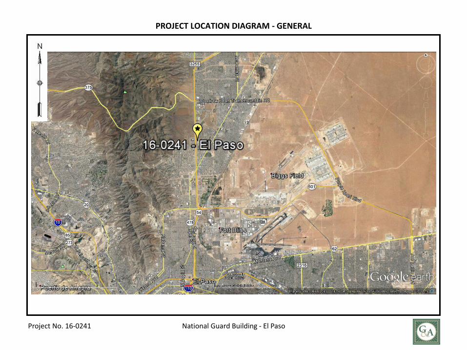
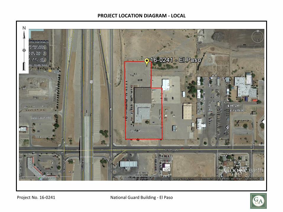
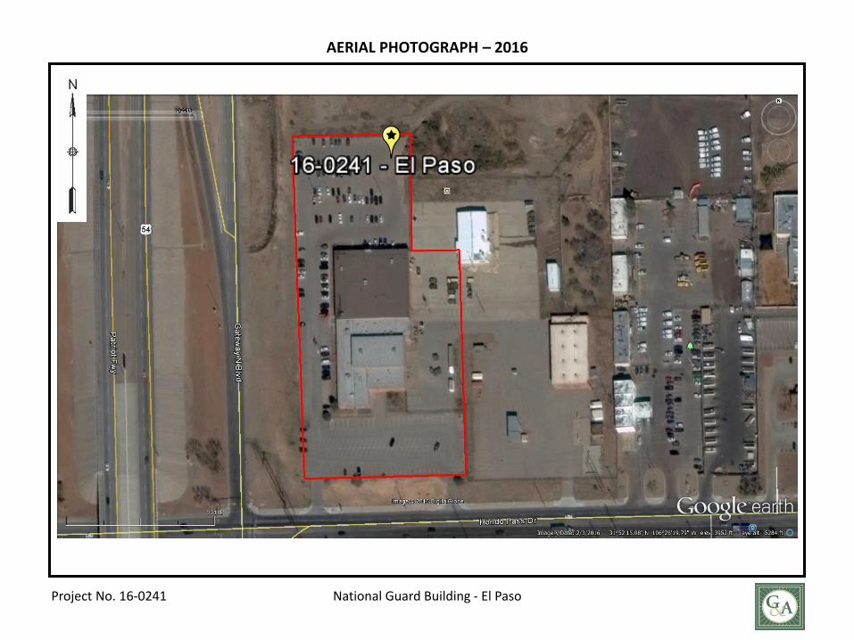
1.0 INTRODUCTION Project Location. The project is located at the northeast corner of Gateway N Blvd., and Hondo Pass Drive in El Paso, Texas. The general location and orientation of the site are provided in Appendix A - Project Location Diagrams. Project Description. The project consists of a proposed addition to the existing building, detention pond and parking and drive areas. Project Authorization. This geotechnical investigation was authorized using Freese and Nichols Subconsultant Authorization dated June 21, 2016. Purpose and Methodology. The principal purposes of this investigation were to evaluate the general soil conditions at the proposed site and to develop geotechnical engineering design recommendations. To accomplish its intended purposes, the study was conducted in the following phases: (1) drill sample borings to evaluate the soil conditions at the boring locations and to obtain soil samples; (2) conduct laboratory tests on selected samples recovered from the borings to establish the pertinent engineering characteristics of the soils; and (3) perform engineering analyses, using field and laboratory data, to develop design criteria. Cautionary Statement Regarding Use of this Report. As with any geotechnical engineering report, this report presents technical information and provides detailed technical recommendations for civil and structural engineering design and construction purposes. G&AI, by necessity, has assumed the user of this document possesses the technical acumen to understand and properly utilize information and recommendations provided herein. G&AI strives to be clear in its presentation and, like the user, does not want potentially detrimental misinterpretation or misunderstanding of this report. Therefore, we encourage any user of this report with questions regarding its content to contact G&AI for clarification. Clarification will be provided verbally and/or issued by G&AI in the form of a report addendum, as appropriate. Report Specificity. This report was prepared to meet the specific needs of the client for the specific project identified. Recommendations contained herein should not be applied to any other project at this site by the client or anyone else without the explicit approval of G&AI.
G&AI Project No. 16-0241 Page 2
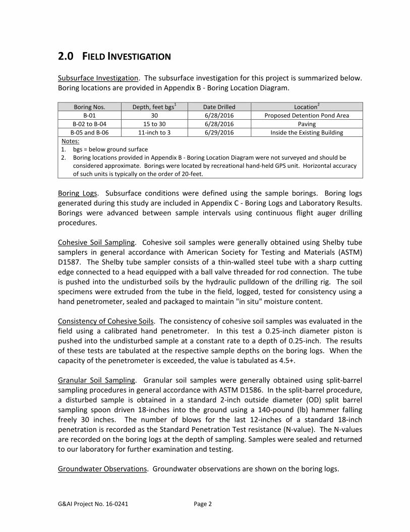
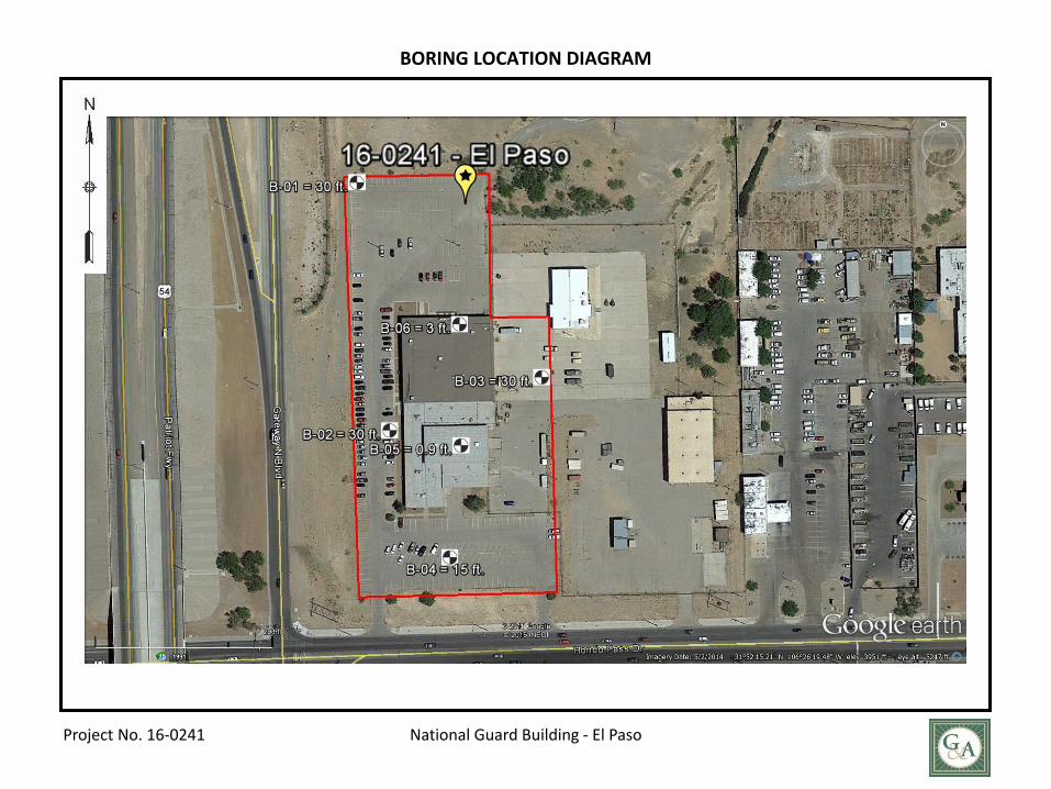
2.0 FIELD INVESTIGATION Subsurface Investigation. The subsurface investigation for this project is summarized below. Boring locations are provided in Appendix B - Boring Location Diagram.
Boring Nos. Depth, feet bgs1 Date Drilled Location2 B-01 30 6/28/2016 Proposed Detention Pond Area
B-02 to B-04 15 to 30 6/28/2016 Paving B-05 and B-06 11-inch to 3 6/29/2016 Inside the Existing Building
Notes: 1. bgs = below ground surface 2. Boring locations provided in Appendix B - Boring Location Diagram were not surveyed and should be
considered approximate. Borings were located by recreational hand-held GPS unit. Horizontal accuracy of such units is typically on the order of 20-feet.
Boring Logs. Subsurface conditions were defined using the sample borings. Boring logs generated during this study are included in Appendix C - Boring Logs and Laboratory Results. Borings were advanced between sample intervals using continuous flight auger drilling procedures. Cohesive Soil Sampling. Cohesive soil samples were generally obtained using Shelby tube samplers in general accordance with American Society for Testing and Materials (ASTM) D1587. The Shelby tube sampler consists of a thin-walled steel tube with a sharp cutting edge connected to a head equipped with a ball valve threaded for rod connection. The tube is pushed into the undisturbed soils by the hydraulic pulldown of the drilling rig. The soil specimens were extruded from the tube in the field, logged, tested for consistency using a hand penetrometer, sealed and packaged to maintain "in situ" moisture content. Consistency of Cohesive Soils. The consistency of cohesive soil samples was evaluated in the field using a calibrated hand penetrometer. In this test a 0.25-inch diameter piston is pushed into the undisturbed sample at a constant rate to a depth of 0.25-inch. The results of these tests are tabulated at the respective sample depths on the boring logs. When the capacity of the penetrometer is exceeded, the value is tabulated as 4.5+. Granular Soil Sampling. Granular soil samples were generally obtained using split-barrel sampling procedures in general accordance with ASTM D1586. In the split-barrel procedure, a disturbed sample is obtained in a standard 2-inch outside diameter (OD) split barrel sampling spoon driven 18-inches into the ground using a 140-pound (lb) hammer falling freely 30 inches. The number of blows for the last 12-inches of a standard 18-inch penetration is recorded as the Standard Penetration Test resistance (N-value). The N-values are recorded on the boring logs at the depth of sampling. Samples were sealed and returned to our laboratory for further examination and testing. Groundwater Observations. Groundwater observations are shown on the boring logs.
G&AI Project No. 16-0241 Page 3
Borehole Plugging. Upon completion of the borings, the boreholes were backfilled from the top and plugged at the surface.
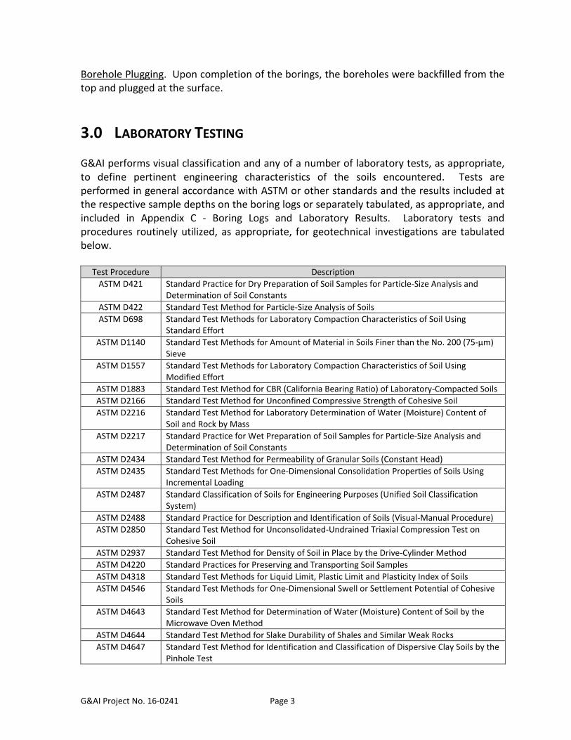
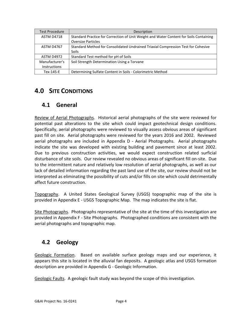
3.0 LABORATORY TESTING G&AI performs visual classification and any of a number of laboratory tests, as appropriate, to define pertinent engineering characteristics of the soils encountered. Tests are performed in general accordance with ASTM or other standards and the results included at the respective sample depths on the boring logs or separately tabulated, as appropriate, and included in Appendix C - Boring Logs and Laboratory Results. Laboratory tests and procedures routinely utilized, as appropriate, for geotechnical investigations are tabulated below.
Test Procedure Description ASTM D421 Standard Practice for Dry Preparation of Soil Samples for Particle-Size Analysis and
Determination of Soil Constants ASTM D422 Standard Test Method for Particle-Size Analysis of Soils ASTM D698 Standard Test Methods for Laboratory Compaction Characteristics of Soil Using
Standard Effort ASTM D1140 Standard Test Methods for Amount of Material in Soils Finer than the No. 200 (75-μm)
Sieve ASTM D1557 Standard Test Methods for Laboratory Compaction Characteristics of Soil Using
Modified Effort ASTM D1883 Standard Test Method for CBR (California Bearing Ratio) of Laboratory-Compacted Soils ASTM D2166 Standard Test Method for Unconfined Compressive Strength of Cohesive Soil ASTM D2216 Standard Test Method for Laboratory Determination of Water (Moisture) Content of
Soil and Rock by Mass ASTM D2217 Standard Practice for Wet Preparation of Soil Samples for Particle-Size Analysis and
Determination of Soil Constants ASTM D2434 Standard Test Method for Permeability of Granular Soils (Constant Head) ASTM D2435 Standard Test Methods for One-Dimensional Consolidation Properties of Soils Using
Incremental Loading ASTM D2487 Standard Classification of Soils for Engineering Purposes (Unified Soil Classification
System) ASTM D2488 Standard Practice for Description and Identification of Soils (Visual-Manual Procedure) ASTM D2850 Standard Test Method for Unconsolidated-Undrained Triaxial Compression Test on
Cohesive Soil ASTM D2937 Standard Test Method for Density of Soil in Place by the Drive-Cylinder Method ASTM D4220 Standard Practices for Preserving and Transporting Soil Samples ASTM D4318 Standard Test Methods for Liquid Limit, Plastic Limit and Plasticity Index of Soils ASTM D4546 Standard Test Methods for One-Dimensional Swell or Settlement Potential of Cohesive
Soils ASTM D4643 Standard Test Method for Determination of Water (Moisture) Content of Soil by the
Microwave Oven Method ASTM D4644 Standard Test Method for Slake Durability of Shales and Similar Weak Rocks ASTM D4647 Standard Test Method for Identification and Classification of Dispersive Clay Soils by the
Pinhole Test
G&AI Project No. 16-0241 Page 4
Test Procedure Description ASTM D4718 Standard Practice for Correction of Unit Weight and Water Content for Soils Containing
Oversize Particles ASTM D4767 Standard Method for Consolidated Undrained Triaxial Compression Test for Cohesive
Soils ASTM D4972 Standard Test method for pH of Soils
Manufacturer's Instructions
Soil Strength Determination Using a Torvane
Tex-145-E Determining Sulfate Content in Soils - Colorimetric Method
4.0 SITE CONDITIONS
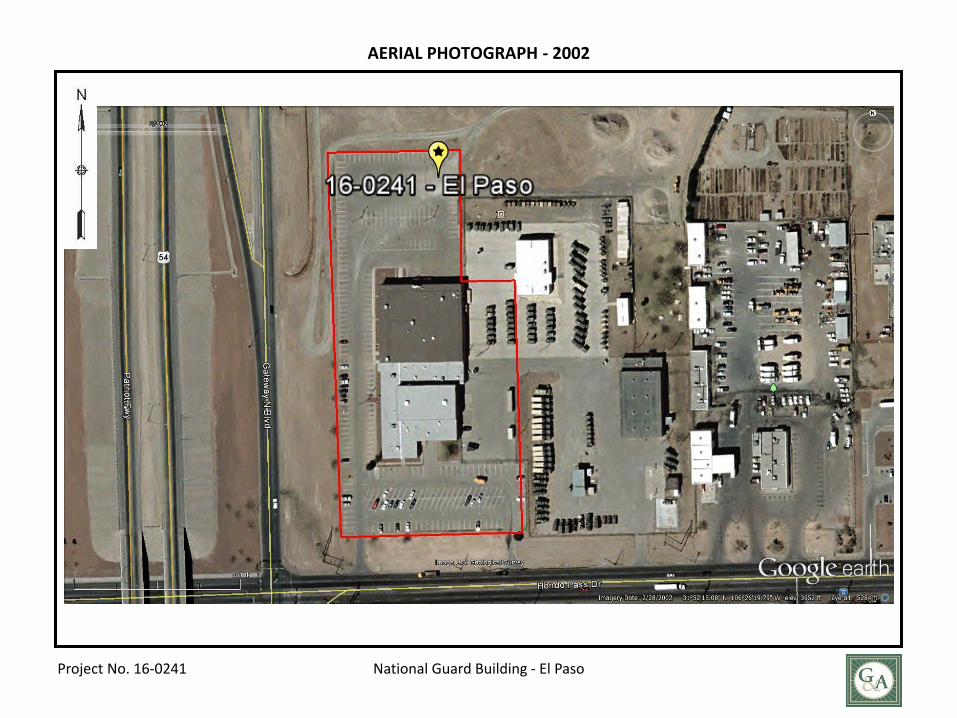
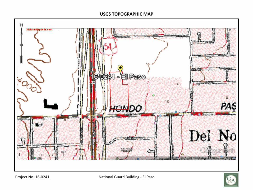
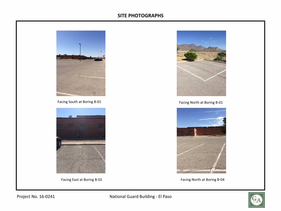
4.1 General Review of Aerial Photographs. Historical aerial photographs of the site were reviewed for potential past alterations to the site which could impact geotechnical design conditions. Specifically, aerial photographs were reviewed to visually assess obvious areas of significant past fill on site. Aerial photographs were reviewed for the years 2016 and 2002. Reviewed aerial photographs are included in Appendix D - Aerial Photographs. Aerial photographs indicate the site was developed with existing building and pavement since at least 2002. Due to previous construction activities, we would expect construction related surficial disturbance of site soils. Our review revealed no obvious areas of significant fill on-site. Due to the intermittent nature and relatively low resolution of aerial photographs, as well as our lack of detailed information regarding the past land use of the site, our review should not be interpreted as eliminating the possibility of cuts and/or fills on site which could detrimentally affect future construction. Topography. A United States Geological Survey (USGS) topographic map of the site is provided in Appendix E - USGS Topographic Map. The map indicates the site is flat. Site Photographs. Photographs representative of the site at the time of this investigation are provided in Appendix F - Site Photographs. Photographed conditions are consistent with the aerial photographs and topographic map.
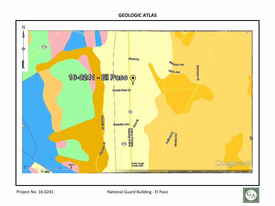
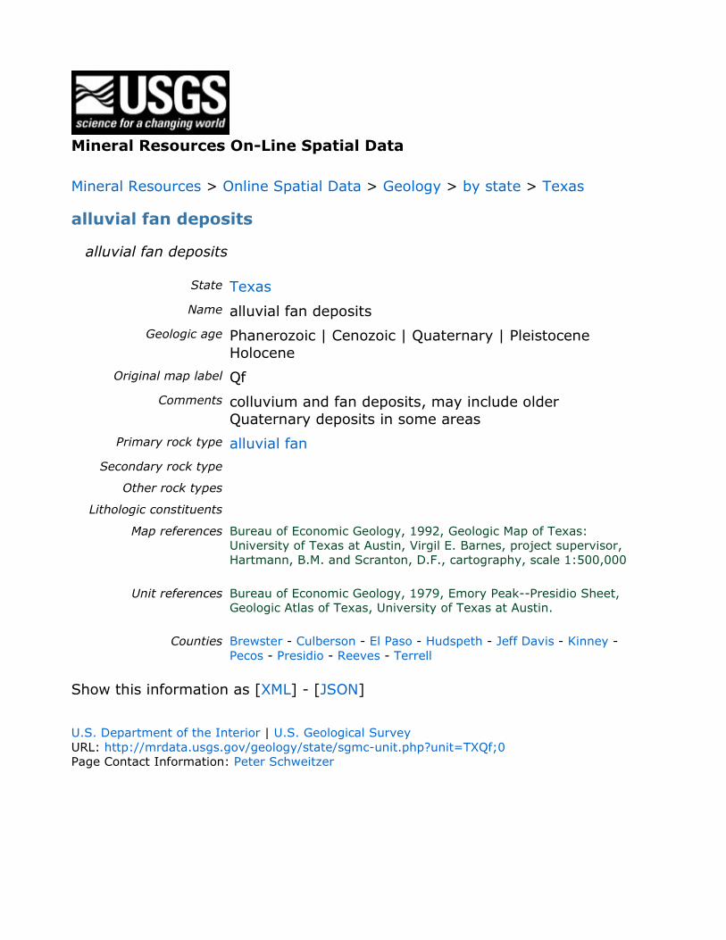
4.2 Geology Geologic Formation. Based on available surface geology maps and our experience, it appears this site is located in the alluvial fan deposits. A geologic atlas and USGS formation description are provided in Appendix G - Geologic Information. Geologic Faults. A geologic fault study was beyond the scope of this investigation.
G&AI Project No. 16-0241 Page 5
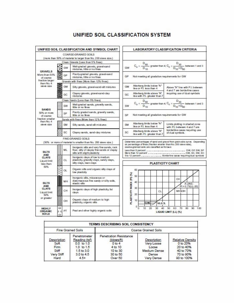
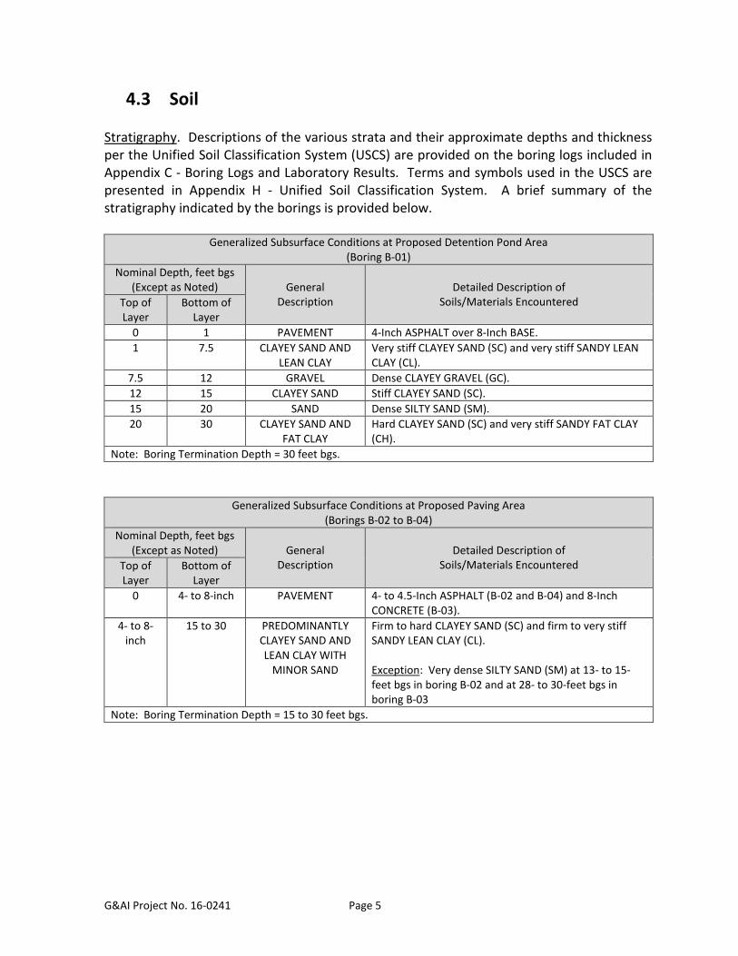
4.3 Soil Stratigraphy. Descriptions of the various strata and their approximate depths and thickness per the Unified Soil Classification System (USCS) are provided on the boring logs included in Appendix C - Boring Logs and Laboratory Results. Terms and symbols used in the USCS are presented in Appendix H - Unified Soil Classification System. A brief summary of the stratigraphy indicated by the borings is provided below.
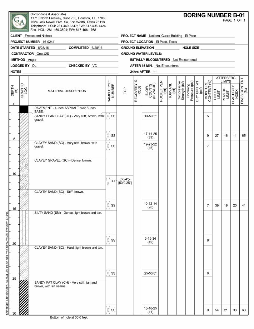
Generalized Subsurface Conditions at Proposed Detention Pond Area (Boring B-01)
Nominal Depth, feet bgs (Except as Noted)
General
Description
Detailed Description of
Soils/Materials Encountered Top of Layer
Bottom of Layer
0 1 PAVEMENT 4-Inch ASPHALT over 8-Inch BASE. 1 7.5 CLAYEY SAND AND
LEAN CLAY Very stiff CLAYEY SAND (SC) and very stiff SANDY LEAN CLAY (CL).
7.5 12 GRAVEL Dense CLAYEY GRAVEL (GC). 12 15 CLAYEY SAND Stiff CLAYEY SAND (SC). 15 20 SAND Dense SILTY SAND (SM). 20 30 CLAYEY SAND AND
FAT CLAY Hard CLAYEY SAND (SC) and very stiff SANDY FAT CLAY (CH).
Note: Boring Termination Depth = 30 feet bgs.
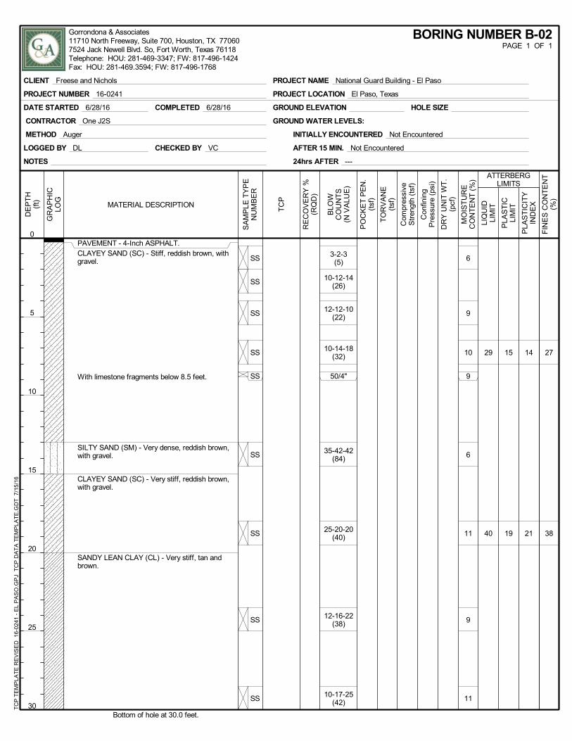
Generalized Subsurface Conditions at Proposed Paving Area
(Borings B-02 to B-04) Nominal Depth, feet bgs
(Except as Noted)
General Description
Detailed Description of
Soils/Materials Encountered Top of Layer
Bottom of Layer
0 4- to 8-inch PAVEMENT 4- to 4.5-Inch ASPHALT (B-02 and B-04) and 8-Inch CONCRETE (B-03).
4- to 8-inch
15 to 30 PREDOMINANTLY CLAYEY SAND AND LEAN CLAY WITH
MINOR SAND
Firm to hard CLAYEY SAND (SC) and firm to very stiff SANDY LEAN CLAY (CL). Exception: Very dense SILTY SAND (SM) at 13- to 15-feet bgs in boring B-02 and at 28- to 30-feet bgs in boring B-03
Note: Boring Termination Depth = 15 to 30 feet bgs.
G&AI Project No. 16-0241 Page 6
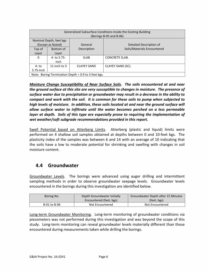
Generalized Subsurface Conditions Inside the Existing Building
(Borings B-05 and B-06) Nominal Depth, feet bgs
(Except as Noted)
General Description
Detailed Description of
Soils/Materials Encountered Top of Layer
Bottom of Layer
0 4- to 5.75-inch
SLAB CONCRETE SLAB.
4- to 5.75-inch
11-inch to 3 CLAYEY SAND CLAYEY SAND (SC).
Note: Boring Termination Depth = 0.9 to 3 feet bgs.
Moisture Change Susceptibility of Near Surface Soils. The soils encountered at and near the ground surface at this site are very susceptible to changes in moisture. The presence of surface water due to precipitation or groundwater may result in a decrease in the ability to compact and work with the soil. It is common for these soils to pump when subjected to high levels of moisture. In addition, these soils located at and near the ground surface will allow surface water to infiltrate until the water becomes perched on a less permeable layer at depth. Soils of this type are especially prone to requiring the implementation of wet weather/soft subgrade recommendations provided in this report. Swell Potential based on Atterberg Limits. Atterberg (plastic and liquid) limits were performed on 4 shallow soil samples obtained at depths between 0 and 10-feet bgs. The plasticity index of the samples was between 6 and 14 with an average of 10 indicating that the soils have a low to moderate potential for shrinking and swelling with changes in soil moisture content.
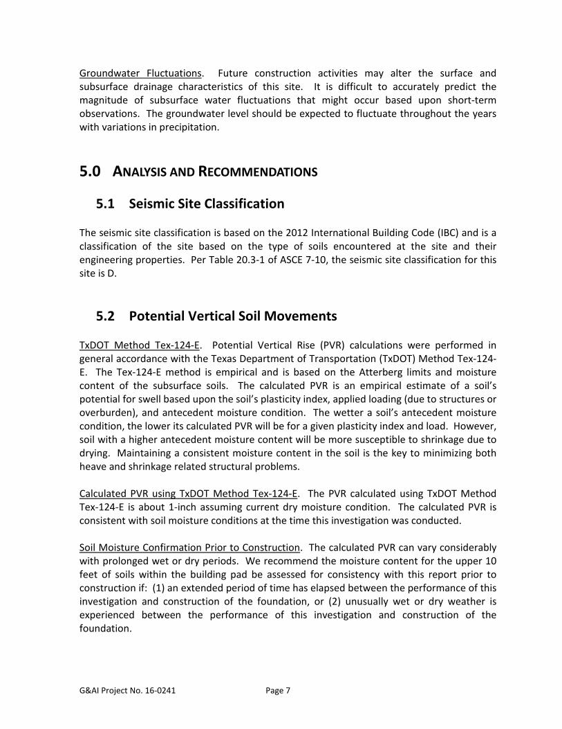
4.4 Groundwater Groundwater Levels. The borings were advanced using auger drilling and intermittent sampling methods in order to observe groundwater seepage levels. Groundwater levels encountered in the borings during this investigation are identified below.
Boring No. Depth Groundwater Initially Encountered (feet, bgs)
Groundwater Depth after 15 Minutes (feet, bgs)
B-01 to B-06 Not Encountered Not Encountered Long-term Groundwater Monitoring. Long-term monitoring of groundwater conditions via piezometers was not performed during this investigation and was beyond the scope of this study. Long-term monitoring can reveal groundwater levels materially different than those encountered during measurements taken while drilling the borings.
G&AI Project No. 16-0241 Page 7
Groundwater Fluctuations. Future construction activities may alter the surface and subsurface drainage characteristics of this site. It is difficult to accurately predict the magnitude of subsurface water fluctuations that might occur based upon short-term observations. The groundwater level should be expected to fluctuate throughout the years with variations in precipitation.
5.0 ANALYSIS AND RECOMMENDATIONS
5.1 Seismic Site Classification The seismic site classification is based on the 2012 International Building Code (IBC) and is a classification of the site based on the type of soils encountered at the site and their engineering properties. Per Table 20.3-1 of ASCE 7-10, the seismic site classification for this site is D.
5.2 Potential Vertical Soil Movements TxDOT Method Tex-124-E. Potential Vertical Rise (PVR) calculations were performed in general accordance with the Texas Department of Transportation (TxDOT) Method Tex-124-E. The Tex-124-E method is empirical and is based on the Atterberg limits and moisture content of the subsurface soils. The calculated PVR is an empirical estimate of a soil’s potential for swell based upon the soil’s plasticity index, applied loading (due to structures or overburden), and antecedent moisture condition. The wetter a soil’s antecedent moisture condition, the lower its calculated PVR will be for a given plasticity index and load. However, soil with a higher antecedent moisture content will be more susceptible to shrinkage due to drying. Maintaining a consistent moisture content in the soil is the key to minimizing both heave and shrinkage related structural problems. Calculated PVR using TxDOT Method Tex-124-E. The PVR calculated using TxDOT Method Tex-124-E is about 1-inch assuming current dry moisture condition. The calculated PVR is consistent with soil moisture conditions at the time this investigation was conducted. Soil Moisture Confirmation Prior to Construction. The calculated PVR can vary considerably with prolonged wet or dry periods. We recommend the moisture content for the upper 10 feet of soils within the building pad be assessed for consistency with this report prior to construction if: (1) an extended period of time has elapsed between the performance of this investigation and construction of the foundation, or (2) unusually wet or dry weather is experienced between the performance of this investigation and construction of the foundation.
G&AI Project No. 16-0241 Page 8
5.3 Construction Excavations Applicability. Recommendations in this section apply to short-term construction-related excavations for this project. Sloped Excavations. All sloped short-term construction excavations on-site should be designed in accordance with Occupational Safety and Health Administration (OSHA) excavation standards. Borings from this investigation indicated that the soils may be classified per OSHA regulations as Type C from the ground surface to a depth of 20-feet bgs. Short-term construction excavations may be constructed with a maximum slope of 1.5:1, horizontal to vertical (H:V), to a depth of 20-feet bgs. If excavations are to be deeper than 20-feet, we should be contacted to evaluate the excavation. Recommendations provided herein are not valid for any long-term or permanent slopes on-site. Shored Excavations. As an alternative to sloped excavations, vertical short-term construction excavations may be used in conjunction with trench boxes or other shoring systems. Shoring systems should be designed using an equivalent fluid weight of 65 pounds per cubic foot (pcf) above the groundwater table and 95 pcf below the groundwater table. Surcharge pressures at the ground surface due to dead and live loads should be added to the lateral earth pressures where they may occur. Lateral surcharge pressures should be assumed to act as a uniform pressure along the upper 20-feet of the excavation based on a lateral earth coefficient of 0.5. Surcharge loads set back behind the excavation at a horizontal distance equal to or greater than the excavation depth may be ignored. We recommend that no more than 200-feet of unshored excavation should be open at any one time to prevent the possibility of failure and excessive ground movement to occur. We also recommend that unshored excavations do not remain open for a period of time longer than 24-hours. Limitations. Recommendations provided herein assume there are no nearby structures or other improvements which might be detrimentally affected by the construction excavation. Before proceeding, we should be contacted to evaluate construction excavations with the potential to affect nearby structures or other improvements. Excavation Monitoring. Excavations should be monitored to confirm site soil conditions consistent with those encountered in the borings drilled as part of this study. Discrepancies in soil conditions should be brought to the attention of G&AI for review and revision of recommendations, as appropriate.
5.4 Groundwater Control Groundwater was not encountered during the subsurface investigation. If groundwater is encountered during excavation, dewatering to bring the groundwater below the bottom of
G&AI Project No. 16-0241 Page 9
excavations may be required. Dewatering could consist of standard sump pits and pumping procedures, which may be adequate to control seepage on a local basis during excavation. Supplemental dewatering will be required in areas where standard sump pits and pumping is not effective. Supplemental dewatering could include submersible pumps in slotted casings, well points, or eductors. The contractor should submit a groundwater control plan, prepared by a licensed engineer experienced in that type of work.
5.5 Earthwork
5.5.1 Site Preparation In the area of improvements, all concrete, trees, stumps, brush, debris, septic tanks, abandoned structures, roots, vegetation, rubbish and any other undesirable matter should be removed and properly disposed. All vegetation should be removed and the exposed surface should be scarified to an additional depth of at least 6 inches. It is the intent of these recommendations to provide a loose surface with no features that would tend to prevent uniform compaction by the equipment to be used.
5.5.2 Proofroll Building pad and paving subgrades should be proofrolled with a fully loaded tandem axle dump truck or similar pneumatic-tire equipment to locate areas of loose subgrade. In areas to be cut, the proofroll should be performed after the final grade is established. In areas to be filled, the proofroll should be performed prior to fill placement. Areas of loose or soft subgrade encountered in the proofroll should be removed and replaced with engineered fill, moisture conditioned (dried or wetted, as needed) and compacted in place.
5.5.3 Grading and Drainage Every attempt should be made to limit the extreme wetting or drying of the subsurface soils because swelling and shrinkage of these soils will result. Standard construction practices of providing good surface water drainage should be used. A positive slope of the ground away from any foundation should be provided. Ditches or swales should be provided to carry the run-off water both during and after construction. Stormwater runoff should be collected by gutters and downspouts and should discharge away from the buildings. Root systems from trees and shrubs can draw a substantial amount of water from the clay soils at this site, causing the clays to dry and shrink. This could cause settlement beneath grade-supported slabs such as floors, walks and paving. Trees and large bushes should be located a distance equal to at least one-half their anticipated mature height away from grade slabs.
G&AI Project No. 16-0241 Page 10
Lawn areas should be watered moderately, without allowing the clay soils to become too dry or too wet.
5.5.4 Wet Weather/Soft Subgrade Soft and/or wet surface soils may be encountered during construction, especially following periods of wet weather. Wet or soft surface soils can present difficulties for compaction and other construction equipment. If specified compaction cannot be achieved due to soft or wet surface soils, one of the following corrective measures will be required:
1. Removal of the wet and/or soft soil and replacement with select fill, 2. Chemical treatment of the wet and/or soft soil to improve the subgrade stability, or 3. If allowed by the schedule, drying by natural means.
Chemical treatment is usually the most effective way to improve soft and/or wet surface soils. G&AI should be contacted for additional recommendations if chemical treatment is planned due to wet and/or soft soils.
5.5.5 Fill Select Fill. Any fill placed in building pad areas should consist of select fill. Select fill should consist of soil with a liquid limit less than 35 and a Plasticity Index between 7 and 15. The select fill should be placed in loose lifts not exceeding 8-inches and should be compacted to at least 95 percent maximum dry density (per ASTM D-698) and at a moisture content between optimum and 4 percent above optimum moisture content. The subgrade to receive select fill should be scarified to a depth of 6 inches and compacted to at least 95 percent maximum dry density (per ASTM D-698) and at a moisture content between optimum and 4 percent above optimum. General Fill. General fill may be placed in improved areas outside of building pad areas. General fill should consist of material approved by the Geotechnical Engineer with a liquid limit less than 50. General fill should be placed in loose lifts not exceeding 8-inches and should be uniformly compacted to a minimum of 95 percent maximum dry density (per ASTM D-698) and within ±2 percent of the optimum moisture content. Fill Restrictions. Select fill and general fill should consist of those materials meeting the requirements stated. Select fill and general fill should not contain material greater than 4-inches in any direction, debris, vegetation, waste material, environmentally contaminated material, or any other unsuitable material. Unsuitable Materials. Materials considered unsuitable for use as select fill or general fill include low and high plasticity silt (ML and MH), silty clay (CL-ML), organic clay and silt (OH and OL) and highly organic soils such as peat (Pt). These soils may be used for site grading
G&AI Project No. 16-0241 Page 11
and restoration in unimproved areas as approved by the Geotechnical Engineer. Soil placed in unimproved areas should be placed in loose lifts not exceeding 10-inches and should be compacted to at least 92 percent maximum dry density (per ASTM D-698) and at a moisture content within ±4 percentage points of optimum. Cautionary Note. It is extremely important that select fill placed within building pads be properly characterized using one or more representative proctor samples. The use of a proctor sample which does not adequately represent the select fill being placed can lead to erroneous compaction (moisture and density) results which can significantly increase the potential for swelling of the select fill. The plasticity index of select fill soils placed during construction should be checked every day to confirm conformance to the project specifications and consistency with the proctor being utilized.
5.5.6 Testing Required Testing and Inspections. Field compaction and classification tests should be performed by G&AI. Compaction tests should be performed in each lift of the compacted material. We recommend the following minimum soil compaction testing be performed: one test per lift per 2,500 square feet (SF) in the area of the building pad, one test per lift per 5,000 SF outside the building pad, and one test per lift per 100 linear feet of utility backfill. If the materials fail to meet the density or moisture content specified, the course should be reworked as necessary to obtain the specified compaction. Classification confirmation inspection/testing should be performed daily on select fill materials (whether on-site or imported) to confirm consistency with the specifications. Liability Limitations. Since proper field inspection and testing are critical to the design recommendations provided herein, G&AI cannot assume responsibility or liability for recommendations provided in this report if construction inspection and/or testing is performed by another party.
5.6 Demolition Considerations Applicability. Recommendations in this section apply to the removal of any existing foundations, utilities or pavement which may be present on this site. General. Special care should be taken in the demolition and removal of existing floor slabs, foundations, utilities and pavements to minimize disturbance of the subgrade. Excessive disturbance of the subgrade resulting from demolition activities can have serious detrimental effects on planned foundation and paving elements. Existing Foundations. Existing foundations are typically slabs, shallow footings, or drilled piers. If slab or shallow footings are encountered, they should be completely removed. If
G&AI Project No. 16-0241 Page 12
drilled piers are encountered, they should be cut off at an elevation at least 24-inches below proposed grade beams or the final subgrade elevation, whichever is deeper. The remainder of the drilled pier should remain in place. Foundation elements to remain in place should be surveyed and superimposed on the proposed development plans to determine the potential for obstructions to the planned construction. G&AI should be contacted if drilled piers are to be excavated and removed completely. Additional earthwork activities will be required to make the site suitable for new construction if the piers are to be removed completely. Existing Utilities. Existing utilities and bedding to be abandoned should be completely removed. Existing utilities and bedding may be abandoned in place if they do not interfere with planned development. Utilities which are abandoned in place should be properly pressure-grouted to completely fill the utility. Backfill. Excavations resulting from the excavation of existing foundations and utilities should be backfilled in accordance with Section 5.5.5 – Fill. Other Buried Structures. Other types of buried structures (wells, cisterns, etc.) could be located on the site. If encountered, G&AI should be contacted to address these types of structures on a case-by-case basis.
5.7 Loading on Buried Structures Uplift. Buried water-tight structures are subjected to uplift forces caused by differential water levels adjacent to and within the structure. Soils with any appreciable silt or sand content will likely become saturated during periods of heavy rainfall and the effective static water level will be at the ground surface. For design purposes, we recommend the groundwater level be assumed at the ground surface. Resistance to uplift pressure is provided by soil skin friction and the dead weight of the structure. Skin friction should be neglected for the upper 3 feet of soil. A skin friction of 200 pounds per square foot (psf) may be used below a depth of 3 feet. Lateral Pressure. Lateral pressures on buried structures due to soil loading can be determined using an equivalent fluid weight of 95 pounds per cubic foot (pcf). This includes hydrostatic pressure but does not include surcharge loads. The lateral load produced by a surcharge may be computed as 50 percent of the vertical surcharge pressure applied as a constant pressure over the full depth of the buried structure. Surcharge loads located a horizontal distance equal to or greater than the buried structure depth may be ignored. Vertical Pressure. Vertical pressures on buried structures due to soil loading can be determined using an equivalent fluid weight of 125 pcf. This does not include surcharge loads. The vertical load produced by a surcharge may be computed as 100 percent of the
G&AI Project No. 16-0241 Page 13
vertical surcharge pressure applied as a constant pressure over the full width of the buried structure.
5.8 Retaining Structures Applicability. G&AI was not notified of any specific retaining structures in conjunction with this project. Recommendations provided in this section are applicable to structures 5-feet or less in height. Retaining structures in excess of 5-feet should be brought to the attention of G&AI for a more detailed assessment. It is imperative that global stability be reviewed by G&AI on any retaining structure in excess of 5-feet in height. Lateral Pressure. Lateral pressures on retaining structures due to soil loading can be determined using an equivalent fluid weight of 65 pounds per cubic foot (pcf) if fill behind the wall is free-draining and above the groundwater table and 95 pcf if fill behind the wall is not free draining or is below the groundwater table. This does not include surcharge loads. This also assumes a horizontal ground surface behind the structure. The lateral load produced by a surcharge may be computed as 50 percent of the vertical surcharge pressure applied as a constant pressure over the full depth of the buried structure. Surcharge loads set back behind the retaining structure at a horizontal distance equal to or greater than the structure height may be ignored. Lateral Resistance. Resistance to lateral loads may be provided by the soil adjacent to the structure. We recommend using an equivalent fluid weight of 100 pcf for lateral resistance. An allowable coefficient of sliding friction of 0.3 (using a Factor of Safety of 2) between the retaining structure concrete footings and underlying soil may be combined with the passive lateral resistance. Bearing Capacity. Assuming a minimum embedment depth of 24-inches, an allowable bearing capacity of 2,000 psf may be used for retaining structure footings (using a Factor of Safety of 3).
5.9 Buried Pipe Applicability. Recommendations in this section are applicable to the design of buried piping placed by open cut methods associated with this project. Pressure on Buried Pipe. Design recommendations provided in the “Loading on Buried Structures” section of this report apply to buried piping. Thrust Restraints. Resistance to lateral forces at thrust blocks will be developed by friction developed along the base of the thrust block and passive earth pressure acting on the
G&AI Project No. 16-0241 Page 14
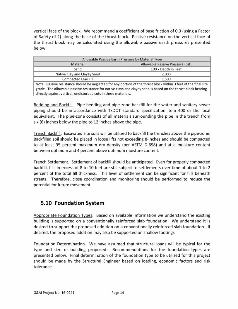
vertical face of the block. We recommend a coefficient of base friction of 0.3 (using a Factor of Safety of 2) along the base of the thrust block. Passive resistance on the vertical face of the thrust block may be calculated using the allowable passive earth pressures presented below.
Allowable Passive Earth Pressure by Material Type Material Allowable Passive Pressure (psf)
Sand 100 x Depth in Feet Native Clay and Clayey Sand 2,000
Compacted Clay Fill 1,500 Note: Passive resistance should be neglected for any portion of the thrust block within 3 feet of the final site grade. The allowable passive resistance for native clays and clayey sand is based on the thrust block bearing directly against vertical, undisturbed cuts in these materials.
Bedding and Backfill. Pipe bedding and pipe-zone backfill for the water and sanitary sewer piping should be in accordance with TxDOT standard specification Item 400 or the local equivalent. The pipe-zone consists of all materials surrounding the pipe in the trench from six (6) inches below the pipe to 12 inches above the pipe. Trench Backfill. Excavated site soils will be utilized to backfill the trenches above the pipe-zone. Backfilled soil should be placed in loose lifts not exceeding 8-inches and should be compacted to at least 95 percent maximum dry density (per ASTM D-698) and at a moisture content between optimum and 4 percent above optimum moisture content. Trench Settlement. Settlement of backfill should be anticipated. Even for properly compacted backfill, fills in excess of 8 to 10 feet are still subject to settlements over time of about 1 to 2 percent of the total fill thickness. This level of settlement can be significant for fills beneath streets. Therefore, close coordination and monitoring should be performed to reduce the potential for future movement.
5.10 Foundation System Appropriate Foundation Types. Based on available information we understand the existing building is supported on a conventionally reinforced slab foundation. We understand it is desired to support the proposed addition on a conventionally reinforced slab foundation. If desired, the proposed addition may also be supported on shallow footings. Foundation Determination. We have assumed that structural loads will be typical for the type and size of building proposed. Recommendations for the foundation types are presented below. Final determination of the foundation type to be utilized for this project should be made by the Structural Engineer based on loading, economic factors and risk tolerance.
G&AI Project No. 16-0241 Page 15
Foundations Adjacent to Slopes. Foundations placed too close to adjacent slopes steeper than 5:1 (H:V) may experience reduced bearing capacities and/or excessive settlement. Recommendations provided herein assume foundations are not close enough to adjacent slopes in excess of 5:1 (H:V) to be detrimentally affected. Therefore, foundations closer than 5 times the depth of adjacent slopes, pits or excavations in excess of 5:1 (H:V) should be brought to our attention in order that we may review the appropriateness of our recommendations. Assumed Maximum Cut Depth. We have also assumed that cuts of less than 1-foot will be required to bring the site to grade. In the event cuts in the building pad exceed 1-foot, we should be notified and allowed to review the design to assess the suitability of the foundation recommendations provided.
5.10.1 Slab Foundation General. The proposed addition can be supported on a reinforced ground-supported slab foundation. The slab foundation should be conventionally reinforced. The slab foundation should be designed with exterior and interior grade beams adequate to provide sufficient rigidity to the foundation system to sustain the vertical soil movements expected at this site as described above. All grade beams and floor slabs should be adequately reinforced with steel to minimize cracking as normal movements occur in the foundation soils. Bearing Capacity. The slab should be designed using a net dead load plus sustained live load bearing pressure of 1,500 psf or a net total load pressure of 2,250 psf, whichever condition results in a larger bearing surface. These bearing pressures are based on a safety factor of 3 and 2, respectively, against shear failure of the foundation bearing soils. Foundation Depth. Grade beams should be founded a minimum of 18 inches below surrounding grade (supported on native soils or select fill, depending on the subgrade treatment implemented). The bottom of the beam trenches should be free of any loose or soft material prior to the placement of the concrete. Deflection Analysis. Slab deflections should be analyzed per recommendations provided in Section 5.11 - Slab-on-Grade.
5.10.2 Shallow Footings General Requirement. Shallow strip and spread footing foundations may be used for support of the proposed addition provided that recommendations in the section entitled “Slab-on-Grade” are followed. Foundation Depth. Shallow strip and spread footing foundations should bear on native soil at a depth of 2-feet below the surrounding grade.
G&AI Project No. 16-0241 Page 16
Bearing Capacity. Continuous strip footings can be proportioned using a net dead load plus sustained live load bearing pressure of 2,000 psf or a net total load bearing pressure of 3,000 psf, whichever condition results in a larger bearing surface. Individual spread footings can be proportioned using a net dead load plus sustained live load bearing pressure of 2,600 psf or a net total load bearing pressure of 3,900 psf, whichever condition results in a larger bearing surface. These bearing pressures are based on a safety factor of 3 and 2, respectively. Geometry. Individual spread footings should be at least 30 inches wide and continuous strip footing foundations should be at least 16 inches wide. Settlement. Settlement of footing foundations is influenced by a number of factors, including: load (pressure), soil consolidation properties, depth to groundwater, geometry (width and length), depth, spacing, and quality of construction. Although a detailed settlement analysis is beyond the scope of this study, settlement for foundations constructed as described above should be about 1 inch or less. Lateral Resistance. Resistance to lateral loads may be provided by the soil adjacent to the footings. We recommend using an equivalent fluid weight of 100 pcf for lateral resistance. An allowable coefficient of sliding friction of 0.3 (using a Factor of Safety of 2) between the concrete footings and underlying soil may be combined with the passive resistance. Construction and Observation. The geotechnical engineer should monitor foundation construction to verify conditions are as anticipated and that the materials encountered are suitable for support of foundations. Soft or unsuitable soils encountered at the foundation bearing level should be removed to expose suitable, firm soil. Foundation excavations should be dry and free of loose material. Excavations for foundations should be filled with concrete before the end of the workday or sooner if necessary to prevent deterioration of the bearing surface. Prolonged exposure or inundation of the bearing surface with water will result in changes in strength and compressibility characteristics. If delays occur, the excavation should be deepened as necessary and cleaned, in order to provide a fresh bearing surface. If more than 24 hours of exposure of the bearing surface is anticipated in the excavation, a “mud slab” should be used to protect the bearing surfaces. If a mud slab is used, the foundation excavations should initially be over-excavated by approximately 4 inches and a lean concrete mud slab of approximately 4 inches in thickness should be placed in the bottom of the excavation immediately following exposure of the bearing surface by excavation. The mud slab will protect the bearing surface, maintain more uniform moisture in the subgrade, facilitate dewatering of excavations if required and provide a working surface for the placement of formwork and reinforcing steel.
G&AI Project No. 16-0241 Page 17
5.11 Slab-on-Grade Potential Vertical Slab Movements. Based on the information gathered during this investigation, a slab constructed on-grade will be subject to potential vertical slab movements of about 1-inch. Subgrade Treatment. Based on the calculated PVR, no subgrade treatment is required to reduce the PVR to 1-inch. Subgrade Moisture. The slab subgrade is prone to drying after being exposed and should be kept moist prior to slab placement. Moisture Barrier. A moisture barrier should be used beneath the slab foundation in areas where floor coverings will be utilized (such as, but not limited to, wood flooring, tile, linoleum and carpeting). Slab Deflection Analysis. Coefficient of subgrade reaction, k, values are soil, load and settlement dependent. Upon request by the Structural Engineer for this project, k value recommendations will be provided for the specific loading application in question.
5.12 Pavement Recommendations for rigid and flexible pavement and preparation of the pavement subgrade are provided in the following sections. A traffic study indicating the number and type of vehicles on which to base the pavement design was not provided. Therefore, our recommendations are based upon our experience with similar projects assuming normal vehicular loading. Any unusual loading conditions should be brought to our attention prior to finalizing the pavement design so that we may assess and modify our recommendations as necessary. Flexible asphaltic pavements subjected to soil-related shrinking and swelling do not perform as well as rigid pavements. As a result, the lifespan of flexible asphaltic pavement can be reduced substantially when compared to rigid pavement. The need for increased maintenance of flexible asphaltic pavements should be considered prior to its selection.
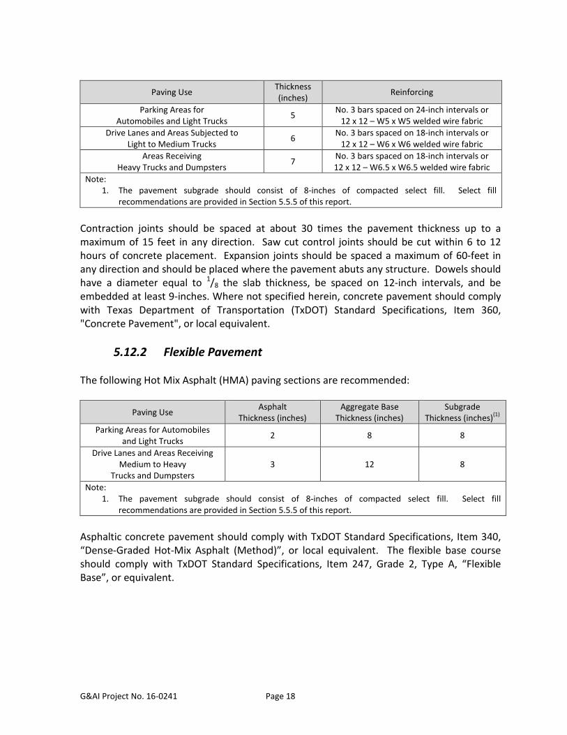
5.12.1 Rigid Pavement Portland cement concrete (PCC) with a minimum 28-day compressive strength of 3,500 pounds per square inch (psi) should be utilized for rigid pavement. Grade 60 reinforcing steel should be utilized in the transverse and longitudinal directions. The following pavement thicknesses and reinforcing are recommended:
G&AI Project No. 16-0241 Page 18
Paving Use Thickness (inches) Reinforcing
Parking Areas for Automobiles and Light Trucks 5 No. 3 bars spaced on 24-inch intervals or
12 x 12 – W5 x W5 welded wire fabric Drive Lanes and Areas Subjected to
Light to Medium Trucks 6 No. 3 bars spaced on 18-inch intervals or 12 x 12 – W6 x W6 welded wire fabric
Areas Receiving Heavy Trucks and Dumpsters 7 No. 3 bars spaced on 18-inch intervals or
12 x 12 – W6.5 x W6.5 welded wire fabric Note:
1. The pavement subgrade should consist of 8-inches of compacted select fill. Select fill recommendations are provided in Section 5.5.5 of this report.
Contraction joints should be spaced at about 30 times the pavement thickness up to a maximum of 15 feet in any direction. Saw cut control joints should be cut within 6 to 12 hours of concrete placement. Expansion joints should be spaced a maximum of 60-feet in any direction and should be placed where the pavement abuts any structure. Dowels should have a diameter equal to 1/8 the slab thickness, be spaced on 12-inch intervals, and be embedded at least 9-inches. Where not specified herein, concrete pavement should comply with Texas Department of Transportation (TxDOT) Standard Specifications, Item 360, "Concrete Pavement", or local equivalent.
5.12.2 Flexible Pavement The following Hot Mix Asphalt (HMA) paving sections are recommended:
Paving Use Asphalt Thickness (inches)
Aggregate Base Thickness (inches)
Subgrade Thickness (inches)(1)
Parking Areas for Automobiles and Light Trucks 2 8 8
Drive Lanes and Areas Receiving Medium to Heavy
Trucks and Dumpsters
3
12
8
Note: 1. The pavement subgrade should consist of 8-inches of compacted select fill. Select fill
recommendations are provided in Section 5.5.5 of this report. Asphaltic concrete pavement should comply with TxDOT Standard Specifications, Item 340, “Dense-Graded Hot-Mix Asphalt (Method)”, or local equivalent. The flexible base course should comply with TxDOT Standard Specifications, Item 247, Grade 2, Type A, “Flexible Base”, or equivalent.
G&AI Project No. 16-0241 Page 19
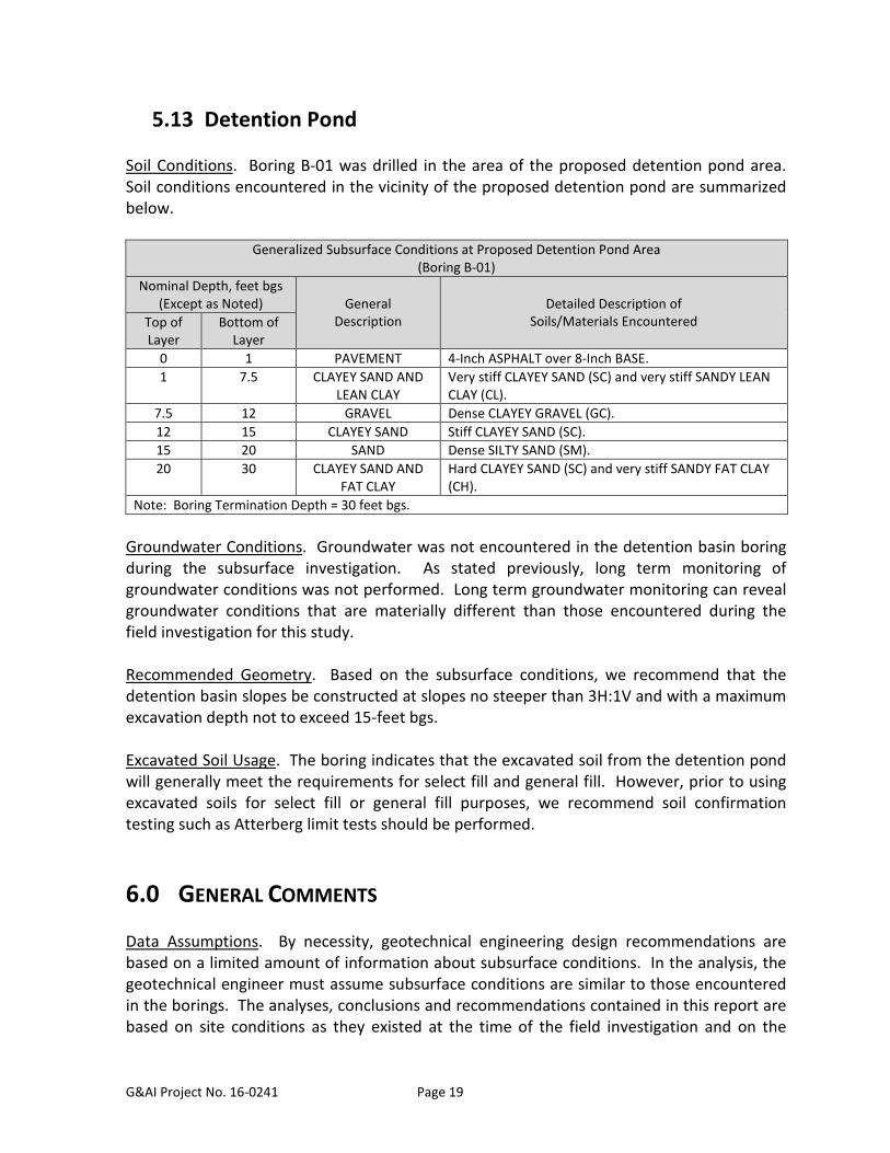
5.13 Detention Pond Soil Conditions. Boring B-01 was drilled in the area of the proposed detention pond area. Soil conditions encountered in the vicinity of the proposed detention pond are summarized below.
Generalized Subsurface Conditions at Proposed Detention Pond Area (Boring B-01)
Nominal Depth, feet bgs (Except as Noted)
General
Description
Detailed Description of
Soils/Materials Encountered Top of Layer
Bottom of Layer
0 1 PAVEMENT 4-Inch ASPHALT over 8-Inch BASE. 1 7.5 CLAYEY SAND AND
LEAN CLAY Very stiff CLAYEY SAND (SC) and very stiff SANDY LEAN CLAY (CL).
7.5 12 GRAVEL Dense CLAYEY GRAVEL (GC). 12 15 CLAYEY SAND Stiff CLAYEY SAND (SC). 15 20 SAND Dense SILTY SAND (SM). 20 30 CLAYEY SAND AND
FAT CLAY Hard CLAYEY SAND (SC) and very stiff SANDY FAT CLAY (CH).
Note: Boring Termination Depth = 30 feet bgs.
Groundwater Conditions. Groundwater was not encountered in the detention basin boring during the subsurface investigation. As stated previously, long term monitoring of groundwater conditions was not performed. Long term groundwater monitoring can reveal groundwater conditions that are materially different than those encountered during the field investigation for this study. Recommended Geometry. Based on the subsurface conditions, we recommend that the detention basin slopes be constructed at slopes no steeper than 3H:1V and with a maximum excavation depth not to exceed 15-feet bgs. Excavated Soil Usage. The boring indicates that the excavated soil from the detention pond will generally meet the requirements for select fill and general fill. However, prior to using excavated soils for select fill or general fill purposes, we recommend soil confirmation testing such as Atterberg limit tests should be performed.
6.0 GENERAL COMMENTS Data Assumptions. By necessity, geotechnical engineering design recommendations are based on a limited amount of information about subsurface conditions. In the analysis, the geotechnical engineer must assume subsurface conditions are similar to those encountered in the borings. The analyses, conclusions and recommendations contained in this report are based on site conditions as they existed at the time of the field investigation and on the
G&AI Project No. 16-0241 Page 20
assumption that the exploratory borings are representative of the subsurface conditions throughout the site; that is, the subsurface conditions everywhere are not significantly different from those disclosed by the borings at the time they were completed. Subsurface Anomalies. Anomalies in subsurface conditions are often revealed during construction. If during construction, different subsurface conditions from those encountered in our borings are observed, or appear to be present in excavations, we must be advised promptly so that we can review these conditions and reconsider our recommendations where necessary. Change of Conditions. If there is a substantial lapse of time between submission of this report and the start of the work at the site, if conditions have changed due either to natural causes or to construction operations at or adjacent to the site, or if structure locations, structural loads or finish grades are changed, we should be promptly informed and retained to review our report to determine the applicability of the conclusions and recommendations, considering the changed conditions and/or time lapse. Design Review. G&AI, Inc. should be retained to review those portions of the plans and specifications for this particular project that pertain to earthwork and foundations as a means to determine whether the plans and specifications are consistent with the recommendations contained in this report. Construction Materials Testing and Inspection. G&AI should be retained to observe earthwork and foundation installation and perform materials evaluation and testing during the construction phase of the project. This enables G&AI’s geotechnical engineer to stay abreast of the project and to be readily available to evaluate unanticipated conditions, to conduct additional tests if required and, when necessary, to recommend alternative solutions to unanticipated conditions. It is proposed that construction phase observation and materials testing commence by the project geotechnical engineer (G&AI) at the outset of the project. Experience has shown that the most suitable method for procuring these services is for the owner to contact directly with the project geotechnical engineer. This results in a clear, direct line of communication between the owner and the owner's design engineers and the geotechnical engineer. Report Recommendations are Preliminary. Until the recommended construction phase services are performed by G&AI, the recommendations contained in this report on such items as final foundation bearing elevations, final depth of undercut of expansive soils for non-expansive earth fill pads and other such subsurface-related recommendations should be considered as preliminary. Liability Limitation. G&AI cannot assume responsibility or liability for recommendations provided in this report if construction inspection and/or testing recommended herein is performed by another party.

G&AI Project No. 16-0241 Page 21
Warranty. This report has been prepared for the exclusive use of the Client and their designated agents for specific application to design of this project. We have used that degree of care and skill ordinarily exercised under similar conditions by reputable members of our profession practicing in the same or similar locality. No other warranty, expressed or implied, is made or intended.

Appendix A ‐ Project Location Diagrams
Project No. 16-0241 National Guard Building - El Paso
PROJECT LOCATION DIAGRAM - GENERAL
Project No. 16-0241 National Guard Building - El Paso
PROJECT LOCATION DIAGRAM - LOCAL

Appendix B ‐ Boring Location Diagram
Project No. 16-0241 National Guard Building - El Paso
BORING LOCATION DIAGRAM

Appendix C ‐ Boring Logs and Laboratory Results
65
41
60
11
20
33
16
19
21
27
39
54
5
9
7
7
8
8
9
13-50/5"
17-14-25(39)
19-23-22(45)
10-12-14(26)
3-15-34(49)
25-50/6"
13-16-25(41)
(50/4")-(50/0.25")
SS
SS
SS
TCP
SS
SS
SS
SS
PAVEMENT - 4-Inch ASPHALT over 8-InchBASE.SANDY LEAN CLAY (CL) - Very stiff, brown, withgravel.
CLAYEY SAND (SC) - Very stiff, brown, withgravel.
CLAYEY GRAVEL (GC) - Dense, brown.
CLAYEY SAND (SC) - Stiff, brown.
SILTY SAND (SM) - Dense, light brown and tan.
CLAYEY SAND (SC) - Hard, light brown and tan.
SANDY FAT CLAY (CH) - Very stiff, tan andbrown, with silt seams.
Bottom of hole at 30.0 feet.
NOTES
GROUND ELEVATION
LOGGED BY DL
METHOD Auger
24hrs AFTER ---
HOLE SIZE
CONTRACTOR One J2S GROUND WATER LEVELS:
CHECKED BY VC
DATE STARTED 6/28/16 COMPLETED 6/28/16
AFTER 15 MIN. Not Encountered
INITIALLY ENCOUNTERED Not Encountered
FIN
ES
CO
NT
EN
T(%
)
PLA
ST
ICIT
YIN
DE
X
PLA
ST
ICLI
MIT
LIQ
UID
LIM
IT
ATTERBERGLIMITS
MO
IST
UR
EC
ON
TE
NT
(%
)
DR
Y U
NIT
WT
.(p
cf)
Con
finin
gP
ress
ure
(psi
)
Com
pres
sive
Str
engt
h (t
sf)
TO
RV
AN
E(t
sf)
PO
CK
ET
PE
N.
(tsf
)
BLO
WC
OU
NT
S(N
VA
LUE
)
RE
CO
VE
RY
%(R
QD
)
TC
P
SA
MP
LE T
YP
EN
UM
BE
R
DE
PT
H(f
t)
0
5
10
15
20
25
30
GR
AP
HIC
LOG
MATERIAL DESCRIPTION
BORING NUMBER B-01PAGE 1 OF 1
CLIENT Freese and Nichols
PROJECT NUMBER 16-0241
PROJECT NAME National Guard Building - El Paso
PROJECT LOCATION El Paso, Texas
TC
P T
EM
PLA
TE
RE
VIS
ED
16-
0241
- E
L P
AS
O.G
PJ
TC
P D
AT
A T
EM
PLA
TE
.GD
T 7
/15
/16
Gorrondona & Associates11710 North Freeway, Suite 700, Houston, TX 770607524 Jack Newell Blvd. So, Fort Worth, Texas 76118Telephone: HOU: 281-469-3347; FW: 817-496-1424Fax: HOU: 281-469.3594; FW: 817-496-1768
27
38
14
21
15
19
29
40
6
9
10
9
6
11
9
11
3-2-3(5)
10-12-14(26)
12-12-10(22)
10-14-18(32)
50/4"
35-42-42(84)
25-20-20(40)
12-16-22(38)
10-17-25(42)
SS
SS
SS
SS
SS
SS
SS
SS
SS
PAVEMENT - 4-Inch ASPHALT.CLAYEY SAND (SC) - Stiff, reddish brown, withgravel.
With limestone fragments below 8.5 feet.
SILTY SAND (SM) - Very dense, reddish brown,with gravel.
CLAYEY SAND (SC) - Very stiff, reddish brown,with gravel.
SANDY LEAN CLAY (CL) - Very stiff, tan andbrown.
Bottom of hole at 30.0 feet.
NOTES
GROUND ELEVATION
LOGGED BY DL
METHOD Auger
24hrs AFTER ---
HOLE SIZE
CONTRACTOR One J2S GROUND WATER LEVELS:
CHECKED BY VC
DATE STARTED 6/28/16 COMPLETED 6/28/16
AFTER 15 MIN. Not Encountered
INITIALLY ENCOUNTERED Not Encountered
FIN
ES
CO
NT
EN
T(%
)
PLA
ST
ICIT
YIN
DE
X
PLA
ST
ICLI
MIT
LIQ
UID
LIM
IT
ATTERBERGLIMITS
MO
IST
UR
EC
ON
TE
NT
(%
)
DR
Y U
NIT
WT
.(p
cf)
Con
finin
gP
ress
ure
(psi
)
Com
pres
sive
Str
engt
h (t
sf)
TO
RV
AN
E(t
sf)
PO
CK
ET
PE
N.
(tsf
)
BLO
WC
OU
NT
S(N
VA
LUE
)
RE
CO
VE
RY
%(R
QD
)
TC
P
SA
MP
LE T
YP
EN
UM
BE
R
DE
PT
H(f
t)
0
5
10
15
20
25
30
GR
AP
HIC
LOG
MATERIAL DESCRIPTION
BORING NUMBER B-02PAGE 1 OF 1
CLIENT Freese and Nichols
PROJECT NUMBER 16-0241
PROJECT NAME National Guard Building - El Paso
PROJECT LOCATION El Paso, Texas
TC
P T
EM
PLA
TE
RE
VIS
ED
16-
0241
- E
L P
AS
O.G
PJ
TC
P D
AT
A T
EM
PLA
TE
.GD
T 7
/15
/16
Gorrondona & Associates11710 North Freeway, Suite 700, Houston, TX 770607524 Jack Newell Blvd. So, Fort Worth, Texas 76118Telephone: HOU: 281-469-3347; FW: 817-496-1424Fax: HOU: 281-469.3594; FW: 817-496-1768
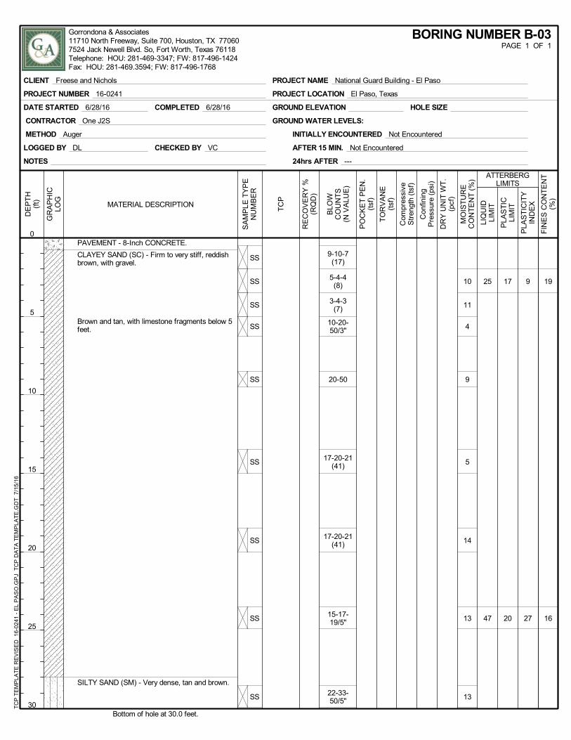
19
16
9
27
17
20
25
47
10
11
4
9
5
14
13
13
9-10-7(17)
5-4-4(8)
3-4-3(7)
10-20-50/3"
20-50
17-20-21(41)
17-20-21(41)
15-17-19/5"
22-33-50/5"
SS
SS
SS
SS
SS
SS
SS
SS
SS
PAVEMENT - 8-Inch CONCRETE.
CLAYEY SAND (SC) - Firm to very stiff, reddishbrown, with gravel.
Brown and tan, with limestone fragments below 5feet.
SILTY SAND (SM) - Very dense, tan and brown.
Bottom of hole at 30.0 feet.
NOTES
GROUND ELEVATION
LOGGED BY DL
METHOD Auger
24hrs AFTER ---
HOLE SIZE
CONTRACTOR One J2S GROUND WATER LEVELS:
CHECKED BY VC
DATE STARTED 6/28/16 COMPLETED 6/28/16
AFTER 15 MIN. Not Encountered
INITIALLY ENCOUNTERED Not Encountered
FIN
ES
CO
NT
EN
T(%
)
PLA
ST
ICIT
YIN
DE
X
PLA
ST
ICLI
MIT
LIQ
UID
LIM
IT
ATTERBERGLIMITS
MO
IST
UR
EC
ON
TE
NT
(%
)
DR
Y U
NIT
WT
.(p
cf)
Con
finin
gP
ress
ure
(psi
)
Com
pres
sive
Str
engt
h (t
sf)
TO
RV
AN
E(t
sf)
PO
CK
ET
PE
N.
(tsf
)
BLO
WC
OU
NT
S(N
VA
LUE
)
RE
CO
VE
RY
%(R
QD
)
TC
P
SA
MP
LE T
YP
EN
UM
BE
R
DE
PT
H(f
t)
0
5
10
15
20
25
30
GR
AP
HIC
LOG
MATERIAL DESCRIPTION
BORING NUMBER B-03PAGE 1 OF 1
CLIENT Freese and Nichols
PROJECT NUMBER 16-0241
PROJECT NAME National Guard Building - El Paso
PROJECT LOCATION El Paso, Texas
TC
P T
EM
PLA
TE
RE
VIS
ED
16-
0241
- E
L P
AS
O.G
PJ
TC
P D
AT
A T
EM
PLA
TE
.GD
T 7
/15
/16
Gorrondona & Associates11710 North Freeway, Suite 700, Houston, TX 770607524 Jack Newell Blvd. So, Fort Worth, Texas 76118Telephone: HOU: 281-469-3347; FW: 817-496-1424Fax: HOU: 281-469.3594; FW: 817-496-1768
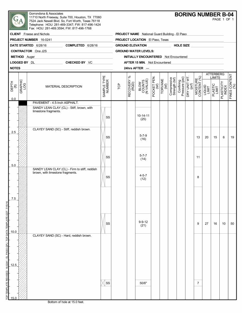
19
50
6
10
15
16
20
27
13
11
8
9
7
10-14-11(25)
5-7-9(16)
5-7-7(14)
4-5-7(12)
9-9-12(21)
50/6"
SS
SS
SS
SS
SS
SS
PAVEMENT - 4.5-Inch ASPHALT.
SANDY LEAN CLAY (CL) - Stiff, brown, withlimestone fragments.
CLAYEY SAND (SC) - Stiff, reddish brown.
SANDY LEAN CLAY (CL) - Firm to stiff, reddishbrown, with limestone fragments.
CLAYEY SAND (SC) - Hard, reddish brown.
Bottom of hole at 15.0 feet.
NOTES
GROUND ELEVATION
LOGGED BY DL
METHOD Auger
24hrs AFTER ---
HOLE SIZE
CONTRACTOR One J2S GROUND WATER LEVELS:
CHECKED BY VC
DATE STARTED 6/28/16 COMPLETED 6/28/16
AFTER 15 MIN. Not Encountered
INITIALLY ENCOUNTERED Not Encountered
FIN
ES
CO
NT
EN
T(%
)
PLA
ST
ICIT
YIN
DE
X
PLA
ST
ICLI
MIT
LIQ
UID
LIM
IT
ATTERBERGLIMITS
MO
IST
UR
EC
ON
TE
NT
(%
)
DR
Y U
NIT
WT
.(p
cf)
Con
finin
gP
ress
ure
(psi
)
Com
pres
sive
Str
engt
h (t
sf)
TO
RV
AN
E(t
sf)
PO
CK
ET
PE
N.
(tsf
)
BLO
WC
OU
NT
S(N
VA
LUE
)
RE
CO
VE
RY
%(R
QD
)
TC
P
SA
MP
LE T
YP
EN
UM
BE
R
DE
PT
H(f
t)
0.0
2.5
5.0
7.5
10.0
12.5
15.0
GR
AP
HIC
LOG
MATERIAL DESCRIPTION
BORING NUMBER B-04PAGE 1 OF 1
CLIENT Freese and Nichols
PROJECT NUMBER 16-0241
PROJECT NAME National Guard Building - El Paso
PROJECT LOCATION El Paso, Texas
TC
P T
EM
PLA
TE
RE
VIS
ED
16-
0241
- E
L P
AS
O.G
PJ
TC
P D
AT
A T
EM
PLA
TE
.GD
T 7
/15
/16
Gorrondona & Associates11710 North Freeway, Suite 700, Houston, TX 770607524 Jack Newell Blvd. So, Fort Worth, Texas 76118Telephone: HOU: 281-469-3347; FW: 817-496-1424Fax: HOU: 281-469.3594; FW: 817-496-1768
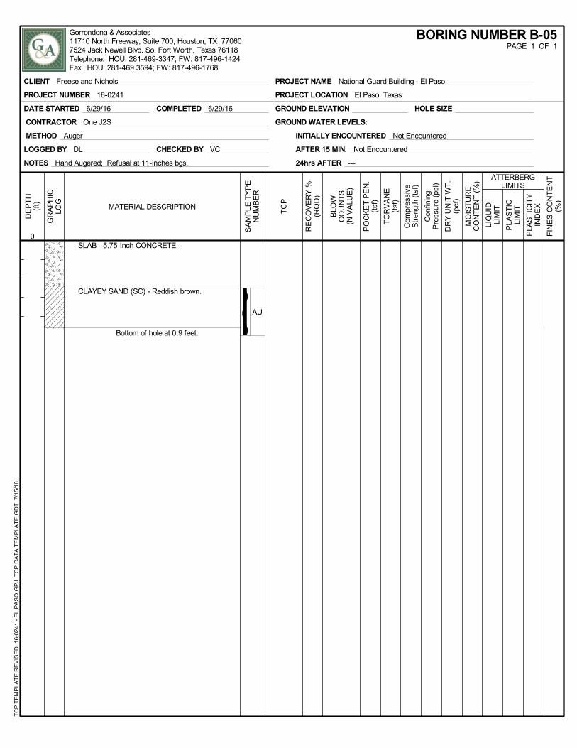
AU
SLAB - 5.75-Inch CONCRETE.
CLAYEY SAND (SC) - Reddish brown.
Bottom of hole at 0.9 feet.
NOTES Hand Augered; Refusal at 11-inches bgs.
GROUND ELEVATION
LOGGED BY DL
METHOD Auger
24hrs AFTER ---
HOLE SIZE
CONTRACTOR One J2S GROUND WATER LEVELS:
CHECKED BY VC
DATE STARTED 6/29/16 COMPLETED 6/29/16
AFTER 15 MIN. Not Encountered
INITIALLY ENCOUNTERED Not Encountered
FIN
ES
CO
NT
EN
T(%
)
PLA
ST
ICIT
YIN
DE
X
PLA
ST
ICLI
MIT
LIQ
UID
LIM
IT
ATTERBERGLIMITS
MO
IST
UR
EC
ON
TE
NT
(%
)
DR
Y U
NIT
WT
.(p
cf)
Con
finin
gP
ress
ure
(psi
)
Com
pres
sive
Str
engt
h (t
sf)
TO
RV
AN
E(t
sf)
PO
CK
ET
PE
N.
(tsf
)
BLO
WC
OU
NT
S(N
VA
LUE
)
RE
CO
VE
RY
%(R
QD
)
TC
P
SA
MP
LE T
YP
EN
UM
BE
R
DE
PT
H(f
t)
0
GR
AP
HIC
LOG
MATERIAL DESCRIPTION
BORING NUMBER B-05PAGE 1 OF 1
CLIENT Freese and Nichols
PROJECT NUMBER 16-0241
PROJECT NAME National Guard Building - El Paso
PROJECT LOCATION El Paso, Texas
TC
P T
EM
PLA
TE
RE
VIS
ED
16-
0241
- E
L P
AS
O.G
PJ
TC
P D
AT
A T
EM
PLA
TE
.GD
T 7
/15
/16
Gorrondona & Associates11710 North Freeway, Suite 700, Houston, TX 770607524 Jack Newell Blvd. So, Fort Worth, Texas 76118Telephone: HOU: 281-469-3347; FW: 817-496-1424Fax: HOU: 281-469.3594; FW: 817-496-1768
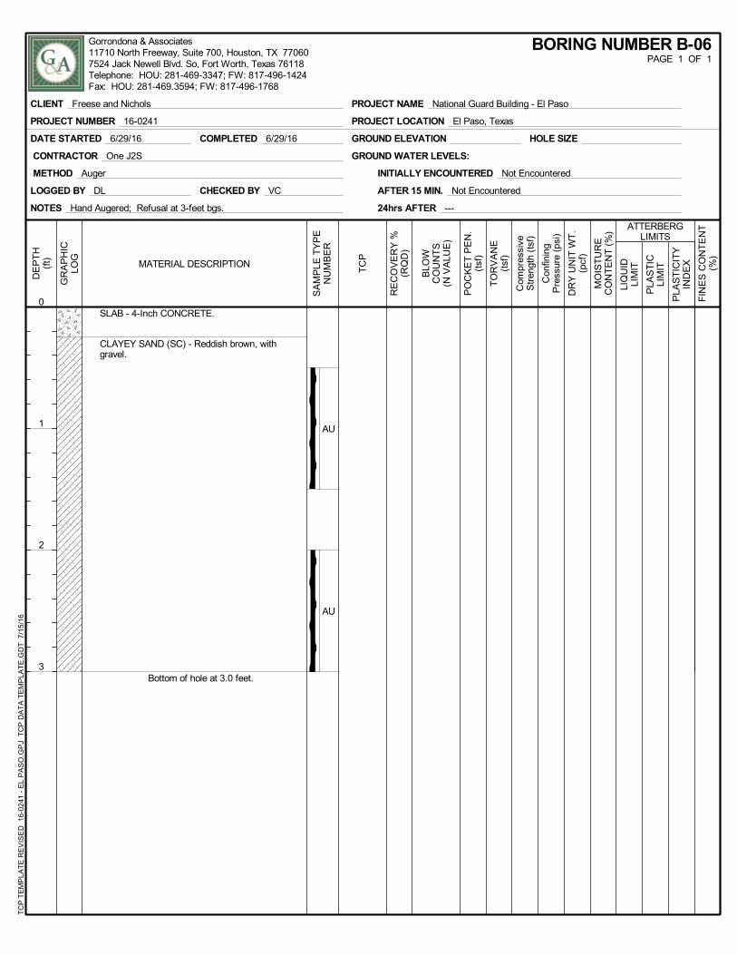
AU
AU
SLAB - 4-Inch CONCRETE.
CLAYEY SAND (SC) - Reddish brown, withgravel.
Bottom of hole at 3.0 feet.
NOTES Hand Augered; Refusal at 3-feet bgs.
GROUND ELEVATION
LOGGED BY DL
METHOD Auger
24hrs AFTER ---
HOLE SIZE
CONTRACTOR One J2S GROUND WATER LEVELS:
CHECKED BY VC
DATE STARTED 6/29/16 COMPLETED 6/29/16
AFTER 15 MIN. Not Encountered
INITIALLY ENCOUNTERED Not Encountered
FIN
ES
CO
NT
EN
T(%
)
PLA
ST
ICIT
YIN
DE
X
PLA
ST
ICLI
MIT
LIQ
UID
LIM
IT
ATTERBERGLIMITS
MO
IST
UR
EC
ON
TE
NT
(%
)
DR
Y U
NIT
WT
.(p
cf)
Con
finin
gP
ress
ure
(psi
)
Com
pres
sive
Str
engt
h (t
sf)
TO
RV
AN
E(t
sf)
PO
CK
ET
PE
N.
(tsf
)
BLO
WC
OU
NT
S(N
VA
LUE
)
RE
CO
VE
RY
%(R
QD
)
TC
P
SA
MP
LE T
YP
EN
UM
BE
R
DE
PT
H(f
t)
0
1
2
3
GR
AP
HIC
LOG
MATERIAL DESCRIPTION
BORING NUMBER B-06PAGE 1 OF 1
CLIENT Freese and Nichols
PROJECT NUMBER 16-0241
PROJECT NAME National Guard Building - El Paso
PROJECT LOCATION El Paso, Texas
TC
P T
EM
PLA
TE
RE
VIS
ED
16-
0241
- E
L P
AS
O.G
PJ
TC
P D
AT
A T
EM
PLA
TE
.GD
T 7
/15
/16
Gorrondona & Associates11710 North Freeway, Suite 700, Houston, TX 770607524 Jack Newell Blvd. So, Fort Worth, Texas 76118Telephone: HOU: 281-469-3347; FW: 817-496-1424Fax: HOU: 281-469.3594; FW: 817-496-1768

Appendix D ‐ Aerial Photographs
Project No. 16-0241 National Guard Building - El Paso
AERIAL PHOTOGRAPH – 2016
Project No. 16-0241 National Guard Building - El Paso
AERIAL PHOTOGRAPH - 2002

Appendix E ‐ USGS Topographic Map
Project No. 16-0241 National Guard Building - El Paso
USGS TOPOGRAPHIC MAP

Appendix F ‐ Site Photographs
Project No. 16-0241 National Guard Building - El Paso
SITE PHOTOGRAPHS
Facing South at Boring B-01 Facing North at Boring B-01
Facing East at Boring B-02 Facing North at Boring B-04
Project No. 16-0241 National Guard Building - El Paso
SITE PHOTOGRAPHS
Vicinity of Boring B-05

Appendix G ‐ Geologic Information
Project No. 16-0241 National Guard Building - El Paso
GEOLOGIC ATLAS
Mineral Resources On-Line Spatial Data
Mineral Resources > Online Spatial Data > Geology > by state > Texas
alluvial fan deposits
alluvial fan deposits
State TexasName alluvial fan deposits
Geologic age Phanerozoic | Cenozoic | Quaternary | Pleistocene Holocene
Original map label QfComments colluvium and fan deposits, may include older
Quaternary deposits in some areasPrimary rock type alluvial fan
Secondary rock type
Other rock types
Lithologic constituents
Map references Bureau of Economic Geology, 1992, Geologic Map of Texas: University of Texas at Austin, Virgil E. Barnes, project supervisor, Hartmann, B.M. and Scranton, D.F., cartography, scale 1:500,000
Unit references Bureau of Economic Geology, 1979, Emory Peak--Presidio Sheet, Geologic Atlas of Texas, University of Texas at Austin.
Counties Brewster - Culberson - El Paso - Hudspeth - Jeff Davis - Kinney - Pecos - Presidio - Reeves - Terrell
Show this information as [XML] - [JSON]
U.S. Department of the Interior | U.S. Geological SurveyURL: http://mrdata.usgs.gov/geology/state/sgmc-unit.php?unit=TXQf;0Page Contact Information: Peter Schweitzer

Appendix H ‐ Unified Soil Classification System