Embed Size (px)
Citation preview

4/30/17 Missouri Department of Transportation
GeoPak Road 2 Ramp Transition


GEOPAK Road 2 Ramp Transition Layout
4/30/17 Missouri Department of Transportation 1
19.1 Group Exercise: Ramp Transition Layout
Objective and Background Information
The objective of this exercise is to demonstrate how the Power GeoPak Civil Tools can be used
to create a profile for a ramp transition. This is the area between the sections A-A and E-E in the
following figure from Missouri Standard Plans for Highway Construction (203.41). The profile
will be applied along the ramp chain.
As the figure indicates, the ramp is in Superelevation transition from the pavement cross slope at
Section A-A to the Superelevation required for the beginning curve of the ramp at Section E-E.
These two sections as shown in the standard plans are provided below.
Before proceeding with the steps to create the profile, a decision needs to be made regarding the
location of the break line between the mainline and ramp cross slopes. According to the Design
Standards group, the exact location of this break line at Section E-E is not set. It can be located
anywhere within the two-foot width of the ramp nose. For the purposes of this exercise, it will
be located on the ramp side of the nose and held at a constant offset of 20’ relative to the ramp
chain from the ramp nose back to the point where this offset intersects with the mainline edge of
pavement. As a designer, you can determine its location for your project.
The break in the slope between the
mainline and the ramp can occur
anywhere within these 2’

Ramp Transition Layout GEOPAK Road 2
2 Missouri Department of Transportation 4/30/17
Also needed is the Superelevation rate at the ramp nose, which is based on the design speed of
the ramp and the radius of the curve. The radius of the first curve in Ramp 2 is 1,041 feet.
The relevant portion of the Superelevation table from Missouri Standard Plan 203.20F is shown
below. Based on emax = 8%, the ramp’s design speed of 40 M.P.H. and a rounded down radius of
1030’, the Superelevation for the start of the ramp is 5.8%.

GEOPAK Road 2 Ramp Transition Layout
4/30/17 Missouri Department of Transportation 3
1) Open Osage\J5P0555\data\J5P0555_Plan_Overview.dgn
a) Review Project scope.
2) Open the J5P0555_Terrain_Existing.dgn.
a) Review the Existing Ground Terrain in file.
3) Create J5P0555_Civil_Geometry.dgn using the i_project_2d_PowerGEOPAK.dgn as
the seed file.
a) Set Annotation Scale to 50
b) Import Alignment and Profile called “Route50” and then import the “Ramp2”
alignment separately from the job555.gpk.
Note: If the User imports all alignments and profiles in one batch import from the
gpk, all profiles will be applied to each alignment.
c) Reference in the J5P0555_Terrain_Existing.dgn, activate the Existing Terrain
d) Open Route 50 Profile Model, activate Proposed Profile (if needed)
4) Open J5P0555_Plan.dgn File.
a) Review plan geometry.
b) Attach J5P0555_Civil_Geometry.dgn
Create template for Route 50 Corridor
5) Create template for Route 50 Corridor
a) In the Corridor Modeling Task select the Create Template icon
b) Save the Modot.itl to the Project’s data folder naming it J5P0555.itl
c) Create a folder under the root directory named J5P0555.
d) Under the J5P0555 folder create a Route 50 folder.
e) Copy the following template into the Route 50 folder:
Templates\Concrete Pavement w/ Shoulders\A2 Shoulders Agg Base\
Concrete Pavement 4 Lane Divided w/ Agg Base Option 3 f) Use the Delete Components option and remove the right outside Shoulder &
Sublayers, Guardrail Widening, and End Conditions. Do not delete Aggregate Base
(See picture below).
g) Delete three outside Aggregate Base points (See arrows below)
Ramp Transition Layout GEOPAK Road 2
4 Missouri Department of Transportation 4/30/17
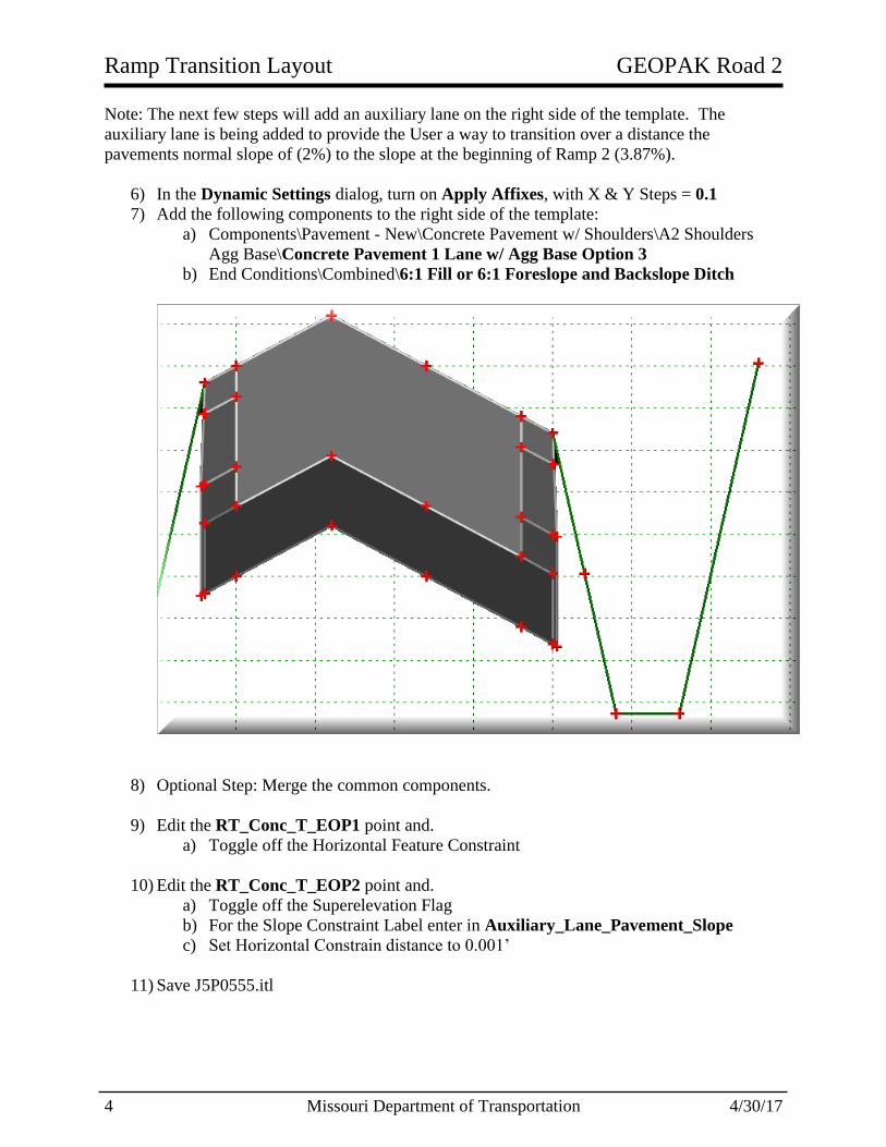
Note: The next few steps will add an auxiliary lane on the right side of the template. The
auxiliary lane is being added to provide the User a way to transition over a distance the
pavements normal slope of (2%) to the slope at the beginning of Ramp 2 (3.87%).
6) In the Dynamic Settings dialog, turn on Apply Affixes, with X & Y Steps = 0.1
7) Add the following components to the right side of the template:
a) Components\Pavement - New\Concrete Pavement w/ Shoulders\A2 Shoulders
Agg Base\Concrete Pavement 1 Lane w/ Agg Base Option 3
b) End Conditions\Combined\6:1 Fill or 6:1 Foreslope and Backslope Ditch
8) Optional Step: Merge the common components.
9) Edit the RT_Conc_T_EOP1 point and.
a) Toggle off the Horizontal Feature Constraint
10) Edit the RT_Conc_T_EOP2 point and.
a) Toggle off the Superelevation Flag
b) For the Slope Constraint Label enter in Auxiliary_Lane_Pavement_Slope
c) Set Horizontal Constrain distance to 0.001’
11) Save J5P0555.itl

GEOPAK Road 2 Ramp Transition Layout
4/30/17 Missouri Department of Transportation 5
Create Route 50 Corridor
12) Create J5P0555_Corridors.dgn using the i_project_2d_PowerGEOPAK.dgn as the
seed file.
a) Reference in J5P0555_Terrain_Existing.dgn
b) Reference in J5P0555_Plan.dgn
c) Reference in J5P0555_Civil_Geometry.dgn
d) Set Annotation Scale to 50
e) Activate Existing Ground Terrain.
f) Select the “Create Corridor” tool.
g) Select the Route50 baseline (use the active profile) and name the corridor “Route50”
h) Apply Roadway template
o J5P0555\Route 50\Concrete Pavement 4 Lane Divided w/ Agg Base
Option 3
o From Station 445+30.94 R1 to Sta. 460+00 R1
o Drop Interval of 5ft.
Note if the drop interval is too large the corridor might not see the
Corridor Reference Elements
i) Select the “F6” key to open 3D view of model.
j) In 3D view adjust brightness up.
13) Make active the J5P0555_Corridors.dgn default Plan View.
a) Turn off the display of the Corridors 3D file.
14) In the Route 50 Corridor add the four individual EOP_New lines from the
J5P0555_Plan.dgn file as corridor references.

Ramp Transition Layout GEOPAK Road 2
6 Missouri Department of Transportation 4/30/17
15) Add the following two Key Stations to the Route 50 Corridor.
a) 451+40.67 R1 (Just past beginning of Ramp 2)
b) 453+55.67 R1 (Just before location of Shoulder Gore nose)
Note: Use the Corridor Object Tool to verify the Key Stations were placed at the
correct location.
16) The shoulder width in the Ramp area is going to be narrower than the mainline. In the
Route 50 Corridor add the Complex EOS_New_Asphalt line from the
J5P0555_Plan.dgn file as Corridor References.
Notes:
The EOS_New_Asphalt plan elements were complexed together using
the Civil Geometry - Horizontal - Complex By Elements Tool.
The shoulder is going to vary in width in certain areas of the project. The
plan shoulder element (EOS_New_Asphalt) will control the width in
these areas
17) Add the following Key Stations to the Route 50 Corridor.
a) 453+88.86 R1 (Just before location of Median Gore nose)
Notes:
If a template drop does not cross an individual corridor reference element,
the Corridor will not draw to that corridor reference element.
Use the Corridor Object Tool to verify the Key Stations were placed at
the correct location.

GEOPAK Road 2 Ramp Transition Layout
4/30/17 Missouri Department of Transportation 7
Calculation of Ramp 2 Vertical Complex Element (Profile)
18) Create J5P0555_Superelevation.dgn using the i_project_2d_PowerGEOPAK.dgn as
the seed file.
a) Reference in J5P0555_Civil_Geometry.dgn
b) Reference in J5P0555_Plan.dgn
c) Review the undivided non-spiraled Superelevation runoff diagram below.
19) Select Create Superelevation Section
20) Select Create Superelevation Lanes
Name: Ramp2
Alignment: Ramp2
Start Station: Beginning of Alignment
Stop Station: End of Alignment
Minimum Transition Length 0.00’
Note: If two Superelevation Sections are created, delete
second Section and then extend the First section to the
end of the Ramp 2 alignment.
Lane Name: Ramp2
Type: Primary
Side of Centerline: Left
Inside Edge Offset: 0.00’
Outside Edge Offset: 12.00’
Normal Cross Slope: 2.00%
Ramp Transition Layout GEOPAK Road 2
8 Missouri Department of Transportation 4/30/17
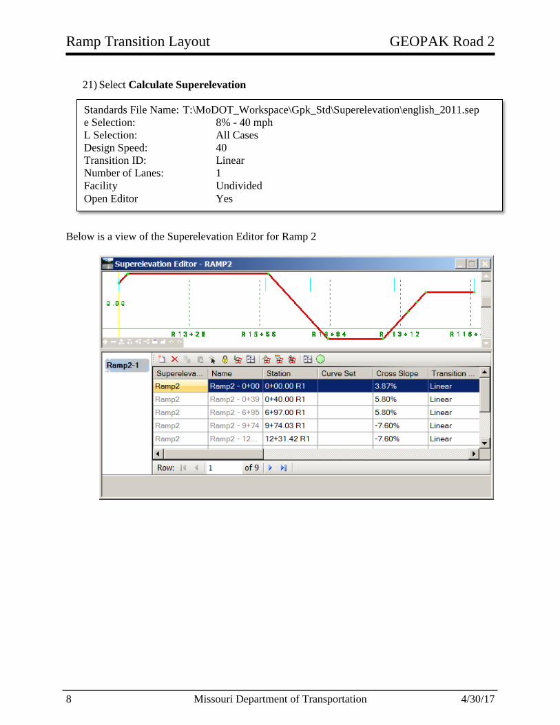
21) Select Calculate Superelevation
Below is a view of the Superelevation Editor for Ramp 2
Standards File Name: T:\MoDOT_Workspace\Gpk_Std\Superelevation\english_2011.sep
e Selection: 8% - 40 mph
L Selection: All Cases
Design Speed: 40
Transition ID: Linear
Number of Lanes: 1
Facility Undivided
Open Editor Yes

GEOPAK Road 2 Ramp Transition Layout
4/30/17 Missouri Department of Transportation 9
22) Next calculate the transition distance of the Mainline Pavement in the transition area
before the PC location of the Ramp2 Curve.
x = (120)(2%)/(8%) = 30’
Distance from C-C section to PC = L - (L/3) - x = (120’) - (120’/3) - 30’ = 50’
Note: This is the distance the Auxiliary Lane will have to transition from 2% (Mainline
Slope) to a 3.87% (Ramp 2 Slope) at the PC location of the Ramp
23) Open the J5P0555_Corridors.dgn.
24) For the next step select the Corridor Views > Open Cross Section Model and verify the
Route 50 Mainline Ramp Pavement is transitioning downward. Use the Place
Temporary Dimension Line to verify the slopes of the mainline pavement.
25) Apply the following Parametric Constraint.
a) Route50 Station at Ramp2 start = Sta. 451+40.67
b) Transition Start Station = Sta. 451+40.67 - 50’ = Sta. 450+90.67
Start: 450+90.67 R1
Stop: 451+40.67 R1
Constraint Label: Auxiliary_Lane_Pavement_Slope
Start Value: -2.00%
Stop Value: -3.87%

Ramp Transition Layout GEOPAK Road 2
10 Missouri Department of Transportation 4/30/17
Create templates for Ramp 2 Corridor
26) Create template for Ramp2 Corridor
a) In the Corridor Modeling Task select the Create Template icon
b) Open the J5P0555.itl
c) Navigate to the J5P0555 and Create a new folder called Ramp2
d) Right click on Ramp2 folder and select New > Template
e) Name the Template Ramp2
f) In the Dynamic Settings dialog, turn on Apply Affixes, with X & Y Steps = 0.1
g) Use the following Components and End Conditions to create the Ramp2 Template:
Template Components:
Left Side
Concrete Pavement 1 Lane w/ Agg Base Option 3
Right Side
A2 Shoulder Asphalt Option 3 w/ Agg Base
Template End Conditions:
Left Side
Fill Slope (6:1)
Right Side
6:1 Fill or 6:1 Forslope and Backslope Ditch
*Notes
a) Concrete Pavement 1 Lane w/ Agg Base Option 3 is located in the following location: Components\Pavement - New\Concrete Pavement w/ Shoulders\A2 Shoulders Agg Base\
b) A2 Shoulder Asphalt Option 3 w/ Agg Base is located in the following location:
Components\Shoulders\Asphalt Adjacent to Concrete Pavt w/o Curb\
c) 6:1 Fill or 6:1 Forslope and Backslope Ditch is located in the following location:
End Conditions\Combined\
d) Adjust pavement slope to be 2% going up from baseline.
e) If not already done so, adjust the shoulders to follow the pavement slope using a Vector
Offset constraint.
f) Check Priorities on End Conditions using the “TEST” button
Template Origin

GEOPAK Road 2 Ramp Transition Layout
4/30/17 Missouri Department of Transportation 11
Next we will need to create another Ramp2 template for the area where the ramp and
mainline butt up to each other.
27) Copy and paste the “Ramp2” Template located in the Ramp2 folder.
28) Name new template “Ramp2 - No LT Shoulder”.
29) Use the Delete Components option and remove the left outside Shoulder & Sub layers,
and End Conditions. Do not delete Aggregate Base (See picture below).
30) Delete two Aggregate Base points (See arrows below)
31) Save Template Library
Ramp Transition Layout GEOPAK Road 2
12 Missouri Department of Transportation 4/30/17
Create Ramp 2 Profile
32) Open the J5P0555_Superelevation.dgn file and review superelevation sections.
a) Verify slope at PC location is 3.87%
b) Verify slope at Max Super is 5.80%
33) Open the J5P0555_Civil_Geometry.dgn file.
a) Reference in the J5P0555_Corridors.dgn file.
34) Open the Profile Model for the Ramp2 corridor.
35) From the Route50 edge of pavement, project the superelevation slope down to the
Ramp2 baseline. Use the Civil Tools - Vertical Geometry - Profile by Variable Slope
from Element.
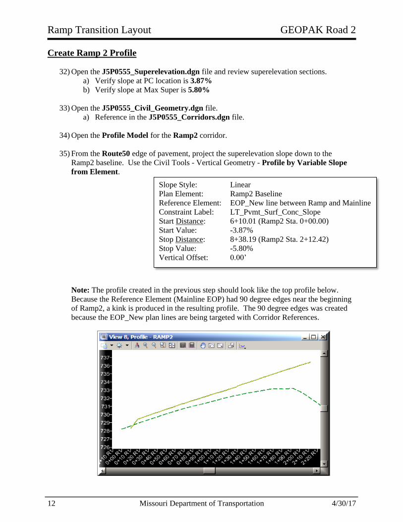
Note: The profile created in the previous step should look like the top profile below.
Because the Reference Element (Mainline EOP) had 90 degree edges near the beginning
of Ramp2, a kink is produced in the resulting profile. The 90 degree edges was created
because the EOP_New plan lines are being targeted with Corridor References.
Slope Style: Linear
Plan Element: Ramp2 Baseline
Reference Element: EOP_New line between Ramp and Mainline
Constraint Label: LT_Pvmt_Surf_Conc_Slope
Start Distance: 6+10.01 (Ramp2 Sta. 0+00.00)
Start Value: -3.87%
Stop Distance: 8+38.19 (Ramp2 Sta. 2+12.42)
Stop Value: -5.80%
Vertical Offset: 0.00’

GEOPAK Road 2 Ramp Transition Layout
4/30/17 Missouri Department of Transportation 13
36) To create a profile without a kink, remove the EOP_New Corridor Reference nearest the
PC of the Curve.
a) Open the J5P0555_Corridors.dgn file
b) From the Corridor heads up tools, select “Remove Corridor Reference”
37) Open the J5P0555_Civil_Geometry.dgn file.
38) Open the Profile Model for the Ramp2 corridor.
39) From the Route50 edge of pavement, project the superelevation slope down to the
Ramp2 baseline. Use the Civil Tools - Vertical Geometry - Profile by Variable Slope
from Element.
a) Note if you add EOP_New Corridor Reference back in the kink will show back
up. The profile is dynamically linked to the EOP profile.
40) Open the Route50 Profile model and verify the profile grade at Sta. 451+40.61 is 4.00%
41) Reopen The Ramp2 Profile model.
42) Using the Vertical Geometry Profile Line Between Points place a 4% slope before the
Projected Ramp2 profile.
43) Using the Vertical Geometry Parabola from Element place a vertical curve from the
start of the projected profile to the end. After starting the tool, select the 4% profile line
as the Reference Profile. After placing the start point, define the endpoint of the vertical
curve by Accu-Snapping to the endpoint of the Projected Profile. When asked to Trim,
select the “None” option.
Note: Use Civil AccuDraw to help start the profile at Sta. 0+00.00
44) The last VPI for the Ramp2 profile will be where the ramp chain crosses the Bighorn
crossroad gutter line. This point is offset 18.5’ from the crossroad centerline. The
elevation of the crossroad at this point and corresponding ramp station has already been
determined below. Based on this, the last VPI at the end of the profile should use the
following VPI station and elevation.
Slope Style: Linear
Plan Element: Ramp2 Baseline
Reference Element: EOP_New line between Ramp and Mainline
Constraint Label: LT_Pvmt_Surf_Conc_Slope
Start Distance: 6+11.43 (Ramp2 Sta. 0+00.00)
Start Value: -3.87%
Stop Distance: 8+27.60 (Ramp2 Sta. 2+12.42)
Stop Value: -5.80%
Vertical Offset: 0.00’
Station Elevation
16+36.81 763.92

Ramp Transition Layout GEOPAK Road 2
14 Missouri Department of Transportation 4/30/17
45) Using the Vertical Geometry Tangent Profile Line to Element select the previously
place profile line and using AccuDraw place the endpoint at Sta. 16+36.81 at an
Elevation of 763.92. When asked to Trim, select the “Back” option.
46) Delete the 4% Profile line located before the PC Point and the Projected Profile.
47) Join the two profile elements using the Vertical Geometry Profile Complex By
Elements, naming the profile Ramp2PR
48) Set the Ramp2PR profile as active.
49) Run the Vertical Alignment Report on the Ramp2PR.
GEOPAK Road 2 Ramp Transition Layout
4/30/17 Missouri Department of Transportation 15
50) Open the J5P0555_Corridors.dgn file.
51) Reapply the EOP_New element located just before the beginning of Ramp2 as a
Corridor Reference for the Route50 corridor.
Create Ramp2PR Corridor
52) Select the “Create Corridor” tool.
53) Select the Ramp2 baseline and name the corridor “Ramp2”
54) Apply Roadway template
a) J5P0555\Ramp2\Ramp2 - No LT Shoulder b) From Station 0+00.00 R1 to Sta. 2+45.18 R1
c) Drop Interval of 1ft.
55) From the Route 50 Corridor clip out the Ramp2 Corridor.
56) Apply Roadway template
a) J5P0555\Ramp2\Ramp2 b) From Station 2+45.19 R1 to Sta. 15+00 R1
c) Drop Interval of 10ft.
57) If needed select the “F6” key to open 3D view of model.
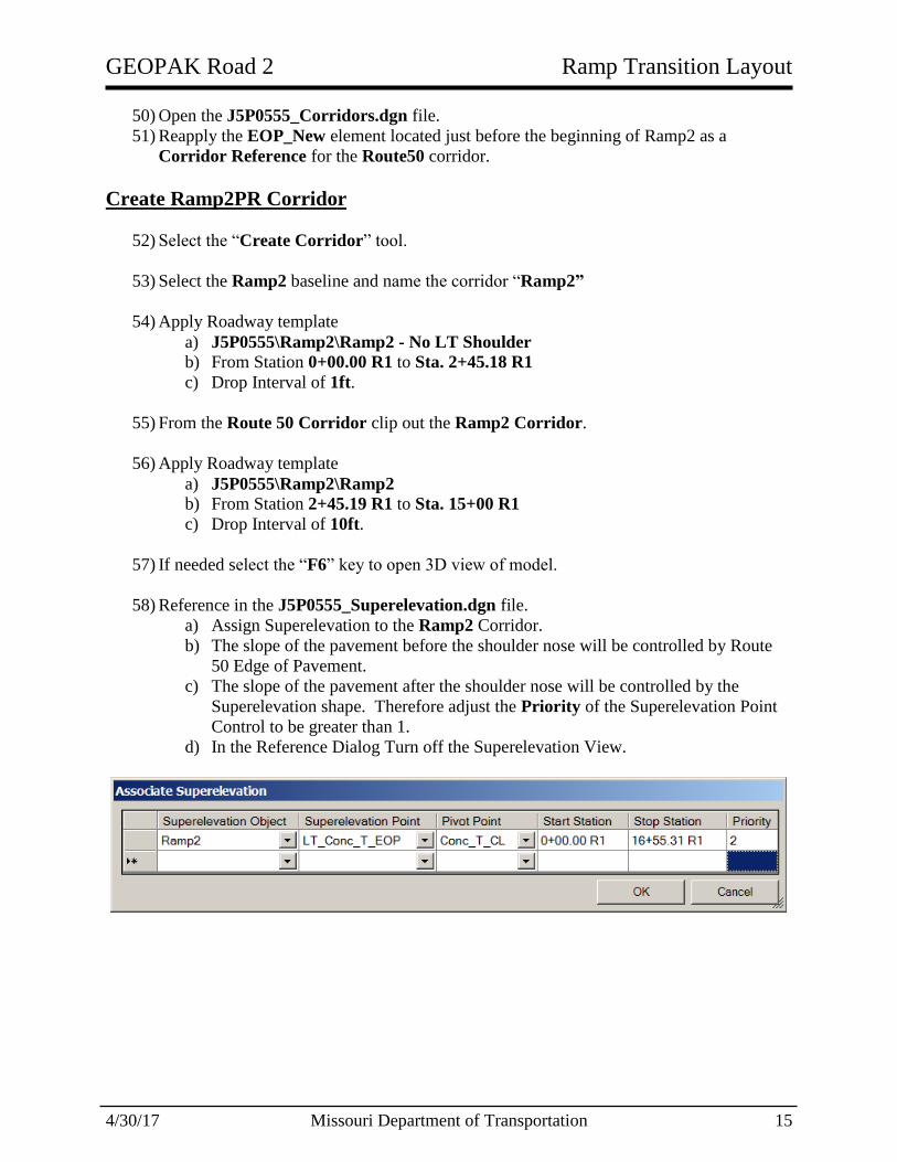
58) Reference in the J5P0555_Superelevation.dgn file.
a) Assign Superelevation to the Ramp2 Corridor.
b) The slope of the pavement before the shoulder nose will be controlled by Route
50 Edge of Pavement.
c) The slope of the pavement after the shoulder nose will be controlled by the
Superelevation shape. Therefore adjust the Priority of the Superelevation Point
Control to be greater than 1.
d) In the Reference Dialog Turn off the Superelevation View.

Ramp Transition Layout GEOPAK Road 2
16 Missouri Department of Transportation 4/30/17
59) To make the Ramp2 pavement draw up to the EOP of the mainline set the following
Point Control:
60) Clip the Ramp2 Corridor from the Route50 Corridor.
61) To make the Ramp2 pavement draw up to the EOS of the mainline (in the area of the
shoulder median), set the following Point Control:
Start Station: 0+00
Stop Station: 2+12.42 (just shy of the shoulder nose)
Description: Draw to Mainline EOP
Mode: Both
Control Type: Corridor Feature
Point: LT_Conc_T_EOP
Corridor: Route50
Reference Feature: RT_Conc_T_EOP2
Priority: 1
Horz. & Vert. Offset: 0
Start Station: 2+12.44
Stop Station: 2+12.44
Description: Draw to Mainline EOS
Mode: Both
Control Type: Corridor Feature
Point: LT_Conc_T_EOP
Corridor: Route50
Reference Feature: RT_AsphSurf_T_O_EOS1
Priority: 1
Horz. & Vert. Offset: 0
GEOPAK Road 2 Ramp Transition Layout
4/30/17 Missouri Department of Transportation 17
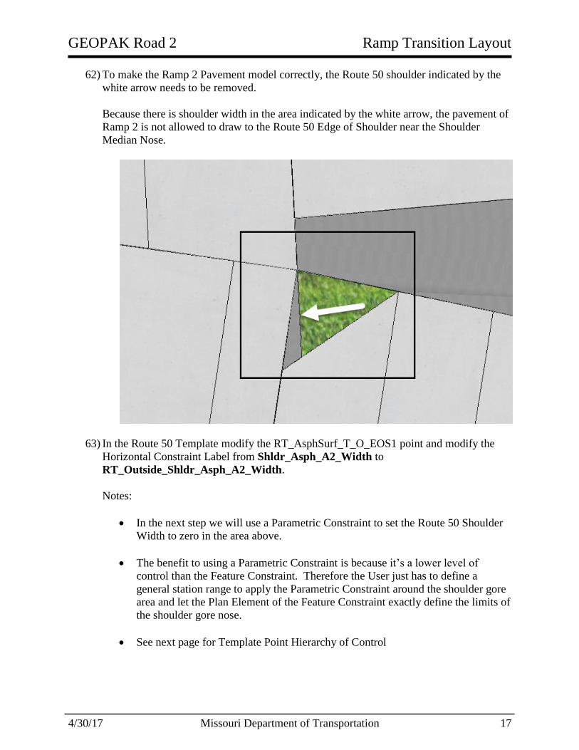
62) To make the Ramp 2 Pavement model correctly, the Route 50 shoulder indicated by the
white arrow needs to be removed.
Because there is shoulder width in the area indicated by the white arrow, the pavement of
Ramp 2 is not allowed to draw to the Route 50 Edge of Shoulder near the Shoulder
Median Nose.
63) In the Route 50 Template modify the RT_AsphSurf_T_O_EOS1 point and modify the
Horizontal Constraint Label from Shldr_Asph_A2_Width to
RT_Outside_Shldr_Asph_A2_Width.
Notes:
In the next step we will use a Parametric Constraint to set the Route 50 Shoulder
Width to zero in the area above.
The benefit to using a Parametric Constraint is because it’s a lower level of
control than the Feature Constraint. Therefore the User just has to define a
general station range to apply the Parametric Constraint around the shoulder gore
area and let the Plan Element of the Feature Constraint exactly define the limits of
the shoulder gore nose.
See next page for Template Point Hierarchy of Control
Ramp Transition Layout GEOPAK Road 2
18 Missouri Department of Transportation 4/30/17
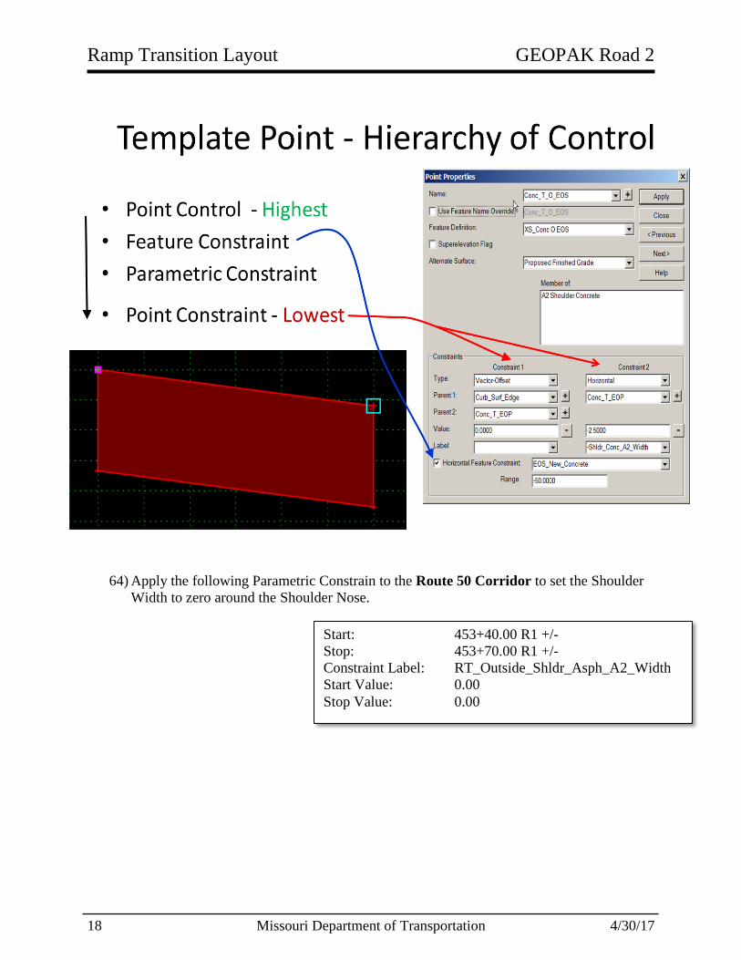
64) Apply the following Parametric Constrain to the Route 50 Corridor to set the Shoulder
Width to zero around the Shoulder Nose.
Start: 453+40.00 R1 +/-
Stop: 453+70.00 R1 +/-
Constraint Label: RT_Outside_Shldr_Asph_A2_Width
Start Value: 0.00
Stop Value: 0.00

GEOPAK Road 2 Ramp Transition Layout
4/30/17 Missouri Department of Transportation 19
65) Add the EOP_New line that transitions from an 18’ offset to a 20’ offset as corridor
references in the Ramp2 Corridor. The EOP line is near the grass gore point (see
below).
66) Within the Ramp 2 Corridor, Target Alias the Route 50 Corridor.
67) The gap in the grass gore area is being caused by the Ramp 2 Pavement and Aggregate
components. Those components are clipping out the components in the Route 50
Corridor.
Ramp Transition Layout GEOPAK Road 2
20 Missouri Department of Transportation 4/30/17
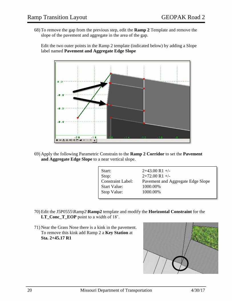
68) To remove the gap from the previous step, edit the Ramp 2 Template and remove the
slope of the pavement and aggregate in the area of the gap.
Edit the two outer points in the Ramp 2 template (indicated below) by adding a Slope
label named Pavement and Aggregate Edge Slope
69) Apply the following Parametric Constrain to the Ramp 2 Corridor to set the Pavement
and Aggregate Edge Slope to a near vertical slope.
70) Edit the J5P0555\Ramp2\Ramp2 template and modify the Horizontal Constraint for the
LT_Conc_T_EOP point to a width of 18’.
71) Near the Grass Nose there is a kink in the pavement.
To remove this kink add Ramp 2 a Key Station at
Sta. 2+45.17 R1
Start: 2+43.00 R1 +/-
Stop: 2+72.00 R1 +/-
Constraint Label: Pavement and Aggregate Edge Slope
Start Value: 1000.00%
Stop Value: 1000.00%

GEOPAK Road 2 Ramp Transition Layout
4/30/17 Missouri Department of Transportation 21
Create Special Ditch - Drawing the Ditch Foreslope to a Alignment and
Profile
72) In the J5P0555_Civil_Geometry.dgn create following Ditch Alignment and Profile.
a) Use the Horizontal Geometry Tool Complex By PI to place a line with a Feature
Definition of Design\Design Standards\Drainage\Special_Ditch_Right at the
following locations:
Note: use Civil AccuDraw to place
line accurately along the Route50 and
Ramp 2 Alignment.
Use a radius of 200’
Name the ditch alignment: Special
Ditch
b) Open the Special Ditch Profile View. Use the Vertical Profile Line Between
Points Tool to place a profile with the following VPIs:
Note: use Civil AccuDraw to place profile
accurately along the Special Ditch Alignment.
Name this profile: Special Ditch Proposed
Make the profile Activate
73) In the J5P0555_Corridors.dgn file create following Point Controls to have the ditch
bottom foreslope point draw the special ditch.
a) Route 50 Corridor:
Station Offset Chain
445+30.94 120 Route50
448+70.00 120 Route50
449+50.00 150 Route50
1+00 90 Ramp2
5+00 70 Ramp2
10+00 100 Ramp2
Station Elevation
0+00 688.00
15+75.75 704.00
Start Station: Beginning of Alignment
Stop Station: 451+40.67 R1
Control Description: Draw to Special Ditch Alignment
Mode: Both
Control Type: Linear Geometry
Point: RT_Dtch_Frslp_1_B
Plan Element: Special Ditch
Profile Element: Special Ditch Proposed
Secondary Alignment: Yes
Priority: 1
Horz. & Vert. Offset: 0

Ramp Transition Layout GEOPAK Road 2
22 Missouri Department of Transportation 4/30/17
Step 72) Continued:
b) Ramp 2 Corridor:
74) Open the Route 50 Dynamic Cross Section Model View. Place Temporary Dimension
Lines along the Ditch Foreslope. You should notice that the slope is changing from
section to section because the bottom ditch foreslope point has to hit the Special Ditch
Alignment and Profile.
In the next few steps, the parameters will change such that the slope remains constant and
the ditch will follow the ditch elevation.
Control Description: Draw to Special Ditch Alignment
Start Station: Beginning of Alignment
Stop Station: 16+55.31 R1
Mode: Both
Control Type: Linear Geometry
Point: RT_Dtch_Frslp_1_B
Plan Element: Special Ditch
Profile Element: Special Ditch Proposed
Secondary Alignment: Yes
Priority: 1
Horz. & Vert. Offset: 0

GEOPAK Road 2 Ramp Transition Layout
4/30/17 Missouri Department of Transportation 23
Create Special Ditch – Drawing to a Ditch Profile while holding constant the
Ditch slope
75) In order to draw to Ditch profile some points in the Ditch Component need to be
redefined in all three template drops on the south side of the project.
a) Edit the RT_Dtch_Frslp_1_B point.
Adjust the slope to -25.00%
Change the Horizontal Constraint to a Vertical Constraint.
b) Edit the RT_Dtch_Bkslp_1_B point.
Adjust the slope to 25.00%
76) In the Route 50 and Ramp 2 Corridors, edit the Special Ditch Point Controls by
changing the Point Control Mode from Both to Vertical.