Embed Size (px)
Citation preview
1
GEOMETRICAL DESIGN OF BERM BREAKWATERS
Jentsje van der Meer1 and Sigurdur Sigurdarson2
Cooperation between the authors has led to a number of papers on main design parameters for berm breakwaters. These were the recession at the berm of a berm breakwater for assumed design conditions and main armour rock class, as well as the functional behaviour (wave overtopping and reflection), where often allowable overtopping rates determine the crest height of the structure. They also gave guidance on how some geometrical aspects may influence the recession. For example a flatter down slope, a higher berm level and a higher toe level all decrease the expected recession. Expected recession and expected wave overtopping (or requested crest height) are only two parameters that influence the design of the cross-section of a berm breakwater. In order to design a complete cross-section many more design decisions have to be taken into account. In the past clear design rules on determining a full cross-section of a berm breakwater were lacking and design was based on the experience with earlier designs (in Iceland and Norway) or simply on good reasoning and then testing the structure in a hydraulic laboratory. This paper gives guidance on all relevant geometrical design parameters.
Keywords: berm breakwater; geometrical design; berm recession; wave overtopping; berm level
INTRODUCTION The cooperation between the authors, both in the scientific as well as the practical field, has led to
a number of papers on design parameters for berm breakwaters, where Sigurdarson and Van der Meer (2013) can be seen as a summary of new design guidance. That paper describes after a thorough analysis what the recession at the berm of a berm breakwater would be for assumed design conditions and main armour rock class. It also gives guidance on how some geometrical aspects may influence the recession. For example a flatter down slope, a higher berm level or a longer berm and a higher toe level all decrease the expected recession. Another part of the mentioned paper describes the functional behaviour (wave overtopping and reflection) as often allowable overtopping rates determine the crest height of the structure.
Sigurdarson and Van der Meer (2013) in principal give expected recession and expected wave overtopping (or requested crest height), but these are only two parameters that influence the design of the cross-section of a berm breakwater. In order to design a complete cross-section many more design decisions have to be taken into account. In the past clear design rules on determining a full cross-section were lacking and design was based on the experience with earlier designs (in Iceland and Norway) or simply on good reasoning and then testing the structure in a hydraulic laboratory.
The geometrical design guidance of berm breakwaters given in this paper is based on many years design experience where the design has developed from one project over to the next with attempts to improve the design in each project. Focus has often been on a design which limits the volumes of rock, but at the same time increasing stability (or decreasing recession). The implicit design experience has been made more explicit in this paper, leading to design guidance on determining the full geometrical cross-section. It is guidance on main principles and every designer has the freedom to deviate from the given principals.
The development of mass armoured berm breakwaters, often fully reshaping as in the eighties of the last century, to more stable Icelandic type berm breakwaters, caused a larger need for guidance on the design of the cross-section. Therefore the geometrical design of the mass armoured and the Icelandic type berm breakwater are treated in this paper.
CLASSIFICATION OF BERM BREAKWATERS A new classification of berm breakwaters was presented in Sigurdarson and Van der Meer (2012)
which is a modification and update of the PIANC (2003) classification. Firstly the classification distinguishes between different types of berm breakwaters. Mass armoured berm breakwaters, MA, with a homogeneous berm of mainly one stone class, often wide graded, and Icelandic-type berm breakwaters, IC, constructed with more rock classes, each class rather narrowly graded, see Figure 1.
1 Van der Meer Consulting BV, P.O. Box 11, 8490 AA, Akkrum, The Netherlands and professor at UNESCO-IHE,
Delft, The Netherlands; [email protected] 2 IceBreak Consulting Engineers ehf, Reykjavik, Iceland; [email protected]
COASTAL ENGINEERING 2014 2
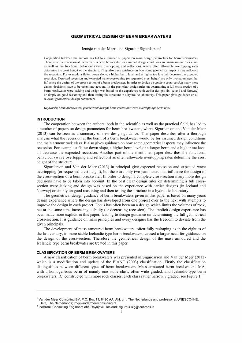
Figure 1. Mass armoured berm breakwater to the left, MA, and Icelandic-type berm breakwater to the right; IC. On both cross sections the expected reshaping is shown with a dotted line.
The behaviour of both types will be very different if relatively small rock is used for the mass armoured berm breakwater and very large rock for the Icelandic-type berm breakwater. The first one may fully reshape, where the second one may show static stability without significant reshaping. But it is also possible that similar rock classes are used and where both types may show partly reshaping. The type of breakwater does not always give similar behaviour and therefore this behaviour, the recession of the berm, is a part of the classification. Both the two types of berm breakwaters and the different structural behaviour lead to a classification with four typical types of berm breakwaters:
Hardly reshaping Icelandic-type berm breakwater HR-IC Partly reshaping Icelandic-type berm breakwater PR-IC Partly reshaping mass armoured berm breakwater PR-MA Fully reshaping berm breakwater (mass armoured) FR-MA
Table 1 shows the classification for berm breakwaters, including indicative values for the stability
number, Hs/ΔDn50, the damage and the recession. These values are given for a 100-years wave condition. For wave conditions with smaller return periods the values will be smaller and consequently, for more severe wave conditions, like overload tests, the values may be larger.
Table 1. Classification of berm breakwaters based on 100-years wave condition.
Abbreviation Hs/∆Dn50 Sd Rec/Dn50 Hardly reshaping Icelandic-type berm breakwater HR-IC 1.7 - 2.0 2 - 8 0.5 - 2 Partly reshaping Icelandic-type berm breakwater PR-IC 2.0 - 2.5 10 - 20 1 - 5 Partly reshaping mass armoured berm breakwater PR-MA 2.0 - 2.5 10 - 20 1 - 5 Reshaping mass armoured berm breakwater FR-MA 2.5 - 3.0 -- 3 - 10
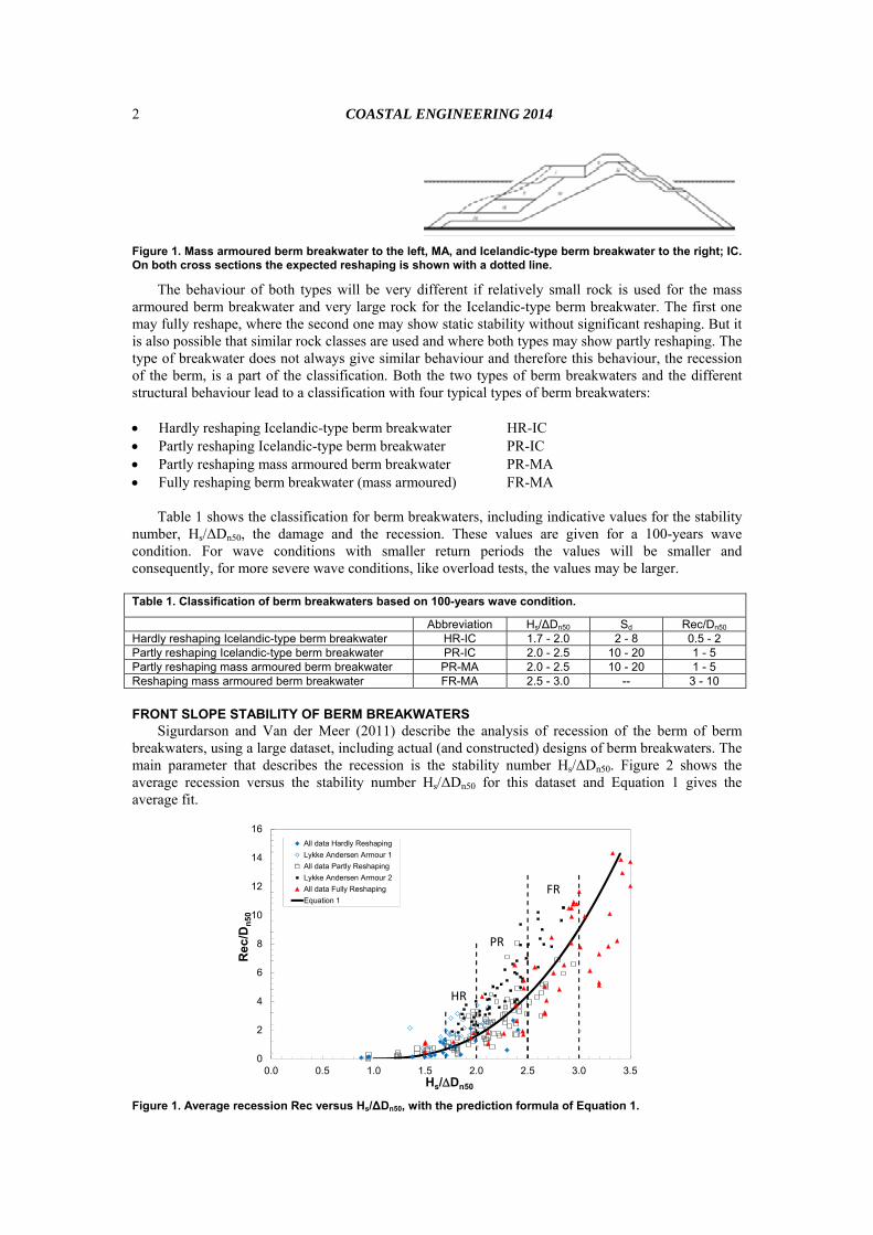
FRONT SLOPE STABILITY OF BERM BREAKWATERS Sigurdarson and Van der Meer (2011) describe the analysis of recession of the berm of berm
breakwaters, using a large dataset, including actual (and constructed) designs of berm breakwaters. The main parameter that describes the recession is the stability number Hs/ΔDn50. Figure 2 shows the average recession versus the stability number Hs/ΔDn50 for this dataset and Equation 1 gives the average fit.
0
2
4
6
8
10
12
14
16
0.0 0.5 1.0 1.5 2.0 2.5 3.0 3.5
Re
c/D
n5
0
Hs/Dn50
All data Hardly Reshaping
Lykke Andersen Armour 1
All data Partly Reshaping
Lykke Andersen Armour 2
All data Fully Reshaping
Equation 1
PR
FR
HR
Figure 1. Average recession Rec versus Hs/∆Dn50, with the prediction formula of Equation 1.
COASTAL ENGINEERING 2014
3
Rec/Dn50 = 1.6 (Hs/ΔDn50 - 1.0)2.5 with: Rec/Dn50 = 0 for Hs/ΔDn50 < 1.0 (1)
The graph shows also the classification of hardly reshaping (HR), partly reshaping (PR) and fully reshaping (FR). The formula shows that for a statically stable Icelandic-type berm breakwater with a design value of Hs/ΔDn50 = 1.5 the expected recession is not more than about half a stone diameter. For Hs/ΔDn50 = 2.0 this may increase to 1.5 to 3 stone diameters, depending on how accurate the rock above swl has been placed. A fully reshaping mass armoured breakwater may have more than 10 stone diameters reshaping.
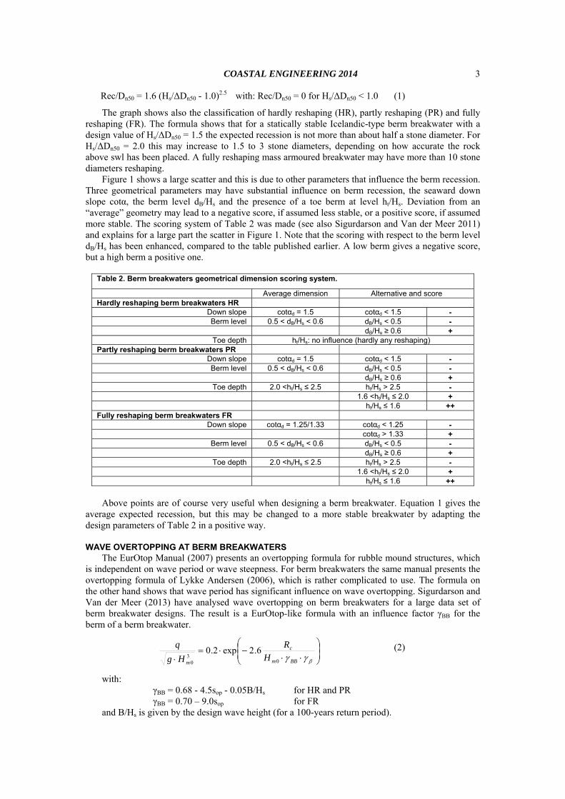
Figure 1 shows a large scatter and this is due to other parameters that influence the berm recession. Three geometrical parameters may have substantial influence on berm recession, the seaward down slope cotα, the berm level dB/Hs and the presence of a toe berm at level ht/Hs. Deviation from an “average” geometry may lead to a negative score, if assumed less stable, or a positive score, if assumed more stable. The scoring system of Table 2 was made (see also Sigurdarson and Van der Meer 2011) and explains for a large part the scatter in Figure 1. Note that the scoring with respect to the berm level dB/Hs has been enhanced, compared to the table published earlier. A low berm gives a negative score, but a high berm a positive one.
Table 2. Berm breakwaters geometrical dimension scoring system.
Average dimension Alternative and score Hardly reshaping berm breakwaters HR
Down slope cotαd = 1.5 cotαd < 1.5 - Berm level 0.5 < dB/Hs < 0.6 dB/Hs < 0.5 -
dB/Hs ≥ 0.6 + Toe depth ht/Hs: no influence (hardly any reshaping)
Partly reshaping berm breakwaters PR Down slope cotαd = 1.5 cotαd < 1.5 - Berm level 0.5 < dB/Hs < 0.6 dB/Hs < 0.5 -
dB/Hs ≥ 0.6 + Toe depth 2.0 <ht/Hs ≤ 2.5 ht/Hs > 2.5 -
1.6 <ht/Hs ≤ 2.0 + ht/Hs ≤ 1.6 ++
Fully reshaping berm breakwaters FR Down slope cotαd = 1.25/1.33 cotαd < 1.25 -
cotαd > 1.33 + Berm level 0.5 < dB/Hs < 0.6 dB/Hs < 0.5 -
dB/Hs ≥ 0.6 + Toe depth 2.0 <ht/Hs ≤ 2.5 ht/Hs > 2.5 -
1.6 <ht/Hs ≤ 2.0 + ht/Hs ≤ 1.6 ++
Above points are of course very useful when designing a berm breakwater. Equation 1 gives the
average expected recession, but this may be changed to a more stable breakwater by adapting the design parameters of Table 2 in a positive way.
WAVE OVERTOPPING AT BERM BREAKWATERS The EurOtop Manual (2007) presents an overtopping formula for rubble mound structures, which
is independent on wave period or wave steepness. For berm breakwaters the same manual presents the overtopping formula of Lykke Andersen (2006), which is rather complicated to use. The formula on the other hand shows that wave period has significant influence on wave overtopping. Sigurdarson and Van der Meer (2013) have analysed wave overtopping on berm breakwaters for a large data set of berm breakwater designs. The result is a EurOtop-like formula with an influence factor γBB for the berm of a berm breakwater.
BBm
c
mH
R
Hg
q
03
0
6.2exp2.0 (2)
with: γBB = 0.68 - 4.5sop - 0.05B/Hs for HR and PR γBB = 0.70 – 9.0sop for FR and B/Hs is given by the design wave height (for a 100-years return period).
COASTAL ENGINEERING 2014 4
The influence factor γBB shows that overtopping at berm breakwaters is indeed influenced by the wave period (or wave steepness) and that for hardly and partly reshaping berm breakwaters the berm width B also plays a role. The latter is not the case for fully reshaping berm breakwaters as the berm will disappear due to the reshaping.
GEOMETRICAL DESIGN OF THE CROSS-SECTION
General description of the cross-section Principle cross-sections of the mass armoured and Icelandic type berm breakwaters were given in
Figure 1. This figure shows the extremes, a fully reshaping berm breakwater with a wide grading of rock on the left side and a hardly reshaping Icelandic type berm breakwater with four classes of large rock. Designs are also possible with three classes of large rock. Mass armoured types are mainly partly and fully reshaping, where the Icelandic type gives only hardly or partly reshaping. This has led to four distinct classes, each with their range of stability numbers, expected damage and/or expected recession, see Table 1.
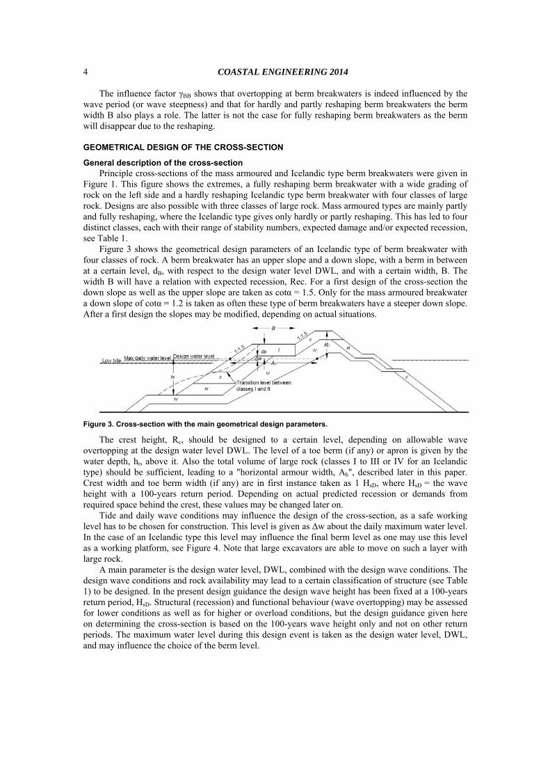
Figure 3 shows the geometrical design parameters of an Icelandic type of berm breakwater with four classes of rock. A berm breakwater has an upper slope and a down slope, with a berm in between at a certain level, dB, with respect to the design water level DWL, and with a certain width, B. The width B will have a relation with expected recession, Rec. For a first design of the cross-section the down slope as well as the upper slope are taken as cotα = 1.5. Only for the mass armoured breakwater a down slope of cotα = 1.2 is taken as often these type of berm breakwaters have a steeper down slope. After a first design the slopes may be modified, depending on actual situations.
Figure 3. Cross-section with the main geometrical design parameters.
The crest height, Rc, should be designed to a certain level, depending on allowable wave overtopping at the design water level DWL. The level of a toe berm (if any) or apron is given by the water depth, ht, above it. Also the total volume of large rock (classes I to III or IV for an Icelandic type) should be sufficient, leading to a "horizontal armour width, Ah", described later in this paper. Crest width and toe berm width (if any) are in first instance taken as 1 HsD, where HsD
= the wave height with a 100-years return period. Depending on actual predicted recession or demands from required space behind the crest, these values may be changed later on.
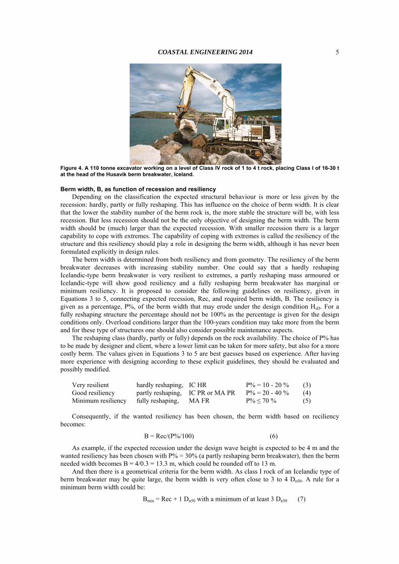
Tide and daily wave conditions may influence the design of the cross-section, as a safe working level has to be chosen for construction. This level is given as Δw about the daily maximum water level. In the case of an Icelandic type this level may influence the final berm level as one may use this level as a working platform, see Figure 4. Note that large excavators are able to move on such a layer with large rock.
A main parameter is the design water level, DWL, combined with the design wave conditions. The design wave conditions and rock availability may lead to a certain classification of structure (see Table 1) to be designed. In the present design guidance the design wave height has been fixed at a 100-years return period, HsD. Structural (recession) and functional behaviour (wave overtopping) may be assessed for lower conditions as well as for higher or overload conditions, but the design guidance given here on determining the cross-section is based on the 100-years wave height only and not on other return periods. The maximum water level during this design event is taken as the design water level, DWL, and may influence the choice of the berm level.
COASTAL ENGINEERING 2014
5
Figure 4. A 110 tonne excavator working on a level of Class IV rock of 1 to 4 t rock, placing Class I of 16-30 t at the head of the Husavik berm breakwater, Iceland.
Berm width, B, as function of recession and resiliency Depending on the classification the expected structural behaviour is more or less given by the
recession: hardly, partly or fully reshaping. This has influence on the choice of berm width. It is clear that the lower the stability number of the berm rock is, the more stable the structure will be, with less recession. But less recession should not be the only objective of designing the berm width. The berm width should be (much) larger than the expected recession. With smaller recession there is a larger capability to cope with extremes. The capability of coping with extremes is called the resiliency of the structure and this resiliency should play a role in designing the berm width, although it has never been formulated explicitly in design rules.
The berm width is determined from both resiliency and from geometry. The resiliency of the berm breakwater decreases with increasing stability number. One could say that a hardly reshaping Icelandic-type berm breakwater is very resilient to extremes, a partly reshaping mass armoured or Icelandic-type will show good resiliency and a fully reshaping berm breakwater has marginal or minimum resiliency. It is proposed to consider the following guidelines on resiliency, given in Equations 3 to 5, connecting expected recession, Rec, and required berm width, B. The resiliency is given as a percentage, P%, of the berm width that may erode under the design condition HsD. For a fully reshaping structure the percentage should not be 100% as the percentage is given for the design conditions only. Overload conditions larger than the 100-years condition may take more from the berm and for these type of structures one should also consider possible maintenance aspects.
The reshaping class (hardly, partly or fully) depends on the rock availability. The choice of P% has to be made by designer and client, where a lower limit can be taken for more safety, but also for a more costly berm. The values given in Equations 3 to 5 are best guesses based on experience. After having more experience with designing according to these explicit guidelines, they should be evaluated and possibly modified.
Very resilient hardly reshaping, IC HR P% = 10 - 20 % (3) Good resiliency partly reshaping, IC PR or MA PR P% = 20 - 40 % (4) Minimum resiliency fully reshaping, MA FR P% ≤ 70 % (5) Consequently, if the wanted resiliency has been chosen, the berm width based on reciliency
becomes:
B = Rec/(P%/100) (6)
As example, if the expected recession under the design wave height is expected to be 4 m and the wanted resiliency has been chosen with P% = 30% (a partly reshaping berm breakwater), then the berm needed width becomes B = 4/0.3 = 13.3 m, which could be rounded off to 13 m.
And then there is a geometrical criteria for the berm width. As class I rock of an Icelandic type of berm breakwater may be quite large, the berm width is very often close to 3 to 4 Dn50. A rule for a minimum berm width could be:
Bmin = Rec + 1 Dn50 with a minimum of at least 3 Dn50 (7)
COASTAL ENGINEERING 2014 6
Crest level, Rc Severe wave overtopping may damage the rear side of a breakwater and if it is not protected well,
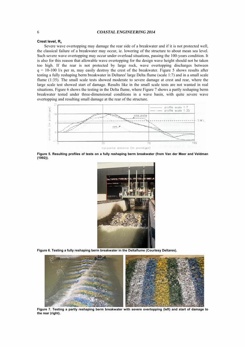
the classical failure of a breakwater may occur, ie. lowering of the structure to about mean sea level. Such severe wave overtopping may occur under overload situations, passing the 100-years condition. It is also for this reason that allowable wave overtopping for the design wave height should not be taken too high. If the rear is not protected by large rock, wave overtopping discharges between q = 10-100 l/s per m, may easily destroy the crest of the breakwater. Figure 5 shows results after testing a fully reshaping berm breakwater in Deltares' large Delta flume (scale 1:7) and in a small scale flume (1:35). The small scale tests showed moderate to severe damage at crest and rear, where the large scale test showed start of damage. Results like in the small scale tests are not wanted in real situations. Figure 6 shows the testing in the Delta flume, where Figure 7 shows a partly reshaping berm breakwater tested under three-dimensional conditions in a wave basin, with quite severe wave overtopping and resulting small damage at the rear of the structure.
Figure 5. Resulting profiles of tests on a fully reshaping berm breakwater (from Van der Meer and Veldman (1992)).
Figure 6. Testing a fully reshaping berm breakwater in the Deltaflume (Courtesy Deltares).
Figure 7. Testing a partly reshaping berm breakwater with severe overtopping (left) and start of damage to the rear (right).
COASTAL ENGINEERING 2014
7
The crest level, depending on the crest freeboard, Rc, can be determined by the new wave overtopping formulae (Equation 2) if allowable overtopping has been established. Besides that a check can be made, based on structures designed and tested in the past. This design data revealed that most berm breakwater structures have a relative freeboard of:
Average relative crest levels in design: Rc/HsD=1.0-1.2 (8)
Equation 8 could be used for comparison and if no allowable overtopping has been given. An easy method to check the stability of the rear side is given by Van der Meer and Veldman
(1992). It only applies to the situation as given in Figure 1, a fully reshaping mass armoured breakwater and with similar rock in the berm and over the crest and rear. The method gives a stability number, including significant wave height, crest freeboard and wave steepness (using the peak period).
Rc/Hs * sop1/3 = A (9)
with A = 0.25 for start of damage; A = 0.21 for moderate damage and A = 0.17 for severe damage. For the design wave height (100-years condition) one should stay below start of damage (say A = 0.25 - 0.30), where for the overload situation between start of damage and moderate damage could be taken as the maximum allowable situation (A = 0.21 - 0.25 in Equation 9). The work of Lykke Andersen (2006) describes rear side stability for other situations with for example very wide berms or crests and partly reshaping of large berms. The crest width and further details of the rear side can be designed as for a conventional structure, see for example the Rock Manual (2007).
Horizontal armour width, Ah An important design parameter in Figure 3 is the "horizontal armour width, Ah". It is the horizontal
distance at design water level from the seaward slope of the armour to the transition of sorted rock class to the core. The good structural behaviour of berm breakwaters is for a large part due to the large capacity of dissipating wave energy in the large berm. A class of sorted rock gives large voids between the stones and this causes the dissipating capacity. For this reason the horizontal width of the armour at design water level should not become too small. It has always been an implicit but important parameter in design and development of the Icelandic type berm breakwater in projects in Iceland and Norway.
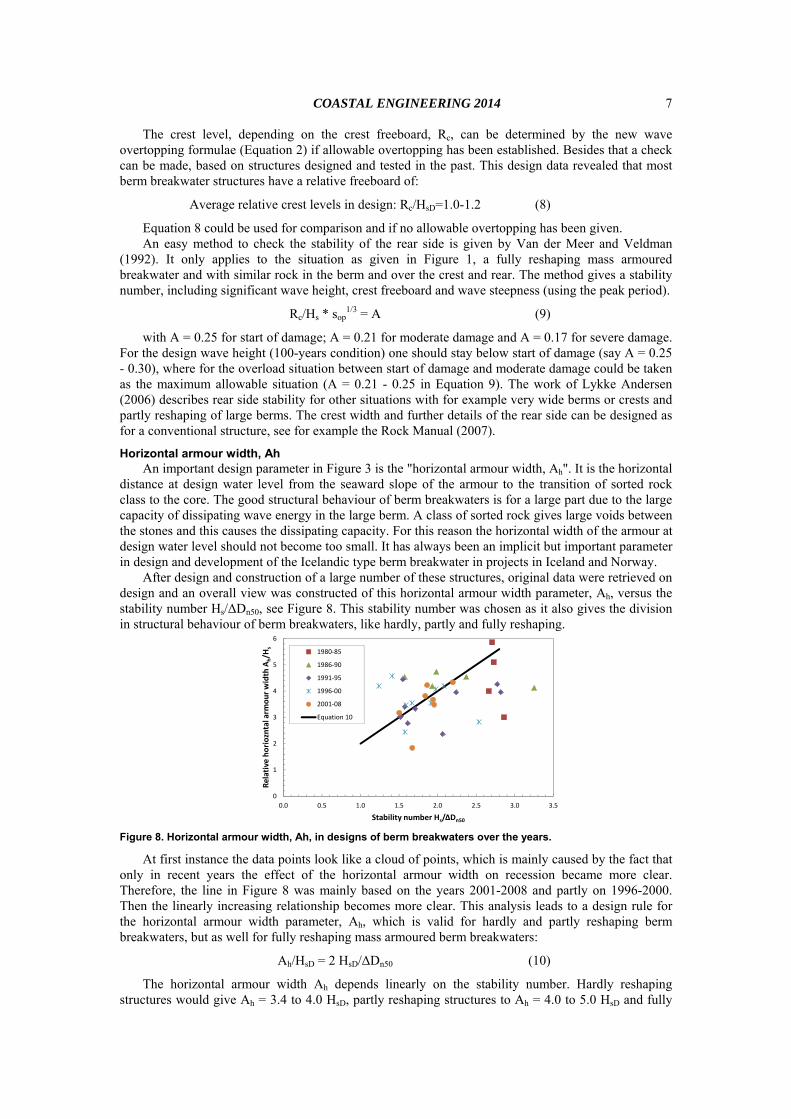
After design and construction of a large number of these structures, original data were retrieved on design and an overall view was constructed of this horizontal armour width parameter, Ah, versus the stability number Hs/ΔDn50, see Figure 8. This stability number was chosen as it also gives the division in structural behaviour of berm breakwaters, like hardly, partly and fully reshaping.
0
1
2
3
4
5
6
0.0 0.5 1.0 1.5 2.0 2.5 3.0 3.5
Relative horiozntal arm
our width A
h/H
s
Stability number Hs/ΔDn50
1980‐85
1986‐90
1991‐95
1996‐00
2001‐08
Equation 10
Figure 8. Horizontal armour width, Ah, in designs of berm breakwaters over the years.
At first instance the data points look like a cloud of points, which is mainly caused by the fact that only in recent years the effect of the horizontal armour width on recession became more clear. Therefore, the line in Figure 8 was mainly based on the years 2001-2008 and partly on 1996-2000. Then the linearly increasing relationship becomes more clear. This analysis leads to a design rule for the horizontal armour width parameter, Ah, which is valid for hardly and partly reshaping berm breakwaters, but as well for fully reshaping mass armoured berm breakwaters:
Ah/HsD = 2 HsD/ΔDn50 (10)
The horizontal armour width Ah depends linearly on the stability number. Hardly reshaping structures would give Ah = 3.4 to 4.0 HsD, partly reshaping structures to Ah = 4.0 to 5.0 HsD and fully
COASTAL ENGINEERING 2014 8
reshaping berm breakwaters to Ah = 5.0 to 6.0 HsD, taking into account the classification given in Table 1.
Rock classes and proposal for new mass armoured berm breakwater The original mass armoured berm breakwater has a large berm with one rock class, which often
has a fairly wide grading, like 1-9 t for example. Figure 1 gives the principle cross-section of a mass armoured breakwater. A mass armoured berm breakwater is expected to reshape and therefore a down slope of 1:1.2 can be chosen, which is often easier to construct, while the upper slope should be taken as 1:1.5. The berm level, dB, is actually free in choice. Sometimes the berm level is just a little above the design water level, sometimes it is much higher. In principal the volume of the berm should remain the same, which leads to a long and low berm, or on the opposite side to a shorter and higher berm, but after reshaping they become more or less similar. One should realise that in construction it is often easier to make a berm higher than longer, as a longer berm needs a longer reach of the excavator. Moreover, a higher berm dissipates more wave energy, which may lead to a little less recession, see also Table 2.
The main differences between mass armoured and Icelandic type berm breakwaters are the design of the berm and expected structural behaviour, ie. expected recession and resiliency. The berm of an Icelandic type berm breakwater is divided in three to four classes of rock, where the original mass armoured berm breakwater has only one class of rock in the berm. The design of an Icelandic type berm breakwater is based on limiting recession by putting the large rock where it is needed, often using very large rock in a small area and making this as stable as possible.
Figures 1 and 3 show the principal cross-section of an Icelandic type berm breakwater. In this case four main armour rock classes I - IV are given, but depending on the wave conditions and utilisation of available rock this could also be reduced to three. The main class is Class I on upper seaward front and on the berm. The principal slopes are 1:1.5 on seaward down and upper slope. In the present case the slope of the core is taken as 1:2 in order to reduce some volume of large rock at lower water depths were they are not needed. But a 1:1.5 slope could also be applied if that would be easier from a construction point view. Then the slope of the core should be rotated around the right point of the horizontal armour width, Ah.
An important geometrical aspect to consider is the division in several rock classes. Class I will be the largest rock class on berm and upper seaward slope. If this one has been determined, consecutive smaller classes have to be chosen. This section gives some principles and examples.
There is a significant difference if standard gradings are used (Rock Manual 2007) or if a dedicated quarry has been or can be opened. In the case of rock supply from existing quarries with standard gradings, the design conditions together with the standard gradings give the stability number that can be achieved and the type of Icelandic berm breakwater (hardly or partly reshaping). The standard heavy gradings are given in the Rock Manual (2007) as: 10-15 t; 6-10 t; 3-6 t; 1-3 t; and 0.3-1 t. Depending on the maximum grading to be used (= Class I), one can use the lighter gradings for the other classes.
In the case of a dedicated quarry there are various aspects to consider to come to an optimised division in rock classes. The in-situ block size distribution may lead to a quarry yield prediction. The maximum size, Mmax, of this prediction plays an important role in choosing the class I rock. But subsequent gradings depend on the required volume of that grading for the breakwater as a whole and the percentage that is predicted from the quarry yield. It may then be an iterative process to come to rock gradings that match the predicted quarry yield as close as possible. Table 3 gives a few examples of possible gradings. In Table 3 the maximum grading has been given as rock exceeding at least 15 t. It is possible that such a large grading cannot be achieved, or that it is simply not required for relatively low design wave heights. In such a case Class II can be promoted to Class I level.
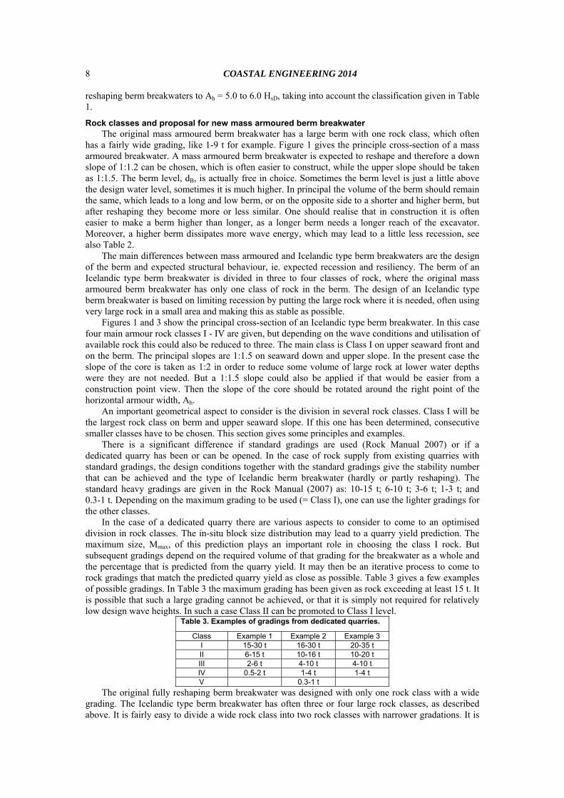
Table 3. Examples of gradings from dedicated quarries.
Class Example 1 Example 2 Example 3 I 15-30 t 16-30 t 20-35 t II 6-15 t 10-16 t 10-20 t III 2-6 t 4-10 t 4-10 t IV 0.5-2 t 1-4 t 1-4 t V 0.3-1 t
The original fully reshaping berm breakwater was designed with only one rock class with a wide grading. The Icelandic type berm breakwater has often three or four large rock classes, as described above. It is fairly easy to divide a wide rock class into two rock classes with narrower gradations. It is
COASTAL ENGINEERING 2014
9
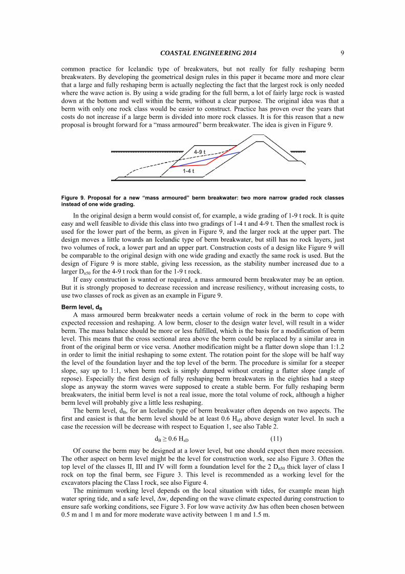
common practice for Icelandic type of breakwaters, but not really for fully reshaping berm breakwaters. By developing the geometrical design rules in this paper it became more and more clear that a large and fully reshaping berm is actually neglecting the fact that the largest rock is only needed where the wave action is. By using a wide grading for the full berm, a lot of fairly large rock is wasted down at the bottom and well within the berm, without a clear purpose. The original idea was that a berm with only one rock class would be easier to construct. Practice has proven over the years that costs do not increase if a large berm is divided into more rock classes. It is for this reason that a new proposal is brought forward for a “mass armoured” berm breakwater. The idea is given in Figure 9.
4-9 t
1-4 t
Figure 9. Proposal for a new “mass armoured” berm breakwater: two more narrow graded rock classes instead of one wide grading.
In the original design a berm would consist of, for example, a wide grading of 1-9 t rock. It is quite easy and well feasible to divide this class into two gradings of 1-4 t and 4-9 t. Then the smallest rock is used for the lower part of the berm, as given in Figure 9, and the larger rock at the upper part. The design moves a little towards an Icelandic type of berm breakwater, but still has no rock layers, just two volumes of rock, a lower part and an upper part. Construction costs of a design like Figure 9 will be comparable to the original design with one wide grading and exactly the same rock is used. But the design of Figure 9 is more stable, giving less recession, as the stability number increased due to a larger Dn50 for the 4-9 t rock than for the 1-9 t rock.
If easy construction is wanted or required, a mass armoured berm breakwater may be an option. But it is strongly proposed to decrease recession and increase resiliency, without increasing costs, to use two classes of rock as given as an example in Figure 9.
Berm level, dB A mass armoured berm breakwater needs a certain volume of rock in the berm to cope with
expected recession and reshaping. A low berm, closer to the design water level, will result in a wider berm. The mass balance should be more or less fulfilled, which is the basis for a modification of berm level. This means that the cross sectional area above the berm could be replaced by a similar area in front of the original berm or vice versa. Another modification might be a flatter down slope than 1:1.2 in order to limit the initial reshaping to some extent. The rotation point for the slope will be half way the level of the foundation layer and the top level of the berm. The procedure is similar for a steeper slope, say up to 1:1, when berm rock is simply dumped without creating a flatter slope (angle of repose). Especially the first design of fully reshaping berm breakwaters in the eighties had a steep slope as anyway the storm waves were supposed to create a stable berm. For fully reshaping berm breakwaters, the initial berm level is not a real issue, more the total volume of rock, although a higher berm level will probably give a little less reshaping.
The berm level, dB, for an Icelandic type of berm breakwater often depends on two aspects. The first and easiest is that the berm level should be at least 0.6 HsD above design water level. In such a case the recession will be decrease with respect to Equation 1, see also Table 2.
dB ≥ 0.6 HsD (11)
Of course the berm may be designed at a lower level, but one should expect then more recession. The other aspect on berm level might be the level for construction work, see also Figure 3. Often the top level of the classes II, III and IV will form a foundation level for the 2 Dn50 thick layer of class I rock on top the final berm, see Figure 3. This level is recommended as a working level for the excavators placing the Class I rock, see also Figure 4.
The minimum working level depends on the local situation with tides, for example mean high water spring tide, and a safe level, Δw, depending on the wave climate expected during construction to ensure safe working conditions, see Figure 3. For low wave activity Δw has often been chosen between 0.5 m and 1 m and for more moderate wave activity between 1 m and 1.5 m.
COASTAL ENGINEERING 2014 10
In conclusion, the lower level of the two diameters thick class I is based on Equation 11 or on local tidal levels (for example mean high water spring) and a safe level for daily wave conditions. Then two diameters Dn50 of the class I rock have to be added to come to the final berm level.
Apron Figures 1 and 9 show that the large rock of a fully reshaping berm breakwater is put on a
foundation layer and that an apron has been designed in front of the berm. Such a layer is really required if the structure is founded on sand or other movable material (and not on rock). This is a common rule for conventional breakwaters, where a geometrical tight, or sometimes geometrically open, filter layer has to be designed or where a geotextile is used. Also berm breakwaters need such a foundation layer, where sand cannot escape from beneath the structure. For a reshaping berm breakwater large rock from the berm will fall down the slope and form a longer S-shaped profile, as given in Figures 1 and 9. Therefore an apron or foundation layer has to be designed in front of the berm to provide a foundation for the reshaping berm.
An apron is also required for an Icelandic type of berm breakwater, but this can be much shorter as the recession will be less for a hardly or partly reshaping structure.
Transition from Class I to Class II The primary goal of the tests performed by Sveinbjörnsson (2008) was to find design guidance
about the depth on the down slope of the transition of Class I to Class II rock. He tested several configurations of Icelandic type berm breakwaters with different stone classes and transitions at various levels. His final guidance gives:
"Class I stones are recommended to reach below LAT as far down as: hI-II ≥ 1.45•ΔDn50, Class I or hI-II ≥ 1.85•ΔDn50, Class II, where hI-II is the transition from class I to class II rock on the down slope. The one of the two that gives the larger hI-II in each case is the recommended choice."
By taking Δ = 1.6 - 1.7 the transition would be about 2.5 Dn50, Class I below the water level considered and this would be regardless of the stability number used for design. Especially the hardly and partly reshaping Icelandic berm breakwaters are designed with fairly low stability numbers of Hs/ΔDn50 = 1.7 - 2.5, where recession is limited and class I rock is fairly large. Then a transition at 2.5 Dn50 below the water level considered is a long distance and longer than used at most structures designed and constructed in the past. Based on earlier designed structures it is proposed to use 0.4 HsD as a limit.
Using this 0.4 HsD-limit should also consider lower water levels with adjusted design wave heights. Structural behaviour (recession) and wave overtopping are often considered at the design water level, DWL, which is the highest water level that can occur under design conditions (100-years event). But it is also possible that the design wave height is present for some time at lower levels, for example during low tide, but including surge. For relatively deep situations the wave height will remain more or less the same for lower water levels, but in depth limited situations the wave height will decrease with lower water levels considered. The 0.4 HsD-level for the transition from class I to class II rock has to be measured from the lowest water level that can occur with more or less the design conditions (probably within 90% of HsD).
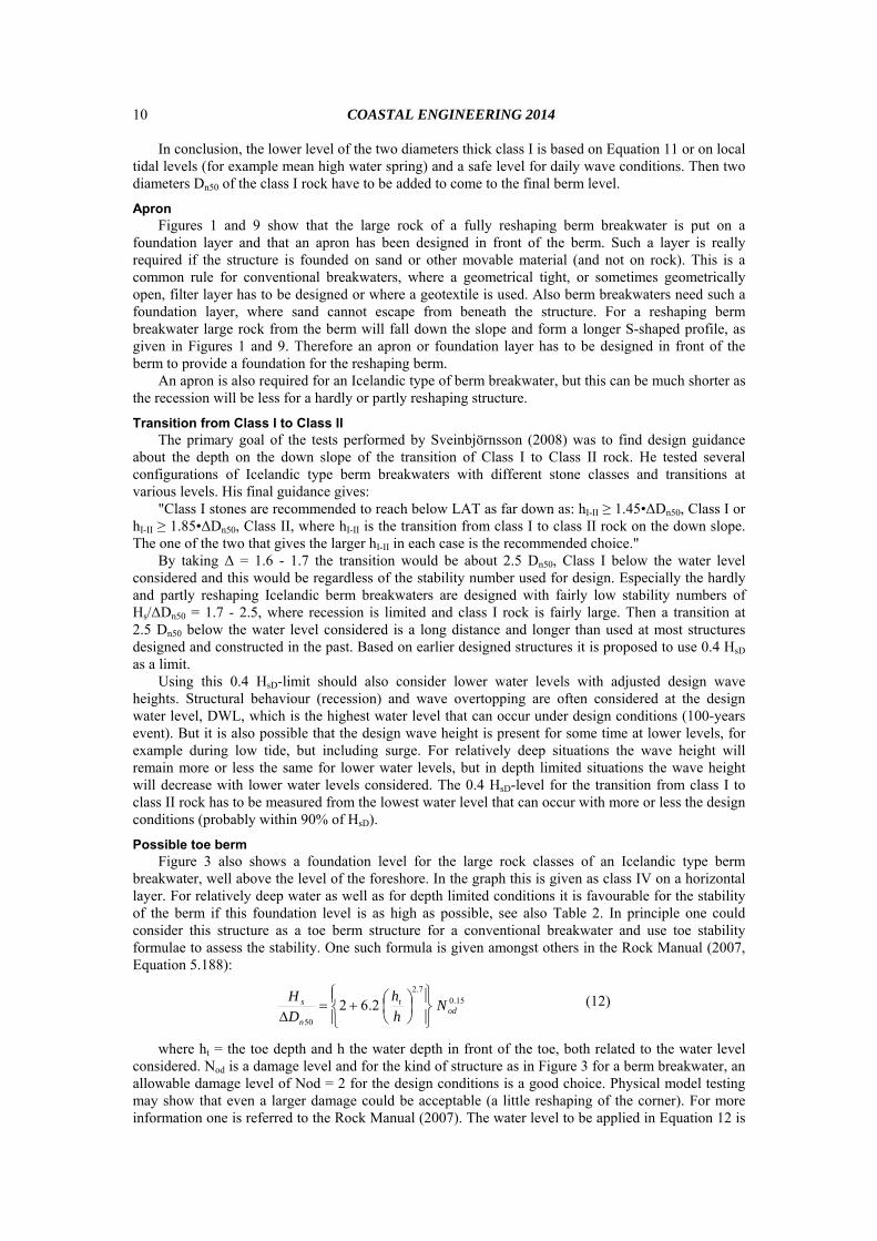
Possible toe berm Figure 3 also shows a foundation level for the large rock classes of an Icelandic type berm
breakwater, well above the level of the foreshore. In the graph this is given as class IV on a horizontal layer. For relatively deep water as well as for depth limited conditions it is favourable for the stability of the berm if this foundation level is as high as possible, see also Table 2. In principle one could consider this structure as a toe berm structure for a conventional breakwater and use toe stability formulae to assess the stability. One such formula is given amongst others in the Rock Manual (2007, Equation 5.188):
15.07.2
50
2.62 odt
n
s Nh
h
D
H
(12)
where ht = the toe depth and h the water depth in front of the toe, both related to the water level considered. Nod is a damage level and for the kind of structure as in Figure 3 for a berm breakwater, an allowable damage level of Nod = 2 for the design conditions is a good choice. Physical model testing may show that even a larger damage could be acceptable (a little reshaping of the corner). For more information one is referred to the Rock Manual (2007). The water level to be applied in Equation 12 is
COASTAL ENGINEERING 2014
11
the maximum design water level, DWL, with the design wave height, HsD, as well as a low water level with accordingly adjusted wave height, based on the 100-years event.
A recently published alternative is the formula on toe rock stability of Van Gent and Van der Werf (2014).
A check should be made whether the level of the designed toe can indeed be constructed, see also Figure 3. It is assumed that the core extends seaward with at least a thickness of 1.5 m. Then on top of this core the rock layer of the toe berm will be constructed, which has a thickness of at least 2 Dn50. The lowest level of the toe berm is then 1.5 m + 2 Dn50 above the foreshore.
APPLICATION OF GEOMETRICAL DESIGN RULES FOR A DESIGN The berm breakwater coastal defence for a reclamation area at Hambantota in Sri Lanka was
designed according to the geometrical design rules in this paper. Background information on this project can be found in Sigurdarson et al. (2014). It was assumed that Class I rock of 5-10 t could be achieved from quarrying operation. The design wave height for swell waves was HsD = 5.6 m with a wave period of Tp = 18 s and a possibility of cyclone waves with a wave height of HsD = 6.5 m, but with a shorter period of Tp = 12.5 s. The water depth was 14 m.
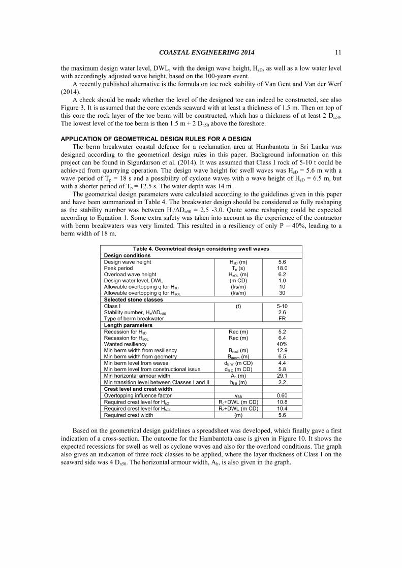
The geometrical design parameters were calculated according to the guidelines given in this paper and have been summarized in Table 4. The breakwater design should be considered as fully reshaping as the stability number was between Hs/ΔDn50 = 2.5 -3.0. Quite some reshaping could be expected according to Equation 1. Some extra safety was taken into account as the experience of the contractor with berm breakwaters was very limited. This resulted in a resiliency of only P = 40%, leading to a berm width of 18 m.
Table 4. Geometrical design considering swell waves
Design conditions Design wave height HsD (m) 5.6 Peak period Tp (s) 18.0 Overload wave height HsOL (m) 6.2 Design water level, DWL (m CD) 1.0 Allowable overtopping q for HsD (l/s/m) 10 Allowable overtopping q for HsOL (l/s/m) 30 Selected stone classes Class I (t) 5-10 Stability number, Hs/∆Dn50 2.6 Type of berm breakwater FR Length parameters Recession for HsD Rec (m) 5.2 Recession for HsOL Rec (m) 6.4 Wanted resiliency 40% Min berm width from resiliency Bresil (m) 12.9 Min berm width from geometry Bgeom (m) 6.5 Min berm level from waves dB W (m CD) 4.4 Min berm level from constructional issue dB C (m CD) 5.8 Min horizontal armour width Ah (m) 29.1 Min transition level between Classes I and II hI-II (m) 2.2 Crest level and crest width Overtopping influence factor γBB 0.60 Required crest level for HsD Rc+DWL (m CD) 10.8 Required crest level for HsOL Rc+DWL (m CD) 10.4 Required crest width (m) 5.6
Based on the geometrical design guidelines a spreadsheet was developed, which finally gave a first
indication of a cross-section. The outcome for the Hambantota case is given in Figure 10. It shows the expected recessions for swell as well as cyclone waves and also for the overload conditions. The graph also gives an indication of three rock classes to be applied, where the layer thickness of Class I on the seaward side was 4 Dn50. The horizontal armour width, Ah, is also given in the graph.
COASTAL ENGINEERING 2014 12
‐15
‐10
‐5
0
5
10
15
0 10 20 30 40 50 60 70 80 90
Design water level DWLChart DatumHorizontal armour width AhRecession for HsD swell and overloadRecession for HsD cyclone and overload
Figure 10. Outcome of spreadsheet with applying the geometrical design rules for the breakwater of Hambantota.
Note that the recession was based on Equation 1 only and that positive effects, as given in Table 2, where not taken into account at this stage to make an adjusted calculation for the recession. Positive effects were mainly a high and long berm and a relatively gentle slope.
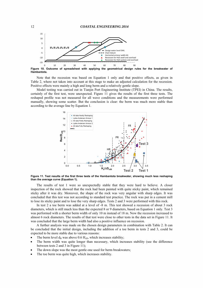
Model testing was carried out in Tianjin Port Engineering Institute (TPEI) in China. The results, certainly of the first test, were unexpected. Figure 11 gives the results of the first three tests. The reshaped profile was not measured for all wave conditions and the measurements were performed manually, showing some scatter. But the conclusion is clear: the berm was much more stable than according to the average line by Equation 1.
0
2
4
6
8
10
12
14
16
0.0 0.5 1.0 1.5 2.0 2.5 3.0 3.5
Rec
/Dn
50
Hs/Dn50
All data Hardly Reshaping
Lykke Andersen Armour 1
All data Partly Reshaping
Lykke Andersen Armour 2
All data Fully Reshaping
fit
PR
FR
HR
Test 1Test 2
Test 3
Figure 11. Test results of the first three tests of the Hambantota breakwater, showing much less reshaping than the average curve (Equation 1).
The results of test 1 were so unexpectedly stable that they were hard to believe. A closer inspection of the rock showed that the rock had been painted with quite sticky paint, which remained sticky after it was dry. Moreover, the shape of the rock was very angular with sharp edges. It was concluded that this test was not according to standard test practice. The rock was put in a cement mill to lose its sticky paint and to lose the very sharp edges. Tests 2 and 3 were performed with this rock.
In test 2 a toe berm was added at a level of -8 m. This test showed a recession of about 3 rock diameters, which is still much less than the expected 8 or 9 diameters, based on Equation 1 only. Test 3 was performed with a shorter berm width of only 10 m instead of 18 m. Now the recession increased to almost 6 rock diameters. The results of that test were close to other tests in the data set in Figure 11. It was concluded that the large berm width had also a positive influence on recession.
A further analysis was made on the chosen design parameters in combination with Table 2. It can be concluded that the initial design, including the addition of a toe berm in tests 2 and 3, could be expected to be more stable due to various reasons: The berm level dB was above 0.6 HsD, which increases stability; The berm width was quite longer than necessary, which increases stability (see the difference
between tests 2 and 3 in Figure 11); The down slope was the most gentle one used for berm breakwaters; The toe berm was quite high, which increases stability.
COASTAL ENGINEERING 2014
13
These four reasons were enough to limit the recession to only one-third of the expected recession based on Equation 1. At first sight the improvements were taken implicitly, as we were aware of the positive points with regard to recession. At hindsight it can be concluded that the limited recession was indeed due to a combination of four positive points.
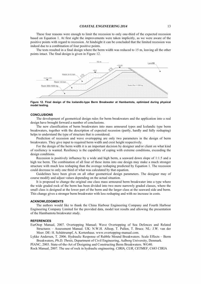
The tests resulted in a final design where the berm width was reduced to 15 m, leaving all the other points intact. The final design is given in Figure 12.
Figure 12. Final design of the Icelandic-type Berm Breakwater at Hambantota, optimized during physical model testing.
CONCLUSIONS The development of geometrical design rules for berm breakwaters and the application into a real
design have brought forward a number of conclusions. The new classification of berm breakwaters into mass armoured types and Icelandic type berm
breakwaters, together with the description of expected recession (partly, hardly and fully reshaping) helps to understand the type of structure that is considered.
Prediction of recession and wave overtopping are only two parameters in the design of berm breakwaters. They give input to required berm width and crest height respectively.
For the design of the berm width it is an important decision by designer and/or client on what kind of resiliency is wanted. Resiliency is the capability of coping with extreme conditions, exceeding the design conditions.
Recession is positively influence by a wide and high berm, a seaward down slope of 1:1.5 and a high toe berm. The combination of all four of these items into one design may make a much stronger structure with much less reshaping than the average reshaping predicted by Equation 1. The recession could decrease to only one third of what was calculated by that equation.
Guidelines have been given on all other geometrical design parameters. The designer may of course modify and adjust values depending on the actual situation.
It is proposed to change the original one class mass armoured berm breakwater into a type where the wide graded rock of the berm has been divided into two more narrowly graded classes, where the small class is designed at the lower part of the berm and the larger class at the seaward side and berm. This change gives a stronger berm breakwater with less reshaping and with no increase in costs.
ACKNOWLEDGMENTS The authors would like to thank the China Harbour Engineering Company and Fourth Harbour
Engineering Company Limited for the provided data, model test results and allowing the presentation of the Hambantota breakwater study.
REFERENCES EurOtop Manual, 2007. Overtopping Manual; Wave Overtopping of Sea Defences and Related
Structures – Assessment Manual. UK: N.W.H. Allsop, T. Pullen, T. Bruce. NL: J.W. van der Meer. DE: H. Schüttrumpf, A. Kortenhaus. www.overtopping-manual.com.
Lykke Andersen, T. 2006. Hydraulic Response of Rubble Mound Breakwaters. Scale Effects – Berm Breakwaters, Ph.D. Thesis, Department of Civil Engineering, Aalborg University, Denmark.
PIANC, 2003. State-of-the-Art of Designing and Constructing Berm Breakwaters. WG40. Rock Manual, 2007. The use of rock in hydraulic engineering. CIRIA, CUR, CETMEF, C683 CIRIA

COASTAL ENGINEERING 2014 14
Sigurdarson, S and J.W. van der Meer, 2014. Icelandic-type berm breakwater for the Hambantota artificial island revetment, application of geometrical design rules. Proceedings of 34th International Conference on Coastal Engineering, ASCE, Seoul, Korea.
Sigurdarson, S. and van der Meer, J., 2012. Wave Overtopping at Berm Breakwaters in line with EurOtop. ASCE, Proceedings of ICCE 2012, Shanghai.
Sigurdarson, S. and J.W. van der Meer. 2011. Front Slope Stability of the Icelandic-type Berm Breakwater, ASCE, Proceedings of Coastal Structures 2011, Yokohama.
Sveinbjörnsson, P.I. , 2008. Stability of Icelandic type Berm Breakwaters. MSc-thesis, TU Delft. Van der Meer, J.W. and J.J. Veldman, 1992. Singular points at berm breakwaters: scale effects, rear,
roundhead and longshore transport. Journal of Coastal Engineering, 17 (1992), pp. 153-171, Elsevier, Amsterdam.
Van Gent, M.R.A. and I.M. van der Werf, 2014. Rock toe stability of rubble mound breakwaters. Journal of Coastal Engineering, 83 (2014) pp. 166-176.