Embed Size (px)
Citation preview
CARIBBEAN EXAMINATIONS COUNCIL
REPORT ON CANDIDATES’ WORK IN THE CARIBBEAN ADVANCED PROFICIENCY EXAMINATION
MAY/JUNE 2007
GEOMETRICAL AND MECHANICAL ENGINEERING DRAWING
Copyright © 2007 Caribbean Examinations Council ® St Michael, Barbados
All rights reserved
2
GEOMETRICAL AND MECHANICAL ENGINEERING DRAWING
CARIBBEAN ADVANCED PROFICIENCY EXAMINATION
MAY/JUNE 2007
GENERAL COMMENTS There has been significant improvement in candidates’ performance in Unit 2 this year. However, candidates continue to display poor drawing skills and limited knowledge of ISO standards and conventions. Site visits to engineering establishments and regular practice using ISO standards should help candidates preparing for the examination.
UNIT 1
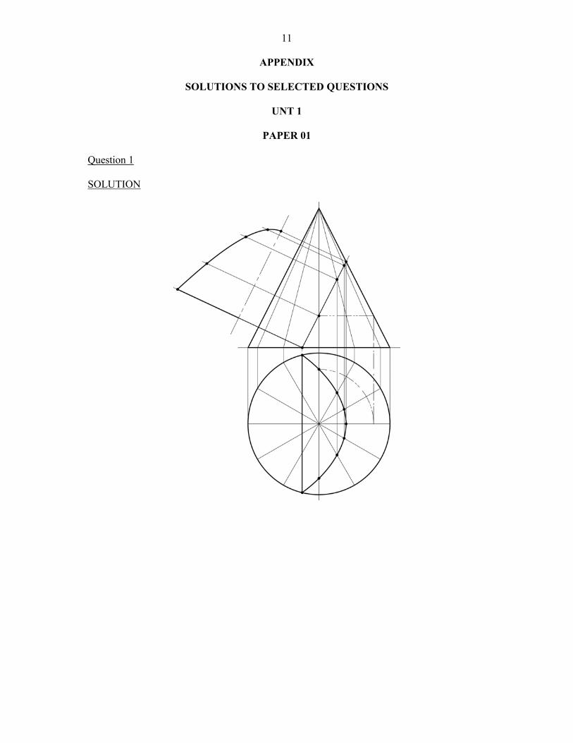
PAPER 01 Question 1 This question tested candidates’ ability to plot points of an auxiliary view from a truncated cone. The weaker candidates reproduced the given figure, a few were able to do the projection, but failed to get the correct curve in the auxiliary view. Most did not do a plan view to show the cut area. Overall approximately 70 percent to 80 percent performed fairly well. Question 2 This question tested candidates’ ability to draw and differentiate between the performance graphs for different cam motions. The question was generally well done, with some candidates scoring full marks. A few candidates were unable to draw the performance graphs, particularly with respect to the uniform acceleration. In some cases candidates incorrectly identified the performance graphs (UV for SHM, UA for SHM, ). Weaker candidates confused the three graphs. Question 3 This question tested candidates’ ability to graphically determine the centroid of a quadrilateral. Approximately 70 percent of the candidates who attempted the question scored 75 percent and over. Several candidates tried unorthodox means of finding the centroid of the given figure and ended up having difficulties. Question 4 This question tested candidates’ ability to construct the curve of intersection of a cylinder and a right cone. Most candidates who attempted the question did not demonstrate the correct method(s) for producing the curve of intersection. Approximately 50 percent of the candidates who attempted the question reproduced the given figure. About 40 percent of the candidates who reproduced the figure knew how the curve of intersection would actually look. Question 5 This question tested candidates’ ability to construct an auxiliary view to show the true shape of the cut surface of the cylinder. Most candidates’ responses were weak. Some candidates only reproduced the given figure. Most of the candidates who attempted the question were able to produce the correct response. More practice is needed with cylindrical solids (truncated).
3 Question 6 This question tested candidates’ knowledge of double start helix. Candidates who attempted this question exhibited a good grasp of the concept of the helix thread and the construction process necessary. Approximately 30 percent of all candidates that attempted the question went beyond the parameter of the question by constructing spring and triple start helix. Generally the response to this question was very good with approximately 98 percent of the candidates obtaining approximately 70 percent of the marks allocated. Question 7 This question tested candidates’ knowledge of welding and machining symbols. Candidates incorrectly identified the weld on opposite side as indicated by the arrow. Some candidates reproduced the given symbols instead of the pictorial sketches that were required. Some candidates seem to lack the knowledge of welding symbols. A number of responses were given as sections. Very few candidates scored above 50 percent and no candidate scored full marks. Most responses showed candidates only being aware of fillet weld symbol. Very few responses indicated the correct meaning of the machining symbols. Question 8 This question tested candidates’ knowledge of oblique projection and freehand sketching. Several candidates were unable to differentiate isometric and oblique projection and were unable to draw neat proportional sketches. A large number of candidates copied the given isometric drawing from the question paper. Approximately 30 percent of the candidates scored 50 percent to 100 percent. Question 9 This question tested candidates’ ability to assemble different engineering components to produce a single drawing. It also tested their knowledge of simple locking devices. The most challenging aspect of the question was the application of the locking devices. 207 candidates attempted this question. Most of the candidates demonstrated a good understanding of how to assemble the components to produce the final drawing.
PAPER 02
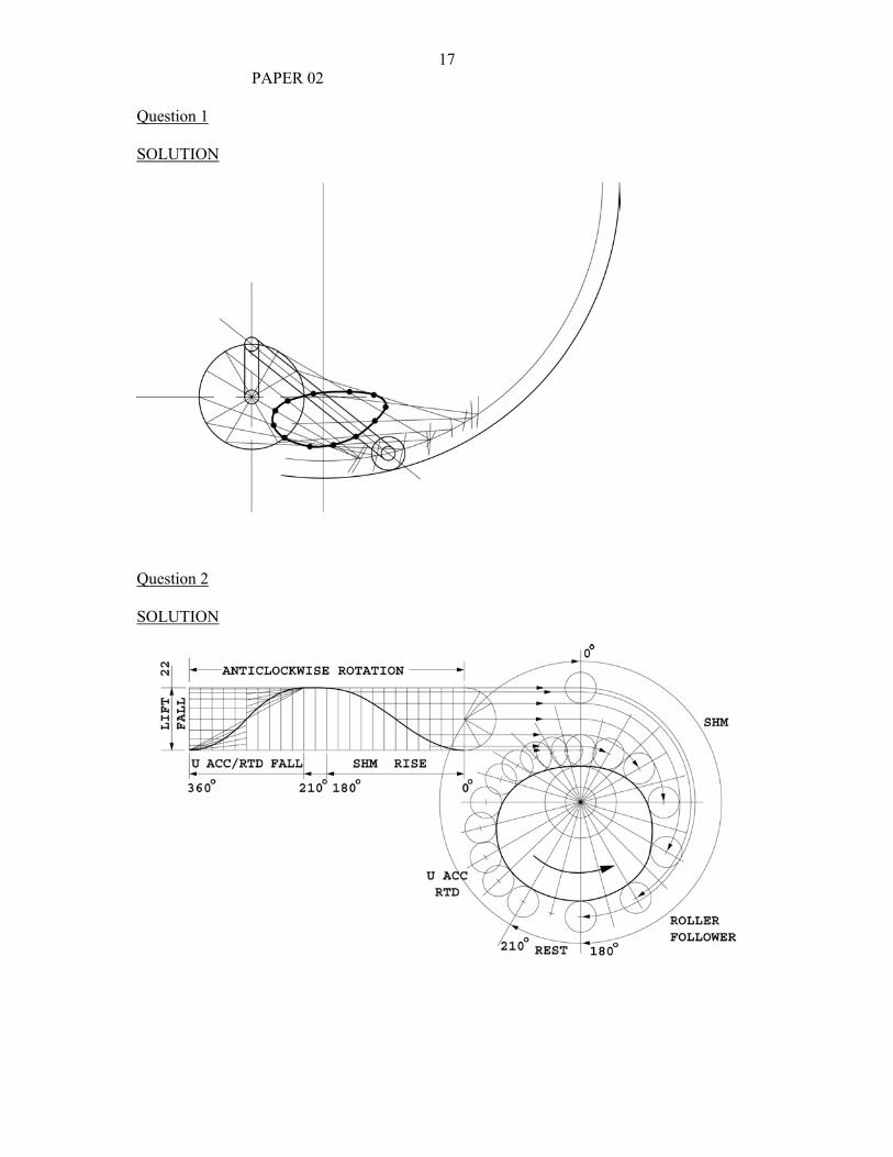
Question 1 This question tested candidates’ knowledge of the locus of a point on a crank and link mechanism. Candidates who attempted this question generally completed the locus of point “P”. Quite a number of candidates either did not use construction lines or erased them. Some candidates used incorrect measurements when drawing the given arrangement. A few candidates did the loci question from examples they remembered ignoring the arrangement given. Approximately 70 percent of the candidates failed to outline the given arrangement or outline at least one position of the mechanism. 65 percent to 70 percent of the candidates were unable to show the path for the roller’s center. Candidates were able to demonstrate good knowledge and understanding of the movement of the mechanism. There is need to improve the line work and lettering fundamental skills which seem to be lacking at this advanced stage of drawing. Teachers are asked to encourage their students to read loci problems and check all the measurements, before attempting them.
4Question 2 This question tested candidates’ ability to design a cam profile of a radial plate cam to impart the following motions:-
(1) Simple Harmonic Motion; (2) Dwell; (3) uniform acceleration and retardation.
Over 80 percent of the candidates attempted this question. Construction of the cam profile was generally well done. A few candidates experienced difficulties with display roller position and drawing tangents to the required rollers. The majority of the candidates who attempted this question performed well. Some candidates exhibited weakness in the following areas:
(1) not aligning cam profile with cam construction; (2) inability to determine the direction of cam movement; (3) poor construction method to find the acceleration and retardation curve; (4) inability to place the roller in the different positions on the cam profile.
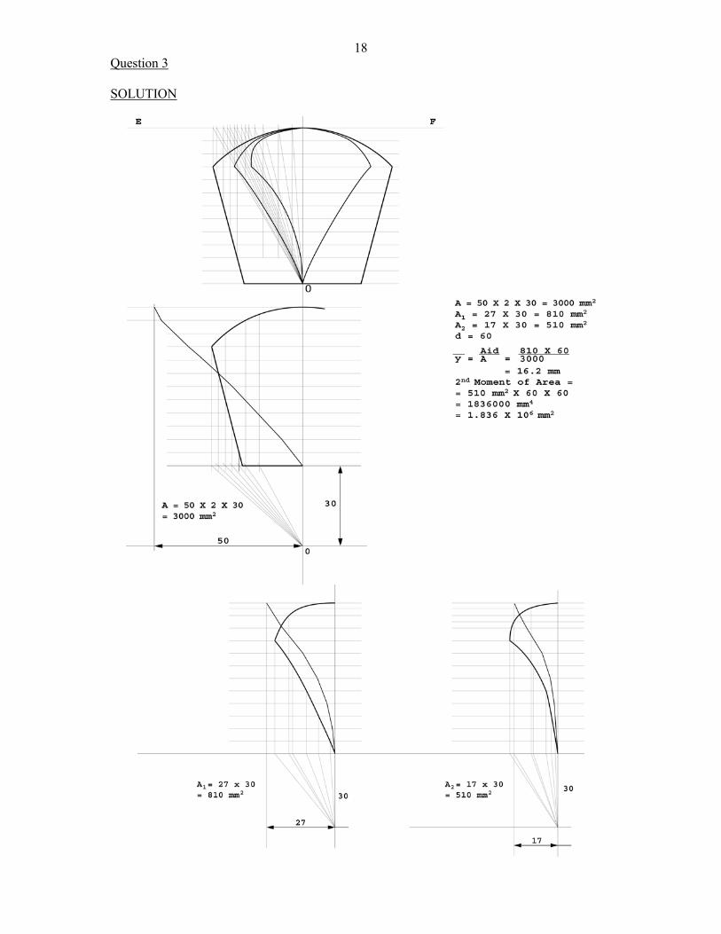
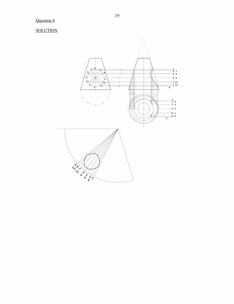
Question 3 This question tested candidates’ knowledge of the centroid and second moment of area. This was a very popular question. Generally, candidates were able to reproduce the given figure and demonstrate good knowledge and understanding and drawing skills in dividing the figure and finding the first and second derived figures graphically. Candidates showed a poor level of understanding in integrating the areas using the first and second derived curves to find the centroid and the second moment of area. Some candidates were able to state the formula but were not able to apply it. Most candidates using graph paper to determine Areas A, A1, A2 did not determine it correctly, the resulting areas were exactly twice as much or greater. Question 4 This question tested candidates’ knowledge of the curve of intersection and development. It was attempted by less than half of the candidates and the responses were poor. Many candidates were unable to correctly construct the curve of intersection and proceeded to draw the curve freehand. Candidates also displayed an inability to draw the development of the right cone. Most candidates were only able to score an average of 15 percent of the marks allocated. Question 5 This question tested candidates’ knowledge of an auxiliary view. It was attempted by about 30 percent of the candidates. A number of candidates had difficulty in projecting the auxiliary curves. Candidates did not demonstrate this understanding that the lines are pulled perpendicularly to the surface and that the curves are to be divided in the given orthographic view, then transferred to the auxiliary view. Generally, candidates were able to reproduce the given orthographic views and project lines to get their auxiliary view but had difficulty with auxiliary views with curves and other engineering features. Question 6 This question tested candidates’ ability to convert an orthographic drawing to an isometric projection. It was attempted by over 75 percent of the candidates. A large majority gave a satisfactory response. There were good performances on the construction of the lower semi-circle. The construction of the upper semi-circle was the weaker area. A large number of candidates were able to handle satisfactorily the isometric axis. However, about 12 percent of the candidates interpreted isometric to
5mean either oblique or axonometric projection. It would be an advantage for candidates to practice isometric drawings that have non-isometric lines, circles and arcs. Areas of difficulty were identified as follows:-
(1) making ‘X’ the lowest point; (2) using the correct angles for isometric projection; (3) accuracy of measurement; (4) interpretation from orthographic to isometric; (5) construction of isometric circles.
Question 7 This question tested the candidates’ knowledge of limits and fits. This was not a popular question. The overall performance was poor. For parts (a) and (b) only 10 percent of respondents correctly used the table and completed the required calculations. For part (c), candidates were able to produce a drawing of the bush; however, the majority misunderstood the phrase ‘working drawing’ and also failed to dimension the component correctly indicating its limits and fits. None of the candidates was able to correctly suggest a suitable bushing for the component. Candidates, who scored in the region of 70 percent for this question, stated the formula and used the table. They were also able to correctly interpret part (c). It is recommended that greater attention be paid to this topic in the classroom. Students should be encouraged to use the applications for limits and fits when producing drawings as a norm. Question 8 This question tested candidates’ knowledge of assembly drawing. This question proved to be the most popular in this section with over 60 percent of candidates providing a response. The majority of respondents demonstrated knowledge of assembly, as well as, a knowledge of sectioning. Only 10 percent of candidates were able to correctly assemble and section the component. Of those attempting this question, 20 percent showed a clear knowledge and application of balloon referencing. The majority demonstrated a knowledge of the parts lists. Candidates generally were unable to produce the end view. Candidates who scored in the region of 80 percent on this question, set out and assembled the drawing correctly and showed clearly the differences in components to be sectioned. They also applied the principles of balloon references well. Candidates, who scored poorly, produced ambiguous drawings and they were unable to apply the general principles. In the classroom it is, therefore, necessary to enforce higher drawing standards to allow students the opportunity to constantly practice line types, layout, drawing techniques, projection symbol and types of projection assembly and sectioning. Question 9 This question tested candidates’ knowledge of centrifugal and reciprocating pumps, seals and fastening devices. Approximately 50 percent of the candidates attempted this question. Sketching was poorly done but the labeling of the pumps was done satisfactorily. Most candidates lacked the knowledge to explain the difference between the two types of pumps. Some candidates explained very well how static seals are used. Part (c) of the question was almost invariably answered correctly for those who attempted it. For part (d) all candidates who attempted the question were able to show the nut and bolt, however, they had difficulty showing the correct shape for the pan head rivet.
6
UNIT 2
PAPER 01
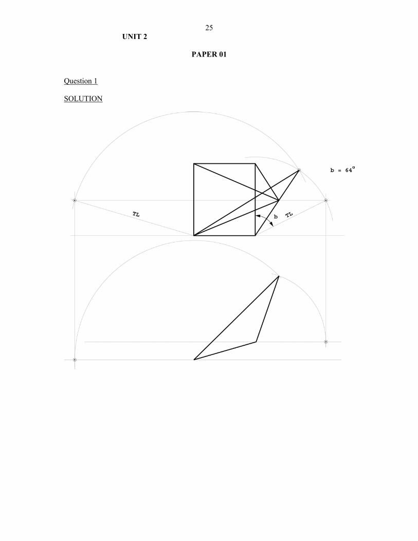
Question 1 This question tested candidates’ ability to draw the true shape of the surface of a prism and find the true angle of slope between two planes. Approximately 40 percent of the candidates who attempted this question completed only the given views. About 90 percent of the candidates who attempted part (a) of the question completed the true length successfully. Some candidates used a construction method to find the true length of BC even though this was given. A number of candidates drew the triangles only, when the question asked for the given view. Question 2 This question tested candidates’ ability to use graphic methods to determine the reactions of a loaded beam. This was a very popular question, and several candidates made a perfect score. The range of marks was from eight to 10. In a few cases, marks were deducted for not stating the magnitudes and not stating the appropriate scale used. A small number of candidates, about five percent or smaller, scored zero to two for drawing the loaded beam to scale, and extending lines of actions of load and scored no further points since the rest of the problem was solved mathematically instead of graphically. Question 3 This question tested candidates’ knowledge of gear teeth and terminology. The quality of sketches produced by the candidates showed a wide range of abilities, from the well defined three dimensional view to two scrappy lines. Candidates need to understand the importance of producing neat clearly annotated sketches/drawing. Over 90 percent of the candidates had no idea what the blank circle diameter was. Some were suggesting that this was a trick question. Candidates were not familiar with terms and practices used. Question 4 This question tested candidates’ knowledge of the properties of materials. It was not handled well by the candidates. Many of the terms were incorrectly identified, except for malleability. Many candidates did not give correct examples for plasticity. Examples for toughness and hardness were generally correct. Question 5 This question tested candidates’ knowledge of the difference between radial and thrust load and their ability to produce neat labeled sectional sketches of ball bearing to take these loads. This question was generally well handled. Candidates had some knowledge of bearings. Some problems that were noted are as follows:
(1) candidates showed confusion in identifying the correct bearing; (2) the definition was long; (3) suitable diagrams were not drawn.
Question 6 This question tested candidates’ knowledge and ability to identify welding processes abbreviation and symbols. About 60 percent of the candidates attempted the question. Very few candidates were able to identify the abbreviations and about 50 percent of those who attempted the question were able to accurately identify the welding symbols.
7Question 7 This question tested candidates’ knowledge of power transmission mechanisms. Many candidates who attempted this question displayed a fair understanding of spur gears but neglected the distance apart of the shafts a feature which made spur gear not a suitable choice. 20 percent were able to produce sketches of a suitable mechanism. Candidates are advised to spend more time in this area and to visit machine shops and factories focusing on solutions to simple problems. Question 8 This question tested candidates’ knowledge of couplings. Many candidates were able to produce sketches of couplings but were unable to give proper names to the sketches. Candidates should be encouraged to compile charts of different types of power transmission devices and their uses. A portfolio approach with field trips should be of help in understanding power transmission devices. Question 9 This question tested candidates’ knowledge of the engineering design principles and process. Candidates were able to express themselves sufficiently clear to indicate that they understood what engineering design meant, however, some candidates could not explain Synthesis and Optimization.
PAPER 02
Question 1 This question tested candidates’ knowledge of forces acting in the members of a simple framework. Approximately 98 percent of the candidates attempted this question. Most candidates had difficulty identifying the tie and strut. Some candidates were unable to distinguish between a framework and a simple beam. Question 2 This question tested candidates’ knowledge and ability to find the shortest distance between two lines in space and to find the angle of slope between the shortest distance and the horizontal plane. Approximately 70 percent of the candidates attempted this question with approximately 25 percent of them scoring between 15 and 25 marks, while about 60 percent scored between zero and eight marks of the total score of 25 marks. A large percentage of the candidates experienced difficulty in finding the second true length of the two lines in space. Most candidates could not project the shortest distance back to the front elevation and plan. Question 3 This question tested candidates’ knowledge and ability to calculate gear teeth parameters and to construct three consecutive gear teeth. Approximately 60 percent of the candidates responded to this question. Most responses scored well, approximately 20 out of 25 marks, with some candidates scoring full marks. Few responses scored less than 10. The question asked candidates to draw twice full size, however, some candidates drew the gear at full, half full size and four times full size. Most candidates were able to perform the calculations to obtain the base, pitch, root and outside circles. Some candidates had difficulty distinguishing between pitch circle and pitch circle diameter. Likewise, a number of candidates indicated the addendum and dedendum as points on the root and outer circles, rather than as distances between these circles and the pitch circle. Many candidates failed to indicate the gear data.
8Question 4 This question tested candidates’ knowledge and ability to identify the three main components of a precision vice, and to select suitable materials and explain how each part can be manufactured. In addition, they were asked to design a suitable handle, list ergonomic and aesthetic qualities of the design and explain how the vice works. This was a popular question and most candidates performed well. The weak candidates had difficulties in understanding the terms mentioned. Question 5 This question tested candidates’ knowledge of antifriction and journal bearings. In addition, they were to sketch a taper roller bearing, explain its use and give an application. This question was a very popular question with approximately 70 percent of the candidates attempting it. Approximately 80 percent of those who did the question scored over 15 out of a maximum of 25 marks. Most candidates were able to
(1) identify the bearings; (2) explain the difference between antifriction and journal/sleeve bearings; (3) give an example of an application for the taper roller bearing; (4) sketch a taper roller bearing.
Question 6 This question tested candidates’ knowledge of properties and uses of thermosetting plastics and thermoplastics. Candidates were also asked to list properties of rubber that is suitable for seals, and applications of rubber. Most candidates, who responded to this question, were able to easily distinguish between thermosetting plastic and thermoplastic. Some candidates confused properties of rubber with its application. Most candidates were able to give uses of plastics. Question 7 This question tested candidates’ knowledge of the design stages and their ability to redesign a component to be fabricated by welding. Few candidates attempted this question. Their scores ranged from two to 18 marks. This wide range shows a great disparity in the abilities of those candidates who attempted it. Most candidates seemed to have misunderstood the phrase “indicate simple forms”. This part of the question carried a significant portion of the marks, resulting in many of the low scores. The choice of appropriate materials was a major challenge to most candidates. Question 8 This question tested candidates’ knowledge and ability to select suitable materials based on the specifications given of an engineering component. This question was very popular. The terms used were not fully understood by the weaker candidates. Question 9 This question tested candidates’ knowledge and ability to design a wall mounted television stand to satisfy some specified conditions. It also tested their knowledge of materials and manufacturing processes. This question was well done by the majority of the candidates who attempted it. Several candidates scored over 12. Few candidates scored below 10. Some of the candidates experienced difficulty with sketching and choosing appropriate materials.
9
INTERNAL ASSESSMENT
UNIT 1
Assignment 1 This assignment was fairly well done. Attempts at problem solving were reasonably informed. Assignment 2 Well done by most candidates. Candidates showed good knowledge of this area of Engineering. However, in terms of housekeeping, (ensuring that Cam Data, Cam centres, Cam rotation arrow are listed or visible), much work is needed. Assignment 3 In this area of the syllabus, many intersections were incorrectly done. Assignment 4 Software incompatibility was evident. Some candidates copied the assignment solutions both on soft and hard copy and submitted them as their own. Some standardization is also necessary for the list of commands requested. Assignment 5 Design was not handled very well. The design process needs to be followed and marks awarded according to the marking scheme. Assignment 6 This assignment was handled very well in terms of the quality of the assignment and the level of the drawing skills.
UNIT 2
Design Most centers did a fairly good job in addressing the aspects of the design process. However, emphasis must be placed on mechanical design in terms of pumps, gears, etc. as opposed to the aesthetics of the design. Candidates must be encouraged to follow the six-stage design process.
LIMITATIONS
CAD Software incompatibility.
10
RECOMMENDATIONS
(1) Greater attention should be paid to the problem solving steps. This would allow candidates to
be better equipped when solving a design problem. (2) The design process should form part of the curriculum even in the lower school. (3) The choice of projects should be addressed so that candidates are encouraged to explore
topics within each of the modules. (4) Greater attention is given to the range of communication skills necessary to produce quality
project reports. (5) Teachers should utilize the resources of the school/community and do team teaching in
relevant topics. (6) Where centers lack teaching aids such as are readily available in the mechanical workshops,
students should be taken on tours to observe the related technologies in action.
SEE APPENDIX - SOLUTIONS TO SELECTED QUESTIONS
11
APPENDIX
SOLUTIONS TO SELECTED QUESTIONS
UNT 1
PAPER 01
Question 1 SOLUTION
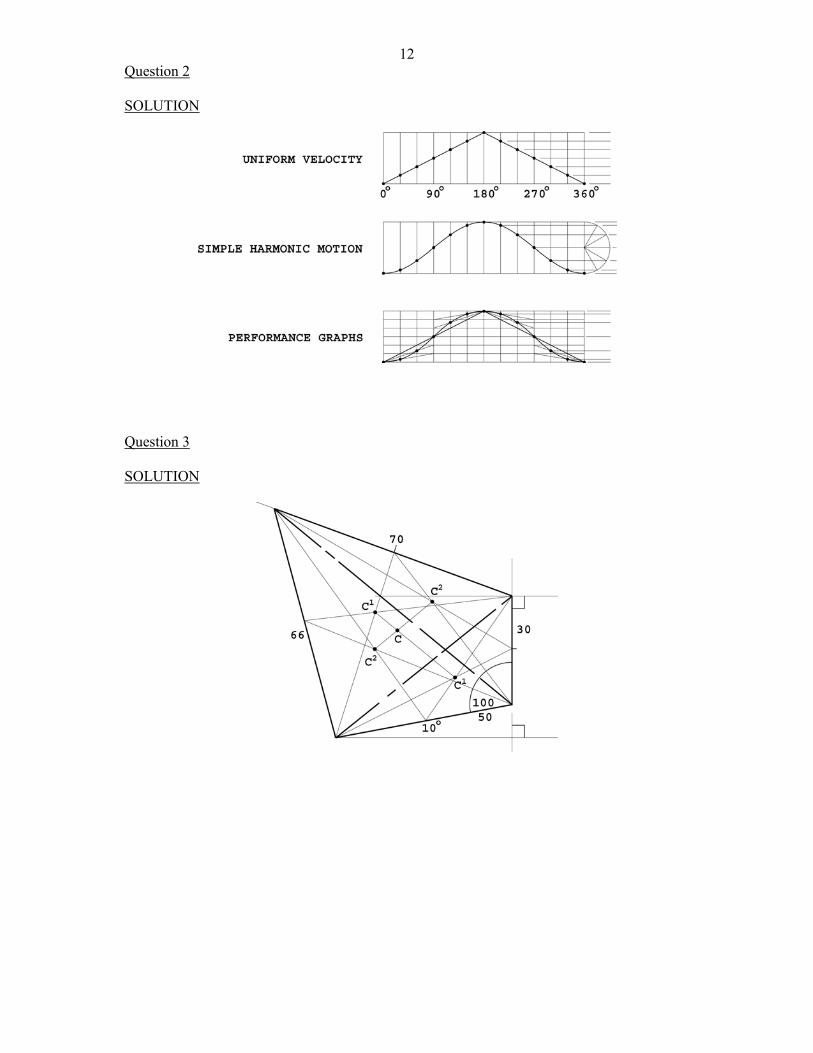
12Question 2 SOLUTION
Question 3 SOLUTION
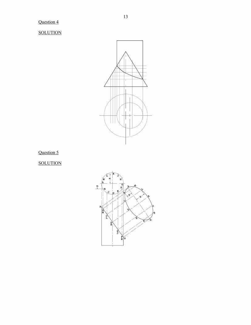
13Question 4 SOLUTION
Question 5 SOLUTION
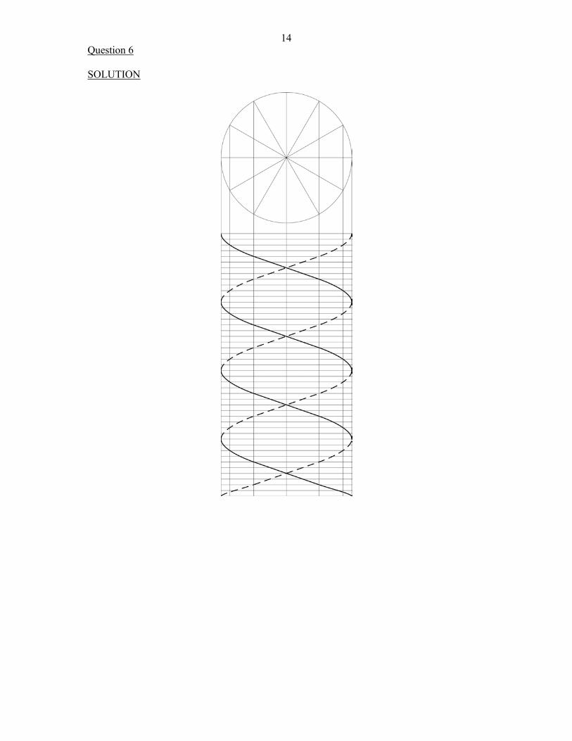
14Question 6 SOLUTION
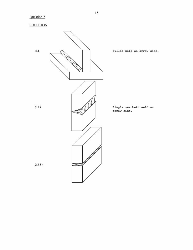
15Question 7 SOLUTION
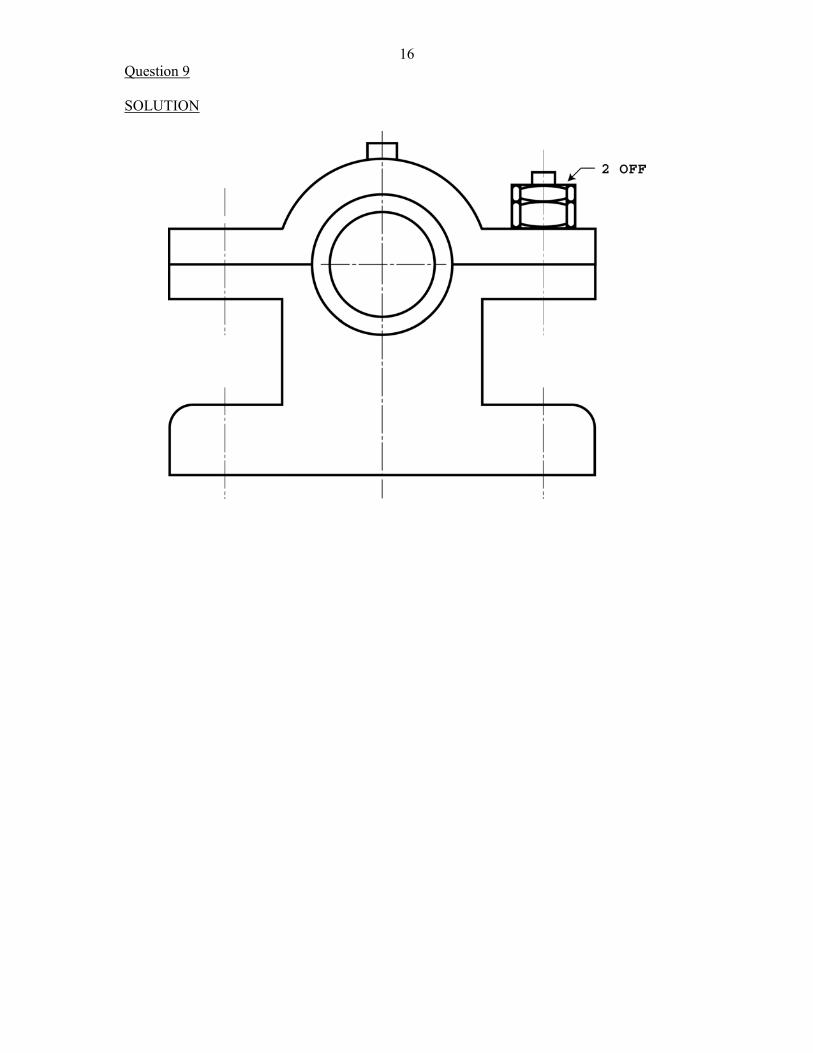
16Question 9 SOLUTION
17PAPER 02
Question 1 SOLUTION
Question 2 SOLUTION
18Question 3 SOLUTION
19Question 4 SOLUTION
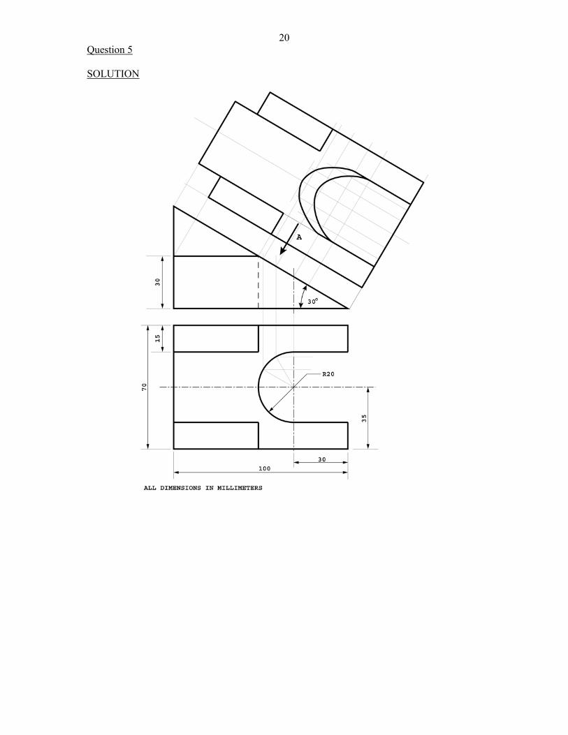
20Question 5 SOLUTION
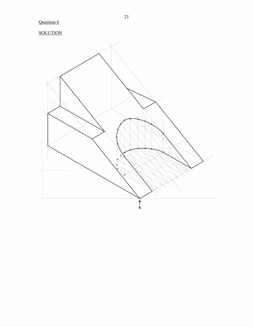
21Question 6 SOLUTION
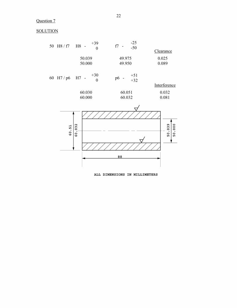
22Question 7 SOLUTION 50 H8 / f7 H8 - f7 - Clearance
50.039 49.975 0.025 50.000 49.950 0.089
60 H7 / p6 H7 - p6 -
Interference
60.030 60.051 0.032 60.000 60.032 0.081
+39 0
-25 -50
+30 0
+51 +32
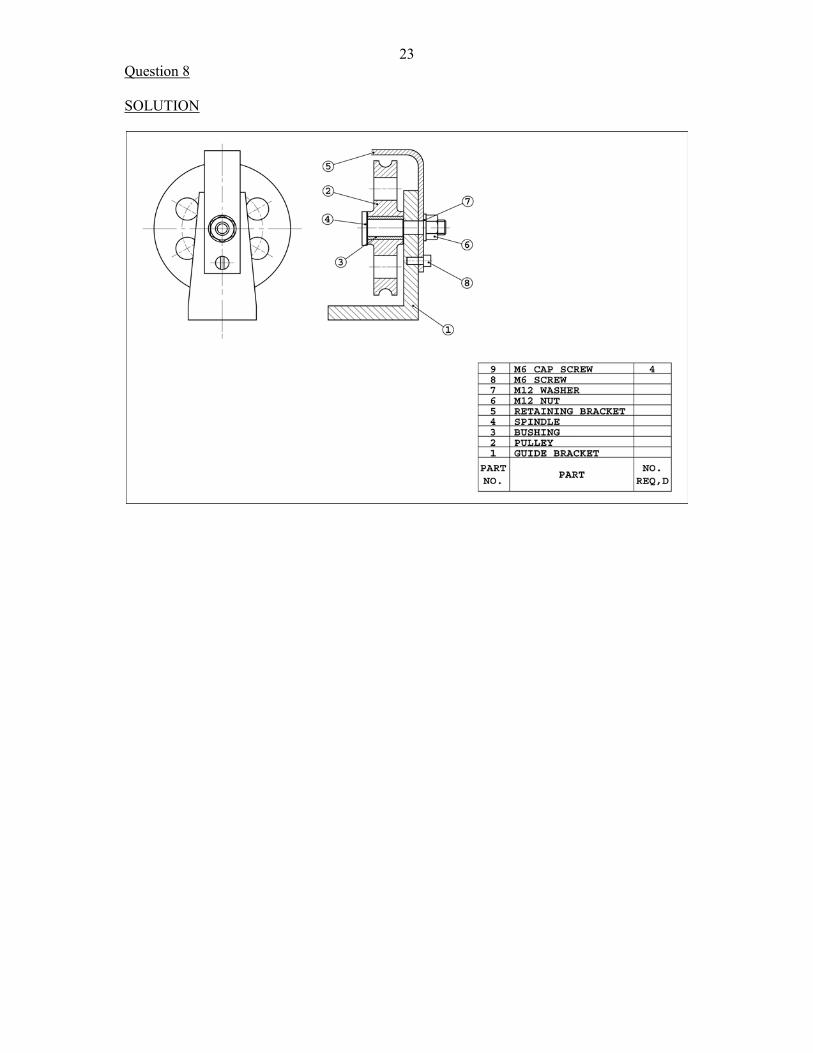
23Question 8 SOLUTION
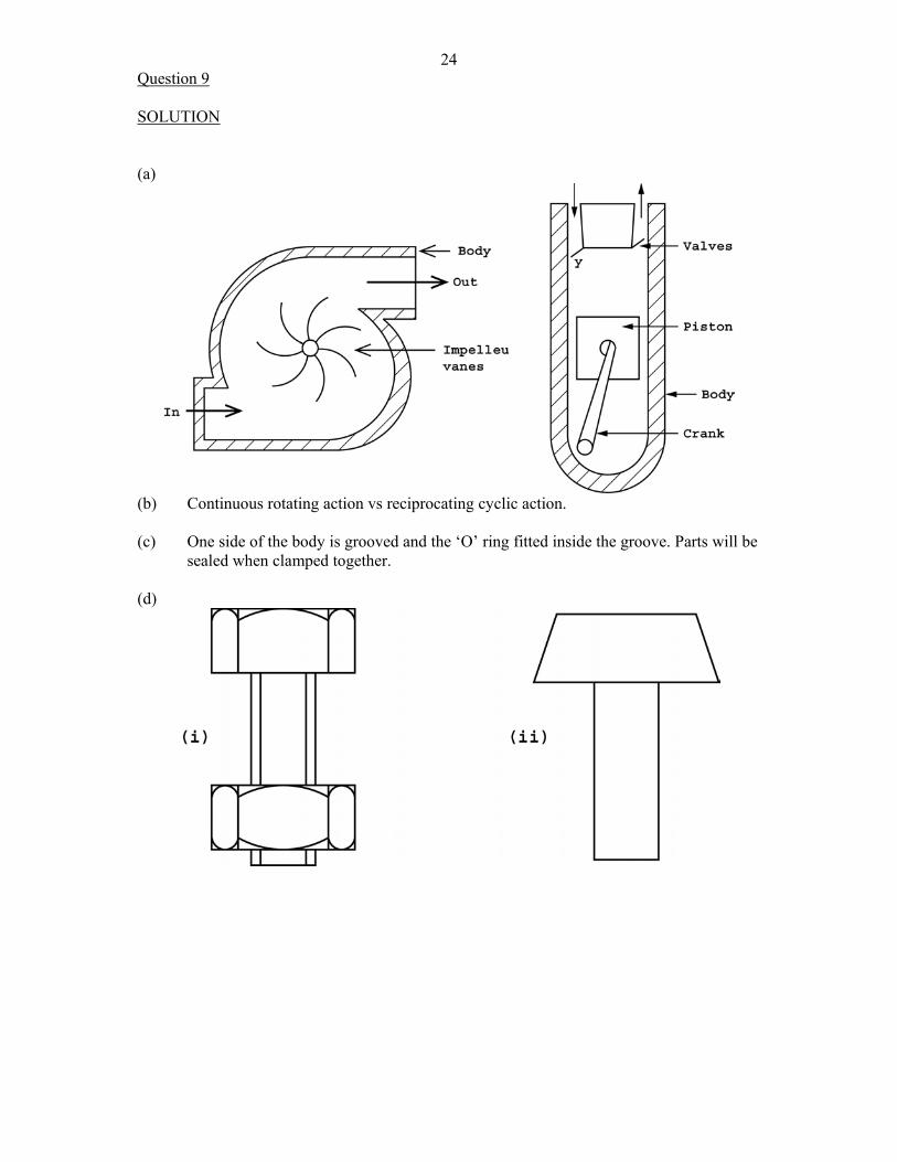
24Question 9 SOLUTION (a)
(b) Continuous rotating action vs reciprocating cyclic action. (c) One side of the body is grooved and the ‘O’ ring fitted inside the groove. Parts will be
sealed when clamped together. (d)
25UNIT 2
PAPER 01
Question 1 SOLUTION
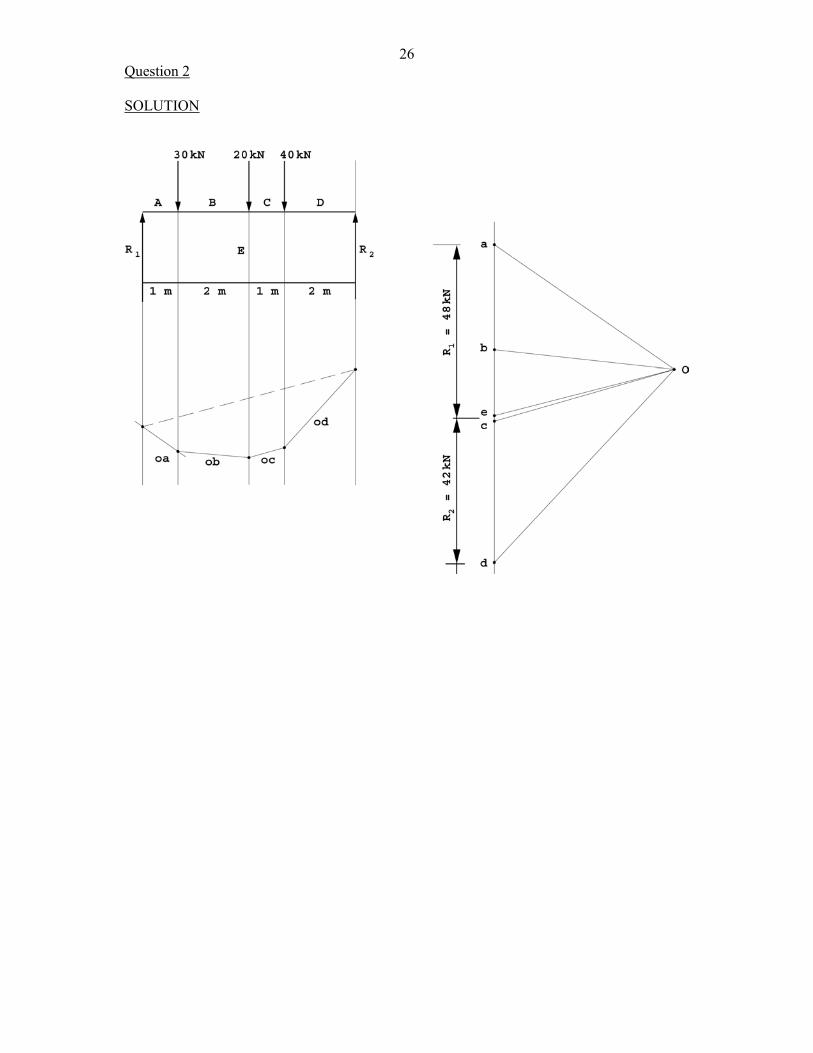
26Question 2 SOLUTION
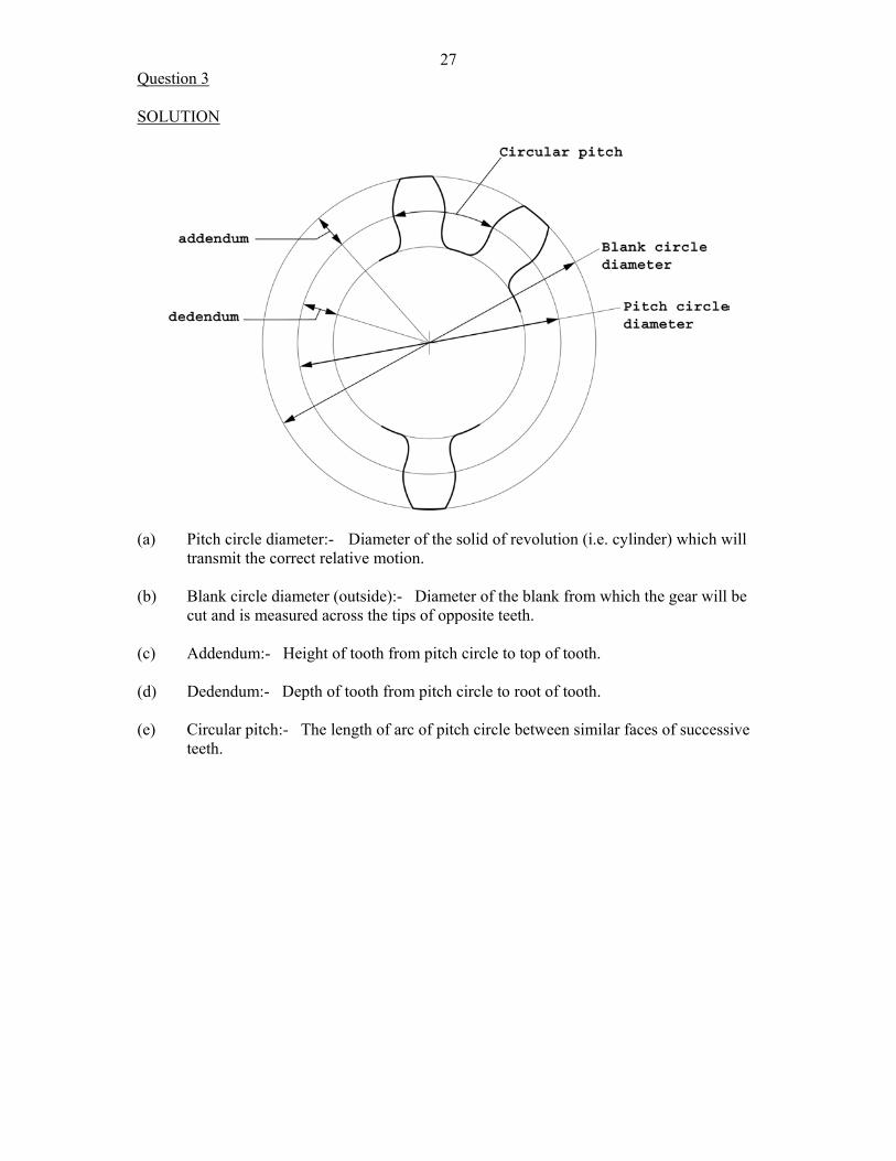
27Question 3 SOLUTION
(a) Pitch circle diameter:- Diameter of the solid of revolution (i.e. cylinder) which will transmit the correct relative motion. (b) Blank circle diameter (outside):- Diameter of the blank from which the gear will be
cut and is measured across the tips of opposite teeth. (c) Addendum:- Height of tooth from pitch circle to top of tooth. (d) Dedendum:- Depth of tooth from pitch circle to root of tooth. (e) Circular pitch:- The length of arc of pitch circle between similar faces of successive
teeth.
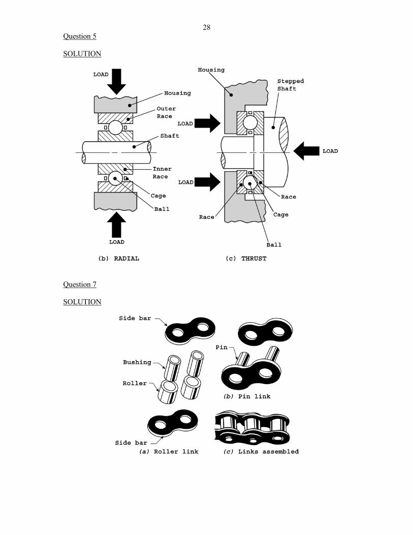
28Question 5 SOLUTION
Question 7 SOLUTION

29Question 8 SOLUTION
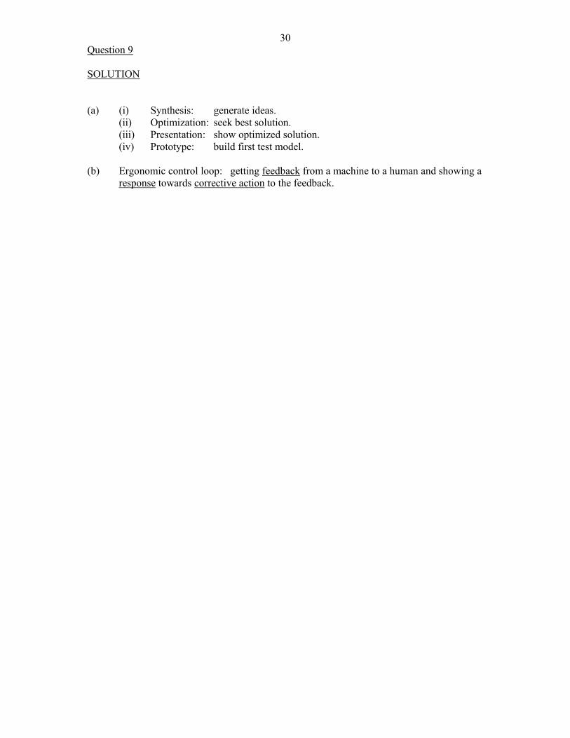
30Question 9 SOLUTION (a) (i) Synthesis: generate ideas. (ii) Optimization: seek best solution. (iii) Presentation: show optimized solution. (iv) Prototype: build first test model. (b) Ergonomic control loop: getting feedback from a machine to a human and showing a
response towards corrective action to the feedback.
31
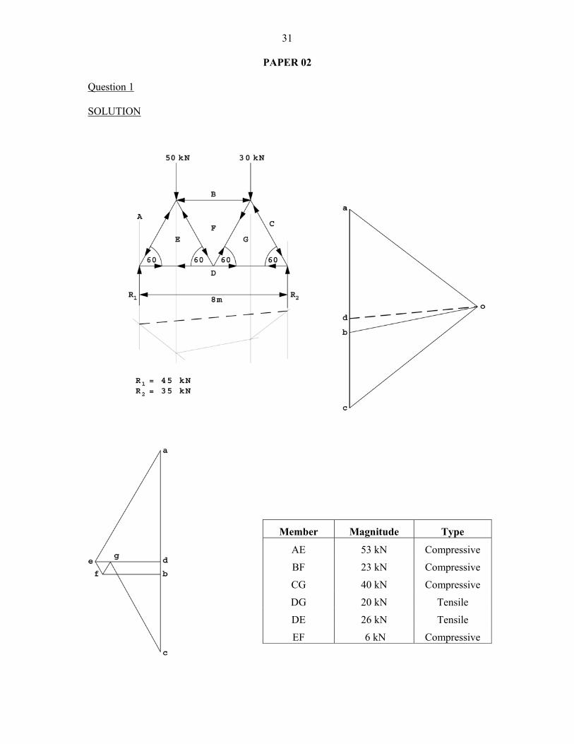
PAPER 02 Question 1 SOLUTION
Member Magnitude Type
AE 53 kN Compressive
BF 23 kN Compressive
CG 40 kN Compressive
DG 20 kN Tensile
DE 26 kN Tensile
EF 6 kN Compressive
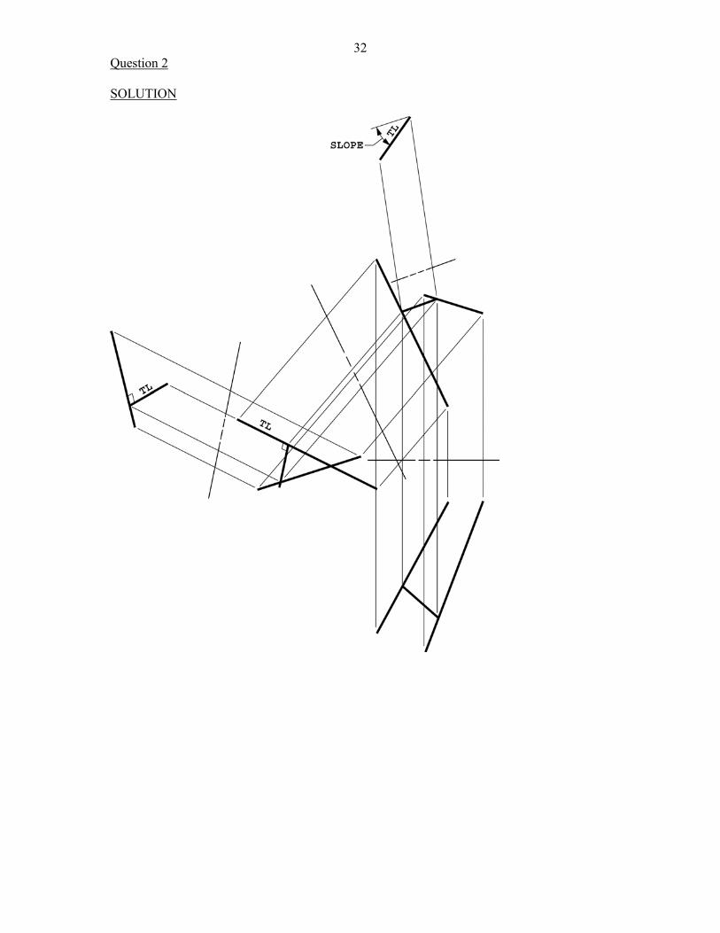
32Question 2 SOLUTION
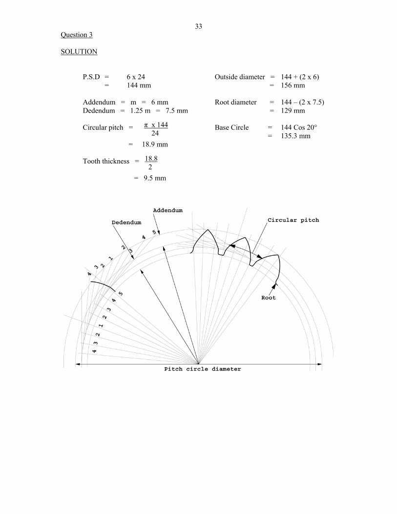
33Question 3 SOLUTION P.S.D = 6 x 24 Outside diameter = 144 + (2 x 6) = 144 mm = 156 mm Addendum = m = 6 mm Root diameter = 144 – (2 x 7.5) Dedendum = 1.25 m = 7.5 mm = 129 mm Circular pitch = Base Circle = 144 Cos 20° = 135.3 mm = 18.9 mm Tooth thickness = = 9.5 mm
π x 144 24
18.8 2
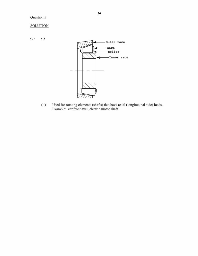
34Question 5 SOLUTION (b) (i)
(ii) Used for rotating elements (shafts) that have axial (longitudinal side) loads.
Example: car front axel, electric motor shaft.
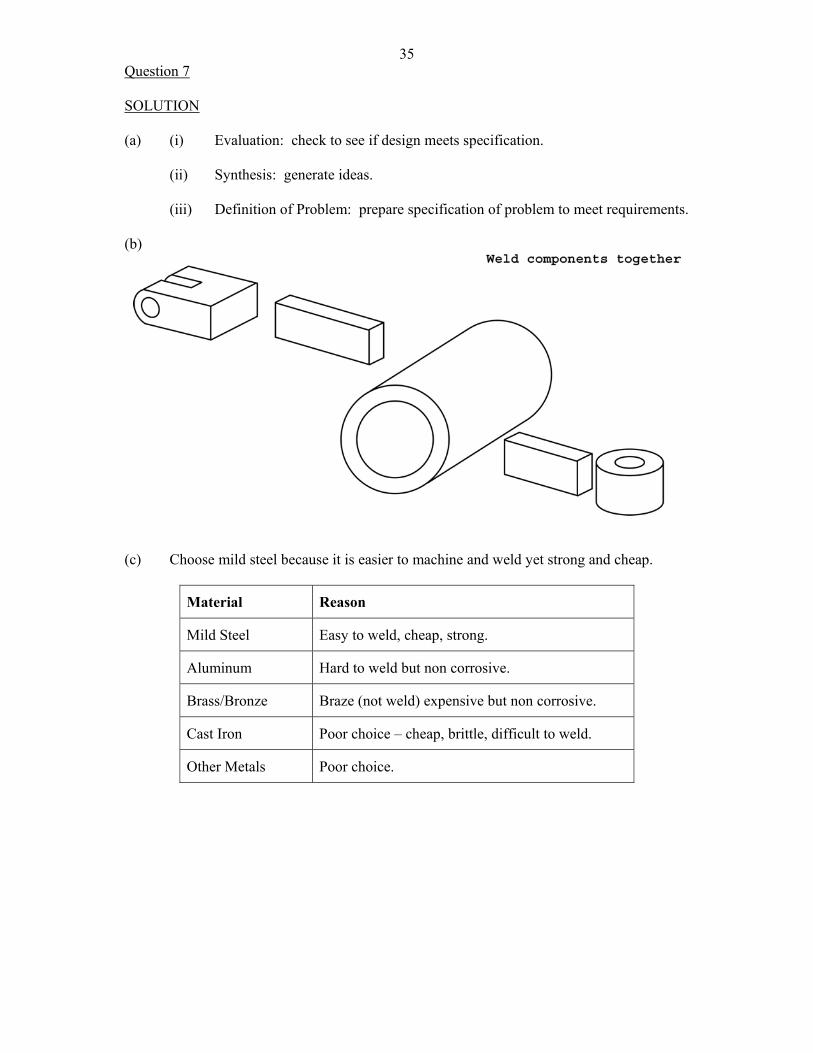
35Question 7 SOLUTION (a) (i) Evaluation: check to see if design meets specification. (ii) Synthesis: generate ideas. (iii) Definition of Problem: prepare specification of problem to meet requirements. (b)
(c) Choose mild steel because it is easier to machine and weld yet strong and cheap.
Material Reason
Mild Steel Easy to weld, cheap, strong.
Aluminum Hard to weld but non corrosive.
Brass/Bronze Braze (not weld) expensive but non corrosive.
Cast Iron Poor choice – cheap, brittle, difficult to weld.
Other Metals Poor choice.