Embed Size (px)
Citation preview
the Limm Of
1 nt- _:_Score_
(Last name) (First name) (Middle name)
When is your birthday?_A.ge last birthday_Yrs.
Age-Yrs_Mo-Da. Class in school—_ (Do not fill in) (Freshman, Jun., etc.)
How many months of drawing instruction have you had ?_
MECHANICAL DRAWING TEST for
HIGH SCHOOLS, TRADE, AND TECHNICAL SCHOOLS
by Drew W. Castle
Vocational Director Joliet Township High School and Junior College
Joliet, Illinois
Instructions for Part No. I (a, b, and c)
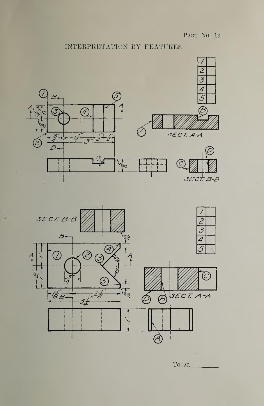
Notice the numbers in the circles on the top view. Notice that these numbers are repeated in the left-hand column of squares. In the circles on the side view are letters. After a careful study of the drawing it will be further noticed that certain numbers on the top view and certain letters on the side view point to the same part of the object. Place these letters opposite their corresponding numbers in the right-hand column of squares. The top view has one more circle than the side view. Consequently, one circle on the top view has no corresponding circle on the side view. The number in that circle is to have a blank space opposite it in the right-hand column of squares.
«
SAMPLE
Copyrighti 1928, Drew W. Caatle
00/ 92 92
9 92
^VUOJL
y/oA/:^<=/ > -7^o/<yj.:ji^o^o p 9A/o/9A/:pu//a "2
Jfi/OOC JS'Ki/OO^
*«’S*Oc/
■avxojj
S
f
2
Z
I
anoos
(ii0(j juo^^ Siii;s0j^
■lOj aoTJdg siqx 9sfi)
s ‘0>^ XHV(J
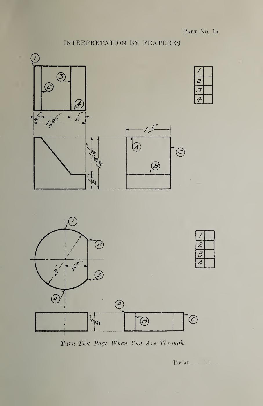
Part No. la
INTERPRETATION BY FEATURES
/
2
3
4-
Turn This Page When You Are Through
Total,
qyjLOj,
9
e f
8
6
I (Smjo;:^8r[ aq; Siiipnpiii SiiiAiEJQ aAoqy aq;
f -O]^ XHY(J
Part No. IZ)
INTERPRETATIONS BY FEATURES
Turn This Page When You Are Through •4b
Total:!!-
avxoj,
’0|SnBpoj 0i[; JO-
•8J0JT0 oqj JO
•apjp o;
•9pjT0 aqj JO
oqj p9|p^) ST p 9ut^ 9qjL
9q; p9n^o SI 0 9up oq^
SI q 9mt 91IX
9qj p9p^0 ST V 9Iiq 9qj,
pdool d^mMlodddv di[i ui
9^SuEtJJ^ ‘Sliorj
‘jqSti3j:^g| ‘djBqg
9IDJI0 ‘japxin^O '91103 '9{Su^piJj
|^9tpi97V ‘OOBJJlIg 'ojBubg 'piiu^ai!(j
ojnoy 'osclipa;
'9|SuY ‘Suo^qo
9Utq 'ptUIEJ/Cj
'9qno ‘0UOO
punoy; 'popj9^
'9|.alIY 'ai3piOtpU9CLl9J
piiu'BJi^j '9J9qdg
‘japuililo ‘aqno
9jnoY ‘j:^piSn'Bj99y; 'pjnozTJojj ‘i^aq
OpSOddQ 'j^|Il9tpU9dJ9J
‘p9pj9^ 'osnjqo
pipjEj '9j^nbg
'{BOIJJO^ ‘9{SUY
: SI 9pij B JO 9Sp9 9qj^
: B oqq pod^qs si dno ut:j y
: B St 9|q^:^ b jo do:^ oqj^
: sSireq pjoo dm^j y
: IB oqq podeqs st oSirejo uy
:st Joop y
:9J^ SOJTM
pu^ 9|od oitoqdopj ^ Joqjo q9B9 oj^
: 0.1B S9JtAV 9uoqd9p
: ire uiJOj ssi?dtno9 'B jo sS9{ u9do 9qj^
: B 9qi| pgdBqs st ojdoojs qojnqo y
'fl
•8T
SI
*IT
‘01
*6
‘8
'L
•9
•c
*1
‘8
‘S
‘T
JB|nSltBp9^ ‘Suorj
9jBnbg ‘puno^
(atduiBg)
: 9JB SUT03
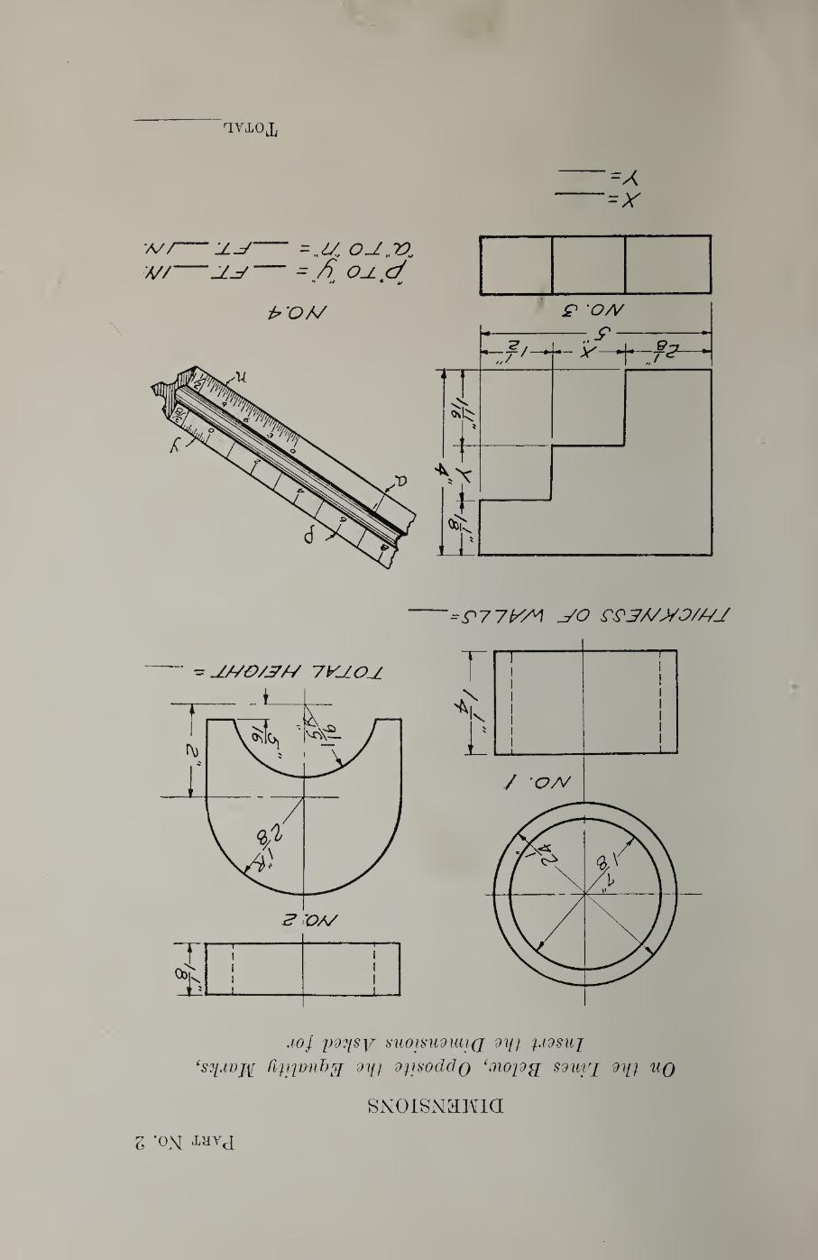
g -ON MYcI'
sdpddv pdocn dip QutjJdpufi
SHaao. ayoiaj^aiTOao
Part No. Ic
INTERPRETATION BY FEATURES
=A
A//-:z^-=M. o^„n w/—-Z-y— - /) o^d
*♦ >/ ^ V
^'OA/ ^ OA/
=P771A/A C^3/7>/0/A7J
- -J770/^A/ 7yj.OU
joJ p^'j/sy suoisu9iai(j dm ydsiij
dm diisodcJQ ‘(Yioid^ sdmq d%[i uq
SNOISNaMia
Z -ON ‘Lhvj
i
Manual for Mechanical Drawing Test /• ‘ ' Ifit UtiHAHIf By
OF ifit D. W. CASTLE
‘Qjp Vocational Director
Joliet Township High School and Junior College
Joliet, Illinois
IN designing a test in any subject it
is first necessary to analyze the
field to determine the various units
of subject matter or achievements to
be tested. Agreement in this matter
is seldom possible, for local conditions
alter educatioiial demands. It is al¬
most always possible, however, to pick
out the most prevalent units of a sub¬
ject by studying many representative
courses of study in the subject from
progressive schools. This has been
done with the result that mechanical
drawing was analyzed into the follow¬
ing divisions:
1. Interpretation of drawings of ob¬
jects by their features.
2. Use of arithmetic in mechanical
drawing dimensional situations.
3. Use of geometrical terms.
4. Pencil drawing technic.
5. Inking technic.
The problem that presented itself
after the analysis was decided upon
was the choice of various devices and
methods that would test adequately
the abilities in these units of the sub¬
ject, each independent from the other;
independent from one another, because
without the quality of independence
obtained from each individual part
there is no assurance that the measures
of a test are not also measures
in some degree of other abilities ob¬
tained from other parts of the test.
Lacking the quality of measuring, iso¬
lated, each ability, a test cannot be
used with much confidence for diag¬
nosing pupil difficulties, and a test
that cannot be used in this way is
of little value to the teacher in the
schoolroom or shop.
A great deal of care must be exer¬
cised in the selection of the devices
for measuring the ability of a pupil
to interpret a drawing. Requiring the
pupil to make, with his own hands,
some object conventionally represented
by a drawing would, of course, be the
most natural and best possible device
for measuring this ability. The im¬
practicability of following this pro¬
cedure in a test is obvious. Requiring
the pupil to draw the conventional
views of an object is likewise unde¬
sirable, because a measure from this
procedure would also include a meas¬
ure of his drawing technic. Further¬
more, we have no assurance that the
ability to draw an object in mechan¬
ical drawing conventions and the
ability to read a conventionalized
mechanical drawing made by someone
else are identical. The device that is
used for this purpose in Part No. 1
is based upon the psychology of the
association of the elements of a con¬
ventionalized mechanical drawing rep¬
resentation of an object, a mental
process that is used in reading draw¬
ings.
Part No. 1. Interpretation of
Drawings
It is hardly possible to associate
Avith certainty an element (solid,
dotted, or center lines) of a view
directly with the corresponding fea-
Copyiighti 1928, Drew W. Castle
2 MANUAL FOR MECHANICAL DRAWING TEST
ture on the object without associating
that element with other elements on
other views, all of them representing
the same features.
This psychology may be illustrated
columns of squares, those numbers
and letters which point to elements
on the drawing that represent the
same feature on the object. (See the
sample problem on the front of test.)
£'Ar£‘/y T
SL £'/^£‘/VT I /f Z Z’/VZVyT’ 2
TC//FS 0^c/£r 0 7“
\3\
I I I i_—I—(
by Fig. 1. If the reader of this draw¬
ing were to look at Element 1 he would
associate it with a flat surface, an edge,
or the tangent line of a cylinder. If,
however, he were to shift his attention
from Element 1 to Element 2, he
would be able to associate Element 1
with Element 2 and recognize at once
that the feature on the object which
both of these elements represent is a
sharp edge. As a check on this in¬
terpretation, the attention may be
shifted to Element “a” where it
would be recognized that the dotted
line represents a hidden corner.
Now, if it is desired to test the
ability of the reader of this drawing
to recognize that these features rep¬
resent a sharp, hidden edge, it is only
necessary to require him to demon¬
strate that he has associated Element
1 with Element 2. The device that
is used for this purpose is a system
of circles in which the subject inserts
numbers and letters and pairs in
As the triangle diagram in Fig. 1
indicates, if the subject has made the
proper associations between Element 1
and the feature it represents and Ele¬
ment 2 and the same feature, he will
be able to indicate this fact by pairing
the letter in the circle that points to
Element 1 with the figure in the circle
that points to Element 2 through the
proper record in the squares. If the
subject does not make the proper
record in the columns of squares, it
indicates that he is not able to analyze
and interpret these elements of the
drawing.
The occasion might arise where it
will be necessary to associate an ele¬
ment on one view with more than one
element an another view before a cor¬
rect interpretation of them can be
made. This situation may be illus¬
trated by Fig. 2.
Element 1, at a casual glance, might
be associated with a hole, but it is
possible for such a line to represent
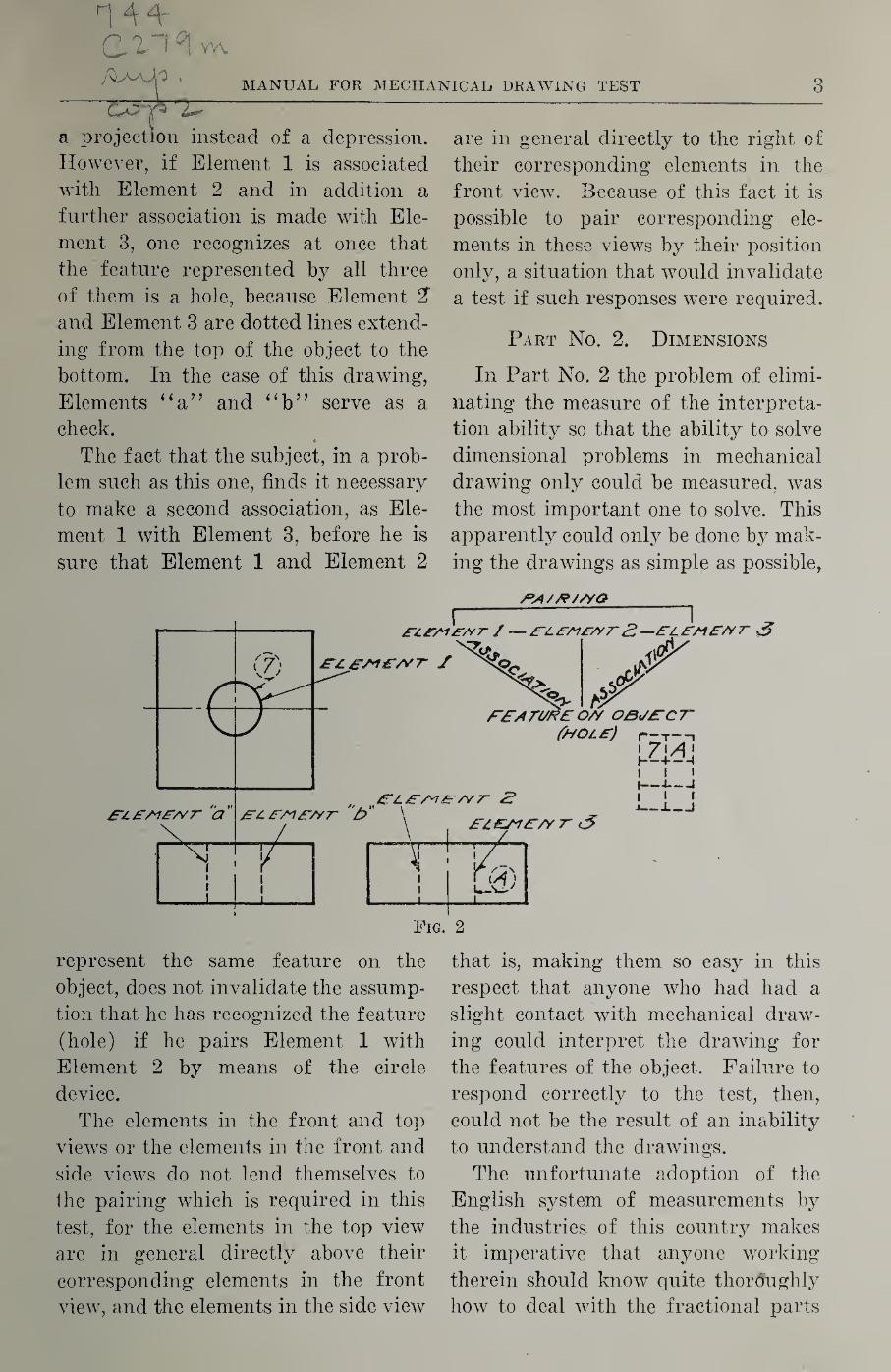
MANUAL FOR MECHANICAL DRAWING TEST 3
a projection instead of a depression.
However, if Element 1 is associated
Avith Element 2 and in addition a
further association is made with Ele¬
ment 3, one recognizes at once that
the feature represented by all three
of them is a hole, because Element 2"
and Element 3 are dotted lines extend¬
ing from the top of the object to the
bottom. In the case of this drawing,
Elements “a” and “b” serve as a
check.
The fact that the subject, in a prob¬
lem such as this one, finds it necessary
to make a second association, as Ele¬
ment 1 with Element 3, before he is
sure that Element 1 and Element 2
are in general directly to the right of
their corresponding elements in the
front view. Because of this fact it is
possible to pair corresponding ele¬
ments in these views by their position
only, a situation that would invalidate
a test if such responses were required.
Part No. 2. Dimensions
In Part No. 2 the problem of elimi¬
nating the measure of the interpreta¬
tion ability so that the ability to solve
dimensional problems in mechanical
drawing only could be measured, Avas
the most important one to solve. This
apparently could only be done by mak¬
ing the drawings as simple as possible,
represent the same feature on the
object, does not invalidate the assump^
tion that he has recognized the feature
(hole) if he pairs Element 1 with
Element 2 by means of the circle
device.
The elements in the front and top
vicAvs or the elements in the front and
side views do not lend themselves to
the pairing which is required in this
test, for the elements in the top view
are in general directly above their
corresponding elements in the front
view, and the elements in the side vieAv
that is, making them so easy in this
respect that anyone who had had a
slight contact with mechanical draw¬
ing could interpret the draAving for
the features of the object. Failure to
respond correctly to the test, then,
could not be the result of an inability
to understand the draAvings.
The unfortunate adoption of the
English system of measurements by
the industries of this country makes
it imperative that anyone working
therein should know quite thoroughly
how to deal with the fractional parts
4 MANUAL FOR MECHANICAL DRAWING TEST
of whole numbers or with devices such
as the scale which does some of the
computing. It is for this reason that
in Part No. 2 stress is placed on
problems involving fractions.
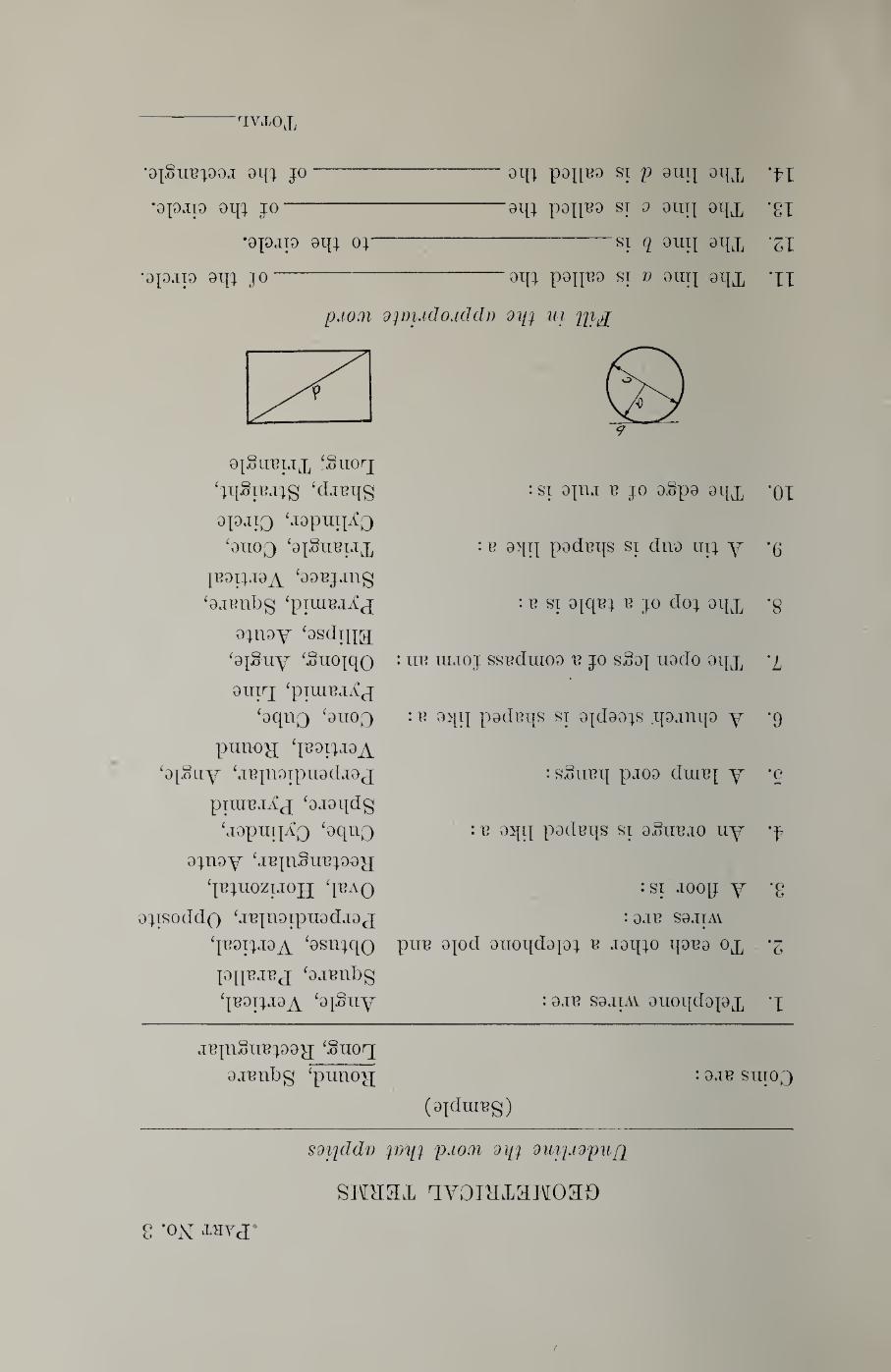
Part No. 3. Geometrical Terms
Using the very working elements of
geometry and the tools that accurately
arrange them into rational forms, as
is done in mechanical drawing, results
in an unavoidable use of geometrical
terms. Since many operations can
only be explained in geometrical lan¬
guage, directions are not understand¬
able without the knowledge of geo¬
metrical terms. This phase of the
subject being purely informational,
the test for the ability to understand
geometrical terms is thrown into the
multiple response and the completion
form of examination.
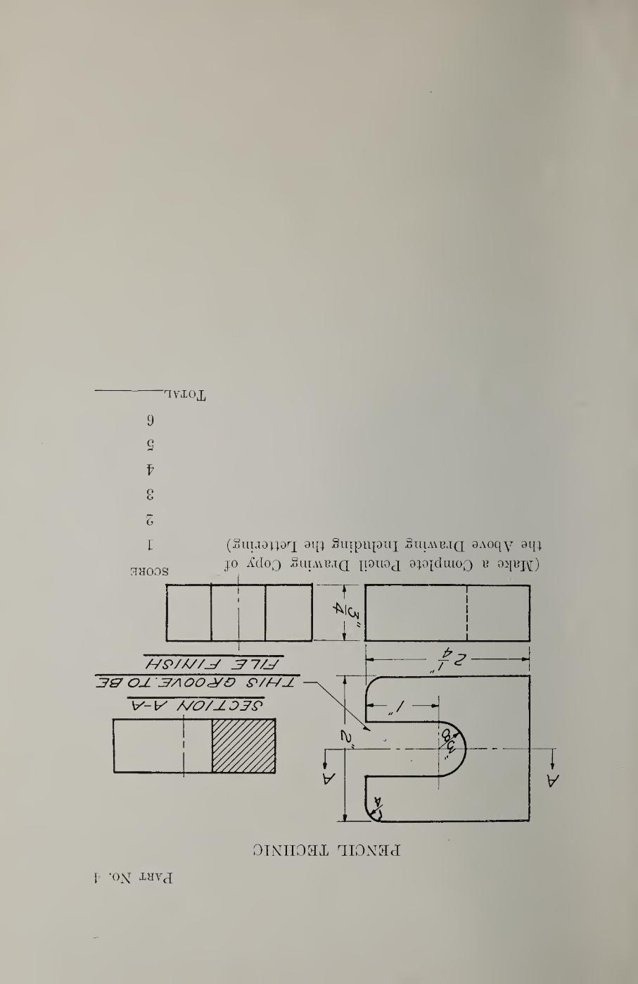
Part No. 4. Pencil Technic
In testing the ability of the subject
to do pencil drawing, the most inti¬
mate related ability that has to be
eliminated is drawing interpretation.
This has been accomplished by requir¬
ing the pupil to copy a drawing that
has already been correctly made.
Theoretically, any one who has never
had instruction in ‘‘mechanical draw¬
ing, but who has been instructed in
the use of the tools in drawing and
the technic of lettering, could copy
this drawing satisfactorily without
having a visual impression of the
appearance of the object. Conse¬
quently, this device measures only the
ability of the subject to perform with
the pencil tools in drafting. In order
to save time in obtaining the sample
of the pencil technic of the subject,
a simple object has been selected.
The drawing qualities rated in this
part were selected as the most common
ones required in commercial practice.
The methods of arriving at the quali¬
tative measurements of the qualities
are admittedly to some degree sub¬
jective. However, by the use of vari¬
ous procedures, this element is reduced
to a minimum.
For example, the completion of a
drawing, one of the qualities rated,
is in a large degree a measure of the
speed of drawing and is arrived at by
estimating that fraction of the draw¬
ing that is finished. “Half done” or
“one-fourth done” are common ex¬
pressions, and to no small degree
accurate when experienced persons
make the estimates. Such estimates
are very easily transferred into meas¬
ures of points, as required in the
weighing of the qualities.
The measure of the legibility of a
drawing is quite subjective at best,
which, of course, makes the rating
that might be given this quality, a
rough estimate. It is quite impera¬
tive, however, for a drawing to possess
this quality, for it must be easy to
read. However, the fact that this
method of judging this quality is not
as objective as it should be, does not
overbalance the importance of making
some rating in legibility. In making
the actual rating, however, as is
pointed out in the Directions for Scor¬
ing, the legibility of the letters must
be ignored, for the rating of this qual¬
ity is covered in a separate item.
The accuracy of a drawing would be
very easy to check if the rater measured
each line. Such procedure is not prac¬
tical, neither is it necessary; for, if
a few measurements are taken at
random, very good samples of the

MANUAL FOR MECHANICAL DRAWING TEST 5
accuracy of the entire drawing can
be obtained. It is important, how¬
ever, that the rater make an effort
to obtain representative samples of
accuracy from different parts of the
drawing.
The quality of the figures and let¬
ters on the pencil drawing are rated
by comparing them with samples of
other pupils’ letters and figures that
have been previously rated by experts.
(Figs. 4 and 5.) This quality could
be rated by the use of a scale already
tried out and found effective, such as
the Rugg Lettering Scale. It would
be necessary, however, to translate the
scales used on Rugg’s device into a*
four-point system that is used in this
test.
It will be noticed that two separate
scales are provided; one for slant
lettering, and the other for vertical
lettering. Also, that the samples fur¬
nished contain the same material that
is found in the test. It is obvious
that a rating based on the comparison
which can be made between a sample
and a scale designed in this way will
be much more accurate than a rating
based on a comparison between a
sample and a scale which contains
material with foreign subject matter.
There is a ‘‘point” in the cleanliness
of the drawing which makes the draw¬
ing acceptable or not acceptable. If
the cleanliness of the drawing is above
this point, one score point is allowed.
If the drawing is “dirty,” this point
is not allowed. It is obvious that the
method of determining whether or not
this point should be allowed for the
quality of cleanliness, is not absolute,
but since the point value attached to
it is small, the final score will be in¬
fluenced by only a small amount.
Part No. 5. Inking Technic
The rating of inked or traced draw¬
ings involves factors quite the same
as those found in pencil drawings.
Those qualities which are identical in
the two situations are COMPLETE¬
NESS, FIGURES, and LETTERS.
The comments made above regard¬
ing these three qualities have equal
application in the case of inked
drawings.
The thickness used in the lines of
an inked drawing is a matter of
standard procedure; made so, because
experience has shown that the legi¬
bility of a drawing is dependent in a
large measure on the rigid adherence
to these standards. Thus, the quality
of legibility, which is used in the case
of pencil drawings, is taken care of in
“quality of lines,” a rating which is
given in the case of inked drawings.
The actual assignment of the number
of points that should be allowed is a
matter of estimate after the lines of
the drawing have been scrutinized and
compared with the model.
The skill of the draftsman with his
pen is very largely determined by his
ability to maintain a constant thick¬
ness of lines. Negligence in keeping
the pen clean or overloading the pen
with ink, will invariably show up in
the non-uniformity of the lines. The
number of points assigned to this
quality will of necessity have to be
an estimate.
The quality of “neatness” in an
inked drawing is an arbitrary name
assigned to that condition of the paper
relative to blots and erasures. The
skill of erasing blots, overruns, and
mistakes, shows up quite plainly in
rating this quality. A subject is not
6 MANUAL FOR MECHANICAL DRAWING TEST
penalized, then, if lie makes a mistake
and corrects it in such a way that it
still presents a neat appearance. Here
again the assignment of the point score
is an estimate, thus making the rating
of this quality more subjective than
objective.
The comments made above relative
to the rating of some of the qualities
have been quite critical. Perhaps so
much so that the inference is made
that ratings which are not entirely
objective are not worth while. It has
been proved, however, that ratings
based on some organized form of pro¬
cedure, whereby all raters have clearly
in mind the exact nature of the quality
rated, are much more accurate and the
results more comparable than they are
by the ordinary method of grading a
drawing or rating a student in me¬
chanical drawing.
DIRECTIONS FOR CONDUCTING THE TEST
Each student must be seated at a drawing bench with the following
equipment: 1 Soft pencil
1 4H pencil (well sharpened)
1 Lettering pen
1 Eubber eraser 1 Set of drawing instruments (leads
well sharpened)
1 Tee square
1 45° triangle
4 Thumb tacks
1 Bottle India ink
1 Cleaning rag (for pens)
After it has been ascertained that
each pupil is ready with the jiroper
equipment in good order, the books
will be distributed in the usual way
with the warning that they are not to
be opened until the signal is given.
Proceed then as follows:
^‘We are now going to determine
how proficient you are in mechanical
drawing. This test is divided into
five parts. You will work on each
part for a certain length of time. It
will be necessary for you to pay very
close attention to directions and do
exactly as I say. Prepare yourself
now by resting your elbow on the
bench with your soft pencil in your
hand as I am showing you. We will
start each part by the signal ‘go’ and
stop upon the signal ‘pencils up,’ at
which time jmu will assume the posi¬
tion you now have and await further
directions. No questions will be
answered because all directions will .
be adequate if you will pay close atten¬
tion to them.”
Filling in Information Blanks
“Lower your pencils and fill in the
blank spaces at the top of the front
page of your booklet with the excep¬
tion of the one marked ‘Age, Yrs.,
Mo., and Da.,’ being careful to note
the information asked for. Make
your writing as plain as you can.”
(Pause.)
Part No. 1. (Allow 3^ min.)
“Pencils up. In Part 1 of this
booklet we are going to interpret some
drawings. It will first be necessary
for you to read carefully with me the
instructions for this part on the front
of your booklet.
‘ ‘ ‘ Notice the numbers in the cir¬ cles on the top view. Notice that these numbers are repeated in the left-hand column of squares. In the circles on the side view are letters. After a careful study of the draw¬ ing it will be further noticed that certain numbers on the top view and certain letters on the side view point to the same part of the object.
MANUAL FOR MECHANICAL DRAWING TEST 7
Place these letters opposite their corresponding numbers in the right- hand column of squares. The top view has one more circle than the side view. Consequently, one circle on the top view has no correspond¬ ing circle on the side view. The number in that circle is to have a blank space opposite it in the right- hand column of squares.’
^‘Following out these directions,
then, you will notice upon a study of
the drawing below that number one
on the top view and letter ‘B’ on the
side view point to the same part of the
object. Lower your pencils and write
the letter ‘B’ in the square opposite
the number one. {Pause.) Upon a
further study of the drawing you will
readily note that the number two and
the letter ‘A’ point to the same part
of the object. Accordingly then write
the letter ‘ A ’ in the right-hand column
of squares opposite the number two.
{Pause.) Pencils up. You will notice
that the number three has no corre¬
sponding letter on the side view. Be¬
cause of this fact the space in the
right-hand column of squares opposite
the number three will be left empty.
In all the problems that follow in the
first part, there will be one more cir¬
cle on the top view than there is on
the side view. Therefore, one vacant
square should always appear in the
right-hand column. Following are
three pages of problems similar to
this one. When you have finished fill¬
ing out the squares on one page turn
immediately to the next one and pro¬
ceed in a like manner until all three
are completed. Do not turn the
fourth page, and remember to put
your pencils up immediately when I
command you to do so. Turn the
first page. Go.” {Allow 3^^ min.)
Part No. 2. {Allow 4 mm.)
“Pencils up. Close the booklet and
turn it over to Part No. 2, which is
entitled Dimensions. Bead with me
the directions at the top of the page.
‘ On the lines below, opposite the
equality marks, insert the dimensions
asked for.’ Here are the front and
top views of three objects, and a pic¬
ture of your scale*. Ydu are to write
on the lines opposite the equality
marks the dimensions called for. In
other words, you are to compute the
thickness of the walls in No. 1 and
write your answer in the space pro¬
vided. For No. 2, you are to compute
the total height of the object; for No.
3 the dimensions X and Y; and for
No. 4 the scale reading from p io y
and from a to n. Do the necessary
computation on the test itself. Start
when I say ‘go,’ and work as many
as you can. Go.” {Allow 4 min.)
Part No. 3. {Allow 1% min.)
“Pencils up. Turn the page over
to Part No. 3, which is entitled Geo¬
metrical Terms. You will notice ten
sentences which are completed by four
words, only one of which is correct.
You are to underline the correct word
as indicated in the sample at the top
of the page: ‘ Coins are: ’ The correct
word is ‘round,’ therefore the word
‘round’ is underlined. The last four
sentences have one word missing. You
are to write in the missing word.
When I say ‘go,’ you are to proceed
and work as many as you can. Go.”
{Allow 1^2 'uiin.)
Part No. 4. {Allow 12 min.)
“Pencils up. Turn the page over
to Part No. 4 entitled Pencil Technic,
lower your pencil, and fasten the book
to your drawing board with thumb
8 MANUAL FOR MECHANICAL DRAWING TEST
tacks, being careful to line it up with
your tee square. (Pause.) You are
going to copy the drawing of the ob¬
ject in the space on the lower half of
the page to see how accurately and
neatly you can draw. It will be neces¬
sary for you now to place near at
hand all of the instruments and equip¬
ment necessary for this work. Use
your 4H pencil for this drawing.
(Pause—he certain that each subject
is prepared.) Do not forget to put
in all of the lettering that belongs to
the drawing. Work carefully at your
usual rate of speed. Pencils up again.
Go.’’ (At the end of 10 mm. say,
you have not already done so, start on
the lettering.^^ (Allow 12 min.)
Part No. 5. (Allow 20 min.)
“Pencils up. Eemove the thumb
tacks and turn the page over to Part
No. 5 entitled Inking Technic. Lower
your pencil, line up the drawing of
the object with your tee square, and
fasten the paper to the board again
with thumb tacks. (Pause.) Take
your instruments and ink the draw¬
ing, assuming it to be executed in
pencil. Take care to give the lines
the proper weight and ink the letter¬
ing in your own style. Work care¬
fully at your usual rate of speed.
(Be sure everybody is ready.) Pen¬
cils up again. Go.” (At the end of
17 min. say, If yaii have not already
done so, start on the lettering.^^)
(Allow 20 mm.)
‘ ‘ Pencils up. Allow the ink to dry
and close your booklet. That’s all.”
DIRECTIONS FOR SCORING THE TEST
IN Part Nos. 1 to 3, inclusive, 1 point
is given for each correct answer.
Total the points on each page and indi¬
cate the figure at the bottom of the
page where a space has been provided.
In Part No. 4 the pencil drawing is
scored on the following qualities and
weights:
1. Completeness. 8 Points
2. Legibility . 5
3. Accuracy. 4
4. Figures. 4
5. Lettering . 4
6. Cleanliness . 1
Total ..'.26
1. Completeness has reference to
that fraction which represents how
much of the drawing is finished. If
the drawing appears to be one-half
done this quality should receive 4
points, if it is one-fourth done, 2
points, etc. 2. Legibility is the quality pos¬
sessed by a drawing that makes it easy
to read. The degree of legibility will
depend on the time necessary to in¬
terpret the lines. The visible outlines
should be clean cut and the hidden
outlines made up of dashes of approxi¬
mately equal length. The extension,
dimension, and center lines should be
a trifle thinner or lighter than the rest.
Do not consider the figures and letters
in this quality for they are rated un¬
der No. 5.
3. A drawing is accurate if it
measures what its dimensions say it
does. To determine this, measure 4
dimensions at random. For every one
that is off rh" reduce the points by 1.
Be sure to include at least one circle
or curve.
4. Figures. Find which on^ of the
accompanying samples (Figs. 4 and 5)
most nearly compares with the figures
on the test, and rate accordingly.
MANUAL FOR MECHANICAL DRAWING TEST 9
5. Letters. Find which one of the
accompanying samples (Figs. 4 and
5) most nearly compares with the let¬
tering on the test, and rate accord¬
ingly. If the subject uses slant letters,
compare his sample with the slant let¬
tering scale. If the subject uses ver¬
tical letters, compare his sample with
the vertical lettering scale.
6. Cleanlimss. If the drawing is
not scrupulously clean, do not allow
this point.
In Part No. 5 the inked drawing is
scored on the following qualities and
weights:
1. Completeness. 8 Points
2. Quality of lines. 5
3. Uniformity of thickness. 4
4. Neatness. 3
5. Figures . 3
6. Letters . 3
Total .S
1. Completeness has reference to
that fraction which represents how
much of the drawing is finished. If
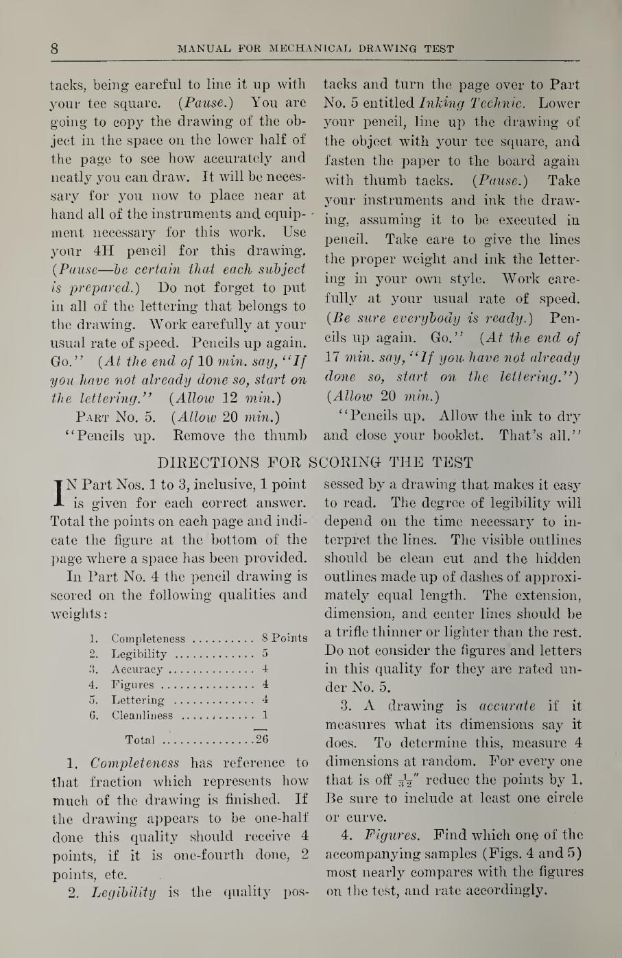
OC/7~/./AV£'
/i//:>£>£r/v oar/L//vJE' %S£‘CT/OA/ //V£: /?/A1£:/V<S/0/V Z/AC£" £'X/'jE'/ys/o/y z//yz:
C^/V7~/Er/P Fig
the drawing appears to be one-half
done, this quality should receive 4
points; if it is one-fourth done, 2
points, etc.
2. Quality of lines. The generally
accepted standard thickness for the
various lines is given in Fig. 3.
Conformity with the above stand¬
ards, smoothness of curve, and
straight-line intersections, uniformity
of distance between section lines, uni¬
formity of length of dashes in hidden
outlines, and quality of arrowheads
should be considered in this score. Do
not consider the figures and letters in
this quality.
3. JJniformity of thickness. This
quality has reference to the uniformity
of thickness of the inked lines. The
following questions should be asked:
Are all visible outlines of the same
thickness; are all center lines of the
same thickness, etc.?
4. Neatness. This quality is gen¬
eral but should exclude figures and
letters. Any blots, erasures, over¬
running lines, and general cleanliness
should be considered.
5. Figures. Find which one of the
accompanying samples (Figs. 4 and 5)
most nearly compares with the figures
on the test, and rate accordingly. If
the subject uses slant letters, compare
his sample with the slant lettering
scale. If the subject uses vertical let¬
ters, compare his sample with the ver¬
tical lettering scale.
3
6. Letters. Find which one of the
accompanying samples (Figs. 4 and 5)
most nearly compares with the letter¬
ing on the test, and rate accordingly.
The possible scores are :
Part Nos.
1. Interpretation by Features. 28
2. Dimensions . 6
3. Geometrical Terms. 14
4. Pencil Technic. 26
5. Inking Technic. 26
Total.100
SLANT
LETTER RATING SCALE
^£-CT/0/y /i-A SECT/ON A-A
r/r/Z’SH ALL OV£:/9 FJN/SH ALL OVER
»
<j£'c r/o/y /-I -A >5^Cr/0/V A-A
rn/tS G/?oovs to bs
T/L B T/ZV/fS//
TH/3 GPOOVe TO S£
F/L£ £/N/S/i
/23^S67e90
Rate 4
/23^S67690
Rate 3
SEcr/o/y A-A SECTION A~A
E//y/5/i ALL OVER FINISH ALL 0 VER
SEC noZiA-A SECTION /4'A
tb/s groove to be TILE E/B/SB
THIS &H.OOYE TO BE
FHE finish
/Z3 46L7& 90 /Z3^7^7890
Rate 2 Rate 1
Fig. 4
10
VERTICAL
LETTER RATING SCALE
SECTION A-fii
FIMI5H ALL 0\/ER
SECTION A.-A
THIS GROOVE TO BE
FILE FINISH
\2345678<^0
Rate 4
SrCTION A A
FINISH Al I OVIR
SECTION A A
THI5 GROOVE TOBt TiLinmn
1234567630 Rate 2
SECTION A-A
FINISH ALL OVER
SECTION A-A
THIS GROOVE TO BE
FILE FINISH
123 4367890 Rate 3
SECTION A-A «
FINISH ALL OVER
SECTION A-A
THIS GROOVE TO BE FILE FINISH
143^567690
Rate 1
Fig. 5
11