Embed Size (px)
Citation preview
Chapter 6
GEOLOGIC MAPPING ANDDOCUMENTATION
Geologic mapping is defined as the examination ofnatural and manmade exposures of rock or uncon-solidated materials, the systematic recording of geologicdata from these exposures, and the analysis and inter-pretation of these data in two- or three-dimensionalformat (maps, cross sections, and perspective [block]diagrams). The maps and cross sections generated fromthese data: (1) serve as a record of the location of factualdata; (2) present a graphic picture of the conceptualmodel of the study area based on the available factualdata; and (3) serve as tools for solving three-dimensionalproblems related to the design, construction, and/ormaintenance of engineered structures or site characteri-zation. This chapter presents guidelines for thecollection and documentation of surface and subsurfacegeologic field data for use in the design, specifications,construc-tion, or maintenance of engineered structuresand site characterization studies.
Responsibilities of the Engineering Geologist
An engineering geologist defines, evaluates, and docu-ments site-specific geologic conditions relating to thedesign, construction, maintenance, and remediation ofengineered structures or other sites. This responsibilityalso may include more regionally based geologic studies,such as materials investigations or regional reconnais-sance mapping. An engineering geologist engaged ingeologic mapping is responsible for:
• Recognizing the key geologic conditions in a studyarea that will or could significantly affect hazardousand toxic waste sites or a proposed or existingstructure;
FIELD MANUAL
130
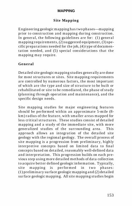
• Integrating all the available, pertinent geologicdata into a rational, interpretive, three-dimensionalconceptual model of the study area and presentingthis conceptual model to design and constructionengineers, other geologists, hydrologists, sitemanagers, and contractors in a form that can beunderstood.
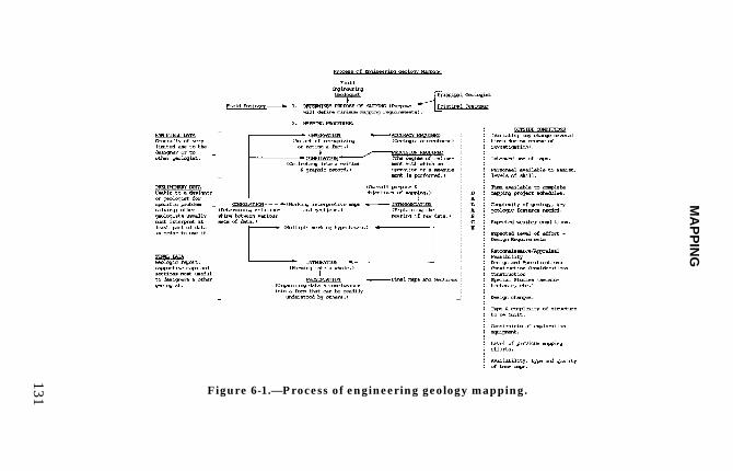
The process and responsibilities of engineering geologymapping are illustrated in figure 6-1.
The engineering geologist needs to realize that geologicmapping for site characterization is a dynamic process ofgathering, evaluating, and revising geologic data andthat the significance of these data, both to the structureand to further exploration, must be continually assessed.The initial exploration program for a structure is alwaysbased on incomplete data and must be modifiedcontinuously as the site geology becomes betterunderstood. The key to understanding the site geologyis through interpretive geologic drawings such asgeologic maps, cross sections, isopachs, and contourmaps of surfaces. These working drawings, periodicallyrevised and re-interpreted as new data become available,are continuously used to assess the effects of the sitegeology and to delineate areas where additional explora-tion is needed. These drawings are used in designs,specifica-tions, and modeling and maintained in thetechnical record of the project.
Development of a Study Plan
Prior to mapping any project, a study plan must bedeveloped. Depending on the complexity of the sitegeology, the nature of the engineered structure, and thelevel of
MA
PP
ING
131 Figure 6-1.—Process of engineering geology mapping.
FIELD MANUAL
132
previous studies, the study plan may be preliminary orcomprehensive. Although elements of the plan may bemodified, expanded, or deleted as geologic data becomeavailable, the primary purpose of the study plan—coordination among all geologists and engineers workingon the project—should be retained. Early study plandevelopment and agreement to this plan by thoseinvolved in the project are necessary to prevent thecollection of unneeded, possibly costly data and ensureneeded data are available at the correct time in theanalysis, design, and construction process.
Scope of Study
The purpose and scope of the mapping project arestrongly influenced by the primary engineering andgeologic considerations, the level of previous studies, andoverall job schedules. The purpose and scope areformulated jointly by the geologists and engineers on theproject. Time of year and critical dates for neededinformation also will have a great impact on the pace ofdata collection and the personnel needed to handle amapping project. Discussion of these factors prior toinitiating the mapping program is essential so that onlynecessary data are obtained and the work can becompleted on schedule. Items to consider when definingthe scope of a mapping program are:
1. Study limits.—Set general regional and site studylimits based on engineering and geologic needs.
2. Critical features and properties.—Determine thecritical geologic features and physical properties of sitematerials that will need to be defined and discuss thedifficulties in collecting data on these features.
MAPPING
133
3. Schedules.—Determine schedules under which thework will be performed and define key data due dates.Prioritize work to be done. The time of year the mappingis to be performed, the type of mapping required,available personnel and their skills, the availability ofsupport personnel such as drill crews and surveyors, andbudget constraints will influence the work schedule andmust be carefully evaluated.
4. Extent of previous studies.—Collect and study allavailable geologic literature for the study area. The ex-tent and adequacy of previous studies helps to define thetypes of mapping required and how data will becollected, i.e., based on analyses, design, or constructionneeds.
5. Photography.—Aerial and terrestrial photo-graphy should be considered for any project. As a mini-mum, aerial photographs of the site should be reviewed.Aerial photographs reveal features that are difficult torecognize from the ground or at small scales. Extensiveuse of terrestrial or aerial photography will require adifferent approach to the mapping program. Defineareas where terrestrial photogrammetry could aidmapping progress. Terrestrial photography of varioustypes is an integral part of the final study record.
Specific Mapping Requirements
This section provides the basic considerations anengineering geologist should evaluate prior to startingany mapping project or portion of a mapping project.
Map Type
Define the types of mapping required and how data areto be collected, including special equipment needed for
FIELD MANUAL
134
data collection. The types of mapping required dependon the study purpose or the type of structure or site thatis to be built or rehabilitated, structure size, the phase ofstudy (planning through operation and maintenance),and the specific design needs.
Scales and Controls
Define the required scales for design or constructionneeds. Although finished maps can be enlarged orreduced photographically or by Computer-Aided DraftingDesign (CADD)-generated drawings to any desired scale,in most cases map text and symbols will have to beredone for legibility. Selection of an adequate map scaleat the beginning of a mapping project will save time andenergy as well as help ensure that the types of dataneeded can be portrayed adequately on the finaldrawings. Suggested map scales for various types ofinvestigations are listed under specific mappingtechniques.
The horizontal and vertical accuracy and precision oflocations on a map depend on the spatial control of thebase map. General base map controls are listed indecreasing significance: (1) Survey Control or ControlledTerrestrial Photogrammetry—geology mapped fromsurvey controlled observation points or by plane table orstadia; (2) Existing Topographic Maps—control for thesemaps vary with scale. The most accurate are large-scalephotogrammetric topographic maps generated fromaerial photographs for specific site studies; (3)U n c o n t r o l l e d A e r i a l / T e r r e s t r i a lPhotogrammetry—Camera lens distor-tion is the chiefsource of error; (4) Brunton Compass/ Tape Surveys—canbe reasonably accurate if measure-ments are taken withcare; and (5) Sketch Mapping— Practice is needed tomake reasonably accurate sketch
MAPPING
135
maps. The Global Positioning System can provide ade-quate position locations depending on the requiredaccuracy or precision.
Global Positioning System
The Global Positioning System (GPS) is a system ofsatellites that provides positioning data to receivers onearth. The receiver uses the positioning data to calculatethe location of the receiver on earth. Accuracy and typeof data output depends on many factors that must beevaluated before using the system. The factors thatmust be evaluated are: (1) the needs of the project, (2)the capabilities of the GPS equipment, and (3) theparameters necessary for collecting the data in anappropriate form.
Project Requirements
The location accuracy or precision needed by the projectis a controlling factor whether GPS is appropriate for theproject. The actual needs of the project should be deter-mined, being careful to differentiate with “what would benice.” Costs should be compared between traditionalsurveying and GPS.
GPS Equipment
Different GPS receiver/systems have differentaccuracies. Accuracies can range from 300 ft to inches(100 m to cm) depending on the GPS system. Costsincrease exponen-tially with the increase in accuracy. Arealistic evalua-tion of the typical accuracy of theequipment to be used is necessary, and a realisticevaluation of the needed, not “what would be nice,”accuracy is important. Possible accuracy and typicalaccuracy are often not the same.
FIELD MANUAL
136
Datums
The datum or theoretical reference surface to be used forthe project must be determined at the start. U.S.Geologi-cal Survey (USGS) topographic maps commonlyuse North American Datum (NAD) 27, but most newsurveys use NAD 83. Changing from one datum toanother can result in apparent location differences ofseveral hundred feet or meters if not done properly.
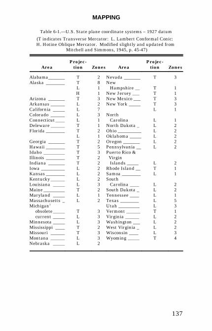
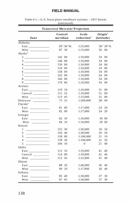
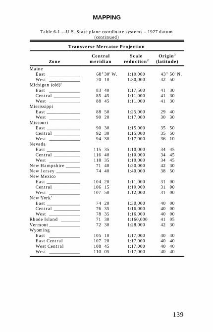
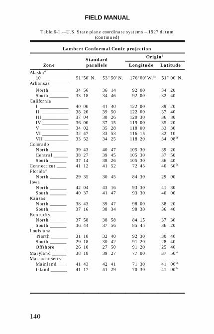
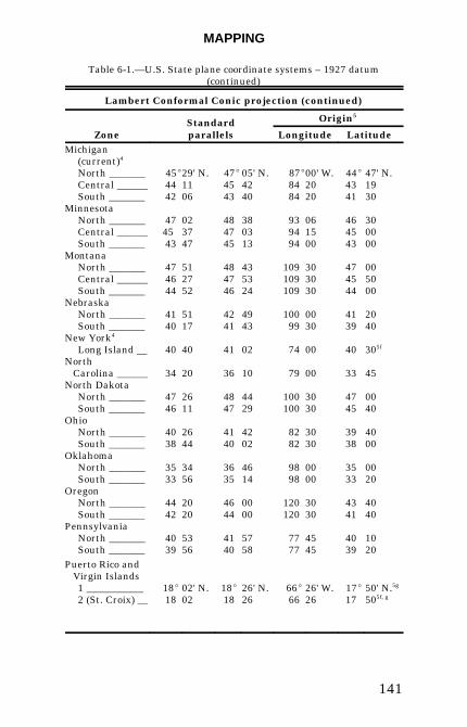
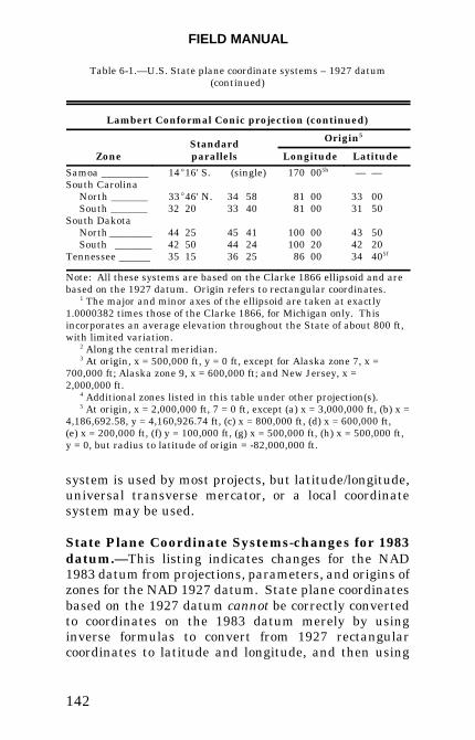
Map Projections
The map projection is the projection used to depict theround shape of the earth on a flat plane or map. Themost common projections used in the United States arethe Transverse Mercator and the Lambert ConformalConic. State plane coordinate systems almostexclusively use one or the other. To use these stateplane projections, location and definition parameters arenecessary. Table 6-1 has the types of projections and theprojection parameters for each state in the UnitedStates. A discussion of map projections and coordinatesystems is in Map Projections - A Working Manual,USGS Profes-sional Paper 1395[1].
Transverse Mercator.—The Transverse Mercatorprojection requires a central meridian, scale reduction,and origin for each state or state zone.
Lambert Conformal Conic.—The Lambert ConformalConic projection requires two standard parallels and anorigin for each state or state zone.
Coordinate System.—The coordinate system is the gridsystem that is to be used on the project. The state plane
MAPPING
137
Table 6-1.—U.S. State plane coordinate systems – 1927 datum
(T indicates Transverse Mercator: L. Lambert Conformal Conic: H. Hotine Oblique Mercator. Modified slightly and updated from
Mitchell and Simmons, 1945, p. 45-47)
AreaProjec-
tion Zones AreaProjec-
tion Zones
Alabama _______Alaska ________
Arizona _______Arkansas ______California _____Colorado ______Connecticut ____Deleware ______Florida ________
Georgia _______Hawaii ________Idaho _________Illinois ________Indiana _______Iowa __________Kansas ________Kentucky ______Louisiana _____Maine _________Maryland _____Massachusetts _Michigan1
obsolete _____current _____
Minnesota _____Mississippi ____Missouri ______Montana ______Nebraska _____
TTLHTLLLLTTLTTTTTLLLLTLL
TLLTTLL
281132731121253222223212
3332332
Nevada _______New Hampshire __New Jersey ___New Mexico ___New York _____
North Carolina North Dakota _Ohio __________Oklahoma _____Oregon _______Pennsylvania __Puerto Rico & Virgin Islands _____Rhode Island __Samoa ________South Carolina ____South Dakota _Tennessee ____Texas ________Utah _________Vermont ______Virginia ______Washington ___West Virginia _Wisconsin ____Wyoming _____
T
TTTTL
LLLLLL
LTL
LLLLLTLLLLT
3
11331
122222
211
22153122234
FIELD MANUAL
138
Table 6-1.—U.S. State plane coordinate systems – 1927 datum(continued)
Transverse Mercator Projection
ZoneCentral
meridianScale
reduction2Origin3
(latitude)
AlabamaEast ______________West _____________
85E87
50' W.30
1:25,0001:15,000
30E30
30' N.00
Alaska4
2 _________________ 142 00 1:10,000 54 003 _________________ 146 00 1:10,000 54 004 _________________ 150 00 1:10,000 54 005 _________________ 154 00 1:10,000 54 006 _________________ 158 00 1:10,000 54 007 _________________ 162 00 1:10,000 54 008 _________________ 166 00 1:10,000 54 009 _________________ 170 00 1:10,000 54 00
ArizonaEast _____________ 110 10 1:10,000 31 00Central ___________ 111 55 1:10,000 31 00West _____________ 113 45 1:15,000 31 00
Delaware ___________ 75 25 1:200,000 38 00Florida4
East _____________ 81 00 1:17,000 24 20West _____________ 82 00 1:17,000 24 20
GeorgiaEast _____________ 82 10 1:10,000 30 00 West ____________ 84 10 1:10,000 30 00
Hawaii1 ________________ 155 30 1:30,000 18 502 ________________ 156 40 1:30,000 20 203 ________________ 158 00 1:100,000 21 104 ________________ 159 30 1:100,000 21 505 ________________ 160 10 0 21 40
IdahoEast ______________ 112 10 1:19,000 41 40Central ___________ 114 00 1:19,000 41 40West _____________ 115 45 1:15,000 41 40
IllinoisEast ______________ 88 20 1:40,000 36 40West _____________ 90 10 1:17,000 36 40
Indiana East _____________ 85 40 1:30,000 37 30West _____________ 87 05 1:30,000 37 30
MAPPING
139
Table 6-1.—U.S. State plane coordinate systems – 1927 datum(continued)
Transverse Mercator Projection
ZoneCentral
meridianScale
reduction2Origin3
(latitude)
MaineEast _____________ 68E30' W. 1:10,000 43E 50' N.West _____________ 70 10 1:30,000 42 50
Michigan (old)4
East _____________ 83 40 1:17,500 41 30Central ___________ 85 45 1:11,000 41 30West _____________ 88 45 1:11,000 41 30
MississippiEast ______________ 88 50 1:25,000 29 40West _____________ 90 20 1:17,000 30 30
MissouriEast ______________ 90 30 1:15,000 35 50Central ___________ 92 30 1:15,000 35 50West _____________ 94 30 1:17,000 36 10
NevadaEast ______________ 115 35 1:10,000 34 45Central ___________ 116 40 1:10,000 34 45West _____________ 118 35 1:10,000 34 45
New Hampshire ______ 71 40 1:30,000 42 30New Jersey __________ 74 40 1:40,000 38 50New Mexico
East ______________ 104 20 1:11,000 31 00Central ___________ 106 15 1:10,000 31 00West _____________ 107 50 1:12,000 31 00
New York4
East ______________ 74 20 1:30,000 40 00Central ___________ 76 35 1:16,000 40 00West _____________ 78 35 1:16,000 40 00
Rhode Island ________ 71 30 1:160,000 41 05Vermont _____________ 72 30 1:28,000 42 30Wyoming
East _____________ 105 10 1:17,000 40 40East Central 107 20 1:17,000 40 40West Central 108 45 1:17,000 40 40West _____________ 110 05 1:17,000 40 40
FIELD MANUAL
140
Table 6-1.—U.S. State plane coordinate systems – 1927 datum(continued)
Lambert Conformal Conic projection
ZoneStandardparallels
Origin5
Longitude Latitude
Alaska4
10 ___________ 51E50' N. 53E 50' N. 176E00' W.5a 51E 00' N.Arkansas
North ________ 34 56 36 14 92 00 34 20South ________ 33 18 34 46 92 00 32 40
California I ____________ 40 00 41 40 122 00 39 20II ___________ 38 20 39 50 122 00 37 40III ___________ 37 04 38 26 120 30 36 30IV ___________ 36 00 37 15 119 00 35 20V ____________ 34 02 35 28 118 00 33 30VI ___________ 32 47 33 53 116 15 32 10VII __________ 33 52 34 25 118 20 34 085b
ColoradoNorth _______ 39 43 40 47 105 30 39 20Central ______ 38 27 39 45 105 30 37 50South _______ 37 14 38 26 105 30 36 40
Connecticut ____ 41 12 41 52 72 45 40 505d
Florida4 North _______ 29 35 30 45 84 30 29 00
Iowa North _______ 42 04 43 16 93 30 41 30South _______ 40 37 41 47 93 30 40 00
Kansas North _______ 38 43 39 47 98 00 38 20South _______ 37 16 38 34 98 30 36 40
Kentucky North _______ 37 58 38 58 84 15 37 30South _______ 36 44 37 56 85 45 36 20
Louisiana North _______ 31 10 32 40 92 30 30 40South _______ 29 18 30 42 91 20 28 40Offshore _____ 26 10 27 50 91 20 25 40
Maryland ______ 38 18 39 27 77 00 37 505c
Massachusetts Mainland ____ 41 43 42 41 71 30 41 005d
Island _______ 41 17 41 29 70 30 41 005c
MAPPING
141
Table 6-1.—U.S. State plane coordinate systems – 1927 datum(continued)
Lambert Conformal Conic projection (continued)
ZoneStandardparallels
Origin5
Longitude LatitudeMichigan
(current)4
North _______ 45E29' N. 47E 05' N. 87E00' W. 44E 47' N.Central ______ 44 11 45 42 84 20 43 19South _______ 42 06 43 40 84 20 41 30
MinnesotaNorth _______ 47 02 48 38 93 06 46 30Central ______ 45 37 47 03 94 15 45 00South _______ 43 47 45 13 94 00 43 00
MontanaNorth _______ 47 51 48 43 109 30 47 00Central ______ 46 27 47 53 109 30 45 50South _______ 44 52 46 24 109 30 44 00
NebraskaNorth _______ 41 51 42 49 100 00 41 20South _______ 40 17 41 43 99 30 39 40
New York4
Long Island __ 40 40 41 02 74 00 40 305f
North Carolina ______
34 20 36 10
79 00 33 45
North Dakota North _______ 47 26 48 44 100 30 47 00South _______ 46 11 47 29 100 30 45 40
OhioNorth _______ 40 26 41 42 82 30 39 40South _______ 38 44 40 02 82 30 38 00
Oklahoma North _______ 35 34 36 46 98 00 35 00South _______ 33 56 35 14 98 00 33 20
OregonNorth _______ 44 20 46 00 120 30 43 40South _______ 42 20 44 00 120 30 41 40
PennsylvaniaNorth _______ 40 53 41 57 77 45 40 10South _______ 39 56 40 58 77 45 39 20
Puerto Rico and Virgin Islands
1 ___________ 18E 02' N. 18E 26' N. 66E 26' W. 17E 50' N.5g
2 (St. Croix) __ 18 02 18 26 66 26 17 505f, g
FIELD MANUAL
142
Table 6-1.—U.S. State plane coordinate systems – 1927 datum(continued)
Lambert Conformal Conic projection (continued)
ZoneStandardparallels
Origin5
Longitude Latitude
Samoa _________ 14E16' S. (single) 170 005h — —South Carolina
North _______ 33E46' N. 34 58 81 00 33 00South _______ 32 20 33 40 81 00 31 50
South DakotaNorth ________ 44 25 45 41 100 00 43 50South _______ 42 50 44 24 100 20 42 20
Tennessee ______ 35 15 36 25 86 00 34 405f
Note: All these systems are based on the Clarke 1866 ellipsoid and arebased on the 1927 datum. Origin refers to rectangular coordinates. 1 The major and minor axes of the ellipsoid are taken at exactly1.0000382 times those of the Clarke 1866, for Michigan only. Thisincorporates an average elevation throughout the State of about 800 ft,with limited variation. 2 Along the central meridian. 3 At origin, x = 500,000 ft, y = 0 ft, except for Alaska zone 7, x =700,000 ft; Alaska zone 9, x = 600,000 ft; and New Jersey, x =2,000,000 ft. 4 Additional zones listed in this table under other projection(s). 5 At origin, x = 2,000,000 ft, 7 = 0 ft, except (a) x = 3,000,000 ft, (b) x =4,186,692.58, y = 4,160,926.74 ft, (c) x = 800,000 ft, (d) x = 600,000 ft,(e) x = 200,000 ft, (f) y = 100,000 ft, (g) x = 500,000 ft, (h) x = 500,000 ft,y = 0, but radius to latitude of origin = -82,000,000 ft.
system is used by most projects, but latitude/longitude,universal transverse mercator, or a local coordinatesystem may be used.
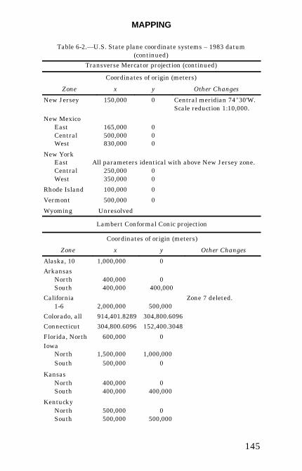
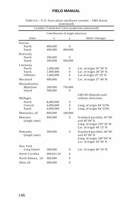
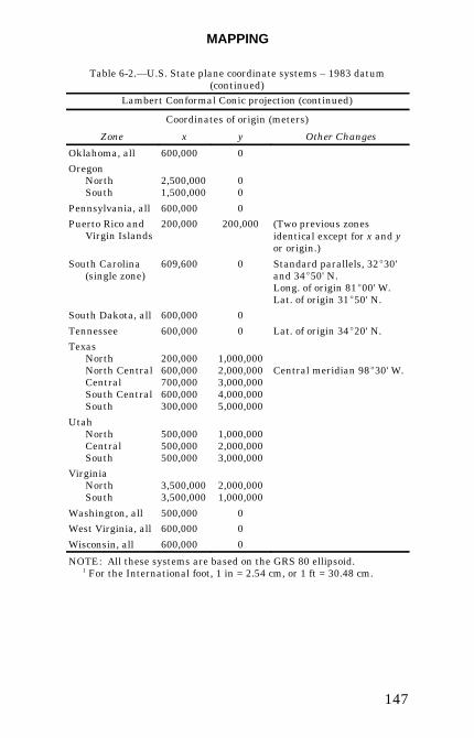
State Plane Coordinate Systems-changes for 1983datum.—This listing indicates changes for the NAD1983 datum from projections, parameters, and origins ofzones for the NAD 1927 datum. State plane coordinatesbased on the 1927 datum cannot be correctly convertedto coordinates on the 1983 datum merely by usinginverse formulas to convert from 1927 rectangularcoordinates to latitude and longitude, and then using
MAPPING
143
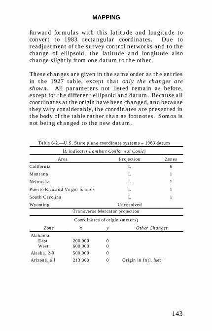
forward formulas with this latitude and longitude toconvert to 1983 rectangular coordinates. Due toreadjustment of the survey control networks and to thechange of ellipsoid, the latitude and longitude alsochange slightly from one datum to the other.
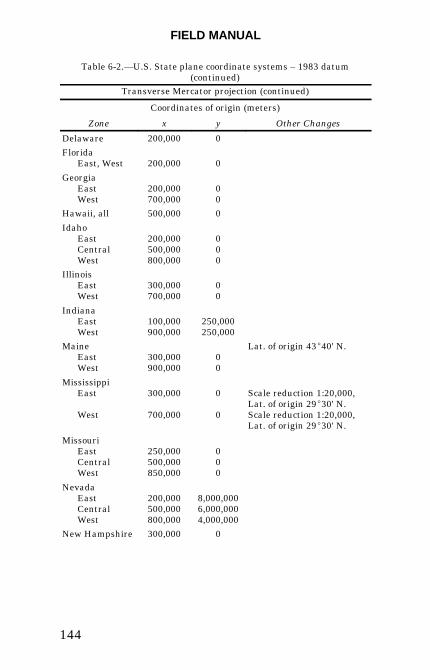
These changes are given in the same order as the entriesin the 1927 table, except that only the changes areshown. All parameters not listed remain as before,except for the different ellipsoid and datum. Because allcoordinates at the origin have been changed, and becausethey vary considerably, the coordinates are presented inthe body of the table rather than as footnotes. Somoa isnot being changed to the new datum.
Table 6-2.—U.S. State plane coordinate systems – 1983 datum
[L indicates Lambert Conformal Conic]
Area Projection Zones
California L 6
Montana L 1
Nebraska L 1
Puerto Rico and Virgin Islands L 1
South Carolina L 1
Wyoming Unresolved
Transverse Mercator projection
Coordinates of origin (meters)
Zone x y Other Changes
AlabamaEastWest
200,000600,000
00
Alaska, 2-9 500,000 0
Arizona, all 213,360 0 Origin in Intl. feet1
FIELD MANUAL
144
Table 6-2.—U.S. State plane coordinate systems – 1983 datum(continued)
Transverse Mercator projection (continued)
Coordinates of origin (meters)
Zone x y Other Changes
Delaware 200,000 0
FloridaEast, West 200,000 0
GeorgiaEastWest
200,000700,000
00
Hawaii, all 500,000 0
IdahoEastCentralWest
200,000500,000800,000
000
IllinoisEastWest
300,000700,000
00
IndianaEastWest
100,000900,000
250,000250,000
MaineEastWest
300,000900,000
00
Lat. of origin 43E40' N.
MississippiEast
West
300,000
700,000
0
0
Scale reduction 1:20,000,Lat. of origin 29E30' N.Scale reduction 1:20,000,Lat. of origin 29E30' N.
MissouriEastCentralWest
250,000500,000850,000
000
NevadaEastCentralWest
200,000500,000800,000
8,000,0006,000,0004,000,000
New Hampshire 300,000 0
MAPPING
145
Table 6-2.—U.S. State plane coordinate systems – 1983 datum(continued)
Transverse Mercator projection (continued)
Coordinates of origin (meters)
Zone x y Other Changes
New Jersey 150,000 0 Central meridian 74E30'W.Scale reduction 1:10,000.
New MexicoEastCentralWest
165,000500,000830,000
000
New YorkEast All parameters identical with above New Jersey zone.CentralWest
250,000350,000
00
Rhode Island 100,000 0
Vermont 500,000 0
Wyoming Unresolved
Lambert Conformal Conic projection
Coordinates of origin (meters)
Zone x y Other Changes
Alaska, 10 1,000,000 0
ArkansasNorth 400,000 0South 400,000 400,000
California1-6 2,000,000 500,000
Zone 7 deleted.
Colorado, all 914,401.8289 304,800.6096
Connecticut 304,800.6096 152,400.3048
Florida, North 600,000 0Iowa
North 1,500,000 1,000,000South 500,000 0
KansasNorth 400,000 0South 400,000 400,000
KentuckyNorth 500,000 0South 500,000 500,000
FIELD MANUAL
146
Table 6-2.—U.S. State plane coordinate systems – 1983 datum(continued)
Lambert Conformal Conic projection (continued)
Coordinates of origin (meters)
Zone x y Other Changes
KansasNorth 400,000 0South 400,000 400,000
KentuckyNorth 500,000 0South 500,000 500,000
LouisianaNorthSouthOffshore
1,000,0001,000,0001,000,000
000
Lat. of origin 30E30' N.Lat. of origin 28E30' N.Lat of origin 25E30' N.
Maryland 400,000 0 Lat. of origin 37E40' N.
MassachusettsMainland 200,000 750,000Island 500,000 0
MichiganGRS 80 ellipsoid usedwithout alteration.
NorthCentralSouth
8,000,0006,000,0004,000,000
000
Long. of origin 84E22'W.Long. of origin 84E22'W.
Minnesota, all 800,000 100,000
Montana(single zone)
600,000 0 Standard parallels, 45E00'and 49E00' N.Long. of origin 109E30' W.Lat. of origin 44E15' N.
Nebraska(single zone)
500,000 0 Standard parallels, 40E00'and 43E00' N.Long. of origin 100E00' W.Lat. of origin 39E50' N.
New YorkLong Island 300,000 0 Lat. of origin 40E10' N.
North Carolina 609,621.22 0
North Dakota, all 600,000 0
Ohio, all 600,000 0
MAPPING
147
Table 6-2.—U.S. State plane coordinate systems – 1983 datum(continued)
Lambert Conformal Conic projection (continued)
Coordinates of origin (meters)
Zone x y Other Changes
Oklahoma, all 600,000 0
OregonNorthSouth
2,500,0001,500,000
00
Pennsylvania, all 600,000 0
Puerto Rico andVirgin Islands
200,000 200,000 (Two previous zonesidentical except for x and yor origin.)
South Carolina(single zone)
609,600 0 Standard parallels, 32E30'and 34E50' N.Long. of origin 81E00' W.Lat. of origin 31E50' N.
South Dakota, all 600,000 0
Tennessee 600,000 0 Lat. of origin 34E20' N.
TexasNorthNorth CentralCentralSouth CentralSouth
200,000600,000700,000600,000300,000
1,000,0002,000,0003,000,0004,000,0005,000,000
Central meridian 98E30' W.
UtahNorthCentralSouth
500,000500,000500,000
1,000,0002,000,0003,000,000
VirginiaNorthSouth
3,500,0003,500,000
2,000,0001,000,000
Washington, all 500,000 0
West Virginia, all 600,000 0
Wisconsin, all 600,000 0
NOTE: All these systems are based on the GRS 80 ellipsoid. 1 For the International foot, 1 in = 2.54 cm, or 1 ft = 30.48 cm.
FIELD MANUAL
148
Units
English or metric units should be selected as early in theproject as possible. Conversions are possible, butconvert-ing a large 1-foot contour map to meters is notrivial matter.
Remember that when using several sources of locationdata, the reference datum must be known. Systematicdifferences in location data are generally due to mixingdatums.
Specific Nomenclature and Definitions
Establish a uniform nomenclature system with writtendefinitions for rock types, map units, and map symbolsused. The American Geologic Institute Glossary ofGeology [2] is the standard for geologic terms exceptwhere Reclamation has established definitions for itsown needs. These definitions and nomenclature arediscussed in chapters 2 through 5.
Field Equipment and Techniques
General geologic mapping equipment and techniques arediscussed in field geology manuals such as Lahee (1961)[3] and Compton (1985) [4]. Refer to these texts for dis-cussions of suggested field equipment and generalgeologic mapping techniques.
Use of Computers
Computers are used during a mapping program in fourbasic ways: (1) to process and analyze voluminousnumerical data (e.g., joint data), (2) as a tool in theanalysis of basic geologic data (e.g., construction of pre-liminary or final plan and section views which
MAPPING
149
incorporate previously entered geologic data),(3) Computer Aided Drafting and Design (CADD) ofsection and plan views, and (4) in modeling geologicconditions. How computers will be used in the reduction,analysis, and drafting of the geologic data generatedduring a mapping program needs to be decided earlybecause records of field data will depend on whetherdata are to be stored in digital format and restructuringthese data at a later date is costly, time consuming, andintroduces transcription errors.
Right-of-Way
Right-of-way is needed for any mapping of non-Reclamation land and should be obtained early toprevent work delays. Although "walk on" permissionusually is obtained easily, permission for trenching anddrilling may take several months, especially ifarcheological or environmental assessment is necessary.
Records
Systematic methods of recording field observations,traverse data, outcrop data, and trench logs areimportant. Suggested sample field book formats areshown under each section below dealing with specificmapping procedures, but any format should allow clearrepresentation of the field data.
Geologic Considerations
The following are some key items that should beevaluated during a mapping project. The degree ofimportance varies with the project but the factors arecommon to most.
FIELD MANUAL
150
Lithology.—Differentiation between the various geo-logic deposits and lithologies in a study area is basic togeologic mapping. However, an engineering geologist ismore concerned with the engineering characteristics ofthe unit than with its geologic definition, and these char-acteristics should be the controlling factor in how geo-logic units are subdivided. For some engineeringgeologic purposes, it may be reasonable to consolidategeologic units with similar engineering properties into asingle engineering geologic map unit. Depending on theneeds of the project, lithologic subunits may be definedjointly between the engineers and the geologists workingon the job.
After the basic geologic subdivisions for a mapping jobhave been agreed upon, detailed descriptions of eachsubunit should be compiled and mapping symbolsselected. Map unit definitions usually will applyspecifically to the job or project area and normally will bemodified as additional data are collected. Map symbolsfall into several categories. American GeologicalInstitute data sheets have a comprehensive tabulation ofsymbols.
Geologic contacts.—Two different line types normallyare used on geologic maps to denote the precision andaccuracy of geologic contacts. These are solid and broken(dashed or dotted) lines. Solid lines usually are usedwhere exposures are excellent, such as a cleanedfoundation or an area with nearly continuous outcrops.Solid lines indicate that the contacts are located with aprescribed degree of accuracy. Broken contacts are usedwhen unsure of the accurate location of the contact, i.e.,when the contact is covered by thin slopewash deposits(dashed line) or where the contact is buried by deepsurficial deposits (dotted line). Confidence levels,expressed in feet or meters, for both types of contactsshould be stated clearly in the definition of the contact
MAPPING
151
line. The mapper should keep in mind the type of geo-logic data being compiled and use the appropriate line.
Discontinuities.—Discontinuities separate geologicalmaterials into discrete blocks that can control thestability and bearing capacity of a foundation or slope.Intersecting discontinuities in cut slopes can formunstable wedges. Because of the destabilizing orweakening effects, mapping and adequately describingdiscontinuities is critical in engineering geology studies.The various types of discontinuities and the terminologyfor describing their engineering properties are discussedin chapter 5.
Weathering and alteration.—The mechanical andchemical alteration of geological materials can signifi-cantly affect stability and bearing strengths. Adequatelydetermining weathering depths, extent of alteredmaterials and the engineering properties of theseweathered and altered materials is critical inengineering geologic mapping. Refer to chapter 4 fordefinitions of weathering and alteration descriptors.
Water.—The location and amount of groundwater to beexpected in an excavation and how it can be controlled iscritical to the overall success of a project.
Geomorphology.—Study of landforms is often the keyto interpreting the geologic history, structure, lithology,and materials at a site. Exploration programs can bebetter designed and implemented using landforms as abasis. The geomorphic history is important indetermining the relative age of faults.
Vegetation indicators.—Differences in vegetationtypes and patterns can provide indirect data onlithologies, dis-continuities, weathering, groundwater,
FIELD MANUAL
152
and mineralization. The water holding capacity of soildeveloped on one rock (e.g., shale) may differ con-siderably from the water holding capacity of soildeveloped on another type of rock (e.g., sandstone);consequently, the types of vegetation that grow in thesesoils can vary considerably. Minerals present in theparent rock may affect soil chemistry and may limitvegetation to types tolerant of highly acidic or alkalinesoils or high concentrations of trace elements.Vegetation seeking groundwater moving up major jointsand faults will form vegetation lineations that are highlyvisible on aerial photographs, particularly color infraredphoto-graphs. In most locations, local conditions have tobe assessed to use vegetative indicators effectively.
Cultural features (manmade).—Cultural features,such as water, gas or oil wells, road cuts or foundationexcavations, can provide surface and subsurface dataand should be reviewed early in the mapping project.When data collection through trenching and core drillingprograms is considered, buried utility lines (water, gas,electrical, sewage, or specialized lines) can be hazardousor embarrassing when broken. Usually the utility orowners will locate their lines.
Field checking.—Field checking by both mapper andindependent reviewer is a critical part of the mappingprocess. Field checking after a map is complete allowsthe mapper to check the interpretations at a givenlocation with the geologic concepts developed on the mapas a whole. Field checking by the independent reviewerensures that the basic field data are correct and conformto project standards. Periodic field checking of pre-viously mapped areas can be useful as the mapper'sconcept of the site geology changes with the addition ofnew surface and subsurface data.
MAPPING
153
Site Mapping
Engineering geologic mapping has two phases—mappingprior to construction and mapping during construction.In general, the following guidelines are for: (1) generalmapping requirements, (2) suggested equipment, (3) spe-cific preparations needed for the job, (4) type of documen-tation needed, and (5) special considerations that themapping may require. General
Detailed site geologic mapping studies generally are donefor most structures or sites. Site mapping requirementsare controlled by numerous factors, the most importantof which are the type and size of structure to be built orrehabilitated or site to be remediated, the phase of study(planning through operation and maintenance), and thespecific design needs.
Site mapping studies for major engineering featuresshould be performed within an approximate 5-mile (8-km) radius of the feature, with smaller areas mapped forless critical structures. These studies consist of detailedmapping and a study of the immediate site, with moregeneralized studies of the surrounding area. Thisapproach allows an integration of the detailed sitegeology with the regional geology. The overall process ofsite mapping is a progression from preliminary, highlyinterpretive concepts based on limited data to finalconcepts based on detailed, reasonably well-defined dataand interpretation. This progression builds on each pre-vious step using more detailed methods of data collectionto acquire better defined geologic information. Typically,site mapping is performed in two phases:(1) preliminary surface geologic mapping and (2) detailedsurface geologic mapping. All site mapping studies begin

FIELD MANUAL
154
with preparation of a preliminary surface geologic mapwhich delineates surficial deposits and existing bedrockexposures. The preliminary surface geologic map is thenused to select sites for dozer trenches, backhoe trenches,and drill holes. Surface geologic maps are then re-interpreted based on the detailed surface and subsurfacedata. If required, detailed subsurface geologic data arealso obtained from exploratory shafts and adits.
Suggested Equipment
The following list of basic equipment should meet mostneeds. Not all listed equipment is necessary for everyproject, but a Brunton Compass, geologist’s pick, (2-pound hammer may be necessary for rock sampling),maps, map board, aerial photographs, notebook, scale,tape measure, protractor, knife, hand lens, various pensand pencils, and a GPS should meet most needs.
Preparation
Whether a site mapping program is completed in onefield season or over several years, the overall projectschedule and budget are critical. A critical assessmentshould be made of the time available for the mappingprogram, the skills and availability of personnel toaccomplish the work, weather conditions, and budgetconstraints.
Documentation
Site data are documented on drawings (and associatednotes) generated during the study. The drawings fallinto two general categories—working drawings and finaldrawings. Working drawings serve as tools to evaluateand analyze data as it is collected and to define areaswhere additional data are needed. Analysis of data in athree-dimensional format is the only way the geologist
MAPPING
155
can understand the site geology. Drawings should begenerated early in the study and continuously updatedas the work progresses. These drawings are used forpre-liminary data transmittals. Scales used for workingdrawings may permit more detailed descriptions andcollection of data that are not as significant to the finaldrawings. Final drawings are generated late in themapping program, after the basic geology is wellunderstood. Many times new maps and cross sectionsare generated to illustrate specific data that were notavailable or well understood when the working drawingswere made. Final drawings serve as a record of theinvestigations for special studies, specifications, ortechnical record reports.
Preliminary Surface Geologic Mapping.—Thepurpose of preliminary surface geologic mapping is todefine the major geologic units and structures in the sitearea and the general engineering properties of the units.Suggested basic geologic maps are a regional recon-naissance map at scales between 1 inch = 2,000 feet and1 inch = 5,280 feet (1:24,000 to 1:62,500), and a sitegeology map at scales between 1 inch = 20 feet and 1inch = 1,000 feet (1:250 to 1:12,000). Scale selectiondepends on the size of the engineered structure and thecomplexity of the geology. Maps of smaller areas may begenerated at scales larger than the base map toillustrate critical conditions. Cross sections should bemade at a natural scale (equal horizontal and vertical) asthe base maps unless specific data are better illustratedat an exaggerated scale. Exaggerated scale crosssections are generally not suited for geologic analysisbecause the distortion makes projection andinterpretation of geologic data difficult.
Initial studies generally are a reconnaissance-level effort,and the time available to do the work usually is limited.
FIELD MANUAL
156
Initially, previous geologic studies in the general sitearea are used. These studies should be reviewed andfield checked for adequacy and new data added. Initialbase maps usually are generated from existingtopographic maps, but because most readily availabletopography is unsuitable for detailed studies, sitetopography at a suitable scale should be obtained ifpossible. Existing aerial photographs can be used astemporary base maps if topographic maps are notavailable. Sketch maps and Brunton/tape surveys orGPS location of surface geologic data can be done ifsurvey accuracy or control is not available or necessary.Good notes and records of outcrop locations and data areimportant to minimize re-examination of previouslymapped areas. Aerial photo-graphy is useful at thisstage in the investigation, as photos can be studied inthe office for additional data. Only after reasonablyaccurate surface geology maps have been compiled canother investigative techniques, such as trenching andcore drilling, be used to full advantage. For some levelsof study, this phase may be all that is required.
Detailed Surface Geologic Mapping.— The purposeof detailed surface geologic mapping is to define theregional geology and site geology in sufficient detail sogeologic questions critical to the structure can beanswered and addressed. Specific geologic featurescritical to this assessment are identified and studied,and detailed descriptions of the engineering properties ofthe site geologic units are compiled. Projectnomenclature should be systematized and standarddefinitions used. Suggested basic geologic maps aresimilar to those for preliminary studies, althoughdrawing scales may be changed based on the results ofthe initial mapping program. Maps of smaller areas maybe generated to illustrate critical data at scales largerthan the base map.
MAPPING
157
The preliminary surface geology maps are used to selectsites for dozer trenches, backhoe trenches, and drill coreholes. As the surface geology is better defined, drill holelocations can be selected to help clarify multiple geologicproblems. Detailed topography of the study site shouldbe obtained, if not obtained during the initialinvestigations. Data collected during the preliminaryinvestigations should be transferred to the new basemaps, if possible, to save drafting time. Field mappingcontrol is provided primarily by the detailed topographicmaps and/or GPS, supplemented by survey control ifavailable or Brunton/ tape survey. If not, large scaleaerial photographs of a site area flown to obtain detailedtopography are useful in geologic mapping.
Dozer Trench Mapping
General
Dozer trenches are cut to expose rock or unconsolidatedmaterials below the surface and major surface creep.Walls normally should be excavated vertically, free ofnarrow benches and loose debris. Upon completion ofexcavation, floors must be cleaned below any depth ofripping, loose rubble should be removed, and a newsurface exposed. Structures such as contacts and shearzones must be traceable from wall into floor for optimumdetermination of their nature and attitude. Thegeologist is responsible to ensure the dozer operatorproduces a safe finished trench that meets Reclamationand Occupational Safety and Health Administration(OSHA) safety standards. If livestock are present,fencing of the trench with four strands of barbed wiremay be required. After trench logging is completed,decide whether to leave the trench open or to backfill. Atsites with complex geology, it is desirable to leave the
FIELD MANUAL
158
trench open for reinterpretation of the trench in light ofnewly acquired data. Backfilling of the dozer trench maybe necessary where an open trench would be a safetyhazard. Generally, all trenches should be backfilled andcom-pacted prior to abandonment.
Suggested Equipment
Additional equipment needed may include hard hat,scraper or putty knife, square-nosed shovel, plasticflagging, nails, wooden stakes, surveyors chain or tapemeasure (feet or meters) and log book. Use putty knife,shovel, and whisk broom for cleaning trench exposuresand a Brunton tripod for more accurate trench bearings.
Preparation
Prior to working in a dozer trench, the geologist shouldinspect the excavation trench walls for failure planes(obvious or incipient) or loose materials. These should beremoved before mapping starts. An examination of thewhole trench should be made at the start of each workperiod. A baseline should be laid out along the toe of thetrench wall or at the top of the excavation. Becausedozer trenches often are not straight, the trench shouldbe divided into a series of straight segments withstations established at each point where the trenchchanges direction. Each station should be marked by astake, tied with flagging, and marked with the trenchnumber and station letter (e.g., DT-12A). Flaggingstrips should be nailed to the wall approximately 6 feet(2 meters [m]) vertically above or below the station foranother reference point in case minor sloughing buries ordislodges the stake.
MAPPING
159
Documentation
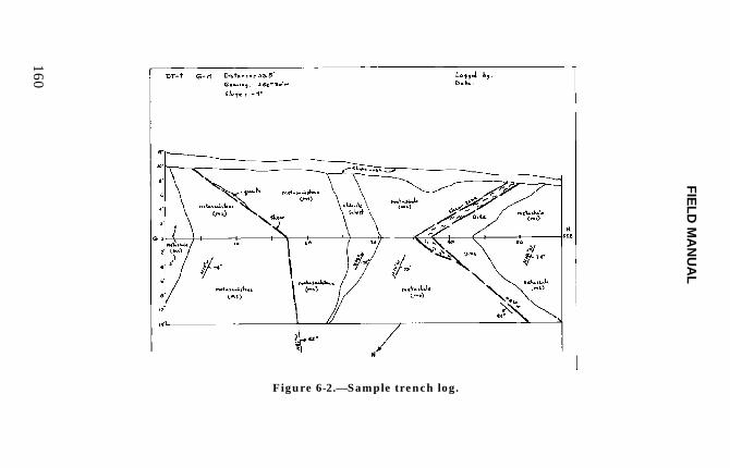
The scale and format selected for logging a backhoetrench depends on the type of data needed and theamount of detail to be illustrated. Typical dozer trenchlog scales are between 1 inch (in) = 5 feet (ft) (1:100) and1 in = 10 ft (1 : 200), but scales of 1 in = 1 ft (1: 50) maybe required in critical areas to adequately showstructural and stratigraphic details. If trench geology isnot complex, record trench logs, along with names of thefield party and date in a field book. Determine andrecord the bearing, slope distance, and slope anglebetween each station. Survey the coordinates andelevations of each station. Orient the log book so thesketch and description may be viewed together (seefigure 6-2). Sketch the walls and floors across the toppage of the open log book. Mark the baseline at 5-foot(1.5-m) intervals and draw a single "hinge line”; wallabove, floor below. Determine the vertical heights of thetrench walls at each station and between stations, if theprofile or thickness of surficial materials changesbetween stations.
Sketches should be accurate and illustrate the fieldrelationship of soil and geologic units and structures.Use nails and flagging strips to mark obscure contacts orother features for ready reference during logging.Designate geologic units by name and symbol. Accuratelyplot the attitude of contacts, bedding, foliation orcleavage, faults, shear zones, and joints where they aredetermined using standard symbols, and write adescription. If attitudes are determined from the wall,they may be projected along strike into the floor, if nochange is apparent in the floor. Note and show thebedding or foliation wherever relationships are complexand differ from the recorded attitude (i.e., where surfacecreep, drag folds, or disturbed zones are exposed in thewall). Record unit attitudes that may have beenaffected
FIE
LD
MA
NU
AL
160
Figure 6-2.—Sample trench log.
MAPPING
161
by surface creep or slumping. Written descriptions ofsoil and rock units and structural zones should berestricted to the page below the sketch and should notbe written over the sketch. Main heading for writtendescriptions are restricted to mappable geologic units.Intervals are noted where the contacts intersect thebaseline. Indent subheadings within text to describelithologic or structural variations within the mappableunit. An example of heading order is as follows:
DT-58, Sta. B-C, Distance - 27.5', Bearing - S. 45EW., Slope + 2 22.5-50.0': Metasediments (description) 39.9-41.0': Chlorite Schist B (description) 47.5-49.0': Talc Schist (description) 48.2-48.4': Shear Zone (description)
Stratigraphic units should be colored to complete the log.Photograph the trench to complement the log or to recordspecific details within the trench.
Backhoe Trench Mapping
General
Backhoe trenches are excavated to expose rock orunconsolidated materials below surficial deposits andmajor surface creep. Generally, backhoe trenches areexcavated at sites which must be returned to near-original conditions and where dozer trenching wouldproduce unacceptable damage. Backhoe trenches oftenare excavated in the floor of an existing dozer trench todeepen the excavation. Walls should be excavatedvertically and free of narrow benches and loose debris.In most cases, the trench should be about 3 to 3-1/2 feetwide (1 m) (width of standard backhoe bucket), 10 to 12
FIELD MANUAL
162
feet (3 to 3.6 m) deep, and slope at one end for easyaccess. Upon excavation completion, hydraulic trenchshores are placed and pressurized or wooden shoresconstructed to support the trench walls. Shoreconstruction and spacing must meet OSHA standardsand standards outlined in Reclamation's ConstructionSafety and Health Standards manual. At no time shouldpersonnel enter unshored portions of the trench over5 feet deep. The geologist who oversees the excavationof the backhoe trench is respon-sible for the constructionof a safe, stable trench.
After trench logging is completed, decide whether toleave the trench open or to backfill. At sites withcomplex geology, leave the trench open, if possible, asthis allows reinterpretation of the trench in light ofnewly acquired data. However, backhoe trenches areprone to sloughing with time, even when supported, andbackfilling of the trench may be necessary for safetyreasons. The coordi-nates and elevation of each end ofthe backhoe trench should be surveyed prior tobackfilling.
Suggested Equipment
Standard field equipment is used during backhoe trenchmapping. Additional equipment may include a hard hat,large knife, flat-blade pick or army trenching tool toclean off trench walls, putty knife, whisk broom, nails,flagging, twine, small string level, 100-foot (30-m) longsurveyor's chain or tape, and map board or log book. Thetype of backhoe needed depends on how consolidated orcemented the material is, site accessibility, and depth tobe excavated. Most of the larger, rubber-tired backhoesare suitable for excavation of typical trenches, but wellconsolidated or cemented material, steep site terrain, ortrench depths over about 12 feet (3.6 m) may require alarger track-mounted hydraulic excavator.
MAPPING
163
Preparation
Each day prior to working in a backhoe trench, thetrench along both sides and the trench walls should beexamined for incipient fractures or loose materials,particularly within the surficial materials. These loosematerials should be removed before work starts.Hydraulic trench shores should be checked visually forleakage and for loss of pressure by pushing on them witha foot. Re-pressure any loose shores and replace leakingshores. The stability of each shore should be checkedbefore the mapper's weight is put on it, particularly ifthe shore is to be used to examine the upper trench wallor to climb out of the trench.
A backhoe trench must be cleaned prior to logging.During excavation, the backhoe bucket may smear clayand silt along the walls, obscuring structural and strati-graphic relationships. This smeared zone may be any-where from a fraction of an inch thick to several inchesthick, depending on the amount of fines and moisture inthe material excavated. The smeared material can beremoved by chipping or scraping with a large knife, flat-bladed pick, or army trenching tool. If the trench isexcavated in reasonably consolidated material and thetrench is free draining, a high pressure water and/or airjet will remove this material. Both walls should be spotcleaned and examined prior to major cleaning to deter-mine which wall exposes the best geologic data. Usuallyonly one wall is completely cleaned; the other wall is spotcleaned during trench logging to expose another view ofcritical features or relationships. After a wall is cleaned,a horizontal base line is established. The baseline is runat about eye level and constructed by stringing twinebetween nails driven into the cleaned trench wall. Thetwine can be leveled using a small string level (availablein most hardware stores) prior to driving nails. Whenthe baseline becomes either too high or too low for
FIELD MANUAL
164
comfort-able measurements, a vertical offset of the stringline is made and the baseline continued at the newhorizon. In complex, critical areas where accuratelylocated contacts are needed, a string grid with horizontaland vertical elements can be constructed off the baselineto assist in mapping.
Documentation
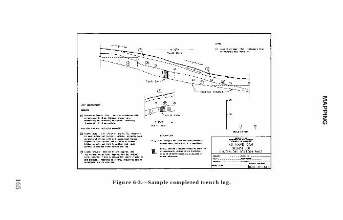
The scale and format selected for logging a backhoetrench depends on the type of data needed and theamount of detail to be illustrated. Typical backhoetrench log scales are between 1 in = 5 ft (1:100) and 1 in= 10 ft (1 : 200), but scales of 1 in = 1 ft (1 : 50) may berequired in critical areas to adequately show structuraland stratigraphic details. If trench geology is notcomplex, a notebook is suggested. The log book shouldbe oriented so the sketch and description may be viewedtogether. The names of the field party, date, trenchnumber, location, and other pertinent data should berecorded. If trench geology is complex and a larger scaleis desired, cut sheets of grid paper attached to a mapboard may be used. These sheets are usually redraftedafter trench logging is completed. If the backhoe trenchis wet or wall material is sloughing down onto the mapboard, a blank grid sheet can be taped to the map boardand overlain by sheets of mylar. Trench data sketchedonto the mylar will not be smeared as easily, and thesheets can be erased without tearing. Prints of thesheets can be made for use in preliminary datatransmittal or as check prints for field checking. Figure6-3 shows a completed trench log.
Because the log sheets are separated easily, each sheetshould be marked with the names of the field party,date, trench number, location, and other pertinent data.
MA
PP
ING
165 Figure 6-3.—Sample completed trench log.
FIELD MANUAL
166
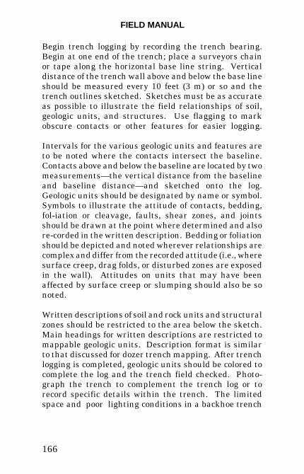
Begin trench logging by recording the trench bearing.Begin at one end of the trench; place a surveyors chainor tape along the horizontal base line string. Verticaldistance of the trench wall above and below the base lineshould be measured every 10 feet (3 m) or so and thetrench outlines sketched. Sketches must be as accurateas possible to illustrate the field relationships of soil,geologic units, and structures. Use flagging to markobscure contacts or other features for easier logging.
Intervals for the various geologic units and features areto be noted where the contacts intersect the baseline.Contacts above and below the baseline are located by twomeasurements—the vertical distance from the baselineand baseline distance—and sketched onto the log.Geologic units should be designated by name or symbol.Symbols to illustrate the attitude of contacts, bedding,fol-iation or cleavage, faults, shear zones, and jointsshould be drawn at the point where determined and alsore-corded in the written description. Bedding or foliationshould be depicted and noted wherever relationships arecomplex and differ from the recorded attitude (i.e., wheresurface creep, drag folds, or disturbed zones are exposedin the wall). Attitudes on units that may have beenaffected by surface creep or slumping should also be sonoted.
Written descriptions of soil and rock units and structuralzones should be restricted to the area below the sketch.Main headings for written descriptions are restricted tomappable geologic units. Description format is similarto that discussed for dozer trench mapping. After trenchlogging is completed, geologic units should be colored tocomplete the log and the trench field checked. Photo-graph the trench to complement the trench log or torecord specific details within the trench. The limitedspace and poor lighting conditions in a backhoe trench
MAPPING
167
many times make it difficult to obtain satisfactoryphotos. Generally, cameras capable of closeup focusingand loaded with fast film work best. Photographs takenwhile standing at the top of the trench generally aremarginal because of poor lighting and perspective. Theends of the trench should be located by GPS or survey.
Construction Geologic Mapping
Geologic mapping during construction is to: (1) identifyand delineate potential or actual construction-relatedneeds and problems; (2) verify and better define geologicinterpretations made during design studies, particularlyfor critical geologic features and properties;(3) determine if the geologic conditions are as interpretedduring the design phase and ensure that the actualconditions revealed are as interpreted. If thoseconditions are not as interpreted, design modificationsmay be required; and (4) provide a record of as-builtconditions in the event of litigation or operationalproblems.
To obtain meaningful data for mapping during con-struction, cooperation and coordination between theContractor and the construction staff is required. Thefield geologist prioritizes mapping; and when the specificarea is ready for mapping and approval, the staff andsurveyors (if required) should accomplish the work asquickly as possible. Photographs should be taken usingappropriate photographic equipment. All photographsshould be captioned and dated.
Possible safety hazards that might occur during mappingshould be evaluated, and appropriate precautions shouldbe taken.
FIELD MANUAL
168
Large Excavation Mapping
General
Construction considerations prepared before constructionbegins should contain guidelines for the mapping of spe-cific features. The scope and detail of mapping requiredat each portion of the site should be determined andsuitable mapping scales determined. Suggested scalesfor detailed foundation mapping are 1 in = 5 ft to 1 in =50 ft (1:50 to 1: 600), generalized foundation invert mapscale 1 in = 20 ft to 1 in = 100 ft (1:20 to 1:1,000).Detailed, as-built foundation geology maps are used infinal design modification, as a final record, and for use inpossible future operation and maintenance problems.Mapping can be done on detailed topographic base mapsgenerated from survey control, GPS, or plane table.Preferably, geology points are flagged and surveyed by asurvey crew. Terrestrial photography, photogrammetry,and GPS can also be used to supplement mapping.Detailed photo-graphy of the entire foundation isimportant for inclusion in the final construction geologyreport and as a part of the construction record. Usestandard nomenclature and symbols both on maps andphotographs, but be consistent with those used in earlierstudies and specifications. Use a systematic method ofcollecting mapping data, then compile these data into auseful and accurate geologic map.
Detailed, as-built geology maps of cutslopes are requiredin delineating and solving major slope stability problemsand in selecting general slope support systems. Recom-mended scale selection for detailed cut-slope geologymaps are 1 inch = 10 feet to 1 inch = 50 feet (1:100 to1:600), generalized cutslope geology maps use a scale1 inch = 20 feet to 1 inch = 100 feet (1:200 to 1:1,000).Generally, maps are on detailed topographic base maps
MAPPING
169
generated from survey control. Geologic points may beflagged for survey by survey crews. Detailedphotographs of the slopes are important.
Steep Slope Mapping
General
Define the purpose and goal for mapping and researchthe stratigraphy and structural geology prior to starting.Select scaling and safety equipment for specific areas.
Preparation
Special training is required for scaling. While scalingand mapping, a pocket tape recorder and camera areuseful for documentation.
Suggested Equipment
Use the appropriate scaling equipment and systems.Standard mapping equipment needs to be reviewed andmodified for scaling operations.
Documentation
Establish ground control for mapping including ter-restrial photo mapping. Data collected while scalingshould be based on the purpose of mapping and detailrequired. Establish general map controls such as gridcontrols.
Special Considerations
Select specific portions of an exposure to be mapped.
FIELD MANUAL
170
Canal and Pipeline Mapping
General
In reconnaissance investigations, surface geologic map-ping is used to determine the most feasible alignment,which may be representative of the geologic conditions tobe encountered, the lining requirements, andconstruction materials available. Design datainvestigations along canal alignments must be detailedenough to determine the final alignment and allassociated requirements for specifications andconstruction.
Preconstruction investigations for canals and pipelinesare less detailed because of the long distances involved.Consequently, geologic construction mapping isnecessary to verify preconstruction assumptions,document changes from original assumptions, andprovide data for potential design changes or claimanalyses.
Preparation
General field mapping requirements.
Documentation
Pertinent geologic data that should be shown on the basemaps include: soil and geologic units, all natural andmanmade exposures, geologic structures, springs andseepage, surface channels, and potentially unstableareas. Where appropriate, photographs with overlays ordetailed site-specific drawings should be used to showsurface conditions in relation to the canal prism orassociated canal structures. Base maps should be planstrip topo-graphy or orthophotography with scales of 1 in= 20 ft (1:400) to 1 in = 100 ft (1:2,000) with associatedtopographic profiles.
MAPPING
171
Underground Geologic Mapping
General
This is a general guide for recording tunnel geology anddescribes mapping requirements and procedures. Thisguide and the field geologist's judgement and experienceshould permit development of geologic data whichadequately document geologic factors that are significantto design, construction, and stability of tunnels andshafts. Some of the necessary data may be obtainedfrom other project personnel such as engineers,surveyors, and inspectors. The following items are ofprimary impor-tance during the construction orexploration for a wide range of tunnel and shaft types,excavation problems, geologic conditions, and contractadministration require-ments. The data recorded andthe emphasis given each item should be determined foreach specific tunnel. (Note: references to tunnels applyequally to shafts)
Three principal objectives are to:
• Acquire progressive, timely mapping of allsignificant geologic features as exposed during theadvance of the tunnel or shaft. These initial fea-tures are important for subsequent identification ofchanges which may take place, such as water flow,rock slaking, or support behavior, as the headingprogresses and before lining or other completionmeasures are undertaken.
• Facilitate periodic transmittal of these data in pre-liminary form to the office so that conditions beingencountered and their effect on the excavation canbe used in immediate evaluation of currentconstruction activities and anticipation of futureexcavation conditions.
FIELD MANUAL
172
• Assure that a systematic, clear, record of geologicconditions is compiled for design reviews and use bythe project and contractor. These data should beincluded in the final construction geology report.These records may prove invaluable during subse-quent operation and maintenance and in theplanning and design of future tunnels and shafts. Ifgeologically related problems occur, these data willbe essential in evaluating the conditions.
Accuracy is essential, and consistency of data shown ontunnel maps is vital. If the maps are used in contractclaim negotiations or in litigation, even a few errors orinconsistencies may compromise the entire map.
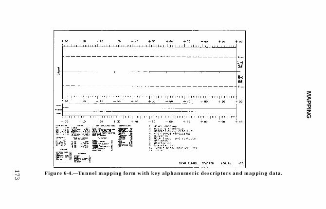
The preparation of an adequate tunnel or shaft geologicmap requires a careful study of geologic structure, lith-ology, mineralogy, groundwater, and their effects on rockquality and behavior, tunneling methods, stability, andsupport. The preparation of a tunnel or shaft geologicmap is a geologic mapping process; geologic data shouldbe recorded directly on the map while making the obser-vations and not described in notes for subsequentdrafting in the office. An appropriately scaled tunnel orshaft mapping form, prepared prior to starting themapping, is essential to systematic data collection. One-matte-sided mylar tunnel forms should be used in wetexcavations and are recommended as a standard for alltunnel and shaft mapping. Figures 6-4 and 6-5 areexamples of field mapping forms. The use of mylars inall tunnels facili-tates copying and immediate use. Theextent or amount of mapping detail for a specific tunnelor shaft will depend on the driving method, geologicconditions, and design considerations. For example,tunnel face (head-ing) maps can be obtained under mostconditions when conventional excavation (drill/blast)methods are used but are difficult to obtain in tunnelsexcavated by tunnel
MA
PP
ING
173 Figure 6-4.—Tunnel mapping form with key alphanumeric descriptors and mapping data.
FIE
LD
MA
NU
AL
174
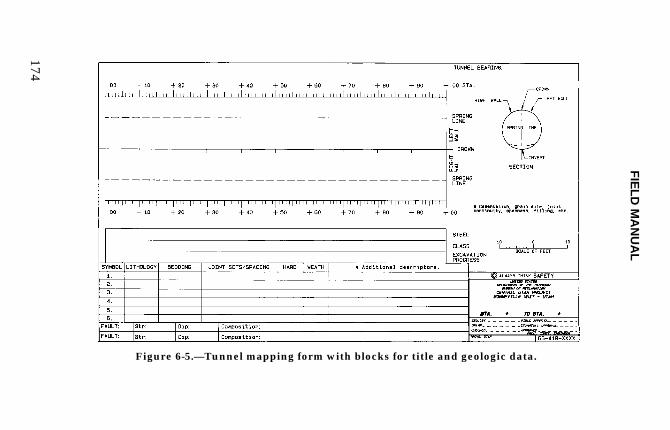
Figure 6-5.—Tunnel mapping form with blocks for title and geologic data.
MAPPING
175
boring machine (TBM). TBM excavated tunnels may bemore difficult to map than conventionally excavatedtunnels, depending on the level of detail required,machine configuration, and the support method.However, the key rock characteristics relative to tunnelstability must be mapped. In tunnels where shotcrete orprecast segments are used for support, detailed mappingmay be impossible; this does not cancel the requirementfor mapping and recording of important data on thegeologic conditions. The geologist must obtain requireddata with the available resources and under the specificconditions. These guidelines apply to all tunnel or shaftexcavations regardless of whether the mapping isperformed during project planning, design data acqui-sition, or construction.
Safety
Underground construction activities are inherently morehazardous than surface construction. Before workingunderground, the specific safety requirements for theparticular tunnel should be determined. Self-rescuertraining commonly is required, and the safety require-ments as described in the Reclamation Safety and HealthStandards [5] should be reviewed. Additional training oradditional requirements may exist under specialcircumstances such as gassy conditions. Beforebeginning work, a familiarization tour of the work site(including the underground workings) should be madewith project personnel, such as an inspector, intimatelyfamiliar with the job. Also, assume that every piece ofequipment and worker is out to get you; you shouldalways maintain an awareness of what the workers andequipment are doing around you.
FIELD MANUAL
176
General Preparation
Tunnel construction is essentially a linear activity. Allaccess, equipment haulage, and work activities takeplace in a line. The mapping process should be plannedsuch that a minimum number of trips to the heading arerequired and a minimum amount of time is spent at theheading. Geologic mapping can usually be integratedinto an optimum part of the construction cycle.Unnecessarily spending time at the heading is not onlyinefficient but can interfere with the constructionprocess by adding to an already congested situation.
Available geologic data should be reviewed andestablished nomenclature used as appropriate. Geologicfeatures described in the available literature should bespecifically investigated while mapping, especially thosedescribed in specifications documents. Forms should bedesigned to expedite the work as much as possible(figures 6-4 and 6-5), required mapping equipment mustbe available, and the construction cycle should be ana-lyzed to determine the best and safest time to map.Tunnel map sheets should be a convenient size such as8.5 x 11 inches (A4) or 11 x 18 inches (A3). This permits100 feet (30 m) of tunnel on a scale of 1 inch = 10 feet(1:200) with sufficient space for concise explanations anda title block. The geology should be mapped in thetunnel directly on the matt side of mylar film. This map,developed in the tunnel, can be edited and copied forquick transmittal to the office. The value of current datacannot be overemphasized. Except under very specialconditions, the recording of geologic data in a notebookwithout mapping for subsequent preparation of a graphictunnel map is unacceptable. Without a graphicrepresen-tation during data acquisition, theinterrelationships of geologic data cannot be properlyevaluated, and data are missed or errors are introduced.Some items listed above will not apply to every tunnel,
MAPPING
177
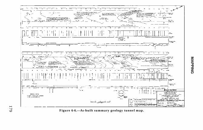
and some items may be shown more appropriately in asummary tunnel map (figure 6-6). This map presents asummary of essential engineering and geologicrelationships. Plotting engi-neering and geologic data asa time line permits direct comparison of geologicconditions, supports installed, overbreak, excavationrate, etc., for correlation. Sum-mary sheet scales mayrange from 1 inch = 10 to 100 feet (1:100 to 1:1,000)depending on amount of data and complexity of thegeology. Ongoing maintenance of these data avoidsexcessive compilation time after construction iscompleted. A summary tunnel map is required ontunnels for construction records.
When several individuals are mapping and/or contractrequirements hinge on geologic data, e.g., payment basedon ground classification, a project or specific mappingmanual may be necessary. A manual provides an easyreference for data requirements and format, reducesinconsistency between geologists, and sets a specificmapping standard.
Excavation Configuration
Conventionally excavated tunnels are usually a modifiedhorseshoe shape. Departures from this shape areusually for a special configuration or when groundconditions dictate a circular shape for optimizing support effective-ness. Machine-excavated tunnels are round if boredunless a road-header type machine is used. Road-headerexcavated tunnels are usually horseshoe shaped for con-struction convenience. Shafts are almost always roundfor optimizing support effectiveness and because mostare drilled or bored either from the surface or raise-boredfrom the bottom. Exploratory shafts may be sunkconven-tionally if shallow. Whatever the shape, the mapformat should be designed to minimize the amount ofprojection
FIELD MANUAL
178
and interpretation required. Whenever possible, the fullperiphery mapping method should be employed.
Data Requirements
The relationship of the geology to the engineeringaspects of the tunnel or shaft is of primary importance.If geologi-cally related problems occur, the recorded datawill be valuable to the geologist and engineer inevaluating the conditions, the cause(s), and in devisingremedial measures. In most cases, geologicdiscontinuities, such as joints, faults, bedding, etc., arethe most important factors affecting excavation stability;and these data are of primary importance. Also, the rockstrength is important in high cover tunnels, and water isimportant in many situations. The following data aremost important:
1. Rock Classification.— Lithology and relatedfeatures such as foliation, schistosity, and flow structure.Rock descriptions should be concise; use standarddescriptors.
• Formation boundaries — describe beddingthick-ness and attitude, areas of soft, or unstablerock. Give dip and strike unless otherwise noted.Dips of planes (not necessarily true dip) into tunnelare desirable in cases where they may influenceexcavation stability.
• Physical properties of the rock — determinehardness by comparison with common or familiarmaterials, brittleness, reaction to pick or knife, andcolor.
• Alteration — describe degree, type, extent, andeffects on construction. Differentiate between wea-thering, other alteration, and cementation.
MA
PP
ING
179 Figure 6-6.—As-built summary geology tunnel map.

FIELD MANUAL
180
MAPPING
181
• Features — describe the size, form (tabular,irregular), contacts (sharp, gradational, sheared),and mineralization, if any.
2. Conditions Which Affect Stability of the Rock.—
• Joints or joint systems — describe spacing,conti-nuity, length, whether open or tight,slickensides, planarity, waviness, cementation,fillings, dip and strike, and water.
• Shear zones — describe severity of shearing andphysical condition of rock in and adjacent to thezone, whether material is crushed or composed ofbreccia, gouge, or mylonite; describe gougethickness, physi-cal properties, mineralogy andalteration; dip and strike, and water.
• Faults — give dimensions of fault breccia and/orgouge and adjacent disturbed or fractured zones,amount of displacement, if determinable, and thefault's effect on stability of rock.
3. Effects of Tunneling on Rock.— Comment on: thecondition of rock after excavation, rate of air slaking orother deterioration of rock where appropriate, rockbursts, fallouts, development of squeezing or heavyground, and time interval between first exposure and thebeginning of these effects. Include the evidence used inevaluation, and the reaction of different rock types toconventional blasting or mechanical excavation method.
Periodic re-examination of the tunnel and comparison oforiginally mapped conditions with those existing later isrecommended.
FIELD MANUAL
182
4. Tunnel Excavation Methods.—
Blast pattern — Give example of typical blast roundpattern, type of explosive and quantity per yard(powder factor) of rock blasted, size of rock fragments,ease or difficulty of rock breakage and condition of thewalls of the tunnel such as whether half-rounds (halfof peripheral shot holes) are visible. Some of thisinfor-mation should be obtainable from the inspectors.
Overbreak — Overbreak and fallout should be mea-sured as a peripheral average from "B" line (excavationpay line), where practical, and maximum at specificstations. Plot average overbreak on the section alongtunnel alignment. Relate this to geologic conditionsand construction methods, particularly blastingprocedure.
Ground behavior — Blockiness, caving, swelling,and/ or squeezing should be described with evidenceand effects.
Supports — Give size and spacing of ribs, size andtypes of struts, and behavior of supports in reaches ofbad ground. Where supports show distress or havefailed, give reason for failure, time after installationfor load to develop, the remedial measuresundertaken, and size and spacing of replaced supportsor jump sets. If a ground classification system is beingused, relate to geologic conditions and support used.Incorporate some reference to the actual need forsupport versus that installed. Use the properterminology when describing supports. A goodreference for tunnel supports (and conventionaltunneling) is Rock Tunneling with Steel Supports [6].
MAPPING
183
Indicate where special supports such as mats, spiling,or breast boards are required and geologic reason.Where rock bolts (or split sets) are used, give spacing,size, length, type, anchor type, torque loading values,and quantities used. Note retorquing, if performed.Locations of rock bolts should be plotted on thegeologic maps.
Machine excavation — In machine-type excavations(in addition to appropriate items above) give: rate ofadvance, pressures used, and description of cuttings orrock breakage. Describe the effect of cutters andgrippers on rock walls, or other geologically relatedproblems such as abrasive rock wearing cutters.
5. Hydrogeology .—Water flows should be mapped andquantities estimated. Daily heading and portal measure-ments should be recorded. The location of all significantflows should be plotted on the tunnel map and changesin rate or duration of flow recorded. If the water ishighly mineralized, obtain chemical analyses of water forpos-sible effect on concrete or steel linings orcontamination of water being discharged or to beconveyed by the tunnel.
6. Gas.—The following should be done:
• Determine type, quantity, occurrence, geologic asso-ciations, and points of discharge should be mapped.
• Samples should be taken. This is usually done bysafety personnel.
• Record actions taken.
7. Instrumentation, Special Tests, Grout, andFeeler Holes.—Locations and logs (if available) shouldbe shown on the tunnel maps.
FIELD MANUAL
184
8. Miscellaneous Excavations.—Geologic maps andsections of related excavations such as surge tanks, gateshafts, inlet and outlet portal open cuts are necessary.
Tunnel maps should include brief comments on thegeologic conditions being encountered and their possibleeffects.
9. Sampling.—A systematic sampling program of thetunnel rock is essential to adequately record tunnelgeology. These samples may be 2 in x 3 in (5 cm x 8 cm)or larger and should be secured in a labeled sample bagshowing station, date, and wall position with anappropriate description. Rock that easily deterioratesshould be protected with wax or plastic. Sampling atirregular (and locally close) intervals may be required toensure that all important rock, geologic, and physicalconditions are adequately represented. A representativestratigraphic series of samples should be collected. Thejudgement of the geologist who is familiar with thegeology is the best guide in determining the mostappropriate sampling interval.
Thorough photographic coverage provides a visual recordof construction and geologic conditions. Postconstructionevaluations use construction photographs extensivelyand are an important part of the construction record. Acamera should be part of the mapping equipment androutinely used. Photographs that show typical, as wellas atypical, geologic conditions should be takenroutinely. Identify photographs of significant features bynumber on the appropriate map sheet.
MAPPING
185
Underground Geologic Mapping Methods
Full Periphery Mapping
The full periphery (or developed surface) mappingmethod is widely used in engineering practice andinvolves creating a map of the surface of theunderground excavation regardless of shape. Themethod produces a map which is virtually free fromdistortion and interpretation present in other methodswhere geologic features are projected onto a plane orsection. The method has been used successfully invarious types and shapes of excavations (Hatheway,1982 [7]; U.S. Army Corps of Engineers, 1970 [8];Proctor, 1971 [9]) and on numerous Reclamationprojects.
The method uses a developed surface created by"unrolling" or "flattening out" the circumference of thetunnel or shaft to form a "plan" of the entire wall surface(figure 6-7). The geologic features are plotted on thisplan. The method is especially effective in that geologicfeatures of all types can be plotted directly onto the mapregardless of orientation or location with no projectionrequired. The method is useful for plotting curving orirregular discontinuities which are difficult to project toa flat plane as in other methods.
Procedure.—Full periphery mapping generally requiresthe assembly of field sheets prior to the actual start ofmapping. This is done for drifts and tunnels by firstdrawing in the crown centerline of the plan (figure 6-7).The bases of the walls or the invert are then plotted at acircumferential distance from the crown centerline onthe plan. For instance, if the tunnel is 10 feet (3.048 m)in excavated diameter, the invert centerline will beplotted 15.71 feet (4.79 m) (in scale) from the crowncenterline. Plot springline at the appropriate circumferential
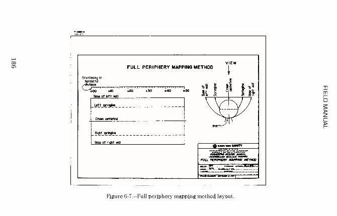
186
MAPPING
187
distance from the crown centerline. This process is donefor both walls and produces a plan which represents theactual wall surface of the excavation. The map layout isdesigned to be viewed from above the tunnel. Shaft dataare plotted as viewed from inside the excavation. Thetunnel invert is not mapped because rock surfacesusually are covered with muck or invert segments. Plotscales on either side of the plan to provide distancecontrol while mapping. A longitudinal section view ofthe excavation may be added alongside the plan toprovide a space to record types and locations of support,overbreak, etc. Plot geologic features on the field sheets(figures 6-4 and 6-5) by noting where the featuresintercept known lines, such as where a particular jointintercepts the crown centerline, the spring line on bothwalls, or the base of either wall. The trace of the joint issketched to scale between these known points. Thestrike and dip of the discontinuity are recorded directlyon the field sheet adjacent to the trace. The locations ofsamples, photographs, water seeps, and flows are plottedon the map (figure 6-8).
The Brunton compass is used to measure dips on thevarious discontinuities; but due to the presence ofsupport steel, rock bolts, utilities, and any naturalmagnetism of the wall rock, a Brunton may not bereliable for deter-mining the strike of the feature. Inthis case, the strike may be determined by one of severalmethods. The first method is to align the map parallelto the tunnel where the feature is exposed in the walland plot the strike by eye on the sheet parallel to thestrike of the feature in the wall. The second method isto observe the strike of the feature on the map where itintersects the crown centerline. At this point, the crownis essentially hori-zontal, and the trace of the feature atthis point represents the strike. The third method isslightly more complex but is the most accurate methodof the three.

FIE
LD
MA
NU
AL
188
Figure 6-8.—Full periphery geologic map example.
MAPPING
189
This method requires locating where the feature inter-sects springline on each wall of the full periphery map.These points are projected to the corrected springline. Aline drawn between the projected points represents thestrike of the feature. Note that these methods assumethat the tunnel or drift is relatively horizontal. In somecases, if the excavation is inclined, the apparent strikecan be corrected for the amount of inclination. A fourthmethod is to use a gyroscopic compass.
Other Applications.—With minor variations in themethod described above, the full periphery method canbe used equally well in vertical or inclined shafts,horseshoe shaped drifts and tunnels, and other regularshaped excavations.
Advantages.—The full periphery method:
• Involves plotting the actual traces of geologicfeatures as they are exposed in the tunnel. Thiseliminates the distortion and interpretation introducedby other methods where the traces are projected backto a plane tangent to the tunnel.
• Allows the geologist to observe and plot irregu-larities in geologic features and make accurate three-dimensional interpretations of the features.
• Allows rapid and easy plotting of the locations ofsamples and photographs.
• Allows easy and rapid recording of the locations ofrock bolts and other types of rock reinforcement.
FIELD MANUAL
190
Disadvantages.—
• Since the surface of the excavation is generally acurved surface, the trace of planar features, such asfractures, faults, and bedding planes, produce curveswhen plotted on the map.
• The full periphery method requires that the pointsat which features intersect springline be projected tothe original tunnel diameter in order to compute thetrue strike of the discontinuity (figure 6-7).
Plan and Section
The plan and section method has been used in engi-neering practice but has generally been replaced by thefull periphery mapping method. The plan and sectionmethod is still used where data interpretation isfacilitated by the flat plan and sections. The methodcreates vertical sections commonly coincident with a wallor walls of a tunnel or shaft, through centerline, or istangent to a curving surface commonly at springline oran edge of a shaft (figure 6-9). Geologic features areprojected to the sections and plotted as they are mapped.
The method produces a map which is a combination ofdirect trace and projection or a projection of the wallsexcept where the map is tangent to the excavation(figure 6-10). The plan through tunnel springline andcenterline or shaft centerline is a projection of thegeologic features exposed in the excavation.
Procedure.—The plan and section method generallyrequires the assembly of field sheets prior to the actualstart of mapping. This is done for drifts and tunnels bydrawing vertical sections the height of the excavation.
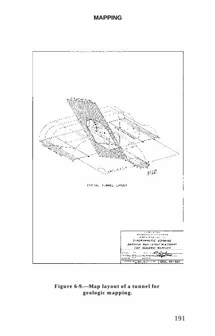
MAPPING
191
Figure 6-9.—Map layout of a tunnel for geologic mapping.
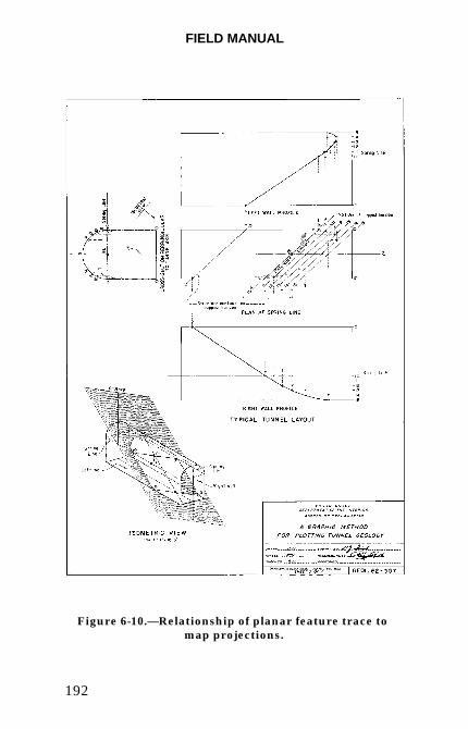
FIELD MANUAL
192
Figure 6-10.—Relationship of planar feature trace to map projections.
MAPPING
193
The bases of the walls or the invert form the base of thesection with springline plotted and the crown formingthe top of the section. For instance, if the tunnel is 20feet (6 m) high, the crown will be 20 feet (6 m) from theinvert. Springline is plotted the appropriate verticaldistance from the crown or invert (figure 6-10). Thisprocess may be done for one or both walls, producing oneor two vertical representations of the wall/arch exposure.Shafts are similar, but the section corresponds to thewall of a rectangular shaft or is tangent to the shaft wallat a point, and the map is a projection of the shaft of onediameter.
A section through tunnel springlines produces a planprojection of the arch except at the plan intersection withthe wall at springline. The corresponding sectionthrough a shaft produces a vertical projection of thewall(s) through a shaft or along a diameter. The maprepresents the actual wall surface of the excavation onlywhere the projection intersects the wall.
Scales are added on either side of the sections to providedistance control while plotting. An additional longitu-dinal section view of the excavation may be added to pro-vide a space to record types and locations of support oroverbreak. Geologic features are then plotted on thefield sheets by noting where the features interceptknown lines, such as where a particular joint interceptsthe crown centerline, the spring line on both walls, or thebase of either wall. The trace of the joint is then pro-jected to the section between these known points. Theattitudes of features are recorded on the field sheet adja-cent to the trace. The location of samples, photographs,water seeps, and flows can be recorded by finding theirlocation on the wall and projecting that location to themap.
FIELD MANUAL
194
Advantages.—The plan and section method:
• Produces two-dimensional sections and plans that donot require conversion. The sections and plans can beintegrated directly with other plans and sections. Thesections and plans are easily understood by individualsnot familiar with full periphery mapping or individualswho have difficulty visualizing structural features inthree-dimensions.
• Permits direct determination of strikes by spring-line intersections.
Disadvantages.—Since the surface of the excavation isgenerally a curved surface, the trace of planar features,such as fractures, faults, and bedding planes, are projec-tions to a plane. The only objective data is where themap is coincident or tangent to the excavation surface.
The plan and section method requires:
• Plotting and observing geologic features and makingaccurate three-dimensional interpretations of thefeatures by projecting locations to a plane.
• Plotting locations of samples and photographs byprojection.
• Recording locations of rock bolts and other types ofrock reinforcement by projection.
• Plotting is done after data collection and re-examination of the site is difficult or not practical.
MAPPING
195
Face Maps
The geology exposed in an excavation face is plotteddirectly on a map. The purpose of the face map is toprovide a quick appraisal of rock conditions and providedata for special detailed studies. The combination ofwall and face maps will usually give an adequate andclear permanent record of any complex tunnel geology.Natural scales such as 1 inch = 1 to 2 feet (1:50) are themost satisfactory. All significant geologic features whichmay affect the stability of the tunnel must be mapped.
Photogrammetric Mapping
Photogrammetric geologic mapping is a specializedmethod consisting of the interpretation of close-rangestereophotography of excavation walls. Photogrammetriccontrol is provided by surveyed targets or by a gnomon orscale in the photographs. The stereophotos are inter-preted using photogrammetric software or an analyticalplotter. Feature location accuracy can vary from a fewinches (cm) to one-eighth of an inch (3mm) depending onequipment and survey control accuracy. The photogram-metric mapping can be combined with detail line surveysfor small-scale data collection and control.
Exploration Mapping Method Selection
The geologic mapping format for exploratory drifts andshafts should be determined by data uses. Directintegra-tion of excavation maps into composite maps ofa dam foundation is much easier if undistorted sectionsare available. The maps can be treated in the samemanner as drill hole logs. The disadvantages of plan andsection mapping may be offset by the advantages of easyinter-pretation and integration into other data bases.
FIELD MANUAL
196
Construction Mapping.—Full periphery geologicmapping should be used for routine constructionactivities. The advantages of increased speed andaccuracy in production mapping and the reduction ofinterpretation offsets the disadvantages.
Summary
This guide to tunnel geologic mapping during construc-tion has been developed for general use and serves tostandardize procedures and data collection. Items ofprimary significance are included, but some are notadaptable to all tunnels or methods of tunnel excavation.The judgment of an experienced geologist is the bestguide to the specific items and amount of detail requiredto provide pertinent, informative data. To ensurereliable and useful tunnel geologic studies, all importantgeology and related engineering construction data whichmay be significant to tunnel construction as well asin the planning, designing, and constructing of futuretunnels should be considered for inclusion in the tunnelmap and report.
Photogeologic Mapping
General
Aerial photographs generally are used in reconnaissancegeologic mapping, geologic field mapping, and in gener-ation of photo-interpretive geologic maps. Various scalesof airphotos are valuable for regional and site studies, forboth detection and mapping of a wide variety of geologicfeatures important to engineering geology.
MAPPING
197
Types of Aerial Photographs
Panchromatic (Black and White).—Panchromaticphotography records images essentially across the entirevisible spectrum, and with proper film and filters alsocan record into the near-infrared. In aerial photography,blue is generally filtered out to reduce the effects ofatmospheric haze.
Natural Color.—Images are recorded in the naturalcolors seen by the human eye in the visible portion of thespectrum.
False-Color Infrared.—Images are recorded using partof the visible spectrum and part of the near-infrared, butthe colors in the resultant photographs are not natural(false-color). Infrared film is commonly used and is lessaffected by haze than other types. False-color photo-graphy is not the same as thermal-infrared imagingwhich uses the thermal part of the infrared spectrum.
Multispectral.—Photographs acquired by multiplecameras simultaneously recording different portions ofthe spectrum can aid interpretation.
Photogrammetry and Equipment
Use stereoscopes to view aerial photographs formaximum utility and ease of interpretation. Pocketstereoscopes are useful in the field or office. Largemirror stereoscopes are useful for viewing largequantities of photos or photos in rolls. Know the photoscale, resolution, and exaggeration. Be aware of thetypes of distortions inherent in airphotos.
FIELD MANUAL
198
Compilation of Photogeologic Map Data
Mapping should be done on transparent one-side-mattemylar overlays and not on the photographs. Any lines,even if erased, can confuse later interpretations usingthe photos. The mapping is then transferred to basemaps minimizing the effects of distortions in photos dueto the camera optics. Orthophoto quadrangles can helpreduce this distortion.
Analysis of Aerial Photographs
General Interpretive Factors
Analysis of aerial photographs involves interpretingindirect data. In most cases, several factors are used tointerpret geologic conditions. Interpretive factorsusually used in the analysis of aerial photographs are:
Sun Angle.—High or low illumination angles may bedesired, depending on the nature of the features to bedetected.
Photographic Tone.—Variations in color, intensity,shade and shadows.
Texture.—Frequency of change in tone, evident asroughness, smoothness.
Color.—True and false-color imagery may be easier tointerpret than panchromatic photographs, depending onfeatures being observed. For some applications (e.g., low sun angle photography), panchromatic photographyis better.
MAPPING
199
Geomorphic Shape and Pattern.—Geologic conditionscan be identified by mapping various types of geomorphicfeatures related to drainage, bedding, and structure.
Vegetation.—Some types of vegetation and vegetal pat-terns can assist in interpreting geology. Vegetation mayindicate depth of soil, type of soil, available moisture,and type of bedrock.
Photoanalysis for ReconnaissanceGeologic Mapping
Photo-reconnaissance geologic mapping can be done toproduce a preliminary geologic map of the study areaprior to going into the field to check and verify theinterpreted geologic data or to produce a finishedgeologic map with little or no field checking. These mapsare called photo-reconnaissance geologic maps andphoto-interpretive geologic maps, respectively.
Photo-Reconnaissance Geologic Mapping
Photo-analysis prior to field work allows the mapper toform a preliminary concept of the geology of the studyarea and to select areas for detailed examination. Priorphoto-analysis is critical if available field time is limited,especially when a large area is involved, as in regionalstudies, reservoir area mapping, and pipeline or canalalignment studies.
Photo-Interpretive Geologic Mapping
Geologic maps produced solely from aerial photographswith little or no field checking are useful when time,funds, or access are limited or when adverse weatherprevents a more detailed field mapping program. The
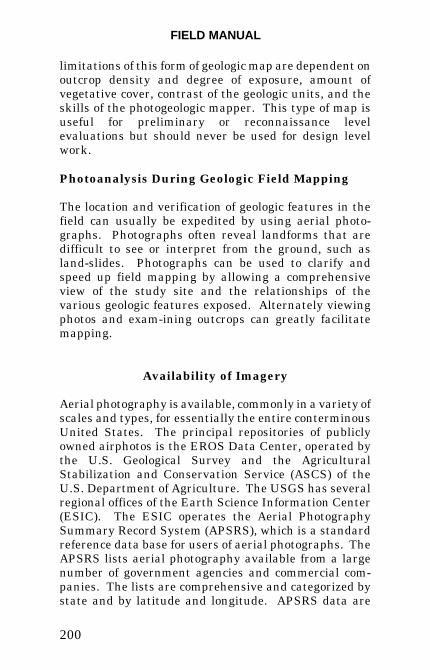
FIELD MANUAL
200
limitations of this form of geologic map are dependent onoutcrop density and degree of exposure, amount ofvegetative cover, contrast of the geologic units, and theskills of the photogeologic mapper. This type of map isuseful for preliminary or reconnaissance levelevaluations but should never be used for design levelwork.
Photoanalysis During Geologic Field Mapping
The location and verification of geologic features in thefield can usually be expedited by using aerial photo-graphs. Photographs often reveal landforms that aredifficult to see or interpret from the ground, such asland-slides. Photographs can be used to clarify andspeed up field mapping by allowing a comprehensiveview of the study site and the relationships of thevarious geologic features exposed. Alternately viewingphotos and exam-ining outcrops can greatly facilitatemapping.
Availability of Imagery
Aerial photography is available, commonly in a variety ofscales and types, for essentially the entire conterminousUnited States. The principal repositories of publiclyowned airphotos is the EROS Data Center, operated bythe U.S. Geological Survey and the AgriculturalStabilization and Conservation Service (ASCS) of theU.S. Department of Agriculture. The USGS has severalregional offices of the Earth Science Information Center(ESIC). The ESIC operates the Aerial PhotographySummary Record System (APSRS), which is a standardreference data base for users of aerial photographs. TheAPSRS lists aerial photography available from a largenumber of government agencies and commercial com-panies. The lists are comprehensive and categorized bystate and by latitude and longitude. APSRS data are
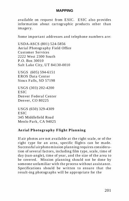
MAPPING
201
available on request from ESIC. ESIC also providesinformation about cartographic products other thanimagery.
Some important addresses and telephone numbers are:
USDA-ASCS (801) 524-5856Aerial Photography Field OfficeCustomer Services2222 West 2300 SouthP.O. Box 30010Salt Lake City, UT 84130-0010
USGS (605) 594-6151EROS Data CenterSioux Falls, SD 57198
USGS (303) 202-4200ESICDenver Federal CenterDenver, CO 80225
USGS (650) 329-4309ESIC345 Middlefield RoadMenlo Park, CA 94025
Aerial Photography Flight Planning
If air photos are not available at the right scale, or of theright type for an area, specific flights can be made.Successful airphoto mission planning requires considera-tion of several factors, including film type, scale, time ofday (sun-angle), time of year, and the size of the area tobe covered. Mission planning should not be done bysomeone unfamiliar with the process without assistance.Specifications should be written to ensure that theresult-ing photographs will be appropriate for the
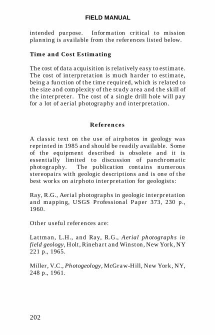
FIELD MANUAL
202
intended purpose. Information critical to missionplanning is available from the references listed below.
Time and Cost Estimating
The cost of data acquisition is relatively easy to estimate.The cost of interpretation is much harder to estimate,being a function of the time required, which is related tothe size and complexity of the study area and the skill ofthe interpreter. The cost of a single drill hole will payfor a lot of aerial photography and interpretation.
References
A classic text on the use of airphotos in geology wasreprinted in 1985 and should be readily available. Someof the equipment described is obsolete and it isessentially limited to discussion of panchromaticphotography. The publication contains numerousstereopairs with geologic descriptions and is one of thebest works on airphoto interpretation for geologists:
Ray, R.G., Aerial photographs in geologic interpretationand mapping, USGS Professional Paper 373, 230 p.,1960.
Other useful references are:
Lattman, L.H., and Ray, R.G., Aerial photographs infield geology, Holt, Rinehart and Winston, New York, NY221 p., 1965.
Miller, V.C., Photogeology, McGraw-Hill, New York, NY,248 p., 1961.
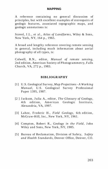
MAPPING
203
A reference containing no general discussion ofprinciples, but with excellent examples of stereopairs ofgeologic features, associated topographic maps, andgeologic annotations is:
Scovel, J.L., et al., Atlas of Landforms, Wiley & Sons,New York, NY, 164 p., 1965.
A broad and lengthy reference covering remote sensingin general, including much information about aerialphotography of all types, is:
Colwell, R.N., editor, Manual of remote sensing,2nd edition, American Society of Photogrammetry, FallsChurch, VA, 272 p., 1983.
BIBLIOGRAPHY
[1] U.S. Geological Survey, Map Projections - A WorkingManual, U.S. Geological Survey ProfessionalPaper 1395, 1987.
[2 ] Jackson, Julia A., editor, The Glossary of Geology,4th edition, American Geologic Institute,Alexandria, VA, 1997.
[3] Lahee, Frederic H., Field Geology, 6th edition,McGraw-Hill, Inc., New York, NY, 1961.
[4] Compton, Robert R., Geology in the Field, JohnWiley and Sons, New York, NY, 1985.
[5] Bureau of Reclamation, Division of Safety, Safetyand Health Standards, Denver Office, Denver, CO.
FIELD MANUAL
204
[6] Proctor, M.E., and White, T.L., Rock Tunneling withSteel Supports, Commercial Shearing, Inc., Youngs-town, OH, 1977.
[7] Hatheway, A.W., “Trench, Shaft, and Tunnel Map-ping,” Bulletin of the Association of EngineeringGeologists, v. XIX, 1982.
[8] U.S. Army Corps of Engineers, “Engineering andDesign, Geologic Mapping of Tunnels and Shafts bythe Full Periphery Method,” Engineer TechnicalLetter No. 1110-1-37, Washington, DC, 1970.
[9] Proctor, R.J., “Mapping Geological Conditions inTunnels,” Bulletin of the Association of EngineeringGeologists, v. VIII, 1971.