Embed Size (px)
Citation preview

7/27/2019 gen_test
http://slidepdf.com/reader/full/gentest 1/37
KPE
Generator Controls Testing & ModellingGenerator Controls Testing & Modelling
December 6-7, 2000
SERC
Presented by
Les Hajagos
Kestrel Power Engineering
(905) 272 2191, [email protected]
7/27/2019 gen_test
http://slidepdf.com/reader/full/gentest 2/37
KPE
Testing to Meet NERC Requirements
F Reactive Capability
F Generator Modelling
F Excitation Systems/Limiters
F Power System Stabilizers
F Governors & Prime Movers
7/27/2019 gen_test
http://slidepdf.com/reader/full/gentest 3/37
KPE
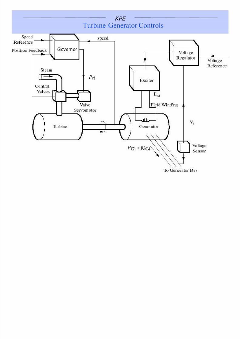
Turbine-Generator Controls

7/27/2019 gen_test
http://slidepdf.com/reader/full/gentest 4/37
KPE
-80
-70
-60
-50
-40
-30
-20
-10
0
10
20
30
40
50
60
70
80
0 10 20 30 40 50 60 70 80 90 100
LOE RELAY
Acti ve Power(MW)
14.5 kV
13.1 kV
13.8 kV
UEL LIMITER
I n U n d e r e x c i t e d
R e a c t i v e P o w e r ( M V
A r )
O u t O v e r e x c i t e d
Generator
Reactive
Capability

7/27/2019 gen_test
http://slidepdf.com/reader/full/gentest 5/37
KPE
Generator Reactive Capability Tests
F Commonly misunderstood test
F Steady-state versus dynamic
F Q = f (V, P)

7/27/2019 gen_test
http://slidepdf.com/reader/full/gentest 6/37
KPE
Testing Reactive Capability - Single Unit
F Normal operation, high Qresults from low system andgenerator voltage
F Test operation high Q resultsfrom high generator voltagewith normal system voltage
F Often ends up being limited byvoltage not truly reactivecapability
F Function of stiffness of systemand transformer impedance
VG
VS
Q

7/27/2019 gen_test
http://slidepdf.com/reader/full/gentest 7/37
KPE
Testing Reactive Capability - Multiple Units
F Maintaining Q1+Q2 constantallows for relatively constantgenerator voltage
F Perform tests simultaneously
F Normally one limit is reachedfirst, meaning that it still maynot be possible to measure bothreactive limits
F Use calculations to extrapolate
results
VG
VS
QT
1 2
Q1 Q2

7/27/2019 gen_test
http://slidepdf.com/reader/full/gentest 8/37
KPE
Case Study - Combined Cycle & Peaker
VS
2 3
Q2 Q3
1
Q1
Combined
CyclePeaker
Steam Gas Limit
P Q V Ifd P Q V Ifd
17 20 14.0 5.3 42 -12 13.2 4.2 UEL
16 40 14.5 7.9 42 -9 13.3 4.3 OEL
18 -15 13.1 2.1 42 15 13.8 5.7 UEL
17 -10 13.3 2.3 42 20 14.0 6.2 4kV OV
Peaker Gas Limit
P Q V Ifd
40 20 14.2 6.1 4 kV OV
40 -13 13.3 4.0 UEL
7/27/2019 gen_test
http://slidepdf.com/reader/full/gentest 9/37
KPE
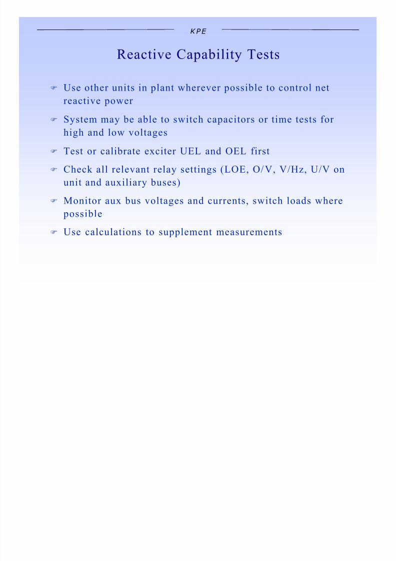
Reactive Capability Tests
F Use other units in plant wherever possible to control net
reactive power
F System may be able to switch capacitors or time tests for
high and low voltages
F Test or calibrate exciter UEL and OEL first
F Check all relevant relay settings (LOE, O/V, V/Hz, U/V on
unit and auxiliary buses)
F Monitor aux bus voltages and currents, switch loads where
possible
F Use calculations to supplement measurements

7/27/2019 gen_test
http://slidepdf.com/reader/full/gentest 10/37
KPE
Excitation Limiters
F Field current limiters (see ANSI C50.13-1977)
Time (seconds) 10 30 60 120
Field Voltage (%) 208 146 125 112F Coordinate with excitation capability
F V/Hz (over-flux) or Terminal voltage
F Under-Excitation Limiters (UEL) coordinated with LOE
and Core-End
7/27/2019 gen_test
http://slidepdf.com/reader/full/gentest 11/37
KPE
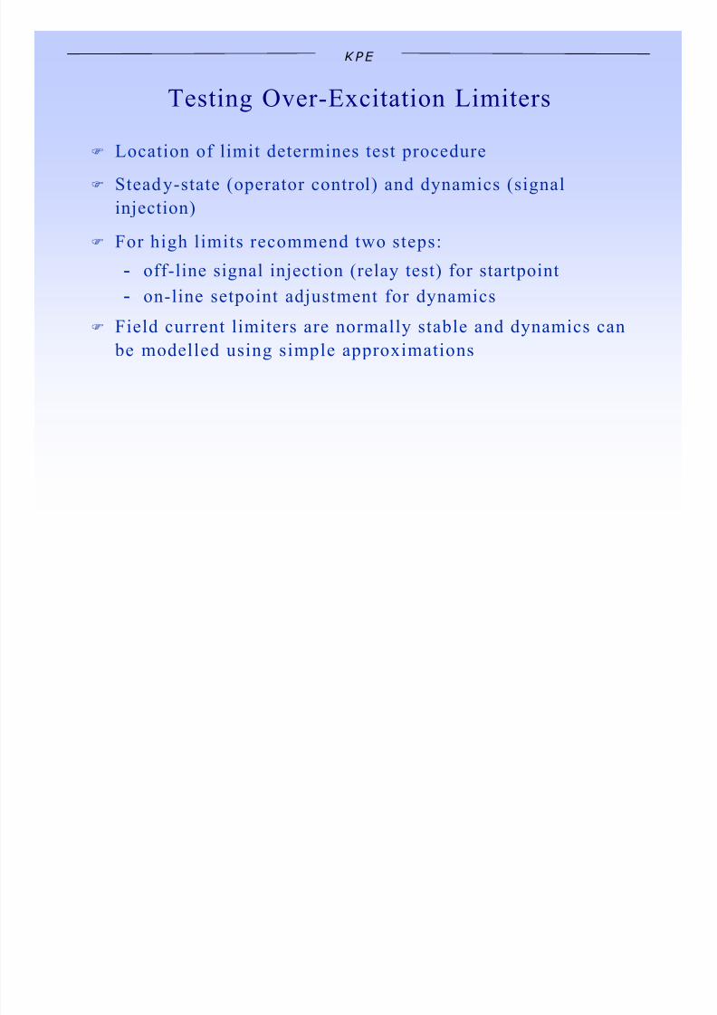
Testing Over-Excitation Limiters
F Location of limit determines test procedure
F Steady-state (operator control) and dynamics (signal
injection)
F
For high limits recommend two steps: off-line signal injection (relay test) for startpoint
on-line setpoint adjustment for dynamics
F Field current limiters are normally stable and dynamics can
be modelled using simple approximations

7/27/2019 gen_test
http://slidepdf.com/reader/full/gentest 12/37
KPE
Operation of Field Current Limiter
-0.1
0
0.1
0.2
0.3
R e a c t i v e P
o w e r
( p u )
0.97
0.98
0.99
1.00
1.01
T e
r m i n a l V
( p u )
30
35
40
45
50
55
F i e l d - V o l t s
( V o l t s )
4.25
4.75
5.25
5.75
0 5 10 15 20
Time (seconds)
F i e l d - A m p s
( A M P s )

7/27/2019 gen_test
http://slidepdf.com/reader/full/gentest 13/37
KPE
Testing Under-Excitation Limiters
F Location of limit determines test procedure
F Steady-state (operator control) and dynamics (signal
injection)
F For low limits recommend two steps:
off-line signal injection (relay test) for startpoint
on-line setpoint adjustment for dynamics
F UE Ls are often poorly-behaved. Caution should always be
exercised when engaging a UEL limit as the response may
be unstable. This is especially true for summing limiterswhere PSS units are installed.

7/27/2019 gen_test
http://slidepdf.com/reader/full/gentest 14/37
KPE
Unit Operation Against UEL Limit
0 . 9610
0 . 9615
0 . 9620
0 . 9625
0 . 9630
T e r
m i n a l V
( p u )
- 2 0 0
- 1 0 0
0
10 0
20 0
30 0
F i e l d - V o l t s
( V o l t s )
2.5
3.0
3.5
4.0
4.5
5.0
0 2 4 6 8 10
T i m e ( s ec onds )
F i e l d - A m p s
( A m p s )
- 0 . 242
- 0 . 238
- 0 . 234
- 0 . 230
R e a c t i v e P o w e r
( p u )

7/27/2019 gen_test
http://slidepdf.com/reader/full/gentest 15/37
KPE
UEL Dynamic Response Test
340
360
380
400
420
440
0 2 4 6 8 10
Time (seconds)
F i e l d
( A m p s )
0.99
1.00
1.01
T e
r m i n a l V
( p u )
40
80
120
160
200
F i e l d
( V o l t s )
-0.10
-0.05
0
0.05
UEL limit (reduced for test)
R e a c t i v e P
o w e r
( p u )

7/27/2019 gen_test
http://slidepdf.com/reader/full/gentest 16/37
KPE
PF/VAR Regulators
F Response needs to be measured
F Guidelines should be in place for:
speed of response deadband
voltage supervision
F Identify where it is implemented
F Perform AVR step response with/without control in-
service

7/27/2019 gen_test
http://slidepdf.com/reader/full/gentest 17/37
KPE
AVR Step Response Performed with PF/VAR
1 .5
2 .5
3 .5
4 .5
0 5 10 15 20
T i m e ( s ec onds )
E x c F i e l d
( A m p s )
0.98
0.99
1.00
1.01
1.02
T e r m i n a l V
( p u )
-0.10
-0.05
0
0.05
0.10
R e a c t i v e P o w e r
( p u )

7/27/2019 gen_test
http://slidepdf.com/reader/full/gentest 18/37
KPE
Types of Stability on AC Power System
F Angular Stability: associated with changes in the angular
positions of generators relative to each other. Frequency
and voltage in normal range.
F Voltage Stability: associated with changes in the vol tage
profile of the system. Frequency and angular positions in
normal range.
F Frequency Stability: associated with islanded operation of
units and changes in the system frequency. Voltage innormal range.

7/27/2019 gen_test
http://slidepdf.com/reader/full/gentest 19/37
KPE
Definitions Applied to Angular Stability
F Steady-State Stability: ability of the power system to
maintain synchronism at all po ints for incremental slow-
moving changes in power outputs of units or power
transfer over transmission facilities
F Transient Stability: ability of the power system to maintain
synchronism during and immediately following a major
disturbance such as a transmission line fault or the loss of a
large generating unit
F Small Signal (Oscillatory Stability): ability of the power
system to maintain synchronism during small changes in
operating conditions which produce small changes in
generator angle, speed and power

7/27/2019 gen_test
http://slidepdf.com/reader/full/gentest 20/37
KPE
Relationship Between Rotor Motion and
Spring-Block Analogy

7/27/2019 gen_test
http://slidepdf.com/reader/full/gentest 21/37
KPE
Functional Description of Stabilizer
• Measure speed (or related quantity)
• Remove steady-state component
• Compensate for phase lags and gains of exciter
• Inject into AVR input
• Create torque change through excitation change

7/27/2019 gen_test
http://slidepdf.com/reader/full/gentest 22/37
KPE
Power System Stabilizers
F Speed-based
F Frequency-based
F Power-based
F Accelerating-power based
F Over 100 in-service in Ontario, most based on the
accelerating-power design

7/27/2019 gen_test
http://slidepdf.com/reader/full/gentest 23/37
KPE
Differential Angle Stabilizer
F phase measurement between generator internal voltage and
a remote system voltage
F
sensitive to system impedance variationsF measurement time lags
F high phase advance requirement
7/27/2019 gen_test
http://slidepdf.com/reader/full/gentest 24/37
KPE
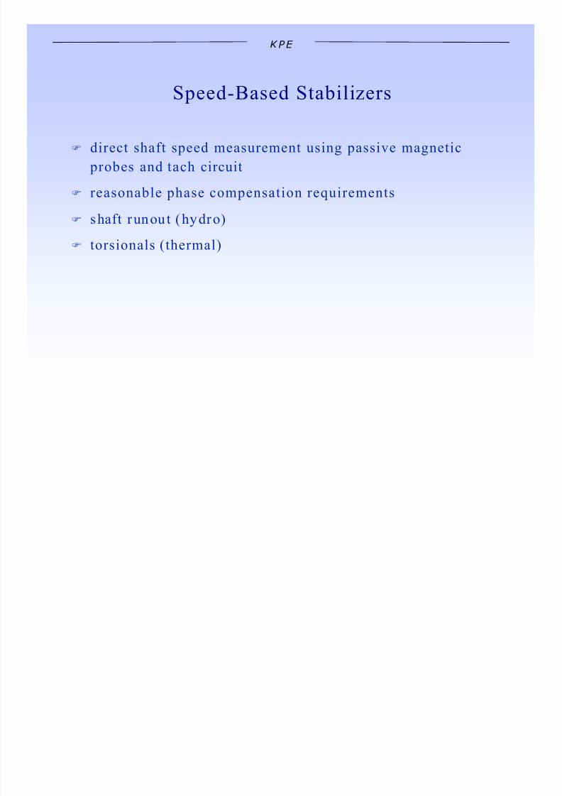
Speed-Based Stabilizers
F direct shaft speed measurement using passive magnetic
probes and tach circuit
F
reasonable phase compensation requirementsF shaft runout (hydro)
F torsionals (thermal)

7/27/2019 gen_test
http://slidepdf.com/reader/full/gentest 25/37
KPE
Speed
s T5
1 + s T5
1
1 + s T6
1
1 + A1 s + A2 s
Ks 1
1 + s T1
1 + s T2
1 + s T3
1 + s T4
Vstmax
Vstmin
Output
High-Pass Filter Stabil izer Gain & Phase Lead Limits
Single-Input Power System Stabilizer (IEEE PSS1A)
2
Torsional Filter

7/27/2019 gen_test
http://slidepdf.com/reader/full/gentest 26/37
KPE
Frequency-Based Stabilizers
F frequency derived from generator terminals or
compensated internal frequency
F
sensitivity to rotor oscillations increases for weak acsystems
F more sensitive to inter-area modes / not sensitive to inter-
machine modes
F system transients cause spurious output signals
F sensitive to other power system noise which is not present
in actual speed
F still requires torsional filtering

7/27/2019 gen_test
http://slidepdf.com/reader/full/gentest 27/37
KPE
Power-Based Stabilizers
F electrical power (inverted) leads speed by 90 degrees
F phase lead requirements met without increasing high-
frequency gainF most not equipped to adjust phase lead and therefore not
very flexible
F sensitive to mechanical power variations
7/27/2019 gen_test
http://slidepdf.com/reader/full/gentest 28/37
KPE
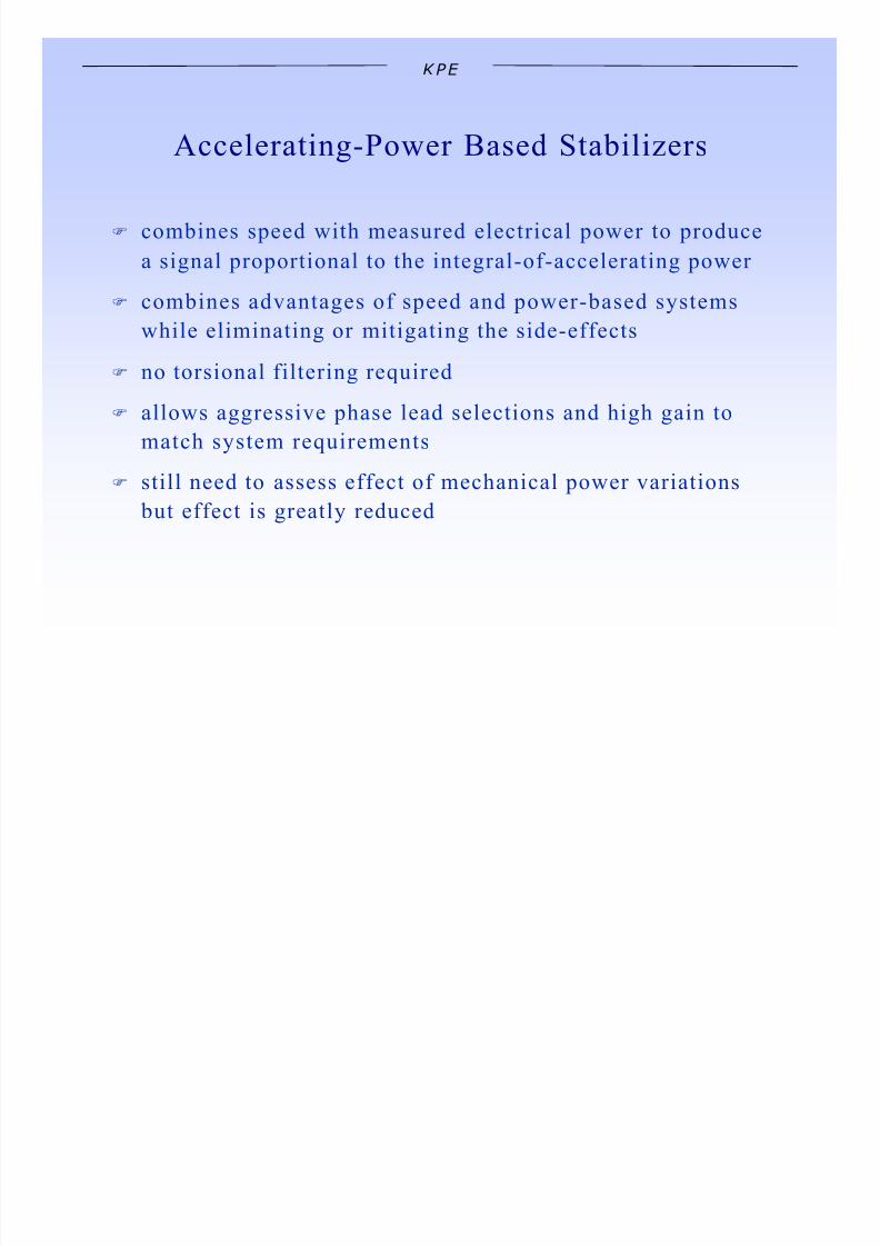
Accelerating-Power Based Stabilizers
F combines speed with measured electrical power to produce
a signal proportional to the integral-of-accelerating power
F
combines advantages of speed and power-based systemswhile eliminating or mitigating the side-effects
F no torsional filtering required
F allows aggressive phase lead selections and high gain to
match system requirements
F still need to assess effect of mechanical power variations
but effect is greatly reduced

7/27/2019 gen_test
http://slidepdf.com/reader/full/gentest 29/37
KPE
Power System Stabilizer Testing&Tuning
F Models rarely reflect reality (AVR/Generator)
F Models lack bandwidth to capture “exciter mode”
F PSS Step response/frequency response
F Measurement of the system phase compensation
requirements
F Step response tests to measure damping improvement at
local mode frequencies
F Load-ramping tests to ensure that the PSS does not
produce undesirable modulation of the unit’s terminal
voltage under normal or emergency operating conditions

7/27/2019 gen_test
http://slidepdf.com/reader/full/gentest 30/37
KPE
Preliminary Tests & Verification
F Verify values at all manufacturer supplied measurement
points
F
Inject signals using test source to verify the transferfunctions of various signal paths
F Install additional transducers as required
F Install any components required to inject test signal into
the AVR summing junction

7/27/2019 gen_test
http://slidepdf.com/reader/full/gentest 31/37
KPE
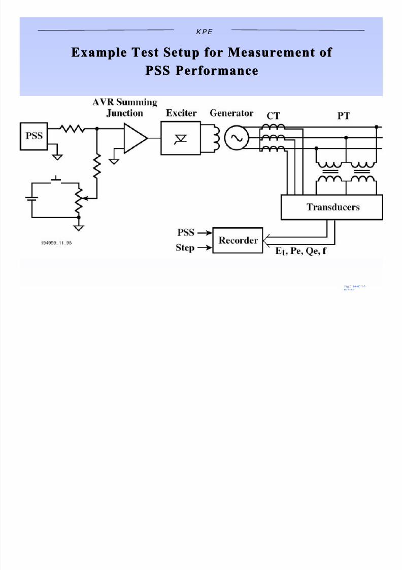
Measured Quantities
F RMS Terminal Voltage
F Field Voltage
F Active Power
F Shaft Speed or Frequency
F PSS Output
F Internal PSS Signals
7/27/2019 gen_test
http://slidepdf.com/reader/full/gentest 32/37
KPE
Example Test Setup for Measurement ofExample Test Setup for Measurement of
PSS PerformancePSS Performance
F i g . 7 . 10-07 / 97-

7/27/2019 gen_test
http://slidepdf.com/reader/full/gentest 33/37
KPE
0.99
1.00
1.01
1.02
1.03
T e r m i n a l V
( p u )
-0.050
-0.025
0
0.025
0.050
0 5 10 15 20
simulatedstabilizer test point
Time (seconds)
P S S - o u t
( p u )
0.80
0.81
0.82
0.83
0.84
A c t i v e P o w e r
( p u )
O n-Line Stabilizer Response

7/27/2019 gen_test
http://slidepdf.com/reader/full/gentest 34/37
KPE
Measurement of ClosedMeasurement of Closed-- Loop Voltage RegulatorLoop Voltage Regulator
Transfer FunctionTransfer Function
F i g . 7 . 9 -07 / 97-B e rube

7/27/2019 gen_test
http://slidepdf.com/reader/full/gentest 35/37
KPE
0
50
100
150
0.1 0.2 0.5 1 2 5
stabilizer phase compensationTw = 10 s, Tlead = 0.18 s, Tlag = 0.05 smeasured phase lead requirement
Frequency (Hz)
P h a s e ( d e g r e e s )
Power System StabilizerPhase Lead Compensation

7/27/2019 gen_test
http://slidepdf.com/reader/full/gentest 36/37
KPE
1.02
1.03
1.04
PSS ONPSS OFF T
e r m
i n a l V
(
p u )
-0.0010
-0.0005
0
0.0005
0.0010
d e l t a s p e e d
( p u )
-0.010
-0.005
0
0.005
0 1 2 3 4 5
P S S
O u t p u t
( p u )
0.90
0.95
1.00
A c t i v e P o w
e r
( p u )
Stabilizer On -Line Step Response

7/27/2019 gen_test
http://slidepdf.com/reader/full/gentest 37/37
KPE
P U BLIC A TIO N S / P R ES EN TA TIO N S
G . R. Bé ru b é , L . M. Ha j a g o s , Utility Experience with Gas Turbine Testing and Modeling , p r e p a re d fo r p r e se n t a t i o n a t t h e IEEE P ES P a n e l o n P o w e r P l a n t Mo d e l i n g , Ja n u a ry
2 0 0 1 .
G . R . B é r ub é , L . M. H a j a g os , R . E . B e a ul i e u , Pr ac ti ca l Ut il it y Ex pe ri en ce wi th Ap pl ic at io n of Po we r Sy st em Sta bi li ze rs , pr es en te d at th e I E EE PE S Pa ne l on P ow er Sy s t em
S t a b i l i z e r s , Ju l y , 1 9 9 9
G . R . B é r ub é , L . M . H a j a g os , Mo de ll in g Ba se d on Fi el d Te st s of Tu rb in e/ Go ve rn or Sy st em s , p r e se n t e d a t t h e IEEE S y m p o s i u m o n F re q u e n c y Co n t ro l Re q u i r e m e n t s , T re n d s a n d
Ch a l l e n g e s i n t h e N e w U t i l i t y En v i ro n m e n t , F e b ru a ry , 1 9 9 9
L . M . H a ja g o s, B . D a n a i , La bo ra to ry Me as ur em en ts an d Mo de ls of Mo de rn Lo ad s an d Th ei r Ef fe ct on Vo lta ge St ab ili ty Stu di es , I E E E T r a n s ac t i o n s o n P ow e r S y s t e ms , V o l 1 3 ,
No 2, M ay 19 98 .
G . R . B é r u b é, L . M . H a j a g o s , Te sti ng an d Mo de ll in g of Ge ne ra to r Co nt ro ls on th e On ta rio Hy dr o Sy st em , p r e se n t e d a t t h e WS CC Wo rk sh o p o n S y n c h ro n o u s U n i t D y n a m i c
Te s t i n g a n d Co m p u t e r Mo d e l V a l i d a t i o n ( Ja n u a ry 3 0 , 1 9 9 7 ) a n d t h e N ERC S y s t e m D y n a m i c s D a t a Wo rk i n g G ro u p S y m p o s i u m (A p r i l 3 0 , 1 9 9 7 )
G . R. Bé ru b é , L . M. Ha j a g o s , Utility Experience with Digital Excitation Systems , IEEE P ES Wi n t e r Me e t i n g 1 9 9 7 , Ne w Y o rk , N Y , P E 5 81 -P WRS -0 0 3 -1 9 9 7 .
G . R. Bé ru b é , L . M. H a j a g o s , R . E . Be a u l i e u , A Ut il it y Pe rsp ec ti ve on Un de re xc it at io n Li mi te rs , IEEE Tra n sa c t i o n s o n En e rg y Co n v e r s i o n , V o l 1 0 , N o 3 , S e p t e m b e r 1 9 9 5 .
G . J . Ro ge r s , R . E. Be a u l i e u , L . M. Ha j a g o s Pe rf or ma nc e of St at io n Se rv ic e In du ct io n Mo to rs Fo ll ow in g Fu ll Lo ad Re je ct io n of a Nu cl ea r Ge ne ra ti ng Un it , IEEE Tra n sa c t i o n s
o n P o w e r S y s t e m s , V o l 1 0 , N o 3 , A u gu s t 1 9 9 5 .
K . S. S h ah , G. R . B é r u b é, R . E . B e a u li e u , Test ing and Modell ing of the Union Electr ic Generator Excitat ion Systems, p r e se n t e d a t t h e 1 9 9 5 Mi sso u r i V al l e y E l e c t r i c a l
A sso c i a t i o n m e e t i n g i n K a n sa s C i t y , MO , A p r i l , 1 9 9 5 .
G . R. Bé ru b é , L . M. Ha j a g o s , R .E . Be a u l i e u , A Ut il it y Pe rs pe ct iv e on Un de re xc it at io n Li mi te rs , IEEE P ES Ex c i t a t i o n S y s t e m S u b c o m m i t t e e P a n e l P re se n t a t i o n , Ju n e 1 9 9 4 .
J . R . R . S e rv i c e , L . M. H a j a g o s , Pr ac ti ca l As pe ct s of On -L oa d Ge ne ra to r Te st in g , EP RI TR-1 0 2 3 5 1 , P ro j e c t 2 3 2 8 -0 2 , F i n a l Re p o r t , Ma y 1 9 9 3 .
G . R . B é r ub é , T . A. G o u g h , Po we r Sy st em Di st ur ba nc e Re co rd er , Ca n a d i a n E l e c t r i c a l A sso c i at i o n , T ra n sm i ss i o n , S t a t i o n P l a n n i n g a n d O p e ra t i o n s S u b se c t i o n , Ma rc h 1 9 8 9 .
G . R o g e r B é r u b é L e s M . H a j a g o s
S en io r E ng inee r S en io r E ng inee r
K es tr el P ow er E ng in ee ri ng K es tr el P ow er E ng in ee ri ng
P h: (4 16 ) 76 7-7 70 4 P h: (9 05 ) 27 2-2 19 1
E - ma il : r o ge r @k e st r el p ow e r. c o m E - ma il : l es @ k e s t r e l p o w e r . c o m


