Embed Size (px)
Citation preview

1
FLAME115 INFRARED HEATER SERVICE MANUAL
INDEX
1. CONTROLS AND COMPONENTS 2. FLAME CONTROL CYCLES 3. MAINTENANCE SCHEDULE 4. TROUBLESHOOTING GUIDE 5. REPAIR PROCEDURES
1. FAN MOTOR ASSEMBLY 2. FUEL FILTER ASSEMBLY 3. FUEL PUMP ASSEMBLY 4. ELECTRIC PANEL ASSEMBLY 5. AIR PRESSURE SWITCH 6. COMBUSTION HEAD ASSEMBLY 7. COMBUSTION CHAMBER 8. COMBUSTION TEST
6. WIRING DIAGRAMS 7. TECHNICAL DATA SHEET
FIRE 115
L-S 116.00-BM
WARNING
The operations described in this booklet must be carried out by qualified and instructed personnel only. Incorrect maintenance may result in improper operation and serious injury.

2
1. CONTROLS AND COMPONENTS
INFRARED HEATER: FIRE 115
CONTROL PANEL
1 COMBUSTION CHAMBER 2 BURNER 3 NOZZLE 4 SOLENOID VALVE 5 DIESEL PUMP 6 MOTOR 7 FAN 8 FUEL FILTER 9 FUEL CIRCUIT 10 SUPPORT/HANDLE 11 WHEEL 12 FUEL TANK 13 RESET BUTTON WITH CONTROL
LAMP 14 MAIN SWITCH 15 ROOM THERMOSTAT PLUG 16 CONTROL LAMP 17 POWER CORD 18 HANDLE 19 FUEL CAP 20 DRAIN PLUG 21 HEAT FLOW
1 2 3 18
6
10
5
12
19
7
9
11
8
21
10
4
20
13
14 15
16 17

3
CONTROL SYSTEM The heater has all operational controls located in a watertight control panel mounted on a lateral side of the unit. The control panel consists of:
a 3-position switch for heating function: normal operation, stop or thermostat operation
plug to connect a remote room thermostat
power cord
control flame box to handle starting / running cycle (see paragraph 2.). The control flame box is equipped with a reset button and a high voltage transformer that generates a spark to ignite the flame.
The control system utilizes:
a safety shut off switch that is a overheat thermostat shutting down the unit if the temperature of combustion chamber and outlet air exceed the maximum allowed level
a flame detector, that is a photocell monitoring constantly the flame presence and its integrity.
a pair of ignition rods to create the ignition spark FUEL SYSTEM The fuel system consists of:
fuel tank, that is made of plastic, shock absorption and fuel resistant. It has a drain plug located underneath the fuel tank to allow discharge of residual fuel before cleaning.
fuel filter
fuel pump. A screw fitted on the fuel pump allows the adjustment of fuel pressure setting
fuel ON/OFF solenoid valve o during normal operation the valve is open and the pressurized fuel flows to the nozzle, where it is
atomized, mixed with primary combustion air and ignited by the electrode spark o during abnormal operation (see paragraph 2.) the flame control unit closes the fuel solenoid valve and
the unit stops.
fuel circuit, including suction and return hoses from fuel tank to fuel pump and high pressure microhose from fuel pump to nozzle
burner head
nozzle COMBUSTION CHAMBER It consists of the internal combustion chamber (stainless steel made) that contains the flames and exchanges heat with the main airflow stream. BURNER HEAD The burner head is the assembly that determines the correct mixing of combustion air and fuel inside the combustion chamber and it consists of:
Fuel nozzle
Nozzle support
Flame diffuser
Air opening baffle: a screw fitted on the burner head allows the adjustment of combustion air setting
Ignition electrodes
Flame detector FAN – MOTOR ASSEMBLY The electric motor drives the fuel pump assembly and a fan which blows air inside and around combustion chamber.

4
2. FLAME CONTROL CYCLES 2.1 RESET LAMP LIGHT During the operating condition, the reset button may have different type of light depending of its operating status (FUNCTION LIGHT): • light off: unit is in stand-by status (waiting for heating request) or starting cycle or running. • steady red light: the heater stops permanently in lock-out status and can restart only if reset button
is pressed. To troubleshooting the unit when it is in lock-out condition, press the reset button for about 5 seconds and then release it. A diagnostic routine is enabled, causing the reset button on the main board to flash (SELF-DIAGNOSIS LIGHT) with the following description
Number of blinks
Fault description
2 Flame failure in starting cycle
4 Extraneous light / flame in starting cycle
7 Flame failure in running cycle
8 - 14 Internal failure of electronic control
2.2 OPERATING CYCLES Depending on the type of the operating cycles, the main components (room thermostat, fan, ignition transformer, fuel valve) and controls element (photocell, reset button) are activated or de-activated according to specific rules and times. In the following diagrams are shown:
Starting cycle
Shut off cycle
Flame failure in starting cycle
Extraneous light or flame during starting cycle
Flame failure in running cycle
The flame control unit starts the sequence of operation after a heating request (normal operation or thermostat operation) and it consists of the following steps:
Self-test (less than 3 s): self-check of electronics efficiency;
Purging time TP (20 seconds): fan motor and ignition transformer are simultaneously switched on while the fuel valve remains closed to eliminate any fuel or unburnt residual. During the purging stage, the flame signal is constantly monitored and any kind of failure leading to combustion prevents the burner ignition causing the controls to lock out the unit.

5
In case of heating request opening (room thermostat opening), the control unit goes to stand-by position. The device remains in this status till closing of the room thermostat;
Safety time (5 seconds): at the end of the purging time TP, the fuel valve is switched on and opens the fuel to the nozzle. In case of flame detection failure by the end of the TS safety time, the control unit goes to lockout, and the fan motor, the ignition transformer and the fuel valve are de-energized, while the lockout signal is enabled. Otherwise, at the end of the TS safety time the control unit disables the ignition transformer and goes to running position.
When the heating request (normal operation or thermostat operation) opens:
fuel valve and ignition transformer are switched off and the flame lights off;
burner fan operates a 90 s post-purge ventilation Restoring the heating request causes the post-purge to be interrupted and the starting cycle to be performed.
If during the safety time TS, the photocell monitors a flame failure (signal to photocell become lower than minimum), at the end of safety time the unit tries to restart twice: should the flame failure being confirmed, then the unit goes in lock out:
burner fan, ignition transformer and fuel valve are de-energized;
alarm lamp on reset button becomes steady red If troubleshooting on reset button is activated as described in 2.1, then the alarm lamp on reset button starts flashing with 2 blinks. FUNCTION LIGHT: steady red SELF-DIAGNOSIS LIGHT: flashing red with 2 blinks

6
Unit can re-start only after pressing the reset button. NOTE: While starting cycle is repeated, a cooling time TXP is required to get the ignition transformer be ready to operate.
If during the pre-purge time the photocell monitors any residual flame then the unit goes in lock out:
burner fan stop to purging combustion chamber
fuel valve and ignition transformer are de-energized
reset lamp becomes steady redIf troubleshooting on reset button is activated as described in 2.1, then the alarm lamp on reset button startsflashing with 4 blinks.FUNCTION LIGHT: steady redSELF-DIAGNOSIS LIGHT: flashing red with 4 blinksUnit can re-start only after pressing the reset button.
In case of flame failure in running status, the flame control unit makes one trial restarting the unit. If the reason of flame failure is confirmed, then the unit stops in lock-out mode, and the reset lamp becomes steady red. If troubleshooting on reset button is activated as described in 2.1, then the alarm lamp on reset button starts flashing with 7 blinks. FUNCTION LIGHT: steady red SELF-DIAGNOSIS LIGHT: flashing red with 7 blinks Unit can re-start only after pressing the reset button.

7
3. MAINTENANCE SCHEDULEPeriodic maintenance of the heater is necessary to ensure proper performance and to prevent failures and it shall be performed at the following periodic intervals:
o Daily maintenance Inspect air inlet / air outlet, remove debris if any Verify fuel tank is full Verify there is not any visible leaks
o Weekly maintenance Inspect fuel filter and replace if necessary Disassemble burner head
• Inspect and clean burner diffuser• Clean ignition electrodes and adjust settings
Inspect the fuel hose assembly and check for any leakso Monthly maintenance
Disassemble burner head• Inspect and replace nozzle if necessary• Check air combustion setting
Check overheat thermostat Inspect and clean the combustion chamber Open electric board, inspect electrical components and check connections Check fuel pressure setting of fuel pump - ensure 166 psi Inspect and test the burner when maintenance has been completed

8
4. TROUBLESHOOTING GUIDE
PROBLEM RESET BUTTON (13) CAUSE REMEDY
• Motor does not start, no ignition
FU
NC
TIO
N L
IGH
T
• Off
SE
LF
-DIA
GN
OS
IS L
IGH
T
-
• Wrong setting of room thermostat orother control
• Check correct setting of heater control. Ifthermostat, make sure selected temperature is higher than room temperature
• Defective thermostat or other control • Replace control device
• Fan does not start or stops during start-up or heating
• Off -
• No electrical current
• Check mains
• Check proper positioning and functioning ofswitch
• Check fuse
• Voltage below 68 V• Check supply voltage: heater will restartautomatically when voltage exceeds 78 V
• Voltage above 147V• Check supply voltage: heater will restartautomatically when voltage is below 138 V
• Fan stops during start-up or heating
• Steady red
4 blinks
• Presence of flame before transformer ignites
• Clean and eliminate diesel residue in combustion chamber
• Defective photocell • Replace photocell
2 blinks or 7 blinks
• Defective electrical motor • Replace electrical motor
• Defective electrical motor bearings • Replace electrical motor bearings
• Burned out condenser • Replace condenser
• Defective electric ignitor
• Check connection of H.T. wires to electrodesand transformer
• Check electrodes setting (see scheme“SETTING THE ELECTRODES”)
• Check electrodes for cleanliness
• Replace H.T. transformer
• Defective flame control box • Replace control box
• Defective photocell • Clean or replace photocell
• Insufficient or no fuel at burner
• Check state of motor-pump plastic coupling
• Check for any air infiltrations in the fuel line by checking the air-tightness of the pipes and of thefilter.
• Clean or replace oil nozzle
• Defective solenoid• Defective electric ignitor
• Check electrical connection
• Check thermostat LI
• Clean solenoid valve and replace it if necessary
8 – 14 blinks • Internal error of electronic control board• Reset the device and attempt at least two starts. If the problem persists, replace theelectronic control board
• Fan starts and flame lights, generating fumes
• Off -
• Insufficient combustion air• Check the position of the air regulation ring
• Clean burner disc
• Excess combustion air • Check the position of the air regulation ring
• Fuel contaminated or contains water • Drain fuel in tank and load with clean fuel
• Replace oil filter
• Air leaks in fuel circuit • Check the seals on the ducts
• Insufficient fuel at burner• Check pump pressure
• Clean or replace fuel nozzle
• Excess fuel at burner• Check pump pressure
• Replace nozzle
• Heater does not stop • Off - • Defective solenoid seal • Replace complete solenoid valve

9
5. REPAIR PROCEDURES
WARNING Before carrying out any maintenance operation the heater must be disconnected from power supply. Refer to instruction manual to fully stop the heater. Therefore:
• Stop the machine as instructed • Turn off the disconnecting switch on the main electric switchboard • Wait until the heater has cooled.
Never service heater while it is plugged in, operating or hot. Severe burns or electrical shock can occur. 1) FAN MOTOR ASSEMBLY
a) To clean the fan blades and motor, carry out the following procedure. i) Remove the bottom and upper rear cover access panel (a) by removing four screws
ii) Remove fan/motor assembly (c) by removing four screws that secure it to the machine.
iii) Inspect and, if necessary, clean the motor using compressed air, being carefully not to direct the air jet to the air pressure switch gauge (c) (the pressure switch could be damaged)
a
b
c

10
iv) Clean the fan blades and plastic conveyor using a stiff brush.
v) Reinstall the fan/motor assemblyvi) Reinstall cover panels.
b) To replace the fan blade and the electric motor, carry out the following procedure.i) Remove the fan/motor assembly as by previous stepsii) Loosen the screw (c) on the fan hub
iii) Extract the faniv) Remove the fan flange (c) by removing four screws
b
c

11
v) Loosen three screws (e) on the fuel pump casing (be sure not to remove the screws)vi) Remove fuel pump from electric motor and keep plastic coupling for next reassembling
vii) Open main electric board on side/front of the heaterviii) Trace the electric motor power cords and disconnect the three wires (white, black, green) from control
panelix) Position a new motor on the motor flange and reassemble four screws (f) to fix itx) Check alignment of the motor to the heater axis and tighten four screws (f) on motor flangexi) Fit fuel pump on electric motor being sure that plastic coupling is aligned and tighten three screws (e)xii) Position fan blade on the motor shaft being sure that the quoted distance is 1 mm
xiii) Tighten screw (d) and check free rotation of the fan bladesxiv) Reinstall covering panels.
1 mm

12
2) FUEL FILTER ASSEMBLY
To replace the plastic type fuel filter, carry out the following procedure. i) Remove front panel (a)
ii) Remove clips (b) and fuel hoses
iii) Replace fuel filter iv) Reassemble the filter assembly checking clips (a) are tightened
b
a

13
3) FUEL PUMP ASSEMBLYa) To replace fuel pump, carry out the following procedure.
i) Remove the bottom and upper rear cover access panel (a) by removing all screws
ii) Remove fan/motor assemblyiii) Loosen three screws (e) on the fuel pump casing (be sure not to remove the screws)iv) Remove fuel pump from electric motor and keep plastic coupling for next reassembling
v) Disconnect wires lead to fuel solenoid valve (g)vi) Reassemble new fuel pump on electric motor being sure that plastic coupling is alignedvii) Tighten three screws (e)viii) Reinstall the cover<.
b) To set fuel pressure on fuel pump, carry out the following procedure.
a
b
a

14
i) Remove the rear cover access panel (b) by removing all screwsii) Loosen cap (a) on side of fuel pump and connect a fuel pressure meteriii) Disconnect wires lead to fuel solenoid valve (to avoid fuel spray inside combustion chamber)
WARNING
The following operation shall be done with top cover and possible access to rotating fan. Fan rotating area is covered by fan support even if accessible
Take measure to avoid touching any rotating parts while setting fuel pressure
iv) Start the heater and check the fuel pressure be the value listed in the final technical sheetv) Correct the pressure by screwing (to increase pressure) or unscrewing (to decrease pressure) screw (b)
vi) Remove fuel pressure meter and tighten cap (a)vii) Connect wires to solenoid fuel valveviii) Reinstall the top cover.
b

15
4) ELECTRIC PANEL ASSEMBLYa) To check electric control board and its fuse, carry out the following procedure.
i) Remove four screws (a) on control board panelii) Remove front cover (b)
iii) Check that all connections are complete and tightiv) To check fuse loosen ¼ clockwise the screw (c) , extract the fuse and check its integrity
v) If necessary, replace it with a new onevi) Reassemble front cover (b) and fix it to the heater
a b
c

16
5) COMBUSTION HEAD ASSEMBLYa) To clean combustion head assembly, carry out the following procedure.
i) Remove the bottom rear cover access panel (a) by removing four screws
ii) Remove the upper rear cover access panel (b) by removing four screws
iii) Loosen screw (c) and remove fast-on connector of yellow/green wire)(c)
iv) Turn counterclockwise burner support (d) and pull it out of burner tube (e)
a
b
c
d
e
17
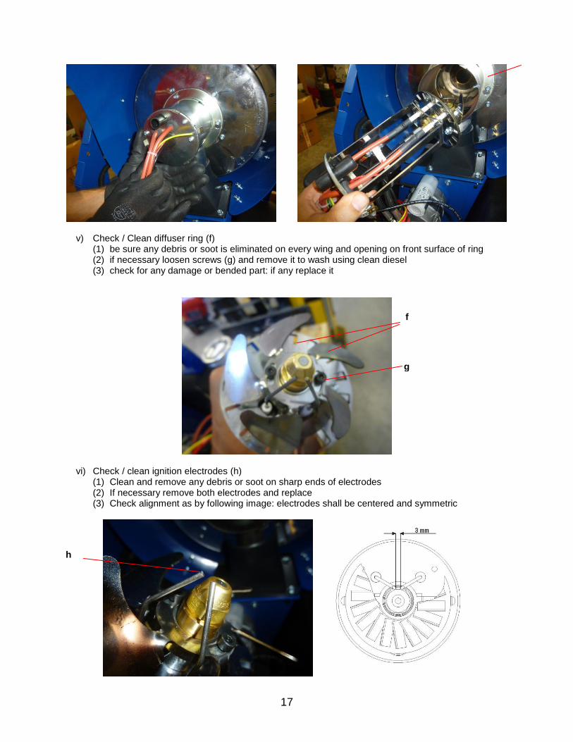
v) Check / Clean diffuser ring (f)(1) be sure any debris or soot is eliminated on every wing and opening on front surface of ring(2) if necessary loosen screws (g) and remove it to wash using clean diesel(3) check for any damage or bended part: if any replace it
vi) Check / clean ignition electrodes (h)(1) Clean and remove any debris or soot on sharp ends of electrodes(2) If necessary remove both electrodes and replace(3) Check alignment as by following image: electrodes shall be centered and symmetric
f
h
g

18
(4) Check electrode connectors (i) be tightened and clean
vii) Check/replace fuel nozzle(1) Loosen fuel nozzle and place a new one
viii) Check / clean photocell(1) Remove photocell (m) and check it is clean
(2) Check photocell support be clean and clean hole (n)
i
m
m

19
ix) Check / adjust air openings(1) Loosen nuts (o)(2) Adjust rotating disc (p) until the requested opening is obtained (check final tech. sheet)
x) Reassemble combustion head
6) COMBUSTION CHAMBER ASSEMBLYa) To clean combustion chamber assembly, carry out the following procedure.
i) Remove the front bumperii) Remove the outlet panel (a) by removing six screws
a
0
p
n

20
iii) Check and clean inside combustion chamber with a cloth, removing liquid fuel residualiv) Reassemble outlet panel (a) and front bumper

21
6. WIRING DIAGRAM
AP CONTROL BOX
TA ROOM THERMOSTAT PLUG
LI1 OVERHEAT THERMOSTAT
EV1 SOLENOID VALVE
FO PHOTOCELL
CO CAPACITOR
MV BURNER MOTOR
FUA FUSE
RV SWITCH
ST ELECTRIC PILOT
RF HEATED FILTER >> OPTIONAL
RL RESET BUTTON
LL LOCK OUT INDICATOR LIGHT
RV1 SWITCH
TD TRANSFORMER H.V.
NOTE Overheating thermostat LI1 is connected in serie to fuel valve EV1. Therefore in case LI1 opens, the fuel valve EV1 is switched off and the flame control unit goes in lock-out in the “flame failure mode”.

22
7. TECHNICAL SPECIFICATION
TECHNICAL SPECIFICATIONS CARACTERISTIQUES TECHNIQUES
FIRE 155
Max heating output Puissance thermique max
[BTU/h] 115.159
Fuel consumption Consommation
[gal/h] 0,849
Power supply Alimentatione électrique
Phase Phase
1
Voltage Tension
[V] 120
Frequency Fréquence
[Hz] 60
Power consumption Puissance électrique
[W] 175
Nozzle Gicleur
[USgal/h] Delavan 0,65 - 80° W
Pump pressure Pression pompe
psi 166
Adjustment of combustion air flap Réglage du volet d'air comburant
[in] a = 0,126
Tank capacity Capacité réservoir
[USgal] 11,35
Noise level at 1 m Niveau sonore à 1 m
[dBA] 69
Dimensions, L x W x H Dimensions, L x P x H
[in] 35.24 x 20.94 x 31.81
Weight Poids
[lb] 92.5