Embed Size (px)
Citation preview
Generator Protection
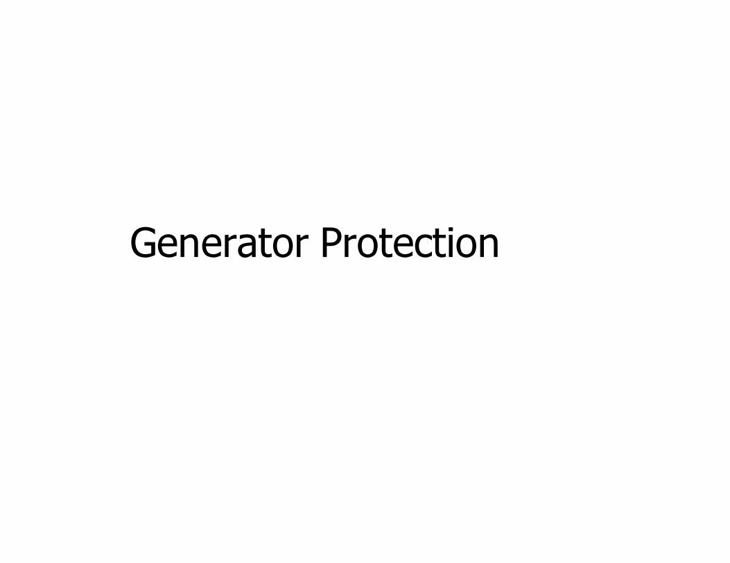
Amount of Protection
• Rated power of the generator
• Ratio of its capacity to the total capacity of the system
• Configuration of the primary plant
– Generator directly connected to the system
– Generator connected to the system through a transformer
• Method of star point grounding
• Type of excitation
• Prime mover
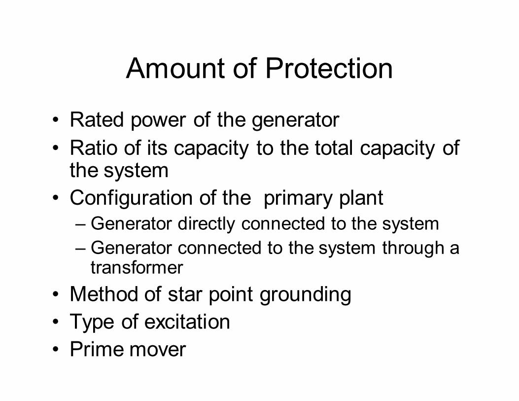
Kinds of Faults Generators are Subjected to
• Due to problems within generator
• Stator ground faults
• Stator phase faults
• Stator inter-turn faults
• Rotor ground faults
• Duplicate ground faults
• Due to external conditions
• Phase faults
• Asymmetric faults
• Stator overload
• Rotor overload
• Over-voltage
• Under-frequency
• Motoring
Stator Ground Fault Protection
• One of the most frequent internal generator faults
• Fault current will depend on the method of
grounding
• High fault currents will cause damage to the core
• Limitation of the fault current to low values reduces
– damage to the core
– possibility of developing into phase-phase faults
Methods of Limiting Erath Fault
Currents
• Resistance earthing
• Distribution Transformer earthing
Generator Directly Connected to the Power System
• Generally only low capacity generators connected directly to the busbars
• Discrimination required
• Placement of the CTs
• Measurement of the earth-fault current– Core balance CT– Residual connection
• Simple Current Relays, Restricted earth fault, Directional relays
Generators Connected Through a Stepping Up Transformer
• As primary winding is delta, earth faults on the HV side are not seen by the generator earth fault relays
• Instantaneous and time delayed relays could be used
• Relay settings need to be set to avoid operation for surges through generator transformer inter-winding capacitance.
• As discrimination is not required, earth fault currents can be limited to low values
• Standard arrangement is to earth the neutral through the primary winding of a transformer
•
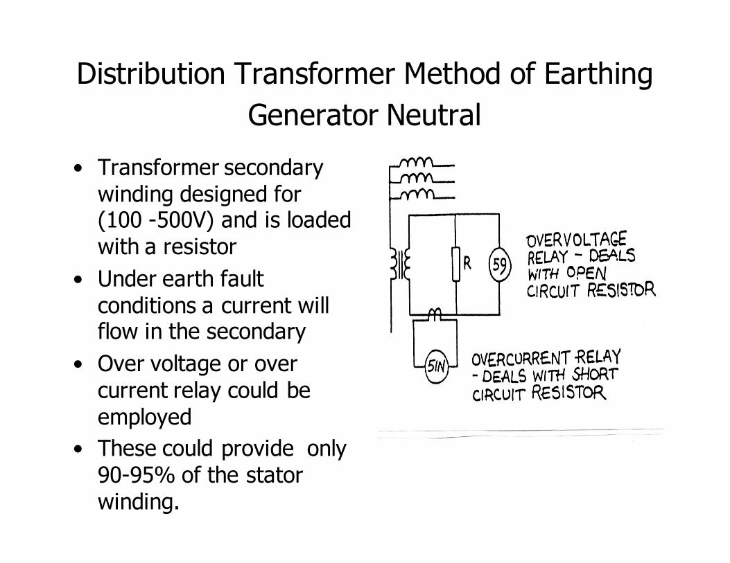
Distribution Transformer Method of Earthing
Generator Neutral
• Transformer secondary winding designed for (100 -500V) and is loaded with a resistor
• Under earth fault conditions a current will flow in the secondary
• Over voltage or over current relay could be employed
• These could provide only 90-95% of the stator winding.
100% Protection of Generator Stator Winding
• 3rd harmonic components exist in the generator phase voltages.
• Under normal operating conditions 3rd harmonic voltages highest at the starpoint and at the generator terminals
• With EF close to neutral 3rd harmonic at the terminals get doubled and that at
the neutral reduces to zero.
• With EF at the terminals, 3rd harmonic at the neutral will be high.
• EF at the centre of the stator winding can not be detected
• Can not detect ground faults when the generator is not running.
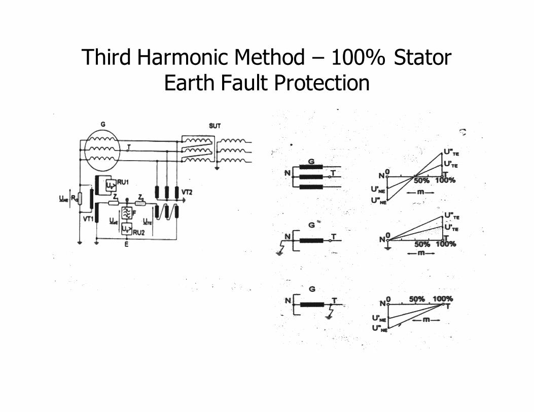
Third Harmonic Method – 100% Stator Earth Fault Protection
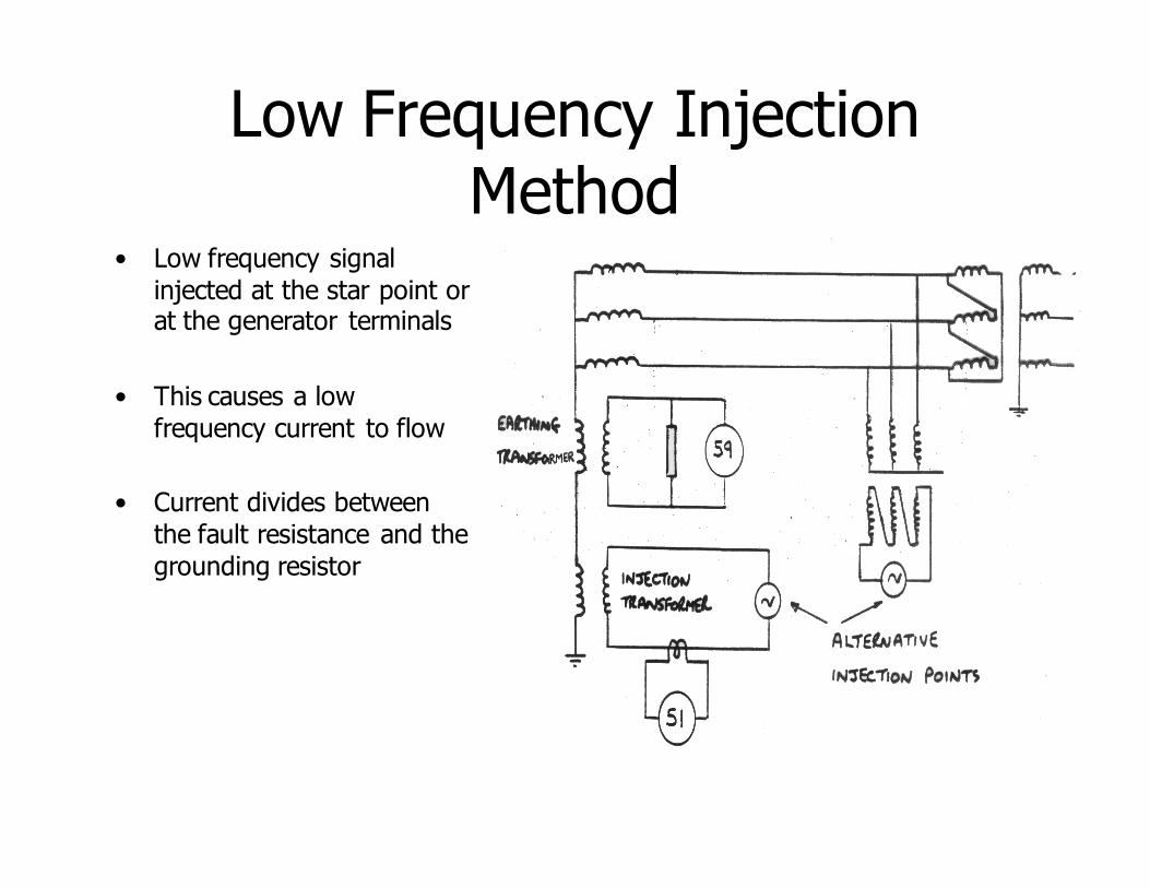
Low Frequency Injection Method
• Low frequency signal
injected at the star point or at the generator terminals
• This causes a low
frequency current to flow
• Current divides between
the fault resistance and the
grounding resistor
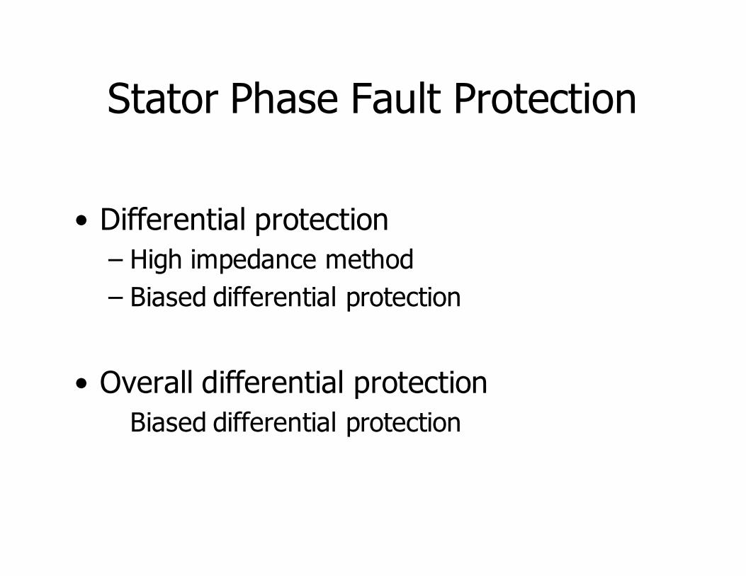
Stator Phase Fault Protection
• Differential protection
– High impedance method
– Biased differential protection
• Overall differential protection
Biased differential protection
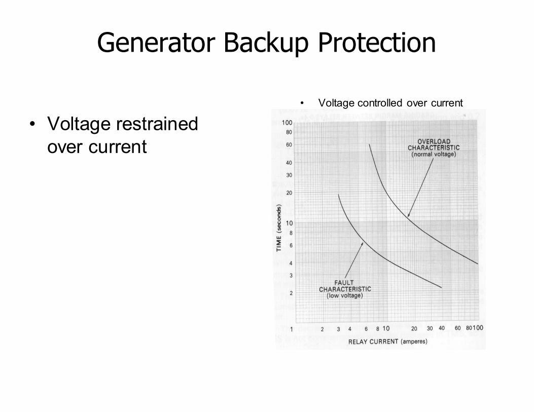
Generator Backup Protection
• Voltage restrained
over current
• Voltage controlled over current
Stator Inter-turn Faults
• Longitudinal differential systems do not detect interturn faults
• Interturn fault protection not commonly
provided as those are rare or later will develop into earth faults
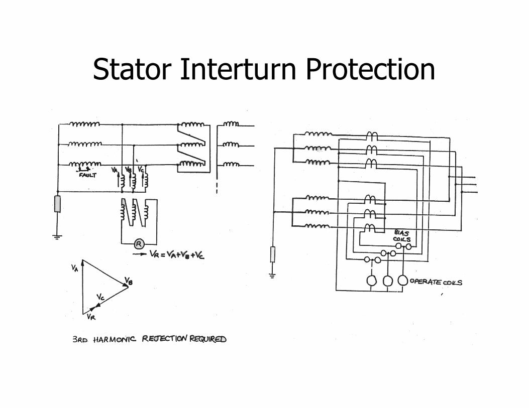
Stator Interturn Protection
Generator Overload Protection
• heating of the stator and rotor
• Insulation failure
• Governor settings
• Direct temperature measurement
• Thermal replica relays
Loss of Synchronism
• Due to loss of excitation
• Due to severe system disturbances
Loss of Excitation
– Short or open circuit of the exciter
– Failure of the automatic voltage regulator
– Operational error under manual control
• Cause partial or complete failure of the the excitation
• Local hot spots in stator or rotor
• Falling out of synchronism with paralllel
running of generators
• With single generator load will be lost
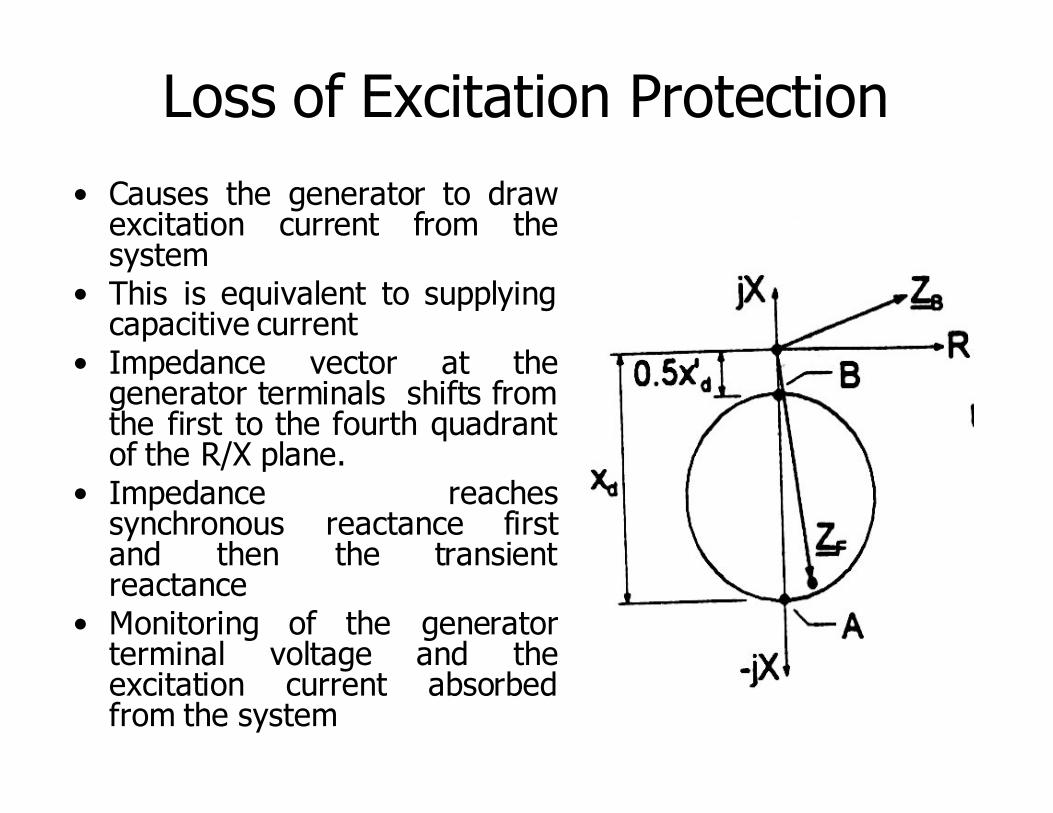
Loss of Excitation Protection
• Causes the generator to drawexcitation current from thesystem
• This is equivalent to supplyingcapacitive current
• Impedance vector at thegenerator terminals shifts fromthe first to the fourth quadrantof the R/X plane.
• Impedance reachessynchronous reactance firstand then the transientreactance
• Monitoring of the generatorterminal voltage and theexcitation current absorbedfrom the system
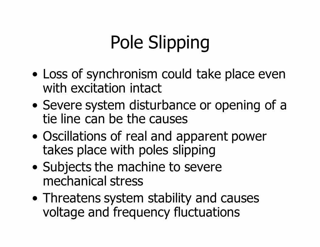
Pole Slipping
• Loss of synchronism could take place even with excitation intact
• Severe system disturbance or opening of a tie line can be the causes
• Oscillations of real and apparent power takes place with poles slipping
• Subjects the machine to severe mechanical stress
• Threatens system stability and causes voltage and frequency fluctuations
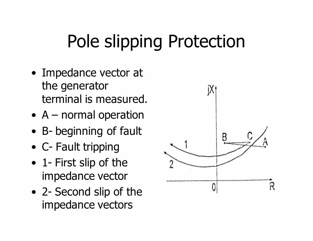
Pole slipping Protection
• Impedance vector at the generator
terminal is measured.
• A – normal operation
• B- beginning of fault
• C- Fault tripping
• 1- First slip of the
impedance vector
• 2- Second slip of the impedance vectors
Unbalanced Loads on Generators
• Balanced load produces a reaction field that rotates with the field system
• Unbalanced loads will make the generators to produce positive, negative and zero sequence components depending on the conditions.
• Zero sequence does not produce an armature reaction
• Negative sequence produces an armature reaction that rotates in the opposite direction to the field system
• Produces a flux which cuts the rotor at twice the rotational velocity
• Induces double frequency currents in the rotor which causes severe heating
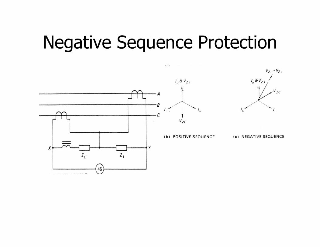
Negative Sequence Protection
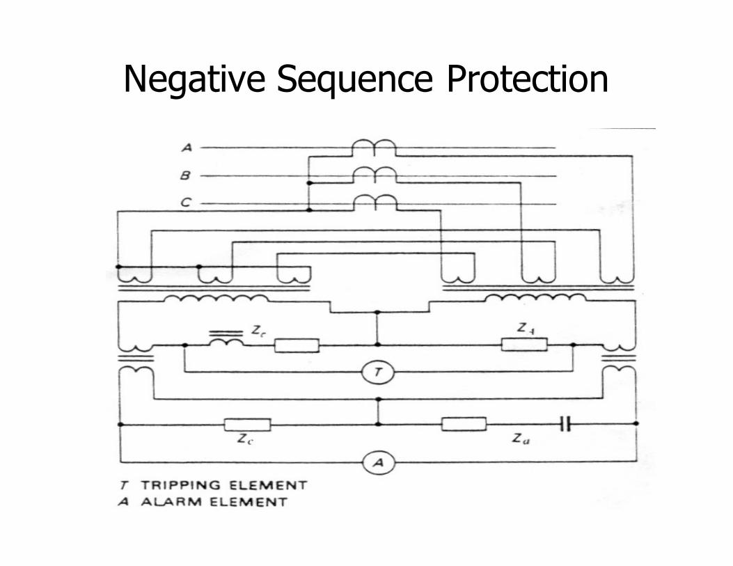
Negative Sequence Protection
Rotor Earth Faults
• Field current is an isolated DC system
• Insulation failure at a single point produces no fault current
• Insulation failure at the second point
shorts part of the field winding, heating the conductors, flux distortion, vibration of
the rotor.
•
Over Voltage Protection
• Over voltage results from
– generator over speed caused by sudden loss
of load
– Failure of the voltage regulator
– Causes over fluxing and endangers insulation
• Time delayed over voltage protection
schemes are provided
Reverse power
• Generator can act as a motor drawing power from the system
• Prime mover gets affected
• Wattmetric type relays are used