Embed Size (px)
Citation preview
Generated on July 6, 2018
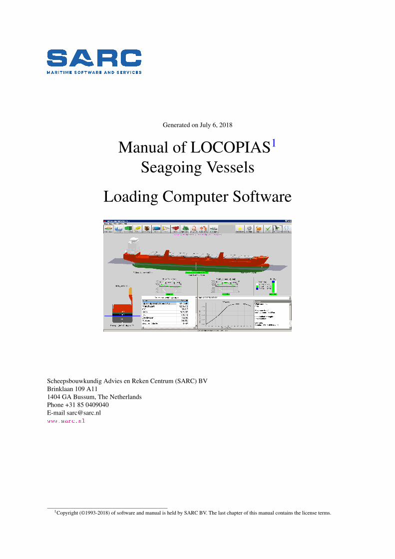
Manual of LOCOPIAS1
Seagoing Vessels
Loading Computer Software
Scheepsbouwkundig Advies en Reken Centrum (SARC) BVBrinklaan 109 A111404 GA Bussum, The NetherlandsPhone +31 85 0409040E-mail [email protected]
1Copyright (©1993-2018) of software and manual is held by SARC BV. The last chapter of this manual contains the license terms.
Contents
1 Preliminary notes 1
2 Loading Software 22.1 General . . . . . . . . . . . . . . . . . . . . . . . . . . . . . . . . . . . . . . . . . . . . . . . . 2
2.1.1 Invoking LOCOPIAS . . . . . . . . . . . . . . . . . . . . . . . . . . . . . . . . . . . . . 22.1.2 Define and verify loading conditions . . . . . . . . . . . . . . . . . . . . . . . . . . . . . 22.1.3 All types of vessels . . . . . . . . . . . . . . . . . . . . . . . . . . . . . . . . . . . . . . 22.1.4 Use of software . . . . . . . . . . . . . . . . . . . . . . . . . . . . . . . . . . . . . . . . 2
2.2 Basic features . . . . . . . . . . . . . . . . . . . . . . . . . . . . . . . . . . . . . . . . . . . . . 22.2.1 Direct Calculations . . . . . . . . . . . . . . . . . . . . . . . . . . . . . . . . . . . . . . 22.2.2 Different modules for different types of cargo . . . . . . . . . . . . . . . . . . . . . . . . 3
2.3 Frequently asked questions . . . . . . . . . . . . . . . . . . . . . . . . . . . . . . . . . . . . . . 3
3 LOCOPIAS Main window 43.1 Main window layout . . . . . . . . . . . . . . . . . . . . . . . . . . . . . . . . . . . . . . . . . 4
3.1.1 Menu bar . . . . . . . . . . . . . . . . . . . . . . . . . . . . . . . . . . . . . . . . . . . 53.2 General approach . . . . . . . . . . . . . . . . . . . . . . . . . . . . . . . . . . . . . . . . . . . 63.3 Conditions . . . . . . . . . . . . . . . . . . . . . . . . . . . . . . . . . . . . . . . . . . . . . . . 73.4 Settings . . . . . . . . . . . . . . . . . . . . . . . . . . . . . . . . . . . . . . . . . . . . . . . . 93.5 Check . . . . . . . . . . . . . . . . . . . . . . . . . . . . . . . . . . . . . . . . . . . . . . . . . 93.6 Output . . . . . . . . . . . . . . . . . . . . . . . . . . . . . . . . . . . . . . . . . . . . . . . . . 103.7 2D/3D View . . . . . . . . . . . . . . . . . . . . . . . . . . . . . . . . . . . . . . . . . . . . . . 113.8 Monitoring . . . . . . . . . . . . . . . . . . . . . . . . . . . . . . . . . . . . . . . . . . . . . . 12
4 Modules 134.1 Common operations in modules . . . . . . . . . . . . . . . . . . . . . . . . . . . . . . . . . . . 13
4.1.1 Genereral operations . . . . . . . . . . . . . . . . . . . . . . . . . . . . . . . . . . . . . 134.1.2 Verification . . . . . . . . . . . . . . . . . . . . . . . . . . . . . . . . . . . . . . . . . . 144.1.3 Float . . . . . . . . . . . . . . . . . . . . . . . . . . . . . . . . . . . . . . . . . . . . . 144.1.4 Settings . . . . . . . . . . . . . . . . . . . . . . . . . . . . . . . . . . . . . . . . . . . . 14
4.2 Tanks . . . . . . . . . . . . . . . . . . . . . . . . . . . . . . . . . . . . . . . . . . . . . . . . . 164.2.1 Layout . . . . . . . . . . . . . . . . . . . . . . . . . . . . . . . . . . . . . . . . . . . . 164.2.2 General approach . . . . . . . . . . . . . . . . . . . . . . . . . . . . . . . . . . . . . . . 17
4.2.2.1 Select . . . . . . . . . . . . . . . . . . . . . . . . . . . . . . . . . . . . . . . 174.2.2.2 Edit . . . . . . . . . . . . . . . . . . . . . . . . . . . . . . . . . . . . . . . . 17
4.2.3 Menu bar . . . . . . . . . . . . . . . . . . . . . . . . . . . . . . . . . . . . . . . . . . . 184.2.3.1 Output/Totals . . . . . . . . . . . . . . . . . . . . . . . . . . . . . . . . . . . 184.2.3.2 Options . . . . . . . . . . . . . . . . . . . . . . . . . . . . . . . . . . . . . . 194.2.3.3 Settings . . . . . . . . . . . . . . . . . . . . . . . . . . . . . . . . . . . . . . 194.2.3.4 Float . . . . . . . . . . . . . . . . . . . . . . . . . . . . . . . . . . . . . . . . 19
4.2.4 Function buttons . . . . . . . . . . . . . . . . . . . . . . . . . . . . . . . . . . . . . . . 194.2.4.1 Sensor reading . . . . . . . . . . . . . . . . . . . . . . . . . . . . . . . . . . . 194.2.4.2 Pump . . . . . . . . . . . . . . . . . . . . . . . . . . . . . . . . . . . . . . . . 19
4.3 RoRo cargo . . . . . . . . . . . . . . . . . . . . . . . . . . . . . . . . . . . . . . . . . . . . . . 204.3.1 Layout . . . . . . . . . . . . . . . . . . . . . . . . . . . . . . . . . . . . . . . . . . . . 204.3.2 General approach . . . . . . . . . . . . . . . . . . . . . . . . . . . . . . . . . . . . . . . 21
4.3.2.1 Define ports . . . . . . . . . . . . . . . . . . . . . . . . . . . . . . . . . . . . 21
CONTENTS ii
4.3.2.2 Database RoRo cargo . . . . . . . . . . . . . . . . . . . . . . . . . . . . . . . 214.3.2.3 Define RoRo cargo . . . . . . . . . . . . . . . . . . . . . . . . . . . . . . . . 224.3.2.4 Load RoRo cargo . . . . . . . . . . . . . . . . . . . . . . . . . . . . . . . . . 224.3.2.5 Edit RoRo cargo . . . . . . . . . . . . . . . . . . . . . . . . . . . . . . . . . . 224.3.2.6 Check . . . . . . . . . . . . . . . . . . . . . . . . . . . . . . . . . . . . . . . 234.3.2.7 Output . . . . . . . . . . . . . . . . . . . . . . . . . . . . . . . . . . . . . . . 23
4.4 Containers . . . . . . . . . . . . . . . . . . . . . . . . . . . . . . . . . . . . . . . . . . . . . . . 254.4.1 Layout . . . . . . . . . . . . . . . . . . . . . . . . . . . . . . . . . . . . . . . . . . . . 254.4.2 General approach . . . . . . . . . . . . . . . . . . . . . . . . . . . . . . . . . . . . . . . 26
4.4.2.1 Select . . . . . . . . . . . . . . . . . . . . . . . . . . . . . . . . . . . . . . . 274.4.2.2 Load . . . . . . . . . . . . . . . . . . . . . . . . . . . . . . . . . . . . . . . . 274.4.2.3 Edit . . . . . . . . . . . . . . . . . . . . . . . . . . . . . . . . . . . . . . . . 274.4.2.4 Multiple containers . . . . . . . . . . . . . . . . . . . . . . . . . . . . . . . . 27
4.4.3 Menu bar . . . . . . . . . . . . . . . . . . . . . . . . . . . . . . . . . . . . . . . . . . . 284.4.3.1 Input . . . . . . . . . . . . . . . . . . . . . . . . . . . . . . . . . . . . . . . . 284.4.3.2 Output . . . . . . . . . . . . . . . . . . . . . . . . . . . . . . . . . . . . . . . 284.4.3.3 BAPLIE . . . . . . . . . . . . . . . . . . . . . . . . . . . . . . . . . . . . . . 294.4.3.4 Float . . . . . . . . . . . . . . . . . . . . . . . . . . . . . . . . . . . . . . . . 29
4.5 Dangerous goods (IMDG) . . . . . . . . . . . . . . . . . . . . . . . . . . . . . . . . . . . . . . 304.5.1 Layout . . . . . . . . . . . . . . . . . . . . . . . . . . . . . . . . . . . . . . . . . . . . 304.5.2 Compliance with IMDG . . . . . . . . . . . . . . . . . . . . . . . . . . . . . . . . . . . 314.5.3 Input of IMDG CTUs and UN substances . . . . . . . . . . . . . . . . . . . . . . . . . . 32
4.5.3.1 Input of IMDG UN substances . . . . . . . . . . . . . . . . . . . . . . . . . . 324.5.4 IMDG information window . . . . . . . . . . . . . . . . . . . . . . . . . . . . . . . . . 364.5.5 Required ship specific data . . . . . . . . . . . . . . . . . . . . . . . . . . . . . . . . . . 37
4.6 Grain/bulk . . . . . . . . . . . . . . . . . . . . . . . . . . . . . . . . . . . . . . . . . . . . . . . 394.6.1 Layout . . . . . . . . . . . . . . . . . . . . . . . . . . . . . . . . . . . . . . . . . . . . 394.6.2 General approach . . . . . . . . . . . . . . . . . . . . . . . . . . . . . . . . . . . . . . . 40
4.6.2.1 Position bulkhead(s) . . . . . . . . . . . . . . . . . . . . . . . . . . . . . . . . 404.6.2.2 Select hold . . . . . . . . . . . . . . . . . . . . . . . . . . . . . . . . . . . . . 404.6.2.3 Load grain or bulk cargo . . . . . . . . . . . . . . . . . . . . . . . . . . . . . 404.6.2.4 Check . . . . . . . . . . . . . . . . . . . . . . . . . . . . . . . . . . . . . . . 414.6.2.5 Output . . . . . . . . . . . . . . . . . . . . . . . . . . . . . . . . . . . . . . . 41
4.7 General cargo . . . . . . . . . . . . . . . . . . . . . . . . . . . . . . . . . . . . . . . . . . . . . 424.7.1 Layout . . . . . . . . . . . . . . . . . . . . . . . . . . . . . . . . . . . . . . . . . . . . 424.7.2 General approach . . . . . . . . . . . . . . . . . . . . . . . . . . . . . . . . . . . . . . . 43
4.7.2.1 Input . . . . . . . . . . . . . . . . . . . . . . . . . . . . . . . . . . . . . . . . 434.7.2.2 Load . . . . . . . . . . . . . . . . . . . . . . . . . . . . . . . . . . . . . . . . 434.7.2.3 Edit . . . . . . . . . . . . . . . . . . . . . . . . . . . . . . . . . . . . . . . . 434.7.2.4 Check . . . . . . . . . . . . . . . . . . . . . . . . . . . . . . . . . . . . . . . 454.7.2.5 Output . . . . . . . . . . . . . . . . . . . . . . . . . . . . . . . . . . . . . . . 45
4.8 Crane loading tool . . . . . . . . . . . . . . . . . . . . . . . . . . . . . . . . . . . . . . . . . . . 464.8.1 Layout . . . . . . . . . . . . . . . . . . . . . . . . . . . . . . . . . . . . . . . . . . . . 464.8.2 General approach . . . . . . . . . . . . . . . . . . . . . . . . . . . . . . . . . . . . . . . 47
4.8.2.1 Define cargo . . . . . . . . . . . . . . . . . . . . . . . . . . . . . . . . . . . . 474.8.2.2 Select cargo . . . . . . . . . . . . . . . . . . . . . . . . . . . . . . . . . . . . 484.8.2.3 Operate crane . . . . . . . . . . . . . . . . . . . . . . . . . . . . . . . . . . . 484.8.2.4 Ballast operations . . . . . . . . . . . . . . . . . . . . . . . . . . . . . . . . . 494.8.2.5 SWL configuration . . . . . . . . . . . . . . . . . . . . . . . . . . . . . . . . 494.8.2.6 Check . . . . . . . . . . . . . . . . . . . . . . . . . . . . . . . . . . . . . . . 494.8.2.7 Output . . . . . . . . . . . . . . . . . . . . . . . . . . . . . . . . . . . . . . . 49
4.9 Hatch . . . . . . . . . . . . . . . . . . . . . . . . . . . . . . . . . . . . . . . . . . . . . . . . . 504.9.1 Layout . . . . . . . . . . . . . . . . . . . . . . . . . . . . . . . . . . . . . . . . . . . . 504.9.2 General approach . . . . . . . . . . . . . . . . . . . . . . . . . . . . . . . . . . . . . . . 51
4.10 Weight list . . . . . . . . . . . . . . . . . . . . . . . . . . . . . . . . . . . . . . . . . . . . . . . 524.10.1 Menu bar functions . . . . . . . . . . . . . . . . . . . . . . . . . . . . . . . . . . . . . . 524.10.2 Content of the weight list . . . . . . . . . . . . . . . . . . . . . . . . . . . . . . . . . . . 544.10.3 Check . . . . . . . . . . . . . . . . . . . . . . . . . . . . . . . . . . . . . . . . . . . . . 55
© SARC, Bussum, The Netherlands July 6, 2018
CONTENTS iii
4.11 Damages . . . . . . . . . . . . . . . . . . . . . . . . . . . . . . . . . . . . . . . . . . . . . . . 564.11.1 The damage definition window . . . . . . . . . . . . . . . . . . . . . . . . . . . . . . . . 564.11.2 General approach . . . . . . . . . . . . . . . . . . . . . . . . . . . . . . . . . . . . . . . 57
4.11.2.1 Review pre-defined damage cases . . . . . . . . . . . . . . . . . . . . . . . . . 574.11.2.2 Define damage cases . . . . . . . . . . . . . . . . . . . . . . . . . . . . . . . . 574.11.2.3 Select damage cases . . . . . . . . . . . . . . . . . . . . . . . . . . . . . . . . 574.11.2.4 Print output . . . . . . . . . . . . . . . . . . . . . . . . . . . . . . . . . . . . 57
4.12 Cargo weight determination . . . . . . . . . . . . . . . . . . . . . . . . . . . . . . . . . . . . . 594.12.1 Layout of the GUI . . . . . . . . . . . . . . . . . . . . . . . . . . . . . . . . . . . . . . 594.12.2 General approach . . . . . . . . . . . . . . . . . . . . . . . . . . . . . . . . . . . . . . . 604.12.3 Steps to be taken . . . . . . . . . . . . . . . . . . . . . . . . . . . . . . . . . . . . . . . 60
4.13 Quartering and following seas . . . . . . . . . . . . . . . . . . . . . . . . . . . . . . . . . . . . 624.13.1 Surfriding and broaching . . . . . . . . . . . . . . . . . . . . . . . . . . . . . . . . . . . 624.13.2 Heavy rolling . . . . . . . . . . . . . . . . . . . . . . . . . . . . . . . . . . . . . . . . . 634.13.3 Loss of stability . . . . . . . . . . . . . . . . . . . . . . . . . . . . . . . . . . . . . . . . 63
4.14 Ballast advice . . . . . . . . . . . . . . . . . . . . . . . . . . . . . . . . . . . . . . . . . . . . . 644.14.1 Determining the amount of ballast water in a loading condition . . . . . . . . . . . . . . . 64
5 Tank soundings including effects of list and trim 665.1 Specify list and trim . . . . . . . . . . . . . . . . . . . . . . . . . . . . . . . . . . . . . . . . . . 665.2 Calculate tank particulars . . . . . . . . . . . . . . . . . . . . . . . . . . . . . . . . . . . . . . . 665.3 Print all tank particulars on paper . . . . . . . . . . . . . . . . . . . . . . . . . . . . . . . . . . . 675.4 Cargo/ullage report, and historical cargo summary . . . . . . . . . . . . . . . . . . . . . . . . . . 68
5.4.1 Print Cargo/Ullage report on screen . . . . . . . . . . . . . . . . . . . . . . . . . . . . . 685.4.2 Print Cargo/Ullage report on paper . . . . . . . . . . . . . . . . . . . . . . . . . . . . . . 695.4.3 Print historical cargo summary . . . . . . . . . . . . . . . . . . . . . . . . . . . . . . . . 695.4.4 View and maintain historical cargo summary . . . . . . . . . . . . . . . . . . . . . . . . 69
5.5 Export tank data to a loading condition . . . . . . . . . . . . . . . . . . . . . . . . . . . . . . . . 695.6 Import tank data from tank measurement systeem . . . . . . . . . . . . . . . . . . . . . . . . . . 705.7 Up-to-date overview of filling and flow rate per tank . . . . . . . . . . . . . . . . . . . . . . . . . 70
6 Miscellaneous subjects 716.1 Operation of LOCOPIAS and general functions . . . . . . . . . . . . . . . . . . . . . . . . . . . 716.2 Content and options in the cells of selection windows and input windows . . . . . . . . . . . . . . 716.3 Preview of output to screen, and export of computation results . . . . . . . . . . . . . . . . . . . 726.4 Definitions and units . . . . . . . . . . . . . . . . . . . . . . . . . . . . . . . . . . . . . . . . . 736.5 LCG and weight distribution of weight items . . . . . . . . . . . . . . . . . . . . . . . . . . . . 746.6 Installation of LOCOPIAS . . . . . . . . . . . . . . . . . . . . . . . . . . . . . . . . . . . . . . 756.7 Supported formats of data exchange files . . . . . . . . . . . . . . . . . . . . . . . . . . . . . . . 78
6.7.1 Import CSV file . . . . . . . . . . . . . . . . . . . . . . . . . . . . . . . . . . . . . . . . 786.7.2 Import & export VCC(Visual Cargo Care) file . . . . . . . . . . . . . . . . . . . . . . . . 796.7.3 Import Excel file . . . . . . . . . . . . . . . . . . . . . . . . . . . . . . . . . . . . . . . 79
6.7.3.1 General settings . . . . . . . . . . . . . . . . . . . . . . . . . . . . . . . . . . 796.7.3.2 Column settings . . . . . . . . . . . . . . . . . . . . . . . . . . . . . . . . . . 80
7 Formalities 817.1 Downloads . . . . . . . . . . . . . . . . . . . . . . . . . . . . . . . . . . . . . . . . . . . . . . 817.2 License conditions . . . . . . . . . . . . . . . . . . . . . . . . . . . . . . . . . . . . . . . . . . 817.3 Certificates . . . . . . . . . . . . . . . . . . . . . . . . . . . . . . . . . . . . . . . . . . . . . . 82
Index 90
© SARC, Bussum, The Netherlands July 6, 2018
Chapter 1
Preliminary notes
Ship-specific data.This manual contains a general description of background and modus operandi of the LOCOPIAS software.Particulars which are specific for a vessel or installation are included in a separate document, labelled “Ship-specific data and test conditions”.
Test your loading software at regular intervals.Your software contains some unmodifiable loading conditions, the so-called test conditions. These are in-tended to be used for verification of the correct operation of LOCOPIAS. Be sure to compute the test con-ditions (as discussed in section 3.6 on page 10, Output) at frequent intervals and compare the programresults with the output as included in the “Ship-specific data and test conditions” booklet. A record of theseverifications can be kept using the forms as included in the last chapter of that booklet.
Pictures and tables presented in this manual are used as examples only.The examples from this general manual are fictional and do not refer to your specific ship.
Users of LOCOPIAS must be qualified.Correct definition of input data and correct interpretation of calculation results requires a certain level oftraining and skill; it is of vital importance to make sure that the person operating LOCOPIAS is indeedqualified for these operations. This remains the responsibility of the master.
Terms of use of the software.See section 7.2 on page 81, License conditions.
The structure of this manual.On the next page the manual starts, directly aimed at the ship-related aspects, such as loading and stability,while computer-related subjects can be found at the end of this manual. That is a well-considered choice,made in order to concentrate on the heart of the matter. Those who wish to focus on the operation of LO←↩COPIAS first can now refer to section 6.1 on page 71, Operation of LOCOPIAS and general functions andsection 6.3 on page 72, Preview of output to screen, and export of computation results. For installation ofLOCOPIAS please refer to section 6.6 on page 75, Installation of LOCOPIAS
Chapter 2
Loading Software
LOCOPIAS is on-board loading computer software. Derived from PIAS1, it uses the same proven technologyto achieve optimum loading within the limits for strength, stability, draft, etc. This ensures optimal loading andmaximum safety of the vessel, its crew, payload or passengers and the environment.
2.1 General
2.1.1 Invoking LOCOPIAS
After the Installation of LOCOPIAS its icon, as depicted below, will be present on your computer desktop. Youstart LOCOPIAS by selecting this icon, then the LOCOPIAS Main window will appear.
2.1.2 Define and verify loading conditions
The purpose of LOCOPIAS is to verify that user-defined loading conditions comply with chosen criteria for(damage-) stability and strength. For this purpose, calculations of intact stability, damage stability, and longi-tudinal strength can be performed. The graphical user interface of LOCOPIAS (chapter 3 on page 4, LOCOPIASMain window) offers on-screen verification as well as full reports printed on paper.
2.1.3 All types of vessels
LOCOPIAS is suitable for all kinds of vessels: dry cargo, passenger, container, RoRo, heavy lift, oil, chemical andgas tankers, special-purpose ships, naval vessels, inland waterway etc. LOCOPIAS can deal with single, composedand asymmetric hull forms, catamarans, trimarans and odd shapes.
2.1.4 Use of software
The software is intended for on-board use, but can be installed in the office or on a laptop PC as well for planningand backup ashore. Loading conditions can be exchanged between versions of LOCOPIAS for the same vessel. Aninstalled version of LOCOPIAS cannot be used by multiple users simultaneously.
2.2 Basic features
2.2.1 Direct Calculations
LOCOPIAS performs calculations based on the actual shape of the hull form and geometry of compartments forevery combination of trim, heel and draft instead of using precalculated tables of hydrostatics, cross-curves etc.
1https://www.sarc.nl/pias/
2.3 Frequently asked questions 3
Calculations are therefore not limited in range of list and trim and interpolation errors are excluded, this leadsto accurate calculation results. LOCOPIAS is accepted by all major classification societies and it complies withCategories B and C of ISO standard 16155.
2.2.2 Different modules for different types of cargo
Multiple modules and special tools to facilitate cargo planning are available. Depending on the type of ship anduser requirements, modules can be integrated in the software for e.g.:
• Calculation of intact stability.• Calculation of longitudinal strength and torsional moments.• Calculation of damage stability.• Tank filling.• Damage control (evaluation of internal and external damages, including countermeasure advices).• Container loading (including BAPLIE import/ export).• Project- or general cargo loading.• Roro loading.• Grain and bulk loading.• Positioning of hatch covers and tweendeck panels.• Crane operation simulation, including dual crane operations.• Interface with tank gauge system.• Sounding, calculation of tank contents including the effect of list and trim.• Calculation of anchor chain forces.• Diagrams indicating dangerous seaways.• Pipe stack module (deck load pipes incl. entrapped water).• Line of sight.• Cargo weight determination.
2.3 Frequently asked questions
1. A new installation of LOCOPIAS brings new loading conditions, so I lost my old ones. Is there anythingto be done about it?You can export the loading conditions of your existing LOCOPIAS installation — refer for that to section 3.3on page 7, Conditions — and re-import these in the newly installed version. However, it is not recom-mended to do so in the transition from a preliminary to a final version of LOCOPIAS, because experiencehas shown that in such a case tanks may have been added or removed.
2. Does LOCOPIAS also work on 64-bits Windows?Yes.
3. Is LOCOPIAS also available for Apple Mac?LOCOPIAS is not available natively for the Mac. A Mac can be configured to emulate or run MicrosoftWindows (possibly in a virtual machine), which might offer the ability to run LOCOPIAS (although LOC←↩OPIAS will then not even be aware of the Mac basis).
4. The results of a remake of a loading condition differ from those of the original.Then the two are not exactly the same. What may be omitted in such cases, is for the weight items also toset the free surface moment type — ‘FSM-type’, as discussed in section 4.10.2 on page 54, Content of theweight list — the same.
5. I am expected to regularly verify the results of LOCOPIAS. Can’t I leave that out, or can it not beautomated?No. With the background of LOCOPIAS such a verification is indeed unnecessary, but the regulator stilldemands it. Automation goes against the intentions of the regulator, because it is precisely the idea that aperson verifies the program’s correctness.
© SARC, Bussum, The Netherlands July 6, 2018
Chapter 3
LOCOPIAS Main window
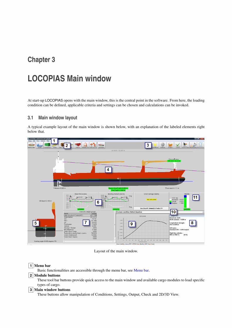
At start-up LOCOPIAS opens with the main window, this is the central point in the software. From here, the loadingcondition can be defined, applicable criteria and settings can be chosen and calculations can be invoked.
3.1 Main window layout
A typical example layout of the main window is shown below, with an explanation of the labeled elements rightbelow that.
Layout of the main window.
1 Menu barBasic functionalities are accessible through the menu bar, see Menu bar.
2 Module buttonsThese tool bar buttons provide quick access to the main window and available cargo modules to load specifictypes of cargo.
3 Main window buttonsThese buttons allow manipulation of Conditions, Settings, Output, Check and 2D/3D View.
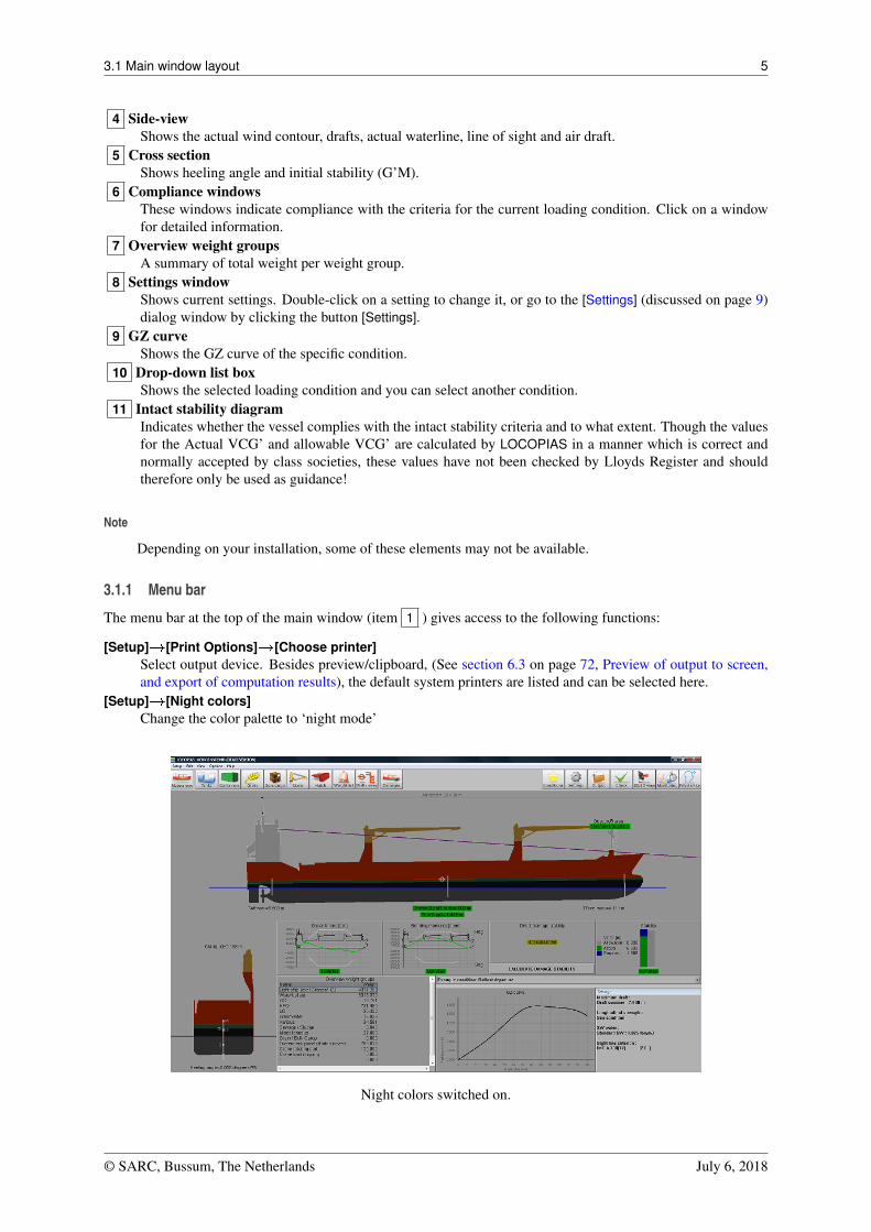
3.1 Main window layout 5
4 Side-viewShows the actual wind contour, drafts, actual waterline, line of sight and air draft.
5 Cross sectionShows heeling angle and initial stability (G’M).
6 Compliance windowsThese windows indicate compliance with the criteria for the current loading condition. Click on a windowfor detailed information.
7 Overview weight groupsA summary of total weight per weight group.
8 Settings windowShows current settings. Double-click on a setting to change it, or go to the [Settings] (discussed on page 9)dialog window by clicking the button [Settings].
9 GZ curveShows the GZ curve of the specific condition.
10 Drop-down list boxShows the selected loading condition and you can select another condition.
11 Intact stability diagramIndicates whether the vessel complies with the intact stability criteria and to what extent. Though the valuesfor the Actual VCG’ and allowable VCG’ are calculated by LOCOPIAS in a manner which is correct andnormally accepted by class societies, these values have not been checked by Lloyds Register and shouldtherefore only be used as guidance!
Note
Depending on your installation, some of these elements may not be available.
3.1.1 Menu bar
The menu bar at the top of the main window (item 1 ) gives access to the following functions:
[Setup]�[Print Options]�[Choose printer]Select output device. Besides preview/clipboard, (See section 6.3 on page 72, Preview of output to screen,and export of computation results), the default system printers are listed and can be selected here.
[Setup]�[Night colors]Change the color palette to ‘night mode’
Night colors switched on.
© SARC, Bussum, The Netherlands July 6, 2018
3.2 General approach 6
[Edit]�[Edit Weight Groups]Weight items can be grouped in so-called weight groups, were a weight group is a category of a particularcontent, such as ‘diesel oil’ or ‘fresh water’. The weight groups are managed from this location in theprogram. Editable properties are:
• The name of the weight group.• The hatching type which is used when hatching or filling in the compartments in tank sketch plots.• The group color, which is the color representing this weight group, and which is used in plots, and also
as background color in text windows if the last column of this weight group is set to ‘yes’.• The text color, which, if the last column is set to ‘yes’, specifies the foreground color in textual overview
windows of the texts which belong to this weight group.• In table, which indicates whether the weight group color should also be used in overview tables of
compartments and weight items.
[Edit]�[Edit cross sections tank graphics]Go to this menu to add or edit cross sections and views of the tanks. These sections and views are automati-cally added to the output of intact stability calculations.
[Edit]�[Edit cross sections stowage plan]Go to this menu to add or edit cross sections and views of the stowage plan.
[View]�[3D View]See section 3.7 on page 11, 2D/3D View
[View]�[Stowage plan]The stowage plan can be shown on screen or printed to paper. All cargoes from all available modules areprinted.
[Options]�[Select stability criteria]See section 3.5 on page 9, Check
[Options]�[Export data via XML]Exports the current loading condition to an XML file which can be used to exchange data with third partysoftware.
[Options]�[Environmental conditions]Gives the ability to simulate running aground.
[Help]�[Help reader (F1)]Opens this help reader.
[Help]�[Manual]�[Ship-specific data and test conditions]Opens the booklet containing the Ship-specific data and test conditions.
[Help]�[About LOCOPIAS]Opens a window with relevant data with regard to the LOCOPIAS program as well as the license conditions.
[Help]�[Not purchased]Shows a preview of modules which have not been purchased.
[Help]�[Enter activation code]Give an activation code here for modules purchased afterwards. At the moment this is only possible for thetank measurement system module for specific sytems. Please contact SARC for further details.
3.2 General approach
In general, you can use the following steps to define a loading condition and perform the required calculations.Please note that this workflow is just one way to get you started, it is not the only possible way to use LOCOPIAS.All actions can be performed in random order and frequency. The functionalities will be elaborated further in theremainder of this chapter. This example starts at the main window.
© SARC, Bussum, The Netherlands July 6, 2018
3.3 Conditions 7
Select the [Conditions] button and create a new condition. When LOCOPIAS is opened forthe first time, the main window shows a preprogrammed example condition. By creating anew condition, you start with a preprogrammed default condition.
Click the [Settings] button and adjust the settings according to your situation. By adjustingthe settings to the current situation before loading your cargo, useful feedback can be re-ceived during configuration of the loading condition. Settings are applicable for the currentloading condition (except output and front page).
Go to the [Tanks] module to modify the contents of consumables e.g. fresh water, fuel oil,lubricating oil.
In the [Weight list], miscellaneous supplies, e.g. crew, provisions and stores can be entered.
Select the appropriate modules for your cargo type and define your cargo.
Open the [Tanks] module again. When all cargo is loaded, the ship’s position can be opti-mized by adding water ballast.
The [Check] button provides a quick check of stability and strength at any moment duringthis process.
Press [Output] to perform calculations and generate output on screen or on paper.
Press [2D/3D view] to view a three-dimensional representation of your vessel, if available.
Press [Monitoring] to put LOCOPIAS in active monitoring, if available.
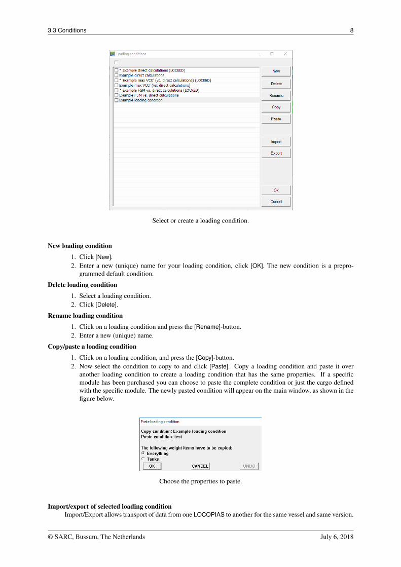
3.3 Conditions
By pressing the [Conditions]-button, the loading conditions menu, as shown in the figure below, will appear. In thiswindow the defined loading conditions are displayed and can be managed. You can create a new loading conditionand you can delete, rename, copy/paste or export existing conditions. To modify a loading condition, select acondition and click the ‘OK’ button. The main window will now reflect this loading condition.
© SARC, Bussum, The Netherlands July 6, 2018
3.3 Conditions 8
Select or create a loading condition.
New loading condition
1. Click [New].2. Enter a new (unique) name for your loading condition, click [OK]. The new condition is a prepro-
grammed default condition.
Delete loading condition
1. Select a loading condition.2. Click [Delete].
Rename loading condition
1. Click on a loading condition and press the [Rename]-button.2. Enter a new (unique) name.
Copy/paste a loading condition
1. Click on a loading condition, and press the [Copy]-button.2. Now select the condition to copy to and click [Paste]. Copy a loading condition and paste it over
another loading condition to create a loading condition that has the same properties. If a specificmodule has been purchased you can choose to paste the complete condition or just the cargo definedwith the specific module. The newly pasted condition will appear on the main window, as shown in thefigure below.
Choose the properties to paste.
Import/export of selected loading conditionImport/Export allows transport of data from one LOCOPIAS to another for the same vessel and same version.
© SARC, Bussum, The Netherlands July 6, 2018
3.4 Settings 9
1. Press the [Export]-button to write the selected loading condition to file.2. Press the [Import]-button to select an exported loading condition to import into the active version of
LOCOPIAS.
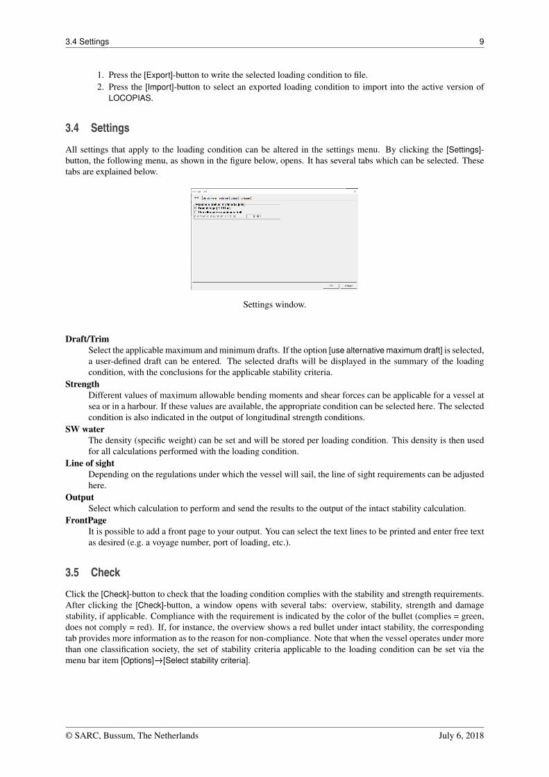
3.4 Settings
All settings that apply to the loading condition can be altered in the settings menu. By clicking the [Settings]-button, the following menu, as shown in the figure below, opens. It has several tabs which can be selected. Thesetabs are explained below.
Settings window.
Draft/TrimSelect the applicable maximum and minimum drafts. If the option [use alternative maximum draft] is selected,a user-defined draft can be entered. The selected drafts will be displayed in the summary of the loadingcondition, with the conclusions for the applicable stability criteria.
StrengthDifferent values of maximum allowable bending moments and shear forces can be applicable for a vessel atsea or in a harbour. If these values are available, the appropriate condition can be selected here. The selectedcondition is also indicated in the output of longitudinal strength conditions.
SW waterThe density (specific weight) can be set and will be stored per loading condition. This density is then usedfor all calculations performed with the loading condition.
Line of sightDepending on the regulations under which the vessel will sail, the line of sight requirements can be adjustedhere.
OutputSelect which calculation to perform and send the results to the output of the intact stability calculation.
FrontPageIt is possible to add a front page to your output. You can select the text lines to be printed and enter free textas desired (e.g. a voyage number, port of loading, etc.).
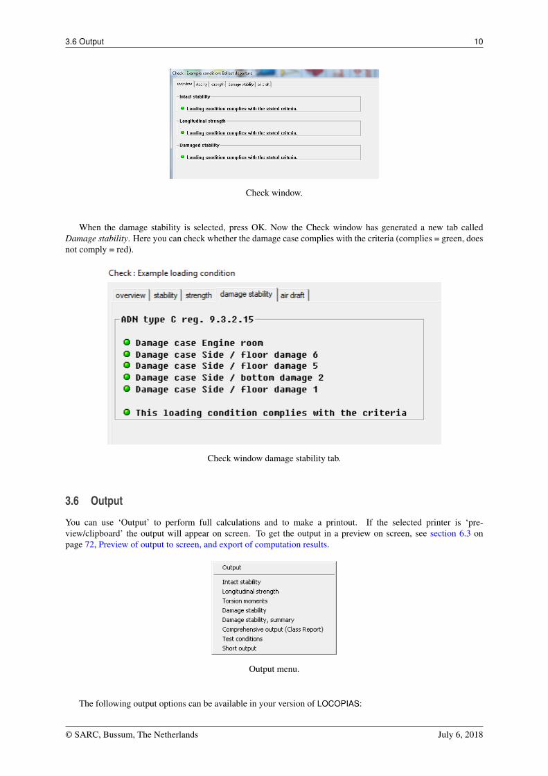
3.5 Check
Click the [Check]-button to check that the loading condition complies with the stability and strength requirements.After clicking the [Check]-button, a window opens with several tabs: overview, stability, strength and damagestability, if applicable. Compliance with the requirement is indicated by the color of the bullet (complies = green,does not comply = red). If, for instance, the overview shows a red bullet under intact stability, the correspondingtab provides more information as to the reason for non-compliance. Note that when the vessel operates under morethan one classification society, the set of stability criteria applicable to the loading condition can be set via themenu bar item [Options]�[Select stability criteria].
© SARC, Bussum, The Netherlands July 6, 2018
3.6 Output 10
Check window.
When the damage stability is selected, press OK. Now the Check window has generated a new tab calledDamage stability. Here you can check whether the damage case complies with the criteria (complies = green, doesnot comply = red).
Check window damage stability tab.
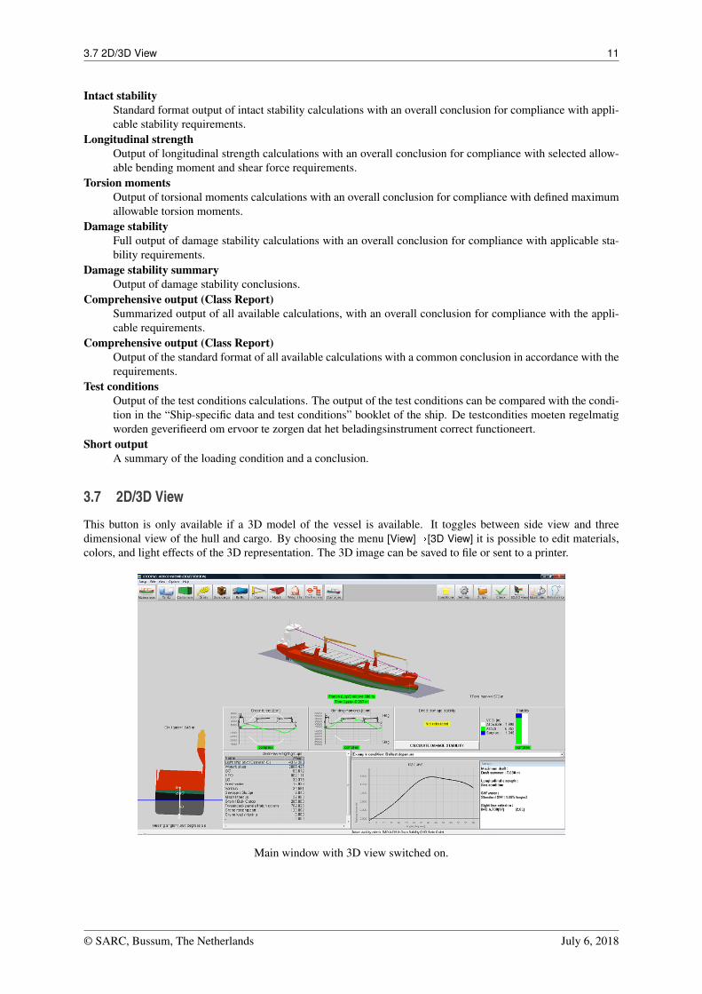
3.6 Output
You can use ‘Output’ to perform full calculations and to make a printout. If the selected printer is ‘pre-view/clipboard’ the output will appear on screen. To get the output in a preview on screen, see section 6.3 onpage 72, Preview of output to screen, and export of computation results.
Output menu.
The following output options can be available in your version of LOCOPIAS:
© SARC, Bussum, The Netherlands July 6, 2018
3.7 2D/3D View 11
Intact stabilityStandard format output of intact stability calculations with an overall conclusion for compliance with appli-cable stability requirements.
Longitudinal strengthOutput of longitudinal strength calculations with an overall conclusion for compliance with selected allow-able bending moment and shear force requirements.
Torsion momentsOutput of torsional moments calculations with an overall conclusion for compliance with defined maximumallowable torsion moments.
Damage stabilityFull output of damage stability calculations with an overall conclusion for compliance with applicable sta-bility requirements.
Damage stability summaryOutput of damage stability conclusions.
Comprehensive output (Class Report)Summarized output of all available calculations, with an overall conclusion for compliance with the appli-cable requirements.
Comprehensive output (Class Report)Output of the standard format of all available calculations with a common conclusion in accordance with therequirements.
Test conditionsOutput of the test conditions calculations. The output of the test conditions can be compared with the condi-tion in the “Ship-specific data and test conditions” booklet of the ship. De testcondities moeten regelmatigworden geverifieerd om ervoor te zorgen dat het beladingsinstrument correct functioneert.
Short outputA summary of the loading condition and a conclusion.
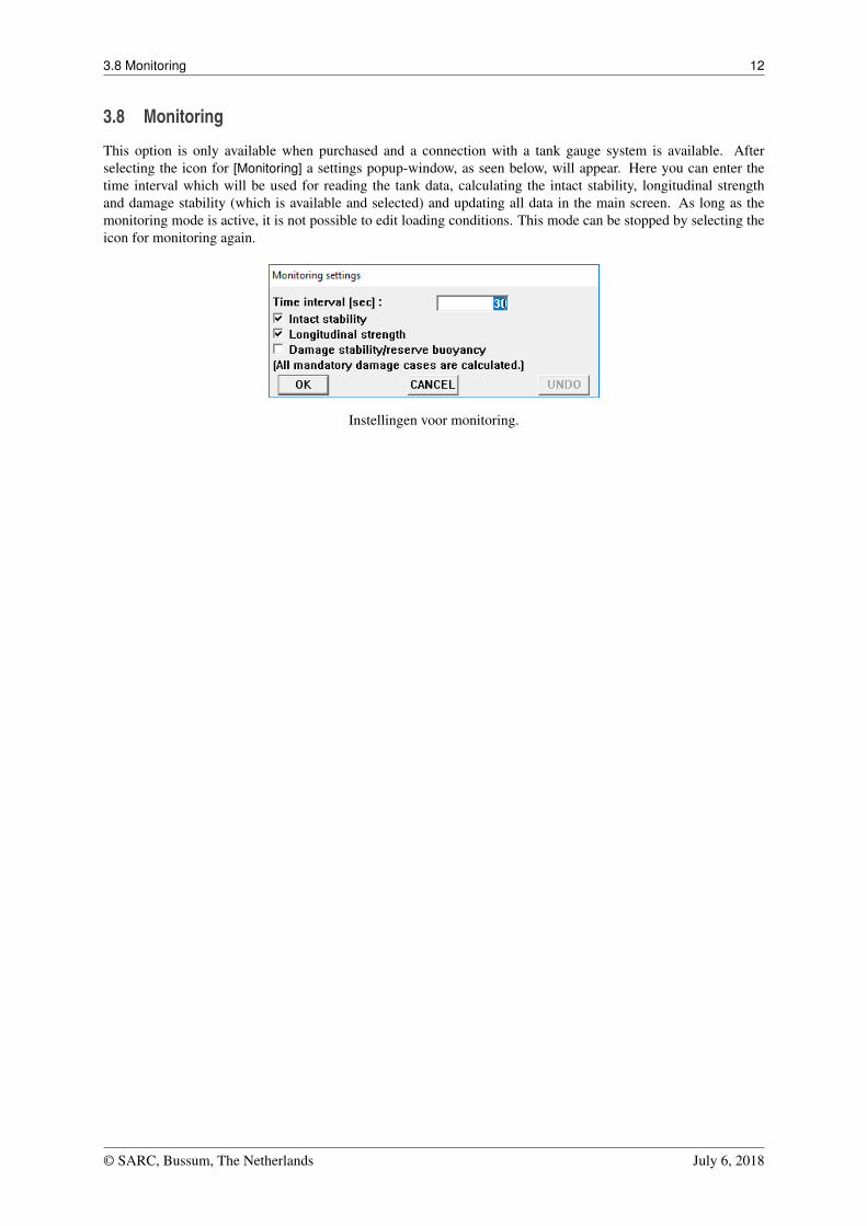
3.7 2D/3D View
This button is only available if a 3D model of the vessel is available. It toggles between side view and threedimensional view of the hull and cargo. By choosing the menu [View]�[3D View] it is possible to edit materials,colors, and light effects of the 3D representation. The 3D image can be saved to file or sent to a printer.
Main window with 3D view switched on.
© SARC, Bussum, The Netherlands July 6, 2018
3.8 Monitoring 12
3.8 Monitoring
This option is only available when purchased and a connection with a tank gauge system is available. Afterselecting the icon for [Monitoring] a settings popup-window, as seen below, will appear. Here you can enter thetime interval which will be used for reading the tank data, calculating the intact stability, longitudinal strengthand damage stability (which is available and selected) and updating all data in the main screen. As long as themonitoring mode is active, it is not possible to edit loading conditions. This mode can be stopped by selecting theicon for monitoring again.
Instellingen voor monitoring.
© SARC, Bussum, The Netherlands July 6, 2018
Chapter 4
Modules
LOCOPIAS can be equipped with modules to define specific weight items in a loading condition. LOCOPIAS for aspecific vessel can be equipped with a selection of modules required for the purpose of the vessel. You can navigateto the modules by clicking one of the Module buttons (see section 3.1 on page 4, Main window layout, element 2). Depending on your installation, the following modules are available in LOCOPIAS:
• Tanks• RoRo cargo• Containers• Dangerous goods (IMDG)• Grain/bulk• General cargo• Crane loading tool• Hatch• Weight list• Damages• Cargo weight determination• Quartering and following seas• Ballast advice
4.1 Common operations in modules
The modules with a graphical interface have the following common functions.
4.1.1 Genereral operations
ZoomZoom in views and cross sections by using the scroll wheel (third, or middle mouse button).
PanPan in views and cross sections by pressing and holding the scroll wheel.
SelectStandard selection methods in the views:
• Left-click an item to select it.• Drag selection box to select a series of items.• <Ctrl+left-click> to toggle the selection status of (multiple)items.• <Ctrl+A> to select all items.
EditRight-click a selected item
4.1 Common operations in modules 14
4.1.2 Verification
In every module the [Check]-button is available to find out if the loading condition com-plies with requirements for intact stability, and, if applicable, longitudinal strength, torsionmoments, air draft and damage stability. More information about the [Check]-button can befound in section 3.5 on page 9, Check.
4.1.3 Float
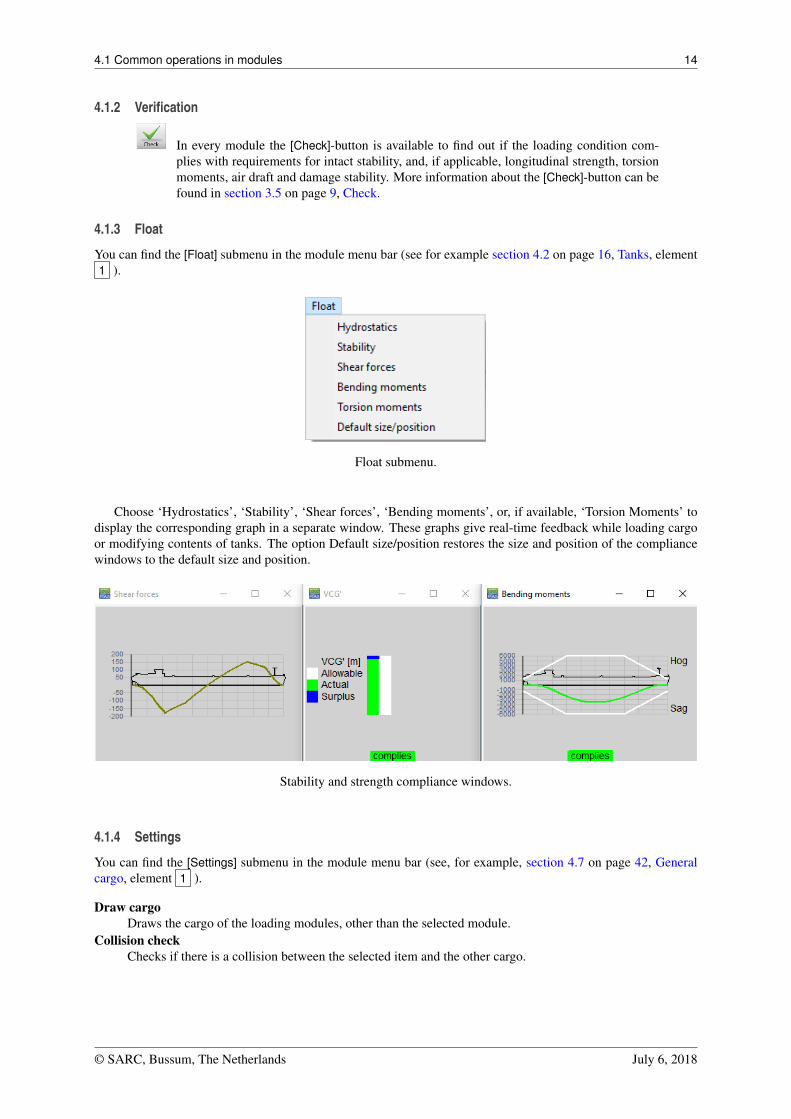
You can find the [Float] submenu in the module menu bar (see for example section 4.2 on page 16, Tanks, element1 ).
Float submenu.
Choose ‘Hydrostatics’, ‘Stability’, ‘Shear forces’, ‘Bending moments’, or, if available, ‘Torsion Moments’ todisplay the corresponding graph in a separate window. These graphs give real-time feedback while loading cargoor modifying contents of tanks. The option Default size/position restores the size and position of the compliancewindows to the default size and position.
Stability and strength compliance windows.
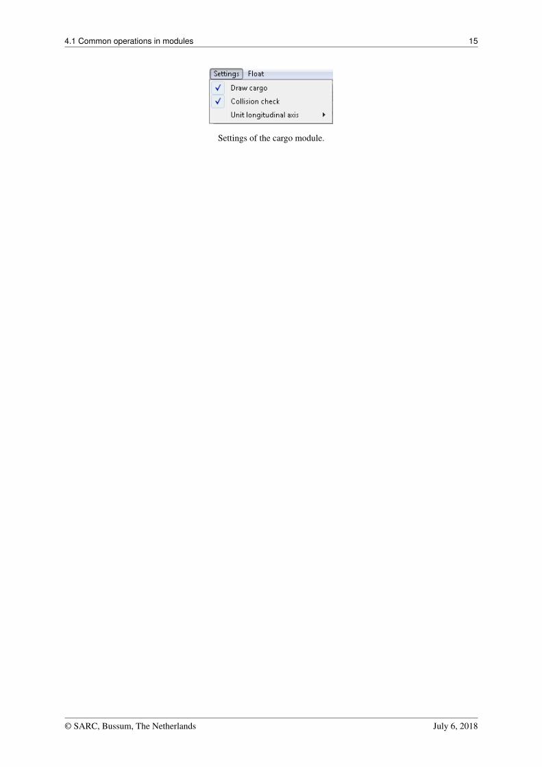
4.1.4 Settings
You can find the [Settings] submenu in the module menu bar (see, for example, section 4.7 on page 42, Generalcargo, element 1 ).
Draw cargoDraws the cargo of the loading modules, other than the selected module.
Collision checkChecks if there is a collision between the selected item and the other cargo.
© SARC, Bussum, The Netherlands July 6, 2018
4.1 Common operations in modules 15
Settings of the cargo module.
© SARC, Bussum, The Netherlands July 6, 2018
4.2 Tanks 16
4.2 Tanks
In the Tanks module you can manipulate the filling of tanks of the vessel for the loading condition under consid-eration.
Note
A video1 exists in which the operation of this module is demonstrated.
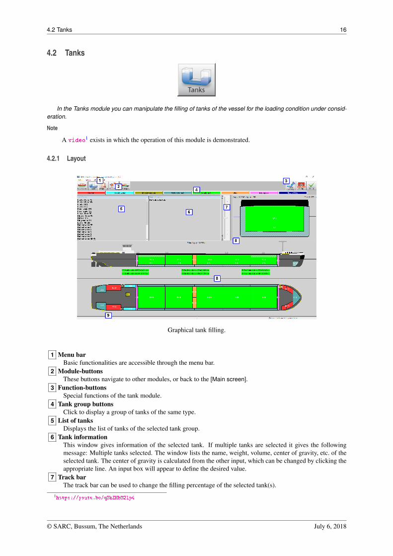
4.2.1 Layout
Graphical tank filling.
1 Menu barBasic functionalities are accessible through the menu bar.
2 Module-buttonsThese buttons navigate to other modules, or back to the [Main screen].
3 Function-buttonsSpecial functions of the tank module.
4 Tank group buttonsClick to display a group of tanks of the same type.
5 List of tanksDisplays the list of tanks of the selected tank group.
6 Tank informationThis window gives information of the selected tank. If multiple tanks are selected it gives the followingmessage: Multiple tanks selected. The window lists the name, weight, volume, center of gravity, etc. of theselected tank. The center of gravity is calculated from the other input, which can be changed by clicking theappropriate line. An input box will appear to define the desired value.
7 Track barThe track bar can be used to change the filling percentage of the selected tank(s).
1https://youtu.be/qSkZHbM2lp4
© SARC, Bussum, The Netherlands July 6, 2018
4.2 Tanks 17
8 Section windowsDisplays top view, vertical section, and cross section. Active sections show a section of the vessel at thecenter of gravity of the selected tank. Fixed sections show sections at predefined locations.
9 Status barGives information about the total weight of the selected tank group and which information is visible in thegraphical tanks.
4.2.2 General approach
1. Select. A tank can be selected by left-clicking a tank in a section window 8 . Tanks can be selected byclicking near their center of gravity. A selected tank will be hatched black and white in the views. In thecross section, the actual fluid level in a tank is indicated.
2. Edit. The contents of a tank can be edited by right-clicking a tank after selecting it.3. Check. The vessel’s position (draft, trim and list) is directly calculated and the vessel is displayed with the
actual waterline in cross section and side view. The values for draft, trim, list and G’M are displayed in therelevant section window 8 . Hit the Checkbutton to check if the ship’s stability and longitudinal strengthcomply with your criteria.
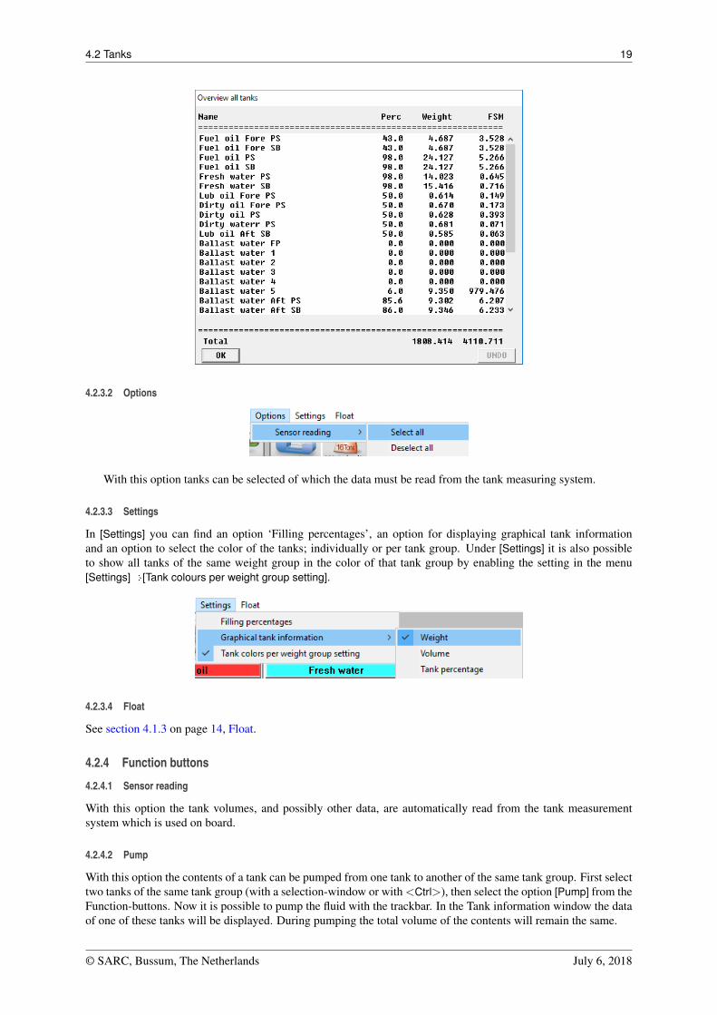
4. Output/Totals. Go to the menu [Output]�[Totals] for an overview of total weight of the selected tank groupon screen.
4.2.2.1 Select
You can select tanks in one of the ways below. A selected tank is marked by black on white cross-hatching in thesection windows.
• Left-click a tank in the List of tanks-window 5 .
• Left-click a tank in one of the Section windows 8 .• Select multiple tanks by holding the left mouse button to drag a selection box in one of the Section windows
8 .• Select all visible tanks by pressing <Ctrl+a>.• Add or remove a tank to/from a selection by holding Ctrl and clicking the tank in a Section window 8 , or
in the List of tanks-window 5 .
The information of this tank is now shown in de Tank information-window 6 .
4.2.2.2 Edit
Once a tank has been selected, there are several ways to edit tank data:
• Double-click a tank in the [List of tanks]-window 5 to open the input form ‘Edit tank data’.
• Right-click a tank in one of the Section windows 8 to open the input form ‘Edit tank data’ of the selectedtank(s). When only one tank is selected, all tank data can be edited. When more than one tank is selected,only filling percentage and density of the content can be changed.
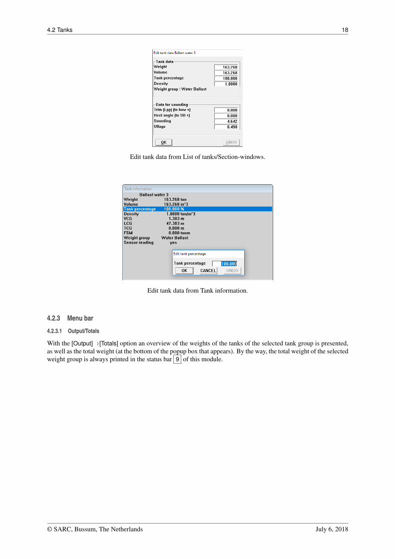
• Double-click a value in the [Tank information]-window 6 to edit that specific value, see figure below.
• Drag the track bar 7 to change the amount of fluid of the selected tank.• Drag the surface of the content of a selected tank.• Double click a tank to empty it or fill it to the maximum filling percentage. Use [Settings]�[Filling percent-
ages] from the menu bar to edit the default filling percentage.• Enter a sounding or ullage. By right-clicking in the Section window 8 , additional fields become available
in the ‘Edit tank data’-window when a sounding pipe has been defined. By entering trim and heeling angletogether with sounding or ullage, the tank volume is calculated according to the sounding data and input forship’s position.
• Pump with track bar. Select two tanks from the same weight group, with the same density and go to [Pump]in the upright corner. Now the track bar enables you to pump fluid from one tank to another tank.
© SARC, Bussum, The Netherlands July 6, 2018
4.2 Tanks 18
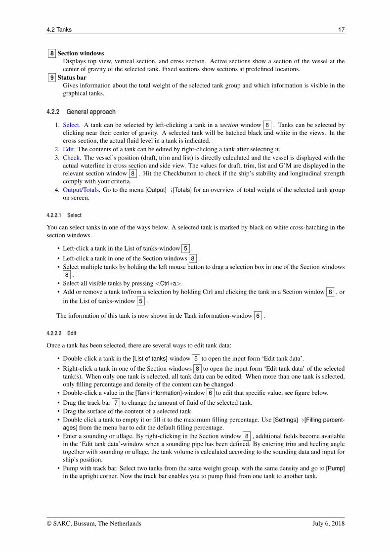
Edit tank data from List of tanks/Section-windows.
Edit tank data from Tank information.
4.2.3 Menu bar
4.2.3.1 Output/Totals
With the [Output]�[Totals] option an overview of the weights of the tanks of the selected tank group is presented,as well as the total weight (at the bottom of the popup box that appears). By the way, the total weight of the selectedweight group is always printed in the status bar 9 of this module.
© SARC, Bussum, The Netherlands July 6, 2018
4.2 Tanks 19
4.2.3.2 Options
With this option tanks can be selected of which the data must be read from the tank measuring system.
4.2.3.3 Settings
In [Settings] you can find an option ‘Filling percentages’, an option for displaying graphical tank informationand an option to select the color of the tanks; individually or per tank group. Under [Settings] it is also possibleto show all tanks of the same weight group in the color of that tank group by enabling the setting in the menu[Settings]�[Tank colours per weight group setting].
4.2.3.4 Float
See section 4.1.3 on page 14, Float.
4.2.4 Function buttons
4.2.4.1 Sensor reading
With this option the tank volumes, and possibly other data, are automatically read from the tank measurementsystem which is used on board.
4.2.4.2 Pump
With this option the contents of a tank can be pumped from one tank to another of the same tank group. First selecttwo tanks of the same tank group (with a selection-window or with <Ctrl>), then select the option [Pump] from theFunction-buttons. Now it is possible to pump the fluid with the trackbar. In the Tank information window the dataof one of these tanks will be displayed. During pumping the total volume of the contents will remain the same.
© SARC, Bussum, The Netherlands July 6, 2018
4.3 RoRo cargo 20
4.3 RoRo cargo
The RoRo cargo module is intended to perform loading operations on RoRo cargo. The weight and center ofgravity are automatically included in the calculation results of the loading condition. RoRo cargo can be positionedon all defined RoRo decks. RoRo cargo stowage plans and loading lists can be printed.
• Collision checking with other (positioned) cargo, deck outline and other defined deck obstructions.• Integrated (user maintainable) database for storage of frequently occurring cargo items.• Cargo can be rotated and stacked.• Check of available deck height and maximum deck load.• Output of stowage plan and lists of RoRo cargo.• RoRo cargo positioned outside the basic ship wind contour is automatically included in the wind contour of
the vessel.
4.3.1 Layout
RoRo-module layout.
1 Menu barBasic tools are accessible through the menu bar
2 Module buttonsThese buttons navigate to another module, or back to the [Main screen]
3 Function buttonsThese buttons represent main functions of the [RoRo]-module
4 RoRo-cargo listThis window displays name, weight, and port of discharge of the cargo which is not (yet) loaded.
5 Cargo infoShows information of cargo selected in visible ports window.
6 Cross sectionDisplays actual cross section indicated with a red line in top view.
7 Deck buttonsSelect the deck to be displayed in the top view.
© SARC, Bussum, The Netherlands July 6, 2018
4.3 RoRo cargo 21
8 Top viewDisplays the top view of the selected deck.
9 MarkerIndicates the position of the cross section.
4.3.2 General approach
1. Define ports. All relevant ports must be defined. This way it is possible to get an overview wich is sorted byport.
2. Database RoRo cargo. The type of RoRo cargo can be defined. This way you can pre-define the measure-ments, vertical center of gravity(VCD), transverse center of gravity (TCG), longitudinal center of gravity(LCG) and the maximum and minumum moments of certain types of cargo.
3. Define RoRo cargo. Now a list of cargo must be compiled.4. Load RoRo cargo. Under the menu [View]�[Ports] you can choose the ports from which you want to load
cargo.5. Edit RoRo cargo. You can move, rotate, discharge or delete cargo and or measure distances on deck.6. Check. Use the Stability/Strength diagrams under [Float] and the [Check]-button to verify the loading condi-
tion.7. Output. The list of RoRo cargo can be sorted and printed.
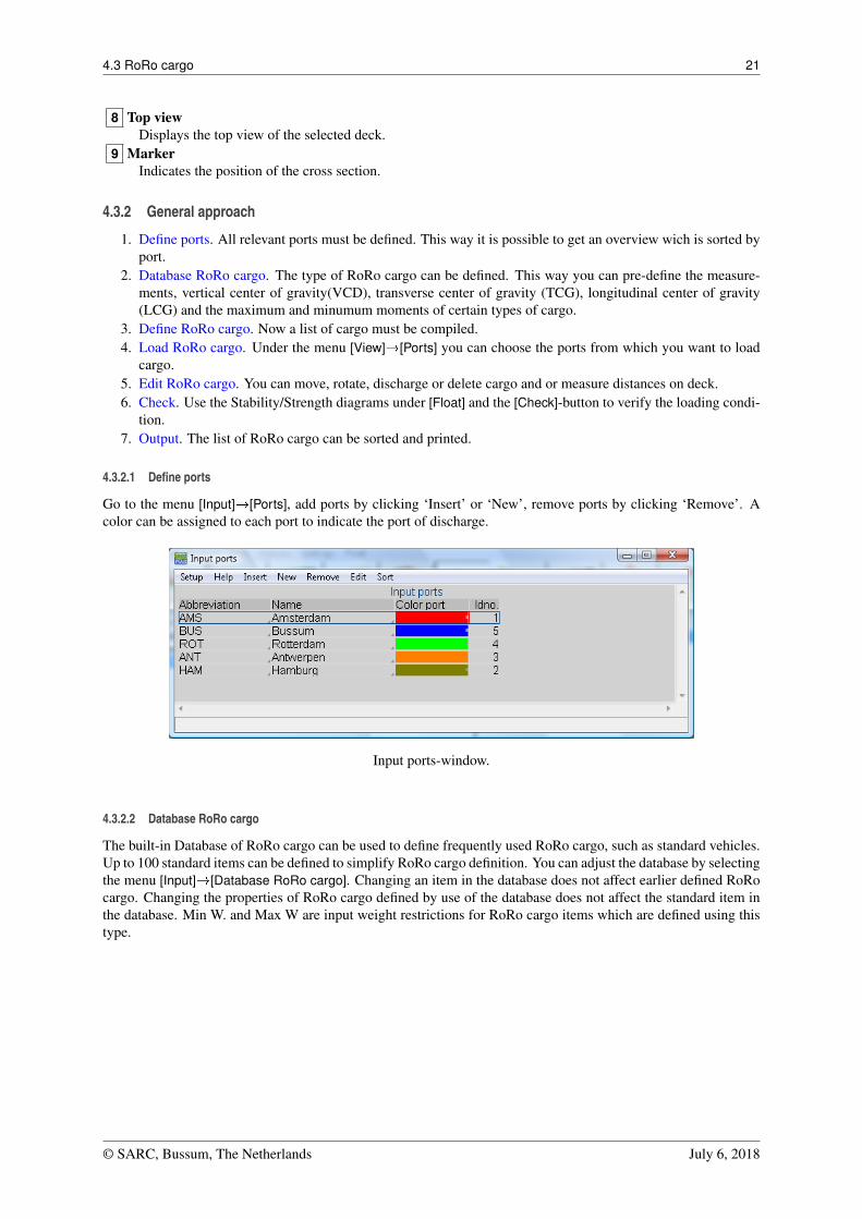
4.3.2.1 Define ports
Go to the menu [Input]�[Ports], add ports by clicking ‘Insert’ or ‘New’, remove ports by clicking ‘Remove’. Acolor can be assigned to each port to indicate the port of discharge.
Input ports-window.
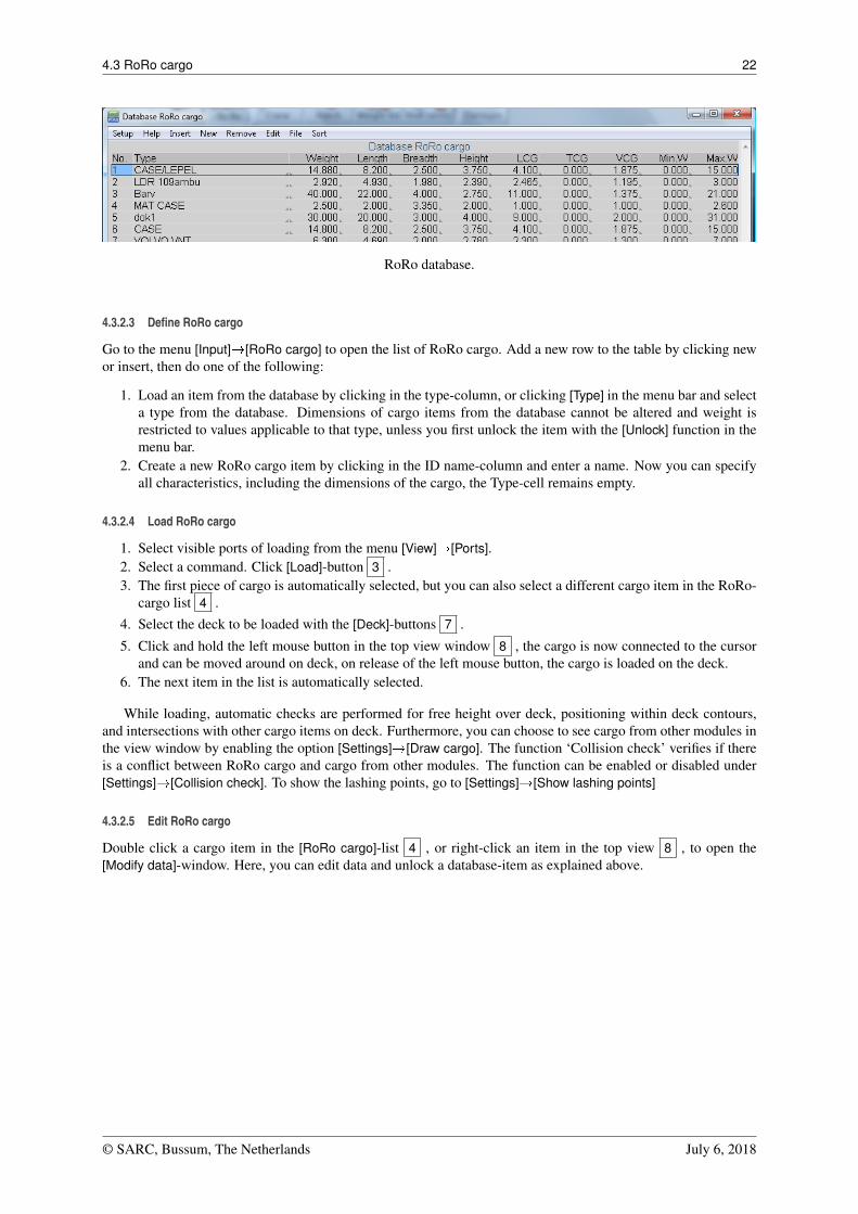
4.3.2.2 Database RoRo cargo
The built-in Database of RoRo cargo can be used to define frequently used RoRo cargo, such as standard vehicles.Up to 100 standard items can be defined to simplify RoRo cargo definition. You can adjust the database by selectingthe menu [Input]�[Database RoRo cargo]. Changing an item in the database does not affect earlier defined RoRocargo. Changing the properties of RoRo cargo defined by use of the database does not affect the standard item inthe database. Min W. and Max W are input weight restrictions for RoRo cargo items which are defined using thistype.
© SARC, Bussum, The Netherlands July 6, 2018
4.3 RoRo cargo 22
RoRo database.
4.3.2.3 Define RoRo cargo
Go to the menu [Input]�[RoRo cargo] to open the list of RoRo cargo. Add a new row to the table by clicking newor insert, then do one of the following:
1. Load an item from the database by clicking in the type-column, or clicking [Type] in the menu bar and selecta type from the database. Dimensions of cargo items from the database cannot be altered and weight isrestricted to values applicable to that type, unless you first unlock the item with the [Unlock] function in themenu bar.
2. Create a new RoRo cargo item by clicking in the ID name-column and enter a name. Now you can specifyall characteristics, including the dimensions of the cargo, the Type-cell remains empty.
4.3.2.4 Load RoRo cargo
1. Select visible ports of loading from the menu [View]�[Ports].2. Select a command. Click [Load]-button 3 .3. The first piece of cargo is automatically selected, but you can also select a different cargo item in the RoRo-
cargo list 4 .4. Select the deck to be loaded with the [Deck]-buttons 7 .
5. Click and hold the left mouse button in the top view window 8 , the cargo is now connected to the cursorand can be moved around on deck, on release of the left mouse button, the cargo is loaded on the deck.
6. The next item in the list is automatically selected.
While loading, automatic checks are performed for free height over deck, positioning within deck contours,and intersections with other cargo items on deck. Furthermore, you can choose to see cargo from other modules inthe view window by enabling the option [Settings]�[Draw cargo]. The function ‘Collision check’ verifies if thereis a conflict between RoRo cargo and cargo from other modules. The function can be enabled or disabled under[Settings]�[Collision check]. To show the lashing points, go to [Settings]�[Show lashing points]
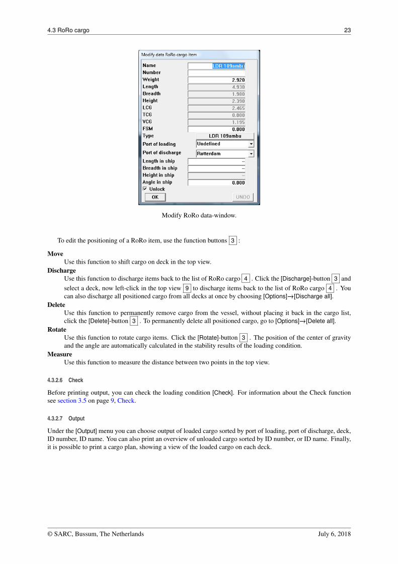
4.3.2.5 Edit RoRo cargo
Double click a cargo item in the [RoRo cargo]-list 4 , or right-click an item in the top view 8 , to open the[Modify data]-window. Here, you can edit data and unlock a database-item as explained above.
© SARC, Bussum, The Netherlands July 6, 2018
4.3 RoRo cargo 23
Modify RoRo data-window.
To edit the positioning of a RoRo item, use the function buttons 3 :
MoveUse this function to shift cargo on deck in the top view.
DischargeUse this function to discharge items back to the list of RoRo cargo 4 . Click the [Discharge]-button 3 andselect a deck, now left-click in the top view 9 to discharge items back to the list of RoRo cargo 4 . Youcan also discharge all positioned cargo from all decks at once by choosing [Options]�[Discharge all].
DeleteUse this function to permanently remove cargo from the vessel, without placing it back in the cargo list,click the [Delete]-button 3 . To permanently delete all positioned cargo, go to [Options]�[Delete all].
RotateUse this function to rotate cargo items. Click the [Rotate]-button 3 . The position of the center of gravityand the angle are automatically calculated in the stability results of the loading condition.
MeasureUse this function to measure the distance between two points in the top view.
4.3.2.6 Check
Before printing output, you can check the loading condition [Check]. For information about the Check functionsee section 3.5 on page 9, Check.
4.3.2.7 Output
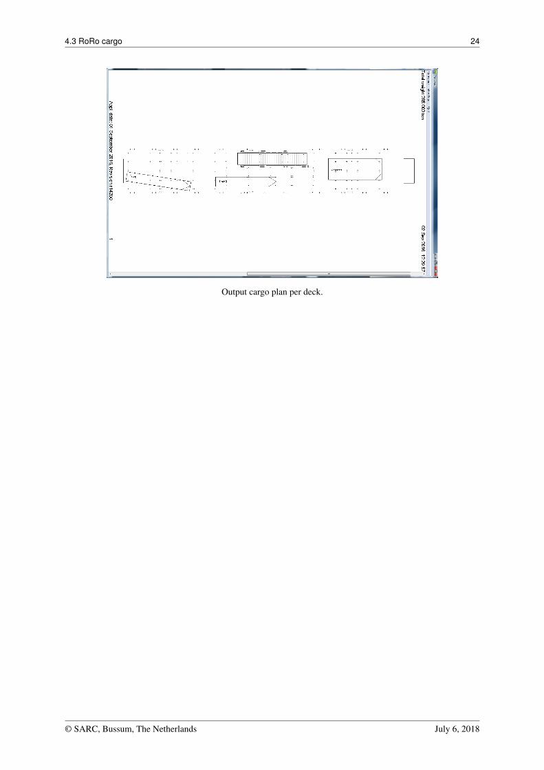
Under the [Output] menu you can choose output of loaded cargo sorted by port of loading, port of discharge, deck,ID number, ID name. You can also print an overview of unloaded cargo sorted by ID number, or ID name. Finally,it is possible to print a cargo plan, showing a view of the loaded cargo on each deck.
© SARC, Bussum, The Netherlands July 6, 2018
4.3 RoRo cargo 24
Output cargo plan per deck.
© SARC, Bussum, The Netherlands July 6, 2018
4.4 Containers 25
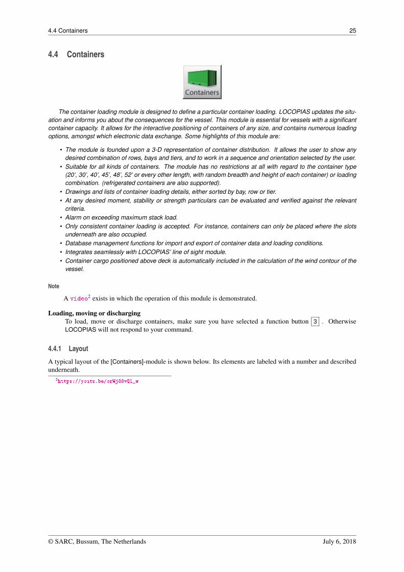
4.4 Containers
The container loading module is designed to define a particular container loading. LOCOPIAS updates the situ-ation and informs you about the consequences for the vessel. This module is essential for vessels with a significantcontainer capacity. It allows for the interactive positioning of containers of any size, and contains numerous loadingoptions, amongst which electronic data exchange. Some highlights of this module are:
• The module is founded upon a 3-D representation of container distribution. It allows the user to show anydesired combination of rows, bays and tiers, and to work in a sequence and orientation selected by the user.
• Suitable for all kinds of containers. The module has no restrictions at all with regard to the container type(20’, 30’, 40’, 45’, 48’, 52’ or every other length, with random breadth and height of each container) or loadingcombination. (refrigerated containers are also supported).
• Drawings and lists of container loading details, either sorted by bay, row or tier.• At any desired moment, stability or strength particulars can be evaluated and verified against the relevant
criteria.• Alarm on exceeding maximum stack load.• Only consistent container loading is accepted. For instance, containers can only be placed where the slots
underneath are also occupied.• Database management functions for import and export of container data and loading conditions.• Integrates seamlessly with LOCOPIAS’ line of sight module.• Container cargo positioned above deck is automatically included in the calculation of the wind contour of the
vessel.
Note
A video2 exists in which the operation of this module is demonstrated.
Loading, moving or dischargingTo load, move or discharge containers, make sure you have selected a function button 3 . OtherwiseLOCOPIAS will not respond to your command.
4.4.1 Layout
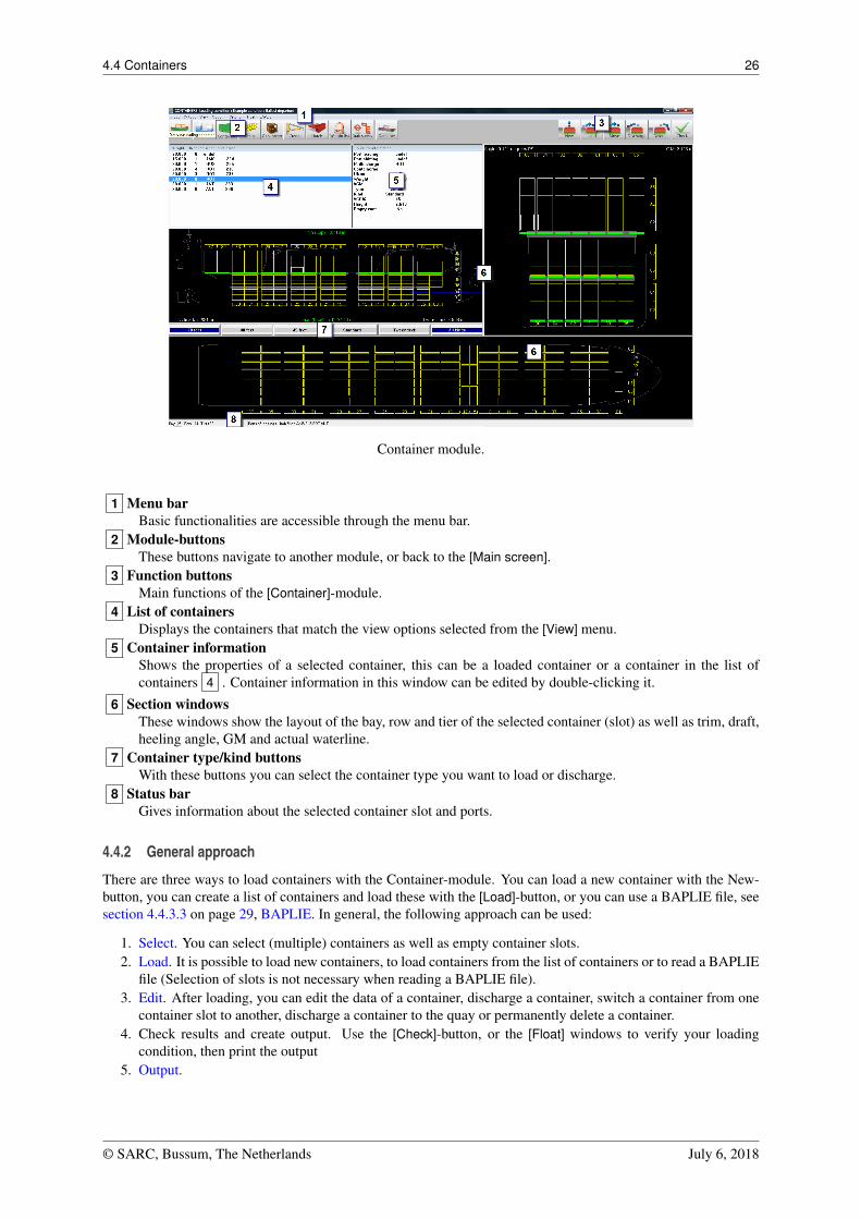
A typical layout of the [Containers]-module is shown below. Its elements are labeled with a number and describedunderneath.
2https://youtu.be/orWj88vQl_w
© SARC, Bussum, The Netherlands July 6, 2018
4.4 Containers 26
Container module.
1 Menu barBasic functionalities are accessible through the menu bar.
2 Module-buttonsThese buttons navigate to another module, or back to the [Main screen].
3 Function buttonsMain functions of the [Container]-module.
4 List of containersDisplays the containers that match the view options selected from the [View] menu.
5 Container informationShows the properties of a selected container, this can be a loaded container or a container in the list ofcontainers 4 . Container information in this window can be edited by double-clicking it.
6 Section windowsThese windows show the layout of the bay, row and tier of the selected container (slot) as well as trim, draft,heeling angle, GM and actual waterline.
7 Container type/kind buttonsWith these buttons you can select the container type you want to load or discharge.
8 Status barGives information about the selected container slot and ports.
4.4.2 General approach
There are three ways to load containers with the Container-module. You can load a new container with the New-button, you can create a list of containers and load these with the [Load]-button, or you can use a BAPLIE file, seesection 4.4.3.3 on page 29, BAPLIE. In general, the following approach can be used:
1. Select. You can select (multiple) containers as well as empty container slots.2. Load. It is possible to load new containers, to load containers from the list of containers or to read a BAPLIE
file (Selection of slots is not necessary when reading a BAPLIE file).3. Edit. After loading, you can edit the data of a container, discharge a container, switch a container from one
container slot to another, discharge a container to the quay or permanently delete a container.4. Check results and create output. Use the [Check]-button, or the [Float] windows to verify your loading
condition, then print the output5. Output.
© SARC, Bussum, The Netherlands July 6, 2018
4.4 Containers 27
4.4.2.1 Select
You can select a container (or container slot) in one of these ways:
• Left-click a container in the List of containers 4 .
• Left-click a container or slot in one of the Section windows 6 .
To select multiple containers or container slots, activate a function-button and perform one of the followingtasks:
• <Ctrl + left-click> in a Section window 6 .
• <Ctrl + a> to select all containers or slots in the Section window 6 .• Drag cursor to create a selection box.• <Ctrl + selection box> to add a group of containers to your selection.
4.4.2.2 Load
Use this function to directly create a new container. You can left-click a selected slot tocreate and load a container with the same properties as the previously loaded container.
Use this function to load containers from the list of containers:
1. Go to the menu [Input]�[Ports] to enter ports, and optionally a specific color.2. Choose the menu [Input]�[Containers] to enter container data.3. Under the menu [View] you can choose which containers you want to see in the ‘list
of containers’ window. This way you can make a list of the containers you want toload, based on container length, type, and port of loading.
4. Click the [Load]-button and select a slot, now left-click the selected slot to load a con-tainer from the list. Note that it is not possible to place a container in a slot when thereare not enough containers under the slot. You can go to the menu [Settings]�[Checkloading/discharging] to turn off this check and load in random order. Green indicatorsunder the container slots (in the views 6 ) turn red when the maximum loading is ex-ceeded. To load multiple (new) containers, see section 4.4.2.4 on this page, Multiplecontainers.
You can also load entire bays, row, or tiers under the menu [Options]�[loading options].
4.4.2.3 Edit
To open the [Edit container data] form, you can right-click on a loaded container or double-click a container in thelist of containers. To edit multiple containers, see the section about ‘Multiple containers’ below. You can selectthe fill color of the containers under the menu [Settings]�[Color container].
Use this function to discharge containers from the vessel. Activate the [Discharge] buttonand left-click a selected slot to discharge the containers. The discharged containers be-come available for loading again in the list of containers. You can also go to the menu[Options]�[Discharge] to discharge per row, bay or tier, or to discharge the entire ship atonce.
Use this function to delete containers permanently from the vessel. Click the [Delete] buttonto remove a selected container from the vessel, the container cannot be loaded again.
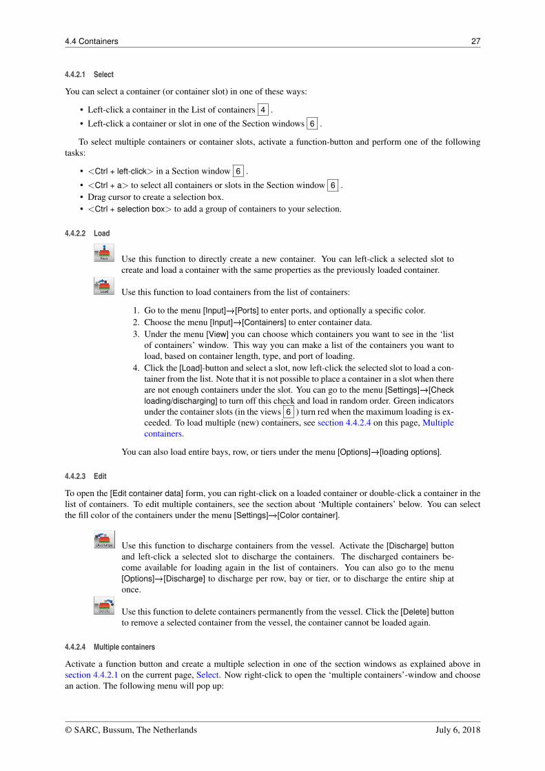
4.4.2.4 Multiple containers
Activate a function button and create a multiple selection in one of the section windows as explained above insection 4.4.2.1 on the current page, Select. Now right-click to open the ‘multiple containers’-window and choosean action. The following menu will pop up:
© SARC, Bussum, The Netherlands July 6, 2018
4.4 Containers 28
Multiple containers window.
4.4.3 Menu bar
4.4.3.1 Input
In the [Input] submenu the following options are available:
[Containers]Here you can insert containers with certain specifications. It is also possible to copy/paste from Excel in thislist.
[Ports]Here you can insert the ports where the vessel will load and discharge containers. It is also possible to add acolor to a port, this can help to organize the containers.
4.4.3.2 Output
In the [Output] submenu the following options are available:
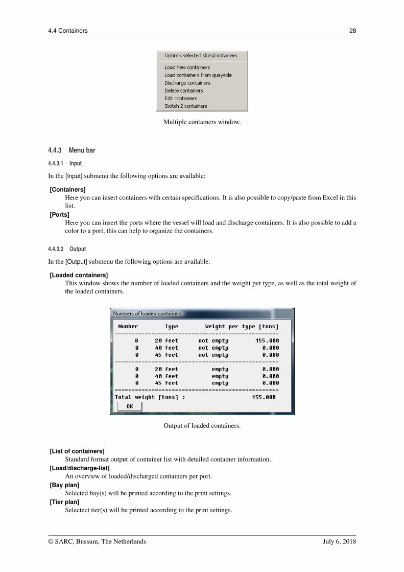
[Loaded containers]This window shows the number of loaded containers and the weight per type, as well as the total weight ofthe loaded containers.
Output of loaded containers.
[List of containers]Standard format output of container list with detailed container information.
[Load/discharge-list]An overview of loaded/discharged containers per port.
[Bay plan]Selected bay(s) will be printed according to the print settings.
[Tier plan]Selectect tier(s) will be printed according to the print settings.
© SARC, Bussum, The Netherlands July 6, 2018
4.4 Containers 29
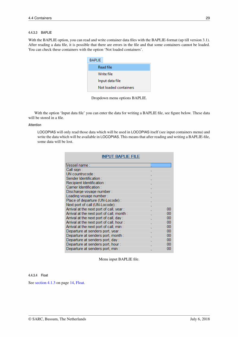
4.4.3.3 BAPLIE
With the BAPLIE option, you can read and write container data files with the BAPLIE-format (up till version 3.1).After reading a data file, it is possible that there are errors in the file and that some containers cannot be loaded.You can check these containers with the option ‘Not loaded containers’.
Dropdown menu options BAPLIE.
With the option ‘Input data file’ you can enter the data for writing a BAPLIE file, see figure below. These datawill be stored in a file.
Attention
LOCOPIAS will only read those data which will be used in LOCOPIAS itself (see input containers menu) andwrite the data which will be available in LOCOPIAS. This means that after reading and writing a BAPLIE-file,some data will be lost.
Menu input BAPLIE file.
4.4.3.4 Float
See section 4.1.3 on page 14, Float.
© SARC, Bussum, The Netherlands July 6, 2018
4.5 Dangerous goods (IMDG) 30
4.5 Dangerous goods (IMDG)
The IMO is a United Nations specialised agency which has developed international legislation dealing with two keyissues for the maritime industry:
• The safety of life at sea.• Prevention of pollution from ships.
To this end the IMO has, among other things, drawn up two international conventions to address these issues:
• The SOLAS Convention (covering safety of life at sea).• The MARPOL Convention (covering pollution prevention).
To supplement the principles laid down in the SOLAS and MARPOL Conventions, the IMO developed the In-ternational Maritime Dangerous Goods (IMDG) Code. The IMDG code contains detailed technical specifications toenable dangerous goods to be transported safely over sea by vessel and is intended to protect crew members andto prevent marine pollution. The IMDG Code became mandatory for adoption by SOLAS signatory states from 1stJanuary 2004.
Attention
This module is an extension to the container module, the break bulk module and/or the RoRo module. Inorder to use this module, some ship specific data relating to the IMDG must be defined beforehand. Thisincludes information about geometry and position of holds, bulkheads and decks, heat sources, ignitionsources, accommodation, etc.
Note
CTU stands for Cargo Transport Unit. A container of a certain type and size is a CTU.This manual is not an IMDG course. Knowledge of IMDG is assumed.
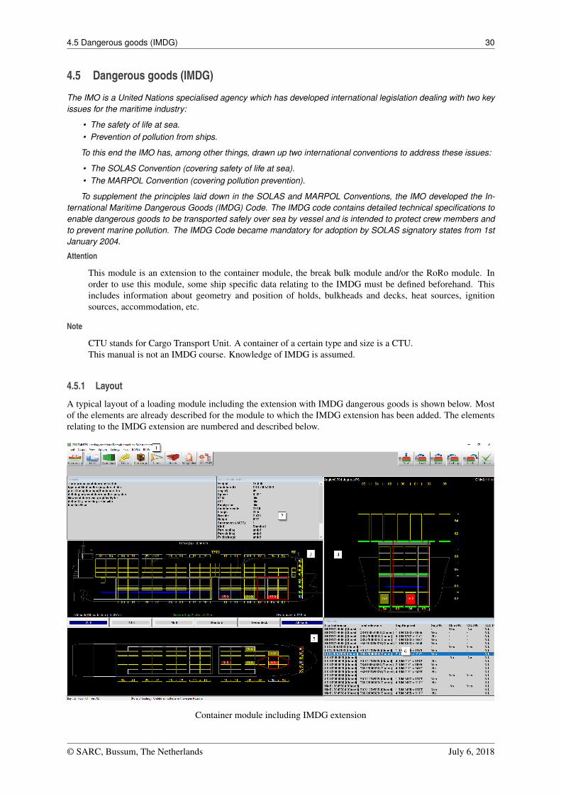
4.5.1 Layout
A typical layout of a loading module including the extension with IMDG dangerous goods is shown below. Mostof the elements are already described for the module to which the IMDG extension has been added. The elementsrelating to the IMDG extension are numbered and described below.
Container module including IMDG extension
© SARC, Bussum, The Netherlands July 6, 2018
4.5 Dangerous goods (IMDG) 31
1 Toolbar optionsFor IMDG relevant toolbar options are:
• [IMDG] An activation code can be entered here, which is required to be able to work with the IMDGdatabase.
• [Input] Here containers to be loaded can be defined and relevant properties with respect to IMDG canbe specified. From this menu, the UN substances list of the CTUs can be created and edited for eachCTU. See Input of IMDG UN substances.
2 Container informationThe properties of the selected container are displayed in this window. A number of properties are relevantfor the IMDG extension. [CST] (Certified Safe Type) [Container Code]3 [Substances] (IMDG). Editing ofthe UN substances list of the selected container.
3 4 5 Section windowsThese windows show a section of respectively selected Tier, Bay and Row. If a line is selected in the IMDGinfo window 6 , then the reference CTU (1st column) is shown in bright red in these section views. If theline contains an incompatible CTU (2nd column), this CTU is highlighted in dark red. In this case, the theprohibited zone (according to IMDG 7.4.3.2 table of segregation of containers on board containerships withclosed cargo holds) is drawn in the section windows around the reference container. To comply with theIMDG, the incompatible container is not allowed inside this prohibited zone.
6 IMDG information windowThis window shows per CTU (if it contains UN substances) a line of information on whether the segregationrequirements within this CTU are met [CTU.OK], whether the CTU meets the stowage requirements applica-ble to this CTU [Stow.OK] and whether the position of the CTU is permitted according to the "document ofcompliance" belonging to the vessel [DOC.O.C.]. In addition, for each pair of containers (in case they bothcontain UN substances) a line of information with the required segregation [Seg.Required] and whether thissegregation requirement between the containers themselves is met [Seg.OK]. Selecting a line will display apopup with multiple tabs with detailed information on segregation and stowage.
4.5.2 Compliance with IMDG
For the implementation of the IMDG code in LOCOPIAS a toolkit (DLL) from the UK based company "ExisTechnologies" is used. They have various tools (both stand-alone applications and online web-based), with whichthey serve various (large) maritime container shippers / carriers. The toolkit contains an extended database withall IMDG substance information (dangerous goods list) as well as various procedures to request all kinds of seg-regation and stowage information and has been fully integrated in LOCOPIAS. Exis will keep their toolkit up todate with the latest amendment, thus ensuring LOCOPIAS can always be equipped with the latest version of theIMDG code. The IMDG Code is evolving and is updated every two years to take account of:
• New dangerous goods which have to be included.• New technology and methods of working with or handling dangerous goods.• Safety concerns which arise as a result of experience.
In addition to a license for the IMDG module in LOCOPIAS, an annual subscription is required to be able towork with the Exis database. Current Version: Amendment 38-16 errata update built 29/09/2017
Below IMDG "stowage comments" are checked by LOCOPIAS:
• On or under deck / On deck / Prohibited.• Contains both on-deck-only and under-deck-only items.• On deck in closed CTU or under deck in closed CTU.• On deck only in closed CTU.• On deck in closed CTU or under deck.• Open units must be stowed under deck.• SW2 Clear of living quarters.• SW5 If under deck, stow in a mechanically ventilated space.• Not to be transported in closed CTUs. Long international voyages are authorized only with the approval of
the competent authority.• Not to be stowed within a horizontal distance of 6m from potential sources of ignition.
3https://www.bic-code.org/size-and-type-code/
© SARC, Bussum, The Netherlands July 6, 2018
4.5 Dangerous goods (IMDG) 32
• Stow not less than a horizontal distance of 12m from living quarters, life-saving appliances and areas withpublic access, and not closer to the ship’s side than a distance equal to one eighth of the beam or 2.4 m,whichever is the lesser.
• When on deck shall be stowed at least 2.4m (container ships) or 3m (other cases) from any potential sourceof ignition.
• SW3 Shall be transported under temperature control.• SW1 Protected from sources of heat.• SW11 Cargo transport units shall be shaded from direct sunlight. Packages in cargo transport units shall be
stowed so as to allow for adequate air circulation throughout the cargo.
Below segregation requirements are checked by LOCOPIAS:
• Class and subrisk segregation of 7.2.4• Segregation groups of 7.2.5 and 3.1.4.4• Segregation exceptions of 7.2.6• Segregation of class 1 of 7.2.7 including the exceptions of 7.2.7.2• SG codes of 7.2.8• Limited and excepted quantites of 3.4 and 3.5• Exemptions in the special provisions of 3.3 and the packing instructions of 4.1.
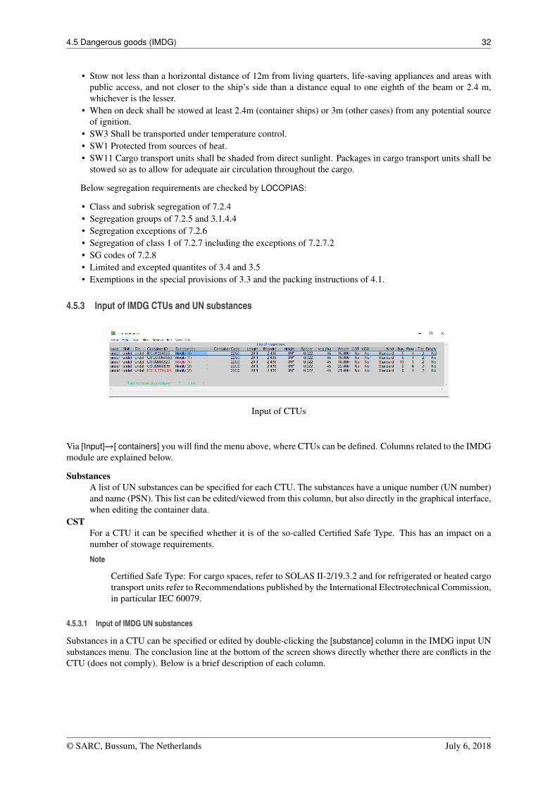
4.5.3 Input of IMDG CTUs and UN substances
Input of CTUs
Via [Input]�[ containers] you will find the menu above, where CTUs can be defined. Columns related to the IMDGmodule are explained below.
SubstancesA list of UN substances can be specified for each CTU. The substances have a unique number (UN number)and name (PSN). This list can be edited/viewed from this column, but also directly in the graphical interface,when editing the container data.
CSTFor a CTU it can be specified whether it is of the so-called Certified Safe Type. This has an impact on anumber of stowage requirements.
Note
Certified Safe Type: For cargo spaces, refer to SOLAS II-2/19.3.2 and for refrigerated or heated cargotransport units refer to Recommendations published by the International Electrotechnical Commission,in particular IEC 60079.
4.5.3.1 Input of IMDG UN substances
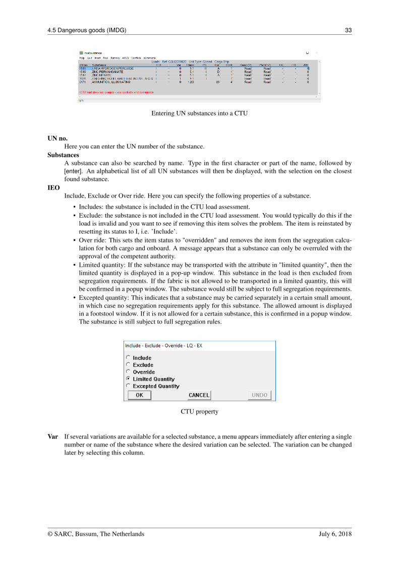
Substances in a CTU can be specified or edited by double-clicking the [substance] column in the IMDG input UNsubstances menu. The conclusion line at the bottom of the screen shows directly whether there are conflicts in theCTU (does not comply). Below is a brief description of each column.
© SARC, Bussum, The Netherlands July 6, 2018
4.5 Dangerous goods (IMDG) 33
Entering UN substances into a CTU
UN no.Here you can enter the UN number of the substance.
SubstancesA substance can also be searched by name. Type in the first character or part of the name, followed by[enter]. An alphabetical list of all UN substances will then be displayed, with the selection on the closestfound substance.
IEOInclude, Exclude or Over ride. Here you can specify the following properties of a substance.
• Includes: the substance is included in the CTU load assessment.• Exclude: the substance is not included in the CTU load assessment. You would typically do this if the
load is invalid and you want to see if removing this item solves the problem. The item is reinstated byresetting its status to I, i.e. ’Include’.
• Over ride: This sets the item status to "overridden" and removes the item from the segregation calcu-lation for both cargo and onboard. A message appears that a substance can only be overruled with theapproval of the competent authority.
• Limited quantity: If the substance may be transported with the attribute in "limited quantity", then thelimited quantity is displayed in a pop-up window. This substance in the load is then excluded fromsegregation requirements. If the fabric is not allowed to be transported in a limited quantity, this willbe confirmed in a popup window. The substance would still be subject to full segregation requirements.
• Excepted quantity: This indicates that a substance may be carried separately in a certain small amount,in which case no segregation requirements apply for this substance. The allowed amount is displayedin a footstool window. If it is not allowed for a certain substance, this is confirmed in a popup window.The substance is still subject to full segregation rules.
CTU property
Var If several variations are available for a selected substance, a menu appears immediately after entering a singlenumber or name of the substance where the desired variation can be selected. The variation can be changedlater by selecting this column.
© SARC, Bussum, The Netherlands July 6, 2018
4.5 Dangerous goods (IMDG) 34
Choice of a substance variation
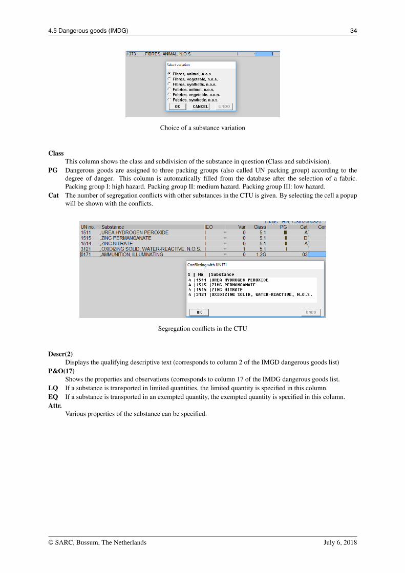
ClassThis column shows the class and subdivision of the substance in question (Class and subdivision).
PG Dangerous goods are assigned to three packing groups (also called UN packing group) according to thedegree of danger. This column is automatically filled from the database after the selection of a fabric.Packing group I: high hazard. Packing group II: medium hazard. Packing group III: low hazard.
Cat The number of segregation conflicts with other substances in the CTU is given. By selecting the cell a popupwill be shown with the conflicts.
Segregation conflicts in the CTU
Descr(2)Displays the qualifying descriptive text (corresponds to column 2 of the IMGD dangerous goods list)
P&O(17)Shows the properties and observations (corresponds to column 17 of the IMDG dangerous goods list.
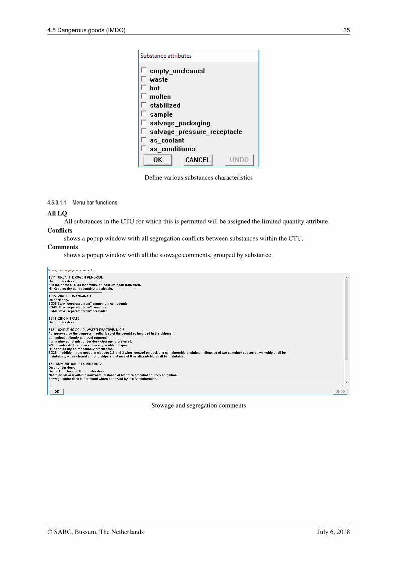
LQ If a substance is transported in limited quantities, the limited quantity is specified in this column.EQ If a substance is transported in an exempted quantity, the exempted quantity is specified in this column.Attr.
Various properties of the substance can be specified.
© SARC, Bussum, The Netherlands July 6, 2018
4.5 Dangerous goods (IMDG) 35
Define various substances characteristics
4.5.3.1.1 Menu bar functions
All LQAll substances in the CTU for which this is permitted will be assigned the limited quantity attribute.
Conflictsshows a popup window with all segregation conflicts between substances within the CTU.
Commentsshows a popup window with all the stowage comments, grouped by substance.
Stowage and segregation comments
© SARC, Bussum, The Netherlands July 6, 2018
4.5 Dangerous goods (IMDG) 36
4.5.4 IMDG information window
Verification against IMDG. IMDG information window
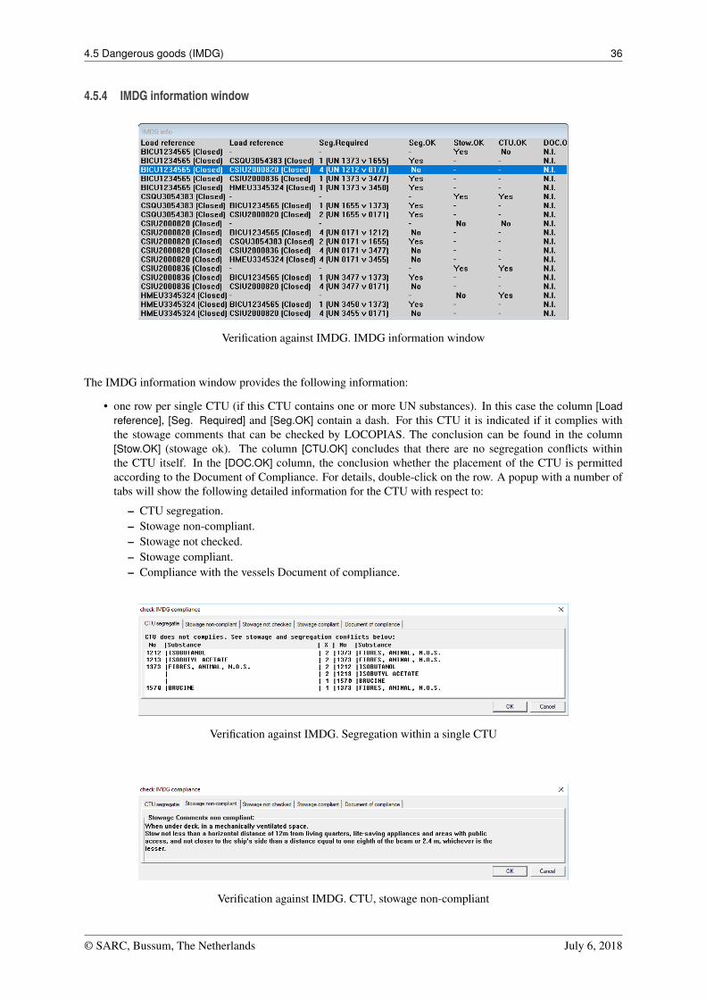
The IMDG information window provides the following information:
• one row per single CTU (if this CTU contains one or more UN substances). In this case the column [Loadreference], [Seg. Required] and [Seg.OK] contain a dash. For this CTU it is indicated if it complies withthe stowage comments that can be checked by LOCOPIAS. The conclusion can be found in the column[Stow.OK] (stowage ok). The column [CTU.OK] concludes that there are no segregation conflicts withinthe CTU itself. In the [DOC.OK] column, the conclusion whether the placement of the CTU is permittedaccording to the Document of Compliance. For details, double-click on the row. A popup with a number oftabs will show the following detailed information for the CTU with respect to:
– CTU segregation.– Stowage non-compliant.– Stowage not checked.– Stowage compliant.– Compliance with the vessels Document of compliance.
Verification against IMDG. Segregation within a single CTU
Verification against IMDG. CTU, stowage non-compliant
© SARC, Bussum, The Netherlands July 6, 2018
4.5 Dangerous goods (IMDG) 37
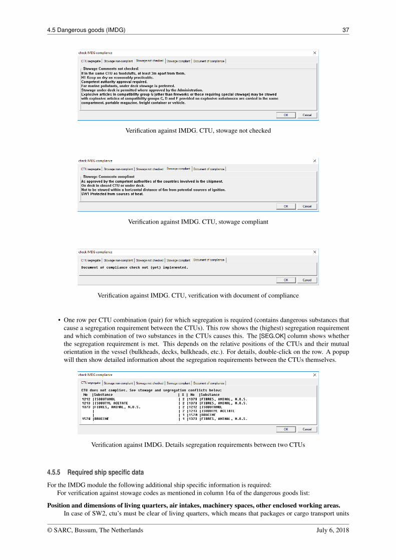
Verification against IMDG. CTU, stowage not checked
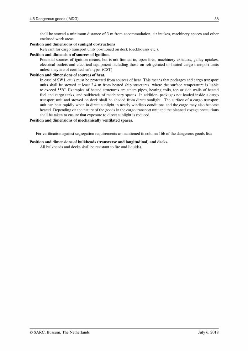
Verification against IMDG. CTU, stowage compliant
Verification against IMDG. CTU, verification with document of compliance
• One row per CTU combination (pair) for which segregation is required (contains dangerous substances thatcause a segregation requirement between the CTUs). This row shows the (highest) segregation requirementand which combination of two substances in the CTUs causes this. The [SEG.OK] column shows whetherthe segregation requirement is met. This depends on the relative positions of the CTUs and their mutualorientation in the vessel (bulkheads, decks, bulkheads, etc.). For details, double-click on the row. A popupwill then show detailed information about the segregation requirements between the CTUs themselves.
Verification against IMDG. Details segregation requirements between two CTUs
4.5.5 Required ship specific data
For the IMDG module the following additional ship specific information is required:For verification against stowage codes as mentioned in column 16a of the dangerous goods list:
Position and dimensions of living quarters, air intakes, machinery spaces, other enclosed working areas.In case of SW2, ctu’s must be clear of living quarters, which means that packages or cargo transport units
© SARC, Bussum, The Netherlands July 6, 2018
4.5 Dangerous goods (IMDG) 38
shall be stowed a minimum distance of 3 m from accommodation, air intakes, machinery spaces and otherenclosed work areas.
Position and dimensions of sunlight obstructionsRelevant for cargo transport units positioned on deck (deckhouses etc.).
Position and dimension of sources of ignition.Potential sources of ignition means, but is not limited to, open fires, machinery exhausts, galley uptakes,electrical outlets and electrical equipment including those on refrigerated or heated cargo transport unitsunless they are of certified safe type. (CST)
Position and dimensions of sources of heat.In case of SW1, ctu’s must be protected from sources of heat. This means that packages and cargo transportunits shall be stowed at least 2.4 m from heated ship structures, where the surface temperature is liableto exceed 55ºC. Examples of heated structures are steam pipes, heating coils, top or side walls of heatedfuel and cargo tanks, and bulkheads of machinery spaces. In addition, packages not loaded inside a cargotransport unit and stowed on deck shall be shaded from direct sunlight. The surface of a cargo transportunit can heat rapidly when in direct sunlight in nearly windless conditions and the cargo may also becomeheated. Depending on the nature of the goods in the cargo transport unit and the planned voyage precautionsshall be taken to ensure that exposure to direct sunlight is reduced.
Position and dimensions of mechanically ventilated spaces.
For verification against segregation requirements as mentioned in column 16b of the dangerous goods list:
Position and dimensions of bulkheads (transverse and longitudinal) and decks.All bulkheads and decks shall be resistant to fire and liquids).
© SARC, Bussum, The Netherlands July 6, 2018
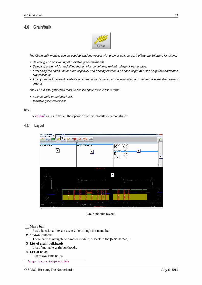
4.6 Grain/bulk 39
4.6 Grain/bulk
The Grain/bulk module can be used to load the vessel with grain or bulk cargo, it offers the following functions:
• Selecting and positioning of movable grain bulkheads.• Selecting grain holds, and filling those holds by volume, weight, ullage or percentage.• After filling the holds, the centers of gravity and heeling moments (in case of grain) of the cargo are calculated
automatically.• At any desired moment, stability or strength particulars can be evaluated and verified against the relevant
criteria.
The LOCOPIAS grain/bulk module can be applied for vessels with:
• A single hold or multiple holds• Movable grain bulkheads
Note
A video4 exists in which the operation of this module is demonstrated.
4.6.1 Layout
Grain module layout.
1 Menu barBasic functionalities are accessible through the menu bar.
2 Module-buttonsThese buttons navigate to another module, or back to the [Main screen].
3 List of grain bulkheadsList of movable grain bulkheads.
4 List of holdsList of available holds.
4https://youtu.be/qYL5uPQf8Hk
© SARC, Bussum, The Netherlands July 6, 2018
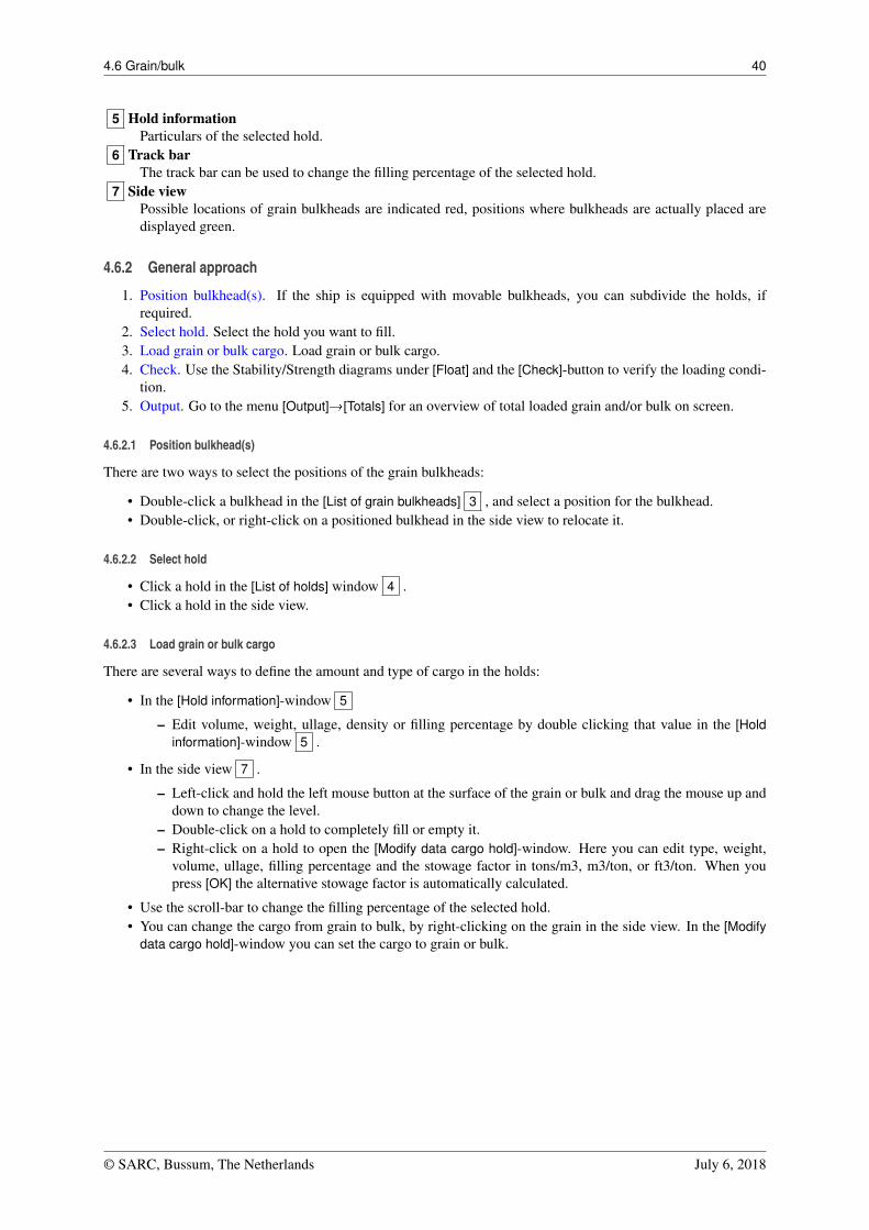
4.6 Grain/bulk 40
5 Hold informationParticulars of the selected hold.
6 Track barThe track bar can be used to change the filling percentage of the selected hold.
7 Side viewPossible locations of grain bulkheads are indicated red, positions where bulkheads are actually placed aredisplayed green.
4.6.2 General approach
1. Position bulkhead(s). If the ship is equipped with movable bulkheads, you can subdivide the holds, ifrequired.
2. Select hold. Select the hold you want to fill.3. Load grain or bulk cargo. Load grain or bulk cargo.4. Check. Use the Stability/Strength diagrams under [Float] and the [Check]-button to verify the loading condi-
tion.5. Output. Go to the menu [Output]�[Totals] for an overview of total loaded grain and/or bulk on screen.
4.6.2.1 Position bulkhead(s)
There are two ways to select the positions of the grain bulkheads:
• Double-click a bulkhead in the [List of grain bulkheads] 3 , and select a position for the bulkhead.• Double-click, or right-click on a positioned bulkhead in the side view to relocate it.
4.6.2.2 Select hold
• Click a hold in the [List of holds] window 4 .• Click a hold in the side view.
4.6.2.3 Load grain or bulk cargo
There are several ways to define the amount and type of cargo in the holds:
• In the [Hold information]-window 5
– Edit volume, weight, ullage, density or filling percentage by double clicking that value in the [Holdinformation]-window 5 .
• In the side view 7 .
– Left-click and hold the left mouse button at the surface of the grain or bulk and drag the mouse up anddown to change the level.
– Double-click on a hold to completely fill or empty it.– Right-click on a hold to open the [Modify data cargo hold]-window. Here you can edit type, weight,
volume, ullage, filling percentage and the stowage factor in tons/m3, m3/ton, or ft3/ton. When youpress [OK] the alternative stowage factor is automatically calculated.
• Use the scroll-bar to change the filling percentage of the selected hold.• You can change the cargo from grain to bulk, by right-clicking on the grain in the side view. In the [Modify
data cargo hold]-window you can set the cargo to grain or bulk.
© SARC, Bussum, The Netherlands July 6, 2018
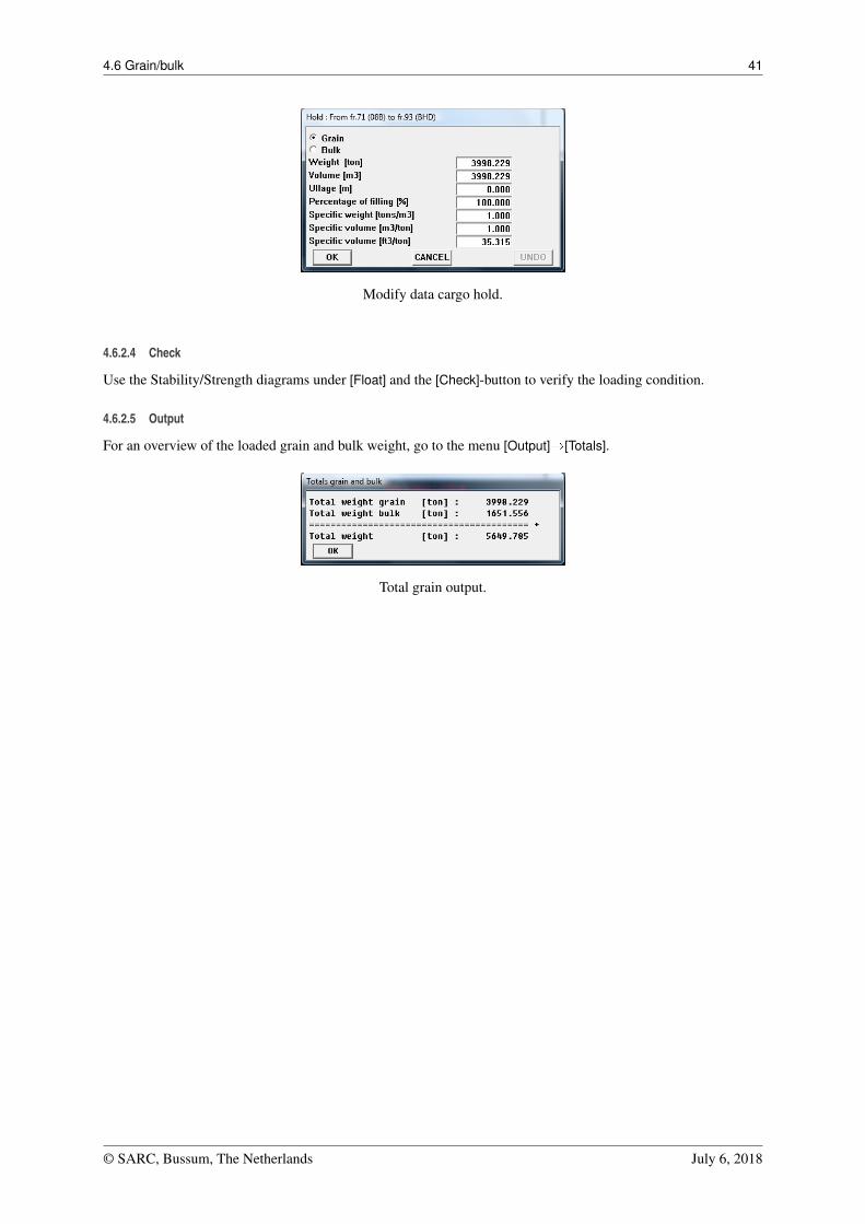
4.6 Grain/bulk 41
Modify data cargo hold.
4.6.2.4 Check
Use the Stability/Strength diagrams under [Float] and the [Check]-button to verify the loading condition.
4.6.2.5 Output
For an overview of the loaded grain and bulk weight, go to the menu [Output]�[Totals].
Total grain output.
© SARC, Bussum, The Netherlands July 6, 2018
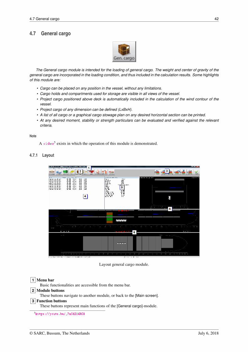
4.7 General cargo 42
4.7 General cargo
The General cargo module is intended for the loading of general cargo. The weight and center of gravity of thegeneral cargo are incorporated in the loading condition, and thus included in the calculation results. Some highlightsof this module are:
• Cargo can be placed on any position in the vessel, without any limitations.• Cargo holds and compartments used for storage are visible in all views of the vessel.• Project cargo positioned above deck is automatically included in the calculation of the wind contour of the
vessel.• Project cargo of any dimension can be defined (LxBxH).• A list of all cargo or a graphical cargo stowage plan on any desired horizontal section can be printed.• At any desired moment, stability or strength particulars can be evaluated and verified against the relevant
criteria.
Note
A video5 exists in which the operation of this module is demonstrated.
4.7.1 Layout
Layout general cargo module.
1 Menu barBasic functionalities are accessible from the menu bar.
2 Module buttonsThese buttons navigate to another module, or back to the [Main screen].
3 Function buttonsThese buttons represent main functions of the [General cargo]-module.
5https://youtu.be/_7aCdZ1WRCA
© SARC, Bussum, The Netherlands July 6, 2018
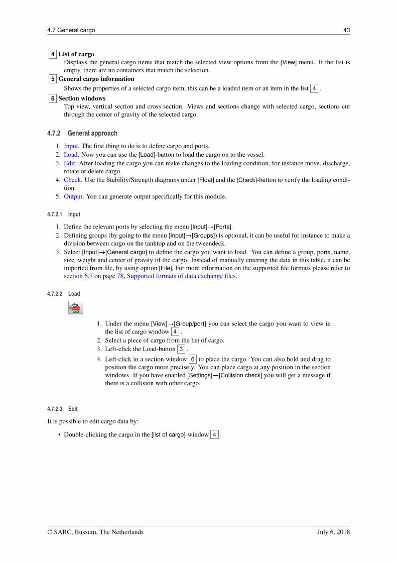
4.7 General cargo 43
4 List of cargoDisplays the general cargo items that match the selected view options from the [View] menu. If the list isempty, there are no containers that match the selection.
5 General cargo informationShows the properties of a selected cargo item, this can be a loaded item or an item in the list 4 .
6 Section windowsTop view, vertical section and cross section. Views and sections change with selected cargo, sections cutthrough the center of gravity of the selected cargo.
4.7.2 General approach
1. Input. The first thing to do is to define cargo and ports.2. Load. Now you can use the [Load]-button to load the cargo on to the vessel.3. Edit. After loading the cargo you can make changes to the loading condition, for instance move, discharge,
rotate or delete cargo.4. Check. Use the Stability/Strength diagrams under [Float] and the [Check]-button to verify the loading condi-
tion.5. Output. You can generate output specifically for this module.
4.7.2.1 Input
1. Define the relevant ports by selecting the menu [Input]�[Ports].2. Defining groups (by going to the menu [Input]�[Groups]) is optional, it can be useful for instance to make a
division between cargo on the tanktop and on the tweendeck.3. Select [Input]�[General cargo] to define the cargo you want to load. You can define a group, ports, name,
size, weight and center of gravity of the cargo. Instead of manually entering the data in this table, it can beimported from file, by using option [File], For more information on the supported file formats please refer tosection 6.7 on page 78, Supported formats of data exchange files.
4.7.2.2 Load
1. Under the menu [View]�[Group/port] you can select the cargo you want to view inthe list of cargo window 4 .
2. Select a piece of cargo from the list of cargo.3. Left-click the Load-button 3 .
4. Left-click in a section window 6 to place the cargo. You can also hold and drag toposition the cargo more precisely. You can place cargo at any position in the sectionwindows. If you have enabled [Settings]�[Collision check] you will get a message ifthere is a collision with other cargo.
4.7.2.3 Edit
It is possible to edit cargo data by:
• Double-clicking the cargo in the [list of cargo]-window 4 .
© SARC, Bussum, The Netherlands July 6, 2018
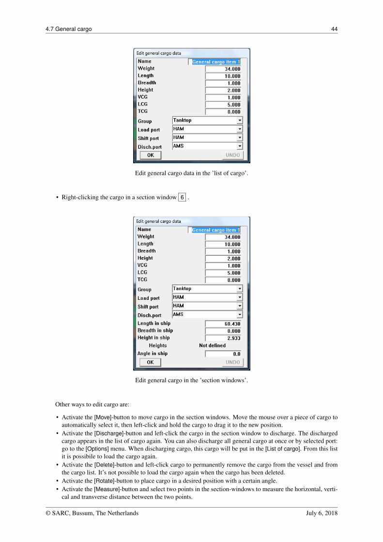
4.7 General cargo 44
Edit general cargo data in the ’list of cargo’.
• Right-clicking the cargo in a section window 6 .
Edit general cargo in the ’section windows’.
Other ways to edit cargo are:
• Activate the [Move]-button to move cargo in the section windows. Move the mouse over a piece of cargo toautomatically select it, then left-click and hold the cargo to drag it to the new position.
• Activate the [Discharge]-button and left-click the cargo in the section window to discharge. The dischargedcargo appears in the list of cargo again. You can also discharge all general cargo at once or by selected port:go to the [Options] menu. When discharging cargo, this cargo will be put in the [List of cargo]. From this listit is possibile to load the cargo again.
• Activate the [Delete]-button and left-click cargo to permanently remove the cargo from the vessel and fromthe cargo list. It’s not possible to load the cargo again when the cargo has been deleted.
• Activate the [Rotate]-button to place cargo in a desired position with a certain angle.• Activate the [Measure]-button and select two points in the section-windows to measure the horizontal, verti-
cal and transverse distance between the two points.
© SARC, Bussum, The Netherlands July 6, 2018
4.7 General cargo 45
4.7.2.4 Check
In section 4.1.2 on page 14, Verification more information can be found about verification of the loading condition.
4.7.2.5 Output
A list of all general cargo items as defined under input can be generated through [Output]�[General cargo list].Views and sections of the stowage plan can be defined under [Output]�[General cargo stowage plan].
© SARC, Bussum, The Netherlands July 6, 2018
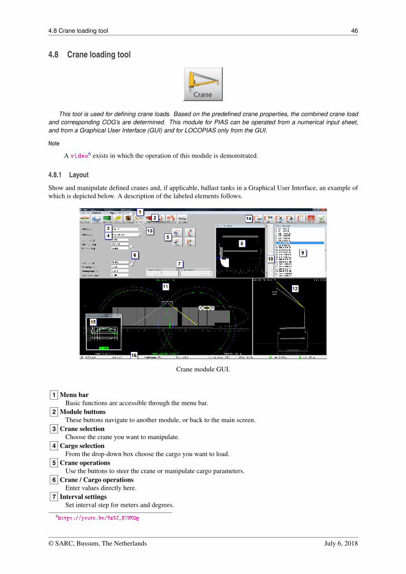
4.8 Crane loading tool 46
4.8 Crane loading tool
This tool is used for defining crane loads. Based on the predefined crane properties, the combined crane loadand corresponding COG’s are determined. This module for PIAS can be operated from a numerical input sheet,and from a Graphical User Interface (GUI) and for LOCOPIAS only from the GUI.
Note
A video6 exists in which the operation of this module is demonstrated.
4.8.1 Layout
Show and manipulate defined cranes and, if applicable, ballast tanks in a Graphical User Interface, an example ofwhich is depicted below. A description of the labeled elements follows.
Crane module GUI.
1 Menu barBasic functions are accessible through the menu bar.
2 Module buttonsThese buttons navigate to another module, or back to the main screen.
3 Crane selectionChoose the crane you want to manipulate.
4 Cargo selectionFrom the drop-down box choose the cargo you want to load.
5 Crane operationsUse the buttons to steer the crane or manipulate cargo parameters.
6 Crane / Cargo operationsEnter values directly here.
7 Interval settingsSet interval step for meters and degrees.
6https://youtu.be/VzSJ_OUUKQg
© SARC, Bussum, The Netherlands July 6, 2018
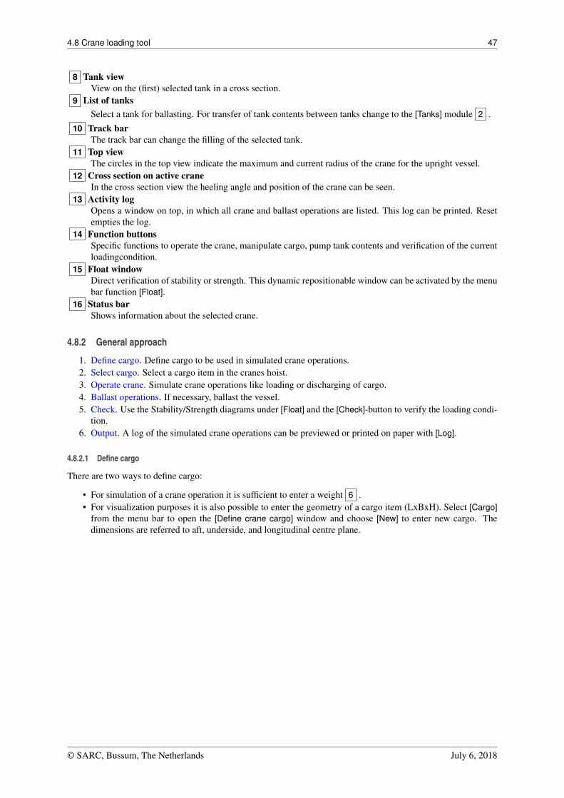
4.8 Crane loading tool 47
8 Tank viewView on the (first) selected tank in a cross section.
9 List of tanksSelect a tank for ballasting. For transfer of tank contents between tanks change to the [Tanks] module 2 .
10 Track barThe track bar can change the filling of the selected tank.
11 Top viewThe circles in the top view indicate the maximum and current radius of the crane for the upright vessel.
12 Cross section on active craneIn the cross section view the heeling angle and position of the crane can be seen.
13 Activity logOpens a window on top, in which all crane and ballast operations are listed. This log can be printed. Resetempties the log.
14 Function buttonsSpecific functions to operate the crane, manipulate cargo, pump tank contents and verification of the currentloadingcondition.
15 Float windowDirect verification of stability or strength. This dynamic repositionable window can be activated by the menubar function [Float].
16 Status barShows information about the selected crane.
4.8.2 General approach
1. Define cargo. Define cargo to be used in simulated crane operations.2. Select cargo. Select a cargo item in the cranes hoist.3. Operate crane. Simulate crane operations like loading or discharging of cargo.4. Ballast operations. If necessary, ballast the vessel.5. Check. Use the Stability/Strength diagrams under [Float] and the [Check]-button to verify the loading condi-
tion.6. Output. A log of the simulated crane operations can be previewed or printed on paper with [Log].
4.8.2.1 Define cargo
There are two ways to define cargo:
• For simulation of a crane operation it is sufficient to enter a weight 6 .• For visualization purposes it is also possible to enter the geometry of a cargo item (LxBxH). Select [Cargo]
from the menu bar to open the [Define crane cargo] window and choose [New] to enter new cargo. Thedimensions are referred to aft, underside, and longitudinal centre plane.
© SARC, Bussum, The Netherlands July 6, 2018
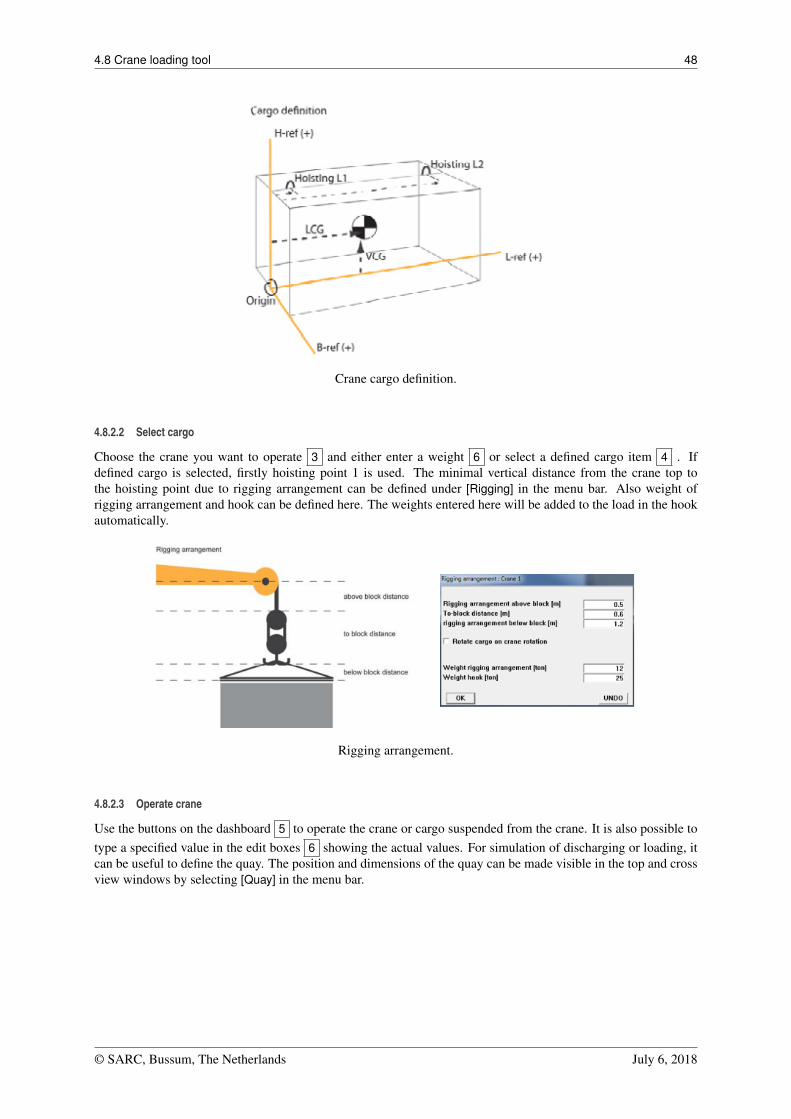
4.8 Crane loading tool 48
Crane cargo definition.
4.8.2.2 Select cargo
Choose the crane you want to operate 3 and either enter a weight 6 or select a defined cargo item 4 . Ifdefined cargo is selected, firstly hoisting point 1 is used. The minimal vertical distance from the crane top tothe hoisting point due to rigging arrangement can be defined under [Rigging] in the menu bar. Also weight ofrigging arrangement and hook can be defined here. The weights entered here will be added to the load in the hookautomatically.
Rigging arrangement.
4.8.2.3 Operate crane
Use the buttons on the dashboard 5 to operate the crane or cargo suspended from the crane. It is also possible totype a specified value in the edit boxes 6 showing the actual values. For simulation of discharging or loading, itcan be useful to define the quay. The position and dimensions of the quay can be made visible in the top and crossview windows by selecting [Quay] in the menu bar.
© SARC, Bussum, The Netherlands July 6, 2018
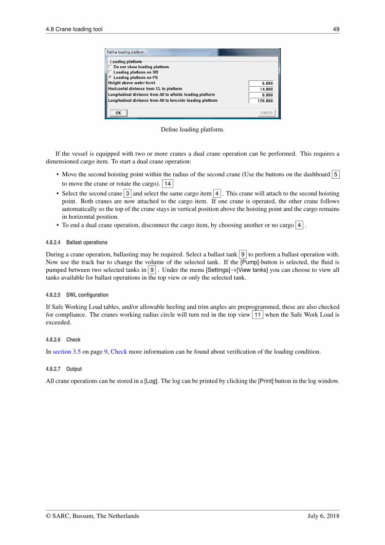
4.8 Crane loading tool 49
Define loading platform.
If the vessel is equipped with two or more cranes a dual crane operation can be performed. This requires adimensioned cargo item. To start a dual crane operation:
• Move the second hoisting point within the radius of the second crane (Use the buttons on the dashboard 5
to move the crane or rotate the cargo). 14
• Select the second crane 3 and select the same cargo item 4 . This crane will attach to the second hoistingpoint. Both cranes are now attached to the cargo item. If one crane is operated, the other crane followsautomatically so the top of the crane stays in vertical position above the hoisting point and the cargo remainsin horizontal position.
• To end a dual crane operation, disconnect the cargo item, by choosing another or no cargo 4 .
4.8.2.4 Ballast operations
During a crane operation, ballasting may be required. Select a ballast tank 9 to perform a ballast operation with.Now use the track bar to change the volume of the selected tank. If the [Pump]-button is selected, the fluid ispumped between two selected tanks in 9 . Under the menu [Settings]�[View tanks] you can choose to view alltanks available for ballast operations in the top view or only the selected tank.
4.8.2.5 SWL configuration
If Safe Working Load tables, and/or allowable heeling and trim angles are preprogrammed, these are also checkedfor compliance. The cranes working radius circle will turn red in the top view 11 when the Safe Work Load isexceeded.
4.8.2.6 Check
In section 3.5 on page 9, Check more information can be found about verification of the loading condition.
4.8.2.7 Output
All crane operations can be stored in a [Log]. The log can be printed by clicking the [Print] button in the log window.
© SARC, Bussum, The Netherlands July 6, 2018
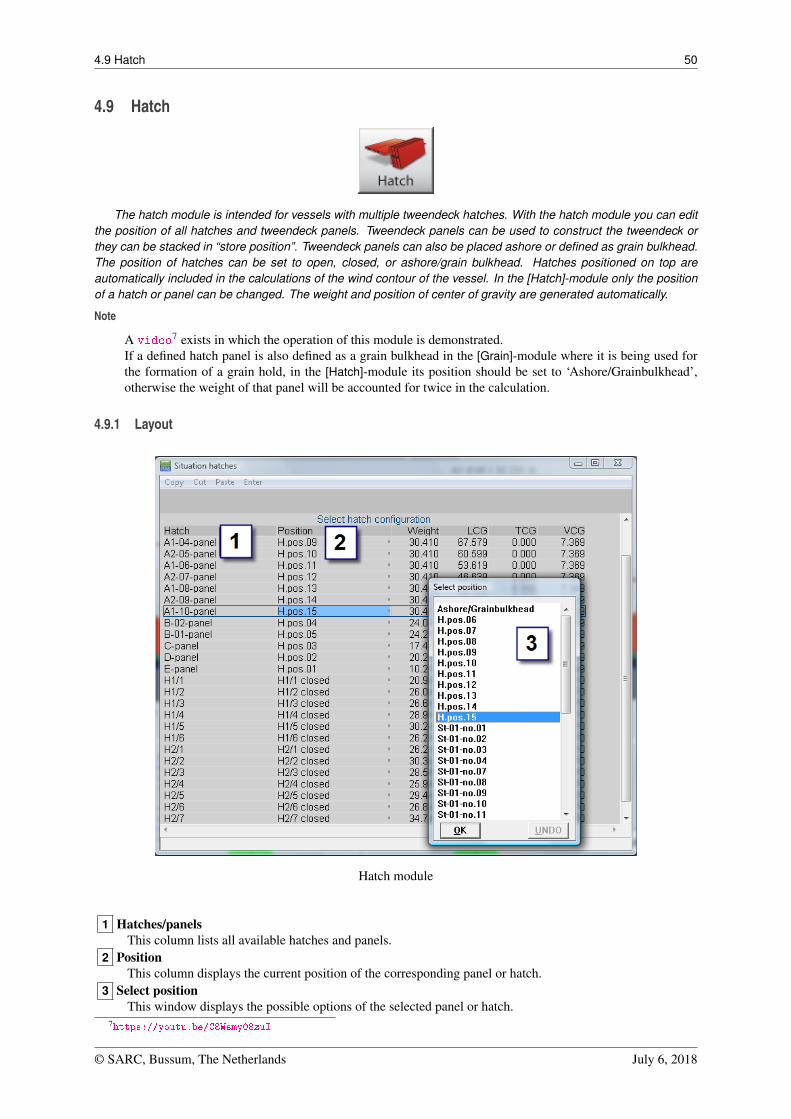
4.9 Hatch 50
4.9 Hatch
The hatch module is intended for vessels with multiple tweendeck hatches. With the hatch module you can editthe position of all hatches and tweendeck panels. Tweendeck panels can be used to construct the tweendeck orthey can be stacked in “store position”. Tweendeck panels can also be placed ashore or defined as grain bulkhead.The position of hatches can be set to open, closed, or ashore/grain bulkhead. Hatches positioned on top areautomatically included in the calculations of the wind contour of the vessel. In the [Hatch]-module only the positionof a hatch or panel can be changed. The weight and position of center of gravity are generated automatically.
Note
A video7 exists in which the operation of this module is demonstrated.If a defined hatch panel is also defined as a grain bulkhead in the [Grain]-module where it is being used forthe formation of a grain hold, in the [Hatch]-module its position should be set to ‘Ashore/Grainbulkhead’,otherwise the weight of that panel will be accounted for twice in the calculation.
4.9.1 Layout
Hatch module
1 Hatches/panelsThis column lists all available hatches and panels.
2 PositionThis column displays the current position of the corresponding panel or hatch.
3 Select positionThis window displays the possible options of the selected panel or hatch.
7https://youtu.be/C8Wsmy08zuI
© SARC, Bussum, The Netherlands July 6, 2018
4.9 Hatch 51
4.9.2 General approach
1. Select position. Double click on a panel or hatch 1 to display all possible positions for this panel or hatchin the ‘Select position’-window 3 and select the position for the loading condition. It’s also possible toselect the position of a panel or hatch 2 and press the spacebar. Now the ‘Select position’-window 3 willpop up.
2. Confirm. Close the hatch module and confirm the modification of the hatches configuration.
© SARC, Bussum, The Netherlands July 6, 2018
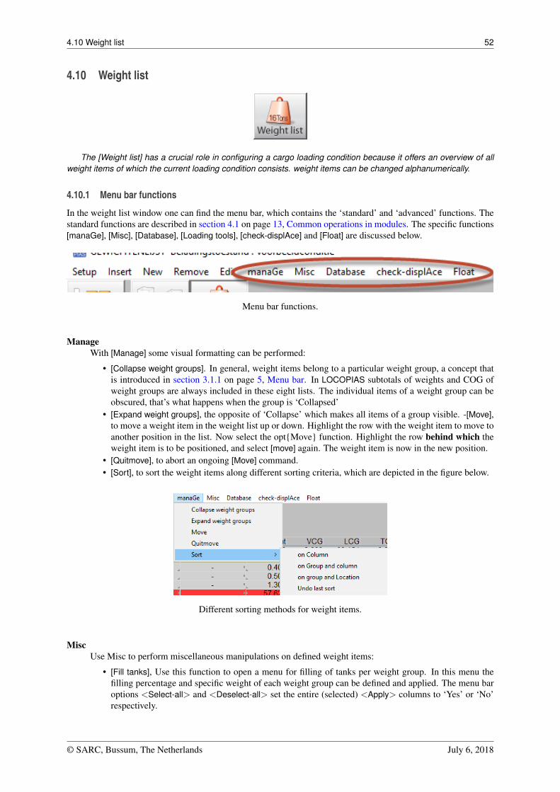
4.10 Weight list 52
4.10 Weight list
The [Weight list] has a crucial role in configuring a cargo loading condition because it offers an overview of allweight items of which the current loading condition consists. weight items can be changed alphanumerically.
4.10.1 Menu bar functions
In the weight list window one can find the menu bar, which contains the ‘standard’ and ‘advanced’ functions. Thestandard functions are described in section 4.1 on page 13, Common operations in modules. The specific functions[manaGe], [Misc], [Database], [Loading tools], [check-displAce] and [Float] are discussed below.
Menu bar functions.
ManageWith [Manage] some visual formatting can be performed:
• [Collapse weight groups]. In general, weight items belong to a particular weight group, a concept thatis introduced in section 3.1.1 on page 5, Menu bar. In LOCOPIAS subtotals of weights and COG ofweight groups are always included in these eight lists. The individual items of a weight group can beobscured, that’s what happens when the group is ‘Collapsed’
• [Expand weight groups], the opposite of ‘Collapse’ which makes all items of a group visible. -[Move],to move a weight item in the weight list up or down. Highlight the row with the weight item to move toanother position in the list. Now select the opt{Move} function. Highlight the row behind which theweight item is to be positioned, and select [move] again. The weight item is now in the new position.
• [Quitmove], to abort an ongoing [Move] command.• [Sort], to sort the weight items along different sorting criteria, which are depicted in the figure below.
Different sorting methods for weight items.
MiscUse Misc to perform miscellaneous manipulations on defined weight items:
• [Fill tanks], Use this function to open a menu for filling of tanks per weight group. In this menu thefilling percentage and specific weight of each weight group can be defined and applied. The menu baroptions <Select-all> and <Deselect-all> set the entire (selected) <Apply> columns to ‘Yes’ or ‘No’respectively.
© SARC, Bussum, The Netherlands July 6, 2018
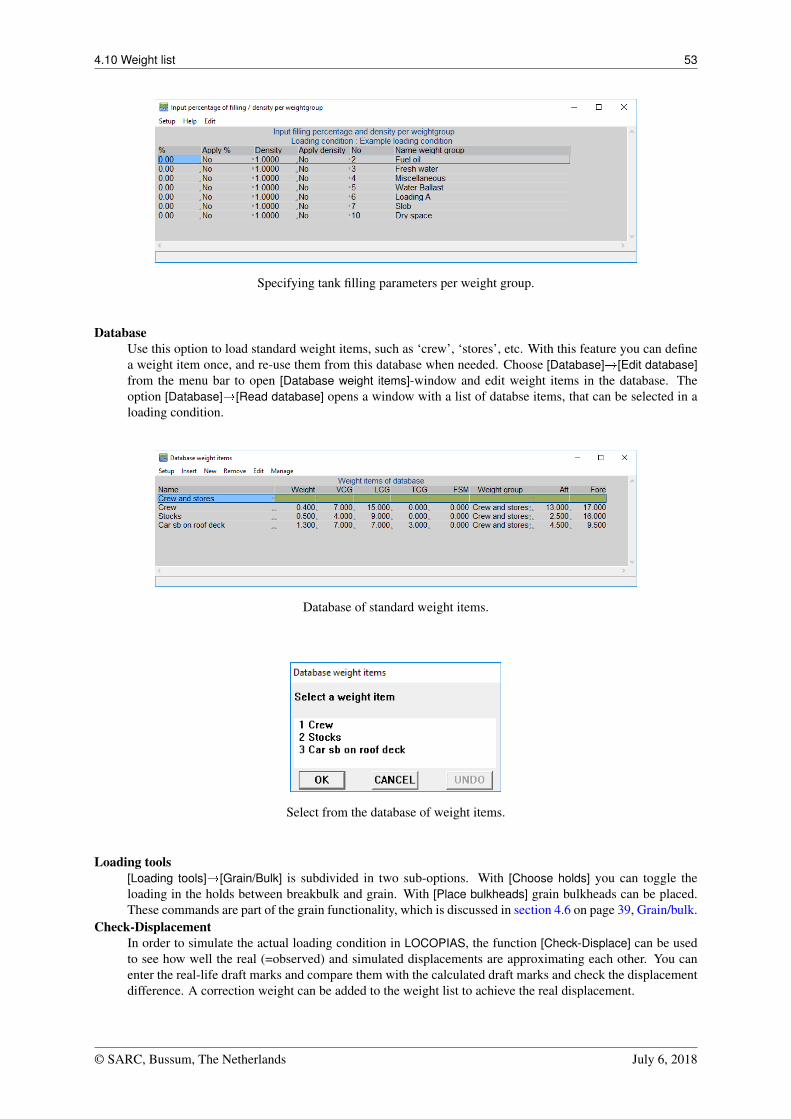
4.10 Weight list 53
Specifying tank filling parameters per weight group.
DatabaseUse this option to load standard weight items, such as ‘crew’, ‘stores’, etc. With this feature you can definea weight item once, and re-use them from this database when needed. Choose [Database]�[Edit database]from the menu bar to open [Database weight items]-window and edit weight items in the database. Theoption [Database]�[Read database] opens a window with a list of databse items, that can be selected in aloading condition.
Database of standard weight items.
Select from the database of weight items.
Loading tools[Loading tools]�[Grain/Bulk] is subdivided in two sub-options. With [Choose holds] you can toggle theloading in the holds between breakbulk and grain. With [Place bulkheads] grain bulkheads can be placed.These commands are part of the grain functionality, which is discussed in section 4.6 on page 39, Grain/bulk.
Check-DisplacementIn order to simulate the actual loading condition in LOCOPIAS, the function [Check-Displace] can be usedto see how well the real (=observed) and simulated displacements are approximating each other. You canenter the real-life draft marks and compare them with the calculated draft marks and check the displacementdifference. A correction weight can be added to the weight list to achieve the real displacement.
© SARC, Bussum, The Netherlands July 6, 2018
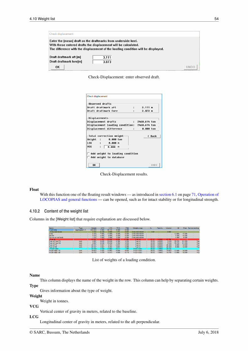
4.10 Weight list 54
Check-Displacement: enter observed draft.
Check-Displacement results.
FloatWith this function one of the floating result windows — as introduced in section 6.1 on page 71, Operation ofLOCOPIAS and general functions — can be opened, such as for intact stability or for longitudinal strength.
4.10.2 Content of the weight list
Columns in the [Weight list] that require explanation are discussed below.
List of weights of a loading condition.
NameThis column displays the name of the weight in the row. This column can help by separating certain weights.
TypeGives information about the type of weight.
WeightWeight in tonnes.
VCGVertical center of gravity in meters, related to the baseline.
LCGLongitudinal center of gravity in meters, related to the aft perpendicular.
© SARC, Bussum, The Netherlands July 6, 2018
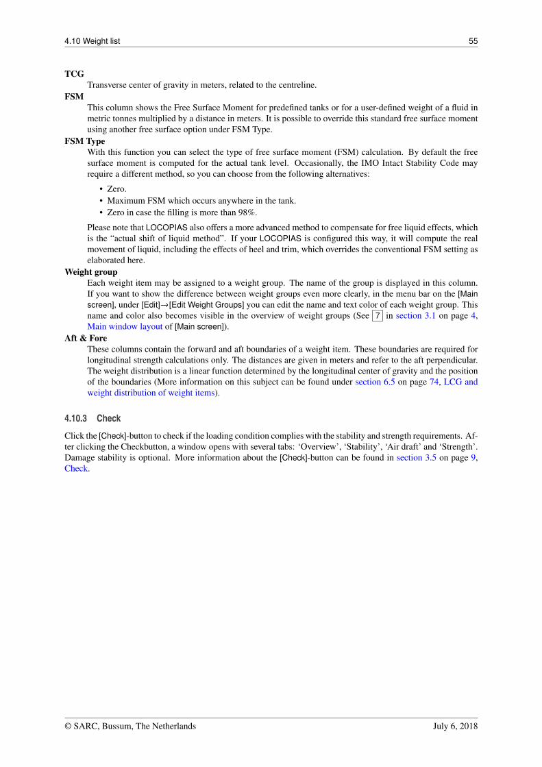
4.10 Weight list 55
TCGTransverse center of gravity in meters, related to the centreline.
FSMThis column shows the Free Surface Moment for predefined tanks or for a user-defined weight of a fluid inmetric tonnes multiplied by a distance in meters. It is possible to override this standard free surface momentusing another free surface option under FSM Type.
FSM TypeWith this function you can select the type of free surface moment (FSM) calculation. By default the freesurface moment is computed for the actual tank level. Occasionally, the IMO Intact Stability Code mayrequire a different method, so you can choose from the following alternatives:
• Zero.• Maximum FSM which occurs anywhere in the tank.• Zero in case the filling is more than 98%.
Please note that LOCOPIAS also offers a more advanced method to compensate for free liquid effects, whichis the “actual shift of liquid method”. If your LOCOPIAS is configured this way, it will compute the realmovement of liquid, including the effects of heel and trim, which overrides the conventional FSM setting aselaborated here.
Weight groupEach weight item may be assigned to a weight group. The name of the group is displayed in this column.If you want to show the difference between weight groups even more clearly, in the menu bar on the [Mainscreen], under [Edit]�[Edit Weight Groups] you can edit the name and text color of each weight group. Thisname and color also becomes visible in the overview of weight groups (See 7 in section 3.1 on page 4,Main window layout of [Main screen]).
Aft & ForeThese columns contain the forward and aft boundaries of a weight item. These boundaries are required forlongitudinal strength calculations only. The distances are given in meters and refer to the aft perpendicular.The weight distribution is a linear function determined by the longitudinal center of gravity and the positionof the boundaries (More information on this subject can be found under section 6.5 on page 74, LCG andweight distribution of weight items).
4.10.3 Check
Click the [Check]-button to check if the loading condition complies with the stability and strength requirements. Af-ter clicking the Checkbutton, a window opens with several tabs: ‘Overview’, ‘Stability’, ‘Air draft’ and ‘Strength’.Damage stability is optional. More information about the [Check]-button can be found in section 3.5 on page 9,Check.
© SARC, Bussum, The Netherlands July 6, 2018
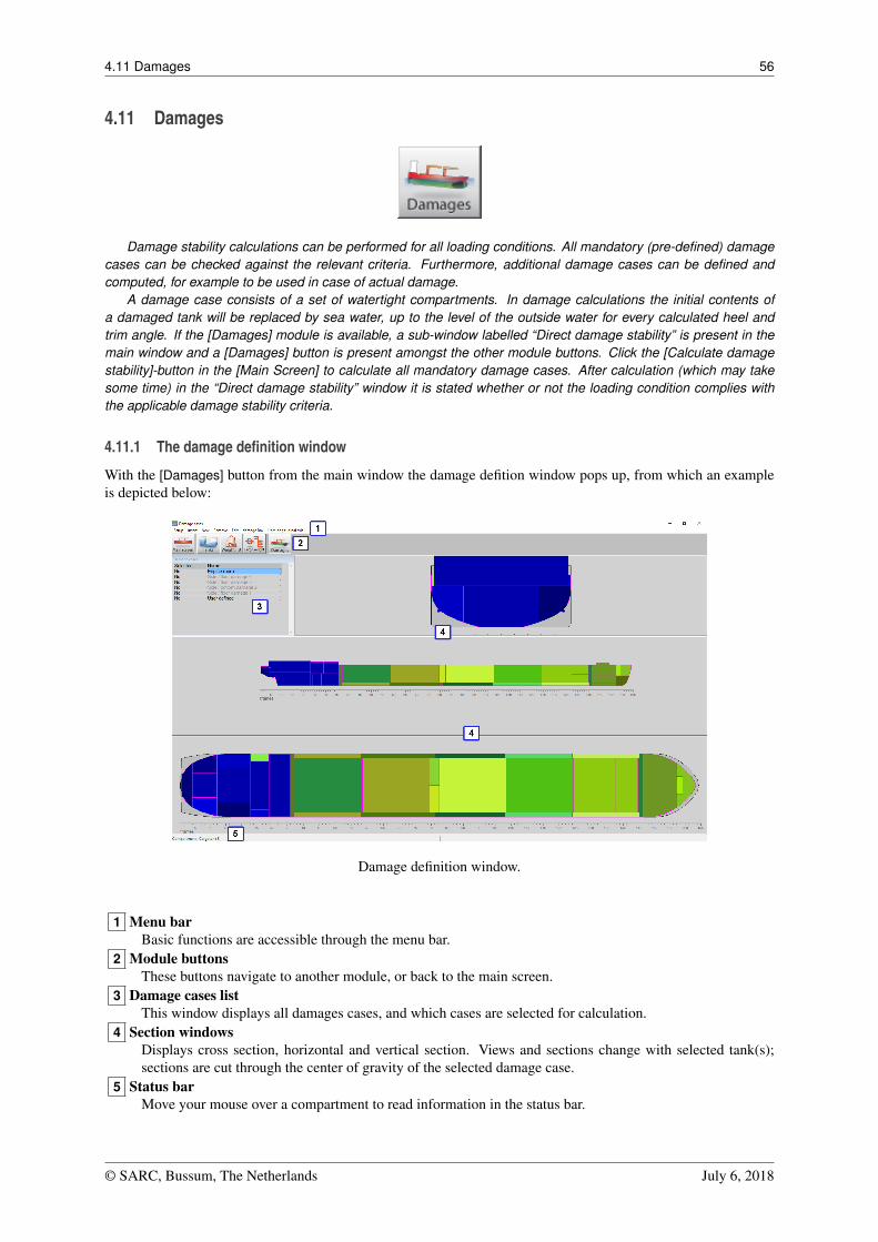
4.11 Damages 56
4.11 Damages
Damage stability calculations can be performed for all loading conditions. All mandatory (pre-defined) damagecases can be checked against the relevant criteria. Furthermore, additional damage cases can be defined andcomputed, for example to be used in case of actual damage.
A damage case consists of a set of watertight compartments. In damage calculations the initial contents ofa damaged tank will be replaced by sea water, up to the level of the outside water for every calculated heel andtrim angle. If the [Damages] module is available, a sub-window labelled “Direct damage stability” is present in themain window and a [Damages] button is present amongst the other module buttons. Click the [Calculate damagestability]-button in the [Main Screen] to calculate all mandatory damage cases. After calculation (which may takesome time) in the “Direct damage stability” window it is stated whether or not the loading condition complies withthe applicable damage stability criteria.
4.11.1 The damage definition window
With the [Damages] button from the main window the damage defition window pops up, from which an exampleis depicted below:
Damage definition window.
1 Menu barBasic functions are accessible through the menu bar.
2 Module buttonsThese buttons navigate to another module, or back to the main screen.
3 Damage cases listThis window displays all damages cases, and which cases are selected for calculation.
4 Section windowsDisplays cross section, horizontal and vertical section. Views and sections change with selected tank(s);sections are cut through the center of gravity of the selected damage case.
5 Status barMove your mouse over a compartment to read information in the status bar.
© SARC, Bussum, The Netherlands July 6, 2018
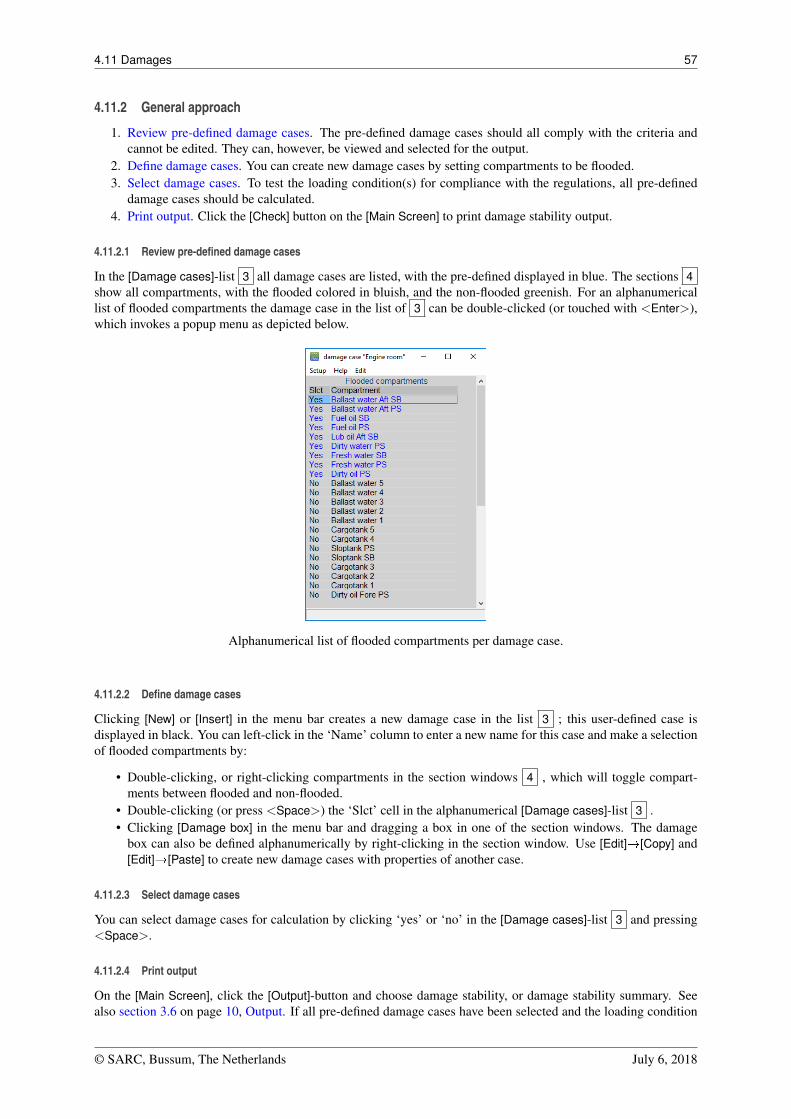
4.11 Damages 57
4.11.2 General approach
1. Review pre-defined damage cases. The pre-defined damage cases should all comply with the criteria andcannot be edited. They can, however, be viewed and selected for the output.
2. Define damage cases. You can create new damage cases by setting compartments to be flooded.3. Select damage cases. To test the loading condition(s) for compliance with the regulations, all pre-defined
damage cases should be calculated.4. Print output. Click the [Check] button on the [Main Screen] to print damage stability output.
4.11.2.1 Review pre-defined damage cases
In the [Damage cases]-list 3 all damage cases are listed, with the pre-defined displayed in blue. The sections 4show all compartments, with the flooded colored in bluish, and the non-flooded greenish. For an alphanumericallist of flooded compartments the damage case in the list of 3 can be double-clicked (or touched with <Enter>),which invokes a popup menu as depicted below.
Alphanumerical list of flooded compartments per damage case.
4.11.2.2 Define damage cases
Clicking [New] or [Insert] in the menu bar creates a new damage case in the list 3 ; this user-defined case isdisplayed in black. You can left-click in the ‘Name’ column to enter a new name for this case and make a selectionof flooded compartments by:
• Double-clicking, or right-clicking compartments in the section windows 4 , which will toggle compart-ments between flooded and non-flooded.
• Double-clicking (or press <Space>) the ‘Slct’ cell in the alphanumerical [Damage cases]-list 3 .• Clicking [Damage box] in the menu bar and dragging a box in one of the section windows. The damage
box can also be defined alphanumerically by right-clicking in the section window. Use [Edit]�[Copy] and[Edit]�[Paste] to create new damage cases with properties of another case.
4.11.2.3 Select damage cases
You can select damage cases for calculation by clicking ‘yes’ or ‘no’ in the [Damage cases]-list 3 and pressing<Space>.
4.11.2.4 Print output
On the [Main Screen], click the [Output]-button and choose damage stability, or damage stability summary. Seealso section 3.6 on page 10, Output. If all pre-defined damage cases have been selected and the loading condition
© SARC, Bussum, The Netherlands July 6, 2018
4.11 Damages 58
complies with the relevant damage stability criteria for all defined damage cases, this conclusion is printed in thedamage stability output.
© SARC, Bussum, The Netherlands July 6, 2018
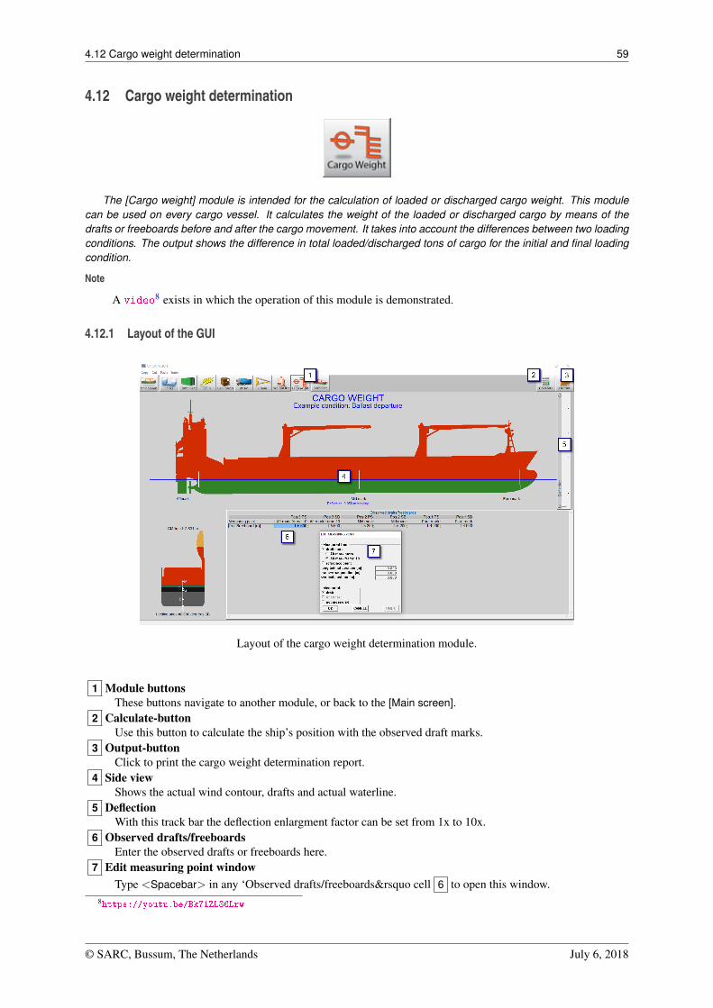
4.12 Cargo weight determination 59
4.12 Cargo weight determination
The [Cargo weight] module is intended for the calculation of loaded or discharged cargo weight. This modulecan be used on every cargo vessel. It calculates the weight of the loaded or discharged cargo by means of thedrafts or freeboards before and after the cargo movement. It takes into account the differences between two loadingconditions. The output shows the difference in total loaded/discharged tons of cargo for the initial and final loadingcondition.
Note
A video8 exists in which the operation of this module is demonstrated.
4.12.1 Layout of the GUI
Layout of the cargo weight determination module.
1 Module buttonsThese buttons navigate to another module, or back to the [Main screen].
2 Calculate-buttonUse this button to calculate the ship’s position with the observed draft marks.
3 Output-buttonClick to print the cargo weight determination report.
4 Side viewShows the actual wind contour, drafts and actual waterline.
5 DeflectionWith this track bar the deflection enlargment factor can be set from 1x to 10x.
6 Observed drafts/freeboardsEnter the observed drafts or freeboards here.
7 Edit measuring point windowType <Spacebar> in any ‘Observed drafts/freeboards&rsquo cell 6 to open this window.
8https://youtu.be/Bk71ZL86Lrw
© SARC, Bussum, The Netherlands July 6, 2018
4.12 Cargo weight determination 60
4.12.2 General approach
The governing idea of this module is that two loading conditions are identified — which are labelled ‘initial’ and‘final’ — from which the weights are computed and subtracted. This gives a weight difference, which equals theloaded or unloaded (cargo) weight between those two conditions.
The ‘initial’ and ‘final’ qualifiers are not fixed to a particular loading condition. The process is that when the[Weight determination] module is invoked, the loading condition from that moment will be assumed to be ‘final’,and when the [Output] is chosen a window pops up where the desired ‘initial’ condition can be selected. So, thesame loading condition that is used as ‘final’ in one weight determination computation, can be ‘initial’ in the other.
For both the ‘initial’ and ‘final’ conditions the observed drafts or freeboards must be given, in part 6 of theGUI. Only loading conditions where these data are entered are selectable as ‘initial’ for a weight determinationcomputation.
An important aspect is that essentially the full displacement difference between the ‘initial’ and ‘final’ is takenas the loaded or unloaded weight. If between ‘initial’ and ‘final’ non-cargo items have changed — e.g. by loadingfresh water or discharging ballast — then those changes must be included in the loading conditions, so that theywill not be seen as ‘cargo’ in the cargo weight report. This also implies that the changed cargo itself should notbe modified in the two loading conditions, otherwise that would also be seen as non-cargo, which is clearly not theintention.
4.12.3 Steps to be taken
1. Define the initial loading condition. Use LOCOPIAS to define the loading condition as described in thismanual, including tank fillings, grain bulkheads, cargo etc. Open the Weight determination module and enterthe observed drafts in this condition. Press [Calculate] 2 to calculate the ship’s position according to theentered draft marks.
2. Define the final loading condition. Go back to the [Main screen] and define the final loading condition,including tank fillings, configuration of grain bulkheads, cargo etc. Open the [Cargo weight] module againand enter the observed draft marks of the (un)loaded vessel. Press [Calculate] 2 to calculate the ship’sposition according to the entered draft marks.
3. Print Output. Click the [Output] button to produce a cargo weight determination report, from which anexample is depicted below.
By default the pre-defined draft marks are used to specify drafty or freeboard in 6 . Alternatively, you can alsodefine a reference point yourself and indicate whether you want to enter drafts or freeboards. Press <Spacebar>— or any other keyboard key, in accordance with the LOCOPIAS operation standard as described in section 6.2on page 71, Content and options in the cells of selection windows and input windows — in the [observed drafts /freeboards] window 6 to open the [edit measuring point] window 7 .
© SARC, Bussum, The Netherlands July 6, 2018
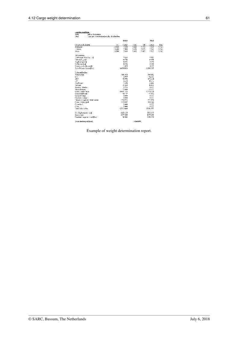
4.12 Cargo weight determination 61
Example of weight determination report.
© SARC, Bussum, The Netherlands July 6, 2018
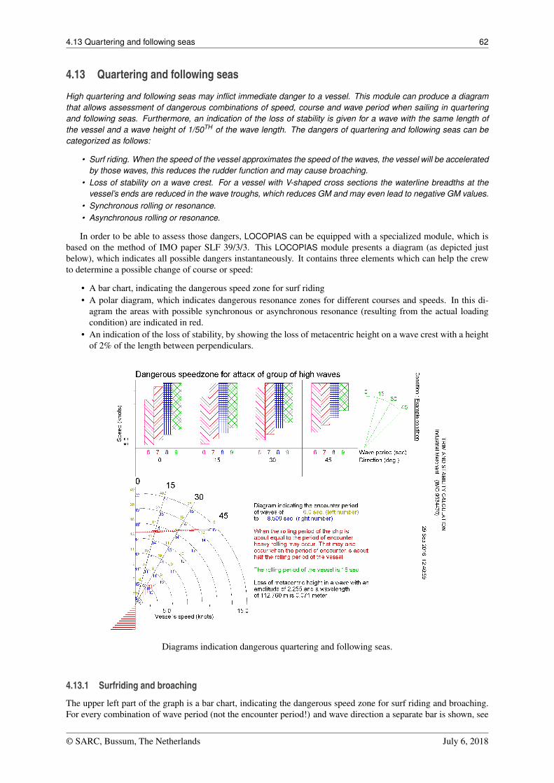
4.13 Quartering and following seas 62
4.13 Quartering and following seas
High quartering and following seas may inflict immediate danger to a vessel. This module can produce a diagramthat allows assessment of dangerous combinations of speed, course and wave period when sailing in quarteringand following seas. Furthermore, an indication of the loss of stability is given for a wave with the same length ofthe vessel and a wave height of 1/50TH of the wave length. The dangers of quartering and following seas can becategorized as follows:
• Surf riding. When the speed of the vessel approximates the speed of the waves, the vessel will be acceleratedby those waves, this reduces the rudder function and may cause broaching.
• Loss of stability on a wave crest. For a vessel with V-shaped cross sections the waterline breadths at thevessel’s ends are reduced in the wave troughs, which reduces GM and may even lead to negative GM values.
• Synchronous rolling or resonance.• Asynchronous rolling or resonance.
In order to be able to assess those dangers, LOCOPIAS can be equipped with a specialized module, which isbased on the method of IMO paper SLF 39/3/3. This LOCOPIAS module presents a diagram (as depicted justbelow), which indicates all possible dangers instantaneously. It contains three elements which can help the crewto determine a possible change of course or speed:
• A bar chart, indicating the dangerous speed zone for surf riding• A polar diagram, which indicates dangerous resonance zones for different courses and speeds. In this di-
agram the areas with possible synchronous or asynchronous resonance (resulting from the actual loadingcondition) are indicated in red.
• An indication of the loss of stability, by showing the loss of metacentric height on a wave crest with a heightof 2% of the length between perpendiculars.
Diagrams indication dangerous quartering and following seas.
4.13.1 Surfriding and broaching
The upper left part of the graph is a bar chart, indicating the dangerous speed zone for surf riding and broaching.For every combination of wave period (not the encounter period!) and wave direction a separate bar is shown, see
© SARC, Bussum, The Netherlands July 6, 2018
4.13 Quartering and following seas 63
the legend on the right hand side of the graph. The bars correspond with a speed range that can be read from theleft hand scale of the graph. The small ‘pie chart’ on the right hand side of the graph is just an indication of thecourse of the vessel relative to the wave direction in degrees.
4.13.2 Heavy rolling
When the encountered wave period is nearly equal to the natural rolling period of the ship, heavy rolling mayoccur (synchronous rolling). Large rolling motions also occur when the encountered wave period is about halfthe natural rolling period (parametric rolling). The lower part of the graph is a polar diagram, which indicatesdangerous resonance zones for different courses and speeds for the actual loading condition. In this diagram theareas with possible synchronous or asynchronous resonance are indicated in red. The actual state of the vessel isthe intersection between the heading of the vessel relative to the wave direction (the diagonal lines in the graph) andspeed (the circular arcs, scale on the bottom axis). The red areas represent the dangerous combinations of speedand course. Left and right of every intersection in the graph, the encounter periods are printed for waves with aperiod of 6 and 9 seconds respectively. Note that the printed periods may differ from the ones above, dependingon the length of the vessel.
4.13.3 Loss of stability
An indication of the loss of stability is shown in text, as the loss of metacentric height on a wave crest with aheight of 2% of the ship’s length. Note that this kind of loss of stability is not included in the regular stabilityvalues of LOCOPIAS, because this loss of stability is usually temporary (only when balancing on a wave crest).However, sailing in following seas with approximately the same speed as the wave can lead to a prolonged periodwith reduced stability, which may lead to dangerous situations.
© SARC, Bussum, The Netherlands July 6, 2018
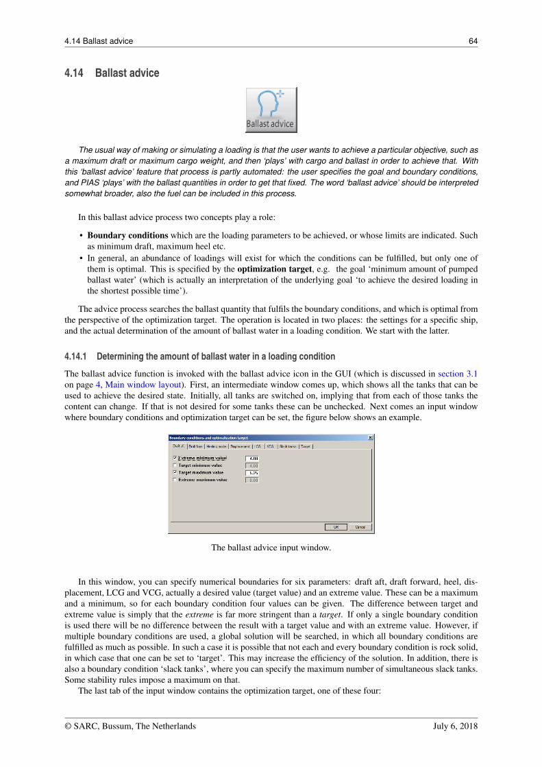
4.14 Ballast advice 64
4.14 Ballast advice
The usual way of making or simulating a loading is that the user wants to achieve a particular objective, such asa maximum draft or maximum cargo weight, and then ‘plays’ with cargo and ballast in order to achieve that. Withthis ‘ballast advice’ feature that process is partly automated: the user specifies the goal and boundary conditions,and PIAS ‘plays’ with the ballast quantities in order to get that fixed. The word ‘ballast advice’ should be interpretedsomewhat broader, also the fuel can be included in this process.
In this ballast advice process two concepts play a role:
• Boundary conditions which are the loading parameters to be achieved, or whose limits are indicated. Suchas minimum draft, maximum heel etc.
• In general, an abundance of loadings will exist for which the conditions can be fulfilled, but only one ofthem is optimal. This is specified by the optimization target, e.g. the goal ‘minimum amount of pumpedballast water’ (which is actually an interpretation of the underlying goal ‘to achieve the desired loading inthe shortest possible time’).
The advice process searches the ballast quantity that fulfils the boundary conditions, and which is optimal fromthe perspective of the optimization target. The operation is located in two places: the settings for a specific ship,and the actual determination of the amount of ballast water in a loading condition. We start with the latter.
4.14.1 Determining the amount of ballast water in a loading condition
The ballast advice function is invoked with the ballast advice icon in the GUI (which is discussed in section 3.1on page 4, Main window layout). First, an intermediate window comes up, which shows all the tanks that can beused to achieve the desired state. Initially, all tanks are switched on, implying that from each of those tanks thecontent can change. If that is not desired for some tanks these can be unchecked. Next comes an input windowwhere boundary conditions and optimization target can be set, the figure below shows an example.
The ballast advice input window.
In this window, you can specify numerical boundaries for six parameters: draft aft, draft forward, heel, dis-placement, LCG and VCG, actually a desired value (target value) and an extreme value. These can be a maximumand a minimum, so for each boundary condition four values can be given. The difference between target andextreme value is simply that the extreme is far more stringent than a target. If only a single boundary conditionis used there will be no difference between the result with a target value and with an extreme value. However, ifmultiple boundary conditions are used, a global solution will be searched, in which all boundary conditions arefulfilled as much as possible. In such a case it is possible that not each and every boundary condition is rock solid,in which case that one can be set to ‘target’. This may increase the efficiency of the solution. In addition, there isalso a boundary condition ‘slack tanks’, where you can specify the maximum number of simultaneous slack tanks.Some stability rules impose a maximum on that.
The last tab of the input window contains the optimization target, one of these four:
© SARC, Bussum, The Netherlands July 6, 2018
4.14 Ballast advice 65
• Minimum volume of pumped ballast water. Ballast water can, of course, be taken in from or discharged intothe sea.
• Switched off, i.e. there is no target at all; the first solution that meets the boundary condition(s) is then taken.• Minimum volume of pumped ballast water, with fixed deplacement. This solution could also be found by
using the first target, combined with constraints on the displacement, but then for each loading condition thedesired displacement should be specified. In this way, it is easier.
• Minimum volume of pumped ballast water with fuel volume given below. Here the boundary conditions arenot met by just changing ballast, but also by the distribution of fuel over the fuel tanks. The total fuel volumecan be given on the next line of this tab. This ‘fuel’ option is only present in this window if the setting (inthe next paragraph) actually specifies that fuel tanks are involved in the ballast advice procedure.
Finally, in the last tab a check box ‘Calculate ballast advice’ is available. This must be switched on in orderactually compute the advice. The background of this box is that the calculation of the advice might take a consid-erable amount of time, so that it may be desirable to leave this input window without calculation. And that canbe achieved by unchecking this box. If the ballast advice has been calculated then the conclusion will be printed(or, alternatively, displayed as preview on screen, and the question is asked whether the loading conditions mustbe adjusted in accordance with the advice. If done so, the original is lost. If that is not desired you should make acopy in advance.
On the ballast advice as such some more remarks can be made:
• You can use as many boundary conditions as you like, but please consider that the solution is found itera-tively. With as result that the computation time can increase significantly with the use of many boundaryconditions, especially when those are nearly or completely contradictory. If there is no solution (anyway,if none is found), then that is reported, but no feedback is given on the reason thereof. As is common withiterative search methods.
• Calculating the advice may require a huge number of intermediate steps, and can sometimes take a long time.If that is deemed undesirable, it is recommended to avoid combinations with other calculation-intensive op-tions, such as ‘shift of COG of liquids’, as much as possible. Another possibility to decrease the computationtime is using only the major tanks and skip the small ones.
• Tanks within a ‘tank combination’ are filled to the same level. If this combination contains a port andstarboard tank it will not be possible to neutralize a heeling angle with this combination.
© SARC, Bussum, The Netherlands July 6, 2018
Chapter 5
Tank soundings including effects of list and trim
This module allows calculation of tank volumes and other tank data based on the actual list and trim of the vessel.Temperature corrections can be computed according to common product data tables or to manual input. Differentoutput formats are available, including output to intact stability and longitudinal strength calculations. Further-more, this module can retrieve data from an automatic draft and tank gauge system. The main menu for thismodule is opened from the main window, and shows:
Tank contents with heel and trim
1 Specify list and trim
2 Calculate tank particulars
3 Print all tank particulars on paper
4 Cargo/ullage report, and historical cargo summary
5 Export tank data to a loading condition
6 Import tank data from tank measurement systeem
7 Up-to-date overview of filling and flow rate per tank
5.1 Specify list and trim
An input window pops up, where the following data can be given:
• Trim in meters (Trim by bow positive), which is the difference in draft on the FPP and the APP (Tfpp -Tapp).
• Angle of inclination in degrees only positive angles can be filled in here.• The above given heeling angle is to PS or SB.• Mean draft. This draft is read out by the draft sensor, which is an option in the context of LOCOPIAS. For
calculating the tank capacities only, it is not required to give a draft.
5.2 Calculate tank particulars
In this menu, the calculated tank particulars are listed: Sounding, volume, density, weight, ullage, LCG, VCG,TCG, FSM, Pressure (if pressure gauges are defined) and ROB (Residue On Bottom). If one of these items ischanged, the other items will be adjusted automatically. Note that the ullage is printed only if the sounding pipeis defined, otherwise a “-” will be printed. When no sounding pipe is defined, the column [sounding] displaysthe liquid level (relative to baseline, CL and App). If no sounding pipe is defined, the effect of trim cannot beestablished. If the tank name is selected the menu ‘Product, temperature and density’ will appear. The followingdata can be given:
Tank nameAs defined in the LOCOPIAS vessel model.
Include this tank in ullage reportIf this compartment should be included in the cargo/ullage report (for an example see section 5.4.1 onpage 68, Print Cargo/Ullage report on screen) then this field should be set to ‘yes’.
5.3 Print all tank particulars on paper 67
Product (substance)The name of the product, which will be used in the cargo/ullage report.
Conversion tableFor the calculation of the cargo weight of heated hydrocarbons, the following conversion tables areavailable:
• No temperature correction.• Correction factor per degree. The ‘Volume Correction Factor’ is calculated according to the defined
temperature and the correction factor per degree (coefficient of expansion).• Volume Correction Factor. The ‘Volume Correction Factor’ can be defined directly.• Table 54B. The ‘Volume Correction Factor’ is determined according to ASTM table 54B.• Table 55. The ‘Volume Correction Factor’ is determined according to ASTM table 55.
Data linkThis is the value that is sent by the tank measurement system (section 5.6 on page 70, Import tank data fromtank measurement systeem). The data link value is for checking purposes only.
TemperatureThe standard temperature is 15°Celsius. The volume is determined at this temperature. The actual tempera-ture of the substance can be defined here.
Volume (not corrected for expansion)This is the volume that is calculated according to the sounding or ullage for this compartment. This volumecomes from the previous window with the list of all the compartments.
Density at 15°Celsius (in air)/(in vacuum)The density of the substance at 15°Celsius can be defined here. If the density in air is defined, the density invacuum is calculated automatically. These two densities are connected to each other and cannot be definedseparately.
Correction factor per degree CelsiusThis factor is used if the conversion table ‘Correction factor per degree’ has been selected, and calculates thevolume correction factor.
Volume Correction FactorThis factor can be determined with four different methods:
• This factor is defined manually, using conversion table ‘Volume Correction Factor’.• This factor is calculated with the correction factor per degree and the difference between the standard
and actual temperature. The conversion table ‘Correction factor per degree’ must be selected.• This factor is read out from the conversion table ‘Table 54B’.• This factor is read out from the conversion table ‘Table 55’. This factor corrects the density at
15°Celsius of the substance for the actual temperature.
Temperature Expansion FactorThis factor corrects for the expansion of the tank at a higher temperature than 15°Celsius. This factor iscalculated automatically and cannot be defined manually.
Density at {defined temperature} degreesDensity at 15°Celsius × Volume Correction Factor.
Residue On Bottom (ROB)Volume of the residue which will be subtracted from the volume of the tank contents.
Density × Temperature Expansion FactorDensity at 15°Celsius × Volume Correction Factor × Temperature Expansion Factor.
WeightThe weight is calculated according to: Volume (not corrected for expansion) × Density at 15°Celsius ×Volume Correction Factor × Temperature Expansion Factor.
5.3 Print all tank particulars on paper
With this option the tank volumes etc. (the same as in the input window of the previous option, see section 5.2 onthe preceding page, Calculate tank particulars) will be printed. An example is pasted just below.
© SARC, Bussum, The Netherlands July 6, 2018
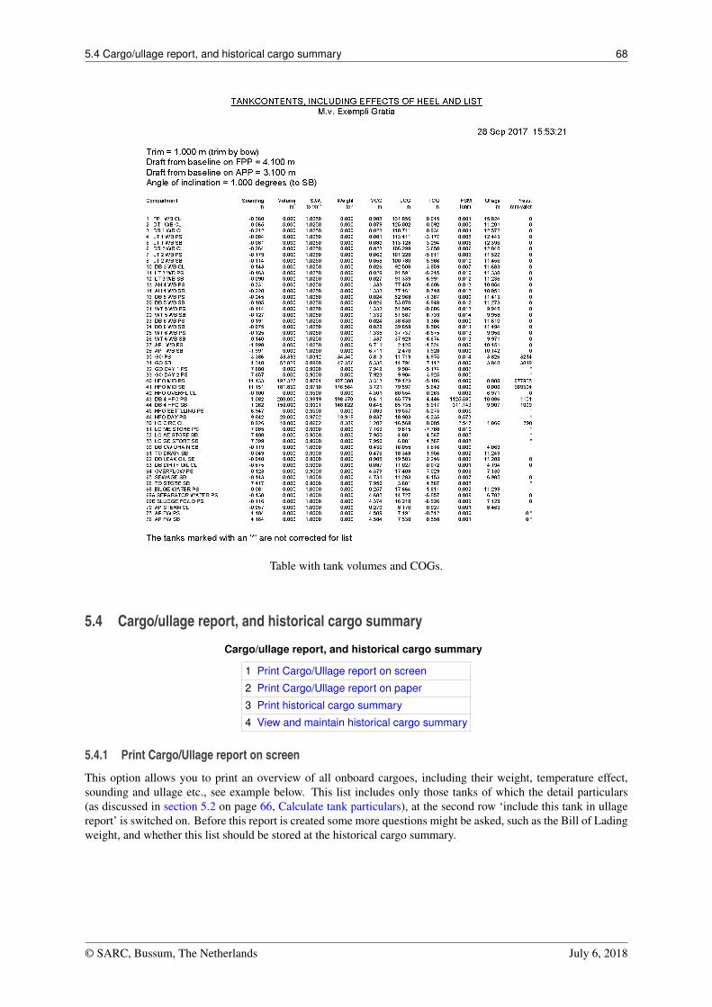
5.4 Cargo/ullage report, and historical cargo summary 68
Table with tank volumes and COGs.
5.4 Cargo/ullage report, and historical cargo summary
Cargo/ullage report, and historical cargo summary
1 Print Cargo/Ullage report on screen
2 Print Cargo/Ullage report on paper
3 Print historical cargo summary
4 View and maintain historical cargo summary
5.4.1 Print Cargo/Ullage report on screen
This option allows you to print an overview of all onboard cargoes, including their weight, temperature effect,sounding and ullage etc., see example below. This list includes only those tanks of which the detail particulars(as discussed in section 5.2 on page 66, Calculate tank particulars), at the second row ‘include this tank in ullagereport’ is switched on. Before this report is created some more questions might be asked, such as the Bill of Ladingweight, and whether this list should be stored at the historical cargo summary.
© SARC, Bussum, The Netherlands July 6, 2018
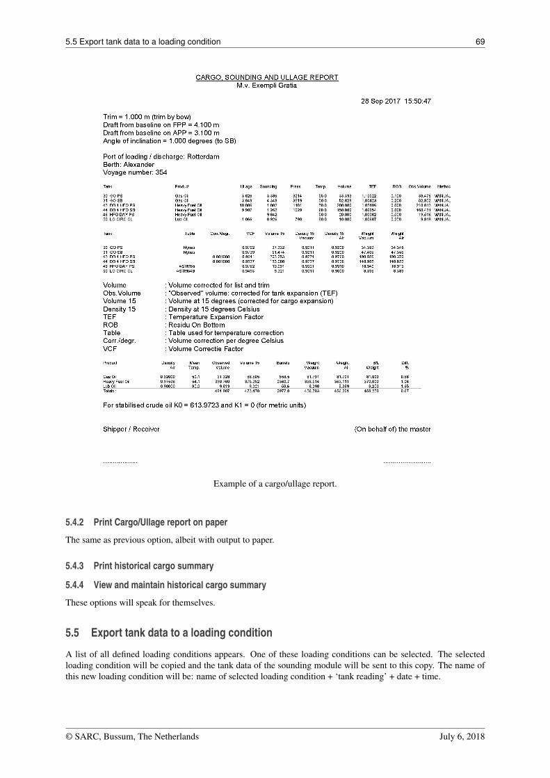
5.5 Export tank data to a loading condition 69
Example of a cargo/ullage report.
5.4.2 Print Cargo/Ullage report on paper
The same as previous option, albeit with output to paper.
5.4.3 Print historical cargo summary
5.4.4 View and maintain historical cargo summary
These options will speak for themselves.
5.5 Export tank data to a loading condition
A list of all defined loading conditions appears. One of these loading conditions can be selected. The selectedloading condition will be copied and the tank data of the sounding module will be sent to this copy. The name ofthis new loading condition will be: name of selected loading condition + ‘tank reading’ + date + time.
© SARC, Bussum, The Netherlands July 6, 2018
5.6 Import tank data from tank measurement systeem 70
5.6 Import tank data from tank measurement systeem
With this option the soundings or ullages of the tank measurement system can be read out and processed in the listof all tanks (section 5.2 on page 66, Calculate tank particulars).
5.7 Up-to-date overview of filling and flow rate per tank
This option opens a window in which the current filling and flow rates are displayed for each tank, as well as theremaining time until the desired filling percentage will be reached. These values are refreshed by default everyfive minutes, but that interval is adjustable. Obviously, this option can only work if there a connection with a tankmeasurement system is available.
© SARC, Bussum, The Netherlands July 6, 2018
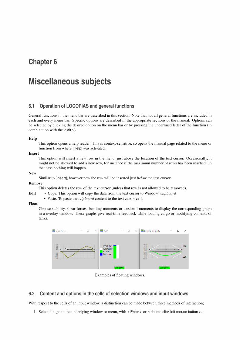
Chapter 6
Miscellaneous subjects
6.1 Operation of LOCOPIAS and general functions
General functions in the menu bar are described in this section. Note that not all general functions are included ineach and every menu bar. Specific options are described in the appropriate sections of the manual. Options canbe selected by clicking the desired option on the menu bar or by pressing the underlined letter of the function (incombination with the <Alt>).
HelpThis option opens a help reader. This is context-sensitive, so opens the manual page related to the menu orfunction from where [Help] was activated.
InsertThis option will insert a new row in the menu, just above the location of the text cursor. Occasionally, itmight not be allowed to add a new row, for instance if the maximum number of rows has been reached. Inthat case nothing will happen.
NewSimilar to [Insert], however now the row will be inserted just below the text cursor.
RemoveThis option deletes the row of the text cursor (unless that row is not allowed to be removed).
Edit • Copy. This option will copy the data from the text cursor to Window’ clipboard• Paste. To paste the clipboard content to the text cursor cell.
FloatChoose stability, shear forces, bending moments or torsional moments to display the corresponding graphin a overlay window. These graphs give real-time feedback while loading cargo or modifying contents oftanks.
Examples of floating windows.
6.2 Content and options in the cells of selection windows and input windows
With respect to the cells of an input window, a distinction can be made between three methods of interaction;
1. Select, i.e. go to the underlying window or menu, with <Enter> or <double click left mouse button>.
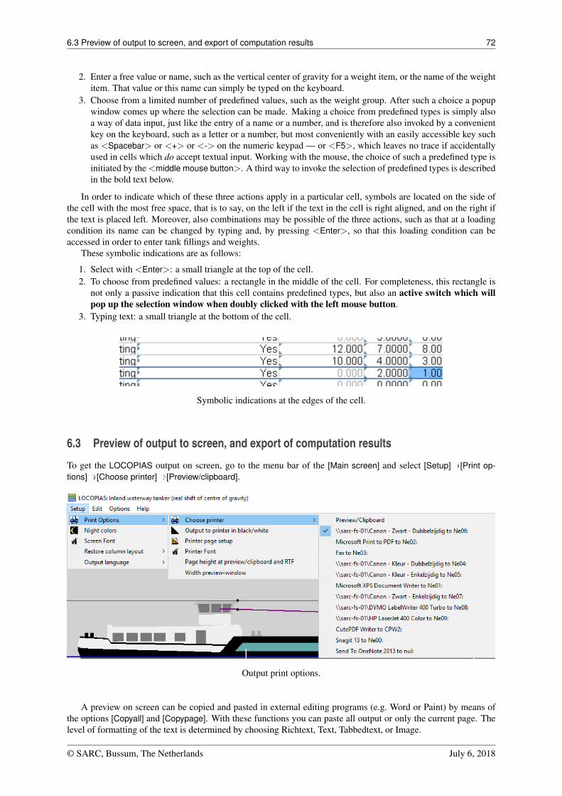
6.3 Preview of output to screen, and export of computation results 72
2. Enter a free value or name, such as the vertical center of gravity for a weight item, or the name of the weightitem. That value or this name can simply be typed on the keyboard.
3. Choose from a limited number of predefined values, such as the weight group. After such a choice a popupwindow comes up where the selection can be made. Making a choice from predefined types is simply alsoa way of data input, just like the entry of a name or a number, and is therefore also invoked by a convenientkey on the keyboard, such as a letter or a number, but most conveniently with an easily accessible key suchas <Spacebar> or <+> or <-> on the numeric keypad — or <F5>, which leaves no trace if accidentallyused in cells which do accept textual input. Working with the mouse, the choice of such a predefined type isinitiated by the <middle mouse button>. A third way to invoke the selection of predefined types is describedin the bold text below.
In order to indicate which of these three actions apply in a particular cell, symbols are located on the side ofthe cell with the most free space, that is to say, on the left if the text in the cell is right aligned, and on the right ifthe text is placed left. Moreover, also combinations may be possible of the three actions, such as that at a loadingcondition its name can be changed by typing and, by pressing <Enter>, so that this loading condition can beaccessed in order to enter tank fillings and weights.
These symbolic indications are as follows:
1. Select with <Enter>: a small triangle at the top of the cell.2. To choose from predefined values: a rectangle in the middle of the cell. For completeness, this rectangle is
not only a passive indication that this cell contains predefined types, but also an active switch which willpop up the selection window when doubly clicked with the left mouse button.
3. Typing text: a small triangle at the bottom of the cell.
Symbolic indications at the edges of the cell.
6.3 Preview of output to screen, and export of computation results
To get the LOCOPIAS output on screen, go to the menu bar of the [Main screen] and select [Setup]�[Print op-tions]�[Choose printer]�[Preview/clipboard].
Output print options.
A preview on screen can be copied and pasted in external editing programs (e.g. Word or Paint) by means ofthe options [Copyall] and [Copypage]. With these functions you can paste all output or only the current page. Thelevel of formatting of the text is determined by choosing Richtext, Text, Tabbedtext, or Image.
© SARC, Bussum, The Netherlands July 6, 2018
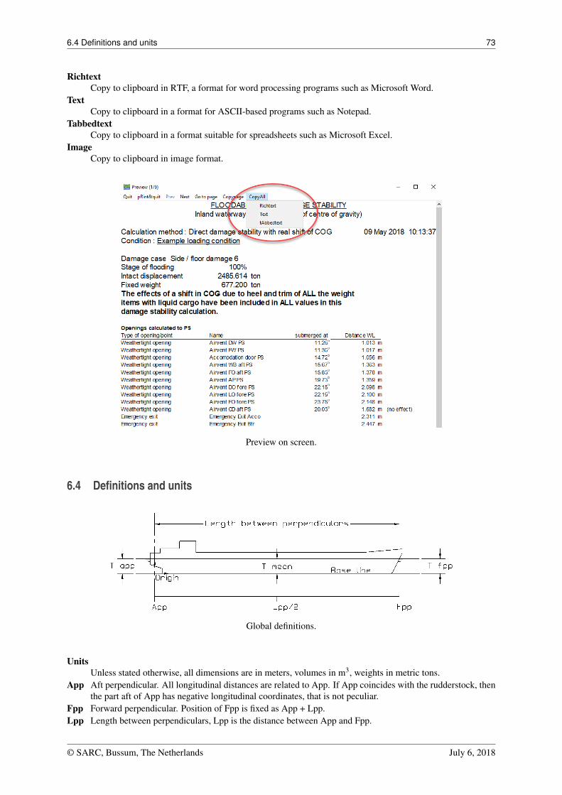
6.4 Definitions and units 73
RichtextCopy to clipboard in RTF, a format for word processing programs such as Microsoft Word.
TextCopy to clipboard in a format for ASCII-based programs such as Notepad.
TabbedtextCopy to clipboard in a format suitable for spreadsheets such as Microsoft Excel.
ImageCopy to clipboard in image format.
Preview on screen.
6.4 Definitions and units
Global definitions.
UnitsUnless stated otherwise, all dimensions are in meters, volumes in m3, weights in metric tons.
App Aft perpendicular. All longitudinal distances are related to App. If App coincides with the rudderstock, thenthe part aft of App has negative longitudinal coordinates, that is not peculiar.
Fpp Forward perpendicular. Position of Fpp is fixed as App + Lpp.Lpp Length between perpendiculars, Lpp is the distance between App and Fpp.
© SARC, Bussum, The Netherlands July 6, 2018
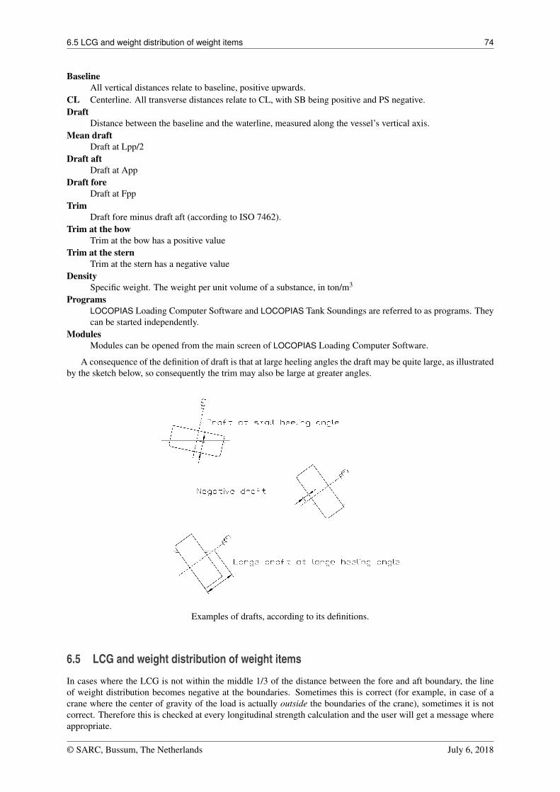
6.5 LCG and weight distribution of weight items 74
BaselineAll vertical distances relate to baseline, positive upwards.
CL Centerline. All transverse distances relate to CL, with SB being positive and PS negative.Draft
Distance between the baseline and the waterline, measured along the vessel’s vertical axis.Mean draft
Draft at Lpp/2Draft aft
Draft at AppDraft fore
Draft at FppTrim
Draft fore minus draft aft (according to ISO 7462).Trim at the bow
Trim at the bow has a positive valueTrim at the stern
Trim at the stern has a negative valueDensity
Specific weight. The weight per unit volume of a substance, in ton/m3
ProgramsLOCOPIAS Loading Computer Software and LOCOPIAS Tank Soundings are referred to as programs. Theycan be started independently.
ModulesModules can be opened from the main screen of LOCOPIAS Loading Computer Software.
A consequence of the definition of draft is that at large heeling angles the draft may be quite large, as illustratedby the sketch below, so consequently the trim may also be large at greater angles.
Examples of drafts, according to its definitions.
6.5 LCG and weight distribution of weight items
In cases where the LCG is not within the middle 1/3 of the distance between the fore and aft boundary, the lineof weight distribution becomes negative at the boundaries. Sometimes this is correct (for example, in case of acrane where the center of gravity of the load is actually outside the boundaries of the crane), sometimes it is notcorrect. Therefore this is checked at every longitudinal strength calculation and the user will get a message whereappropriate.
© SARC, Bussum, The Netherlands July 6, 2018
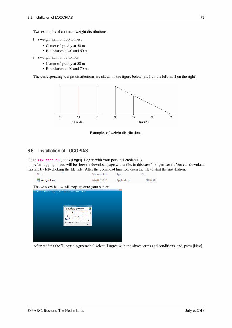
6.6 Installation of LOCOPIAS 75
Two examples of common weight distributions:
1. a weight item of 100 tonnes,
• Center of gravity at 50 m• Boundaries at 40 and 60 m.
2. a weight item of 75 tonnes,
• Center of gravity at 50 m• Boundaries at 40 and 70 m.
The corresponding weight distributions are shown in the figure below (nr. 1 on the left, nr. 2 on the right).
Examples of weight distributions.
6.6 Installation of LOCOPIAS
Go to www.sarc.nl , click [Login]. Log in with your personal credentials.After logging in you will be shown a download page with a file, in this case ’morgen1.exe’. You can download
this file by left-clicking the file title. After the download finished, open the file to start the installation.
The window below will pop-up onto your screen.
After reading the ’License Agreement’, select ’I agree with the above terms and conditions, and, press [Next].
© SARC, Bussum, The Netherlands July 6, 2018
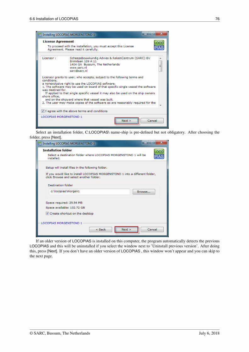
6.6 Installation of LOCOPIAS 76
Select an installation folder, C:LOCOPIAS\ name-ship is pre-defined but not obligatory. After choosing thefolder, press [Next].
If an older version of LOCOPIAS is installed on this computer, the program automatically detects the previousLOCOPIAS and this will be uninstalled if you select the window next to ’Uninstall previous version’. After doingthis, press [Next]. If you don’t have an older version of LOCOPIAS , this window won’t appear and you can skip tothe next page.
© SARC, Bussum, The Netherlands July 6, 2018
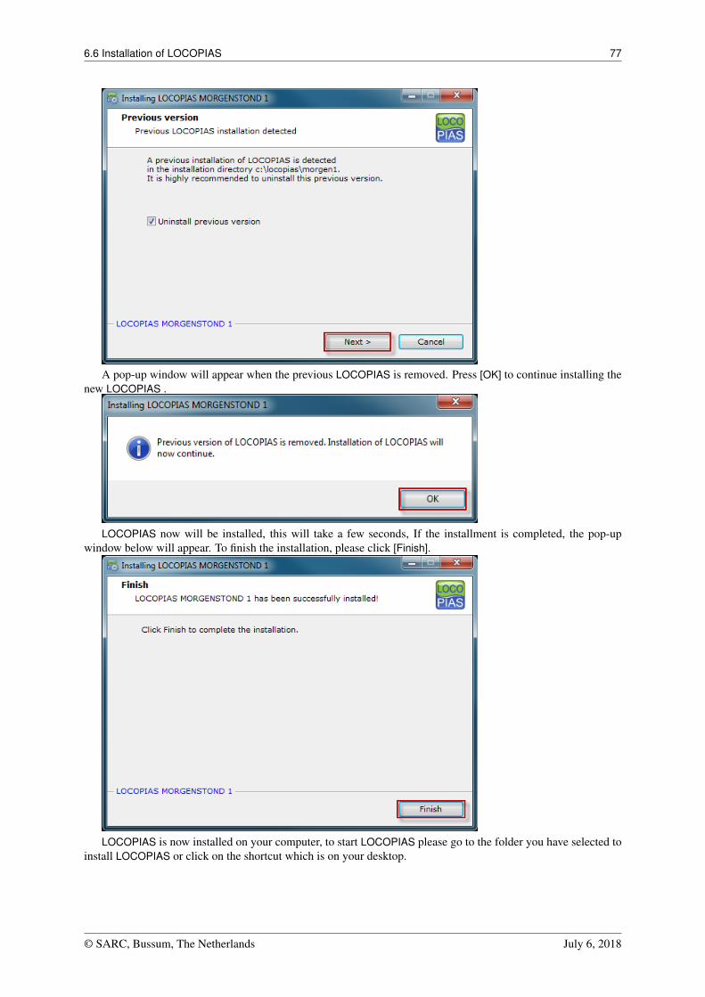
6.6 Installation of LOCOPIAS 77
A pop-up window will appear when the previous LOCOPIAS is removed. Press [OK] to continue installing thenew LOCOPIAS .
LOCOPIAS now will be installed, this will take a few seconds, If the installment is completed, the pop-upwindow below will appear. To finish the installation, please click [Finish].
LOCOPIAS is now installed on your computer, to start LOCOPIAS please go to the folder you have selected toinstall LOCOPIAS or click on the shortcut which is on your desktop.
© SARC, Bussum, The Netherlands July 6, 2018
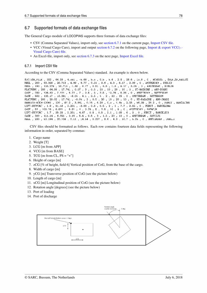
6.7 Supported formats of data exchange files 78
6.7 Supported formats of data exchange files
The General Cargo module of LOCOPIAS supports three formats of data exchange files:
• CSV (Comma Separated Values), import only, see section 6.7.1 on the current page, Import CSV file.• VCC (Visual Cargo Care), import and output section 6.7.2 on the following page, Import & export VCC(←↩
Visual Cargo Care) file.• An Excel-file, import only, see section 6.7.3 on the next page, Import Excel file.
6.7.1 Import CSV file
According to the CSV (Comma Separated Values) standard. An example is shown below.
SUCTION_PILE , 182 , 64.38 , 4.551 , -5.66 , 5.5 , 0.5 , 5.6 , 2.8 , 29.6 , 15.6 , 0 , HOUSTON , GULF_OF_MEXICO
REEL , 200 , 93.356 , 20.713 , 4.69 , 8.77 , 0.51 , 8.6 , 4.3 , 6.17 , 3.09 , 0 , AMSTERDAM , DUBLIN
REEL , 190 , 103.276 , 20.713 , 4.48 , 8.77 , 0.51 , 8.6 , 4.3 , 6.17 , 3.09 , 0 , AMSTERDAM , DUBLIN
PLATFORM , 200 , 64.88 , 17.741 , 0.07 , 3 , 0.5 , 20 , 10 , 20 , 10 , 0 , ST-NAZAIRE , ABU-DHABI
CASE , 230 , 106.43 , 7.121 , 5.72 , 7 , 0.5 , 5 , 2.5 , 10.76 , 5.38 , 0 , AMSTERDAM , ROTTERDAM
CASE , 500 , 108.17 , 18.291 , -6.04 , 4.1 , 0.5 , 4 , 2 , 30 , 15 , 0 , AMSTERDAM , ROTTERDAM
PLATFORM , 200 , 28.02 , 17.741 , -0.04 , 3 , 0.5 , 20 , 10 , 20 , 10 , 0 , ST-NAZAIRE , ABU-DHABI
DERRICK-BOOM-100MT , 100 , 67.2 , 3.941 , 0.78 , 4.28 , 0.5 , 4.45 , 2.23 , 56.39 , 28.2 , 0 , FENIT , BARCELONA
LIFT-SUPPORT , 1.9 , 91.46 , 2.201 , -3.88 , 0.8 , 0.5 , 2 , 1 , 7.7 , 3.85 , 0 , FENIT , BARCELONA
CASE , 52 , 106.16 , 6.621 , -5.81 , 4 , 0.75 , 5 , 2.5 , 10 , 5 , 0 , AMSTERDAM , KATWIJK
LIFT-SUPPORT , 1.7 , 35.25 , 2.201 , 4.67 , 0.8 , 0.5 , 2.1 , 1.05 , 6 , 3 , 0 , FENIT , BARCELONA
CASE , 300 , 111.14 , 6.321 , 0.15 , 5.4 , 0.5 , 3 , 1.5 , 20 , 10 , 0 , AMSTERDAM , KATWIJK
REEL , 230 , 50.194 , 20.706 , 0.11 , 14.54 , 0.307 , 8.6 , 4.3 , 10.7 , 5.35 , 0 , AMSTERDAM , DUBLIN
CSV files should be formatted as follows. Each row contains fourteen data fields representing the followinginformation in order, separated by commas:
1. Cargo name2. Weight [T]3. LCG [m from APP]4. VCG [m from BASE]5. TCG [m from CL, PS = “+”]6. Height of cargo [m]7. zCG [% of height, field 6] Vertical position of CoG, from the base of the cargo.8. Width of cargo [m]9. yCG [m] Transverse position of CoG (see the picture below)
10. Length of cargo [m]11. xCG [m] Longitudinal position of CoG (see the picture below)12. Rotation angle [degrees] (see the picture below)13. Port of loading14. Port of discharge
© SARC, Bussum, The Netherlands July 6, 2018
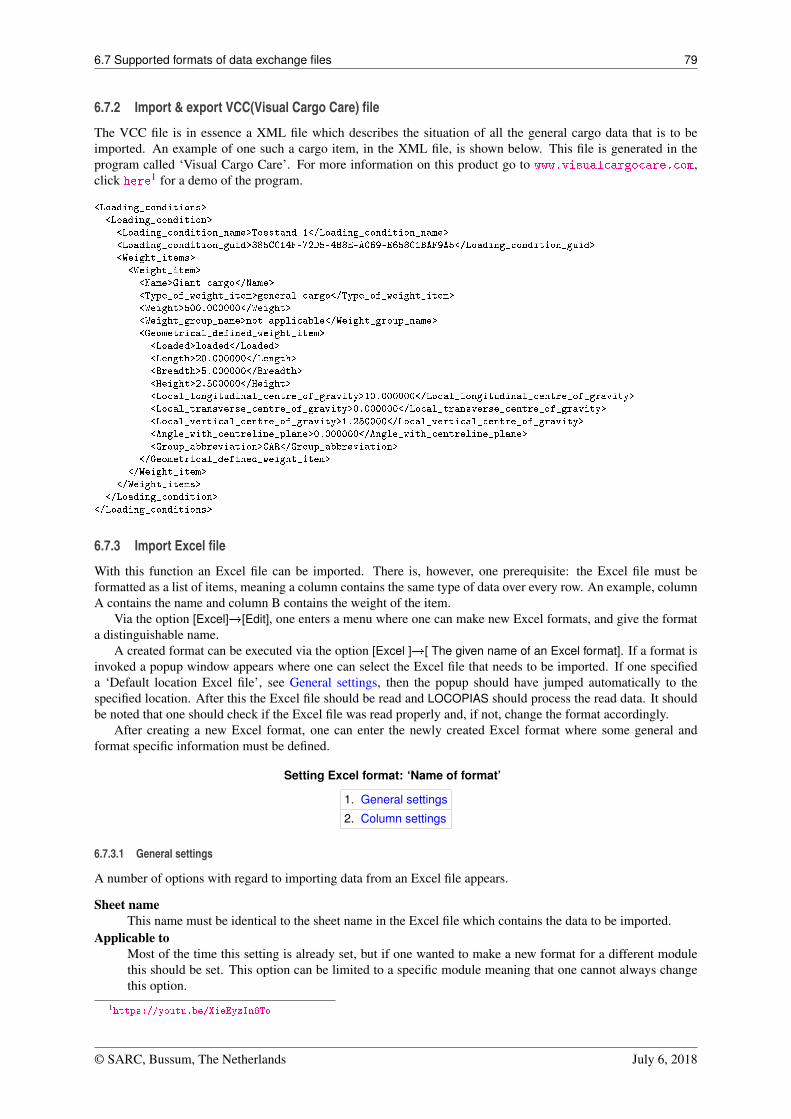
6.7 Supported formats of data exchange files 79
6.7.2 Import & export VCC(Visual Cargo Care) file
The VCC file is in essence a XML file which describes the situation of all the general cargo data that is to beimported. An example of one such a cargo item, in the XML file, is shown below. This file is generated in theprogram called ‘Visual Cargo Care’. For more information on this product go to www.visualcargocare.com,click here1 for a demo of the program.
<Loading_conditions>
<Loading_condition>
<Loading_condition_name>Toestand 1</Loading_condition_name>
<Loading_condition_guid>385CC14F-72D5-4B8E-A069-E658C1BAF9A5</Loading_condition_guid>
<Weight_items>
<Weight_item>
<Name>Giant cargo</Name>
<Type_of_weight_item>general cargo</Type_of_weight_item>
<Weight>500.000000</Weight>
<Weight_group_name>not applicable</Weight_group_name>
<Geometrical_defined_weight_item>
<Loaded>loaded</Loaded>
<Length>20.000000</Length>
<Breadth>5.000000</Breadth>
<Height>2.500000</Height>
<Local_longitudinal_centre_of_gravity>10.000000</Local_longitudinal_centre_of_gravity>
<Local_transverse_centre_of_gravity>0.000000</Local_transverse_centre_of_gravity>
<Local_vertical_centre_of_gravity>1.250000</Local_vertical_centre_of_gravity>
<Angle_with_centreline_plane>0.000000</Angle_with_centreline_plane>
<Group_abbreviation>CAR</Group_abbreviation>
</Geometrical_defined_weight_item>
</Weight_item>
</Weight_items>
</Loading_condition>
</Loading_conditions>
6.7.3 Import Excel file
With this function an Excel file can be imported. There is, however, one prerequisite: the Excel file must beformatted as a list of items, meaning a column contains the same type of data over every row. An example, columnA contains the name and column B contains the weight of the item.
Via the option [Excel]�[Edit], one enters a menu where one can make new Excel formats, and give the formata distinguishable name.
A created format can be executed via the option [Excel ]�[ The given name of an Excel format]. If a format isinvoked a popup window appears where one can select the Excel file that needs to be imported. If one specifieda ‘Default location Excel file’, see General settings, then the popup should have jumped automatically to thespecified location. After this the Excel file should be read and LOCOPIAS should process the read data. It shouldbe noted that one should check if the Excel file was read properly and, if not, change the format accordingly.
After creating a new Excel format, one can enter the newly created Excel format where some general andformat specific information must be defined.
Setting Excel format: ‘Name of format’
1. General settings
2. Column settings
6.7.3.1 General settings
A number of options with regard to importing data from an Excel file appears.
Sheet nameThis name must be identical to the sheet name in the Excel file which contains the data to be imported.
Applicable toMost of the time this setting is already set, but if one wanted to make a new format for a different modulethis should be set. This option can be limited to a specific module meaning that one cannot always changethis option.
1https://youtu.be/XieEyzIn6To
© SARC, Bussum, The Netherlands July 6, 2018
6.7 Supported formats of data exchange files 80
Start reading on rowIf this is zero, than the Excel sheet will be read from row 1. If this is set to anything other than zero, it willstart reading the Excel sheet from the specified row.
Start minimizedThat Excel should be started minimized opposed to maximized.
Save after readingIf the Excel file should be saved after reading.
Quit after readingIf after reading the Excel file, the Excel program should be closed.
Default location Excel fileHere one can specify a location which would contain most of the time the to be imported Excel file.
Note
De opties ‘Beginnen met geminimaliseerd’, ‘Opslaan na uitlezen’ en ‘Afsluiten na het uitlezen’ zullen geeneffect hebben als Excel niet door LOCOPIAS werd ingeroepen.
6.7.3.2 Column settings
Here one must specify which column in the specified Excel sheet contains which type of data.
ColumnThis name should be identical as in the Excel sheet.
Typ columnThis identifies the kind of data this specified column contains, as defined in General settings.
© SARC, Bussum, The Netherlands July 6, 2018
Chapter 7
Formalities
LOCOPIAS has no protection against copying. Therefore, for any given vessel, LOCOPIAS may be distributed atthe discretion of the owner, for example for office use or training. Although flexible, use of LOCOPIAS is notwithout restrictions, see section 7.2 on this page, License conditions. LOCOPIAS is produced by:
SARC BVBrinklaan 109 A111404 GA BussumThe NetherlandsTel. +31 85 04 09 040Web www.sarc.nl
Email [email protected]
7.1 Downloads
New and updated versions of LOCOPIAS are distributed on a USB-stick or via the download section1 of theSARC website www.sarc.nl. Access to LOCOPIAS installation files is granted after entering the username andmatching password. Again, distribution of username and password is at the discretion of the owner.
7.2 License conditions
Licensor:Scheepsbouwkundig Advies & RekenCentrum (SARC) BVBrinklaan 109 A 111404 GA Bussum, The NetherlandsWeb www.sarc.nl , Email [email protected]
Licensor grants to user who accepts, subject to the following terms and conditions, a nonexclusive right to usethe LOCOPIAS software:
1. The software may be used on board of that specific single vessel the software was destined for. If applied tothat single specific vessel it may also be used at the ship owner’s shore office, and at the shipyard where thatvessel was built.
2. For archival and security purposes the software may be copied in its entirety or partly, but only for use bythe user.
3. User shall not modify, adjust, translate, counterfeit, decompile, demount, disassemble the software or makeworks that are based on it.
4. The software has been designed to be used on a regular Personal Computer driven by the operating systemMicrosoft Windows, the versions Vista, 7, 8 or 10.
5. Licensor is the owner of the software and documentation, and also owns its copyright. Only the license ispurchased by the user.
1https://cloud.sarc.nl/
7.3 Certificates 82
6. Subject to an attributable failing or a wonderful act, the user cannot hold SARC liable for any damageresulting from, or related to, the use of or not being able to use the software, and indemnifies the licensoragainst all claims of third parties due to such damage.
7. The liability of SARC for damages suffered by the customer, being the result of an attributable failing orwonderful act, is limited to the purchase price of the software license.
8. The restriction from the previous article does not apply in case of foul play or serious misconduct, in whichcase the liability is limited to C100,000.
9. To licensors best knowledge the software is correct. Licensor does not warrant the correctness of the softwareor any part of it however.
10. Updates of the software, if applicable, will in general only contain enhancements and extended functionality.However, licensor does not guarantee that functions of less importance will always remain to exist. Addi-tionally, licensor does not guarantee that updates will always lead to exactly the same calculation results asthe original software (for example, in an update a more exact calculation procedure might be applied).
11. Even if the software is initially approved by a regulatory body or a classification society, licensor does notguarantee that this approval will remain valid eternally, or that this approval is also applicable to updates ofthe software.
12. User is obliged to ensure that the terms and conditions of this agreement are also valid for subsequent owners.13. This agreement shall be governed by, and interpreted in accordance with, the laws of the Netherlands. Dis-
putes will be subjected to the judgment of a Dutch court.
Last modification date of these license conditions: October 16, 2015
7.3 Certificates
LOCOPIAS is accepted by all major classification societies and complies with Cat. B and C of ISO standard16155. (Shipboard Loading Instruments). Just below, some of the type approval certificates of PIAS and LOC←↩OPIAS of some major bodies have been included. Other societies may not issue type approval certificates at all,or SARC has not requested for such certificates. In that case classification societies have approval procedures foreach ship-specific LOCOPIAS version. Note that no LOCOPIAS version has ever been denied approval by any ofthe classification societies SARC has come across, regardless whether or not that class had issued type approvalcertificates for LOCOPIAS or PIAS.
So, each ship-specific LOCOPIAS version requires in general an individual appraisal by a classification societyor authority. The availability of a type approval certificate can assist in that procedure, but is not always required.And if a ship-specific certificate has been issued, the type approval certificate — and its expiry date — is notrelevant anymore. After all, if updates of LOCOPIAS would be installed they would require a renewed ship-specificappraisal, but existing LOCOPIAS’s are continuously covered by their ship-specific certificate.
© SARC, Bussum, The Netherlands July 6, 2018
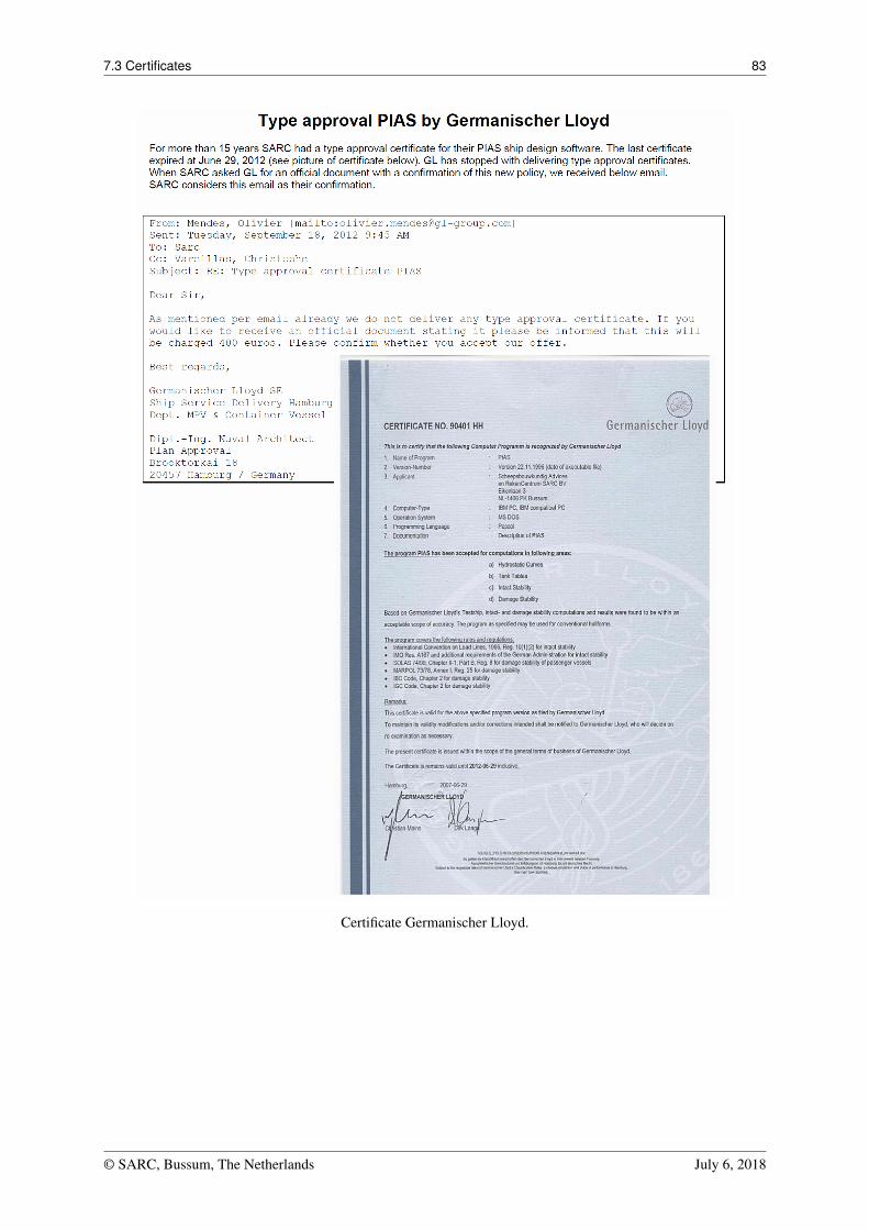
7.3 Certificates 83
Certificate Germanischer Lloyd.
© SARC, Bussum, The Netherlands July 6, 2018
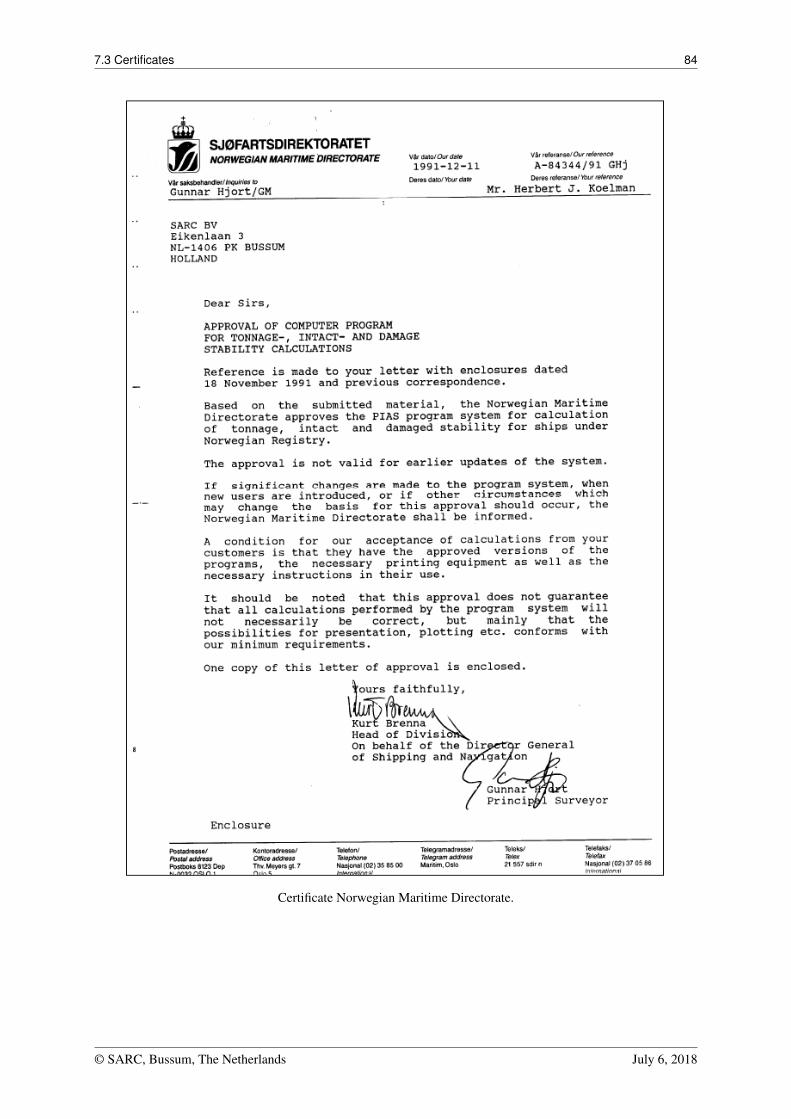
7.3 Certificates 84
Certificate Norwegian Maritime Directorate.
© SARC, Bussum, The Netherlands July 6, 2018
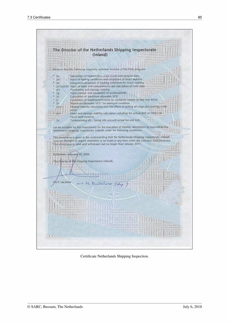
7.3 Certificates 85
Certificate Netherlands Shipping Inspection.
© SARC, Bussum, The Netherlands July 6, 2018
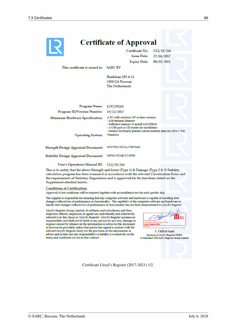
7.3 Certificates 86
Certificate Lloyd’s Register (2017-2021) 1/2.
© SARC, Bussum, The Netherlands July 6, 2018
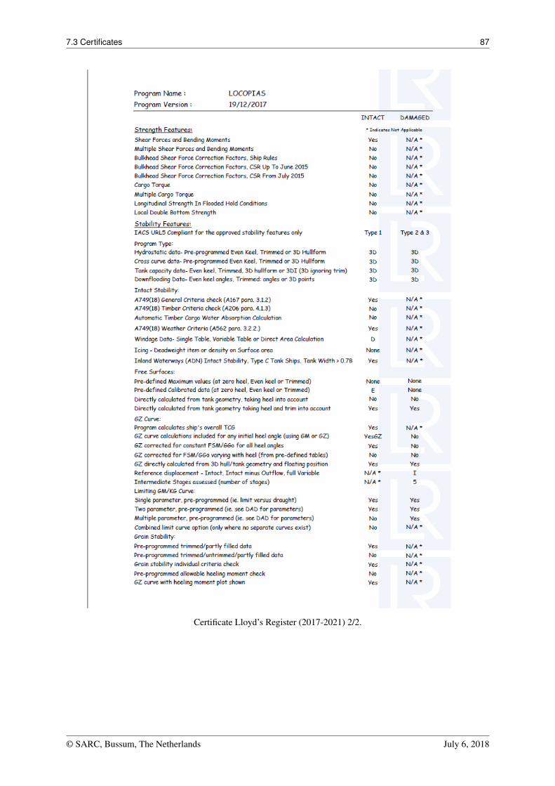
7.3 Certificates 87
Certificate Lloyd’s Register (2017-2021) 2/2.
© SARC, Bussum, The Netherlands July 6, 2018
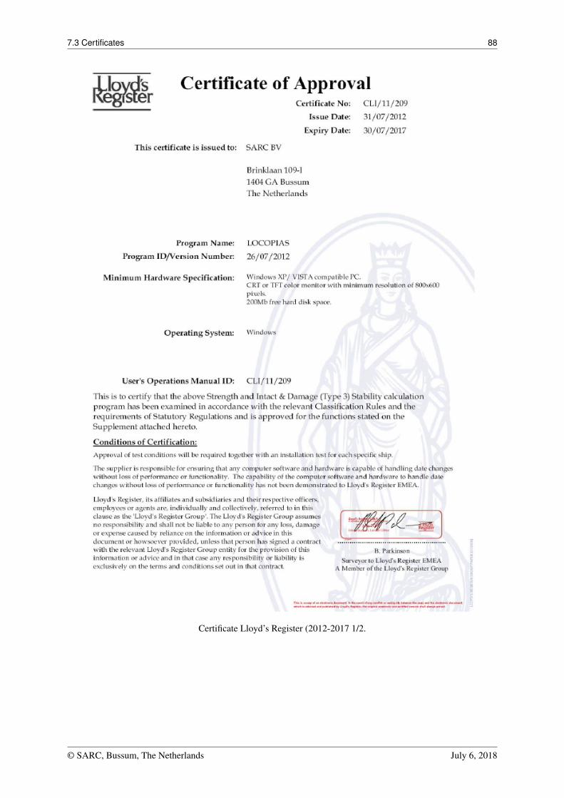
7.3 Certificates 88
Certificate Lloyd’s Register (2012-2017 1/2.
© SARC, Bussum, The Netherlands July 6, 2018
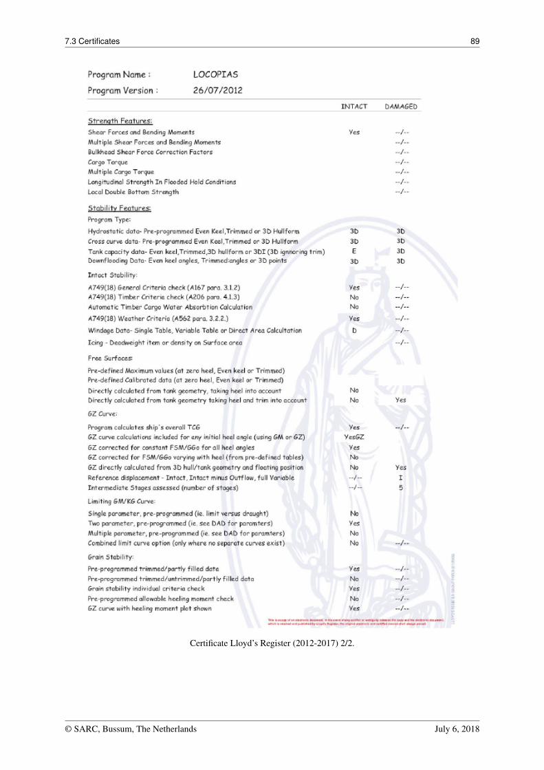
7.3 Certificates 89
Certificate Lloyd’s Register (2012-2017) 2/2.
© SARC, Bussum, The Netherlands July 6, 2018
Index
64-bits Windows, 3
Actual shift of liquid, 55ASTM tables, 67
Ballast advice, 64Ballast loading advice, 64BAPLIE, 26Boundaries of a weight item, 55
Certificates of approval, 82Clipboard, export LOCOPIAS results to, 72Container loading module, 25Crane, loading by, 46CSV file format, 78
Damage cases, 57Damage stability, 56Damaged compartments, 57Dangerous goods, 30Database of standard weight items, 53Definitions and units, 73Determination of the weight of loaded or discharged
cargo, 59Download LOCOPIAS, 81Draft survey, 59Draft, definition of, 74Dutch Shipping Inspection certificate, 82
Excel, import from, 79
FAQ, 3Final drafts (for cargo weight determination), 60Floating windows, 71Free Surface Moment, 55Frequently Asked Questions, 3
General approach, 6General cargo module, 42Germanischer Lloyd type approval certificate, 82Grain bulkheads and grain holds, 53
Heavy rolling, 63Hydrocarbons, 67
IMDG, 30IMO SLF 39/3/3, 62Insert new row, 71Installation of LOCOPIAS, 75ISO standard 16155, 2
License conditions, 81
Line of sight, 9List of weight items, 52Lloyds Register type approval certificate, 82Loading condition check, 9Loading condition comprehensive output (Class Re-
port), 10Loading condition output, 10Loading condition test conditions, 10Loadingcondition import/export, 7Loss of stability (danger in seaway), 63
Mac (Apple), 3Main screen 2D\3D view, 11main window, 4main window layout, 4modules available, 3Monitoring, 12
night colors, 5Norwegian Maritime Directorate certificate, 82
Observed drafts (for cargo weight determination), 60Optimization of ballast quantity, 64
Preview of output to screen, 72
Quartering and following seas, 62
Residue On Bottom, 67Rich Text Format, 73ROB (Residue On Bottom), 67RoRo cargo loading tool, 20RTF, 73
Safe Working Load (SWL) of crane, 49settings, 9Ship-specific data, 1SLF 39/3/3, 62Sort weight items, 52Sounding and ullage report, 68Standard weight items, 53Surfriding and broaching, 62SW water, 9
TEF (Temperature Expansion Factor), 67Temperature Expansion Factor, 67Terms of use, 81Test conditions, 1Trim at larger heel, 74Type approval certificates, 82
Ullage report, 68
INDEX 91
VCC file format, 79Visual Cargo Care, 79
Weight group, assigning weight items to a, 55Weight groups, 6
© SARC, Bussum, The Netherlands July 6, 2018