Embed Size (px)
Citation preview
APPROVED FOR PUBLIC RELEASE – DISTRIBUTION IS UNLIMITED
NASA TECHNICAL
STANDARD
NASA-STD-5006A
National Aeronautics and Space Administration
Approved: 2015-07-31
Superseding NASA-STD-5006
Washington, DC 20546-0001
GENERAL WELDING REQUIREMENTS FOR
AEROSPACE MATERIALS
MEASUREMENT SYSTEM IDENTIFICATION:
METRIC/INCH-POUND
NASA-STD-5006A
APPROVED FOR PUBLIC RELEASE – DISTRIBUTION IS UNLIMITED
2 of 33
DOCUMENT HISTORY LOG
Status Document
Revision
Approval Date Description
Baseline 1999-02-17 Baseline Release
Revision A 2015-07-31 General Revision
NASA-STD-5006A
APPROVED FOR PUBLIC RELEASE – DISTRIBUTION IS UNLIMITED
3 of 33
FOREWORD
This Standard is published by the National Aeronautics and Space Administration (NASA) to
provide uniform engineering and technical requirements for processes, procedures, practices, and
methods that have been endorsed as standard for NASA programs and projects, including
requirements for selection, application, and design criteria of an item.
This Standard is approved for use by NASA Headquarters and all NASA Centers, including
Component Facilities and Technical and Service Support Centers.
This Standard establishes general directions and describes the type of information that NASA
expects for welded structures. This Standard does not provide the detailed process and quality
assurance requirements for weldments on flight hardware. Instead, it is intended as a higher
level document which states minimum requirements for welded hardware.
“Requests for information, corrections, or additions to this Standard should be submitted via
“Feedback” at http://standards.nasa.gov.”
Original Signed By: 2015-07-31
Ralph R. Roe, Jr. Approval Date
NASA Chief Engineer
NASA-STD-5006A
APPROVED FOR PUBLIC RELEASE – DISTRIBUTION IS UNLIMITED
4 of 33
SECTION
TABLE OF CONTENTS
PAGE
DOCUMENT HISTORY LOG ........................................................................................... 2
FOREWORD ....................................................................................................................... 3
TABLE OF CONTENTS ..................................................................................................... 4
LIST OF APPENDICES ...................................................................................................... 5
LIST OF FIGURES ............................................................................................................. 5
1. SCOPE ................................................................................................................ 6
1.1 Purpose ................................................................................................................. 6
1.2 Applicability .......................................................................................................... 6
1.3 Tailoring ............................................................................................................... 6
2. APPLICABLE DOCUMENTS ......................................................................... 7
2.1 General ................................................................................................................. 7
2.2 Government Documents....................................................................................... 7
2.3 Non-Government Documents .............................................................................. 7
2.4 Order of Precedence ............................................................................................. 7
3. ACRONYMS AND DEFINITIONS ................................................................. 8
3.1 Acronyms and Abbreviations ............................................................................... 8
3.2 Definitions ............................................................................................................ 8
4. REQUIREMENTS ............................................................................................. 12
4.1 Specification of this Standard on Contracts ......................................................... 12
4.2 Joint Classes ......................................................................................................... 12
4.3 Equipment ............................................................................................................ 13
4.4 Materials ............................................................................................................... 14
4.5 Weld Procedure and Performance Qualification.................................................. 16
4.6 Pre-Weld Operations ............................................................................................ 18
4.7 Production Welding ............................................................................................. 19
4.8 Post-Weld Operations .......................................................................................... 21
4.9 Weld Joint Strength Requirements....................................................................... 25
4.10 Weldment Quality Requirements ......................................................................... 26
4.11 Repair Welding .................................................................................................... 26
4.12 Quality Assurance ................................................................................................ 27

NASA-STD-5006A
APPROVED FOR PUBLIC RELEASE – DISTRIBUTION IS UNLIMITED
5 of 33
SECTION
TABLE OF CONTENTS (Continued)
PAGE
APPENDICES
A Guidance ....................................................................................................... 30
A.1 Purpose ......................................................................................................... 36 30
A.2 Reference Documents ................................................................................... 30
A.2.1 Government Documents ............................................................................... 30
A.2.2 Non-Government Documents ....................................................................... 32
FIGURE
LIST OF FIGURES
PAGE
1 Welding Procedure Specification Example ................................................. 17
2 Welding Techniques ..................................................................................... 20
3 Mismatch and Peaking ................................................................................ 22
4 Fillet Welds ................................................................................................. 24
5 Minimum Inspection Requirements ............................................................ 29
NASA-STD-5006A
APPROVED FOR PUBLIC RELEASE – DISTRIBUTION IS UNLIMITED
6 of 33
GENERAL WELDING REQUIREMENTS FOR
AEROSPACE MATERIALS
1. SCOPE
1.1 Purpose
The purpose of this Standard, as defined in NASA Procedural Requirement (NPR) 7120.10,
Technical Standards for NASA Programs and Projects, is to establish the processing and quality
assurance requirements for manual, automatic, machine, and semiautomatic welding for
spaceflight applications and special test equipment used for testing flight hardware with the
exception of ground-based pressure systems, which are subjected to NASA-STD-8719.17,
NASA Requirements for Ground-Based Pressure Vessels and Pressurized Systems (PVS).
1.2 Applicability
This Standard is applicable to all welding processes used for joining metallic materials. This
includes, but is not limited to arc welding (AW), solid state welding (SSW), resistance welding
(RW), and high energy density welding (HEDW). This Standard covers all metallic materials
used in the manufacture of hardware for spaceflight applications and special test equipment used
for testing flight within NASA.
This Standard is approved for use by NASA Headquarters and NASA Centers, including
Component Facilities and Technical and Service Support Centers, and may be cited in contract,
program, and other Agency documents as a technical requirement. This Standard may also apply to
the Jet Propulsion Laboratory or to other contractors, grant recipients, or parties to agreements only
to the extent specified or referenced in their contracts, grants, or agreements.
Requirements are numbered and indicated by the word “shall.” Explanatory or guidance text is
indicated in italics beginning in section 4.
1.3 Tailoring
Tailoring of this Standard for application to a specific program or project shall be formally
documented as part of program or project requirements and approved by the responsible
Technical Authority in accordance with NPR 7120.5, NASA Space Flight Program and Project
Management Requirements. The requirements in this document may be tailored by submitting a
detailed weld process specification or stating applicable industry standards that meet the intent of
this Standard.
NASA-STD-5006A
APPROVED FOR PUBLIC RELEASE – DISTRIBUTION IS UNLIMITED
7 of 33
2. APPLICABLE DOCUMENTS
2.1 General
The documents listed in this section contain provisions that constitute requirements of this Standard
as cited in the text.
2.1.1 The latest issuances of cited documents shall apply unless specific versions are designated.
2.1.2 Non-use of specific versions as designated shall be approved by the responsible Technical
Authority.
The applicable documents are accessible at https://standards.nasa.gov or may be obtained
directly from the Standards Developing Organizations or other document distributors.
2.2 Government Documents
NASA
NPR 1441.1 NASA Records Management Program Requirements
NPR 7120.5
NASA Space Flight Program Management Requirements
NPR 7120.10 Technical Standards for NASA Programs and Projects
2.3 Non-Government Documents
Aerospace Industries Association (AIA)/National Aerospace Standard (NAS)
AIA/NAS 410
NAS Certification and Qualification of Nondestructive Test
Personnel
American Welding Society (AWS)
AWS QC1 Standard for AWS Certification of Welding Inspectors
2.4 Order of Precedence
2.4.1 This Standard establishes requirements for all welding processes used for joining
spaceflight metallic materials but does not supersede nor waive established Agency requirements
found in other documentation.
NASA-STD-5006A
APPROVED FOR PUBLIC RELEASE – DISTRIBUTION IS UNLIMITED
8 of 33
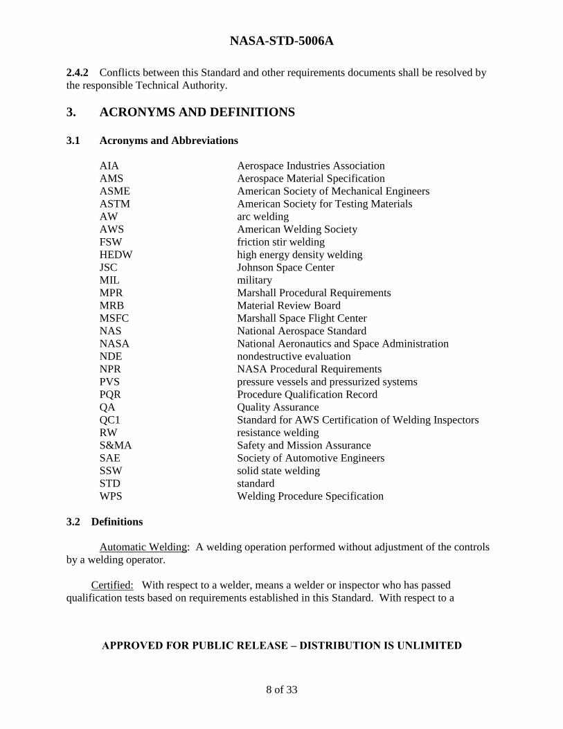
2.4.2 Conflicts between this Standard and other requirements documents shall be resolved by
the responsible Technical Authority.
3. ACRONYMS AND DEFINITIONS
3.1 Acronyms and Abbreviations
AIA Aerospace Industries Association
AMS Aerospace Material Specification
ASME American Society of Mechanical Engineers
ASTM American Society for Testing Materials
AW arc welding
AWS American Welding Society
FSW friction stir welding
HEDW high energy density welding
JSC Johnson Space Center
MIL military
MPR Marshall Procedural Requirements
MRB Material Review Board
MSFC Marshall Space Flight Center
NAS National Aerospace Standard
NASA National Aeronautics and Space Administration
NDE nondestructive evaluation
NPR NASA Procedural Requirements
PVS pressure vessels and pressurized systems
PQR Procedure Qualification Record
QA Quality Assurance
QC1 Standard for AWS Certification of Welding Inspectors
RW resistance welding
S&MA Safety and Mission Assurance
SAE Society of Automotive Engineers
SSW solid state welding
STD standard
WPS Welding Procedure Specification
3.2 Definitions
Automatic Welding: A welding operation performed without adjustment of the controls
by a welding operator.
Certified: With respect to a welder, means a welder or inspector who has passed
qualification tests based on requirements established in this Standard. With respect to a
NASA-STD-5006A
APPROVED FOR PUBLIC RELEASE – DISTRIBUTION IS UNLIMITED
9 of 33
procedure or process specification, a term describing a weld procedure or process that has passed
qualification tests based on requirements established in this Standard.
Concave Root Surface: A weld root with penetration not extending beyond the thickness
of the parent metal. Note: Periodically referred to as “suckback.”
Conventional Friction Stir Welding (FSW): FSW in which the load is reacted by an
anvil.
Critical Flaw Size: The analytically determined flaw size that produces a critical stress
intensity factor of concern for a specified number of life cycles which will likely produce a
catastrophic mission failure.
Defect: A discontinuity or discontinuities that by nature, or accumulated effect, render
a part or product unable to meet minimum standards or specifications; designates rejectability.
Dross: A mass of solid impurities floating on a molten metal or dispersed in the metal.
Essential Variables: Weld process parameters that influence directly the weld process
and resulting weld properties in such a manner that changes to them require requalification of the
weld procedure. Note: Examples are heat input, travel speed, torch setup, and pin tool
configuration.
Fail Safe: A condition in which, after failure of a single individual structural member,
the remaining structure can withstand the redistributed loads with an ultimate factor of safety
of 1.0 on limit load. Note: The failure is contained or constrained so that the failed part does
not affect other flight elements or personnel.
Heat-Affected Zone: The portion of the base metal whose microstructure or
mechanical properties have been altered by the heat of welding, brazing, soldering, or thermal
cutting.
Heat Input: Quantity of energy introduced per unit length of weld from a traveling heat
source, expressed in joules per millimeter or joules per inch. Note: Computed as the ratio of the
total input power of the heat source in watts to the travel velocity in millimeters per
second or inches per minute.
Heat Sensitive Alloys: Alloys that require mechanical working, precipitation
strengthening, or other metallurgical mechanisms to regain their rated strength due to exposure to
the heat input from the welding process.
Improper Fusion: A condition when the weld metal that replaces base metal is
insufficient.
NASA-STD-5006A
APPROVED FOR PUBLIC RELEASE – DISTRIBUTION IS UNLIMITED
10 of 33
Incomplete Fusion: A weld discontinuity in which fusion did not occur between weld
metal and parent material or adjoining weld beads.
Incomplete Joint Penetration: The condition of a weld failing to extend through the full
thickness of the joint.
In-Process Correction: Action taken by a welder to complete a process before submittal
to inspection.
Lack of Fill: A weld face surface not extending to the surface of the parent metal.
Machine Welding: Welding with equipment that performs the welding operation under
the constant observation and control of a welding operator.
Manual Welding: A welding operation performed and controlled completely by hand.
Material Review Board (MRB): A cross-functional group that reviews production or
purchased items on hold because of nonconformance or usability concerns. The MRB is to
determine the disposition, which may include rework, scrap, or return to the vendor.
Material Thickness: The minimum material thickness of a joint member per drawing
tolerance. Note: The thinner of the joint members with different thicknesses is designated “t.”
Mismatch: The linear misalignment of components resulting from improper fit-up or
distortion during welding. Note: Mismatch is calculated as the difference in the alignment of
specified features (usually either center lines or surfaces) of the two parts having been welded
and should not be confused with the difference in center lines as a result of welding two different
thickness components.
Nonstructural Weld: A non-load-bearing weld.
Peaking: The angular distortion of the components resulting from welding. Note:
Peaking is calculated as the angle resulting from the intersection of tangents taken from the
surface of the two components being welded.
Procedure Qualification Record (PQR): A document providing the actual welding
variables used to produce an acceptable test weld and the results of tests conducted on the weld
for the purpose of demonstrating process and procedural capability and repeatability. Note:
Demonstration of capability qualifies the welding procedure.
Qualified Inspector: A certified individual with the responsibility and ability to judge the
quality of the welded specimens in relation to some form of written specification.
NASA-STD-5006A
APPROVED FOR PUBLIC RELEASE – DISTRIBUTION IS UNLIMITED
11 of 33
Repair: A procedure that makes a nonconforming item acceptable for use. Note: The
purpose of the repair is to reduce the effect of the nonconformance. Repair is distinguished from
rework in that the characteristics after repair still do not completely conform to the applicable
drawings, specifications, or contract requirements. Nonstandard repair procedures are
authorized by MRB action for use on a one-time basis only. All repairs require MRB approval
before implementation.
Rework: A procedure applied to a nonconforming item that completely eliminates the
nonconformance and results in a characteristic that conforms completely to the drawings,
specifications, or contract requirements. Note: Not all rework activities require MRB approval
before implementation.
Semiautomatic Welding: Welding with equipment that controls only the filler metal
feed. Note: The weld progression is manually controlled.
Special Test Equipment: Any non-flight, non-GSE, or non-facility structure, hardware,
piping systems, pressure vessels, or equipment intended to be used for testing or simulation, or
associated with the manufacturing, process development, and preparation of Marshall Space
Flight Center (MSFC) facilities for testing or simulation. Note: Designs include, but are not
limited to, test stands, test beds, load reaction and application structures, load line components,
hot fire testing of engines and engine components, fluid flow and pressure tests, high pressure
and/or cryogenic storage and/or run systems, solid propellant tests, flight hardware mockups
and simulators, hardware support stands and dollies, personnel access stands, lifting and
handling hardware, and tooling used to facilitate the fabrication and/or assembly of flight/non-
flight hardware, such as master drill templates or alignment/clamping fixtures used during
machining and welding processes.
Undercut: A groove melted into the base metal adjacent to the weld toe or weld root and
left unfilled by weld metal.
Welding Procedure Specification (WPS): A document providing in detail the required
variables for a specific application to ensure repeatability by properly trained welders and
welding operators.
Welding Process Specification: A document that prescribes, in a complete, precise,
verifiable manner, the requirements, design, behavior, or characteristics of a system or system
component.
Weld Zone: The weld metal fusion zone plus the heat-affected zone.
NASA-STD-5006A
APPROVED FOR PUBLIC RELEASE – DISTRIBUTION IS UNLIMITED
12 of 33
4. REQUIREMENTS
4.1 Specification of this Standard on Contracts
When this Standard is specified on contract documents, a detailed weld process specification, as
defined in NPR 7120.10, which meets the intent of this Standard shall be submitted. Industry,
government, and company specifications can be used for welding flight hardware if they contain
the information required by this Standard. The contractor has the responsibility to submit the
detailed weld process specification.
4.2 Joint Classes
Welding performed using this Standard shall be classified in accordance with the service of the
joints as follows in the next sections.
4.2.1 Class A
Critical applications. Welds where a single failure would cause loss of system, loss of major
components, loss of control, and loss of crew.
4.2.1.1 Class A welds shall require visual, dimensional, surface, and volumetric inspections,
and additional inspection when required by engineering drawing.
Note: Based on consequences of failure, all fracture-critical welds are, by definition, Class A
joint. If the quality of the Class A joint cannot be verified as required by this Standard, e.g.,
inaccessible volume or root surfaces, then alternative rationale for acceptance is to be presented
to the responsible NASA Fracture Control Board for approval as required by NASA-STD 5019,
Fracture Control Requirements for Spaceflight Hardware.
4.2.2 Class B
Semicritical applications. Welds where a failure would reduce overall efficiency of the system,
preclude the intended function or use of the equipment, but loss of the system or endangering
personnel would not be experienced.
4.2.2.1 Class B welds shall require visual, dimensional, and surface inspections, and
additional inspection when required by engineering drawing.
4.2.2.2 Class B welds shall be subjected to volumetric inspection if required by engineering
design and specified by drawing or special instruction.
4.2.2.3 Weld requiring fail-safe capability shall be classified as a Class B joint.
4.2.3 Class C

NASA-STD-5006A
APPROVED FOR PUBLIC RELEASE – DISTRIBUTION IS UNLIMITED
13 of 33
Noncritical applications. Welds where a failure would not affect the efficiency of the system or
endanger personnel.
4.2.3.1 Class C welds shall require visual and dimensional inspections, and, additional
inspection when required by engineering drawing.
4.2.3.2 Class C joints shall require weld integrity verification based on function of the joint
(e.g., seal welds require leak testing commensurate with the leak rate requirement).
4.3 Equipment
4.3.1 Welding Equipment
a. Automatic, semiautomatic, manual, and machine welding shall be accomplished using
equipment containing calibrated dials, meters, or recorders that quantitatively indicate process
parameters.
b. All joining equipment (including manual) shall be capable of producing joints that meet the
requirements specified herein.
4.3.1.1 Acceptance Testing
a. New, repaired, relocated, or modified welding machines and equipment for automatic and
machine welding shall be acceptance-tested prior to processing of flight hardware.
b. Machines and equipment shall meet the requirements of the applicable purchase
specification, design specification, or modification order.
c. Power supplies and supporting components (electrical or mechanical or both) shall be
capable of operating reliably within the range of parameters and duty cycle to be used for joining
production parts.
4.3.1.2 Calibration
a. Measuring instruments, meters, gages, or direct reading electrical control circuits to
be used for automatic, semiautomatic, and machine joining operations shall be initially calibrated
and periodically recalibrated to maintain adequate performance.
b. Maintenance performed on measuring instruments, meters, gages, or direct reading
electrical control circuits to be used for automatic, semiautomatic, and machine performance
joining operations shall require recalibration to maintain adequate performance.
c. Measuring instruments, meters, gages, or direct reading electrical control circuits to
be used for automatic, semiautomatic, and machine joining operations shall be initially calibrated
NASA-STD-5006A
APPROVED FOR PUBLIC RELEASE – DISTRIBUTION IS UNLIMITED
14 of 33
and periodically recalibrated to maintain adequate performance or when any maintenance is
performed that may have changed calibration.
4.3.1.3 Maintenance and Records
a. Welding machines shall be provided with adequate periodic maintenance service so
that acceptable welds can be produced using qualified welding procedure specifications.
b. A current record of each maintenance repair or functional check shall be maintained
for each welding machine.
4.3.2 Tooling and Fixtures
a. Tooling and fixtures used in the joining operation shall be constructed of
nonmagnetic materials that do not affect the welding arc or beam, or that are not detrimental to
the weld quality.
b. Tooling and fixtures shall not be a source of contamination of the joint.
c. Magnetic materials, when used, shall be degaussed prior to welding.
d. Degaussing, when necessary, shall be controlled by the WPS for the successful
completion of the weld.
e. Tooling and fixtures required to ensure compliance with dimensional requirements of
section 4.8.3 shall be identified on the WPS.
4.4 Materials
4.4.1 Base Metals
a. Unless otherwise specified or approved by the procuring agency, base metal alloy
shall conform to applicable government and/or industry specifications for each alloy group.
b. The base metal, material condition, and appropriate specification shall be recorded in
the WPS.
c. Weld start and runoff tabs, when used, shall be of the same alloy as the material being
joined and be welded with the same filler metal specified on the drawing or WPS. Backing
material may be used when verified by procedure qualification.
NASA-STD-5006A
APPROVED FOR PUBLIC RELEASE – DISTRIBUTION IS UNLIMITED
15 of 33
4.4.2 Filler Metals
a. Unless otherwise specified or approved by the procuring agency, fillermetal alloy
shall conform to applicable government and/or industry specifications for each alloy group.
b. Specifications used to procure filler metals shall include provisions to mitigate the
possibility of two different filler wires being errantly mixed together on a single spool or in a
filler rod container.
c. Weld filler metals and the appropriate specifications shall be recorded in the WPS.
4.4.3 Shielding Gas
a. Welding-grade gases conforming to the applicable industry or military specifications
shall be used for gas shielding.
b. The shield gas type, specification, and flow rate shall be recorded in the WPS.
4.4.4 Tungsten Electrodes
a. Tungsten electrodes shall conform to the applicable industry or military
specifications.
b. The electrode diameter, electrode tip shape, alloy composition, and specification shall
be recorded as a part of the WPS.
4.4.5 Friction Stir Welding Pin Tools
4.4.5.1 Pin and shoulder service life shall be demonstrated to meet the intended use.
4.4.5.2 Pins and shoulders shall be limited to the demonstrated life.
4.4.5.3 Pin tool design, materials, and service life shall be recorded in the WPS.
a. Pins and shoulders that have reached the specified service life shall be marked and
removed from service to preclude an accidental future use in the FSW production process.
b. If used for more than one weld joint, pins and shoulders shall be cleaned and
inspected before reuse on production hardware.
NASA-STD-5006A
APPROVED FOR PUBLIC RELEASE – DISTRIBUTION IS UNLIMITED
16 of 33
4.5 Weld Procedure and Performance Qualification
4.5.1 Welder Performance Qualification
a. Operators of automatic, semiautomatic, machine, or manual welding equipment shall be
certified for the applicable process.
b. Suppliers shall define the weld certification process in their detailed weld process
specification.
4.5.2 Welding Procedure Specification
a. Prior to first production of parts, or when changes are made to essential variables of
the WPS, qualification joints shall be made to establish a satisfactory WPS for each different
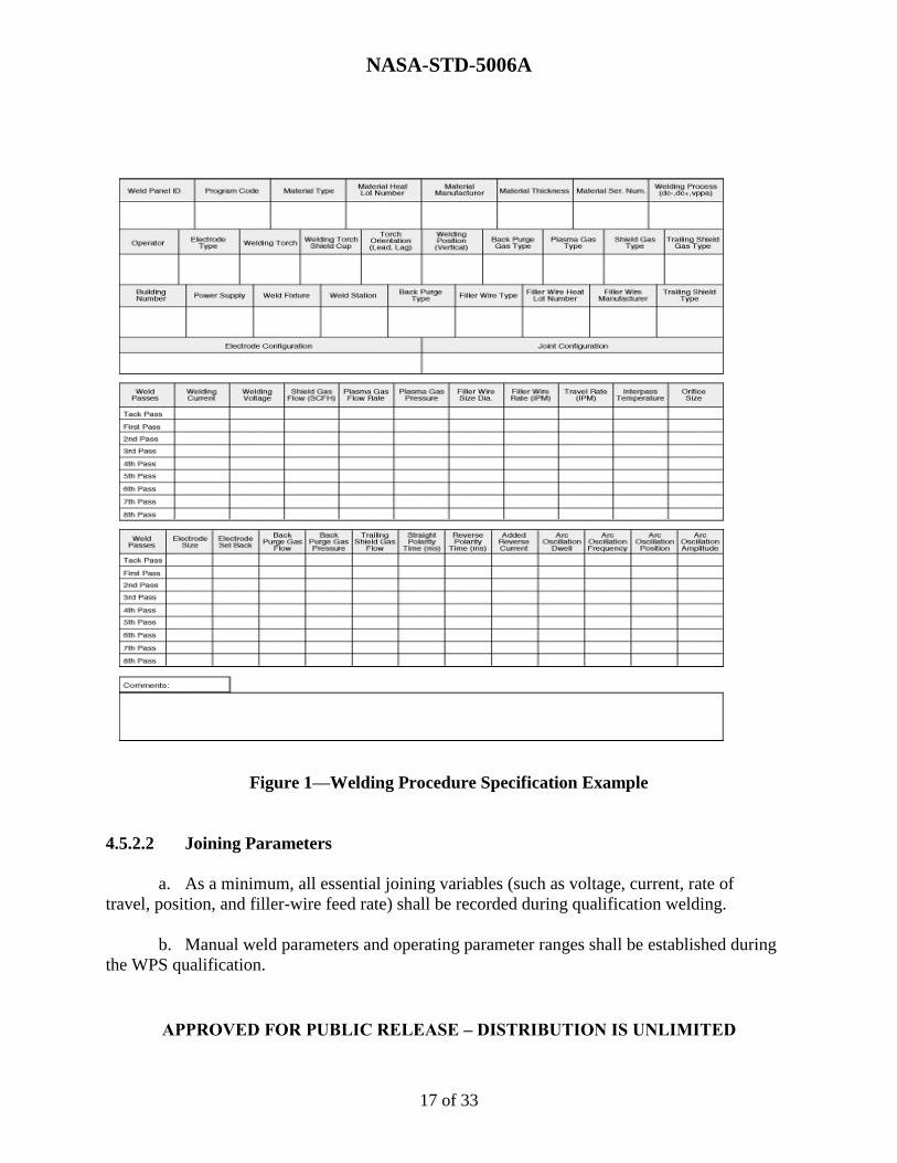
configuration of A, B, and C classes of welds. Figure 1, Welding Procedure Specification
Example, contains an example of a WPS (for reference only).
b. Variables considered essential shall be so identified in the WPS.
4.5.2.1 Classes A and B Joints
a. Classes A and B joints shall be qualified with joints that simulate the production
part with respect to section thickness, alloy, heat-treat condition, joint preparation, pre-weld
cleaning, fit-up, position, and post-weld operations.
b. The joints shall be processed in either the actual production fixture or in a test
fixture simulating the production fixture using the production welding equipment.
c. Base metal for qualification joining tests shall be identified by lot or heat number,
type, and condition and maintain identification through all evaluation processes.
d. The qualification weld shall be subjected to metallurgical evaluation and the same
post-weld inspections and processes as the production parts, including reinforcement removal,
mechanical deformation, stress relief, and thermal treatments associated with artificial aging or
any operation affecting mechanical properties.
NASA-STD-5006A
APPROVED FOR PUBLIC RELEASE – DISTRIBUTION IS UNLIMITED
17 of 33
Figure 1—Welding Procedure Specification Example
4.5.2.2 Joining Parameters
a. As a minimum, all essential joining variables (such as voltage, current, rate of
travel, position, and filler-wire feed rate) shall be recorded during qualification welding.
b. Manual weld parameters and operating parameter ranges shall be established during
the WPS qualification.
NASA-STD-5006A
APPROVED FOR PUBLIC RELEASE – DISTRIBUTION IS UNLIMITED
18 of 33
c. The WPS shall document all pre-welding operations, setup conditions, welding
equipment, and any pertinent information about the welding system used which affects the
joining operation.
4.5.2.3 Parameter Tolerances
a. For automatic, semiautomatic, and machine joining, parameter tolerances may be
used and shall be listed in the qualified WPS.
b. Test samples representing the minimum and maximum heat input shall be processed
to verify acceptable welds and the results documented in the PQR.
4.5.3 Welding Procedure Specification Qualification
All test and inspection results used to verify the weld integrity shall be recorded on the PQR.
4.5.4 Records
4.5.4.1 Records of test specimens that meet the acceptance requirements of this process
specification shall be signed and dated by a Quality Assurance (QA) representative as an
accurate record of the welding and testing of the procedure test weldment.
4.5.4.2 The WPS and PQR shall be prepared and retained as long-term temporary records in
accordance with NPR 1441.1, NASA Records Retention Schedules, with the current WPS being
maintained at the welding station.
4.5.4.3 All WPSs and PQRs shall be maintained and made available for review by the
responsible NASA Engineering Authority before production of hardware covered under this
Standard.
4.6 Pre-Weld Operations
4.6.1 Joint Design
Acceptable joint designs are butt, lap, corner, tee, and edge. All joints shall be documented on
a WPS, design drawing, or other suitable document.
4.6.2 Pre-Weld Cleaning
a. Pre-weld cleaning of filler materials and surfaces to be welded in order to remove
contaminants that are detrimental to weld quality shall be accomplished in an environment that
will not degrade the quality of the weld.
b. Cleanliness shall be maintained during welding.
NASA-STD-5006A
APPROVED FOR PUBLIC RELEASE – DISTRIBUTION IS UNLIMITED
19 of 33
c. Pre-weld and interpass cleaning requirements shall be included in the WPS.
4.7 Production Welding
4.7.1 Equipment Operational Check
a. A welding equipment operational readiness check shall be made immediately prior to a
production weld to verify the equipment is operating properly.
b. The equipment operational readiness check criteria shall be provided to the procuring
agency.
4.7.2 Temperature Control
a. Pre-heat, interpass, and post-heat temperatures shall be controlled so as not to degrade
the properties of the material being welded.
b. The parameters of pre-heat, interpass, and post-heat temperatures shall be recorded in
an applicable WPS.
4.7.3 Tack Welding
a. Tack welding is allowable and shall either be removed or become a part of the
finished weld (i.e., tack welds are to be completely consumed by the final weldment).
b. Tack welds that become part of the finished weld shall be performed by certified
welders in accordance with certified procedures meeting the requirements of this Standard.
c. After the weldment is completed, the tack areas shall be evaluated to the requirements
of the finished weld.
d. Tack welding requirements shall be included in the WPS.
4.7.4 Welding Techniques
4.7.4.1 Classes A and B Joints
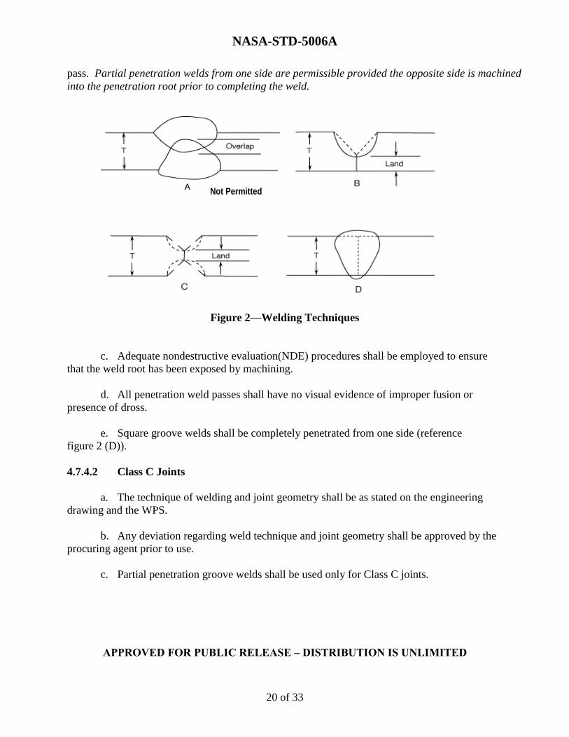
a. The technique of welding the initial passes from both sides where the weld roots
overlap beneath the exposed surfaces (reference figure 2 (A), Welding Techniques) shall be
permitted only if the root of the first pass is removed to sound metal prior to placement of the
first weld pass from the second side.
b. Joints which have prepared grooves from one or both sides (reference figure 2 (B) and (C))
and/or multi-pass welds shall have a weld land that is completely penetrated on the initial
NASA-STD-5006A
APPROVED FOR PUBLIC RELEASE – DISTRIBUTION IS UNLIMITED
20 of 33
pass. Partial penetration welds from one side are permissible provided the opposite side is machined
into the penetration root prior to completing the weld.
Figure 2—Welding Techniques
c. Adequate nondestructive evaluation(NDE) procedures shall be employed to ensure
that the weld root has been exposed by machining.
d. All penetration weld passes shall have no visual evidence of improper fusion or
presence of dross.
e. Square groove welds shall be completely penetrated from one side (reference
figure 2 (D)).
4.7.4.2 Class C Joints
a. The technique of welding and joint geometry shall be as stated on the engineering
drawing and the WPS.
b. Any deviation regarding weld technique and joint geometry shall be approved by the
procuring agent prior to use.
c. Partial penetration groove welds shall be used only for Class C joints.
Not Permitted

NASA-STD-5006A
APPROVED FOR PUBLIC RELEASE – DISTRIBUTION IS UNLIMITED
21 of 33
4.7.5 Welding Procedure
Production welding shall be accomplished according to a qualified WPS. A specific WPS for
each weld is required for production welding Classes A, B, and C.
4.7.6 Procedure Departure
a. Departure from the qualified WPS during production welding shall require
withholding the part for MRB disposition.
b. The cause for departure shall be determined.
c. Corrective action shall be taken prior to further production welding.
4.8 Post-Weld Operations
4.8.1 Inspection
Each completed weldment, including the base metal, shall be inspected to ensure compliance
with the requirements of sections 4.8.2, 4.8.3, and 4.10, and as dictated by the class of weld for a
minimum of 12.5 mm (0.5 in) on either side of the weld interface.
4.8.2 General Visual/Surface Requirements
a. Weld deposits, buildup, and root reinforcement shall comply with the criteria outlined
in the accompanying detailed weld process specification that is submitted in support of this
Standard.
b. The edge of the weld deposit shall blend into the base metal without unfused overlaps
or undercut.
c. Weld face and root sides shall be free of surface cracks, crater cracks, and other
defects open to the surface.
d. Weld deposits shall be free of open voids or unfused overlapping folds or other lack
of fusion.
e. Undercutting, concavity, lack of fill, or root concavity shall be unacceptable in any
weld where it occurs as a sharp notch or where the depth reduces the material thickness below
the minimum thickness specified on the applicable drawing.
NASA-STD-5006A
APPROVED FOR PUBLIC RELEASE – DISTRIBUTION IS UNLIMITED
22 of 33
4.8.3 Dimensional Requirements
4.8.3.1 Mismatch
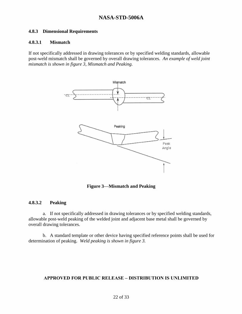
If not specifically addressed in drawing tolerances or by specified welding standards, allowable
post-weld mismatch shall be governed by overall drawing tolerances. An example of weld joint
mismatch is shown in figure 3, Mismatch and Peaking.
Figure 3—Mismatch and Peaking
4.8.3.2 Peaking
a. If not specifically addressed in drawing tolerances or by specified welding standards,
allowable post-weld peaking of the welded joint and adjacent base metal shall be governed by
overall drawing tolerances.
b. A standard template or other device having specified reference points shall be used for
determination of peaking. Weld peaking is shown in figure 3.
NASA-STD-5006A
APPROVED FOR PUBLIC RELEASE – DISTRIBUTION IS UNLIMITED
23 of 33
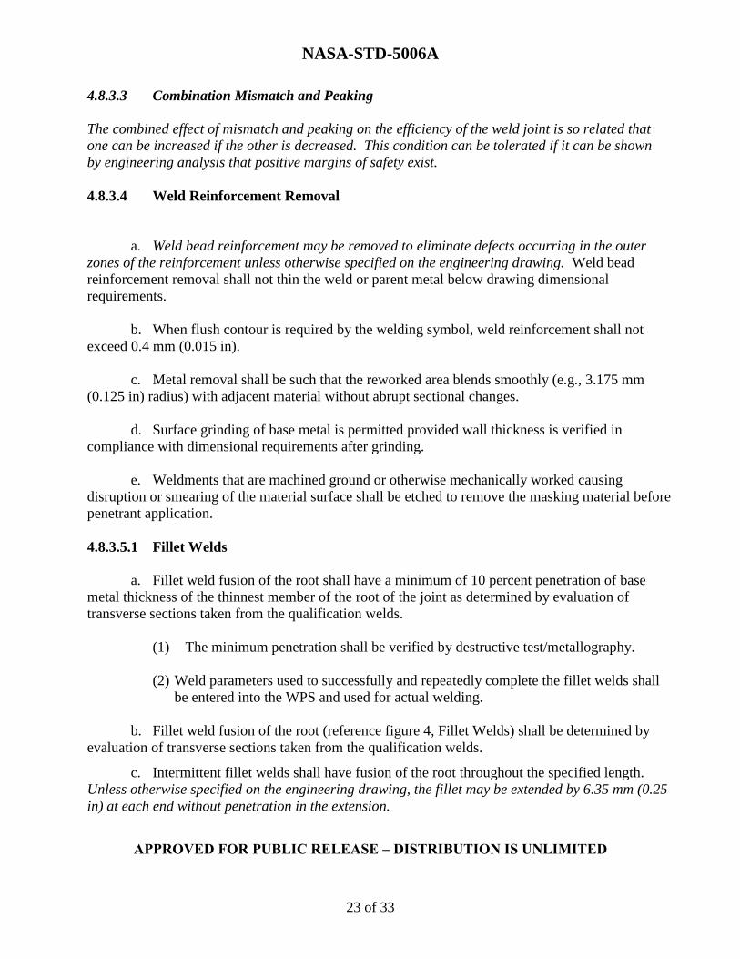
4.8.3.3 Combination Mismatch and Peaking
The combined effect of mismatch and peaking on the efficiency of the weld joint is so related that
one can be increased if the other is decreased. This condition can be tolerated if it can be shown
by engineering analysis that positive margins of safety exist.
4.8.3.4 Weld Reinforcement Removal
a. Weld bead reinforcement may be removed to eliminate defects occurring in the outer
zones of the reinforcement unless otherwise specified on the engineering drawing. Weld bead
reinforcement removal shall not thin the weld or parent metal below drawing dimensional
requirements.
b. When flush contour is required by the welding symbol, weld reinforcement shall not
exceed 0.4 mm (0.015 in).
c. Metal removal shall be such that the reworked area blends smoothly (e.g., 3.175 mm
(0.125 in) radius) with adjacent material without abrupt sectional changes.
d. Surface grinding of base metal is permitted provided wall thickness is verified in
compliance with dimensional requirements after grinding.
e. Weldments that are machined ground or otherwise mechanically worked causing
disruption or smearing of the material surface shall be etched to remove the masking material before
penetrant application.
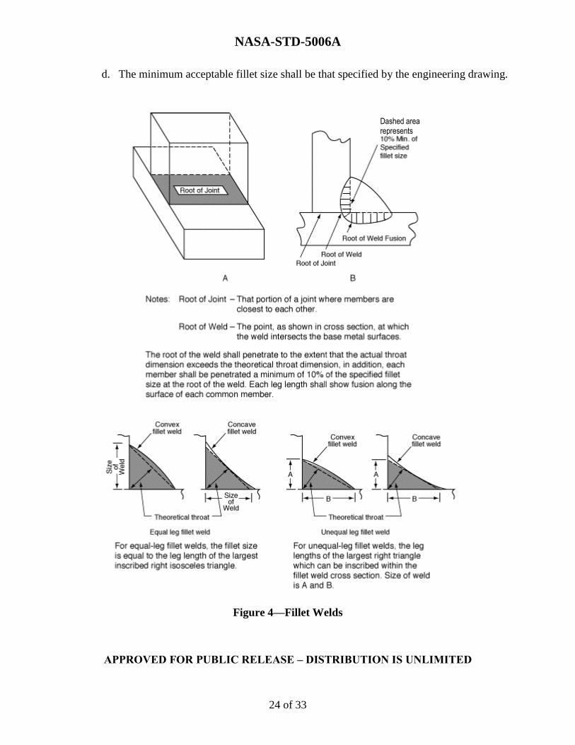
4.8.3.5.1 Fillet Welds
a. Fillet weld fusion of the root shall have a minimum of 10 percent penetration of base
metal thickness of the thinnest member of the root of the joint as determined by evaluation of
transverse sections taken from the qualification welds.
(1) The minimum penetration shall be verified by destructive test/metallography.
(2) Weld parameters used to successfully and repeatedly complete the fillet welds shall
be entered into the WPS and used for actual welding.
b. Fillet weld fusion of the root (reference figure 4, Fillet Welds) shall be determined by
evaluation of transverse sections taken from the qualification welds.
c. Intermittent fillet welds shall have fusion of the root throughout the specified length.
Unless otherwise specified on the engineering drawing, the fillet may be extended by 6.35 mm (0.25
in) at each end without penetration in the extension.
NASA-STD-5006A
APPROVED FOR PUBLIC RELEASE – DISTRIBUTION IS UNLIMITED
24 of 33
d. The minimum acceptable fillet size shall be that specified by the engineering drawing.
Figure 4—Fillet Welds
Dashed area represents
NASA-STD-5006A
APPROVED FOR PUBLIC RELEASE – DISTRIBUTION IS UNLIMITED
25 of 33
e. Unless otherwise specified on the engineering drawing, the maximum acceptable fillet
size shall be the size specified plus 50 percent or 4.8 mm (0.188 in), whichever is less, as permitted
in section 4.11.
f. The minimum acceptable actual throat shall equal or exceed the theoretical throat
(reference figure 4).
4.8.4 Weldment Straightening
a. Welds and adjacent base metal which have been deformed by the welding operation
may be straightened. Prior to implementation, however, verification by NDE, destructive
testing, and metallurgical evaluation that the process used for straightening does not degrade the
weld or surrounding material below the specified design requirements shall be performed.
b. Following weldment straightening, the weld and adjacent base metal shall be
inspected in accordance with section 4.8.1.
c. Weldments in which defects caused by weldment straightening are revealed shall not
be acceptable.
4.8.5 Post-Weld Heat Treat Requirements
a. Weldments that are subject to heat treatment operations shall be subsequently
inspected to the surface quality requirements of the engineering drawing.
b. Any required post-weld heat treatment processing shall be specified in the WPS.
4.9 Weld Joint Strength Requirements
4.9.1 Butt Joints
a. If not otherwise specified in the design requirements, weld strength shall meet or
exceed that of the parent material.
b. Qualified WPSs shall be established to demonstrate the weld meets the strength
required by design.
4.9.2 Fillet Welds
a. Unless otherwise directed by the procuring agency, fillet weld shear strength shall
meet or exceed 60 percent of the minimum ultimate tensile requirements of the weld.
NASA-STD-5006A
APPROVED FOR PUBLIC RELEASE – DISTRIBUTION IS UNLIMITED
26 of 33
b. For fillet weld joints involving materials of different thicknesses having different
ultimate tensile strength values, the minimum requirement for the shear joint shall be 60 percent
of the lower of the minimum ultimate tensile requirements.
4.10 Weldment Quality Requirements
a. Weldment quality requirements shall be established to ensure the weld meets design
requirements for strength and integrity.
b. The compliance of the weld with quality requirements shall be verified by mechanical
testing.
4.11 Repair Welding
4.11.1 Allowable Repair Welding
a. Additional welding operations shall be permitted to correct any unacceptable
condition established per section 4.10, provided the repair welding parameters and procedures
are specified in a qualified repair WPS, and the repair is contained within the original weld zone.
b. Complete records of the repair welding operation, including identification of the
repaired weldment, type of defect, and location of the repair weld, shall be retained in permanent
records. Examples of typical weld defects requiring repair are listed below.
(1) Undercut.
(2) Lack of fill.
(3) Concave root surface.
(4) Incomplete joint penetration.
(5) Crack and crack-like defects.
(6) Oxides and porosity.
(7) Lack of fusion.
4.11.1.1 No more than two weld repair attempts shall be made without approval of the MRB.
4.11.2 Repair Welding Requiring Disposition
At a minimum, the following conditions require MRB disposition by the procuring agency:
a. When more than two weld repair attempts have been performed at any one
location.
b. When the incorrect filler metal has been used.
NASA-STD-5006A
APPROVED FOR PUBLIC RELEASE – DISTRIBUTION IS UNLIMITED
27 of 33
c. When a weldment has been post-weld heat treated to increase its strength and
cannot be returned to the original drawing requirements with additional heat treatments
following reweld.
d. When finish machining has been completed prior to rewelding.
e. When the repair extends outside the original weld zone.
f. All FSW repairs.
g. All friction plug repairs.
4.11.3 Repair Welding Reinspection
Reinspection of all repair weld areas shall be performed using the same methods/requirements as
the original weld.
4.12 Quality Assurance
a. The supplier is responsible for the performance of all inspection requirements as
specified herein. Except as otherwise specified, the supplier shall use inspection facilities and
services approved by the procuring agency shall be used by the supplier.
b. Inspection and test records shall be kept complete and, upon request, made available
to the procuring agency or its designated representative. The procuring agency or its designated
representative reserves the right to perform any or all of the inspections set forth in the
specification to ensure that the end item conforms to the prescribed requirements.
c. NDE procedures to be employed in inspection for weldment internal and surface
quality requirements shall be qualified/validated as being capable of detecting the weldment
quality criteria prescribed prior to inspection of the first production weld.
d. The documented proof of capability shall be retained as a permanent record.
e. Personnel performing visual weld inspections shall be certified in accordance with
AWS QC1, Standard for AWS Certification of Welding Inspectors, or an equivalent standard as
determined by the Quality Authority.
f. Personnel performing NDE weld inspections shall be certified in accordance with
NAS 410, NASA Certification and Qualification of Nondestructive Test Personnel, or an
equivalent standard as determined by the Quality Authority.
NASA-STD-5006A
APPROVED FOR PUBLIC RELEASE – DISTRIBUTION IS UNLIMITED
28 of 33
4.12.1 Pre-Weld and Weld Inspection
a. Documentation relative to the production weld shall be reviewed for conformance to
section 4.
b. Each production weld shall be certified that it was made within the range of operating
parameters established in the WPS. The contractor has the responsibility for certification.
c. Any deviations from operating parameters established in WPS shall be noted and
referred to the procuring agency for disposition.
4.12.2 Post-Weld Inspection
4.12.2.1 Visual Inspection
a. Each completed weldment, including the base metal, shall be inspected to ensure
compliance with the requirements of sections 4.8.2, 4.8.3, 4.10, and as dictated by the class of
weld for a minimum of 12.5 mm (0.5 in) on either side of the weld interface.
b. The weld shall be in the as-welded condition for the initial inspection, with surface
smut and loose oxide removed using a technique that does not smear metal or change the quality
of the weld.
c. Titanium weld deposit and heat-affected zone shall adhere to the color requirements
of the accompanying detailed weld process specification identified in section 1.2.
4.12.2.2 Dimensional Inspection
Dimensional inspection shall be performed on weldments to ensure compliance with the
requirements of the design drawing for all weld classes.
4.12.2.3 Internal Quality Inspection
a. NDE shall be performed to ensure compliance with the internal quality requirements
of the design drawing established per section 4.10 for Class A, B and C welds as noted in figure
5, Minimum Inspection Requirements.
b. NDE procedures and techniques shall be qualified. When a critical flaw size is
specified, qualification includes verification of detectability of the critical size either by
demonstration or by reference to the “standard” NDE methods and procedures identified in
NASA-STD-5009, Nondestructive Evaluation Requirements for Fracture Critical Metallic
Components. When reliability of inspection and critical flaw detection so dictate, redundant
and/or complementing inspection techniques and procedures shall be employed.

NASA-STD-5006A
APPROVED FOR PUBLIC RELEASE – DISTRIBUTION IS UNLIMITED
29 of 33
Method of Inspection Weld Class
A B C
Visual X X X
Dimensional X X X
Surface X X O
Volumetric X see note O
Additional Inspection When Required by
Drawing X X X
Note: Class B welds shall be subjected to volumetric inspection if required by
engineering design and specified by drawing or special instruction.
Figure 5—Minimum Inspection Requirements
4.12.2.4 Surface Quality Inspection
a. NDE shall be performed to ensure compliance with the surface quality requirements
of the design drawing for Class A and Class B welds.
b. NDE procedures shall be qualified. When a critical flaw size is specified,
qualification includes verification of detectability of the critical size either by demonstration or
by reference to the "standard" NDE methods and procedures identified in NASA-STD-5009.
c. When reliability of inspection and critical flaw detection so dictate, redundant and/or
complementing inspection techniques and procedures shall be employed.
d. Machined, ground, or otherwise mechanically worked weldments that have been
subject to smearing of the weld material surface shall be etched to remove the masking material
prior to penetrant application.
4.12.2.5 Records
a. A continuous audit of weldment production quality shall be maintained.
b. Weldment production quality audit records shall include, but not be limited to, the
location of repairs, type of defects repaired, procedures used, and inches of repair per total inches
of weld.
c. Audit records of weldment production quality shall be made available to the
procuring agency upon request.
NASA-STD-5006A
APPROVED FOR PUBLIC RELEASE – DISTRIBUTION IS UNLIMITED
30 of 33
APPENDIX A
GUIDANCE
A.1 Purpose
The purpose of this appendix is to provide guidance, which is made available in the reference
documents listed below.
A.2 Reference Documents
A.2.1 Government Documents
Department of Defense
MIL-A-18455 Argon, Technical
MIL-PRF-27401 Propellant Pressurizing Agent, Nitrogen
MIL-PRF-27407 Propellant Pressurizing Agent, Helium
MIL-STD-1537 Test Method Standard for Electrical Conductivity Test for
Verification of Heat Treatment of Aluminum Alloys, Eddy Current
Method
MIL-STD-2154
(Cancelled)
Inspection, Ultrasonic, Wrought Metals, Process For
MIL-H-81200
(Cancelled)
Heat Treatment of Titanium and Titanium Alloys
MIL-HDBK-1823 Nondestructive Evaluation System Reliability Assessment
MIL-STD-2219A
(Cancelled)
Fusion Welding For Aerospace Applications
Federal (authorized by the General Services Administration)
BB-C-101 Carbon Dioxide (CO2): Technical and USP
BB-H-886 Hydrogen
NASA-STD-5006A
APPROVED FOR PUBLIC RELEASE – DISTRIBUTION IS UNLIMITED
31 of 33
BB-O-925
Cancelled
Oxygen, Technical, Gas and Liquid
National Aeronautics and Space Administration
NASA-STD-5001A Structural Design and Test Factors of Safety for Spaceflight
Hardware
NASA-STD-5009 Nondestructive Evaluation Requirements for Fracture Critical
Metallic Components
NASA-STD-5019
Fracture Control Requirements for Spaceflight Hardware
NASA-STD- 6016 Standard Materials and Processes Requirements for Spacecraft
NASA-STD-8719.17 NASA Requirements for Ground-Based Pressure Vessels and
Pressurized Systems (PVS)
Johnson Space Center (JSC)
PRC-0001 Process Specification for the Manual Arc Welding of Aluminum
Alloy Hardware
PRD-0002 B Process Specification for the Manual Arc Welding of Titanium
Alloy Hardware
PRC-0005 F Process Specification for the Manual Arc Welding of Carbon Steel
and Nickel Alloy Hardware
PRC-0008C
Process Specification for the Qualification of Manual Arc Welders
PRC-0009 D Process Specification for the Resistance Spot Welding of Battery
and Electronic Assemblies
PRC-0010 Automatic and Machine Arc Welding of Steel and Nickel Alloy
Hardware
NASA-STD-5006A
APPROVED FOR PUBLIC RELEASE – DISTRIBUTION IS UNLIMITED
32 of 33
Marshall Space Flight Center (MSFC)
MPR 8715.1 Marshall Safety, Health, and Environmental (SHE) Program
MSFC-SPEC-3679 Process Specification-Welding Aerospace Flight Hardware
A.2.2 Non-Government Documents
Aerospace Industries Association (AIA)/National Aerospace Standard (NAS)
AIA/NAS 976
(Inactive for New
Design)
Electron-Beam Welding Machine—High Vacuum
AIA/NAS 1514
Radiographic Standard for Classification of Fusion Weld
Discontinuities
American Society of Mechanical Engineers (ASME)
ASME B46.1 Surface Texture (Surface Roughness, Waviness, and Lay)
American Society for Testing Materials (ASTM)
ASTM E 8/E 8M Standard Test Methods for Tension Testing of Metallic Materials
American Welding Society (AWS)
AWS A2.4 Standard Symbols for Welding, Brazing, and Nondestructive
Examination
AWS A3.0M/A3.0 Standard Welding Terms and Definitions Including Terms for
Adhesive Bonding, Brazing, Soldering, Thermal Cutting, and
Thermal Spraying
AWS A5.01M/A5.01 Welding Consumables—Procurement of Filler Metals and Fluxes
AWS
A5.36/A5.36M:2012
Specification for Carbon and Low-Alloy Steel Flux Cored
Electrodes for Flux Cored Arc Welding and Metal Cored
Electrodes for Gas Metal Arc Welding
AWS B4.0 Standard Methods for Mechanical Testing of Welds
AWS C6.1 Recommended Practices for Friction Welding
NASA-STD-5006A
APPROVED FOR PUBLIC RELEASE – DISTRIBUTION IS UNLIMITED
33 of 33
AWS C7.4/C7.4 M Process Specification and Operator Qualification for Laser Beam
Welding
AWS
D17.1/D17.1M:2010-
AMD1
Specification for Fusion Welding for Aerospace Applications
AWS D17.2/D17.2 M Specification for Resistance Welding for Aerospace Applications
AWS
D17.3/D17.3M:2010
Specification for Friction Stir Welding of Aluminum Alloys for
Aerospace Applications
AWS G2.4/G2.4 M Guide for the Fusion Welding of Titanium and Titanium Alloys
SAE International/American Material Specification (AMS)
SAE-AMS-2154 Inspection, Ultrasonic, Wrought Metals, Process For
SAE AMS 2680C-
2001
Electron-Beam Welding for Fatigue Critical Applications
(Reaffirmed 2010)
SAE AMS 2770J-
2011
Heat Treatment of Wrought Aluminum Alloy Parts
SAE AMS-H-
81200B
Heat Treatment of Titanium and Titanium Alloys
SAE AMS-W-6858A
Welding, Resistance: Spot and Seam